Embed Size (px)
Citation preview

Low Voltage Switchgear MNSService ManualService-Handbuch

Inhalt
Content
Seite/ Page
MNS Service 2
Folgen bei Nichtbeachtung ABB lehnt in folgenden Fällen jede Verantwortung ab: • Bei fahrlässigem Umgang an der Niederspannungs-
schaltanlage entgegen den jeweils geltenden Sicherheits- und Arbeitsvorschriften.
• Bei mangelhaften Wartungen, Nichtbeachtung der hier abge-gebenen Empfehlungen oder nicht sachgemäßen Reparaturen durch ungeschultes bzw. unzureichend ausgerüstetes Perso-nal.
• Bei jeglichen Transportschäden. • Bei nicht bestimmungsgemäßer Nutzung. • Bei Modifikationen an den Niederspannungsschaltanlagen, die
nicht durch autorisierte Fachkräfte ausgeführt worden sind. Technische Vorbehalte Die Angaben in dieser Druckschrift gelten vorbehaltlich technischer Änderungen.
Consequences in the event of non-compliance ABB shall not assume any liability for any of the following events: • Negligent handling of the low-voltage switchgear system and
non-compliance with the safety and working regulations as amended from time to time.
• Insufficient maintenance, non-compliance with the recommen-dations given herein or inappropriate repairs by personnel with-out the necessary training or adequate equipment.
• Transport damages of any kind. • Inappropriate use. • Modification of the low-voltage switchgear systems which were
not made by authorized specialized personnel. Technical reservations The data and figures of this publication are subject to change as required by technical progress.
Inhalt
Content
Seite/ Page
MNS Service 3
MNS Service Handbuch / Manual
Montage, Inbetriebnahme, Betrieb und Wartung Erection, Commissioning, Operation and Maintenance
Druckschrift-Nr. / Publication No. 1TGC 902006 M0402
Ausgabe / Edition November 2004
Inhalt
Content
Seite/ Page
MNS Service 4
1 Technische Angaben Technical Description 6
1.1 Technische Angaben Technical data 6
1.2 Mechanischer Aufbau Mechanical design 8
1.3 Schienensystem Busbar system 10
1.4 Ausbausystem Modular add-on parts 17
2 Verpackung und Transport Packing and Transport 24
2.1 Allgemeines General 24
2.2 Verpackung Packing 24
2.3 Behandlung von Anlagenkomponenten Handling of switchgear components 27
2.4 Abladen und Baustellentransport Unloading and transport at site 29
2.5 Zwischenlagerung Intermediate storage 31
2.6 Lagerung von Reservemodulen Storage of spare modules 32
3 Montage und Inbetriebnahme Erection and Commissioning 33
3.1 Lieferkontrolle Checks on delivery 33
3.2 Bauliche Voraussetzungen Constructional requirements 33
3.3 Entfernen des Transportrahmens Removal of the transport frame 33
3.4 Aufstellung Erection 34
3.5 Fundamentbefestigung Fastening methods to foundation 39
3.6 Kabelanschluss, Leitungsverbindung Cable connections, wiring 41
3.7 Schutzleiter-Anschlussmöglichkeit Protective conductor connection 47
3.8 Neutralleiter-Anschlussmöglichkeit Neutral conductor connection 47
3.9 Besondere Hinweise Special information 48
3.10 Abschließende Arbeiten Final preparations 49
3.11 Kontrollen Checks 49
3.12 Inbetriebsetzung Commissioning 49
4 Bedienung Operation 50
4.1 Elektrische Betriebsmittel Electrical equipment 50
4.2 Festeinbau-Technik Fixed technique 50
4.3 Einsatz-, Steckeinsatz- und Schubeinsatztechnik
Plug-in, disconnectable and railable technique
50
4.4 Sicherungslasttrennschalter SR Fused load-break switch type SR 53
4.5 Einschübe Größe 8E/4 und 8E/2 Withdrawable units size 8E/4 and 8E/2 54
4.6 Einschübe Größe 4E bis 48E Withdrawable units size 4E up to 48E 56
4.7 Besondere Hinweise Special information 59
Inhalt
Content
Seite/ Page
MNS Service 5
5 Wartung und Ersatzteile Maintenance and Spare Parts 60
5.1 Allgemeines General 60
5.2 Einsatz-, Steckeinsatz- und Schubeinsatztech-nik
Plug-in, disconnectable and railable technique 64
5.3 Einschubtechnik Withdrawable technique 68
5.4 Umrüsten und Austausch von Einschubfächern
Conversion and change of withdrawable module compartments
70
5.5 Überprüfen von MNS-Kontaktsystemen im Rahmen von Anlagenrevisionen
Examination of MNS contact systems within the scope of plant revisions
74
5.6 Fetten von Kontaktflächen Greasing of contact areas 76
5.7 Schmieren von Einschubverriegelungen Lubrication of withdrawable module interlocks 78
5.8 Einbau der Leistungskontakte Installation of power contacts 79
5.9 Lackschäden Paintwork damage 81
5.10 Mechanische Schäden Mechanical damage 81
5.11 Ersatzteile Spare parts 82
5.12 Hilfsstoffe Accessories 85
5.13 Aufstellung der Standard-Schrauben mit ESLOK-Gewindesicherung
List of standard screws with ESLOK-threadlocking
86
5.14 Anziehdrehmomente von Schraubverbindun-gen
Tightening torques for screw connections 87
5.15 Inbetriebnahme und Wartung von MNS Blind-leistungs-Kompensationsanlagen
Commissioning and maintenance of MNS re-active power compensation systems
89
5.16 Messung des Isolationswiderstandes Measuring of the insulation resistance 94
5.17 Messprotokoll MNS Blindleistungs-Kompensationsanlage
Measuring log for MNS reactive power com-pensation system
97
5.18 Wartungsintervalle, Sicherheitsaspekte, War-tungs- und Inspektionslisten
Maintenance intervals, safety aspects, maitenance and inspection lists
99
6 Anhang Appendix 110
Abbildungsverzeichnis List of figures 110
Stichwortverzeichnis Index 113
Technische Angaben
Technical Description 1
MNS Service 6
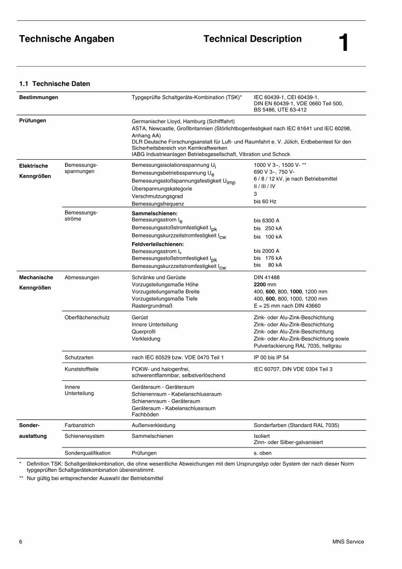
1.1 Technische Daten
Bestimmungen Typgeprüfte Schaltgeräte-Kombination (TSK)* IEC 60439-1, CEI 60439-1, DIN EN 60439-1, VDE 0660 Teil 500, BS 5486, UTE 63-412
Prüfungen Germanischer Lloyd, Hamburg (Schifffahrt) ASTA, Newcastle, Großbritannien (Störlichtbogenfestigkeit nach IEC 61641 und IEC 60298, Anhang AA) DLR Deutsche Forschungsanstalt für Luft- und Raumfahrt e. V. Jülich, Erdbebentest für den Sicherheitsbereich von Kernkraftwerken IABG Industrieanlagen Betriebsgesellschaft, Vibration und Schock
Elektrische
Kenngrößen
Bemessungs-spannungen
Bemessungsisolationsspannung Ui
Bemessungsbetriebsspannung Ue
Bemessungsstoßspannungsfestigkeit Uimp
Überspannungskategorie Verschmutzungsgrad Bemessungsfrequenz
1000 V 3~, 1500 V- ** 690 V 3~, 750 V- 6 / 8 / 12 kV, je nach Betriebsmittel II / III / IV 3 bis 60 Hz
Bemessungs- ströme
Sammelschienen: Bemessungsstrom Ie
Bemessungsstoßstromfestigkeit Ipk
Bemessungskurzzeitstromfestigkeit Icw
Feldverteilschienen: Bemessungsstrom Ie Bemessungsstoßstromfestigkeit Ipk
Bemessungskurzzeitstromfestigkeit Icw
bis 6300 A bis 250 kA
bis 100 kA bis 2000 A bis 176 kA bis 80 kA
Mechanische
Kenngrößen
Abmessungen
Schränke und Gerüste Vorzugsteilungsmaße Höhe Vorzugsteilungsmaße Breite Vorzugsteilungsmaße Tiefe Rastergrundmaß
DIN 41488 2200 mm 400, 600, 800, 1000, 1200 mm 400, 600, 800, 1000, 1200 mm E = 25 mm nach DIN 43660
Oberflächenschutz
Gerüst Innere Unterteilung Querprofil Verkleidung
Zink- oder Alu-Zink-Beschichtung Zink- oder Alu-Zink-Beschichtung Zink- oder Alu-Zink-Beschichtung Zink- oder Alu-Zink-Beschichtung sowie Pulverlackierung RAL 7035, hellgrau
Schutzarten nach IEC 60529 bzw. VDE 0470 Teil 1 IP 00 bis IP 54
Kunststoffteile
FCKW- und halogenfrei, schwerentflammbar, selbstverlöschend
IEC 60707, DIN VDE 0304 Teil 3
Innere Unterteilung
Geräteraum - Geräteraum Schienenraum - Kabelanschlussraum Schienenraum - Geräteraum Geräteraum - Kabelanschlussraum Fachböden
Sonder- Farbanstrich Außenverkleidung Sonderfarben (Standard RAL 7035)
austattung Schienensystem Sammelschienen Isoliert Zinn- oder Silber-galvanisiert
Sonderqualifikation Prüfungen s. oben
* Definition TSK: Schaltgerätekombination, die ohne wesentliche Abweichungen mit dem Ursprungstyp oder System der nach dieser Norm typgeprüften Schaltgerätekombination übereinstimmt.
** Nur gültig bei entsprechender Auswahl der Betriebsmittel
Technische Angaben
Technical Description 1
MNS Service 7
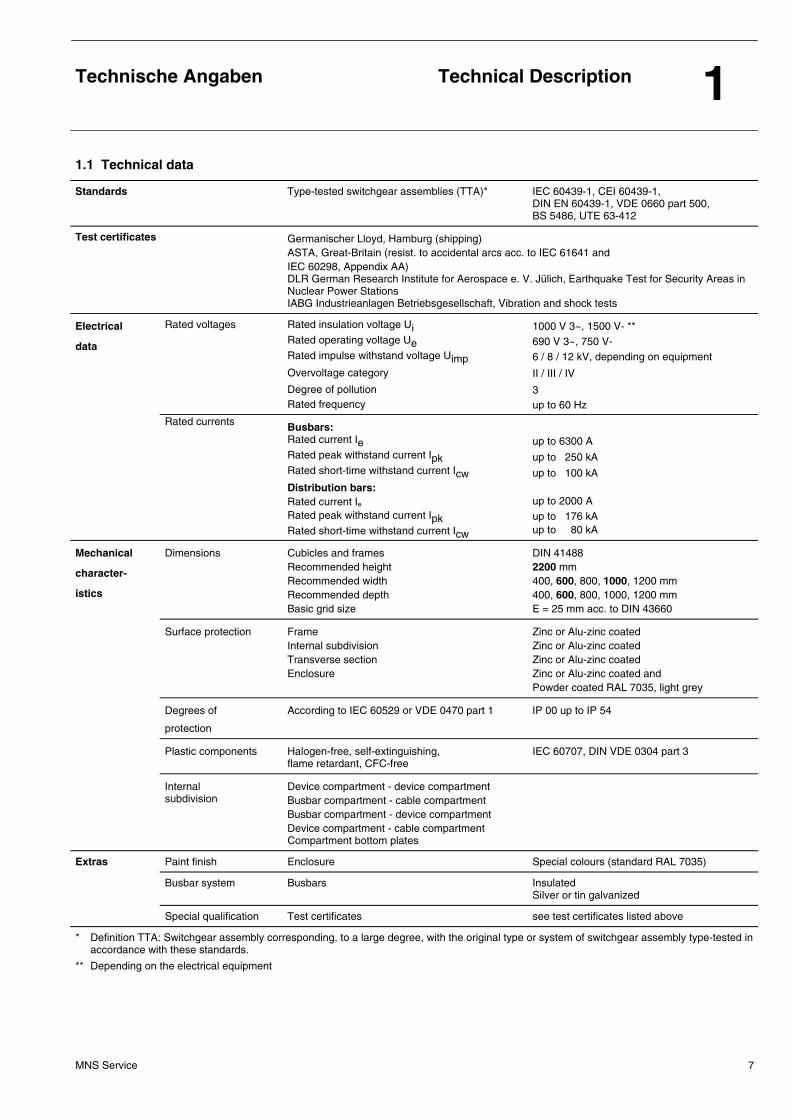
1.1 Technical data
Standards Type-tested switchgear assemblies (TTA)* IEC 60439-1, CEI 60439-1, DIN EN 60439-1, VDE 0660 part 500, BS 5486, UTE 63-412
Test certificates Germanischer Lloyd, Hamburg (shipping) ASTA, Great-Britain (resist. to accidental arcs acc. to IEC 61641 and IEC 60298, Appendix AA) DLR German Research Institute for Aerospace e. V. Jülich, Earthquake Test for Security Areas in Nuclear Power Stations IABG Industrieanlagen Betriebsgesellschaft, Vibration and shock tests
Electrical
data
Rated voltages Rated insulation voltage Ui
Rated operating voltage Ue
Rated impulse withstand voltage Uimp
Overvoltage category
Degree of pollution Rated frequency
1000 V 3~, 1500 V- ** 690 V 3~, 750 V- 6 / 8 / 12 kV, depending on equipment
II / III / IV
3 up to 60 Hz
Rated currents Busbars: Rated current Ie
Rated peak withstand current Ipk
Rated short-time withstand current Icw
Distribution bars: Rated current Ie Rated peak withstand current Ipk
Rated short-time withstand current Icw
up to 6300 A
up to 250 kA
up to 100 kA up to 2000 A up to 176 kA up to 80 kA
Mechanical
character-
istics
Dimensions
Cubicles and frames Recommended height Recommended width Recommended depth Basic grid size
DIN 41488 2200 mm 400, 600, 800, 1000, 1200 mm 400, 600, 800, 1000, 1200 mm E = 25 mm acc. to DIN 43660
Surface protection
Frame Internal subdivision Transverse section Enclosure
Zinc or Alu-zinc coated Zinc or Alu-zinc coated Zinc or Alu-zinc coated Zinc or Alu-zinc coated and Powder coated RAL 7035, light grey
Degrees of
protection
According to IEC 60529 or VDE 0470 part 1 IP 00 up to IP 54
Plastic components
Halogen-free, self-extinguishing, flame retardant, CFC-free
IEC 60707, DIN VDE 0304 part 3
Internal subdivision
Device compartment - device compartment Busbar compartment - cable compartment Busbar compartment - device compartment Device compartment - cable compartment Compartment bottom plates
Extras Paint finish Enclosure Special colours (standard RAL 7035)
Busbar system Busbars Insulated Silver or tin galvanized
Special qualification Test certificates see test certificates listed above
* Definition TTA: Switchgear assembly corresponding, to a large degree, with the original type or system of switchgear assembly type-tested in accordance with these standards.
** Depending on the electrical equipment
Technische Angaben
Technical Description 1
MNS Service 8
1.2 Mechanischer Aufbau 1.2 Mechanical design
Der mechanische Grundaufbau besteht aus
• dem Gerüst,
• der äußeren Umhüllung,
• den inneren Unterteilungen.
Grundelemente der Gerüste sind C-Profile aus 2 mm starkem Stahlblech mit Lochungen im 25 mm-Raster. Die Gerüstteile sind mit gewindeformenden Schrauben wartungsfrei verschraubt. Die Eckverbindungen sind ausgeführt mittels
• Druckplatten,
• ESLOK-gesicherten Sechskantschrauben M 10 x 18.
In Abhängigkeit von der Bauform sind die Felder partiell oder allseitig verkleidet. Türen und Verkleidungsbleche können mit Lüftungsgittern versehen sein, Sichtfenster in Türen bestehen aus Mehrscheiben-Verbundsicherheitsglas oder Polycarbonat. Die Felder sind je nach Anforderung oder Ausbauart in die folgenden Funktionsräume unterteilt:
The basic mechanical design comprises
• the frame,
• the enclosure,
• the internal constructions.
The basic elements of the frames are C-sections of 2 mm thick sheet steel with holes at 25 mm intervals. The parts of the frame are secured with thread-forming screws and require no maintenance. The corner joints are carried out by means of
• pressure plates,
• ESLOK-secured hex head screws M 10 x 18.
Depending on the type of construction, the cubicle may be enclosed partially or on all sides. Doors, front covers and rear walls can be provided with ventilation louvers. Windows in the doors are made of multilayer safety glass or polycarbonate. Depending on the requirements or the design the cubicles are divi-ded into functional compartments:
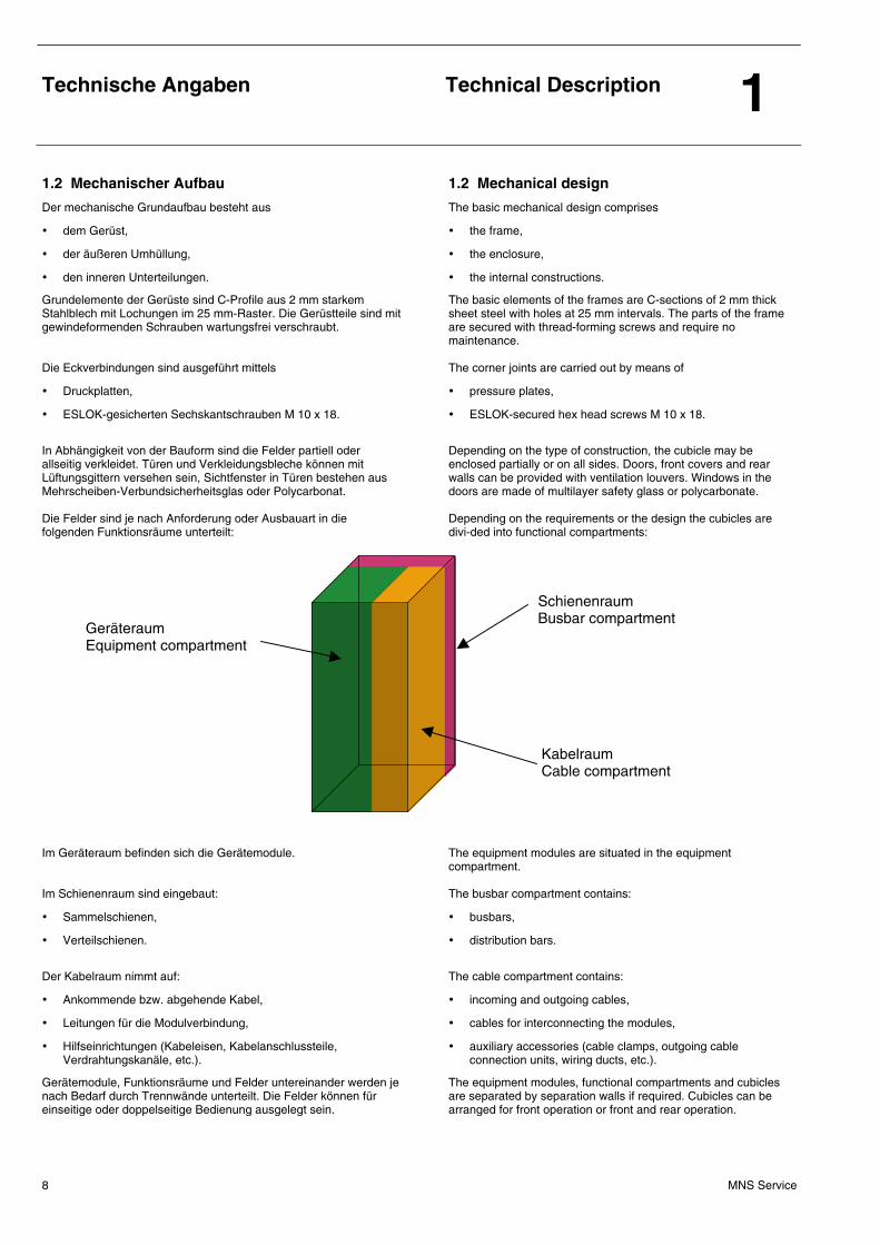
Im Geräteraum befinden sich die Gerätemodule. Im Schienenraum sind eingebaut:
• Sammelschienen,
• Verteilschienen.
Der Kabelraum nimmt auf:
• Ankommende bzw. abgehende Kabel,
• Leitungen für die Modulverbindung,
• Hilfseinrichtungen (Kabeleisen, Kabelanschlussteile, Verdrahtungskanäle, etc.).
Gerätemodule, Funktionsräume und Felder untereinander werden je nach Bedarf durch Trennwände unterteilt. Die Felder können für einseitige oder doppelseitige Bedienung ausgelegt sein.
The equipment modules are situated in the equipment compartment. The busbar compartment contains:
• busbars,
• distribution bars.
The cable compartment contains:
• incoming and outgoing cables,
• cables for interconnecting the modules,
• auxiliary accessories (cable clamps, outgoing cable connection units, wiring ducts, etc.).
The equipment modules, functional compartments and cubicles are separated by separation walls if required. Cubicles can be arranged for front operation or front and rear operation.
Geräteraum Equipment compartment
Schienenraum Busbar compartment
Kabelraum Cable compartment
Technische Angaben
Technical Description 1
MNS Service 9
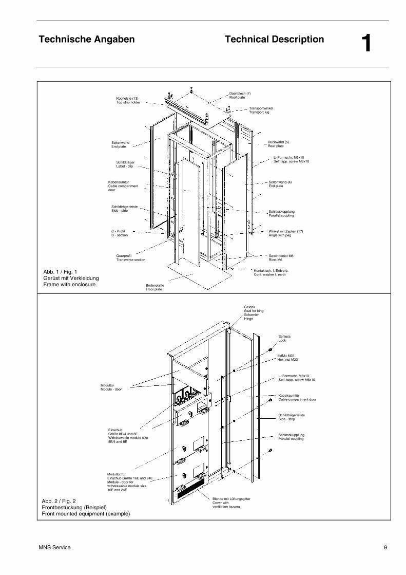
Abb. 1 / Fig. 1 Gerüst mit Verkleidung Frame with enclosure
Kopfleiste (13) Top strip holder
Seitenwand End plate
Schildträger Label - clip
Kabelraumtür Cable compartment door
Schildträgerleiste Side - strip
C - Profil C - section
Querprofil Transverse section
Bodenplatte Floor plate
Kontaktsch. f. Erdverb. Cont. washer f. earth
Gewindeniet M6 Rivet M6
Winkel mit Zapfen (17) Angle with peg
Schlosskupplung Parallel coupling
Seitenwand (4) End plate
Li-Formschr. M6x10 Self tapp. screw M6x10
Rückwand (5) Rear plate
Transportwinkel Transport lug
Dachblech (7) Roof plate
Abb. 2 / Fig. 2 Frontbestückung (Beispiel) Front mounted equipment (example)
Blende mit Lüftungsgitter Cover with ventilation louvers
Modultür Module - door
Einschub Größe 8E/4 und 8E Withdrawable module size 8E/4 and 8E
Modultür für Einschub Größe 16E und 24E Module - door for withdrawable module size 16E and 24E
Schlosskupplung Parallel coupling
Schildträgerleiste Side - strip
Kabelraumtür Cable compartment door
Li-Formschr. M6x10 Self. tapp. screw M6x10
6ktMu M22 Hex. nut M22
Schloss Lock
Gelenk Stud for hing Scharnier Hinge
Technische Angaben
Technical Description 1
MNS Service 10
1.3 Schienensystem 1.3 Busbar system
Folgende Schienensysteme können eingebaut sein:
• Sammelschienen (siehe Abb. 3 und 4), • Feldverteilschienen (siehe Abb. 5, 6 und 7), • Schutz- und Neutralleiterschienen (PE+N/PEN) (siehe Abb. 4).
The following busbar systems can be installed:
• busbars (see fig. 3 and 4), • distribution bars (see fig. 5, 6 and 7), • protective and neutral conductor bars (PE+N/PEN)
(see fig. 4).
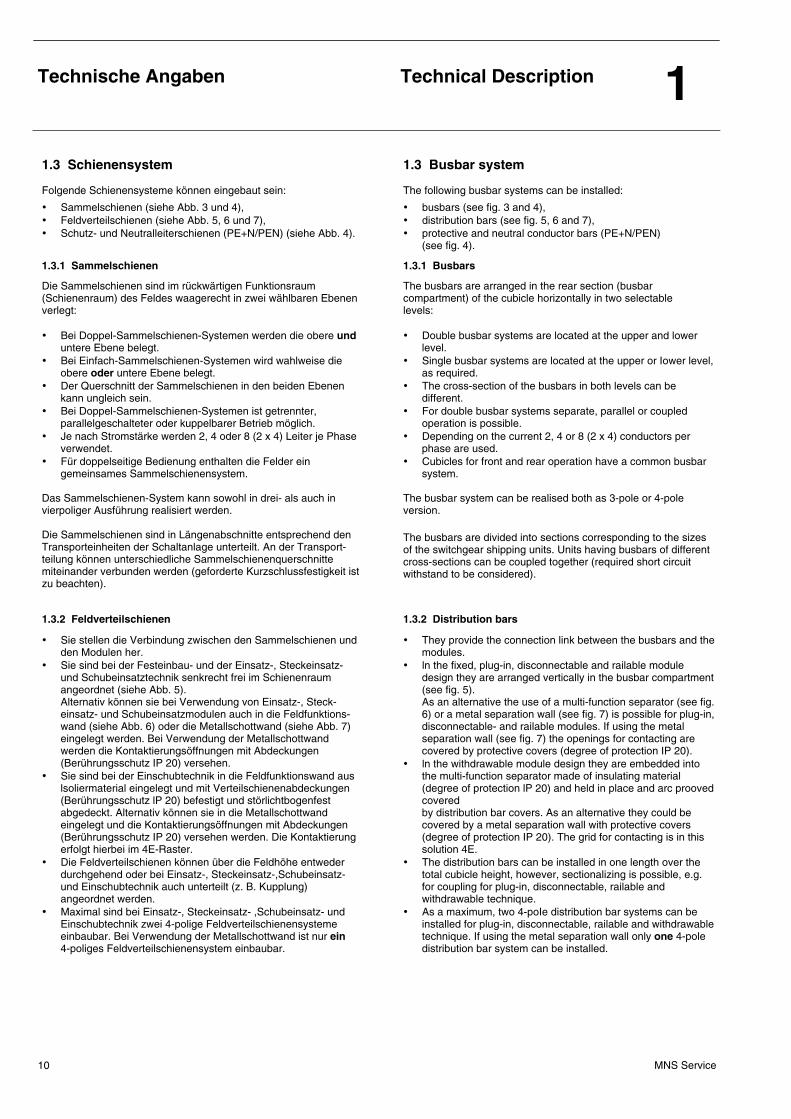
1.3.1 Sammelschienen 1.3.1 Busbars
Die Sammelschienen sind im rückwärtigen Funktionsraum (Schienenraum) des Feldes waagerecht in zwei wählbaren Ebenen verlegt: • Bei Doppel-Sammelschienen-Systemen werden die obere und
untere Ebene belegt. • Bei Einfach-Sammelschienen-Systemen wird wahlweise die
obere oder untere Ebene belegt. • Der Querschnitt der Sammelschienen in den beiden Ebenen
kann ungleich sein. • Bei Doppel-Sammelschienen-Systemen ist getrennter,
parallelgeschalteter oder kuppelbarer Betrieb möglich. • Je nach Stromstärke werden 2, 4 oder 8 (2 x 4) Leiter je Phase
verwendet. • Für doppelseitige Bedienung enthalten die Felder ein
gemeinsames Sammelschienensystem. Das Sammelschienen-System kann sowohl in drei- als auch in vierpoliger Ausführung realisiert werden. Die Sammelschienen sind in Längenabschnitte entsprechend den Transporteinheiten der Schaltanlage unterteilt. An der Transport-teilung können unterschiedliche Sammelschienenquerschnitte miteinander verbunden werden (geforderte Kurzschlussfestigkeit ist zu beachten).
The busbars are arranged in the rear section (busbar compartment) of the cubicle horizontally in two selectable levels: • Double busbar systems are located at the upper and lower
level. • Single busbar systems are located at the upper or Iower level,
as required. • The cross-section of the busbars in both levels can be
different. • For double busbar systems separate, parallel or coupled
operation is possible. • Depending on the current 2, 4 or 8 (2 x 4) conductors per
phase are used. • Cubicles for front and rear operation have a common busbar
system. The busbar system can be realised both as 3-pole or 4-pole version. The busbars are divided into sections corresponding to the sizes of the switchgear shipping units. Units having busbars of different cross-sections can be coupled together (required short circuit withstand to be considered).
1.3.2 Feldverteilschienen 1.3.2 Distribution bars
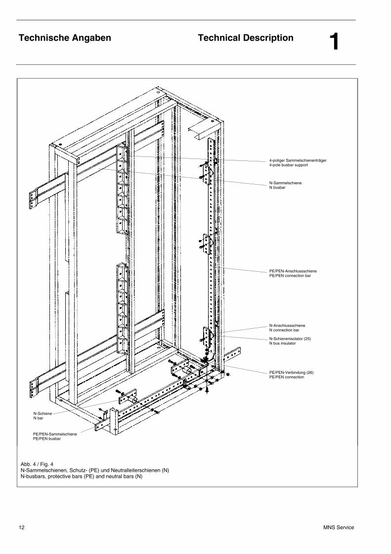
• Sie stellen die Verbindung zwischen den Sammelschienen und den Modulen her.
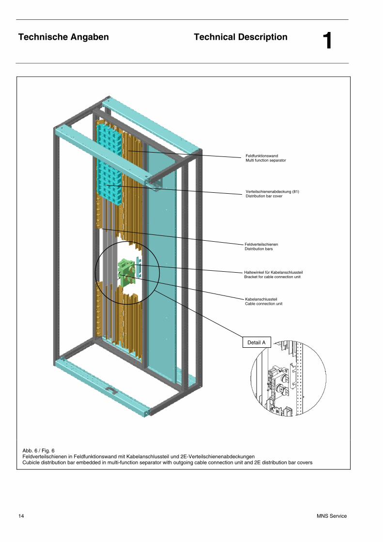
• Sie sind bei der Festeinbau- und der Einsatz-, Steckeinsatz- und Schubeinsatztechnik senkrecht frei im Schienenraum angeordnet (siehe Abb. 5). Alternativ können sie bei Verwendung von Einsatz-, Steck-einsatz- und Schubeinsatzmodulen auch in die Feldfunktions-wand (siehe Abb. 6) oder die Metallschottwand (siehe Abb. 7) eingelegt werden. Bei Verwendung der Metallschottwand werden die Kontaktierungsöffnungen mit Abdeckungen (Berührungsschutz IP 20) versehen.
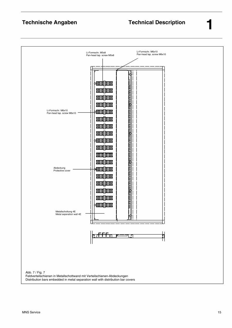
• Sie sind bei der Einschubtechnik in die Feldfunktionswand aus lsoliermaterial eingelegt und mit Verteilschienenabdeckungen (Berührungsschutz lP 20) befestigt und störlichtbogenfest abgedeckt. Alternativ können sie in die Metallschottwand eingelegt und die Kontaktierungsöffnungen mit Abdeckungen (Berührungsschutz IP 20) versehen werden. Die Kontaktierung erfolgt hierbei im 4E-Raster.
• Die Feldverteilschienen können über die Feldhöhe entweder durchgehend oder bei Einsatz-, Steckeinsatz-,Schubeinsatz- und Einschubtechnik auch unterteilt (z. B. Kupplung) angeordnet werden.
• Maximal sind bei Einsatz-, Steckeinsatz- ,Schubeinsatz- und Einschubtechnik zwei 4-polige Feldverteilschienensysteme einbaubar. Bei Verwendung der Metallschottwand ist nur ein 4-poliges Feldverteilschienensystem einbaubar.
• They provide the connection link between the busbars and the modules.
• ln the fixed, plug-in, disconnectable and railable module design they are arranged vertically in the busbar compartment (see fig. 5). As an alternative the use of a multi-function separator (see fig. 6) or a metal separation wall (see fig. 7) is possible for plug-in, disconnectable- and railable modules. If using the metal separation wall (see fig. 7) the openings for contacting are covered by protective covers (degree of protection IP 20).
• ln the withdrawable module design they are embedded into the multi-function separator made of insulating material (degree of protection lP 20) and held in place and arc prooved covered by distribution bar covers. As an alternative they could be covered by a metal separation wall with protective covers (degree of protection IP 20). The grid for contacting is in this solution 4E.
• The distribution bars can be installed in one length over the total cubicle height, however, sectionalizing is possible, e.g. for coupling for plug-in, disconnectable, railable and withdrawable technique.
• As a maximum, two 4-poIe distribution bar systems can be installed for plug-in, disconnectable, railable and withdrawable technique. If using the metal separation wall only one 4-pole distribution bar system can be installed.
Technische Angaben
Technical Description 1
MNS Service 11
Abb. 3 / Fig. 3 Sammelschienensystem mit angedeutetem 4. Pol Busbar system with outlined 4th pole
Sammelschienenträger 3- oder 4-polig Busbar support 3- or 4-pole
Klemmbügel Busbar holding plate
Sammelschiene Busbar
Klemmbügel (22) Busbar holding plate
N-Sammelschiene N busbar
Technische Angaben
Technical Description 1
MNS Service 12
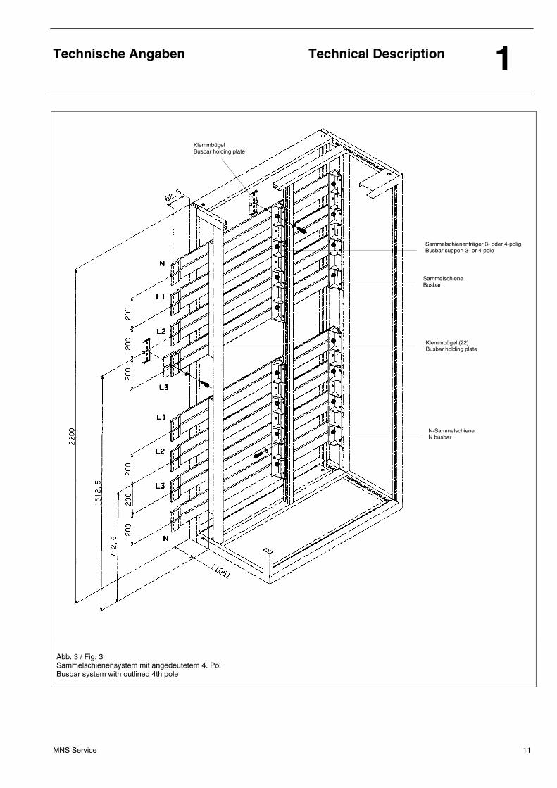
Abb. 4 / Fig. 4 N-Sammelschienen, Schutz- (PE) und Neutralleiterschienen (N) N-busbars, protective bars (PE) and neutral bars (N)
4-poliger Sammelschienenträger 4-pole busbar support
N-Sammelschiene N busbar
PE/PEN-Anschlussschiene PE/PEN connection bar
N-Anschlussschiene N connection bar
N-Schienenisolator (25) N bus insulator
PE/PEN-Verbindung (26) PE/PEN connection
N-Schiene N bar
PE/PEN-Sammelschiene PE/PEN busbar
Technische Angaben
Technical Description 1
MNS Service 13
Abb. 5 / Fig. 5 Feldverteilschienen frei im Schienenraum Open version of distribution bars
Technische Angaben
Technical Description 1
MNS Service 14
Abb. 6 / Fig. 6 Feldverteilschienen in Feldfunktionswand mit Kabelanschlussteil und 2E-Verteilschienenabdeckungen Cubicle distribution bar embedded in multi-function separator with outgoing cable connection unit and 2E distribution bar covers
Verteilschienenabdeckung (81) Distribution bar cover
Haltewinkel für Kabelanschlussteil Bracket for cable connection unit
Feldfunktionswand Multi function separator
Kabelanschlussteil Cable connection unit
Detail A
Feldverteilschienen Distribution bars
Technische Angaben
Technical Description 1
MNS Service 15
Abb. 7 / Fig. 7 Feldverteilschienen in Metallschottwand mit Verteilschienen-Abdeckungen Distribution bars embedded in metal separation wall with distribution bar covers
Li-Formschr. M6x10 Pan-head tap. screw M6x10
Metallschottung 4E Metal seperation wall 4E
Li-Formschr. M5x8 Pan-head tap. screw M5x8
Li-Formschr. M6x10 Pan-head tap. screw M6x10
Abdeckung Protective cover
Technische Angaben
Technical Description 1
MNS Service 16
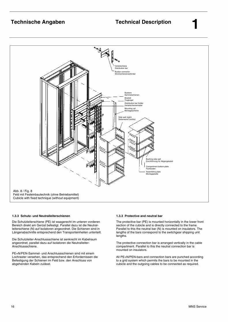
Abb. 8 / Fig. 8 Feld mit Festeinbautechnik (ohne Betriebsmittel) Cubicle with fixed technique (without equipment)
1.3.3 Schutz- und Neutralleiterschienen 1.3.3 Protective and neutral bar
Die Schutzleiterschiene (PE) ist waagerecht im unteren vorderen Bereich direkt am Gerüst befestigt. Parallel dazu ist die Neutral-leiterschiene (N) auf lsolatoren angeordnet. Die Schienen sind in Längenabschnitte entsprechend den Transporteinheiten unterteilt. Die Schutzleiter-Anschlussschiene ist senkrecht im Kabelraum angeordnet, parallel dazu auf lsolatoren die NeutralIeiter- Anschlussschiene. PE+N/PEN-Sammel- und Anschlussschienen sind mit einem Lochraster versehen, das entsprechend den Erfordernissen die Befestigung der Schienen im Feld bzw. den Anschluss von abgehenden Kabeln zuIässt.
The protective bar (PE) is mounted horizontally in the lower front section of the cubicle and is directly connected to the frame. Parallel to this the neutral bar (N) is mounted on insulators. The lengths of the bars correspond to the switchgear shipping unit lengths. The protective connection bar is arranged vertically in the cable compartment. Parallel to this the neutral connection bar is mounted on insulators. All PE+N/PEN-bars and connection bars are punched according to a grid system which permits the bars to be mounted in the cubicle and the outgoing cables to be connected as required.
Busbars Sammelschienen
Bracket Tragbügel
Distribution bar holder Verteilschienenhalter
Mounting rail Montageschiene
Side wall (right) Seitenwand (rechts)
Bushing side wall Durchführung für Abgangskabel
Compartment bottom plate Fachboden
Assembling plate Montageplatte
Verteilschiene Distribution bar
Busbar connector Stromschienenverbinder
Technische Angaben
Technical Description 1
MNS Service 17
1.4 Ausbausystem 1.4 Modular add-on parts
Betriebsmittel, die zu einer Funktionseinheit gehören, sind in einer Baueinheit (Modul) zusammengefasst. Standard-Bauformen sind:
• Sammelschienen-Direktanschluss,
• Festeinbau-Technik,
• Einsatz-, Steckeinsatz- und Schubeinsatztechnik,
• Einschubtechnik,
• Steuermodule oder Steuerfelder,
• Frontmodule (Anzeige-, Mess-, Melde- und Bedienungsgeräte im Gerätetableau der Frontblende bzw. Messnische).
The equipment beIonging to a functional unit is contained in a single module. Standard designs are:
• direct connection to the busbar,
• fixed technique,
• plug-in, disconnectable and railable technique,
• withdrawabIe technique,
• control modules or control cubicles,
• front modules (indicating, measuring, annunciating, operating and control units mounted on the instrument panel of the front cover or the measuring recess).
1.4.1 Sammelschienen-Direktanschluss 1.4.1 Direct connection to the busbar
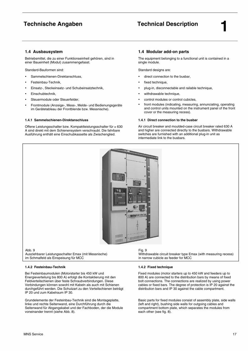
Offene Leistungsschalter bzw. Kompaktleistungsschalter für ≥ 630 A sind direkt mit dem Schienensystem verschraubt. Die fahrbare Ausführung enthält eine Einschubkassette als Zwischenglied.
Air circuit breaker and moulded-case circuit breaker rated 630 A and higher are connected directIy to the busbars. Withdrawable switches are furnished with an additional plug-in unit as intermediate link to the busbars.
Abb. 9 Ausziehbarer Leistungsschalter Emax (mit Messnische) im Schmalfeld als Einspeisung für MCC
Fig. 9 Withdrawable circuit breaker type Emax (with measuring recess) in narrow cubicle as feeder for MCC
1.4.2 Festeinbau-Technik 1.4.2 Fixed technique
Bei Festeinbaumodulen (Motorstarter bis 450 kW und Energieverteilung bis 800 A) erfolgt die Kontaktierung mit den Feldverteilschienen über feste Schraubverbindungen. Diese Verbindungen können sowohl mit Kabeln als auch mit Schienen durchgeführt werden. Die Schutzart zu den Verteilschienen beträgt IP 20 und zum Kabelraum IP 30. Grundelemente der Festeinbau-Technik sind die Montageplatte, linke und rechte Seitenwand, eine Durchführung durch die Seitenwand für Abgangskabel und der Fachboden, der die Module voneinander trennt (siehe Abb. 8).
Fixed modules (motor starters up to 450 kW and feeders up to 800 A) are connected to the distribution bars by means of fixed bolt connections. The connections are realized by using power cables or fixed bars. The degree of protection is IP 20 against the distribution bars and IP 30 against the cable compartment. Basic parts for fixed modules consist of assembly plate, side walls (left and right), bushing side walls for outgoing cables and compartment bottom plate, which separates the modules from each other (see fig. 8).
Technische Angaben
Technical Description 1
MNS Service 18
1.4.3 Einsatz-, Steckeinsatz- und Schubeinsatztechnik 1.4.3 Plug-in, disconnectable and railable technique
Bei Einsatz-, Steckeinsatz- und Schubeinsatzmodulen (bis 630 A) erfolgt die Kontaktierung mit den Feldverteilschienen über Steckkontakte. Eine Variante der Einsatzmodule bildet der NH-Sicherungs-lasttrennschalter SR. Die komplette Einheit ist direkt im Gerüst befestigt und mit eigenen Kontakten mit den Feldverteilschienen verbunden.
Plug-in, disconnectable and railable modules (up to 630 A) are connected to the distribution bars by means of plug-in contacts. The LV HRC load break switch type SR constitutes a type of plug-in module. The complete unit is mounted directly on the frame and connected through its own contact elements to the distribution bars.
1.4.3.1 Einsatzmodule 1.4.3.1 Plug-in modules
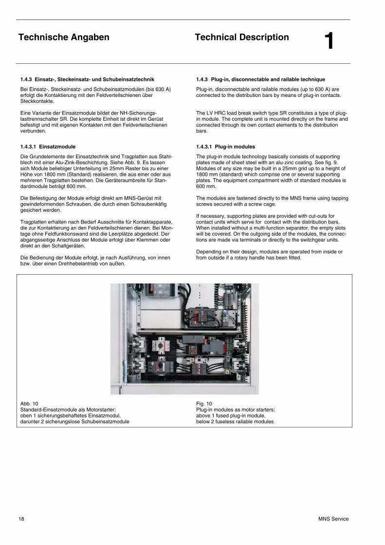
Die Grundelemente der Einsatztechnik sind Tragplatten aus Stahl-blech mit einer Alu-Zink-Beschichtung. Siehe Abb. 9. Es lassen sich Module beliebiger Unterteilung im 25mm Raster bis zu einer Höhe von 1800 mm (Standard) realisieren, die aus einer oder aus mehreren Tragplatten bestehen. Die Geräteraumbreite für Stan-dardmodule beträgt 600 mm. Die Befestigung der Module erfolgt direkt am MNS-Gerüst mit gewindeformenden Schrauben, die durch einen Schraubenkäfig gesichert werden. Tragplatten erhalten nach Bedarf Ausschnitte für Kontaktapparate, die zur Kontaktierung an den Feldverteilschienen dienen. Bei Mon-tage ohne Feldfunktionswand sind die Leerplätze abgedeckt. Der abgangsseitige Anschluss der Module erfolgt über Klemmen oder direkt an den Schaltgeräten. Die Bedienung der Module erfolgt, je nach Ausführung, von innen bzw. über einen Drehhebelantrieb von außen.
The plug-in module technology basically consists of supporting plates made of sheet steel with an alu-zinc coating. See fig. 9. Modules of any size may be built in a 25mm grid up to a height of 1800 mm (standard) which comprise one or several supporting plates. The equipment compartment width of standard modules is 600 mm. The modules are fastened directly to the MNS frame using tapping screws secured with a screw cage. If necessary, supporting plates are provided with cut-outs for contact units which serve for contact with the distribution bars. When installed without a multi-function separator, the empty slots will be covered. On the outgoing side of the modules, the connec-tions are made via terminals or directly to the switchgear units. Depending on their design, modules are operated from inside or from outside if a rotary handle has been fitted.
Abb. 10 Standard-Einsatzmodule als Motorstarter: oben 1 sicherungsbehaftetes Einsatzmodul, darunter 2 sicherungslose Schubeinsatzmodule
Fig. 10 Plug-in modules as motor starters: above 1 fused plug-in module, below 2 fuseless railable modules
Technische Angaben
Technical Description 1
MNS Service 19
1.4.3.2 Steckeinsatzmodule 1.4.3.2 Disconnectable modules
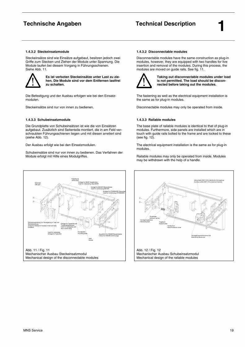
Steckeinsätze sind wie Einsätze aufgebaut, besitzen jedoch zwei Griffe zum Stecken und Ziehen der Module unter Spannung. Die Module laufen bei diesem Vorgang in Führungsschienen. Siehe Abb. 11.
Es ist verboten Steckeinsätze unter Last zu zie-hen. Die Module sind vor dem Entfernen lastfrei zu schalten.
Die Befestigung und der Ausbau erfolgen wie bei den Einsatz-modulen. Steckeinsätze sind nur von innen zu bedienen.
Disconnectable modules have the same construction as plug-in modules, however, they are equipped with two handles for live insertion and removal of the modules. During this process, the modules are moved on guide rails. See fig. 11.
Taking out disconnectable modules under load is not permitted. The load should be discon-nected before taking out the modules.
The fastening as well as the electrical equipment installation is the same as for plug-in modules. Disconnectable modules may only be operated from inside.
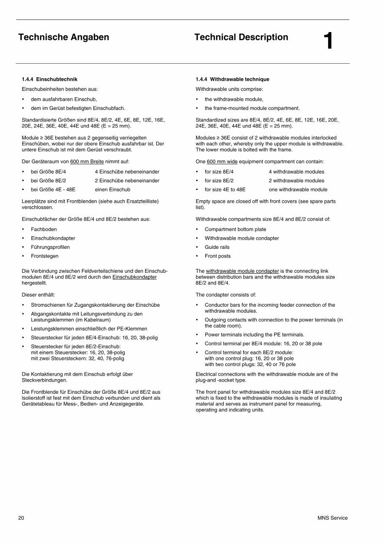
1.4.3.3 Schubeinsatzmodule 1.4.3.3 Railable modules
Die Grundplatte von Schubeinsätzen ist wie die von Einsätzen aufgebaut. Zusätzlich sind Seitenteile montiert, die in am Feld ver-schraubten Führungsschienen liegen und mit diesen arretiert sind (siehe Abb. 12). Der Ausbau erfolgt wie bei den Einsatzmodulen. Schubeinsätze sind nur von innen zu bedienen. Das Verfahren der Module erfolgt mit Hilfe eines Modulgriffes.
The base plate of railable modules is identical to that of plug-in modules. Furthermore, side panels are installed which are in touch with guide rails bolted to the frame and are locked to these (see fig. 12). The electrical equipment installation is the same as for plug-in modules. Railable modules may only be operated from inside. Modules may be withdrawn with the help of a handle.
Grundplatte mounting plate
Einlage für Typschild und Türübergangsstecker inset for nameplate and door control plug
Schraubverbindung zur Verriegelung in Test und Betriebsstellung screw for interlock of module in test and duty condition
inset for nameplate Einlage für Typschild Ausschnitt für INSUM Steuerstecker
Cutout for INSUM control plugs Griff handle
Einlage für BAYER Steuerstecker inset for control plug BAYER
Einlage für STANDARD Steuerstecinset for control plug STANDARD
Einlage für BASF Koppelrelais inset for interposing relay BASF
Kabelkanal wiring duct
Seitenteil side part
Verriegelungsmechanismus kpl.interlocking device cpl.
Verriegelungsbolzeninterlocking bolt
Druckfederpressure spring
TragblechSupport plate
HandschutzHand Protection cover
Hilfsschalter SEF-10 für elektrische VerriegelungAuxiliary switch SEF-10 for electrical interlock
Abb. 11 / Fig. 11 Mechanischer Ausbau Steckeinsatzmodul Mechanical design of the disconnectable modules
Abb. 12 / Fig. 12 Mechanischer Ausbau Schubeinsatzmodul Mechanical design of the railable modules
Technische Angaben
Technical Description 1
MNS Service 20
1.4.4 Einschubtechnik 1.4.4 Withdrawable technique
Einschubeinheiten bestehen aus:
• dem ausfahrbaren Einschub,
• dem im Gerüst befestigten Einschubfach.
Standardisierte Größen sind 8E/4, 8E/2, 4E, 6E, 8E, 12E, 16E, 20E, 24E, 36E, 40E, 44E und 48E (E = 25 mm). Module ≥ 36E bestehen aus 2 gegenseitig verriegelten Einschüben, wobei nur der obere Einschub ausfahrbar ist. Der untere Einschub ist mit dem Gerüst verschraubt. Der Geräteraum von 600 mm Breite nimmt auf:
• bei Größe 8E/4 4 Einschübe nebeneinander
• bei Größe 8E/2 2 Einschübe nebeneinander
• bei Größe 4E - 48E einen Einschub
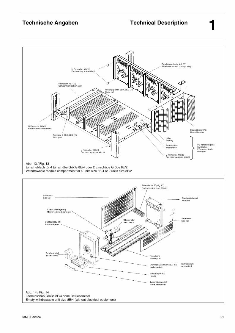
Leerplätze sind mit Frontblenden (siehe auch Ersatzteilliste) verschlossen. Einschubfächer der Größe 8E/4 und 8E/2 bestehen aus:
• Fachboden
• Einschubkondapter
• Führungsprofilen
• Frontstegen
Die Verbindung zwischen Feldverteilschiene und den Einschub-modulen 8E/4 und 8E/2 wird durch den Einschubkondapter hergestellt. Dieser enthält:
• Stromschienen für Zugangskontaktierung der Einschübe
• Abgangskontakte mit Leitungsverbindung zu den Leistungsklemmen (im Kabelraum)
• Leistungsklemmen einschließlich der PE-Klemmen
• Steuerstecker für jeden 8E/4-Einschub: 16, 20, 38-polig
• Steuerstecker für jeden 8E/2-Einschub: mit einem Steuerstecker: 16, 20, 38-polig mit zwei Steuersteckern: 32, 40, 76-polig
Die Kontaktierung mit dem Einschub erfolgt über Steckverbindungen. Die Frontblende für Einschübe der Größe 8E/4 und 8E/2 aus lsolierstoff ist fest mit dem Einschub verbunden und dient als Gerätetableau für Mess-, Bedien- und Anzeigegeräte.
Withdrawable units comprise:
• the withdrawable module,
• the frame-mounted module compartment.
Standardized sizes are 8E/4, 8E/2, 4E, 6E, 8E, 12E, 16E, 20E, 24E, 36E, 40E, 44E und 48E (E = 25 mm). Modules ≥ 36E consist of 2 withdrawable modules interlocked with each other, whereby only the upper module is withdrawable. The lower module is bolted with the frame. One 600 mm wide equipment compartment can contain:
• for size 8E/4 4 withdrawable modules
• for size 8E/2 2 withdrawable modules
• for size 4E to 48E one withdrawable module
Empty space are closed off with front covers (see spare parts list). Withdrawable compartments size 8E/4 and 8E/2 consist of:
• Compartment bottom pIate
• Withdrawable module condapter
• Guide rails
• Front posts
The withdrawable module condapter is the connecting link between distribution bars and the withdrawable modules size 8E/2 and 8E/4. The condapter consists of:
• Conductor bars for the incoming feeder connection of the withdrawable modules.
• Outgoing contacts with connection to the power terminals (in the cable room).
• Power terminals including the PE terminals.
• Control terminal per 8E/4 module: 16, 20 or 38 pole
• Control terminal for each 8E/2 module: with one control plug: 16, 20 or 38 pole with two control plugs: 32, 40 or 76 pole
Electrical connections with the withdrawable module are of the plug-and -socket type. The front panel for withdrawabIe modules size 8E/4 and 8E/2 which is fixed to the withdrawable modules is made of insuIating material and serves as instrument panel for measuring, operating and indicating units.
Technische Angaben
Technical Description 1
MNS Service 21
Abb. 13 / Fig. 13 Einschubfach für 4 Einschübe Größe 8E/4 oder 2 Einschübe Größe 8E/2 Withdrawable module compartment for 4 units size 8E/4 or 2 units size 8E/2
Abb. 14 / Fig. 14 Leereinschub Größe 8E/4 ohne Betriebsmittel Empty withdrawable unit size 8E/4 (without electrical equipment)
(kein Standard) (no standard)
Fachboden kpl. (72) Compartment bottom assy.
Führungsprofil f. 8E/4, 8E/2 (73) Guide rail
Einschubkondapter kpl. (77) Withdrawable mod. condapt. assy.
Steuerstecker (79) Control terminal
Li-Formschr. M6x10 Pan head tap.screw M6x10
Li-Formschr. M6x10 Pan head tap.screw M6x10
Frontsteg f. 8E/4, 8E/2 (76) Front post
Li-Formschr. M6x20 Pan head tap.screw M6x20
Li-Formschr. M6x10 Pan head tap.screw M6x10
Hülse Bushing
Scheibe B6.4 Washer B6.4
PE-Verbindung des Kondapters PE-connecttion for condapter
Technische Angaben
Technical Description 1
MNS Service 22
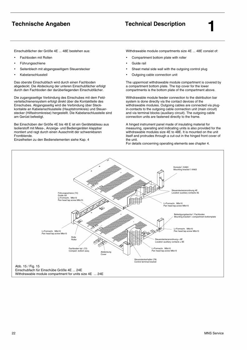
Einschubfächer der Größe 4E ... 48E bestehen aus:
• Fachboden mit Rollen
• Führungsschiene
• Seitenblech mit abgangsseitigem Steuerstecker
• Kabelanschlussteil
Das oberste Einschubfach wird durch einen Fachboden abgedeckt. Die Abdeckung der unteren Einschubfächer erfolgt durch den Fachboden der darüberliegenden Einschubfächer. Die zugangsseitige Verbindung des Einschubes mit dem Feld-verteilschienensystem erfolgt direkt über die Kontaktteile des Einschubes. Abgangsseitig wird die Verbindung über Steck-kontakte an Kabelanschlussteile (Hauptstromkreis) und Steuer-stecker (Hilfsstromkreise) hergestellt. Die Kabelanschlussteile sind am Gerüst befestigt. Bei Einschüben der Größe 4E bis 48 E ist ein Gerätetableau aus lsolierstoff mit Mess-, Anzeige- und Bediengeräten klappbar montiert und ragt durch einen Ausschnitt der schwenkbaren Frontblende. Einzelheiten zu den Bedienelementen siehe Kap. 4
Withdrawable moduIe compartments size 4E ... 48E consist of:
• Compartment bottom pIate with roller
• Guide raiI
• Sheet metal side wall with the outgoing control plug
• Outgoing cable connection unit
The uppermost withdrawable module compartment is covered by a compartment bottom pIate. The top cover for the lower compartments is the bottom plate of the compartment above. Withdrawable module feeder connection to the distribution bar system is done directly via the contact devices of the withdrawable modules. Outgoing cables are connected via plug-in-contacts to the outgoing cable connection unit (main circuit) and via terminal blocks (auxiliary circuit). The outgoing cable connection units are fastened directly to the frame. A hinged instrument panel made of insulating material for measuring, operating and indicating units is also provided for the withdrawable modules size 4E to 48E. lt is mounted on the unit itself and protrudes through a cut-out in the hinged front cover of the unit. For details concerning operating elements see chapter 4.
Abb. 15 / Fig. 15 Einschubfach für Einschübe Größe 4E ... 24E Withdrawable module compartment for units size 4E ... 24E
Steuersteckerhalter (78) Control terminal bracket
Fachboden kpl. (72) Compart. bottom assy.
Li-Formschr. M6x10 Pan head tap.screw M6x10
Abdeckung Cover
Li-Formschr. M6x10 Pan head tap.screw M6x10
Befestigungslasche f. Fachboden Mounting bracket f. compartment bottomplate
Li-Formschr. M6x10 Pan head tap.screw M6x10
Steuersteckeranordnung ≥ 8E Location auxiliary contacts ≥ 8E
Li-Formschr. M6x10 Pan head tap.screw M6x10
Konsole f. KA63 Mounting bracket f. KA63
Steuersteckeranordnung 4E Location auxiliary contacts 4E
Rolle Roller
Führungsschiene (74) Guide rail Li-Formschr. M6x10 Pan head tap.screw M6x10
Technische Angaben
Technical Description 1
MNS Service 23
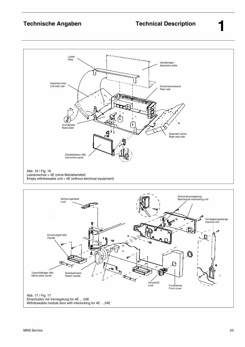
Abb. 16 / Fig. 16 Leereinschub > 4E (ohne Betriebsmittel) Empty withdrawable unit > 4E (without electrical equipment)
Abb. 17 / Fig. 17 Einschubtür mit Verriegelung für 4E ... 24E Withdrawable module door with interlocking for 4E ... 24E
Leiste Strip
Geräteträger Apparatus plate
Seitenteil rechts Right wall side
Einschubrückwand Rear wall
Seitenteil links Left side wall
Grundplatte Base plate
Gerätetableau (89) Instrument panel
Verriegelungsstange Interlock link
Einschubverriegelung Mechanical interlocking unit
Einschubgriff (83) Handle
Typschildträger (84) Name plate carrier
Schalterknebel Switch handle
Verschluß Lock Frontblende
Front cover
Sicherungshebel Lock
Verpackung und Transport
Packing and Transport 2
MNS Service 24
2.1 Allgemeines 2.1 General
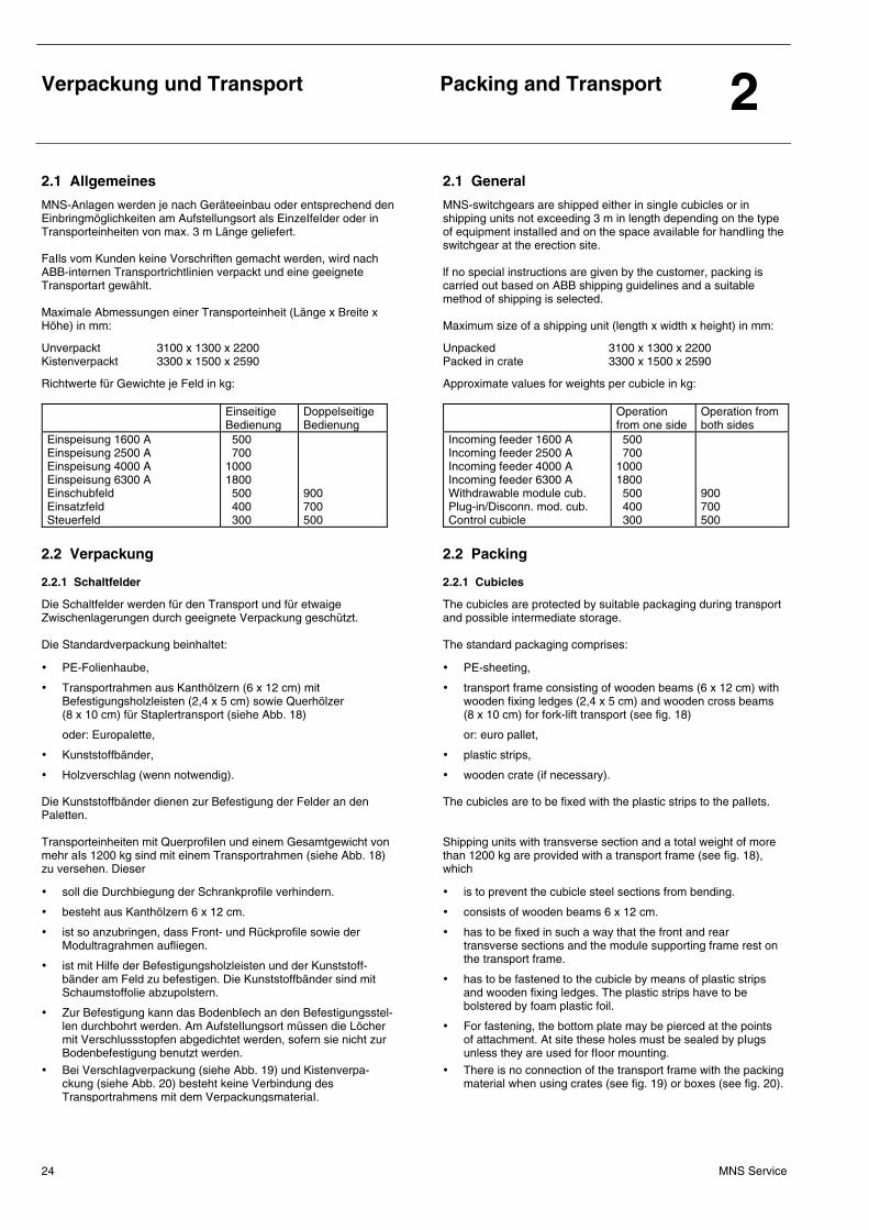
MNS-Anlagen werden je nach Geräteeinbau oder entsprechend den Einbringmöglichkeiten am Aufstellungsort als EinzeIfeIder oder in Transporteinheiten von max. 3 m Länge geliefert. FaIls vom Kunden keine Vorschriften gemacht werden, wird nach ABB-internen Transportrichtlinien verpackt und eine geeignete Transportart gewählt. Maximale Abmessungen einer Transporteinheit (Länge x Breite x Höhe) in mm:
Unverpackt 3100 x 1300 x 2200 Kistenverpackt 3300 x 1500 x 2590
Richtwerte für Gewichte je Feld in kg: Einseitige
Bedienung Doppelseitige Bedienung
Einspeisung 1600 A Einspeisung 2500 A Einspeisung 4000 A Einspeisung 6300 A Einschubfeld Einsatzfeld Steuerfeld
500 700 1000 1800 500 400 300
900 700 500
MNS-switchgears are shipped either in singIe cubicles or in shipping units not exceeding 3 m in length depending on the type of equipment instalIed and on the space available for handIing the switchgear at the erection site. lf no special instructions are given by the customer, packing is carried out based on ABB shipping guidelines and a suitable method of shipping is selected. Maximum size of a shipping unit (length x width x height) in mm:
Unpacked 3100 x 1300 x 2200 Packed in crate 3300 x 1500 x 2590
Approximate values for weights per cubicle in kg: Operation
from one side Operation from both sides
Incoming feeder 1600 A Incoming feeder 2500 A Incoming feeder 4000 A Incoming feeder 6300 A Withdrawable module cub. Plug-in/Disconn. mod. cub. Control cubicle
500 700 1000 1800 500 400 300
900 700 500
2.2 Verpackung
2.2 Packing
2.2.1 Schaltfelder 2.2.1 Cubicles
Die Schaltfelder werden für den Transport und für etwaige Zwischenlagerungen durch geeignete Verpackung geschützt. Die Standardverpackung beinhaltet:
• PE-Folienhaube,
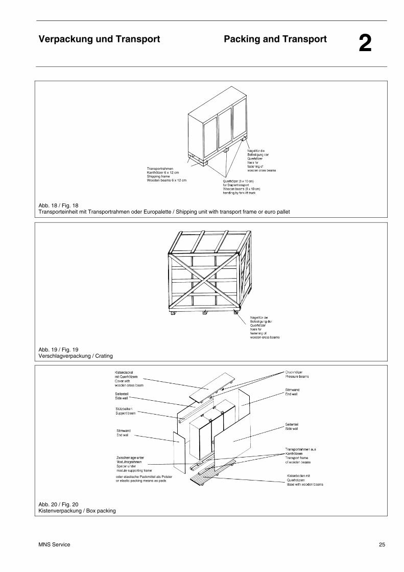
• Transportrahmen aus Kanthölzern (6 x 12 cm) mit Befestigungsholzleisten (2,4 x 5 cm) sowie Querhölzer (8 x 10 cm) für Staplertransport (siehe Abb. 18)
oder: Europalette,
• Kunststoffbänder,
• Holzverschlag (wenn notwendig).
Die Kunststoffbänder dienen zur Befestigung der Felder an den Paletten. Transporteinheiten mit QuerprofiIen und einem Gesamtgewicht von mehr aIs 1200 kg sind mit einem Transportrahmen (siehe Abb. 18) zu versehen. Dieser
• soll die Durchbiegung der Schrankprofile verhindern.
• besteht aus Kanthölzern 6 x 12 cm.
• ist so anzubringen, dass Front- und Rückprofile sowie der Modultragrahmen aufliegen.
• ist mit Hilfe der Befestigungsholzleisten und der Kunststoff-bänder am Feld zu befestigen. Die Kunststoffbänder sind mit Schaumstoffolie abzupolstern.
• Zur Befestigung kann das BodenbIech an den Befestigungsstel-len durchbohrt werden. Am AufsteIlungsort müssen die Löcher mit Verschlussstopfen abgedichtet werden, sofern sie nicht zur Bodenbefestigung benutzt werden.
• Bei VerschIagverpackung (siehe Abb. 19) und Kistenverpa-ckung (siehe Abb. 20) besteht keine Verbindung des Transportrahmens mit dem VerpackungsmateriaI.
The cubicles are protected by suitable packaging during transport and possible intermediate storage. The standard packaging comprises:
• PE-sheeting,
• transport frame consisting of wooden beams (6 x 12 cm) with wooden fixing ledges (2,4 x 5 cm) and wooden cross beams (8 x 10 cm) for fork-lift transport (see fig. 18)
or: euro pallet,
• plastic strips,
• wooden crate (if necessary).
The cubicles are to be fixed with the plastic strips to the palIets. Shipping units with transverse section and a total weight of more than 1200 kg are provided with a transport frame (see fig. 18), which
• is to prevent the cubicle steel sections from bending.
• consists of wooden beams 6 x 12 cm.
• has to be fixed in such a way that the front and rear transverse sections and the module supporting frame rest on the transport frame.
• has to be fastened to the cubicle by means of plastic strips and wooden fixing ledges. The plastic strips have to be bolstered by foam plastic foil.
• For fastening, the bottom plate may be pierced at the points of attachment. At site these holes must be sealed by pIugs unless they are used for fIoor mounting.
• There is no connection of the transport frame with the packing material when using crates (see fig. 19) or boxes (see fig. 20).
Verpackung und Transport
Packing and Transport 2
MNS Service 25
Abb. 18 / Fig. 18 Transporteinheit mit Transportrahmen oder Europalette / Shipping unit with transport frame or euro pallet
Abb. 19 / Fig. 19 Verschlagverpackung / Crating
Abb. 20 / Fig. 20 Kistenverpackung / Box packing
Transportrahmen Kanthölzer 6 x 12 cm Shipping frame Wooden beams 6 x 12 cm
oder elastische Packmittel als Polster or elastic packing means as pads
Verpackung und Transport
Packing and Transport 2
MNS Service 26
Unverpackte Transporteinheiten sind direkt mit QuerhöIzern (siehe Abb. 18) für den Staplertransport zu versehen, bei verpackten Transporteinheiten befinden sich die Querhölzer unter der Verpackung. Zum Schutz gegen Feuchtigkeit sind die Schaltanlagen mit einer FoIie zu umgeben; zwischen Folie und SchaItanlage befindet sich ein TrockenschutzmitteI, z. B. Silikagel. Die export-/seemäßige Verpackung (für Seetransport sowie Lkw- oder Bahntransport außerhalb Kontinentaleuropas) beinhaltet:
• Geschlossene Holzkiste,
• verschweißte Folie,
• TrockenmitteI (gemäß DIN 55474),
• Querhölzer (8 x 10 cm) für Staplertransport,
• elastische Packmittel als Polster.
Als Verpackungsmaterial ist zulässig:
• Sperrholz 13 mm,
• Schnittholz 24 oder 30 mm,
• Nut / Feder 28 mm.
Die Schaltanlage ist nach dem Polstern von scharfen Ecken und Kanten mit einer Folie zu verpacken. Die Nahtstellen der Folie sind zu verschweißen. Zwischen Folie und Schaltanlage ist ein Trockenschutzmittel nach DIN 55474 beizulegen. Dieses Trockenmittel darf keinen direkten Kontakt mit der Schaltanlage haben. Bei Containertransport ist keine Kistenpackung nötig.
Verpackung erst nach der Anlieferung auf der BausteIle entfernen.
Transportrahmen an den Schaltfeldböden erst am Aufstellungsort abnehmen.
Unpacked shipping units have to be provided directly with wooden cross beams (see fig. 18) for handling by fork-lift trucks. For packed shipping units the wooden cross beams are Iocated underneath the packing material. To protect them against moisture, the switchgear instalIations have to be encased in a foil. A protective drying agent (such as silicagel) has to be provided between the foil and the switchgear. The export/seaworthy packaging (for sea transport and truck or train transport outside continental Europe) comprises:
• Closed wooden box,
• heat-sealed foil,
• drying agent (acc. DIN 55474),
• wooden cross beams (8 x 10 cm) for fork-lift transport,
• elastic packing means as pads.
As packaging material the following is allowed:
• Plywood 13 mm,
• Cut timber 24 or 30 mm,
• Slot and feather 28 mm.
The switchgear has to be wrapped with foil after upholstering sharp edges and corners. The joints of the foil have to be sealed. A protective drying agent according DIN 55474 has to be provided between the foil and the switchgear. No direct contact of this protective drying agent with the switchgear is allowed. With container traffic no box packing is necessary.
Only remove the packaging after delivery of the switchgear to site.
Only remove the transport frames from the cu-bicle bases at the place of erection.
2.2.2 Verpackung von Anlagenkomponenten 2.2.2 Packaging of switchgear components
Folgende Geräte und Materialien sind unabhängig von der Transportart separat verpackt mit der Anlage zu liefern:
• Ausfahrbare offene Leistungsschalter,
• Ausfahrbare Kompaktleistungsschalter ab 1.000 A Betriebsstrom,
• Sicherungen,
• Transformatoren und Drosseln ab 25 kg, bei Bodenbefestigung ab 100 kg,
• Hochwertige Mess- und Anzeigegeräte,
• Beleuchtungsröhren,
• Moduleinsätze mit einphasigen Steuertrafos ab 2 kVA,
• Einschub- und Einsatzmodule als Ersatzeinheiten,
• Kopfleisten,
• Rückwände aus Schichtpressstoff für Felder ≥ 3500 A,
• Einschübe mit einen Gewicht ≥ 30 kg.
The following devices and materials have to be delivered sepa-rately packed with the switchgear independent from the kind of transport:
• withdrawable air circuit breaker,
• withdrawable moulded case circuit breaker with a nominal current of more than 1.000 A,
• fuses,
• transformers and reactors with a weight of more than 25 kg, in the case of floor mounted units of more than 100 kg,
• precision instruments of high value for measuring and indica-tion,
• fluorescent tubes,
• modules with single phase control power transformers of more than 2 kVA,
• spare withdrawable and P-/R-modules,
• top stripe holders,
• rear walls made of laminate for cubicles ≥ 3500 A,
• withdrawable modules with weight ≥ 30 kg.
Verpackung und Transport
Packing and Transport 2
MNS Service 27
Mit Ausnahme der NH-Sicherungen sind diese Teile mit Angabe des Einbauortes (Anhänger, Aufkleber) durch die Fertigungsstätte zu kennzeichnen. Für die Verpackung ist nach Möglichkeit das Originalverpackungs-material des Herstellers wiederzuverwenden. Einschub-, Einsatz-, Steckeinsatz- und Schubeinsatzmodule als Ersatzeinheiten bzw. für die Nachrüstung von Anlagen sind mit den notwendigen technischen Daten für die Verwendung (Einbauort, Typ, Bestell-Nr.) zu beschriften. Hierbei bleiben die Sicherungen eingebaut. Angaben über den Bezug von Standardkartons können bei der Speditionsabteilung der Fertigungsstätte Ladenburg erfragt werden. Die Qualität der Innenverpackung hängt von der Art des zu verpackenden Gutes ab. Die Festlegung erfolgt fallweise durch die Speditionsabteilung. Zu verwendende Materialien für die Innenverpackung: Füllmaterial (Chips aus Styropor), Wellpappe, Folie, Styroporplatten, Kartonagenzuschnitte. In der Bestellung sind bereits Angaben über den separaten Versand von Anlagenkomponenten zu machen.
With exception of the LV HRC fuses the above mentioned parts have to be marked (label, tag) by the work shop including the statement of the module location. If possible the original packaging material of the manufacturer should be reused for packaging. Withdrawable, plug-in, disconnectable and railable modules as spare parts or as supplementary parts for switchgears have to be marked with the necessary technical data for the use (module location, type, order number). The fuses remain in the modules. Information concerning the procurement of standard boxes can be obtained from the shipping department of the workshop in Ladenburg. The quality of the internal packaging depends on the kind of good to be packaged and has to be choosen by the shipping depart-ment. Materials to be used: Padding (chips made of expanded polystyrene), corrugated card-board, foil, expanded polystyrene board, cardboards. Already in the order the separat shipping of switchgear compo-nents should be specified.
2.3 Behandlung von Anlagenkomponenten 2.3 Handling of switchgear components
2.3.1 Leistungsschalter 2.3.1 Circuit breaker
Leistungsschalter sind folgendermaßen zu behandeln:
• Festeingebaute Schalter sind zusätzlich abzustützen.
• Ausfahrbare offene Leistungsschalter sowie ausfahrbare Kompaktleistungsschalter ab 1000 A Betriebsstrom sind auszubauen und separat zu verpacken.
• Schwere Sammelschienen-Konstruktionen sind in geeigneter Art und Weise für den Transport abzustützen. Dringend erforderlich ist dabei die Anbringung eines Warn-Hinweises, der die Entfernung dieser Transport-Abstützung während der Anlagenaufstellung anordnet.
Für die Verpackung der ausgebauten Leistungsschalter ist nach Möglichkeit das Originalverpackungsmaterial wiederzuverwenden. Die Abstützung ist vor der lnbetriebnahme zu entfernen. Separat verpackte Schalter sind entsprechend der beiliegenden Einbauanweisung zu montieren.
Circuit breaker have to be treated the following way:
• Fixed circuit breaker have to be braced additionally.
• Withdrawable air circuit breaker and withdrawable moulded case circuit breaker with a rated current of more than 1000 A have to be dismounted and packed separately.
• Heavy busbar constructions have to be supported during transport in an adequate way. It is urgently necessary to attach a caution label demanding the removal of the used transport fixing material during switchgear erection.
If possible the original packaging material should be reused for packing the dismounted circuit breaker. The bracing has to be removed prior to commissioning. Separately shipped circuit breakers are to be mounted in accordance with the mounting instructions enclosed.
2.3.2 Einschübe 2.3.2 Withdrawable modules
Einschübe sind für den Transport durch die Verriegelungsfunktion des VerriegelungsschaIters (Betriebs-, Null- oder TeststeIlung) zu sichern. Einschübe mit einen Gewicht ≥ 30 kg sind separat zu versenden. Die Einschübe können auf Wunsch mit einem Drehriegelzusatz-verschluss, mit 5 mm Doppelbart oder Sicherheitszylinder, unab-hängig vom VerriegeIungsschaIter gesichert sein. Notwendige Schalterstellungen vor lnbetriebnahme:
• Haupt-Verriegelungsschalter in Nullstellung
Withdrawable modules have to be secured for shipping by their own mechanical interIock operated by the switch handle (ON, OFF or TEST position). Withdrawable modules with weight ≥ 30 kg must be shipped separately. In addition, the withdrawabIe modules may be secured by a latch-type lock which works independently from the mechanical interlock and which may be operated by 5 mm double bit key or a cylinder type safety key. Necessary switch positions prior to commissioning:
• Switch handle must be in position „OFF“.
Verpackung und Transport
Packing and Transport 2
MNS Service 28
2.3.3 Einsatz-, Steckeinsatz- und Schubeinsatzmodule 2.3.3 Plug-in, disconnectable and railable modules
2.3.3.1 Einsatzmodule und Steckeinsatzmodule 2.3.3.1 Plug-in modules and disconnectable modules
Es sind keine zusätzlichen Transportsicherungsmaßnahmen nötig. No additional transport protection has to be provided.
2.3.3.2 Schubeinsatzmodule 2.3.3.2 Railable modules
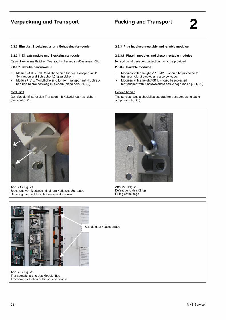
• Module >11E < 31E Modulhöhe sind für den Transport mit 2 Schrauben und Schraubenkäfig zu sichern.
• Module ≥ 31E Modulhöhe sind für den Transport mit 4 Schrau-ben und Schraubenkäfig zu sichern (siehe Abb. 21, 22).
Modulgriff
Der Modulgriff ist für den Transport mit Kabelbindern zu sichern (siehe Abb. 23)
• Modules with a height >11E <31 E should be protected for transport with 2 screws and a screw cage.
• Modules with a height ≥31 E should be protected for transport with 4 screws and a screw cage (see fig. 21, 22)
Service handle
The service handle should be secured for transport using cable straps (see fig. 23).
Abb. 21 / Fig. 21 Sicherung von Modulen mit einem Käfig und Schraube Securing the module with a cage and a screw
Abb. 22 / Fig. 22 Befestigung des Käfigs Fixing of the cage
Abb. 23 / Fig. 23 Transportsicherung des Modulgriffes Transport protection of the service handle
Kabelbinder / cable straps
Verpackung und Transport
Packing and Transport 2
MNS Service 29
2.3.5 Sonstige Anlagenkomponenten 2.3.5 Other switchgear components
Separat verpackte Betriebsmittel wie z. B
• Sicherungen,
• Transformatoren und Drosseln ab 25 kg, bei Bodenbefestigung ab 100 kg,
• hochwertige Mess- und Anzeigegeräte,
• Beleuchtungsröhren,
• ModuIeinsätze mit einphasigen Steuertrafos ab 2 kVA,
• Einsatz- und Einschubmodule als Ersatzeinheiten
sind mit Angaben des Einbauortes zu kennzeichnen. BeiIiegende Einbauanweisungen sind zu beachten.
Separately packed components, such as
• fuses,
• transformers and reactors with a weight of more than 25 kg, fIoor mounted units of more than 100 kg,
• precision instruments of high value,
• fluorescent tubes,
• modules with single phase control power transformers of more than 2 kVA,
• spare withdrawable or plug-in/disconnectable modules
are marked with their place of instalIation. The encIosed mounting instructions must be observed.
2.4 Abladen und Baustellentransport 2.4 Unloading and transport at site
Das Abladen vom Lkw kann mit Kran oder Stapler erfolgen. Absetzen ist nur auf ebener Fläche zulässig.
The truck can be unloaded by crane or fork-lift truck. The loads must be lowered onto a flat surface.
2.4.1 Bodentransport 2.4.1 Ground transport
• Mit Staplern (siehe Abb. 24).
• Mit Hub- und Rolleneinrichtungen.
• Im NotfaIl mit Rollen (mindestens 3 Stück). Für Rollentrans- port sind die Querhölzer zu entfernen (nur bei Feldern mit Querprofilen bis 1200 kg) (siehe Abb. 26).
• Schaltanlagen sind nur in aufrechter Lage zu transpor- tieren.
• Kippen und Verkanten ist zu vermeiden (siehe Abb. 24).
• Einzelfelder (Einschubfelder ohne Einschübe, Leistungsschal-terfelder ohne Leistungsschalter) können im Notfall, wenn die Höhe der Türöffnung zum Aufstellungsort einen aufrechten Transport nicht zulässt, kurzzeitig in die waagerechte Lage mit großflächiger Unterstützung der Schrankprofile gebracht werden.
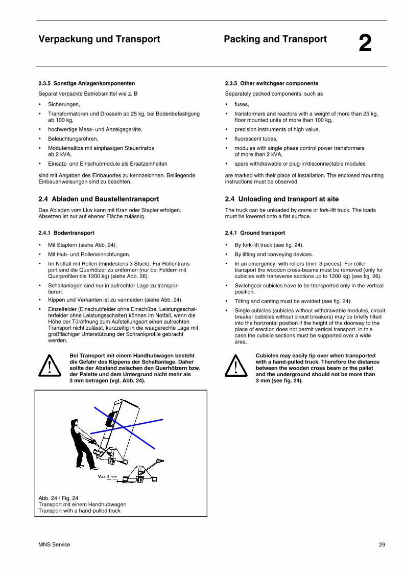
Bei Transport mit einem Handhubwagen besteht die Gefahr des Kippens der Schaltanlage. Daher sollte der Abstand zwischen den Querhölzern bzw. der Palette und dem Untergrund nicht mehr als 3 mm betragen (vgl. Abb. 24).
• By fork-lift truck (see fig. 24).
• By lifting and conveying devices.
• In an emergency, with rollers (min. 3 pieces). For roller transport the wooden cross-beams must be removed (only for cubicles with transverse sections up to 1200 kg) (see fig. 26).
• Switchgear cubicles have to be transported only in the vertical position.
• Tilting and canting must be avoided (see fig. 24).
• Single cubicles (cubicles without withdrawable modules, circuit breaker cubicles without circuit breakers) may be briefly tilted into the horizontal position if the height of the doorway to the place of erection does not permit vertical transport. ln this case the cubicle sections must be supported over a wide area.
Cubicles may easily tip over when transported with a hand-pulled truck. Therefore the distance between the wooden cross beam or the pallet and the underground should not be more than 3 mm (see fig. 24).
Abb. 24 / Fig. 24 Transport mit einem Handhubwagen Transport with a hand-pulled truck
Verpackung und Transport
Packing and Transport 2
MNS Service 30
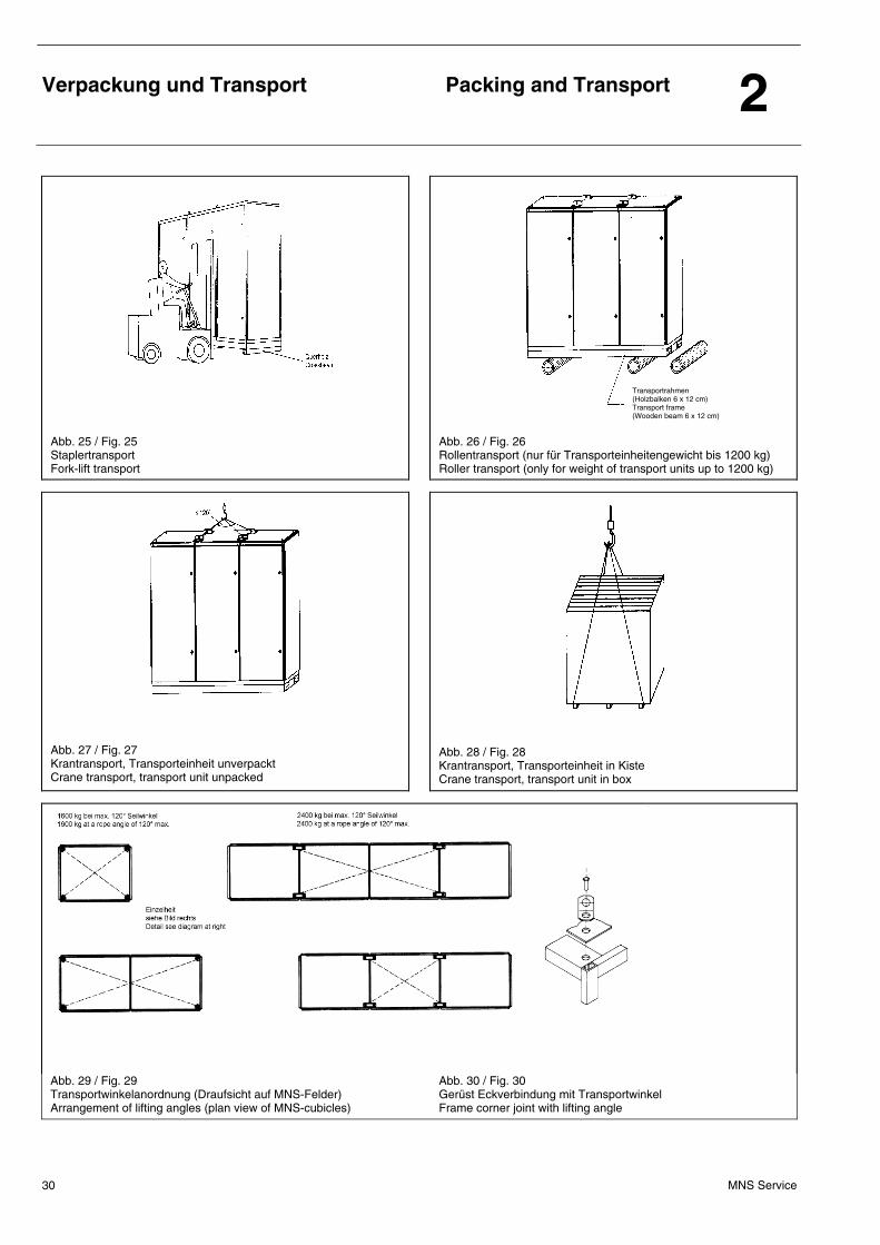
Abb. 25 / Fig. 25 Staplertransport Fork-lift transport
Abb. 26 / Fig. 26 Rollentransport (nur für Transporteinheitengewicht bis 1200 kg) Roller transport (only for weight of transport units up to 1200 kg)
Abb. 27 / Fig. 27 Krantransport, Transporteinheit unverpackt Crane transport, transport unit unpacked
Abb. 28 / Fig. 28 Krantransport, Transporteinheit in Kiste Crane transport, transport unit in box
Abb. 29 / Fig. 29 Transportwinkelanordnung (Draufsicht auf MNS-Felder) Arrangement of lifting angles (plan view of MNS-cubicles)
Abb. 30 / Fig. 30 Gerüst Eckverbindung mit Transportwinkel Frame corner joint with lifting angle
Transportrahmen (Holzbalken 6 x 12 cm) Transport frame (Wooden beam 6 x 12 cm)
Verpackung und Transport
Packing and Transport 2
MNS Service 31
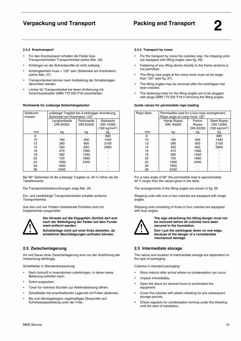
2.4.2 Krantransport 2.4.2 Transport by crane
• Für den Krantransport erhalten die Felder bzw. Transporteinheiten Transportwinkel (siehe Abb. 29).
• Anhängen an die Schrankprofile ist nicht zulässig.
• Anhängewinkel muss < 120° sein (Seilwinkel am Kranhaken) (siehe Abb. 27).
• Transportwinkel können nach Aufstellung der Schaltanlagen demontiert werden.
• Löcher für Transportwinkel bei deren Entfernung mit Verschlussstopfen GMN 775 502 P18 verschließen.
Richtwerte für zulässige Seilanhängelasten Seildurch- messer
zulässige Traglast bei 4-strängiger Anordnung, Seilwinkel am Kranhaken 120°
mm
Langhanfseile DlN 83325
kg
Perlonseile DlN 83330
kg
StahlseiIe DlN 15060
(160 kg/mm2) kg
8 10 12 14 16 18 20 24 30 36
- 180 280 350 470 580 720 1000 1600 2400
- 400 600 820
1060 1340 1660 2400
- -
890 1440 2100 2900
- - - - - -
Bei 90° Seilwinkel ist die zulässige Traglast ca. 40 % höher als die Tabellenwerte. Die Transportwinkelanordnungen zeigt Abb. 29. Ein- und zweifeldrige Transporteinheiten erhalten einfache Transportwinkel. Aus drei und vier FeIdern bestehende Einheiten sind mit DoppelwinkeI ausgerüstet.
Der Hinweis auf die Kippgefahr (Schild) darf erst nach der Befestigung der Felder auf dem Funda-ment entfernt werden.
Schaltanlage nicht auf einer Ecke abstellen, da erhebliche Beschädigungen auftreten können.
• For the transport by crane the cubicles resp. the shipping units are equipped with lifting angles (see fig. 29).
• Fastening of any Iifting device directly to the frame sections is not permitted.
• The lifting rope angle at the crane hook must not be larger than 120° (see fig. 27).
• The lifting angles may be removed after the switchgear has been erected.
• The fastening holes for the lifting angles are to be plugged with plugs GMN 775 502 P18 if removing the lifting angels.
Guide values for permissible rope loading Rope diam.
Permissible Ioad for a four-rope arrangement, Rope angle at crane hook 120°
mm
Hamp Ropes DlN 83325
kg
Perlon Ropes
DlN 83330 kg
Steel Ropes DlN 15060
(160 kg/mm2) kg
8 10 12 14 16 18 20 24 30 36
- 180 280 350 470 580 720 1000 1600 2400
- 400 600 820
1060 1340 1660 2400
- -
890 1440 2100 2900
- - - - - -
For a rope angle of 90° the permissible load is approximately 40 % larger than the values given in the table. The arrangements of the lifting angles are shown in fig. 29. Shipping units with one or two cubicIes are equipped with single angles. Shipping units consisting of three or four cubicles are equipped with dual angIes.
The sign advertising the tilting danger must not be removed before all cubicles have been secured to the foundation.
Don´t put the switchgear down on one edge, because of the danger of a considerable mechanical damage.
2.5 Zwischenlagerung 2.5 Intermediate storage
Art und Dauer einer Zwischenlagerung sind von der Ausführung der Verpackung abhängig. SchaItfelder in Standardverpackung:
• Nach Ankunft in lnnenräumen unterbringen, in denen keine Betauung auftreten kann.
• Sofort auspacken.
• Türen für mehrere Stunden zur Akklimatisierung öffnen.
• Schaltfelder bei anschließender Lagerzeit mit Folien abdecken.
• Bis zum Montagebeginn regelmäßiges Überprüfen auf Schwitzwasserbildung unter der Folie.
The nature and duration of intermediate storage are dependent on the type of packaging. Cubicles in standard packaging:
• Store indoors after arrival where no condensation can occur.
• Unpack immediately.
• Open the doors for several hours to acclimatize the equipment.
• Cover the cubicles with plastic sheeting for any subsequent storage periods.
• Check regularIy for condensation forming under the sheeting until the start of installation.
Verpackung und Transport
Packing and Transport 2
MNS Service 32
Schaltfelder in export-/seemäßiger Verpackung:
• Nur bei unversehrter Verpackung ist Feuchtigkeitsschutz gewährleistet.
• Zwischenlagerung im Freien möglich.
• Lagerzeit maximal 12 Monate bei unversehrter Verpackung mit verschweißter PE-Folie.
• Bei Transport- und Lagerzeiten über 12 bis maximal 24 Monate und/oder bei gewünschter KontroIlmöglichkeit des Trockenmittelzustandes kann anstelle der verschweißten PE-Folie folgendes verwendet werden:
− Verschweißte Aluminium-Verbundfolie, mit in Folie integrier-tem Feuchtigkeitsanzeiger, dadurch mindestens 24 Monate Feuchtigkeitsschutz.
− Feuchtigkeitsanzeige durch Öffnung in der Transportkiste von außen sichtbar.
• Bei Überschreiten der Lagerzeit Trockenmittel erneuern und FoIie wieder verschweißen.
Cubicles with export/seaworthy packaging:
• Moisture protection is only guaranteed if the packaging is undamaged.
• Possibility of intermediate storage outdoors.
• Storage period of maximum 12 months if wrapped in heat sealed PE sheeting and the packaging is undamaged.
• For duration of transport and storage from 12 month up to maximum 24 month and/or if the possibility to check the status of the drying agent is needed, the following can be used instead of heat-sealed PE-sheeting:
− Heat-sealed aluminium-compound foil with integrated hygroscope which provides moisture protection for at least 24 months.
− The hygroscope is visible from the outside through a opening in the transport box.
• When the storage period is exceeded, the drying agent must be replaced and the plastic sheeting has to be resealed.
2.6 Lagerung von Reservemodulen 2.6 Storage of spare modules
• Lagerung nur in trockenen Räumen.
• Die Module sind in unversehrter Originalverpackung aufzube-wahren.
• Sie dürfen keinen größeren Temperaturschwankungen ausge-setzt werden.
• Die Kartons sind mit der Oberseite nach oben zu lagern.
• Module ≥ 16E nicht übereinander stapeln.
• Storage is only allowed in dry rooms.
• The modules have to be stored in undamaged original pack-ing.
• Do not expose the modules to bigger temperature variations.
• Store the boxes with the top side to the top.
• Do not store modules with sizes ≥ 16E one on top of the other.
Montage und Inbetriebnahme
Erection and Commissioning 3
MNS Service 33
3.1 Lieferkontrolle 3.1 Checks on delivery
Überprüfen der Lieferung bei Ankunft auf der BausteIle auf:
• VolIständigkeit,
• Versandschäden (evtI. Schadensumfang, Schadensursache und Verursacher ermitteln).
Werden Mängel festgestellt, ist wie folgt vorzugehen:
• Offene Schäden unmittelbar auf dem Frachtbrief vermerken.
• Verdeckte Schäden innerhalb einer Woche in schriftlicher Form an den zuständigen Spediteur melden.
Bei Fehlen der Bescheinigung sowie bei unterlasse-ner Schadensmeldung entfällt jede Haftung des Herstellers.
Check the consignment on arrival at site for:
• Completeness,
• transport damage (if found, determine the extent, cause and originator).
When damage is detected it must be proceeded as foIlows:
• lmmediately write down visible damage in the consignment note.
• Report hidden damage in writing to the relevant forwarding agent within one week.
When certification is missing or a claim has not been made, the manufacturer can disclaim all Iiability.
3.2 Bauliche Voraussetzungen 3.2 Constructional requirements
Zur Vermeidung von Schäden durch Feuchtigkeit und Verschmutzung müssen vor der AufsteIlung der SchaltanIagen beispielsweise folgende Arbeiten ausgeführt sein:
• Wand- und Deckenputz sowie Anstriche fertiggestellt.
• Türen und Fenster eingesetzt.
• Boden-, Wand- und Deckendurchbrüche für Kabel, Leitungen, Rohre, Schienen und Luftkanäle gemäß Bauzeichnungen vorhanden.
• Halteeisen, Unterzüge, Einfassungen und Fundamentrahmen montiert und gestrichen.
• Ggf. Aufständerungen passend zu den Grundabmessungen der Schaltanlagen mit Querstreben entsprechend der Feldteilung montiert.
Die Einhaltung von lnnenraumbedingungen ist sicherzustellen. Aus-reichende Beleuchtung sowie Zugänglichkeit zu den SchaItanIagen-räumen ist zu gewährIeisten. Starke Temperaturwechsel bei gIeich-zeitiger hoher Luftfeuchtigkeit sind durch Beheizen des Raumes zu verhindern. Schwitzwasserbildung ist zu vermeiden.
To prevent damage being caused by moisture and dirt the following tasks (only examples) must be carried out before erection of the switchgear:
• Walls and ceilings pIastered, painting completed.
• Doors and windows installed.
• Openings in the floor, wall and ceiling for cables, conductors pipes, bars and ventiIation in accordance with the construction drawings provided.
• Supporting brackets, beams, enclosures and foundation frames assembled and painted.
• lf necessary, assemble braces appropriate to the basic dimensions of the switchgear installation with cross struts corresponding to the cubicle divisions.
Suitable indoor conditions must be maintained. Adequate lighting as well as free access to the switchgear rooms must be provided. Excessive temperature fIuctuations together with high humidity should be prevented by heating the room. Condensation should also be prevented.
3.3 Entfernen des Transportrahmens 3.3 Removal of the transport frame
Der Transportrahmen ist am AufstelIungsort vor dem Befestigen und AnschIießen der Anlage auf folgende Art und Weise zu entfernen:
• Lösen der rückwärtigen Transportrahmenteile. Dazu evtl. Abschrauben der Rückwände.
• Anschließend Rückwände wieder ordnungsgemäß befestigen.
The transport frame has to be removed at site as described in the following before installing and connecting the switchgear:
• Release the rear parts of the transport frame. For this purpose it may be necessary to unscrew the rear walls.
• Afterwards refit the rear walls correctly.
Montage und Inbetriebnahme
Erection and Commissioning 3
MNS Service 34
3.4 Aufstellung 3.4 Erection
3.4.1 Aufstellung und Verbindung der Schaltfelder 3.4.1 Erection and connection of the cubicles
Die Aufstellung der Schaltfelder ist wie folgt durchzuführen:
1. Die in einer Reihe aufzustellenden Transporteinheiten sind zueinander genau auszurichten. Auf lotrechten Stand ist zu achten. Türen und Blenden dürfen nicht verkantet oder verspannt sein. Es kann rechts oder links beginnend aufgestelIt werden.
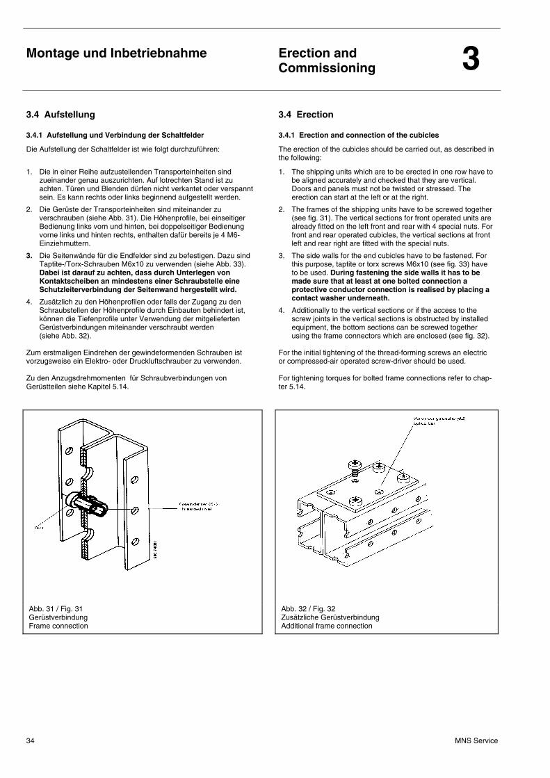
2. Die Gerüste der Transporteinheiten sind miteinander zu verschrauben (siehe Abb. 31). Die Höhenprofile, bei einseitiger Bedienung links vorn und hinten, bei doppelseitiger Bedienung vorne links und hinten rechts, enthalten dafür bereits je 4 M6-Einziehmuttern.
3. Die Seitenwände für die Endfelder sind zu befestigen. Dazu sind Taptite-/Torx-Schrauben M6x10 zu verwenden (siehe Abb. 33). Dabei ist darauf zu achten, dass durch Unterlegen von Kontaktscheiben an mindestens einer Schraubstelle eine Schutzleiterverbindung der Seitenwand hergestellt wird.
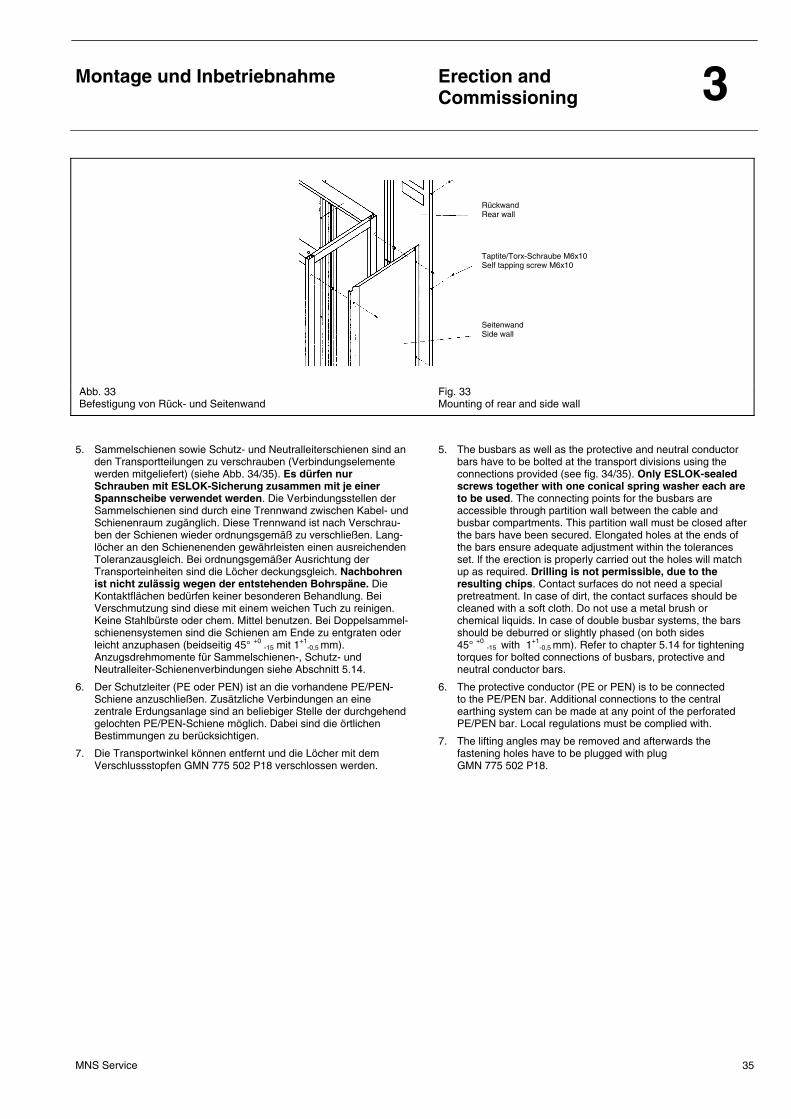
4. Zusätzlich zu den Höhenprofilen oder falls der Zugang zu den Schraubstellen der Höhenprofile durch Einbauten behindert ist, können die Tiefenprofile unter Verwendung der mitgelieferten Gerüstverbindungen miteinander verschraubt werden (siehe Abb. 32).
Zum erstmaligen Eindrehen der gewindeformenden Schrauben ist vorzugsweise ein Elektro- oder Druckluftschrauber zu verwenden. Zu den Anzugsdrehmomenten für Schraubverbindungen von Gerüstteilen siehe Kapitel 5.14.
The erection of the cubicles should be carried out, as described in the following:
1. The shipping units which are to be erected in one row have to be aligned accurately and checked that they are vertical. Doors and panels must not be twisted or stressed. The erection can start at the left or at the right.
2. The frames of the shipping units have to be screwed together (see fig. 31). The vertical sections for front operated units are already fitted on the left front and rear with 4 special nuts. For front and rear operated cubicles, the vertical sections at front left and rear right are fitted with the special nuts.
3. The side walls for the end cubicles have to be fastened. For this purpose, taptite or torx screws M6x10 (see fig. 33) have to be used. During fastening the side walls it has to be made sure that at least at one bolted connection a protective conductor connection is realised by placing a contact washer underneath.
4. Additionally to the vertical sections or if the access to the screw joints in the vertical sections is obstructed by installed equipment, the bottom sections can be screwed together using the frame connectors which are encIosed (see fig. 32).
For the initial tightening of the thread-forming screws an eIectric or compressed-air operated screw-driver should be used. For tightening torques for bolted frame connections refer to chap-ter 5.14.
Abb. 31 / Fig. 31 Gerüstverbindung Frame connection
Abb. 32 / Fig. 32 Zusätzliche Gerüstverbindung Additional frame connection
Montage und Inbetriebnahme
Erection and Commissioning 3
MNS Service 35
Abb. 33 Befestigung von Rück- und Seitenwand
Fig. 33 Mounting of rear and side wall
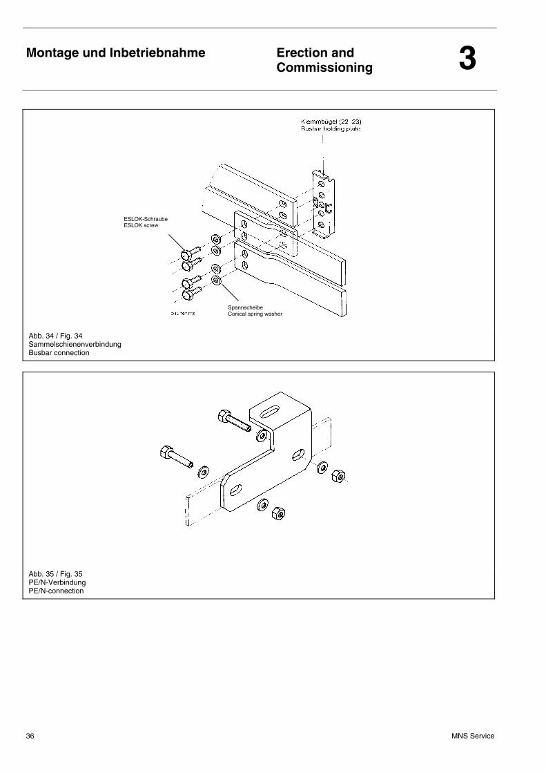
5. Sammelschienen sowie Schutz- und Neutralleiterschienen sind an den Transportteilungen zu verschrauben (Verbindungselemente werden mitgeliefert) (siehe Abb. 34/35). Es dürfen nur Schrauben mit ESLOK-Sicherung zusammen mit je einer Spannscheibe verwendet werden. Die Verbindungsstellen der Sammelschienen sind durch eine Trennwand zwischen Kabel- und Schienenraum zugänglich. Diese Trennwand ist nach Verschrau-ben der Schienen wieder ordnungsgemäß zu verschließen. Lang-löcher an den Schienenenden gewährleisten einen ausreichenden Toleranzausgleich. Bei ordnungsgemäßer Ausrichtung der Transporteinheiten sind die Löcher deckungsgleich. Nachbohren ist nicht zulässig wegen der entstehenden Bohrspäne. Die Kontaktflächen bedürfen keiner besonderen Behandlung. Bei Verschmutzung sind diese mit einem weichen Tuch zu reinigen. Keine Stahlbürste oder chem. Mittel benutzen. Bei Doppelsammel-schienensystemen sind die Schienen am Ende zu entgraten oder leicht anzuphasen (beidseitig 45° +0 -15 mit 1+1
-0,5 mm). Anzugsdrehmomente für Sammelschienen-, Schutz- und Neutralleiter-Schienenverbindungen siehe Abschnitt 5.14.
6. Der Schutzleiter (PE oder PEN) ist an die vorhandene PE/PEN-Schiene anzuschließen. Zusätzliche Verbindungen an eine zentrale Erdungsanlage sind an beliebiger Stelle der durchgehend gelochten PE/PEN-Schiene möglich. Dabei sind die örtlichen Bestimmungen zu berücksichtigen.
7. Die Transportwinkel können entfernt und die Löcher mit dem Verschlussstopfen GMN 775 502 P18 verschlossen werden.
5. The busbars as well as the protective and neutral conductor bars have to be bolted at the transport divisions using the connections provided (see fig. 34/35). Only ESLOK-sealed screws together with one conical spring washer each are to be used. The connecting points for the busbars are accessible through partition wall between the cable and busbar compartments. This partition wall must be closed after the bars have been secured. Elongated holes at the ends of the bars ensure adequate adjustment within the tolerances set. lf the erection is properly carried out the holes will match up as required. Drilling is not permissible, due to the resulting chips. Contact surfaces do not need a special pretreatment. In case of dirt, the contact surfaces should be cleaned with a soft cloth. Do not use a metal brush or chemical liquids. In case of double busbar systems, the bars should be deburred or slightly phased (on both sides 45° +0 -15 with 1+1
-0,5 mm). Refer to chapter 5.14 for tightening torques for bolted connections of busbars, protective and neutral conductor bars.
6. The protective conductor (PE or PEN) is to be connected to the PE/PEN bar. Additional connections to the central earthing system can be made at any point of the perforated PE/PEN bar. Local regulations must be complied with.
7. The lifting angles may be removed and afterwards the fastening holes have to be plugged with plug GMN 775 502 P18.
Rückwand Rear wall
Taptite/Torx-Schraube M6x10 Self tapping screw M6x10
Seitenwand Side wall
Montage und Inbetriebnahme
Erection and Commissioning 3
MNS Service 36
Abb. 34 / Fig. 34 Sammelschienenverbindung Busbar connection
Abb. 35 / Fig. 35 PE/N-Verbindung PE/N-connection
ESLOK-Schraube ESLOK screw
Spannscheibe Conical spring washer
Montage und Inbetriebnahme
Erection and Commissioning 3
MNS Service 37
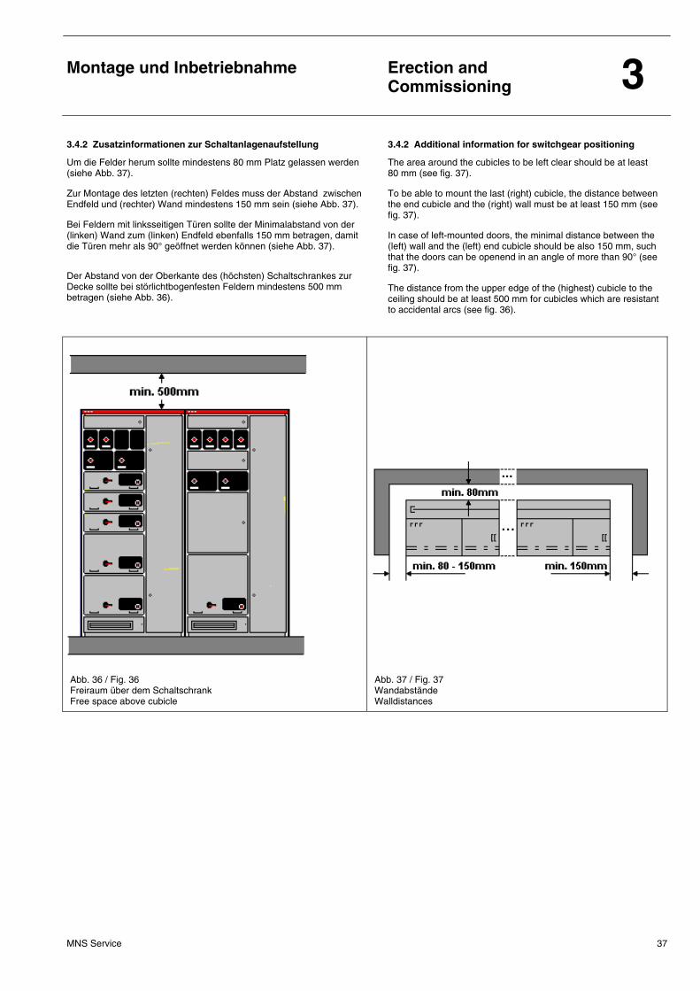
3.4.2 Zusatzinformationen zur Schaltanlagenaufstellung 3.4.2 Additional information for switchgear positioning
Um die Felder herum sollte mindestens 80 mm Platz gelassen werden (siehe Abb. 37). Zur Montage des letzten (rechten) Feldes muss der Abstand zwischen Endfeld und (rechter) Wand mindestens 150 mm sein (siehe Abb. 37). Bei Feldern mit linksseitigen Türen sollte der Minimalabstand von der (linken) Wand zum (linken) Endfeld ebenfalls 150 mm betragen, damit die Türen mehr als 90° geöffnet werden können (siehe Abb. 37). Der Abstand von der Oberkante des (höchsten) Schaltschrankes zur Decke sollte bei störlichtbogenfesten Feldern mindestens 500 mm betragen (siehe Abb. 36).
The area around the cubicles to be left clear should be at least 80 mm (see fig. 37). To be able to mount the last (right) cubicle, the distance between the end cubicle and the (right) wall must be at least 150 mm (see fig. 37). In case of left-mounted doors, the minimal distance between the (left) wall and the (left) end cubicle should be also 150 mm, such that the doors can be openend in an angle of more than 90° (see fig. 37). The distance from the upper edge of the (highest) cubicle to the ceiling should be at least 500 mm for cubicles which are resistant to accidental arcs (see fig. 36).
Abb. 36 / Fig. 36 Freiraum über dem Schaltschrank Free space above cubicle
Abb. 37 / Fig. 37 Wandabstände Walldistances
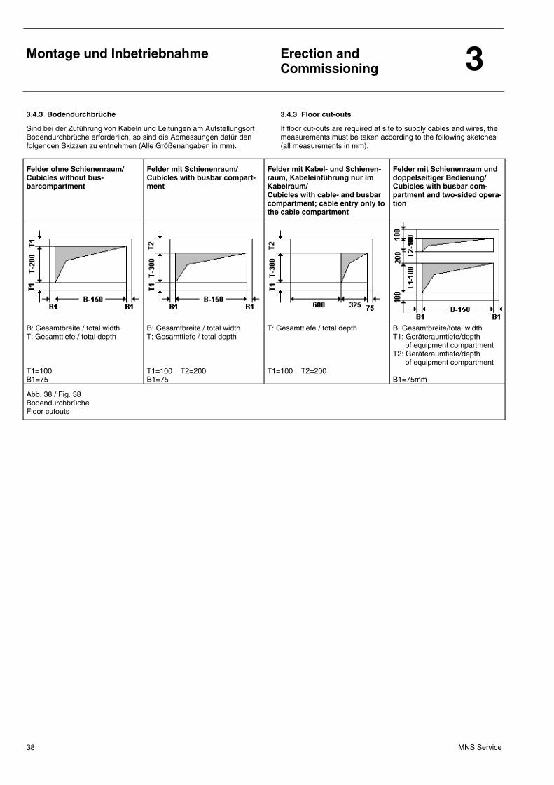
Montage und Inbetriebnahme
Erection and Commissioning 3
MNS Service 38
3.4.3 Bodendurchbrüche 3.4.3 Floor cut-outs
Sind bei der Zuführung von Kabeln und Leitungen am Aufstellungsort Bodendurchbrüche erforderlich, so sind die Abmessungen dafür den folgenden Skizzen zu entnehmen (Alle Größenangaben in mm).
If floor cut-outs are required at site to supply cables and wires, the measurements must be taken according to the following sketches (all measurements in mm).
Felder ohne Schienenraum/ Cubicles without bus-barcompartment
Felder mit Schienenraum/ Cubicles with busbar compart-ment
Felder mit Kabel- und Schienen-raum, Kabeleinführung nur im Kabelraum/ Cubicles with cable- and busbar compartment; cable entry only to the cable compartment
Felder mit Schienenraum und doppelseitiger Bedienung/ Cubicles with busbar com-partment and two-sided opera-tion
B: Gesamtbreite / total width T: Gesamttiefe / total depth T1=100 B1=75
B: Gesamtbreite / total width T: Gesamttiefe / total depth T1=100 T2=200 B1=75
T: Gesamttiefe / total depth T1=100 T2=200
B: Gesamtbreite/total width T1: Geräteraumtiefe/depth of equipment compartment T2: Geräteraumtiefe/depth of equipment compartment B1=75mm
Abb. 38 / Fig. 38 Bodendurchbrüche Floor cutouts
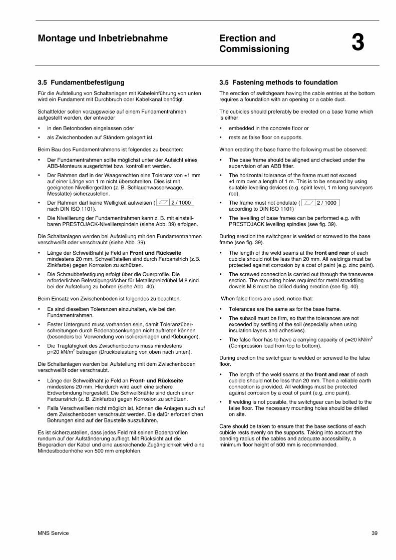
Montage und Inbetriebnahme
Erection and Commissioning 3
MNS Service 39
3.5 Fundamentbefestigung 3.5 Fastening methods to foundation
Für die Aufstellung von Schaltanlagen mit Kabeleinführung von unten wird ein Fundament mit Durchbruch oder Kabelkanal benötigt. Schaltfelder sollen vorzugsweise auf einem Fundamentrahmen aufgestellt werden, der entweder
• in den Betonboden eingelassen oder
• als Zwischenboden auf Ständern gelagert ist.
Beim Bau des Fundamentrahmens ist folgendes zu beachten:
• Der Fundamentrahmen sollte möglichst unter der Aufsicht eines ABB-Monteurs ausgerichtet bzw. kontrolliert werden.
• Der Rahmen darf in der Waagerechten eine Toleranz von ±1 mm auf einer Länge von 1 m nicht überschreiten. Dies ist mit geeigneten Nivelliergeräten (z. B. Schlauchwasserwaage, Messlatte) sicherzustellen.
• Der Rahmen darf keine Welligkeit aufweisen ( nach DIN lSO 1101).
• Die Nivellierung der Fundamentrahmen kann z. B. mit einstell-baren PRESTOJACK-Nivellierspindeln (siehe Abb. 39) erfolgen.
Die Schaltanlagen werden bei Aufstellung mit den Fundamentrahmen verschweißt oder verschraubt (siehe Abb. 39).
• Länge der Schweißnaht je Feld an Front und Rückseite mindestens 20 mm. Schweißstellen sind durch Farbanstrich (z.B. Zinkfarbe) gegen Korrosion zu schützen.
• Die Schraubbefestigung erfolgt über die Querprofile. Die erforderlichen Befestigungslöcher für Metallspreizdübel M 8 sind bei der Aufstellung zu bohren (siehe Abb. 40).
Beim Einsatz von Zwischenböden ist folgendes zu beachten:
• Es sind dieselben Toleranzen einzuhalten, wie bei den Fundamentrahmen.
• Fester Untergrund muss vorhanden sein, damit Toleranzüber-schreitungen durch Bodenabsenkungen nicht auftreten können (besonders bei Verwendung von lsoliereinlagen und Klebungen).
• Die Tragfähigkeit des Zwischenbodens muss mindestens p=20 kN/m2 betragen (Druckbelastung von oben nach unten).
Die Schaltanlagen werden bei Aufstellung mit dem Zwischenboden verschweißt oder verschraubt.
• Länge der Schweißnaht je Feld an Front- und Rückseite mindestens 20 mm. Hierdurch wird auch eine sichere Erdverbindung hergestellt. Die Schweißnähte sind durch einen Farbanstrich (z. B. Zinkfarbe) gegen Korrosion zu schützen.
• Falls Verschweißen nicht möglich ist, können die Anlagen auch auf dem Zwischenboden verschraubt werden. Die dafür erforderlichen Bohrungen sind auf der Baustelle auszuführen.
Es ist sicherzustellen, dass jedes Feld mit seinen Bodenprofilen rundum auf der Aufständerung aufIiegt. Mit Rücksicht auf die Biegeradien der Kabel und eine ausreichende Zugänglichkeit wird eine Mindestbodenhöhe von 500 mm empfohlen.
The erection of switchgears having the cable entries at the bottom requires a foundation with an opening or a cable duct. The cubicles should preferably be erected on a base frame which is either
• embedded in the concrete fIoor or
• rests as false floor on supports.
When erecting the base frame the following must be observed:
• The base frame should be aligned and checked under the supervision of an ABB fitter.
• The horizontal tolerance of the frame must not exceed ±1 mm over a length of 1 m. This is to be ensured by using suitable levelling devices (e.g. spirit level, 1 m long surveyors rod).
• The frame must not ondulate ( according to DIN lSO 1101)
• The leveIling of base frames can be performed e.g. with PRESTOJACK levelling spindles (see fig. 39).
During erection the switchgear is welded or screwed to the base frame (see fig. 39).
• The length of the weld seams at the front and rear of each cubicle should not be less than 20 mm. All weldings must be protected against corrosion by a coat of paint (e.g. zinc paint).
• The screwed connection is carried out through the transverse section. The mounting hoIes required for metal straddling dowels M 8 must be drilled during erection (see fig. 40).
When false floors are used, notice that:
• Tolerances are the same as for the base frame.
• The subsoil must be firm, so that the tolerances are not exceeded by settling of the soil (especially when using insulation layers and adhesives).
• The false floor has to have a carrying capacity of p=20 kN/m2 (Compression load from top to bottom).
During erection the switchgear is welded or screwed to the false floor.
• The length of the weld seams at the front and rear of each cubicle should not be less than 20 mm. Then a reliable earth connection is provided. All weldings must be protected against corrosion by a coat of paint (e.g. zinc paint).
• lf welding is not possible, the switchgear can be bolted to the false floor. The necessary mounting holes should be driIled on site.
Care should be taken to ensure that the base sections of each cubicle rests evenly on the supports. Taking into account the bending radius of the cables and adequate accessibility, a minimum floor height of 500 mm is recommended.
2 / 1000 2 / 1000
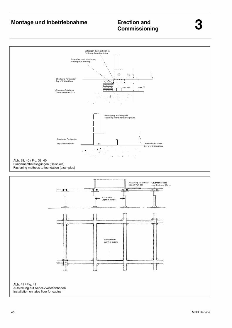
Montage und Inbetriebnahme
Erection and Commissioning 3
MNS Service 40
Abb. 39, 40 / Fig. 39, 40 Fundamentbefestigungen (Beispiele) Fastening methods to foundation (examples)
Abb. 41 / Fig. 41 Aufstellung auf Kabel-Zwischenboden Installation on false floor for cables
Befestigen durch Schweißen Fastening through welding
Schweißen nach Nivellierung Welding after levelling
Oberkante Fertigboden Top of finished floor
Oberkante Rohdecke Top of unfinished floor
max. 40 max. 55
Befestigung am Querprofil Fastening on the transverse provile
Oberkante Rohdecke Top of unfinished floor
Oberkante Fertigboden
Top of finished floor
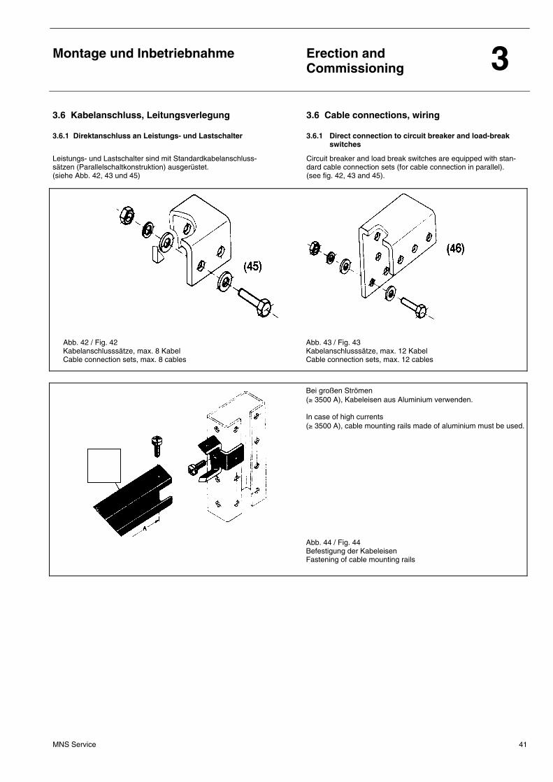
Montage und Inbetriebnahme
Erection and Commissioning 3
MNS Service 41
3.6 Kabelanschluss, Leitungsverlegung 3.6 Cable connections, wiring
3.6.1 Direktanschluss an Leistungs- und Lastschalter 3.6.1 Direct connection to circuit breaker and load-break switches
Leistungs- und Lastschalter sind mit Standardkabelanschluss- sätzen (Parallelschaltkonstruktion) ausgerüstet. (siehe Abb. 42, 43 und 45)
Circuit breaker and load break switches are equipped with stan- dard cable connection sets (for cable connection in parallel). (see fig. 42, 43 and 45).
Abb. 42 / Fig. 42 Kabelanschlusssätze, max. 8 Kabel Cable connection sets, max. 8 cables
Abb. 43 / Fig. 43 Kabelanschlusssätze, max. 12 Kabel Cable connection sets, max. 12 cables
Bei großen Strömen (≥ 3500 A), Kabeleisen aus Aluminium verwenden. In case of high currents (≥ 3500 A), cable mounting rails made of aluminium must be used.
Abb. 44 / Fig. 44 Befestigung der Kabeleisen Fastening of cable mounting rails
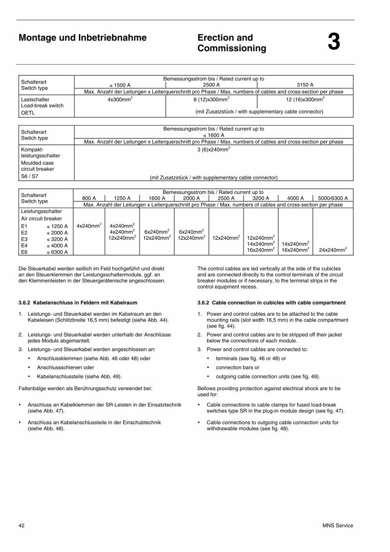
Montage und Inbetriebnahme
Erection and Commissioning 3
MNS Service 42
Bemessungsstrom bis / Rated current up to ≤ 1500 A 2500 A 3150 A Schalterart
Switch type Max. Anzahl der Leitungen x Leiterquerschnitt pro Phase / Max. numbers of cables and cross-section per phase
Lastschalter Load-break switch
4x300mm2 8 (12)x300mm2 12 (16)x300mm2
OETL (mit Zusatzstück / with supplementary cable connector)
Bemessungsstrom bis / Rated current up to
≤ 1600 A Schalterart Switch type
Max. Anzahl der Leitungen x Leiterquerschnitt pro Phase / Max. numbers of cables and cross-section per phase
Kompakt- leistungsschalter Moulded case circuit breaker S6 / S7
3 (6)x240mm2
(mit Zusatzstück / with supplementary cable connector)
Bemessungsstrom bis / Rated current up to
800 A 1250 A 1600 A 2000 A 2500 A 3200 A 4000 A 5000/6300 A Schalterart Switch type
Max. Anzahl der Leitungen x Leiterquerschnitt pro Phase / Max. numbers of cables and cross-section per phase Leistungsschalter Air circuit breaker
E1 ≤ 1250 A E2 ≤ 2000 A E3 ≤ 3200 A E4 ≤ 4000 A E6 ≤ 6300 A
4x240mm2
4x240mm2
4x240mm2
12x240mm2
6x240mm2
12x240mm2
6x240mm2
12x240mm2
12x240mm2
12x240mm2
14x240mm2
16x240mm2
14x240mm2
16x240mm2
24x240mm2
Die Steuerkabel werden seitlich im Feld hochgeführt und direkt an den Steuerklemmen der Leistungsschaltermodule, ggf. an den Klemmenleisten in der Steuergerätenische angeschlossen.
The control cabIes are led vertically at the side of the cubicIes and are connected directly to the control terminals of the circuit breaker moduIes or if necessary, to the terminaI strips in the control equipment recess.
3.6.2 Kabelanschluss in Feldern mit Kabelraum 3.6.2 Cable connection in cubicles with cable compartment
1. Leistungs- und Steuerkabel werden im Kabelraum an den Kabeleisen (Schlitzbreite 16,5 mm) befestigt (siehe Abb. 44).
2. Leistungs- und Steuerkabel werden unterhalb der Anschlüsse jedes Moduls abgemantelt.
3. Leistungs- und Steuerkabel werden angeschlossen an:
• Anschlussklemmen (siehe Abb. 46 oder 48) oder
• Anschlussschienen oder
• Kabelanschlussteile (siehe Abb. 49).
Faltenbälge werden als Berührungsschutz verwendet bei:
• Anschluss an Kabelklemmen der SR-Leisten in der Einsatztechnik (siehe Abb. 47).
• Anschluss an Kabelanschlussteile in der Einschubtechnik (siehe Abb. 48).
1. Power and control cables are to be attached to the cable mounting rails (slot width 16,5 mm) in the cable compartment (see fig. 44).
2. Power and control cables are to be stripped off their jacket below the connections of each module.
3. Power and control cabIes are connected to:
• terminals (see fig. 46 or 48) or
• connection bars or
• outgoing cable connection units (see fig. 49).
Bellows providing protection against electrical shock are to be used for:
• Cable connections to cable clamps for fused Ioad-break switches type SR in the plug-in module design (see fig. 47).
• CabIe connections to outgoing cable connection units for withdrawable modules (see fig. 48).
Montage und Inbetriebnahme
Erection and Commissioning 3
MNS Service 43
3.6.3 Leitungsanschluss an Einsätzen und Einschüben 3.6.3 Cable connections at plug-in and withdrawable modules
Die Kabel müssen vor dem Befestigen an den Leis-tungsklemmen der Einsätze bzw. an den Kabelan-schlussteilen der Einschübe so abgefangen bzw. gebogen werden, dass kein Zug oder Druck auf das Kabelanschlussteil ausgeübt wird.
Anschlussmaterial und Berührungsschutzabdeckungen werden separat mitgeliefert. Die am Gerüst befestigten Kabeleisen können zur Anpassung an die Modulanschlüsse versetzt werden. Die Kabeleinführung kann von unten oder oben erfolgen. Dabei ist die geforderte Schutzart zu beachten. Steuerkabel, deren Adern an mehreren Modulen angeschlossen werden, sind im Kabelraum abzumanteln. Die Einzeladern sind durch den im Kabelraum senkrecht angeordneten Verdrahtungskanal zu führen, ebenso SteuerIeitungen für die Verdrahtung zwischen den Modulen.
Before fastening the cables at the power termi-nals of the plug-in modules or the outgoing cable connection unit of the withdrawable modules they must be supported or bended so that no tension or pressure is exerted on the cable connection unit.
Connection material and barriers are supplied with the switchgear separately. The frame-mounted cable mounting rails can be moved as required for the module terminals. Cable entrance to the cubicIe can be from above or below under consideration of the specified degree of protection. Control cables with individual conductors to be connected to several different modules are to be stripped within the cable compartment. The individual conductors must be installed inside the verticalIy mounted wiring duct in the cable compartment; likewise control cables for interwiring between modules.
3.6.4 Kabelanschluss in Steuerfeldern und Verdrahtung zwischen Transporteinheiten
3.6.4 Cable connections in control cubicles and wiring between shipping units
Die Steuerkabel werden seitlich im unteren Bereich des Feldes befestigt und durch den vertikalen Verdrahtungskanal zu den Steuermodulen geführt. Vor dem Absetzen der Kabel ist eine Fixierung mit Kabelbindern zweckmäßig. Steuerkabel bzw. -leitungen für die Feld-zu-Feld-Verdrahtung werden durch den im oberen Bereich des Geräteraumes verlaufenden Steuerleitungskanal geführt. An der Transportteilung sind die getrennten Leitungen zu verbinden. Hierbei sind die Leitungen gemäß den angebrachten Kennzeichnungen an den Anschlussklemmen des Steuerleitungskanals anzuschließen.
The control cables are installed at the side in the lower part of the cubicle and led to the control modules through the vertical wiring duct. Before positioning the cables it is advisable to secure them with cable straps. Control cables and conductors for the cubicle-to-cubicIe wiring are Ied through the control wiring duct situated in the upper part of the equipment compartment. At the transport divisions the separated cables have to be connected. For this the cables have to be connected to the terminals of the control wiring duct in accordance with the markings.
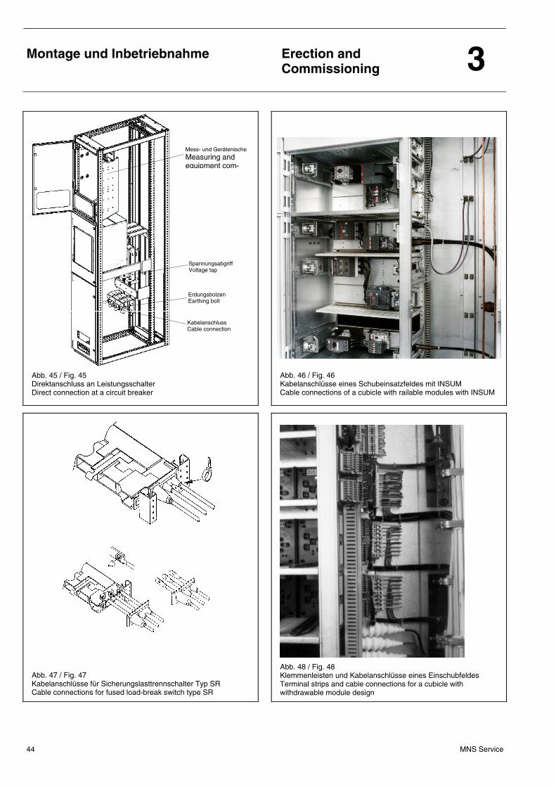
Montage und Inbetriebnahme
Erection and Commissioning 3
MNS Service 44
Abb. 45 / Fig. 45 Direktanschluss an Leistungsschalter Direct connection at a circuit breaker
Abb. 46 / Fig. 46 Kabelanschlüsse eines Schubeinsatzfeldes mit INSUM Cable connections of a cubicle with railable modules with INSUM
Abb. 47 / Fig. 47 Kabelanschlüsse für Sicherungslasttrennschalter Typ SR Cable connections for fused load-break switch type SR
Abb. 48 / Fig. 48 Klemmenleisten und Kabelanschlüsse eines Einschubfeldes Terminal strips and cable connections for a cubicle with withdrawable module design
Spannungsabgriff Voltage tap
Mess- und Gerätenische
Measuring and equipment com-
Kabelanschluss Cable connection
Erdungsbolzen Earthing bolt
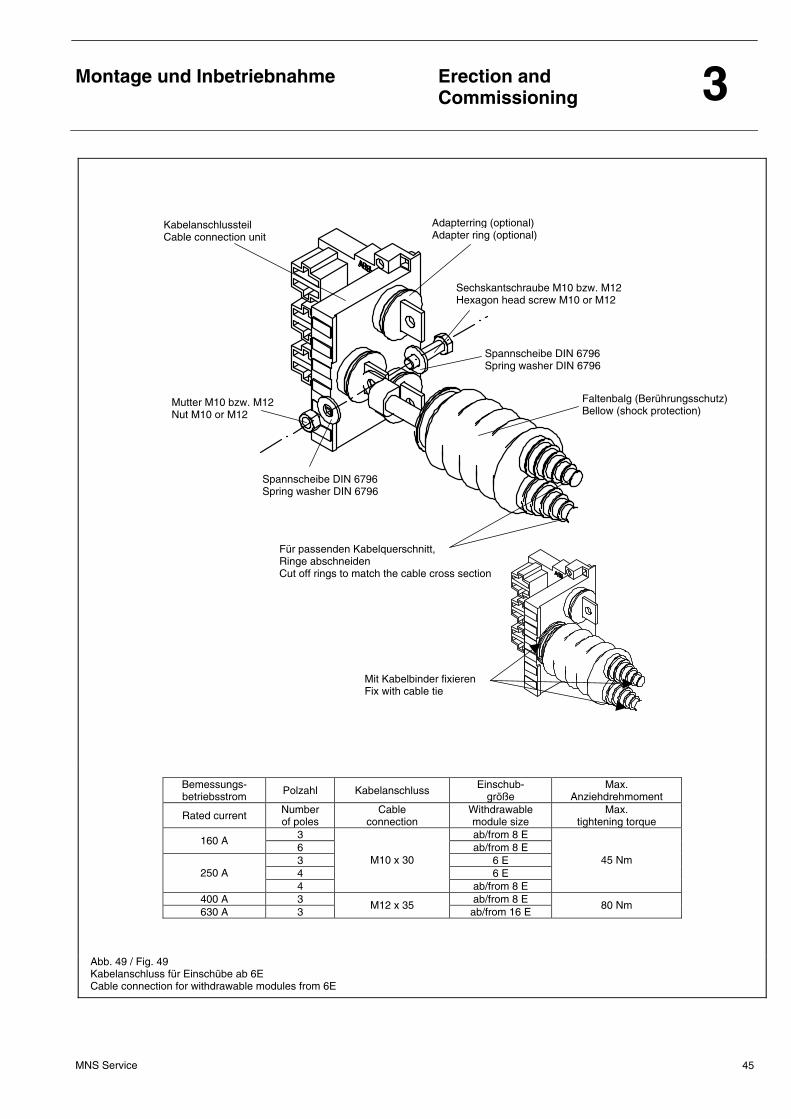
Montage und Inbetriebnahme
Erection and Commissioning 3
MNS Service 45
Bemessungs- betriebsstrom Polzahl Kabelanschluss Einschub-
größe Max.
Anziehdrehmoment
Rated current Number of poles
Cable connection
Withdrawable module size
Max. tightening torque
3 ab/from 8 E 160 A 6 ab/from 8 E 3 6 E 4 6 E 250 A 4
M10 x 30
ab/from 8 E
45 Nm
400 A 3 ab/from 8 E 630 A 3
M12 x 35 ab/from 16 E
80 Nm
Abb. 49 / Fig. 49 Kabelanschluss für Einschübe ab 6E Cable connection for withdrawable modules from 6E
Sechskantschraube M10 bzw. M12 Hexagon head screw M10 or M12
Mutter M10 bzw. M12 Nut M10 or M12
Kabelanschlussteil Cable connection unit
Spannscheibe DIN 6796 Spring washer DIN 6796
Adapterring (optional) Adapter ring (optional)
Faltenbalg (Berührungsschutz) Bellow (shock protection)
Spannscheibe DIN 6796 Spring washer DIN 6796
Mit Kabelbinder fixieren Fix with cable tie
Für passenden Kabelquerschnitt, Ringe abschneiden Cut off rings to match the cable cross section
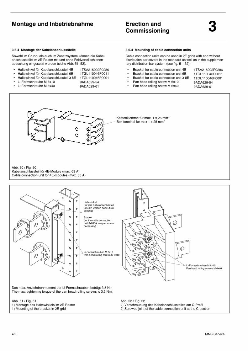
Montage und Inbetriebnahme
Erection and Commissioning 3
MNS Service 46
Li-Formschrauben M 6x10 Pan head rolling screws M 6x10
Li-Formschrauben M 6x40 Pan head rolling screws M 6x40
3.6.4 Montage der Kabelanschlusssteile 3.6.4 Mounting of cable connection units
Sowohl im Grund- als auch im Zusatzsystem können die Kabel-anschlussteile im 2E-Raster mit und ohne Feldverteilschienen-abdeckung eingesetzt werden (siehe Abb. 51–52).
• Haltewinkel für Kabelanschlussteil 4E • Haltewinkel für Kabelanschlussteil 6E • Haltewinkel für Kabelanschlussteil ≥ 8E • Li-Formschraube M 6x10 • Li-Formschraube M 6x40
1TSA215002P0286 1TGL110046P0011 1TGL110046P0001 9ADA629-54 9ADA629-61
Cable connection units can be used in 2E grids with and without distribution bar covers in the standard as well as in the supplemen-tary distribution bar system (see fig. 51–52).
• Bracket for cable connection unit 4E • Bracket for cable connection unit 6E • Bracket for cable connection unit ≥ 8E • Pan head rolling screw M 6x10 • Pan head rolling screw M 6x40
1TSA215002P0286 1TGL110046P0011 1TGL110046P0001 9ADA629-54 9ADA629-61
Abb. 50 / Fig. 50 Kabelanschlussteil für 4E-Module (max. 63 A) Cable connection unit for 4E-modules (max. 63 A)
Das max. Anziehdrehmoment der Li-Formschrauben beträgt 3,5 Nm The max. tightening torque of the pan head rolling screws is 3.5 Nm.
Abb. 51 / Fig. 51 1) Montage des Haltewinkels im 2E-Raster 1) Mounting of the bracket in 2E-grid
Abb. 52 / Fig. 52 2) Verschraubung des Kabelanschlussteiles am C-Profil 2) Screwed joint of the cable connection unit at the C-section
Haltewinkel (für das Kabelanschlussteil 3x630A werden zwei Stück benötigt Bracket (for the cable connection unit 3x630A two pieces are necessary)
Kastenklemme für max. 1 x 25 mm2
Box terminal for max 1 x 25 mm2
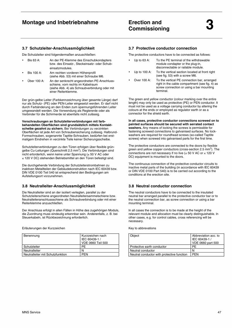
Montage und Inbetriebnahme
Erection and Commissioning 3
MNS Service 47
3.7 Schutzleiter-Anschlussmöglichkeit 3.7 Protective conductor connection
Die Schutzleiter sind folgendermaßen anzuschließen:
• Bis 63 A: An der PE-Klemme des Einschubkondapters bzw. des Einsatz-, Steckeinsatz- oder Schub- einsatzmodules.
• Bis 100 A: Am rechten vorderen Höhenprofil (siehe Abb. 53) mit einer Schraube M6.
• Über 100 A: An der senkrecht angeordneten PE-Anschluss- schiene, vorn rechts im Kabelraum (siehe Abb. 4) als Schraubverbindung oder mit einer Reiterklemme.
Der grün-gelbe Leiter (Farbkennzeichnung über gesamte Länge) darf nur als Schutz- (PE) oder PEN-Leiter eingesetzt werden. Er darf nicht durch Farbänderung an den Enden zum spannungsführenden Leiter umgewandelt werden. Die Verwendung als Reglererde oder als Verbinder für die Schirmerde ist ebenfalIs nicht zulässig. Verschraubungen an Schutzleiterverbindungen mit farb-behandelten Oberflächen sind grundsätzlich mittels Kontakt-scheibe gezahnt zu sichern. Bei Verbindungen zu verzinkten Oberflächen ist jede Art von Schraubensicherung zulässig. Halbrund-Formschrauben, sogenannte Taptite-Schrauben, bedürfen bei erst-maligem Eindrehen in verzinkte Teile keiner Sicherungsscheibe. Schutzleiterverbindungen zu den Türen erfolgen über flexible grün-gelbe Cu-Leitungen (Querschnitt 2,5 mm2). Die Verbindungen sind nicht ertorderlich, wenn keine unter Spannung (≤ 50 V AC oder ≤ 120 V DC) stehenden Betriebsmittel an den Türen befestigt sind. Die durchgehende Verbindung der Schutzleiterstrombahnen zu inaktiven Metallteilen der Gebäudekonstruktion nach lEC 60439 bzw. DlN VDE 0100 Teil 540 ist entsprechend den Bedingungen am Aufstellungsort vorzunehmen.
The protective conductors have to be connected as follows:
• Up to 63 A: To the PE terminal of the withdrawable module condapter or the plug-in, disconnectable or railable module.
• Up to 100 A: To the vertical section located at front right (see fig. 53) with a screw M6.
• Over 100 A: To the vertical PE connection bar, arranged right in the cable compartment (see fig. 4) as screw connection or using a bar mounting terminal.
The green and yelIow conductor (colour marking over the entire length) may only be used as protective (PE) or PEN conductor. lt must not be used as a voltage carrying conductor by altering the colours at the ends or employed as regulator earth or as a connector for the shield earth. ln all cases, protective conductor connections screwed on to painted surfaces should be secured with serrated contact washers. Any means of locking the screws is permissible for fastening screwed connections to gaIvanised surfaces. No lock-washers are required for roundhead screws (so-called Taptite screws) when screwed into galvanised parts for the first time. The protective conductors are connected to the doors by fIexible green and yellow copper conductors (cross-section 2.5 mm2). The connections are not necessary if no Iive (≤ 50 V AC or ≤ 120 V DC) equipment is mounted to the doors. The continuous connection of the protective conductor circuits to inactive metal parts of the building (in accordance with lEC 60439 or DIN VDE 0100 Part 540) is to be carried out according to the conditions at the erection site.
3.8 Neutralleiter-Anschlussmöglichkeit 3.8 Neutral conductor connection
Die Neutralleiter sind an der isoliert verlegten, parallel zu der SchutzIeiterschiene angeordneten Neutralleitersammelschiene bzw. Neutralleiteranschlussschiene als Schraubverbindung oder mit einer Reiterklemme anzuschließen. Der Anschluss erfolgt in allen Fällen in Höhe des zugehörigen Moduls, die Zuordnung muss eindeutig erkennbar sein. Anderenfalls, z. B. bei Steuerkabeln, ist Rückbezeichnung erforderlich. Erläuterungen der Kurzzeichen Benennung Kurzzeichen nach
IEC 60439-1 / VDE 0660 Teil 500
Schutzleiter PE Neutralleiter N Neutralleiter mit Schutzfunktion PEN
The neutral conductors have to be connected to the insulated neutral bar arranged parallel to the protective conductor bar or to the neutral connection bar, as screw connection or using a bar mounting terminal. ln all cases the connection is to be made at the height of the relevant module and allocation must be clearly distinguishable. ln other cases, e.g. for control cables, cross referencing will be necessary. Key to abbrevations Object Abbreviation acc. to
IEC 60439-1 / VDE 0660 part 500
Protective earth conductor PE Neutral conductor N Neutral conductor with protective function PEN
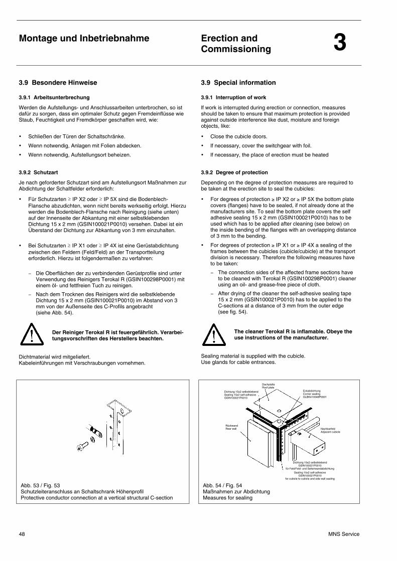
Montage und Inbetriebnahme
Erection and Commissioning 3
MNS Service 48
3.9 Besondere Hinweise 3.9 Special information
3.9.1 Arbeitsunterbrechung 3.9.1 lnterruption of work
Werden die Aufstellungs- und Anschlussarbeiten unterbrochen, so ist dafür zu sorgen, dass ein optimaler Schutz gegen Fremdeinflüsse wie Staub, Feuchtigkeit und Fremdkörper geschaffen wird, wie:
• Schließen der Türen der Schaltschränke.
• Wenn notwendig, Anlagen mit Folien abdecken.
• Wenn notwendig, Aufstellungsort beheizen.
lf work is interrupted during erection or connection, measures should be taken to ensure that maximum protection is provided against outside interference like dust, moisture and foreign objects, like:
• Close the cubicle doors.
• lf necessary, cover the switchgear with foil.
• lf necessary, the pIace of erection must be heated
3.9.2 Schutzart 3.9.2 Degree of protection
Je nach geforderter Schutzart sind am Aufstellungsort Maßnahmen zur Abdichtung der Schaltfelder erforderlich:
• Für Schutzarten ≥ IP X2 oder ≥ IP 5X sind die Bodenblech-Flansche abzudichten, wenn nicht bereits werkseitig erfolgt. Hierzu werden die Bodenblech-Flansche nach Reinigung (siehe unten) auf der Innenseite der Abkantung mit einer selbstklebenden Dichtung 15 x 2 mm (GSIN100021P0010) versehen. Dabei ist ein Überstand der Dichtung zur Abkantung von 3 mm einzuhalten.
• Bei Schutzarten ≥ IP X1 oder ≥ IP 4X ist eine Gerüstabdichtung zwischen den Feldern (Feld/Feld) an der Transportteilung erforderlich. Hierzu ist folgendermaßen zu verfahren:
− Die Oberflächen der zu verbindenden Gerüstprofile sind unter
Verwendung des Reinigers Terokal R (GSIN100298P0001) mit einem öl- und fettfreien Tuch zu reinigen.
− Nach dem Trocknen des Reinigers wird die selbstklebende Dichtung 15 x 2 mm (GSIN100021P0010) im Abstand von 3 mm von der Außenseite des C-Profils angebracht (siehe Abb. 54).
Der Reiniger Terokal R ist feuergefährlich. Verarbei-tungsvorschriften des Herstellers beachten.
Dichtmaterial wird mitgeIiefert. Kabeleinführungen mit Verschraubungen vornehmen.
Depending on the degree of protection measures are required to be taken at the erection site to seal the cubicles:
• For degrees of protection ≥ IP X2 or ≥ IP 5X the bottom plate covers (flanges) have to be sealed, if not already done at the manufacturers site. To seal the bottom plate covers the self adhesive sealing 15 x 2 mm (GSIN100021P0010) has to be used which has to be applied after cleaning (see below) on the inside bending of the flanges with an overlapping distance of 3 mm to the bending.
• For degrees of protection ≥ IP X1 or ≥ IP 4X a sealing of the frames between the cubicles (cubicle/cubicle) at the transport division is necessary. Therefore the following measures have to be taken:
− The connection sides of the affected frame sections have to be cleaned with Terokal R (GSIN100298P0001) cleaner using an oil- and grease-free piece of cloth.
− After drying of the cleaner the self-adhesive sealing tape 15 x 2 mm (GSIN100021P0010) has to be applied to the C-sections at a distance of 3 mm from the outer edge (see fig. 54).
The cleaner Terokal R is inflamable. Obeye the use instructions of the manufacturer.
Sealing material is supplied with the cubicle. Use glands for cable entrances.
Abb. 53 / Fig. 53 Schutzleiteranschluss an Schaltschrank Höhenprofil Protective conductor connection at a vertical structural C-section
Abb. 54 / Fig. 54 Maßnahmen zur Abdichtung Measures for sealing
Nachbarfeld Adjacent cubicle
Dichtung 15x2 selbstklebend Sealing 15x2 self-adhesive GSIN100021P0010
Sealing 15x2 self-adhesive GSIN100021P0010
for cubicle to cubicle and side wall sealing
Dichtung 15x2 selbstklebend GSIN100021P0010
für Feld/Feld- und Seitenwandabdichtung
Eckabdichtung Corner sealing GLBK410048P0001
Dachplatte Roof plate
Rückwand Rear wall
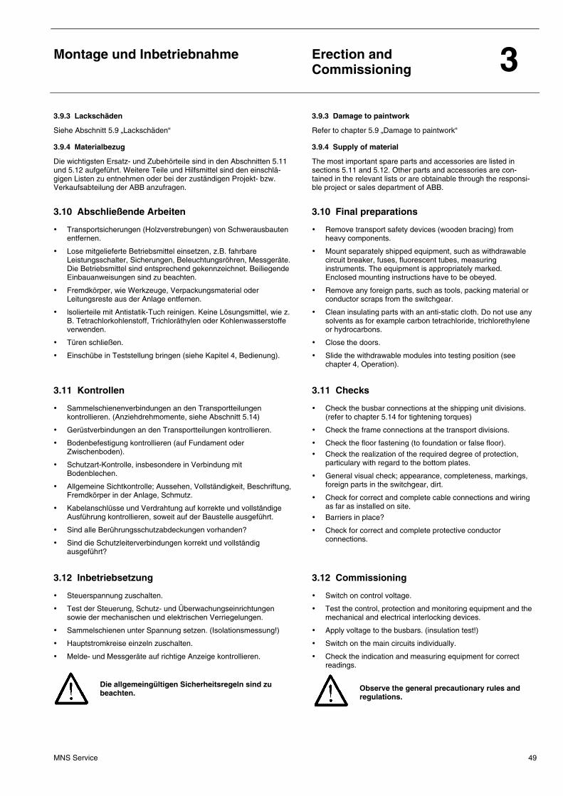
Montage und Inbetriebnahme
Erection and Commissioning 3
MNS Service 49
3.9.3 Lackschäden 3.9.3 Damage to paintwork
Siehe Abschnitt 5.9 „Lackschäden“ Refer to chapter 5.9 „Damage to paintwork“
3.9.4 Materialbezug 3.9.4 Supply of material
Die wichtigsten Ersatz- und ZubehörteiIe sind in den Abschnitten 5.11 und 5.12 aufgeführt. Weitere Teile und Hilfsmittel sind den einschlä-gigen Listen zu entnehmen oder bei der zuständigen Projekt- bzw. Verkaufsabteilung der ABB anzufragen.
The most important spare parts and accessories are listed in sections 5.11 and 5.12. Other parts and accessories are con-tained in the relevant lists or are obtainable through the responsi-ble project or sales department of ABB.
3.10 Abschließende Arbeiten 3.10 Final preparations
• Transportsicherungen (Holzverstrebungen) von Schwerausbauten entfernen.
• Lose mitgelieferte Betriebsmittel einsetzen, z.B. fahrbare Leistungsschalter, Sicherungen, Beleuchtungsröhren, Messgeräte. Die Betriebsmittel sind entsprechend gekennzeichnet. Beiliegende Einbauanweisungen sind zu beachten.
• Fremdkörper, wie Werkzeuge, Verpackungsmaterial oder Leitungsreste aus der Anlage entfernen.
• lsolierteile mit Antistatik-Tuch reinigen. Keine Lösungsmittel, wie z. B. Tetrachlorkohlenstoff, Trichloräthylen oder Kohlenwasserstoffe verwenden.
• Türen schließen.
• Einschübe in Teststellung bringen (siehe Kapitel 4, Bedienung).
• Remove transport safety devices (wooden bracing) from heavy components.
• Mount separately shipped equipment, such as withdrawable circuit breaker, fuses, fluorescent tubes, measuring instruments. The equipment is appropriately marked. Enclosed mounting instructions have to be obeyed.
• Remove any foreign parts, such as tools, packing material or conductor scraps from the switchgear.
• Clean insulating parts with an anti-static cloth. Do not use any solvents as for example carbon tetrachloride, trichlorethyIene or hydrocarbons.
• Close the doors.
• Slide the withdrawable modules into testing position (see chapter 4, Operation).
3.11 Kontrollen 3.11 Checks
• Sammelschienenverbindungen an den Transportteilungen kontrollieren. (Anziehdrehmomente, siehe Abschnitt 5.14)
• Gerüstverbindungen an den Transportteilungen kontrollieren.
• Bodenbefestigung kontrollieren (auf Fundament oder Zwischenboden).
• Schutzart-Kontrolle, insbesondere in Verbindung mit Bodenblechen.
• Allgemeine Sichtkontrolle; Aussehen, Vollständigkeit, Beschriftung, Fremdkörper in der Anlage, Schmutz.
• Kabelanschlüsse und Verdrahtung auf korrekte und vollständige Ausführung kontrollieren, soweit auf der Baustelle ausgeführt.
• Sind alle Berührungsschutzabdeckungen vorhanden?
• Sind die Schutzleiterverbindungen korrekt und vollständig ausgeführt?
• Check the busbar connections at the shipping unit divisions. (refer to chapter 5.14 for tightening torques)
• Check the frame connections at the transport divisions.
• Check the floor fastening (to foundation or false floor).
• Check the realization of the required degree of protection, particulary with regard to the bottom plates.
• General visual check; appearance, completeness, markings, foreign parts in the switchgear, dirt.
• Check for correct and complete cable connections and wiring as far as installed on site.
• Barriers in place?
• Check for correct and complete protective conductor connections.
3.12 Inbetriebsetzung 3.12 Commissioning
• Steuerspannung zuschalten.
• Test der Steuerung, Schutz- und Überwachungseinrichtungen sowie der mechanischen und elektrischen Verriegelungen.
• Sammelschienen unter Spannung setzen. (Isolationsmessung!)
• Hauptstromkreise einzeln zuschalten.
• Melde- und Messgeräte auf richtige Anzeige kontrollieren. Die allgemeingültigen Sicherheitsregeln sind zu beachten.
• Switch on control voltage.
• Test the control, protection and monitoring equipment and the mechanical and electrical interlocking devices.
• Apply voltage to the busbars. (insulation test!)
• Switch on the main circuits individually.
• Check the indication and measuring equipment for correct readings.
Observe the general precautionary rules and regulations.
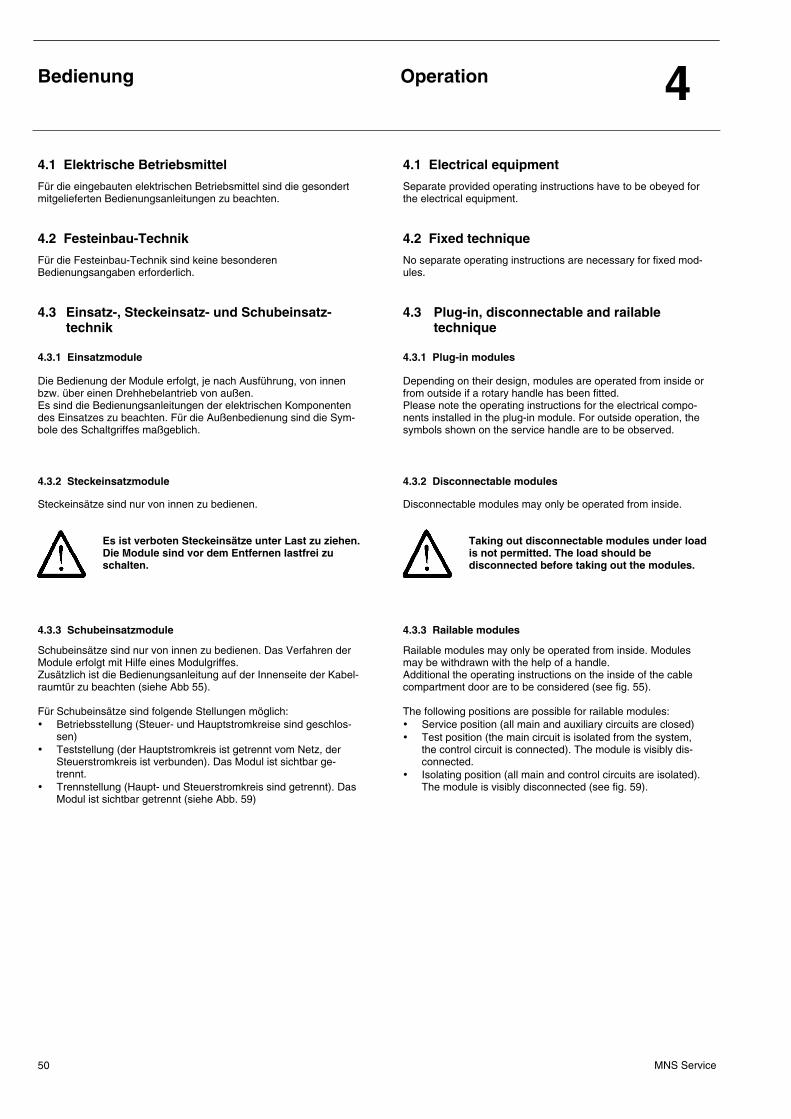
Bedienung
Operation 4
MNS Service 50
4.1 Elektrische Betriebsmittel 4.1 Electrical equipment
Für die eingebauten elektrischen Betriebsmittel sind die gesondert mitgelieferten Bedienungsanleitungen zu beachten.
Separate provided operating instructions have to be obeyed for the electrical equipment.
4.2 Festeinbau-Technik 4.2 Fixed technique
Für die Festeinbau-Technik sind keine besonderen Bedienungsangaben erforderlich.
No separate operating instructions are necessary for fixed mod-ules.
4.3 Einsatz-, Steckeinsatz- und Schubeinsatz- technik
4.3 Plug-in, disconnectable and railable technique
4.3.1 Einsatzmodule 4.3.1 Plug-in modules
Die Bedienung der Module erfolgt, je nach Ausführung, von innen bzw. über einen Drehhebelantrieb von außen. Es sind die Bedienungsanleitungen der elektrischen Komponenten des Einsatzes zu beachten. Für die Außenbedienung sind die Sym-bole des Schaltgriffes maßgeblich.
Depending on their design, modules are operated from inside or from outside if a rotary handle has been fitted. Please note the operating instructions for the electrical compo-nents installed in the plug-in module. For outside operation, the symbols shown on the service handle are to be observed.
4.3.2 Steckeinsatzmodule 4.3.2 Disconnectable modules
Steckeinsätze sind nur von innen zu bedienen.
Es ist verboten Steckeinsätze unter Last zu ziehen. Die Module sind vor dem Entfernen lastfrei zu schalten.
Disconnectable modules may only be operated from inside.
Taking out disconnectable modules under load is not permitted. The load should be disconnected before taking out the modules.
4.3.3 Schubeinsatzmodule 4.3.3 Railable modules
Schubeinsätze sind nur von innen zu bedienen. Das Verfahren der Module erfolgt mit Hilfe eines Modulgriffes. Zusätzlich ist die Bedienungsanleitung auf der Innenseite der Kabel-raumtür zu beachten (siehe Abb 55). Für Schubeinsätze sind folgende Stellungen möglich: • Betriebsstellung (Steuer- und Hauptstromkreise sind geschlos-
sen) • Teststellung (der Hauptstromkreis ist getrennt vom Netz, der
Steuerstromkreis ist verbunden). Das Modul ist sichtbar ge-trennt.
• Trennstellung (Haupt- und Steuerstromkreis sind getrennt). Das Modul ist sichtbar getrennt (siehe Abb. 59)
Railable modules may only be operated from inside. Modules may be withdrawn with the help of a handle. Additional the operating instructions on the inside of the cable compartment door are to be considered (see fig. 55). The following positions are possible for railable modules: • Service position (all main and auxiliary circuits are closed) • Test position (the main circuit is isolated from the system,
the control circuit is connected). The module is visibly dis-connected.
• Isolating position (all main and control circuits are isolated). The module is visibly disconnected (see fig. 59).
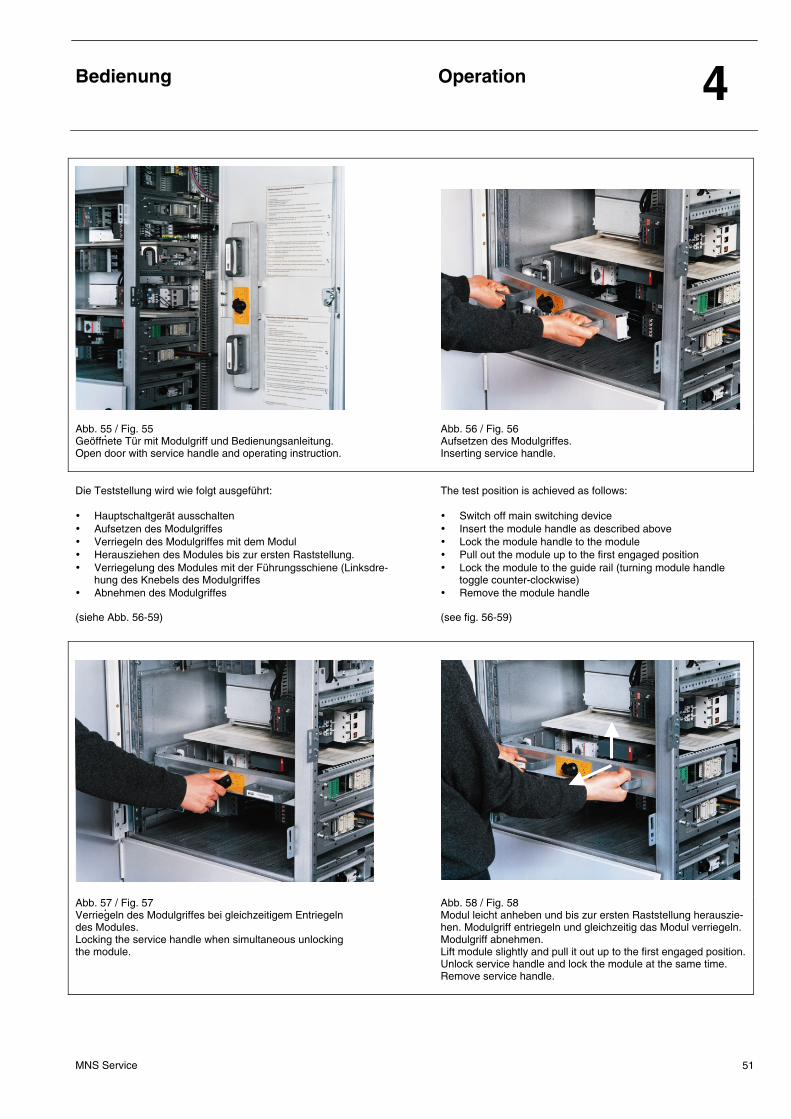
Bedienung
Operation 4
MNS Service 51
Abb. 55 / Fig. 55 Geöffnete Tür mit Modulgriff und Bedienungsanleitung. Open door with service handle and operating instruction.
Abb. 56 / Fig. 56 Aufsetzen des Modulgriffes. Inserting service handle.
Die Teststellung wird wie folgt ausgeführt: • Hauptschaltgerät ausschalten • Aufsetzen des Modulgriffes • Verriegeln des Modulgriffes mit dem Modul • Herausziehen des Modules bis zur ersten Raststellung. • Verriegelung des Modules mit der Führungsschiene (Linksdre-
hung des Knebels des Modulgriffes • Abnehmen des Modulgriffes (siehe Abb. 56-59)
The test position is achieved as follows: • Switch off main switching device • Insert the module handle as described above • Lock the module handle to the module • Pull out the module up to the first engaged position • Lock the module to the guide rail (turning module handle
toggle counter-clockwise) • Remove the module handle (see fig. 56-59)
Abb. 57 / Fig. 57 Verriegeln des Modulgriffes bei gleichzeitigem Entriegeln des Modules. Locking the service handle when simultaneous unlocking the module.
Abb. 58 / Fig. 58 Modul leicht anheben und bis zur ersten Raststellung herauszie-hen. Modulgriff entriegeln und gleichzeitig das Modul verriegeln. Modulgriff abnehmen. Lift module slightly and pull it out up to the first engaged position. Unlock service handle and lock the module at the same time. Remove service handle.
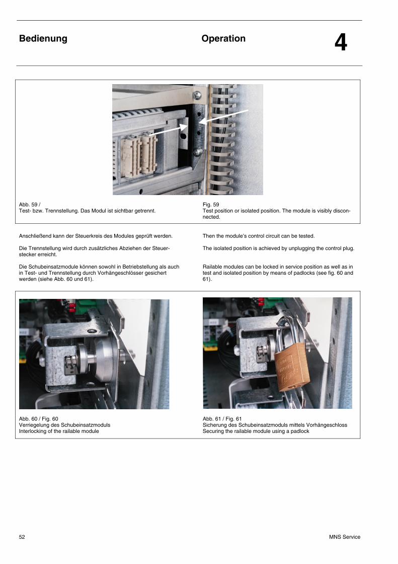
Bedienung
Operation 4
MNS Service 52
Abb. 59 / Test- bzw. Trennstellung. Das Modul ist sichtbar getrennt.
Fig. 59 Test position or isolated position. The module is visibly discon-nected.
Anschließend kann der Steuerkreis des Modules geprüft werden. Die Trennstellung wird durch zusätzliches Abziehen der Steuer-stecker erreicht. Die Schubeinsatzmodule können sowohl in Betriebstellung als auch in Test- und Trennstellung durch Vorhängeschlösser gesichert werden (siehe Abb. 60 und 61).
Then the module’s control circuit can be tested. The isolated position is achieved by unplugging the control plug. Railable modules can be locked in service position as well as in test and isolated position by means of padlocks (see fig. 60 and 61).
Abb. 60 / Fig. 60 Verriegelung des Schubeinsatzmoduls Interlocking of the railable module
Abb. 61 / Fig. 61 Sicherung des Schubeinsatzmoduls mittels Vorhängeschloss Securing the railable module using a padlock
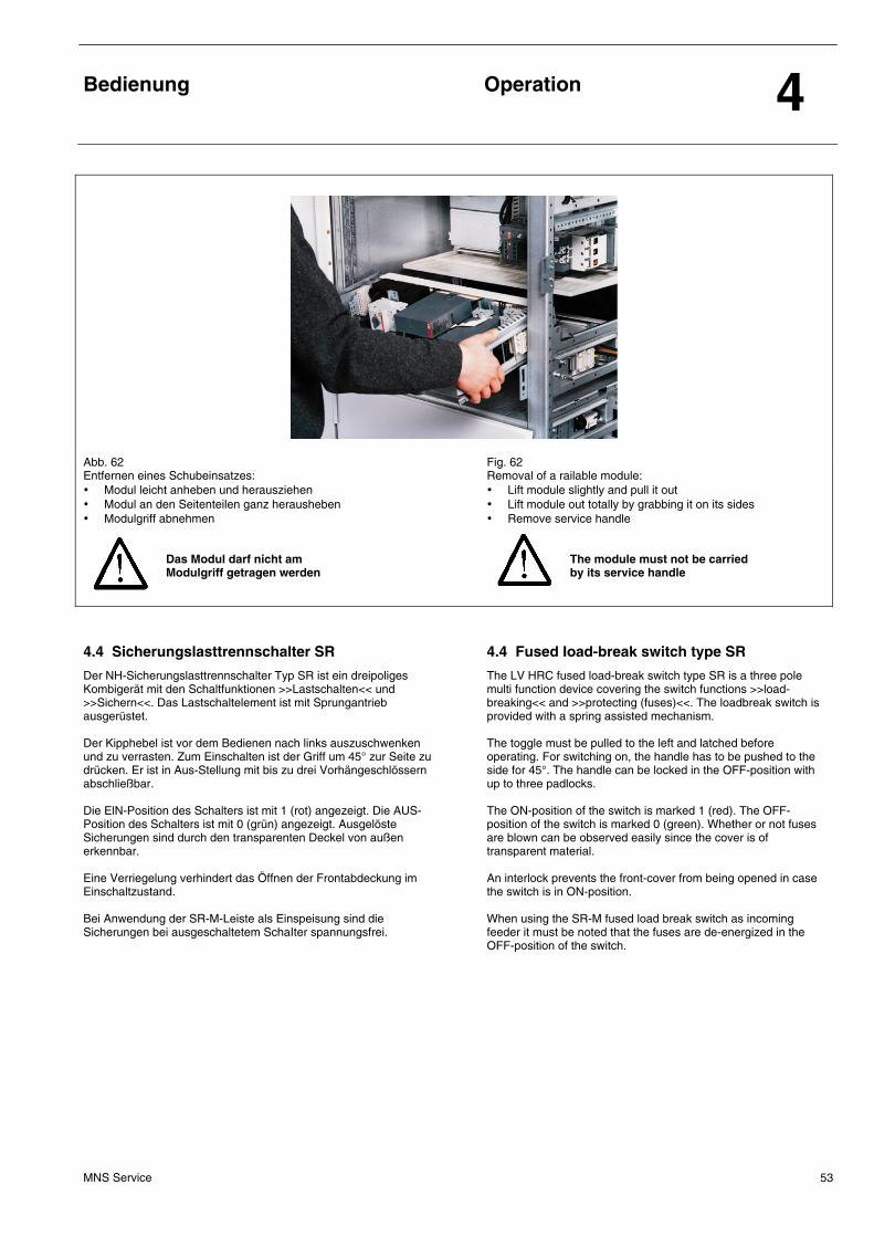
Bedienung
Operation 4
MNS Service 53
Abb. 62 Entfernen eines Schubeinsatzes: • Modul leicht anheben und herausziehen • Modul an den Seitenteilen ganz herausheben • Modulgriff abnehmen
Das Modul darf nicht am Modulgriff getragen werden
Fig. 62 Removal of a railable module: • Lift module slightly and pull it out • Lift module out totally by grabbing it on its sides • Remove service handle
The module must not be carried by its service handle
4.4 Sicherungslasttrennschalter SR 4.4 Fused Ioad-break switch type SR
Der NH-Sicherungslasttrennschalter Typ SR ist ein dreipoliges Kombigerät mit den Schaltfunktionen >>Lastschalten<< und >>Sichern<<. Das Lastschaltelement ist mit Sprungantrieb ausgerüstet. Der Kipphebel ist vor dem Bedienen nach links auszuschwenken und zu verrasten. Zum Einschalten ist der Griff um 45° zur Seite zu drücken. Er ist in Aus-Stellung mit bis zu drei Vorhängeschlössern abschließbar. Die ElN-Position des Schalters ist mit 1 (rot) angezeigt. Die AUS-Position des Schalters ist mit 0 (grün) angezeigt. Ausgelöste Sicherungen sind durch den transparenten Deckel von außen erkennbar. Eine Verriegelung verhindert das Öffnen der Frontabdeckung im Einschaltzustand. Bei Anwendung der SR-M-Leiste als Einspeisung sind die Sicherungen bei ausgeschaltetem SchaIter spannungsfrei.
The LV HRC fused load-break switch type SR is a three pole multi function device covering the switch functions >>load-breaking<< and >>protecting (fuses)<<. The loadbreak switch is provided with a spring assisted mechanism. The toggle must be pulled to the left and latched before operating. For switching on, the handle has to be pushed to the side for 45°. The handle can be locked in the OFF-position with up to three padlocks. The ON-position of the switch is marked 1 (red). The OFF-position of the switch is marked 0 (green). Whether or not fuses are blown can be observed easily since the cover is of transparent material. An interlock prevents the front-cover from being opened in case the switch is in ON-position. When using the SR-M fused load break switch as incoming feeder it must be noted that the fuses are de-energized in the OFF-position of the switch.
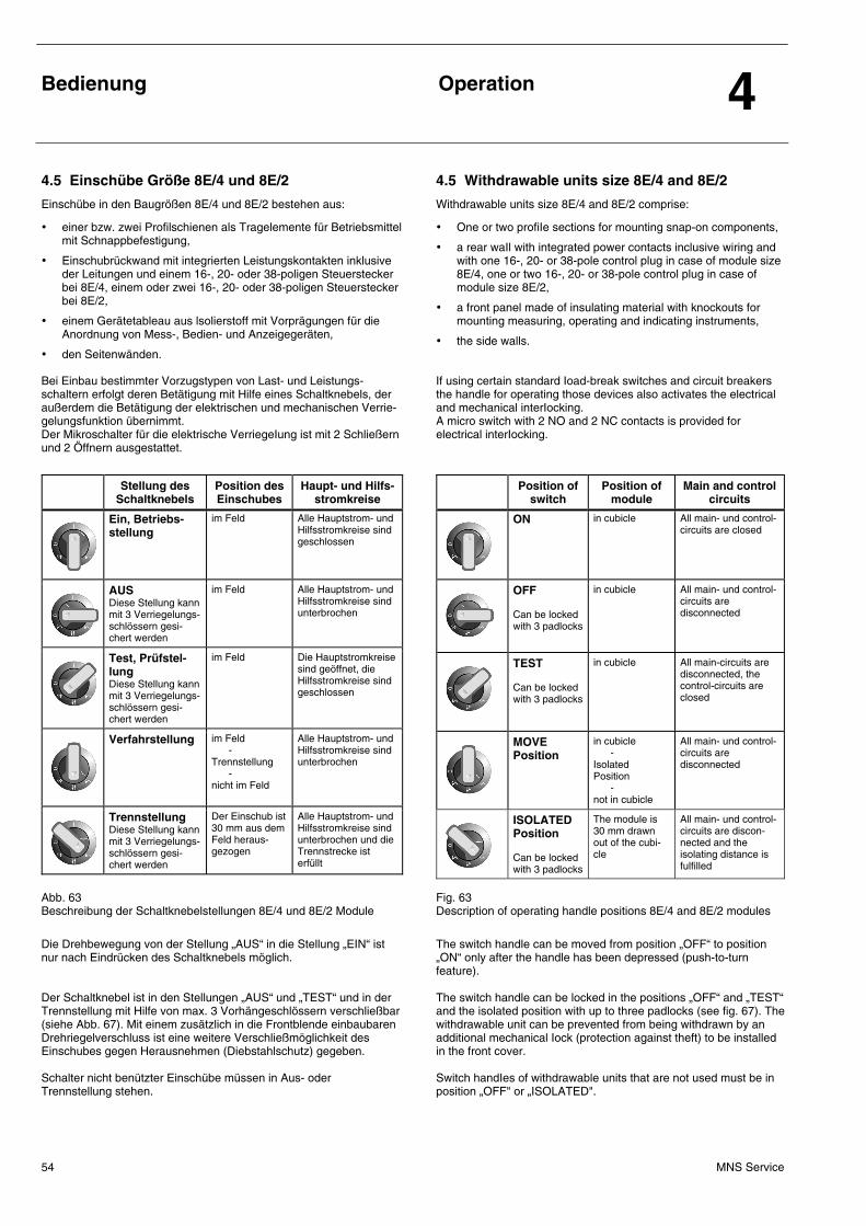
Bedienung
Operation 4
MNS Service 54
4.5 Einschübe Größe 8E/4 und 8E/2 4.5 Withdrawable units size 8E/4 and 8E/2
Einschübe in den Baugrößen 8E/4 und 8E/2 bestehen aus:
• einer bzw. zwei Profilschienen als Tragelemente für Betriebsmittel mit Schnappbefestigung,
• Einschubrückwand mit integrierten Leistungskontakten inklusive der Leitungen und einem 16-, 20- oder 38-poligen Steuerstecker bei 8E/4, einem oder zwei 16-, 20- oder 38-poligen Steuerstecker bei 8E/2,
• einem Gerätetableau aus lsolierstoff mit Vorprägungen für die Anordnung von Mess-, Bedien- und Anzeigegeräten,
• den Seitenwänden.
Bei Einbau bestimmter Vorzugstypen von Last- und Leistungs-schaltern erfolgt deren Betätigung mit Hilfe eines Schaltknebels, der außerdem die Betätigung der elektrischen und mechanischen Verrie-gelungsfunktion übernimmt. Der Mikroschalter für die elektrische VerriegeIung ist mit 2 Schließern und 2 Öffnern ausgestattet.
Withdrawable units size 8E/4 and 8E/2 comprise:
• One or two profiIe sections for mounting snap-on components,
• a rear waIl with integrated power contacts inclusive wiring and with one 16-, 20- or 38-pole control plug in case of module size 8E/4, one or two 16-, 20- or 38-pole control plug in case of module size 8E/2,
• a front panel made of insulating material with knockouts for mounting measuring, operating and indicating instruments,
• the side walls.
If using certain standard Ioad-break switches and circuit breakers the handle for operating those devices also activates the electrical and mechanical interIocking. A micro switch with 2 NO and 2 NC contacts is provided for electrical interIocking.
Stellung des Schaltknebels
Position des Einschubes
Haupt- und Hilfs-stromkreise
Ein, Betriebs-stellung
im Feld Alle Hauptstrom- und Hilfsstromkreise sind geschlossen
AUS Diese Stellung kann mit 3 Verriegelungs-schlössern gesi-chert werden
im Feld Alle Hauptstrom- und Hilfsstromkreise sind unterbrochen
Test, Prüfstel-lung Diese Stellung kann mit 3 Verriegelungs-schlössern gesi-chert werden
im Feld Die Hauptstromkreise sind geöffnet, die Hilfsstromkreise sind geschlossen
Verfahrstellung im Feld - Trennstellung - nicht im Feld
Alle Hauptstrom- und Hilfsstromkreise sind unterbrochen
Trennstellung Diese Stellung kann mit 3 Verriegelungs-schlössern gesi-chert werden
Der Einschub ist 30 mm aus dem Feld heraus-gezogen
Alle Hauptstrom- und Hilfsstromkreise sind unterbrochen und die Trennstrecke ist erfüllt
Position of switch
Position of module
Main and control circuits
ON
in cubicle All main- und control-circuits are closed
OFF Can be locked with 3 padlocks
in cubicle All main- und control-circuits are disconnected
TEST Can be locked with 3 padlocks
in cubicle All main-circuits are disconnected, the control-circuits are closed
MOVE Position
in cubicle - Isolated Position - not in cubicle
All main- und control-circuits are disconnected
ISOLATED Position Can be locked with 3 padlocks
The module is 30 mm drawn out of the cubi-cle
All main- und control-circuits are discon-nected and the isolating distance is fulfilled
Abb. 63 Beschreibung der Schaltknebelstellungen 8E/4 und 8E/2 Module
Fig. 63 Description of operating handle positions 8E/4 and 8E/2 modules
Die Drehbewegung von der Stellung „AUS“ in die Stellung „EIN“ ist nur nach Eindrücken des Schaltknebels möglich. Der Schaltknebel ist in den Stellungen „AUS“ und „TEST“ und in der Trennstellung mit Hilfe von max. 3 Vorhängeschlössern verschließbar (siehe Abb. 67). Mit einem zusätzlich in die Frontblende einbaubaren Drehriegelverschluss ist eine weitere Verschließmöglichkeit des Einschubes gegen Herausnehmen (Diebstahlschutz) gegeben. Schalter nicht benützter Einschübe müssen in Aus- oder Trennstellung stehen.
The switch handle can be moved from position „OFF“ to position „ON“ only after the handle has been depressed (push-to-turn feature). The switch handle can be locked in the positions „OFF“ and „TEST“ and the isolated position with up to three padlocks (see fig. 67). The withdrawable unit can be prevented from being withdrawn by an additional mechanical Iock (protection against theft) to be installed in the front cover. Switch handIes of withdrawable units that are not used must be in position „OFF" or „ISOLATED".
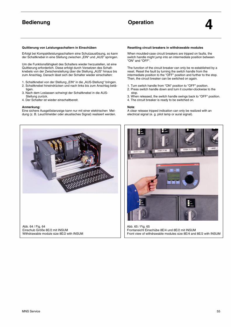
Bedienung
Operation 4
MNS Service 55
Quittierung von Leistungsschaltern in Einschüben Resetting circuit breakers in withdrawable modules
Erfolgt bei Kompaktleistungsschaltern eine Schutzauslösung, so kann der Schaltknebel in eine Stellung zwischen „EIN“ und „AUS“ springen. Um die Funktionsfähigkeit des Schalters wieder herzustellen, ist eine Quittierung erforderlich. Diese erfolgt durch Versetzen des Schalt-knebels von der Zwischenstellung über die Stellung „AUS“ hinaus bis zum Anschlag. Danach lässt sich der Schalter wieder einschalten: 1. Schaltknebel von der Stellung „EIN“ in die „AUS-Stellung“ bringen. 2. Schaltknebel hineindrücken und nach links bis zum Anschlag betä-
tigen. 3. Nach dem Loslassen schwingt der Schaltknebel in die AUS-
Stellung zurück. 4. Der Schalter ist wieder einschaltbereit. Anmerkung: Eine sichere Ausgelöstanzeige kann nur mit einer elektrischen Mel-dung (z. B. Leuchtmelder oder akustisches Signal) realisiert werden.
When moulded-case circuit breakers are tripped on faults, the switch handle might jump into an intermediate position between "ON" and "OFF“. The function of the circuit breaker can only be re-established by a reset. Reset the fault by turning the switch handle from the intermediate position to the "OFF" position and further to the stop. Then, the circuit breaker can be switched on again. 1. Turn switch handle from "ON" position to "OFF" position. 2. Press switch handle down and turn it counter-clockwise to the
stop. 3. When released, the switch handle swings back to “OFF“ position. 4. The circuit breaker is ready to be switched on. Note: A clear release tripped indication can only be realized with an electrical signal (e. g. pilot lamp or aural signal).
Abb. 64 / Fig. 64 Einschub Größe 8E/2 mit INSUM Withdrawable module size 8E/2 with INSUM
Abb. 65 / Fig. 65 Frontansicht Einschübe 8E/4 und 8E/2 mit INSUM Front view of withdrawable modules size 8E/4 and 8E/2 with INSUM
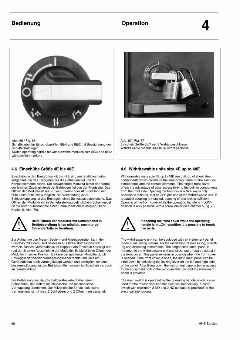
Bedienung
Operation 4
MNS Service 56
Abb. 66 / Fig. 66 Schaltknebel für Einschubgrößen 8E/4 und 8E/2 mit Bezeichnung der Schalterstellungen Switch operating handle for withdrawable modules size 8E/4 and 8E/2 with position markers
Abb. 67 / Fig. 67 Einschub Größe 8E/4 mit 3 Vorhängeschlössern Withdrawable module size 8E/4 with 3 padlocks
4.6 Einschübe Größe 4E bis 48E 4.6 Withdrawable units size 4E up to 48E
Einschübe in den Baugrößen 4E bis 48E sind aus Stahlblechteilen aufgebaut, die das Traggerüst für die Betriebsmittel und die Kontaktelemente bilden. Die schwenkbare Modultür bietet den Vorteil der leichten Zugänglichkeit der Betriebsmittel von der Frontseite. Das Öffnen der Modultür ist nur in Test-, Trenn- oder AUS-Stellung mit Hilfe eines Schlüssels möglich. Bei Verwendung einer Schlosskupplung ist das Entriegeln eines Schlosses ausreichend. Das Öffnen der Modultür mit in Betriebsstellung befindlichem Schaltknebel ist nur unter Zuhilfenahme eines Schraubenziehers möglich (siehe Kapitel 5, Abb. 75).
Beim Öffnen der Modultür mit Schaltknebel in Betriebsstellung ist es möglich, spannungs- führende Teile zu berühren.
Zur Aufnahme von Mess-, Bedien- und Anzeigegeräten kann der Einschub mit einem Gerätetableau aus Isolierstoff ausgerüstet werden. Dieses Gerätetableau ist klappbar am Einschub befestigt und ragt durch einen Ausschnitt in der Modultür. Es bleibt beim Öffnen der Modultür in seiner Position. Es kann bei geöffneter Modultür durch Entriegeln der beiden Verriegelungshebel rechts und links am Gerätetableau nach vorne geklappt werden und ermöglicht so einen besseren Zugang zu den Betriebsmitteln sowohl im Einschub als auch im Gerätetableau. Die Betätigung des Hauptschaltgerätes erfolgt über einen Schalthebel, der zudem die elektrische und mechanische Verriegelung übernimmt. Der Mikroschalter für die elektrische Verriegelung ist mit max. 2 Schließern und 2 Öffnern ausgestattet.
Withdrawable units size 4E up to 48E are built-up of sheet steel components which constitute the supporting frame for the electrical components and the contact elements. The hinged front cover offers the advantage of easy accessibility to the built in components from the front side. Opening the front cover with a key is only possible in isolated, test or OFF-position of the withdrawable unit. If a parallel coupling is installed, opening of one lock is sufficient. Opening of the front cover while the operating handle is in „ON“-position is only possible with a screw driver (see chapter 5, fig. 75).
If opening the front cover while the operating handle is in „ON“-position it is possible to touch live parts.
The withdrawable unit can be equipped with an instrument panel made of insulating material for the installation of measuring, operat-ing and indicating instruments. The hinged instrument panel is mounted to the withdrawable unit and sticks out through a cutout in the front cover. This panel remains in position when the front cover is opened. If the front cover is open, the instrument panel can be tilted down by unlocking the locking lever on the left and right side of the panel. After tilting down the instrument panel a better access to the equipment both in the withdrawable unit and the instrument panel is provided. The main switch is operated by the operating handle which is also used for the mechanical and the electrical interlocking. A micro switch with maximum 2 NO and 2 NC contacts is provided for the electrical interlocking.
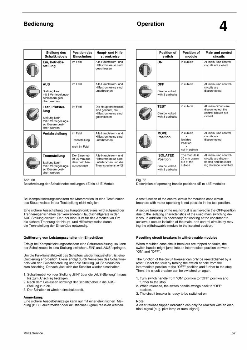
Bedienung
Operation 4
MNS Service 57
Stellung des Schaltknebels
Position des Einschubes
Haupt- und Hilfs-stromkreise
Ein, Betriebs-stellung
im Feld
Alle Hauptstrom- und Hilfsstromkreise sind geschlossen
AUS Stellung kann mit 3 Verriegelungs-schlössern gesi-chert werden
im Feld Alle Hauptstrom- und Hilfsstromkreise sind unterbrochen
Test, Prüfstel-lung Stellung kann mit 3 Verriegelungs-schlössern gesi-chert werden
im Feld Die Hauptstromkreise sind geöffnet, die Hilfsstromkreise sind geschlossen
Verfahrstellung im Feld - Trennstellung - nicht im Feld
Alle Hauptstrom- und Hilfsstromkreise sind unterbrochen
Trennstellung Stellung kann mit 3 Verriegelungs-schlössern gesi-chert werden
Der Einschub ist 30 mm aus dem Feld her-ausgezogen
Alle Hauptstrom- und Hilfsstromkreise sind unterbrochen und die Trennstrecke ist erfüllt
Position of switch
Position of module
Main and control circuits
ON
in cubicle
All main- und control-circuits are closed
OFF Can be locked with 3 padlocks
in cubicle All main- und control-circuits are disconnected
TEST Can be locked with 3 padlocks
in cubicle All main-circuits are disconnected, the control-circuits are closed
MOVE Position
in cubicle - Isolated Position - not in cubicle
All main- und control-circuits are disconnected
ISOLATED Position Can be locked with 3 padlocks
The module is 30 mm drawn out of the cubicle
All main- und control-circuits are discon-nected and the isolat-ing distance is fulfilled
Abb. 68 Beschreibung der Schaltknebelstellungen 4E bis 48 E Module
Fig. 68 Description of operating handle positions 4E to 48E modules
Bei Kompaktleistungsschaltern mit Motorantrieb ist eine Testfunktion des Steuerkreises in der Teststellung nicht möglich.
A test function of the control circuit for moulded case circuit breakers with motor operating is not possible in the test position.
Eine sichere Ausschaltung des Hauptstromkreises wird aufgrund der Trennereigenschaften der verwendeten Hauptschaltgeräte in der AUS-Stellung erreicht. Darüber hinaus ist für das Arbeiten vor Ort die sichere Trennung der Haupt- und Hilfsstromkreise durch die Trennstellung der Einschübe notwendig.
A secure breaking of the maincircuit is achieved in the OFF-position due to the isolating characteristics of the used main switching de-vices. In addition it is necessary for working at the consumer to achieve a secure isolation of the main- and control-circuits by mov-ing the withdrawable module to the isolated position.
Quittierung von Leistungsschaltern in Einschüben Resetting circuit breakers in withdrawable modules
Erfolgt bei Kompaktleistungsschaltern eine Schutzauslösung, so kann der Schaltknebel in eine Stellung zwischen „EIN“ und „AUS“ springen. Um die Funktionsfähigkeit des Schalters wieder herzustellen, ist eine Quittierung erforderlich. Diese erfolgt durch Versetzen des Schaltkne-bels von der Zwischenstellung über die Stellung „AUS“ hinaus bis zum Anschlag. Danach lässt sich der Schalter wieder einschalten: 1. Schaltknebel von der Stellung „EIN“ über die „AUS-Stellung“ hinaus
bis zum Anschlag betätigen. 2. Nach dem Loslassen schwingt der Schaltknebel in die AUS-
Stellung zurück. 3. Der Schalter ist wieder einschaltbereit. Anmerkung: Eine sichere Ausgelöstanzeige kann nur mit einer elektrischen Mel-dung (z. B. Leuchtmelder oder akustisches Signal) realisiert werden.
When moulded-case circuit breakers are tripped on faults, the switch handle might jump into an intermediate position between "ON" and "OFF“. The function of the circuit breaker can only be reestablished by a reset. Reset the fault by turning the switch handle from the intermediate position to the "OFF" position and further to the stop. Then, the circuit breaker can be switched on again. 1. Turn switch handle from "ON" position to "OFF" position and
further to the stop. 2. When released, the switch handle swings back to “OFF“
position. 3. The circuit breaker is ready to be switched on. Note: A clear release tripped indication can only be realized with an elec-trical signal (e. g. pilot lamp or aural signal).
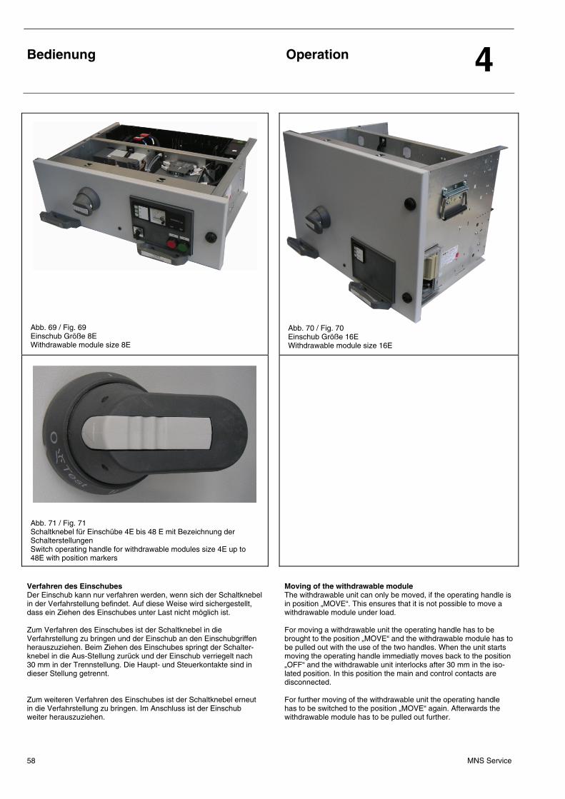
Bedienung
Operation 4
MNS Service 58
Abb. 69 / Fig. 69 Einschub Größe 8E Withdrawable module size 8E
Abb. 70 / Fig. 70 Einschub Größe 16E Withdrawable module size 16E
Abb. 71 / Fig. 71 Schaltknebel für Einschübe 4E bis 48 E mit Bezeichnung der Schalterstellungen Switch operating handle for withdrawable modules size 4E up to 48E with position markers
Verfahren des Einschubes Der Einschub kann nur verfahren werden, wenn sich der Schaltknebel in der Verfahrstellung befindet. Auf diese Weise wird sichergestellt, dass ein Ziehen des Einschubes unter Last nicht möglich ist. Zum Verfahren des Einschubes ist der Schaltknebel in die Verfahrstellung zu bringen und der Einschub an den Einschubgriffen herauszuziehen. Beim Ziehen des Einschubes springt der Schalter-knebel in die Aus-Stellung zurück und der Einschub verriegelt nach 30 mm in der Trennstellung. Die Haupt- und Steuerkontakte sind in dieser Stellung getrennt. Zum weiteren Verfahren des Einschubes ist der Schaltknebel erneut in die Verfahrstellung zu bringen. Im Anschluss ist der Einschub weiter herauszuziehen.
Moving of the withdrawable module The withdrawable unit can only be moved, if the operating handle is in position „MOVE“. This ensures that it is not possible to move a withdrawable module under load. For moving a withdrawable unit the operating handle has to be brought to the position „MOVE“ and the withdrawable module has to be pulled out with the use of the two handles. When the unit starts moving the operating handle immediatly moves back to the position „OFF“ and the withdrawable unit interlocks after 30 mm in the iso-lated position. In this position the main and control contacts are disconnected. For further moving of the withdrawable unit the operating handle has to be switched to the position „MOVE“ again. Afterwards the withdrawable module has to be pulled out further.
Bedienung
Operation 4
MNS Service 59
Vor dem Ende der Verfahrstrecke verriegelt der Einschub erneut, um ein unkontrolliertes Herausziehen des Einschubes aus dem Feld zu verhindern. Diese Sicherheitssperre kann durch das Herunterdrücken Hebels auf der linken Seite des Einschubs gelöst werden (siehe Abb. 85). Wenn der zu verfahrende Einschub eine hohe Einbauposition im Feld hat, kann der Verriegelungshebel gelöst werden, indem der Einschub mit der rechten Hand von unten gestützt wird und der Hebel mit der linken Hand betätigt wird. Im Anschluss kann der Einschub vollständig aus dem Feld entnommen werden.
Die Einschübe haben je nach Größe ein hohes Gewicht. Daher sind die folgenden Vorsichts-maßnahmen unbedingt einzuhalten:
• Wenn der Einschub zur Hälfte aus dem Einschubfach
herausgezogen ist, muss der Bediener bei 4E- und 8E-Einschüben den Einschub von unten fassen.
• Für Einschübe ≥ 12E sollte der Einschub nur von zwei Personen
herausgezogen werden. Dazu sollte sich je ein Bediener auf eine Seite des Einschubes stellen und den Einschub von unten (12E) bzw. an den vorgesehenen Haltegriffen an den Seitenwänden (> 12E) fassen.
• In der Position des Sicherheitsstops sollte der Einschub nicht
länger als notwendig belassen werden, da der Schwerpunkt des Einschubes bereits außerhalb des Feldes liegt. Missachtung dieser Regel kann zu mechanischen Schäden am Einschub führen.
Einschübe in Trennstellung bzw. in der Position des Sicherheitsstops nicht als Steighilfe verwenden, da hierdurch Personen gefährdet und/oder die Anlage beschädigt werden kann.
Die Teststellung wird ohne Verfahren des Einschubs durch Umschalten des Schaltknebels in die Stellung „TEST“ erreicht. Der Schaltknebel ist in den Stellungen „AUS“ und „TEST“ mit Hilfe von max. 3 Vorhängeschlössern abschließbar. Ein zusätzlich in die Frontblende einbaubarer Drehriegelverschluss bietet eine weitere Verschlussmöglichkeit des Einschubes gegen Herausnehmen (Diebstahlschutz). Bei nicht benutzten Einschüben muss der Schaltknebel in Aus-Stellung stehen.
Before removing the withdrawable unit from the cubicle completely the withdrawable unit interlocks again to avoid being pulled out from the cubicle uncontrolled. To release this safety stop it is necessary to press down the lever on the left side of the withdrawable unit (see fig. 85). If the withdrawable unit which should be moved is installed in a high position in the cubicle the safety stop can be released by supporting the withdrawable unit with the right hand from below and releasing the lever with the left hand. Afterwards the withdrawable unit can be removed completely from the cubicle.
Depending on their size withdrawable units have a high weight. Therefore the following safety measures have to be obeyed by all means:
• After moving out the withdrawable unit halfway from the with-
drawable module compartment the operator has to grasp the withdrawable unit from below under the sides (for withdrawable units size 4E and 8E).
• For withdrawable units size 12E and bigger the withdrawable
unit should only be withdrawn by two persons. For this the op-erators should be located at one side of the withdrawable unit each and grasp the withdrawable unit from bellow (12E) or at the provided hand grips located at the side walls (> 12E).
• The withdrawable unit should not be left longer than necessary
in the position of the safety stop, because the centre of gravity is already outside the cubicle in this position. Disregarding of this regulation can lead to mechanical damage at the with-drawable unit.
Withdrawable units in isolated position or in the position of the safety stop are not to be used as help for climbing because persons can be endangered and/or the switchgear can be damaged.
The test position can be achieved without moving the withdrawable unit by turning the operating handle to the position „TEST“. The operating handle can be locked in the positions „OFF“ and „TEST“ by using up to three padlocks. Removing of the unit can be prevented by an additional mechanical lock (protection against theft) which additionally can be installed in the front cover. For withdrawable units that are not being used the operating handle must be in the position „OFF“.
4.7 Besondere Hinweise 4.7 Special information
Es ist darauf zu achten, dass bei in Betrieb befindlichen Anlagen
• die Türen und Einschubblenden verschlossen sind,
• Einschübe verriegelt sind,
• Lüftungsgitter freiliegen und nicht verschmutzt sind.
When the installation is in operation ensure that
• the doors and the front covers of the withdrawable modules are closed,
• the withdrawabIe modules are interlocked,
• the ventilation louvers are not abstructed or clogged
Wartung und Ersatzteile
Maintenance and Spare Parts 5
MNS Service 60
5.1 Allgemeines 5.1 General
Wartungsarbeiten, z.B. Sicherungswechsel sind nur durch Fachpersonal oder unterwiesene Personen unter Beachtung der Sicherheitsvorschriften auszu-führen.
Bei allen Arbeiten in und an den Schaltfeldern sind folgende Vorschriften zu beachten: • Die nationalen und internationalen Sicherheitsbestimmungen
(z.B. VDE 0105, Bestimmungen für den Betrieb von Starkstromanlagen).
• Die besonderen Wartungsvorschriften der eingebauten Apparate und Einrichtungen.
Um- und Nachrüstung von Feldern ist je nach Um-fang und Ausbauart mit oder ohne Betriebsunter-brechung benachbarter Anlagenteile möglich. Bei Umbauten in den Schaltfeldern ist die veränderte Wärmebilanz in den Feldern zu beachten. Die zuläs-sige Grenzerwärmung im Schaltfeld darf nicht über-schritten werden. In Zweifelsfällen wenden Sie sich bitte an Ihre zuständige ABB-Niederlassung.
Die Schienenverbindungen sind durch die Verwendung von Schrauben mit ESLOK-Sicherung wartungsfrei ausgeführt. Nach Störungen sind Kontrollen wie vor der lnbetriebnahme durchzuführen.
Maintenance work, such as replacing fuses etc., must only be carried out by suitable instructed personnel observing the safety rules.
When working on switchgear cubicles the following regulations must be observed: • The national and international safety rules (e.g. VDE 0105,
regulations for the operation of power installations).
• The specific maintenance instructions of the installed devices.
When making modifications to cubicles it may be necessary to interrupt the operation of adja-cent parts of the installation, depending on the extent of the work and the type of design. For modifications inside the cubicles it is necessary to reconsider the changed heat balance. The allowed limit of temperature-rise inside the switchpanel must not be exceeded. In case of doubt please contact your appropriate ABB branch.
The use of ESLOK-secured screws renders maintenance of the bar connections unnecessary. After fault situations the checks are to be carried out just as before commissioning.
5.1.1 Maximal zulässige effektive Verlustleistung Pveff 5.1.1 Maximum admittable effective power loss Pveff
Folgende Voraussetzungen gelten für die unter 5.1.1.1 und 5.1.1.2 genannten Richtwerte:
• Schränke mindestens 8 cm von der Wand entfernt aufgestellt • MitteIschrank in einer Schrankreihe
The following preconditions are valid for the standard values given under 5.1.1.1 and 5.1.1.2:
• Cubicle distance from wall at least 8 cm • Middle cubicle in multi cubicle arrangement
5.1.1.1 Richtwerte der maximal zulässigen effektiven Verlustleistung Pveff bis Schutzart IP 31 und IP 41, natürliche Belüftung
5.1.1.1 Standard values of maximum admittable effective power loss Pveff for degrees of protection up to IP 31 and IP41, natural air circulation
Dach: belüftet mit Abdeckung Vorderseite: 1 Lüftungsgitter IP30/IP40 Rückseite: 1 Lüftungsgitter IP30/IP40 Bei Schmalfeldern (B = 400, 600 mm) sind zwei Lüftungsgitter einzusetzen. Bei Belüftung der Schaltfelder von unten (ohne Bodenblech), z.B. bei Kabelschächten oder aufgeständertem Boden, sind keine Lüftungsgitter erforderlich, wenn eine gleichwertige Luftzirkulation möglich ist.
Roof-plate: stretch lattice Front: 1 ventilation louvre IP30/IP40 Back: 1 ventilation louvre IP30/IP40 For small cubicles (W = 400, 600 mm) 2 ventilation louvres must be used. In case of ventilation from bottom (without bottom plate) i.e. because of cable pits or false floors, there are no ventilation louvres necessary for cubicles, as long as an equivalent air circulation is possible.
5.1.1.2 Richtwerte der maximal zulässigen effektiven VerIustleistung Pveff bei Schutzarten IP 32/IP 42 (unbelüftet) und IP 54
5.1.1.2 Standard values of maximum admittable effective power loss Pveff for protection classes IP 32/IP 42 (non-ventilated) and IP 54
Schaltschrank: H = 2200 mm B = 1000 mm T = 600 mm Geräteraum: B1 = 600 mm Leistungsreduzierung bzw. Leistungserhöhung: • Bei Feldbreiten < 1000 mm ist Kurve 3 prozentual zu senken, z.B.
B = 800 mm, Kurve 3 auf 80 % reduzieren. • Für Endschränke von SchaItanIagen kann die zusätzliche
Abstrahlfläche einer Seitenwand mit einer Erhöhung der Kurven um 20 % berücksichtigt werden (Wandabstand mindestens 8 cm).
Cubicle: H = 2200 mm W = 1000 mm D = 600 mm Equipment compartment: W1 = 600 mm Decrease resp. increase of standard values: • For cubicles < 1000 mm curve 3 must be lowered in percent-
age terms, i.e. for W = 800 mm, lower curve 3 to 80 %. • For end cubicles of a switchgear, an increase of the curves by
20 % can be taken into account, due to an additional emmission area of one side wall (Cubicle distance to wall at least 8 cm).
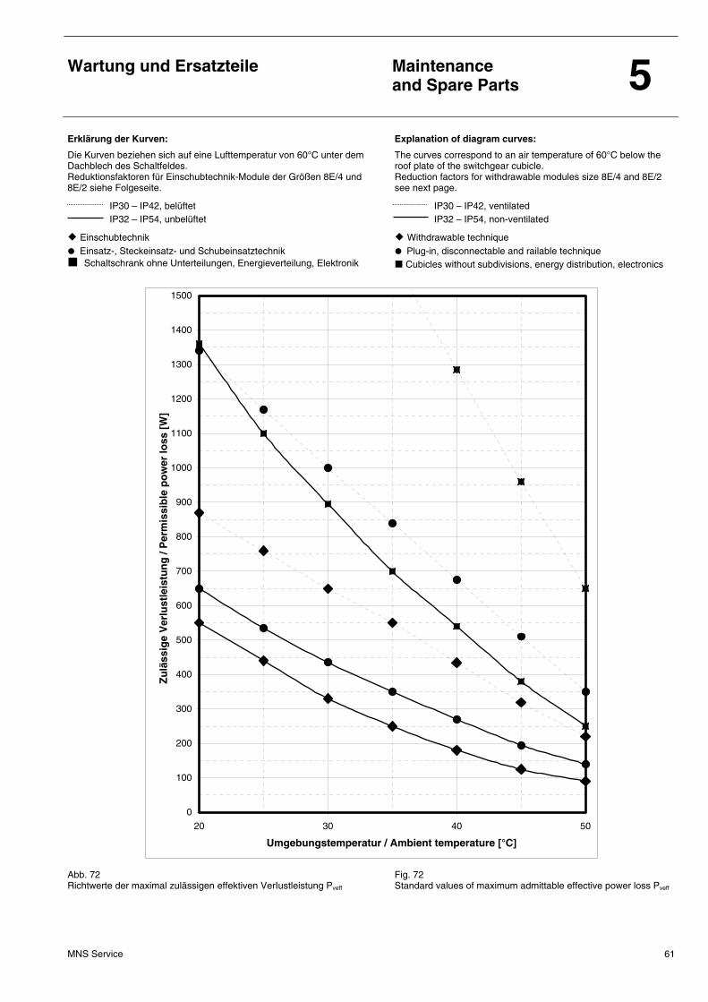
Wartung und Ersatzteile
Maintenance and Spare Parts 5
MNS Service 61
Erklärung der Kurven:
Die Kurven beziehen sich auf eine Lufttemperatur von 60°C unter dem Dachblech des Schaltfeldes. Reduktionsfaktoren für Einschubtechnik-Module der Größen 8E/4 und 8E/2 siehe Folgeseite.
IP30 – IP42, belüftet IP32 – IP54, unbelüftet
Einschubtechnik Einsatz-, Steckeinsatz- und Schubeinsatztechnik Schaltschrank ohne Unterteilungen, Energieverteilung, Elektronik
Explanation of diagram curves:
The curves correspond to an air temperature of 60°C below the roof plate of the switchgear cubicle. Reduction factors for withdrawable modules size 8E/4 and 8E/2 see next page.
IP30 – IP42, ventilated IP32 – IP54, non-ventilated
Withdrawable technique Plug-in, disconnectable and railable technique Cubicles without subdivisions, energy distribution, electronics
0
100
200
300
400
500
600
700
800
900
1000
1100
1200
1300
1400
1500
20 30 40 50
Umgebungstemperatur / Ambient temperature [°C]
Zu
läss
ige
Ver
lust
leis
tun
g /
Per
mis
sib
le p
ow
er lo
ss [
W]
Abb. 72 Richtwerte der maximal zulässigen effektiven VerIustleistung Pveff
Fig. 72 Standard values of maximum admittable effective power loss Pveff
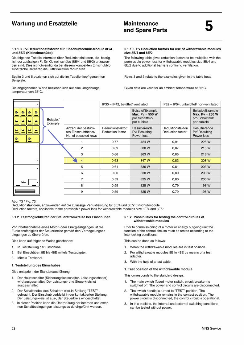
Wartung und Ersatzteile
Maintenance and Spare Parts 5
MNS Service 62
5.1.1.3 Pv-Reduktionsfaktoren für Einschubtechnik-Module 8E/4 und 8E/2 (Kleineinschübe)
5.1.1.3 Pv Reduction factors for use of withdrawable modules size 8E/4 and 8E/2
Die folgende Tabelle informiert über Reduktionsfaktoren, die bezüg-lich der zulässigen PV für Kleineinschübe (8E/4 und 8E/2) anzuwen-den sind. Dies ist notwendig, da bei diesem kompakten Einschubtyp zusätzliche Barrieren die Luftzirkulation reduzieren. Spalte 3 und 5 beziehen sich auf die im Tabellenkopf genannten Beispiele. Die angegebenen Werte beziehen sich auf eine Umgebungs-temperatur von 35°C.
The following table gives reduction factors to be multiplied with the permissible power loss for withdrawable modules size 8E/4 and 8E/2 due to additional barriers confining ventilation. Rows 3 and 5 relate to the examples given in the table head. Given data are valid for an ambient temperature of 35°C.
Beispiel/ Example
IP30 – IP42, belüftet/ ventilated IP32 – IP54, unbelüftet/ non-ventilated
Beispiel/Example Max. Pv = 550 W pro Schaltfeld/ per cubicle
Beispiel/Example Max. Pv = 250 W pro Schaltfeld/ per cubicle
Anzahl der bestück-ten Einschubfächer/ No. of occupied rows
Reduktionsfaktor/ Reduction factor
Resultierende Pv/ Resulting Power loss
Reduktionsfaktor/ Reduction factor
Resultierende Pv/ Resulting Power loss
1 0,77 424 W 0,91 228 W
2 0,69 380 W 0,87 218 W
3 0,66 363 W 0,85 213 W
4 0,63 347 W 0,83 208 W
5 0,61 336 W 0,81 203 W
6 0,60 330 W 0,80 200 W
7 0,59 325 W 0,80 200 W
8 0,59 325 W 0,79 198 W
9 0,59 325 W 0,79 198 W Abb. 73 / Fig. 73 Reduktionsfaktoren, anzuwenden auf die zulässige Verlustleistung für 8E/4 und 8E/2 Einschubmodule Reduction factors, applicable to the permissible power loss for withdrawable modules size 8E/4 and 8E/2
5.1.2 Testmöglichkeiten der Steuerstromkreise bei Einschüben 5.1.2 Possibilities for testing the control circuits of withdrawable modules
Vor Inbetriebnahme eines Motor- oder Energieabganges ist die Funktionsfähigkeit der Steuerkreise gemäß den Verriegelungsbe-dingungen zu überprüfen.
Dies kann auf folgende Weise geschehen:
1. In Teststellung der Einschübe.
2. Bei Einschüben 8E bis 48E mittels Testadapter.
3. Mittels Testkabel.
1. Teststellung des Einschubes
Dies entspricht der Standardausführung.
1. Der Hauptschalter (Sicherungslastschalter, Leistungsschalter) wlrd ausgeschaltet. Der Leistungs- und Steuerkreis ist ausgeschaltet.
2. Der Schaltknebel des Schalters wird in Stellung "TEST" gebracht. Der Einschub verbleibt in der kontaktierten Stellung. Der Leistungskreis ist aus-, der Steuerkreis eingeschaltet.
3. In dieser Position kann die Überprüfung der internen und exter-nen Schaltbedingungen leistungslos durchgeführt werden.
Prior to commissioning of a motor or energy outgoing unit the function of the control circuits must be tested according to the interlocking conditions.
This can be done as follows:
1. When the withdrawable modules are in test position.
2. For withdrawable modules 8E to 48E by means of a test adapter.
3. With the help of a test cable.
1. Test position of the withdrawable module
This corresponds to the standard design.
1. The main switch (fused motor switch, circuit breaker) is switched off. The power and control circuits are disconnected.
2. The switch handle is turned to ”TEST” position. The withdrawable module remains in the contact position. The power circuit is disconnected, the control circuit is operational.
3. In this positino, the internal and external switching conditions can be tested without power.
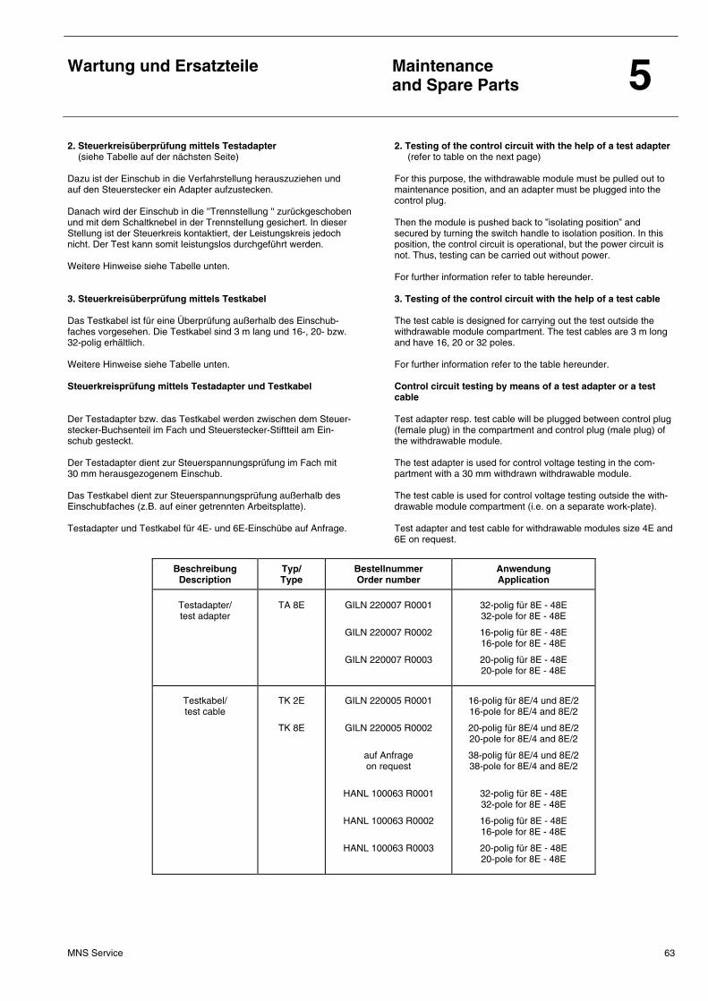
Wartung und Ersatzteile
Maintenance and Spare Parts 5
MNS Service 63
2. Steuerkreisüberprüfung mittels Testadapter (siehe Tabelle auf der nächsten Seite) Dazu ist der Einschub in die Verfahrstellung herauszuziehen und auf den Steuerstecker ein Adapter aufzustecken. Danach wird der Einschub in die ''Trennstellung '' zurückgeschoben und mit dem Schaltknebel in der Trennstellung gesichert. In dieser Stellung ist der Steuerkreis kontaktiert, der Leistungskreis jedoch nicht. Der Test kann somit Ieistungslos durchgeführt werden. Weitere Hinweise siehe Tabelle unten. 3. Steuerkreisüberprüfung mittels Testkabel Das Testkabel ist für eine Überprüfung außerhalb des Einschub-faches vorgesehen. Die Testkabel sind 3 m lang und 16-, 20- bzw. 32-polig erhältlich. Weitere Hinweise siehe Tabelle unten. Steuerkreisprüfung mittels Testadapter und Testkabel Der Testadapter bzw. das Testkabel werden zwischen dem Steuer-stecker-Buchsenteil im Fach und Steuerstecker-Stiftteil am Ein-schub gesteckt. Der Testadapter dient zur Steuerspannungsprüfung im Fach mit 30 mm herausgezogenem Einschub. Das Testkabel dient zur Steuerspannungsprüfung außerhalb des Einschubfaches (z.B. auf einer getrennten Arbeitsplatte). Testadapter und Testkabel für 4E- und 6E-Einschübe auf Anfrage.
2. Testing of the control circuit with the help of a test adapter (refer to table on the next page) For this purpose, the withdrawable module must be pulled out to maintenance position, and an adapter must be plugged into the control plug. Then the module is pushed back to ”isolating position” and secured by turning the switch handle to isolation position. In this position, the control circuit is operational, but the power circuit is not. Thus, testing can be carried out without power. For further information refer to table hereunder. 3. Testing of the control circuit with the help of a test cable The test cable is designed for carrying out the test outside the withdrawable module compartment. The test cables are 3 m long and have 16, 20 or 32 poles. For further information refer to the table hereunder. Control circuit testing by means of a test adapter or a test cable Test adapter resp. test cable will be plugged between control plug (female plug) in the compartment and control plug (male plug) of the withdrawable module. The test adapter is used for control voltage testing in the com-partment with a 30 mm withdrawn withdrawable module. The test cable is used for control voltage testing outside the with-drawable module compartment (i.e. on a separate work-plate). Test adapter and test cable for withdrawable modules size 4E and 6E on request.
Beschreibung Description
Typ/ Type
Bestellnummer Order number
Anwendung Application
Testadapter/ test adapter
TA 8E
GILN 220007 R0001
GILN 220007 R0002
GILN 220007 R0003
32-polig für 8E - 48E 32-pole for 8E - 48E
16-polig für 8E - 48E 16-pole for 8E - 48E
20-polig für 8E - 48E 20-pole for 8E - 48E
Testkabel/ test cable
TK 2E
TK 8E
GILN 220005 R0001
GILN 220005 R0002
auf Anfrage on request
HANL 100063 R0001
HANL 100063 R0002
HANL 100063 R0003
16-polig für 8E/4 und 8E/2 16-pole for 8E/4 and 8E/2
20-polig für 8E/4 und 8E/2 20-pole for 8E/4 and 8E/2
38-polig für 8E/4 und 8E/2 38-pole for 8E/4 and 8E/2
32-polig für 8E - 48E 32-pole for 8E - 48E
16-polig für 8E - 48E 16-pole for 8E - 48E
20-polig für 8E - 48E 20-pole for 8E - 48E
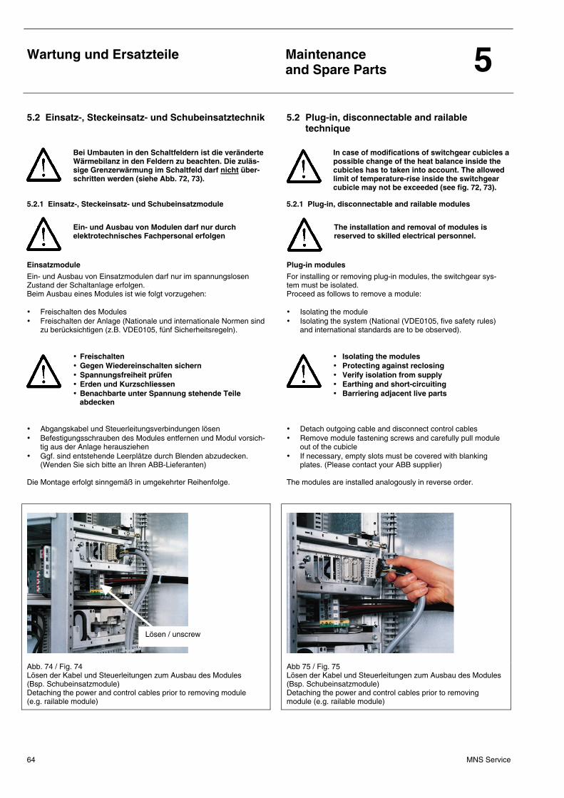
Wartung und Ersatzteile
Maintenance and Spare Parts 5
MNS Service 64
5.2 Einsatz-, Steckeinsatz- und Schubeinsatztechnik 5.2 Plug-in, disconnectable and railable technique
Bei Umbauten in den Schaltfeldern ist die veränderte Wärmebilanz in den Feldern zu beachten. Die zuläs-sige Grenzerwärmung im Schaltfeld darf nicht über-schritten werden (siehe Abb. 72, 73).
In case of modifications of switchgear cubicles a possible change of the heat balance inside the cubicles has to taken into account. The allowed limit of temperature-rise inside the switchgear cubicle may not be exceeded (see fig. 72, 73).
5.2.1 Einsatz-, Steckeinsatz- und Schubeinsatzmodule 5.2.1 Plug-in, disconnectable and railable modules
Ein- und Ausbau von Modulen darf nur durch elektrotechnisches Fachpersonal erfolgen
The installation and removal of modules is reserved to skilled electrical personnel.
Einsatzmodule
Ein- und Ausbau von Einsatzmodulen darf nur im spannungslosen Zustand der Schaltanlage erfolgen. Beim Ausbau eines Modules ist wie folgt vorzugehen: • Freischalten des Modules • Freischalten der Anlage (Nationale und internationale Normen sind
zu berücksichtigen (z.B. VDE0105, fünf Sicherheitsregeln).
• Freischalten • Gegen Wiedereinschalten sichern • Spannungsfreiheit prüfen • Erden und Kurzschliessen • Benachbarte unter Spannung stehende Teile
abdecken • Abgangskabel und Steuerleitungsverbindungen lösen • Befestigungsschrauben des Modules entfernen und Modul vorsich-
tig aus der Anlage herausziehen • Ggf. sind entstehende Leerplätze durch Blenden abzudecken.
(Wenden Sie sich bitte an Ihren ABB-Lieferanten) Die Montage erfolgt sinngemäß in umgekehrter Reihenfolge.
Plug-in modules
For installing or removing plug-in modules, the switchgear sys-tem must be isolated. Proceed as follows to remove a module: • Isolating the module • Isolating the system (National (VDE0105, five safety rules)
and international standards are to be observed).
• Isolating the modules • Protecting against reclosing • Verify isolation from supply • Earthing and short-circuiting • Barriering adjacent live parts
• Detach outgoing cable and disconnect control cables • Remove module fastening screws and carefully pull module
out of the cubicle • If necessary, empty slots must be covered with blanking
plates. (Please contact your ABB supplier) The modules are installed analogously in reverse order.
Abb. 74 / Fig. 74 Lösen der Kabel und Steuerleitungen zum Ausbau des Modules (Bsp. Schubeinsatzmodule) Detaching the power and control cables prior to removing module (e.g. railable module)
Abb 75 / Fig. 75 Lösen der Kabel und Steuerleitungen zum Ausbau des Modules (Bsp. Schubeinsatzmodule) Detaching the power and control cables prior to removing module (e.g. railable module)
Lösen / unscrew
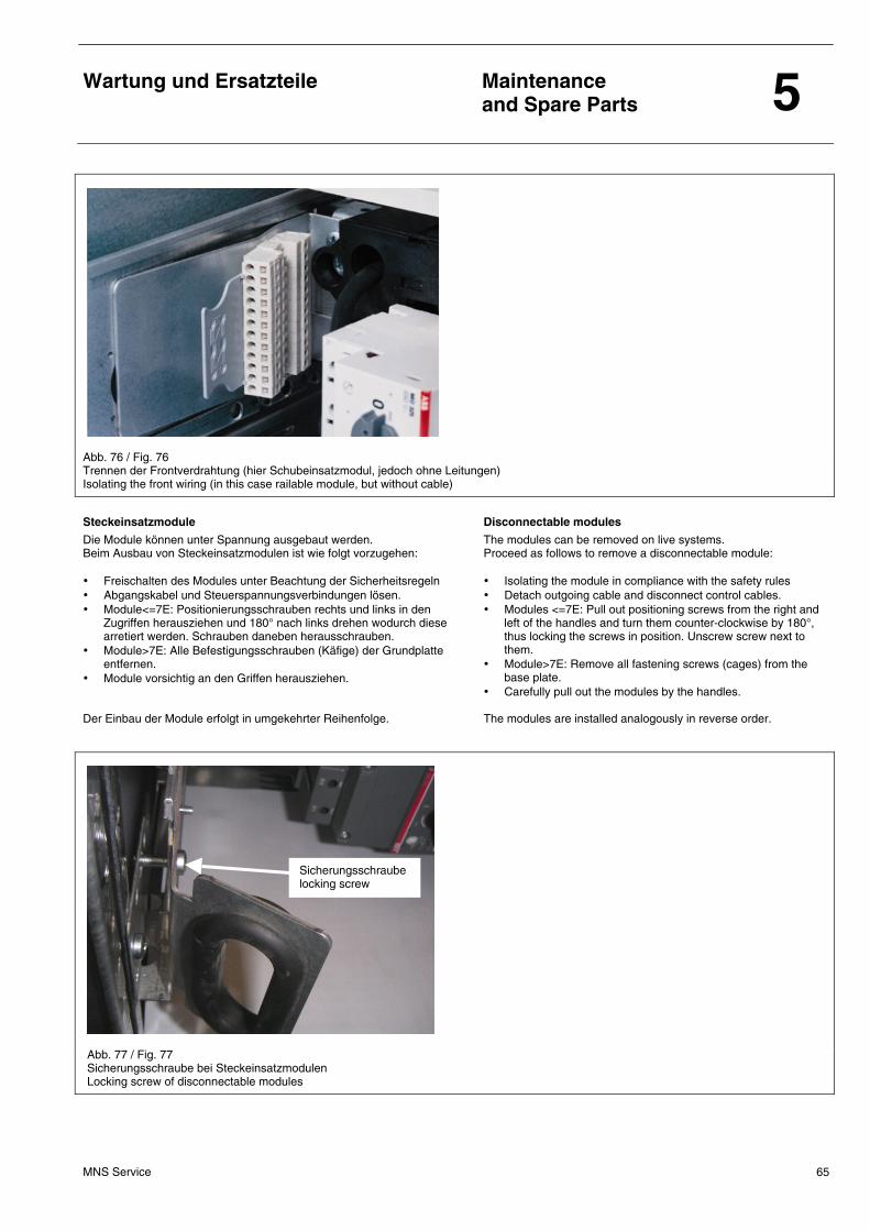
Wartung und Ersatzteile
Maintenance and Spare Parts 5
MNS Service 65
Abb. 76 / Fig. 76 Trennen der Frontverdrahtung (hier Schubeinsatzmodul, jedoch ohne Leitungen) Isolating the front wiring (in this case railable module, but without cable)
Steckeinsatzmodule
Die Module können unter Spannung ausgebaut werden. Beim Ausbau von Steckeinsatzmodulen ist wie folgt vorzugehen: • Freischalten des Modules unter Beachtung der Sicherheitsregeln • Abgangskabel und Steuerspannungsverbindungen lösen. • Module<=7E: Positionierungsschrauben rechts und links in den
Zugriffen herausziehen und 180° nach links drehen wodurch diese arretiert werden. Schrauben daneben herausschrauben.
• Module>7E: Alle Befestigungsschrauben (Käfige) der Grundplatte entfernen.
• Module vorsichtig an den Griffen herausziehen. Der Einbau der Module erfolgt in umgekehrter Reihenfolge.
Disconnectable modules
The modules can be removed on live systems. Proceed as follows to remove a disconnectable module: • Isolating the module in compliance with the safety rules • Detach outgoing cable and disconnect control cables. • Modules <=7E: Pull out positioning screws from the right and
left of the handles and turn them counter-clockwise by 180°, thus locking the screws in position. Unscrew screw next to them.
• Module>7E: Remove all fastening screws (cages) from the base plate.
• Carefully pull out the modules by the handles. The modules are installed analogously in reverse order.
Abb. 77 / Fig. 77 Sicherungsschraube bei Steckeinsatzmodulen Locking screw of disconnectable modules
Sicherungsschraube locking screw
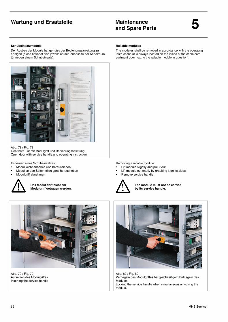
Wartung und Ersatzteile
Maintenance and Spare Parts 5
MNS Service 66
Schubeinsatzmodule
Der Ausbau der Module hat gemäss der Bedienungsanleitung zu erfolgen (diese befindet sich jeweils an der Innenseite der Kabelraum-tür neben einem Schubeinsatz).
Railable modules
The modules shall be removed in accordance with the operating instructions (it is always located on the inside of the cable com-partment door next to the railable module in question).
Abb. 78 / Fig. 78 Geöffnete Tür mit Modulgriff und Bedienungsanleitung Open door with service handle and operating instruction
Entfernen eines Schubeinsatzes: • Modul leicht anheben und herausziehen • Modul an den Seitenteilen ganz herausheben • Modulgriff abnehmen
Das Modul darf nicht am Modulgriff getragen werden.
Removing a railable module: • Lift module slightly and pull it out • Lift module out totally by grabbing it on its sides • Remove service handle
The module must not be carried by its service handle.
Abb. 79 / Fig. 79 Aufsetzen des Modulgriffes Inserting the service handle
Abb. 80 / Fig. 80 Verriegeln des Modulgriffes bei gleichzeitigem Entriegeln des Modules. Locking the service handle when simultaneous unlocking the module.
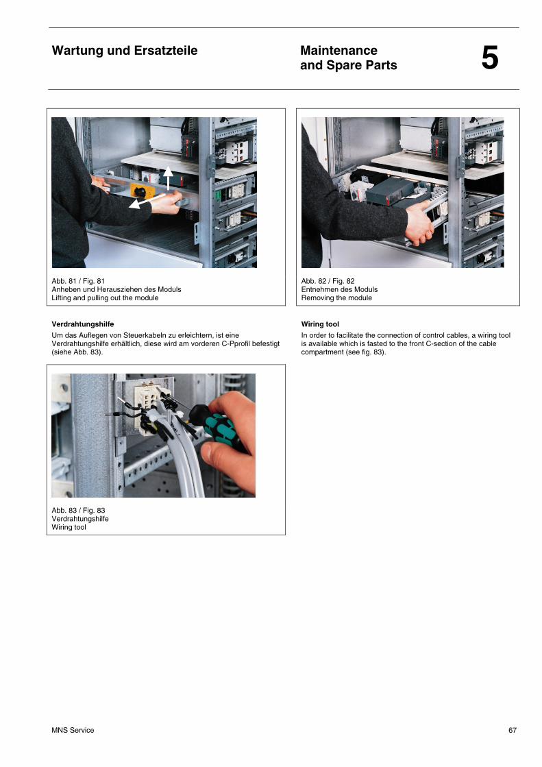
Wartung und Ersatzteile
Maintenance and Spare Parts 5
MNS Service 67
Abb. 81 / Fig. 81 Anheben und Herausziehen des Moduls Lifting and pulling out the module
Abb. 82 / Fig. 82 Entnehmen des Moduls Removing the module
Verdrahtungshilfe
Um das Auflegen von Steuerkabeln zu erleichtern, ist eine Verdrahtungshilfe erhältlich, diese wird am vorderen C-Pprofil befestigt (siehe Abb. 83).
Wiring tool
In order to facilitate the connection of control cables, a wiring tool is available which is fasted to the front C-section of the cable compartment (see fig. 83).
Abb. 83 / Fig. 83 Verdrahtungshilfe Wiring tool
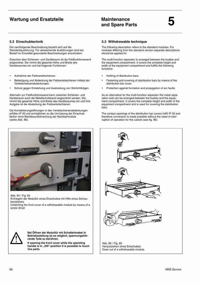
Wartung und Ersatzteile
Maintenance and Spare Parts 5
MNS Service 68
5.3 Einschubtechnik 5.3 Withdrawable technique
Die nachfolgende Beschreibung bezieht sich auf die Standardausführung. Für abweichende Ausführungen sind bei Bedarf im Einzelfall gesonderte Beschreibungen anzufordern. Zwischen dem Schienen- und Geräteraum ist die Feldfunktionswand angeordnet. Sie nimmt die gesamte Höhe und Breite des Geräteraumes ein und hat folgende Funktionen:
• Aufnahme der Feldverteilschienen.
• Befestigung und Abdeckung der Feldverteilschienen mittels der Verteilschienenabdeckungen.
• Schutz gegen Entstehung und Ausbreitung von StörIichtbögen. Alternativ zur Feldfunktionswand kann zwischen Schienen- und Geräteraum auch die Metallschottwand angeordnet werden. Sie nimmt die gesamte Höhe und Breite des Geräteraumes ein und ihre Aufgabe ist die Abdeckung der Feldverteilschienen. Die Kontaktierungsöffnungen in den Verteilschienenabdeckungen erfüllen lP 20 und ermöglichen so die Umrüstung der Einschub-fächer ohne Betriebsunterbrechung der Nachbarmodule (siehe Abb. 86).
The following description refers to the standard modules. For modules differing from the standard version separate descriptions should be applied for. The multi-function separator is arranged between the busbar and the equipment compartment. lt covers the complete height and width of the equipment compartment and fullfils the following functions:
• Holding of distribution bars.
• Fastening and covering of distribution bars by means of the distribution bar cover.
• Protection against formation and propagation of arc faults. As an alternative for the multi-function separator the metal sepa-ration wall can be arranged between the busbar and the equip-ment compartment. It covers the complete height and width of the equipment compartment and is used for covering the distribution bars. The contact openings of the distribution bar covers fulfill IP 20 and therefore conversion is made possible without the need of inter-ruption of operation for the cubicle (see fig. 86).
Abb. 84 / Fig. 84 Entriegeln der Modultür eines Einschubes mit Hilfe eines Schrau-bendrehers Unlatching the front cover of a withdrawable module by means of a screw driver
Bei Öffnen der Modultür mit Schalterknebel in Betriebsstellung ist es möglich, spannungsfüh-rende Teile zu berühren.
If opening the front cover while the operating handle is in „ON“-position it is possible to touch live parts.
Abb. 85 / Fig. 85 Herausziehen eines Einschubes Draw out of a withdrawable module
Wartung und Ersatzteile
Maintenance and Spare Parts 5
MNS Service 69
Der Einschub, d.h. die bewegliche Einheit, kann ohne FreischaItung ausgewechselt oder zu Wartungszwecken aus dem Fach entnommen und wieder eingesetzt werden. Zur Entnahme sind die Einschubgrößen 8E/4 und 8E/2 in der Verfahrstellung des Verriegelungsschalters ohne Anschlag ausziehbar. Die Einschubgrößen 4E bis 48E sind bis zum Anschlag auszuziehen, zu entriegeln und können dann herausgehoben werden. Bei Einschüben mit schwenkbarer Frontblende sind die eingebauten Hauptsicherungen nach dem Entriegeln und Öffnen der Frontblende zugänglich. Die Entriegelung der Frontblende ist in der Betriebs-stellung des Einschubes nur mit Hilfe eines Werkzeuges (Schrau-bendreher) möglich (siehe Abb. 84). Die Verriegelungseinrichtung befindet sich seitlich am Schaltknebel. Zur Umrüstung von kompletten Einschubeinheiten, z.B. Ersatz einer großen Einheit durch mehrere kIeine oder umgekehrt, ist auch das im Gerüst befestigte Einschubfach auszutauschen (siehe Abb. 86/87).
The withdrawable module can be exchanged or removed and replaced in the compartment during maintenance without isola-tion. With the interIocking switch handle in the move position, with-drawable modules size 8E/4 and 8E/2 can be withdrawn without stop. The modules size 4E up to 48E have to be withdrawn up to the stop position, released and then removed completely. Main fuses in withdrawable modules with hinged front cover are accessibIe after the main switching device has been turned OFF and after the front cover has been unlatched. Unlocking the front cover with the module in the operating position can only be achieved by means of a tooI, e.g. a screw driver (see fig. 84). The interlocking mechanism can be found at the side of the switch handle. For conversion or modification of complete withdrawable module units, e.g. replacement of one large unit through several smaller units or vice versa, the frame-mounted compartment has to be exchanged, too (see fig. 86/87).
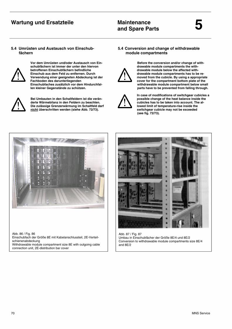
Wartung und Ersatzteile
Maintenance and Spare Parts 5
MNS Service 70
5.4 Umrüsten und Austausch von Einschub-fächern
5.4 Conversion and change of withdrawable module compartments
Vor dem Umrüsten und/oder Austausch von Ein-schubfächern ist immer der unter den hiervon betroffenen Einschubfächern befindliche Einschub aus dem Feld zu entfernen. Durch Verwendung einer geeigneten Abdeckung ist der Fachboden des darunterliegenden Einschubfaches zusätzlich vor dem Hindurchfal-len kleiner Gegenstände zu schützen.
Bei Umbauten in den Schaltfeldern ist die verän-derte Wärmebilanz in den Feldern zu beachten. Die zulässige Grenzerwärmung im Schaltfeld darf nicht überschritten werden (siehe Abb. 72/73).
Before the conversion and/or change of with-drawable module compartments the with-drawable module below the affected with-drawable module compartments has to be re-moved from the cubicle. By using a appropriate cover for the compartment bottom plate of the withdrawable module compartment below small parts have to be prevented from falling through. In case of modifications of switchgear cubicles a possible change of the heat balance inside the cubicles has to be taken into account. The al-lowed limit of temperature-rise inside the switchgear cubicle may not be exceeded (see fig. 72/73).
Abb. 86 / Fig. 86 Einschubfach der Größe 8E mit Kabelanschlussteil, 2E-Verteil-schienenabdeckung Withdrawable module compartment size 8E with outgoing cable connection unit, 2E-distribution bar cover
Abb. 87 / Fig. 87 Umbau in Einschubfächer der Größe 8E/4 und 8E/2 Conversion to withdrawable module compartments size 8E/4 and 8E/2
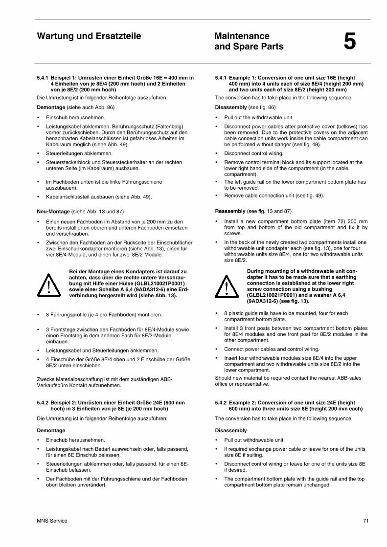
Wartung und Ersatzteile
Maintenance and Spare Parts 5
MNS Service 71
5.4.1 Beispiel 1: Umrüsten einer Einheit Größe 16E = 400 mm in 4 Einheiten von je 8E/4 (200 mm hoch) und 2 Einheiten von je 8E/2 (200 mm hoch)
5.4.1 Example 1: Conversion of one unit size 16E (height 400 mm) into 4 units each of size 8E/4 (height 200 mm) and two units each of size 8E/2 (height 200 mm)
Die Umrüstung ist in folgender Reihenfolge auszuführen:
Demontage (siehe auch Abb. 86)
• Einschub herausnehmen.
• Leistungskabel abklemmen. Berührungsschutz (Faltenbalg) vorher zurückschieben. Durch den Berührungsschutz auf den benachbarten Kabelanschlüssen ist gefahrloses Arbeiten im Kabelraum möglich (siehe Abb. 49).
• SteuerIeitungen abklemmen.
• Steuersteckerblock und Steuersteckerhalter an der rechten unteren Seite (im Kabelraum) ausbauen.
• lm Fachboden unten ist die linke Führungsschiene auszubauen).
• KabelanschlussteiI ausbauen (siehe Abb. 49).
Neu-Montage (siehe Abb. 13 und 87)
• Einen neuen Fachboden im Abstand von je 200 mm zu den bereits installierten oberen und unteren Fachböden einsetzen und verschrauben.
• Zwischen den Fachböden an der Rückseite der Einschubfächer zwei Einschubkondapter montieren (siehe Abb. 13), einen für vier 8E/4-Module, und einen für zwei 8E/2-Module.
Bei der Montage eines Kondapters ist darauf zu achten, dass über die rechte untere Verschrau-bung mit Hilfe einer Hülse (GLBL210021P0001) sowie einer Scheibe A 6,4 (9ADA312-6) eine Erd-verbindung hergestellt wird (siehe Abb. 13).
• 8 Führungsprofile (je 4 pro Fachboden) montieren.
• 3 Frontstege zwischen den Fachböden für 8E/4-Module sowie einen Frontsteg in dem anderen Fach für 8E/2-Module einbauen.
• Leistungskabel und Steuerleitungen anklemmen.
• 4 Einschübe der Größe 8E/4 oben und 2 Einschübe der Größe 8E/2 unten einschieben.
Zwecks Materialbeschaffung ist mit dem zuständigen ABB-Verkaufsbüro Kontakt aufzunehmen.
The conversion has to take place in the following sequence:
Disassembly (see fig. 86)
• Pull out the withdrawable unit.
• Disconnect power cables after protective cover (bellows) has been removed. Due to the protective covers on the adjacent cable connection units work inside the cable compartment can be performed without danger (see fig. 49).
• Disconnect control wiring.
• Remove control terminal block and its support located at the lower right hand side of the compartment (in the cable compartment).
• The left guide rail on the Iower compartment bottom plate has to be removed.
• Remove cable connection unit (see fig. 49).
Reassembly (see fig. 13 and 87)
• Install a new compartment bottom plate (item 72) 200 mm from top and bottom of the old compartment and fix it by screws.
• In the back of the newly created two compartments install one withdrawable unit condapter each (see fig. 13), one for four withdrawable units size 8E/4, one for two withdrawable units size 8E/2.
During mounting of a withdrawable unit con-dapter it has to be made sure that a earthing connection is established at the lower right screw connection using a bushing (GLBL210021P0001) and a washer A 6,4 (9ADA312-6) (see fig. 13).
• 8 plastic guide rails have to be mounted, four for each compartment bottom plate.
• Install 3 front posts between two compartment bottom plates for 8E/4 modules and one front post for 8E/2 modules in the other compartment.
• Connect power cables and control wiring.
• Insert four withdrawable modules size 8E/4 into the upper compartment and two withdrawable units size 8E/2 into the lower compartment.
Should new material be required contact the nearest ABB-sales office or representative.
5.4.2 Beispiel 2: Umrüsten einer Einheit Größe 24E (600 mm hoch) in 3 Einheiten von je 8E (je 200 mm hoch)
5.4.2 Example 2: Conversion of one unit size 24E (height 600 mm) into three units size 8E (height 200 mm each)
Die Umrüstung ist in folgender Reihenfolge auszuführen: Demontage
• Einschub herausnehmen.
• Leistungskabel nach Bedarf auswechseln oder, falls passend, für einen 8E Einschub belassen.
• Steuerleitungen abklemmen oder, falls passend, für einen 8E-Einschub belassen.
• Der Fachboden mit der Führungsschiene und der Fachboden oben bleiben unverändert.
The conversion has to take place in the following sequence: Disassembly
• Pull out withdrawable unit.
• lf required exchange power cable or leave for one of the units size 8E if suiting.
• Disconnect control wiring or Ieave for one of the units size 8E if desired.
• The compartment bottom plate with the guide rail and the top compartment bottom plate remain unchanged.
Wartung und Ersatzteile
Maintenance and Spare Parts 5
MNS Service 72
Neu-Montage
• 2 Kabelanschlussteile (Auswahl siehe Abb. 49).
• Zwei weitere Fachböden im 8E-Raster einsetzen und verschrauben.
• Die zwei neuen Fachböden mit einer Führungsschiene links bestücken sowie die Rollen und Abdeckungen montieren.
• Zwischen den Fachböden rechts im Kabelraum sind je ein Steuersteckerhalter mit einem oder zwei 16-/20-pol. Steuersteckerblöcken (Steuerklemmenblöcken) zu montieren. Bei Montage von nur einem Steuersteckerblock ist dieser im oberen TeiI des Steuersteckerhalters einzusetzen und der untere Teil mit einer Verschlussplatte abzudecken.
• LeistungskabeI mit Berührungsschutz (Faltenbalg) installieren (siehe Abb. 50) und Steuerleitungen anklemmen.
• 3 neue Einschübe der Größe 8E einschieben. Zwecks Materialbeschaffung ist mit dem zuständigen ABB-Verkaufsbüro Kontakt aufzunehmen.
Reassembly
• lnstall 2 outgoing cable connection units (details see fig. 49).
• Insert two new compartment bottom plates with a distance of 8E each and fix them with screws.
• The newIy installed bottom plates must be equipped with the left guide rail and the rollers and covers have to be mounted.
• Between the newly installed compartment bottom plates one control terminal block support per withdrawable module compartment with one or two 16-/20-pole terminal blocks must be mounted on the right hand side (in the cabIe compartment). lf only one terminal block per support is required it must be mounted in the upper part of the cut-out of the support. The lower part has to be covered with a cover plate.
• Connect power cabIes with their protective covers (bellows) (see fig. 50) and also the control wiring.
• lnsert three new withdrawable units size 8E. Should new material be required contact the nearest ABB saIes office or representative.
5.4.3 Beispiel 3: Umrüsten von 6 Einheiten Größe 8E/2 (200 mm hoch) in eine Einheit mit 24E (600 mm hoch)
5.4.3 Example 3: Conversion of 6 units size 8E/2 (height 200 mm) into one unit size 24E (height 600 mm)
Die Umrüstung ist in folgender Reihenfolge auszuführen: Demontage
• 6 Einschübe herausnehmen.
• Leistungskabel und Steuerleitungen abklemmen.
• Die zwei mittleren Fachböden mit Frontstegen und Führungsprofilen ausbauen (siehe Abb. 13).
• Die Führungsprofile und den Frontsteg am unteren Fachboden entfernen (siehe Abb. 13/15).
• Die 3 Einschubkondapter ausbauen (siehe Abb. 13). Neu-Montage
• Ein Kabelanschlussteil (Auswahl siehe Abb. 50) je nach Ausführung des Einschubes montieren. Für Parallelschaltung zur Betriebsstromerhöhung oder für Stern-Dreieck-Abgang können 2 KabelanschlussteiIe montiert werden.
• Die Führungsschiene links am unteren Fachboden montieren (siehe Abb. 15).
• Rollen und Abdeckung im Fachboden montieren (siehe Abb. 15).
• Steuersteckerhalter mit einem oder zwei 16-/20-pol. Steuer-steckerblöcken (Steuerklemmenblöcken) montieren (siehe Abb. 15). Bei Montage von nur einem Steuersteckerblock ist dieser im oberen Teil des Steuersteckerhalters einzusetzen und der untere Teil mit einer Verschlussplatte abzudecken.
• Leistungskabel mit Berührungsschutz (Faltenbalg, siehe Abb. 49) und auch Steuerleitungen anschließen. Bei Parallel-schaltung von 2 KabelanschlussteiIen ist ein zusätzlicher FaltenbaIg erforderlich.
• Neuen Einschub der Größe 24E einschieben.
The conversion has to take place in the following sequence: Disassembly
• Pull out the 6 withdrawable units.
• Disconnect power and control cables and wiring.
• DisassembIe the two middIe compartment bottom plates with front posts and guide rails (see fig. 13).
• Remove guide rail and front post from the lower compartment bottom plate (see fig. 13/15).
• Take out the 3 withdrawable module condapters with their terminal blocks (see fig. 13).
Reassembly • InstalI one outgoing cable connection unit (details see fig. 50)
depending on the module design. Depending on the current or whether a star-delta unit is used two outgoing cabIe connection units can be mounted.
• Install guide rail left on the lower compartment bottom plate (see fig. 15).
• Mount roller and cover in the compartment bottom plate (see fig. 15).
• lnstall control terminal block support with one or two 16-/20-pole control terminal blocks. When only one 16-/20-pole control terminal block is required mount it in the upper part of the support and use a cover for the lower part of the support.
• Connect power cable including protective cover (bellows, see fig. 49) and control wiring. For parallel connection of two outgoing cable connection units an additional bellow is required.
• lnsert new withdrawable unit size 24E.
Wartung und Ersatzteile
Maintenance and Spare Parts 5
MNS Service 73
5.4.4 Beispiel 4: Umrüsten von 3 Einheiten Größe 8E (200 mm hoch) in eine Einheit Größe 24E (600 mm hoch)
5.4.4 Example 4: Conversion of 3 units size 8E (height 200 mm) into one unit size 24E (height 600 mm)
Die Umrüstung ist in folgender Reihenfolge auszuführen: Demontage
• 3 Einschübe herausnehmen.
• Leistungskabel abklemmen. Berührungsschutz (Faltenbalg) vorher zurückschieben (siehe Abb. 49). Durch den Berührungs-schutz auf den benachbarten Kabelanschlüssen ist gefahrloses Arbeiten im KabeIraum möglich.
• Die beiden oberen Steuersteckerhalter mit den 2 Steuerstecker-blöcken (SteuerklemmenbIöcken) ausbauen. Der untere kann unverändert bleiben oder nach Bedarf auf ein oder zwei 16-/20-pol. SteuersteckerbIöcke umgebaut werden. Bei ten auf einen Steuersteckerblock ist dieser im oberen Teil des Steuer-steckerhalters einzusetzen und der untere Teil mit einer Verschlussplatte abzudecken.
• Die zwei mittleren Fachböden mit den linken Führungsschienen entfernen, der untere bleibt unverändert (siehe Abb. 15).
• Je nach Ausführung des Einschubes sind ein oder zwei Kabelanschlussteile zu demontieren. Bei Bedarf evtl. Kabel anschlussteil austauschen (Auswahl siehe Abb. 50). Bei Parallelschaltung zur Betriebsstromerhöhung oder Stern-Dreieck-Abgang sind zwei Kabelanschlussteile zu belassen oder auszutauschen.
Neu-Montage
• Leistungskabel mit Berührungsschutz (Faltenbalg) und Steuerleitungen anschließen (siehe Abb. 49).
• Neuen Einschub Größe 24E einschieben. Zwecks MateriaIbeschaffung ist mit dem zuständigen ABB- Verkaufsbüro Kontakt aufzunehmen.
The conversion has to take place in the following sequence: Disassembly
• Pull out the 3 withdrawable units.
• Disconnect power cables after protective cover (bellows) has been removed (see fig. 49). Due to the protective covers on the adjacent outgoing cable connection units working inside the cable compartment can be performed without danger.
• Take out the two upper control terminal bIock supports with their control terminal blocks. The Iower support may remain unchanged or, if necessary, can be converted to one or two 16-/ 20-pole control terminal blocks. When converting from two to one control terminal block the remaining one must be at the top of the support while the space below has to be covered with a cover.
• Dismantle the two middle compartment bottom plates with their guide rails The lower bottom plate remains unchanged (see fig. 15).
• Depending upon module design remove one or two outgoing cable connection units. When necessary exchange outgoing cable connection unit (details see fig. 50). Depending upon current or whether a star-delta unit is required two outgoing cable connection units have to remain or must be exchanged.
Reassembly
• Connect power cable including protective cover (bellows) and control wiring (see fig. 49).
• lnsert new withdrawable unit size 24E. Should new material be required contact the nearest ABB sales office or representative.
Wartung und Ersatzteile
Maintenance and Spare Parts 5
MNS Service 74
5.5 Überprüfung von MNS-Kontaktsystemen im Rahmen von Anlagenrevisionen
5.5 Examination of MNS contact systems within the scope of plant revisions
Entsprechend den geltenden nationalen und internationalen Normen und Festlegungen (z.B. DlN 57 105 Teil 1 / VDE 0105 Teil 1; BGV A2), sind elektrische Anlagen durch den Betreiber in einem ordnungsgemäßen Zustand zu erhalten. Bei allen Arbeiten, die im Zusammenhang mit den dazu notwendigen Akivitäten stehen, sind zusätzlich zu den gültigen Sicherheitsvor-schriften auch alle relevanten Festlegungen der MNS-Fertigungs-anweisungen sowie MNS-Produktmitteilungen zu berücksichtigen und einzuhalten. Zu den genannten gehören unter anderem:
• „Einbau von Leistungskontakten“
• „Fetten der Leistungskontakte“
• „Anziehdrehmomente von Schraubverbindungen“
die sich ebenfalls in diesem Abschnitt befinden. Jedes Modul (Einschub / Einsatz / SR-Leiste / Einschubkondapter) ist vor jedem Einsetzen in das MNS-Feld (beim ersten Aufbau in der Werkstatt wie auch nach jeder Revision) Sichtkontrollen zu unter-werfen. Die Sichtkontrolle der Kontaktsysteme soll folgende Punkte einschließen bzw. empfehlen wir zu beachten:
• Beschädigungen (wie z.B. Silber- bzw. Zinnschicht abgenutzt, Spuren unzulässiger Erwärmung usw.) an den Kontaktierungsoberflächen der MNS-Kontakte und des Gegenstückes (Feldverteilschiene, Einschubkondapter, Kabelanschlussteil).
• Kontakte beweglich und richtig in Einschubrückwand oder Kontaktapparatgehäuse eingerastet.
• Deformierung der Kontakte (verbogen), mechanische Beschädigungen.
• Fester Sitz der Kontaktfeder (Einschübe 8E/4 und 8E/2) in der vorgebenen Position.
• Aufgequollene lsolierung hinter der Crimpstelle.
• Kontakte gefettet.
According to the applicable national and international standards and provisions (e.g. DlN 57 105 part 1/ VDE 0105 part 1; BGV A2), electrical plants must be maintained in an orderly condition by their operator. For all works in connection with the activities required for this purpose, all relevant determinations of the MNS manufacturing instructions and MNS product information sheets must be observed and complied with in addition to the valid safety regulations and all relevant provisions. The former include the following:
• „Installation of power contacts"
• „Greasing of power contacts“
• „Tightening torques of bolted connections"
which you will find in this chapter, too. Each module (withdrawable / plug-in module, fused SR elements, or withdrawable module condapter) is subject to the following mandatory visual inspections prior to installation in the cubicle (before first installation in the workshop as well as after each revision). The visual inspection of the contact system should include the following items resp. their observation is strongly recommended:
• Damages (e.g. worn silver resp. tin layer, signs of inadmissible heating, etc.) at the contacting surfaces of the MNS contacts and their counterparts (distribution bars, withdrawable module condapter, outgoing cable connection unit).
• Contacts movable and properly snaped into position in the withdrawable module rear wall or contact apparatus housing.
• Deformation of contacts (bent), mechanical damages.
• Medium-force fit of the contact spring (withdrawable modules 8E/4 and 8E/2) in its specified position.
• lnsulation behind crimping swollen.
• Contacts greased.
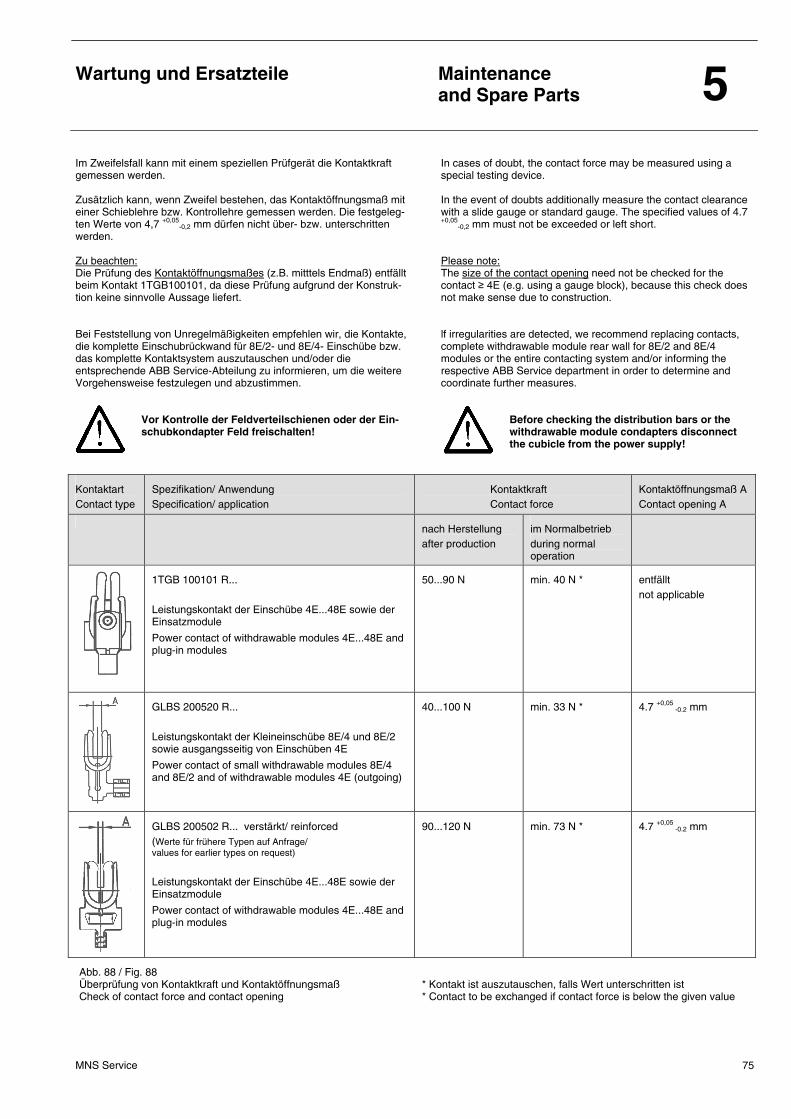
Wartung und Ersatzteile
Maintenance and Spare Parts 5
MNS Service 75
Im Zweifelsfall kann mit einem speziellen Prüfgerät die Kontaktkraft gemessen werden. Zusätzlich kann, wenn Zweifel bestehen, das Kontaktöffnungsmaß mit einer Schieblehre bzw. Kontrollehre gemessen werden. Die festgeleg-ten Werte von 4,7 +0,05
-0,2 mm dürfen nicht über- bzw. unterschritten werden. Zu beachten: Die Prüfung des Kontaktöffnungsmaßes (z.B. mitttels Endmaß) entfällt beim Kontakt 1TGB100101, da diese Prüfung aufgrund der Konstruk-tion keine sinnvolle Aussage liefert. Bei Feststellung von Unregelmäßigkeiten empfehlen wir, die Kontakte, die komplette Einschubrückwand für 8E/2- und 8E/4- Einschübe bzw. das komplette Kontaktsystem auszutauschen und/oder die entsprechende ABB Service-Abteilung zu informieren, um die weitere Vorgehensweise festzulegen und abzustimmen.
In cases of doubt, the contact force may be measured using a special testing device. In the event of doubts additionally measure the contact clearance with a slide gauge or standard gauge. The specified values of 4.7 +0,05
-0,2 mm must not be exceeded or left short. Please note: The size of the contact opening need not be checked for the contact ≥ 4E (e.g. using a gauge block), because this check does not make sense due to construction. lf irregularities are detected, we recommend replacing contacts, complete withdrawable module rear wall for 8E/2 and 8E/4 modules or the entire contacting system and/or informing the respective ABB Service department in order to determine and coordinate further measures.
Vor Kontrolle der Feldverteilschienen oder der Ein-schubkondapter Feld freischalten!
Before checking the distribution bars or the withdrawable module condapters disconnect the cubicle from the power supply!
Kontaktart Contact type
Spezifikation/ Anwendung Specification/ application
Kontaktkraft Contact force
Kontaktöffnungsmaß A Contact opening A
nach Herstellung after production
im Normalbetrieb during normal operation
1TGB 100101 R... Leistungskontakt der Einschübe 4E...48E sowie der Einsatzmodule
Power contact of withdrawable modules 4E...48E and plug-in modules
50...90 N min. 40 N *
entfällt not applicable
GLBS 200520 R... Leistungskontakt der Kleineinschübe 8E/4 und 8E/2 sowie ausgangsseitig von Einschüben 4E
Power contact of small withdrawable modules 8E/4 and 8E/2 and of withdrawable modules 4E (outgoing)
40...100 N min. 33 N * 4.7 +0,05 -0.2 mm
GLBS 200502 R... verstärkt/ reinforced (Werte für frühere Typen auf Anfrage/ values for earlier types on request)
Leistungskontakt der Einschübe 4E...48E sowie der Einsatzmodule
Power contact of withdrawable modules 4E...48E and plug-in modules
90...120 N min. 73 N * 4.7 +0,05 -0.2 mm
Abb. 88 / Fig. 88 Überprüfung von Kontaktkraft und Kontaktöffnungsmaß Check of contact force and contact opening
* Kontakt ist auszutauschen, falls Wert unterschritten ist * Contact to be exchanged if contact force is below the given value
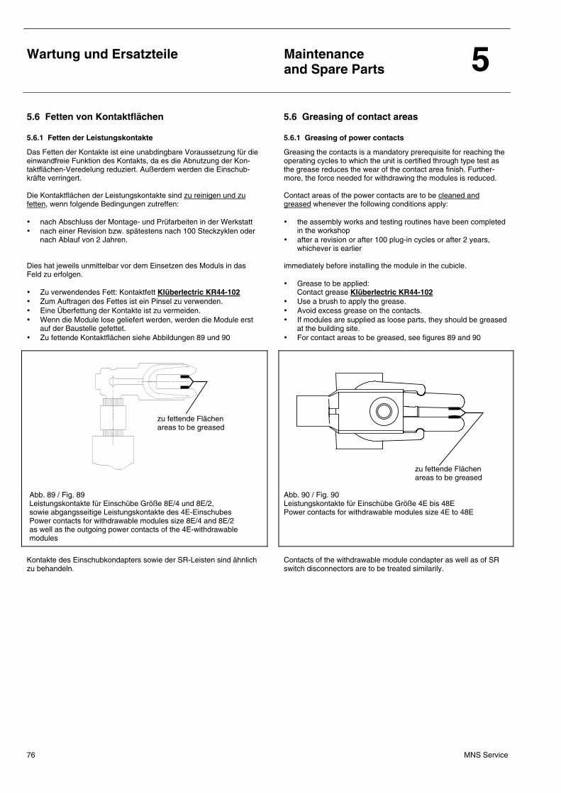
Wartung und Ersatzteile
Maintenance and Spare Parts 5
MNS Service 76
5.6 Fetten von Kontaktflächen 5.6 Greasing of contact areas
5.6.1 Fetten der Leistungskontakte 5.6.1 Greasing of power contacts
Das Fetten der Kontakte ist eine unabdingbare Voraussetzung für die einwandfreie Funktion des Kontakts, da es die Abnutzung der Kon-taktflächen-Veredelung reduziert. Außerdem werden die Einschub-kräfte verringert. Die Kontaktflächen der Leistungskontakte sind zu reinigen und zu fetten, wenn folgende Bedingungen zutreffen: • nach Abschluss der Montage- und Prüfarbeiten in der Werkstatt • nach einer Revision bzw. spätestens nach 100 Steckzyklen oder
nach Ablauf von 2 Jahren. Dies hat jeweils unmittelbar vor dem Einsetzen des Moduls in das Feld zu erfolgen. • Zu verwendendes Fett: Kontaktfett Klüberlectric KR44-102 • Zum Auftragen des Fettes ist ein Pinsel zu verwenden. • Eine Überfettung der Kontakte ist zu vermeiden. • Wenn die Module lose geliefert werden, werden die Module erst
auf der Baustelle gefettet. • Zu fettende Kontaktflächen siehe Abbildungen 89 und 90
Greasing the contacts is a mandatory prerequisite for reaching the operating cycles to which the unit is certified through type test as the grease reduces the wear of the contact area finish. Further-more, the force needed for withdrawing the modules is reduced. Contact areas of the power contacts are to be cleaned and greased whenever the following conditions apply: • the assembly works and testing routines have been completed
in the workshop • after a revision or after 100 plug-in cycles or after 2 years,
whichever is earlier immediately before installing the module in the cubicle. • Grease to be applied:
Contact grease Klüberlectric KR44-102 • Use a brush to apply the grease. • Avoid excess grease on the contacts. • If modules are supplied as loose parts, they should be greased
at the building site. • For contact areas to be greased, see figures 89 and 90
Abb. 89 / Fig. 89 Leistungskontakte für Einschübe Größe 8E/4 und 8E/2, sowie abgangsseitige Leistungskontakte des 4E-Einschubes Power contacts for withdrawable modules size 8E/4 and 8E/2 as well as the outgoing power contacts of the 4E-withdrawable modules
Abb. 90 / Fig. 90 Leistungskontakte für Einschübe Größe 4E bis 48E Power contacts for withdrawable modules size 4E to 48E
Kontakte des Einschubkondapters sowie der SR-Leisten sind ähnlich zu behandeln.
Contacts of the withdrawable module condapter as well as of SR switch disconnectors are to be treated similarily.
zu fettende Flächen areas to be greased
zu fettende Flächen areas to be greased
Wartung und Ersatzteile
Maintenance and Spare Parts 5
MNS Service 77
Bei lose zu liefernden Einschüben werden die Kontakte erst auf der Baustelle gefettet. Hierzu sind den Einschüben Tuben mit je 7 g (8 ml) lnhalt beizufügen: Für 1 bis 4 Einschübe Größe 8E/4 und 8E/2 • je eine Tube Für Einschübe Größe 4E bis 48E • je 8 Kontakte je 0,5 Tuben Für Einsätze • bis 400 A (je 4 Kontakte) je 0,25 Tuben
• über 400 A (je 4 Kontakte) je 1 Tube Vor der Transportverpackung ist die entsprechende Anzahl durch die fertigende Abteilung an den Einschüben anzubringen (Tuben werden am Einschubgriff befestigt; je Verpackungseinheit mindestens eine Tube, bei größeren Lieferungen an einen Kunden kann das Fett auch in Dosen mitgeliefert werden). Beispiel: • 1 Einschub Größe 8E, 250 A (8 Kontakte) 1 Tube
• 2 Einschübe Größe 8E, 250 A (8 Kontakte) 1 Tube
• 3 Einschübe Größe 8E, 250 A (8 Kontakte) 2 Tuben
Withdrawable modules which are to be supplied separately, the contacts should only be greased on site. The following quantities of 7 g (8 ml) tubes are to be supplied together with the modules for this purpose: For 1 up to 4 modules of size 8E/4 and 8E/2 • 1 tube each For module sizes 4E up to 48E • 8 contacts each 0.5 tubes For plug-in modules • up to 400 A, 4 contacts each 0.25 tubes
• over 400 A, 4 contacts each 1 tube Prior to transport packaging the appropriate number of tubes has to be fixed to the modules by the manufacturing department (tubes are fixed to the withdrawable module handle, at least one tube per packaging unit, in case of major deliveries to one customer the grease can also be supplied in tins). Example: • 1 module size 8E, 250 A (8 contacts) 1 tube
• 2 modules size 8E, 250 A (8 contacts) 1 tube
• 3 modules size 8E, 250 A (8 contacts) 2 tubes
Ident-Nummern des Kontaktfettes
Dose mit 1 kg Inhalt 1TGB000172R1000 Tube mit 7 g (8 ml) Inhalt 1TGB000172R0008
Ident numbers of the contact grease
Tin containing 1 kg of grease 1TGB000172R1000 Tube containing 7 g (8 ml) of grease 1TGB000172R0008
5.6.2 Fetten der Sicherungseinsätze 5.6.2 Greasing the fuse links
Auch die Kontaktfahnen der NH-Sicherungen müssen vor jedem Einsetzen in die Fassung bei allen Arten von Schaltgeräten (OS / OESA; SLP/ XLP; SR-Leisten etc.) gefettet werden. Wenn die Siche-rungen lose mitgeliefert werden, sind je Modul (1 Satz = maximal 4 Sicherungen für alle Größen) 0,5 Tuben Kontaktfett erforderlich.
The contact lugs of the LV HRC fuses must also be greased every time before being inserted into the fuse holder of any type of switching device (OS / OESA, SLP/ XLP, SR elements, etc.). If the fuses are supplied loosely, 0.5 tubes of contact grease are re-quired for each module (1 set = maximally 4 fuses for all sizes).
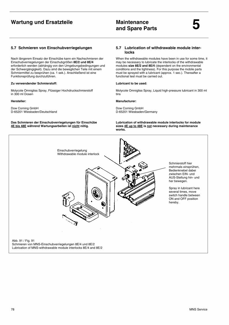
Wartung und Ersatzteile
Maintenance and Spare Parts 5
MNS Service 78
5.7 Schmieren von Einschubverriegelungen 5.7 Lubrication of withdrawable module inter-locks
Nach längerem Einsatz der Einschübe kann ein Nachschmieren der Einschubverriegelungen der Einschubgrößen 8E/2 und 8E/4 erforderlich werden (abhängig von den Umgebungsbedingungen und der Schwergängigkeit). Dazu sind die beweglichen Teile mit einem Schmiermittel zu besprühen (ca. 1 sek.). Anschließend ist eine Funktionsprüfung durchzuführen. Zu verwendender Schmierstoff: Molycote Omnigliss Spray, Flüssiger Hochdruckschmierstoff in 300 ml Dosen Hersteller: Dow Corning GmbH D-65201 Wiesbaden/Deutschland Das Schmieren der Einschubverriegelungen für Einschübe 4E bis 48E während Wartungsarbeiten ist nicht nötig.
When the withdrawable modules have been in use for some time, it may be necessary to lubricate the interlocks of the withdrawable modules size 8E/2 and 8E/4 (dependent on the environmental conditions and the tightness). For this purpose the mobile parts must be sprayed with a lubricant (approx. 1 sec.). Thereafter a functional test must be carried out. Lubricant to be used: Molycote Omnigliss Spray, Liquid high-pressure lubricant in 300 ml tins Manufacturer: Dow Corning GmbH D-65201 Wiesbaden/Germany Lubrication of withdrawable module interlocks for module sizes 4E up to 48E is not necessary during maintenance works.
Abb. 91 / Fig. 91 Schmieren von MNS-Einschubverriegelungen 8E/4 und 8E/2 Lubrication of MNS-withdrawable module interlocks 8E/4 and 8E/2
Einschubverriegelung Withdrawable module interlock
Schmierstoff hier mehrmals einsprühen, Bedienknebel dabei zwischen EIN- und AUS-Stellung hin- und her bewegen. Spray in lubricant here several times, move switch handle between ON and OFF position hereby.
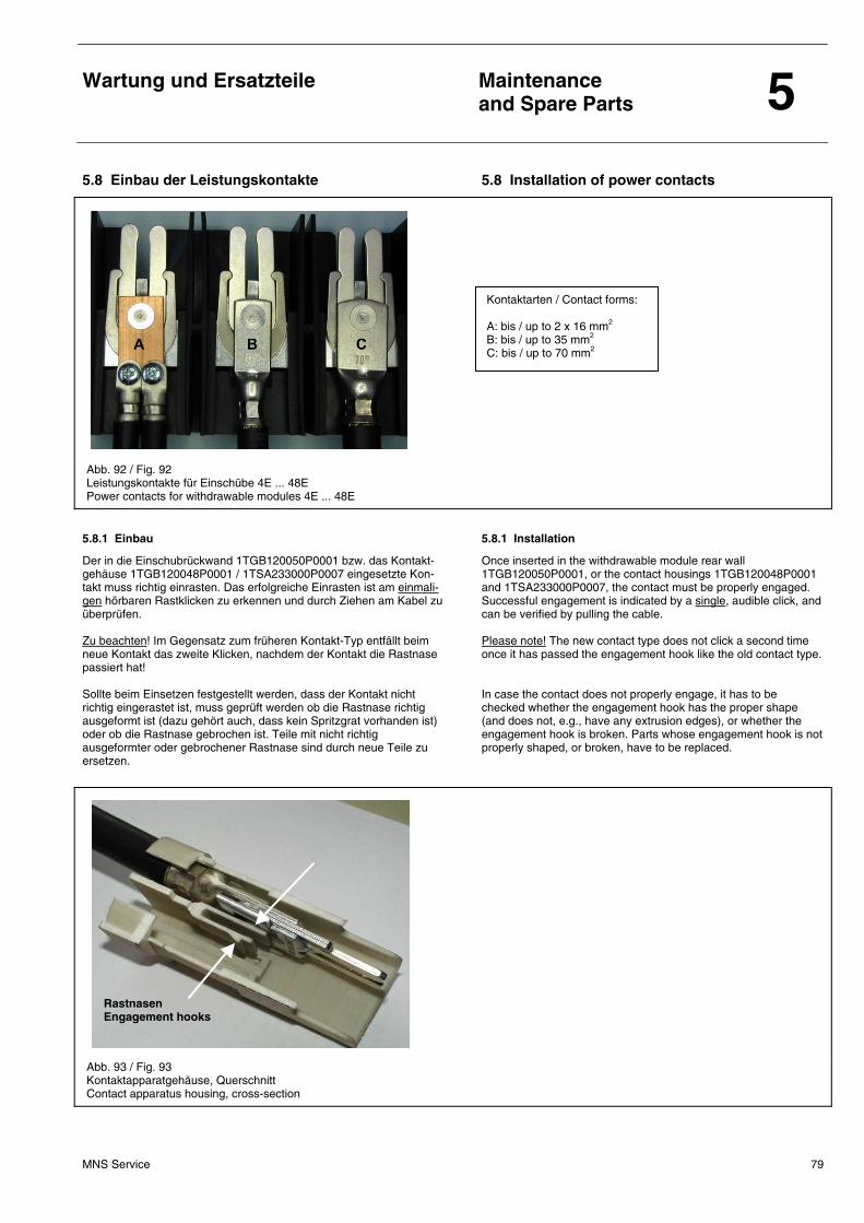
Wartung und Ersatzteile
Maintenance and Spare Parts 5
MNS Service 79
5.8 Einbau der Leistungskontakte 5.8 Installation of power contacts
Abb. 92 / Fig. 92 Leistungskontakte für Einschübe 4E ... 48E Power contacts for withdrawable modules 4E ... 48E
5.8.1 Einbau 5.8.1 Installation
Der in die Einschubrückwand 1TGB120050P0001 bzw. das Kontakt-gehäuse 1TGB120048P0001 / 1TSA233000P0007 eingesetzte Kon-takt muss richtig einrasten. Das erfolgreiche Einrasten ist am einmali-gen hörbaren Rastklicken zu erkennen und durch Ziehen am Kabel zu überprüfen. Zu beachten! Im Gegensatz zum früheren Kontakt-Typ entfällt beim neue Kontakt das zweite Klicken, nachdem der Kontakt die Rastnase passiert hat! Sollte beim Einsetzen festgestellt werden, dass der Kontakt nicht richtig eingerastet ist, muss geprüft werden ob die Rastnase richtig ausgeformt ist (dazu gehört auch, dass kein Spritzgrat vorhanden ist) oder ob die Rastnase gebrochen ist. Teile mit nicht richtig ausgeformter oder gebrochener Rastnase sind durch neue Teile zu ersetzen.
Once inserted in the withdrawable module rear wall 1TGB120050P0001, or the contact housings 1TGB120048P0001 and 1TSA233000P0007, the contact must be properly engaged. Successful engagement is indicated by a single, audible click, and can be verified by pulling the cable. Please note! The new contact type does not click a second time once it has passed the engagement hook like the old contact type. In case the contact does not properly engage, it has to be checked whether the engagement hook has the proper shape (and does not, e.g., have any extrusion edges), or whether the engagement hook is broken. Parts whose engagement hook is not properly shaped, or broken, have to be replaced.
Abb. 93 / Fig. 93 Kontaktapparatgehäuse, Querschnitt Contact apparatus housing, cross-section
Kontaktarten / Contact forms: A: bis / up to 2 x 16 mm2 B: bis / up to 35 mm2 C: bis / up to 70 mm2
Rastnasen Engagement hooks
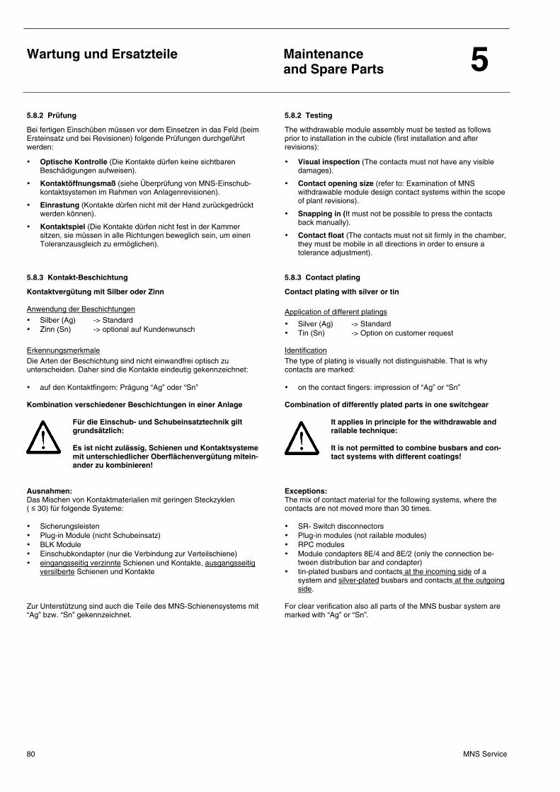
Wartung und Ersatzteile
Maintenance and Spare Parts 5
MNS Service 80
5.8.2 Prüfung 5.8.2 Testing
Bei fertigen Einschüben müssen vor dem Einsetzen in das Feld (beim Ersteinsatz und bei Revisionen) folgende Prüfungen durchgeführt werden:
• Optische Kontrolle (Die Kontakte dürfen keine sichtbaren Beschädigungen aufweisen).
• Kontaktöffnungsmaß (siehe Überprüfung von MNS-Einschub-kontaktsystemen im Rahmen von Anlagenrevisionen).
• Einrastung (Kontakte dürfen nicht mit der Hand zurückgedrückt werden können).
• Kontaktspiel (Die Kontakte dürfen nicht fest in der Kammer sitzen, sie müssen in alle Richtungen beweglich sein, um einen Toleranzausgleich zu ermöglichen).
The withdrawable module assembly must be tested as follows prior to installation in the cubicle (first installation and after revisions):
• Visual inspection (The contacts must not have any visible damages).
• Contact opening size (refer to: Examination of MNS withdrawable module design contact systems within the scope of plant revisions).
• Snapping in (It must not be possible to press the contacts back manually).
• Contact float (The contacts must not sit firmly in the chamber, they must be mobile in all directions in order to ensure a tolerance adjustment).
5.8.3 Kontakt-Beschichtung 5.8.3 Contact plating
Kontaktvergütung mit Silber oder Zinn Anwendung der Beschichtungen
• Silber (Ag) -> Standard • Zinn (Sn) -> optional auf Kundenwunsch
Contact plating with silver or tin
Application of different platings
• Silver (Ag) -> Standard • Tin (Sn) -> Option on customer request
Erkennungsmerkmale Die Arten der Beschichtung sind nicht einwandfrei optisch zu unterscheiden. Daher sind die Kontakte eindeutig gekennzeichnet: • auf den Kontaktfingern: Prägung “Ag” oder “Sn”
Identification The type of plating is visually not distinguishable. That is why contacts are marked: • on the contact fingers: impression of “Ag” or “Sn”
Kombination verschiedener Beschichtungen in einer Anlage Für die Einschub- und Schubeinsatztechnik gilt grundsätzlich: Es ist nicht zulässig, Schienen und Kontaktsysteme mit unterschiedlicher Oberflächenvergütung mitein-ander zu kombinieren!
Ausnahmen: Das Mischen von Kontaktmaterialien mit geringen Steckzyklen ( ≤ 30) für folgende Systeme: • Sicherungsleisten • Plug-in Module (nicht Schubeinsatz) • BLK Module • Einschubkondapter (nur die Verbindung zur Verteilschiene) • eingangsseitig verzinnte Schienen und Kontakte, ausgangsseitig
versilberte Schienen und Kontakte Zur Unterstützung sind auch die Teile des MNS-Schienensystems mit “Ag” bzw. “Sn” gekennzeichnet.
Combination of differently plated parts in one switchgear
It applies in principle for the withdrawable and railable technique: It is not permitted to combine busbars and con-tact systems with different coatings!
Exceptions: The mix of contact material for the following systems, where the contacts are not moved more than 30 times. • SR- Switch disconnectors • Plug-in modules (not railable modules) • RPC modules • Module condapters 8E/4 and 8E/2 (only the connection be-
tween distribution bar and condapter) • tin-plated busbars and contacts at the incoming side of a
system and silver-plated busbars and contacts at the outgoing side.
For clear verification also all parts of the MNS busbar system are marked with “Ag” or “Sn”.
Wartung und Ersatzteile
Maintenance and Spare Parts 5
MNS Service 81
5.9 Lackschäden 5.9 Paintwork damage
5.9.1 Vorbereitung der Schadstelle 5.9.1 Preparation of the damaged Iocation
Durch Fett/Öl verunreinigte Oberflächen oder Stellen werden mit einem Reinigungsmittel (aliphatisch) mittels eines Leinentuches gesäubert.
Surfaces or locations soiled by grease/oil shall be cleaned with an aliphatic cleaning agent using a linen cloth.
5.9.2 Ausführung 5.9.2 Execution
Das Farbreparatur-Gebinde, das farblich auf die jeweilige Anlage abgestimmt ist und beiliegt (falls bestellt), dient zur Ausbesserung von Lackschäden. Der in dem kleinen Behälter beigefügte Härter wird komplett in den größeren mit Lack gefüllten Behälter gegeben. Die Menge des Härters ist genau auf die Menge des Lackes abgestimmt. Sind Härter und Lack gut miteinander vermischt, dann erfolgt der Anstrich mit einem Pinsel oder einer Lammfellrolle auf die betreffende Oberfläche. Eine Ausbesserung kann auch punktuell erfolgen, ist aber abhängig von der Oberflächenvorbereitung und/oder vom „Handling".
The paintwork repair set whose colour matches that of the plant to which it is attached (if ordered) shall be used for paintwork repairs. The hardening agent in the small container shall be completely added to the Iarger container filled with paint. The quantity of hardening agent exactly matches the quantity of the paint. After hardening agent and paint have been thoroughly mixed the mixture shall be appIied using a brush or a lambskin paint roller to the surface to be repaired. Small marks may be repaired isolated; but the success depends on the surface preparation and/or the „handling".
5.10 Mechanische Schäden 5.10 Mechanical damage
5.10.1 Vorbereitung der Schadstelle 5.10.1 Preparation of the damaged Iocation
Treten größere Beschädigungen auf, werden die betreffenden Schadstellen mit Schleifpapier (400-Körnung) angeschliffen. Anschließend ist die Schadstelle mit einem Leinentuch oder Pressluft von entstandenem Staub zu reinigen.
When major damage to Iarge areas has occurred the respective surfaces shalI be ground with abrasive paper (grade 400). The damaged area has then to be wiped with a linen cloth or cleaned with compressed air to remove the dust.
5.10.2 Ausführung 5.10.2 Execution
Mit einer Ziehspachtel wird die Spachtelmasse (Alkydharzbasis) oberflächenbündig aufgetragen. Die Spachtelmasse härtet „über Nacht" aus. Danach muss die ausgebesserte Stelle erneut leicht angeschliffen werden. Anschließend muss, wie unter Lackschäden beschrieben, vorgegangen werden.
A filler material (aIkyd resin basis) shalI be applied flush with the surface using a drawing scraper. The filler shall be left to set over night. The filled-in location has again to be slightIy ground. Thereafter the paint has to be appIied as described above.
5.10.3 Material (siehe auch Abschnitt 5.12) 5.10.3 Materials (see also section 5.12)
Farbe: RAL .... (z.B. 7035, hellgrau) (2 Komponenten Kunstharzlack) Ausbesserungslack: RAL .... und Härter (Farbreparatur-Gebinde) Spachtelmasse: Auf Alkydharzbasis Reinigungsmittel: Aliphatisch (z. B. Testbenzin)
Colour: RAL .... (e.g. 7035, light-grey) (2-component synthetic resin varnish) Repair paint: RAL .... and hardener (paint repair set) Filler: Alkyd resin base Cleaning agent: Aliphatic (e.g. white spirit)
5.10.4 Werkzeug 5.10.4 Tools
Reinigung: Leinentuch (darf nicht fusseln) Schleifpapier (400-Körnung) Farbanstrich: Pinsel oder Lammfellrolle Ausbesserung: Ziehspachtel
For cleaning: Linen cIoth (lint-free) Abrasive paper (grade 400) For painting: Brush or lambskin paint rolIer For repair: Scraper
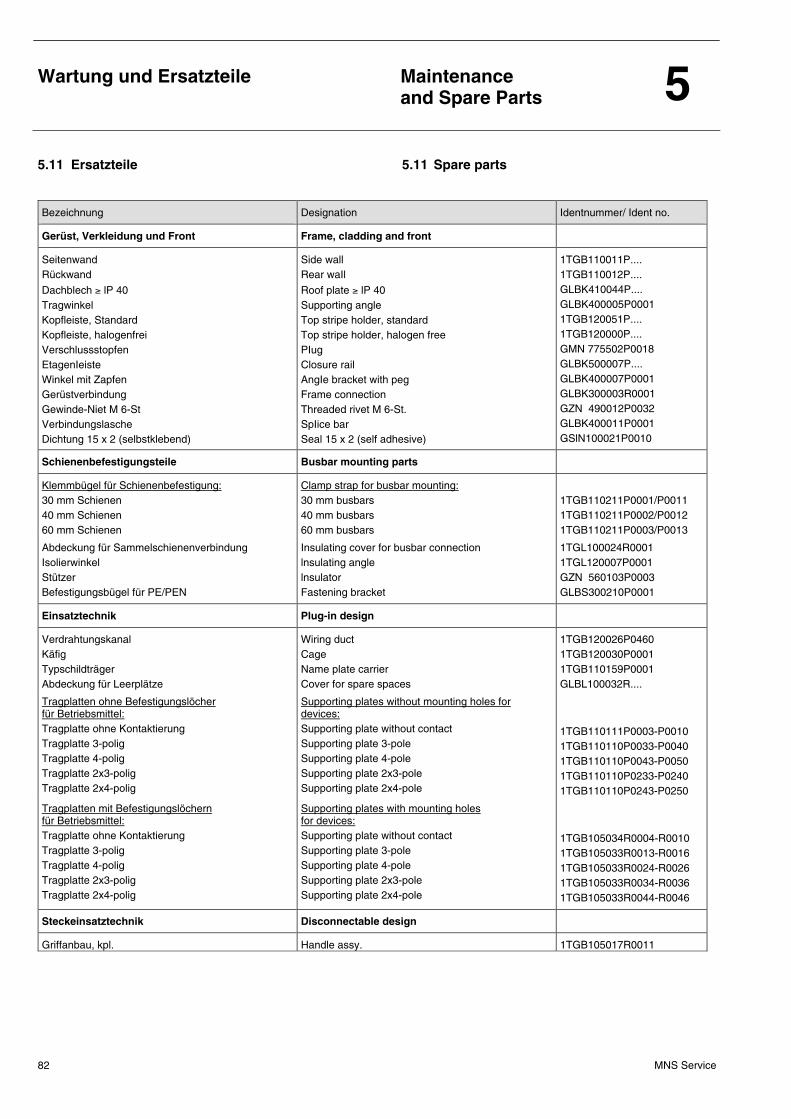
Wartung und Ersatzteile
Maintenance and Spare Parts 5
MNS Service 82
5.11 Ersatzteile 5.11 Spare parts
Bezeichnung Designation Identnummer/ Ident no.
Gerüst, Verkleidung und Front Frame, cladding and front
Seitenwand Rückwand
Dachblech ≥ lP 40 Tragwinkel Kopfleiste, Standard Kopfleiste, halogenfrei Verschlussstopfen EtagenIeiste Winkel mit Zapfen Gerüstverbindung Gewinde-Niet M 6-St Verbindungslasche Dichtung 15 x 2 (selbstklebend)
Side wall Rear waIl
Roof plate ≥ lP 40 Supporting angle Top stripe holder, standard Top stripe holder, halogen free PIug Closure rail AngIe bracket with peg Frame connection Threaded rivet M 6-St. SpIice bar Seal 15 x 2 (self adhesive)
1TGB110011P.... 1TGB110012P.... GLBK410044P.... GLBK400005P0001 1TGB120051P.... 1TGB120000P.... GMN 775502P0018 GLBK500007P.... GLBK400007P0001 GLBK300003R0001 GZN 490012P0032 GLBK400011P0001 GSlN100021P0010
Schienenbefestigungsteile Busbar mounting parts
Klemmbügel für Schienenbefestigung: 30 mm Schienen 40 mm Schienen 60 mm Schienen
Clamp strap for busbar mounting: 30 mm busbars 40 mm busbars 60 mm busbars
1TGB110211P0001/P0011 1TGB110211P0002/P0012 1TGB110211P0003/P0013
Abdeckung für Sammelschienenverbindung Isolierwinkel Stützer Befestigungsbügel für PE/PEN
Insulating cover for busbar connection lnsulating angle lnsulator Fastening bracket
1TGL100024R0001 1TGL120007P0001 GZN 560103P0003 GLBS300210P0001
Einsatztechnik Plug-in design
Verdrahtungskanal Käfig Typschildträger Abdeckung für Leerplätze
Wiring duct Cage Name plate carrier Cover for spare spaces
1TGB120026P0460 1TGB120030P0001 1TGB110159P0001 GLBL100032R....
Tragplatten ohne Befestigungslöcher für Betriebsmittel: Tragplatte ohne Kontaktierung Tragplatte 3-polig Tragplatte 4-polig Tragplatte 2x3-polig Tragplatte 2x4-polig
Supporting plates without mounting holes for devices: Supporting plate without contact Supporting plate 3-pole Supporting plate 4-pole Supporting plate 2x3-pole Supporting plate 2x4-pole
1TGB110111P0003-P0010 1TGB110110P0033-P0040 1TGB110110P0043-P0050 1TGB110110P0233-P0240 1TGB110110P0243-P0250
Tragplatten mit Befestigungslöchern für Betriebsmittel: Tragplatte ohne Kontaktierung Tragplatte 3-polig Tragplatte 4-polig Tragplatte 2x3-polig Tragplatte 2x4-polig
Supporting plates with mounting holes for devices: Supporting plate without contact Supporting plate 3-pole Supporting plate 4-pole Supporting plate 2x3-pole Supporting plate 2x4-pole
1TGB105034R0004-R0010 1TGB105033R0013-R0016 1TGB105033R0024-R0026 1TGB105033R0034-R0036 1TGB105033R0044-R0046
Steckeinsatztechnik Disconnectable design
Griffanbau, kpl. Handle assy. 1TGB105017R0011
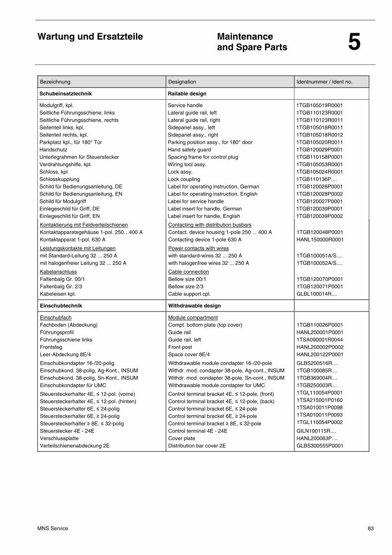
Wartung und Ersatzteile
Maintenance and Spare Parts 5
MNS Service 83
Bezeichnung Designation Identnummer / Ident no.
Schubeinsatztechnik Railable design
Modulgriff, kpl. Seitliche Führungsschiene, links Seitliche Führungsschiene, rechts Seitenteil links, kpl. Seitenteil rechts, kpl. Parkplatz kpl., für 180° Tür Handschutz Unterlegrahmen für Steuerstecker Verdrahtungshilfe, kpl. Schloss, kpl Schlosskupplung Schild für Bedienungsanleitung, DE Schild für Bedienungsanleitung, EN Schild für Modulgriff Einlegeschild für Griff, DE Einlegeschild für Griff, EN
Service handle Lateral guide rail, left Lateral guide rail, right Sidepanel assy., left Sidepanel assy., right Parking position assy., for 180° door Hand safety guard Spacing frame for control plug Wiring tool assy. Lock assy. Lock coupling Label for operating instruction, German Label for operating instruction, English Label for service handle Label insert for handle, German Label insert for handle, English
1TGB105019R0001 1TGB110123R0001 1TGB110123R0011 1TGB105018R0011 1TGB105018R0012 1TGB105020R0011 1TGB120029P0001 1TGB110158P0001 1TGB105053R0001 1TGB105024R0001 1TGB110136P.... 1TGB120028P0001 1TGB120028P0002 1TGB120027P0001 1TGB120039P0001 1TGB120039P0002
Kontaktierung mit Feldverteilschienen Kontaktapparategehäuse 1-pol. 250…400 A Kontaktapparat 1-pol. 630 A
Contacting with distribution busbars Contact. device housing 1-pole 250 ... 400 A Contacting device 1-pole 630 A
1TGB120048P0001 HANL150000R0001
Leistungskontakte mit Leitungen mit Standard-Leitung 32 ... 250 A mit halogenfreier Leitung 32 ... 250 A
Power contacts with wires with standard-wires 32 ... 250 A with halogenfree wires 32 ... 250 A
1TGB100051A/S.... 1TGB100052A/S....
Kabelanschluss Faltenbalg Gr. 00/1 Faltenbalg Gr. 2/3 KabeIeisen kpl.
Cable connection Bellow size 00/1 Bellow size 2/3 Cable support cpl.
1TGB120070P0001 1TGB120071P0001 GLBL100014R....
Einschubtechnik Withdrawable design
Einschubfach Fachboden (Abdeckung) Führungsprofil Führungsschiene links Frontsteg Leer-Abdeckung 8E/4
Module compartment Compt. bottom plate (top cover) Guide rail Guide raiI, left Front post Space cover 8E/4
1TGB110026P0001 HANL200001P0001 1TSA090001R0044 HANL200002P0002 HANL200122P0001
Einschubkondapter 16-/20-polig Einschubkond. 38-polig, Ag-Kont., INSUM Einschubkond. 38-polig, Sn-Kont., INSUM Einschubkondapter für UMC
Withdrawable module condapter 16-/20-pole Withdr. mod. condapter 38-pole, Ag-cont., INSUM Withdr. mod. condapter 38-pole, Sn-cont., INSUM Withdrawable module condapter for UMC
GLBS200516R.... 1TGB100085R.... 1TGB369004R.... 1TGB250003R....
Steuersteckerhalter 4E, ≤ 12-pol. (vorne) Steuersteckerhalter 4E, ≤ 12-pol. (hinten) Steuersteckerhalter 6E, ≤ 24-polig Steuersteckerhalter 6E, ≥ 24-polig Steuersteckerhalter ≥ 8E, ≤ 32-polig
Control terminal bracket 4E, ≤ 12-pole, (front) Control terminal bracket 4E, ≤ 12-pole, (back) Control terminal bracket 6E, ≤ 24-pole Control terminal bracket 6E, ≥ 24-pole Control terminal bracket ≥ 8E, ≤ 32-pole
1TGL110054P0001 1TSA215001P0160 1TSA010011P0098 1TSA010011P0093 1TGL110054P0002
Steuerstecker 4E - 24E Verschlussplatte
Control terminal 4E - 24E Cover plate
GILN100115R.... HANL200063P....
Verteilschienenabdeckung 2E Distribution bar cover 2E GLBS300555P0001
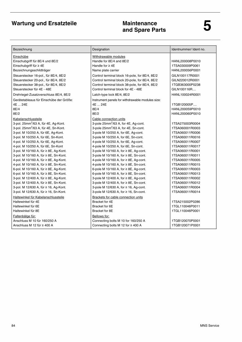
Wartung und Ersatzteile
Maintenance and Spare Parts 5
MNS Service 84
Bezeichnung Designation Identnummer/ Ident no.
Einschübe Einschubgriff für 8E/4 und 8E/2 Einschubgriff für ≥ 4E Bezeichnungsschildträger
Withdrawable modules Handle for 8E/4 and 8E/2 Handle for ≥ 4E Name plate carrier
HANL200008P0010 1TSA030009P0061 HANL200056P0001
Steuerstecker 16-pol., für 8E/4, 8E/2 Steuerstecker 20-pol., für 8E/4, 8E/2 Steuerstecker 38-pol., für 8E/4, 8E/2 Steuerstecker für 4E - 48E
ControI terminal block 16-poIe, for 8E/4, 8E/2 ControI terminal block 20-poIe, for 8E/4, 8E/2 ControI terminal block 38-poIe, for 8E/4, 8E/2 Control terminal block for 4E - 48E
GILN100117R0001 GILN220012R0001 1TGB363000P0238 GILN100116R....
Drehriegel-Zusatzverschluss 8E/4, 8E/2 Latch-type lock 8E/4, 8E/2 HANL100024R0001
Gerätetableaus für Einschübe der Größe: 4E ... 24E 8E/4 8E/2
lnstrument panels for withdrawable modules size: 4E ... 24E 8E/4 8E/2
1TGB120005P.... HANL200059P0010 HANL200060P0010
Kabelanschlussteile 3-pol. 25mm2/63 A, für 4E, Ag-Kont. 3-pol. 25mm2/63 A, für 4E, Sn-Kont. 3-pol. M 10/250 A, für 6E, Ag-Kont. 3-pol. M 10/250 A, für 6E, Sn-Kont. 4-pol. M 10/250 A, für 6E, Ag-Kont. 4-pol. M 10/250 A, für 6E, Sn-Kont 3-pol. M 10/160 A, für ≥ 8E, Ag-Kont. 3-pol. M 10/160 A, für ≥ 8E, Sn-Kont. 4-pol. M 10/160 A, für ≥ 8E, Ag-Kont. 4-pol. M 10/160 A, für ≥ 8E, Sn-Kont. 6-pol. M 10/160 A, für ≥ 8E, Ag-Kont. 6-pol. M 10/160 A, für ≥ 8E, Sn-Kont. 3-pol. M 12/400 A, für ≥ 8E, Ag-Kont. 3-pol. M 12/400 A, für ≥ 8E, Sn-Kont. 3-pol. M 12/630 A, für ≥ 16, Ag-Kont. 3-pol. M 12/630 A, für ≥ 16, Sn-Kont.
Cable connection units 3-pole 25mm2/63 A, for 4E, Ag-cont. 3-pole 25mm2/63 A, for 4E, Sn-cont. 3-pole M 10/250 A, for 6E, Ag-cont. 3-pole M 10/250 A, for 6E, Sn-cont. 4-pole M 10/250 A, for 6E, Ag-cont. 4-pole M 10/250 A, for 6E, Sn-cont. 3-pole M 10/160 A, for ≥ 8E, Ag-cont. 3-pole M 10/160 A, for ≥ 8E, Sn-cont. 4-pole M 10/160 A, for ≥ 8E, Ag-cont. 4-pole M 10/160 A, for ≥ 8E, Sn-cont. 6-pole M 10/160 A, for ≥ 8E, Ag-cont. 6-pole M 10/160 A, for ≥ 8E, Sn-cont. 3-pole M 12/400 A, for ≥ 8E, Ag-cont. 3-pole M 12/400 A, for ≥ 8E, Sn-cont. 3-pole M 12/630 A, for ≥ 16, Ag-cont. 3-pole M 12/630 A, for ≥ 16, Sn-cont.
1TSA275003R0004 1TSA060001R0003 1TSA060011R0006 1TSA060011R0016 1TSA060011R0007 1TSA060011R0017 1TSA060011R0001 1TSA060011R0011 1TSA060011R0005 1TSA060011R0015 1TSA060011R0003 1TSA060011R0013 1TSA060011R0002 1TSA060011R0012 1TSA060011R0004 1TSA060011R0014
Haltewinkel für Kabelanschlussteile Haltewinkel für 4E Haltewinkel für 6E Haltewinkel für 8E
Brackets for cable connection units Bracket for 4E Bracket for 6E Bracket for 8E
1TSA215002P0286 1TGL110046P0011 1TGL110046P0001
Faltenbälge für: Anschluss M 10 für 160/250 A AnschIuss M 12 für ≥ 400 A
BelIows for: Connecting bolts M 10 for 160/250 A Connecting bolts M 12 for ≥ 400 A
1TGB120070P0001 1TGB120071P0001
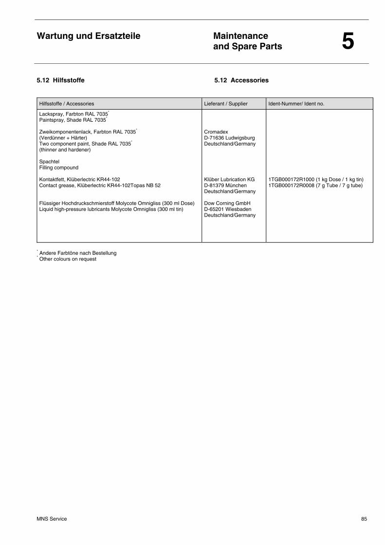
Wartung und Ersatzteile
Maintenance and Spare Parts 5
MNS Service 85
5.12 Hilfsstoffe 5.12 Accessories
Hilfsstoffe / Accessories Lieferant / Supplier Ident-Nummer/ Ident no.
Lackspray, Farbton RAL 7035* Paintspray, Shade RAL 7035*
Zweikomponentenlack, Farbton RAL 7035* (Verdünner + Härter) Two component paint, Shade RAL 7035* (thinner and hardener) Spachtel Filling compound Kontaktfett, Klüberlectric KR44-102 Contact grease, Klüberlectric KR44-102Topas NB 52 Flüssiger Hochdruckschmierstoff Molycote Omnigliss (300 ml Dose) Liquid high-pressure lubricants Molycote Omnigliss (300 ml tin)
Cromadex D-71636 Ludwigsburg Deutschland/Germany Klüber Lubrication KG D-81379 München Deutschland/Germany Dow Corning GmbH D-65201 Wiesbaden Deutschland/Germany
1TGB000172R1000 (1 kg Dose / 1 kg tin) 1TGB000172R0008 (7 g Tube / 7 g tube)
* Andere Farbtöne nach Bestellung * Other colours on request
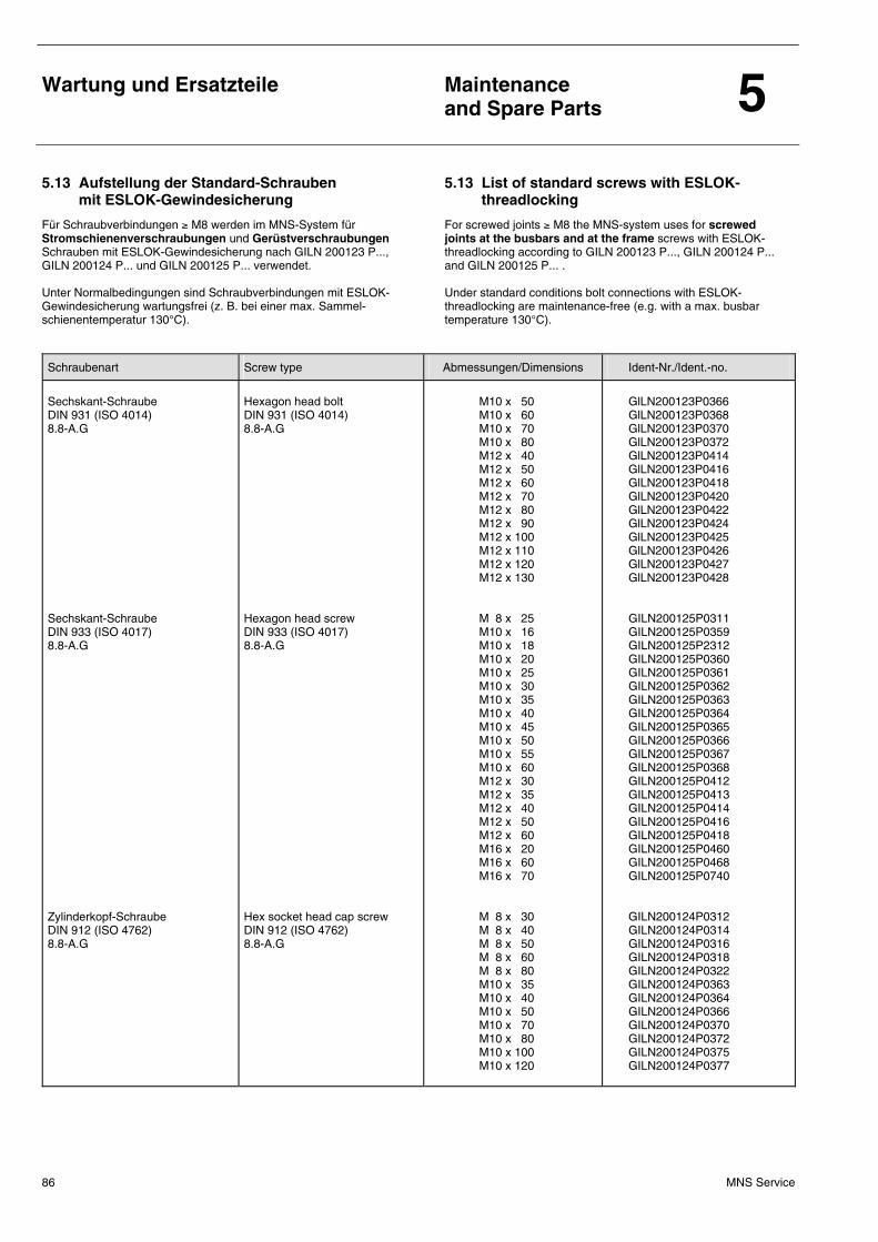
Wartung und Ersatzteile
Maintenance and Spare Parts 5
MNS Service 86
5.13 Aufstellung der Standard-Schrauben mit ESLOK-Gewindesicherung
5.13 List of standard screws with ESLOK-threadlocking
Für Schraubverbindungen ≥ M8 werden im MNS-System für Stromschienenverschraubungen und Gerüstverschraubungen Schrauben mit ESLOK-Gewindesicherung nach GILN 200123 P..., GILN 200124 P... und GILN 200125 P... verwendet. Unter Normalbedingungen sind Schraubverbindungen mit ESLOK-Gewindesicherung wartungsfrei (z. B. bei einer max. Sammel-schienentemperatur 130°C).
For screwed joints ≥ M8 the MNS-system uses for screwed joints at the busbars and at the frame screws with ESLOK-threadlocking according to GILN 200123 P..., GILN 200124 P... and GILN 200125 P... . Under standard conditions bolt connections with ESLOK-threadlocking are maintenance-free (e.g. with a max. busbar temperature 130°C).
Schraubenart Screw type Abmessungen/Dimensions Ident-Nr./Ident.-no. Sechskant-Schraube DIN 931 (ISO 4014) 8.8-A.G Sechskant-Schraube DIN 933 (ISO 4017) 8.8-A.G Zylinderkopf-Schraube DIN 912 (ISO 4762) 8.8-A.G
Hexagon head bolt DIN 931 (ISO 4014) 8.8-A.G Hexagon head screw DIN 933 (ISO 4017) 8.8-A.G Hex socket head cap screw DIN 912 (ISO 4762) 8.8-A.G
M10 x 50 M10 x 60 M10 x 70 M10 x 80 M12 x 40 M12 x 50 M12 x 60 M12 x 70 M12 x 80 M12 x 90 M12 x 100 M12 x 110 M12 x 120 M12 x 130 M 8 x 25 M10 x 16 M10 x 18 M10 x 20 M10 x 25 M10 x 30 M10 x 35 M10 x 40 M10 x 45 M10 x 50 M10 x 55 M10 x 60 M12 x 30 M12 x 35 M12 x 40 M12 x 50 M12 x 60 M16 x 20 M16 x 60 M16 x 70 M 8 x 30 M 8 x 40 M 8 x 50 M 8 x 60 M 8 x 80 M10 x 35 M10 x 40 M10 x 50 M10 x 70 M10 x 80 M10 x 100 M10 x 120
GlLN200123P0366 GlLN200123P0368 GlLN200123P0370 GlLN200123P0372 GlLN200123P0414 GlLN200123P0416 GlLN200123P0418 GlLN200123P0420 GlLN200123P0422 GlLN200123P0424 GlLN200123P0425 GlLN200123P0426 GlLN200123P0427 GlLN200123P0428 GILN200125P0311 GILN200125P0359 GILN200125P2312 GILN200125P0360 GILN200125P0361 GILN200125P0362 GILN200125P0363 GILN200125P0364 GILN200125P0365 GILN200125P0366 GILN200125P0367 GILN200125P0368 GILN200125P0412 GILN200125P0413 GILN200125P0414 GILN200125P0416 GILN200125P0418 GILN200125P0460 GILN200125P0468 GILN200125P0740 GILN200124P0312 GILN200124P0314 GILN200124P0316 GILN200124P0318 GILN200124P0322 GILN200124P0363 GILN200124P0364 GILN200124P0366 GILN200124P0370 GILN200124P0372 GILN200124P0375 GILN200124P0377
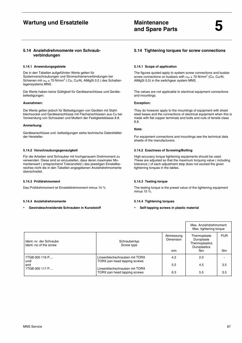
Wartung und Ersatzteile
Maintenance and Spare Parts 5
MNS Service 87
5.14 Anziehdrehmomente von Schraub-verbindungen
5.14 Tightening torques for screw connections
5.14.1 Anwendungsgsbiete 5.14.1 Scope of application
Die in den Tabellen aufgeführten Werte gelten für Systemverschraubungen und Stromschienenverbindungen bei Schienen mit σ02 ≥ 70 N/mm2 ( Cu, Cu/Al, AlMgSi 0,5 ) des Schaltan-lagensystems MNS. Die Werte haben keine Gültigkeit für Geräteanschlüsse und Geräte-befestigungen. Ausnahmen: Die Werte gelten jedoch für Befestigungen von Geräten mit Stahl-blechsockel und Geräteanschlüsse mit Flachanschlüssen aus Cu bei Verwendung von Schrauben und Muttern der Festigkeitsklasse 8.8. Anmerkung: Geräteanschlüsse und -befestigungen siehe technische Datenblätter der Hersteller.
The figures quoted apply to system screw connections and busbar screw connections on busbars with σ02 ≥ 70 N/mm2 (Cu, Cu/Al, AlMgSi 0,5) in the switchgear system MNS. The values are not applicable to electrical equipment connections and mountings. Exception: They do however apply to the mountings of equipment with sheet steel bases and the connections of electrical equipment when this is made with flat copper terminals and bolts and nuts of tensile class 8.8. Note: For equipment connections and mountings see the technical data sheets of the manufacturers.
5.14.2 Verschraubungsgenauigkeit 5.14.2 Exactness of Screwing/Bolting
Für die Arbeiten sind Schrauber mit hochgenauem Drehmoment zu verwenden. Diese sind so einzustellen, dass deren maximaler Mo-mentenwert ( entsprechend Toleranzfeld ) des jeweiligen Einstellbe-reiches nicht die in den Tabellen angegebenen Anziehdrehmomente überschreitet.
High-accuracy torque tightening equipments should be used. These are adjusted so that the maximum torquing value ( including tolerance ) of each adjustment step does not exceed the given tightening torques in the tables.
5.14.3 Prüfdrehmoment 5.14.3 Testing torque
Das Prüfdrehmoment ist Einstelldrehmoment minus 15 %
The testing torque is the preset vaIue of the tightening equipment minus 15 %.
5.14.4 Anziehdrehmomente 5.14.4 Tightening torques
• Gewindeschneidende Schrauben in Kunststoff
• SeIf-tapping screws in plastic material
Max. Anziehdrehmoment Max. tightening torque
Ident.-nr. der Schraube Ident.-no of the screw
Schraubentyp Screw type
Abmessung Dimension
mm
Thermoplaste Duroplaste
Thermoplastics Duroplastics
Nm
PUR
Nm
1TGB 000 116 P.... und/ and 1TGB 000 117 P....
Linsenblechschrauben mit TORX TORX pan head tapping screws Linsenblechschrauben mit TORX TORX pan head tapping screws
4.2
5.5
6.3
2.0
4.5
5.5
-
3.5
3.5
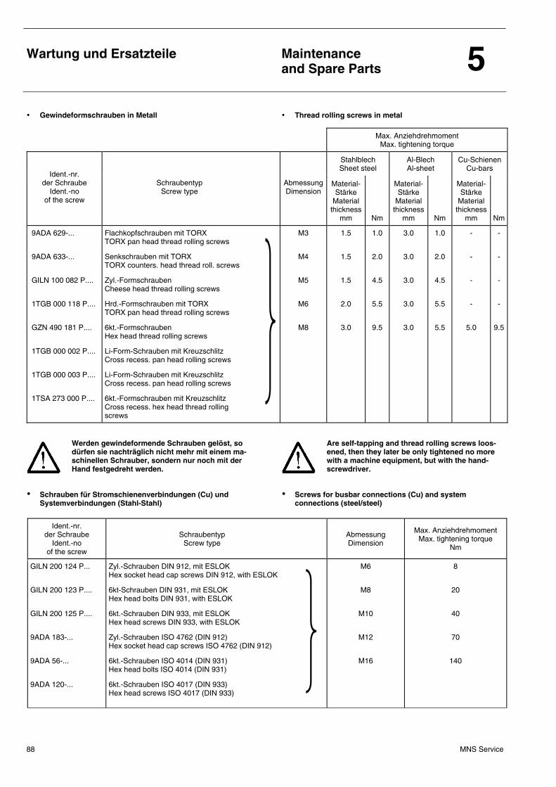
Wartung und Ersatzteile
Maintenance and Spare Parts 5
MNS Service 88
• Gewindeformschrauben in Metall • Thread rolling screws in metal
Max. Anziehdrehmoment Max. tightening torque
Stahlblech Sheet steel
Al-Blech Al-sheet
Cu-Schienen Cu-bars
Ident.-nr. der Schraube
Ident.-no of the screw
Schraubentyp Screw type Abmessung
Dimension Material- Stärke
Material thickness
mm
Nm
Material- Stärke
Material thickness
mm
Nm
Material- Stärke
Material thickness
mm
Nm
9ADA 629-...
9ADA 633-...
GILN 100 082 P....
1TGB 000 118 P....
GZN 490 181 P....
1TGB 000 002 P....
1TGB 000 003 P....
1TSA 273 000 P....
Flachkopfschrauben mit TORX TORX pan head thread rolling screws
Senkschrauben mit TORX TORX counters. head thread roll. screws
Zyl.-Formschrauben Cheese head thread rolling screws
Hrd.-Formschrauben mit TORX TORX pan head thread rolling screws
6kt.-Formschrauben Hex head thread rolling screws
Li-Form-Schrauben mit Kreuzschlitz Cross recess. pan head rolling screws
Li-Form-Schrauben mit Kreuzschlitz Cross recess. pan head rolling screws
6kt.-Formschrauben mit Kreuzschlitz Cross recess. hex head thread rolling screws
M3
M4
M5
M6
M8
1.5
1.5
1.5
2.0
3.0
1.0
2.0
4.5
5.5
9.5
3.0
3.0
3.0
3.0
3.0
1.0
2.0
4.5
5.5
5.5
-
-
-
-
5.0
-
-
-
-
9.5
Werden gewindeformende Schrauben gelöst, so dürfen sie nachträglich nicht mehr mit einem ma-schinellen Schrauber, sondern nur noch mit der Hand festgedreht werden.
Are self-tapping and thread rolling screws loos-ened, then they later be only tightened no more with a machine equipment, but with the hand-screwdriver.
• Schrauben für Stromschienenverbindungen (Cu) und Systemverbindungen (Stahl-Stahl)
• Screws for busbar connections (Cu) and system connections (steel/steel)
Ident.-nr. der Schraube
Ident.-no of the screw
Schraubentyp Screw type Abmessung
Dimension
Max. Anziehdrehmoment Max. tightening torque
Nm
GILN 200 124 P...
GILN 200 123 P....
GILN 200 125 P....
9ADA 183-...
9ADA 56-...
9ADA 120-...
Zyl.-Schrauben DIN 912, mit ESLOK Hex socket head cap screws DIN 912, with ESLOK
6kt-Schrauben DIN 931, mit ESLOK Hex head bolts DIN 931, with ESLOK
6kt.-Schrauben DIN 933, mit ESLOK Hex head screws DIN 933, with ESLOK
Zyl.-Schrauben ISO 4762 (DIN 912) Hex socket head cap screws ISO 4762 (DIN 912)
6kt.-Schrauben ISO 4014 (DIN 931) Hex head bolts ISO 4014 (DIN 931)
6kt.-Schrauben ISO 4017 (DIN 933) Hex head screws ISO 4017 (DIN 933)
M6
M8
M10
M12
M16
8
20
40
70
140
Wartung und Ersatzteile
Maintenance and Spare Parts 5
MNS Service 89
5.15 Inbetriebnahme und Wartung von MNS Blind-leistungs-Kompensationsanlagen
5.15 Commissioning and maintenance of MNS re-active power compensation systems
5.15.1 Inbetriebnahme und Wartung 5.15.1 Commissioning and maintenance
Kompensationsanlagen werden häufig dauernd mit der höchsten Leistung betrieben. Am Aufstellungsort ist deshalb für gute Belüftung zu sorgen, damit die zulässige Umgebungstemperatur von 35°C (im 24-Stunden-Mittel) nicht überschritten wird.
Das Feststellen von Fehlfunktionen oder nicht mehr ausreichender Kompensationsleistung geschieht am einfachsten (aber zu spät) über den Blindleistungsverbrauch (Stromrechnung). Die Berück-sichtigung folgender Punkte bei Inbetriebnahme und den regelmäßi-gen Wartungen lässt einen Kompensations-Leistungsverlust früh-zeitig erkennen.
1. Überprüfung der Belüftung am Aufstellungsort.
2. Überprüfung der Konstruktion:
a) Jeweils ober- und unterhalb des einzelnen Modules (bzw. der Module) muss für Zu- und Abluftmöglichkeit gesorgt sein.
b) Bei geschlossenem Feldboden (keine Zuluft durch den Bo-den) müssen mindestens 4 Lüftungsausschnitte vorhanden sein.
c) Im Feld dürfen keine Fachböden oder andere Einbauten vorhanden sein, die die Belüftung beeinflussen können.
d) Bei Schutzgraden > IP 32 oder Einbauten die von c) abwei-chen ist eine Zwangsbelüftung (oder reduzierte Bestü-ckungsdichte) erforderlich.
e) Zwischen Kabel- und Geräteraum muss eine Querschottung eingebaut sein.
3. Überprüfung der Einstellungen und Funktion des Reglers (Schaltausgänge).
4. Schütze auf Funkenbildung beim Schalten und einwandfreies Ein- und Ausschalten prüfen. Für die Wartungsintervalle der Kontakte der Kondensatorschütze gemäß Schaltspielzahl (beim ESTAmat® RPR ablesbar) gilt die Herstellervorschrift.
Kondensatorschütze dürfen nicht von Hand ge-schaltet werden!
5. Die Stromaufnahme der Anlage und der Module dient als Indika-
tor für den Kapazitätsverlust, wenn eine Kapazitätsprüfung (die eine Freischaltung der Kompensationsanlage erfordert) nicht möglich ist; in diesem Fall müssen gleichzeitig Ströme und Spannungen jeder Phase gemessen werden. (Aufgrund mögli-cher Stromverzerrungen durch Oberschwingungen ist die Strommessung jedoch nur ein grobes Kriterium!)
6. Vor dem Berühren der Kondensatoren:
a) Mindestens eine Minute Entladezeit abwarten.
b) Die Anlage gegen Wiedereinschalten sichern.
c) Spannungsfreiheit feststellen.
d) Kondensatorklemmen untereinander und mit dem Gehäuse kurzschließen und erden, um Potentialunterschiede aus-zugleichen.
e) Benachbarte unter Spannung stehende Teile gegen Berüh-ren sichern.
In the worst case, compensation systems are permanently operated with their maximum power. Therefore, good ventilation is to be en-sured in the place of installation in order to prevent the ambient temperature from exceeding the max. admissible limit of 35°C (mean value over 24 hours).
Malfunctions or an insufficient compensation power can be best determined (although too late) by checking the reactive power de-mand (electricity bill). If the following points are noted during commis-sioning and the regular maintenance works, a loss in compensation power can be detected at an early stage.
1. Check ventilation in the place of installation.
2. Check the construction:
a) Above and below each individual module (or the modules), an air supply and air discharge must be available.
b) If the cubicle bottom plate is closed (no air supply through bottom plate), there must be at least 4 ventilation slots.
c) No compartment bottom plates or other installations may be present in the cubicle which might adversely affect ventila-tion.
d) For protection class > IP 32 or installations which deviate from c) above, forced ventilation (or a reduced amount of equipment) is required.
e) A transverse partitioning must be installed between the cable compartment and the equipment compartment.
3. Check the settings and the functioning of the controller (switching outputs).
4. Check contactors for sparking when switching and for faultless making and breaking operations. The maintenance intervals of the contacts of the capacitor contactors depending on their num-ber of switching operations (can be read off ESTAmat® RPR) are subject to the manufacturer´s instructions.
Do not operate capacitor-contactors by hand!
5. The current consumption of the system and the modules serves
as an indication for a loss in capacitance if a capacitance test (which requires safety disconnection of the compensation sys-tem) is not possible; in this case, the currents and voltages in each phase must be measured simultaneously. (However, cur-rent measurement is only a rough criterion in view of possible current distortions caused by harmonic waves!)
6. Before touching the capacitors:
a) Wait for at least one minute until the capacitor is discharged.
b) Protect the system against reclosing.
c) Verify safe isolation from supply.
d) Short-circuit the capacitor terminals among each other and with the housing in order to compensate for differences in po-tential.
e) Protect neighbouring live parts against accidental contact.
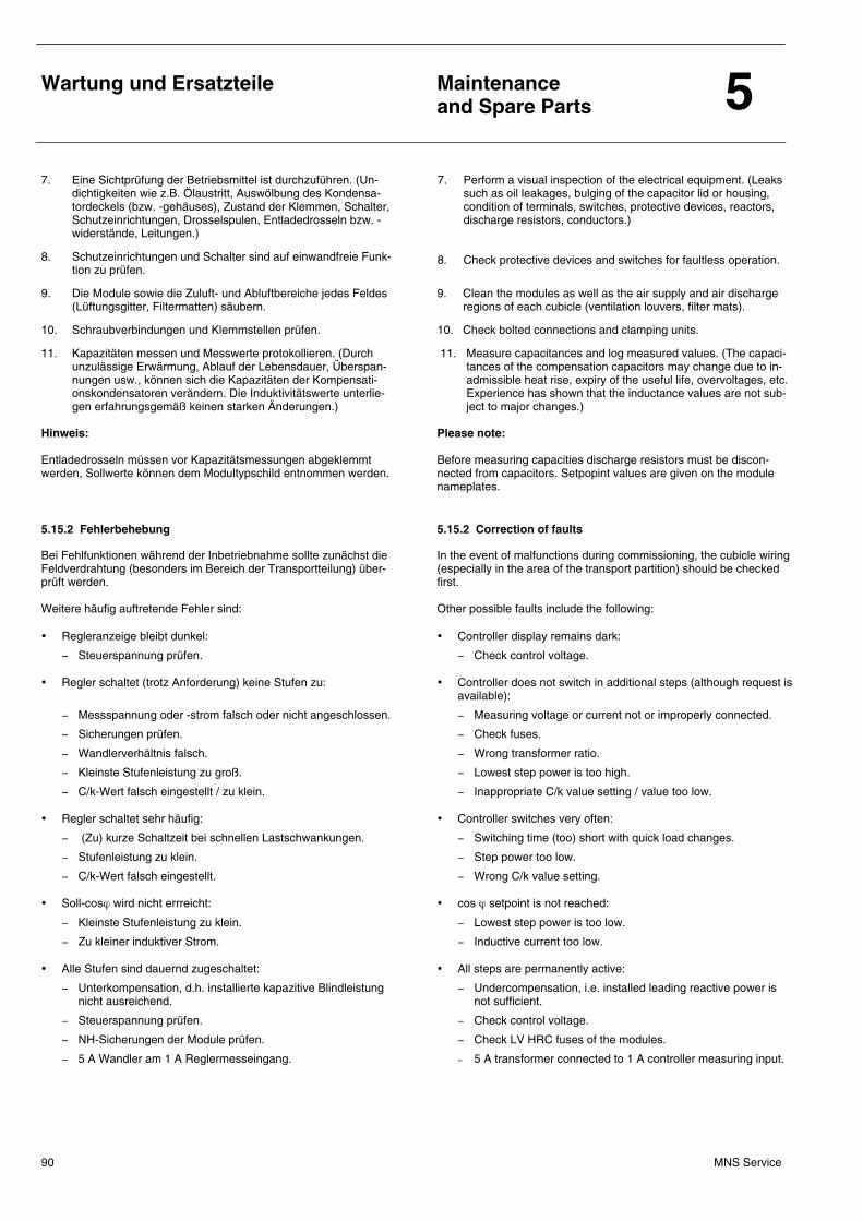
Wartung und Ersatzteile
Maintenance and Spare Parts 5
MNS Service 90
7. Eine Sichtprüfung der Betriebsmittel ist durchzuführen. (Un-dichtigkeiten wie z.B. Ölaustritt, Auswölbung des Kondensa-tordeckels (bzw. -gehäuses), Zustand der Klemmen, Schalter, Schutzeinrichtungen, Drosselspulen, Entladedrosseln bzw. -widerstände, Leitungen.)
8. Schutzeinrichtungen und Schalter sind auf einwandfreie Funk-tion zu prüfen.
9. Die Module sowie die Zuluft- und Abluftbereiche jedes Feldes (Lüftungsgitter, Filtermatten) säubern.
10. Schraubverbindungen und Klemmstellen prüfen.
11. Kapazitäten messen und Messwerte protokollieren. (Durch unzulässige Erwärmung, Ablauf der Lebensdauer, Überspan-nungen usw., können sich die Kapazitäten der Kompensati-onskondensatoren verändern. Die Induktivitätswerte unterlie-gen erfahrungsgemäß keinen starken Änderungen.)
Hinweis: Entladedrosseln müssen vor Kapazitätsmessungen abgeklemmt werden, Sollwerte können dem Modultypschild entnommen werden.
7. Perform a visual inspection of the electrical equipment. (Leaks such as oil leakages, bulging of the capacitor lid or housing, condition of terminals, switches, protective devices, reactors, discharge resistors, conductors.)
8. Check protective devices and switches for faultless operation.
9. Clean the modules as well as the air supply and air discharge regions of each cubicle (ventilation louvers, filter mats).
10. Check bolted connections and clamping units.
11. Measure capacitances and log measured values. (The capaci-tances of the compensation capacitors may change due to in-admissible heat rise, expiry of the useful life, overvoltages, etc. Experience has shown that the inductance values are not sub-ject to major changes.)
Please note: Before measuring capacities discharge resistors must be discon-nected from capacitors. Setpopint values are given on the module nameplates.
5.15.2 Fehlerbehebung 5.15.2 Correction of faults
Bei Fehlfunktionen während der Inbetriebnahme sollte zunächst die Feldverdrahtung (besonders im Bereich der Transportteilung) über-prüft werden. Weitere häufig auftretende Fehler sind: • Regleranzeige bleibt dunkel:
− Steuerspannung prüfen.
• Regler schaltet (trotz Anforderung) keine Stufen zu:
− Messspannung oder -strom falsch oder nicht angeschlossen.
− Sicherungen prüfen.
− Wandlerverhältnis falsch.
− Kleinste Stufenleistung zu groß.
− C/k-Wert falsch eingestellt / zu klein.
• Regler schaltet sehr häufig:
− (Zu) kurze Schaltzeit bei schnellen Lastschwankungen.
− Stufenleistung zu klein.
− C/k-Wert falsch eingestellt.
• Soll-cosϕ wird nicht errreicht:
− Kleinste Stufenleistung zu klein.
− Zu kleiner induktiver Strom.
• Alle Stufen sind dauernd zugeschaltet:
− Unterkompensation, d.h. installierte kapazitive Blindleistung nicht ausreichend.
− Steuerspannung prüfen.
− NH-Sicherungen der Module prüfen.
− 5 A Wandler am 1 A Reglermesseingang.
In the event of malfunctions during commissioning, the cubicle wiring (especially in the area of the transport partition) should be checked first. Other possible faults include the following: • Controller display remains dark:
− Check control voltage.
• Controller does not switch in additional steps (although request is available):
− Measuring voltage or current not or improperly connected.
− Check fuses.
− Wrong transformer ratio.
− Lowest step power is too high.
− Inappropriate C/k value setting / value too low.
• Controller switches very often:
− Switching time (too) short with quick load changes.
− Step power too low.
− Wrong C/k value setting.
• cos ϕ setpoint is not reached:
− Lowest step power is too low.
− Inductive current too low.
• All steps are permanently active:
− Undercompensation, i.e. installed leading reactive power is not sufficient.
− Check control voltage.
− Check LV HRC fuses of the modules.
− 5 A transformer connected to 1 A controller measuring input.
Wartung und Ersatzteile
Maintenance and Spare Parts 5
MNS Service 91
• Zu viele Stufen sind zugeschaltet (Überkompensation):
− Wandlereinbau prüfen.
− Reglereinstellungen prüfen.
− Spannungsmessanschluss falsch (Phase-Phase und Phase-N vertauscht).
• cosϕ-Anzeige stimmt nicht mit zusätzlichem Leistungsfaktor-messer überein: − Spannungsmessanschluss falsch
(Phase-Phase und Phase-N vertauscht).
− Geringe Abweichungen können durch ungenaue Anzeige-geräte und/oder unterschiedliche Messpunkte bedingt sein.
Kodierschalter beim ESTAmat® RPR (Einstellung nach Abnahme der Frontplatte)
• Too many steps active (overcompensation):
− Check transformer installation.
− Check controller settings.
− Wrong measuring voltage connection (phase-phase and phase-N exchanged).
• cos ϕ display does not coincide with additional power factor meter reading: − wrong voltage measuring connection (phase-phase and
phase-N exchanged).
− slight deviations may be due to inaccurate measuring units and/or different measuring points.
DIP-switch programming of ESTAmat® RPR (adjustment after removing the frontplate)
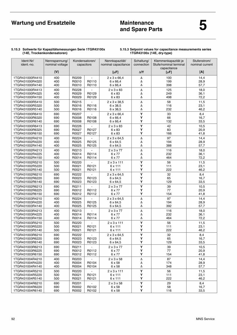
Wartung und Ersatzteile
Maintenance and Spare Parts 5
MNS Service 92
5.15.3 Sollwerte für Kapazitätsmessungen Serie 1TGR43100x (14E, Trockenkondensatoren)
5.15.3 Setpoint values for capacitance measurements series 1TGR43100x (14E, dry-type)
Ident-Nr/ ident.-no.
Nennspannung/ nominal voltage
[V]
Kondensatoren/ capacitors
Nennkapazität/ nominal capacitance
[µF]
Schaltung/ connection
∆/Y
Klemmenkapazität je Stufe/nominal terminal
capacitance [µF]
Stufenstrom/ nominal current
[A]
1TGR431000R4410 1TGR431000R4320 1TGR431000R4140
400 400 400
R0209 R0010 R0010
- R0110 R0110
2 x 3 x 66,4 6 x 66,4 6 x 66,4
∆ ∆ ∆
100 199 398
14,4 28,9 57,7
1TGR431000R4413 1TGR431000R4325 1TGR431000R4150
400 400 400
R0228 R0029 R0029
- R0129 R0129
2 x 3 x 83 6 x 83 6 x 83
∆ ∆ ∆
125 249 498
18,0 36,1 72,2
1TGR431000R5410 1TGR431000R5320 1TGR431000R5140
500 500 500
R0215 R0016 R0016
- R0116 R0116
2 x 3 x 38,5 6 x 38,5 6 x 38,5
∆ ∆ ∆
58 116 232
11,5 23,1 46,2
1TGR431000R6410 1TGR431000R6320 1TGR431000R6140
690 690 690
R0207 R0008 R0008
- R0108 R0108
2 x 3 x 66,4 6 x 66,4 6 x 66,4
Y Y Y
33 66
132
8,4 16,7 33,5
1TGR431000R6413 1TGR431000R6325 1TGR431000R6150
690 690 690
R0226 R0027 R0027
- R0127 R0127
2 x 3 x 83 6 x 83 6 x 83
Y Y Y
42 83
166
10,5 20,9 41,8
1TGR431002R4210 1TGR431002R4220 1TGR431002R4140
400 400 400
R0224 R0025 R0025
- R0125 R0125
2 x 3 x 64,5 6 x 64,5 6 x 64,5
∆ ∆ ∆
97 194 388
14,4 28,9 57,7
1TGR431002R4213 1TGR431002R4225 1TGR431002R4150
400 400 400
R0213 R0014 R0014
- R0114 R0114
2 x 3 x 77 6 x 77 6 x 77
∆ ∆ ∆
116 232 464
18,0 36,1 72,2
1TGR431002R5210 1TGR431002R5220 1TGR431002R5140
500 500 500
R0220 R0021 R0021
- R0121 R0121
2 x 3 x 111 6 x 111 6 x 111
Y Y Y
56 111 222
11,5 23,1 46,2
1TGR431002R6210 1TGR431002R6220 1TGR431002R6140
690 690 690
R0222 R0023 R0023
- R0123 R0123
2 x 3 x 64,5 6 x 64,5 6 x 64,5
Y Y Y
32 65
129
8,4 16,7 33,5
1TGR431002R6213 1TGR431002R6225 1TGR431002R6150
690 690 690
R0211 R0012 R0012
- R0112 R0112
2 x 3 x 77 6 x 77 6 x 77
Y Y Y
39 77
154
10,5 20,9 41,8
1TGR431003R4210 1TGR431003R4220 1TGR431003R4140
400 400 400
R0224 R0025 R0025
- R0125 R0125
2 x 3 x 64,5 6 x 64,5 6 x 64,5
∆ ∆ ∆
97 194 392
14,4 28,9 57,7
1TGR431003R4213 1TGR431003R4225 1TGR431003R4150
400 400 400
R0213 R0014 R0014
- R0114 R0114
2 x 3 x 77 6 x 77 6 x 77
∆ ∆ ∆
116 232 464
18,0 36,1 72,2
1TGR431003R5210 1TGR431003R5220 1TGR431003R5140
500 500 500
R0220 R0021 R0021
- R0121 R0121
2 x 3 x 111 6 x 111 6 x 111
Y Y Y
56 111 222
11,5 23,1 46,2
1TGR431003R6210 1TGR431003R6220 1TGR431003R6140
690 690 690
R0222 R0023 R0023
- R0123 R0123
2 x 3 x 64,5 6 x 64,5 6 x 64,5
Y Y Y
32 65
129
8,4 16,7 33,5
1TGR431003R6213 1TGR431003R6225 1TGR431003R6150
690 690 690
R0211 R0012 R0012
- R0112 R0112
2 x 3 x 77 6 x 77 6 x 77
Y Y Y
39 77
154
10,5 20,9 41,8
1TGR431004R4210 1TGR431004R4220 1TGR431004R4140
400 400 400
R0203 R0004 R0004
- R0104 R0104
2 x 3 x 58 6 x 58 6 x 58
∆ ∆ ∆
87 174 348
14,4 28,9 57,7
1TGR431004R5210 1TGR431004R5220 1TGR431004R5140
500 500 500
R0220 R0021 R0021
- R0121 R0121
2 x 3 x 111 6 x 111 6 x 111
Y Y Y
56 111 222
11,5 23,1 46,2
1TGR431004R6210 1TGR431004R6220 1TGR431004R6140
690 690 690
R0201 R0002 R0002
- R0102 R0102
2 x 3 x 58 6 x 58 6 x 58
Y Y Y
29 58
116
8,4 16,7 33,5
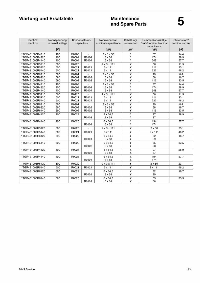
Wartung und Ersatzteile
Maintenance and Spare Parts 5
MNS Service 93
Ident-Nr/ Ident no.
Nennspannung/ nominal voltage
[V]
Kondensatoren/ capacitors
Nennkapazität/ nominal capacitance
[µF]
Schaltung/ connection
∆/Y
Klemmenkapazität je Stufe/nominal terminal
capacitance [µF]
Stufenstrom/ nominal current
[A]
1TGR431005R4210 1TGR431005R4220 1TGR431005R4140
400 400 400
R0203 R0004 R0004
- R0104 R0104
2 x 3 x 58 6 x 58 6 x 58
∆ ∆ ∆
87 174 348
14,4 28,9 57,7
1TGR431005R5210 1TGR431005R5220 1TGR431005R5140
500 500 500
R0220 R0021 R0021
- R0121 R0121
2 x 3 x 111 6 x 111 6 x 111
Y Y Y
56 111 222
11,5 23,1 46,2
1TGR431005R6210 1TGR431005R6220 1TGR431005R6140
690 690 690
R0201 R0002 R0002
- R0102 R0102
2 x 3 x 58 6 x 58 6 x 58
Y Y Y
29 58
116
8,4 16,7 33,5
1TGR431006R4210 1TGR431006R4220 1TGR431006R4140
400 400 400
R0203 R0004 R0004
- R0104 R0104
2 x 3 x 58 6 x 58 6 x 58
∆ ∆ ∆
87 174 348
14,4 28,9 57,7
1TGR431006R5210 1TGR431006R5220 1TGR431006R5140
500 500 500
R0220 R0021 R0021
- R0121 R0121
2 x 3 x 111 6 x 111 6 x 111
Y Y Y
56 111 222
11,5 23,1 46,2
1TGR431006R6210 1TGR431006R6220 1TGR431006R6140
690 690 690
R0201 R0002 R0002
- R0102 R0102
2 x 3 x 58 6 x 58 6 x 58
Y Y Y
29 58
116
8,4 16,7 33,5
1TGR431007R4120 400 R0024 R0103
3 x 64,5 3 x 58
∆ ∆
97 87
28,9
1TGR431007R4140 400 R0025 R0104
6 x 64,5 6 x 58
∆ ∆
194 174
57,7
1TGR431007R5120 500 R0220 - 2 x 3 x 111 Y 2 x 56 23,1 1TGR431007R5140 500 R0021 R0121 6 x 111 Y 2 x 111 46,2 1TGR431007R6120 690 R0022
R0101 6 x 64,5 3 x 58
Y Y
32 29
16,7
1TGR431007R6140 690 R0023 R0102
6 x 64,5 6 x 58
Y Y
65 58
33,5
1TGR431008R4120 400 R0024 R0103
3 x 64,5 3 x 58
∆ ∆
97 87
28,9
1TGR431008R4140 400 R0025 R0104
6 x 64,5 6 x 58
∆ ∆
194 174
57,7
1TGR431008R5120 500 R0220 - 2 x 3 x 111 Y 2 x 56 23,1 1TGR431008R5140 500 R0021 R0121 6 x 111 Y 2 x 111 46,2 1TGR431008R6120 690 R0022
R0101 6 x 64,5 3 x 58
Y Y
32 29
16,7
1TGR431008R6140 690 R0023 R0102
6 x 64,5 6 x 58
Y Y
65 58
33,5
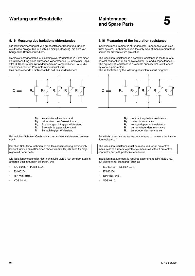
Wartung und Ersatzteile
Maintenance and Spare Parts 5
MNS Service 94
5.16 Messung des Isolationswiderstandes 5.16 Measuring of the insulation resistance
Die Isolationsmessung ist von grundsätzlicher Bedeutung für eine elektrische Anlage. Sie ist auch die einzige Messung, die dem vor-beugenden Brandschutz dient. Der Isolationswiderstand ist ein komplexer Widerstand in Form einer Parallelschaltung eines ohmschen Widerstandes RW und einer Kapa-zität C. Dabei ist der Wirkwiderstand eine veränderliche Größe, die von verschiedenen Parametern beeinflusst wird. Das nachstehende Ersatzschaltbild soll das verdeutlichen:
Insulation measurement is of fundamental importance to an elec-trical system. Furthermore, it is the only type of measurement that serves for preventive fire protection. The insulation resistance is a complex resistance in the form of a parallel connection of an ohmic resistor RW and a capacitance C. The equivalent resistance is a variable quantity that is influenced by various parameters. This is illustrated by the following equivalent circuit diagram:
C Rw RD Ru Ri Rt
RW: konstanter Wirkwiderstand RD: Widerstand des Dielektrikums RU: Spannungsabhängiger Widerstand Ri: Stromabhängiger Widerstand Rt Zeitabhängiger Widerstand
C Rw RD Ru Ri Rt
RW: constant equivalent resistance RD: dielectric resistance RU: voltage-dependent resistance Ri: current-dependent resistance Rt time-dependent resistance
Bei welchen Schutzmaßnahmen ist der Isolationswiderstand zu mes-sen? Bei allen Schutzmaßnahmen ist die Isolationsmessung erforderlich! Sowohl für Schutzmaßnahmen ohne Schutzleiter, als auch für dieje-nigen mit Schutzleiter. Die Isolationsmessung ist nicht nur in DIN VDE 0100, sondern auch in anderen Bestimmungen gefordert, wie
• IEC 60439-1, Punkt 8.3.4,
• EN 60204,
• DIN VDE 0105,
• VDE 0110.
For which protective measures do you have to measure the insula-tion resistance? The insulation resistance must be measured for all protective measures! This refers to protective measures without protective conductor and with protective conductor. Insulation measurement is required according to DIN VDE 0100, but also to other standards, such as
• IEC 60439-1, Section 8.3.4,
• EN 60204,
• DIN VDE 0105,
• VDE 0110.
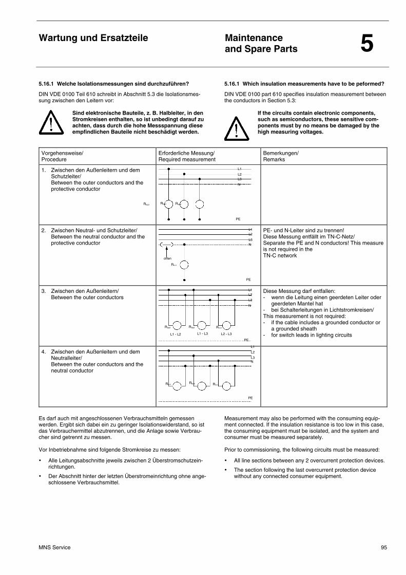
Wartung und Ersatzteile
Maintenance and Spare Parts 5
MNS Service 95
5.16.1 Welche Isolationsmessungen sind durchzuführen? 5.16.1 Which insulation measurements have to be peformed?
DIN VDE 0100 Teil 610 schreibt in Abschnitt 5.3 die Isolationsmes-sung zwischen den Leitern vor:
Sind elektronische Bauteile, z. B. Halbleiter, in den Stromkreisen enthalten, so ist unbedingt darauf zu achten, dass durch die hohe Messspannung diese empfindlichen Bauteile nicht beschädigt werden.
DIN VDE 0100 part 610 specifies insulation measurement between the conductors in Section 5.3:
If the circuits contain electronic components, such as semiconductors, these sensitive com-ponents must by no means be damaged by the high measuring voltages.
Vorgehensweise/ Procedure
Erforderliche Messung/ Required measurement
Bemerkungen/ Remarks
1. Zwischen den Außenleitern und dem Schutzleiter/
Between the outer conductors and the protective conductor
2. Zwischen Neutral- und Schutzleiter/ Between the neutral conductor and the
protective conductor
PE- und N-Leiter sind zu trennen! Diese Messung entfällt im TN-C-Netz/ Separate the PE and N conductors! This measure is not required in the TN-C network
3. Zwischen den Außenleitern/ Between the outer conductors
Diese Messung darf entfallen: - wenn die Leitung einen geerdeten Leiter oder
geerdeten Mantel hat - bei Schalterleitungen in Lichtstromkreisen/ This measurement is not required: - if the cable includes a grounded conductor or
a grounded sheath - for switch leads in lighting circuits
4. Zwischen den Außenleitern und dem Neutralleiter/
Between the outer conductors and the neutral conductor
Es darf auch mit angeschlossenen Verbrauchsmitteln gemessen werden. Ergibt sich dabei ein zu geringer Isolationswiderstand, so ist das Verbrauchermittel abzutrennen, und die Anlage sowie Verbrau-cher sind getrennt zu messen. Vor Inbetriebnahme sind folgende Stromkreise zu messen:
• Alle Leitungsabschnitte jeweils zwischen 2 Überstromschutzein-richtungen.
• Der Abschnitt hinter der letzten Überstromeinrichtung ohne ange-schlossene Verbrauchsmittel.
Measurement may also be performed with the consuming equip-ment connected. If the insulation resistance is too low in this case, the consuming equipment must be isolated, and the system and consumer must be measured separately. Prior to commissioning, the following circuits must be measured:
• All line sections between any 2 overcurrent protection devices.
• The section following the last overcurrent protection device without any connected consumer equipment.
L1
L2
L3
N
offen
PE
RIsol
RIsol RIsol RIsol
L1
L2
L3
N
PE
L1
L2
L3 N
PE
RIsol RIsol RIsol
PE
RIsol L1 - L2 L1 - L3 L2 - L3
L1
L2
L3
N
RIsol RIsol
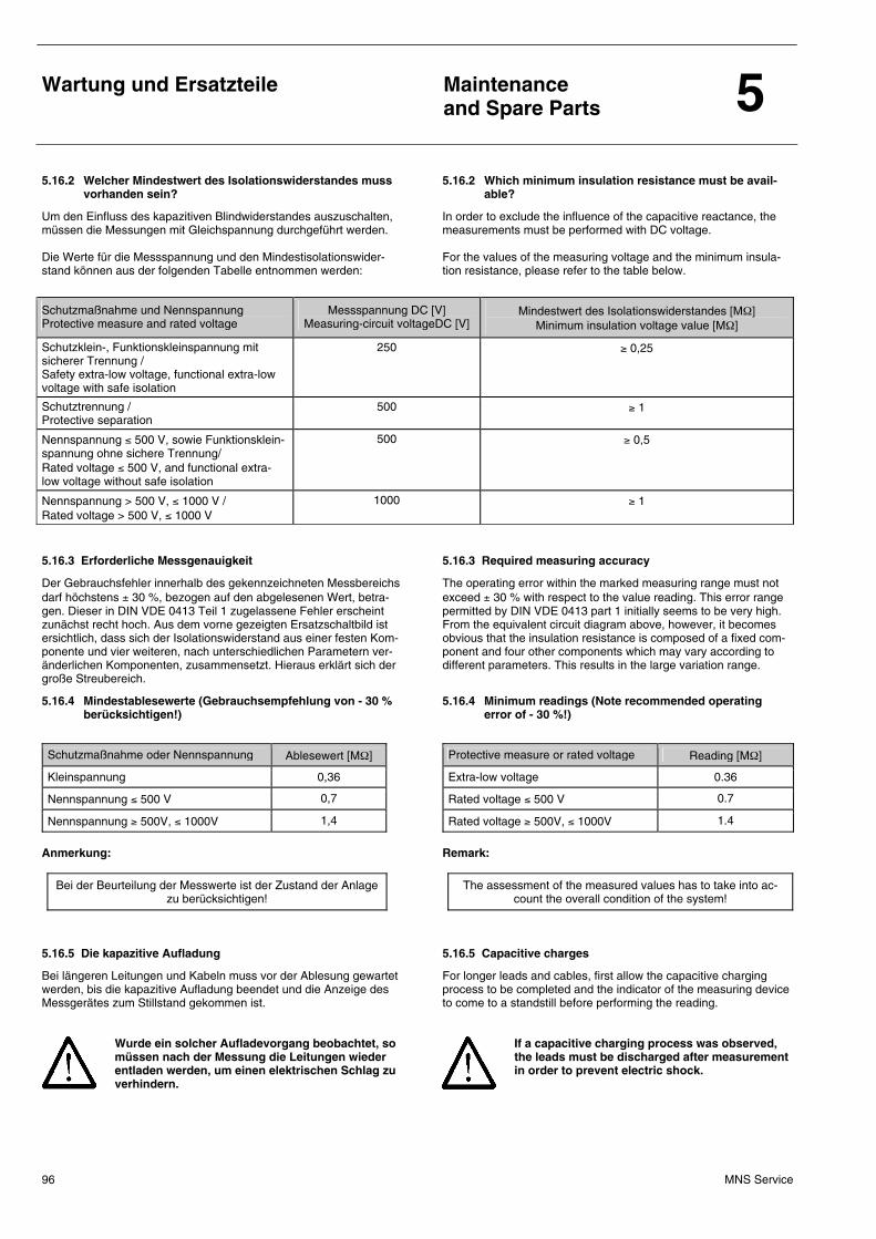
Wartung und Ersatzteile
Maintenance and Spare Parts 5
MNS Service 96
5.16.2 Welcher Mindestwert des Isolationswiderstandes muss vorhanden sein?
5.16.2 Which minimum insulation resistance must be avail-able?
Um den Einfluss des kapazitiven Blindwiderstandes auszuschalten, müssen die Messungen mit Gleichspannung durchgeführt werden. Die Werte für die Messspannung und den Mindestisolationswider-stand können aus der folgenden Tabelle entnommen werden:
In order to exclude the influence of the capacitive reactance, the measurements must be performed with DC voltage. For the values of the measuring voltage and the minimum insula-tion resistance, please refer to the table below.
Schutzmaßnahme und Nennspannung Protective measure and rated voltage
Messspannung DC [V] Measuring-circuit voltageDC [V]
Mindestwert des Isolationswiderstandes [MΩ] Minimum insulation voltage value [MΩ]
Schutzklein-, Funktionskleinspannung mit sicherer Trennung / Safety extra-low voltage, functional extra-low voltage with safe isolation
250 ≥ 0,25
Schutztrennung / Protective separation
500 ≥ 1
Nennspannung ≤ 500 V, sowie Funktionsklein-spannung ohne sichere Trennung/ Rated voltage ≤ 500 V, and functional extra-low voltage without safe isolation
500 ≥ 0,5
Nennspannung > 500 V, ≤ 1000 V / Rated voltage > 500 V, ≤ 1000 V
1000 ≥ 1
5.16.3 Erforderliche Messgenauigkeit 5.16.3 Required measuring accuracy
Der Gebrauchsfehler innerhalb des gekennzeichneten Messbereichs darf höchstens ± 30 %, bezogen auf den abgelesenen Wert, betra-gen. Dieser in DIN VDE 0413 Teil 1 zugelassene Fehler erscheint zunächst recht hoch. Aus dem vorne gezeigten Ersatzschaltbild ist ersichtlich, dass sich der Isolationswiderstand aus einer festen Kom-ponente und vier weiteren, nach unterschiedlichen Parametern ver-änderlichen Komponenten, zusammensetzt. Hieraus erklärt sich der große Streubereich.
The operating error within the marked measuring range must not exceed ± 30 % with respect to the value reading. This error range permitted by DIN VDE 0413 part 1 initially seems to be very high. From the equivalent circuit diagram above, however, it becomes obvious that the insulation resistance is composed of a fixed com-ponent and four other components which may vary according to different parameters. This results in the large variation range.
5.16.4 Mindestablesewerte (Gebrauchsempfehlung von - 30 % berücksichtigen!)
5.16.4 Minimum readings (Note recommended operating error of - 30 %!)
Schutzmaßnahme oder Nennspannung Ablesewert [MΩ]
Kleinspannung 0,36
Nennspannung ≤ 500 V 0,7
Nennspannung ≥ 500V, ≤ 1000V 1,4
Anmerkung:
Bei der Beurteilung der Messwerte ist der Zustand der Anlage zu berücksichtigen!
Protective measure or rated voltage Reading [MΩ]
Extra-low voltage 0.36
Rated voltage ≤ 500 V 0.7
Rated voltage ≥ 500V, ≤ 1000V 1.4
Remark:
The assessment of the measured values has to take into ac-count the overall condition of the system!
5.16.5 Die kapazitive Aufladung 5.16.5 Capacitive charges
Bei längeren Leitungen und Kabeln muss vor der Ablesung gewartet werden, bis die kapazitive Aufladung beendet und die Anzeige des Messgerätes zum Stillstand gekommen ist.
Wurde ein solcher Aufladevorgang beobachtet, so müssen nach der Messung die Leitungen wieder entladen werden, um einen elektrischen Schlag zu verhindern.
For longer leads and cables, first allow the capacitive charging process to be completed and the indicator of the measuring device to come to a standstill before performing the reading.
If a capacitive charging process was observed, the leads must be discharged after measurement in order to prevent electric shock.
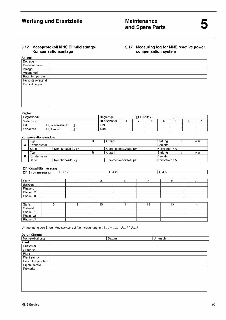
Wartung und Ersatzteile
Maintenance and Spare Parts 5
MNS Service 97
5.17 Messprotokoll MNS Blindleistungs-Kompensationsanlage
5.17 Measuring log for MNS reactive power compensation system
Anlage Betreiber Bestellnummer Anlage Anlagenteil Raumtemperatur Rundsteuersignal Bemerkungen
Regler Reglermodul Reglertyp RPR12 Soll-cosϕ DIP-Schalter 1 2 3 4 5 6 7 C/k automatisch EIN Schaltzeit Faktor AUS
Kompensationsmodule
Typ R Anzahl Stufung x kvar A Kondensator Baujahr Stufe Nennkapazität / µF Klemmenkapazität / µF Nennstrom / A Typ R Anzahl Stufung x kvar
B Kondensator Baujahr Stufe Nennkapazität / µF Klemmenkapazität / µF Nennstrom / A
Kapazitätsmessung Strommessung U (L1) U (L2) U (L3)
Stufe 1 2 3 4 5 6 7 Sollwert Phase L1 Phase L2 Phase L3
Stufe 8 9 10 11 12 13 14 Sollwert Phase L1 Phase L2 Phase L3
Umrechnung von Strom-Messwerten auf Nennspannung mit: Inenn = Imess · Unenn² / Umess² Durchführung Name/Abteilung Datum Unterschrift
Plant Customer Order no. Plant Plant section Room temperature Ripple control Remarks
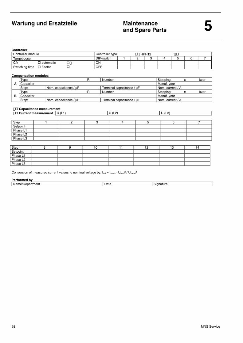
Wartung und Ersatzteile
Maintenance and Spare Parts 5
MNS Service 98
Controller Controller module Controller type RPR12 Target-cosϕ DIP-switch 1 2 3 4 5 6 7 C/k automatic ON Switching time Factor OFF
Compensation modules
Type R Number Stepping x kvar A Capacitor Manuf. year Step: Nom. capacitance / µF Terminal capacitance / µF Nom. current / A Type R Number Stepping x kvar
B Capacitor Manuf. year Step: Nom. capacitance / µF Terminal capacitance / µF Nom. current / A
Capacitance measurement Current measurement U (L1) U (L2) U (L3)
Step 1 2 3 4 5 6 7 Setpoint Phase L1 Phase L2 Phase L3
Step 8 9 10 11 12 13 14 Setpoint Phase L1 Phase L2 Phase L3 Conversion of measured current values to nominal voltage by: Iact = Imeas · Unom² / Umeas² Performed by Name/Department Date Signature
Wartung und Ersatzteile
Maintenance and Spare Parts 5
MNS Service 99
5.18 Wartungsintervalle 5.18 Maintenance intervals
5.18.1 Allgemeines 5.18.1 General
5.18.1.1 Rechtliche Rahmenbedingungen 5.18.1.1 Legal conditions
Die Notwendigkeit der kontinuierlichen Instandhaltung elektrischer Schaltanlagen ergibt sich nicht nur aus technischen und wirtschaftli-chen Gesichtspunkten. Um den Ordnungsrahmen in der Energiewirt-schaft festzulegen, hat der Gesetzgeber eine Reihe von Rechtsvor-schriften erlassen, aus denen sich auch die Erfordernisse der In-standhaltung ableiten lassen.
Electrical switchgear and controlgear systems require permanent preventive maintenance not only for technical and economic rea-sons. In an effort to define the due order in the energy sector, the government dictated a number of legal provisions from which the requirements of preventive maintenance can be derived.
5.18.1.2 Instandhaltungsmaßnahmen 5.18.1.2 Preventive maintenance
Eine technische Norm, die die Instandhaltung an den Anlagen elektri-scher Verteilnetze umfassend regelt, gibt es derzeit nicht! In den Grundsätzen wird unter anderem gefordert, dass die elektri-schen Anlagen und Betriebsmittel entsprechend den elektrotechni-schen Regeln zu betreiben sind, also auch instand zu halten sind.
• Festgestellte Mängel sind unverzüglich zu beheben.
• Besteht eine dringende Gefahr, dürfen mangelhafte elektrische Anlagen nicht mehr betrieben werden.
Auch die Bestimmungen der DIN 57105 Teil 1/VDE 0105 Teil 1 gehen nicht über allgemeine Aussagen zur Instandhaltung elektrischer Anla-gen hinaus. Die wichtigsten Aussagen zur Instandhaltung sind im Punkt 5 „Erhalt des ordnungsgemäßen Zustandes und wieder-kehrende Prüfung“ zusammengefasst. Hier heißt es unter anderem, dass Starkstromanlagen entsprechend ihren Errichtungsnormen in einem ordnungsgemäßen Zustand zu halten sind.
Mängel an elektrischen Anlagen müssen immer unverzüglich, d. h. ohne schuldhaftes Zögern beseitigt werden. Besteht eine dringende Gefahr für Personen, Sachen oder die Umwelt, so sind mangelhafte elektrische Anlagen oder Betriebsmittel sofort außer Betrieb zu setzen. Sie dürfen im mangelhaften Zustand nicht verwendet werden.
Mangelhaft ist eine Schaltanlage, wenn durch ihren Betrieb die Si-cherheit beeinträchtigt wird. Um rechtzeitig Mängel, die nach Inbetriebnahme der elektrischen Anlagen sowie nach einer Instandsetzung oder Änderung aufgetreten sein können zu erkennen, schreibt die DIN 57105 Teil 1 / VDE 0105 Teil 1 die Durchführung wiederkehrender Prüfungen vor, ohne aller-dings konkrete Angaben zu den Prüfzyklen zu machen. Wiederkeh-rende Prüfung dienen der Beurteilung des ordnungsgemäßen Zu-stands elektrischer Anlagen und Betriebsmittel. Zu den wiederkehrenden Prüfungen gehören:
• das Besichtigen
• das Erproben
• das Messen
• sonstige Prüfungen
At the moment, no technical standard provides comprehensive guidance on the preventive maintenance of electrical distribution networks and equipment. The principles require, i.a., that the electrical systems and equip-ment must be operated in accordance with the rules of electrotech-nology, which includes preventive maintenance.
• All defects must be immediately remedied.
• In the event of imminent danger, electrical systems must no longer be operated.
Even the provisions of DIN 57105 part 1/VDE 0105 part 1 do not contain any specific requirements beyond general information on the preventive maintenance of electrical systems. The most impor-tant information on preventive maintenance is summarized in item 5, "Preservation of proper condition and repetitive testing". This item stipulates, i.a., that high-current systems must be kept in proper conditions in accordance with the standards governing their installation.
Defects of electrical systems must always be remedied immediately, i.e. without any culpable delay. If danger to persons, property or the envi-ronment is imminent, defective electrical systems or equipment must be immediately put out of operation. They must not be used in defective condition.
A switchgear system is defective if safety is jeopardized by its operation. In order to be able to timely recognize any defects that might have occurred after commissioning of the electrical systems or after a repair or modification thereof, DIN 57105 part 1 / VDE 0105 part 1 demands the performance of repetitive tests, however, without detailing concrete terms for the test cycles. Repetitive tests serve for the evaluation of the proper condition of electrical systems and equipment. Repetitive tests include:
• a visual inspection
• trial runs
• measurements
• other tests
Wartung und Ersatzteile
Maintenance and Spare Parts 5
MNS Service 100
5.18.2 Wartung von MNS-Schaltanlagen 5.18.2 Maintenance of MNS switchgear systems
5.18.2.1 Allgemeine Sicherheitshinweise 5.18.2.1 General safety instructions
Sämtliche Reinigungsarbeiten in der Schaltanlage sind im spannungsfreien Zustand der Anlage oder des Anlagenteils durchzuführen! Die Verwendung von Druckluft zum Ausblasen verstaubter Anlagen wird nicht empfohlen.
Arbeitssicherheit: Wie der Ablauf der Schalthandlungen zu erfolgen hat, ist durch die Durchführungsanweisungen zum §6 der BGV A2 vorgegeben: Das Herstellen des spannungsfreien Zustandes vor Beginn der Arbei-ten und dessen Sicherstellen an der Arbeitsstelle für die Dauer der Arbeiten geschieht unter Beachtung der nachfolgenden fünf Sicher-heitsregeln, deren Anwendung der Regelfall sein muss: Diese fünf Sicherheitsregeln stellen die Sicherheitsmaßnahmen bei Arbeiten an elektrischen Anlagen und Betriebsmitteln dar.
For cleaning the switchgear system inside, the system or component must be off circuit. It is not recommended to use compressed air for purging dusty systems.
Safety at work: The procedure for performing switching operations is prescribed by the implementing instructions on BGV A2, §6: The off-circuit condition must be established prior to commence-ment of the work and must be ensured at the place of work for the duration of the work in compliance with the following five safety rules which must be applied as a standard: These five safety rules must be observed as safety measures for work at electrical systems and equipment.
5.18.2.2 Gesundheit und Sicherheit 5.18.2.2 Health and safety
Folgende Angaben sind zu beachten:
• Installations- und Unterhaltsarbeiten an MNS-Schaltanlagen dürfen gemäß den gültigen Verordnungen nur von Fachkräften ausgeführt werden.
• Für Manipulationen an Niederspannungsschaltanlagenteilen muss der Geräteteil, an dem gearbeitet werden soll, unbedingt freige-schaltet werden!!! Ebenfalls freizuschalten ist eine möglicherwei-se vorhandene Speisung des Kondensators von einer entfernten Hilfsstromquelle.
• Zwischen dem Freischalten der Anlage und dem Abbau der ge-speicherten Spannung im Kondensator, über die Entladewider-stände, muss eine Minute gewartet werden. Als zusätzliche Si-cherheitsmaßnahme müssen vor dem Arbeitsbeginn die Konden-satorabgänge mit einem isolierten Kabel auf die Entladung über-prüft werden.
• Überprüfe ob die Stromwandler kurzgeschlossen sind, bevor sie freigeschaltet bzw. zugeschaltet werden.
• Der automatische Kondensator muss gemäß den Normen IEC 60831-1&2 sowie landesspezifischen Bestimmungen instal-liert werden.
• Ein Kurzschluss kann Menschenleben gefährden und natürlich auch Geräte zerstören! Deshalb ist es lebensnotwendig, bei der Inbetriebnahme bzw. bei der Revision von elektrischen Anlagen stets geeignete Werkzeuge und Instrumente zu verwenden.
Please note the following information:
• In accordance with the valid regulations all installation and maintenance work involving MNS-switchgear systems may only be performed by qualified personnel.
• For manipulations at low-voltage switchgear system compo-nents, the component to be manipulated must be isolated!!! The power supply to the capacitor by a remote auxiliary power source, if any, must also be isolated.
• When the system has been isolated, allow the voltage stored in the capacitor to be discharged by the discharging resistors by waiting for one minute. As an additional safety measure, the outgoing capacitor circuits must be tested for discharged condi-tion using an insulated cable.
• Check whether the current transformers have been short-circuited before they are isolated or connected.
• The automatic capacitor must be installed in accordance with the standards IEC 60831-1&2 and all national regulations.
• A short-circuit may pose dangers to human life and destroy equipment! Therefore, it is of vital importance to use suitable tools and instruments for commissioning or inspection of elec-trical systems.
Fünf Sicherheitsregeln: Vor Beginn der Arbeiten:
– Freischalten – Gegen Wiedereinschalten sichern – Spannungsfreiheit feststellen – Erden und kurzschließen – Benachbarte, unter Spannung stehende Teile abdecken
oder abschranken
Five safety rules Prior to commencement of work:
– Safety isolation – Protection against re-closing – Verify off-circuit condition – Earthing and short-circuiting – Cover or barrier adjacent live parts
Wartung und Ersatzteile
Maintenance and Spare Parts 5
MNS Service 101
5.18.3 Wartungs- und Inspektionsarbeiten an MNS-Schaltanlagen
5.18.3 Maintenance and inspection of MNS switchgear systems
5.18.3.1 Allgemeines 5.18.3.1 General
• Besonders bei Anlagen mit höherem Gefahrenrisiko (z. B. Kern-kraftwerke) ist es erforderlich, den Betrieb und die Instandhaltung sorgfältiger zu handhaben, um das vertretbare Grenzrisiko nicht zu überschreiten.
• Angaben über die mechanische und elektrische Lebensdauer von verwendeten Betriebsmitteln sind den entsprechenden Produkt-dokumentationen zu entnehmen.
• Wartungsarbeiten und erforderliche Anzugsdrehmomente an den eingesetzten Betriebsmitteln müssen ebenfalls nach verbindlichen Hersteller-Betriebsanleitungen ausgeführt werden.
• Especially in the case of systems associated with a higher risk (e.g. nuclear power plants) the operation and maintenance must be handled extremely carefully in order not to exceed the acceptable limit risk.
• For information on the mechanical and electrical life of electri-cal equipment, please refer to the relevant product documenta-tion.
• All maintenance work and the required tightening torques relating to the electrical equipment in use must also be carried out in accordance with the binding manufacturer´s instructions.
5.18.3.2 Wartungsintervalle (mit lfd. Nr. gemäß 5.18.4) 5.18.3.2 Maintenance intervals (incl. item no. acc. to 5.18.4)
1. Allgemeine Besichtigung (wiederkehrende Prüfungen) 1.1 Äußere Besichtigung
1.2 Innenausbau
1.3 Schaltgerätekombinationen (Einschübe oder Einsätze) 2. Zusätzliche Kontrollen 2.1 Einschubtechnik
2.2 Einsatz-, Steckeinsatz-, Schubeinsatztechnik
2.3 Direktanschluss Energie-Ein- und Abgänge mit Leistungsschal-ter, z. B. Emax, ISOMAX oder Tmax
1. General visual inspection (repetitive tests) 1.1 External inspection
1.2 Completion of the interior
1.3 Switchgear and controlgear assemblies (withdrawable or plug-in modules)
2. Additional inspections 2.1 Withdrawable technique
2.2 Plug-in, disconnectable, railable technique
2.3 Direct connection of incoming and outgoing power feeders with circuit breakers, e.g. Emax, ISOMAX or Tmax
5.18.3.3 Erläuterungen zu den nachfolgenden Inspektionslisten 5.18.3.3 Notes on the inspection lists on the following pages
• Unter Häufigkeit können Zeitintervalle (monatlich, jährlich, u.s.w.), Betriebsstunden, Einschalthäufigkeit u. ä. verstanden werden.
Es werden zur Angabe der Häufigkeit Abkürzungen verwendet: m: monatlich
a: jährlich
n: Steckzyklen der Module
x: Prüfen im Störungsfall (z. B. nach einem Kurzschluss) • Spalte „Einsatzklasse“ Es werden nachstehende Einsatzklassen unterschieden, da die Häufigkeit der Wartungs- oder Inspektionsarbeiten abhängig von der Einsatzbedingung ist: Einsatzklasse A: Normaler Betrieb
Einsatzklasse B: Erschwerter Betrieb, z. B. Zementwerk
Einsatzklasse C: Kurzschluss (Störung)
• The frequency refers to time intervals (monthly, annually, etc.), service hours, starting frequency, etc.
The following abbreviations are used to denote the frequency: m: monthly
a: annually
n: insertion cycles of modules
x: test in the event of a fault (e.g. after a short-circuit) • "Installation category" column
A distinction is made between the following installation cate-gories, because the frequency of maintenanceor inspection depends on the operating conditions:
Installation category A: Normal operation
Installation category B: Heavy-duty operation, e.g. cement factory
Installation category C: Short circuit (fault)
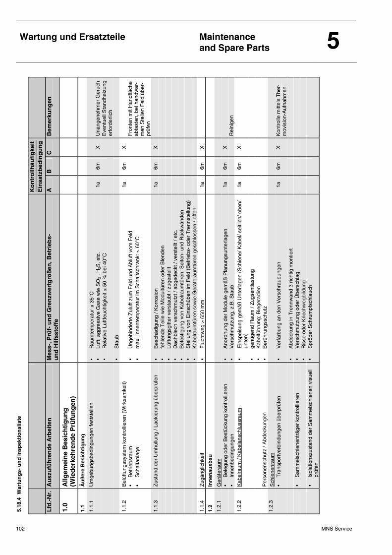
Wartung und Ersatzteile
Maintenance and Spare Parts
102 MNS Service
5.18
.4 W
artu
ng
s- u
nd
Insp
ekti
on
slis
te
K
on
tro
llhäu
fig
keit
E
insa
tzb
edin
gu
ng
Lfd
.-N
r.
Au
szu
füh
ren
de
Arb
eite
n
Mes
s-, P
rüf-
un
d G
ren
zwer
tgrö
ßen
, Bet
rieb
s-
un
d H
ilfss
toff
e A
B
C
B
emer
kun
gen
1.0
Allg
emei
ne
Bes
ich
tig
un
g
(Wie
der
keh
ren
de
Prü
fun
gen
)
1.1
Äu
ßer
e B
esic
hti
gu
ng
1.1.
1 U
mge
bung
sbed
ingu
ngen
fest
stel
len
• R
aum
tem
pera
tur
≤ 35
°C
• Lu
ft, a
ggre
ssiv
e G
ase
wie
SO
2 , H
2S, e
tc.
1a
6m
X
Una
ngen
ehm
er G
eruc
h
•
Rel
ativ
e Lu
ftfeu
chtig
keit
≤ 50
% b
ei 4
0°C
Eve
ntue
ll S
tand
heiz
ung
erfo
rder
lich
•
Sta
ub
1.1.
2 B
elüf
tung
ssys
tem
kon
trol
liere
n (W
irksa
mke
it)
1a
6m
X
•
Bet
riebs
raum
•
Ung
ehin
dert
e Z
uluf
t zum
Fel
d un
d A
bluf
t vom
Fel
d
•
Sch
alta
nlag
e •
max
. Inn
ente
mpe
ratu
r im
Sch
alts
chra
nk: ≤
60°
C
F
ront
en m
it H
andf
läch
e ab
tast
en, b
ei h
andw
ar-
men
Ste
llen
Fel
d üb
er-
prüf
en
1.1.
3 Z
usta
nd d
er U
mhü
llung
/ La
ckie
rung
übe
rprü
fen
• B
esch
ädig
ung
/ Kor
rosi
on
1a
6m
X
•
fehl
ende
Tei
le w
ie M
odul
türe
n od
er B
lend
en
• Lü
ftung
sgitt
er v
erst
aubt
/ zu
gest
ellt
• D
achb
lech
ver
schm
utzt
/ ab
gede
ckt /
ver
stel
lt / e
tc.
• B
efes
tigun
g vo
n K
abel
raum
türe
n, S
eite
n- u
nd R
ückw
ände
n
•
Ste
llung
von
Ein
schü
ben
im F
eld
(Bet
riebs
- od
er T
renn
stel
lung
)
•
Kab
elra
umtü
ren
sow
ie G
erät
erau
mtü
ren
gesc
hlos
sen
/ offe
n
1.
1.4
Zug
ängl
ichk
eit
• F
luch
tweg
≥ 6
50 m
m
1a
6m
X
1.2
Inn
enau
sbau
1.2.
1 G
erät
erau
m
• B
eleg
ung
oder
Bes
tück
ung
kont
rolli
eren
•
Ano
rdnu
ng d
er M
odul
e ge
mäß
Pla
nung
sunt
erla
gen
1a
6m
X
• In
nenb
edin
gung
en
• V
ersc
hmut
zung
, z.B
. Sta
ub
R
eini
gen
1.2.
2 K
abel
raum
/ K
abel
ansc
hlus
srau
m
• E
insp
eisu
ng g
emäß
Unt
erla
gen
(Sch
iene
/ Kab
el/ s
eitli
ch/ o
ben/
un
ten)
1a
6m
X
• ge
nüge
nd R
aum
/ Z
ugse
ntla
stun
g
•
Kab
elfü
hrun
g; B
iege
radi
en
P
erso
nens
chut
z / A
bdec
kung
en
• B
erüh
rung
ssch
utz
1.2.
3 S
chie
nenr
aum
•
Tra
nspo
rtve
rbin
dung
en ü
berp
rüfe
n •
Ver
färb
ung
an d
en V
ersc
hrau
bung
en
1a
6m
X
Kon
trol
le m
ittel
s T
her-
mov
isio
n-A
ufna
hmen
•
Abd
ecku
ng in
Tre
nnw
and
3 ric
htig
mon
tiert
• S
amm
elsc
hien
entr
äger
kon
trol
liere
n •
Ver
schm
utzu
ng o
der
Übe
rsch
lag
• R
isse
ode
r K
riech
weg
bild
ung
•
Isol
atio
nszu
stan
d de
r S
amm
elsc
hien
en v
isue
ll pr
üfen
•
Spr
öder
Sch
rum
pfsc
hlau
ch
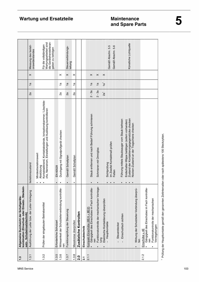
Wartung und Ersatzteile
Maintenance and Spare Parts
MNS Service 103
1.3
Allg
emei
ne
Du
rch
sich
t d
er S
chal
tger
äte-
kom
bin
atio
n (
Ein
sch
ub
- o
der
Ein
satz
-, S
teck
ein
-sa
tz-,
Sch
ub
ein
satz
tech
nik
)
1.3.
1 A
usfü
hrun
g de
r Le
iter
bzw
. der
Lei
ter-
Ver
legu
ng
Isol
atio
nszu
stan
d 2a
1a
X
M
essu
ng d
es Is
olat
i-on
swid
erst
ande
s
•
Min
dest
isol
atio
nsw
ert
• A
bstü
tzun
g
1.
3.2
Prü
fen
der
eing
ebau
ten
Bet
riebs
mitt
el
• K
onta
ktab
bran
d, K
onta
ktab
stän
de, I
onis
atio
nska
mm
er /
Lösc
hble
-ch
e, N
enns
trom
, Ein
stel
lung
en u
nd A
uslö
sung
kon
trol
liere
n
Für
die
vol
lstä
ndig
en
War
tung
sarb
eite
n si
nd
die
Ger
äteh
erst
elle
ran-
gabe
n zu
bef
olge
n 1.
3.5
Erf
orde
rlich
e S
chut
zart
•
EN
605
29
1.3.
6 W
irksa
mke
it de
r S
chut
zlei
terv
erbi
ndun
g ko
ntro
llie-
ren
• D
urch
gang
mit
Sig
nalp
rüfg
erät
che
cken
2a
1a
X
1.3.
7 F
unkt
ions
prüf
ung
der
Ste
ueru
ng
• G
emäß
Sch
altp
lan
2a
1a
X
Ste
uerv
erbi
ndun
gs-
leitu
ng
1.3.
8 M
essk
reis
e üb
erpr
üfen
•
Gem
äß S
chal
tpla
n 2a
1a
X
2.0
Zu
sätz
lich
e K
on
tro
llen
2.1
Ein
sch
ub
tech
nik
2.1.
1 K
ompa
kt-E
insc
hübe
(8E
/4 +
8E
/2)
• G
ängi
gkei
t des
Ein
schu
bes
im F
ach
kont
rolli
e-re
n •
Sta
ub e
ntfe
rnen
und
nac
h B
edar
f Füh
rung
sch
mie
ren
2 -
3a
1a
X
•
Fun
ktio
nsko
ntro
lle d
er m
echa
nisc
hen
Ver
riege
-lu
ng
• S
chm
iere
n m
it O
mni
glis
s 2
- 3a
1a
X
•
Ele
ktris
che
Kon
takt
ieru
ng ü
berp
rüfe
n
2a1
1a1
X
−
Hau
ptko
ntak
te
• S
icht
prüf
ung
•
Im Z
wei
fel K
onta
ktm
aß p
rüfe
n
Gem
äß A
bsch
n. 5
.5
• F
ette
n
Gem
äß A
bsch
n. 5
.6
−
S
teue
rste
cker
−
E
insc
hubf
ach
sich
ten
• F
ühru
ng m
ittel
s S
taub
saug
er v
om S
taub
bef
reie
n
• E
ndsc
halte
r-W
ippe
bet
ätig
en (
sofe
rn v
orha
nden
)
•
Zus
tand
der
Kon
takt
ieru
ngsg
egen
stüc
ke c
heck
en
K
ünst
liche
Lic
htqu
elle
•
Noc
ken-
Zus
tand
an
der
Tra
gsch
iene
che
cken
• W
irkun
g de
r S
chut
zlei
ter-
Ver
bind
ung
über
prü-
fen
2.1.
2 E
insc
hübe
≥ 4
E
• G
ängi
gkei
t des
Ein
schu
bes
im F
ach
kont
rolli
e-re
n
•
Fun
ktio
nsko
ntro
lle d
er m
echa
nisc
hen
V
errie
gelu
ngen
1 Prü
fung
der
Hau
ptko
ntak
te g
emäß
den
gen
annt
en Z
eitin
terv
alle
n od
er n
ach
spät
este
ns 1
00 S
teck
zykl
en.
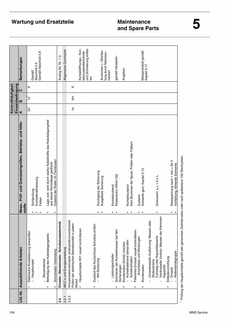
104 MNS Service
Wartung und Ersatzteile
Maintenance and Spare Parts
K
on
tro
llhäu
fig
keit
E
insa
tzb
edin
gu
ng
Lfd
.-N
r.
Au
szu
füh
ren
de
Arb
eite
n
Mes
s-, P
rüf-
un
d G
ren
zwer
tgrö
ßen
, Bet
rieb
s- u
nd
Hilf
s-st
off
e A
B
C
B
emer
kun
gen
•
Ele
ktris
che
Kon
takt
ieru
ng ü
berp
rüfe
n
2a1
1a1
X
−
Hau
ptko
ntak
t •
Sic
htpr
üfun
g •
Kon
takt
kraf
tmes
sung
•
Fet
ten
G
emäß
A
bsch
nitt
5.5
Gem
äß A
bsch
nitt
5.6
−
S
teue
rste
cker
•
Bef
estig
ung
des
Kab
elab
gang
stei
ls
• La
ge; e
vtl.
wird
dur
ch s
tark
e K
abel
kräf
te d
as K
abel
abga
ngst
eil
aus
sei
ner
Nor
mal
lage
ged
rück
t
•
Sch
utzl
eite
r-V
erbi
ndun
g •
Zus
tand
der
Rol
len
im F
achb
oden
2.2
Ein
satz
-, S
teck
ein
satz
-, S
chu
bei
nsa
tzte
chn
ik
Ana
log
lfd. N
r. 1
.3
2.2.
1 M
CC
’s u
nd E
nerg
ieve
rtei
lung
A
llgem
eine
Dur
chsi
cht
2.2.
2 K
ompe
nsat
ions
mod
ule
verd
ross
elt/u
nver
dros
selt
Prü
fen
der
elek
tris
chen
Bet
riebs
mitt
el in
jede
m
Mod
ul
1a
6m
X
•
Hau
ptko
ntak
te X
01 v
isue
ll ko
ntro
llier
en
Kon
takt
öffn
ungs
-, K
on-
takt
zust
ands
kont
rolle
un
d S
chm
ieru
ng e
ntfa
l-le
n
•
Zus
tand
des
Kur
zsch
luss
-Sch
utze
s pr
üfen
−
N
H-S
iche
rung
•
Dur
chga
ng d
er S
iche
rung
•
Aus
gelö
ste
Sic
heru
ng
A
nzei
chen
v. Ü
berla
s-tu
ng d
urch
Net
zres
o-na
nzen
−
Leis
tung
ssch
alte
r •
Kon
takt
zust
and
•
Sch
mie
ren
der
Kon
takt
mes
ser
bei N
H-
Sic
heru
ngen
•
Klü
berle
ctric
KR
44-1
02
ge
mäß
Her
stel
ler-
•
Kon
dens
ator
-Sch
ütz
chec
ken
Ang
aben
−
Kon
takt
abbr
and
über
prüf
en
• K
onta
ktzu
stan
d
−
Sch
altv
erha
lten
• K
ein
Bru
mm
en d
er S
pule
, Pre
llen
oder
Fla
ttern
• F
ilter
krei
s-D
ross
el v
isue
ll ko
ntro
llier
en
A
nsch
lüss
e un
d W
ickl
unge
n •
Zus
tand
• K
onde
nsat
or
• S
ollw
erte
gem
. Kap
itel 5
.15
M
essp
roto
koll
gem
äß
Kap
itel 5
.17
−
U
nver
dros
selte
Aus
führ
ung:
Mes
sen
alle
r S
tufe
nstr
öme
3-ph
asig
ode
r K
apaz
itäts
wer
te
• G
renz
wer
t: I B
≤ 1
,3 x
I n
−
V
erdr
osse
lte V
ersi
on: M
esse
n de
r K
lem
men
-K
apaz
ität
•
Ent
lade
vorr
icht
ung
−
Dro
ssel
•
Res
tspa
nnun
g na
ch 1
min
≤ 5
0 V
−
Wid
erst
ands
grup
pe
• V
erfä
rbun
g; fe
hlen
de E
lem
ente
1 Prü
fung
der
Hau
ptko
ntak
te g
emäß
den
gen
annt
en Z
eitin
terv
alle
n od
er n
ach
spät
este
ns 1
00 S
teck
zykl
en.
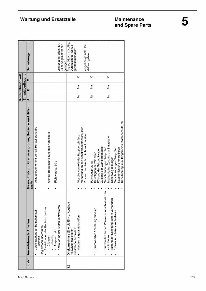
MNS Service 105
Wartung und Ersatzteile
Maintenance and Spare Parts
K
on
tro
llhäu
fig
keit
E
insa
tzb
edin
gu
ng
Lfd
.-N
r.
Au
szu
füh
ren
de
Arb
eite
n
Mes
s-, P
rüf-
un
d G
ren
zwer
tgrö
ßen
, Bet
rieb
s- u
nd
Hilf
s-st
off
e A
B
C
B
emer
kun
gen
•
Ver
schr
aubu
ng a
n B
etrie
bsm
ittel
•
Anz
ugsd
rehm
omen
t gem
äß H
erst
elle
rang
abe
−
Is
olat
ion
Reg
lerm
odul
übe
rprü
fen
• E
inst
ellu
ngen
des
Reg
lers
che
cken
−
C
/k-W
ert
• G
emäß
Bet
riebs
anle
itung
des
Her
stel
lers
−
Sol
l-cos
ϕ
−
Ans
prec
hzei
t •
Ric
htw
ert c
a. 6
0 s
•
Ans
teue
rung
der
Stu
fen
kont
rolli
eren
Le
istu
ngst
eil o
ffen,
d.h
. S
iche
rung
slas
ttren
ner
gezo
gen
2.3
Dir
ekta
nsc
hlu
ss (
Ene
rgie
Ein
- u.
Abg
änge
m
it Le
istu
ngss
chal
tern
)
Z
usät
zlic
he K
ontr
olle
n:
Ana
log
lfd. N
r. 1
.3 „
Allg
. D
urch
sich
t der
Sch
alt-
gerä
teko
mbi
natio
n“
•
Hau
ptsc
haltg
erät
übe
rprü
fen
• V
isue
lle K
ontr
olle
der
Hau
ptan
schl
üsse
1a
6m
X
• V
erfä
rbun
g an
den
Sch
alte
rhau
ptan
schl
üsse
n
•
Zus
tand
der
Hau
pt-
u. A
bbra
ndko
ntak
te
V
orge
hen
gem
äß H
er-
stel
lera
ngab
en
• F
unkt
ions
prüf
ung
1a
6m
X
• S
trom
wan
dler
-Ano
rdnu
ng c
heck
en
• B
efes
tigun
g de
r W
andl
er
• F
ühru
ng d
er S
ekun
därk
abel
•
Zus
tand
der
Wan
dler
gehä
use
•
Stü
tzst
reife
n an
den
Win
kel-
u. A
nsch
luss
sätz
en
• V
ersc
hrau
bung
en ü
berp
rüfe
n
ko
ntro
llier
en
• M
echa
nisc
her
Zus
tand
der
Stü
tzpl
atte
1a
6m
X
•
Zus
tand
der
Sch
ottu
ng (
sofe
rn v
orha
nden
) •
Krie
chw
eg-B
ildun
gen
•
Ext
erne
Ans
chlü
sse
kont
rolli
eren
•
Ver
schr
aubu
ngen
übe
rprü
fen
• K
abel
entla
stun
g ko
ntro
llier
en
• K
abel
führ
ung,
min
. Bie
gera
dien
, Kan
tens
chut
z, e
tc.
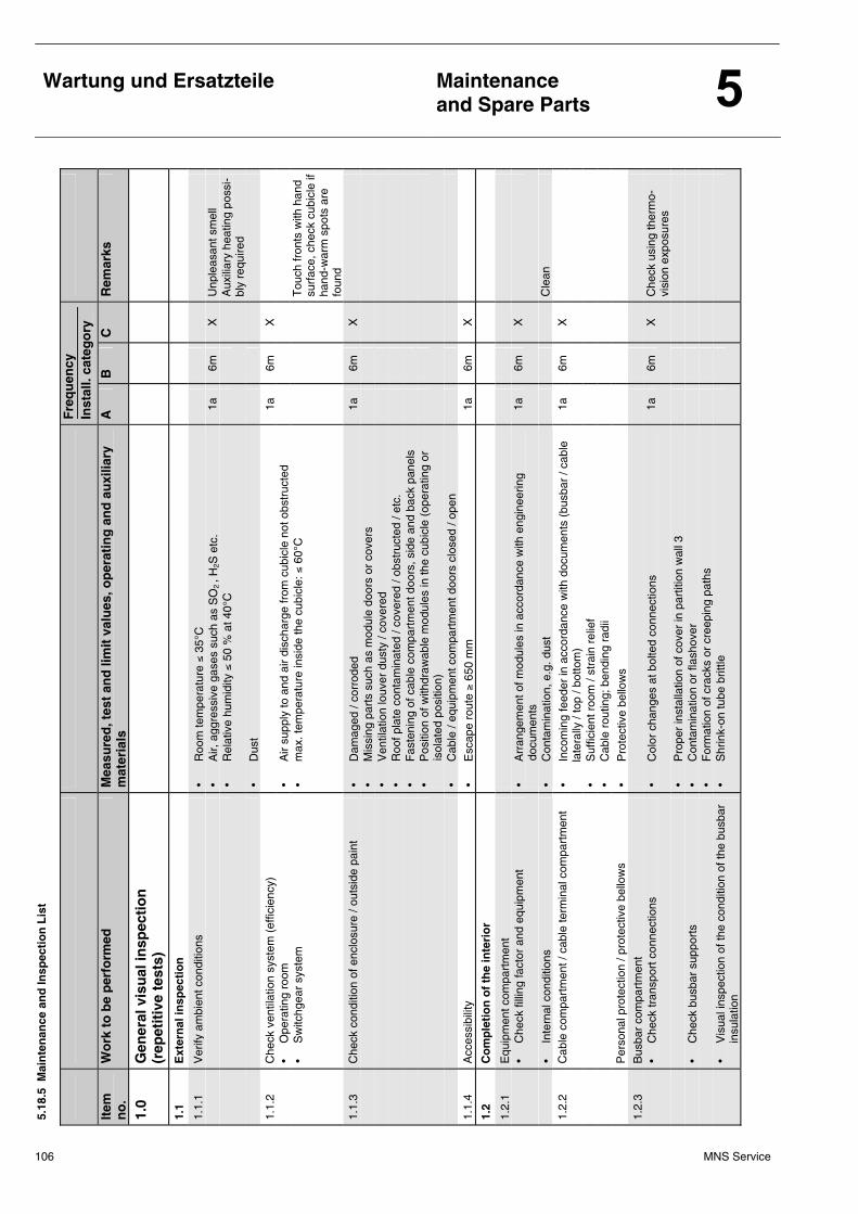
106 MNS Service
Wartung und Ersatzteile
Maintenance and Spare Parts
5.18
.5 M
ain
ten
ance
an
d In
spec
tio
n L
ist
F
req
uen
cy
Inst
all.
cate
go
ry
Item
n
o.
Wo
rk t
o b
e p
erfo
rmed
M
easu
red
, tes
t an
d li
mit
val
ues
, op
erat
ing
an
d a
uxi
liary
m
ater
ials
A
B
C
R
emar
ks
1.0
Gen
eral
vis
ual
insp
ecti
on
(r
epet
itiv
e te
sts)
1.1
Ext
ern
al in
spec
tio
n
1.1.
1 V
erify
am
bien
t con
ditio
ns
• R
oom
tem
pera
ture
≤ 3
5°C
•
Air,
agg
ress
ive
gase
s su
ch a
s S
O2 , H
2S e
tc.
1a
6m
X
Unp
leas
ant s
mel
l
•
Rel
ativ
e hu
mid
ity ≤
50
% a
t 40°
C
A
uxili
ary
heat
ing
poss
i-bl
y re
quire
d
•
Dus
t
1.
1.2
Che
ck v
entil
atio
n sy
stem
(ef
ficie
ncy)
1a
6m
X
• O
pera
ting
room
•
Air
supp
ly to
and
air
disc
harg
e fr
om c
ubic
le n
ot o
bstr
ucte
d
• S
witc
hgea
r sy
stem
•
max
. tem
pera
ture
insi
de th
e cu
bicl
e: ≤
60°
C
T
ouch
fron
ts w
ith h
and
surf
ace,
che
ck c
ubic
le if
ha
nd-w
arm
spo
ts a
re
foun
d 1.
1.3
Che
ck c
ondi
tion
of e
nclo
sure
/ ou
tsid
e pa
int
• D
amag
ed /
corr
oded
1a
6m
X
• M
issi
ng p
arts
suc
h as
mod
ule
door
s or
cov
ers
• V
entil
atio
n lo
uver
dus
ty /
cove
red
• R
oof p
late
con
tam
inat
ed /
cove
red
/ obs
truc
ted
/ etc
.
•
Fas
teni
ng o
f cab
le c
ompa
rtm
ent d
oors
, sid
e an
d ba
ck p
anel
s
•
Pos
ition
of w
ithdr
awab
le m
odul
es in
the
cubi
cle
(ope
ratin
g or
i
sola
ted
posi
tion)
• C
able
/ eq
uipm
ent c
ompa
rtm
ent d
oors
clo
sed
/ ope
n
1.
1.4
Acc
essi
bilit
y •
Esc
ape
rout
e ≥
650
mm
1a
6m
X
1.2
Co
mp
leti
on
of
the
inte
rio
r
1.2.
1 E
quip
men
t com
part
men
t
•
Che
ck fi
lling
fact
or a
nd e
quip
men
t •
Arr
ange
men
t of m
odul
es in
acc
orda
nce
with
eng
inee
ring
d
ocum
ents
1a
6m
X
•
Inte
rnal
con
ditio
ns
• C
onta
min
atio
n, e
.g. d
ust
C
lean
1.
2.2
Cab
le c
ompa
rtm
ent /
cab
le te
rmin
al c
ompa
rtm
ent
• In
com
ing
feed
er in
acc
orda
nce
with
doc
umen
ts (
busb
ar /
cabl
e 1a
6m
X
lat
eral
ly /
top
/ bot
tom
)
•
Suf
ficie
nt r
oom
/ st
rain
rel
ief
• C
able
rou
ting;
ben
ding
rad
ii
Per
sona
l pro
tect
ion
/ pro
tect
ive
bello
ws
• P
rote
ctiv
e be
llow
s
1.
2.3
Bus
bar
com
part
men
t
•
Che
ck tr
ansp
ort c
onne
ctio
ns
• C
olor
cha
nges
at b
olte
d co
nnec
tions
1a
6m
X
C
heck
usi
ng th
erm
o-
visi
on e
xpos
ures
•
Pro
per
inst
alla
tion
of c
over
in p
artit
ion
wal
l 3
•
Che
ck b
usba
r su
ppor
ts
• C
onta
min
atio
n or
flas
hove
r
•
For
mat
ion
of c
rack
s or
cre
epin
g pa
ths
•
Vis
ual i
nspe
ctio
n of
the
cond
ition
of t
he b
usba
r in
sula
tion
• S
hrin
k-on
tube
brit
tle
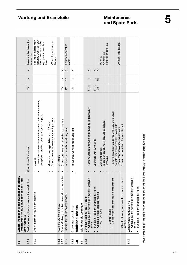
MNS Service 107
Wartung und Ersatzteile
Maintenance and Spare Parts
1.3
Gen
eral
insp
ecti
on
of
the
swit
chg
ear
asse
mb
ly
(wit
hd
raw
able
or
plu
g-i
n, d
isco
nn
ecta
ble
, rai
l-ab
le t
ech
niq
ue)
1.3.
1 D
esig
n of
con
duct
ors
and
cond
ucto
r in
stal
latio
n C
ondi
tion
of in
sula
tion
2a
1a
X
Mea
sure
the
insu
latio
n re
sist
ance
1.
3.2
Che
ck e
lect
rical
equ
ipm
ent i
nsta
lled
• B
raci
ng
• C
heck
con
tact
cor
rosi
on, c
onta
ct g
aps,
ioni
zatio
n ch
ambe
r,
arc
spl
itter
, rat
ed c
urre
nts,
set
tings
and
trip
ping
F
or th
e co
mpl
ete
mai
n-te
nanc
e w
ork,
obs
erve
th
e in
stru
ctio
ns o
f the
eq
uipm
ent m
anuf
ac-
ture
r
•
Min
imum
cre
epag
e di
stan
ce ≥
12,
5 m
m
• C
heck
min
imum
cle
aran
ce fo
r ar
cing
spa
ce
C
f. eq
uipm
ent m
anu-
fact
urer
1.
3.5
Req
uire
d pr
otec
tion
clas
s •
EN
605
29
1.3.
6 C
heck
effi
cien
cy o
f pro
tect
ive
cond
ucto
r co
nnec
tion
• C
heck
con
tinui
ty w
ith s
igna
l tes
t app
arat
us
2a
1a
X
1.
3.7
Fun
ctio
n te
st o
f the
con
trol
dev
ice
• In
acc
orda
nce
with
circ
uit d
iagr
am
2a
1a
X
Con
trol
con
nect
ion
cabl
e.
1.3.
8 C
heck
mea
surin
g lo
ops
• In
acc
orda
nce
with
circ
uit d
iagr
am
2a
1a
X
2.0
Ad
dit
ion
al c
hec
ks
2.
1 W
ith
dra
wab
le t
ech
niq
ue
2.1.
1 C
ompa
ct m
odul
es (
8E/4
+ 8
E/2
)
•
Che
ck e
asy
mov
emen
t of m
odul
e in
com
part
-m
ent
• R
emov
e du
st a
nd g
reas
e fr
om g
uide
rai
l if n
eces
sary
2
- 3a
1a
X
•
Fun
ctio
n te
st o
f mec
hani
cal i
nter
lock
•
Lubr
icat
e w
ith O
mni
glis
s 2
- 3a
1a
X
•
Che
ck e
lect
rical
con
tact
-mak
ing
2a
1 1a
1 X
−
M
ain
cont
acts
•
Vis
ual i
nspe
ctio
n
Ref
er to
•
In c
ase
of d
oubt
che
ck c
onta
ct c
lear
ance
Cha
pter
5.5
•
Gre
asin
g
Ref
er to
cha
pter
5.6
−
Con
trol
plu
gs
−
Vis
ual i
nspe
ctio
n of
mod
ule
com
part
men
t •
Rem
ove
dust
from
gui
de r
ail w
ith v
acuu
m c
lean
er
• A
ctua
te li
mit
switc
h ro
cker
(if
avai
labl
e)
• C
heck
con
ditio
n of
mat
ing
cont
acts
Art
ifici
al li
ght s
ourc
e
• C
heck
effi
cien
cy o
f pro
tect
ive
cond
ucto
r co
n-ne
ctio
n •
Che
ck c
am c
ondi
tion
at s
uppo
rtin
g ra
il
2.1.
2 W
ithdr
awab
le m
odul
es ≥
4E
•
Che
ck e
asy
mov
emen
t of m
odul
e in
com
part
-m
ent
•
Fun
ctio
n te
st o
f mec
hani
cal i
nter
lock
1 Mai
n co
ntac
t to
be c
heck
ed e
ither
acc
ordi
ng th
e m
entio
ned
time
inte
rval
s or
late
st a
fter
100
cycl
es.
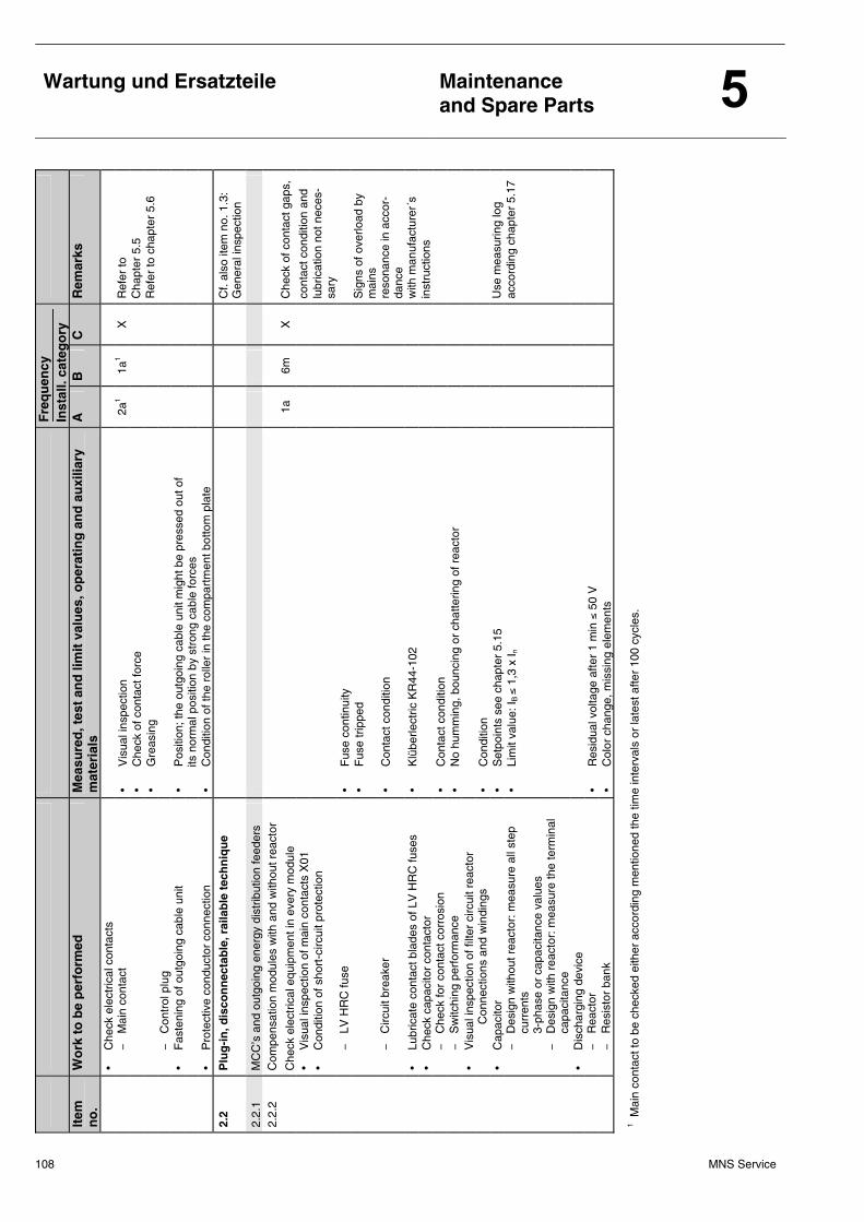
108 MNS Service
Wartung und Ersatzteile
Maintenance and Spare Parts
F
req
uen
cy
Inst
all.
cate
go
ry
Item
n
o.
Wo
rk t
o b
e p
erfo
rmed
M
easu
red
, tes
t an
d li
mit
val
ues
, op
erat
ing
an
d a
uxi
liary
m
ater
ials
A
B
C
R
emar
ks
•
Che
ck e
lect
rical
con
tact
s
−
M
ain
cont
act
• V
isua
l ins
pect
ion
2a1
1a1
X
Ref
er to
•
Che
ck o
f con
tact
forc
e
Cha
pter
5.5
•
Gre
asin
g
Ref
er to
cha
pter
5.6
−
Con
trol
plu
g
•
Fas
teni
ng o
f out
goin
g ca
ble
unit
• P
ositi
on; t
he o
utgo
ing
cabl
e un
it m
ight
be
pres
sed
out o
f
i
ts n
orm
al p
ositi
on b
y st
rong
cab
le fo
rces
• P
rote
ctiv
e co
nduc
tor
conn
ectio
n •
Con
ditio
n of
the
rolle
r in
the
com
part
men
t bot
tom
pla
te
2.2
Plu
g-i
n, d
isco
nn
ecta
ble
, rai
lab
le t
ech
niq
ue
Cf.
also
item
no.
1.3
: G
ener
al in
spec
tion
2.2.
1 M
CC
’s a
nd o
utgo
ing
ener
gy d
istr
ibut
ion
feed
ers
2.
2.2
Com
pens
atio
n m
odul
es w
ith a
nd w
ithou
t rea
ctor
C
heck
ele
ctric
al e
quip
men
t in
ever
y m
odul
e
1a
6m
X
Che
ck o
f con
tact
gap
s,
•
Vis
ual i
nspe
ctio
n of
mai
n co
ntac
ts X
01
cont
act c
ondi
tion
and
•
Con
ditio
n of
sho
rt-c
ircui
t pro
tect
ion
lubr
icat
ion
not n
eces
-sa
ry
−
LV
HR
C fu
se
• F
use
cont
inui
ty
• F
use
trip
ped
S
igns
of o
verlo
ad b
y m
ains
−
Circ
uit b
reak
er
• C
onta
ct c
ondi
tion
re
sona
nce
in a
ccor
-da
nce
•
Lubr
icat
e co
ntac
t bla
des
of L
V H
RC
fuse
s •
Klü
berle
ctric
KR
44-1
02
w
ith m
anuf
actu
rer´
s
• C
heck
cap
acito
r co
ntac
tor
inst
ruct
ions
−
Che
ck fo
r co
ntac
t cor
rosi
on
• C
onta
ct c
ondi
tion
−
S
witc
hing
per
form
ance
•
No
hum
min
g, b
ounc
ing
or c
hatte
ring
of r
eact
or
•
Vis
ual i
nspe
ctio
n of
filte
r ci
rcui
t rea
ctor
Con
nect
ions
and
win
ding
s •
Con
ditio
n
• C
apac
itor
• S
etpo
ints
see
cha
pter
5.1
5
Use
mea
surin
g lo
g
−
Des
ign
with
out r
eact
or: m
easu
re a
ll st
ep
curr
ents
3-
phas
e or
cap
acita
nce
valu
es
• Li
mit
valu
e: I B
≤ 1
,3 x
I n
ac
cord
ing
chap
ter
5.17
−
D
esig
n w
ith r
eact
or: m
easu
re th
e te
rmin
al
capa
cita
nce
•
Dis
char
ging
dev
ice
−
Rea
ctor
•
Res
idua
l vol
tage
afte
r 1
min
≤ 5
0 V
−
Res
isto
r ba
nk
• C
olor
cha
nge,
mis
sing
ele
men
ts
1 Mai
n co
ntac
t to
be c
heck
ed e
ither
acc
ordi
ng m
entio
ned
the
time
inte
rval
s or
late
st a
fter
100
cycl
es.
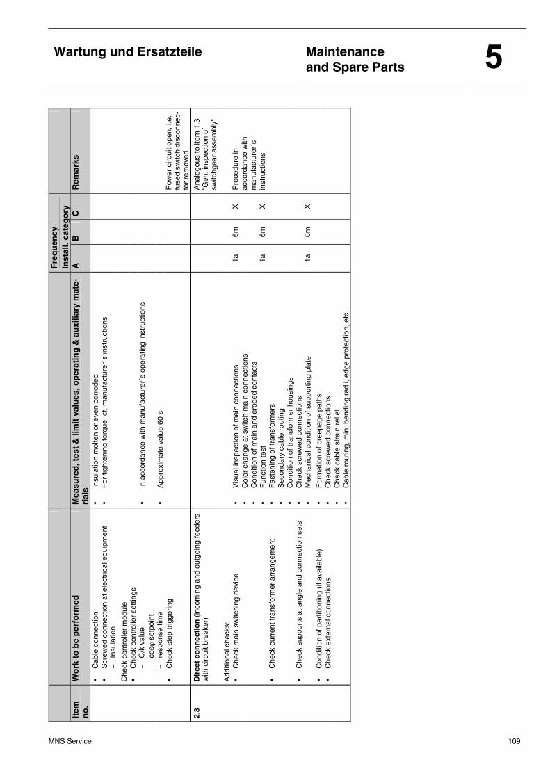
MNS Service 109
Wartung und Ersatzteile
Maintenance and Spare Parts
F
req
uen
cy
Inst
all.
cate
go
ry
Item
n
o.
Wo
rk t
o b
e p
erfo
rmed
M
easu
red
, tes
t &
lim
it v
alu
es, o
per
atin
g &
au
xilia
ry m
ate-
rial
s A
B
C
R
emar
ks
•
Cab
le c
onne
ctio
n •
Insu
latio
n m
olte
n or
eve
n co
rrod
ed
•
Scr
ewed
con
nect
ion
at e
lect
rical
equ
ipm
ent
• F
or ti
ghte
ning
torq
ue, c
f. m
anuf
actu
rer´
s in
stru
ctio
ns
−
In
sula
tion
Che
ck c
ontr
olle
r m
odul
e
•
Che
ck c
ontr
olle
r se
tting
s
−
C
/k v
alue
•
In a
ccor
danc
e w
ith m
anuf
actu
rer´
s op
erat
ing
inst
ruct
ions
−
cosϕ
set
poin
t
−
re
spon
se ti
me
• A
ppro
xim
ate
valu
e 60
s
•
Che
ck s
tep
trig
gerin
g
P
ower
circ
uit o
pen,
i.e.
fu
sed
switc
h di
scon
nec-
tor
rem
oved
2.3
Dir
ect
con
nec
tio
n (
inco
min
g an
d ou
tgoi
ng fe
eder
s w
ith c
ircui
t bre
aker
)
A
nalo
gous
to it
em 1
.3
"Gen
. ins
pect
ion
of
switc
hgea
r as
sem
bly"
A
dditi
onal
che
cks:
•
Che
ck m
ain
switc
hing
dev
ice
• V
isua
l ins
pect
ion
of m
ain
conn
ectio
ns
1a
6m
X
Pro
cedu
re in
•
Col
or c
hang
e at
sw
itch
mai
n co
nnec
tions
acco
rdan
ce w
ith
• C
ondi
tion
of m
ain
and
erod
ed c
onta
cts
m
anuf
actu
rer´
s
• F
unct
ion
test
1a
6m
X
in
stru
ctio
ns
•
Che
ck c
urre
nt tr
ansf
orm
er a
rran
gem
ent
• F
aste
ning
of t
rans
form
ers
• S
econ
dary
cab
le r
outin
g
•
Con
ditio
n of
tran
sfor
mer
hou
sing
s
• C
heck
sup
port
s at
ang
le a
nd c
onne
ctio
n se
ts
• C
heck
scr
ewed
con
nect
ions
•
Mec
hani
cal c
ondi
tion
of s
uppo
rtin
g pl
ate
1a
6m
X
•
Con
ditio
n of
par
titio
ning
(if
avai
labl
e)
• F
orm
atio
n of
cre
epag
e pa
ths
•
Che
ck e
xter
nal c
onne
ctio
ns
• C
heck
scr
ewed
con
nect
ions
•
Che
ck c
able
str
ain
relie
f
•
Cab
le r
outin
g, m
in. b
endi
ng r
adii,
edg
e pr
otec
tion,
etc
.
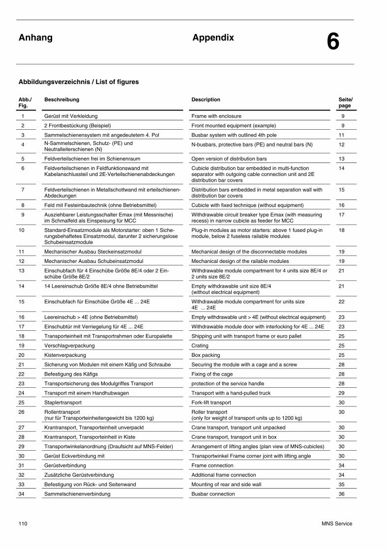
Anhang
Appendix 6
MNS Service 110
Abbildungsverzeichnis / List of figures
Abb./ Fig.
Beschreibung Description Seite/page
1 Gerüst mit Verkleidung Frame with enclosure 9
2 2 Frontbestückung (Beispiel) Front mounted equipment (example) 9
3 Sammelschienensystem mit angedeutetem 4. Pol Busbar system with outlined 4th pole 11
4 N-Sammelschienen, Schutz- (PE) und Neutralleiterschienen (N)
N-busbars, protective bars (PE) and neutral bars (N) 12
5 Feldverteilschienen frei im Schienenraum Open version of distribution bars 13
6 Feldverteilschienen in Feldfunktionswand mit Kabelanschlussteil und 2E-Verteilschienenabdeckungen
Cubicle distribution bar embedded in multi-function separator with outgoing cable connection unit and 2E distribution bar covers
14
7 Feldverteilschienen in Metallschottwand mit erteilschienen-Abdeckungen
Distribution bars embedded in metal separation wall with distribution bar covers
15
8 Feld mit Festeinbautechnik (ohne Betriebsmittel) Cubicle with fixed technique (without equipment) 16
9 Ausziehbarer Leistungsschalter Emax (mit Messnische) im Schmalfeld als Einspeisung für MCC
Withdrawable circuit breaker type Emax (with measuring recess) in narrow cubicle as feeder for MCC
17
10 Standard-Einsatzmodule als Motorstarter: oben 1 Siche-rungsbehaftetes Einsatzmodul, darunter 2 sicherungslose Schubeinsatzmodule
Plug-in modules as motor starters: above 1 fused plug-in module, below 2 fuseless railable modules
18
11 Mechanischer Ausbau Steckeinsatzmodul Mechanical design of the disconnectable modules 19
12 Mechanischer Ausbau Schubeinsatzmodul Mechanical design of the railable modules 19
13 Einschubfach für 4 Einschübe Größe 8E/4 oder 2 Ein-schübe Größe 8E/2
Withdrawable module compartment for 4 units size 8E/4 or 2 units size 8E/2
21
14 14 Leereinschub Größe 8E/4 ohne Betriebsmittel Empty withdrawable unit size 8E/4 (without electrical equipment)
21
15 Einschubfach für Einschübe Größe 4E ... 24E Withdrawable module compartment for units size 4E ... 24E
22
16 Leereinschub > 4E (ohne Betriebsmittel) Empty withdrawable unit > 4E (without electrical equipment) 23
17 Einschubtür mit Verriegelung für 4E ... 24E Withdrawable module door with interlocking for 4E ... 24E 23
18 Transporteinheit mit Transportrahmen oder Europalette Shipping unit with transport frame or euro pallet 25
19 Verschlagverpackung Crating 25
20 Kistenverpackung Box packing 25
21 Sicherung von Modulen mit einem Käfig und Schraube Securing the module with a cage and a screw 28
22 Befestigung des Käfigs Fixing of the cage 28
23 Transportsicherung des Modulgriffes Transport protection of the service handle 28
24 Transport mit einem Handhubwagen Transport with a hand-pulled truck 29
25 Staplertransport Fork-lift transport 30
26 Rollentransport (nur für Transporteinheitengewicht bis 1200 kg)
Roller transport (only for weight of transport units up to 1200 kg)
30
27 Krantransport, Transporteinheit unverpackt Crane transport, transport unit unpacked 30
28 Krantransport, Transporteinheit in Kiste Crane transport, transport unit in box 30
29 Transportwinkelanordnung (Draufsicht auf MNS-Felder) Arrangement of lifting angles (plan view of MNS-cubicles) 30
30 Gerüst Eckverbindung mit Transportwinkel Frame corner joint with lifting angle 30
31 Gerüstverbindung Frame connection 34
32 Zusätzliche Gerüstverbindung Additional frame connection 34
33 Befestigung von Rück- und Seitenwand Mounting of rear and side wall 35
34 Sammelschienenverbindung Busbar connection 36
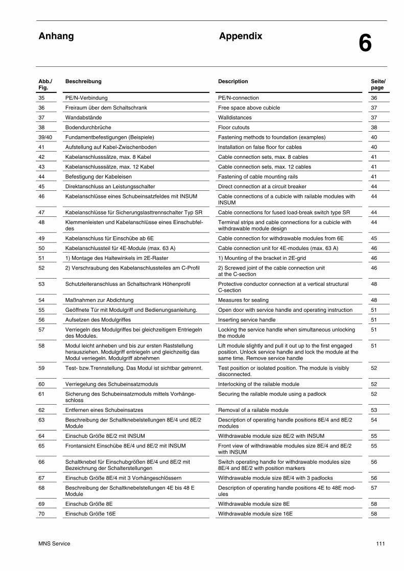
Anhang
Appendix 6
MNS Service 111
Abb./ Fig.
Beschreibung Description Seite/page
35 PE/N-Verbindung PE/N-connection 36
36 Freiraum über dem Schaltschrank Free space above cubicle 37
37 Wandabstände Walldistances 37
38 Bodendurchbrüche Floor cutouts 38
39/40 Fundamentbefestigungen (Beispiele) Fastening methods to foundation (examples) 40
41 Aufstellung auf Kabel-Zwischenboden Installation on false floor for cables 40
42 Kabelanschlusssätze, max. 8 Kabel Cable connection sets, max. 8 cables 41
43 Kabelanschlusssätze, max. 12 Kabel Cable connection sets, max. 12 cables 41
44 Befestigung der Kabeleisen Fastening of cable mounting rails 41
45 Direktanschluss an Leistungsschalter Direct connection at a circuit breaker 44
46 Kabelanschlüsse eines Schubeinsatzfeldes mit INSUM Cable connections of a cubicle with railable modules with INSUM
44
47 Kabelanschlüsse für Sicherungslasttrennschalter Typ SR Cable connections for fused load-break switch type SR 44
48 Klemmenleisten und Kabelanschlüsse eines Einschubfel-des
Terminal strips and cable connections for a cubicle with withdrawable module design
44
49 Kabelanschluss für Einschübe ab 6E Cable connection for withdrawable modules from 6E 45
50 Kabelanschlussteil für 4E-Module (max. 63 A) Cable connection unit for 4E-modules (max. 63 A) 46
51 1) Montage des Haltewinkels im 2E-Raster 1) Mounting of the bracket in 2E-grid 46
52 2) Verschraubung des Kabelanschlussteiles am C-Profil 2) Screwed joint of the cable connection unit at the C-section
46
53 Schutzleiteranschluss an Schaltschrank Höhenprofil Protective conductor connection at a vertical structural C-section
48
54 Maßnahmen zur Abdichtung Measures for sealing 48
55 Geöffnete Tür mit Modulgriff und Bedienungsanleitung. Open door with service handle and operating instruction 51
56 Aufsetzen des Modulgriffes Inserting service handle 51
57 Verriegeln des Modulgriffes bei gleichzeitigem Entriegeln des Modules.
Locking the service handle when simultaneous unlocking the module
51
58 Modul leicht anheben und bis zur ersten Raststellung herausziehen. Modulgriff entriegeln und gleichzeitig das Modul verriegeln. Modulgriff abnehmen
Lift module slightly and pull it out up to the first engaged position. Unlock service handle and lock the module at the same time. Remove service handle
51
59 Test- bzw.Trennstellung. Das Modul ist sichtbar getrennt. Test position or isolated position. The module is visibly disconnected.
52
60 Verriegelung des Schubeinsatzmoduls Interlocking of the railable module 52
61 Sicherung des Schubeinsatzmoduls mittels Vorhänge-schloss
Securing the railable module using a padlock 52
62 Entfernen eines Schubeinsatzes Removal of a railable module 53
63 Beschreibung der Schaltknebelstellungen 8E/4 und 8E/2 Module
Description of operating handle positions 8E/4 and 8E/2 modules
54
64 Einschub Größe 8E/2 mit INSUM Withdrawable module size 8E/2 with INSUM 55
65 Frontansicht Einschübe 8E/4 und 8E/2 mit INSUM Front view of withdrawable modules size 8E/4 and 8E/2 with INSUM
55
66 Schaltknebel für Einschubgrößen 8E/4 und 8E/2 mit Bezeichnung der Schalterstellungen
Switch operating handle for withdrawable modules size 8E/4 and 8E/2 with position markers
56
67 Einschub Größe 8E/4 mit 3 Vorhängeschlössern Withdrawable module size 8E/4 with 3 padlocks 56
68 Beschreibung der Schaltknebelstellungen 4E bis 48 E Module
Description of operating handle positions 4E to 48E mod-ules
57
69 Einschub Größe 8E Withdrawable module size 8E 58
70 Einschub Größe 16E Withdrawable module size 16E 58
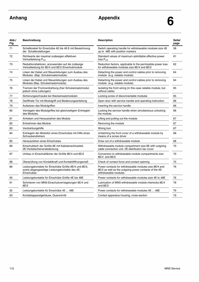
Anhang
Appendix 6
MNS Service 112
Abb./ Fig.
Beschreibung Description Seite/page
71 Schaltknebel für Einschübe 4E bis 48 E mit Bezeichnung der Schalterstellungen
Switch operating handle for withdrawable modules size 4E up to 48E with position markers
58
72 Richtwerte der maximal zulässigen effektiven VerIustleistung Pveff
Standard values of maximum admittable effective power loss Pveff
61
73 Reduktionsfaktoren, anzuwenden auf die zulässige Verlustleistung für 8E/4 und 8E/2 Einschubmodule
Reduction factors, applicable to the permissible power loss for withdrawable modules size 8E/4 and 8E/2
62
74 Lösen der Kabel und Steuerleitungen zum Ausbau des Modules (Bsp. Schubeinsatzmodule)
Detaching the power and control cables prior to removing module (e.g. railable module)
64
75 Lösen der Kabel und Steuerleitungen zum Ausbau des Modules (Bsp. Schubeinsatzmodule)
Detaching the power and control cables prior to removing module (e.g. railable module)
64
76 Trennen der Frontverdrahtung (hier Schubeinsatzmodul, jedoch ohne Leitungen)
Isolating the front wiring (in this case railable module, but without cable)
65
77 Sicherungsschraube bei Steckeinsatzmodulen Locking screw of disconnectable modules 65
78 Geöffnete Tür mit Modulgriff und Bedienungsanleitung Open door with service handle and operating instruction 66
79 Aufsetzen des Modulgriffes Inserting the service handle 66
80 Verriegeln des Modulgriffes bei gleichzeitigem Entriegeln des Modules.
Locking the service handle when simultaneous unlocking the module.
66
81 Anheben und Herausziehen des Moduls Lifting and pulling out the module 67
82 Entnehmen des Moduls Removing the module 67
83 Verdrahtungshilfe Wiring tool 67
84 Entriegeln der Modultür eines Einschubes mit Hilfe eines Schraubendrehers
Unlatching the front cover of a withdrawable module by means of a screw driver
68
85 Herausziehen eines Einschubes Draw out of a withdrawable module 68
86 Einschubfach der Größe 8E mit Kabelanschlussteil, 2E-Verteilschienenabdeckung
Withdrawable module compartment size 8E with outgoing cable connection unit, 2E-distribution bar cover
70
87 Umbau in Einschubfächer der Größe 8E/4 und 8E/2 Conversion to withdrawable module compartments size 8E/4 and 8E/2
70
88 Überprüfung von Kontaktkraft und Kontaktöffnungsmaß Check of contact force and contact opening 75
89 Leistungskontakte für Einschübe Größe 8E/4 und 8E/2, sowie abgangsseitige Leistungskontakte des 4E-Einschubes
Power contacts for withdrawable modules size 8E/4 and 8E/2 as well as the outgoing power contacts of the 4E-withdrawable modules
76
90 Leistungskontakte für Einschübe Größe 4E bis 48E Power contacts for withdrawable modules size 4E to 48E 76
91 Schmieren von MNS-Einschubverriegelungen 8E/4 und 8E/2
Lubrication of MNS-withdrawable module interlocks 8E/4 and 8E/2
78
92 Leistungskontakte für Einschübe 4E ... 48E Power contacts for withdrawable modules 4E ... 48E 79
93 Kontaktapparatgehäuse, Querschnitt Contact apparatus housing, cross-section 79
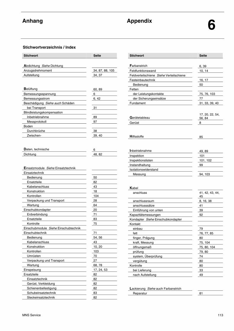
Anhang
Appendix 6
MNS Service 113
Stichwort Seite
Abdichtung Siehe Dichtung
Anzugsdrehmoment 34, 87, 88, 105
Aufstellung 34, 37
Belüftung
60, 89
Bemessungsspannung 6
Bemessungsstrom 6, 42
Beschädigung Siehe auch Schäden
bei Transport 31
Blindleistungskompensation
Inbetriebnahme 89
Messprotokoll 97
Boden
Durchbrüche 38
Zwischen- 39, 40
Daten, technische
6
Dichtung 48, 82
Einsatzmodule Siehe Einsatztechnik
Einsatztechnik
Bedienung 50
Ersatzteile 82
Kabelanschluss 43
Konstruktion 18
Kontrollen 104
Verpackung und Transport 28
Wartung 64
Einschubkondapter 20
Erdverbindung 71
Ersatzteile 83
Kontrolle 75
Einschubmodule Siehe Einschubtechnik
Einschubtechnik 71
Bedienung 54, 56
Kabelanschluss 43
Konstruktion 10, 20
Kontrollen 103
Umrüsten 70
Verpackung und Transport 27
Wartung 68, 78
Einspeisung 17, 24, 53
Ersatzteile 82
Einsatztechnik 82
Gerüst, Verkleidung 82
Schienenbefestigung 82
Schubeinsatztechnik 83
Steckeinsatztechnik 82
Stichwort Seite
Farbanstrich
6, 39
Feldfunktionswand 10, 14
Feldverteilschiene Siehe Verteilschiene
Festeinbautechnik 16, 17
Bedienung 50
Fetten
der Leistungskontakte 75, 76, 103
der Sicherungseinsätze 77
Fundament 31, 33, 39, 40
Gerätetableau
17, 20, 22, 54, 56, 84
Gerüst 8
Hilfsstoffe
85
Inbetriebnahme
49, 89
Inspektion 101
Inspektionslisten 101, 102
Instandhaltung 99
Isolationswiderstand
Messung 94, 103
Kabel
anschluss 41, 42, 43, 44, 45
anschlussraum 8, 16, 38
anschlusssätze 41
Einführung von unten 39
Kapazitätsmessungen 92
Kondapter Siehe Einschubkondapter
Kontakt
einbau 79
fett 76, 77, 85
finger, Prägung 80
kraft, Messung 75, 104
öffnungsmaß 75, 80, 104
prüfung 79, 80
system, Überprüfung 74
vergütung 80
Kontrolle 80
bei Lieferung 33
nach Aufstellung 49
Lackierung Siehe auch Farbanstrich
Reparatur 81
Stichwortverzeichnis / Index
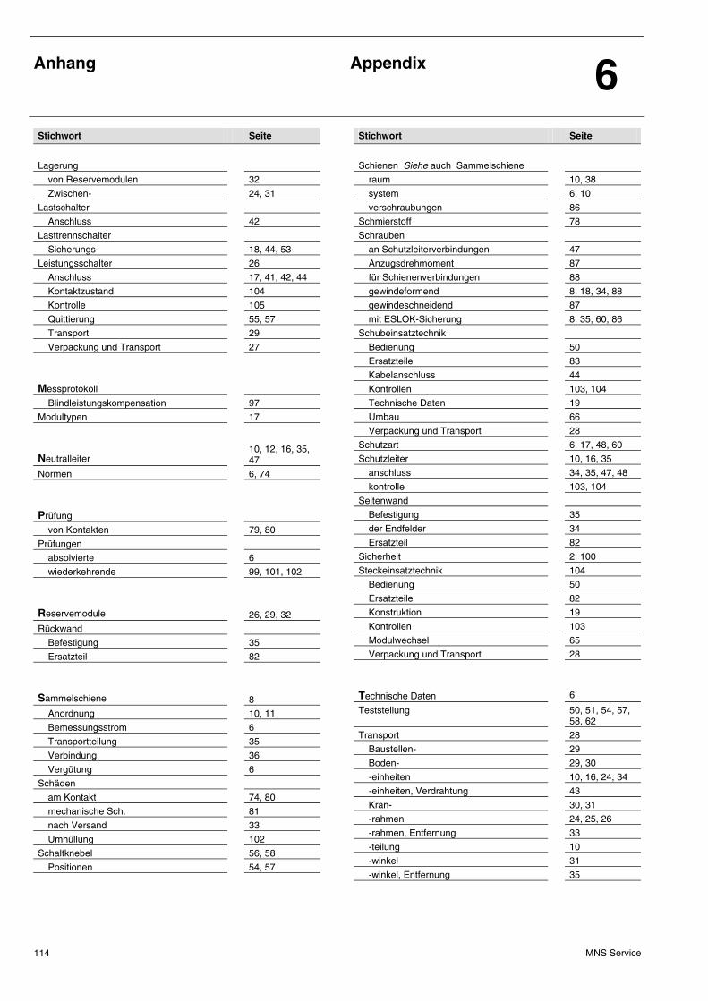
Anhang
Appendix 6
MNS Service 114
Stichwort Seite
Lagerung
von Reservemodulen 32
Zwischen- 24, 31
Lastschalter
Anschluss 42
Lasttrennschalter
Sicherungs- 18, 44, 53
Leistungsschalter 26
Anschluss 17, 41, 42, 44
Kontaktzustand 104
Kontrolle 105
Quittierung 55, 57
Transport 29
Verpackung und Transport 27
Messprotokoll
Blindleistungskompensation 97
Modultypen 17
Neutralleiter
10, 12, 16, 35, 47
Normen 6, 74
Prüfung
von Kontakten 79, 80
Prüfungen
absolvierte 6
wiederkehrende 99, 101, 102
Reservemodule
26, 29, 32
Rückwand
Befestigung 35
Ersatzteil 82
Sammelschiene
8
Anordnung 10, 11
Bemessungsstrom 6
Transportteilung 35
Verbindung 36
Vergütung 6
Schäden
am Kontakt 74, 80
mechanische Sch. 81
nach Versand 33
Umhüllung 102
Schaltknebel 56, 58
Positionen 54, 57
Stichwort Seite
Schienen Siehe auch Sammelschiene
raum 10, 38
system 6, 10
verschraubungen 86
Schmierstoff 78
Schrauben
an Schutzleiterverbindungen 47
Anzugsdrehmoment 87
für Schienenverbindungen 88
gewindeformend 8, 18, 34, 88
gewindeschneidend 87
mit ESLOK-Sicherung 8, 35, 60, 86
Schubeinsatztechnik
Bedienung 50
Ersatzteile 83
Kabelanschluss 44
Kontrollen 103, 104
Technische Daten 19
Umbau 66
Verpackung und Transport 28
Schutzart 6, 17, 48, 60
Schutzleiter 10, 16, 35
anschluss 34, 35, 47, 48
kontrolle 103, 104
Seitenwand
Befestigung 35
der Endfelder 34
Ersatzteil 82
Sicherheit 2, 100
Steckeinsatztechnik 104
Bedienung 50
Ersatzteile 82
Konstruktion 19
Kontrollen 103
Modulwechsel 65
Verpackung und Transport 28
Technische Daten
6
Teststellung 50, 51, 54, 57, 58, 62
Transport 28
Baustellen- 29
Boden- 29, 30
-einheiten 10, 16, 24, 34
-einheiten, Verdrahtung 43
Kran- 30, 31
-rahmen 24, 25, 26
-rahmen, Entfernung 33
-teilung 10
-winkel 31
-winkel, Entfernung 35
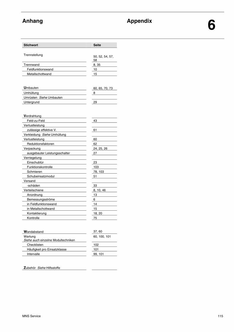
Anhang
Appendix 6
MNS Service 115
Stichwort Seite
Trennstellung
50, 52, 54, 57, 58
Trennwand 8, 35
Feldfunktionswand 10
Metallschottwand 15
Umbauten
60, 65, 70, 73
Umhüllung 8
Umrüsten Siehe Umbauten
Untergrund 29
Verdrahtung
Feld-zu-Feld 43
VerIustleistung
zulässige effektive V. 61
Verkleidung Siehe Umhüllung
Verlustleistung 60
Reduktionsfaktoren 62
Verpackung 24, 25, 26
ausgebauter Leistungsschalter 27
Verriegelung
Einschubtür 23
Funktionskontrolle 103
Schmieren 78, 103
Schubeinsatzmodul 51
Versand
-schäden 33
Verteilschiene 8, 10, 46
Anordnung 13
Bemessungsströme 6
in Feldfunktionswand 14
in Metallschottwand 15
Kontaktierung 18, 20
Kontrolle 75
Wandabstand
37, 60
Wartung Siehe auch einzelne Modultechniken
60, 100, 101
Checklisten 102
Häufigkeit pro Einsatzklasse 101
Intervalle 99, 101
Zubehör Siehe Hilfsstoffe
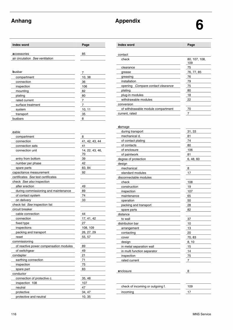
Anhang
Appendix 6
MNS Service 116
Index word Page
accessories
85
air circulation See ventilation
busbar
7
compartment 10, 38
connection 36
inspection 106
mounting 82
plating 80
rated current 7
surface treatment 7
system 10, 11
transport 35
busbars 8
cable
compartment 8
connection 41, 42, 43, 44
connection sets 41
connection unit 14, 22, 43, 46, 70
entry from bottom 39
number per phase 42
spare parts 83, 84
capacitance measurement 92
certificates See test certificates
check See also inspection
after erection 49
during commissioning and maintenance 89
of contact system 74
on delivery 33
check list See inspection list
circuit breaker
cable connection 44
connection 17, 41, 42
fixed type 27
inspections 108, 109
packing and transport 26, 27, 29
reset 55, 57
commissioning
of reactive power compensation modules 89
of switchgear 49
condapter 21
earthing connection 71
inspection 75
spare part 83
conductor
connection of protective c. 35, 48
inspection 108 107
neutral 47
protective 34, 47
protective and neutral 10, 35
Index word Page
contact
check 80, 107, 108, 109
clearance 75
grease 76, 77, 85
greasing 76
installation 79
opening Compare contact clearance 75
plating 80
plug-in modules 18
withdrawable modules 22
conversion
of withdrawable module compartment 70
current, rated 7
damage
during transport 31, 33
mechanical d. 81
of contact plating 74
of contacts 80
of enclosure 106
of paintwork 81
degree of protection 6, 48, 60
design
mechanical 8
standard modules 17
disconnectable modules
check 108
construction 19
inspection 107
maintenance 65
operation 50
packing and transport 28
spare parts 82
distance
to wall 37
distribution bar 10
arrangement 13
contacting 20
cover 70, 83
design 8, 10
in metal separation wall 15
in multi function separator 14
inspection 75
rated current 7
enclosure
8
check of incoming or outgoing f. 109
incoming 17
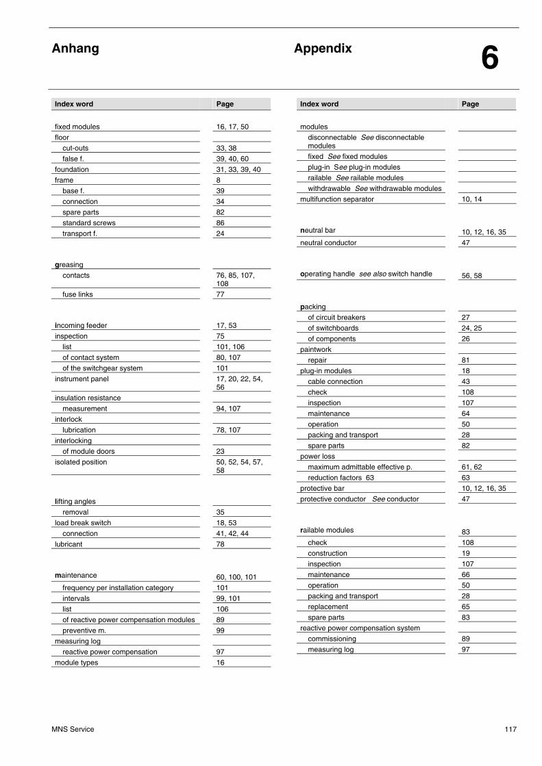
Anhang
Appendix 6
MNS Service 117
Index word Page
fixed modules
16, 17, 50
floor
cut-outs 33, 38
false f. 39, 40, 60
foundation 31, 33, 39, 40
frame 8
base f. 39
connection 34
spare parts 82
standard screws 86
transport f. 24
greasing
contacts 76, 85, 107, 108
fuse links 77
incoming feeder
17, 53
inspection 75
list 101, 106
of contact system 80, 107
of the switchgear system 101
instrument panel 17, 20, 22, 54, 56
insulation resistance
measurement 94, 107
interlock
lubrication 78, 107
interlocking
of module doors 23
isolated position 50, 52, 54, 57, 58
lifting angles
removal 35
load break switch 18, 53
connection 41, 42, 44
lubricant 78
maintenance
60, 100, 101
frequency per installation category 101
intervals 99, 101
list 106
of reactive power compensation modules 89
preventive m. 99
measuring log
reactive power compensation 97
module types 16
Index word Page
modules
disconnectable See disconnectable modules
fixed See fixed modules
plug-in See plug-in modules
railable See railable modules
withdrawable See withdrawable modules
multifunction separator 10, 14
neutral bar
10, 12, 16, 35
neutral conductor 47
operating handle see also switch handle
56, 58
packing
of circuit breakers 27
of switchboards 24, 25
of components 26
paintwork
repair 81
plug-in modules 18
cable connection 43
check 108
inspection 107
maintenance 64
operation 50
packing and transport 28
spare parts 82
power loss
maximum admittable effective p. 61, 62
reduction factors 63 63
protective bar 10, 12, 16, 35
protective conductor See conductor 47
railable modules
83
check 108
construction 19
inspection 107
maintenance 66
operation 50
packing and transport 28
replacement 65
spare parts 83
reactive power compensation system
commissioning 89
measuring log 97
Anhang
Appendix 6
MNS Service 118
Index word Page
safety
2, 100
screws
ESLOK secured 8, 35, 60, 86
for busbar connections 88
for galvanized surfaces 47
thread-forming
8, 18, 34
thread-rolling 87, 88
tightening torque 87
sealing 48, 82
separation wall See also multifunction separator
8
metal s. 15
shipping unit 10, 16, 24, 25, 31, 34, 43
spare modules 26, 29
storage 32
spare parts 82
busbar mounting 82
disconnectable modules 82
frame 82
plug-in modules 82
standards 7, 74
storage
intermediate 24, 31
period 31
switch handle 56
operation 58
positions 54, 57
technical data
7
test certificates 7
test position 50, 51, 52, 54, 57, 58, 62
testing
of contacts 79, 80
tests
repetitive 99, 101, 106
tightening torque 45, 46, 87, 88
Index word Page
transport
by crane 30, 31
frame 24, 25, 26
frame removal 33
on ground 29, 30
on site 29
ventilation
60, 89
voltages, rated 7
wall
distance to w. 37, 60
partition w. 35
rear w. 35
separation w. 8, 15
side w. 34, 35
weight 24, 29, 30
wiring 41
field-to-field 43
tool 83
withdrawable modules
cable connection 43
commissioning 44
condapter See condapter
construction 20
conversion 70
distribution bar connection 10
inspection 107
maintenance 68, 78
operation 54, 55, 56
packing and transport 27
test prior to installation 80


ABB Schaltanlagentechnik GmbH Wallstadter Str. 59 D - 68526 Ladenburg / Germany Related Products, News, Local Contacts / Weitere Produkte, Neuigkeiten, Kontakte: www.abb.com/mns
Editor / Herausgeber: DEAST/T Publication no./ Druckschriften-Nr. 1TGC902006M0402
ABB
ABB Low Voltage SystemsPublication Editor:ABB Automation Products GmbHLadenburg, Germany
Local Contacts onwww.abb.com/mns
Pub
licat
ion
no./
Dru
cksc
hrift
en-N
r. 1T
GC
9020
06M
0402
Contact
Note:We reserve the right to make technical changes or modify the contents of this document without prior notice. With regard to purchase orders, the agreed particulars shall prevail. ABB AG does not accept any responsibility whatsoever for potential errors or possible lack of information in this document.
We reserve all rights in this document and in the subject matter and illustrations contained therein. Any reproduction, disclosure to third parties or utilization of its contents – in whole or in parts – is forbidden without prior written consent of ABB AG.
Copyright© 2009 ABB All rights reserved