Embed Size (px)
Citation preview

P a g e | 1
Operation and MaintenanceeMWT-20
Mobile Wastewater Treatment System

P a g e | 2
TABLE OF CONTENTS
EMERGENCY CONTACTS……………………………………………………………… 2
TREATMENT TRAILER DRAWING………………………………………………........ 3
GLOSSARY……………………………………………………………………………….. 4
INTRODUCTION…………………………………………………………………………. 4
START-UP PROCEDURES………………………………………………………………. 5
OPERATING PROCEDURES……………………………………………………………. 5
MAINTENANCE PROCEDURES…………………………………………….……...….. 6
TROUBLESHOOTING…………………………………………….………………...…… 7
SAFETY DATA SHEETS…………………………………………….…………...……… 8
MANUFACTURER’S LITERATURE………………………………………………....… 12
MATERIALS LIST……………………………………………………………………….. 21
Emergency Contacts
Name Position 24/7 PhoneNumber
John Mulholland Operations Manager (989) 413-8103john@global-
treatmentsolutions.com
Alex FancyGeologist/ Certified
Water TreatmentOperator
(231) 631-4202afancy@global-
treatmentsolutions.com
P a g e | 3

P a g e | 4
Glossary
Carbon Vessel- Pressure vessel designed to hold up to 1,500 pounds of granular activatedcarbon with internal screening to keep the carbon within the vessel and allow the waste stream toexit.
Influent- Incoming waste stream prior to treatment.
Intermediate- Waste stream flow between the lead and lag carbon vessels
Empty Bed Contact Time (EBCT)- A measure of the time during which water to be treated isin contact with the treatment medium in a contact vessel, assuming that all liquid passes throughthe vessel at the same velocity. EBCT is equal to the volume of the empty bed divided by theflow rate.
Effluent- Waste stream after treatment
Granular Activated Carbon- A granular form of carbon processed to have small, low-volumepores that increase the surface area available for adsorption
Lead Carbon Vessel- The first bed of carbon contacted by the waste stream. Adsorbs themajority of organic contaminants in a waste stream (dependent on influent concentrations)
Lag Carbon Vessel- The last bed of carbon contacted by the waste stream. Gives the wastestream a final polish before discharge.
Spent Carbon- Carbon that has reach its maximum adsorption potential causing breakthrough ofcontaminants through the carbon bed.
Introduction
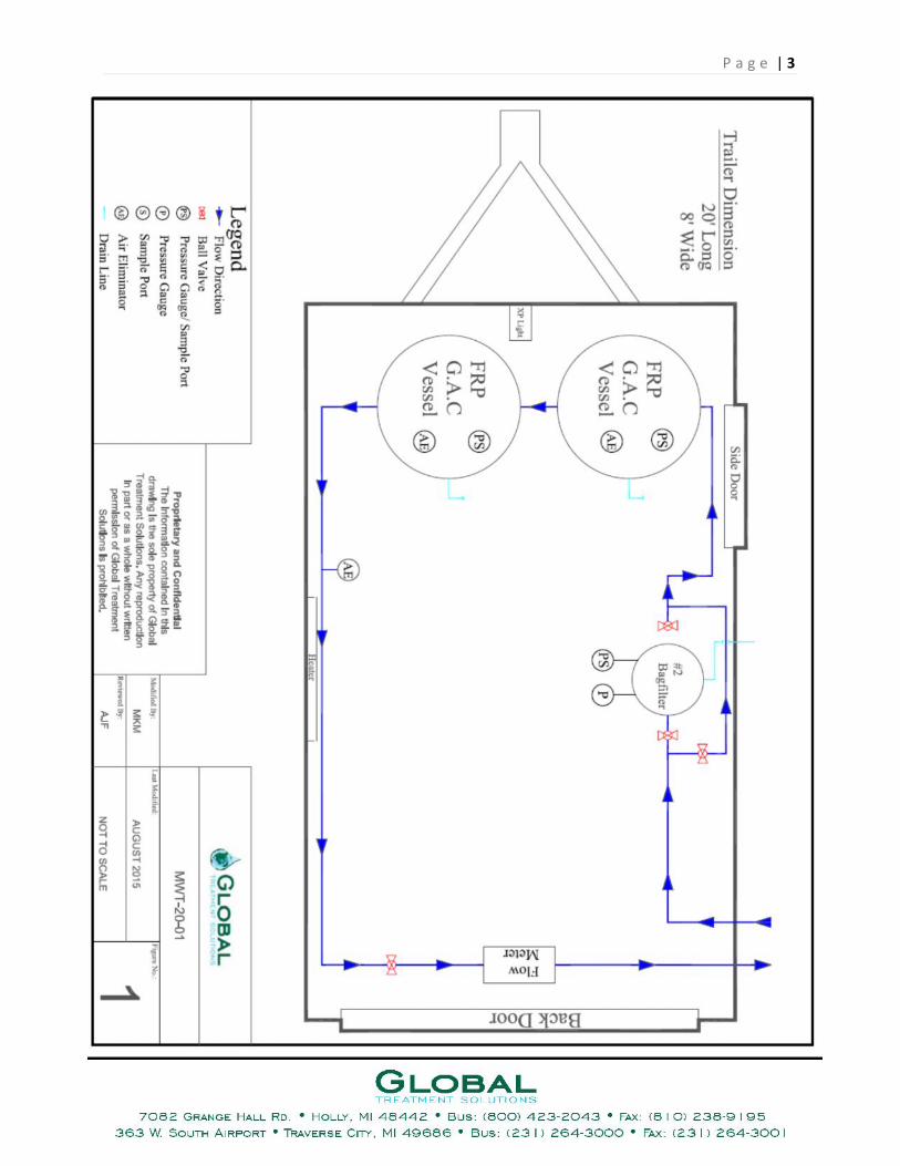
The purpose of this manual is to provide basic operation and maintenance for Global TreatmentSolution’s heated and enclosed MWT-20 activated carbon wastewater treatment trailer. Thissystem includes a single stage trade sized 2 bag filter housing, lead 300 LB FRP carbon vessel,and lag 300 LB FRP vessel. This system is equipped with influent, intermediate, and effluentpressure gauges with sampling ports.
The MWT-20 is a heated and enclosed trailer. All electrical components inside the trailer are XPrated. Power can be supplied using a 30 amp female connector or a 15 amp female connector.There is a light switch and thermostat located at the front right corner of the trailer next to theside door.
The MWT-20 is rated for a maximum flow rate of 20 GPM (dependent on customer’s pumpcapabilities) with an empty bed contact time (EBCT) of 7.5 minutes. Each carbon vessel can befilled with up to 300 pounds of granular activated carbon (G.A.C.).

P a g e | 5
This system is designed to remove particulates and organic contaminates from a waste stream inan efficient, user friendly process. Global Treatment Solutions technicians are available 24/7 toassist with the operation of this waste water treatment system.
Start-Up Procedures
Before treatment operations commence, Global recommends wetting the carbon. To do this, bothcarbon vessels are filled with water above the carbon line. Once this is done, the vessels are toremain inactive for at least 8 hours. After this period, the water within the tank will becomesaturated with fine carbon granules (often referred to as carbon dust) and will appear black incolor. Before effluent is discharged, Global recommends reprocessing the initial effluent until aclear discharge is observed.
Operating Procedures
Before the feed pump (customer supplied) can be started, a series of steps must be performed bythe treatment system operator:
1. Ensure appropriate influent, intermediate valves are open for all components oftreatment system.
2. Due to the fragile nature of the flow meter, Global recommends having the flowregulating valve ¼ open for the system start-up to ensure no damage is caused to the flowmeter.
3. After double checking valve orientation, pump is started and treatment can commence.
After system start-up, a few additional steps must be followed to ensure the efficient operation ofthe waste water treatment system:
1. Slowly open the regulating valve until fully open to ensure no damage is caused to theflow meter.
2. Check flowmeter to confirm flow.3. Bleed air from the bag filter housings. Lead and lag carbon vessels will do so
automatically.4. Observe influent and effluent pressures as well as flow rates to ensure
System Shut Down:
For short-term shut downs of the waste water treatment system, turn off feed pump and open airbleed valves on the bag filter housings and carbon vessels. The system has a built in anti-siphonwith vacuum break to ensure the carbon vessels do not drain to the discharge source. If feedpump does not have a built in check valve, the influent valves for the bag filter chambers shouldbe closed to ensure there is no back flow back to the feed pump.

P a g e | 6
For periods of extended shut down or in freezing conditions, the carbon vessels and bag filterhousing should be drained and all valves should be placed in the open position.
Maintenance Procedures
Bag Filters Change-outs
This treatment system has one single stage bag filter chamber. The chamber is equipped with aninfluent and effluent pressure gauge. During regular operations, these two gauges should have nomore than a 15 PSI pressure differential. As the bag filters collect particulates, the pressuredifferential between the two gauges will grow. At about a 15 PSI pressure differential, the filtersshould be changed. The process for changing the filters is described below:
1. Open 1” bag filter by pass valve or shut down feed pump.2. Close influent valve and effluent 1” ball valves to stop flow to the bag filter3. Open drain ball valve located at the bottom of the housing and open air bleeder valve on
the lid.4. Once water is drained out of chamber, loosen all bolts and lift the lid to access the bag
filter within the housing.5. Remove spent filter bag and replace with new one.6. Inspect gasket that makes the seal between the lid and the canister7. Lower lid onto the housing, ensure lid is straight before moving on to the next step.8. Tighten bolts in an alternating pattern to ensure lid is sealed properly9. Close drain valve and air bleeder10. Open influent/ effluent valves and resume filtration.11. Bleed air from bag filter housing, and carbon vessels.
Back Washing Carbon Vessels
As the volume of water treated increases, pressure drop across a carbon vessel may increase thusdecreasing flow rate. If this occurs, each vessel can be back washed to remove any finesediments. This will reduce the pressure drop and increase the flow rate. The system must beshut down before a back wash can begin. Back wash water should be discharged into a storagetank where it can be reprocessed. Global recommends using clean water to perform backwashoperations, but it is not required. The procedure for backwashing is as follows:
1. Turn off feed pump and shut down water treatment system.2. Disconnect influent and effluent hoses from vessel to be back washed.3. Connect back wash discharge hose to the vessel influent 1” camlock located at the top
right of the vessel4. Connect hose from the back wash feed pump (customer supplied) to the vessel effluent
1”camlock located at the top left of the vessel.

P a g e | 7
5. Ensure appropriate valves are opened and closed before activating backwash feed pump.6. Turn on backwash feed pump to commence backwash.
a. Back wash at a low velocity to minimize the loss of carbon7. Observe clarity of backwash discharge using the air bleed.8. Back wash for 5 to 20 minutes (depending on clarity)9. Once complete, shut down back wash feed pump and return system to original
configuration.
The duration of the back wash is determined by the clarity of the back wash discharge. The moreclarity present, the better the back wash.
Troubleshooting
Problem Probable Cause RemedyHigh pressure drop across
carbon vesselHigh discharge pressurecoming from feed pump
Improper valve configuration
High sediment load in carbon
Throttle down feed pump
Check valve sequence
Back wash vessel, considersmaller micron bag filters
Leaking Flange Loose bolts
Rotted gasket
Tighten bolts
Replace gasketCarbon granules in effluent Internal screen failure Remove carbon and repair
broken screenLow or no flow reading on
flow meterClogged bag filters
Improper valve configuration
High sediment load in carbon
Low volume of influent water
Broken flow meter
Replace bag filters
Check valve sequence
Back wash lead and lagvessels
Check influent source,consider throttling down feed
pump
Remove and replace flowmeter

P a g e | 8
Febuary 25, 2015
SAFETY DATA SHEET
IN CASE OF EMERGENCY OUTSIDE OF NORMAL BUSINESS HOURS CALLJOHN MULHOLLAND (989) 413-8103 OR ALEX FANCY (231) 631-4202
SECTION 1-IDENTIFICATION
CHEMICAL NAME : CarbonCAS NUMBER : 7440-44-0 (CARBON)COMMON NAME : ACTIVATED CARBONTYPE Reactivated Carbon
CHEMICAL FORMULA : C
SECTION 2- HAZARDOUS INGREDIENTS
CHEMICAL 8 PEL (OSHA) TLV (ACGIH) OTHERCARBON 100 N/A N/A N/A
CAUTION SHOULD BE TAKEN FOR A RESPIRABLE DUST.THE ACGIH TWA FOR RESPIRABLE DUST IS 1.0mg/M3.CARCINOGENIC PROPERTIES: NONE
SECTION 3- PHYSICAL DATA
DESCRIPTION: ODORLESS BLACK SOLID GRANULES.
VAPOR PRESSURE: N/A MELTING POINT: 6656 F (3680 C)APPARENT DENSITY: 0.3 TO 0.6gm/cc BOILING POINT: 7592 F (4200 C)SOLUBILITY: STABLE
EMPHASIZE PROTECTION AGAINST REPETITIVE OR LONG TERM EXPOSURETO CARBON DUST INHALATION.SECTION 4- FIRE AND EXPLOSION HAZARD DATA

P a g e | 9
FLASH POINT: N/AEXTINGUISHING MEDIA: WATER, FOAM, CO2, OR DRY CHEMICAL.SPECIAL FIRE FIGHTING PRECAUTIONS: NONE
UNUSUAL FIRE AND EXPLOSION HAZARDS: CONTACT WITH STRONGOXIDIZERS MAY RESULT IN FIRE.
SECTION 5-REACTIVITY DATA
STABILITY: STABLECONDITION TO AVOID: NONEINCOMPATIBILITY: AVOID CONTACT WITH STRONG OXIDIZERS.HAZARDOUS DECOMPOSITION PRODUCT: CARBON MONOXIDE MAY BEFORMED IN THE EVENT OF A FIRE.
SECTION 6-HEALTH DATA
ROUTE(S) OF ENTRY:
INGESTION: THIS PRODUCT IS NON-TOXIC THROUGHINGESTION THE ACTIVE ORAL LD 50 (RAT) IS
>10 gm/kg.
INHALATION: THE PHYSICAL NATURE OF THIS PRODUCTMAY IRRITATE THE RESPIRATORY
SYSTEM. THE ACUTE LC5 (RAT)IS>64.4 mg/L (NOMINALCONCENTRATION)
DERMAL EXPOSURE: THIS MATERIAL IS NON-TOXIC THROUGH SKINABSORPTION.
ACTIVATED CARBON IS NOT A PRIMARY SKIN IRRITANT.NO SENSITIZATION EFFECTS ARE KNOWN.EYE IRRITATION: THE PHYSICAL NATURE OF THIS PRODUCT MAY PRODUCEEYE IRRITATION.
FIRST AID: IN CASE OF EYE CONTACT FLUSH WITH WATER FOR AT LEAST 15MINUTES.
OTHER: THE EFFECTS OF CHRONIC AND SUBCHRONIC EXPOSURE HAVE NOTBEEN DETERMINED. SAFE HANDLING ON A LONG TERM BASIS SHOULDEMPHASIZE PROTECTION AGAINST REPETITIVE OR LONG TERM EXPOSURETO CARBON DUST INHALATION.

P a g e | 10
SECTION 7-SPILL OR LEAK PROCEDURE
IF THE MATERIAL IS RELEASED OR SPILLED: UNUSED PRODUCT SHOULD BESWEPT UP AND DISCARD OR REPACKAGED.
WASTE DISPOSAL METHOD:UNUSED CARBON MAY BE DISPOSED OF BY ANY APPROPRIATE MEANS. USEDPRODUCTS MAY CONTAIN HAZARDOUS CHEMICALS OR EXHIBIT HAZARDOUSPROPERTIES THAT MAY HAVE TO BE EXAMINED TO DETERMINEAPPROPRIATE DISPOSAL METHOD. THIS PRODUCT MUST BE DISPOSED OF INACCORDANCE WITH ALL FEDERAL, STATE, AND LOCAL REGULATIONS.
SECTION 8- HANDLING AND STORAGE
EYE PROTECTION: SAFETY GLASSES OR GOGGLES RECOMMENDED.
PROTECTIVE GLOVES: RECOMMENDED.
OTHER PROTECTIVE CLOTHING: NONE REQUIRED.
RESPIRATORY PROTECTION: A HIGH EFFICIENCY PARTICULATE FILTER ISRECOMMENDED WHENEVER EXCESSIVE DUST MAY BE GENERATED.
VENTILATION: LOCAL EXHAUST IS RECOMMENDED SUFFICIENT TOCONTROL DUST.
WORK/HYGIENIC: WASH THOROUGHLY AFTER HANDLING.
SECTION 9 - TRANSPORTATION DATA
PROPER SHIPPING (Article) NAME: Steam Activated Carbon, Non-Regulated ORCarbon, Activated, Non-Regulated
DOT CLASSIFICATION: NMFC 40560 / DOT MARKING: N/A / DOT PLACARD: N/A
EMERGENCY ACCIDENT PRECAUTIONS AND PROCEDURES:Contact: Global Treatment SolutionsPhone: 989-413-8103
PRECAUTIONS TO BE TAKEN IN TRANSPORTATION: N/A
OTHER CAUTION: WET ACTIVATED CARBON REMOVES OXYGEN FROM THEAIR CAUSING A SEVERE HAZARD TO WORKERS IN REQUIRED SPACE.SAMPLING AND WORK PROCEDURES FOR LOW OXYGEN LEVELS SHOULD BE

P a g e | 11
TAKEN WHENEVER WORKERS MAY BE ENTERING CARBON VESSELSENCLOSED OR CONFINED SPACE.ALL FEDERAL STATE AND LOCALREGULATIONS SHOULD BE OBSERVED.

P a g e | 12
Manufacturers Literature

P a g e | 13

P a g e | 14

P a g e | 15

P a g e | 16

P a g e | 17

P a g e | 18

P a g e | 19
P a g e | 20

P a g e | 21
Materials List
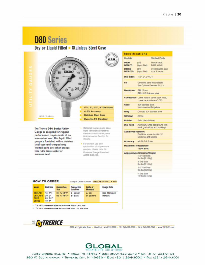
Filtration Equipment Pressure GaugesQuantity Item Descriptions Size Quantity Item Description
2 300 LB Carbon Vessels 1/4" 4 0-100 PSI Gauges1 SS Rosedale 8x30 Bag filter Canisters PVC SCH. 80 Fitting
Camlock Fittings 1" 10' PipeSize Quantity Item Description 1" 3 SOC X SOC 90 Degree Elbow2" 2 Male Cam X FNPT 1" 1 SOC Tee1" 12 Male Cam X MNPT 1" 3 SOC X MNPT Adapter1" 8 Female Cam X FNPT 1" 2 SOC X FNPT Adapter1" 16 16 Female Cam X Hose Barb 1" 1 SOC X SOC Union1" 5 Female Cam X FNPT1" 3 Female Cam Blind Caps Steel Fittings2" 2" 5 2" MNPT X 1" FNPT Reducing Bushing Galv.
Valves1-
1/4" 2 1-1/4" FNPT X 1" FNPT Reducer Galv.1" 5 FNPT Brass Ball Valve 1" 24 1" MNPT Nipple Galv.
1/2" 2 FNPT Brass Ball Valve 1" 6 FNPT X FNPT 90 Degree Elbow Galv.1/4" 4 FNPT Brass Ball Valve 1" 1 FNPT X MNPT 90 Degree Street Elbow Galv.
1" 2 FNPT X FNPT 24 Degree Elbow Galv.Hoses 1" 4 FNPT X FNPT Coupler SS
1" 35' Suction Hose 1" 3 FNPT Tee Galv.
1" 21" MNPT X 1/2" FNPT Reducing Bushing
Galv.Brass 1/2" 8 MNPT Nipple Galv.
1" 1 Watts Air Eliminator 1/2" 2 FNPT X FNPT 90 Degree Elbow Galv.1/4" 2 Watts Air Eliminator 1/4" 2 FNPT X FNPT 90 Degree Elbow Galv.1/4" 4 1/4" MNPT X 1/8" Hose Barb 1/4" 3 FNPT Tee Galv.
1/4" 9 MNPT Nipple Galv.
Customer is responsible for any damages that occur during the rental period. Parts and labor will be added to invoice.