Embed Size (px)
Citation preview
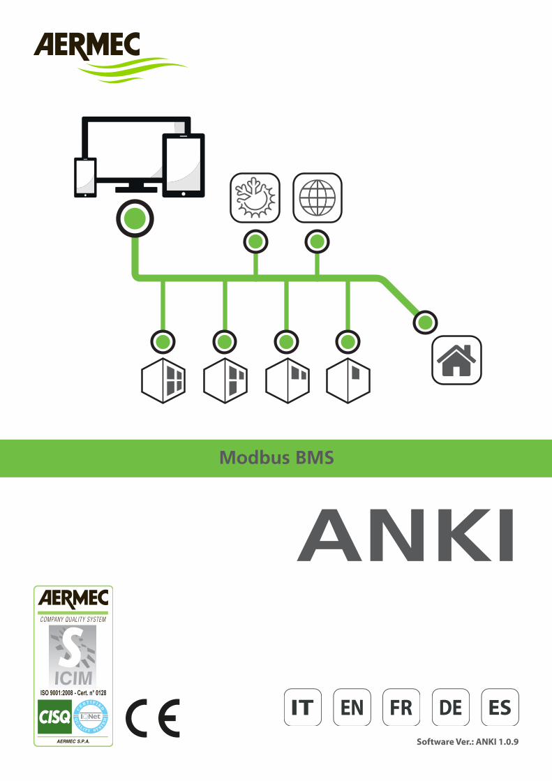
Modbus BMS
Software Ver.: ANKI 1.0.9
ANKI
2
Estimado cliente:La agradecemos por haber comprado un producto AERMEC. Es el resultado de muchos años de experiencia y estudios especiales de diseño, y ha sido constru-ido con materiales de la más alta calidad y tecnologías avanzadas. Nuestro nivel de calidad está sometido a una vigilancia constante, por lo que los productos AERMEC son sinónimo de Seguridad, Calidad y Fiabilidad.
Los datos pueden sufrir las modificaciones que se consideren necesarias para mejorar el producto, en cualquier momento y sin previo aviso.
Nuevamente gracias.AERMEC S.p.A.
Questo marchio indica che il prodotto non deve essere smaltito con altri rifiuti domestici in tutta l’UE. Per evitare eventuali danni all’ambiente o alla salute umana causati dall’errato smaltimento dei Rifiuti Elettrici ed Elettronici (RAEE), si prega di restituire il dispositivo utilizzando gli opportuni sistemi di raccolta, oppure contattando il riven-ditore presso il quale il prodotto è stato acquistato. Per maggiori informazioni si prega di contattare l’autorità locale competente. Lo smaltimento abusivo del prodotto da parte dell’utente comporta l’applicazione delle sanzioni ammini-strative previste dalla normativa vigente
Tutte le specifiche sono soggette a modifiche senza preavviso. Sebbene sia stato fatto ogni sforzo per assicurare la precisione, Aermec non si assume alcuna responsabilità per eventuali errori od omissioni.
Gentile cliente,La ringraziamo per aver preferito nell’acquisto un prodotto AERMEC. Esso è frutto di pluriennali esperienze e di particolari studi di progettazione, ed è sta-to costruito con materiali di primissima scelta e con tecnologie avanzatissime.Il livello qualitativo è sotto costante sorveglianza, ed i prodotti AERMEC sono pertanto sinonimo di Sicurezza, Qualità e Affidabilità.I dati possono subire modifiche ritenute necessarie per il miglioramento del prodotto, in qualsiasi momento senza obbligo di preavviso.
Nuovamente grazie.AERMEC S.p.A.
Dear customer,Thank you for choosing an AERMEC product. It's the result of many years of experience and dedicated design studies, and was built using first-class mate-rials and highly advanced technologies. The quality level is being constantly monitored, so AERMEC products are synonymous with Safety, Quality and Reliability.The data are subject to any modifications considered necessary to im-prove the product, at any time and without prior notice.
Thank you again.AERMEC S.p.A.
Cher client,Nous vous remercions d'avoir opté pour l'achat d'un produit AERMEC. Il est le résultat de nombreuses années d'expérience et d'études de conception spé-ciales et a été construit avec des matériaux de haute qualité et des technolo-gies de pointe. Le niveau de qualité est soumis à une surveillance constante et les produits AERMEC sont donc synonyme de sécurité, qualité et fiabilité.
Les données peuvent subir des modifications jugées nécessaires à l'amé-lioration du produit, à tout moment et sans préavis.
Nous vous remercions de nouveau.AERMEC S.p.A.
This marking indicates that this product should not be dis-posed with other household wastes in the entire EU. To pre-vent any harm to the environment or human health caused by incorrect disposal of Waste Electrical and Electronic Equipment (WEEE), please return the device using suitable collection systems, or contacting the retailer where the product was purchased. For further information please con-tact the appropriate local authority. The incorrect disposal of the product by the user will lead to the application of the administrative sanctions envisaged by the laws in force.
All specifications are subject to modification without prior notice. Although every effort has been made to ensure accuracy, Aermec cannot be held liable for any possible errors or omissions.
Ce symbole indique que le produit ne doit pas être éliminé avec les autres déchets ménagers dans l’UE. Pour éviter tout dommage à l’environnement ou à la santé humaine causé par une élimination incorrecte des déchets électriques et électroniques (DEEE), veuillez renvoyer l’appareil en utilisant les systèmes de collecte appropriés ou contacter le reven-deur chez qui vous avez acheté le produit. Pour plus d’in-formations, veuillez contacter l’autorité compétente locale. L’élimination illégale du produit par l’utilisateur entraîne l’application de sanctions administratives prévues par la législation en vigueur.
Toutes les spécifications peuvent faire l’objet de modifications sans préavis. Bien que tous les efforts aient été déployés pour en assurer l’exactitude, Aermec n’as-sume aucune responsabilité pour les éventuelles erreurs ou omissions.
Diese Marke weist darauf hin, dass das Produkt in der ganzen EG nicht mit anderen Hausabfällen entsorgt werden darf. Um eventuelle Umwelt- oder Gesundheitsschäden auf Grund einer unsachgemäßen Entsorgung von elektrischen und elektronischen Abfallprodukten (RAEE) zu vermeiden, wird darum gebeten, das Gerät an den entsprechenden Sammelstellen zu entsor-gen oder den Verkäufer des Geräts zu kontaktieren. Für nähere Informationen wird auf die zuständige örtliche Behörde ver-wiesen. Die unerlaubte Entsorgung des Produktes durch den Benutzer bringt administrative Sanktionen mit sich, die von den geltenden Vorschriften vorgesehen sind
Alle Spezifikationen können ohne Vorankündigung geändert werden. Obwohl die Fa. Aermec sich bemüht, Genauigkeit zu gewährleisten, übernimmt sie keine Verantwortung oder Haftung für eventuelle Fehler oder fehlende Informationen.
Esta marca indica que el producto no debe ser eliminado con otros residuos domésticos en toda la UE. Para evitar daños al medio ambiente o a la salud de las personas debido a la eliminación errónea de los Residuos Electrónicos y Electrotécnicos (RAEE), restituir el dispositivo uti-lizando los sistemas de recogida adecuados, o bien, contactando con el revendedor donde se compró el producto. Para más información, contactar con la autoridad local competente. La eliminación indiscriminada del producto por parte del cliente, conlleva a la aplicación de sanciones administrativas previstas por la normativa en vigor
Todas las modificaciones están sujetas a modificaciones sin previo aviso. Aunque se han realizado todos los esfuerzos para garantizar la precisión, Aermec no asume ninguna responsabilidad por errores u omisiones.
Sehr geehrter Kunde,Wir danken Ihnen dafür, dass Sie sich für ein Produkt von AERMEC entschieden haben. Dieses ist das Ergebnis langjähriger Erfahrung und besonderer Konstruk-tionsstudien und wurde mit erstklassigen Materialien und hoch fortschrittlichen Technologien hergestellt. Das Qualitätsniveau unterliegt einer ständigen Kontrol-le, weshalb AERMEC-Produkte für Sicherheit, Qualität und Zuverlässigkeit stehen.
Die Daten können jederzeit und ohne Vorankündigung Änderungen unter-liegen, die für die Produktverbesserung als notwendig erachtet werden.
Nochmals danke.AERMEC S.p.A.
parametro (L) menu installatore BAUDRATE0 96001 192002 38400
1. CARATTERISTICHE COMUNICAZIONE
• BAUDRATE: Il baudrate deve essere impostato attraverso parametro (N17) del menù installatore (password=30) del pannello comandi:
• STOP BITS: 2• PARITY: none• INDIRIZZO SERIALE: deve essere impostato attraverso il parametro
(N16) del menù installatore (password=30). Il valore dell’indirizzo seriale è impostabile tra 1-999.
cmd Descrizione0x01 Read Coil Status0x03 Read Holding Registers 0x05 Force Single Coil 0x06 Preset Single Register0x0F Preset Multiple Coils0x10 Preset Multiple Registers
2. CODICI MODBUS UTILIZZATI
COMANDI DIGITALI DISPONIBILI Read Coil StatusForce Single Coil
Force Multiple Coils
3. ELENCO DIGITALI (COIL)
Per avere la possibilità di scrivere i parametri COIL sulla scheda Modu_Control occorre abilitare i comandi di supervisione impostando il parametro parame-tro (N) = 1 del menù installatore (password=30) del pannello semplice.
Indirizzo Descrizione0 Comando Stanby/Acceso (toggle) 0=OFF 1=ON 1 Comando modo funzionamento (toggle) 0=FREDDO 1=CALDO2 Comando remoto acqua sanitaria 0=Normale, 1=Sanitario3 Abilitazione Termostato Remoto 0=Disabilitato, 1=Abilitato4 Comando Reset Allarmi. 1=Reset allarmi5 Stato compressore1 0=OFF 1=ON67 Stato Caldaia/Resistenza 0=OFF 1=ON8 Stato Produzione acqua sanitaria. 0=non attiva 1=attiva9 Stato ID acqua sanitaria 0=ID chiuso – 1=ID aperto
10 Stato ID ON_OFF remoto 0=ID chiuso – 1=ID aperto11 Stato ID stagione 0=ID chiuso (Freddo) , 1=ID aperto (Caldo)12 Stato ID termostato ambiente 0=ID chiuso – 1=ID aperto13 Riassunto Allarme75 Stato Uscita D01 (0=OFF 1=ON)76 Stato Uscita D02 (0=OFF 1=ON)77 Stato Uscita D03 (0=OFF 1=ON)78 Stato Uscita D04 (0=OFF 1=ON)79 Stato Uscita D05 (0=OFF 1=ON)80 Stato Uscita D06 (0=OFF 1=ON)81 Stato Uscita D07 (0=OFF 1=ON)82 Stato Uscita D08 (0=OFF 1=ON) 83 Stato Uscita D09 (0=OFF 1=ON)84 1 Errore in scrittura della memoria85 2 Sonda Ingresso Acqua Rotta o disconnessa86 3 Sonda Uscita Acqua rotta o disconnessa87 4 Sonda Aria Esterna rotta o disconnessa88 5Sonda Batteria rotta o disconnessa89 6 Sonda Scarico rotta o disconnessa90 7 Sonda Aspirazione rotta o disconnessa91 8 Trasduttore AP rotto o disconnesso
92 9 Trasduttore BP rotto o disconnesso93 10 Allarme basso surriscaldamento (EVD)94 11 Allarme LOP (EVD)95 12 Allarme MOP (EVD)96 13 Allarme alta temperatura Condensazione (EVD)97 14 Allarme bassa temperatura di aspirazione (EVD)98 15 Allarme valvola(EVD)99 16 Autotuning valvola (EVD)
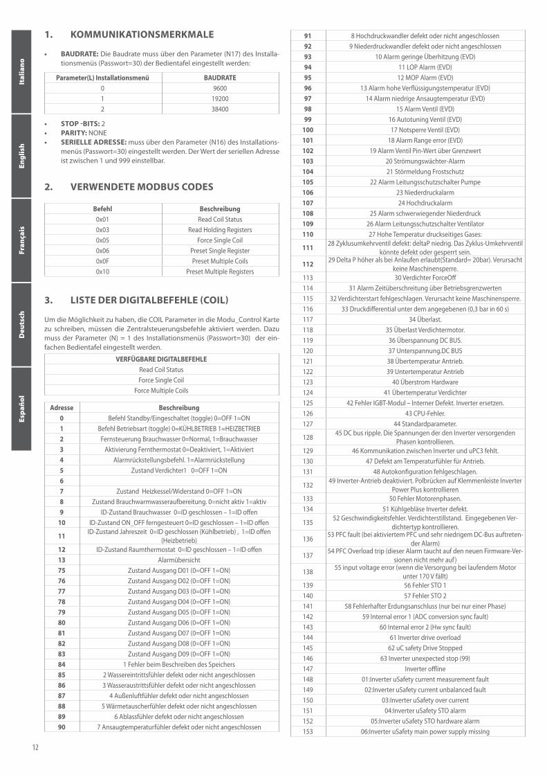
100 17 Chiusura emergenza valvola (EVD)101 18 Allarme Range error (EVD)102 19 Allarme Valvola valore pin fuori limite103 20 Allarme Flussostato104 21 Allarme antigelo105 22 Allarme magnetotermico pompa106 23 Allarme bassa pressione107 24 Allarme alta pressione108 25 Allarme bassa pressione grave109 26 Allarme magnetotermico ventilatore110 27 Temperatura gas premente elevata:
111 28 Valvola inversione di ciclo guasta: Basso deltaP. La valvola di inver-sione ciclo potrebbere essere guasta o bloccata.
112 29 Delta P maggiore del permesso allo start up ( default = 20bar). Non causa blocco macchina.
113 30 Compressore ForceOff114 31 Allarme Superamento tempo oltre i limiti operativi115 32 Avviamento fallito compressore. Non causa blocco macchina.
116 33 Differenziale di pressione inferiore a quello specificato (0,3 bar in 60sec)
117 34 Sovracorrente. 118 35 Sovraccarico Motore compressore. 119 36 Sovratensione DC BUS. 120 37 Sottotensione.DC BUS 121 38 Sovratemperatura drive. 122 39 Sottotemperatura drive 123 40 Sovracorrente Hardware 124 41 Sovratemperatura compressore 125 42 Errore modulo IGBT – Guasto interno. Sostituire Inverter. 126 43 Errore CPU. 127 44 Parametri default.
128 45 DC bus ripple. Controllare le tensioni delle fasi che alimentano l’inverter.
129 46 Comunicazione tra inverter e uPC3 assente. 130 47 Guasto sensore temperatura drive. 131 48 Autoconfigurazione fallita.
132 49 Drive inverter disabilitato . Controllare ponti su morsettiera Inverter Power Plus
133 50 Errore fasi motore. 134 51 Ventola di raffreddamento Inverter guasta.
135 52 Speed fault. Stallo compressore. Controllare tipo di compressore impostato.
136 53 PFC fault (allarme che si verifica con PFC abilitato mentre il bus DC è molto basso)
137 54 PFC overload trip (questo allarme non sarà più presente nelle nuove versioni di firmware)
138 55 input voltage error (quando l’alimentazione scende sotto i 170 V con motore in moto)
139 56 Errore STO 1140 57 Errore STO 2141 58 Guasto connessione di terra (solo per monofase)142 59 Internal error 1 (ADC conversion sync fault)143 60 Internal error 2 (Hw sync fault)144 61 Inverter drive overload145 62 uC safety Drive Stopped146 63 Inverter unexpected stop (99)147 Inverter offline148 01:Inverter uSafety current measurement fault149 02:Inverter uSafety current unbalanced fault150 03:Inverter uSafety over current151 04:Inverter uSafety STO alarm152 05:Inverter uSafety STO hardware alarm153 06:Inverter uSafety main power supply missing
3
Italiano
English
Fran
çais
Deu
tsch
Espa
ñol
154 07:Inverter uSafety HW fault on inverter command buffer155 08:Inverter uSafety HW fault on heater circuitry156 09:Inverter uSafety data communication fault157 10:Inverter uSafety compressor stall detect158 11:Inverter uSafety DC bus over current159 12:Inverter uSafety HWF DC bus current alarm160 13:Inverter uSafety DC bus voltage alarm161 14:Inverter uSafety HWF DC bus voltage alarm162 15:Inverter uSafety input voltage alarm163 16:Inverter uSafety HWF input voltage alarm164 Alta pressione da pressostato165 Allarme riassunto Termiche166 Sbrinamento forzato per alta temperatura gas premente167 Allarme alta temperatura ingresso acqua168 Allarme force off basso contenuto d’acqua169 Errore caricamento parametri inverter170 Inverter non compatibile con quello selezionato171 Avviamento fallito attesa tentativo sucessivo172 Massimo numero di avviamenti falliti173 Alta temperatura gas premente da inviluppo174 Allarme inviluppo zona 2: alto rapporto di compressione175 Allarme inviluppo zona 3: alta temperatura gas premente176 Allarme inviluppo zona 4: alta corrente compressore177 Allarme inviluppo zona 5: bassa pressione di aspirazione178 Allarme inviluppo zona 6: basso rapporto di compressione179 Allarme inviluppo zona 7: basso differenziale di pressione180 Allarme inviluppo zona 8: basso pressione di scarico181 Allarme inviluppo zona 9: bassa pressione di aspirazione 182 Allarme inviluppo zona 10: alta temperatura gas premente183 17:Inverter uSafety DC bus power alarm184 18:Inverter uSafety HWF power mismatch185 19:Inverter uSafety NTC over temperature186 20:Inverter uSafety NTC under temperature187 21:Inverter uSafety NTC fault188 22:Inverter uSafety HWF sync fault189 23:Inverter uSafety invalid parameter190 24:Inverter uSafety FW fault191 25:Inverter uSafety HW fault192 26:Inverter uSafety - reseved193 27:Inverter uSafety – reseved194 28:Inverter uSafety – reseved195 29:Inverter uSafety – reseved196 30:Inverter uSafety – reseved197 31:Inverter uSafety – reseved198 32:Inverter uSafety – reseved199 Sonda Remota DHW guasta200 Guasto Sonda ingresso multifunzione (accumulo impianto)
COMANDI DIGITALI DISPONIBILI Read Holding Register
4. ELENCO READ REGISTER
Indirizzo Descrizione UnitàRisoluzione
0 Tipologia macchina: 5 – ANKI2 Ingresso NTC1 (TIA) (SIW) 1=0,1°C3 Ingresso NTC2 (TUA) (SUW) 1=0,1°C4 Ingresso NTC3 (TSB) (SS) 1=0,1°C5 Ingresso NTC4 (TGP) (SGP) 1=0,1°C6 Ingresso NTC5 (TAE) (SAE) 1=0,1°C7 Ingresso trasduttore di alta pressione (AP) (TAP) 1=0,1BAR8 Ingresso trasduttore di bassa pressione (BP) (TBP) 1=0,1BAR9 Ingresso 0-10Vdd 1=0,1°V
10 Stato uscite digitali relè (non inserire nelle istruzioni) binario11 Banda sicurezza su force OFF 1=0,1°C12 Tempo all’avvio/spegnimento compressore SEC
COMANDI SCRITTURA DISPONIBILI Preset Single Register
Preset Multiple Registers
5. ELENCO WRITE REGISTER
Indirizzo Descrizione Limiti Min Max UnitàRisoluzione
39 Setpoint Freddo -200 ÷ 260 [°C] 1=0,1°C40 Banda Setpoint Freddo 10 ÷ 200 [°C] 1=0,1°C41 Setpoint Caldo 250 ÷ (REGISTER 38) 1=0,1°C42 Banda Setpoint Caldo 10 ÷ 200 [°C] 1=0,1°C43 Correzione Setpoint 0 ÷ 3 1=1
13 Ore funzionamento compressore primario (migliaia) 1=1000h14 Ore funzionamento compressore primario 1=1h
15 Numero di spunti effettuati dal compressore (migliaia) 1=1000
16 Numero di spunti effettuati dal compressore 1=117 Major sw version18 Minor sw version
19 Setpoint di regolazione della macchina (comprensi-va di correzioni) 1=0,1°C
20 Set pressione controllo della condensazione 1=0,1BAR
21 Differenziale di pressione per controllo condensa-zione 1=0,1BAR
22 Ore di funzionamento del compressore ausiliario (migliaia) 1=1000h
23 Ore di funzionamento del compressore ausiliario 1=1h
24 Numero di spunti effettuati dal compressore ausilia-rio (migliaia) 1=1000
25 Numero di spunti effettuati dal compressore ausiliario 1=1
26 Potenza fornita dalla macchina (chiller ON-OFF) Frequenza in uso (chiller inverter) Hz / %
27 Caduta di pressione in aspirazione del compressore 1=0,1bar28 Potenza richiesta al controllo inverter 1=1h
29 Configurazione Dip-Switch (0x0000 = tutti OFF ÷ 0x0FFF = tutti ON) 1=1000
30 Configurazione comandi remoti 1=1
31 Stato abilitazione termostato ambiente collegato a ingresso ID3 1= abilitato
32
Stato di funzionamento macchina: 0 - Chiller Off, 1 - Chiller On, 2 – Iniezione di parzializzazione, 3 – Sbrinamento per iniezione, 4 – Sbrinamento per
inversione di ciclo33 Accessorio Resistenza/Caldaia: 0- resistenza integrazione assente
1- resistenza integrazione montata ma non attiva durante la produzione di acqua sanitaria
2- comando attivazione resistenza utilizzato come consenso per accensione caldaia esterna
3- Resistenza integrazione presente e attiva durante la produzione di acqua sanitaria
4-comando attivazione resistenza utilizzato come
consenso per accensione caldaia esterna anche in modalità integrativa.
34 Corrente inverter Carel 1=0,1A35 Tensione uscita inverter Carel 1=1V36 Tensione di BUS inverter Carel 1=1V37 Temperatura Aletta di raffreddamento inverter Carel 1=0,1°C38 Limite massimo impostabile del Setpoint a caldo 1=0,1°C
57 Sonda ingresso acqua condensatore (Solo unità acqua/acqua) 1=0,1°C
58 Sonda uscita acqua condensatore (Solo unità acqua/acqua) 1=0,1°C
59 Countdown al prossimo sbrinamento per tempo (solo inverter) 1 min
60 Temperatura aspirazione (inverter Carel) 1=0,1°C61 Surriscaldamento (°K) (inverter Carel) 1=0,1°K62 Apertura valvola % (inverter Carel) 1=0,1%63 Apertura valvola (n° steps) (Inverter Carel) 1=1step64 Compressor rotor speed (rps) (Inverter Carel) 1=0,1rps65 Motor Power (Kw) (Inverter Carel) 1=0,1kW67 Tensione uscita DCP 1=0,1V
4
Italiano
English
Fran
çais
Deu
tsch
Espa
ñol
44 Set Freddo 1 -200 ÷ 260 [°C] 1=0,1°C45 TA Esterna freddo 1 400 ÷ 500 [°C] 1=0,1°C46 Set Freddo 2 -200 ÷ 260 [°C] 1=0,1°C47 TA Esterna freddo 2 -400 ÷ 500 [°C] 1=0,1°C48 Set Caldo 1 250 ÷ (REGISTER 38) 1=0,1°C49 TA Esterna Caldo 1 -400 ÷ 500 [°C] 1=0,1°C50 Set Caldo 2 250 ÷ (REGISTER 38) 1=0,1°C51 TA Esterna Caldo 2 -400 ÷ 500 [°C] 1=0,1°C52 Set Acqua Sanitaria -250 ÷ (REGISTER 38) 1=0,1°C53 Banda Acqua Sanitaria 10 ÷ 200 [°C] 1=0,1°C
54 Percentuale potenza richiesta da termostato 0 ÷ 100 [%] 1=1
55 PWD_SET_VMF -32768 ÷ 3276756 Sonda Remota DHW -32768 ÷ 32767
5
Italiano
English
Fran
çais
Deu
tsch
Espa
ñol

installer menu parameter (L) BAUDRATE0 96001 192002 38400
1. COMMUNICATION CHARACTERISTICS
• BAUDRATE: The baudrate must be set through the parameter (N17) form the installer menu (password=30) on the control panel:
• Stop bits: 2• PARITY: none• SERIAL ADDRESS: must be set through the parameter (N16) from the
installer menu (password=30). The value of the serial address can be set between 1 and 999.
cmd Description0x01 Read Coil Status0x03 Read Holding Registers 0x05 Force Single Coil 0x06 Preset Single Register0x0F Preset Multiple Coils0x10 Preset Multiple Registers
2. MODBUS CODES USED
DIGITAL COMMANDS AVAILABLE Read Coil StatusForce Single Coil
Force Multiple Coils
3. LIST OF DIGITAL COMMANDS (COIL)
To be able to write the COIL parameters on the Modu_Control tab, you must enable the supervision commands by setting parameter parameter(N) = 1 on the installer menu (password=30) of the simple panel.
Address Description0 Standby/ON command (toggle) 0=OFF 1=ON 1 Operating mode command (toggle) 0=COOL 1=HEAT2 Remote DHW command 0=Normal, 1=DHW3 Remote thermostat enabling 0=Disabled, 1=Enabled4 Alarm reset command 1=Reset alarms5 Status of compressor1 0=OFF 1=ON67 Status of boiler/heater 0=OFF 1=ON8 Status of DHW production 0=Not active 1=Active9 Status of DHW ID 0=ID closed – 1=ID open
10 Status of remote ON_OFF ID 0=ID closed – 1=ID open11 Status of season ID 0=ID closed (Cool), 1=ID open (Heat)12 Status of room thermostat ID 0=ID closed – 1=ID open13 Alarm summary75 Status of output D01 (0=OFF 1=ON)76 Status of output D02 (0=OFF 1=ON)77 Status of output D03 (0=OFF 1=ON)78 Status of output D04 (0=OFF 1=ON)79 Status of output D05 (0=OFF 1=ON)80 Status of output D06 (0=OFF 1=ON)81 Status of output D07 (0=OFF 1=ON)82 Status of output D08 (0=OFF 1=ON) 83 Status of output D09 (0=OFF 1=ON)84 1 Memory write error85 2 Water inlet probe broken or disconnected86 3 Water outlet probe broken or disconnected87 4 External air probe broken or disconnected88 5 Battery probe broken or disconnected89 6 Discharge probe broken or disconnected90 7 Intake probe broken or disconnected91 8 HP transducer broken or disconnected
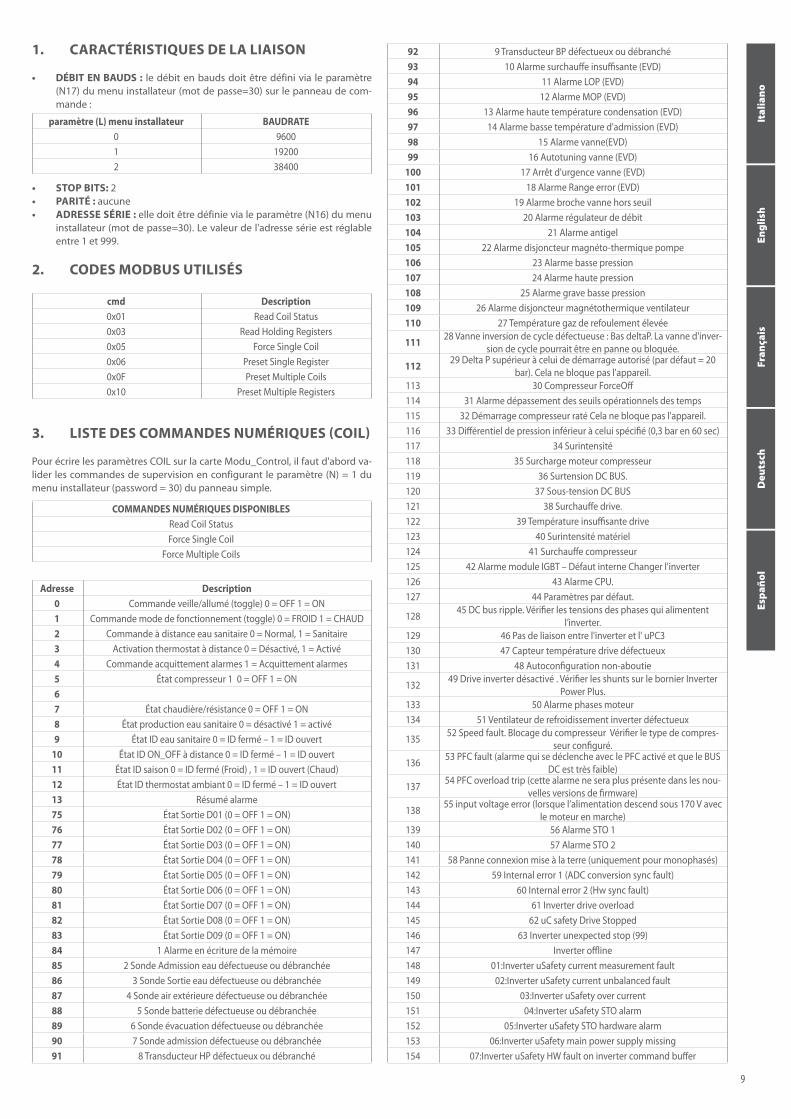
92 9 LP transducer broken or disconnected93 10 Low overheating alarm (EVD)94 11 LOP alarm (EVD)95 12 MOP alarm (EVD)96 13 High condensation temperature alarm (EVD)97 14 Low intake temperature alarm (EVD)98 15 Valve alarm (EVD)99 16 Valve self-tuning (EVD)
100 17 Emergency valve closure (EVD)101 18 Alarm range error (EVD)102 19 Valve alarm - pin value outside limit103 20 Flow switch alarm104 21 Anti-freeze alarm105 22 Thermomagnetic pump switch alarm106 23 Low pressure alarm107 24 High pressure alarm108 25 Serious low pressure alarm109 26 Thermomagnetic fan switch alarm110 27 High discharge gas temperature:
111 28 Faulty cycle inversion valve: Low deltaP. The reverse cycle valve could be faulty or blocked.
112 29 P delta greater than allowed at start-up (default = 20bar). Does not cause machine block.
113 30 ForceOff compressor114 31 Alarm for exceeded operating limit time115 32 Compressor start-up failed. Does not cause machine block.116 33 Pressure differential lower than specified value (0.3 bar in 60sec)117 34 Overcurrent 118 35 Compressor motor overload 119 36 DC BUS overvoltage 120 37 DC BUS undervoltage 121 38 Drive overtemperature 122 39 Drive undertemperature 123 40 Hardware overcurrent 124 41 Compressor overtemperature 125 42 IGBT module error – Internal fault. Replace inverter. 126 43 CPU error 127 44 Default parameters 128 45 DC BUS ripple. Check phase voltages powering the inverter.129 46 No communication between inverter and uPC3 130 47 Drive temperature sensor fault 131 48 Self-configuration failed
132 49 Inverter drive disabled. Check bridges on Power Plus Inverter terminal strip
133 50 Motor phase error 134 51 Inverter cooling fan faulty 135 52 Speed fault. Compressor stalled. Check type of compressor set.136 53 PFC fault (alarm occurs when PFC is enabled and DC BUS is very low)
137 54 PFC overload trip (this alarm will no longer be included in the new firmware versions)
138 55 Input voltage error (when power supply falls below 170V with the motor running)
139 56 STO 1 error140 57 STO 2 error141 58 Earth connection fault (for single-phase only)142 59 Internal error 1 (ADC conversion synch fault)143 60 Internal error 2 (hw synch fault)144 61 Inverter drive overload145 62 uC safety - Drive stopped146 63 Unexpected inverter stop (99)147 Inverter offline148 01:Inverter uSafety current measurement fault149 02:Inverter uSafety current unbalanced fault150 03:Inverter uSafety over current151 04:Inverter uSafety STO alarm152 05:Inverter uSafety STO hardware alarm153 06:Inverter uSafety main power supply missing154 07:Inverter uSafety HW fault on inverter command buffer155 08:Inverter uSafety HW fault on heater circuitry
6
Italiano
English
Fran
çais
Deu
tsch
Espa
ñol
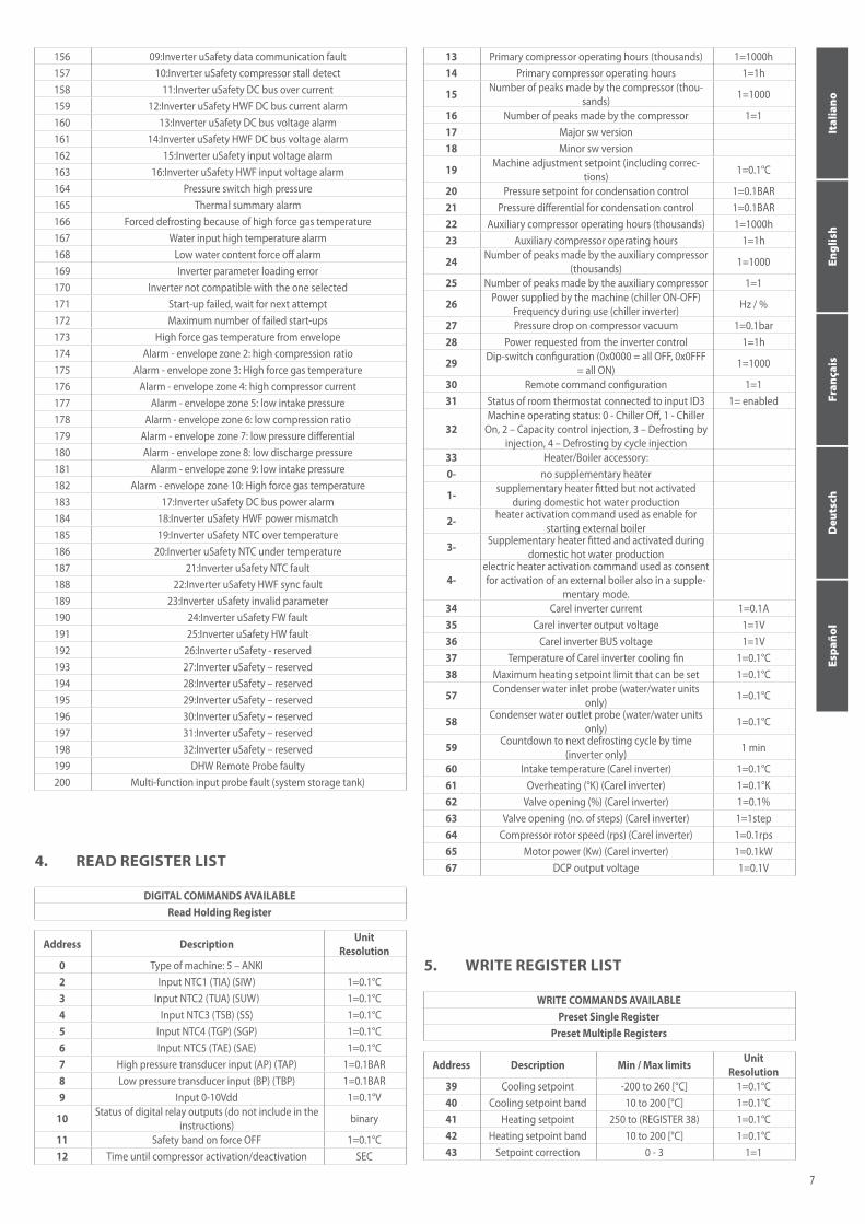
156 09:Inverter uSafety data communication fault157 10:Inverter uSafety compressor stall detect158 11:Inverter uSafety DC bus over current159 12:Inverter uSafety HWF DC bus current alarm160 13:Inverter uSafety DC bus voltage alarm161 14:Inverter uSafety HWF DC bus voltage alarm162 15:Inverter uSafety input voltage alarm163 16:Inverter uSafety HWF input voltage alarm164 Pressure switch high pressure165 Thermal summary alarm166 Forced defrosting because of high force gas temperature167 Water input high temperature alarm168 Low water content force off alarm169 Inverter parameter loading error170 Inverter not compatible with the one selected171 Start-up failed, wait for next attempt172 Maximum number of failed start-ups173 High force gas temperature from envelope174 Alarm - envelope zone 2: high compression ratio175 Alarm - envelope zone 3: High force gas temperature176 Alarm - envelope zone 4: high compressor current177 Alarm - envelope zone 5: low intake pressure178 Alarm - envelope zone 6: low compression ratio179 Alarm - envelope zone 7: low pressure differential180 Alarm - envelope zone 8: low discharge pressure181 Alarm - envelope zone 9: low intake pressure 182 Alarm - envelope zone 10: High force gas temperature183 17:Inverter uSafety DC bus power alarm184 18:Inverter uSafety HWF power mismatch185 19:Inverter uSafety NTC over temperature186 20:Inverter uSafety NTC under temperature187 21:Inverter uSafety NTC fault188 22:Inverter uSafety HWF sync fault189 23:Inverter uSafety invalid parameter190 24:Inverter uSafety FW fault191 25:Inverter uSafety HW fault192 26:Inverter uSafety - reserved193 27:Inverter uSafety – reserved194 28:Inverter uSafety – reserved195 29:Inverter uSafety – reserved196 30:Inverter uSafety – reserved197 31:Inverter uSafety – reserved198 32:Inverter uSafety – reserved199 DHW Remote Probe faulty200 Multi-function input probe fault (system storage tank)
DIGITAL COMMANDS AVAILABLE Read Holding Register
4. READ REGISTER LIST
Address Description UnitResolution
0 Type of machine: 5 – ANKI2 Input NTC1 (TIA) (SIW) 1=0.1°C3 Input NTC2 (TUA) (SUW) 1=0.1°C4 Input NTC3 (TSB) (SS) 1=0.1°C5 Input NTC4 (TGP) (SGP) 1=0.1°C6 Input NTC5 (TAE) (SAE) 1=0.1°C7 High pressure transducer input (AP) (TAP) 1=0.1BAR8 Low pressure transducer input (BP) (TBP) 1=0.1BAR9 Input 0-10Vdd 1=0.1°V
10 Status of digital relay outputs (do not include in the instructions) binary
11 Safety band on force OFF 1=0.1°C12 Time until compressor activation/deactivation SEC
WRITE COMMANDS AVAILABLE Preset Single Register
Preset Multiple Registers
5. WRITE REGISTER LIST
Address Description Min / Max limits UnitResolution
39 Cooling setpoint -200 to 260 [°C] 1=0.1°C40 Cooling setpoint band 10 to 200 [°C] 1=0.1°C41 Heating setpoint 250 to (REGISTER 38) 1=0.1°C42 Heating setpoint band 10 to 200 [°C] 1=0.1°C43 Setpoint correction 0 - 3 1=1
13 Primary compressor operating hours (thousands) 1=1000h14 Primary compressor operating hours 1=1h
15 Number of peaks made by the compressor (thou-sands) 1=1000
16 Number of peaks made by the compressor 1=117 Major sw version18 Minor sw version
19 Machine adjustment setpoint (including correc-tions) 1=0.1°C
20 Pressure setpoint for condensation control 1=0.1BAR21 Pressure differential for condensation control 1=0.1BAR22 Auxiliary compressor operating hours (thousands) 1=1000h23 Auxiliary compressor operating hours 1=1h
24 Number of peaks made by the auxiliary compressor (thousands) 1=1000
25 Number of peaks made by the auxiliary compressor 1=1
26 Power supplied by the machine (chiller ON-OFF) Frequency during use (chiller inverter) Hz / %
27 Pressure drop on compressor vacuum 1=0.1bar28 Power requested from the inverter control 1=1h
29 Dip-switch configuration (0x0000 = all OFF, 0x0FFF = all ON) 1=1000
30 Remote command configuration 1=131 Status of room thermostat connected to input ID3 1= enabled
32Machine operating status: 0 - Chiller Off, 1 - Chiller
On, 2 – Capacity control injection, 3 – Defrosting by injection, 4 – Defrosting by cycle injection
33 Heater/Boiler accessory: 0- no supplementary heater
1- supplementary heater fitted but not activated during domestic hot water production
2- heater activation command used as enable for starting external boiler
3- Supplementary heater fitted and activated during domestic hot water production
4-electric heater activation command used as consent for activation of an external boiler also in a supple-
mentary mode.34 Carel inverter current 1=0.1A35 Carel inverter output voltage 1=1V36 Carel inverter BUS voltage 1=1V37 Temperature of Carel inverter cooling fin 1=0.1°C38 Maximum heating setpoint limit that can be set 1=0.1°C
57 Condenser water inlet probe (water/water units only) 1=0.1°C
58 Condenser water outlet probe (water/water units only) 1=0.1°C
59 Countdown to next defrosting cycle by time (inverter only) 1 min
60 Intake temperature (Carel inverter) 1=0.1°C61 Overheating (°K) (Carel inverter) 1=0.1°K62 Valve opening (%) (Carel inverter) 1=0.1%63 Valve opening (no. of steps) (Carel inverter) 1=1step64 Compressor rotor speed (rps) (Carel inverter) 1=0.1rps65 Motor power (Kw) (Carel inverter) 1=0.1kW67 DCP output voltage 1=0.1V
7
Italiano
English
Fran
çais
Deu
tsch
Espa
ñol
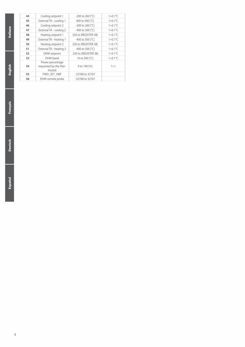
44 Cooling setpoint 1 -200 to 260 [°C] 1=0.1°C45 External TA - cooling 1 400 to 500 [°C] 1=0.1°C46 Cooling setpoint 2 -200 to 260 [°C] 1=0.1°C47 External TA - cooling 2 -400 to 500 [°C] 1=0.1°C48 Heating setpoint 1 250 to (REGISTER 38) 1=0.1°C49 External TA - heating 1 -400 to 500 [°C] 1=0.1°C50 Heating setpoint 2 250 to (REGISTER 38) 1=0.1°C51 External TA - heating 2 -400 to 500 [°C] 1=0.1°C52 DHW setpoint -250 to (REGISTER 38) 1=0.1°C53 DHW band 10 to 200 [°C] 1=0.1°C
54Power percentage
requested by the ther-mostat
0 to 100 [%] 1=1
55 PWD_SET_VMF -32768 to 3276756 DHW remote probe -32768 to 32767
8
Italiano
English
Fran
çais
Deu
tsch
Espa
ñol
paramètre (L) menu installateur BAUDRATE0 96001 192002 38400
1. CARACTÉRISTIQUES DE LA LIAISON
• DÉBIT EN BAUDS : le débit en bauds doit être défini via le paramètre (N17) du menu installateur (mot de passe=30) sur le panneau de com-mande :
• STOP BITS: 2• PARITÉ : aucune• ADRESSE SÉRIE : elle doit être définie via le paramètre (N16) du menu
installateur (mot de passe=30). Le valeur de l'adresse série est réglable entre 1 et 999.
cmd Description0x01 Read Coil Status0x03 Read Holding Registers 0x05 Force Single Coil 0x06 Preset Single Register0x0F Preset Multiple Coils0x10 Preset Multiple Registers
2. CODES MODBUS UTILISÉS
COMMANDES NUMÉRIQUES DISPONIBLES Read Coil StatusForce Single Coil
Force Multiple Coils
3. LISTE DES COMMANDES NUMÉRIQUES (COIL)
Pour écrire les paramètres COIL sur la carte Modu_Control, il faut d'abord va-lider les commandes de supervision en configurant le paramètre (N) = 1 du menu installateur (password = 30) du panneau simple.
Adresse Description0 Commande veille/allumé (toggle) 0 = OFF 1 = ON 1 Commande mode de fonctionnement (toggle) 0 = FROID 1 = CHAUD2 Commande à distance eau sanitaire 0 = Normal, 1 = Sanitaire3 Activation thermostat à distance 0 = Désactivé, 1 = Activé4 Commande acquittement alarmes 1 = Acquittement alarmes5 État compresseur 1 0 = OFF 1 = ON67 État chaudière/résistance 0 = OFF 1 = ON8 État production eau sanitaire 0 = désactivé 1 = activé9 État ID eau sanitaire 0 = ID fermé – 1 = ID ouvert
10 État ID ON_OFF à distance 0 = ID fermé – 1 = ID ouvert11 État ID saison 0 = ID fermé (Froid) , 1 = ID ouvert (Chaud)12 État ID thermostat ambiant 0 = ID fermé – 1 = ID ouvert13 Résumé alarme75 État Sortie D01 (0 = OFF 1 = ON)76 État Sortie D02 (0 = OFF 1 = ON)77 État Sortie D03 (0 = OFF 1 = ON)78 État Sortie D04 (0 = OFF 1 = ON)79 État Sortie D05 (0 = OFF 1 = ON)80 État Sortie D06 (0 = OFF 1 = ON)81 État Sortie D07 (0 = OFF 1 = ON)82 État Sortie D08 (0 = OFF 1 = ON) 83 État Sortie D09 (0 = OFF 1 = ON)84 1 Alarme en écriture de la mémoire85 2 Sonde Admission eau défectueuse ou débranchée86 3 Sonde Sortie eau défectueuse ou débranchée87 4 Sonde air extérieure défectueuse ou débranchée88 5 Sonde batterie défectueuse ou débranchée89 6 Sonde évacuation défectueuse ou débranchée90 7 Sonde admission défectueuse ou débranchée91 8 Transducteur HP défectueux ou débranché
92 9 Transducteur BP défectueux ou débranché93 10 Alarme surchauffe insuffisante (EVD)94 11 Alarme LOP (EVD)95 12 Alarme MOP (EVD)96 13 Alarme haute température condensation (EVD)97 14 Alarme basse température d'admission (EVD)98 15 Alarme vanne(EVD)99 16 Autotuning vanne (EVD)
100 17 Arrêt d'urgence vanne (EVD)101 18 Alarme Range error (EVD)102 19 Alarme broche vanne hors seuil103 20 Alarme régulateur de débit104 21 Alarme antigel105 22 Alarme disjoncteur magnéto-thermique pompe106 23 Alarme basse pression107 24 Alarme haute pression108 25 Alarme grave basse pression109 26 Alarme disjoncteur magnétothermique ventilateur110 27 Température gaz de refoulement élevée
111 28 Vanne inversion de cycle défectueuse : Bas deltaP. La vanne d'inver-sion de cycle pourrait être en panne ou bloquée.
112 29 Delta P supérieur à celui de démarrage autorisé (par défaut = 20 bar). Cela ne bloque pas l'appareil.
113 30 Compresseur ForceOff114 31 Alarme dépassement des seuils opérationnels des temps115 32 Démarrage compresseur raté Cela ne bloque pas l'appareil.116 33 Différentiel de pression inférieur à celui spécifié (0,3 bar en 60 sec)117 34 Surintensité 118 35 Surcharge moteur compresseur 119 36 Surtension DC BUS. 120 37 Sous-tension DC BUS 121 38 Surchauffe drive. 122 39 Température insuffisante drive 123 40 Surintensité matériel 124 41 Surchauffe compresseur 125 42 Alarme module IGBT – Défaut interne Changer l'inverter 126 43 Alarme CPU. 127 44 Paramètres par défaut.
128 45 DC bus ripple. Vérifier les tensions des phases qui alimentent l’inverter.
129 46 Pas de liaison entre l'inverter et l' uPC3 130 47 Capteur température drive défectueux 131 48 Autoconfiguration non-aboutie
132 49 Drive inverter désactivé . Vérifier les shunts sur le bornier Inverter Power Plus.
133 50 Alarme phases moteur 134 51 Ventilateur de refroidissement inverter défectueux
135 52 Speed fault. Blocage du compresseur Vérifier le type de compres-seur configuré.
136 53 PFC fault (alarme qui se déclenche avec le PFC activé et que le BUS DC est très faible)
137 54 PFC overload trip (cette alarme ne sera plus présente dans les nou-velles versions de firmware)
138 55 input voltage error (lorsque l’alimentation descend sous 170 V avec le moteur en marche)
139 56 Alarme STO 1140 57 Alarme STO 2141 58 Panne connexion mise à la terre (uniquement pour monophasés)142 59 Internal error 1 (ADC conversion sync fault)143 60 Internal error 2 (Hw sync fault)144 61 Inverter drive overload145 62 uC safety Drive Stopped146 63 Inverter unexpected stop (99)147 Inverter offline148 01:Inverter uSafety current measurement fault149 02:Inverter uSafety current unbalanced fault150 03:Inverter uSafety over current151 04:Inverter uSafety STO alarm152 05:Inverter uSafety STO hardware alarm153 06:Inverter uSafety main power supply missing154 07:Inverter uSafety HW fault on inverter command buffer
9
Italiano
English
Fran
çais
Deu
tsch
Espa
ñol
155 08:Inverter uSafety HW fault on heater circuitry156 09:Inverter uSafety data communication fault157 10:Inverter uSafety compressor stall detect158 11:Inverter uSafety DC bus over current159 12:Inverter uSafety HWF DC bus current alarm160 13:Inverter uSafety DC bus voltage alarm161 14:Inverter uSafety HWF DC bus voltage alarm162 15:Inverter uSafety input voltage alarm163 16:Inverter uSafety HWF input voltage alarm164 Haute pression du pressostat165 Alarme récapitulatif thermiques166 Dégivrage forcé pour température gaz de refoulement élevée167 Alarme de haute température d'entrée d'eau168 Alarme force off bas contenu d’eau169 Erreur chargement paramètres inverter170 Inverter incompatible avec celui sélectionné171 Démarrage échoué attente tentative suivant172 Nombre maximal de démarrages échoués173 Température du gaz de refoulement élevée par enveloppe174 Alarme enveloppe zone 2 : haut rapport de compression175 Alarme enveloppe zone 3 : température du gaz de refoulement élevée176 Alarme enveloppe zone 4 : courant élevé compresseur177 Alarme enveloppe zone 5 : pression d'aspiration faible178 Alarme enveloppe zone 6 : bas rapport de compression179 Alarme enveloppe zone 7 : bas différentiel de pression180 Alarme enveloppe zone 8 : basse pression d'évacuation181 Alarme enveloppe zone 9 : pression d'aspiration faible 182 Alarme enveloppe zone 10 : température du gaz de refoulement élevée183 17:Inverter uSafety DC bus power alarm184 18:Inverter uSafety HWF power mismatch185 19:Inverter uSafety NTC over temperature186 20:Inverter uSafety NTC under temperature187 21:Inverter uSafety NTC fault188 22:Inverter uSafety HWF sync fault189 23:Inverter uSafety invalid parameter190 24:Inverter uSafety FW fault191 25:Inverter uSafety HW fault192 26:Inverter uSafety - reseved193 27:Inverter uSafety – reseved194 28:Inverter uSafety – reseved195 29:Inverter uSafety – reseved196 30:Inverter uSafety – reseved197 31:Inverter uSafety – reseved198 32:Inverter uSafety – reseved199 Sonde à distance DHW en panne
200 Panne de la sonde entrée multifonction (ballon tampon de l'installa-tion)
COMMANDES NUMÉRIQUES DISPONIBLES Read Holding Register
4. LISTE DES REGISTRES DE LECTURE
Adresse Description UnitéRésolution
0 Type de machine : 5 – ANKI2 Admission NTC1 (TIA) (SIW) 1 = 0,1°C3 Admission NTC2 (TUA) (SUW) 1 = 0,1°C4 Admission NTC3 (TSB) (SS) 1 = 0,1°C5 Admission NTC4 (TGP) (SGP) 1 = 0,1°C6 Admission NTC5 (TAE) (SAE) 1 = 0,1°C7 Admission transducteur haute pression (AP) (TAP) 1=0,1 BAR8 Admission transducteur basse pression (BP) (TBP) 1=0,1 BAR9 Admission 0-10 Vdd 1 = 0,1°V
10 État des sorties numériques du relais (ne pas inclure dans la notice d’instructions) binaire
11 Bande sécurité sur force OFF 1 = 0,1°C12 Temps au démarrage/arrêt compresseur S
COMMANDES ÉCRITURE DISPONIBLES Preset Single Register
Preset Multiple Registers
5. LISTE DES REGISTRES D'ÉCRITURE
Adresse Description Seuils min/max UnitéRésolution
39 Point de consigne Froid de -200 à 260 [°C] 1 = 0,1°C
40 Bande point de consigne Froid de 10 à 200 [°C] 1 = 0,1°C
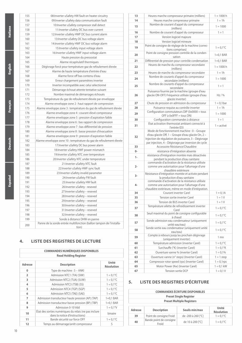
13 Heures marche compresseur primaire (milliers) 1 = 1000 h14 Heures marche compresseur primaire 1 = 1h
15 Nombre de courant d'appel du compresseur (milliers) 1 = 1000
16 Nombre de courant d'appel du compresseur 1 = 117 Version logiciel majeure18 Version logiciel mineure
19 Point de consigne de réglage de la machine (correc-tions comprises) 1 = 0,1°C
20 Point de consigne pression contrôle de la conden-sation 1=0,1 BAR
21 Différentiel de pression pour contrôle condensation 1=0,1 BAR
22 Heures de marche du compresseur secondaire (milliers) 1 = 1000 h
23 Heures de marche du compresseur secondaire 1 = 1h
24 Nombre de courants d'appel du compresseur secondaire (milliers) 1 = 1000
25 Nombre de courants d'appel du compresseur secondaire 1 = 1
26Puissance fournie par la machine (groupe d'eau
glacée ON-OFF) Fréquence utilisée (groupe d'eau glacée inverter)
Hz / %
27 Chute de pression en admission du compresseur 1 = 0,1bar28 Puissance requise au contrôle inverter 1 = 1h
29 Configuration commutateurs DIP (0x0000 = tous OFF à 0x0FFF = tous ON) 1 = 1000
30 Configuration commandes à distance 1 = 1
31 État activation thermostat ambiant connecté à l'entrée ID3 1 = activé
32
Mode de fonctionnement machine : 0 – Groupe d’eau glacée Off, 1 – Groupe d’eau glacée On, 2 –
Injection de régulation de puissance, 3 – Dégivrage par injection, 4 – Dégivrage par inversion de cycle
33 Accessoire Résistance/Chaudière 0- résistance d’intégration absente
1- résistance d’intégration montée mais désactivée pendant la production d’eau sanitaire
2-commande d’activation de la résistance utilisée comme une autorisation pour l’allumage d’une
chaudière extérieure
3- Résistance d’intégration montée et activée pendant la production d’eau sanitaire
4-commande d’activation de la résistance utilisée comme une autorisation pour l’allumage d’une
chaudière extérieure, même en mode d’intégration.34 Courant inverter Carel 1 = 0,1A35 Tension sortie inverter Carel 1 = 1 V36 Tension de BUS inverter Carel 1 = 1 V
37 Température ailette de refroidissement inverter Carel 1 = 0,1°C
38 Seuil maximal du point de consigne configurable à chaud 1 = 0,1°C
57 Sonde admission eau condensateur (uniquement unité eau/eau) 1 = 0,1°C
58 Sonde sortie eau condensateur (uniquement unité eau/eau) 1 = 0,1°C
59 Compte à rebours jusqu'au prochain dégivrage (uniquement inverter) 1 mn
60 Température admission (inverter Carel) 1 = 0,1°C61 Surchauffe (°K) (inverter Carel) 1 = 0,1°K62 Ouverture vanne % (inverter Carel) 1 = 0,1%63 Ouverture vanne (n° steps) (Inverter Carel) 1 = 1 step64 Compressor rotor speed (rps) (Inverter Carel) 1 = 0,1rps65 Motor Power (Kw) (Inverter Carel) 1 = 0,1 kW67 Tension sortie DCP 1 = 0,1 V
10
Italiano
English
Fran
çais
Deu
tsch
Espa
ñol
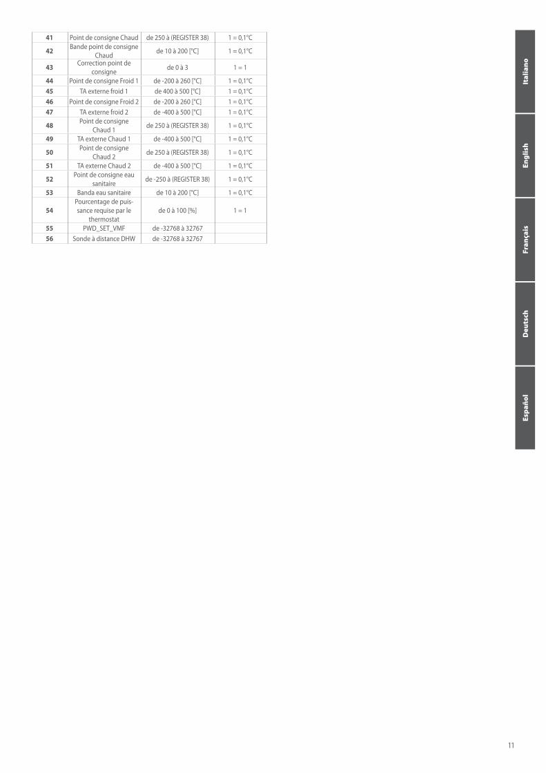
41 Point de consigne Chaud de 250 à (REGISTER 38) 1 = 0,1°C
42 Bande point de consigne Chaud de 10 à 200 [°C] 1 = 0,1°C
43 Correction point de consigne de 0 à 3 1 = 1
44 Point de consigne Froid 1 de -200 à 260 [°C] 1 = 0,1°C45 TA externe froid 1 de 400 à 500 [°C] 1 = 0,1°C46 Point de consigne Froid 2 de -200 à 260 [°C] 1 = 0,1°C47 TA externe froid 2 de -400 à 500 [°C] 1 = 0,1°C
48 Point de consigne Chaud 1 de 250 à (REGISTER 38) 1 = 0,1°C
49 TA externe Chaud 1 de -400 à 500 [°C] 1 = 0,1°C
50 Point de consigne Chaud 2 de 250 à (REGISTER 38) 1 = 0,1°C
51 TA externe Chaud 2 de -400 à 500 [°C] 1 = 0,1°C
52 Point de consigne eau sanitaire de -250 à (REGISTER 38) 1 = 0,1°C
53 Banda eau sanitaire de 10 à 200 [°C] 1 = 0,1°C
54Pourcentage de puis-sance requise par le
thermostatde 0 à 100 [%] 1 = 1
55 PWD_SET_VMF de -32768 à 3276756 Sonde à distance DHW de -32768 à 32767
11
Italiano
English
Fran
çais
Deu
tsch
Espa
ñol
Parameter(L) Installationsmenü BAUDRATE0 96001 192002 38400
1. KOMMUNIKATIONSMERKMALE
• BAUDRATE: Die Baudrate muss über den Parameter (N17) des Installa-tionsmenüs (Passwort=30) der Bedientafel eingestellt werden:
• STOP -BITS: 2• PARITY: NONE• SERIELLE ADRESSE: muss über den Parameter (N16) des Installations-
menüs (Passwort=30) eingestellt werden. Der Wert der seriellen Adresse ist zwischen 1 und 999 einstellbar.
Befehl Beschreibung0x01 Read Coil Status0x03 Read Holding Registers 0x05 Force Single Coil 0x06 Preset Single Register0x0F Preset Multiple Coils0x10 Preset Multiple Registers
2. VERWENDETE MODBUS CODES
VERFÜGBARE DIGITALBEFEHLE Read Coil StatusForce Single Coil
Force Multiple Coils
3. LISTE DER DIGITALBEFEHLE (COIL)
Um die Möglichkeit zu haben, die COIL Parameter in die Modu_Control Karte zu schreiben, müssen die Zentralsteuerungsbefehle aktiviert werden. Dazu muss der Parameter (N) = 1 des Installationsmenüs (Passwort=30) der ein-fachen Bedientafel eingestellt werden.
Adresse Beschreibung0 Befehl Standby/Eingeschaltet (toggle) 0=OFF 1=ON 1 Befehl Betriebsart (toggle) 0=KÜHLBETRIEB 1=HEIZBETRIEB2 Fernsteuerung Brauchwasser 0=Normal, 1=Brauchwasser3 Aktivierung Fernthermostat 0=Deaktiviert, 1=Aktiviert4 Alarmrückstellungsbefehl. 1=Alarmrückstellung5 Zustand Verdichter1 0=OFF 1=ON67 Zustand Heizkessel/Widerstand 0=OFF 1=ON8 Zustand Brauchwarmwasseraufbereitung. 0=nicht aktiv 1=aktiv9 ID-Zustand Brauchwasser 0=ID geschlossen – 1=ID offen
10 ID-Zustand ON_OFF ferngesteuert 0=ID geschlossen – 1=ID offen
11 ID-Zustand Jahreszeit 0=ID geschlossen (Kühlbetrieb) , 1=ID offen (Heizbetrieb)
12 ID-Zustand Raumthermostat 0=ID geschlossen – 1=ID offen13 Alarmübersicht75 Zustand Ausgang D01 (0=OFF 1=ON)76 Zustand Ausgang D02 (0=OFF 1=ON)77 Zustand Ausgang D03 (0=OFF 1=ON)78 Zustand Ausgang D04 (0=OFF 1=ON)79 Zustand Ausgang D05 (0=OFF 1=ON)80 Zustand Ausgang D06 (0=OFF 1=ON)81 Zustand Ausgang D07 (0=OFF 1=ON)82 Zustand Ausgang D08 (0=OFF 1=ON) 83 Zustand Ausgang D09 (0=OFF 1=ON)84 1 Fehler beim Beschreiben des Speichers85 2 Wassereintrittsfühler defekt oder nicht angeschlossen86 3 Wasseraustrittsfühler defekt oder nicht angeschlossen87 4 Außenluftfühler defekt oder nicht angeschlossen88 5 Wärmetauscherfühler defekt oder nicht angeschlossen89 6 Ablassfühler defekt oder nicht angeschlossen90 7 Ansaugtemperaturfühler defekt oder nicht angeschlossen
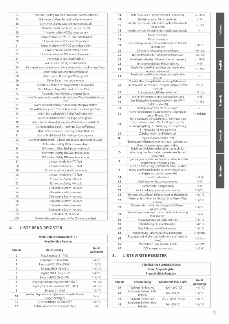
91 8 Hochdruckwandler defekt oder nicht angeschlossen92 9 Niederdruckwandler defekt oder nicht angeschlossen93 10 Alarm geringe Überhitzung (EVD)94 11 LOP Alarm (EVD)95 12 MOP Alarm (EVD)96 13 Alarm hohe Verflüssigungstemperatur (EVD)97 14 Alarm niedrige Ansaugtemperatur (EVD)98 15 Alarm Ventil (EVD)99 16 Autotuning Ventil (EVD)
100 17 Notsperre Ventil (EVD)101 18 Alarm Range error (EVD)102 19 Alarm Ventil Pin-Wert über Grenzwert103 20 Strömungswächter-Alarm104 21 Störmeldung Frostschutz105 22 Alarm Leitungsschutzschalter Pumpe106 23 Niederdruckalarm107 24 Hochdruckalarm108 25 Alarm schwerwiegender Niederdruck109 26 Alarm Leitungsschutzschalter Ventilator110 27 Hohe Temperatur druckseitiges Gases:
111 28 Zyklusumkehrventil defekt: deltaP niedrig. Das Zyklus-Umkehrventil könnte defekt oder gesperrt sein.
112 29 Delta P höher als bei Anlaufen erlaubt(Standard= 20bar). Verursacht keine Maschinensperre.
113 30 Verdichter ForceOff114 31 Alarm Zeitüberschreitung über Betriebsgrenzwerten115 32 Verdichterstart fehlgeschlagen. Verursacht keine Maschinensperre.116 33 Druckdifferential unter dem angegebenen (0,3 bar in 60 s)117 34 Überlast. 118 35 Überlast Verdichtermotor. 119 36 Überspannung DC BUS. 120 37 Unterspannung.DC BUS 121 38 Übertemperatur Antrieb. 122 39 Untertemperatur Antrieb 123 40 Überstrom Hardware 124 41 Übertemperatur Verdichter 125 42 Fehler IGBT-Modul – Interner Defekt. Inverter ersetzen. 126 43 CPU-Fehler. 127 44 Standardparameter.
128 45 DC bus ripple. Die Spannungen der den Inverter versorgenden Phasen kontrollieren.
129 46 Kommunikation zwischen Inverter und uPC3 fehlt. 130 47 Defekt am Temperaturfühler für Antrieb. 131 48 Autokonfiguration fehlgeschlagen.
132 49 Inverter-Antrieb deaktiviert. Polbrücken auf Klemmenleiste Inverter Power Plus kontrollieren
133 50 Fehler Motorenphasen. 134 51 Kühlgebläse Inverter defekt.
135 52 Geschwindigkeitsfehler. Verdichterstillstand. Eingegebenen Ver-dichtertyp kontrollieren.
136 53 PFC fault (bei aktiviertem PFC und sehr niedrigem DC-Bus auftreten-der Alarm)
137 54 PFC Overload trip (dieser Alarm taucht auf den neuen Firmware-Ver-sionen nicht mehr auf )
138 55 input voltage error (wenn die Versorgung bei laufendem Motor unter 170 V fällt)
139 56 Fehler STO 1140 57 Fehler STO 2141 58 Fehlerhafter Erdungsanschluss (nur bei nur einer Phase)142 59 Internal error 1 (ADC conversion sync fault)143 60 Internal error 2 (Hw sync fault)144 61 Inverter drive overload145 62 uC safety Drive Stopped146 63 Inverter unexpected stop (99)147 Inverter offline148 01:Inverter uSafety current measurement fault149 02:Inverter uSafety current unbalanced fault150 03:Inverter uSafety over current151 04:Inverter uSafety STO alarm152 05:Inverter uSafety STO hardware alarm153 06:Inverter uSafety main power supply missing
12
Italiano
English
Fran
çais
Deu
tsch
Espa
ñol
154 07:Inverter uSafety HW fault on inverter command buffer155 08:Inverter uSafety HW fault on heater circuitry156 09:Inverter uSafety data communication fault157 10:Inverter uSafety compressor stall detect158 11:Inverter uSafety DC bus over current159 12:Inverter uSafety HWF DC bus current alarm160 13:Inverter uSafety DC bus voltage alarm161 14:Inverter uSafety HWF DC bus voltage alarm162 15:Inverter uSafety input voltage alarm163 16:Inverter uSafety HWF input voltage alarm164 Hoher Druck von Druckwächter165 Alarme aller Leitungsschutzschalter166 Zwangsabtauen wegen hoher Vorlauftemperatur druckseitiges Gases167 Alarm Hohe Wassereintrittstemperatur168 Alarm Force off niedriger Wassergehalt169 Fehler Laden Inverterparameter170 Inverter nicht mit dem ausgewählten kompatibel171 Start fehlgeschlagen Wartezeit nächster Versuch172 Maximale Anzahl fehlgeschlagener Starts
173 Hohe Temperatur druckseitiges Gases Vorlauf Verdichterbetriebsbe-reich
174 Alarm Betriebsbereich 2: hohes Verdichtungsverhältnis175 Alarm Betriebsbereich 3: hohe Temperatur druckseitiges Gases176 Alarm Betriebsbereich 4: hoher Verdichterstrom177 Alarm Betriebsbereich 5: niedriger Ansaugdruck178 Alarm Betriebsbereich 6: niedriges Verdichtungsverhältnis179 Alarm Betriebsbereich 7: niedriges Druckdifferential180 Alarm Betriebsbereich 8: niedriger Austrittsdruck181 Alarm Betriebsbereich 9: niedriger Ansaugdruck 182 Alarm Betriebsbereich 10: hohe Temperatur druckseitiges Gases183 17:Inverter uSafety DC bus power alarm184 18:Inverter uSafety HWF power mismatch185 19:Inverter uSafety NTC over temperature186 20:Inverter uSafety NTC over temperature187 21:Inverter uSafety NTC fault188 22:Inverter uSafety NTC fault189 23:Inverter uSafety invalid parameter190 24:Inverter uSafety NTC fault191 25:Inverter uSafety HW fault192 26:Inverter uSafety HW fault193 27:Inverter uSafety – reseved194 28:Inverter uSafety – reseved195 29:Inverter uSafety – reseved196 30:Inverter uSafety – reseved197 31:Inverter uSafety – reseved198 32:Inverter uSafety – reseved199 Fernfühler DHW defekt200 Defekt Mehrzweckeingangsfühler (Anlagenspeicher)
VERFÜGBARE DIGITALBEFEHLE Read Holding Register
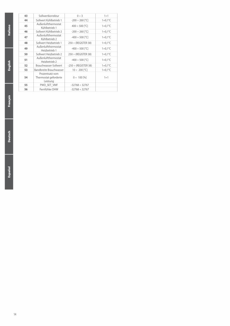
4. LISTE READ REGISTER
Adresse Beschreibung GerätAuflösung
0 Maschinentyp: 5 – ANKI2 Eingang NTC1 (TIA) (SIW) 1=0,1°C3 Eingang NTC2 (TUA) (SUW) 1=0,1°C4 Eingang NTC3 (TSB) (SS) 1=0,1°C5 Eingang NTC4 (TGP) (SGP) 1=0,1°C6 Eingang NTC5 (TAE) (SAE) 1=0,1°C7 Eingang Hochdruckwandler (HD) (TAP) 1=0,1bar8 Eingang Niederdruckwandler (ND) (TAP) 1=0,1bar9 Eingang 0-10Vdd 1=0,1°V
10 Zustand Digitalrelaisausgänge (nicht in die Anwei-sungen einfügen) binär
11 Sicherheitsband auf force OFF 1=0,1°C12 Anlauf-/Abschaltzeit des Verdichters Sek
VERFÜGBARE SCHREIBBEFEHLE Preset Single Register
Preset Multiple Registers
5. LISTE WRITE REGISTER
Adresse Beschreibung Grenzwerte Min. / Max. GerätAuflösung
39 Sollwert Kühlbetrieb -200 ÷ 260 [°C] 1=0,1°C
40 Bandbreite Sollwert Kühl-betrieb 10 ÷ 200 [°C] 1=0,1°C
41 Sollwert Heizbetrieb 250 ÷ (REGISTER 38) 1=0,1°C
42 Bandbreite Sollwert Heiz-betrieb 10 ÷ 200 [°C] 1=0,1°C
13 Betriebsstunden Primärverdichter (in tausend) 1=1000h14 Betriebsstunden Primärverdichter 1=1h
15 Anzahl der vom Verdichter durchgeführten Anläufe (in tausend) 1=1000
16 Anzahl der vom Verdichter durchgeführten Anläufe 1=117 Major sw version18 Minor sw version
19 Einstellungs-Sollwert der Maschine (einschließlich Korrekturen) 1=0,1°C
20 Sollwert Kondensationskontrolldruck 1=0,1bar21 Druckdifferential für Kondensationskontrolle 1=0,1bar22 Betriebsstunden des Hilfsverdichters (in tausend) 1=1000h23 Betriebsstunden des Hilfsverdichters 1=1h
24 Anzahl der vom Hilfsverdichter durchgeführten Anläufe (in tausend) 1=1000
25 Anzahl der vom Hilfsverdichter durchgeführten Anläufe 1=1
26Von der Maschine gelieferte Leistung (Kaltwasser-
satz ON-OFF) Verwendete Frequenz (Kaltwassersatz Inverter)
Hz / %
27 Ansaugdruckabfall des Verdichters 1=0,1bar28 Von der Invertersteuerung verlangte Leistung 1=1h
29 Dip-Schalterkonfiguration (0x0000 = alle OFF ÷ 0x0FFF = alle ON) 1=1000
30 Konfiguration der Fernsteuerungen 1=1
31 Aktivierungszustand Raumthermostat angeschlos-sen an Eingang ID3 1= aktiviert
32
Betriebszustand der Maschine: 0 - Kaltwassersatz Off, 1 - Kaltwassersatz On, 2 – Einspritzung für
Leistungsregelung, 3 – Abtauung für Einspritzung, 4 – Abtauung für Zyklusumkehr
33 Zubehör Widerstand/Heizkessel: 0- Ergänzungswiderstand fehlt
1- Ergänzungswiderstand montiert, doch während der Brauchwassererzeugung nicht aktiv
2-Befehl zur Aktivierung des Widerstands als Zu-
stimmung zum Einschalten des externen Kessels verwendet
3- Ergänzungswiderstand vorhanden und während der Brauchwassererzeugung aktiv
4-Befehl zur Aktivierung des Widerstands als Zustim-mung zum Einschalten des externen Kessels auch
im Ergänzungsbetrieb verwendet34 Carel Inverterstrom 1=0,1A35 Carel Inverter-Ausgangsspannung 1=1V36 Carel Inverter Busspannung 1=1V37 Kühllamellentemperatur Carel Inverter 1=0,1°C38 Höchster einstellbarer Sollgrenzwert im Heizbetrieb 1=0,1°C
57 Wassereintrittsfühler Verflüssiger (Nur Wasser/Was-ser Gerät) 1=0,1°C
58 Wasseraustrittsfühler Verflüssiger (Nur Wasser/Wasser Gerät) 1=0,1°C
59 Zeitmäßiger Countdown bis zur nächsten Abtauung (nur Inverter) 1 Min
60 Ansaugtemperatur (Carel Inverter) 1=0,1°C61 Überhitzung (°K) (Carel Inverter) 1=0,1°K62 Ventilöffnung in % (Carel Inverter) 1=0,1%63 Ventilöffnung (Schrittanzahl) (Carel Inverter) 1=1Schritt
64 Rotorgeschwindigkeit des Verdichters (rps) (Inverter Carel) 1=0,1rps
65 Motorstärke (kW) (Inverter Carel) 1=0,1kW67 DCP Ausgangsspannung 1=0,1V
13
Italiano
English
Fran
çais
Deu
tsch
Espa
ñol
43 Sollwertkorrektur 0 ÷ 3 1=144 Sollwert Kühlbetrieb 1 -200 ÷ 260 [°C] 1=0,1°C
45 Außenluftthermostat Kühlbetrieb 1 400 ÷ 500 [°C] 1=0,1°C
46 Sollwert Kühlbetrieb 2 -200 ÷ 260 [°C] 1=0,1°C
47 Außenluftthermostat Kühlbetrieb 2 -400 ÷ 500 [°C] 1=0,1°C
48 Sollwert Heizbetrieb 1 250 ÷ (REGISTER 38) 1=0,1°C
49 Außenluftthermostat Heizbetrieb 1 -400 ÷ 500 [°C] 1=0,1°C
50 Sollwert Heizbetrieb 2 250 ÷ (REGISTER 38) 1=0,1°C
51 Außenluftthermostat Heizbetrieb 2 -400 ÷ 500 [°C] 1=0,1°C
52 Brauchwasser-Sollwert -250 ÷ (REGISTER 38) 1=0,1°C53 Bandbreite Brauchwasser 10 ÷ 200 [°C] 1=0,1°C
54Prozentsatz vom
Thermostat geforderte Leistung
0 ÷ 100 [%] 1=1
55 PWD_SET_VMF -32768 ÷ 3276756 Fernfühler DHW -32768 ÷ 32767
14
Italiano
English
Fran
çais
Deu
tsch
Espa
ñol
parámetro(L) menú del instalador BAUDRATE0 96001 192002 38400
1. CARACTERÍSTICAS DE COMUNICACIÓN
• BAUDRATE: El baudrate se debe establecer a través del parámetro (N17) del menú del instalador (contraseña=30) del tablero de mando:
• STOP BITS: 2• PARITY: NONE• DIRECCIÓN SERIE: Se debe establecer a través del parámetro (N16) del
menú del instalador (contraseña=30). El valor de la dirección serie se puede establecer entre 1-999.
cmd Descripción0x01 Read Coil Status0x03 Read Holding Registers 0x05 Force Single Coil 0x06 Preset Single Register0x0F Preset Multiple Coils0x10 Preset Multiple Registers
2. CÓDIGOS MODBUS UTILIZADOS
COMANDOS DIGITALES DISPONIBLES Read Coil StatusForce Single Coil
Force Multiple Coils
3. LISTA DE DIGITALES (COILS)
Para tener la posibilidad de escribir parámetros COIL en la tarjeta Modu_Con-trol hay que habilitar los comandos de control estableciendo el parámetro parámetro(N)=1 del menú del instalador (contraseña=30) del tablero sencillo.
Dirección Descripción0 Comando Stanby/Acceso (toggle) 0=OFF 1=ON 1 Comando de modo de funcionamiento (toggle) 0=FRÍO 1=CALIENTE2 Control remoto de agua sanitaria 0=Normal, 1=Sanitario3 Activación de termostato remoto 0=Desactivado, 1=Activado
4 Comando de restablecimiento de Alarmas. 1=Restablecimiento de alarmas
5 Estado del compresor1 0=OFF 1=ON67 Estado de la caldera /resistencia 0=OFF 1=ON8 Estado de la producción de agua sanitaria. 0=no activa 1=activa9 Estado ID de agua sanitaria 0=ID cerrado – 1=ID abierto
10 Estado ID ON_OFF remoto 0=ID cerrado – 1=ID abierto11 Estado ID estación 0=ID cerrado (Frío) , 1=ID abierto (Caliente)12 Estado ID termostato ambiental 0=ID cerrado – 1=ID abierto13 Resumen de alarmas75 Estado salida D01 (0=OFF 1=ON)76 Estado salida D02 (0=OFF 1=ON)77 Estado salida D03 (0=OFF 1=ON)78 Estado salida D04 (0=OFF 1=ON)79 Estado salida D05 (0=OFF 1=ON)80 Estado salida D06 (0=OFF 1=ON)81 Estado salida D07 (0=OFF 1=ON)82 Estado salida D08 (0=OFF 1=ON) 83 Estado salida D09 (0=OFF 1=ON)84 1 Error de escritura en la memoria85 2 Sonda de entrada agua rota o desconectada86 3 Sonda de salida agua rota o desconectada87 4 Sonda de aire exterior rota o desconectada88 5Sonda de Batería rota o desconectada89 6 Sonda de Descarga rota o desconectada90 7 Sonda de Aspiración rota o desconectada
91 8 Transductor AP roto o desconectado92 9 Transductor BP roto o desconectado93 10 Alarma bajo recalentamiento (EVD)94 11 Alarma LOP (EVD)95 12 Alarma MOP (EVD)96 13 Alarma alta temperatura de Condensación (EVD)97 14 Alarma baja temperatura de aspiración (EVD)98 15 Alarma válvula (EVD)99 16 Autotuning válvula (EVD)
100 17 Cierre de emergencia válvula (EVD)101 18 Alarma Rango error (EVD)102 19 Alarma Válvula valor pin fuera de límite103 20 Alarma flujostato104 21 Alarma antihielo105 22 Alarma magnetotérmico bomba106 23 Alarma baja presión107 24 Alarma alta presión108 25 Alarma baja presión grave109 26 Alarma magnetotérmico ventilador110 27 Temperatura alta de gas impelente:
111 28 Válvula de inversión de ciclo averiada: Bajo delta P. La válvula de inversión del ciclo podría estar averiada o bloqueada.
112 29 Delta P superior al permitido en el start up (por defecto=20 bar). No provoca el bloqueo de la máquina.
113 30 Compresor ForceOff
114 31 Alarma Superación del tiempo por encima del límite de funciona-miento
115 32 Arranque fallido del compresor. No provoca el bloqueo de la máquina.
116 33 Diferencial de presión inferior al especificado (0,3 bar en 60 seg)117 34 Sobrecorriente. 118 35 Sobrecarga motor compresor. 119 36 Sobretensión CC BUS. 120 37 Tensión insuficiente CC BUS 121 38 Exceso de temperatura drive. 122 39 Temperatura insuficiente drive 123 40 Exceso de corriente Hardware 124 41 Exceso de temperatura compresor 125 42 Error módulo IGBT – Fallo interno. Sustituir Inverter. 126 43 Error CPU. 127 44 Parámetros por defecto.
128 45 CC bus ripple. Controlar las tensiones de las fases que alimentan el inverter.
129 46 Comunicación entre inverter y uPC3 ausente. 130 47 Fallo en sensor de temperatura drive. 131 48 Autoconfiguración fallida.
132 49 Drive inverter inhabilitado. Controlar puentes en caja de conexiones del inverter Power Plus
133 50 Error de fases del motor. 134 51 Ventilador de refrigeración del inverter averiado.
135 52 Speed fault. Pérdida de potencia del compresor. Controlar tipo de compresor configurado.
136 53 PFC fault (alarma que se produce con PFC habilitado mientras el bus CC es muy bajo)
137 54 PFC overload trip (esta alarma ya no estará presente en las nuevas versiones del firmware)
138 55 input voltage error (cuando la alimentación desciende por debajo de 170 V con motor en marcha)
139 56 Error STO 1140 57 Error STO 2141 58 Fallo de la conexión a tierra (solo para monofásica)142 59 Internal error 1 (ADC conversion sync fault)143 60 Internal error 2 (Hw sync fault)144 61 Inverter drive overload145 62 uC safety Drive Stopped146 63 Inverter unexpected stop (99)147 Inverter offline148 01:Inverter uSafety current measurement fault149 02:Inverter uSafety current unbalanced fault150 03:Inverter uSafety over current151 04:Inverter uSafety STO alarm152 05:Inverter uSafety STO hardware alarm
15
Italiano
English
Fran
çais
Deu
tsch
Espa
ñol
153 06:Inverter uSafety main power supply missing154 07:Inverter uSafety HW fault on inverter command buffer155 08:Inverter uSafety HW fault on heater circuitry156 09:Inverter uSafety data communication fault157 10:Inverter uSafety compressor stall detect158 11:Inverter uSafety DC bus over current159 12:Inverter uSafety HWF DC bus current alarm160 13:Inverter uSafety DC bus voltage alarm161 14:Inverter uSafety HWF DC bus voltage alarm162 15:Inverter uSafety input voltage alarm163 16:Inverter uSafety HWF input voltage alarm164 Alta presión de presostato165 Alarma resumen Térmicas166 Desescarchado forzado por alta temperatura de gas impelente167 Alarma alta temperatura entrada de agua168 Alarma force off bajo contenido de agua169 Error de carga de parámetros del inverter170 Inverter no compatible con el seleccionado171 Arranque fallido espera intento siguiente172 Número máximo de arranques fallidos173 Alta temperatura gas impelente envolvente174 Alarma envolvente zona 2: alta relación de compresión175 Alarma envolvente zona 3: alta temperatura gas impelente176 Alarma envolvente zona 4: alta corriente compresor177 Alarma envolvente zona 5: baja presión de succión178 Alarma envolvente zona 6: baja relación de compresión179 Alarma envolvente zona 7: bajo diferencial de presión180 Alarma envolvente zona 8: baja presión de descarga181 Alarma envolvente zona 9: baja presión de succión 182 Alarma envolvente zona 10: alta temperatura gas impelente183 17:Inverter uSafety DC bus power alarm184 18:Inverter uSafety HWF power mismatch185 19:Inverter uSafety NTC over temperature186 20:Inverter uSafety NTC under temperature187 21:Inverter uSafety NTC fault188 22:Inverter uSafety HWF sync fault189 23:Inverter uSafety invalid parameter190 24:Inverter uSafety FW fault191 25:Inverter uSafety HW fault192 26:Inverter uSafety - reseved193 27:Inverter uSafety – reseved194 28:Inverter uSafety – reseved195 29:Inverter uSafety – reseved196 30:Inverter uSafety – reseved197 31:Inverter uSafety – reseved198 32:Inverter uSafety – reseved199 Sonda de Remota DHW averiada200 Fallo Sonda de entrada multifunción (acumulación instalación)
COMANDOS DIGITALES DISPONIBLES Read Holding Register
4. LISTA READ REGISTER
Dirección Descripción UnidadesResolución
0 Tipo de máquina: 5 – ANKI2 Entrada NTC1 (TIA) (SIW) 1=0,1°C3 Entrada NTC2 (TUA) (SUW) 1=0,1°C4 Entrada NTC3 (TSB) (SS) 1=0,1°C5 Entrada NTC4 (TGP) (SGP) 1=0,1°C6 Entrada NTC5 (TAE) (SAE) 1=0,1°C7 Entrada de transductor de alta presión (AP) (TAP) 1=0,1bar8 Entrada de transductor de baja presión (BP) (TBP) 1=0,1bar9 Entrada 0-10Vdd 1=0,1°V
10 Estado de las salidas digitales relé (no incluir en las instrucciones) binario
11 Banda de seguridad en force OFF 1=0,1°C12 Tiempo para el arranque/parada del compresor SEG
COMANDOS DE ESCRITURA DISPONIBLES Preset Single Register
Preset Multiple Registers
5. LISTA WRITE REGISTER
Dirección Descripción Mín./Máx. UnidadesResolución
39 Setpoint Frío -200 ÷ 260 [°C] 1=0,1°C40 Banda Setpoint Frío 10 ÷ 200 [°C] 1=0,1°C
13 Horas de funcionamiento del compresor primario (miles) 1=1000h
14 Horas de funcionamiento del compresor primario 1=1h
15 Número de arranques efectuados por el compresor (miles) 1=1000
16 Número de arranques efectuados por el compresor 1=117 Major sw version18 Minor sw version
19 Setpoint de ajuste de la máquina (incluyendo correcciones) 1=0,1°C
20 Set presión control de la condensación 1=0,1bar
21 Diferencial de presión para control de la conden-sación 1=0,1bar
22 Horas de funcionamiento del compresor auxiliar (miles) 1=1000h
23 Horas de funcionamiento del compresor auxiliar 1=1h
24 Número de arranques efectuados por el compresor auxiliar (miles) 1=1000
25 Número de arranques efectuados por el compresor auxiliar 1=1
26Potencia suministrada por la máquina (enfriado-ra ON-OFF) Frecuencia utilizada (enfriadora del
inverter)Hz/%
27 Caída de presión en la línea de succión del com-presor 1=0,1bar
28 Potencia necesaria para el control del inverter 1=1h
29 Configuración Dip-Switch (0x0000 = todos OFF ÷ 0x0FFF = todos ON) 1=1000
30 Configuración de comandos remotos 1=1
31 Estado de habilitación del termostato ambiental conectado a la entrada ID3 1= habilitado
32
Estado de funcionamiento de la máquina: 0 - Enfriadora Off, 1 - Enfriadora On, 2 – Inyección de parcialización, 3 – Desescarchado para inyección,
4 – Desescarchado para inversión de ciclo33 Accesorio de resistencia/caldera: 0- resistencia de integración ausente
1- resistencia de integración montada pero sin activar durante la producción de agua sanitaria
2-mando de activación de la resistencia utilizado como habilitación para encendido de la caldera
exterior
3- Resistencia de integración presente y activa durante la producción de agua sanitaria
4-mando de activación de la resistencia utilizado como habilitación para encendido de la caldera
exterior también en modalidad integrativa.34 Corriente del inverter Carel 1=0,1A35 Tensión de salida del inverter Carel 1=1V36 Tensión de BUS del inverter Carel 1=1V
37 Temperatura de la aleta de enfriamiento del inverter Carel 1=0,1°C
38 Límite máximo configurable del Setpoint en caliente 1=0,1°C
57 Sonda de entrada del agua del condensador (Sólo unidades de agua/agua) 1=0,1°C
58 Sonda de salida del agua del condensador (Sólo unidades de agua/agua) 1=0,1°C
59 Cuenta atrás para el próximo desescarchado por tiempo (solo inverter) 1 min
60 Temperatura de succión (Inverter Carel) 1=0,1°C61 Recalentamiento (K) (Inverter Carel) 1=0,1°K62 Abertura de la válvula% (Inverter Carel) 1=0,1%63 Abertura de la válvula (n° steps) (Inverter Carel) 1=1step64 Compresor del rotor speed (rps) (Inverter Carel) 1=0,1rps65 Motor Power (Kw) (Inverter Carel) 1=0,1kW67 Tensión de salida DCP 1=0,1V
16
Italiano
English
Fran
çais
Deu
tsch
Espa
ñol
41 Setpoint Caliente 250 ÷ (REGISTER 38) 1=0,1°C42 Banda Setpoint Caliente 10 ÷ 200 [°C] 1=0,1°C43 Corrección Setpoint 0 ÷ 3 1=144 Set Frio 1 -200 ÷ 260 [°C] 1=0,1°C45 TA Exterior frío 1 400 ÷ 500 [°C] 1=0,1°C46 Set Frío 2 -200 ÷ 260 [°C] 1=0,1°C47 TA Exterior frío 2 -400 ÷ 500 [°C] 1=0,1°C48 Set Caliente 1 250 ÷ (REGISTER 38) 1=0,1°C49 TA Exterior Caliente 1 -400 ÷ 500 [°C] 1=0,1°C50 Set Caliente 2 250 ÷ (REGISTER 38) 1=0,1°C51 TA Exterior Caliente 2 -400 ÷ 500 [°C] 1=0,1°C52 Set Agua Sanitaria -250 ÷ (REGISTER 38) 1=0,1°C53 Banda Agua Sanitaria 10 ÷ 200 [°C] 1=0,1°C
54Porcentaje de poten-cia necesaria para el
termostato0 ÷ 100 [%] 1=1
55 PWD_SET_VMF -32768 ÷ 3276756 Sonda Remota DHW -32768 ÷ 32767
17
Italiano
English
Fran
çais
Deu
tsch
Espa
ñol

carta riciclatarecycled paperpapier recyclérecycled Papier
AERMEC S.p.A.Via Roma, 99637040 Bevilacqua (VR) - ItaliaTel. + 39 0442 633111Fax +39 0442 [email protected]
Aermec se reserva la facultad de aportar, en cualquier momento, todas las modificaciones consideradas necesarias para la mejora del producto. Aermec se reserva el derecho a efectuar cualquier modificación que estime necesaria para mejorar el producto en cualquier momento con la modificación de los datos técnicos.