Embed Size (px)
Citation preview

FURUNO ELECTRIC CO., LTD.Japan www.furuno.com
FURUNO U.S.A., INC.U.S.A. www.furunousa.com
FURUNO PANAMA S.A.Republic of Panama www.furuno.com.pa
FURUNO (UK) LIMITEDU.K. www.furuno.co.uk
FURUNO NORGE A/SNorway www.furuno.no
FURUNO DANMARK A/S Denmark www.furuno.dk
FURUNO SVERIGE ABSweden www.furuno.se
FURUNO FINLAND OYFinland www.furuno.�
FURUNO POLSKA Sp. Z o.o.Poland www.furuno.pl
FURUNO DEUTSCHLAND GmbHGermany www.furuno.de
FURUNO FRANCE S.A.S.France www.furuno.fr
FURUNO ESPAÑA S.A.Spain www.furuno.es
FURUNO ITALIA S.R.L.Italy www.furuno.it
FURUNO HELLAS S.A.Greece www.furuno.gr
FURUNO (CYPRUS) LTDCyprus www.furuno.com.cy
FURUNO EURUS LLCRussian Federation www.furuno.ru
FURUNO SHANGHAI CO., LTD.China www.furuno.com/cn
FURUNO CHINA CO., LTD.Hong Kong www.furuno.com/cn
FURUNO KOREA CO., LTDKorea
FURUNO SINGAPORESingapore www.furuno.sg
PT FURUNO ELECTRIC INDONESIAIndonesia www.furuno.id
1-B-1711PDFCatalogue No. CA000001188
All brand and product names are registered trademarks, trademarks or service marks of their respective holders.
Beware of similar products
www.furuno.com
10 0.39"
110 4.33"
468.6 18.45"
448 17.64"
389
15.
31"
269
10.
59"
489.4 19.27"
4-Ø7
468.6 18.45"
450 17.72"
397
15.
63"
269
10.
59"
�xing hole
Model: FAR-22x8 series
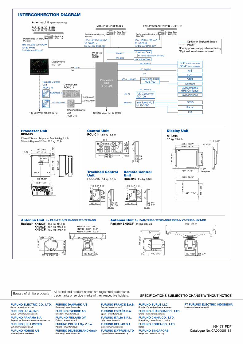
INTERCONNECTION DIAGRAM
Antenna Unit for FAR-2218/2218-BB/2228/2228-BBRadiator
Antenna Unit for FAR-2238S/2238S-BB/2238S-NXT/2238S-NXT-BBRadiator SN36CF 144 kg 317.5 lb 3822 150.5"
420 16.5" 69 2.7"640 25.2"
457
18.
0"
769
30.
3"12 0.
5"
XN12CF: 1297 51.1"XN20CF: 2097 82.6"XN24CF: 2597 102.2"
255 10.0" 257 10.1"
395
15.
6"
575
22.
7" 109
4.3"
90.35"15 0.
6"
409 16.1"
XN12CF 46.2 kg 101.9 lbXN20CF 48.1 kg 106.1 lbXN24CF 49.3 kg 108.7 lb
Display Unit
MU-1908.8 kg 19.4 lb
Processor Unit RPU-025X-band/ S-band 24rpm w/ Fan 9.6 kg 21 lbS-band 42rpm w/ 2 Fan 11.5 kg 25 lb
385 12.63"370 12.14"2-Ø7
36 1
.18"
340
11.
15"
350 11.48"
359 11.78"
183
6.0
0"
410
13.
45"
Control UnitRCU-014 2.5 kg 5.5 lb
Trackball ControlUnitRCU-015 2.4 kg 5.3 lb
Remote ControlUnitRCU-016 2.4 kg 5.3 lb
308 12.1"398 15.7" 39 1.5"
54 2.1"
4-ø4
92 3.6"
136
5.4
"18
0 7
.1"
160 6.3"
110 4.3"
136
5.4
"18
0 7
.1"
4-ø4
89 3.5"
35 1.4"50 2.0"
160 6.3"
136
5.4
"18
0 7
.1"
110 4.3" 4-ø4
89 3.5"
35 1.4"50 2.0"
Keep Steady at Seawith the safe, reliable and user-friendly next generation radar
Radar
Intelligent HUBHUB-3000
ProcessorUnit
RPU-025
Display UnitMU-190
FAR-2218/2218-BBFAR-2228/2228-BB
Gear BoxRSB-128
FAR-2238S/2238S-BB
Gear BoxRSB-129
FAR-2238S-NXT/2238S-NXT-BB
Gear BoxRSB-133
RW-0013515/30/40/50M
/10 m
100-115/220-230 VAC1 , 50-60 Hzfor Dei-cer 0P03-226
100-115/220-230 VAC1 , 50-60 Hzfor Dei-cer 0P03-227
100-115/220-230 VAC1 , 50-60 Hzfor Dei-cer 0P03-227
A/D ConverterAD-100
AD-10
Performance MonitorPM-32A
Performance MonitorPM-52A
Performance MonitorPM-52B
Remote Control UnitRCU-016
* Foremast Installation(X-band only)
Control UnitRCU-014
Trackball Control UnitRCU-015
DVI
100-230 VAC, 1Ø, 50-60 Hz 100-230 VAC, 1Ø, 50-60 Hz
Sensors
IEC-61162-450
2.3/10/20/30 m
1.5/10/20/30 m
1.5/10/20/30 m
XH10P-W-6P

Complies with the following regulations:IEC 62388 Ed.2.0 IEC 61162-1 Ed.5.0IEC 62288 Ed.2.0 IEC 60945 Ed.4.0IEC 61162-2 IEC 61162-450
Keep Steady at Seawith the safe, reliable and user-friendly next generation radar
Advanced technologies for safe navigationThe FURUNO FAR-22x8 series is a brand-new radar series characterized by its
state-of-the-art antenna design and innovative signal processing techniques.
FURUNO latest and �nest technologies and intuitive design will increase situational
awareness and enable safer than ever navigation.
FAR-2218/FAR-2218-BB X-band, 12 kW, TR upFAR-2228/FAR-2228-BB X-band, 25 kW, TR upFAR-2238S/FAR-2238S-BB S-band, 30 kW, TR up,FAR-2238S-NXT/FAR-2238S-NXT-BB S-band, 250 W, TR up, Solid State
FAR-22x8 seriesfor Category 2 of ship/craft, with 19" LCD
Automatic Clutter Elimination (ACE) for unprecedented echo clarity
Quickly adjusts the radar image with a single button press. When the ACE function is activated, the system automatically
adjusts clutter reduction �lters and gain control according to the sea and weather conditions.
Fast Target Tracking™ function to prevent collision at an early stage
With Fast Target Tracking™, the FAR-22x8 series provides
accurate tracking information; speed and course vectors are
displayed in mere seconds allowing operators to take action
and avoid incidents at a very early stage.
ACE OFF ACE ON
ACE ON
Read the QR cord to see detail explanations of above functions.
Target Vector
Target Information

Control Unit
EBL controls
VRM controls
Menu Item Selector (wheel and enter keys)
Cursor ControlUser Customizable Function Keys
Trackball Control Unit
The FAR-22x8 series is designed to provide clearer and more accurate radar images of the surroundings while
increasing reliability and decreasing overall cost of ownership with easy maintenance.
High image quality is achieved by the signal processor inside the antenna unit directly converting analog to digital
signals before sending them to the main processor unit. Signals are safely transported though the Ethernet network
between the antenna and below deck processing unit.
The new antenna shape suppresses aerodynamic drag and lightens the burden on the gear box.
The gear box itself has also been redesigned. Decreased aerodynamic drag and DC brushless motor result in a very
durable gear box that can be used for prolonged period of time.
Installation and maintenance are now easier than ever. All components of the gear box are integrated into one block
that can easily be removed from the gear box when maintenance is required. The cable to the gear box can be
connected from the side of the gear box.
InstantAccess bar™ gives immediate access to the functions you need.
InstantAccess bar™ contains shortcut menus of tasks (functions/actions) which
operators frequently use, so users can quickly access necessary tasks.
Comfortable usability is very important on long voyages. With that in mind, these control units are designed based on
ergonomics to �t the operator’s hand. All operations can be controlled with the trackball.
Well-designed controllers for stress-free operation
InstantAccess bar™
Radar functionmenu
Display settingmenu
Re�ned antenna with high signal accuracy and excellent reliability
User interface designed for the ultimate intuitive operation

Product Name MARINE RADAR
Antenna Radiator1. Type Slotted waveguide array2. Beam width and sidelobe attenuation
3. Polarization Horizontal 4. Rotation 24 rpm or 42 rpm (for high speed craft)5. Wind load 100 kn relative6. De-icer (option) On: when temperature goes down to 0°C Off: when temperature goes up to +5°C
Transceiver1. TX Frequency and modulation X-band (Magnetron) 9410 MHz ±30 MHz, P0N S-band (Magnetron) 3050 MHz ±30 MHz, P0N S-band (Solid state) CH1 P0N: 3043.75 MHz/ Q0N: 3063.75 MHz ±5 MHz or CH2 P0N: 3053.75 MHz/ Q0N: 3073.75 MHz ±5 MHz2. Output power FAR-2218/2218-BB 12 kW FAR-2228/2228-BB 25 kW FAR-2238S/2238S-BB 30 kW FAR-2238S-NXT/2238S-NXT-BB 250 W (equivalent to magnetron radar 30 kW)3. Range scale, Pulse Repetition Rate and Pulselength Magnetron radar: FAR-2218/2218-BB/2228/2228-BB/2238S/2238S-BB
*: 500 Hz on 96 NM range.
Solid state radar: FAR-2238S-NXT/2238S-NXT-BB
Processor Unit1. Minimum range 22 m2. Range discrimination 26 m3. Range accuracy 1% of the maximum range of the scale in use or 10 m, whichever is the greater4. Bearing discrimination 2.1° (XN12CF), 1.5° (XN20CF), 1.2° (XN24CF), 2.0° (SN36CF)5. Bearing accuracy ±1°6. Range scale and Range ring interval (RI)
7. Warm-up time 3 min. approx. (solid state radar excluded)8. Presentation mode Head-up, STAB head-up, Course-up, North-up (RM/TM), Stern-up9. Marks Cursor, Range ring, Heading mark, North mark, Bearing mark, Target trail, VRM, EBL, Acquisition zone10. Target tracking (TT) Auto or manual acquisition 100 targets in 24/32 NM (range selected from menu for maintenance) Auto tracking on all acquired targets, Tracking 5/10 pts on all targets Vector time Off, 30 s, 1-60 min11. AIS Display capacity 350 targets Tracking 5/10 pts on activated targets Vector time Off, 30 s, 1-60 min 12. Radar map 20,000 points13. Acquisition zone 2 zones14. Interswitch function Selectable from menu
Display UnitMU-1901. Screen type 19-inch color LCD, 1280 x 1024 (SXGA)2. Brightness 450 cd/m2 typical3. Visible distance 1.02 m nominal4. Radar effective diameter 282 mm
Interface1. Number of port (processor unit) Serial 7 ports (IEC61162-1/2: 2 ports, IEC61162-1: 4 ports, AD-10: 1 port) Alarm output 6 ports: contact signal, load current 250 mA (Normal close/ open: 4, System fail: 1, Power fail: 1) DVI output 2 ports: DVI-D, DVI-I or RGB picture data (VDR) LAN 2 ports: Ethernet 100Base-TX RS-232C 1 port: brilliance control Sub display (for ECDIS) 2 ports: HD, BP, Trigger and Video signal2. Data sentences (IEC61162-1/2, IEC61162-450) Input ABK, ACK, ACN, ALR, BWC, BWR, CUR, DBK*1, DBS*1, DBT, DDC, DPT, DTM, GGA, GLL, GNS, HBT, HDT*1, MTW, MWV, OSD, RAQ, RMB, RMC, ROT, RTE, THS, VBW, VDM, VDO, VDR, VHW, VSD, VTG, VWR*1, VWT*1, WPL, ZDA Output ABM, ACK, AIQ, ALC, ALF, ALR, ARC, BBM, DDC, EVE, HBT, OSD, RSD, TLB, TLL, TTD, TTM, VSD *1: for retrofit.3. Ethernet interface for IEC61162-450 Port (LAN2) 100Base-TX, IPv4, 8P8C connector IEC61162-450 transmission group Input MISC, TGTD, SATD, NAVD, TIME, PROP Output Arbitrary (default: TGTD) Multicast address 239.192.0.1 to 239.192.0.16 Destination port 60001 to 60016 Re-transmittable binary image transfer Multicast address 239.192.0.26 to 239.192.0.30 Destination port 60026 to 60030 Other network function excepted IEC61162-450 SNMP, HTTP, Syslog, Furuno Management Protocol (FMP)4. Output port on antenna unit Sub display (for radar) 1 port: HD, BP, Trigger and Video signal
Power Supply1. Processor unit FAR-2218 100-230 VAC: 2.2-1.1 A, 1 phase, 50-60 Hz FAR-2228 100-230 VAC: 2.6-1.3 A, 1 phase, 50-60 Hz FAR-2238S 100-230 VAC: 3.9-1.7 A, 1 phase, 50-60 Hz FAR-2238S-NXT 100-230 VAC: 3.0-1.5 A, 1 phase, 50-60 Hz2. Display Unit MU-190 100-230 VAC: 0.7-0.4 A, 1 phase, 50-60 Hz3. HUB (option) 100-230 VAC: 0.1 A max. 1 phase, 50/60 Hz4. De-icer (option) 100-115/220-230 VAC: 2.6/1.3 A, 1 phase, 50-60 Hz
Environmental Conditions1. Ambient temperature Antenna unit -25°C to +55°C (storage: -25°C to +70°C) Indoor units -15°C to +55°C (storage: -20°C to +70°C)2. Relative humidity 95% or less at +40°C3. Degree of protection Antenna unit IP56 Processor/ monitor unit IP22 Control unit IP20 HUB IP20 (HUB-100), IP22 (HUB-3000)4. Vibration IEC 60945 Ed.4
Equipment ListStandard1. Display Unit MU-1902. Processor Unit RPU-0253. Control Unit RCU-014 Trackball Control Unit (Specify when ordering) RCU-0154. Antenna Radiator XN12CF/XN20CF/XN24CF/SN36CF 5. Transceiver RTR-105/106/107/1116. Gear Box RSB-128/129/1337. DVI cable (5 m) DVI-D/D S-LINK 5M, not supplied with BB model8. Standard Spare Parts and Installation Materials9. Performance Monitor PM-32A/52A/52BOption1. Remote Control Unit RCU-0162. Junction Box RJB-0013. AD Converter AD-100-E4. Switching HUB HUB-1005. Intelligent HUB HUB-30006. De-icer OP03-226/227/231/2327. LAN Signal Converter X-band OP03-247-3, S-band (magnetron) OP03-247-2, S-band (NXT) OP03-247-1
Existing monitor, control unit and cables can be used in retro�tting*. *Only when retro�tting in lieu of FAR-2xx7 series
Optional LAN Signal Converter enables Ethernet communication. Also extension of the cable between antenna unit and processor unit utilizing existing cables when retro�tting is possible.
Ethernet connectivity enables interface and information exchange. Ethernet expands the radar's capability with connection between either existing or newly installed system such as
ECDIS and VDR.
With the optional Ethernet HUB, Inter-switch can be utilized only with LAN cable.
DVI-I cable is connectible to VDR in retro�tting.
Easy installation for new building as well as retro�ts, with expanded capabilities
Directly connect VDR with LAN or convert the RGB signal from a DVI-I port using video LAN converter, and input to the VDR.
Directly input the RGB signal from a DVI-I port to the VDR.
Please check with the VDR manufacturer to connect appropriately.
VR-7000/7000S
Other manufacturer’s VDR
VR-3000/3000S
How to connect VDR with FAR-22x8 series
Clear images FURUNO Solid State Radar technology generates clear echo images, which allows users to obtain a clear picture of the
area around thier vessel, including weaker echoes from small craft.
Reduced maintenance and running costs Fan-less Solid State antenna dramatically reduces maintenance costs for the magnetron and CPU fan.
Solid State Radar keeps almost same power ability as conventional magnetron radar.
Solid State Radar model - NXT - specialized in target detection and maintainability (S-band only)
Power Amplifier Module of the Solid State transceiver
FURUNO Solid State Radars emphasize quality and reliability, while also meeting the rigorous demands of the marine environment.
0.125 0.25 0.5 0.75 1.5 3 6 12 24 48 962400 2000 1500 1060 1000 600
PRR(Hz approx.)
Range scale (NM)
S1S2
M1M2
M3L
3000 3000 1500 1200 1000 600*
PRR(Hz approx.)
Range scale (NM)0.125 0.25 0.5 0.75 1.5 3 6 12 24 48 96
S1S2
M1M2
M3L
0.125 0.25 0.5 0.75 1.5 3 6 12 24 48 960.025 0.05 0.1 0.25 0.25 0.5 1 2 4 8 16
5 5 5 3 6 6 6 6 6 6 6
Range (NM)RI (NM)Number of rings
X-Band S-BandRadiator type
LengthHorizontal beam widthVertical beam widthSidelobe within ±10°Sidelobe outside ±10°
XN12CF4 ft1.9°20°
-24 dB-30 dB
XN20CF6.5 ft1.23°20°
-28 dB-32 dB
XN24CF8 ft
0.95°20°
-28 dB-32 dB
SN36CF12 ft1.8°25°
-24 dB-30 dB
FURUNO ELECTRIC CO., LTD.Japan www.furuno.com
FURUNO U.S.A., INC.U.S.A. www.furunousa.com
FURUNO PANAMA S.A.Republic of Panama www.furuno.com.pa
FURUNO (UK) LIMITEDU.K. www.furuno.co.uk
FURUNO NORGE A/SNorway www.furuno.no
FURUNO DANMARK A/S Denmark www.furuno.dk
FURUNO SVERIGE ABSweden www.furuno.se
FURUNO FINLAND OYFinland www.furuno.�
FURUNO POLSKA Sp. Z o.o.Poland www.furuno.pl
FURUNO DEUTSCHLAND GmbHGermany www.furuno.de
FURUNO FRANCE S.A.S.France www.furuno.fr
FURUNO ESPAÑA S.A.Spain www.furuno.es
FURUNO ITALIA S.R.L.Italy www.furuno.it
FURUNO HELLAS S.A.Greece www.furuno.gr
FURUNO (CYPRUS) LTDCyprus www.furuno.com.cy
FURUNO EURUS LLCRussian Federation www.furuno.ru
FURUNO SHANGHAI CO., LTD.China www.furuno.com/cn
FURUNO CHINA CO., LTD.Hong Kong www.furuno.com/cn
FURUNO KOREA CO., LTDKorea
FURUNO SINGAPORESingapore www.furuno.sg
PT FURUNO ELECTRIC INDONESIAIndonesia www.furuno.id
1-B-1711PDFCatalogue No. CA000001188
All brand and product names are registered trademarks, trademarks or service marks of their respective holders.
Beware of similar products
www.furuno.com
10 0.39"
110 4.33"
468.6 18.45"
448 17.64"
389
15.
31"
269
10.
59"
489.4 19.27"
4-Ø7
468.6 18.45"
450 17.72"39
7 1
5.63
"
269
10.
59"
�xing hole
Model: FAR-22x8 series
INTERCONNECTION DIAGRAM
Antenna Unit for FAR-2218/2218-BB/2228/2228-BBRadiator
Antenna Unit for FAR-2238S/2238S-BB/2238S-NXT/2238S-NXT-BBRadiator SN36CF 144 kg 317.5 lb 3822 150.5"
420 16.5" 69 2.7"640 25.2"
457
18.
0"
769
30.
3"12 0.
5"
XN12CF: 1297 51.1"XN20CF: 2097 82.6"XN24CF: 2597 102.2"
255 10.0" 257 10.1"
395
15.
6"
575
22.
7" 109
4.3"
90.35"15 0.
6"
409 16.1"
XN12CF 46.2 kg 101.9 lbXN20CF 48.1 kg 106.1 lbXN24CF 49.3 kg 108.7 lb
Display Unit
MU-1908.8 kg 19.4 lb
Processor Unit RPU-025X-band/ S-band 24rpm w/ Fan 9.6 kg 21 lbS-band 42rpm w/ 2 Fan 11.5 kg 25 lb
385 12.63"370 12.14"2-Ø7
36 1
.18"
340
11.
15"
350 11.48"
359 11.78"
183
6.0
0"
410
13.
45"
Control UnitRCU-014 2.5 kg 5.5 lb
Trackball ControlUnitRCU-015 2.4 kg 5.3 lb
Remote ControlUnitRCU-016 2.4 kg 5.3 lb
308 12.1"398 15.7" 39 1.5"
54 2.1"
4-ø4
92 3.6"
136
5.4
"18
0 7
.1"
160 6.3"
110 4.3"
136
5.4
"18
0 7
.1"
4-ø4
89 3.5"
35 1.4"50 2.0"
160 6.3"
136
5.4
"18
0 7
.1"
110 4.3" 4-ø4
89 3.5"
35 1.4"50 2.0"
Keep Steady at Seawith the safe, reliable and user-friendly next generation radar
Radar
Intelligent HUBHUB-3000
ProcessorUnit
RPU-025
Display UnitMU-190
FAR-2218/2218-BBFAR-2228/2228-BB
Gear BoxRSB-128
FAR-2238S/2238S-BB
Gear BoxRSB-129
FAR-2238S-NXT/2238S-NXT-BB
Gear BoxRSB-133
RW-0013515/30/40/50M
/10 m
100-115/220-230 VAC1 , 50-60 Hzfor Dei-cer 0P03-226
100-115/220-230 VAC1 , 50-60 Hzfor Dei-cer 0P03-227
100-115/220-230 VAC1 , 50-60 Hzfor Dei-cer 0P03-227
A/D ConverterAD-100
AD-10
Performance MonitorPM-32A
Performance MonitorPM-52A
Performance MonitorPM-52B
Remote Control UnitRCU-016
* Foremast Installation(X-band only)
Control UnitRCU-014
Trackball Control UnitRCU-015
DVI
100-230 VAC, 1Ø, 50-60 Hz 100-230 VAC, 1Ø, 50-60 Hz
Sensors
IEC-61162-450
2.3/10/20/30 m
1.5/10/20/30 m
1.5/10/20/30 m
XH10P-W-6P