Embed Size (px)
Citation preview
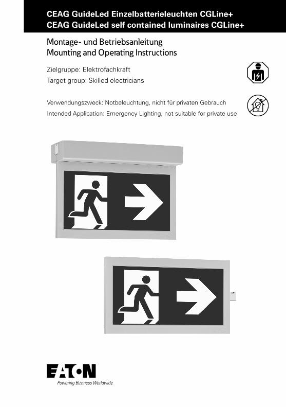
CEAG GuideLed Einzelbatterieleuchten CGLine+CEAG GuideLed self contained luminaires CGLine+
Montage- und Betriebsanleitung Mounting and Operating Instructions
Zielgruppe: Elektrofachkraft
Target group: Skilled electricians
Verwendungszweck: Notbeleuchtung, nicht für privaten Gebrauch
Intended Application: Emergency Lighting, not suitable for private use
2 Montage- und Betriebsanleitung GuideLed CGLine+ 40071860260_A Mai 2015 www.ceag.de
DISCLAIMER OF WARRANTIES AND LIMITATION OF LI-ABILITY
The information, recommendations, descriptions and safety notations in this document are based on Eaton Corporation’s (“Eaton”) experience and judgment and may not cover all contingencies. If further information is required, an Eaton sales office should be consulted. Sale of the product shown in this literature is subject to the terms and conditions outlined in appropriate Eaton selling policies or other contractual agreement between Eaton and the purchaser.
THERE ARE NO UNDERSTANDINGS, AGREEMENTS, WARRANTIES, EXPRESSED OR IMPLIED, INCLUDING WARRANTIES OF FITNESS FOR A PARTICULAR PURPOSE OR MERCHANTABILITY, OTHER THAN THOSE SPECIFICALLY SET OUT IN ANY EXISTING CONTRACT BETWEEN THE PARTIES. ANY SUCH CONTRACT STATES THE ENTIRE OBLIGATION OF EATON. THE CONTENTS OF THIS DOCUMENT SHALL NOT BECOME PART OF OR MODIFY ANY CONTRACT BETWEEN THE PARTIES.
In no event will Eaton be responsible to the purchaser or user in contract, in tort (including negligence), strict liability or other-wise for any special, indirect, incidental or consequential damage or loss whatsoever, including but not limited to damage or loss of use of equipment, plant or power system, cost of capital, loss of power, additional expenses in the use of existing power facilities, or claims against the purchaser or user by its customers resulting from the use of the information, recommendations and descriptions contained herein. The information contained in this manual is subject to change without notice.
3Mounting and Operating Instruction GuideLed CGLine+ 40071860260_A Mai 2015 www.ceag.de
GuideLed CGLine+
Inhalt
1. Normenkonformität . . . . . . . . . . . . . . . . . . . . . . 4
2. Kurzbeschreibung/Verwendungsbereich . . . . . . 5
3. Generelle Hinweise . . . . . . . . . . . . . . . . . . . . . . 5
4. Montage / Maßbilder . . . . . . . . . . . . . . . . . . . . . 84.1 10811 / 11811 CGLine+ . . . . . . . . . . . . . . . . . . . . . . . . . 84.2 10812 / 11812 CGLine+ . . . . . . . . . . . . . . . . . . . . . . . . . 94.3 10821 / 11821 CGLine+ . . . . . . . . . . . . . . . . . . . . . . . .104.4 10822 / 10823 / 11822 / 11823 CGLine+ . . . . . . . . . . .114.5 10824 / 11824 CGLine+ . . . . . . . . . . . . . . . . . . . . . . . .124.6 10825 / 11825 CGLine+ . . . . . . . . . . . . . . . . . . . . . . . .134.7 10826 / 11826 CGLine+ . . . . . . . . . . . . . . . . . . . . . . . .14
5. Installation / Inbetriebnahme . . . . . . . . . . . . . 15
6. Wartung / Instandhaltung. . . . . . . . . . . . . . . . . 18
7. Entsorgung / Recycling . . . . . . . . . . . . . . . . . 18
8. Technische Daten . . . . . . . . . . . . . . . . . . . . . . 19
Table of Contents
1. Conformity with standards . . . . . . . . . . . . . . 4
2. Brief description / Scope of application . . . 5
3. General notes . . . . . . . . . . . . . . . . . . . . . . . . . 5
4. Mounting / Dimensional drawings . . . . . . . 84.1 10811 / 11811 CGLine+ . . . . . . . . . . . . . . . . . . . . . . . . . 84.2 10812 / 11812 CGLine+ . . . . . . . . . . . . . . . . . . . . . . . . . 94.3 10821 / 11821 CGLine+ . . . . . . . . . . . . . . . . . . . . . . . .104.4 10822 / 10823 / 11822 / 11823 CGLine+ . . . . . . . . . . .114.5 10824 / 11824 CGLine+ . . . . . . . . . . . . . . . . . . . . . . . .124.6 10825 / 11825 CGLine+ . . . . . . . . . . . . . . . . . . . . . . . .134.7 10826 / 11826 CGLine+ . . . . . . . . . . . . . . . . . . . . . . . .14
5. Installation / Operation . . . . . . . . . . . . . . . . 15
6. Service / Maintenance. . . . . . . . . . . . . . . . . 18
7. Disposal / Recycling . . . . . . . . . . . . . . . . . . 18
8. Technical Data . . . . . . . . . . . . . . . . . . . . . . . 19
4 Montage- und Betriebsanleitung GuideLed CGLine+ 40071860260_A Mai 2015 www.ceag.de
SiChErhEitShinwEiSE
• Die Leuchte ist bestim mungs gemäß in unbeschädigtem und einwandfreiem Zu-stand zu betreiben!
• Als Ersatz dürfen nur Originalteile von CEAG verwendet werden!
• Vor der ersten inbetriebnahme muss die Leuchte entsprechend den im Abschnitt installation genannten Anweisungen geprüft werden!
• Die notleuchtenkenn zeich nung vorneh-men: Stromkreis und Leuchtennummer zuordnen und eintragen.
• Die Protokollführung gemäß der natio-nalen Vorschriften ist durchzuführen (entfällt bei automatischer Protokollie-rung)!
• Alle Fremdkörper müssen vor der ersten inbetriebnahme aus dem Gerät entfernt werden!
• Beachten Sie bei allen Ar beiten an dem Gerät die nationalen Sicherheits- und Unfallverhütungsvorschriften und die nachfolgenden Sicherheitshinweise in der Betriebsanleitung, die mit einem versehen sind!
SAFEty inStrUCtiOnS • the device shall only be used for its
intended purpose and in undamaged and flawless condition
• Only genuine CEAG spare parts may be used for replacement and repair
• Prior to its initial operation, the luminaire will have to be checked in line with the instructions (see installation sector)
• Carry out the marking of the emergency luminaire: Assign the circuit and the luminaire no. and enter them.
• recording in the minutes shall be performed in compliance with the national regulations (is deleted in case of automatic recording).
• Any foreign object shall be removed from the luminaire prior to its initial operation!
• Observe the national safety rules and regulations to prevent accidents as well as the safety instructions included in these operating instruction marked with
1 NormenkonformitätDie Leuchte ist konform mit: EN 60 598-1, EN 60 598-2-22 und DIN EN 1838. Gemäß DIN EN ISO 9001 entwickelt, gefertigt und geprüft.
1 Conformity with standardsConforms to: EN 60 598-1, EN 60 598-2-22 and DIN EN 1838. Developed, manufactured and tested in ac-cordance with DIN EN ISO 9001.
5Mounting and Operating Instruction GuideLed CGLine+ 40071860260_A Mai 2015 www.ceag.de
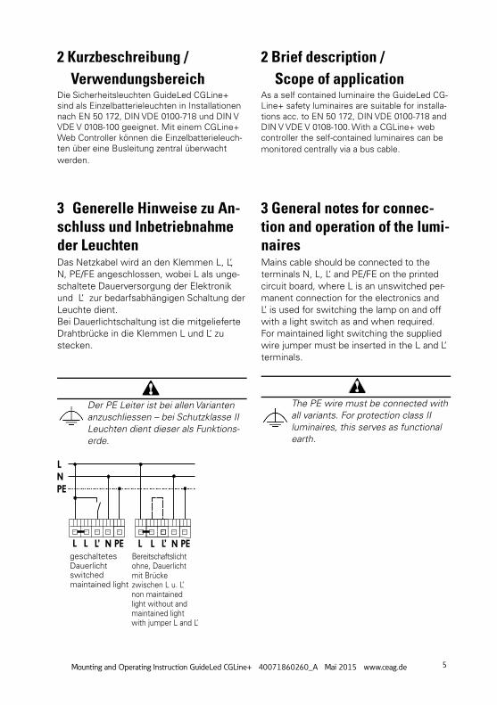
geschaltetesDauerlicht
Bereitschaftslicht ohne, Dauerlicht mit Brücke zwischen L u. L’
switched maintained light
non maintained light without and maintained light with jumper L and L’
2 Kurzbeschreibung / VerwendungsbereichDie Sicherheitsleuchten GuideLed CGLine+ sind als Einzelbatterieleuchten in Installationen nach EN 50 172, DIN VDE 0100-718 und DIN V VDE V 0108-100 geeignet. Mit einem CGLine+ Web Controller können die Einzelbatterieleuch-ten über eine Busleitung zentral überwacht werden.
2 Brief description / Scope of applicationAs a self contained luminaire the GuideLed CG-Line+ safety luminaires are suitable for installa-tions acc. to EN 50 172, DIN VDE 0100-718 and DIN V VDE V 0108-100. With a CGLine+ web controller the self-contained luminaires can be monitored centrally via a bus cable.
3 Generelle Hinweise zu An-schluss und Inbetriebnahme der Leuchten Das Netzkabel wird an den Klemmen L, L‘, N, PE/FE angeschlossen, wobei L als unge-schaltete Dauerversorgung der Elektronik und L‘ zur bedarfsabhängigen Schaltung der Leuchte dient.Bei Dauerlichtschaltung ist die mitgelieferte Drahtbrücke in die Klemmen L und L‘ zu stecken.
Der PE Leiter ist bei allen Varianten anzuschliessen – bei Schutzklasse II Leuchten dient dieser als Funktions-erde.
3 General notes for connec-tion and operation of the lumi-nairesMains cable should be connected to the terminals N, L, L‘ and PE/FE on the printed circuit board, where L is an unswitched per-manent connection for the electronics and L’ is used for switching the lamp on and off with a light switch as and when required.For maintained light switching the supplied wire jumper must be inserted in the L and L‘ terminals.
The PE wire must be connected with all variants. For protection class II luminaires, this serves as functional earth.
6 Montage- und Betriebsanleitung GuideLed CGLine+ 40071860260_A Mai 2015 www.ceag.de
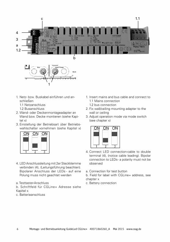
1. Netz- bzw. Buskabel einführen und an-schließen 1.1 Netzanschluss 1.2 Busanschluss
2. Wand- oder Deckenmontageadapter an Wand bzw. Decke montieren (siehe Kapi-tel x)
3. Einstellung der Betriebsart über Betriebs-wahlschalter vornehmen (siehe Kapitel x)
4. LED Anschlussleitung mit 2er Steckklemme verbinden (4), (Leitungsführung beachten). Bipolarer Anschluss der LEDs - auf eine Polung muss nicht geachtet werden
a. Testtaster-Anschlussb. Schriftfeld für CGLine+ Adresse siehe Kapitel xc. Batterieanschluss
1. Insert mains and bus cable and connect to 1.1 Mains connection 1.2 bus connection
2. Fix wall/ceiling mounting adapter to the wall or ceiling
3. Adjust operation mode via mode switch (see chapter x)
4. Connect LED connection-cable to double terminal (4), (notice cable leading). Bipolar connection to LEDs - a polarity must not be observed
a. Connection for test buttonb. Field for label with CGLine+ address, see chapter xc. Battery connection
1.1
1.2
4
3
1
a
b
c
7Mounting and Operating Instruction GuideLed CGLine+ 40071860260_A Mai 2015 www.ceag.de
Busanschluss Im Falle einer zentralen Überwachung über den CGLine+ Bus, ist der Busanschluss an den Klemmen D1 und D2 vorzunehmen, wobei die Klemmen jeweils zweifach vorhan-den und geräteseitig gebrückt sind, um eine Durchverdrahtung zu ermöglichen.
LED-AnschlussDie eingebaute Versorgungselektronik ist für den Betrieb von unterschiedlichen LED-Leiterkartengeeignet. Beim ersten Einschalten bzw. nachdem Netz und Batterie abgeklemmt waren oder nach einem Reset (Testtaster > 10 s gedrückt) erkennt die Elektronik die verwendete Leiterkarte und stellt die zum Betrieb notwendigen Parameter ein. Dieser Initialisierungsvorgang dauert ca. 5 s.Sollte nach der ersten Inbetriebnahme das Piktogramm gewechselt werden müssen – z.B. Tausch von einseitigem Piktogramm auf zweiseitigem Piktogramm, ist die Leuchte - wie oben beschrieben - zu initialisieren.
Die LED-Lichtquellen der GuideLed Ret-tungszeichen sind für einen bipolaren An-schluss ausgerüstet - auf eine Polung muss daher nicht geachtet werden!
BatterieanschlussDie Inbetriebnahme sollte nur bei Temperatu-ren innerhalb der angegebenen Bereich erfol-gen, insbesondere das Laden der Batterien bei zu hohen oder zu niedrigen Temperaturen kann zur Schädigung der Batterien führen und wird daher von der Elektronik verhindert.Für die Nachvollziehbarkeit der Batterie-Le-bensdauer bitte das Inbetriebnahme-Datum in das auf der Batterie vorgesehene Feld eintragen!
taster/LED-Folien-AnschlussBeim Wechsel von Taster/LED oder Leiterkar-te bitte Markierung 1 auf der Leiterkarte und auf der Leiterbahnfolie beachten!
Bus connectionWith central monitoring via the CGLine+ bus, bus connection is via the D1 and D2 terminals, whereby the terminals each exist twice and are bypassed on the device side to enable through-wiring.
LED-connectionThe integrated supply electronics are sui-table for the operation of various LED circuit boards. When switching on for the first time or after the network and battery have been disconnected or after a reset (test button pressed > 10 s) the electronics detect the circuit board used and set the correct para-meters for operation. This initialisation pro-cess requires approx. 5 s.If after the first commissioning process the pictogram needs to be replaced, for examp-le replacing a single-sided pictogram for a double-sided pictogram, then the luminaire must be initialised as described above.
The LED light sources of the GuideLed esca-pe signs are equipped for bipolar connection, and so one polarity need not be observed!
Battery connectionCommissioning should only be carried out at temperatures within the specified ran-ge. Charging of the batteries at excessive or insufficient temperatures may damage batteries and is therefore prevented by the electronics.To fathom batteries life please note the start-up date on the battery in the given data field!
Button/LED-foil-connectionChanging button/LED or printed circuit plea-se see marker 1 on the printed circuit board and on the printed conductor!
8 Montage- und Betriebsanleitung GuideLed CGLine+ 40071860260_A Mai 2015 www.ceag.de
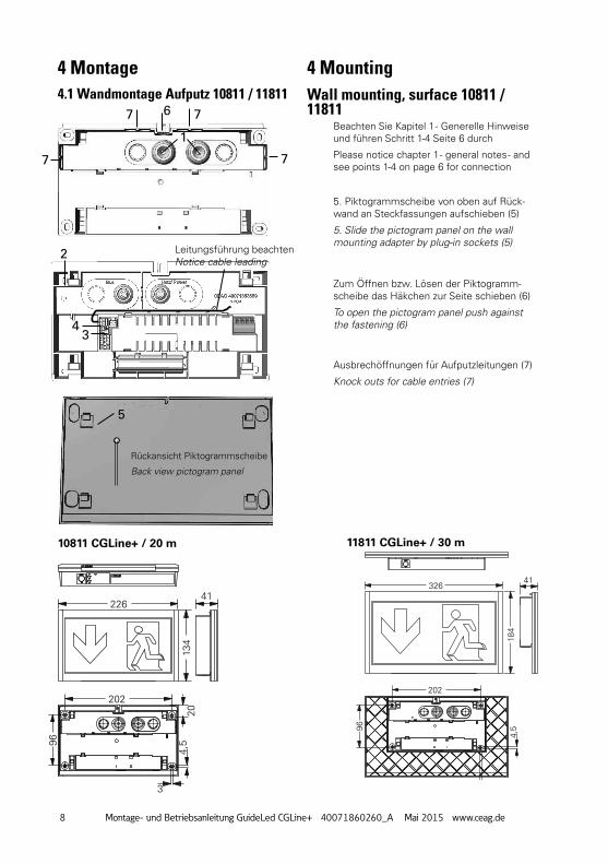
5. Piktogrammscheibe von oben auf Rück-wand an Steckfassungen aufschieben (5)
5. Slide the pictogram panel on the wall mounting adapter by plug-in sockets (5)
Zum Öffnen bzw. Lösen der Piktogramm-scheibe das Häkchen zur Seite schieben (6)
To open the pictogram panel push against the fastening (6)
Ausbrechöffnungen für Aufputzleitungen (7)
Knock outs for cable entries (7)
4.1 Wandmontage Aufputz 10811 / 11811 Wall mounting, surface 10811 / 11811
1
2
3
6
4
5
7 7
77
Rückansicht Piktogrammscheibe
Back view pictogram panel
Leitungsführung beachtenNotice cable leading
226
226
134
202
41
204,
5
3
9691
134
20
88
366
16
4,6
185
20310027 27
19,5
56
326
184
202
41
4,5
3
96
326
91
184
20 88
366
16
4,6
185
20310027 27
19,5
56
10811 CGLine+ / 20 m 11811 CGLine+ / 30 m
Beachten Sie Kapitel 1 - Generelle Hinweise und führen Schritt 1-4 Seite 6 durch
Please notice chapter 1 - general notes - and see points 1-4 on page 6 for connection
4 Montage 4 Mounting
9Mounting and Operating Instruction GuideLed CGLine+ 40071860260_A Mai 2015 www.ceag.de
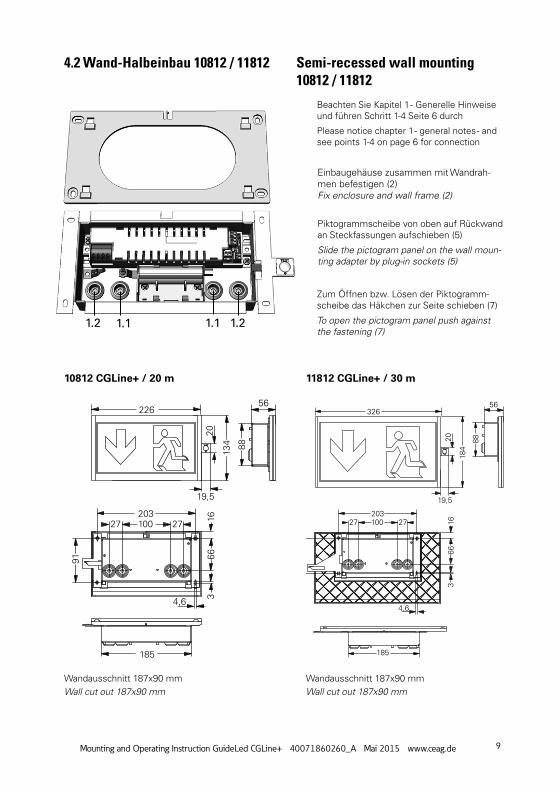
4.2 Wand-Halbeinbau 10812 / 11812 Semi-recessed wall mounting 10812 / 11812
1.11.2 1.21.1
1
Einbaugehäuse zusammen mit Wandrah-men befestigen (2)Fix enclosure and wall frame (2)
Piktogrammscheibe von oben auf Rückwand an Steckfassungen aufschieben (5)
Slide the pictogram panel on the wall moun-ting adapter by plug-in sockets (5)
Zum Öffnen bzw. Lösen der Piktogramm-scheibe das Häkchen zur Seite schieben (7)
To open the pictogram panel push against the fastening (7)
226
226
134
202
4120
4,5
3
9691
134
20
88
366
16
4,6
185
20310027 27
19,5
56
326
184
202
41
4,5
3
96
326
91
184
20 88
366
16
4,6
185
20310027 27
19,5
56
10812 CGLine+ / 20 m
Wandausschnitt 187x90 mmWall cut out 187x90 mm
Wandausschnitt 187x90 mmWall cut out 187x90 mm
11812 CGLine+ / 30 m
Beachten Sie Kapitel 1 - Generelle Hinweise und führen Schritt 1-4 Seite 6 durch
Please notice chapter 1 - general notes - and see points 1-4 on page 6 for connection
10 Montage- und Betriebsanleitung GuideLed CGLine+ 40071860260_A Mai 2015 www.ceag.de
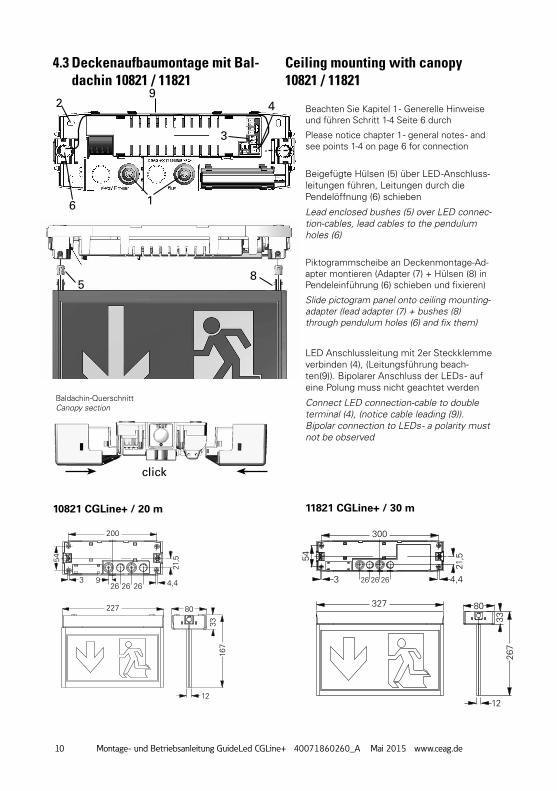
Baldachin-QuerschnittCanopy section
4.3 Deckenaufbaumontage mit Bal-dachin 10821 / 11821
Ceiling mounting with canopy10821 / 11821
Beigefügte Hülsen (5) über LED -Anschluss-leitungen führen, Leitungen durch die Pendelöffnung (6) schieben
Lead enclosed bushes (5) over LED connec-tion-cables, lead cables to the pendulum holes (6)
1
3
49
8
6
5
click
2
Piktogrammscheibe an Deckenmontage-Ad-apter montieren (Adapter (7) + Hülsen (8) in Pendeleinführung (6) schieben und fixieren)
Slide pictogram panel onto ceiling mounting-adapter (lead adapter (7) + bushes (8) through pendulum holes (6) and fix them)
LED Anschlussleitung mit 2er Steckklemme verbinden (4), (Leitungsführung beach-ten(9)). Bipolarer Anschluss der LEDs - auf eine Polung muss nicht geachtet werden
Connect LED connection-cable to double terminal (4), (notice cable leading (9)). Bipolar connection to LEDs - a polarity must not be observed
200
26269
263
54
227
227
274
262
226
361
80
12
12
12
21,5
4,4
167
33
80
75
61
134
3313
4
62 92
19
2727 5015
12
300
26 26 263
54
21,5
4,4
327
327
80
12
12
80
267
3333
184
374
362
326
461
75
61
184
62 92
19
2727 5015
6
10821 CGLine+ / 20 m 11821 CGLine+ / 30 m
Beachten Sie Kapitel 1 - Generelle Hinweise und führen Schritt 1-4 Seite 6 durch
Please notice chapter 1 - general notes - and see points 1-4 on page 6 for connection
11Mounting and Operating Instruction GuideLed CGLine+ 40071860260_A Mai 2015 www.ceag.de
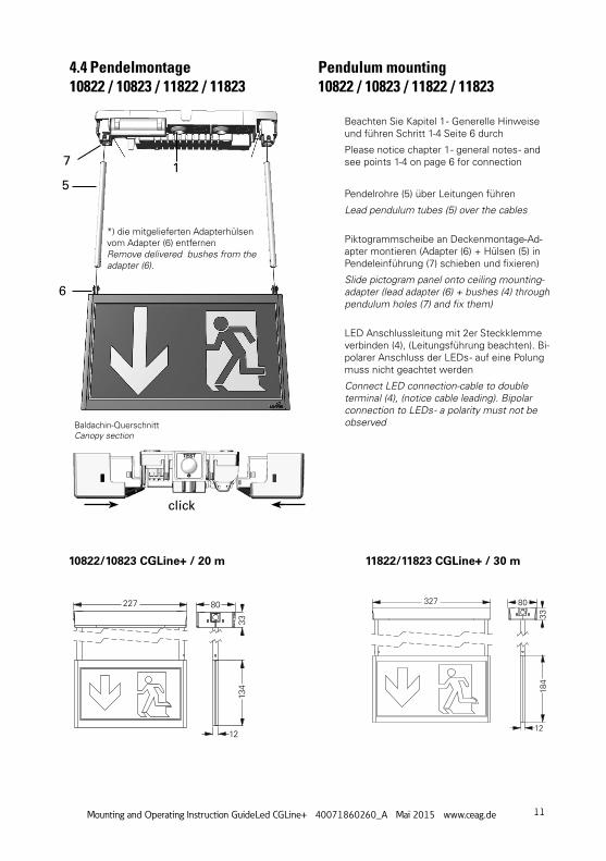
Baldachin-QuerschnittCanopy section
click
*) die mitgelieferten Adapterhülsen vom Adapter (6) entfernenRemove delivered bushes from the adapter (6).
Pendelrohre (5) über Leitungen führen
Lead pendulum tubes (5) over the cables
Piktogrammscheibe an Deckenmontage-Ad-apter montieren (Adapter (6) + Hülsen (5) in Pendeleinführung (7) schieben und fixieren)
Slide pictogram panel onto ceiling mounting-adapter (lead adapter (6) + bushes (4) through pendulum holes (7) and fix them)
LED Anschlussleitung mit 2er Steckklemme verbinden (4), (Leitungsführung beachten). Bi-polarer Anschluss der LEDs - auf eine Polung muss nicht geachtet werden
Connect LED connection-cable to double terminal (4), (notice cable leading). Bipolar connection to LEDs - a polarity must not be observed
15
7
6
Beachten Sie Kapitel 1 - Generelle Hinweise und führen Schritt 1-4 Seite 6 durch
Please notice chapter 1 - general notes - and see points 1-4 on page 6 for connection
4.4 Pendelmontage10822 / 10823 / 11822 / 11823
Pendulum mounting 10822 / 10823 / 11822 / 11823
10822/10823 CGLine+ / 20 m 11822/11823 CGLine+ / 30 m
200
26269
263
54
227
227
274
262
226
361
80
12
12
12
21,5
4,4
167
33
80
75
61
134
3313
4
62 92
19
2727 5015
12
300
26 26 263
54
21,5
4,4
327
327
80
12
12
80
267
3333
184
374
362
326
461
75
61
184
62 92
19
2727 5015
6
12 Montage- und Betriebsanleitung GuideLed CGLine+ 40071860260_A Mai 2015 www.ceag.de
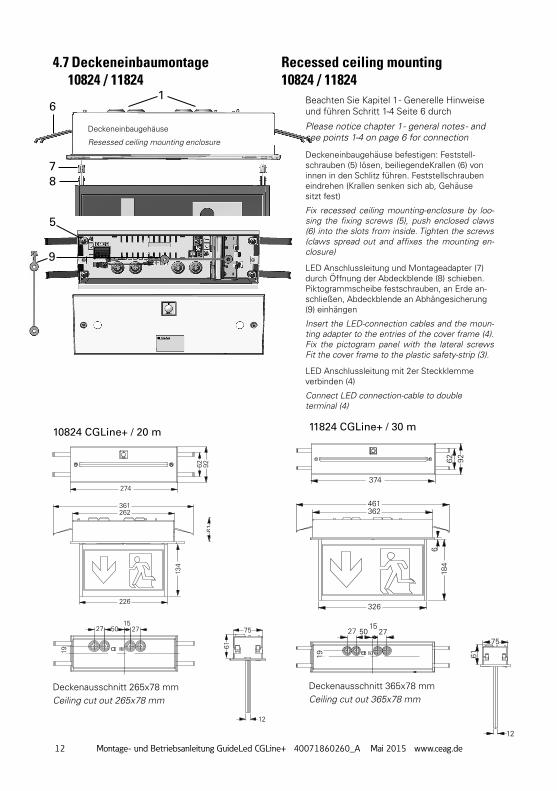
Deckeneinbaugehäuse befestigen: Feststell-schrauben (5) lösen, beiliegendeKrallen (6) von innen in den Schlitz führen. Feststellschrauben eindrehen (Krallen senken sich ab, Gehäuse sitzt fest)
Fix recessed ceiling mounting-enclosure by loo-sing the fixing screws (5), push enclosed claws (6) into the slots from inside. Tighten the screws (claws spread out and affixes the mounting en-closure)
200
26269
263
54
227
227
274
262
226
361
80
12
12
12
21,5
4,4
167
33
80
75
61
134
3313
4
62 92
19
2727 5015
200
26269
263
54
227
227
274
262
226
361
80
12
12
12
21,5
4,4
167
33
80
75
61
134
3313
4
62 92
19
2727 5015
200
26269
263
54
227
227
274
262
226
361
80
12
12
12
21,5
4,4
167
33
80
75
61
134
3313
4
62 92
19
2727 5015
12
300
26 26 263
54
21,5
4,4
327
327
80
12
12
80
267
3333
184
374
362
326
461
75
61
184
62 92
19
2727 5015
6
Deckenausschnitt 365x78 mmCeiling cut out 365x78 mm
Deckenausschnitt 265x78 mmCeiling cut out 265x78 mm
10824 CGLine+ / 20 m
Deckeneinbaugehäuse
Resessed ceiling mounting enclosure
11824 CGLine+ / 30 m
1
5
9
6
78
LED Anschlussleitung und Montageadapter (7) durch Öffnung der Abdeckblende (8) schieben. Piktogrammscheibe festschrauben, an Erde an-schließen, Abdeckblende an Abhängesicherung (9) einhängen
Insert the LED-connection cables and the moun-ting adapter to the entries of the cover frame (4). Fix the pictogram panel with the lateral screws Fit the cover frame to the plastic safety-strip (3).
LED Anschlussleitung mit 2er Steckklemme verbinden (4)
Connect LED connection-cable to double terminal (4)
4.7 Deckeneinbaumontage 10824 / 11824
Recessed ceiling mounting10824 / 11824
Beachten Sie Kapitel 1 - Generelle Hinweise und führen Schritt 1-4 Seite 6 durch
Please notice chapter 1 - general notes - and see points 1-4 on page 6 for connection
13Mounting and Operating Instruction GuideLed CGLine+ 40071860260_A Mai 2015 www.ceag.de
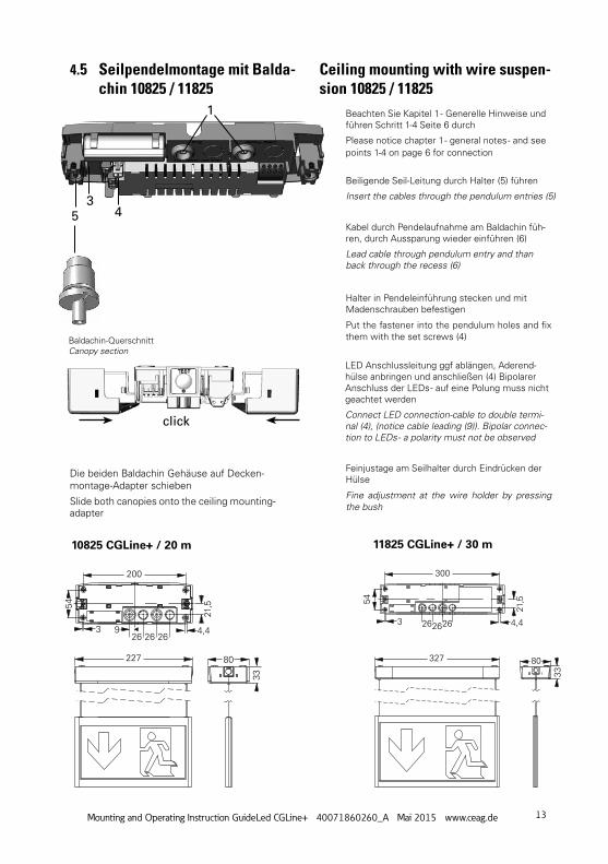
Beiligende Seil-Leitung durch Halter (5) führen
Insert the cables through the pendulum entries (5)
Kabel durch Pendelaufnahme am Baldachin füh-ren, durch Aussparung wieder einführen (6)
Lead cable through pendulum entry and than back through the recess (6)
Halter in Pendeleinführung stecken und mit Madenschrauben befestigen
Put the fastener into the pendulum holes and fix them with the set screws (4)
Feinjustage am Seilhalter durch Eindrücken der Hülse
Fine adjustment at the wire holder by pressing the bush
Die beiden Baldachin Gehäuse auf Decken-montage-Adapter schieben
Slide both canopies onto the ceiling mounting-adapter
53
4
1
LED Anschlussleitung ggf ablängen, Aderend-hülse anbringen und anschließen (4) Bipolarer Anschluss der LEDs - auf eine Polung muss nicht geachtet werden
Connect LED connection-cable to double termi-nal (4), (notice cable leading (9)). Bipolar connec-tion to LEDs - a polarity must not be observed
Baldachin-QuerschnittCanopy section
click
Beachten Sie Kapitel 1 - Generelle Hinweise und führen Schritt 1-4 Seite 6 durch
Please notice chapter 1 - general notes - and see points 1-4 on page 6 for connection
4.5 Seilpendelmontage mit Balda-chin 10825 / 11825
Ceiling mounting with wire suspen-sion 10825 / 11825
200
26 26 2693
54
227 80
56
51
21,5
4,4
33
39
36
337
204
57
200
26 26 2693
54
227 80
56
51
21,5
4,4
33
39
36
337
204
57
300
2626 263
54
327 80
56
5121
,5
4,4
33
39
36
304
354,3
300
2626 263
54
327 80
56
5121
,5
4,4
33
39
36
304
354,3
10825 CGLine+ / 20 m 11825 CGLine+ / 30 m
14 Montage- und Betriebsanleitung GuideLed CGLine+ 40071860260_A Mai 2015 www.ceag.de
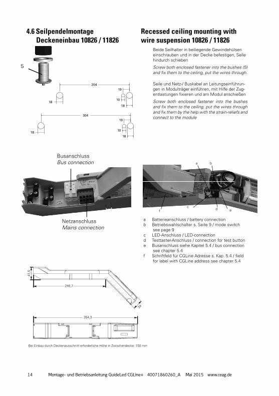
4.6 Seilpendelmontage Deckeneinbau 10826 / 11826
Recessed ceiling mounting with wire suspension 10826 / 11826
Beide Seilhalter in beiliegende Gewindehülsen einschrauben und in der Decke befestigen, Seile hindurch schieben
Screw both enclosed fastener into the bushes (5) and fi x them to the ceiling, put the wires through.
Seile und Netz-/ Buskabel an Leitungseinführun-gen in Modulträger einführen, mit Hilfe der Zug-entlastungen fi xieren und am Modul anschießen
Screw both enclosed fastener into the bushes and fi x them to the ceiling, put the wires through and fi x them by the help with the strain-reliefs and connect to the module
5
1818
18
10
10
19
19
204
304
18
BusanschlussBus connection
NetzanschlussMains connection
a Batterieanschluss / battery connectionb Betriebswahlschalter s. Seite 9 / mode switch
see page 9c LED-Anschluss / LED-connectiond Testtaster-Anschluss / connection for test buttone Busanschluss siehe Kapitel 5.4 / bus connection
see chapter 5.4f Schriftfeld für CGLine Adresse s. Kap. 5.4 / fi eld
for label with CGLine address see chapter 5.4
a
c d ef
b
Deckenausschnitt
Ausrichtung Fluchtweg
Bei Einbau durch Deckenausschnitt erforderliche Höhe in Zwischendecke: 150 mm
Deckenstärke 1-20mm
246,7
354,3
41,5
34
85
100
18,5
85
394,5
100
118
15Mounting and Operating Instruction GuideLed CGLine+ 40071860260_A Mai 2015 www.ceag.de
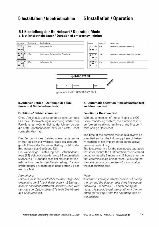
5.1 Einstellung der Betriebsart / Operation Modea. notlichtbetriebsdauer / Duration of emergency lighting
Abbildung Codierung Beschreibung
00x Notlichtdauer 1h.
10x Notlichtdauer 3h. (werkseitige Einstellung)
01x Notlichtdauer 8h.
Display Encoding Description
00x Duration of emergency lighting 1h.
10x Duration of emergency lighting 3h. (Default)
01x Duration of emergency lighting 8h.
b. Autarker Betrieb – Zeitpunkt des Funk-tions- und Betriebsdauertests
Funktions-/ Betriebsdauertest
Ohne Anschluss der Leuchte an eine zentrale CGLine+ Überwachungseinrichtung startet der Funktionstest wöchentlich zu der Uhrzeit zu der die erste Inbetriebnahme bzw. der letzte Reset stattgefunden hat.
Der Zeitpunkt des Betriebsdauertests sollte immer so gewählt werden, dass die darauffol-gende Phase der Batterieaufl adung nicht in die Betriebszeit des Gebäudes fällt. Die werkseitige Einstellung des Betriebsdauer-tests (BT) sieht vor, dass der erste BT automatisch 6 Monate + 12 Stunden nach der ersten Inbetrieb-nahme bzw. des letzten Resets erfolgt. Danach erfolgt genau 6 Monate nach dem letzten BT der nächste Test.
b. Automatic operation - time of function test and duration test
Function / Duration test
Without connection of the luminaire to a CG-Line+ monitoring system, the function test is performed weekly at the time of the fi rst com-missioning or last reset.
The time of the duration test should always be specifi ed so that the following phase of batte-ry charging is not implemented during acitve times in the building. The factory setting for the continuous operation test intends that the fi rst duration test is carried out automatically 6 months + 12 hours after the fi rst commissioning or last reset. Following that, the next test occurs precisely 6 months after the last duration test.
Anmerkung:Dadurch, dass die Inbetriebname meist tagsüber erfolgt und der BT nach 6 Monaten + 12 Stunden daher in der Nacht stattfi ndet, soll vermieden wer-den, dass der Zeitpunkt des BTs in die Betriebszeit des Gebäudes fällt.
Note:as commissioning is usually carried out during the day and the duration test therefore occurs (following 6 months + 12 hours) during the night, this should avoid the duration of the du-ration test falling within the operating time of the building.
5 Installation / Inbetriebnahme 5 Installation / Operation
* * ****** ***
IMPORTANT
gem./acc.to IEC 60598-2-22:2014
16 Montage- und Betriebsanleitung GuideLed CGLine+ 40071860260_A Mai 2015 www.ceag.de
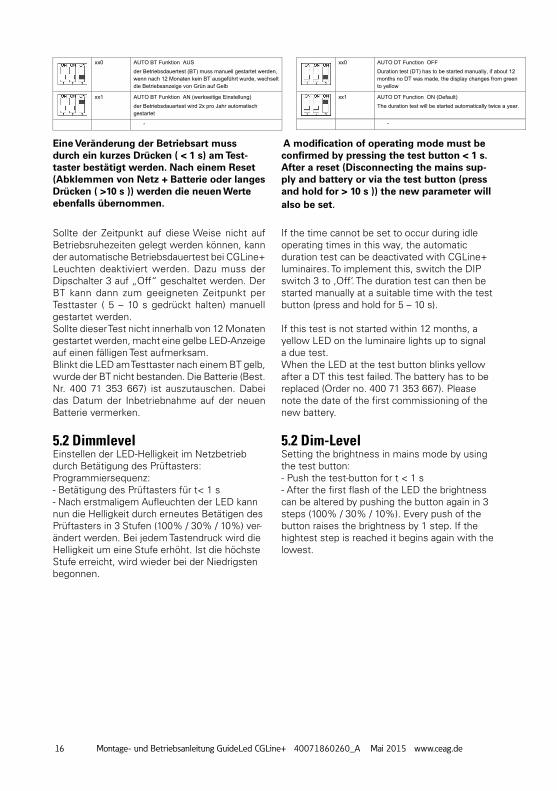
Eine Veränderung der Betriebsart muss durch ein kurzes Drücken ( < 1 s) am test-taster bestätigt werden. nach einem reset (Abklemmen von netz + Batterie oder langes Drücken ( >10 s )) werden die neuen werte ebenfalls übernommen.
A modification of operating mode must be confirmed by pressing the test button < 1 s. After a reset (Disconnecting the mains sup-ply and battery or via the test button (press and hold for > 10 s )) the new parameter will also be set.
xx0 AUTO BT Funktion AUS der Betriebsdauertest (BT) muss manuell gestartet werden, wenn nach 12 Monaten kein BT ausgeführt wurde, wechselt die Betriebsanzeige von Grün auf Gelb
xx1 AUTO BT Funktion AN (werkseitige Einstellung) der Betriebsdauertest wird 2x pro Jahr automatisch gestartet
-
xx0 AUTO DT Function OFF Duration test (DT) has to be started manually, if about 12 months no DT was made, the display changes from green to yellow
xx1 AUTO DT Function ON (Default) The duration test will be started automatically twice a year.
-
Sollte der Zeitpunkt auf diese Weise nicht auf Betriebsruhezeiten gelegt werden können, kann der automatische Betriebsdauertest bei CGLine+ Leuchten deaktiviert werden. Dazu muss der Dipschalter 3 auf „Off“ geschaltet werden. Der BT kann dann zum geeigneten Zeitpunkt per Testtaster ( 5 – 10 s gedrückt halten) manuell gestartet werden.Sollte dieser Test nicht innerhalb von 12 Monaten gestartet werden, macht eine gelbe LED-Anzeige auf einen fälligen Test aufmerksam.Blinkt die LED am Testtaster nach einem BT gelb, wurde der BT nicht bestanden. Die Batterie (Best. Nr. 400 71 353 667) ist auszutauschen. Dabei das Datum der Inbetriebnahme auf der neuen Batterie vermerken.
5.2 DimmlevelEinstellen der LED-Helligkeit im Netzbetrieb durch Betätigung des Prüftasters:Programmiersequenz:- Betätigung des Prüftasters für t< 1 s- Nach erstmaligem Aufleuchten der LED kann nun die Helligkeit durch erneutes Betätigen des Prüftasters in 3 Stufen (100% / 30% / 10%) ver-ändert werden. Bei jedem Tastendruck wird die Helligkeit um eine Stufe erhöht. Ist die höchste Stufe erreicht, wird wieder bei der Niedrigsten begonnen.
If the time cannot be set to occur during idle operating times in this way, the automatic duration test can be deactivated with CGLine+ luminaires. To implement this, switch the DIP switch 3 to ‚Off‘. The duration test can then be started manually at a suitable time with the test button (press and hold for 5 – 10 s). If this test is not started within 12 months, a yellow LED on the luminaire lights up to signal a due test.When the LED at the test button blinks yellow after a DT this test failed. The battery has to be replaced (Order no. 400 71 353 667). Please note the date of the first commissioning of the new battery.
5.2 Dim-LevelSetting the brightness in mains mode by using the test button:- Push the test-button for t < 1 s- After the first flash of the LED the brightness can be altered by pushing the button again in 3 steps (100% / 30% / 10%). Every push of the button raises the brightness by 1 step. If the hightest step is reached it begins again with the lowest.
17Mounting and Operating Instruction GuideLed CGLine+ 40071860260_A Mai 2015 www.ceag.de
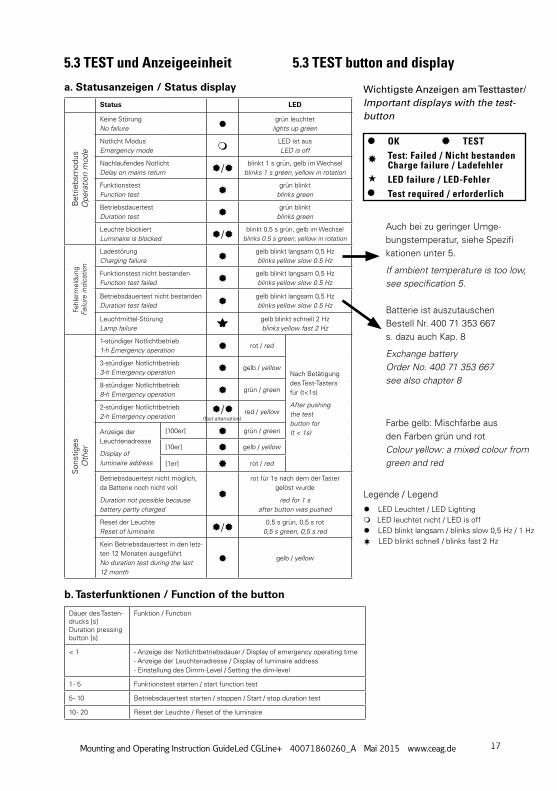
5.3 TEST und Anzeigeeinheit 5.3 TEST button and display
Auch bei zu geringer Umge-bungstemperatur, siehe Spezifi kationen unter 5.
If ambient temperature is too low, see specification 5.
Batterie ist auszutauschen Bestell Nr. 400 71 353 667s. dazu auch Kap. 8
Exchange batteryOrder No. 400 71 353 667see also chapter 8
Farbe gelb: Mischfarbe aus den Farben grün und rotColour yellow: a mixed colour from green and red
Wichtigste Anzeigen am Testtaster/Important displays with the test-button
Status LED
Bet
riebs
mod
usO
pera
tion
mod
e
Keine StörungNo failure
grün leuchtetlights up green
Notlicht ModusEmergency mode
LED ist ausLED is off
Nachlaufendes NotlichtDelay on mains return / blinkt 1 s grün, gelb im Wechsel
blinks 1 s green, yellow in rotation
FunktionstestFunction test
grün blinktblinks green
BetriebsdauertestDuration test
grün blinktblinks green
Leuchte blockiertLuminaire is blocked / blinkt 0,5 s grün, gelb im Wechsel
blinks 0.5 s green, yellow in rotation
Fehl
erm
eldu
ngFa
ilure
indi
catio
n
LadestörungCharging failure
gelb blinkt langsam 0,5 Hzblinks yellow slow 0.5 Hz
Funktionstest nicht bestandenFunction test failed
gelb blinkt langsam 0,5 Hzblinks yellow slow 0.5 Hz
Betriebsdauertest nicht bestandenDuration test failed
gelb blinkt langsam 0,5 Hzblinks yellow slow 0.5 Hz
Leuchtmittel-StörungLamp failure
gelb blinkt schnell 2 Hzblinks yellow fast 2 Hz
Son
stig
esO
ther
1-stündiger Notlichtbetrieb1-h Emergency operation rot / red
Nach Betätigung des Test-Tasters für (t<1s)
After pushingthe testbutton for (t < 1s)
3-stündiger Notlichtbetrieb3-h Emergency operation gelb / yellow
8-stündiger Notlichtbetrieb8-h Emergency operation grün / green
2-stündiger Notlichtbetrieb2-h Emergency operation
/ red / yellow
Anzeige der Leuchtenadresse
Display ofluminaire address
[100er] grün / green
[10er] gelb / yellow
[1er] rot / red
Betriebsdauertest nicht möglich, da Batterie noch nicht voll
Duration not possible because battery partly charged
rot für 1s nach dem der Taster gelöst wurde
red for 1 safter button was pushed
Reset der LeuchteReset of luminaire / 0,5 s grün, 0,5 s rot
0,5 s green, 0,5 s red
Kein Betriebsdauertest in den letz-ten 12 Monaten ausgeführtNo duration test during the last 12 month
gelb / yellow
a. Statusanzeigen / Status display
b. tasterfunktionen / Function of the button
Dauer des Tasten-drucks [s]Duration pressing button [s]
Funktion / Function
< 1 - Anzeige der Notlichtbetriebsdauer / Display of emergency operating time- Anzeige der Leuchtenadresse / Display of luminaire address- Einstellung des Dimm-Level / Setting the dim-level
1 - 5 Funktionstest starten / start function test
5 - 10 Betriebsdauertest starten / stoppen / Start / stop duration test
10 - 20 Reset der Leuchte / Reset of the luminaire
Legende / Legend
LED Leuchtet / LED Lighting LED leuchtet nicht / LED is off LED blinkt langsam / blinks slow 0,5 Hz / 1 Hz LED blinkt schnell / blinks fast 2 Hz
(fast alternation)
OK TESTTest: Failed / Nicht bestandenCharge failure / LadefehlerLED failure / LED-FehlerTest required / erforderlich
18 Montage- und Betriebsanleitung GuideLed CGLine+ 40071860260_A Mai 2015 www.ceag.de
5.4 Überwachungseinrichtung CGLine+Die Leuchten GuideLed CGLine+ sind für den An-schluss an eine zentrale CGLine+ Überwachungs-einrichtung. Jeder Leuchte der Leuchtenserie CGLine+ ist eine individuelle, unverwechselbare Identifikationsnummer mit 6 Ziffern zugeordnet.Diese ID-Nummer muss für spätere Konfigurati-onsarbeiten in den Installationsplan übertragen werden. Dazu dient der abziehbare ID-Aufkleber in der Leuchte.
An eine zentrale CGLine+ Überwachungseinrich-tung können maximal 4 Busleitungen (2-adrig) mit jeweils bis zu 100 Leuchten angeschlossen werden. Die max. Datenleitungslänge beträgt je Strang bei 0,5 mm2 : 330 m 1,0 mm2 : 660 m 1,5 mm2 : 1000 mBusspannung: 22,5 VDCMax.Spg.-Abfall: 13 VDCBusstrom 400 mA
Als Datenleitung kann eine ungeschirmte, 2-adrige Leitung in freier Bus-Topologie zum Einsatz kommen. Jede an der Daten-Bus-Leitung ange-schlossene Leuchte wird vom CG-Controller auto-matisch erkannt. Der CG-Controller kann den angeschlossenen Leuchten eine Kurzadresse zuweisen, die über die drei LEDs an der Leuchte abgefragt werden kann.Weitere Informationen zur Adressierung siehe Betriebsanleitung der zentralen CGLine+ Überwachungseinrichtung.
5.4 Luminaire monitoring CGLine+The GuideLed CGLine+ luminaires are prepared for connection to a central CGLine+ luminaire moni-toring. An individual, distinct identification number (6 characters) is assigned to every luminaire in the CGLine+ luminaire series.
This ID number must be transferred to the installation plan for subsequent configuration work. The removable ID sticker in the luminaire can be used for this.
To central CGLine+ monitoring system maximum 4 bus cables (2-core) with up to 100 luminaires each can be connected. The max. data line length per line is 0.5 mm2 : 330m 1.0 mm2 : 660 m 1.5 mm2 : 1000 m Bus voltage: 22.5 VDCMax.voltage drop: 13 VDCBus current 400 mA
An unscreened, 2-core cable with free bus topolo-gy can be used as a data cable.Each of the luminaires connected to the data bus cable is automatically recognised by the CG-Cont-roller. The CG-Controller can assign a short address to the connected luminaires, which can be polled via the three LEDs on the luminaire.For more information regarding addressing please see operating instructions of a the central CGLine+ monitoring system.
6 Wartung / InstandhaltungHalten Sie die für Instandhaltung, Wartung und Prüfung von elektrischen Betriebsmitteln geltenden Bestimmungen ein! Im Fall von Rücksendungen benötigen Sie von uns eine RMA - Nummer. Entnehmen Sie bitte weitere Infos hierzu unserer Internetseite www.ceag.de! Für Ersatzleuchtmittel kontaktieren Sie bitte [email protected].
7 Entsorgung / RecyclingBeachten Sie bei der Entsorgung defekter Geräte die gültigen Vorschriften für Recycling und Entsorgung. Kunststoffteile sind mit entsprechenden Symbolen gekennzeichnet. Der in der Leuchte eingebaute LiIon-Akku ist - entsprechend der EU-Richtlinie 2006/66/EG - beim Wechsel an den Vertreiber oder an einen zugelassenen Entsorger zurück zu geben und darf nicht selbst entsorgt werden!
6 Servicing / MaintenanceObserve the relevant national regulations applying to the maintenance, servicing and check-ing of electri-cal apparatus ! In case of returns you need a RMA - number from us. For further information see www.ceag.de!Contact [email protected] for replacement of light source
7 Disposal / RecyclingWhen disposing of defective devices, comply with valid regulations for recycling and waste disposal. Plastic parts are marked with corresponding symbols. The LiIon battery integrated in the luminaire must be returned to the seller or an approved disposal location and must not be disposed of by the customer, in ac-cordance with the 2006/66/EC directive.
19Mounting and Operating Instruction GuideLed CGLine+ 40071860260_A Mai 2015 www.ceag.de
Technische Änderungen vorbehalten!
We reserve the right to make technical alterations without notice!
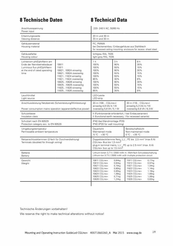
8 Technische Daten 8 Technical DataAnschlussspannungPower input
220 - 240 V AC, 50/60 Hz
ErkennungsweiteViewing distance
20 m und 30 m20 m and 30 m
GehäusematerialHousing material
PC, PMMAbei Deckeneinbau: Einbaugehäuse aus Stahlblechfor recessed ceiling mounting: enclosure for recess: sheet steel
GehäusefarbeHousing colour
lichtgrau RAL 7035light-grey RAL 7035
Lichtstrom phiE/phiNenn am Ende der NennbetriebsdauerLuminous flux phiE/phiNenn at the end of rated operating time
108111181110821...10824 einseitig10821...10824 zweiseitig11821...11824 einseitig11821...11824 zweiseitig10825...10826 einseitig10825...10826 zweiseitig11825...11826 einseitig11825...11826 zweiseitig
1 h100%100%100%100%100%85%100%100%100%85%
3 h90%55%90%55%55%30%90%55%55%30%
8 h30%15%30%15%15%8%30%15%15%8%
LeuchtmittelLight source
LED-LeisteLED-strip
Anschlussleistung Netzbetrieb (Scheinleistung/Wirkleistung)
Power consumption mains operation (apparent/effective power)
20 m (108... CGLine+)einseitig 4,8 VA/ 4,1 Wzweiseitig 5,6 VA / 5,1 W
30 m (118... CGLine+)einseitig 5,3 VA/ 4,7 Wzweiseitig 6,6 VA / 6,3 W
SchutzklasseInsulation class
II (Funktionserde erforderlich, I bei Einbauvarianten)II (functional earth necessary, I for recessed variants)
Schutzart nach EN 60529Protection category acc. to EN 60529
IP40 (bei Wandmontage IP20)IP40 (IP20 for wall mounting)
UmgebungstemperaturPermissable ambient temperature
DauerlichtMaintained mode-5 °C .. +30 °C
BereitschaftslichtNon-maintained mode0 °C .. +35 °C
Netzanschlussklemmen (2-fach für Durchverdrahtung)Terminals (doubled for through wiring)
Doppelsteckklemme Netz, L,L´, PE bis 2,5 mm2 (max 6 A)CGLine+ Bus bis 1,5 mm2plug-in terminal mains, L,L´, PE up to 2.5 mm2 (max. 6 A)CGLine+ bus up to 1.5 mm2
BatterieBattery
Lithium-Ionen 3,7 V / 2000 mAh m. Mehrfach SchutzbeschaltungLithium-Ion 3.7 V / 2000 mAh with multiple protection circuit
GewichtWeight
10811 CGLine+ 0,64kg10812 CGLine+ 0,84kg10821 CGLine+ 0,70kg10822 CGLine+ 0,80kg10823 CGLine+ 0,85kg10824 CGLine+ 1,06kg10825 CGLine+ 0,71kg10826 CGLine+ 1,24kg
11811 CGLine+ 0,77kg11812 CGLine+ 0,97kg11821 CGLine+ 1,04kg11822 CGLine+ 1,14kg 11823 CGLine+ 1,19kg11824 CGLine+ 1,65kg11825 CGLine+ 1,06kg11826 CGLine+ 0,83kg

Eaton is a registered trademark.
All trademarks are property of their respective owners.
Eaton industries Manufacturing GmbhElectrical Sector EMEARoute de la Longeraie 71110 Morges, SwitzerlandEaton.eu
CEAG notlichtsysteme GmbhSenator-Schwartz-Ring 2659494 Soest, GermanyTel.: +49 (0) 2921 69-870Fax: +49 (0) 2921 69-617E-Mail: [email protected] Web: www.ceag.de
© 2015 EatonAll Rights ReservedPrinted in GermanyPublication No. IB451051MLOrder No. 40071860260(A)May 2015
Eatons Ziel ist es, zuverlässige, effiziente und sichere Stromversorgung dann zu bieten, wenn sie am meisten benötigt wird. Die Experten von Eaton verfügen über ein umfassendes Fachwissen im Bereich Energiemanagement in verschiedensten Branchen und sorgen so für kundens-pezifische, integrierte Lösungen, um anspruchsvollste Anforderungen der Kunden zu erfüllen.
Wir sind darauf fokussiert, stets die richtige Lösung für jede Anwendung zu finden. Dabei erwarten Entscheidungsträger mehr als lediglich innovative Produkte. Unternehmen wenden sich an Eaton, weil individuelle Unterstützung und der Erfolg unserer Kunden stets an erster Stelle stehen. Für mehr Informationen besuchen Sie www.eaton.eu.
Eaton is dedicated to ensuring that reliable, efficient and safe power is available when it’s needed most. With unparalleled knowledge of electrical power management across industries, experts at Eaton deliver customized, integrated solutions to solve our customers’ most critical-challenges.
Our focus is on delivering the right solution for the appli-cation. But, decision makers demand more than just innovative products. They turn to Eaton for an unwavering commitment to personal support that makes customer success a top priority. For more information, visit www.eaton.com/electrical.