Embed Size (px)
Citation preview
Montageanleitung (Original: de) 8048588 1603NH
†‡
Fronteinheit ERMH-…-E17
Festo AG & Co. KG Postfach 73726 Esslingen Deutschland +49 711 347-0 www.festo.com
1. Teileliste
22130d_1
1 Fronteinheit 2 Zentrierhülse 3 Schraube 4 Schlauch1) 5 Encoderleitung
NEBM-M12G12-… 6 Motorleitung
NEBM-M12G4-… 7 Verbindungsleitung
NEBU-M8G3-… 8 Erdungskabel
M4 – M4 9 Zahnscheibe aJ U-Scheibe aA Schraube
(gewindeformend)
(1x) (2x) (4x) (1x) (1x)
(1x)
(1x)
(1x)
(1x) (1x) (1x)
Nicht im Lieferumfang:
22130d_2
aB Linienportal EXCT
(1x)
2. Aufbau
22130d_3
Anschlüsse: – (A) Arbeitsluft – (B) Arbeitsluft – (C) Encoderleitung 5 – (D) Motorleitung 6 – (E) Verbindungsleitung 7
3. Bestimmungsgemäße Verwendung Fronteinheit ERMH-…-E17: Drehantrieb und dritte Achse des Linienportals aB. Die Fronteinheit ERMH-...-P-E17 hat eine pneumatische Drehdurchführung. Nur baugleiche Fronteinheiten ersetzen.
EXCT-... -T1 -T2 -T3 -T4
ERMH -8-E17 -8-P-E17 -11-E17 -11-P-E17
1) Schlauch 4 liegt nur bei Fronteinheit mit pneumatischer Drehdurchführung bei.
4. Sicherheitshinweise und Hinweise zur Montage
Stromversorgung und Druckluft vor Montagearbeiten abschalten. Sicherheitshinweise beachten ( Mitgeltende Dokumente). Steckverbindungen nicht unter Spannung stecken oder trennen. Anziehdrehmomente einhalten ( Abschnitt 7).
Info
Mitgeltende Dokumente 1 Beschreibung des Linienportals aB www.festo.com/sp 2 Montageanleitungen der Leitungen 5 … 7 www.festo.com/sp
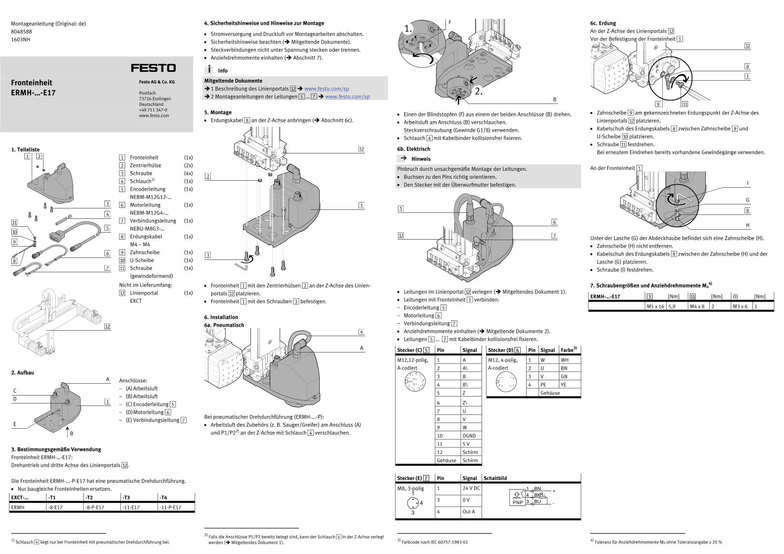
5. Montage Erdungskabel 8 an der Z-Achse anbringen ( Abschnitt 6c).
22130d_4
Fronteinheit 1 mit den Zentrierhülsen 2 an der Z-Achse des Linien-portals aB platzieren.
Fronteinheit 1 mit den Schrauben 3 befestigen.
6. Installation 6a. Pneumatisch
22130d_5
Bei pneumatischer Drehdurchführung (ERMH-...-P): Arbeitsluft des Zubehörs (z. B. Sauger/Greifer) am Anschluss (A)
und P1/P22) an der Z-Achse mit Schlauch 4 verschlauchen.
2) Falls die Anschlüsse P1/P2 bereits belegt sind, kann der Schlauch 4 in der Z-Achse verlegt
werden ( Mitgeltendes Dokument 1).
22130d_6
Einen der Blindstopfen (F) aus einem der beiden Anschlüsse (B) drehen. Arbeitsluft am Anschluss (B) verschlauchen.
Steckverschraubung (Gewinde G1/8) verwenden. Schlauch 4 mit Kabelbinder kollisionsfrei fixieren.
6b. Elektrisch
Hinweis
Pinbruch durch unsachgemäße Montage der Leitungen. Buchsen zu den Pins richtig orientieren. Den Stecker mit der Überwurfmutter befestigen.
22130d_7
Leitungen im Linienportal aB verlegen ( Mitgeltendes Dokument 1). Leitungen mit Fronteinheit 1 verbinden: – Encoderleitung 5 – Motorleitung 6 – Verbindungsleitung 7 Anziehdrehmomente einhalten ( Mitgeltende Dokumente 2). Leitungen 5 … 7 mit Kabelbinder kollisionsfrei fixieren.
Stecker (C) 5 Pin Signal Stecker (D) 6 Pin Signal Farbe3)
M12,12-polig,
A-codiert
17468d_8
1 A M12, 4-polig,
A-codiert
1 W WH
2 A\ 2 U BN
3 B 3 V GN
4 B\ 4 PE YE
5 Z Gehäuse
6 Z\ 17468d_9
7 U
8 V
9 W
10 DGND
11 5 V
12 Schirm
Gehäuse Schirm
Stecker (E) 7 Pin Signal Schaltbild
M8, 3-polig
991155
1 24 V DC
991701
3 0 V
4 Out A
3) Farbcode nach IEC 60757:1983-01
6c. Erdung An der Z-Achse des Linienportals aB Vor der Befestigung der Fronteinheit 1
22130d_8
Zahnscheibe 9 am gekennzeichneten Erdungspunkt der Z-Achse des Linienportals aB platzieren.
Kabelschuh des Erdungskabels 8 zwischen Zahnscheibe 9 und U-Scheibe aJ platzieren.
Schraube aA festdrehen. Bei erneutem Eindrehen bereits vorhandene Gewindegänge verwenden.
An der Fronteinheit 1
22130d_9
Unter der Lasche (G) der Abdeckhaube befindet sich eine Zahnscheibe (H). Zahnscheibe (H) nicht entfernen. Kabelschuh des Erdungskabels 8 zwischen der Zahnscheibe (H) und der
Lasche (G) platzieren. Schraube (I) festdrehen.
7. Schraubengrößen und Anziehdrehmomente MA4)
ERMH-…-E17 3 [Nm] aA [Nm] (I) [Nm]
M5 x 16 5,9 M4 x 8 2 M3 x 6 1
4) Toleranz für Anziehdrehmomente MA ohne Toleranzangabe ± 20 %
6
5
3
4
7 8
9
aA
aJ
2 1
aB
1
B
C
E
D
A
1
2
aB
3
4
A
B
F
5
6
7 aB
aA
1
8
9
aB
G
8
I
H
Assembly instructions (Original: de) 8048588 1603NH
†‡
Front unit ERMH-…-E17
Festo AG & Co. KG Postfach 73726 Esslingen Germany +49 711 347-0 www.festo.com
1. Parts list
22130d_1
1 Front unit 2 Centring sleeve 3 Screw 4 Tube1) 5 Encoder cable
NEBM-M12G12-… 6 Motor cable
NEBM-M12G4-… 7 Connecting cable
NEBU-M8G3-… 8 Earthing cable
M4 – M4 9 Toothed disc aJ Washer aA Screw
(thread-cutting)
(1x) (2x) (4x) (1x) (1x)
(1x)
(1x)
(1x)
(1x) (1x) (1x)
Not included in delivery:
22130d_2
aB Linear gantry EXCT
(1x)
2. Design
22130d_3
Connections: – (A) Air – (B) Air – (C) Encoder cable 5 – (D) Motor cable 6 – (E) Connecting cable 7
3. Intended use Front unit ERMH-…-E17: Rotary drive and third axis of the linear gantry aB. The front unit ERMH-...-P-E17 has a pneumatic rotary throughfeed. Replace only with identically constructed front units.
EXCT-... -T1 -T2 -T3 -T4
ERMH -8-E17 -8-P-E17 -11-E17 -11-P-E17
1) Tube 4 is included only with front unit with pneumatic rotary throughfeed.
4. Safety instructions and notes on mounting
Switch off power supply and compressed air before mounting work. Observe the safety instructions ( applicable documents). Do not connect or disconnect plug connectors when powered. Observe tightening torques ( section 7).
Information
Applicable documents 1 Description of the linear gantry aB www.festo.com/sp 2 Mounting instructions for the cables 5 … 7 www.festo.com/sp
5. Mounting Attach earthing cable 8 to the Z-axis ( section 6c).
22130d_4
Place front unit 1 with the centring sleeves 2 on the Z-axis of the linear gantry aB.
Fasten front unit 1 with the screws 3.
6. Installation 6a. Pneumatic
22130d_5
With pneumatic rotary throughfeed (ERMH-...-P): Connect tubing from the air of the accessory (e.g. vacuum cup/gripper) at
connection (A) and P1/P22) to the Z-axis with tube 4.
2) If the connections P1/P2 are already occupied, the tube 4 can be placed in the Z-axis
( applicable document 1).
22130d_6
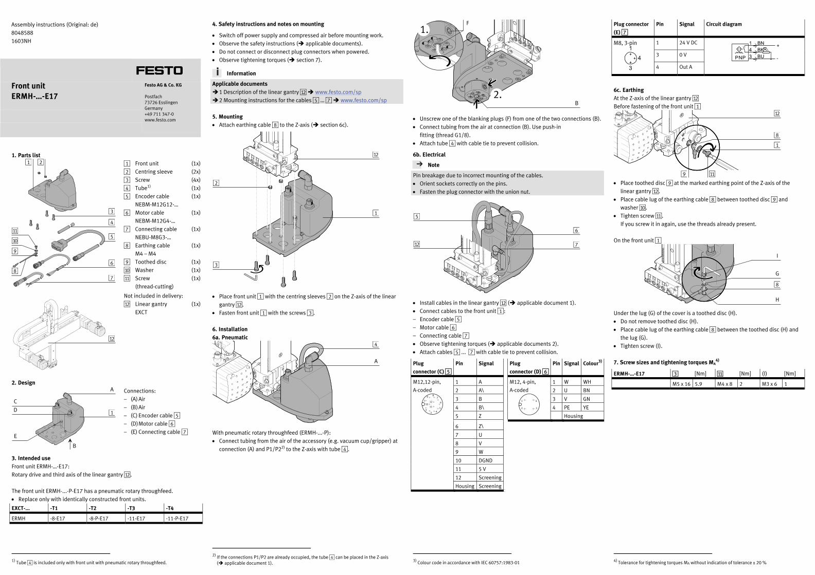
Unscrew one of the blanking plugs (F) from one of the two connections (B). Connect tubing from the air at connection (B). Use push-in
fitting (thread G1/8). Attach tube 4 with cable tie to prevent collision.
6b. Electrical
Note
Pin breakage due to incorrect mounting of the cables. Orient sockets correctly on the pins. Fasten the plug connector with the union nut.
22130d_7
Install cables in the linear gantry aB ( applicable document 1). Connect cables to the front unit 1: – Encoder cable 5 – Motor cable 6 – Connecting cable 7 Observe tightening torques ( applicable documents 2). Attach cables 5 ... 7 with cable tie to prevent collision.
Plug
connector (C) 5
Pin Signal Plug
connector (D) 6
Pin Signal Colour3)
M12,12-pin,
A-coded
17468d_8
1 A M12, 4-pin,
A-coded
1 W WH
2 A\ 2 U BN
3 B 3 V GN
4 B\ 4 PE YE
5 Z Housing
6 Z\ 17468d_9
7 U
8 V
9 W
10 DGND
11 5 V
12 Screening
Housing Screening
3) Colour code in accordance with IEC 60757:1983-01
Plug connector
(E) 7
Pin Signal Circuit diagram
M8, 3-pin
991155
1 24 V DC
991701
3 0 V
4 Out A
6c. Earthing At the Z-axis of the linear gantry aB Before fastening of the front unit 1
22130d_8
Place toothed disc 9 at the marked earthing point of the Z-axis of the linear gantry aB.
Place cable lug of the earthing cable 8 between toothed disc 9 and washer aJ.
Tighten screw aA. If you screw it in again, use the threads already present.
On the front unit 1
22130d_9
Under the lug (G) of the cover is a toothed disc (H). Do not remove toothed disc (H). Place cable lug of the earthing cable 8 between the toothed disc (H) and
the lug (G). Tighten screw (I).
7. Screw sizes and tightening torques MA4)
ERMH-…-E17 3 [Nm] aA [Nm] (I) [Nm]
M5 x 16 5.9 M4 x 8 2 M3 x 6 1
4) Tolerance for tightening torques MA without indication of tolerance ± 20 %
6
5
3
4
7 8
9
aA
aJ
2 1
aB
1
B
C
E
D
A
1
2
aB
3
4
A
B
F
5
6
7 aB
aA
1
8
9
aB
G
8
I
H