Embed Size (px)
Citation preview
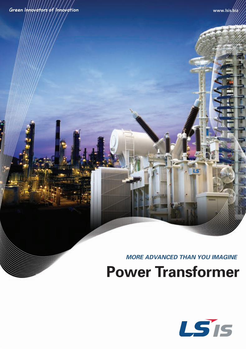
Power Transformer MORE ADVANCED THAN YOU IMAGINE
초고압영문은별-110816-2 2011.8.16 1:35 PM 페이지2
LSIS has contributed greatly to the infrastructure of the electricity
and automotive industries -the foundations of the Korea’s economy- on numerous
construction sites and building structures over 30 years.
We are presently moving up to a whole new level in order to become a world-class
company with a passion, and accumulations of countless technology and experience.
LSIS - The Specialist of Power Solutions
초고압영문은별-110816-2 2011.8.16 1:35 PM 페이지3
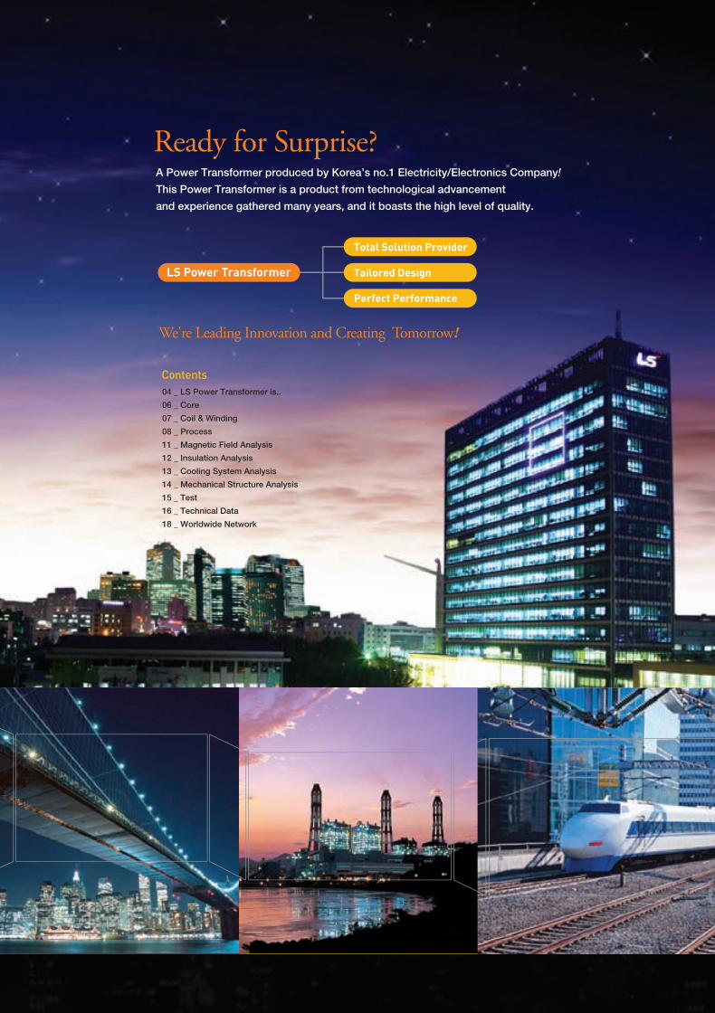
We're Leading Innovation and Creating Tomorrow!
Ready for Surprise?A Power Transformer produced by Korea’s no.1 Electricity/Electronics Company!
This Power Transformer is a product from technological advancement
and experience gathered many years, and it boasts the high level of quality.
04 _ LS Power Transformer is..
06 _ Core
07 _ Coil & Winding
08 _ Process
11 _ Magnetic Field Analysis
12 _ Insulation Analysis
13 _ Cooling System Analysis
14 _ Mechanical Structure Analysis
15 _ Test
16 _ Technical Data
18 _ Worldwide Network
Contents
LS Power Transformer
Total Solution Provider
Tailored Design
Perfect Performance
초고압영문은별-110816-2 2011.8.16 1:35 PM 페이지4
LSIS is a NEW & LARGE supplier in the Power Transformer Market.That’s why LSIS continues to work longer and harder for you.As the leading company in Korea’s power solutions industry, LSIS is playing a central role in the
national power supply network, based on its reliability and technology. LS’s experience of
transformer manufacturing and production technologies of over 20 years has enabled us to
proudly present the Power Transformer. Now, LSIS is going to instill confidence in our
customers once again.
Not only ‘Latest’, but also ‘Newest’ Technology!
LSIS’ Power Transformer does not merely possess the latest technologies, but is the state-of-
the-art product equipped with the newest technologies. On top of all the merits that are part of
existing systems, the Power Transformer provides a Total Solution with a Network Control
System for the benefit of the private consumer as well as commercial power plants.
Trust LS Transformer-Perfect performance
Safety and reliability are of the utmost importance in the power transformer. That is why you
need to choose a reliable company. LSIS’s Power Transformer will ensure optimum reliability
through stable performance in any given condition.
Over 30 years of experience for electrical solution. ( Since 1974)
LSIS has been walking a single path in the field of industrial electricity / electronics for the past
30 years, and has achieved technological innovations and improved competitiveness through
continuous R&D and investments.
Strict test make reliable & safe products.
LSIS’ conviction, that rigorous testing is the only way to ensure perfectly operational products at
industrial sites was also applied to the Power Transformer. If you are concerned with reduced
competitiveness caused by maintenance problems and defects, hesitate no more and choose
LSIS.
Professional staffs make your project succeed.
LSIS, Korea’s top engineers will lead you to perfect success on your business with highly trained
skills and careful management.
The newest facilities and equipments make faultless products.
LSIS has constructed an ultramodern factory in an effort to satisfy the diverse demands of its
customers. Our clean facilities enable the production of zero-defect products, within which even
a single speck of dust is not allowed.
LS always think about efficiency & environment.
LSIS takes into consideration the global environment that is in harmony with future-oriented
technologies. We aim to not only provide economic advantages for our customers through
increased energy efficiency, but also to fulfill our social responsibilities through the development
of environment-friendly products.
04 _ LSIS
초고압영문은별-110816-2 2011.8.16 1:35 PM 페이지5
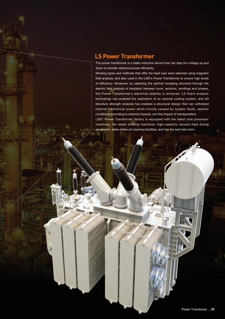
The power transformer is a static inductive device that can step the voltage up and
down to transfer electrical power efficiently.
Winding types and methods that offer the least loss were selected using magnetic
field analysis, and also used in the LSIS’s Power Transformer to ensure high levels
of efficiency. Moreover, by selecting the optimal insulating structure through the
electric field analysis of insulation between turns, sections, windings and phases,
the Power Transformer's electrical stability is achieved. LS fluent analysis
technology has enabled the realization of an optimal cooling system, and 3D
structure strength analysis has enabled a structural design that can withstand
internal mechanical power short-circuits caused by system faults, seismic
conditions according to external impacts, and the impact of transportation.
LSIS’ Power Transformer factory is equipped with the latest core processor
machines, the latest winding machines, high-capacity vacuum heat drying
equipment, state-of-the-art cleaning facilities, and has the best test room.
LS Power Transformer
Power Transfomer _ 05
초고압영문은별-110816-2 2011.8.16 1:35 PM 페이지6
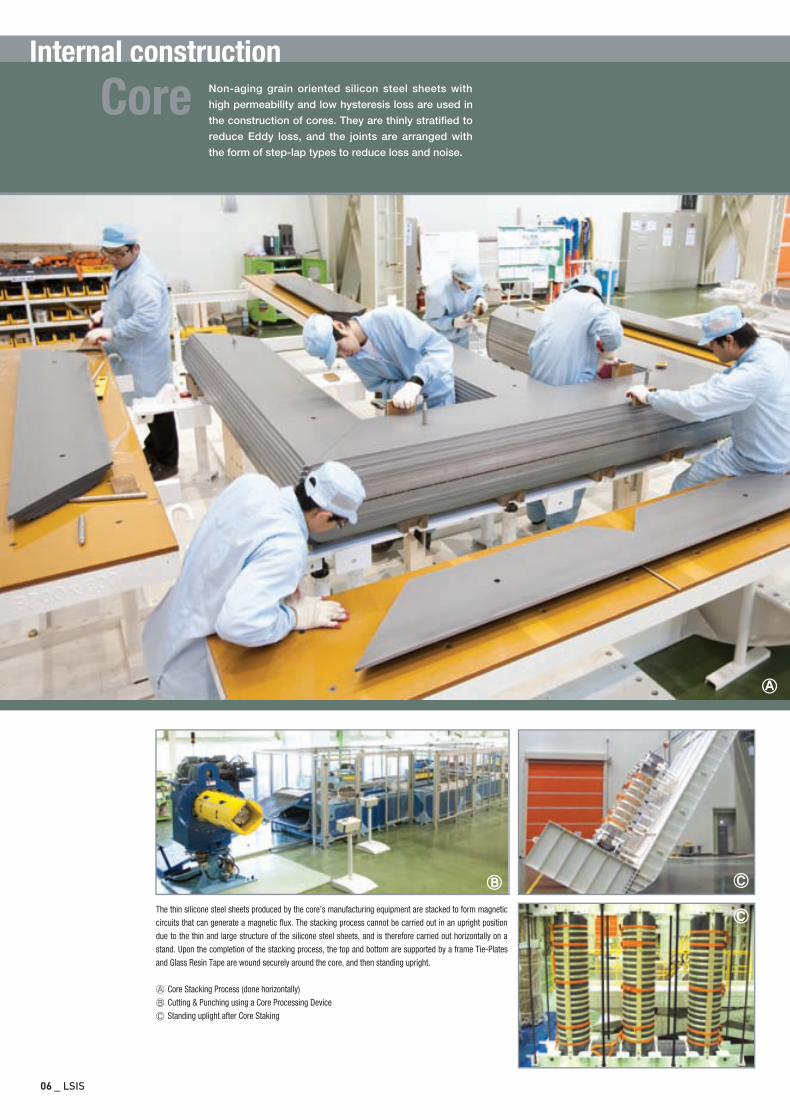
Internal constructionNon-aging grain oriented silicon steel sheets with
high permeability and low hysteresis loss are used in
the construction of cores. They are thinly stratified to
reduce Eddy loss, and the joints are arranged with
the form of step-lap types to reduce loss and noise.
Core
06 _ LSIS
The thin silicone steel sheets produced by the core’s manufacturing equipment are stacked to form magneticcircuits that can generate a magnetic flux. The stacking process cannot be carried out in an upright positiondue to the thin and large structure of the silicone steel sheets, and is therefore carried out horizontally on astand. Upon the completion of the stacking process, the top and bottom are supported by a frame Tie-Platesand Glass Resin Tape are wound securely around the core, and then standing upright.
Core Stacking Process (done horizontally) Cutting & Punching using a Core Processing Device Standing uplight after Core Staking
초고압영문은별-110816-2 2011.8.16 1:35 PM 페이지7
Coil &Winding
Power Transfomer _ 07
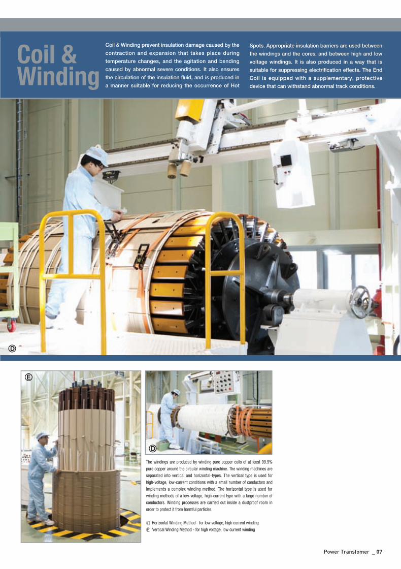
The windings are produced by winding pure copper coils of at least 99.9%pure copper around the circular winding machine. The winding machines areseparated into vertical and horizontal-types. The vertical type is used forhigh-voltage, low-current conditions with a small number of conductors andimplements a complex winding method. The horizontal type is used forwinding methods of a low-voltage, high-current type with a large number ofconductors. Winding processes are carried out inside a dustproof room inorder to protect it from harmful particles.
Horizontal Winding Method - for low voltage, high current winding Vertical Winding Method - for high voltage, low current winding
Coil & Winding prevent insulation damage caused by the
contraction and expansion that takes place during
temperature changes, and the agitation and bending
caused by abnormal severe conditions. It also ensures
the circulation of the insulation fluid, and is produced in
a manner suitable for reducing the occurrence of Hot
Spots. Appropriate insulation barriers are used between
the windings and the cores, and between high and low
voltage windings. It is also produced in a way that is
suitable for suppressing electrification effects. The End
Coil is equipped with a supplementary, protective
device that can withstand abnormal track conditions.
초고압영문은별-110816-2 2011.8.16 1:35 PM 페이지8
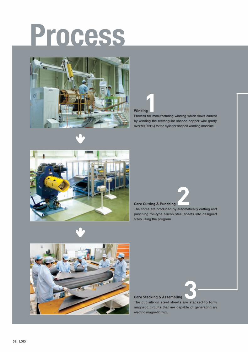
Winding
Process for manufacturing winding which flows current
by winding the rectangular shaped copper wire (purty
over 99.999%) to the cylinder shaped winding machine.
Core Cutting & Punching
The cores are produced by automatically cutting and
punching roll-type silicon steel sheets into designed
sizes using the program.
Core Stacking & Assembling
The cut silicon steel sheets are stacked to form
magnetic circuits that are capable of generating an
electric magnetic flux.
1
2
3
Process
08_ LSIS
초고압영문은별-110816-2 2011.8.16 1:35 PM 페이지9
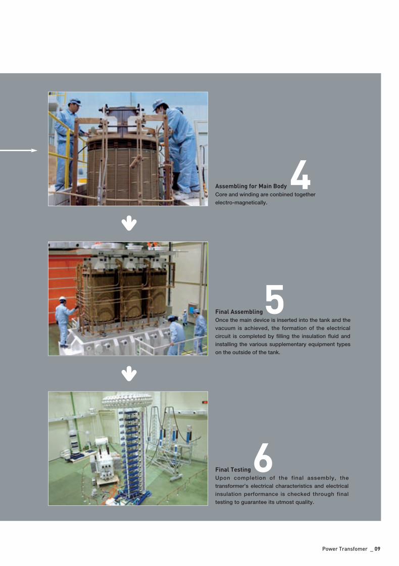
Assembling for Main Body
Core and winding are conbined together
electro-magnetically.
Final Assembling
Once the main device is inserted into the tank and the
vacuum is achieved, the formation of the electrical
circuit is completed by filling the insulation fluid and
installing the various supplementary equipment types
on the outside of the tank.
Final Testing
Upon completion of the final assembly, the
transformer’s electrical characteristics and electrical
insulation performance is checked through final
testing to guarantee its utmost quality.
4
5
6
Power Transfomer _ 09
초고압영문은별-110816-2 2011.8.16 1:35 PM 페이지10
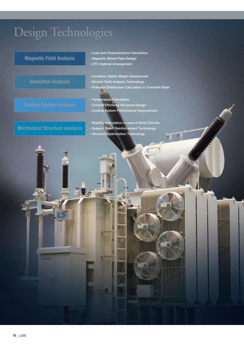
•Loss and Characteristics Calculation
•Magnetic Shield Plate Design
•CTC Optimal Arrangement
10 _ LSIS
Magnetic Field Analysis
•Insulation Safety Margin Assessment
•Electric Field Analysis Technology
•Potential Distribution Calculation in Transient State
Insulation Analysis
•Temperature Calculation
•Cooling Efficiency Structure Design
•Cooling System Performance Improvement
Cooling System Analysis
•Stability Calculation in case of Short Circuits
•Support Beam Reinforcement Technology
•Structure Optimization Technology
Mechanical Structure Analysis
Design Technologies
초고압영문은별-110816-2 2011.8.16 1:35 PM 페이지11
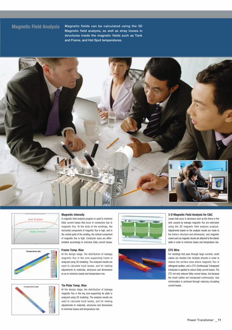
Magnetic Intensity
A magnetic field analysis program is used to minimizeEddy current losses that occur in conductors due tomagnetic flux. At the ends of the windings, thehorizontal component of magnetic flux is high, and inthe central parts of the winding, the vertical componentof magnetic flux is high. Conductor sizes are differ-entiated accordingly to minimize Eddy current losses.
3-D Magnetic Field Analysis for C&C
Losses that occur in structures such as the frame or thetank caused by leakage magnetic flux are estimatedusing the 3D magnetic field analysis program.Adjustments based on the analysis results are made tothe frame’s structure and dimensions, and magneticcovers such as magnetic shunts are attached to the interiorwalls in order to minimize losses and temperature rise.
Frame Temp. Rise
At the design stage, the distribution of leakagemagnetic flux in the core-supporting frame isanalyzed using 3D modeling. The analyzed results areused to calculate local losses, and for makingadjustments to materials, structures and dimensionsso as to minimize losses and temperature rise.
Tie Plate Temp. Rise
At the design stage, the distribution of leakagemagnetic flux in the leg core-supporting tie plate isanalyzed using 3D modeling. The analysis results areused to calculate local losses, and for makingadjustments to materials, structures and dimensionsto minimize losses and temperature rise.
CTC Wire
For windings that pass through large currents, smallcables are divided into multiple strands in order toreduce the surface area where magnetic flux inorthogonal position, and a CTC (Continuously TransposedConductor) is applied to reduce Eddy current losses. TheCTC not only reduces Eddy current losses, but becausethe small cables are transposed continuously, lossminimization is achieved through reducing circulatingcurrent losses.
Axial Direction
Radial Direction
Magnetic fields can be calculated using the 3D
Magnetic field analysis, as well as stray losses in
structures inside the magnetic fields such as Tank
and Frame, and Hot Spot temperatures.
Magnetic Field Analysis
Power Transfomer _ 11
초고압영문은별-110816-2 2011.8.16 1:35 PM 페이지12
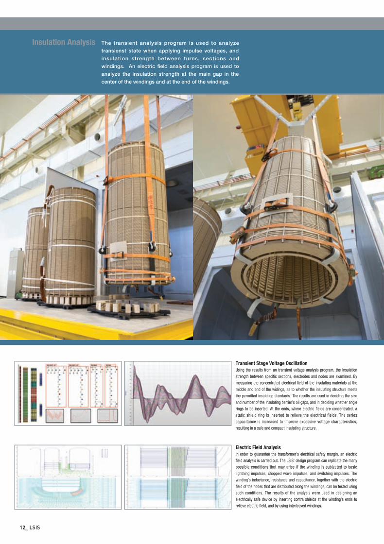
Electric Field Analysis
In order to guarantee the transformer’s electrical safety margin, an electricfield analysis is carried out. The LSIS’ design program can replicate the manypossible conditions that may arise if the winding is subjected to basiclightning impulses, chopped wave impulses, and switching impulses. Thewinding’s inductance, resistance and capacitance, together with the electricfield of the nodes that are distributed along the windings, can be tested usingsuch conditions. The results of the analysis were used in designing anelectrically safe device by inserting contra shields at the winding’s ends torelieve electric field, and by using interleaved windings.
The transient analysis program is used to analyze
transienst state when applying impulse voltages, and
insulation strength between turns, sections and
windings. An electric field analysis program is used to
analyze the insulation strength at the main gap in the
center of the windings and at the end of the windings.
Insulation Analysis
Transient Stage Voltage Oscillation
Using the results from an transient voltage analysis program, the insulationstrength between specific sections, electrodes and nodes are examined. Bymeasuring the concentrated electrical field of the insulating materials at themiddle and end of the widings, as to whether the insulating structure meetsthe permitted insulating standards. The results are used in deciding the sizeand number of the insulating barrier’s oil gaps, and in deciding whether anglerings to be inserted. At the ends, where electric fields are concentrated, astatic shield ring is inserted to relieve the electrical fields. The seriescapacitance is increased to improve excessive voltage characteristics,resulting in a safe and compact insulating structure.
12_ LSIS
초고압영문은별-110816-2 2011.8.16 1:35 PM 페이지13
Power Transfomer _ 13
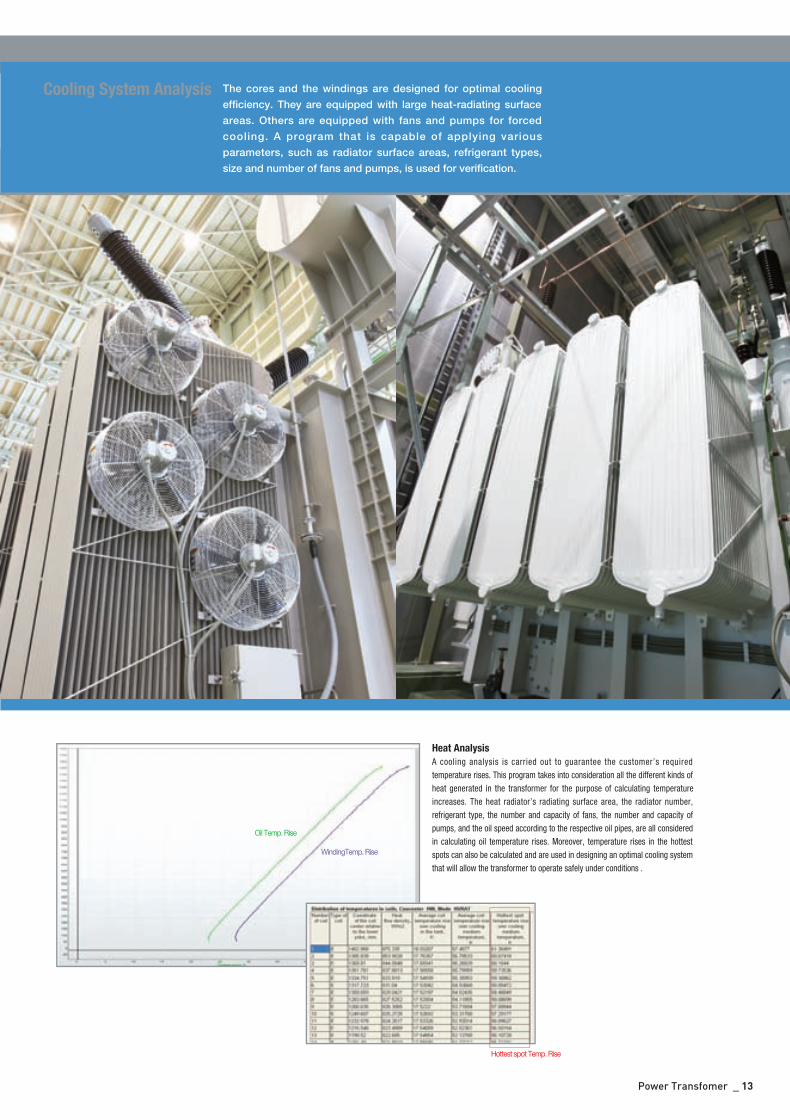
Heat Analysis
A cooling analysis is carried out to guarantee the customer’s requiredtemperature rises. This program takes into consideration all the different kinds ofheat generated in the transformer for the purpose of calculating temperatureincreases. The heat radiator’s radiating surface area, the radiator number,refrigerant type, the number and capacity of fans, the number and capacity ofpumps, and the oil speed according to the respective oil pipes, are all consideredin calculating oil temperature rises. Moreover, temperature rises in the hottestspots can also be calculated and are used in designing an optimal cooling systemthat will allow the transformer to operate safely under conditions .
The cores and the windings are designed for optimal cooling
efficiency. They are equipped with large heat-radiating surface
areas. Others are equipped with fans and pumps for forced
cooling. A program that is capable of applying various
parameters, such as radiator surface areas, refrigerant types,
size and number of fans and pumps, is used for verification.
Cooling System Analysis
Oil Temp. Rise
WindingTemp. Rise
Hottest spot Temp. Rise
초고압영문은별-110816-2 2011.8.16 1:35 PM 페이지14
14_ LSIS
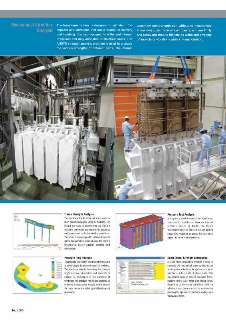
Frame Strength Analysis
The frame’s ability to withstand stress such asshort-circuits is analysed using 3D modeling. Theresults are used in determining the frame’sstructure, dimensions and materials to ensure itsendurance even in the harshest of conditions.The frame is also designed to withstand impactsduring transportation, which ensures the frame’smechanical safety against bending anddeformation.
The transformer’s tank is designed to withstand the
impacts and vibrations that occur during its delivery
and handling. It is also designed to withstand internal
pressures that may arise due to electrical faults. The
ANSYS strength analysis program is used to analysis
the various strengths of different parts. The internal
Mechanical Structure
Analysisassembly components can withstand mechanical
stress during short-circuits and faults, and are firmly
and safely attached to the tank to withstand a variety
of impacts or vibrations while in transportation.
Pressure Ring Strength
The pressure ring’s ability to withstand stress suchas short-circuits is analysed using 3D modeling.The results are used in determining the pressurering’s structure, dimensions and materials toensure its endurance in the harshest ofconditions. The pressure ring is also designed towithstand transportation impacts, which ensuresthe ring’s mechanical safety against bending anddeformation.
Pressure Test Analysis
A program is used to analyse the transformertank’s ability to withstand abnormal internalpressure caused by faults. The tank’smechanical safety is ensured through addingsupporting materials to areas that are weakagainst abnormal internal pressure.
Short Circuit Strength Calculation
A faults mode calculating program is used tocalculate the mechanical stress applied to thewindings due to faults in the system such as 1-line faults, 2-line faults, 3-phase faults. Thismechanical stress is divided into hoop force,bucking force, axial force and tilting force,depending on the many conditions, and thewinding’s mechanical safety is ensured bychoosing the optimal conductors to endure suchmechanical forces.
Input Data for
Conductor Strength
초고압영문은별-110816-2 2011.8.16 1:35 PM 페이지15
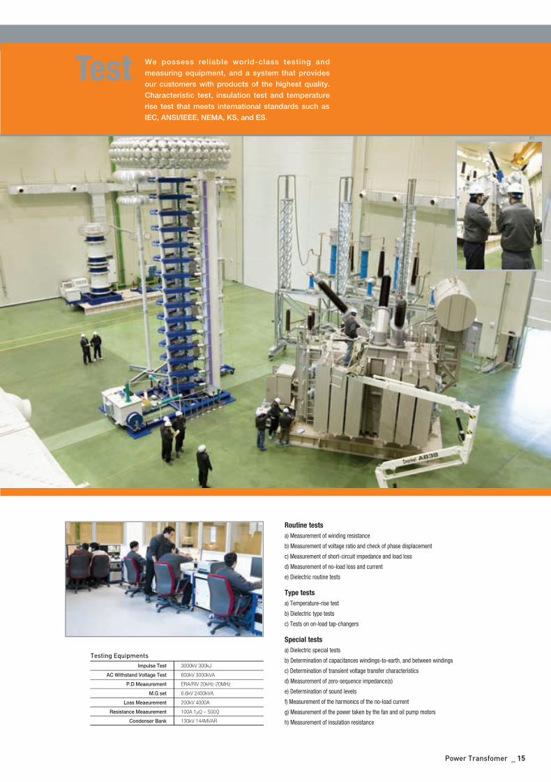
Testing EquipmentsImpulse Test
AC Withstand Voltage Test
P.D Meaeurement
M.G set
Loss Meaeurement
Resistance Meaeurement
Condenser Bank
3000kV 300kJ
600kV 3000kVA
ERA/RIV 20kHz-20MHz
6.6kV 2400kVA
200kV 4000A
100A 1μΩ~ 500Ω
130kV 144MVAR
Power Transfomer _ 15
We possess reliable world-class testing and
measuring equipment, and a system that provides
our customers with products of the highest quality.
Characteristic test, insulation test and temperature
rise test that meets international standards such as
IEC, ANSI/IEEE, NEMA, KS, and ES.
Test
Routine tests
a) Measurement of winding resistance
b) Measurement of voltage ratio and check of phase displacement
c) Measurement of short-circuit impedance and load loss
d) Measurement of no-load loss and current
e) Dielectric routine tests
Type tests
a) Temperature-rise test
b) Dielectric type tests
c) Tests on on-load tap-changers
Special tests
a) Dielectric special tests
b) Determination of capacitances windings-to-earth, and between windings
c) Determination of transient voltage transfer characteristics
d) Measurement of zero-sequence impedance(s)
e) Determination of sound levels
f) Measurement of the harmonics of the no-load current
g) Measurement of the power taken by the fan and oil pump motors
h) Measurement of insulation resistance
초고압영문은별-110816-2 2011.8.16 1:35 PM 페이지16
16_ LSIS
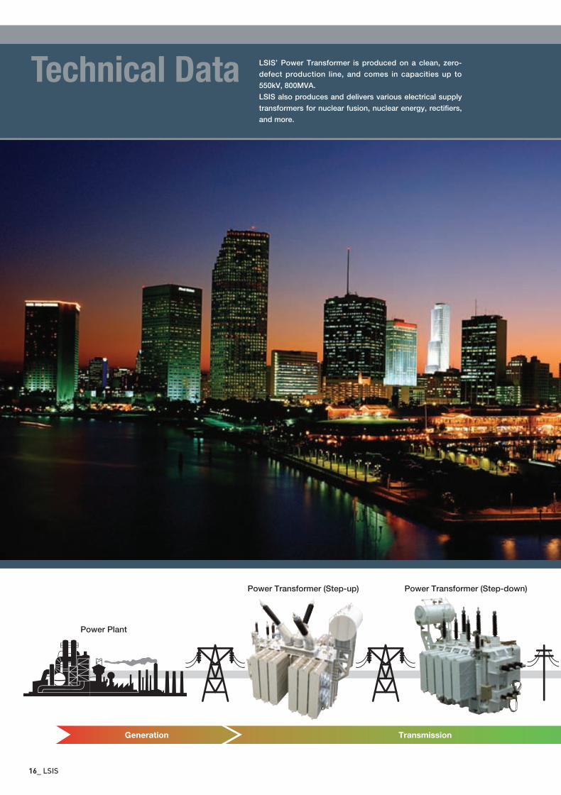
LSIS’ Power Transformer is produced on a clean, zero-
defect production line, and comes in capacities up to
550kV, 800MVA.
LSIS also produces and delivers various electrical supply
transformers for nuclear fusion, nuclear energy, rectifiers,
and more.
Technical Data
Generation Transmission
Power Transformer (Step-up)
Power Plant
Power Transformer (Step-down)
초고압영문은별-110816-2 2011.8.16 1:35 PM 페이지17
Power Transfomer _ 17
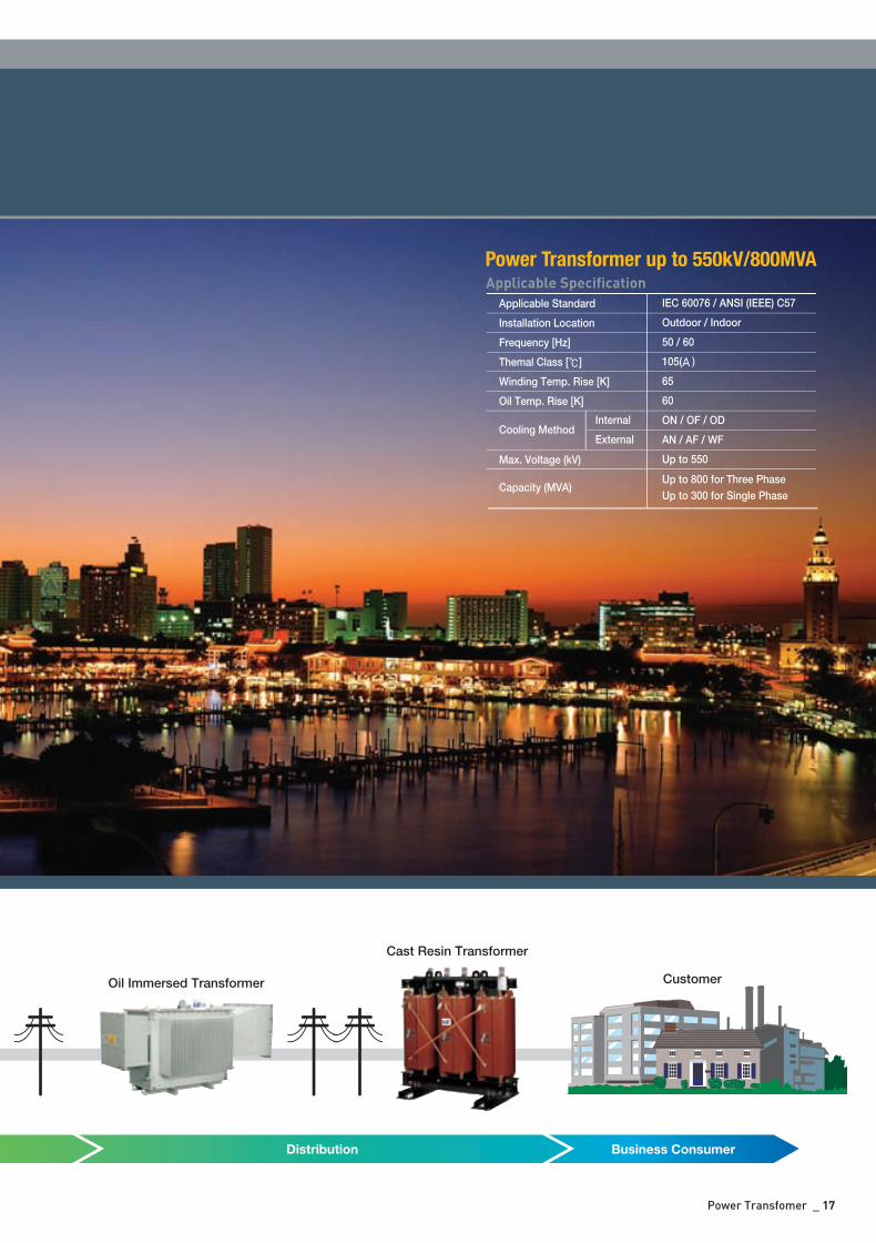
Distribution Business Consumer
Oil Immersed Transformer
Cast Resin Transformer
Customer
Applicable Specification
Applicable Standard
Installation Location
Frequency [Hz]
Themal Class []
Winding Temp. Rise [K]
Oil Temp. Rise [K]
Max. Voltage (kV)
Cooling Method
Capacity (MVA)Up to 800 for Three Phase
Up to 300 for Single Phase
Internal
External
IEC 60076 / ANSI (IEEE) C57
Outdoor / Indoor
50 / 60
105(A)
65
60
ON / OF / OD
AN / AF / WF
Up to 550
Power Transformer up to 550kV/800MVA
초고압영문은별-110816-2 2011.8.16 1:36 PM 페이지18
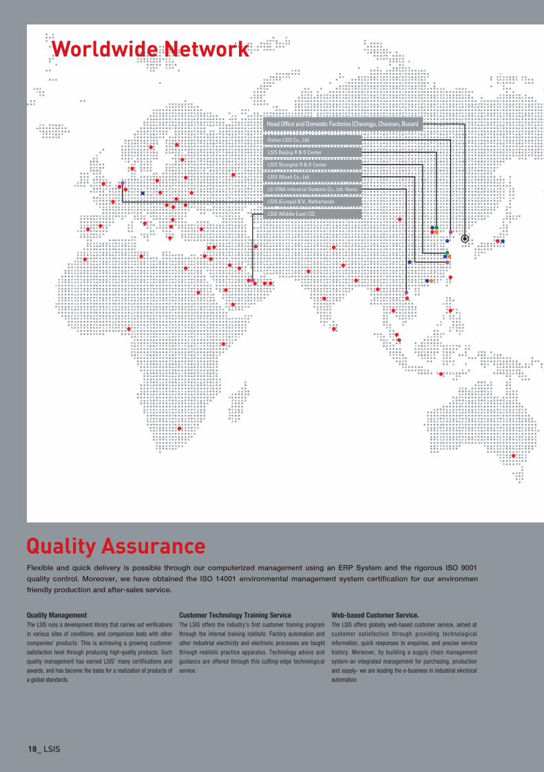
Worldwide Network
18_ LSIS
Flexible and quick delivery is possible through our computerized management using an ERP System and the rigorous ISO 9001
quality control. Moreover, we have obtained the ISO 14001 environmental management system certification for our environmen
friendly production and after-sales service.
Quality Assurance
Quality Management
The LSIS runs a development library that carries out verificationsin various sites of conditions. and comparison tests with othercompanies’ products. This is achieving a growing customersatisfaction level through producing high-quality products. Suchquality management has earned LSIS’ many certifications andawards, and has become the basis for a realization of products ofa global standards.
Customer Technology Training Service
The LSIS offers the industry’s first customer training programthrough the internal training institute. Factory automation andother Industrial electricity and electronic processes are taughtthrough realistic practice apparatus. Technology advice andguidance are offered through this cutting-edge technologicalservice.
Web-based Customer Service.
The LSIS offers globally web-based customer service, aimed atcustomer satisfaction through providing technologicalinformation, quick responses to enquiries, and precise servicehistory. Moreover, by building a supply chain managementsystem-an integrated management for purchasing, productionand supply- we are leading the e-business in industrial electricalautomation.
초고압영문은별-110816-2 2011.8.16 1:36 PM 페이지19
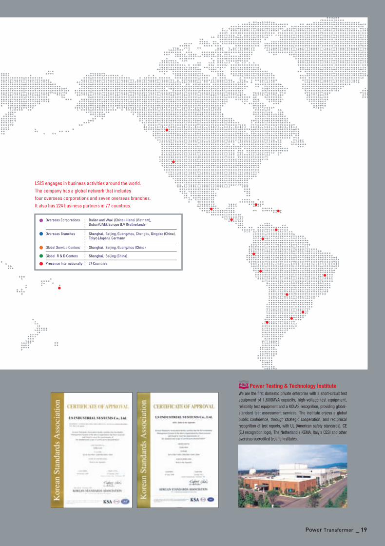
Power Transformer _ 19
We are the first domestic private enterprise with a short-circuit testequipment of 1,600MVA capacity, high-voltage test equipment,reliability test equipment and a KOLAS recognition, providing global-standard test assessment services. The institute enjoys a globalpublic confidence, through strategic cooperation, and reciprocalrecognition of test reports, with UL (American safety standards), CE(EU recognition logo), The Netherland’s KEMA, Italy’s CESI and otheroverseas accredited testing institutes.
Power Testing & Technology Institute
초고압영문은별-110816-2 2011.8.16 1:36 PM 페이지20
This catalogue was produced using environmentally-friendly paper recommended by environmental organizations.
Head Office
Korea Gyeonggi-do Anyang-si Dongan-gu LS-ro 127 (Hogye-dong)
Tel +82-2-2034-4906/4940~8 E-mail [email protected]
Fax +82-2-780-0382 [email protected]
Global Network
LSIS (Middle East) FZE. Dubai, U.A.E. LOB 19 JAFZA VIEW TOWER Room 205, Jebel Ali Freezone P.O. Box 114216, Dubai, United Arab Emirates Tel: 971-4-886 5360 Fax: 971-4-886-5361 e-mail: [email protected]
Dalian LSIS Co., Ltd. Dalian, China No.15, Liaohexi 3-Road, Economic and Technical Development zone, Dalian 116600, ChinaTel: 86-411-8273-7777 Fax: 86-411-8730-7560 e-mail: [email protected]
LSIS (Wuxi) Co., Ltd. Wuxi, China 102-A , National High & New Tech Industrial Development Area, Wuxi, Jiangsu,214028, P.R.ChinaTel: 86-510-8534-6666 Fax: 86-510-522-4078 e-mail: [email protected]
LS-VINA Industrial Systems Co., Ltd. Hanoi, Vietnam Nguyen Khe - Dong Anh - Ha Noi - Viet NamTel: 84-4-882-0222 Fax: 84-4-882-0220 e-mail: [email protected]
LS-VINA Industrial Systems Co., Ltd. Hochiminh, Vietnam 41 Nguyen Thi Minh Khai Str. Yoco Bldg 4th Floor, Hochiminh City, VietnamTel: 84-8-3822-7941 Fax: 84-8-3822-7942 e-mail: [email protected]
LSIS Tokyo Office. Tokyo, Japan 16FL, Higashi-Kan, Akasaka Twin Tower 17-22, 2-chome, Akasaka, Minato-ku Tokyo 107-8470, JapanTel: 81-3-3582-9128 Fax: 81-3-3582-2667 e-mail: [email protected]
LSIS Shanghai Office. Shanghai, China Room E-G, 12th Floor Huamin Empire Plaza, No.726, West Yan'an Road Shanghai 200050, P.R. ChinaTel: 86-21-5237-9977 (609) Fax: 89-21-5237-7191 e-mail: [email protected]
LSIS Beijing Office. Beijing, China B-Tower 17FL.Beijing Global Trade Center B/D. No.36, BeiSanHuanDong-Lu, DongCheng-District, Beijing100013, P.R. ChinaTel: 86-10-5825-6025,7 Fax: 86-10-5825-6026 e-mail: [email protected]
LSIS Guangzhou Office. Guangzhou, China Room 1403,14F,New Poly Tower,2 Zhongshan Liu Road,Guangzhou, P.R. ChinaTel: 86-20-8326-6764 Fax: 86-20-8326-6287 e-mail: [email protected]
LSIS Chengdu Office. Chengdu, China 12Floor, Guodong Building, No52 Jindun Road Chengdu, 610041, P.R. ChinaTel: 86-28-8612-9151 Fax: 86-28-8612-9236 e-mail: [email protected]
LSIS Qingdao Office. Qingdao, China 7B40,Haixin Guangchang Shenye Building B, No.9, Shandong Road Qingdao 26600, P.R. ChinaTel: 86-532-8501-6568 Fax: 86-532-583-3793 e-mail: [email protected]
2011. 08. Power Transformer (E) 2010. 08/(04) 2011. 08 Printed in Korea TMB Strategy
초고압영문은별-110816-2 2011.8.16 1:35 PM 페이지1