Embed Size (px)
Citation preview

MD BrasilConsulting Services, Trainings and
IT Equipment

2
Direitos Autorais
Esta apostila foi totalmente desenvolvida pela equipe da MD Brasil e estáelaborada na língua inglesa pois foi e tem sido utilizada para ministrar cursos noexterior.
Todo o material aqui contido está destinado ao uso e estudo pessoal de seusportadores, não podendo ser utilizado em treinamentos comerciais, mesmo quegratuitos, apresentações públicas ou, em qualquer outra forma que não para o usoem estudos privados.
A reprodução total ou parcial dos textos e ou figuras e tabelas aqui presentes, estáexpressamente proibida, podendo somente ser feita com a autorização por escritoda empresa MD Brasil – Tecnologia da Informação Ltda.
Contatos com a empresa podem ser feitos pelo e-mail: [email protected]
®mdbrasil - todos direitos reservados

3
Copyright note
This material was totally developed by MD Brasil team and is in English languagebecause has been used to give trainings outside Brazil.
All material here is destined to the personal studies and cannot be used incommercial trainings, even those without cost, public presentations, or any otherform different from personal learning.
The reproduction total or partial of the texts, images or tables from this material isforbidden and could be made only with formal and written authorization of MD Brasil– Tecnologia da Informação Ltda.
Contacts with the company can be made by the e-mail: [email protected]
®mdbrasil - todos direitos reservados

MTCRE Training
Overview and objectives
Objectives
To prepare attendees to plan, implement and run robust routed networks using
Mikrotik RouterOS features, based on MTCRE certification program;
What participants will learn
Main concepts involved in static and dynamic routing inside an Autonomous
System (AS), specially using OSPF as the main IGP protocol;
-Site to site connectivity using different VPN's techniques;
After the training is expected that attendees will be able to plan and deploy
dynamic routing in their networks, using Mikrotik RouterOS.
4

Who we are
Located in the State of São Paulo – Brazil
Internet Service Provider since 1995. Authorized Telecommunication Operator for
the whole country
Training programs since 2002.
Mikrotik Distributor and Training Partner
www.mdbrasil.com / www.mikrotikbrasil.com
5

About the instructors
Wardner Maia (Maia)
Sérgio Souza (Sérgio)
Edson Xavier Veloso Jr. (Edson)
Detailed curriculum can be seen at:
http://mdbrasil.com.br/en/profile_of_instructors.htm
6

MTCRE Program
1) Introduction
–Overview
–Training Objectives
–Training Schedule
–Housekeeping
–About the Instructors
–Students Introductions
2) Class Setup
– Groups division and student's routers configuration
–Creating the basic scenario
7

MTCRE Program
3) Routing essentials
– Router architecture – functional view
–Routing table x forwarding table
–Routing protocols
–Link state and distance vector algorithms
–Mikrotik RouterOS routing implementation overview
4) Forwarding Protocols
–A Networking environment – the big picture
–Quick overview of all forwarding protocols supported by Mikrotik RouterOS
–Static Routing, RIP, OSPF, BGP, MPLS, MME
8

MTCRE Program
5) Static Routing on Mikrotik RouterOS
– Connected routes and simple static routes
–Load balancing with ECMP
–Failover
–Best path selection
–Routing policy
–Routes selection and routing decision processes.
–Route processing
–Route distances
–Next hop resolving
–Scope and target scope values
–Other route options
9

MTCRE Program
6) OSPF Protocol (1/3)
–Open Shortest Path First
–OSPF protocol features
–OSPF Area structure – transit and regular areas
–Routers terminology
–Network types
–Forming Neighbors Adjacencies
–Flooding
–OSPF Calculation
–Link State Advertisement Types
–Routing Computation and Equal-Cost Multipath
–OSPF Packet Format
–OSPF Packet Types
10

MTCRE Program
6) OSPF Protocol (2/3)
–LSA/LSU processing
–Exchanging and synchronizing LSDB's
–Forming and maintaining network routes
–LSA Sequence Numbers and Topology Maintenance
–Establishing a bi directional communication
–Network routes discovery
–Network types in OSPF
–DR and BDR election
–Point to Point, BMA and NBMA areas
–Full mesh, Partial mesh and Star topologies
–LSA types
–Summarization
–Default route distribution
11

MTCRE Program
6) OSPF Protocol (3/3)
–Costs calculations
–Special Type Areas: Stub, Totally Stub and NSSA
–Virtual Links
–Routing Filters
–OSPF Security
–Threats in OSPF plants
–Authentication
–Passive interfaces
–Countermeasures against OSPF attacks
–IPv6 and OSPFv3
–IPv6 static addressing and routing overview
–OSPFv3 configurations
12

MTCRE Program
7) Tunnels and VPN‘s
– Site to Site Connectivity with tunnels
–IPIP, EoIP
–Virtual Private Networks
–PPtP, L2TP, SSTP
–Vlan's
–Vlan’s and managed switch
–Vlan’s and switch chip configuration
–QinQ implementation
–Vlan usage in a IXP environment
13

Routing Essentials
14

Routing Essentials
15

Routing Essentials
16
Routing Information
Base (RIB)
Routing Information base is
the data base where all
information about IP routes
are stored. Each protocol
has its RIB

Routing Essentials
17
Forwarding Information
Base (FIB)
FIB contains information
of prefixes related to the
network interfaces that
could be used to forward
packets.

Routing Essentials
RouterOS implementation
18

Routing Essentials
19
Routing Table:
By default 2 routing process will be made first for local addresses and after for
other routes. That means that router will have 2 tables:
A table for local addresses. Successful lookup in this table means that the
packet is to be delivered on the host itself.
A table for all other routes, manually introduced or learned dynamically by
means of routing protocols.

Routing Essentials
20
FIB and Routing Cache:

Routing Table x Routing Cache
21
Routing Table:
Destination Next Hop Interface
192.168.0.0/24 1.1.1.1 eth1
After router have received packets to 192.168.0.10 and 192.168.0.20:
Routing Cache:
Destination Next Hop Interface
192.168.0.10 1.1.1.1 eth1
192.168.0.20 1.1.1.1 eth1

Lookups on the routing table
22

Routing Essentials
Connected Routes
For each IP address associated to one active interface, one connected route is
dynamically created.
23

Routing Essentials
24
Static routes
Static routes can point either to the next hop
IP address or directly to the interface.

Routing Essentials
Default Route
A default route is a route with destination 0.0.0.0/0, that means all IPv4 address
space (0.0.0.1–255.255.255.255). If a routing table contains at least one default
route active, then route lookup will never fail.
25

Routing Essentials
Dynamic Routes
Learned by dynamic routing protocols. Mikrotik RouterOS supports the following
dynamic routing protocols:
RIP
OSPF
BGP
MME
26

Preparing the Scenario
27

Preparing the Scenario
Preparing the Scenario
Reset all previous configurations /system reset-configuration (do not forget to
keep intact the system users)
Class will be divided in groups of 4 students
The following slides will explain how things will work
28

Physical Infrastructure
29

IP Infrastructure
30

IP detailed Infrastructure
31

Preparing the Scenario
Preparing the Scenario
Ensure that you from your Laptop you are pinging your router
Ensure that from your router you are pinging the right and left neighbor’s routers
Please, make a backup of your router’s configuration naming it “INFRA1”
/ system backup save name=INFRA1
Copy your backup file to your desktop – this will be the basic ip infrastructure
backup
32

Static Routing LAB
Objective: Test Static routes configuration
LAB: Configure the necessary routes to allow:
Network behind R1 access network behind R3, via R2
Network behind R2 access network behind R4, via R3
Test:
Laptop behind R1 should ping R3;
Laptop behind R2 should ping R4:
33
R3
R1R2
R4

Multiple Matches in a Routing Table
In a routing table, if there is only one route toward each destination address,
routing lookups would be trivial. As soon a router finds a route whose destination
subnet includes the destination address, packet will be forwarded.
However, it is very common to have multiple routes to the same destinations in
different subnets, like the below one:
DST-ADDRESS GATEWAY
192.168.0.0/24 1.1.1.1
192.168.0.0/25 2.2.2.2
In this case a packet destined to e.g. 192.168.0.1 will find 2 possible destinations,
because it belongs to both subnets.
34

Longest Prefix Match
When a packet has multiple matches, longest prefix match (more specific
networks) will be preferred.
E.g. Router has the following routing table:
DST-ADDRESS GATEWAY
192.168.0.0/24 1.1.1.1
192.168.0.0/25 2.2.2.2
192.168.0.0/26 3.3.3.3
0.0.0./0 4.4.4.4
Which gateway packets destined to the following IP will be forwarded to?
1) 192.168.0.1; 2) 192.168.0.63; 3) 192.168.0.64; 192.168.1.1
35

Longest Prefix Match LAB
Objective: To test longest prefix match
LAB: Keep the routes from previous LAB. Configure more routes to allow:
R1 R3, via R4 with more specific networks
R2 R4, via R3 with more specific networks
Test:
Trace a route from Laptop 1 to Laptop 3 and check the route
Trace a route from Laptop 1 to Laptop 3 and check the route
36
R3
R1R2
R4

Longest Prefix Match LAB
For Discussion:
Does this previous setup provides redundancy ?
For instance, what happens with traffic from R3 to R1 if:
Link 3 – 4 is broken ?
Link 4 – 1 is broken ?
37
R3
R1R2
R4

Routes Processing
38
What happens if a router learns
from different routing protocols,
more than one path to the same
prefix and with the same match
length ?

Routes ProcessingDistance (Administrative Distance)
Distance refers to the reliability of the route. If
there is more than one destination to the
same network prefix, the less distance will be
chosen.
Default RouterOS values are:
Connected routes: 0
Static routes: 1
eBGP: 20
OSPF: 110
RIP: 120
MME:130
iBGP:200
39

Distance LAB
40
Objective: To test routes distance
LAB: Keep routes /24 from previous LAB and delete more specific ones. Create
below routes:
R1 R3, via R4 with distance > 1
R2 R4, via R3 with distance > 1
Test:
Look at your routing table and check which route is active
Disable active route and see what happensR3
R1R2
R4

Longest Prefix Match LAB
For Discussion:
From the perspective of R3, what happens with the failure of the below
links:
R3 R4, R3 R2,
R2 R4, R4 R1
41
R3
R1R2
R4
Distance = 1
Distance = 1
Distance = 10
Distance = 1

Load Balancing and
Multipath (ECMP) Routes
Multipath (ECMP) Routes
ECMP (Equal Cost Multi-Path) routes have multiple gateway next-hop values. All
reachable next-hops are copied to FIB and used in forwarding packets.
Routes can be created manually adding multiple gateways (next-hop or
interfaces)
42
In some setups OSPF protocol will create ECMP routes automatically

Multipath (ECMP) Routes
Because results of the forwarding decision are cached, packets with the same:
source address, destination address, source interface, routing mark and ToS
are sent to the same gateway.
This means that one connection will use only one link in each direction, so ECMP routes can be used to implement per-connection load balancing.
43

ECMP Example
44
We want to route packets from network 192.168.0.0/24 through 2 links:
Link1 – 10.0.0.0/30 – 10 mbpsLink2 – 10.1.0.0/30 – 20 mbps
The solution to balance is to place 1 time link1 and 2 times link 2 as a gateway
192.168.0.0/24
10.0.0.1/30
10.0.0.2/30
10 mbps10.1.0.1/30
20 mbps
10.1.0.1/30

Check Gateway option
Gateway is checked every 10 seconds
After 2 times out, gateway is considered unreachable.
Routes pointing to that gateway will turn to inactive.
45
Recover will happen after receiving a reply from gateway. Timeout
counter is reset.

Load Balancing LAB
46
Objective: To test load balance (ECMP)
LAB: Configure ECMP routes in order to R3 (R4) reach R1 (R2) via R2 (R3)
and R4 (R1)
Test:
Trace routes from R3(R4) to R1(R2)
Tip Configure Some IP Addresses on your Laptop/Mikrotik and try varying
source / destination addresses.
MD1203052048

Policy-based Routing (PBR)
Policy-Based Routing
By default routing decision is only based on the destination address value.
PBR provides a tool for routing data packets based on policies
Policies are defined by network administrators, and can be set using
additional information such as source address, protocol, destination or source
port, type of service, etc.
47

Policy-based Routing (PBR)
Routing Tables and Routing Marks
RouterOS can split the routing tables in several ones separated by routing
marks;
Routing marks are assigned to routes using firewall mangle facility.
By default all active routes without marks are kept in the main routing table;
48

Policy Routing simple example
49
We want that the neworks
NET1 192.168.1.0/24, uses gateway GW1,
NET2 192.168.2.0/24, uses gateway GW2
NET1
192.168.1.0/24
NET2
192.168.2.0/24
10.0.0.1 10.0.0.2
10.0.0.254
Network 10.0.0.0/24
GW1 GW2

Policy-based Routing Simple Example
50
1) Mark packets from network 192.168.1.0/24 with new-routing-mark=net1, and packets from
network 192.168.2.0/24 with new-routing-mark=net2:
Policy-based Routing Simple Example
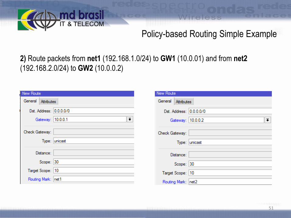
2) Route packets from net1 (192.168.1.0/24) to GW1 (10.0.01) and from net2
(192.168.2.0/24) to GW2 (10.0.0.2)
51

Policy-based Routing
Simple Example with Redundancy
We want that the neworks
NET1 192.168.1.0/24, use gateway GW1, NET2 192.168.2.0/24, use gateway GW2
In case of ping failures to GW1 or GW2, automatically switch to GW3
52
NET1
192.168.1.0/24
NET2
192.168.2.0/24
10.0.0.1 10.0.0.2
10.0.0.3
10.0.0.254
Network 10.0.0.0/24
GW1 GW2
GW3

Policy-based Routing simple
example with redundancy
Same prior setup, with the options check-gateway enabled
53

PBR LAB
54
R3
R1R2
R4
MD1203052048
Web Access port 80
FTP Access port 21
Objective: To test PBR configurations
LAB: R3(R4) should access R1(R2) Web service via R2 (R1) and R1(R2) FTP service
via R4
Test: (Suggestion)
Log services on Firewall to check on which interface the flow is going through.

Routes Processing
55

Routes Selection Process
There can be multiple routes learned from dynamic protocols and static
configurations;
Each routing table can have only one active route for each destination prefix;
If a route meet the criteria to become an active route, then active route is
selected from all candidate routes with the same: dst-address AND routing-
mark
Candidate route with the lowest distance becomes an active route. If distance
is the same, selection is arbitrary (except for BGP routes).
56

Routes Selection Process
Criteria to become an active route (participate in the routing selection process)
route is not disabled.
distance is not 255. Routes that are rejected by routing filters have distance
value of 255.
pref-src is either not set or is a valid local address of the router.
If there is a routing-mark it is referred by firewall or policy routing rules.
If type of route is unicast and it is not a connected route, it must have at least
one reachable next-hop
57

Next-hop lookup
Next-hop lookup is part of the routes selection process.
Routes that are installed in the FIB need to have interface associated with
each gateway address.
Gateway address (next-hop) has to be directly reachable via this interface.
Interface that should be used to send out packets to each gateway address is
found by doing next-hop lookup.
Next-hop lookup is done only in the main routing table, even for routes with
different value of routing mark.
Routes pointing to physical interface are not used to next-hop lookup.
58

Scope and target-scope
A router can have several routes in the main table. It is necessary to restrict
the set of routes that can be used to the lookup process.
For instance, next-hop values for static routes, are supposed to be directly
reachable and should be looked up only using connected routes.
To limit the scope where a router should look up, a route has the properties
scope and target-scope
Routes with scope greater than the maximum acceptable (target-scope) will
not be used for next-hop lookup.
Scope and target-scope can be administratively manipulated.
59

Routes Selection Process
60
NB: With default values, iBGP will use Static, OSPF, RIP, MME and connect routes.
scope target-scope
Connected routes: 10
OSPF, RIP, MME: 20 10
Static Routes: 30 10
eBGP: 40 10
iBGP: 40 30
scope target-scope
Connected routes: 10
OSPF, RIP, MME: 20 10
Static Routes: 30 10
eBGP: 40 10
iBGP: 40 30
Scope and target-scope default values

Scope and Target Scope Example
61
A router has an IP address 1.1.1.1/24 configured in one of its interface and thus, it
has a connected route 1.1.1.0/24 pointing to that interface.
One route to network 2.2.2.0/24 pointing to, e.g. 1.1.1.2 will be installed normally but
another to 3.3.3.0/24 pointing to 2.2.2.2 will become inactive

Scope and Target Scope Example
62
Changing Target scope to a value >= 30 will turn the route active (will be installed on
FIB). The route will appear as recursive.

Recursive Routing LAB
63
Objective:
To test recursive routing with target-scope manipulation
LAB:
All routers configure a static route to an arbitrary (e.g. 1.1.1.0/24) network
pointing to a directly connected IP - the route should be installed.
Create a second static route to another arbitrary (e.g. 2.2.2.0/24) network pointing
to an IP address belonging to the first network (e.g. 1.1.1.1) – the route should be
inactive.
Change the target-scope of this second route to something >= 30 – route should
turn to active state and route will appear as recursive.

Policy-based Routing
Case Study
Suppose we have a setup implementing failover over 2 ADSL links
What if remote gateway is down ?
Will option check gateway work ?
64
For a detailed explanation, see this interesting article:
http://wiki.mikrotik.com/wiki/Advanced_Routing_Failover_without_Scripting
NET1
192.168.1.0/24
NET2
192.168.2.0/24
10.0.0.1 10.0.0.2
GW1 GW2
ADSL ADSL

Dynamic Routing
65

Dynamic Routing
Path (Distance) Vector Protocols
Protocol assigns a number, the cost, to each of the links between each node in the network;
Nodes will send information from point A to point B via the path that results in the lowest total cost (sum of the costs of the links between the nodes used).
Examples of distance vector protocols :
RIPv1, RIPv2 and IGRP.
BGP can be considered a type of path vector implementation but not pure, because there are some attributes other than cost that influence routes calculation.
66

Dynamic Routing
Link-state Vector Protocols
On link-state protocols, each node uses as its fundamental data a map of the network in the form of a graph;
To produce this, each node floods the entire network with information about what other nodes it can connect to, and each node then independently assembles this information into a map.
Using this map, each router then independently determines the least-cost path from itself to every other node using a standard shortest paths algorithm.
Examples of link-state protocols are OSPF and IS-IS
67

Dynamic Routing
Link-State Protocols Characteristics:
Respond quickly to network changes;
Send triggered updates when a network change occurs;
Send periodic updates at longer intervals, known as link-state refresh;
Link-state protocols use LSA – Link State Advertisements messages to inform the states of the links for all the network.
68
OSPF – Open Shortest Path First
69

OSPF
Open Shortest Path First
Link State protocol that uses Dijkstra’s algorithm to calculate the shortest path to all known destinations networks;
OSPF distributes routing information between the routers belonging to the same AS (Autonomous System) and which have the OSPF protocol enabled;
All routers must have the same MTU for all networks announced by the protocol;
OSPF is directly encapsulated in IP datagrams with protocol number 89 (it does not use a transport protocol like UDP or TCP)
OSPF handles its own error detection and correction functions.
70

Autonomous System
Internet Context x OSPF Context
Autonomous System – Internet Context
An Autonomous System (AS) is a collection of connected Internet
Protocol (IP) routing prefixes under the control of one or more network operators
that presents a common, clearly defined routing policy to the Internet.
Autonomous System – OSPF Context (according to RFC 2328)
“Autonomous System: A group of routers exchanging routing information via a
common routing protocol”
71

How OSPF Works
72
Hello Packets discover
neighbors nodes and form
relationships between them.
A link state database
(LSDB) is constructed Dijkstra algorithm runs
OSPF tree for each node is built FIB is formed
Flood LSA messages

How OSPF Works
OSPF tables
OSPF works maintaining 3 separate tables:
Neighbor table: Contains a list of recognized neighbors.
Also called adjacency database
Topology table: Contains all routers and their attached links.
Referred as LSBD
Routing table: Contains the list of best paths to
destinations. This is the FIB
73

OSPF Areas
In large networks the number of
potential paths to each
destination can be very large.
Paths calculations can be
complex and time consuming.
OSPF allows collections of
routers to be grouped together in
groups called Areas to minimize
the number of LSA’s that food
through the areas.
74
Area 1
Area 2
Area 0
Backbone Area
MD1201151011

OSPF Areas
By dividing a Network in areas
leads to:
Minimize routing table entries
Restrict the impact of topology
changes to the area
Detailed LSA flooding stops at
the area boundary
Hierarchical planning of the
network is important to divide it
into areas.
75
Area 1
Area 2
Area 0
Backbone Area
MD1201151011

OSPF Areas
There is no “magic number” for
maximum routers inside an area
(Mikrotik suggests <80)
The structure of an area is
invisible outside the area
Each area runs a separate copy
of basic link-state algorithm
OSPF areas are identified by a
32 bit (4 bytes) number (0.0.0.0 –
255.255.255.255)
Area ID must be exclusive
inside an area76
Area 1
Area 2
Area 0
Backbone Area
MD1201151011

OSPF Area Types
Transit Area: An area that
interconnect other OSPF areas.
OSPF area 0 or backbone area is a
transit area. Area ID is 0.0.0.0
Regular area: An area whose main
function is to connect users and
resources
All non-backbone area must be
connected to the backbone area
(directly or using virtual links)
77
Area 1
Area 2
Area 0
Backbone Area
MD1201151011

OSPF Router Types
OSPF defines the following type of
routers according to their role and
location:
ASBR – Autonomous System
Boundary Router: A router that is
connected to more than one AS
ABR- Area Border Router: A router
that is connected to more than one
area
Internal Router: router connected to
only one area
78
Area 1
Area 2
Area 0
Backbone Area
MD1201151011

Establishing Network Adjacencies
OSPF routers exchange hello packets using
multicast address to discover neighboring
nodes and form adjacencies.
Routers check specific parameters and after
the exchange is complete, the neighbor is
considered up.
After adjacency is established, routers
exchange LSA’s to synchronize their LSDB
and after this synchronization OSPF
considers the routers in full adjacent state.
79

Neighborhood x Adjacencies
The fact that routers are neighbors does not guarantee an exchange of link-state
updates. To do it they must form adjacencies to exchange link-state updates.
Adjacency is formed by routers that are willing to exchange routing information.
Routers reach a FULL state of adjacency when they have synchronized their
LSDB.
Once a router decides to form an adjacency with a neighbor, it starts by
exchanging a full copy of its LSDB and vice-versa. After passing through several
neighbor states, the routers become fully adjacent.
80

Establishing Network Adjacencies
On point-to-point links, neighbors become
fully adjacent.
On Broadcast media (e.g. Ethernet links),
there is an election of DR (Designated
Router) and a BDR (Backup Designated
Router) and other routers form adjacencies
only between DR and BDR
81
BDR
DR

Finding the Best Paths
Each router inside an area has the same
LSDB.
Each router “sees” the network by its own
point of view, placing itself as the root of the
tree that will be built.
82
Dijkstra algorithm runs for each router, calculating the best path with respect to
lowest total cost of the links to a specific destination.
Best routes are put in the forwarding database (routing table or FIB)

Finding the Best Paths
83
Link-state Database (LSDB)
Each router inside the one area
has a copy of this database will all
possible paths
Forwarding Database
Router X knows all the best paths
to reach to each router inside the
areaRouter X
Dijkstra’s algorithm
NB: Assuming that all links have the same cost

OSPF and ECMP routes
Modifying the previous scenario,
suppose we have another link as
indicated in the picture..
For router X to get to router Y, there
will be 2 paths with the same cost.
In this case OSPF will balance the
traffic using ECMP routes.
84
Router X
Router X
Dijkstra’s algorithm
Router Y

OSPF Packets
OSPF doesn’t use TCP or UDP as transport protocol. All five OSPF packets are
encapsulated directly into IP payload.
To ensure reliability of the communication OSPF has its own scheme – using an
acknowledgment packet (type 5 - LSAck)
85
Link Header IP Header OSPF Packet Link Trailer
Protocol ID 89 (OSPF)

OSPF Packet Types and Format
OSPF has 5 packet types:
86

OSPF Packet Types and Format
Common Header
87
0 1 2 3 4 5 6 7 0 1 2 3 4 5 6 7 0 1 2 3 4 5 6 7 0 1 2 3 4 5 6 7
Version (1 byte) Type (1 byte) Packet Length (2 bytes)
Router ID (4 bytes)
Area ID(4 bytes)
Checksum (2 bytes) Authentication Type (2 bytes)
Authentication (4 bytes)
Authentication (4 bytes)

Establishing Adjacencies
Hello Protocol
On Broadcast networks each interface engaged in OSPF uses IP multicast address 224.0.0.5 to send hello packets periodically.
This allows neighbors to be discovered dynamically. These Hello Packets contain the router's view of the Designated Router's identity, and the list of routers whose Hello Packets have been seen recently.
88

Establishing Communication
and Exchanging LSDB’s
89
192.168.1.1/24 192.168.1.2/24
Down State
I am router 192.168.1.1 and I see no one Hello
to 224.0.0.5
Init State
Hello to
192. 168.1.1
2-way state
I am router 192.168.1.2 and I see 192.168.1.1
eth2 eth3
R1 has R2 as neighbor at eth2 and R2 has R1 at eth3
R1 R2

Establishing Communication
and Exchanging LSDB’s
90
I will start exchange. My router ID is 192.168.1.1 DBD to
192.168.1.2
Exstart State
192. 168.1.1
Exchange State
Sorry, my router ID is 192.168.1.2 and I will start
R1
R2
DBD to
192. 168.1.1
Here is a summary of my LSDBR2
DBD to
192.168.1.2
Here is a summary of my LSDBR1

Adding Link State entries
91
LSAck to
192. 168.1.1
Loading State
Thank you for the information !R2
I request information about network 192.168.1.0/24
LSAck to
192.168.1.2
LSAck to
192. 168.1.2
LSR to
192.168.1.2
LSU to
192. 168.1.1
Here is the entry for network 192.168.1.0/24R2
Thank you for the information !
Full State

What happens when network changes ?
R1 detects a link failure and sends to multicast address 224.0.0.6 notifying all DR and BDR
DR acknowledges and flood the LSU to others using multicast address 224.0.0.5.
All routers acknowledges to the DR
Routers updated their LSDB, Dijkstraalgorithm runs again to calculate the SPF.
92
R1 DR
LSU
LSU
LSU
BDR

Link State Sequence Numbers
The sequence number field is a signed 32-bit integer, used to detect old and duplicate LSAs.
The space of sequence numbers is linearly ordered.
The larger the sequence number (when compared as signed 32-bit integers) the more recent the LSA.
OSPF floods LSA’s every 30 minutes to maintain database synchronization. Each time LSA is flooded, sequence number is incremented by one.
93

LSA/LSU Processing
94

OSPF Packet Types and Format
Hello Packet
95
0 1 2 3 4 5 6 7 0 1 2 3 4 5 6 7 0 1 2 3 4 5 6 7 0 1 2 3 4 5 6 7
Network Mask (4 bytes)
Hello Interval (2 bytes) Options (1 byte) Priority (1 byte)
Router Dead Interval (4 bytes)
Designated Router (4 bytes)
Backup Designated Router (4 bytes)
Neighbors (4 bytes each)
....
....

OSPF Packet Types and Format
DBD – Database Description
96
0 1 2 3 4 5 6 7 0 1 2 3 4 5 6 7 0 1 2 3 4 5 6 7 0 1 2 3 4 5 6 7
Interface MTU
(2 bytes)
Options
(1 byte)
0 0 0 0 0 1 M MS
DD Sequence Number (4 bytes)
LSA Headers (4 bytes)
....
.....
.....

OSPF Packet Types and Format
LSR - Link State Request
Link State request packet is used for pulling information.
97
0 1 2 3 4 5 6 7 0 1 2 3 4 5 6 7 0 1 2 3 4 5 6 7 0 1 2 3 4 5 6 7
Link State Type (4 bytes)
Link State ID (4 bytes)
Advertising Router (4 bytes)
.....
Link State Type (4 bytes)
Link State ID (4 bytes)
Advertising Router (4 bytes)
....

OSPF Packet Types and Format
LSU – Link State Updates
98
0 1 2 3 4 5 6 7 0 1 2 3 4 5 6 7 0 1 2 3 4 5 6 7 0 1 2 3 4 5 6 7
Number of LSA’s (4 bytes)
LSA1
.....
LSA2
…..
LSA3
….
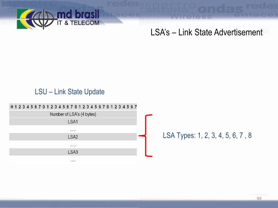
LSA’s – Link State Advertisement
99
LSU – Link State Update
LSA Types: 1, 2, 3, 4, 5, 6, 7 , 8

OSPF LAB’s
We will work together with all routers in the classroom as if we were only one
AS.
Please, try to not do things in advance, in order to allow the best
understanding for all participants.
Be careful, because one configuration error in only one router could influence
the whole setup
100

Loopback Interfaces
In dynamic routing it is very common to use loopback interfaces
Loopback Interfaces eliminate the dependency of physical Interfaces. If an
interface goes down, the loopback remains up.
If the loopback interface on a router is down, that means that the router is
unavailable as a whole.
There are some ways to configure a loopback interface on Mikrotik RouterOS.
The more simple is to create a bridge without any port associated.
/interface bridge add name=loopback
101
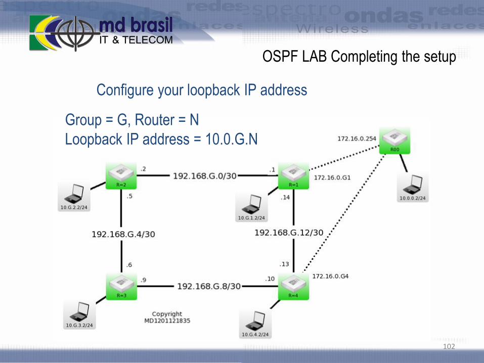
OSPF LAB Completing the setup
102
Group = G, Router = N
Loopback IP address = 10.0.G.N
Configure your loopback IP address
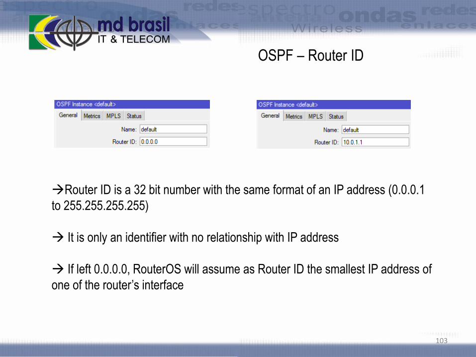
OSPF – Router ID
103
Router ID is a 32 bit number with the same format of an IP address (0.0.0.1
to 255.255.255.255)
It is only an identifier with no relationship with IP address
If left 0.0.0.0, RouterOS will assume as Router ID the smallest IP address of
one of the router’s interface

OSPF LAB
Working together setup an OSPF network with only one area (backbone area)
Minimal OSPF configuration is networks configuration.
To avoid conflicts, please configure a router ID (Use as ID the IP of your
loopback interface);
Declare the networks your router is connected to;
Verify the neighbors;
Test the connectivity. Are you reaching all network nodes ?
104

OSPF LAB
On neighbors tab, mark an entry, right-click and choose “show state”
For network 172.16.0.0/24, observe that only 2 have full connection and
others are in 2-way state.
Identify the routers that have full connection. Why this occurred ?
Can we influence the election ?
105

Network Types in OSPF
106

Network Types in OSPF
Broadcast Networks
A multi access broadcast network, like Ethernet
Non-Broadcast Multi Access or NBMA
Networks supporting many (more than two) routers, but having no
broadcast capability. E.g. Frame Relay, ATM, etc.
Point-to-Multipoint
Special type of NBMA, consisted of collection of point-to-point links
Point-to-Point
A network that joins a single pair of routers
107

Broadcast Multi-access Network
108
e.g. Ethernet
DR and BDR election is required
Neighbors form full adjacency with DR and BDR
Packets to DR and BDR use multicast address 224.0.0.6
Packets from DR to “DRothers” use multicast address 224.0.0.5
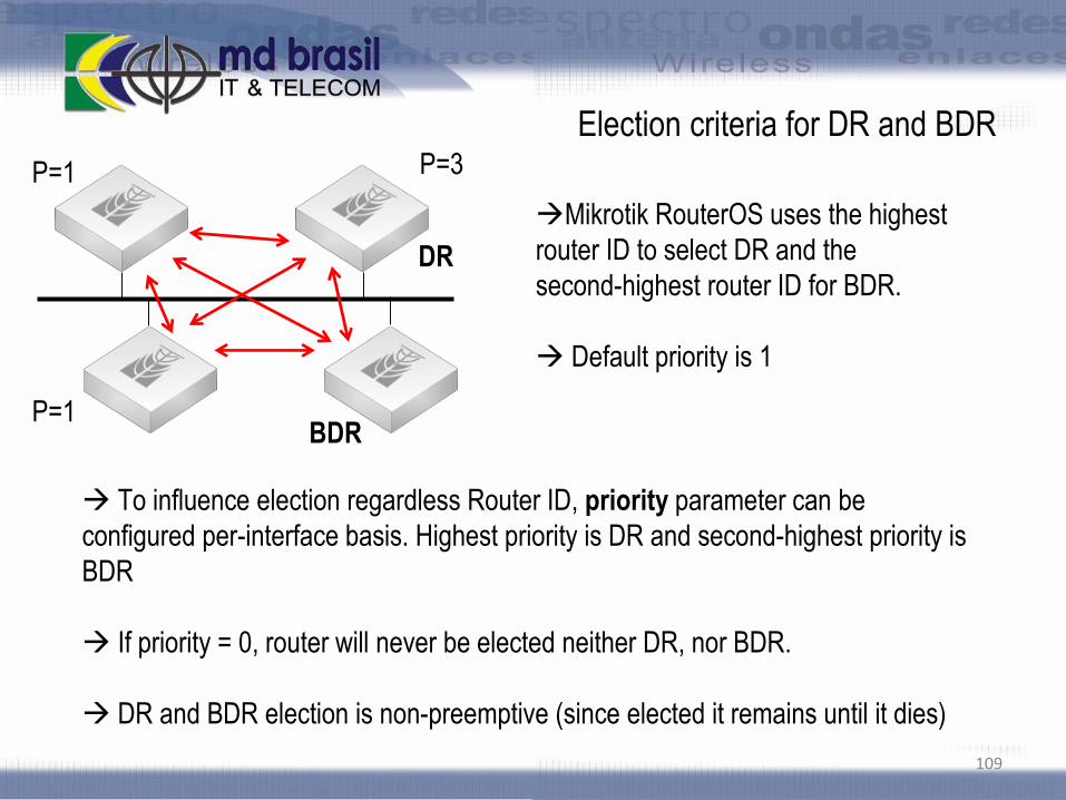
Election criteria for DR and BDR
Mikrotik RouterOS uses the highest
router ID to select DR and the
second-highest router ID for BDR.
Default priority is 1
109
To influence election regardless Router ID, priority parameter can be
configured per-interface basis. Highest priority is DR and second-highest priority is
BDR
If priority = 0, router will never be elected neither DR, nor BDR.
DR and BDR election is non-preemptive (since elected it remains until it dies)
P=1
P=1
P=3
DR
BDR

Priority configuration LAB
Considering our topology which router
could be a good router for being DR ?
110
P=1
P=1
P=3
P=2
DR
BDR
Tip: to configure priority, first turn the interface static

Pause for Backup
111
Please make a backup now to return to this point when necessary.
Name it INFRA2
/system backup save name=INFRA2
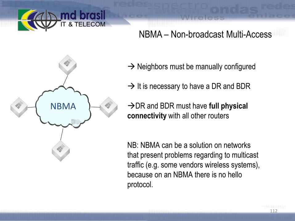
NBMA – Non-broadcast Multi-Access
Neighbors must be manually configured
It is necessary to have a DR and BDR
DR and BDR must have full physical
connectivity with all other routers
NB: NBMA can be a solution on networks
that present problems regarding to multicast
traffic (e.g. some vendors wireless systems),
because on an NBMA there is no hello
protocol.
112
NBMA

NBMA – LAB
Configure a NBMA network among routers
connected via Wireless with the central AP
113
NBMA

Point-to-multipoint (pmtp)
Easier configuration compared to NBMA
Does not elect neither DR nor BDR
Very useful for wireless networks where
Layer 2 isolation is applied (default forward
on AP is disabled)
114

PMTP – LAB
Configure a pmtp network among
routers connected via Wireless with the
central AP
115

Point-to-point interfaces
Neither DR nor BDR election
disable default forward at AP and test
OSPF Packets are sent using the multicast address 224.0.0.5
Point-to-point LAB
Do not change now to point-to-point. Let’s see the impact on LSA’s !
116

LSA’s in depth
117

LSA Header
LSA packets are the heart of a link state protocol. A LSA packet consists of a
header, followed by data for different link types. Below is the header format
118
0 1 2 3 4 5 6 7 0 1 2 3 4 5 6 7 0 1 2 3 4 5 6 7 0 1 2 3 4 5 6 7
Age (2 bytes) Options (1 byte) Type (1 byte)
Link State ID (4 bytes)
Advertising Router (4 bytes)
Sequence Number (4 bytes)
Checksum (2 bytes) Length (2 bytes)
LSA’s (can be types 1,2,3,4,5,6,7,8)

LSA Header
LSA packets are the heart of a link state protocol. A LSA packet consists of a
header, followed by data for different link types. Below is the header format
119
0 1 2 3 4 5 6 7 0 1 2 3 4 5 6 7 0 1 2 3 4 5 6 7 0 1 2 3 4 5 6 7
Age (2 bytes) Options (1 byte) Type (1 byte)
Link State ID (4 bytes)
Advertising Router (4 bytes)
Sequence Number (4 bytes)
Checksum (2 bytes) Length (2 bytes)
LSA’s (can be types 1,2,3,4,5,6,7,8)

LSA type = 1 (Router LSA)
There is one LSA type 1
for each router in one area
LSA includes a list of
directly connected links
LSA identified by the
router ID of the originating
router
Floods within its area
only. Do not cross ABR
120
Area 1
Area 2
Area 0
Backbone Area
MD1201151011

LSA type = 2 (Network LSA)
There is one LSA type 2 for
each transit broadcast or
NBMA network within the area
Advertised by the DR
Includes list of attached
routers on the transit link and
subnet mask of the link
Floods within its area only.
Do not cross ABR
121
Area 1
Area 2
Area 0
Backbone Area
MD1201151011
DR
DR
DR

LSA type = 3 (Summary LSA)
LSA type 3 are used to flood
network information intra-areas.
Describes network number
and mask
Advertized by ABR of
originating area. Regenerated by
subsequent ABR’s to flood
throughout the AS
LSA type 3 is advertized for
each subnet. No network
summarization is made by default
122
Area 1
Area 2
Area 0
Backbone Area
MD1201151011
Type 1
Type 3
Type 3
Type 1
Type 3
Type 3

LSA type = 4 (Summary LSA)
Generated by ABR, only if an
ASBR exists within the area.
LSA type 4 identifies an ASBR
and provide a route to it
Regenerated by subsequent
ABR’s to flood throughout the AS
123
Area 1
Area 2
Area 0
Backbone Area
MD1201151011
Type 4
Type 1
Type 4
ASBR
ABR
ABR
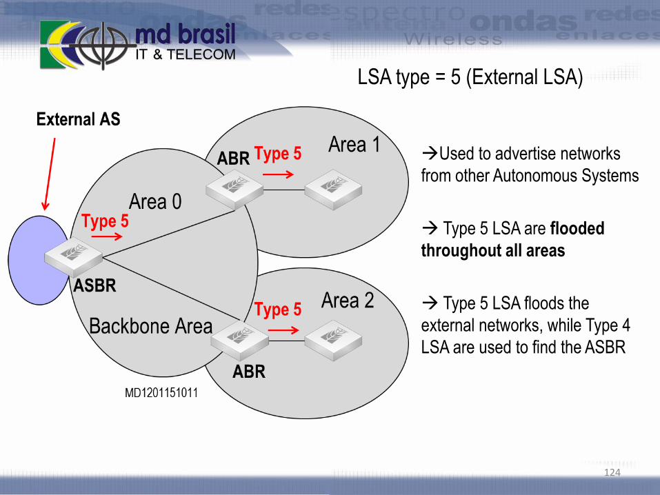
LSA type = 5 (External LSA)
Used to advertise networks
from other Autonomous Systems
Type 5 LSA are flooded
throughout all areas
Type 5 LSA floods the
external networks, while Type 4
LSA are used to find the ASBR
124

LSA type = 7 (External LSA)
Generated in NSSA Areas
by ASBR
ABR’s can change type 7 to
type 5 (optional configuration)
125

OSPF LAB
(Point-to-point Interfaces)
Observe on current configuration LSA quantities and types
Change interfaces mode to point-to-point on link”s:
R1 R2
R2 R3
R3 R4
R4 R1
Observe now the LSA’s
126
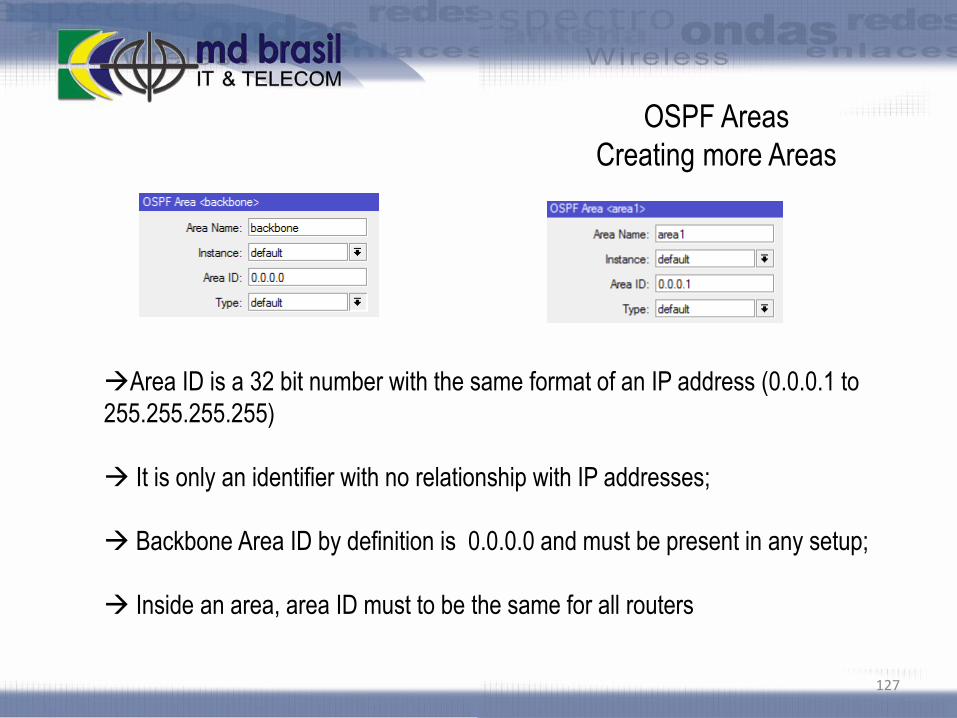
OSPF Areas
Creating more Areas
127
Area ID is a 32 bit number with the same format of an IP address (0.0.0.1 to
255.255.255.255)
It is only an identifier with no relationship with IP addresses;
Backbone Area ID by definition is 0.0.0.0 and must be present in any setup;
Inside an area, area ID must to be the same for all routers

OSPF LAB
Creating more Areas
Each group creates one area with Area ID 0.0.0.G
Routers G1 and G4 will be the ABR’s (will have networks on area 1 and one
network on backbone area
Routers G2 and G4 will have all networks in area 0.0.0.G
Observe the changes on LSA’s
128

LSA’s
129
Type 2
(network)
Type 1
(router)
Type 3 and 4
(summary)

Routing Table Manipulations
Routes Summarization
Costs
Routes Redistribution
Default Route
130

Routes Summarization
Minimizes number of entries in
the routing table
Minimizes LSA’s type 3 and 5
Saves CPU and memory
resources
131

OSPF LAB
Before the LAB:
Observe current routing tables
LAB
Make a list of all possible summarizations per group
Decide on which routers configurations should be applied to
Make the setup an observe the routing tables
132

Route Cost
Costs are computed per interface (egress interface)
Route from A to B has 2 ways, One with total cost = 30 and other total cost = 20133

OSPF LAB – Costs
134
Initial analysis:
Write down all possibilities for R3 to get to R0
Which route is better? Check if OSPF has chosen it.
R3
R1R2
R4
MD1203052048
R0

OSPF LAB – Costs
135
Using Costs, ensure that upload and download traffic between R3 and
R0 will choose the routes:
R3 – R2 – R1 – R0
R0 – R1 – R2 – R3
R3
R1R2
R4
MD1203052048
R0

Routes Redistribution
Routes that are not part of
OSPF domain can be
redistributed inside OSPF
Such routes will be
considered as external AS
and LSA type 5 will be used
136

Routes Redistribution
Dynamic, connected and static routes that are
not part of OSPF domain can be redistributed.
As-type-1 computes sum of external and
internal metrics.
As-type-2 computes only external metrics.
Routes redistributed will appear as external-as
routes.
137

External Type 1 or type 2 metrics
If Type 1 is used, routes from A to B have the following cost:
red route: 30 + 10 +10 + 10 = 60
green route: 30 + 10 + 10 = 50 (this will be preferred) 138

External Type 1 or type 2 metrics
If type 2 is chosen, both green or red route will have the same cost - 30
ECMP will be made on ASBR
139

Default Route
Default Route is not
distributed by default
It is injected via a LSA type 5
Default route is not
considered a static route, even if
configured statically.
Can be distributed regardless
it is present in the routing table.
140

Default Route
Default Route distribution
Never: do not distribute the default route
always as type 1: distributes as type 1 regardless it
is present in the routing table
always as type 2: distributes as type 1 regardless it
is present in the routing table
if installed as type 1: distributes as type 1 only if a
default route is present in the routing table
if installed as type 2: distributes as type 2 only if a
default route is present in the routing table
141

OSPF LAB – Default Route
Main AP distributes default route with type 1 and type 2.
Compare the results
142

Special Area Types
Area Stub
Areas Totally Stub
Areas NSSA
143

Stub Area
Stub areas do not accept
information of external routes (LSA
type 5)
Routers within an Stub area
need default routes to access
external AS’s
Stub areas do accept
information from other areas
In the picture, 1.1.10/24 is an
external network and 2.2.2.0/24 is
an internal one.
144

Totally Stub Area
Totally Stub areas do neither
accept information of external
routes (LSA type 5), nor summary
routes from other areas.
Routers within a Totally Stub
area need default routes to
access external AS’s
Stub and Totally Stub areas
do not accept ASBR inside,
except ABR that can be an
ASBR.
145

Stub and Totally Stub Areas
One area can be Stub or Totally Stub Area if::
All routers in the area must be configured as STUB;
There is no ASBR inside the area;
Area is not the backbone area;
There is no virtual link in the area.
146

Stub and Totally Stub Areas
147
Stub Area
Do not accept external LSA’s
Accept summary
Totally Stub Area
Do not accept external LSA’s
Do not accept summary

OSPF LAB – Stub and Totally Stub areas
Groups configure themselves as Stub Areas and see the LSA’s
The same for Totally Sub areas
Differences observed ?
148

NSSA Areas
ASBR’s are allowed in NSSA areas.
ASBR generates special type 7 LSA’s
ABR can convert LSA type 7 to LSA type 5 when LSA crosses the boundary
149

NSSA Areas
ABR can be configured as translator
(LSA7 LSA5) with the following
roles:
translate never: LSA’s will not be
translated and will not cross the
boundary
translate always: LSA’s will be
converted to type 5
translate candidate: OSPF will
elect a ABR to translate the LSA’s
150
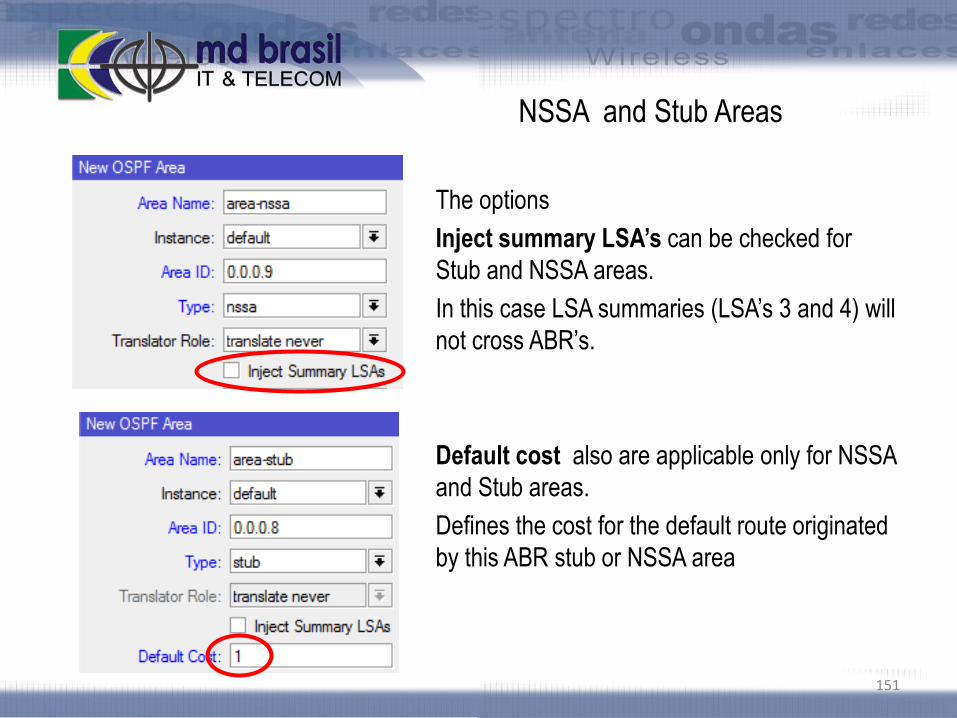
NSSA and Stub Areas
The options
Inject summary LSA’s can be checked for
Stub and NSSA areas.
In this case LSA summaries (LSA’s 3 and 4) will
not cross ABR’s.
Default cost also are applicable only for NSSA
and Stub areas.
Defines the cost for the default route originated
by this ABR stub or NSSA area
151

OSPF LAB – NSSA Areas
Groups configure their areas as NSSA and check the results
Verify the change checking option “inject summary lsa’s”
Differences observed ?
152

OSPF Security
153

Attacks against OSPF
Basically, attacks against OSPF consist on forging Hello, LSA and LSU
messages on behalf of authorized hosts, causing:
Denial of service
and / or
Topology changes
154

OSPF Resource Starvation Attacks
“Phantom LSAs” are Router/Network LSAs sent on behalf of non-existing OSPF
peers.
These entries are ignored by the Shortest Path First (SPF) algorithm (do not
produce topology changes)
“Phantom LSAs” are entered in the Link State Database and each entry is
kept until “MaxAge” expires
NB: Starvation attacks will work regardless of encryption
155

OSPF Attacks - Forcing Topology Changes
An attacker can force topology changes by introducing false LSA Information
Pre-condition:
absence of encryption.
compromised pre shared key.
Impacts of Topology Changes
Allow Eavesdropping
Starve/Overload a network
Unstable topology (loops, route-flapping)
156

Misdirecting traffic to form routing Loops
157
BEST PATH
2.2.2.0/24R1 R2
R3 R4
Attacker injects false LSA
telling R2 that 2.2.2.2
is reachable through R1
ROUTING LOOP
2.2.2.2

Misdirecting Traffic to a Black Hole
158
BEST PATH
2.2.2.0/24R1 R2
R3 R4
Attacker injects false LSA
telling R1 that 2.2.2.2
is reachable through himselfREDIRECTED TRAFFIC
2.2.2.2
BLACK HOLE

Eavesdropping/Man-in-the-middle
159
BEST PATH
2.2.2.0/24R1 R2
R3 R4
Attacker injects false LSA telling
R1 that 2.2.2.2 is reachable
through himself and redirect
packets to R2
REDIRECTED TRAFFIC
Huumm, I can hear everything
2.2.2.2
Eavesdropping/Ma
n-in-the-middle

Attacks against OSPF
(from the perspective of attacker’s location)
160

Attacks against OSPF
A) Attacker is outside of the AS boundary (1/2)
Question: will such attack work ??
On physical point-to-point networks and Broadcast networks the IP
destination is set to the Multicast address “AllSPFRouters” (224.0.0.5) .
On NBMA and all other network types (including virtual links), the
majority of OSPF packets are sent as unicasts, i.e., sent directly to the other end
of the adjacency. In this case, the IP destination is just the Neighbor IP address
associated with the other end of the adjacency (see RFC 2326, section 10).
So, the answer is YES, the attack could work from any point of the Internet !
161

Attacks against OSPF
A) Attacker is outside of the AS boundary (2/2) -
Countermeasures
Although external attacks are possible, the attacker should
be able to send unicast OSPF packets destined to internal
routers. To thwart such attacks, just follow the 2 hints
below:
Never, never run OSPF beyond your boundaries i.e. with
networks under other administration.
Deny protocol 89 (OSPF) at your border routers.
162

Attacks against OSPF
(from the perspective of attacker’s location)
B) Attacker is inside the AS, but not in the same L2
network segment. (e.g. your client CPE)
The same considerations from external AS attacks
could be made. Countermeasures are similar:
Firewall rules should be placed at the boundaries
of OSPF domain (forward an input chains)
163
Deny protocol 89
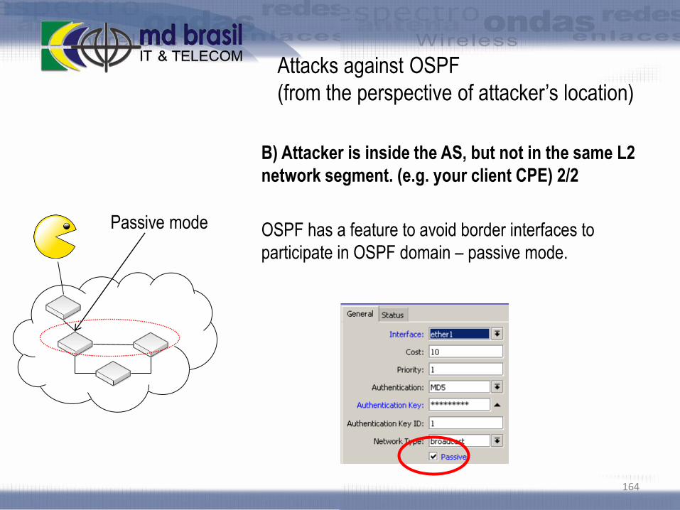
Attacks against OSPF
(from the perspective of attacker’s location)
B) Attacker is inside the AS, but not in the same L2
network segment. (e.g. your client CPE) 2/2
OSPF has a feature to avoid border interfaces to
participate in OSPF domain – passive mode.
164
Passive mode

Attacks against OSPF
C) Attacker is inside and in the same L2 segment (1/3)
Without any doubt , this is the worst condition. Even with MD5 authentication
OSPF can be exploited easily. On the net there are tools to explore this situation.
165
OSPF domain

Attacks against OSPF
C) Attacker is inside and in the same L2 segment (2/3)
Once the pre shared key is compromised, attacker could do anything a real
router could, since flooding LSA’s for resource starvation, or impersonate a
network router. Imagination and creativity will do the rest
166
Creating an arbitrary
network

Attacks against OSPF
C) Attacker is inside and in the same L2 segment
(3/3)
Countermeasures:
Choosing a strong password will delay (but not avoid)
the discovery. It’s only a matter of time.
The real solution is NOT TO SHARE L2 segments with
outsiders.
When L2 sharing could not be avoided, make sure to
promote L2 isolation between hosts. Take a look on the
presentation:
http://mum.mikrotik.com/presentations/PL10/maia.pdf167
OSPF domain

Authentication
Authentication can be:
Simple: clear text password
MD5: uses a MD5 hash and messages will be encrypted. Authentication Key ID
will be used to calculated message digest and must be the same in all routers
168
OSPF messages can be authenticated per-
interface basis

Passive mode
When an interface is in passive mode, reouter will prevent all OSPF traffic through that
interface.
Very useful in border interfaces specially if there are customers connected to.
169
Passive mode

OSPF LAB – Authentication and Passive mode
All routers configure authentication
Test the option passive mode (your laptop probably is not running OSPF, so
test with your neighbor’s router)
170

Virtual Links
171

Virtual Links
OSPF protocol establishes that all areas should be connected to the backbone
area. This connection usually is made by an ABR that physically connects both
areas. That means all areas are contiguous to the backbone area
With virtual links it is possible to logically connect a not contiguous area to the
backbone area.
172

Virtual Links
Transit Area should be connected to the backbone
configuration parameters are neighbor ID and transit
area
Areas Stub or NSSA are not allowed as transit areas
173

Virtual Link - LAB
174
Area 0.0.0.0Area 0.0.0.G
Area 0.0.G.1
Disconnect routers 3 and 4
Configure Area 0.0.G.1
Configure Virtual Link
R4
R3
R2
R1
R0Virtual Link

SHAM Links
In the above scenario, the path over the backdoor link will always be selected
because OSPF prefers intra-area paths over inter-area paths
OSPF cost configured with a SHAM link allows you to decide if OSPF client site
traffic will be routed over a backdoor link or through the VPN backbone.
175

IPV6 Addressing and Routing
176
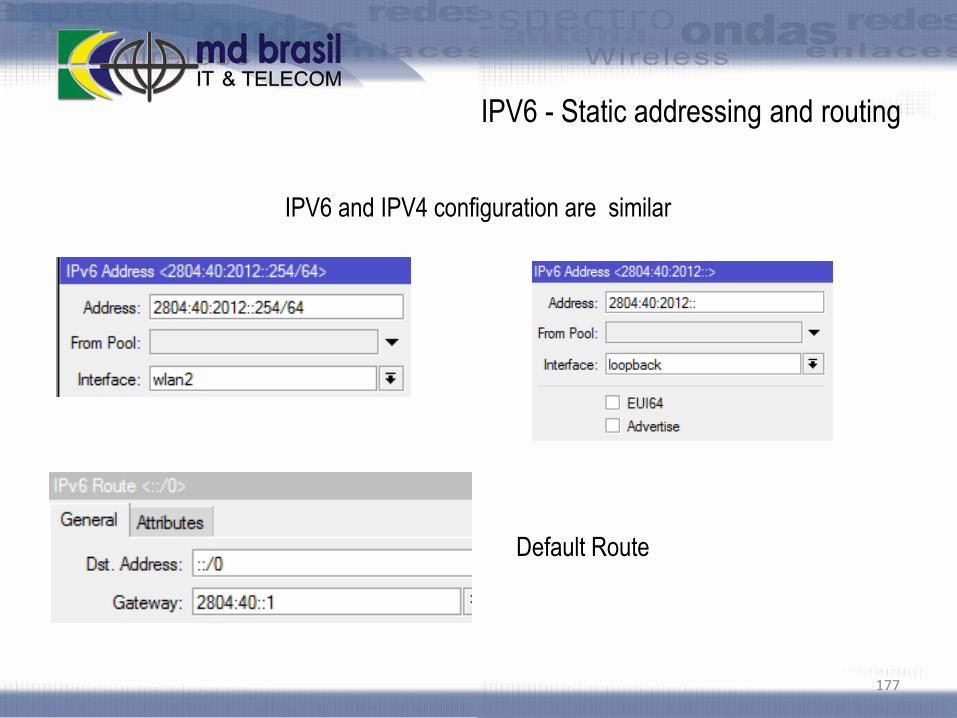
IPV6 - Static addressing and routing
177
IPV6 and IPV4 configuration are similar
Default Route

Loopback addresses configuration with IPV6
IPV6 addresses are formed automatically from MAC Addresses. Because bridge
has no MAC by default, the method will fail. As a solution use Admin MAC
178
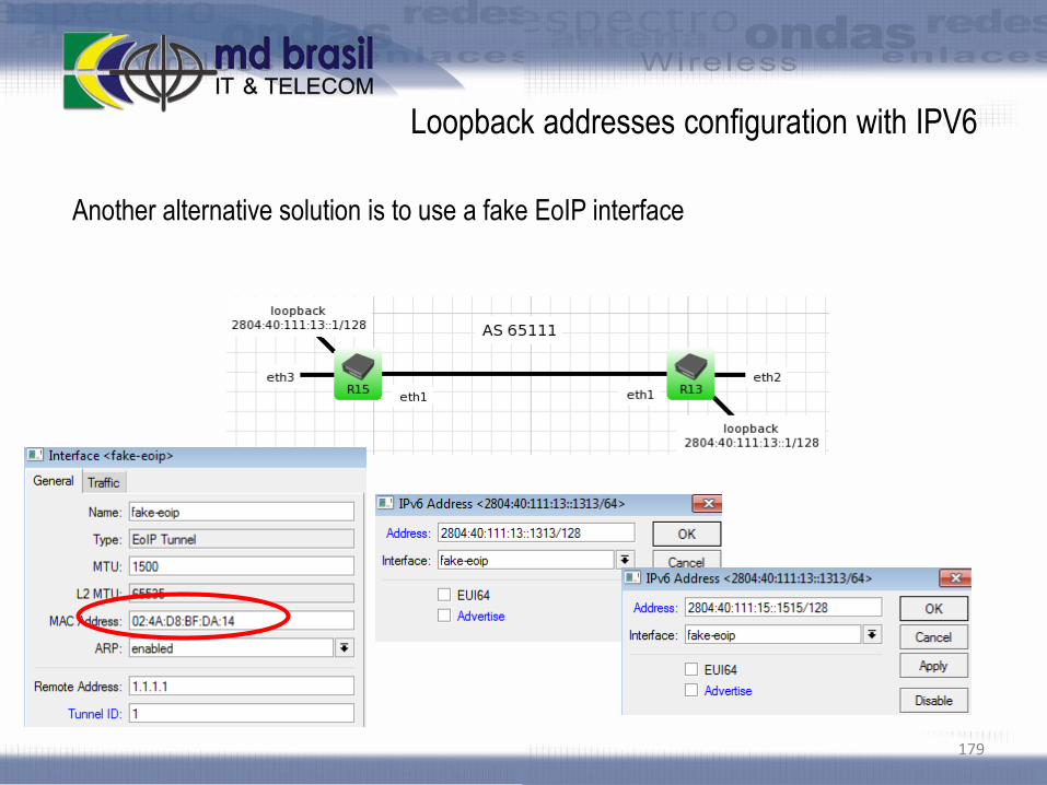
Loopback addresses configuration with IPV6
Another alternative solution is to use a fake EoIP interface
179

IPV6 Addressing LAB
180

Dynamic Routing with IPv6
Mikrotik RouterOS supports the following IPv6 routing
protocols:
RIP “New Generation” (RIPng)
OSPFv3
BGP is the same for IPv4 (BGPv4). It carries IPv6
information in the attribute “Address Family
181

Dynamic Routing with IPv6 - RIPng
Based on RIPv2 and RFC 2080
Uses Bellman-Ford algorithm – a
“distance vector” protocol..
Limited to 15 hops
Uses Multicast group ff02::9 (All RIP
Routers) as destination for all update
messages.
182

Dynamic Routing with IPv6 OSPFv3
OSPF protocol used for IPv4 (OSPFv2) needed several
modifications for supporting IPv6, and a new protocol was
made - OSPFv3 (RFC 2740)
The same principles used for IPv4 were kept in the new
version, like LSA’s, Dijkstra Algorithm, flooding, etc.
However OSPFv3 has a lot of improvements when
compared to its antecessor, OSPFv2;
The main difference in terms of configuration is that with
OSPFv3 there is no network configuration but interfaces
configuration that are mandatory.
183

OSPF LAB – OSPFv3 Configuration
Configure OSPFv3 with a single area for all the classroom
Observe and comment the results
184

VLAN’s
185

VLan’s
Virtual Local Area Network (VLAN) is layer 2 method that allows configuration of
(Virtual) LANs on a single physical interface. Mikrotik RouterOS implementation is
based on IEEE 802.1Q standard.
Some characteristics of Vlan’s:
Vlan’s are layer 2 devices and can be used as they are regular interfaces
Traffic between VLan’s are segregated. Each VLan has a unique VLan ID
Up to 4095 different VLan’s ID can be configured for one physical interface
It is possible to mark Vlan packets and to use marks done by other devices
It is possible to configure priority on Vlan’s
186

Vlan Packet
802.1Q defines how to insert the 4 byte identifiers (VLAN ID) into an ethernet frame.
187

802.1q Header
802.1q header is divided:
TPID: Tag Protocol Identifier
TCI: Tag Control Identifier
PCP: Priority Code Point
CFI: Canonical Format Indicator
VID: VLAN Identifier (12 bits 4096 possible VLAN’s)
188
16 bits 3 bits 1 bit 12 bits
TPIDTCI
PCP CFI VID

Vlan Trunk
In order to carry traffic of multiple VLAN’s between switches, inter-switch ports
have to be configured as trunk ports.
189
VLAN 10VLAN 20
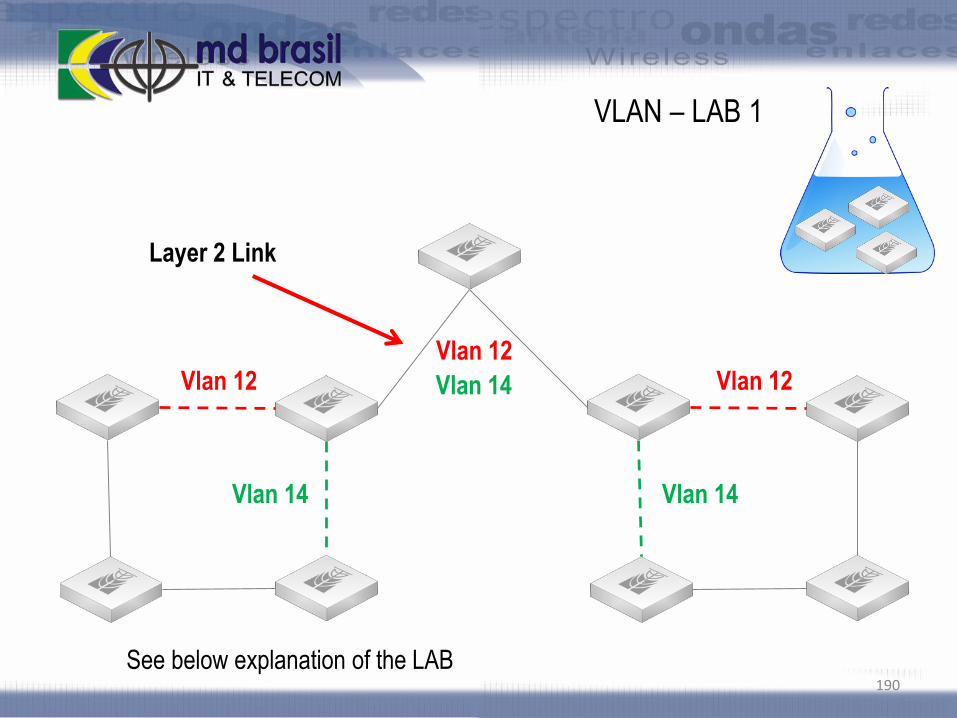
VLAN – LAB 1
190
Vlan 12
Vlan 14 Vlan 14
Vlan 12
Layer 2 Link
See below explanation of the LAB
Vlan 12
Vlan 14

Vlan Q-in-Q
Q-in-Q allows two or more VLAN headers. In RouterOS Q-in-Q can be configured by
adding one VLAN interface over another
191

VLAN – LAB 2
QinQ
192
Vlan 12
Vlan 14 Vlan 14
Vlan 12
See below explanation of the LAB
Vlan 100

802.1ad
Q-in-Q allows multiple VLAN tags to be inserted into an ethernet frame, an
essential capability for implementing Metro Ethernet topologies. 802.1ad protocol
should be used in some scenarios like the below one:
193

802.1ad
802.1ad configuration on RouterOS
194

VLAN – LAB 2
802.1ad
195
Vlan 12
Vlan 14 Vlan 14
Vlan 12
See below explanation of the LAB
Vlan 100

VLAN’s and Wireless Interfaces
As VLAN works on OSI Layer 2, it can be used just as any other network
interface without any restrictions. VLAN successfully passes through regular
Ethernet bridges.
You can also transport VLANs over wireless links and put multiple VLAN
interfaces on a single wireless interface. Note that as VLAN is not a full tunnel
protocol (i.e., it does not have additional fields to transport MAC addresses of
sender and recipient), the same limitation applies to bridging over VLAN as to
bridging plain wireless interfaces.
In other words, while wireless clients may participate in VLANs put on wireless
interfaces, it is not possible to have VLAN put on a wireless interface in station
mode bridged with any other interface.
196

VLAN’s – MTU Issues
MTU should be set to 1500 bytes as on Ethernet interfaces. But this may not
work with some Ethernet cards that do not support receiving/transmitting of full
size Ethernet packets with VLAN header added (1500 bytes data + 4 bytes VLAN
header + 14 bytes Ethernet header).
In this situation MTU 1496 can be used, but note that this will cause packet
fragmentation if larger packets have to be sent over interface. At the same time
remember that MTU 1496 may cause problems if path MTU discovery is not
working properly between source and destination
197

Unnumbered Interfaces
Mikrotk RouterOS can implement the concept of “unnumbered IP addresses
using VLAN’s. See the below scenario:
198
172.16.0.0/24 192.168.0.0/24
VLAN (over eth2)
IP 192.168.0.1/32
eth1 eth1
eth2eth2
R1 R2
VLAN (over eth2)
IP 172.16.0.1/32

Vlan’s on Switches
199
VLAN-compliant switches can be used to implement those previous setups with gain in
performance, because without using bridges the packets will be forwarded at “wire
speed”. Switch chip features supported by RouterOS are:
Port Switching
Port Mirroring
Host Table
Vlan Tabel
Rule Table

Switch Chip Features
Switch chip features that are implemented in RouterOS (complete set of features
implemented starting v4.0)
Feature Atheros8316 Atheros8327 Atheros7240 ICPlus175D Others
Port Switching Yes Yes Yes Yes Yes
Port Mirroring Yes Yes Yes Yes No
Host Table 2k entries 2k entries 2k entries No No
Vlan Table 4096 entries 4096 entries 16 entries No No
Rule Table 32 rules 92 rules No No No
Switch chip features present in several Routerboards. For more details:
http://wiki.mikrotik.com/wiki/Manual:Switch_Chip_Features
Site to Site Connectivity with
tunnels
202
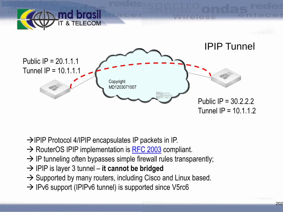
IPIP Protocol 4/IPIP encapsulates IP packets in IP.
RouterOS IPIP implementation is RFC 2003 compliant.
IP tunneling often bypasses simple firewall rules transparently;
IPIP is layer 3 tunnel – it cannot be bridged
Supported by many routers, including Cisco and Linux based.
IPv6 support (IPIPv6 tunnel) is supported since V5rc6
IPIP Tunnel
Public IP = 20.1.1.1
Tunnel IP = 10.1.1.1
Public IP = 30.2.2.2
Tunnel IP = 10.1.1.2
Copyright
MD1203071007

IPIP Tunnel LAB
203
Restore Backup INFRA2 to have connectivity
between routers
Working in pairs, create a IPIP tunnel between:
R1 R3
R2 R4
Give IP address to the tunnel and make a route
pointing to remote site using as gateway the local IP
tunnel address
Test connectivity

Point to Point Addressing
204
Point-to-point addressing utilizes only two IP’s per link while /30 utilizes four IP’s
There is no broadcast address, but network address must be set manually to the
opposite IP address. Example:
Router1: address=1.1.1.1/32, network=2.2.2.2
Router2: address=2.2.2.2/32, network=1.1.1.1
There can be identical /32 addresses on the router – each address will have
different connected route
IP 1.1.1.1/32,
Network 2.2.2.2
Copyright
MD1203071007
IP 2.2.2.2/32,
Network 1.1.1.1

EoIP Tunnel
205
Public IP = 20.1.1.1
Tunnel IP = 10.1.1.1
Public IP = 30.2.2.2
Tunnel IP = 10.1.1.2
Mikrotik proprietary protocol that uses IP protocol 47/GRE to create tunnel by
encapsulating ethernet frames on IP packets;
EoIP is a layer 2 tunnel and can be bridged;
To create a tunnel is necessary to specify remote’s router address and
choose unique tunnel ID;
Check that EoIP interface has different MAC on opposite side

EoIP Tunnel LAB
206
Working in pairs, create a EoIP tunnel between:
R1 R3
R2 R4
Create a Bridge and add as ports the tunnel
interface and ethernet laptops are connected to;
Test layer 2 connectivity. Configure an arbitrary
address from same subnet on laptops and ping each
other. Arp –a should show Laptop’s MAC.

PPtP and L2TP Tunels
207
PPtp or L2TP
PPTP and L2TP are used for site to site or to client to site connections
Both have mostly the same functionality
Configuration of the both tunnels are identical in RouterOS

PPtP and L2TP Tunnels
208
PPTP Tunnels
PPTP uses TCP port 1723 and IP protocol 47/GRE
PPTP clients are available for and/or included in almost all OS
You must use PPTP and GRE “NAT helpers” to connect to any public
PPTP server from your private masqueraded network
L2TP Tunnels
L2TP traffic uses UDP port 1701 only for link establishment, further
traffic is using any available UDP port
L2TP don't have problems with NATed clients – it don't required “NAT
helpers”

PPtP and L2TP
Client Configuration
209

PPtP and L2TP
Server Configuration
210

PPtP and L2TP LAB’s
211
Working in pairs, create a L2TP and PPtP tunnel
between:
R1 R3
R2 R4
Test Layer 3 connectivity

PPP Bridge Control Protocol (BCP)
212
RouterOS offers BCP support for all asynchronous PPP, PPTP, L2TP & PPPoE
(not ISDN) interfaces
BCP allows to bridge Ethernet packets through the PPP link
BCP is independent part of PPP tunnel - It is not related to IP address of PPP
interface
Bridging and routing over PPP link can happen at the same time, independently

PPP Bridge Control Protocol (BCP)
213
Setting up BCP
Bridge must be specified the ppp
profiles on both sides of the tunnel
Note that PPP interface don't have
any MAC addresses – so your bridge
must have a MAC address before you
add ppp to the bridge
PPP Bridge Control Protocol (BCP)
214
PPP MTU Problem
PPP interface MTU is smaller than standard Ethernet interface
It is impossible to fragment Ethernet frames – tunnels must have inner
algorithm how to transfer Ethernet frames via link with smaller MTU
EOIP have encapsulation algorithm enabled by default, PPP interfaces doesn't
PPP interfaces can utilize PPP Multi-link Protocol to handle Ethernet frames
PPP Bridge Control Protocol (BCP)
215
PPP Multi-link Protocol
PPP Multi-link Protocol allows divide packet to multiple channels therefore
increasing possible MTU and MRU (up to 65535 bytes)
MLPPP can be created:
over single physical link – where multiple channels run on the same
link
over multiple physical links - where multiple channels run on the
multiple link

PPP Bridge Control Protocol (BCP)
216
MRRU
To enable PPP Multi-link Protocol over single link you must specify MRRU
option;
If both sides support this feature there are no need for MSS adjustment (in
firewall mangle)
MRRU is less CPU expensive that 2 mangle rules per client if you have more
that 30 clients
In MS Windows you must enable "Negotiate multi-link for single link
connections" option

PPtP and L2TP LAB’s
217
Create a bridge , enable MRRU , bind ethernet port
and turn your tunnel a Layer 2 connection
Test Layer 2 connection

SSTP Tunnel
218
SSTP
SSTP – Secure Socket Tunneling Protocol
SSTP is the way to transport PPP tunnel over SSL 3.0 channel. The use of SSL over
TCP port 443 allows SSTP to pass through virtually all firewalls and proxy servers.

SSTP Connection Mechanism
219
TCP connection is established from client to server (by default on port 443);
SSL validates server certificate. If certificate is valid connection is established
otherwise connection is torn down;
The client sends SSTP control packets within the HTTPS session which
establishes the SSTP state machine on both sides;
PPP negotiation over SSTP. Client authenticates to the server and binds IP
addresses to SSTP interface;
SSTP tunnel is now established and packet encapsulation can begin.

Configuring SSTP
220

SSTP LAB
Using Certificates
221
In this LAB, Central AP will be
SSTP Server and all routers will be
clients.
Certificates should be installed and
used
SSTP Server
SSTP ClientsSSTP Clients

SSTP LAB – Using Certificates
222
Ask the teacher for the FTP IP address to download pre built Certificates
Certificates should be signed by the same Certificate Authority (CA)
Download Certificates to your Computer:
Your_Number_cert.pem
Your_Number_key.pem
cacert.pem
Upload Certificates to your Mikrotik router.

SSTP LAB – Using Certificates
223
Import Certificates (/system certificate) to the system in the following order:
Your Certificate, your key (ask the teacher for the key passwork) and CA
Certificate.

SSTP LAB – Using Certificates
224
Configure SSTP to use the certificate imported and to Verify Certificate.
Try to connect and see logs to debug problems..

225
/system reset-configuration
Final LAB

226
Edson Veloso Sergio Souza Wardner Maia
[email protected] [email protected] [email protected]
hvala
grazie
хвала
gracias
obrigadoდიდი მადლობა