Embed Size (px)
Citation preview

139
Sele
ctio
n G
uide
Prod
uct
Info
rmat
ion
Plas
tic B
earin
gM
ulti-
laye
r Bea
ring
Met
allic
Bea
ring
Air
Bear
ings
Tech
nica
l In
form
atio
nSl
ide
Shift
erCo
rpor
ate
Profi
le
066-139_樹脂系ベアリング.indd 139 19/11/13 11:09
Multi-layer Bearings
140
Oiles Drymet ST ……………………………………P.141Oiles Drymet LF ……………………………………P.151Oiles LF Guides ………………………………… P.164Oiles Techmet B ………………………………… P.166Oiles Techmet E ………………………………… P.169Oiles Toughmet ………………………………… P.170Oiles Toughmet D ……………………………… P.173Oiles Hiplast N/E ………………………………… P.179
140-183_複層系ベアリング.indd 140 19/11/13 18:25

Oiles Drymet ST Oil-impregnated polyacetal multi-layer bearings with back metals
Ser vice rangeLubrication condition
Service temperature range ℃Allowable max. pressure P N/mm2{kgf/cm2}
Allowable max. velocity V m/s{m/min}
Allowable max. PV value N/mm2・m/s{kgf/cm2・m/min}
Dry
-40~+120
24.5(137){250(1,400)}
1.15{69}
3.25{1,990}
Relief angle
Rake angle
Nose radius (mm)
Speed (m/min)
Cut depth (mm)
Feed (mm/rev)
carbide tool(JIS)
5~10゜
10~20゜
0.10~0.20
60~200
0.05~0.10
0.05~0.20
Lathe turningC
utt
ing
tool
Con
dit
ion
I.D.
class 7 (Note)
O.D.
-
Length
class 8 to 9
Machining accuracy (bushing)
(Note) Accuracy after press fitting.
Classes here are in JIS standard.
This product demonstrates satisfactory performance at the slide surface roughness of Rz6.3 to 12.5μm.
Dimensions may change due to thermal expansion, chucking pressure, moisture absorption deformation, etc. High accuracy is ensured if the product is installed on the housing and then ground.
Attention should be paid to dimensional var iances due to thermal expansion, chucking, and bend of the material.
Image
The values in parentheses are static bearing pressures, which are the bearing pressures in applications with no motion or very small motion (≦0.0017m/s[0.1m/min]).
※The values shown above are typical values, not the standard values.※The values shown above are values of back metal.
Tensile strength
Elongation
Hardness
JIS Z 2241
JIS Z 2241
JIS Z 2244
380{3,875}
27
107
Mechanical proper tiesN/mm2{kgf/cm2}
%
HV
Oil-impregnated polyacetal layer
Back metal layer
Sliding surface
Sintered bronze layer
Feature●Ser viceable without the need for lubrication and demonstrates low
coefficient of friction and superior load performance.●Demonstrates superior wear resistance in applications where oil film is
seldom produced such as reciprocating motions, oscillation, frequent starts and stops, etc.
●Thin bearing allows compact design.●Superior dimensional stability, mechanical strength, and thermal
conductivity.●The standard products and plate material of various sizes are available.
141
Sele
ctio
n G
uide
Prod
uct
Info
rmat
ion
Plas
tic B
earin
gM
ulti-
laye
r Bea
ring
Met
allic
Bea
ring
Air
Bear
ings
Tech
nica
l In
form
atio
nSl
ide
Shift
erCo
rpor
ate
Profi
le
140-183_複層系ベアリング.indd 141 19/11/13 18:25
Test data
W
W
Journal rotation test<Testing conditions>Bearing dimension : φ40×φ44×R30Mating material : S45C(surface roughness Rz0.6μm)Pressure : 10.3N/mm2{105.0kgf/cm2}Velocity : 0.922m/s{55.3m/min}Test time : 80hrs.Lubrication : grease is applied at assembley
Journal oscillation test<Testing conditions>Bearing dimension : φ40×φ44×R30(Oiles Drymet ST) φ40×φ50×R30(Oil impregnated sintered bronze bearing)Mating material : S45C(surface roughness Rz1.5μm)Pressure : 19.6N/mm2{200.0kgf/cm2}Velocity : 0.023m/s{1.40m/min}Oscillating cycle : 100cpmOscillating angle : 20°Oscillating frequency : 300,000cycleLubrication : grease is applied at assembly
0.3
0.2
0.1
0
Wear amount〔mm〕
200 40 60 80
Test time〔hrs.〕
0.3
0.2
0.1
0200 40 60 80
Test time〔hrs.〕
Coefficient of friction〔μ〕
1.0
0.8
0.6
0.4
0.2
0
Wear amount〔mm〕
500 100 250200150 300
Oscillation frequency〔×103cycle〕
Oil impregnated sintered bronze bearing
Oiles Drymet ST
142
Selection Guide
ProductInform
ationPlastic Bearing
Multi-layer Bearing
Metallic Bearing
Air Bearings
Technical Inform
ationSlide Shifter
Corporate Profi le
140-183_複層系ベアリング.indd 142 19/11/13 18:25

Oiles Drymet ST Oil-impregnated polyacetal multi-layer bearings with back metals
Press-fitting (Rolled bushing)
〔 〕
Housing chamferFor the housing chamfer, either a round chamfer or a tapered chamfer is recommended. In case of a C-surface chamfer, (more than C1.0) make sure there is no burr. Smoother press-fitting is possible by applying small amount of grease or lubricant.
Press-fit forcePress-fit smoothly with hydralic (pressure), pneumatic pressure, or a vice. Avoid press-fit by use of impact such as use of a hammer. It might induce damage of the bushing, or change the size of the inner diameter after press-fit.
F=(0.9 to 1.2)×104・ 〔kg〕D1t・L・S Backing steel thickness
: thickness of the steel backing: length of the bushing: average interference : O.D. of bushing
tLSD1
I.D.of bushingUp to φ18φ19 to φ25φ26 to φ40φ42 and over φ42
t0.50.951.381.88
Unit : mm
Press-fitting jigGenerally, as shown in the figure 1, a mandrel is used for the press-fitting. However use of a guide ring facilitates easier press-fitting. Use of a guide ring prevents damage of a bushing at the time of press-fitting. The dimension of a guide ring should be calculated from the table below.Inner diameter of the guide ring should be the size so that the bushing can be inserted by hands. Length of the guide ring should be more than one-third of the bushing, or if possible, it should be the same length as the bushing.
Dimension of bushing
I.D. D0
O.D. D1
Length L
Dimension of mandrel
d0=D0-(0.05 to 0.10)
d1=D1-(0.20 to 0.30)
R≧L
The dimension of mandrel should be calculatedfrom table below.
Load Load
Mandrel
Bushing Guide ring
Housing
Regular press-fitting Press-fitting with guide ringL R
D0
d0
d1D1 D1+(10 to 15)
C1.0
Inner diameter of the guide ring should be the size that bushing can be inserted by hands. The length of the guide ring should be more than one-third of the bushing, or if possible, it should be the same length as the bushing.
The dimension of guide ring should be calculated from table below.
Dimension of bushing
Up to φ40
φ42 to φ60
Over φ65
Guide ring O.D.
D1+(10 to 15)
Guide ring I.D.
D1+(0.1 to 0.3)
D1+(0.2 to 0.5)
D1+(0.5 to 1.0)
Press-fit force is obtained by below formula.
Figure 1
Figure 3Figure 2
143
Sele
ctio
n G
uide
Prod
uct
Info
rmat
ion
Plas
tic B
earin
gM
ulti-
laye
r Bea
ring
Met
allic
Bea
ring
Air
Bear
ings
Tech
nica
l In
form
atio
nSl
ide
Shift
erCo
rpor
ate
Profi
le
140-183_複層系ベアリング.indd 143 19/11/13 18:25
Dimensional inspec tion and chamfering of Oiles Dr ymet ST
Oiles Drymet ST is dimensionally inspected before shipping as indicated below:
1. The O.D. is cheeked by "GO" and "NO GO" ring gauges.
2. The I.D.mounted in the "GO" ring gauge is checked by plug gauges.
3. The "GO" ring gauge stands for the upper limit and the "NO GO" ring gauge the lower limit of the O.D. tolerance.
4. Chamfering: Both ends of the I.D. and O.D. are chamfered as shown in the right diagram except those with the ID of 9mm or less which are not chamfered.
Free gap“GO”“NO GO”
Thickness
L
20°±5°
Both ends of I.D.0.3 to 0.5×45°
Both ends of O.D. 0.5 to 1.0Thickness 1.0mm : 0.5mmThickness 1.5mm : 0.8mmThickness 2.0mm : 1.0mmThickness 2.5mm : 1.0mm〔 〕〔 〕
0-0.3
144
Selection Guide
ProductInform
ationPlastic Bearing
Multi-layer Bearing
Metallic Bearing
Air Bearings
Technical Inform
ationSlide Shifter
Corporate Profi le
140-183_複層系ベアリング.indd 144 19/11/13 18:25

70B Oiles Drymet ST Bushings (I.D. φ5~φ30)
Shaft Housing I.D. O.D.
Size Size φd φD Tolerance
5678910121314151617181920222425262830
-0.012
-0.012
-0.015
-0.015
-0.015
-0.015
-0.018
-0.018
-0.018
-0.018
-0.018
-0.018
-0.018
-0.021
-0.021
-0.021
-0.021
-0.021
-0.021
-0.021
-0.021
0
0
0
0
0
0
0
0
0
0
0
0
0
0
0
0
0
0
0
0
0
789101112141516171819202223252728303234
789101112141516171819202223252728303234
5678910121314151617181920222425262830
+0.015
+0.015
+0.015
+0.015
+0.018
+0.018
+0.018
+0.018
+0.018
+0.018
+0.018
+0.021
+0.021
+0.021
+0.021
+0.021
+0.021
+0.021
+0.021
+0.025
+0.025
0
0
0
0
0
0
0
0
0
0
0
0
0
0
0
0
0
0
0
0
0
+0.025
+0.025
+0.025
+0.025
+0.030
+0.030
+0.030
+0.030
+0.035
+0.035
+0.035
+0.035
+0.040
+0.040
+0.045
+0.045
+0.045
+0.050
+0.050
+0.050
+0.050
+0.055
+0.055
+0.055
+0.055
+0.060
+0.060
+0.060
+0.060
+0.065
+0.065
+0.070
+0.070
+0.075
+0.075
+0.080
+0.080
+0.080
+0.085
+0.080
+0.090
+0.090
4
05045
050506050705
6
05060606
0806
10061206
7
06070707
1007
8
05080608
0808
10081208
10
061007100810091010101210
141015101610
1810
20102210
2510
Length L Tolerance 0-0.3
※Outer diameter is measrued by exclusive gauge.※The I.D. tolerance after press fitting is for reference only.※I.D. φ31~φ160 are shown on pages 147 to 148.
Specify Part No. by required I.D. and length.
(e.g.) I.D. is 15mm and length is 10mm.
※The joint causes no influences upon rotation of the shaft. Be careful when press-fitting so that the joint is not at the position to which the maximum load is applied.
L
Motiondirection
Bushing
φdφD
joint※
6.3( )
chamfer
Housing
H7
Mating shaft
h7
0.8( )
thick bushingT
70B - 1510
h7Tolerance
H7Tolerance
Wall thickness
ToleranceT
1.01.01.01.01.01.01.01.01.01.01.01.01.01.51.51.51.51.52.02.02.0
-0.075
-0.075
-0.075
-0.075
-0.075
-0.075
-0.075
-0.075
-0.075
-0.085
-0.085
-0.085
-0.085
-0.085
-0.085
-0.085
-0.085
-0.085
-0.090
-0.090
-0.090
-0.030
-0.030
-0.030
-0.030
-0.030
-0.030
-0.030
-0.030
-0.030
-0.035
-0.035
-0.035
-0.035
-0.035
-0.035
-0.035
-0.035
-0.035
-0.035
-0.035
-0.035
Part No.
145
Sele
ctio
n G
uide
Prod
uct
Info
rmat
ion
Plas
tic B
earin
gM
ulti-
laye
r Bea
ring
Met
allic
Bea
ring
Air
Bear
ings
Tech
nica
l In
form
atio
nSl
ide
Shift
erCo
rpor
ate
Profi
le
140-183_複層系ベアリング.indd 145 19/11/13 18:25
20 25 30 35 40
15251625
1825
2025222524252525
28253025
5678910121314151617181920222425262830
07120812
10121212
141215121612
1812
20122212
2512
28123012
1015121513151415151516151715181519152015221524152515261528153015
10201220
14201520162017201820
2020222024202520262028203020
2030223024302530263028303030
2535
28403040
1512
Length L Tolerance 0-0.3
+0.060
+0.060
+0.060
+0.060
+0.060
+0.060
+0.060
+0.060
+0.060
+0.070
+0.070
+0.070
+0.070
+0.070
+0.070
+0.070
+0.070
+0.070
+0.070
+0.070
+0.070
+0.165
+0.165
+0.165
+0.165
+0.168
+0.168
+0.168
+0.168
+0.168
+0.188
+0.188
+0.191
+0.191
+0.191
+0.191
+0.191
+0.191
+0.191
+0.201
+0.205
+0.205
T(20°±5°)
Back metal
Oil-impregnated
polyacetalφdφD
L
a
b
※Chamfering of inner or outer diameters less than φ10 mm is done only to remove burrs.
a: O.D. chamfering for the bushing I.D. of φ10 or more
b: I.D. chamfering for the bushing I.D. of φ10 or more
a
b
T 1.00.5
2.01.0
1.50.8
T 1.0C0.3
1.5C0.5
2.0C0.5
(mm)
(mm)
I.D.
φd
I.D. toleranceafter press
fitting (reference)
146
Selection Guide
ProductInform
ationPlastic Bearing
Multi-layer Bearing
Metallic Bearing
Air Bearings
Technical Inform
ationSlide Shifter
Corporate Profi le
140-183_複層系ベアリング.indd 146 19/11/13 18:25

70B Oiles Drymet ST Bushings (I.D. φ31~φ160)
Shaft Housing I.D. O.D.
Size Size φd φD Tolerance
31323538404245505560657075808590100110120130140150160
-0.025
-0.025
-0.025
-0.025
-0.025
-0.025
-0.025
-0.025
-0.030
-0.030
-0.030
-0.030
-0.030
-0.030
-0.035
-0.035
-0.035
-0.035
-0.035
-0.040
-0.040
-0.040
-0.040
0
0
0
0
0
0
0
0
0
0
0
0
0
0
0
0
0
0
0
0
0
0
0
35363942444750556065707580859095105115125135145155165
35363942444750556065707580859095105115125135145155165
31323538404245505560657075808590100110120130140150160
+0.025
+0.025
+0.025
+0.025
+0.025
+0.025
+0.025
+0.030
+0.030
+0.030
+0.030
+0.030
+0.030
+0.035
+0.035
+0.035
+0.035
+0.035
+0.040
+0.040
+0.040
+0.040
+0.040
0
0
0
0
0
0
0
0
0
0
0
0
0
0
0
0
0
0
0
0
0
0
0
+0.050
+0.050
+0.055
+0.055
+0.055
+0.055
+0.060
+0.060
+0.065
+0.070
+0.075
+0.075
+0.075
+0.075
+0.075
+0.075
+0.080
+0.080
+0.090
+0.090
+0.100
+0.120
+0.120
+0.090
+0.090
+0.095
+0.095
+0.095
+0.095
+0.100
+0.105
+0.110
+0.120
+0.125
+0.125
+0.130
+0.130
+0.130
+0.130
+0.140
+0.140
+0.145
+0.145
+0.165
+0.185
+0.185
12
3512
4012
15
3515
20
3220352038204020
45205020
312532253525
4025
4525
25
3230353038304030
45305030553060306530
7530
30
3140324035403840404042404540504055406040654070407540804085409040
40
35503850405042504550
6050
10050110501205013050140501505016050
50
Wall thickness
ToleranceT
2.02.02.02.02.02.52.52.52.52.52.52.52.52.52.52.52.52.52.52.52.52.52.5
-0.035
-0.035
-0.035
-0.035
-0.035
-0.040
-0.040
-0.040
-0.040
-0.040
-0.045
-0.045
-0.045
-0.045
-0.045
-0.045
-0.060
-0.060
-0.060
-0.060
-0.060
-0.060
-0.060
-0.090
-0.090
-0.090
-0.090
-0.090
-0.105
-0.105
-0.105
-0.105
-0.105
-0.095
-0.095
-0.095
-0.095
-0.095
-0.095
-0.110
-0.110
-0.110
-0.110
-0.110
-0.110
-0.110
Specify Part No. by required I.D. and length.
(e.g.) I.D. is 60mm and length is 50mm.
70B - 6050
※Outer diameter is measrued by exclusive gauge.※The I.D. tolerance after press fitting is for reference only.※I.D. φ5~φ30 are shown on pages 145 to 146.
Length L Tolerance 0-0.3
h7Tolerance
H7Tolerance
※The joint causes no influences upon rotation of the shaft. Be careful when press-fitting so that the joint is not at the position to which the maximum load is applied.
L
Motiondirection
Bushing
φdφD
joint※
6.3( )
chamfer
Housing
H7
Mating shaft
h7
0.8( )
thick bushingT
Part No.
147
Sele
ctio
n G
uide
Prod
uct
Info
rmat
ion
Plas
tic B
earin
gM
ulti-
laye
r Bea
ring
Met
allic
Bea
ring
Air
Bear
ings
Tech
nica
l In
form
atio
nSl
ide
Shift
erCo
rpor
ate
Profi
le
140-183_複層系ベアリング.indd 147 19/11/13 18:25
Length L Tolerance
31323538404245505560657075808590100110120130140150160
55
5055
60
4560506055606060656070607560806085609060
65
5065
70
5570
100701107012070
80
6080
7080758080808580
13080140801508016080
90
9090
95
100951109512095
100
140100150100160100
125
130125140125150125160125
0-0.3
+0.070
+0.070
+0.070
+0.070
+0.070
+0.080
+0.080
+0.080
+0.080
+0.080
+0.090
+0.090
+0.090
+0.090
+0.090
+0.090
+0.120
+0.120
+0.120
+0.120
+0.120
+0.120
+0.120
+0.205
+0.205
+0.205
+0.205
+0.205
+0.235
+0.235
+0.240
+0.240
+0.240
+0.220
+0.220
+0.220
+0.225
+0.225
+0.225
+0.255
+0.255
+0.260
+0.260
+0.260
+0.260
+0.260
a: Chamfering for O.D.
b: Chamfering for I.D.
a
b
T 2.01.0
2.51.0
T 2.0C0.5
2.5C0.5
(mm)
(mm)
I.D.
φd
I.D. toleranceafter press
fitting (reference)
T(20°±5°)
Back metal
Oil-impregnated
polyacetalφdφD
L
a
b
148
Selection Guide
ProductInform
ationPlastic Bearing
Multi-layer Bearing
Metallic Bearing
Air Bearings
Technical Inform
ationSlide Shifter
Corporate Profi le
140-183_複層系ベアリング.indd 148 19/11/13 18:25
70W Oiles Drymet ST Washers
I.D. O.D. Thickness Knock pin hole Position of knock pin
Part No. φd Toleramce φD Toleramce T Toleramce
8101012141617182022232426283234363839424447485052556065
1618202426303032363840424448545860626666747874847892100108
1.51.51.51.51.51.51.51.51.51.51.51.51.51.51.51.51.51.51.51.52.02.02.02.02.02.52.52.5
H Toleramce P.C.D Toleramce
1.51.51.51.52.02.02.02.03.03.03.03.03.03.03.03.03.03.03.04.04.04.04.04.05.05.05.05.0
12 14 15 18 20 23 23.525 28 30 31.533 35 38 43 46 48 50 52.554 59 62.561 67 65 73.580 86.5
+0.25
+0.25
+0.25
+0.25
+0.25
+0.25
+0.25
+0.25
+0.25
+0.25
+0.25
+0.25
+0.25
+0.25
+0.25
+0.25
+0.25
+0.25
+0.25
+0.25
+0.25
+0.25
+0.25
+0.25
+0.25
+0.25
+0.25
+0.25
0
0
0
0
0
0
0
0
0
0
0
0
0
0
0
0
0
0
0
0
0
0
0
0
0
0
0
0
70W-081570W-100070W-101570W-121570W-141570W-161570W-171570W-181570W-201570W-221570W-231570W-241570W-261570W-281570W-321570W-341570W-361570W-381570W-391570W-421570W-442070W-472070W-482070W-502070W-522070W-552570W-602570W-6525
-0.3
-0.3
-0.3
-0.3
-0.3
-0.3
-0.3
-0.3
-0.3
-0.3
-0.3
-0.3
-0.3
-0.3
-0.3
-0.3
-0.3
-0.3
-0.3
-0.3
-0.3
-0.3
-0.3
-0.3
-0.3
-0.3
-0.3
-0.3
0
0
0
0
0
0
0
0
0
0
0
0
0
0
0
0
0
0
0
0
0
0
0
0
0
0
0
0
-0.115
-0.115
-0.115
-0.115
-0.115
-0.115
-0.115
-0.115
-0.115
-0.115
-0.115
-0.115
-0.115
-0.115
-0.115
-0.115
-0.115
-0.115
-0.115
-0.115
-0.115
-0.115
-0.115
-0.115
-0.115
-0.115
-0.115
-0.115
-0.015
-0.015
-0.015
-0.015
-0.015
-0.015
-0.015
-0.015
-0.015
-0.015
-0.015
-0.015
-0.015
-0.015
-0.015
-0.015
-0.015
-0.015
-0.015
-0.015
-0.015
-0.015
-0.015
-0.015
-0.015
-0.015
-0.015
-0.015
+0.1
+0.1
+0.1
+0.1
+0.1
+0.1
+0.1
+0.1
+0.1
+0.1
+0.1
+0.1
+0.1
+0.1
+0.1
+0.1
+0.1
+0.1
+0.1
+0.1
+0.1
+0.1
+0.1
+0.1
+0.1
+0.1
+0.1
+0.1
+0.4
+0.4
+0.4
+0.4
+0.4
+0.4
+0.4
+0.4
+0.4
+0.4
+0.4
+0.4
+0.4
+0.4
+0.4
+0.4
+0.4
+0.4
+0.4
+0.4
+0.4
+0.4
+0.4
+0.4
+0.4
+0.4
+0.4
+0.4
+0.1
+0.1
+0.1
+0.1
+0.1
+0.1
+0.1
+0.1
+0.1
+0.1
+0.1
+0.1
+0.1
+0.1
+0.1
+0.1
+0.1
+0.1
+0.1
+0.1
+0.1
+0.1
+0.1
+0.1
+0.1
+0.1
+0.1
+0.1
-0.1
-0.1
-0.1
-0.1
-0.1
-0.1
-0.1
-0.1
-0.1
-0.1
-0.1
-0.1
-0.1
-0.1
-0.1
-0.1
-0.1
-0.1
-0.1
-0.1
-0.1
-0.1
-0.1
-0.1
-0.1
-0.1
-0.1
-0.1
Specify Part No. by required I.D. and thickness.
(e.g.) I.D. is 28mm and thickness is 1.5mm.
70W - 2815
T
knock pin hole H
φDφd
● Sliding surface consists of a plastic layer.
P.C.D
Part No.
149
Sele
ctio
n G
uide
Prod
uct
Info
rmat
ion
Plas
tic B
earin
gM
ulti-
laye
r Bea
ring
Met
allic
Bea
ring
Air
Bear
ings
Tech
nica
l In
form
atio
nSl
ide
Shift
erCo
rpor
ate
Profi
le
140-183_複層系ベアリング.indd 149 19/11/13 18:25
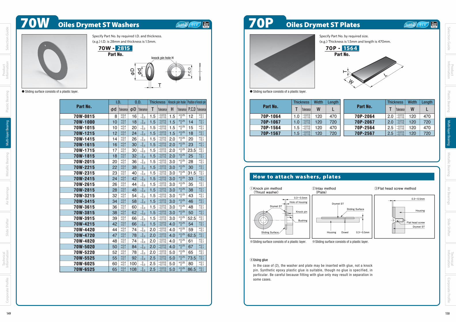
70P Oiles Drymet ST Plates
How to attach washers, plates
Part No.
70P-206470P-206770P-256470P-2567
Thickness
T Tolerance
2.02.02.52.5
Length
L
470720470720
Width
W
120120120120
Part No.
70P-106470P-106770P-156470P-1567
Thickness
T Tolerance
1.01.01.51.5
Length
L
470720470720
Width
W
120120120120
-0.115
-0.115
-0.115
-0.115
-0.015
-0.015
-0.015
-0.015
-0.115
-0.115
-0.115
-0.115
-0.015
-0.015
-0.015
-0.015
①Knock pin method (Thrust washer)
③Flat head screw method②Inlay method (Plate)
0.3~0.5mm
Knock pin
Bushing
Hole of housing
0.3~0.5mmDowelHousing
Drymet STDrymet ST
Sliding Surface
Sliding Surface
④Using glue
In the case of (2), the washer and plate may be inserted with glue, not a knock pin. Synthetic epoxy plastic glue is suitable, though no glue is specified, in particular. Be careful because fitting with glue only may result in separation in some cases.
※Sliding surface consists of a plastic layer. ※Sliding surface consists of a plastic layer.
T
WL
Specify Part No. by required size.
(e.g.) Thickness is 1.5mm and length is 470mm.
70P - 1 564
● Sliding surface consists of a plastic layer.
0.3~0.5mm
Housing
Drymet STFlat head screw
Part No.
150
Selection Guide
ProductInform
ationPlastic Bearing
Multi-layer Bearing
Metallic Bearing
Air Bearings
Technical Inform
ationSlide Shifter
Corporate Profi le
140-183_複層系ベアリング.indd 150 19/11/13 18:25
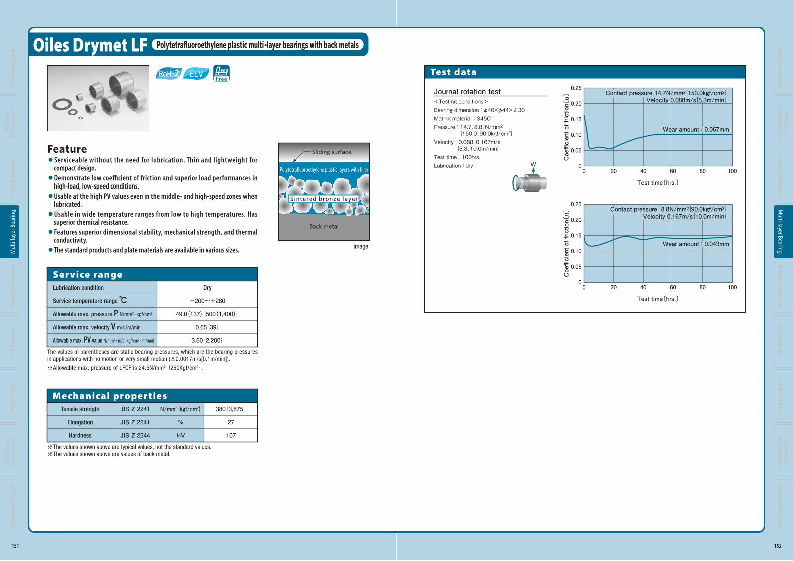
Oiles Drymet LF Polytetrafluoroethylene plastic multi-layer bearings with back metals
Feature●Serviceable without the need for lubrication. Thin and lightweight for
compact design.●Demonstrate low coefficient of friction and superior load performances in
high-load, low-speed conditions.●Usable at the high PV values even in the middle- and high-speed zones when
lubricated.●Usable in wide temperature ranges from low to high temperatures. Has
superior chemical resistance.●Features superior dimensional stability, mechanical strength, and thermal
conductivity.●The standard products and plate materials are available in various sizes.
Ser vice rangeLubrication condition
Service temperature range ℃Allowable max. pressure P N/mm2{kgf/cm2}
Allowable max. velocity V m/s{m/min}
Allowable max. PV value N/mm2・m/s{kgf/cm2・m/min}
Dry
-200~+280
49.0(137){500(1,400)}
0.65{39}
3.60{2,200}
The values in parentheses are static bearing pressures, which are the bearing pressures in applications with no motion or very small motion (≦0.0017m/s[0.1m/min]).
※Allowable max. pressure of LFCF is 24.5N/mm2 {250Kgf/cm2}.
image
Polytetrafluoroethylene plastic layers with filler
Back metal
Sliding surface
Sintered bronze layer
※The values shown above are typical values, not the standard values.※The values shown above are values of back metal.
Tensile strength
Elongation
Hardness
JIS Z 2241
JIS Z 2241
JIS Z 2244
380{3,875}
27
107
Mechanical proper tiesN/mm2{kgf/cm2}
%
HV
151
Sele
ctio
n G
uide
Prod
uct
Info
rmat
ion
Plas
tic B
earin
gM
ulti-
laye
r Bea
ring
Met
allic
Bea
ring
Air
Bear
ings
Tech
nica
l In
form
atio
nSl
ide
Shift
erCo
rpor
ate
Profi
le
140-183_複層系ベアリング.indd 151 19/11/13 18:25
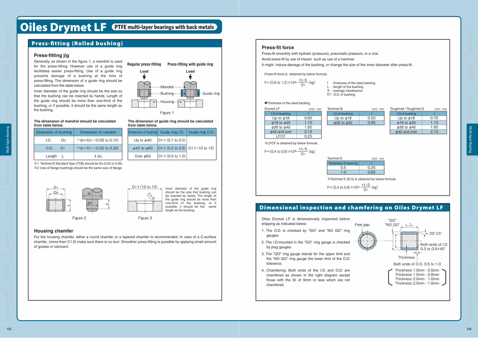
Test data
W
Journal rotation test<Testing conditions>Bearing dimension : φ40×φ44×R30Mating material : S45CPressure : 14.7、8.8、N/mm2 {150.0、90.0kgf/cm2}Velocity : 0.088、0.167m/s {5.3、10.0m/min}Test time : 100hrs.Lubrication : dry
0.25
0.20
0.15
0.10
0.05
0
Coefficient of friction〔μ〕
200 40 8060 100
Test time〔hrs.〕
Contact pressure 8.8N/mm2{90.0kgf/cm2}Velocity 0.167m/s{10.0m/min}
Wear amount : 0.043mm
0.25
0.20
0.15
0.10
0.05
0
Coefficient of friction〔μ〕
200 40 8060 100
Test time〔hrs.〕
Contact pressure 14.7N/mm2{150.0kgf/cm2}Velocity 0.088m/s{5.3m/min}
Wear amount : 0.067mm
152
Selection Guide
ProductInform
ationPlastic Bearing
Multi-layer Bearing
Metallic Bearing
Air Bearings
Technical Inform
ationSlide Shifter
Corporate Profi le
140-183_複層系ベアリング.indd 152 19/11/13 18:25
Press-fitting (Rolled bushing)
Oiles Drymet LF PTFE multi-layer bearings with back metals
Housing chamferFor the housing chamfer, either a round chamfer or a tapered chamfer is recommended. In case of a C-surface
chamfer, (more than C1.0) make sure there is no burr. Smoother press-fitting is possible by applying small amount
of grease or lubricant.
Press-fitting jigGenerally, as shown in the figure 1, a mandrel is used
for the press-fitting. However use of a guide ring
facilitates easier press-fitting. Use of a guide ring
prevents damage of a bushing at the time of
press-fitting, The dimension of a guide ring should be
calculated from the table below.
Inner diameter of the guide ring should be the size so
that the bushing can be inserted by hands. Length of
the guide ring should be more than one-third of the
bushing, or if possible, it should be the same length as the bushing.
Dimension of bushing
I.D. D0
O.D. D1
Length L
Dimension of mandrel
※1d0=D0-(0.05 to 0.10)
※2d1=D1-(0.20 to 0.30)
R≧L
The dimension of mandrel should be calculatedfrom table below.
Load Load
Mandrel
Bushing Guide ring
Housing
Regular press-fitting Press-fitting with guide ringL R
D0
d0
d1D1 D1+(10 to 15)
C1.0
Inner diameter of the guide ring should be the size that bushing can be inserted by hands. The length of the guide ring should be more than one-third of the bushing, or if possible, it should be the same length as the bushing.
The dimension of guide ring should be calculated from table below.
Dimension of bushing
Up to φ40
φ42 to φ60
Over φ65
Guide ring O.D.
D1+(10 to 15)
Guide ring I.D.
D1+(0.1 to 0.3)
D1+(0.2 to 0.5)
D1+(0.5 to 1.0)
〔 〕
Figure 1
Figure 3Figure 2
※1 Techmet B Standard Type (TCB) should be Do-(0.25 to 0.30).
※2 Use of flange bushings should be the same size of flange.
153
Sele
ctio
n G
uide
Prod
uct
Info
rmat
ion
Plas
tic B
earin
gM
ulti-
laye
r Bea
ring
Met
allic
Bea
ring
Air
Bear
ings
Tech
nica
l In
form
atio
nSl
ide
Shift
erCo
rpor
ate
Profi
le
140-183_複層系ベアリング.indd 153 19/11/13 18:25
Dimensional inspec tion and chamfering on Oiles Dr ymet LF
Press-fit forcePress-fit smoothly with hydralic (pressure), pneumatic pressure, or a vice.
Avoid press-fit by use of impact such as use of a hammer.
It might induce damage of the bushing, or change the size of the inner diameter after press-fit.
F=(0.9 to 1.2)×104・ 〔kg〕D1t・L・S
F=(0.4 to 0.8)×104・ 〔kg〕D1t・L・S
: thickness of the steel backing: length of the bushing: average interference : O.D. of bushing
tLSD1
Unit : mm Unit : mm Unit : mm
Oiles Drymet LF is dimensionally inspected before
shipping as indicated below:
1. The O.D. is cheeked by "GO" and "NO GO" ring
gauges.
2. The I.D.mounted in the "GO" ring gauge is checked
by plug gauges.
3. The "GO" ring gauge stands for the upper limit and
the "NO GO" ring gauge the lower limit of the O.D.
tolerance.
4. Chamfering: Both ends of the I.D. and O.D. are
chamfered as shown in the right diagram except
those with the ID of 9mm or less which are not
chamfered.
Free gap“GO”“NO GO”
Thickness
L
20°±5°
Both ends of I.D.0.3 to 0.5×45°
Both ends of O.D. 0.5 to 1.0Thickness 1.0mm : 0.5mmThickness 1.5mm : 0.8mmThickness 2.0mm : 1.0mmThickness 2.5mm : 1.0mm〔 〕〔 〕
0-0.3
Press-fit force is obtained by below formula.
●Thickness of the steel backing
※LFCF is obtained by below formula.
I.D.of bushing
Up to φ18
φ19 to φ25
φ26 to φ40
φ42 and overLFCF
t0.651.151.652.150.25
Drymet LF
I.D.of bushing
Up to φ18
φ19 to φ25
φ26 to φ40
φ42 and over
t0.701.101.602.10
Toughmet / Toughmet D
I.D.of bushing
Up to φ18
φ20 to φ22
t0.500.95
Techmet B
Unit : mmt0.250.65
Techmet E
F=(0.4 to 0.8)×104・ 〔kg〕D1t・L・S
※Techmet E (t0.5) is obtained by below formula.
thickness of bearing
0.51.0
154
Selection Guide
ProductInform
ationPlastic Bearing
Multi-layer Bearing
Metallic Bearing
Air Bearings
Technical Inform
ationSlide Shifter
Corporate Profi le
140-183_複層系ベアリング.indd 154 19/11/13 18:25

LFB Oiles Drymet LF Bushings (I.D. φ3~φ28)
※The joint causes no influences upon rotation of the shaft. Be careful when press-fitting so that the joint is not at the position to which the maximum load is applied.
HousingShaft I.D. O.D.
Size Tolerance φd φD Tolerance
3456789101213141516171819202224252628
-0.034
-0.037
-0.037
-0.037
-0.040
-0.040
-0.040
-0.040
-0.043
-0.043
-0.043
-0.043
-0.043
-0.043
-0.043
-0.046
-0.046
-0.046
-0.046
-0.046
-0.046
-0.046
-0.025
-0.025
-0.025
-0.025
-0.025
-0.025
-0.025
-0.025
-0.025
-0.025
-0.025
-0.025
-0.025
-0.025
-0.025
-0.025
-0.025
-0.025
-0.025
-0.025
-0.025
-0.025
567891011121415161718192022232527283032
567891011121415161718192022232527283032
3456789101213141516171819202224252628
+0.012
+0.012
+0.015
+0.015
+0.015
+0.015
+0.018
+0.018
+0.018
+0.018
+0.018
+0.018
+0.018
+0.021
+0.021
+0.021
+0.021
+0.021
+0.021
+0.021
+0.021
+0.025
0
0
0
0
0
0
0
0
0
0
0
0
0
0
0
0
0
0
0
0
0
0
+0.017
+0.017
+0.025
+0.025
+0.025
+0.025
+0.030
+0.030
+0.030
+0.030
+0.035
+0.035
+0.035
+0.035
+0.040
+0.040
+0.045
+0.045
+0.045
+0.050
+0.050
+0.050
+0.047
+0.047
+0.055
+0.055
+0.055
+0.055
+0.060
+0.060
+0.060
+0.060
+0.065
+0.065
+0.070
+0.070
+0.075
+0.075
+0.080
+0.080
+0.080
+0.085
+0.085
+0.090
43 8765
0303040305030603
0304040405040604
030504050505060507050805
030604060506060607060806090610061206
060707070807
1007
04080508060807080808
10081208130814081508
L
Motiondirection
Bushing
φdφD
joint※
6.3( )
chamfer
Housing
H7
Mating shaft
Sh
aft
0.8( )
※Outer diameter is measrued by exclusive gauge.※The I.D. tolerance after press fitting is for reference only.※I.D. φ30~φ160 are shown on pages 157 to 158.
Length L Tolerance 0-0.3
Specify Part No. by required I.D. and length.
(e.g.) I.D. is 15mm and length is 8mm.
LFB - 1508
SizeH7
Tolerance
thick bushingT
Wall thickness
ToleranceT
1.01.01.01.01.01.01.01.01.01.01.01.01.01.01.01.51.51.51.51.52.02.0
-0.025
-0.025
-0.025
-0.025
-0.025
-0.025
-0.025
-0.025
-0.025
-0.025
-0.025
-0.025
-0.025
-0.025
-0.025
-0.030
-0.030
-0.030
-0.030
-0.030
-0.030
-0.030
0
0
0
0
0
0
0
0
0
0
0
0
0
0
0
0
0
0
0
0
0
0
Part No.
155
Sele
ctio
n G
uide
Prod
uct
Info
rmat
ion
Plas
tic B
earin
gM
ulti-
laye
r Bea
ring
Met
allic
Bea
ring
Air
Bear
ings
Tech
nica
l In
form
atio
nSl
ide
Shift
erCo
rpor
ate
Profi
le
140-183_複層系ベアリング.indd 155 19/11/13 18:25
14 15 16 20 25 30 35
0815
101512151315141515151615171518151915201522152415251526152815
3456789101213141516171819202224252628
061007100810091010101210131014101510161017101810191020102210
2510
061207120812
101212121312141215121612
1812
20122212
2512
2812
1414 1416
102012201320142015201620
18201920202022202420252026202820
15251625
1825
202522252425252526252825
1830
203022302430253026302830
2535
1210
0
0
0
0
0
0
0
0
0
0
0
0
0
0
0
0
0
0
0
0
0
0
+0.062
+0.062
+0.065
+0.065
+0.065
+0.065
+0.068
+0.068
+0.068
+0.068
+0.068
+0.068
+0.068
+0.071
+0.071
+0.081
+0.081
+0.081
+0.081
+0.081
+0.081
+0.085
Length L Tolerance 0-0.3
※Chamfering of inner or outer diameters less than φ10 mm is done only to remove burrs.
a: O.D. chamfering for the bushing I.D. of φ10 or more
b: I.D. chamfering for the bushing I.D. of φ10 or more
a
b
T 1.00.5
2.01.0
1.50.8
T 1.0C0.3
1.5C0.5
2.0C0.5
(mm)
(mm)
I.D.
φd
T(20°±5°)
PTFE with filler
φdφD
a
b
Back metal
L
I.D. toleranceafter press
fitting (reference)
156
Selection Guide
ProductInform
ationPlastic Bearing
Multi-layer Bearing
Metallic Bearing
Air Bearings
Technical Inform
ationSlide Shifter
Corporate Profi le
140-183_複層系ベアリング.indd 156 19/11/13 18:25
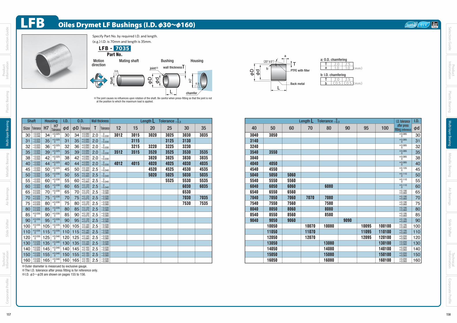
LFB Oiles Drymet LF Bushings (I.D. φ30~φ160)
Housing I.D. O.D.
H7 φd φD Tolerance
30313235384045505560657075808590100110120130140150160
-0.046
-0.050
-0.050
-0.050
-0.050
-0.050
-0.050
-0.050
-0.055
-0.055
+0.005
+0.005
+0.005
+0.005
0
0
0
0
0
-0.005
-0.005
-0.005
-0.005
-0.025
-0.025
-0.025
-0.025
-0.025
-0.025
-0.025
-0.025
-0.025
-0.025
+0.035
+0.035
+0.035
+0.035
+0.035
+0.035
+0.035
+0.035
+0.035
+0.035
+0.035
+0.035
+0.035
34353639424450556065707580859095105115125135145155165
34353639424450556065707580859095105115125135145155165
30313235384045505560657075808590100110120130140150160
+0.025
+0.025
+0.025
+0.025
+0.025
+0.025
+0.025
+0.030
+0.030
+0.030
+0.030
+0.030
+0.030
+0.035
+0.035
+0.035
+0.035
+0.035
+0.040
+0.040
+0.040
+0.040
+0.040
0
0
0
0
0
0
0
0
0
0
0
0
0
0
0
0
0
0
0
0
0
0
0
+0.050
+0.050
+0.050
+0.055
+0.055
+0.055
+0.060
+0.060
+0.065
+0.070
+0.075
+0.075
+0.075
+0.075
+0.075
+0.075
+0.080
+0.080
+0.090
+0.090
+0.100
+0.120
+0.120
+0.090
+0.090
+0.090
+0.095
+0.095
+0.095
+0.100
+0.105
+0.110
+0.120
+0.125
+0.125
+0.130
+0.130
+0.130
+0.130
+0.140
+0.140
+0.145
+0.145
+0.165
+0.185
+0.185
12 15 20 25 30 35
3015311532153515
4015
3012
3512
4012
3020
322035203820402045205020
302531253225352538254025452550255525
3030313032303530383040304530503055306030653070307530
3035
3535383540354535503555356035
70357535
Length L Tolerance 0-0.3
※Outer diameter is measrued by exclusive gauge.※The I.D. tolerance after press fitting is for reference only.※I.D. φ3~φ28 are shown on pages 155 to 156.
Specify Part No. by required I.D. and length.
(e.g.) I.D. is 70mm and length is 35mm.
LFB - 7035
※The joint causes no influences upon rotation of the shaft. Be careful when press-fitting so that the joint is not at the position to which the maximum load is applied.
L
Motiondirection
Bushing
φdφD
joint※
6.3( )
chamfer
Housing
H7
Mating shaft
Sh
aft
0.8( )
wall thicknessT
Shaft
Size ToleranceH7
Tolerance
Wall thickness
ToleranceT
2.02.02.02.02.02.02.52.52.52.52.52.52.52.52.52.52.52.52.52.52.52.52.5
-0.030
-0.030
-0.030
-0.030
-0.030
-0.030
-0.040
-0.040
-0.040
-0.040
-0.080
-0.080
-0.080
-0.080
-0.080
-0.080
-0.080
-0.080
-0.080
-0.080
-0.080
-0.080
-0.080
0
0
0
0
0
0
0
0
0
0
-0.030
-0.030
-0.030
-0.030
-0.030
-0.030
-0.030
-0.030
-0.030
-0.030
-0.030
-0.030
-0.030
Part No.
157
Sele
ctio
n G
uide
Prod
uct
Info
rmat
ion
Plas
tic B
earin
gM
ulti-
laye
r Bea
ring
Met
allic
Bea
ring
Air
Bear
ings
Tech
nica
l In
form
atio
nSl
ide
Shift
erCo
rpor
ate
Profi
le
140-183_複層系ベアリング.indd 157 19/11/13 18:25
40 50 60 70 80 90 95 100
30313235384045505560657075808590100110120130140150160
3040314032403540384040404540504055406040654070407540804085409040
3050
3550
40504550505055506050655070507550805085509050
10050110501205013050140501505016050
506055606060656070607560806085609060
7070
100701107012070
6080
7080758080808580
10080
13080140801508016080
9090100951109512095
100100110100120100130100140100150100160100
0
0
0
0
0
0
0
0
0
0
+0.060
+0.060
+0.060
+0.060
+0.060
+0.060
+0.060
+0.060
+0.060
+0.060
+0.060
+0.060
+0.060
+0.085
+0.085
+0.085
+0.085
+0.085
+0.085
+0.105
+0.110
+0.110
+0.110
+0.190
+0.190
+0.190
+0.195
+0.195
+0.195
+0.195
+0.195
+0.200
+0.200
+0.200
+0.200
+0.200
Length L Tolerance 0-0.3
a: O.D. chamfering
b: I.D. chamfering
a
b
T 2.01.0
2.51.0
T 2.0C0.5
2.5C0.5
(mm)
(mm)
I.D.
φd
I.D. toleranceafter press
fitting (reference)
T(20°±5°)
PTFE with filler
φdφD
a
b
Back metal
L
158
Selection Guide
ProductInform
ationPlastic Bearing
Multi-layer Bearing
Metallic Bearing
Air Bearings
Technical Inform
ationSlide Shifter
Corporate Profi le
140-183_複層系ベアリング.indd 158 19/11/13 18:25

LFF Oiles Drymet LF Flange Bushings
※The joint causes no influences upon rotation of the shaft. Be careful when press-fitting so that the joint is not at the position to which the maximum load is applied.
I.D. O.D. Flange
Toleranceφd φD
34567891012131415161820222425262830313235384045505560
-0.8
-0.8
-0.8
-0.8
-0.8
-0.8
-0.8
-0.8
-0.8
-0.8
-0.8
-0.8
-0.8
-0.8
-0.8
-0.8
-0.8
-0.8
-0.8
-0.8
-0.8
-0.8
-0.8
-0.8
-0.8
-0.8
-0.8
-0.8
-0.8
-0.8
0
0
0
0
0
0
0
0
0
0
0
0
0
0
0
0
0
0
0
0
0
0
0
0
0
0
0
0
0
0
4.65.67 8 9 10 11 12 14 15 16 17 18 20 23 25 27 28 30 32 34 35 36 39 42 44 50 55 60 65
4.65.67 8 9 10 11 12 14 15 16 17 18 20 23 25 27 28 30 32 34 35 36 39 42 44 50 55 60 65
φF
7910121315161820212223242631333536384042454649525460657075
34567891012131415161820222425262830313235384045505560
+0.012
+0.012
+0.015
+0.015
+0.015
+0.015
+0.018
+0.018
+0.018
+0.018
+0.018
+0.018
+0.018
+0.021
+0.021
+0.021
+0.021
+0.021
+0.021
+0.025
+0.025
+0.025
+0.025
+0.025
+0.025
+0.025
+0.025
+0.030
+0.030
+0.030
0
0
0
0
0
0
0
0
0
0
0
0
0
0
0
0
0
0
0
0
0
0
0
0
0
0
0
0
0
0
-0.15
-0.15
-0.15
-0.15
-0.15
-0.15
-0.15
-0.15
-0.15
-0.15
-0.15
-0.15
-0.15
-0.15
-0.15
-0.15
-0.15
-0.15
-0.15
-0.15
-0.15
-0.15
-0.15
-0.15
-0.15
-0.15
-0.15
-0.15
-0.15
-0.15
0
0
0
0
0
0
0
0
0
0
0
0
0
0
0
0
0
0
0
0
0
0
0
0
0
0
0
0
0
0
ToleranceT2
0.80.81.01.01.01.01.01.01.01.01.01.01.01.01.51.51.51.52.02.02.02.02.02.02.02.02.52.52.52.5
-0.034
-0.037
-0.037
-0.037
-0.040
-0.040
-0.040
-0.040
-0.043
-0.043
-0.043
-0.043
-0.043
-0.043
-0.046
-0.046
-0.046
-0.046
-0.046
-0.046
-0.046
-0.050
-0.050
-0.050
-0.050
-0.050
-0.050
-0.050
-0.055
-0.055
-0.025
-0.025
-0.025
-0.025
-0.025
-0.025
-0.025
-0.025
-0.025
-0.025
-0.025
-0.025
-0.025
-0.025
-0.025
-0.025
-0.025
-0.025
-0.025
-0.025
-0.025
-0.025
-0.025
-0.025
-0.025
-0.025
-0.025
-0.025
-0.025
-0.025
6543
030304040504
0305
050506050705
040605060606
0806
10061206
Wall thickness
ToleranceT1
0.80.81.01.01.01.01.01.01.01.01.01.01.01.01.51.51.51.52.02.02.02.02.02.02.02.02.52.52.52.5
-0.025
-0.025
-0.025
-0.025
-0.025
-0.025
-0.025
-0.025
-0.025
-0.025
-0.025
-0.025
-0.025
-0.025
-0.030
-0.030
-0.030
-0.030
-0.030
-0.030
-0.030
-0.030
-0.030
-0.030
-0.030
-0.030
-0.040
-0.040
-0.040
-0.040
0
0
0
0
0
0
0
0
0
0
0
0
0
0
0
0
0
0
0
0
0
0
0
0
0
0
0
0
0
0
Mating shaft Flange bushing
T2
φF
φdφD
ℓ
joint※ T1
6.3( )
chamfer
Motiondirection
Housing
H7
Sh
aft
0.8( )
Length ℓ Tolerance 0-0.3
※Outer diameter is measrued by exclusive gauge.※The I.D. tolerance after press fitting is for reference only.
Specify Part No. by required I.D. and length.
(e.g.) I.D. is 20mm and length is 10mm.
LFF - 2010
Shaft
Size Tolerance
Housing
SizeH7
Tolerance
Part No.
159
Sele
ctio
n G
uide
Prod
uct
Info
rmat
ion
Plas
tic B
earin
gM
ulti-
laye
r Bea
ring
Met
allic
Bea
ring
Air
Bear
ings
Tech
nica
l In
form
atio
nSl
ide
Shift
erCo
rpor
ate
Profi
le
140-183_複層系ベアリング.indd 159 19/11/13 18:25
(mm)
(mm)
34567891012131415161820222425262830313235384045505560
+0.062
+0.062
+0.065
+0.065
+0.065
+0.065
+0.068
+0.068
+0.068
+0.068
+0.068
+0.068
+0.068
+0.071
+0.081
+0.081
+0.081
+0.081
+0.081
+0.085
+0.085
+0.085
+0.085
+0.085
+0.085
+0.085
+0.105
+0.110
+0.110
+0.110
0
0
0
0
0
0
0
0
0
0
0
0
0
0
0
0
0
0
0
0
0
0
0
0
0
0
0
0
0
0
12
07120812
10121212
141215121612181220122212
2512
28123012
3512
4012
7
06070707
10071207
15
10151215131514151515161518152015221524152515261528153015
20
1220
14201520162018202020222024202520262028203020
322035203820402045205020
25
1525162518252025222524252525
3025312532253525
40254525
30
2030
24302530
28303030
32303530383040304530503055306030
40
3040
3540384040404540504055406040
50
3550
40504550
60
506055606060
8
0608
0808
10081208
10
0610071008100910101012101310141015101610181020102210
2510
1.00.5
2.51.0
2.01.0
1.50.8
1.0C0.3
1.5C0.5
2.0C0.5
2.5C0.5
T1
T1
※Chamfering of inner or outer diameters less than φ10 mm is done only to remove burrs.
R0.5 or less
T1
T2
R3.5 or less
ℓ
φdφDφF
(20°±5°)
Length ℓ Tolerance 0-0.3
a
b
a: O.D. chamfering for the bushing I.D. of φ10 or more
b: I.D. chamfering for the bushing I.D. of φ10 or more
a
b
I.D.
φd
I.D. toleranceafter press
fitting (reference)
PTFE with filler
Back metal
160
Selection Guide
ProductInform
ationPlastic Bearing
Multi-layer Bearing
Metallic Bearing
Air Bearings
Technical Inform
ationSlide Shifter
Corporate Profi le
140-183_複層系ベアリング.indd 160 19/11/13 18:25

LFW Oiles Drymet LF Washers
I.D. O.D. Thickness Knock pin hole Position of knock pin
Part No. φd Tolerance φD Tolerance T Tolerance
8101214161820222426283238424852
-0.25
-0.25
-0.25
-0.25
-0.25
-0.25
-0.25
-0.25
-0.25
-0.25
-0.25
-0.25
-0.25
-0.25
-0.25
-0.25
0
0
0
0
0
0
0
0
0
0
0
0
0
0
0
0
16182426303236384244485462667478
1.51.51.51.51.51.51.51.51.51.51.51.51.51.52.02.0
+0.25
+0.25
+0.25
+0.25
+0.25
+0.25
+0.25
+0.25
+0.25
+0.25
+0.25
+0.25
+0.25
+0.25
+0.25
+0.25
0
0
0
0
0
0
0
0
0
0
0
0
0
0
0
0
-0.08
-0.08
-0.08
-0.08
-0.08
-0.08
-0.08
-0.08
-0.08
-0.08
-0.08
-0.08
-0.08
-0.08
-0.08
-0.08
-0.03
-0.03
-0.03
-0.03
-0.03
-0.03
-0.03
-0.03
-0.03
-0.03
-0.03
-0.03
-0.03
-0.03
-0.03
-0.03
H Tolerance P.C.D Tolerance
1 11.52 223 333444444
12141820232528303335384350546165
±0.12
±0.12
±0.12
±0.12
±0.12
±0.12
±0.12
±0.12
±0.12
±0.12
±0.12
±0.12
±0.12
±0.12
±0.12
±0.12
+0.10
+0.10
+0.125
+0.125
+0.125
+0.125
+0.125
+0.125
+0.125
+0.125
+0.125
+0.125
+0.125
+0.125
+0.125
+0.125
+0.30
+0.30
+0.375
+0.375
+0.375
+0.375
+0.375
+0.375
+0.375
+0.375
+0.375
+0.375
+0.375
+0.375
+0.375
+0.375
LFW-0815LFW-1015LFW-1215LFW-1415LFW-1615LFW-1815LFW-2015LFW-2215LFW-2415LFW-2615LFW-2815LFW-3215LFW-3815LFW-4215LFW-4820LFW-5220
T
knock pin hole H
φDφd
Specify Part No. by required I.D. and thickness.
(e.g.) I.D. is 20mm and thickness is 1.5mm.
LFW - 2015
● Sliding surface consists of a plastic layer.
P.C.D
Part No.
161
Sele
ctio
n G
uide
Prod
uct
Info
rmat
ion
Plas
tic B
earin
gM
ulti-
laye
r Bea
ring
Met
allic
Bea
ring
Air
Bear
ings
Tech
nica
l In
form
atio
nSl
ide
Shift
erCo
rpor
ate
Profi
le
140-183_複層系ベアリング.indd 161 19/11/13 18:25
LFCF Oiles Drymet LF (t0.5)
Tolerance of mating shaft
General use, high load e7※1 The degree shown is after press-fitted into the ring gauge of φD +0.055mm.
(the ring gauge of φD+0.060mm is used for the bushings of φ11 or bigger.)
※2 The joint causes no influences upon rotation of the shaft. Be careful when press-fitting so that the joint is not at the position to which the maximum load is applied.
※3 There is no chamfer on LFCF.
R1.0max
T1
T2L
R0.5max
φD110°max ※1
Flange th ickness within 120°range
is max.0.7mm.
φF φd
φd
6
7
8
9
11
13
17
I.D. O.D. Flnage
φd φD Tolerance Tolerance Tolerance Tolerance
5
6
7
8
10
12
16
T2φF
8.5
10
11
12
15
17
21
LFCF-0505
LFCF-0605
LFCF-0705
LFCF-0805
LFCF-1006
LFCF-1206
LFCF-1606
Part No.Thick bushing I.D. tolerance
after pressfitting (reference)
+0.055
+0.055
+0.055
+0.055
+0.060
+0.060
+0.060
+0.025
+0.025
+0.025
+0.025
+0.030
+0.030
+0.030
+0.092
+0.095
+0.095
+0.095
+0.098
+0.098
+0.098
0
0
0
0
0
0
0
+-0.05
0.05
0.05
0.05
0.05
0.05
0.05
+-0.02
0.02
0.02
0.02
0.02
0.02
0.02
5.5
5.5
5.5
5.5
6.5
6.5
6.5
+-
+- +-+-
+- +-+-
+- +-+-
+- +-+-
+- +-+-
+- +-+-
0.5
0.5
0.5
0.5
0.5
0.5
0.5
0.48
0.48
0.48
0.48
0.48
0.48
0.48
T1
0.48
0.48
0.48
0.48
0.48
0.48
0.48
※Outer diameter is measrued by exclusive gauge.※I.D after press-fitted into the housing of φD H7 is reference value.
Specify Part No. by required I.D. and length.
(e.g.) I.D. is 8mm and length is 5.5mm.
Part No.LFCF - 0805
Length L
Tolerance±0.3
6.3( )
chamfer
Housing
H7
Mating shaftMotiondirection
Sh
aft
0.8( )
Feature●This bearing is as thin as 0.5 mm, allowing the user who gives up an
idea to use a bearing in a small space to use it.●The sliding layer made of plastic containing special additives
maintains stable coefficient of friction. It is effective to reduce abnormal noise and wear in applications without bushings.
joint ※2
162
Selection Guide
ProductInform
ationPlastic Bearing
Multi-layer Bearing
Metallic Bearing
Air Bearings
Technical Inform
ationSlide Shifter
Corporate Profi le
140-183_複層系ベアリング.indd 162 19/11/13 18:25
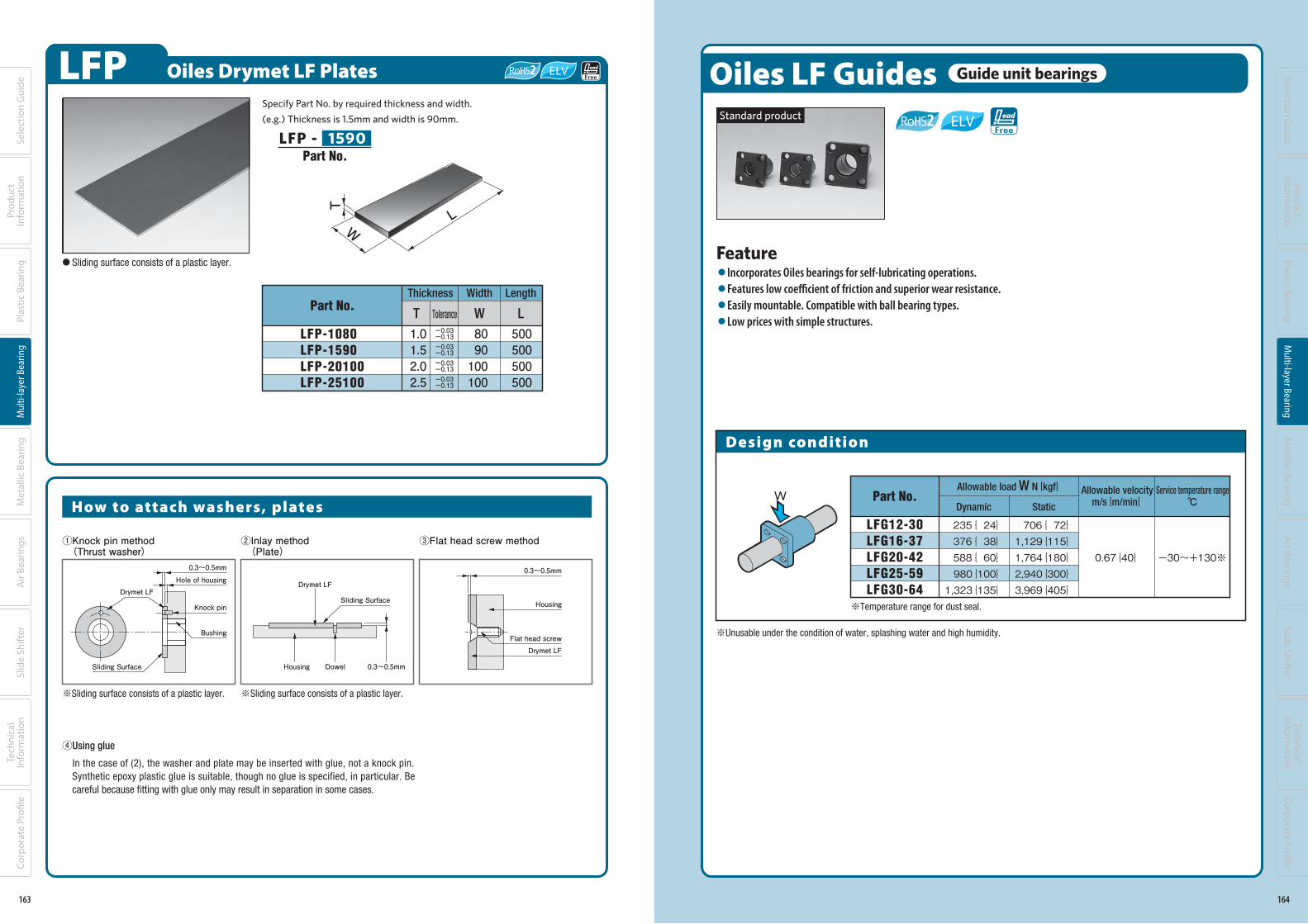
LFP Oiles Drymet LF Plates
Part No.
LFP-1080LFP-1590LFP-20100LFP-25100
Thickness Width
T Tolerance W
1.01.52.02.5
Length
L
500500500500
8090100100
-0.13
-0.13
-0.13
-0.13
-0.03
-0.03
-0.03
-0.03
T
WL
Specify Part No. by required thickness and width.
(e.g.) Thickness is 1.5mm and width is 90mm.
LFP - 1590
● Sliding surface consists of a plastic layer.
①Knock pin method (Thrust washer)
③Flat head screw method②Inlay method (Plate)
0.3~0.5mm
Knock pin
Bushing
Hole of housing
0.3~0.5mmDowelHousing
Drymet LFDrymet LF
Sliding Surface
Sliding Surface
④Using glue
In the case of (2), the washer and plate may be inserted with glue, not a knock pin. Synthetic epoxy plastic glue is suitable, though no glue is specified, in particular. Be careful because fitting with glue only may result in separation in some cases.
※Sliding surface consists of a plastic layer. ※Sliding surface consists of a plastic layer.
0.3~0.5mm
Housing
Drymet LFFlat head screw
How to attach washers, plates
Part No.
163
Sele
ctio
n G
uide
Prod
uct
Info
rmat
ion
Plas
tic B
earin
gM
ulti-
laye
r Bea
ring
Met
allic
Bea
ring
Air
Bear
ings
Tech
nica
l In
form
atio
nSl
ide
Shift
erCo
rpor
ate
Profi
le
140-183_複層系ベアリング.indd 163 19/11/13 18:25
Oiles LF Guides Guide unit bearings
Design condition
Allowable load W N{kgf}Part No.
LFG12-30LFG16-37LFG20-42LFG25-59LFG30-64
235{ 24}376{ 38}588{ 60}980{100}1,323{135}
0.67{40} -30~+130※
StaticDynamic
Allowable velocity
m/s{m/min}Service temperature range
℃
706{ 72}1,129{115}1,764{180}2,940{300}3,969{405}
W
※Temperature range for dust seal.
Feature●Incorporates Oiles bearings for self-lubricating operations.●Features low coefficient of friction and superior wear resistance.●Easily mountable. Compatible with ball bearing types.●Low prices with simple structures.
※Unusable under the condition of water, splashing water and high humidity.
Standard product
164
Selection Guide
ProductInform
ationPlastic Bearing
Multi-layer Bearing
Metallic Bearing
Air Bearings
Technical Inform
ationSlide Shifter
Corporate Profi le
140-183_複層系ベアリング.indd 164 19/11/13 18:25
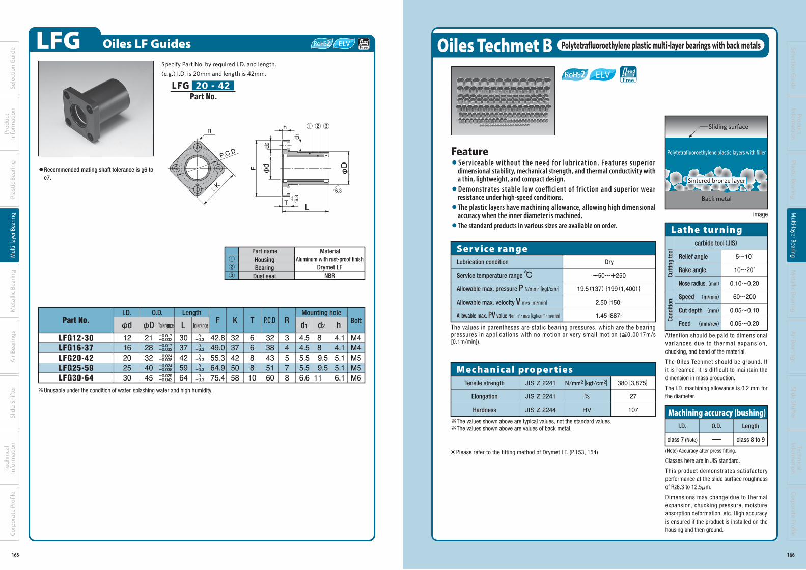
LFG Oiles LF Guides
Mounting hole
Part No.I.D. O.D. Length
φd Tolerance
1216202530
φD L
2128324045
LFG12-30LFG16-37LFG20-42LFG25-59LFG30-64
668810
3037425964
42.849.055.364.975.4
3237425058
3238435160
T RF K
34578
Tolerance
-0.3
-0.3
-0.3
-0.3
-0.3
0
0
0
0
0
P.C.Dd2 hd1
4.54.55.55.56.6
4.14.15.15.16.1
8 8 9.59.511
Bolt
M4M4M5M5M6
-0.032
-0.032
-0.038
-0.038
-0.042
-0.017
-0.017
-0.024
-0.024
-0.029
6.3
6.3
F
d2
d1
φd
φD
h
T
R
P.C.D
□K
① ② ③
L
Specify Part No. by required I.D. and length.
(e.g.) I.D. is 20mm and length is 42mm.
Housing
Bearing
Dust seal
Aluminum with rust-proof finish
Drymet LF
NBR
①②③
MaterialPart name
LFG 20 - 42
●Recommended mating shaft tolerance is g6 to
e7.
Part No.
※Unusable under the condition of water, splashing water and high humidity.
165
Sele
ctio
n G
uide
Prod
uct
Info
rmat
ion
Plas
tic B
earin
gM
ulti-
laye
r Bea
ring
Met
allic
Bea
ring
Air
Bear
ings
Tech
nica
l In
form
atio
nSl
ide
Shift
erCo
rpor
ate
Profi
le
140-183_複層系ベアリング.indd 165 19/11/13 18:25
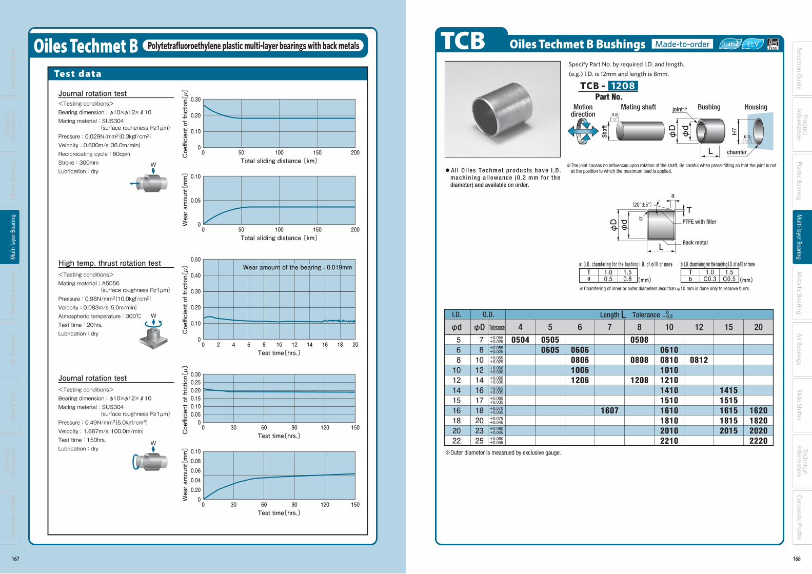
Oiles Techmet B Polytetrafluoroethylene plastic multi-layer bearings with back metals
Ser vice rangeLubrication condition
Service temperature range ℃Allowable max. pressure P N/mm2{kgf/cm2}
Allowable max. velocity V m/s{m/min}
Allowable max. PV value N/mm2・m/s{kgf/cm2・m/min}
Dry
-50~+250
19.5(137){199(1,400)}
2.50{150}
1.45{887}
Relief angle
Rake angle
Nose radius, (mm)
Speed (m/min)
Cut depth (mm)
Feed (mm/rev)
carbide tool(JIS)
5~10゜
10~20゜
0.10~0.20
60~200
0.05~0.10
0.05~0.20
Lathe turning
Cu
ttin
g t
ool
Con
dit
ion
I.D.
class 7 (Note)
O.D.
-
Length
class 8 to 9
Machining accuracy (bushing)
The values in parentheses are static bearing pressures, which are the bearing pressures in applications with no motion or very small motion (≦0.0017m/s[0.1m/min]).
(Note) Accuracy after press fitting.
Classes here are in JIS standard.
This product demonstrates satisfactory performance at the slide surface roughness of Rz6.3 to 12.5μm.
Dimensions may change due to thermal expansion, chucking pressure, moisture absorption deformation, etc. High accuracy is ensured if the product is installed on the housing and then ground.
Attention should be paid to dimensional var iances due to thermal expansion, chucking, and bend of the material.
The Oiles Techmet should be ground. If it is reamed, it is difficult to maintain the dimension in mass production.
The I.D. machining allowance is 0.2 mm for the diameter.
Polytetrafluoroethylene plastic layers with filler
Back metal
Sintered bronze layer
image
Sliding surface
※The values shown above are typical values, not the standard values.※The values shown above are values of back metal.
Tensile strength
Elongation
Hardness
JIS Z 2241
JIS Z 2241
JIS Z 2244
380{3,875}
27
107
Mechanical proper tiesN/mm2{kgf/cm2}
%
HV
Feature ●Ser viceable without the need for lubrication. Features superior
dimensional stability, mechanical strength, and thermal conductivity with a thin, lightweight, and compact design.●Demonstrates stable low coefficient of friction and superior wear
resistance under high-speed conditions.●The plastic layers have machining allowance, allowing high dimensional
accuracy when the inner diameter is machined.●The standard products in various sizes are available on order.
Please refer to the fitting method of Drymet LF. (P.153, 154)
166
Selection Guide
ProductInform
ationPlastic Bearing
Multi-layer Bearing
Metallic Bearing
Air Bearings
Technical Inform
ationSlide Shifter
Corporate Profi le
140-183_複層系ベアリング.indd 166 19/11/13 18:25
Oiles Techmet B Polytetrafluoroethylene plastic multi-layer bearings with back metals
Test data
W
W
W
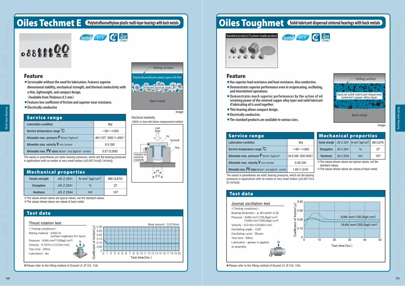
Journal rotation test<Testing conditions>Bearing dimension : φ10×φ12×R10Mating material : SUS304 (surface rouheness Rz1μm)Pressure : 0.029N/mm2{0.3kgf/cm2}Velocity : 0.600m/s{36.0m/min}Reciprocating cycle : 60cpmStroke : 300mmLubrication : dry
High temp. thrust rotation test<Testing conditions>Mating material : A5056 (surface roughness Rz1μm)Pressure : 0.98N/mm2{10.0kgf/cm2}Velocity : 0.083m/s{5.0m/min}Atmospheric temperature : 300℃Test time : 20hrs.Lubrication : dry
0.50
0.40
0.30
0.20
0.10
0
Coefficient of friction〔μ〕
20 4 181614121086 20Test time〔hrs.〕
Wear amount of the bearing : 0.019mm
Journal rotation test<Testing conditions>Bearing dimension : φ10×φ12×R10Mating material : SUS304 (surface roughness Rz1μm)Pressure : 0.49N/mm2{5.0kgf/cm2}Velocity : 1.667m/s{100.0m/min}Test time : 150hrs.Lubrication : dry
0.30
0.20
0.10
0
Coefficient of friction〔μ〕
500 100 150 200Total sliding distance 〔km〕
50 100 150 200
0.10
0.05
0 Wear amount〔mm〕
0Total sliding distance 〔km〕
30 60 15012090
0.100.080.060.040.200 W
ear amount〔mm〕
0Test time〔hrs.〕
0.300.250.200.150.100.050
Coefficient of friction〔μ〕
300 60 15012090Test time〔hrs.〕
167
Sele
ctio
n G
uide
Prod
uct
Info
rmat
ion
Plas
tic B
earin
gM
ulti-
laye
r Bea
ring
Met
allic
Bea
ring
Air
Bear
ings
Tech
nica
l In
form
atio
nSl
ide
Shift
erCo
rpor
ate
Profi
le
140-183_複層系ベアリング.indd 167 19/11/13 18:25
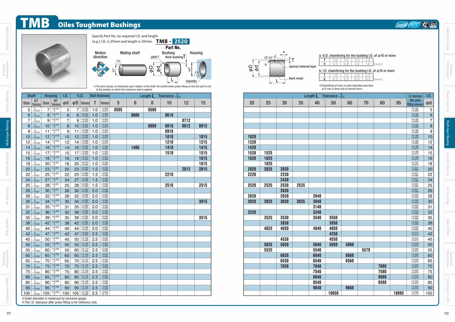
TCB Oiles Techmet B Bushings Made-to-order
I.D. O.D.
φd φD 54 151210876 20
5681012141516182022
78101214161718202325
0504 05050605 0606
080610061206
1607
0508
0808
1208
0610081010101210141015101610181020102210
0812
1620182020202220
14151515161518152015
●Al l O i l es Techmet p roduc ts have I .D .
machin ing a l lowance (0 .2 mm for the
diameter) and available on order.
※The joint causes no influences upon rotation of the shaft. Be careful when press-fitting so that the joint is not at the position to which the maximum load is applied.
※Chamfering of inner or outer diameters less than φ10 mm is done only to remove burrs.
T 1.0C0.3
1.5C0.5(mm)
T 1.00.5
1.50.8 (mm)
T(20°±5°)
PTFE with filler
φdφD
L
L
Bushing
φdφD
joint※
6.3( )
chamfer
Motiondirection
Mating shaft Housing
H7
Sh
aft
0.8( )
Length L Tolerance 0-0.3
a
b
a b
Specify Part No. by required I.D. and length.
(e.g.) I.D. is 12mm and length is 8mm.
TCB - 1208
Tolerance
+0.055
+0.055
+0.055
+0.060
+0.060
+0.065
+0.065
+0.070
+0.075
+0.080
+0.080
+0.025
+0.025
+0.025
+0.030
+0.030
+0.035
+0.035
+0.035
+0.040
+0.045
+0.045
a: O.D. chamfer ing for the bushing I .D. of φ10 or more b: I.D. chamfering for the bushing I.D. of φ10 or more
Back metal
Part No.
※Outer diameter is measrued by exclusive gauge.
168
Selection Guide
ProductInform
ationPlastic Bearing
Multi-layer Bearing
Metallic Bearing
Air Bearings
Technical Inform
ationSlide Shifter
Corporate Profi le
140-183_複層系ベアリング.indd 168 19/11/13 18:25
Oiles Techmet E Polytetrafluoroethylene plastic multi-layer bearings with back metals
Feature●Serviceable without the need for lubrication. Features superior dimensional stability, mechanical strength, and thermal conductivity with a thin, lightweight, and compact design. (Available from Thickness 0.5 mm)●Features low coefficient of friction and superior wear resistance.●Electrically conductive
※The values shown above are typical values, not the standard values.※The values shown above are values of back metal.
Tensile strength
Elongation
Hardness
JIS Z 2241
JIS Z 2241
JIS Z 2244
380{3,875}
27
107
Mechanical proper tiesN/mm2{kgf/cm2}
%
HV
Electrical resistivity1000Ω or less with below measurement method
試験データ
Ring
TechmetE
Load20kgf
Pin
Indicator for electrical resistivity
φ8
φ10
Sintered bronze layer
Back metal
Polytetrafluoroethylene plastic layers with filter
image
Please refer to the fitting method of Drymet LF. (P.153, 154)
Sliding surface
The values in parentheses are static bearing pressures, which are the bearing pressures in applications with no motion or very small motion (≦0.0017m/s[0.1m/min]).
Ser vice rangeLubrication condition
Service temperature range ℃Allowable max. pressure P N/mm2{kgf/cm2}
Allowable max. velocity V m/s{m/min}
Allowable max. PV value N/mm2・m/s{kgf/cm2・m/min}
Dry
-50~+250
49(137){500(1,400)}
0.5{30}
3.27{2,000}
0.300.250.200.150.100.050
Coefficient of friction〔μ〕
0 1 2 3 4 5 6 7 8 9 10 11 12 13 14 15 16 17 18 19 20Test time〔hrs.〕
Wear amount : 0.015mm
Test data
N
Thrust rotation test<Testing conditions>Mating material : S45C-N
(surface roughness Rz1.6μm)Pressure : 9.8N/mm2{100kgf/cm2}Velocity : 0.167m/s{10.0m/min}Test time : 20hrsLubrication : dry
169
Sele
ctio
n G
uide
Prod
uct
Info
rmat
ion
Plas
tic B
earin
gM
ulti-
laye
r Bea
ring
Met
allic
Bea
ring
Air
Bear
ings
Tech
nica
l In
form
atio
nSl
ide
Shift
erCo
rpor
ate
Profi
le
140-183_複層系ベアリング.indd 169 19/11/13 18:25
Oiles Toughmet Solid-lubricant dispersed sintered bearings with back metals
Feature●Has superior load resistance and heat resistance. Also conductive.●Demonstrates superior performance even in reciprocating, oscillating,
and intermittent operations.●Demonstrates much superior performances by the action of oil
retaining power of the sintered copper alloy layer and solid lubricant if lubricating oil is used together.●Thin bearing allows compact design.●Electrically conductive.●The standard products are available in various sizes.
Test data
Ser vice rangeLubrication condition
Service temperature range ℃Allowable max. pressure P N/mm2{kgf/cm2}
Allowable max. velocity V m/s{m/min}
Allowable max. PV value N/mm2・m/s{kgf/cm2・m/min}
Dry
-40~+350
24.5(49){250(500)}
0.40{24}
1.65{1,010}
The values in parentheses are static bearing pressures, which are the bearing pressures in applications with no motion or very small motion (≦0.0017m/s[0.1m/min]).
※The values shown above are typical values, not the standard values.※The values shown above are values of back metal.
Tensile strength
Elongation
Hardness
JIS Z 2241
JIS Z 2241
JIS Z 2244
380{3,875}
27
107
Mechanical proper tiesN/mm2{kgf/cm2}
%
HV
W
Back metal
image
Sliding surface
Special solid-lubricant dispersedsintered copper alloy layer
Journal oscillation test<Testing conditions>Bearing dimension : φ 40×φ44×R30Pressure : 9.8N/mm2{100.0kgf/cm2} 19.6N/mm2{200.0kgf/cm2}Velocity : 0.014m/s{0.84m/min}Oscillating angle : ±20°Oscillating cycle : 30cpmTest time : 50hrs. Lubrication : grease is applled at assembly.
0.40
0.30
0.20
0.10
0Coefficient of friction〔μ〕
100 20 30 40 50
Test time〔hrs.〕
19.6N/mm2{200.0kgf/cm2}
9.8N/mm2{100.0kgf/cm2}
Please refer to the fitting method of Drymet LF. (P.153, 154)
Standard product/Custom-made product
170
Selection Guide
ProductInform
ationPlastic Bearing
Multi-layer Bearing
Metallic Bearing
Air Bearings
Technical Inform
ationSlide Shifter
Corporate Profi le
140-183_複層系ベアリング.indd 170 19/11/13 18:25
TMB Oiles Toughmet Bushings
Shaft Housing I.D. O.D.
Size Size φd φD Tolerance
Wall thickness
T Tolerance
567891012141516182022242526283031323538404245505560657075808590100
-0.012
-0.012
-0.015
-0.015
-0.015
-0.015
-0.018
-0.018
-0.018
-0.018
-0.018
-0.021
-0.021
-0.021
-0.021
-0.021
-0.021
-0.021
-0.025
-0.025
-0.025
-0.025
-0.025
-0.025
-0.025
-0.025
-0.030
-0.030
-0.030
-0.030
-0.030
-0.030
-0.035
-0.035
-0.035
0
0
0
0
0
0
0
0
0
0
0
0
0
0
0
0
0
0
0
0
0
0
0
0
0
0
0
0
0
0
0
0
0
0
0
78910111214161718202325272830323435363942444750556065707580859095105
78910111214161718202325272830323435363942444750556065707580859095105
567891012141516182022242526283031323538404245505560657075808590100
+0.015
+0.015
+0.015
+0.015
+0.018
+0.018
+0.018
+0.018
+0.018
+0.018
+0.021
+0.021
+0.021
+0.021
+0.021
+0.021
+0.025
+0.025
+0.025
+0.025
+0.025
+0.025
+0.025
+0.025
+0.025
+0.030
+0.030
+0.030
+0.030
+0.030
+0.030
+0.035
+0.035
+0.035
+0.035
0
0
0
0
0
0
0
0
0
0
0
0
0
0
0
0
0
0
0
0
0
0
0
0
0
0
0
0
0
0
0
0
0
0
0
+0.025
+0.025
+0.025
+0.025
+0.030
+0.030
+0.030
+0.035
+0.035
+0.035
+0.040
+0.045
+0.045
+0.045
+0.050
+0.050
+0.050
+0.050
+0.050
+0.050
+0.055
+0.055
+0.055
+0.055
+0.060
+0.060
+0.065
+0.070
+0.075
+0.075
+0.075
+0.075
+0.075
+0.075
+0.080
+0.055
+0.055
+0.055
+0.055
+0.060
+0.060
+0.060
+0.065
+0.065
+0.070
+0.075
+0.080
+0.080
+0.080
+0.085
+0.085
+0.090
+0.090
+0.090
+0.090
+0.095
+0.095
+0.095
+0.095
+0.100
+0.105
+0.110
+0.120
+0.125
+0.125
+0.130
+0.130
+0.130
+0.130
+0.140
1.01.01.01.01.01.01.01.01.01.01.01.51.51.51.52.02.02.02.02.02.02.02.02.52.52.52.52.52.52.52.52.52.52.52.5
-0.075
-0.075
-0.075
-0.075
-0.075
-0.075
-0.075
-0.085
-0.085
-0.085
-0.085
-0.090
-0.090
-0.090
-0.090
-0.090
-0.090
-0.090
-0.090
-0.090
-0.090
-0.090
-0.090
-0.095
-0.095
-0.095
-0.095
-0.095
-0.095
-0.095
-0.095
-0.095
-0.095
-0.095
-0.115
-0.030
-0.030
-0.030
-0.030
-0.030
-0.030
-0.030
-0.035
-0.035
-0.035
-0.035
-0.030
-0.030
-0.030
-0.030
-0.030
-0.030
-0.030
-0.030
-0.030
-0.030
-0.030
-0.030
-0.035
-0.035
-0.035
-0.035
-0.035
-0.035
-0.035
-0.035
-0.035
-0.035
-0.035
-0.055
5
05056
0606
1406
8
0508
0808
10
0610
081009101010121014101510
2210
2510
12
07120812
2012
15
0815
1015121514151515161518152015
2515
3015
3515
Length L Tolerance 0-0.3
※Outer diameter is measrued by exclusive gauge.※The I.D. tolerance after press fitting is for reference only.
Specify Part No. by required I.D. and length.
(e.g.) I.D. is 25mm and length is 20mm. TMB - 2520
h7Tolerance
H7Tolerance
※The joint causes no influences upon rotation of the shaft. Be careful when press-fitting so that the joint is not at the position to which the maximum load is applied.
L
Motiondirection
Bushing
φdφD
joint※
6.3( )
chamfer
Housing
H7
Mating shaft
h7
0.8( )
thick bushingT
Part No.
171
Sele
ctio
n G
uide
Prod
uct
Info
rmat
ion
Plas
tic B
earin
gM
ulti-
laye
r Bea
ring
Met
allic
Bea
ring
Air
Bear
ings
Tech
nica
l In
form
atio
nSl
ide
Shift
erCo
rpor
ate
Profi
le
140-183_複層系ベアリング.indd 171 19/11/13 18:25
※Chamfering of inner or outer diameters less than φ10 mm is done only to remove burrs.
20
10201220142015201620
20202220
2520
28203020
3220
35
2535
3035
30
2030223024302530263028303030
353038304030
45305030
603065307030
40
28403040314032403540
4040
504055406040654070407540804085409040
50
355038504050425045505050
10050
60
5060
60606560
9060
70
5570
80
7080758080808580
95
10095
567891012141516182022242526283031323538404245505560657075808590100
1525162518252025
2525
3025
3525
4025
50255525
25+0.165
+0.165
+0.165
+0.165
+0.168
+0.168
+0.168
+0.188
+0.188
+0.188
+0.191
+0.201
+0.201
+0.201
+0.201
+0.201
+0.205
+0.205
+0.205
+0.205
+0.205
+0.205
+0.205
+0.215
+0.215
+0.220
+0.220
+0.220
+0.220
+0.220
+0.220
+0.225
+0.225
+0.225
+0.265
+0.060
+0.060
+0.060
+0.060
+0.060
+0.060
+0.060
+0.070
+0.070
+0.070
+0.070
+0.060
+0.060
+0.060
+0.060
+0.060
+0.060
+0.060
+0.060
+0.060
+0.060
+0.060
+0.060
+0.070
+0.070
+0.070
+0.070
+0.070
+0.070
+0.070
+0.070
+0.070
+0.070
+0.070
+0.110
T20°±5°
Special sintered layer
φdφD
L
a: O.D. chamfering for the bushing I.D. of φ10 or more
b: I.D. chamfering for the bushing I.D. of φ10 or more
a
b
T 1.00.5
2.51.0
2.01.0
1.50.8
T 1.00.3
1.50.5
2.00.5
2.50.5
(mm)
(mm)
Length L Tolerance 0-0.3
a
b
I.D.
φd
I.D. toleranceafter press
fitting (reference)
Back metal
172
Selection Guide
ProductInform
ationPlastic Bearing
Multi-layer Bearing
Metallic Bearing
Air Bearings
Technical Inform
ationSlide Shifter
Corporate Profi le
140-183_複層系ベアリング.indd 172 19/11/13 18:25

Oiles Toughmet D Sintered bronze bearings consisting of a steel backand uniformly dispersed wear resistant lubricants.
Features●Superior durability and stable low coefficient of friction where lubrication is
present.●Able to handle reciprocating, oscillating, and intermittent motion where oil
film is difficult to be formed.●Thin walled configuration for compact design.●Dramatically reduces lubrication intervals.●Possesses high load carrying capacity, wear resistance, and seize resistance.●Electric coductivity.●Available in various standard and custom sizes.
Ser vice rangeLubrication condition
Service temperature range ℃Allowable max. pressure P N/mm2{kgf/cm2}
Allowable max. velocity V m/s{m/min}
Allowable max. PV value N/mm2・m/s{kgf/cm2・m/min}
Periodical lubrication
1.00{60}
3.26{2,000}
The values in parentheses are static bearing pressures, which are the bearing pressures in applications with no motion or very small motion (≦0.0017m/s[0.1m/min]).
Oil lubrication
5.00{300}
4.89{3,000}
-40~+150
50(100){510(1,020)}
Please refer to the fitting method of Drymet LF. (P.153, 154)
Back metal
image
Sliding surfaceDimples
Wear resistant lubricants dispersed sintered bronze layer
※Value here is typical value, not standard.※Above value indicates the value of back metal.
Tensile strength
Elongation
Hardness
JIS Z 2241
JIS Z 2241
JIS Z 2244
380{3,875}
27
107
Mechanical proper tiesN/mm2{kgf/cm2}
%
HV
173
Sele
ctio
n G
uide
Prod
uct
Info
rmat
ion
Plas
tic B
earin
gM
ulti-
laye
r Bea
ring
Met
allic
Bea
ring
Air
Bear
ings
Tech
nica
l In
form
atio
nSl
ide
Shift
erCo
rpor
ate
Profi
le
140-183_複層系ベアリング.indd 173 19/11/13 18:25
Test aborted after 31 hours
Test data
W
W
W
0.50.450.40.350.30.250.20.150.10.050
100 20 30 40 50Coefficient of friction〔μ〕
Testing time〔hrs〕
Test aborted after 31 hours
CAC603(LBC3)
CAC406(BC6)
Toughmet D
0.050 0.150.1 500.2
Wear amount〔mm〕
CAC603(LBC3)
CAC406(BC6)
Toughmet D 0.026
0.045
0.062 Test aborted after 31 hours
0.020 0.060.04 0.10.08
Wear amount〔mm〕
CAC603(LBC3)
CAC406(BC6)
Toughmet D 0.009
0.046
0.089
0.5
0.4
0.3
0.2
0.1
0200 40 60 80 100C
oefficient of friction〔μ〕
Testing time〔hrs〕
CAC603(LBC3)
CAC406(BC6)
Toughmet D
0.50.450.40.350.30.250.20.150.10.050
100 20 30 40 50Coefficient of friction〔μ〕
Testing time〔hrs〕
Test aborted after 42 hours
CAC603(LBC3)
CAC406(BC6)
Toughmet D
Wear amount 0.024
Wear0.196
Wear0.037
Journal rotation test<Testing conditions>Bearing material : ○CAC603(LBC3) ○CAC406(BC6) ○Toughmet DMating material : S45CPressure : 20N/mm2{203.9kgf/cm2}Velocity : 0.84×10⁻²m/s{0.5m/min}Testing time : 50hrsLubrication : Grease is applied during assembling
Journal oscillation test<Testing conditions>Bearing material : ○CAC603(LBC3) ○CAC406(BC6) ○Toughmet DMating material : S45CPressure : 30N/mm2{305.9kgf/cm2}Velocity : 0.841×10⁻²m/s{0.5m/min}Oscillationcycles : 8cpmOscillation angle : ±45°{90°}Testing time : 50hrsLubrication : Grease is applied during assembling
Journal oscillation test<Testing conditions>Bearing material : ○CAC603(LBC3) ○CAC406(BC6) ○Toughmet DMating material : S45CPressure : 20N/mm2{203.9kgf/cm2}Velocity : 1.68×10⁻²m/s{1.0m/min}Oscillationcycles : 16cpmOscillation angle : 90°Testing time : 100hrsLubrication : Periodical lubrication {3cc/hr}
174
Selection Guide
ProductInform
ationPlastic Bearing
Multi-layer Bearing
Metallic Bearing
Air Bearings
Technical Inform
ationSlide Shifter
Corporate Profi le
140-183_複層系ベアリング.indd 174 19/11/13 18:25
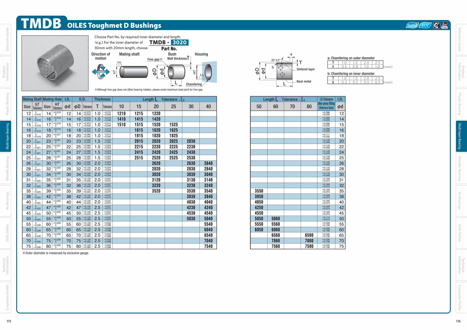
TMDB OILES Toughmet D Bushings
Mating Shaft Mating Hole I.D. O.D.
Size Size φd φD Tolerance
Thickness
T Tolerance
12141516182022242526283031323538404245505560657075
-0.018
-0.018
-0.018
-0.018
-0.018
-0.021
-0.021
-0.021
-0.021
-0.021
-0.021
-0.021
-0.025
-0.025
-0.025
-0.025
-0.025
-0.025
-0.025
-0.025
-0.030
-0.030
-0.030
-0.030
-0.030
0
0
0
0
0
0
0
0
0
0
0
0
0
0
0
0
0
0
0
0
0
0
0
0
0
14161718202325272830323435363942444750556065707580
14161718202325272830323435363942444750556065707580
12141516182022242526283031323538404245505560657075
+0.018
+0.018
+0.018
+0.018
+0.021
+0.021
+0.021
+0.021
+0.021
+0.021
+0.025
+0.025
+0.025
+0.025
+0.025
+0.025
+0.025
+0.025
+0.025
+0.030
+0.030
+0.030
+0.030
+0.030
+0.030
+0.035
+0.035
+0.035
+0.035
+0.045
+0.045
+0.045
+0.045
+0.045
+0.045
+0.055
+0.055
+0.055
+0.055
+0.055
+0.055
+0.055
+0.055
+0.055
+0.060
+0.060
+0.060
+0.060
+0.060
+0.060
+0.070
+0.070
+0.070
+0.070
+0.085
+0.085
+0.085
+0.085
+0.085
+0.085
+0.105
+0.105
+0.105
+0.105
+0.105
+0.105
+0.105
+0.105
+0.105
+0.120
+0.120
+0.120
+0.120
+0.120
+0.120
1.01.01.01.01.01.51.51.51.52.02.02.02.02.02.02.02.02.52.52.52.52.52.52.52.5
-0.040
-0.040
-0.040
-0.040
-0.045
-0.054
-0.054
-0.054
-0.054
-0.054
-0.054
-0.054
-0.072
-0.072
-0.072
-0.072
-0.072
-0.072
-0.072
-0.072
-0.098
-0.098
-0.098
-0.098
-0.098
-0.015
-0.015
-0.015
-0.015
-0.015
-0.024
-0.024
-0.024
-0.024
-0.024
-0.024
-0.024
-0.037
-0.037
-0.037
-0.037
-0.037
-0.037
-0.037
-0.037
-0.053
-0.053
-0.053
-0.053
-0.053
10
121014101510
15
121514151515161518152015221524152515
20
122014201520162018202020222024202520262028203020312032203520
25
1525162518252025222524252525
30
203022302430253026302830303031303230353038304030423045305030
40
2640284030403140324035403840404042404540504055406040654070407540
Length L Tolerance 0-0.3
Choose Part No. by required inner diameter and length.(e.g.) For the inner diameter of
30mm with 20mm length, chooseTMDB - 3020
h7Tolerance
H7Tolerance
※Although free gap does not affect bearing rotation, please avoid maximum load point for free gap.
L
Direction ofmotion
Bush
φdφD
Free gap※
6.3( )
Chamfering
Housing
H7
Mating shaft
h7
0.8( )
Wall thicknessT
0
0
0
0
0
0
0
0
0
0
0
0
0
0
0
0
0
0
0
0
0
0
0
0
0
Part No.
※Outer diameter is measrued by exclusive gauge.
175
Sele
ctio
n G
uide
Prod
uct
Info
rmat
ion
Plas
tic B
earin
gM
ulti-
laye
r Bea
ring
Met
allic
Bea
ring
Air
Bear
ings
Tech
nica
l In
form
atio
nSl
ide
Shift
erCo
rpor
ate
Profi
le
140-183_複層系ベアリング.indd 175 19/11/13 18:25
7060
506055606060656070607560
80
658070807580
12141516182022242526283031323538404245505560657075
35503850405042504550505055506050
50+0.098
+0.098
+0.098
+0.098
+0.111
+0.129
+0.129
+0.129
+0.129
+0.129
+0.133
+0.133
+0.169
+0.169
+0.169
+0.169
+0.169
+0.169
+0.169
+0.174
+0.226
+0.226
+0.226
+0.226
+0.226
+0.030
+0.030
+0.030
+0.030
+0.030
+0.048
+0.048
+0.048
+0.048
+0.048
+0.048
+0.048
+0.074
+0.074
+0.074
+0.074
+0.074
+0.074
+0.074
+0.074
+0.106
+0.106
+0.106
+0.106
+0.106
T20°±5°
Sintered layer
φdφD
L
a: Chamfering on outer diameter
b: Chamfering on inner diameter
a
b
T 1.00.5
2.51.0
2.01.0
1.50.8
T 1.00.3
1.50.5
2.00.5
2.50.5
(mm)
(mm)
Length L Tolerance 0-0.3
a
b
I.D.
φd
I.D.Toleranceafter press fitting(Reference Value)
Back metal
176
Selection Guide
ProductInform
ationPlastic Bearing
Multi-layer Bearing
Metallic Bearing
Air Bearings
Technical Inform
ationSlide Shifter
Corporate Profi le
140-183_複層系ベアリング.indd 176 19/11/13 18:25
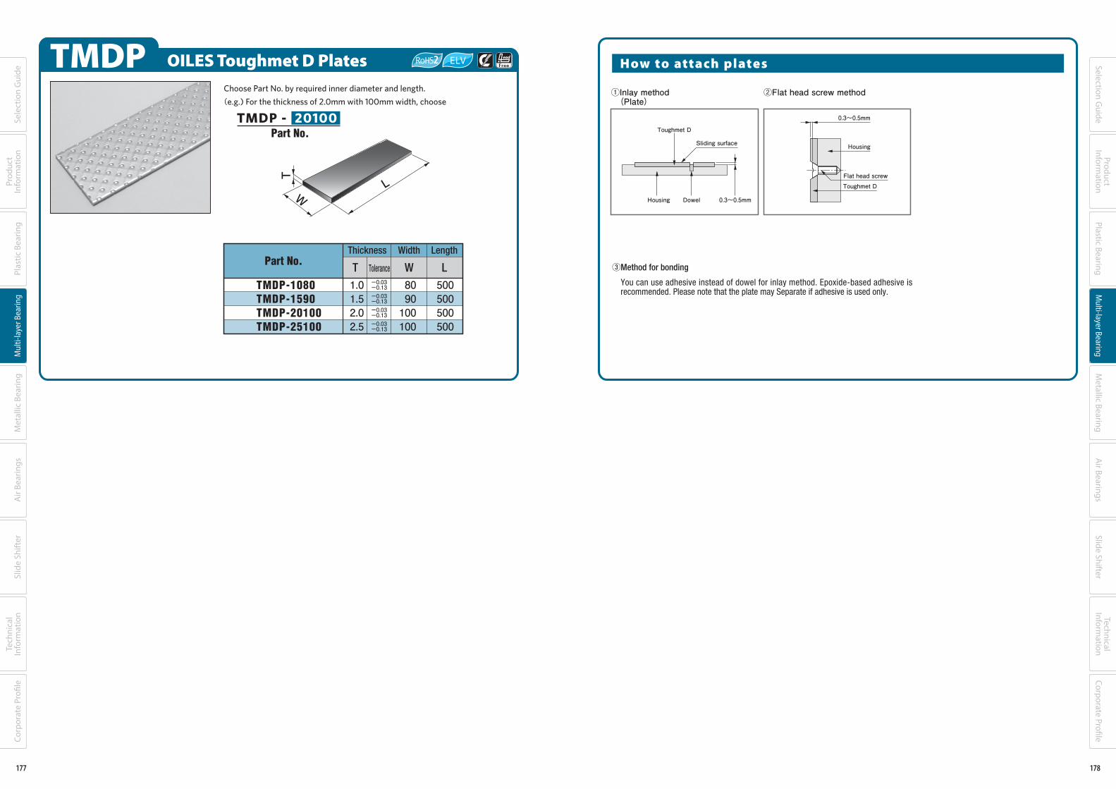
TMDP OILES Toughmet D Plates
Part No.
TMDP-1080TMDP-1590TMDP-20100TMDP-25100
Thickness Width
T Tolerance W
1.01.52.02.5
Length
L
500500500500
8090100100
-0.13
-0.13
-0.13
-0.13
-0.03
-0.03
-0.03
-0.03
T
WL
Choose Part No. by required inner diameter and length.
(e.g.) For the thickness of 2.0mm with 100mm width, choose
TMDP - 20100Part No.
177
Sele
ctio
n G
uide
Prod
uct
Info
rmat
ion
Plas
tic B
earin
gM
ulti-
laye
r Bea
ring
Met
allic
Bea
ring
Air
Bear
ings
Tech
nica
l In
form
atio
nSl
ide
Shift
erCo
rpor
ate
Profi
le
140-183_複層系ベアリング.indd 177 19/11/13 18:25
②Flat head screw method①Inlay method (Plate)
0.3~0.5mmDowelHousing
Toughmet D
Sliding surface
③Method for bonding
You can use adhesive instead of dowel for inlay method. Epoxide-based adhesive is recommended. Please note that the plate may Separate if adhesive is used only.
0.3~0.5mm
Housing
Toughmet DFlat head screw
How to attach plates
178
Selection Guide
ProductInform
ationPlastic Bearing
Multi-layer Bearing
Metallic Bearing
Air Bearings
Technical Inform
ationSlide Shifter
Corporate Profi le
140-183_複層系ベアリング.indd 178 19/11/13 18:25

Oiles Hiplast N/E Metallic mesh polytetrafluoroethylene plastic composite bearings
Feature●Serviceable without the need for lubrication. Features superior load
resistance and wear resistance. As thin as 0.5 mm, allowing for a compact design.
●Features superior chemical and heat resistance.●Special mounting method unique to the Hiplast series allows zero
clearance. (Backlash prevention)●Metallic mesh offers lower thermal expansion coefficient and higher
thermal conductivity than plastic bearings.●Press-formed and available in intended forms.●The conductive grade Hiplast E is available when electric conductivity is
required.
※The values shown above are typical values, not the standard values.
Tensile strength
Elongation
JIS K 7113
34.3{350}
30
Mechanical proper tiesN/mm2{kgf/cm2}
%
Expanded metalMeshSpace
image
Ser vice rangeLubrication condition
Service temperature range ℃Allowable max. pressure P N/mm2{kgf/cm2}
Allowable max. velocity V m/s{m/min}
Allowable max. PV value N/mm2・m/s{kgf/cm2・m/min}
Dry
-50~+250
49.0{500}
0.35{21}
1.65{1,010}
(Hiplast E)
Slidingsurface
Metallicmesh
Polytetrafluoroethylene plasticcomposite with filler
0.50
Electrically conductive
Hiplast EHiplast N
179
Sele
ctio
n G
uide
Prod
uct
Info
rmat
ion
Plas
tic B
earin
gM
ulti-
laye
r Bea
ring
Met
allic
Bea
ring
Air
Bear
ings
Tech
nica
l In
form
atio
nSl
ide
Shift
erCo
rpor
ate
Profi
le
140-183_複層系ベアリング.indd 179 19/11/13 18:25
Test data
W
W
Thrust test (limit PV value)<Testing conditions>Mating material : S45CTest time : 100hrs.Lubrication : dry
Thrust test<Testing conditions>Mating matreraial : S45CPressure : 9.8N/mm2{100kgf/cm2}is incre mentally loaded every one hour.Velocity : 0.083m/s{5.0m/min}Lubrication : dry
Rotational torque, pin press fit force vs. interference
Mating shaft pin S45C roughness Rz1μm or less/press-fit dry
0.15
0.10
0.05
0
Coefficient of friction〔μ〕
9.8{100}
0 19.6{200}
29.4{300}
39.2{400}
49.0{500}
Pressure 〔 〕N/mm2{kgf/cm2}
0.021{1.25}
0.167{10}
0.833{50}
0.98 {10}C
ontact pressure 〔 〕
N/mm2
{kgf/cm2 }
9.8 {100}
98 {1,000}
Sliding velocity 〔 〕m/s{m/min}
0.10-0.05loose
0.050 0.15
Interference 〔mm〕
0
2,940 {300}
1,960 {200}
980 {100}
Press-fit force 〔 〕
N{kgf}
φ13×R8
φ8×R7
0.10-0.05loose
0.050 0.15
Interference〔mm〕
6.86 {70}
Rotational torque 〔 〕
N・m
{kgf・cm}
φ13×R8
φ8×R7
5.88 {60}4.90 {50}3.92 {40}2.94 {30}1.96 {20}0.98 {10}
0
180
Selection Guide
ProductInform
ationPlastic Bearing
Multi-layer Bearing
Metallic Bearing
Air Bearings
Technical Inform
ationSlide Shifter
Corporate Profi le
140-183_複層系ベアリング.indd 180 19/11/13 18:25

Oiles Hiplast N/E Polytetrafluoroethylene Plastic Composite Bearings with Metallic Meshes
Outline of Flange Forming
●The single-flange Oiles Hiplast bushing may be formed into a both-flange bushing easily.
Set a product on the mount housing, carry out preliminary forming once, and carry out final forming. It
has much superior assembly performance and economic efficiency than combination of the conventional
single-flange bushing and washer.
※The Drymet LF (t 0.5) also allows flange machining. Contact the nearest sales office for details.
(3) Flange bed
C
A+0.05+0.03
0.5±0.01
(1) Forming pin
A ±0.01
Bー 0.02ー 0.05
(2) Rough forming pin
A ー 0.1ー 0.2
70°
B ー 0.03ー 0.08
(4) Forming pin guide
B ±0.01
A: Forming pin diameter (minimum mating hole diameter ー 1 mm)B: Forming flange diameter (flange diameter after forming)C: Upper limit of product flange diameter tolerance + 0.2 mm
●Flange forming jigs Four jigs are needed to form the flange: (1) Forming pin, (2) rough forming pin, (3) flange bed, and (4)
forming pin guide. The dimensions necessary for making the jigs are shown below for reference.
Mounthousing
Product
(3) Flange bed
Inserting bushing Rough forming
(2) Rough forming pin
(3) Flange bed
Load
Flange forming
(4) Forming pin guide
(1) Forming pin
181
Sele
ctio
n G
uide
Prod
uct
Info
rmat
ion
Plas
tic B
earin
gM
ulti-
laye
r Bea
ring
Met
allic
Bea
ring
Air
Bear
ings
Tech
nica
l In
form
atio
nSl
ide
Shift
erCo
rpor
ate
Profi
le
140-183_複層系ベアリング.indd 181 19/11/13 18:25
HPF Oiles Hiplast N Flange BushingsSpecify Part No. by required I.D. and length.
(e.g.) I.D. is 8mm and length is 8mm.
HPF - 0808
※The joint causes no influences upon rotation of the shaft. Be careful when press-fitting so that the joint is not at the position to which the maximum load is applied.
Mating shaft Flange bushing
0.5
φF
φdφD
ℓ
joint※
t
6.3( )
chamfer
Housing
H7
Sh
aft
0.8( )
t
0.5±0.05 ℓ
φdφDφF
Motiondirection
Shaft O.D. Flnage
Size Tolerance φD 65 1512108
I.D.
φd
4568101215
5679111316
φF
8101113161822
4568101215
Thickness
t Tolerance
0.50.50.50.50.50.50.5
±0.05
±0.02
±0.02
±0.02
±0.02
±0.02
±0.02
04050505
06060808
20
12201520
05100610
10101212
08151015
1515
Length ℓ Tolerance±0.3
-0.100
-0.040
-0.040
-0.040
-0.040
-0.040
-0.040
+0.112
+0.055
+0.055
+0.055
+0.058
+0.058
+0.058
※The HPF0405, HPF0505, HPF0510, HPF1515 and HPF1520 have straight flange bottoms. ※The I.D. tolerances after press fitting are the reference values measured in the condition where the bushings are inserted into the housings and in close contact with them.
-0.055
-0.055
-0.055
-0.055
-0.058
-0.058
-0.058
-0.040
-0.040
-0.040
-0.040
-0.040
-0.040
-0.040
I.D. toleranceafter press
fitting (reference)
Part No.
182
Selection Guide
ProductInform
ationPlastic Bearing
Multi-layer Bearing
Metallic Bearing
Air Bearings
Technical Inform
ationSlide Shifter
Corporate Profi le
140-183_複層系ベアリング.indd 182 19/11/13 18:25