Embed Size (px)
Citation preview
IM 329802-01E1st EditionL4036AF
Multimedia Display Tester
iIM 329802-01E
ForewardThank you for purchasing the 3298F Multimedia Display Tester.This user’s manual contains useful information about the functions,operating procedures, and handling precautions of the 3298F. Toensure correct use, please read this manual thoroughly before beginningoperation.After reading the manual, keep it in a convenient location for quickreference whenever a question arises during operation.
Notes• The contents of this manual are subject to change without prior notice
as a result of continuing improvements to the instrument’sperformance and functions. The figures given in this manual maydiffer from the actual screen.
• Every effort has been made in the preparation of this manual toensure the accuracy of its contents. However, should you have anyquestions or find any errors, please contact your nearest YOKOGAWAdealer.
• Copying or reproducing all or any part of the contents of this manualwithout the permission of Yokogawa Electric Corporation is strictlyprohibited.
Trademarks• Adobe and Adobe Acrobat are trademarks of Adobe Systems
incorporated.• Other company and product names are trademarks or registered
trademarks of their respective companies.
Revisions1st Edition: December 2003
1st Edition : December 2003 (YK)
All Rights Reserved, Copyright © 2003 Yokogawa Electric Corporation
ii IM 329802-01E
Checking the Contents of the Package
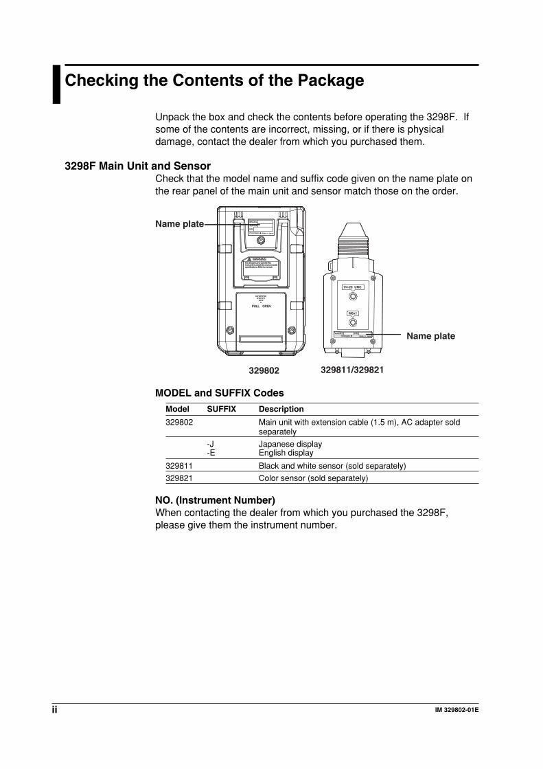
Unpack the box and check the contents before operating the 3298F. Ifsome of the contents are incorrect, missing, or if there is physicaldamage, contact the dealer from which you purchased them.
3298F Main Unit and SensorCheck that the model name and suffix code given on the name plate onthe rear panel of the main unit and sensor match those on the order.
1/4-20 UNC
M6x1
MODEL NO.Made in Japan
MODEL
SUFFIX
NO.
Made in Japan
WARNING
PULL OPEN
It is dangerous to operate thisinstrument outside its environmentalspecifications. Refer to manual.
Name plate
Name plate
329802 329811/329821
MODEL and SUFFIX Codes
Model SUFFIX Description
329802 Main unit with extension cable (1.5 m), AC adapter soldseparately
-J Japanese display-E English display
329811 Black and white sensor (sold separately)
329821 Color sensor (sold separately)
NO. (Instrument Number)When contacting the dealer from which you purchased the 3298F,please give them the instrument number.
iiiIM 329802-01E
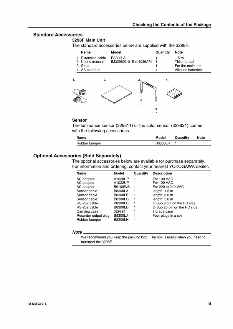
Standard Accessories3298F Main UnitThe standard accessories below are supplied with the 3298F.
Name Model Quantity Note
1. Extension cable B8300LA 1 1.5 m2. User’s manual IM329802-01E (L4036AF) 1 This manual3. Strap 1 For the main unit4. AA batteries 4 Alkaline batteries
2. 3. 4. 1.
SensorThe luminance sensor (329811) or the color sensor (329821) comeswith the following accessories.
Name Model Quantity Note
Rubber bumper B8300LH 1
Optional Accessories (Sold Separately)The optional accessories below are available for purchase separately.For information and ordering, contact your nearest YOKOGAWA dealer.
Name Model Quantity Description
AC adapter A1020UP 1 For 100 VACAC adapter A1022UP 1 For 120 VACAC adapter B9108WB 1 For 220 to 240 VACSensor cable B8300LA 1 length: 1.5 mSensor cable B8300LB 1 length: 3.0 mSensor cable B8300LG 1 length: 5.0 mRS-232 cable B8300LC 1 D-Sub 9 pin on the PC sideRS-232 cable B8300LD 1 D-Sub 25 pin on the PC sideCarrying case 329891 1 storage caseRecorder output plug B8300LJ 1 Four plugs in a setRubber bumper B8300LH 1
NoteWe recommend you keep the packing box. The box is useful when you need totransport the 3298F.
Checking the Contents of the Package
iv IM 329802-01E
Safety Precautions
The general safety precautions described herein must be observedduring all phases of operation. If the 3298F is used in a manner notspecified in this manual, the protection provided by the 3298F may beimpaired. Yokogawa Electric Corporation assumes no liability for thecustomer’s failure to comply with these requirements.
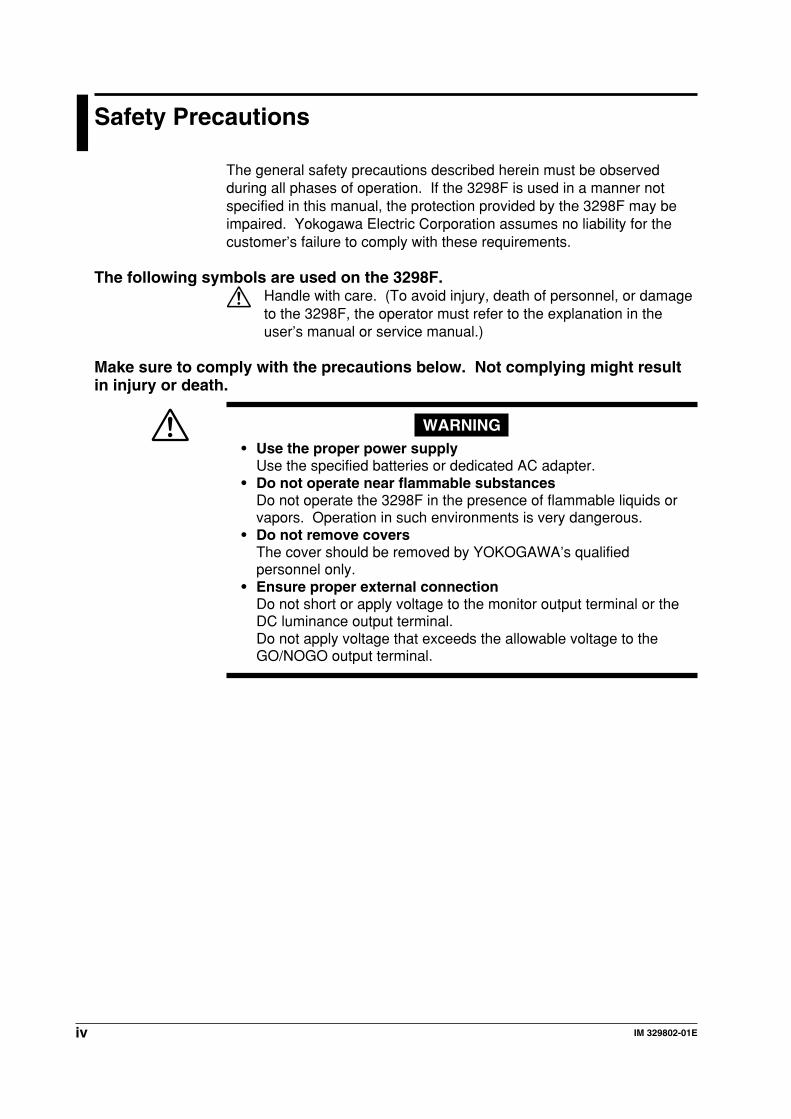
The following symbols are used on the 3298F.Handle with care. (To avoid injury, death of personnel, or damageto the 3298F, the operator must refer to the explanation in theuser’s manual or service manual.)
Make sure to comply with the precautions below. Not complying might resultin injury or death.
WARNING• Use the proper power supply
Use the specified batteries or dedicated AC adapter.• Do not operate near flammable substances
Do not operate the 3298F in the presence of flammable liquids orvapors. Operation in such environments is very dangerous.
• Do not remove coversThe cover should be removed by YOKOGAWA’s qualifiedpersonnel only.
• Ensure proper external connectionDo not short or apply voltage to the monitor output terminal or theDC luminance output terminal.Do not apply voltage that exceeds the allowable voltage to theGO/NOGO output terminal.
vIM 329802-01E
Structure of This Manual
This user’s manual consists of the following sections.
Chapter 1 Explanation of FunctionsDescribes the system configuration and function configuration of the 3298F. Alsodescribes the measurement principles. Operating procedures are not given in thischapter. However, reading this chapter will help you understand the operatingprocedures given in the chapters that follow.
Chapter 2 Names and Uses of PartsDescribes the names and uses of each part of the 3298F.
Chapter 3 Measurement Preparation and Common OperationsDescribes preparations that are taken before making measurements such ashandling precautions, how to install the 3298F, how to connect to the power supply,how to handle the batteries, how to turn ON/OFF the power switch, the procedurefor entering numeric values, and other operations.
Chapter 4 Measurement Conditions and 3298F SetupDescribes parameters that should be specified before starting measurements suchas the luminance, reference value, calibration coefficient, white balance, lightsource calibration coefficient, trigger mode, and 3298F settings. Describes how toset the measurement conditions.
Chapter 5 MeasurementDescribes how to measure the luminance, contrast, flicker, and chromaticity.
Chapter 6 Serial (RS-232) Communications FunctionDescribes the communications function with a PC using the RS-232 interface.
Chapter 7 SpecificationsSummarizes the main specifications of the 3298F main unit and the sensor in atable.
IndexIndex of contents.
vi IM 329802-01E
How to Use This Manual
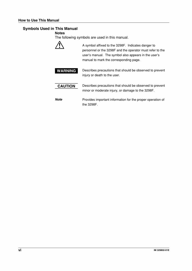
Symbols Used in This ManualNotesThe following symbols are used in this manual.
A symbol affixed to the 3298F. Indicates danger to
personnel or the 3298F and the operator must refer to the
user’s manual. The symbol also appears in the user’s
manual to mark the corresponding page.
WARNING Describes precautions that should be observed to prevent
injury or death to the user.
CAUTION Describes precautions that should be observed to prevent
minor or moderate injury, or damage to the 3298F.
Note Provides important information for the proper operation of
the 3298F.
viiIM 329802-01E
Contents
Foreward .......................................................................................................................... iChecking the Contents of the Package ........................................................................... iiSafety Precautions ......................................................................................................... ivStructure of This Manual ................................................................................................. v
Chapter 1 Explanation of Functions1.1 Block Diagram and Functions ........................................................................... 1-11.2 Measurement Principles .................................................................................... 1-31.3 Calculation Methods of Color Systems ............................................................. 1-61.4 Light Source Calibration Coefficient ................................................................ 1-101.5 User-Calibration Coefficients ........................................................................... 1-121.6 Other Functions ............................................................................................... 1-17
Chapter 2 Names and Uses of Parts2.1 3298F Main Unit ................................................................................................ 2-12.2 Sensor and Sensor Cable ................................................................................. 2-22.3 A List of Operations ........................................................................................... 2-3
Chapter 3 Measurement Preparation and Common Operations3.1 Before Starting Measurements .......................................................................... 3-13.2 Installation ......................................................................................................... 3-33.3 Installing the Sensor .......................................................................................... 3-43.4 Connecting the Power Supply and Turning ON/OFF the Power ....................... 3-73.5 Offset Calibration ............................................................................................... 3-93.6 Connecting External Input/Output ................................................................... 3-103.7 Screen Switching Operation and Parameter Selecting Operation .................. 3-133.8 Numeric Setting Operation and Character Setting Operation ......................... 3-143.9 Memory Operations ......................................................................................... 3-16
Chapter 4 Measurement Conditions and 3298F Setup4.1 A List of Menus .................................................................................................. 4-14.2 Setting the Reference Value .............................................................................. 4-34.3 Setting Calibration Coefficients ......................................................................... 4-74.4 Setting the White Balance Adjustment .............................................................4-114.5 Setting Light Source Calibration ...................................................................... 4-144.6 Setting the Trigger Mode ................................................................................. 4-154.7 Setting the 3298F ............................................................................................ 4-16
Chapter 5 Measurement5.1 Measuring the Luminance ................................................................................. 5-15.2 Measuring the Contrast ..................................................................................... 5-25.3 Measuring the Flicker ........................................................................................ 5-45.4 Measuring the Chromaticity ............................................................................... 5-6
Chapter 6 Serial (RS-232) Communications Function6.1 RS-232 Interface Functions and Specifications ................................................ 6-16.2 Connection via the RS-232 Interface ................................................................ 6-26.3 Handshaking Method ........................................................................................ 6-46.4 Data Format ...................................................................................................... 6-66.5 RS-232 Commands ........................................................................................... 6-76.6 Sample Program ............................................................................................. 6-14
1
2
3
4
5
6
7
App
Index
viii IM 329802-01E
Contents
Chapter 7 Specifications7.1 Specifications .................................................................................................... 7-17.2 Dimensional Drawings ....................................................................................... 7-5
AppendixAppendix 1 List of Default Values ........................................................................... App-1Appendix 2 Adjusting the White Balance ................................................................ App-3Appendix 3 Adjusting the Flicker ............................................................................ App-8
Index
1-1IM 329802-01E
Exp
lanatio
n o
f Fu
nctio
ns
11.1 Block Diagram and Functions
Block Diagram
Light
Photodetector unit Main unit
Diffuser
Temperature detector
Variable low-pass filter
Power supply
Operation keys
A/D con-
verter
GO/NOGO
RS-232
Trigger input
External power supply input
Display (LCD)
Flash
SRAM
CPU
LPF
LPF
LPF
Flicker separation
Silicon photodiode
Distributor lens
Optical filterI/V amplifier
Amplifier
Amplifier
AmplifierMonitor output
Gain, colorcalibrationcoefficient
DC lumina-nce output
E -PROM
-+
-+
-+
2
Mu
ltiplexerz
y
x
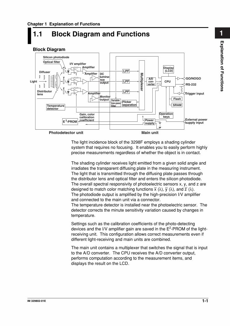
The light incidence block of the 3298F employs a shading cylindersystem that requires no focusing. It enables you to easily perform highlyprecise measurements regardless of whether the object is in contact.
The shading cylinder receives light emitted from a given solid angle andirradiates the transparent diffusing plate in the measuring instrument.The light that is transmitted through the diffusing plate passes throughthe distributor lens and optical filter and enters the silicon photodiode.The overall spectral responsivity of photoelectric sensors x, y, and z aredesigned to match color matching functions x
_ (λ), y
_ (λ), and z
_ (λ).
The photodiode output is amplified by the high-precision I/V amplifierand connected to the main unit via a connector.The temperature detector is installed near the photoelectric sensor. Thedetector corrects the minute sensitivity variation caused by changes intemperature.
Settings such as the calibration coefficients of the photo-detectingdevices and the I/V amplifier gain are saved in the E2-PROM of the light-receiving unit. This configuration allows correct measurements even ifdifferent light-receiving and main units are combined.
The main unit contains a multiplexer that switches the signal that is inputto the A/D converter. The CPU receives the A/D converter output,performs computation according to the measurement items, anddisplays the result on the LCD.
Chapter 1 Explanation of Functions
1-2 IM 329802-01E
FunctionsLuminance MeasurementDisplays the measured results numerically and in a bar graph.
Contrast MeasurementYou can select Auto or Manual for the measurement mode.• Auto: Performs the measurement twice. The greater of the two
measured luminance values is displayed as the measuredvalue for white.
• Manual: Performs a measurement after you specify white or black.
Flicker MeasurementThe DC component (average luminance) and AC component (rms flickervalue) are separated from the incident light containing the flicker, andtheir ratio (flicker ratio) is determined. The flicker ratio is displayed interms of percentage and dB as well as using bar graphs.
Chromaticity MeasurementThe tristimulus values are determined from the measured incident light,and the chromaticity is displayed using one of the following colorsystems.• Chromaticity coordinates: x, y, L/u’, v’, L• Tristimulus values: X, Y, Z/R, G, B/RGB ratio• Correlated color temperature: Tc, duv, L
• White balance adjustmentThe 3298F allows you to set the x and y values of the target colortemperature. Therefore, you can easily adjust the white balance byadjusting the level of the target display so that the measured values ofR, G, and B are all 100%.Chromaticity measurement is not possible using the luminancesensor.
TriggerThe following two measurement triggers are available on the 3298F.• Repeat: Repeats measurements. The measured value is held when
you press the MEAS key. The measurement resumes whenyou press the MEAS key again.
• Single: Executes the measurement once when you press the MEASkey or when a signal is received from the external triggerinput.
GO/NOGO DeterminationIn each measurement, a GO/NOGO determination is carried outaccording to the criteria that are specified beforehand, and thedetermination result can be displayed on the screen and outputexternally.
Memory Function200 panels of data can be saved to the memory for each measurement.You can easily load and display the saved information.The memory is cleared for each type of measurement.
1.1 Block Diagram and Functions
1-3IM 329802-01E
Exp
lanatio
n o
f Fu
nctio
ns
11.2 Measurement Principles
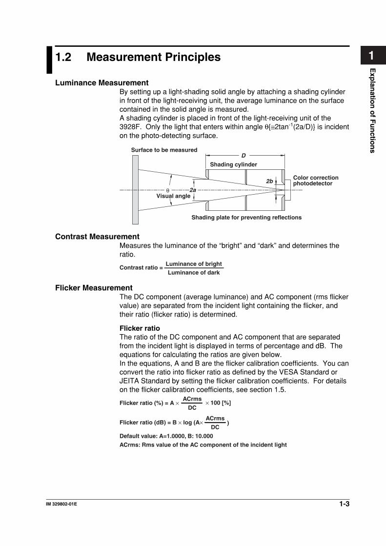
Luminance MeasurementBy setting up a light-shading solid angle by attaching a shading cylinderin front of the light-receiving unit, the average luminance on the surfacecontained in the solid angle is measured.A shading cylinder is placed in front of the light-receiving unit of the3928F. Only the light that enters within angle θ≅2tan-1(2a/D) is incidenton the photo-detecting surface.
θ 2a
2b
DSurface to be measured
Shading cylinder
Color correction photodetector
Shading plate for preventing reflections
Visual angle
Contrast MeasurementMeasures the luminance of the “bright” and “dark” and determines theratio.
Contrast ratio =Luminance of dark
Luminance of bright
Flicker MeasurementThe DC component (average luminance) and AC component (rms flickervalue) are separated from the incident light containing the flicker, andtheir ratio (flicker ratio) is determined.
Flicker ratioThe ratio of the DC component and AC component that are separatedfrom the incident light is displayed in terms of percentage and dB. Theequations for calculating the ratios are given below.In the equations, A and B are the flicker calibration coefficients. You canconvert the ratio into flicker ratio as defined by the VESA Standard orJEITA Standard by setting the flicker calibration coefficients. For detailson the flicker calibration coefficients, see section 1.5.
Flicker ratio (%) = A × DC
ACrms× 100 [%]
Default value: A=1.0000, B: 10.000
ACrms: Rms value of the AC component of the incident light
Flicker ratio (dB) = B × log (A× DC
ACrms)
1-4 IM 329802-01E
1.2 Measurement Principles
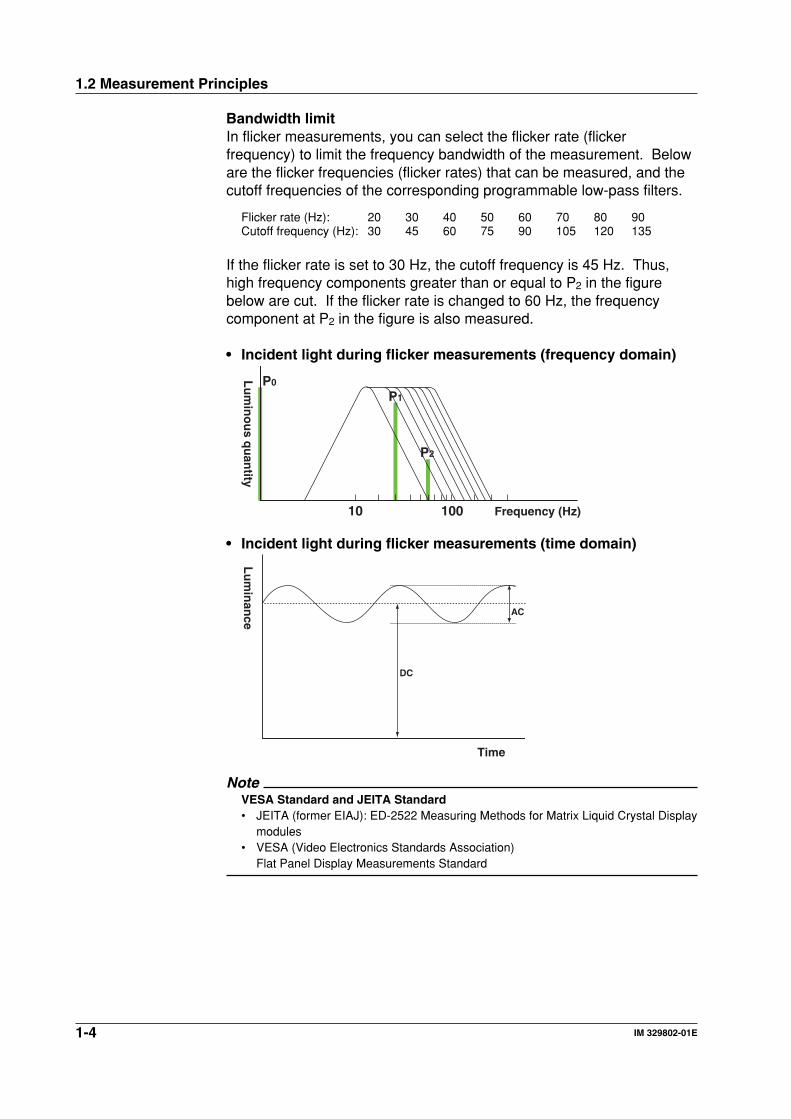
Bandwidth limitIn flicker measurements, you can select the flicker rate (flickerfrequency) to limit the frequency bandwidth of the measurement. Beloware the flicker frequencies (flicker rates) that can be measured, and thecutoff frequencies of the corresponding programmable low-pass filters.
Flicker rate (Hz): 20 30 40 50 60 70 80 90Cutoff frequency (Hz): 30 45 60 75 90 105 120 135
If the flicker rate is set to 30 Hz, the cutoff frequency is 45 Hz. Thus,high frequency components greater than or equal to P2 in the figurebelow are cut. If the flicker rate is changed to 60 Hz, the frequencycomponent at P2 in the figure is also measured.
• Incident light during flicker measurements (frequency domain)
Frequency (Hz)10 100
Lu
min
ou
s qu
antity
P0
P1
P2
• Incident light during flicker measurements (time domain)
DC
AC
Time
Lu
min
ance
NoteVESA Standard and JEITA Standard• JEITA (former EIAJ): ED-2522 Measuring Methods for Matrix Liquid Crystal Display
modules• VESA (Video Electronics Standards Association)
Flat Panel Display Measurements Standard
1-5IM 329802-01E
Exp
lanatio
n o
f Fu
nctio
ns
1Chromaticity MeasurementThe color of light is determined by the correlation between the spectralradiation of the light source and the spectral luminosity of the personwatching the light source. Commission Internationale de l’Eclairage(CIE) defines three color matching functions (x
_ (λ), y
_ (λ), and z
_ (λ)) that
correspond to the spectral responsivity of the human eye. The outputobtained by measuring the light source through these functions isexpressed in terms of X, Y, and Z. These values are called tristimulusvalues.The 3298F uses photoelectric sensors whose frequency response isequivalent to the color matching functions to measure the incident lightand determine the tristimulus values. A photoelectric tristimulus systemis employed for measurements. In addition, the measured tristimulusvalues can be used to display the chromaticity in various coordinatesystems. The 3298F is designed so that the overall spectral responsivitycorresponds to the color matching functions by using a siliconphotodiode, in the sensor (which excels in linearity and stability) andcombining it with an optical filter. The current output from the sensor isproportional to the incident-luminous energy. Thus, the tristimulusvalues are determined by measuring the current. There are two types ofcolor matching functions, 2° color matching functions (CIE 1931) and 10°color matching functions (CIE 1964).The 3298F adopts the 2° color matching functions.
1.2 Measurement Principles
1-6 IM 329802-01E
1.3 Calculation Methods of Color Systems
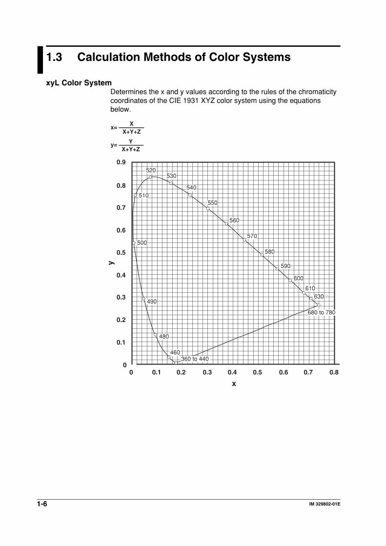
xyL Color SystemDetermines the x and y values according to the rules of the chromaticitycoordinates of the CIE 1931 XYZ color system using the equationsbelow.
x=X+Y+Z
X
y=X+Y+Z
Y
00 0.1
0.1
0.2
0.3
0.4
0.5
0.6
0.7
0.8
0.9
0.2 0.3 0.4 0.5 0.6 0.7 0.8
x
y
520
510
500
490
480480
460
680 to 780
360 to 440
630610
600
590
580
570
560
550
540
530
1-7IM 329802-01E
Exp
lanatio
n o
f Fu
nctio
ns
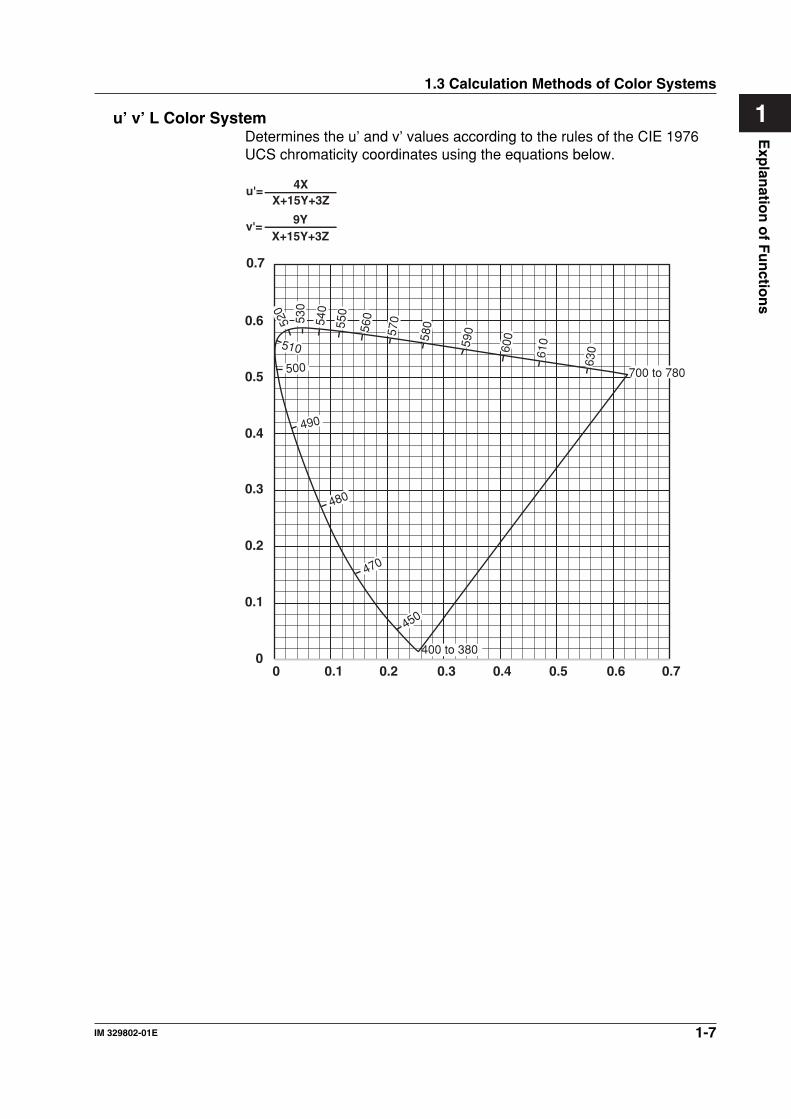
1u’ v’ L Color SystemDetermines the u’ and v’ values according to the rules of the CIE 1976UCS chromaticity coordinates using the equations below.
u'=X+15Y+3Z
4X
v'=X+15Y+3Z
9Y
00 0.1
0.1
0.2
0.3
0.4
0.5
0.6
0.2 0.3 0.4 0.5 0.6 0.7
0.7
400 to 380
700 to 780
450
470
480
490
500
510
520
530
560
570
580
590
600
610
630
540
550
1.3 Calculation Methods of Color Systems
1-8 IM 329802-01E
1.3 Calculation Methods of Color Systems
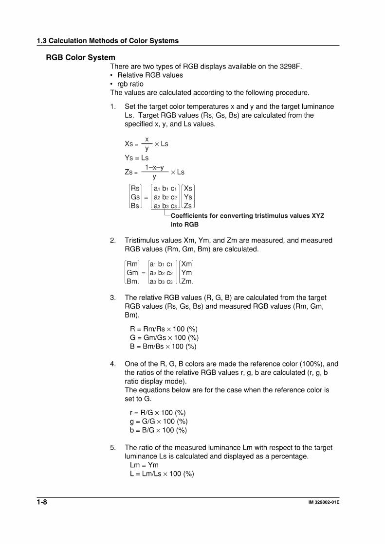
RGB Color SystemThere are two types of RGB displays available on the 3298F.• Relative RGB values• rgb ratioThe values are calculated according to the following procedure.
1. Set the target color temperatures x and y and the target luminanceLs. Target RGB values (Rs, Gs, Bs) are calculated from thespecified x, y, and Ls values.
RsGsBs
XsYsZs
a1 b1 c1
a2 b2 c2
a3 b3 c3
=
Xs = × Lsyx
Zs = × Lsy
1–x–yYs = Ls
Coefficients for converting tristimulus values XYZ into RGB
2. Tristimulus values Xm, Ym, and Zm are measured, and measuredRGB values (Rm, Gm, Bm) are calculated.
RmGmBm
XmYmZm
a1 b1 c1
a2 b2 c2
a3 b3 c3
=
3. The relative RGB values (R, G, B) are calculated from the targetRGB values (Rs, Gs, Bs) and measured RGB values (Rm, Gm,Bm).
R = Rm/Rs × 100 (%)G = Gm/Gs × 100 (%)B = Bm/Bs × 100 (%)
4. One of the R, G, B colors are made the reference color (100%), andthe ratios of the relative RGB values r, g, b are calculated (r, g, bratio display mode).The equations below are for the case when the reference color isset to G.
r = R/G × 100 (%)g = G/G × 100 (%)b = B/G × 100 (%)
5. The ratio of the measured luminance Lm with respect to the targetluminance Ls is calculated and displayed as a percentage.
Lm = YmL = Lm/Ls × 100 (%)
1-9IM 329802-01E
Exp
lanatio
n o
f Fu
nctio
ns
1Target Chromaticity x, yThe 3298F comes equipped with the target chromaticity values below.The target chromaticity values can also be defined by the user.
Color Temperature Target Chromaticityx y
6504 K (D65 light source) 0.3127 0.32926774 K (C light source) 0.3101 0.31619304 K 0.2848 0.2934
A List of CoefficientsThe 3298F provides RGB conversion coefficients for three broadcastsystems below. Up to two sets of coefficients for other broadcastsystems can also be defined by the user.
NTSC System
a1 = 1.9106 b1 = –0.5326 c1 = –0.2883a2 = –0.9843 b2 = 1.9984 c2 = 0.0283a3 = 0.0584 b3 = –0.1185 c3 = 0.8985
PAL System
a1 = 3.063 b1 = –1.393 c1 = –0.476a2 = –0.969 b2 = 1.876 c2 = 0.042a3 = 0.068 b3 = –0.229 c3 = 1.069
HDTV System
a1 = 3.2479 b1 = –1.5428 c1 = –0.5014a2 = –0.9733 b2 = 1.8788 c2 = 0.0430a3 = 0.0569 b3 = –0.20427 c3 = 1.05616
Correlated Color Temperature and ErrorThe values are derived according to JIS Z 8725 “Methods forDetermining Distribution Temperature and Color Temperature orCorrelated Color Temperature of Light Sources.”
1.3 Calculation Methods of Color Systems
1-10 IM 329802-01E
1.4 Light Source Calibration Coefficient
The 3298F has the following light source calibration coefficients.• type-A: Type-A standard light source• FL3: Three-wavelength fluorescent lamp• CRT: CRT
Select the appropriate light source correlation coefficient according tothe measured light source. For example, specify the light sourcecalibration coefficient of Standard light source A for a tail lamp of a carthat consists of a light bulb covered by a colored glass. Specify the lightsource calibration coefficient of three-wavelength fluorescent lamp for anLCD that uses a three-wavelength fluorescent lamp for its backlight.
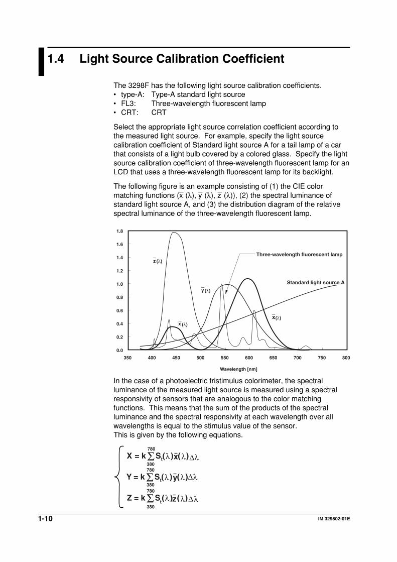
The following figure is an example consisting of (1) the CIE colormatching functions (x
_ (λ), y
_ (λ), z
_ (λ)), (2) the spectral luminance of
standard light source A, and (3) the distribution diagram of the relativespectral luminance of the three-wavelength fluorescent lamp.
350
0.0
0.2
0.4
0.6
0.8
1.0
1.2
1.4
1.6
1.8
400 450 500 550 600 650 700 750 800
Standard light source A
Wavelength [nm]
Three-wavelength fluorescent lamp
x(λ)_
y (λ)_
x (λ)_
z (λ)_
In the case of a photoelectric tristimulus colorimeter, the spectralluminance of the measured light source is measured using a spectralresponsivity of sensors that are analogous to the color matchingfunctions. This means that the sum of the products of the spectralluminance and the spectral responsivity at each wavelength over allwavelengths is equal to the stimulus value of the sensor.This is given by the following equations.
X k S x
Y k S y
Z k S z
t
t
t
=
=
=
Σ
Σ
Σ
( ) ( )
( ) (
(
)∆
( ) )
∆λ380
780
380
780
380
780
λλλ
λλλ
λλ
∆
1-11IM 329802-01E
Exp
lanatio
n o
f Fu
nctio
ns
11.4 Light Source Calibration Coefficient
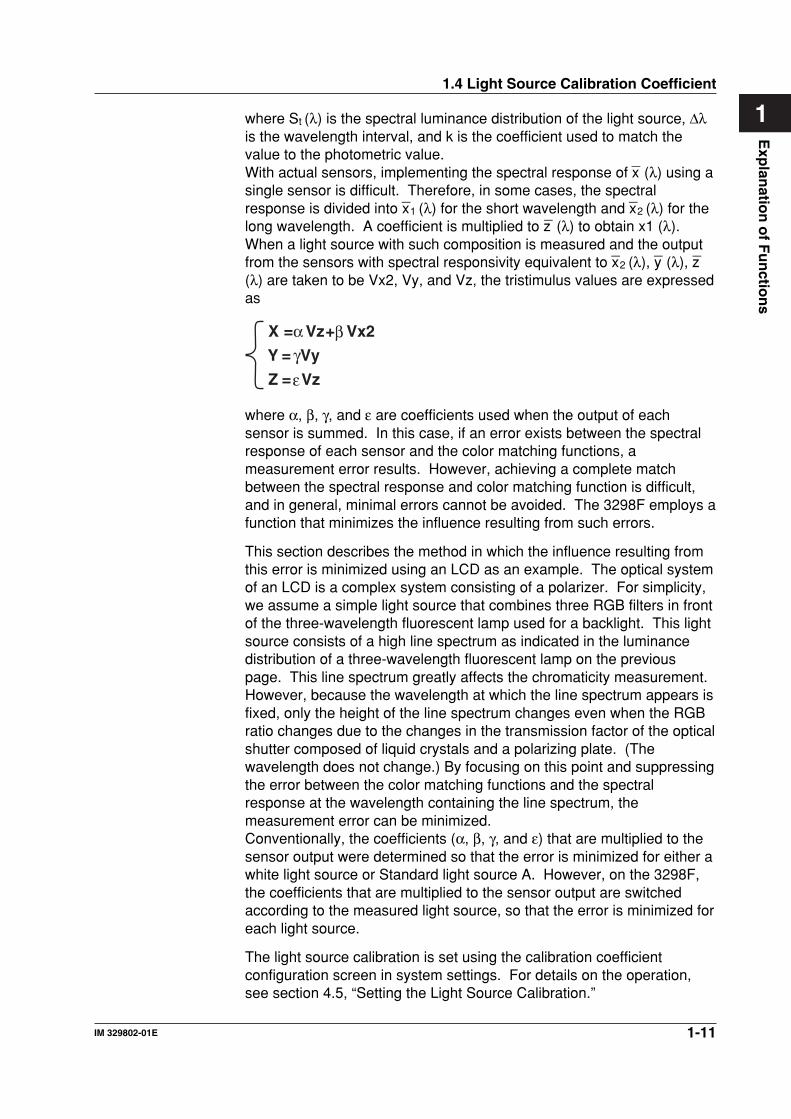
where St (λ) is the spectral luminance distribution of the light source, ∆λis the wavelength interval, and k is the coefficient used to match thevalue to the photometric value.With actual sensors, implementing the spectral response of x
_ (λ) using a
single sensor is difficult. Therefore, in some cases, the spectralresponse is divided into x
_1 (λ) for the short wavelength and x
_2 (λ) for the
long wavelength. A coefficient is multiplied to z_
(λ) to obtain x1 (λ).When a light source with such composition is measured and the outputfrom the sensors with spectral responsivity equivalent to x
_2 (λ), y
_ (λ), z
_
(λ) are taken to be Vx2, Vy, and Vz, the tristimulus values are expressedas
X Vz Vx2
Y Vy
Z Vz
= +
=
=
α βγε
where α, β, γ, and ε are coefficients used when the output of eachsensor is summed. In this case, if an error exists between the spectralresponse of each sensor and the color matching functions, ameasurement error results. However, achieving a complete matchbetween the spectral response and color matching function is difficult,and in general, minimal errors cannot be avoided. The 3298F employs afunction that minimizes the influence resulting from such errors.
This section describes the method in which the influence resulting fromthis error is minimized using an LCD as an example. The optical systemof an LCD is a complex system consisting of a polarizer. For simplicity,we assume a simple light source that combines three RGB filters in frontof the three-wavelength fluorescent lamp used for a backlight. This lightsource consists of a high line spectrum as indicated in the luminancedistribution of a three-wavelength fluorescent lamp on the previouspage. This line spectrum greatly affects the chromaticity measurement.However, because the wavelength at which the line spectrum appears isfixed, only the height of the line spectrum changes even when the RGBratio changes due to the changes in the transmission factor of the opticalshutter composed of liquid crystals and a polarizing plate. (Thewavelength does not change.) By focusing on this point and suppressingthe error between the color matching functions and the spectralresponse at the wavelength containing the line spectrum, themeasurement error can be minimized.Conventionally, the coefficients (α, β, γ, and ε) that are multiplied to thesensor output were determined so that the error is minimized for either awhite light source or Standard light source A. However, on the 3298F,the coefficients that are multiplied to the sensor output are switchedaccording to the measured light source, so that the error is minimized foreach light source.
The light source calibration is set using the calibration coefficientconfiguration screen in system settings. For details on the operation,see section 4.5, “Setting the Light Source Calibration.”
1-12 IM 329802-01E
1.5 User-Calibration Coefficients
You can set user-calibration factors on the 3298F. By setting the user-calibration factors, you can display the measured values according tothe reference values that the user specified.The type of user-calibration coefficients that can be specified are asfollows:• Luminance calibration coefficient (when using the luminance sensor)• Flicker calibration coefficient• Chromaticity calibration coefficient (when using the color sensor)
The user-calibration coefficients are set on the calibration coefficientscreen on the SET menu. For details of the operation, see section 4.3,“Setting the Calibration Coefficients.” The following two methods areavailable for setting the user-calibration coefficients.
• Key input• Measurement input (Luminance calibration coefficient and
chromaticity calibration coefficient)
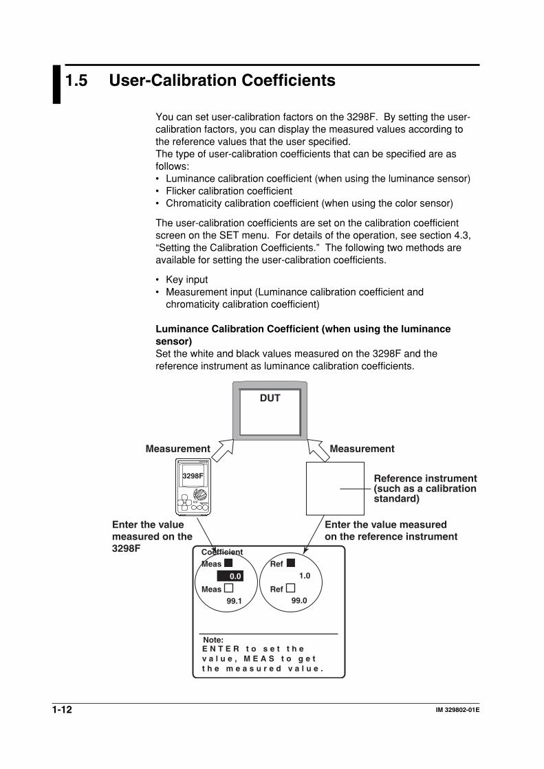
Luminance Calibration Coefficient (when using the luminancesensor)Set the white and black values measured on the 3298F and thereference instrument as luminance calibration coefficients.
DUT
Reference instrument(such as a calibration standard)
Measurement
Enter the value measured on the 3298F
Enter the value measured on the reference instrument
Measurement
3298F
0.0 1.0
99.099.1
CoefficientMeas Ref
Meas Ref
Note:E N T E R t o s e t t h e v a l u e , M E A S t o g e tt h e m e a s u r e d v a l u e .
1-13IM 329802-01E
Exp
lanatio
n o
f Fu
nctio
ns
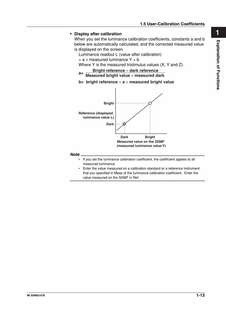
1• Display after calibrationWhen you set the luminance calibration coefficients, constants a and bbelow are automatically calculated, and the corrected measured valueis displayed on the screen.
Luminance readout L (value after calibration)= a × measured luminance Y + bWhere Y is the measured tristimulus values (X, Y and Z).
b= bright reference – a × measured bright value
Bright reference – dark referenceMeasured bright value – measured dark a=
Dark BrightMeasured value on the 3298F (measured luminance value Y)
Bright
Reference (displayed luminance value L)
Dark
Note• If you set the luminance calibration coefficient, the coefficient applies to all
measured luminance.• Enter the value measured on a calibration standard or a reference instrument
that you specified in Meas of the luminance calibration coefficient. Enter thevalue measured on the 3298F in Ref.
1.5 User-Calibration Coefficients
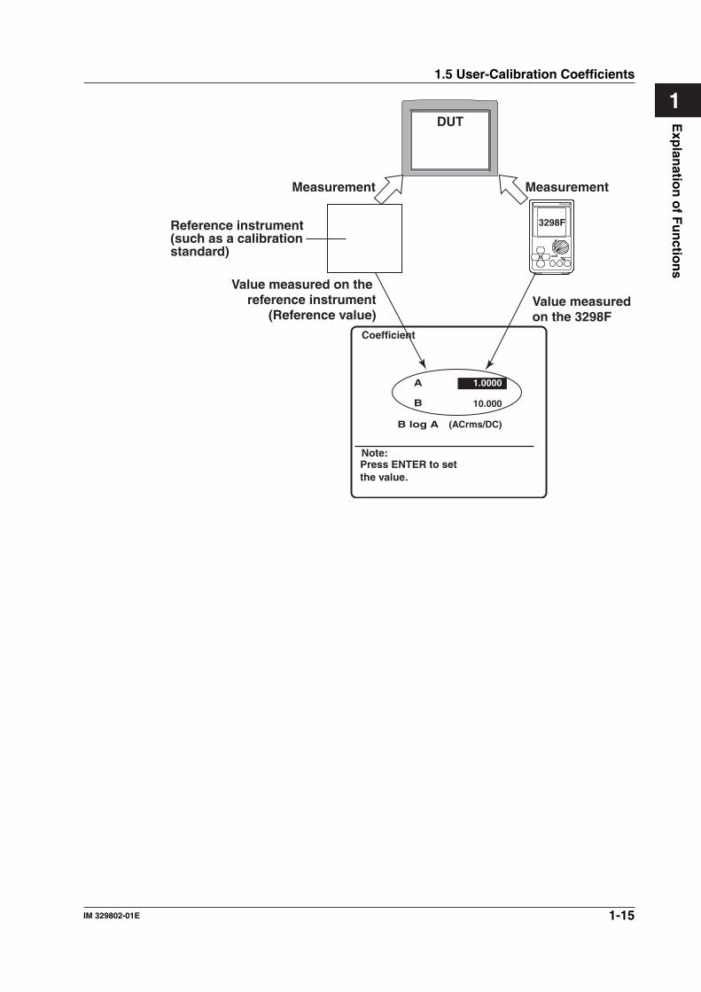
1-14 IM 329802-01E
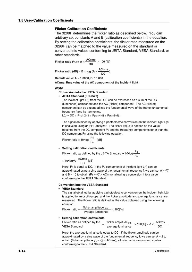
Flicker Calibration CoefficientsThe 3298F determines the flicker ratio as described below. You canarbitrary set constants A and B (calibration coefficients) in the equation.By setting the calibration coefficients, the flicker ratio measured on the3298F can be matched to the value measured on the standard orconverted into values conforming to JEITA Standard, VESA Standard, orother standards.
Flicker ratio (%) = A ×DC
ACrms× 100 [%]
Default value: A = 1.0000, B: 10.000
ACrms: Rms value of the AC component of the incident light
Flicker ratio (dB) = B × log (A ×DC
ACrms)
NoteConversion into the JEITA Standard• JEITA Standard (ED-2522)
The incident light L(t) from the LCD can be expressed as a sum of the DC(luminance) component and the AC (flicker) component. The AC (flicker)component can be expanded into the fundamental wave of the frame fundamentalfrequency f and its harmonics.L(t) = DC + P1sin2πft + P2sin4πft + P3sin6πft...
The signal obtained by applying a photoelectric conversion on the incident light L(t)is analyzed using an FFT analyzer. The flicker value is defined as the valueobtained from the DC component P0 and the frequency components other than theDC component PX using the following equation.
PXFlicker ratio = 10•log [dB] P0
• Setting calibration coefficientsPXFlicker ratio as defined by the JEITA Standard = 10•logP0
ACrms= 10•log•A [dB]
DCHere, P0 is equal to DC. If the PX components of incident light L(t) can beapproximated using a sine wave of the fundamental frequency f, we can set A = 2and B = 10 to obtain (P1 = 2 × ACrms), allowing a conversion into a valueconforming to the JEITA Standard.
Conversion into the VESA Standard• VESA Standard
The signal obtained by applying a photoelectric conversion on the incident light L(t)is applied to an oscilloscope, and the flicker amplitude and average luminance aremeasured. The flicker ratio is defined as the value obtained using the followingequation.
flicker amplitude p-pFlicker ratio = × 100[%] average luminance
• Setting calibration coefficientsFlicker ratio as defined by the flicker amplitude p-p ACrms
= × 100[%] = A ×VESA Standard average luminance DC
Here, the average luminance is equal to DC. If the flicker amplitude can beapproximated by a sine wave of the fundamental frequency f, we can set A = 2 toobtain (flicker amplitude p-p = 2 × ACrms), allowing a conversion into a valueconforming to the VESA Standard.
1.5 User-Calibration Coefficients
1-15IM 329802-01E
Exp
lanatio
n o
f Fu
nctio
ns
1
Coefficient
Note:Press ENTER to setthe value.
DUT
Measurement Measurement
Value measured on the 3298F
Value measured on the reference instrument
(Reference value)
3298FReference instrument(such as a calibration standard)
B
A
B log A
1.0000
10.000
(ACrms/DC)
1.5 User-Calibration Coefficients
1-16 IM 329802-01E
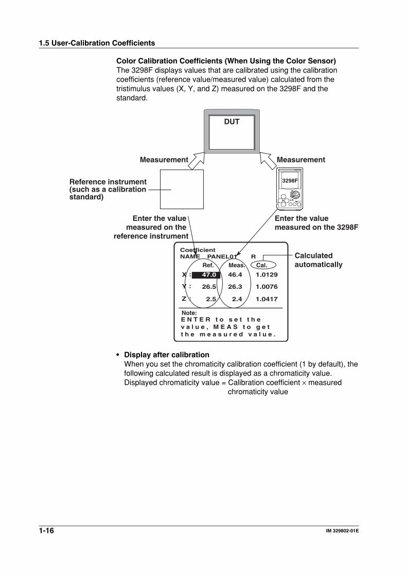
Color Calibration Coefficients (When Using the Color Sensor)The 3298F displays values that are calibrated using the calibrationcoefficients (reference value/measured value) calculated from thetristimulus values (X, Y, and Z) measured on the 3298F and thestandard.
DUT
Measurement Measurement
3298F
Enter the value measured on the 3298F
Enter the value measured on the
reference instrument
0.0
CoefficientNAME R
Note:E N T E R t o s e t t h e v a l u e , M E A S t o g e tt h e m e a s u r e d v a l u e .
Ref. Meas. Cal.
:
:
:
46.4
26.3
2.4
47.0
26.5
2.5
1.0129
1.0076
1.0417
X
Y
Z
PANEL01
Reference instrument(such as a calibration standard)
Calculated automatically
• Display after calibrationWhen you set the chromaticity calibration coefficient (1 by default), thefollowing calculated result is displayed as a chromaticity value.Displayed chromaticity value = Calibration coefficient × measured
chromaticity value
1.5 User-Calibration Coefficients
1-17IM 329802-01E
Exp
lanatio
n o
f Fu
nctio
ns
11.6 Other Functions
External I/O FunctionThe following I/O functions are available. For details and handling ofeach function, see section 3.6. For details on the serial (RS-232)communication, see chapter 6.• Serial (RS-232) communication• Trigger (contact) input• GO/NOGO determination• Monitor output• DC luminance output
Turning ON/OFF the Back lightThe back light can be turned ON/OFF on the 3298F. For the procedure,see section 4.7.The backlight operation when using an AC adapter and the operationwhen using batteries are as follows:• When using an AC adapter: The backlight is always ON in the ON
setting.• When battery-driven: The backlight is ON for approximately
20 seconds in the ON setting and turnsOFF automatically.The backlight turns back ON when a keyis pressed. The backlight is always OFFin the OFF setting.
Power DownWhen the 3298F is battery-driven, the auto power down time can be setto one of the following. For the procedure, see section 4.7.• OFF, 1 min, 2 min, 5 min, 10 min, and 20 min
1-18 IM 329802-01E
1.6 Other Functions
TriggerThe 3298F has the following two trigger modes. For the procedure, seesection 4.6.• Repeat: Performs continuous measurements.
The measured value is held when you press the MEAS key.Continuous measurement is resumed when you press theMEAS key again.
• Single: A single triggered measurement is made in the followingcases.• When the MEAS key is pressed.• Each time a signal is input through the external trigger
input terminal.
Average CountIf you set the average count, the average value is calculated anddisplayed after executing the measurement the specified number of times.You can select the average count from the following:• None: Does not perform averaging of measured values.• 2 to 20: Repeats the measurement the specified number of times
and displays the average value.
NoteIf you set the measurement mode to AUTO in the contrast measurement (section5.2), the trigger mode is switched to single even if the trigger mode is set to repeat.
Communication FunctionsYou can remotely control the 3298F using the serial (RS-232) interface.
InitializeYou can set the 3298F settings to factory default.You can select the settings to be initialized from the items below.• Setting values• Reference values• Calibration coefficients• All settingsSee Appendix 1 for the initialized items and factory default values foreach type of initialization.
VersionYou can check the ROM version of the 3298F.
2-1IM 329802-01E
Nam
es and
Uses o
f Parts
2
Chapter 2 Names and Uses of Parts
2.1 3298F Main Unit
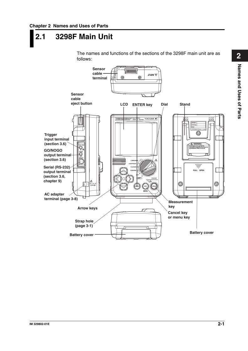
The names and functions of the sections of the 3298F main unit are asfollows:
EXT TRIG
EJE
CT
IN
GO/NG
LUMINANCE
CONTRAST
FLICKER
CHROMA
SET
ENTER ESC MEAS
TRIGGER
MENU
OFF
OUT
DC IN 8V
RS232C
INPUT
Trigger input terminal (section 3.6)
GO/NOGO output terminal (section 3.6)
Serial (RS-232) output terminal (section 3.6, chapter 9)
Sensor cable eject button
AC adapter terminal (page 3-8)
Sensor cable terminal
Arrow keys
Measurement key
Cancel key or menu key
ENTER keyLCD
Battery coverBattery cover
Dial Stand
MODEL
SUFFIX
NO.
Made in Japan
WARNING
PULL OPEN
It is dangerous to operate thisinstrument outside its environmentalspecifications. Refer to manual.
Strap hole (page 3-1)
MULTIMEDIADISPLAY TESTER
2-2 IM 329802-01E
2.2 Sensor and Sensor Cable
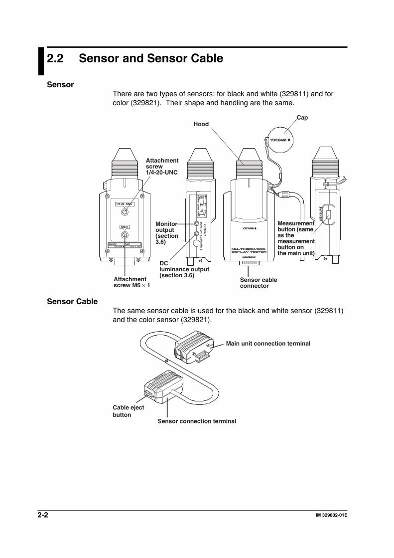
SensorThere are two types of sensors: for black and white (329811) and forcolor (329821). Their shape and handling are the same.
1/4-20 UNC
M6x1
OU
TP
UT
ME
AS
UR
E
MO
NITO
RL
UM
INA
NC
E
MODEL NO.Made in Japan
7342
100mm
50mm
100mm
Sensor cable connector
CapHood
Monitor output (section 3.6)
Attachment screw 1/4-20-UNC
Attachment screw M6 × 1
Measurement button (same as the measurement button on the main unit)
DC luminance output (section 3.6)
Sensor CableThe same sensor cable is used for the black and white sensor (329811)and the color sensor (329821).
Sensor connection terminal
Cable eject button
Main unit connection terminal
2-3IM 329802-01E
Nam
es and
Uses o
f Parts
2
2.3 A List of Operations
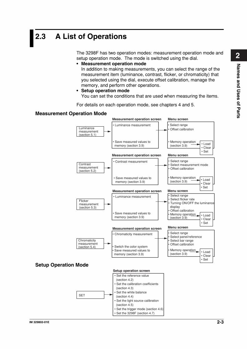
The 3298F has two operation modes: measurement operation mode andsetup operation mode. The mode is switched using the dial.• Measurement operation mode
In addition to making measurements, you can select the range of themeasurement item (luminance, contrast, flicker, or chromaticity) thatyou selected using the dial, execute offset calibration, manage thememory, and perform other operations.
• Setup operation modeYou can set the conditions that are used when measuring the items.
For details on each operation mode, see chapters 4 and 5.
Measurement Operation Mode
Luminance measurement (section 5.1)
• Luminance measurement
Contrast measurement (section 5.2)
• Contrast measurement
• Save measured values to memory (section 3.9)
Flicker measurement (section 5.3)
• Save measured values to memory (section 3.9)
Chromaticity measurement (section 5.4)
• Luminance measurement
• Switch the color system• Save measured values to memory (section 3.9)
• Offset calibration
• Chromaticity measurement
• Select range
• Select range• Select measurement mode• Offset calibration
• Select range• Select flicker rate• Turning ON/OFF the luminance display
• Offset calibration
• Select range• Select panel/reference• Select bar range• Offset calibration
Measurement operation screen Menu screen
Menu screen
Menu screen
Menu screen
Measurement operation screen
Measurement operation screen
Measurement operation screen
• Load• Clear• Set
• Load• Clear• Set
• Memory operation(section 3.9)
• Load• Clear• Set
• Memory operation (section 3.9)
• Load• Clear• Set
• Memory operation (section 3.9)
• Memory operation (section 3.9)
• Save measured values to memory (section 3.9)
Setup Operation Mode
SET
• Set the reference value (section 4.2)
• Set the calibration coefficients (section 4.3)
• Set the white balance (section 4.4)
• Set the light source calibration (section 4.5)
• Set the trigger mode (section 4.6)• Set the 3298F (section 4.7)
Setup operation screen
3-1IM 329802-01E
Measu
remen
t Prep
aration
and
Co
mm
on
Op
eration
s
3
Chapter 3 Measurement Preparation and Common Operations
3.1 Before Starting Measurements
Safety PrecautionsWhen using the 3298F for the first time, make sure to read “SafetyPrecautions” on page iv.
Do not remove the case from the 3298F.For internal inspection or adjustment, contact your nearest YOKOGAWAdealer.
Do not operate if you detect abnormal behavior.Stop using the 3298F if there are any symptoms of trouble such asstrange odors or smoke coming from the 3298F. If these symptomsoccur, immediately turn OFF the power and, if you are using an ACadapter, unplug the AC adapter from the outlet. In addition, turn OFFthe power to the device that is connected to the input terminal. In suchcase, contact your nearest YOKOGAWA dealer.
Use the proper AC adapter.Use only the AC adapter provided for the 3298F. Do not place objectson top of the AC adapter and keep it away form heat sources. Whenunplugging the AC adapter from the outlet, never pull by the cord itself.Always hold and pull by the plug. If the cord is damaged, contact yourdealer for replacement. Refer to page iii for the part number whenplacing an order.
General Handling PrecautionsUnplug before carrying the 3298F.First, turn OFF the power to the target display. Then, turn OFF thepower switch of the 3298F. If you are using an AC adapter, remove theplug from the outlet. Remove the connected cables. When carrying the3298F, attach the strap that came with the package to prevent it frombeing dropped.
Do not bring charged objects near the 3298F.Do not bring charged objects near the input connector. Doing so coulddamage the internal circuitry.
Do not let volatile solutions, rubber, or PVC products contact the3298F.Do not pour volatile substances on the case or operation panel, or leavethem in contact with rubber or PVC products for extended time. Theoperation panel is made of thermoplastic resin. Make sure heatingelements such as soldering bits do not come in contact with theoperation panel.
Unplug before wiping off dirt.When wiping off dirt from the case or operation panel, turn OFF thepower switch of the 3298F. If you are using an AC adapter, remove theplug from the outlet. Then, wipe with a dry, soft, clean cloth. Do not usevolatile chemicals as this may cause discoloring and deformation.
3-2 IM 329802-01E
3.1 Before Starting Measurements
Unplug when not using the AC adapter for an extended time.If you are using an AC adapter and plan not to use it for an extendedtime, remove the AC adapter plug from the outlet.
Handle the batteries correctly.For information about the handling of batteries, see section 3.3,“Connecting the Power Supply and Turning ON/OFF the Power.” Neveruse the 3298F with the battery cover opened.
Do not stack the 3298F.The 3298F is not designed to be stacked. Never stack the 3298F as thiswill cause unstable installation leading to accidents and malfunction.
Do not place objects on top of the 3298F.Never place any objects containing water on top of the 3298F. Doing socould lead to malfunction.
Do not apply shock or vibration.Do not apply shock or vibration. Doing so could lead to malfunction. Inaddition, applying shock to the input/output terminal or the connectedcable can cause electrical noise to enter or output from the 3298F.
Protect the sensor’s optical aperture.Do not insert sharp objects, foreign objects, or liquids into the sensor’soptical aperture. Doing so could lead to malfunction.
3-3IM 329802-01E
Measu
remen
t Prep
aration
and
Co
mm
on
Op
eration
s
3
3.2 Installation
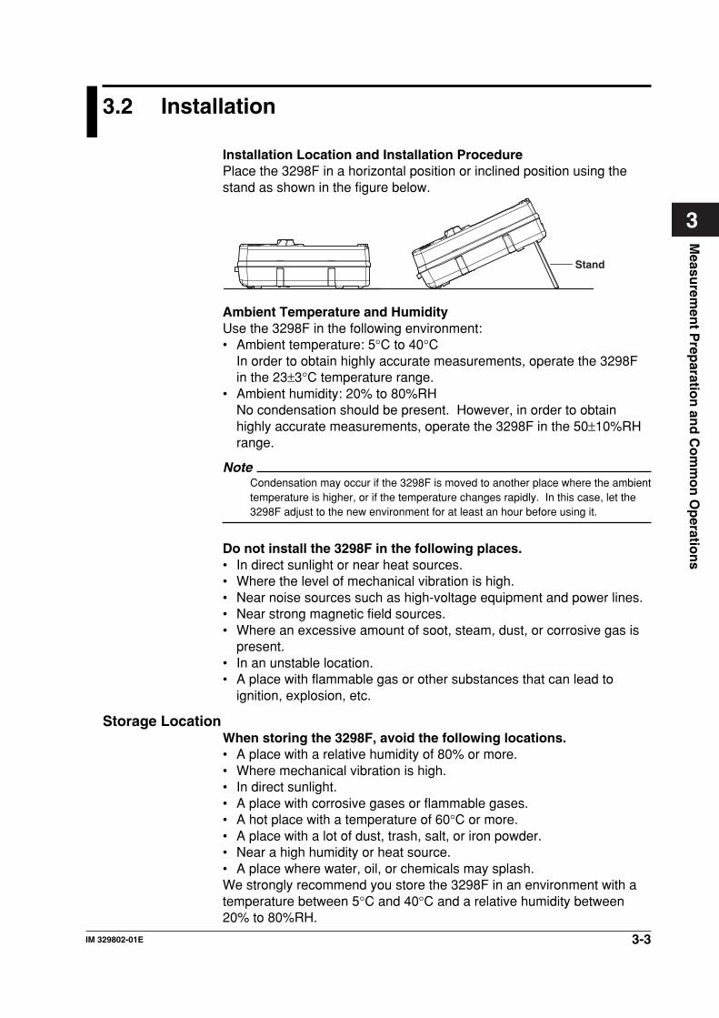
Installation Location and Installation ProcedurePlace the 3298F in a horizontal position or inclined position using thestand as shown in the figure below.
Stand
Ambient Temperature and HumidityUse the 3298F in the following environment:• Ambient temperature: 5°C to 40°C
In order to obtain highly accurate measurements, operate the 3298Fin the 23±3°C temperature range.
• Ambient humidity: 20% to 80%RHNo condensation should be present. However, in order to obtainhighly accurate measurements, operate the 3298F in the 50±10%RHrange.
NoteCondensation may occur if the 3298F is moved to another place where the ambienttemperature is higher, or if the temperature changes rapidly. In this case, let the3298F adjust to the new environment for at least an hour before using it.
Do not install the 3298F in the following places.• In direct sunlight or near heat sources.• Where the level of mechanical vibration is high.• Near noise sources such as high-voltage equipment and power lines.• Near strong magnetic field sources.• Where an excessive amount of soot, steam, dust, or corrosive gas is
present.• In an unstable location.• A place with flammable gas or other substances that can lead to
ignition, explosion, etc.
Storage LocationWhen storing the 3298F, avoid the following locations.• A place with a relative humidity of 80% or more.• Where mechanical vibration is high.• In direct sunlight.• A place with corrosive gases or flammable gases.• A hot place with a temperature of 60°C or more.• A place with a lot of dust, trash, salt, or iron powder.• Near a high humidity or heat source.• A place where water, oil, or chemicals may splash.We strongly recommend you store the 3298F in an environment with atemperature between 5°C and 40°C and a relative humidity between20% to 80%RH.
3-4 IM 329802-01E
3.3 Installing the Sensor
CAUTIONWhen connecting or disconnecting the sensor cable from the3298F, be sure to turn OFF the power to the 3298F. Connectingor disconnecting the sensor cable with the power turned ON candamage the 3298F or the sensor.
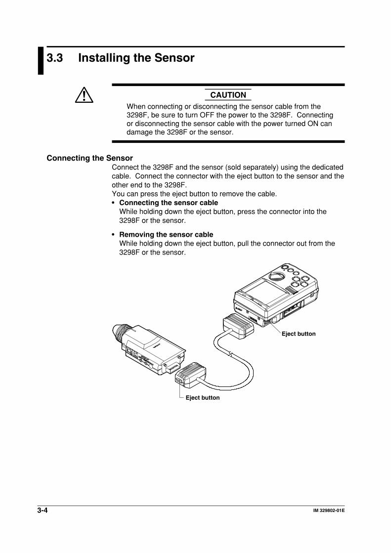
Connecting the SensorConnect the 3298F and the sensor (sold separately) using the dedicatedcable. Connect the connector with the eject button to the sensor and theother end to the 3298F.You can press the eject button to remove the cable.• Connecting the sensor cable
While holding down the eject button, press the connector into the3298F or the sensor.
• Removing the sensor cableWhile holding down the eject button, pull the connector out from the3298F or the sensor.
Eject button
Eject button
3-5IM 329802-01E
Measu
remen
t Prep
aration
and
Co
mm
on
Op
eration
s
3
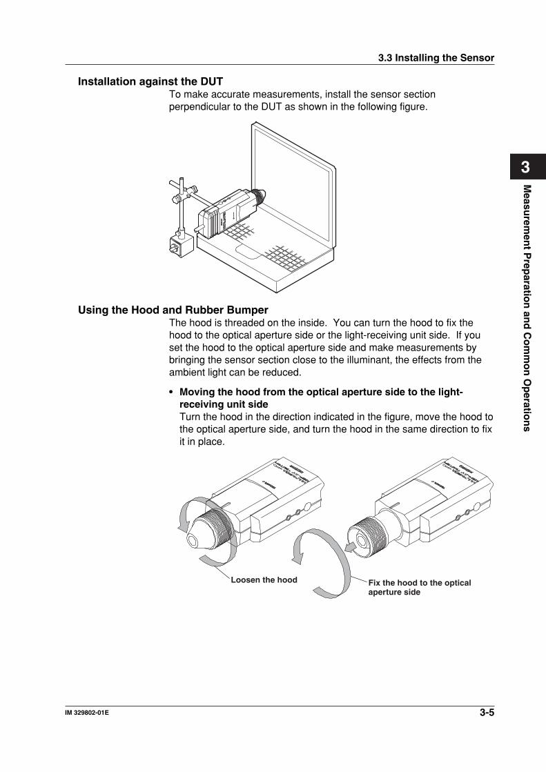
Installation against the DUTTo make accurate measurements, install the sensor sectionperpendicular to the DUT as shown in the following figure.
Using the Hood and Rubber BumperThe hood is threaded on the inside. You can turn the hood to fix thehood to the optical aperture side or the light-receiving unit side. If youset the hood to the optical aperture side and make measurements bybringing the sensor section close to the illuminant, the effects from theambient light can be reduced.
• Moving the hood from the optical aperture side to the light-receiving unit sideTurn the hood in the direction indicated in the figure, move the hood tothe optical aperture side, and turn the hood in the same direction to fixit in place.
Loosen the hood Fix the hood to the optical aperture side
3.3 Installing the Sensor
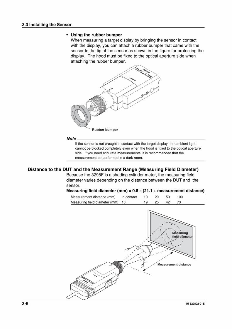
3-6 IM 329802-01E
• Using the rubber bumperWhen measuring a target display by bringing the sensor in contactwith the display, you can attach a rubber bumper that came with thesensor to the tip of the sensor as shown in the figure for protecting thedisplay. The hood must be fixed to the optical aperture side whenattaching the rubber bumper.
Rubber bumper
NoteIf the sensor is not brought in contact with the target display, the ambient lightcannot be blocked completely even when the hood is fixed to the optical apertureside. If you need accurate measurements, it is recommended that themeasurement be performed in a dark room.
Distance to the DUT and the Measurement Range (Measuring Field Diameter)Because the 3298F is a shading cylinder meter, the measuring fielddiameter varies depending on the distance between the DUT and thesensor.Measuring field diameter (mm) = 0.6 × (21.1 + measurement distance)
Measurement distance (mm) In contact 10 20 50 100
Measuring field diameter (mm) 10 19 25 42 73
Measurement distance
Measuring field diameter
3.3 Installing the Sensor
3-7IM 329802-01E
Measu
remen
t Prep
aration
and
Co
mm
on
Op
eration
s
3
3.4 Connecting the Power Supply and Turning ON/OFF the Power
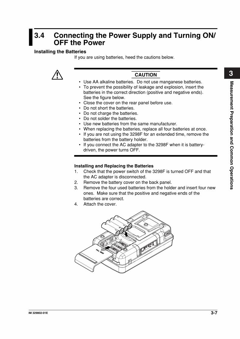
Installing the BatteriesIf you are using batteries, heed the cautions below.
CAUTION• Use AA alkaline batteries. Do not use manganese batteries.• To prevent the possibility of leakage and explosion, insert the
batteries in the correct direction (positive and negative ends).See the figure below.
• Close the cover on the rear panel before use.• Do not short the batteries.• Do not charge the batteries.• Do not solder the batteries.• Use new batteries from the same manufacturer.• When replacing the batteries, replace all four batteries at once.• If you are not using the 3298F for an extended time, remove the
batteries from the battery holder.• If you connect the AC adapter to the 3298F when it is battery-
driven, the power turns OFF.
Installing and Replacing the Batteries1. Check that the power switch of the 3298F is turned OFF and that
the AC adapter is disconnected.2. Remove the battery cover on the back panel.3. Remove the four used batteries from the holder and insert four new
ones. Make sure that the positive and negative ends of thebatteries are correct.
4. Attach the cover.
3-8 IM 329802-01E
Indication of Low BatteryWhen the batteries are low, a warning message “Low Battery” or“Battery Empty” is displayed at the top section of the LCD. When“Battery Empty” is displayed, the power is turned OFF within a fewseconds.Under continuous operation, the 3298F can run for approximately sixhours on four alkaline batteries.
Connecting the AC AdapterFollow the warnings and cautions below to avoid the danger ofelectric shock and damage to the 3298F.
WARNING• Only use YOKOGAWA’s AC adapters.• Check that the power switch is turned OFF before connecting the
AC adapter.
Connecting the AC adapterThe AC adapter is optional.1. Check that the power switch is OFF.2. Connect the AC adapter jack to the AC adapter terminal of the
3298F.
Turning ON/OFF the PowerThe power is turned ON/OFF through dial operation.
Power ON1. Check that the 3298F and the sensor are connected.
For the procedure to connect the sensor, see section 3.3.2. Connect external input/output as necessary.3. Connect the AC adapter.4. Place the cap on the tip of the sensor hood.5. Turn the dial from the OFF position to the desired position
(LUMINANCE, CONTRAST, FLICKER, CHROMA, or SET).6. The power turns ON, and the LCD shows “Initial Data Loading...”
followed by “Offset Calibration.”
Power OFF7. Turn the dial to the OFF position.
The power turns OFF.
Note• When turning the power ON, make sure to place the sensor cap is attached.• The setup information and data saved to the memory are retained even when the
power is turned OFF.
3.4 Connecting the Power Supply and Turning ON/OFF the Power
3-9IM 329802-01E
Measu
remen
t Prep
aration
and
Co
mm
on
Op
eration
s
3
3.5 Offset Calibration
Zero level calibration (offset calibration) can be carried out using thefollowing two methods on the 3298F.In either case, always place the sensor cap and shut out the input lightbefore calibration.
• At power up: Calibration is automatically executed.• Manual: You can execute calibration as necessary. For the
procedure, see below.
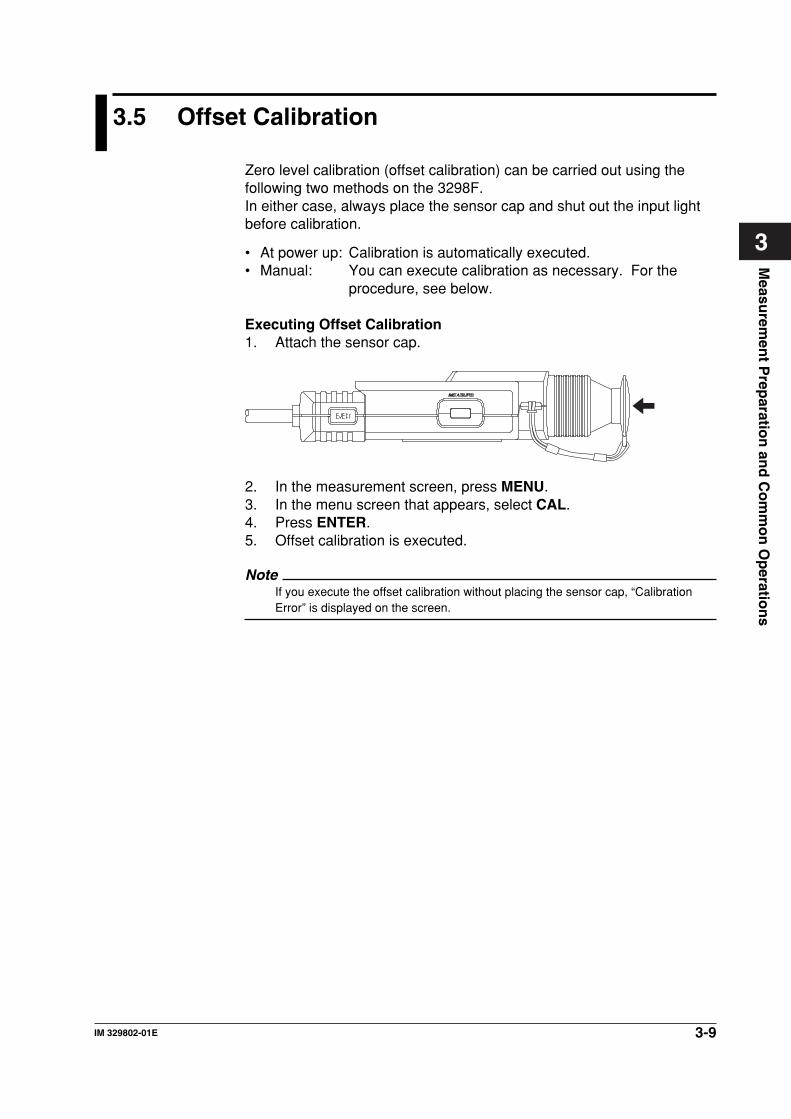
Executing Offset Calibration1. Attach the sensor cap.
2. In the measurement screen, press MENU.3. In the menu screen that appears, select CAL.4. Press ENTER.5. Offset calibration is executed.
NoteIf you execute the offset calibration without placing the sensor cap, “CalibrationError” is displayed on the screen.
3-10 IM 329802-01E
3.6 Connecting External Input/Output
Serial (RS-232) ConnectionConnect the 3298F and your PC using the dedicated cable. A serialcable with a D-sub 9 pin (part no. B8300LC) used to connect to the PCand another with a D-sub 25 pin (part no. B8300LD) are available.Select the appropriate cable for your PC.For details on the communications conditions and commands, seechapter 6, “Serial (RS-232) Communications Function.”
RS232C
Serial (RS-232) interface terminal
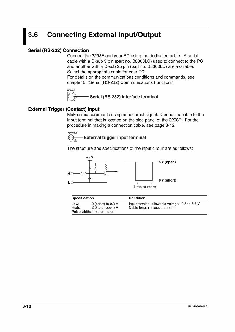
External Trigger (Contact) InputMakes measurements using an external signal. Connect a cable to theinput terminal that is located on the side panel of the 3298F. For theprocedure in making a connection cable, see page 3-12.
External trigger input terminalEXT TRIG
IN
The structure and specifications of the input circuit are as follows:
H
+5 V
L
5 V (open)
0 V (short)
1 ms or more
Specification Condition
Low: 0 (short) to 0.3 V Input terminal allowable voltage: -0.5 to 5.5 VHigh: 2.0 to 5 (open) V Cable length is less than 3 m.Pulse width: 1 ms or more
3-11IM 329802-01E
Measu
remen
t Prep
aration
and
Co
mm
on
Op
eration
s
3
3.6 Connecting External Input/Output
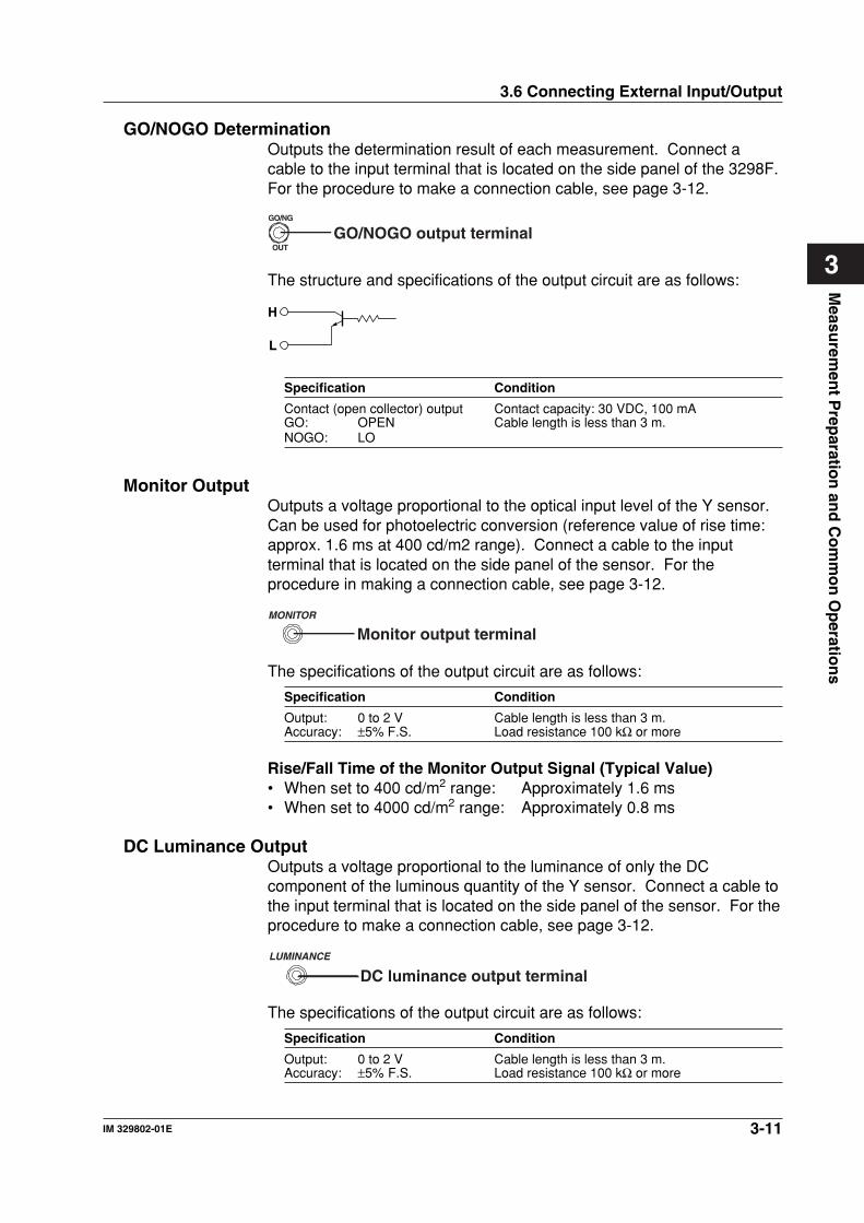
GO/NOGO DeterminationOutputs the determination result of each measurement. Connect acable to the input terminal that is located on the side panel of the 3298F.For the procedure to make a connection cable, see page 3-12.
GO/NG
OUTGO/NOGO output terminal
The structure and specifications of the output circuit are as follows:
H
L
Specification Condition
Contact (open collector) output Contact capacity: 30 VDC, 100 mAGO: OPEN Cable length is less than 3 m.NOGO: LO
Monitor OutputOutputs a voltage proportional to the optical input level of the Y sensor.Can be used for photoelectric conversion (reference value of rise time:approx. 1.6 ms at 400 cd/m2 range). Connect a cable to the inputterminal that is located on the side panel of the sensor. For theprocedure in making a connection cable, see page 3-12.
MONITOR
Monitor output terminal
The specifications of the output circuit are as follows:
Specification Condition
Output: 0 to 2 V Cable length is less than 3 m.Accuracy: ±5% F.S. Load resistance 100 kΩ or more
Rise/Fall Time of the Monitor Output Signal (Typical Value)• When set to 400 cd/m2 range: Approximately 1.6 ms• When set to 4000 cd/m2 range: Approximately 0.8 ms
DC Luminance OutputOutputs a voltage proportional to the luminance of only the DCcomponent of the luminous quantity of the Y sensor. Connect a cable tothe input terminal that is located on the side panel of the sensor. For theprocedure to make a connection cable, see page 3-12.
LUMINANCE
DC luminance output terminal
The specifications of the output circuit are as follows:
Specification Condition
Output: 0 to 2 V Cable length is less than 3 m.Accuracy: ±5% F.S. Load resistance 100 kΩ or more
3-12 IM 329802-01E
3.6 Connecting External Input/Output
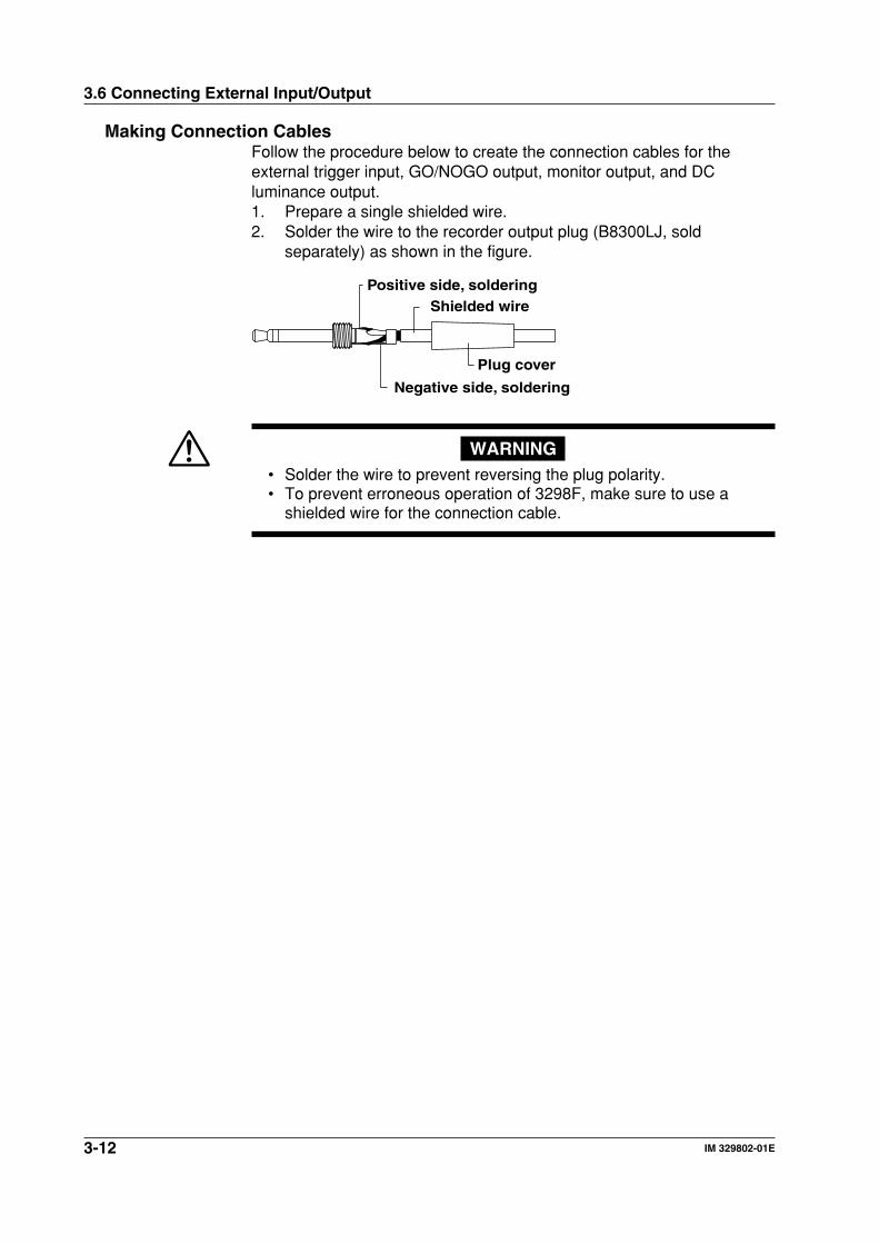
Making Connection CablesFollow the procedure below to create the connection cables for theexternal trigger input, GO/NOGO output, monitor output, and DCluminance output.1. Prepare a single shielded wire.2. Solder the wire to the recorder output plug (B8300LJ, sold
separately) as shown in the figure.
Positive side, soldering
Negative side, soldering
Shielded wire
Plug cover
WARNING• Solder the wire to prevent reversing the plug polarity.• To prevent erroneous operation of 3298F, make sure to use a
shielded wire for the connection cable.
3-13IM 329802-01E
Measu
remen
t Prep
aration
and
Co
mm
on
Op
eration
s
3
3.7 Screen Switching Operation and ParameterSelecting Operation
Switching ScreensSwitching to a Lower Menu or Screen1. Press to highlight the desired item.2. Press ENTER or .3. The lower menu or screen appears.
Switching to a Higher Menu or Screen4. Press ESC or .5. The higher menu or screen appears.
Selecting ItemsSelecting Numeric Setting Items1. Press to highlight the desired item.2. Press ENTER or .3. The numeric input window appears.
Selecting Character Setting Items3. Press to highlight the desired item.4. Press ENTER or .5. The character input window appears.
Selecting Items6. Press to highlight the desired item.7. Press ENTER or .8. A appears by the selected item.
ESC Key and ENTER KeyWhen you press ESC, one of the following operations is performed.• The operation in progress is aborted.• The previous (higher) menu is selected.
When you press ENTER, one of the following operations is performed.• A screen is selected.• An item is selected.• An input is confirmed.
3-14 IM 329802-01E
3.8 Numeric Setting Operation and CharacterSetting Operation
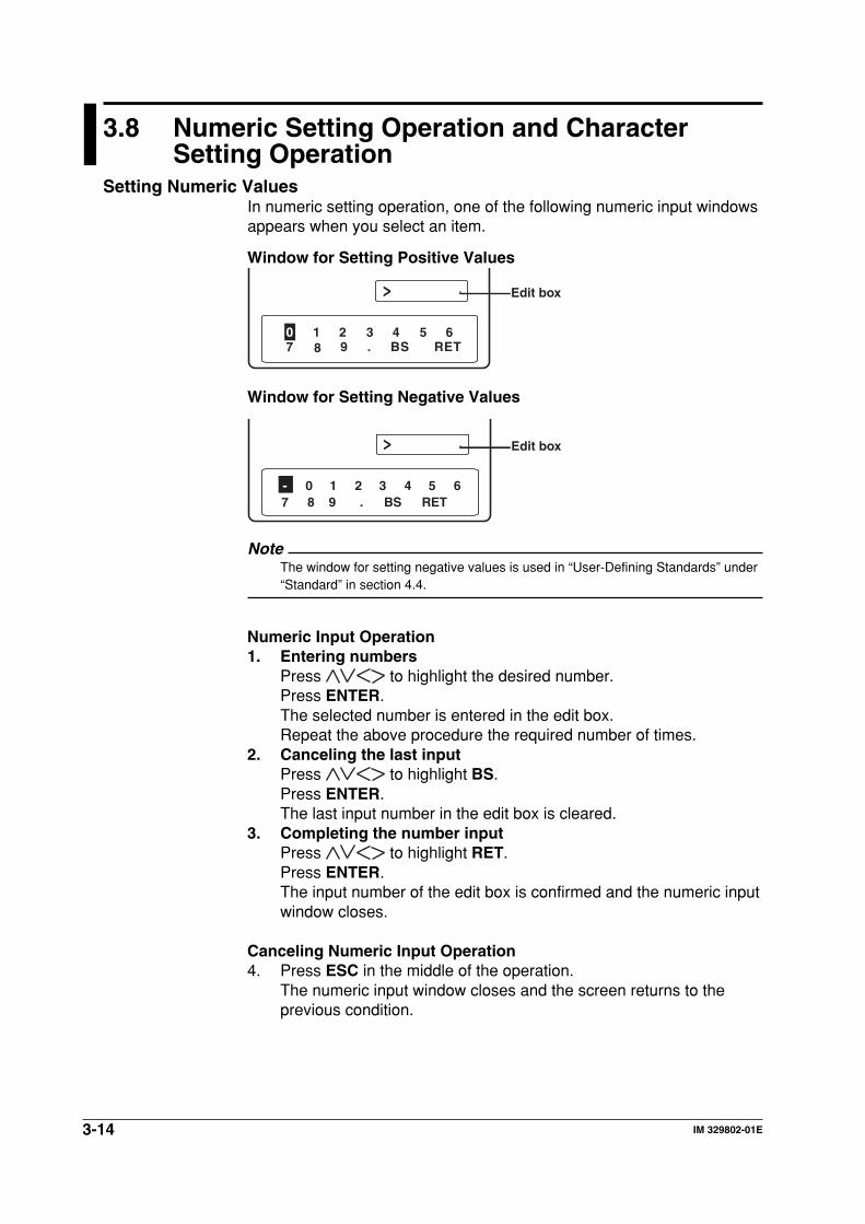
Setting Numeric ValuesIn numeric setting operation, one of the following numeric input windowsappears when you select an item.
Window for Setting Positive Values
>
0 1 2 3 4 5 67 8 9 . BS RET
Edit box
Window for Setting Negative Values
>
- 0 1 2 3 4 5 67 8 9 . BS RET
Edit box
NoteThe window for setting negative values is used in “User-Defining Standards” under“Standard” in section 4.4.
Numeric Input Operation1. Entering numbers
Press to highlight the desired number.Press ENTER.The selected number is entered in the edit box.Repeat the above procedure the required number of times.
2. Canceling the last inputPress to highlight BS.Press ENTER.The last input number in the edit box is cleared.
3. Completing the number inputPress to highlight RET.Press ENTER.The input number of the edit box is confirmed and the numeric inputwindow closes.
Canceling Numeric Input Operation4. Press ESC in the middle of the operation.
The numeric input window closes and the screen returns to theprevious condition.
3-15IM 329802-01E
Measu
remen
t Prep
aration
and
Co
mm
on
Op
eration
s
3
3.8 Numeric Setting Operation and Character Setting Operation
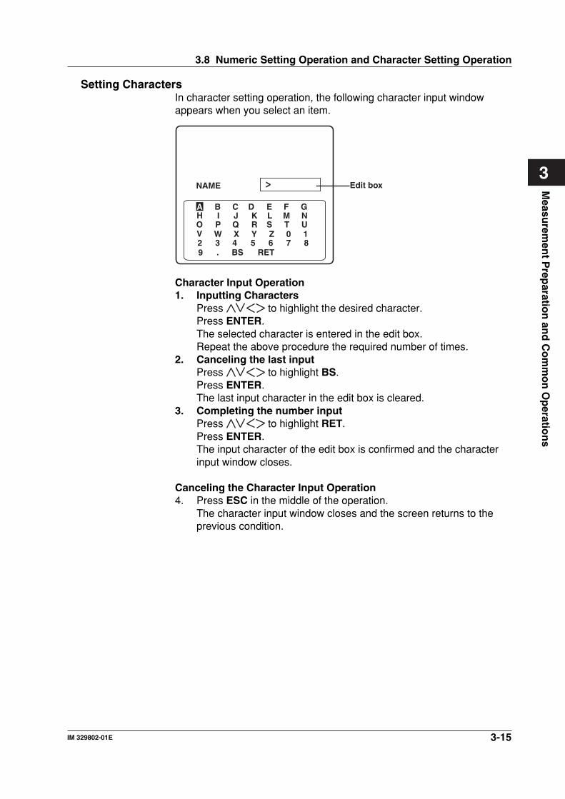
Setting CharactersIn character setting operation, the following character input windowappears when you select an item.
NAME >
A B C D E F GH I J K L M NO P Q R S T UV W X Y Z 0 12 3 4 5 6 7 89 . BS RET
Edit box
Character Input Operation1. Inputting Characters
Press to highlight the desired character.Press ENTER.The selected character is entered in the edit box.Repeat the above procedure the required number of times.
2. Canceling the last inputPress to highlight BS.Press ENTER.The last input character in the edit box is cleared.
3. Completing the number inputPress to highlight RET.Press ENTER.The input character of the edit box is confirmed and the characterinput window closes.
Canceling the Character Input Operation4. Press ESC in the middle of the operation.
The character input window closes and the screen returns to theprevious condition.
3-16 IM 329802-01E
3.9 Memory Operations
The 3298F can store 200 sets (memory no. 001 through 200) of data foreach measurement.
Saving the Measured ResultsThe following operation is performed in each measurement screen.1. To save the data to the memory number that is currently displayed
at the upper left corner of the LCD, proceed to step 3. To changethe memory number, proceed to step 2.
2. Press to switch the memory number that is displayed at theupper left corner of the LCD to the desired memory number.
3. Press ENTER.The measured results area saved to the memory that is currentlydisplayed at the upper left corner of the LCD.
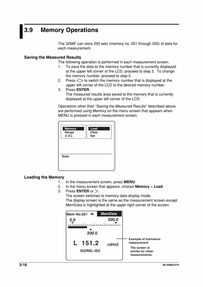
Operations other than “Saving the Measured Results” described aboveare performed using Memory on the menu screen that appears whenMENU is pressed in each measurement screen.
Note:
RangeC A L
ClearSet
Memory Load
Loading the Memory1. In the measurement screen, press MENU.2. In the menu screen that appears, choose Memory > Load.3. Press ENTER or .
The screen switches to memory data display mode.The display screen is the same as the measurement screen exceptMemData is highlighted at the upper right corner of the screen.
cd/m2
200.0
500.00.0Mem No.021
GO/NG::GO
L 151.2
MemData
Example of luminance measurement
The screen is similar for other measurements.
3-17IM 329802-01E
Measu
remen
t Prep
aration
and
Co
mm
on
Op
eration
s
3
3.9 Memory Operations
4. To switch the memory to be loaded, press to switch thememory number that is displayed at the upper left corner of the LCDto the desired memory number.
5. To return to the measurement screen, press ESC three times.
Clearing the Memory1. In the measurement screen, press MENU.2. In the menu screen that appears, choose Memory > Clear.3. Press ENTER or .
A confirmation message appears.4. To clear the memory, press ENTER. To cancel, press ESC.
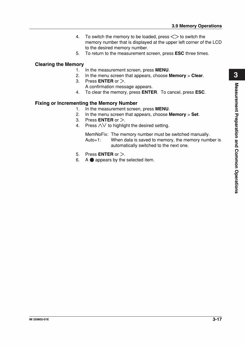
Fixing or Incrementing the Memory Number1. In the measurement screen, press MENU.2. In the menu screen that appears, choose Memory > Set.3. Press ENTER or .4. Press to highlight the desired setting.
MemNoFix: The memory number must be switched manually.Auto+1: When data is saved to memory, the memory number is
automatically switched to the next one.
5. Press ENTER or .6. A appears by the selected item.
4-1IM 329802-01E
Measu
remen
t Co
nd
ition
s and
3298F S
etup
4
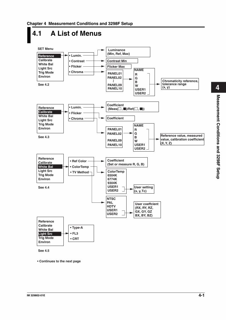
4.1 A List of Menus
Luminance(Min, Ref, Max)
Contrast Min
Flicker Max
ReferenceCalibrateWhite BalLight SrcTrig ModeEnviron
ReferenceCalibrateWhite BalLight SrcTrig ModeEnviron
ReferenceCalibrateWhite BalLight SrcTrig ModeEnviron
PANEL10
Chromaticity reference, tolerance range(x, y)
NAMERGBWUSER1USER2
Coefficient (Meas( , )/Ref( , ))
Coefficient
Reference value, measured value, calibration coefficient(X, Y, Z)
Coefficient(Set or measure R, G, B)
NTSCPALHDTVUSER1USER2
ColorTemp6504K6774K9304KUSER1USER2
User coeffcient(RX, RY, RZ, GX, GY, GZBX, BY, BZ)
User setting(x, y, Tc)
• Lumin.
• Contrast
• Flicker
• Chroma
• Lumin.
• Flicker
• Chroma
PANEL01PANEL02
PANEL09
ReferenceCalibrateWhite BalLight SrcTrig ModeEnviron
PANEL10
NAMERGBWUSER1USER2
PANEL01PANEL02
PANEL09
• Ref Color
• ColorTemp
• TV Method
• Type-A
• FL3
• CRT
See 4.2
See 4.3
See 4.4
See 4.5
SET Menu
• Continues to the next page
Chapter 4 Measurement Conditions and 3298F Setup
4-2 IM 329802-01E
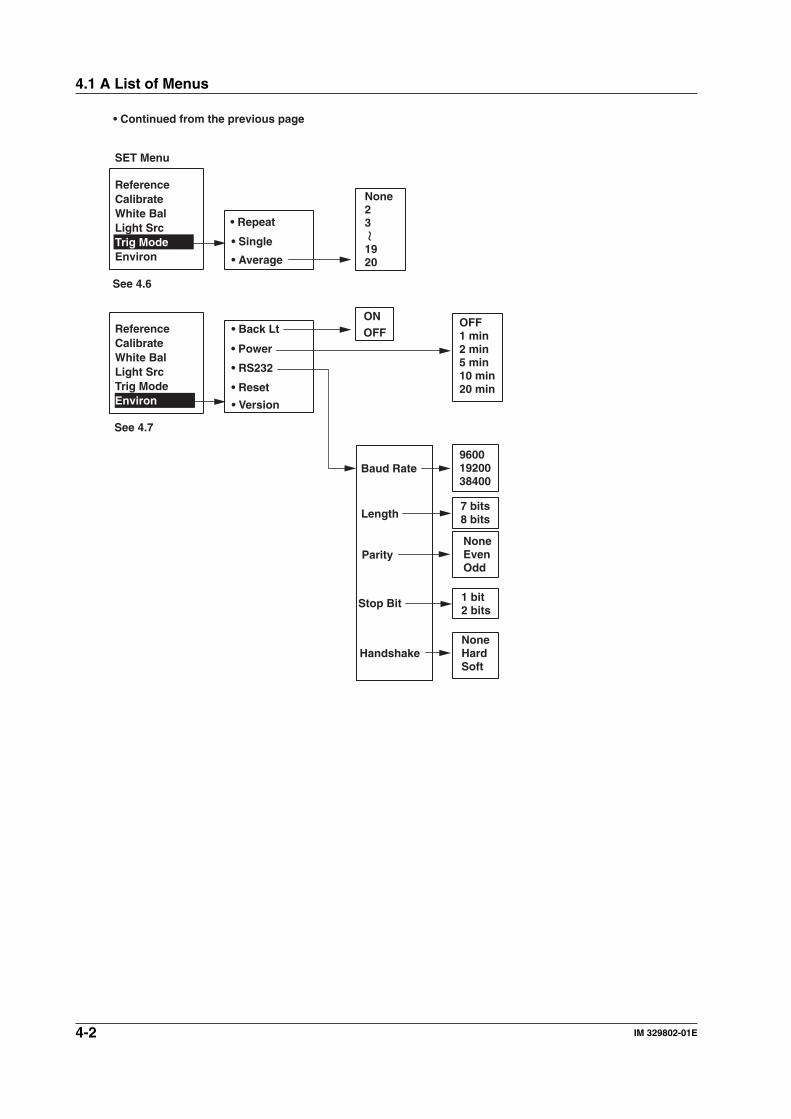
None23
1920
NoneHardSoft
1 bit2 bits
OFF1 min2 min5 min10 min20 min
96001920038400
NoneEvenOdd
7 bits8 bits
• Repeat
• Single
• Average
• Back Lt
• Power
• RS232
• Reset
• Version
ONOFF
Baud Rate
Length
Parity
Stop Bit
Handshake
SET Menu
ReferenceCalibrateWhite BalLight SrcTrig ModeEnviron
ReferenceCalibrateWhite BalLight SrcTrig ModeEnviron
See 4.6
See 4.7
• Continued from the previous page
4.1 A List of Menus
4-3IM 329802-01E
Measu
remen
t Co
nd
ition
s and
3298F S
etup
4
4.2 Setting the Reference Value
ExplanationReference ValuesReference values refer to target values used for the GO/NOGOdetermination. The following reference values are available for eachmeasurement function.• Luminance reference• Contrast reference• Flicker reference• Chromaticity reference
GO/NOGO DeterminationGO/NOGO determination determines whether the measured value iswithin a preset range, displays the determination result (GO or NOGO),and outputs a state signal.The reference values for each function are shown below.• Luminance reference
Set the reference (Ref) and the tolerance (Min and Max).Determines whether the measured luminance is within the tolerance.
• Contrast referenceSet the minimum contrast.Determines whether the measured contrast is greater than or equal tothe reference.
• Flicker referenceSet the maximum flicker.Determines whether the measured flicker ratio is less than or equal tothe reference.
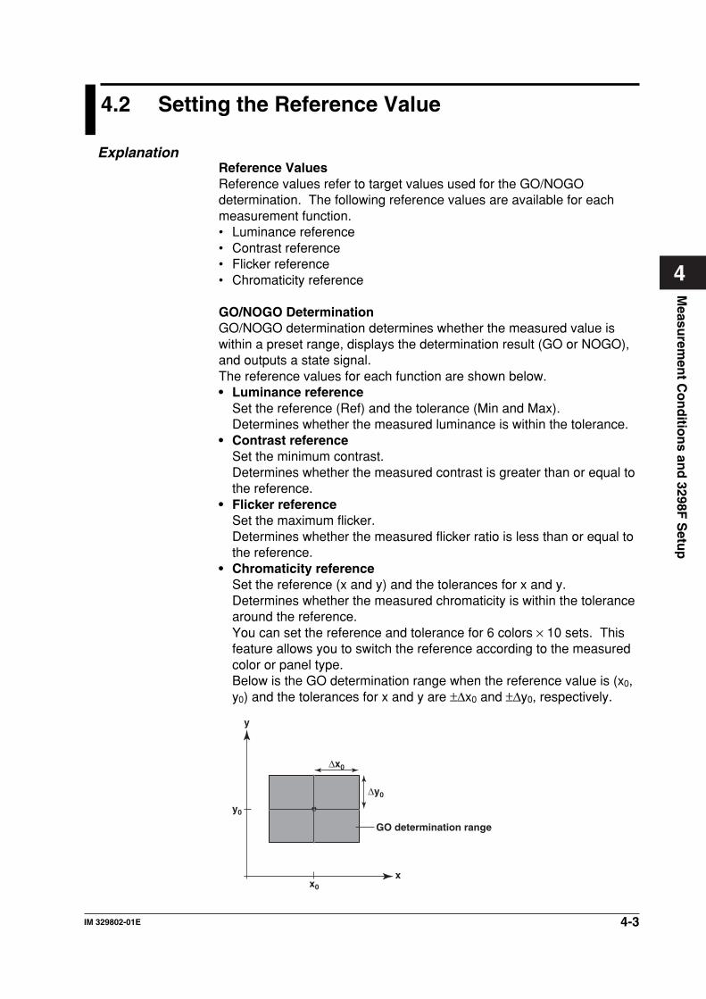
• Chromaticity referenceSet the reference (x and y) and the tolerances for x and y.Determines whether the measured chromaticity is within the tolerancearound the reference.You can set the reference and tolerance for 6 colors × 10 sets. Thisfeature allows you to switch the reference according to the measuredcolor or panel type.Below is the GO determination range when the reference value is (x0,y0) and the tolerances for x and y are ±∆x0 and ±∆y0, respectively.
∆x0
∆y0
y
xx0
y0
GO determination range
4-4 IM 329802-01E
4.2 Setting the Reference Value
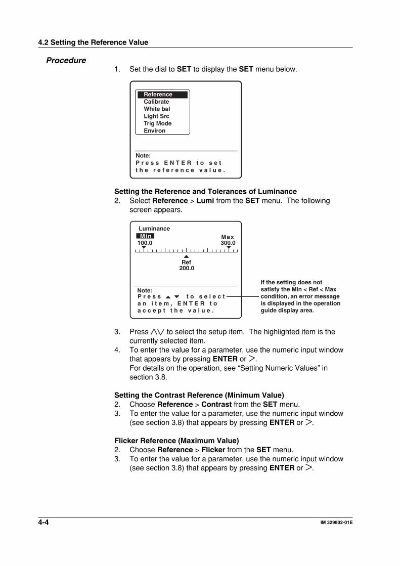
Procedure1. Set the dial to SET to display the SET menu below.
Note:P r e s s E N T E R t o s e tt h e r e f e r e n c e v a l u e .
ReferenceCalibrateWhite balLight SrcTrig ModeEnviron
Setting the Reference and Tolerances of Luminance2. Select Reference > Lumi from the SET menu. The following
screen appears.
Min Max300.0
200.0Ref
100.0
Luminance
P r e s s t o s e l e c t a n i t e m , E N T E R t o a c c e p t t h e v a l u e .
Note:If the setting does not satisfy the Min < Ref < Max condition, an error message is displayed in the operation guide display area.
3. Press to select the setup item. The highlighted item is thecurrently selected item.
4. To enter the value for a parameter, use the numeric input windowthat appears by pressing ENTER or .For details on the operation, see “Setting Numeric Values” insection 3.8.
Setting the Contrast Reference (Minimum Value)2. Choose Reference > Contrast from the SET menu.3. To enter the value for a parameter, use the numeric input window
(see section 3.8) that appears by pressing ENTER or .
Flicker Reference (Maximum Value)2. Choose Reference > Flicker from the SET menu.3. To enter the value for a parameter, use the numeric input window
(see section 3.8) that appears by pressing ENTER or .
4-5IM 329802-01E
Measu
remen
t Co
nd
ition
s and
3298F S
etup
4
Note• Press ESC to cancel the setup operation.• The scale of the bar graph on the flicker measurement screen is determined by
the maximum flicker value (criteria)
Maximum Flicker Scale
Less than 2% 2%Less than 4% 4%Less than 8% 8%Other 20%
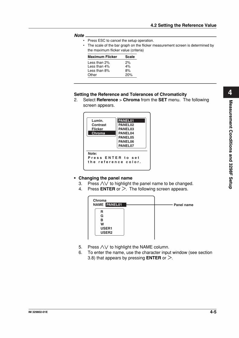
Setting the Reference and Tolerances of Chromaticity2. Select Reference > Chroma from the SET menu. The following
screen appears.
Note:P r e s s E N T E R t o s e tt h e r e f e r e n c e c o l o r .
PANEL01PANEL02PANEL03PANEL04PANEL05PANEL06PANEL07
Lumin.ContrastFlickerChroma
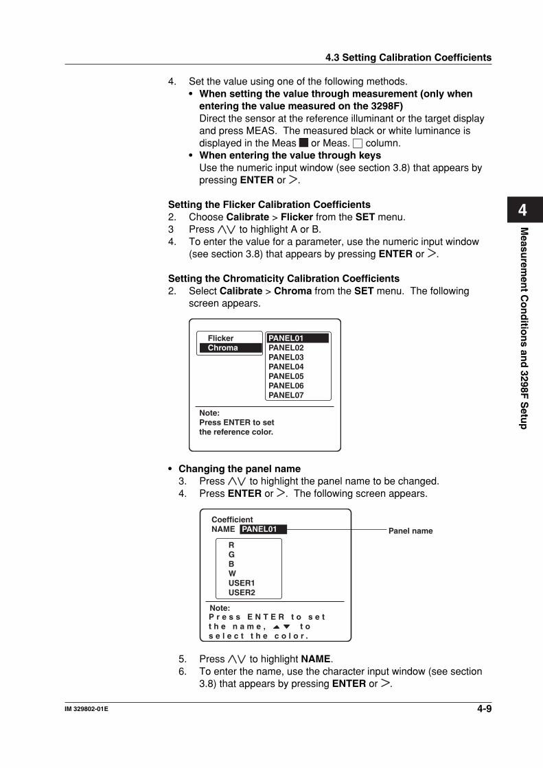
• Changing the panel name3. Press to highlight the panel name to be changed.4. Press ENTER or . The following screen appears.
RGBW USER1USER2
ChromaNAME PANEL01 Panel name
5. Press to highlight the NAME column.6. To enter the name, use the character input window (see section
3.8) that appears by pressing ENTER or .
4.2 Setting the Reference Value
4-6 IM 329802-01E
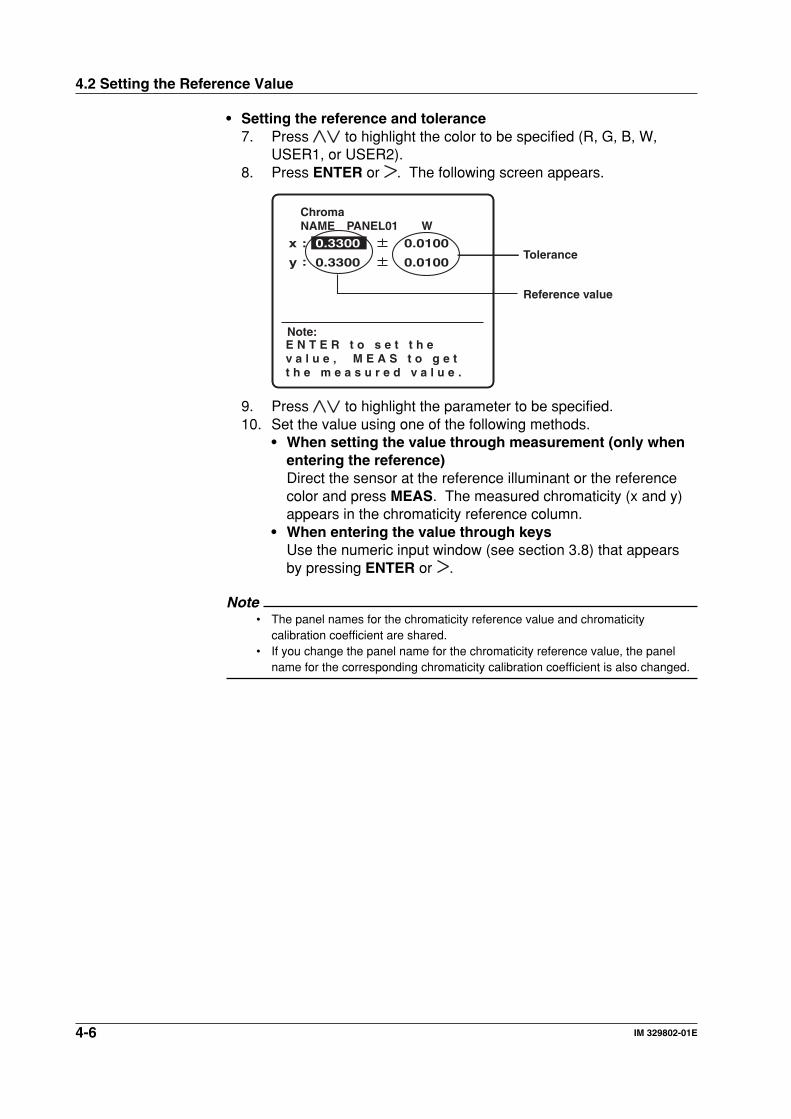
• Setting the reference and tolerance7. Press to highlight the color to be specified (R, G, B, W,
USER1, or USER2).8. Press ENTER or . The following screen appears.
ChromaNAME WPANEL01
y
x 0.0100:
:
0.3300
0.01000.3300
Note:E N T E R t o s e t t h e v a l u e , M E A S t o g e tt h e m e a s u r e d v a l u e .
Tolerance
Reference value
9. Press to highlight the parameter to be specified.10. Set the value using one of the following methods.
• When setting the value through measurement (only whenentering the reference)Direct the sensor at the reference illuminant or the referencecolor and press MEAS. The measured chromaticity (x and y)appears in the chromaticity reference column.
• When entering the value through keysUse the numeric input window (see section 3.8) that appearsby pressing ENTER or .
Note• The panel names for the chromaticity reference value and chromaticity
calibration coefficient are shared.• If you change the panel name for the chromaticity reference value, the panel
name for the corresponding chromaticity calibration coefficient is also changed.
4.2 Setting the Reference Value
4-7IM 329802-01E
Measu
remen
t Co
nd
ition
s and
3298F S
etup
4
4.3 Setting Calibration Coefficients
ExplanationIf you use the calibration coefficient function, the values measured onthe 3298F can be matched to the values measured on the standard. Inflicker measurements, the flicker ratio can be converted to valueconforming to the JEITA Standard or VESA Standard. You can set thefollowing calibration coefficients for each measurement function.• Luminance calibration coefficients
You can set the luminance calibration coefficients only when using theluminance sensor.The luminance calibration coefficients are calculated by setting thefollowing values.• White/Black luminance measured on the 3298F (Meas.)• White/Black luminance measured on the standard (Ref.)The measured luminance value using the luminance calibrationcoefficients is displayed. For details on how the calibrationcoefficients are determined, see section 1.5.
• Flicker calibration coefficientsSet the following values.• A: Flicker calibration coefficient• B: LOG calculation coefficientFor details on how to set the flicker calibration coefficients, see section1.5.
• Chromaticity calibration coefficientsYou can set chromaticity calibration coefficients only when using thecolor sensor.You can display corrected measured chromaticity values using thechromaticity calibration coefficients.You can set chromaticity calibration coefficients for six colors (R, G, B,W, USER1, and USER2) for 10 types of target panels.Chromaticity calibration coefficients are calculated by setting thefollowing values for each color• Tristimulus values X, Y, and Z measured on the 3298F (Meas.)• Tristimulus values X, Y, and Z measured on the standard (Ref.)The equation for calculating the chromaticity calibration coefficients isas follows:Chromaticity calibration coefficient = Meas./Ref.
Entering the Luminance and Chromaticity Calibration CoefficientsYou can set the calibration coefficients using the following two methods.• Use the numeric input window and enter the values using keys (Meas.
and Ref.)• Automatically set the measured values as calibration coefficients
(Meas. only)
4-8 IM 329802-01E
NoteUse tristimulus values X, Y, and Z to set each chromaticity calibration coefficient.• Reference value conversion
The calibration coefficient is set using the XYZ color system. If the valuesmeasured on the reference instrument are in x, y, L color system, convert thevalues to the X, Y, Z color system using the following equations.X = x/y × LY = LZ = (1-x-y)/y × L• When you set the calibration coefficient, the coefficient applies to all color
systems. For a description of the method of selecting the chromaticitycalibration coefficient during measurement, see “Selecting the chromaticityreference value or chromaticity calibration coefficient” in section 5.4, “Measuringthe Chromaticity.”
• Enter the value measured on a calibration standard or a reference instrumentthat you specified in Meas of the chromaticity calibration coefficient. Enter thevalue measured on the 3298F in Ref.
• If you set the Y value of the luminance calibration coefficients, the calibrationcoefficients are applied to the luminance (L) of all measurement functions.
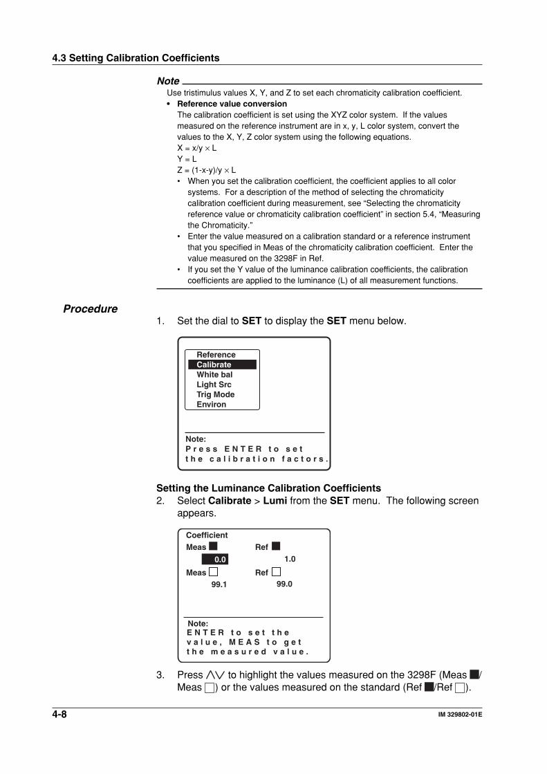
Procedure1. Set the dial to SET to display the SET menu below.
Note:P r e s s E N T E R t o s e tt h e c a l i b r a t i o n f a c t o r s .
ReferenceCalibrateWhite balLight SrcTrig ModeEnviron
Setting the Luminance Calibration Coefficients2. Select Calibrate > Lumi from the SET menu. The following screen
appears.
0.0 1.0
99.099.1
CoefficientMeas Ref
Meas Ref
Note:E N T E R t o s e t t h e v a l u e , M E A S t o g e tt h e m e a s u r e d v a l u e .
3. Press to highlight the values measured on the 3298F (Meas /Meas ) or the values measured on the standard (Ref /Ref ).
4.3 Setting Calibration Coefficients
4-9IM 329802-01E
Measu
remen
t Co
nd
ition
s and
3298F S
etup
4
4. Set the value using one of the following methods.• When setting the value through measurement (only when
entering the value measured on the 3298F)Direct the sensor at the reference illuminant or the target displayand press MEAS. The measured black or white luminance isdisplayed in the Meas or Meas. column.
• When entering the value through keysUse the numeric input window (see section 3.8) that appears bypressing ENTER or .
Setting the Flicker Calibration Coefficients2. Choose Calibrate > Flicker from the SET menu.3 Press to highlight A or B.4. To enter the value for a parameter, use the numeric input window
(see section 3.8) that appears by pressing ENTER or .
Setting the Chromaticity Calibration Coefficients2. Select Calibrate > Chroma from the SET menu. The following
screen appears.
Note:Press ENTER to setthe reference color.
PANEL01PANEL02PANEL03PANEL04PANEL05PANEL06PANEL07
FlickerChroma
• Changing the panel name3. Press to highlight the panel name to be changed.4. Press ENTER or . The following screen appears.
RGBW USER1USER2
CoefficientNAME PANEL01 Panel name
Note:P r e s s E N T E R t o s e t t h e n a m e , t o s e l e c t t h e c o l o r .
5. Press to highlight NAME.6. To enter the name, use the character input window (see section
3.8) that appears by pressing ENTER or .
4.3 Setting Calibration Coefficients
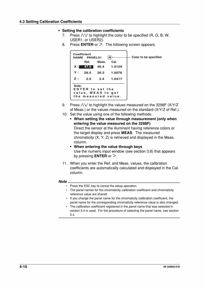
4-10 IM 329802-01E
• Setting the calibration coefficients7. Press to highlight the color to be specified (R, G, B, W,
USER1, or USER2).8. Press ENTER or . The following screen appears.
0.0
CoefficientNAME R
Note:E N T E R t o s e t t h e v a l u e , M E A S t o g e tt h e m e a s u r e d v a l u e .
Ref. Meas. Cal.
:
:
:
46.4
26.3
2.4
47.0
26.5
2.5
1.0129
1.0076
1.0417
X
Y
Z
PANEL01 Color to be specified
9. Press to highlight the values measured on the 3298F (X/Y/Zof Meas.) or the values measured on the standard (X/Y/Z of Ref.).
10. Set the value using one of the following methods.• When setting the value through measurement (only when
entering the value measured on the 3298F)Direct the sensor at the illuminant having reference colors orthe target display and press MEAS. The measuredchromaticity (X, Y, Z) is retrieved and displayed in the Meas.column.
• When entering the value through keysUse the numeric input window (see section 3.8) that appearsby pressing ENTER or .
11. When you enter the Ref. and Meas. values, the calibrationcoefficients are automatically calculated and displayed in the Cal.column.
Note• Press the ESC key to cancel the setup operation.• The panel names for the chromaticity calibration coefficient and chromaticity
reference value are shared.• If you change the panel name for the chromaticity calibration coefficient, the
panel name for the corresponding chromaticity reference value is also changed.• The calibration coefficient registered in the panel name that was selected in
section 5.4 is used. For the procedure of selecting the panel name, see section5.4.
4.3 Setting Calibration Coefficients
4-11IM 329802-01E
Measu
remen
t Co
nd
ition
s and
3298F S
etup
4
4.4 Setting the White Balance Adjustment
ExplanationAdjusting the White BalanceThe white balance (color temperature) of the display is adjusted bychanging the optical intensity of R, G, B. Therefore, the RGB colorsystem is usually used when adjusting the white balance. To display inthe RGB color system, the following parameters need to be configured.• Reference color: Select the color to be fixed when adjusting RGB.
The chromaticity of the selected color (R, G, orB) is taken to be 100%, and the chromaticityvalues of other colors are displayed aspercentages.
• Color temperature: Select 6504K, 6774K, 9304K, USER1, orUSER2. The target chromaticity x and y areautomatically determined from the selected colortemperature. You can arbitrarily set the targetluminance L. If you select USER1 or USER2, setthe target color temperature x and y and thetarget luminance L.
• Standard: The constants necessary to calculate the logicalvalues of RGB and the measured values of RGBvary depending on the broadcasting system(NTSC, PAL, HDTV, and user-defined). Selectthe broadcasting system that complies with thetarget display.
In white balance adjustment, set these parameters correctly and use theRGB color system.
User-Defining Color TemperaturesYou can register two types of settings.You can set target color temperatures x and y and the target luminanceL using one of two methods.• Use the numeric input window and enter the values using keys• Enter the values by retrieving measured values
User-Defining StandardsYou can user-define two sets of constants for standards other than theNTSC, PAL, and HDTV broadcasting systems.You set the constants (RX, RY, RZ/GX, GY, GZ/BX, BY, and BZ) for thetristimulus values of R, G, B.
RGB
XYZ
RX RY RZ
GX GY GZ
BX BY BZ
=
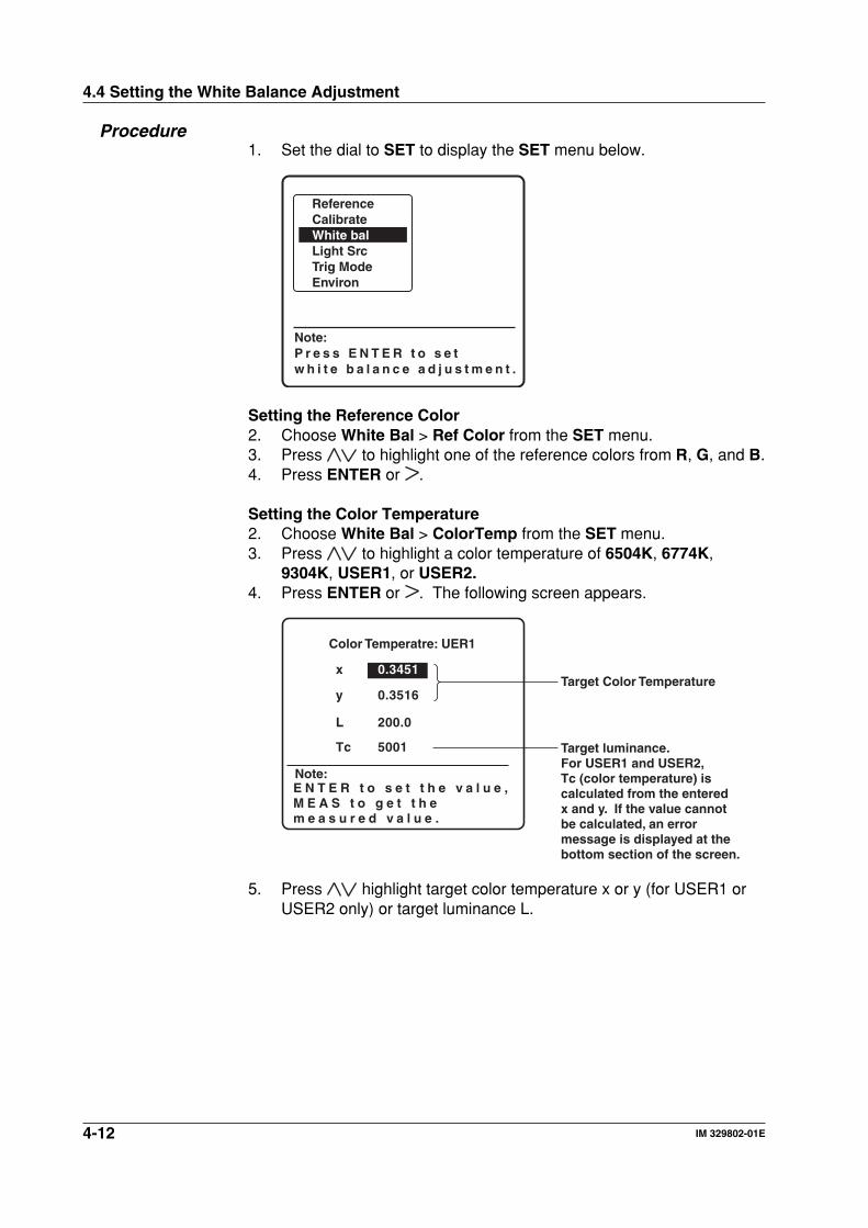
4-12 IM 329802-01E
Procedure1. Set the dial to SET to display the SET menu below.
Note:P r e s s E N T E R t o s e tw h i t e b a l a n c e a d j u s t m e n t .
ReferenceCalibrateWhite balLight SrcTrig ModeEnviron
Setting the Reference Color2. Choose White Bal > Ref Color from the SET menu.3. Press to highlight one of the reference colors from R, G, and B.4. Press ENTER or .
Setting the Color Temperature2. Choose White Bal > ColorTemp from the SET menu.3. Press to highlight a color temperature of 6504K, 6774K,
9304K, USER1, or USER2.4. Press ENTER or . The following screen appears.
x 0.3451
y 0.3516
L 200.0
Color Temperatre: UER1
Tc 5001 Target luminance. For USER1 and USER2, Tc (color temperature) is calculated from the entered x and y. If the value cannot be calculated, an error message is displayed at the bottom section of the screen.
Target Color Temperature
Note:E N T E R t o s e t t h e v a l u e , M E A S t o g e t t h e m e a s u r e d v a l u e .
5. Press highlight target color temperature x or y (for USER1 orUSER2 only) or target luminance L.
4.4 Setting the White Balance Adjustment
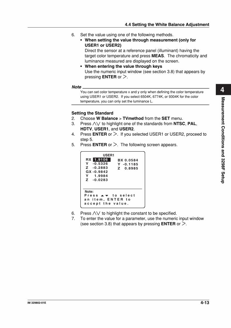
4-13IM 329802-01E
Measu
remen
t Co
nd
ition
s and
3298F S
etup
4
6. Set the value using one of the following methods.• When setting the value through measurement (only for
USER1 or USER2)Direct the sensor at a reference panel (illuminant) having thetarget color temperature and press MEAS. The chromaticity andluminance measured are displayed on the screen.
• When entering the value through keysUse the numeric input window (see section 3.8) that appears bypressing ENTER or .
NoteYou can set color temperature x and y only when defining the color temperatureusing USER1 or USER2. If you select 6504K, 6774K, or 9304K for the colortemperature, you can only set the luminance L.
Setting the Standard2. Choose W Balance > TVmethod from the SET menu.3. Press to highlight one of the standards from NTSC, PAL,
HDTV, USER1, and USER2.4. Press ENTER or . If you selected USER1 or USER2, proceed to
step 5.5. Press ENTER or . The following screen appears.
RXYZGXYZ
1.9106-0.5326-0.2883-0.98421.9984
-0.0283
BXYZ
0.0584-0.11850.8985
USER1
Note:P r e s s t o s e l e c t a n i t e m , E N T E R t o a c c e p t t h e v a l u e .
6. Press to highlight the constant to be specified.7. To enter the value for a parameter, use the numeric input window
(see section 3.8) that appears by pressing ENTER or .
4.4 Setting the White Balance Adjustment
4-14 IM 329802-01E
4.5 Setting Light Source Calibration
ExplanationThe 3298F has the light source calibration coefficients below. Select theappropriate light source calibration coefficient according to the targetdisplay.
• Type A (Type-A standard light source)Makes measurements using the light source calibration coefficientobtained when the 3298F was calibrated using standard illuminant A.For example, select this coefficient when measuring a car tail lampthat has a light bulb covered by a colored glass.
• FL3 (Three-wavelength fluorescent lamp)Makes measurements using the light source calibration coefficientobtained when the 3298F was calibrated using a three-wavelengthfluorescent lamp.For example, select this coefficient when measuring an LCD that usescold-cathode fluorescent lamp for its backlight.
• CRTMakes measurements using the light source calibration coefficientobtained when the 3298F was calibrated using a CRT. Select thiscoefficient when measuring CRTs.
For details on light source calibration coefficients, see section 1.4.
Procedure1. Set the dial to SET to display the SET menu.2. Choose LightSrc from the SET menu.
Selecting the Light Source Calibration Coefficient3. Press to highlight a light source of Type-A, FL3, or CRT.4. Press ENTER or .
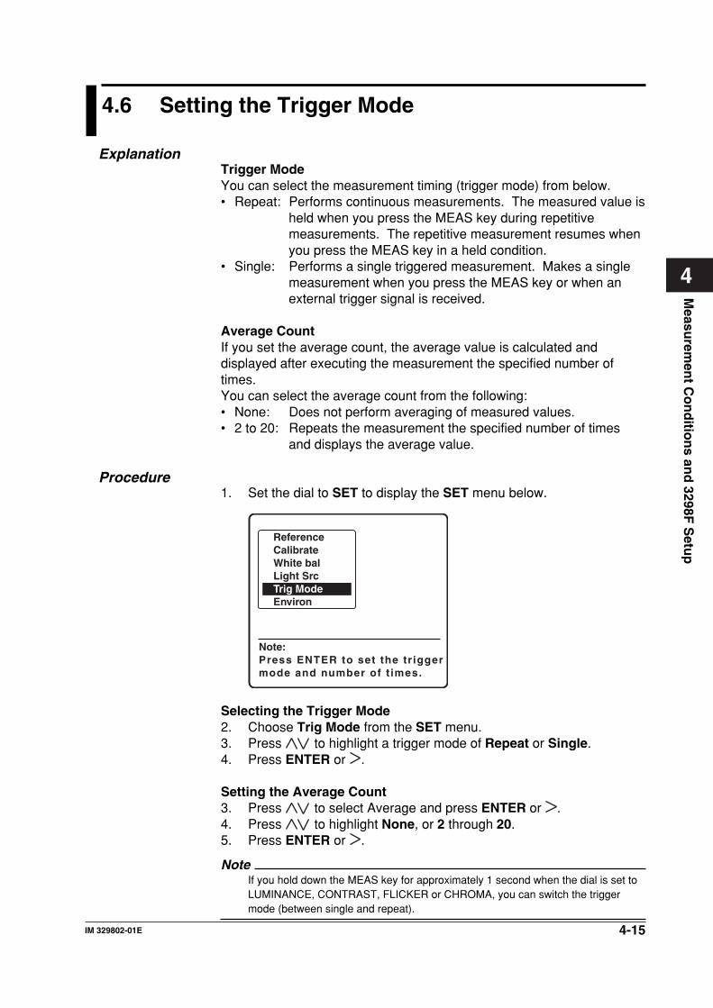
4-15IM 329802-01E
Measu
remen
t Co
nd
ition
s and
3298F S
etup
4
4.6 Setting the Trigger Mode
ExplanationTrigger ModeYou can select the measurement timing (trigger mode) from below.• Repeat: Performs continuous measurements. The measured value is
held when you press the MEAS key during repetitivemeasurements. The repetitive measurement resumes whenyou press the MEAS key in a held condition.
• Single: Performs a single triggered measurement. Makes a singlemeasurement when you press the MEAS key or when anexternal trigger signal is received.
Average CountIf you set the average count, the average value is calculated anddisplayed after executing the measurement the specified number oftimes.You can select the average count from the following:• None: Does not perform averaging of measured values.• 2 to 20: Repeats the measurement the specified number of times
and displays the average value.
Procedure1. Set the dial to SET to display the SET menu below.
Note:Press ENTER to set the tr igger mode and number of t imes.
ReferenceCalibrateWhite balLight SrcTrig ModeEnviron
Selecting the Trigger Mode2. Choose Trig Mode from the SET menu.3. Press to highlight a trigger mode of Repeat or Single.4. Press ENTER or .
Setting the Average Count3. Press to select Average and press ENTER or .4. Press to highlight None, or 2 through 20.5. Press ENTER or .
NoteIf you hold down the MEAS key for approximately 1 second when the dial is set toLUMINANCE, CONTRAST, FLICKER or CHROMA, you can switch the triggermode (between single and repeat).
4-16 IM 329802-01E
4.7 Setting the 3298F
Procedure1. Set the dial to SET to display the SET menu.
Back Light2. Choose Environ > Back Lt from the SET menu.
Turning the Back Light ON/OFF3. Press to highlight either of the backlight settings from OFF and
ON.4. Press ENTER or .
NoteIf you turn the backlight ON when the 3298F is battery-driven, the backlightautomatically turns OFF after approximately 20 seconds. The backlight turns backON when a key is pressed.
Shut Down2. Choose Environ > Shutdown from the SET menu.
Setting Shut Down3. Press to highlight a shut down setting of OFF, 1 min, 2 min, 5
min, 10 min, or 20 min.4. Press ENTER or .
NoteThis function is valid when the 3298F is battery-driven.
Setting CommunicationsTo set communications conditions, use the screen that appears bychoosing Environ > RS232.The following items and selections are available.
Item Selection
Baud rate 9600, 19200, and 38400Data length 7 bits and 8 bitsParity None, Even, and OddStop bit 1 bit and 2 bitsHandshaking None, Hard, and Soft
Setting the Baud Rate2. Choose Environ > RS232 > Baud Rate from the SET menu.3. Press to highlight one of the baud rates choosing from 9800,
19200, and 38400.4. Press ENTER or .
Setting Data Length through Handshaking ParametersSet other parameters in a fashion similar to the aforementioned baudrate.
4-17IM 329802-01E
Measu
remen
t Co
nd
ition
s and
3298F S
etup
4
Initial2. Choose Environ > Initial from the SET menu.3. Press ENTER or to display a screen for selecting the items to be
initialized.4. Press to highlight [ALL], [Settings], [Reference], or
[Calibrate].5. Press ENTER or to execute the initialization of the selected
items. Press ESC to abort initialization.
NoteYou can select the items to be initialized from the following:• ALL: Initializes setting values, reference values, and calibration coefficients.• Settings: Initializes only the settings.• Reference: Initialize the reference values and panel names• Calibrate: Initializes only the calibration coefficients.For details on the default values, see Appendix 1.
Version2. Choose Environ > Version from the SET menu.3. The ROM version of the 3298F is displayed.
4.7 Setting the 3298F
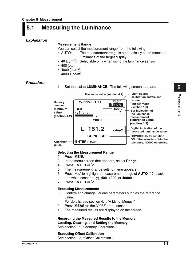
5-1IM 329802-01E
Measu
remen
t
5
Chapter 5 Measurement
5.1 Measuring the Luminance
ExplanationMeasurement RangeYou can select the measurement range from the following:• AUTO: The measurement range is automatically set to match the
luminance of the target display.• 40 [cd/m2]: Selectable only when using the luminance sensor• 400 [cd/m2]• 4000 [cd/m2]• 40000 [cd/m2]
Procedure1. Set the dial to LUMINANCE. The following screen appears.
ENTER:
cd/m2
200.0
500.00.0
Mem
MemNo.001
GO/NG: GO
L 151.2
Memory number
Reference value (section 4.2)
Bar indication of the luminance measurement
Minimum value (section 4.2)
Operation guide
Maximum value (section 4.2)
Digital indication of the measured luminance value
GO/NOGO DeterminationGO if the value is within the tolerance, NOGO otherwise.
SingleFL3
Trigger mode (section 1.6)
Light source calibration coefficient to use
Selecting the Measurement Range2. Press MENU.3. In the menu screen that appears, select Range.4. Press ENTER or .5. The measurement range setting menu appears.6. Press to highlight a measurement range of AUTO, 40 (black
and white sensor only), 400, 4000, or 40000.7. Press ENTER or .
Executing Measurements8. Confirm and change various parameters such as the reference
value.For details, see section 4.1, “A List of Menus.”
9. Press MEAS on the 3298F or the sensor.10. The measured results are displayed on the screen.
Recording the Measured Results to the MemoryLoading, Clearing, and Setting the MemorySee section 3.9, “Memory Operations.”
Executing Offset CalibrationSee section 3.5, “Offset Calibration.”
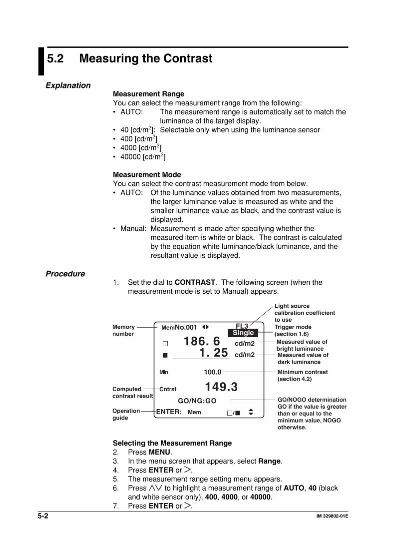
5-2 IM 329802-01E
5.2 Measuring the Contrast
ExplanationMeasurement RangeYou can select the measurement range from the following:• AUTO: The measurement range is automatically set to match the
luminance of the target display.• 40 [cd/m2]: Selectable only when using the luminance sensor• 400 [cd/m2]• 4000 [cd/m2]• 40000 [cd/m2]
Measurement ModeYou can select the contrast measurement mode from below.• AUTO: Of the luminance values obtained from two measurements,
the larger luminance value is measured as white and thesmaller luminance value as black, and the contrast value isdisplayed.
• Manual: Measurement is made after specifying whether themeasured item is white or black. The contrast is calculatedby the equation white luminance/black luminance, and theresultant value is displayed.
Procedure1. Set the dial to CONTRAST. The following screen (when the
measurement mode is set to Manual) appears.
Memory number
Operation guide
ENTER:
cd/m2
cd/m2
100.0
Mem /
MemNo.001
Cntrst
Min
GO/NG:GO
149.3
186. 61. 25
Measured value of bright luminanceMeasured value of dark luminance
Minimum contrast (section 4.2)
Computed contrast result
GO/NOGO determinationGO if the value is greater than or equal to the minimum value, NOGO otherwise.
SingleFL3 Trigger mode
(section 1.6)
Light source calibration coefficient to use
Selecting the Measurement Range2. Press MENU.3. In the menu screen that appears, select Range.4. Press ENTER or .5. The measurement range setting menu appears.6. Press to highlight a measurement range of AUTO, 40 (black
and white sensor only), 400, 4000, or 40000.7. Press ENTER or .
5-3IM 329802-01E
Measu
remen
t
5
5.2 Measuring the Contrast
Select Measurement Mode8. At the measurement screen, press MENU.9. In the menu screen that appears, select MeasMode.10. Press ENTER or .11. The measurement mode setting menu appears.12. Press to highlight either the Auto or Manual measurement
mode.13. Press ENTER or .
Executing Measurements14. Confirm and change various parameters such as the reference
value.For details, see section 4.1, “A List of Menus.”
15. Execute theÌeasurement.• When the Measurement Mode is Set to Auto
Press MEAS on the 3298F or the sensor. Switch the displaycondition of the target display, and press MEAS again.
• When the Measurement Mode is Set to ManualCheck whether the display condition of the target display is thesame as the underlined color. Then, press MEAS on the 3298For the sensor.Press and switch the display condition of the target display,and press MEAS again.
• Recording the Measured Results to the Memory• Loading, Clearing, and Setting the Memory
See section 3.9, “Memory Operations.”
• Executing Offset CalibrationSee section 3.5, “Offset Calibration.”
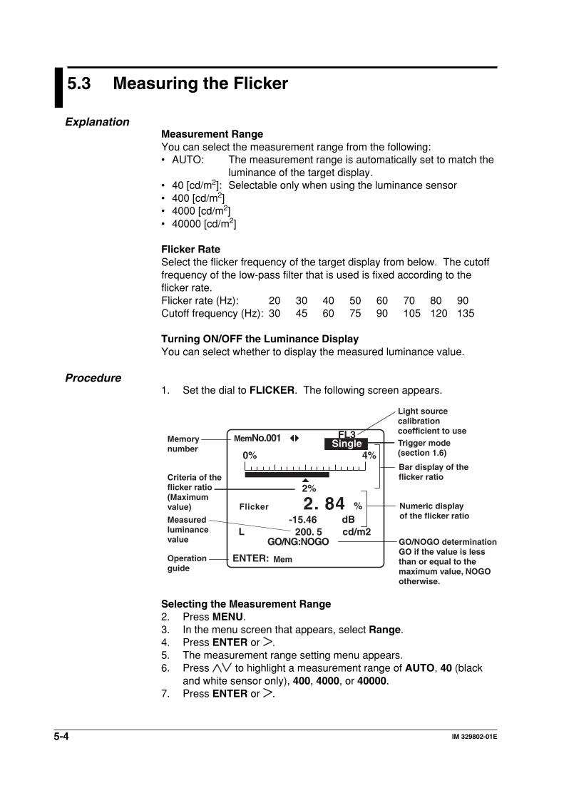
5-4 IM 329802-01E
5.3 Measuring the Flicker
ExplanationMeasurement RangeYou can select the measurement range from the following:• AUTO: The measurement range is automatically set to match the
luminance of the target display.• 40 [cd/m2]: Selectable only when using the luminance sensor• 400 [cd/m2]• 4000 [cd/m2]• 40000 [cd/m2]
Flicker RateSelect the flicker frequency of the target display from below. The cutofffrequency of the low-pass filter that is used is fixed according to theflicker rate.Flicker rate (Hz): 20 30 40 50 60 70 80 90Cutoff frequency (Hz): 30 45 60 75 90 105 120 135
Turning ON/OFF the Luminance DisplayYou can select whether to display the measured luminance value.
Procedure1. Set the dial to FLICKER. The following screen appears.
Memory number
Operation guide
ENTER:
L cd/m2200. 5
2%
%dB-15.46
0% 4%
Mem
MemNo.001
Flicker
GO/NG:NOGO
2. 84
Bar display of the flicker ratio
Numeric display of the flicker ratioMeasured
luminance value
Criteria of the flicker ratio(Maximum value)
GO/NOGO determinationGO if the value is less than or equal to the maximum value, NOGO otherwise.
Single Trigger mode(section 1.6)
FL3
Light source calibration coefficient to use
Selecting the Measurement Range2. Press MENU.3. In the menu screen that appears, select Range.4. Press ENTER or .5. The measurement range setting menu appears.6. Press to highlight a measurement range of AUTO, 40 (black
and white sensor only), 400, 4000, or 40000.7. Press ENTER or .
5-5IM 329802-01E
Measu
remen
t
5
5.3 Measuring the Flicker
Selecting the Luminance Display8. At the measurement screen, press MENU.9. In the menu screen that appears, select Lumi.dsp.10. Press ENTER or .11. The luminance display setting menu is displayed.12. Press to highlight ON or OFF.13. Press ENTER or .
NoteIf you turn ON the luminance display, the measurement time (screen updating)takes longer.
Selecting the Flicker Rate14. In the measurement screen, press MENU.15. In the menu screen that appears, select Freqency.16. Press ENTER or .17. The flicker rate setting menu is displayed.18. Press to highlight one of the flicker rates from 20 Hz through
90 Hz (10 Hz steps)19. Press ENTER or .
Executing Measurements20. Confirm and change various parameters such as the reference
value.For details, see section 4.1, “A List of Menus.”
21. Press MEAS on the 3298F or the sensor.22. The measured result is displayed on the screen.
Recording the Measured Results to the MemoryLoading, Clearing, and Setting the MemorySee section 3.9, “Memory Operations.”
Executing Offset CalibrationSee section 3.5, “Offset Calibration.”
5-6 IM 329802-01E
5.4 Measuring the Chromaticity
Measurement RangeYou can select the measurement range from the following:• AUTO: The measurement range is automatically set to match the
luminance of the target display.• 400 [cd/m2]• 4000 [cd/m2]• 40000 [cd/m2]
Reference Values and Calibration CoefficientsFrom the measurement condition panels registered in advance insection 4.2 and 4.3, select the panel that is used for GO/NOGOdetermination and calibration. Each measurement condition panel has aset of registered chromaticity reference values and chromaticitycalibration coefficients. There is also a DEFAULT panel in whichchromaticity reference values and chromaticity calibration coefficientsare not specified. If you select this panel and make measurements, GO/NOGO determination and calibration will not be performed.
Selecting the Target Color for GO/NOGO Determination andChromaticity CalibrationSelect the target color for GO/NOGO determination and chromaticitycalibration.R, G, B, W, USER1, or USER2
Display ModeYou can select the color system from the following:x, y, L/u’, v’, L/X, Y, Z/r,g,b ratio/R, G, B/Tc, duv, or L
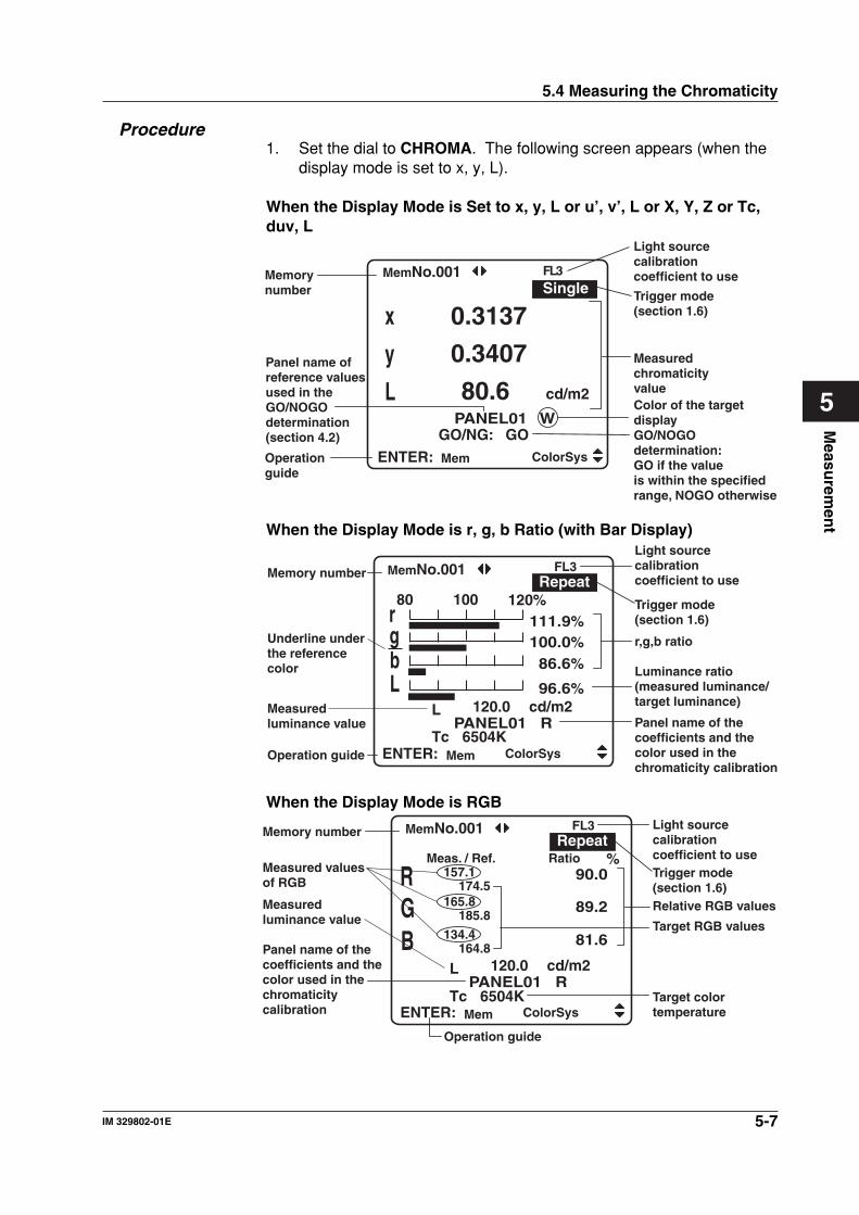
5-7IM 329802-01E
Measu
remen
t
5
5.4 Measuring the Chromaticity
Procedure1. Set the dial to CHROMA. The following screen appears (when the
display mode is set to x, y, L).
When the Display Mode is Set to x, y, L or u’, v’, L or X, Y, Z or Tc,duv, L
x
y
L
0.3137
0.3407
80.6PANEL01 W
GO/NG: GO
cd/m2
FL3
ENTER: Mem ColorSys
Memory number
Operation guide
MemNo.001
Measured chromaticity valueColor of the target display
Panel name of reference values used in the GO/NOGO determination (section 4.2) GO/NOGO
determination:GO if the value is within the specified range, NOGO otherwise
Single Trigger mode(section 1.6)
Light source calibration coefficient to use
When the Display Mode is r, g, b Ratio (with Bar Display)
PANEL01 R
Memory number
Operation guide
Measured luminance value
rgb
L 120.0
Tc 6504K
cd/m2
80 100 120111.9100.0
86.6
Light source calibration coefficient to use
r,g,b ratio
Luminance ratio (measured luminance/target luminance)
Panel name of the coefficients and the color used in the chromaticity calibration
Underline under the reference color
Trigger mode(section 1.6)
%%%%
L 96.6%
FL3Repeat
ENTER: ColorSys
MemNo.001
Mem
When the Display Mode is RGB
PANEL01 R
Meas.157.1
174.5165.8
185.8
134.4164.8
/ Ref. Ratio
Memory number
Measured values of RGB
Operation guide
Measured luminance value
Panel name of the coefficients and the color used in the chromaticity calibration
RGB
L 120.0
Tc 6504K
cd/m2
90.0
89.2
81.6
Light source calibration coefficient to use
Relative RGB values
Target RGB values
Target color temperature
Trigger mode(section 1.6)
%
FL3Repeat
ENTER: ColorSys
MemNo.001
Mem
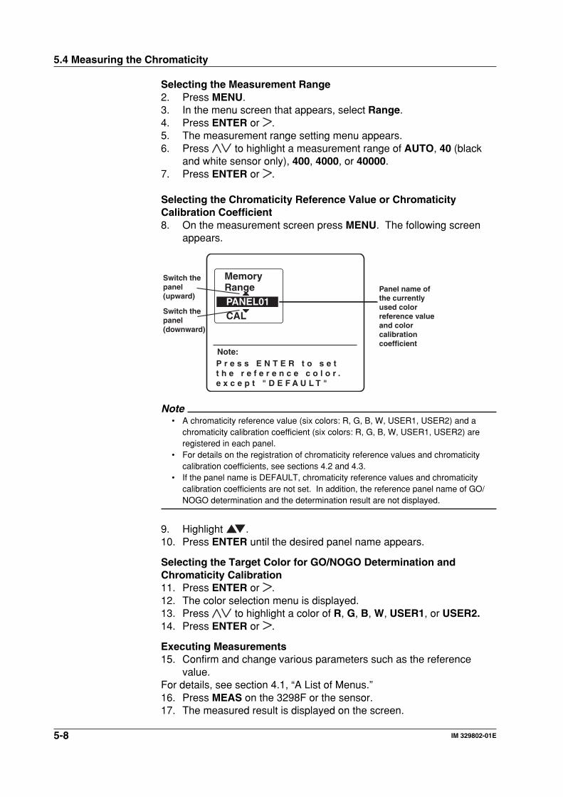
5-8 IM 329802-01E
Selecting the Measurement Range2. Press MENU.3. In the menu screen that appears, select Range.4. Press ENTER or .5. The measurement range setting menu appears.6. Press to highlight a measurement range of AUTO, 40 (black
and white sensor only), 400, 4000, or 40000.7. Press ENTER or .
Selecting the Chromaticity Reference Value or ChromaticityCalibration Coefficient8. On the measurement screen press MENU. The following screen
appears.
Note:
Range
P r e s s E N T E R t o s e tt h e r e f e r e n c e c o l o r .e x c e p t " D E F A U L T "
CALPANEL01
MemoryPanel name of the currently used color reference value and color calibration coefficient
Switch the panel(upward)
Switch the panel(downward)
Note• A chromaticity reference value (six colors: R, G, B, W, USER1, USER2) and a
chromaticity calibration coefficient (six colors: R, G, B, W, USER1, USER2) areregistered in each panel.
• For details on the registration of chromaticity reference values and chromaticitycalibration coefficients, see sections 4.2 and 4.3.
• If the panel name is DEFAULT, chromaticity reference values and chromaticitycalibration coefficients are not set. In addition, the reference panel name of GO/NOGO determination and the determination result are not displayed.
9. Highlight .10. Press ENTER until the desired panel name appears.
Selecting the Target Color for GO/NOGO Determination andChromaticity Calibration11. Press ENTER or .12. The color selection menu is displayed.13. Press to highlight a color of R, G, B, W, USER1, or USER2.14. Press ENTER or .
Executing Measurements15. Confirm and change various parameters such as the reference
value.For details, see section 4.1, “A List of Menus.”16. Press MEAS on the 3298F or the sensor.17. The measured result is displayed on the screen.
5.4 Measuring the Chromaticity
5-9IM 329802-01E
Measu
remen
t
5
Switching the Display Mode (Color System)18. Press to switch the display mode (color system) in a cyclic
fashion as shown below.[x,y,L] [u',v',L] [X,Y,Z] [r,g,b]
[R,G,B] [Tc,duv,L] [x,y,L]
Recording the Measured Results to the MemoryLoading, Clearing, and Setting the MemorySee section 3.9, “Memory Operations.”
Executing Offset CalibrationSee section 3.5, “Offset Calibration.”
5.4 Measuring the Chromaticity
6-1IM 329802-01E
Serial (R
S-232) C
om
mu
nicatio
ns F
un
ction
6
Chapter 6 Serial (RS-232) Communications Function
6.1 RS-232 Interface Functions and Specifications
Reception FunctionsYou can specify the same settings as those specified by front panel key operations.The 3298F receives output requests for measured and computed data, and setup information.
Transmission FunctionsOutputs measured and computed data.Able to output setup information.
RS-232 Interface SpecificationsElectrical characteristics: Conforms to EIA RS-232Connection method: Point-to-pointTransmission mode: Full-duplexSynchronization: Start-stop synchronizationBaud rate: 9600, 19200, and 38400Start bit: Fixed to 1 bitData length: 7 or 8 bitsParity: Even, odd, or no parityStop bit: 1 or 2 bitsConnector: 8-pin circular DIN connectorHardware handshaking: Controlled using the RS and CS signals.Software handshaking: Controls transmission and reception using the X-ON and X-OFF
signals.X-ON (ASCII 11H)X-OFF (ASCII 13H)
Received buffer length: 64 bytes
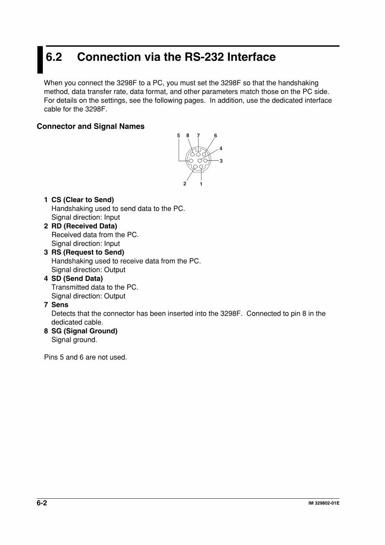
6-2 IM 329802-01E
6.2 Connection via the RS-232 Interface
When you connect the 3298F to a PC, you must set the 3298F so that the handshakingmethod, data transfer rate, data format, and other parameters match those on the PC side.For details on the settings, see the following pages. In addition, use the dedicated interfacecable for the 3298F.
Connector and Signal Names
1
3
6785
4
2
1 CS (Clear to Send)Handshaking used to send data to the PC.Signal direction: Input
2 RD (Received Data)Received data from the PC.Signal direction: Input
3 RS (Request to Send)Handshaking used to receive data from the PC.Signal direction: Output
4 SD (Send Data)Transmitted data to the PC.Signal direction: Output
7 SensDetects that the connector has been inserted into the 3298F. Connected to pin 8 in thededicated cable.
8 SG (Signal Ground)Signal ground.
Pins 5 and 6 are not used.
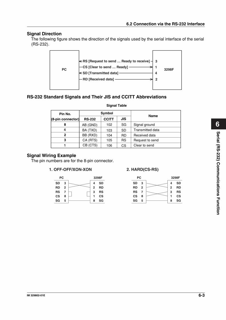
6-3IM 329802-01E
Serial (R
S-232) C
om
mu
nicatio
ns F
un
ction
6
6.2 Connection via the RS-232 Interface
Signal DirectionThe following figure shows the direction of the signals used by the serial interface of the serial(RS-232).
PC 3298F
RS [Request to send … Ready to receive]
SD [Transmitted data]
RD [Received data] 2
3
CS [Clear to send … Ready] 1
4
RS-232 Standard Signals and Their JIS and CCITT Abbreviations
Signal Table
Pin No.
(8-pin connector)
Symbol
RS-232Name
CCITT JIS
3
2
8 AB (GND)
BA (TXD)
BB (RXD)
CB (CTS)
CA (RTS)
102 SG
103104
106
105
SD
RD
CS
RS
Signal ground
Transmitted data
Request to sendReceived data
Clear to send
4
1
Signal Wiring ExampleThe pin numbers are for the 8-pin connector.
SDRDRSCSSG
SDRDRS
SG
1. OFF-OFF/XON-XON
PC 3298F
SDRDRSCSSG
SDRDRS
SG
2. HARD(CS-RS)
PC 3298F
CS CS
2 3
8 7
5
2 4
1 3
8
2 3
8 7
5
2 4
1 3
8
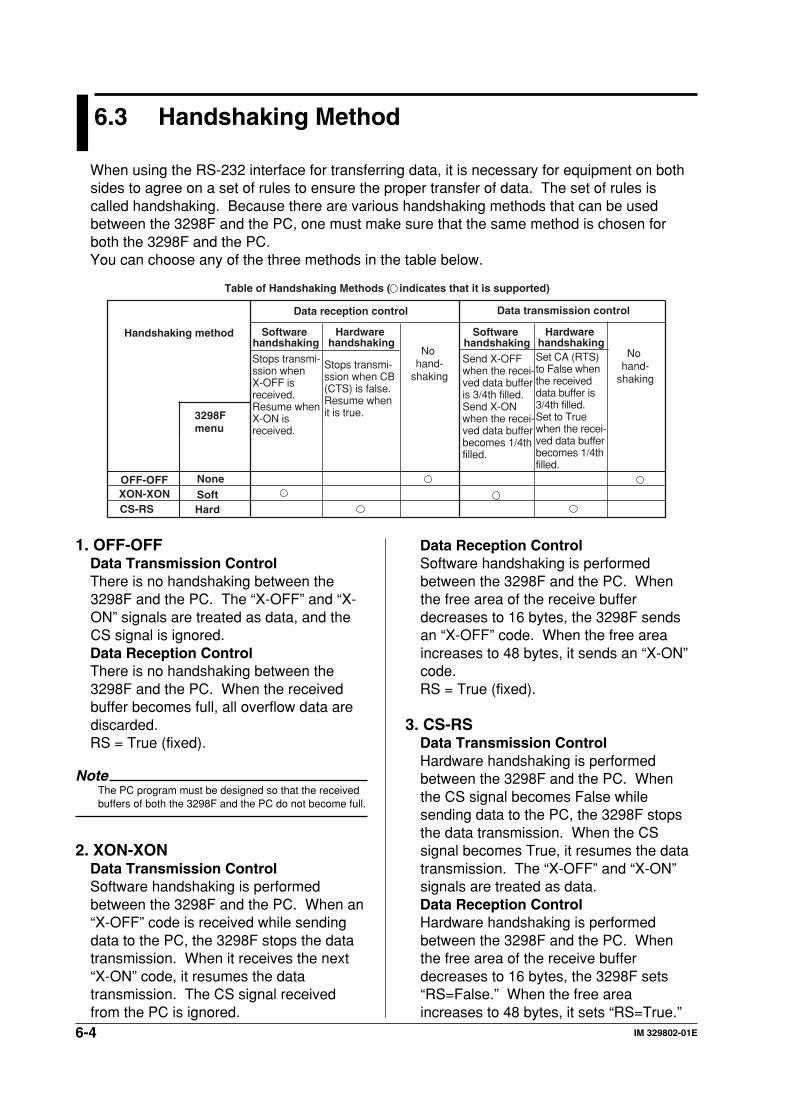
6-4 IM 329802-01E
6.3 Handshaking Method
When using the RS-232 interface for transferring data, it is necessary for equipment on bothsides to agree on a set of rules to ensure the proper transfer of data. The set of rules iscalled handshaking. Because there are various handshaking methods that can be usedbetween the 3298F and the PC, one must make sure that the same method is chosen forboth the 3298F and the PC.You can choose any of the three methods in the table below.
Data reception control Data transmission control
Software handshaking
Table of Handshaking Methods ( indicates that it is supported)
NoneOFF-OFF
Handshaking method
Stops transmi-ssion when X-OFF is received. Resume when X-ON is received.
Stops transmi-ssion when CB(CTS) is false. Resume when it is true.
No hand-
shaking
No hand-
shaking
Send X-OFF when the recei-ved data buffer is 3/4th filled. Send X-ON when the recei-ved data buffer becomes 1/4th filled.
Set CA (RTS) to False when the received data buffer is 3/4th filled. Set to True when the recei-ved data buffer becomes 1/4th filled.
Hardware handshaking
Software handshaking
Hardware handshaking
3298F menu
SoftHard
XON-XONCS-RS
1. OFF-OFFData Transmission ControlThere is no handshaking between the3298F and the PC. The “X-OFF” and “X-ON” signals are treated as data, and theCS signal is ignored.Data Reception ControlThere is no handshaking between the3298F and the PC. When the receivedbuffer becomes full, all overflow data arediscarded.RS = True (fixed).
NoteThe PC program must be designed so that the receivedbuffers of both the 3298F and the PC do not become full.
2. XON-XONData Transmission ControlSoftware handshaking is performedbetween the 3298F and the PC. When an“X-OFF” code is received while sendingdata to the PC, the 3298F stops the datatransmission. When it receives the next“X-ON” code, it resumes the datatransmission. The CS signal receivedfrom the PC is ignored.
Data Reception ControlSoftware handshaking is performedbetween the 3298F and the PC. Whenthe free area of the receive bufferdecreases to 16 bytes, the 3298F sendsan “X-OFF” code. When the free areaincreases to 48 bytes, it sends an “X-ON”code.RS = True (fixed).
3. CS-RSData Transmission ControlHardware handshaking is performedbetween the 3298F and the PC. Whenthe CS signal becomes False whilesending data to the PC, the 3298F stopsthe data transmission. When the CSsignal becomes True, it resumes the datatransmission. The “X-OFF” and “X-ON”signals are treated as data.Data Reception ControlHardware handshaking is performedbetween the 3298F and the PC. Whenthe free area of the receive bufferdecreases to 16 bytes, the 3298F sets“RS=False.” When the free areaincreases to 48 bytes, it sets “RS=True.”
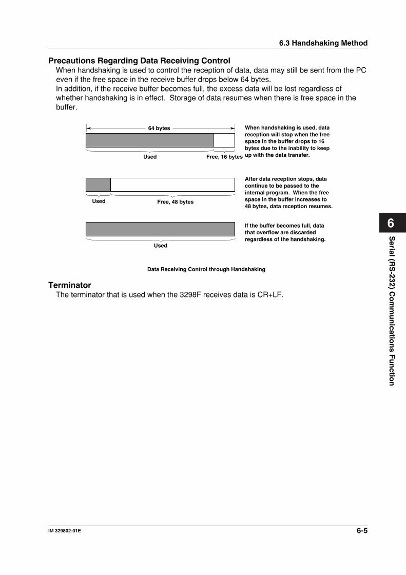
6-5IM 329802-01E
Serial (R
S-232) C
om
mu
nicatio
ns F
un
ction
6
6.3 Handshaking Method
Precautions Regarding Data Receiving ControlWhen handshaking is used to control the reception of data, data may still be sent from the PCeven if the free space in the receive buffer drops below 64 bytes.In addition, if the receive buffer becomes full, the excess data will be lost regardless ofwhether handshaking is in effect. Storage of data resumes when there is free space in thebuffer.
64 bytes
Used Free, 16 bytes
When handshaking is used, data reception will stop when the free space in the buffer drops to 16 bytes due to the inability to keep up with the data transfer.
Used Free, 48 bytes
After data reception stops, data continue to be passed to the internal program. When the free space in the buffer increases to 48 bytes, data reception resumes.
Used
If the buffer becomes full, data that overflow are discarded regardless of the handshaking.
Data Receiving Control through Handshaking
TerminatorThe terminator that is used when the 3298F receives data is CR+LF.
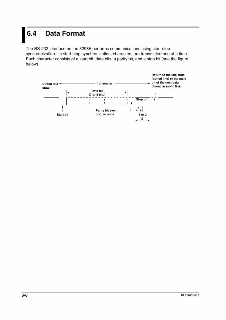
6-6 IM 329802-01E
6.4 Data Format
The RS-232 interface on the 3298F performs communications using start-stopsynchronization. In start-stop synchronization, characters are transmitted one at a time.Each character consists of a start bit, data bits, a parity bit, and a stop bit (see the figurebelow).
Data bit(7 or 8 bits)
1 character
Stop bit
1
21 or 2
Parity bit even, odd, or noneStart bit
Circuit idle state
Return to the idle state (dotted line) or the start bit of the next data character (solid line)
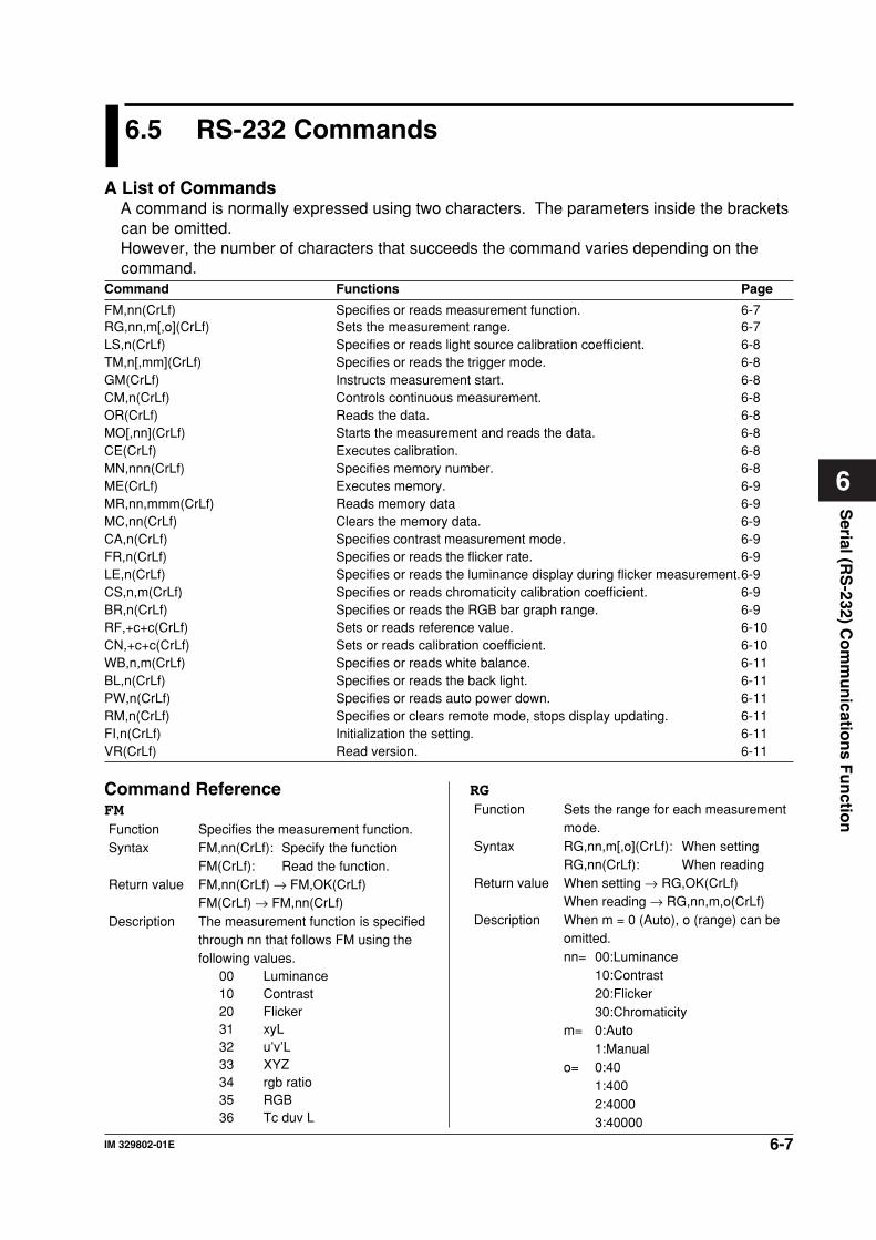
6-7IM 329802-01E
Serial (R
S-232) C
om
mu
nicatio
ns F
un
ction
6
6.5 RS-232 Commands
A List of CommandsA command is normally expressed using two characters. The parameters inside the bracketscan be omitted.However, the number of characters that succeeds the command varies depending on thecommand.
Command Functions Page
FM,nn(CrLf) Specifies or reads measurement function. 6-7RG,nn,m[,o](CrLf) Sets the measurement range. 6-7LS,n(CrLf) Specifies or reads light source calibration coefficient. 6-8TM,n[,mm](CrLf) Specifies or reads the trigger mode. 6-8GM(CrLf) Instructs measurement start. 6-8CM,n(CrLf) Controls continuous measurement. 6-8OR(CrLf) Reads the data. 6-8MO[,nn](CrLf) Starts the measurement and reads the data. 6-8CE(CrLf) Executes calibration. 6-8MN,nnn(CrLf) Specifies memory number. 6-8ME(CrLf) Executes memory. 6-9MR,nn,mmm(CrLf) Reads memory data 6-9MC,nn(CrLf) Clears the memory data. 6-9CA,n(CrLf) Specifies contrast measurement mode. 6-9FR,n(CrLf) Specifies or reads the flicker rate. 6-9LE,n(CrLf) Specifies or reads the luminance display during flicker measurement.6-9CS,n,m(CrLf) Specifies or reads chromaticity calibration coefficient. 6-9BR,n(CrLf) Specifies or reads the RGB bar graph range. 6-9RF,+c+c(CrLf) Sets or reads reference value. 6-10CN,+c+c(CrLf) Sets or reads calibration coefficient. 6-10WB,n,m(CrLf) Specifies or reads white balance. 6-11BL,n(CrLf) Specifies or reads the back light. 6-11PW,n(CrLf) Specifies or reads auto power down. 6-11RM,n(CrLf) Specifies or clears remote mode, stops display updating. 6-11FI,n(CrLf) Initialization the setting. 6-11VR(CrLf) Read version. 6-11
Command ReferenceFMFunction Specifies the measurement function.Syntax FM,nn(CrLf): Specify the function
FM(CrLf): Read the function.Return value FM,nn(CrLf) → FM,OK(CrLf)
FM(CrLf) → FM,nn(CrLf)Description The measurement function is specified
through nn that follows FM using thefollowing values.
00 Luminance10 Contrast20 Flicker31 xyL32 u’v’L33 XYZ34 rgb ratio35 RGB36 Tc duv L
RGFunction Sets the range for each measurement
mode.Syntax RG,nn,m[,o](CrLf): When setting
RG,nn(CrLf): When readingReturn value When setting → RG,OK(CrLf)
When reading → RG,nn,m,o(CrLf)Description When m = 0 (Auto), o (range) can be
omitted.nn= 00:Luminance
10:Contrast20:Flicker30:Chromaticity
m= 0:Auto1:Manual
o= 0:401:4002:40003:40000
6-8 IM 329802-01E
6.5 RS-232 Commands
LSFunction Sets the type of light source calibration
coefficient.Syntax LS,n(CrLf): When setting
LS(CrLf): When readingReturn value LS,n(CrLf) → LS,OK(CrLf)
LS(CrLf) → LS,n(CrLf)Description n=0: type-A, 1: FL3, 2: CRT
TMFunction Specifies the trigger mode.Syntax TM,n[,mm](CrLf): When setting
TM(CrLf): When readingReturn value When setting → TM,OK(CrLf)
When reading → TM,n,mm(CrLf)Description Set the trigger mode using the
following parameters (n and mm) thatsucceed TM.n= 0: Single, 1: Repeatmm=Average count (00 or 01 signifies
no average.)
GMFunction Starts the measurement.Syntax GM,n(CrLf)Return value GM,OK(CrLf)Description Performs the same operation as the
MEAS key on the 3298F and thesensor.The operation varies depending on thetrigger mode as follows:When the trigger mode is repeat:
Switches between repeat(continuous measurement) andhold.
When the trigger mode is single:Performs a single measurement(single trigger measurement).
CMFunction Starts/Stops continuous measurement.Syntax CM,n(CrLf)Return value CM,OK(CrLf)Description Instructs starting and stopping of
continuous measurement and thetransmission of continuous data.n=0: Stops continuous measurement.n=1: Starts continuous measurement.
Equivalent to issuing the GMcommand when repeat isspecified.
n=2: Starts continuous measurementand outputs data each time ameasurement is completed.When n=2, CM,OK is nottransmitted.
ORFunction Reads the measured data.Syntax OR(CrLf)Return value See output data format (page 6-11).Description The measured data is read according
to the current measurement functionthat is selected. This commandalways reads the last measured value.To retrieve the newest measuredvalue, perform measurements inadvance using the GM command.
MOFunction Starts the measurement and reads the
data.Syntax MO[,nn](CrLf)
Switches the function and performsmeasurement and data read. If youomit [], measurement and data readare performed using the currentfunction.MO,10,m(CrLf)Switches the function to contrast andperforms measurement and data read.Specify white measurement or blackmeasurement using parameter m.
Return value See output data format (page 6-11).Description nn = 00: Luminance
10: Contrast20: Flicker31: xyL32: u'v'L33: XYZ34: RGB ratio35: RGB36: Tc duv L
m= 0: Black measurement1: White measurement
Parameter m is valid only duringcontrast measurement.
CEFunction The CE command executes zero
calibration.Syntax CE(CrLf)Return value CE,OK(CrLf)Description The 3298F returns CE,OK when the
calibration is completed.
MNFunction Specifies the memory number.Syntax MN,nnn(CrLf)Return value MN,OK(CrLf)Description nnn: Memory number (001 through
200)
6-9IM 329802-01E
Serial (R
S-232) C
om
mu
nicatio
ns F
un
ction
6
MEFunction Saves the current measured value to
the memory.Syntax ME(CrLf)Return value ME,OK(CrLf)
MRFunction Reads the memory data at number
mmm of the function specified by nn.Syntax MR,nn,mmm(CrLf)Return value Same format as the returned value for
the OR command.Description The memory data can be read
regardless of the position of the dial.nn: Measurement function (see the
FM command)mmm: Memory number (001 through
200)
MCFunction Clears the memory for each
measurement mode.Syntax MC,nn(CrLf)Return value MC,OK(CrLf)Description nn= 00: Luminance
10: Contrast20: Flicker30: Chromaticity
CAFunction Specifies the measurement mode
(Auto/Manual) for contrastmeasurement.
Function CA,n(CrLf): When settingCA(CrLf): When reading
Return value When setting → CA,OK(CrLf)When reading → CA,n(CrLf)
Description n:0=Manual1=Auto
FRFunction Specifies the flicker rate.Syntax FR,n(CrLf): When setting
FR(CrLf): When readingReturn value When setting → FR,OK(CrLf)
When reading → FR,n(CrLf)Description Specifies the flicker rate.
n= 0: 20Hz, 1: 30Hz, 2: 40Hz,3: 50Hz4: 60Hz, 5: 70Hz, 6: 80Hz,7: 90Hz
6.5 RS-232 Commands
LEFunction Enables or disables the luminance
display during flicker measurement.Syntax LE,n(CrLf):When setting
LE(CrLf): When readingReturn value When setting → LE,OK(CrLf)
When reading → LE,n(CrLf)Description n:0=Disable luminance display
1=Enable luminance display
CSFunction Sets the chromaticity reference.Syntax CS,n,m(CrLf): When setting
CS(CrLf): When readingReturn value When setting → CS,OK(CrLf)
When reading → CS,n,m(CrLf)Description n= Reference pannel number (0
through 9)m= 0: R, 1: G, 2: B, 3: W,
4: USER1, 5: USER2When pannel name is “DEFAULT”,n=“-”.
BRFunction Sets the bar range for RGB
measurement.Syntax BR,n(CrLf): When setting
BR(CrLf): When readingReturn value When setting → BR,OK(CrLf)
When reading → BR,n(CrLf)Description n:0=±2%
1=±4%2=±10%3=±20%4=±40%
6-10 IM 329802-01E
6.5 RS-232 Commands
RFFunction Sets the reference values for each
measurement mode.Syntax RF,nn,mm,oo,pp,value(CrLf):
When settingRF,nn,mm,oo,pp(CrLf):When reading
Return value When setting → RF,OK(CrLf)When reading → RF,value(CrLf)
Description Sets the reference values of eachmeasurement mode using thefollowing parameters (nn, mm, oo, andpp) that come after RF.
Minimum luminance reference:00, 00, 00, 00 (nn,mm,oo,pp)Luminance reference:00, 00, 00, 01Maximum luminance reference:00, 00, 00, 02Minimum contrast:10, 00, 00, 00Maximum flicker:20, 00, 00, 00Chromaticity name:30, *1, 00, 00Chromaticity reference x:30, *1, *2, 01Chromaticity reference y:30, *1, *2, 02Chromaticity tolerance x:30, *1, *2, 03Chromaticity reference y:30, *1, *2, 04White balance target colortemperature:34, *3, 00, 00White balance target colortemperature y:34, *3, 00, 01White balance target luminance L:34, *3, 00, 02*1 Reference panel number 00
through 09*2 00: R, 01: G, 02: B, 03: W,
04: USER1, 05: USER2*3 00: USER1, 01:USER2,
02: 6504K, 03:6774K,04: 9304K
CNFunction Sets the calibration coefficients for
each measurement mode.Syntax CN,nn,mm,oo,pp,value(CrLf):
When settingCN,nn,mm,oo,pp(CrLf):When reading
Return value When setting → CN,OK(CrLf)When reading → CN,value(CrLf)
Description Specify the type of calibrationcoefficient using the parameters (nn,mm, oo, and pp) that succeed CN.
Luminance calibration coefficient a:00, 00, 00, 00Luminance calibration coefficient b:00, 00, 00, 01Flicker calibration coefficient A:20, 00, 00, 00Flicker calibration coefficient B:20, 00, 00, 01Chromaticity calibration coefficientX:30, *1, *2, 01Chromaticity calibration coefficientY:30, *1, *2, 02Chromaticity calibration coefficientZ:30, *1, *2, 03User-defined white balance setting:34, *3, *4, *5*1 Reference panel number 00
through 09 *2 00: R, 01: G, 02: B, 03: W,
04: USER1, 05: USER2*3 00: USER1, 01: USER2*4 00: R, 01: G, 02: B*5 00: X, 01: Y, 02: Z
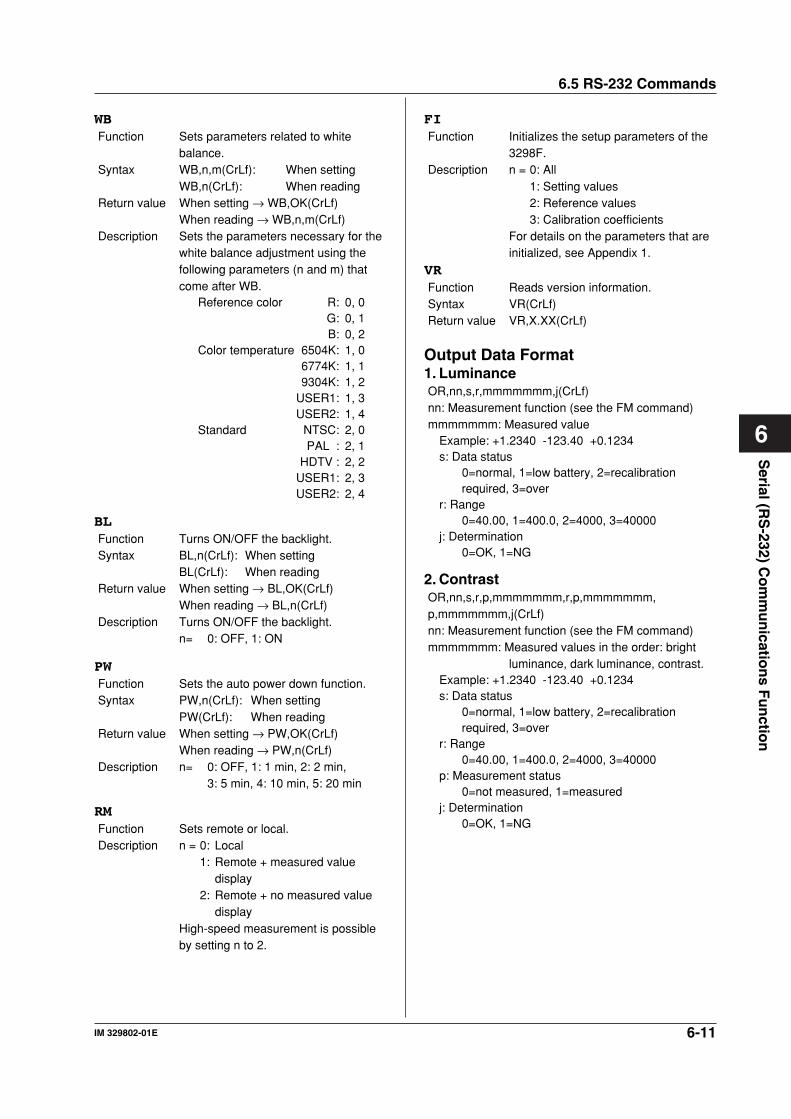
6-11IM 329802-01E
Serial (R
S-232) C
om
mu
nicatio
ns F
un
ction
6
WBFunction Sets parameters related to white
balance.Syntax WB,n,m(CrLf): When setting
WB,n(CrLf): When readingReturn value When setting → WB,OK(CrLf)
When reading → WB,n,m(CrLf)Description Sets the parameters necessary for the
white balance adjustment using thefollowing parameters (n and m) thatcome after WB.
Reference color R: 0, 0G: 0, 1B: 0, 2
Color temperature 6504K: 1, 06774K: 1, 19304K: 1, 2
USER1: 1, 3USER2: 1, 4
Standard NTSC: 2, 0PAL : 2, 1
HDTV : 2, 2USER1: 2, 3USER2: 2, 4
BLFunction Turns ON/OFF the backlight.Syntax BL,n(CrLf): When setting
BL(CrLf): When readingReturn value When setting → BL,OK(CrLf)
When reading → BL,n(CrLf)Description Turns ON/OFF the backlight.
n= 0: OFF, 1: ON
PWFunction Sets the auto power down function.Syntax PW,n(CrLf): When setting
PW(CrLf): When readingReturn value When setting → PW,OK(CrLf)
When reading → PW,n(CrLf)Description n= 0: OFF, 1: 1 min, 2: 2 min,
3: 5 min, 4: 10 min, 5: 20 min
RMFunction Sets remote or local.Description n = 0: Local
1: Remote + measured valuedisplay
2: Remote + no measured valuedisplay
High-speed measurement is possibleby setting n to 2.
6.5 RS-232 Commands
FIFunction Initializes the setup parameters of the
3298F.Description n = 0: All
1: Setting values2: Reference values3: Calibration coefficients
For details on the parameters that areinitialized, see Appendix 1.
VRFunction Reads version information.Syntax VR(CrLf)Return value VR,X.XX(CrLf)
Output Data Format1. LuminanceOR,nn,s,r,mmmmmmm,j(CrLf)nn: Measurement function (see the FM command)mmmmmmm: Measured value
Example: +1.2340 -123.40 +0.1234s: Data status
0=normal, 1=low battery, 2=recalibrationrequired, 3=over
r: Range0=40.00, 1=400.0, 2=4000, 3=40000
j: Determination0=OK, 1=NG
2. ContrastOR,nn,s,r,p,mmmmmmm,r,p,mmmmmmm,p,mmmmmmm,j(CrLf)nn: Measurement function (see the FM command)mmmmmmm: Measured values in the order: bright
luminance, dark luminance, contrast.Example: +1.2340 -123.40 +0.1234s: Data status
0=normal, 1=low battery, 2=recalibrationrequired, 3=over
r: Range0=40.00, 1=400.0, 2=4000, 3=40000
p: Measurement status0=not measured, 1=measured
j: Determination0=OK, 1=NG
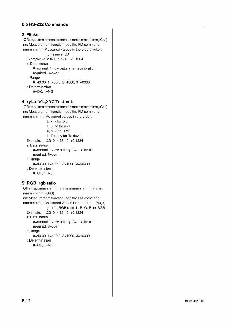
6-12 IM 329802-01E
6.5 RS-232 Commands
3. Flicker OR,nn,s,r,mmmmmmm,mmmmmmm,mmmmmmm,j(CrLf)nn: Measurement function (see the FM command)mmmmmmm:Measured values in the order: flicker,
luminance, dBExample: +1.2340 -123.40 +0.1234s: Data status
0=normal, 1=low battery, 2=recalibrationrequired, 3=over
r: Range0=40.00, 1=400.0, 2=4000, 3=40000
j: Determination0=OK, 1=NG
4. xyL,u’v’L,XYZ,Tc duv L OR,nn,s,r,mmmmmmm,mmmmmmm,mmmmmmm,j(CrLf)nn: Measurement function (see the FM command)mmmmmmm: Measured values in the order:
L, x, y for xyLL, u’, v’ for u’v’LX, Y, Z for XYZL, Tc, duv for Tc duv L
Example: +1.2340 -123.40 +0.1234s: Data status
0=normal, 1=low battery, 2=recalibrationrequired, 3=over
r: Range0=40.00, 1=400, 0,2=4000, 3=40000
j: Determination0=OK, 1=NG
5. RGB, rgb ratioOR,nn,s,r,mmmmmmm,mmmmmmm,mmmmmmm,mmmmmmm,j(CrLf)nn: Measurement function (see the FM command)mmmmmmm: Measured values in the order: L (%), r,
g, b for RGB ratio, L, R, G, B for RGBExample: +1.2340 -123.40 +0.1234s: Data status
0=normal, 1=low battery, 2=recalibrationrequired, 3=over
r: Range0=40.00, 1=400.0, 2=4000, 3=40000
j: Determination0=OK, 1=NG
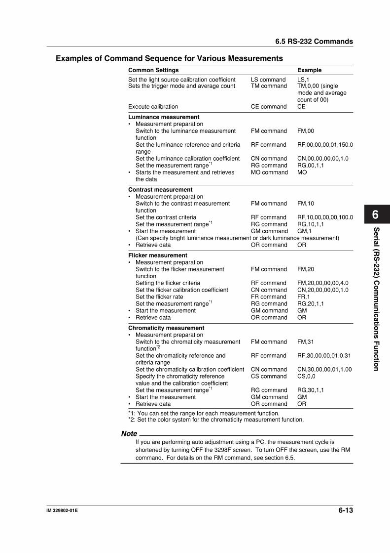
6-13IM 329802-01E
Serial (R
S-232) C
om
mu
nicatio
ns F
un
ction
6
Examples of Command Sequence for Various MeasurementsCommon Settings Example
Set the light source calibration coefficient LS command LS,1Sets the trigger mode and average count TM command TM,0,00 (single
mode and averagecount of 00)
Execute calibration CE command CE
Luminance measurement• Measurement preparation
Switch to the luminance measurement FM command FM,00functionSet the luminance reference and criteria RF command RF,00,00,00,01,150.0rangeSet the luminance calibration coefficient CN command CN,00,00,00,00,1.0Set the measurement range*1 RG command RG,00,1,1
• Starts the measurement and retrieves MO command MOthe data
Contrast measurement• Measurement preparation
Switch to the contrast measurement FM command FM,10functionSet the contrast criteria RF command RF,10,00,00,00,100.0Set the measurement range*1 RG command RG,10,1,1
• Start the measurement GM command GM,1(Can specify bright luminance measurement or dark luminance measurement)
• Retrieve data OR command OR
Flicker measurement• Measurement preparation
Switch to the flicker measurement FM command FM,20functionSetting the flicker criteria RF command FM,20,00,00,00,4.0Set the flicker calibration coefficient CN command CN,20,00,00,00,1.0Set the flicker rate FR command FR,1Set the measurement range*1 RG command RG,20,1,1
• Start the measurement GM command GM• Retrieve data OR command OR
Chromaticity measurement• Measurement preparation
Switch to the chromaticity measurement FM command FM,31function*2
Set the chromaticity reference and RF command RF,30,00,00,01,0.31criteria rangeSet the chromaticity calibration coefficient CN command CN,30,00,00,01,1.00Specify the chromaticity reference CS command CS,0,0value and the calibration coefficientSet the measurement range*1 RG command RG,30,1,1
• Start the measurement GM command GM• Retrieve data OR command OR
*1: You can set the range for each measurement function.*2: Set the color system for the chromaticity measurement function.
NoteIf you are performing auto adjustment using a PC, the measurement cycle isshortened by turning OFF the 3298F screen. To turn OFF the screen, use the RMcommand. For details on the RM command, see section 6.5.
6.5 RS-232 Commands
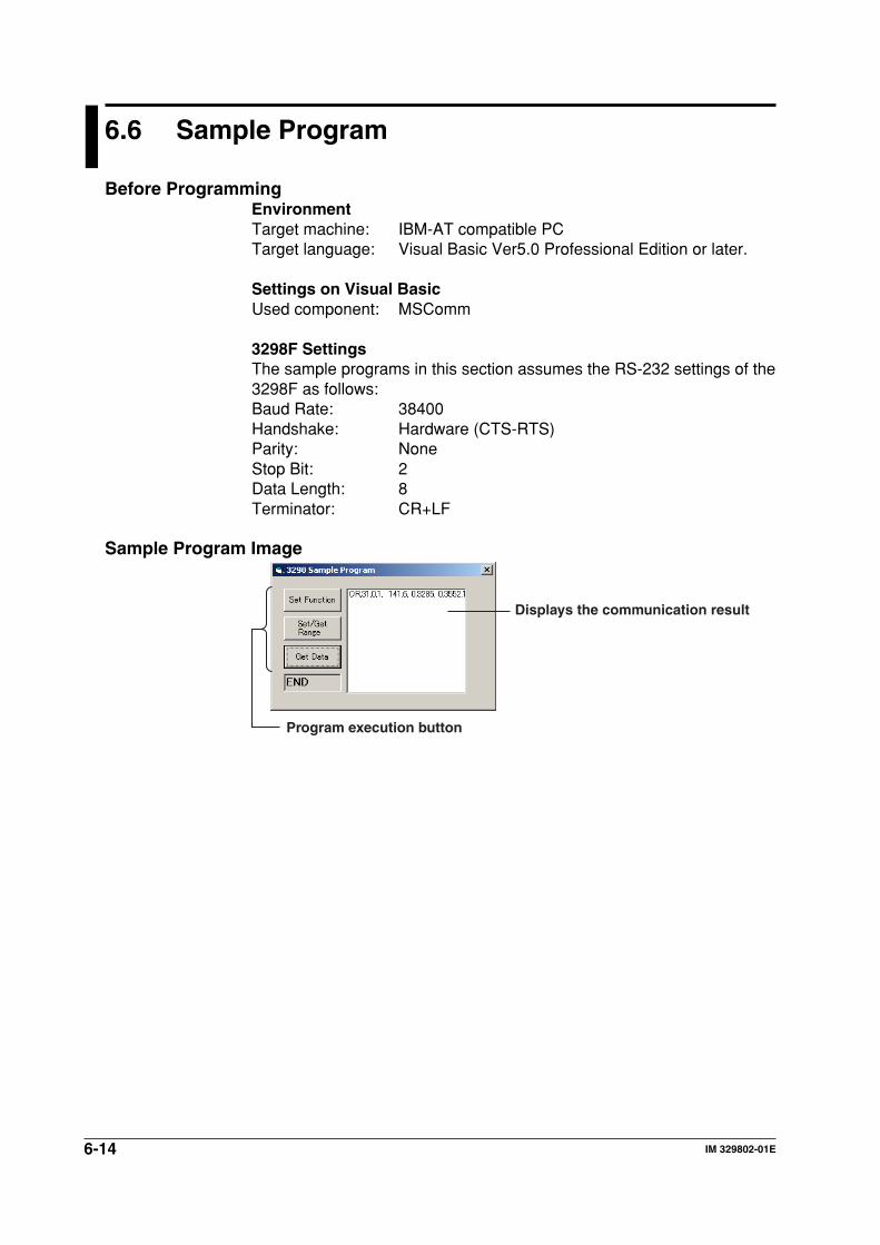
6-14 IM 329802-01E
6.6 Sample Program
Before ProgrammingEnvironmentTarget machine: IBM-AT compatible PCTarget language: Visual Basic Ver5.0 Professional Edition or later.
Settings on Visual BasicUsed component: MSComm
3298F SettingsThe sample programs in this section assumes the RS-232 settings of the3298F as follows:Baud Rate: 38400Handshake: Hardware (CTS-RTS)Parity: NoneStop Bit: 2Data Length: 8Terminator: CR+LF
Sample Program Image
Displays the communication result
Program execution button
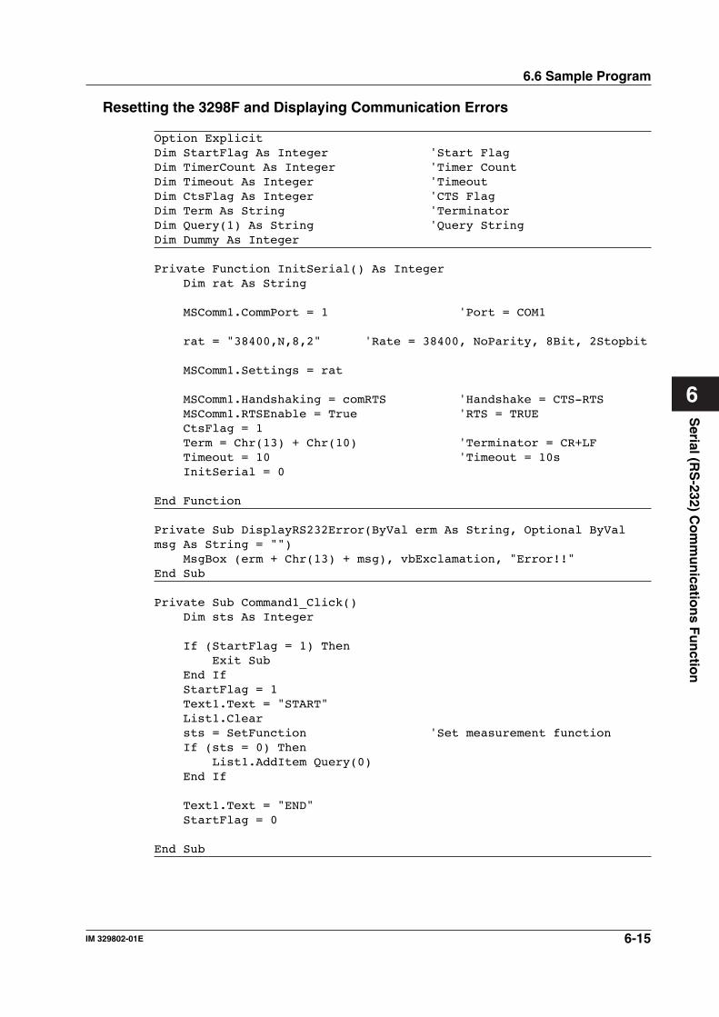
6-15IM 329802-01E
Serial (R
S-232) C
om
mu
nicatio
ns F
un
ction
6
6.6 Sample Program
Resetting the 3298F and Displaying Communication Errors
Option ExplicitDim StartFlag As Integer 'Start FlagDim TimerCount As Integer 'Timer CountDim Timeout As Integer 'TimeoutDim CtsFlag As Integer 'CTS FlagDim Term As String 'TerminatorDim Query(1) As String 'Query StringDim Dummy As Integer
Private Function InitSerial() As Integer Dim rat As String
MSComm1.CommPort = 1 'Port = COM1
rat = "38400,N,8,2" 'Rate = 38400, NoParity, 8Bit, 2Stopbit
MSComm1.Settings = rat
MSComm1.Handshaking = comRTS 'Handshake = CTS-RTS MSComm1.RTSEnable = True 'RTS = TRUE CtsFlag = 1 Term = Chr(13) + Chr(10) 'Terminator = CR+LF Timeout = 10 'Timeout = 10s InitSerial = 0
End Function
Private Sub DisplayRS232Error(ByVal erm As String, Optional ByValmsg As String = "") MsgBox (erm + Chr(13) + msg), vbExclamation, "Error!!"End Sub
Private Sub Command1_Click() Dim sts As Integer
If (StartFlag = 1) Then Exit Sub End If StartFlag = 1 Text1.Text = "START" List1.Clear sts = SetFunction 'Set measurement function If (sts = 0) Then List1.AddItem Query(0) End If
Text1.Text = "END" StartFlag = 0
End Sub
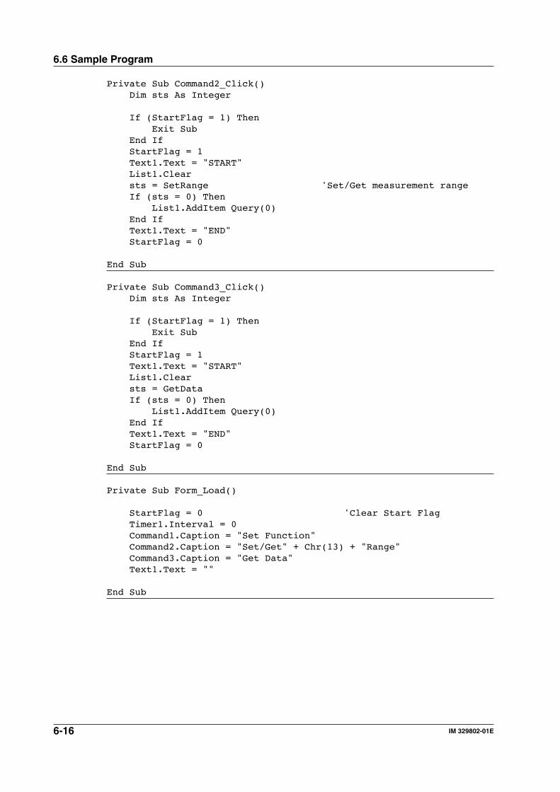
6-16 IM 329802-01E
Private Sub Command2_Click() Dim sts As Integer
If (StartFlag = 1) Then Exit Sub End If StartFlag = 1 Text1.Text = "START" List1.Clear sts = SetRange 'Set/Get measurement range If (sts = 0) Then List1.AddItem Query(0) End If Text1.Text = "END" StartFlag = 0
End Sub
Private Sub Command3_Click() Dim sts As Integer
If (StartFlag = 1) Then Exit Sub End If StartFlag = 1 Text1.Text = "START" List1.Clear sts = GetData If (sts = 0) Then List1.AddItem Query(0) End If Text1.Text = "END" StartFlag = 0
End Sub
Private Sub Form_Load()
StartFlag = 0 'Clear Start Flag Timer1.Interval = 0 Command1.Caption = "Set Function" Command2.Caption = "Set/Get" + Chr(13) + "Range" Command3.Caption = "Get Data" Text1.Text = ""
End Sub
6.6 Sample Program
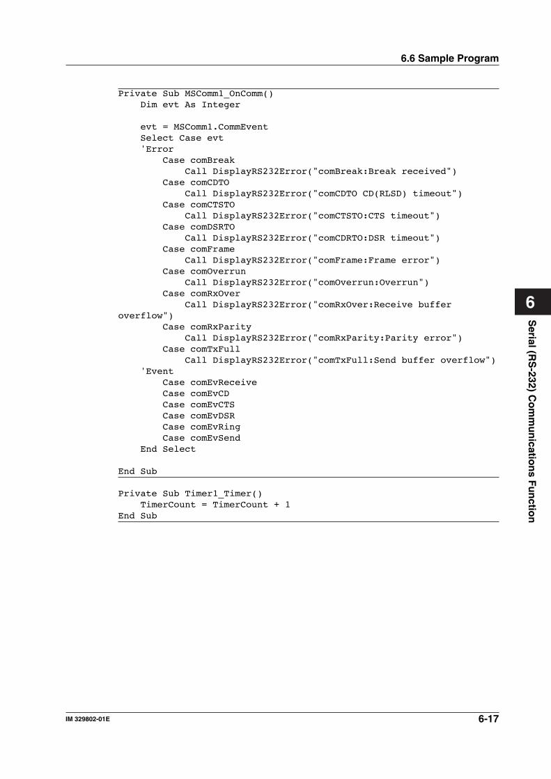
6-17IM 329802-01E
Serial (R
S-232) C
om
mu
nicatio
ns F
un
ction
6
6.6 Sample Program
Private Sub MSComm1_OnComm() Dim evt As Integer
evt = MSComm1.CommEvent Select Case evt 'Error Case comBreak Call DisplayRS232Error("comBreak:Break received") Case comCDTO Call DisplayRS232Error("comCDTO CD(RLSD) timeout") Case comCTSTO Call DisplayRS232Error("comCTSTO:CTS timeout") Case comDSRTO Call DisplayRS232Error("comCDRTO:DSR timeout") Case comFrame Call DisplayRS232Error("comFrame:Frame error") Case comOverrun Call DisplayRS232Error("comOverrun:Overrun") Case comRxOver Call DisplayRS232Error("comRxOver:Receive bufferoverflow") Case comRxParity Call DisplayRS232Error("comRxParity:Parity error") Case comTxFull Call DisplayRS232Error("comTxFull:Send buffer overflow") 'Event Case comEvReceive Case comEvCD Case comEvCTS Case comEvDSR Case comEvRing Case comEvSend End Select
End Sub
Private Sub Timer1_Timer() TimerCount = TimerCount + 1End Sub
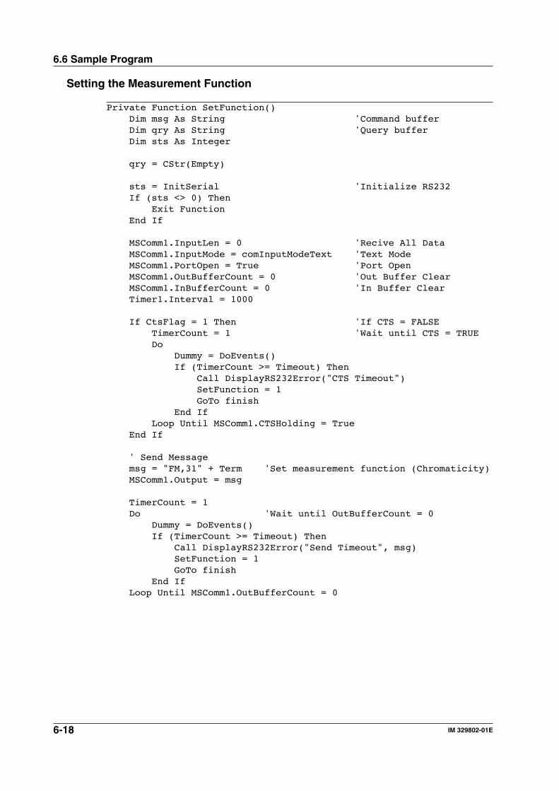
6-18 IM 329802-01E
6.6 Sample Program
Setting the Measurement Function
Private Function SetFunction() Dim msg As String 'Command buffer Dim qry As String 'Query buffer Dim sts As Integer
qry = CStr(Empty)
sts = InitSerial 'Initialize RS232 If (sts <> 0) Then Exit Function End If
MSComm1.InputLen = 0 'Recive All Data MSComm1.InputMode = comInputModeText 'Text Mode MSComm1.PortOpen = True 'Port Open MSComm1.OutBufferCount = 0 'Out Buffer Clear MSComm1.InBufferCount = 0 'In Buffer Clear Timer1.Interval = 1000
If CtsFlag = 1 Then 'If CTS = FALSE TimerCount = 1 'Wait until CTS = TRUE Do Dummy = DoEvents() If (TimerCount >= Timeout) Then Call DisplayRS232Error("CTS Timeout") SetFunction = 1 GoTo finish End If Loop Until MSComm1.CTSHolding = True End If
' Send Message msg = "FM,31" + Term 'Set measurement function (Chromaticity) MSComm1.Output = msg
TimerCount = 1 Do 'Wait until OutBufferCount = 0 Dummy = DoEvents() If (TimerCount >= Timeout) Then Call DisplayRS232Error("Send Timeout", msg) SetFunction = 1 GoTo finish End If Loop Until MSComm1.OutBufferCount = 0

6-19IM 329802-01E
Serial (R
S-232) C
om
mu
nicatio
ns F
un
ction
6
6.6 Sample Program
TimerCount = 1 Do 'Receive Query qry = qry + MSComm1.Input 'Wait until End Data = Terminator Dummy = DoEvents() If (TimerCount >= Timeout) Then Call DisplayRS232Error("Receive Timeout", msg) SetFunction = 1 GoTo finish End If Loop Until Right$(qry, 1) = Chr(10)
Query(0) = Left$(qry, Len(qry) - 2) SetFunction = 0
finish: MSComm1.PortOpen = False 'Port Close Timer1.Interval = 0
End Function
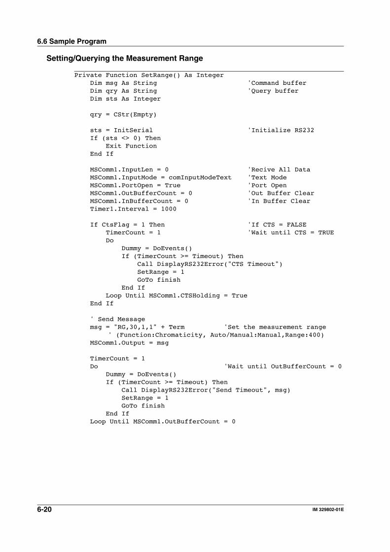
6-20 IM 329802-01E
6.6 Sample Program
Setting/Querying the Measurement Range
Private Function SetRange() As Integer Dim msg As String 'Command buffer Dim qry As String 'Query buffer Dim sts As Integer
qry = CStr(Empty)
sts = InitSerial 'Initialize RS232 If (sts <> 0) Then Exit Function End If
MSComm1.InputLen = 0 'Recive All Data MSComm1.InputMode = comInputModeText 'Text Mode MSComm1.PortOpen = True 'Port Open MSComm1.OutBufferCount = 0 'Out Buffer Clear MSComm1.InBufferCount = 0 'In Buffer Clear Timer1.Interval = 1000
If CtsFlag = 1 Then 'If CTS = FALSE TimerCount = 1 'Wait until CTS = TRUE Do Dummy = DoEvents() If (TimerCount >= Timeout) Then Call DisplayRS232Error("CTS Timeout") SetRange = 1 GoTo finish End If Loop Until MSComm1.CTSHolding = True End If
' Send Message msg = "RG,30,1,1" + Term 'Set the measurement range
' (Function:Chromaticity, Auto/Manual:Manual,Range:400) MSComm1.Output = msg
TimerCount = 1 Do 'Wait until OutBufferCount = 0 Dummy = DoEvents() If (TimerCount >= Timeout) Then Call DisplayRS232Error("Send Timeout", msg) SetRange = 1 GoTo finish End If Loop Until MSComm1.OutBufferCount = 0
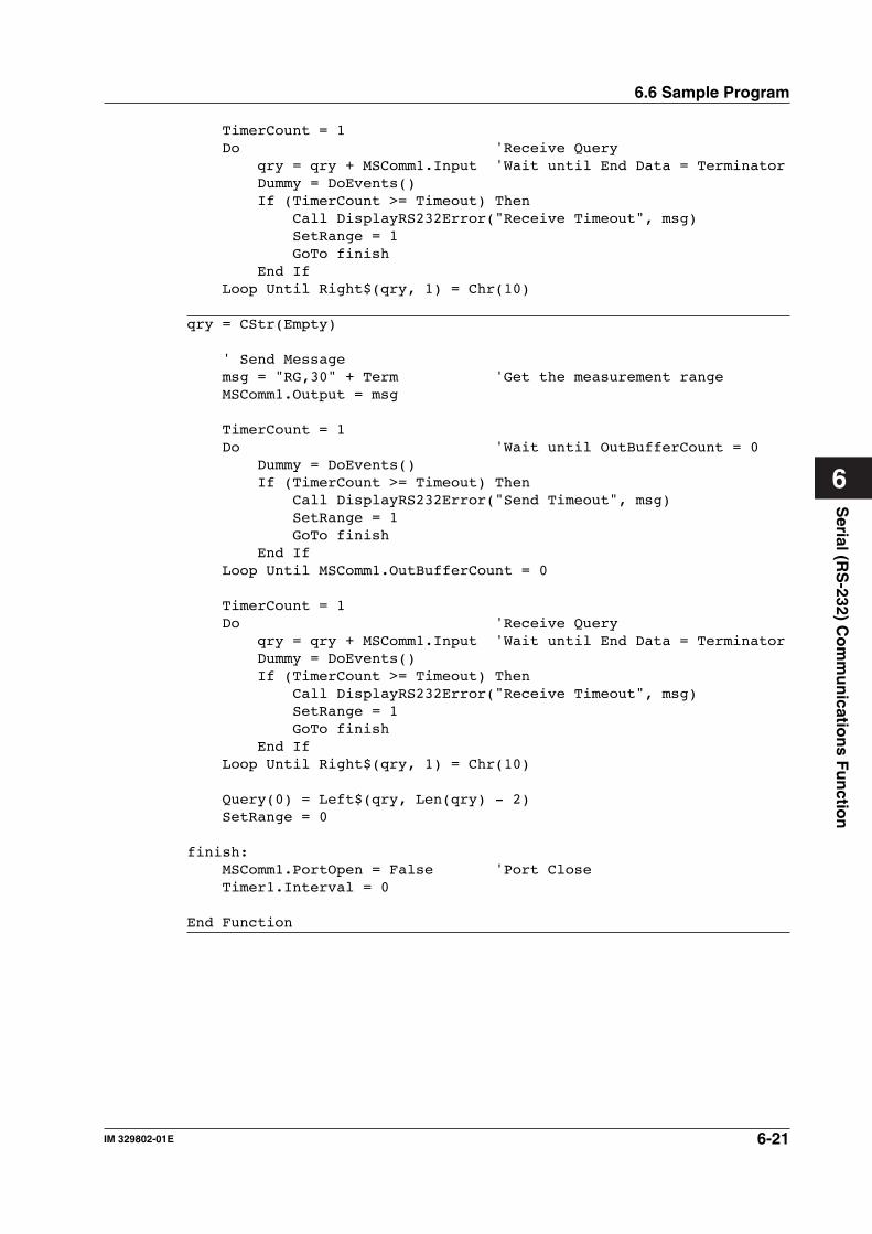
6-21IM 329802-01E
Serial (R
S-232) C
om
mu
nicatio
ns F
un
ction
6
6.6 Sample Program
TimerCount = 1 Do 'Receive Query qry = qry + MSComm1.Input 'Wait until End Data = Terminator Dummy = DoEvents() If (TimerCount >= Timeout) Then Call DisplayRS232Error("Receive Timeout", msg) SetRange = 1 GoTo finish End If Loop Until Right$(qry, 1) = Chr(10)
qry = CStr(Empty)
' Send Message msg = "RG,30" + Term 'Get the measurement range MSComm1.Output = msg
TimerCount = 1 Do 'Wait until OutBufferCount = 0 Dummy = DoEvents() If (TimerCount >= Timeout) Then Call DisplayRS232Error("Send Timeout", msg) SetRange = 1 GoTo finish End If Loop Until MSComm1.OutBufferCount = 0
TimerCount = 1 Do 'Receive Query qry = qry + MSComm1.Input 'Wait until End Data = Terminator Dummy = DoEvents() If (TimerCount >= Timeout) Then Call DisplayRS232Error("Receive Timeout", msg) SetRange = 1 GoTo finish End If Loop Until Right$(qry, 1) = Chr(10)
Query(0) = Left$(qry, Len(qry) - 2) SetRange = 0
finish: MSComm1.PortOpen = False 'Port Close Timer1.Interval = 0
End Function
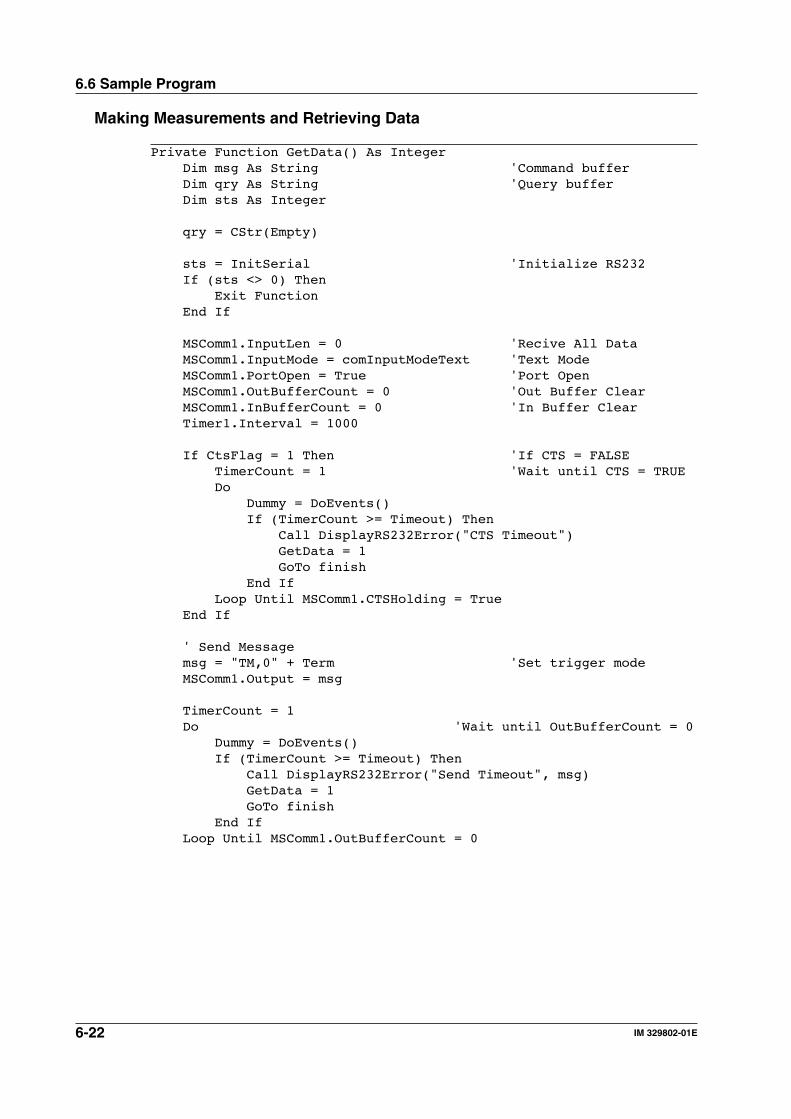
6-22 IM 329802-01E
6.6 Sample Program
Making Measurements and Retrieving Data
Private Function GetData() As Integer Dim msg As String 'Command buffer Dim qry As String 'Query buffer Dim sts As Integer
qry = CStr(Empty)
sts = InitSerial 'Initialize RS232 If (sts <> 0) Then Exit Function End If
MSComm1.InputLen = 0 'Recive All Data MSComm1.InputMode = comInputModeText 'Text Mode MSComm1.PortOpen = True 'Port Open MSComm1.OutBufferCount = 0 'Out Buffer Clear MSComm1.InBufferCount = 0 'In Buffer Clear Timer1.Interval = 1000
If CtsFlag = 1 Then 'If CTS = FALSE TimerCount = 1 'Wait until CTS = TRUE Do Dummy = DoEvents() If (TimerCount >= Timeout) Then Call DisplayRS232Error("CTS Timeout") GetData = 1 GoTo finish End If Loop Until MSComm1.CTSHolding = True End If
' Send Message msg = "TM,0" + Term 'Set trigger mode MSComm1.Output = msg
TimerCount = 1 Do 'Wait until OutBufferCount = 0 Dummy = DoEvents() If (TimerCount >= Timeout) Then Call DisplayRS232Error("Send Timeout", msg) GetData = 1 GoTo finish End If Loop Until MSComm1.OutBufferCount = 0

6-23IM 329802-01E
Serial (R
S-232) C
om
mu
nicatio
ns F
un
ction
6
6.6 Sample Program
TimerCount = 1 Do 'Receive Query qry = qry + MSComm1.Input 'Wait until End Data = Terminator Dummy = DoEvents() If (TimerCount >= Timeout) Then Call DisplayRS232Error("Receive Timeout", msg) GetData = 1 GoTo finish End If Loop Until Right$(qry, 1) = Chr(10)
qry = CStr(Empty)
' Send Message msg = "MO" + Term 'Measurement start MSComm1.Output = msg
TimerCount = 1 Do 'Wait until OutBufferCount = 0 Dummy = DoEvents() If (TimerCount >= Timeout) Then Call DisplayRS232Error("Send Timeout", msg) GetData = 1 GoTo finish End If Loop Until MSComm1.OutBufferCount = 0
TimerCount = 1 Do 'Receive Query qry = qry + MSComm1.Input 'Wait until End Data = Terminator Dummy = DoEvents() If (TimerCount >= Timeout) Then Call DisplayRS232Error("Receive Timeout", msg) GetData = 1 GoTo finish End If Loop Until Right$(qry, 1) = Chr(10)
Query(0) = Left$(qry, Len(qry) - 2) GetData = 0
finish: MSComm1.PortOpen = False 'Port Close Timer1.Interval = 0
End Function
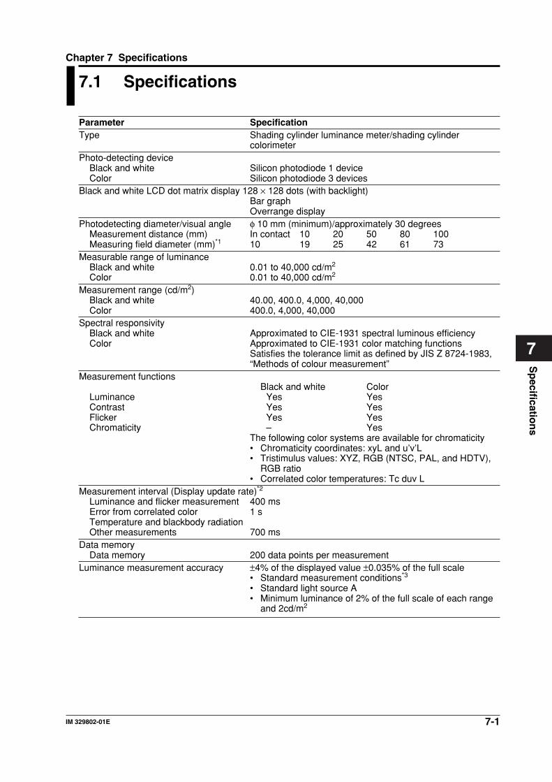
7-1IM 329802-01E
Sp
ecification
s
7
Chapter 7 Specifications
7.1 Specifications
Parameter SpecificationType Shading cylinder luminance meter/shading cylinder
colorimeterPhoto-detecting device
Black and white Silicon photodiode 1 deviceColor Silicon photodiode 3 devices
Black and white LCD dot matrix display 128 × 128 dots (with backlight)Bar graphOverrange display
Photodetecting diameter/visual angle φ 10 mm (minimum)/approximately 30 degreesMeasurement distance (mm) In contact 10 20 50 80 100Measuring field diameter (mm)*1 10 19 25 42 61 73
Measurable range of luminanceBlack and white 0.01 to 40,000 cd/m2
Color 0.01 to 40,000 cd/m2
Measurement range (cd/m2)Black and white 40.00, 400.0, 4,000, 40,000Color 400.0, 4,000, 40,000
Spectral responsivityBlack and white Approximated to CIE-1931 spectral luminous efficiencyColor Approximated to CIE-1931 color matching functions
Satisfies the tolerance limit as defined by JIS Z 8724-1983,“Methods of colour measurement”
Measurement functionsBlack and white Color
Luminance Yes YesContrast Yes YesFlicker Yes YesChromaticity – Yes
The following color systems are available for chromaticity• Chromaticity coordinates: xyL and u’v’L• Tristimulus values: XYZ, RGB (NTSC, PAL, and HDTV),
RGB ratio• Correlated color temperatures: Tc duv L
Measurement interval (Display update rate)*2
Luminance and flicker measurement 400 msError from correlated color 1 sTemperature and blackbody radiationOther measurements 700 ms
Data memoryData memory 200 data points per measurement
Luminance measurement accuracy ±4% of the displayed value ±0.035% of the full scale• Standard measurement conditions*3
• Standard light source A• Minimum luminance of 2% of the full scale of each range
and 2cd/m2
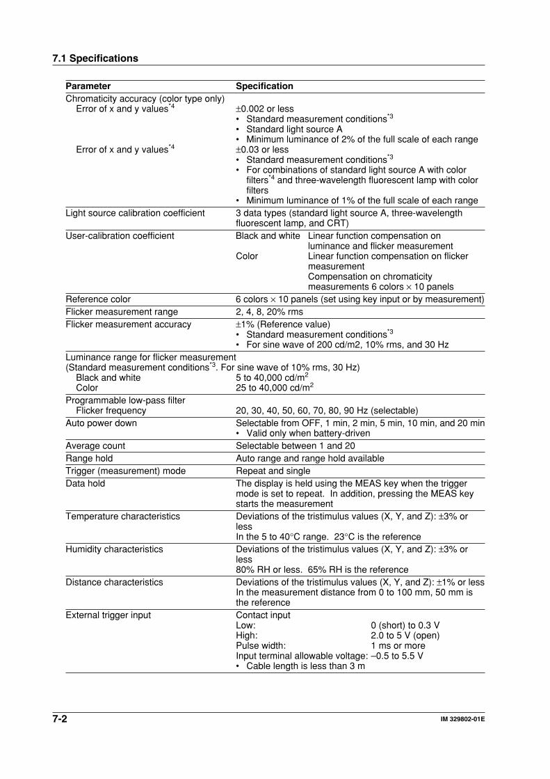
7-2 IM 329802-01E
7.1 Specifications
Parameter SpecificationChromaticity accuracy (color type only)
Error of x and y values*4 ±0.002 or less• Standard measurement conditions*3
• Standard light source A• Minimum luminance of 2% of the full scale of each range
Error of x and y values*4 ±0.03 or less• Standard measurement conditions*3
• For combinations of standard light source A with colorfilters*4 and three-wavelength fluorescent lamp with colorfilters
• Minimum luminance of 1% of the full scale of each rangeLight source calibration coefficient 3 data types (standard light source A, three-wavelength
fluorescent lamp, and CRT)User-calibration coefficient Black and white Linear function compensation on
luminance and flicker measurementColor Linear function compensation on flicker
measurementCompensation on chromaticitymeasurements 6 colors × 10 panels
Reference color 6 colors × 10 panels (set using key input or by measurement)Flicker measurement range 2, 4, 8, 20% rmsFlicker measurement accuracy ±1% (Reference value)
• Standard measurement conditions*3
• For sine wave of 200 cd/m2, 10% rms, and 30 HzLuminance range for flicker measurement(Standard measurement conditions*3. For sine wave of 10% rms, 30 Hz)
Black and white 5 to 40,000 cd/m2
Color 25 to 40,000 cd/m2
Programmable low-pass filterFlicker frequency 20, 30, 40, 50, 60, 70, 80, 90 Hz (selectable)
Auto power down Selectable from OFF, 1 min, 2 min, 5 min, 10 min, and 20 min• Valid only when battery-driven
Average count Selectable between 1 and 20Range hold Auto range and range hold availableTrigger (measurement) mode Repeat and singleData hold The display is held using the MEAS key when the trigger
mode is set to repeat. In addition, pressing the MEAS keystarts the measurement
Temperature characteristics Deviations of the tristimulus values (X, Y, and Z): ±3% orlessIn the 5 to 40°C range. 23°C is the reference
Humidity characteristics Deviations of the tristimulus values (X, Y, and Z): ±3% orless80% RH or less. 65% RH is the reference
Distance characteristics Deviations of the tristimulus values (X, Y, and Z): ±1% or lessIn the measurement distance from 0 to 100 mm, 50 mm isthe reference
External trigger input Contact inputLow: 0 (short) to 0.3 VHigh: 2.0 to 5 V (open)Pulse width: 1 ms or moreInput terminal allowable voltage: –0.5 to 5.5 V• Cable length is less than 3 m
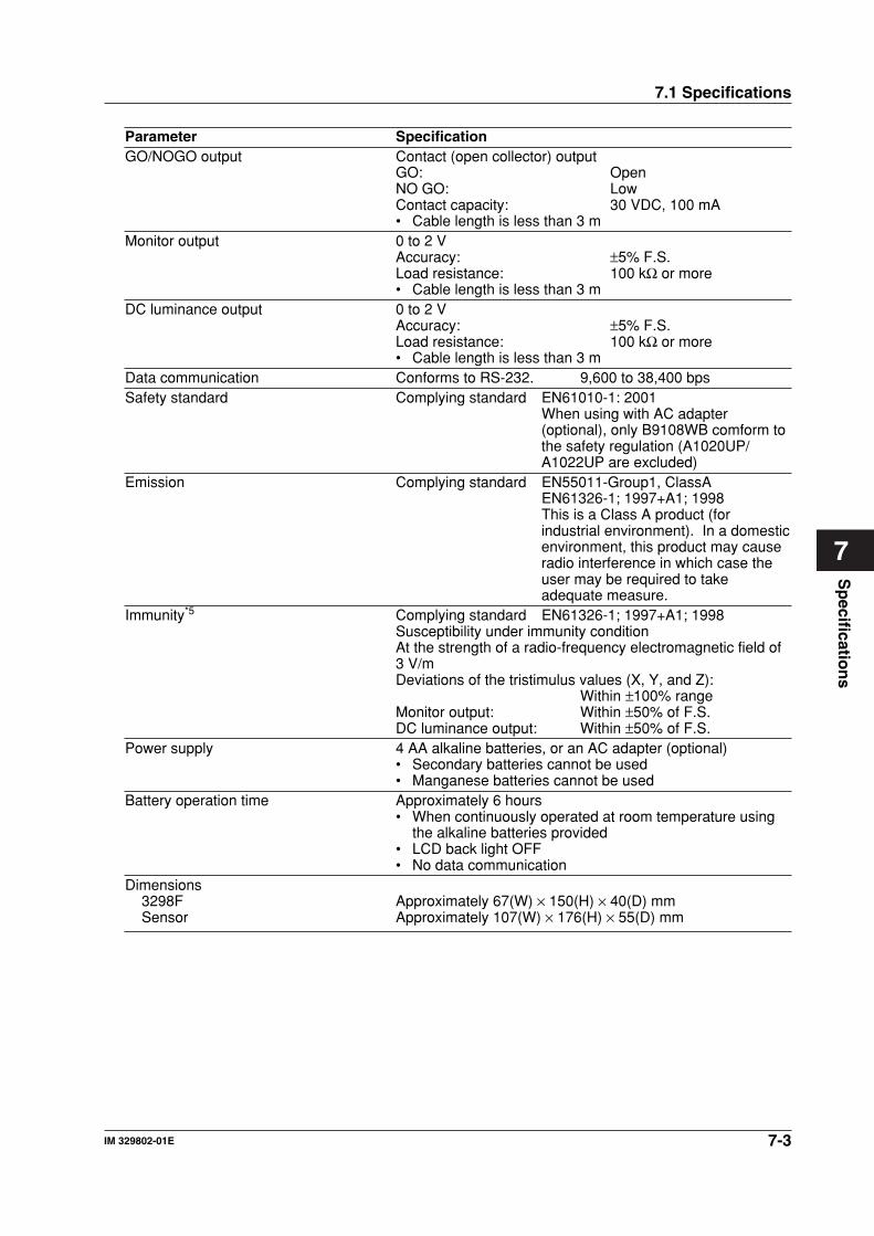
7-3IM 329802-01E
Sp
ecification
s
7
Parameter SpecificationGO/NOGO output Contact (open collector) output
GO: OpenNO GO: LowContact capacity: 30 VDC, 100 mA• Cable length is less than 3 m
Monitor output 0 to 2 VAccuracy: ±5% F.S.Load resistance: 100 kΩ or more• Cable length is less than 3 m
DC luminance output 0 to 2 VAccuracy: ±5% F.S.Load resistance: 100 kΩ or more• Cable length is less than 3 m
Data communication Conforms to RS-232. 9,600 to 38,400 bpsSafety standard Complying standard EN61010-1: 2001
When using with AC adapter(optional), only B9108WB comform tothe safety regulation (A1020UP/A1022UP are excluded)
Emission Complying standard EN55011-Group1, ClassAEN61326-1; 1997+A1; 1998This is a Class A product (forindustrial environment). In a domesticenvironment, this product may causeradio interference in which case theuser may be required to takeadequate measure.
Immunity*5 Complying standard EN61326-1; 1997+A1; 1998Susceptibility under immunity conditionAt the strength of a radio-frequency electromagnetic field of3 V/mDeviations of the tristimulus values (X, Y, and Z):
Within ±100% rangeMonitor output: Within ±50% of F.S.DC luminance output: Within ±50% of F.S.
Power supply 4 AA alkaline batteries, or an AC adapter (optional)• Secondary batteries cannot be used• Manganese batteries cannot be used
Battery operation time Approximately 6 hours• When continuously operated at room temperature using
the alkaline batteries provided• LCD back light OFF• No data communication
Dimensions3298F Approximately 67(W) × 150(H) × 40(D) mmSensor Approximately 107(W) × 176(H) × 55(D) mm
7.1 Specifications
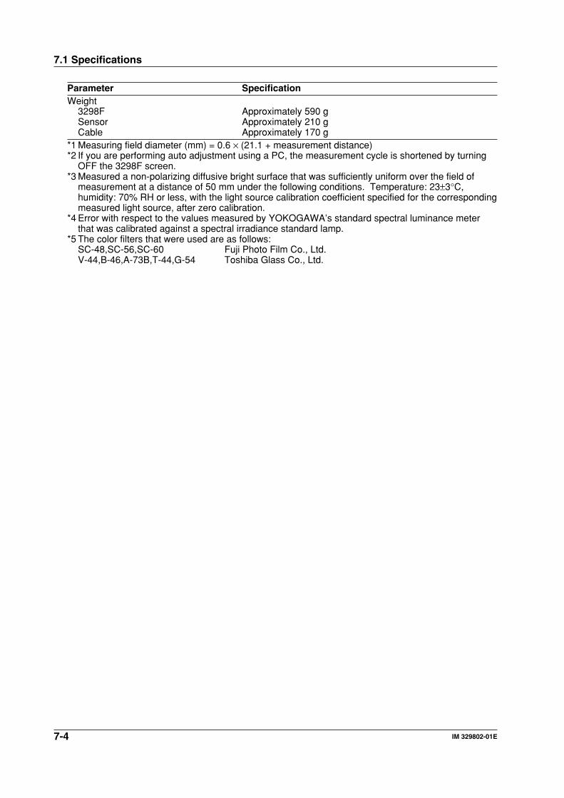
7-4 IM 329802-01E
Parameter SpecificationWeight
3298F Approximately 590 gSensor Approximately 210 gCable Approximately 170 g
*1 Measuring field diameter (mm) = 0.6 × (21.1 + measurement distance)*2 If you are performing auto adjustment using a PC, the measurement cycle is shortened by turning
OFF the 3298F screen.*3 Measured a non-polarizing diffusive bright surface that was sufficiently uniform over the field of
measurement at a distance of 50 mm under the following conditions. Temperature: 23±3°C,humidity: 70% RH or less, with the light source calibration coefficient specified for the correspondingmeasured light source, after zero calibration.
*4 Error with respect to the values measured by YOKOGAWA’s standard spectral luminance meterthat was calibrated against a spectral irradiance standard lamp.
*5 The color filters that were used are as follows:SC-48,SC-56,SC-60 Fuji Photo Film Co., Ltd.V-44,B-46,A-73B,T-44,G-54 Toshiba Glass Co., Ltd.
7.1 Specifications
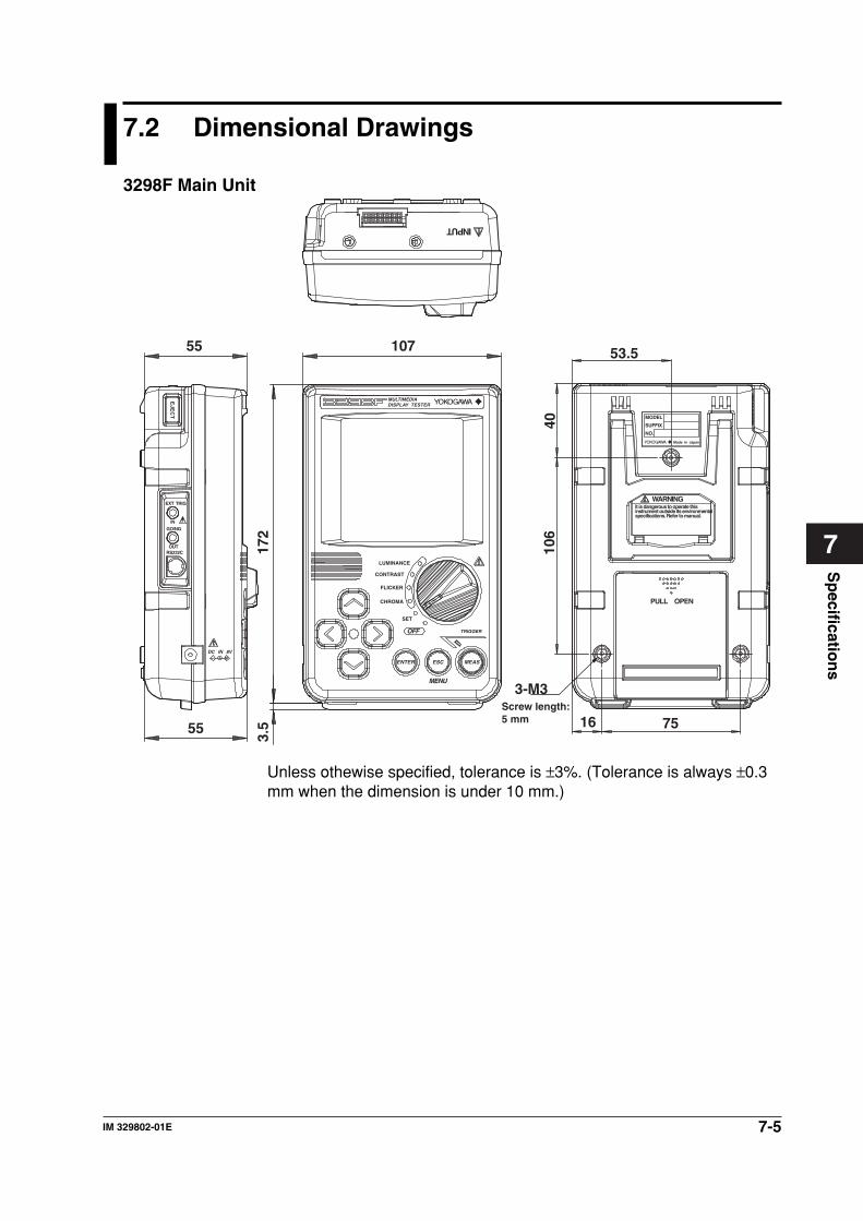
7-5IM 329802-01E
Sp
ecification
s
7
7.2 Dimensional Drawings
3298F Main Unit
55
55
107
172
3.5
EXT TRIG
EJE
CT
IN
GO/NG
ENTER ESC MEAS
TRIGGER
MENU
OFF
MULTIMEDIADISPLAY TESTER
OUT
DC IN 8V
RS232C
INPUT
MODEL
SUFFIX
NO.
Made in Japan
WARNING
PULL OPEN
It is dangerous to operate thisinstrument outside its environmentalspecifications. Refer to manual.
53.5
16 75
4010
6
3-M3Screw length:5 mm
CHROMA
LUMINANCE
CONTRAST
FLICKER
SET
Unless othewise specified, tolerance is ±3%. (Tolerance is always ±0.3mm when the dimension is under 10 mm.)
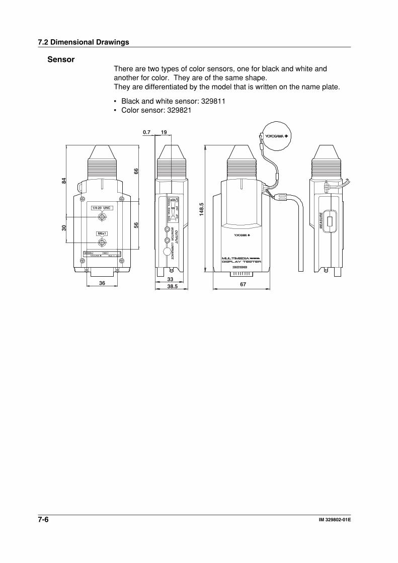
7-6 IM 329802-01E
SensorThere are two types of color sensors, one for black and white andanother for color. They are of the same shape.They are differentiated by the model that is written on the name plate.
• Black and white sensor: 329811• Color sensor: 329821
148.
5
67
ME
AS
UR
E
3338.5
1/4-20 UNC
M6x1
OU
TP
UT
MO
NITO
RL
UM
INA
NC
E
MODEL NO.Made in Japan
7342
100mm
50mm
100mm
0.7 19
36
8430
6656
7.2 Dimensional Drawings
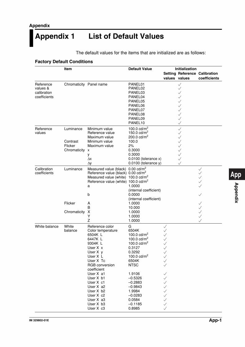
App-1IM 329802-01E
Ap
pen
dix
App
Appendix
Appendix 1 List of Default Values
The default values for the items that are initialized are as follows:
Factory Default Conditions
Item Default Value InitializationSetting Reference Calibrationvalues values coefficients
Reference Chromaticity Panel name PANEL01values & PANEL02calibration PANEL03coefficients PANEL04
PANEL05PANEL06PANEL07PANEL08PANEL09PANEL10
Reference Luminance Minimum value 100.0 cd/m2
values Reference value 150.0 cd/m2
Maximum value 200.0 cd/m2
Contrast Minimum value 100.0Flicker Maximum value 2%Chromaticity x 0.3000
y 0.3000∆x 0.0100 (tolerance x)∆y 0.0100 (tolerance y)
Calibration Luminance Measured value (black) 0.00 cd/m2
coefficients Reference value (black) 0.00 cd/m2
Measured value (white) 100.0 cd/m2
Reference value (white) 100.0 cd/m2
a 1.0000(internal coefficient)
b 0.0000(internal coefficient)
Flicker A 1.0000B 10.000
Chromaticity X 1.0000Y 1.0000Z 1.0000
White balance White Reference color Gbalance Color temperature 6504K
6504K L 100.0 cd/m2
6447K L 100.0 cd/m2
9304K L 100.0 cd/m2
User X x 0.3127User X y 0.3292User X L 100.0 cd/m2
User X Tc 6504KRGB conversion NTSCcoefficientUser X a1 1.9106User X b1 –0.5326User X c1 –0.2883User X a2 –0.9843User X b2 1.9984User X c2 –0.0283User X a3 0.0584User X b3 –0.1185User X c3 0.8985
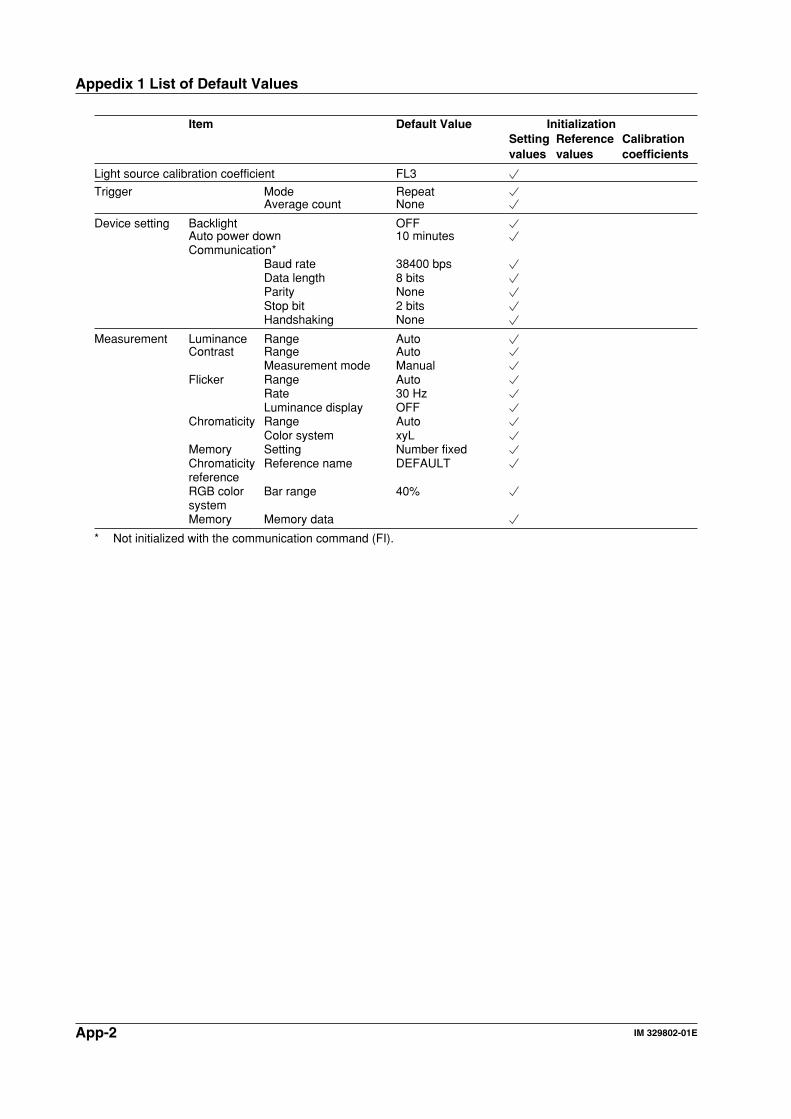
App-2 IM 329802-01E
Appedix 1 List of Default Values
Item Default Value InitializationSetting Reference Calibrationvalues values coefficients
Light source calibration coefficient FL3
Trigger Mode RepeatAverage count None
Device setting Backlight OFFAuto power down 10 minutesCommunication*
Baud rate 38400 bpsData length 8 bitsParity NoneStop bit 2 bitsHandshaking None
Measurement Luminance Range AutoContrast Range Auto
Measurement mode ManualFlicker Range Auto
Rate 30 HzLuminance display OFF
Chromaticity Range AutoColor system xyL
Memory Setting Number fixedChromaticity Reference name DEFAULTreferenceRGB color Bar range 40%systemMemory Memory data
* Not initialized with the communication command (FI).
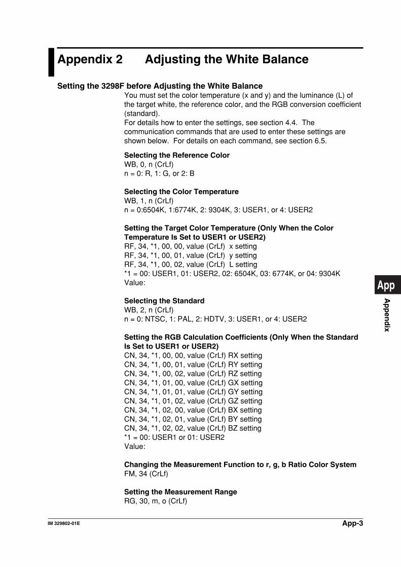
App-3IM 329802-01E
Ap
pen
dix
App
Appendix 2 Adjusting the White Balance
Setting the 3298F before Adjusting the White BalanceYou must set the color temperature (x and y) and the luminance (L) ofthe target white, the reference color, and the RGB conversion coefficient(standard).For details how to enter the settings, see section 4.4. Thecommunication commands that are used to enter these settings areshown below. For details on each command, see section 6.5.
Selecting the Reference ColorWB, 0, n (CrLf)n = 0: R, 1: G, or 2: B
Selecting the Color TemperatureWB, 1, n (CrLf)n = 0:6504K, 1:6774K, 2: 9304K, 3: USER1, or 4: USER2
Setting the Target Color Temperature (Only When the ColorTemperature Is Set to USER1 or USER2)RF, 34, *1, 00, 00, value (CrLf) x settingRF, 34, *1, 00, 01, value (CrLf) y settingRF, 34, *1, 00, 02, value (CrLf) L setting*1 = 00: USER1, 01: USER2, 02: 6504K, 03: 6774K, or 04: 9304KValue:
Selecting the StandardWB, 2, n (CrLf)n = 0: NTSC, 1: PAL, 2: HDTV, 3: USER1, or 4: USER2
Setting the RGB Calculation Coefficients (Only When the StandardIs Set to USER1 or USER2)CN, 34, *1, 00, 00, value (CrLf) RX settingCN, 34, *1, 00, 01, value (CrLf) RY settingCN, 34, *1, 00, 02, value (CrLf) RZ settingCN, 34, *1, 01, 00, value (CrLf) GX settingCN, 34, *1, 01, 01, value (CrLf) GY settingCN, 34, *1, 01, 02, value (CrLf) GZ settingCN, 34, *1, 02, 00, value (CrLf) BX settingCN, 34, *1, 02, 01, value (CrLf) BY settingCN, 34, *1, 02, 02, value (CrLf) BZ setting*1 = 00: USER1 or 01: USER2Value:
Changing the Measurement Function to r, g, b Ratio Color SystemFM, 34 (CrLf)
Setting the Measurement RangeRG, 30, m, o (CrLf)
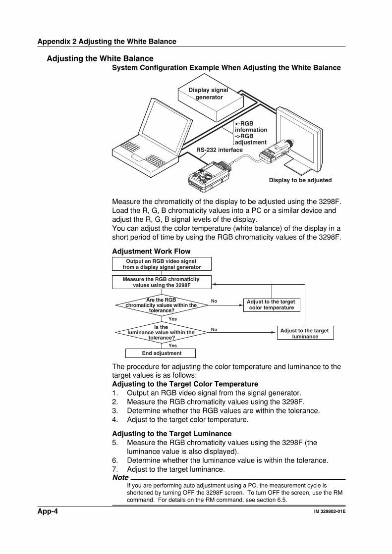
App-4 IM 329802-01E
Appendix 2 Adjusting the White Balance
Adjusting the White BalanceSystem Configuration Example When Adjusting the White Balance
Display signal generator
Display to be adjusted
RS-232 interface
<-RGB information->RGB adjustment
Measure the chromaticity of the display to be adjusted using the 3298F.Load the R, G, B chromaticity values into a PC or a similar device andadjust the R, G, B signal levels of the display.You can adjust the color temperature (white balance) of the display in ashort period of time by using the RGB chromaticity values of the 3298F.
Adjustment Work FlowOutput an RGB video signal
from a display signal generator
Are the RGB chromaticity values within the
tolerance?
Is the luminance value within the
tolerance?
Measure the RGB chromaticity values using the 3298F
Adjust to the target color temperature
Adjust to the target luminance
End adjustment
No
No
Yes
Yes
The procedure for adjusting the color temperature and luminance to thetarget values is as follows:Adjusting to the Target Color Temperature1. Output an RGB video signal from the signal generator.2. Measure the RGB chromaticity values using the 3298F.3. Determine whether the RGB values are within the tolerance.4. Adjust to the target color temperature.
Adjusting to the Target Luminance5. Measure the RGB chromaticity values using the 3298F (the
luminance value is also displayed).6. Determine whether the luminance value is within the tolerance.7. Adjust to the target luminance.Note
If you are performing auto adjustment using a PC, the measurement cycle isshortened by turning OFF the 3298F screen. To turn OFF the screen, use the RMcommand. For details on the RM command, see section 6.5.
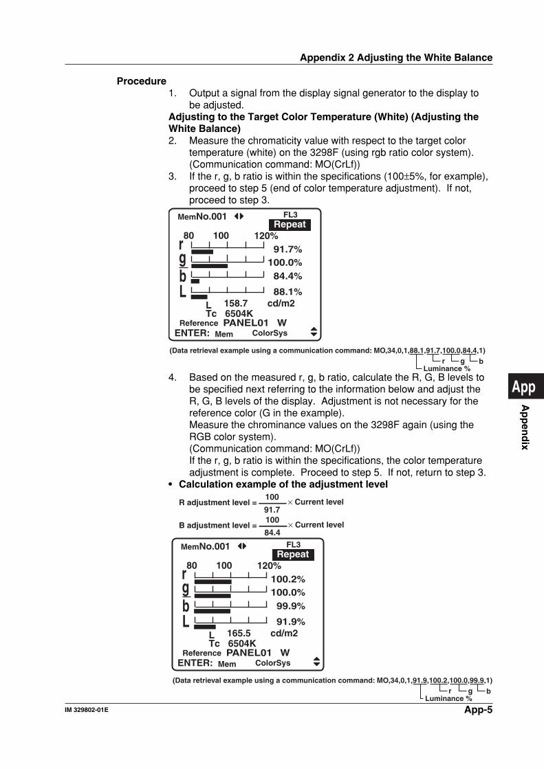
App-5IM 329802-01E
Ap
pen
dix
App
Procedure1. Output a signal from the display signal generator to the display to
be adjusted.Adjusting to the Target Color Temperature (White) (Adjusting theWhite Balance)2. Measure the chromaticity value with respect to the target color
temperature (white) on the 3298F (using rgb ratio color system).(Communication command: MO(CrLf))
3. If the r, g, b ratio is within the specifications (100±5%, for example),proceed to step 5 (end of color temperature adjustment). If not,proceed to step 3.
PANEL01 WReference
rgb
L 158.7Tc 6504K
cd/m2
80 100 12091.7
100.0 84.4
%%%%
L 88.1%
(Data retrieval example using a communication command: MO,34,0,1,88.1,91.7,100.0,84.4,1)bgr
Luminance %
FL3Repeat
ENTER: ColorSys
MemNo.001
Mem
4. Based on the measured r, g, b ratio, calculate the R, G, B levels tobe specified next referring to the information below and adjust theR, G, B levels of the display. Adjustment is not necessary for thereference color (G in the example).Measure the chrominance values on the 3298F again (using theRGB color system).(Communication command: MO(CrLf))If the r, g, b ratio is within the specifications, the color temperatureadjustment is complete. Proceed to step 5. If not, return to step 3.
• Calculation example of the adjustment level
R adjustment level = × Current level91.7
100
B adjustment level = × Current level84.4
100
PANEL01 W
rgb
L 165.5Tc 6504K
cd/m2
80 100 120100.2100.0 99.9
%%%%
L 91.9%
(Data retrieval example using a communication command: MO,34,0,1,91.9,100.2,100.0,99.9,1)bgr
Luminance %
FL3Repeat
MemNo.001
ReferenceENTER: ColorSysMem
Appendix 2 Adjusting the White Balance
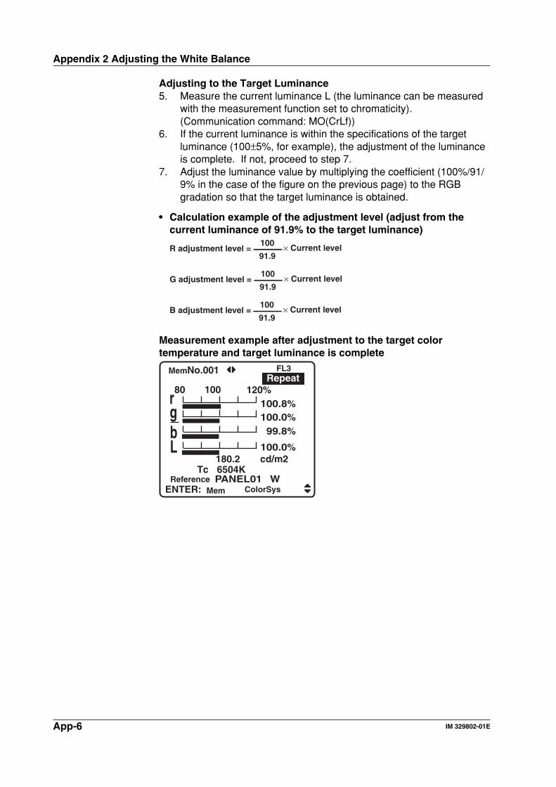
App-6 IM 329802-01E
Adjusting to the Target Luminance5. Measure the current luminance L (the luminance can be measured
with the measurement function set to chromaticity).(Communication command: MO(CrLf))
6. If the current luminance is within the specifications of the targetluminance (100±5%, for example), the adjustment of the luminanceis complete. If not, proceed to step 7.
7. Adjust the luminance value by multiplying the coefficient (100%/91/9% in the case of the figure on the previous page) to the RGBgradation so that the target luminance is obtained.
• Calculation example of the adjustment level (adjust from thecurrent luminance of 91.9% to the target luminance)
R adjustment level = × Current level91.9
100
G adjustment level = × Current level91.9
100
B adjustment level = × Current level91.9
100
Measurement example after adjustment to the target colortemperature and target luminance is complete
PANEL01 W
rgb
180.2Tc 6504K
cd/m2
80 100 120100.8100.0 99.8
%%%%
L 100.0%
FL3Repeat
MemNo.001
ReferenceENTER: ColorSysMem
Appendix 2 Adjusting the White Balance
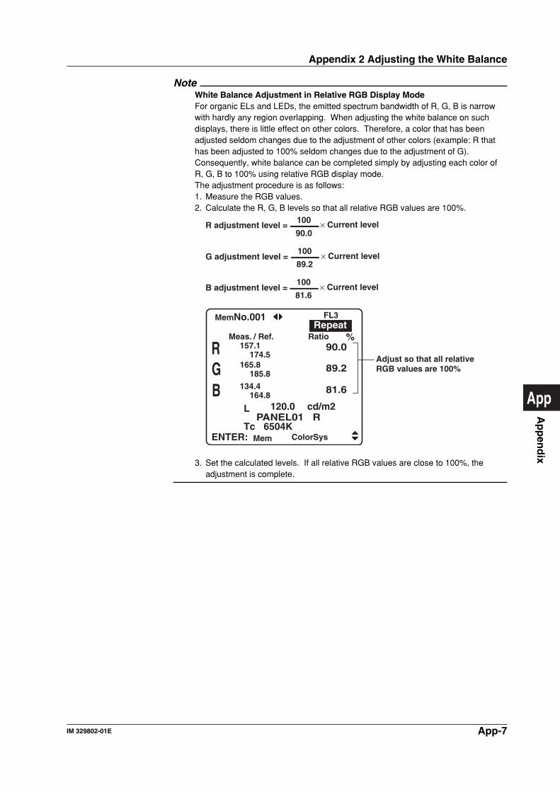
App-7IM 329802-01E
Ap
pen
dix
App
NoteWhite Balance Adjustment in Relative RGB Display ModeFor organic ELs and LEDs, the emitted spectrum bandwidth of R, G, B is narrowwith hardly any region overlapping. When adjusting the white balance on suchdisplays, there is little effect on other colors. Therefore, a color that has beenadjusted seldom changes due to the adjustment of other colors (example: R thathas been adjusted to 100% seldom changes due to the adjustment of G).Consequently, white balance can be completed simply by adjusting each color ofR, G, B to 100% using relative RGB display mode.The adjustment procedure is as follows:1. Measure the RGB values.2. Calculate the R, G, B levels so that all relative RGB values are 100%.
R adjustment level = × Current level90.0
100
G adjustment level = × Current level89.2
100
B adjustment level = × Current level81.6
100
PANEL01 R
157.1174.5
165.8185.8
134.4164.8
RGB
L 120.0
Tc 6504K
cd/m2
90.0
89.2
81.6
Adjust so that all relative RGB values are 100%
Meas. / Ref. Ratio %
FL3Repeat
MemNo.001
ENTER: ColorSysMem
3. Set the calculated levels. If all relative RGB values are close to 100%, theadjustment is complete.
Appendix 2 Adjusting the White Balance
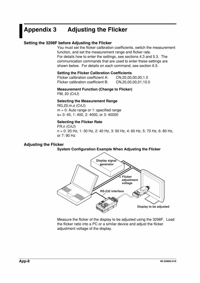
App-8 IM 329802-01E
Appendix 3 Adjusting the Flicker
Setting the 3298F before Adjusting the FlickerYou must set the flicker calibration coefficients, switch the measurementfunction, and set the measurement range and flicker rate.For details how to enter the settings, see sections 4.3 and 5.3. Thecommunication commands that are used to enter these settings areshown below. For details on each command, see section 6.5.
Setting the Flicker Calibration CoefficientsFlicker calibration coefficient A: CN,20,00,00,00,1.0Flicker calibration coefficient B: CN,20,00,00,01,10.0
Measurement Function (Change to Flicker)FM, 20 (CrLf)
Selecting the Measurement RangeRG,20,m,o (CrLf)m = 0: Auto range or 1: specified rangeo= 0: 40, 1: 400, 2: 4000, or 3: 40000
Selecting the Flicker RateFR,n (CrLf)n = 0: 20 Hz, 1: 30 Hz, 2: 40 Hz, 3: 50 Hz, 4: 60 Hz, 5: 70 Hz, 6: 80 Hz,or 7: 90 Hz
Adjusting the FlickerSystem Configuration Example When Adjusting the Flicker
Display signal generator
Display to be adjusted
RS-232 interface
-> Flicker adjustment voltage
Measure the flicker of the display to be adjusted using the 3298F. Loadthe flicker ratio into a PC or a similar device and adjust the flickeradjustment voltage of the display.
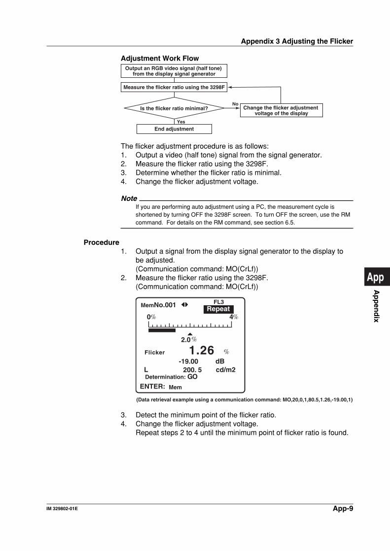
App-9IM 329802-01E
Ap
pen
dix
App
Adjustment Work FlowOutput an RGB video signal (half tone)
from the display signal generator
Is the flicker ratio minimal?
Measure the flicker ratio using the 3298F
Change the flicker adjustment voltage of the display
End adjustment
No
Yes
The flicker adjustment procedure is as follows:1. Output a video (half tone) signal from the signal generator.2. Measure the flicker ratio using the 3298F.3. Determine whether the flicker ratio is minimal.4. Change the flicker adjustment voltage.
NoteIf you are performing auto adjustment using a PC, the measurement cycle isshortened by turning OFF the 3298F screen. To turn OFF the screen, use the RMcommand. For details on the RM command, see section 6.5.
Procedure1. Output a signal from the display signal generator to the display to
be adjusted.(Communication command: MO(CrLf))
2. Measure the flicker ratio using the 3298F.(Communication command: MO(CrLf))
L cd/m2200. 5
2.0
dB-19.00
0 4
Determination:
Flicker
GO
1.26
(Data retrieval example using a communication command: MO,20,0,1,80.5,1.26,-19.00,1)
FL3RepeatMemNo.001
ENTER: Mem
3. Detect the minimum point of the flicker ratio.4. Change the flicker adjustment voltage.
Repeat steps 2 to 4 until the minimum point of flicker ratio is found.
Appendix 3 Adjusting the Flicker
Index-1IM 329802-01E
Ind
ex
Index
Index
Index
Ffix the memory number ................................. 3-17FL3 ...................................................... 1-10, 4-14flicker ............................................................... 5-4flicker calibration coefficient ............................ 4-7flicker measurement ................................ 1-2, 1-3flicker rate ........................................................ 5-4flicker reference ............................................... 4-3Freqency ......................................................... 5-5
GGO/NOGO determination .............. 1-2, 3-11, 4-3
Hhandshaking .......................................... 4-16, 6-4hood ................................................................ 3-5
Iincrement ...................................................... 3-17installing the sensor ........................................ 3-4instrument number .............................................. ii
Llight source calibration .................................. 4-14light source calibration coefficient ....... 1-10, 4-14Load .............................................................. 3-16load the memory ........................................... 3-16low battery ....................................................... 3-8luminance ........................................................ 5-1luminance calibration coefficient ........... 1-12, 4-7luminance display ............................................ 5-5luminance display ON/OFF ............................. 5-4luminance measurement ......................... 1-2, 1-3luminance reference ........................................ 4-3
Mmaking connection cable ............................... 3-12Manual ............................................................ 5-2MeasMode ...................................................... 5-3measurement mode ........................................ 5-2measurement range ................................ 3-6, 5-1measuring field diameter ................................. 3-6Memory ......................................................... 3-16memory function.............................................. 1-2monitor output ............................................... 3-11
AAC adapter ...................................................... 3-8accessory ........................................................... iiiAUTO .............................................................. 5-2auto power down ................................. 1-17, 4-16average count ............................................... 4-15
Bback light ............................................. 1-17, 4-16battery install ................................................... 3-7baud rate ....................................................... 4-16block diagram .................................................. 1-1buffer ............................................................... 6-5
Ccalibration coefficient ....................................... 5-6character setting............................................ 3-15chromaticity ..................................................... 5-6chromaticity calibration coefficient .................. 4-7chromaticity measurement .............................. 1-2chromaticity reference ..................................... 4-3Clear .............................................................. 3-17clear the memory .......................................... 3-17coefficient list ................................................... 1-9color system .................................................... 1-6command ........................................................ 6-7connection cable ........................................... 3-12connector ........................................................ 6-2contact input .................................................. 3-10contrast ........................................................... 5-2contrast measurement ............................ 1-2, 1-3contrast reference ........................................... 4-3correlated color temperature ........................... 1-9CRT ..................................................... 1-10, 4-14
Ddata format ...................................................... 6-6data length .................................................... 4-16DC luminance output ..................................... 3-11default value list ..........................................App-1display mode ................................................... 5-6
EENTER key ................................................... 3-13ESC key ........................................................ 3-13external trigger input ..................................... 3-10
Index-2 IM 329802-01E
Index
Nnumeric setting .............................................. 3-14
Ooffset calibration .............................................. 3-9output data format ......................................... 6-11
Pparameter selection....................................... 3-13parity ............................................................. 4-16power down ......................................... 1-17, 4-16power supply connect ..................................... 3-7
Rrange ....................................... 5-1, 5-2, 5-4, 5-8reference value ....................................... 4-3, 5-6reference value conversion ............................. 4-8relative RGB value .......................................... 1-8repeat ............................................................ 1-18RGB color system ........................................... 1-8rgb ratio ........................................................... 1-8RS-232 connection........................................ 3-10RS-232 interface ............................................. 6-1rubber bumper ................................................. 3-6
Ssave the measured result .............................. 3-16screen switching............................................ 3-13sensor ............................................................. 2-2sensor cable .................................................... 2-2sensor connection ........................................... 3-4serial connection ........................................... 3-10Set ................................................................. 3-17single ............................................................. 1-18specification .................................................... 7-1stop bit ........................................................... 4-16suffix code ........................................................... ii
Ttarget chromaticity x, y .................................... 1-9terminator ........................................................ 6-5trigger .............................................................. 1-2trigger mode ........................................ 1-18, 4-15Type-A ................................................. 1-10, 4-14
Uu’ v’ L color system .......................................... 1-7user-calibration factor .................................... 1-12user-define .................................................... 4-11
Vversion........................................................... 4-17
Wwhite balance adjustment .................. 4-11, App-3
XxyL color system ............................................. 1-6
Zzero level calibration ....................................... 3-9