Embed Size (px)
Citation preview
ENGLISH
FRANÇAIS
ESPAÑOL
DEUTSCH
ITALIANO
日本語
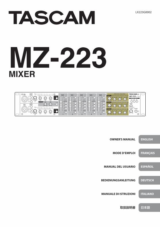
OWNER'S MANUAL
MODE D’EMPLOI
MANUAL DEL USUARIO
BEDIENUNGSANLEITUNG
MANUALE DI ISTRUZIONI
取扱説明書
LX223G0002
MZ-223MIXER

2 TASCAM MZ-223
• TASCAM is a trademark of TEAC CORPORATION, registered in the U.S. and other countries.
• Other company names, product names and logos in this document are the trademarks or registered trademarks of their respective owners.
https://tascam.jp/jp/〒206-8530 東京都多摩市落合1-47
TEAC AMERICA, INC.http://tascam.com/Phone: +1-323-726-03031834 Gage Road, Montebello, California 90640 USA
TEAC UK Ltd.http://tascam.eu/Phone: +44-8451-3025112 Huxley Road, Surrey Research Park Guildford, GU2 7RE, United Kingdom
TEAC EUROPE GmbHhttp://tascam.eu/Phone: +49-611-71580Bahnstrasse 12, 65205 Wiesbaden-Erbenheim, Germany
TEAC SALES & TRADING(SHENZHEN) CO., LTDPhone: +86-755-88311561~2Room 817, Block A, Hailrun Complex, 6021 Shennan Blvd., Futian District, Shenzhen 518040, China

TASCAM MZ-223 3
OWNER’S MANUAL
IMPORTANT SAFETY PRECAUTIONS
CAUTION: TO REDUCE THE RISK OF ELECTRIC SHOCK, DO NOT REMOVE COVER (OR BACK). NO USER-SERVICEABLE PARTS INSIDE. REFER SERVICING TO QUALIFIED SERVICE PERSONNEL.
The lightning flash with arrowhead symbol, within equilateral triangle, is intended to alert the user to the presence of uninsulated “dangerous voltage” within the product’s enclosure that may be of sufficient magnitude to constitute a risk of electric shock to persons.The exclamation point within an equilateral triangle is intended to alert the user to the presence of important operating and mainte-nance (servicing) instructions in the literature accompanying the appliance.
WARNING: TO PREVENT FIRE OR SHOCK HAZ-ARD, DO NOT EXPOSE THIS APPLIANCE TO RAIN OR MOISTURE.
For U.S.A.Declaration of ConformityModel Number: MZ-223Trade Name: TASCAMResponsible party: TEAC AMERICA, INC.Address: 1834 Gage Road, Montebello, California,
U.S.A.Telephone number: 1-323-726-0303This device complies with Part 15 of the FCC Rules. Operation is subject to the following two conditions: (1) this device may not cause harmful interference, and (2) this device must accept any interference received, including interference that may cause undesired operation.
INFORMATION TO THE USERThis equipment has been tested and found to com-ply with the limits for a Class B digital device, pur-suant to Part 15 of the FCC Rules. These limits are designed to provide reasonable protection against harmful interference in a residential installation. This equipment generates, uses, and can radiate radio frequency energy and, if not installed and used in accordance with the instruction manual, may cause harmful interference to radio commu-nications. However, there is no guarantee that in-terference will not occur in a particular installation. If this equipment does cause harmful interference to radio or television reception, which can be de-termined by turning the equipment off and on, the user is encouraged to try to correct the interference by one or more of the following measures.
a) Reorient or relocate the receiving antenna.b) Increase the separation between the equipment
and receiver.c) Connect the equipment into an outlet on a circuit
different from that to which the receiver is con-nected.
d) Consult the dealer or an experienced radio/TV technician for help.
CAUTIONChanges or modifications to this equipment not ex-pressly approved by TEAC CORPORATION for com-pliance could void the user’s authority to operate this equipment.
IN USA/CANADA, USE ONLY ON 120 V SUPPLY.
For CanadaTHIS CLASS B DIGITAL APPARATUS COMPLIES WITH CANADIAN ICES-003.CET APPAREIL NUMERIQUE DE LA CLASSE B EST CONFORME A LA NORME NMB-003 DU CANADA.
This product complies with the Eu-ropean Directives request and the other Commission Regulations.
CE Marking InformationEN55103-2a) Applicable electromagnetic environment: E1, E2,
E3, E4
4 TASCAM MZ-223
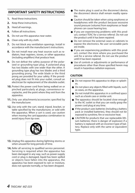
IMPORTANT SAFETY INSTRUCTIONS
1. Read these instructions.
2. Keep these instructions.
3. Heed all warnings.
4. Follow all instructions.
5. Do not use this apparatus near water.
6. Clean only with dry cloth.
7. Do not block any ventilation openings. Install in accordance with the manufacturer’s instructions.
8. Do not install near any heat sources such as ra-diators, heat registers, stoves, or other apparatus (including amplifiers) that produce heat.
9. Do not defeat the safety purpose of the polar-ized or grounding-type plug. A polarized plug has two blades with one wider than the other. A grounding type plug has two blades and a third grounding prong. The wide blade or the third prong are provided for your safety. If the provid-ed plug does not fit into your outlet, consult an electrician for replacement of the obsolete outlet.
10. Protect the power cord from being walked on or pinched particularly at plugs, convenience re-ceptacles, and the point where they exit from the apparatus.
11. Only use attachments/accessories specified by the manufacturer.
12. Use only with the cart, stand, tripod, bracket, or table specified by the manufacturer, or sold with the apparatus. When a cart is used, use caution when moving the cart/apparatus combination to avoid injury from tip-over.
13. Unplug this apparatus during lightning storms or when unused for long periods of time.
14. Refer all servicing to qualified service personnel. Servicing is required when the apparatus has been damaged in any way, such as power-supply cord or plug is damaged, liquid has been spilled or objects have fallen into the apparatus, the apparatus has been exposed to rain or moisture, does not operate normally, or has been dropped.
0 The mains plug is used as the disconnect device, the disconnect device shall remain readily opera-ble.
0 Caution should be taken when using earphones or headphones with the product because excessive sound pressure (volume) from earphones or head-phones can cause hearing loss.
0 If you are experiencing problems with this prod-uct, contact TEAC for a service referral. Do not use the product until it has been repaired.
0 Do not remove the external cases or cabinets to expose the electronics. No user serviceable parts are inside.
0 If you are experiencing problems with this prod-uct, contact the store where you purchased the unit for a service referral. Do not use the product until it has been repaired.
0 Use of controls or adjustments or performance of procedures other than those specified herein may result in hazardous radiation exposure.
CAUTION
0 Do not expose this apparatus to drips or splash-es.
0 Do not place any objects filled with liquids, such as vases, on the apparatus.
0 Do not install this apparatus in a confined space such as a book case or similar unit.
0 The apparatus should be located close enough to the AC outlet so that you can easily grasp the power cord plug at any time.
0 If the product uses batteries (including a battery pack or installed batteries), they should not be exposed to sunshine, fire or excessive heat.
0 CAUTION for products that use replaceable lith-ium batteries: there is danger of explosion if a battery is replaced with an incorrect type of bat-tery. Replace only with the same or equivalent type.
TASCAM MZ-223 5
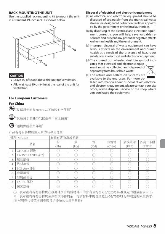
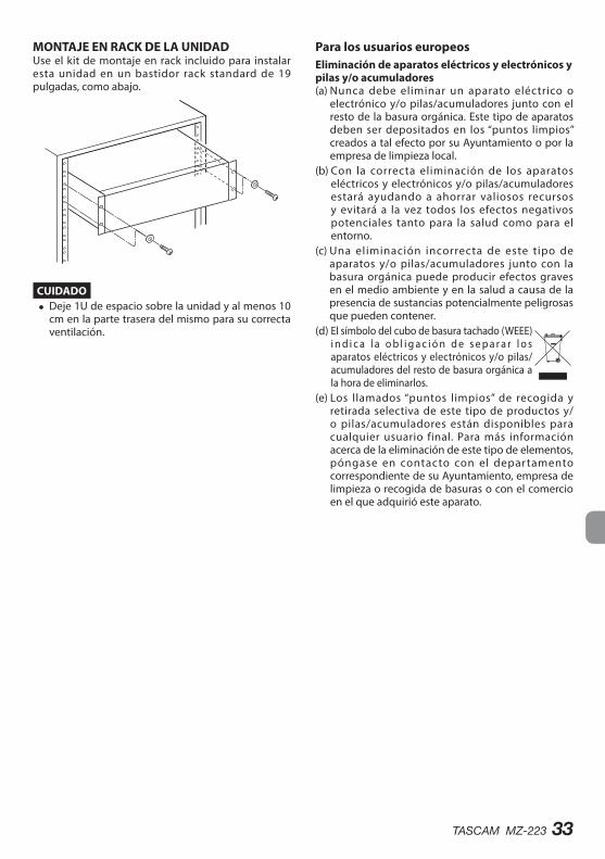
RACK-MOUNTING THE UNITUse the supplied rack-mounting kit to mount the unit in a standard 19-inch rack, as shown below.
CAUTION i Leave 1U of space above the unit for ventilation.
i Allow at least 10 cm (4 in) at the rear of the unit for ventilation.
For European Customers
Disposal of electrical and electronic equipment(a) All electrical and electronic equipment should be
disposed of separately from the municipal waste stream via designated collection facilities appoint-ed by the government or the local authorities.
(b) By disposing of the electrical and electronic equip-ment correctly, you will help save valuable re-sources and prevent any potential negative effects on human health and the environment.
(c) Improper disposal of waste equipment can have serious effects on the environment and human health as a result of the presence of hazardous substances in electrical and electronic equipment.
(d) The crossed out wheeled dust bin symbol indi-cates that electrical and electronic equip-ment must be collected and disposed of separately from household waste.
(e) The return and collection systems are available to the end users. For more de-tailed information about disposal of old electrical and electronic equipment, please contact your city office, waste disposal service or the shop where you purchased the equipment.
For China
“仅适用于海拔2000m 以下地区安全使用”
“仅适用于非熱帯气候条件下安全使用”
“環境保護使用年限”
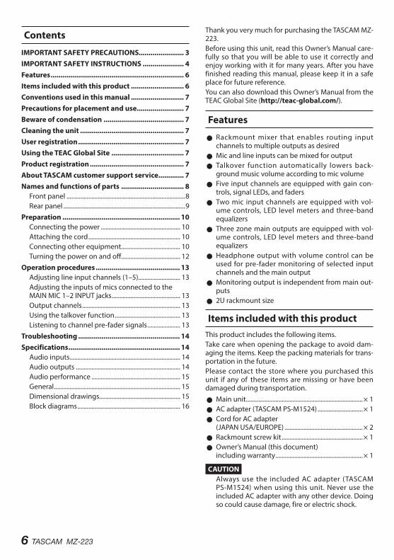
产品有毒有害物质或元素的名称及含量
机种: MZ-223 有毒有害物质或元素
品名铅
(Pb)汞
(Hg)镉
(Cd)六价铬(Cr6+)
多溴联苯(PBB)
多溴二苯醚(PBDE)
1 CHASSIS 部份 ○ ○ ○ ○ ○ ○2 FRONT PANEL 部份 ○ ○ ○ ○ ○ ○3 螺丝部份 ○ ○ ○ ○ ○ ○4 线材部份 ○ ○ ○ ○ ○ ○5 PCB Assy 部份 × ○ ○ ○ ○ ○6 电源部份 ○ ○ ○ ○ ○ ○7 附属品部份 × ○ ○ ○ ○ ○8 LABEL 部份 ○ ○ ○ ○ ○ ○
9 包装部份 ○ ○ ○ ○ ○ ○
○ :表示该有毒有害物质在该部件所有均质材料中的含有量均在 GB/T26572 标准规定的限量要求以下。× :表示该有毒有害物质至少在该部件的某一均质材料中的含量超出 GB/T26572 标准规定的限量要求。(针对现在代替技术困难的电子部品及合金中的铅)
6 TASCAM MZ-223
Thank you very much for purchasing the TASCAM MZ-223.Before using this unit, read this Owner’s Manual care-fully so that you will be able to use it correctly and enjoy working with it for many years. After you have finished reading this manual, please keep it in a safe place for future reference.You can also download this Owner’s Manual from the TEAC Global Site (http://teac-global.com/).
Features
0 Rackmount mixer that enables routing input channels to multiple outputs as desired
0 Mic and line inputs can be mixed for output 0 Talkover function automatically lowers back-ground music volume according to mic volume
0 Five input channels are equipped with gain con-trols, signal LEDs, and faders
0 Two mic input channels are equipped with vol-ume controls, LED level meters and three-band equalizers
0 Three zone main outputs are equipped with vol-ume controls, LED level meters and three-band equalizers
0 Headphone output with volume control can be used for pre-fader monitoring of selected input channels and the main output
0 Monitoring output is independent from main out-puts
0 2U rackmount size
Items included with this productThis product includes the following items.Take care when opening the package to avoid dam-aging the items. Keep the packing materials for trans-portation in the future.Please contact the store where you purchased this unit if any of these items are missing or have been damaged during transportation.
0 Main unit ...........................................................................× 1 0 AC adapter (TASCAM PS-M1524) .............................× 1 0 Cord for AC adapter (JAPAN USA/EUROPE) ..................................................× 2
0 Rackmount screw kit ....................................................× 1 0 Owner’s Manual (this document) including warranty ........................................................× 1
CAUTIONAlways use the included AC adapter (TASCAM PS-M1524) when using this unit. Never use the included AC adapter with any other device. Doing so could cause damage, fire or electric shock.
Contents
IMPORTANT SAFETY PRECAUTIONS....................... 3IMPORTANT SAFETY INSTRUCTIONS ..................... 4Features .................................................................... 6Items included with this product ........................... 6Conventions used in this manual ........................... 7Precautions for placement and use ........................ 7Beware of condensation ......................................... 7Cleaning the unit ..................................................... 7User registration ...................................................... 7Using the TEAC Global Site ..................................... 7Product registration ................................................ 7About TASCAM customer support service ............. 7Names and functions of parts ................................ 8
Front panel ............................................................................8Rear panel ..............................................................................9
Preparation ............................................................ 10Connecting the power ................................................... 10Attaching the cord ........................................................... 10Connecting other equipment...................................... 10Turning the power on and off...................................... 12
Operation procedures ........................................... 13Adjusting line input channels (1–5)........................... 13Adjusting the inputs of mics connected to the MAIN MIC 1–2 INPUT jacks ............................................ 13Output channels ............................................................... 13Using the talkover function .......................................... 13Listening to channel pre-fader signals ..................... 13
Troubleshooting .................................................... 14Specifications ......................................................... 14
Audio inputs ....................................................................... 14Audio outputs ................................................................... 14Audio performance ......................................................... 15General ................................................................................. 15Dimensional drawings.................................................... 15Block diagrams .................................................................. 16

TASCAM MZ-223 7
Conventions used in this manualIn this manual, we use the following conventions:
0 The names of switches, connectors and other physical parts of this unit are written using a bold font like this: POWER switch.
0 Additional information is provided as necessary as tips, notes and cautions.
TIPThese are tips about how to use the unit.
NOTEThese provide additional explanations and de-scribe special cases.
CAUTIONFailure to follow these instructions could result in injury, damage to equipment or lost recording data, for example.
Precautions for placement and use
0 The operating temperature range of this unit is 5–35 °C.
0 Do not install this unit in the following types of locations. Doing so could cause malfunction.
Places with significant vibrationsNear windows or other places exposed to di-rect sunlightNear heaters or other extremely hot placesExtremely cold placesPlaces with bad ventilation or high humidityVery dusty locations
0 To enable good heat dissipation, do not place any-thing on top of the unit.
0 Do not place the unit on top of a power amplifier or other device that generates heat.
Beware of condensationIf the unit is moved from a cold to a warm place, or used after a sudden temperature change, there is a danger of condensation; vapor in the air could con-dense on the internal mechanism, making correct operation impossible.To prevent this, or if this occurs, let the unit sit for one or two hours at the new room temperature before using it.
Cleaning the unitTo clean the unit, wipe it gently with a soft dry cloth. Do not wipe with chemical cleaning cloths, benzene, thinner, alcohol or other chemical agents. Doing so could damage the surface or cause discoloration.
User registrationCustomers in the USA, please visit the TASCAM web-site to register as a user online.
https://tascam.jp/jp/login
Using the TEAC Global SiteYou can download updates for this unit from the TEAC Global Site:
http://teac-global.com/In the TASCAM Downloads section, select the desired language to open the Downloads website page for that language.
Product registrationCustomers in the USA, please visit the following TAS-CAM website to register your TASCAM product online.
http://tascam.com/
About TASCAM customer support service
TASCAM products are supported and warrantied only in their country/region of purchase.To receive support after purchase, on the TASCAM Distributors list page of the TEAC Global Site (http:// teac-global.com/), search for the local company or representative for the region where you purchased the product and contact that organization.When making inquiries, the address (URL) of the shop or web shop where it was purchased and the pur-chase date are required.Moreover, the warranty card and proof of purchase might also be necessary.
8 TASCAM MZ-223
Names and functions of parts
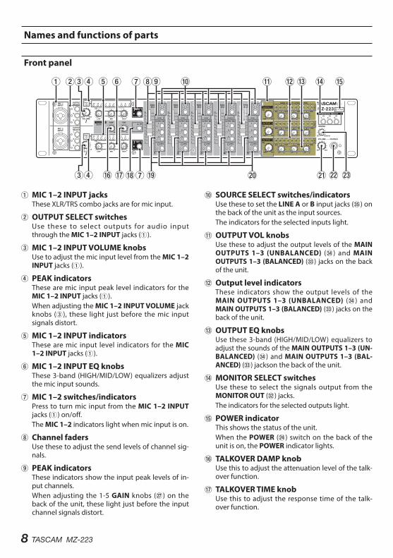
Front panel
1MIC 1–2 INPUT jacksThese XLR/TRS combo jacks are for mic input.
2OUTPUT SELECT switchesUse these to select outputs for audio input through the MIC 1–2 INPUT jacks (1).
3MIC 1–2 INPUT VOLUME knobsUse to adjust the mic input level from the MIC 1–2 INPUT jacks (1).
4PEAK indicatorsThese are mic input peak level indicators for the MIC 1–2 INPUT jacks (1).When adjusting the MIC 1–2 INPUT VOLUME jack knobs (3), these light just before the mic input signals distort.
5MIC 1–2 INPUT indicatorsThese are mic input level indicators for the MIC 1–2 INPUT jacks (1).
6MIC 1–2 INPUT EQ knobsThese 3-band (HIGH/MID/LOW) equalizers adjust the mic input sounds.
7MIC 1–2 switches/indicatorsPress to turn mic input from the MIC 1–2 INPUT jacks (1) on/off.The MIC 1–2 indicators light when mic input is on.
8Channel fadersUse these to adjust the send levels of channel sig-nals.
9PEAK indicatorsThese indicators show the input peak levels of in-put channels.When adjusting the 1-5 GAIN knobs (j) on the back of the unit, these light just before the input channel signals distort.
0SOURCE SELECT switches/indicatorsUse these to set the LINE A or B input jacks (b) on the back of the unit as the input sources.The indicators for the selected inputs light.
qOUTPUT VOL knobsUse these to adjust the output levels of the MAIN OUTPUTS 1–3 (UNBALANCED) (v) and MAIN OUTPUTS 1–3 (BALANCED) (c) jacks on the back of the unit.
wOutput level indicatorsThese indicators show the output levels of the MAIN OUTPUTS 1–3 (UNBALANCED) (v) and MAIN OUTPUTS 1–3 (BALANCED) (c) jacks on the back of the unit.
eOUTPUT EQ knobsUse these 3-band (HIGH/MID/LOW) equalizers to adjust the sounds of the MAIN OUTPUTS 1–3 (UN-BALANCED) (v) and MAIN OUTPUTS 1–3 (BAL-ANCED) (c) jackson the back of the unit.
rMONITOR SELECT switchesUse these to select the signals output from the MONITOR OUT (x) jacks.The indicators for the selected outputs light.
tPOWER indicatorThis shows the status of the unit.When the POWER (f) switch on the back of the unit is on, the POWER indicator lights.
yTALKOVER DAMP knobUse this to adjust the attenuation level of the talk-over function.
uTALKOVER TIME knobUse this to adjust the response time of the talk-over function.
TASCAM MZ-223 9
iTALKOVER ON switch/indicatorPress to turn the talkover function on/off.When the talkover function is on, the TALKOVER ON indicator lights, and the levels of all input channels are lowered automatically when sound is input from a mic.Use the TALKOVER DAMP (y) and TALKOVER TIME (u) knobs to adjust the attenuation level and response time (MIC 1 only).
oOUTPUT SEL switchesUse these to select the output channel stereo buses (1–3) that receive the input signals of each channel.
pPFL switches/indicatorsWhen a PFL switch is on (PFL indicator lit), the pre-fader signal (signal before fader adjustment) can be monitored through headphones.
aPHONES VOLUME knobUse this to adjust the headphone output level.
sPHONES jackUse this standard stereo jack to connect stereo headphones.Use an adapter to connect headphones with a mini plug.When PFL switches (p) are on, the PFL signal can be monitored.
dMIXING knobUse this to mix the pre-fader and monitoring sig-nals output to the headphones.
o Turn all the way to the PFL side to monitor channels that have their PFL (p) switches pressed in.
o Turn all the way to the MONITOR side to moni-tor the monitoring signal.
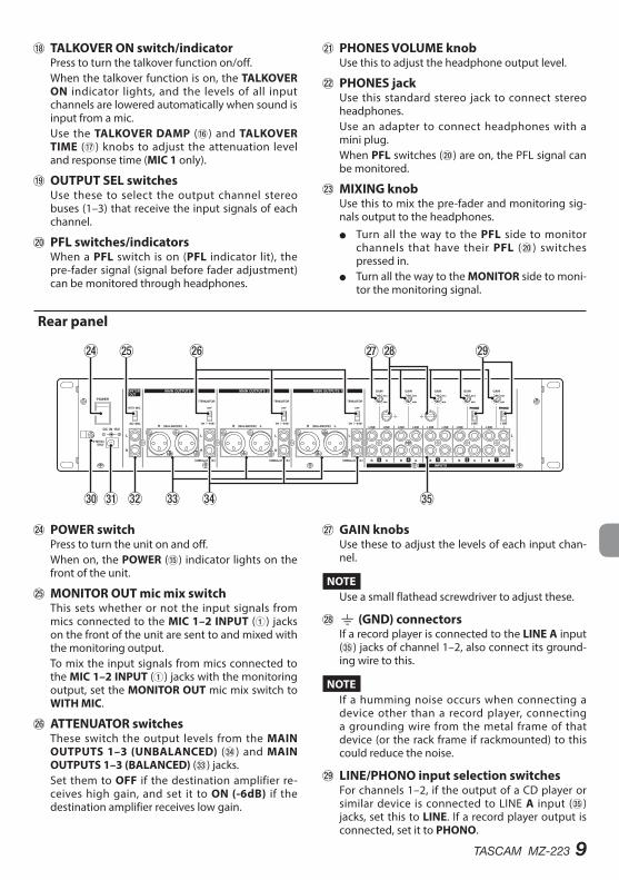
Rear panel
fPOWER switchPress to turn the unit on and off.When on, the POWER (t) indicator lights on the front of the unit.
gMONITOR OUT mic mix switchThis sets whether or not the input signals from mics connected to the MIC 1–2 INPUT (1) jacks on the front of the unit are sent to and mixed with the monitoring output.To mix the input signals from mics connected to the MIC 1–2 INPUT (1) jacks with the monitoring output, set the MONITOR OUT mic mix switch to WITH MIC.
hATTENUATOR switchesThese switch the output levels from the MAIN OUTPUTS 1–3 (UNBALANCED) (v) and MAIN OUTPUTS 1–3 (BALANCED) (c) jacks.Set them to OFF if the destination amplifier re-ceives high gain, and set it to ON (-6dB) if the destination amplifier receives low gain.
jGAIN knobsUse these to adjust the levels of each input chan-nel.
NOTEUse a small flathead screwdriver to adjust these.
k| (GND) connectorsIf a record player is connected to the LINE A input (b) jacks of channel 1–2, also connect its ground-ing wire to this.
NOTEIf a humming noise occurs when connecting a device other than a record player, connecting a grounding wire from the metal frame of that device (or the rack frame if rackmounted) to this could reduce the noise.
l LINE/PHONO input selection switchesFor channels 1–2, if the output of a CD player or similar device is connected to LINE A input (b) jacks, set this to LINE. If a record player output is connected, set it to PHONO.
10 TASCAM MZ-223
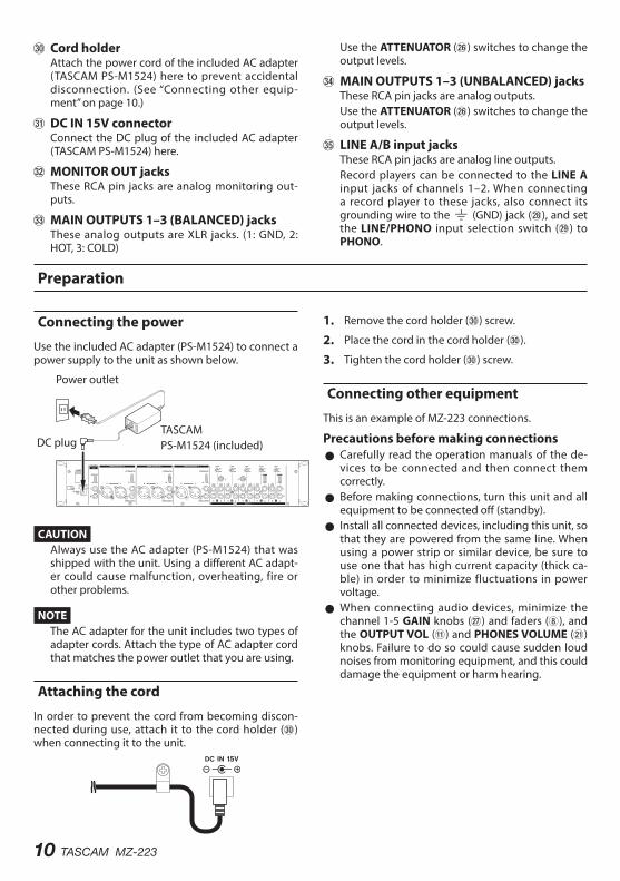
;Cord holderAttach the power cord of the included AC adapter (TASCAM PS-M1524) here to prevent accidental disconnection. (See “Connecting other equip-ment” on page 10.)
z DC IN 15V connectorConnect the DC plug of the included AC adapter (TASCAM PS-M1524) here.
x MONITOR OUT jacksThese RCA pin jacks are analog monitoring out-puts.
c MAIN OUTPUTS 1–3 (BALANCED) jacks These analog outputs are XLR jacks. (1: GND, 2: HOT, 3: COLD)
Use the ATTENUATOR (h) switches to change the output levels.
v MAIN OUTPUTS 1–3 (UNBALANCED) jacksThese RCA pin jacks are analog outputs.Use the ATTENUATOR (h) switches to change the output levels.
b LINE A/B input jacksThese RCA pin jacks are analog line outputs.Record players can be connected to the LINE A input jacks of channels 1–2. When connecting a record player to these jacks, also connect its grounding wire to the | (GND) jack (k), and set the LINE/PHONO input selection switch (l) to PHONO.
Preparation
Connecting the power
Use the included AC adapter (PS-M1524) to connect a power supply to the unit as shown below.
Power outlet
DC plugTASCAMPS-M1524 (included)
CAUTIONAlways use the AC adapter (PS-M1524) that was shipped with the unit. Using a different AC adapt-er could cause malfunction, overheating, fire or other problems.
NOTEThe AC adapter for the unit includes two types of adapter cords. Attach the type of AC adapter cord that matches the power outlet that you are using.
Attaching the cord
In order to prevent the cord from becoming discon-nected during use, attach it to the cord holder (;) when connecting it to the unit.
1. Remove the cord holder (;) screw.
2. Place the cord in the cord holder (;).
3. Tighten the cord holder (;) screw.
Connecting other equipment
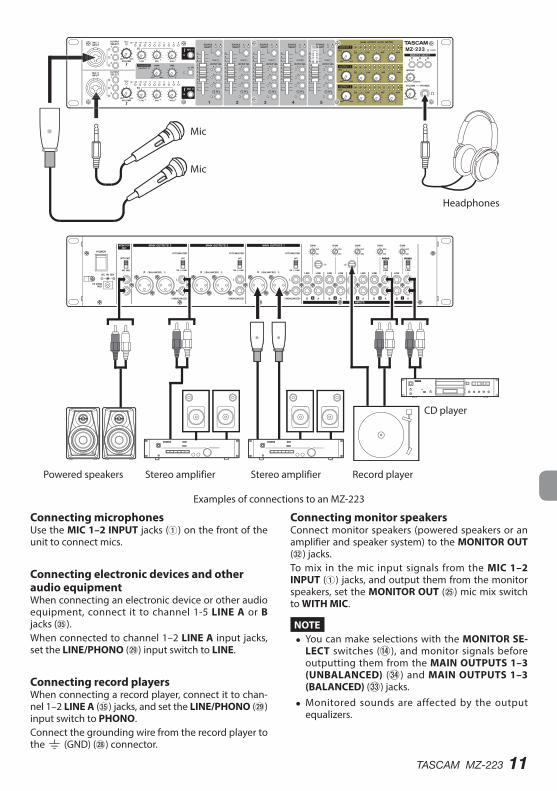
This is an example of MZ-223 connections.
Precautions before making connections 0 Carefully read the operation manuals of the de-vices to be connected and then connect them correctly.
0 Before making connections, turn this unit and all equipment to be connected off (standby).
0 Install all connected devices, including this unit, so that they are powered from the same line. When using a power strip or similar device, be sure to use one that has high current capacity (thick ca-ble) in order to minimize fluctuations in power voltage.
0 When connecting audio devices, minimize the channel 1-5 GAIN knobs (j) and faders (8), and the OUTPUT VOL (q) and PHONES VOLUME (a) knobs. Failure to do so could cause sudden loud noises from monitoring equipment, and this could damage the equipment or harm hearing.
TASCAM MZ-223 11
Powered speakers
Headphones
CD player
Record player
Mic
Mic
Stereo amplifierStereo amplifier
Examples of connections to an MZ-223
Connecting microphonesUse the MIC 1–2 INPUT jacks (1) on the front of the unit to connect mics.
Connecting electronic devices and other audio equipmentWhen connecting an electronic device or other audio equipment, connect it to channel 1-5 LINE A or B jacks (b).When connected to channel 1–2 LINE A input jacks, set the LINE/PHONO (l) input switch to LINE.
Connecting record playersWhen connecting a record player, connect it to chan-nel 1–2 LINE A (b) jacks, and set the LINE/PHONO (l) input switch to PHONO.Connect the grounding wire from the record player to the | (GND) (k) connector.
Connecting monitor speakersConnect monitor speakers (powered speakers or an amplifier and speaker system) to the MONITOR OUT (x) jacks.To mix in the mic input signals from the MIC 1–2 INPUT (1) jacks, and output them from the monitor speakers, set the MONITOR OUT (g) mic mix switch to WITH MIC.
NOTE i You can make selections with the MONITOR SE-
LECT switches (r), and monitor signals before outputting them from the MAIN OUTPUTS 1–3 (UNBALANCED) (v) and MAIN OUTPUTS 1–3 (BALANCED) (c) jacks.
i Monitored sounds are affected by the output equalizers.
12 TASCAM MZ-223
Connecting headphonesConnect headphones to the PHONES (s) jack (stan-dard stereo).You can monitor input channel pre-fader signals and signals before they are sent to the stereo output bus.Use the MONITOR SELECT (r) switches to select the outputs that you want to monitor.
CAUTIONBefore connecting headphones, minimize the vol-ume with the PHONES VOLUME (a) knob. Failure to do so could result in a sudden loud noise that could harm hearing, for example.
NOTESounds output from headphones are affected by the output equalizers.
Connecting stereo amplifiersWhen connecting a stereo amplifier, connect it to the MAIN OUTPUTS 1–3 (UNBALANCED) (v) or MAIN OUTPUTS 1–3 (BALANCED) (c) jacks.
TIP i When connecting 2 or more amplifier and speaker
systems, including main and sub, main and mon-itoring, or front and rear combinations, using the MAIN OUTPUTS 1–3 (UNBALANCED) (f) and MAIN OUTPUTS 1–3 (BALANCED) (c) jacks could be convenient. Moreover, the outputs of the jacks are independent and have their own dedicated output knobs, so you can set the output levels separately with this unit.
i By connecting a recorder to MONITOR OUT (x) jacks, the signal output to amplifier/speaker sys-tems can be recorded.
Turning the power on and off
CAUTION i Turn down the volume of the sound system con-
nected to the unit before starting up or shutting down the unit.
i Do not wear connected headphones when turn-ing the unit on and off. Loud noises could damage the speakers or harm your hearing.
Before turning the power on1. Make the following settings on the front of the
unit.
o EQ knobs w center values o Other knobs w all the way left (MIN side) o Faders w all the way down o Switches w off (not pushed in)
2. Minimize the output levels of audio sources and input levels of amplifiers connected to this unit.
Turning the power on1. Use the POWER (f) switch on the back of the
unit to turn its power on.The POWER (t) indicator on the front of the unit will light when on.
2. Turn connected input audio source devices on.
3. Finally turn amplifiers on.
Turning the power offFollow the procedures above in reverse when turning the power off.Failure to follow the correct order could result in click-ing noises, for example, that might damage equip-ment.
TASCAM MZ-223 13
Operation proceduresAfter turning the power on, adjust the levels of the input signals.
Adjusting line input channels (1–5)
1. Set the channel 1–5 GAIN knobs (j) to their cen-ter positions.
2. Press the channel 1–5 SOURCE SELECT switches (0), so that the SOURCE SELECT indicator (A/B) lights.
3. Press the channel 1–5 OUTPUT SEL switches (o) to select the output channel stereo buses (1–3) that receive the input signals of each channel.
4. When connecting an audio device to channel 1–2 LINE A/B (b) input jacks, set the LINE/PHONE switch (l) to LINE.
5. Set the OUTPUT VOL (q) knob levels low.
6. Start playback on the connected audio device.Use the GAIN knobs (j) to adjust the levels so that the channel 1–5 PEAK indicators (9) do not light red.
7. Follow the above procedures to adjust other line input channels with connected audio devices.
Adjusting the inputs of mics connected to the MAIN MIC 1–2 INPUT jacks
1. Connect a mic to a MIC 1–2 INPUT jack (1), and press the MIC 1–2 switch (7) so that the MIC 1–2 indicator (7) lights.
2. Press OUTPUT SELECT switches (2) to select outputs for signals input through the MIC 1–2 INPUT jacks (1).
3. While checking the MIC 1–2 INPUT (5) and PEAK (4) indicators, use the MIC 1–2 INPUT VOLUME knobs (3) to adjust the mic input lev-els.
4. Use the MIC 1–2 INPUT EQ knobs (6) to adjust the 3-band (HIGH/MID/LOW) equalizers.
Output channels
Output signals can be sent to the following jacks from the stereo output bus after the output equalizer.
0 MAIN OUTPUTS 1–3 (UNBALANCED) (v) and MAIN OUTPUTS 1–3 (BALANCED) (c) jacks
0 MONITOR OUT jacks (x)
NOTEThe output level from the MONITOR OUT (x) jacks cannot be adjusted.
Adjusting the levels output from the MAIN OUTPUTS 1–3 (UNBALANCED) and MAIN OUTPUTS 1–3 (BALANCED) jacksWhile checking the output level indicators (w), use the channel faders (8) and OUTPUT VOL (q) knobs to adjust the output levels. The optimal output level adjustment is usually when the output level indica-tors (w) light around 0 dB.When an amplifier is connected to the MAIN OUT-PUTS 1–3 (UNBALANCED) (v) or MAIN OUTPUTS 1–3 (BALANCED) (c) jacks, set the ATTENUATOR (h) switch to OFF if it accepts high gain or ON (-6dB) if it accepts low gain.Use the OUTPUT EQ knobs (e) to adjust the 3-band (HIGH/MID/LOW) equalizers for the output sound.
Using the talkover function
When the talkover function is turned on by pressing the TALKOVER ON switch (i), the levels of channels 1 will be automatically lowered when sound is input from a mic connected to a MIC 1–2 INPUT (1) jack, making the mic signal easier to hear.To turn the talkover function off, press the TALKOVER ON (i) switch to disable it (TALKOVER ON (i) indi-cator becomes unlit).Use the TALKOVER DAMP (y) and TALKOVER TIME (u) knobs to adjust the attenuation level and re-sponse time.
Listening to channel pre-fader signals
By pressing the PFL (p) switches of channels to turn them on, you can enable headphone monitoring of individual channels 1–5, even when their faders (8) are set at minimum values.
1. Press PFL (p) switches so that their PFL indica-tors light, and turn the MIXING (d) knob to PFL.To monitor the signal before it is sent to the stereo output bus, turn the MIXING (d) knob to MONITOR.
2. Use the PHONES VOLUME (a) knob to adjust the monitoring output level.
14 TASCAM MZ-223
TroubleshootingIf you are having trouble with the operation of this unit, please try the following before seeking repair.If these measures do not solve the problem, please contact the store where you purchased this unit or TASCAM customer support service.
The unit will not turn on. 0 Confirm that the AC adapter (TASCAM PS-M1524) is securely connected to both the outlet and the DC jack.
Sound is not output from speakers connect-ed via the MAIN OUTPUTS 1–3 jacks.
0 Check the settings and volume of the connected amplifier.
0 Confirm that channel faders (8) are raised. 0 Confirm that the input sound source is connected properly.
The volume is low even when faders are raised.
0 Confirm that the GAIN (j) knobs for channels 1–5 are set properly.
The sound is distorted. 0 Confirm that the channel 1–5 GAIN knobs (j) are set properly.
0 Confirm that the EQ is not set too high. 0 Confirm that the channel 1–5 faders (8) and OUT-PUT VOL knobs (q) are not set too high.
Sound from a record player is strange. 0 Confirm that it is connected to channel 1–2 LINE A jacks and that the LINE/PHONO input switch (l) is set to PHONO.
0 Confirm that the grounding wire from the record player is connected to the | (GND) connector (k).
A connected device is making a humming noise.
0 Connect a grounding wire from the metal frame of the connected device to the | (GND) connector (k) on this unit.
No sound is output from headphones. 0 Use the MONITOR SELECT (r) switches to select the outputs.
No sound is output from the monitoring sys-tem connected to the MONITOR OUT jacks.
0 Check the settings of the connected monitoring system.
0 Confirm that the channel 1–5 GAIN knobs (j) and channel faders (8) are raised.
Specifications
Audio inputs
MIC 1–2 INPUT (BALANCED) jacksConnectors:
XLR-3-31 (1: GND, 2: HOT, 3: COLD)6.3mm (1/4”) standard TRS jacks (Tip: HOT, Ring: COLD, Sleeve: GND)
Input impedance: 33 kΩNominal input level: -65 dBu
(VOLUME knob at MAX)Nominal input level: -30 dBu
(VOLUME knob at MIN)
INPUTS: LINE (UNBALANCED) jacksConnectors: RCA pin jacksNominal input level: -10 dBVMaximum input level: 10 dBVInput impedance: 22 kΩ
0 0 dBu=0.775 Vrms, 0 dBV=1 V
Audio outputs
MAIN OUTPUTS (UNBALANCED) jacksConnectors: RCA pin jacksRated output level: -10 dBVMaximum output level: 6 dBVOutput impedance: 200 Ω
MAIN OUTPUTS (BALANCED) jacksConnectors: XLR-3-32 (1: GND, 2: HOT, 3: COLD)Rated output level: 4 dBuMaximum output level: 24 dBuOutput impedance: 200 Ω
MONITOR OUT jacksConnectors: RCA pin jacksRated output level: -16 dBVMaximum output level: 0 dBVOutput impedance: 200 Ω
PHONES jackConnectors: 6.3mm (1/4”) standard stereo jackMaximum output: 50 mW + 50 mW
(into 32 Ω load)
0 0 dBu=0.775 Vrms, 0 dBV=1 V
TASCAM MZ-223 15
Audio performance
Frequency response20 Hz–20 kHz (INPUTS LINE to MAIN OUTPUTS)
Distortion0.03% or less (INPUTS LINE to MAIN OUTPUTS)
S/N ratio80 dB or more (INPUTS LINE to MAIN OUTPUTS)
Crosstalk65 dB or more (INPUTS LINE to MAIN OUTPUTS)
General
PowerDedicated AC adapter (PS-M1524)Input voltage: AC 100–240V ~, 50/60HzOutput voltage: DC 15V Output current: 2.4 A
Power consumption35 W
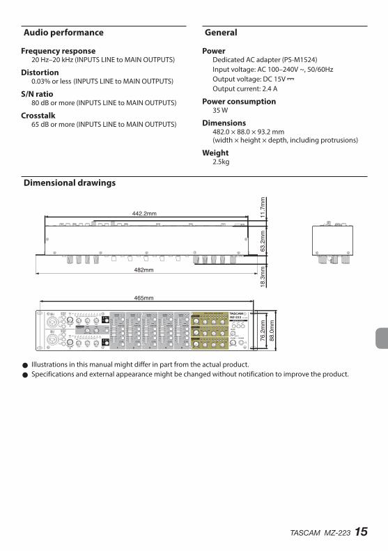
Dimensions482.0 × 88.0 × 93.2 mm (width × height × depth, including protrusions)
Weight2.5kg
Dimensional drawings
465mm
482mm76.2mm
18.3mm
63.2mm
11.7mm
442.2mm
88.0mm
0 Illustrations in this manual might differ in part from the actual product. 0 Specifications and external appearance might be changed without notification to improve the product.
16 TASCAM MZ-223
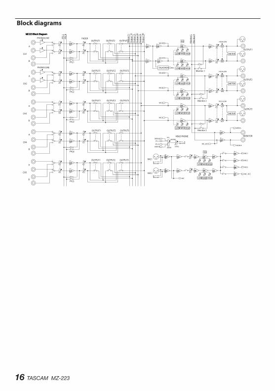
Block diagrams

TASCAM MZ-223 17
MODE D'EMPLOI
PRÉCAUTIONS DE SÉCURITÉ IMPORTANTES
ATTENTION : POUR RÉDUIRE LE RISQUE D'ÉLECTROCUTION, NE RETIREZ PAS LE CAPOT (OU L'ARRIÈRE). AUCUNE PIÈCE INTERNE N'EST RÉPARABLE PAR L'UTILISATEUR. CONFIEZ TOUTE RÉPARATION À UN SERVICE APRÈS-VENTE QUALIFIÉ.
Le symbole d'éclair à tête de flèche dans un triangle équilatéral sert à prévenir l'utilisateur de la présence dans l'enceinte du produit d'une « tension dangereuse » non isolée d'une grandeur suffisante pour constituer un risque d'électrocution pour les personnes.Le point d'exclamation dans un triangle équilatéral sert à prévenir l'utilisateur de la présence d'instructions importantes de fonctionne-ment et de maintenance (entretien) dans les documents accompa-gnant l'appareil.
AVERTISSEMENT : POUR PRÉVENIR LES RISQUES D'INCENDIE ET D'ÉLECTROCUTION, N'EXPOSEZ PAS CET APPAREIL À LA PLUIE NI À L'HUMIDITÉ.
AUX USA/CANADA, UTILISEZ UNIQUEMENT UNE TENSION D'ALIMENTATION DE 120 V.
Pour le CanadaTHIS CLASS B DIGITAL APPARATUS COMPLIES WITH CANADIAN ICES-003.CET APPAREIL NUMÉRIQUE DE LA CLASSE B EST CONFORME À LA NORME NMB-003 DU CANADA.
Ce produit est conforme aux impé-ratifs des directives européennes et autres règlements de la Commission.
Informations sur le marquage CEEN55103-2a) Environnement électromagnétique applicable :
E1, E2, E3, E4
18 TASCAM MZ-223
INSTRUCTIONS DE SÉCURITÉ IMPORTANTES
1. Lisez ces instructions.
2. Conservez ces instructions.
3. Tenez compte de tous les avertissements.
4. Suivez toutes les instructions.
5. N'utilisez pas cet appareil avec de l'eau à proximité.
6. Nettoyez-le uniquement avec un chiffon sec.
7. Ne bloquez aucune ouverture de ventilation. Installez-le conformément aux instructions du fabricant.
8. Ne l'installez pas près de sources de chaleur telles que des radiateurs, bouches de chauffage, poêles ou autres appareils (y compris des amplificateurs) dégageant de la chaleur.
9. Ne neutralisez pas la fonction de sécurité de la fiche polarisée ou de terre. Une fiche polarisée a deux broches, l'une plus large que l'autre. Une fiche de terre a deux broches identiques et une troisième broche pour la mise à la terre. La bro-che plus large ou la troisième broche servent à votre sécurité. Si la fiche fournie n'entre pas dans votre prise, consultez un électricien pour le rem-placement de la prise obsolète.
10. Évitez de marcher sur le cordon d'alimentation et de le pincer, en particulier au niveau des fiches, des prises secteur, et du point de sortie de l'appa-reil.
11. N'utilisez que des fixations/accessoires spécifiés par le fabricant.
12. Utilisez-le uniquement avec le chariot, socle, trépied, support ou table spécifié par le fabricant ou vendu avec l'appareil. Si un chariot est utilisé, faites attention à ne pas être blessé par un ren-versement lors du déplacement de l'ensemble chariot/appareil.
13. Débranchez cet appareil en cas d'orage ou de non utilisation prolongée.
14. Confiez toute réparation à des techniciens de maintenance qualifiés. Une réparation est né-cessaire si l'appareil a été endommagé d'une quelconque façon, par exemple si le cordon ou la fiche d'alimentation est endommagé, si du li-quide a été renversé sur l'appareil ou si des objets sont tombés dedans, si l'appareil a été exposé à la pluie ou à l'humidité, s'il ne fonctionne pas
normalement, ou s'il est tombé.
0 La fiche secteur est utilisée comme dispositif de déconnexion et doit donc toujours rester dispo-nible.
0 Des précautions doivent être prises en cas d'utili-sation d'écouteurs ou d'un casque avec le produit car une pression sonore excessive (volume trop fort) dans les écouteurs ou dans le casque peut causer une perte auditive.
0 Si vous rencontrez des problèmes avec ce produit, contactez TEAC pour une assistance technique. N'utilisez pas le produit tant qu'il n'a pas été réparé.
0 Ne retirez pas les capots externes ou boîtiers pour exposer l’électronique. aucune pièce interne n’est réparable par l’utilisateur.
0 Si vous rencontrez des problèmes avec ce produit, contactez le magasin où vous avez acheté l’unité. n’utilisez pas le produit tant qu’il n’a pas été répa-ré.
0 L’utilisation de commandes, de réglages ou le suivi de procédures autres que ce qui est décrit dans ce document peut provoquer une exposition à un rayonnement dangereux.
ATTENTION
0 N'exposez pas cet appareil aux gouttes ni aux éclaboussures.
0 Ne placez pas d'objet rempli de liquide sur l'ap-pareil, comme par exemple un vase.
0 N’installez pas cet appareil dans un espace confiné comme une bibliothèque ou un meuble similaire.
0 L’appareil doit être placé suffisamment près de la prise de courant pour que vous puissiez à tout moment attraper facilement la fiche du cordon d'alimentation.
0 Si le produit utilise des piles/batteries (y compris un pack de batteries ou des batteries fixes), elles ne doivent pas être exposées au soleil, au feu ou à une chaleur excessive.
0 PRÉCAUTION pour les produits qui utilisent des batteries remplaçables au lithium : remplacer une batterie par un modèle incorrect entraîne un risque d'explosion. Remplacez-les unique-ment par un type identique ou équivalent.
TASCAM MZ-223 19
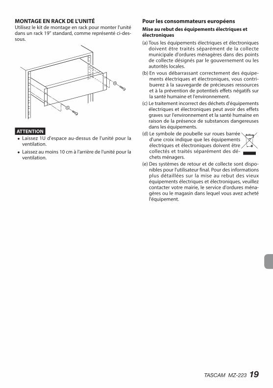
MONTAGE EN RACK DE L'UNITÉUtilisez le kit de montage en rack pour monter l'unité dans un rack 19" standard, comme représenté ci-des-sous.
ATTENTION i Laissez 1U d'espace au-dessus de l'unité pour la
ventilation.
i Laissez au moins 10 cm à l'arrière de l'unité pour la ventilation.
Pour les consommateurs européensMise au rebut des équipements électriques et électroniques(a) Tous les équipements électriques et électroniques
doivent être traités séparément de la collecte municipale d'ordures ménagères dans des points de collecte désignés par le gouvernement ou les autorités locales.
(b) En vous débarrassant correctement des équipe-ments électriques et électroniques, vous contri-buerez à la sauvegarde de précieuses ressources et à la prévention de potentiels effets négatifs sur la santé humaine et l'environnement.
(c) Le traitement incorrect des déchets d'équipements électriques et électroniques peut avoir des effets graves sur l'environnement et la santé humaine en raison de la présence de substances dangereuses dans les équipements.
(d) Le symbole de poubelle sur roues barrée d'une croix indique que les équipements électriques et électroniques doivent être collectés et traités séparément des dé-chets ménagers.
(e) Des systèmes de retour et de collecte sont dispo-nibles pour l'utilisateur final. Pour des informations plus détaillées sur la mise au rebut des vieux équipements électriques et électroniques, veuillez contacter votre mairie, le service d'ordures ména-gères ou le magasin dans lequel vous avez acheté l'équipement.
20 TASCAM MZ-223
Merci beaucoup d'avoir choisi le MZ-223 TASCAM.Avant d'utiliser cette unité, lisez attentivement ce mode d'emploi pour pouvoir l'utiliser correctement et en profiter durant de nombreuses années. Une fois la lecture de ce mode d'emploi terminée, veillez à le conserver en lieu sûr pour référence ultérieure.Vous pouvez aussi télécharger ce mode d'emploi de-puis le site mondial de TEAC (http://teac-global.com/).
Caractéristiques
0 Mélangeur en rack permettant d’envoyer comme désiré les canaux d’entrée vers plusieurs sorties
0 Les entrées micro et ligne peuvent être mixées pour la sortie
0 La fonction Talkover abaisse automatiquement le volume de la musique d’ambiance en réponse à la montée de volume du micro
0 Cinq canaux d’entrée sont équipés de commandes de gain, d’indicateurs de niveau à LED et de faders
0 Deux canaux d’entrée micro sont équipés de com-mandes de volume, d’indicateurs de niveau à LED et d’égaliseurs 3 bandes
0 Trois sorties générales de zone sont équipées de commandes de volume, d’indicateurs de niveau à LED et d’égaliseurs 3 bandes
0 La sortie casque avec commande de volume peut servir à l’écoute pré-fader des canaux d’entrée sé-lectionnés et de la sortie générale
0 La sortie de monitoring est indépendante des sor-ties générales
0 Montage en rack 2U
Éléments fournis avec ce produitCe produit est livré avec les éléments suivants.Ouvrez l’emballage avec soin pour ne pas endomma-ger ces éléments. Conservez les matériaux d’embal-lage pour de futurs transports.Si un élément quelconque est manquant ou a été endommagé durant le transport, veuillez contacter le magasin dans lequel vous avez acheté cette unité.
0 Unité principale ..............................................................× 1 0 Adaptateur secteur (PS-M1524 TASCAM) .............× 1 0 Cordon pour adaptateur secteur (JAPON ÉTATS-UNIS/EUROPE) ...................................× 2
0 Kit de vis pour montage en rack ..............................× 1 0 Mode d'emploi (ce document) incluant la garantie .......................................................× 1
ATTENTIONUtilisez toujours l'adaptateur secteur (PS-M1524 TASCAM) fourni avec cette unité. N'utilisez jamais un adaptateur secteur fourni avec un autre ap-pareil. Cela pourrait entraîner des dommages, un incendie, voire un choc électrique.
Sommaire
PRÉCAUTIONS DE SÉCURITÉ IMPORTANTES ....... 17INSTRUCTIONS DE SÉCURITÉ IMPORTANTES ...... 18Caractéristiques ..................................................... 20Éléments fournis avec ce produit ......................... 20Conventions employées dans ce mode d'emploi .................................................. 21Précautions concernant l'emplacement et l'emploi ............................................................... 21Attention à la condensation ................................. 21Nettoyage de l'unité .............................................. 21Utilisation du site mondial TEAC .......................... 21À propos du service d’assistance clientèle TASCAM .................................................................. 21Nomenclature et fonctions des parties ............... 22
Face avant ........................................................................... 22Face arrière ......................................................................... 23
Préparation ............................................................ 24Connexion de l'alimentation ........................................ 24Fixation du cordon ........................................................... 24Branchement d'autres équipements ........................ 24Mise sous/hors tension .................................................. 26
Procédures de fonctionnement ............................ 27Réglage des canaux d’entrée ligne (1-5) .................. 27Réglage des entrées MIC 1–2 INPUT ......................... 27Canaux de sortie ............................................................... 27Emploi de la fonction Talkover .................................... 27Écoute pré-fader des signaux de canal .................... 27
Guide de dépannage ............................................. 28Caractéristiques techniques ................................. 29
Entrées audio ..................................................................... 29Sorties audio ...................................................................... 29Performances audio ........................................................ 29Caractéristiques générales............................................ 29Dessins avec cotes ........................................................... 30Schémas synoptiques ..................................................... 30
TASCAM MZ-223 21
Conventions employées dans ce mode d'emploi
Dans ce document, les conventions suivantes sont employées :
0 Les touches, connecteurs et autres parties phy-siques de cette unité sont indiqués au moyen de caractères gras comme ceci : interrupteur d’ali-mentation POWER.
0 Des informations supplémentaires sont fournies si besoin est sous les intitulés CONSEIL, NOTE et ATTENTION.
CONSEILCe sont des conseils concernant l'emploi de l'unité.
NOTECe sont des explications supplémentaires et des descriptions de cas particuliers.
ATTENTIONNe pas suivre ces instructions peut par exemple entraîner des blessures, des dommages pour l'équipement ou la perte de données enregistrées.
Précautions concernant l'emplacement et l'emploi
0 La plage de température de fonctionnement de cette unité se situe entre 5 ºC et 35 ºC.
0 Ne placez pas cette unité dans les types d'empla-cement suivants. Cela pourrait entraîner un mau-vais fonctionnement.
Lieux sujets à des vibrations importantesPrès de fenêtres ou en exposition directe au soleilPrès de chauffages ou dans des lieux extrême-ment chaudsLieux extrêmement froidsLieux mal ventilés ou très humidesLieux très poussiéreux
0 Pour permettre une bonne dispersion thermique, ne placez rien sur le dessus de l'unité.
0 Ne placez pas l'unité sur un amplificateur de puis-sance ou un autre appareil dégageant de la cha-leur.
Attention à la condensationSi l'unité est déplacée d’un endroit froid à un endroit chaud, ou utilisée après un changement soudain de température, il existe un risque de condensation ; la vapeur de l'air peut se condenser sur le mécanisme interne, empêchant le bon fonctionnement.Pour empêcher cela ou si cela se produit, laissez l’unité une ou deux heures à la température de la nouvelle pièce avant de l'utiliser.
Nettoyage de l'unitéPour nettoyer l'unité, essuyez-la délicatement avec un chiffon sec et doux. Ne l'essuyez pas avec des lingettes de nettoyage contenant des produits chimiques, du diluant, de l'alcool ou d'autres agents chimiques. Cela pourrait endommager la surface ou causer une décoloration.
Utilisation du site mondial TEACVous pouvez télécharger des mises à jour pour cette unité depuis le site mondial :
http://teac-global.com/Dans la section TASCAM Downloads (téléchargements TASCAM), sélectionnez la langue souhaitée afin d’ou-vrir la page de téléchargement du site web pour cette langue.
À propos du service d’assistance clientèle TASCAM
Les produits TASCAM ne bénéficient d’une assistance et d’une garantie que dans leur pays/région d’achat.Pour bénéficier d’une assistance après l’achat, recher-chez dans la liste des distributeurs TASCAM fournie sur le site mondial TEAC (http:// teac-global.com/) la société ou le représentant local pour la région dans laquelle vous avez acheté le produit et contactez cette organisation.Pour toute demande, l’adresse physique ou URL du magasin ou du site marchand chez qui a été effectué l’achat ainsi que la date d’achat sont requises. De plus, la carte de garantie et une preuve d’achat peuvent également être nécessaires.
22 TASCAM MZ-223
Nomenclature et fonctions des parties
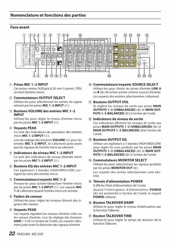
Face avant
1 Prises MIC 1–2 INPUTCes prises mixtes XLR/jack 6,35 mm 3 points (TRS) servent d’entrée micro.
2 Commutateurs OUTPUT SELECTUtilisez-les pour sélectionner les sorties du signal entrant par les prises MIC 1–2 INPUT (1).
3 Boutons VOLUME des entrées MIC 1–2 INPUTUtilisez-les pour régler le niveau d’entrée micro par les prises MIC 1–2 INPUT (1).
4 Voyants PEAKCe sont des indicateurs de saturation des entrées micro MIC 1–2 INPUT (1).Lors du réglage des boutons VOLUME (3) pour les entrées MIC 1–2 INPUT, ils s’allument juste avant que les signaux de l’entrée micro ne saturent.
5 Indicateurs de niveau MIC 1–2 INPUTCe sont des indicateurs de niveau d’entrée micro par les prises MIC 1–2 INPUT (1).
6 Boutons EQ des entrées MIC 1–2 INPUTCes égaliseurs 3 bandes (HIGH/MID/LOW) cor-rigent les sons des entrées micro.
7 Commutateurs/voyants MIC 1–2Pressez-les pour activer/désactiver l’entrée micro par les prises MIC 1–2 INPUT (1). Les voyants MIC 1–2 s'allument quand l'entrée micro est activée.
8 Faders de canauxUtilisez-les pour régler les niveaux d’envoi des si-gnaux des canaux.
9 Voyants PEAKCes voyants signalent les niveaux d’entrée crête sur les canaux d’entrée. Lors du réglage des boutons GAIN 1–5 (j) à l’arrière de l’unité, ces voyants s’allu-ment juste avant la distorsion des signaux d’entrée.
0 Commutateurs/voyants SOURCE SELECTUtilisez-les pour choisir les prises d’entrée LINE A ou B (b) de la face arrière comme sources d’entrée.Les voyants des entrées sélectionnées s'allument.
q Boutons OUTPUT VOLIls règlent les niveaux de sortie aux prises MAIN OUTPUTS 1–3 (UNBALANCED) (v) et MAIN OUT-PUTS 1–3 (BALANCED) (c) à l’arrière de l’unité.
w Indicateurs de niveau de sortieCes indicateurs affichent les niveaux de sortie aux prises MAIN OUTPUTS 1–3 (UNBALANCED) (v) et MAIN OUTPUTS 1–3 (BALANCED) (c)à l’arrière de l’unité.
e Boutons OUTPUT EQUtilisez ces égaliseurs à 3 bandes (HIGH/MID/LOW) pour régler les sons produits par les prises MAIN OUTPUTS 1–3 (UNBALANCED) (v) et MAIN OUT-PUTS 1–3 (BALANCED) (c) à l’arrière de l’unité.
r Commutateurs MONITOR SELECTUtilisez-les pour sélectionnez les signaux produits par les prises MONITOR OUT (x).Les voyants des sorties sélectionnées sont allu-més.
t Témoin d'alimentation POWERIl affiche l'état d’alimentation de l'unité.Quand l’interrupteur d’alimentation POWER (f) est enclenché à l’arrière de l’unité, le voyant POWER s’allume.
y Bouton TALKOVER DAMPUtilisez-le pour régler le niveau d’atténuation par la fonction Talkover.
u Bouton TALKOVER TIMEUtilisez-le pour régler le temps de réaction de la fonction Talkover.
TASCAM MZ-223 23
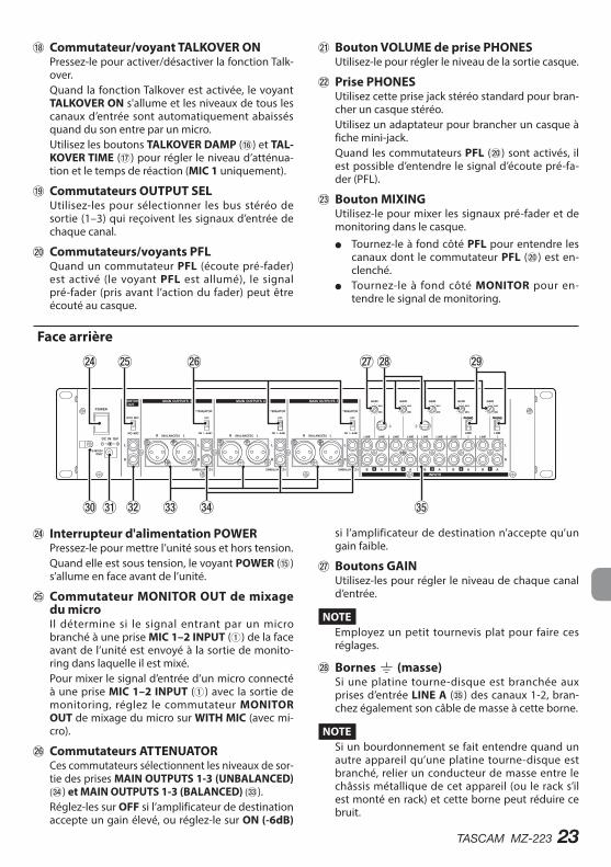
i Commutateur/voyant TALKOVER ONPressez-le pour activer/désactiver la fonction Talk-over.Quand la fonction Talkover est activée, le voyant TALKOVER ON s'allume et les niveaux de tous les canaux d’entrée sont automatiquement abaissés quand du son entre par un micro.Utilisez les boutons TALKOVER DAMP (y) et TAL-KOVER TIME (u) pour régler le niveau d’atténua-tion et le temps de réaction (MIC 1 uniquement).
o Commutateurs OUTPUT SELUtilisez-les pour sélectionner les bus stéréo de sortie (1–3) qui reçoivent les signaux d’entrée de chaque canal.
p Commutateurs/voyants PFLQuand un commutateur PFL (écoute pré-fader) est activé (le voyant PFL est allumé), le signal pré-fader (pris avant l’action du fader) peut être écouté au casque.
a Bouton VOLUME de prise PHONES Utilisez-le pour régler le niveau de la sortie casque.
s Prise PHONESUtilisez cette prise jack stéréo standard pour bran-cher un casque stéréo.Utilisez un adaptateur pour brancher un casque à fiche mini-jack.Quand les commutateurs PFL (p) sont activés, il est possible d’entendre le signal d’écoute pré-fa-der (PFL).
d Bouton MIXINGUtilisez-le pour mixer les signaux pré-fader et de monitoring dans le casque.
o Tournez-le à fond côté PFL pour entendre les canaux dont le commutateur PFL (p) est en-clenché.
o Tournez-le à fond côté MONITOR pour en-tendre le signal de monitoring.
Face arrière
f Interrupteur d'alimentation POWERPressez-le pour mettre l’unité sous et hors tension.Quand elle est sous tension, le voyant POWER (t) s’allume en face avant de l’unité.
g Commutateur MONITOR OUT de mixage du microIl détermine si le signal entrant par un micro branché à une prise MIC 1–2 INPUT (1) de la face avant de l’unité est envoyé à la sortie de monito-ring dans laquelle il est mixé.Pour mixer le signal d’entrée d’un micro connecté à une prise MIC 1–2 INPUT (1) avec la sortie de monitoring, réglez le commutateur MONITOR OUT de mixage du micro sur WITH MIC (avec mi-cro).
h Commutateurs ATTENUATORCes commutateurs sélectionnent les niveaux de sor-tie des prises MAIN OUTPUTS 1-3 (UNBALANCED) (v) et MAIN OUTPUTS 1-3 (BALANCED) (c).Réglez-les sur OFF si l’amplificateur de destination accepte un gain élevé, ou réglez-le sur ON (-6dB)
si l’amplificateur de destination n’accepte qu’un gain faible.
j Boutons GAINUtilisez-les pour régler le niveau de chaque canal d’entrée.
NOTEEmployez un petit tournevis plat pour faire ces réglages.
kBornes | (masse)Si une platine tourne-disque est branchée aux prises d’entrée LINE A (b) des canaux 1-2, bran-chez également son câble de masse à cette borne.
NOTESi un bourdonnement se fait entendre quand un autre appareil qu’une platine tourne-disque est branché, relier un conducteur de masse entre le châssis métallique de cet appareil (ou le rack s’il est monté en rack) et cette borne peut réduire ce bruit.
24 TASCAM MZ-223
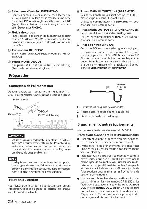
l Sélecteurs d’entrée LINE/PHONOPour les canaux 1-2, si la sortie d’un lecteur de CD ou appareil similaire est raccordée à une prise d’entrée LINE A (b), réglez ce sélecteur sur LINE (ligne). Si une platine tourne-disque y est connec-tée, réglez-le sur PHONO.
; Guide de cordonFaites passer ici le cordon de l'adaptateur secteur fourni (PS-M1524 TASCAM) pour éviter sa décon-nexion accidentelle. (voir « Fixation du cordon » en page 24.)
z Connecteur DC IN 15VBranchez ici l'adaptateur secteur fourni (PS-M1524 TASCAM).
x Prises MONITOR OUTCes prises RCA sont des sorties de monitoring (écoute de contrôle) analogiques.
c Prises MAIN OUTPUTS 1–3 (BALANCED)Ces sorties analogiques sont des prises XLR (1 : masse, 2 : point chaud, 3 : point froid).Utilisez le commutateur ATTENUATOR (h) pour changer leur niveau de sortie.
v Prises MAIN OUTPUTS 1–3 (UNBALANCED)Ces prises RCA sont des sorties analogiques.Utilisez les commutateurs ATTENUATOR (h) pour changer leur niveau de sortie.
b Prises d’entrée LINE A/BCes prises RCA sont des sorties ligne analogiques.Des platines tourne-disques peuvent être bran-chées aux prises d’entrée LINE A des canaux 1-2. Si vous branchez une platine tourne-disque à ces prises, branchez également son câble de masse à la borne | (masse) (k), et réglez le sélecteur d’entrée LINE/PHONO (l) sur PHONO.
Préparation
Connexion de l'alimentation
Utilisez l'adaptateur secteur fourni (PS-M1524 TAS-CAM) pour alimenter l'unité comme illustré ci-dessous.
Prise secteur
Fiche CCTASCAMPS-M1524 (fourni)
ATTENTIONUtilisez toujours l'adaptateur secteur (PS-M1524 TASCAM ) fourni avec cette unité. L'emploi d'un autre adaptateur secteur pourrait entraîner des mauvais fonctionnements, une surchauffe, un in-cendie ou d'autres problèmes.
NOTEL'adaptateur secteur de cette unité comprend deux types de cordon d’alimentation. Montez le cordon d’alimentation secteur du type correspon-dant à la prise de courant que vous utilisez.
Fixation du cordon
Pour éviter que le cordon ne se déconnecte durant l'utilisation, fixez-le au guide de cordon (;) lorsque vous le branchez à l’unité.
1. Retirez la vis du guide de cordon (;).
2. Faites passer le cordon dans le guide (;).
3. Revissez le guide de cordon (;).
Branchement d'autres équipements
Voici un exemple de branchements du MZ-223.
Précautions avant de faire les branchements 0 Lisez attentivement les modes d'emploi des appa-reils à brancher et branchez-les correctement.
0 Avant de faire les branchements, éteignez cette unité et tous les équipements à connecter (mode veille ou standby).
0 Installez tous les appareils connectés, y compris cette unité, pour qu'ils soient alimentés par la même ligne de courant. Si vous utilisez une multi-prise ou un dispositif similaire, veillez à ce qu'elle ait une capacité de courant suffisante (câble de forte section) pour minimiser les fluctuations de tension d'alimentation.
0 Lorsque vous branchez des appareils audio, bais-sez au minimum les commandes GAIN (j) et les faders (8) des canaux 1–5 et les boutons OUTPUT VOL (q) et PHONES VOLUME (a). Ne pas le faire pourrait causer des bruits forts et soudains dans l'équipement d'écoute, risquant de provoquer des dommages auditifs ou à l'équipement.
TASCAM MZ-223 25
Enceintes amplifiées
Casque
Lecteur de CD
Platine tourne-disque
Micro
Micro
Amplificateur stéréoAmplificateur stéréo
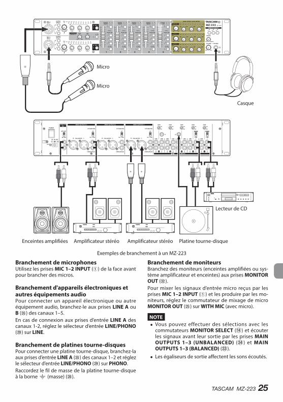
Exemples de branchement à un MZ-223
Branchement de microphonesUtilisez les prises MIC 1–2 INPUT (1) de la face avant pour brancher des micros.
Branchement d'appareils électroniques et autres équipements audioPour connecter un appareil électronique ou autre équipement audio, branchez-le aux prises LINE A ou B (b) des canaux 1–5.En cas de connexion aux prises d’entrée LINE A des canaux 1-2, réglez le sélecteur d’entrée LINE/PHONO (l) sur LINE.
Branchement de platines tourne-disquesPour connecter une platine tourne-disque, branchez-la aux prises d’entrée LINE A (b) des canaux 1–2 et réglez le sélecteur d’entrée LINE/PHONO (l) sur PHONO.Raccordez le fil de masse de la platine tourne-disque à la borne | (masse) (k).
Branchement de moniteursBranchez des moniteurs (enceintes amplifiées ou sys-tème amplificateur et enceintes) aux prises MONITOR OUT (x).Pour mixer les signaux d’entrée micro reçus par les prises MIC 1–2 INPUT (1) et les produire par les mo-niteurs, réglez le commutateur de mixage de micro MONITOR OUT (g) sur WITH MIC (avec micro).
NOTE i Vous pouvez effectuer des sélections avec les
commutateurs MONITOR SELECT (r) et écouter les signaux avant leur sortie par les prises MAIN OUTPUTS 1–3 (UNBALANCED) (v) et MAIN OUTPUTS 1–3 (BALANCED) (c).
i Les égaliseurs de sortie affectent les sons écoutés.
26 TASCAM MZ-223
Branchement d'un casqueBranchez le casque à la prise PHONES (s) (jack stéréo standard).Vous pouvez écouter les signaux pré-fader des ca-naux d’entrée et les signaux avant qu’ils ne soient envoyés au bus de sortie stéréo.Utilisez les commutateurs MONITOR SELECT (r) pour sélectionner les sorties à écouter.
ATTENTIONAvant de brancher le casque, baissez le volume au minimum avec le bouton PHONES VOLUME (a). Ne pas le faire pourrait entraîner la production d'un bruit fort et soudain risquant par exemple d'endommager votre audition.
NOTELes égaliseurs de sortie affectent les sons produits au casque.
Branchement d’amplificateurs stéréoPour brancher un amplificateur stéréo, connectez-le aux prises MAIN OUTPUTS 1–3 (UNBALANCED) (v) ou MAIN OUTPUTS 1–3 (BALANCED) (c).
CONSEIL i Pour brancher 2 systèmes à amplificateur et en-
ceintes ou plus, avec des combinaisons de signal principal et secondaire (Sub), principal et de moni-toring, ou avant et arrière, il peut être pratique d’uti-liser les prises MAIN OUTPUTS 1–3 (UNBALANCED) (f) et MAIN OUTPUTS 1–3 (BALANCED) (c). De plus, les prises de sortie sont indépendantes et ont leur propre bouton de sortie dédié pour que vous puissiez régler les niveaux de sortie séparément avec cette unité.
i En branchant un enregistreur aux prises MONI-TOR OUT (x), il est possible d’enregistrer la sortie de signal destinée aux systèmes amplificateur/enceintes.
Mise sous/hors tension
ATTENTION i Baissez le volume du système audio connecté à
l'unité avant d'allumer ou d'éteindre l'unité.
i Ne portez pas de casque connecté à l'unité quand vous la mettez sous/hors tension. Des bruits forts pourraient endommager les haut-parleurs ou votre audition.
Avant de mettre sous tension1. Faites les réglages suivants en face avant de l'unité.
o Boutons EQ w au centre o Autres boutons w à fond à gauche (côté MIN) o Faders w tout en bas o Commutateurs w désactivés (non enclenchés)
2. Réglez au minimum les niveaux de sortie des sources audio et les niveaux d'entrée des amplifi-cateurs connectés à cette unité.
Mise sous tension1. Utilisez l’interrupteur d’alimentation POWER (f)
à l’arrière de l’unité pour la mettre sous tension.Le voyant POWER (t) de la face avant de l’unité s’allume quand celle-ci est sous tension.
2. Allumez les appareils sources connectés aux en-trées audio.
3. Enfin, allumez les amplificateurs.
Mise hors tensionSuivez la procédure ci-dessus mais en ordre inverse pour l’extinction.Ne pas suivre l’ordre correct peut entraîner par exemple des bruits de commutation potentiellement dangereux pour les équipements.
TASCAM MZ-223 27
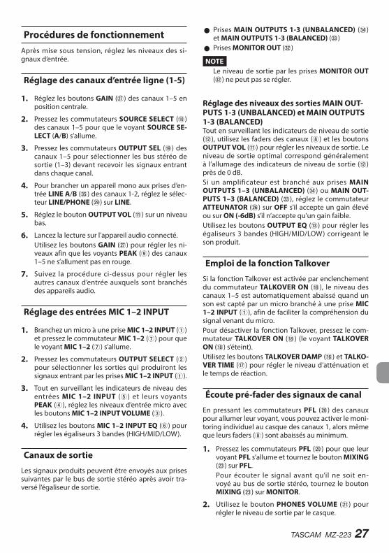
Procédures de fonctionnementAprès mise sous tension, réglez les niveaux des si-gnaux d’entrée.
Réglage des canaux d’entrée ligne (1-5)
1. Réglez les boutons GAIN (j) des canaux 1–5 en position centrale.
2. Pressez les commutateurs SOURCE SELECT (0) des canaux 1–5 pour que le voyant SOURCE SE-LECT (A/B) s’allume.
3. Pressez les commutateurs OUTPUT SEL (o) des canaux 1–5 pour sélectionner les bus stéréo de sortie (1–3) devant recevoir les signaux entrant dans chaque canal.
4. Pour brancher un appareil mono aux prises d’en-trée LINE A/B (b) des canaux 1-2, réglez le sélec-teur LINE/PHONE (l) sur LINE.
5. Réglez le bouton OUTPUT VOL (q) sur un niveau bas.
6. Lancez la lecture sur l'appareil audio connecté.Utilisez les boutons GAIN (j) pour régler les ni-veaux afin que les voyants PEAK (9) des canaux 1–5 ne s’allument pas en rouge.
7. Suivez la procédure ci-dessus pour régler les autres canaux d’entrée auxquels sont branchés des appareils audio.
Réglage des entrées MIC 1–2 INPUT
1. Branchez un micro à une prise MIC 1–2 INPUT (1) et pressez le commutateur MIC 1–2 (7) pour que le voyant MIC 1–2 (7) s’allume.
2. Pressez les commutateurs OUTPUT SELECT (2) pour sélectionner les sorties qui produiront les signaux entrant par les prises MIC 1–2 INPUT (1).
3. Tout en surveillant les indicateurs de niveau des entrées MIC 1–2 INPUT (5) et leurs voyants PEAK (4), réglez les niveaux d’entrée micro avec les boutons MIC 1–2 INPUT VOLUME (3).
4. Utilisez les boutons MIC 1–2 INPUT EQ (6) pour régler les égaliseurs 3 bandes (HIGH/MID/LOW).
Canaux de sortie
Les signaux produits peuvent être envoyés aux prises suivantes par le bus de sortie stéréo après avoir tra-versé l’égaliseur de sortie.
0 Prises MAIN OUTPUTS 1-3 (UNBALANCED) (v) et MAIN OUTPUTS 1-3 (BALANCED) (c)
0 Prises MONITOR OUT (x)
NOTELe niveau de sortie par les prises MONITOR OUT (x) ne peut pas se régler.
Réglage des niveaux des sorties MAIN OUT-PUTS 1-3 (UNBALANCED) et MAIN OUTPUTS 1-3 (BALANCED)Tout en surveillant les indicateurs de niveau de sortie (w), utilisez les faders des canaux (8) et les boutons OUTPUT VOL (q) pour régler les niveaux de sortie. Le niveau de sortie optimal correspond généralement à l’allumage des indicateurs de niveau de sortie (w) près de 0 dB.Si un amplificateur est branché aux prises MAIN OUTPUTS 1–3 (UNBALANCED) (v) ou MAIN OUT-PUTS 1–3 (BALANCED) (c), réglez le commutateur ATTEUNATOR (h) sur OFF s’il accepte un gain élevé ou sur ON (-6dB) s’il n’accepte qu’un gain faible.Utilisez les boutons OUTPUT EQ (e) pour régler les égaliseurs 3 bandes (HIGH/MID/LOW) corrigeant le son produit.
Emploi de la fonction Talkover
Si la fonction Talkover est activée par enclenchement du commutateur TALKOVER ON (i), le niveau des canaux 1–5 est automatiquement abaissé quand un son est capté par un micro branché à une prise MIC 1–2 INPUT (1), afin de faciliter la compréhension du signal venant du micro.Pour désactiver la fonction Talkover, pressez le com-mutateur TALKOVER ON (i) (le voyant TALKOVER ON (i) s’éteint).Utilisez les boutons TALKOVER DAMP (y) et TALKO-VER TIME (u) pour régler le niveau d’atténuation et le temps de réaction.
Écoute pré-fader des signaux de canal
En pressant les commutateurs PFL (p) des canaux pour allumer leur voyant, vous pouvez activer le moni-toring individuel au casque des canaux 1, alors même que leurs faders (8) sont abaissés au minimum.
1. Pressez les commutateurs PFL (p) pour que leur voyant PFL s’allume et tournez le bouton MIXING (d) sur PFL.Pour écouter le signal avant qu’il ne soit en-voyé au bus de sortie stéréo, tournez le bouton MIXING (d) sur MONITOR.
2. Utilisez le bouton PHONES VOLUME (a) pour régler le niveau de sortie par le casque.
28 TASCAM MZ-223
Guide de dépannageSi vous avez des problèmes de fonctionnement avec cette unité, veuillez essayer ce qui suit avant de solli-citer une réparation.Si ces mesures ne résolvent pas le problème, veuillez contacter le magasin dans lequel vous avez acheté cette unité ou le service aprèsvente TASCAM.
L'unité ne s'allume pas. 0 Vérifiez que l'adaptateur secteur fourni (PS-M1524 TASCAM) est bien branché à la fois à la prise sec-teur et à la prise d'alimentation CC.
Le son ne sort pas par les enceintes branchées aux prises MAIN OUTPUTS 1-3.
0 Vérifiez les réglages et le volume de l’amplificateur connecté.
0 Assurez-vous que les faders de canal (8) sont montés.
0 Assurez-vous que la source sonore d’entrée est bien connectée.
Le volume sonore est faible même si l'on monte les faders.
0 Assurez-vous que les boutons GAIN (j) des ca-naux 1–5 sont correctement réglés.
Le son souffre de distorsion. 0 Assurez-vous que les boutons GAIN (j) des ca-naux 1–5 sont correctement réglés.
0 Vérifiez que l’égaliseur n’est pas réglé trop haut. 0 Assurez-vous que les faders des canaux 1–5 (8) et les boutons OUTPUT VOL (q) ne sont pas réglés trop haut.
Le son d’une platine tourne-disque est bizarre.
0 Assurez-vous qu’elle est branchée aux prises d’en-trée LINE A des canaux 1–2 et que le sélecteur d’entrée LINE/PHONO (l) est réglé sur PHONO.
0 Vérifiez que le fil de masse de la platine tourne-disque est bien raccordé à la borne | (masse) (k).
Un appareil connecté produit un bourdonnement.
0 Raccordez un fil de masse venant du châssis mé-tallique de cet appareil à la borne | (masse) (k) de cette unité.
Aucun son ne sort par le système d’écoute branché aux prises MONITOR OUT.
0 Vérifiez les réglages du système d'écoute connec-té.
0 Assurez-vous que les boutons GAIN (j) et les fa-ders (8) des canaux 1–5 sont montés.
Aucun son ne sort par le casque. 0 Utilisez les commutateurs MONITOR SELECT (r) pour sélectionner les sorties.
TASCAM MZ-223 29
Caractéristiques techniques
Entrées audio
Prises symétriques MIC 1–2 INPUTConnecteurs :
XLR-3-31 (1 : masse, 2 : point chaud, 3 : point froid)Jack 6,35 mm 3 points (TRS) standard (pointe : point chaud, bague : point froid, manchon : masse)
Impédance d'entrée : 33 kΩNiveau d'entrée nominal : -65 dBu (bouton VOLUME sur MAX)Niveau d'entrée nominal : -30 dBu (bouton VOLUME sur MIN)
INPUTS : prises asymétriques LINEConnecteurs : RCANiveau d'entrée nominal : -10 dBVNiveau d'entrée maximal : 10 dBVImpédance d'entrée : 22 kΩ
0 0 dBu=0.775 Vrms, 0 dBV=1 V
Sorties audio
Prises MAIN OUTPUTS (UNBALANCED)Connecteurs : RCANiveau de sortie nominal : -10 dBVNiveau de sortie maximal : 6 dBVImpédance de sortie : 200 Ω
Prises MAIN OUTPUTS (BALANCED)Connecteurs : XLR-3-32 (1 : masse, 2 : point chaud, 3 : point froid)Niveau de sortie nominal : 4 dBuNiveau de sortie maximal : 24 dBuImpédance de sortie : 200 Ω
Prises MONITOR OUTConnecteurs : RCANiveau de sortie nominal : -16 dBVNiveau de sortie maximal : 0 dBVImpédance de sortie : 200 Ω
Prise PHONESConnecteur : jack 6,35 mm stéréo standardSortie maximale : 50 mW + 50 mW (sous charge de 32 Ω)
0 0 dBu=0.775 Vrms, 0 dBV=1 V
Performances audio
Réponse en fréquence20 Hz–20 kHz (INPUTS LINE vers MAIN OUTPUTS)
Distorsion0,03 % ou moins (INPUTS LINE vers MAIN OUTPUTS)
Rapport signal/bruit80 dB ou plus (INPUTS LINE vers MAIN OUTPUTS)
Diaphonie65 dB ou plus (INPUTS LINE vers MAIN OUTPUTS)
Caractéristiques générales
AlimentationAdaptateur secteur dédié (PS-M1524)Tension d'entrée : CA 100-240 V ~, 50/60 HzTension de sortie : CC 15 V Courant en sortie : 2,4 A
Consommation électrique35 W
Dimensions482,0 × 88,0 × 93,2 mm (largeur × hauteur × profondeur, avec parties saillantes)
Poids2,5 kg
30 TASCAM MZ-223
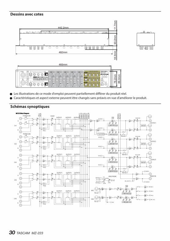
Dessins avec cotes
465mm
482mm
76.2mm
18.3mm
63.2mm
11.7mm
442.2mm
88.0mm
0 Les illustrations de ce mode d'emploi peuvent partiellement différer du produit réel. 0 Caractéristiques et aspect externe peuvent être changés sans préavis en vue d'améliorer le produit.
Schémas synoptiques
TASCAM MZ-223 31
MANUAL DE INSTRUCCIONES
PRECAUCIONES IMPORTANTES DE SEGURIDAD
PRECAUCIÓN: PARA REDUCIR EL RIESGO DE DESCARGAS ELÉCTRICAS, NO QUITE LA CARCASA (NI LA TAPA TRASERA) DENTRO DE LA UNIDAD NO HAY PIEZAS QUE PUEDAN SER REPARADAS POR EL USUARIO.
El símbolo de un rayo dentro de un triángulo equilátero se usa internacionalmente para alertar al usuario de la presencia de “voltajes peligrosos” no aislados dentro de la carcasa del aparato que pueden ser de magnitud suficiente para constituir un riesgo real de descarga eléctrica para las personas.El símbolo de exclamación dentro de un triángulo equilátero se utiliza para advertir al usuario de la existencia de importantes instrucciones de uso y mantenimiento (reparaciones) en los documentos que acompañan a la unidad.
CUIDADO: PARA EVITAR EL RIESGO DE INCENDIOS O DESCARGAS ELÉCTRICAS, NO EXPONGA ESTE APARATO A LA LLUVIA O LA HUMEDAD.
E s t e a p a r a t o c u m p l e c o n t o d o s los requisitos establecidos por las Directivas Europeas, así como por otras Regulaciones de la Comisión Europea.
Información de normativa CEEN55103-2a) Entorno electromagnético aplicable: E1, E2, E3, E4
32 TASCAM MZ-223
INSTRUCCIONES IMPORTANTES DE SEGURIDAD
1. Lea estas instrucciones.
2. Conserve estas instrucciones.
3. Preste atención a todos los avisos.
4. Siga todo lo indicado en las instrucciones.
5. No utilice este aparato cerca del agua.
6. Limpie este aparato solo con un trapo seco.
7. No bloquee ninguna de las aber turas de ventilación. Instale este aparato de acuerdo con las instrucciones del fabricante.
8. No instale este aparato cerca de fuentes de calor como radiadores, ca lentadores, hornos o cualquier otro aparato (incluyendo amplificadores) que produzca calor.
9. No anule el sistema de seguridad que supone un enchufe de corriente polarizado o con toma de tierra. Un enchufe polarizado tiene dos bornes de distinta anchura. Uno con toma de tierra tiene dos bornes iguales y una lámina para la conexión a tierra. El borne ancho del primer tipo de enchufe y la lámina del otro se incluyen para su seguridad. Si el enchufe que se incluye con la unidad no encaja en su salida de corriente, haga que un electricista cambie su salida anticuada.
10. Coloque el cable de corriente de forma que no pueda quedar aplastado o retorc ido, especialmente allí donde estén los conectores, receptáculos y en el punto en que el cable sale del aparato.
11. Utilice solo accesorios/complementos que hayan sido especificados por el fabricante.
12. Utilice este aparato solo con un bastidor, soporte, trípode o superficie especificado por el fabricante o que se venda con el propio aparato. Cuando utilice un bastidor con ruedas, tenga cuidado al mover la combinación bastidor/aparato para evitar posibles daños en caso de que vuelquen.
13. Desconecte de la corriente este aparato durante las tormentas eléctricas o cuando no lo vaya a usar durante un periodo de tiempo largo.
14. Consulte cualquier posible avería al servicio técnico oficial. Este aparato deberá ser revisado cuando se haya dañado de alguna forma, como por ejemplo si el cable de corriente o el enchufe se ha roto, si se ha derramado cualquier líquido o
se ha introducido un objeto dentro de la unidad, si el aparato ha quedado expuesto a la lluvia o la humedad, si no funciona normalmente o si se ha caído al suelo.
0 El enchufe de alimentación sirve como dispositivo de desconexión, por lo que colóquelo de forma que siempre pueda acceder a él fácilmente.
0 Una presión sonora excesiva en los auriculares puede producirle daños auditivos.
0 Si experimenta cualquier tipo de problema con este aparato, póngase en contacto con TEAC para una reparación. No utilice de nuevo el aparato hasta que no haya sido reparado.
0 No quite las carcasas externas ni deje al aire la electrónica. ¡en el interior no hay piezas que el usuario pueda manipular!
0 Si experimenta problemas con este producto, póngase en contacto con el establecimiento donde adquirió la unidad para solicitar servicio técnico. no utilice el aparato hasta que haya sido reparado.
0 El uso de controles, ajustes o procedimientos que no sean los especificados en este manual puede causar exposición a radiaciones peligrosas.
CUIDADO
0 No permita que este aparato quede expuesto a salpicaduras de ningún tipo.
0 No coloque objetos que contengan líquidos, como jarrones, encima de este aparato.
0 No instale este aparato encastrado en una librería o mueble similar.
0 E l a p a r a t o d e b e e s t a r c o l o c a d o l o suficientemente cerca de la salida de corriente como para poder acceder al enchufe en cualquier momento.
0 Si este aparato uti l iza pilas, dichas pilas (el bloque de pilas o las pilas individuales instaladas) no deben ser expuestas a niveles de calor excesivos como expuestas directamente a la luz solar o sobre un fuego.
0 AVISO para aquellos aparatos que usen pilas de litio recambiables: existe el riesgo de explosión en caso de que la pila sea sustituida por otra del tipo incorrecto. Sustituya la pila únicamente por otra idéntica o equivalente.
TASCAM MZ-223 33
MONTAJE EN RACK DE LA UNIDADUse el kit de montaje en rack incluido para instalar esta unidad en un bastidor rack standard de 19 pulgadas, como abajo.
CUIDADO i Deje 1U de espacio sobre la unidad y al menos 10
cm en la parte trasera del mismo para su correcta ventilación.
Para los usuarios europeosEliminación de aparatos eléctricos y electrónicos y pilas y/o acumuladores(a) Nunca debe eliminar un aparato eléctrico o
electrónico y/o pilas/acumuladores junto con el resto de la basura orgánica. Este tipo de aparatos deben ser depositados en los “puntos limpios” creados a tal efecto por su Ayuntamiento o por la empresa de limpieza local.
(b) Con la correcta eliminación de los aparatos eléctricos y electrónicos y/o pilas/acumuladores estará ayudando a ahorrar valiosos recursos y evitará a la vez todos los efectos negativos potenciales tanto para la salud como para el entorno.
(c) Una eliminación incorrecta de este tipo de aparatos y/o pilas/acumuladores junto con la basura orgánica puede producir efectos graves en el medio ambiente y en la salud a causa de la presencia de sustancias potencialmente peligrosas que pueden contener.
(d) El símbolo del cubo de basura tachado (WEEE) i n d i c a l a o b l i g a c i ó n d e s e p a r a r l o s aparatos eléctricos y electrónicos y/o pilas/acumuladores del resto de basura orgánica a la hora de eliminarlos.
(e) Los llamados “puntos limpios” de recogida y retirada selectiva de este tipo de productos y/o pilas/acumuladores están disponibles para cualquier usuario final. Para más información acerca de la eliminación de este tipo de elementos, póngase en contacto con el departamento correspondiente de su Ayuntamiento, empresa de limpieza o recogida de basuras o con el comercio en el que adquirió este aparato.
34 TASCAM MZ-223
Felicidades y gracias por la compra de su TASCAM MZ-223. A n te s d e e m p e z a r a u t i l i z a r e s t a u n i d a d, l e a detenidamente este manual para saber cómo configurar y conectar esta unidad correctamente y cómo utilizar sus funciones. Una vez que lo haya leído, conserve este manual a mano para cualquier consulta en el futuro.También puede descargarse este manual de instrucciones desde la página web global de TEAC (http://teac-global.com/).
Características
0 Mezclador para montaje en rack que permite el ruteo de canales de entrada a múltiples salidas de la forma que quiera
0 Las entradas de micro y l ínea pueden ser mezcladas para su salida
0 Función Talkover que reduce automáticamente el volumen de la música de fondo de acuerdo al volumen de la señal del micro
0 Cinco canales de entrada equipados con controles de ganancia, LEDs de señal y faders
0 Dos canales de entrada de micro equipados con controles de volumen, medidores de nivel LED y EQ de 3 bandas
0 Tres salidas de zonas principales equipadas con controles de volumen, medidores de nivel LED y EQ de 3 bandas
0 Salida de auriculares con control de volumen que puede usar para monitorización pre-fader de canales de entrada concretos y la salida principal
0 Salida de monitorización independiente de las salidas principales
0 2U de tamaño rack
Elementos incluidosDentro del embalaje encontrará los siguientes elementos.Tenga cuidado de no dañar estos objetos al abrir el embalaje. Conserve la caja y las protecciones por si alguna vez necesita transportar el aparato.Póngase en contacto con su distribuidor si echa en falta alguno de estos elementos o si observa que alguno de ellos ha resultado dañado durante el transporte.
0 Unidad principal ............................................................× 1 0 Adaptador de corriente (TASCAM PS-M1524) ....× 1 0 Cable para adaptador (JAPON USA/EUROPA) .....× 2 0 Kit de tornillos para montaje en rack .....................× 1 0 Manual de instrucciones (este documento) incluyendo garantía ......................................................× 1
CUIDADOUtilice siempre esta unidad con el adaptador de corriente incluido con ella ( TASCAM PS-M1524). No utilice nunca este adaptador con otro dispositivo. El hacerlo podría dar lugar a un incendio o descarga eléctrica.
Índice
PRECAUCIONES IMPORTANTES DE SEGURIDAD . 31INSTRUCCIONES IMPORTANTES DE SEGURIDAD 32Características ....................................................... 34Elementos incluidos .............................................. 34Acerca de este manual .......................................... 35Precauciones relativas a la ubicación y uso ......... 35Cuidado con la condensación ............................... 35Limpieza de la unidad ........................................... 35Uso de la web global TEAC .................................... 35Acerca del servicio de atención al usuario de TASCAM .................................................................. 35Nombres y funciones de las partes ...................... 36
Panel frontal ....................................................................... 36Panel trasero ...................................................................... 37
Preparativos ........................................................... 38Alimentación...................................................................... 38Colocación del cable ....................................................... 38Conexión de otros aparatos ......................................... 38Encendido y apagado ..................................................... 40
Procesos operativos .............................................. 41Ajuste de canales de entrada de línea (1–5) ........... 41Ajuste de la entrada de micros conectados a las tomas MAIN MIC 1–2 INPUT ......................................... 41Canales de salida .............................................................. 41Uso de la función talkover ............................................ 41Escucha de las señales pre-fader ................................ 41
Resolución de problemas ...................................... 42Especificaciones técnicas ...................................... 43
Entradas audio .................................................................. 43Salidas audio ...................................................................... 43Rendimiento audio .......................................................... 43General ................................................................................. 43Esquema de dimensiones ............................................. 44Diagrama de bloques ..................................................... 44
TASCAM MZ-223 35
Acerca de este manualEn este manual utilizamos los convencionalismos siguientes:
0 Cuando hagamos referencia a botones, conectores y otras partes físicas de esta unidad, utilizaremos letras en negrita; por ejemplo: interruptor POWER.
0 Además también encontrará información adicional en los siguientes formatos.
AVISOSon avisos y consejos relativos al uso de este aparato.
NOTASon explicaciones sobre actuaciones para casos concretos.
CUIDADOEsto le advierte que puede dañar el equipo o perder datos si no sigue las instrucciones.
Precauciones relativas a la ubicación y uso
0 El rango de temperaturas seguro para el uso de este aparato es entre 5–35 °C.
0 Para evitar degradar la calidad del sonido o que se produzcan averías, no instale la unidad en los siguientes tipos de lugares.
Lugares sujetos a fuer tes vibraciones o inestablesCerca de ventanas o expuestos a la luz solar directaCerca de radiadores o lugares extremadamente calurosos Lugares demasiado fríosSitios mal ventilados o demasiado húmedosLugares polvorientos
0 Para permitir la correcta refrigeración de la unidad, no coloque ningún objeto encima de este producto.
0 No coloque este aparato encima de una etapa de potencia o de otro aparato que genere mucho calor.
Cuidado con la condensaciónSi traslada la unidad de un lugar frío a uno cálido o si la usa después de un cambio fuerte de temperatura, puede producirse condensación de agua. Para evitar esto o si se produce la condensación, deje la unidad en la sala en la que la vaya a usar durante una o dos horas antes de encenderla.
Limpieza de la unidadPara limpiar la unidad, utilice un trapo suave y seco. No use gasolina, alcohol u otros productos similares ya que podría dañar su superficie.
Uso de la web global TEACPuede descargar actualizaciones para esta unidad desde la página web global de TEAC:
http://teac-global.com/En la sección TASCAM Downloads, elija el idioma que quiera para hacer que se abra la página Downloads para ese idioma.
Acerca del servicio de atención al usuario de TASCAM
La garantía y el soporte técnico de los productos TASCAM solo se garantiza en el país/región de la compra original.En caso de que necesite soporte técnico tras la compra, busque en el listado de distribuidores TASCAM de la web global de TEAC (http:// teac-global.com/), la empresa o distribuidor local del país en el que haya adquirido este producto y contacte con ellos.A la hora de cualquier consulta o reclamación será necesaria la dirección (URL) del comercio o página web en el que haya adquirido esta unidad. De la misma forma, también deberá disponer de la tarjeta de garantía y la prueba de compra (factura o recibo de compra).
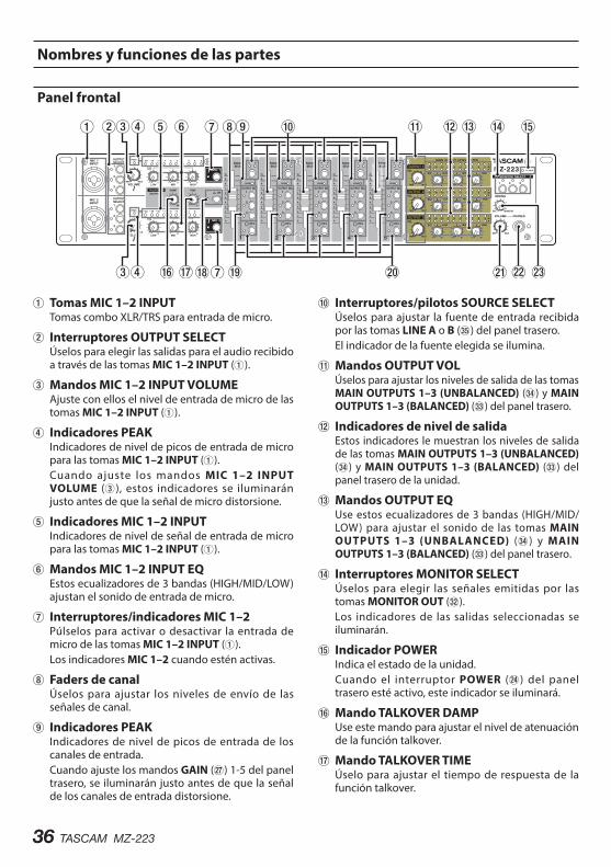
36 TASCAM MZ-223
Nombres y funciones de las partes
Panel frontal
1Tomas MIC 1–2 INPUTTomas combo XLR/TRS para entrada de micro.
2Interruptores OUTPUT SELECTÚselos para elegir las salidas para el audio recibido a través de las tomas MIC 1–2 INPUT (1).
3Mandos MIC 1–2 INPUT VOLUMEAjuste con ellos el nivel de entrada de micro de las tomas MIC 1–2 INPUT (1).
4Indicadores PEAKIndicadores de nivel de picos de entrada de micro para las tomas MIC 1–2 INPUT (1).Cuando ajuste los mandos MIC 1–2 INPUT VOLUME (3), estos indicadores se iluminarán justo antes de que la señal de micro distorsione.
5Indicadores MIC 1–2 INPUTIndicadores de nivel de señal de entrada de micro para las tomas MIC 1–2 INPUT (1).
6Mandos MIC 1–2 INPUT EQEstos ecualizadores de 3 bandas (HIGH/MID/LOW) ajustan el sonido de entrada de micro.
7Interruptores/indicadores MIC 1–2Púlselos para activar o desactivar la entrada de micro de las tomas MIC 1–2 INPUT (1).Los indicadores MIC 1–2 cuando estén activas.
8Faders de canalÚselos para ajustar los niveles de envío de las señales de canal.
9Indicadores PEAKIndicadores de nivel de picos de entrada de los canales de entrada.Cuando ajuste los mandos GAIN (j) 1-5 del panel trasero, se iluminarán justo antes de que la señal de los canales de entrada distorsione.
0Interruptores/pilotos SOURCE SELECTÚselos para ajustar la fuente de entrada recibida por las tomas LINE A o B (b) del panel trasero.El indicador de la fuente elegida se ilumina.
qMandos OUTPUT VOLÚselos para ajustar los niveles de salida de las tomas MAIN OUTPUTS 1–3 (UNBALANCED) (v) y MAIN OUTPUTS 1–3 (BALANCED) (c) del panel trasero.
wIndicadores de nivel de salidaEstos indicadores le muestran los niveles de salida de las tomas MAIN OUTPUTS 1–3 (UNBALANCED) (v) y MAIN OUTPUTS 1–3 (BALANCED) (c) del panel trasero de la unidad.
eMandos OUTPUT EQUse estos ecualizadores de 3 bandas (HIGH/MID/LOW) para ajustar el sonido de las tomas MAIN OUTPUTS 1–3 (UNBALANCED) (v) y MAIN OUTPUTS 1–3 (BALANCED) (c) del panel trasero.
rInterruptores MONITOR SELECTÚselos para elegir las señales emitidas por las tomas MONITOR OUT (x).Los indicadores de las salidas seleccionadas se iluminarán.
tIndicador POWERIndica el estado de la unidad.Cuando el interruptor POWER (f) del panel trasero esté activo, este indicador se iluminará.
yMando TALKOVER DAMPUse este mando para ajustar el nivel de atenuación de la función talkover.
uMando TALKOVER TIMEÚselo para ajustar el tiempo de respuesta de la función talkover.
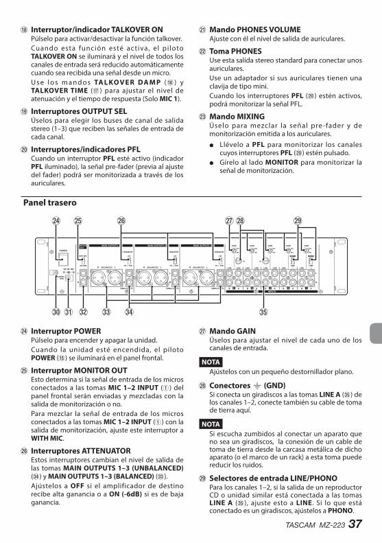
TASCAM MZ-223 37
iInterruptor/indicador TALKOVER ONPúlselo para activar/desactivar la función talkover.Cuando esta función esté activa, el pi loto TALKOVER ON se iluminará y el nivel de todos los canales de entrada será reducido automáticamente cuando sea recibida una señal desde un micro.U s e l o s m a n d o s TA L KO V E R DA M P (y ) y TALKOVER TIME (u) para ajustar el nivel de atenuación y el tiempo de respuesta (Solo MIC 1).
oInterruptores OUTPUT SELÚselos para elegir los buses de canal de salida stereo (1–3) que reciben las señales de entrada de cada canal.
pInterruptores/indicadores PFLCuando un interruptor PFL esté activo (indicador PFL iluminado), la señal pre-fader (previa al ajuste del fader) podrá ser monitorizada a través de los auriculares.
aMando PHONES VOLUMEAjuste con él el nivel de salida de auriculares.
sToma PHONESUse esta salida stereo standard para conectar unos auriculares.Use un adaptador si sus auriculares tienen una clavija de tipo mini.Cuando los interruptores PFL (p) estén activos, podrá monitorizar la señal PFL.
dMando MIXINGÚselo para mezclar la señal pre-fader y de monitorización emitida a los auriculares.
o Llévelo a PFL para monitorizar los canales cuyos interruptores PFL (p) estén pulsado.
o Gírelo al lado MONITOR para monitorizar la señal de monitorización.
Panel trasero
fInterruptor POWERPúlselo para encender y apagar la unidad.Cuando la unidad esté encendida, el piloto POWER (t) se iluminará en el panel frontal.
gInterruptor MONITOR OUTEsto determina si la señal de entrada de los micros conectados a las tomas MIC 1–2 INPUT (1) del panel frontal serán enviadas y mezcladas con la salida de monitorización o no.Para mezclar la señal de entrada de los micros conectados a las tomas MIC 1–2 INPUT (1) con la salida de monitorización, ajuste este interruptor a WITH MIC.
hInterruptores ATTENUATOREstos interruptores cambian el nivel de salida de las tomas MAIN OUTPUTS 1–3 (UNBALANCED) (v) y MAIN OUTPUTS 1–3 (BALANCED) (c).Ajústelos a OFF si el amplificador de destino recibe alta ganancia o a ON (-6dB) si es de baja ganancia.
jMando GAINÚselos para ajustar el nivel de cada uno de los canales de entrada.
NOTAAjústelos con un pequeño destornillador plano.
kConectores | (GND) Si conecta un giradiscos a las tomas LINE A (b) de los canales 1–2, conecte también su cable de toma de tierra aquí.
NOTASi escucha zumbidos al conectar un aparato que no sea un giradiscos, la conexión de un cable de toma de tierra desde la carcasa metálica de dicho aparato (o el marco de un rack) a esta toma puede reducir los ruidos.
l Selectores de entrada LINE/PHONOPara los canales 1–2, si la salida de un reproductor CD o unidad similar está conectada a las tomas LINE A (b), ajuste esto a LINE. Si lo que está conectado es un giradiscos, ajústelos a PHONO.
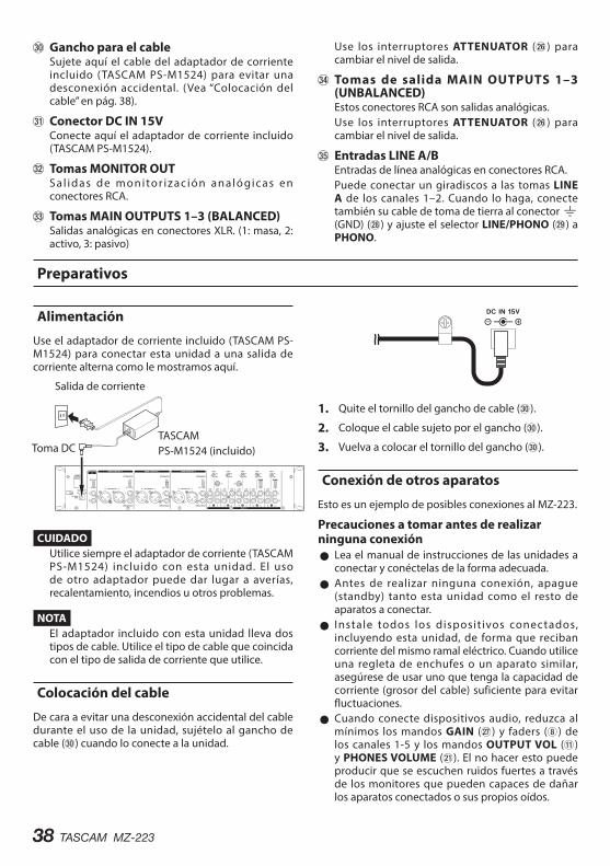
38 TASCAM MZ-223
;Gancho para el cableSujete aquí el cable del adaptador de corriente incluido (TASCAM PS-M1524) para evitar una desconexión accidental. (Vea “Colocación del cable” en pág. 38).
z Conector DC IN 15VConecte aquí el adaptador de corriente incluido (TASCAM PS-M1524).
x Tomas MONITOR OUTS al idas de monitor izac ión analógicas en conectores RCA.
c Tomas MAIN OUTPUTS 1–3 (BALANCED) Salidas analógicas en conectores XLR. (1: masa, 2: activo, 3: pasivo)
Use los interruptores ATTENUATOR (h) para cambiar el nivel de salida.
v Tomas de salida MAIN OUTPUTS 1–3 (UNBALANCED)Estos conectores RCA son salidas analógicas.Use los interruptores ATTENUATOR (h) para cambiar el nivel de salida.
b Entradas LINE A/BEntradas de línea analógicas en conectores RCA.Puede conectar un giradiscos a las tomas LINE A de los canales 1–2. Cuando lo haga, conecte también su cable de toma de tierra al conector | (GND) (k) y ajuste el selector LINE/PHONO (l) a PHONO.
Preparativos
Alimentación
Use el adaptador de corriente incluido (TASCAM PS-M1524) para conectar esta unidad a una salida de corriente alterna como le mostramos aquí.
Salida de corriente
Toma DCTASCAMPS-M1524 (incluido)
CUIDADOUtilice siempre el adaptador de corriente (TASCAM PS-M1524) incluido con esta unidad. El uso de otro adaptador puede dar lugar a averías, recalentamiento, incendios u otros problemas.
NOTAEl adaptador incluido con esta unidad lleva dos tipos de cable. Utilice el tipo de cable que coincida con el tipo de salida de corriente que utilice.
Colocación del cable
De cara a evitar una desconexión accidental del cable durante el uso de la unidad, sujételo al gancho de cable (;) cuando lo conecte a la unidad.
1. Quite el tornillo del gancho de cable (;).
2. Coloque el cable sujeto por el gancho (;).
3. Vuelva a colocar el tornillo del gancho (;).
Conexión de otros aparatos
Esto es un ejemplo de posibles conexiones al MZ-223.
Precauciones a tomar antes de realizar ninguna conexión
0 Lea el manual de instrucciones de las unidades a conectar y conéctelas de la forma adecuada.
0 Antes de realizar ninguna conexión, apague (standby) tanto esta unidad como el resto de aparatos a conectar.
0 Instale todos los disposit ivos conectados, incluyendo esta unidad, de forma que reciban corriente del mismo ramal eléctrico. Cuando utilice una regleta de enchufes o un aparato similar, asegúrese de usar uno que tenga la capacidad de corriente (grosor del cable) suficiente para evitar fluctuaciones.
0 Cuando conecte dispositivos audio, reduzca al mínimos los mandos GAIN (j) y faders (8) de los canales 1-5 y los mandos OUTPUT VOL (q) y PHONES VOLUME (a). El no hacer esto puede producir que se escuchen ruidos fuertes a través de los monitores que pueden capaces de dañar los aparatos conectados o sus propios oídos.
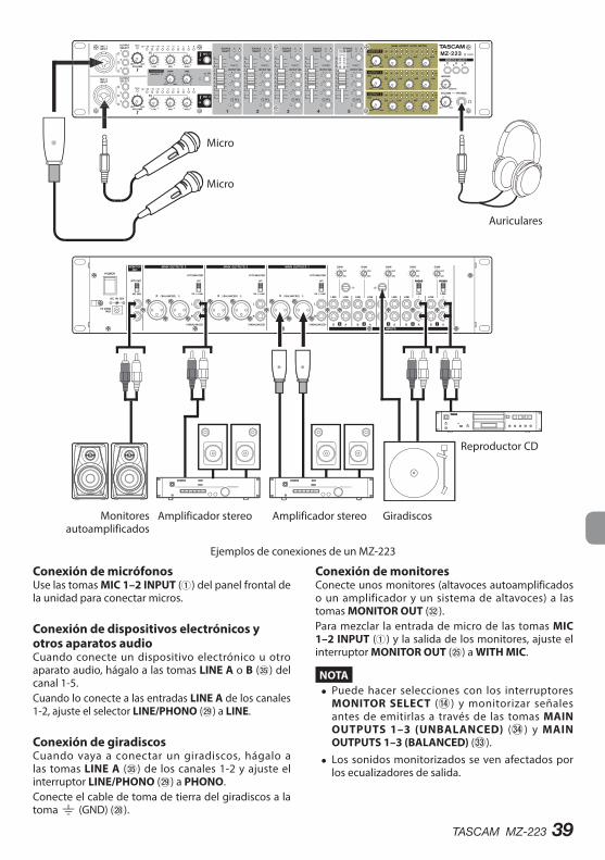
TASCAM MZ-223 39
Monitores autoamplificados
Auriculares
Reproductor CD
Giradiscos
Micro
Micro
Amplificador stereoAmplificador stereo
Ejemplos de conexiones de un MZ-223
Conexión de micrófonosUse las tomas MIC 1–2 INPUT (1) del panel frontal de la unidad para conectar micros.
Conexión de dispositivos electrónicos y otros aparatos audioCuando conecte un dispositivo electrónico u otro aparato audio, hágalo a las tomas LINE A o B (b) del canal 1-5.Cuando lo conecte a las entradas LINE A de los canales 1-2, ajuste el selector LINE/PHONO (l) a LINE.
Conexión de giradiscosCuando vaya a conectar un giradiscos, hágalo a las tomas LINE A (b) de los canales 1-2 y ajuste el interruptor LINE/PHONO (l) a PHONO.Conecte el cable de toma de tierra del giradiscos a la toma | (GND) (k).
Conexión de monitoresConecte unos monitores (altavoces autoamplificados o un amplificador y un sistema de altavoces) a las tomas MONITOR OUT (x).Para mezclar la entrada de micro de las tomas MIC 1–2 INPUT (1) y la salida de los monitores, ajuste el interruptor MONITOR OUT (g) a WITH MIC.
NOTA i Puede hacer selecciones con los interruptores
MONITOR SELECT (r) y monitorizar señales antes de emitirlas a través de las tomas MAIN OUTPUTS 1–3 (UNBALANCED) (v) y MAIN OUTPUTS 1–3 (BALANCED) (c).
i Los sonidos monitorizados se ven afectados por los ecualizadores de salida.
40 TASCAM MZ-223
Conexión de auricularesConecte los auriculares a la toma PHONES (s) (stereo standard).Puede monitorizar las señales pre-fader de canal de entrada y la señal antes de que sea enviada al bus de salida stereo.Use los interruptores MONITOR SELECT (r). para elegir las salidas que quiera monitorizar.
CUIDADOAntes de conectar los auriculares, reduzca al mínimo el volumen con el mando PHONES VOLUME (a). El no hacerlo puede dar lugar a la aparición de un ruido potente que podría dañar sus oídos.
NOTAEl sonido emitido a través de los auriculares se ve afectado por los ecualizadores de salida.
Conexión de amplificadores stereoCuando conecte un amplificador stereo hágalo en las salidas MAIN OUTPUTS 1–3 (UNBALANCED) (v) o MAIN OUTPUTS 1–3 (BALANCED) (c).
AVISO i Cuando conecte 2 o más sistemas de amplificador y
altavoces, incluyendo combinaciones de principales y subs, principales y monitores o frontales y traseros, el uso de las salidas MAIN OUTPUTS 1–3 (UNBALANCED) (f) y MAIN OUTPUTS 1–3 (BALANCED) (c) puede resultar más útil. Además, las salidas de estas tomas son independientes y tienen sus propios mandos de volumen específicos, por lo que puede ajustar los niveles de salida de forma independiente.
i Si conecta una grabadora a las tomas MONITOR OUT (x), podrá grabar la salida emitida al sistema de amplificador/altavoces.
Encendido y apagado
CUIDADO i Reduzca el volumen del sistema de sonido conectado
a esta unidad antes de encenderla/apagarla.
i Apártese los auriculares de los oídos cuando encienda o apague la unidad. Se pueden producir ruidos fuertes capaces de producir daños.
Antes de encender la unidad1. Haga los ajustes siguientes en el panel frontal.
o Mandos EQ w valor central o Otros mandos w tope izquierdo (lado MIN) o Faders w abajo del todo o Interruptores w off (sin pulsar)
2. Reduzca al mínimo el nivel de volumen de las fuentes audio y los niveles de entrada de los amplificadores conectados a esta unidad.
Encendido1. Use el interruptor POWER (f) del panel trasero
para encender esta unidad.El pi loto POWER (t) del panel frontal se iluminará cuando la unidad esté encendida.
2. Encienda las fuentes audio conectadas.
3. Finalmente encienda los amplificadores.
ApagadoPara apagar la unidad, siga los pasos anteriores en orden inverso.El no seguir correctamente este orden puede dar lugar a chasquidos o ruidos capaces de dañar sus aparatos.
TASCAM MZ-223 41
Procesos operativosTras encender la unidad, ajuste los niveles de las señales de entrada.
Ajuste de canales de entrada de línea (1–5)
1. Ajuste los mandos GAIN (j) de los canales 1-5 a sus posiciones centrales.
2. Pulse el interruptor SOURCE SELECT (0) de los canales 1-5, de forma que los indicadores SOURCE SELECT (A/B) se iluminen.
3. Pulse el interruptor OUTPUT SEL (o) de los canales 1-5 para elegir los buses de salida de canal stereo (1–3) que reciben las señales de entrada de cada canal.
4. Cuando conecte un dispositivo audio a las tomas de entrada LINE A/B (b) de los canales 1-2, ajuste el interruptor LINE/PHONE (l) a LINE.
5. Ajuste los mandos OUTPUT VOL (q) a un nivel bajo.
6. Comience la reproducción en el dispositivo.Use los mandos GAIN (j) para ajustar el nivel de forma que los indicadores PEAK (9) de los canales 1-5 no se iluminen en rojo.
7. Repita los pasos anteriores para el resto de canales de entrada con dispositivos conectados.
Ajuste de la entrada de micros conectados a las tomas MAIN MIC 1–2 INPUT
1. Conecte un micro a una toma MIC 1–2 INPUT (1) y pulse el interruptor MIC 1–2 (7) de forma que el indicador MIC 1–2 (7) se ilumine.
2. Pulse los interruptores OUTPUT SELECT (2) para elegir las salidas de las señales recibidas en las tomas MIC 1–2 INPUT (1).
3. Mientras comprueba los indicadores MIC 1–2 INPUT (5) y PEAK (4), use los mandos MIC 1–2 INPUT VOLUME (3) para ajustar los niveles de entrada de los micros.
4. Use los mandos MIC 1–2 INPUT EQ (6) para ajustar los ecualizadores de 3 bandas (HIGH/MID/LOW).
Canales de salida
Las señales de salida pueden ser enviadas a las siguientes tomas desde el bus de salida stereo tras el ecualizador de salida.
0 Tomas MAIN OUTPUTS 1–3 (UNBALANCED) (v) y MAIN OUTPUTS 1–3 (BALANCED) (c)
0 Tomas MONITOR OUT (x)
NOTAEl nivel de salida de las tomas MONITOR OUT (x) no puede ser ajustado.
Ajuste del nivel emitido por las tomas MAIN OUTPUTS 1–3 (UNBALANCED) y MAIN OUTPUTS 1–3 (BALANCED) Mientras comprueba los indicadores de nivel de salida (w), use los faders de canal (8) y los mandos OUTPUT VOL (q) para ajustar el nivel de salida. El ajuste óptimo se suele conseguir cuando los indicadores de nivel de salida (w) se iluminan sobre el 0 dB.Cuando tenga un amplificador conectado a las tomas MAIN OUTPUTS 1–3 (UNBALANCED) (v) o MAIN OUTPUTS 1–3 (BALANCED) (c), ajuste el interruptor ATTENUATOR (h) a OFF si es que acepta una señal de ganancia elevada o a ON (-6dB) si acepta una señal de baja ganancia.Use los mandos OUTPUT EQ (e) para ajustar los ecualizadores de 3 bandas (HIGH/MID/LOW) para el sonido de salida.
Uso de la función talkover
Cuando active esta función pulsando el interruptor TALKOVER ON (i), los niveles de los canales 1 serán reducidos automáticamente cuando sea recibida una señal desde un micro conectado a la toma MIC 1–2 INPUT (1) para que esa señal sea más fácil de oír.Para desactivar la función talkover, pulse el interruptor TALKOVER ON (i) (el piloto TALKOVER ON (i) se apagará).Use los mandos TALKOVER DAMP (y) y TALKOVER TIME (u) para ajustar el nivel de atenuación y el tiempo de respuesta.
Escucha de las señales pre-fader
Al pulsar los interruptores PFL (p) de los canales para activarlos podrá monitorizar a través de auriculares los canales individuales 1–5, incluso aunque sus fader (8) estén al mínimo.
1. Pulse los interruptores PFL (p) de forma que los indicadores PFL se iluminen y gire el mando MIXING (d) hacia PFL.Para monitorizar la señal antes de que sea enviada al bus de salida stereo, gire el mando MIXING (d) hacia MONITOR.
2. Use el mando PHONES VOLUME (a) para ajustar el nivel de salida de monitorización.
42 TASCAM MZ-223
Resolución de problemasS i e s t a u n i d a d n o f u n c i o n a co r re c t a m e n te, compruebe los puntos siguientes antes de solicitar una reparación. Si el problema persiste, póngase en contacto con el comercio en el que adquirió esta unidad o con el servicio técnico oficial de TASCAM más cercano.
La unidad no se enciende. 0 Confirme que el adaptador de corriente (TASCAM PS-M1524) esté conectado firmemente tanto a la salida de corriente alterna como a la toma DC.
No es emitido ningún sonido por los altavoces conectados en MAIN OUTPUTS 1–3.
0 Compruebe los ajustes generales y de volumen del amplificador conectado.
0 Confirme que los fader de canal (8) no estén al mínimo.
0 Compruebe que la fuente del sonido de entrada esté conectada correctamente.
El volumen es bajo incluso aunque suba los faders.
0 Confirme que los mandos GAIN (j) de los canales 1–5 estén ajustados correctamente.
El sonido distorsiona. 0 Confirme que los mandos GAIN (j) de los canales 1–5 estén ajustados correctamente.
0 Compruebe que no ha ajustado el EQ muy alto. 0 Compruebe que no ha ajustado el EQ muy alto 1–5 (8) y los mandos OUTPUT VOL (q) no estén ajustados muy altos.
La señal de un tocadiscos suena extraña. 0 Compruebe que esa unidad esté conectada a las tomas de entrada LINE A del canal 1-2 y que el interruptor de entrada LINE/PHONO (l) esté ajustado a PHONO.
0 Confirme que el cable de toma de tierra del tocadiscos esté conectado a la toma | (GND) (k).
Un dispositivo conectado genera zumbidos. 0 Conecte un cable de toma de tierra desde la carcasa metálica de ese dispositivo a la toma | (GND) (k) de esta unidad.
No es emitido ningún sonido desde el sistema de monitorización conectado a las tomas MONITOR OUT.
0 C o m p r u e b e l o s a j u s t e s d e l s i s t e m a d e monitorización conectado.
0 Confirme que los mandos GAIN (j) de los canales 1-5 y sus faders de canal (8) no estén al mínimo.
No sound is output from headphones. 0 Use the MONITOR SELECT (r) switches to select the outputs.
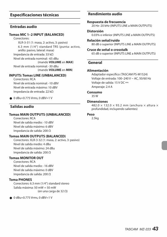
TASCAM MZ-223 43
Especificaciones técnicas
Entradas audio
Tomas MIC 1–2 INPUT (BALANCED) Conectores:
XLR-3-31 (1: masa, 2: activo, 3: pasivo)6.3 mm (1/4”) standard TRS (punta: activo, anillo: pasivo, lateral: masa)
Impedancia de entrada: 33 kΩNivel de entrada nominal: -65 dBu (mando VOLUME en MAX)Nivel de entrada nominal: -30 dBu (mando VOLUME en MIN)
INPUTS: Tomas LINE (UNBALANCED) Conectores: RCANivel de entrada nominal: -10 dBVNivel de entrada máximo: 10 dBVImpedancia de entrada: 22 kΩ
0 0 dBu=0.775 Vrms, 0 dBV=1 V
Salidas audio
Tomas MAIN OUTPUTS (UNBALANCED) Conectores: RCANivel de salida medio: -10 dBVNivel de salida máximo: 6 dBVImpedancia de salida: 200 Ω
Tomas MAIN OUTPUTS (BALANCED) Conectores: XLR-3-32 (1: masa, 2: activo, 3: pasivo)Nivel de salida medio: 4 dBuNivel de salida máximo: 24 dBuImpedancia de salida: 200 Ω
Tomas MONITOR OUTConectores: RCANivel de salida medio: -16 dBVNivel de salida máximo: 0 dBVImpedancia de salida: 200 Ω
Toma PHONESConectores: 6.3 mm (1/4”) standard stereoSalida máxima: 50 mW + 50 mW (en una carga de 32 Ω)
0 0 dBu=0.775 Vrms, 0 dBV=1 V
Rendimiento audio
Respuesta de frecuencia20 Hz–20 kHz (INPUTS LINE a MAIN OUTPUTS)
Distorsión0.03% o inferior (INPUTS LINE a MAIN OUTPUTS)
Relación señal/ruido80 dB o superior (INPUTS LINE a MAIN OUTPUTS)
Cruce de señal o crosstalk65 dB o superior (INPUTS LINE a MAIN OUTPUTS)
General
AlimentaciónAdaptador específico (TASCAM PS-M1524)Voltaje de entrada: 100–240 V ~ AC, 50/60 HzVoltaje de salida: 15 V DC Amperaje: 2.4 A
Consumo35 W
Dimensiones482.0 × 132.0 × 93.2 mm (anchura × altura × profundidad, incluyendo salientes)
Peso2.5kg
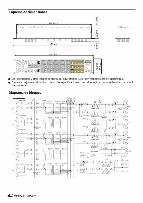
44 TASCAM MZ-223
Esquema de dimensiones
465mm
482mm
76.2mm
18.3mm
63.2mm
11.7mm
442.2mm
88.0mm
0 Las ilustraciones y otras imágenes mostradas aquí pueden variar con respecto a las del aparato real. 0 De cara a mejoras en el producto, tanto las especificaciones como el aspecto exterior están sujetos a cambios sin previo aviso.
Diagrama de bloques
TASCAM MZ-223 – Bedienungsanleitung 45
Wichtige Hinweise zu Ihrer Sicherheit
VORSICHT! Gefahr eines Stromschlags. Öffnen Sie nicht das Gehäuse des Wechselstromadapters. Es befinden sich keine vom Anwender zu wartenden Teile im Gerät. Lassen Sie das Gerät nur von qualifi-ziertem Fachpersonal reparieren.
Dieses Symbol, ein Blitz in einem Dreieck, warnt vor nicht isolierten, elektrischen Spannungen im Inneren des Geräts, die zu einem gefährlichen Stromschlag führen können.Dieses Symbol, ein Ausrufezeichen in einem Dreieck, weist auf wichtige Bedienungs- oder Sicherheits hinweise hin.
• Diese Anleitung ist Teil des Geräts. Bewahren Sie sie gut auf und geben Sie das Gerät nur mit dieser Anleitung weiter.
• Lesen Sie diese Anleitung, um das Gerät fehlerfrei nutzen zu können und sich vor eventuellen Rest-gefahren zu schützen.
• Beachten Sie alle Warnhinweise. Neben den hier aufgeführten allgemeinen Sicherheitshin-weisen sind möglicherweise weitere Warnungen an entsprechenden Stellen dieses Handbuchs aufgeführt.
• Lassen Sie Wartungsarbeiten und Reparaturen nur von einem Tascam-Servicecenter ausführen. Bringen Sie das Gerät zu einem Tascam- Servicecenter, wenn es Regen oder Feuchtigkeit ausgesetzt war, wenn Flüssigkeit oder Fremd-körper hinein gelangt sind, wenn es herunterge-fallen ist, nicht normal funktioniert oder offen-sichtlich beschädigt ist. Benutzen Sie das Gerät nicht mehr, bis es repariert wurde.
Bestimmungsgemäße VerwendungDas Gerät ist als Mischer für Tonsignale für die nicht-industrielle Verwendung in trockenen Räumen (nicht unter freiem Himmel) ausgelegt. Benutzen Sie es nur zu dem Zweck und auf die Weise, wie in dieser Anleitung beschrieben.
VWARNUNG
Stromschlag, Kurzschluss oder Brand• Verwenden Sie nur den mitgelieferten oder vom
Hersteller empfohlene Wechselstromadapter. Verwenden Sie den Wechselstromadapter nicht mit anderen Geräten.
• Öffnen Sie nicht das Gehäuse des Wechselstrom-adapters.
• Stellen Sie das Gerät in der Nähe einer gut erreich-baren Steckdose auf. Es muss jederzeit möglich sein, den Netzstecker zu ziehen, um das Gerät vom Stromnetz zu trennen.
• Verbinden Sie den Wechselstromadapter nur dann mit dem Stromnetz, wenn die Angaben auf dem Wechselstromadapter mit der örtlichen Netzspannung übereinstimmen. Fragen Sie im Zweifelsfall einen Elektro fachmann.
• Wenn der mitgelieferte Netzstecker nicht in Ihre Steck dose passt, ziehen Sie einen Elektro-fachmann zu Rate.
• Sorgen Sie dafür, dass das Netzkabel nicht gedehnt, gequetscht oder geknickt werden kann – insbesondere am Stecker und am Netz-kabelausgang des Wechselstromadapters – und verlegen Sie es so, dass man nicht darüber stolpern kann.
• Ziehen Sie den Netzstecker bei Gewitter oder wenn Sie das Gerät längere Zeit nicht benutzen.
• Wenn das Gerät raucht oder einen ungewöhn-lichen Geruch verströmt, trennen Sie es sofort vom Stromnetz und bringen Sie es zu einem Tascam-Servicecenter.
• Stellen Sie das Gerät immer so auf, dass es nicht nass werden kann. Setzen Sie das Gerät niemals Regen, hoher Luftfeuchte oder anderen Flüssig-keiten aus.
• Stellen Sie keine mit Flüssigkeit gefüllten Behälter (Vasen, Kaffeetassen usw.) auf das Gerät.
• Reinigen Sie das Gerät nur mit einem trockenen Tuch.
Überhitzung• Versperren Sie niemals vorhandene Lüftungs-
öffnungen. • Stellen Sie das Gerät nicht in der Nähe von Hitze
abstrahlenden Geräten (Heizlüfter, Öfen, Ver-stärker usw.) auf.
• Stellen Sie dieses Gerät nicht an einem räumlich beengten Ort ohne Luftzirkulation auf.
Bedienungsanleitung
46 TASCAM MZ-223 – Bedienungsanleitung
Falsches Zubehör• Verwenden Sie nur Zubehör oder
Zube hör-teile, die der Hersteller empfiehlt.
• Verwenden Sie nur Wagen, Ständer, Stative, Halter oder Tische, die vom Hersteller em pfohlen oder mit dem Gerät verkauft werden.
Hörschäden• Denken Sie immer daran: Hohe Lautstärkepegel
können schon nach kurzer Zeit Ihr Gehör schädigen.
Wichtige Informationen
Informationen zur elektromagnetischen VerträglichkeitDieses Gerät wurde auf die Einhaltung der Gren-zwerte gemäß der EMV-Richtlinie 2014/30/EU der Europäischen Gemeinschaft hin geprüft. Diese Grenzwerte stellen einen angemessenen Schutz gegen schädliche Funkstörungen innerhalb von Wohngebäuden sicher. Dieses Gerät arbeitet mit Hochfrequenz energie, die ausgestrahlt werden kann, und kann bei unsachgemäßer, nicht der Anleitung des Herstellers entsprechenden Installation und Verwendung Störungen des Rundfunkempfangs verursachen. Es gibt jedoch keine Garantie, dass in einer bestimmten Ins-tallation keine Störungen auftreten. Falls das Gerät nachweislich Störungen des Radio- oder Fernsehempfangs verursacht, was sich durch Aus- und Einschalten des Geräts überprüfen lässt, ergreifen Sie eine oder mehrere der folgenden Maßnahmen:• Richten Sie die Empfangsantenne neu aus,
oder stellen Sie sie an einem anderen Ort auf. • Vergrößern Sie den Abstand zwischen dem
Gerät und dem Empfänger. • Schließen Sie das Gerät an eine Steckdose an,
die mit einem anderen Stromkreis verbunden ist als die Steckdose des Emp fängers.
• Wenden Sie sich an Ihren Händler oder einen Fachmann für Rundfunk- und Fernsehtechnik.
Wichtiger HinweisÄnderungen oder Modifikationen am Gerät, die nicht ausdrücklich von der TEAC Corporation geprüft und genehmigt worden sind, können zum Erlöschen der Betriebserlaubnis führen.
Ausgelegt für folgende elektromagnetische Umgebungen: E1, E2, E3, E4
Dieses Produkt entspricht den geltenden EU-Richtlinien sowie den nationalen Gesetzen zur Umsetzung dieser Richtlinien.
Angaben zur Umweltverträglichkeit und zur Entsorgung
Entsorgung von AltgerätenWenn ein Symbol einer durchgestri-chenen Mülltonne auf einem Produkt, der Verpackung und/oder der beglei-tenden Dokumentation angebracht ist, unterliegt dieses Produkt den europäischen Richtlinien 2012/19/EU und/oder 2006/66/EG sowie nationalen Gesetzen zur Umsetzung dieser Richtlinien.Richtlinien und Gesetze schreiben vor, dass Elektro- und Elektronik-Altgeräte nicht in den Hausmüll (Restmüll) gelangen dürfen. Um die fachgerechte Entsorgung, Aufbereitung und Wiederverwertung sicherzustellen, sind Sie verpflichtet, Altgeräte über staatlich dafür vorge-sehene Stellen zu entsorgen. Durch die ordnungsgemäße Entsorgung solcher Geräte leisten Sie einen Beitrag zur Einsparung wertvoller Rohstoffe und verhindern potenziell schädliche Auswirkungen auf die menschliche Gesundheit und die Umwelt, die durch falsche Abfallentsorgung entstehen können. Die Ent-sorgung ist für Sie kostenlos.Weitere Informationen zur Wertstoffsammlung und Wiederverwertung von Alt geräten erhalten Sie bei Ihrer Stadt verwaltung, dem für Sie zustän-digen Abfall ent sor gungs unternehmen oder der Verkaufsstelle, bei der Sie das Produkt erworben haben.
Angaben zum StromverbrauchDieses Gerät verbraucht auch dann eine geringe Menge Strom, wenn es mit dem Stromnetz ver-bunden und ausgeschaltet ist.
TASCAM MZ-223 – Bedienungsanleitung 47
Vielen Dank, dass Sie sich für den Einbau-Mischer MZ-223 von Tascam entschieden haben.Bevor Sie das Gerät benutzen, lesen Sie sich dieses Handbuch bitte aufmerksam durch. Nur so ist sicher-gestellt, dass Sie den Mischer richtig bedienen und viele Jahre Freude daran haben. Bewahren Sie dieses Handbuch gut auf, und geben Sie es immer zusammen mit dem MZ-223 weiter, da es zum Gerät gehört.Eine digitale Version des Handbuchs steht auf unserer Website zum Download bereit: https://tascam.eu/de/downloads/MZ-223
Ausstattungsmerkmale• Einbau-Mischer mit mehreren Eingängen, die an
mehrere Ausgänge geleitet werden können• Mikrofon- und Line-Signale können gemischt
ausgegeben werden• Die Talkover-Funktion kann die Lautstärke von
Hintergrundmusik entsprechend dem Mikrofon-pegel automatisch verringern
• Fünf Eingangskanäle mit rückseitigen Eingangspegel-reglern sowie frontseitigen Signal-LEDs und Fadern
• Zwei Eingangskanäle mit Pegelreglern, Dreiband -Klangregelung und LED-Pegelanzeigen
• Drei Zonenausgänge mit Pegelreglern, Dreiband -Klangregelung und LED-Pegelanzeigen
• Kopfhörerausgang mit Pegelregler nutzbar für das Vorhören (vor dem Fader) ausgewählter Eingangs-kanäle und das Abhören der Summenausgänge
• Separater Stereo-Monitorausgang• 19-Zoll-Einbaugehäuse mit zwei Höheneinheiten
Auspacken/LieferumfangZum Lieferumfang dieses Produkts gehören die unten aufgeführten Bestandteile.Achten Sie beim Öffnen der Verpackung darauf, dass Sie nichts beschädigen. Bewahren Sie das Verpackungsma-terial für einen eventuellen zukünftigen Transport auf.Sollte etwas fehlen oder auf dem Transport beschädigt worden sein, wenden Sie sich bitte an Ihren Händler.• MZ-223 ..................................................................................1• Wechselstromadapter Tascam PS-M1524 .................1• Kabel für Wechselstromadapter ...................................2• Schraubensatz für den Rackeinbau ............................1• Bedienungsanleitung (das vorliegende
Dokument) einschließlich Garantiehinweis .............1
VORSICHTVerwenden Sie ausschließlich den zum Lieferumfang gehörenden Wechselstromadapter Tascam PS-M1524 für den Betrieb des Mischers. Verwenden Sie den zum Lie-ferumfang gehörenden Wechselstromadapter niemals mit anderen Geräten. Andernfalls bestehen Brand- und Stromschlaggefahr und die Gefahr von Sachschäden.
InhaltsverzeichnisWichtige Hinweise zu Ihrer Sicherheit .......................... 45Wichtige Informationen ..................................................... 46Ausstattungsmerkmale .......................................................47Auspacken/Lieferumfang ...................................................47Hinweise zur Benutzung dieses Handbuchs .............. 48Ergänzende Sicherheitshinweise zur Aufstellung ... 48
Kondensation vermeiden ...........................................................48Das Produkt reinigen ........................................................... 48Informationen auf unserer Website TEAC Global finden ........................................................................................ 48Informationen zum Kundendienst von Tascam ........ 48Die Bedienelemente und ihre Funktionen ................. 49
Gerätevorderseite ............................................................................ 49Geräterückseite ..................................................................................51
Vorbereitende Schritte ........................................................52Stromversorgung ............................................................................. 52Das Kabel des Wechselstromadapters befestigen ..... 52Weitere Geräte anschließen ...................................................... 53Den Mischer ein- und ausschalten ....................................... 55
Grundsätzliche Bedienung ................................................55Anpassen der Line-Eingänge (Kanäle 1–5) ...................... 55Die frontseitig angeschlossenen Mikrofone anpassen ................................................................................................ 55Die Ausgänge nutzen ................................................................... 56Die Talkover-Funktion nutzen .................................................. 56Eingangssignale vorhören (PFL) ............................................. 56
Fehlerbehebung ....................................................................57Technische Daten ................................................................. 58
Audioeingänge.................................................................................. 58Audioausgänge ................................................................................. 58Leistungsdaten Audio ................................................................... 58Stromversorgung und sonstige Daten .............................. 58Maßzeichnung ................................................................................... 59Blockschaltbild................................................................................... 60

48 TASCAM MZ-223 – Bedienungsanleitung
Hinweise zur Benutzung dieses Handbuchs
In diesem Handbuch verwenden wir die folgenden Schriftbilder und Schreibweisen:• Die Bedienelemente und Anschlüsse dieses
Produkts kennzeichnen wir wie folgt mit fett gesetzten Großbuchstaben: POWER-Schalter.
• Ergänzende Informationen oder wichtige Hinweise sind wie folgt gekennzeichnet:
TippNützliche Praxistipps.
AnmerkungHierunter finden Sie ergänzende Erklärungen und Hinweise zu besonderen Situationen.
WichtigBesonderheiten, die bei Nichtbeachtung zu Funk-tionsstörungen oder unerwartetem Verhalten des Geräts führen können.
VORSICHTWenn Sie so gekennzeichnete Hinweise nicht beachten, besteht ein Risiko von leichten oder mittel-schweren Verletzungen (beispielsweise Hörschäden).
Ergänzende Sicherheitshinweise zur Aufstellung• Der zulässige Betriebstemperaturbereich für
dieses Gerät liegt zwischen 5 °C und 35 °C.• Stellen Sie das Gerät nicht an den im Folgenden
bezeichneten Orten auf. Andernfalls kann es zu Fehlfunktionen kommen.
– Orte, die starken Erschütterungen ausgesetzt sind,
– Orte mit direkter Sonneneinstrahlung (z.B. an einem Fenster),
– in der Nähe von Heizgeräten oder an anderen Orten, an denen hohe Temperaturen herrschen,
– wenn die Temperatur unter dem Gefrierpunkt liegt,
– Orte mit schlechter Belüftung oder hoher Luftfeuchte,
– Orte mit hoher Staubkonzentration,• Legen Sie keine Gegenstände auf das Gerät, um
eine ausreichende Wärmeabfuhr zu gewährleisten.• Stellen Sie das Gerät nicht auf einen Leistungsver-
stärker oder andere Geräte, die Wärme abgeben.• Mit dem mitgelieferten Befestigungssatz können
Sie das Gerät wie hier gezeigt in einem üblichen 19-Zoll-Rack befestigen. Lassen Sie ausreichend Raum (mindestens 1 HE = 45 mm) über und 10 cm hinter dem Gerät frei für die Belüftung.
Kondensation vermeidenWenn Sie das Gerät aus einer kalten Umgebung in eine warme Umgebung bringen, besteht die Gefahr, dass sich Kondenswasser bildet. Kondenswasser im Geräteinneren kann Fehlfunktionen hervorrufen.Um dies zu vermeiden, lassen Sie das Gerät ein bis zwei Stunden stehen, bevor Sie es einschalten.
Das Produkt reinigenVerwenden Sie zum Reinigen des Produkts ein tro-ckenes, weiches Tuch. Verwenden Sie zum Reinigen niemals getränkte Reinigungstücher auf chemischer Basis, Verdünner, Alkohol oder andere chemische Substanzen. Diese können die Oberfläche des Geräts angreifen oder Verfärbungen hervorrufen.
Informationen auf unserer Website TEAC Global finden
Sie können Dokumente für dieses und andere Tascam-Produkte von der globalen TEAC-Website herunterladen:
http://teac-global.com/Klicken Sie unter TASCAM im Bereich Downloads auf die gewünschte Sprache, um die in dieser Sprache verfügbaren Downloads anzuzeigen.
Informationen zum Kundendienst von Tascam
Kunden haben nur in dem Land Anspruch auf Kundendienst und Gewährleistung, in dem sie das Produkt gekauft haben.Um den Kundendienst von Tascam in Anspruch zu nehmen, suchen Sie auf der TEAC Global Site unter http:// teac-global.com/ nach der lokalen Niederlassung oder dem Distri-butor für das Land, in dem Sie das Produkt erworben haben, und wenden Sie sich an dieses Unternehmen.Bei Anfragen geben Sie bitte die Adresse des Geschäfts oder Webshops (URL), in dem Sie das Produkt gekauft haben, und das Kaufdatum an. Darüber hinaus kann die Garantiekarte und der Kaufbeleg erforderlich sein.
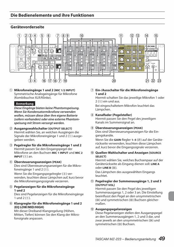
TASCAM MZ-223 – Bedienungsanleitung 49
Die Bedienelemente und ihre Funktionen
Gerätevorderseite
1 Mikrofoneingänge 1 und 2 (MIC 1/2 INPUT)Symmetrische Analogeingänge für Mikrofone (Kombibuchse XLR/Klinke).
AnmerkungDiese Eingänge bieten keine Phantomspeisung. Wenn Sie Kondensatormikrofone verwenden wollen, müssen diese über ihre eigene Batterie (sofern vorhanden) oder eine externe Phantom-speisung mit Strom versorgt werden.
2 Ausgangswahlschalter (OUTPUT SELECT)Hiermit wählen Sie, an welchen Ausgängen die Signale der Mikrofoneingänge 1 und 2 (1) ausge-geben werden.
3 Pegelregler für die Mikrofoneingänge 1 und 2Hiermit passen Sie den Eingangspegel der Mikrofone an den Buchsen MIC 1 INPUT und MIC 2 INPUT (1) an.
4 Übersteuerungsanzeigen (PEAK)Dies sind Übersteuerungsanzeigen für die Mikro-foneingänge 1 und 2 (1).Wenn Sie die Eingangspegelregler (3) ver-wenden, leuchten diese Lämpchen auf, kurz bevor die Mikrofoneingangssignale verzerren.
5 Pegelanzeigen für die Mikrofoneingänge 1 und 2Dies sind Pegelanzeigen für die Mikrofoneingänge 1 und 2 (1).
6 Klangregler für die Mikrofoneingänge 1 und 2 (EQ LOW/MID/HIGH)Mit dieser Dreiband-Klangregelung (Höhen, Mitten, Tiefen) können Sie den Klang der Mikro-fonsignale anpassen.
7 Ein-/Ausschalter für die Mikrofoneingänge 1 und 2Hiermit schalten Sie das jeweilige Mikrofon 1 oder 2 (1) ein und aus.Bei eingeschaltetem Mikrofon leuchtet das Lämpchen.
8 Kanalfader (Pegelsteller)Hiermit passen Sie den Pegel des jeweiligen Kanals im Summensignal an.
9 Übersteuerungsanzeigen (PEAK)Dies sind Übersteuerungsanzeigen für die Ein-gangskanäle.Wenn Sie die GAIN-Regler 1–5 (j) auf der Geräte-rückseite verwenden, leuchten diese Lämpchen auf, kurz bevor die Eingangssignale verzerren.
0 Quellen-Wahlschalter und Anzeigen (SOURCE SELECT)Hiermit wählen Sie, welches Buchsenpaar auf der Geräterückseite als Eingang dienen soll: LINE A oder LINE B (b).Das Lämpchen des ausgewählten Eingangs leuchtet.
q Pegelregler der Summenausgänge 1, 2 und 3 (OUTPUT VOL)Hiermit passen Sie den Pegel des jeweiligen Summenausgangs 1, 2 oder 3 an. Die Einstellung beeinflusst den Pegel an den unsymmetrischen (v) und symmetrischen (c) Buchsen gleicher-maßen.
w AusgangspegelanzeigenDiese Pegelanzeigen stellen den Ausgangspegel an den Summenausgängen 1, 2 und 3 dar, und zwar jeweils an den unsymmetrischen (v) und symmetrischen (c) Buchsen.

50 TASCAM MZ-223 – Bedienungsanleitung
e Klangregler der Summenausgänge 1, 2 und 3 (EQ)Mit dieser Dreiband-Klangregelung (Höhen, Mitten, Tiefen) beeinflussen Sie den Klang der Ausgangssignale an den unsymmetrischen (v) und symmetrischen (c) Buchsen.
r Wahlschalter für das Abhörsignal (MONITOR SELECT)Hiermit wählen Sie, welche der Ausgangssignale an den Buchsen MONITOR OUT (x) und am Kopf-hörerausgang (s) ausgegeben werden.Die Lämpchen der ausgewählten Ausgänge leuchten.
t Betriebsanzeige (POWER)Zeigt den Status der Stromversorgung an.Das POWER-Lämpchen leuchtet, wenn das Gerät mit dem Schalter POWER auf der Rückseite (f) eingeschaltet ist und mit Strom versorgt wird.
y Regler für die Pegelabsenkung der Talkover -Funktion (DAMP)Hiermit bestimmen Sie, wie weit die Talkover -Funktion den Pegel des Ausgangssignals absenkt.
u Regler für die Ansprechzeit der Talkover Funktion (TIME)Hiermit bestimmen Sie, wie schnell die Talko-ver-Funktion anspricht.
i Schalter und Anzeige für die Talkover-Funktion (ON)Hiermit schalten Sie die Talkover-Funktion ein und aus.Bei eingeschalteter Talkover-Funktion leuchtet das dazugehörige Lämpchen und die Pegel aller Eingangskanäle werden automatisch abgesenkt, sobald ein Tonsignal über ein Mikrofon eingeht.Nutzen Sie die Regler DAMP (y) und TIME (u), um die Pegelabsenkung und die Ansprechzeit an die Erfordernisse anzupassen (nur MIC 1).
o Ausgangswahlschalter (OUTPUT SEL)Hiermit wählen Sie, an welchen der drei Aus-gängen die Signale des jeweiligen Kanals ausge-geben werden.
p Schalter und Anzeigen für das Vorhören (PFL)Wenn der Schalter PFL gedrückt ist und das Lämpchen leuchtet, hören Sie über den Kopf-hörerausgang das entsprechende Signal vor der Beeinflussung durch den Fader. Welches Signal genau zu hören ist, ist auch von der Stellung des Reglers MIXING abhängig.
a Regler für Kopfhörerlautstärke (PHONES VOLUME)Hiermit passen Sie die Kopfhörerlautstärke an.
s KopfhörerausgangAn diese Stereoklinkenbuchse können Sie Ihren Kopfhörer anschließen.Um Kopfhörer mit Miniklinkenstecker anzu-schließen, verwenden Sie einen geeigneten Adapter.Wenn einer der Schalter PFL (p) gedrückt ist, können Sie das jeweilige PFL-Signal abhören.
d Mischregler Vorhören/Monitor (MIXING)Mit diesem Regler erstellen Sie für den Kopf-hörerausgang eine Mischung aus dem Vorhör-signal und dem Monitorsignal.
– Drehen Sie den Regler ganz in Richtung PFL, um alle Kanäle abzuhören, deren Taste PFL (p) gedrückt ist.
– Drehen Sie den Regler ganz in Richtung MONITOR, um das Signal des Monitorausgangs abzuhören.
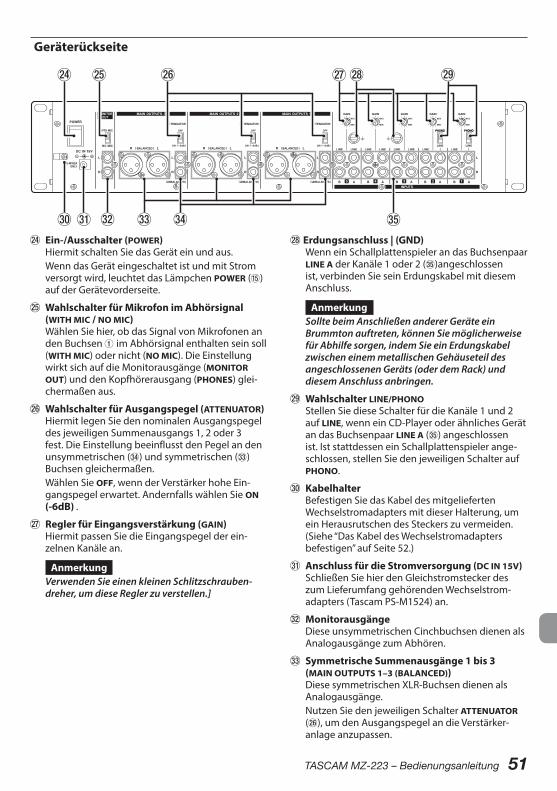
TASCAM MZ-223 – Bedienungsanleitung 51
Geräterückseite
f Ein-/Ausschalter (POWER)Hiermit schalten Sie das Gerät ein und aus.Wenn das Gerät eingeschaltet ist und mit Strom versorgt wird, leuchtet das Lämpchen POWER (t) auf der Gerätevorderseite.
g Wahlschalter für Mikrofon im Abhörsignal (WITH MIC / NO MIC)Wählen Sie hier, ob das Signal von Mikrofonen an den Buchsen 1 im Abhörsignal enthalten sein soll (WITH MIC) oder nicht (NO MIC). Die Einstellung wirkt sich auf die Monitorausgänge (MONITOR OUT) und den Kopfhörerausgang (PHONES) glei-chermaßen aus.
h Wahlschalter für Ausgangspegel (ATTENUATOR)Hiermit legen Sie den nominalen Ausgangspegel des jeweiligen Summenausgangs 1, 2 oder 3 fest. Die Einstellung beeinflusst den Pegel an den unsymmetrischen (v) und symmetrischen (c) Buchsen gleichermaßen.Wählen Sie OFF, wenn der Verstärker hohe Ein-gangspegel erwartet. Andernfalls wählen Sie ON (-6dB) .
j Regler für Eingangsverstärkung (GAIN)Hiermit passen Sie die Eingangspegel der ein-zelnen Kanäle an.
AnmerkungVerwenden Sie einen kleinen Schlitzschrauben-dreher, um diese Regler zu verstellen.]
k Erdungsanschluss | (GND)Wenn ein Schallplattenspieler an das Buchsenpaar LINE A der Kanäle 1 oder 2 (b)angeschlossen ist, verbinden Sie sein Erdungskabel mit diesem Anschluss.
AnmerkungSollte beim Anschließen anderer Geräte ein Brummton auftreten, können Sie möglicherweise für Abhilfe sorgen, indem Sie ein Erdungskabel zwischen einem metallischen Gehäuseteil des angeschlossenen Geräts (oder dem Rack) und diesem Anschluss anbringen.
l Wahlschalter LINE/PHONOStellen Sie diese Schalter für die Kanäle 1 und 2 auf LINE, wenn ein CD-Player oder ähnliches Gerät an das Buchsenpaar LINE A (b) angeschlossen ist. Ist stattdessen ein Schallplattenspieler ange-schlossen, stellen Sie den jeweiligen Schalter auf PHONO.
; KabelhalterBefestigen Sie das Kabel des mitgelieferten Wechselstromadapters mit dieser Halterung, um ein Herausrutschen des Steckers zu vermeiden.(Siehe “Das Kabel des Wechselstromadapters befestigen” auf Seite 52.)
z Anschluss für die Stromversorgung (DC IN 15V)Schließen Sie hier den Gleichstromstecker des zum Lieferumfang gehörenden Wechselstrom-adapters (Tascam PS-M1524) an.
x MonitorausgängeDiese unsymmetrischen Cinchbuchsen dienen als Analogausgänge zum Abhören.
c Symmetrische Summenausgänge 1 bis 3 (MAIN OUTPUTS 1–3 (BALANCED))Diese symmetrischen XLR-Buchsen dienen als Analogausgänge.Nutzen Sie den jeweiligen Schalter ATTENUATOR (h), um den Ausgangspegel an die Verstärker-anlage anzupassen.
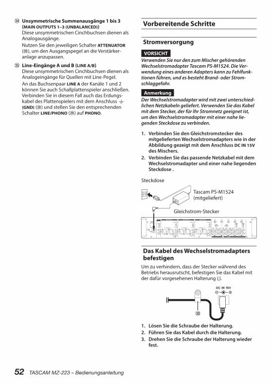
52 TASCAM MZ-223 – Bedienungsanleitung
v Unsymmetrische Summenausgänge 1 bis 3 (MAIN OUTPUTS 1–3 (UNBALANCED))Diese unsymmetrischen Cinchbuchsen dienen als Analogausgänge.Nutzen Sie den jeweiligen Schalter ATTENUATOR (h), um den Ausgangspegel an die Verstärker-anlage anzupassen.
b Line-Eingänge A und B (LINE A/B)Diese unsymmetrischen Cinchbuchsen dienen als Analogeingänge für Quellen mit Line-Pegel.An das Buchsenpaar LINE A der Kanäle 1 und 2 können Sie auch Schallplattenspieler anschließen. Verbinden Sie in diesem Fall auch das Erdungs-kabel des Plattenspielers mit dem Anschluss | (GND) (k) und stellen Sie den entsprechenden Schalter LINE/PHONO (l) auf PHONO.
Vorbereitende Schritte
Stromversorgung
VORSICHTVerwenden Sie nur den zum Mischer gehörenden Wechselstromadapter Tascam PS-M1524. Die Ver-wendung eines anderen Adapters kann zu Fehlfunk-tionen führen, und es besteht Brand- oder Strom-schlaggefahr.
AnmerkungDer Wechselstromadapter wird mit zwei unterschied-lichen Netzkabeln geliefert. Verwenden Sie das Kabel mit dem Stecker, der für Ihr Stromnetz geeignet ist, um den Wechselstromadapter mit einer nahe lie-genden Steckdose zu verbinden.
1. Verbinden Sie den Gleichstromstecker des mitgelieferten Wechselstromadapters wie in der Abbildung gezeigt mit dem Anschluss DC IN 15V des Mischers.
2. Verbinden Sie das passende Netzkabel mit dem Wechselstromadapter und einer nahe liegenden Steckdose .
Steckdose
Gleichstrom-Stecker
Tascam PS-M1524 (mitgeliefert)
Das Kabel des Wechselstromadapters befestigen
Um zu verhindern, dass der Stecker während des Betriebs herausrutscht, befestigen Sie das Kabel mit der dafür vorgesehenen Halterung (;).
;
1. Lösen Sie die Schraube der Halterung.2. Führen Sie das Kabel durch die Halterung.3. Drehen Sie die Schraube der Halterung wieder
fest.
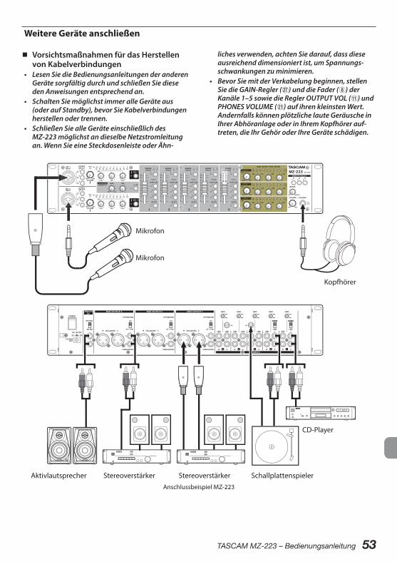
TASCAM MZ-223 – Bedienungsanleitung 53
Weitere Geräte anschließen
8 Vorsichtsmaßnahmen für das Herstellen von Kabelverbindungen
• Lesen Sie die Bedienungsanleitungen der anderen Geräte sorgfältig durch und schließen Sie diese den Anweisungen entsprechend an.
• Schalten Sie möglichst immer alle Geräte aus (oder auf Standby), bevor Sie Kabelverbindungen herstellen oder trennen.
• Schließen Sie alle Geräte einschließlich des MZ-223 möglichst an dieselbe Netzstromleitung an. Wenn Sie eine Steckdosenleiste oder Ähn-
liches verwenden, achten Sie darauf, dass diese ausreichend dimensioniert ist, um Spannungs-schwankungen zu minimieren.
• Bevor Sie mit der Verkabelung beginnen, stellen Sie die GAIN-Regler (j) und die Fader (8) der Kanäle 1–5 sowie die Regler OUTPUT VOL (q) und PHONES VOLUME (a) auf ihren kleinsten Wert. Andernfalls können plötzliche laute Geräusche in Ihrer Abhöranlage oder in Ihrem Kopfhörer auf-treten, die Ihr Gehör oder Ihre Geräte schädigen.
Aktivlautsprecher
Kopfhörer
CD-Player
Schallplattenspieler
Mikrofon
Mikrofon
StereoverstärkerStereoverstärker Anschlussbeispiel MZ-223
54 TASCAM MZ-223 – Bedienungsanleitung
8 Mikrofone anschließenMikrofone können Sie an eine der Buchsen MIC 1 INPUT oder MIC 2 INPUT (1) auf der Gerätevorderseite anschließen.
AnmerkungWenn Sie Kondensatormikrofone verwenden wollen, müssen diese über ihre eigene Batterie (sofern vorhanden) oder eine externe Phantomspeisung mit Strom versorgt werden.
8 Andere Audiogeräte anschließenStereo-Abspielgeräte wie CD-Player oder Kassetten-decks verbinden Sie mit dem Buchsenpaar LINE A oder LINE B der Kanäle 1–5 (b).Wenn Sie das Buchsenpaar LINE A der Kanäle 1–2 nutzen, stellen Sie zudem den jeweiligen Schalter LINE/PHONO (l) auf LINE.
8 Schallplattenspieler anschließenEinen Schallplattenspieler können Sie an die Buchsen paare LINE A der Kanäle 1–2 (b) anschließen. Stellen Sie in diesem Fall den jeweiligen Schalter LINE/PHONO (l) auf PHONO.Verbinden Sie das Erdungskabel des Plattenspielers mit dem Anschluss | (GND) (k).
8 Eine Abhöranlage anschließenAktive Monitorlautsprecher oder eine Verstärker-anlage zum Abhören verbinden Sie mit den Buchsen MONITOR OUT (x).Damit die Signale von Mikrofonen, die an einer Buchsen MIC 1 INPUT oder MIC 2 INPUT (1) ange-schlossen sind, mit dem übrigen Signal gemischt über die Abhöranlage ausgegeben werden, stellen Sie den Schalter MONITOR OUT (g) auf WITH MIC. Diese Einstellung wirkt sich auch auf den Kopf-hörerausgang (PHONES) aus.
Anmerkung• Mithilfe der Schalter MONITOR SELECT (r) wählen
Sie, welche der drei Summensignale an den Buchsen MONITOR OUT ausgegeben werden.
• Das abgehörte Signal wird auch durch die Klang-regler der Ausgänge (e) beeinflusst, jedoch nicht durch den jeweiligen Summenregler.
8 Kopfhörer anschließen
VORSICHTBevor Sie einen Kopfhörer anschließen, drehen Sie den Pegel mit dem Regler PHONES VOLUME (a) voll-ständig herunter. Andernfalls kann es zu plötzlichen, sehr lauten Geräuschen kommen, die Ihr Gehör oder Ihre Geräte schädigen.
Verbinden Sie Ihren Kopfhörer mit der Buchse PHONES (s) auf der Gerätevorderseite.Über Kopfhörer können Sie Folgendes abhören:• die PFL-Signale der Eingangskanäle (wenn der
entsprechende PFL-Schalter gedrückt ist• die mit den Tasten MONITOR SELECT (r)
gewählten Summensignale bevor sie an die Ausgänge geleitet werden.
AnmerkungDas Signal am Kopfhörerausgang wird auch durch die Klangregler der Ausgänge (e) beeinflusst.
8 Stereoverstärker anschließenEinen Stereoverstärker verbinden Sie mit den unsym-metrischen (v) oder symmetrischen (c) Ausgangs-buchsen (MAIN OUTPUTS 1, 2 und/oder 3).
Tipp• Wenn Sie zwei oder mehr Verstärker mit Laut-
sprechern benötigen, etwa um unterschiedliche Zonen zu beschallen oder ein System aus vorderen und hinteren Lautsprechern und einem Subbass einzurichten, können Sie dafür die separat einstellbaren Ausgänge MAIN OUTPUTS 1 bis 3 (UNBALANCED) (f) oder MAIN OUTPUTS 1 bis 3 (BALANCED) (c) nutzen. Darüber hinaus steht Ihnen das Buchsenpaar MONITOR OUT (x) für Abhörlautsprecher oder eine weitere Beschal-lungszone zur Verfügung.Dadurch, dass die Ausgänge unabhängig voneinander sind und ihre eigenen Regler haben, können Sie die Pegel für jede Zone separat anpassen.
• Indem Sie einen Recorder an die Buchsen MONITOR OUT (x) anschließen, können Sie das an die Verstärker ausgegebene Signal aufzeichnen.

TASCAM MZ-223 – Bedienungsanleitung 55
Den Mischer ein- und ausschalten
VORSICHT• Regeln Sie den Pegel der angeschlossenen Abhör-
anlage stets vollständig herunter, bevor Sie den MZ-223 ein- oder ausschalten.
• Wenn Sie einen Kopfhörer mit dem Recorder verbunden haben, nehmen Sie diesen ab, bevor Sie das Gerät ein- oder ausschalten. Sie vermeiden dadurch Hörschäden oder Schäden an Ihren Laut-sprechern infolge plötzlicher Lautstärkesprünge.
8 Bevor Sie den Mischer einschalten1. Nehmen Sie die folgenden Einstellungen auf der
Gerätevorderseite vor. – EQ-Regler w Mittelstellung – Andere Regler w ganz nach links
(in Richtung MIN) – Fader w ganz nach unten – Schalter w aus (nicht gedrückt)
2. Senken Sie den Ausgangspegel aller Tonquellen und den Eingangspegel aller mit dem Mischer verbundenen Verstärker vollständig ab.
8 Den Mischer einschalten1. Schalten Sie den Mischer mit dem Schalter
POWER (f) auf der Geräterückseite ein.Das POWER-Lämpchen (t) auf der Gerätevorder-seite leuchtet, wenn das Gerät eingeschaltet ist und mit Strom versorgt wird.
2. Schalten Sie die angeschlossenen Tonquellen ein.
3. Zuletzt schalten Sie die Verstärker ein.
8 Den Mischer ausschaltenUm das Gerät auszuschalten, führen Sie die oben beschriebenen Schritte in umgekehrter Reihenfolge aus.Die Nichtbeachtung der korrekten Reihenfolge kann zum Beispiel zu Knackgeräuschen führen, die das Gerät beschädigen könnten.
Grundsätzliche BedienungNachdem Sie den Mischer eingeschaltet haben, passen Sie im nächsten Schritt die Pegel der ein-zelnen Eingangssignale an.
Anpassen der Line-Eingänge (Kanäle 1–5)
1. Bringen Sie die GAIN-Regler (j) aller fünf Kanäle in ihre Mittelstellung.
2. Drücken Sie den SOURCE SELECT-Schalter (0), der den verwendeten Eingangsbuchsen ent-spricht, so dass das dazugehörige Lämpchen leuchtet (A oder B).
3. Wählen Sie mit den OUTPUT SEL-Schaltern (o), an welchen der drei Ausgängen die Signale des jeweiligen Kanals ausgegeben werden sollen.
4. Ist das Audiogerät dagegen mit dem Buchsen- paar LINE A der Kanäle 1 oder 2 verbunden, stellen Sie den dazugehörenden Schalter (l) auf LINE.
5. Stellen Sie zunächst die Kanalfader und die Regler OUTPUT 1 VOL bis OUTPUT 3 VOL (q) auf einen niedrigen Wert.
6. Starten Sie die Wiedergabe am angeschlossenen Audiogerät.Passen Sie die Eingangssignale mit den GAIN-Reglern (j) so an, dass die PEAK-Lämpchen (9) nicht aufleuchten.
7. Passen Sie die Mischung der Kanäle unterein-ander mithilfe der Kanalfader (8) an.
8. Befolgen Sie dieselben Schritte für alle anderen Line-Eingangskanäle mit angeschlossenen Audiogeräten.
Die frontseitig angeschlossenen Mikrofone anpassen
1. Verbinden Sie ein Mikrofon mit der Buchse MIC 1 INPUT oder MIC 2 INPUT (1), und drücken Sie den Schalter MIC 1 beziehungsweise MIC 2 (7), so dass das dazugehörige Lämpchen (7) leuchtet.
2. Wählen Sie mit den OUTPUT SEL-Schaltern, an welchen Ausgängen die Signale des jeweiligen Mikrofons ausgegeben werden soll.
3. Passen Sie die Eingangspegel mit den VOLUME-Reglern (3) so an, dass das dazugehörige PEAK-Lämpchen gerade nicht aufleuchtet.
4. Nutzen Sie die Regler der Dreiband- -Klangregelung (6), um den Klang der Mikrofon-signale anzupassen.
5. Passen Sie die Mischung der Kanäle unterein-ander mithilfe der Kanalfader (8) an.
56 TASCAM MZ-223 – Bedienungsanleitung
Die Ausgänge nutzenDer MZ-223 stellt die folgenden Ausgangsbuchsen zur Verfügung:• MAIN OUTPUTS 1 bis 3 (UNBALANCED) (v) und
(BALANCED) (c)• MONITOR OUT (x)
AnmerkungDer Ausgangspegel am Buchsenpaar MONITOR OUT (x) ist nicht veränderbar.
8 Pegelanpassung für die Hauptausgänge 1 bis 3 (MAIN OUTPUTS 1–3 (UNBALANCED) und (BALANCED)
1. Passen Sie den Ausgangspegel mit dem jewei-ligen Regler OUTPUT VOL (8) an. Achten Sie dabei auf die Ausgangspegelanzeigen (w). Der Ausgangspegel ist normalerweise optimal, wenn sich die Pegelanzeigen um 0 dB herum bewegen.
2. Wenn ein Verstärker an diese Buchsen angeschlossen ist, stellen Sie den Schalter ATTENUATOR (h) entsprechend der Ein-gangsempfindlichkeit des Verstärkers ein. Wählen Sie OFF, wenn der Verstärker hohe Eingangspegel toleriert. Wählen Sie ON (-6dB), wenn der Verstärker nur niedrige Eingangspegel toleriert.
3. Nutzen Sie die Regler der Dreiband-Klang-regelung (e), um den Klang des jeweiligen Ausgangssignals anzupassen.
Die Talkover-Funktion nutzenDie Talkover-Funktion ermöglicht es, den Pegel von Kanal 1 automatisch abzusenken, sobald ein Ton-signal über ein Mikrofon eingeht, das an der Buchse MIC 1 INPUT oder MIC 2 INPUT (1) angeschlossen ist.Dadurch ist das Mikrofonsignal besser zu hören.Mit dem Schalter TALKOVER ON (i) können Sie die Funktion ein- und ausschalten. Wenn die Funktion eingeschaltet ist, leuchtet das dazugehörige Lämpchen.Nutzen Sie die Regler DAMP (y) und TIME (u), um die Pegelabsenkung und die Ansprechzeit an die Erfor-dernisse anzupassen.
Eingangssignale vorhören (PFL)Indem Sie die PFL-Schalter (p) drücken, können Sie die einzelnen Kanäle 1–5 vorhören. Dies funktio-niert auch, wenn die entsprechenden Fader (8) auf Minimum gestellt sind.1. Drücken Sie die PFL-Schalter der Kanäle, die
Sie vorhören wollen, so dass das dazugehörige Lämpchen leuchtet.
2. Stellen Sie den Regler MIXING (d) auf PFL.Je weiter Sie den Regler MIXING (d) in Richtung MONITOR drehen, desto mehr wird das mit den Tasten 1–3 (r) gewählte Summensignal zum PFL-Signal hinzugemischt.
3. Mit dem Regler PHONES VOLUME (a) passen Sie den Pegel des Kopfhörersignals an.
TASCAM MZ-223 – Bedienungsanleitung 57
FehlerbehebungBitte prüfen Sie die folgenden Punkte, falls das Gerät nicht wie erwartet funktionieren sollte. Falls sich das Problem auf diese Weise nicht beheben lässt, wenden Sie sich bitte an Ihren Händler oder an den Kundendienst von Tascam.
8 Das Gerät lässt sich nicht einschalten.Vergewissern Sie sich, dass der Wechselstrom-adapter richtig angeschlossen ist und die Steckdose Netzstrom liefert.
8 Keine Tonausgabe über die an das Buchsenpaar MAIN OUTPUTS 1, 2 oder 3 angeschlossenen Verstärker/Lautsprecher.
• Überprüfen Sie die Einstellungen und den Pegel des Verstärkers.
• Vergewissern Sie sich, dass die Kanalfader (8) entsprechend aufgezogen sind.
• Überprüfen Sie, ob die Tonquellen richtig ange-schlossen sind.
8 Selbst bei aufgezogenen Fadern ist die Lautstärke zu gering.Überprüfen Sie, ob die GAIN-Regler (j) für die Kanäle 1 bis 5 richtig eingestellt sind.
8 Der Klang ist verzerrt.• Überprüfen Sie, ob die GAIN-Regler (j) für die
Kanäle 1 bis 5 richtig eingestellt sind.• Vergewissern Sie sich, dass die Klangregler (EQ)
nicht zu weit aufgedreht sind.• Stellen Sie sicher, dass die Fader (8) der Kanäle 1
bis 5 und die Regler für die Summenausgänge (q) nicht zu weit aufgedreht sind.
8 Das Schallplattensignal klingt ungewöhnlich.
• Vergewissern Sie sich, dass der Schallplatten-spieler an das Buchsenpaar LINE A der Kanäle 1 bis 2 angeschlossen und der dazugehörige Schalter LINE/PHONO (l) auf PHONO gestellt ist.
• Vergewissern Sie sich, dass das Erdungskabel des Plattenspielers mit dem Anschluss | (GND) (k) verbunden ist.
8 Ein angeschlossenes Gerät erzeugt einen Brummton.Verbinden Sie das Metallgehäuse des angeschlos-senen Geräts über ein Erdungskabel mit dem Anschluss | (GND) (k) des Mischers.
8 Keine Tonausgabe über das am Buchsenpaar MONITOR OUT angeschlossene Abhörsystem.
• Überprüfen Sie die Einstellungen des angeschlos-senen Abhörsystems.
• Vergewissern Sie sich, dass die GAIN-Regler (j) aufgedreht und die Kanalfader (8) entsprechend aufgezogen sind.
8 Über den Kopfhörer ist nichts zu hören.• Wählen Sie mit den Tasten MONITOR SELECT (r),
welche Ausgänge Sie abhören wollen.
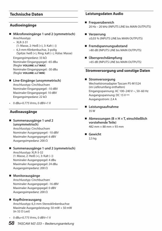
58 TASCAM MZ-223 – Bedienungsanleitung
Technische Daten
Audioeingänge
8 Mikrofoneingänge 1 und 2 (symmetrisch)Anschlusstyp:
– XLR-3-31 (1: Masse, 2: Heiß (+), 3: Kalt (–))
– 6,3-mm-Klinkenbuchse, 3-polig (Spitze: heiß (+), Ring: kalt (–), Hülse: Masse)
Eingangsimpedanz: 33 kΩNominaler Eingangspegel: -65 dBu (Regler VOLUME auf MAX)Nominaler Eingangspegel: -30 dBu (Regler VOLUME auf MIN)
8 Line-Eingänge (unsymmetrisch)Anschlusstyp: CinchbuchsenNominaler Eingangspegel: -10 dBVMaximaler Eingangspegel: 10 dBVEingangsimpedanz: 22 kΩ
• 0 dBu=0.775 Vrms, 0 dBV=1 V
Audioausgänge
8 Summenausgänge 1 und 2 (unsymmetrisch)Anschlusstyp: CinchbuchsenNominaler Ausgangspegel: -10 dBVMaximaler Ausgangspegel: 6 dBVAusgangsimpedanz: 200 Ω
8 Summenausgänge 1 und 2 (symmetrisch)Anschlusstyp: XLR-3-32 (1: Masse, 2: Heiß (+), 3: Kalt (–))Nominaler Ausgangspegel: 4 dBuMaximaler Ausgangspegel: 24 dBuAusgangsimpedanz: 200 Ω
8 MonitorausgängeAnschlusstyp: CinchbuchsenNominaler Ausgangspegel: -16 dBVMaximaler Ausgangspegel: 0 dBVAusgangsimpedanz: 200 Ω
8 KopfhörerausgangAnschlusstyp: 6,3-mm-StereoklinkenbuchseMaximale Ausgangsleistung: 50 mW + 50 mW (in 32 Ω Last)
• 0 dBu=0.775 Vrms, 0 dBV=1 V
Leistungsdaten Audio
8 Frequenzbereich20 Hz – 20 kHz (INPUTS LINE bis MAIN OUTPUTS)
8 Verzerrung≤0,03 % (INPUTS LINE bis MAIN OUTPUTS)
8 Fremdspannungsabstand>80 dB (INPUTS LINE bis MAIN OUTPUTS)
8 Übersprechdämpfung>65 dB (INPUTS LINE bis MAIN OUTPUTS)
Stromversorgung und sonstige Daten
8 StromversorgungWechselstromadapter Tascam PS-M1524 (im Lieferumfang enthalten)Eingangsspannung: AC 100–240 V ~, 50–60 HzAusgangsspannung: DC 15 V Ausgangsstrom: 2,4 A
8 Leistungsaufnahme35 W
8 Abmessungen (B × H × T, einschließlich vorstehende Teile)482 mm × 88 mm × 93 mm
8 Gewicht2,5 kg
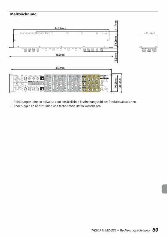
TASCAM MZ-223 – Bedienungsanleitung 59
Maßzeichnung
465mm
482mm
76.2mm
18.3mm
63.2mm
11.7mm
442.2mm
88.0mm
• Abbildungen können teilweise vom tatsächlichen Erscheinungsbild des Produkts abweichen.• Änderungen an Konstruktion und technischen Daten vorbehalten.
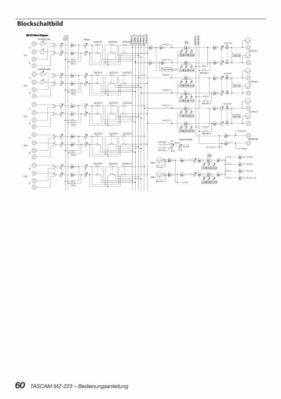
60 TASCAM MZ-223 – Bedienungsanleitung
Blockschaltbild

TASCAM MZ-223 61
MANUALE DI ISTRUZIONI
IMPORTANTI PRECAUZIONI DI SICUREZZA
CAUTELA: PER RIDURRE IL RISCHIO DI SCOSSE ELETTRICHE, NON RIMUOVERE IL COPERCHIO (O IL RETRO). NON CI SONO PARTI RIPARABILI ALL’INTERNO DESTINATE ALL’UTENTE. PER RIPARAZIONI RIVOLGERSI A PERSONALE QUALIFICATO.
Il simbolo di un fulmine dentro un triangolo equilatero avverte l’utente della presenza di “tensioni pericolose” non isolate all’interno del contenitore del prodotto che possono essere di intensità suffi-ciente per costituire un rischio di scossa elettrica alle persone.
Il punto esclamativo all’interno di un triangolo equilatero avverte l’utente della presenza di importanti istruzioni operative e di manu-tenzione nella documentazione che accompagna l’apparecchio.
AVVERTENZA: PER PREVENIRE IL PERICOLO DI INCENDI O DI FOLGORAZIONE, NON ESPORRE QUESTO APPARATO ALLA PIOGGIA O ALL’UMIDI-TÀ.
Questo prodotto è conforme alle direttive europee e agli altri regola-menti della Commissione.
Informazioni sul marchio CEEN55103-2a) Ambiente di applicabilità elettromagnetica: E1,
E2, E3, E4
62 TASCAM MZ-223
IMPORTANTI ISTRUZIONI DI SICUREZZA
1. Leggere le seguenti istruzioni.
2. Conservare queste istruzioni.
3. Prestare attenzione agli avvertimenti.
4. Seguire tutte le istruzioni.
5. Non usare l’apparecchio vicino all’acqua.
6. Pulire solo con un panno asciutto.
7. Non bloccare le aperture per la ventilazione. In-stallare secondo le istruzioni del costruttore.
8. Non installare l’apparecchio vicino a fonti di ca-lore come radiatori, regolatori di calore, stufe o altri apparecchi che producono calore (inclusi gli amplificatori).
9. Non eliminare la spina polarizzata di sicurezza o la spina di messa a terra. La spina polarizzata ha due lame, una più larga dell’altra. Una spina di messa a terra ha due lame e una terza punta di messa terra. La lama larga o la terza punta sono fornite per la vostra sicurezza. Se la spina fornita non è adatta al tipo di presa, consultate un elet-tricista per sostituire la presa obsoleta.
10. Non calpestare o strattonare il cordone di ali-mentazione, in modo particolare vicino alla spina e alla presa a cui è collegato l’apparecchio e dal punto in cui esce dall’apparecchio.
11. Usare solamente attacchi/accessori specificati dal costruttore.
12. Usare solo carrello, supporto, treppiede, menso-la o tavola specificata dal costruttore o venduto insieme all’apparecchio. Quando viene usato un carrello, prestare attenzione quando si sposta la combinazione carrello/apparato per evitare cadu-te da sopra.
13. Scollegare questo apparato durante temporali o quando non viene utilizzato per lunghi periodi di tempo.
14. Rivolgersi solo a personale qualificato. La ripa-razione è richiesta quando l’apparecchio è stato danneggiato in qualunque modo, come nel caso che il cordone dell’alimentazione o la spina siano stati danneggiati, l’apparecchio sia stato esposto a pioggia o umidità, non funzioni correttamente o sia stato lasciato cadere.
0 La presa di rete è utilizzata come dispositivo di sconnessione, il dispositivo di sconnessione deve restare sempre operativo
0 Si deve usare cautela quando si usano gli auricola-ri o le cuffie con il prodotto, perché un eccesso di pressione sonora (volume) negli auricolari o nelle cuffie può causare la perdita dell’udito.
0 Se si verificano problemi con questo prodotto, contattare TEAC per una riparazione. Non utilizza-re il prodotto fino a quando non è stato riparato.
0 Non rimuovere il coperchio o l’involucro esterno per esporre le parti elettroniche. All’interno non ci sono parti riparabili dall’utente.
0 Se si verificano problemi con questo prodotto, contattare il negozio dove è stato acquistato l’ap-parecchio per una riparazione. non usare il pro-dotto fino a che non sia stato riparato.
0 L’uso di controlli o regolazioni o l’esecuzione di procedure diverse da quelle specificate qui po-trebbero provocare pericolose esposizioni a radia-zioni.
CAUTELA
0 Non esporre questo apparecchio a gocciola-menti o schizzi.
0 Non appoggiare alcun contenitore o vaso pieno d’acqua sopra l’apparecchio.
0 Non installare questo apparecchio in spazi ri-stretti come una libreria o ambienti simili.
0 Questo apparecchio dovrebbe essere collocato sufficientemente vicino alla presa AC in modo da poter facilmente afferrare la spina del cordo-ne di alimentazione in qualsiasi momento.
0 Se il prodotto utilizza batterie (incluso un pacco batterie o batterie installate), non dovrebbero essere esposte alla luce solare, fuoco o calore eccessivo.
0 CAUTELA per i prodotti che utilizzano batterie al litio sostituibili: vi è pericolo di esplosione se la batteria viene sostituita con una di tipo scorret-to. Sostituire solo con tipo uguale o equivalente.
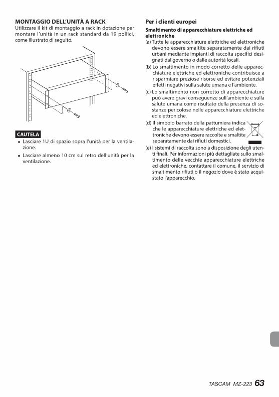
TASCAM MZ-223 63
MONTAGGIO DELL’UNITÀ A RACKUtilizzare il kit di montaggio a rack in dotazione per montare l’unità in un rack standard da 19 pollici, come illustrato di seguito.
CAUTELA i Lasciare 1U di spazio sopra l’unità per la ventila-
zione.
i Lasciare almeno 10 cm sul retro dell’unità per la ventilazione.
Per i clienti europeiSmaltimento di apparecchiature elettriche ed elettroniche(a) Tutte le apparecchiature elettriche ed elettroniche
devono essere smaltite separatamente dai rifiuti urbani mediante impianti di raccolta specifici desi-gnati dal governo o dalle autorità locali.
(b) Lo smaltimento in modo corretto delle apparec-chiature elettriche ed elettroniche contribuisce a risparmiare preziose risorse ed evitare potenziali effetti negativi sulla salute umana e l’ambiente.
(c) Lo smaltimento non corretto di apparecchiature può avere gravi conseguenze sull’ambiente e sulla salute umana come risultato della presenza di so-stanze pericolose nelle apparecchiature elettriche ed elettroniche.
(d) Il simbolo barrato della pattumiera indica che le apparecchiature elettriche ed elet-troniche devono essere raccolte e smaltite separatamente dai rifiuti domestici.
(e) I sistemi di raccolta sono a disposizione degli uten-ti finali. Per informazioni più dettagliate sullo smal-timento delle vecchie apparecchiature elettriche ed elettroniche, contattare il comune, il servizio di smaltimento rifiuti o il negozio dove è stato acqui-stato l’apparecchio.
64 TASCAM MZ-223
Grazie mille per aver acquistato il TASCAM MZ-223.Prima di utilizzare questa unità, leggere attentamente questo manuale di istruzioni in modo da utilizzarlo correttamente e utilizzarlo per molti anni. Dopo aver finito di leggere questo manuale, si prega di tenerlo in un luogo sicuro per riferimenti futuri.È anche possibile scaricare questo manuale di istru-zioni da TEAC Global Site (http://teac-global.com/).
Caratteristiche
0 Mixer con montaggio su rack che consente di instradare i canali di ingresso su più uscite come desiderato
0 Gli ingressi Mic e Line possono essere mixati in uscita
0 La funzione Talkover riduce automaticamente il volume della musica in sottofondo in base al volu-me del microfono
0 Cinque canali di ingresso sono dotati di controlli di guadagno, LED di segnalazione e fader
0 Due canali di ingresso microfonici sono dotati di controlli del volume, misuratori di livello a LED e equalizzatori a tre bande
0 Le uscite principali a tre zone sono dotate di controlli del volume, misuratori di livello a LED e equalizzatori a tre bande
0 L’uscita cuffie con controllo del volume può essere utilizzata per il monitoraggio pre-fader dei canali di ingresso selezionati e dell’uscita principale
0 L’uscita di monitoraggio è indipendente dalle usci-te principali
0 Dimensione rack 2U
Articoli inclusi con questo prodottoQuesto prodotto include i seguenti articoli.Fare attenzione quando si apre la confezione a non danneggiare gli oggetti. Conservare i materiali di im-ballo per un eventuale trasporto futuro.Si prega di contattare il rivenditore presso cui si è acquistata l’unità se uno di questi articoli manca o è stato danneggiato durante il trasporto.
0 Unità principale ..............................................................× 1 0 Adattatore AC (TASCAM PS-M1524) .......................× 1 0 Cavo per adattatore AC. (GIAPPONE USA / EUROPA) ........................................× 2
0 Kit viti per montaggio su rack ...................................× 1 0 Manuale di istruzioni (questo documento) inclusa la garanzia .........................................................× 1
CAUTELAUtilizzare sempre l’adattatore AC incluso (TASCAM PS-M1524) quando si usa questa unità. Non utilizza-re mai un adattatore incluso con altri dispositivi. Ciò potrebbe causare danni, incendi o scosse elettriche.
Indice dei contenuti
IMPORTANTI PRECAUZIONI DI SICUREZZA ......... 61IMPORTANTI ISTRUZIONI DI SICUREZZA ............. 62Caratteristiche ....................................................... 64Articoli inclusi con questo prodotto .................... 64Convenzioni utilizzate in questo manuale .......... 65Precauzioni per il posizionamento e l’uso ........... 65Attenzione alla condensa ..................................... 65Pulizia dell’unità .................................................... 65Come usare il sito TEAC Global ............................. 65Informazioni sul servizio di assistenza clienti TASCAM .................................................................. 65Nomi e funzioni delle parti ................................... 66
Pannello frontale .............................................................. 66Pannello posteriore ......................................................... 67
Preparativi .............................................................. 68Collegare l’alimentazione .............................................. 68Attaccare il cavo ................................................................ 68Collegamento di altre apparecchiature ................... 68Accensione e spegnimento .......................................... 70
Procedure operative .............................................. 71Regolazione dei canali di ingresso linea (1–5) ....... 71Regolazione degli ingressi dei microfoni collegati alle prese MAIN MIC 1–2 INPUT .................................. 71Canali di uscita .................................................................. 71Uso della funzione talkover .......................................... 71Ascolto dei segnali pre-fader dei canali ................... 72
Risoluzione dei problemi ...................................... 72Specifiche ............................................................... 73
Ingressi audio .................................................................... 73Uscite audio ........................................................................ 73Prestazioni audio .............................................................. 73Generali ................................................................................ 73Dimensioni ......................................................................... 74Diagramma a blocchi ...................................................... 74
TASCAM MZ-223 65
Convenzioni utilizzate in questo manuale
0 In questo manuale, vengono usate le seguenti convenzioni:
0 I nomi di interruttori, connettori e altre parti fisi-che di questa unità sono scritti usando un caratte-re in grassetto come questo: POWER.
0 Se necessario, ulteriori informazioni sono fornite sotto forma di suggerimenti, note e cautele.
SUGGERIMENTOConsigli su come utilizzare l’unità.
NOTAFornisce spiegazioni aggiuntive e descrive casi speciali.
CAUTELALa mancata osservanza di queste istruzioni può causare lesioni, danni alle apparecchiature o la perdita di dati.
Precauzioni per il posizionamento e l’uso
0 La temperatura di funzionamento di questa unità è compresa fra 0-40 °C.
0 Non installare l’unità nei seguenti luoghi. Si po-trebbe peggiorare la qualità del suono o causare malfunzionamenti.
Luoghi con forti vibrazioniIn prossimità di finestre o altri luoghi esposti alla luce diretta del soleNei pressi di caloriferi o altri luoghi estrema-mente caldiLuoghi troppo freddiIn luoghi molto umidi o scarsamente ventilatiAmbienti molto polverosi
0 Per una buona dissipazione di calore, non appog-giare nulla sulla parte superiore dell’unità.
0 Non posizionare l’unità su di un amplificatore di potenza o altro dispositivo che genera calore.
Attenzione alla condensaSe l’unità viene spostata da un luogo freddo a uno caldo o utilizzata dopo un improvviso cambiamento di temperatura, esiste il rischio di condensa; il vapore nell’aria potrebbe condensarsi sul meccanismo inter-no, rendendo impossibile il corretto funzionamento.Per evitare ciò, o se ciò si verifica, lasciare l’unità per una o due ore alla nuova temperatura ambiente pri-ma di usarla.
Pulizia dell’unitàUsare un panno morbido e asciutto per pulire l’unità. Non pulire con panni chimici di pulizia, diluenti, alco-ol o altri agenti chimici. Ciò potrebbe danneggiare la superficie o causare scolorimento.
Come usare il sito TEAC GlobalÈ possibile scaricare il manuale di Istruzioni necessa-rio per questa unità dal sito TEAC Global:
http://teac-global.comNella sezione TASCAM Downloads, cliccare sulla lin-gua desiderata per aprire la pagina Downloads nella lingua scelta.
Informazioni sul servizio di assis-tenza clienti TASCAM
I prodotti TASCAM sono supportati e garantiti solo nel relativo paese/regione di acquisto.Per ricevere assistenza dopo l’acquisto, nella pagina dell’elenco dei distributori TASCAM del sito TEAC Glo-bal Site (http:// teac-global.com/), cercare l’azienda o il rappresentante locale per la regione in cui è stato acquistato il prodotto e contattare l’organizzazione.Quando si effettuano richieste di informazioni, sono richiesti l’indirizzo (URL) del negozio o del negozio web in cui è stato acquistato e la data di acquisto. Inoltre, potrebbe essere necessaria la scheda di ga-ranzia e la prova di acquisto.
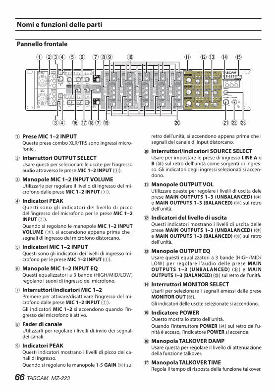
66 TASCAM MZ-223
Nomi e funzioni delle parti
Pannello frontale
1Prese MIC 1–2 INPUTQueste prese combo XLR/TRS sono ingressi micro-fonici.
2Interruttori OUTPUT SELECTUsare questi per selezionare le uscite per l’ingresso audio attraverso le prese MIC 1–2 INPUT (1).
3Manopole MIC 1–2 INPUT VOLUMEUtilizzarle per regolare il livello di ingresso del mi-crofono dalle prese MIC 1–2 INPUT (1).
4Indicatori PEAKQuesti sono gli indicatori del livello di picco dell’ingresso del microfono per le prese MIC 1–2 INPUT (1).Quando si regolano le manopole MIC 1–2 INPUT VOLUME (3), si accendono appena prima che i segnali di ingresso del microfono distorcano.
5Indicatori MIC 1–2 INPUTQuesti sono gli indicatori dei livelli di ingresso mi-crofono per le prese MIC 1–2 INPUT (1).
6Manopole MIC 1–2 INPUT EQQuesti equalizzatori a 3 bande (HIGH/MID/LOW) regolano i suoni di ingresso del microfono.
7Interruttori/indicatori MIC 1–2Premere per attivare/disattivare l’ingresso del mi-crofono dalle prese MIC 1–2 INPUT (1).Gli indicatori MIC 1–2 si accendono quando l’in-gresso del microfono è attivo.
8Fader di canaleUtilizzarli per regolare i livelli di invio dei segnali dei canali.
9Indicatori PEAKQuesti indicatori mostrano i livelli di picco dei ca-nali di ingresso.Quando si regolano le manopole 1-5 GAIN (j) sul
retro dell’unità, si accendono appena prima che i segnali del canale di input distorcano.
0Interruttori/indicatori SOURCE SELECTUsare per impostare le prese di ingresso LINE A o B (b) sul retro dell’unità come sorgenti di ingres-so. Gli indicatori degli ingressi selezionati si accen-dono.
qManopole OUTPUT VOLUtilizzare queste per regolare i livelli di uscita dele prese MAIN OUTPUTS 1–3 (UNBALANCED) (v) e MAIN OUTPUTS 1–3 (BALANCED) (c) sul retro dell’unità.
wIndicatori del livello di uscitaQuesti indicatori mostrano i livelli di uscita delle prese MAIN OUTPUTS 1–3 (UNBALANCED) (v) e MAIN OUTPUTS 1–3 (BALANCED) (c) sul retro dell’unità.
eManopole OUTPUT EQUsare questi equalizzatori a 3 bande (HIGH/MID/LOW ) per regolare l ’audio delle prese MAIN OUTPUTS 1–3 (UNBALANCED) (v) e MAIN OUTPUTS 1–3 (BALANCED) (c) sul retro dell’unità.
rInterruttori MONITOR SELECTUsarli per selezionare i segnali emessi dalle prese MONITOR OUT (x).Gli indicatori delle uscite selezionate si accendono.
tIndicatore POWERQuesto mostra lo stato dell’unità.Quando l’interruttore POWER (f) sul retro dell’u-nità è acceso, l’indicatore POWER si accende.
yManopola TALKOVER DAMPUsare questa per regolare il livello di attenuazione della funzione talkover.
uManopola TALKOVER TIMERegola il tempo di risposta della funzione talkover.
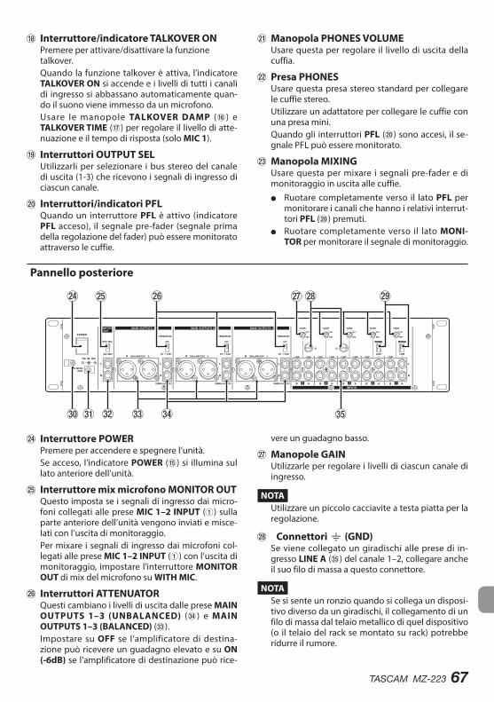
TASCAM MZ-223 67
iInterruttore/indicatore TALKOVER ONPremere per attivare/disattivare la funzione talkover.Quando la funzione talkover è attiva, l’indicatore TALKOVER ON si accende e i livelli di tutti i canali di ingresso si abbassano automaticamente quan-do il suono viene immesso da un microfono.Usare le manopole TALKOVER DAMP (y) e TALKOVER TIME (u) per regolare il livello di atte-nuazione e il tempo di risposta (solo MIC 1).
oInterruttori OUTPUT SELUtilizzarli per selezionare i bus stereo del canale di uscita (1-3) che ricevono i segnali di ingresso di ciascun canale.
pInterruttori/indicatori PFLQuando un interruttore PFL è attivo (indicatore PFL acceso), il segnale pre-fader (segnale prima della regolazione del fader) può essere monitorato attraverso le cuffie.
aManopola PHONES VOLUMEUsare questa per regolare il livello di uscita della cuffia.
sPresa PHONESUsare questa presa stereo standard per collegare le cuffie stereo.Utilizzare un adattatore per collegare le cuffie con una presa mini.Quando gli interruttori PFL (p) sono accesi, il se-gnale PFL può essere monitorato.
dManopola MIXINGUsare questa per mixare i segnali pre-fader e di monitoraggio in uscita alle cuffie.
o Ruotare completamente verso il lato PFL per monitorare i canali che hanno i relativi interrut-tori PFL (p) premuti.
o Ruotare completamente verso il lato MONI-TOR per monitorare il segnale di monitoraggio.
Pannello posteriore
fInterruttore POWERPremere per accendere e spegnere l’unità.Se acceso, l’indicatore POWER (t) si illumina sul lato anteriore dell’unità.
gInterruttore mix microfono MONITOR OUTQuesto imposta se i segnali di ingresso dai micro-foni collegati alle prese MIC 1–2 INPUT (1) sulla parte anteriore dell’unità vengono inviati e misce-lati con l’uscita di monitoraggio.Per mixare i segnali di ingresso dai microfoni col-legati alle prese MIC 1–2 INPUT (1) con l’uscita di monitoraggio, impostare l’interruttore MONITOR OUT di mix del microfono su WITH MIC.
hInterruttori ATTENUATORQuesti cambiano i livelli di uscita dalle prese MAIN OUTPUTS 1–3 (UNBALANCED) (v) e MAIN OUTPUTS 1–3 (BALANCED) (c).Impostare su OFF se l’amplificatore di destina-zione può ricevere un guadagno elevato e su ON (-6dB) se l’amplificatore di destinazione può rice-
vere un guadagno basso.
jManopole GAINUtilizzarle per regolare i livelli di ciascun canale di ingresso.
NOTAUtilizzare un piccolo cacciavite a testa piatta per la regolazione.
kConnettori | (GND)Se viene collegato un giradischi alle prese di in-gresso LINE A (b) del canale 1–2, collegare anche il suo filo di massa a questo connettore.
NOTASe si sente un ronzio quando si collega un disposi-tivo diverso da un giradischi, il collegamento di un filo di massa dal telaio metallico di quel dispositivo (o il telaio del rack se montato su rack) potrebbe ridurre il rumore.
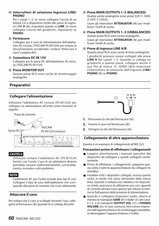
68 TASCAM MZ-223
l Interruttori di selezione ingresso LINE/PHONOPer i canali 1–2, se viene collegata l’uscita di un lettore CD o dispositivo simile alle prese di ingres-so LINE A (b), impostare questo su LINE. Se viene collegata l’uscita del giradischi, impostarlo su PHONO.
;FermacavoCollegare qui il cavo di alimentazione dell’adatta-tore AC incluso (TASCAM PS-M1524) per evitare la disconnessione accidentale. (vedere “Attaccare il cavo” a pagina 68.)
z Connettore DC IN 15VCollegare qui la spina DC dell’adattatore AC inclu-so (TASCAM PS-M1524).
x Prese MONITOR OUTQueste prese RCA sono uscite di monitoraggio analogiche.
c Prese MAIN OUTPUTS 1–3 (BALANCED)Queste uscite analogiche sono prese XLR (1: GND, 2: HOT, 3: COLD).Usare gli interruttori ATTENUATOR (h) per modi-ficare i livelli di uscita.
v Prese MAIN OUTPUTS 1–3 (UNBALANCED)Queste prese RCA sono uscite analogiche.Usare gli interruttori ATTENUATOR (h) per modi-ficare i livelli di uscita.
b Prese di ingresso LINE A/BQueste prese RCA sono uscite di linea analogiche.I giradischi possono essere collegati alle prese LINE A dei canali 1–2. Quando si collega un giradischi a queste prese, collegare anche il suo filo di massa | (GND) (k)e impostare l’interruttore di selezione dell’ingresso LINE/PHONO (l) su PHONO.
Preparativi
Collegare l’alimentazione
Utilizzare l’adattatore AC incluso (PS-M1524) per collegare un alimentatore all’unità come mostrato di seguito.
Presa di corrente
Spina DCTASCAMPS-M1524 (incluso)
CAUTELAUtilizzare sempre l’adattatore AC (PS-M1524) fornito con l’unità. L’uso di un adattatore diverso potrebbe causare malfunzionamenti, surriscalda-mento, incendio o altri problemi.
NOTAL’adattatore AC per l’unità include due tipi di cavi. Collegare il tipo di cavo dell’adattatore che corri-sponde alla presa di corrente che si sta utilizzando.
Attaccare il cavo
Per evitare che il cavo si scolleghi durante l’uso, colle-garlo al fermacavo (;) quando lo si collega all’unità.
1. Rimuovere la vite del fermacavo (;).
2. Inserire il cavo nel fermacavo (;).
3. Stringere la vite del fermacavo (;).
Collegamento di altre apparecchiature
Questo è un esempio di collegamenti all’MZ-223.
Precauzioni prima di effettuare i collegamenti 0 Leggere attentamente i manuali operativi dei dispositivi da collegare e quindi collegarli corret-tamente.
0 Prima di effettuare i collegamenti, spegnere que-sta unità e tutte le apparecchiature da collegare (in standby).
0 Installare tutti i dispositivi collegati, inclusa questa unità, in modo che siano alimentati dalla stessa linea. Quando si utilizza una ciabatta o un dispositi-vo simile, assicurarsi di utilizzarne uno con capacità di corrente elevata (cavo spesso) per ridurre al mini-mo le fluttuazioni della tensione di alimentazione.
0 Quando si collegano dispositivi audio, ridurre al minimo le manopole GAIN (j) e fader (8) dei cana-li 1-5 e le manopole OUTPUT VOL (q) e PHONES VOLUME (a). In caso contrario, forti rumori improv-visi dall’apparecchiatura di monitoraggio potrebbe-ro danneggiare l’apparecchiatura o l’udito.
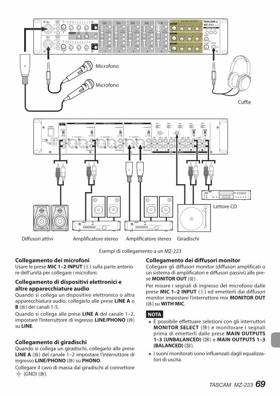
TASCAM MZ-223 69
Diffusori attivi
Cuffie
Lettore CD
Giradischi
Microfono
Microfono
Amplificatore stereoAmplificatore stereo
Esempi di collegamento a un MZ-223
Collegamento dei microfoniUsare le prese MIC 1–2 INPUT (1) sulla parte anterio-re dell’unità per collegare i microfoni.
Collegamento di dispositivi elettronici e altre apparecchiature audioQuando si collega un dispositivo elettronico o altra apparecchiatura audio, collegarlo alle prese LINE A o B (b) dei canali 1-5.Quando si collega alle prese LINE A del canale 1–2, impostare l’interruttore di ingresso LINE/PHONO (l) su LINE.
Collegamento di giradischiQuando si collega un giradischi, collegarlo alle prese LINE A (b) del canale 1–2 impostare l’interruttore di ingresso LINE/PHONO (l) su PHONO.Collegare il cavo di massa dal giradischi al connettore | (GND) (k).
Collegamento dei diffusori monitorCollegare gli diffusori monitor (diffusori amplificati o un sistema di amplificatori e diffusori passivi) alle pre-se MONITOR OUT (x) .Per mixare i segnali di ingresso del microfono dalle prese MIC 1–2 INPUT (1) ed emetterli dai diffusori monitor impostare l’interruttore mix MONITOR OUT (g) su WITH MIC.
NOTA i È possibile effettuare selezioni con gli interruttori
MONITOR SELECT (r) e monitorare i segnali prima di emetterli dalle prese MAIN OUTPUTS 1–3 (UNBALANCED) (v) e MAIN OUTPUTS 1–3 (BALANCED) (c).
i I suoni monitorati sono influenzati dagli equalizza-tori di uscita.
70 TASCAM MZ-223
Collegamento delle cuffieCollegare le cuffie alla presa (stereo standard) PHONES (s).È possibile monitorare i segnali e i segnali pre-fader dei canali di ingresso prima che vengano inviati al bus di uscita stereo.Utilizzare gli interruttori MONITOR SELECT (r) per selezionare le uscite che si desidera monitorare.
CAUTELAPrima di collegare le cuffie, ridurre il volume con la manopola PHONES VOLUME (a). In caso con-trario, ad esempio, potrebbe verificarsi un rumore improvviso che potrebbe danneggiare l’udito.
NOTAI suoni emessi dalle cuffie sono influenzati dagli equalizzatori di uscita.
Collegamento di amplificatori stereoQuando si collega un amplificatore stereo, collegarlo alle prese MAIN OUTPUTS 1–3 (UNBALANCED) (v) o MAIN OUTPUTS 1–3 (BALANCED) (c).
SUGGERIMENTO i Quando si collegano 2 o più amplificatori e sistemi
di diffusori, tra cui main e sub, main e monitorag-gio o combinazioni frontali e posteriori, potrebbe essere conveniente usare le prese MAIN OUTPUTS 1–3 (UNBALANCED) (f) e MAIN OUTPUTS 1–3 (BALANCED) (c). Inoltre, le uscite delle prese sono indipendenti e hanno una propria manopola di uscita dedicata, quindi con questa unità è possi-bile impostare i livelli di uscita separatamente.
i Collegando un registratore alle prese MONITOR OUT (x), l’uscita del segnale ai sistemi di amplifi-catori/diffusori può essere registrata.
Accensione e spegnimento
CAUTELA i Abbassare il volume del sistema audio collegato
all’unità prima di avviare o spegnere l’unità.
i Non indossare le cuffie collegate quando si ac-cende e si spegne l’unità. Forti rumori possono danneggiare gli altoparlanti o danneggiare l’udito.
Prima di accendere1. Effettuare le seguenti impostazioni sulla parte
anteriore dell’unità.
o Manopole EQ w valori centrali o Altre manopole w tutte a sinistra (lato MIN) o Fader w completamente abbassati o Interruttori w spenti (non spinti dentro)
2. Ridurre al minimo i livelli di uscita delle sorgenti audio e i livelli di ingresso degli amplificatori col-legati a questa unità.
Accensione1. Usare l’interruttore POWER (f) sul retro dell’uni-
tà per accenderla.L’indicatore POWER (t) sulla parte anteriore dell’unità si accenderà quando è accesa.
2. Attivare i dispositivi di sorgente audio di ingresso collegati.
3. Infine accendere gli amplificatori.
Spegnere l’alimentazioneSeguire le procedure sopra riportate al contrario quando si spegne.La mancata osservanza dell’ordine corretto potrebbe causare rumori che, ad esempio, potrebbero danneg-giare l’apparecchiatura.
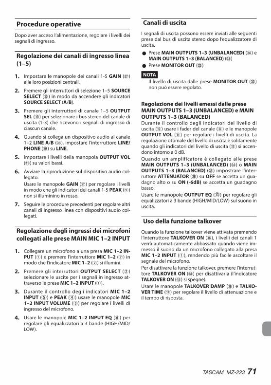
TASCAM MZ-223 71
Procedure operativeDopo aver acceso l’alimentazione, regolare i livelli dei segnali di ingresso.
Regolazione dei canali di ingresso linea (1–5)
1. Impostare le manopole dei canali 1-5 GAIN (j) alle loro posizioni centrali.
2. Premere gli interruttori di selezione 1–5 SOURCE SELECT (0) in modo da accendere gli indicatori SOURCE SELECT (A/B).
3. Premere gli interruttori di canale 1–5 OUTPUT SEL (o) per selezionare i bus stereo del canale di uscita (1-3) che ricevono i segnali di ingresso di ciascun canale.
4. Quando si collega un dispositivo audio al canale 1–2 LINE A/B (b), impostare l’interruttore LINE/PHONE (l) su LINE.
5. Impostare i livelli della manopola OUTPUT VOL (q) su valori bassi.
6. Avviare la riproduzione sul dispositivo audio col-legato.Usare le manopole GAIN (j) per regolare i livelli in modo che gli indicatori dei canali 1-5 PEAK (9) non si illuminino in rosso.
7. Seguire le procedure precedenti per regolare altri canali di ingresso linea con dispositivi audio col-legati.
Regolazione degli ingressi dei microfoni collegati alle prese MAIN MIC 1–2 INPUT
1. Collegare un microfono a una presa MIC 1–2 IN-PUT (1) e premere l’interruttore MIC 1–2 (7) in modo che l’indicatore MIC 1–2 (7) si illumini.
2. Premere gli interruttori OUTPUT SELECT (2) selezionare le uscite per i segnali in ingresso at-traverso le prese MIC 1–2 INPUT (1).
3. Durante il controllo degli indicatori MIC 1–2 INPUT (5) e PEAK (4) usare le manopole MIC 1–2 INPUT VOLUME (3) per regolare i livelli di ingresso del microfono.
4. Usare le manopole MIC 1–2 INPUT EQ (6) per regolare gli equalizzatori a 3 bande (HIGH/MID/LOW).
Canali di uscita
I segnali di uscita possono essere inviati alle seguenti prese dal bus di uscita stereo dopo l’equalizzatore di uscita.
0 Prese MAIN OUTPUTS 1–3 (UNBALANCED) (v) e MAIN OUTPUTS 1–3 (BALANCED) (c)
0 Prese MONITOR OUT (x)
NOTAIl livello di uscita dalle prese MONITOR OUT (x) non può essere regolato.
Regolazione dei livelli emessi dalle prese MAIN OUTPUTS 1–3 (UNBALANCED) e MAIN OUTPUTS 1–3 (BALANCED) Durante il controllo degli indicatori del livello di uscita (w) usare i fader del canale (8) e le manopole OUTPUT VOL (q) per regolare i livelli di uscita. La regolazione ottimale del livello di uscita è solitamente quando gli indicatori del livello di uscita (w) si accen-dono intorno a 0 dB.Quando un amplificatore è collegato alle prese MAIN OUTPUTS 1–3 (UNBALANCED) (v) o MAIN OUTPUTS 1–3 (BALANCED) (c) impostrare l’inter-ruttore ATTENUATOR (h) su OFF se accetta un gua-dagno alto o su ON (-6dB) se accetta un guadagno basso.Usare le manopole OUTPUT EQ (e) per regolare gli equalizzatori a 3 bande (HIGH/MID/LOW) sul suono in uscita.
Uso della funzione talkover
Quando la funzione talkover viene attivata premendo l’interruttore TALKOVER ON (i), i livelli dei canali 1 verrà automaticamente abbassato quando viene im-messo il suono da un microfono collegato alla presa MIC 1–2 INPUT (1), rendendo più facile ascoltare il segnale del microfono.Per disattivare la funzione talkover, premere l’interrut-tore TALKOVER ON (i) per disattivarla (l’indicatore TALKOVER ON (i) si spegne).Usare le manopole TALKOVER DAMP (y) e TALKO-VER TIME (u) per regolare il livello di attenuazione e il tempo di risposta.
72 TASCAM MZ-223
Ascolto dei segnali pre-fader dei canali
Premendo gli interruttori PFL (p) dei canali per ac-cenderli, è possibile abilitare il monitoraggio in cuffia dei singoli canali 1-5, anche quando i loro fader (8) sono impostati ai valori minimi.
1. Premere gli interruttori PFL (p) in modo da accendere il relativo indicatore PFL e ruotare la manopola MIXING (d) su PFL.Per monitorare il segnale prima che venga invia-to al bus di uscita stereo, ruotare la manopola MIXING (d) su MONITOR.
2. Usare la manopola PHONES VOLUME (a) per regolare il livello di uscita del monitoraggio.
Risoluzione dei problemiSe l’unità non funziona correttamente, controllare le seguenti voci prima di chiamare l’assistenza. Se non si riesce ancora a risolvere il problema rivol-gersi al rivenditore presso cui è stata acquistata l’unità o l’assistenza clienti TASCAM.
L’unità non si accende. 0 Verificare che l’adattatore AC (TASCAM PS-M1524) sia collegato saldamente sia alla presa che alla presa DC.
Il suono non viene emesso dagli altoparlanti collegati tramite le prese MAIN OUTPUTS 1–3.
0 Controllare le impostazioni e il volume dell’ampli-ficatore collegato.
0 Verificare di aver alzato i fader del canale (8). 0 Verificare che la sorgente sonora di ingresso sia collegata correttamente.
Il volume è basso anche quando i fader sono alzati.
0 Verificare che le manopole GAIN (j) dei canali 1-5 siano impostate correttamente.
Il suono è distorto. 0 Verificare che le manopole GAIN (j) dei canali 1-5 siano impostate correttamente.
0 Verificare che l’EQ non sia impostato troppo alto. 0 Verificare che i fader dei canali 1-5 (8) e le mano-pole OUTPUT VOL (q) non siano impostati trop-po alti.
Il suono di un giradischi è strano. 0 Verificare che sia collegato al canale 1–2 LINE A e che l’interruttore LINE/PHONO (l) sia impostato su PHONO.
0 Verificare che il filo di massa del giradischi sia col-legato al connettore | (GND) (k).
Un dispositivo collegato emette un ronzio. 0 Collegare un filo di massa dal telaio metallico del dispositivo collegato al connettore | (GND) (k) di questa unità.
Nessun suono viene emesso dal sistema di monitoraggio collegato alle prese MONITOR OUT.
0 Controllare le impostazioni del sistema di monito-raggio collegato.
0 Verificare che la manopola GAIN dei canali 1-5 (j) e i fader di canale (8) siano alzati.
Nessun suono viene emesso dalle cuffie. 0 Utilizzare gli interruttori MONITOR SELECT (r) per selezionare le uscite.
TASCAM MZ-223 73
Specifiche
Ingressi audio
Prese MIC 1–2 INPUT (BALANCED)Connettori:
XLR-3-31 (1: GND, 2: HOT, 3: COLD)Prese TRS standard da 6,3 mm (1/4 “) (Tip: HOT, Ring: COLD, Sleeve: GND)
Impedenza di ingresso: 33 kΩLivello nominale di ingresso: -65 dBu (manopola VOLUME su MAX)Livello nominale di ingresso: -30 dBu (manopola VOLUME su MIN)
Prese INPUTS: LINE (UNBALANCED)Connettori: prese RCALivello nominale di ingresso: -10 dBVLivello massimo di ingresso: 10 dBVImpedenza di ingresso: 22 kΩ
0 0 dBu=0.775 Vrms, 0 dBV=1 V
Uscite audio
Prese MAIN OUTPUTS (UNBALANCED)Connettori: prese RCALivello nominale di uscita: -10 dBVLivello massimo di uscita: 6 dBVImpedenza di uscita: 200 Ω
Prese MAIN OUTPUTS (BALANCED)Connettori: XLR-3-32 (1: GND, 2: HOT, 3: COLD)Livello nominale di uscita: 4 dBuLivello massimo di uscita: 24 dBuImpedenza di uscita: 200 Ω
Prese MONITOR OUTConnettori: prese RCALivello nominale di uscita: -16 dBVLivello massimo di uscita: 0 dBVImpedenza di uscita: 200 Ω
Presa PHONESConnettori: stereo standard da 6,3mm (1/4 “)Potenza massima: 50 mW + 50 mW (nel carico di 32 Ω)
0 0 dBu=0.775 Vrms, 0 dBV=1 V
Prestazioni audio
Risposta in frequenza20 Hz–20 kHz (da INPUTS LINE a MAIN OUTPUTS).
Distorsione0,03% o inferiore (da INPUTS LINE a MAIN OUTPUTS).
Rapporto S/N80 dB o più (da INPUTS LINE a MAIN OUTPUTS).
Diafonia65 dB o più (da INPUTS LINE a MAIN OUTPUTS).
Generali
AlimentazioneAdattatore AC dedicato (PS-M1524)Tensione di ingresso: AC 100-240 V ~ , 50/60 HzVoltaggio in uscita: DC 15V Corrente di uscita: 2,4 A
Consumo35 W
Dimensioni482,0 × 88,0 × 93,2 mm (larghezza × altezza × profondità, sporgenze inclu-se)
Peso2,5 kg
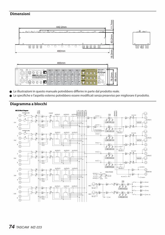
74 TASCAM MZ-223
Dimensioni
465mm
482mm
76.2mm
18.3mm
63.2mm
11.7mm
442.2mm
88.0mm
0 Le illustrazioni in questo manuale potrebbero differire in parte dal prodotto reale. 0 Le specifiche e l’aspetto esterno potrebbero essere modificati senza preavviso per migliorare il prodotto.
Diagramma a blocchi
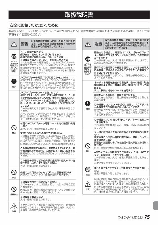
TASCAM MZ-223 75
安全にお使いいただくために製品を安全に正しくお使いいただき、あなたや他の人々への危害や財産への損害を未然に防止するために、以下の注意事項をよくお読みください。
V 警告以下の内容を無視して誤った取り扱いをすると、人が死亡または重傷を負う可能性が想定される内容を示しています。
PACアダプターの電源プラグをコンセントから抜く
万一、異常が起きたら煙が出た、変なにおいや音がするときは機器の内部に異物や水などが入ったときはこの機器を落とした、カバーを破損したときはすぐに機器本体の電源を切り、必ずACアダプターの電源プラグをコンセントから抜いてください。異常状態のまま使用すると、火災・感電の原因となります。販売店またはティアック修理センター(巻末に記載)に修理をご依頼ください。
N指示
ACアダプターの電源プラグにほこりをためないACアダプターの電源プラグとコンセントの間にゴミやほこりが付着すると、火災・感電の原因となります。定期的(年1回くらい)にACアダプターの電源プラグを抜いて、乾いた布でゴミやほこりを取り除いてください。
=禁止
ACアダプターのコードを傷つけないACアダプターのコードの上に重い物をのせたり、コードを壁や棚との間に挟み込んだり、本機の下敷きにしないACアダプターのコードを加工したり、無理に曲げたり、ねじったり、引っ張ったり、熱器具に近づけて加熱したりしないコードが傷んだまま使用すると火災・感電の原因となります。万一、ACアダプターのコードが破損したら(芯線の露出、断線など)、販売店またはティアック修理センター(巻末に記載)をご依頼ください。
付属のACアダプターや電源コードを他の機器に使用しない故障、火災、感電の原因となります。
交流100ボルト以外の電圧で使用しないこの機器を使用できるのは日本国内のみです。表示された電源電圧(交流100ボルト)以外の電圧で使用しないでください。また、船舶などの直流(DC)電源には接続しないでください。火災・感電の原因となります。
この機器を設置する場合は、放熱をよくするために、壁や他の機器との間は少し(20cm以上)離して設置する隙間を空けないと内部に熱がこもり、火災の原因となります。
この機器の隙間などから内部に金属類や燃えやすい物などを差し込む、または落とさない火災・感電の原因となります。
C禁止
機器の上に花びんや水などが入った容器を置かない内部に水が入ると火災・感電の原因となります。
Y分解禁止
この機器のカバーは絶対に外さないカバーを外す、または改造すると、火災・感電の原因となります。内部の点検・修理は販売店またはティアック修理センター(巻末に記載)にご依頼ください。
この機器を改造しない火災・感電の原因となります。
注意
イヤホンやヘッドホンからの過度の音圧は、聴覚障害の原因となります。聴覚障害の可能性を防ぐために、長時間,高音量で聴かないでください。
V 注意以下の内容を無視して誤った取り扱いをすると、人が傷害を負う可能性が想定される内容および物的損害のみの発生が想定される内容を示しています。
PACアダプターの電源プラグをコンセントから抜く
移動させる場合は、電源をオフにし、必ずACアダプターの電源プラグをコンセントから抜き、外部の接続コードを外すコードが傷つき、火災・感電の原因や、引っ掛けてけがの原因になることがあります。
旅行などで長期間この機器を使用しないときやお手入れの際は、安全のため必ずACアダプターの電源プラグをコンセントから抜く通電状態の放置やお手入れは、漏電や感電の原因となることがあります。
N指示
オーディオ機器を接続する場合は、各々の機器の取扱説明書をよく読み、電源を切り、説明にしたがって接続するまた、接続は指定のコードを使用する
電源を入れる前には、音量を最小にする突然大きな音が出て、聴力障害などの原因となることがあります。
この機器はコンセントの近くに設置し、ACアダプターの電源プラグは簡単に手が届くようにする異常が起きた場合は、すぐにACアダプターの電源プラグをコンセントから抜いて、完全に電源が切れるようにしてください。
この機器には、付属の専用ACアダプターや電源コードを使用するそれ以外の物を使用すると、故障、火災、感電の原因となります。
=禁止
ぐらついた台の上や傾いた所など不安定な場所に置かない湿気やほこりの多い場所に置かない。風呂、シャワー室では使用しない調理台や加湿器のそばなど油煙や湯気が当たる場所に置かない火災・感電やけがの原因となることがあります。
ACアダプターの電源プラグを抜くときは、ACアダプターの電源コードを引っ張らないコードが傷つき、火災・感電の原因となることがあります。必ずプラグを持って抜いてください。
O禁止
濡れた手でACアダプターの電源プラグを抜き差ししない感電の原因となることがあります。
V注意
5年に1度は、機器内部の掃除を販売店またはティアック修理センター(巻末に記載)にご相談ください。内部にほこりがたまったまま、長い間掃除をしないと火災や故障の原因となることがあります。特に、湿気の多くなる梅雨期の前に行うと、より効果的です。なお、掃除費用については、ご相談ください。
取扱説明書
76 TASCAM MZ-223
このたびは、TASCAM MZ−223をお買い上げいただきまして、誠にありがとうございます。ご使用になる前に、この取扱説明書をよくお読みになり、正しい取り扱い方法をご理解いただいた上で、末永くご愛用くださいますようお願い申しあげます。お読みになったあとは、いつでも見られる所に保管してください。また取扱説明書は、TASCAMのウェブサイト(https://tascam.jp/jp/)からダウンロードすることができます。
本機の概要 0入力チャンネルを任意のゾーン出力にルーティング可能なラックマウントタイプのミキサー 0マイク入力とライン入力のミックス出力が可能 0BGMの音量をマイクの音量にあわせて自動的に下げるトークオーバー機能を搭載 0ゲインコントロール、シグナルLED、フェーダーを備えた5つの入力チャンネル 0ボリュームコントロール、LEDレベルメーター、3バンドイコライザーを備えた2系統のマイク入力 0ボリュームコントロール、LEDレベルメーター、3バンドイコライザーを備えた3つのゾーンメイン出力 0ボリュームコントロールが可能なヘッドホン出力で、任意の入力チャンネルのプリフェーダーモニタリングや、メイン出力のモニタリングが可能 0メイン出力から独立したモニター出力 02Uラックマウントサイズ
本製品の構成本製品の構成は、以下の通りです。開梱は本体に損傷を与えないよう慎重に行ってください。梱包箱と梱包材は、後日輸送するときのために保管しておいてください。付属品が不足している場合や輸送中の損傷が見られる場合は、お買い上げの販売店にお問い合わせください。
0本体 ................................................................................x1 0ACアダプター(TASCAM PS-M1524) ...............x1 0ACアダプター用コード
(JAPAN USA/EUROPE) ........................................x2 0ラックマウントビスキット..........................................x1 0取扱説明書(本書、保証書付き) ................................x1注意
本機には必ず、付属の専用ACアダプター(TASCAM PS-M1524)とACアダプター用コードをご使用ください。また、付属のACアダプターを他の機器に使用しないでください。故障、火災、感電の原因となります。
目次安全にお使いいただくために.......................................... 75本機の概要......................................................................... 76本製品の構成..................................................................... 76本書の表記......................................................................... 77設置上の注意..................................................................... 77結露について..................................................................... 77製品のお手入れ................................................................. 77ユーザー登録について...................................................... 77アフターサービス.............................................................. 77各部の名称......................................................................... 78
フロントパネル ............................................................. 78リアパネル ..................................................................... 79準備..................................................................................... 80
電源を接続する ............................................................. 80コードの固定方法.......................................................... 80外部機器を接続する ...................................................... 80電源をオンにする/オフにする .................................. 82操作手順............................................................................. 83
ライン入力チャンネルの調節(チャンネル1-5) ...... 83MAIN MIC 1-2 INPUT端子に接続した マイク入力の調節.......................................................... 83出力チャンネルについて .............................................. 83トークオーバー機能を使う .......................................... 83チャンネルのプリフェーダー信号音を聴く ............... 83トラブルシューティング.................................................. 84仕様..................................................................................... 84
オーディオ入力定格 ...................................................... 84オーディオ出力定格 ...................................................... 84オーディオ性能 ............................................................. 84一般 ................................................................................. 85寸法図 ............................................................................. 85ブロックダイヤグラム .................................................. 86
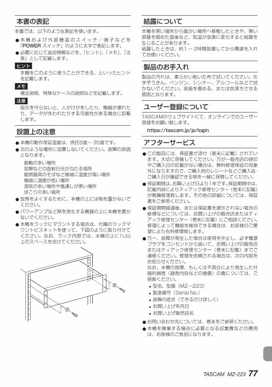
TASCAM MZ-223 77
本書の表記本書では、以下のような表記を使います。
0本 機 お よ び 外 部 機 器 の ス イ ッ チ / 端 子 な ど を「POWER スイッチ」のように太字で表記します。 0必要に応じて追加情報などを、「ヒント」、「メモ」、「注意」として記載します。ヒント
本機をこのように使うことができる、といったヒントを記載します。メモ
補足説明、特殊なケースの説明などを記載します。注意
指示を守らないと、人がけがをしたり、機器が壊れたり、データが失われたりする可能性がある場合に記載します。
設置上の注意 0本機の動作保証温度は、摂氏5度〜 35度です。 0次のような場所に設置しないてください。故障の原因となります。
振動の多い場所窓際などの直射日光が当たる場所暖房器具のそばなど極端に温度が高い場所極端に温度が低い場所湿気の多い場所や風通しが悪い場所ほこりの多い場所
0放熱をよくするために、本機の上には物を置かないでください。 0パワーアンプなど熱を発生する機器の上に本機を置かないでください。 0本機をラックにマウントする場合は、付属のラックマウントビスキットを使って、下図のように取り付けてください。なお、ラック内部では、本機の上に1U以上のスペースを空けてください。
結露について本機を寒い場所から暖かい場所へ移動したときや、寒い部屋を暖めた直後など、気温が急激に変化すると結露を生じることがあります。結露したときは、約1 〜 2時間放置してから電源を入れてお使いください。
製品のお手入れ製品の汚れは、柔らかい乾いた布で拭いてください。化学ぞうきん、ベンジン、シンナー、アルコールなどで拭かないでください。表面を傷める、または色落ちさせる原因となります。
ユーザー登録についてTASCAMのウェブサイトにて、オンラインでのユーザー登録をお願い致します。https://tascam.jp/jp/login
アフターサービス 0この製品には、保証書が添付(巻末に記載)されています。大切に保管してください。万が一販売店の捺印やご購入日の記載がない場合は、無料修理保証の対象外になりますので、ご購入時のレシートなどご購入店・ご購入日が確認できる物を一緒に保管してください。 0保証期間は、お買い上げ日より1年です。保証期間中は、記載内容によりティアック修理センター(巻末に記載)が無償修理致します。その他の詳細については、保証書をご参照ください。 0保証期間経過後、または保証書を提示されない場合の修理などについては、お買い上げの販売店またはティアック修理センター(巻末に記載)にご相談ください。修理によって機能を維持できる場合は、お客様のご要望により有料修理致します。 0万一、故障が発生した場合は使用を中止し、必ず電源プラグをコンセントから抜いて、お買い上げの販売店またはティアック修理センター(巻末に記載)までご連絡ください。修理を依頼される場合は、次の内容をお知らせください。なお、本機の故障、もしくは不具合により発生した付随的損害(録音内容などの補償)の責については、ご容赦ください。
i 型名、型番(MZ−223) i 製造番号(Serial No.) i 故障の症状(できるだけ詳しく) i お買い上げ年月日 i お買い上げ販売店名
0お問い合わせ先については、巻末をご参照ください。 0本機を廃棄する場合に必要となる収集費などの費用は、お客様のご負担になります。
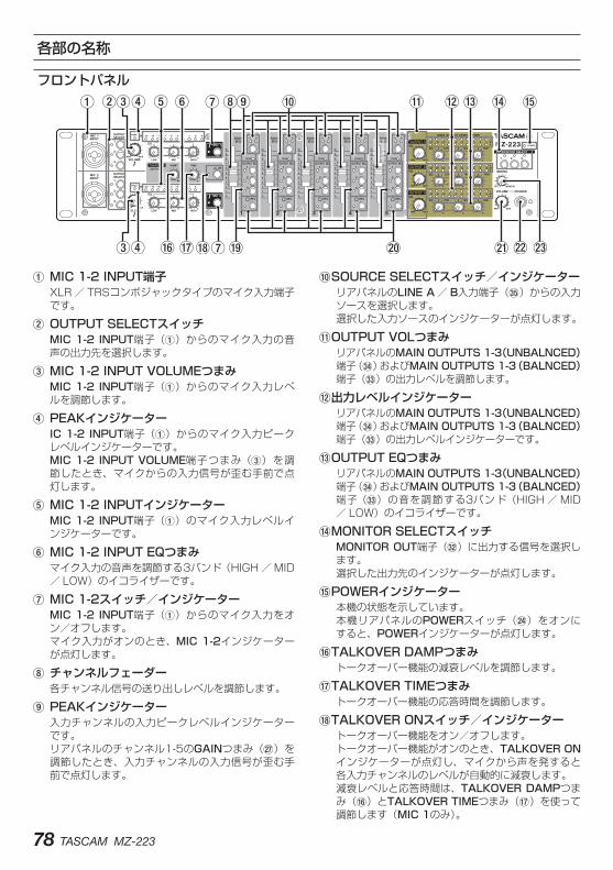
78 TASCAM MZ-223
各部の名称
フロントパネル
1.MIC.1-2.INPUT端子XLR / TRSコンボジャックタイプのマイク入力端子です。
2.OUTPUT.SELECTスイッチMIC.1-2.INPUT端子(1)からのマイク入力の音声の出力先を選択します。
3.MIC.1-2.INPUT.VOLUMEつまみMIC.1-2.INPUT端子(1)からのマイク入力レベルを調節します。
4.PEAKインジケーターIC.1-2.INPUT端子(1)からのマイク入力ピークレベルインジケーターです。MIC.1-2.INPUT.VOLUME端子つまみ(3)を調節したとき、マイクからの入力信号が歪む手前で点灯します。
5.MIC.1-2.INPUTインジケーターMIC.1-2.INPUT端子(1)のマイク入力レベルインジケーターです。
6.MIC.1-2.INPUT.EQつまみマイク入力の音声を調節する3バンド(HIGH / MID/ LOW)のイコライザーです。
7.MIC.1-2スイッチ/インジケーターMIC.1-2.INPUT端子(1)からのマイク入力をオン/オフします。マイク入力がオンのとき、MIC.1-2インジケーターが点灯します。
8.チャンネルフェーダー各チャンネル信号の送り出しレベルを調節します。
9.PEAKインジケーター入力チャンネルの入力ピークレベルインジケーターです。リアパネルのチャンネル1-5のGAINつまみ(j)を調節したとき、入力チャンネルの入力信号が歪む手前で点灯します。
0SOURCE.SELECTスイッチ/インジケーターリアパネルのLINE.A/ B入力端子(b)からの入力ソースを選択します。選択した入力ソースのインジケーターが点灯します。
qOUTPUT.VOLつまみリアパネルのMAIN.OUTPUTS.1-3(UNBALNCED)端子(v)およびMAIN.OUTPUTS.1-3(BALNCED)端子(c)の出力レベルを調節します。
w出力レベルインジケーターリアパネルのMAIN.OUTPUTS.1-3(UNBALNCED)端子(v)およびMAIN.OUTPUTS.1-3(BALNCED)端子(c)の出力レベルインジケーターです。
eOUTPUT.EQつまみリアパネルのMAIN.OUTPUTS.1-3(UNBALNCED)端子(v)およびMAIN.OUTPUTS.1-3(BALNCED)端子(c)の音を調節する3バンド(HIGH / MID/ LOW)のイコライザーです。
rMONITOR.SELECTスイッチMONITOR.OUT端子(x)に出力する信号を選択します。選択した出力先のインジケーターが点灯します。
tPOWERインジケーター本機の状態を示しています。本機リアパネルのPOWERスイッチ(f)をオンにすると、POWERインジケーターが点灯します。
yTALKOVER.DAMPつまみトークオーバー機能の減衰レベルを調節します。
uTALKOVER.TIMEつまみトークオーバー機能の応答時間を調節します。
iTALKOVER.ONスイッチ/インジケータートークオーバー機能をオン/オフします。トークオーバー機能がオンのとき、TALKOVER.ONインジケーターが点灯し、マイクから声を発すると各入力チャンネルのレベルが自動的に減衰します。減衰レベルと応答時間は、TALKOVER.DAMPつまみ(y)とTALKOVER.TIMEつまみ(u)を使って調節します(MIC.1のみ)。
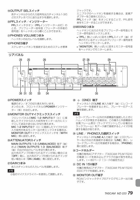
TASCAM MZ-223 79
oOUTPUT.SELスイッチ各チャンネルからの入力信号を出力チャンネル1-3のどのステレオバスに送り出すかを選択します。
pPFLスイッチ/インジケーターPFLスイッチがオン(PFLインジケーター点灯)のとき、プリフェーダー信号音(フェーダーの手前の信号音)をヘッドホンから聴くことができます。
aPHONES.VOLUMEつまみヘッドホンの出力レベルを調節します。
sPHONES端子ステレオヘッドホンを接続するためのステレオ標準
ジャックです。ミニプラグのヘッドホンを接続する場合は、変換アダプターをご使用ください。PFLスイッチ(p)をオンにすることで、PFL信号音をモニターすることができます。
dMIXINGつまみヘッドホンに出力されるプリフェーダー信号音とモニター信号音をミックスします。 i「PFL」側いっぱいに回すとPFLスイッチ(p)が押されているチャンネルのプリフェーダー信号音をヘッドホンでモニターします。
i「MONITOR」側いっぱいに回すとモニター信号音をヘッドホンでモニターします。
リアパネル
fPOWERスイッチ電源のオン/オフの切り換えを行います。オンのとき、フロントパネルのPOWERインジケーター(t)が点灯します。
gMONITOR.OUTマイクミックススイッチフロントパネルのMIC.1-2.INPUT端子(1)に接続したマイクからの入力信号をモニター出力にミックスして送るか送らないか切り換えます。MIC.1-2.INPUT端子(1)に接続したマイクからの入力信号があるモニター出力をミックスする場合は、MONITOR.OUTマイクミックススイッチを「WITH.MIC」側に設定します。
hATTENUATORスイッチMAIN.OUTPUTS.1-3(UNBALNCED)端子(v)およびMAIN.OUTPUTS.1-3(BALNCED)端子
(c)の出力の出力レベルを切り換えます。出力先のアンプの受けられるゲインが高い場合には
「OFF」側に、出力先のアンプの受けられるゲインが低い場合には「ON.(-6dB)」側に設定します。
jGAINつまみ各入力チャンネルの入力レベルを調節します。
メモ小型のマイナスドライバーを使用して調節します。
k|(GND)端子チャンネル1-2のLINE.A入力端子(b)にレコードプレーヤーを接続するときに、プレーヤーのアース線を接続します。
メモレコードプレーヤー以外の外部機器を接続したときにハムノイズが発生する場合は、この端子と外部機器の金属フレーム部分(ラックマウントしている場合はラックフレーム)をアース線で接続するとノイズが低減する場合があります。
l.LINE / PHONO入力選択スイッチチャンネル1-2のLINE A入力端子(b)にCDプレーヤーなどの出力を接続する場合は「LINE」側に、レコードプレーヤー出力を接続する場合は、「PHONO」側に設定します。
;コードホルダー付属の専用ACアダプター(TASCAM PS-M1524)の電源コードを挟み込んでプラグの抜け落ちを防止します。(→ 80ページ「コードの固定方法」)
z.DC.IN.15V端子付属の専用ACアダプター(TASCAM PS-M1524)のDCプラグを接続します。
x.MONITOR.OUT端子RCAピンジャックタイプのアナログモニター出力端子です。
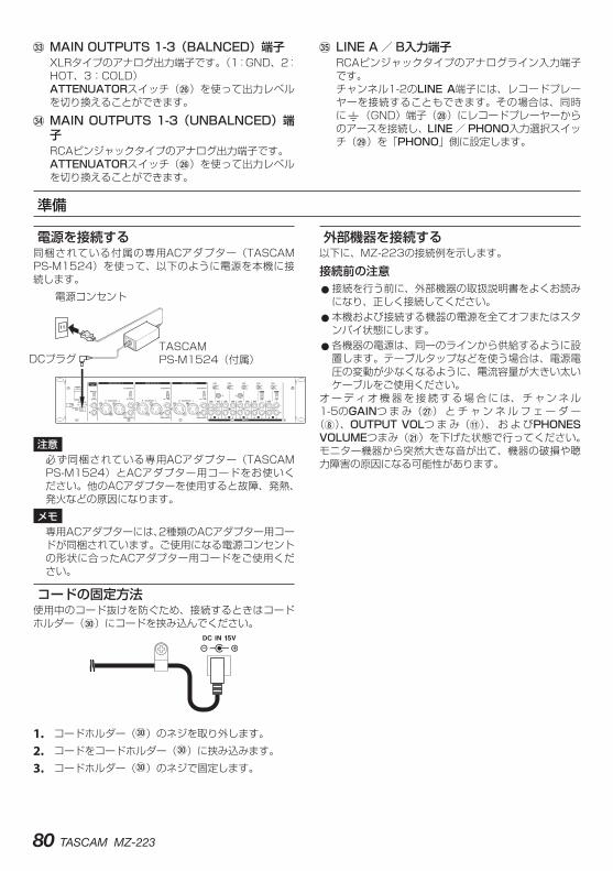
80 TASCAM MZ-223
c.MAIN.OUTPUTS.1-3(BALNCED)端子XLRタイプのアナログ出力端子です。(1:GND、2:HOT、3:COLD)ATTENUATORスイッチ(h)を使って出力レベルを切り換えることができます。
v.MAIN.OUTPUTS.1-3(UNBALNCED)端子RCAピンジャックタイプのアナログ出力端子です。ATTENUATORスイッチ(h)を使って出力レベルを切り換えることができます。
b.LINE.A / B入力端子RCAピンジャックタイプのアナログライン入力端子です。チャンネル1-2のLINE A端子には、レコードプレーヤーを接続することもできます。その場合は、同時に|(GND)端子(k)にレコードプレーヤーからのアースを接続し、LINE / PHONO入力選択スイッチ(l)を「PHONO」側に設定します。
準備
電源を接続する同梱されている付属の専用ACアダプター(TASCAM PS-M1524)を使って、以下のように電源を本機に接続します。
電源コンセント
DCプラグTASCAMPS-M1524(付属)
注意必ず同梱されている専用ACアダプター(TASCAM PS-M1524)とACアダプター用コードをお使いください。他のACアダプターを使用すると故障、発熱、発火などの原因になります。メモ
専用ACアダプターには、2種類のACアダプター用コードが同梱されています。ご使用になる電源コンセントの形状に合ったACアダプター用コードをご使用ください。
コードの固定方法使用中のコード抜けを防ぐため、接続するときはコードホルダー(;)にコードを挟み込んでください。
1. コードホルダー(;)のネジを取り外します。2. コードをコードホルダー(;)に挟み込みます。3. コードホルダー(;)のネジで固定します。
外部機器を接続する以下に、MZ-223の接続例を示します。
接続前の注意 0接続を行う前に、外部機器の取扱説明書をよくお読みになり、正しく接続してください。 0本機および接続する機器の電源を全てオフまたはスタンバイ状態にします。 0各機器の電源は、同一のラインから供給するように設置します。テーブルタップなどを使う場合は、電源電圧の変動が少なくなるように、電流容量が大きい太いケーブルをご使用ください。
オ ー デ ィ オ 機 器 を 接 続 す る 場 合 に は、 チ ャ ン ネ ル1-5のGAINつ ま み(j) と チ ャ ン ネ ル フ ェ ー ダ ー
(8)、OUTPUT.VOLつ ま み(q)、 お よ びPHONES.VOLUMEつまみ(a)を下げた状態で行ってください。モニター機器から突然大きな音が出て、機器の破損や聴力障害の原因になる可能性があります。
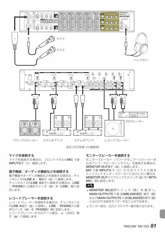
TASCAM MZ-223 81
パワードスピーカー
ヘッドホン
CDプレーヤー
レコードプレーヤー
マイク
マイク
ステレオアンプステレオアンプ
[MZ-223を使った接続例]
マイクを接続するマイクを接続する場合は、フロントパネルのMIC.1-2.INPUT端子(1)接続します。
電子機器/オーディオ機器などを接続する電子機器やオーディオ機器などを接続する場合は、チャンネル1-5のLINE.A/ B端子(b)に接続します。チャンネル1-2のLINE.A端子に接続する場合は、LINE/ PHONO入力選択スイッチ(l)を「LINE」側に設定します。
レコードプレーヤーを接続するレコードプレーヤーを接続する場合は、チャンネル1-2のLINE.A端子(b)に接続し、LINE / PHONO入力選択スイッチ(l)を「PHONO」側に設定します。レコードプレーヤーからのアース線は、|(GND)端子(k)に接続します。
モニタースピーカーを接続するモニタースピーカー(パワードモニタースピーカーまたはアンプ/スピーカーシステム)を接続する場合は、MONITOR.OUT端子(x)に接続します。MIC.1-2.INPUT端 子(1) か ら の マ イ ク 入 力 音 をミックスしてモニタースピーカーに出力したい場合は、MONITOR.OUTマイクミックススイッチ(g)を「WITH.MIC」側に設定します。メモ.i MONITOR.SELECTス イ ッ チ(r) を 選 択 し、MAIN.OUTPUTS.1-3(UNBLANCED)端子(v)およびMAIN.OUTPUTS.1-3(BLANCED)端子(c)に出力される前をモニターすることができます。
i モニター音は、出力イコライザー後の音になります。
82 TASCAM MZ-223
ヘッドホンを接続するヘッドホンは、PHONES端子(s、ステレオ標準ジャック)に接続します。入力チャンネルのプリフェーダー信号音、またはステレオ出力バスに送られる前の音をモニターすることができます。モニターしたい出力をMONITOR.SELECTスイッチ
(r)で選んでください。注意
ヘッドホンを接続する前には、PHONES.VOLUME つまみ(a)で音量を最小にしてください。突然大きな音が出て、聴力障害などの原因となることがあります。メモ
ヘッドホンからの音は、出力イコライザー後の音になります。
外部ステレオアンプに接続するステレオアンプに接続する場合は、MAIN.OUTPUTS.1-3(UNBLANCED) 端 子(v) ま た はMAIN.OUTPUTS.1-3(BLANCED)端子(c)に接続します。ヒント i メインとサブ、メインとモニター、あるいはフロントとリアなどのように2組以上のアンプ/スピーカーシステムを接続する場合は、MAIN.OUTPUTS.1-3(UNBLANCED) 端 子(v) ま た はMAIN.OUTPUTS.1-3(BLANCED)端子(c)を使うと便利です。また、出力は各端子とも独立しており、それぞれ専用の出力つまみを装備していますので、本機で個別に出力レベルの設定を行うことができます。
i MONITOR.OUT端子(x)をレコーダーに接続することにより、アンプ/スピーカーシステムへの出力信号を録音することができます。
電源をオンにする/オフにする注意 i 本機の電源のオン/オフは、本機に接続しているモニターシステムのボリュームを絞った状態で行ってください。
i 電源のオン/オフ時にヘッドホンを装着しないでください。ノイズによっては、スピーカーや聴覚を損傷する恐れがあります。
電源を入れる前に1. 本機のフロントパネル上の設定を以下のようにしま
す。
i EQつまみ w 中央 i 他のつまみ w 左いっぱい(MIN側) i フェーダー w 一番下 i スイッチ類 w オフ(押し込まない状態)
2. 本機に接続している音源の出力レベル、アンプの入力レベルを最小にします。
電源をオンにする1. 本機リアパネルのPOWERスイッチ(f)を使って
本機の電源をオンにします。フロントパネルのPOWERインジケーター(t)が点灯します。
2. 接続した入力音源機器の電源をオンにします。3. 最後にアンプの電源をオンにします。
電源をオフにする電源をオフにするときは、上記と反対の順序でオフにします。正しい順序で行わないと、クリックノイズなどで機器を破損する恐れがあります。
TASCAM MZ-223 83
操作手順電源を入れたあと、各入力信号のレベルを調節します。
ライン入力チャンネルの調節(チャンネル1-5)
1. チャンネル1 〜 5のGAINつまみ(j)を中央に設定します。
2. チャンネル1 〜 5のSOURCE.SELECTスイッチ(0)を押して、選択したSOURCE.SELECTスイッチのインジケーター(A/ Bインジケーター)を点灯させます。
3. チャンネル1 〜 5のOUTPUT.SELスイッチ(o)を押して、入力信号を出力チャンネル1-3のどのステレオバスに送り出すかを選択します。
4. オーディオ機器をチャンネル1 〜 2のLINE.A/ B入力端子(b)に接続した場合は、LINE/PHONE入力選択スイッチ(l)を「LINE」側に設定します。
5. OUTPUT.VOLつまみ(q)を、低い音量に調節します。
6. 接続したオーディオ機器を再生します。チャンネル1 〜 5のPEAKインジケーター(9)の赤色が点灯しないように、GAINつまみ(j)を使って入力レベルを調節します。
7. 接続している別のライン入力チャンネルについても、上述の手順で調節します。
MAIN.MIC.1-2.INPUT端子に接続したマイク入力の調節
1. MIC.1-2.INPUT端 子(1) に マ イ ク を 接 続 し、MIC.1-2スイッチ(7)を押してMIC.1-2インジケーター(7)を点灯させます。
2. OUTPUT.SELECTスイッチ(2)を押して、MIC.1-2.INPUT端子(1)からのマイク入力の音声の出力先を選択します。
3. MIC.1-2.INPUTインジケーター(5)とPEAKインジケーター(4)を確認しながら、MIC.1-2.INPUT.VOLUMEつまみ(3)を使ってマイクからの入力レベルを調節します。
4. MIC.1-2.INPUT.EQつまみ(6)を使って、マイクからの音声を3バンド(HIGH / MID / LOW)イコライザーを調節します。
出力チャンネルについて以下の端子にステレオ出力バスから出力イコライザー経由で出力信号が送られます。
0MAIN.OUTPUTS.1-3(UNBLANCED)端子(v)およびMAIN.OUTPUTS.1-3(BLANCED)端子(c) 0MONITOR.OUT端子(x)メモMONITOR.OUT端子(x)の出力レベルの調節はできません。
MAIN.OUTPUTS.1-3(UNBLANCED)端子およびMAIN.OUTPUTS.1-3(BLANCED)端子の調節出力レベルインジケーター(w)を確認しながら、チャンネルフェーダー(8)とOUTPUT.VOLつまみ(q)を使って出力レベルを調節します。通常、出力レベルインジケーター(w)の0dBあたりが点灯していれば、出力レベルの調節は最適の状態です。MAIN.OUTPUTS.1-3(UNBLANCED) 端 子(v)またはMAIN.OUTPUTS.1-3(BLANCED)端子(c)に接続した出力先のアンプの受けられるゲインが高い場合にはATTENUATORスイッチ(h)を「OFF」側に、出力先のアンプの受けられるゲインが低い場合には「ON.(-6dB)」側に設定します。OUTPUT.EQつまみ(e)を使って、出力する音声を3バンド(HIGH / MID / LOW)イコライザーを調節します。
トークオーバー機能を使うTALKOVER.ONスイッチ(i)を押してトークオーバー機能をオンにしマイクから声を発すると、チャンネル1のレベルを自動的に減衰し、MIC.1-2.INPUT端子(1)に接続したマイクからの音声を聴きやすくすることができます。トークオーバー機能をオフにするには、TALKOVER.ONス イ ッ チ(i) を 押 し て ロ ッ ク を 解 除 し ま す
(TALKOVER.ONインジケーター(i)が消灯)。減衰レベルと応答時間は、TALKOVER.DAMPつまみ
(y)とTALKOVER.TIMEつまみ(u)を使って調節できます。
チャンネルのプリフェーダー信号音を聴くチャンネルのPFLスイッチ(p)をオンにすると、チャンネルフェーダー(8)を最小値に設定していても、ヘッドホンでチャンネル1からチャンネル5までを個々にモニターすることができます。
1. PFLスイッチ(p)を押してPFLインジケーターを点灯し、MIXINGつまみ(d)を「PFL」側にします。ステレオ出力バスに送られる前の信号をモニターするには、MIXINGつまみ(d)を「MONITOR」側にします。
2. モニター出力のレベルをPHONES.VOLUMEつまみ(a)で調節します。
84 TASCAM MZ-223
トラブルシューティング本機の動作がおかしいときは、修理を依頼する前にもう一度、下記の点検を行ってください。それでも改善しないときは、お買い上げの販売店またはティアック修理センター(巻末に記載)にご連絡ください。
電源が入らない。 0付属の専用ACアダプター(TASCAM PS-M1524)の電源プラグおよびDCジャックがしっかりと差し込まれていますか?
MAIN.OUTPUTS.1-3端子経由で接続したスピーカーから音が出ない。
0接続しているアンプの設定やボリュームを確認してください。 0チャンネルフェーダー(8)が上がっていますか? 0入力音源が正しく接続されていますか?
フェーダーを上げても音が小さい。 0チャンネル1 〜 5は、GAINつまみ(j)が適切に設定されていますか?
音が歪む。 0チャンネル1 〜 5のGAINつまみ(j)が適切に設定されていますか? 0EQを上げ過ぎていませんか? 0チャンネル1 〜 5のチャンネルフェーダー(8)やOUTPUT.VOLつまみ(q)を上げ過ぎていませんか?
レコードプレーヤーの音がおかしい。 0チ ャ ン ネ ル1-2のLINE.A端 子 に 接 続 し、LINE /PHONO入力選択スイッチ(l)を「PHONO」側にしていますか? 0レコードプレーヤーのアース線が本機の|(GND)端子(k)に接続されていますか?
外部機器からハムノイズが発生する。 0外部機器の金属フレーム部分と本機の|(GND)端子(k)をアース線で接続してみてください。
MONITOR.OUT端子に接続しているモニターシステムから音が出ない。
0外部モニターシステムの設定を確認してください。 0チャンネル1 〜 5のGAINつまみ(j)およびチャンネルフェーダー(8)が上がっていますか?
HEADPHONEから音が出ない 0MONITOR.SELECTスイッチ(r)で出力先を選択してください。
仕様
オーディオ入力定格MIC.1-2.INPUT(BALANCED)端子
コネクター:XLR-3-31(1:GND、2:HOT、3:COLD)φ6.3mm(1/4 ″)TRS標 準 ジ ャ ッ ク(Tip:HOT、Ring:COLD、Sleeve:GND)
入力インピーダンス:33kΩ規定入力レベル: −65dBu
(VOLUMEつまみ「MAX」時)規定入力レベル: −30dBu
(VOLUMEつまみ「MIN」時)
INPUTS.LINE(UNBALANCED)端子コネクター:RCAピンジャック規定入力レベル:−10dBV最大入力レベル:10dBV入力インピーダンス:22kΩ
00dBu=0.775Vrms、0dBV=1V
オーディオ出力定格MAIN.OUTPUTS(UNBALANCED)端子
コネクター:RCAピンジャック規定出力レベル:−10dBV最大出力レベル:6dBV出力インピーダンス:200Ω
MAIN.OUTPUTS(BALANCED)端子コネクター: XLR-3-32
(1:GND、2:HOT、3:COLD)規定出力レベル:4dBu最大出力レベル:24dBu出力インピーダンス:200Ω
MONITOR.OUT端子コネクター:RCAピンジャック規定出力レベル:−16dBV最大出力レベル:0dBV出力インピーダンス:200Ω
PHONES端子コネクター:φ6.3mm(1/4”)ステレオ標準ジャック最大出力:50mW + 50mW(32Ω負荷)
00dBu=0.775Vrms、0dBV=1V
オーディオ性能周波数特性
20Hz 〜 20kHz (INPUTS LINE to MAIN OUTPUTS)
歪率0.03%以下(INPUTS LINE to MAIN OUTPUTS)
S/N比80dB以上(INPUTS LINE to MAIN OUTPUTS)
クロストーク65dB以上(INPUTS LINE to MAIN OUTPUTS)
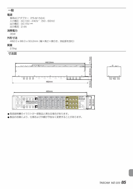
TASCAM MZ-223 85
一般電源
専用ACアダプター(PS-M1524)入力電圧:AC100 - 240V ~(50 - 60Hz)出力電圧:DC15V 出力電流:2.4A
消費電力35W
外形寸法482.0 x 88.0 x 93.2mm (幅×高さ×奥行き、突起部を含む)
質量2.5kg
寸法図
465mm
482mm
76.2mm
18.3mm
63.2mm
11.7mm
442.2mm
88.0mm
0取扱説明書のイラストが一部製品と異なる場合があります。 0製品の改善により、仕様および外観が予告なく変更することがあります。
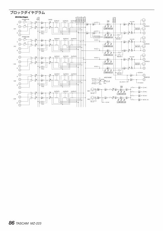
86 TASCAM MZ-223
ブロックダイヤグラム

TASCAM MZ-223 87
88 TASCAM MZ-223
〒206-8530 東京都多摩市落合1-47
この製品の取り扱いなどに関するお問い合わせはタスカム.カスタマーサポート 〒206-8530 東京都多摩市落合1-47
0570-000-809 0携帯電話、またはナビダイヤルがご利用いただけない場合
電話:042-356-9137/ FAX:042-356-9185受付時間は、10:00 〜 12:00 / 13:00 〜 17:00 です。(土・日・祝日・弊社指定休日を除く)
故障・修理や保守についてのお問い合わせはティアック修理センター 〒358-0026 埼玉県入間市小谷田858
0570-000-501 0携帯電話、またはナビダイヤルがご利用いただけない場合
電話:04-2901-1033/ FAX:04-2901-1036受付時間は、9:30 〜 17:00です。(土・日・祝日・弊社指定休日を除く)
■ 住所や電話番号は、予告なく変更する場合があります。あらかじめご了承ください。


< In the United States >This warranty gives you specific legal rights and you may also have other rights which vary from state to state. This warranty is only valid within the country the unit was originally purchased.
WHAT IS AND IS NOT COVEREDExcept as specified below, this warranty covers all defects in materials and workmanship in this product. The following are not covered by the warranty:1. Damage to or deterioration of the external cabinet.2. Damages resulting from accident, misuse, abuse
or neglect.3. Damage resulting from failure to per form
basic daily maintenance and/or calibration or otherwise resulting from failure to follow instructions contained in your owner’s manual.
4. Damage occurring during shipment of the product. (Claims must be presented to the carrier)
5. Damage resulting from repair or attempted re p a i r by a nyo n e o t h e r t h a n T E AC o r a n authorized TASCAM service station.
6. Damage resulting from causes other than product defects, including lack of technical skill, competence, or experience of the user.
7. Damage to any unit which has been altered or on which the serial number has been defaced, modified or is missing.
WHO MAY ENFORCE THE WARRANTYThis warranty may be enforced only by the original purchaser. This warranty is not valid if the product was purchased through an unauthorized dealer.
LENGTH OF WARRANTYAll parts except heads and disk drives are warranted for one (1) year from the date of original purchase. Heads and disk drives are warranted to ninety (90) days from date of original purchase. Labor is warranted for ninety (90) days from date of original purchase.
WHAT WE WILL PAY FORWe will pay all labor and material expenses for items covered by the warranty. Payment of shipping charges is discussed in the next section of this warranty.
HOW YOU CAN GET WARRANTY SERVICEYour unit must be serviced by an authorized TASCAM service station in the United States. (This warranty is not enforceable outside the U.S.) If you are unable to locate an authorized TASCAM service station in your area, please contact us. We either will refer you to an authorized service station or instruct you to return the unit to the factory. Whenever warranty service is required, you must present a copy of the original dated sales receipt from an Authorized TASCAM Dealer.You must pay any shipping charges if it is necessary to ship the product to service. However, if the necessary repairs are covered by the warranty, we will pay return surface shipping charges to any destination within the United States.
LIMITATION OF IMPLIED WARRANTIESAny implied warranties, INCLUDING WARRANTIES OF MERCHANTABILITY AND FITNESS FOR A PARTICULAR PURPOSE, are limited in duration to the length of this warranty.
EXCLUSION OF DAMAGESTEAC’s liability for any defective product is limited to repair or replacement of the product, at TEAC’s option. TEAC shall not be liable for:1. Damages based upon inconvenience, loss of use of
the product, loss of time interrupted operation or commercial loss; or
2. Any other damages, whether incidental, consequential or otherwise.
Some states do not allow limitations on how long an implied warranty lasts and/or do not allow the exclusion or limitation of incidental or consequential damages, so the above limitations and exclusions may not apply to you.
To locate an Authorized Service Center in Your AreaCALL 1-800-447-8322
< Europe >This product is subject to the legal warranty regulations of the country of purchase. In case of a defect or a problem, please contact the dealer where you bought the product.Ce produit est sujet aux réglementations concernant la garantie légale dans le pays d’achat. En cas de défaut ou de problème, veuillez contacter le revendeur chez qui vous avez acheté le produit.D i e s e s G e r ä t u n t e r l i e g t d e n g e s e t z l i c h e n G e w ä h r l e i s t u n g s b e s t i m m u n g e n d e s L a n d e s, i n dem es er worben wurde. Bitte wenden Sie sich im Gewährleistungsfall an den Händler, bei dem sie das Gerät erworben haben.Questo apparecchio è conforme alle norme sulla garanzia vigenti nel rispettivo Paese in cui esso è stato acquistato. Si prega di rivolgersi al proprio commerciante, presso il quale è stato acquistato l’apparecchio, nel caso in cui si voglia richiedere una prestazione in garanzia.Las condiciones de garantía de este aparato están sujetas a las disposiciones legales sobre garantía del país en el que ha sido adquirido. En caso de garantía, debe dirigirse al establecimiento donde adquirió el aparato.
<日本>無料修理規定(持ち込み修理)1. 取扱説明書、本体貼付ラベルなどの注意
書きにしたがった正常な使用状態で保証期間内に故障が発生した場合には、ティアック修理センターが無料修理いたします。
2. 本体の保証期間は、お買い上げの日から1年です。
3. 保証期間内に故障して無料修理を受ける場合は、本書をご提示の上、ティアック修理センターまたはお買い上げの販売店に修理をご依頼ください。商品を送付していただく場合の送付方法については、事前にティアック修理センターにお問い合わせください。
4. ご転居、ご贈答品などでお買い上げの販売店に修理をご依頼になれない場合は、ティアック修理センターにご連絡ください。
5. 次の場合には、保証期間内でも有料修理となります。(1) ご使用上の誤りおよび不当な修理や
改造による故障および損傷(2) お買い上げ後の輸送・移動・落下な
どによる故障および損傷(3) 火災、地震、水害、落雷、その他の
天災地変、公害や異常電圧による故障および損傷
(4) 接続している他の機器に起因する故障および損傷
(5) 業務上の長時間使用など、特に苛酷な条件下において使用された場合の故障および損傷
(6)メンテナンス(7)本書の提示がない場合(8) 本書にお買い上げ年月日、お客様名、
販売店名(印)の記入のない場合、あるいは字句を書き換えられた場合
6. 本書(日本語記載部)は日本国内においてのみ有効です。These warranty provisions in Japanese are valid only in Japan.
7. 本書は再発行いたしませんので、紛失しないよう大切に保管してください。
※ この保証書は、本書に明示した期間・条件のもとにおいて無料修理をお約束するものです。この保証書によって保証書を発行しているもの(保証責任者)、およびそれ以外の事業者に対するお客様の法律上の権利を制限するものではありません。保証期間経過後の修理などについてご不明の場合は、ティアック修理センターにお問い合わせください。
< In other countries/areas >This warranty gives you specific legal rights, and you may also have other rights that vary by country, state or province.If you have a warranty claim or request, please contact the dealer where you bought the product.
该保证书赋予了顾客特定的合法权利,并且因国家,州或省等地域的不同,顾客可能拥有其他权利。如需申请或要求保修,请与购买本产品的销售店进行联系。
I f you require repair ser vices for your TASCAM equipment, please contact the dealer where the product was purchased from or the TASCAM Distributor in your country. A list of TASCAM Distributors can be found on our website at: http://teac-global.com/
WARRANTY/保証書✂

✂
Model / Modèle / Modell Modello / Modelo / 型名
Serial No. / No de Série / Seriennummer Numero di serie / Número de serie / 機番
Date of purchase / Date de l’achat / Datum des Kaufs Data dell’acquisto / Fecha de compra / お買い上げ日
http://teac-global.com/
Owner’s name / Nom du possesseur / Name des Eigentümers Nome del proprietario / Nombre del propietario / お名前
Address / Adresse / Adresse Indirizzo / Dirección / ご住所
Dealer’s name / Nom du détaillant / Name des Händlers Nome del commerciante / Nombre del establecimiento / 販売店
Dealer’s address / Adresse du détaillant / Adresse des Händlers Indirizzo del commerciante / Dirección del establecimiento / 住所
MZ-223
Memo / 修理メモ
WARRANTY / 保証書
Printed in China
お客様にご記入いただいた保証書の控えは、保証期間内のサービス活動およびその後の安全点検活動のために記載内容を利用させていただく場合がございますので、ご了承ください。
0418.MA-2470B
〒206-8530 東京都多摩市落合1-47
ティアック修理センター〒 358-0026 埼玉県入間市小谷田 858電話:0570-000-501 / 04-2901-1033

![ilidza - mz - butmir-5opcinailidza.ba/uploads/files/shares/DOKUMENTI/MZ_KARTE/Karta_mz_butmir.pdfnovi grad op]ina had@i]i op]ina kiseljak op]ina visoko mz rakovica mz bla@uj mz osijek](https://img.pdfslide.tips/doc/110x75/5e46a0f7ba811f20b86a4642/ilidza-mz-butmir-novi-grad-opina-hadii-opina-kiseljak-opina-visoko-mz.jpg)