Embed Size (px)
Citation preview
Chapter 7 Plug-in ModulesN2260A 40-Channel MUX Module
7
Advanced Test Equipment Rentalswww.atecorp.com 800-404-ATEC (2832)
®
Established 1981
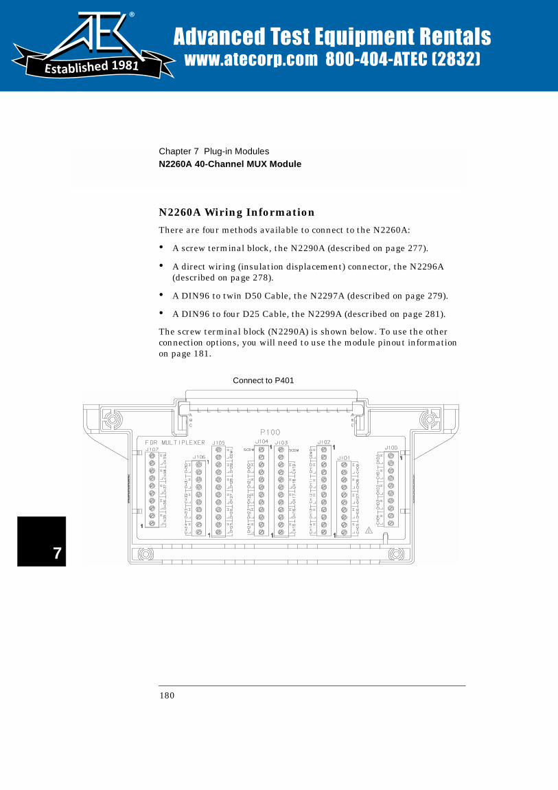
N2260A Wiring Information
There are four methods available to connect to the N2260A:
• A screw terminal block, the N2290A (described on page 277).
• A direct wiring (insulation displacement) connector, the N2296A (described on page 278).
• A DIN96 to twin D50 Cable, the N2297A (described on page 279).
• A DIN96 to four D25 Cable, the N2299A (described on page 281).
The screw terminal block (N2290A) is shown below. To use the other connection options, you will need to use the module pinout information on page 181.
Connect to P401
180

Chapter 7 Plug-in ModulesN2260A 40-Channel MUX Module
4
7
N2260A Pinout P401 is a 96-pin male DIN connector mounted on the N2260A. The connector and pin assignments are shown below.
Pin # A B C Pin # A B C
1 CH0_L CH1_L CH2_L 17 CH20_L CH21_L CH22_L
2 CH0_H CH1_H CH2_H 18 CH20_H CH21_H CH22_H
3 CH3_L CH4_L CH5_L 19 CH23_L CH24_L CH25_L
4 CH3_H CH4_H CH5_H 20 CH23_H CH24_H CH25_H
5 CH6_L CH7_L CH8_L 21 CH26_L CH27_L CH28_L
6 CH6_H CH7_H CH8_H 22 CH26_H CH27_H CH28_H
7 CH9_L Not used COM0_L 23 CH29_L Not used COM1_L
8 CH9_H Not used COM0_H 24 CH29_H Not used COM1_H
9 CH10_L CH11_L CH12_L 25 CH30_L CH31_L CH32_L
10 CH10_H CH11_H CH12_H 26 CH30_H CH31_H CH32_H
11 CH13_L CH14_L CH15_L 27 CH33_L CH34_L CH35_L
12 CH13_H CH14_H CH15_H 28 CH33_H CH34_H CH35_H
13 CH16_L CH17_L CH18_L 29 CH36_L CH37_L CH38_L
14 CH16_H CH17_H CH18_H 30 CH36_H CH37_H CH38_H
15 CH19_L Not used SE-COM 31 CH39_L Not used Not used
16 CH19_H Not used SE-COM 32 CH39_H Not used Not used
C
B
A
32 31 30 29 28 27 26 25 24 23 22 21 20 19 18 17 16 15 14 13 12 11 10 9 8 7 6 5 4 3 21
View from the Pin Side of the Connector
C
B
A
181

Chapter 7 Plug-in ModulesN2261A 40-Channel GP Relay Module
7
N2261A 40-Channel GP Relay Module
The Agilent N2261A GP Relay Module contains 40 independent Single Pole - Single Throw (SPST, Form A) latching relays.
If necessary, you can pair two N2261A modules to provide 2-wire switching.
The N2261A can be operated in one of two modes: single channel break-before-make (BBM) or multiple channels in a closed position.
A parallel switching feature makes the N2261A well suited for high speed switching. The 40 2-wire relays on the N2261A can be separated into four groups and up to 10 relays in the same group can be closed simultaneously (parallel switching). The groups are: group 1 (channel 00 through channel 09), group 2 (channel 10 through channel 19), group 3 (channel 20 through channel 29) and group 4 (channel 30 through channel 39). Additional information about parallel switching is given on page 84.
Specifications for the Agilent N2261A are given on page 305.
N2261A Simplified Schematic
A simplified schematic is shown below. The N2261A contains 40 independent Single Pole-Single Throw (SPST, Form A) latching relays. A channel refers to an individual relay on the module. Channels are numbered 00 through 39 for the N2261A.
L
HCH39
L
HCH00
L
HCH19
L
HCH20
L
L
L
L
H CH39
H CH00
H CH19
H CH20
N2261A GP Relay Module Terminal Block
182
Chapter 7 Plug-in ModulesN2261A 40-Channel GP Relay Module
4
7
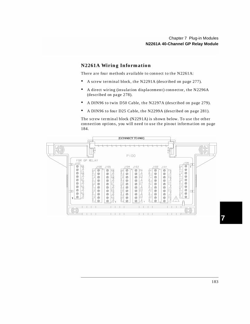
N2261A Wiring Information
There are four methods available to connect to the N2261A:
• A screw terminal block, the N2291A (described on page 277).
• A direct wiring (insulation displacement) connector, the N2296A (described on page 278).
• A DIN96 to twin D50 Cable, the N2297A (described on page 279).
• A DIN96 to four D25 Cable, the N2299A (described on page 281).
The screw terminal block (N2291A) is shown below. To use the other connection options, you will need to use the pinout information on page 184.
183
Chapter 7 Plug-in ModulesN2261A 40-Channel GP Relay Module
7
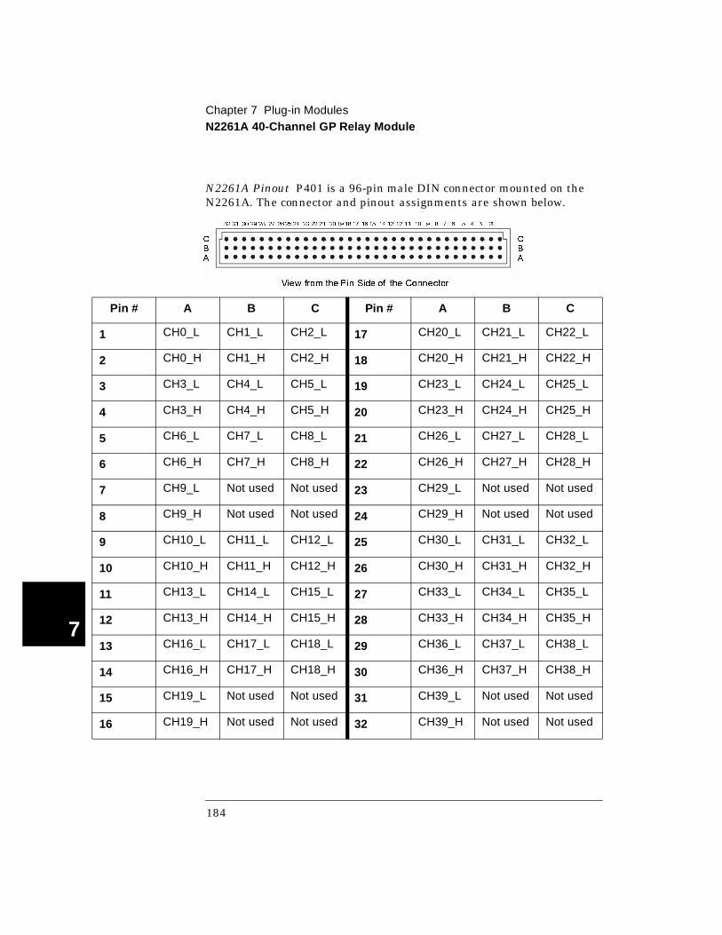
N2261A Pinout P401 is a 96-pin male DIN connector mounted on the N2261A. The connector and pinout assignments are shown below.
Pin # A B C Pin # A B C
1 CH0_L CH1_L CH2_L 17 CH20_L CH21_L CH22_L
2 CH0_H CH1_H CH2_H 18 CH20_H CH21_H CH22_H
3 CH3_L CH4_L CH5_L 19 CH23_L CH24_L CH25_L
4 CH3_H CH4_H CH5_H 20 CH23_H CH24_H CH25_H
5 CH6_L CH7_L CH8_L 21 CH26_L CH27_L CH28_L
6 CH6_H CH7_H CH8_H 22 CH26_H CH27_H CH28_H
7 CH9_L Not used Not used 23 CH29_L Not used Not used
8 CH9_H Not used Not used 24 CH29_H Not used Not used
9 CH10_L CH11_L CH12_L 25 CH30_L CH31_L CH32_L
10 CH10_H CH11_H CH12_H 26 CH30_H CH31_H CH32_H
11 CH13_L CH14_L CH15_L 27 CH33_L CH34_L CH35_L
12 CH13_H CH14_H CH15_H 28 CH33_H CH34_H CH35_H
13 CH16_L CH17_L CH18_L 29 CH36_L CH37_L CH38_L
14 CH16_H CH17_H CH18_H 30 CH36_H CH37_H CH38_H
15 CH19_L Not used Not used 31 CH39_L Not used Not used
16 CH19_H Not used Not used 32 CH39_H Not used Not used
C
B
A
32 31 30 29 28 27 26 25 24 23 22 21 20 19 18 17 16 15 14 13 12 11 10 9 8 7 6 5 4 3 21
View from the Pin Side of the Connector
C
B
A
184
Chapter 7 Plug-in ModulesN2262A 4 x 8 2-Wire Matrix Switch Module
4
7
N2262A 4 x 8 2-Wire Matrix Switch Module
The Agilent N2262A 4 x 8 Matrix module contains 32 2-wire nodes (crosspoints) organized in a 4-row by 8-column configuration. Each node in the matrix contains a 2-wire latching relay for switching both Hi (H) and Lo (L) terminals of a signal line. Multiple switches can be closed, allowing any combination of row-to-column connections.
The parallel switching feature makes it well suited for high speed switching applications. Up to 8 2-wire node/crosspoint relays in the same row can be closed all at once (parallel switching).
The N2262A provides a convenient way to connect multiple test instruments to multiple test points on a device or to multiple devices. Multiple N2262A modules can be connected together, or used in conjunction with other modules such as the N2260A 40-Channel MUX to provide a wide variety of switching combinations.
Specifications for the Agilent N2262A are given on page 307.
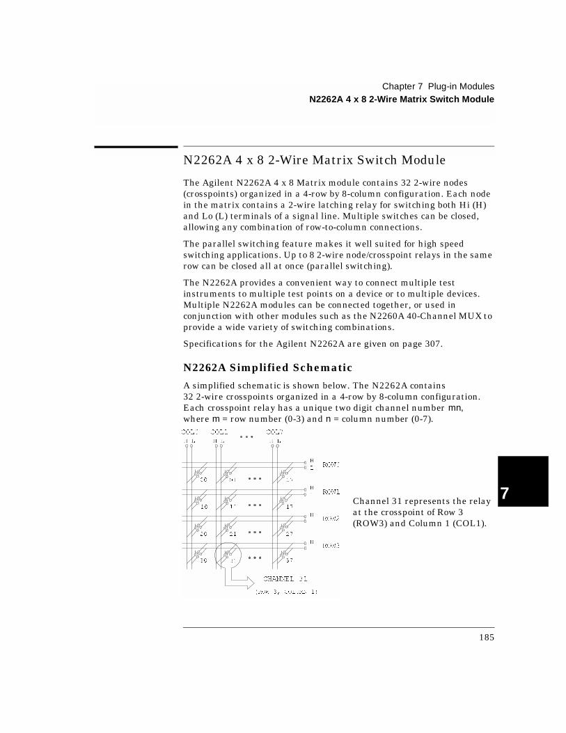
N2262A Simplified Schematic
A simplified schematic is shown below. The N2262A contains 32 2-wire crosspoints organized in a 4-row by 8-column configuration. Each crosspoint relay has a unique two digit channel number mn, where m = row number (0-3) and n = column number (0-7).
ROW0
ROW1
ROW2
ROW3
COL0
H L
COL1
H L
COL7
H L
H
L
H
L
H
L
H
L
CHANNEL 31
(ROW 3, COLUMN 1)
00 01 07
10 11
20 21
17
27
30 31 37
Channel 31 represents the relay at the crosspoint of Row 3 (ROW3) and Column 1 (COL1).
185
Chapter 7 Plug-in ModulesN2262A 4 x 8 2-Wire Matrix Switch Module
7
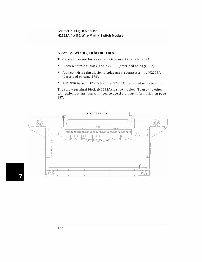
N2262A Wiring Information
There are three methods available to connect to the N2262A:
• A screw terminal block, the N2292A (described on page 277).
• A direct wiring (insulation displacement) connector, the N2296A (described on page 278).
• A DIN96 to twin D25 Cable, the N2298A (described on page 280).
The screw terminal block (N2292A) is shown below. To use the other connection options, you will need to use the pinout information on page 187.
(CONNECT TO P300)
186
Chapter 7 Plug-in ModulesN2262A 4 x 8 2-Wire Matrix Switch Module
4
7
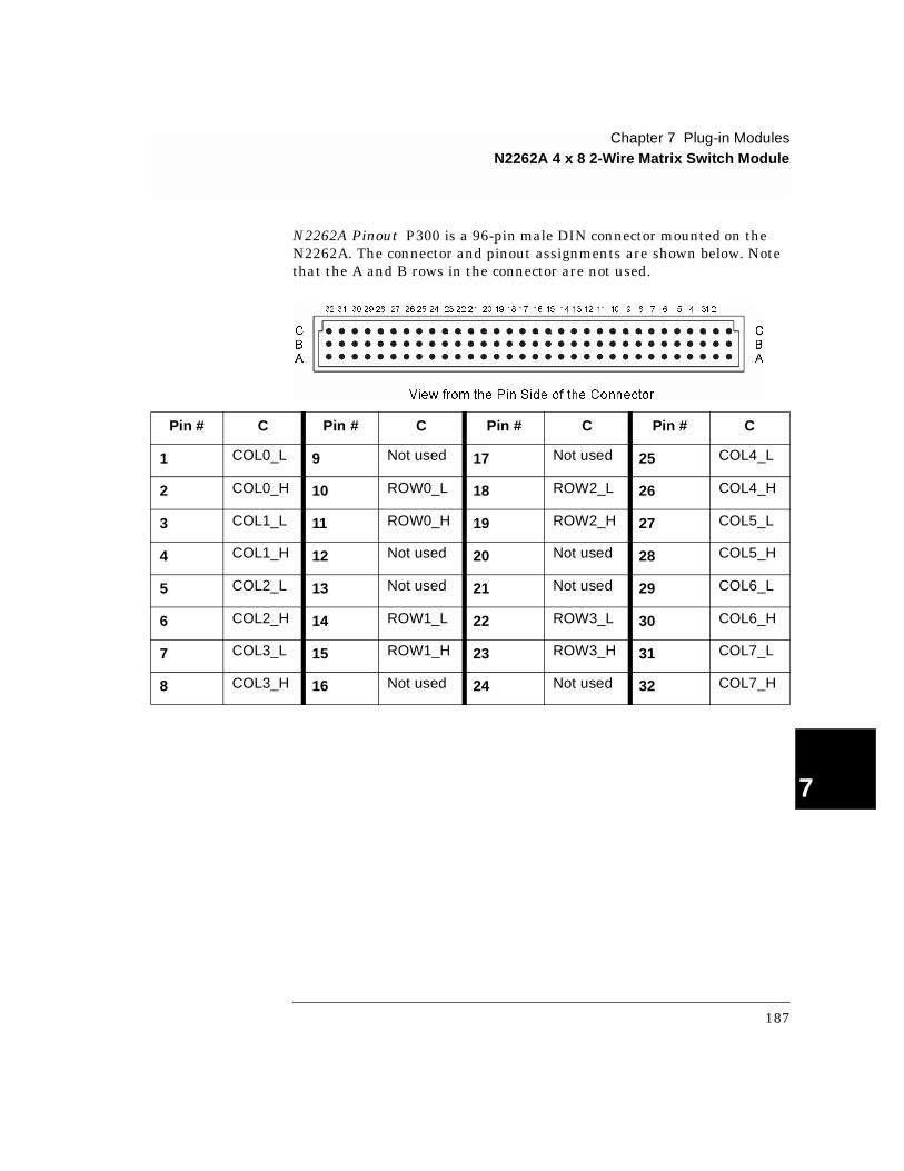
N2262A Pinout P300 is a 96-pin male DIN connector mounted on the N2262A. The connector and pinout assignments are shown below. Note that the A and B rows in the connector are not used.
Pin # C Pin # C Pin # C Pin # C
1 COL0_L 9 Not used 17 Not used 25 COL4_L
2 COL0_H 10 ROW0_L 18 ROW2_L 26 COL4_H
3 COL1_L 11 ROW0_H 19 ROW2_H 27 COL5_L
4 COL1_H 12 Not used 20 Not used 28 COL5_H
5 COL2_L 13 Not used 21 Not used 29 COL6_L
6 COL2_H 14 ROW1_L 22 ROW3_L 30 COL6_H
7 COL3_L 15 ROW1_H 23 ROW3_H 31 COL7_L
8 COL3_H 16 Not used 24 Not used 32 COL7_H
C
B
A
32 31 30 29 28 27 26 25 24 23 22 21 20 19 18 17 16 15 14 13 12 11 10 9 8 7 6 5 4 3 21
View from the Pin Side of the Connector
C
B
A
187
Chapter 7 Plug-in ModulesN2263A 32-bit Digital I/O Module
7
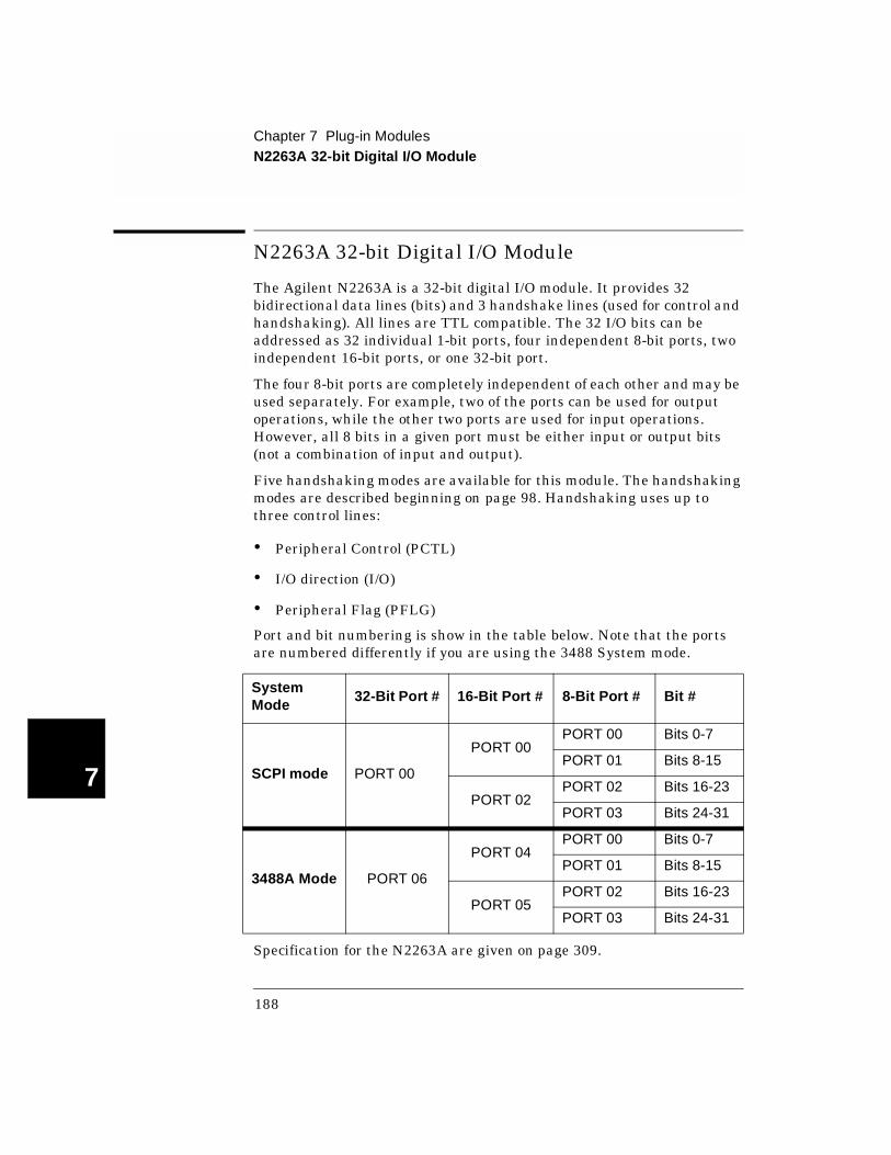
N2263A 32-bit Digital I/O Module
The Agilent N2263A is a 32-bit digital I/O module. It provides 32 bidirectional data lines (bits) and 3 handshake lines (used for control and handshaking). All lines are TTL compatible. The 32 I/O bits can be addressed as 32 individual 1-bit ports, four independent 8-bit ports, two independent 16-bit ports, or one 32-bit port.
The four 8-bit ports are completely independent of each other and may be used separately. For example, two of the ports can be used for output operations, while the other two ports are used for input operations. However, all 8 bits in a given port must be either input or output bits (not a combination of input and output).
Five handshaking modes are available for this module. The handshaking modes are described beginning on page 98. Handshaking uses up to three control lines:
• Peripheral Control (PCTL)
• I/O direction (I/O)
• Peripheral Flag (PFLG)
Port and bit numbering is show in the table below. Note that the ports are numbered differently if you are using the 3488 System mode.
Specification for the N2263A are given on page 309.
System Mode
32-Bit Port # 16-Bit Port # 8-Bit Port # Bit #
SCPI mode PORT 00
PORT 00PORT 00 Bits 0-7
PORT 01 Bits 8-15
PORT 02PORT 02 Bits 16-23
PORT 03 Bits 24-31
3488A Mode PORT 06
PORT 04PORT 00 Bits 0-7
PORT 01 Bits 8-15
PORT 05PORT 02 Bits 16-23
PORT 03 Bits 24-31
188

Chapter 7 Plug-in ModulesN2263A 32-bit Digital I/O Module
4
7
N2263A Simplified Schematic
The N2263A consists of 32 bidirectional I/O channels, each of which includes digital in and digital out circuits as shown in the simplified schematic below. Each input has its own pull-up resistor, allowing easy detection of external termination (grounded or open-circuited) status. Each output driver is capable of sinking an externally-supplied current up to 600 mA, making it possible to control relays without the need for additional driver circuitry.
PFLG Handshake Signal
OPEN COLLECTOR/
TERMINALCONNECTIONBLOCK
ONE I/O LINE
PCTL or I/OHandshake Signal
CURRENT SINK
(VMOS FET)
DRIVER OUTPUT
INPUT SENSEREFERENCE
VOLTAGE
10K
+5V
10K
60V
+5V +5V
Resetable fuse215 TERMINAL
CONNECTIONBLOCK
10K
+5V +5V
Resetable fuse215 TERMINAL
CONNECTIONBLOCK
189
Chapter 7 Plug-in ModulesN2263A 32-bit Digital I/O Module
7
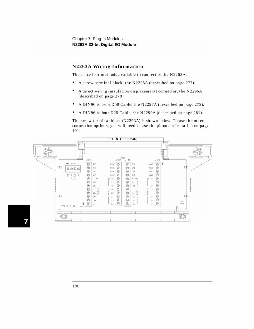
N2263A Wiring Information
There are four methods available to connect to the N2263A:
• A screw terminal block, the N2293A (described on page 277).
• A direct wiring (insulation displacement) connector, the N2296A (described on page 278).
• A DIN96 to twin D50 Cable, the N2297A (described on page 279).
• A DIN96 to four D25 Cable, the N2299A (described on page 281).
The screw terminal block (N2293A) is shown below. To use the other connection options, you will need to use the pinout information on page 191.
(CONNECT TO P702)
190

Chapter 7 Plug-in ModulesN2263A 32-bit Digital I/O Module
4
7
N2263A Pinout P702 is a 96-pin male DIN connector mounted on the N2263A. The connector and pinout assignments are shown below.
Pin # A B C Pin # A B C
1-2 Not used Not used Not used 19 BIT16 BIT17 BIT18
3 BIT0 BIT1 BIT2 20 GND GND GND
4 GND GND GND 21 BIT19 BIT20 BIT21
5 BIT3 BIT4 BIT5 22 GND GND GND
6 GND GND GND 23 BIT22 BIT23 GND
7 BIT6 BIT7 GND 24 GND GND GND
8 GND GND GND 25 BIT24 BIT25 BIT26
9 BIT8 BIT9 BIT10 26 GND GND GND
10 GND GND GND 27 BIT27 BIT28 BIT29
11 BIT11 BIT12 BIT13 28 GND GND GND
12 GND GND GND 29 BIT30 BIT31 GND
13 BIT14 BIT15 GND 30 GND GND GND
14 GND GND GND 31 I/O PCTL PFLG
15-18 Not used Not used Not used 32 GND GND GND
C
B
A
32 31 30 29 28 27 26 25 24 23 22 21 20 19 18 17 16 15 14 13 12 11 10 9 8 7 6 5 4 3 21
View from the Pin Side of the Connector
C
B
A
191
Chapter 7 Plug-in ModulesN2264A Multifunction Module
7
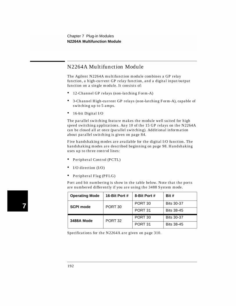
N2264A Multifunction Module
The Agilent N2264A multifunction module combines a GP relay function, a high-current GP relay function, and a digital input/output function on a single module. It consists of:
• 12-Channel GP relays (non-latching Form-A)
• 3-Channel High-current GP relays (non-latching Form-A), capable of switching up to 5 amps.
• 16-bit Digital I/O
The parallel switching feature makes the module well suited for high speed switching applications. Any 10 of the 15 GP relays on the N2264A can be closed all at once (parallel switching). Additional information about parallel switching is given on page 84.
Five handshaking modes are available for the digital I/O function. The handshaking modes are described beginning on page 98. Handshaking uses up to three control lines:
• Peripheral Control (PCTL)
• I/O direction (I/O)
• Peripheral Flag (PFLG)
Port and bit numbering is show in the table below. Note that the ports are numbered differently if you are using the 3488 System mode.
Specifications for the N2264A are given on page 310.
Operating Mode 16-Bit Port # 8-Bit Port # Bit #
SCPI mode PORT 30PORT 30 Bits 30-37
PORT 31 Bits 38-45
3488A Mode PORT 32PORT 30 Bits 30-37
PORT 31 Bits 38-45
192
Chapter 7 Plug-in ModulesN2264A Multifunction Module
4
7
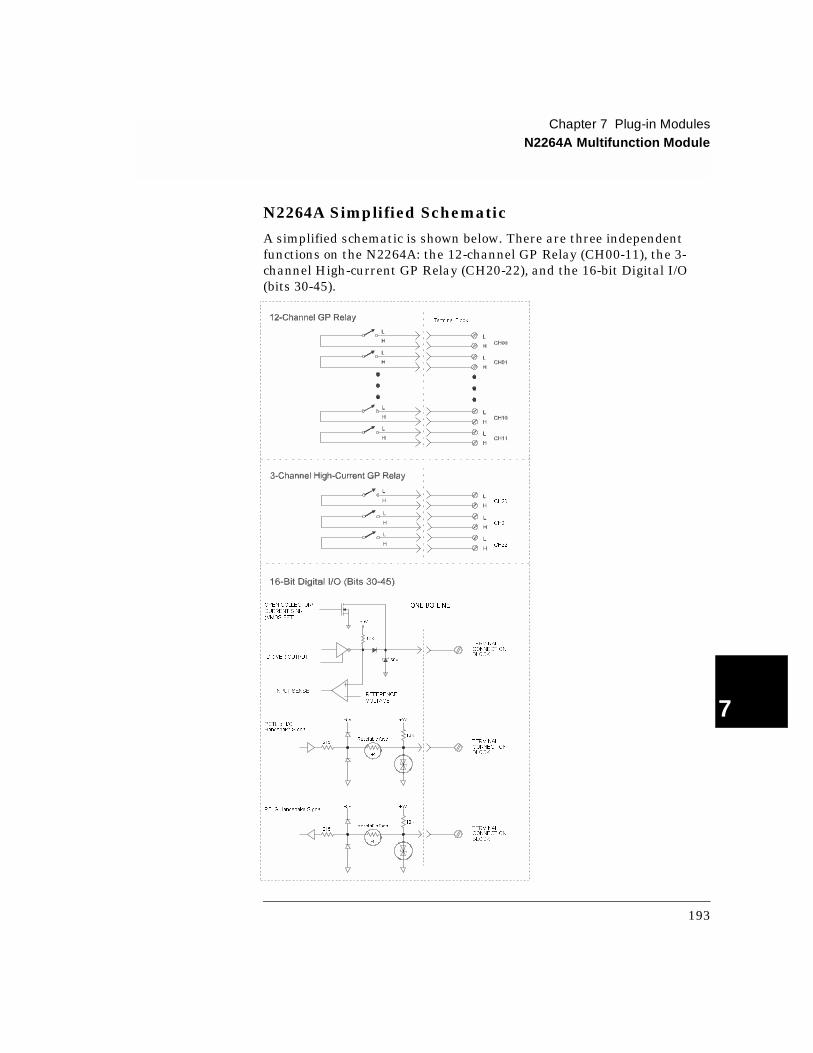
N2264A Simplified Schematic
A simplified schematic is shown below. There are three independent functions on the N2264A: the 12-channel GP Relay (CH00-11), the 3-channel High-current GP Relay (CH20-22), and the 16-bit Digital I/O (bits 30-45).
CH20
CH21
CH22
PFLG Handshake Signal
OPEN COLLECTOR/
TERMINALCONNECTIONBLOCK
ONE I/O LINE
PCTL or I/OHandshake Signal
CURRENT SINK
(VMOS FET)
DRIVER OUTPUT
INPUT SENSEREFERENCE
VOLTAGE
10K
+5V
10K
60V
+5V +5V
Resetable fuse215 TERMINAL
CONNECTIONBLOCK
10K
+5V +5V
Resetable fuse215 TERMINAL
CONNECTIONBLOCK
+t
+t
Terminal Block
193
Chapter 7 Plug-in ModulesN2264A Multifunction Module
7
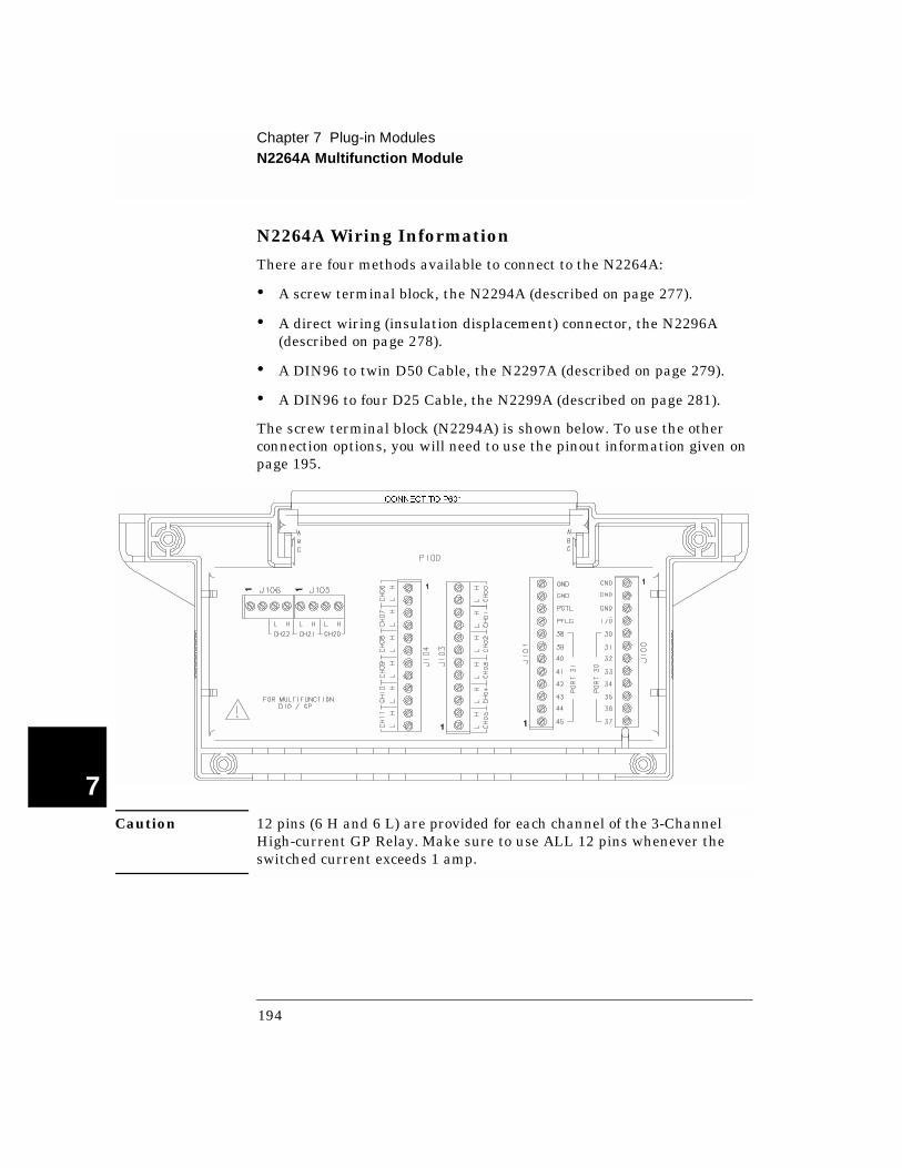
N2264A Wiring Information
There are four methods available to connect to the N2264A:
• A screw terminal block, the N2294A (described on page 277).
• A direct wiring (insulation displacement) connector, the N2296A (described on page 278).
• A DIN96 to twin D50 Cable, the N2297A (described on page 279).
• A DIN96 to four D25 Cable, the N2299A (described on page 281).
The screw terminal block (N2294A) is shown below. To use the other connection options, you will need to use the pinout information given on page 195.
Caution 12 pins (6 H and 6 L) are provided for each channel of the 3-Channel High-current GP Relay. Make sure to use ALL 12 pins whenever the switched current exceeds 1 amp.
CONNECT TO P601
194
Chapter 7 Plug-in ModulesN2264A Multifunction Module
4
7
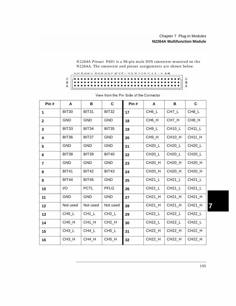
N2264A Pinout P601 is a 96-pin male DIN connector mounted on the N2264A. The connector and pinout assignments are shown below.
Pin # A B C Pin # A B C
1 BIT30 BIT31 BIT32 17 CH6_L CH7_L CH8_L
2 GND GND GND 18 CH6_H CH7_H CH8_H
3 BIT33 BIT34 BIT35 19 CH9_L CH10_L CH11_L
4 BIT36 BIT37 GND 20 CH9_H CH10_H CH11_H
5 GND GND GND 21 CH20_L CH20_L CH20_L
6 BIT38 BIT39 BIT40 22 CH20_L CH20_L CH20_L
7 GND GND GND 23 CH20_H CH20_H CH20_H
8 BIT41 BIT42 BIT43 24 CH20_H CH20_H CH20_H
9 BIT44 BIT45 GND 25 CH21_L CH21_L CH21_L
10 I/O PCTL PFLG 26 CH21_L CH21_L CH21_L
11 GND GND GND 27 CH21_H CH21_H CH21_H
12 Not used Not used Not used 28 CH21_H CH21_H CH21_H
13 CH0_L CH1_L CH2_L 29 CH22_L CH22_L CH22_L
14 CH0_H CH1_H CH2_H 30 CH22_L CH22_L CH22_L
15 CH3_L CH4_L CH5_L 31 CH22_H CH22_H CH22_H
16 CH3_H CH4_H CH5_H 32 CH22_H CH22_H CH22_H
C
B
A
32 31 30 29 28 27 26 25 24 23 22 21 20 19 18 17 16 15 14 13 12 11 10 9 8 7 6 5 4321
View from the Pin Side of the Connector
C
B
A
195
Chapter 7 Plug-in ModulesN2265A Multifunction Module
7
N2265A Multifunction Module
The Agilent N2265A is a multifunction module which consists of:
• A 4 x 4 2-wire Matrix module (16 latching relays) and;
• A 16-bit digital I/O module.
The parallel switching feature makes the matrix portion of this module well suited for high-speed switching applications. Up to eight 2-wire node/crosspoint relays in the same row can be closed all at once (parallel switching). Additional information about parallel switching is given on page 84.
Five handshaking modes are available for the digital I/O function. The handshaking modes are described beginning on page 98. Handshaking uses up to three control lines:
• Peripheral Control (PCTL)
• I/O direction (I/O)
• Peripheral Flag (PFLG)
Port and bit numbering is show in the table below. Note that the ports are numbered differently if you are using the 3488 System mode.
Specifications for the N2265A are shown on page 313.
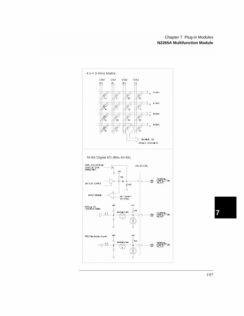
N2265A Simplified Schematic
A simplified schematic of the N2265A is shown on the next page. The N2265A is separated into two sections: the 4 x 4 2-wire matrix and the 16-bit digital I/O. A channel on the N2265A refers to an individual crosspoint on the matrix, or an individual bit on the 16-bit digital I/O.
Operating Mode 16-Bit Port # 8-Bit Port # Bit #
SCPI mode PORT 40PORT 40 Bits 40-47
PORT 41 Bits 48-55
3488A Mode PORT 42PORT 40 Bits 40-47
PORT 41 Bits 48-55
196
Chapter 7 Plug-in ModulesN2265A Multifunction Module
4
7
PFLG Handshake Signal
OPEN COLLECTOR/
TERMINALCONNECTIONBLOCK
ONE I/O LINE
PCTL or I/OHandshake Signal
CURRENT SINK(VMOS FET)
DRIVER OUTPUT
INPUT SENSEREFERENCEVOLTAGE
10K
+5V
10K
60V
+5V +5V
Resetable fuse215 TERMINAL
CONNECTIONBLOCK
10K
+5V +5V
Resetable fuse215 TERMINAL
CONNECTIONBLOCK
+t
+t
ROW0
COL0
ROW1
COL1
ROW2
COL2
ROW3
COL3
H L
H
L
CHANNEL 32
(ROW 3, COLUMN 2)
H LH L H L
H
L
H
L
H
L
00 01 02 03
10 11 12 13
20 21 22 23
30 31 33
197

Chapter 7 Plug-in ModulesN2265A Multifunction Module
7
N2265A Wiring Information
There are four methods available to connect to the N2265A:
• A screw terminal block, the N2295A (described on page 277).
• A direct wiring (insulation displacement) connector, the N2296A (described on page 278).
• A DIN96 to twin D50 Cable, the N2297A (described on page 279).
• A DIN96 to four D25 Cable, the N2299A (described on page 281).
The screw terminal block (N2295A) is shown below. To use the other connection options, you will need to use the pinout information on page 199.
(CONNECT TO P600)
198
Chapter 7 Plug-in ModulesN2265A Multifunction Module
4
7
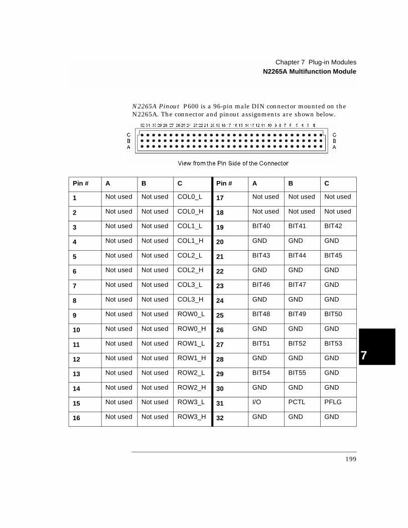
N2265A Pinout P600 is a 96-pin male DIN connector mounted on the N2265A. The connector and pinout assignments are shown below.
Pin # A B C Pin # A B C
1 Not used Not used COL0_L 17 Not used Not used Not used
2 Not used Not used COL0_H 18 Not used Not used Not used
3 Not used Not used COL1_L 19 BIT40 BIT41 BIT42
4 Not used Not used COL1_H 20 GND GND GND
5 Not used Not used COL2_L 21 BIT43 BIT44 BIT45
6 Not used Not used COL2_H 22 GND GND GND
7 Not used Not used COL3_L 23 BIT46 BIT47 GND
8 Not used Not used COL3_H 24 GND GND GND
9 Not used Not used ROW0_L 25 BIT48 BIT49 BIT50
10 Not used Not used ROW0_H 26 GND GND GND
11 Not used Not used ROW1_L 27 BIT51 BIT52 BIT53
12 Not used Not used ROW1_H 28 GND GND GND
13 Not used Not used ROW2_L 29 BIT54 BIT55 GND
14 Not used Not used ROW2_H 30 GND GND GND
15 Not used Not used ROW3_L 31 I/O PCTL PFLG
16 Not used Not used ROW3_H 32 GND GND GND
C
B
A
32 31 30 29 28 27 26 25 24 23 22 21 20 19 18 17 16 15 14 13 12 11 10 9 8 7 6 5 4 3 21
View from the Pin Side of the Connector
C
B
A
199
Chapter 7 Plug-in ModulesN2266A 40-Channel MUX Module
7
N2266A 40-Channel MUX Module
The Agilent N2266A is a configurable multiplexer (MUX) module. It contains 40 2-wire non-latching relays for switching and two non-latching tree relays for configuration applications.
The N2266A can be configured as:
• an 80-channel 1-wire multiplexer,
• a 40-channel 2-wire multiplexer (default),
• two independent 20-channel 2-wire multiplexer,
• or a 20-channel 4-wire multiplexer.
These modes can be selected from the front-panel or with a SCPI command (see page 83).
An instrument power-on or reset will set the N2266A to its default configuration as a 40-channel 2-wire MUX module. When instrument power is removed, all relays will open on the multiplexer.
The N2266A can be operated in either SCPI mode or 3488A mode, but configuration is only possible in the SCPI mode. In 3488A mode, the N2266A can only be used as a 40-channel 2-wire MUX module.
A parallel switching feature makes the N2266A well suited for high speed switching. The 40 2-wire relays on the N2266A can be separated into four groups and up to 10 relays in the same group can be closed simultaneously (parallel switching). The groups are: group 1 (channel 00 through channel 09), group 2 (channel 10 through channel 19), group 3 (channel 20 through channel 29) and group 4 (channel 30 through channel 39). Additional information about parallel switching is given on page 84.
Specifications for the N2266A are given on page 315.
200
Chapter 7 Plug-in ModulesN2266A 40-Channel MUX Module
4
7
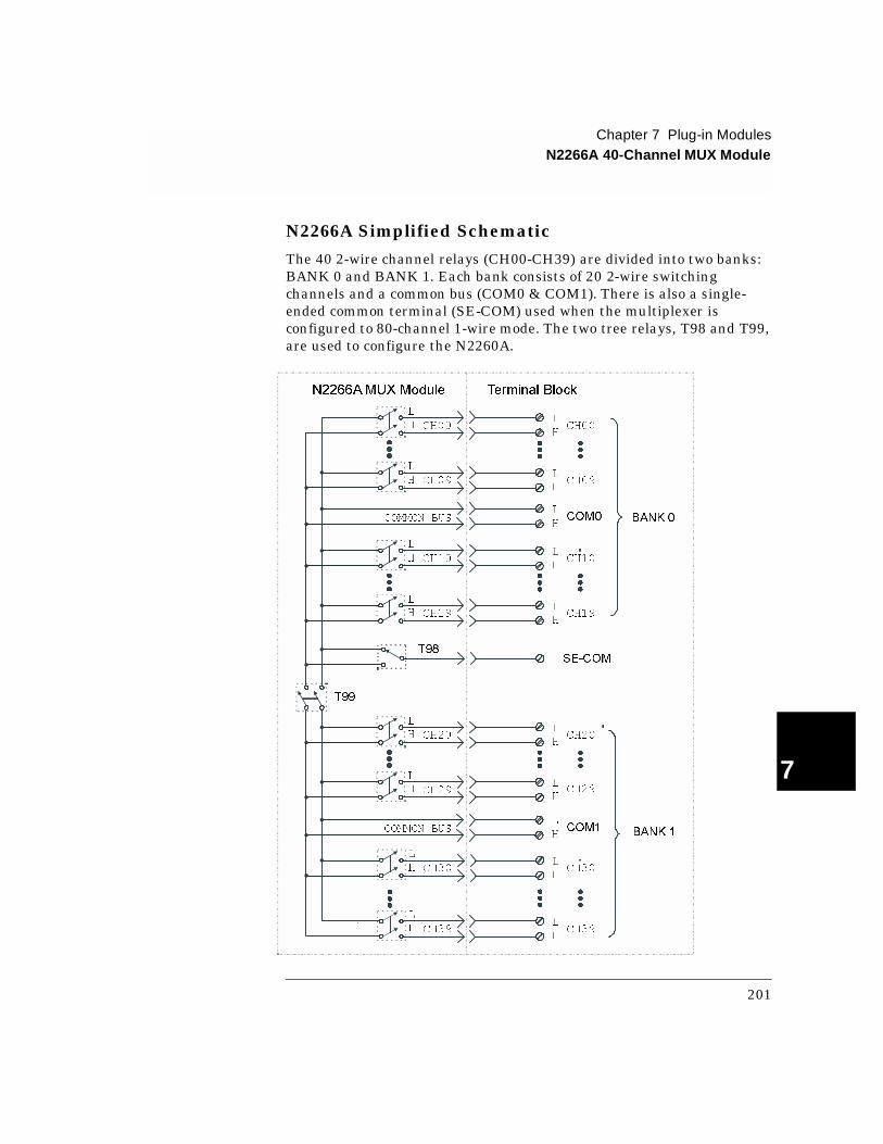
N2266A Simplified Schematic
The 40 2-wire channel relays (CH00-CH39) are divided into two banks: BANK 0 and BANK 1. Each bank consists of 20 2-wire switching channels and a common bus (COM0 & COM1). There is also a single-ended common terminal (SE-COM) used when the multiplexer is configured to 80-channel 1-wire mode. The two tree relays, T98 and T99, are used to configure the N2260A.
L
H
L
H CH00
L
H
L
H CH09
L
H
L
H CH19
SE-COM
L
H
L
H CH10
CH00
CH09
CH19
CH10
L
H
L
H CH29
L
H
L
H CH20
L
H
L
H CH39
L
H
L
H CH30
CH39
CH30
L
HCOMMON BUS COM0
CH20
L
HCOMMON BUS COM1
CH29
BANK 0
BANK 1
T98
T99
N2266AMUX Module Terminal Block
201

Chapter 7 Plug-in ModulesN2266A 40-Channel MUX Module
7
1-Wire Mode In this mode, either the High (H) or Low (L) terminal of a channel is switched to the single-ended (SE-COM) terminal. The Low terminals form the first 40 1-wire channels (00-39), and the High terminals form the second 40 1-wire channels (40-79). Only one channel can be closed at a time in the 1-wire mode.
Note Only one channel can be closed at a time in the 1-wire mode.
2-Wire Mode This is the default mode of the N2266A and provides 40 2-wire channels. In this mode, the Hi and Lo terminals of a channel are switched to Hi and Lo common terminals (COM0 and COM1). The channels are numbered 00 through 39.
Dual 2-Wire Mode In this mode, the N2266A is separated into two independent banks (BANK 0 & BANK 1). Each bank consists of 20 2-wire channels and a corresponding common bus, COM0 and COM1. The channels in BANK 0 are numbered 00 through 19, and the channels in BANK 1 are numbered 20 through 39.
Note You must modify the PC board to use this mode of operation. The modification is described in the next section.
4-Wire Mode In this mode, the two banks (BANK 0 & BANK 1) are paired to form a 20-channel 4-wire multiplexer. The first channels of each bank (CH00 & CH20) form Channel 00, the second channels of the each bank (CH01 & CH21) form Channel 01, and so on.
Note An instrument power-on or reset will set the N2266A to its default configuration as a 40-channel 2-wire MUX module. When powered off, all channels are opened.
202
Chapter 7 Plug-in ModulesN2266A 40-Channel MUX Module
4
7
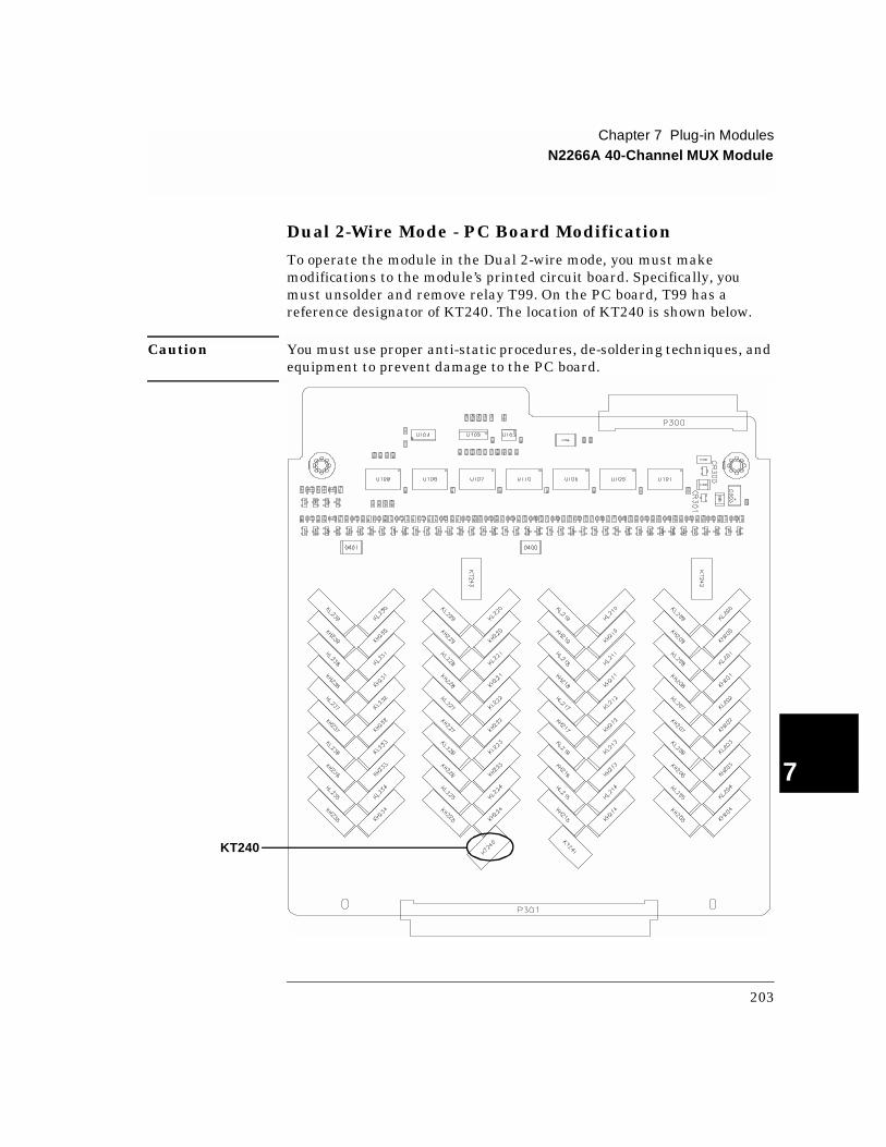
Dual 2-Wire Mode - PC Board Modification
To operate the module in the Dual 2-wire mode, you must make modifications to the module’s printed circuit board. Specifically, you must unsolder and remove relay T99. On the PC board, T99 has a reference designator of KT240. The location of KT240 is shown below.
Caution You must use proper anti-static procedures, de-soldering techniques, and equipment to prevent damage to the PC board.
KT240
203
Chapter 7 Plug-in ModulesN2266A 40-Channel MUX Module
7
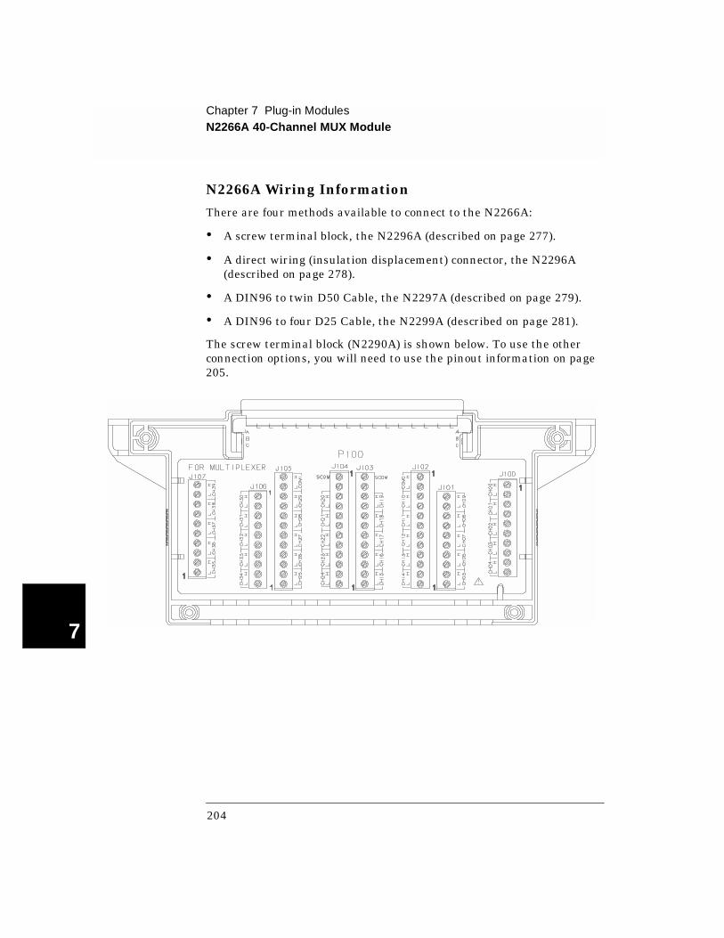
N2266A Wiring Information
There are four methods available to connect to the N2266A:
• A screw terminal block, the N2296A (described on page 277).
• A direct wiring (insulation displacement) connector, the N2296A (described on page 278).
• A DIN96 to twin D50 Cable, the N2297A (described on page 279).
• A DIN96 to four D25 Cable, the N2299A (described on page 281).
The screw terminal block (N2290A) is shown below. To use the other connection options, you will need to use the pinout information on page 205.
204
Chapter 7 Plug-in ModulesN2266A 40-Channel MUX Module
4
7
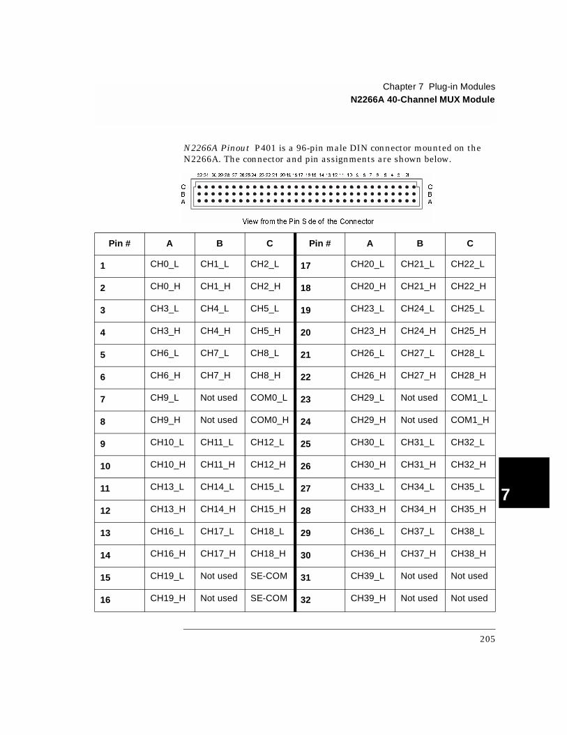
N2266A Pinout P401 is a 96-pin male DIN connector mounted on the N2266A. The connector and pin assignments are shown below.
Pin # A B C Pin # A B C
1 CH0_L CH1_L CH2_L 17 CH20_L CH21_L CH22_L
2 CH0_H CH1_H CH2_H 18 CH20_H CH21_H CH22_H
3 CH3_L CH4_L CH5_L 19 CH23_L CH24_L CH25_L
4 CH3_H CH4_H CH5_H 20 CH23_H CH24_H CH25_H
5 CH6_L CH7_L CH8_L 21 CH26_L CH27_L CH28_L
6 CH6_H CH7_H CH8_H 22 CH26_H CH27_H CH28_H
7 CH9_L Not used COM0_L 23 CH29_L Not used COM1_L
8 CH9_H Not used COM0_H 24 CH29_H Not used COM1_H
9 CH10_L CH11_L CH12_L 25 CH30_L CH31_L CH32_L
10 CH10_H CH11_H CH12_H 26 CH30_H CH31_H CH32_H
11 CH13_L CH14_L CH15_L 27 CH33_L CH34_L CH35_L
12 CH13_H CH14_H CH15_H 28 CH33_H CH34_H CH35_H
13 CH16_L CH17_L CH18_L 29 CH36_L CH37_L CH38_L
14 CH16_H CH17_H CH18_H 30 CH36_H CH37_H CH38_H
15 CH19_L Not used SE-COM 31 CH39_L Not used Not used
16 CH19_H Not used SE-COM 32 CH39_H Not used Not used
C
B
A
32 31 30 29 28 27 26 25 24 23 22 21 20 19 18 17 16 15 14 13 12 11 10 9 8 7 6 5 4 3 21
View from the Pin Side of the Connector
C
B
A
205
Chapter 7 Plug-in ModulesN2267A 8-Channel High Current GP Module
7
N 2267A 8-Channel H igh C urrent G P M odule
The Agilent N2267A is an 8-Channel High Current GP module typically used in mobile phone battery test applications. It can switch up to 8 A at 250 Vac or 5 A at 30 Vdc, with decreasing current to 1 A at 125 Vdc.
The module includes temperature control and protection circuitry, designed to prevent the module temperature from rising too high. The N2267A can potentially be switching up to 64 A (8 channels at 8 A). The temperature control circuitry prevents dangerous overheating.
The 8 channels of the N2267A are independent, more than one channel can be closed or opened at the same time.
Caution Exceeding the maximum switching current of 8 Ampere on any channel will damage the N2267A module and possibly the system.
Specifications for the N2267A are given on page 317.
Temperature Control
The temperature control circuitry includes two sensor ICs and a cooling fan. When the temperature of the N2267A reaches 45o C (113o F), the cooling fan on the module turns on. If the temperature drops below 40o C (104o F), the fan turns off.
Over-temperature ProtectionIf the module temperature rises to 75o C (167o F), all channels on the module are opened and a TTL-level warning output (connected via SMB) on the rear panel will change from high to low. This output can be used to drive an external LED or buzzer. The warning output will reset (change from low to high) when the module temperature drops below 59o C (138o F).
The over-temperature protection is controlled by hardware logic on the module. Therefore, if the over-temperature protection has opened all the channels on the module, the mainframe front-panel and system memory will still indicate the original state of the channels. To regain control of the channels, you must cycle the power to the module (reset and channel commands will not work). Note that cycling power to regain control will only work if the module temperature has dropped below 59o C (138o F) otherwise the protection circuitry will be activated again.
206
Chapter 7 Plug-in ModulesN2267A 8-Channel High Current GP Module
4
7
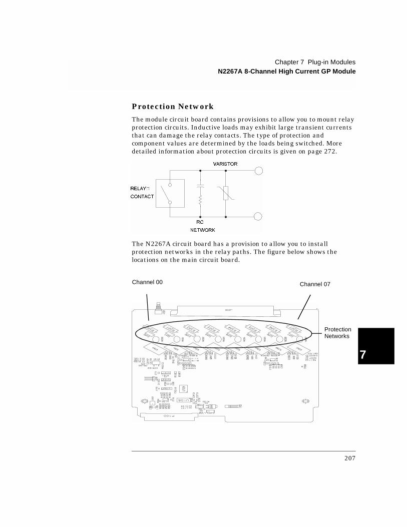
Protection Network
The module circuit board contains provisions to allow you to mount relay protection circuits. Inductive loads may exhibit large transient currents that can damage the relay contacts. The type of protection and component values are determined by the loads being switched. More detailed information about protection circuits is given on page 272.
The N2267A circuit board has a provision to allow you to install protection networks in the relay paths. The figure below shows the locations on the main circuit board.
RELAY
CONTACT
RC
NETWORK
VARISTOR
Protection Networks
Channel 07Channel 00
207

Chapter 7 Plug-in ModulesN2267A 8-Channel High Current GP Module
7
N2267A Simplified Schematic
A simplified schematic is shown below. The N2267A consists of eight independent high current channels, each containing a Single Pole-Single Throw (SPST) Normally Open (Form A) relay.
N2267A Wiring InformationThe N2267A rear panel has two connectors: an SMB for the over-temperature warning signal, and a 16-pin male connector for connections to the relay contacts.
The 16-pin connector on the rear-panel is an AMP Metrimate In-Line Connector: Right Angle Header 207544-1.
An Agilent N2327A terminal block can be used to make the connections to the N2267A. Included in the N2327A are an AMP Metrimate In-Line Connector: Plug, 207542-1 and an AMP Contact Type III Socket AWG18-14, 66360-2. Refer to page 282 for more information about the N2327A.
WARNING Voltages greater than 30 Vrms, 42 Vpk or 60 Vdc present an electric shock hazard. Disconnect source voltages before removing or connecting the source-to-module I/O connector or wiring the connector. All field wiring must be rated for the highest voltage applied to any single channel.
Agilent N2267A Module Connector
L
L
L
H
H
H
H
H
H
L
L
L
12345678910111213141516
208
Chapter 7 Plug-in ModulesN2267A 8-Channel High Current GP Module
4
7
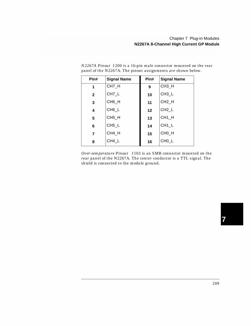
N2267A Pinout J200 is a 16-pin male connector mounted on the rear panel of the N2267A. The pinout assignments are shown below.
Over-temperature Pinout J103 is an SMB connector mounted on the rear panel of the N2267A. The center conductor is a TTL signal. The shield is connected to the module ground.
Pin# Signal Name Pin# Signal Name
1 CH7_H 9 CH3_H
2 CH7_L 10 CH3_L
3 CH6_H 11 CH2_H
4 CH6_L 12 CH2_L
5 CH5_H 13 CH1_H
6 CH5_L 14 CH1_L
7 CH4_H 15 CH0_H
8 CH4_L 16 CH0_L
209
Chapter 7 Plug-in ModulesN2268A 50Ω 3.5 GHz Dual 1-to-4 MUX Module
7
N 2268A 50Ω 3.5 G H z D ual 1-to-4 M U X M odule
The Agilent N2268A consists of two, independent, 1-to-4 MUX switches (GROUP 00 and GROUP 10) that provide bidirectional switching. The latching relays in this module are configured in a “tree” structure to provide isolation and low VSWR (voltage standing wave ratio). Each channel in this module can switch up to 30 Vdc or peak ac at frequencies from dc to 3.5 GHz.
Specifications for the N2268A are given on page 319.
N2268A Simplified Schematic
A simplified schematic is shown on the next page. The N2268A contains two 1-to-4 MUXs, designated as GROUP 00 and GROUP 10. The two groups are isolated from each other. Each 1-to-4 multiplexer consists of three form-C relays. A tree relay is connected to the common channel. The two channel relays allow selection of one of the four channel in each group. Channels in each group are break-before-make and are numbered as 00 through 03 for GROUP 00 and 10 through 13 for GROUP 10.
210
Chapter 7 Plug-in ModulesN2268A 50Ω 3.5 GHz Dual 1-to-4 MUX Module
4
7
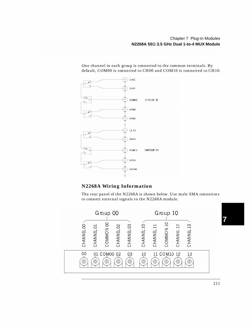
One channel in each group is connected to the common terminals. By default, COM00 is connected to CH00 and COM10 is connected to CH10.
N2268A Wiring Information
The rear panel of the N2268A is shown below. Use male SMA connectors to connect external signals to the N2268A module.
CH00
CH01
COM00
CH03
CH02
CH10
CH11
COM10
CH12
CH130
GROUP 00
GROUP 10
CHANNEL00
CHANNEL03
CHANNEL02
COMMON00
CHANNEL01
CHANNEL10
CHANNEL13
CHANNEL12
COMMON10
CHANNEL11
Group 00 Group 10
00 01 COM00 02 03 10 11 COM10 12 13
211
Chapter 7 Plug-in ModulesN2270A 10-Channel High Voltage MUX Module
7
N 2270A 10-Channel H igh Voltage M U X M odule
The Agilent N2270A is a 10-Channel 2-wire High Voltage multiplexer typically used in the semiconductor test field. The Maximum Switching Voltage is 1000 V peak, and the Maximum Switching Power is 10 W.
The module has a metal shell to minimize interference while switching high voltage.
Specifications for the N2270A are given on page 321.
WARNING Hazardous voltages may exist on the wiring and connectors. DO NOT remove or install the module or the module connector until all external voltages have been removed.
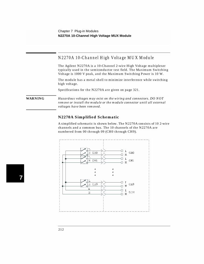
N2270A Simplified Schematic
A simplified schematic is shown below. The N2270A consists of 10 2-wire channels and a common bus. The 10 channels of the N2270A are numbered from 00 through 09 (CH0 through CH9).
CH0
CH1
CH9
C
L
H
L
H
L
H
L
H
L
H CH0
L
H CH1
L
H CH9
L
H
212
Chapter 7 Plug-in ModulesN2270A 10-Channel High Voltage MUX Module
4
7
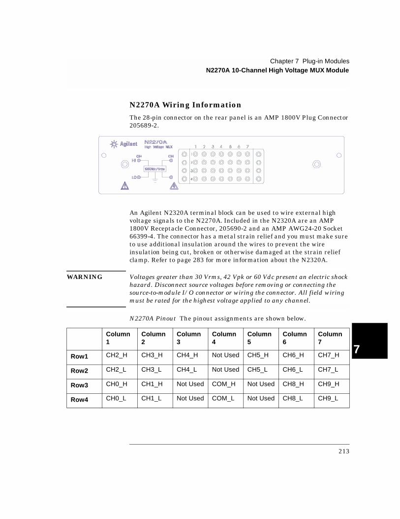
N2270A Wiring Information
The 28-pin connector on the rear panel is an AMP 1800V Plug Connector 205689-2.
An Agilent N2320A terminal block can be used to wire external high voltage signals to the N2270A. Included in the N2320A are an AMP 1800V Receptacle Connector, 205690-2 and an AMP AWG24-20 Socket 66399-4. The connector has a metal strain relief and you must make sure to use additional insulation around the wires to prevent the wire insulation being cut, broken or otherwise damaged at the strain relief clamp. Refer to page 283 for more information about the N2320A.
WARNING Voltages greater than 30 Vrms, 42 Vpk or 60 Vdc present an electric shock hazard. Disconnect source voltages before removing or connecting the source-to-module I/O connector or wiring the connector. All field wiring must be rated for the highest voltage applied to any channel.
N2270A Pinout The pinout assignments are shown below.
Column1
Column2
Column3
Column4
Column5
Column6
Column7
Row1 CH2_H CH3_H CH4_H Not Used CH5_H CH6_H CH7_H
Row2 CH2_L CH3_L CH4_L Not Used CH5_L CH6_L CH7_L
Row3 CH0_H CH1_H Not Used COM_H Not Used CH8_H CH9_H
Row4 CH0_L CH1_L Not Used COM_L Not Used CH8_L CH9_L
213

Chapter 7 Plug-in ModulesN2272A 1 GHz RF 1-to-9 MUX Module
7
N2272A 1 GHz RF 1-to-9 MUX Module
The Agilent N2272A is a 1 GHz RF 1-to-9 Multiplexer well suited for use in RF test and measurement applications. Seven channels are standard branch channels. One channel, CH08, has smaller insertion loss and lower VSWR and can be used either as standard branch channel or an auxiliary channel.
Using the auxiliary channel, CH08, multiple N2272A modules can be cascaded to form larger RF multiplexers while minimizing performance degradation. For example, by connecting CH08 to the COM of a second N2272A, a 17:1 multiplexer can be configured. Adding another N2272A to channel 8 of the second N2272A allows a 25:1 multiplexer to be configured, and so on.
Only one channel can be closed at a time. The Agilent N2272A does not support the OPEN command (one channel must always be closed). Closing a channel opens any other closed channel.
Note The Agilent N2272A can only be used with the SCPI Mode of 3499 Firmware Revision 3.0 or later. See page 59 for details about the firmware revisions.
Specifications for the N2272A are given on page 323.
214
Chapter 7 Plug-in ModulesN2272A 1 GHz RF 1-to-9 MUX Module
4
7
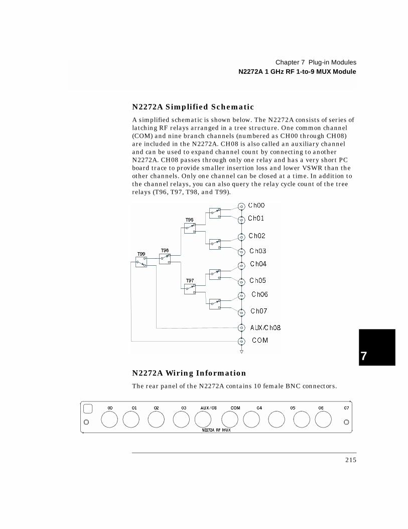
N2272A Simplified Schematic
A simplified schematic is shown below. The N2272A consists of series of latching RF relays arranged in a tree structure. One common channel (COM) and nine branch channels (numbered as CH00 through CH08) are included in the N2272A. CH08 is also called an auxiliary channel and can be used to expand channel count by connecting to another N2272A. CH08 passes through only one relay and has a very short PC board trace to provide smaller insertion loss and lower VSWR than the other channels. Only one channel can be closed at a time. In addition to the channel relays, you can also query the relay cycle count of the tree relays (T96, T97, T98, and T99).
N2272A Wiring Information
The rear panel of the N2272A contains 10 female BNC connectors.
Ch00
Ch01
Ch02
Ch03
Ch04
Ch05
Ch06
Ch07
AUX/Ch08
COM
T99T98
T97
T96
N2272A RF MUX
00 01 02 03 AUX/08 COM 04 05 06 07
215

Chapter 7 Plug-in ModulesN2272A 1 GHz RF 1-to-9 MUX Module
7
Connecting Multiple N2272A’s
The figure below illustrates how to connect two or more N2272A’s together to form larger channel count multiplexers. Additional N2272A’s are added by connecting each COM to the low insertion loss/low VSWR auxiliary channel on the first N2272A.The example below, shows a 1-to-16 multiplexer. Channel 00 through 07 are on the first N2272A, and channel 08 through 15 are on the second N2272A. Switch the first N2272A COM to AUX/08 to access the second bank of multiplexer channels. Additional multiplexers can be added as necessary.
You can also connect multiple N2272A’s in a tree structure to implement high channel count multiplexers, however, this configuration will cause signal delays.
N2272A RF MU X
00 01 02 03 AUX/08 COM 04 05 06 07
N2272A RF MU X
00 01 02 03 AUX/08 COM 04 05 06 07
To next N2272A’s COM Channel if needed
COM Channel of chained N2272As
N2272A RF MU X
00 01 02 03 AUX/08 COM 04 05 06 07
......
COM Channel of tree-combined N2272As
N2272A RF MU X
00 01 02 03 AUX/08 COM 04 05 06 07
N2272A RF MU X
00 01 02 03 AUX/08 COM 04 05 06 07
N2272A RF MUX
00 01 02 03 AUX/08 COM 04 05 06 07
216

Chapter 7 Plug-in ModulesN2276A Dual 1-to-6(4) Microwave MUX/Attenuator Module
4
7
N2276A Dual 1-to-6(4) Microwave MUX/Attenuator Module
The Agilent 2276A contains microwave switch and attenuator driver circuits. The microwave switches or attenuators can be mounted to the rear panel of the module or connected with an auxiliary cable for convenience. Several microwave switches and attenuators are available for use with the module.
The N2276A is preconfigured in one of two options:
The N2276A is a three slot module and cannot be used in the 3499B two-slot mainframe.
Due to the drive circuitry, each N2276A causes about 0.5 second’s delay during power up. Your 3499A/C may seem to turn on slower after you add N2276A modules.
An 8-bit DIP switch on the module sets the configuration for the switches and attenuators. Four connectors are located on the module; two 16-pin connectors (labeled as switch0 & switch1) for connecting switches and two 10-pin connectors (labeled as attenuator0 & attenuator1) for connecting attenuators.
Note The Agilent N2276A can only be used with the SCPI Mode of 3499A/C Firmware Revision 3.0 or later. See page 59 for details about the firmware revisions.
Caution The driving circuitry of the module is capacitive. Turn off power before installing or removing the module, switches, or attenuators.
Specifications for the N2276A are given on page 325.
Option Configuration Switches Used
204 Dual 1-to-4 up to 20 GHz 87104B
206 (default) Dual 1-to-6 up to 20 GHz 87106B
217

Chapter 7 Plug-in ModulesN2276A Dual 1-to-6(4) Microwave MUX/Attenuator Module
7
Up to two attenuators can be added to the N2272A using provided ribbon cables. The following attenuators (user provided) are available from Agilent:
N2276A Simplified Schematic
The simplified schematic below shows the Agilent 87106B 1-to-6 microwave switch (option 206) as used in the Agilent N2276A. Please refer to the switch or attenuator data sheets for information specific to each switch and attenuator.
Only one channel in a switch may be closed at a time. Closing a channel will open any previously closed channel.
External Attenuators (up to two may be used)
0 to 11 dB in 1 dB steps
Agilent 84904K up to 26.5 GHz
Agilent 84904L up to 40 GHz
0 to 90 dB in 10 dB steps
Agilent 84906K up to 26.5 GHz
Agilent 84906L up to 40 GHz
0 to 70 dB in 10 dB steps
Agilent 84907K up to 26.5 GHz
Agilent 84907L up to 40 GHz
6 5 4 3 2 1 C
87106A/B/C
218

Chapter 7 Plug-in ModulesN2276A Dual 1-to-6(4) Microwave MUX/Attenuator Module
4
7
Configuration
An 8-bit DIP switch (labeled S100) on the N2276A is used to configure the switches and optional attenuators. The following table shows specific configurations. If the 8-bit DIP switch’s configuration does not match the switches or attenuators installed, errors or unexpected results will occur.
Bit Setting
Attenuator 1 Attenuator 0 Switch 1 Switch 0
Bit 7- 6 Bit 5- 4 Bit 3- 2 Bit 1- 0
00 None None None None
01 84904K/L 84904K/L 87104A/B/C 87104A/B/C
10 84906K/L 84906K/L 87106A/B/C 87106A/B/C
11 84907K/L 84907K/L Reserved Reserved
219
Chapter 7 Plug-in ModulesN2276A Dual 1-to-6(4) Microwave MUX/Attenuator Module
7
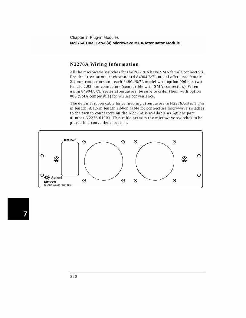
N2276A Wiring Information
All the microwave switches for the N2276A have SMA female connectors. For the attenuators, each standard 84904/6/7L model offers two female 2.4 mm connectors and each 84904/6/7L model with option 006 has two female 2.92 mm connectors (compatible with SMA connectors). When using 84904/6/7L series attenuators, be sure to order them with option 006 (SMA compatible) for wiring convenience.
The default ribbon cable for connecting attenuators to N2276A/B is 1.5 m in length. A 1.5 m length ribbon cable for connecting microwave switches to the switch connectors on the N2276A is available as Agilent part number N2276-61003. This cable permits the microwave switches to be placed in a convenient location.
220
Chapter 7 Plug-in ModulesN2276B Microwave MUX/Attenuator Module
4
7
N 2276B M icrow ave M U X /A ttenuator M odule
The Agilent N2276B contains microwave switch and attenuator driver circuits. The microwave switches or attenuators can be mounted to the rear panel of the module or connected with an auxiliary cable for convenience.
The N2276B is shipped without any switches, allowing for custom configuration. Several microwave switches and attenuators are available for use with the module.
The N2276B is a three slot module and cannot be used in the 3499B two-slot mainframe.
Due to the drive circuitry, each N2276B causes about 0.5 second’s delay during power up. Your 3499A/C may seem to turn on slower after you add N2276B modules.
An 8-bit DIP switch on the module sets the configuration for the switches and attenuators. Four connectors are located on the module; two 16-pin connectors (labeled as switch0 & switch1) for connecting switches and two 10-pin connectors (labeled as attenuator0 & attenuator1) for connecting attenuators.
Note The Agilent N2276B can only be used with the SCPI Mode of 3499A/B/C Firmware Revision 3.0 or later. See page 59 for details about the firmware revisions.
Caution The driving circuitry of the module is capacitive. Turn off power before installing or removing the module, switches, or attenuators.
Specifications for the N2276B are given on page 325.
221
Chapter 7 Plug-in ModulesN2276B Microwave MUX/Attenuator Module
7
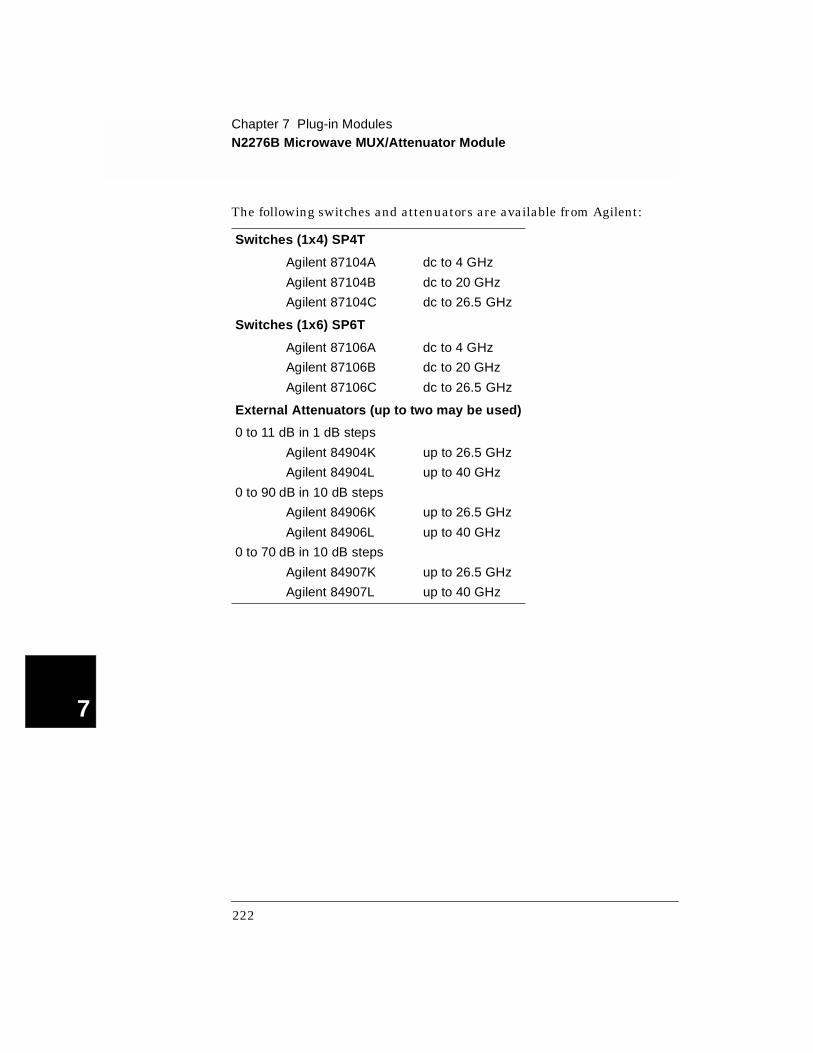
The following switches and attenuators are available from Agilent:
Switches (1x4) SP4T
Agilent 87104A dc to 4 GHz
Agilent 87104B dc to 20 GHz
Agilent 87104C dc to 26.5 GHz
Switches (1x6) SP6T
Agilent 87106A dc to 4 GHz
Agilent 87106B dc to 20 GHz
Agilent 87106C dc to 26.5 GHz
External Attenuators (up to two may be used)
0 to 11 dB in 1 dB steps
Agilent 84904K up to 26.5 GHz
Agilent 84904L up to 40 GHz
0 to 90 dB in 10 dB steps
Agilent 84906K up to 26.5 GHz
Agilent 84906L up to 40 GHz
0 to 70 dB in 10 dB steps
Agilent 84907K up to 26.5 GHz
Agilent 84907L up to 40 GHz
222
Chapter 7 Plug-in ModulesN2276B Microwave MUX/Attenuator Module
4
7
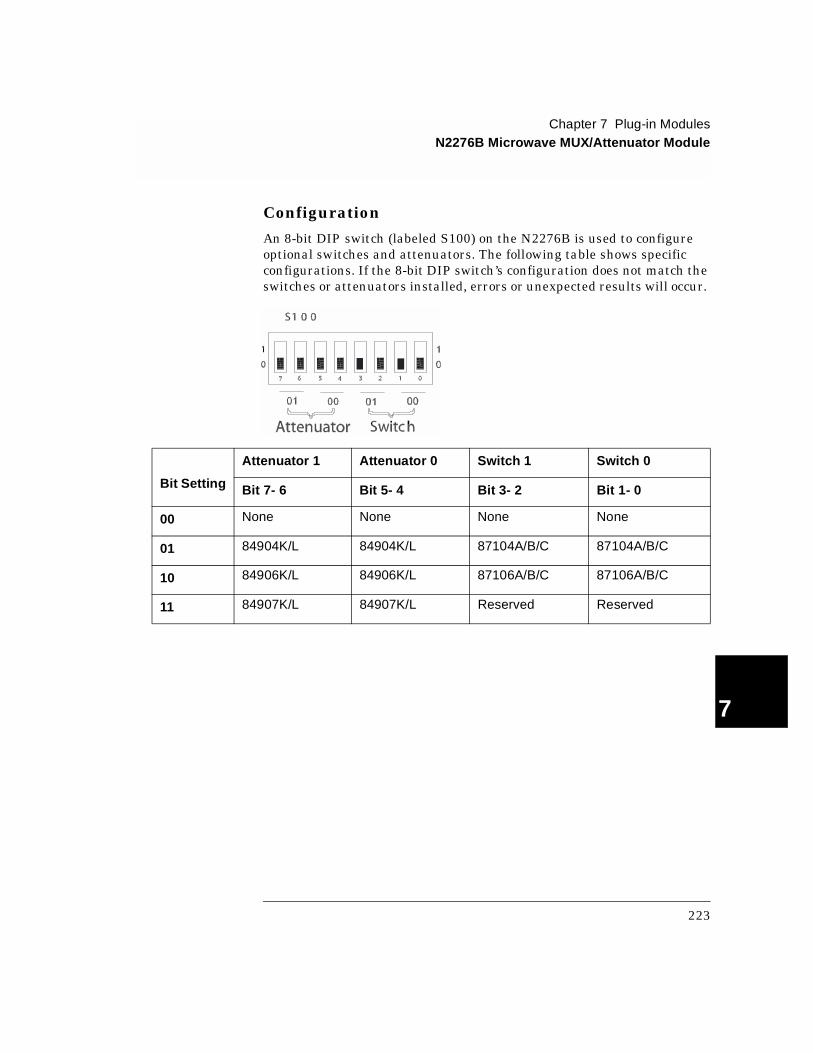
Configuration
An 8-bit DIP switch (labeled S100) on the N2276B is used to configure optional switches and attenuators. The following table shows specific configurations. If the 8-bit DIP switch’s configuration does not match the switches or attenuators installed, errors or unexpected results will occur.
Bit Setting
Attenuator 1 Attenuator 0 Switch 1 Switch 0
Bit 7- 6 Bit 5- 4 Bit 3- 2 Bit 1- 0
00 None None None None
01 84904K/L 84904K/L 87104A/B/C 87104A/B/C
10 84906K/L 84906K/L 87106A/B/C 87106A/B/C
11 84907K/L 84907K/L Reserved Reserved
223
Chapter 7 Plug-in ModulesN2276B Microwave MUX/Attenuator Module
7
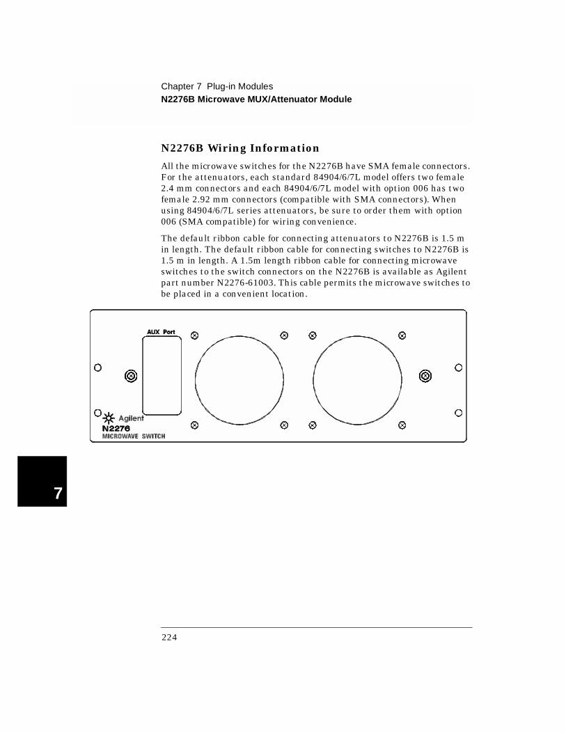
N2276B Wiring Information
All the microwave switches for the N2276B have SMA female connectors. For the attenuators, each standard 84904/6/7L model offers two female 2.4 mm connectors and each 84904/6/7L model with option 006 has two female 2.92 mm connectors (compatible with SMA connectors). When using 84904/6/7L series attenuators, be sure to order them with option 006 (SMA compatible) for wiring convenience.
The default ribbon cable for connecting attenuators to N2276B is 1.5 m in length. The default ribbon cable for connecting switches to N2276B is 1.5 m in length. A 1.5m length ribbon cable for connecting microwave switches to the switch connectors on the N2276B is available as Agilent part number N2276-61003. This cable permits the microwave switches to be placed in a convenient location.
224
Chapter 7 Plug-in ModulesN2280A Quadruple 1-to-2 Optical Switch Module
4
7
N2280A Quadruple 1-to-2 Optical Switch Module
The Agilent N2280A Module contains four 1-to-2 optical switches. All four optical switches are non-latching. For each switch, only one channel can be closed at a time. Closing a channel will open the other channel in the same switch. After power on or a reset, the common channel of each 1-to-2 optical switch is connected to the second channel by default.
Specifications for the N2280A are given on page 326.
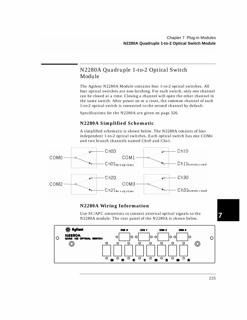
N2280A Simplified Schematic
A simplified schematic is shown below. The N2280A consists of four independent 1-to-2 optical switches. Each optical switch has one COMx and two branch channels named Chx0 and Chx1.
N2280A Wiring InformationUse SC/APC connectors to connect external optical signals to the N2280A module. The rear panel of the N2280A is shown below.
Ch00
Ch01
COM0
Ch20
Ch21
COM2
Ch10
Ch11
COM1
Ch30
Ch31
COM3
Normally c losed
Normally c losed
Normally c losed
Normally c losed
225

Chapter 7 Plug-in ModulesN2281A Dual 1-to-4 Optical Switch Module
7
N2281A Dual 1-to-4 Optical Switch Module
The Agilent N2281A Module consists of two 1-to-4 optical switches. The two optical switches are non-latching. For each switch, only one channel can be closed at a time. Closing one channel will open the other channel in the same switch. After power on or a reset, the common channel of each 1-to-4 optical switch is connected to the third channel by default.
Specifications for the N2281A are given on page 327.
N2281A Simplified Schematic
A simplified schematic is shown below. The Agilent N2281A consists of two independent 1-to-4 optical switches. Channels are numbered as 00, 01, 02, 03 for COM0 and 10, 11, 12, 13 for COM1. The third channel of each 1-to-4 optical switch is connected to the common channel by default.
Ch00
Ch01
Ch02
Ch03
Ch10
Ch11
Ch12
Ch13
COM1
COM0Normally c losed
Norma lly c losed
226
Chapter 7 Plug-in ModulesN2281A Dual 1-to-4 Optical Switch Module
4
7
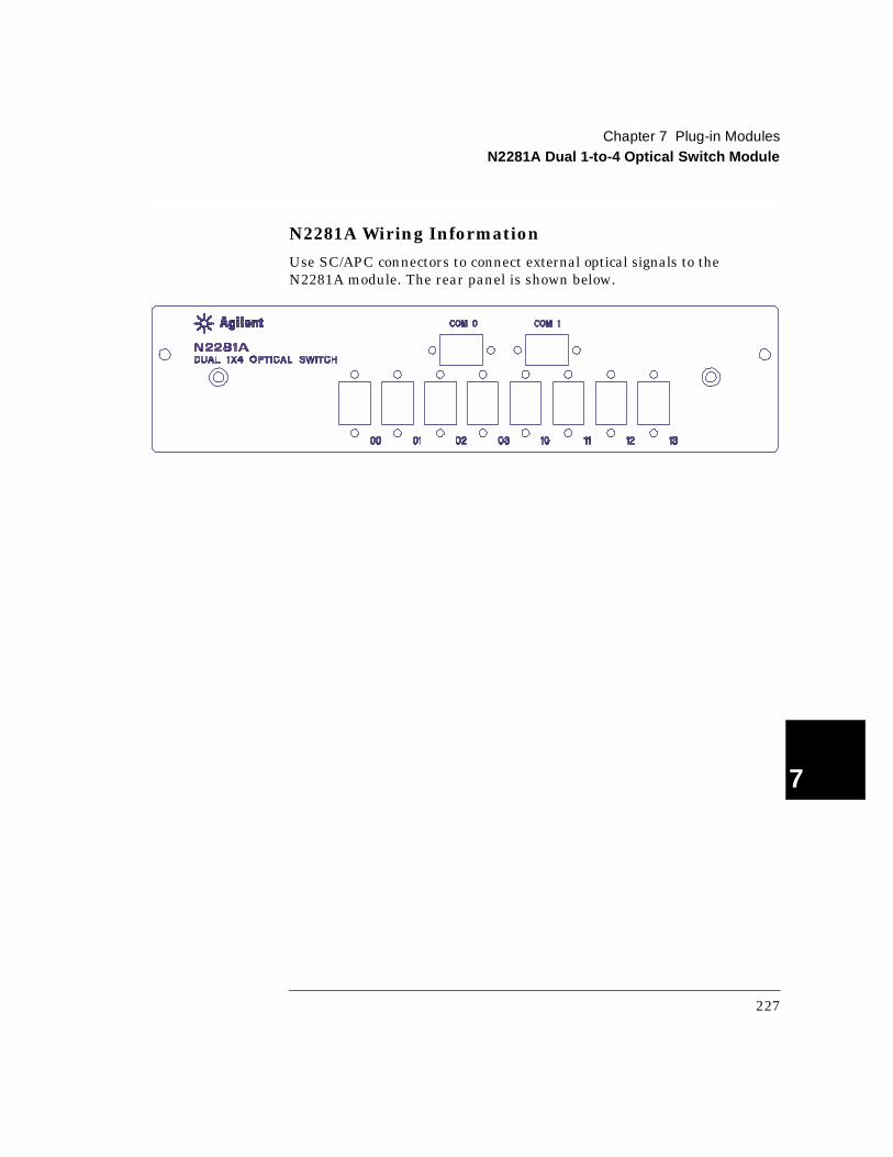
N2281A Wiring Information
Use SC/APC connectors to connect external optical signals to the N2281A module. The rear panel is shown below.
227
Chapter 7 Plug-in ModulesN2282A 1-to-8 Optical Switch Module
7
N2282A 1-to-8 Optical Switch Module
The Agilent N2282A Optical Switch contains a latching 1-to-8 optical switch. Only one channel at a time may be closed. The N2282A does not support the OPEN command. Closing a channel will open any previously closed channels. A special, virtual channel is included that allows all channels in the switch to be opened.
Channels are numbered as CH00 through CH08. CH00 through CH07 are standard channels. CH08 is a special channel used when programming to open all other channels (CH00 through CH07). The latching characteristic of the optical switch makes it hold its most recently state after powered off.
Specifications for the N2282A are given on page 328.
Note The Agilent N2282A can only be used with the SCPI Mode of 3499 Firmware Revision 3.0 or later. See page 59 for details about the firmware revisions.
N2282A Simplified Schematic
A simplified schematic is shown on the next page. The N2282A consists of one 1-to-8 optical switch whose channels are numbered as CH00 through CH07 and a special channel, CH08, with no external connection.
228
Chapter 7 Plug-in ModulesN2282A 1-to-8 Optical Switch Module
4
7
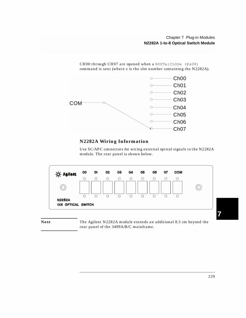
CH00 through CH07 are opened when a ROUTe:CLOSe (@x08) command is sent (where x is the slot number containing the N2282A).
N2282A Wiring Information
Use SC/APC connectors for wiring external optical signals to the N2282A module. The rear panel is shown below.
Note The Agilent N2282A module extends an additional 8.5 cm beyond the rear panel of the 3499A/B/C mainframe.
Ch00Ch01Ch02Ch03
Ch04Ch05Ch06Ch07
COM
229
Chapter 7 Plug-in Modules44470A 10-Channel MUX Module
7
44470A 10-Channel MUX Module
The Agilent 44470A Relay Multiplexer (MUX) provides 10 2-wire channels (latching relays) to switch both Hi (H) and Lo (L) input signal lines to a common bus. Relays on this module are rated at a maximum voltage of 250 volts with a maximum current of 2 amps dc or ac rms.
The module exhibits low thermal offset characteristics, making it ideal for precision low-level measurements. However, since no thermocouple compensation is included, temperature measurement errors may occur if you use this module to switch thermocouples.
The 44470A can be operated in either of two modes, single channel break-before-make (BBM), or multiple channels closed at the same time.
Specifications for the 44470A are given on page 329.
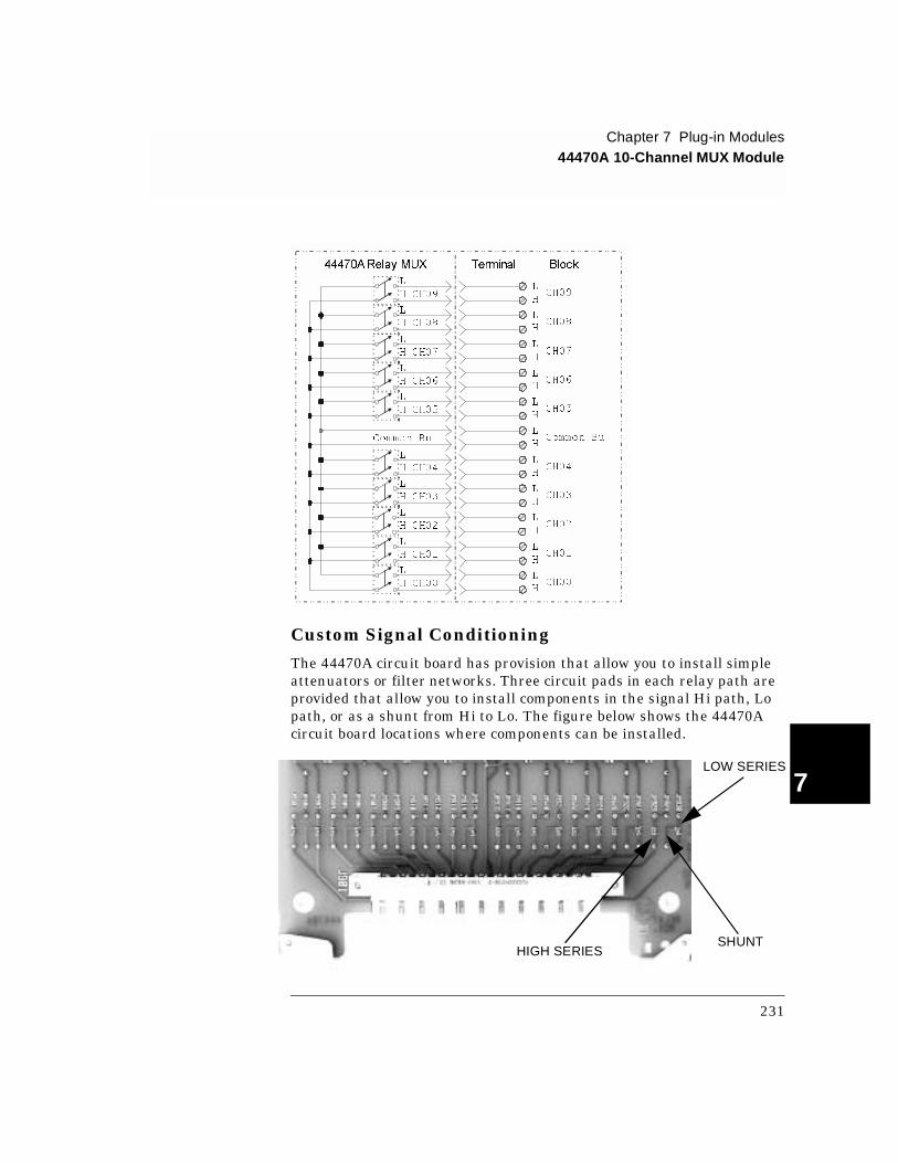
44470A Simplified Schematic
A simplified schematic of the 44470A is shown below. The 44470A consists of 10 2-wire relay channels that may be connected to a common bus. Channels on the 44470A are numbered as 00 through 09 (CH00 through CH09).
230
Chapter 7 Plug-in Modules44470A 10-Channel MUX Module
4
7
Custom Signal Conditioning
The 44470A circuit board has provision that allow you to install simple attenuators or filter networks. Three circuit pads in each relay path are provided that allow you to install components in the signal Hi path, Lo path, or as a shunt from Hi to Lo. The figure below shows the 44470A circuit board locations where components can be installed.
Common Bu
CH09
CH08
CH06
CH04
CH03
CH01
CH00
CH05
Common Bu
CH02
H
L
H
L
H
L
H
L
H
L
H
L
H
L
L
H
L
H
L
H
L
HCH07
H CH00
L
H CH09
L
H CH08
L
H CH06
L
H CH04
L
H CH03
L
H CH01
L
L
H CH05
L
H CH02
L
H CH07
44470ARelay MUX Terminal Block
LOW SERIES
HIGH SERIESSHUNT
231

Chapter 7 Plug-in Modules44470A 10-Channel MUX Module
7
Creating attenuators An attenuator is composed of two resistors that act as a voltage divider. A typical attenuator circuit is also shown below.
To select the attenuator components, use the following equation:
One typical use for the shunt component is to convert the output of 4 to 20 mA transducers to a voltage that can be measured using a DMM. A 50 Ω, ±1%, 0.5 watt resistor can be installed in the R2 (shunt) location and the resultant voltage drop (transducer current through the resistor) measured. The 50 Ω resistor converts the 4 - 20 mA current to an 0.2 - 1 volt signal. No series element (R1) is needed.
44470A Wiring InformationUse the Agilent 44480A Terminal Block to make connections to the 44470A. One 44480A is supplied with the module.
The terminal block includes a screw terminal that connects external wiring to the 44470A. The screw terminal is shown below. Additional information about the terminal block is given on page 285.
Vout = Vin * (R2/(R1 + R2))
R2
(series element)
SIGNAL INPUT Vin
SIGNALOUTPUT Vout
R1
(shunt element)
Vo Vi R2 R1 R2+( )⁄×=
232
Chapter 7 Plug-in Modules44470D 20-Channel MUX Module
4
7
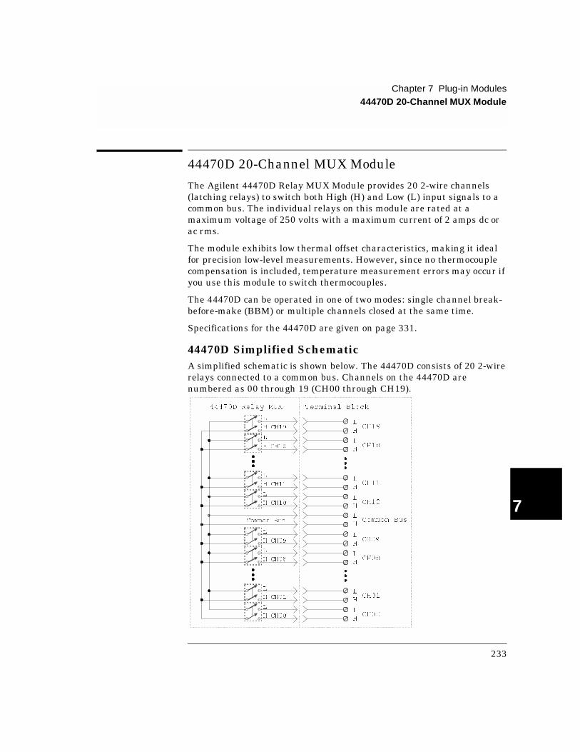
44470D 20-Channel MUX Module
The Agilent 44470D Relay MUX Module provides 20 2-wire channels (latching relays) to switch both High (H) and Low (L) input signals to a common bus. The individual relays on this module are rated at a maximum voltage of 250 volts with a maximum current of 2 amps dc or ac rms.
The module exhibits low thermal offset characteristics, making it ideal for precision low-level measurements. However, since no thermocouple compensation is included, temperature measurement errors may occur if you use this module to switch thermocouples.
The 44470D can be operated in one of two modes: single channel break-before-make (BBM) or multiple channels closed at the same time.
Specifications for the 44470D are given on page 331.
44470D Simplified SchematicA simplified schematic is shown below. The 44470D consists of 20 2-wire relays connected to a common bus. Channels on the 44470D are numbered as 00 through 19 (CH00 through CH19).
L
HCH19
L
HCH18
L
HCH11
L
HCH09
L
HCH10
L
HCH08
L
HCH01
L
HCH00
L
HCommon Bus
L
H CH19
L
H CH18
L
H CH10
L
H CH11
L
H CH00
L
H CH01
L
H CH09
L
H CH08
Common Bus
44470D Relay MUX Terminal Block
233

Chapter 7 Plug-in Modules44470D 20-Channel MUX Module
7
44470D Wiring Information
Use the Agilent 44480B Terminal Block to make connections to the 44470D. One 44480B is supplied with the module. The terminal block connectors are shown below. Additional information about the terminal block is given on page 287.
J101 (Connect to J901)
234

Chapter 7 Plug-in Modules44470D 20-Channel MUX Module
4
7
44470D J901 Pinout
J901 is a 3-row, 48-pin male connector mounted on the 44470D. The pin assignments in this connector are shown below.
CH15 LA24
CH15 HC24
CH16 LA26
CH16 HC26
CH17 LE26
CH17 HE28
CH18 LA28
CH18 HC28
CH19 LA30
CH19 HC30
NC
NC
CH05 LA8
CH05 HC8
CH06 LA10
CH06 HC10
CH07 LE10
CH07 HE12
CH08 LA12
CH08 HC12
CH09 LA14
CH09 HC14
NC
NC
CH00 LA2
CH00 HC2
CH01 LE2
CH01 HE4
CH02 LA4
CH02 HC4
CH03 LA6
CH03 HC6
CH04 LE6
CH04 HE8
NC
NC
J901CH10 L
A18
CH10 HC18
CH11 LE18
CH11 HE20
CH12 LA20
CH12 HC20
CH13 LA22
CH13 HC22
CH14 LE22
CH14 HE24
A16L COM
E16H COM
A32, C16, C 32, E14, E30, E32 NOTCONNEC TED (NC )
J901 (on 44470D)
E32 E30 E4 E2
C2
A4 A2A32 A30
C32
E14
C16
E30
A32
C32
E32
235
Chapter 7 Plug-in Modules44471A 10-Channel GP Relay Module
7
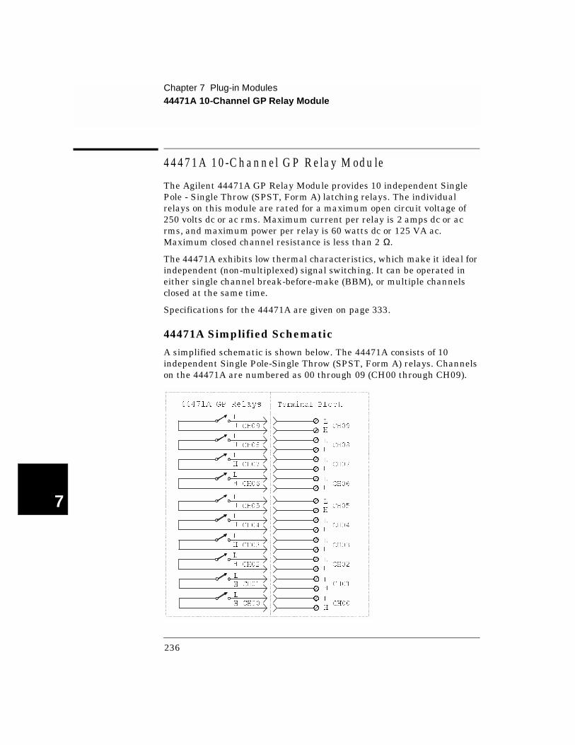
44471A 10-C hannel G P R elay M odu le
The Agilent 44471A GP Relay Module provides 10 independent Single Pole - Single Throw (SPST, Form A) latching relays. The individual relays on this module are rated for a maximum open circuit voltage of 250 volts dc or ac rms. Maximum current per relay is 2 amps dc or ac rms, and maximum power per relay is 60 watts dc or 125 VA ac. Maximum closed channel resistance is less than 2 Ω.
The 44471A exhibits low thermal characteristics, which make it ideal for independent (non-multiplexed) signal switching. It can be operated in either single channel break-before-make (BBM), or multiple channels closed at the same time.
Specifications for the 44471A are given on page 333.
44471A Simplified Schematic
A simplified schematic is shown below. The 44471A consists of 10 independent Single Pole-Single Throw (SPST, Form A) relays. Channels on the 44471A are numbered as 00 through 09 (CH00 through CH09).
L
HCH09
L
HCH08
L
H
L
H
CH09
CH08
L
HCH05
L
HCH04
L
H
L
H
CH05
CH04
L
HCH03
L
HCH02
L
H
L
H
CH03
CH02
L
HCH01
L
HCH00
L
H
L
H
CH01
CH00
L
HCH07
L
HCH06
L
H
L
H
CH07
CH06
44471A GP Relays Terminal Block
236

Chapter 7 Plug-in Modules44471A 10-Channel GP Relay Module
4
7
Custom Signal Conditioning
The 44471A circuit board has a provision to allow you to install simple attenuators or filters in the relay paths. There is also a place to install relay contact protection networks. The figure below shows the locations on the main circuit board.
Protection Networks An RC protection network and a varistor can be installed in each relay path. More detailed information about protection circuits is given on page 272.
HIGH SERIES
LOW SERIES
SHUNT
PROTECTIONNETWORK
TERMINAL
BLOCK
RELAY
CONTACT
RC
NETWORK
VARISTOR
237
Chapter 7 Plug-in Modules44471A 10-Channel GP Relay Module
7
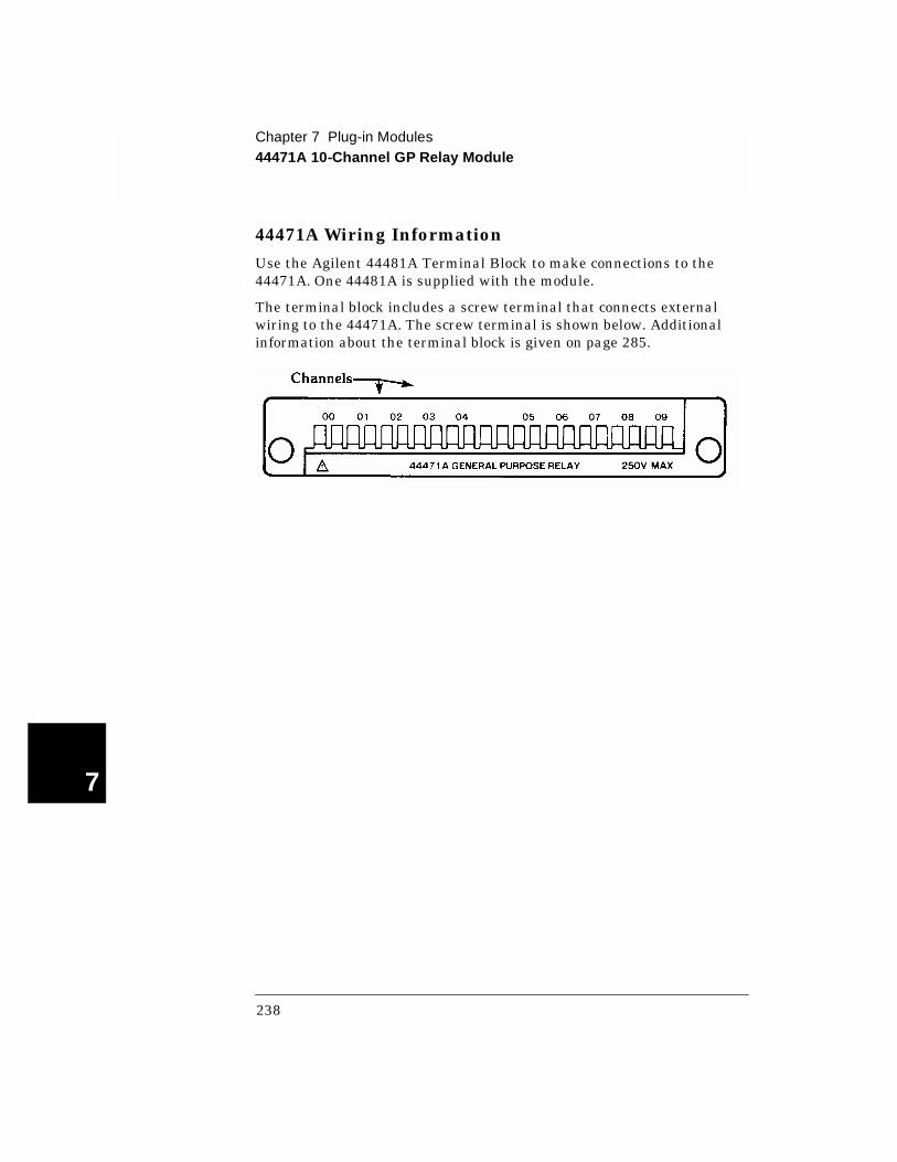
44471A Wiring Information
Use the Agilent 44481A Terminal Block to make connections to the 44471A. One 44481A is supplied with the module.
The terminal block includes a screw terminal that connects external wiring to the 44471A. The screw terminal is shown below. Additional information about the terminal block is given on page 285.
238

Chapter 7 Plug-in Modules44471D 20-Channel GP Relay Module
4
7
44471D 20-Channel GP Relay M odule
The Agilent 44471D GP Relay module provides 20 independent Single Pole - Single Throw (SPST, Form A) latching relays. Typically used as an actuator assembly, its low thermal characteristics make it ideal for independent (non-multiplexed) signal switching.
The individual relays on this module are rated for a maximum open circuit voltage of 250 volts dc or ac rms. Maximum current per relay is 1 amp dc or ac rms, and maximum power per relay is 60 watts dc or 125 VA ac. Maximum closed channel resistance is less than 2 Ω.
Specifications for the 44471D are given on page 335.
44471D Simplified Schematic
A simplified schematic is shown below. The 44471D GP Relay Module consists of 20 independent SPST (Single Pole - Single Through) relays. Channels are numbered as 00 through 19 (CH00 through CH19).
239
Chapter 7 Plug-in Modules44471D 20-Channel GP Relay Module
7
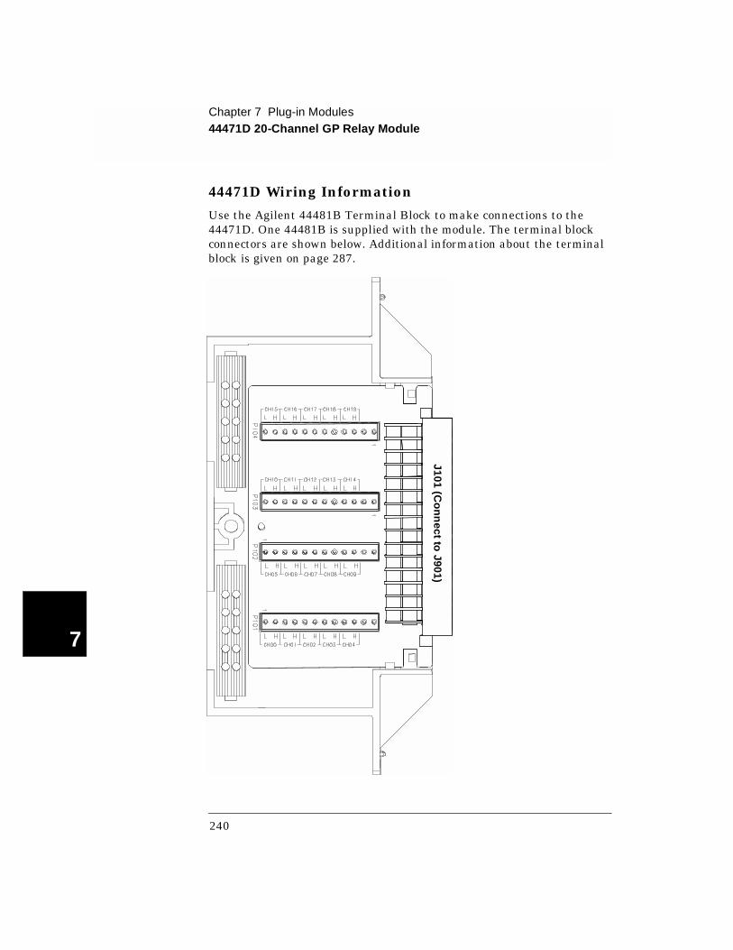
44471D Wiring Information
Use the Agilent 44481B Terminal Block to make connections to the 44471D. One 44481B is supplied with the module. The terminal block connectors are shown below. Additional information about the terminal block is given on page 287.
J101 (Co
nn
ect to J901)
240
Chapter 7 Plug-in Modules44471D 20-Channel GP Relay Module
4
7
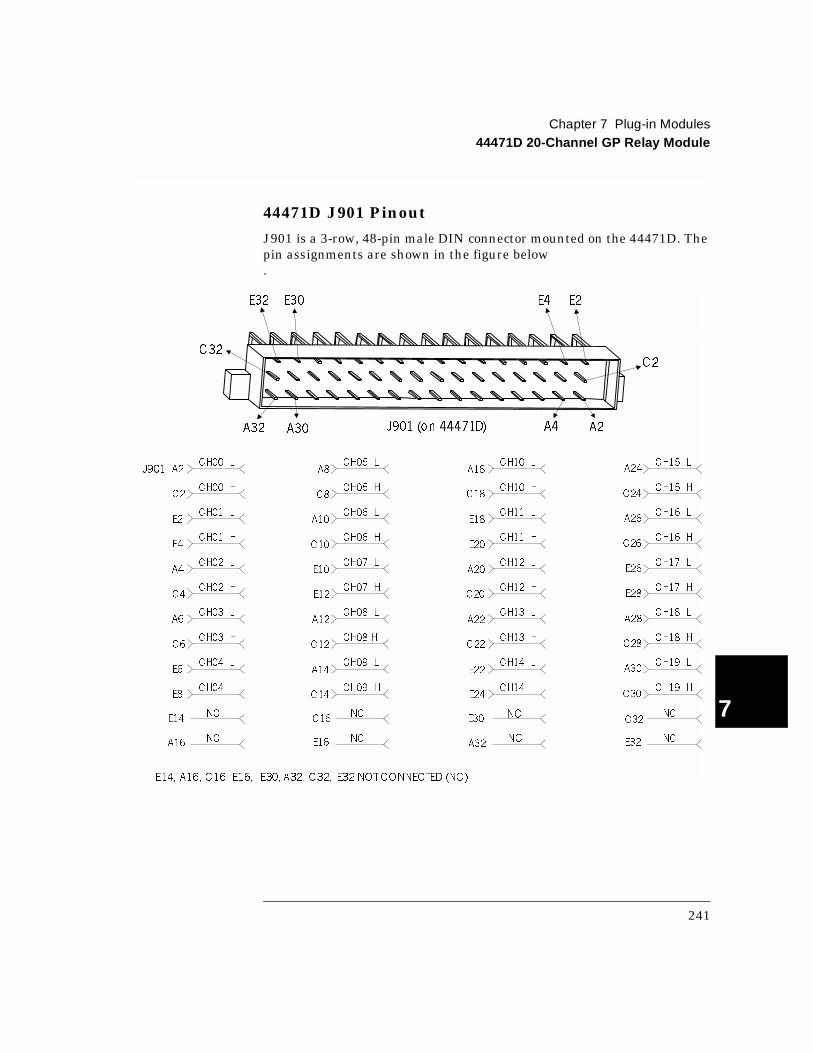
44471D J901 Pinout
J901 is a 3-row, 48-pin male DIN connector mounted on the 44471D. The pin assignments are shown in the figure below.
CH15 LA24
CH15 HC24
CH16 LA26
CH16 HC26
CH17 LE26
CH17 HE28
CH18 LA28
CH18 HC28
CH19 LA30
CH19 HC30
NC
NC
CH05 LA8
CH05 HC8
CH06 LA10
CH06 HC10
CH07 LE10
CH07 HE12
CH08 LA12
CH08 HC12
CH09 LA14
CH09 HC14
NC
NC
CH00 LA2
CH00 HC2
CH01 LE2
CH01 HE4
CH02 LA4
CH02 HC4
CH03 LA6
CH03 HC6
CH04 LE6
CH04 HE8
NC
NC
J901CH10 L
A18
CH10 HC18
CH11 LE18
CH11 HE20
CH12 LA20
CH12 HC20
CH13 LA22
CH13 HC22
CH14 LE22
CH14 HE24
E30NC
A32NC
E14, A32, C32,A16, C16, E16, E30, E32 NOTCONNECTED (NC)
J901 (on 44471D)
E32 E30 E4 E2
C2
A4 A2A32 A30
C32
E14
A16
C16
E16
C32
E32
241
Chapter 7 Plug-in Modules44472A Dual 4-Channel VHF Switch Module
7
44472A D ual 4-C hannel VH F Sw itch M odule
The Agilent 44472A VHF Switch Module provides two independent 4-to-1 coaxial multiplexers. These multiplexers are specifically designed for broadband signal switching up to 300 MHz. This module is the ideal choice for wide dynamic range measurements with spectrum and distortion analyzers.
Connections to the module are made through 10 BNC (coaxial) connectors mounted directly on the 44472A. Characteristic impedance is 50 Ω.
Note The 44472A is not recommended for use with instruments that require high DC isolation from earth ground (such as a DMM).
Specifications for the 44472A are given on page 337.
242
Chapter 7 Plug-in Modules44472A Dual 4-Channel VHF Switch Module
4
7
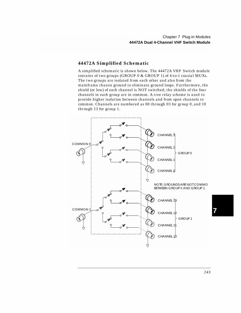
44472A Simplified Schematic
A simplified schematic is shown below. The 44472A VHF Switch module contains of two groups (GROUP 0 & GROUP 1) of 4-to-1 coaxial MUXs. The two groups are isolated from each other and also from the mainframe chassis ground to eliminate ground loops. Furthermore, the shield (or low) of each channel is NOT switched; the shields of the four channels in each group are in common. A tree relay scheme is used to provide higher isolation between channels and from open channels to common. Channels are numbered as 00 through 03 for group 0, and 10 through 13 for group 1.
NOTE: GROUNDS ARE NOT COMMONBETWEEN GROUP 0 AND GROUP 1.
COMMON 0
CHANNEL 3
CHANNEL 2
CHANNEL 1
CHANNEL 0
GROUP 0
COMMON 1
CHANNEL 13
CHANNEL 12
CHANNEL 11
CHANNEL 10
GROUP 1
243

Chapter 7 Plug-in Modules44472A Dual 4-Channel VHF Switch Module
7
44472A Wiring Information
Regardless of the topology (configuration) you are using, always use 50 Ω shielded coaxial cables to maintain both characteristic impedance and isolation. Keep cables as short as possible, especially in high frequency circuits or pulse circuits where a rise/fall time of less than 50 nsec is critical. Long cables can add considerable delay time which may cause timing problems. All test equipment (counters, spectrum analyzers, oscilloscopes, etc.) must be terminated with a 50 Ω impedance to minimize reflection loss. The rear panel is shown below.
Switch Group 0 Switch Group 1
244
Chapter 7 Plug-in Modules44473A 4 x 4 2-Wire Matrix Switch Module
4
7
44473A 4 x 4 2-Wire Matrix Switch Module
The Agilent 44473A Matrix Switch provides a 4 x 4 matrix of 2-wire switches. Each node (crosspoint) in the matrix contains a latching relay that connects a row to a column. Both Hi (H) and Lo (L) lines are switched. More than one switch can be closed at a time, allowing any combination of rows and columns to be connected.
Matrix switching provides a convenient way to connect a group of test instruments to multiple test points on a device or to multiple devices. This matrix switch offers highly flexible switching for testing devices over a frequency range of dc to 100 kHz.
Multiple 44473A modules may be connected together to form a larger matrices. The 44473A can also be used in conjunction with other modules (such as the 44470A 10-Channel MUX) to provide a wide variety of switching combinations. When wiring between multiple modules, keep wire length as short as possible to minimize noise and signal degradation.
Specifications for the 44473A are given on page 339.
245

Chapter 7 Plug-in Modules44473A 4 x 4 2-Wire Matrix Switch Module
7
44473A Simplified Schematic
A simplified schematic is shown below. The 44473A consists of 16 2-wire relays (nodes/crosspoints) organized in a 4-row by 4-column matrix.
Channels in this matrix module are numbered in the Row-Column format. For example, channel 32 represents the crosspoint connection between row 3 and column 2; while the channel 23 represents the crosspoint connection between row 2 and column 3, and so on.
ROW0
COL0
ROW1
COL1
ROW2
COL2
ROW3
COL3
H L
H
L
CHANNEL 32
(ROW 3, COLUMN 2)
H LH L H L
H
L
H
L
H
L
00 01 02 03
10 11 12 13
20 21 22 23
30 31 33
246

Chapter 7 Plug-in Modules44473A 4 x 4 2-Wire Matrix Switch Module
4
7
44473A Wiring Information
Use the Agilent 44483A Terminal Block to make connections to the 44473A. One 44483A is supplied with the module.
The terminal block includes a screw terminal that connects external wiring to the 44473A. The screw terminal is shown below. Additional information about the terminal block is given on page 285.
247

Chapter 7 Plug-in Modules44474A 16-Bit Digital I/O Module
7
44474A 16-Bit Digital I/O Module
The Agilent 44474A Digital I/O module provides 16 bidirectional data lines (bits) plus 4 lines used for control and handshaking. All lines are TTL compatible. The 16 I/O lines or bits can be addressed individually (bit-by-bit), as two independent 8-bit ports, or as one 16-bit word.
The two 8-bit ports are completely independent of each other and may be used separately. For instance, one port can be used for output operations, while the other for input. However, all 8 bits in a given port must be either input or output bits (not a combination of input and output).
Five handshaking modes are available for this module. The handshaking modes are described beginning on page 98. Handshaking uses up to three control lines:
• Peripheral Control (PCTL)
• I/O direction (I/O)
• Peripheral Flag (PFLG or EI)
Additionally, the 44474A provides an additional Channel Closed (CC) line that changes state to indicate a channel has been closed. The External Increment (EI) and Channel Closed (CC) lines can be used to control an external instrument such as a DMM. For example, Agilent DMMs have a Voltmeter Complete line that indicates when a measurement has completed. This line is connected to the 44474A EI input and the Channel Closed output is connected to the DMM External Trigger. When properly configured, a scan list can then be executed and measured without external computer control.
Port and bit numbering is show in the table below. Note that the ports are numbered differently if you are using the 3488 System mode.
Specifications for the 44474A are given on page 341.
System Mode 16-Bit Port # 8-Bit Port # Bit #
SCPI mode PORT 00PORT 00 Bits 0-7 (LO BYTE)
PORT 01 Bits 0-7 (HI BYTE)
3488A Mode PORT 02PORT 00 Bits 0-7 (LO BYTE)
PORT 01 Bits 0-7 (HI BYTE)
248
Chapter 7 Plug-in Modules44474A 16-Bit Digital I/O Module
4
7
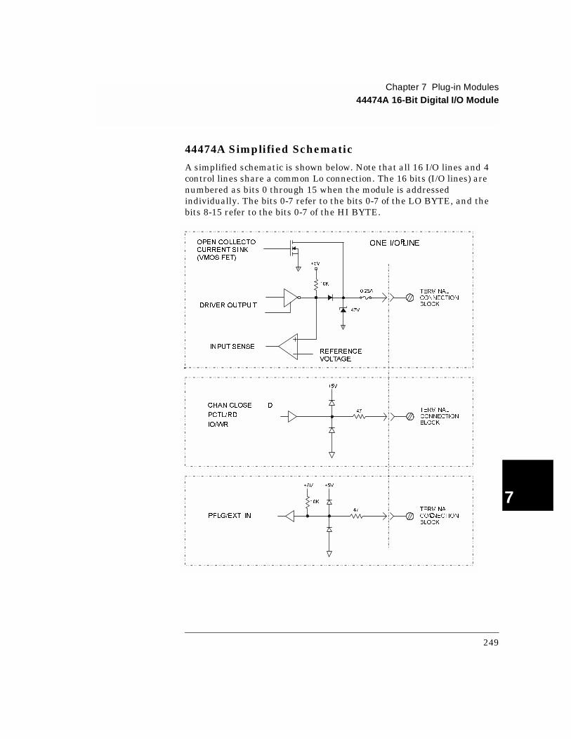
44474A Simplified Schematic
A simplified schematic is shown below. Note that all 16 I/O lines and 4 control lines share a common Lo connection. The 16 bits (I/O lines) are numbered as bits 0 through 15 when the module is addressed individually. The bits 0-7 refer to the bits 0-7 of the LO BYTE, and the bits 8-15 refer to the bits 0-7 of the HI BYTE.
CHAN CLOSE D
PCTL/RD
IO/WR
TERMINAL
CONNECTION
BLOCK
PFLG/EXT. IN CTERMINAL
CONNECTION
BLOCK
+5V
47
+5V
47
+5V
10K
+5V
47V
OPEN COLLECTO RCURRENT SINK(VMOS FET)
DRIVER OUTPUT
INPUT SENSEREFERENCEVOLTAGE
ONE I/O LINE
0.25A TERMINAL
CONNECTION
BLOCK
10K
249
Chapter 7 Plug-in Modules44474A 16-Bit Digital I/O Module
7
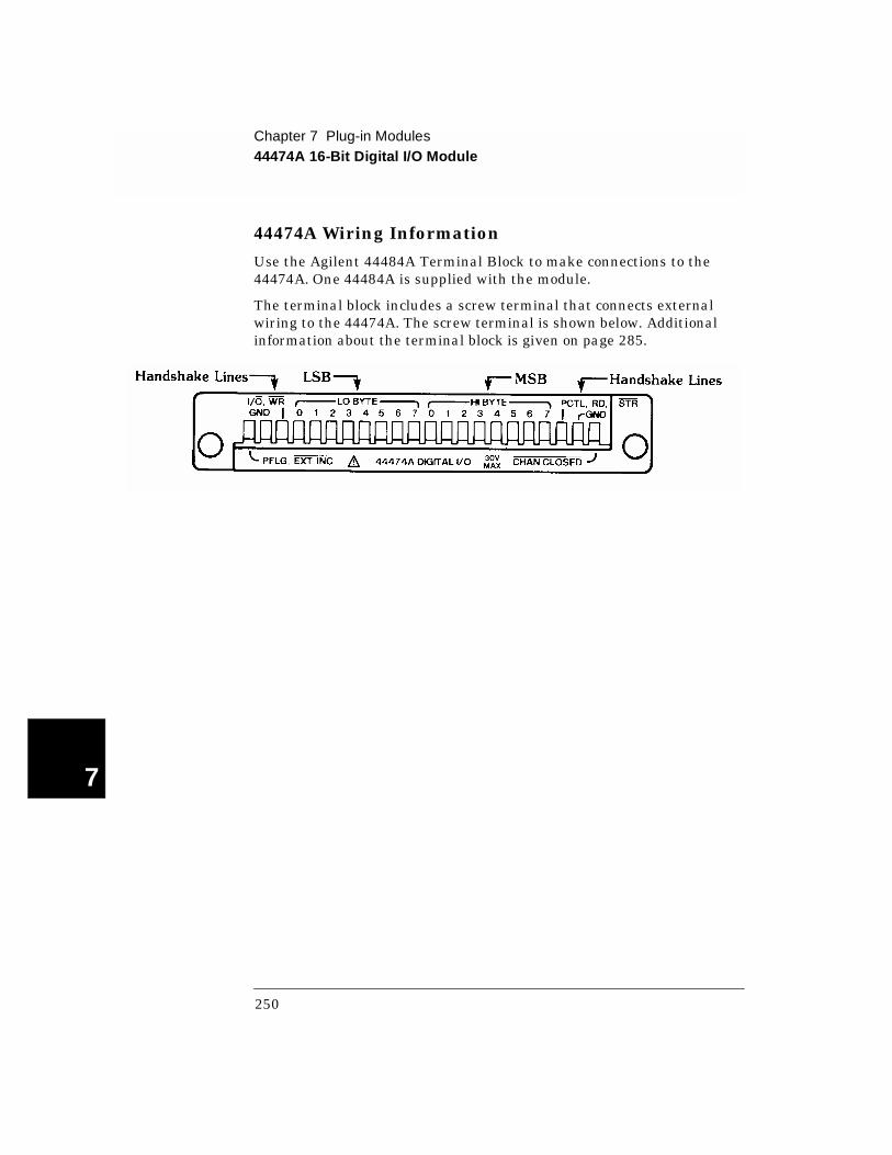
44474A Wiring Information
Use the Agilent 44484A Terminal Block to make connections to the 44474A. One 44484A is supplied with the module.
The terminal block includes a screw terminal that connects external wiring to the 44474A. The screw terminal is shown below. Additional information about the terminal block is given on page 285.
250

Chapter 7 Plug-in Modules44475A Breadboard Module
4
7
44475A Breadboard Module
The Agilent 44475A Breadboard module provides a means to mount custom designed circuits for use in the mainframe. If a desired function is not be available on a standard plug-in module, the 44475A provides the ideal solution.
Components are specified (but not supplied with the Breadboard module) for interfacing the Breadboard to the 3499A/B/C backplane. When these components are used, the Breadboard then provides 8 static input and 8 static output lines.
Two commands are used to control the Breadboard; DIAG:SPEEK? reads data from the input port and DIAG:SPOKE writes data to the output port. These commands are described on page 131.
Specifications for the 44475A are given on page 342.
251
Chapter 7 Plug-in Modules44475A Breadboard Module
7
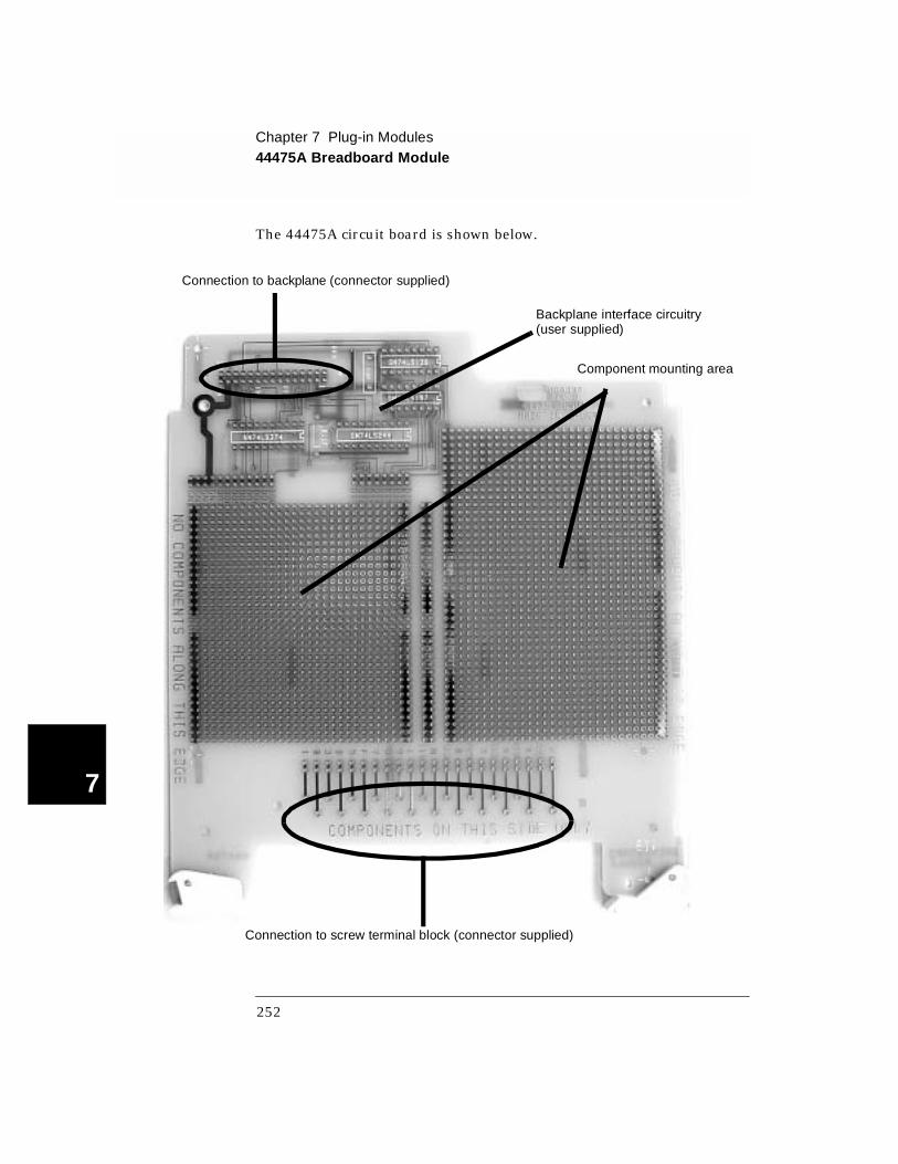
The 44475A circuit board is shown below.
Connection to screw terminal block (connector supplied)
Connection to backplane (connector supplied)
Backplane interface circuitry(user supplied)
Component mounting area
252
Chapter 7 Plug-in Modules44475A Breadboard Module
4
7
44475A Simplified Schematic
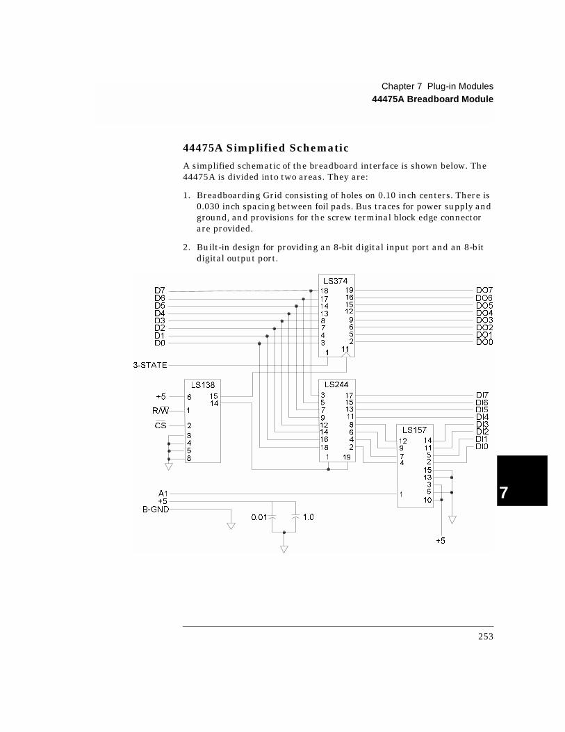
A simplified schematic of the breadboard interface is shown below. The 44475A is divided into two areas. They are:
1. Breadboarding Grid consisting of holes on 0.10 inch centers. There is 0.030 inch spacing between foil pads. Bus traces for power supply and ground, and provisions for the screw terminal block edge connector are provided.
2. Built-in design for providing an 8-bit digital input port and an 8-bit digital output port.
3-STATE
D0D1
D2D3
D4
D5
D6
D7
+5
R/W
CS
A1
+5
B-GND
0.01 1.0
+5
DI0
DI1DI2DI3DI4DI5DI6
DI7
DO0DO1DO2
DO3DO4DO5
DO6
DO7
LS374
LS138 LS244
LS157
6
1
2
3
4
5
8
15
14
3
5
7
9
12
14
16
18
1 19
2
4
6
8
11
13
15
17
18
17
14
13
8
7
4
3
111
19
16
15
12
9
6
5
2
12
9
4
1
14
11
5
2
15
13
3
6
10
7
253
Chapter 7 Plug-in Modules44475A Breadboard Module
7
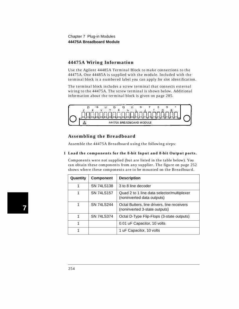
44475A Wiring Information
Use the Agilent 44485A Terminal Block to make connections to the 44475A. One 44485A is supplied with the module. Included with the terminal block is a numbered label you can apply for slot identification.
The terminal block includes a screw terminal that connects external wiring to the 44475A. The screw terminal is shown below. Additional information about the terminal block is given on page 285.
Assembling the Breadboard
Assemble the 44475A Breadboard using the following steps:
1 Load the components for the 8-bit Input and 8-bit Output ports.
Components were not supplied (but are listed in the table below). You can obtain these components from any supplier. The figure on page 252 shows where these components are to be mounted on the Breadboard.
Quantity Component Description
1 SN 74LS138 3 to 8 line decoder
1 SN 74LS157 Quad 2 to 1 line data selector/multiplexer (noninverted data outputs)
1 SN 74LS244 Octal Butters, line drivers, line receivers (noninverted 3-state outputs)
1 SN 74LS374 Octal D-Type Flip-Flops (3-state outputs)
1 0.01 uF Capacitor, 10 volts
1 1 uF Capacitor, 10 volts
254
Chapter 7 Plug-in Modules44475A Breadboard Module
4
7
2 Install your custom circuitry.
Component height restrictions and how far the component leads extend through the circuit board are limited by the top and bottom shields. These shields provide RF shielding as well as structural strength and must never be eliminated.
The maximum component height allowed is 12.7 mm (0.50 in.). However, if the height of any component exceeds 10 mm, the conductive surface of the component must be insulated. On the circuit side of the Breadboard, the lead lengths are limited to 3.2 mm (0.125 in.) from the circuit board.
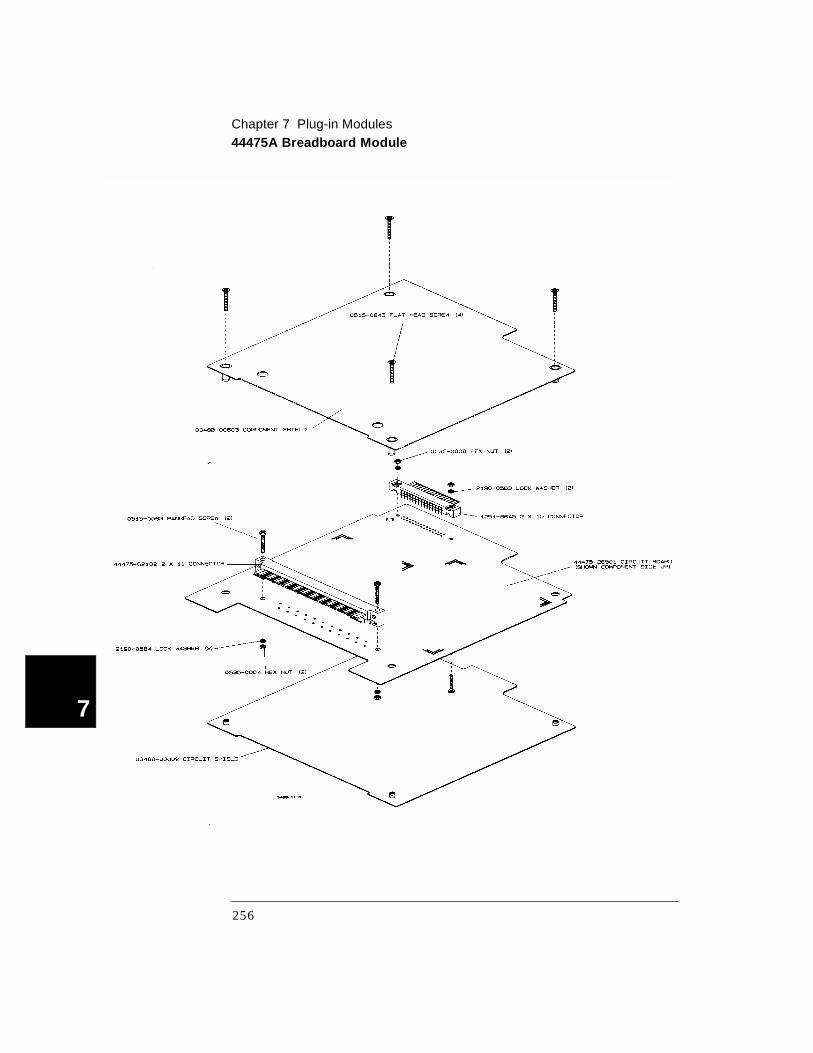
3 Assemble the hardware.
The table below lists the hardware parts that are supplied with the 44475A. An assembly diagram is given on the next page.
Part Number Description
44475-26501 Breadboard circuit board
03488-00602 Bottom shield
03488-00603 Top shield (component side)
1251-8645 2 rows x 15 pins right angle connector (small connector)
44475-62102 2 rows x 11 pins right angle connector (large connector)
44475-62101 Terminal Block, keyed for the breadboard connector
5040-5193 Connector Housing
0515-5194 Cable Clamp
0515-0063 Pan Head screw, 2.5 x 12 (metric)
0515-0843 Flat Head screw, 2.5 x 20 Lock (metric)
0515-0045 Pan Head screw, 3 x 18 Lock (metric)
0535-0004 Hex Nut, 3 x 0.5
0535-0008 Hex Nut, 2.5 x 0.45
2190-0583 Lock Washer
2190-0584 Lock Washer
255
Chapter 7 Plug-in Modules44475A Breadboard Module
7
256

Chapter 7 Plug-in Modules44476A Microwave Switch Module
4
7
44476A Microwave Switch Module
The 44476A contains three Microwave Switches. These switches have the following features:
• Broad bandwidth (dc to 18 GHz)
• High isolation (> 90 dB to 18 GHz)
• Excellent repeatability (typically 0.03 dB after 1,000,000 switchings)
• Internal 50 Ω terminations
The Agilent 8762B is a break-before-make switch controlled by a latching solenoid. Once switched, coil voltage can be removed and the switch remains in the switched position. Internal coil contacts open and remove coil voltage after a switching operation to minimize the amount of heat dissipated near the switch contacts. The Agilent 8762B uses SMA connectors for ease in cable connections
The 3499A/B/C identifies this module as a 44471A on the front-panel display. Changing the state of channels other than channels 00 through 02 does not generate an error, but has no effect.
Specifications for the 44476A are given on page 344.
257
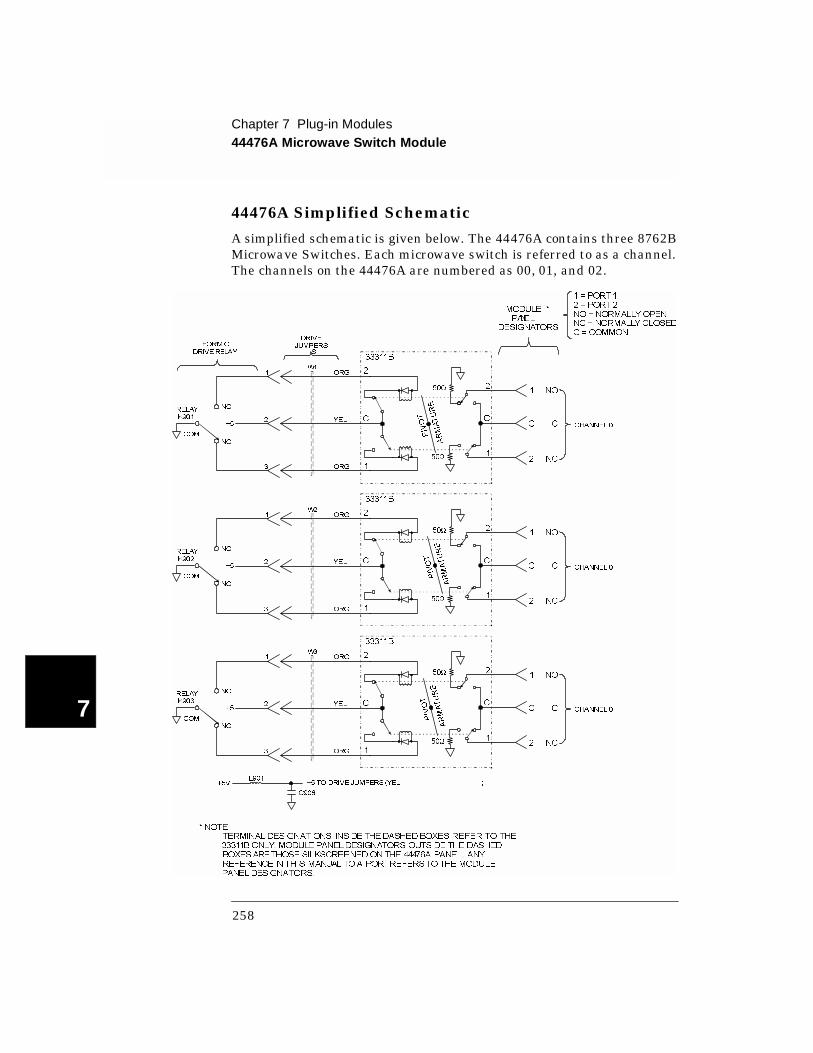
Chapter 7 Plug-in Modules44476A Microwave Switch Module
7
44476A Simplified Schematic
A simplified schematic is given below. The 44476A contains three 8762B Microwave Switches. Each microwave switch is referred to as a channel. The channels on the 44476A are numbered as 00, 01, and 02.
DRIVE
JUMPERSFORMC
DRIVERELAY S
+5VL901
C906
+5TO DRIVE JUMPERS (YEL )
RELAY
K901
COM
NO
NC
+5
1
2
3
ORG
YEL
ORG
W1
CHANNEL0
50Ω
50Ω
33311B
2
C
1
2
C
1
1
C
2
NO
C
NC
RELAY
K903
COM
NO
NC
+5
1
2
3
ORG
YEL
ORG
W3
CHANNEL0
50Ω
50Ω
33311B
2
C
1
2
C
1
1
C
2
NO
C
NC
RELAY
K902
COM
NO
NC
+5
1
2
3
ORG
YEL
ORG
W2
CHANNEL0
50Ω
50Ω
33311B
2
C
1
2
C
1
1
C
2
NO
C
NC
MODULE *
PANEL
DESIGNATORS
1 = PORT 1
2 = PORT 2
NO = NORMALLY OPEN
NC = NORMALLY CLOSED
C = COMMON
* NOTE :
TERMINALDESIGNATIONS INSIDE THEDASHED BOXES REFER TO THE
33311B ONLY. MODULE PANELDESIGNATORS OUTSIDE THE DASHED
BOXESARETHOSE SILKSCREENEDON THE 44476A PANEL. ANY
REFERENCEIN THIS MANUAL TOA PORTREFERSTO THEMODULE
PANELDESIGNATORS.
PIVOT
ARMATURE
PIVOT
ARMATURE
PIVOT
ARMATURE
258

Chapter 7 Plug-in Modules44476A Microwave Switch Module
4
7
44476A Wiring Information
The 44476A provides nine 50 Ω SMA connectors.
259

Chapter 7 Plug-in Modules44476B Microwave Switch Module
7
44476B Microwave Switch Module
The 44476B is not supplied with microwave switches. You must provide your own microwave switches, mount them on the assembly, and connect one of the module’s Form C relay drive circuits to each switch.
The 44476B panel has two 53.8 X 9.6 mm cutouts for a set of microwave switches. The recommended Agilent microwave switches are listed below.
The 3499A/B/C identifies this module as a 44471A on the front-panel display. Changing the state of channels other than channels 00 through 02 does not generate an error, but has no effect.
Specifications for the 44476B are dependent upon the switches used. Refer to the switch data sheets for more information.
Microwave Switch Ports Frequency
8762A 3 DC-4 GHz
8762B 3 DC-18 GHz
8762C 3 DC-26.5 GHz
8762Fa
a. Except the 8762F Microwave Switch with 75 Ω characteristic impedance, all others are 50 Ω.
3 DC-4 GHz
8763B 4 DC-18 GHz
8763C 4 DC-26.5 GHz
8764B 5 DC-18 GHz
8764C 5 DC-26.5 GHz
260

Chapter 7 Plug-in Modules44476B Microwave Switch Module
4
7
The 44476B is shown below.
261
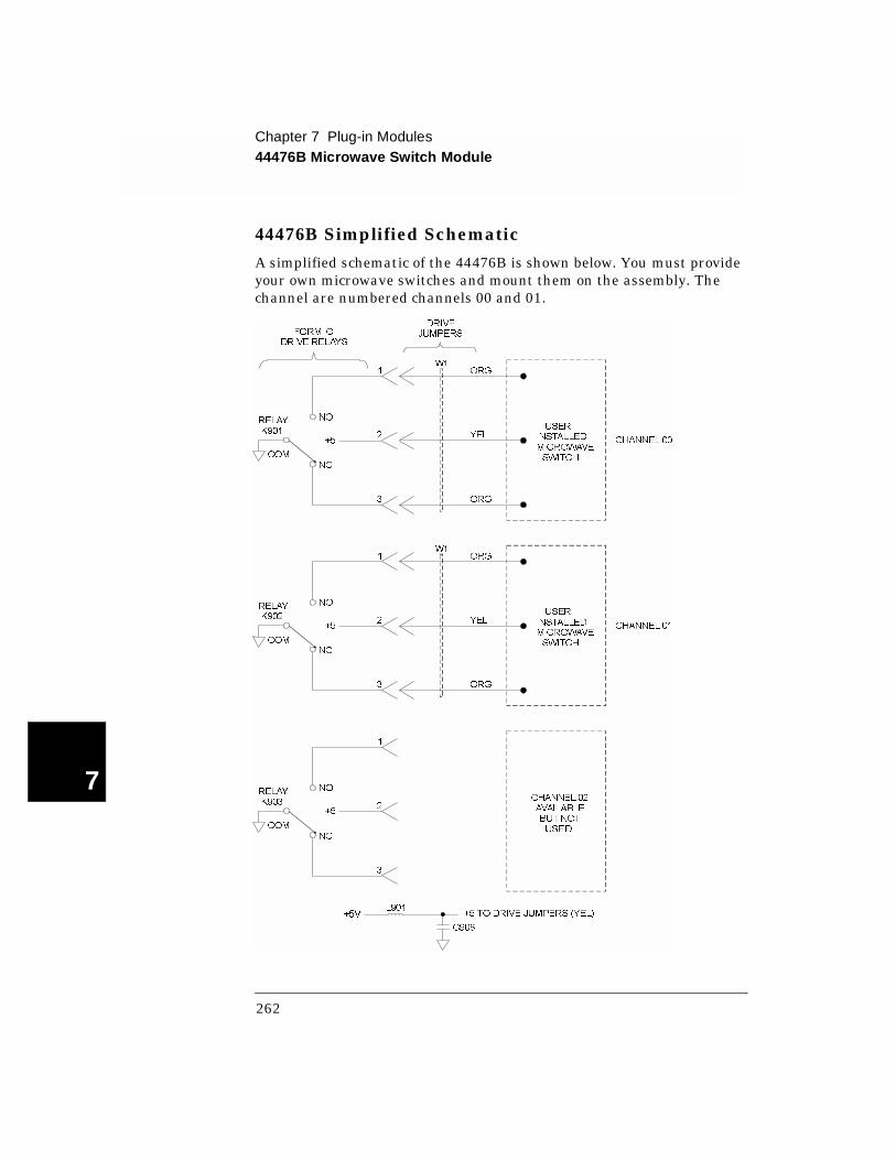
Chapter 7 Plug-in Modules44476B Microwave Switch Module
7
44476B Simplified Schematic
A simplified schematic of the 44476B is shown below. You must provide your own microwave switches and mount them on the assembly. The channel are numbered channels 00 and 01.
RELAYK901
COM
NO
NC
+5
1
2
3
ORG
YEL
ORG
W1
CHANNEL00
USERINSTALLEDMICROWAVESWITCH
DRIVEJUMPERSFORM C
DRIVE RELAYS
RELAYK903
COM
NO
NC
+5
1
2
3
CHANNEL02AVAILABLEBUT NOTUSED
RELAYK902
COM
NO
NC
+5
1
2
3
ORG
YEL
ORG
W1
CHANNEL01
USERINSTALLEDMICROWAVESWITCH
+5VL901
C906
+5 TO DRIVE JUMPERS (YEL)
262
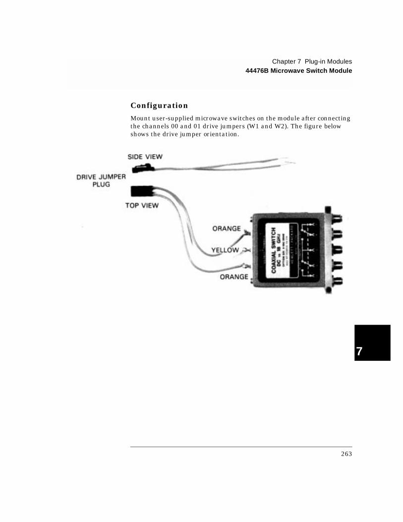
Chapter 7 Plug-in Modules44476B Microwave Switch Module
4
7
Configuration
Mount user-supplied microwave switches on the module after connecting the channels 00 and 01 drive jumpers (W1 and W2). The figure below shows the drive jumper orientation.
263
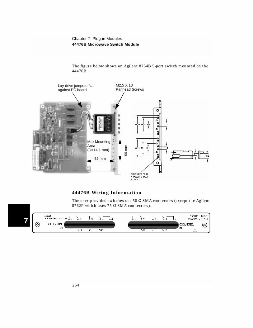
Chapter 7 Plug-in Modules44476B Microwave Switch Module
7
The figure below shows an Agilent 8764B 5-port switch mounted on the 44476B.
44476B Wiring Information
The user-provided switches use 50 Ω SMA connectors (except the Agilent 8762F which uses 75 Ω SMA connectors).
All mounting holes
threaded for M2.5
screws
55.58 44.44 30.1 11.2
55.58 44.44 30.1 11.2
7.0116.42
M2.5 X 18 Panhead Screws
Lay drive jumpers flat against PC board
Max Mounting Area(D=14.1 mm)
62 mm
66 m
m
44476B
MICROWAVE SWITCH
CHANNEL
00
1 2 3 4 5 1 2 3 4 5
NO C NC NO C NC
CHANNEL
01
7VDC = MAX
1WCW / CHAN
!
264

Chapter 7 Plug-in Modules44477A Form-C Relay Module
4
7
44477A Form-C Relay Module
The Agilent 44477A consists of seven independent, break-before-make, SPDT Form-C latching relays (one contact normally open, one contact normally closed).
The 44477A can be used for signal switching or power applications (250V, 2A). Additionally, this module is ideally suited for driving remote RF, coaxial, and microwave devices such as the Agilent 8761, 8762A/B/C, 8763B/C, and 8764B/C switches or programmable step attenuators like the 876xx series.
You can use the 3499A/B/C +5 V power supply available on the module or provide an external supply to use as pull-ups on either the NO or NC paths.
The 3499A/B/C identifies this module as a 44471A on the front-panel display. Changing the state of channels other than channels 00 through 06 does not generate an error, but has no effect.
Specifications for the 44477A are given on page 345.
44477A Simplified Schematic
A simplified schematic is given on the next page. The 44477A consists of seven independent Form-C relays (K901-K907) which are numbered as channels 00 through 06. Closing a channel (relay) will connect the normally open (NO) contact to the common port (C). After power-on or a reset, the Form C relays on the 44477A have their normally open (NO) contacts open and normally closed (NC) contacts closed.
Each relay circuit has mounting holes (JM901 - JM914) used to add a pull-up resistor from the NO (normally open) and/or NC (normally closed) contacts to the +5V power supply. Also, there are mounting holes (JM921 and JM922) at the +5V supply for the addition of a protection resistor or inductor if the internal supply is to be used. If the internal supply is not used, an external power supply can be applied through the screw terminal block via the “H” terminal. The addition of pull-up resistors can be useful when driving logic circuits where the common (C) terminal is connected to ground and used to pull either the NO or the NC line low.
265
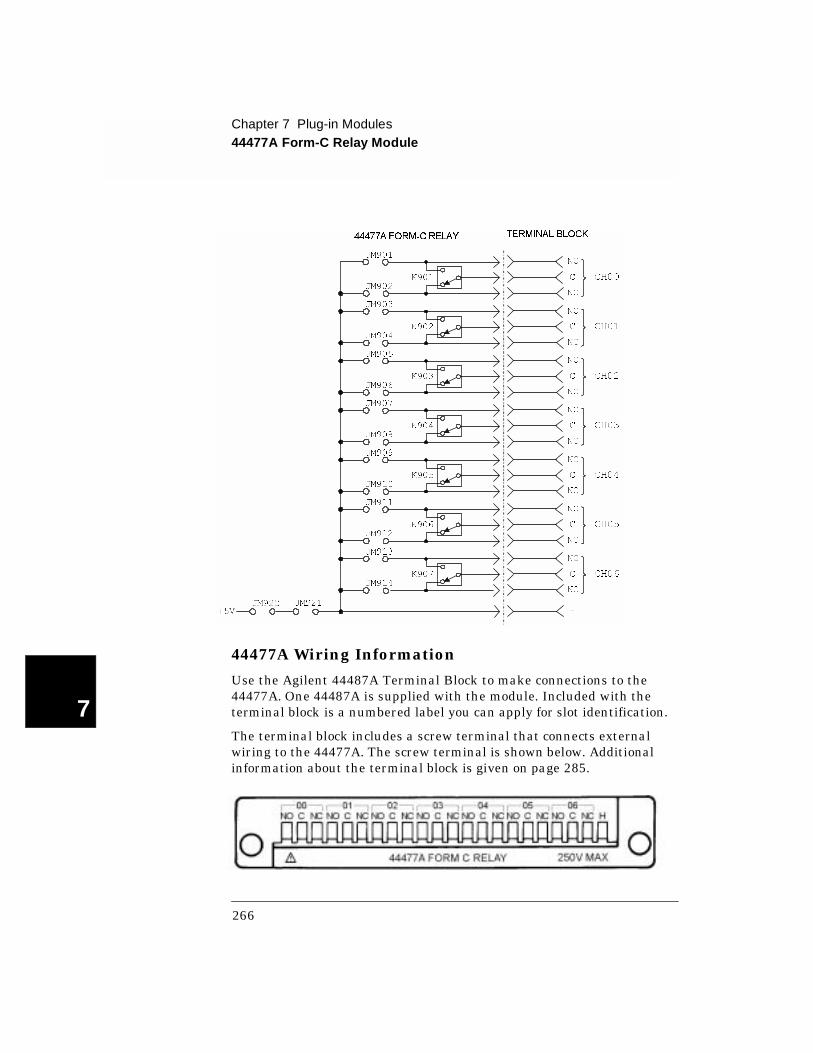
Chapter 7 Plug-in Modules44477A Form-C Relay Module
7
44477A Wiring Information
Use the Agilent 44487A Terminal Block to make connections to the 44477A. One 44487A is supplied with the module. Included with the terminal block is a numbered label you can apply for slot identification.
The terminal block includes a screw terminal that connects external wiring to the 44477A. The screw terminal is shown below. Additional information about the terminal block is given on page 285.
44477A FORM-CRELAY TERMINAL BLOCK
JM903
JM904
K902
NO
C
NC
CH01
JM901
JM902
K901
NO
C
NC
CH00
JM905
JM906
K903
NO
C
NC
CH02
JM907
JM908
K904
NO
C
NC
CH03
JM909
JM910
K905
NO
C
NC
CH04
JM911
JM912
K906
NO
C
NC
CH05
JM913
JM914
K907
NO
C
NC
CH06
JM921
HJM922
+5V
266

Chapter 7 Plug-in Modules44478A/B 1.3 GHz Dual 4-to-1 MUX Modules
4
7
44478A /B 1.3 G H z D ual 4-to-1 M U X M odules
The Agilent 44478A and 44478B consist of two independent 4-to-1 multiplexers (group 00 and group 01) that provide bidirectional switching. The module’s latching relays are configured in a “tree” structure, to provide high isolation and low VSWR (voltage standing wave ratio). Each channel can switch up to 42V dc + ac peak at frequencies up to 1.3 GHz.
The 44478A is intended for 50 Ω impedance applications. The 44478B is intended for 75 Ω impedance applications.
User connections for the channels are through BNC connectors on the rear panel. Each channel has an SMB connector on the main PC board used to connect resistive terminations and terminate unused channels.
The 3499A/B/C identifies this module as a 44472A on the front-panel display. Changing the state of channels other than channels 00 through 03 or 10 through 13 does not generate an error, but has no effect.
Specifications for the 44478A/B are given on page 347.
267
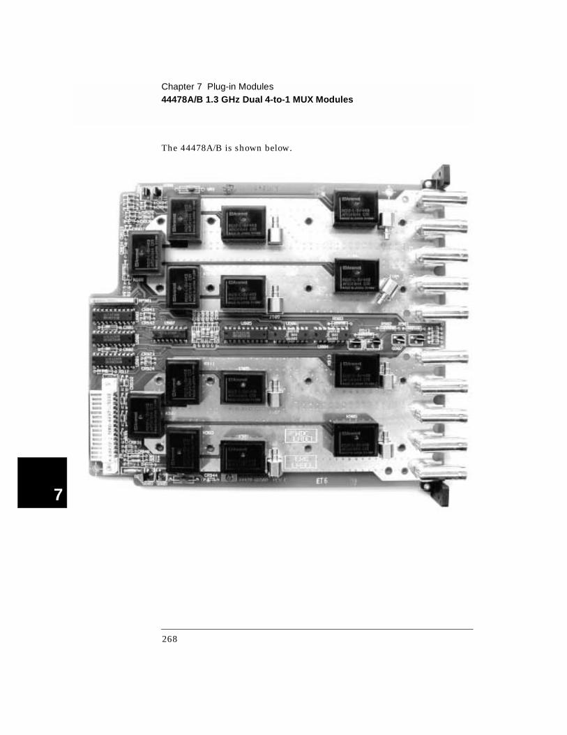
Chapter 7 Plug-in Modules44478A/B 1.3 GHz Dual 4-to-1 MUX Modules
7
The 44478A/B is shown below.
268
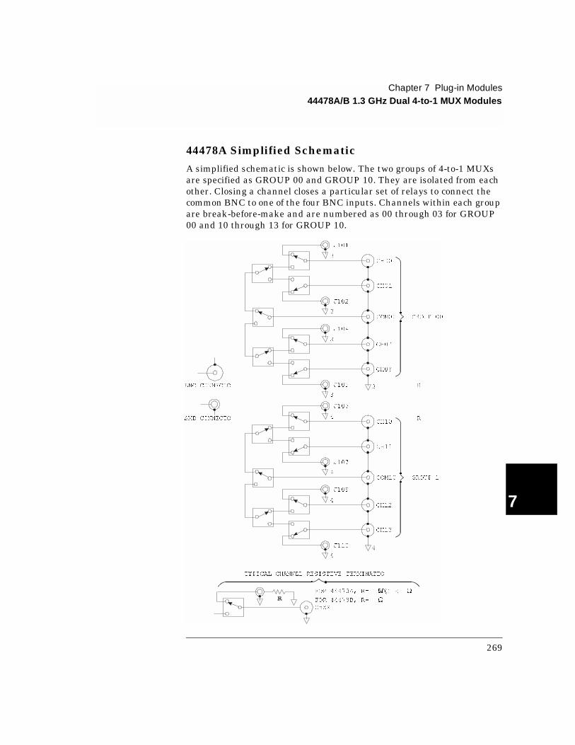
Chapter 7 Plug-in Modules44478A/B 1.3 GHz Dual 4-to-1 MUX Modules
4
7
44478A Simplified Schematic
A simplified schematic is shown below. The two groups of 4-to-1 MUXs are specified as GROUP 00 and GROUP 10. They are isolated from each other. Closing a channel closes a particular set of relays to connect the common BNC to one of the four BNC inputs. Channels within each group are break-before-make and are numbered as 00 through 03 for GROUP 00 and 10 through 13 for GROUP 10.
3
CH00
CH01
J101
3
J102
3
CH02
CH03
J104
3
J105
COM00
3
GROUP 00
4
CH11
CH10
J106
4
J107
4
CH12
CH13
J109
4
J110
COM10 GROUP 1
BNC CONNECTO R
SMB CONNECTO R
TYPICAL CHANNEL RESISTIVE TERMINATIO
ChXX
FOR 44478B, R= Ω
FOR 44478A, R= 50O RΩ ( Ω
269
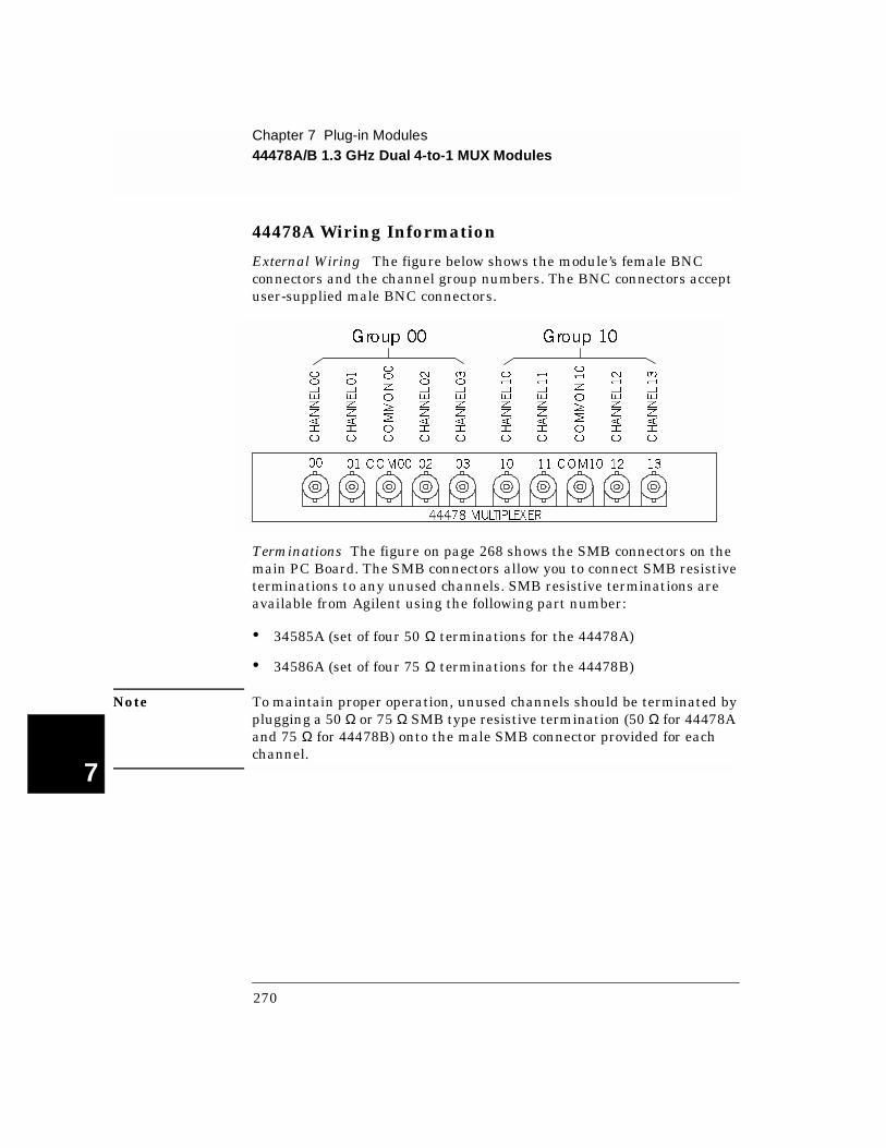
Chapter 7 Plug-in Modules44478A/B 1.3 GHz Dual 4-to-1 MUX Modules
7
44478A Wiring Information
External Wiring The figure below shows the module’s female BNC connectors and the channel group numbers. The BNC connectors accept user-supplied male BNC connectors.
Terminations The figure on page 268 shows the SMB connectors on the main PC Board. The SMB connectors allow you to connect SMB resistive terminations to any unused channels. SMB resistive terminations are available from Agilent using the following part number:
• 34585A (set of four 50 Ω terminations for the 44478A)
• 34586A (set of four 75 Ω terminations for the 44478B)
Note To maintain proper operation, unused channels should be terminated by plugging a 50 Ω or 75 Ω SMB type resistive termination (50 Ω for 44478A and 75 Ω for 44478B) onto the male SMB connector provided for each channel.
CHANNEL00
CHANNEL03
CHANNEL02
COMMON00
CHANNEL01
CHANNEL10
CHANNEL13
CHANNEL12
COMMON10
CHANNEL11
Group 00 Group 10
00 01 COM00 02 03 10 11 COM10 12 13
44478 MULTIPLEXER
270
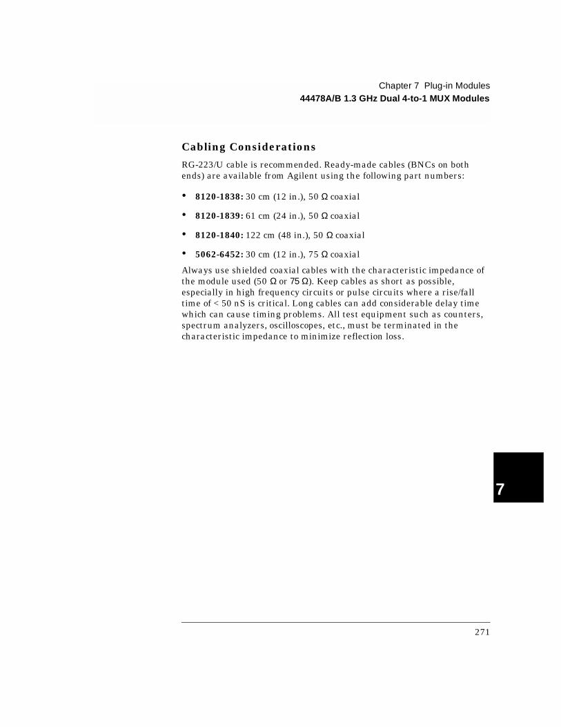
Chapter 7 Plug-in Modules44478A/B 1.3 GHz Dual 4-to-1 MUX Modules
4
7
Cabling Considerations
RG-223/U cable is recommended. Ready-made cables (BNCs on both ends) are available from Agilent using the following part numbers:
• 8120-1838: 30 cm (12 in.), 50 Ω coaxial
• 8120-1839: 61 cm (24 in.), 50 Ω coaxial
• 8120-1840: 122 cm (48 in.), 50 Ω coaxial
• 5062-6452: 30 cm (12 in.), 75 Ω coaxial
Always use shielded coaxial cables with the characteristic impedance of the module used (50 Ω or 75 Ω). Keep cables as short as possible, especially in high frequency circuits or pulse circuits where a rise/fall time of < 50 nS is critical. Long cables can add considerable delay time which can cause timing problems. All test equipment such as counters, spectrum analyzers, oscilloscopes, etc., must be terminated in the characteristic impedance to minimize reflection loss.
271
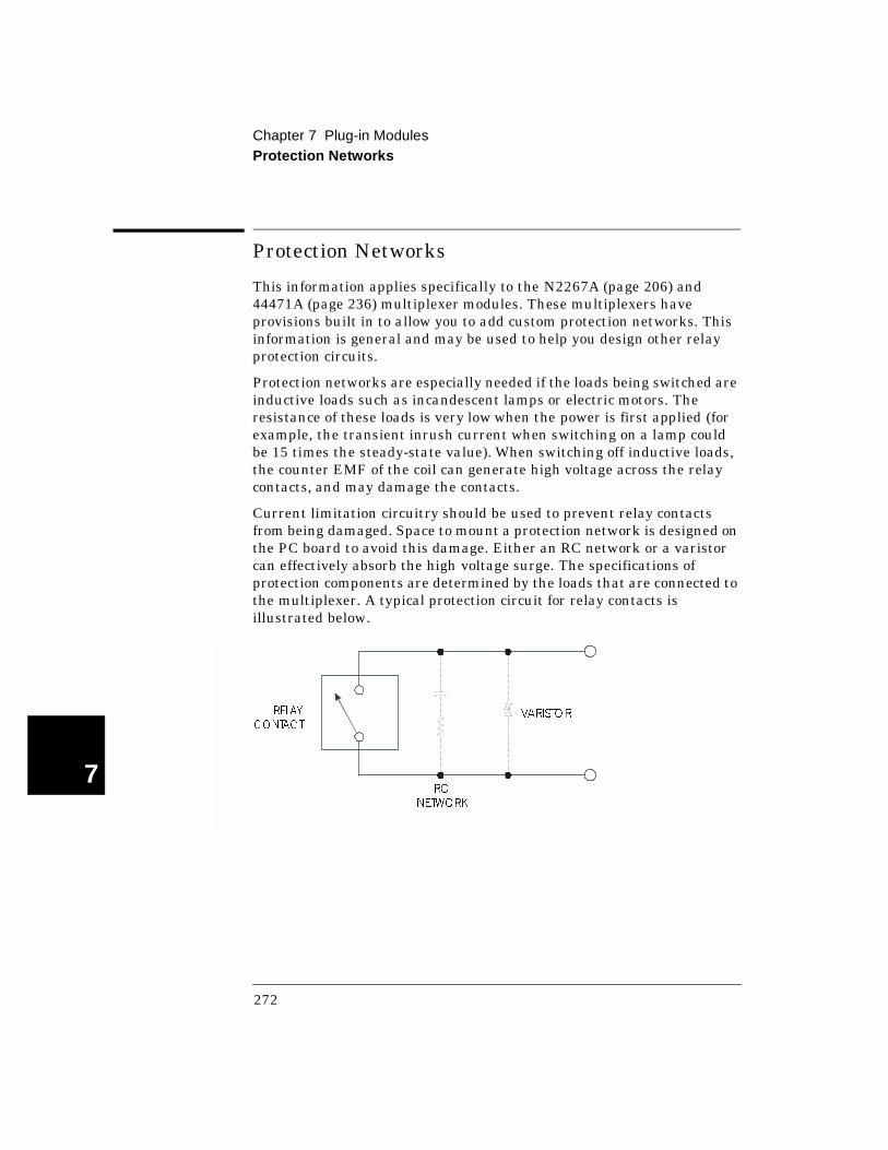
Chapter 7 Plug-in ModulesProtection Networks
7
Protection Networks
This information applies specifically to the N2267A (page 206) and 44471A (page 236) multiplexer modules. These multiplexers have provisions built in to allow you to add custom protection networks. This information is general and may be used to help you design other relay protection circuits.
Protection networks are especially needed if the loads being switched are inductive loads such as incandescent lamps or electric motors. The resistance of these loads is very low when the power is first applied (for example, the transient inrush current when switching on a lamp could be 15 times the steady-state value). When switching off inductive loads, the counter EMF of the coil can generate high voltage across the relay contacts, and may damage the contacts.
Current limitation circuitry should be used to prevent relay contacts from being damaged. Space to mount a protection network is designed on the PC board to avoid this damage. Either an RC network or a varistor can effectively absorb the high voltage surge. The specifications of protection components are determined by the loads that are connected to the multiplexer. A typical protection circuit for relay contacts is illustrated below.
RELAY
CONTACT
RC
NETWORK
VARISTOR
272

Chapter 7 Plug-in ModulesProtection Networks
4
7
In designing RC protection networks, the protection resistor, Rp, is selected as a compromise between two values. The minimum value of Rp is determined by the maximum acceptable relay contact current (Io). The maximum allowable relay current (Io) is 2 amps ac rms or 2 amps dc. Thus, the minimum value for Rp is V/Io, where V is the peak value of the supply voltage.
Rp = V/Io = V/2 Equation 1
The maximum value for Rp is usually made equal to the load resistance, RI. Therefore, the limits on Rp can be stated as:
V/Io < Rp < RI Equation 2
Note, the actual value of Io in a circuit is determined by the equation:
Io = V/RI Equation 3
Where V is the peak value of the source voltage and RI is the resistance of the load. Equations 1 & 2 use Io as the maximum allowable relay current to determine the minimum value of Rp. The value for Io calculated in Equation 3 will be used to determine the value of the protection capacitor, Cp.
In determine the value of the protection network capacitor Cp, there are several things that need to be considered. First, the total circuit capacitance (C) must be such that the peak voltage across the open relay contacts does not exceed 353 volts peak (250 V rms = 353 Vp). The equation for determining the minimum allowable circuit capacitance is:
C ≥ (Io/353)2L Equation 4
where L = the inductance of the load and Io is the value calculated in Equation 3.
In reality, the total circuit capacitance (C) is made up of the wiring capacitance plus the value of the protection network capacitor Cp. Therefore, the minimum value for Cp should be the value obtained for the total circuit capacitance, C, from Equation 4. Indeed, the actual value used for Cp should be substantially greater than the value calculated for C.
273

Chapter 7 Plug-in ModulesProtection Networks
7
For example, we will determine the typical values for an RC protection network where the load is a small ac motor running on the 120 V ac line (170 V peak). This motor draws a maximum of 2 amps.
Using Equation 1 we can find the minimum value for Rp:
Rp = V/Io = 170/2 = 85 Ω
The maximum value for Rp would be equal to the load resistance or 400 Ω. Therefore, any resistor (preferably at least 1 watt) between 85 and 400 Ω will suffice.
To keep the peak contact voltage below 353V peak, use equation 3 to determine Io:
Io = V/R1 = 170/400 = 0.425 A
Now use equation 4 to determine C:
C ≥ (Io/353)2L = (0.425/353)2(0.1) = 0.144 µF
Since Rp can vary between 85 Ω and 400 Ω, an appropriate protection network to be connected to this circuit is Rp = 220 Ω and Cp = 0.15 µF.
Using Varistors
Just as contact protection circuits are important to suppress noise while relay contacts are opening and closing, transient protection should be provided while the relays are open. This is the purpose of the varistor. When selecting a varistor, make certain that it has a voltage rating sufficient for your application. A typical 250 VAC varistor can be purchased with the Agilent part number 0873-0227.
274

Chapter 7 Plug-in ModulesTerminals and Connections Information
4
7
Terminals and Connections Information
This section contains details about each of the terminals and connections available for the plug-in modules. Some modules have more than one available terminal. The table below shows the terminals available for each plug-in module. The general wiring information about each terminal is on the listed page number. Additionally, for some terminals, you will need to consult the specific plug-in module for connector pin-out diagrams and assignments.
Plug-in Module
Available Terminal(s) Page
N2260A N2290AN2296AN2297AN2299A
Screw Terminal BlockDirect wiring (insulation displacement) connectorDIN96 to twin D50 CableDIN96 to quad D25 cable
277278279281
N2261A N2291AN2296AN2297AN2299A
Screw Terminal BlockDirect wiring (insulation displacement) connectorDIN96 to twin D50 CableDIN96 to quad D25 cable
277278279281
N2262A N2292AN2296AN2298A
Screw Terminal BlockDirect wiring (insulation displacement) connectorDIN96 to D25 Cable
277278280
N2263A N2293AN2296AN2297AN2299A
Screw Terminal BlockDirect wiring (insulation displacement) connectorDIN96 to twin D50 CableDIN96 to quad D25 cable
277278279281
N2264A N2294AN2296AN2297AN2299A
Screw Terminal BlockDirect wiring (insulation displacement) connectorDIN96 to twin D50 CableDIN96 to quad D25 cable
277278279281
N2265A N2295AN2296AN2297AN2299A
Screw Terminal BlockDirect wiring (insulation displacement) connectorDIN96 to twin D50 CableDIN96 to quad D25 cable
277278279281
275
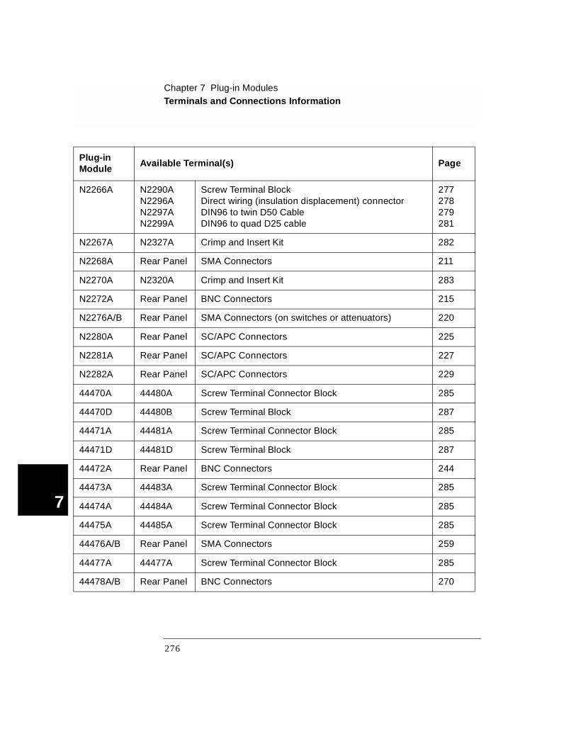
Chapter 7 Plug-in ModulesTerminals and Connections Information
7
Plug-in Module
Available Terminal(s) Page
N2266A N2290AN2296AN2297AN2299A
Screw Terminal BlockDirect wiring (insulation displacement) connectorDIN96 to twin D50 CableDIN96 to quad D25 cable
277278279281
N2267A N2327A Crimp and Insert Kit 282
N2268A Rear Panel SMA Connectors 211
N2270A N2320A Crimp and Insert Kit 283
N2272A Rear Panel BNC Connectors 215
N2276A/B Rear Panel SMA Connectors (on switches or attenuators) 220
N2280A Rear Panel SC/APC Connectors 225
N2281A Rear Panel SC/APC Connectors 227
N2282A Rear Panel SC/APC Connectors 229
44470A 44480A Screw Terminal Connector Block 285
44470D 44480B Screw Terminal Block 287
44471A 44481A Screw Terminal Connector Block 285
44471D 44481D Screw Terminal Block 287
44472A Rear Panel BNC Connectors 244
44473A 44483A Screw Terminal Connector Block 285
44474A 44484A Screw Terminal Connector Block 285
44475A 44485A Screw Terminal Connector Block 285
44476A/B Rear Panel SMA Connectors 259
44477A 44477A Screw Terminal Connector Block 285
44478A/B Rear Panel BNC Connectors 270
276

Chapter 7 Plug-in ModulesTerminals and Connections Information
4
7
N229X Screw Terminal Blocks
This terminal block is compatible with the N2290A, N2291A, N2292A, N2293A, and N2295A plug-in modules. Refer to each plug-in module section for detailed wiring information. The figure below shows the basic steps to wire and assemble this terminal block.
STEP 1. Remove cover
A. Release screws on top of the cover;B. Press tab forward and release.
STEP 2. Attach wires
A. The wire gauge: 18-26 AWG;B. Insert wire into terminal connectors;C. Tighten screws on the connectors.
STEP 3. Tighten the wires
A. Insert the wires into the nearest cableboot, move the cable boot to theCable slot;
B. Tighten the cable boot.
STEP 4. Replace cover
A. Hook the top cover tabs onto the fixture;B. Press down and tighten screws.
Cable Boot
277
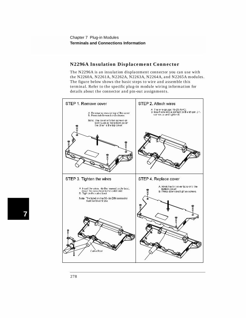
Chapter 7 Plug-in ModulesTerminals and Connections Information
7
N2296A Insulation Displacement Connector
The N2296A is an insulation displacement connector you can use with the N2260A, N2261A, N2262A, N2263A, N2264A, and N2265A modules. The figure below shows the basic steps to wire and assemble this terminal. Refer to the specific plug-in module wiring information for details about the connector and pin-out assignments.
STEP 1. Remove cover
A. Release screws on top of the cover;B. Press tab forward and release.
Note: The cover with two screws onboth sides is the bottom cover,the other is the top cover.
STEP 2. Attach wires
STEP 3. Tighten the wires
A. Insert the wires into the nearest cable boot,move the cable boot to the cable slot;
B. Tighten the cable boot.
Note: The label on the 96-pin DIN connectormust be toward you.
STEP 4. Replace cover
A. Hook the top cover tabs onto theBottom cover;
B. Press down and tighten screws.
Cable Boot
A. The wire gauge: 18-26 AWG;B. Insert wire into a contact on the 96-pin DIN
connector and tighten it.
278

Chapter 7 Plug-in ModulesTerminals and Connections Information
4
7
N2297A DIN96 to twin D50 Cable
The N2297A is a female DIN96 to twin male D50 Cable. The cable uses 26 AWG wire (which meets UL AWM: 2464) with overall foil shield. The maximum voltage is 200 volts per wire. The figure below shows the connections between the D96 and the two D50s. Refer to the specific plug-in module wiring information for details about the connector and pin-out assignments.
17
118
34
33
50
17
18
34
33
50
1
Note: A “--” indicates that the pin is not used.
CONNECTION
CONNECTOR 1 vs. 96-PIN DIN
PIN 1-161718-333435-50
A1-A16--B1-B16--C1-C16
CONNECTOR 2 vs. 96-PIN DIN
PIN 1-161718-333435-50
A17-A32--B17-B32--C17-C32
CONNECTION
279
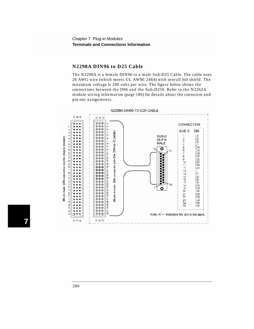
Chapter 7 Plug-in ModulesTerminals and Connections Information
7
N2298A DIN96 to D25 Cable
The N2298A is a female DIN96 to a male Sub-D25 Cable. The cable uses 26 AWG wire (which meets UL AWM: 2464) with overall foil shield. The maximum voltage is 200 volts per wire. The figure below shows the connections between the D96 and the Sub-D250. Refer to the N2262A module wiring information (page 186) for details about the connector and pin-out assignments.
C B A
3231
30292827
262524
232221201918171615
1413121110
98
76
54
32
1
C B A
3231302928272625242322212019181716151413121110
98
76
54
32
1
96-pin
female
DIN
connector(ontheDIN
-to-D
cable)
96-pin
male
DIN
connector(ontheplug-inmodule)
N2298A DIN96-TO-D25 CABLE
1
14
1325
SUB-D25-PINMALE
CONNECTION
SUB-D DIN
1
2
3
4
5
6
7
8
9
10
11
12
13
14
15
16
17
18
19
20
21
22
23
24
25
C1
C3
C5
C7
C10
C14
C18
C22
C25
C27
C29
C31
--
C2
C4
C6
C8
C11
C15
C19
C23
C26
C28
C30
C32
Note: A “--” indicates the pin is not used.
280
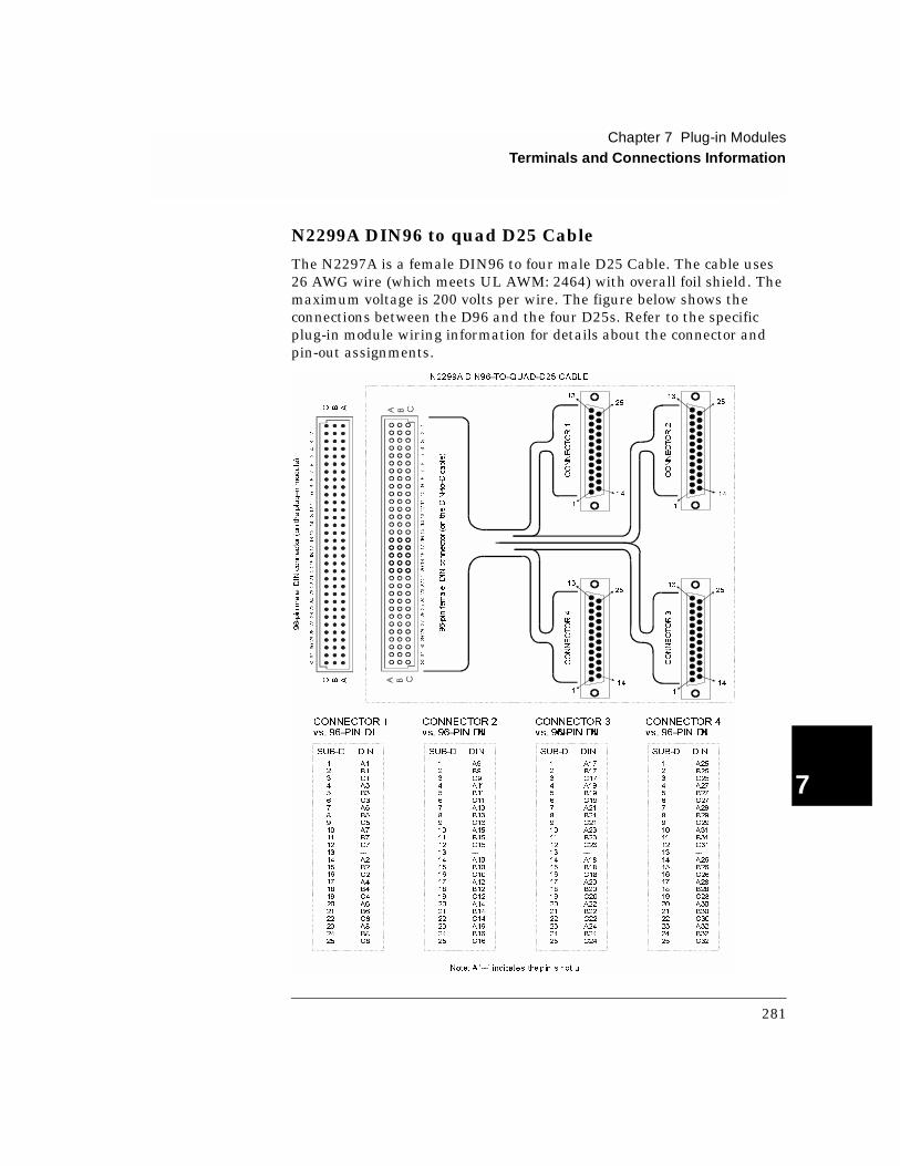
Chapter 7 Plug-in ModulesTerminals and Connections Information
4
7
N2299A DIN96 to quad D25 Cable
The N2297A is a female DIN96 to four male D25 Cable. The cable uses 26 AWG wire (which meets UL AWM: 2464) with overall foil shield. The maximum voltage is 200 volts per wire. The figure below shows the connections between the D96 and the four D25s. Refer to the specific plug-in module wiring information for details about the connector and pin-out assignments.
3231302928272625242322212019181716151413121110
98
76
54
32
1
96-pinfemale
DIN
connector(ontheDIN-to-D
cable)
96-pinmale
DIN
connector(ontheplug-inmodule)
1
14
13
25
CONNECTOR1
1
14
1325
CONNECTOR3
13
1
14
25
CONNECTOR2
1
14
13
25
CONNECTOR4
N2299A DIN96-TO-QUAD-D25 CABLE
C B A
3231302928272625242322212019181716151413121110
98
76
54
32
1
C B A
CONNECTOR 1
vs. 96-PIN DI N
SUB-D DIN
1
2
3
4
5
6
7
8
9
10
11
12
13
14
15
16
17
18
19
20
21
22
23
24
25
A1
B1
C1
A3
B3
C3
A5
B5
C5
A7
B7
C7
--
A2
B2
C2
A4
B4
C4
A6
B6
C6
A8
B8
C8
Note: A “--” indicates the p in is not u
SUB-D DIN
1
2
3
4
5
6
7
8
9
10
11
12
13
14
15
16
17
18
19
20
21
22
23
24
25
A9
B9
C9
A11
B11
C11
A13
B13
C13
A15
B15
C15
--
A10
B10
C10
A12
B12
C12
A14
B14
C14
A16
B16
C16
SUB-D DIN
1
2
3
4
5
6
7
8
9
10
11
12
13
14
15
16
17
18
19
20
21
22
23
24
25
A17
B17
C17
A19
B19
C19
A21
B21
C21
A23
B23
C23
--
A18
B18
C18
A20
B20
C20
A22
B22
C22
A24
B24
C24
SUB-D DIN
1
2
3
4
5
6
7
8
9
10
11
12
13
14
15
16
17
18
19
20
21
22
23
24
25
A25
B25
C25
A27
B27
C27
A29
B29
C29
A31
B31
C31
--
A26
B26
C26
A28
B28
C28
A30
B30
C30
A32
B32
C32
CONNECTOR 4
vs. 96-PIN DIN
CONNECTOR 3
vs. 96-PIN DIN
CONNECTOR 2
vs. 96-PIN DIN
281

Chapter 7 Plug-in ModulesTerminals and Connections Information
7
N2327A Crimp and Insert Terminal Block
This terminal is for the N2267A plug-in module only. Refer to the N2267A module wiring information (page 208) for details about the connector and pin-out assignments. The figures below illustrate how to wire and assemble this terminal.
Stripped wire (14-18 AWG) Socket
A. Prepare the Wire and the Socket.
B. Insert the Wire into the Socket.
C. Crimp the Wire with the Socket by using an AMP Hand Crimping Tool (90067-5) or equivalent tool.
Insert wired Socket into the ConnectorTo the N2267A module.
In-Line Connector
16 2 1Pin Number
282

Chapter 7 Plug-in ModulesTerminals and Connections Information
4
7
N2320A Crimp and Insert Terminal Block
This terminal block is for the N2270A plug-in module only. Refer to the N2270A module wiring information (page 213) for details about the connector and pin-out assignments. The figures below illustrate how to wire and assemble this terminal.
Stripped wire (14-18 AWG) Socket
A. Prepare the Wire and the Socket.
B. Insert the Wire into the Socket.
C. Crimp the Wire with the Socket by using an AMP Hand Crimping Tool (90067-5) or equivalent tool.
metal strain relie f clamp
R elease the four screws and uncover the upper metal shield
R ear v iew Front view
Upper metal shield
283
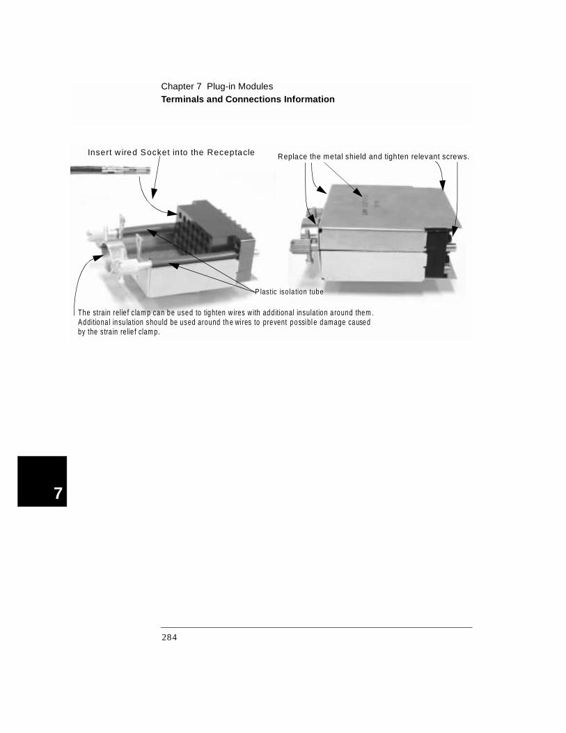
Chapter 7 Plug-in ModulesTerminals and Connections Information
7
Insert w ired Socket into the Receptacle
The strain relie f c lam p can be used to tighten w ires w ith add itional insulation a round them .
Replace the metal shield and tighten relevant screws.
Additiona l insu la tion should be used around th e wi res to prevent possibl e damage causedby the stra in re lie f clam p.
P lastic iso la tion tube
284
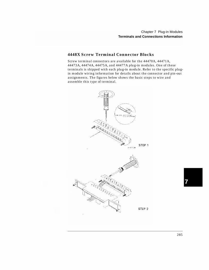
Chapter 7 Plug-in ModulesTerminals and Connections Information
4
7
4448X Screw Terminal Connector Blocks
Screw terminal connectors are available for the 44470A, 44471A, 44473A, 44474A, 44475A, and 44477A plug-in modules. One of these terminals is shipped with each plug-in module. Refer to the specific plug-in module wiring information for details about the connector and pin-out assignments. The figures below shows the basic steps to wire and assemble this type of terminal.
285
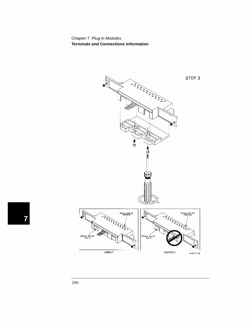
Chapter 7 Plug-in ModulesTerminals and Connections Information
7
286
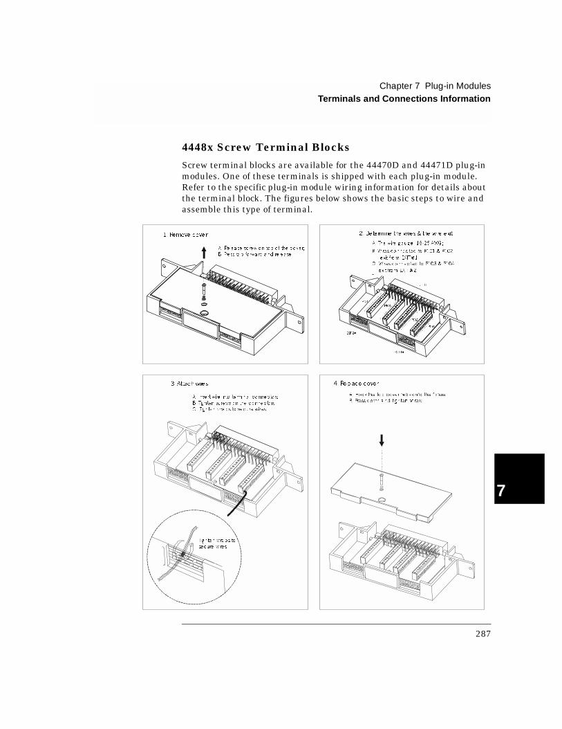
Chapter 7 Plug-in ModulesTerminals and Connections Information
4
7
4448x Screw Terminal Blocks
Screw terminal blocks are available for the 44470D and 44471D plug-in modules. One of these terminals is shipped with each plug-in module. Refer to the specific plug-in module wiring information for details about the terminal block. The figures below shows the basic steps to wire and assemble this type of terminal.
1. Remove cover 2. Determine the wires& the wire exit
P101
P102
P103
P104
J101
EXIT1#
EXIT2#
B. Wire s connec ted to P101 & P102
exit from EXIT# 1;C . Wire s connec ted to P103 & P104
exit from EXIT# 2.
3. Attach wires
A. Inse rt wire into te rmina l connec to rs;
B. Tig hten sc rews on the connec to rs;
C . Tig hte n wra ps to se cure wire s.
Tighten wra ps to
secure wire s
4. Replace cover
A. Hook the to p cove r ta bs onto the fixture ;
B. Press down a nd tig hten sc rew.
A. Re lea se sc rew o n top o f the co ve r;
B. Press ta b fo rwa rd a nd re le ase .
A. The wire g auge : 18-26 AWG ;
287

7
288

8
8
Application Programs
8
Application Programs
This chapter provides example programs in Visual C++, Visual BASIC and BASIC to help you develop programs for your specific application. Chapter contents include:
• Visual C++ Example Program, on page 291
• Visual BASIC Example Program, on page 293
• VB.net Example Program, on page 296
• BASIC Example Program, on page 298
Note For the example programs provided in this chapter to run properly, make sure that your system has been properly setup according to the requirements of the individual example.
290

Chapter 8 Application ProgramsVisual C++ Example Program
4
8
Visual C++ Example Program
This example program is written in Visual C++ 6.0 and has been tested on a PC running WIN95/NT. The example uses the SCPI commands. As the example is currently written, the program requirements are:
• GPIB interface selected and set to the address of 09 from the front-panel;
• Any one of the relay modules installed in Slot 1 of the mainframe;
• A GPIB interface card installed in your PC with the VISA library.
To program a 3499A/B/C using the RS-232 interface, you will need to modify the code at the top of the program. Change the line # define USING_RS232 0 to # define USING_RS232 1. On the 3499A/B/C, select the RS-232 interface and set its parameters to: BAUD RATE (9600), PARITY (NONE, 8 BITS), and FLOW (FLOW NONE). A GPIB card in your PC is not necessary if you are using RS-232.
# include <stdio.h># include <windows.h># include "visa.h"
# define USING_RS232 0 // Change 0 to 1 if RS-232 interface // is to be used.
# if USING_RS232# define INST_ADDR"ASRL1::INSTR"// 3499A/B/C RS-232 address.# else# define INST_ADDR"GPIB0::9::INSTR"// 3499A/B/C GPIB address.# endif
void main()
ViSession drm; // Session to default resource manager.ViSession vi; // Session to instrument.ViStatus status; // VISA function status return code.char retStr[128]; // String returned from the instrument.
/* Open the default resource manager. */status = viOpenDefaultRM( &drm ); if ( status < VI_SUCCESS )
printf( "VISA ERROR: viOpenDefaultRM()\n");exit(1);
/* Open a session to the 3499A/B/C. */status = viOpen( drm, INST_ADDR, VI_NULL, VI_NULL, &vi );if ( status < VI_SUCCESS )
printf( "VISA ERROR: viOpen(). Address: %s\n",INST_ADDR);viClose( drm );exit(1);
291
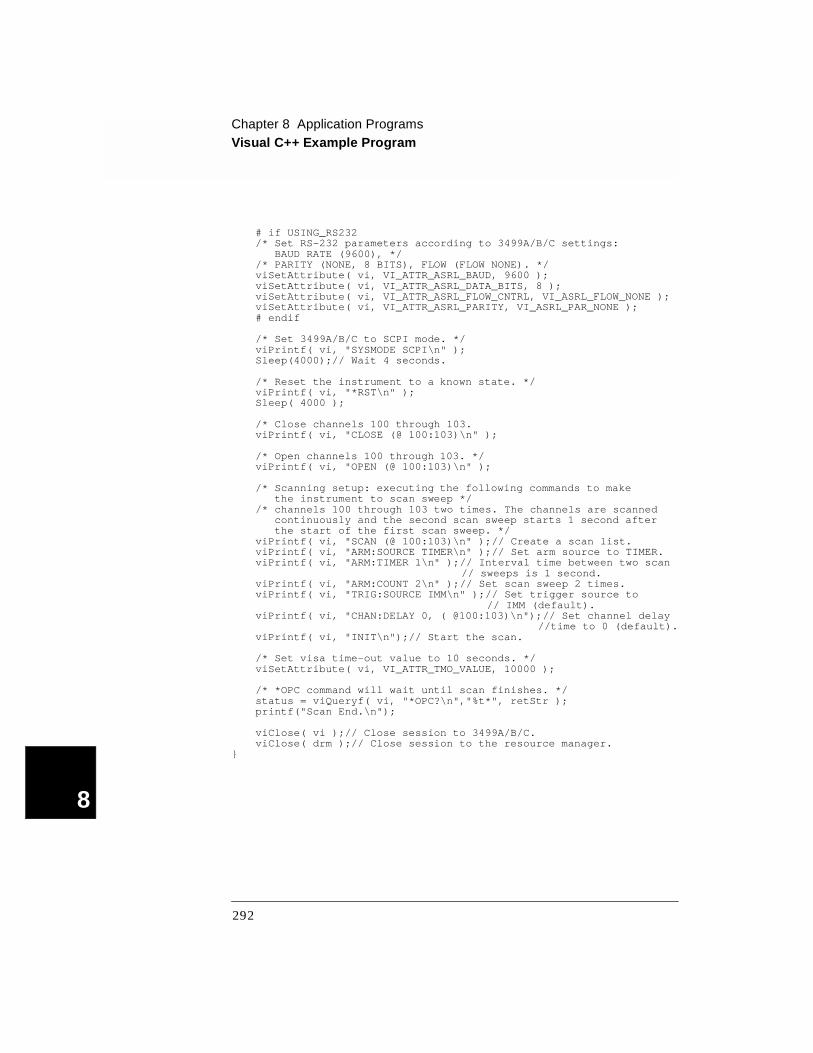
Chapter 8 Application ProgramsVisual C++ Example Program
8
# if USING_RS232/* Set RS-232 parameters according to 3499A/B/C settings: BAUD RATE (9600), *//* PARITY (NONE, 8 BITS), FLOW (FLOW NONE). */viSetAttribute( vi, VI_ATTR_ASRL_BAUD, 9600 );viSetAttribute( vi, VI_ATTR_ASRL_DATA_BITS, 8 );viSetAttribute( vi, VI_ATTR_ASRL_FLOW_CNTRL, VI_ASRL_FLOW_NONE );viSetAttribute( vi, VI_ATTR_ASRL_PARITY, VI_ASRL_PAR_NONE );# endif
/* Set 3499A/B/C to SCPI mode. */viPrintf( vi, "SYSMODE SCPI\n" );Sleep(4000);// Wait 4 seconds.
/* Reset the instrument to a known state. */viPrintf( vi, "*RST\n" );Sleep( 4000 );
/* Close channels 100 through 103.viPrintf( vi, "CLOSE (@ 100:103)\n" );
/* Open channels 100 through 103. */viPrintf( vi, "OPEN (@ 100:103)\n" );
/* Scanning setup: executing the following commands to make the instrument to scan sweep */
/* channels 100 through 103 two times. The channels are scannedcontinuously and the second scan sweep starts 1 second after the start of the first scan sweep. */
viPrintf( vi, "SCAN (@ 100:103)\n" );// Create a scan list.viPrintf( vi, "ARM:SOURCE TIMER\n" );// Set arm source to TIMER.viPrintf( vi, "ARM:TIMER 1\n" );// Interval time between two scan
// sweeps is 1 second.viPrintf( vi, "ARM:COUNT 2\n" );// Set scan sweep 2 times.viPrintf( vi, "TRIG:SOURCE IMM\n" );// Set trigger source to
// IMM (default).viPrintf( vi, "CHAN:DELAY 0, ( @100:103)\n");// Set channel delay
//time to 0 (default).viPrintf( vi, "INIT\n");// Start the scan.
/* Set visa time-out value to 10 seconds. */viSetAttribute( vi, VI_ATTR_TMO_VALUE, 10000 );
/* *OPC command will wait until scan finishes. */status = viQueryf( vi, "*OPC?\n","%t*", retStr );printf("Scan End.\n");
viClose( vi );// Close session to 3499A/B/C.viClose( drm );// Close session to the resource manager.
292

Chapter 8 Application ProgramsVisual BASIC Example Program
4
8
Visual BASIC Example Program
This example program is written in Visual BASIC 6.0 and has been tested on a PC running WIN95/NT. The example uses the SCPI com-mands. As the example is currently written, the program requirements are:
• GPIB interface selected and set to the address of 09 from the front-panel;
• Any one of the relay modules installed in Slot 1 of the mainframe;
• A GPIB interface card installed in your PC with the VISA library.
To program a 3499A/B/C using the RS-232 interface, you will need to modify the code at the top of the program. Change the line Const USING_RS232 =0 to Const USING_RS232 =1. On the 3499A/B/C, select the RS-232 interface and set its parameters to: BAUD RATE (9600), PARITY (NONE, 8 BITS), and FLOW (FLOW NONE). A GPIB card in your PC is not necessary if you are using RS-232.
Const USING_RS232 =0' Change 0 to 1 if RS-232 interface is to be used. ' Sleep( ) function declaration.
Declare Sub Sleep Lib "Kernel32" (ByVal s As Long)
Sub main()
Dim drm As Long ' Session to default resource manager.Dim vi As Long ' Session to instrument.Dim status As Long ' VISA function status return codeDim retStr As String * 128' String returned from the instrument.Dim str As String ' String for individual channel number.
On Error GoTo ErrorHandler
' Open default resource manager.drm = -1status = viOpenDefaultRM(drm)If (status < VI_SUCCESS) Then GoTo VisaErrorHandler
' Select an interface for 3499A/B/C. ' GPIB interface is used when USING_RS232 = 0,' or RS-232 interface is used when USING_RS232 = 1.If USING_RS232 Then
INST_ADDR = "ASRL1::INSTR"Else
INST_ADDR = "GPIB0::9::INSTR"Endif
' Open a session to 3499A/B/C.status = viOpen(drm, INST_ADDR, 0, 0, vi)If (status < VI_SUCCESS) Then GoTo VisaErrorHandler
293

Chapter 8 Application ProgramsVisual BASIC Example Program
8
' Set RS-232 interface parameters when USING_RS232 equals 1.If USING_RS232 Then
Call viSetAttribute(vi, VI_ATTR_ASRL_BAUD, 9600)Call viSetAttribute(vi, VI_ATTR_ASRL_DATA_BITS, 8)Call viSetAttribute(vi, VI_ATTR_ASRL_STOP_BITS,_
VI_ASRL_STOP_ONE)Call viSetAttribute(vi, VI_ATTR_ASRL_FLOW_CNTRL,_
VI_ASRL_FLOW_NONE)Call viSetAttribute(vi, VI_ATTR_ASRL_PARITY, VI_ASRL_PAR_NONE)
End If
' Set the 3499A/B/C to SCPI mode.Call viVPrintf(vi, "SYSMODE SCPI" + Chr$(10), 0)Call Sleep(4000) ' Wait 4 seconds
' Reset the instrument to a known state.Call viVPrintf(vi, "*RST" + Chr$(10), 0)Call Sleep(4000)
' Close channels 100 through 103.Call viVPrintf(vi, "CLOSE ( @ 100:103)" + Chr$(10), 0)
' Open channels 100 through 103.Call viVPrintf(vi, "OPEN ( @ 100:103)" + Chr$(10), 0)
' Scanning setup: the following commands make the instrument scan ' channels 100 through 103 two times. The channels are scanned' continuously and the second scan sweep starts 1 second after the' start of the first scan sweep.
' Create a scan list 100 through 103.Call viVPrintf(vi, "SCAN (@100:103)" + Chr$(10), 0)
' Set arm source to TIMER.Call viVPrintf(vi, "ARM:SOURCE TIMER" + Chr$(10), 0)
' Interval time between two scan sweeps is 1 second.Call viVPrintf(vi, "ARM:TIMER 1" + Chr$(10), 0)
' Set scan sweep two times.Call viVPrintf(vi, "ARM:COUNT 2" + Chr$(10), 0)
' Set trigger source to IMM (default).Call viVPrintf(vi, "TRIG:SOURCE IMM" + Chr$(10), 0)
' Set trigger source to IMM (default).Call viVPrintf(vi, "CHAN:DELAY 0, (@100:103)" + Chr$(10), 0
' Start scanning.Call viVPrintf(vi, "INIT" + Chr$(10), 0)
' Set visa time-out value to 10 secondsCall viSetAttribute(vi, VI_ATTR_TMO_VALUE, 10 * 1000)
' *OPC command will wait until scan finished.Call viVQueryf(vi, "*OPC?" + Chr$(10), "%t*", retStr)
viClose (vi)' Close session to 3499A/B/C.viClose (drm)' Close session to default resource manager.End
294
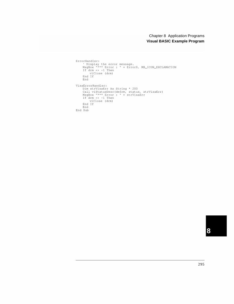
Chapter 8 Application ProgramsVisual BASIC Example Program
4
8
ErrorHandler:' Display the error message.MsgBox "*** Error : " + Error$, MB_ICON_EXCLAMATIONIf drm <> -1 Then
viClose (drm)End IfEnd
VisaErrorHandler:Dim strVisaErr As String * 200Call viStatusDesc(defrm, status, strVisaErr)MsgBox "*** Error : " + strVisaErrIf drm <> -1 Then
viClose (drm)End IfEnd
End Sub
295
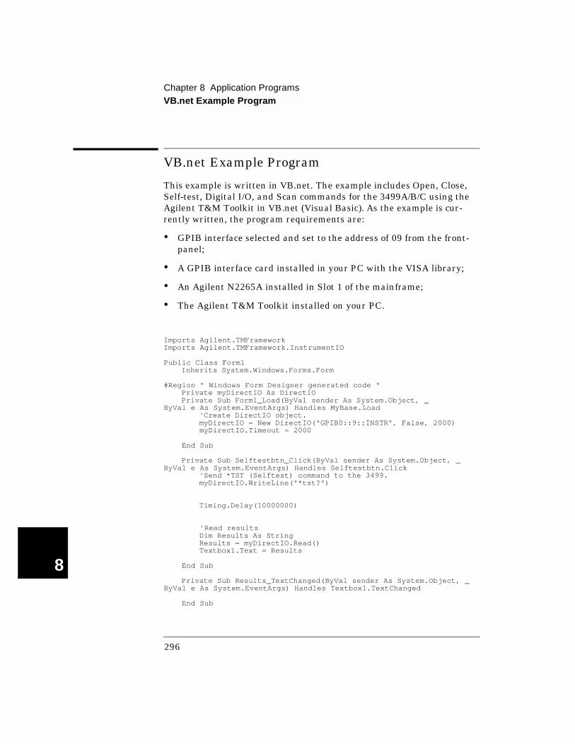
Chapter 8 Application ProgramsVB.net Example Program
8
VB.net Example Program
This example is written in VB.net. The example includes Open, Close, Self-test, Digital I/O, and Scan commands for the 3499A/B/C using the Agilent T&M Toolkit in VB.net (Visual Basic). As the example is cur-rently written, the program requirements are:
• GPIB interface selected and set to the address of 09 from the front-panel;
• A GPIB interface card installed in your PC with the VISA library;
• An Agilent N2265A installed in Slot 1 of the mainframe;
• The Agilent T&M Toolkit installed on your PC.
Imports Agilent.TMFrameworkImports Agilent.TMFramework.InstrumentIO
Public Class Form1 Inherits System.Windows.Forms.Form
#Region " Windows Form Designer generated code " Private myDirectIO As DirectIO Private Sub Form1_Load(ByVal sender As System.Object, _ByVal e As System.EventArgs) Handles MyBase.Load 'Create DirectIO object. myDirectIO = New DirectIO("GPIB0::9::INSTR", False, 2000) myDirectIO.Timeout = 2000
End Sub
Private Sub Selftestbtn_Click(ByVal sender As System.Object, _ByVal e As System.EventArgs) Handles Selftestbtn.Click 'Send *TST (Selftest) command to the 3499. myDirectIO.WriteLine("*tst?")
Timing.Delay(10000000)
'Read results Dim Results As String Results = myDirectIO.Read() Textbox1.Text = Results
End Sub
Private Sub Results_TextChanged(ByVal sender As System.Object, _ByVal e As System.EventArgs) Handles Textbox1.TextChanged
End Sub
296

Chapter 8 Application ProgramsVB.net Example Program
4
8
'This example closes/opens multiple switches within a 4x4 Matrix. 'The switches can be controlled within one command line or listed
'separtely. Private Sub Closebtn_Click(ByVal sender As System.Object, _ByVal e As System.EventArgs) Handles Closebtn.Click myDirectIO.WriteLine("CLOS (@120,123)") End Sub
Private Sub Openbtn_Click(ByVal sender As System.Object, _ByVal e As System.EventArgs) Handles Openbtn.Click myDirectIO.WriteLine("OPEn (@120)") myDirectIO.WriteLine("OPEn (@123)") End Sub
'Digital Input/Output - on power up or after Reset all Digital I/O 'ports in the 3499 will be input ports. Mode 1 is default mode. Private Sub DigIObtn_Click(ByVal sender As System.Object, _ByVal e As System.EventArgs) Handles DigIObtn.Click myDirectIO.WriteLine("SENSE:DIGITAL:DATA:BYTE:VALue? 140")
'Read the Digital Input results 8 bits (1 byte), binary value is'displayed.
Dim Digitalin As String Digitalin = myDirectIO.Read() TextBox2.Text = Digitalin End Sub 'Create and execute a scan list Private Sub Scanbtn_Click(ByVal sender As System.Object, _ByVal e As System.EventArgs) Handles Scanbtn.Click myDirectIO.WriteLine("SCAN (@200:209,220:225)") myDirectIO.WriteLine("INIT") myDirectIO.WriteLine("SCAN:LIST?")
Dim Scanresults As String Scanresults = myDirectIO.Read() Scanlst.Text = Scanresults End Sub
End Class
297

Chapter 8 Application ProgramsBASIC Example Program
8
BASIC Example Program
Sample programs in this section are written in BASIC 6.0 and have been tested on a UNIX workstation.
Requirements:
• GPIB interface selected and set to the address of 09 from the front-panel;
• Any one of the relay modules installed in Slot 1 of the mainframe;
• A GPIB interface card installed in your UNIX workstation.
Note Either GPIB or RS-232 interface can be used in SCPI mode. However, we only provide and test the BASIC program examples over the GPIB interface.
10 ! EXAMPLE.BAS: TEST 3499A/B/C IN SCPI MODE20 DIM Retstr$[128]! String returned from the instrument.30 OUTPUT 709; "SYSMODE SCPI"! Set 3499A/B/C to SCPI mode.40 WAIT 4! Wait 4 seconds.50 OUTPUT 709; "*RST"! Reset 3499A/B/C.60 WAIT 4! Wait 4 second.70 OUTPUT 709; "CLOSE (@100:103)"! Close channels 100 through 103.80 OUTPUT 709; "OPEN (@100:103)"! Open channels 100 through 103.
100 ! LINES 150 TO 200 SET UP A TIMER CONTROLLED SCANNING.110 ! 3499A/B/C SCAN SWEEP CHANNELS 100 THROUGH 139 TWO TIMES.120 ! THE CHANNELS ARE SCANNED CONTINUOUSLY.130 ! THE SECOND SCAN SWEEP STARTS 1 SECOND AFTER THE START140 ! OF THE FIRST SCAN SWEEP.150 OUTPUT 709; "SCAN (@100:103)"! Create a scan list.160 OUTPUT 709; "ARM:SOUR TIMER"! Set arm source to timer.170 OUTPUT 709; "ARM:TIMER 1"! Interval time between two scan sweeps
! is 1 second.180 OUTPUT 709; "ARM:COUNT 2"! Set scan sweep 2 times.190 OUTPUT 709; "TRIG:SOUR IMM"! Set trigger source to IMM (default).200 OUTPUT 709; "CHAN:DELAY 0, (@100:103)"! Set channel delay time
!to 0 (default).210 OUTPUT 709; "INIT"! Start scanning220 OUTPUT 709; "*OPC?"! Wait until scan finishes.230 ENTER 709; Retstr$240 Done: END
298

9
9
Specifications

9
Specifications
Specification for the mainframe and all plug-in modules are given in this chapter for easy reference. This chapter includes:
• 3499A/B/C Mainframe, on page 301
• N2260A 40-Channel MUX Module, on page 303
• N2261A 40-Channel GP Relay Module, on page 305
• N2262A 4 x 8 2-Wire Matrix Switch Module, on page 307
• N2263A 32-bit Digital I/O Module, on page 309
• N2264A Multifunction Module, on page 310
• N2265A Multifunction Module, on page 313
• N2266A 40-Channel MUX Module, on page 315
• N2267A 8-Channel High Current GP Module, on page 317
• N2268A 50Ω 3.5GHz Dual 1-to-4 MUX Module, on page 319
• N2270A 10-Channel High Voltage MUX Module, on page 321
• N2272A 1 GHz RF 1-to-9 MUX Module, on page 323
• N 2276A Dual 1-to-6(4) M icrowave M U X/Attenuator M odule, on page 325
• N2276B Microwave MUX/Attenuator Module, on page 325
• N2280A Quadruple 1-to-2 Optical Switch Module, on page 326
• N2281A Dual 1-to-4 Optical Switch Module, on page 327
• N2282A 1-to-8 Optical Switch Module, on page 328
• 44470A 10-Channel MUX Module, on page 329
• 44470D 20-Channel MUX Module, on page 331
• 44471A 10-Channel GP Relay Module, on page 333
• 44471D 20-Channel GP Relay Module, on page 335
• 44472A Dual 4-Channel VHF Switch Module, on page 337
• 44473A 4 x 4 2-Wire Matrix Switch Module, on page 339
• 44474A 16-Bit Digital I/O Module, on page 341
• 44475A Breadboard Module, on page 342
• 44476A Microwave Switch Module, on page 344
• 44476B Microwave Switch Module, on page 344
• 44477A Form-C Relay Module, on page 345
• 44478A/B 1.3 GHz Dual 4-to-1 MUX Modules, on page 347
300

Chapter 9 Specifications3499A/B/C Mainframe
4
3499A/B/C Mainframe
GENERAL
Power Supply: For 3499A/B: 100 to 240 VAC universal input; 47 Hz to 440 Hz; 90 VA maximum;For 3499C: 100 to 240 VAC universal input; 47 Hz to 63 Hz; 140 VA maximum.
Operating Environment:
0 to 55oC (32 to 131oF); < 80% RH, 0 to 40oC (32 to 104oF).
Storage Environment:
-40 to +70oC (-40 to 158oF).
Net Weight:3499A: 3.8 kg (8.4 lbs); 3499B: 2.5 kg (5.5 lbs);3499C: 7.4 kg (16.4 lbs).
Dimensions:3499A (H x W x L): 89mm x 426mm x 348mm (3.5” x 16.8” x 13.7”);3499B (H x W x L): 89mm x 213mm x 348mm (3.5” x 8.4” x 13.7”);3499C (H x W x L):221.5mm x 426mm x 353.5mm (8.7” x 16.8“ x 13.9”).
Safety: Conforms to CSA, UL-1244, IEC 1010 Cat I.
RFI and ESD: CISPR 11, IEC 801/2/3/4.
SYSTEM
Capacity:
3499A: 5 slots; 3499B: 2 slots; 3499C: electrically 9 slots
(Slot 1~6 are 1-slot width, Slot 7 is 2-slot width, Slot 8~9 are 3-slot width).
Display: Vacuum fluorescent, 13 characters can be displayed simultaneously.
Rear Panel Connectors:
GPIB (IEEE 488); RS-232;8-pin Mini DIN connector (built-in 4-bit Digital I/O & built-in external trigger in/out).
Memory:
For 3499A/B mainframe with Controller board 1.0 (Firmware REV 1.0/2.0/3.0): Capable of storing 10 instrument setups and 10 errors in SCPI mode or 40 instrument setups and 1 error in 3488A mode.
For 3499A/B/C mainframe with Controller board 2.0 (Firmware REV 4.0 or later): Capable of storing 50 instrument setups and 10 errors in SCPI mode or 40 instrument setups and 1 error in 3488A mode.
301
9
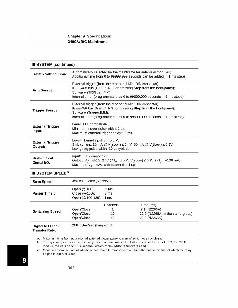
Chapter 9 Specifications3499A/B/C Mainframe
9
SYSTEM (continued)
Switch Setting Time: Automatically selected by the mainframe for individual modules;Additional time from 0 to 99999.999 seconds can be added in 1 ms steps.
Arm Source:
External trigger (from the rear panel Mini DIN connector);IEEE-488 bus (GET, *TRG, or pressing Step from the front-panel);Software (TRIGger:IMM);Internal timer (programmable as 0 to 99999.999 seconds in 1 ms steps).
Trigger Source:
External trigger (from the rear panel Mini DIN connector);IEEE-488 bus (GET, *TRG, or pressing Step from the front-panel);Software (Trigger:IMM);Internal timer (programmable as 0 to 99999.999 seconds in 1 ms steps).
External Trigger Input:
Level: TTL compatible;Minimum trigger pulse width: 2 µs;Maximum external trigger delaya: 2 ms.
External Trigger Output:
Level: Normally pull up to 5 V;Sink current: 10 mA @ Vo(Low) ≤ 0.4V; 80 mA @ Vo(Low) ≤ 0.8V;Low going pulse width: 10 µs typical.
Built-in 4-bit Digital I/O:
Input: TTL compatible;Output: Vo(high) ≥ 2.4V @ Io = 1 mA; Vo(Low) ≤ 0.8V @ Io = −100 mA;Maximum Vo = 42V, with external pull-up.
SYSTEM SPEEDb
Scan Speed: 350 chans/sec (N2266A)
Parser Timec:Open (@100): 3 msClose (@100): 3 msOpen (@100:139): 4 ms
Switching Speed:
Channels Time (ms)Open/Close: 1 7.1 (N2266A)Open/Close: 10 22.0 (N2266A, in the same group)Open/Close: 40 28.9 (N2266A)
Digital I/O Block Transfer Rate:
20K bytes/sec (long word)
a. Maximum time from activation of external trigger pulse to start of switch open or close.b. The system speed specification may vary in a small range due to the speed of the remote PC, the GPIB
module, the version of VISA and the version of 3499A/B/C’s firmware used. c. Measured from the time at which the command terminator is taken from the bus to the time at which the relay
begins to open or close.
302

Chapter 9 SpecificationsN2260A 40-Channel MUX Module
4
N2260A 40-Channel MUX Module
INPUT CHARACTERISTICS
Total Channels: 80 1-wire; or 40 2-wire; or dual 20 2-wire; or 20 4-wire
Maximum Voltage: Terminal-Terminal or Terminal-Chassis:
200 V, dc or ac rms
Maximum Current:Per Channel: 1 A, dc or ac rms
Per Module: 2A, dc or ac rms
Maximum Power:Per Channel: 60 W dc; 62.5 VA ac
Per Module: 120 W dc; 125 VA ac
Thermal Offset: < 3 µV differential or single-ended
Initial Closed Channel Resistance:
< 1 Ω
Relay Life: Mechanical:Electrical:
108 (at 36000 operations/hour)5 x 105 (1A load)
Maximum Scan Rate: 80 Chans/sec
DC ISOLATION (with terminal block)
Open Channel, Channel-Channel: (with 1 channel closed)
< (40oC, 50% RH):< (40oC, 80% RH):
> 1010 Ω> 109 Ω
HI-LO: (with 1 channel closed)
< (40oC, 50% RH):< (40oC, 80% RH):
> 1010 Ω> 109 Ω
Channel-Chassis: (with 1 channel closed)
< (40oC, 50% RH):< (40oC, 80% RH):
> 1010 Ω> 109 Ω
303
9

Chapter 9 SpecificationsN2260A 40-Channel MUX Module
9
AC ISOLATION / PERFORMANCEa (without terminal block)
Capacitance: (with 1 channel closed)
Open Channel, Channel-Channel:HI-LO:Channel-Chassis:
< 7 pF (2-wire);
< 75 pF (2-wire);< 150 pF (2-wire);
< 7 pF (dual 2-wire)
< 45 pF (dual 2-wire)< 90 pF (dual 2-wire)
Insertion Loss: (with 50Ω termination)
100 kHz:1 MHz:10 MHz:
< 0.10 dB< 0.20 dB< 1.50 dB
Crosstalk:(with 50Ω termination)
100 kHz:1 MHz:10 MHz:
< -70 dB (2-wire);< -50 dB (2-wire);< -30 dB (2-wire);
< -40 dB (1-wire)< -25 dB (1-wire)NA (1-wire)
a. With chassis of all instruments connected, and with the Lo Terminal of the input connected to the Lo Terminal of the output (either directly or via the 3499A/B/C switching channels).
304

Chapter 9 SpecificationsN2261A 40-Channel GP Relay Module
4
N2261A 40-Channel GP Relay Module
INPUT CHARACTERISTICS
Total Channels: 40
Maximum Voltage:Terminal-Terminal or Terminal-Chassis:
200 V, dc or ac rms
Maximum Current:Per Channel:Per Module:
1 A, dc or ac rms20 A, dc or ac rms
Maximum Power:Per Channel:Per Module:
60 W dc; 62.5 VA ac1200 W dc; 1250 VA ac
Thermal Offset: Per Channel: < 3 µV
Initial Closed Channel Resistance:
< 0.5 Ω
Relay Life:Mechanical:Electrical:
108 (at 36000 operations/hour)5 x 105 (1A load)
Maximum Scan Rate: 80 Chans/sec
DC ISOLATION (with terminal block)
Open Channel, Channel-Channel:(with 1 channel closed)
< (40oC, 50% RH):< (40oC, 80% RH):
> 1010 Ω> 109 Ω
Channel-Chassis:(with 1 channel closed)
< (40oC, 50% RH):< (40oC, 80% RH):
> 1010 Ω> 109 Ω
305
9
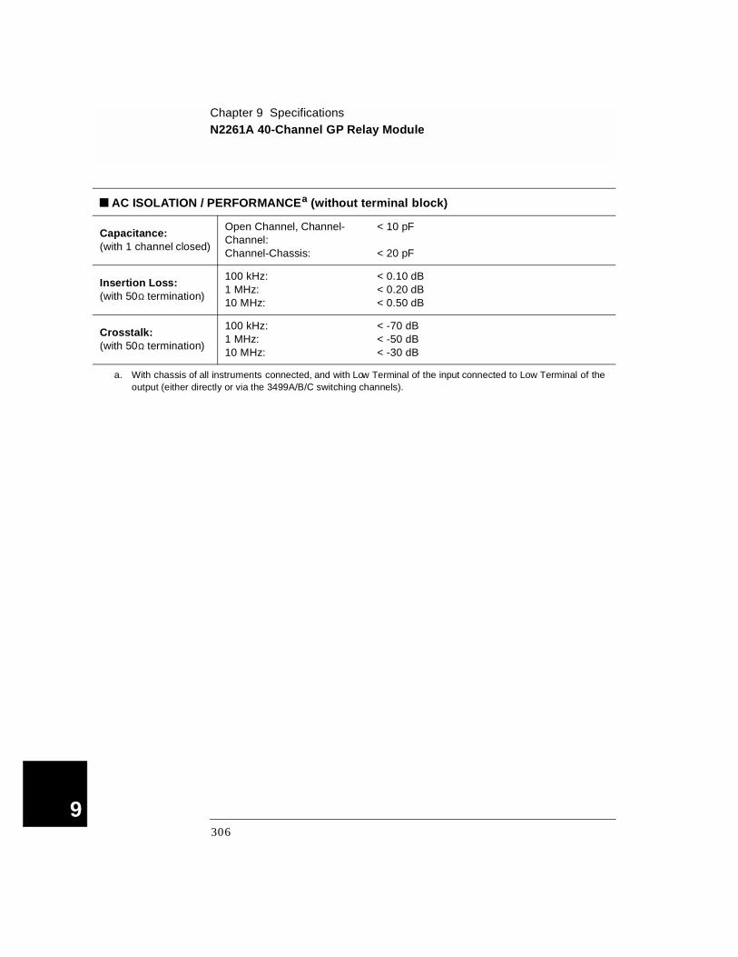
Chapter 9 SpecificationsN2261A 40-Channel GP Relay Module
9
AC ISOLATION / PERFORMANCEa (without terminal block)
Capacitance: (with 1 channel closed)
Open Channel, Channel-Channel:Channel-Chassis:
< 10 pF
< 20 pF
Insertion Loss:(with 50Ω termination)
100 kHz:1 MHz:10 MHz:
< 0.10 dB< 0.20 dB< 0.50 dB
Crosstalk: (with 50Ω termination)
100 kHz:1 MHz:10 MHz:
< -70 dB< -50 dB< -30 dB
a. With chassis of all instruments connected, and with Low Terminal of the input connected to Low Terminal of the output (either directly or via the 3499A/B/C switching channels).
306
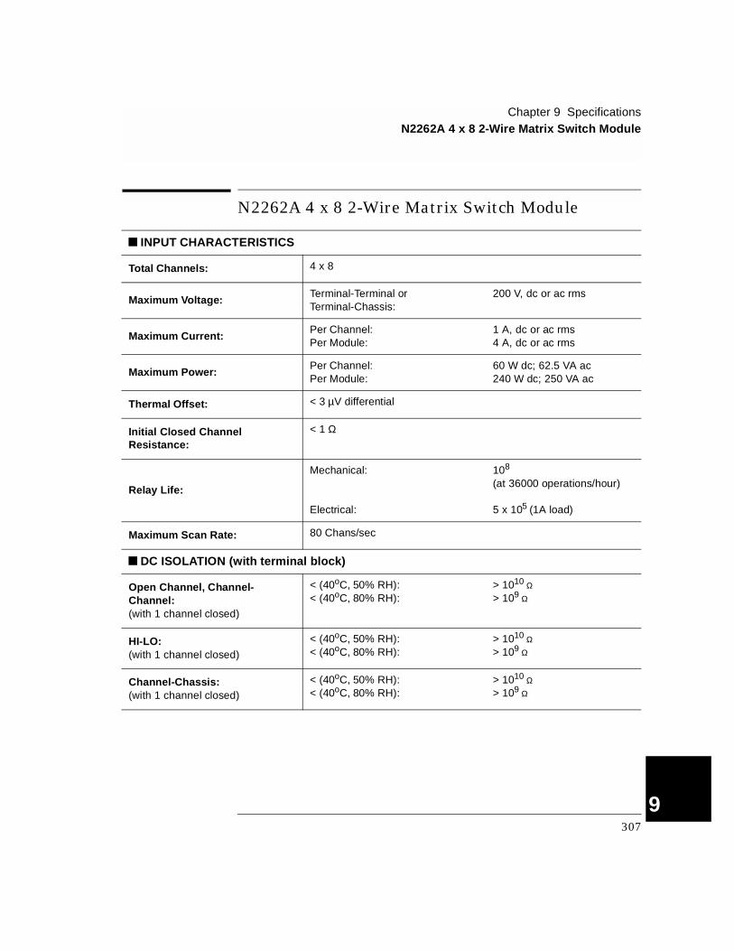
Chapter 9 SpecificationsN2262A 4 x 8 2-Wire Matrix Switch Module
4
N2262A 4 x 8 2-Wire Matrix Switch Module
INPUT CHARACTERISTICS
Total Channels: 4 x 8
Maximum Voltage:Terminal-Terminal or Terminal-Chassis:
200 V, dc or ac rms
Maximum Current:Per Channel:Per Module:
1 A, dc or ac rms4 A, dc or ac rms
Maximum Power:Per Channel:Per Module:
60 W dc; 62.5 VA ac240 W dc; 250 VA ac
Thermal Offset: < 3 µV differential
Initial Closed Channel Resistance:
< 1 Ω
Relay Life:
Mechanical:
Electrical:
108
(at 36000 operations/hour)
5 x 10⁵ (1A load)
Maximum Scan Rate: 80 Chans/sec
DC ISOLATION (with terminal block)
Open Channel, Channel-Channel:(with 1 channel closed)
< (40oC, 50% RH):< (40oC, 80% RH):
> 1010 Ω> 109 Ω
HI-LO:(with 1 channel closed)
< (40oC, 50% RH):< (40oC, 80% RH):
> 1010 Ω> 109 Ω
Channel-Chassis:(with 1 channel closed)
< (40oC, 50% RH):< (40oC, 80% RH):
> 1010 Ω> 109 Ω
307
9
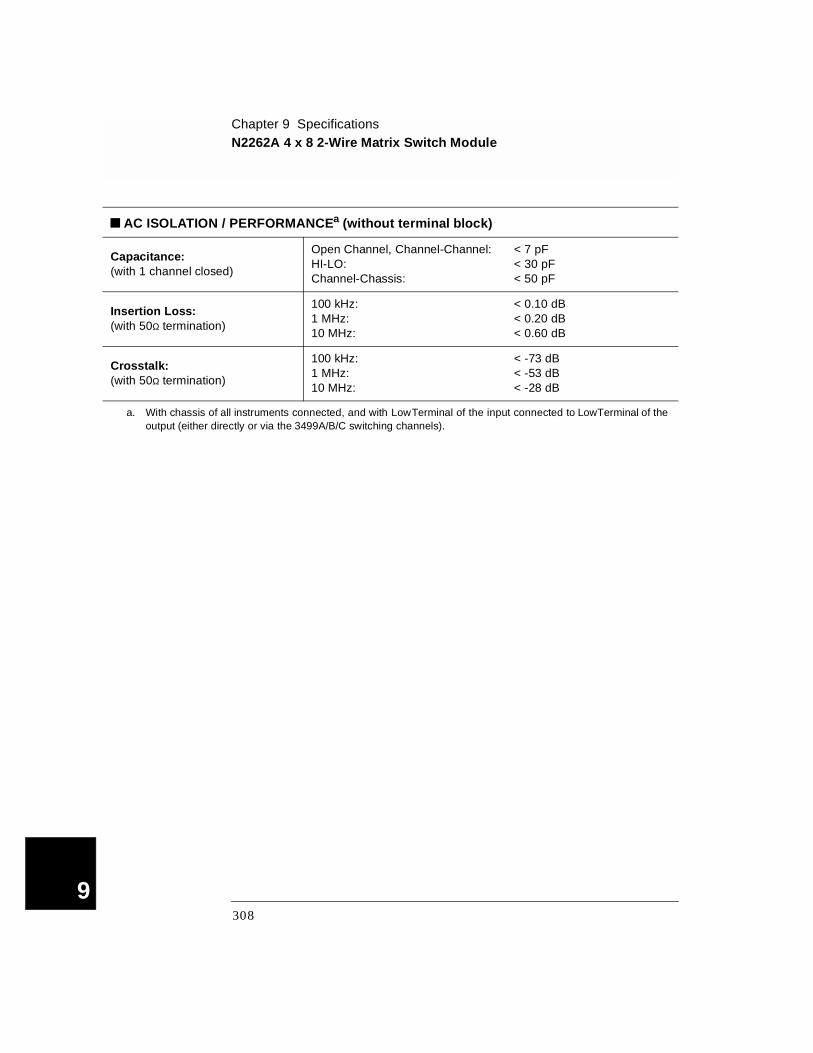
Chapter 9 SpecificationsN2262A 4 x 8 2-Wire Matrix Switch Module
9
AC ISOLATION / PERFORMANCEa (without terminal block)
Capacitance: (with 1 channel closed)
Open Channel, Channel-Channel:HI-LO:Channel-Chassis:
< 7 pF< 30 pF< 50 pF
Insertion Loss: (with 50Ω termination)
100 kHz:1 MHz:10 MHz:
< 0.10 dB< 0.20 dB< 0.60 dB
Crosstalk: (with 50Ω termination)
100 kHz:1 MHz:10 MHz:
< -73 dB< -53 dB< -28 dB
a. With chassis of all instruments connected, and with Low Terminal of the input connected to Low Terminal of the output (either directly or via the 3499A/B/C switching channels).
308
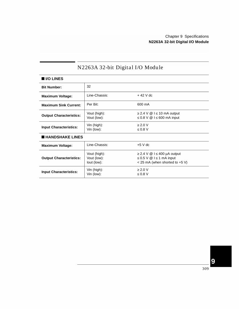
Chapter 9 SpecificationsN2263A 32-bit Digital I/O Module
4
N2263A 32-bit Digital I/O Module
I/O LINES
Bit Number: 32
Maximum Voltage: Line-Chassis: + 42 V dc
Maximum Sink Current: Per Bit: 600 mA
Output Characteristics: Vout (high):Vout (low):
≥ 2.4 V @ I ≤ 10 mA output≤ 0.8 V @ I ≤ 600 mA input
Input Characteristics:Vin (high):Vin (low):
≥ 2.0 V≤ 0.8 V
HANDSHAKE LINES
Maximum Voltage: Line-Chassis: +5 V dc
Output Characteristics: Vout (high):Vout (low):Iout (low):
≥ 2.4 V @ I ≤ 400 µA output≤ 0.5 V @ I ≤ 1 mA input< 25 mA (when shorted to +5 V)
Input Characteristics: Vin (high):Vin (low):
≥ 2.0 V≤ 0.8 V
309
9

Chapter 9 SpecificationsN2264A Multifunction Module
9
N2264A Multifunction Module
The maximum number of channels that can be closed simultaneously is 10 (including the GP and High-Current GP relays). The maximum carrying current is 15 A (including the GP, High-Current GP and Digital I/O.
16-bit Digital I/O Function
I/O LINES
Bit Number: 16
Maximum Voltage: Line-Chassis: + 42 V dc
Maximum Sink Current: Per Bit: 600 mA
Output Characteristics: Vout (high):Vout (low):
≥ 2.4 V @ I ≤ 10 mA output≤ 0.8 V @ I ≤ 600 mA input
Input Characteristics:Vin (high):Vin (low):
≥ 2.0 V≤ 0.8 V
HANDSHAKE LINES
Maximum Voltage: Line-Chassis: +5 V dc
Output Characteristics: Vout (high):Vout (low):Iout (low):
≥ 2.4 V @ I ≤ 400 µA output≤ 0.5 V @ I ≤ 1 mA input< 25 mA (when shorted to +5 V)
Input Characteristics: Vin (high):Vin (low):
≥ 2.0 V≤ 0.8 V
310

Chapter 9 SpecificationsN2264A Multifunction Module
4
12-Channel GP Relay Function
INPUT CHARACTERISTICS
Total Channels: 12
Maximum Voltage:Terminal-Terminal or Terminal-Chassis:
200 V, dc or ac rms
Maximum Current: Per Channel: 1 A, dc or ac rms
Maximum Power: Per Channel: 60 W dc; 62.5 VA ac
Thermal Offset: Per Channel: < 3 µV
Initial Closed Channel Resistance:
< 0.5 Ω
Relay Life:Mechanical:Electrical:
108 (at 36000 operations/hour)5 x 105 (1A load)
Maximum Scan Rate: 80 Chans/sec
DC ISOLATION (with terminal block)
Open Channel, Channel-Channel:(with 1 channel closed)
< (40oC, 50% RH):< (40oC, 80% RH):
> 1010 Ω> 109 Ω
Channel-Chassis:(with 1 channel closed)
< (40oC, 50% RH):< (40oC, 80% RH):
> 1010 Ω> 109 Ω
AC ISOLATION / PERFORMANCEa (without terminal block)
Capacitance: (with 1 channel closed)
Open Channel, Channel-Channel:Channel-Chassis:
< 10 pF< 20 pF
Insertion Loss: (with 50Ω termination)
100 kHz:1 MHz:10 MHz:
< 0.10 dB< 0.20 dB< 0.50 dB
Crosstalk:(with 50Ω termination)
100 kHz:1 MHz:10 MHz:
< -70 dB< -50 dB< -30 dB
a. With chassis of all instruments connected, and with Lo Terminal of the input connected to Lo Terminal of the output (either directly or via the 3499A/B/C switching channels).
311
9
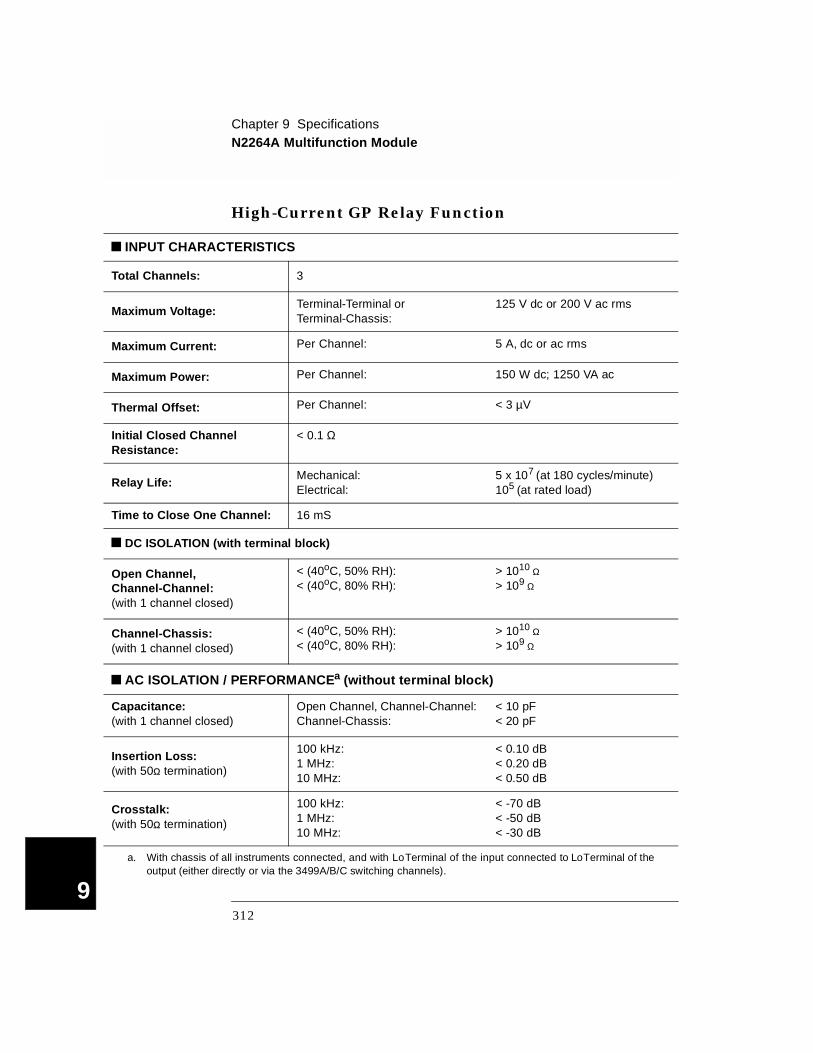
Chapter 9 SpecificationsN2264A Multifunction Module
9
High-Current GP Relay Function
INPUT CHARACTERISTICS
Total Channels: 3
Maximum Voltage:Terminal-Terminal or Terminal-Chassis:
125 V dc or 200 V ac rms
Maximum Current: Per Channel: 5 A, dc or ac rms
Maximum Power: Per Channel: 150 W dc; 1250 VA ac
Thermal Offset: Per Channel: < 3 µV
Initial Closed Channel Resistance:
< 0.1 Ω
Relay Life:Mechanical:Electrical:
5 x 10⁷ (at 180 cycles/minute)105 (at rated load)
Time to Close One Channel: 16 mS
DC ISOLATION (with terminal block)
Open Channel, Channel-Channel:(with 1 channel closed)
< (40oC, 50% RH):< (40oC, 80% RH):
> 1010 Ω> 109 Ω
Channel-Chassis:(with 1 channel closed)
< (40oC, 50% RH):< (40oC, 80% RH):
> 1010 Ω> 109 Ω
AC ISOLATION / PERFORMANCEa (without terminal block)
Capacitance: (with 1 channel closed)
Open Channel, Channel-Channel:Channel-Chassis:
< 10 pF< 20 pF
Insertion Loss: (with 50Ω termination)
100 kHz:1 MHz:10 MHz:
< 0.10 dB< 0.20 dB< 0.50 dB
Crosstalk: (with 50Ω termination)
100 kHz:1 MHz:10 MHz:
< -70 dB< -50 dB< -30 dB
a. With chassis of all instruments connected, and with Lo Terminal of the input connected to Lo Terminal of the output (either directly or via the 3499A/B/C switching channels).
312
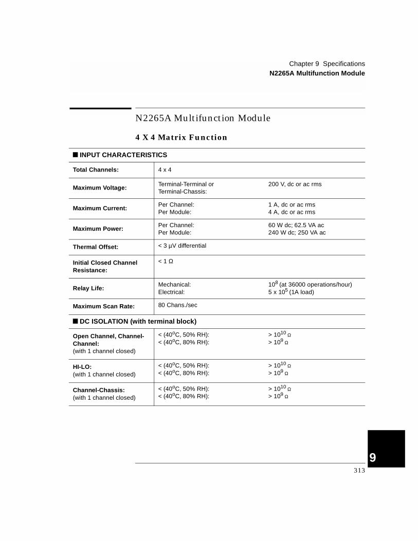
Chapter 9 SpecificationsN2265A Multifunction Module
4
N2265A Multifunction Module
4 X 4 Matrix Function
INPUT CHARACTERISTICS
Total Channels: 4 x 4
Maximum Voltage: Terminal-Terminal or Terminal-Chassis:
200 V, dc or ac rms
Maximum Current: Per Channel:Per Module:
1 A, dc or ac rms4 A, dc or ac rms
Maximum Power: Per Channel:Per Module:
60 W dc; 62.5 VA ac240 W dc; 250 VA ac
Thermal Offset: < 3 µV differential
Initial Closed Channel Resistance:
< 1 Ω
Relay Life:Mechanical:Electrical:
108 (at 36000 operations/hour)5 x 105 (1A load)
Maximum Scan Rate: 80 Chans./sec
DC ISOLATION (with terminal block)
Open Channel, Channel-Channel:(with 1 channel closed)
< (40oC, 50% RH):< (40oC, 80% RH):
> 1010 Ω> 109 Ω
HI-LO:(with 1 channel closed)
< (40oC, 50% RH):< (40oC, 80% RH):
> 1010 Ω> 109 Ω
Channel-Chassis:(with 1 channel closed)
< (40oC, 50% RH):< (40oC, 80% RH):
> 1010 Ω> 109 Ω
313
9
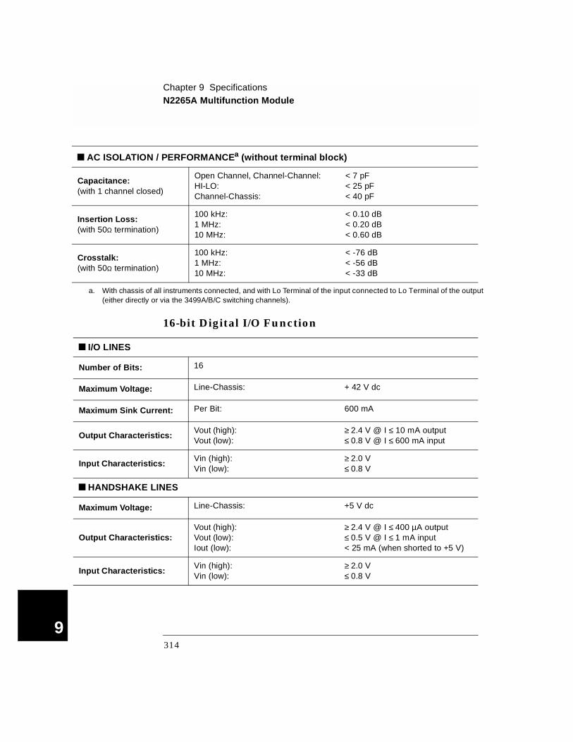
Chapter 9 SpecificationsN2265A Multifunction Module
9
16-bit Digital I/O Function
AC ISOLATION / PERFORMANCEa (without terminal block)
Capacitance: (with 1 channel closed)
Open Channel, Channel-Channel:HI-LO:Channel-Chassis:
< 7 pF< 25 pF< 40 pF
Insertion Loss: (with 50Ω termination)
100 kHz:1 MHz:10 MHz:
< 0.10 dB< 0.20 dB< 0.60 dB
Crosstalk: (with 50Ω termination)
100 kHz:1 MHz:10 MHz:
< -76 dB< -56 dB< -33 dB
a. With chassis of all instruments connected, and with Lo Terminal of the input connected to Lo Terminal of the output (either directly or via the 3499A/B/C switching channels).
I/O LINES
Number of Bits: 16
Maximum Voltage: Line-Chassis: + 42 V dc
Maximum Sink Current: Per Bit: 600 mA
Output Characteristics:Vout (high):Vout (low):
≥ 2.4 V @ I ≤ 10 mA output≤ 0.8 V @ I ≤ 600 mA input
Input Characteristics:Vin (high):Vin (low):
≥ 2.0 V≤ 0.8 V
HANDSHAKE LINES
Maximum Voltage: Line-Chassis: +5 V dc
Output Characteristics: Vout (high):Vout (low):Iout (low):
≥ 2.4 V @ I ≤ 400 µA output≤ 0.5 V @ I ≤ 1 mA input< 25 mA (when shorted to +5 V)
Input Characteristics: Vin (high):Vin (low):
≥ 2.0 V≤ 0.8 V
314

Chapter 9 SpecificationsN2266A 40-Channel MUX Module
4
N2266A 40-Channel MUX Module
INPUT CHARACTERISTICS
Total Channels: 80 1-wire; or 40 2-wire; or dual 20 2-wire; or 20 4-wire
Maximum Switching Voltage:
Terminal-Terminal or Terminal-Chassis:
200 V, dc or peak AC Resist.
Maximum Switching Current:
Per Channel:Per Module:
0.5 A, dc or peak AC Resist.1 A, dc or peak AC Resist.
Maximum Switching Power:
Per Channel:Per Module:
10 W dc or peak AC Resist.20 W dc or peak AC Resist.
Thermal Offset: Per Channel: 50 µV differential or single-ended
Initial Closed Channel Resistance:
< 1 Ω
Relay Life: @1V/1mA: 109
Maximum Scan Rate 350 Chans/sec
DC CHARACTERISTICS
Open Channel, Channel-Channel: (with 1 channel closed)
< (40oC, 50% RH):< (40oC, 80% RH):
> 1010 Ω> 109 Ω
HI-LO: (with 1 channel closed)
< (40oC, 50% RH):< (40oC, 80% RH):
> 1010 Ω> 109 Ω
Channel-Chassis: (with 1 channel closed)
< (40oC, 50% RH):< (40oC, 80% RH)”
> 1010 Ω> 109 Ω
315
9
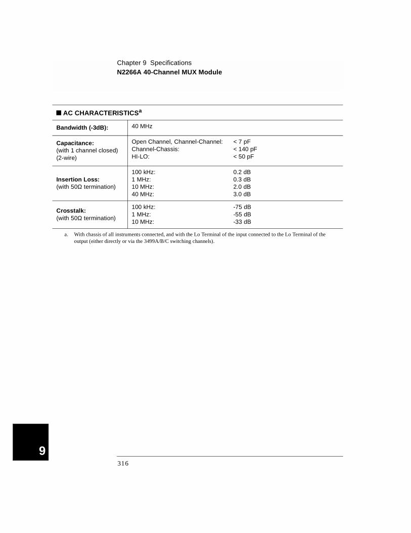
Chapter 9 SpecificationsN2266A 40-Channel MUX Module
9
AC CHARACTERISTICSa
Bandwidth (-3dB): 40 MHz
Capacitance: (with 1 channel closed)(2-wire)
Open Channel, Channel-Channel:Channel-Chassis:HI-LO:
< 7 pF< 140 pF < 50 pF
Insertion Loss: (with 50Ω termination)
100 kHz:1 MHz:10 MHz:40 MHz:
0.2 dB0.3 dB2.0 dB3.0 dB
Crosstalk: (with 50Ω termination)
100 kHz:1 MHz:10 MHz:
-75 dB-55 dB -33 dB
a. With chassis of all instruments connected, and with the Lo Terminal of the input connected to the Lo Terminal of the output (either directly or via the 3499A/B/C switching channels).
316
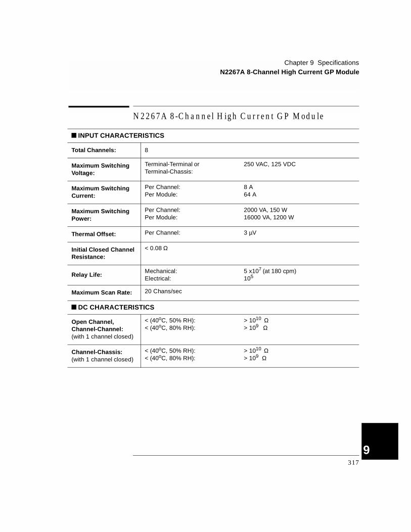
Chapter 9 SpecificationsN2267A 8-Channel High Current GP Module
4
N 2267A 8-Channel H igh C urrent G P M odule
INPUT CHARACTERISTICS
Total Channels: 8
Maximum Switching Voltage:
Terminal-Terminal or Terminal-Chassis:
250 VAC, 125 VDC
Maximum Switching Current:
Per Channel:Per Module:
8 A64 A
Maximum Switching Power:
Per Channel:Per Module:
2000 VA, 150 W16000 VA, 1200 W
Thermal Offset: Per Channel: 3 µV
Initial Closed Channel Resistance:
< 0.08 Ω
Relay Life:Mechanical:Electrical:
5 x10⁷ (at 180 cpm)105
Maximum Scan Rate: 20 Chans/sec
DC CHARACTERISTICS
Open Channel, Channel-Channel:(with 1 channel closed)
< (40oC, 50% RH):< (40oC, 80% RH):
> 1010 Ω> 109 Ω
Channel-Chassis:(with 1 channel closed)
< (40oC, 50% RH):< (40oC, 80% RH):
> 1010 Ω> 109 Ω
317
9
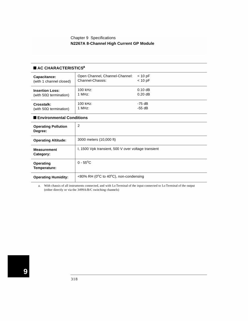
Chapter 9 SpecificationsN2267A 8-Channel High Current GP Module
9
AC CHARACTERISTICSa
Capacitance: (with 1 channel closed)
Open Channel, Channel-Channel:Channel-Chassis:
< 10 pF< 10 pF
Insertion Loss:(with 50Ω termination)
100 kHz:1 MHz:
0.10 dB0.20 dB
Crosstalk: (with 50Ω termination)
100 kHz:1 MHz:
-75 dB-55 dB
Environmental Conditions
Operating Pollution Degree:
2
Operating Altitude: 3000 meters (10,000 ft)
Measurement Category:
I, 1500 Vpk transient, 500 V over voltage transient
Operating Temperature:
0 - 55oC
Operating Humidity: <80% RH (0oC to 40oC), non-condensing
a. With chassis of all instruments connected, and with Lo Terminal of the input connected to Lo Terminal of the output (either directly or via the 3499A/B/C switching channels)
318
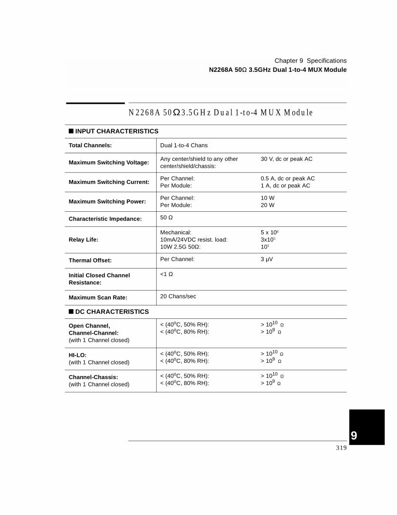
Chapter 9 SpecificationsN2268A 50Ω 3.5GHz Dual 1-to-4 MUX Module
4
N 2268A 50Ω 3 .5G H z D ual 1-to-4 M U X M odule
INPUT CHARACTERISTICS
Total Channels: Dual 1-to-4 Chans
Maximum Switching Voltage:Any center/shield to any other center/shield/chassis:
30 V, dc or peak AC
Maximum Switching Current:Per Channel:Per Module:
0.5 A, dc or peak AC1 A, dc or peak AC
Maximum Switching Power:Per Channel:Per Module:
10 W20 W
Characteristic Impedance: 50 Ω
Relay Life:Mechanical:10mA/24VDC resist. load:10W 2.5G 50Ω:
5 x 10⁶
3x10⁵
105
Thermal Offset: Per Channel: 3 µV
Initial Closed Channel Resistance:
<1 Ω
Maximum Scan Rate: 20 Chans/sec
DC CHARACTERISTICS
Open Channel, Channel-Channel:(with 1 Channel closed)
< (40oC, 50% RH):< (40oC, 80% RH):
> 1010 Ω> 109 Ω
HI-LO:(with 1 Channel closed)
< (40oC, 50% RH):< (40oC, 80% RH):
> 1010 Ω> 109 Ω
Channel-Chassis:(with 1 Channel closed)
< (40oC, 50% RH):< (40oC, 80% RH):
> 1010 Ω> 109 Ω
319
9

Chapter 9 SpecificationsN2268A 50Ω 3.5GHz Dual 1-to-4 MUX Module
9
AC CHARACTERISTICSa
Bandwidth (-3dB): 50 Ω source, 50 Ω termination: 3.5 GHz
Insertion Loss: (with 50Ω termination)
1 GHz:2 GHz:3 GHz:3.5 GHz:
0.9 dB1.2 dB1.4 dB1.7 dB
Crosstalk: (with 50Ω termination)
DC-2 GHz:2 GHz-3.5 GHz:
-64 dB-50 dB
VSWR:1 GHz:2 GHz:3.5 GHz:
1.201.351.35
Capacitance:Center-Shield:Center-Center:
20 pF0.06 pF
Rise Time: <150 ps
Signal Delay: <1.5 ns
a. With chassis of all instruments connected, and with Lo Terminal of the input connected to Lo Terminal of the output (either directly or via the 3499A/B/C switching channels).
320

Chapter 9 SpecificationsN2270A 10-Channel High Voltage MUX Module
4
N2270A 10-Channel High Voltage MUX Module
INPUT CHARACTERISTICS
Total Channels: 10
Maximum Switching Voltage:
Terminal-Terminal or Terminal-Chassis:
1000 V peak (per IEC1010 for Pollution Degree I)
Maximum Switching Current:
Per Channel:Per Module:
1 A1 A
Maximum Switching Power:Per Channel:Per Module:
10 W10 W
Thermal Offset: Per Channel: 200 µV
Initial Closed Channel Resistance:
< 1 Ω
Relay Life: Signal load, 1V 10mA: 108
Maximum Scan Rate: 100 Chans/sec
DC CHARACTERISTICS
Open Channel, Channel-Channel:(with 1 channel closed)
< (40oC, 50% RH):< (40oC, 80% RH):
> 1010 Ω> 109 Ω
Channel-Chassis:(with 1 channel closed)
< (40oC, 50% RH):< (40oC, 80% RH):
> 1010 Ω> 109 Ω
321
9

Chapter 9 SpecificationsN2270A 10-Channel High Voltage MUX Module
9
AC CHARACTERISTICSa
Capacitance: (with 1 channel closed)
Open Channel, Channel-Channel, Hi-Lo:Channel-Chassis:
< 7 pF
< 50 pF
Insertion Loss:(with 50Ω termination)
100 kHz:1 MHz:
0.1 dB0.2 dB
Crosstalk :(with 50Ω termination)
100 kHz:1 MHz:
-70 dB-50 dB
Environmental Conditions
Operating Pollution Degree: 2
Operating Altitude:3000 meters (10,000 ft)
Measurement Category: I, 1500 Vpk transient, 500 V over voltage transient
Operating Temperature: 0-55oC
Operating Humidity: <80% RH (0oC-40oC), non-condensing
a. With chassis of all instruments connected, and with Lo Terminal of the input connected to Lo Terminal of the output (either directly or via the 3499A/B/C switching channels).
322

Chapter 9 SpecificationsN2272A 1 GHz RF 1-to-9 MUX Module
4
N2272A 1 GHz RF 1-to-9 MUX Module
INPUT CHARACTERISTICS
Total Channels: 1-to-9
Relay Type: Latching
Connector Type: BNC
Maximum Switching Voltage: 24 VDC
Maximum Switching Current: 1 A
Maximum Switching Power: 24 W
Characteristic Impedance: 50Ω
Relay Life:Mechanical:Electrical@1A24VDC:
5X10⁶
105
DC CHARACTERISTICS
Offset Voltage (mV): 8.0
Initial Closed Channel Resistance (Ω):
0.8
Insulation Resistance (Ω):
@(25oC, 40%RH) (Open Ch, Ch-Ch):
(Ch-Chassis, Ch-Center):@(40oC, 80%RH)
(Open Ch, Ch-Ch): (Ch-Chassis, Ch-Center):
10101010
109
109
323
9
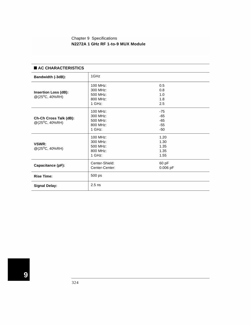
Chapter 9 SpecificationsN2272A 1 GHz RF 1-to-9 MUX Module
9
AC CHARACTERISTICS
Bandwidth (-3dB): 1GHz
Insertion Loss (dB):@(25oC, 40%RH)
100 MHz:300 MHz:500 MHz:800 MHz:1 GHz:
0.50.81.01.82.5
Ch-Ch Cross Talk (dB):@(25oC, 40%RH)
100 MHz:300 MHz:500 MHz:800 MHz:1 GHz:
-75-65-65-55-50
VSWR:@(25oC, 40%RH)
100 MHz:300 MHz:500 MHz:800 MHz:1 GHz:
1.201.301.351.351.55
Capacitance (pF):Center-Shield:Center-Center:
60 pF0.006 pF
Rise Time: 500 ps
Signal Delay: 2.5 ns
324
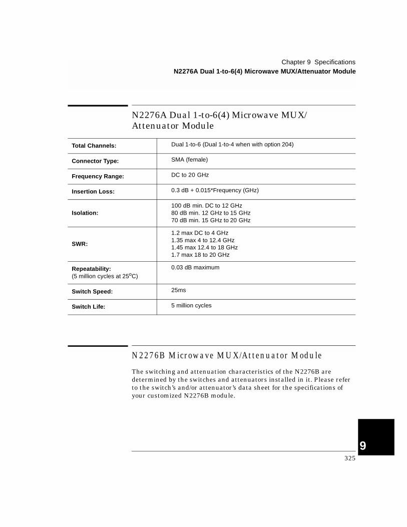
Chapter 9 SpecificationsN2276A Dual 1-to-6(4) Microwave MUX/Attenuator Module
4
N2276A Dual 1-to-6(4) Microwave MUX/Attenuator Module
N 2276B M icrowave M U X/Attenuator M odule
The switching and attenuation characteristics of the N2276B are determined by the switches and attenuators installed in it. Please refer to the switch’s and/or attenuator’s data sheet for the specifications of your customized N2276B module.
Total Channels: Dual 1-to-6 (Dual 1-to-4 when with option 204)
Connector Type: SMA (female)
Frequency Range: DC to 20 GHz
Insertion Loss: 0.3 dB + 0.015*Frequency (GHz)
Isolation:100 dB min. DC to 12 GHz80 dB min. 12 GHz to 15 GHz70 dB min. 15 GHz to 20 GHz
SWR:
1.2 max DC to 4 GHz1.35 max 4 to 12.4 GHz1.45 max 12.4 to 18 GHz1.7 max 18 to 20 GHz
Repeatability: (5 million cycles at 25oC)
0.03 dB maximum
Switch Speed: 25ms
Switch Life: 5 million cycles
325
9

Chapter 9 SpecificationsN2280A Quadruple 1-to-2 Optical Switch Module
9
N2280A Quadruple 1-to-2 Optical Switch Module
Typical Maximum
Insertion Loss: Single-mode (SM):a
a. Excluding connectors. Include 0.2dB (typical insertion loss) for each connector.
0.5 dB 0.8 dB
Return Loss: SM:b
b. Excluding connectors.
50 dB 45 dB (min.)
Polarization Dependent Loss:b SM: 0.02 dB 0.07 dB
Insertion Loss Stability:c
c. Drift of any channel relative to one assigned reference channel at + 3o C deviation of ambient temperature over a seven-day period.
±0.03 dB ±0.05 dB
Repeatability: ±0.03dB ±0.005 dB
Crosstalk: -70 dB -60 dB
Optical Input Power: 300 mW
Switching Time: 15 ms 20 ms
Cycle Rate: 5 c/s
Relay Life: 10M cycles (min.)
Operating Temperature: 0 to 55oC
Storage Temperature; -40 to 70oC
Humidity: (non-condensing) < 80%RH
Power: 5 ±5%VDC/45mA 5 ±5%VDC/70mA
326

Chapter 9 SpecificationsN2281A Dual 1-to-4 Optical Switch Module
4
N2281A Dual 1-to-4 Optical Switch Module
Typical Maximum
Insertion Loss: Single-mode (SM):a
a. Excluding connectors. Include 0.2dB (typical insertion loss) for each connector.
0.5 dB 0.8 dB
Return Loss: SM:b
b. Excluding connectors.
50 dB 45 dB (min.)
Polarization Dependent Loss:b SM: 0.02 dB 0.07 dB
Insertion Loss Stability:c
c. Drift of any channel relative to one assigned reference channel at ±3o C deviation of ambient temperature over a seven-day period.
±0.03 dB ±0.05 dB
Repeatability: ±0.03 dB ±0.005 dB
Crosstalk: -70 dB -60 dB
Optical Input Power: 300 mW
Switching Time: 20 ms 25 ms
Cycle Rate: 5 c/s
Relay Life: 10M cycles (min.)
Operating Temperature: 0 to 55oC
Storage Temperature: -40 to 70oC
Humidity (non-condensing): < 80%RH
Power: 5 ±5%VDC/45mA 5 ±5%VDC/70mA
327
9
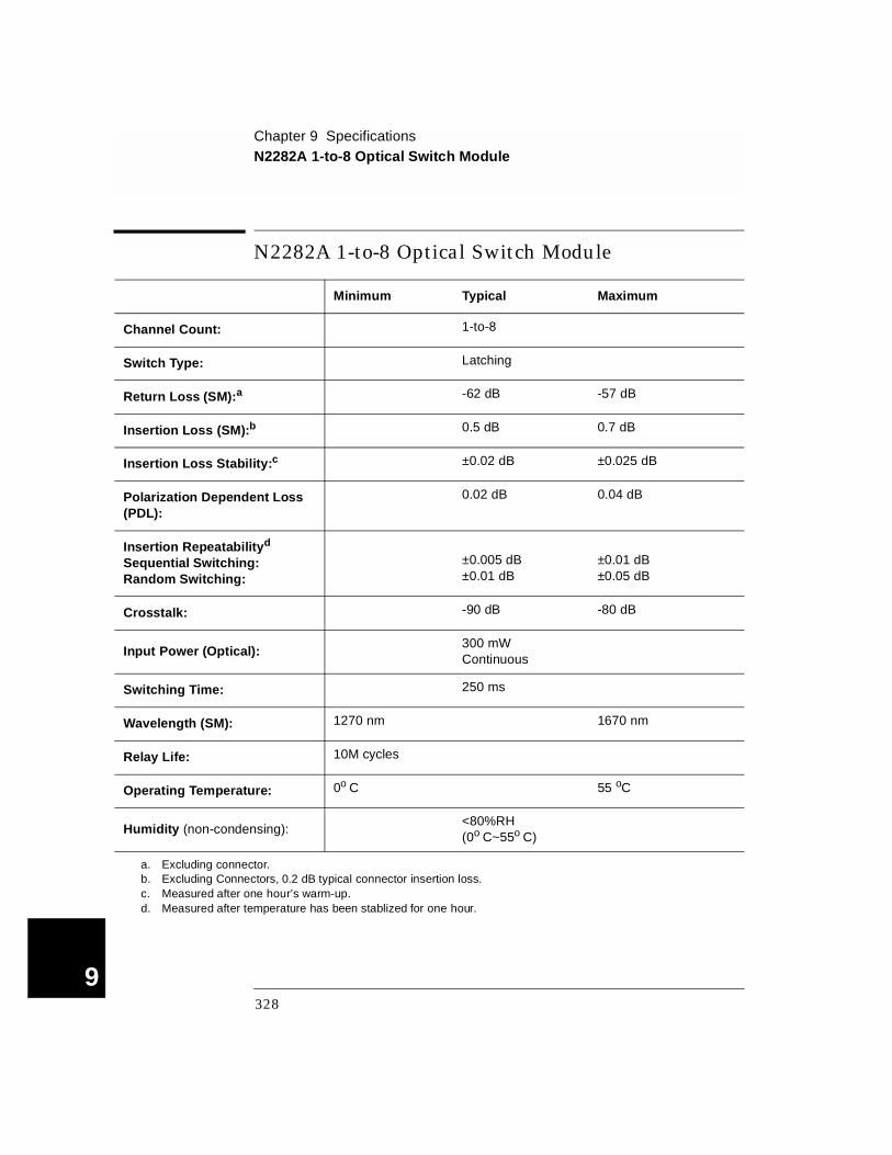
Chapter 9 SpecificationsN2282A 1-to-8 Optical Switch Module
9
N2282A 1-to-8 Optical Switch Module
Minimum Typical Maximum
Channel Count: 1-to-8
Switch Type: Latching
Return Loss (SM):a
a. Excluding connector.
-62 dB -57 dB
Insertion Loss (SM):b
b. Excluding Connectors, 0.2 dB typical connector insertion loss.
0.5 dB 0.7 dB
Insertion Loss Stability:c
c. Measured after one hour’s warm-up.
±0.02 dB ±0.025 dB
Polarization Dependent Loss (PDL):
0.02 dB 0.04 dB
Insertion Repeatabilityd
Sequential Switching:Random Switching:
d. Measured after temperature has been stablized for one hour.
±0.005 dB±0.01 dB
±0.01 dB±0.05 dB
Crosstalk: -90 dB -80 dB
Input Power (Optical):300 mW Continuous
Switching Time: 250 ms
Wavelength (SM): 1270 nm 1670 nm
Relay Life: 10M cycles
Operating Temperature: 0o C 55 oC
Humidity (non-condensing):<80%RH (0o C~55o C)
328

Chapter 9 Specifications44470A 10-Channel MUX Module
4
44470A 10-Channel MUX Module
INPUT CHARACTERISTICS
Total Channels: 10
Maximum Voltage:Terminal-Terminal or Terminal-Chassis:
250 V, dc or ac rms
Maximum Current: Per Channel or Module: 2 A, dc or ac rms
Maximum Power: Per Channel or Module: 60 W dc; 500 VA ac
Maximum Overvoltage Transients:
1400 Vpk
Thermal Offset: < 3 µV differential or single-ended
Initial Closed Channel Resistance:
< 1 Ω
Relay Life:Dry Load of < 300 mA & < 10 V:Maximum Rated Load:
108
105
Maximum Scan Rate:a
a. Using the 44474A external increment & channel closed, display off.
43 Chans/sec
DC ISOLATION
Open Channel, Channel-Channel: (with 1 channel closed)
< (40oC, 60% RH):< (40oC, 95% RH):
> 1011 Ω>109 Ω
HI-LO: (with 1 channel closed)
< (40oC, 60% RH):< (40oC, 95% RH):
> 1010 Ω> 108 Ω
Channel-Chassis: (with 1 channel closed)
< (40oC, 60% RH):< (40oC, 95% RH):
> 1010 Ω> 5 x 10⁸ Ω
329
9

Chapter 9 Specifications44470A 10-Channel MUX Module
9
AC ISOLATION / PERFORMANCEa
Capacitance: (with 1 channel closed)
Open Channel, Channel-Channel:HI-LO:Channel-Chassis:
< 5 pF< 27 pF< 80 pF
Insertion Loss: (with 50Ω termination)
100 kHz:1 MHz:10 MHz:
< 0.20 dB< 0.25 dB< 0.50 dB
Crosstalk: (with 50Ω termination)
100 kHz:1 MHz:10 MHz:
< -73 dB< -53 dB< -33 dB
a. With chassis of all instruments connected, and with the Lo of input lines connected to the Lo of output lines (either directly or via the 3499A/B/C switching channels).
330
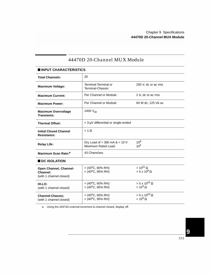
Chapter 9 Specifications44470D 20-Channel MUX Module
4
44470D 20-Channel MUX Module
INPUT CHARACTERISTICS
Total Channels: 20
Maximum Voltage:Terminal-Terminal or Terminal-Chassis:
250 V, dc or ac rms
Maximum Current: Per Channel or Module: 2 A, dc or ac rms
Maximum Power: Per Channel or Module: 60 W dc; 125 VA ac
Maximum Overvoltage Transients:
1400 Vpk
Thermal Offset: < 3 µV differential or single-ended
Initial Closed Channel Resistance:
< 1 Ω
Relay Life:Dry Load of < 300 mA & < 10 V:Maximum Rated Load:
108
105
Maximum Scan Rate:a
a. Using the 44474A external increment & channel closed, display off.
43 Chans/sec
DC ISOLATION
Open Channel, Channel-Channel:(with 1 channel closed)
< (40oC, 60% RH):< (40oC, 95% RH):
> 1011 Ω> 5 x 10⁹ Ω
HI-LO:(with 1 channel closed)
< (40oC, 60% RH):< (40oC, 95% RH):
> 5 x 10¹⁰ Ω> 109 Ω
Channel-Chassis;(with 1 channel closed)
< (40oC, 60% RH):< (40oC, 95% RH):
> 5 x 10¹⁰ Ω> 109 Ω
331
9
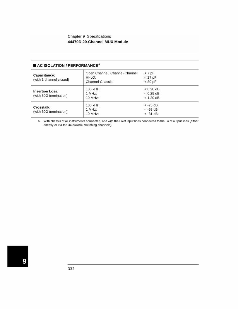
Chapter 9 Specifications44470D 20-Channel MUX Module
9
AC ISOLATION / PERFORMANCEa
Capacitance: (with 1 channel closed)
Open Channel, Channel-Channel:HI-LO:Channel-Chassis:
< 7 pF< 27 pF< 80 pF
Insertion Loss:(with 50Ω termination)
100 kHz:1 MHz:10 MHz:
< 0.20 dB< 0.25 dB< 1.20 dB
Crosstalk: (with 50Ω termination)
100 kHz:1 MHz:10 MHz:
< -73 dB< -53 dB< -31 dB
a. With chassis of all instruments connected, and with the Lo of input lines connected to the Lo of output lines (either directly or via the 3499A/B/C switching channels).
332
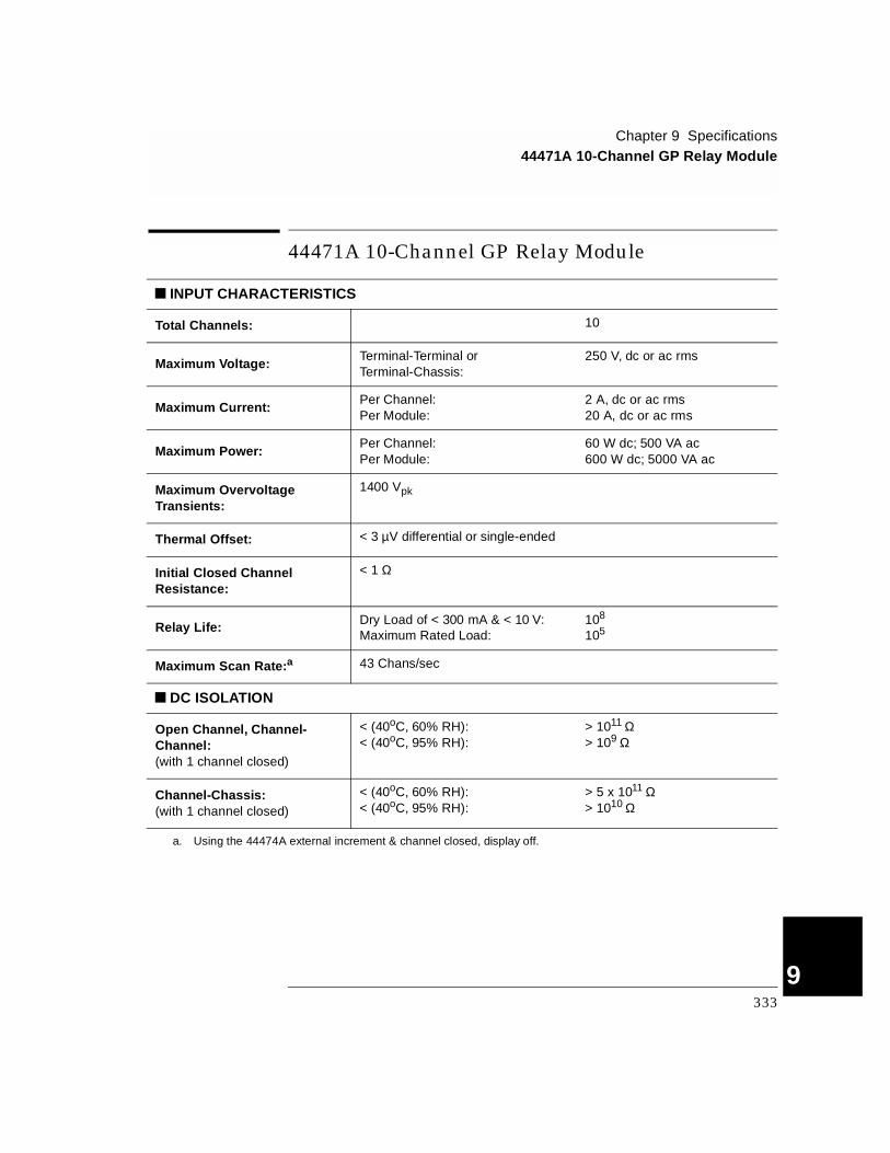
Chapter 9 Specifications44471A 10-Channel GP Relay Module
4
44471A 10-Channel GP Relay Module
INPUT CHARACTERISTICS
Total Channels: 10
Maximum Voltage:Terminal-Terminal or Terminal-Chassis:
250 V, dc or ac rms
Maximum Current:Per Channel:Per Module:
2 A, dc or ac rms20 A, dc or ac rms
Maximum Power:Per Channel:Per Module:
60 W dc; 500 VA ac600 W dc; 5000 VA ac
Maximum Overvoltage Transients:
1400 Vpk
Thermal Offset: < 3 µV differential or single-ended
Initial Closed Channel Resistance:
< 1 Ω
Relay Life: Dry Load of < 300 mA & < 10 V:Maximum Rated Load:
108
105
Maximum Scan Rate:a
a. Using the 44474A external increment & channel closed, display off.
43 Chans/sec
DC ISOLATION
Open Channel, Channel-Channel:(with 1 channel closed)
< (40oC, 60% RH):< (40oC, 95% RH):
> 1011 Ω> 109 Ω
Channel-Chassis:(with 1 channel closed)
< (40oC, 60% RH):< (40oC, 95% RH):
> 5 x 10¹¹ Ω> 1010 Ω
333
9

Chapter 9 Specifications44471A 10-Channel GP Relay Module
9
AC ISOLATION / PERFORMANCEa
Capacitance: (with 1 channel closed)
Open Channel:Channel-Channel:Channel-Chassis:
< 7 pF< 10 pF< 25 pF
Insertion Loss: (with 50Ω termination)
100 kHz:1 MHz:10 MHz:
< 0.20 dB< 0.25 dB< 0.50 dB
Crosstalk:(with 50Ω termination)
100 kHz:1 MHz:10 MHz:
< -73 dB< -53 dB< -33 dB
a. With chassis of all instruments connected, and with the Lo of input lines connected to the Lo of output lines (either directly or via the 3499A/B/C switching channels).
334
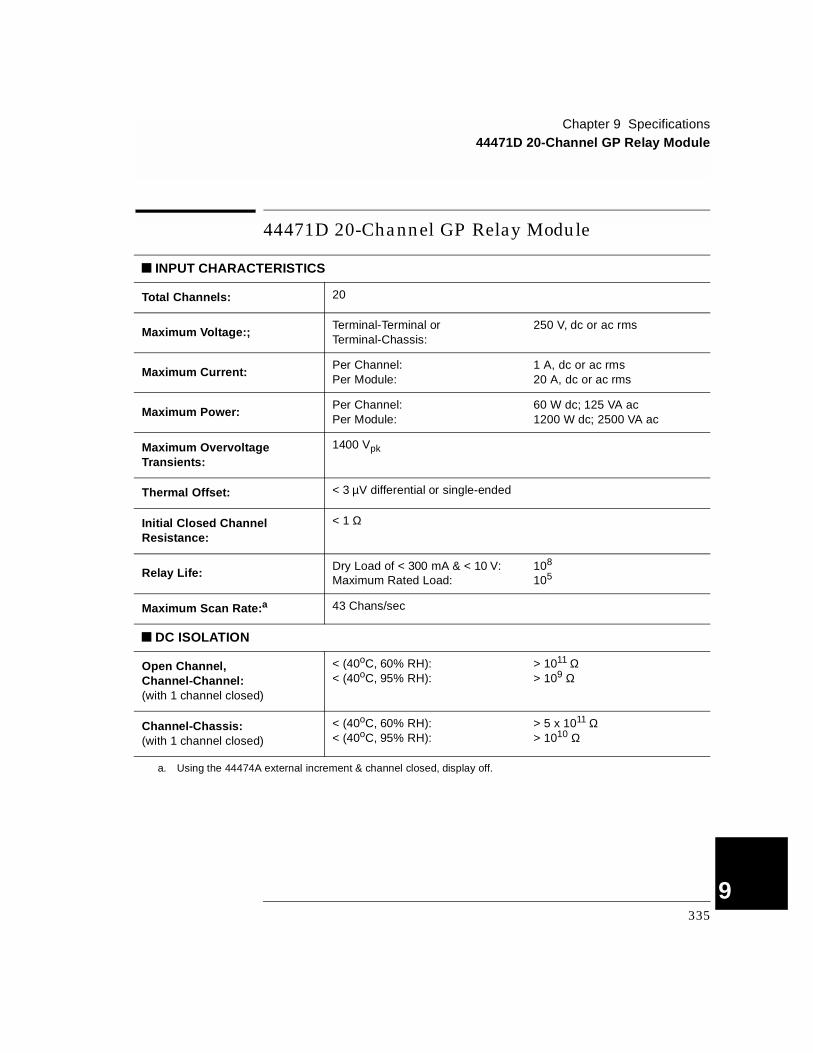
Chapter 9 Specifications44471D 20-Channel GP Relay Module
4
44471D 20-Channel GP Relay Module
INPUT CHARACTERISTICS
Total Channels: 20
Maximum Voltage:;Terminal-Terminal or Terminal-Chassis:
250 V, dc or ac rms
Maximum Current:Per Channel:Per Module:
1 A, dc or ac rms20 A, dc or ac rms
Maximum Power:Per Channel:Per Module:
60 W dc; 125 VA ac1200 W dc; 2500 VA ac
Maximum Overvoltage Transients:
1400 Vpk
Thermal Offset: < 3 µV differential or single-ended
Initial Closed Channel Resistance:
< 1 Ω
Relay Life: Dry Load of < 300 mA & < 10 V:Maximum Rated Load:
108
105
Maximum Scan Rate:a
a. Using the 44474A external increment & channel closed, display off.
43 Chans/sec
DC ISOLATION
Open Channel, Channel-Channel:(with 1 channel closed)
< (40oC, 60% RH):< (40oC, 95% RH):
> 1011 Ω> 109 Ω
Channel-Chassis:(with 1 channel closed)
< (40oC, 60% RH):< (40oC, 95% RH):
> 5 x 10¹¹ Ω> 1010 Ω
335
9

Chapter 9 Specifications44471D 20-Channel GP Relay Module
9
AC ISOLATION / PERFORMANCEa
Capacitance:(with 1 channel closed)
Open Channel:Channel-Channel:Channel-Chassis:
< 7 pF< 10 pF< 25 pF
Insertion Loss:(with 50Ω termination)
100 kHz:1 MHz:10 MHz:
< 0.20 dB< 0.25 dB< 1 dB
Crosstalk: (with 50Ω termination)
100 kHz:1 MHz:10 MHz:
< -71 dB< -51 dB< -31 dB
a. With chassis of all instruments connected, and with the Lo of input lines connected to the Lo of output lines (either directly or via the 3499A/B/C switching channels).
336

Chapter 9 Specifications44472A Dual 4-Channel VHF Switch Module
4
44472A Dual 4-Channel VH F Switch M odule
INPUT CHARACTERISTICS
Total Channels: Dual 4 Chans
Connector Type: BNC
Maximum Voltage:Center-Center or Center-Low:
Low-Chassis or Low-Low:
250 V dc, 30 V ac rms or 42 V ac peak42 V dc
Maximum Current: Per Channel: 30 mA dc, 300 mA ac rms
Thermal Offset: Per Channel: < 15 µV
Characteristic Impedance: 50 Ω
Initial Closed Channel Resistance:
< 1 Ω
Relay Life:Dry Load of < 300 mA & < 10 V:Maximum Rated Load:
108
105
Maximum Scan Rate:a
a. Using Agilent 44474A external increment & channel closed, display off.
43 Chans/sec
DC ISOLATION
Between Any Two Points: < (40oC, 95% RH): > 107 Ω
337
9
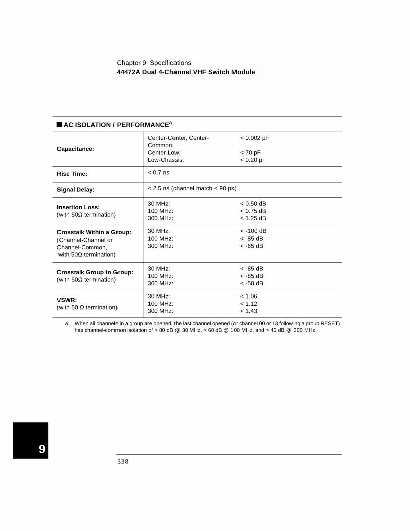
Chapter 9 Specifications44472A Dual 4-Channel VHF Switch Module
9
AC ISOLATION / PERFORMANCEa
Capacitance:
Center-Center, Center-Common:Center-Low:Low-Chassis:
< 0.002 pF
< 70 pF< 0.20 µF
Rise Time: < 0.7 ns
Signal Delay: < 2.5 ns (channel match < 90 ps)
Insertion Loss: (with 50Ω termination)
30 MHz:100 MHz:300 MHz:
< 0.50 dB< 0.75 dB< 1.25 dB
Crosstalk Within a Group:(Channel-Channel or Channel-Common, with 50Ω termination)
30 MHz:100 MHz:300 MHz:
< -100 dB< -85 dB< -65 dB
Crosstalk Group to Group:(with 50Ω termination)
30 MHz:100 MHz:300 MHz:
< -85 dB< -85 dB< -50 dB
VSWR:(with 50 Ω termination)
30 MHz:100 MHz:300 MHz:
< 1.06< 1.12< 1.43
a. When all channels in a group are opened, the last channel opened (or channel 00 or 13 following a group RESET) has channel-common isolation of > 80 dB @ 30 MHz, > 60 dB @ 100 MHz, and > 40 dB @ 300 MHz.
338
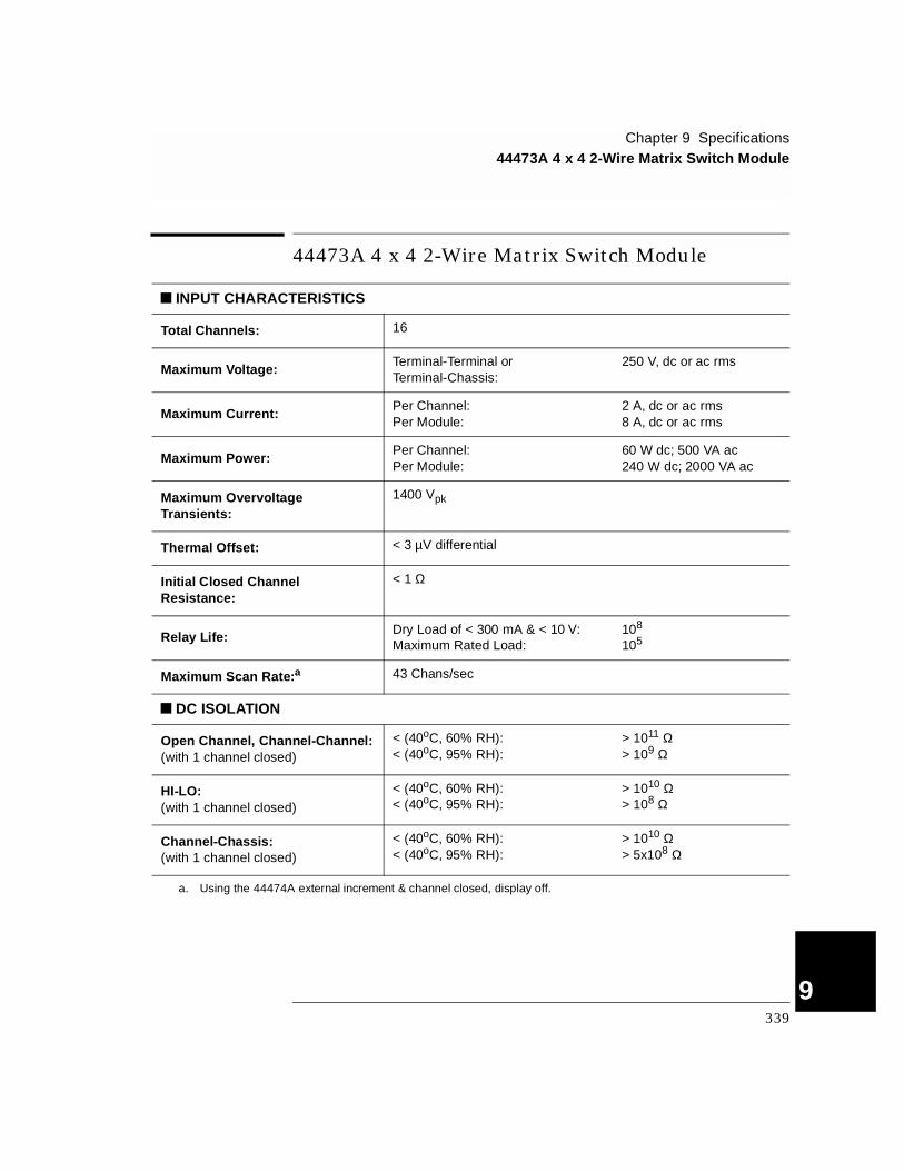
Chapter 9 Specifications44473A 4 x 4 2-Wire Matrix Switch Module
4
44473A 4 x 4 2-Wire Matrix Switch Module
INPUT CHARACTERISTICS
Total Channels: 16
Maximum Voltage:Terminal-Terminal or Terminal-Chassis:
250 V, dc or ac rms
Maximum Current:Per Channel:Per Module:
2 A, dc or ac rms8 A, dc or ac rms
Maximum Power:Per Channel:Per Module:
60 W dc; 500 VA ac240 W dc; 2000 VA ac
Maximum Overvoltage Transients:
1400 Vpk
Thermal Offset: < 3 µV differential
Initial Closed Channel Resistance:
< 1 Ω
Relay Life: Dry Load of < 300 mA & < 10 V:Maximum Rated Load:
108
105
Maximum Scan Rate:a
a. Using the 44474A external increment & channel closed, display off.
43 Chans/sec
DC ISOLATION
Open Channel, Channel-Channel:(with 1 channel closed)
< (40oC, 60% RH):< (40oC, 95% RH):
> 1011 Ω> 109 Ω
HI-LO:(with 1 channel closed)
< (40oC, 60% RH):< (40oC, 95% RH):
> 1010 Ω> 108 Ω
Channel-Chassis:(with 1 channel closed)
< (40oC, 60% RH):< (40oC, 95% RH):
> 1010 Ω> 5x10⁸ Ω
339
9
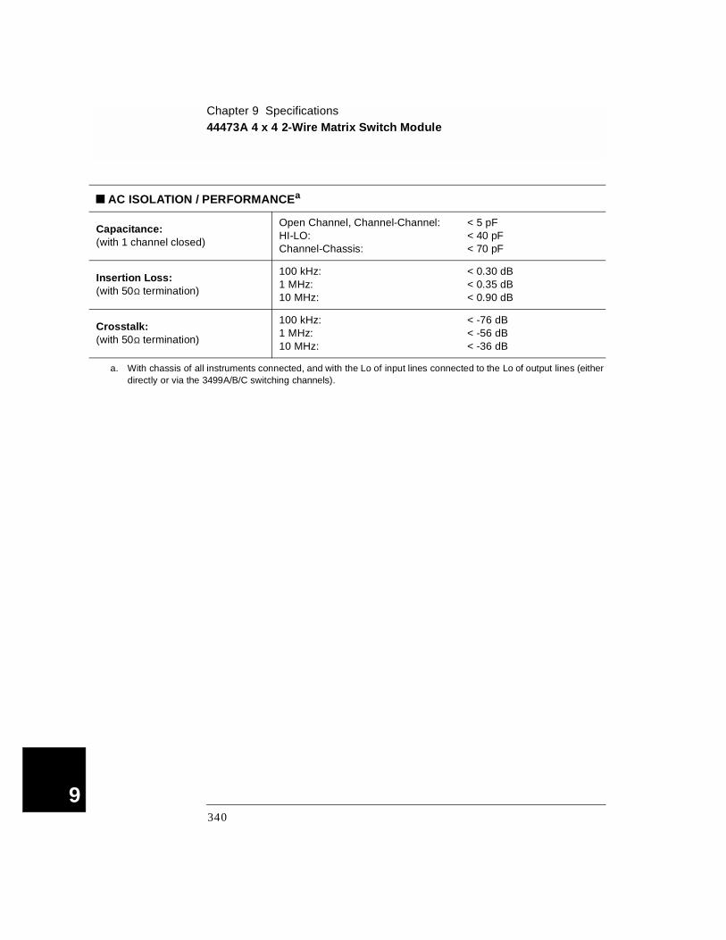
Chapter 9 Specifications44473A 4 x 4 2-Wire Matrix Switch Module
9
AC ISOLATION / PERFORMANCEa
Capacitance: (with 1 channel closed)
Open Channel, Channel-Channel:HI-LO:Channel-Chassis:
< 5 pF< 40 pF< 70 pF
Insertion Loss: (with 50Ω termination)
100 kHz:1 MHz:10 MHz:
< 0.30 dB< 0.35 dB< 0.90 dB
Crosstalk: (with 50Ω termination)
100 kHz:1 MHz:10 MHz:
< -76 dB< -56 dB< -36 dB
a. With chassis of all instruments connected, and with the Lo of input lines connected to the Lo of output lines (either directly or via the 3499A/B/C switching channels).
340

Chapter 9 Specifications44474A 16-Bit Digital I/O Module
4
44474A 16-Bit Digital I/O Module
I/O LINES
Number of Bits: 16
Maximum Voltage: Line-Chassis: +30 V dc
Output Characteristics:
Vout (high):Vout (low):I (low):
≥ 2.4 V @ I ≤ 8 mA output≤ 0.4 V @ I ≤ 16 mA input= 125 mA @ Vout (low) ≤ 1.25 Vfused at 250 mA
Input Characteristics:Vin (high):Vin (low):
≥ 2.0 V≤ 0.8 V
HANDSHAKE LINES
Maximum Voltage: Line-Chassis: +5 V dc
Output Characteristics: Vout (high):Vout (low):
≥ 2.4 V @ I ≤ 400 µA output≤ 0.5 V @ I ≤ 2 mA input
Input Characteristics: Vin (high):Vin (low):
≥ 2.0 V≤ 0.8 V
External Increment (EI):a
a. Both EI and CC lines are used for external controlled scanning. The 3499A/B/C will advance to the next channel in the scan list on the falling edge of EI pulse.
Minimum TTL Pulse Width: 0.25 µs
Channel Closed (CC):b
b. When the next channel closes, the 44474A outputs a CC pulse to trigger the voltmeter.
Minimum TTL Pulse Width: 10 µs
341
9
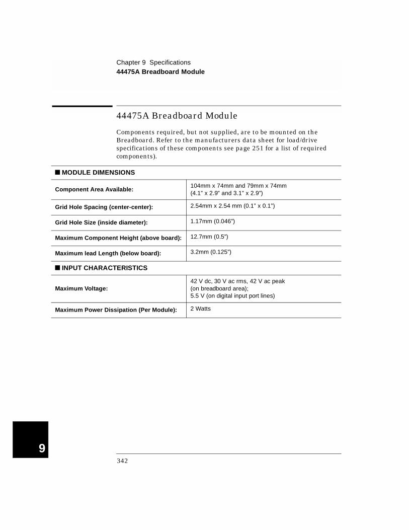
Chapter 9 Specifications44475A Breadboard Module
9
44475A Breadboard Module
Components required, but not supplied, are to be mounted on the Breadboard. Refer to the manufacturers data sheet for load/drive specifications of these components see page 251 for a list of required components).
MODULE DIMENSIONS
Component Area Available:104mm x 74mm and 79mm x 74mm(4.1” x 2.9” and 3.1” x 2.9”)
Grid Hole Spacing (center-center): 2.54mm x 2.54 mm (0.1” x 0.1”)
Grid Hole Size (inside diameter): 1.17mm (0.046”)
Maximum Component Height (above board): 12.7mm (0.5”)
Maximum lead Length (below board): 3.2mm (0.125”)
INPUT CHARACTERISTICS
Maximum Voltage:42 V dc, 30 V ac rms, 42 V ac peak (on breadboard area);5.5 V (on digital input port lines)
Maximum Power Dissipation (Per Module): 2 Watts
342
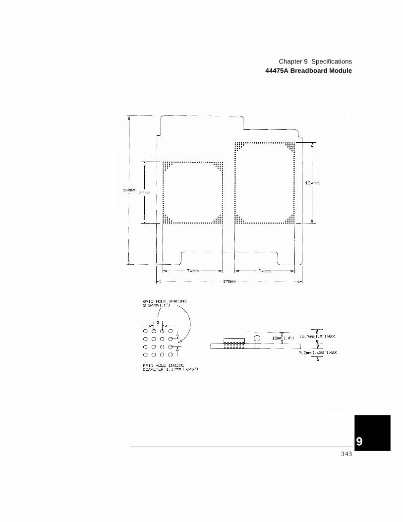
Chapter 9 Specifications44475A Breadboard Module
4
343
9

Chapter 9 Specifications44476A Microwave Switch Module
9
44476A Microwave Switch Module
44476B Microwave Switch Module
The switching and attenuation characteristics of the 44476B are determined by the switches and attenuators installed in it. Please refer to the switch’s and/or attenuator’s data sheet for the specifications of your customized 44476B module.
INPUT CHARACTERISTICS
Frequency Range: DC to 18 GHz
Characteristic Impedance: 50 Ω
Input Power Rating: 1 Watt average, 100 Watts peak (Also less than ±7 V dc)
Average Switch Life: 106
Repeatability (typical): 0.03 dB after 106 switchings
Maximum Scan Rate:a
a. Using the 44474A External Increment & Channel Closed, display off.
43 Chans/sec
Connector: SMA
AC ISOLATION / PERFORMANCE
Isolation: DC - 18 GHz: > 90 dB
Insertion Loss:DC - 2 GHz:DC - 18 GHz:
< 0.25 dB< 0.50 dB
SWR (3 mm SMA):DC - 2 GHz:DC - 12.4 GHz:DC - 18.0 GHz:
< 1.15 dB< 1.25 dB< 1.40 dB
344

Chapter 9 Specifications44477A Form-C Relay Module
4
44477A Form-C Relay Module
INPUT CHARACTERISTICS
Total Channels: 7
Maximum Voltage:Terminal-Terminal or Terminal-Chassis:
250 V dc or ac rms, 350 V ac peak
Maximum Current:Per Channel:Per Module:
2 A, dc or ac rms14 A, dc or ac rms
Maximum Power:Per Channel:Per Module:
60 W dc; 500 VA ac420 W dc; 3500 VA ac
Maximum Overvoltage Transients:
1400 Vpk
Thermal Offset: < 3 µV per channel
Initial Closed Channel Resistance:
< 1 Ω
Relay Life: Dry Load of < 300 mA & < 10 V:Maximum Rated Load:
108
105
Maximum Scan Rate:a
a. Using the 44474A external increment & channel closed, display off.
43 Chans/sec
DC ISOLATION
Open Channel, Channel-Channel: (with 1 channel closed)
≤ (40oC, 60% RH):≤ (40oC, 95% RH):
> 1011 Ω>109 Ω
Channel-Chassis: (with 1 channel closed)
≤ (40oC, 60% RH):≤ (40oC, 95% RH):
> 5 x 10¹¹ Ω> 1010 Ω
345
9
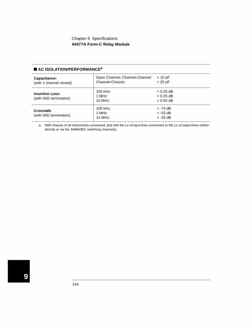
Chapter 9 Specifications44477A Form-C Relay Module
9
AC ISOLATION/PERFORMANCEa
Capacitance: (with 1 channel closed)
Open Channel, Channel-Channel:Channel-Chassis:
< 10 pF< 25 pF
Insertion Loss: (with 50Ω termination)
100 kHz:1 MHz:10 MHz:
< 0.20 dB< 0.25 dB< 0.50 dB
Crosstalk: (with 50Ω termination)
100 kHz:1 MHz:10 MHz:
< -73 dB< -53 dB< -33 dB
a. With chassis of all instruments connected, and with the Lo of input lines connected to the Lo of output lines (either directly or via the 3499A/B/C switching channels).
346
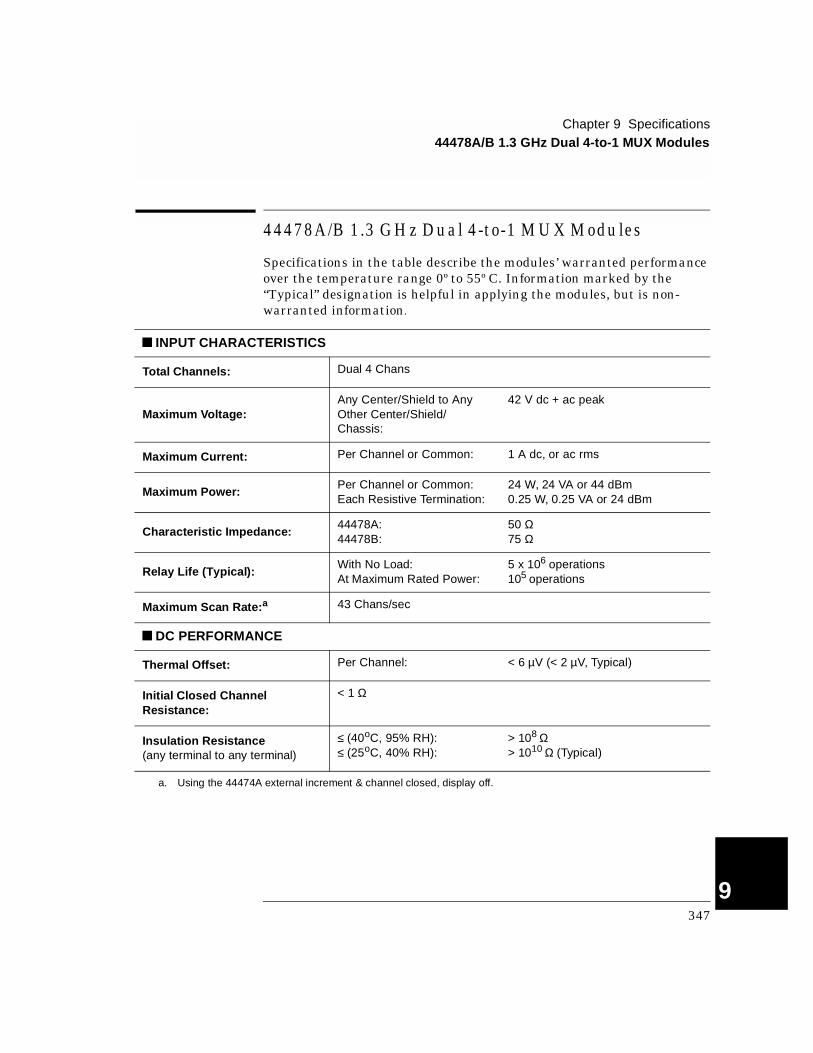
Chapter 9 Specifications44478A/B 1.3 GHz Dual 4-to-1 MUX Modules
4
44478A /B 1.3 G H z D ual 4-to-1 M U X M odu les
Specifications in the table describe the modules’ warranted performance over the temperature range 0º to 55º C. Information marked by the “Typical” designation is helpful in applying the modules, but is non-warranted information.
INPUT CHARACTERISTICS
Total Channels: Dual 4 Chans
Maximum Voltage:Any Center/Shield to Any Other Center/Shield/Chassis:
42 V dc + ac peak
Maximum Current: Per Channel or Common: 1 A dc, or ac rms
Maximum Power:Per Channel or Common:Each Resistive Termination:
24 W, 24 VA or 44 dBm0.25 W, 0.25 VA or 24 dBm
Characteristic Impedance:44478A:44478B:
50 Ω75 Ω
Relay Life (Typical):With No Load:At Maximum Rated Power:
5 x 10⁶ operations105 operations
Maximum Scan Rate:a 43 Chans/sec
DC PERFORMANCE
Thermal Offset: Per Channel: < 6 µV (< 2 µV, Typical)
Initial Closed Channel Resistance:
< 1 Ω
Insulation Resistance(any terminal to any terminal)
≤ (40oC, 95% RH):≤ (25oC, 40% RH):
> 108 Ω> 1010 Ω (Typical)
a. Using the 44474A external increment & channel closed, display off.
347
9

Chapter 9 Specifications44478A/B 1.3 GHz Dual 4-to-1 MUX Modules
9
.
AC ISOLATION / PERFORMANCE (ZL = ZS = 50Ω or 75Ω)a
Insertion Loss
≤ 40oC, 95% RH:
≤ 10 MHz:≤ 100 MHz:≤ 500 MHz:≤ 1.3 GHz:
< 0.3 dB< 0.7 dB< 1.5 dB< 3.0 dB
≤ 25oC, 40% RH (Typical):
≤ 10 MHz:≤ 100 MHz:≤ 500 MHz:≤ 1.3 GHz:
< 0.2 dB< 0.5 dB< 1.1 dB< 1.9 dB
Crosstalkb
Channel-Channel, Channel-Common:(with 1 channel closed)
≤ 10 MHz:≤ 100 MHz:≤ 500 MHz:≤ 1.3 GHz:
< -90 dB< -80 dB< -65 dB< -55 dB
Group-Group, Module-Module:
≤ 10 MHz:≤ 100 MHz:≤ 500 MHz:≤ 1.3 GHz:
< -90 dB< -80 dB< -70 dB< -60 dB
VSWR:
≤ 10 MHz:≤ 100 MHz:≤ 500 MHz:≤ 1.3 GHz:
< 1.20< 1.25< 1.35< 1.55
Capacitance:Center-Center:Center-Shield:
< 0.006 pF< 60 pF
Rise Time: < 300 ps
Signal Delay: < 3 ns (channel matched to ±50 ps)
a. ZL = ZS = 50 Ω applies for the 44478A and ZL = ZS = 75 Ω applies for the 44478B.b. The CrossTalk specifications assume 50 Ω termination for the 44478A and 75 Ω termination for the 44478B. If all
channels unterminated, derate specification by 6 dB.
348
Ind
ex
Index
If you have questions realated to the operation of the Agilent 3499A/B/C or plug-in modules, call 1.800.453.4844 in the United States, or contact your nearest Agilent Technologies Sales Office.
*CLS 108, 149, 166*ESE 151*ESE? 151*ESR? 151*IDN? 59, 153*OPC 156*OPC? 156*RCL 107, 147*RST 74, 156*SAV 107, 147*SRE 152*SRE? 152*STB? 152*TRG 138*TST? 157*TST? command 1091-wire mode 82, 1782-wire mode 1783488 Mode Defaults 753488A mode selection 1123499A
Features 2rack mount 23rear panel 6
3499BFeatures 2rack mount 24rear panel 6
3499CFeatures 2rack mount 26rear panel 7
44470A modulechannel numbering 72description 230descriptoin 63mounting attenuators 231relay type 63simplified schematic 230specifications 329wiring 232
44470D modulechannel numbering 72connector pinout 235description 63, 233pinout 235relay type 63simplified schematic 233wiring 234
44471A modulechannel numbering 72descriptioin 64description 236mounting attenuators 237relay type 64simplified schematic 236specifications 333wiring 238
44471D modulechannel numbering 72descriptiion 65description 239relay type 65simplified schematic 239specifications 335wiring 240, 241
44472A moduleBNC connector 243channel numbering 72description 63, 242relay type 63simplified schematic 243specifications 337, 338wiring 244
44473A modulechannel numbering 73description 66, 245relay type 66simplified schematic 246specifications 339wiring 247
44474A modulechannel numbering 73description 67, 248simplified schematic 249specifications 341wiring 250
44475A modulechannel numbering 73description 65, 251hardware assembly 254simplified schematic 253specifications 342wiring 254
44476A modulechannel numbering 73description 65, 257relay type 65specifications 344
44476B modulechannel numbering 73description 65, 260mounting microwave
switches 264specifications 344
44477A modulechannel numbering 73description 65, 265relay type 65simplified schematic 265specifications 345
44478A modulecabling considerations 271channel numbering 73description 63, 267relay type 63simplified schematic 269SMB connector 270specifications 347wiring 270
349
Ind
ex
44478B modulecabling considerations 271channel numbering 73description 63relay type 63SMB connector 270
4448x Screw Term inal B locks 2874448X Screw Terminal Connector Blocks 2854-wire mode 178AABORt 92, 138aborting scan 92address, GPIB (IEEE 488) 47Addressing
channels 19Agilent
contacting 8phone 8
Agilent BASIC 298Annunciators 5application program
VB.net 296Visual BASIC 293Visual C++ 291
application programsAgilent BASIC 298Visual BASIC 293
ARMCOUNt 134COUNt? 134SOURce 134SOURce? 134TIMer 135TIMer? 135
arm count selection 91arm layer 87arm source description 302
BUS 87EXT 87HOLD 87IMM 87MIX 87TIMER 87
arm source selection 91
BBasic Operation 19built-in digital I/O
channel numbering 72read from 31, 104specifications 302write 105write to 32
built-in external triggerconfiguration 42, 93specifications 302
BYTE 104Ccard pair 41CC/EI 93channel
addressing 19close 21, 82monitoring 80open 21, 82open all 22
channel listrules 79, 115
channel number 19clear scan list 89close/open relay channel 21, 82command reference
alphabetical 116functional 122
command separator 161command syntax
SCPI commandformat 161
Common Commands 161CONFigure
EXTernalTRIGger
OUTPut 137SOURce 137SOURce? 137
configure MUX module 83connecting
with screw terminal block 275
ConnectorGPIB 6, 7mini DIN 7RS-232 6, 7
Contact Agilent 8convention
front panel operation 28, 78SCPI command 79, 115
cycle counts of relay 111Ddata display format 96default states 74delay time setting 91DIAGnostic
DISPlayINFOrmation 158STATe 158STATe? 158
MONitor 159MONitor? 159RELay
CYCLesCLEar 155MAX? 155
CYCLes? 111, 155SPOKE 131
Digital I/Oconfiguration 95default setting 104, 105general rules 95operation described 95read from port 104read port 31write port 32write to port 105
Digital I/O configurationcontrol line polarity 96data display format 96data line polarity 96default settings 95flag line polarity 96flow control mode 33front panel 33I/O line polarity 96
350
Ind
ex
4
Digital I/O input/outputgeneral rules 139write to port 32
Digital I/O modulesgeneral information 67
DIN Connector 7Display 5display message 110DTR/DSR 48dual 2-wire mode 178EEI/CC 93enable/disable EI/CC 42enable/disable trigger out pulse
42, 94error messages 166errors
execution 167instrument 170
errors viewing/clearing 36, 108errors, self-test 172example program
VB.net 296Visual BASIC 293Visual C++ 291
example programsAgilent BASIC 298Visual BASIC 293
execution errors 167external trigger 93
general rules 93configuration 94
external trigger (3488A mode)built-in TRIG IN/TRIG
OUT specifications 302
configuration 42EI/CC specifications 341
external trigger (SCPI mode)built-in TRIG IN/TRIG
OUT specifications 302
configuration 42EI/CC specifications 341
Ffactory default 74Features 2FIFO 108Filler Panels 7, 26firmware
revision 52revision 4.0 44revision differences 106
flow control mode description (DIO modules)
full handshake mode #5 102
read and write strobe mode #4 101
read or write and strobe mode #3 100
static mode #1 99static mode #2 99
flow control mode description (RS-232)
DTR/DSR 48None 48RTS/CTS 48XON/XOFF 48
FP1 7, 26FP2 7, 26Front Panel 4front-panel display
general description 5on/off 110text message 110
Front-Panel Operation 28function m ode (N 2260A m odule )
1-wire mode 1782-wire mode 1784-wire mode 178dual 2-wire mode 178
GGP modules
general information 64GPIB (IEEE 488)
address selection 47connector 6, 7interface configuration 46
Hhandshake mode description (DIO modules)
default 99full handshake mode #5
102read and write strobe mode
#4 101read or write and strobe
Mode #3 100static mode #1 99static mode #2 99
handshake mode description (RS-232)
DTR/DSR 48None 48RTS/CTS 48XON/XOFF 48
high-current relays (N2264A module) 192high-speed switching 84Iidle state 86IEEE 488.2 commands 161INITiate 92, 138Inoperative instrument 16instrument
firmware revision 52idle state 87local/remote state 54mounting onto rack 23power on 29power on failure 16power on process 15power-on state setting 44recall state 107serial number 53state storage 106store state 107system mode selection 112unpacking & inspection 15viewing errors 36
instrument errors 170Insulation Displacement Connector 278
351

Ind
ex
interface, GPIB (IEEE 488)address selection 47
interface, RS-232baud rate 48, 49data bits 48, 50default setting 48flow control 48, 50parity 48, 50setting 48
Llinking commands 163local 54LWORD 104Mmainframes
general description 58Matrix modules
general information 66Menu key operation
card pair 41configure external trigger
42configure power-on state 44configure remote interface
46firmware revision query 52perform self-test 51serial number query 53system mode 112
Mini DIN 6, 7Mode #1 99Mode #2 99Mode #3 100Mode #4 101Mode #5 102Mode key operation
configure DIO module 33configure DIO port 34
modulesclassification 61installation 18installation procedure 17pairing 41removal 17screw terminal blocks 275wiring information 275
modules information44470A module 23044470D module 23344471A module 23644471D module 23944472A module 24244473A module 24544474A module 24844475A module 25144476A/B module 25744476B module 26044477A module 26544478A/B module 267N2260A module 176N2261A module 182N2262A module 185N2263A module 188N2264A module 192N2265A module 196N2266A module 200N2267A module 206N2268A module 210N2270A module 212N2272A module 214N2276A/B module 217, 221N2280A module 225N2281A module 226N2282A module 228
monitoring channel/slot 29, 80mount
3499A 233499B 243499C 26
mount mainframe onto rack 23Multifunction modules
general information 68MUX modules
configuration 83general information 61
NN2260A module
channel numbering 70configure function mode 83default setting 83, 95description 176descripton 62exception 83relay type 62simplified schematic 177specifications 303
N2261A modulechannel numbering 70description 64, 182relay type 64simplified schematic 182specifications 305
N2262A modulechannel numbering 70description 66, 185relay type 66simplified schematic 185specifications 307
N2263A modulechannel numbering 71description 67, 188simplified schematic 189specifications 309
N2264A moduleCaution 194channel numbering 71description 68, 192relay type 68simplified schematic 193specifications 310
N2265A modulechannel numbering 71description 68, 196relay type 68simplified schematic 196specifications 313
352

Ind
ex
4
N2266A modulechannel numbering 71configuration 202description 62, 200pinout 205relay type 62simplified schematic 201wiring 204
N2267A modulechannel numbering 71description 64, 206pinout 209protection network 207relay type 64simplified schematic 208specifications 317temperature control 206wiring 208
N2268A modulechannel numbering 71description 62, 210relay type 62simplified schematic 210specifications 319
N2270A modulechannel numbering 72description 62, 212relay type 62simplified schematic 212specifications 321wiring 213
N2272A modulechannel numbering 72connecting multiple 216description 63, 214relay type 63simplified schematic 215Specifications 323wiring 215
N2276A modulechannel numbering 72configuration 219description 217simplified schematic 218specifications 325wiring 220
N2276A/B modulechannel numbering 72description 63relay type 63simplified schematic 218wiring 224
N2276B modulechannel numbering 72configuration 223description 221specifications 325
N2280A modulechannel numbering 72description 69, 225relay type 69simplified schematic 225specifications 326wiring 225
N2281A modulechannel numbering 72description 69, 226relay type 69simplified schematic 226specifications 327wiring information 227
N2282A modulechannel numbering 72description 69, 228relay type 69simplified schematic 228Specifications 328wiring 229
N2296A Insulation Displacement Connector 278N2297A DIN96 to twin D50 Cable 279N2298A DIN96-to-D25 cable 280N2299A DIN96-to-D25 cable 281N2320A Crimp and Insert Terminal Block 283non-latching relay (N2264A module) 192
Oopen/close relay channel 82Optical modules
general information 69Ppair modules 41parallel operation 58parallel switching 84plug-in modules
classification 61overview 61pairing 41removal 17screw terminal blocks 275wiring information 275
plug-in modules information44470A module 23044470D module 23344471A module 23644471D module 23944472A module 24244473A module 24544474A module 24844475A module 25144476A/B module 25744476B module 26044477A module 26544478A/B module 267N2260A module 176N2261A module 182N2262A module 185N2263A module 188N2264A module 192N2265A module 196N2266A module 200N2267A module 206N2268A module 210N2270A module 212N2272A module 214N2276A/B module 217, 221N2280A module 225N2281A module 226N2282A module 228
power on instrument 15, 29power-on state setting 44protection networks 272
353

Ind
ex
RR/W and Strobe Mode #3 100Rack Mount 23Read and Write Strobe Mode #4 101read from port 104read or write and strobe mode #3 100read relay cycles 111Rear Panel 6rear panel connectors 301recall instrument state 107
by including into scan list 89
by setting power-on to 44relay cycle count 111relay protection 272remote interface configuration 46remote interface, GPIB (IEEE 488)
address selection 47remote interface, RS-232
baud rate 48, 49data bits 48, 50default setting 48flow control 48, 50parity 48, 50
remove module from mainframe 17reset 22
states 74ROUTe
CHANnelDELay 136DELay? 136
CLOSe 127STATe? 128
CLOSe? 127CPAir 129CPAir? 129DIAGnostic
SPEEK? 131FUNCtion 130FUNCtion? 130OPEN 128
ROUTeOPEN? 128SCAN
LIST 132LIST? 132SIZE 132
SCAN CLEar 132RS-232 Interface
baud rate 48, 49connector 6data bits 48, 50default setting 48described 48flow control 48, 50parity 48, 50selecting interface 49
RTS/CTS 48Sscan
list 38list clear 39viewing list 40
scan listrules 79, 115viewing 40
scanningarm Layer 87arm source selection 91clearing scan list 89creating scan list 89external mode 93from front-panel 38general rules 85idle state 87initiating and stopping 92process description 86scan procedure description
86starting 92trigger layer 88
scanning (3488A mode)default settings 75
scanning (SCPI mode)arm count selection 91default settings 75, 90delay time setting 91
SCPI commandabbreviated 162alphabetical reference 116application programs 291,
293, 296, 298channel list 115functional reference 122implied commands 162linking commands 163parameters 163scan list 115syntax 79, 115, 161
SCPI Mode Defaults 76SCPI mode selection 112screw terminal blocks summary 275self-test 15, 51, 109SENSe
DIGitalDATA 142
BIT? 142BLOCK? 143TRACe 146
TRACEDATA? 146
serial number 53slot
monitoring 80slot numbers 19SOURce
DIGitalCONTrol
POLarity 141POLarity? 141
DATA 144BIT 143BLOCK 144POLarity 141TRACe 146
FLAGPOLarity 141POLarity? 141
IOPOLarity 141POLarity? 141
MODE 140MODE? 140
354
Ind
ex
4
SOURceDIGital
TRACeDATA 146DEFine 145
CATalog? 145DEFine? 145DELete 145
ALL 145specifications
3499A/B/C 30144470A 32944470A 32944471A 33344471A 33344471D 33544472A 33744472A 33844473A 33944473A 33944474A 34144475A 34244476A 34444476B 34444477A 34544477A 34544478A 347mainframe 301N2260A 303N2261A 305N2262A 307N2263A 309N2264A 310N2265A 313N2267A 317N2268A 319N2270A 321N2272A 323N2276A 325N2276B 325N2280A 326N2281A 327N2282A 328
State Storage 60and firmware revision 106
Static Mode #1 99Static Mode #2 99STATus
OPERationCONDition? 150ENABle 150ENABle? 150EVENt? 150
PRESet 150store instrument state 106Switch/Control System
features 2mainframes description 58plug-in modules overview
61switching relay channel 82SYSMODE 159SYSMODE? 159SYSTem
CPON 157CTYPE? 153ERRor? 108, 153LOCal 160REMote 160RWLoc 160STATe
DELete 147VERSion? 153
system mode3488A mode selection 112general description 58SCPI mode selection 112
TTelephone 8terminal block
4448X 285, 287N229X 277N2320A 283
TRIGgerIMMediate 138SOURce 135SOURce? 135TIMer 136TIMer? 136
trigger layer 88trigger source description 302
BUS 88EXT 88HOLD 88IMM 88MIX 88TIMER 88
turn on instrument 29turn on/off display 110VVaristors 274VB.net 296VHF MUX module 242view errors 36, 108View key operation
view error 36view scan list 40
view relay cycles 111view scan list 40Visual BASIC 293Visual C++ 291Wwiring
with screw terminal block 275
WORD 104write to port 32, 105XXON/XOFF 48
355
© Copyright Agilent Technologies, Inc.1999-2002
No part of this manual may be repro-duced in any form or by any means (including electronic storage and retrieval or translation into a foreign language) without prior agreement and written consent from Agilent Technologies as governed by the United States and international copyright laws.
Manual Part Number
03499-90017, November 2002
Revision
Revision D, November 2002Revision C, April 2002Revision B, April 2000Revision A, September 1999
Printed in Malaysia
Agilent Technologies, Inc.815 14th Street S.W.Loveland, Colorado 80537 U.S.A.
AssistanceProduct maintenance agreements and other customer assistance agreements are available for Agilent Technologies products. For assistance, contact your nearest Agilent Technologies Sales and Service Office. Further information is available on the Agilent web site atwww.agilent.com/find/assist.
Trademark InformationMicrosoft® and Windows® are U.S. registered trademarks of Microsoft Corporation. All other brand and product names are trademarks or registered trademarks of their respective companies.
Certification
Agilent Technologies certifies that this product met its published specifications at the time of shipment from the factory. Agilent Technologies further certifies that its calibration measurements are traceable to the United States National Institute of Standards and Technology, to the extent allowed by that organiza-tion's calibration facility, and to the calibration facilities of other Interna-tional Standards Organization members.
WarrantyThe material contained in this document is provided “as is,” and is subject to being changed, without notice, in future editions. Further, to the maximum extent permitted by applicable law, Agilent disclaims all warranties, either express or implied with regard to this manual and any information contained herein, including but not limited to the implied warranties of mer-chantability and fitness for a particular purpose. Agilent shall not be liable for errors or for incidental or consequential damages in connection with the furnishing, use, or performance of this document or any information contained herein. Should Agilent and the user have a separate written agreement with warranty terms covering the material in this document that conflict with these terms, the warranty terms in the separate agreement will control.
Technologies Licenses
The hardware and/or software described in this document are furnished under a license and may be used or copied only in accordance with the terms of such license.
Restricted Rights Legend
If software is for use in the performance of a U.S. Government prime contract or subcontract, Software is delivered and licensed as “Commercial computer soft-ware” as defined in DFAR 252.227-7014 (June 1995), or as a “commercial item” as defined in FAR 2.101(a) or as “Restricted computer software” as defined in FAR 52.227-19 (June 1987) or any equivalent agency regulation or contract clause. Use, duplication or disclosure of Software is subject to Agilent Technologies’ standard commer-cial license terms, and non-DOD Departments and Agencies of the U.S. Government will receive no greater than Restricted Rights as defined in FAR 52.227-19(c)(1-2) (June 1987). U.S. Government users will receive no greater than Limited Rights as defined in FAR 52.227-14 (June 1987) or DFAR 252.227-7015 (b)(2) (November 1995), as applicable in any technical data.
Safety NoticesDo not install substitute parts or perform any unauthorized modification to the product. Return the product to an Agilent Technologies Sales and Service Office for service and repair to ensure that safety features are maintained.
WARNING
A WARNING notice denotes a hazard. It calls attention to an operating proce-dure, practice, or the like that, if not correctly performed or adhered to, could result in personal injury or death. Do not proceed beyond a WARNING notice until the indicated conditions are fully understood and met.
CAUTI ON
A CAUTION notice denotes a hazard. It calls attention to an operating proce-dure, practice, or the like that, if not correctly performed or adhered to, could result in damage to the product or loss of important data. Do not proceed beyond a CAUTION notice until the indicated conditions are fully understood and met.
Earth ground symbol.
Chassis ground symbol.
WARNING
Only qualified, service-trained person-nel who are aware of the hazards involved should remove the cover from the instrument.
WARNING
For continued protection against fire, replace the line fuse only with a fuse of the specified type and rating.