Embed Size (px)
Citation preview
N700E INSTRUCCIONES DE MANUAL
A
N700E
MANUAL INSTRUCCIONES DE
N700E INSTRUCCIONES DE MANUAL
I
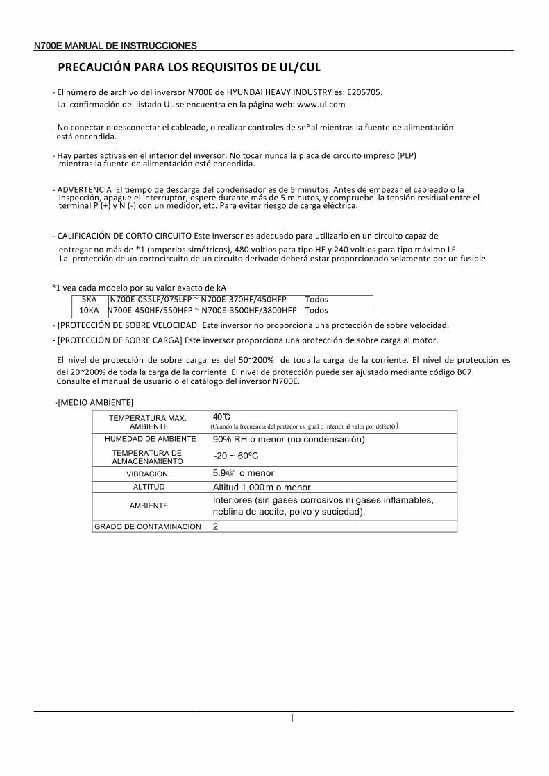
PRECAUCIÓN UL/CUL DE REQUISITOS LOS PARA
- La
www.ul.com web: página la en encuentra se UL listado del confirmación
E205705. es: INDUSTRY HEAVY HYUNDAI de N700E inversor del archivo de númeroEl
- encendida está
alimentación de fuente la mientras señal de controles realizar o cableado, el desconectar o conectarNo .
-
encendida esté alimentación de fuente la mientras (PLP) impreso circuito de placa la nunca tocar No inversor. del interior el en activas partesHay
.
- ADVERTENCIA
eléctrica. carga de riesgo evitar Para etc. medidor, un con (-) N y (+) P terminal el entre residual tensión la compruebe y minutos, 5 de más durante espere interruptor, el apague inspección,
la o cableado el empezar de Antes minutos. 5 de es condensador del descarga de tiempo El
-
La
fusible. un por solamente proporcionado estar deberá derivado circuito un de cortocircuito un de protección LF. máximo tipo para voltios 240 y HF tipo para voltios 480 simétricos), (amperios *1 de más no entregar
de capaz circuito un en utilizarlo para adecuado es inversor Este CIRCUITO CORTO DECALIFICACIÓN
vea *1 de exacto valor su por modelo cada kA
5KA N700E-055LF/075LFP ~ N700E-370HF/450HFP Todos 10KA N700E-450HF/550HFP ~ N700E-3500HF/3800HFP Todos
- [ velocidad sobre de protección una proporciona no inversor Este VELOCIDAD] SOBRE DEPROTECCIÓN . - [
N700E. inversor del catálogo el o usuario de manual el Consulte
B07. código mediante ajustado ser puede protección de nivel El corriente. la de carga la toda de 20~200% del es protección de nivel El corriente. la de carga la toda de 50~200% del es carga sobre de protección de nivel
motor. al carga sobre de protección una proporciona inversor Este CARGA] SOBRE DEPROTECCIÓN
El
40 andou( C otcdefe orp alorv al inferior o algui se ortadorp del iacencufre la )
90% HR condensación) (no menor o
5.9 o menor ltitudA 1,000 m o menor
nterioresI suciedad). y polvo aceite, de neblina
inflamables, gases ni corrosivos gases (sin
RADOG CONTAMINACION DE 2
-[MEDIO BIENTE]AM
IENTEBAM
ALTITUD
RACIONBIV
ERATURAPTEM ALMACENAMIENTO DE
UMEDADH IENTEBAM DE
ERATURAPTEM IENTEBAM
X.MA
~0-2 Cº06
II
SEGURIDAD
lea serie variador el con resultados joresme los Para N700E,colocadas advertenciade
señales las todas y atención con manual este
rápida.consulta cualquier para manualeste Guarde instrucciones. las siga equipo, el operar y instalar de Antes aparato. el en
SÍMBOLOS DEFINICIONES Y
Una seguridad de instruccion ( ensajeM ) es símboloCada precaución
o adverencia de palabra una y alerta de peligro de un . manual el todo en significado siguiente el tiene señal
cuidadosamente instrucciones estas siga y esjmensa estos eaL uipo.qe este operen ueq personas otras u usted ante peligrosas ser anípodr
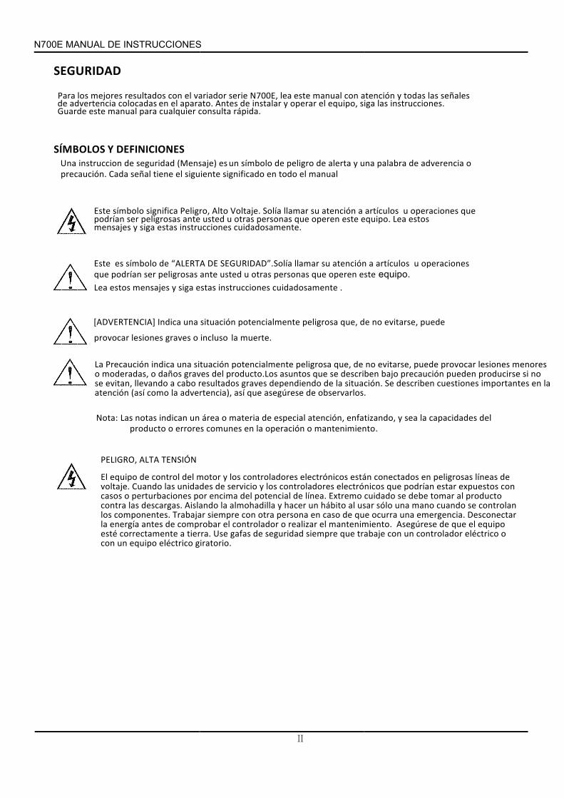
ueq operaciones u culosíart a atención su llamar aíolS e.jVolta ltoA Peligro, significa mboloís
Este
.
Este
cuidadosamente instrucciones estas siga y esjmensa estos eaL uipo.qe este operen ueq personas otras u usted ante peligrosas ser anípodr ueq
peraciones o u culosíart a atención su llamar DADIUREGS ED de mboloís es ATREAL“ aíolS”.
.
mantenimiento o operación la en comunes errores oproducto delcapacidadeslasea y enfatizando, atención, especial de materia o área un indican notasLas Nota:
.
PELIGRO,
TENSIÓN ALTA
línea. de potencial del encima por perturbaciones o casos con expuestos estar podríanque electrónicos controladores los y servicio de unidades las voltaje.
de líneas peligrosas en conectados están electrónicos controladores los y motor del control de equipo ElCuando
giratorio. eléctrico equipo un con o eléctrico controlador un con trabaje que siempre seguridad de gafas Use tierra. a correctamente esté equipo el que de mantenimiento. el realizar o controlador el comprobar de antes energía la
Desconectar emergencia. una ocurra que de caso en persona otra con siempre componentes. los controlan se cuando mano una sólo usar al hábito un hacer y almohadilla la descargas. las contra
producto al tomar debe se cuidado ExtremoAislando
TrabajarAsegúrese
00E7N INSTRUCCIONES DE MANUAL
]AICTENRVE[AD
.muerte laincluso o graves lesiones provocar
puede evitarse, no de ue,q peligrosa potencialmente situación una Indica
La
observarlos. de asegúrese que así advertencia), la como (así atención la en importantes cuestiones describen Se situación. la de dependiendo graves resultados cabo a llevando evitan, se
no si producirse pueden precaución bajo describen se que asuntos producto.Los del graves daños o moderadas, o menores lesiones provocar puede evitarse, no de que, peligrosa potencialmente situación una indica Precaución
N700E INSTRUCCIONES DE MANUAL
III
PRECAUCIÓN
corporales. lesiones en resultados
dar aípodr precaución esta de incumplimiento implicados. peligros los y uipamientoqe del operación y construcción una con familiar cualificado ctricoéel mantenimiento de
personal un por mantenido y ustadoja instalado, estar aídeber uipoqe Este]A :ICTENRVE [AD
El
punto. un en ocurrido puntual fallo
un a debido personal al lesiones propiciar y uiposqe los desuso en arjde resultar puede acerloh .AC motor el para gama la de seleccionada
frecuencia imaáxm la de 150% de frecuencia una en segura operación una de capaces son neaíl de material de proceso el y IDANYUH por suministrado no mecanismo del tren de unidad
la accionada, uinariaqma la toda ueq asegurar de responsable es usuario El]A :ICTENRVE[AD
No
corporales. lesiones proteger para adoñdise áest no circuito del tierra a protección de fallo innecesaria.
operación una evitar para corrientes grandes para capacidad alta de frecuencia de circuito un con diferencial ticoáautom interruptor un instalar protección, la Para ]A :ICTENRVE
[AD
El
sustituir. o retirar al levantar para apropiadas cnicasét y elevación
de aszpie arzutili espalda, de lesiones o muscular tensión la evitar Para pesado. etojbO:N]ÓICAUCER[P
E.700N serie inversor del uipamientoqe el con arjtraba de antes claramente entenderse y leerse anídeber instrucciones Estas :N]ÓICAUCER[P
IDANYUH por proporcionado es no y usuario del responsabilidad son ubicación su y seguridad de dispositivos otros u dispositivos los desconectar ustificadas,j ausasC:N]ÓICAUCER
[P.
:N]ÓICAUCER [P
sobrecalentado. motor un ayah ueq osobrecarga de caso en cierre se inversor el ueq asegurar para E700N serie controlador
el para dispositivos son ueq rmicoét érel un o motor guarda un conectar de reseúsegA
unidad. la en trabajar de antes eléctrica corriente la siempre Desconectar seguir:
deben se que instrucciones) de manual el en (incluidos prueba de procedimientosrecomienda fabricante El mantenimiento. y alineación instalación, la realizar debe calificado personal locales. yacionalesn
eléctricos códigos los a conformerealizados sean trabajos los todos que recomienda se tanto, lo peligrosos. ser pueden suelo del encima por eléctricos potenciales los y ejes los de rotación La [PRECAUCIÓN]:
PorSólo
IV
NOTA : GRADO 2 CONTAMINACIÓN DE
son conductora contaminación de posibilidad la reducen que típicas construcciones 2,contaminación de grados los de ambiente medio el en utilizar debe se inversor lE
.
1) ventilación sin recinto un de uso lE .
escape. un y positiva entrada una proporcionan que recinto del dentro fuelles más o uno mediante
logra se ventilación la decir, es forzada, es ventilación la cuando ventilado recinto un de filtrado de usolE 2)
00E7N INSTRUCCIONES DE MANUAL
N700E INSTRUCCIONES DE MANUAL
V
Precaución Electromagnética) (Compatibilidad EMC para
verificación de lista siguiente la sigue norma, la con cumplir y CEM directiva la de seguridad La .
Este
corporales. lesiones en resultados dar podría precaución esta de incumplimiento El implicados. peligros los y equipamiento del operación y construcción una con familiar cualificado
eléctrico mantenimiento de personal un por mantenido y ajustado instalado, estar debería equipo
1. especificaciones: siguientes las cumplir debe N700E inversor el para alimentación de fuenteLa a. menos. o ±10% tensión deFluctuaciones
b. menos. o ±3% tensión de desequilibrioEl c. o frecuencia de variaciónLa ±4% menos .d. menos. o 10% = THD voltaje de distorsiónLa
2. instalación: la deMedida a. N700E. inversor el para diseñado filtro unUtilice
3. Cableado a.
metros 20 a inferior ser debe longitud la y cableado de motor para requiere se apantallado) (cable blindadoCable
.
b. electromagnética compatibilidad
de requisitos los satisfacer para KHz 5 a inferior ser debe ajuste de frecuenciaLa .
c. señal/proceso. de cableado de circuito del circuitos principales losSeparard.
EMC. a ajusta se no inversor el conector, cable con distancia a funcionamiento un de caso elEn
4. Condiciones ambientales – en puntos siga estos filtro, un utilizar de caso :
a. Temparatura ambiente de : -10 - +40 b. Humedad : 20 a 90% RH(sin ) condensación c. Vibración : 5.9 M/S (0.62G) 10 – 55HZ (N700E-5.5 ~ 22KW) d. Ubicación : 1000 metros en altitud de menos o , . interiores
(Sin polvo o corrosivo gas )
ADVERTENCIA
N700E INSTRUCCIONES DE MANUAL
VI
CONFORMIDAD (LVD) TENSIÓN BAJA DE DIRECTIVA LA A
variador tensión. baja de Reglamento el con cumplir debe protección de caja La siguiente: lo en cubiertas añadiendo o armario
un en montando ser puede El
1. CUBIERTA YENVOLVENTE
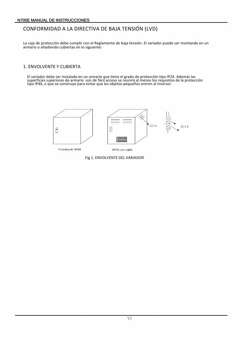
IP2X. tipo protección de grado el tiene que armario un en instalado ser debe variador El Además
inversor. al entren pequeños objetos los que evitar para construye se que o IP4X, tipo protección la de requisitos los menos al reunirá se acceso fácil de son armario de superiores superficies
las
Fig 1. ENVOLVENTE VARIADOR DEL

N700E INSTRUCCIONES DE MANUAL
VII
MANUAL N700E SERIE PARA PRECAUCIONES Y ADVERTENCIAS DE
ESTE FINAL.USUARIO
AL ENTREGADO SER DEBE AUXILIAR INSTRUCCIONES DE MANUAL
1. Cableado
"USAR PAR". DE ÍNDICE CON 75ºC SOLO DE COBRECONDUCTOR SOLO cableado de especificaciones y eléctricos aparatos los para .
2. CABLEADO DE RANGO Y APRIETE DEPAR
eléctrico. esquema el en o terminal el en adyacente marcados están cables los de terminales para cableado de rango y apriete de Par
MODELO VARIADOR
N700E- Carga( pesada Carga/ Normal)
PAR APRIETE DE [LB -IN]
DIÁMETRO (AWG)
Ancho [mm] áx.M
N700E-055LF/075LFP 12.4 8 10.6
N700E-075LF/110LFP 12.4 8 10.6
N700E-110LF/150LFP 26.6 6 13
N700E-150LF/185LFP 26.6 4 13
N700E-185LF/220LFP 35.4 3 17
N700E-220LF 35.4 1 17
N700E-055HF/075HFP 12.4 12 10.6
N700E-075HF/110HFP 12.4 10 10.6
N700E-110HF/150HFP 12.4 8 10.6
N700E-150HF/185HFP 26.6 8 13
N700E-185HF/220HFP 26.6 8 13
N700E-220HF/300HFP 26.6 6 13
N700E-300HF/370HFP 35.4 4 17
N700E-370HF/450HFP 35.4 2 17
N700E-450HF/550HFP 58.4 1 22
N700E-550HF/750HFP 58.4 2/0 22
N700E-750HF/900HFP 58.4 4/0 29
N700E-900HF/1100HFP 58.4 300 (kcmil) 29
N700E-1100HF/1320HFP 105.7 350 (kcmil) 30
N700E-1320HF/1600HFP 105.7 400 (kcmil) 30
N700E-1600HF/2000HFP 113 400(kcmil) 38
N700E-2200HF/2500HFP 113 480(kcmil) 38
N700E-2800HF/3200HFP 113 630(kcmil) 38
N700E-3500HF/3800HFP 113 800(kcmil) 38
* Recomendado
máximo. ancho mm 12 110LF: ~ 055LF PARA UL) en (Inscrito anillo de terminal poner
TAMAÑO
TERMINAL
N700E INSTRUCCIONES DE MANUAL
VIII
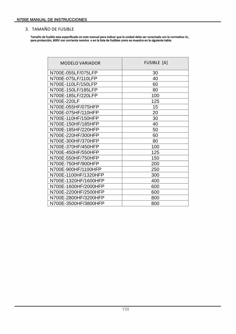
3. FUSIBLE DETAMAÑOoñamaT
tabla: siguiente la en muestra se como fusibles de lista la en o nomina corriente con 600V protección, para UL, normativa la con adaconect ser debe unidad la que indicar para manual este en especificado atse elbisuf ed
MODELO VARIADOR FUSIBLE [A]
N700E-055LF/075LFP 30
N700E-075LF/110LFP 40
N700E-110LF/150LFP 60
N700E-150LF/185LFP 80
N700E-185LF/220LFP 100
N700E-220LF 125
N700E-055HF/075HFP 15
N700E-075HF/110HFP 20
N700E-110HF/150HFP 30
N700E-150HF/185HFP 40
N700E-185HF/220HFP 50
N700E-220HF/300HFP 60
N700E-300HF/370HFP 80
N700E-370HF/450HFP 100
N700E-450HF/550HFP 125
N700E-550HF/750HFP 150
N700E-750HF/900HFP 200
N700E-900HF/1100HFP 250
N700E-1100HF/1320HFP 300
N700E-1320HF/1600HFP 400
N700E-1600HF/2000HFP 600
N700E-2200HF/2500HFP 600
N700E-2800HF/3200HFP 800
N700E-3500HF/3800HFP 800
7N 00E INSTRUCCIONES DE MANUAL
IX
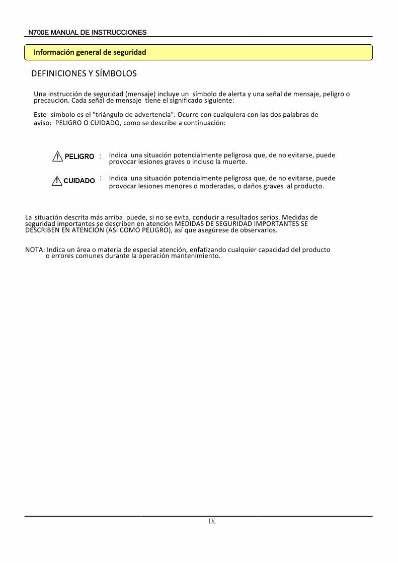
DEFINICIONES SÍMBOLOS Y
Una siguiente significado el tiene mensaje de señal Cada precaución.
o peligro mensaje, de señal una y alerta de símbolo un incluye (mensaje) seguridad de instrucción:
Este continuación: a describe se como CUIDADO, O PELIGRO aviso:
de palabras dos las con cualquiera con Ocurre advertencia". de "triángulo el es símbolo
: Indica muerte la incluso o graves lesiones provocar
puede evitarse, no de que, peligrosa potencialmente situación una .
: Indica
.producto al graves daños o moderadas, o menores lesiones provocar puede evitarse, no de que, peligrosa potencialmente situación una
La
observarlos de asegúrese que así PELIGRO), COMO (ASÍ ATENCIÓN EN DESCRIBEN SE IMPORTANTES SEGURIDAD DE MEDIDAS atención en describen se importantes seguridad
de Medidas serios. resultados a conducir evita, se no si puede, arriba más descrita situación
.
NOTA:
mantenimiento operación la durante comunes errores o del capacidad cualquier enfatizando atención, especial de materia o área un Indica producto
.
maciónrnfoI dadirsegu ed alrgene
N700E INSTRUCCIONES DE MANUAL
X
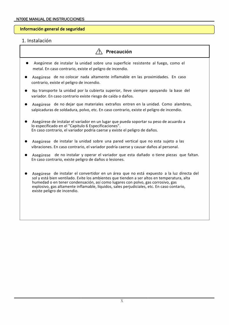
1. Instalación
Asegúrese incendio. de peligro el existe contrario,
caso En proximidades. las en inflamable altamente nada colocar no de
No daños. o caída de riesgo existe contrario caso En variador
del base la apoyando siempre lleve superior, cubierta la por unidad la transporte .
Asegúrese incendio. de peligro el existecontrario, casoEn etc. polvo, soldadura, de salpicaduras
alambres, Como unidad. la en entren extraños materiales que dejar no de
Asegúrese
daños. de peligro elexiste y caerse podría variador el contrario, caso En Especificaciones". 6 Capitulo" el en especificadolo
a acuardo de peso su soportar pueda que lugar un en variador el instalar de
Asegúrese personal. al daños causar y caerse variador podríael contrario, caso Envibraciones.
las a sujeto esta no que vertical pared una sobre unidad la instalar de
Asegúrese lesiones. o daños de peligro existe contrario, caso
En
faltan. que piezas tiene o dañado esta que variador el operar y instalar no de
Asegúrese
incendio. depeligro existe contario, caso En etc. perjudiciales, salesdos, líqui inflamable, altamente gas explosivo,
gas corrosivo, gas polvo, con lugares como así condensación, tener en o humedad alta temperatura, en altos ser a tienden que ambientes los Evite ventilado. bien está y sol
del directa luz la a expuesto está no que área un en convertidor el instalar de
maciónrnfoI dadirsegu ed alrgene
Asegúrese
incendio. de peligro el existe contrario, caso En metal. el como fuego, al resistente superficie una sobre unidad la instalar de
XI
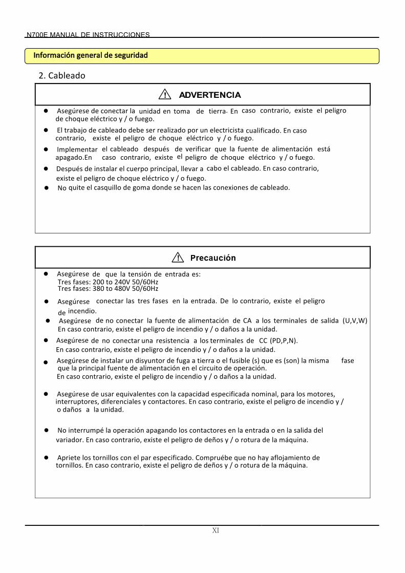
2. Cableado
reseúAseg fuego. o / y eléctricochoque de
peligro el existe contrario, caso En.tierra de toma en unidad la conectar de
El
fuego. o / y eléctricochoque de peligro el existe contrario, caso Encualificado. electricista un por realizado ser debe cableado de trabajo
Implementar apagado.En fuego. o / y eléctrico choque de peligro el existecontrario, caso
está alimentación de fuente la que verificar de después cableado el
fuego. o / y eléctrico choque de peligro elexiste contrario, caso cableado el cabo a llevar principal, cuerpo el instalar de Después En.
No cableado. de conexiones las hacen se donde goma de casquillo el quite
Asegúrese es: entrada de tensión la que de Tres fases: 200 to 240V 50/60Hz Tres fases: 380 to 480V 50/60Hz
Asegúrese incendio. de
peligro el existe contrario, lo Deentrada. la en fases tres las conectar
Asegúrese U,V,W)( salida de terminales los a CA de alimentación de fuente la conectar no de unidad la a dañoso / yincendio de peligro el existe contrario,En caso .
Asegúrese (PD,P,N). CC de terminales los a resistencia una conectar no de En unidad. la a daños o / y incendio de peligro el existe contrario, caso Asegúrese
operación. de circuito el en alimentación de fuente principal la que fase
misma la (son) es que (s) fusible el o tierra a fuga de disyuntor un instalar de
En unidad. la a daños o / y incendio de peligro el existe contrario, caso
Asegúrese
unidad. la a daños o
/ y incendio de peligro el existe contrario, caso En contactores. ydiferenciales interruptores, motores, los para nominal,especificada capacidadla con equivalentes usar de
No
máquina. la de rotura o / y deños de peligro el existe contrario, caso En variador. del salida laen o entrada la en contactores los apagando operación la interrumpé
Apriete
máquina. la de rotura o / y deños de peligro el existe contrario, caso En tornillos. de aflojamiento hay noque Compruébe especificado. par el con tornillos los
maciónrnfoI dadirsegu ed alrgene
E700N SNEOISTRUCCIN DE UALNMA
N700E INSTRUCCIONES DE MANUAL
XII
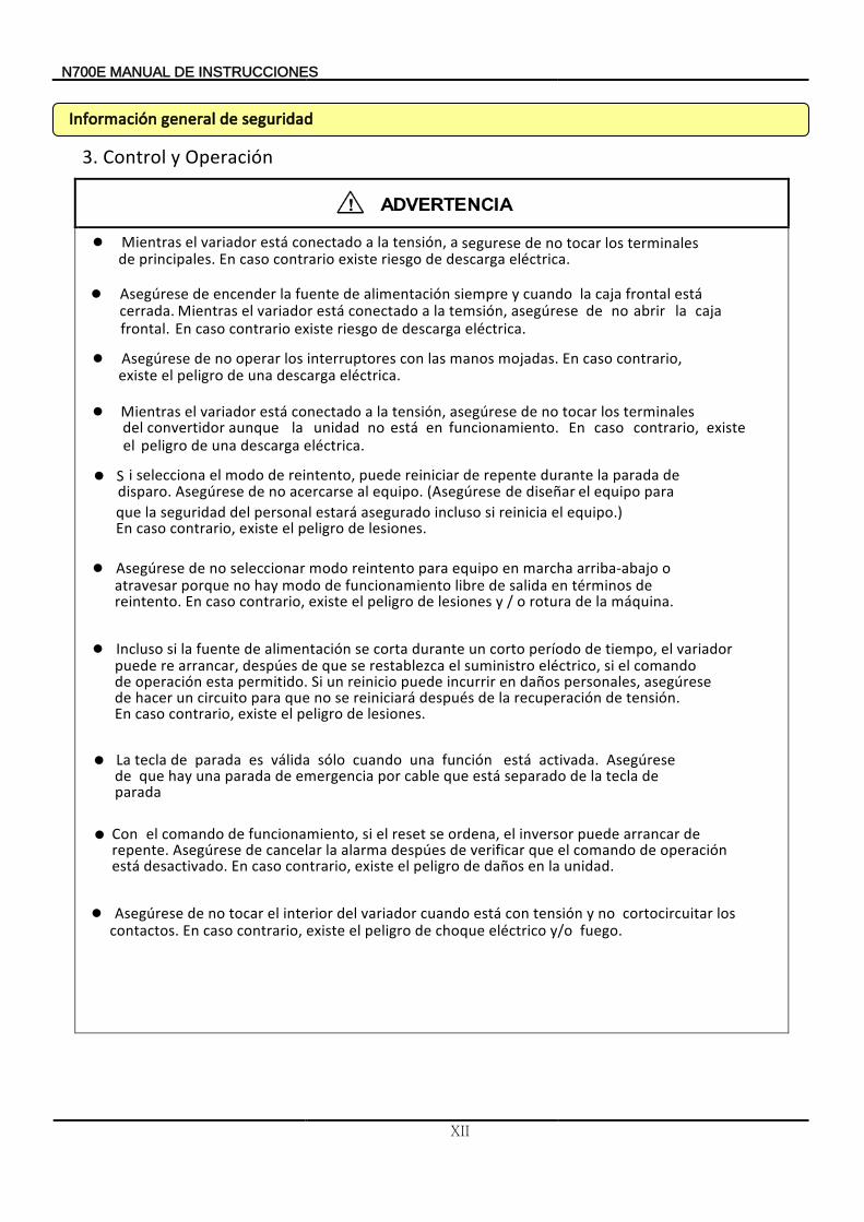
3. Operación y Control
eléctrica. descarga de riesgo existe contrario caso En principales. de
terminales los tocar no de segurese, a tensión la a conectado está variador elMientras
Asegúrese
eléctrica. descarga de riesgo existe contrario caso Enfrontal.
caja la abrir no de asegúrese temsión la a ,conectado está variador el Mientrascerrada. está frontal caja la cuando y siempre alimentación de fuente la encender de
Asegúrese
eléctrica. descarga una de peligro el existe
contrario,
caso En mojadas. manos las con interruptores los operar no de
Mientras
eléctrica. descarga una de peligro el
existecontrario, caso Enfuncionamiento. en está no unidad la aunqueconvertidor del terminales los tocar no de asegúrese tensión la a ,conectado está variador el
iS
disparo. de parada la durante repente de reiniciar puede reintento, de modo elselecciona
equipo al acercarse no desegúreseA . segúreseA(
lesiones. de peligro elexiste contrario, caso En equipo el reinicia si incluso asegurado estará personal del seguridadla que
para equipo el arñdise de .)
Asegúrese
máquina. la de rotura o / y lesiones de peligro el existe contrario, caso reintento. En
de términos en salida de libre funcionamiento de modo hay no porque atravesar o arriba-abajo marcha en equipo para reintento modo seleccionar no de
Incluso
lesiones. de peligro el existecontrario, caso .
En tensión de recuperación la de después reiniciará se no que para circuitoun hacer de
asegúrese personales, daños en incurrir puede reinicioun Si. permitido taesoperación de comando el si eléctrico, suministro el restablezca se que de despúes arrancar, repuede
variador el tiempo, de período corto un durante corta se alimentación de fuente la si
unidad. la en daños de peligro el existe contrario, caso Endesactivado. está operación de comando el que verificar de despúes alarma la cancelar Asegúrese derepente.
de arrancar puede inversor el ordena, se reset el si funcionamiento, de comando elCon
Asegúrese
fuego. o/ y eléctrico choque de peligro el existe contrario, caso En contactos. los cortocircuitar no y tensión con está cuando variador del interior el tocar no de
maciónrnfoI dadirsegu ed alrgene
La
parada
de tecla la de separado está que cable por emergencia de parada hay que unade Asegúrese activada. está función una cuando sólo válida es parada de tecla
N700E INSTRUCCIONES DE MANUAL
XIII
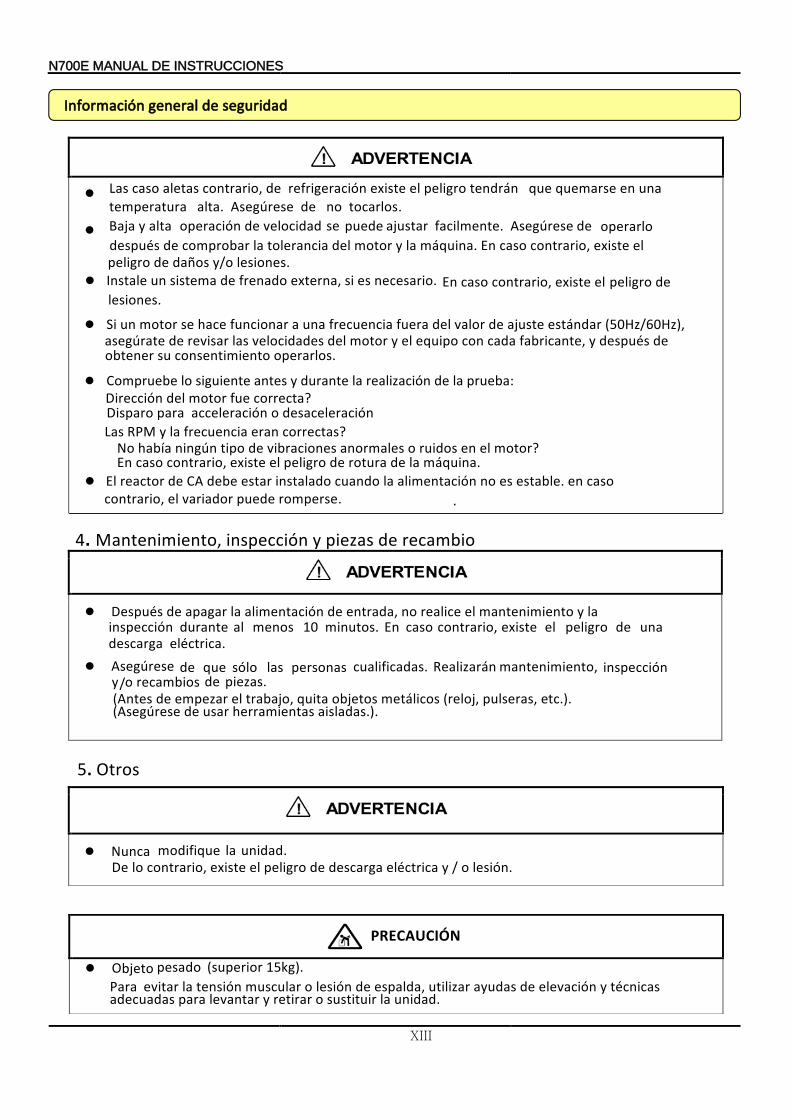
d
eInstal
.lesiones de peligro el existe contrario, caso En necesario. es si externa, frenado de sistema un
os.loperar consentimiento us obtener de suédesp y,ricantebaf cada con ipoque le y motor lde ocidadeslev asl isarvre derategúase
(50Hz/60Hz), ndaráest stejua de orlav lde erafu enciaurecf nau a ncionarfu aceh se motor nuSi
ebeuomprC :abeupr al de aciónzilrea al ranteud y antes ientegusi ol correctaefu motor ldeD irección ?
isparo D para desaceleración oacceleración asL correctas eran enciaurecf al y RPM ?
motor le en idosur o eslanorma racionesbiv de tipo ngúnin abíah oN ? inaáqum al de raurot de rogilpe le istexe ,contrario caso En .
lE romperse. edeup ariadorv le, contrario
caso en e.blesta es no imentaciónla al andouc adolinsta estar ebde CA de reactor .
4. Mantenimiento recambio de piezas y inspección,
Después
eléctrica. descarga una de peligro el existe contrario, caso En minutos. 10 menos al durante inspección
la y mantenimiento el realice no entrada, de alimentación la apagar de
Asegúrese .piezas. de recambios o / y
inspección mantenimiento, Realizarán cualificadas personas las sólo que de Antes( quita trabajo el empezar de , pulseras metálicos objetos reloj( , , etc.) .Asegúrese( aisladas herramientas usar de .).
5. Otros
Nunca unidad. la modifique De lesión. o / y eléctrica descarga de peligro el existe contrario, lo
O pesadobjeto (superior 15kg). Para
unidad. la sustituir o retirar y levantar para adecuadas técnicas y elevación de ayudas utilizar espalda, de lesión o muscular tensión la evitar
maciónrnfoI dadirsegu ed alrgene
Baja
y/o lesiones.daños depeligro el existe contrario, caso En máquina. la y motor del tolerancia la comprobar deespués
operarlo de Asegúrese facilmente. ajustar puede se velocidad de operación alta y
PRECAUCIÓN
asL tocarlos. no de Asegúrese alta. emperatura t
una en quemarse que endrán t peligro elxiste eefrigeración r deontrario,c aletas caso
N700E INSTRUCCIONES DE MANUAL
XIV
CONTENIDO
1. GENERAL DESCRIPTION ............................................................................... 1-1
1.1 Inspection upon Unpacking ........................................................................................... 1-1
1.1.1 Inspection of the unit ..................................................................................................... 1-1
1.1.2 Instruction manual ........................................................................................................ 1-1
1.2 Questions and Warranty of the Unit ............................................................................... 1-2
1.2.1 Questions on Unit ......................................................................................................... 1-2
1.2.2 Warranty for the unit ..................................................................................................... 1-2
1.3 Appearance .................................................................................................................. 1-3
1.3.1 N700E-055LF/075LFP ~ N700E-220HF/300HFP .......................................................... 1-3
1.3.2 N700E-300HF/370HFP ~ N700E-1320HF/1600HFP ..................................................... 1-4
1.3.3 N700E-1600HF/2000HFP ~ N700E-2200HF/2500HFP ................................................. 1-5
1.3.4 N700E-2800HF/3200HFP ~ N700E-3500HF/3800HFP ................................................. 1-6
2. Installation and Wiring ....................................................................................... 2-1
2.1 Installation .................................................................................................................... 2-1
2.1.1 Installation .................................................................................................................... 2-2
2.2 Wiring ........................................................................................................................... 2-4
2.2.1 Terminal Connection Diagram (sink type) ...................................................................... 2-5
2.2.2 Main circuit wiring ......................................................................................................... 2-7
2.2.3 Terminal connection diagram ...................................................................................... 2-14
3. Operation ............................................................................................................. 3-1
3.1 Operating...................................................................................................................... 3-3
3.1.1 Operation setting and a frequency setting by the terminal control .................................. 3-3
3.1.2 Operation setting and frequency setting with the digital operator ................................... 3-3 3.1.3 Operation setting and frequency setting from both the digital operator and the terminal
operator ........................................................................................................................ 3-3
3.2 Test Run ....................................................................................................................... 3-4
3.2.1 To input the operation setting and the frequency setting from the terminal control .......... 3-4
3.2.2 Operation setting and the frequency setting from the digital operator ............................. 3-5
4. Parameter Code List .......................................................................................... 4-1
4.1 About Digital Operator .................................................................................................. 4-1
4.1.1 Name and contents of each part of Standard-type digital operator ................................. 4-1
N700E INSTRUCCIONES DE MANUAL
XV
.............................. 4-1
4.2 Function List ................................................................................................................. 4-4
4.2.1 Monitor Mode (d-group) ................................................................................................ 4-4
4.2.2 Trip & Warning monitor mode (d-group) ...................................................................... 4-5
4.2.3 Basic Function Mode .................................................................................................... 4-6
4.2.4 Expanded Function Mode of A Group ............................................................................ 4-7
4.2.5 Expanded function mode of b group ............................................................................ 4-14
4.2.6 Expanded Function Mode of C Group ......................................................................... 4-19
4.2.7 Expanded Function mode of H Group ......................................................................... 4-22
5. Using intelligent terminals ................................................................................. 5-1
5.1 Intelligent terminal lists .................................................................................................. 5-1
5.2 Monitor terminal function ............................................................................................... 5-3
5.3 Intelligent Input Terminal Function ................................................................................. 5-4
5.4 Using Intelligent output terminals ................................................................................ 5-16
5.5 Alarm Terminal Function ............................................................................................. 5-21
5.6 Sensorless Vector Control ........................................................................................... 5-22
6. Protective function ............................................................................................. 6-1
7. Troubleshooting Tips ......................................................................................... 7-1
8. Maintenance and Inspection ............................................................................ 8-1
8.1 General Precautions and Notes .................................................................................... 8-1
8.2 Inspection Items ........................................................................................................... 8-1
8.3 General Inverter Electrical Measurements ..................................................................... 8-4
9. RS485 Communication ..................................................................................... 9-1
10. Specification ...................................................................................................... 10-1
10.1 Standard specification list ............................................................................................ 10-1
10.2 The selection of braking resistor and the breaking unit ................................................ 10-4
10.3 Dimension .................................................................................................................. 10-5
N700E INSTRUCCIONES DE MANUAL
1-1
1. DESCRIPCIÓN GENERAL 1.1 Inspección Desembalaje tras 1.1.1 Inspección unidad la de
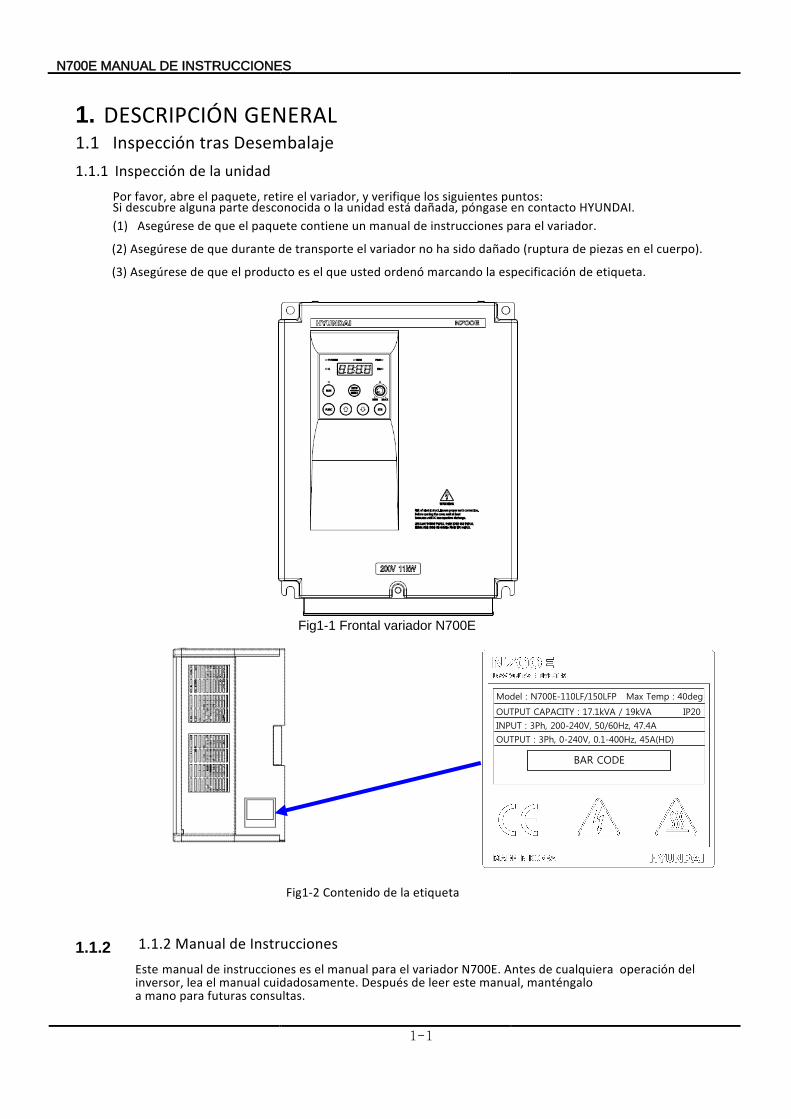
Por puntos: siguientes los verifique y variador, el retire paquete, el abre favor, Si HYUNDAI contacto en póngase dañada, está unidad la o desconocida parte alguna descubre . (1) variador el para instrucciones de manual un contiene paquete el que deAsegúrese .
(2) cuerpo) el en piezas de (ruptura dañado sido ha no variador el transporte de durante que deAsegúrese .
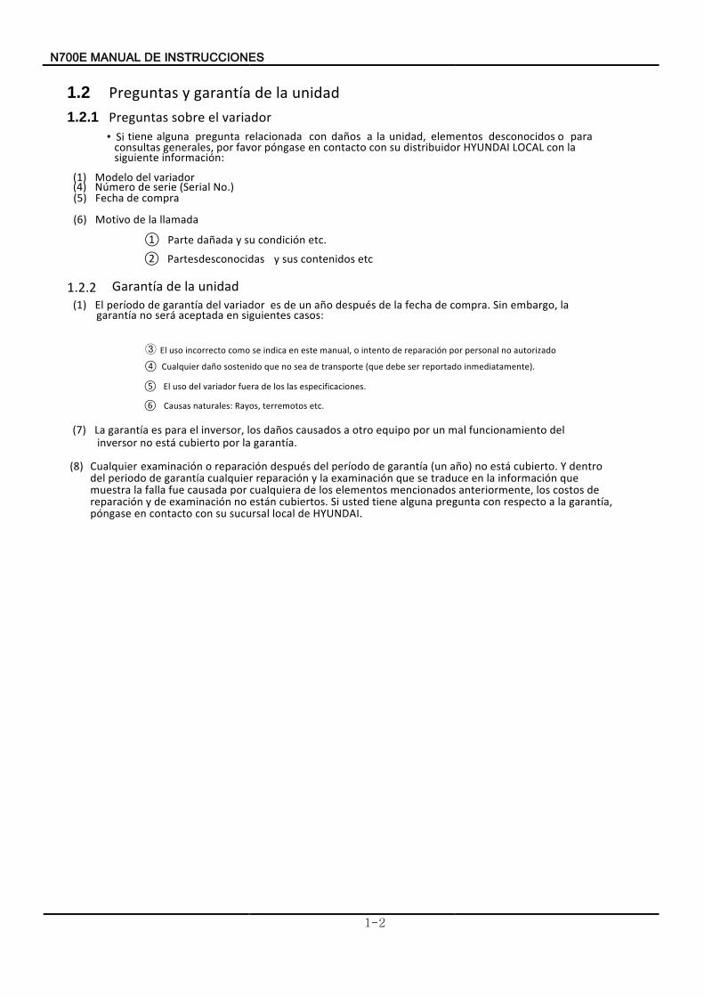
(3) etiqueta de especificación la marcando ordenó usted que el es producto el que deAsegúrese .
Fig1-1 Frontal variador N700E
Model : N700E-110LF/150LFP Max Temp : 40deg
OUTPUT CAPACITY : 17.1kVA / 19kVA IP20
INPUT : 3Ph, 200-240V, 50/60Hz, 47.4A
OUTPUT : 3Ph, 0-240V, 0.1-400Hz, 45A(HD)
BAR CODE
Fig1-2 Contenido etiqueta la de
1.1.2 1.1.2 Instrucciones de Manual N700E variador el para manual el es instrucciones de manual .Este Antes
consultas. futuras para mano a manténgalo manual, este leer de Después cuidadosamente. manual el lea inversor,
del operación cualquiera de
700EN SENORUCCITINS ED ANUALM
1-2
1.2 Preguntas unidad la de garantía y 1.2.1 variador el sobrePreguntas
• Si
información: siguiente la con LOCAL HYUNDAI distribuidor su con contacto en póngase favor por generales, consultas
para o desconocidos elementos unidad, la a daños con relacionada pregunta alguna tiene
(1) Modelo variador del (4) serie deNúmero (Serial No.) (5)
compra deFecha
(6)
llamada la deMotivo
① Parte
etc condición su y dañada . ② Partes
etc contenidos sus y
desconocidas
1.2.2 unidad la de
Garantía
(1) El
casos: siguientes en aceptada será no garantía la embargo, Sin compra. de fecha la de después año un de es variador del garantía de período
④ Cualquier
inmediatamente). reportado ser debe (que transporte de sea no que sostenido daño
⑤ El .especificaciones asl los de fuera variador del uso
⑥ Causas etc. terremotos Rayos, naturales:
(7)
garantía. la por cubierto está no inversor
del funcionamiento mal un por equipo otro a causados daños los inversor, el para es garantíaLa
(8) Cualquier
HYUNDAI. de local sucursal su con contacto en póngase garantía, la a respecto con pregunta alguna tiene usted Si cubiertos. están no examinación de y reparación
de costos los anteriormente, mencionados elementos los de cualquiera por causada fue falla la muestra que información la en traduce se que examinación la y reparación cualquier garantía de periodo del
dentro Y cubierto. está no año) (un garantía de período del después reparación o examinación
③ autorizado no personal por reparación de intento o manual, este en indica se como incorrecto uso El
700EN SENORUCCITINS ED ANUALM
1-3
1.3 Apariencia
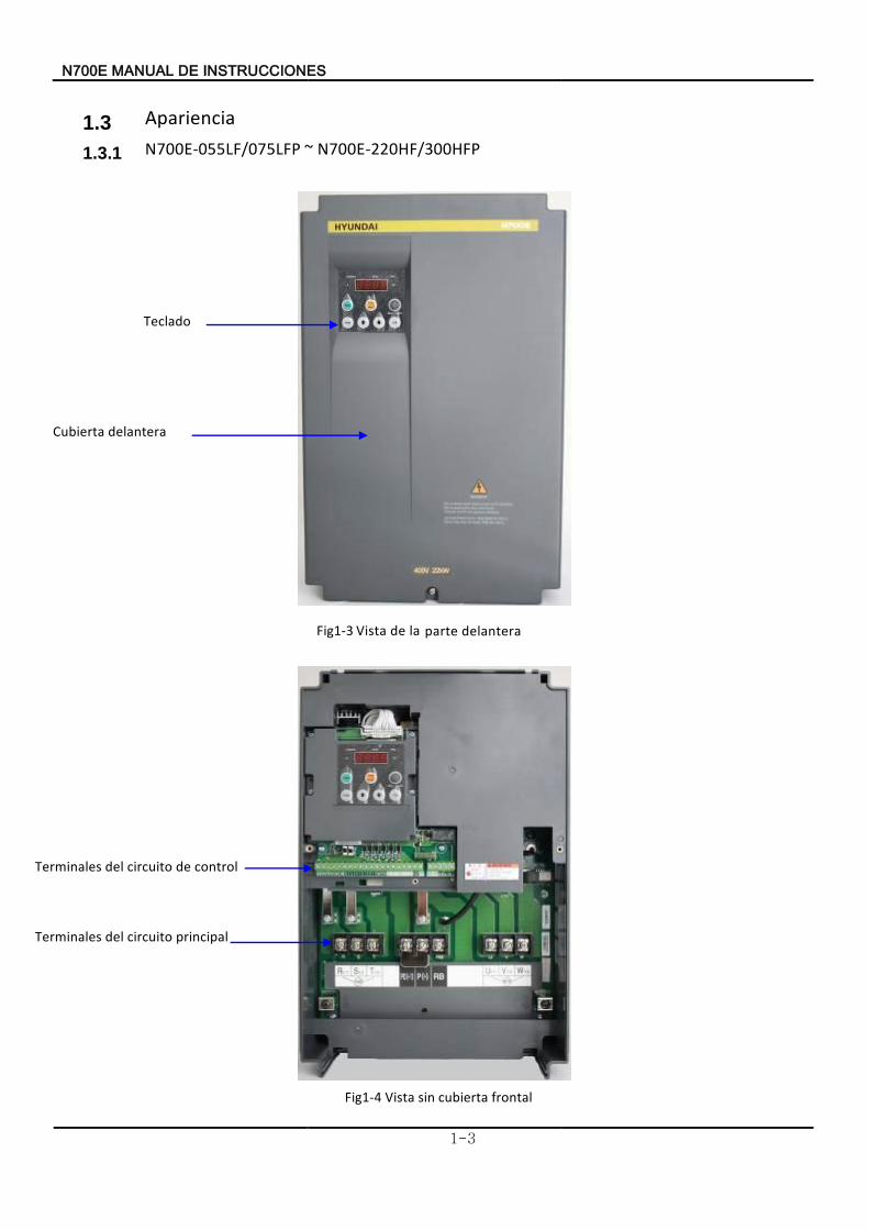
1.3.1 N700E-055LF/075LFP ~ N700E-220HF/300HFP
Fig1-3 Vista delantera partela de
Fig1-4 Vista frontal cubierta sin
delanteraCubierta
Terminales control de circuito del
Teclado
Terminales principal circuito del
EN700 SEINSTRUCCION ED MANUAL
1-4
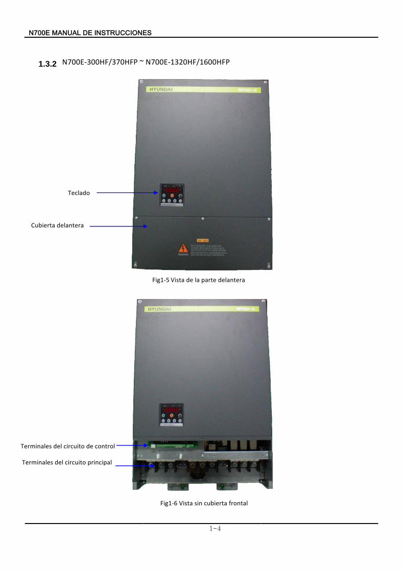
1.3.2 N700E-300HF/370HFP ~ N700E-1320HF/1600HFP
Fig1-5 istaV delantera parte la de
Fig1-6 Vista frontal cubierta sin
Cubierta delantera
Terminales principal circuito del
Terminales control de circuito del
Teclado
N700E INSTRUCCIONES DE MANUAL
1-5
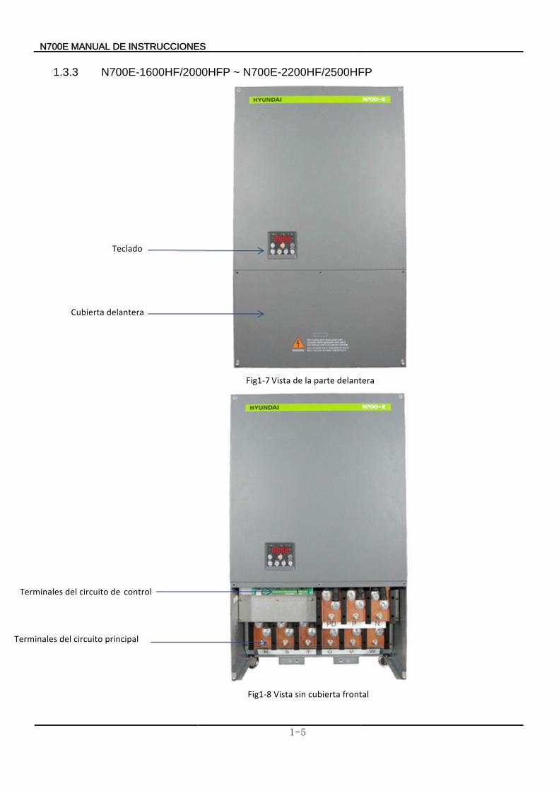
1.3.3 N700E-1600HF/2000HFP ~ N700E-2200HF/2500HFP
Teclado
Cubierta delantera
Fig1-7 Vista delantera parte la de
Terminales control de circuito del
Terminales principal circuito del
Fig1-8 Vista frontal cubierta sin
EN700 SEINSTRUCCION ED MANUAL
1-6
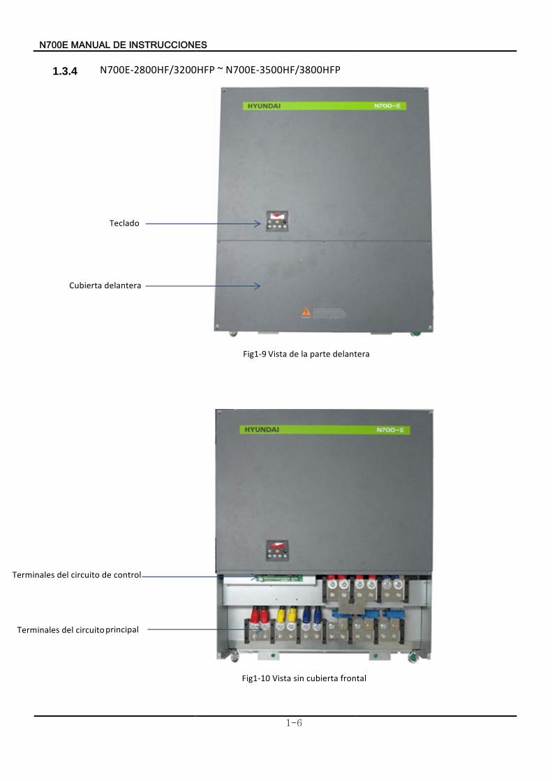
1.3.4 N700E-2800HF/3200HFP ~ N700E-3500HF/3800HFP
Teclado
Cubierta delantera
Fig1-9 Vista delantera parte la de
Terminales control de circuito del
Terminales principal circuito del
Fig1-10 istaV ontalrf tarcubie sin
EN700 SEINSTRUCCION ED MANUAL
2-1
2.2. cableado y Instalación2.1 Instalación
reseúAseg de peligro el existe contrario, caso nE etal.m el
como fuego, al resistente superficie una sobre unidad la instalar de incendio
reseúAseg incendio. de peligro el existe contrario, caso
n E
proximidades. las en inflamable nada colocar no de No
lesiones. y caídas de riesgo el Existe unidad. la de base la apoyando siempre lleve superior, cubierta la por unidad la transporte
Asegúrese
incendio. de peligro elexiste contrario, caso En etc. polvo, alambre,, hierro de soldadura, de salpicaduras las
, corte de alambre como tales extraños materiales que dejar no de
Asegúrese
lesiones. causar y caerse podría contrario, caso En texto. el en especificado lo a acuerdo de peso su soportar pueda que lugar un en variador el instalar de
Asegúreselesiones. causar y caerse podría contrario, caso En vibración.
la a sujeto está no que vertical pared una sobre unidad la instalar de
Asegúrese
lesiones. de peligro el existe contrario, caso Enfaltan. que las de parteshay o dañado esté que variador el operar y instalar no de
Asegúrese
incendio. de peligro el existe contrario, caso En etc. perjudiciales, sales, inflamable gas explosivo,gas corrosivos, gases polvo, con lugares como así, humedad la de altatemperatura,
en altos ser a tienden que ambientes los Evite ventilado. bien está y sol del directa luz la a expuesto está no que área un en convertidor el instalar de
N700E INSTRUCCIONES DE MANUAL
2-2
2.1.1 Instalación (1) Transporte:
Manejalo plactico de partes tiene varaidor .Este cuidado con .
No as, caída. de riesgo causando romperse pueden soportesLos
fijacione las demasiado aprieteNo
piezas faltan le o dañado estar parece si variador el utilice o instale .
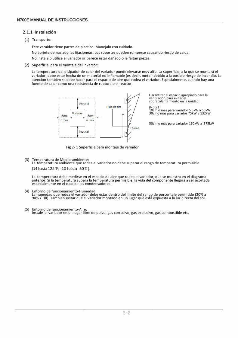
(2) Superficie inversor: del montaje el para
Fig 2- 1 Superficie variador de montaje para
(3) Temperatura edio-ambiente:M de
La permisible temperatura de rango el superar debe no variador el rodea que ambiente temperatura (14 hasta 122°F, -10 hasta 50).
La
condensadores los de caso el en especialmente acortada ser a llegará componente del vida la permisible, temperatura la supera temperatura la Si anterior.
diagrama el en muestra se que ,variador el rodea que aire de espacio el en medirse debe temperatura
.
(4) Entorno funcionamiento-Humedad: de La
HR). / 90% a (20% permitido porcentaje de rango del límite del dentro estar debe variador el rodea que humedad sol. del directa luz la a expuesta está que lugar un en montado variador el que evitarTambién
(5) Entorno funcionamiento-Aire: de
Instale etc combustible gas explosivo, gas corrosivo, gas polvo, de libre lugar un en variador el .
unidad. la en sobrecalentamiento el evitar para ventilación
la para apropiado espacio el Garantizar
. (Nota1)
o
10cm para más variador 5.5kW a 55kW variador para más 30cmo 75kW a 132kW
o 50cm variador para más 160kW a 375kW
La
reactor. el o ruptura de resistencia una como calor de fuente una hay cuando Especialmente, variador. el rodea que aire de espacio el para hacer debe se también atención
La incendio. de riesgo posible la a debido metal) decir, (es inflamable no material un de hecha estar debe variador, el montará se que la a superficie, La alto. muy elevarse puede variador del calor de disipador del temperatura
N700E INSTRUCCIONES DE MANUAL
2-3
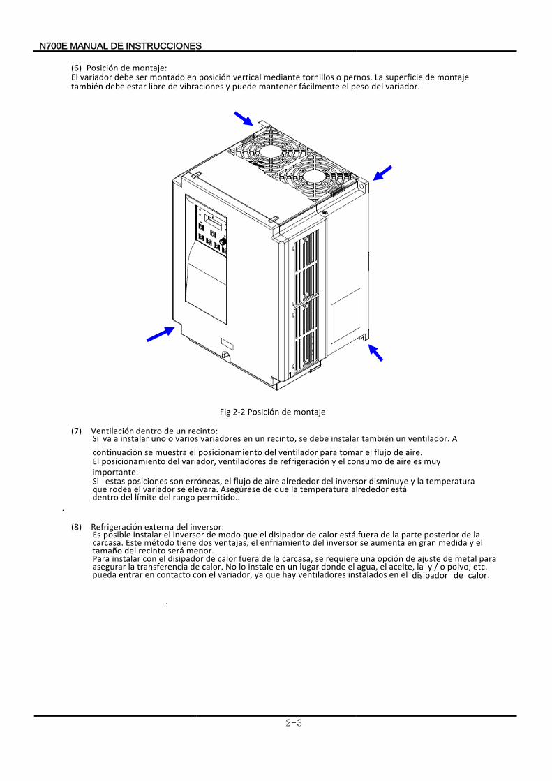
(6) Posición
.variador del peso el fácilmente mantener puede y vibraciones de libre estar debe también montaje de superficie La pernos. o tornillos mediante vertical posición enEl montado ser debe variador
montaje: de
Fig 2-2 Posición montaje de
(7) Ventilación recinto: un de dentro Si A ventilador un también instalar debe se recinto, un en variadores varios o uno instalar a va .
. aire de flujo el tomar para ventilador del posicionamiento el muestra se continuación
El importante
muy es aire de consumo el y refrigeración de ventiladores ,variador del posicionamiento.
Si
permitido. rango del límite del dentro está alrededor temperatura la que desegúreseA elevará. se variador el rodea que
temperatura la y disminuye inversor del alrededor aire de flujo el erróneas, son posiciones estas
..
(8) Refrigeración inversor: del externa
EsEste carcasa
la de posterior parte la de fuera está calor de disipador el que modo de inversor el instalar posible .
menor será recinto del tamaño el y medida gran en aumenta se inversor del enfriamiento el ventajas, dos tiene método
.Para
calor.
de
disipador el en instalados ventiladores hay que ya ,variador el con contacto en entrar pueda etc. polvo, o / y la aceite, el agua, el donde lugar un en instale lo No calor. de transferencia la asegurar
para metal de ajuste de opción una requiere se carcasa, la de fuera calor de disipador el con instalar
.
EN700 ESTRUCCIONSIN ED MANUAL
2-4
2.2 Cableado
Asegúrese
fuego. o / y eléctrico choque de
peligro el existe caso En contrario,tierra. de toma la a unidad la conectar de
El
fuego. o / y eléctrico choque depeligro el existe contrario,caso En cualificado. electricista un por realizado ser debe cableado de trabajo
Implementar
fuego. o / y eléctrico choque de peligro el existe contrario, caso En
apagado. está alimentación de fuente la que verificar de después cableado el
Después cableado. el cabo a llevar inversor, el montar de lesión. o / y eléctrica descarga de peligro el existe contrario,En caso
No cableado. de conexiones las hacen se donde goma de casquillo elquite (5.5 to 22kW) Debido
cableado del cubierta la de borde el con tierra de fallo un tener puede o cortocircuito en ado,ñda ser puede cable un que de posibilidad la a
resegúseA de :es entrada de tensión al equ resT :asesf 200 to 240V 50/60Hz
(Mod oel : N700E-055LF/075LFP ~ 220LF) resT :asesf 380 to 480V 50/60Hz
(Mod oel : N700E-055HF/075HFP ~ 3500HF/3800HFP)
entrada. la en fases tres las conectar deAsegúrese En lo incendio de peligro el existe contrario, caso .
salidade terminales los a CA de alimentación de fuente la conecte No (U,V,W). De unidad. la a daños o / y incendio o / y lesiones de peligro el existe contrario, lo No (PD,P,N).
unidad. la a daños y/o incendio de peligro el existe contrario casoEn CC de terminaleslos a resistencia unaconecte
operación. de circuito el en alimentación de fuente principal la que fasemisma la (son) es que (s) fusible el o a fuga de disyuntor un instalar de tierraAsegúrese
contactores. y diferenciales los
interruptores, motores para nominal, especificada capacidad la con equivalentes usar deAsegúrese
No
máquina. la de rotura o / y deños de peligro el existe contrario, caso Envariador. del salida la en o entrada la en contactores los apagando operación la interrumpé
Apriete
máquina la de rotura o / y deños de peligro el existe contrario, caso Entornillos. de aflojamiento hay no que Compruébe especificado. par el con tornillos los
.
N700E INSTRUCCIONES DE MANUAL
2-5
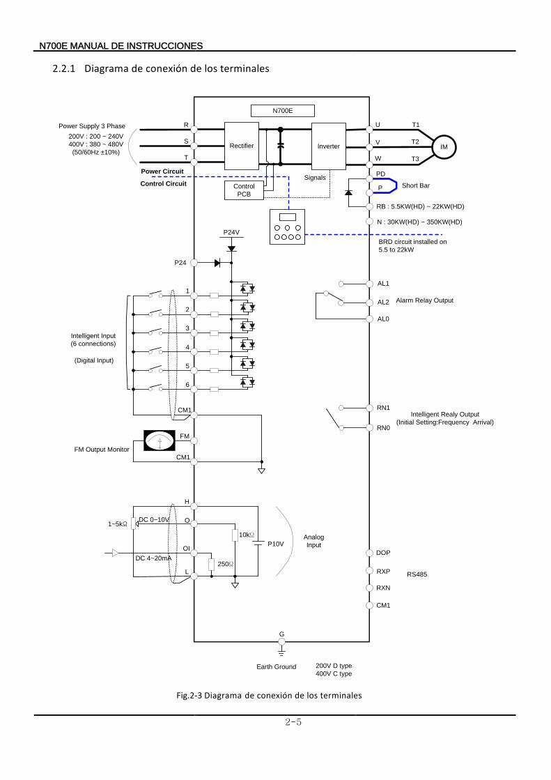
2.2.1 Diagrama terminales los de conexión de
Fig.2-3 Diagrama terminales los de conexión de
Power Supply 3 Phase
200V : 200 ~ 240V
400V : 380 ~ 480V
(50/60Hz ±10%)
R
S
T
U
V
W
Short Bar
PD
P
RB : 5.5KW(HD) ~ 22KW(HD)
P24
2
CM1
FM
H
O
OI
L
3
FM Output Monitor
DC 0~10V
DC 4~20mA
P24V
Alarm Relay Output
G
AL1
AL2
AL0
RN1
RN0
Intelligent Realy Output
(Initial Setting:Frequency Arrival)
Control Circuit
N700E
IM
T1
T2
T3
Rectifier
Control
PCB
Inverter
Signals
CM1
Power Circuit
BRD circuit installed on
5.5 to 22kW
RS485
1
Intelligent Input
(6 connections)
(Digital Input)
4
5
6
P10V
DOP
RXP
RXN
CM1
Analog
Input
250Ω
10kΩ
200V D type
400V C typeEarth Ground
N : 30KW(HD) ~ 350KW(HD)
1~5kΩ
INSTRUCCIONES DE MANUAL N700E
2-6
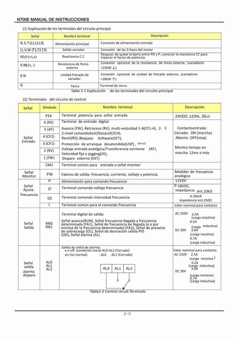
(1) Explicación principal circuito del terminales los de
Señal Nombre terminal
R, S, T (L1,L2,L3) Alimentación principal Conexión entrada alimentación de
U, V, W (T1,T2,T3) Salida variador Conexión motor del 3-fases las de
PD,P (+1,+) Reactancia C.C Despues potencia de factor el mejorar
para CC reactancia la conectar P, y PD entre barra la quitar de .
P, RB (+, -) Resistenciaexterna
freno de Conexión )↓<22kW
(variadores externa. freno de resistencia la de opcional
P, N Unidadvariador
de frenado
G
Table 2-1 Explicación principal circuito del terminales losde
(2) Terminales control de circuito del
Señal Nombre terminal Descripción
Señal Entrada
Terminal entrada señal para potencia 24VDC ±10%, 35
6 (RS)
(FAvance W), Retroceso (RV), multi-velocidad 1-4(CF1-4), 2- 2-nivel (2CH),
Acel/Desacelcomando
Reset(RS), Software Bloqueo (SFT), Protección desatendido arranque de (USP) (Nota2),
corriente analógica/Transferencia entrada (Voltaje AT),Velocidad jogging o fija (JG),
C Contacto entrada: Cerrado: ON (marcha)
Abierto : OFF(stop)
o más 12ms marchaen tiempoMinimo
5 (AT)
4 (CF2)
3 (CF1)
2 (RV)
1 (FW)
CM1 Terminal monitor señal o entrada para común
SeñalMonitor
FM potencia. y voltaje corriente, frecuencia, salida: de aloresV
Medidor analógica
frecuencia de
Señal
frecuenciaAjuste
H Alimentación frecuencia comando para 12VDC O Terminal frecuencia voltaje comando 0-10VDC,
impedancia 10kΩ ent.
OI Terminal frecuencia intensidad comando ent.250Ωimpedancia
L Terminal frecuencia comando el para común
Señal Salida
RN0 RN1
salida de digital :Terminal
determinada frecuencia allegada frecuencia avanceSeñal (RUN) Señal,
(FA1), Señal
(AL) alarma Señal (OD), PID salida desviación de Señal (OL), sobrecarga de
preaviso de Señal (FA2), determinada) frecuencia la de encima por o (a llegada de frecuencia de
Valor contacto para nominal
AC 250V 2.5A (carga resistiva )
0.2A (carga inductiva) DC 30V 3.0A (carga resistiva ) 0.7A carga( inductiva )
Señal
disparo alarma
salida
AL0 AL1 AL2
Salida alarma de señal de : ne off (condición inicial AL0-AL2 (Cerrado)
en normal) o(n : AL0 -AL1 (Cerrado)
AL0 AL1 AL2
contacto para nominal :Valor AC 250V 2.5A
(carga resistiva ) 0.2A (carga inductiva)DC 30V
3.0A
(carga resistiva ) 0.7A (carga inductiva )
Table2-2 Control circuit Terminals
Descripción
Conexión )↑>30kW
(variadores externo. frenado de unidad de opcional
Terminal tierra de
Símbolo
P24 Terminal digital entrada de
Disparo (EXT) externo
Tierra
4-20mA
N700E INSTRUCCIONES DE MANUAL
2-7
2.2.2 Cableado principal circuito del (1) Advertencia cableado sobre
① Principales alimentación de terminales (R(L1), S(L2), T(L3)) Conecte
tierra. de fuga de disyuntor un o electromagnético contactor un de través a limentacióna de fuente la a T(L3)) S(L2), (R(L1), alimentación de terminales principales los
accidentes. y daños de propagación la evita y alimentación de fuente la aísla que ,variador del protección de función la opera cuando que ya alimentación,
de terminales principales las para electromagnético contactor el conectarrecomiendaSe
Esta
incendio. de peligro y variador el dañar de posibilidad la existecontrario, caso nE monofásica. tensión con variador el alimentar no de asegúrese trífasica, tensión con alimenta se unidad
Si HYUNDAI. con contacto en póngase monofásica, alimentación de fuente una necesita
válida:es abierta
defase protección la si abierta fase de ocurrencia la en condición siguiente la en entra orvariadEl - Fase R , asef S o T asef abierta fase de :condición
Se ocurrir. puede corriente, de sobreintensidad o deficiencia de tensión una como
tal disparo, de Operación fase. sola una de operación la de condición en convierte
No
variador El abierta fase de condiciones en use lo . condiciones:siguientes las de
consecuencia como dañado estar puede - nU de más es alimentación de tensión la de desequilibrio 3% - La
el y inversor del capacidad la deveces 10 de más es energía de suministro de capacidad
- alimentación de fuente la endrástico cambioUn
(Ejemplo) Encendido variador. el dañar de posibilidad la Existe minuto. un en
vecestres de más hacer debe se no alimentación de fuente la de apagado /
② Terminales variador del salida de (U(T1), V(T2), y W(T3)) tensión de caída laprevenir puede calibre mayor de cable un de usoEl
Particularmente el bajas frecuencias las tengan salidas las cuando , se motor del par cable del tensión
de caída la por reduce.
El salida la asobretensiones de limitador un o potencia de factor del corrección de capacitores instale
.No
daños. sufriran sobretensiones de limitador el o condensadoreslos desconectará, se variador
la cable el en inductancia la o flotación de capacidad la por daños
causar puede y tensión de pico un generará se que posible es 20m, supera cable del longitud quecasoEn Cuando HYUNDAI. de local oficina su con contacto enpóngase EMC filtro ,uninstalar a va
En motor. cada apar térmico relé un instale motores, más o dos de caso el
Realiza eléctrico. motor del nominal corriente de veces 1,1 de valor del térmico relé del RC valor el
③ Reactancia continuacorriente de (DCL) terminales conexión de (PD, P) Estos
potencia. de factor el mejorar a ayudar para (opcional) actual reactancia DCL el conectar para terminales los son
En corta. barra la desconecte no DCL, un utilizar no de caso
④ External braking resistor connection terminals (P, RB)
El estándar. como construye se (BRD) regenerativo frenado de circuito Cuando terminales. estos de frenado el para externa resistencia una instale frenado un requiere se
La
terminales. estos a externa frenado de resistencia la sea no que dispositivo otro ningún conecte Noinductancia. la
reducir para conexión de cables dos los gire y, metros5 a inferior ser debe cable del longitud
Al BRD. el por pasa que corriente la limitar para
correcta es resistencia la que de asegurarse externa frenado de resistencia una instalar
carga. sudisiparán condensadores los que
de antes tiempo, de retardo un hay alimentación, de fuente la retirar de Después voltaje. de medidor un con siempre hacerse debe final comprobación Una ilumina. se no carga de indicador el que verificar de Asegúrese cubierta.
la retirar de antes minutos diez menos lo por espere variador, el en cableado de trabajo el cabo a llevarPara
La primero. frenado de resistencia la desconectar que tendrá DCL
un conectar a va si fábrica, la de sale cuando terminales los a conecta se frenado de resistencia
N700E INSTRUCCIONES DE MANUAL
2-8
⑤ Terminales regenerativo frenado de unidad la de conexión de (P,N)
variadores
Los (opcional). resistencia la además requiere se (opción) externo BRD circuitoun regenerativo
frenado requiere else Si BRD. circuito un llevan no KW 30 de más potencia con
Conecte .variador el en
N) (P, terminales los a N) (P, externos regenerativo frenado de unidad la de terminales los
La variador
aldirectamente no y externa frenado de unidad la en conectado está frenado de resistencia
.
La
inductancia
la reducir para conexión de hilos los torcer y metros, 5 a inferior ser debe cable del longitud
.
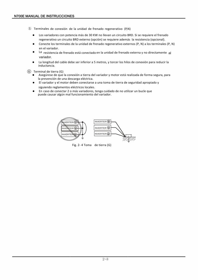
⑥ Terminal tierra de (G) Asegúrese
eléctrica. descarga unade prevención la para segura, forma de realizada motor y variador estádel tierra a conexión la que de
El variador
locales.eléctricos reglamentos siguiendo y apropiado seguridad de tierra de toma una a conectarse deben motor el y
En
.variador del funcionamiento mal algún causar puede que bucle un utilizar no de cuidado tenga ,variadores más o 2conectar de caso
Fig. 2- 4 Toma tierra de (G)
INVERTER INVERTER
INVERTER
INVERTER
INVERTER
INVERTER
N700E INSTRUCCIONES DE MANUAL
2-9
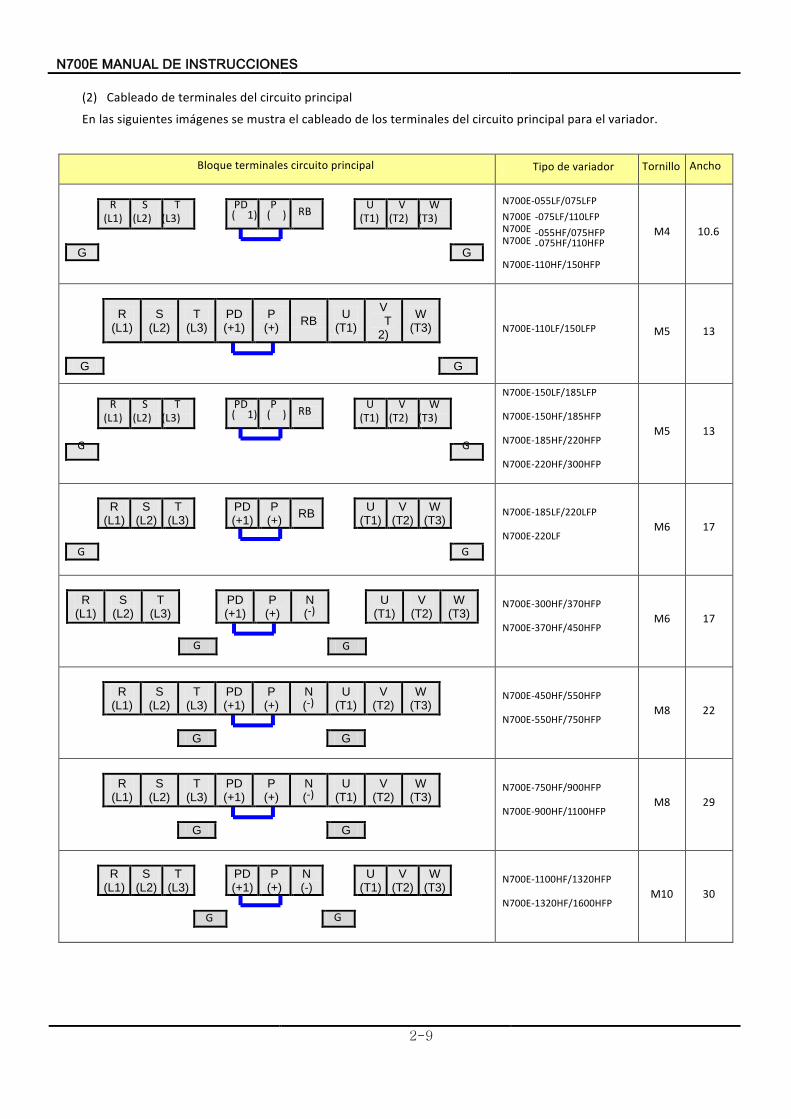
(2) Cableado principal circuito del terminales de En l
variador. el para principal circuito del terminales los de cableado e mustra se imágenes siguientes las
Bloque principal circuito terminales Tipo variadorde
R (L1)
S (L2)
T (L3)
PD ( 1)
P ( ) RB U
(T1) V
(T2) W
(T3)
G
G
N700E-055LF/075LFP N700E -075LF/110LFP N700E -055HF/075HFP N700E -075HF/110HFP
N700E-110HF/150HFP
M4 10.6
R
(L1) S
(L2) T
(L3) PD (+1)
P (+)
RB U
(T1)
V T2)
W (T3)
G G
N700E-110LF/150LFP M5 13
R (L1)
S (L2)
T (L3)
PD ( 1)
P ( ) RB U
(T1) V
(T2) W
(T3)
G G
N700E-150LF/185LFP
N700E-150HF/185HFP
N700E-185HF/220HFP
N700E-220HF/300HFP
M5 13
R
(L1) S
(L2) T
(L3) PD
(+1) P
(+) RB
U (T1)
V (T2)
W (T3)
G
G
N700E-185LF/220LFP
N700E-220LF M6 17
R (L1)
S (L2)
T (L3)
PD (+1)
P (+)
N (-)
U (T1)
V (T2)
W (T3)
G
G
N700E-300HF/370HFP
N700E-370HF/450HFP M6 17
R
(L1) S
(L2) T
(L3) PD (+1)
P (+)
N (-)
U (T1)
V (T2)
W (T3)
G
G
N700E-450HF/550HFP
N700E-550HF/750HFP M8 22
R
(L1) S
(L2) T
(L3) PD (+1)
P (+)
N (-)
U (T1)
V (T2)
W (T3)
G
G
N700E-750HF/900HFP
N700E-900HF/1100HFP M8 29
R
(L1) S
(L2) T
(L3) PD
(+1) P
(+) N (-)
U
(T1) V
(T2) W
(T3)
G G
N700E-1100HF/1320HFP
N700E-1320HF/1600HFP M10 30
Tornillo Ancho
N700E INSTRUCCIONES DE MANUAL
2-10
PD (+1)
P (+)
N (-)
R
(L1)
S (L2)
T (L3)
U (T1)
V (T2)
W (T3)
G G
N700E-1600HF/2000HFP
N700E-2200HF/2500HFP M10 38
PD (+1)
P (+)
N (-)
R
(L1)
S (L2)
T (L3)
U (T1)
V (T2)
W (T3)
G G
N700E-2800HF/3200HFP
N700E-3500HF/3800HFP M13 38
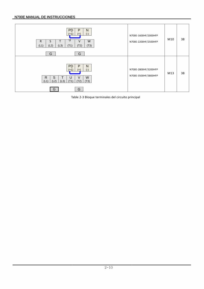
Table 2-3 Bloque principal circuitodel terminales
N700E INSTRUCCIONES DE MANUAL
2-11
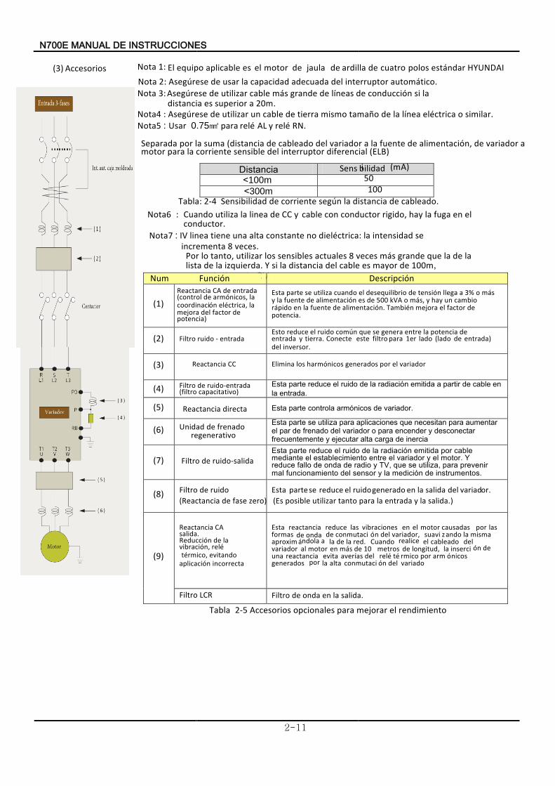
(3) ccesoriosA 1:Nota HYUNDAI estándarpolos cuatro de ardilla de jaula de motor el es aplicable equipoEl
aNot 2 : reseúAseg
tico.áautom interruptor deladecuada capacidad la usar de aNot 3: reseúAseg
0m2 a superior esdistancia la si nóconducci de neasíl de grande sám cable arzutili de
.aNot 4 : reseúAseg similar. o ctricaéel neaíl la de oñtama mismo tierra de cable un arzutili de aNot 5 : arUs para 0.75 érel AL y érel RN .
Separada (ELB) diferencial interruptor del sensible corriente la para motor
a variador de n,óalimentaci de fuente la a variador del cableado de (distancia suma la por
<
Sens bilidadi (mA)100m
<
50 300m 100
Tabla: 2-4 S cableado. de distancia la núsegensibilidad corriente de Nota6 :
conductor. el en fuga la hay rigido, conductor con bleca y de CClinea la azutiliCuando
Nota7 : IV veces 8 ncrementai
se intensidad la ctrica:édiel no constante alta una tiene linea .
CV. de neaíl la arzutili 100m, de mayor es cable del distancia la si Y quierda.zi la de lista
la de la que grande sám veces 8 actuales sensibles los arzutili tanto, lo Por
nóDescripci
(1) potencia)
de factor del orajme lactrica,éel nócoordinaci la nicos,óarm de (control entrada deReactancia CA Esta
potencia. de factor el orajme néTambi n.óalimentaci de fuente la en pidoár cambio un hay y s,ám o kVA 005 de es nóalimentaci de fuente la y
sám o %3 a llega nótensi de desequilibrio el cuando azutili se parte
(2) Filtro entrada - ruido Esto
. inversor del entrada) de (lado lado 1er para filtro este Conecte tierra. y entrada
de potencia la entre genera se que núcom ruido el reduce
(3) Reactancia CC Elimina variador el por generados nicosóharm los
(4) Filtro entrada-ruido de filtro( capacitativo )
Esta
entrada la
en cable de partir a emitida nóradiaci la de ruido el reduce parte
.
(5) Reactancia directa Esta variador denicosóarm controla parte .
(6) Unidad
regenerativo
frenado de Esta
inercia de carga alta ecutarje y frecuentemente desconectar y encender para o variador del frenado de par el
aumentar para necesitan que aplicaciones para azutili se parte
(7) Filtro alidas-ruido de Esta
instrumentos de medición la y sensor del funcionamiento mal prevenir para utiliza, se que TV, y radio de onda de fallo reduce
Y motor. el y variador el entre establecimiento el mediante cable por emitida radiación la de ruido el reduce parte
.
(8) Filtro ruido de Reactancia( eroz fase de )
Esta or.variad del salida la en generado ruido el reduce se parte Es( salida la y entrada la para tanto utilizar posible .)
(9) incorrecta nóplicacia
evitando rmico,té érel n,óvibraci
la denóReducci salida.
Reactancia CA Esta
variado del nóconmutaci alta la por generados nicosóarm por rmicoét érel del asíaver evita reactancia una
de nóinserci la longitud, de metros 10 de sám en motor al variador del cableado el realice Cuando red. la de la a ndolaáaproxim
misma la andozsuavi variador, del nóconmutaci de onda de formas las por causadas motor el en vibraciones las reduce reactancia
Filtro LCR
salida la en onda deFiltro .
Tabla 2-5 Accesorios rendimiento el orarjme para opcionales
Num
tanciasDi
Función
E00N7 INSTRUCCIONES DE LANUAM
2-12
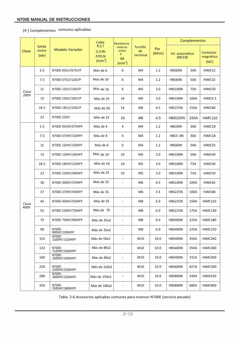
(4 ) Complementos aplicables comunes
Clase
(kW)
Modelo Variador
CableR,S,T U,V,W,
P,PD,N
(mm2)
RB (mm2)
Par(N•m)
Complementos
Int. áautom tico (MCCB)
(MC)
Clase200V
5.5 N700E-055LF/075LFP Más de 6 6 M4 1.2 HBS60N 50A HiMC32
7.5 N700E-075LF/110LFP Más 10 de 6 M4 1.2 HBS60N 50A HiMC32
11 N700E-110LF/150LFP Más 16 de 6 M5 3.0 HBS100N 75A HiMC50
15 N700E-150LF/185LFP Más 25 de 16 M5 3.0 HBS100N 100A HiMC6 5
18.5 N700E-185LF/220LFP sáM 30 de 16 M6 4.5 HBS225N 150A HiMC80
22 N700E-220LF Más 35 de 16 M6 4.5 HBS225N 150A HiMC110
laseC400V
5.5 N700E-055HF/075HFP Más 4 de 4 M4 1.2 HBS30N 30A HiMC18
7.5 N700E-075HF/110HFP Más 4 de 4 M4 1.2 HBS3 0N 30A HiMC18
11 N700E-110HF/150HFP Más de 6 6 M4 1.2 HBS60N 50A HiMC32
15 N700E-150HF/185HFP Más de 10 10 M5 3.0 HBS100N 50A HiMC40
18.5 N700E-185HF/220HFP Más 16 de 10 M5 3.0 HBS100N 75A HiMC40
22 N700E-220HF/300HFP Más 25 de 10 M5 3.0 HBS100N 75A HiMC50
30 N700E-300HF/370HFP Más 25de - M6 4.5 HBS100N 100A HiMC65
37 N700E-370HF/450HFP ásM de 35 - M6 4.5 HBS225N 100A HiMC80
45 N700E-450HF/550HFP Más 35 de - M8 6.0 HBS225N 150A HiMC110
55 N700E-550HF/750HFP sáM de 70 - M8 6.0 HBS225N 175A HiMC130
75 N700E-750HF/900HFP sáM de 35x2 - M8 6.0 HBS400N 225A HiMC180
90 N700E-900HF/1100HFP
- M8 6.0 HBS400N 225A HiMC220
110 N700E-1100HF/1320HFP sáM de 50x2 - M10 10.0 HBS400N 350A HiMC260
132 N700E-1320HF/1600HFP
sáM de 80x2 - M10 10.0 HBS400N 350A HiMC300
160 N700E-1600HF/2000HFP sáM de 90x2 - M10 10.0 HBS400N 311A HiMC400
220
N700E-2200HF/2500HFP
sáM de 110x2 - M10 10.0 HBS600N 427A HiMC500
280 N700E-2800HF/3200HFP
- M10 10.0 HBS800N 544A HiMC630
350 N700E-3500HF/3800HFP
- M10 10.0 HBS800N 680A HiMC800
Tabla 2-6 ccesoriosA )pesado servicio( EN700 inversor para comunes aplicabes
Salidamotor
Resistencia
P entre
externa Tornillo
terminal de
émagn tico Contactor
Más 35x2 de
sáM 20x81 de
Más 150x2 de
E00N7 INSTRUCCIONES DE LANUAM
2-13
Cl eas
otorM
(kW)
odelovariadorM
variador
Cable
R,S,T U,V,W, P,PD,N (mm
2)
esistenciaR
P
entre
ternaxe
RB (mm2)
Tornillo de
Termi an l
ar P (N•m)
omplementosC
.ntI automático (MCCB)
ontacto C
(MC)
Clase200V
5.5 6 M4 1.2 HBS60N 50A HiMC32
7.5 N700E-055LF/075LFP sáM
01 de
6 M4 1.2 HBS60N 50A HiMC32
11 N700E-075LF/110LFP sáM 16 de
6 M5 3.0 HBS100N 75A HiMC50
15 N700E-110LF/150LFP sáM de 25 16 M5 3.0 HBS100N 100A HiMC65
18.5 N700E-150LF/185LFP sá
M de 30 16 M6 4.5 HBS225N 150A HiMC80
22 N700E-185LF/220LFP sMá
35de 16 M6 4.5 HBS225N 150A HiMC110
Clase400V
5.5 sMá
4 de 4 M4 1.2 HBS30N 30A HiMC18
7.5 N700E-055HF/075HFP
6 de
4 M4 1.2 HBS30N 30A HiMC18
11 N700E-075HF/110HFP sMá 6 M4 1.2 HBS60N 50A HiMC32
15 N700E-110HF/150HFP
10 M5 3.0 HBS100N 50A HiMC40
18.5 N700E-150HF/185HFP sá M de 16 10 M5 3.0 HBS100N 75A HiMC40
22 N700E-185HF/220HFP
sáM de 25 10 M5 3.0 HBS100N 75A HiMC50
30 N700E-220HF/300HFP
sáM de 25 - M6 4.5 HBS100N 100A HiMC65
37 N700E-300HF/370HFP
sáM de 35 -
M6 4.5 HBS225N 100A HiMC80
45 N700E-370HF/450HFP
sáM de 35 -
M8 6.0 HBS225N 150A HiMC110
55 N700E-450HF/550HFP
sáM de 70
- M8 6.0 HBS225N 175A HiMC130
75 N700E-550HF/750HFP
- M8 6.0 HBS400N 225A HiMC180
90 N700E-750HF/900HFP -
M8 6.0 HBS400N 225A HiMC220
110 N700E-900HF/1100HFP
- M10 10.0 HBS400N 350A HiMC260
132 N700E-1100HF/1320HFP
sáM de 80x2 -
M10 10.0 HBS400N 350A HiMC300
160 N700E-1320HF/1600HFP sáM de 80x2
M10 10.0 HB S400N 350A HiMC300
200 N700E-1600HF/2000HFP
- M14 10.0 HBS400N 389A HiMC400
250 N700E-2200HF/2500HFP - M14 10.0 HBS600N 486A HiMC500
320 N700E-2800HF/3200HFP - M14 10.0 HBS800N 622A HiMC630
375 N700E-3500HF/3800HFP
- M14 10.0 HBS1000N 729A HiMC800
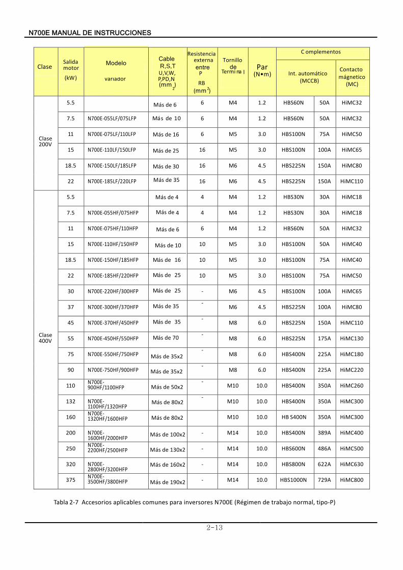
T abla 2-7 P)-tipo normal, ojtraba de gimené(R 00E7N inversores para comunes aplicablesAccesorios
Salida motor
sáM 6 de
sáM 10 de
mágnetico
Más 4 de
Más 35x2 de
sáM 20x5 de
Más 35x2 de
Más 100x2 de
Más 130x2 de
Más 160x2 de
Más 190x2 de
E00N7 INSTRUCCIONES DE LANUAM
2-14
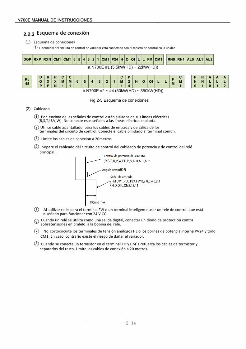
2.2.3 Esquema conexión de (1) Esquema
El
conexiones de ① unidad. la enontrol c de tablero el con conectado está variador de control de circuito del terminal
DOP RXP RXN CM1 CM1 6 5 4 3 2 1 CM1 P24 H O OI L L FM CM1 RN0 RN1 AL0 AL1 AL2
a.N700E #1 (5.5kW(HD) ~ 22kW(HD))
RJ
45
D
O
P
R
X
P
R
X
N
C
M
1
C
M
1
6 5 4 3 2 1
C
M
1
P
2
4
H O OI L L F
M
C
M
1
R
N
0
R
N
1
A
L
0
A
L
1
A
L
2
b.N700E #2 ~ #4 (30kW(HD) ~ 350kW(HD))
Fig 2-5 Esquema conexiones de (2) Cableado
① Por
planta. o elécricas líneas las a señales esas conecte No (R,S,T,U,V,W).
eléctricas líneas sus de aislados están control de señales las de encima
.común minalrte al odadblin cable el Conecte .olrcont ed cuitorci eldminalesr te
los ed adsali ed y adarent ed cables los arpa o,dapantalla cable Utilice ②
Limite ③ .
0metros2 a conexión de cables los
④principal.
relé del control de y potencia de cableado del control de circuito del cableado el Separe
⑤
CC. V 24 con funcionar para diseñado
está que control de relé un usarinteligente terminal un o FW terminal el para relés utilizar Al
⑥
⑦ No
.variador el dañar de riesgo el existe contrario caso . En CM1 todo y PV24 interna potencia de bornes los o HL nálogosatensión determinales los cortocircuite
⑧ Cuando metros. 20 a conexión de cables los Limite resto. del separarlos
y termistor de cables los retuerza CM´1 y TH terminal el en termistor un conecta se
Cuando relé. del bobina la a pralelo en sobretensiones
contra protección de diodo un conectar ,digital salida una como utiliza se relé un
N700E INSTRUCCIONES DE MANUAL
2-15
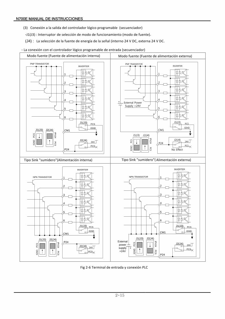
(3) Conexión programable lógico controlador del salida la a (secuenciador) -J1(J3) : Interruptor
fuente). de (modo funcionamiento de modo de selección de
(J4) : DC. V 24 externa ,DC V 24 (interno señal la de energía de fuente la de selecciónLa
- La (secuenciador) entrada de programable lógico controlador el con conexión Modo interna) alimentación de (Fuente fuente externa) alimentación de (Fuente fuente Modo
IGND
PCS
CM1
24V
P24
PCS
J1(J3) J2(J4)
IPV
24
PC
SIGN
DP
CS
1
2
3
4
5
6
INVERTER
J1(J3)
J2(J4)
PNP TRANSISTOR
IGN
DPCS
IPV24
PCS
J1(J3) J2(J4)
IGND
PCS
CM1
24VP24
PCS
1
2
3
4
5
6
INVERTER
J1(J3)
J2(J4)
External Power Supply +24V
+
PNP TRANSISTOR
No Effect
sumidero"(" Sink
Tipo
interna)AlimentaciónTipo externa "sumidero" Sink Tipo Alimentación( )
24V
P24
IGND
PCS
CM1
PCS
IPV
24
PC
S
IGN
DP
CS
J1(J3) J2(J4)
1
2
3
4
5
6
INVERTER
NPN TRANSISTOR
J1(J3)
J2(J4)
IGND
PCS
CM1
1
2
3
4
5
6
INVERTER
NPN TRANSISTOR
24V
P24
PCS
IPV
24
PC
S
IGN
DP
CS
J1(J3) J2(J4)
J1(J3)
J2(J4)External
power
supply
+24V
+
Fig 2-6 Terminal PLC conexión y entrada de
N700E INSTRUCCIONES DE MANUAL
2-16
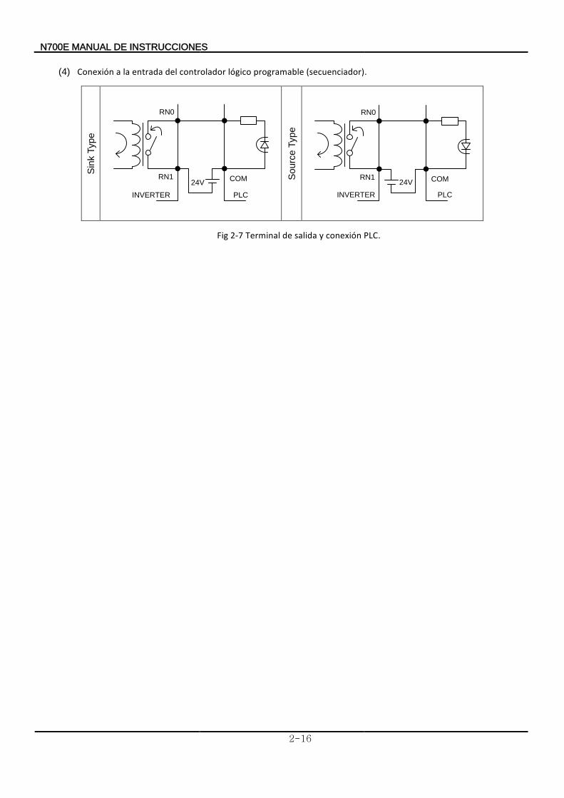
(4) Conexión (secuenciador). programable lógico controlador del entrada la a
Fig 2-7 erminalT PLC. conexión y salida de
Sin
k T
ype
RN0
RN1 COM24V
INVERTER PLC
Sourc
e T
ype
RN0
RN1 COM24V
INVERTER PLC
N700E INSTRUCCIONES DE MANUAL
3-1
3. Funcionamiento
eléctrica.descarga una de peligro el existe ontrario lo De connectores. y/o cables eliminar
o señal de complemento el comprobar para o principal terminal el tocar no lade Asegúrese
eléctrica. descarga de peligro el contrario caso En mojadas. manos las con mojadas manos las con interruptores los operar no deAsegúrese
existe
Mientrasterminales. En eléctrica. descarga de peligro el existe contrario, caso
los tocar no de asegúrese tensión, la a conectado está variador el
se seleccionaSi
lesiones. de peligro el existe contrario, casoEn equipo.) el reinicia si incluso asegurado estará personal del seguridad laque
para equipo el diseñar de (Asegúrese equipo. al acercarse no de Asegúresedisparo. de parada la durante repente de reiniciar puede reintento, de modo el
máquina. la de rotura o / y lesiones de peligro el existe contrario, caso Enreintento. de términos en salida de libre funcionamiento de modo hay no porqueatravesar
o arriba-abajo marcha en equipo para reintento modo seleccionar no deAsegúrese
Incluso
lesiones. de peligro el existe contrario, casoEn tensión. de recuperación la de después reiniciará se no que para circuito un hacerde asegúrese
personales, daños en incurrir puede reinicio un Si permitido. esta operaciónde comando el si eléctrico, suministro el restablezca se que de despúes arrancar, repuede variador
el tiempo, de período corto un durante corta se alimentación de fuente la si
La
parada.de tecla la de separado está que cable por emergencia de parada hay que unade Asegúrese
activada. está función una cuando sólo válida es parada de tecla
La
unidad. la en daños de peligro el existe contrario, caso Endesactivado. está operaciónde comando el que verificar de despúes alarma la cancelar de
Asegúrese activada. está función una cuando sólo válida es parada de tecla
fuego. o / y eléctrico choque de peligro el existe contrario, caso En contactos. loscortocircuitar
no y tensión con está cuando variador del interior el tocar no deAsegúrese
Asegúrese
eléctrica. descarga de peligro existe contrario, lo De frontal. cubierta la retirar no de asegúrese enérgicamente cargado esté inversor el Mientras cerrada. esté frontal
caja la de después hasta entrada de alimentación de fuente la apagar no de
EN700 ESTRUCCIONSIN ED MANUAL
3-2
Las quemaduras. de peligro el existe contrario, caso
En tocarlos. no de Asegúrese temperatura. alta tendrán refrigeración de aletas
y Bajo
lesiones. y/o osñda de peligro el existecontrario, caso En máquina. la y motor del tolerancia la comprobar de después operarlo deAsegúrese fácilmente. configurar puede se ariadorv delvelocidad de operación velocidad alta
arlnstaI esiones.l de rogilpe leistexe
,contrario caso En necesario. es si ,ternaxe renadof de sistema nu
Si
operarlos. consentimiento su obtener de después y fabricante, cada con equipo el y motor del velocidades las revisar de asegúrate 60Hz), / (50Hz
estándar ajuste de valor del fuera frecuencia una a funcionar hace se motor un
EN700 ESTRUCCIONSIN ED MANUAL
3-3
3.1 Operaciones Este correctamente. funcione inversor el que de fin el con diferentes señales dos requiere inversor El
A frecuencia. de ajuste de señal una y operación de entorno un de tanto requiere inversor
funcionamiento. su para necesarias instrucciones las y operación de método cada de detalles los indican se continuación
CABLEADO EXTERNO
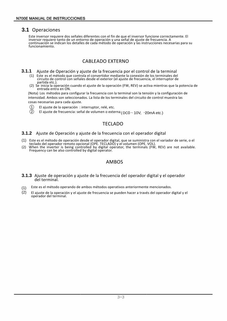
3.1.1 Ajuste terminal la de control el por frecuencia la deajuste y Operación de(1) Este
(2) etc.). partida
de interruptor el frecuencia, de ajuste (el exterior el desde señales con control de circuito del terminales los de conexión la mediante convertidor el controla que método el es
Se ON en entra entrada
de potencia la que mientras activa se REV) (FW, operación la de ajuste el cuando operación la inicia .
(Nota) Los
ajuste cada para necesarias cosas las muestra control de circuito del terminaleslos de lista La seleccionados. son Ambos intensidad
.
de configuración lay tensión la son terminal la con frecuencia la configurar para métodos
.① El : etc. relé, interruptor, operación la de ajuste
El ② señal frecuencia de ajuste : 0DC ( externa o de volumen ∼10V, ∼20mA etc.)
TECLADO
3.1.2 Ajuste digital operador el con frecuencia la de ajuste y Operación de (1) Este
VOL) E.(OP menluov le y CLADO)ET E.(OP lopciona remoto operador lde adoltec le o ,serie de ariadorv le con ministraus se equ l,itagdi operador le desde operación de todoém le es
.(2) When the inverter is being controlled by digital operator, the terminals (FW, REV) are not available.
Frequency can be also controlled by digital operator.
AMBOS
3.1.3 Ajuste terminal. del
operador el y digital operador del frecuencia la de ajuste y peracióno de
(1) Este mencionados anteriormente operativos métodos ambos deperando o método el es .(2)
El
terminal. del operador el y digital operador del través a hacer pueden se frecuencia de ajuste el y operación la de ajuste
7N 00E INSTRUCCIONES DE MANUAL
3-4
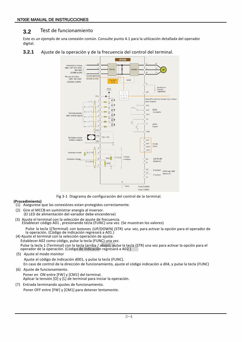
3.2 Test de funcionamiento Este
digital. operador del detallada utilización la para 4.1onsulte punto Ccomún. conexión una de ejemplo un es
3.2.1 terminal. del control del frecuencia lade y operación la de justeA
Fig 3-1 l.termina al de lcontro configuración ldede ramagiaD (Procedimiento)
(1) Asegurese correctamente. protegidos estan nesóconexi las que (2) Gire inversor al aíenerg suministrar en MCCB el .
(El encenderse debe variador del nóalimentaci de LED )(3)
ustejA frecuencia de usteja de nóselecci la con terminal el .
Establecer digoóc A01 , resionandop una tecla (FUNC) zve . Se( valores los muestran )Pulse tecla la 1(Terminal) con botones (UP/DOWN) (STR) una
usteja de nóoperaci nóselecci la con terminal el
A01.) a áregresar nóindicaci de digoó(C n.óoperaci la de operador el para nóopci laactivar para ,zve
)4( ustejA .Establecer zve una (FUNC) tecla la pulse digo,óc como 2A0 .
.)2A0 a áregresar nóindicaci de digoó(C n.óoperaci la de operador el para nóopci la activar para zve una (STR) tecla la pulse o),jaba / (arriba tecla la con (Terminal) 1 Pulse tecla la
(5) ustejA
monitor modo elA juste (FUNC). tecla la pulse y d001, indicaciónde código el En ajuste (FUNC) tecla la pulse y d04, a indicación código el funcionamiento, de dirección la de control de caso
( )6 Ajuste . funcionamiento de
Poner en ON entre [FW] y [CM1] del terminal.
Aplicar tensión la [O] y [L] de operación. la iniciar para terminal
( )7 Entrada . funcionamiento de ajustes terminando
Poner OFF entre [FW] y [CM1] para lentamente detener .
7N 00E INSTRUCCIONES DE MANUAL
3-5
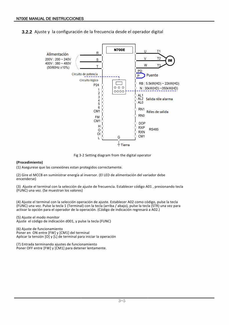
3.2.2 digital operador eldesde frecuencia la deconfiguración la y justeA
Fig 3-2 Setting diagram from the digital operator
(Procedimiento) (1) (2)
(3)
(4)
Ajuste d001, (6)
funcionamiento de Ajuste
(FUNC) tecla la pulse y
Poner
(7)Poner lentamente. detener para [CM1] y [FW] entre OFF
funcionamiento de ajustes terminando Entrada
operación la iniciar para terminal de[L] y [O] tensión laAplicar terminal del [CM1] y [FW] entre ON en
(5)
indicación de código el monitor modo el Ajuste
A02.) a regresará indicación de (Código operación. la deoperador el para opción la activar para vez una (STR) tecla la pulse abajo), / (arriba tecla la con (Terminal) 1 tecla la Pulse vez. una (FUNC)
tecla la pulse código, como A02Establecer ajuste. de operación selección la con terminal el Ajuste
valores) los muestran (Se vez. una (FUNC) tecla presionando , A01 código Establecer frecuencia. de ajuste de selección la con terminal el Ajuste
encenderse)
debe variador del alimentación de LED (El inversor. al energía suministrar en MCCB el Gire
correctamente. protegidos estan conexiónes las que Asegurese
INSTRUCCIONES DE MANUAL 7N 00E
4-1
4. parametros de codigos de Listado4.1 gitaldi Ope dorra
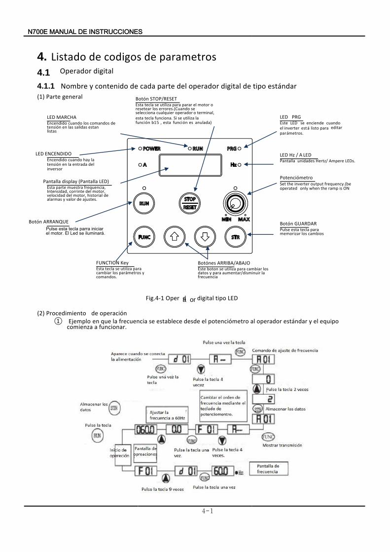
4.1.1 Nombre estándar tipo de digital operador del parte cada de contenido y (1) P eart general
Fig.4-1 LED tipo digital Oper da or (2) Procedimiento operación de
① jemploE funcionar. a comienza
equipo el y estándar operador al potenciómetro el desde establece se frecuencia la que en
PRG LED Este
metros.ápar editar para listo áest inverter el
cuando enciende se LED
ENCENDIDO LEDEncendido
inversor del entrada la en tensión la hay cuando
Pantalla LED) (Pantalla display Esta
ajustes. de valor y alarmas de historial motor, del velocidad
motor, del corrinte Intensidad, frequencia, muestra parte
Botón ARRANQUE Pulse
.áiluminar se Led El motor. el iniciar parra tecla esta
Botón STOP/RESET Esta
anulada) es nófunci esta , 5b1 nófunci la azutili se Si funciona. tecla esta
terminal, o operador cualquier selecciona se errores.(Cuando los resetear
o motor el parar para azliíut se tecla
Hz LED / A LED Pantalla LEDs. Ampere z/Hert unidades
Potenciómetro Set
ON is ramp the when only operated frequency.(be output inverter the
Botón GUARDAR Pulse
cambios los arzmemori para tecla esta
FUNCTION Key Esta
comandos. y metrosápar los cambiar
paraazutili se tecla Botónes ARRIBA/ABAJO Este
frecuencia la disminuir/aumentar para y datos
los cambiar para azutili se boton
MARCHA LEDEncendido
listas estan salidas las en tensión
de comandos los cuando
N700E INSTRUCCIONES DE MANUAL
4-2
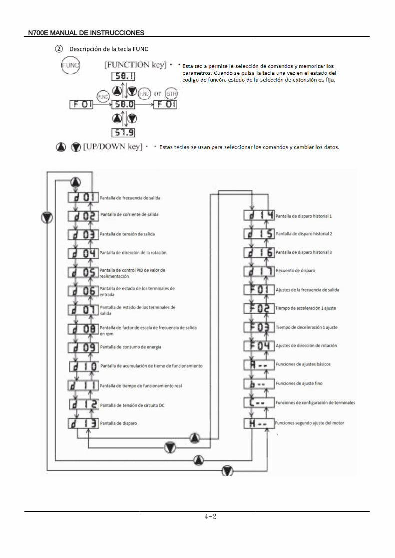
② Descripción FUNC tecla la de
in RPM
N700E INSTRUCCIONES DE MANUAL
4-3
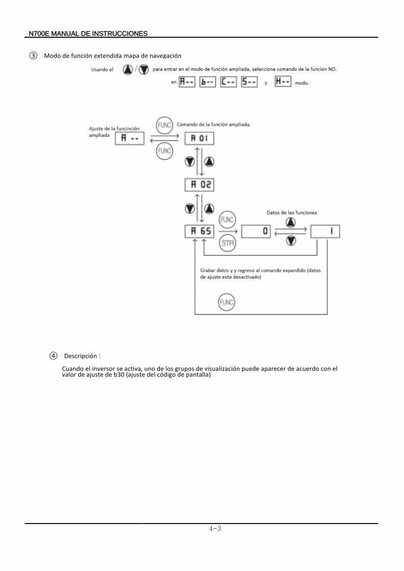
③ Modo navegación de mapa extendida función de
④ Descripción :
Cuando
pantalla) de código del (ajuste b30 de ajuste de valor el con acuerdo de aparecer puede visualización de grupos los de uno activa, se inversor el
N700E INSTRUCCIONES DE MANUAL
4-4
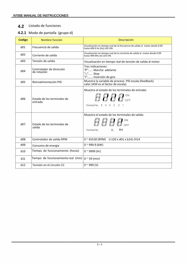
4.2 Listado funciones de
4.2.1 Modo pantalla de (grupo-d) Nombre función Descripción
d01 Frecuencia salida de
d02 Corriente salida de
d03 Tensión salida de
d04 Controlador rotación de
dirección de Tres indicaciones :"F"..... Marcha
adelante ""..... Stop "r"...... giro deInversión
d05 Retroalimentación PID
Muestra escala) de factor el es (A50
(feedback)valor
escala PID proceso de variable la
d06 Estado entrada
de terminales los de
Terminal No.
d07 Estado salida
de terminales los de
Muestra salida de terminales los de estado el :
Terminal No.
d08 Controlador RPM salida de 0 ~ 65530 (RPM) (=120 x d01 x b14) /H14
d09 Consumo energia de 0 ~ 999.9 (kW)
d10
0 ~ 9999 (hr)
d11
0 ~ 59 (min)
d12 Tensión C C circuito el en 0 ~ 999 (V)
Codigo
Tiempo (horas) funcionamiento de
Tiempo (min) real funcionamiento de
Visualización ON. LED(Hz) Hz400.0 hasta
0.00 desde motor al salida de frecuencia la de realtiempo en
Visualización ON. LEDHz (A) 999.9 hasta
0.00 desde motor al salida de corriente la de real tiempo en
Visualización motor. al salida de tensión real tiempo deen
Muestra entrada: de terminales los de estado el
N700E INSTRUCCIONES DE MANUAL
4-5
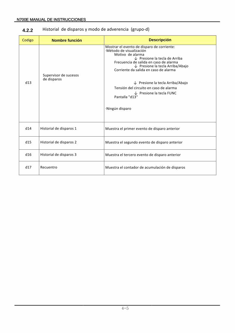
4.2.2 Historial adverencia de modo y disparos de (grupo-d)
Nombre función Descripción
d13
Supervisor disparos de
sucesos de
Mostrar corriente: de disparo de evento el Método· visualización de
Motivo alarma de ↓ Presione rribaA de tecla la Frecuencia alarma de caso en salida de ↓ Presione Arriba/Abajo tecla la Corriente alarma de caso en salida da
↓ Presione Arriba/Abajo tecla la Tensión alarma de caso en circuito del ↓ Presione tecla la FUNC Pantalla "d13"
·Ningún disparo
d14 Historial disparos de 1 Muestra anterior disparo de evento primer el
d15 Historial disparos de 2 Muestra anterior disparo de evento segundo el
d16 Historial disparos de 3 Muestra anterior disparo deevento tercero el
d17 Recuentro Muestra disparos de acumulación de contador el
Codigo
N700E INSTRUCCIONES DE MANUAL
4-6
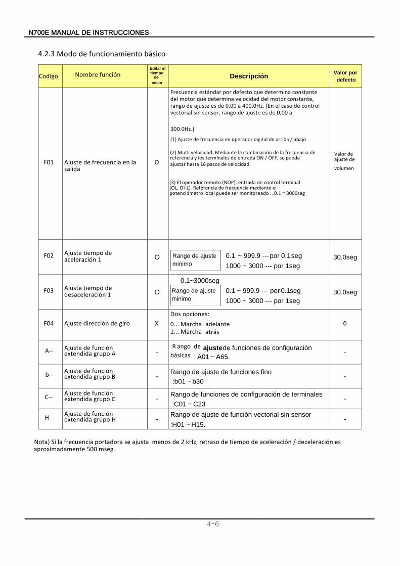
4.2.3 Modo básico funcionamiento de
Nombre función
Descripción Valor
defecto
por
F01 Ajuste salida
la en frecuencia de O
300.0Hz.)
a 0,00 de es ajuste de rango sensor, sin vectorial control de caso el (En 400.0Hz. a 0,00 de es ajuste de rango
constante, motor del velocidad determina que motor del constante determina que defecto por recuenciaF stándare
(1) Ajuste abajo / arribade digital operador en frecuencia de
(2) Mult
velocidad. de pasos 16 ajustar puede
hastase OFF, / ON entrada de terminales los y referencia
de frecuencia la de combinación laMediante velocidad:i
Valor
volumen
de ajuste de
F02 Ajuste 1 aceleración
de tiempo O 0.1 ~ 999.9 --- por 0.1seg
1000 ~ 3000 --- por 1seg
Rango
minimo
ajuste de
30.0seg
F03 Ajuste 1 desaceleración de tiempo
O
0.1~3000seg
0.1 ~ 999.9 --- por 0.1seg
1000 ~ 3000 --- por 1seg
Rango
minimo
ajuste de
30.0seg
F04 Ajuste giro de dirección X opciones :Dos
0... Marcha adelante 1... Marcha atrás
0
A-- Ajuste grupo extendida función de A -
uncionesangoR básicas
configuración de f de ajuste de
: A01∼A65. -
b-- AjusteB grupo extendida función de
- Rango
fino funciones de ajuste de
:b01∼b30 -
C-- justeA C uporg adidexten
función ed -
Rango unciones terminales de configuración de f de
:C01∼C23 -
H-- justeA H uporg adidexten
función ed -
Rango juste sensor sin vectorial función de a de
:H01∼H15.-
Nota)
mseg. 500
aproximadamentees deceleración / aceleración de tiempo de retraso kHz, 2 de menos ajusta se portadora frecuenciala Si
Codigo Editar el tiempo
de
inicio
(3)
3000seg ~ 0.1 .. monitoreado ser puede local potenciómetro el mediante frecuencia de Referencia OI-L). (OL,
terminal control de entrada (NOP), remoto operador lE
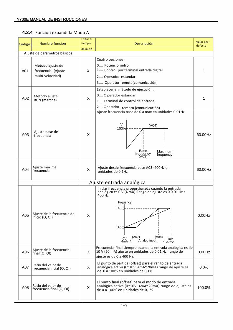
N700E INSTRUCCIONES DE MANUAL
4-7
4.2.4 Función A Modo expandida
Nombre función Descripción Valor defecto por
Ajuste básicos parametros de
A01
X
opciones :Cuatro0.... Potenciometro 1.... Control digital entrada terminal por
2.... Operador estandar 3.... O perator (comunicación)
ejecución de método el
remoto
1
A02 (marcha) ajusteMétodo
RUN X
Establecer :0.... O estándar perador 1.... Terminal entrada de control de 2.... Operador remoto (comunicación)
1
A03 X
Ajuste 0.01Hz unidades en max a 0 de base frecuencia
Basefrequency
(A03)
Maximumfrequency
V
100%(A04)
60.00Hz
A04 Ajuste máxima
recuenciaf
X 0.1Hz deunidades en A03~400Hz base frecuencia desdeAjuste
60.00Hz
Ajuste nalógicaa entrada
A05 Ajuste inicio
de frecuencia la de (O, OI) X
Iniciar
Hz 400 a Hz 0,01 0 es ajuste deango R mA) (4 V 0 es analógica
entrada la cuando proporcionada frecuencia
Frquency
Analog input0V
4mA10V
20mA
(A08)(A07)
(A05)
(A06)
0.00Hz
A06 Ajuste
final frecuencia la de
(O, OI) X
Hz. 400 a 0 de es ajuste de rango Hz. 0,01 de unidades enajuste mA) (20 V
de es analógica entrada la cuando siempre final10Frecuencia
0.00Hz
A07 Ratio
incial frecuencia de valor del
(O, OI) X El
0,1% de unidades en 100% a 0 de
es ajuste de rango 4mA~20mA) (0~10V, analógica
activaentrada de rango el para (offset) partida de punto
0.0%
A08 Ratio
final frecuencia de valor del
(O, OI) X
El
0,1% de unidades en 100% a 0 de es ajuste de rango 4mA~20mA) (0~10V, activa analógica
entrada de modo el para (offset) final punto
100.0%
Codigo Editar
inicio de tiempo el
Método
multi-velocidad) (Ajuste frecuencia
de ajuste
Ajuste frecuencia
de base
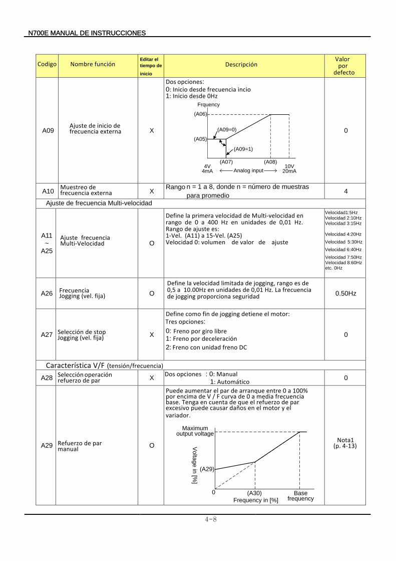
N700E INSTRUCCIONES DE MANUAL
4-8
A09 Ajuste
externa frecuencia de inicio de
X
Dos opciones ::0 I nicio incio frecuencia desde:1 Inicio desde 0Hz
(A08)
(A09=0)
(A06)
(A05)
4V4mA
10V20mA
(A09=1)
(A07)
Analog input
Frquency
0
A10 Muestreo
externa frecuencia de
X Rango n = 1 a 8, donde n = número
promedio para
muestras de
4
Ajuste Multi-velocidad frecuencia de
A11 ~
A25
fAjuste recuencia Multi-Velocidad
O
Define
(A25)Velocidad ajuste de valor de volumen 0:
15-Vel. a (A11) 1-Vel. es: ajuste de Rango
Hz. 0,01 de unidades en Hz 400 a 0 de rango en Multi-velocidad de velocidad primera la
Velocidad1:5HzVelocidad
2:10Hz
Velocidad 3:15Hz
Velocidad 4:20 Hz
Velocidad
5:30Hz
Velocidad 6:40H z
Velocidad 7:50Hz Velocidad 8:60Hz etc. 0Hz
A26 Frecuencia fija) (vel.ogging J
O
Define
seguridad proporciona jogging de frecuencia La Hz. 0,01 de unidades en 10.00Hz a0,5
de es rango, jogging de limitada velocidad la
0.50Hz
A27 Selección fija) (vel. Jogging stop de X
Define motor el detiene jogging de fin como :
0: Freno libre giro por 1 deceleración porFreno : 2: F reno DC freno unidad con
0
Característica V/F tensión( /frecuencia)
A28 Selección
par de refuerzo operación
X opcionesosD : :0 Manual
:1 Automático 0
A29 Refuerzo manual
par de O
Puede
variador el y motor el en daños causar puede excesivo
par de refuerzo el que de cuenta en Tenga base. frecuencia media a 0 de curva F / V de encima por
100%a 0 entre arranque de par el aumentar
.
Vo
ltag
e in
[%]
Frequency in [%]
0 Basefrequency
(A29)
(A30)
Maximum output voltage
Nota1 (p. 4-13)
Codigo
funciónNombre Editar
inicio
de tiempo
el
Descripción Valor
defectopor
Tres opciones:
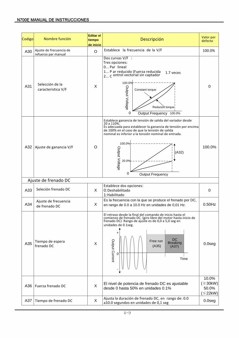
N700E INSTRUCCIONES DE MANUAL
4-9
funciónNombre
Descripción Valor
defecto por
A30 Ajuste recuencia manual par refuerzo
de f de O
100.0%
A31
X
Dos curvas V/F :
0... Par lineal 1... P ar veces 1.7 r reducido educida(Fuerza 2... C
ontrol captador sin vectorial
100.0%
0O
utp
ut V
olta
ge
Output Frequency
Reduced torque
Constant torque
100.0%
0
A32 Ajuste V/F ganancia de O
Establece 110%. a 20
desde variador del salida de tensión de ganancia
Es
entrada. de nominal tensión la a inferior es nominal salida de tensión la que de caso el en 100% de
encima por tensión de ganancia la establecer para adecuada
100.0%
0
20.0%
(A32)
Ou
tpu
t Vo
ltag
e
Output Frequency
100.0%
Ajuste DC frenado de
A33 Seleción CD frenado X Establece opciones: dos 0: Deshabilitado 1: Habilitado
0
A34 Ajuste recuencia
DC frenado de f de
X Es a
Hz. 0,01 de unidades en Hz 10.0 a 0.0de rangoen
,DC por frenado el produce se que la con frecuencia l
0.50Hz
A35 Tiempo
DC frenado espera de
X
El
0.1seg.de unidades en seg 5,0 a 0,0 de es ajuste de Rango DC) frenado
de inicio hasta motor del libre (giro DC. frenado de comienzo el hasta inicio de comando del final la desde retraso
Ou
tpu
t Cu
rren
t
Free run DCBreaking
(A35) (A37)
+
0
-
Time
0.0seg
A36 Fuerza DC frenado X El
desde ajustable es DC frenado de potencia de nivel
0 hasta 50% en unidades 0.1%
10.0%
(≥30kW)
50.0%
(≤22kW)
A37 Tiempo DC frenado de X Ajusta
C, seg 0,1 de unidades en segundos a10.0
0.0 de: rango en D frenado de duración la 0.0seg
Codigo Editar
inicio de
tiempo
el
Selección V/F caracteristica
la de
Establece V/F la de frecuencia la
Tres opciones:
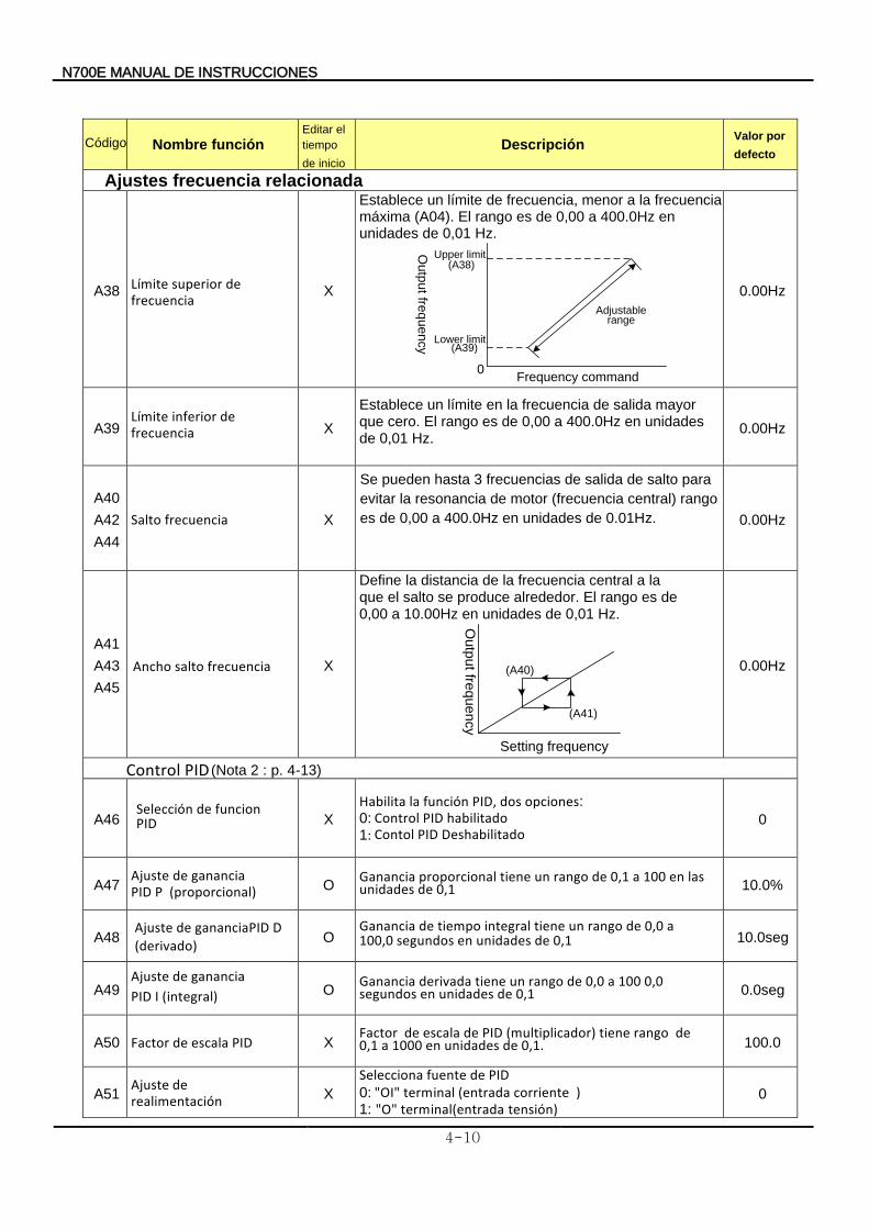
N700E INSTRUCCIONES DE MANUAL
4-10
Nombre función
Descripción
Valor
defecto
por
Ajustes relacionada frecuencia
A38 Límite
frecuencia de superior
X
Establece
Hz. 0,01 de unidades en 400.0Hz a 0,00 de es rango El (A04). máxima
frecuencia la a menor frecuencia, de límite un
Frequency command0
(A38)
(A39)
Ou
tpu
t freq
ue
ncy
Adjustable range
Upper limit
Lower limit
0.00Hz
A39 Límite
frecuencia de inferior
X
Establece
Hz. 0,01 de unidades en 400.0Hz a 0,00 de es rango El cero. que
mayor salida de frecuencia la en límite un
0.00Hz
A40
A42
A44
Salto frecuencia X
de unidades en 400.0Hz a 0,00 de es
rango central) (frecuencia motor de resonancia la evitar
para salto de salida de frecuencias 3 astah puedeneS
0.01Hz. 0.00Hz
A41
A43
A45
X
Define
Hz. 0,01 de unidades en 10.00Hz a 0,00 de es rango El alrededor. produce se salto el que
la a central frecuencia la de distancia la
Setting frequency
Ou
tpu
t freq
ue
ncy
(A41)
(A40)
0.00Hz
Control PID (Nota 2 : p. 4-13)
A46 X
Habilita opciones dos PID, función la :0: Control PID habilitado
:1 Contol P ID Deshabilitado 0
A47 AjustePID
ganancia de P (proporcional)
O Ganancia
0,1 de unidades las en 100 a 0,1 de rango un tiene proporcional
10.0%
A48
AjustePID
ganancia de I (integral)
O 0,1 de unidades en segundos 100,0 a 0,0 de rango un tiene integral tiempo deGanancia
10.0seg
A49
Ajuste
(derivado) D gananciaPID de
O
Ganancia 0,1 de unidades en segundos
0,0 100 a 0,0 de rango un tiene derivada 0.0seg
A50 F PID escala deactor X Factor
0,1. de unidades en 1000 a 0,1 de rango tiene (multiplicador) PID de escala de
100.0
A51 Ajuste
realimentación de
X
Selecciona PID de fuente 0: "OI" terminal ) corriente(entrada 1: "O" terminal(entrada tensión )
0
Código Editar
inicio de
tiempo
el
nchoA ecuenciarf salto
Selección PID
funcion de
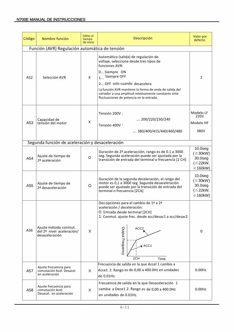
N700E MANUAL INSTRUCCIONES DE
4-11
Nombre función
Descripción Valordefecto
por
Función (AVR) tensión de automáticaRegulación
A52 Selección AVR X
Automático
AVR funciones de tipos tres desde selecciona voltaje,
de regulación de (salida)
:0... Siempre ON 1... Siempre OFF
2... OFF desacelera cuando solo La
entrada. laen potencia de fluctuaciones ante constante relativamente amplitud una a variador
del salida de onda de forma la mantiene AVR función
2
A53 Capacidad
motor del tensión de X
Tensión 200V : .... 200/220/230/240 Tensión 400V :
.... 380/400/415/440/460/480
Modelo LF 220V
Modelo HF
380V
Segunda de función aceleración desaceleración y
A54 Ajuste iempo
aceleración 2ª de tde O
Duración 0.1 a de es rango aceleracción, 2ª de
CH] [2 frecuencia o terminal del entrada de transición la por ajustada ser puede aceleración Segunda seg. 3000
10.0seg
(≥30kW)
30.0seg
(≤22kW,
≥160kW)
A55 Ajuste iempo
desaceleración 2ª de t de
O
Duración
[2CA] frecuencia o terminal del entrada de transiciónla por ajustado ser puede
aceleracióndes Segunda seg 3000 a 0,1 es motor del rango el deceleración, segunda lade
10.0seg
(≥30kW)
30.0seg
(≤22kW,
≥160kW)
A56 Ajuste
desaceleración
aceleración/ nivel del
2ºconmut. método
X
Dos deceleración / aceleración
2ª a 1ª de cambio el para opciones :
0: [2CH] terminal desdeEntrada 1: C onmut. acc/desac2 a acc/desac1 desde frec. ajuste
Ou
tpu
t Fre
qu
en
cy
Time
ACC2
2CH
ACC1
0
A57 Ajuste
aceleración en
Desacel. Acel. comutación para frecuencia
X
Frecuencia de
0.01Hz. de unidades en 400.0Hz a 0,00 de es angoR 2. Acce1
a cambia 1 Accel que la en salida 0.00Hz
A58
X
Frecuencia de
0.01Hz . de unidades en
400.0Hz a 0,00 de es angoR 2. Dece1 a cambia 1 Desaceleración que la en salida
0.00Hz
Código Editar
inicio
detiempo
el
Ajuste
aceleración en Desacel. Acel. comutación
para frecuencia
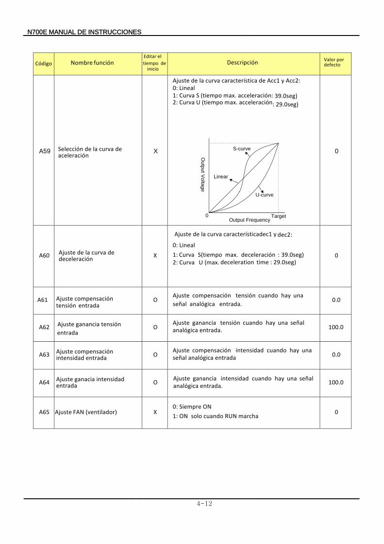
N700E INSTRUCCIONES DE MANUAL
4-12
Nombre función
Descripción Valor defecto
por
A59 X
Ajuste Acc2 y Acc1 de característica curva la de : 0: Lineal
1: Curva S (tiempo max. acceleración:
39.0seg)
2: Curva U (tiempo max. acceleración 29.0seg) :
S-curve
Linear
Output Frequency0
U-curve
Ou
tpu
t Vo
ltag
e
Target
0
A60 X
Ajuste dec1 y característica curva la de dec2: 0: Lineal 1: 39.0seg): deceleración max.S(tiempoCurva 2: C urva 29.0seg) : time deceleration (max. U
0
A61 O Ajuste
entrada. analógica señal una hay cuando tensión compensación
0.0
A62 O Ajuste
entrada. analógica señal una hay cuando tensión ganancia
100.0
A63 Ajuste entrada intensidad
compensación O Ajuste
entrada analógica señal una hay cuando intensidad compensación
0.0
A64 Ajuste entrada
intensidad ganacia O Ajuste entrada. analógica
señal una hay cuando intensidad ganancia 100.0
A65 Ajuste (ventilador) FAN X ON Siempre0:
1 : ON marcha RUN cuando solo 0
Código Editar
inicio de tiempo
el
Selección aceleración
de curva la de
Ajuste deceleración
de curva la de
Ajuste
entrada tensión compensación
Ajuste
entrada tensión ganancia
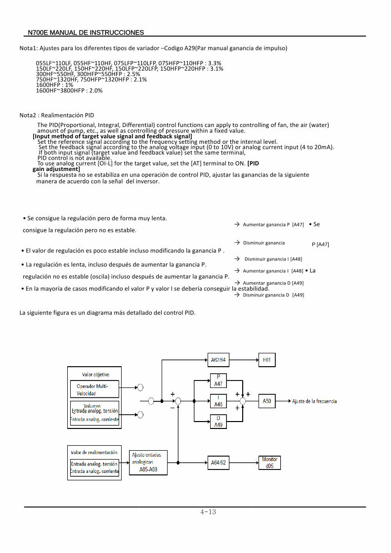
N700E INSTRUCCIONES DE MANUAL
4-13
Nota1: A variador de tipos diferentes los parajustes –Codigo A29(Par impulso deganancia manual )
055LF~110LF, 055HF~110HF, 075LFP~110LFP, 075HFP~110HFP : 3.3% 150LF~220LF, 150HF~220HF, 150LFP~220LFP, 150HFP~220HFP : 3.1% 300HF~550HF, 300HFP~550HFP : 2.5% 750HF~1320HF, 750HFP~1320HFP : 2.1% 1600HFP : 1%
1600HF~3800HFP : 2.0%
Nota2 : PIDRealimentación
The PID(Proportional, Integral, Differential) control functions can apply to controlling of fan, the air (water) amount of pump, etc., as well as controlling of pressure within a fixed value.
[Input method of target value signal and feedback signal] Set the reference signal according to the frequency setting method or the internal level.
Set the feedback signal according to the analog voltage input (0 to 10V) or analog current input (4 to 20mA). If both input signal (target value and feedback value) set the same terminal,
PID control is not available. To use analog current [OI-L] for the target value, set the [AT] terminal to ON. [PID
gain adjustment] Si
inversor del señal la con acuerdo demanera
siguiente la de ganancias las ajustar PID, control de operación una en estabiliza se no respuesta la .
• Se lenta muy forma de pero regulación la consigue . → Aumentar ganancia P [A47] • Se
estable. es no pero regulación la consigue
→ Disminuir ganancia P [A47] • El regulación P ganancia la modificando incluso estable poco es de valor . → Disminuir I ganancia [A48] • La regulación P ganancia la aumentar de después incluso lenta, es . → Aumentar ganancia I [A48] • La
regulación P ganancia la aumentarde despuésincluso (oscila) estable esno
. → Aumentar Dganancia [A49] • En estabilidad la conseguir debería se I valor y P valor el modificando casos de mayoría la . → Disminuir ganancia D [A49] La PID control del detallado más diagrama un es figura siguiente .
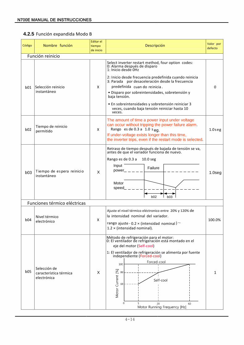
N700E INSTRUCCIONES DE MANUAL
4-14
4.2.5 Función B Modo expandida
Nombre función
Descripción Valor
defecto por
Función reinicio
b01 nócciSele eontáantins
oinicier X
Select inverter restart method, four option codes: :0 armalA
:1 oniciI oarpisd de séupsde
desde 0Hz
:2 I onici iniciaer docuan adiniedefrp nciaecuerf desdead ara: P3
.iniciaer docuanadiniedefrp nciaecuerf al desde nóracielesacde rpo
• oarpDis
.nónsite ajab
y nónsieterobs ,sdeadnsiteinerobs rpo
• nE
.secve 10 atash iniciarer nónsite ajab docuan ,secve
3 iniciarer nónsieterobs y sdeadnsiteinerobs
0
b02 pomeiT
doitrmipe oinicier de
X
The amount of time a power input under voltage can occur without tripping the power failure alarm.
oangR 0.3 a de se .ges1.0 If under-voltage exists longer than this time, the inverter trips, even if the restart mode is selected.
1.0s ge
b03 pomeiT eontáantins
oinicier rapese de X
orasRet
evonu denaouncif rdoariav el euq de stean
,av es nónsite de adajab de séupsde pomeit de .
oRang de se 0.3 a 10.0 seg
b02 b03
Motor
speed
Input
powerFailure
1.0s ge
Funciones eléctricas térmico
b04 veliN
onicórtcele ormicté
X
ertne onicortcelé ormicté velni el teusAj 20la
de y% 120%
variador. del nominal
intensidad
ajuste rango - 0.2 × (intensidad nominal )∼1.2 × (intensidad nominal ).
100.0%
b05 nócciSele
nicaórtcele rmicaté icatsírtecarac
de X
motor el para refrigeración de Método :0: El
motor deleje el en montado está refrigeración de ventilador
(Self-cool)
1: El independiente
fuente por alimenta se refrigeración de ventilador (Forced-cool)
1
Código Editar
inicio de tiempo el
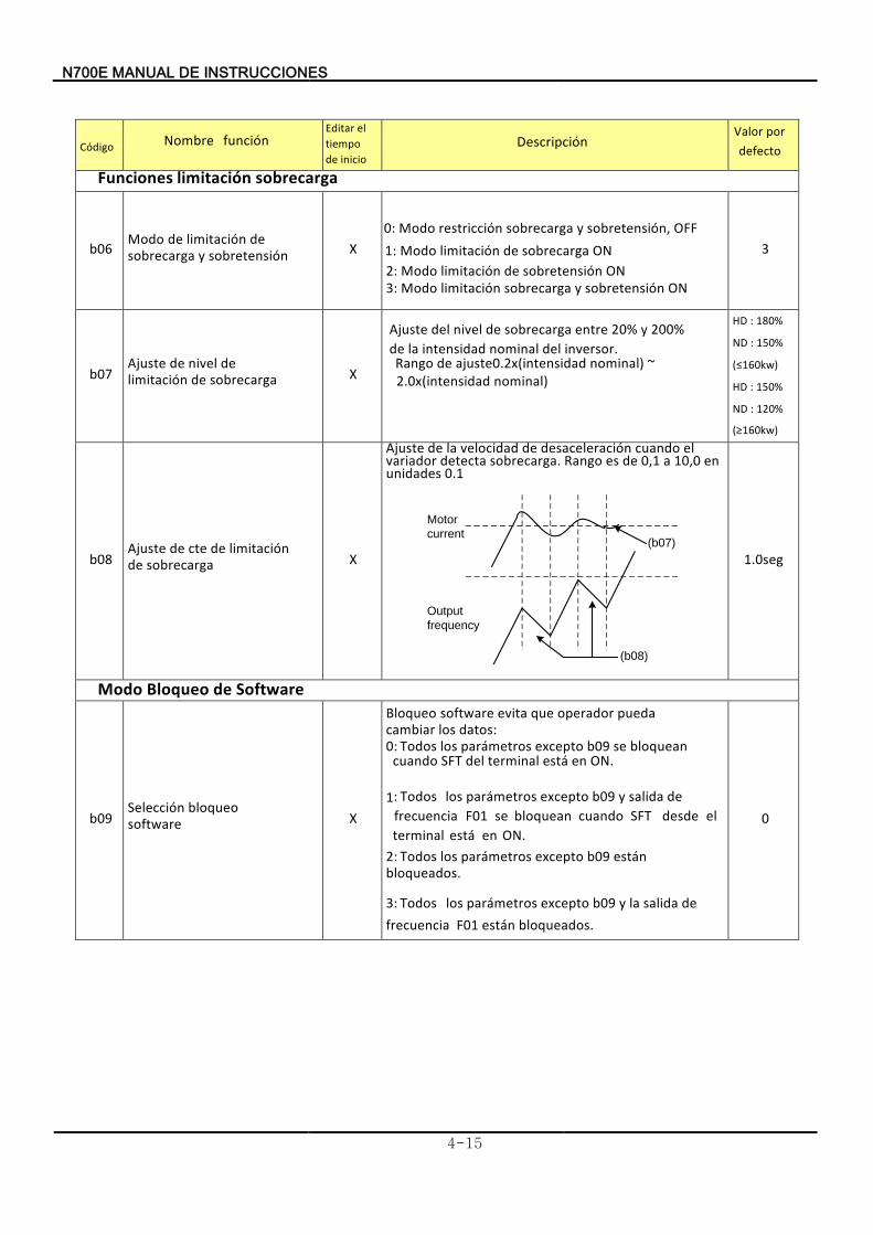
N700E INSTRUCCIONES DE MANUAL
4-15
Nombre función
Descripción Valor
defecto por
Funciones sobrecarga limitación
b06 Modo
sobretensión y sobrecarga de limitación de
X :0 Modo OFF n,ósobretensi y sobrecarga nórestricci 1: ON sobrecarga de limitación Modo
:2 ON sobretensión de limitación Modo :3 ON sobretensión y sobrecarga limitaciónModo
3
b07 Ajuste
sobrecarga de limitación de nivel de
X
Ajuste 20% .inversor del nominal intensidad la de
200% y entre sobrecarga de nivel del
Rango 0.2x(intensidad nominal ajuste de ) ~ 2.0x(intensidad nominal)
HD : 180%
ND : 150%
(≤160kw)
HD : 150%
ND : 120%
(≥160kw)
b08 Ajuste
sobrecarga de limitación de cte de
X
Ajuste
0.1 unidades en 10,0 a 0,1ango de es R carga.sobre detecta variador
el cuando desaceleración develocidad lade
(b08)
(b07)
Motor
current
Output
frequency
1.0seg
Modo Software de Bloqueo
b09 Selección
software bloqueo
X
datos los cambiar pueda operador que evita software Bloqueo
:0:
ON. en está terminal del SFT cuando bloquean se b09 excepto parámetros los Todos
1: Todos
ON. en está terminal el desde SFT cuando bloquean se frecuencia
F01
de salida y b09 excepto parámetros los
2: Todos
bloqueados. están b09 excepto parámetros los
3: Todos bloqueados. están F01 frecuencia
de salida la y b09 excepto parámetros los
0
Código
Editar
inicio de tiempo el
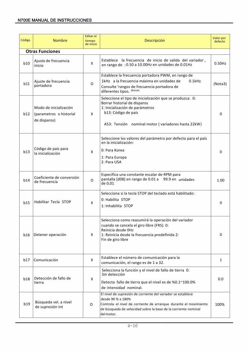
7N 00E INSTRUCCIONES DE MANUAL
4-16
Nombre
Descripción Valor
defecto por
Otras Funciones
b10 Ajuste inicio
frecuencia de X Establece
de :rangoen ,variador del salida de inicio de frecuencia la
0.50 a 10.00Hz Hz01.0de unidades en 0.50Hz
b11 Ajuste recuencia portadora
f de O
Establece de rango en PWM, portadora frecuencia la 1kHz a de unidades en máxima frecuencia la 0.1kHz.
tipos diferentes de portadora frecuencia de 'rangos Consulte
. a(Not 4)
(Nota3)
b12 Modo inicialización de (parametros
disparos) de historial o
X
produzca se que inicialización de tipo el Seleccione : :0 disparos de historial Borrar
:1 nicialización I parámetros de b13: ódigoC país de
A53: Tensión variadores motor nominal ( hasta 22kW )
0
b13 Código
inicialización la para aísp de
X
:0 Korea Para :1 Europa
Para
:2 USA Para
0
b14 Coeficiente
frecuencia de conversión de
O
Especifica0.01 a de rango ]8[d0 en pantalla
para RPM de escalar constante una 99.9 en
de unidades
0.01 1.00
b15 Habilitar STOP Tecla X
aSeleccion habilitado áest teclado del STOP tecla la si :: Habilita0 STOP : Inhabilita1 STOP
0
b16 Detener nóoperaci X
Selecciona (FRS). libre giro el cancela se cuando
variador eld operación lareasumirá como :0
0Hz desde einiciaR
:1 predefinida frecuencia la desde Reinicia :2 libre giro de Fin
0
b17 nóComunicaci X
1
b18 nóDetecci tierra
de fallo de X
Detecta 0.1~100.0%de
%dees nivel el quetierra de fallo nominal. intensidad
0.0
b19 squedaúB int nósupresi de
nivel a vel. O
El 180% a % 90 desde
establece se rvariado del corriente de supresión de nivel
100%
Código Editar
inicio de tiempo el
Seleccione :inicialización la en
país el para defecto por parámetro del valores los
Establece .23 a 1 de es rango el n,ócomunicaci
la para nócomunicaci de meroún el
Selecciona 0: detección Sin
tierra de fallo de nivel el y nófunci la
Controla
motor.
del nominal corriente la de base la sobre velocidad de búsqueda de
movimiento el durante arranque de corriente de nivel el
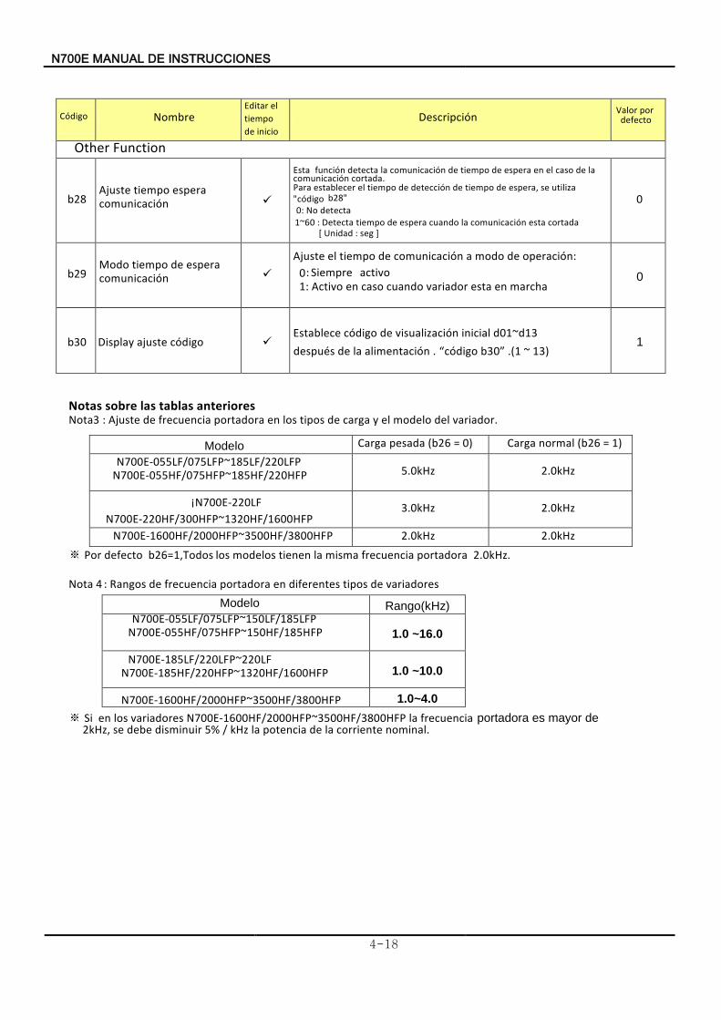
N700E INSTRUCCIONES DE MANUAL
4-18
Nombre Descripción Valor
defecto por
Other Function
b28 Ajuste
comunicación espera tiempo
Esta cortada comunicación
la de caso el en espera de tiempo de comunicación la detecta función .
Para b28" "código
utiliza se espera, de tiempo de detección de tiempo el establecer 0: No detecta
1~60 : Detecta cortadaesta comunicación la cuando espera detiempo [ Unidad : seg ]
0
b29 Modo
comunicación espera de tiempo
Ajuste operación: de modo a comunicación de tiempo el 0 : Siempre activo 1 Activo : marcha en esta variador cuando caso en
0
b30 Display código ajuste Establece d01
inicial visualización de código ~d13después alimentación la de . “código b30” .(1 ~ 13)
1
Notas anteriores tablas las sobre Nota3 : Ajuste variador del modelo el y carga de tipos los en portadorarecuencia f de .
Modelo Carga pesada (b26 = 0) Carga normal (b26 = 1) N700E-055LF/075LFP~185LF/220LFP
N700E-055HF/075HFP~185HF/220HFP 5.0kHz 2.0kHz
¡ N700E-220LF N700E-220HF/300HFP~1320HF/1600HFP
3.0kHz 2.0kHz
N700E-1600HF/2000HFP~3500HF/3800HFP 2.0kHz 2.0kHz
※ Por defecto b26=1,Todos portadora frecuencia misma la tienen modelos los 2.0kHz.
Nota 4 Rangos : oresvariad de tipos diferentes en portadora frecuencia de Modelo Rango(kHz)
N700E-055LF/075LFP~150LF/185LFP N700E-055HF/075HFP~150HF/185HFP 1.0 ~16.0 N700E-185LF/220LFP~220LF
N700E-185HF/220HFP~1320HF/1600HFP 1.0 ~10.0
N700E-1600HF/2000HFP~3500HF/3800HFP 1.0~4.0
※ Si losen N700E-1600HF/2000HFP~3500HF/3800HFP variadores la frecuencia nominal. corriente la de potencia kHz / la5% disminuir debe se
2kHz
de mayor es ,
portadora
Código Editar
inicio de tiempo el
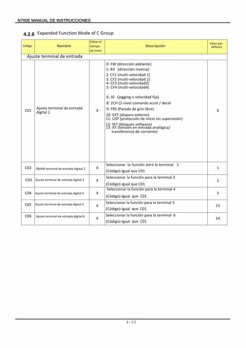
N700E INSTRUCCIONES DE MANUAL
4-19
4.2.6 Expanded Function Mode of C Group
Nombre
Descripción Valor
defecto por
Ajuste entrada de terminal
C01 X
9: libre) giro de (Parada FRS
12: software) (bloqueo SFT
0
C02 X Seleccionar 2 terminal la para función la (Código)-Igual C01 que
1
C03 X Seleccionar 3 terminal la para función la
(Código)-Igual C01 que 2
C04 X Seleccionar 4 terminal la para función la
(Código)-Igual C01 que 3
C05 X Seleccionar terminal la para función la 5 (Código)-Igual C01 que
13
C06 X Seleccionar terminal la para función la 6 (Código)-Igual C01 que
14
Código Editar
inicio de tiempo el
6 digital entrada de terminal
Ajuste
5 digital entrada de terminal Ajuste
3digital entrada de terminalAjuste
2 digital entrada de terminal
Ajuste
0: adelante) (dirección FW
Ajuste 1digital
entrada de terminal
1: RV
inversa) (dirección 2: 1) (multi-velocidad CF13: 2) (multi-velocidad CF2 4: (multi-velocidad3) CF3 5: (multi-velocidad4) CF4
6: JG fija) velocidad o (jogging 8: decel / accel comando (2-nivel 2CH
10: externo) (disparo EXT 11: supervisión) sin inicio de (protección USP
13:
corriente) detransferencia analógica/ entrada en (tensión AT
Ajuste 4 digital entrada de terminal
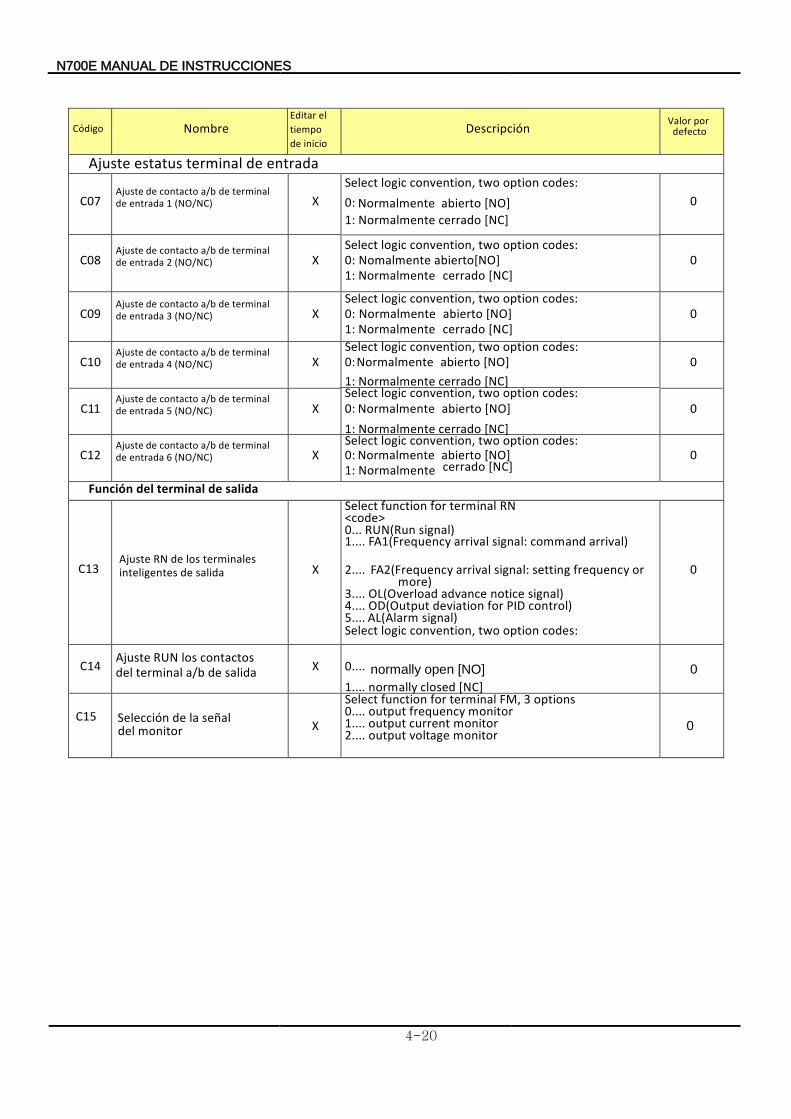
N700E INSTRUCCIONES DE MANUAL
4-20
Nombre Descripción Valor
defecto por
Ajuste entrada de terminal estatus
C07 Ajuste contacto de a/b de
1 entrada de terminal
(NO/NC) X Select logic convention, two option codes: 0: Normalmente abierto [NO] 1: cerrado Normalmente [NC]
0
C08 2 entrada de terminal de a/b contacto de Ajuste
(NO/NC) X Select logic convention, two option codes: 0: malmenteNo [NO] abierto1: Normalmente cerrado [NC]
0
C09 Ajuste
3 entrada de terminal de a/b contacto de
(NO/NC) X Select logic convention, two option codes: 0: Normalmente abierto [NO]1: Normalmente cerrado [NC]
0
C10 Ajuste
4 entrada de terminal de a/b contacto de
(NO/NC) X Select logic convention, two option codes: 0: Normalmente abierto [NO] 1: [NC] cerrado Normalmente
0
C11 5 entrada de terminal de a/b contacto de Ajuste
(NO/NC) X Select logic convention, two option codes: 0: Normalmente [NO] abierto 1: cerrado Normalmente [NC]
0
C12 Ajuste
6 entrada de terminal de a/b contacto de
(NO/NC) X Select logic convention, two option codes: 0: Normalmente [NO] abierto 1: Normalmente cerrado [NC]
0
Función salida de terminal del
C13 Ajuste
salida deinteligentes terminales los de RN
X
Select function for terminal RN <code> 0... RUN(Run signal) 1.... FA1(Frequency arrival signal: command arrival)
2.... FA2(Frequency arrival signal: setting frequency or more)
3.... OL(Overload advance notice signal) 4.... OD(Output deviation for PID control) 5.... AL(Alarm signal)
0
C14 Ajuste
salida de a/b terminal del contactos los RUN
X
Select logic convention, two option codes:
0.... normally open [NO]
1.... normally closed [NC] 0
C15 Selección monitordel
señal la de X
Select function for terminal FM, 3 options 0.... output frequency monitor 1.... output current monitor 2.... output voltage monitor
0
Código Editar
inicio de tiempo el
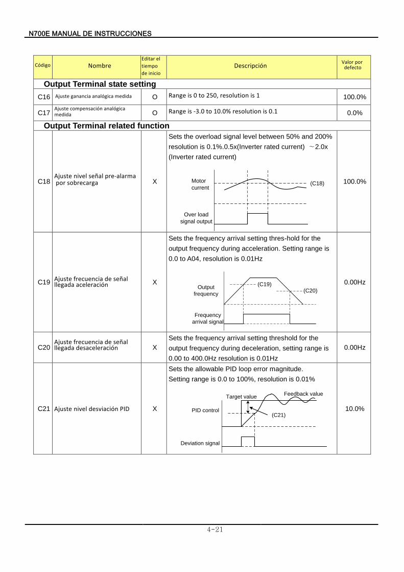
N700E INSTRUCCIONES DE MANUAL
4-21
Nombre
Descripción Valor defecto por
Output Terminal state setting
C16
O Range is 0 to 250, resolution is 1 100.0%
C17
O Range is -3.0 to 10.0% resolution is 0.1 0.0%
Output Terminal related function
C18 Ajuste
sobrecarga por pre-alarma señal nivel
X
Sets the overload signal level between 50% and 200%
resolution is 0.1%.0.5x(Inverter rated current) ∼2.0x
(Inverter rated current)
Motor
current
Over load
signal output
(C18)
100.0%
C19 Ajuste
aceleración llegada señal de frecuencia
X
Sets the frequency arrival setting thres-hold for the
output frequency during acceleration. Setting range is
0.0 to A04, resolution is 0.01Hz
Output
frequency
Frequency
arrival signal
(C19)(C20)
0.00Hz
C20 Ajuste
desaceleración llegada señal de frecuencia
X
Sets the frequency arrival setting threshold for the
output frequency during deceleration, setting range is
0.00 to 400.0Hz resolution is 0.01Hz
0.00Hz
C21 A juste PID desviación nivel X
Sets the allowable PID loop error magnitude.
Setting range is 0.0 to 100%, resolution is 0.01%
PID control
Deviation signal
(C21)
Target valueFeedback value
10.0%
Código Editar
inicio de tiempo el
Ajuste medida analógica ganancia
Ajuste medida
analógica compensación
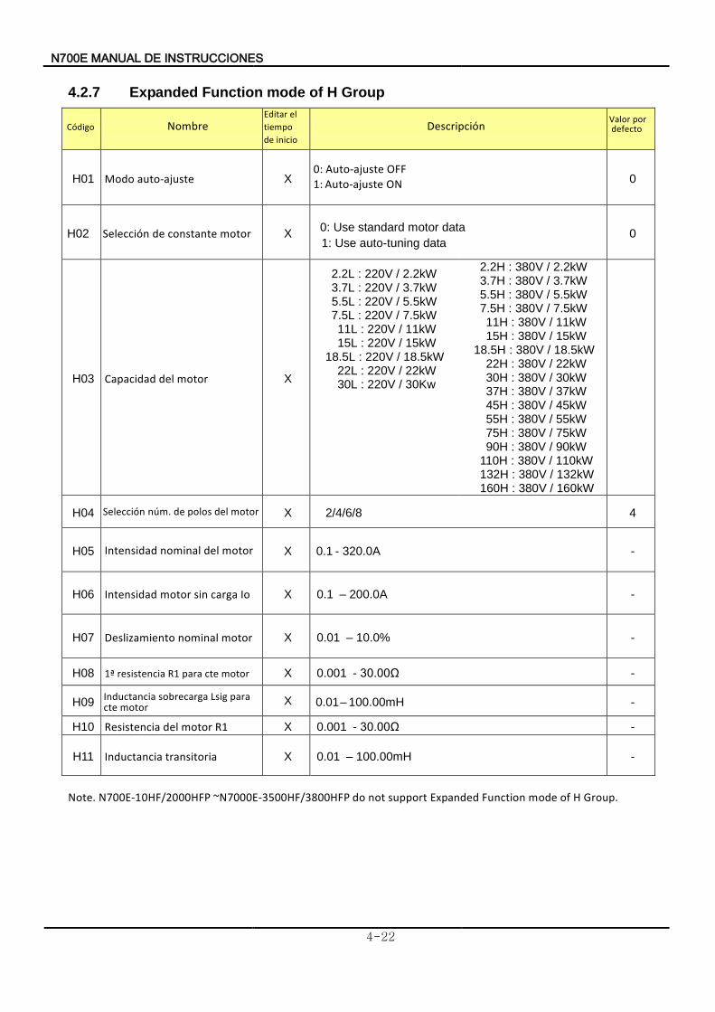
7N 00E INSTRUCCIONES DE MANUAL
4-22
4.2.7 Expanded Function mode of H Group
Nombre
Descripción
H01 Modo auto-ajuste X
0: Auto-ajuste OFF
1: Auto-ajuste ON 0
H02 Selección motor constante de X
0: Use standard motor data
1: Use auto-tuning data 0
H03 Capacidad motor del X
2.2L : 220V / 2.2kW 3.7L : 220V / 3.7kW
5.5L : 220V / 5.5kW 7.5L : 220V / 7.5kW 11L : 220V / 11kW 15L : 220V / 15kW 18.5L : 220V / 18.5kW 22L : 220V / 22kW 30L : 220V / 30Kw
2.2H : 380V / 2.2kW 3.7H : 380V / 3.7kW 5.5H : 380V / 5.5kW 7.5H : 380V / 7.5kW 11H : 380V / 11kW 15H : 380V / 15kW 18.5H : 380V / 18.5kW 22H : 380V / 22kW 30H : 380V / 30kW 37H : 380V / 37kW 45H : 380V / 45kW 55H : 380V / 55kW 75H : 380V / 75kW 90H : 380V / 90kW 110H : 380V / 110kW 132H : 380V / 132kW 160H : 380V / 160kW
H04 Selección motor del polos de núm. X 2/4/6/8 4
H05 Intensidad motor del nominal X 0.1 - 320.0 A -
H06 Intensidad Io carga sin motor X 0.1 – 200.0A -
H07 Deslizamiento motor nominal X 0.01 – 10.0% -
H08 ª1 motor cte para R1 esistenciar X 0.001 - 30.00Ω -
H09Inductancia
motor cte para Lsig sobrecarga X 0.01 – 100.00mH -
H10 Resistencia R1 motor del X 0.001 - 30.00Ω -
H11 Inductancia transitoria
X 0.01 – 100.00mH -
Note. N700E-1 0HF/2000HFP ~N7000E-3500HF/3800HFP do not support Expanded Function mode of H Group.
Código Editar
inicio de tiempo el Valor
defecto por
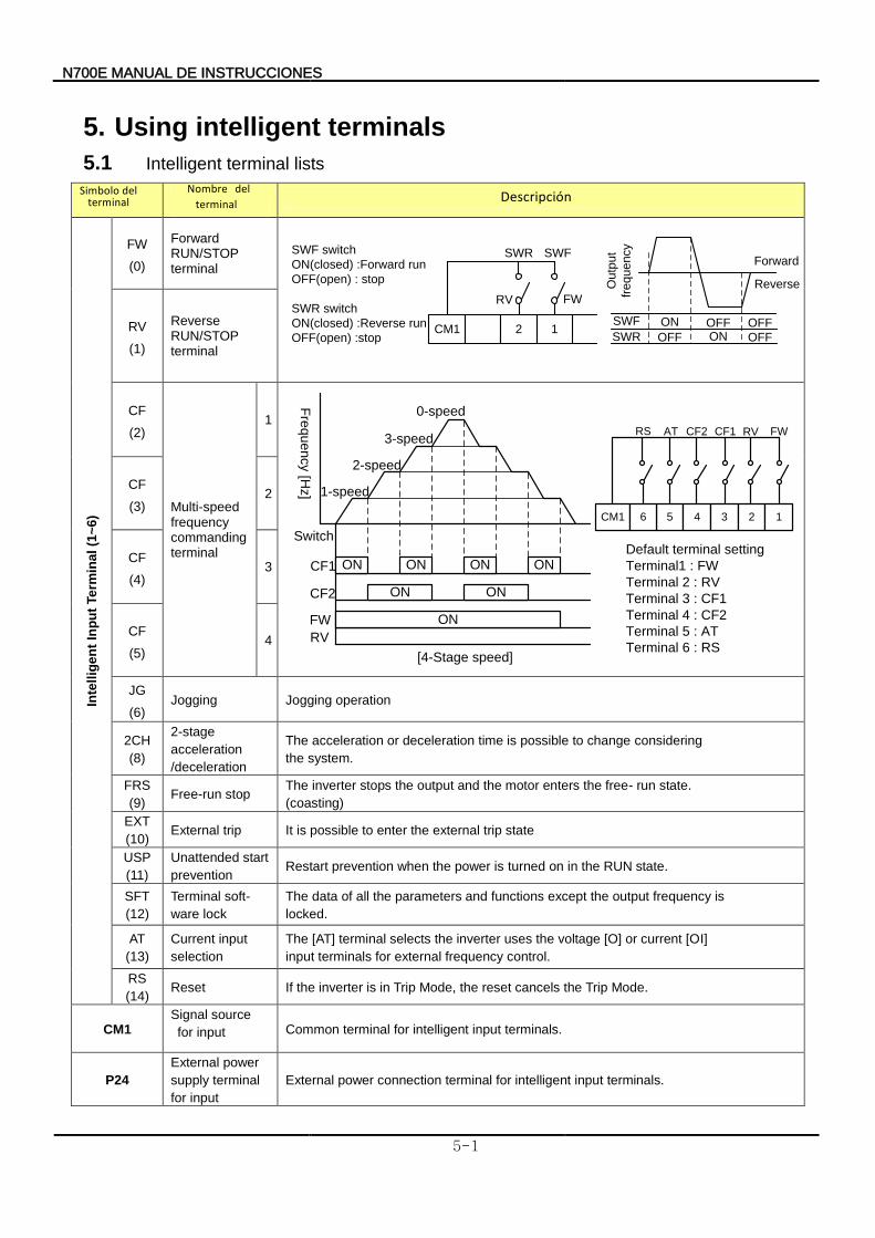
N700E INSTRUCCIONES DE MANUAL
5-1
5. Using intelligent terminals
5.1 Intelligent terminal lists
Descripción
Inte
llig
en
t In
pu
t Te
rmin
al
(1~
6)
FW
(0)
Forward RUN/STOP terminal
CM1 2 1
SWFSWR
FWRV
Ou
tpu
t
fre
qu
en
cy
Forward
Reverse
ON
OFF
SWF
SWROFFON
OFF
OFF
SWF switch
ON(closed) :Forward run
OFF(open) : stop
SWR switch
ON(closed) :Reverse run
OFF(open) :stop
RV
(1)
Reverse RUN/STOP terminal
CF
(2)
Multi-speed frequency commanding terminal
1
Fre
qu
en
cy [H
z]
Switch
CF1
CF2
FW
RV
ON ON ON ON
ON ON
ON
0-speed
3-speed
2-speed
1-speed
[4-Stage speed]
CM1 5 4
CF2AT FWRV
3 2 1
CF1
Default terminal setting
Terminal1 : FW
Terminal 2 : RV
Terminal 3 : CF1
Terminal 4 : CF2
Terminal 5 : AT
Terminal 6 : RS
6
RS
CF
(3) 2
CF
(4) 3
CF
(5) 4
JG
(6) Jogging Jogging operation
2CH
(8)
2-stage
acceleration
/deceleration
The acceleration or deceleration time is possible to change considering
the system.
FRS
(9) Free-run stop
The inverter stops the output and the motor enters the free- run state.
(coasting)
EXT
(10) External trip It is possible to enter the external trip state
USP
(11)
Unattended start
prevention Restart prevention when the power is turned on in the RUN state.
SFT
(12)
Terminal soft-
ware lock
The data of all the parameters and functions except the output frequency is
locked.
AT
(13)
Current input
selection
The [AT] terminal selects the inverter uses the voltage [O] or current [OI]
input terminals for external frequency control.
RS
(14) Reset If the inverter is in Trip Mode, the reset cancels the Trip Mode.
CM1 Signal source
for input Common terminal for intelligent input terminals.
P24
External power
supply terminal
for input
External power connection terminal for intelligent input terminals.
Simbolo terminal
del Nombre terminal
del
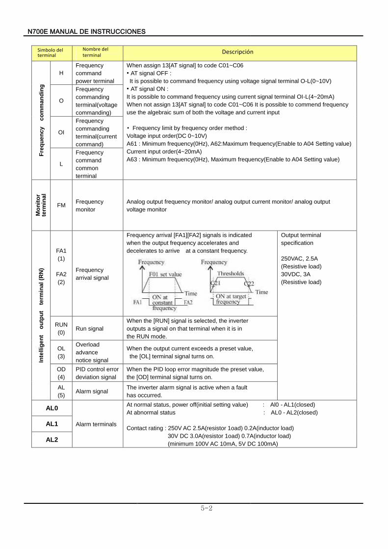
N700E INSTRUCCIONES DE MANUAL
5-2
Descripción
Fre
qu
en
cy
c
om
ma
nd
ing
H
Frequency
command
power terminal
When assign 13[AT signal] to code C01~C06
• AT signal OFF :
It is possible to command frequency using voltage signal terminal O-L(0~10V)
• AT signal ON :
It is possible to command frequency using current signal terminal OI-L(4~20mA)
When not assign 13[AT signal] to code C01~C06 It is possible to commend frequency
use the algebraic sum of both the voltage and current input
• Frequency limit by frequency order method :
Voltage input order(DC 0~10V)
A61 : Minimum frequency(0Hz), A62:Maximum frequency(Enable to A04 Setting value)
Current input order(4~20mA)
A63 : Minimum frequency(0Hz), Maximum frequency(Enable to A04 Setting value)
O
Frequency
commanding
terminal(voltage
commanding)
OI
Frequency
commanding
terminal(current
command)
L
Frequency
command
common
terminal
Mo
nit
or
term
ina
l
FM Frequency
monitor
Analog output frequency monitor/ analog output current monitor/ analog output
voltage monitor
Inte
llig
en
t o
utp
ut
te
rmin
al
(RN
)
FA1
(1)
FA2
(2)
Frequency
arrival signal
Frequency arrival [FA1][FA2] signals is indicated
when the output frequency accelerates and
decelerates to arrive at a constant frequency.
Output terminal
specification
250VAC, 2.5A
(Resistive load)
30VDC, 3A
(Resistive load)
RUN
(0) Run signal
When the [RUN] signal is selected, the inverter
outputs a signal on that terminal when it is in
the RUN mode.
OL
(3)
Overload
advance
notice signal
When the output current exceeds a preset value,
the [OL] terminal signal turns on.
OD
(4)
PID control error
deviation signal
When the PID loop error magnitude the preset value,
the [OD] terminal signal turns on.
AL
(5) Alarm signal
The inverter alarm signal is active when a fault
has occurred.
AL0
Alarm terminals
At normal status, power off(initial setting value) : Al0 - AL1(closed)
At abnormal status : AL0 - AL2(closed)
Contact rating : 250V AC 2.5A(resistor 1oad) 0.2A(inductor load)
30V DC 3.0A(resistor 1oad) 0.7A(inductor load)
(minimum 100V AC 10mA, 5V DC 100mA)
AL1
AL2
Simbolo terminal
del Nombre terminal
del
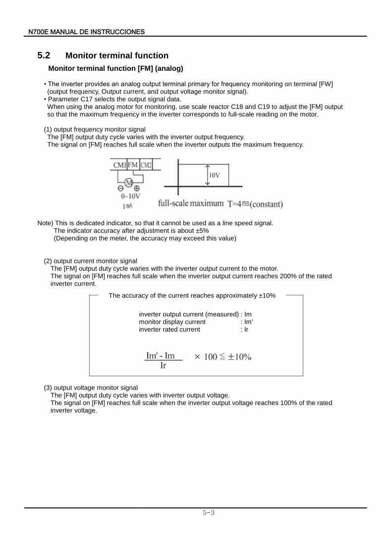
7N 00E INSTRUCCIONES DE MANUAL
5-3
5.2 Monitor terminal function
Monitor terminal function [FM] (analog)
• The inverter provides an analog output terminal primary for frequency monitoring on terminal [FW] (output frequency, Output current, and output voltage monitor signal). • Parameter C17 selects the output signal data. When using the analog motor for monitoring, use scale reactor C18 and C19 to adjust the [FM] output so that the maximum frequency in the inverter corresponds to full-scale reading on the motor.
(1) output frequency monitor signal The [FM] output duty cycle varies with the inverter output frequency.
The signal on [FM] reaches full scale when the inverter outputs the maximum frequency.
Note) This is dedicated indicator, so that it cannot be used as a line speed signal.
The indicator accuracy after adjustment is about ±5% (Depending on the meter, the accuracy may exceed this value)
(2) output current monitor signal The [FM] output duty cycle waries with the inverter output current to the motor.
The signal on [FM] reaches full scale when the inverter output current reaches 200% of the rated inverter current.
inverter output current (measured) : Im monitor display current : Im' inverter rated current : Ir
(3) output voltage monitor signal
The [FM] output duty cycle varies with inverter output voltage. The signal on [FM] reaches full scale when the inverter output voltage reaches 100% of the rated
inverter voltage.
The accuracy of the current reaches approximately ±10%
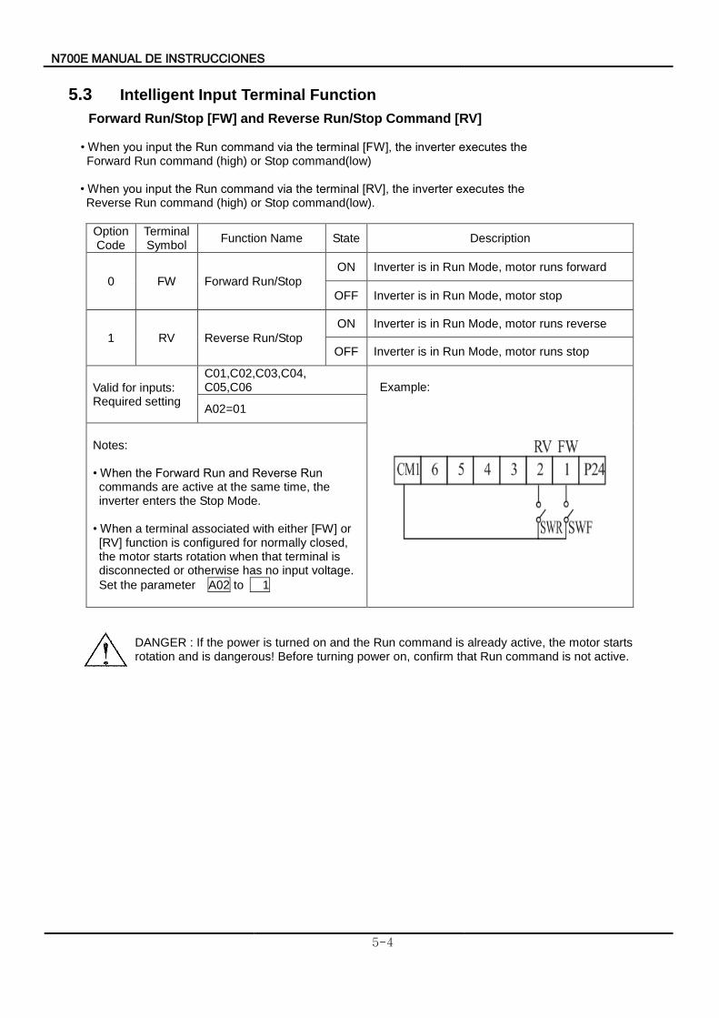
7N 00E INSTRUCCIONES DE MANUAL
5-4
5.3 Intelligent Input Terminal Function
Forward Run/Stop [FW] and Reverse Run/Stop Command [RV]
• When you input the Run command via the terminal [FW], the inverter executes the Forward Run command (high) or Stop command(low)
• When you input the Run command via the terminal [RV], the inverter executes the Reverse Run command (high) or Stop command(low).
Option Code
Terminal Symbol
Function Name State Description
0 FW Forward Run/Stop
ON Inverter is in Run Mode, motor runs forward
OFF Inverter is in Run Mode, motor stop
1 RV Reverse Run/Stop
ON Inverter is in Run Mode, motor runs reverse
OFF Inverter is in Run Mode, motor runs stop
Valid for inputs: Required setting
C01,C02,C03,C04, C05,C06
Example:
A02=01
Notes: • When the Forward Run and Reverse Run commands are active at the same time, the inverter enters the Stop Mode.
• When a terminal associated with either [FW] or [RV] function is configured for normally closed, the motor starts rotation when that terminal is disconnected or otherwise has no input voltage.
Set the parameter A02 to 1
DANGER : If the power is turned on and the Run command is already active, the motor starts rotation and is dangerous! Before turning power on, confirm that Run command is not active.
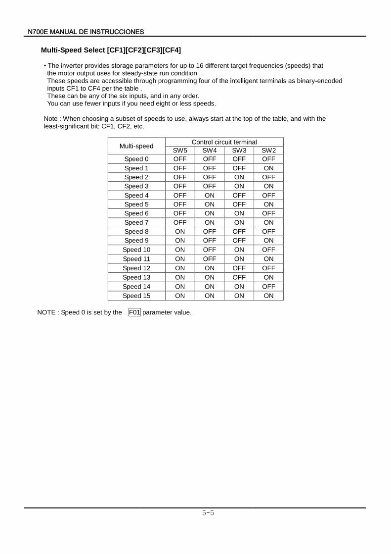
7N 00E INSTRUCCIONES DE MANUAL
5-5
Multi-Speed Select [CF1][CF2][CF3][CF4]
• The inverter provides storage parameters for up to 16 different target frequencies (speeds) that the motor output uses for steady-state run condition.
These speeds are accessible through programming four of the intelligent terminals as binary-encoded inputs CF1 to CF4 per the table .
These can be any of the six inputs, and in any order. You can use fewer inputs if you need eight or less speeds.
Note : When choosing a subset of speeds to use, always start at the top of the table, and with the least-significant bit: CF1, CF2, etc.
Multi-speed Control circuit terminal
SW5 SW4 SW3 SW2
Speed 0 OFF OFF OFF OFF
Speed 1 OFF OFF OFF ON
Speed 2 OFF OFF ON OFF
Speed 3 OFF OFF ON ON
Speed 4 OFF ON OFF OFF
Speed 5 OFF ON OFF ON
Speed 6 OFF ON ON OFF
Speed 7 OFF ON ON ON
Speed 8 ON OFF OFF OFF
Speed 9 ON OFF OFF ON
Speed 10 ON OFF ON OFF
Speed 11 ON OFF ON ON
Speed 12 ON ON OFF OFF
Speed 13 ON ON OFF ON
Speed 14 ON ON ON OFF
Speed 15 ON ON ON ON
NOTE : Speed 0 is set by the F01 parameter value.
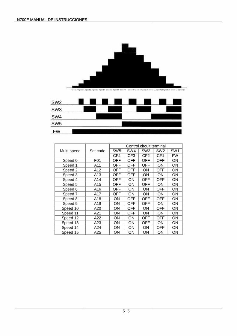
N700E INSTRUCCIONES DE MANUAL
5-6
Speed 0 Speed 1 Speed 2 Speed 3 Speed 4 Speed 5 Speed 6 Speed 7 Speed 8 Speed 9 Speed 10 Speed 11 Speed 12 Speed 13 Speed 14 Speed 15
SW2
SW3
SW4
SW5
FW
Multi-speed Set code
Control circuit terminal
SW5 SW4 SW3 SW2 SW1
CF4 CF3 CF2 CF1 FW
Speed 0 F01 OFF OFF OFF OFF ON
Speed 1 A11 OFF OFF OFF ON ON
Speed 2 A12 OFF OFF ON OFF ON
Speed 3 A13 OFF OFF ON ON ON
Speed 4 A14 OFF ON OFF OFF ON
Speed 5 A15 OFF ON OFF ON ON
Speed 6 A16 OFF ON ON OFF ON
Speed 7 A17 OFF ON ON ON ON
Speed 8 A18 ON OFF OFF OFF ON
Speed 9 A19 ON OFF OFF ON ON
Speed 10 A20 ON OFF ON OFF ON
Speed 11 A21 ON OFF ON ON ON
Speed 12 A22 ON ON OFF OFF ON
Speed 13 A23 ON ON OFF ON ON
Speed 14 A24 ON ON ON OFF ON
Speed 15 A25 ON ON ON ON ON
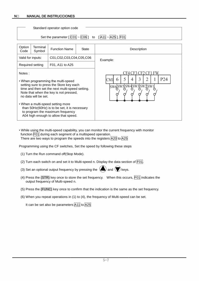
N INSTRUCCIONES DE MANUAL
5-7
Set the parameter [ C01 ~ C06 ] to [ A11 ~ A25 ], F01
Option Code
Terminal Symbol
Function Name State Description
Valid for inputs: C01,C02,C03,C04,C05,C06 Example:
Required setting F01, A11 to A25
Notes : • When programming the multi-speed setting sure to press the Store key each time and then set the next multi-speed setting. Note that when the key is not pressed,
no data will be set. • When a multi-speed setting more
than 50Hz(60Hz) is to be set, it is necessary to program the maximum frequency A04 high enough to allow that speed.
• While using the multi-speed capability, you can monitor the current frequency with monitor
function F01 during each segment of a multispeed operation.
There are two ways to program the speeds into the registers A20 to A25
Programming using the CF switches, Set the speed by following these steps (1) Turn the Run command off(Stop Mode).
(2) Turn each switch on and set it to Multi-speed n. Display the data section of F01.
(3) Set an optional output frequency by pressing the and keys.
(4) Press the (STR) key once to store the set frequency. When this occurs, F01 indicates the
output frequency of Multi-speed n. (5) Press the (FUNC) key once to confirm that the indication is the same as the set frequency. (6) When you repeat operations in (1) to (4), the frequency of Multi-speed can be set.
It can be set also be parameters A11 to A25
Standard operator option code
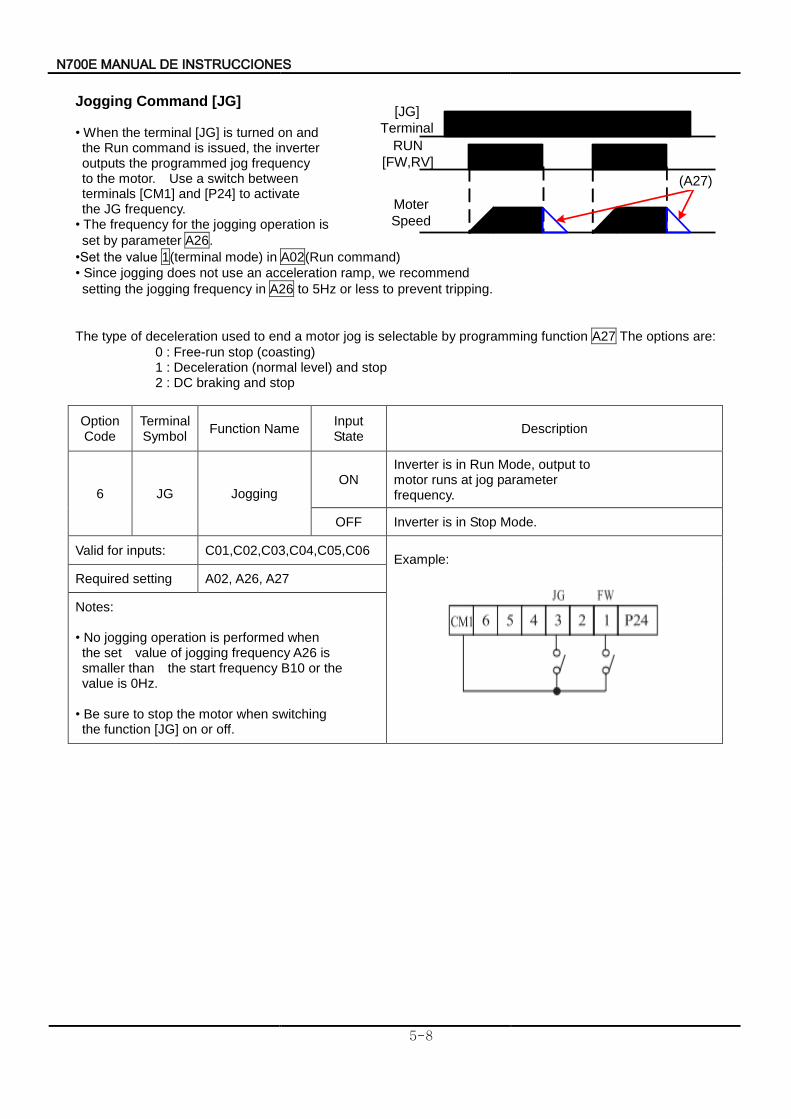
7N 00E INSTRUCCIONES DE MANUAL
5-8
[JG]
Terminal
RUN
[FW,RV]
Moter
Speed
(A27)
Jogging Command [JG] • When the terminal [JG] is turned on and the Run command is issued, the inverter outputs the programmed jog frequency to the motor. Use a switch between terminals [CM1] and [P24] to activate the JG frequency. • The frequency for the jogging operation is
set by parameter A26.
•Set the value 1(terminal mode) in A02(Run command)
• Since jogging does not use an acceleration ramp, we recommend
setting the jogging frequency in A26 to 5Hz or less to prevent tripping.
The type of deceleration used to end a motor jog is selectable by programming function A27 The options are:
0 : Free-run stop (coasting) 1 : Deceleration (normal level) and stop 2 : DC braking and stop
Option Code
Terminal Symbol
Function Name Input State
Description
6 JG Jogging ON
Inverter is in Run Mode, output to motor runs at jog parameter frequency.
OFF Inverter is in Stop Mode.
Valid for inputs: C01,C02,C03,C04,C05,C06 Example:
Required setting A02, A26, A27
Notes: • No jogging operation is performed when the set value of jogging frequency A26 is smaller than the start frequency B10 or the value is 0Hz. • Be sure to stop the motor when switching the function [JG] on or off.
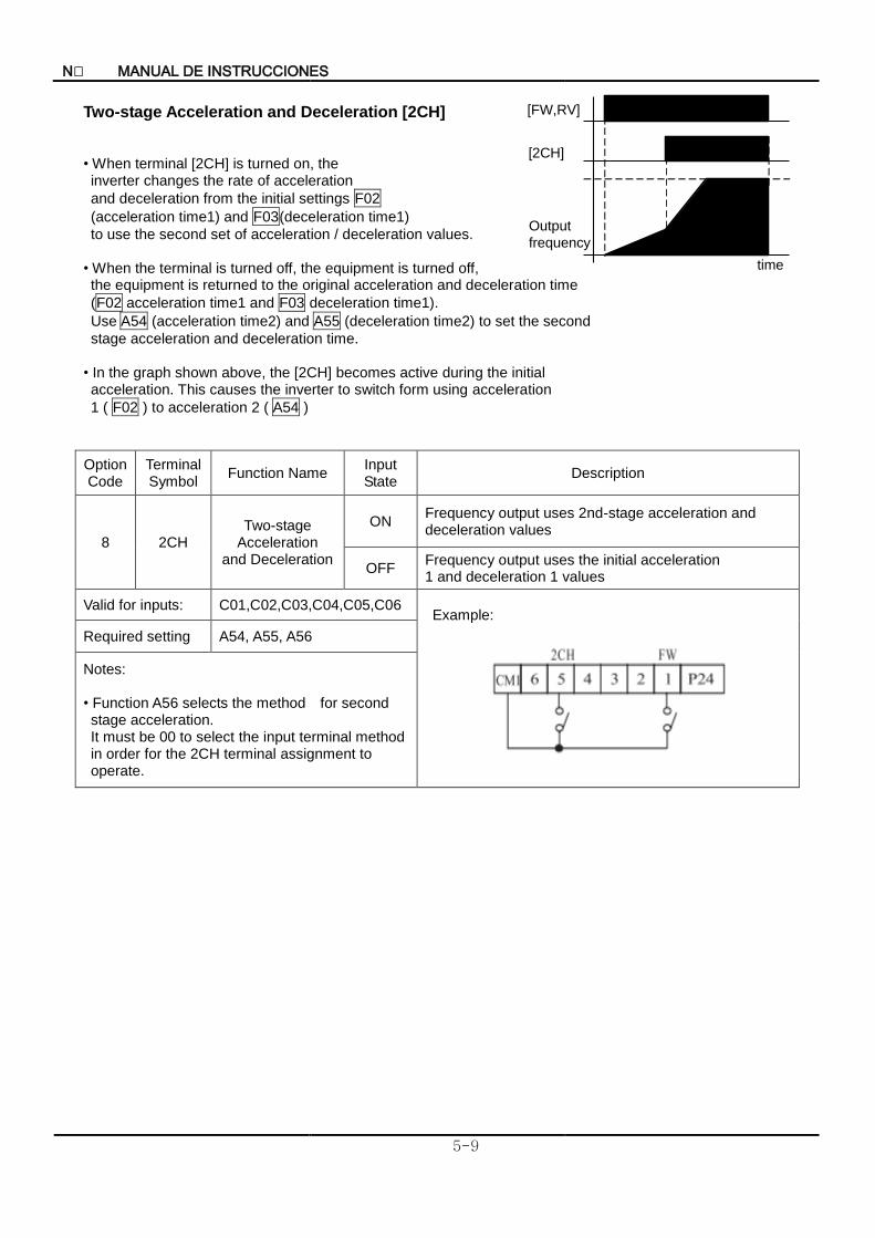
N INSTRUCCIONES DE MANUAL
5-9
[FW,RV]
Output
frequency
[2CH]
time
Two-stage Acceleration and Deceleration [2CH] • When terminal [2CH] is turned on, the inverter changes the rate of acceleration
and deceleration from the initial settings F02
(acceleration time1) and F03(deceleration time1)
to use the second set of acceleration / deceleration values.
• When the terminal is turned off, the equipment is turned off, the equipment is returned to the original acceleration and deceleration time
(F02 acceleration time1 and F03 deceleration time1).
Use A54 (acceleration time2) and A55 (deceleration time2) to set the second
stage acceleration and deceleration time. • In the graph shown above, the [2CH] becomes active during the initial acceleration. This causes the inverter to switch form using acceleration
1 ( F02 ) to acceleration 2 ( A54 )
Option Code
Terminal Symbol
Function Name Input State
Description
8 2CH Two-stage
Acceleration and Deceleration
ON Frequency output uses 2nd-stage acceleration and deceleration values
OFF Frequency output uses the initial acceleration 1 and deceleration 1 values
Valid for inputs: C01,C02,C03,C04,C05,C06 Example:
Required setting A54, A55, A56
Notes: • Function A56 selects the method for second stage acceleration. It must be 00 to select the input terminal method
in order for the 2CH terminal assignment to operate.
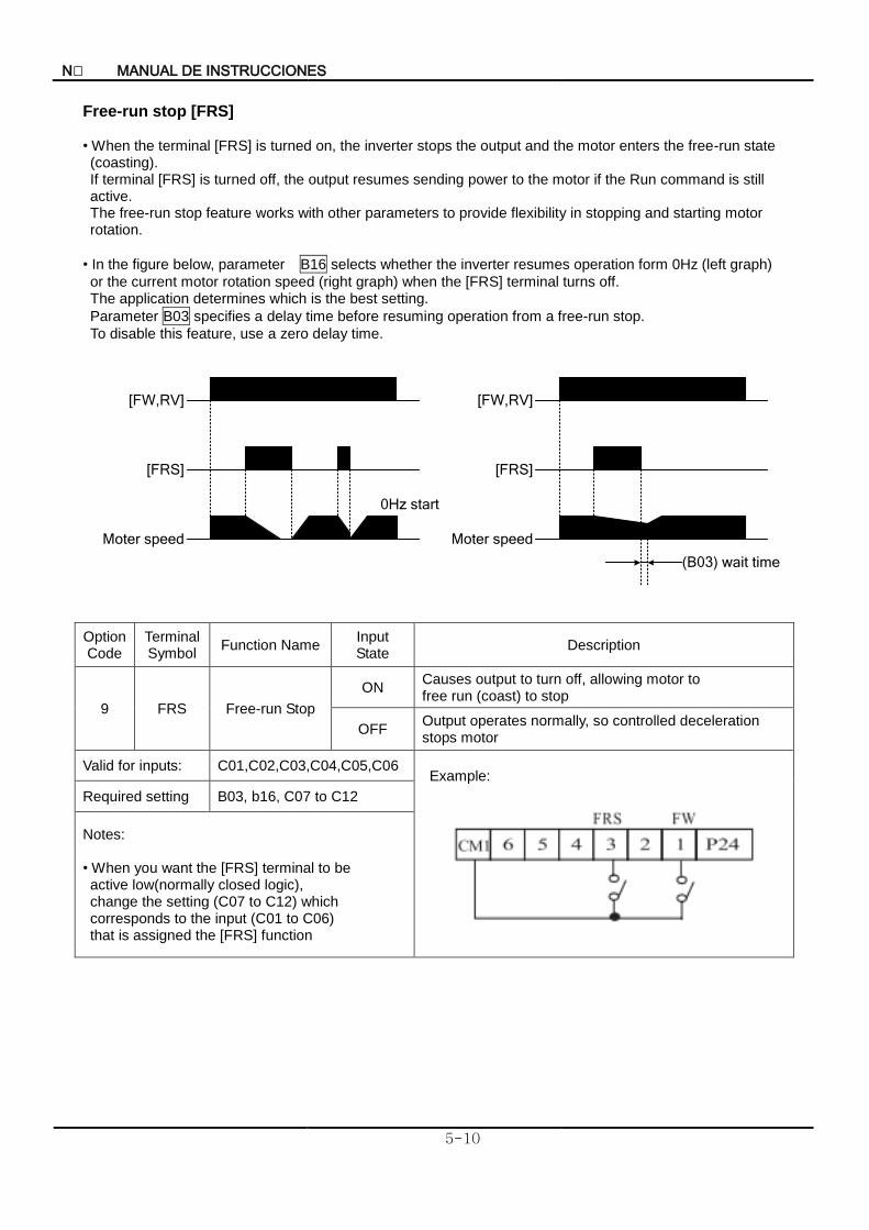
N INSTRUCCIONES DE MANUAL
5-10
Free-run stop [FRS] • When the terminal [FRS] is turned on, the inverter stops the output and the motor enters the free-run state (coasting). If terminal [FRS] is turned off, the output resumes sending power to the motor if the Run command is still active.
The free-run stop feature works with other parameters to provide flexibility in stopping and starting motor rotation.
• In the figure below, parameter B16 selects whether the inverter resumes operation form 0Hz (left graph)
or the current motor rotation speed (right graph) when the [FRS] terminal turns off. The application determines which is the best setting.
Parameter B03 specifies a delay time before resuming operation from a free-run stop.
To disable this feature, use a zero delay time.
Moter speed
[FW,RV]
Moter speed
[FRS]
(B03) wait time
[FW,RV]
[FRS]
0Hz start
Option Code
Terminal Symbol
Function Name Input State
Description
9 FRS Free-run Stop
ON Causes output to turn off, allowing motor to free run (coast) to stop
OFF Output operates normally, so controlled deceleration stops motor
Valid for inputs: C01,C02,C03,C04,C05,C06 Example:
Required setting B03, b16, C07 to C12
Notes: • When you want the [FRS] terminal to be active low(normally closed logic), change the setting (C07 to C12) which corresponds to the input (C01 to C06) that is assigned the [FRS] function
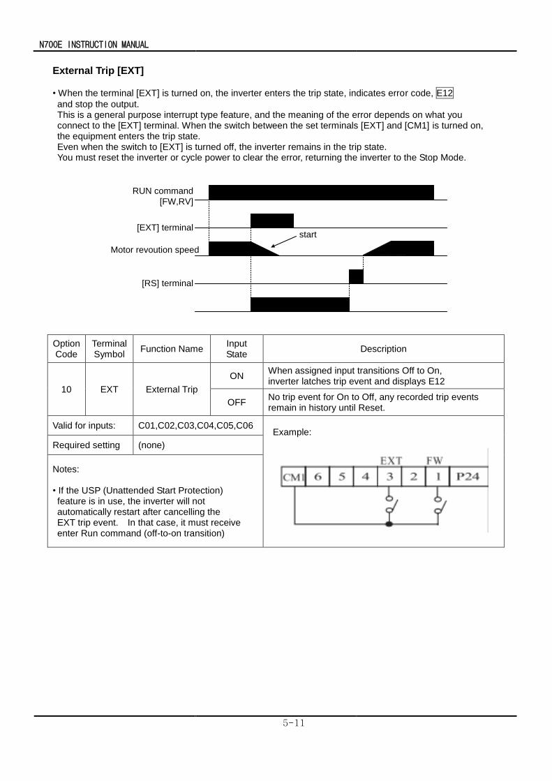
N700E INSTRUCTION MANUAL
5-11
External Trip [EXT]
• When the terminal [EXT] is turned on, the inverter enters the trip state, indicates error code, E12
and stop the output. This is a general purpose interrupt type feature, and the meaning of the error depends on what you connect to the [EXT] terminal. When the switch between the set terminals [EXT] and [CM1] is turned on, the equipment enters the trip state. Even when the switch to [EXT] is turned off, the inverter remains in the trip state. You must reset the inverter or cycle power to clear the error, returning the inverter to the Stop Mode.
RUN command
[FW,RV]
[EXT] terminal
[RS] terminal
start
Motor revoution speed
Option Code
Terminal Symbol
Function Name Input State
Description
10 EXT External Trip
ON When assigned input transitions Off to On, inverter latches trip event and displays E12
OFF No trip event for On to Off, any recorded trip events remain in history until Reset.
Valid for inputs: C01,C02,C03,C04,C05,C06 Example:
Required setting (none)
Notes: • If the USP (Unattended Start Protection) feature is in use, the inverter will not automatically restart after cancelling the EXT trip event. In that case, it must receive enter Run command (off-to-on transition)
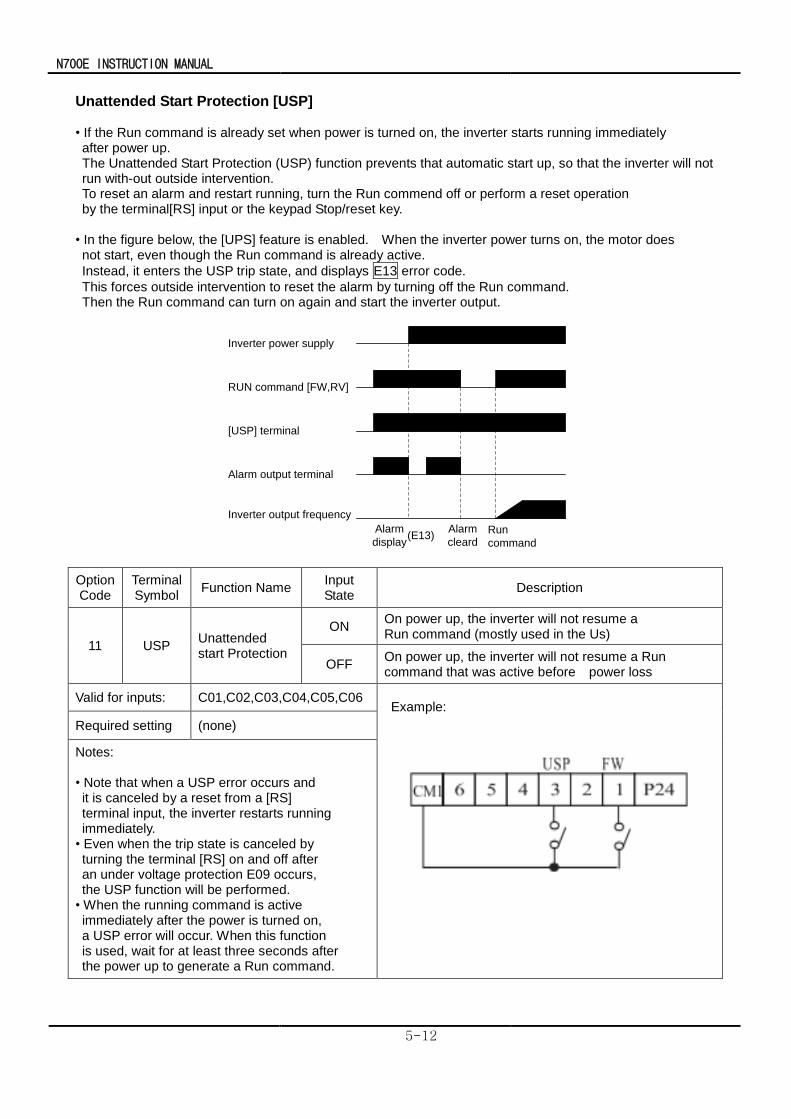
N700E INSTRUCTION MANUAL
5-12
Unattended Start Protection [USP] • If the Run command is already set when power is turned on, the inverter starts running immediately after power up. The Unattended Start Protection (USP) function prevents that automatic start up, so that the inverter will not run with-out outside intervention. To reset an alarm and restart running, turn the Run commend off or perform a reset operation by the terminal[RS] input or the keypad Stop/reset key.
• In the figure below, the [UPS] feature is enabled. When the inverter power turns on, the motor does not start, even though the Run command is already active.
Instead, it enters the USP trip state, and displays E13 error code.
This forces outside intervention to reset the alarm by turning off the Run command. Then the Run command can turn on again and start the inverter output.
Inverter power supply
RUN command [FW,RV]
[USP] terminal
Alarm output terminal
Inverter output frequency
Alarm
display
Alarm
cleardRun
command(E13)
Option Code
Terminal Symbol
Function Name Input State
Description
11 USP Unattended start Protection
ON On power up, the inverter will not resume a Run command (mostly used in the Us)
OFF On power up, the inverter will not resume a Run command that was active before power loss
Valid for inputs: C01,C02,C03,C04,C05,C06 Example:
Required setting (none)
Notes: • Note that when a USP error occurs and it is canceled by a reset from a [RS] terminal input, the inverter restarts running immediately.
• Even when the trip state is canceled by turning the terminal [RS] on and off after an under voltage protection E09 occurs, the USP function will be performed. • When the running command is active immediately after the power is turned on, a USP error will occur. When this function is used, wait for at least three seconds after the power up to generate a Run command.
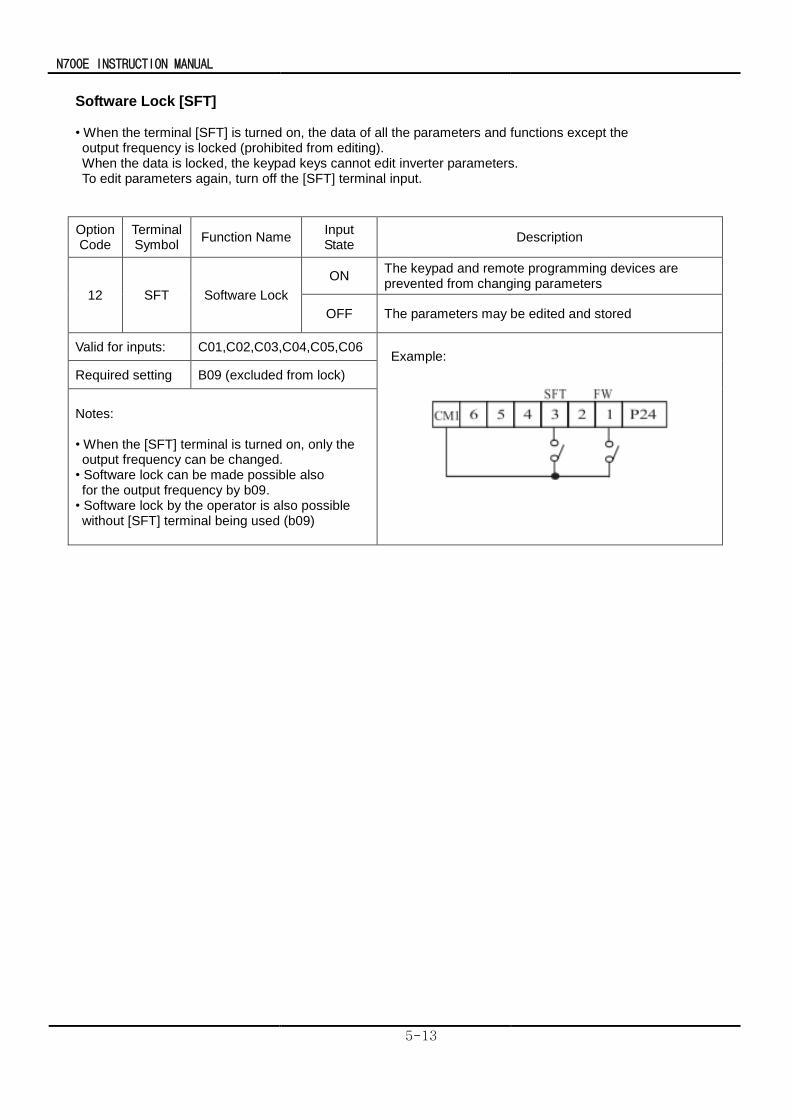
N700E INSTRUCTION MANUAL
5-13
Software Lock [SFT] • When the terminal [SFT] is turned on, the data of all the parameters and functions except the output frequency is locked (prohibited from editing). When the data is locked, the keypad keys cannot edit inverter parameters. To edit parameters again, turn off the [SFT] terminal input.
Option Code
Terminal Symbol
Function Name Input State
Description
12 SFT Software Lock
ON The keypad and remote programming devices are prevented from changing parameters
OFF The parameters may be edited and stored
Valid for inputs: C01,C02,C03,C04,C05,C06 Example:
Required setting B09 (excluded from lock)
Notes: • When the [SFT] terminal is turned on, only the output frequency can be changed. • Software lock can be made possible also for the output frequency by b09.
• Software lock by the operator is also possible without [SFT] terminal being used (b09)
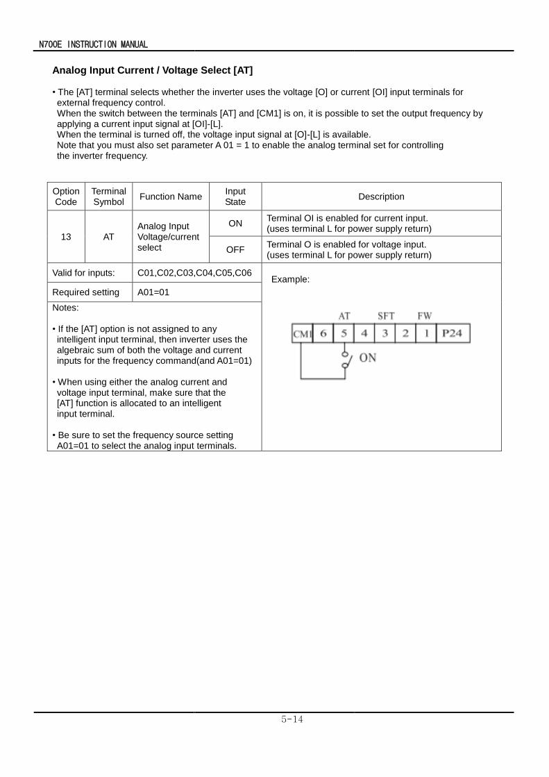
N700E INSTRUCTION MANUAL
5-14
Analog Input Current / Voltage Select [AT] • The [AT] terminal selects whether the inverter uses the voltage [O] or current [OI] input terminals for external frequency control. When the switch between the terminals [AT] and [CM1] is on, it is possible to set the output frequency by applying a current input signal at [OI]-[L]. When the terminal is turned off, the voltage input signal at [O]-[L] is available. Note that you must also set parameter A 01 = 1 to enable the analog terminal set for controlling the inverter frequency.
Option Code
Terminal Symbol
Function Name Input State
Description
13 AT Analog Input Voltage/current select
ON Terminal OI is enabled for current input. (uses terminal L for power supply return)
OFF Terminal O is enabled for voltage input. (uses terminal L for power supply return)
Valid for inputs: C01,C02,C03,C04,C05,C06 Example:
Required setting A01=01
Notes: • If the [AT] option is not assigned to any intelligent input terminal, then inverter uses the algebraic sum of both the voltage and current inputs for the frequency command(and A01=01)
• When using either the analog current and voltage input terminal, make sure that the [AT] function is allocated to an intelligent input terminal. • Be sure to set the frequency source setting A01=01 to select the analog input terminals.
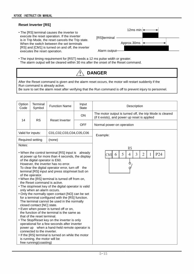
N700E INSTRUCTION MANUAL
5-15
[RS]terminal
Alarm output
Approx.30ms
12ms min
Reset Inverter [RS] • The [RS] terminal causes the inverter to execute the reset operation. If the inverter is in Trip Mode, the reset cancels the Trip state. When the switch between the set terminals [RS] and [CM1] is turned on and off, the inverter executes the reset operation.
• The input timing requirement for [RST] needs a 12 ms pulse width or greater. The alarm output will be cleared within 30 ms after the onset of the Reset command.
DANGER
After the Reset command is given and the alarm reset occurs, the motor will restart suddenly if the Run command is already active. Be sure to set the alarm reset after verifying that the Run command is off to prevent injury to personnel.
Option Code
Terminal Symbol
Function Name Input State
Description
14 RS Reset Inverter
ON The motor output is turned off, the trip Mode is cleared (if it exists), and power up reset is applied
OFF Normal power-on operation
Valid for inputs: C01,C02,C03,C04,C05,C06 Example:
Required setting (none)
Notes: • When the control terminal [RS] input is already at power up for more than 4 seconds, the display of the digital operator is E60. However, the inverter has no error.
To clear the digital operator error, turn off the terminal [RS] input and press stop/reset butt on of the operator. • When the [RS] terminal is turned off from on, the Reset command is active.
• The stop/reset key of the digital operator is valid only when an alarm occurs. • Only the normally open contact [NO] can be set for a terminal configured with the [RS] function. The terminal cannot be used in the normally closed contact [NC] state. • Even when power is turned off or on, the function of the terminal is the same as that of the reset terminal.
• The Stop/Reset key on the inverter is only operational for a few seconds after inverter power up when a hand-held remote operator is connected to the inverter. • If the [RS] terminal is turned on while the motor is running, the motor will be free running(coasting)
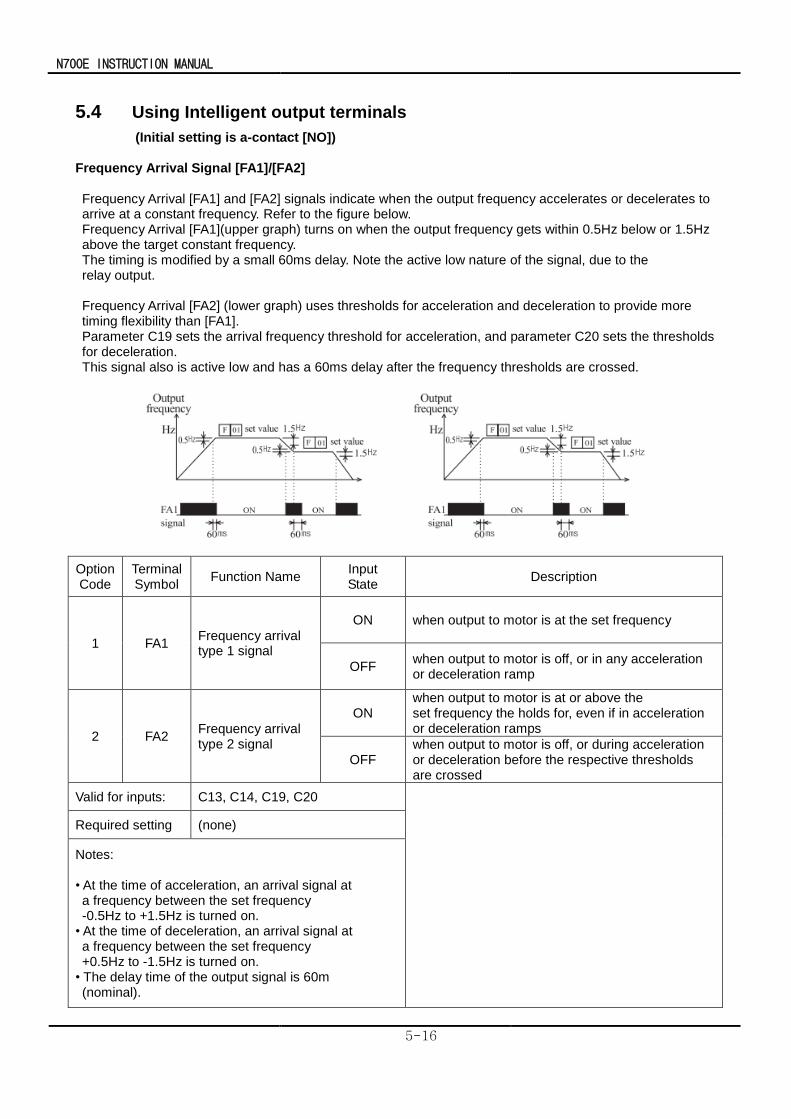
N700E INSTRUCTION MANUAL
5-16
5.4 Using Intelligent output terminals
(Initial setting is a-contact [NO]) Frequency Arrival Signal [FA1]/[FA2] Frequency Arrival [FA1] and [FA2] signals indicate when the output frequency accelerates or decelerates to arrive at a constant frequency. Refer to the figure below. Frequency Arrival [FA1](upper graph) turns on when the output frequency gets within 0.5Hz below or 1.5Hz above the target constant frequency. The timing is modified by a small 60ms delay. Note the active low nature of the signal, due to the relay output.
Frequency Arrival [FA2] (lower graph) uses thresholds for acceleration and deceleration to provide more timing flexibility than [FA1]. Parameter C19 sets the arrival frequency threshold for acceleration, and parameter C20 sets the thresholds for deceleration. This signal also is active low and has a 60ms delay after the frequency thresholds are crossed.
Option Code
Terminal Symbol
Function Name Input State
Description
1 FA1 Frequency arrival type 1 signal
ON when output to motor is at the set frequency
OFF when output to motor is off, or in any acceleration or deceleration ramp
2 FA2 Frequency arrival type 2 signal
ON when output to motor is at or above the set frequency the holds for, even if in acceleration or deceleration ramps
OFF when output to motor is off, or during acceleration or deceleration before the respective thresholds are crossed
Valid for inputs: C13, C14, C19, C20
Required setting (none)
Notes: • At the time of acceleration, an arrival signal at a frequency between the set frequency -0.5Hz to +1.5Hz is turned on.
• At the time of deceleration, an arrival signal at a frequency between the set frequency +0.5Hz to -1.5Hz is turned on.
• The delay time of the output signal is 60m (nominal).
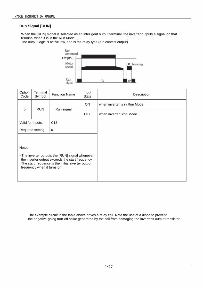
N700E INSTRUCTION MANUAL
5-17
Run Signal [RUN] When the [RUN] signal is selected as an intelligent output terminal, the inverter outputs a signal on that terminal when it is in the Run Mode. The output logic is active low, and is the relay type (a,b contact output)
Option Code
Terminal Symbol
Function Name Input State
Description
0 RUN Run signal
ON when inverter is in Run Mode
OFF when inverter Stop Mode
Valid for inputs: C13
Required setting 0
Notes: • The inverter outputs the [RUN] signal whenever the inverter output exceeds the start frequency. The start frequency is the initial inverter output frequency when it turns on.
The example circuit in the table above drives a relay coil. Note the use of a diode to prevent
the negative-going turn-off spike generated by the coil from damaging the inverter's output transistor.
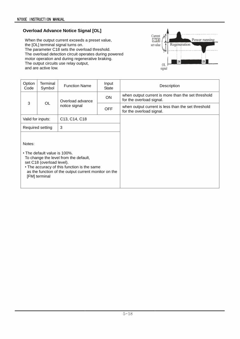
N700E INSTRUCTION MANUAL
5-18
Overload Advance Notice Signal [OL] When the output current exceeds a preset value, the [OL] terminal signal turns on. The parameter C18 sets the overload threshold. The overload detection circuit operates during powered motor operation and during regenerative braking. The output circuits use relay output, and are active low.
Option Code
Terminal Symbol
Function Name Input State
Description
3 OL Overload advance notice signal
ON when output current is more than the set threshold for the overload signal.
OFF when output current is less than the set threshold for the overload signal.
Valid for inputs: C13, C14, C18
Required setting 3
Notes: • The default value is 100%. To change the level from the default, set C18 (overload level).
• The accuracy of this function is the same as the function of the output current monitor on the [FM] terminal
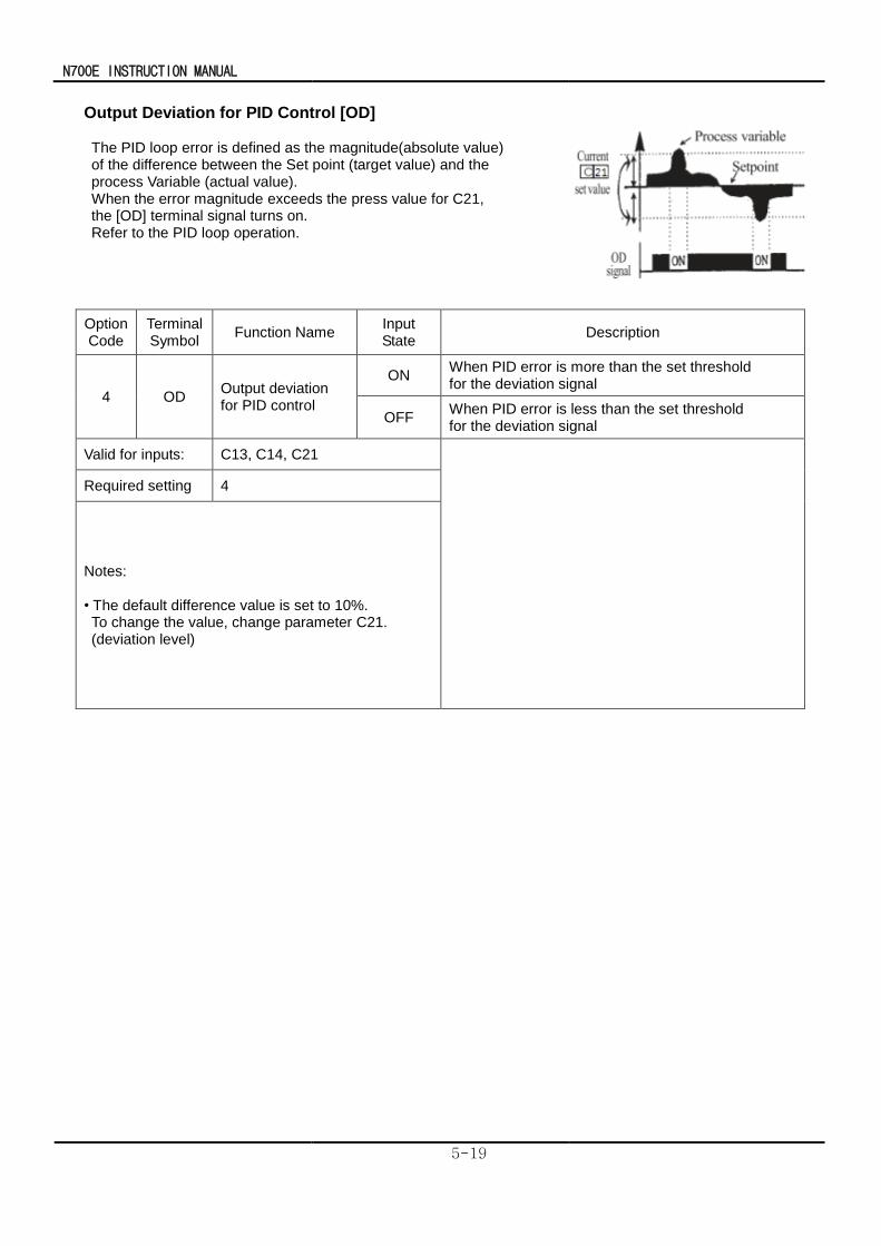
N700E INSTRUCTION MANUAL
5-19
Output Deviation for PID Control [OD] The PID loop error is defined as the magnitude(absolute value) of the difference between the Set point (target value) and the process Variable (actual value). When the error magnitude exceeds the press value for C21, the [OD] terminal signal turns on. Refer to the PID loop operation.
Option Code
Terminal Symbol
Function Name Input State
Description
4 OD Output deviation for PID control
ON When PID error is more than the set threshold for the deviation signal
OFF When PID error is less than the set threshold for the deviation signal
Valid for inputs: C13, C14, C21
Required setting 4
Notes: • The default difference value is set to 10%. To change the value, change parameter C21. (deviation level)
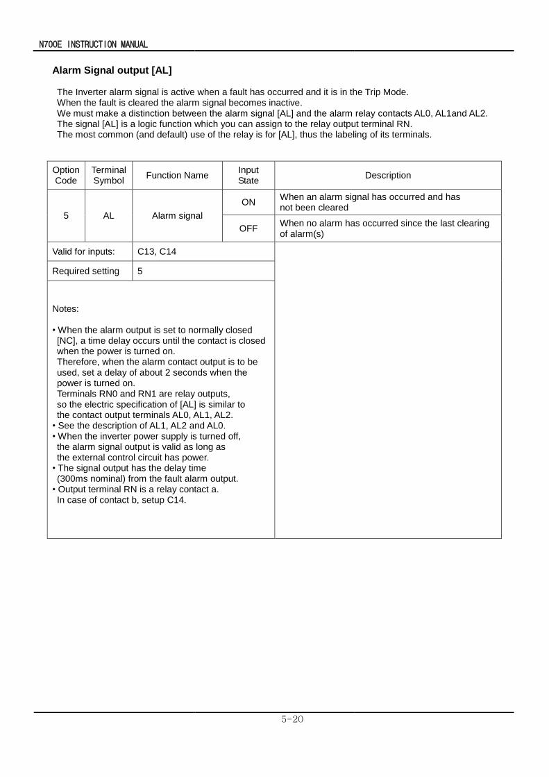
N700E INSTRUCTION MANUAL
5-20
Alarm Signal output [AL] The Inverter alarm signal is active when a fault has occurred and it is in the Trip Mode. When the fault is cleared the alarm signal becomes inactive. We must make a distinction between the alarm signal [AL] and the alarm relay contacts AL0, AL1and AL2. The signal [AL] is a logic function which you can assign to the relay output terminal RN. The most common (and default) use of the relay is for [AL], thus the labeling of its terminals.
Option Code
Terminal Symbol
Function Name Input State
Description
5 AL Alarm signal
ON When an alarm signal has occurred and has not been cleared
OFF When no alarm has occurred since the last clearing of alarm(s)
Valid for inputs: C13, C14
Required setting 5
Notes: • When the alarm output is set to normally closed [NC], a time delay occurs until the contact is closed when the power is turned on. Therefore, when the alarm contact output is to be used, set a delay of about 2 seconds when the power is turned on. Terminals RN0 and RN1 are relay outputs, so the electric specification of [AL] is similar to the contact output terminals AL0, AL1, AL2.
• See the description of AL1, AL2 and AL0. • When the inverter power supply is turned off, the alarm signal output is valid as long as the external control circuit has power.
• The signal output has the delay time (300ms nominal) from the fault alarm output.
• Output terminal RN is a relay contact a. In case of contact b, setup C14.
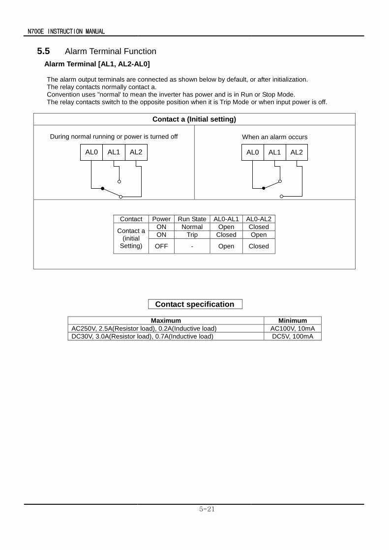
N700E INSTRUCTION MANUAL
5-21
5.5 Alarm Terminal Function
Alarm Terminal [AL1, AL2-AL0] The alarm output terminals are connected as shown below by default, or after initialization. The relay contacts normally contact a. Convention uses "normal' to mean the inverter has power and is in Run or Stop Mode. The relay contacts switch to the opposite position when it is Trip Mode or when input power is off.
Contact a (Initial setting)
During normal running or power is turned off
AL0 AL1 AL2
When an alarm occurs
AL0 AL1 AL2
Contact Power Run State AL0-AL1 AL0-AL2
Contact a (initial
Setting)
ON Normal Open Closed
ON Trip Closed Open
OFF - Open Closed
Contact specification
Maximum Minimum
AC250V, 2.5A(Resistor load), 0.2A(Inductive load) AC100V, 10mA
DC30V, 3.0A(Resistor load), 0.7A(Inductive load) DC5V, 100mA
N700E INSTRUCTION MANUAL
5-22
5.6 Sensorless Vector Control
Function description
The N700E inverter has a built-in auto-tuning algorithm.
The N700E inverter can be possible to do high-starting torque and high-precision operation. The required torque characteristic or speed control characteristic may not be maintained in case that the inverter capacity is more than twice the capacity of the motor in use .
Function setting method
Select the parameter A31 to 2 (sensorless vector control).
Parameter H03 and H04 select motor capacity and poles (example 4 for 4-poles). Parameter H02 selects which data(standard data, auto-tuning data) of motor constants you want the inverter to use.
※ N700E-1600HF/2000HFP ~N7000E-3500HF/3800HFP do not support Sensorless Vector Control
N700E INSTRUCTION MANUAL
5-23
Auto-tuning(1)
Function description
The auto-tuning procedure automatically sets the motor parameter related to sensorless vector control.
Since sensorless vector control needs motor parameter, the standard motor parameters have been set at the factory.
Therefore, when an inverter exclusive-use motor is used or when a motor of any other manufacture is drive, the motor parameter is detected by auto-tuning because the parameters are not matched.
Function setting
Follow the steps below to auto-tune the inverter, finally set the parameter H01. F02, F03 setting : Set the time the range that over-current or over-voltage trip event not occurs. Set the same as setting F02. H03 setting : Set the motor rating.
2.2L : 220V / 2.2kW 2.2H : 380V / 2.2kW 3.7L : 220V / 3.7kW 3.7H : 380V / 3.7kW 5.5L : 220V / 5.5kW 5.5H : 380V / 5.5kW 7.5L : 220V / 7.5kW 7.5H : 380V / 7.5kW 11L : 220V / 11kW 11H : 380V / 11kW 15L : 220V / 15kW 15H : 380V / 15kW 18.5L : 220V / 18.5kW 18.5H : 380V / 18.5kW 22L : 220V / 22kW 22H : 380V / 22kW 30L : 220V / 30kW 30H : 380V / 30kW 37H : 380V/37kW 45H : 380V/45kW 55H : 380V/55Kw 75H : 380V/75kW 90H : 380V/90kW 110H : 380V/110kW 132H : 380V/132kW 160H : 380V/160kW
H04 setting : set the motor poles A01 setting : set the frequency command source to 0 (potentiometer) A03 setting : set the base frequency(example 60Hz) F01 setting : set the operation frequency except 0hz (by the potentiometer) A53 setting : select output voltage for motor. A33 setting : set DC braking setting to 0(disable). H01 setting : select the auto-tuning mode (2). After setting above parameters, press the RUN key on the standard operator.
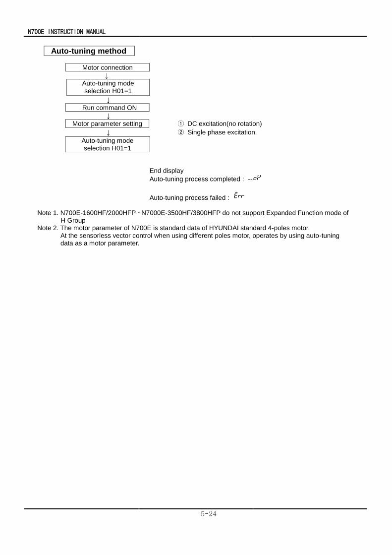
N700E INSTRUCTION MANUAL
5-24
Auto-tuning method
Motor connection
↓
Auto-tuning mode selection H01=1
↓
Run command ON
↓
Motor parameter setting ① DC excitation(no rotation)
↓ ② Single phase excitation.
End display
Auto-tuning process completed :
Auto-tuning process failed : Note 1. N700E-1600HF/2000HFP ~N7000E-3500HF/3800HFP do not support Expanded Function mode of
H Group Note 2. The motor parameter of N700E is standard data of HYUNDAI standard 4-poles motor.
At the sensorless vector control when using different poles motor, operates by using auto-tuning data as a motor parameter.
Auto-tuning mode selection H01=1
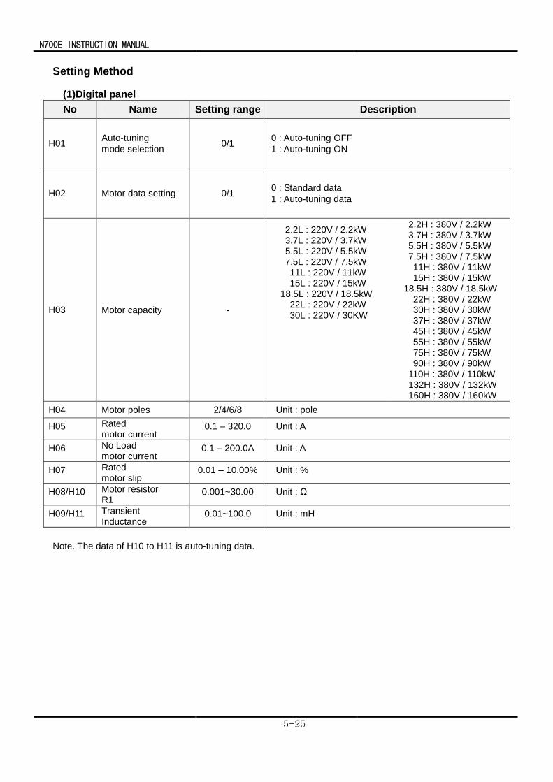
N700E INSTRUCTION MANUAL
5-25
Setting Method
(1)Digital panel
No Name Setting range Description
H01 Auto-tuning
mode selection 0/1
0 : Auto-tuning OFF
1 : Auto-tuning ON
H02 Motor data setting 0/1 0 : Standard data
1 : Auto-tuning data
H03 Motor capacity -
2.2L : 220V / 2.2kW 3.7L : 220V / 3.7kW
5.5L : 220V / 5.5kW 7.5L : 220V / 7.5kW 11L : 220V / 11kW 15L : 220V / 15kW 18.5L : 220V / 18.5kW 22L : 220V / 22kW 30L : 220V / 30KW
2.2H : 380V / 2.2kW 3.7H : 380V / 3.7kW 5.5H : 380V / 5.5kW 7.5H : 380V / 7.5kW 11H : 380V / 11kW 15H : 380V / 15kW 18.5H : 380V / 18.5kW 22H : 380V / 22kW 30H : 380V / 30kW 37H : 380V / 37kW 45H : 380V / 45kW 55H : 380V / 55kW 75H : 380V / 75kW 90H : 380V / 90kW 110H : 380V / 110kW 132H : 380V / 132kW 160H : 380V / 160kW
H04 Motor poles 2/4/6/8 Unit : pole
H05 Rated motor current
0.1 – 320.0 Unit : A
H06 No Load motor current
0.1 – 200.0A Unit : A
H07 Rated motor slip
0.01 – 10.00% Unit : %
H08/H10 Motor resistor R1
0.001~30.00 Unit : Ω
H09/H11 Transient Inductance
0.01~100.0 Unit : mH
Note. The data of H10 to H11 is auto-tuning data.
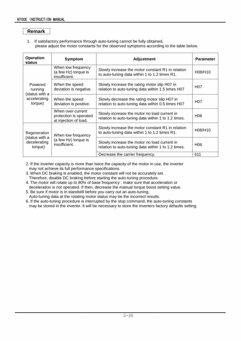
N700E INSTRUCTION MANUAL
5-26
Remark
1. If satisfactory performance through auto-tuning cannot be fully obtained,
please adjust the motor constants for the observed symptoms according to the table below.
Operation status
Symptom Adjustment Parameter
Powered running
(status with a accelerating
torque)
When low frequency (a few Hz) torque is insufficient.
Slowly increase the motor constant R1 in relation to auto-tuning data within 1 to 1.2 times R1.
H08/H10
When the speed deviation is negative.
Slowly increase the rating motor slip H07 in relation to auto-tuning data within 1.5 times H07
H07
When the speed deviation is positive.
Slowly decrease the rating motor slip H07 in relation to auto-tuning data within 0.5 times H07
H07
When over current protection is operated at injection of load.
Slowly increase the motor no load current in relation to auto-tuning data within 1 to 1.2 times.
H06
Regeneration (status with a decelerating
torque)
When low frequency (a few Hz) torque is insufficient.
Slowly increase the motor constant R1 in relation to auto-tuning data within 1 to 1.2 times R1.
H08/H10
Slowly increase the motor no load current in relation to auto-tuning data within 1 to 1.2 times.
H06
Decrease the carrier frequency. b11
2. If the inverter capacity is more than twice the capacity of the motor in use, the inverter
may not achieve its full performance specifications. 3. When DC braking is enabled, the motor constant will not be accurately set.
Therefore, disable DC braking before starting the auto-tuning procedure. 4. The motor will rotate up to 80% of base frequency : make sure that acceleration or
deceleration is not operated. If then, decrease the manual torque boost setting value. 5. Be sure if motor is in standstill before you carry out an auto-tuning.
Auto-tuning data at the rotating motor status may be the incorrect results. 6. If the auto-tuning procedure is interrupted by the stop command, the auto-tuning constants
may be stored in the inverter. It will be necessary to store the inverters factory defaults setting.
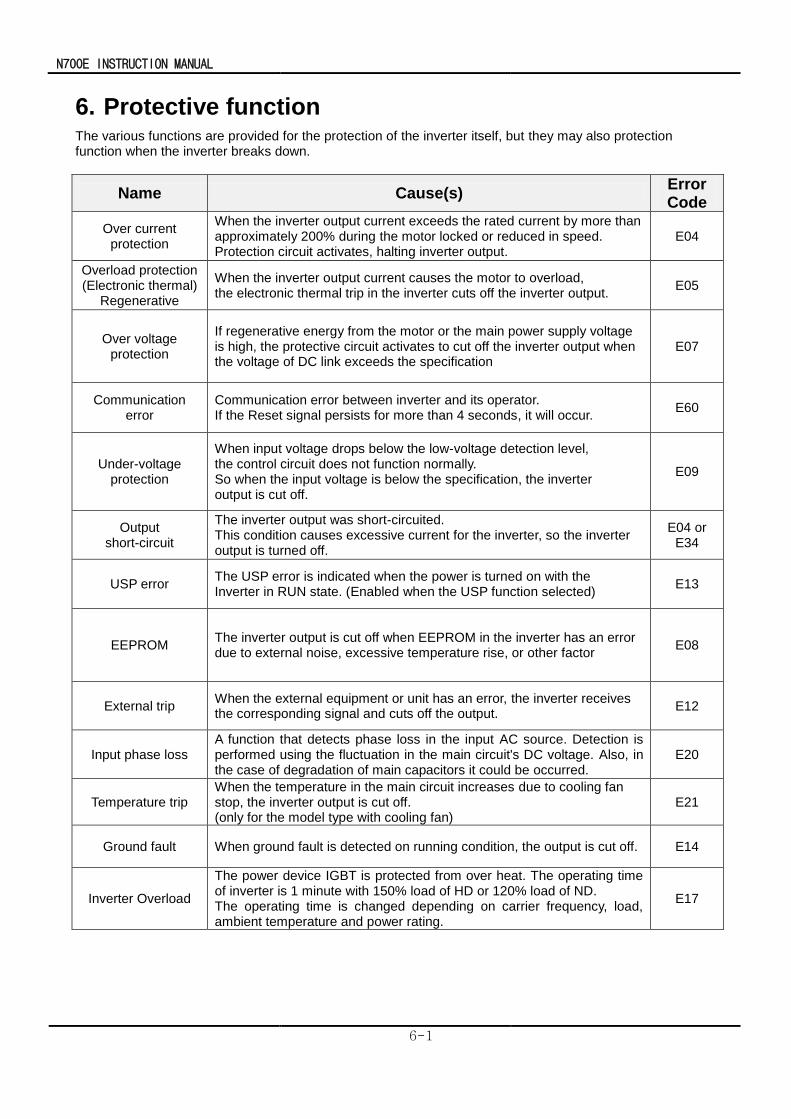
N700E INSTRUCTION MANUAL
6-1
6. Protective function The various functions are provided for the protection of the inverter itself, but they may also protection function when the inverter breaks down.
Name Cause(s) Error Code
Over current protection
When the inverter output current exceeds the rated current by more than approximately 200% during the motor locked or reduced in speed. Protection circuit activates, halting inverter output.
E04
Overload protection (Electronic thermal)
Regenerative
When the inverter output current causes the motor to overload, the electronic thermal trip in the inverter cuts off the inverter output.
E05
Over voltage protection
If regenerative energy from the motor or the main power supply voltage is high, the protective circuit activates to cut off the inverter output when the voltage of DC link exceeds the specification
E07
Communication error
Communication error between inverter and its operator. If the Reset signal persists for more than 4 seconds, it will occur.
E60
Under-voltage protection
When input voltage drops below the low-voltage detection level, the control circuit does not function normally. So when the input voltage is below the specification, the inverter output is cut off.
E09
Output short-circuit
The inverter output was short-circuited. This condition causes excessive current for the inverter, so the inverter output is turned off.
E04 or E34
USP error The USP error is indicated when the power is turned on with the Inverter in RUN state. (Enabled when the USP function selected)
E13
EEPROM The inverter output is cut off when EEPROM in the inverter has an error due to external noise, excessive temperature rise, or other factor
E08
External trip When the external equipment or unit has an error, the inverter receives the corresponding signal and cuts off the output.
E12
Input phase loss A function that detects phase loss in the input AC source. Detection is performed using the fluctuation in the main circuit's DC voltage. Also, in the case of degradation of main capacitors it could be occurred.
E20
Temperature trip When the temperature in the main circuit increases due to cooling fan stop, the inverter output is cut off. (only for the model type with cooling fan)
E21
Ground fault When ground fault is detected on running condition, the output is cut off. E14
Inverter Overload
The power device IGBT is protected from over heat. The operating time of inverter is 1 minute with 150% load of HD or 120% load of ND. The operating time is changed depending on carrier frequency, load, ambient temperature and power rating.
E17
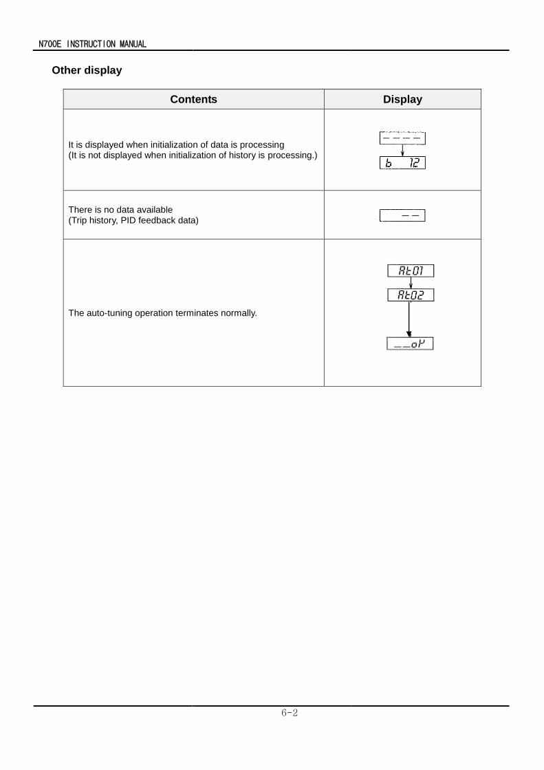
N700E INSTRUCTION MANUAL
6-2
Other display
Contents Display
It is displayed when initialization of data is processing (It is not displayed when initialization of history is processing.)
There is no data available (Trip history, PID feedback data)
The auto-tuning operation terminates normally.
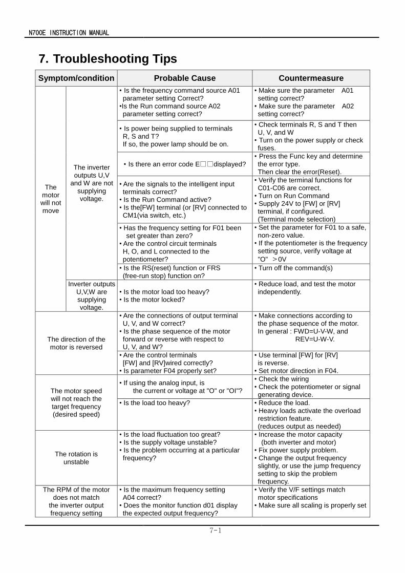
N700E INSTRUCTION MANUAL
7-1
7. Troubleshooting Tips
Symptom/condition Probable Cause Countermeasure
The motor will not move
The inverter outputs U,V
and W are not supplying voltage.
• Is the frequency command source A01 parameter setting Correct?
•Is the Run command source A02 parameter setting correct?
• Make sure the parameter A01 setting correct?
• Make sure the parameter A02 setting correct?
• Is power being supplied to terminals R, S and T? If so, the power lamp should be on.
• Check terminals R, S and T then U, V, and W
• Turn on the power supply or check fuses.
• Is there an error code Edisplayed? • Press the Func key and determine the error type.
Then clear the error(Reset).
• Are the signals to the intelligent input terminals correct?
• Is the Run Command active? • Is the[FW] terminal (or [RV] connected to CM1(via switch, etc.)
• Verify the terminal functions for C01-C06 are correct. • Turn on Run Command • Supply 24V to [FW] or [RV] terminal, if configured.
(Terminal mode selection)
• Has the frequency setting for F01 been set greater than zero?
• Are the control circuit terminals H, O, and L connected to the potentiometer?
• Set the parameter for F01 to a safe, non-zero value.
• If the potentiometer is the frequency setting source, verify voltage at
"O" >0V
• Is the RS(reset) function or FRS (free-run stop) function on?
• Turn off the command(s)
Inverter outputs U,V,W are supplying voltage.
• Is the motor load too heavy? • Is the motor locked?
• Reduce load, and test the motor independently.
The direction of the motor is reversed
• Are the connections of output terminal U, V, and W correct?
• Is the phase sequence of the motor forward or reverse with respect to U, V, and W?
• Make connections according to the phase sequence of the motor. In general : FWD=U-V-W, and REV=U-W-V.
• Are the control terminals [FW] and [RV]wired correctly?
• Is parameter F04 properly set?
• Use terminal [FW] for [RV] is reverse.
• Set motor direction in F04.
The motor speed will not reach the target frequency (desired speed)
• If using the analog input, is the current or voltage at "O" or "OI"?
• Check the wiring • Check the potentiometer or signal generating device.
• Is the load too heavy? • Reduce the load. • Heavy loads activate the overload restriction feature.
(reduces output as needed)
The rotation is unstable
• Is the load fluctuation too great? • Is the supply voltage unstable? • Is the problem occurring at a particular frequency?
• Increase the motor capacity (both inverter and motor) • Fix power supply problem. • Change the output frequency slightly, or use the jump frequency setting to skip the problem frequency.
The RPM of the motor does not match
the inverter output frequency setting
• Is the maximum frequency setting A04 correct?
• Does the monitor function d01 display the expected output frequency?
• Verify the V/F settings match motor specifications
• Make sure all scaling is properly set
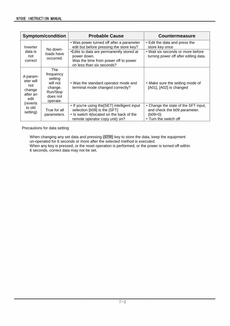
N700E INSTRUCTION MANUAL
7-2
Symptom/condition Probable Cause Countermeasure
Inverter data is
not correct
No down- loads have occurred.
• Was power turned off after a parameter edit but before pressing the store key?
• Edit the data and press the store key once
•Edits to data are permanently stored at power down. Was the time from power off to power on less than six seconds?
• Wait six seconds or more before turning power off after editing data.
A param- eter will
not change after an
edit (reverts to old
setting)
The frequency
setting will not change. Run/Stop does not operate.
• Was the standard operator mode and terminal mode changed correctly?
• Make sure the setting mode of [A01], [A02] is changed
True for all parameters.
• If you're using the[SET] intelligent input selection [b09] is the [SFT] • Is switch 4(located on the back of the remote operator copy unit) on?
• Change the state of the SFT input, and check the b09 parameter. (b09=0) • Turn the switch off
Precautions for data setting
When changing any set data and pressing (STR) key to store the data, keep the equipment un-operated for 6 seconds or more after the selected method is executed. When any key is pressed, or the reset operation is performed, or the power is turned off within 6 seconds, correct data may not be set.
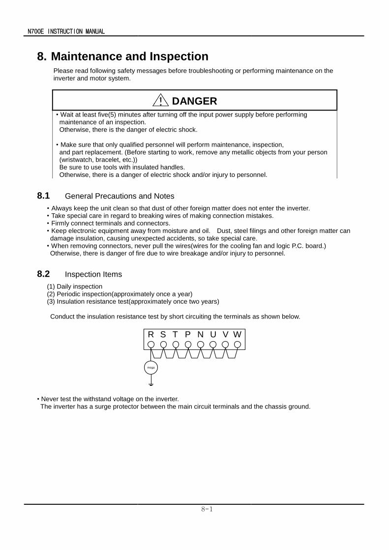
N700E INSTRUCTION MANUAL
8-1
8. Maintenance and Inspection Please read following safety messages before troubleshooting or performing maintenance on the
inverter and motor system.
8.1 General Precautions and Notes
• Always keep the unit clean so that dust of other foreign matter does not enter the inverter. • Take special care in regard to breaking wires of making connection mistakes. • Firmly connect terminals and connectors. • Keep electronic equipment away from moisture and oil. Dust, steel filings and other foreign matter can damage insulation, causing unexpected accidents, so take special care. • When removing connectors, never pull the wires(wires for the cooling fan and logic P.C. board.) Otherwise, there is danger of fire due to wire breakage and/or injury to personnel.
8.2 Inspection Items
(1) Daily inspection (2) Periodic inspection(approximately once a year) (3) Insulation resistance test(approximately once two years) Conduct the insulation resistance test by short circuiting the terminals as shown below.
mega
R S T P N U V W
• Never test the withstand voltage on the inverter. The inverter has a surge protector between the main circuit terminals and the chassis ground.
DANGER
• Wait at least five(5) minutes after turning off the input power supply before performing maintenance of an inspection. Otherwise, there is the danger of electric shock.
• Make sure that only qualified personnel will perform maintenance, inspection, and part replacement. (Before starting to work, remove any metallic objects from your person (wristwatch, bracelet, etc.)) Be sure to use tools with insulated handles. Otherwise, there is a danger of electric shock and/or injury to personnel.
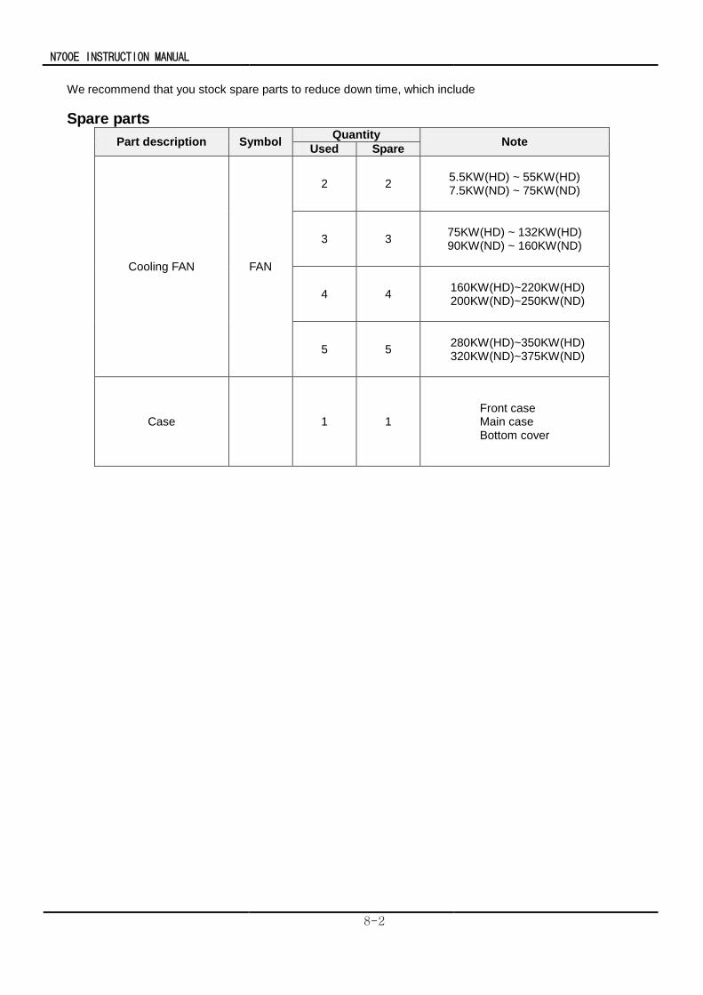
N700E INSTRUCTION MANUAL
8-2
We recommend that you stock spare parts to reduce down time, which include
Spare parts
Part description Symbol Quantity
Note Used Spare
Cooling FAN FAN
2 2 5.5KW(HD) ~ 55KW(HD) 7.5KW(ND) ~ 75KW(ND)
3 3 75KW(HD) ~ 132KW(HD) 90KW(ND) ~ 160KW(ND)
4 4 160KW(HD)~220KW(HD) 200KW(ND)~250KW(ND)
5 5 280KW(HD)~350KW(HD) 320KW(ND)~375KW(ND)
Case 1 1 Front case Main case Bottom cover
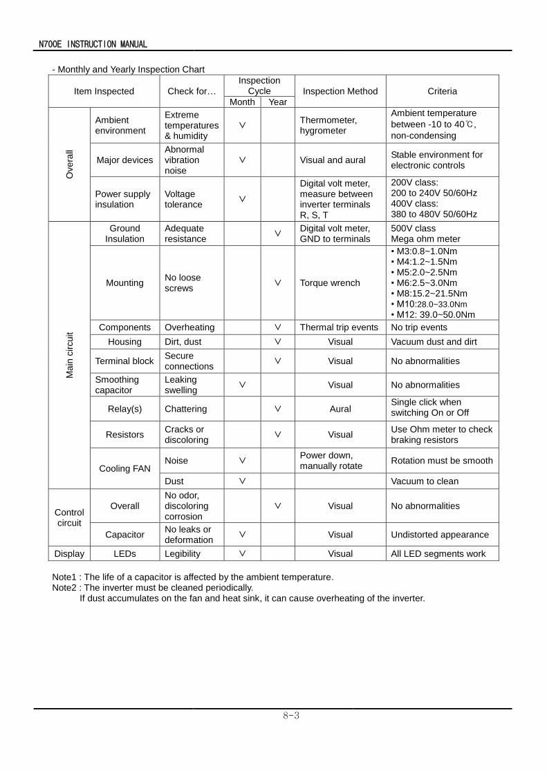
N700E INSTRUCTION MANUAL
8-3
- Monthly and Yearly Inspection Chart
Item Inspected Check for…
Inspection Cycle Inspection Method Criteria
Month Year
Overa
ll
Ambient environment
Extreme temperatures & humidity
∨ Thermometer, hygrometer
Ambient temperature
between -10 to 40,
non-condensing
Major devices Abnormal vibration noise
∨ Visual and aural Stable environment for electronic controls
Power supply insulation
Voltage tolerance
∨
Digital volt meter, measure between inverter terminals R, S, T
200V class: 200 to 240V 50/60Hz 400V class: 380 to 480V 50/60Hz
Main
circuit
Ground Insulation
Adequate resistance
∨ Digital volt meter, GND to terminals
500V class Mega ohm meter
Mounting No loose screws
∨ Torque wrench
• M3:0.8~1.0Nm • M4:1.2~1.5Nm • M5:2.0~2.5Nm • M6:2.5~3.0Nm • M8:15.2~21.5Nm • M10:28.0~33.0Nm • M12: 39.0~50.0Nm
Components Overheating ∨ Thermal trip events No trip events
Housing Dirt, dust ∨ Visual Vacuum dust and dirt
Terminal block Secure connections
∨ Visual No abnormalities
Smoothing capacitor
Leaking swelling
∨ Visual No abnormalities
Relay(s) Chattering ∨ Aural Single click when switching On or Off
Resistors Cracks or discoloring
∨ Visual Use Ohm meter to check braking resistors
Cooling FAN Noise ∨
Power down, manually rotate
Rotation must be smooth
Dust ∨ Vacuum to clean
Control circuit
Overall No odor, discoloring corrosion
∨ Visual No abnormalities
Capacitor No leaks or deformation
∨ Visual Undistorted appearance
Display LEDs Legibility ∨ Visual All LED segments work
Note1 : The life of a capacitor is affected by the ambient temperature. Note2 : The inverter must be cleaned periodically.
If dust accumulates on the fan and heat sink, it can cause overheating of the inverter.
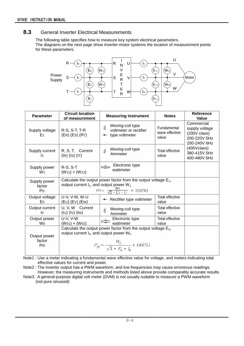
N700E INSTRUCTION MANUAL
8-4
8.3 General Inverter Electrical Measurements
The following table specifies how to measure key system electrical parameters. The diagrams on the next page show inverter-motor systems the location of measurement points for these parameters.
IR
IS
IT
W11
W12ES
ER
ET
IU
IV
IW
W01
W02EV-W
EU-V
EW-U
R
S
T
Power
Supply
U
V
W
R
S
T
U
V
W
I
N
V
E
R
T
E
R
Motor
Parameter Circuit location of measurement
Measuring instrument Notes Reference
Value
Supply voltage E1
R-S, S-T, T-R (ER) (ES) (RT)
Moving-coil type voltmeter or rectifier
type voltmeter
Fundamental wave effective value
Commercial
supply voltage
(200V class)
200-220V 5Hz
200-240V 6Hz
(400Vclass)
380-415V 5Hz
400-480V 6Hz
Supply current I1
R, S, T, Current (IR) (IS) (IT)
Moving-coil type Ammeter
Total effective value
Supply power W1
R-S, S-T (W11) + (W12)
Electronic type wattmeter
Supply power factor
Pf1
Calculate the output power factor from the output voltage E1, output current I1, and output power W1
Output voltage E0
U-V, V-W, W-U (EU) (EV) (EW)
Rectifier type voltmeter Total effective value
Output current I0
U, V, W Current (IU) (IV) (IW)
Moving-coil type Ammeter
Total effective value
Output power W0
U-V, V-W (W01) + (W02)
Electronic type wattmeter
Total effective value
Output power factor
Pf0
Calculate the output power factor from the output voltage E0, output current I0, and output power W0
Note1 : Use a meter indicating a fundamental wave effective value for voltage, and meters indicating total effective values for current and power.
Note2 : The inverter output has a PWM waveform, and low frequencies may cause erroneous readings. However, the measuring instruments and methods listed above provide comparably accurate results.
Note3 : A general-purpose digital volt meter (DVM) is not usually suitable to measure a PWM waveform (not pure sinusoid)
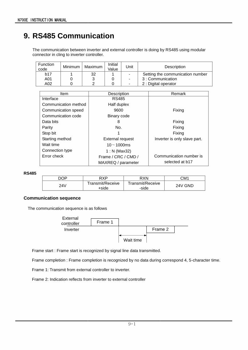
N700E INSTRUCTION MANUAL
9-1
9. RS485 Communication
The communication between inverter and external controller is doing by RS485 using modular connector in cling to inverter controller.
Function code
Minimum Maximum Initial Value
Unit Description
b17 1 32 1 - Setting the communication number A01 0 3 0 - 3 : Communication A02 0 2 0 - 2 : Digital operator
Item Description Remark
Interface
Communication method
Communication speed
Communication code
Data bits
Parity
Stop bit
Starting method
Wait time
Connection type
Error check
RS485
Half duplex
9600
Binary code
8
No.
1
External request
10∼1000ms
1 : N (Max32)
Frame / CRC / CMD /
MAXREQ / parameter
Fixing
Fixing
Fixing
Fixing
Inverter is only slave part.
Communication number is
selected at b17
RS485
DOP RXP RXN CM1
24V Transmit/Receive
+side Transmit/Receive
-side 24V GND
Communication sequence The communication sequence is as follows
External
controller
Inverter
Frame 1
Frame 2
Wait time
Frame start : Frame start is recognized by signal line data transmitted.
Frame completion : Frame completion is recognized by no data during correspond 4, 5-character time.
Frame 1: Transmit from external controller to inverter.
Frame 2: Indication reflects from inverter to external controller
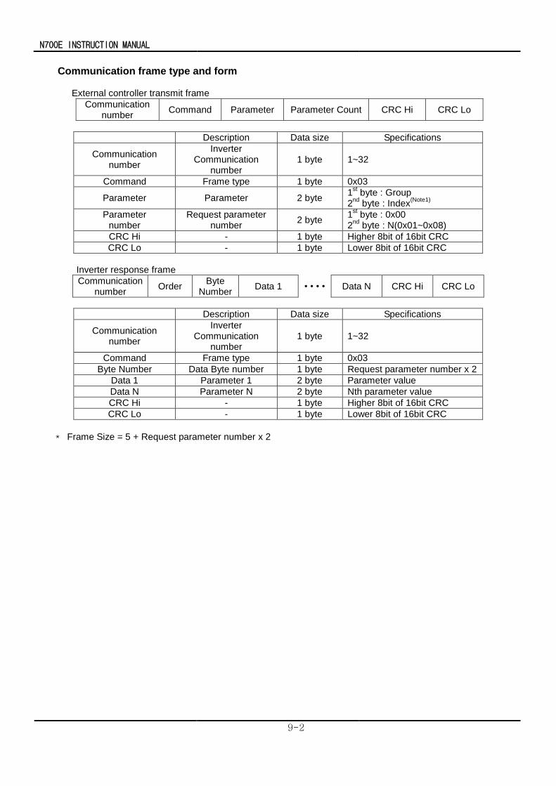
N700E INSTRUCTION MANUAL
9-2
Communication frame type and form
External controller transmit frame
Communication number
Command Parameter Parameter Count CRC Hi CRC Lo
Description Data size Specifications
Communication number
Inverter Communication
number 1 byte 1~32
Command Frame type 1 byte 0x03
Parameter Parameter 2 byte 1
st byte : Group
2nd
byte : Index(Note1)
Parameter number
Request parameter number
2 byte 1
st byte : 0x00
2nd
byte : N(0x01~0x08)
CRC Hi - 1 byte Higher 8bit of 16bit CRC
CRC Lo - 1 byte Lower 8bit of 16bit CRC
Inverter response frame
Communication number
Order Byte
Number Data 1 • • • • Data N CRC Hi CRC Lo
Description Data size Specifications
Communication number
Inverter Communication
number 1 byte 1~32
Command Frame type 1 byte 0x03
Byte Number Data Byte number 1 byte Request parameter number x 2
Data 1 Parameter 1 2 byte Parameter value
Data N Parameter N 2 byte Nth parameter value
CRC Hi - 1 byte Higher 8bit of 16bit CRC
CRC Lo - 1 byte Lower 8bit of 16bit CRC
* Frame Size = 5 + Request parameter number x 2
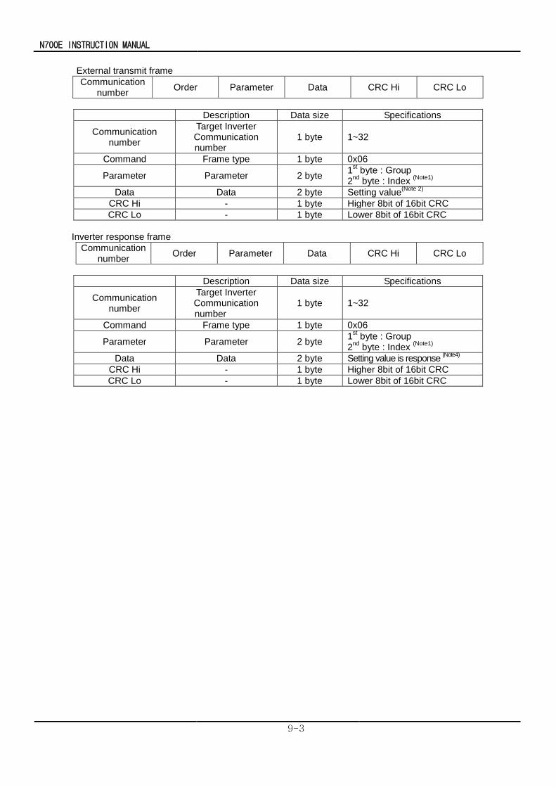
N700E INSTRUCTION MANUAL
9-3
External transmit frame
Communication number
Order Parameter Data CRC Hi CRC Lo
Description Data size Specifications
Communication number
Target Inverter Communication number
1 byte 1~32
Command Frame type 1 byte 0x06
Parameter Parameter 2 byte 1
st byte : Group
2nd
byte : Index (Note1)
Data Data 2 byte Setting value(Note 2)
CRC Hi - 1 byte Higher 8bit of 16bit CRC
CRC Lo - 1 byte Lower 8bit of 16bit CRC
Inverter response frame
Communication number
Order Parameter Data CRC Hi CRC Lo
Description Data size Specifications
Communication number
Target Inverter Communication number
1 byte 1~32
Command Frame type 1 byte 0x06
Parameter Parameter 2 byte 1
st byte : Group
2nd
byte : Index (Note1)
Data Data 2 byte Setting value is response (Note4)
CRC Hi - 1 byte Higher 8bit of 16bit CRC
CRC Lo - 1 byte Lower 8bit of 16bit CRC
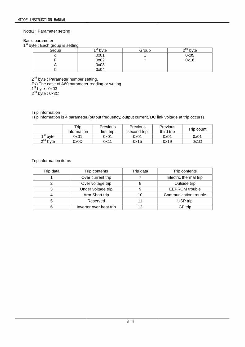
N700E INSTRUCTION MANUAL
9-4
Note1 : Parameter setting Basic parameter 1
st byte : Each group is setting
Group 1st byte Group 2
nd byte
d F A b
0x01 0x02 0x03 0x04
C H
0x05 0x16
2
nd byte : Parameter number setting.
Ex) The case of A60 parameter reading or writing 1
st byte : 0x03
2nd
byte : 0x3C Trip information Trip information is 4 parameter.(output frequency, output current, DC link voltage at trip occurs)
Trip
Information Previous first trip
Previous second trip
Previous third trip
Trip count
1st byte 0x01 0x01 0x01 0x01 0x01
2nd
byte 0x0D 0x11 0x15 0x19 0x1D
Trip information items
Trip data Trip contents Trip data Trip contents
1 Over current trip 7 Electric thermal trip
2 Over voltage trip 8 Outside trip
3 Under voltage trip 9 EEPROM trouble
4 Arm Short trip 10 Communication trouble
5 Reserved 11 USP trip
6 Inverter over heat trip 12 GF trip
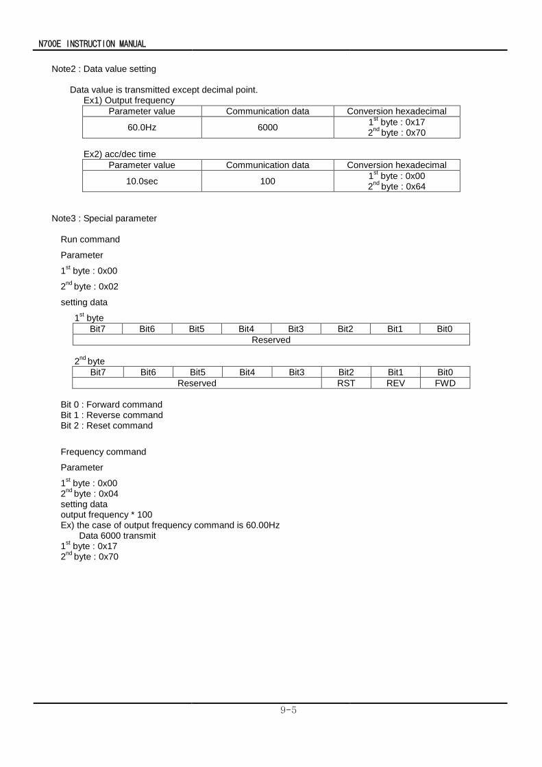
N700E INSTRUCTION MANUAL
9-5
Note2 : Data value setting
Data value is transmitted except decimal point. Ex1) Output frequency
Parameter value Communication data Conversion hexadecimal
60.0Hz 6000 1
st byte : 0x17
2nd
byte : 0x70
Ex2) acc/dec time
Parameter value Communication data Conversion hexadecimal
10.0sec 100 1
st byte : 0x00
2nd
byte : 0x64
Note3 : Special parameter
Run command
Parameter
1st byte : 0x00
2nd
byte : 0x02
setting data
1st byte
Bit7 Bit6 Bit5 Bit4 Bit3 Bit2 Bit1 Bit0
Reserved
2
nd byte
Bit7 Bit6 Bit5 Bit4 Bit3 Bit2 Bit1 Bit0
Reserved RST REV FWD
Bit 0 : Forward command Bit 1 : Reverse command Bit 2 : Reset command
Frequency command
Parameter
1st byte : 0x00
2nd
byte : 0x04 setting data output frequency * 100 Ex) the case of output frequency command is 60.00Hz Data 6000 transmit 1
st byte : 0x17
2nd
byte : 0x70
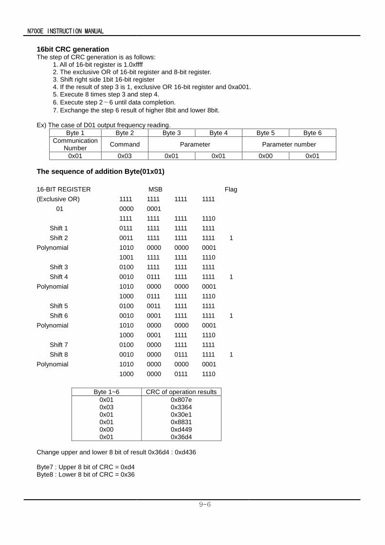
N700E INSTRUCTION MANUAL
9-6
16bit CRC generation The step of CRC generation is as follows: 1. All of 16-bit register is 1.0xffff 2. The exclusive OR of 16-bit register and 8-bit register. 3. Shift right side 1bit 16-bit register 4. If the result of step 3 is 1, exclusive OR 16-bit register and 0xa001. 5. Execute 8 times step 3 and step 4.
6. Execute step 2∼6 until data completion.
7. Exchange the step 6 result of higher 8bit and lower 8bit. Ex) The case of D01 output frequency reading.
Byte 1 Byte 2 Byte 3 Byte 4 Byte 5 Byte 6
Communication Number
Command Parameter Parameter number
0x01 0x03 0x01 0x01 0x00 0x01
The sequence of addition Byte(01x01)
16-BIT REGISTER MSB Flag
(Exclusive OR) 1111 1111 1111 1111
01 0000 0001
1111 1111 1111 1110
Shift 1 0111 1111 1111 1111
Shift 2 0011 1111 1111 1111 1
Polynomial 1010 0000 0000 0001
1001 1111 1111 1110
Shift 3 0100 1111 1111 1111
Shift 4 0010 0111 1111 1111 1
Polynomial 1010 0000 0000 0001
1000 0111 1111 1110
Shift 5 0100 0011 1111 1111
Shift 6 0010 0001 1111 1111 1
Polynomial 1010 0000 0000 0001
1000 0001 1111 1110
Shift 7 0100 0000 1111 1111
Shift 8 0010 0000 0111 1111 1
Polynomial 1010 0000 0000 0001
1000 0000 0111 1110
Byte 1~6 CRC of operation results
0x01 0x03 0x01 0x01 0x00 0x01
0x807e 0x3364 0x30e1 0x8831 0xd449 0x36d4
Change upper and lower 8 bit of result 0x36d4 : 0xd436 Byte7 : Upper 8 bit of CRC = 0xd4 Byte8 : Lower 8 bit of CRC = 0x36
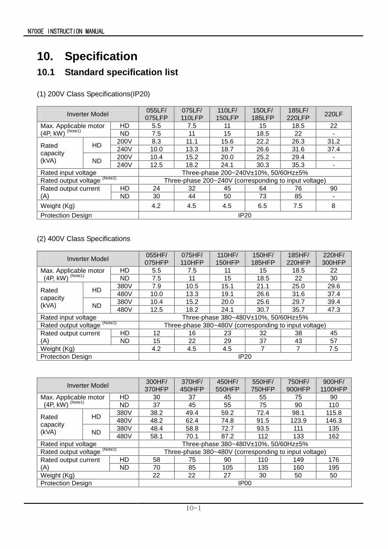
N700E INSTRUCTION MANUAL
10-1
10. Specification
10.1 Standard specification list
(1) 200V Class Specifications(IP20)
Inverter Model 055LF/ 075LFP
075LF/ 110LFP
110LF/ 150LFP
150LF/ 185LFP
185LF/ 220LFP
220LF
Max. Applicable motor (4P, kW)
(Note1)
HD 5.5 7.5 11 15 18.5 22
ND 7.5 11 15 18.5 22 -
Rated capacity (kVA)
HD 200V 8.3 11.1 15.6 22.2 26.3 31.2
240V 10.0 13.3 18.7 26.6 31.6 37.4
ND 200V 10.4 15.2 20.0 25.2 29.4 -
240V 12.5 18.2 24.1 30.3 35.3 -
Rated input voltage Three-phase 200~240V±10%, 50/60Hz±5%
Rated output voltage (Note2)
Three-phase 200~240V (corresponding to input voltage)
Rated output current (A)
HD 24 32 45 64 76 90
ND 30 44 50 73 85 -
Weight (Kg) 4.2 4.5 4.5 6.5 7.5 8
Protection Design IP20
(2) 400V Class Specifications
Inverter Model 055HF/ 075HFP
075HF/ 110HFP
110HF/ 150HFP
150HF/ 185HFP
185HF/ 220HFP
220HF/ 300HFP
Max. Applicable motor (4P, kW)
(Note1)
HD 5.5 7.5 11 15 18.5 22
ND 7.5 11 15 18.5 22 30
Rated capacity (kVA)
HD 380V 7.9 10.5 15.1 21.1 25.0 29.6
480V 10.0 13.3 19.1 26.6 31.6 37.4
ND 380V 10.4 15.2 20.0 25.6 29.7 39.4
480V 12.5 18.2 24.1 30.7 35.7 47.3
Rated input voltage Three-phase 380~480V±10%, 50/60Hz±5%
Rated output voltage (Note2)
Three-phase 380~480V (corresponding to input voltage)
Rated output current (A)
HD 12 16 23 32 38 45
ND 15 22 29 37 43 57
Weight (Kg) 4.2 4.5 4.5 7 7 7.5
Protection Design IP20
Inverter Model 300HF/ 370HFP
370HF/ 450HFP
450HF/ 550HFP
550HF/ 750HFP
750HF/ 900HFP
900HF/ 1100HFP
Max. Applicable motor (4P, kW)
(Note1)
HD 30 37 45 55 75 90
ND 37 45 55 75 90 110
Rated capacity (kVA)
HD 380V 38.2 49.4 59.2 72.4 98.1 115.8
480V 48.2 62.4 74.8 91.5 123.9 146.3
ND 380V 48.4 58.8 72.7 93.5 111 135
480V 58.1 70.1 87.2 112 133 162
Rated input voltage Three-phase 380~480V±10%, 50/60Hz±5%
Rated output voltage (Note2)
Three-phase 380~480V (corresponding to input voltage)
Rated output current (A)
HD 58 75 90 110 149 176
ND 70 85 105 135 160 195
Weight (Kg) 22 22 27 30 50 50
Protection Design IP00
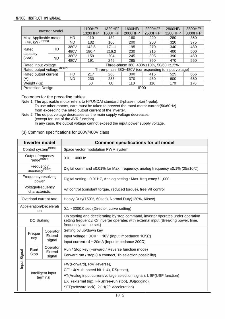
N700E INSTRUCTION MANUAL
10-2
Inverter Model 1100HF/ 1320HFP
1320HF/ 1600HFP
1600HF/2000HFP
2200HF/ 2500HFP
2800HF/ 3200HFP
3500HF/ 3800HFP
Max. Applicable motor (4P, kW)
(Note1)
HD 110 132 160 220 280 350
ND 132 160 200 250 320 375
Rated capacity (kVA)
HD 380V 142.8 171.1 195 270 340 430
480V 180.4 216.2 230 315 400 500
ND 380V 159 204 245 305 390 460
480V 191 245 285 360 470 550
Rated input voltage Three-phase 380~480V±10%, 50/60Hz±5%
Rated output voltage (Note2)
Three-phase 380~480V (corresponding to input voltage)
Rated output current (A)
HD 217 260 300 415 525 656
ND 230 285 370 450 600 680
Weight (Kg) 60 60 110 110 170 170
Protection Design IP00
Footnotes for the preceding tables Note 1. The applicable motor refers to HYUNDAI standard 3-phase motor(4-pole).
To use other motors, care must be taken to prevent the rated motor current(50/60Hz) from exceeding the rated output current of the inverter.
Note 2. The output voltage decreases as the main supply voltage decreases (except for use of the AVR function). In any case, the output voltage cannot exceed the input power supply voltage.
(3) Common specifications for 200V/400V class
Inverter model Common specifications for all model
Control system(Note3)
Space vector modulation PWM system
Output frequency range
(Note4)
0.01∼400Hz
Frequency accuracy
(Note5)
Digital command ±0.01% for Max. frequency, analog frequency ±0.1% (25±10)
Frequency resolving power
Digital setting : 0.01HZ, Analog setting : Max. frequency / 1,000
Voltage/frequency characteristic
V/f control (constant torque, reduced torque), free V/f control
Overload current rate Heavy Duty(150%, 60sec), Normal Duty(120%, 60sec)
Acceleration/Deceleration
0.1∼3000.0 sec (Director, curve setting)
DC Braking On starting and decelerating by stop command, inverter operates under operation setting frequency. Or inverter operates with external input (Breaking power, time, frequency can be set.)
Input
Sig
nal
Frequency
Operator Extend signal
Setting by up/down key
Input voltage : DC0∼+10V (Input impedance 10KΩ)
Input current : 4∼20mA (Input impedance 200Ω)
Run/ Stop
Operator Extend signal
Run / Stop key (Forward / Reverse function mode)
Forward run / stop (1a connect, 1b selection possibility)
Intelligent input terminal
FW(Forward), RV(Reverse),
CF1~4(Multi-speed bit 1~4), RS(reset),
AT(Analog input current/voltage selection signal), USP(USP function)
EXT(external trip), FRS(free-run stop), JG(jogging),
SFT(software lock), 2CH(2nd
acceleration)
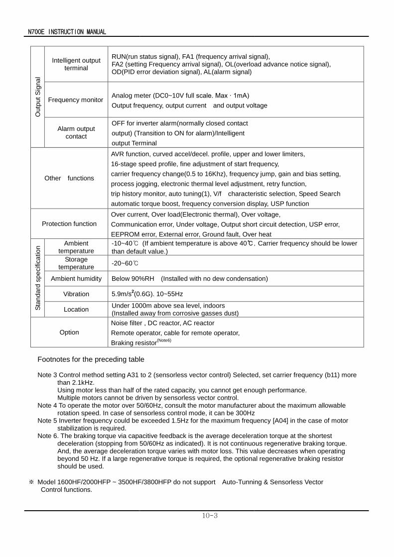
N700E INSTRUCTION MANUAL
10-3
Outp
ut
Sig
na
l
Intelligent output terminal
RUN(run status signal), FA1 (frequency arrival signal), FA2 (setting Frequency arrival signal), OL(overload advance notice signal), OD(PID error deviation signal), AL(alarm signal)
Frequency monitor Analog meter (DC0~10V full scale. Max ∙ 1mA)
Output frequency, output current and output voltage
Alarm output contact
OFF for inverter alarm(normally closed contact
output) (Transition to ON for alarm)/Intelligent
output Terminal
Other functions
AVR function, curved accel/decel. profile, upper and lower limiters,
16-stage speed profile, fine adjustment of start frequency,
carrier frequency change(0.5 to 16Khz), frequency jump, gain and bias setting,
process jogging, electronic thermal level adjustment, retry function,
trip history monitor, auto tuning(1), V/f characteristic selection, Speed Search
automatic torque boost, frequency conversion display, USP function
Protection function
Over current, Over load(Electronic thermal), Over voltage,
Communication error, Under voltage, Output short circuit detection, USP error,
EEPROM error, External error, Ground fault, Over heat
Sta
ndard
sp
ecific
atio
n Ambient
temperature -10~40 (If ambient temperature is above 40, Carrier frequency should be lower
than default value.)
Storage temperature
-20~60
Ambient humidity Below 90%RH (Installed with no dew condensation)
Vibration 5.9m/s2(0.6G). 10~55Hz
Location Under 1000m above sea level, indoors (Installed away from corrosive gasses dust)
Option
Noise filter , DC reactor, AC reactor
Remote operator, cable for remote operator,
Braking resistor(Note6)
Footnotes for the preceding table Note 3 Control method setting A31 to 2 (sensorless vector control) Selected, set carrier frequency (b11) more
than 2.1kHz. Using motor less than half of the rated capacity, you cannot get enough performance. Multiple motors cannot be driven by sensorless vector control.
Note 4 To operate the motor over 50/60Hz, consult the motor manufacturer about the maximum allowable rotation speed. In case of sensorless control mode, it can be 300Hz
Note 5 Inverter frequency could be exceeded 1.5Hz for the maximum frequency [A04] in the case of motor stabilization is required.
Note 6. The braking torque via capacitive feedback is the average deceleration torque at the shortest deceleration (stopping from 50/60Hz as indicated). It is not continuous regenerative braking torque. And, the average deceleration torque varies with motor loss. This value decreases when operating beyond 50 Hz. If a large regenerative torque is required, the optional regenerative braking resistor should be used.
※ Model 1600HF/2000HFP ~ 3500HF/3800HFP do not support Auto-Tunning & Sensorless Vector Control functions.
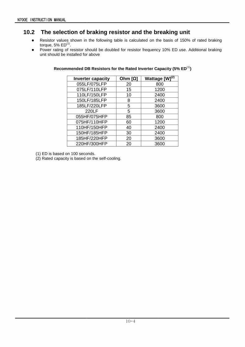
N700E INSTRUCTION MANUAL
10-4
10.2 The selection of braking resistor and the breaking unit
Resistor values shown in the following table is calculated on the basis of 150% of rated braking torque, 5% ED
(1).
Power rating of resistor should be doubled for resistor frequency 10% ED use. Additional braking unit should be installed for above
Recommended DB Resistors for the Rated Inverter Capacity (5% ED(1)
)
Inverter capacity Ohm [Ω] Wattage [W](2)
055LF/075LFP 20 800
075LF/110LFP 15 1200
110LF/150LFP 10 2400
150LF/185LFP 8 2400
185LF/220LFP 5 3600
220LF 5 3600
055HF/075HFP 85 800
075HF/110HFP 60 1200
110HF/150HFP 40 2400
150HF/185HFP 30 2400
185HF/220HFP 20 3600
220HF/300HFP 20 3600
(1) ED is based on 100 seconds. (2) Rated capacity is based on the self-cooling.
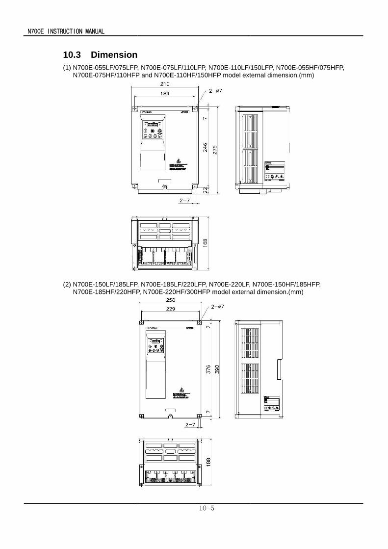
N700E INSTRUCTION MANUAL
10-5
10.3 Dimension
(1) N700E-055LF/075LFP, N700E-075LF/110LFP, N700E-110LF/150LFP, N700E-055HF/075HFP, N700E-075HF/110HFP and N700E-110HF/150HFP model external dimension.(mm)
(2) N700E-150LF/185LFP, N700E-185LF/220LFP, N700E-220LF, N700E-150HF/185HFP, N700E-185HF/220HFP, N700E-220HF/300HFP model external dimension.(mm)
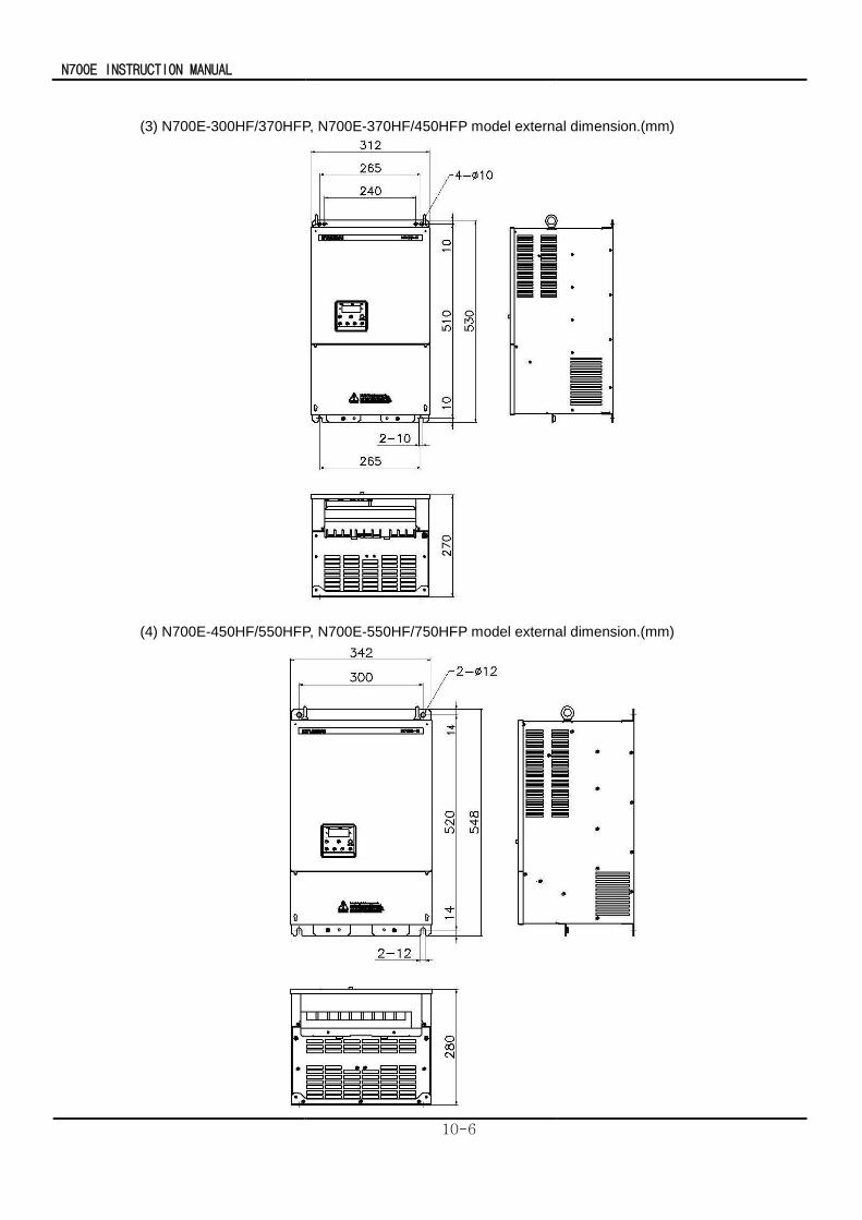
N700E INSTRUCTION MANUAL
10-6
(3) N700E-300HF/370HFP, N700E-370HF/450HFP model external dimension.(mm)
(4) N700E-450HF/550HFP, N700E-550HF/750HFP model external dimension.(mm)
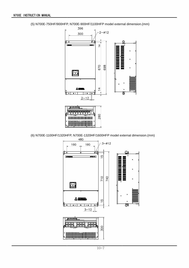
N700E INSTRUCTION MANUAL
10-7
(5) N700E-750HF/900HFP, N700E-900HF/1100HFP model external dimension.(mm)
(6) N700E-1100HF/1320HFP, N700E-1320HF/1600HFP model external dimension.(mm)
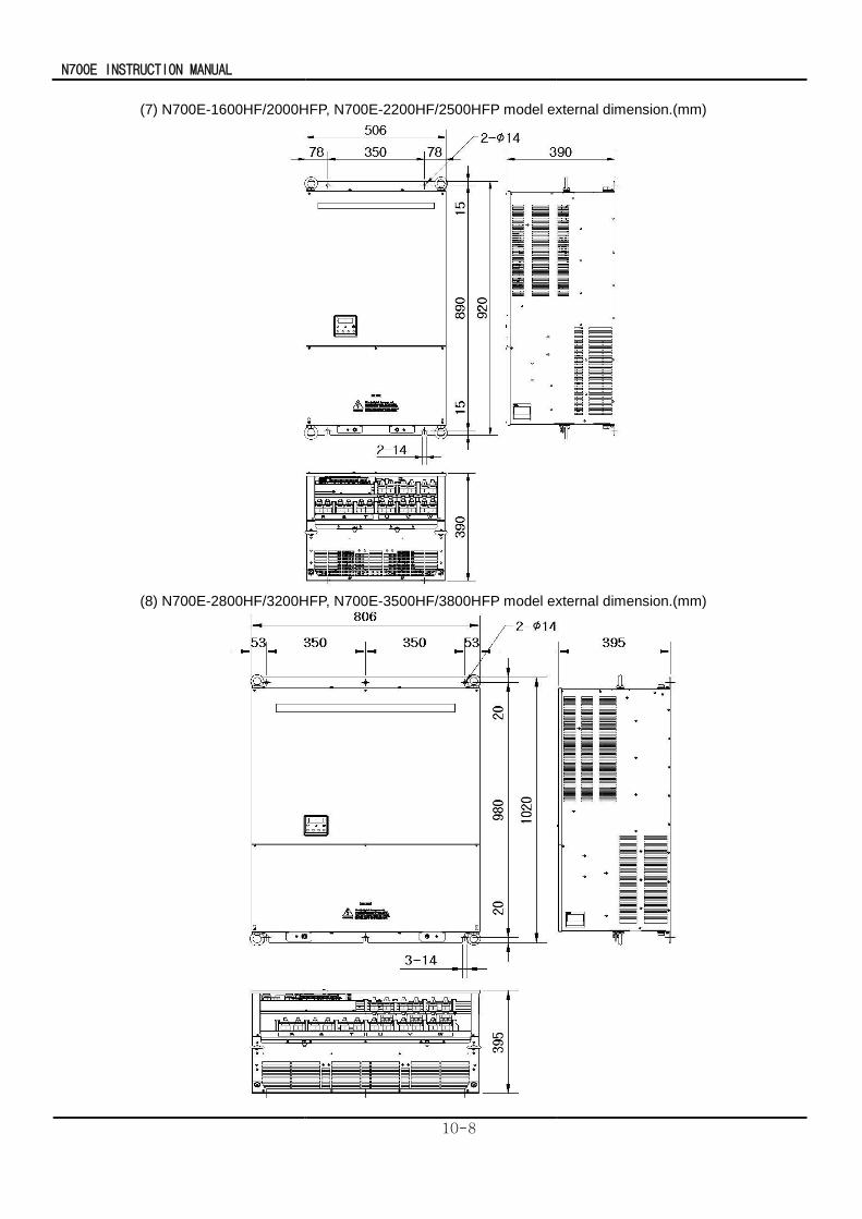
N700E INSTRUCTION MANUAL
10-8
(7) N700E-1600HF/2000HFP, N700E-2200HF/2500HFP model external dimension.(mm)
(8) N700E-2800HF/3200HFP, N700E-3500HF/3800HFP model external dimension.(mm)