Embed Size (px)
Citation preview
\\ /’4*,.4/#-ii?..L%A+..-.J
/ Jim No. L6C19@“
.tY’
NATIONAL ADVISORY COMMITTEE FOR AERONAUTICS
WAIHW.IE luwolr”ORIGINALLY ISSUED
M~ 1946 as
AdvanceRestrictedReport16C19
COLT)NMAND HAI!ECOMPRESSIVESTRI!NGTES
OF KUWRAFT STRUCTURALMATERIAIS
EXTRUDEDlk3-TALUMINUMALLOY
By GeorgeJ. Heimerland DonaldE. Niles
LangleyMemorialAercmauticalLaboratoryLangleyField,Va.
,,
N’AC”A’’:YWASHINGTON
NACA WARTIME REPORTS are reprintsofpapersoriginallyissuedtoproviderapiddistributionofadvanceresearchresultstoan authorizedgroup requiringthem forthewar effort.They were pre-viouslyheldunder a securitystatusbutare now’unclassified.Some ofthesereportswere nottech-nicallyedited.All have been reproducedwithoutchangeinordertoexpeditegeneraldistribution.
L- 284
t .,

.-
3—.—-
,
I
117601354- i——--
EACA.mR NO. L6c19 .NATIONAL ADVISORY COMMITTEE FOR AERONAUTICS
.
ADVANCE RESTRICllED REPORT. . . ..-.- .-.. .,. - ..,.., ....- .- —-.
CCILU’WAND PLATE COMPRESSIVE STRENGTHS
OF AIRCPAFT STRUCTURAL MATERIALS
EXTRUDED 14S-T ALURII!!M ALLOY
By George J. Hei.merl and Donald E. Niles
SWMARY
CCIIUmnand nlate compressive strengths of extrudedL!+S-Talumlnum alloy were determined both within andbeyond the elastic ran~e from tests af flat-end H-sectionCOIWWM and from,local-instability tests of F-, Z-J andchannel-section colcmms. Tkese tests are part of anextensive research lnvest~ljation t,~prov?de data on thestructural stren:zthof vartous aircraft materials. !IIIeresults are prsssntec? In the term of curves anflchartsthat are suitable for use in the design and anal~sis ofaircraft structures.
INTRODUCTION
Col’a!Jnand Plate rembers that fall by instabilityare ba9ic elements in an aircraft structure. For thedesign of structurally efficient aircraft, the strengthof these eler,entsmust be known for the various aircraftmaterials. An extensive research program has thereforebeen undertaken at the Lan@ey kemorial AeronauticalLaboratnrg to establish the column and plate com?resslvestrengths of a number of’the alloys kvailable for use inaircraft structures. Parts of this investigation havebeen completed; the alloys already Investigated include
9. Z!4S-T and 17S-T alumlnuz?z?-alloysheet and extruded 75S-lP,“ 24S-T, and l?303-T&luminum alloys (references 1 to 5,
rhapectfvely-).
\ I.,,.—-----.,..... ,.,,. ...— ——. -. .,, . ,-
“2 NACA
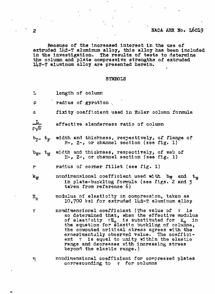
Because of the increased Interest In theextruded l.&T aluminum alloy, this alloy has
ARRNo. L6C19
use ofbeen included
in the investigation. The risu.lts of teats to determinethe column and plate oompresslve strengths of extrudedUS-T aluminm alloy are presented herein. .
SYME?QLS
r
%
‘F
tiv
length of column
radius of gyratfon .. ‘
fixity coefficient used in Euler column formula
effective slenderness ratio of column
width and thickness, res~ectively, of flange ofH-, Z-, or channel section (see fig. 1)
width and thicknsss, respectively, of web ofE-, z-, or channel sectlan (see fig. 1)
radius gf corner fillet (see fig. 1)
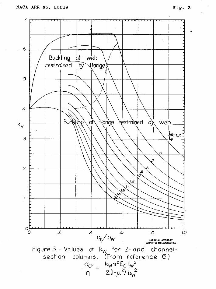
nondimensional coefficient used wltlh blv and tl~In plate-buckling formula (see figs. 2 and 3ta~~en from reference 6)
modulus of elasticity in compression, taken as10,700 ksi fcr extruded l@3-T aluminum alloy
nondimensional coeffjoient (The value of T 1sso determined that, when the effective modulusof elasticity TEC is substituted for Ec Intk.e equ8tlon for ela~t?.c b~~klil~,of ~~l~n~,the computed crit!cal stress agrees with theeynerimentally observed value. The coeffici-ent T is equal to unity within the elastiora~e and decreases wtth increasing stressbeyond the elsstlc range.)
T. n~ndimsnslonal coefficient for compressed platescorresponding t? T for columns
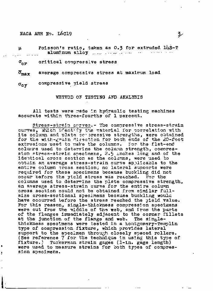
P Polsson?s ratio, taken as 0.3 for extruded 14S-Talumlnum alloy ...... .--..-.. ---- .- c“--’. -“------- .--.,”
5W average compressive stress at maximum load
~cycompressive yield stress
METEOD OF TZSTIN3 AN) ANALYSIS
All tests were fiede:.nh~~raulic testing machinesaccurate rJith5n three-fourths of 1 percent.
~tres~-st~~~yj~~l~ve3.- The compressive stress-strain—— ————.. --—curves, xhich i~ent’Cy tne ~aterial i’orcorrelation withits cclumn an,~plste zr+ ~reesive strengt%, were obtainedfor tlie witk-~~~~n S.irectlorifor both ends of the 20-footextrusion used to nake the columns. For the flat-endcolrwms used to fleterwina the ~olm:illstrength, compres-sion Ftress-atreln specim.er~s,.2.5inches lorigand of’theide-~tlcal cro3s sestion as the colawms, were used toobt~in an average stvess-strain curve ap.>lica”olet~ theentire colunm tress section; no lateral supnorts wererequired for thes9 specimens because buckling did notocour “ue~ore the yield stress was reached. F5r thecolumis used to determine the plete compressive stren~th,an avera$jestress-strain curve for the entire columncross section could not be obtair.d from similar f-~ll-size cross-sectional specimens because buckling wouldhave occurred before the stress reached the yield value.For this reason, si~-le-thickness compression speci-uenswere cut from tb-emiddle of tineweb, snd from the pwtsof the fl~es Immsdi.ately adjacent to the corner f’illetsat the junction of the flange and web. The sin@e-thlckness s~ectmens were tested 3.na ?fiont&om9ry-Temgllnt~e of comFressian fixture, which prov!des lateralsupport to the specimen throu@ closely spaced rollers.(See reference 7 f~r the technique in using this t’ypeoffiXtUrO. ) Tuckerman strain gages (l-in. gage length)
} were used to measure strains for both types of comVres-? sion spscimens.
IM.* -— .-. ._
. . .
,,
)+ NACA ARR NO. L6c19
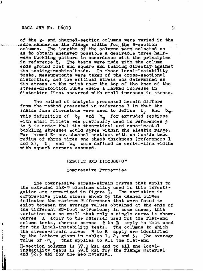
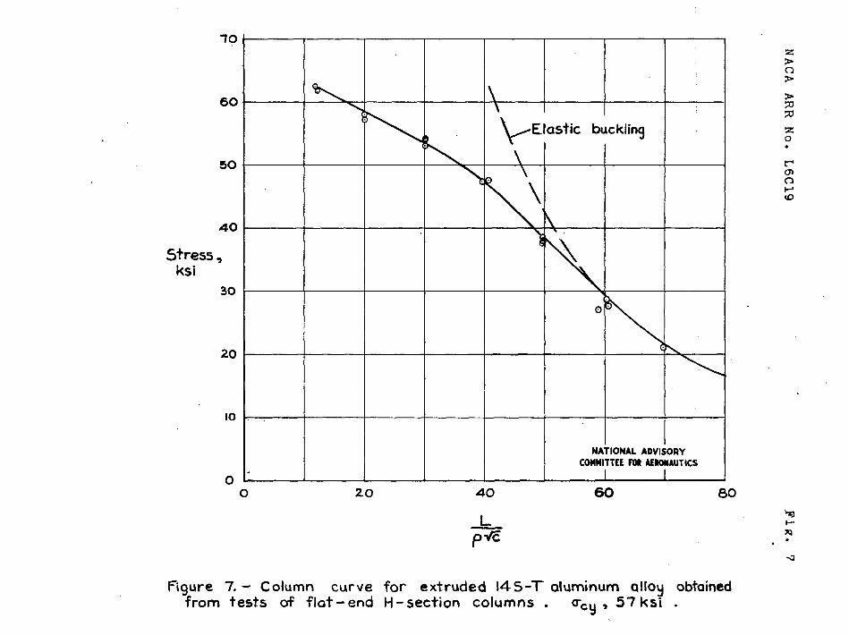
ColU~ strength. - The column strength and.theassoolated effective column modulus of elasticity wereobtained from. tests of flat-end H-seotlon columns withthe fixity coefficient c assumed to be equal to k.The columns were tested with the ends ground flat andsquare and bearing directly agatnet tinetesting-machineheads. The nominal cross-sectional dimensions for alltke columns were bF = 0.56, bW= 1.61J.,and
t., = tw = 0.125 inch. fiis size of section was nbtained
b; ‘T,illingoff the nacessary mount from the fla~es ofan extruded E-section and was chosen so that t-hecolumnswould d-evelop a hlqher local-inst~kility strength than
the greatest column stremgtL expected.
~~e cron:~efineasof the c~l-amns, the d:stanca frona p~iat at the vLidpoint of the column Irom a straightline dr~wn betwean corresponding points at the ends ofthe column, was measured by means of d plsne surfs’~eand a moveable d?al-gafe setu~. T1.er~tlo of la~th tocrookedness was .g.resterthan 1300 ir.all ca~es. (Thestrenytb of colu:ms with this ratio less than 1029 naybe rioticeahly reduced by the crool.edngss of the column.)AH so-~eof the zoluxns developed a tendency to twistafter tt.eflanges were machined down, tk!istwist wasrewoved b9fcre the crookedness t~asdetermined and befcrethe c~lumn test was mM!e. Tn order to measure thecro~kedn.esss the tw!st TBS rewoved by I.oldirkgthe fl~il:;esat each end of the colurm to tear firwly against uniformlythick steel blocks resting on the plane swrface. ‘*forethe tests were m~de, the cnlumn was clm.c9d against agul.debar at.each end until e small inttlal loud wasmmlled, then the Su-:.dehers w9re remmefi.
The iol~te ccnpres::iv? sl:.rant:th.W:lSabtained fromco?m?rassi.l~i?t~StS Of’ ~--,Z-, d~ ChK?l?lel-Sf3Ct~On COIUTinS
sc nronortionsd 99 to tzvelop loGEi i.mtability, thatis, i~~ta:.liltt~,’fWe plata ele-r{:nts. (See fi~. 1<.)qxtru,+.~d.;T-sections of’three differaat web widths weretested, ~Ll~ fl=nge wltlths fOr eac~iwere varied by millin~off parts of the fl~nges. The flanges of some of theH-section extrusions were removed in such a was as ta .make Z- or channel sections as desired; the ila+qe wic?ths
NACA ARR No. L6C19 . 5
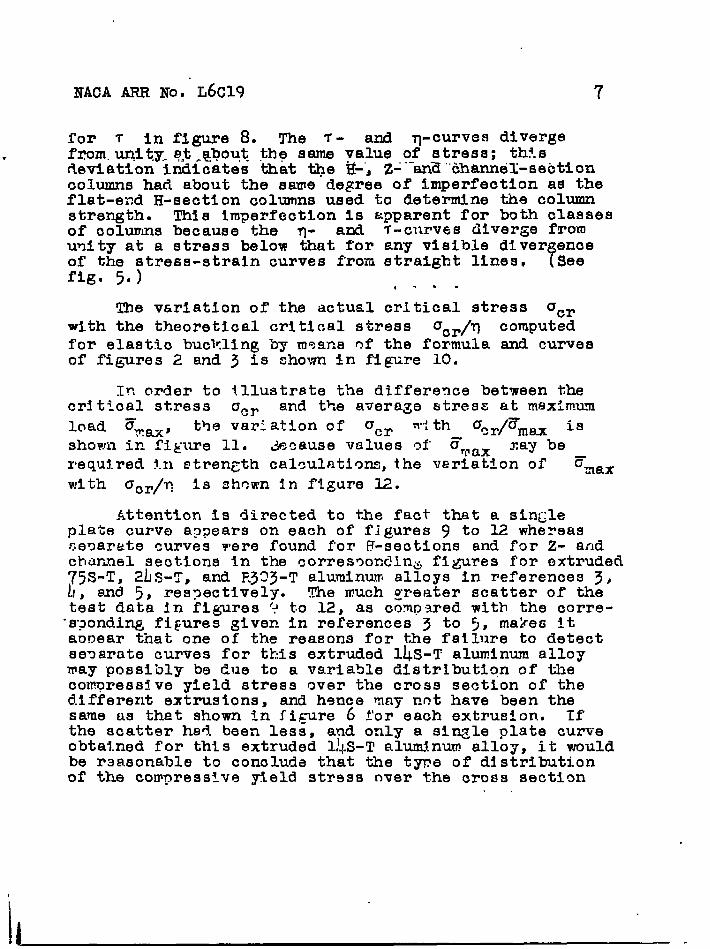
of the Z- and channel-section columns ,were varied in the9...---Zsame..manner.-.as.the flange widths -foq-$he,-H-section
columns, The lengths of the columns were sel-eotedso “ “as to obtain whenever possible a desirable three half-wave burkling pattern In accordance with the prl.nciplesin reference 8. The tests were made with the oolumnends ~round flat and square and beartng directly. againstthe testing-machine ’heads. In these local-instabilitytests, measurements were taken of the cross-seotlonaldistortion, and the critical stdess was determined asthe stress at the point near the top of the knee of thestress-distortion curve where a marked increase in
distortion first occurred with small Increase in stress.
The method of analysis presented herein differsfrom the ~ethod presented in reference 1 in that theinside face dimensions were used to define bF and
This d,eflnition ofbw”
% and b~j for extruded sectionswith small fillets was previously used in references 3to 5 ~n order that the theoretical and experimentalbuckling stresses would agree within the elastic range,For f~~ed Z- and channel sections with an inside bendradius of three times the sheet thickness (references 1and 2), bF ond bw were defined as cent9r-llne. widthswith square corners assumed.
KESTJT,TSAED DISCUSSTO~
Compressive Properties
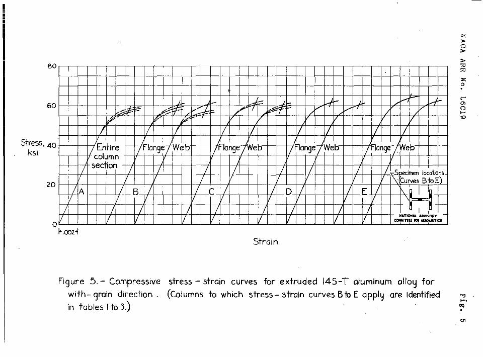
The compressive stress-strain curves that apply tothe extruded l]AS-Teluminum alloy used in this investl--~atlon are summarized in fl~:ire5. !thevariation incompressive yield stress shown .bythe dashed curvesindicates the maximum ,?.inferencesthat were found toexist between the average values obtained at the ends ofthe fliff’erent20-foot extp~sions; In some cases, thisvariation was so small that onl~ a sl~rle curve is shown.Curves A agaly to the material used for the flat-end
s column tests, whereas curves B to E anply to that usedfor the local-instability tests. The colimns to which
I the stress-strain curves BtoE apply are identified
] by the letters given in tables 1, 2, and 3. The averagevalue of .Ccv that applies to all the flat-end
H-section co&ns is 57.() ksi and to all the local-,i’ instability tests Is 59.8 ksi for the flange material!* and 5~.3 ksl for the web material.

I. .
. .
6 NACA ARR NO. L6c19
The ave’ragi values of acy for the web were lower
tkan-those for the flange. In a few cas6s, however,
individual velues of ‘cy for the web were .sliglhtlyhigher than th.o;eobtained far ‘he flange. A surveyof Ccy over q cross”sectlor.of -+&-elargest extrusion{sea f~g. 6) sb.owed that the values o.f 0Cy were lower‘L~- the outer than in the inner part of the flanges.~Jimitedt~t~ on the ~nte~ediata.size extrugion i~icatedv.~reunifom dlstributton of ‘Cy over the flange widths
than shown in fi&ure 6. The varietion of compressive~!.eld stre~:th shown,.therefore, should not be regardedneces~~rlly as ty’~ic~lfor extrusions of this elloy.
Colurn .md Plate %~pressive Strengths
Because the comrecsive oropert~es of an extrudedaluminum alloy may var~-considerably, tk,edata andcharts of this regort should not be ucet!for desiLn pur-~oses for eytrus!.cns of l)LS-Taltiminuw alloy thr~th-avea~~rec~alllydifierent compressive properties frorltbmsereported herein, unless a suita>le metkod is devised fora~justing test results to ficcauntfzr Variations iamater: al properties, (Aver~ge values of ~cy ar9 given .~r,r~un~.nl~qlj~rson f~.FsO7ta 12.)” The results of th9cold:m and local-instability tes$s of extruded 14S-Taluminum a?.loy firesmmarlzed hsreln; a disc-tisstonofbasic relationsy,l~,~“: Zive:+,in re~ereHc2 1.
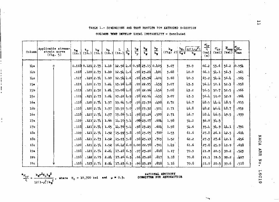
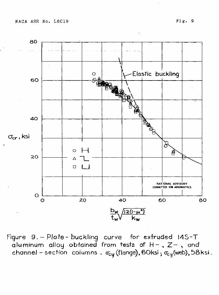
plete-comoressj.ve strtingth.-The results af theIocal-instability tssts ~f tke—~-, Z-, findcka.ni_ael-section columns used to deterrdns the plate cam.>res.sivestren~:thare given In tables 1} 2, and 3, re~lJ~cti~-~~~.
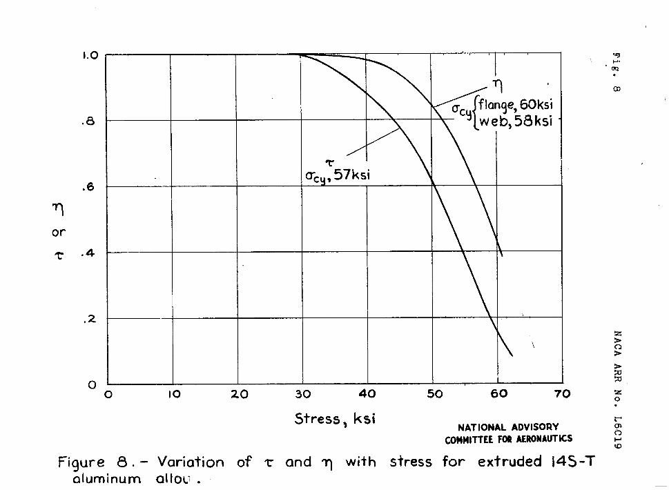
The pl&te-WcUling curve, sin~lo.gousto the columncurve of figure 7, is shown in f’ig~re~. The reducticmof the effective modulus of elasticity for plates 1]3Cwith increase in stres~ is indicated by the vari~.timof q with stress, which :s shown witk the curve
NACA ARR Noo”L6C19 7
for T in figure 8. The T- and q-curves diverge. from.unity. q$ .sbout the same value of stress; th?.s
fleviation indioates that we H-”,Z-‘-”an~“’tihtmneil-sebtioncolumns had about the same degree of imperfection as theflat-end H-section columns used to determine the columnstrength. This imperfection Is &pparent for both classesof columns because the q- and T-curves diverge f“romunity at a stress below that for any visible diver enceof the stress-strain curves from.straight lines, ?Seefig. 5.) ,-=.
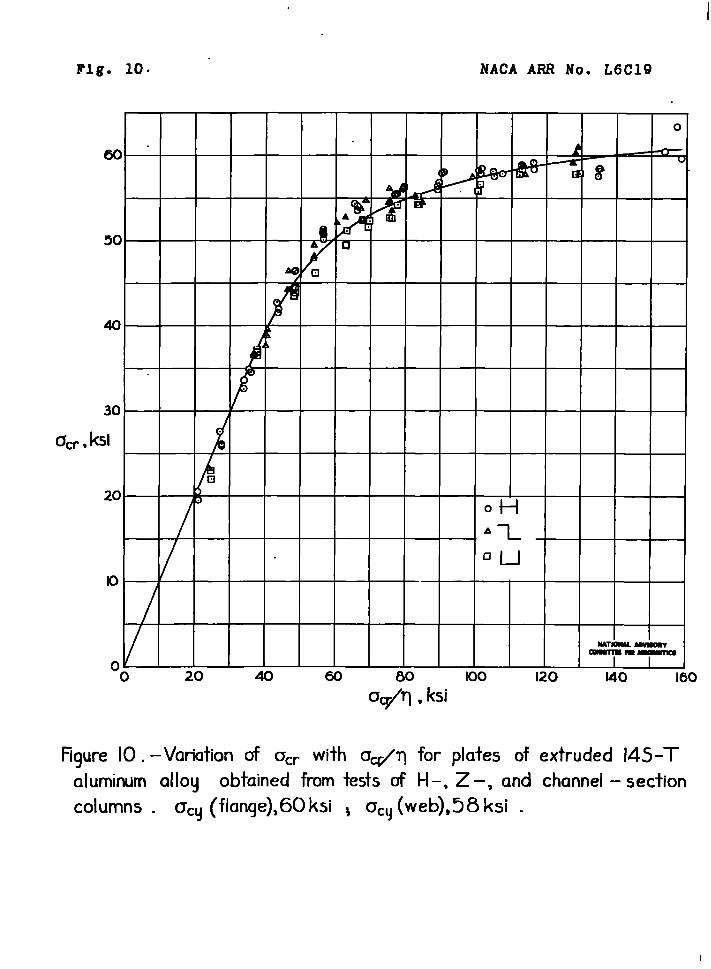
The variation of the actual critical stress Ocrwith the theoretical critical stress ‘cr/~ computedfor elastic buckling by m~ans nf the formula and curvesof figures 2 and 3 is shown in figure 10.
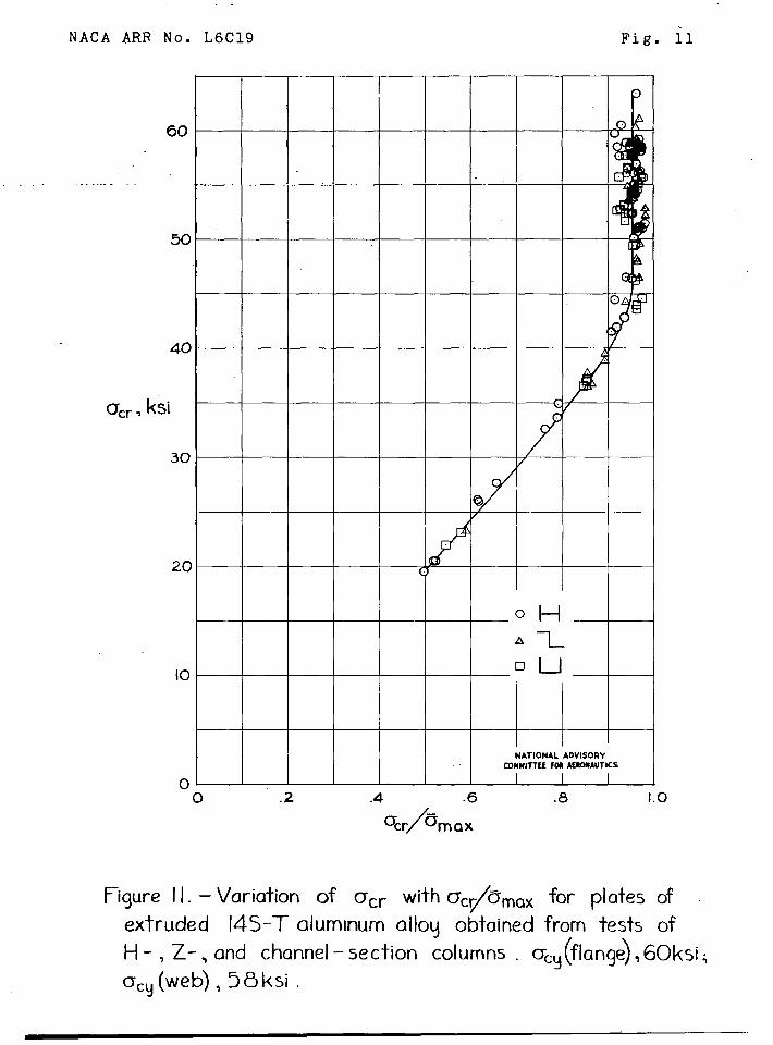
Irborder to ~llustr~te the differe~cg bet~een t~critical stress *Cr and the average stress at tnsxi.nnrm
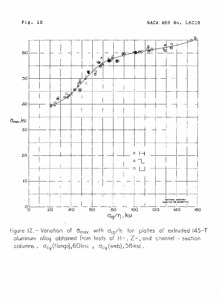
load 5WU, the varlatton of acr with -~c#mU issh~pjilin figure 11. ~.cause values of =,L,ax xay berequj.redfn strenCth calculations, the veriati.on of ~maxwith ocr/T is shcwn in ftgure 12.
Attention is directed to the fact that a sinLleplate curve agpears on each of fjgures 9 to 12 whenaasce~arete curves ~’erefound for F-sections and for Z- a.iidctlar~elsectl~ns in the corres~ondinz. figures for extruded75S-T, 2~s-T, and F.323-Taluminum alloys in references 3,~1, and 5, res~ectively. The much greater scatter of thetest data in figures 2 t.o12, as compared with the corre-.s-~ondingf’iguresgiven in references 3 to 5, ma%es ita~oear that one of the reasons for the f’allnre to detectseaarate curves for this extruded 14S-T aluminum alloymay possibly be due to a variable dlstrlbutiqn of thecompressive yield stress over the cross section of thedifferent extrusions, and hence may not have been thesame as thet shown in figure 6 t’oreach extrusion. Tfthe scatter haq been less, and only a si~le plate curveobtal.nedfor this extruded l!.@-Taluminum allo~, it wouldbe reasonable to conclude that the type of distributionof the compressive yield stress over the cross sectim
,,
8.” NACA ARR NO. L6C19
was different from that found for the other extrudedaluminum alloys (references 3 to 5).
Langley Kemorlal Aeronautical LaboratoryNational Advisory Cormnttteeior Aeronmtics
Langley Field, Va.

N.ACAARR No. L6C19
PREFERENCES“.. ., , - .. .. . .. .-, . .. . . . . .
11. Lundquist, Eugene E., Schuette; Evan H., Heimerl,George J., end Roy,J. Albert: colwn and plateCompressive Strengths of Aircraft StructuralMaterials. 24s-T Aluminum-Alloy Sheet. NACAARR F@. L51?01,1945. .
2. Heimerl, George J., and Roy, J. Albert: Column andPlate Compressive Strengths of Aircraft Structuralyater~alsa 17S-T Aluminum-Alloy Sheet. NACA ARENO. L5F03 , 1945.
3. Heimerl, GeorZe J., and Roy, J. Albert: Column andPlate Wxcpresslve Strengths of Aircraft Structural?l~at9ria19, Extruded 75S.T AIUn\n~ Alloy. FA5AAT? No, L5F~8~, 194.5.
h. Heirnerl,Ge9rge J., and Roy, J, Albert: Column andPlate comaress~ve Strengths cf A~rcraft Structural~~aterta~~. Fxtrufied2!&T Alumtnum Alloy. .RACAA?l?1?0.L5F06b, 1945.
~. Feimerl, Gecu’ge J., end ~ay, D@uglas P.: Calumn andPlate Com~ressi’.7eStren~tks of Aircraft Structuralll.ater~els. Extruded ~~0~-T Aluminum Alloy. IJACAAIW Yo. L~H@~, 1$-d.l.~.
\ 6. ~roll, v:.D., risher, 3ordon P., and I1elmerl,~eor~e J.:Ch~rts for calculation of the Crftical Stress for
Local Inst6bllity of Cclumns with 1- Z_ ch~~=el,and ?ecta~ular-lu’oe Section. l’ACA ~RR & . 3W)4,1943,
79 Yotanchik$ Joseph N., Woods, Walter, and Keinberger,Robert A.: Invest.lgation of ~v.etkodsof SupportingSin61e-Thickness Saecimens in a Fixture for Deter-mination of Compressive Stress-Strain Curves. NACARE No. L5E15 , 19~L5. \
~. H-eimerl,George J.S end Roy, J. Albert: ?@terminationof ~esirable Lengths of Z- and Shannel-SectionColuwms for Local-Inst~billty Tests.No. ~HIO , 194h.
NACA FB
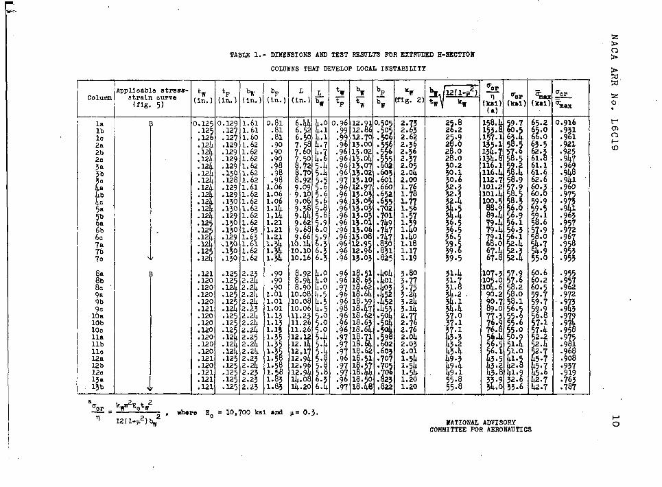
H-SECTIOHDIMENSIONSANDTEST RESULTSFOREXTRUDED
COLUMNSTHATDEVELOPLOCALINSTABILITY
TABm l.-
1 I I
column
——lalbU.?2a2b2CJa~b
tc
4:4C
}!
;:7a
%.
::::9b1::10b10CllallbllC12a12b120l~a13b
‘w ‘F bw bF L AIn.) (in.) (In.) (in.) (in.) bw
‘%rT =OPpa;) (kbl]
lpplicebleatress-straincurve(fig.5)
).1250.129
::;2 :E;.124 .129.i2L .129.124 .129.124.129.124 .130.124.x28.124.129.124.129.124.130.12L.130.4 .129.E5 .130
.130::1.124.:&.12i
.130.12 .130
i
1.611,611.601.621.621.621.621.621.621.611.621.621.621.621.621.651.631.611.621.62
i
0.81.81.81.90.90
%.98.981.061.061.061.11.+1041.211.21“1.211.341.341.34
z2. 32. 32.622.562,362.372.02.0i2.001.761.78
;:$1.571. 9t1. 0
1.40I..181.171.19
2 .8t2 .2
:3:228.028.030.230.130.632.3
g: 1?
$!
p
‘239.39.5
3;:?2757:!bj:t
;~i h:!1 .1 5 .2
z16.lL 5 *412.758.901.25 .9
g01.45 .5oo.~58.388.56.089.$56.979.456.179.456.3ii::;::i67.52.k i67.52.
1.916
:;%.921.925
k.97.9
8● 94
k.9 1.90:;;~
k.9 1.93● 957
:q.95.953.953
.955AZ;
;;g
.943
.97.?
:;?8.95.i.9 1
.968
.908
.937
.919:;;;
t;6.36.3
.121
.120
.120
.120
.120
.121
.120
.120
.120
.120
.L20
.120
.121
.120
.121
.121
.1211.1252.2
4.12 2.2?
:125S:3.12 2.24.12 2.2
‘o?:;:]:.:4.12 2.24.12 2.2
‘?.1242.2.12k2.24.1252.2.1252.2?.1252.23.1252.23.1252.23
\ ;$
[
.901.011.011.011.131.13l.1~1.351.351.31.5.?1.581. 831. 3
1.83
Ipg10:0810.0810.06
3.803.77
d3.73.
;:$2.7
1;:;6Z.oll
31.11
.i31.
&
34:437.0.37::
U43:243.4
~:~
55:855.8
13..2311,2611.2612.1212.412c1712.912.9k
z:; k14.20
2.032.011.541.541.541.201.20
a[WT?EctW2‘cr.=— , mh.re EC
11= 10,700ksl md p= O.3.
12(1-w2)# NATIONALADVISORYCOMMI’lTEEFOR AERONAUTICS
48
lhb
140
158
15b
15C
16a
16b
160
178
17b
18a
18b
18c
19a
19b
19C
TABLE l.- DINENSIOIWAND TEST RESULTSFOR EXTRUDEDH-SECTION
OOLIWfS‘IWW Ixn%LOPLOOAL IN?JTABILITY - ouncluded
tw ‘F bwh.) (In. ) (In.
1.1180.121 2.73
.118 .1202.73
.117 .1202.711
.119 .120 2.73
.119 .1212.72
,119 .1212.73
.118. .1.202.711
.118 .1202.74
.118 .1202.74
.119 .K1 2.74
.118 .121“2.74
.119 .1212.74
.118 .1212.73
.120 .1212.74
.118 .1212.7~
.118 .122 2.T5
.118 .1232.74
%(in.]
1.10
1.10
1.10
led+
1.24
1.24
1.37
1.37
1.37
1.66
1.65
1.92
1.92
1.92
2.24
2.24
2.24
I I
12.56lL.60.98 23.150.405
12.54~.6 .9823.21.401
12.544.6 .9823.36.kol
13.164.8 .9922.95.45513.084.8 .9822.96.456
13.224.9 .9822.911.455
13.6L5.0 .9823.30.498
13.595.0 .9823.32.sol
13.865.1 .9823.26.500
14.705.4 .* 23.07.604
4.765.4 .9823.25.604
15*995.8 .9823.05.700
15.935.8 .9823.19.703
16.426.01.0022.78.701
17.286.3 .9723.20.818
17.266.3 .9623.28.817
17.236.3 .9623.29.818
3.67
3.68
3.68
3.07
3.08
5.07
2.72
2.71
2.71
1.98
1.98
1.53
1.52
1.491.17
1.18
1.18
“f--y 12(1-W )t~ ‘w
39.9
40.0
40.3
43.3
43.2
43.3
46.7
46.8
46.7
54.2
54.6
61.6
62.2
61.6
70.9
70.8
70.8
‘orT
(~a;
66.2
66.1
65.2
56.4
56.5
56.4
48.5
48.2
48.4
36.0
35.4
27.8
27,3
27.8
21.0
21.1
21.0
%c~ kw&Eotw2 lJATIOllALADWSORY—= - , wh.ra EO = 1o,700k~l and p = 0.3. COMMITTEEFOR AERONAUTICS
d-cr(kal
53.6
54.1
54.4
50.1
50.7
51.0
44.4
46.4
46.5
34.5
34.9
26.1
27.6
25.9
20.5
19.5
20.5
56.2
56.3
56.4
52.3
52.5
52.9
lL8.5
48.7
49.5
44.,1
42*51+2.1
&l.9
39.2
59.2
39.6
‘.954.961
.965
.958
*966
.961+
.915
● 953
● 939
.791
.614
.656
.618
.523
.497
.518

}o lum
lalblC2a2b2C
/?,&b5a5b
6a
;:
8:!
QaQb
10a10bllallbllC12a12b12C13a
Applicablestrea8.9tralncurves(fig.5)
B
E
TABLE2.- DIKENSIbNSAh~ TEST i?ESULTSFOR EXTRUDEDZ-SECTION
—.
‘w[in.)
1.126.127.121.126.122.125.126.124.12.12z.124
.120
.120
.119
.119
.119
.119
.’119
.119
.U?
.120
.120
.120
.120
.120
.120
.L20
.120
.120
‘F:in.)
).K8.129.129.128.131.128.128.127.127.127.127
,126.124.123.125.123.125.125.125.125
.120
.123
.123
.122
.120
.121
.121
.120
.121
bw bF Lin.) (in.) (in.)
$
1.61 0:;8 6.1+9 4.01.61
86.454.0
1.61 .91.611.0
i% k:;
1.61100 7.304.51.621.061.61,1.161::8$:21.621.348.0 5.0
i1.621.348.0 5.01.621.349.7 6.01.621.349.756.0
12.22 1.4 10.10 L.62.22 1.14 10.10,$.;2.23 1.37 12.2.22 1.37 12.18 y:2.23 1.60 13.00 5.32.22 1.63 12.99 5.9
:;% ::;2 ;Z:% 2:;2.22 1.86 14.21 6.4
, I 1a
5cr
kWr2Ect~2—=n * where Ec = 10,700kai and v = 0.3
12(1-y2)bW2
.00’ 22.85 .415;;: 2$.8$ .417
.511.98!22:89 .50700!22.86 .504:99{22.88 .604.99~22.84 ;:;.00 22.7.9922.7II .822z
i I
‘wfig. 3]
%2.351.92.01.9i1.691.321.321.321.31
2:99.2.92.1i2.251. 01.$1.61.331.32
3.623.682.89
“3:. ;2.192.162.161.31
r% 2(1-p2)q ‘w
NATICINALADVISORYCOMMITTEEFUR AERONAUTICS
?
Fmm(kal)
g:?.61.662.260.760.960.3
;Z::57.857.1
57.057.053.1
i3.87.1
!J::
H
$;:!5;.:
z4?
:7
44:1$;.~
.
.—
1-N
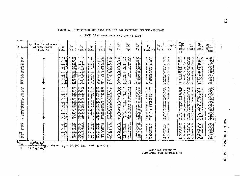
TABLE 3.- ETYEN.SIONSAIW)TEST FESULTS FOR EXTRUDED CHANNEL-SECTION
COIIWNS THAT DEVELOP LOCAL INSTABILITY
—
‘Cr‘pQ;g;::c:;:a8-tw tF bw bF & >‘Olumn
~ > ~
F
2(1-p ) r Fmm rc~
(fig. ~) (in.) (In.) (in.) (in.) (i:.) % ‘F tw‘w
bw (fig. 3) tw % (x) (k%) (kd) -~(a)
max.m------
la B
/
0;::; 0.129 1.61 0.98 6.48 4.0 0.94 13.34 0.606 2. 6? z
28. 128.2 57.8 61.0 0.94Elb .1291.61 .97 6.494.0
8.601 28. 129.~ 5 .8 60.8
2a .126.1281.611.077.26L.y je ::g .666 % 8.951
30.5 112.95 .4 60.22b .126.1.281.611.07
1.30 4.5 1.91
3a .126.1281.621.lJ .08 ~.o .9812:87:;% g:~ %:$ ;Z:zW :;&
2b .12
2.1281.621.4 .8.07.0
i z:;:z:% ;g; :!8 :
100.455.760.2.12 .12E1.611.349.9 .1
.925.
L:76.05 .1 56.8
.12z
.1281.611.31
.9812.8 ;Z.; 3.935
.12 z:8i2:; 11.33
.128~.611.3.951
;Z:;;2:?;7::k:
1.30.124 :;;% t8 :g!
37.3.1281.611.349.806.1 1.31 i.9.21
37.5 75.252.7 5 .8 .928
5a B .121 .12112.22 1.I.410.12 4.6 83.4 5 .1 56.9;;:t
.9~ 18*38 :;:; :;:;~,3.$
5b
.1
;;;; .121!2.22 1.4 10.10 J.I.5 .9 16.3 1?83.3 5 .2 56.6~; .124,2.22 1.13 10.12 lL.6 .9 18.36 .509 83.5 5~.2 56.7
:;;:
.121 .124 2.22 1.36 12.21 5.5 ;;9 ::.;; .613 2.19 63.1 1.1 52.7.956
: .121 .124.2.22 1.36 12.21 5.5
.121 :Ek ::% ::?; W ;:3 :;& %; ;!: ::Z
41:6.121 41;0 %8 i;”z 5;:5 ?
7a 46.6 & ~:] ~;.; ;;?7b .121 .124 2.22 1.60 12.99 5.8 .98 16.35 .720
i
1.67 L6.9c. .121 .124 2.22 1.60 1 .00 5.
t {.98 18.33 . 20
$48:1 43:5 45:2 .2
1 j28 ::!!
$.;
8;.121 .12 2.22 1.84 1..18 6.
?.9 18.33 . 28 37* 3 .2 43.5 ?l
.121 .12 2.22 1.84 14.18 6.~8C
.9 18.31.122 .124 2.22 1.84 14.16 6.b. .98 18.28 .828 1:;1 ‘8 ig.
37”. 3i.5 ,!i3.2 :&37.9 36.9 43.3 .852
9tl D .120 .122 2.74 1.12 12.50 4.6
J
.98 22.76 .408 3.719b
39.1.120 .123 2.7
J?1.11 12.51 lL.6 .98 22.71 .40
2 :38.9 %:8 z:; ;;:8 :?’8
.121. .122 2.7 1.11 12. 0 ~.6l:c .120 .121 2.74 1.37 13lla .120 .121 2.74 2.24 1<:1 2:; jj Eli %; !2 ?j:
$: g:: W :;k
llb:
.121 .1.212.74 2.24 17.27 6.3 .99 22.72 ●818 1.32 65:3 24:7 22:0 l::! :%>
‘c rkw+!zctw’
—- = ——2’
where Ec~
= 10,700 ksi and p= O.?.12/1-~2)bw
NATIONAL ADVISORYCOMMITTEE FOR AERONAUTICS
zo●
.
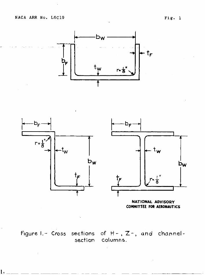
NACA ARR No. L6C19 Fig. 1
m. .—
[ -
T- “ -+*bF
J_Lt~ r= &“
4
t-b+ t-
bF-
t~I
+ tw
bw
—}
t
1—
NATIONAL ADVISORYCOMMITTEEFORAERONAUTICS
Figure l.- Cross sections of H - , Z- , and channel-
sect ion Columns.
I ‘?
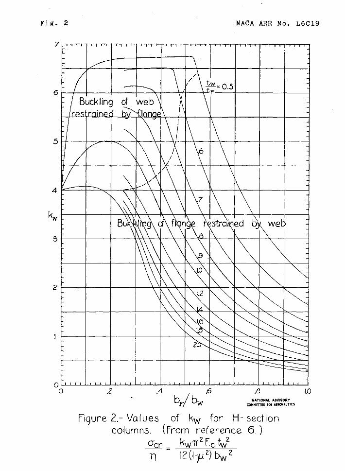
Fig. 2 NACA ARR No. L6C19
7 1 1 1 I I t I 1 1 I 1 I 1 1I1 III1 1,I1 II1I I1I1 11II I1II
6—
of web\b>f]~ap\ I
I\
5
I/
\
4 \
kW - \
3
\
2 \
\ \
I \ \ \ \
z.
\
o-’’” I I I I 1 I 1 I I I I I I ! I t I I I I I 1 I I I I I # I I I I 1 I 1 I
o .2 .4 .6.
b/bFW
Figure 2,- Values of kw for H-columns. (From reference
.(5 10FiATIONAL ADvIsonv
COMMlllEE FW MSONAUTICS
section
6.)
~cr . kwrz ECtw2
n Iz(l-pz) bwz
INACA
7
6
5
4
kw
3
2
ARR No. L6C19 Fig. 3
I1i1 I1I# 1Ii1 111I I1I1 I1II 1It.=L IIII 1I11 i11t
\
/ ‘
restraine\
~
\ ,
~ ‘
\ \/\
\
\\
\ \.
=
2 1 I I 1 1 I 1 I I 1 1 1 1 1 1 1 I 1 1 1 I 1 1 I 1 1 1 1 1 1 1 1 1 1 1 1 I I I 1
-o .2 ./3 Lo
.
“4b,/~ “6
Fiqure 3.- Values of kw for Z- and channel-
NATWNAL ADVISORY,COMNlllfE K, M-AUTKS
section columns. (From reference 6.)
*= kwn2 Ec twz
Q 12(l-#z) bw2
NACA ARR No. L6.(319 . Fig. 4
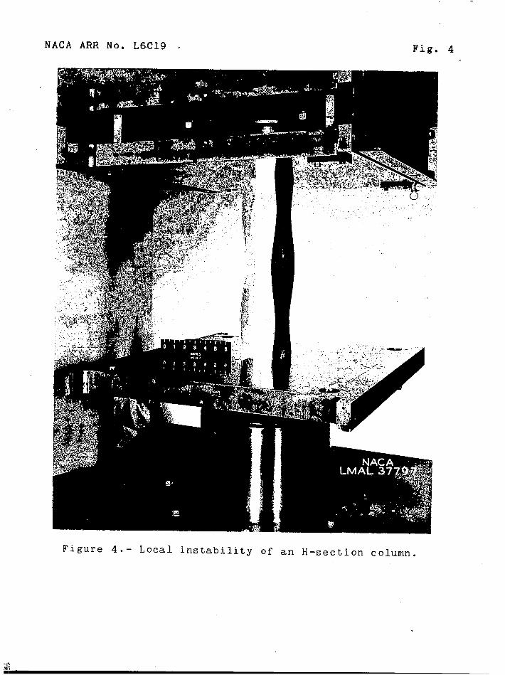
Figure 4.- Local instability of an H-section column.
I
80
60
Stress,40
ksi
20
0
Figure 5.- Compressive
with- grain direction .
in tables I to 3.)
zo.
Strain
stress - strain curves for extruded 14S-T aluminum alloy for
(Columns to which stress- strain curves Bto E apply are identified wP.w.
CJl
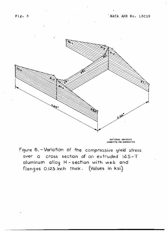
Fig. 6
L
.
.
“NACA ARR No. L6C19
NATIONAL ADVISORY
COMMITTEE FOR AERONAUTICS
Figure 6. – Variation of the compressive yield stress
over Q cross section of an extruded 14 S-T
aluminum alloy H - section with web and
flanges 0.125 inch thick . (values in ksi~
10
60
50
40
Stress,ksi
30
20
10
0
NATIONAL ADVISORYCOMMITTEEFORAEROIWTKS
zo●
0 20 40 60 80
%l--
* m.“
-a
Figure 7.- Column curve for extruded 14 S-T aluminum alloy obtainedfrom tests & flat- end H - section columns .
‘CY ‘57ksi .
1.0
.8
.6
Tor
T .4
,2
00 10 20 30 40
Stress, ksi
50 70
NATIONAL ADVISORYCOMMITTEEF~ AERONAUTICS
Figure 8.- Variation of ~ and q with stress for extruded 145-Taiuminum ollou .
NACA ARR No. L6C19 Fig. 9
80
60
40
G-, ksi.
20
.,
0
OH
A~—
❑ u
0“0 20
Figure 9.– Plate- buckling
\
%
4-i--~Elastic buckling
\
\
%
“\
El””
——
40
T
% l!!?
TI
NATIONAL AWI!COMMITTEE FORAERONAUTICS I
60 80
curve for extruded 14 S-T
aluminum alloy obtained from tests of H – , Z– , and
channel – section columns . acy (flange), 60ksi j mcg(web),58ksi .
I
Fig. 10. NACA ARR No. L6C19
60 “
A
50 ‘ A
40
30
,ksi
20 ~Oti
❑ u10
MTIOIMA~m8mrmm~o
0 20 40 60 80 100 120 140 160
a#rl ,ksi
17gure 10.-Variation d Ocr with a~~ for plates of extruded 145-T
aluminum alloy obtained from tests UF H –, Z -, and channel – section
columns . OCY(flang4,60 ksi ; q,, (web),58 ksi .
INACA ARR No.
60
— . ..— .
50
40
a=,. ksi
30
20
10
00
L6C19
.2
I
3?!.
Fig. 11
Al- 1
4---LE_D u
NATIONAL ADVISORYCOMMITTEE F~ AERONAUTICS
.4 .6 .8 1.0
Figure II. - Variation of ~cr with C@Omax for plates of
extruded 145-T alummum alloy obtained from tests of
H -, Z-, and channel - section columns . a.~(flange~, 60ksi;
acg (web) , 58ksi .
I
Fig. 12 NACA ARR No. L6C19
60
am
50
0%
40 Wti
dmx,ksi
30
20
10
NATIONAL ADVISORY
oCOMMITIUFMMROIIIUTICS
Io 20 40 60 80 100 120 140 160
~c~q , ksi
Figure 12. - Variation of ?5maX with CJC/~ for plates of extruded 145-T
aluminum alloy obtained from tests of H –, Z–, and channel – section
columns . oC9(flange),60ksi ; oCq (web),38ksi .
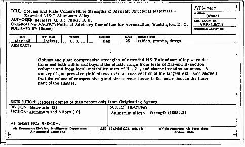
TITLE: Column and Plate Compresslve Strengths of Aircraft Structural Materials - Extruded 14S-T Aluminum Alloy
AUTHOR1S): Heimerl, G. I.; Nlles, D. E. ORIGINATING AGENCY: National Advisory Committee for Aeronautics, Washington, D. C. PUBLISHED BY: (Same)
r
fiYO- 7457
(None) OBIO. AOfNCY NO.
ARR-L6C19 PUOUSHINO AGENCY HO.
Mav '46 Unclass. u.s. Eng. PAOCS lUUSnATIONl
25 1 tables, graphs, drwgs ABSTRACT:
Column and plate compresslve strengths of extruded 14S-T aluminum alloy were de- termined both within and beyond the elastic range from tests of flat-end H-sectlon columns and from local-instability tests of H-, Z-, and channel-section columns. A survey of compresslve yield stress over a cross section of the largest extrusion showed that the values of compresslve yield stress were lower in the outer than in the inner part of the flanges.
DISTRIBUTION: Request copies of this report only from Originating Agency DIVISION: Materials (8) SECTION: Aluminum and Alloys (10)
ATI SHEET NO.: R-8-10-8
SUBJECT HEADINGS: Aluminum alloys - Strength (10589.6)
Air Documonta Division, tntolligorxo Doportmonr Air Mutes rial Command
AIR TECHNICAL INDEX Wright-Patterson Air Fared Baso Dayton, Ohio
-I