Embed Size (px)
Citation preview

This document is downloaded at: 2018-08-30T15:20:07Z
Title Fabrication and Characterization of SiC-Hybridized Carbon FibreReinforced Aluminium Matrix ComPosites
Author(s) Cheng, Hui-Ming; Kitahara, Akira; Akiyama, Shigeru; Uchiyama, Yasuo;Kobayashi, Kazuo; Hideaki, Sano; Zhou, Ben-Lian
Citation 長崎大学工学部研究報告, 23(41), pp.201-214; 1993
Issue Date 1993-07
URL http://hdl.handle.net/10069/24421
Right
NAOSITE: Nagasaki University's Academic Output SITE
http://naosite.lb.nagasaki-u.ac.jp

Report of The Faculty of Engineering, Nagasaki University, Vol.23, No. 41, July 1993' 201
Fabrication and Characterization of SiC-Hybridized
Carbon Fibre Reinforced Aluminium Matrix ComPosites
Hui-Ming CHENG*, Akira KITAHARA**, Shigeru AKIYAMA**
tt ' ' Yasuo UCHIYAMA*, Kazuo KOBAYASHI*, Hideaki SANO* ' ' .t and Ben-Lian ZHOU***
Carbon fibre reinforced aluminium matrix(CFIAI)composites were fabricated with a hybridization
technology through pressure casting and characterization of the hybrid composites obtained was carried
out. Hybridization with SiC additive could improve the infiltration performance of fibre preform, control
the fibre volume fraction, and increase the fibre-strength transfer efficiency of the hybrid composites. The
longitudinal tensile strength of the hybrid combosites was greatly improved compared with that of the con-
ventional composite. It was found that the strength deterioration of high-modulus・cabon fibres(HMCFs)
during fabrication was not heavy and depended upon the type of aluminium matrix, while the strength of
high-strength carbon fibres(HSCFs)was greatly reduced by aluminium matrix, but the degradation did
not depend on the variety of the matrix. As a result, the longitudinal tensile strength of hybrid HMCFIAI
composites was higher than 800 MPa, while that of hybrid HSCFIAI composites was about 400 MPa. Con-
trariwise, the transverse tensile strength of hybrid HSCFIAI composites was much greater than that Of
hybrid HMCFIAI composites. The results of thermal exposure of hybrid HMCFZAI-Si composites at 773
K showed that their longitudinal tensile strength increased, then decreased, while their transverse tensile
strength increased montonically, as the exposure was proceeded. The thermal exposure slightly reduced
fibre strength, caused chemical interactions, and resulted in changes of fracture morphology and fibre
pull-out length of the composites. It was also concluded that fibrelmatrix interfacial bonding has an impor-
tant effect on the mechanical properties of CF/Al composites and intermediate interfacial bonding can be
expected to result in good longitudinal and transverse tensile strengths of CFIAI composites.
1. lntroduction ・ Metal matrix composite materials (MMCs) have been developed to offer attractive properties including high ten-
sile strength and stiffness, improved fatigue life, and goQd mechanical properties at elevated temperatures. Many
fabrication technologies for MMCs have been developed. One of the most successfu1 fabrication technologies is of
intruding liquid metal into a fabric on prearranged fibre configuration called a preform. This intrusion can be car-
ried out under pressure, vacuum, or combination of pressure and vacuum. The techniques able to be utilized in this
area include die casting, pressure infiltration, and vacuum infiltration, etc. The potential advantage for these pro-
cesses is near-shape part fabrication in a simple and cost-effective manner. Among these techniques, pressure in-
filtration, often called pressure casting or squeezing casting, is the most commonly used technique, Some
developmentsi・ 2) show that, as one of the most important MMCs, carbon fibre reinforced aluminium(CF/Al)
*Department of Materials Science and Engineering
**Government Industrial Research Institute:Kyushu, AIST, MITI, Shuku-machi, Tosu-shi, Saga ,841,
***Institute of Metal Research, Academia Sinica, 72 Wenhua Road, Shenyang, 110015, China
Japan

202 Fabrication and Characterization of SiC-Hybridized Carbon Fibre Reinforced Aluminium Matrix Composites
composites can also permit the use of this technique, thereby eliminating the need for precursor wires as an in-
,.,t tt .t 1.termediate step.. ,'.'' .'L' , .'・ .', .,. 1{ ,' ,Tj'/・ ':,, ' , '.・.' '.".-,・..',: ・. ' Nevertheless, this pressure casting progess also suffers from critic{ 1 prob,lems. (i)Bec,ause qlyminiurp, .qoes not
spontaneously wet carbon fibres, the direbt infiltration 6f molten aluminium into the pr6fotm of carbon
multifilaments needs high pressure and high melt temperatures. As a result, not only do fibre contacts in the CF/Al
composites obtained occur and composite failures initiate at these contact points 3 ), but also chemical interaction on
fibfelmatrix ihferface is accelerated by the high' t6mpeiatures;'' (ii)The fibte volume fraction 6f CF/Al composites
is difficult to control in a sense of satisfying,.yariog, s.T,gquir..emen,1 .s gf different customers with the minimum fibre
consumptioh' , or saving expensive' carbon fibres.
Recently,・ dne entirely different approach has been developed for the manufacture of CF/Al composites directly
by a casting process. It is based on the pre-distribution of SiC whiskers or particles among.carbon fibres4). It has
been reported that the longitudinal flexural strength of the hybrid composites was improved in comparison with
that of the conventional composites. ' ・ ・ - Although CF/Al composites can be developed using the above fabrication methods to offer excellent mechanical
properties, all these properties strongly depend on fabrieation methods and conditions, varieties of carbon fibres,
and aluminium matrixes. Moreover, it is known that, though the properties of CFIAI composites m'ay be excellent
at ambient temperatures, in most cases, they are disappointing at elevated temperatures.'This is because chemical
interactions occur at the interface of carbon fibres and alUminium matrix, causing fibre degradation and matrix em-
brittlementt5・ 6) .
A number of research works on the fibre degradation of CF/Al composites and on the properties'of CFIAI precur-
sor wires after thermal exposure have been presented 2 ・ 7-9). Nevertheless, most bf these investigations were main-
ly focused on the strength degradation of carbon fibres and on the propenies of CFIAI composite precursor wires
after heat treatment; they did not deal with the behaviour of CFIAI composite bodies.・ Because CFfAl composites
are generally considered for applications at intermediate or elevated temperatures, it is important to understand the
thermal exposure behaviour of CFIAI composite bodies and the effect of thermal exposure on the fibrelmatrix in-
terface of CFIAI composites.
In the present work, unidirectional SiC particle-and SiC whisker-hybridized 'carbon fibre reinforced aluminium
matrix composites(abbreviated as SiC,-CF/Al and SiC.-CF/Al composites, respectively)were prepared
through pressure casting and were characterized. The functions of SiC particles or・whiskers in the infiltration pro-
cess and their effect on the strength of the compbsites obtained Were discussed. Finally, the effect of thermal ex-
posure on the longitudinal and transverse tensile strengths and on the fibre degradation behaviour of hybrid CF/Al
composites were investigated.
2. E`xperimental
The carbon fibres used in this investigation were polyacrylonitrile (PAN) based high-modulus and high-strength
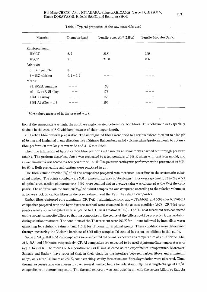
fibres(HMCFS and HSCFs, respectively). Some'properties of the fibres, along With those Of SiC particles and'
whiskers and aluminium alloys, are listed・ in Table 1 1 The tensile strengths of carb6n fibres and aluminium alloys
weire 'measured ・in the present work, whereas the other data in Table 1 were quoted froM the manufacturers'
technical specifications. Tensile strength test ・of carbon fibres was performed on single fibres and the number of
testing was 50 having a gauge length of 25 mm at a crosshead speed of 8. 3 ptmls. The results were evaluated via the
Weibul1 distribution theory.
The sequences adopted to prepare hybrid carbon fibre preforms incltided the following/two mairi steps.
(i)Distribution of SiC particles or whiskers among carbon fibres. The carbon fibres were impregnated into an
aqueous suspension of O-15 wt% SiC particles or whiskers, Using a'polymer as a binding agent and an
organometallic compound as a dispersing agent. After 'this treatment, the particles and whiskers were rather
uniformly distributed among the carbon fibres with the binding of the binder. However, when additive concentra-
Hui-Ming CHENG, Akira KITAHARA, Shigeru AKIYAMA, Yasuo UCHIYAMA,Kazuo KOBAYASHI, Hideaki SANO, and Ben-Lian ZHOU
203
Table 1 Typical properties of the raw materials used
Material Diameter (ptm) Tensile Strength* (MPa) Tensile Modulus(GPa)
Reinforcement:
HMCF HSCFAdditive:
a-SiC particle
P - SiC whisker
Matrix:
99. 99%Aluminium
Al-12 wt% Si alloy
6061 Al Alloy
6061 Al Alloy-T6
6.7
7.0
O.6
O. 1-O. 6
2331
3160
38
172
158
294
359
236
t
*the values measured in the present work
tion of the suspension was high, the additives agglomerated between carbon fibres. This behaviour was especially
obvious in the case of SiC whiskers because of their longer length. "
(ii) Carbon fibre preform preparation. The impregnated fibres were dried to a certain extent, then cut to a length
of 80 mm and laminated in one direction into a Shirasu Balloon (expanded volcanic glass) preform mould to obtain a
fibre preform 80 mm long, 9 mm wide and 3-5 mm thick.
Then, the infiltration of hybrid carbon fibre preforms with molten aluminium was carried out through pressure
casting. The preform described above was preheated to a temperature of 648 K along with cast iron mould, and
aluminium matrix was heated to a 'temperature of 1053 K. The pressure casting was performed with a pressure of 49 MPa
for 60 s. Both preheating and casting were practised in air.
The fibre volume fraction(Vf)of all the composites prepared was measured according to the systematic point-
count method. The points counted were 360 in a measuring area of 96x60 mm 2 . For every specimen, 12 to 20 pieces
of optical cross-section photographs (xlOOO) were counted and an average value was calcuated as the Vf of the com-
posite. The additive volume fraction (V.dd) of hybrid composites was computed according to the relative volume of
additives stuck on carbon fibres in the pre-treatment and the Vf of the related composites.
Carbon fibre reinforced pure aluminium (CF/P-Al) , aluminium-silicon alloy (CF/Al-Si) , and 6061 alloy (CF/6061)
composites prepared with the hybridization method were examined in the as-cast condition (AC) . CF/6061 com-
posites were also investigated after subjected to a T6 heat treatment (T6) . The T6 heat treatment was conducted
on the as-cast composite billets so that the composites in the centre of the billets could be protected from oxidation
during solution treatment. The conditions of the T6 treatment were 793 K for 1 hour followed by immediate water
quenching for solption treatment, and 413 K for 18 hours for artificial ageing. These conditions were determined
through measuring the Vicker's hardness of 6061-alloy samples T6-treated in various conditions in this study.
Some of SiC,-HMCF/Al-Si composites were subjected to thermal exposure at a temperature of 773 K for 72, 144,
216, 288, and 360 hours, respectively..CF/Al composites are expected to be usd( at intermediate temperatures of tttbl673 K to 773 K. Therefore the temperature of 773 K was selected as the experi'i"'6ntal temperature. Moreover,
Sawada and Bader2) have reported that, in their study on the interface between carbon fibres and aluminium
alloys, only after 240 hours at 773 K, some cracking, cavity formation, and fibre degradation were observed. Thus,
thermal exposure time was chosen t6 cover several hundred hours to understand fully the strength change of CF/Al
composites with thermal exposure. The thermal exposure was conducted in air with the as-cast billets so that the

204 Fabrication and Characterization of SiC-Hybridized Carbon Fibre Reinforced Aluminium Matrix Composites
composites in the centre of the billets could be protected from oxidation during the treatment.
From all these composites,"dumb-bell"shaped longitudinal tensile specimens having a gauge length of 25 mm, a
width of 4 mm, and a thickness of 1 - 1 . 5 mm were prepared. Transverse tensile samples were 30 mm in length, 8
mm in width, and 1 - 1 . 5 mm in thickness. All the longitudinal and transverse tensile specimens were polished with
eSiC paper to 1000 grit before tensile testing. Tensile testing was performed at room temperature at a crosshead
speed of 8. 3 pm/s using an Autograph testing machine. The tensile fracture morphologies of these specimens were
studied with a scanning electron microscope(SEM) .
Some of CF/Al composites were also investigated with a transmission electron microscope(TEM)to clarify their
interface characteristics. The specimens for TEM observation were mechanically polished to 30- 50 ptm thick, and
then thinned with an ion-thinner in the following sequence:18 degrees and 5 KV for 3 hours; 15 degrees and 4. 5
KV for 10 hours; and 10 degrees and 4 KV for 4 to 5 hours.
To understand the strength change of carbon fibres after composite fabrication and thermal exposure, single
fibre tensile test was performed on the fibres after preheating and extracted from CF/Al composites. The extrac-
tion of carbon fibres from CF/Al composites was accomplished with a 10 wt% NaOH aqueous solution. The
number of fibres tested was 50 having a gauge length of 25 mm. Tensile testing was carried out at a crosshead
speed of 8. 3 ptm/s. The results obtained were evaluated via the Weibull distribution theory.
3 . Results and Discussion
3. 1 Effect of SiC hybridization on preparation and properties of HMCF/At-Si composites
3. 1. 1 Microstructure of hybrid HMCF/Al-Si composites
The microstructure of transverse cross sections of the HMCFIAI-Si composites obtained is shown in Fig. 1 .
<a)
$
$Si
xli.wa'
wq
wh-1Opm
Fig. 1 Optical micrographs of transverse cross sections of (a) HMCF/Al-Si, (b)SiC,-HMCF/Al-Si(V,dd: 1.0
vol%) and (c)SiC.-HMCF/Al-Si(V,dd: 1. 1 vol%)composites

Hui-MingCHENG,AkiraKazuo KOBAYASHI, Hid
KITAHARA, Shigeru AKIYAMA, Yasuo UCHIYAMA,eaki SANO, and Ben-Lian ZHOU
205
Apparently, the structure of the hybrid composites is quite different from that of the conventional composite. It was
found that the carbon fibres in the hybrid composites were infiltrated with aluminium matrix to yield a sound billet.
Very few carbon fibres made contacts with one another and little voids existed between the fibres and the matrix.
On the other hand, in the conventional composite shown in Fig. 1 a, the carbon fibres were closely packed one by
'one. Not only did most of them make contact with the neighbouring fibres, in some areas almost perfect hexagonal
packing being observed, but also at the sites close to the contacts, impregnation of aluminium was incomplete, and
voids existed. It can also be noted that the concentration of carbon fibres in the conventional composite was much
higher than that in the hybrids. Comparing Fig.Ib with c, there seems to be no big difference in microstructure in
addition to their fibre volume fraction between SiC,-HMCF/A!-Si and SiC.-HMCF/Al-Si composites. Although the
volume fraction of SiC particles was almost the same as that of whiskers, the distribution of carbon fibres in SiC,-
HMCF/Al-Si composites was denser than that of SiC.-HMCF/Al-Si composites. This behaviour indicates that SiC
whiskers can make larger spaces between carbon fibres than SiC particles.
3. 1. 2 Longitudinal tensile strength and fibre volume fraction of hybrid HMCF/Al-Si composites
The longitudinal tensile strength(LTS)and
1OOOa.
g£ 8009g-
g- 6oo
Ert
v 400..=J-
9s
iliE`
v=.96gLoERo>OL
p.
L
60
40
20
(b)
/n)k;.rllllrl])..D.xxax.o
xt
(a) O HMCFLtdd-Si
-r SiC -HMCF/Al-SiCXxN. a sic:-HMcFiA!-si
N9.>-.-.N.a N"・Nii4..li '"-""'D"'------o
'-'-t" "'t
o
Ol2345 Additive Volume Fractlon (vol%)
Fig.2 Effects of additive volume fraction on(a)
fibre volume fraction and (b) longitudinal
tensile strength of hybrid HMCF/Al-Si com-
posites・
3. 1. 3 FractUre morphology of hybrid HMCF/Al-Si composites
Figure 3 gives the SEM fractographs of the hybrid HMCF/Al-Si composites. For the conventional composite
shown in Fig. 3 a, it can be seen that most carbon fibres were totally pulled out from the aluminium matrix or strip-
ped off the interface due to interlamilar failure. However, in the hybrid cases as shown in Fig, 3 b-d, although
many carbon fibres were pulled out from the friatrix as well, the pull-out length was much shorter than that in the
conventional case, and interlamilar failure rarely existed. Further, when the amount of SiC additives increased, the
pull-out length decreased, as observed in Fig. 3 b and c. Comparing Fig. 3 c with Fig. 3 d, it appears that the frac-
ture behaviour of SiC,-HMCF/Al-Si and SiC.-HMCF/Al-Si composites was almost the same.
Vf of
the hybrid HMCF/Al-Si composites obtained' are
shown in Fig.2as a function of the V,dd of the com-
posites. Evidently, as the V,dd increased, the Vf of the
hybrid composites decreased monotonically, because
SiC particles and whiskers have widened the space
among carbon fibres. However, the LTS of the hybrid
composites did not have the same tendency as that of
the Vf・ as illustrated in Fig. 2 b. The LTS increased
sharply as the V,dd increased to around1vol%, even
though the Vf of the hybrid composites was lower than
that of the conventionalLcomposite. After the V,dd ex-
ceeded 1 vol%, the LTS went down mainly because
of the obvious decrease of their Vf. Also, when much
more than the suitable amount of SiC additives was
added, because agglomerated grains were formed
with extra SiC additives, the strength of the hybrid
composites was reduced. Although the same amount
of SiC particles or whiskers was distributed in the com-
posites, the Vf of SiC,-HMCF/Al-Si composites was a
little higher than that of SiC.-HMCF/Al-Si com-
posites. As a result, the LTS of the former was also
greater than that of the latter.

206 Fabrication and Characterization of SiC-Hybridized Carbon Fibre Reinforced Aluminium Matrix Composites
ee ee
gistiE,
me-x'
.
ee
(c)
ss,ec1.rr
g,eq%i
ee・
.1!.!,Lu!!!Om
"g5ma
ee
il$i
--ew
g
.ltyu!!!Omj
Fig. 3 SEM micrographs of longitudinal tensile fracture surfaces of(a)HMCF/Al-Si, (b)and(c)SiC.-HMCF/Al-
Si(V,dd: 1. 1 and 2. 2 vol%, respectively), and(d)SiC,-HMCF/Al-Si(V.dd: 2.7 vol%)composites
The above observations indicate that the interfacial behaviour of the conventional and hybrid composites is dif-
ferent. It is known that there is generally a large difference in the thermal expansion coefficient of aluminium
matrix and carbon fibres. The fabrication route involved cooling from elevated temperature to room temperature,
and thus CFIAI composites contained thermally induced residual stress before any external loading. Moreover, the
thermal residual stress would provide an initial compressive stress clamping the matrix to carbon fibres, resulting
in improved interface bonding. WilkinsoniO) pointed out that, in continuous fibre reinforced MMCs, the average
radial compression at the interface became smaller, as the intervening thickness of the matrix between fibres was
reduced by increasing fibre content. This means that the clamping effect of the matrix around the fibres is decreas-
ed by the Vf increase, which would weaken the interfacial bonding. Therefore, it can be understood that the inter-
face bonding of the hybrid composites has been improved by their Vf decrease, which caused shortened fibre pul1-
out length, and consequently promoted the tensile strength of the hybrid composites.
3. 1. 4 Functions of SiC additives in hybrid HMCF/Al-Si composites
a ) Improvement of infiltration performance of CF preform
Carbon fibres without pretreatment cannot be completely impregnated by molten aluminium through pressure
casting, and most carbon fibres make contact with the neighbouring fibres as shown in Fig. 1 a. One reason for this
is the poor wettability of carbon fibres against aluminium; another is that carbon fibres themselves are subjected to
the applied stress during pressing, causing densification of carbon fibre preforms and forming a closely-packed
mlcrostructure.

Hui-Ming CHENG, Akira KITAHARA, Shigeru AKIYAMA, Yasuo UCHIYAMA,Kazuo KOBAYASHI, Hideaki SANO, and Ben-Lian ZHOU
207
iiiiiiii
pa eq ae:.
ig/.esses:. .
.・ .lisu9k・
ee".tLs.li'
ew
-ge ti:1.y-eeeOm
<b)
iig$l
3ieii
'e's'iVn'A
1e ptm
Fig. 4 SEM micrographs of transverse cross sections of(a)SiC particle-distributed(volume ratio of particle to
fibre: 7.3%) and(b)SiC whisker-distributed(volume ratio of whisker to fibre: 7.7%) carbon fibre
preforms
In the case where SiC additives are uniformly distributed among carbon fibres, although the hybridization cannot
lower the wet angle of carbon fibres and aluminium, it can enlarge the spacing distance between carbon fibres to
produce many bigger capillaries in the fibre preforms, as illustrated in Fig. 4 , which will reduce infiltration
pressure. When pressure casting is applied, with their high compressive strength, the distributed additives are
capable of enduring the applied pressure and maintaining the formed fibre separation to a certain degree, to allow
molten aluminium and the following plastic solidifying aluminium to fill these capillaries up. The greater the
amount of SiC particles or whiskers is added, the bigger the capillaries form; as a result, the easier the liquid infiltra-
tion and the lower the Vf of hybrid composites. Because SiC whiskers have a longer length and lower packing densi-
ty, their capacity to separate carbon fibres is greater than that of SiC particles. This is consistent with the varying
tendency of Vf given in Fig. 2 a.
b ) Tailoring fibre volume fraction
In the direct-casting process (unlike other processes in which one can design the Vf of composites by arranging
the volume of precursor wires in advance), fibre preform prepared from multifilament bundles is densified in a
closely packed manner under the applied stress during pressure infiltration. The CF/Al composites obtained usual-
ly have a Vf of as high as 60 vol%ii). Therefore it is almost impossible to manufacture composites with a certain Vf
as required by practical applications. When considering the variations of applications and reduction of cost, never-
theless, it is essential to be capable of controlling Vf to satisfy property requirements with the minimum fibre con-
sumptlon.
From Fig. 2 a, it can be seen that the Vf of the hybrid composites had a definite relation to the V,dd, and the Vf
variation was in a range of 59 vol% to 25 vol% with LTS not lower than that of the conventional composite. This in-
dicates that Vf can be easily controlled to such an extent as to meet the requirements of various applications with
the minimum consumption of costly carbon fibres. Moreover, in comparison with the conventional composite, the
decrease in Vf of the hybrid composites does not imply a sacrifice of composite properties, in particular, when LTS
is the main concern.
c ) Promotion of strength transfer efficiency of carbon fibres
Figure 5 shows the relation of V.dd and transfer efficiency of fibre strength of the hybrid composites(rp) , which is
defined as follows
a, ==afVfrp +o.( 1 -Vf)

208 Fabrication and Characterization of SiC-Hyb ridized Carbon Fibre Reinforced Aluminium Matrix Composites
Where o represents tensile strength; V is the volume fraction; subscripts c, f, and m refer to composite, fibre, and
matrix, respectively; and a. is the matrix stress at the strain corresponding to the composite ultimate tensile
strength. In the calculation, the contribution of SiC additives was ignored because of its small volume fraction and
ineffectiveness as a reinforcement compared with carbon fibres. It can be seen that the fibre strength transfer effi-
ciency of the hybrid composites was much higher than that of the conventional one.
In the conventional composite, the interfacial bon-
100
:.
g. so
£
3t 6o
6'o
lg- ,,
hi
g・
SC. 20
o
zff
l
/ilYr--== :'=`tf-N'-ter.?xo
O''HMCFIAI-Si
t SiC -HMCFIAI-Si wD SiC -HMCFIAI-Si p
Fig. 5
O l 2 3 4 5 Additive Volume Fraction (vol%)
Effect of additive volume fraction on strength
transfe'r efficiency of carbon fibres for hybrid
HMCFIAI-Si composites
reasonable to consider that this promotion originates from the direct contribution of the
forcement, because of their very low volume fractions. As mentioned
prohibit fibre contacts and enhance the complete infiltration
billets. The intermediate length of fibre pull-out, observed
evidently indicates that carbon fibres have played a more important role in th
assumed that the strength increase of the hybrid composites originates from the great improvement of strengthen-
ing efficiency of the carbon fibres themselves.
From the above discussion oh additive・functions, it can be understood that this hybridization method not only can
be used in the fabrication of CFIAI composites to improve fibre strengthening efficiency and to tailor fibre volume
fraction, but also can be applied to other fibre reinforced composite systems.
ding of carbon fibres and aluminium matrix is too
weak to transfer efficiently the applied stress to car-
bon fibres. Moreover, because of the incomplete im-
pregnation, direct fibre contacts and voids exist, name-
ly, not enough aluminium matrix presents around the
circumferences of carbon fibres. Therefore, concen-
trated stress caused by failure at the weak points of
carbon fibres cannot be released by the plastic defor-
mation of aluminium matrix. The stress concentration
grows very quickly even at low stress levels, and
causes interlamilar failure in which the carbon fibres
are broken at the weakest points and then stripped off
interface. It is considered that they result in a lower
strength of the composite and a lower strength
transfer efficiency of carbon fibres.
The hybrid composites obtained had much higher
strength than the conventional composite, but it is not
additives as strength rein-
above, additive distribution can effectively
of aluminium, which leads to production of good
on the fracture surfaces of the hybrid composites,
e composites. Therefore, it can be
3.2 Characterization of Several SiC,-CF/Al Composite systems
3. 2. 1 Fibre strength degradation of SiC,-CFIAI composites
Using the above hybridization method, HMCFIP-Al, HSCF/Al-Si, HMCF/6061, and HSCF/6061 composites
were prepared with the addition of 1 . 0 Vol% SiC particles. In order to investigate the srtength degradation of car-
bon fibres, single-fibre tensile test was performed on the carbon fibres after preheating and extracted from the com-
posites. The results obtained are illustrated in Fig. 6 , along with the computed degradation rate, which is a ratio of
strength decrease of the treated carbon fibres to the sttength of the as-received carbon fibres.
In the case of HMCFs, as shown in Fig. 6 a, the fibre strength was marginally reduced after preheating. This
decrease was considered to be caused by mechanical damage during preparation of hybrid fibre preforms by hand.
After incorporated with Al-Si matrix and 6061 matrix, HMCFs maintained 85%of the strength of the as-received
counterpart. However, HMCFs from the pure aluminium and T6-treated 6061 matrix composites ' weredeteriorated. Because interfacial chemical interactions affect the strength of carbon fibres, the strength change of

100
Hui-Ming CHENG, Akira KITAHARA, Shigeru AKIYAMA, Yasuo UCHIYAMA,Kazuo KOBAYASHI, Hideaki SANO, and Ben-Lian ZHOU
gE" so
lr
oEr 6o69as
ec
408.dr
va
8p 2o
o
2400
209
(a)
9
Z29
1720
n Degradatlon Rate
O Tensile Strength
1980 1900
26
1518
22
1815
G22oo Et
62000 i
6 E 918oo g co 9. 21ooo e
100
ge 80li'
8= 606Etuor
c 40.9ts
vsig 2oa
o
Fig. 6
Preheated Pure JN N-Si
Mathx
6061 6061-T6
2552
(b)
%DegradationRate
0TensileStrength
22472209
3429 30
2071
19
Preheated N-Si
Matrix
6061 606t -T6
2800
2600
2400
2200
2000
r.
gLoco=6Eg9di
9.
2e
Tensile strength and degradation rate of(a)
high-modulus and(b)high-strength carbon
fibres in SiC,-CF/Al composites
;・・ s5ec
t).(l・/ieeT.,.
CRX. gg:
{.diut
Fig. 7 TEM micrographHMCF/6061-T6 composite
es
k
ts・-=inntof interface of SiC p
posites. The difference in their interfacial morphology between the two types of carbon fibres is clearly shown. Ob
viously, the interfacial interactions between HSCFs and al
strength was greatly deteriorated.
carbon fibres in those composites implies that
aluminium matrix has important influences on the in-
terfacial characteristics. There appears a sequence of
matrix activity, from the highest, pure aluminium, to
6061 alloy, and to the lowest, Al-Si alloy. The strength
of HMCFs in the T6-treated 6061 matrix composite
was reduced, which supposed that interfacial reac-
tions might occur during the solution treatment at 793
K. However, on the fibre/matrix interface, interface
zone or foreign substance cannot be observed, as
shown in Fig.7. This fact indicates that the chemical
interactions between HMCFs and 6061 matrix were
not greatly accelerated by T6 treatment, although the
fibre strength was decreased.
On the other hand, it can be seen from Fig. 6 b that,
in the case of HSCFs, the fibre strength was decreas-
ed by preheating treatment. Obviously, this decrease
cannot be explained only by mechanical damage dur-
ing processing. However, other reasons for the unex-
pectedly rapid decrease were not definitely identified.
The most probable factor considered may be the oxida-
tion of HSCFs during preheating in air. It is known
that HSCFs begin to oxidize at much lower
temperatures than HMCFs. Thus, oxidation of
HSCFs might take place during preheating, and conse-
quently caused the degradation of fibre strength.
Because of the high reactivity of HSCFs with
aluminium, the fibre strength degradation after
casting and after the T6 treatment was very
distinguished. Moreover, the degradation rate seemed
not depend upon the type of aluminium matrix.
The result of the light degradation of HMCFs and
the heavy degradation of HSCFs in Al-Si and 6061
alloy matr{v composites is consistent with those
reported by other researchers5・ 7・i2). This difference
in degradation behaviour by the fibre type can be
generally attributed to the difference in crystal struc-
ture and surface properties, which determine the reac-
tivity, of carbon fibres. Figure 8 gives etched surfaces
of SiC,-HMCF/6061-T6 and SiC,-HSCF/6061-T6 com-
uminium were much more active. As a result, the fibre
3. 2. 2 Tensile strength of SiC,-CF/Al composites
Table 2 gives the properties of all the SiC,-CF/Al composites obtained. The rpapp and rp,..i in the table stand for the

210 Fabrication and Characterization of SiC-Hybri dized Carbon Fibre Reinforced Aluminium Matrix Composites
x
stew・
-ng
k.
ew
lilii
.95.-!MZ!.M
(b)
.ee
Nes.
,x'
2. .rc.
.¥・
g,.
・・ew2 ptm
Fig. 8 SEM micrographs of(a )sic,-HMCF/6061-T6 and (b)SiC,-HSCF/6061-T6 composites
apparent and real transfer efficiency of fibre strength, respectively, as defined above. For the calculation of rp,,,, the
strength of the as-received carbon fibres should be used for the af. For the calculation of v,,al, the strength of those
fibres extracted from the composites should be used for the af. All the composites had a similar Vf of about 41 vol%. The
LTS of these composites, however, was considerably different, from the greatest value of 1020 MPa to the lowest of
407 MPa. In particular, the LTSs of SiC,-HMCF/Al composites were much greater than those of SiC,-HSCF/Al
composites, although the tensile strength of the HSCFs was much higher than that of the HMCFs. On the basis of
transfer efficiency of fibre strength, the difference between SiC,-HMCF/Al and SiC,-HSCFIAI composites was
even more outstanding. These results suggest that the HMCFs have effectively strengthened the aluminium
matrixes, but the HSCFs have hardly transferred their excellent strength to the composites. In contrary to the
LTSs, the transverse tensile strengths(TTSs)of SiC,-HSCF/Al composites, above 60 MPa, were much greater
than those of SiC,-HMCFIAI composites, about 16 MPa.
It is worth noting that the n.,, of SiC,-HMCF/6061-T6 composite was higher than that of SiC,-HMCF/6061-AC
composite. Contrarily, the n,,, of SiC,-HSCF/6061-T6 composite was lower than that of SiC,-HSCF16061-AC com-
posite. In HMCF/Al system, the interactions on fibrelmatrix interface could hardly happen during fabrication.
This indicates that almost no chemical bonding exists in the interface. Because the surfaces of the fibres are quite
smooth, mechanical bonding is also weak. The weak TTS, 16 MPa given in Table 2 for the as-cast SiC,-HMCFIAI com-
posites, is consistent with this implication, because the transverse behaviour of a composite is closely and directly
Table 2 The propenies of SiC,-CFIA! composites obtained
Composite Vf (Vol%) LTS(MPa) TTS(MPa) V app Vreal
sic
sic
sic
sic
sic
sic
sic
,-HMCFIP-Al
,-HMCF/Al-Si
,-HMCF16061-AC
,-HMCF/6061-T6
,-HSCF/Al-Si
,-HSCF/6061-AC
,-HSCF16061-T6
40
40
40
41
41
42
41
575
807
811
1020
412
407
425
16
16
20
61
63
83
O. 60
O. 76
O. 77
O. 89
O.24
O. 24
O.19
O.81
O. 90
O. 94
1.14
O. 34
O.34
1.30
*LTS
TTS
longitudinal tensile strength
transverse tensile strength
7,pp: apparent transfer efficiency of fibre strength
rpreai: real transfer efficiency of fibre strength

Hui-Ming CHENG, Akira KITAHARA, Shigeru AKIYAMA, Yasuo UCHIYAMA,Kazuo KOBAYASHI, Hideaki SANO, and Ben-Lian ZHOU
211
related to the interfacial bonding properties of the composite'3). Thus, the interface bonding of HMCFIAI com-
posites is very weak, which results in a lower fibre strength transfer. However, as chemical interactions might oc-
cur between HMCFs and aluminium matrix above 773 K, somewhat chemical bonding in SiC,-HMCF/6061-T6 com-
posite might be formed during the solution treatment at 793 K for an hour. The TTS increase of SiC,-HMCF/6061-
T6 composite compared with the as-cast one agrees with this suggestion. Therefore, it is important to be able to con-
trol the degree of bonding between aluminium matrix and HMCFs so that applied load can be effectively transfer-
red from the matrix to the fibres through fibrelmatrix interface. In the case of HSCF/Al system, because heavier in-
terfacial interactions between the fibres and aluminium matrix occurred during casting, the TTSs of SiC,-
HSCF/Al composites were much higher than those of the HMCF/Al composites. This implies that there was a very
strong interface in this system, which caused poor LTS of the compositesii).
3.3 Behaviour of SiC,-HMCFIAI-Si Composites after Thermal Exposure
3.3.1 Tensilestrength・ofSiC,-HMCF/AI-Sicomposites
It is known that the LTS of CF/Al composites is reduced by thermal exposure at high temperatures even for
HMCF/Al compositesi`). However, it was found that, as shown in Fig. 9 , which is a plot of the LTS and TTS of Si
C,-HMCF/Al-Si composites as a function of therMal exposure time at 773 K, the LTS gradually increased with in-
creasing exposure time up to 216 hours. At this point, the strength reached its maximum value of 899 MPa. Exten-
ding the thermal exposure time caused the LTS of the composites to decrease. However, the minimum strength of
the composite was 652 MPa, even after exposure for
360 hours. These results suggest that SiC,-HMCFIAI-
25
r.
g 2oco
p
l5
1000
atu 8005co!i
600
iir
t
e/e/e/exxxx
Oxe
O 72 144 2t6 288 360 Holding Time at 773K (hr)
Fig. 9 Effect of holding time of thermal exposure on
longitudinal and transverse tensile strengths
of SiC,-HMCFIAI-Si composites
proved as a result of the thermal ekposure. The changes of the LTS and TTS o
greatest LTS of SiC,-HMCFIAI-Si composites can be achieved when the
strength, which is consistent with other observations ,on CF/Al composite wiresi6)
It is worthy to note that the LTS of the composites sharply. decreased
hours. Two reasons for this behaviour can be suggested. One is that the strength of carbon fibres rnight be reduced
by excessive interfacial interactions during the long-term thermal exposure. The other is that the mechanism of
,crack propagation and the fracture mode of the composites might be changed by srtonger interfacial bonding after
the thermal exposure. These points are discussed in detail below.
Si composites can have a relatively long lifetime when
they are to be used below 773 K.
Among the important behaviour of a composite
resulting from thermal exposure, the first to be con-
sidered is the changes that occur at the matrixlfibre in-
terface of the composite. This is because the variation
of interfacial bonding wi11 directly influence its
mechanical properties. The direct measurement of in-
terfacial bonding strength of MMCs is extremely dif-
ficult. However, some studies have indicated that the
transverse behaviour can be colsely and directly
related to the interfacial propertiesi3・'i5). Therefore,
the TTS of SiC,-HMCFIAI-Si composites was
measured to represent indirectly the interfacial bon-
ding srtength. In strong conrtast to the variation of
the LTS, the TTS of the composites increased
monotonically with thermal exposure time, i.e. the in-
terfacial bonding strength of the composites was im-
f the composites imply that the
composites have moderate interfacial
when the exposure time was over 216

212 Fabrication and Characterization of SiC-Hybri dized Carbon Fibre Reinforced Aluminium Matrix Composites
3.3.2 Fibre strength of SiC,
(a)
ee.vaP-waves¢..
-HMCF/Al-Si composites
Fig.10 SEM photographs of carbon fibres in SiC,
hours at 773 K
-HMCF/Al-Si composites (a) unexposed and (b) exposed for 360
a.
5£
a[9es
=o-
2R
2500
2000
1500
0I
6 N--------;----st--.--.-.t-.-.---.-.-
)k.-----t O the as-received CF
O the CF extracted from the as-casted composite
t the CF extracted from the treated composjtes
Fig.11
O 72 144 216 288 360 Holding Time at 773K (hr)
Effect of holding time of thermal exposure on
tensile strength of carbon fibres extracted
from SiC,-HMCF/Al-Si composites
Figure 10 shows carbon fibre surfaces taken from
the as-cast and thermally exposed composites. The
fibre surface of the as-cast composite was very
smooth and was free from foreign particles, like an as-
received carbon fibre. However, it can be seen that,
on the fibre surface of the composite thermally expos-
ed at 773 K for 360 hours, there are many foreign par-
ticles and erosion pits. It is considered that the fine
particles were formed from, and the pits were caused
by, the fibrelmatirx interactions during the exposure.
A plot of the tensile strength of the fibres extracted
from the thermally exposed composites as a function
of therrnal exposure time at 773 K is shown in Fig. 11.
The fibre strength gradually decre`ased with increas-
ing thermal exposure time, which is not consistent
with the steep decrease of the LTS of the composites for exposure time exceeding 216 hours. These results indicate
that the LTS decrease of the composites with long-term thermal exposure at 773 K can not be totally attributed to
the fibre degradation caused by thermal exposure.
3. 3. 3 Fracture morphology of SiC,-HMCFIAI-Si composites
As mentioned above, the TTS results suggest that the interface of the composites became progressively stronger
with increasing thermal exposure time. This was confirmed by tensile fracture morphologies of the composites
shown in Fig.12. It can be found that the behaviour of fibre pull-out greatly changes with the thermal exposure
time. In the composite treated for 216 hours moderate fibre pull-out occurs, which corresponds to the higher LTS of
the composite. However, the composites untreated and treated for 72 hours reveal considerable fibre pull-out and
that treated for 360 hours has little fibre pull-out, both cases referring to lower values of LTS. This observation in-
dicates that fibre pull-out behaviour has an important effect on the longitudinal mechanical properties of the com-
posltes.
Generally, fibre pull-out in a composite is associated with the interfacial bonding of the compositei3). If the inter-
face is strong, propagation of cracks initiated in the composite under an applied stress cannot be blunted by debon-

Hui-Ming CHENG, Akira KITAHARA, Shigeru AKIYAMA, Yasuo UCHIYAMA,Kazuo KOBAYASHI, Hideaki SANO, and Ben-Lian ZHOU
213
(a)
"' t' ss'
eessge・Ie.wy
1e ptm
(c)
agtw
ge
$
tw-
k- -tw-.sus
M. ..・.
kb)
rkipa
tsgge
xge
th
e>)
10 ptm
Fig.12 SEM photographs of longitudinal tensile fracture surfaces of SiC,-HMCFIAI-Si composites(a)unexposed,
(b)exposed for 72 hours at 773 K, (c) exposed for 216 hours at 773 K, and (d)exposed for 360 hours at 773 K
ding of the interface. Therefore, concentration of stress occurs rapidly and this leads to progressive fibre overload
which eventually results in catastrophic failure with a planar fracture surface without fibre pull-out and a somewhat
weaker strength of the composite. Where the interfacial bonding is suitably weak, if the stress exerted on the inter-
face exceeds the interfacial bonding strength, debonding occurs and the cracks are blunted. As a result, the fibre
can be protected from notch damage by the cracks. On the other hand, the interfacial strength should be sufficient
to transfer efficiently the applied stress from the matrix to the stress-bearing fibres so that the fibre srtength can be
effectively used, thereby strengthening the composite. The fracture mode of this type of composite is cumulative
and the fracture surface appears to have a moderate fibre pull-out. Too weak an interface, however, cannot suffi-
ciently transfer the applied stress to the strong fibres, and consequently the strength of the composite is relatively
low. Although Fig.12 is not a typical illustration for the three interfacial states, they can satisfactorily explain, from
the differences in length of the fibre pull-out, the effects of interfacial bonding on the composites.
From the above results and discussion, it can be drawn the conclusion that some controlled amount of interac-
tions at matrixlreinforcement interface may even be desirable for achieving good transverse properties and obtain-
ing a bonding between the reinforcement and the matrix strong enough to translate effectively the applied stress
from the matrix to the reinforcement, and that a strong interfacial bonding, however, will adversely degrade com-
posite longitudinal properties.
4 Conclusions1 ) The hybridization with SiC additive could improve the infiltration performance of fibre preforrns, control the

214 Fabrication and Characterization of SiC-Hybridized Carbon Fibre Reinforced Aluminium Matrix Composites
fibre volume fraction, and increase the fibre strength transfer efficiency of hybrid composites. The
longitudinal tensile strength of the hybrid HMCFIAI composites was greatly improved, although their fibre
volume fraction was very low compared to that of the conventional composite.
2 ) The strength degradation of high-modulus carbon fibres during fabrication was not heavy and depended upon
the type of aluminium matrix. The strength of high-strength carbon fibres was greatly reduced after incor-
porated with aluminium matrix, but the degradation did not depend on the variety of aluminum matrix. As a
result, the SiC,-HMCF/Al composites having a longitudinal tensile strength of more than 800 MPa were suc-
cessfu11y achieved, while SiC,-HSCF/Al composites had only a longitudinal tensile strength of about 400 MPa.
Contrariwise, the transverse tensile strength of SiC,-HSCF/Al composites was much greater than that of SiC,-
HMCF/Al composites.
3 ) The longitudinal tensile strength of SiC,-HMCF/Al-Si composites at first increased, then decreased, while the
transverse tensile strength of the composites monotonically increased, as the thermal exposure at 773 K was
prolonged. The thermal exposure slightly degraded the fibre strength and caused chemical interactions on the
interface of the composites.
4 ) Thermal exposure at 773 K resulted in changes of fracture morphology of SiC,-HMCF/Al-Si composites. It
was found that an intermediate fibre pull-out and a planar fracture pattern corresponded to a good and poor
longitudinal tensile strength of the composites, respectively.
5) The results and discussion suggest that fibre/matrix interfacial bonding has an important effect on the
mechanical propenies of CFIAI composites and intermediate interfacial bonding can be expected to result in
good longitudinal and transverse tensile strengths of CF/Al composites.
References
1. Towata, S., Yamada, S. and Ohwakii t.; Trans. Jpn. Inst. Metals, 26 (1986), 563.
2 . Sawada, Y. and Bader, M. G.; in Proceedings of the 5th International Conference on Composite Materials, San
Diego, 1985, edited by W. C. Harrigan, Jr. et al. (1985), 785, The Metall. Soc., Inc..
3. Towata, S. and Yamada, S.; Trans. Jpn. Inst. Metals, 27 (1986), 709.
4. Towata, S., Ilruno, H. and Yamada, S.; Trans. Jpn. Inst. Metals, 29 (1988). 314.
5. Khan, I. H.; Met. Trans., 7A(1976), 1281.
6. Amateau, M. F.; J. Comp.,Mater., 10 (1976), 279.
7 . Kohara, S. and Muto, N.; J. Jpn. Inst. Metals, 52 (1988), 1063.
8 . Pepper, R. T., Upp, J. W., Rossi, R. C. and Kendall, E. G,; Metall. Trans., 2 (1971), 117.
9. Chen, R.,-Zhang, G. D. and Wu, R. J.; in Proceedings of the 8th International Conference on Cbmposite
Materials, Honolulu, edited by S. W. Tsai and G. S. Springer(1991), 19F, SAMPE.
10. Wilkinson, A. J.; Scripta Metall. et Mater., 26 (1992), 387.
11. Cheng, H. M., Kitahara, A., Akiyama, S., Kobayashi, K. and Zhou, B. L.; Scripta Metall. et Mater.,
26 (1992), 1475.
12. Goddard, D. M.; J. Mater. ScL, 13 (1978), 1841.
13. Fishman, S. G.; in Proceedings of the 8th International Conference on Composite Materials, Honolulu, edited
by S. W. Tsai and G. S. Springer (1991), 19A, SAMPE.
14. Asanuma, H. and Okura, A.; J. Jpn. Inst. Metals, 48 (1984), 1198.
15. Steckel, G. L., Fowers, R. H. and Amateau, M. F.; "Transverse strength properties of graphite-aluminum com-
posites", Report TOR O078 (3726-03) - 4 , Naval Surface Weapons Center,1978.
16. ShorShorov, M. Kh., Chernyshova, T.A. and Kobeleva, L. T.; in Proceedings of the 4th International Con-
ference on Composite Materials, Tokyo, 1982, p. 1273, Japan Society for Comp. Mater..