Embed Size (px)
Citation preview
(La foto dell’unità è indicativa e potrebbe variare in base al modello)
GAS REFRIGERANTE R410ACOMPLETA VERSATILITA’VENTILATORI CENTRIFUGHI AD ELEVATE PRESTAZIONIGRUPPO IDRONICO INTEGRATO
Climaveneta Bollettino TecnicoNECS-C 0152-0612_201211_IT_EN
NECS-C 0152-061237,1-159 kW Refrigeratore di liquido con sorgente aria per installazione
internaChiller, air source for indoor installation
REFRIGERANT GAS R410ATOTAL VERSATILITYHIGH PERFORMANCE CENTRIFUGAL FANSINTEGRATED HYDRONIC MODULE
- Technical Brochures
(The photo of the unit is indicative and may vary depending on the model)
Valori ESEER
Descrizione unità
Accessori
Caratteristiche controllore
Prestazioni ventilatatori
Dati tecnici generali
Prestazioni in refrigerazione
Prestazioni desurriscaldatore
Limiti di funzionamento
Dati idraulici
Dati elettrici
Livelli sonori a pieno carico
Disegni dimensionali
Gruppo idronico (optional)
pg. n° I
pg. n° 1
pg. n° 3
pg. n° 4
pg. n° 5
pg. n° 9
pg. n° 13
pg. n° 19
pg. n° 23
pg. n° 24
pg. n° 25
pg. n° 26
pg. n° A1
pg. n° B1
ESEER values
Unit description
Accessories
Electronic control features
Fan performances
General technical data
Cooling capacity performance
Desuperheater capacity performance
Operating range
Hydraulic data
Electrical data
Full load sound level
Dimensional drawings
Hydronic group (optional)
SOMMARIO SOMMARY
B100HL_103_110D_CV_06_07_IT_GB
NECS-C 0152 - 0612
I dati contenuti possono essere variati senza obbligo di preavvisoAll specification and data are subject to change without notice
Questa azienda è associataal Programma di Certificazione Eurovent.I prodotti sono elencati nelDirectory dei prodotti certificati.
This company partecipatesin the Eurovent Certification Programme.
The products are listed in theDirectory of certified products.
Company quality systemcertified to UNI EN ISO 9001
Azienda con sistema qualitàcertificato UNI EN ISO 9001
I B100HL_103_110D_CV_06_07_IT_GB
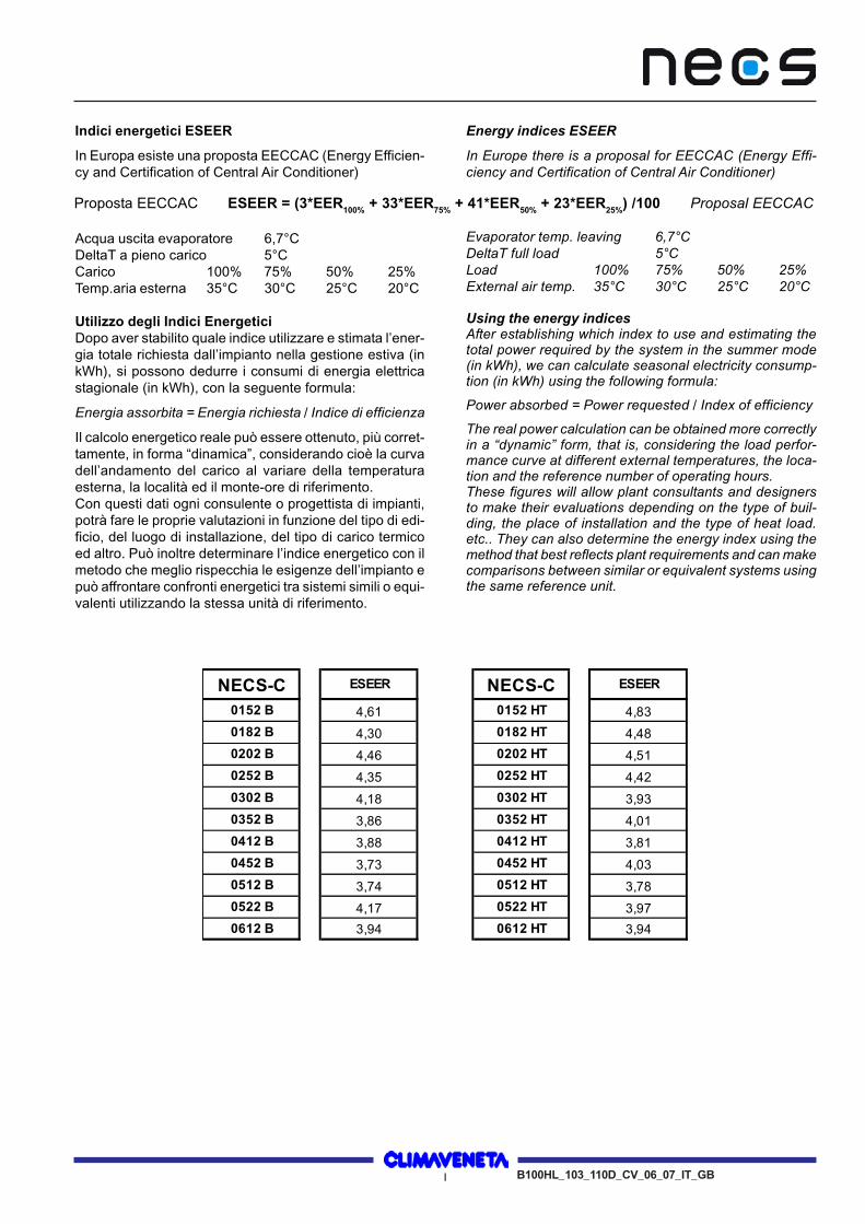
Indici energetici ESEER
In Europa esiste una proposta EECCAC (Energy Efficien-cy and Certification of Central Air Conditioner)
Acqua uscita evaporatore 6,7°CDeltaT a pieno carico 5°CCarico 100% 75% 50% 25%Temp.aria esterna 35°C 30°C 25°C 20°C
Utilizzo degli Indici EnergeticiDopo aver stabilito quale indice utilizzare e stimata l’ener-gia totale richiesta dall’impianto nella gestione estiva (inkWh), si possono dedurre i consumi di energia elettricastagionale (in kWh), con la seguente formula:
Energia assorbita = Energia richiesta / Indice di efficienza
Il calcolo energetico reale può essere ottenuto, più corret-tamente, in forma “dinamica”, considerando cioè la curvadell’andamento del carico al variare della temperaturaesterna, la località ed il monte-ore di riferimento.Con questi dati ogni consulente o progettista di impianti,potrà fare le proprie valutazioni in funzione del tipo di edi-ficio, del luogo di installazione, del tipo di carico termicoed altro. Può inoltre determinare l’indice energetico con ilmetodo che meglio rispecchia le esigenze dell’impianto epuò affrontare confronti energetici tra sistemi simili o equi-valenti utilizzando la stessa unità di riferimento.
Energy indices ESEER
In Europe there is a proposal for EECCAC (Energy Effi-ciency and Certification of Central Air Conditioner)
Evaporator temp. leaving 6,7°CDeltaT full load 5°CLoad 100% 75% 50% 25%External air temp. 35°C 30°C 25°C 20°C
Using the energy indicesAfter establishing which index to use and estimating thetotal power required by the system in the summer mode(in kWh), we can calculate seasonal electricity consump-tion (in kWh) using the following formula:
Power absorbed = Power requested / Index of efficiency
The real power calculation can be obtained more correctlyin a “dynamic” form, that is, considering the load perfor-mance curve at different external temperatures, the loca-tion and the reference number of operating hours.These figures will allow plant consultants and designersto make their evaluations depending on the type of buil-ding, the place of installation and the type of heat load.etc.. They can also determine the energy index using themethod that best reflects plant requirements and can makecomparisons between similar or equivalent systems usingthe same reference unit.
Proposta EECCAC ESEER = (3*EER100% + 33*EER75% + 41*EER50% + 23*EER25%) /100 Proposal EECCAC
NECS-C ESEER NECS-C ESEER
0152 B 4,61 0152 HT 4,83
0182 B 4,30 0182 HT 4,48
0202 B 4,46 0202 HT 4,51
0252 B 4,35 0252 HT 4,42
0302 B 4,18 0302 HT 3,93
0352 B 3,86 0352 HT 4,01
0412 B 3,88 0412 HT 3,81
0452 B 3,73 0452 HT 4,03
0512 B 3,74 0512 HT 3,78
0522 B 4,17 0522 HT 3,97
0612 B 3,94 0612 HT 3,94
UNIT DESCRIPTIONNECS-C
DESCRIZIONE UNITA'
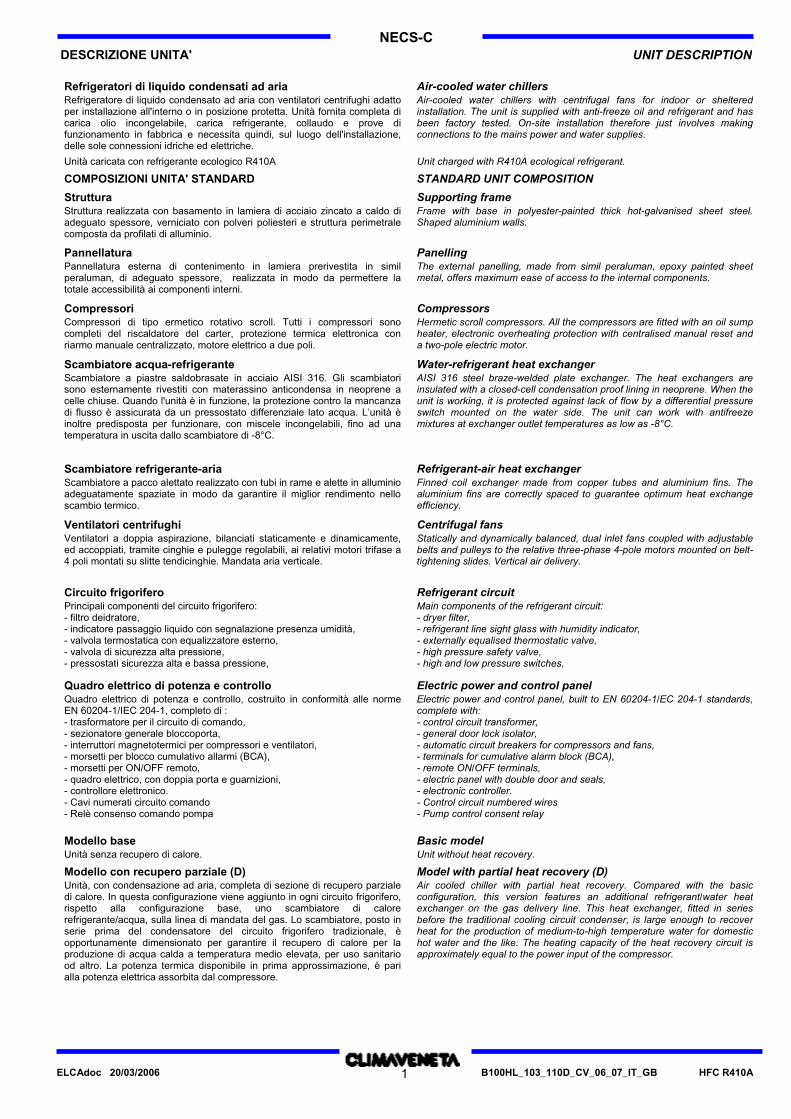
Refrigeratori di liquido condensati ad aria Air-cooled water chillersRefrigeratore di liquido condensato ad aria con ventilatori centrifughi adattoper installazione all'interno o in posizione protetta. Unità fornita completa dicarica olio incongelabile, carica refrigerante, collaudo e prove difunzionamento in fabbrica e necessita quindi, sul luogo dell'installazione,delle sole connessioni idriche ed elettriche.
Air-cooled water chillers with centrifugal fans for indoor or shelteredinstallation. The unit is supplied with anti-freeze oil and refrigerant and hasbeen factory tested. On-site installation therefore just involves makingconnections to the mains power and water supplies.
Unità caricata con refrigerante ecologico R410A Unit charged with R410A ecological refrigerant.
COMPOSIZIONI UNITA' STANDARD STANDARD UNIT COMPOSITION
Struttura Supporting frameStruttura realizzata con basamento in lamiera di acciaio zincato a caldo diadeguato spessore, verniciato con polveri poliesteri e struttura perimetralecomposta da profilati di alluminio.
Frame with base in polyester-painted thick hot-galvanised sheet steel.Shaped aluminium walls.
Pannellatura PanellingPannellatura esterna di contenimento in lamiera prerivestita in similperaluman, di adeguato spessore, realizzata in modo da permettere latotale accessibilità ai componenti interni.
The external panelling, made from simil peraluman, epoxy painted sheetmetal, offers maximum ease of access to the internal components.
Compressori CompressorsCompressori di tipo ermetico rotativo scroll. Tutti i compressori sonocompleti del riscaldatore del carter, protezione termica elettronica conriarmo manuale centralizzato, motore elettrico a due poli.
Hermetic scroll compressors. All the compressors are fitted with an oil sumpheater, electronic overheating protection with centralised manual reset anda two-pole electric motor.
Scambiatore acqua-refrigerante Water-refrigerant heat exchangerScambiatore a piastre saldobrasate in acciaio AISI 316. Gli scambiatorisono esternamente rivestiti con materassino anticondensa in neoprene acelle chiuse. Quando l'unità è in funzione, la protezione contro la mancanzadi flusso è assicurata da un pressostato differenziale lato acqua. L’unità èinoltre predisposta per funzionare, con miscele incongelabili, fino ad unatemperatura in uscita dallo scambiatore di -8°C.
AISI 316 steel braze-welded plate exchanger. The heat exchangers areinsulated with a closed-cell condensation proof lining in neoprene. When theunit is working, it is protected against lack of flow by a differential pressureswitch mounted on the water side. The unit can work with antifreezemixtures at exchanger outlet temperatures as low as -8°C.
Scambiatore refrigerante-aria Refrigerant-air heat exchangerScambiatore a pacco alettato realizzato con tubi in rame e alette in alluminioadeguatamente spaziate in modo da garantire il miglior rendimento nelloscambio termico.
Finned coil exchanger made from copper tubes and aluminium fins. Thealuminium fins are correctly spaced to guarantee optimum heat exchangeefficiency.
Ventilatori centrifughi Centrifugal fansVentilatori a doppia aspirazione, bilanciati staticamente e dinamicamente,ed accoppiati, tramite cinghie e pulegge regolabili, ai relativi motori trifase a4 poli montati su slitte tendicinghie. Mandata aria verticale.
Statically and dynamically balanced, dual inlet fans coupled with adjustablebelts and pulleys to the relative three-phase 4-pole motors mounted on belt-tightening slides. Vertical air delivery.
Circuito frigorifero Refrigerant circuitPrincipali componenti del circuito frigorifero:- filtro deidratore,- indicatore passaggio liquido con segnalazione presenza umidità,- valvola termostatica con equalizzatore esterno,- valvola di sicurezza alta pressione,- pressostati sicurezza alta e bassa pressione,
Main components of the refrigerant circuit:- dryer filter,- refrigerant line sight glass with humidity indicator,- externally equalised thermostatic valve,- high pressure safety valve,- high and low pressure switches,
Quadro elettrico di potenza e controllo Electric power and control panelQuadro elettrico di potenza e controllo, costruito in conformità alle normeEN 60204-1/IEC 204-1, completo di :- trasformatore per il circuito di comando,- sezionatore generale bloccoporta,- interruttori magnetotermici per compressori e ventilatori,- morsetti per blocco cumulativo allarmi (BCA),- morsetti per ON/OFF remoto,- quadro elettrico, con doppia porta e guarnizioni,- controllore elettronico.- Cavi numerati circuito comando- Relè consenso comando pompa
Electric power and control panel, built to EN 60204-1/EC 204-1 standards,complete with:- control circuit transformer,- general door lock isolator,- automatic circuit breakers for compressors and fans,- terminals for cumulative alarm block (BCA),- remote ON/OFF terminals,- electric panel with double door and seals,- electronic controller.- Control circuit numbered wires- Pump control consent relay
Modello base Basic modelUnità senza recupero di calore. Unit without heat recovery.
Modello con recupero parziale (D) Model with partial heat recovery (D)Unità, con condensazione ad aria, completa di sezione di recupero parzialedi calore. In questa configurazione viene aggiunto in ogni circuito frigorifero,rispetto alla configurazione base, uno scambiatore di calorerefrigerante/acqua, sulla linea di mandata del gas. Lo scambiatore, posto inserie prima del condensatore del circuito frigorifero tradizionale, èopportunamente dimensionato per garantire il recupero di calore per laproduzione di acqua calda a temperatura medio elevata, per uso sanitariood altro. La potenza termica disponibile in prima approssimazione, è parialla potenza elettrica assorbita dal compressore.
Air cooled chiller with partial heat recovery. Compared with the basicconfiguration, this version features an additional refrigerant/water heatexchanger on the gas delivery line. This heat exchanger, fitted in seriesbefore the traditional cooling circuit condenser, is large enough to recoverheat for the production of medium-to-high temperature water for domestichot water and the like. The heating capacity of the heat recovery circuit isapproximately equal to the power input of the compressor.
HFC R410AB100HL_103_110D_CV_06_07_IT_GB1ELCAdoc 20/03/2006
UNIT DESCRIPTIONNECS-C
DESCRIZIONE UNITA'
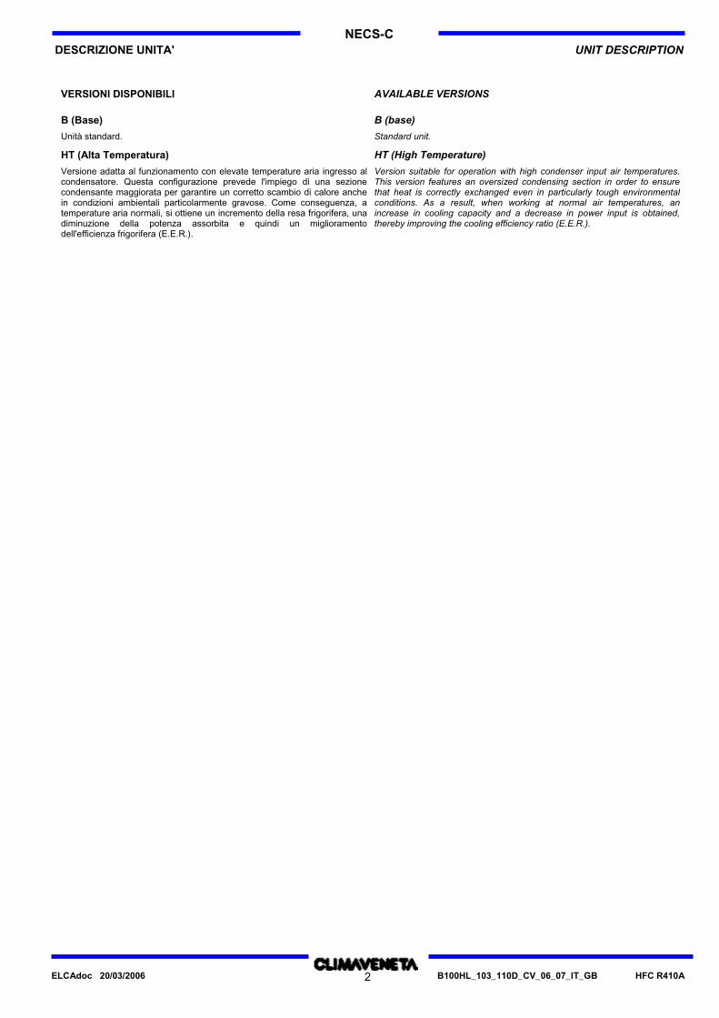
B (Base) B (base)
Unità standard. Standard unit.
HT (Alta Temperatura) HT (High Temperature)
Versione adatta al funzionamento con elevate temperature aria ingresso alcondensatore. Questa configurazione prevede l'impiego di una sezionecondensante maggiorata per garantire un corretto scambio di calore anchein condizioni ambientali particolarmente gravose. Come conseguenza, atemperature aria normali, si ottiene un incremento della resa frigorifera, unadiminuzione della potenza assorbita e quindi un miglioramentodell'efficienza frigorifera (E.E.R.).
Version suitable for operation with high condenser input air temperatures.This version features an oversized condensing section in order to ensurethat heat is correctly exchanged even in particularly tough environmentalconditions. As a result, when working at normal air temperatures, anincrease in cooling capacity and a decrease in power input is obtained,thereby improving the cooling efficiency ratio (E.E.R.).
HFC R410AB100HL_103_110D_CV_06_07_IT_GB2ELCAdoc 20/03/2006
VERSIONI DISPONIBILI AVAILABLE VERSIONS
DESCRIZIONE UNITA' UNIT DESCRIPTIONNECS-C
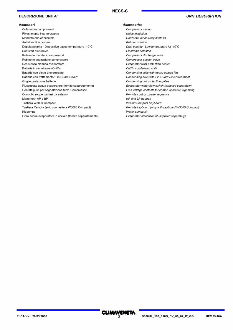
Accessori AccessoriesCofanatura compressori Compressor casingRivestimento insonorizzante Noise insulationMandata aria orizzontale Horizontal air delivery ducts kit.Antivibranti in gomma Rubber isolatorsDoppia polarità - Dispositivo basse temperature -10°C Dual polarity - Low temperature kit -10°CSoft start elettronico Electronic soft startRubinetto mandata compressori Compressor discharge valveRubinetto aspirazione compressore Compressor suction valveResistenza elettrica evaporatore Evaporator frost protection heaterBatterie in rame/rame -Cu/Cu Cu/Cu condensing coilsBatterie con alette preverniciate Condensing coils with epoxy-coated finsBatterie con trattamento "Fin Guard Silver" Condensing coils with Fin Guard Silver treatmentGriglie protezione batterie Condensing coil protection grillesFlussostato acqua evaporatore (fornito separatamente) Evaporator water flow switch (supplied separately)Contatti puliti per segnalazione funz. Compressori Free voltage contacts for compr. operation signallingControllo sequenza fasi da esterno Remote control phase sequenceManometri AP e BP HP and LP gaugesTastiera W3000 Compact W3000 Compact KeyboardTastiera Remota (solo con tastiera W3000 Compact) Remote keyboard (only with keyboard W3000 Compact)Kit pompe Water pumps kitFiltro acqua evaporatore in acciaio (fornito separatamente) Evaporator steel filter kit (supplied separately)
HFC R410AB100HL_103_110D_CV_06_07_IT_GB3ELCAdoc 20/03/2006
NECS-CDESCRIZIONE UNITA' UNIT DESCRIPTION
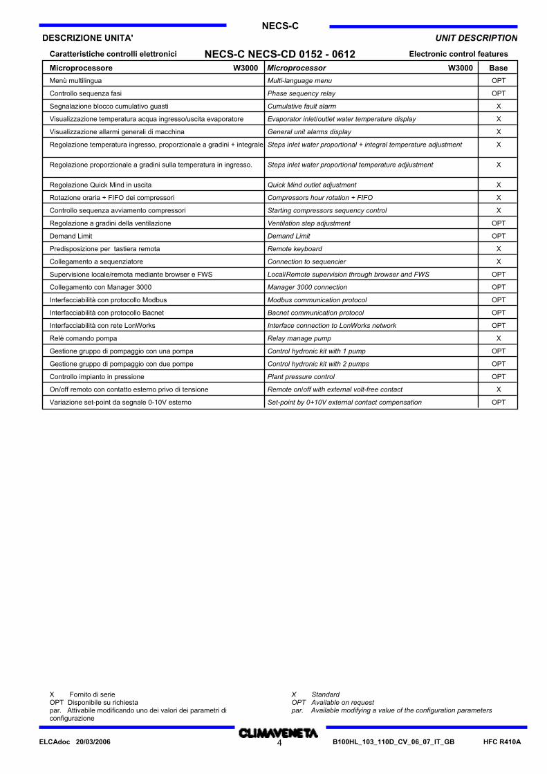
Electronic control featuresCaratteristiche controlli elettronici
MicroprocessorMicroprocessore
NECS-C NECS-CD 0152 - 0612W3000 W3000 Base
Multi-language menuMenù multilingua OPT
Phase sequency relayControllo sequenza fasi OPT
Cumulative fault alarmSegnalazione blocco cumulativo guasti X
Evaporator inlet/outlet water temperature displayVisualizzazione temperatura acqua ingresso/uscita evaporatore X
General unit alarms displayVisualizzazione allarmi generali di macchina X
Steps inlet water proportional + integral temperature adjustmentRegolazione temperatura ingresso, proporzionale a gradini + integrale X
Steps inlet water proportional temperature adjiustmentRegolazione proporzionale a gradini sulla temperatura in ingresso. X
Quick Mind outlet adjustmentRegolazione Quick Mind in uscita X
Compressors hour rotation + FIFORotazione oraria + FIFO dei compressori X
Starting compressors sequency controlControllo sequenza avviamento compressori X
Ventilation step adjustmentRegolazione a gradini della ventilazione OPT
Demand LimitDemand Limit OPT
Remote keyboardPredisposizione per tastiera remota X
Connection to sequencierCollegamento a sequenziatore X
Local/Remote supervision through browser and FWSSupervisione locale/remota mediante browser e FWS OPT
Manager 3000 connectionCollegamento con Manager 3000 OPT
Modbus communication protocolInterfacciabilità con protocollo Modbus OPT
Bacnet communication protocolInterfacciabilità con protocollo Bacnet OPT
Interface connection to LonWorks networkInterfacciabilità con rete LonWorks OPT
Relay manage pumpRelè comando pompa X
Control hydronic kit with 1 pumpGestione gruppo di pompaggio con una pompa OPT
Control hydronic kit with 2 pumpsGestione gruppo di pompaggio con due pompe OPT
Plant pressure controlControllo impianto in pressione OPT
Remote on/off with external volt-free contactOn/off remoto con contatto esterno privo di tensione X
Set-point by 0+10V external contact compensationVariazione set-point da segnale 0-10V esterno OPT
X Fornito di serieOPT Disponibile su richiestapar. Attivabile modificando uno dei valori dei parametri diconfigurazione
X StandardOPT Available on requestpar. Available modifying a value of the configuration parameters
HFC R410AB100HL_103_110D_CV_06_07_IT_GB4ELCAdoc 20/03/2006
5
NECS-C
B100HL_103_110D_CV_06_07_IT_GB HFC R410A
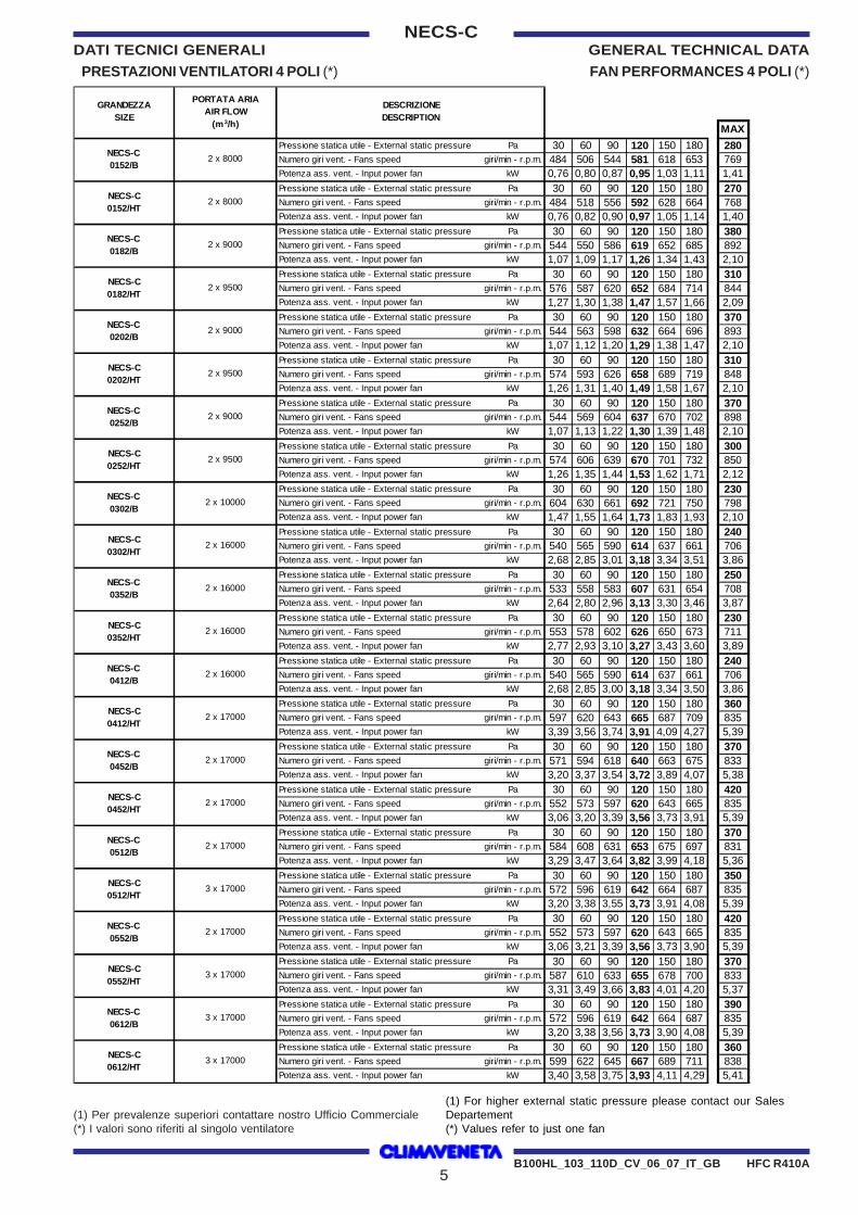
DATI TECNICI GENERALI GENERAL TECHNICAL DATA
PRESTAZIONI VENTILATORI 4 POLI (*) FAN PERFORMANCES 4 POLI (*)
(1) Per prevalenze superiori contattare nostro Ufficio Commerciale(*) I valori sono riferiti al singolo ventilatore
(1) For higher external static pressure please contact our SalesDepartement(*) Values refer to just one fan
MAXPressione statica utile - External static pressure Pa 30 60 90 120 150 180 280Numero giri vent. - Fans speed giri/min - r.p.m. 484 506 544 581 618 653 769Potenza ass. vent. - Input power fan kW 0,76 0,80 0,87 0,95 1,03 1,11 1,41Pressione statica utile - External static pressure Pa 30 60 90 120 150 180 270Numero giri vent. - Fans speed giri/min - r.p.m. 484 518 556 592 628 664 768Potenza ass. vent. - Input power fan kW 0,76 0,82 0,90 0,97 1,05 1,14 1,40Pressione statica utile - External static pressure Pa 30 60 90 120 150 180 380Numero giri vent. - Fans speed giri/min - r.p.m. 544 550 586 619 652 685 892Potenza ass. vent. - Input power fan kW 1,07 1,09 1,17 1,26 1,34 1,43 2,10Pressione statica utile - External static pressure Pa 30 60 90 120 150 180 310Numero giri vent. - Fans speed giri/min - r.p.m. 576 587 620 652 684 714 844Potenza ass. vent. - Input power fan kW 1,27 1,30 1,38 1,47 1,57 1,66 2,09Pressione statica utile - External static pressure Pa 30 60 90 120 150 180 370Numero giri vent. - Fans speed giri/min - r.p.m. 544 563 598 632 664 696 893Potenza ass. vent. - Input power fan kW 1,07 1,12 1,20 1,29 1,38 1,47 2,10Pressione statica utile - External static pressure Pa 30 60 90 120 150 180 310Numero giri vent. - Fans speed giri/min - r.p.m. 574 593 626 658 689 719 848Potenza ass. vent. - Input power fan kW 1,26 1,31 1,40 1,49 1,58 1,67 2,10Pressione statica utile - External static pressure Pa 30 60 90 120 150 180 370Numero giri vent. - Fans speed giri/min - r.p.m. 544 569 604 637 670 702 898Potenza ass. vent. - Input power fan kW 1,07 1,13 1,22 1,30 1,39 1,48 2,10Pressione statica utile - External static pressure Pa 30 60 90 120 150 180 300Numero giri vent. - Fans speed giri/min - r.p.m. 574 606 639 670 701 732 850Potenza ass. vent. - Input power fan kW 1,26 1,35 1,44 1,53 1,62 1,71 2,12Pressione statica utile - External static pressure Pa 30 60 90 120 150 180 230Numero giri vent. - Fans speed giri/min - r.p.m. 604 630 661 692 721 750 798Potenza ass. vent. - Input power fan kW 1,47 1,55 1,64 1,73 1,83 1,93 2,10Pressione statica utile - External static pressure Pa 30 60 90 120 150 180 240Numero giri vent. - Fans speed giri/min - r.p.m. 540 565 590 614 637 661 706Potenza ass. vent. - Input power fan kW 2,68 2,85 3,01 3,18 3,34 3,51 3,86Pressione statica utile - External static pressure Pa 30 60 90 120 150 180 250Numero giri vent. - Fans speed giri/min - r.p.m. 533 558 583 607 631 654 708Potenza ass. vent. - Input power fan kW 2,64 2,80 2,96 3,13 3,30 3,46 3,87Pressione statica utile - External static pressure Pa 30 60 90 120 150 180 230Numero giri vent. - Fans speed giri/min - r.p.m. 553 578 602 626 650 673 711Potenza ass. vent. - Input power fan kW 2,77 2,93 3,10 3,27 3,43 3,60 3,89Pressione statica utile - External static pressure Pa 30 60 90 120 150 180 240Numero giri vent. - Fans speed giri/min - r.p.m. 540 565 590 614 637 661 706Potenza ass. vent. - Input power fan kW 2,68 2,85 3,00 3,18 3,34 3,50 3,86Pressione statica utile - External static pressure Pa 30 60 90 120 150 180 360Numero giri vent. - Fans speed giri/min - r.p.m. 597 620 643 665 687 709 835Potenza ass. vent. - Input power fan kW 3,39 3,56 3,74 3,91 4,09 4,27 5,39Pressione statica utile - External static pressure Pa 30 60 90 120 150 180 370Numero giri vent. - Fans speed giri/min - r.p.m. 571 594 618 640 663 675 833Potenza ass. vent. - Input power fan kW 3,20 3,37 3,54 3,72 3,89 4,07 5,38Pressione statica utile - External static pressure Pa 30 60 90 120 150 180 420Numero giri vent. - Fans speed giri/min - r.p.m. 552 573 597 620 643 665 835Potenza ass. vent. - Input power fan kW 3,06 3,20 3,39 3,56 3,73 3,91 5,39Pressione statica utile - External static pressure Pa 30 60 90 120 150 180 370Numero giri vent. - Fans speed giri/min - r.p.m. 584 608 631 653 675 697 831Potenza ass. vent. - Input power fan kW 3,29 3,47 3,64 3,82 3,99 4,18 5,36Pressione statica utile - External static pressure Pa 30 60 90 120 150 180 350Numero giri vent. - Fans speed giri/min - r.p.m. 572 596 619 642 664 687 835Potenza ass. vent. - Input power fan kW 3,20 3,38 3,55 3,73 3,91 4,08 5,39Pressione statica utile - External static pressure Pa 30 60 90 120 150 180 420Numero giri vent. - Fans speed giri/min - r.p.m. 552 573 597 620 643 665 835Potenza ass. vent. - Input power fan kW 3,06 3,21 3,39 3,56 3,73 3,90 5,39Pressione statica utile - External static pressure Pa 30 60 90 120 150 180 370Numero giri vent. - Fans speed giri/min - r.p.m. 587 610 633 655 678 700 833Potenza ass. vent. - Input power fan kW 3,31 3,49 3,66 3,83 4,01 4,20 5,37Pressione statica utile - External static pressure Pa 30 60 90 120 150 180 390Numero giri vent. - Fans speed giri/min - r.p.m. 572 596 619 642 664 687 835Potenza ass. vent. - Input power fan kW 3,20 3,38 3,56 3,73 3,90 4,08 5,39Pressione statica utile - External static pressure Pa 30 60 90 120 150 180 360Numero giri vent. - Fans speed giri/min - r.p.m. 599 622 645 667 689 711 838Potenza ass. vent. - Input power fan kW 3,40 3,58 3,75 3,93 4,11 4,29 5,41
2 x 9500
NECS-C 0252/B
2 x 9000
NECS-C 0452/HT
2 x 17000
NECS-C 0452/B
2 x 17000
NECS-C 0412/B
2 x 16000
2 x 10000NECS-C 0302/B
2 x 17000
NECS-C 0352/HT
2 x 16000
NECS-C 0412/HT
NECS-C 0352/B
2 x 16000
NECS-C 0302/HT
2 x 16000
2 x 17000
NECS-C 0512/HT
3 x 17000
NECS-C 0512/B
2 x 17000
NECS-C 0202/HT
2 x 9500
NECS-C 0612/HT
3 x 17000
NECS-C 0612/B
3 x 17000
NECS-C 0552/HT
3 x 17000
NECS-C 0552/B
NECS-C 0252/HT
NECS-C 0152/HT
2 x 8000
GRANDEZZA SIZE
NECS-C 0152/B
2 x 8000
DESCRIZIONEDESCRIPTION
PORTATA ARIAAIR FLOW
(m3/h)
NECS-C 0182/HT
2 x 9500
NECS-C 0202/B
NECS-C 0182/B
2 x 9000
2 x 9000
6
NECS-C
B100HL_103_110D_CV_06_07_IT_GB HFC R410A
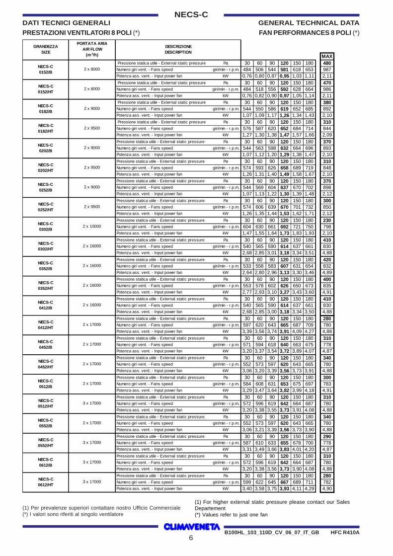
DATI TECNICI GENERALI GENERAL TECHNICAL DATA
PRESTAZIONI VENTILATORI 8 POLI (*) FAN PERFORMANCES 8 POLI (*)
MAX Pressione statica utile - External static pressure Pa 30 60 90 120 150 180 480Numero giri vent. - Fans speed giri/min - r.p.m. 484 506 544 581 618 653 987Potenza ass. vent. - Input power fan kW 0,76 0,80 0,87 0,95 1,03 1,11 2,11 Pressione statica utile - External static pressure Pa 30 60 90 120 150 180 470Numero giri vent. - Fans speed giri/min - r.p.m. 484 518 556 592 628 664 986Potenza ass. vent. - Input power fan kW 0,76 0,82 0,90 0,97 1,05 1,14 2,11 Pressione statica utile - External static pressure Pa 30 60 90 120 150 180 380Numero giri vent. - Fans speed giri/min - r.p.m. 544 550 586 619 652 685 892Potenza ass. vent. - Input power fan kW 1,07 1,09 1,17 1,26 1,34 1,43 2,10 Pressione statica utile - External static pressure Pa 30 60 90 120 150 180 310Numero giri vent. - Fans speed giri/min - r.p.m. 576 587 620 652 684 714 844Potenza ass. vent. - Input power fan kW 1,27 1,30 1,38 1,47 1,57 1,66 2,09Pressione statica utile - External static pressure Pa 30 60 90 120 150 180 370Numero giri vent. - Fans speed giri/min - r.p.m. 544 563 598 632 664 696 893Potenza ass. vent. - Input power fan kW 1,07 1,12 1,20 1,29 1,38 1,47 2,10Pressione statica utile - External static pressure Pa 30 60 90 120 150 180 310Numero giri vent. - Fans speed giri/min - r.p.m. 574 593 626 658 689 719 848Potenza ass. vent. - Input power fan kW 1,26 1,31 1,40 1,49 1,58 1,67 2,10Pressione statica utile - External static pressure Pa 30 60 90 120 150 180 370Numero giri vent. - Fans speed giri/min - r.p.m. 544 569 604 637 670 702 898Potenza ass. vent. - Input power fan kW 1,07 1,13 1,22 1,30 1,39 1,48 2,12Pressione statica utile - External static pressure Pa 30 60 90 120 150 180 300Numero giri vent. - Fans speed giri/min - r.p.m. 574 606 639 670 701 732 850Potenza ass. vent. - Input power fan kW 1,26 1,35 1,44 1,53 1,62 1,71 2,12Pressione statica utile - External static pressure Pa 30 60 90 120 150 180 230Numero giri vent. - Fans speed giri/min - r.p.m. 604 630 661 692 721 750 798Potenza ass. vent. - Input power fan kW 1,47 1,55 1,64 1,73 1,83 1,93 2,10Pressione statica utile - External static pressure Pa 30 60 90 120 150 180 410Numero giri vent. - Fans speed giri/min - r.p.m. 540 565 590 614 637 661 830Potenza ass. vent. - Input power fan kW 2,68 2,85 3,01 3,18 3,34 3,51 4,88Pressione statica utile - External static pressure Pa 30 60 90 120 150 180 420Numero giri vent. - Fans speed giri/min - r.p.m. 533 558 583 607 631 654 832Potenza ass. vent. - Input power fan kW 2,64 2,80 2,96 3,13 3,30 3,46 4,89Pressione statica utile - External static pressure Pa 30 60 90 120 150 180 400Numero giri vent. - Fans speed giri/min - r.p.m. 553 578 602 626 650 673 835Potenza ass. vent. - Input power fan kW 2,77 2,93 3,10 3,27 3,43 3,60 4,91Pressione statica utile - External static pressure Pa 30 60 90 120 150 180 410Numero giri vent. - Fans speed giri/min - r.p.m. 540 565 590 614 637 661 830Potenza ass. vent. - Input power fan kW 2,68 2,85 3,00 3,18 3,34 3,50 4,88Pressione statica utile - External static pressure Pa 30 60 90 120 150 180 280Numero giri vent. - Fans speed giri/min - r.p.m. 597 620 643 665 687 709 780Potenza ass. vent. - Input power fan kW 3,39 3,56 3,74 3,91 4,09 4,27 4,88Pressione statica utile - External static pressure Pa 30 60 90 120 150 180 310Numero giri vent. - Fans speed giri/min - r.p.m. 571 594 618 640 663 675 778Potenza ass. vent. - Input power fan kW 3,20 3,37 3,54 3,72 3,89 4,07 4,87Pressione statica utile - External static pressure Pa 30 60 90 120 150 180 340Numero giri vent. - Fans speed giri/min - r.p.m. 552 573 597 620 643 665 780Potenza ass. vent. - Input power fan kW 3,06 3,20 3,39 3,56 3,73 3,91 4,88Pressione statica utile - External static pressure Pa 30 60 90 120 150 180 300Numero giri vent. - Fans speed giri/min - r.p.m. 584 608 631 653 675 697 783Potenza ass. vent. - Input power fan kW 3,29 3,47 3,64 3,82 3,99 4,18 4,91Pressione statica utile - External static pressure Pa 30 60 90 120 150 180 310Numero giri vent. - Fans speed giri/min - r.p.m. 572 596 619 642 664 687 780Potenza ass. vent. - Input power fan kW 3,20 3,38 3,55 3,73 3,91 4,08 4,88Pressione statica utile - External static pressure Pa 30 60 90 120 150 180 340Numero giri vent. - Fans speed giri/min - r.p.m. 552 573 597 620 643 665 780Potenza ass. vent. - Input power fan kW 3,06 3,21 3,39 3,56 3,73 3,90 4,88Pressione statica utile - External static pressure Pa 30 60 90 120 150 180 290Numero giri vent. - Fans speed giri/min - r.p.m. 587 610 633 655 678 700 778Potenza ass. vent. - Input power fan kW 3,31 3,49 3,66 3,83 4,01 4,20 4,87Pressione statica utile - External static pressure Pa 30 60 90 120 150 180 310Numero giri vent. - Fans speed giri/min - r.p.m. 572 596 619 642 664 687 780Potenza ass. vent. - Input power fan kW 3,20 3,38 3,56 3,73 3,90 4,08 4,88Pressione statica utile - External static pressure Pa 30 60 90 120 150 180 280Numero giri vent. - Fans speed giri/min - r.p.m. 599 622 645 667 689 711 782Potenza ass. vent. - Input power fan kW 3,40 3,58 3,75 3,93 4,11 4,29 4,90
NECS-C 0412/B
2 x 9000
NECS-C 0252/HT
2 x 9500
NECS-C 0252/B
NECS-C 0182/HT
2 x 17000
NECS-C 0302/B
2 x 10000
NECS-C 0302/HT
2 x 16000
NECS-C 0352/B
2 x 16000
NECS-C 0352/HT
2 x 16000
NECS-C 0202/B
2 x 9000
NECS-C 0202/HT
2 x 9500
3 x 17000
3 x 17000
3 x 17000
2 x 17000
NECS-C 0552/HT
NECS-C 0552/B
NECS-C 0512/HT
3 x 17000
2 x 8000
2 x 8000
2 x 9500
DESCRIZIONEDESCRIPTION
PORTATA ARIAAIR FLOW
(m 3/h)
GRANDEZZA SIZE
NECS-C 0182/B
2 x 9000
NECS-C 0152/B
NECS-C 0152/HT
NECS-C 0612/HT
2 x 16000
NECS-C 0412/HT
2 x 17000
NECS-C 0452/B
2 x 17000
NECS-C 0452/HT
2 x 17000
NECS-C 0512/B
NECS-C 0612/B
(1) Per prevalenze superiori contattare nostro Ufficio Commerciale(*) I valori sono riferiti al singolo ventilatore
(1) For higher external static pressure please contact our SalesDepartement(*) Values refer to just one fan
NECS-C 0152-06127 - IT
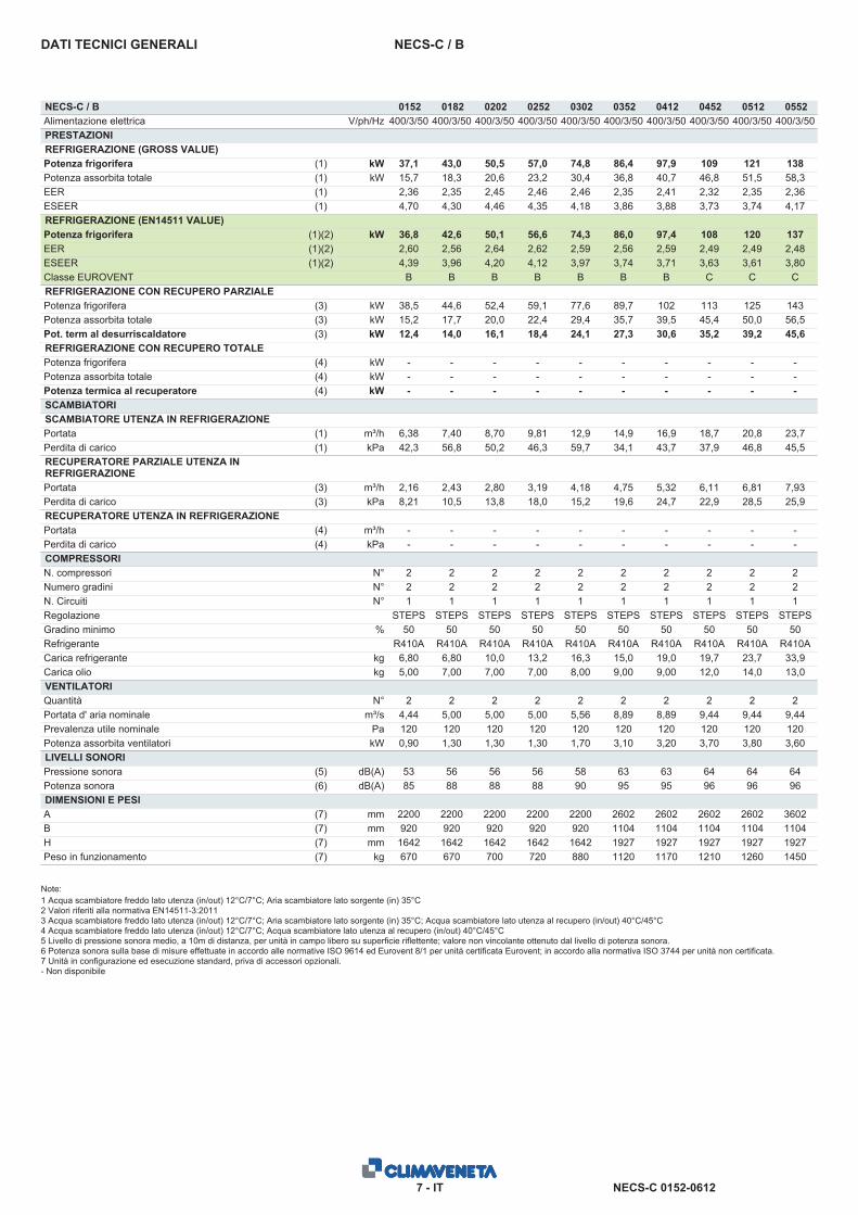
NECS-C / BDATI TECNICI GENERALI
NECS-C / B 0152 0182 0202 0252 0302 0352 0412 0452 0512 0552Alimentazione elettrica V/ph/Hz 400/3/50 400/3/50 400/3/50 400/3/50 400/3/50 400/3/50 400/3/50 400/3/50 400/3/50 400/3/50PRESTAZIONIREFRIGERAZIONE (GROSS VALUE)Potenza frigorifera (1) kW 37,1 43,0 50,5 57,0 74,8 86,4 97,9 109 121 138Potenza assorbita totale (1) kW 15,7 18,3 20,6 23,2 30,4 36,8 40,7 46,8 51,5 58,3EER (1) 2,36 2,35 2,45 2,46 2,46 2,35 2,41 2,32 2,35 2,36ESEER (1) 4,70 4,30 4,46 4,35 4,18 3,86 3,88 3,73 3,74 4,17REFRIGERAZIONE (EN14511 VALUE)Potenza frigorifera (1)(2) kW 36,8 42,6 50,1 56,6 74,3 86,0 97,4 108 120 137EER (1)(2) 2,60 2,56 2,64 2,62 2,59 2,56 2,59 2,49 2,49 2,48ESEER (1)(2) 4,39 3,96 4,20 4,12 3,97 3,74 3,71 3,63 3,61 3,80Classe EUROVENT B B B B B B B C C CREFRIGERAZIONE CON RECUPERO PARZIALEPotenza frigorifera (3) kW 38,5 44,6 52,4 59,1 77,6 89,7 102 113 125 143Potenza assorbita totale (3) kW 15,2 17,7 20,0 22,4 29,4 35,7 39,5 45,4 50,0 56,5Pot. term al desurriscaldatore (3) kW 12,4 14,0 16,1 18,4 24,1 27,3 30,6 35,2 39,2 45,6REFRIGERAZIONE CON RECUPERO TOTALEPotenza frigorifera (4) kW - - - - - - - - - -Potenza assorbita totale (4) kW - - - - - - - - - -Potenza termica al recuperatore (4) kW - - - - - - - - - -SCAMBIATORISCAMBIATORE UTENZA IN REFRIGERAZIONEPortata (1) m³/h 6,38 7,40 8,70 9,81 12,9 14,9 16,9 18,7 20,8 23,7Perdita di carico (1) kPa 42,3 56,8 50,2 46,3 59,7 34,1 43,7 37,9 46,8 45,5RECUPERATORE PARZIALE UTENZA INREFRIGERAZIONEPortata (3) m³/h 2,16 2,43 2,80 3,19 4,18 4,75 5,32 6,11 6,81 7,93Perdita di carico (3) kPa 8,21 10,5 13,8 18,0 15,2 19,6 24,7 22,9 28,5 25,9RECUPERATORE UTENZA IN REFRIGERAZIONEPortata (4) m³/h - - - - - - - - - -Perdita di carico (4) kPa - - - - - - - - - -COMPRESSORIN. compressori N° 2 2 2 2 2 2 2 2 2 2Numero gradini N° 2 2 2 2 2 2 2 2 2 2N. Circuiti N° 1 1 1 1 1 1 1 1 1 1Regolazione STEPS STEPS STEPS STEPS STEPS STEPS STEPS STEPS STEPS STEPSGradino minimo % 50 50 50 50 50 50 50 50 50 50Refrigerante R410A R410A R410A R410A R410A R410A R410A R410A R410A R410ACarica refrigerante kg 6,80 6,80 10,0 13,2 16,3 15,0 19,0 19,7 23,7 33,9Carica olio kg 5,00 7,00 7,00 7,00 8,00 9,00 9,00 12,0 14,0 13,0VENTILATORIQuantità N° 2 2 2 2 2 2 2 2 2 2Portata d' aria nominale m³/s 4,44 5,00 5,00 5,00 5,56 8,89 8,89 9,44 9,44 9,44Prevalenza utile nominale Pa 120 120 120 120 120 120 120 120 120 120Potenza assorbita ventilatori kW 0,90 1,30 1,30 1,30 1,70 3,10 3,20 3,70 3,80 3,60LIVELLI SONORIPressione sonora (5) dB(A) 53 56 56 56 58 63 63 64 64 64Potenza sonora (6) dB(A) 85 88 88 88 90 95 95 96 96 96DIMENSIONI E PESIA (7) mm 2200 2200 2200 2200 2200 2602 2602 2602 2602 3602B (7) mm 920 920 920 920 920 1104 1104 1104 1104 1104H (7) mm 1642 1642 1642 1642 1642 1927 1927 1927 1927 1927Peso in funzionamento (7) kg 670 670 700 720 880 1120 1170 1210 1260 1450
Note:1 Acqua scambiatore freddo lato utenza (in/out) 12°C/7°C; Aria scambiatore lato sorgente (in) 35°C2 Valori riferiti alla normativa EN14511-3:20113 Acqua scambiatore freddo lato utenza (in/out) 12°C/7°C; Aria scambiatore lato sorgente (in) 35°C; Acqua scambiatore lato utenza al recupero (in/out) 40°C/45°C4 Acqua scambiatore freddo lato utenza (in/out) 12°C/7°C; Acqua scambiatore lato utenza al recupero (in/out) 40°C/45°C5 Livello di pressione sonora medio, a 10m di distanza, per unità in campo libero su superficie riflettente; valore non vincolante ottenuto dal livello di potenza sonora.6 Potenza sonora sulla base di misure effettuate in accordo alle normative ISO 9614 ed Eurovent 8/1 per unità certificata Eurovent; in accordo alla normativa ISO 3744 per unità non certificata.7 Unità in configurazione ed esecuzione standard, priva di accessori opzionali.- Non disponibile
NECS-C 0152-06128 - IT
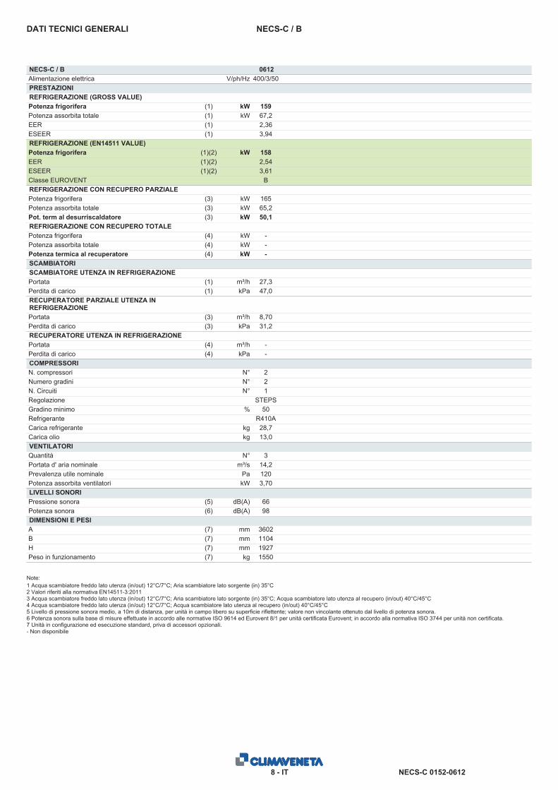
NECS-C / BDATI TECNICI GENERALI
NECS-C / B 0612Alimentazione elettrica V/ph/Hz 400/3/50PRESTAZIONIREFRIGERAZIONE (GROSS VALUE)Potenza frigorifera (1) kW 159Potenza assorbita totale (1) kW 67,2EER (1) 2,36ESEER (1) 3,94REFRIGERAZIONE (EN14511 VALUE)Potenza frigorifera (1)(2) kW 158EER (1)(2) 2,54ESEER (1)(2) 3,61Classe EUROVENT BREFRIGERAZIONE CON RECUPERO PARZIALEPotenza frigorifera (3) kW 165Potenza assorbita totale (3) kW 65,2Pot. term al desurriscaldatore (3) kW 50,1REFRIGERAZIONE CON RECUPERO TOTALEPotenza frigorifera (4) kW -Potenza assorbita totale (4) kW -Potenza termica al recuperatore (4) kW -SCAMBIATORISCAMBIATORE UTENZA IN REFRIGERAZIONEPortata (1) m³/h 27,3Perdita di carico (1) kPa 47,0RECUPERATORE PARZIALE UTENZA INREFRIGERAZIONEPortata (3) m³/h 8,70Perdita di carico (3) kPa 31,2RECUPERATORE UTENZA IN REFRIGERAZIONEPortata (4) m³/h -Perdita di carico (4) kPa -COMPRESSORIN. compressori N° 2Numero gradini N° 2N. Circuiti N° 1Regolazione STEPSGradino minimo % 50Refrigerante R410ACarica refrigerante kg 28,7Carica olio kg 13,0VENTILATORIQuantità N° 3Portata d' aria nominale m³/s 14,2Prevalenza utile nominale Pa 120Potenza assorbita ventilatori kW 3,70LIVELLI SONORIPressione sonora (5) dB(A) 66Potenza sonora (6) dB(A) 98DIMENSIONI E PESIA (7) mm 3602B (7) mm 1104H (7) mm 1927Peso in funzionamento (7) kg 1550
Note:1 Acqua scambiatore freddo lato utenza (in/out) 12°C/7°C; Aria scambiatore lato sorgente (in) 35°C2 Valori riferiti alla normativa EN14511-3:20113 Acqua scambiatore freddo lato utenza (in/out) 12°C/7°C; Aria scambiatore lato sorgente (in) 35°C; Acqua scambiatore lato utenza al recupero (in/out) 40°C/45°C4 Acqua scambiatore freddo lato utenza (in/out) 12°C/7°C; Acqua scambiatore lato utenza al recupero (in/out) 40°C/45°C5 Livello di pressione sonora medio, a 10m di distanza, per unità in campo libero su superficie riflettente; valore non vincolante ottenuto dal livello di potenza sonora.6 Potenza sonora sulla base di misure effettuate in accordo alle normative ISO 9614 ed Eurovent 8/1 per unità certificata Eurovent; in accordo alla normativa ISO 3744 per unità non certificata.7 Unità in configurazione ed esecuzione standard, priva di accessori opzionali.- Non disponibile
NECS-C 0152-06129 - IT
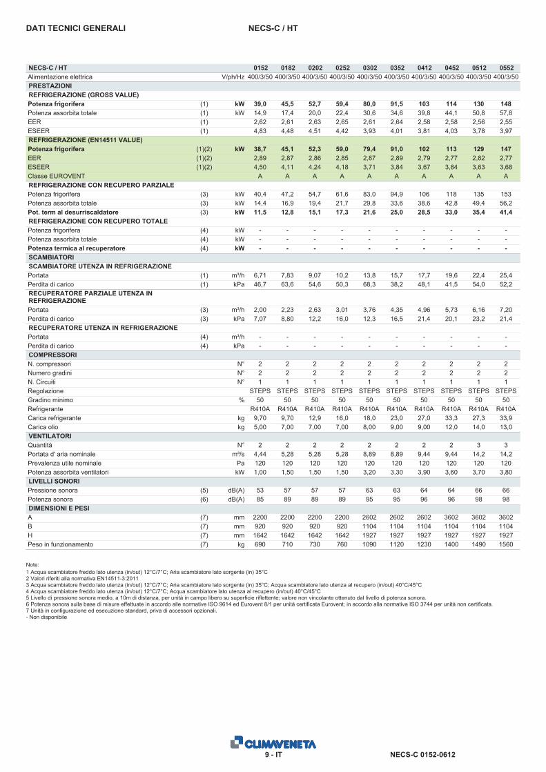
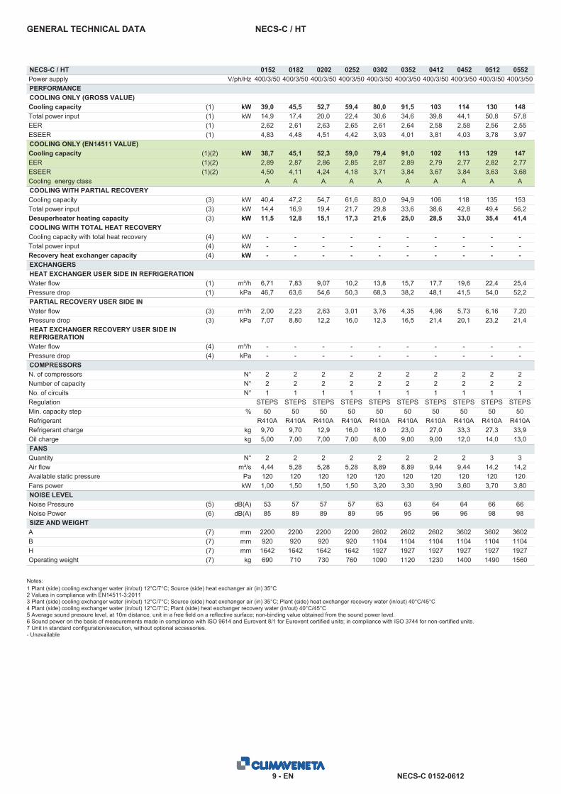
NECS-C / HTDATI TECNICI GENERALI
NECS-C / HT 0152 0182 0202 0252 0302 0352 0412 0452 0512 0552Alimentazione elettrica V/ph/Hz 400/3/50 400/3/50 400/3/50 400/3/50 400/3/50 400/3/50 400/3/50 400/3/50 400/3/50 400/3/50PRESTAZIONIREFRIGERAZIONE (GROSS VALUE)Potenza frigorifera (1) kW 39,0 45,5 52,7 59,4 80,0 91,5 103 114 130 148Potenza assorbita totale (1) kW 14,9 17,4 20,0 22,4 30,6 34,6 39,8 44,1 50,8 57,8EER (1) 2,62 2,61 2,63 2,65 2,61 2,64 2,58 2,58 2,56 2,55ESEER (1) 4,83 4,48 4,51 4,42 3,93 4,01 3,81 4,03 3,78 3,97REFRIGERAZIONE (EN14511 VALUE)Potenza frigorifera (1)(2) kW 38,7 45,1 52,3 59,0 79,4 91,0 102 113 129 147EER (1)(2) 2,89 2,87 2,86 2,85 2,87 2,89 2,79 2,77 2,82 2,77ESEER (1)(2) 4,50 4,11 4,24 4,18 3,71 3,84 3,67 3,84 3,63 3,68Classe EUROVENT A A A A A A A A A AREFRIGERAZIONE CON RECUPERO PARZIALEPotenza frigorifera (3) kW 40,4 47,2 54,7 61,6 83,0 94,9 106 118 135 153Potenza assorbita totale (3) kW 14,4 16,9 19,4 21,7 29,8 33,6 38,6 42,8 49,4 56,2Pot. term al desurriscaldatore (3) kW 11,5 12,8 15,1 17,3 21,6 25,0 28,5 33,0 35,4 41,4REFRIGERAZIONE CON RECUPERO TOTALEPotenza frigorifera (4) kW - - - - - - - - - -Potenza assorbita totale (4) kW - - - - - - - - - -Potenza termica al recuperatore (4) kW - - - - - - - - - -SCAMBIATORISCAMBIATORE UTENZA IN REFRIGERAZIONEPortata (1) m³/h 6,71 7,83 9,07 10,2 13,8 15,7 17,7 19,6 22,4 25,4Perdita di carico (1) kPa 46,7 63,6 54,6 50,3 68,3 38,2 48,1 41,5 54,0 52,2RECUPERATORE PARZIALE UTENZA INREFRIGERAZIONEPortata (3) m³/h 2,00 2,23 2,63 3,01 3,76 4,35 4,96 5,73 6,16 7,20Perdita di carico (3) kPa 7,07 8,80 12,2 16,0 12,3 16,5 21,4 20,1 23,2 21,4RECUPERATORE UTENZA IN REFRIGERAZIONEPortata (4) m³/h - - - - - - - - - -Perdita di carico (4) kPa - - - - - - - - - -COMPRESSORIN. compressori N° 2 2 2 2 2 2 2 2 2 2Numero gradini N° 2 2 2 2 2 2 2 2 2 2N. Circuiti N° 1 1 1 1 1 1 1 1 1 1Regolazione STEPS STEPS STEPS STEPS STEPS STEPS STEPS STEPS STEPS STEPSGradino minimo % 50 50 50 50 50 50 50 50 50 50Refrigerante R410A R410A R410A R410A R410A R410A R410A R410A R410A R410ACarica refrigerante kg 9,70 9,70 12,9 16,0 18,0 23,0 27,0 33,3 27,3 33,9Carica olio kg 5,00 7,00 7,00 7,00 8,00 9,00 9,00 12,0 14,0 13,0VENTILATORIQuantità N° 2 2 2 2 2 2 2 2 3 3Portata d' aria nominale m³/s 4,44 5,28 5,28 5,28 8,89 8,89 9,44 9,44 14,2 14,2Prevalenza utile nominale Pa 120 120 120 120 120 120 120 120 120 120Potenza assorbita ventilatori kW 1,00 1,50 1,50 1,50 3,20 3,30 3,90 3,60 3,70 3,80LIVELLI SONORIPressione sonora (5) dB(A) 53 57 57 57 63 63 64 64 66 66Potenza sonora (6) dB(A) 85 89 89 89 95 95 96 96 98 98DIMENSIONI E PESIA (7) mm 2200 2200 2200 2200 2602 2602 2602 3602 3602 3602B (7) mm 920 920 920 920 1104 1104 1104 1104 1104 1104H (7) mm 1642 1642 1642 1642 1927 1927 1927 1927 1927 1927Peso in funzionamento (7) kg 690 710 730 760 1090 1120 1230 1400 1490 1560
Note:1 Acqua scambiatore freddo lato utenza (in/out) 12°C/7°C; Aria scambiatore lato sorgente (in) 35°C2 Valori riferiti alla normativa EN14511-3:20113 Acqua scambiatore freddo lato utenza (in/out) 12°C/7°C; Aria scambiatore lato sorgente (in) 35°C; Acqua scambiatore lato utenza al recupero (in/out) 40°C/45°C4 Acqua scambiatore freddo lato utenza (in/out) 12°C/7°C; Acqua scambiatore lato utenza al recupero (in/out) 40°C/45°C5 Livello di pressione sonora medio, a 10m di distanza, per unità in campo libero su superficie riflettente; valore non vincolante ottenuto dal livello di potenza sonora.6 Potenza sonora sulla base di misure effettuate in accordo alle normative ISO 9614 ed Eurovent 8/1 per unità certificata Eurovent; in accordo alla normativa ISO 3744 per unità non certificata.7 Unità in configurazione ed esecuzione standard, priva di accessori opzionali.- Non disponibile
NECS-C 0152-061210 - IT
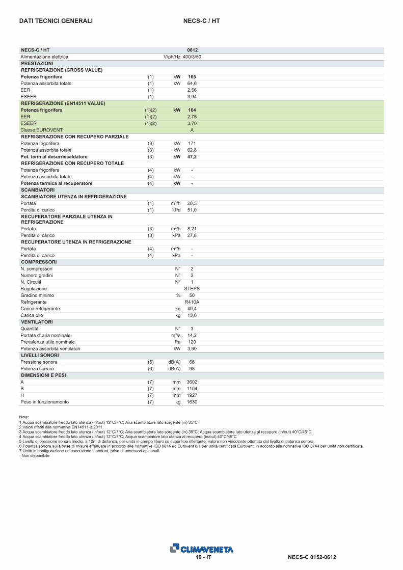
NECS-C / HTDATI TECNICI GENERALI
NECS-C / HT 0612Alimentazione elettrica V/ph/Hz 400/3/50PRESTAZIONIREFRIGERAZIONE (GROSS VALUE)Potenza frigorifera (1) kW 165Potenza assorbita totale (1) kW 64,6EER (1) 2,56ESEER (1) 3,94REFRIGERAZIONE (EN14511 VALUE)Potenza frigorifera (1)(2) kW 164EER (1)(2) 2,75ESEER (1)(2) 3,70Classe EUROVENT AREFRIGERAZIONE CON RECUPERO PARZIALEPotenza frigorifera (3) kW 171Potenza assorbita totale (3) kW 62,8Pot. term al desurriscaldatore (3) kW 47,2REFRIGERAZIONE CON RECUPERO TOTALEPotenza frigorifera (4) kW -Potenza assorbita totale (4) kW -Potenza termica al recuperatore (4) kW -SCAMBIATORISCAMBIATORE UTENZA IN REFRIGERAZIONEPortata (1) m³/h 28,5Perdita di carico (1) kPa 51,0RECUPERATORE PARZIALE UTENZA INREFRIGERAZIONEPortata (3) m³/h 8,21Perdita di carico (3) kPa 27,8RECUPERATORE UTENZA IN REFRIGERAZIONEPortata (4) m³/h -Perdita di carico (4) kPa -COMPRESSORIN. compressori N° 2Numero gradini N° 2N. Circuiti N° 1Regolazione STEPSGradino minimo % 50Refrigerante R410ACarica refrigerante kg 40,4Carica olio kg 13,0VENTILATORIQuantità N° 3Portata d' aria nominale m³/s 14,2Prevalenza utile nominale Pa 120Potenza assorbita ventilatori kW 3,90LIVELLI SONORIPressione sonora (5) dB(A) 66Potenza sonora (6) dB(A) 98DIMENSIONI E PESIA (7) mm 3602B (7) mm 1104H (7) mm 1927Peso in funzionamento (7) kg 1630
Note:1 Acqua scambiatore freddo lato utenza (in/out) 12°C/7°C; Aria scambiatore lato sorgente (in) 35°C2 Valori riferiti alla normativa EN14511-3:20113 Acqua scambiatore freddo lato utenza (in/out) 12°C/7°C; Aria scambiatore lato sorgente (in) 35°C; Acqua scambiatore lato utenza al recupero (in/out) 40°C/45°C4 Acqua scambiatore freddo lato utenza (in/out) 12°C/7°C; Acqua scambiatore lato utenza al recupero (in/out) 40°C/45°C5 Livello di pressione sonora medio, a 10m di distanza, per unità in campo libero su superficie riflettente; valore non vincolante ottenuto dal livello di potenza sonora.6 Potenza sonora sulla base di misure effettuate in accordo alle normative ISO 9614 ed Eurovent 8/1 per unità certificata Eurovent; in accordo alla normativa ISO 3744 per unità non certificata.7 Unità in configurazione ed esecuzione standard, priva di accessori opzionali.- Non disponibile
NECS-C 0152-06127 - EN
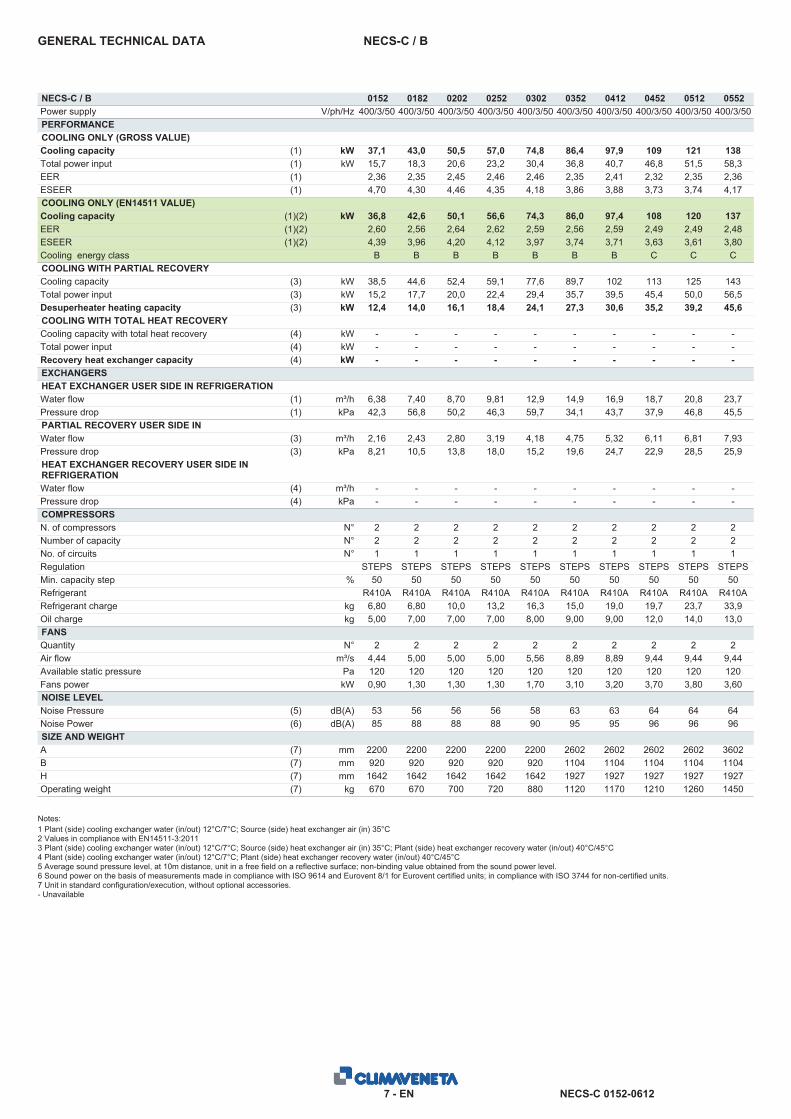
NECS-C / BGENERAL TECHNICAL DATA
NECS-C / B 0152 0182 0202 0252 0302 0352 0412 0452 0512 0552Power supply V/ph/Hz 400/3/50 400/3/50 400/3/50 400/3/50 400/3/50 400/3/50 400/3/50 400/3/50 400/3/50 400/3/50PERFORMANCECOOLING ONLY (GROSS VALUE)Cooling capacity (1) kW 37,1 43,0 50,5 57,0 74,8 86,4 97,9 109 121 138Total power input (1) kW 15,7 18,3 20,6 23,2 30,4 36,8 40,7 46,8 51,5 58,3EER (1) 2,36 2,35 2,45 2,46 2,46 2,35 2,41 2,32 2,35 2,36ESEER (1) 4,70 4,30 4,46 4,35 4,18 3,86 3,88 3,73 3,74 4,17COOLING ONLY (EN14511 VALUE)Cooling capacity (1)(2) kW 36,8 42,6 50,1 56,6 74,3 86,0 97,4 108 120 137EER (1)(2) 2,60 2,56 2,64 2,62 2,59 2,56 2,59 2,49 2,49 2,48ESEER (1)(2) 4,39 3,96 4,20 4,12 3,97 3,74 3,71 3,63 3,61 3,80Cooling energy class B B B B B B B C C CCOOLING WITH PARTIAL RECOVERYCooling capacity (3) kW 38,5 44,6 52,4 59,1 77,6 89,7 102 113 125 143Total power input (3) kW 15,2 17,7 20,0 22,4 29,4 35,7 39,5 45,4 50,0 56,5Desuperheater heating capacity (3) kW 12,4 14,0 16,1 18,4 24,1 27,3 30,6 35,2 39,2 45,6COOLING WITH TOTAL HEAT RECOVERYCooling capacity with total heat recovery (4) kW - - - - - - - - - -Total power input (4) kW - - - - - - - - - -Recovery heat exchanger capacity (4) kW - - - - - - - - - -EXCHANGERSHEAT EXCHANGER USER SIDE IN REFRIGERATIONWater flow (1) m³/h 6,38 7,40 8,70 9,81 12,9 14,9 16,9 18,7 20,8 23,7Pressure drop (1) kPa 42,3 56,8 50,2 46,3 59,7 34,1 43,7 37,9 46,8 45,5PARTIAL RECOVERY USER SIDE INREFRIGERATIONWater flow (3) m³/h 2,16 2,43 2,80 3,19 4,18 4,75 5,32 6,11 6,81 7,93Pressure drop (3) kPa 8,21 10,5 13,8 18,0 15,2 19,6 24,7 22,9 28,5 25,9HEAT EXCHANGER RECOVERY USER SIDE INREFRIGERATIONWater flow (4) m³/h - - - - - - - - - -Pressure drop (4) kPa - - - - - - - - - -COMPRESSORSN. of compressors N° 2 2 2 2 2 2 2 2 2 2Number of capacity N° 2 2 2 2 2 2 2 2 2 2No. of circuits N° 1 1 1 1 1 1 1 1 1 1Regulation STEPS STEPS STEPS STEPS STEPS STEPS STEPS STEPS STEPS STEPSMin. capacity step % 50 50 50 50 50 50 50 50 50 50Refrigerant R410A R410A R410A R410A R410A R410A R410A R410A R410A R410ARefrigerant charge kg 6,80 6,80 10,0 13,2 16,3 15,0 19,0 19,7 23,7 33,9Oil charge kg 5,00 7,00 7,00 7,00 8,00 9,00 9,00 12,0 14,0 13,0FANSQuantity N° 2 2 2 2 2 2 2 2 2 2Air flow m³/s 4,44 5,00 5,00 5,00 5,56 8,89 8,89 9,44 9,44 9,44Available static pressure Pa 120 120 120 120 120 120 120 120 120 120Fans power kW 0,90 1,30 1,30 1,30 1,70 3,10 3,20 3,70 3,80 3,60NOISE LEVELNoise Pressure (5) dB(A) 53 56 56 56 58 63 63 64 64 64Noise Power (6) dB(A) 85 88 88 88 90 95 95 96 96 96SIZE AND WEIGHTA (7) mm 2200 2200 2200 2200 2200 2602 2602 2602 2602 3602B (7) mm 920 920 920 920 920 1104 1104 1104 1104 1104H (7) mm 1642 1642 1642 1642 1642 1927 1927 1927 1927 1927Operating weight (7) kg 670 670 700 720 880 1120 1170 1210 1260 1450
Notes:1 Plant (side) cooling exchanger water (in/out) 12°C/7°C; Source (side) heat exchanger air (in) 35°C2 Values in compliance with EN14511-3:20113 Plant (side) cooling exchanger water (in/out) 12°C/7°C; Source (side) heat exchanger air (in) 35°C; Plant (side) heat exchanger recovery water (in/out) 40°C/45°C4 Plant (side) cooling exchanger water (in/out) 12°C/7°C; Plant (side) heat exchanger recovery water (in/out) 40°C/45°C5 Average sound pressure level, at 10m distance, unit in a free field on a reflective surface; non-binding value obtained from the sound power level.6 Sound power on the basis of measurements made in compliance with ISO 9614 and Eurovent 8/1 for Eurovent certified units; in compliance with ISO 3744 for non-certified units.7 Unit in standard configuration/execution, without optional accessories.- Unavailable
NECS-C 0152-06128 - EN
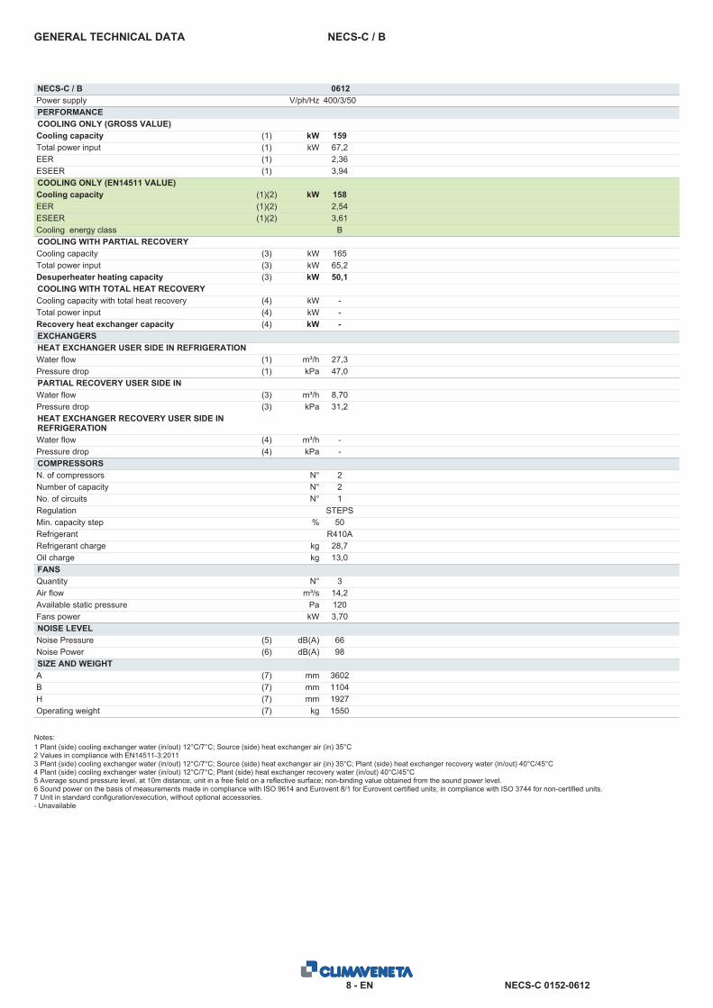
NECS-C / BGENERAL TECHNICAL DATA
NECS-C / B 0612Power supply V/ph/Hz 400/3/50PERFORMANCECOOLING ONLY (GROSS VALUE)Cooling capacity (1) kW 159Total power input (1) kW 67,2EER (1) 2,36ESEER (1) 3,94COOLING ONLY (EN14511 VALUE)Cooling capacity (1)(2) kW 158EER (1)(2) 2,54ESEER (1)(2) 3,61Cooling energy class BCOOLING WITH PARTIAL RECOVERYCooling capacity (3) kW 165Total power input (3) kW 65,2Desuperheater heating capacity (3) kW 50,1COOLING WITH TOTAL HEAT RECOVERYCooling capacity with total heat recovery (4) kW -Total power input (4) kW -Recovery heat exchanger capacity (4) kW -EXCHANGERSHEAT EXCHANGER USER SIDE IN REFRIGERATIONWater flow (1) m³/h 27,3Pressure drop (1) kPa 47,0PARTIAL RECOVERY USER SIDE INREFRIGERATIONWater flow (3) m³/h 8,70Pressure drop (3) kPa 31,2HEAT EXCHANGER RECOVERY USER SIDE INREFRIGERATIONWater flow (4) m³/h -Pressure drop (4) kPa -COMPRESSORSN. of compressors N° 2Number of capacity N° 2No. of circuits N° 1Regulation STEPSMin. capacity step % 50Refrigerant R410ARefrigerant charge kg 28,7Oil charge kg 13,0FANSQuantity N° 3Air flow m³/s 14,2Available static pressure Pa 120Fans power kW 3,70NOISE LEVELNoise Pressure (5) dB(A) 66Noise Power (6) dB(A) 98SIZE AND WEIGHTA (7) mm 3602B (7) mm 1104H (7) mm 1927Operating weight (7) kg 1550
Notes:1 Plant (side) cooling exchanger water (in/out) 12°C/7°C; Source (side) heat exchanger air (in) 35°C2 Values in compliance with EN14511-3:20113 Plant (side) cooling exchanger water (in/out) 12°C/7°C; Source (side) heat exchanger air (in) 35°C; Plant (side) heat exchanger recovery water (in/out) 40°C/45°C4 Plant (side) cooling exchanger water (in/out) 12°C/7°C; Plant (side) heat exchanger recovery water (in/out) 40°C/45°C5 Average sound pressure level, at 10m distance, unit in a free field on a reflective surface; non-binding value obtained from the sound power level.6 Sound power on the basis of measurements made in compliance with ISO 9614 and Eurovent 8/1 for Eurovent certified units; in compliance with ISO 3744 for non-certified units.7 Unit in standard configuration/execution, without optional accessories.- Unavailable
NECS-C 0152-06129 - EN
NECS-C / HTGENERAL TECHNICAL DATA
NECS-C / HT 0152 0182 0202 0252 0302 0352 0412 0452 0512 0552Power supply V/ph/Hz 400/3/50 400/3/50 400/3/50 400/3/50 400/3/50 400/3/50 400/3/50 400/3/50 400/3/50 400/3/50PERFORMANCECOOLING ONLY (GROSS VALUE)Cooling capacity (1) kW 39,0 45,5 52,7 59,4 80,0 91,5 103 114 130 148Total power input (1) kW 14,9 17,4 20,0 22,4 30,6 34,6 39,8 44,1 50,8 57,8EER (1) 2,62 2,61 2,63 2,65 2,61 2,64 2,58 2,58 2,56 2,55ESEER (1) 4,83 4,48 4,51 4,42 3,93 4,01 3,81 4,03 3,78 3,97COOLING ONLY (EN14511 VALUE)Cooling capacity (1)(2) kW 38,7 45,1 52,3 59,0 79,4 91,0 102 113 129 147EER (1)(2) 2,89 2,87 2,86 2,85 2,87 2,89 2,79 2,77 2,82 2,77ESEER (1)(2) 4,50 4,11 4,24 4,18 3,71 3,84 3,67 3,84 3,63 3,68Cooling energy class A A A A A A A A A ACOOLING WITH PARTIAL RECOVERYCooling capacity (3) kW 40,4 47,2 54,7 61,6 83,0 94,9 106 118 135 153Total power input (3) kW 14,4 16,9 19,4 21,7 29,8 33,6 38,6 42,8 49,4 56,2Desuperheater heating capacity (3) kW 11,5 12,8 15,1 17,3 21,6 25,0 28,5 33,0 35,4 41,4COOLING WITH TOTAL HEAT RECOVERYCooling capacity with total heat recovery (4) kW - - - - - - - - - -Total power input (4) kW - - - - - - - - - -Recovery heat exchanger capacity (4) kW - - - - - - - - - -EXCHANGERSHEAT EXCHANGER USER SIDE IN REFRIGERATIONWater flow (1) m³/h 6,71 7,83 9,07 10,2 13,8 15,7 17,7 19,6 22,4 25,4Pressure drop (1) kPa 46,7 63,6 54,6 50,3 68,3 38,2 48,1 41,5 54,0 52,2PARTIAL RECOVERY USER SIDE INREFRIGERATIONWater flow (3) m³/h 2,00 2,23 2,63 3,01 3,76 4,35 4,96 5,73 6,16 7,20Pressure drop (3) kPa 7,07 8,80 12,2 16,0 12,3 16,5 21,4 20,1 23,2 21,4HEAT EXCHANGER RECOVERY USER SIDE INREFRIGERATIONWater flow (4) m³/h - - - - - - - - - -Pressure drop (4) kPa - - - - - - - - - -COMPRESSORSN. of compressors N° 2 2 2 2 2 2 2 2 2 2Number of capacity N° 2 2 2 2 2 2 2 2 2 2No. of circuits N° 1 1 1 1 1 1 1 1 1 1Regulation STEPS STEPS STEPS STEPS STEPS STEPS STEPS STEPS STEPS STEPSMin. capacity step % 50 50 50 50 50 50 50 50 50 50Refrigerant R410A R410A R410A R410A R410A R410A R410A R410A R410A R410ARefrigerant charge kg 9,70 9,70 12,9 16,0 18,0 23,0 27,0 33,3 27,3 33,9Oil charge kg 5,00 7,00 7,00 7,00 8,00 9,00 9,00 12,0 14,0 13,0FANSQuantity N° 2 2 2 2 2 2 2 2 3 3Air flow m³/s 4,44 5,28 5,28 5,28 8,89 8,89 9,44 9,44 14,2 14,2Available static pressure Pa 120 120 120 120 120 120 120 120 120 120Fans power kW 1,00 1,50 1,50 1,50 3,20 3,30 3,90 3,60 3,70 3,80NOISE LEVELNoise Pressure (5) dB(A) 53 57 57 57 63 63 64 64 66 66Noise Power (6) dB(A) 85 89 89 89 95 95 96 96 98 98SIZE AND WEIGHTA (7) mm 2200 2200 2200 2200 2602 2602 2602 3602 3602 3602B (7) mm 920 920 920 920 1104 1104 1104 1104 1104 1104H (7) mm 1642 1642 1642 1642 1927 1927 1927 1927 1927 1927Operating weight (7) kg 690 710 730 760 1090 1120 1230 1400 1490 1560
Notes:1 Plant (side) cooling exchanger water (in/out) 12°C/7°C; Source (side) heat exchanger air (in) 35°C2 Values in compliance with EN14511-3:20113 Plant (side) cooling exchanger water (in/out) 12°C/7°C; Source (side) heat exchanger air (in) 35°C; Plant (side) heat exchanger recovery water (in/out) 40°C/45°C4 Plant (side) cooling exchanger water (in/out) 12°C/7°C; Plant (side) heat exchanger recovery water (in/out) 40°C/45°C5 Average sound pressure level, at 10m distance, unit in a free field on a reflective surface; non-binding value obtained from the sound power level.6 Sound power on the basis of measurements made in compliance with ISO 9614 and Eurovent 8/1 for Eurovent certified units; in compliance with ISO 3744 for non-certified units.7 Unit in standard configuration/execution, without optional accessories.- Unavailable

NECS-C 0152-061210 - EN
NECS-C / HTGENERAL TECHNICAL DATA
NECS-C / HT 0612Power supply V/ph/Hz 400/3/50PERFORMANCECOOLING ONLY (GROSS VALUE)Cooling capacity (1) kW 165Total power input (1) kW 64,6EER (1) 2,56ESEER (1) 3,94COOLING ONLY (EN14511 VALUE)Cooling capacity (1)(2) kW 164EER (1)(2) 2,75ESEER (1)(2) 3,70Cooling energy class ACOOLING WITH PARTIAL RECOVERYCooling capacity (3) kW 171Total power input (3) kW 62,8Desuperheater heating capacity (3) kW 47,2COOLING WITH TOTAL HEAT RECOVERYCooling capacity with total heat recovery (4) kW -Total power input (4) kW -Recovery heat exchanger capacity (4) kW -EXCHANGERSHEAT EXCHANGER USER SIDE IN REFRIGERATIONWater flow (1) m³/h 28,5Pressure drop (1) kPa 51,0PARTIAL RECOVERY USER SIDE INREFRIGERATIONWater flow (3) m³/h 8,21Pressure drop (3) kPa 27,8HEAT EXCHANGER RECOVERY USER SIDE INREFRIGERATIONWater flow (4) m³/h -Pressure drop (4) kPa -COMPRESSORSN. of compressors N° 2Number of capacity N° 2No. of circuits N° 1Regulation STEPSMin. capacity step % 50Refrigerant R410ARefrigerant charge kg 40,4Oil charge kg 13,0FANSQuantity N° 3Air flow m³/s 14,2Available static pressure Pa 120Fans power kW 3,90NOISE LEVELNoise Pressure (5) dB(A) 66Noise Power (6) dB(A) 98SIZE AND WEIGHTA (7) mm 3602B (7) mm 1104H (7) mm 1927Operating weight (7) kg 1630
Notes:1 Plant (side) cooling exchanger water (in/out) 12°C/7°C; Source (side) heat exchanger air (in) 35°C2 Values in compliance with EN14511-3:20113 Plant (side) cooling exchanger water (in/out) 12°C/7°C; Source (side) heat exchanger air (in) 35°C; Plant (side) heat exchanger recovery water (in/out) 40°C/45°C4 Plant (side) cooling exchanger water (in/out) 12°C/7°C; Plant (side) heat exchanger recovery water (in/out) 40°C/45°C5 Average sound pressure level, at 10m distance, unit in a free field on a reflective surface; non-binding value obtained from the sound power level.6 Sound power on the basis of measurements made in compliance with ISO 9614 and Eurovent 8/1 for Eurovent certified units; in compliance with ISO 3744 for non-certified units.7 Unit in standard configuration/execution, without optional accessories.- Unavailable
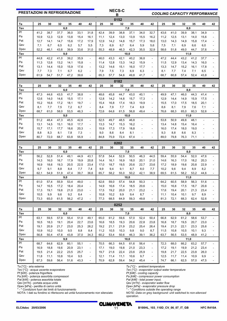
B COOLING CAPACITY PERFORMANCEPRESTAZIONI IN REFRIGERAZIONE NECS-C
01524225 42 4040 353542403525 3232 3030 253230Ta
6,0Tev 8,07,0Pf 41,0 39,9 38,1 34,9 -43,639,9 38,8 37,1 34,0 32,742,431,833,136,037,738,741,2Pa 12,5 13,1 14,0 15,6 -11,212,4 13,0 13,9 15,5 16,211,116,115,413,812,912,310,9Pat 14,3 14,9 15,8 17,4 -13,014,2 14,8 15,7 17,3 18,012,917,917,215,614,714,112,7Qev 7,1 6,9 6,6 6,0 -7,56,9 6,7 6,4 5,9 5,67,35,55,76,26,56,77,1Dpev 51,8 49,0 44,7 37,6 -58,648,9 46,3 42,3 35,5 32,955,331,033,639,943,646,152,2
9,0Tev 11,010,0Pf 44,4 43,2 41,2 37,7 -47,243,3 42,1 40,2 36,8 -46,0-35,939,241,042,244,8Pa 12,9 13,4 14,3 16,0 -11,512,8 13,3 14,2 15,9 -11,4-15,814,113,212,611,3Pat 14,7 15,2 16,1 17,8 -13,314,6 15,1 16,0 17,7 -13,2-17,615,915,014,413,1Qev 7,7 7,4 7,1 6,5 -8,17,5 7,3 6,9 6,3 -7,9-6,26,77,17,37,7Dpev 60,8 57,4 52,4 43,8 -68,757,7 54,6 49,8 41,7 -65,3-39,647,251,754,761,9
01824225 42 4040 353542403525 3232 3030 253230Ta
6,0Tev 8,07,0Pf 47,1 46,0 44,3 41,4 -49,945,8 44,7 43,0 40,1 -48,6-38,841,743,544,647,3Pa 14,4 14,9 15,9 17,5 -12,914,2 14,8 15,7 17,3 -12,8-17,115,514,614,012,6Pat 17,0 17,5 18,5 20,1 -15,516,8 17,4 18,3 19,9 -15,4-19,718,117,216,615,2Qev 8,1 7,9 7,6 7,1 -8,67,9 7,7 7,4 6,9 -8,4-6,77,27,57,78,1Dpev 68,3 65,0 60,3 52,6 -76,664,6 61,5 56,8 49,4 -72,6-46,353,558,061,068,7
9,0Tev 11,010,0Pf 50,9 49,8 48,1 - -53,849,7 48,5 46,8 - -52,5-42,645,547,348,451,2Pa 14,8 15,4 16,4 - -13,414,7 15,3 16,2 - -13,3-17,716,015,114,513,1Pat 17,4 18,0 19,0 - -16,017,3 17,9 18,8 - -15,9-20,318,617,717,115,7Qev 8,8 8,6 8,3 - -9,38,6 8,4 8,1 - -9,0-7,37,88,18,38,8Dpev 79,8 76,3 71,1 - -89,075,9 72,4 67,4 - -84,8-55,963,868,772,080,7
02024225 42 4040 353542403525 3232 3030 253230Ta
6,0Tev 8,07,0Pf 55,9 54,4 52,0 47,6 -59,454,4 52,9 50,5 46,3 44,557,843,144,949,151,452,856,2Pa 16,3 17,0 18,2 20,3 -14,616,1 16,9 18,0 20,1 21,014,420,819,917,916,716,014,3Pat 18,9 19,6 20,8 22,9 -17,218,7 19,5 20,6 22,7 23,617,023,422,520,519,318,616,9Qev 9,6 9,4 8,9 8,2 -10,29,4 9,1 8,7 8,0 7,79,97,47,78,48,89,19,7Dpev 61,5 58,2 53,2 44,6 -69,558,2 55,0 50,2 42,1 38,965,736,639,747,451,954,962,1
9,0Tev 11,010,0Pf 60,5 58,9 56,3 51,6 -64,259,0 57,4 54,8 50,3 -62,6-49,053,455,957,461,0Pa 16,8 17,5 18,7 20,8 -15,016,6 17,4 18,5 20,6 -14,9-20,418,417,216,514,7Pat 19,4 20,1 21,3 23,4 -17,619,2 20,0 21,1 23,2 -17,5-23,021,019,819,117,3Qev 10,4 10,1 9,7 8,9 -11,110,2 9,9 9,4 8,7 -10,8-8,49,29,69,910,5Dpev 72,1 68,3 62,4 52,6 -81,368,5 64,9 59,3 49,8 -77,3-47,256,261,565,073,3
02524225 42 4040 353542403525 3232 3030 253230Ta
6,0Tev 8,07,0Pf 62,9 61,2 58,6 53,7 -66,861,2 59,6 57,0 52,4 50,465,049,151,055,457,959,563,1Pa 18,7 19,5 20,7 23,0 -16,818,5 19,3 20,6 22,8 23,816,623,622,720,419,118,316,5Pat 21,3 22,1 23,3 25,6 -19,421,1 21,9 23,2 25,4 26,419,226,225,323,021,720,919,1Qev 10,8 10,5 10,1 9,3 -11,510,5 10,3 9,8 9,0 8,711,28,48,89,510,010,210,9Dpev 56,5 53,5 48,9 41,2 -63,753,4 50,6 46,3 39,1 36,260,234,337,043,847,850,456,8
9,0Tev 11,010,0Pf 68,0 66,2 63,2 57,7 -72,366,3 64,5 61,6 56,4 -70,5-55,160,162,964,668,7Pa 19,1 19,9 21,2 23,4 -17,219,0 19,8 21,0 23,3 -17,1-23,120,919,618,816,9Pat 21,7 22,5 23,8 26,0 -19,821,6 22,4 23,6 25,9 -19,7-25,723,522,221,419,5Qev 11,7 11,4 10,9 9,9 -12,511,4 11,1 10,6 9,7 -12,1-9,510,410,811,111,8Dpev 66,1 62,5 57,0 47,5 -74,762,8 59,4 54,2 45,4 -70,9-43,351,656,459,667,3
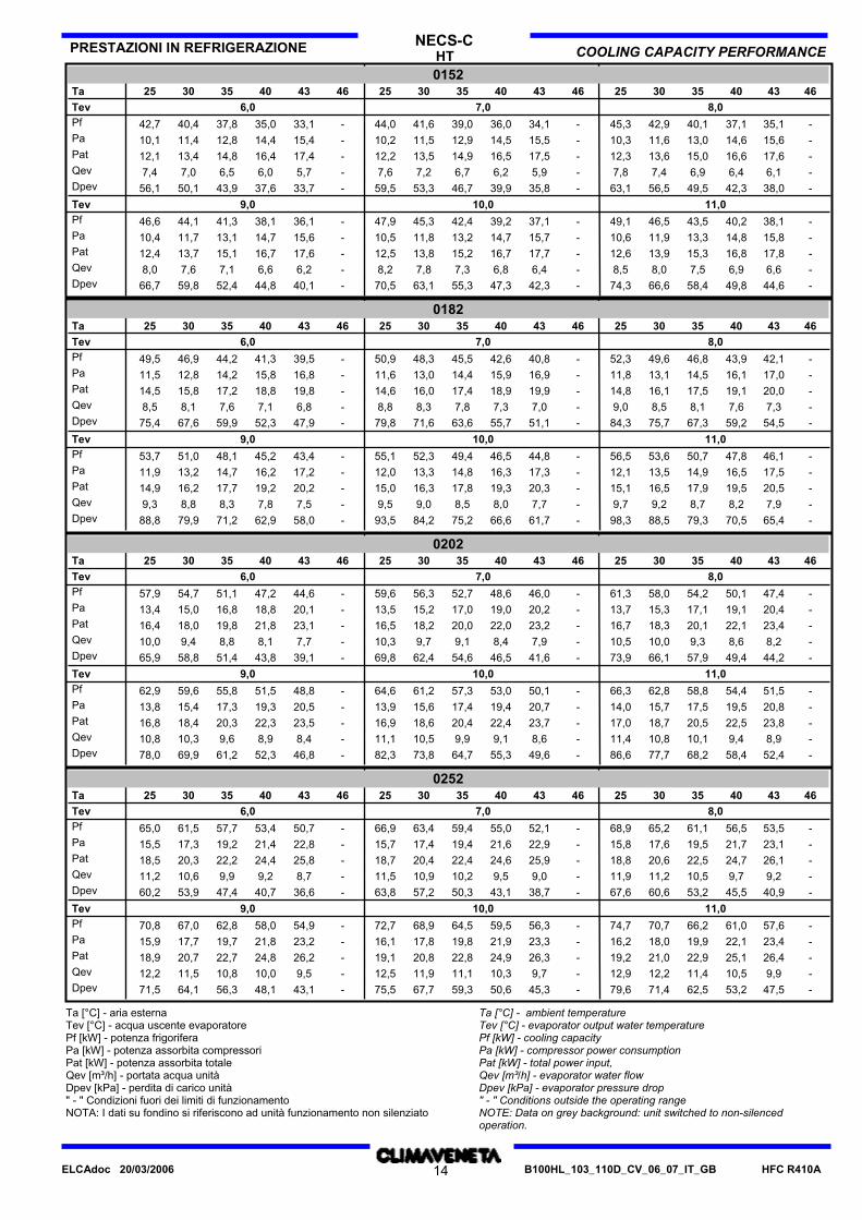
Ta [°C] - aria esternaTev [°C] - acqua uscente evaporatorePf [kW] - potenza frigoriferaPa [kW] - potenza assorbita compressoriPat [kW] - potenza assorbita totaleQev [m³/h] - portata acqua unitàDpev [kPa] - perdita di carico unità" - " Condizioni fuori dei limiti di funzionamentoNOTA: I dati su fondino si riferiscono ad unità funzionamento non silenziato
Ta [°C] - ambient temperatureTev [°C] - evaporator output water temperaturePf [kW] - cooling capacityPa [kW] - compressor power consumptionPat [kW] - total power input,Qev [m³/h] - evaporator water flowDpev [kPa] - evaporator pressure drop" - " Conditions outside the operating rangeNOTE: Data on grey background: unit switched to non-silencedoperation.
HFC R410AB100HL_103_110D_CV_06_07_IT_GB11ELCAdoc 20/03/2006
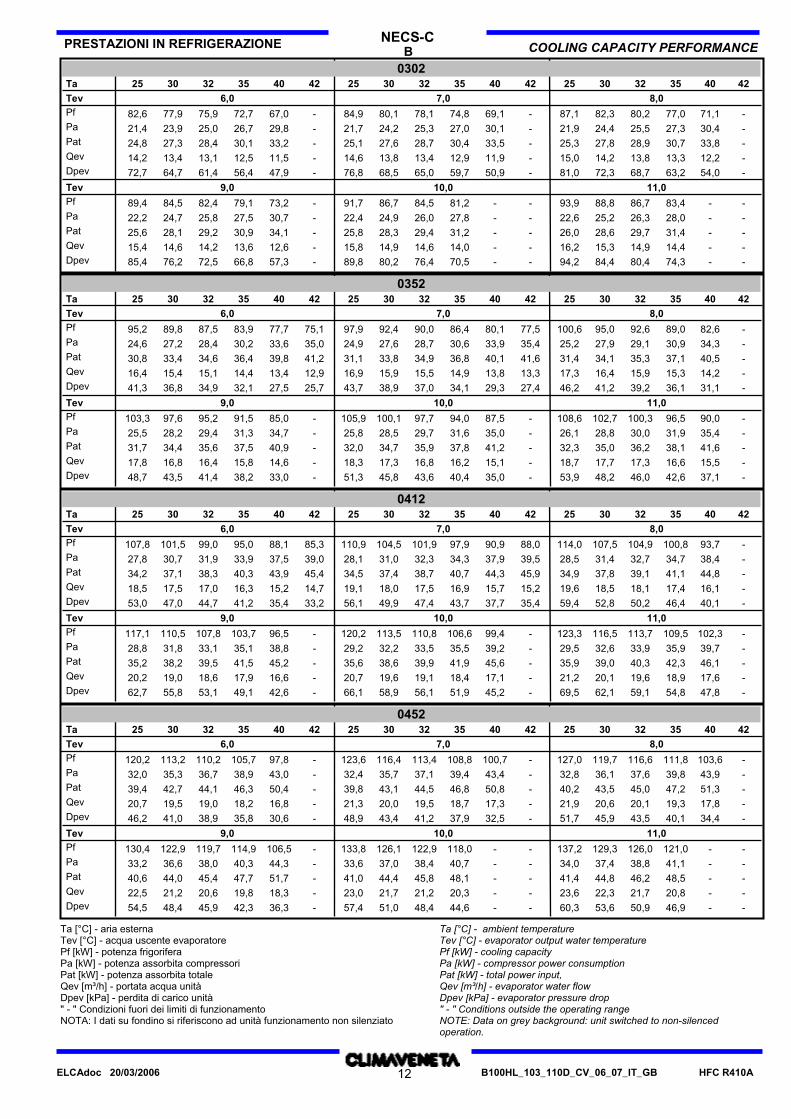
B COOLING CAPACITY PERFORMANCEPRESTAZIONI IN REFRIGERAZIONE NECS-C
03024225 42 4040 353542403525 3232 3030 253230Ta
6,0Tev 8,07,0Pf 82,3 80,2 77,0 71,1 -87,180,1 78,1 74,8 69,1 -84,9-67,072,775,977,982,6Pa 24,4 25,5 27,3 30,4 -21,924,2 25,3 27,0 30,1 -21,7-29,826,725,023,921,4Pat 27,8 28,9 30,7 33,8 -25,327,6 28,7 30,4 33,5 -25,1-33,230,128,427,324,8Qev 14,2 13,8 13,3 12,2 -15,013,8 13,4 12,9 11,9 -14,6-11,512,513,113,414,2Dpev 72,3 68,7 63,2 54,0 -81,068,5 65,0 59,7 50,9 -76,8-47,956,461,464,772,7
9,0Tev 11,010,0Pf 88,8 86,7 83,4 - -93,986,7 84,5 81,2 - -91,7-73,279,182,484,589,4Pa 25,2 26,3 28,0 - -22,624,9 26,0 27,8 - -22,4-30,727,525,824,722,2Pat 28,6 29,7 31,4 - -26,028,3 29,4 31,2 - -25,8-34,130,929,228,125,6Qev 15,3 14,9 14,4 - -16,214,9 14,6 14,0 - -15,8-12,613,614,214,615,4Dpev 84,4 80,4 74,3 - -94,280,2 76,4 70,5 - -89,8-57,366,872,576,285,4
03524225 42 4040 353542403525 3232 3030 253230Ta
6,0Tev 8,07,0Pf 95,0 92,6 89,0 82,6 -100,692,4 90,0 86,4 80,1 77,597,975,177,783,987,589,895,2Pa 27,9 29,1 30,9 34,3 -25,227,6 28,7 30,6 33,9 35,424,935,033,630,228,427,224,6Pat 34,1 35,3 37,1 40,5 -31,433,8 34,9 36,8 40,1 41,631,141,239,836,434,633,430,8Qev 16,4 15,9 15,3 14,2 -17,315,9 15,5 14,9 13,8 13,316,912,913,414,415,115,416,4Dpev 41,2 39,2 36,1 31,1 -46,238,9 37,0 34,1 29,3 27,443,725,727,532,134,936,841,3
9,0Tev 11,010,0Pf 102,7 100,3 96,5 90,0 -108,6100,1 97,7 94,0 87,5 -105,9-85,091,595,297,6103,3Pa 28,8 30,0 31,9 35,4 -26,128,5 29,7 31,6 35,0 -25,8-34,731,329,428,225,5Pat 35,0 36,2 38,1 41,6 -32,334,7 35,9 37,8 41,2 -32,0-40,937,535,634,431,7Qev 17,7 17,3 16,6 15,5 -18,717,3 16,8 16,2 15,1 -18,3-14,615,816,416,817,8Dpev 48,2 46,0 42,6 37,1 -53,945,8 43,6 40,4 35,0 -51,3-33,038,241,443,548,7
04124225 42 4040 353542403525 3232 3030 253230Ta
6,0Tev 8,07,0Pf 107,5 104,9 100,8 93,7 -114,0104,5 101,9 97,9 90,9 88,0110,985,388,195,099,0101,5107,8Pa 31,4 32,7 34,7 38,4 -28,531,0 32,3 34,3 37,9 39,528,139,037,533,931,930,727,8Pat 37,8 39,1 41,1 44,8 -34,937,4 38,7 40,7 44,3 45,934,545,443,940,338,337,134,2Qev 18,5 18,1 17,4 16,1 -19,618,0 17,5 16,9 15,7 15,219,114,715,216,317,017,518,5Dpev 52,8 50,2 46,4 40,1 -59,449,9 47,4 43,7 37,7 35,456,133,235,441,244,747,053,0
9,0Tev 11,010,0Pf 116,5 113,7 109,5 102,3 -123,3113,5 110,8 106,6 99,4 -120,2-96,5103,7107,8110,5117,1Pa 32,6 33,9 35,9 39,7 -29,532,2 33,5 35,5 39,2 -29,2-38,835,133,131,828,8Pat 39,0 40,3 42,3 46,1 -35,938,6 39,9 41,9 45,6 -35,6-45,241,539,538,235,2Qev 20,1 19,6 18,9 17,6 -21,219,6 19,1 18,4 17,1 -20,7-16,617,918,619,020,2Dpev 62,1 59,1 54,8 47,8 -69,558,9 56,1 51,9 45,2 -66,1-42,649,153,155,862,7
04524225 42 4040 353542403525 3232 3030 253230Ta
6,0Tev 8,07,0Pf 119,7 116,6 111,8 103,6 -127,0116,4 113,4 108,8 100,7 -123,6-97,8105,7110,2113,2120,2Pa 36,1 37,6 39,8 43,9 -32,835,7 37,1 39,4 43,4 -32,4-43,038,936,735,332,0Pat 43,5 45,0 47,2 51,3 -40,243,1 44,5 46,8 50,8 -39,8-50,446,344,142,739,4Qev 20,6 20,1 19,3 17,8 -21,920,0 19,5 18,7 17,3 -21,3-16,818,219,019,520,7Dpev 45,9 43,5 40,1 34,4 -51,743,4 41,2 37,9 32,5 -48,9-30,635,838,941,046,2
9,0Tev 11,010,0Pf 129,3 126,0 121,0 - -137,2126,1 122,9 118,0 - -133,8-106,5114,9119,7122,9130,4Pa 37,4 38,8 41,1 - -34,037,0 38,4 40,7 - -33,6-44,340,338,036,633,2Pat 44,8 46,2 48,5 - -41,444,4 45,8 48,1 - -41,0-51,747,745,444,040,6Qev 22,3 21,7 20,8 - -23,621,7 21,2 20,3 - -23,0-18,319,820,621,222,5Dpev 53,6 50,9 46,9 - -60,351,0 48,4 44,6 - -57,4-36,342,345,948,454,5
Ta [°C] - aria esternaTev [°C] - acqua uscente evaporatorePf [kW] - potenza frigoriferaPa [kW] - potenza assorbita compressoriPat [kW] - potenza assorbita totaleQev [m³/h] - portata acqua unitàDpev [kPa] - perdita di carico unità" - " Condizioni fuori dei limiti di funzionamentoNOTA: I dati su fondino si riferiscono ad unità funzionamento non silenziato
Ta [°C] - ambient temperatureTev [°C] - evaporator output water temperaturePf [kW] - cooling capacityPa [kW] - compressor power consumptionPat [kW] - total power input,Qev [m³/h] - evaporator water flowDpev [kPa] - evaporator pressure drop" - " Conditions outside the operating rangeNOTE: Data on grey background: unit switched to non-silencedoperation.
HFC R410AB100HL_103_110D_CV_06_07_IT_GB12ELCAdoc 20/03/2006
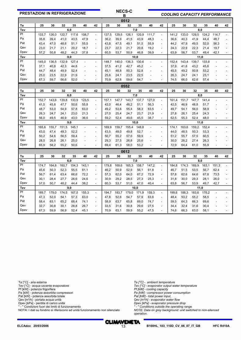
B COOLING CAPACITY PERFORMANCEPRESTAZIONI IN REFRIGERAZIONE NECS-C
05124225 42 4040 353542403525 3232 3030 253230Ta
6,0Tev 8,07,0Pf 133,0 129,5 124,2 114,7 -141,2129,5 126,1 120,9 111,7 -137,5-108,7117,6122,7126,0133,7Pa 40,3 41,9 44,4 48,7 -36,639,9 41,5 43,9 48,3 -36,2-47,943,541,039,435,8Pat 47,9 49,5 52,0 56,3 -44,247,5 49,1 51,5 55,9 -43,8-55,551,148,647,043,4Qev 22,9 22,3 21,4 19,7 -24,322,3 21,7 20,8 19,2 -23,7-18,720,221,121,723,0Dpev 56,7 53,7 49,4 42,1 -63,953,7 50,9 46,8 39,9 -60,5-37,844,348,250,857,2
9,0Tev 11,010,0Pf 143,4 139,7 133,8 - -152,4140,0 136,3 130,6 - -148,7--127,4132,9136,5145,0Pa 41,6 43,2 45,6 - -37,941,2 42,7 45,2 - -37,5--44,842,340,837,1Pat 49,2 50,8 53,2 - -45,548,8 50,3 52,8 - -45,1--52,449,948,444,7Qev 24,7 24,1 23,1 - -26,324,1 23,5 22,5 - -25,6--21,922,923,525,0Dpev 66,0 62,6 57,4 - -74,562,8 59,6 54,7 - -70,9--52,056,659,767,3
05524225 42 4040 353542403525 3232 3030 253230Ta
6,0Tev 8,07,0Pf 151,7 147,7 141,4 - -161,4147,7 143,7 137,7 127,0 -157,1-123,5133,9139,8143,6152,7Pa 46,9 48,8 51,7 - -42,546,4 48,2 51,1 56,3 -42,0-55,850,647,745,841,5Pat 54,1 56,0 58,9 - -49,753,6 55,4 58,3 63,5 -49,2-63,057,854,953,048,7Qev 26,1 25,4 24,3 - -27,825,4 24,7 23,7 21,9 -27,0-21,323,024,124,726,3Dpev 55,3 52,4 48,0 - -62,552,4 49,6 45,5 38,7 -59,2-36,643,046,949,556,0
9,0Tev 11,010,0Pf 163,6 159,2 152,4 - -174,1159,7 155,4 148,8 - -169,9--145,1151,5155,7165,6Pa 48,5 50,3 53,3 - -44,048,0 49,8 52,7 - -43,5--52,249,347,443,0Pat 55,7 57,5 60,5 - -51,255,2 57,0 59,9 - -50,7--59,456,554,650,2Qev 28,2 27,4 26,3 - -30,027,5 26,8 25,6 - -29,3--25,026,126,828,5Dpev 64,4 61,0 55,9 - -72,961,3 58,0 53,2 - -69,4--50,655,258,265,9
06124225 42 4040 353542403525 3232 3030 253230Ta
6,0Tev 8,07,0Pf 174,3 169,9 163,1 151,3 -184,8169,6 165,3 158,7 147,2 -179,8-143,1154,3160,7164,8174,7Pa 51,5 53,5 56,7 62,4 -46,750,9 52,9 56,1 61,8 -46,2-61,155,552,350,345,6Pat 62,6 64,6 67,8 73,5 -57,862,0 64,0 67,2 72,9 -57,3-72,266,663,461,456,7Qev 30,0 29,3 28,1 26,0 -31,829,2 28,5 27,3 25,3 -30,9-24,626,627,728,430,1Dpev 56,7 53,9 49,7 42,7 -63,853,7 51,0 47,0 40,4 -60,3-38,244,448,250,757,0
9,0Tev 11,010,0Pf 188,3 183,6 176,2 - -199,6183,7 179,0 171,9 159,3 -194,7-155,3167,5174,5179,0189,7Pa 53,2 55,2 58,5 - -48,452,6 54,7 57,9 63,6 -47,8-63,057,354,152,047,3Pat 64,3 66,3 69,6 - -59,563,7 65,8 69,0 74,7 -58,9-74,168,465,263,158,4Qev 32,4 31,6 30,4 - -34,431,6 30,8 29,6 27,5 -33,5-26,728,830,130,832,7Dpev 66,3 63,0 58,1 - -74,663,1 59,9 55,2 47,5 -70,9-45,152,456,959,967,3
Ta [°C] - aria esternaTev [°C] - acqua uscente evaporatorePf [kW] - potenza frigoriferaPa [kW] - potenza assorbita compressoriPat [kW] - potenza assorbita totaleQev [m³/h] - portata acqua unitàDpev [kPa] - perdita di carico unità" - " Condizioni fuori dei limiti di funzionamentoNOTA: I dati su fondino si riferiscono ad unità funzionamento non silenziato
Ta [°C] - ambient temperatureTev [°C] - evaporator output water temperaturePf [kW] - cooling capacityPa [kW] - compressor power consumptionPat [kW] - total power input,Qev [m³/h] - evaporator water flowDpev [kPa] - evaporator pressure drop" - " Conditions outside the operating rangeNOTE: Data on grey background: unit switched to non-silencedoperation.
HFC R410AB100HL_103_110D_CV_06_07_IT_GB13ELCAdoc 20/03/2006
HT COOLING CAPACITY PERFORMANCEPRESTAZIONI IN REFRIGERAZIONE NECS-C
01524625 46 4343 404046434025 3535 3030 253530Ta
6,0Tev 8,07,0Pf 42,9 40,1 37,1 35,1 -45,341,6 39,0 36,0 34,1 -44,0-33,135,037,840,442,7Pa 11,6 13,0 14,6 15,6 -10,311,5 12,9 14,5 15,5 -10,2-15,414,412,811,410,1Pat 13,6 15,0 16,6 17,6 -12,313,5 14,9 16,5 17,5 -12,2-17,416,414,813,412,1Qev 7,4 6,9 6,4 6,1 -7,87,2 6,7 6,2 5,9 -7,6-5,76,06,57,07,4Dpev 56,5 49,5 42,3 38,0 -63,153,3 46,7 39,9 35,8 -59,5-33,737,643,950,156,1
9,0Tev 11,010,0Pf 46,5 43,5 40,2 38,1 -49,145,3 42,4 39,2 37,1 -47,9-36,138,141,344,146,6Pa 11,9 13,3 14,8 15,8 -10,611,8 13,2 14,7 15,7 -10,5-15,614,713,111,710,4Pat 13,9 15,3 16,8 17,8 -12,613,8 15,2 16,7 17,7 -12,5-17,616,715,113,712,4Qev 8,0 7,5 6,9 6,6 -8,57,8 7,3 6,8 6,4 -8,2-6,26,67,17,68,0Dpev 66,6 58,4 49,8 44,6 -74,363,1 55,3 47,3 42,3 -70,5-40,144,852,459,866,7
01824625 46 4343 404046434025 3535 3030 253530Ta
6,0Tev 8,07,0Pf 49,6 46,8 43,9 42,1 -52,348,3 45,5 42,6 40,8 -50,9-39,541,344,246,949,5Pa 13,1 14,5 16,1 17,0 -11,813,0 14,4 15,9 16,9 -11,6-16,815,814,212,811,5Pat 16,1 17,5 19,1 20,0 -14,816,0 17,4 18,9 19,9 -14,6-19,818,817,215,814,5Qev 8,5 8,1 7,6 7,3 -9,08,3 7,8 7,3 7,0 -8,8-6,87,17,68,18,5Dpev 75,7 67,3 59,2 54,5 -84,371,6 63,6 55,7 51,1 -79,8-47,952,359,967,675,4
9,0Tev 11,010,0Pf 53,6 50,7 47,8 46,1 -56,552,3 49,4 46,5 44,8 -55,1-43,445,248,151,053,7Pa 13,5 14,9 16,5 17,5 -12,113,3 14,8 16,3 17,3 -12,0-17,216,214,713,211,9Pat 16,5 17,9 19,5 20,5 -15,116,3 17,8 19,3 20,3 -15,0-20,219,217,716,214,9Qev 9,2 8,7 8,2 7,9 -9,79,0 8,5 8,0 7,7 -9,5-7,57,88,38,89,3Dpev 88,5 79,3 70,5 65,4 -98,384,2 75,2 66,6 61,7 -93,5-58,062,971,279,988,8
02024625 46 4343 404046434025 3535 3030 253530Ta
6,0Tev 8,07,0Pf 58,0 54,2 50,1 47,4 -61,356,3 52,7 48,6 46,0 -59,6-44,647,251,154,757,9Pa 15,3 17,1 19,1 20,4 -13,715,2 17,0 19,0 20,2 -13,5-20,118,816,815,013,4Pat 18,3 20,1 22,1 23,4 -16,718,2 20,0 22,0 23,2 -16,5-23,121,819,818,016,4Qev 10,0 9,3 8,6 8,2 -10,59,7 9,1 8,4 7,9 -10,3-7,78,18,89,410,0Dpev 66,1 57,9 49,4 44,2 -73,962,4 54,6 46,5 41,6 -69,8-39,143,851,458,865,9
9,0Tev 11,010,0Pf 62,8 58,8 54,4 51,5 -66,361,2 57,3 53,0 50,1 -64,6-48,851,555,859,662,9Pa 15,7 17,5 19,5 20,8 -14,015,6 17,4 19,4 20,7 -13,9-20,519,317,315,413,8Pat 18,7 20,5 22,5 23,8 -17,018,6 20,4 22,4 23,7 -16,9-23,522,320,318,416,8Qev 10,8 10,1 9,4 8,9 -11,410,5 9,9 9,1 8,6 -11,1-8,48,99,610,310,8Dpev 77,7 68,2 58,4 52,4 -86,673,8 64,7 55,3 49,6 -82,3-46,852,361,269,978,0
02524625 46 4343 404046434025 3535 3030 253530Ta
6,0Tev 8,07,0Pf 65,2 61,1 56,5 53,5 -68,963,4 59,4 55,0 52,1 -66,9-50,753,457,761,565,0Pa 17,6 19,5 21,7 23,1 -15,817,4 19,4 21,6 22,9 -15,7-22,821,419,217,315,5Pat 20,6 22,5 24,7 26,1 -18,820,4 22,4 24,6 25,9 -18,7-25,824,422,220,318,5Qev 11,2 10,5 9,7 9,2 -11,910,9 10,2 9,5 9,0 -11,5-8,79,29,910,611,2Dpev 60,6 53,2 45,5 40,9 -67,657,2 50,3 43,1 38,7 -63,8-36,640,747,453,960,2
9,0Tev 11,010,0Pf 70,7 66,2 61,0 57,6 -74,768,9 64,5 59,5 56,3 -72,7-54,958,062,867,070,8Pa 18,0 19,9 22,1 23,4 -16,217,8 19,8 21,9 23,3 -16,1-23,221,819,717,715,9Pat 21,0 22,9 25,1 26,4 -19,220,8 22,8 24,9 26,3 -19,1-26,224,822,720,718,9Qev 12,2 11,4 10,5 9,9 -12,911,9 11,1 10,3 9,7 -12,5-9,510,010,811,512,2Dpev 71,4 62,5 53,2 47,5 -79,667,7 59,3 50,6 45,3 -75,5-43,148,156,364,171,5
Ta [°C] - aria esternaTev [°C] - acqua uscente evaporatorePf [kW] - potenza frigoriferaPa [kW] - potenza assorbita compressoriPat [kW] - potenza assorbita totaleQev [m³/h] - portata acqua unitàDpev [kPa] - perdita di carico unità" - " Condizioni fuori dei limiti di funzionamentoNOTA: I dati su fondino si riferiscono ad unità funzionamento non silenziato
Ta [°C] - ambient temperatureTev [°C] - evaporator output water temperaturePf [kW] - cooling capacityPa [kW] - compressor power consumptionPat [kW] - total power input,Qev [m³/h] - evaporator water flowDpev [kPa] - evaporator pressure drop" - " Conditions outside the operating rangeNOTE: Data on grey background: unit switched to non-silencedoperation.
HFC R410AB100HL_103_110D_CV_06_07_IT_GB14ELCAdoc 20/03/2006
HT COOLING CAPACITY PERFORMANCEPRESTAZIONI IN REFRIGERAZIONE NECS-C
03024625 46 4343 404046434025 3535 3030 253530Ta
6,0Tev 8,07,0Pf 87,2 82,3 76,9 73,5 -91,584,8 80,0 74,7 71,3 67,789,065,569,172,577,782,486,5Pa 21,9 24,4 27,3 29,1 -19,721,7 24,2 27,0 28,9 30,819,530,628,626,824,021,519,3Pat 28,3 30,8 33,7 35,5 -26,128,1 30,6 33,4 35,3 37,225,937,035,033,230,427,925,7Qev 15,0 14,2 13,3 12,7 -15,814,6 13,8 12,9 12,3 11,615,311,311,912,513,414,214,9Dpev 81,1 72,3 63,2 57,6 -89,476,7 68,3 59,6 54,2 48,884,645,850,956,164,472,479,9
9,0Tev 11,010,0Pf 94,2 89,2 83,7 80,2 -98,891,9 86,9 81,4 77,9 -96,4-75,779,284,689,594,0Pa 22,5 25,0 27,9 29,7 -20,322,3 24,8 27,7 29,5 -20,1-29,327,524,622,119,9Pat 28,9 31,4 34,3 36,1 -26,728,7 31,2 34,1 35,9 -26,5-35,733,931,028,526,3Qev 16,2 15,4 14,4 13,8 -17,015,8 15,0 14,0 13,4 -16,6-13,013,614,615,416,2Dpev 94,9 85,0 74,9 68,7 -104,490,2 80,7 70,9 64,9 -99,3-61,267,076,485,694,3
03524625 46 4343 404046434025 3535 3030 253530Ta
6,0Tev 8,07,0Pf 99,9 94,2 88,0 84,1 -105,297,1 91,5 85,4 81,6 77,6102,375,179,082,888,894,399,4Pa 25,5 28,3 31,4 33,5 -23,125,3 28,0 31,1 33,2 35,322,935,032,830,827,725,022,6Pat 32,1 34,9 38,0 40,1 -29,731,9 34,6 37,7 39,8 41,929,541,639,437,434,331,629,2Qev 17,2 16,2 15,2 14,5 -18,116,7 15,7 14,7 14,0 13,417,612,913,614,315,316,217,1Dpev 45,6 40,5 35,4 32,3 -50,543,0 38,2 33,3 30,4 27,547,825,728,531,336,040,645,1
9,0Tev 11,010,0Pf 108,2 102,2 95,9 91,9 -113,9105,4 99,5 93,2 89,3 -111,0-86,790,696,8102,7108,1Pa 26,3 29,1 32,3 34,3 -23,826,0 28,8 32,0 34,0 -23,6-33,831,728,625,823,3Pat 32,9 35,7 38,9 40,9 -30,432,6 35,4 38,6 40,6 -30,2-40,438,335,232,429,9Qev 18,6 17,6 16,5 15,8 -19,618,2 17,1 16,1 15,4 -19,1-14,915,616,717,718,6Dpev 53,5 47,8 42,0 38,6 -59,350,8 45,3 39,7 36,5 -56,3-34,337,542,848,253,4
04124625 46 4343 404046434025 3535 3030 253530Ta
6,0Tev 8,07,0Pf 112,3 105,7 98,8 94,5 -118,6109,1 102,6 95,8 91,6 -115,284,488,792,999,6105,9111,9Pa 29,3 32,3 35,7 37,9 -26,628,9 32,0 35,4 37,6 -26,339,537,235,031,628,626,0Pat 37,1 40,1 43,5 45,7 -34,436,7 39,8 43,2 45,4 -34,147,345,042,839,436,433,8Qev 19,3 18,2 17,0 16,3 -20,418,8 17,7 16,5 15,8 -19,814,515,316,017,118,219,3Dpev 57,6 51,0 44,6 40,8 -64,254,3 48,1 41,9 38,3 -60,632,535,939,445,251,257,2
9,0Tev 11,010,0Pf 121,8 114,9 107,8 103,4 -128,4118,6 111,8 104,8 100,4 -125,2-97,4101,8108,8115,5121,9Pa 30,2 33,3 36,8 39,0 -27,429,9 33,0 36,4 38,7 -27,1-38,336,132,629,626,9Pat 38,0 41,1 44,6 46,8 -35,237,7 40,8 44,2 46,5 -34,9-46,143,940,437,434,7Qev 21,0 19,8 18,6 17,8 -22,120,4 19,3 18,0 17,3 -21,6-16,817,518,719,921,0Dpev 67,8 60,4 53,1 48,9 -75,464,3 57,1 50,2 46,1 -71,6-43,447,354,060,967,8
04524625 46 4343 404046434025 3535 3030 253530Ta
6,0Tev 8,07,0Pf 124,8 117,2 109,0 103,9 -132,0121,4 113,9 105,9 100,9 -128,4-97,9102,8110,6117,9124,7Pa 33,8 37,3 41,2 43,7 -30,633,4 36,9 40,8 43,3 -30,3-42,940,436,533,029,9Pat 41,0 44,5 48,4 50,9 -37,840,6 44,1 48,0 50,5 -37,5-50,147,643,740,237,1Qev 21,5 20,2 18,8 17,9 -22,720,9 19,6 18,2 17,4 -22,1-16,917,719,020,321,5Dpev 49,9 44,0 38,1 34,6 -55,847,1 41,5 35,9 32,6 -52,7-30,733,839,144,549,8
9,0Tev 11,010,0Pf 135,2 127,0 118,3 - -142,9131,7 123,7 115,2 - -139,3-106,9112,1120,4128,3135,6Pa 34,8 38,4 42,3 - -31,634,5 38,0 41,9 - -31,3-44,141,637,734,131,0Pat 42,0 45,6 49,5 - -38,841,7 45,2 49,1 - -38,5-51,348,844,941,338,2Qev 23,3 21,9 20,4 - -24,622,7 21,3 19,8 - -24,0-18,419,320,722,123,4Dpev 58,6 51,7 44,9 - -65,555,6 49,1 42,6 - -62,2-36,640,346,552,758,9
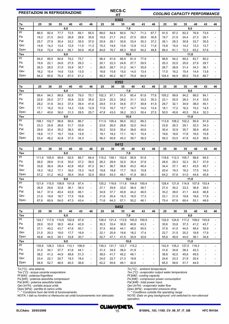
Ta [°C] - aria esternaTev [°C] - acqua uscente evaporatorePf [kW] - potenza frigoriferaPa [kW] - potenza assorbita compressoriPat [kW] - potenza assorbita totaleQev [m³/h] - portata acqua unitàDpev [kPa] - perdita di carico unità" - " Condizioni fuori dei limiti di funzionamentoNOTA: I dati su fondino si riferiscono ad unità funzionamento non silenziato
Ta [°C] - ambient temperatureTev [°C] - evaporator output water temperaturePf [kW] - cooling capacityPa [kW] - compressor power consumptionPat [kW] - total power input,Qev [m³/h] - evaporator water flowDpev [kPa] - evaporator pressure drop" - " Conditions outside the operating rangeNOTE: Data on grey background: unit switched to non-silencedoperation.
HFC R410AB100HL_103_110D_CV_06_07_IT_GB15ELCAdoc 20/03/2006

HT COOLING CAPACITY PERFORMANCEPRESTAZIONI IN REFRIGERAZIONE NECS-C
05124625 46 4343 404046434025 3535 3030 253530Ta
6,0Tev 8,07,0Pf 142,0 133,6 124,7 119,0 -149,6138,0 129,9 121,2 115,7 -145,5-112,4117,7126,2134,0141,3Pa 36,3 40,0 44,1 46,8 -33,036,0 39,7 43,8 46,4 -32,7-46,043,439,335,632,3Pat 47,4 51,1 55,2 57,9 -44,147,1 50,8 54,9 57,5 -43,8-57,154,550,446,743,4Qev 24,4 23,0 21,5 20,5 -25,823,8 22,4 20,9 19,9 -25,0-19,320,321,723,124,3Dpev 64,5 57,2 49,8 45,4 -71,761,0 54,0 47,0 42,8 -67,7-40,444,451,057,563,9
9,0Tev 11,010,0Pf 153,8 144,8 135,1 128,9 -162,1149,8 141,1 131,6 125,6 -157,9-122,3128,2137,4145,9153,8Pa 37,4 41,1 45,1 47,7 -34,037,0 40,7 44,8 47,4 -33,7-47,144,540,436,733,3Pat 48,5 52,2 56,2 58,8 -45,148,1 51,8 55,9 58,5 -44,8-58,255,651,547,844,4Qev 26,5 24,9 23,3 22,2 -27,925,8 24,3 22,7 21,6 -27,2-21,122,123,725,126,5Dpev 75,8 67,2 58,5 53,3 -84,272,0 63,8 55,5 50,6 -79,9-47,952,660,468,275,8
05524625 46 4343 404046434025 3535 3030 253530Ta
6,0Tev 8,07,0Pf 161,3 151,7 141,5 135,0 -170,3156,8 147,5 137,5 131,2 -165,5-127,5133,6143,3152,3160,8Pa 42,5 46,9 51,6 54,7 -38,642,1 46,4 51,2 54,3 -38,2-53,850,746,041,737,8Pat 53,9 58,3 63,0 66,1 -50,053,5 57,8 62,6 65,7 -49,6-65,262,157,453,149,2Qev 27,8 26,1 24,4 23,2 -29,327,0 25,4 23,7 22,6 -28,5-21,923,024,726,227,7Dpev 62,5 55,3 48,1 43,8 -69,659,1 52,2 45,4 41,3 -65,8-39,042,849,355,762,0
9,0Tev 11,010,0Pf 174,7 164,3 153,2 146,2 -184,4170,3 160,2 149,3 142,5 -179,7-138,7145,4155,9165,8175,0Pa 43,8 48,2 52,9 56,0 -39,843,4 47,7 52,5 55,6 -39,4-55,252,147,343,039,0Pat 55,2 59,6 64,3 67,4 -51,254,8 59,1 63,9 67,0 -50,8-66,663,558,754,450,4Qev 30,1 28,3 26,4 25,2 -31,829,3 27,6 25,7 24,5 -31,0-23,925,026,928,630,1Dpev 73,4 65,0 56,5 51,4 -81,869,7 61,7 53,6 48,8 -77,6-46,250,858,466,173,6
06124625 46 4343 404046434025 3535 3030 253530Ta
6,0Tev 8,07,0Pf 180,8 170,0 158,5 151,3 -190,9175,8 165,3 154,1 147,1 -185,6-142,8149,7160,5170,7180,3Pa 48,5 53,4 58,9 62,4 -44,048,0 52,9 58,3 61,8 -43,5-61,357,852,447,543,0Pat 60,2 65,1 70,6 74,1 -55,759,7 64,6 70,0 73,5 -55,2-73,069,564,159,254,7Qev 31,1 29,3 27,3 26,0 -32,930,3 28,5 26,5 25,3 -32,0-24,625,827,629,431,0Dpev 61,1 54,0 46,9 42,7 -68,157,7 51,0 44,3 40,4 -64,3-38,141,848,154,460,7
9,0Tev 11,010,0Pf 195,8 184,2 171,7 163,9 -206,7190,8 179,5 167,3 159,7 -201,5-155,5162,9174,7185,8196,2Pa 50,0 55,0 60,5 64,0 -45,449,5 54,5 60,0 63,5 -45,0-62,959,454,049,044,5Pat 61,7 66,7 72,2 75,7 -57,161,2 66,2 71,7 75,2 -56,7-74,671,165,760,756,2Qev 33,7 31,7 29,6 28,2 -35,632,9 30,9 28,8 27,5 -34,7-26,828,130,132,033,8Dpev 71,7 63,4 55,2 50,2 -80,068,1 60,2 52,3 47,7 -75,9-45,249,657,164,571,9
Ta [°C] - aria esternaTev [°C] - acqua uscente evaporatorePf [kW] - potenza frigoriferaPa [kW] - potenza assorbita compressoriPat [kW] - potenza assorbita totaleQev [m³/h] - portata acqua unitàDpev [kPa] - perdita di carico unità" - " Condizioni fuori dei limiti di funzionamentoNOTA: I dati su fondino si riferiscono ad unità funzionamento non silenziato
Ta [°C] - ambient temperatureTev [°C] - evaporator output water temperaturePf [kW] - cooling capacityPa [kW] - compressor power consumptionPat [kW] - total power input,Qev [m³/h] - evaporator water flowDpev [kPa] - evaporator pressure drop" - " Conditions outside the operating rangeNOTE: Data on grey background: unit switched to non-silencedoperation.
HFC R410AB100HL_103_110D_CV_06_07_IT_GB16ELCAdoc 20/03/2006
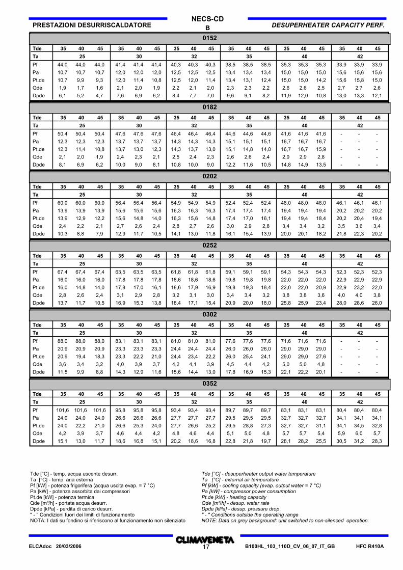
B DESUPERHEATER CAPACITY PERF.PRESTAZIONI DESURRISCALDATORENECS-CD
0152
Tde 35 40 45 35 35 35 35 35 40 40 40 40 40 45 45 45 45 45
Ta 25 30 32 35 40 42
Pf 44,0 41,4 41,4 41,4 40,340,3 40,3 38,5 38,5 38,5 35,3 35,3 35,3 33,9 33,9 33,944,044,0
Pa 10,7 12,0 12,0 12,0 12,512,5 12,5 13,4 13,4 13,4 15,0 15,0 15,0 15,6 15,6 15,610,710,7
Pt.de 9,9 12,0 11,4 10,8 11,412,5 12,0 13,4 13,1 12,4 15,0 15,0 14,2 15,6 15,8 15,09,310,7
Qde 1,7 2,1 2,0 1,9 2,02,2 2,1 2,3 2,3 2,2 2,6 2,6 2,5 2,7 2,7 2,61,61,9
Dpde 5,2 7,6 6,9 6,2 7,08,4 7,7 9,6 9,1 8,2 11,9 12,0 10,8 13,0 13,3 12,14,76,1
0182
Tde 35 40 45 35 35 35 35 35 40 40 40 40 40 45 45 45 45 45
Ta 25 30 32 35 40 42
Pf 50,4 47,6 47,6 47,6 46,446,4 46,4 44,6 44,6 44,6 41,6 41,6 41,6 - - -50,450,4
Pa 12,3 13,7 13,7 13,7 14,314,3 14,3 15,1 15,1 15,1 16,7 16,7 16,7 - - -12,312,3
Pt.de 11,4 13,7 13,0 12,3 13,014,3 13,7 15,1 14,8 14,0 16,7 16,7 15,9 - - -10,812,3
Qde 2,0 2,4 2,3 2,1 2,32,5 2,4 2,6 2,6 2,4 2,9 2,9 2,8 - - -1,92,1
Dpde 6,9 10,0 9,0 8,1 9,010,8 10,0 12,2 11,6 10,5 14,8 14,9 13,5 - - -6,28,1
0202
Tde 35 40 45 35 35 35 35 35 40 40 40 40 40 45 45 45 45 45
Ta 25 30 32 35 40 42
Pf 60,0 56,4 56,4 56,4 54,954,9 54,9 52,4 52,4 52,4 48,0 48,0 48,0 46,1 46,1 46,160,060,0
Pa 13,9 15,6 15,6 15,6 16,316,3 16,3 17,4 17,4 17,4 19,4 19,4 19,4 20,2 20,2 20,213,913,9
Pt.de 12,9 15,6 14,8 14,0 14,816,3 15,6 17,4 17,0 16,1 19,4 19,4 18,4 20,2 20,4 19,412,213,9
Qde 2,2 2,7 2,6 2,4 2,62,8 2,7 3,0 2,9 2,8 3,4 3,4 3,2 3,5 3,6 3,42,12,4
Dpde 8,8 12,9 11,7 10,5 11,814,1 13,0 16,1 15,4 13,9 20,0 20,1 18,2 21,8 22,3 20,27,910,3
0252
Tde 35 40 45 35 35 35 35 35 40 40 40 40 40 45 45 45 45 45
Ta 25 30 32 35 40 42
Pf 67,4 63,5 63,5 63,5 61,861,8 61,8 59,1 59,1 59,1 54,3 54,3 54,3 52,3 52,3 52,367,467,4
Pa 16,0 17,8 17,8 17,8 18,618,6 18,6 19,8 19,8 19,8 22,0 22,0 22,0 22,9 22,9 22,916,016,0
Pt.de 14,8 17,8 17,0 16,1 16,918,6 17,9 19,8 19,3 18,4 22,0 22,0 20,9 22,9 23,2 22,014,016,0
Qde 2,6 3,1 2,9 2,8 3,03,2 3,1 3,4 3,4 3,2 3,8 3,8 3,6 4,0 4,0 3,82,42,8
Dpde 11,7 16,9 15,3 13,8 15,418,4 17,1 20,9 20,0 18,0 25,8 25,9 23,4 28,0 28,6 26,010,513,7
0302
Tde 35 40 45 35 35 35 35 35 40 40 40 40 40 45 45 45 45 45
Ta 25 30 32 35 40 42
Pf 88,0 83,1 83,1 83,1 81,081,0 81,0 77,6 77,6 77,6 71,6 71,6 71,6 - - -88,088,0
Pa 20,9 23,3 23,3 23,3 24,424,4 24,4 26,0 26,0 26,0 29,0 29,0 29,0 - - -20,920,9
Pt.de 19,4 23,3 22,2 21,0 22,224,4 23,4 26,0 25,4 24,1 29,0 29,0 27,6 - - -18,320,9
Qde 3,4 4,0 3,9 3,7 3,94,2 4,1 4,5 4,4 4,2 5,0 5,0 4,8 - - -3,23,6
Dpde 9,9 14,3 12,9 11,6 13,015,6 14,4 17,8 16,9 15,3 22,1 22,2 20,1 - - -8,811,5
0352
Tde 35 40 45 35 35 35 35 35 40 40 40 40 40 45 45 45 45 45
Ta 25 30 32 35 40 42
Pf 101,6 95,8 95,8 95,8 93,493,4 93,4 89,7 89,7 89,7 83,1 83,1 83,1 80,4 80,4 80,4101,6101,6
Pa 24,0 26,6 26,6 26,6 27,727,7 27,7 29,5 29,5 29,5 32,7 32,7 32,7 34,1 34,1 34,124,024,0
Pt.de 22,2 26,6 25,3 24,0 25,227,7 26,6 29,5 28,8 27,3 32,7 32,7 31,1 34,1 34,5 32,821,024,0
Qde 3,9 4,6 4,4 4,2 4,44,8 4,6 5,1 5,0 4,8 5,7 5,7 5,4 5,9 6,0 5,73,74,2
Dpde 13,0 18,6 16,8 15,1 16,820,2 18,6 22,8 21,8 19,7 28,1 28,2 25,5 30,5 31,2 28,311,715,1
Tde [°C] - temp. acqua uscente desurr.Ta [°C] - temp. aria esternaPf [kW] - potenza frigorifera (acqua uscita evap. = 7 °C)Pa [kW] - potenza assorbita dai compressoriPt.de [kW] - potenza termicaQde [m³/h] - portata acqua desurr.Dpde [kPa] - perdita di carico desurr." - " Condizioni fuori dei limiti di funzionamentoNOTA: I dati su fondino si riferiscono al funzionamento non silenziato
Tde [°C] - desuperheater output water temperatureTa [°C] - external air temperaturePf [kW] - cooling capacity (evap. output water = 7 °C)Pa [kW] - compressor power consumptionPt.de [kW] - heating capacityQde [m³/h] - desup. water rateDpde [kPa] - desup. pressure drop" - " Conditions outside the operating rangeNOTE: Data on grey background: unit switched to non-silenced operation.
HFC R410AB100HL_103_110D_CV_06_07_IT_GB17ELCAdoc 20/03/2006
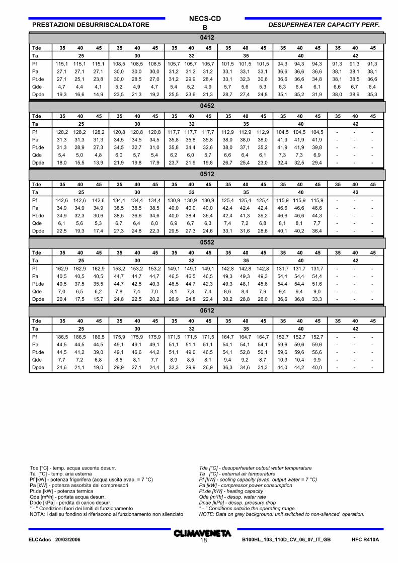
B DESUPERHEATER CAPACITY PERF.PRESTAZIONI DESURRISCALDATORENECS-CD
0412
Tde 35 40 45 35 35 35 35 35 40 40 40 40 40 45 45 45 45 45
Ta 25 30 32 35 40 42
Pf 115,1 108,5 108,5 108,5 105,7105,7 105,7 101,5 101,5 101,5 94,3 94,3 94,3 91,3 91,3 91,3115,1115,1
Pa 27,1 30,0 30,0 30,0 31,231,2 31,2 33,1 33,1 33,1 36,6 36,6 36,6 38,1 38,1 38,127,127,1
Pt.de 25,1 30,0 28,5 27,0 28,431,2 29,9 33,1 32,3 30,6 36,6 36,6 34,8 38,1 38,5 36,623,827,1
Qde 4,4 5,2 4,9 4,7 4,95,4 5,2 5,7 5,6 5,3 6,3 6,4 6,1 6,6 6,7 6,44,14,7
Dpde 16,6 23,5 21,3 19,2 21,325,5 23,6 28,7 27,4 24,8 35,1 35,2 31,9 38,0 38,9 35,314,919,3
0452
Tde 35 40 45 35 35 35 35 35 40 40 40 40 40 45 45 45 45 45
Ta 25 30 32 35 40 42
Pf 128,2 120,8 120,8 120,8 117,7117,7 117,7 112,9 112,9 112,9 104,5 104,5 104,5 - - -128,2128,2
Pa 31,3 34,5 34,5 34,5 35,835,8 35,8 38,0 38,0 38,0 41,9 41,9 41,9 - - -31,331,3
Pt.de 28,9 34,5 32,7 31,0 32,635,8 34,4 38,0 37,1 35,2 41,9 41,9 39,8 - - -27,331,3
Qde 5,0 6,0 5,7 5,4 5,76,2 6,0 6,6 6,4 6,1 7,3 7,3 6,9 - - -4,85,4
Dpde 15,5 21,9 19,8 17,9 19,823,7 21,9 26,7 25,4 23,0 32,4 32,5 29,4 - - -13,918,0
0512
Tde 35 40 45 35 35 35 35 35 40 40 40 40 40 45 45 45 45 45
Ta 25 30 32 35 40 42
Pf 142,6 134,4 134,4 134,4 130,9130,9 130,9 125,4 125,4 125,4 115,9 115,9 115,9 - - -142,6142,6
Pa 34,9 38,5 38,5 38,5 40,040,0 40,0 42,4 42,4 42,4 46,6 46,6 46,6 - - -34,934,9
Pt.de 32,3 38,5 36,6 34,6 36,440,0 38,4 42,4 41,3 39,2 46,6 46,6 44,3 - - -30,634,9
Qde 5,6 6,7 6,4 6,0 6,36,9 6,7 7,4 7,2 6,8 8,1 8,1 7,7 - - -5,36,1
Dpde 19,3 27,3 24,8 22,3 24,629,5 27,3 33,1 31,6 28,6 40,1 40,2 36,4 - - -17,422,5
0552
Tde 35 40 45 35 35 35 35 35 40 40 40 40 40 45 45 45 45 45
Ta 25 30 32 35 40 42
Pf 162,9 153,2 153,2 153,2 149,1149,1 149,1 142,8 142,8 142,8 131,7 131,7 131,7 - - -162,9162,9
Pa 40,5 44,7 44,7 44,7 46,546,5 46,5 49,3 49,3 49,3 54,4 54,4 54,4 - - -40,540,5
Pt.de 37,5 44,7 42,5 40,3 42,346,5 44,7 49,3 48,1 45,6 54,4 54,4 51,6 - - -35,540,5
Qde 6,5 7,8 7,4 7,0 7,48,1 7,8 8,6 8,4 7,9 9,4 9,4 9,0 - - -6,27,0
Dpde 17,5 24,8 22,5 20,2 22,426,9 24,8 30,2 28,8 26,0 36,6 36,8 33,3 - - -15,720,4
0612
Tde 35 40 45 35 35 35 35 35 40 40 40 40 40 45 45 45 45 45
Ta 25 30 32 35 40 42
Pf 186,5 175,9 175,9 175,9 171,5171,5 171,5 164,7 164,7 164,7 152,7 152,7 152,7 - - -186,5186,5
Pa 44,5 49,1 49,1 49,1 51,151,1 51,1 54,1 54,1 54,1 59,6 59,6 59,6 - - -44,544,5
Pt.de 41,2 49,1 46,6 44,2 46,551,1 49,0 54,1 52,8 50,1 59,6 59,6 56,6 - - -39,044,5
Qde 7,2 8,5 8,1 7,7 8,18,9 8,5 9,4 9,2 8,7 10,3 10,4 9,9 - - -6,87,7
Dpde 21,1 29,9 27,1 24,4 26,932,3 29,9 36,3 34,6 31,3 44,0 44,2 40,0 - - -19,024,6
Tde [°C] - temp. acqua uscente desurr.Ta [°C] - temp. aria esternaPf [kW] - potenza frigorifera (acqua uscita evap. = 7 °C)Pa [kW] - potenza assorbita dai compressoriPt.de [kW] - potenza termicaQde [m³/h] - portata acqua desurr.Dpde [kPa] - perdita di carico desurr." - " Condizioni fuori dei limiti di funzionamentoNOTA: I dati su fondino si riferiscono al funzionamento non silenziato
Tde [°C] - desuperheater output water temperatureTa [°C] - external air temperaturePf [kW] - cooling capacity (evap. output water = 7 °C)Pa [kW] - compressor power consumptionPt.de [kW] - heating capacityQde [m³/h] - desup. water rateDpde [kPa] - desup. pressure drop" - " Conditions outside the operating rangeNOTE: Data on grey background: unit switched to non-silenced operation.
HFC R410AB100HL_103_110D_CV_06_07_IT_GB18ELCAdoc 20/03/2006
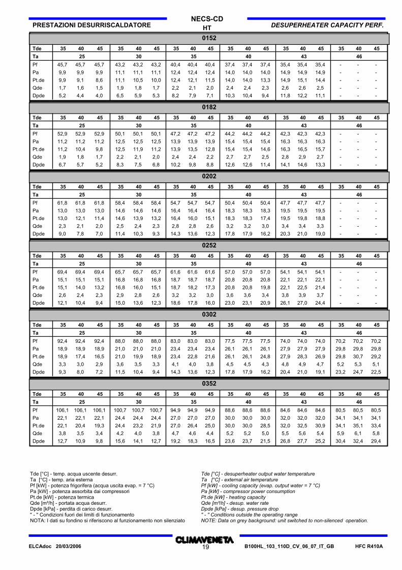
HT DESUPERHEATER CAPACITY PERF.PRESTAZIONI DESURRISCALDATORENECS-CD
0152
Tde 35 40 45 35 35 35 35 35 40 40 40 40 40 45 45 45 45 45
Ta 25 30 35 40 43 46
Pf 45,7 43,2 43,2 43,2 40,440,4 40,4 37,4 37,4 37,4 35,4 35,4 35,4 - - -45,745,7
Pa 9,9 11,1 11,1 11,1 12,412,4 12,4 14,0 14,0 14,0 14,9 14,9 14,9 - - -9,99,9
Pt.de 9,1 11,1 10,5 10,0 11,512,4 12,1 14,0 14,0 13,3 14,9 15,1 14,4 - - -8,69,9
Qde 1,6 1,9 1,8 1,7 2,02,2 2,1 2,4 2,4 2,3 2,6 2,6 2,5 - - -1,51,7
Dpde 4,4 6,5 5,9 5,3 7,18,2 7,9 10,3 10,4 9,4 11,8 12,2 11,1 - - -4,05,2
0182
Tde 35 40 45 35 35 35 35 35 40 40 40 40 40 45 45 45 45 45
Ta 25 30 35 40 43 46
Pf 52,9 50,1 50,1 50,1 47,247,2 47,2 44,2 44,2 44,2 42,3 42,3 42,3 - - -52,952,9
Pa 11,2 12,5 12,5 12,5 13,913,9 13,9 15,4 15,4 15,4 16,3 16,3 16,3 - - -11,211,2
Pt.de 10,4 12,5 11,9 11,2 12,813,9 13,5 15,4 15,4 14,6 16,3 16,5 15,7 - - -9,811,2
Qde 1,8 2,2 2,1 2,0 2,22,4 2,4 2,7 2,7 2,5 2,8 2,9 2,7 - - -1,71,9
Dpde 5,7 8,3 7,5 6,8 8,810,2 9,8 12,6 12,6 11,4 14,1 14,6 13,3 - - -5,26,7
0202
Tde 35 40 45 35 35 35 35 35 40 40 40 40 40 45 45 45 45 45
Ta 25 30 35 40 43 46
Pf 61,8 58,4 58,4 58,4 54,754,7 54,7 50,4 50,4 50,4 47,7 47,7 47,7 - - -61,861,8
Pa 13,0 14,6 14,6 14,6 16,416,4 16,4 18,3 18,3 18,3 19,5 19,5 19,5 - - -13,013,0
Pt.de 12,1 14,6 13,9 13,2 15,116,4 16,0 18,3 18,3 17,4 19,5 19,8 18,8 - - -11,413,0
Qde 2,1 2,5 2,4 2,3 2,62,8 2,8 3,2 3,2 3,0 3,4 3,4 3,3 - - -2,02,3
Dpde 7,8 11,4 10,3 9,3 12,314,3 13,6 17,8 17,9 16,2 20,3 21,0 19,0 - - -7,09,0
0252
Tde 35 40 45 35 35 35 35 35 40 40 40 40 40 45 45 45 45 45
Ta 25 30 35 40 43 46
Pf 69,4 65,7 65,7 65,7 61,661,6 61,6 57,0 57,0 57,0 54,1 54,1 54,1 - - -69,469,4
Pa 15,1 16,8 16,8 16,8 18,718,7 18,7 20,8 20,8 20,8 22,1 22,1 22,1 - - -15,115,1
Pt.de 14,0 16,8 16,0 15,1 17,318,7 18,2 20,8 20,8 19,8 22,1 22,5 21,4 - - -13,215,1
Qde 2,4 2,9 2,8 2,6 3,03,2 3,2 3,6 3,6 3,4 3,8 3,9 3,7 - - -2,32,6
Dpde 10,4 15,0 13,6 12,3 16,018,6 17,8 23,0 23,1 20,9 26,1 27,0 24,4 - - -9,412,1
0302
Tde 35 40 45 35 35 35 35 35 40 40 40 40 40 45 45 45 45 45
Ta 25 30 35 40 43 46
Pf 92,4 88,0 88,0 88,0 83,083,0 83,0 77,5 77,5 77,5 74,0 74,0 74,0 70,2 70,2 70,292,492,4
Pa 18,9 21,0 21,0 21,0 23,423,4 23,4 26,1 26,1 26,1 27,9 27,9 27,9 29,8 29,8 29,818,918,9
Pt.de 17,4 21,0 19,9 18,9 21,623,4 22,8 26,1 26,1 24,8 27,9 28,3 26,9 29,8 30,7 29,216,518,9
Qde 3,0 3,6 3,5 3,3 3,84,1 4,0 4,5 4,5 4,3 4,8 4,9 4,7 5,2 5,3 5,12,93,3
Dpde 8,0 11,5 10,4 9,4 12,314,3 13,6 17,8 17,9 16,2 20,4 21,0 19,1 23,2 24,7 22,57,29,3
0352
Tde 35 40 45 35 35 35 35 35 40 40 40 40 40 45 45 45 45 45
Ta 25 30 35 40 43 46
Pf 106,1 100,7 100,7 100,7 94,994,9 94,9 88,6 88,6 88,6 84,6 84,6 84,6 80,5 80,5 80,5106,1106,1
Pa 22,1 24,4 24,4 24,4 27,027,0 27,0 30,0 30,0 30,0 32,0 32,0 32,0 34,1 34,1 34,122,122,1
Pt.de 20,4 24,4 23,2 21,9 25,027,0 26,4 30,0 30,0 28,5 32,0 32,5 30,9 34,1 35,1 33,419,322,1
Qde 3,5 4,2 4,0 3,8 4,44,7 4,6 5,2 5,2 5,0 5,5 5,6 5,4 5,9 6,1 5,83,43,8
Dpde 10,9 15,6 14,1 12,7 16,519,2 18,3 23,6 23,7 21,5 26,8 27,7 25,2 30,4 32,4 29,49,812,7
Tde [°C] - temp. acqua uscente desurr.Ta [°C] - temp. aria esternaPf [kW] - potenza frigorifera (acqua uscita evap. = 7 °C)Pa [kW] - potenza assorbita dai compressoriPt.de [kW] - potenza termicaQde [m³/h] - portata acqua desurr.Dpde [kPa] - perdita di carico desurr." - " Condizioni fuori dei limiti di funzionamentoNOTA: I dati su fondino si riferiscono al funzionamento non silenziato
Tde [°C] - desuperheater output water temperatureTa [°C] - external air temperaturePf [kW] - cooling capacity (evap. output water = 7 °C)Pa [kW] - compressor power consumptionPt.de [kW] - heating capacityQde [m³/h] - desup. water rateDpde [kPa] - desup. pressure drop" - " Conditions outside the operating rangeNOTE: Data on grey background: unit switched to non-silenced operation.
HFC R410AB100HL_103_110D_CV_06_07_IT_GB19ELCAdoc 20/03/2006
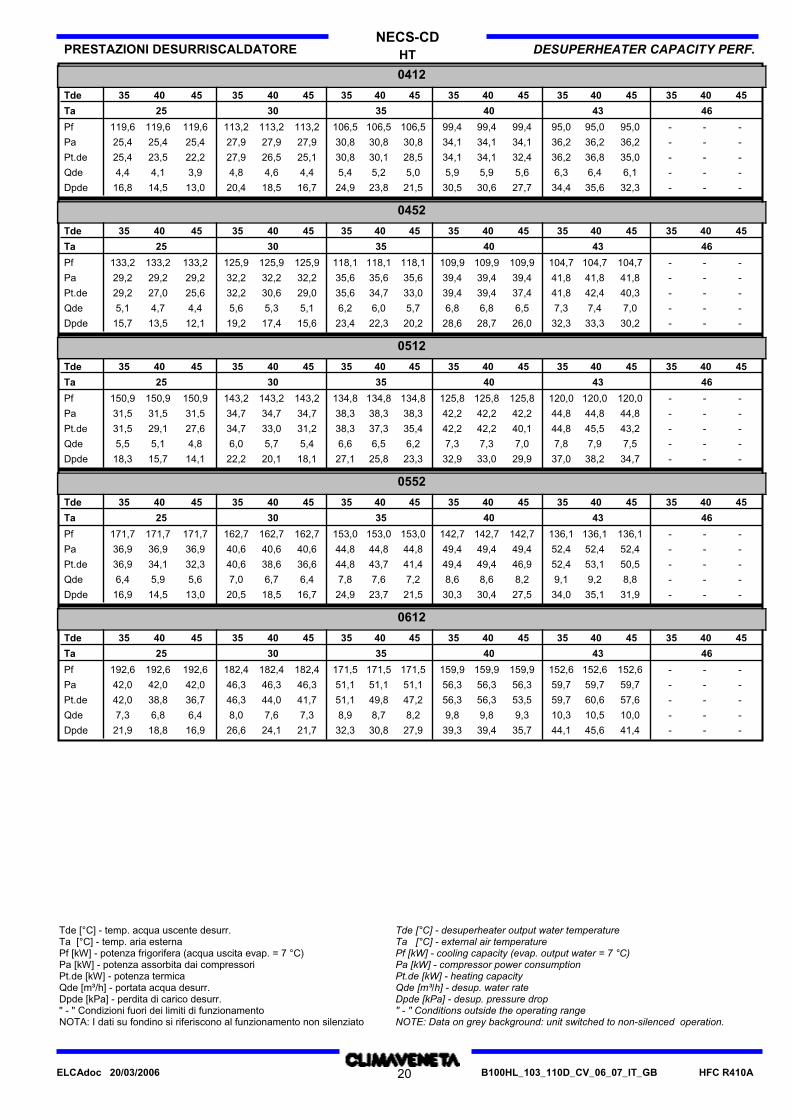
HT DESUPERHEATER CAPACITY PERF.PRESTAZIONI DESURRISCALDATORENECS-CD
0412
Tde 35 40 45 35 35 35 35 35 40 40 40 40 40 45 45 45 45 45
Ta 25 30 35 40 43 46
Pf 119,6 113,2 113,2 113,2 106,5106,5 106,5 99,4 99,4 99,4 95,0 95,0 95,0 - - -119,6119,6
Pa 25,4 27,9 27,9 27,9 30,830,8 30,8 34,1 34,1 34,1 36,2 36,2 36,2 - - -25,425,4
Pt.de 23,5 27,9 26,5 25,1 28,530,8 30,1 34,1 34,1 32,4 36,2 36,8 35,0 - - -22,225,4
Qde 4,1 4,8 4,6 4,4 5,05,4 5,2 5,9 5,9 5,6 6,3 6,4 6,1 - - -3,94,4
Dpde 14,5 20,4 18,5 16,7 21,524,9 23,8 30,5 30,6 27,7 34,4 35,6 32,3 - - -13,016,8
0452
Tde 35 40 45 35 35 35 35 35 40 40 40 40 40 45 45 45 45 45
Ta 25 30 35 40 43 46
Pf 133,2 125,9 125,9 125,9 118,1118,1 118,1 109,9 109,9 109,9 104,7 104,7 104,7 - - -133,2133,2
Pa 29,2 32,2 32,2 32,2 35,635,6 35,6 39,4 39,4 39,4 41,8 41,8 41,8 - - -29,229,2
Pt.de 27,0 32,2 30,6 29,0 33,035,6 34,7 39,4 39,4 37,4 41,8 42,4 40,3 - - -25,629,2
Qde 4,7 5,6 5,3 5,1 5,76,2 6,0 6,8 6,8 6,5 7,3 7,4 7,0 - - -4,45,1
Dpde 13,5 19,2 17,4 15,6 20,223,4 22,3 28,6 28,7 26,0 32,3 33,3 30,2 - - -12,115,7
0512
Tde 35 40 45 35 35 35 35 35 40 40 40 40 40 45 45 45 45 45
Ta 25 30 35 40 43 46
Pf 150,9 143,2 143,2 143,2 134,8134,8 134,8 125,8 125,8 125,8 120,0 120,0 120,0 - - -150,9150,9
Pa 31,5 34,7 34,7 34,7 38,338,3 38,3 42,2 42,2 42,2 44,8 44,8 44,8 - - -31,531,5
Pt.de 29,1 34,7 33,0 31,2 35,438,3 37,3 42,2 42,2 40,1 44,8 45,5 43,2 - - -27,631,5
Qde 5,1 6,0 5,7 5,4 6,26,6 6,5 7,3 7,3 7,0 7,8 7,9 7,5 - - -4,85,5
Dpde 15,7 22,2 20,1 18,1 23,327,1 25,8 32,9 33,0 29,9 37,0 38,2 34,7 - - -14,118,3
0552
Tde 35 40 45 35 35 35 35 35 40 40 40 40 40 45 45 45 45 45
Ta 25 30 35 40 43 46
Pf 171,7 162,7 162,7 162,7 153,0153,0 153,0 142,7 142,7 142,7 136,1 136,1 136,1 - - -171,7171,7
Pa 36,9 40,6 40,6 40,6 44,844,8 44,8 49,4 49,4 49,4 52,4 52,4 52,4 - - -36,936,9
Pt.de 34,1 40,6 38,6 36,6 41,444,8 43,7 49,4 49,4 46,9 52,4 53,1 50,5 - - -32,336,9
Qde 5,9 7,0 6,7 6,4 7,27,8 7,6 8,6 8,6 8,2 9,1 9,2 8,8 - - -5,66,4
Dpde 14,5 20,5 18,5 16,7 21,524,9 23,7 30,3 30,4 27,5 34,0 35,1 31,9 - - -13,016,9
0612
Tde 35 40 45 35 35 35 35 35 40 40 40 40 40 45 45 45 45 45
Ta 25 30 35 40 43 46
Pf 192,6 182,4 182,4 182,4 171,5171,5 171,5 159,9 159,9 159,9 152,6 152,6 152,6 - - -192,6192,6
Pa 42,0 46,3 46,3 46,3 51,151,1 51,1 56,3 56,3 56,3 59,7 59,7 59,7 - - -42,042,0
Pt.de 38,8 46,3 44,0 41,7 47,251,1 49,8 56,3 56,3 53,5 59,7 60,6 57,6 - - -36,742,0
Qde 6,8 8,0 7,6 7,3 8,28,9 8,7 9,8 9,8 9,3 10,3 10,5 10,0 - - -6,47,3
Dpde 18,8 26,6 24,1 21,7 27,932,3 30,8 39,3 39,4 35,7 44,1 45,6 41,4 - - -16,921,9
Tde [°C] - temp. acqua uscente desurr.Ta [°C] - temp. aria esternaPf [kW] - potenza frigorifera (acqua uscita evap. = 7 °C)Pa [kW] - potenza assorbita dai compressoriPt.de [kW] - potenza termicaQde [m³/h] - portata acqua desurr.Dpde [kPa] - perdita di carico desurr." - " Condizioni fuori dei limiti di funzionamentoNOTA: I dati su fondino si riferiscono al funzionamento non silenziato
Tde [°C] - desuperheater output water temperatureTa [°C] - external air temperaturePf [kW] - cooling capacity (evap. output water = 7 °C)Pa [kW] - compressor power consumptionPt.de [kW] - heating capacityQde [m³/h] - desup. water rateDpde [kPa] - desup. pressure drop" - " Conditions outside the operating rangeNOTE: Data on grey background: unit switched to non-silenced operation.
HFC R410AB100HL_103_110D_CV_06_07_IT_GB20ELCAdoc 20/03/2006
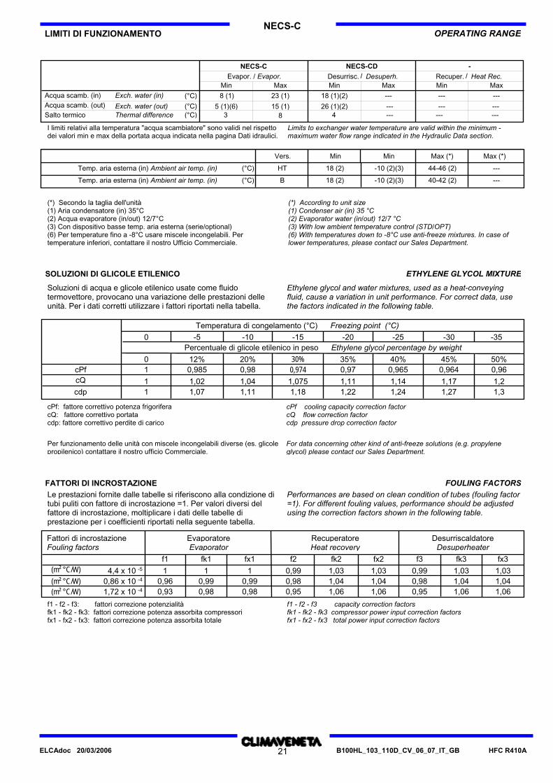
NECS-CLIMITI DI FUNZIONAMENTO OPERATING RANGE
---
---
------
---
------
---
426 (1)(2)
18 (1)(2)
815 (1)
23 (1)
3
8 (1)
Thermal differenceExch. water (out)
Exch. water (in)
Heat Rec.Desuperh.MaxMax MinMin
Salto termicoAcqua scamb. (out)Acqua scamb. (in)
MaxMinRecuper.Desurrisc.
(°C)
(°C)(°C)
Evapor. / Evapor.NECS-CD -
/ /NECS-C
5 (1)(6) ---
Limits to exchanger water temperature are valid within the minimum -maximum water flow range indicated in the Hydraulic Data section.
I limiti relativi alla temperatura "acqua scambiatore" sono validi nel rispettodei valori min e max della portata acqua indicata nella pagina Dati idraulici.
Max (*)Max (*)MinVers. Min
(°C)Temp. aria esterna (in) Ambient air temp. (in) 18 (2) -10 (2)(3) 44-46 (2) ---HT
(°C)Temp. aria esterna (in) Ambient air temp. (in) 18 (2) -10 (2)(3) 40-42 (2) ---B
(*) Secondo la taglia dell'unità(1) Aria condensatore (in) 35°C(2) Acqua evaporatore (in/out) 12/7°C(3) Con dispositivo basse temp. aria esterna (serie/optional)(6) Per temperature fino a -8°C usare miscele incongelabili. Pertemperature inferiori, contattare il nostro Ufficio Commerciale.
(*) According to unit size(1) Condenser air (in) 35 °C(2) Evaporator water (in/out) 12/7 °C(3) With low ambient temperature control (STD/OPT)(6) With temperatures down to -8°C use anti-freeze mixtures. In case oflower temperatures, please contact our Sales Department.
SOLUZIONI DI GLICOLE ETILENICO ETHYLENE GLYCOL MIXTURE
Ethylene glycol and water mixtures, used as a heat-conveyingfluid, cause a variation in unit performance. For correct data, usethe factors indicated in the following table.
Soluzioni di acqua e glicole etilenico usate come fluidotermovettore, provocano una variazione delle prestazioni delleunità. Per i dati corretti utilizzare i fattori riportati nella tabella.
1,3
0 -5 -10 -15 -20 -25 -30 -35
0 12% 20% 30% 35% 40% 45% 50%
Temperatura di congelamento (°C)
Percentuale di glicole etilenico in peso
cPfcQ
cdp
Ethylene glycol percentage by weight
Freezing point (°C)
1
11
0,985
1,021,07
0,98
1,041,11
0,9741,0751,18
0,97
1,111,22
0,965
1,141,24
0,964
1,171,27
0,96
1,2
cPf cooling capacity correction factorcQ flow correction factorcdp pressure drop correction factor
For data concerning other kind of anti-freeze solutions (e.g. propyleneglycol) please contact our Sales Department.
cPf: fattore correttivo potenza frigoriferacQ: fattore correttivo portatacdp: fattore correttivo perdite di carico
Per funzionamento delle unità con miscele incongelabili diverse (es. glicolepropilenico) contattare il nostro ufficio Commerciale.
FOULING FACTORSFATTORI DI INCROSTAZIONELe prestazioni fornite dalle tabelle si riferiscono alla condizione ditubi puliti con fattore di incrostazione =1. Per valori diversi delfattore di incrostazione, moltiplicare i dati delle tabelle diprestazione per i coefficienti riportati nella seguente tabella.
Performances are based on clean condition of tubes (fouling factor=1). For different fouling values, performance should be adjustedusing the correction factors shown in the following table.
Desurriscaldatore
f1 fk1 fx1 f2 fk2 fx2 f3 fk3 fx3
Fattori di incrostazione Evaporatore RecuperatoreFouling factors Evaporator Heat recovery Desuperheater
1 1 10,96 0,99 0,990,93 0,98 0,98
0,99 0,990,98 0,980,95 0,95
1,03 1,031,03 1,031,04 1,04 1,04 1,041,06 1,06 1,06 1,06
-5
-4
-4
4,4 x 100,86 x 101,72 x 10
(m² °C/W)(m² °C/W)(m² °C/W)
f1 - f2 - f3: fattori correzione potenzialitàfk1 - fk2 - fk3: fattori correzione potenza assorbita compressorifx1 - fx2 - fx3: fattori correzione potenza assorbita totale
f1 - f2 - f3 capacity correction factorsfk1 - fk2 - fk3 compressor power input correction factorsfx1 - fx2 - fx3 total power input correction factors
HFC R410AB100HL_103_110D_CV_06_07_IT_GB21ELCAdoc 20/03/2006

B - HTNECS-C
DATI IDRAULICI HYDRAULIC DATA
PORTATA ACQUA E PERDITA DI CARICO WATER FLOW AND PRESSURE DROP
Water flow in the heat exchangers is given by:Q=Px 0,86/Dt
Q: water flow (m³/h)Dt: difference between inlet and outlet water temp. (°C)P: heat exchanger capacity (kW)
Pressure drop is given by:Dp=K x Q² /1000
Q: water flow (m³/h)Dp: pressure drop (kPa)K: unit size ratio
La portata d'acqua negli scambiatori si calcola con la seguenterelazione:Q=Px 0,86/ Dt
Q: portata d'acqua (m³/h)Dt: salto termico sull'acqua (°C)P: potenza dello scambiatore (kW)
Le perdite di carico si calcolano con la seguente relazione:Dp=K x Q²/1000
Q: portata d'acqua (m³/h)Dp: perdite di carico (kPa)K: coefficiente riportato per le varie grandezze
Evaporatore / Evaporator Rec. (1) - Cond (2) Desurrisc. / DesuperheaterGRANDEZZA
SIZE Q min Q max Q min Q max Q min Q maxK K K
m³/h m³/hm³/h m³/hmin m³m³/h m³/hC.a. / W.c.
3,9 10,8 1.037 0,30152 1767 2,9----- -
4,5 12,4 1.037 0,40182 1767 3,1----- -
5,3 14,6 664 0,40202 1767 3,6----- -
6,0 16,4 481 0,50252 1767 4,1----- -
8,0 21,6 360 0,60302 871 5,4----- -
9,2 24,9 154 0,70352 871 6,0----- -
10,5 28,3 154 0,80412 871 6,7----- -
11,6 31,3 108 0,90452 613 7,7----- -
12,9 34,8 108 1,00512 613 8,6----- -
14,7 39,6 81,0 1,20552 412 10,0----- -
17,0 45,6 63,0 1,40612 412 11,0----- -
Q min: minima portata acqua ammessa allo scambiatoreQ max: massima portata acqua ammessa allo scambiatoreC.a. min: minimo contenuto d'acqua ammesso nell'impianto Valore ininfluente per queste unità.
(1) Rec. = Recuperatore. Valido per tutte le unità con recupero totale dicalore(2) Cond. = Condensatore. Valido per le sole unità con condensazione adacqua. Nelle unità con recupero di calore, i valori sono validi sia per ilcondensatore che per il recuperatore.
Q min: minimum water flow admitted to the heat exchanger.Q max: maximum water flow admitted to the heat exchanger.W.c min.: minimum water content admitted in the plant. Non-influential value for these units.
(1) Rec. = Heat Recovery. For units with total heat recovery.(2) Cond. = Condenser. For water to water type units. In those units withheat-recovery, this data is valid for both the condensing and the heat-recovery exchangers.
HFC R410AB100HL_103_110D_CV_06_07_IT_GB22ELCAdoc 20/03/2006
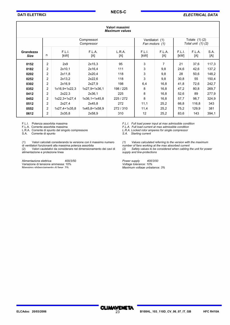
NECS-CELECTRICAL DATADATI ELETTRICI
Valori massimi
Grandezza
Compressori Ventilatori (1)
nF.L.I.[kW]
F.L.A.[A]
L.R.A.[A]
S.A.[A]
F.L.I.[kW]
F.L.I.[kW]
F.L.A.[A]
F.L.A.[A]
Maximum values
Size
Compressor Fan motors (1)Totale (1) (2)
Total unit (1) (2)
2 73952x9 2x15,3 21 37,6 117,30152 2 9,831112x10,1 2x16,4 24,6 42,6 137,20182 2 9,831182x11,8 2x20,4 28 50,6 148,20202 2 9,831182x13,2 2x22,6 30,8 55 150,40252 2 16,86,41982x16,9 2x27,9 41,8 72,6 242,70302 2 16,88198 / 2251x16,9+1x22,3 1x27,9+1x36,1 47,2 80,8 269,70352 2 16,882252x22,3 2x36,1 52,6 89 277,90412 2 16,88225 / 2721x22,3+1x27,4 1x36,1+1x45,8 57,7 98,7 324,90452 2 25,211,12722x27,4 2x45,8 66,8 116,8 3430512 2 25,211,4272 / 3101x27,4+1x35,8 1x45,8+1x58,9 75,2 129,9 3810552 2 25,2123102x35,8 2x58,9 83,6 143 394,10612
F.L.I. Potenza assorbita massimaF.L.A. Corrente assorbita massimaL.R.A. Corrente di spunto del singolo compressoreS.A. Corrente di spunto
(1) Valori calcolati considerando la versione con il massimo numerodi ventilatori funzionanti alla massima potenza assorbita(2) Valori cautelativi da considerare nel dimensionamento dei cavi dialimentazione e protezione linea
Alimentazione elettrica: 400/3/50Variazione di tensione ammessa: 10%Massimo sbilanciamento di fase: 3%
F.L.I. Full load power input at max admissible conditionF.L.A. Full load current at max admissible conditionL.R.A. Locked rotor amperes for single compressorS.A. Starting current
(1) Values calculated referring to the version with the maximumnumber of fans working at the max absorbed current(2) Safety values to be considered when cabling the unit for powersupply and line-protections
Power supply 400/3/50Voltage tolerance: 10%Maximum voltage unbalance: 3%
HFC R410AB100HL_103_110D_CV_06_07_IT_GB23ELCAdoc 20/03/2006

NECS-CBLIVELLI SONORI A PIENO CARICO FULL LOAD SOUND LEVEL
Bande d'ottava [Hz] - Octave band [Hz]Livelli sonori totali - Total sound level
800040002000100050025012563Grandezza
Size
Pressure
Livelli di potenza sonora [dB] Sound power level [dB]
PressionePotenza
Power
-
-1 m (coil)10 m (medium) 75 76 81 79 80 79 76 70 850152 -- -- 78 78 82 82 82 82 79 73 880182 -- -- 78 79 82 82 82 82 79 74 880202 -- -- 78 79 83 82 82 82 79 74 880252 -- -- 80 82 84 84 84 84 81 77 900302 -- -- 83 85 88 90 89 89 87 81 950352 -- -- 83 85 88 90 88 89 87 81 950412 -- -- 85 86 89 92 90 90 88 83 960452 -- -- 85 86 89 92 90 90 88 83 960512 -- -- 85 86 89 91 90 90 86 83 960552 -- -- 87 88 91 94 92 92 90 85 980612 -- --
Condizioni di funzionamento: Working conditionsAcqua evaporatore (in/out) 12/7 [°C]Aria condensatore 35 [°C]
Evaporator water (in/out) 12/7 [°C]Ambient air 35 [°C]
Potenza sonora Sound powerPotenza sonora totale dei ventilatori come dichiarato dal costruttore,riferito alla velocità di rotazione nominale e prevalenza statica utile di120 Pa lato mandata.
Total sound power of fans, as declared by the maker, at the rated speedof rotation and a useful static head of 120 Pa on the delivery side.
Detta certificazione si riferisce specificatamente alla PotenzaSonora in dB(A) che è quindi l'unico dato acustico da considerarsiimpegnativo.
Such certification refers specifically to the sound Power Level indB(A). This is therefore the only acoustic data to be considered asbinding.
HFC R410AB100HL_103_110D_CV_06_07_IT_GB24ELCAdoc 20/03/2006
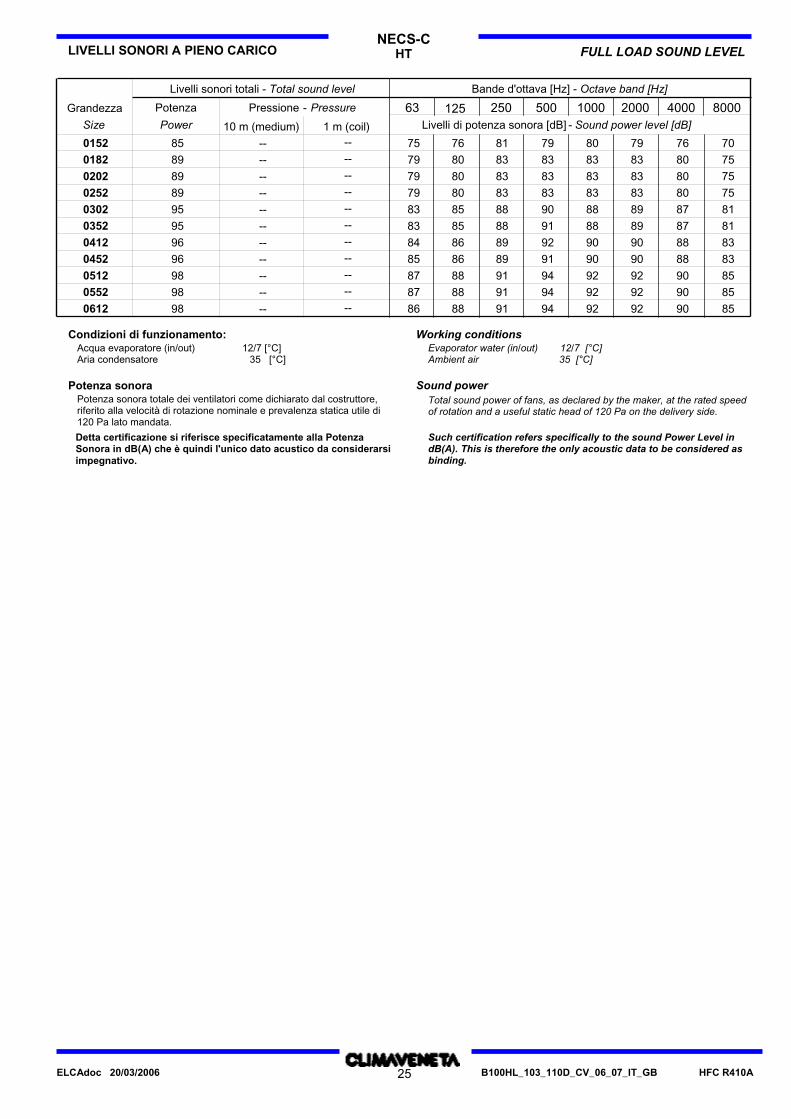
NECS-CHTLIVELLI SONORI A PIENO CARICO FULL LOAD SOUND LEVEL
Bande d'ottava [Hz] - Octave band [Hz]Livelli sonori totali - Total sound level
800040002000100050025012563Grandezza
Size
Pressure
Livelli di potenza sonora [dB] Sound power level [dB]
PressionePotenza
Power
-
-1 m (coil)10 m (medium) 75 76 81 79 80 79 76 70 850152 -- -- 79 80 83 83 83 83 80 75 890182 -- -- 79 80 83 83 83 83 80 75 890202 -- -- 79 80 83 83 83 83 80 75 890252 -- -- 83 85 88 90 88 89 87 81 950302 -- -- 83 85 88 91 88 89 87 81 950352 -- -- 84 86 89 92 90 90 88 83 960412 -- -- 85 86 89 91 90 90 88 83 960452 -- -- 87 88 91 94 92 92 90 85 980512 -- -- 87 88 91 94 92 92 90 85 980552 -- -- 86 88 91 94 92 92 90 85 980612 -- --
Condizioni di funzionamento: Working conditionsAcqua evaporatore (in/out) 12/7 [°C]Aria condensatore 35 [°C]
Evaporator water (in/out) 12/7 [°C]Ambient air 35 [°C]
Potenza sonora Sound powerPotenza sonora totale dei ventilatori come dichiarato dal costruttore,riferito alla velocità di rotazione nominale e prevalenza statica utile di120 Pa lato mandata.
Total sound power of fans, as declared by the maker, at the rated speedof rotation and a useful static head of 120 Pa on the delivery side.
Detta certificazione si riferisce specificatamente alla PotenzaSonora in dB(A) che è quindi l'unico dato acustico da considerarsiimpegnativo.
Such certification refers specifically to the sound Power Level indB(A). This is therefore the only acoustic data to be considered asbinding.
HFC R410AB100HL_103_110D_CV_06_07_IT_GB25ELCAdoc 20/03/2006
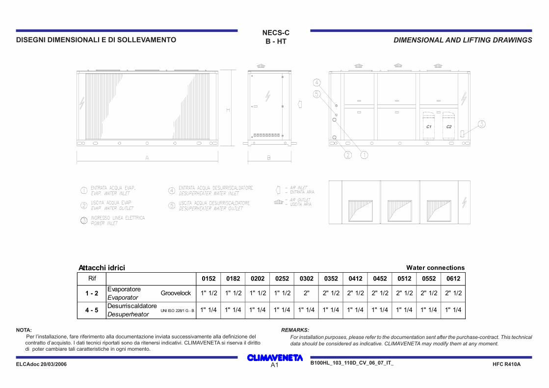
DISEGNI DIMENSIONALI E DI SOLLEVAMENTO DIMENSIONAL AND LIFTING DRAWINGS
ELCAdoc 20/03/2006 HFC R410AA1
NOTA:Per l’installazione, fare riferimento alla documentazione inviata successivamente alla definizione delcontratto d’acquisto. I dati tecnici riportati sono da ritenersi indicativi. CLIMAVENETA si riserva il dirittodi poter cambiare tali caratteristiche in ogni momento.
REMARKS:For installation purposes, please refer to the documentation sent after the purchase-contract. This technicaldata should be considered as indicative. CLIMAVENETA may modify them at any moment.
NECS-CB - HT
B100HL_103_110D_CV_06_07_IT_
Attacchi idrici Water connections
Rif 0152 0182 0202 0252 0302 0352 0412 0452 0512 0552 0612
1 - 2Evaporatore Evaporator
Groovelock 1" 1/2 1" 1/2 1" 1/2 1" 1/2 2" 2" 1/2 2" 1/2 2" 1/2 2" 1/2 2" 1/2 2" 1/2
4 - 5Desurriscaldatore Desuperheator
UNI ISO 228/1 G - B 1" 1/4 1" 1/4 1" 1/4 1" 1/4 1" 1/4 1" 1/4 1" 1/4 1" 1/4 1" 1/4 1" 1/4 1" 1/4
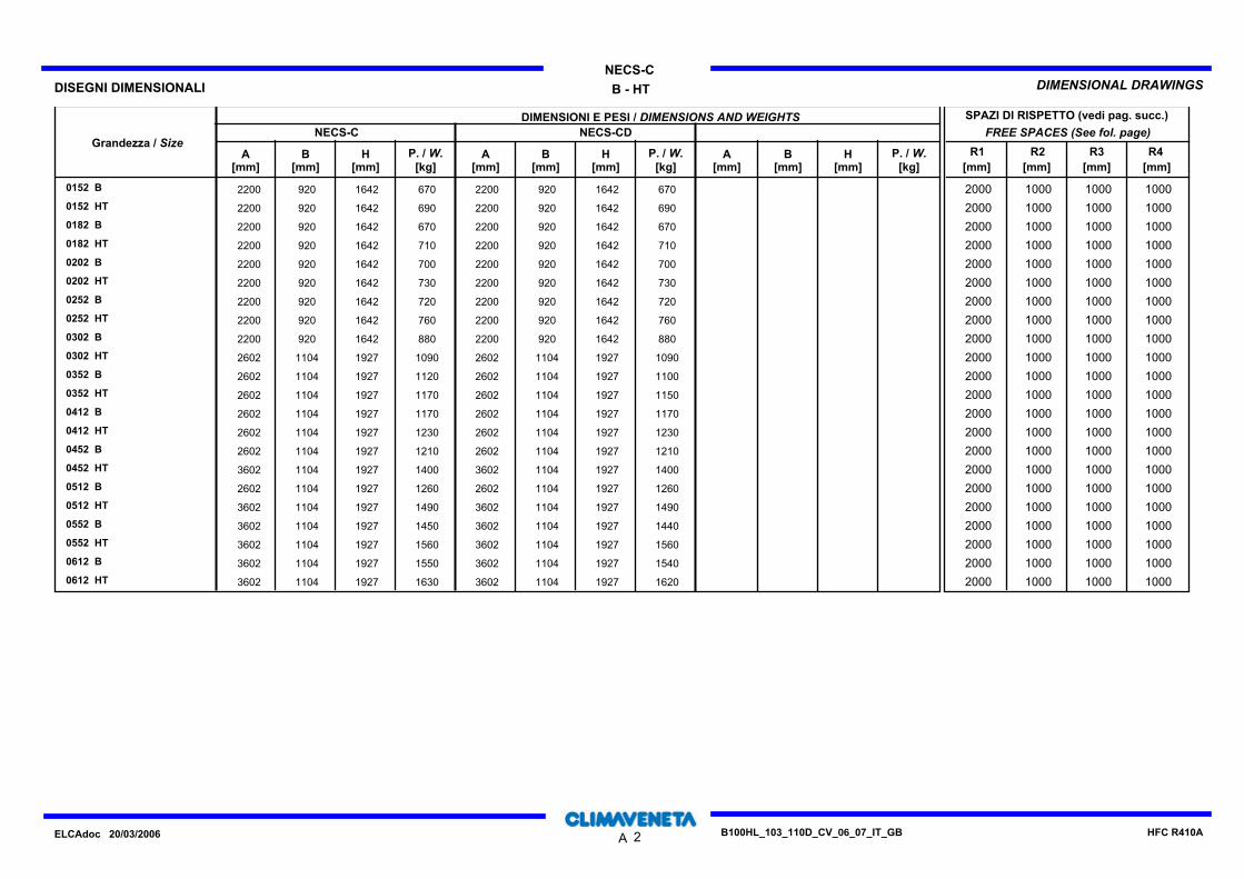
06
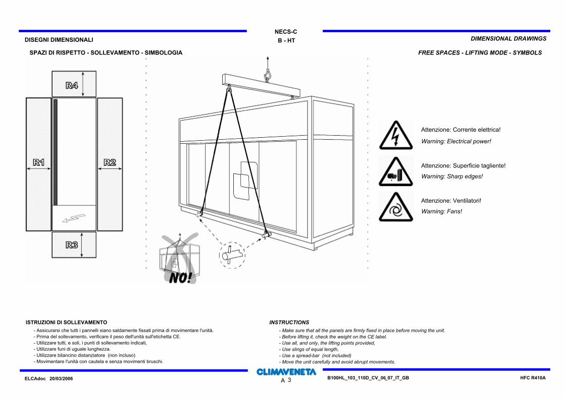
06
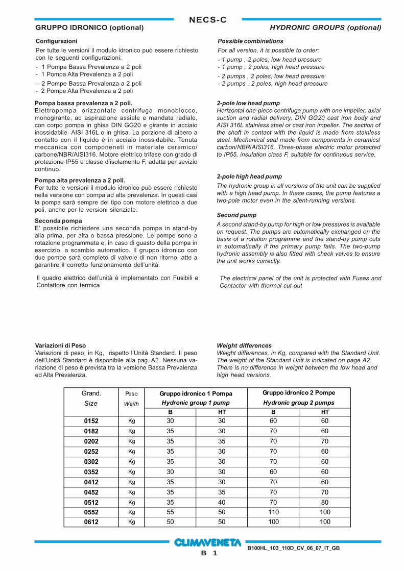
B 1
NECS-CGRUPPO IDRONICO (optional) HYDRONIC GROUPS (optional)
B100HL_103_110D_CV_06_07_IT_GB
Configurazioni
Per tutte le versioni il modulo idronico può essere richiestocon le seguenti configurazioni:
- 1 Pompa Bassa Prevalenza a 2 poli- 1 Pompa Alta Prevalenza a 2 poli
- 2 Pompe Bassa Prevalenza a 2 poli- 2 Pompe Alta Prevalenza a 2 poli
Possible combinations
For all version, it is possible to order:
- 1 pump , 2 poles, low head pressure- 1 pump , 2 poles, high head pressure
- 2 pumps , 2 poles, low head pressure- 2 pumps , 2 poles, high head pressure
Pompa bassa prevalenza a 2 poli.Elettropompa orizzontale centrifuga monoblocco,monogirante, ad aspirazione assiale e mandata radiale,con corpo pompa in ghisa DIN GG20 e girante in acciaioinossidabile AISI 316L o in ghisa. La porzione di albero acontatto con il liquido è in acciaio inossidabile. Tenutameccanica con componeneti in materiale ceramico/carbone/NBR/AISI316. Motore elettrico trifase con grado diprotezione IP55 e classe d’isolamento F, adatta per seviziocontinuo.
Pompa alta prevalenza a 2 poli.Per tutte le versioni il modulo idronico può essere richiestonella versione con pompa ad alta prevalenza. In questi casila pompa sarà sempre del tipo con motore elettrico a duepoli, anche per le versioni silenziate.
Seconda pompaE’ possibile richiedere una seconda pompa in stand-byalla prima, per alta o bassa pressione. Le pompe sono arotazione programmata e, in caso di guasto della pompa inesercizio, a scambio automatico. Il gruppo idronico condue pompe sarà completo di valvole di non ritorno, atte agarantire il corretto funzionamento dell’unità.
2-pole low head pumpHorizontal one-piece centrifuge pump with one impeller, axialsuction and radial delivery, DIN GG20 cast iron body andAISI 316L stainless steel or cast iron impeller. The section ofthe shaft in contact with the liquid is made from stainlesssteel. Mechanical seal made from components in ceramics/carbon/NBR/AISI316. Three-phase electric motor protectedto IP55, insulation class F, suitable for continuous service.
2-pole high head pump
The hydronic group in all versions of the unit can be suppliedwith a high head pump. In these cases, the pump features atwo-pole motor even in the silent-running versions.
Second pump
A second stand-by pump for high or low pressures is availableon request. The pumps are automatically exchanged on thebasis of a rotation programme and the stand-by pump cutsin automatically if the primary pump fails. The two-pumphydronic assembly is also fitted with check valves to ensurethe unit works correctly.
Variazioni di PesoVariazioni di peso, in Kg, rispetto l’Unità Standard. Il pesodell’Unità Standard è disponibile alla pag. A2. Nessuna va-riazione di peso è prevista tra la versione Bassa Prevalenzaed Alta Prevalenza.
Weight differencesWeight differences, in Kg, compared with the Standard Unit.The weight of the Standard Unit is indicated on page A2.There is no difference in weight between the low head andhigh head versions.
Grand. Peso Gruppo idronico 1 Pompa Gruppo idronico 2 Pompe
Size Weith Hydronic group 1 pump Hydronic group 2 pumps
B HT B HT0152 Kg 30 30 60 60
0182 Kg 35 30 70 60
0202 Kg 35 35 70 70
0252 Kg 35 30 70 60
0302 Kg 35 30 70 60
0352 Kg 30 30 60 60
0412 Kg 35 30 70 60
0452 Kg 35 35 70 70
0512 Kg 35 40 70 80
0552 Kg 55 50 110 100
0612 Kg 50 50 100 100
Il quadro elettrico dell’unità è implementato con Fusibili eContattore con termica
The electrical panel of the unit is protected with Fuses andContactor with thermal cut-out
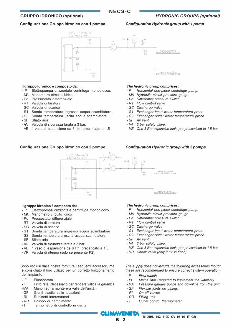
B 2
NECS-CGRUPPO IDRONICO (optional) HYDRONIC GROUPS (optional)
B100HL_103_110D_CV_06_07_IT_GB
Il gruppo idronico è composto da:- P Elettropompa orizzontale centrifuga monoblocco.- MA Manometro circuito idrico- Pd Pressostato differenziale- RT Valvola di taratura- SC Valvola di scarico- S1 Sonda temperatura ingresso acqua scambiatore- S2 Sonda temperatura uscita acqua scambiatore- SF Sfiato aria- VA Valvola di sicurezza tarata a 3 bar.- VE 1 vaso di espansione da 8 litri, precaricato a 1,5- VR Valvola di ritegno (solo se presente P2).
The hydronic group comprises:- P Horizontal one-piece centrifuge pump.- MA Hydraulic circuit pressure gauge- Pd Differential pressure switch- RT Flow control valve- SC Discharge valve- S1 Exchanger input water temperature probe- S2 Exchanger outlet water temperature probe- SF Air vent- VA 3 bar safety valve.- VE One 8-litre expansion tank, pre-pressurised to 1,5 bar.- VR Check valve (only if P2 is fitted)
Configurazione Gruppo idronico con 2 pompe Configuration Hydronic group with 2 pomps
Configurazione Gruppo idronico con 1 pompa Configuration Hydronic group with 1 pomp
Il gruppo idronico è composto da:- P Elettropompa orizzontale centrifuga monoblocco.- MA Manometro circuito idrico- Pd Pressostato differenziale- RT Valvola di taratura- SC Valvola di scarico- S1 Sonda temperatura ingresso acqua scambiatore- S2 Sonda temperatura uscita acqua scambiatore- SF Sfiato aria- VA Valvola di sicurezza tarata a 3 bar.- VE 1 vaso di espansione da 8 litri, precaricato a 1,5
The hydronic group comprises:- P Horizontal one-piece centrifuge pump.- MA Hydraulic circuit pressure gauge- Pd Differential pressure switch- RT Flow control valve- SC Discharge valve- S1 Exchanger input water temperature probe- S2 Exchanger outlet water temperature probe- SF Air vent- VA 3 bar safety valve.- VE One 8-litre expansion tank, pre-pressurised to 1,5 bar.
The supply does not include the following accessories thougtthese are recommended to ensure correct system operation:
- F Flow switch- FI Mains filter Required to implement the warranty- MA Pressure gauges upline and downline from the unit.- GF Flexible joints on piping.- RI On-off valves- RR Filling unit- T Outlet control thermometer
Sono esclusi dalla nostra fornitura i seguenti accessori, maè consigliato il loro utilizzo per un corretto funzionamentodell’impianto:
- F Flussostato- FI Filtro rete. Necessario per rendere valida la garanzia- MA Manometri a monte e a valle dell’unità.- GF Giunti elastici sulle tubazioni.- RI Rubinetti intercettatori- RR Gruppo di riempimento- T Termometro di controllo in uscita
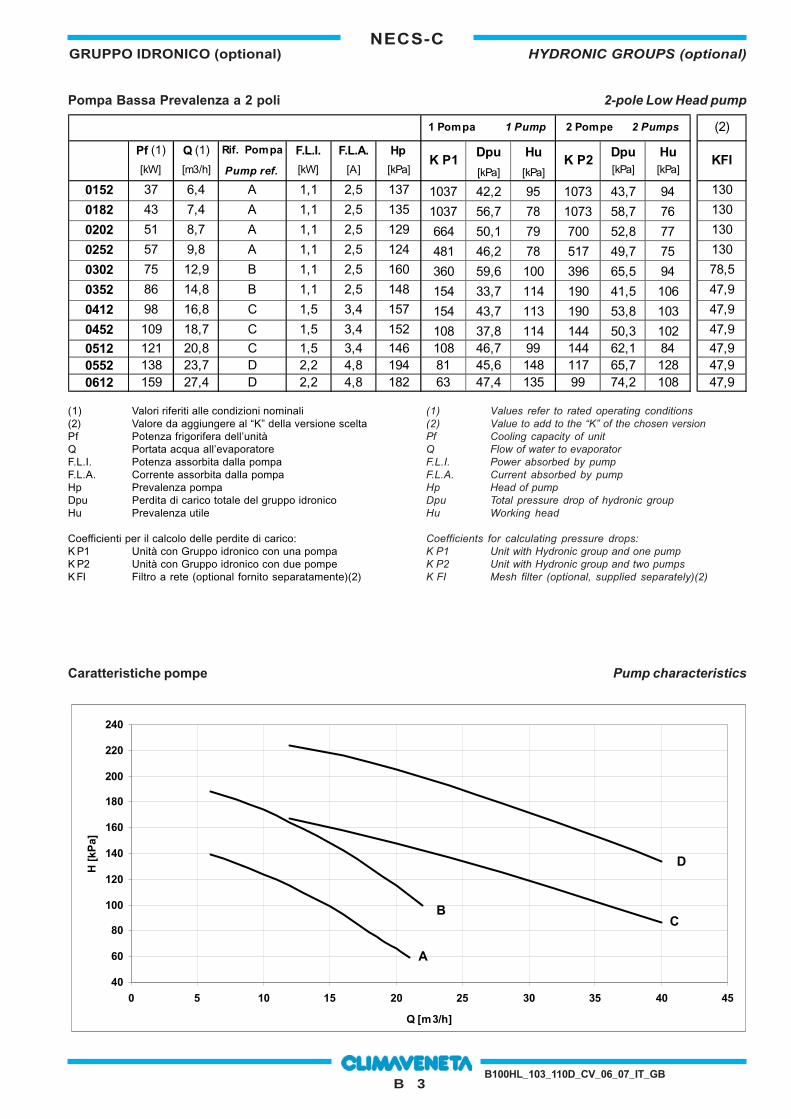
B 3
NECS-CGRUPPO IDRONICO (optional) HYDRONIC GROUPS (optional)
B100HL_103_110D_CV_06_07_IT_GB
(1) Valori riferiti alle condizioni nominali(2) Valore da aggiungere al “K” della versione sceltaPf Potenza frigorifera dell’unitàQ Portata acqua all’evaporatoreF.L.I. Potenza assorbita dalla pompaF.L.A. Corrente assorbita dalla pompaHp Prevalenza pompaDpu Perdita di carico totale del gruppo idronicoHu Prevalenza utile
Coefficienti per il calcolo delle perdite di carico:K P1 Unità con Gruppo idronico con una pompaK P2 Unità con Gruppo idronico con due pompeK FI Filtro a rete (optional fornito separatamente)(2)
(1) Values refer to rated operating conditions(2) Value to add to the “K” of the chosen versionPf Cooling capacity of unitQ Flow of water to evaporatorF.L.I. Power absorbed by pumpF.L.A. Current absorbed by pumpHp Head of pumpDpu Total pressure drop of hydronic groupHu Working head
Coefficients for calculating pressure drops:K P1 Unit with Hydronic group and one pumpK P2 Unit with Hydronic group and two pumpsK FI Mesh filter (optional, supplied separately)(2)
Pompa Bassa Prevalenza a 2 poli
Caratteristiche pompe Pump characteristics
B - HT A B - HT B B - HT C B - HT DBP 2 poli BP 2 poli BP 2 poli BP 2 poli
DWC 300/1,1 (R) DWC 300/1,1 DWC 500/1,5 DWC 500/2,2[m^3/h] [kPa] [m^3/h] [kPa] [m^3/h] [kPa] [m^3/h] [kPa]
6 139,0 6 188,0 12 167,0 12 224,08 132,0 8 182,0 16 158,0 16 216,010 124,0 10 174,0 20 148,0 20 205,012 115,0 12 164,0 24 137,0 24 193,014 104,3 14 154,0 28 125,0 28 179,016 93,0 16 142,0 32 112,5 32 165,018 79,0 18 129,0 36 100,0 36 150,020 66,0 20 115,0 40 86,5 40 134,021 59,0 22 100,0
40
60
80
100
120
140
160
180
200
220
240
0 5 10 15 20 25 30 35 40 45
Q [m3/h]
H [
kPa]
A
BC
D
2-pole Low Head pump
1 Pompa 1 Pump 2 Pompe 2 Pumps (2)
Pf (1) Q (1) Rif. Pompa F.L.I. F.L.A. Hp Dpu Hu Dpu Hu[kW] [m3/h] Pump ref. [kW] [A] [kPa] [kPa] [kPa] [kPa] [kPa]
0152 37 6,4 A 1,1 2,5 137 1037 42,2 95 1073 43,7 94 130
0182 43 7,4 A 1,1 2,5 135 1037 56,7 78 1073 58,7 76 130
0202 51 8,7 A 1,1 2,5 129 664 50,1 79 700 52,8 77 130
0252 57 9,8 A 1,1 2,5 124 481 46,2 78 517 49,7 75 130
0302 75 12,9 B 1,1 2,5 160 360 59,6 100 396 65,5 94 78,5
0352 86 14,8 B 1,1 2,5 148 154 33,7 114 190 41,5 106 47,9
0412 98 16,8 C 1,5 3,4 157 154 43,7 113 190 53,8 103 47,9
0452 109 18,7 C 1,5 3,4 152 108 37,8 114 144 50,3 102 47,9
0512 121 20,8 C 1,5 3,4 146 108 46,7 99 144 62,1 84 47,90552 138 23,7 D 2,2 4,8 194 81 45,6 148 117 65,7 128 47,90612 159 27,4 D 2,2 4,8 182 63 47,4 135 99 74,2 108 47,9
K P1 K P2 KFI
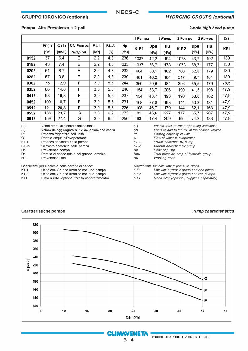
B 4
NECS-CGRUPPO IDRONICO (optional) HYDRONIC GROUPS (optional)
B100HL_103_110D_CV_06_07_IT_GB
Pompa Alta Prevalenza a 2 poli
Caratteristiche pompe Pump characteristics
(1) Valori riferiti alle condizioni nominali(2) Valore da aggiungere al “K” della versione sceltaPf Potenza frigorifera dell’unitàQ Portata acqua all’evaporatoreF.L.I. Potenza assorbita dalla pompaF.L.A. Corrente assorbita dalla pompaHp Prevalenza pompaDpu Perdita di carico totale del gruppo idronicoHu Prevalenza utile
Coefficienti per il calcolo delle perdite di carico:K P1 Unità con Gruppo idronico con una pompaK P2 Unità con Gruppo idronico con due pompeK FI Filtro a rete (optional fornito separatamente)
E F GAP 2 poli AP 2 poli AP 2 poliDWC 500/2,2 DWC 500/3,0 FHE 40 160-30
[m^3/h] [kPa] [m^3/h] [kPa] [m^3/h] [kPa]12 224,0 12 244,0 0 31416 216,0 16 238,0 5 312,320 205,0 20 230,0 10 308,324 193,0 24 219,0 15 30228 179,0 28 207,0 20 286,432 165,0 32 192,0 25 267,436 150,0 36 176,0 30 243,840 134,0 40 159,0 35 216
40 185
120
140
160
180
200
220
240
260
280
300
320
5 10 15 20 25 30 35 40 45
Q [m3/h]
H [
kPa]
F
E
G
(1) Values refer to rated operating conditions(2) Value to add to the “K” of the chosen versionPf Cooling capacity of unitQ Flow of water to evaporatorF.L.I. Power absorbed by pumpF.L.A. Current absorbed by pumpHp Head of pumpDpu Total pressure drop of hydronic groupHu Working head
Coefficients for calculating pressure drops:K P1 Unit with Hydronic group and one pumpK P2 Unit with Hydronic group and two pumpsK FI Mesh filter (optional, supplied separately)
2-pole high head pump
1 Pompa 1 Pump 2 Pompe 2 Pumps (2)
Pf (1) Q (1) Rif. Pompa F.L.I. F.L.A. Hp Dpu Hu Dpu Hu[kW] [m3/h] Pump ref. [kW] [A] [kPa] [kPa] [kPa] [kPa] [kPa]
0152 37 6,4 E 2,2 4,8 236 1037 42,2 194 1073 43,7 192 130
0182 43 7,4 E 2,2 4,8 235 1037 56,7 178 1073 58,7 177 130
0202 51 8,7 E 2,2 4,8 232 664 50,1 182 700 52,8 179 130
0252 57 9,8 E 2,2 4,8 230 481 46,2 184 517 49,7 181 130
0302 75 12,9 F 3,0 5,6 244 360 59,6 184 396 65,5 179 78,5
0352 86 14,8 F 3,0 5,6 240 154 33,7 206 190 41,5 198 47,9
0412 98 16,8 F 3,0 5,6 237 154 43,7 193 190 53,8 182 47,9
0452 109 18,7 F 3,0 5,6 231 108 37,8 193 144 50,3 181 47,9
0512 121 20,8 F 3,0 5,6 226 108 46,7 179 144 62,1 163 47,90552 138 23,7 G 3,0 6,2 273 81 45,6 227 117 65,7 207 47,90612 159 27,4 G 3,0 6,2 256 63 47,4 209 99 74,2 183 47,9
K P1 K P2 KFI
I dati contenuti nel presente bollettino possono essere variati senza obbligo di preavvisoAll specification and data are subject to change without notice
36061 BASSANO DEL GRAPPA (VICENZA) ITALIA - VIA SARSON 57/cTEL. +39 / 0424 509 500 (r.a.) - TELEFAX +39 / 0424 509 509http://www.climaveneta.it