Embed Size (px)
Citation preview

Microgrid ProtectionIEEE PES Swiss Chapter Workshop: MicrogridsEvolution and Integration in Modern Power Systems
Alexandre Oudalov, ABB Switzerland Ltd., Corporate Research, 2014-04-30

© ABB GroupMay 2, 2014 | Slide 2
Microgrid ProtectionOutline
§ What is a microgrid?§ Traditional distribution grid protection§ Problems caused by DER and islanded operation§ Potential solutions
§ Adaptive protection concept§ Hailuoto microgrid§ Distributed adaptive protection approach

© ABB GroupMay 2, 2014 | Slide 3
MicrogridsExpected evolution of distribution system
Central generation includingrenewables 50-25’000 MW
HV grid a backbone for longdistance bulk powertransmission at 110-1200 kV(AC or DC)
MV grid for a local powerdistribution at 6-69 kVDistributed generation includingrenewables1-25 MW
LV grid for the “last mile” powerdistribution at 110-1000 VSub-utility generation includingrenewables0.005-1 MW

© ABB GroupMay 2, 2014 | Slide 4
MicrogridsExpected evolution of distribution system
Central generation includingrenewables 50-25’000 MW
HV grid a backbone for longdistance bulk powertransmission at 110-1200 kV(AC or DC)
MV grid for a local powerdistribution at 6-69 kVDistributed generation includingrenewables1-25 MW
LV grid for the “last mile” powerdistribution at 110-1000 VSub-utility generation includingrenewables0.005-1 MW
Microgridsare electricity distributionsystems containing loadsand distributed energyresources, (such asdistributed generators,storage devices, orcontrollable loads) thatcan be operated in acontrolled, coordinatedway either whileconnected to the mainpower network or whileislanded.
CIGRE C6.22 workingdefinition

© ABB GroupMay 2, 2014 | Slide 5
MicrogridsExpected evolution of distribution system
Central generation includingrenewables 50-25’000 MW
HV grid a backbone for longdistance bulk powertransmission at 110-1200 kV(AC or DC)
MV grid for a local powerdistribution at 6-69 kVDistributed generation includingrenewables1-25 MW
LV grid for the “last mile” powerdistribution at 110-1000 VSub-utility generation includingrenewables0.005-1 MW
Microgridsare electricity distributionsystems containing loadsand distributed energyresources, (such asdistributed generators,storage devices, orcontrollable loads) thatcan be operated in acontrolled, coordinatedway either whileconnected to the mainpower network or whileislanded.
CIGRE C6.22 workingdefinition
Microgridsare electricity distributionsystems containing loadsand distributed energyresources, (such asdistributed generators,storage devices, orcontrollable loads) thatcan be operated in acontrolled, coordinatedway either whileconnected to the mainpower network or whileislanded.
CIGRE C6.22 workingdefinition
© ABB GroupMay 2, 2014 | Slide 6
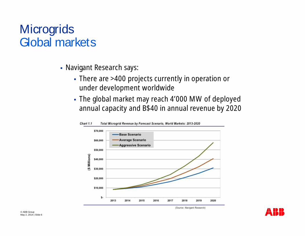
MicrogridsGlobal markets
§ Navigant Research says:§ There are >400 projects currently in operation or
under development worldwide§ The global market may reach 4’000 MW of deployed
annual capacity and B$40 in annual revenue by 2020

© ABB GroupMay 2, 2014 | Slide 7
Microgrid protectionGrid connected and islanded modes
Protection mustrespond to bothutility grid andmicrogrid faultsutility grid faults:protection isolatesthe microgridfrom the utilitygrid as rapidly asnecessary toprotect themicrogrid loads.microgrid faults:protection isolatesthe smallestpossible section ofthe feeder.

© ABB GroupMay 2, 2014 | Slide 8
Microgrid protectionGrid connected and islanded modes
Protection mustrespond to bothutility grid andmicrogrid faultsutility grid faults:protection isolatesthe microgridfrom the utilitygrid as rapidly asnecessary toprotect themicrogrid loads.microgrid faults:protection isolatesthe smallestpossible section ofthe feeder.

© ABB GroupMay 2, 2014 | Slide 9
Faults in traditional distribution networksCauses and damages
§ Unintentional short circuits mayoccur between phases, phase(s)and neutral/earth and are usuallycaused when a wire's insulationbreaks down, or when anotherconducting material is introduced
§ A large current causes:§ rapid buildup of heat,
potentially resulting inoverheat and damage to thewire's insulation, or a fire
§ vibration due to magneticforces, deformation ofbusbars
Initiated by:§ Lightning§ Dirt/salt on
insulators§ Flashover line-
line (wind)§ Flashover to tree§ Tower/pole or
conductor falls§ Objects fall on
conductors§ Cable insulation
failure§ Excavation work

© ABB GroupMay 2, 2014 | Slide 10
Protection devices used in distribution networksFuses and Circuit Breakers
§ Objectives of unit protection:§ Protect faulted part from damage:
§ Detect fault§ Selectively isolate faulted component
§ Continued supply for rest of system§ Apparatuses
§ Fuses§ Circuit breakers – CBs (operated by relays)
Unit protectionprotectsgenerator, line,transformer… butweakens systemwhen tripping CB
System protectionacts to avoidsystem blackoutse.g. sacrifice someload to save therest
All protections arebased onknowledge aboutnormal andabnormaloperation andlimits of thesystem

© ABB GroupMay 2, 2014 | Slide 11
Digital protection relaysSolutions for MV and LV networks
§ Control the tripping of CBssurrounding the faulted part of thenetwork
§ Large variety of protection functions:§ Over-current (OC)§ Directional over current§ Earth fault§ Under/over voltage§ Under/over frequency§ Reverse power flow§ Phase unbalance§ etc.
§ Remote configuration, monitoring andcontrol via a communication link

© ABB GroupMay 2, 2014 | Slide 12
Protection settingsOver-current protection
§ Measured values are compared with pre-calculated settings and relay generates atripping command when the measured valueexceeds the thresholds
§ Settings are usually calculated at thedesign/planning stage either manually orwith software tools based on standards, e.g.IEC60909
§ Usually settings are not touched afterwards§ Multiple setting groups are possible today
(switching by means of an externalcommand) but not actively used

© ABB GroupMay 2, 2014 | Slide 13
Protection settingsOver-current protection
§ Measured values are compared with pre-calculated settings and relay generates atripping command when the measured valueexceeds the thresholds
§ Settings are usually calculated at thedesign/planning stage either manually orwith software tools based on standards, e.g.IEC60909
§ Usually settings are not touched afterwards§ Multiple setting groups are possible today
(switching by means of an externalcommand) but not actively used

© ABB GroupMay 2, 2014 | Slide 14
Protection settings
§ Selective operation is when only theCB immediately on the supply side ofthe fault is tripped and continuity ofservice for the rest of the system isensured
§ It requires a coordination ofprotection devices between thesource and the fault. The selectivityis obtained by current and/ortripping time discriminating
Coordination between multiple protection devices
Load A
CB A
Load B Load C
CB B CB C

© ABB GroupMay 2, 2014 | Slide 15
Protection settings
§ Selective operation is when only theCB immediately on the supply side ofthe fault is tripped and continuity ofservice for the rest of the system isensured
§ It requires a coordination ofprotection devices between thesource and the fault. The selectivityis obtained by differentiating thecurrent values and the trip times
Coordination between multiple protection devices
Load A
CB A
Load B Load C
CB B CB C
in in inout outout
Blocking signal Blocking signal No signal

© ABB GroupMay 2, 2014 | Slide 16
Microgrid Protection
§ DERs and isolated operation from maingrid imposes new challenges for thetraditional distribution grid protection§ Changes in the magnitude and
direction of short circuit currents§ Reduction of fault detection
sensitivity and speed in tappedDER connections
§ Unnecessary tripping of utilitybreaker for faults in adjacent linesdue to fault contribution of the DER
§ Auto-reclosing of the utility linebreaker policies may fail
Main challenges

© ABB GroupMay 2, 2014 | Slide 17
Utility grid
Microgrid Protection
§ In the grid connected mode theutility provides a significant faultcurrent during the fault
§ After isolation from the utilitygrid the local generator (DG) isthe only fault current source inthe island
§ Fault current level depends ontype, size and location of DG butit is lower than the fault currentfrom the utility grid
§ CB1 operation will be delayedand if the time delay exceeds alimit of DG under voltageprotection CB2 will disconnectDG unit and the island will beshut down
Main challenges
DG
Fault
CB1
CB2

© ABB GroupMay 2, 2014 | Slide 18
Utility grid
Microgrid Protection
§ In the grid connected mode theutility provides a significant faultcurrent during the fault
§ After isolation from the utilitygrid the local generator (DG) isthe only fault current source inthe island
§ Fault current level depends ontype, size and location of DG butit is lower than the fault currentfrom the utility grid
§ CB1 operation will be delayedand if the time delay exceeds alimit of DG under voltageprotection CB2 will disconnectDG unit and the island will beshut down
Main challenges
DG
Fault
CB1
CB2

© ABB GroupMay 2, 2014 | Slide 19
Microgrid Protection
§ In the grid connected mode theutility provides a significant faultcurrent during the fault
§ After isolation from the utilitygrid the local generator (DG) isthe only fault current source inthe island
§ Fault current level depends ontype, size and location of DG butit is lower than the fault currentfrom the utility grid
§ CB1 operation will be delayedand if the time delay exceeds alimit of DG under voltageprotection CB2 will disconnectDG unit and the island will beshut down
Main challenges
Utility grid
DG
Fault
CB1
CB2

© ABB GroupMay 2, 2014 | Slide 20
Microgrid protection
§ Microgrid protection strategies ideally should be genericsuch that they could be:§ Applicable for both grid and islanded operation§ Adapted to any DER type§ Scalable so that the strategy does not need to be
redefined with each new DER connection§ May include requirements for:
§ Modifying/replacing protection devices§ Use of advanced protection functions§ Add new/upgrade existing fault current sources§ Dynamic protection settings management
New Strategies

Fault Current SourceEnsure fault level in inverter dominated microgrids
§ Do not enforce sophisticated protection incustomer’s premises. Use classical fuses
§ At least one resource must deliver a faultcurrent high enough to ensure operation andselectivity of protections
§ High-power storage is an ideal candidate fora Fault Current Source (FCS)
§ An FCS is connected to the “main” LV bus inparallel to the network and contains:§ A slow-charge, rapid-release electricity
storage§ An inverter in idle mode, rated to deliver
a high current for a few seconds§ A short-circuit detection unit (measure
local voltage)§ A charging circuit to restore the status of
energy storage device

© ABB GroupMay 2, 2014 | Slide 22
Microgrid protection
§ Adapt protection settings to the actualstate of the microgrid based on the presetlogic
§ Accomplished by monitoring of actualprotection settings and DER/networkconnectivity information
§ A programmable logic application is calledto perform after changes in CB status. Noon-line setting calculations are needed inthis application.
§ Suggestions for practical implementation:
Dynamic protection settings management
§ Use of IEDs with directional over-current protection function and withmultiple setting groups
§ Use of communication infrastructure and standard protocols to exchangeinformation between IEDs and a central setting coordination unit (e.g.substation computer or RTU)

© ABB GroupMay 2, 2014 | Slide 23
Centralized microgrid adaptive protection exampleGrid connected mode
Load
DG
1 2
ActiveSetting Group
Utility Grid
3Load
1 2 3 1 2 3
IEDCB
Central controller CommunicationNetwork

© ABB GroupMay 2, 2014 | Slide 24
Centralized microgrid adaptive protection exampleTransition to islanded mode
DG
1 2
Utility Grid
3 1 2 3 1 2 3
1. Data (CB status) are transmitted from the end devices using unsolicited messages as conditionschange. The central controller also polls each end device periodically to ensure that the end deviceis still healthy

© ABB GroupMay 2, 2014 | Slide 25
Centralized microgrid adaptive protection exampleTransition to islanded mode
DG
1 2
Utility Grid
3 1 2 3 1 2 3
1. Data (CB status) are transmitted from the end devices using unsolicited messages as conditionschange. The central controller also polls each end device periodically to ensure that the end deviceis still healthy
2. The central controller analyzes the network state and if necessary adapts protection settings to fitthe new network configuration
© ABB GroupMay 2, 2014 | Slide 26
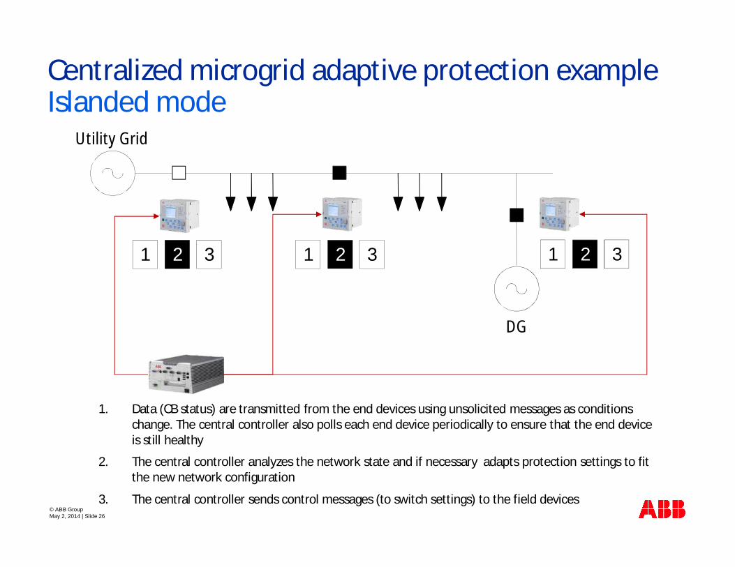
Centralized microgrid adaptive protection exampleIslanded mode
DG
1 2
Utility Grid
3 1 2 3 1 2 3
3. The central controller sends control messages (to switch settings) to the field devices
1. Data (CB status) are transmitted from the end devices using unsolicited messages as conditionschange. The central controller also polls each end device periodically to ensure that the end deviceis still healthy
2. The central controller analyzes the network state and if necessary adapts protection settings to fitthe new network configuration

© ABB GroupMay 2, 2014 | Slide 27
Centralized microgrid adaptive protection exampleIslanded mode
DG
1 2
Utility Grid
3 1 2 3 1 2 3
3. The central controller sends control messages (to switch settings) to the field devices
1. Data (CB status) are transmitted from the end devices using unsolicited messages as conditionschange. The central controller also polls each end device periodically to ensure that the end deviceis still healthy
2. The central controller analyzes the network state and if necessary adapts protection settings to fitthe new network configuration

© ABB GroupMay 2, 2014 | Slide 28
Microgrid protectionCentralized adaptation scheme lab tests
§ Centralized approach has been tested in thelab (focus on data exchange) with arealization for MV (IEC61850) and LV(Modbus) grids
§ In addition a real-time HIL simulations havebeen conducted for the MV case
§ Adaptation process is limited bycommunication system/protocol capabilityand takes <100 ms in the MV case and ~700ms (per circuit breaker) in the LV case
§ Both systems have demonstrated goodperformance and operated properly indifferent conditions (including situationwhen settings have been forced manually tothe wrong setting group)

© ABB GroupMay 2, 2014 | Slide 29
Hailuoto microgrid
§ Goal is to develop anddemonstrate in the fieldan active microgridmanagement
§ Active managementfunctionalities include:§ Protection settings
changing based onmicrogrid topology(e.g. grid connectedó island)
Hailuoto is theFinnish island inthe Northern Gulfof Bothnia in theBaltic Sea. It has~1000 regularinhabitants and600 holidayhouses
Practical demonstration of adaptive protection
§ Transition between grid connected and islanded operation modes:§ Unintentional islanding via black-start§ Intentional islanding via SCADA§ Re-synchronization to the utility grid

© ABB GroupMay 2, 2014 | Slide 30
Hailuoto microgridSystem configuration

© ABB GroupMay 2, 2014 | Slide 31
Hailuoto microgridSystem configuration

© ABB GroupMay 2, 2014 | Slide 32
Hailuoto microgridSystem configuration

© ABB GroupMay 2, 2014 | Slide 33
Hailuoto microgridAutomation system configuration
§ Off-line process§ “Trusted” settings are
uploaded to IEDs asmultiple setting groups
§ IEC 61850 is used as amaster protocol forcommunications with theIEDs
§ IEC 61131 programminglanguages are used in thePLC application whichallows easy cross-platformtransfer of the application
© ABB GroupMay 2, 2014 | Slide 34
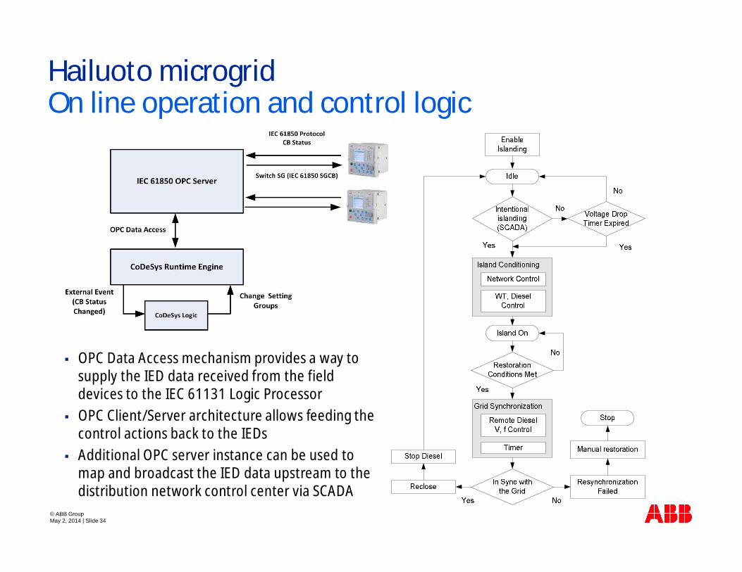
Hailuoto microgridOn line operation and control logic
§ OPC Data Access mechanism provides a way tosupply the IED data received from the fielddevices to the IEC 61131 Logic Processor
§ OPC Client/Server architecture allows feeding thecontrol actions back to the IEDs
§ Additional OPC server instance can be used tomap and broadcast the IED data upstream to thedistribution network control center via SCADA

© ABB GroupMay 2, 2014 | Slide 35
Microgrid protection
§ Aimed to simplify animplementation for amicrogrid with a large numberof circuit breakers
§ Protected system is split intosmall areas being delimited bythe adjacent switchingdevices coordinated by locallogic units (LL)
§ Each LL communicates withunits in directly adjacent areasand exchange information onlocal short circuit levels (SCL)
Distributed adaptation scheme
© ABB GroupMay 2, 2014 | Slide 36
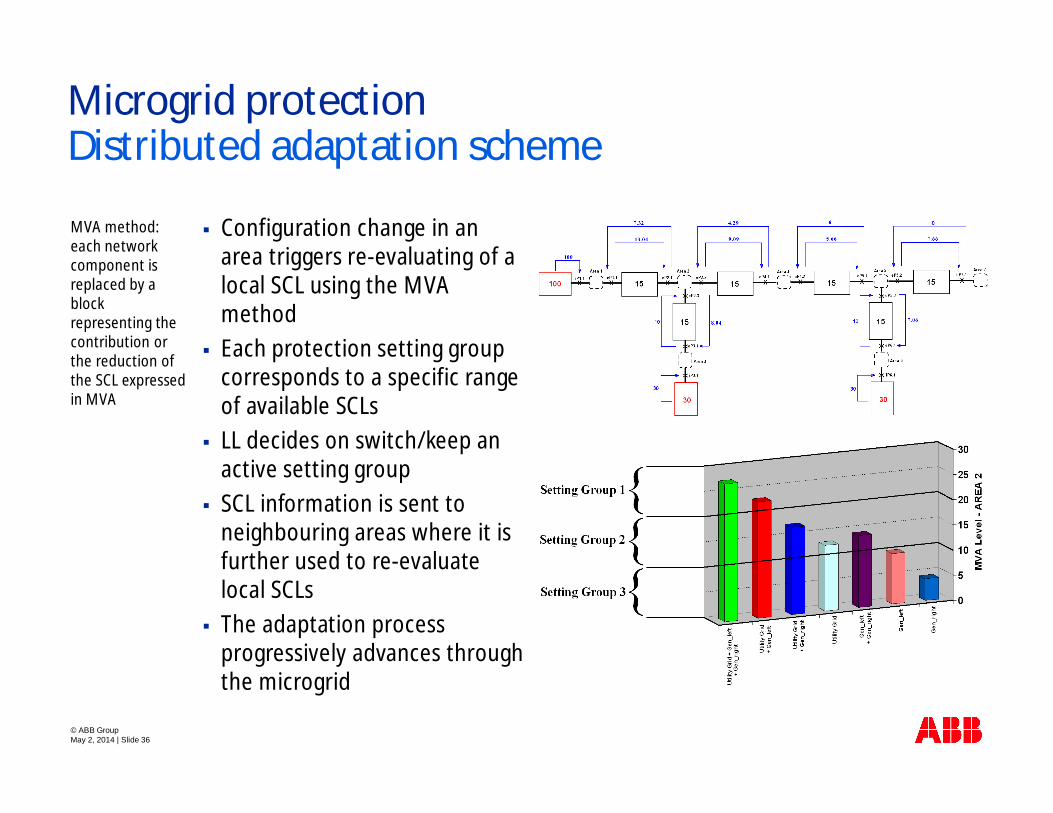
Microgrid protection
§ Configuration change in anarea triggers re-evaluating of alocal SCL using the MVAmethod
§ Each protection setting groupcorresponds to a specific rangeof available SCLs
§ LL decides on switch/keep anactive setting group
§ SCL information is sent toneighbouring areas where it isfurther used to re-evaluatelocal SCLs
§ The adaptation processprogressively advances throughthe microgrid
MVA method:each networkcomponent isreplaced by ablockrepresenting thecontribution orthe reduction ofthe SCL expressedin MVA
Distributed adaptation scheme
© ABB GroupMay 2, 2014 | Slide 37
Microgrid Protection
§ High penetration level of DER and islanded operationmode pose main protection challenges in microgrids
§ Ideally protection system must follow microgridconfiguration changes
§ Adaptive protection may increase availability of localgeneration and reduces customer outages
§ At the moment it looks like a switching between the pre-calculated “trusted” setting groups is a preferred solution
§ Centralized adaptive protection scheme based on fullconnectivity model can be suitable for small scalemicrogrids
§ For large scale microgrids a distributed adaptive protectionscheme with a limited connectivity model can be morepertinent
Key take away points

© ABB GroupMay 2, 2014 | Slide 38
Microgrid Protection
§ A. Oudalov, A. Fidigatti, “Adaptive Network Protection inMicrogrids”, International Journal of Distributed EnergyResources, Vol.5, No.3, pp.201-226, July-September 2009
§ W. Zhao, A. Oudalov, B. Su, Y. Chen, “Research on Close-LoopSimulation for Centralized Coordination of Protection Settings”,in Proc. of China International Conference on ElectricityDistribution, Shanghai, 2012
§ A. Oudalov, L. Milani, E. Ragaini, A. Fidigatti, “SampleImplementation of Adaptive Protection for LV Networks”, PACWorld Magazine, Vol.20, pp.28-33, June 2012
§ D. Ishchenko, A. Oudalov and J. Stoupis, "ProtectionCoordination in Active Distribution Grids with IEC 61850," inProc. of IEEE T&D conference, 2012, Orlando, FL, USA.
§ H. Laaksonen, D. Ishchenko, A. Oudalov, “Adaptive Protectionand Microgrid Control Design for Hailuoto island”, IEEE Trans onSmart Grids, March, 2014
Further reading