Embed Size (px)
Citation preview

CONTENTS
Page List of Tables List of Figures Diversion.……………….……………………………………………………………………………………………. 5B.1 Grassed Waterway…….……………………………………………………………………………………………… 5B.11 Lined Waterway or Outlet……………………………………………………………………………………………. 5B.17 Rock Outlet Protection…………..…….……………………………………………………………………………… 5B.21 Grade Stabilization Structure…………………………………………………………………………………………. 5B.31 Paved Flume.....……………………………………………………………………………………………………….. 5B.33 Structural Streambank Protection.……………………………………………………………………………………… 5B.37 Debris Basin…..………...……………………………………………………………………………………………… 5B.41 Subsurface Drain………………...…………………………………………………………………………………….. 5B.45 Landgrading………………………………………………………………………………………………………….. 5B.49 Surface Roughening…...………………………………………………………………………………………………. 5B.55 Riprap Slope Protection……………….………………………………………………………………………………. 5B.57 Retaining Walls..…………………...………………………………………………………………………………….. 5B.61 References
SECTION 5B PERMANENT STRUCTURAL MEASURES
FOR EROSION AND SEDIMENT CONTROL

List of Tables Table Name Page
5B.1 Diversion Maximum Permissible Design Velocities…..…………………………………………… 5B.1 5B.2 Retardance Factors for Various Grasses and Legumes…………………………………………….. 5B.2 5B.3 Riprap Gradations…….……………….………………..….……………………………………… 5B.38

List of Figures Figure Title Page
5B.1 Diversion Details ………………………………….…..…………………………………………… 5B.3 5B.2 Parabolic Diversion Design, without freeboard-1...……..….……………………………………… 5B.4 5B.3 Parabolic Diversion Design, without freeboard-2……..…..………………………………………. 5B.5 5B.4 Parabolic Diversion Design, without freeboard-3..….…………………………………………….. 5B.6 5B.5 Parabolic Diversion Design, without freeboard-4………………………………………………….. 5B.7 5B.6 Parabolic Diversion Design, without freeboard-5…………………………………………………. 5B.8 5B.7 Parabolic Diversion Design, without freeboard-6………………………………………………….. 5B.9 5B.8 Typical Waterway Cross Sections……………………..…………………………………………… 5B.13 5B.9 Parabolic Waterway Design Chart………………………………………………………………… 5B.14 5B.10 Grassed Waterway Details……………..…..……………………………...………………………. 5B.15 5B.11 Determining “n” for Riprap Lined Channel Using Depth of Flow………………………………… 5B.20 5B.12 Outlet Protection Design—Minimum Tailwater Condition……………………………………….. 5B.25 5B.13 Outlet Protection Design—Maximum Tailwater Condition………………………………………. 5B.26 5B.14 Riprap Outlet Protection Example (1)………..……………………………………………………… 5B.27 5B.15 Riprap Outlet Protection Example (2)…………………..…………………………………………… 5B.28 5B.16 Riprap Outlet Protection Example (3).….…………………………………………………………… 5B.29 5B.17 Examples of Outlet Structures………………………………………………………………………. 5B.35 5B.18 Paved Flume Details…………………………………………...….………………………………… 5B.36 5B.19 Riprap Streambank Protection Details…………………………………………………………….. 5B.39 5B.20 Structural Streambank Protection Examples………………………………………………………. 5B.40 5B.21 One Year Debris Basin Sediment Capacity………………………………………………………… 5B.44 5B.22 Surface Drain Chart—Corrugated Plastic Drain Tubing…………………………………………… 5B.48 5B.23 Typical Section of Serrated Cut Slope……..……….……………………………………………… 5B.51 5B.24(1) Landgrading Details...…………………………………………………………………………….. 5B.52 5B.24(2) Landgrading Construction Specifications…………………………………………………………. 5B.53 5B.25 Surface Roughening Details………..………………………………………………………………. 5B.56 5B.26 Angle of Repose of Riprap Stones.…….…………………………………………………………… 5B.59 5B.27 Typical Rock Slope Protection Details….……………….………………………………………… 5B.59 5B.28 Retaining Wall Examples……………..…………………………………………………………… 5B.63 5B.29 Segmented Retaining Wall………………………………………………………………………… 5B.64

August 2005 Page 5B.1 New York Standards and Specifications For Erosion and Sediment Control
STANDARD AND SPECIFICATIONS FOR
DIVERSION
Definition A drainage way of parabolic or trapezoidal cross-section with a supporting ridge on the lower side that is constructed across the slope. Purpose The purpose of a diversion is to intercept and convey runoff to stable outlets at non-erosive velocities. Conditions Where Practice Applies Diversions are used where: 1. Runoff from higher areas has potential for damaging
properties, causing erosion, or interfering with, or preventing the establishment of, vegetation on lower areas. 2. Surface and/or shallow subsurface flow is damaging sloping upland. 3. The length of slopes needs to be reduced so that soil loss will be kept to a minimum.
Diversions are only applicable below stabilized or protected areas. Avoid establishment on slopes greater than fifteen percent. Diversions should be used with caution on soils subject to slippage. Construction of diversions shall be in compliance with state drainage and water laws. Design Criteria Location Diversion location shall be determined by considering
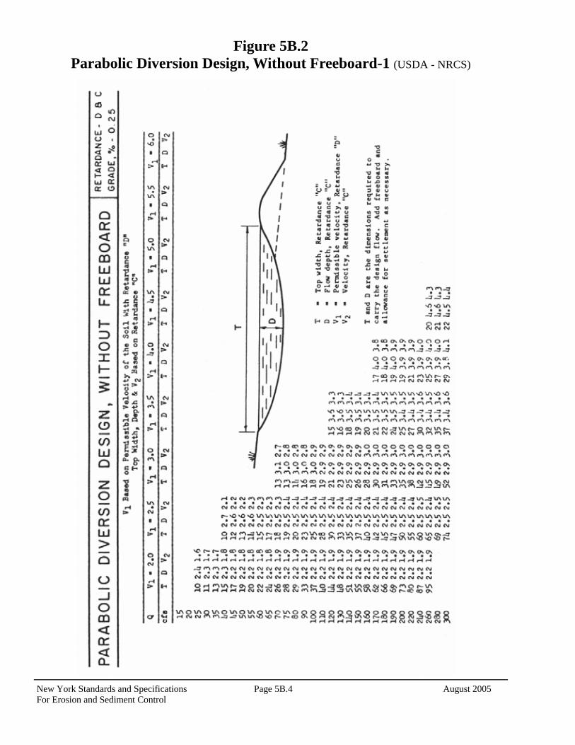
outlet conditions, topography, land use, soil type, length of slope, seep planes (when seepage is a problem), and the development layout. Capacity Peak rates of runoff values used in determining the capacity requirements shall be computed by TR-55, Urban Hydrology for Small Watersheds, or other appropriate methods. The constructed diversion shall have capacity to carry, as a minimum, the peak discharge from a ten-year frequency rainfall event with freeboard of not less than 0.3 feet. Diversions designed to protect homes, schools, industrial buildings, roads, parking lots, and comparable high-risk areas, and those designed to function in connection with other structures, shall have sufficient capacity to carry peak runoff expected from a storm frequency consistent with the hazard involved. Cross Section The diversion channel shall be parabolic or trapezoidal in shape. Parabolic Diversion design charts are provided in Figures 5B.2 through 5B.7 on pages 5B.4 to 5B.9. The diversion shall be designed to have stable side slopes. The side slopes shall not be steeper than 2:1 and shall be flat enough to ensure ease of maintenance of the diversion and its protective vegetative cover. The ridge shall have a minimum width of four feet at the design water elevation; a minimum of 0.3 feet freeboard and a reasonable settlement factor shall be provided. Velocity and Grade The permissible velocity for the specified method of stabilization will determine the maximum grade. Maximum permissible velocities of flow for the stated conditions of stabilization shall be as shown in Table 5B.1 on page 5B.2 of this standard. Diversions are not usually applicable below high sediment producing areas unless land treatment practices or structural measures, designed to prevent damaging accumulations of sediment in the channels, are installed with, or before, the diversions.

New York Standards and Specifications Page 5B.2 August 2005 For Erosion and Sediment Control
Outlets Each diversion must have an adequate outlet. The outlet may be a grassed waterway, vegetated or paved area, grade stabilization structure, stable watercourse, or subsurface drain outlet. In all cases, the outlet must convey runoff to a point where outflow will not cause damage. Vegetated outlets shall be installed before diversion construction, if needed, to ensure establishment of vegetative cover in the outlet channel. The design elevation of the water surface in the diversion shall not be lower than the design elevation of the water surface in the outlet at their junction when both are
operating at design flow. Stabilization Diversions shall be stabilized in accordance with the following tables. Construction Specifications See Figure 5B.1 on page 5B.3 for details.
Table 5B.1 Diversion Maximum Permissible Design Velocities
Soil Texture
Retardance and Cover
Permissible Velocity (ft / second) for Selected
Channel Vegetation
Sand, Silt, Sandy loam, silty loam, loamy sand (ML, SM, SP, SW)
C-Kentucky 31 tall fescue and Kentucky bluegrass
D-Annuals1 Small grain (rye, oats, barley, millet) Ryegrass
3.0
2.5
Silty clay loam, Sandy clay loam (ML-CL, SC)
C-Kentucky 31 tall fescue and Kentucky bluegrass
D-Annuals1 Small grain (rye, oats, barley, millet) Ryegrass
4.0
3.5
Clay (CL) C-Kentucky 31 tall fescue and Kentucky bluegrass
D-Annuals1 Small grain (rye, oats, barley, millet) Ryegrass
5.0
4.0
1 Annuals—Use only as temporary protection until permanent vegetation is established.
Retardance Cover Condition
A Reed canarygrass………………………………………………... Excellent stand, tall (average 36 inches)
B Smooth bromegrass…………………………………………… Tall fescue…………………………………………………….. Grass-legume mixture—Timothy, smooth bromegrass, or Or-
chard grass with birdsfoot trefoil………………………… Reed canarygrass………………………………………………. Tall fescue, with birdsfoot trefoil or ladino clover……………..
Good stand, mowed (average 12 to 15 inches) Good stand, unmowed (average 18 inches) Good stand, uncut (average 20 inches) Good stand, mowed (average 12 to 15 inches) Good stand, uncut (average 18 inches)
C Redtop……………………………………………………… Grass-legume mixture—summer (Orchard grass, redtop, Annual
ryegrass, and ladino or white clover)………………………… Kentucky bluegrass…………………………………………….
Good stand, headed (15 to 20 inches) Good stand, uncut (6 to 8 inches) Good stand, headed (6 to 12 inches)
D Red fescue……………………………………………………… Grass-legume mixture—fall, spring (Orchard grass, redtop, An-
nual ryegrass, and white or ladino clover)……………….
Good stand, headed (12 to 18 inches) Good stand, uncut (4 to 5 inches)
Table 5B.2—Retardance Factors for Various Grasses and Legumes

August 2005 Page 5B.3 New York Standards and Specifications For Erosion and Sediment Control
Figure 5B.1 Diversion
New York Standards and Specifications Page 5B.4 August 2005 For Erosion and Sediment Control
Figure 5B.2 Parabolic Diversion Design, Without Freeboard-1 (USDA - NRCS)

August 2005 Page 5B.5 New York Standards and Specifications For Erosion and Sediment Control
Figure 5B.3 Parabolic Diversion Design, Without Freeboard-2 (USDA - NRCS)

New York Standards and Specifications Page 5B.6 August 2005 For Erosion and Sediment Control
Figure 5B.4 Parabolic Diversion Design, Without Freeboard-3 (USDA - NRCS)

August 2005 Page 5B.7 New York Standards and Specifications For Erosion and Sediment Control
Figure 5B.5 Parabolic Diversion Design, Without Freeboard-4 (USDA - NRCS)

New York Standards and Specifications Page 5B.8 August 2005 For Erosion and Sediment Control
Figure 5B.6 Parabolic Diversion Design, Without Freeboard-5 (USDA - NRCS)

August 2005 Page 5B.9 New York Standards and Specifications For Erosion and Sediment Control
Figure 5B.7 Parabolic Diversion Design, Without Freeboard-6 (USDA - NRCS)

New York Standards and Specifications Page 5B.10 August 2005 For Erosion and Sediment Control
This Page Intentionally Left blank

August 2005 Page 5B.11 New York Standards and Specifications For Erosion and Sediment Control
STANDARD AND SPECIFICATIONS FOR
GRASSED WATERWAY
Definition A natural or man-made channel of parabolic or trapezoidal cross-section that is below adjacent ground level and is stabilized by suitable vegetation. The flow channel is normally wide and shallow and conveys the runoff down the slope. Purpose The purpose of a grassed waterway is to convey runoff without causing damage by erosion. Conditions Where Practice Applies Grass waterways are used where added vegetative protection is needed to control erosion resulting from concentrated runoff. Design Criteria Capacity The minimum capacity shall be that required to confine the peak rate of runoff expected from a 10-year frequency rainfall event or a higher frequency corresponding to the hazard involved. This requirement for confinement may be waived on slopes of less than one (1) percent where out-of-bank flow will not cause erosion or property damage. Peak rates of runoff values used in determining the capacity requirements shall be computed by TR-55, Urban Hydrology for Small Watersheds, or other appropriate methods. Where there is base flow, it shall be handled by a stone
center, subsurface drain, or other suitable means since sustained wetness usually prevents adequate vegetative cover. The cross-sectional area of the stone center or subsurface drain size to be provided shall be determined by using a flow rate of 0.1 cfs/acre or by actual measurement of the maximum base flow. Velocity Please see Table 5B.1, Diversion Maximum Permissible Design Velocities, for seed, soil, and velocity variables. Cross Section The design water surface elevation of a grassed waterway receiving water from diversions or other tributary channels shall be equal to or less than the design water surface elevation in the diversion or other tributary channels. The top width of parabolic waterways shall not exceed 30 feet and the bottom width of trapezoidal waterways shall not exceed 15 feet unless multiple or divided waterways, stone center, or other means are provided to control meandering of low flows. Structural Measures In cases where grade or erosion problems exist, special control measures may be needed such as lined waterways (5B.17), or grade stabilization measures (5B.31). Where needed, these measures will be supported by adequate design computations. For typical cross sections of waterways with riprap sections or stone centers, refer to Figure 5B.8 on page 5B.13. The design procedures for parabolic and trapezoidal channels are available in the NRCS Engineering Field Handbook; Figure 5B.9 on page 5B.14 also provides a design chart for parabolic waterway. Outlets Each waterway shall have a stable outlet. The outlet may be another waterway, a stabilized open channel, grade stabilization structure, etc. In all cases, the outlet must discharge in such a manner as not to cause erosion. Outlets shall be constructed and stabilized prior to the operation of the waterway.

New York Standards and Specifications Page 5B.12 August 2005 For Erosion and Sediment Control
Stabilization Waterways shall be stabilized in accordance with the appropriate vegetative stabilization standard and specifications, and will be dependent on such factors as slope, soil class, etc. Construction Specifications See Figure 5B.10 on page 5B.15 for details.

August 2005 Page 5B.13 New York Standards and Specifications For Erosion and Sediment Control
Figure 5B.8 Typical Waterway Cross Sections

New York Standards and Specifications Page 5B.14 August 2005 For Erosion and Sediment Control
Figure 5B.9 Parabolic Waterway Design Chart (USDA - NRCS)

August 2005 Page 5B.15 New York Standards and Specifications For Erosion and Sediment Control
Figure 5B.10 Grassed Waterway

New York Standards and Specifications Page 5B.16 August 2005 For Erosion and Sediment Control
This Page Intentionally Left blank

August 2005 Page 5B.17 New York Standards and Specifications For Erosion and Sediment Control
STANDARD AND SPECIFICATIONS FOR
LINED WATERWAY OR OUTLET
Definition A waterway or outlet with a lining of concrete, stone, or other permanent material. The lined section extends up the side slopes to the designed depth. The earth above the permanent lining may be vegetated or otherwise protected. Purpose To provide for the disposal of concentrated runoff without damage from erosion or flooding, where grassed waterways would be inadequate due to high velocities. Scope This standard applies to waterways or outlets with linings of cast-in-place concrete, flagstone mortared in place, rock riprap, gabions, or similar permanent linings. It does not apply to irrigation ditch or canal linings, grassed waterways with stone centers or small lined sections that carry prolonged low flows, or to reinforced concrete channels. The maximum capacity of the waterway flowing at design depth shall not exceed 100 cubic feet per second. Conditions Where Practice Applies This practice applies where the following or similar conditions exist:
1. Concentrated runoff is such that a lining is required to control erosion.
2. Steep grades, wetness, prolonged base flow,
seepage, or piping that would cause erosion.
3. The location is such that damage from use by people or animals precludes use of vegetated waterways or outlets.
4. Soils are highly erosive or other soil and climate
conditions preclude using vegetation. 5. High value property or adjacent facilities warrant
the extra cost to contain design runoff in a limited space.
Design Criteria Capacity 1. The minimum capacity shall be adequate to carry the peak rate of runoff from a 10-year, 24-hour storm. Velocity shall be computed using Manning’s equation with a coefficient of roughness “n” as follows: Lined Material “n”
Concrete (Type):
Trowel Finish 0.015
Float Finish 0.019
Gunite 0.019
Flagstone 0.022
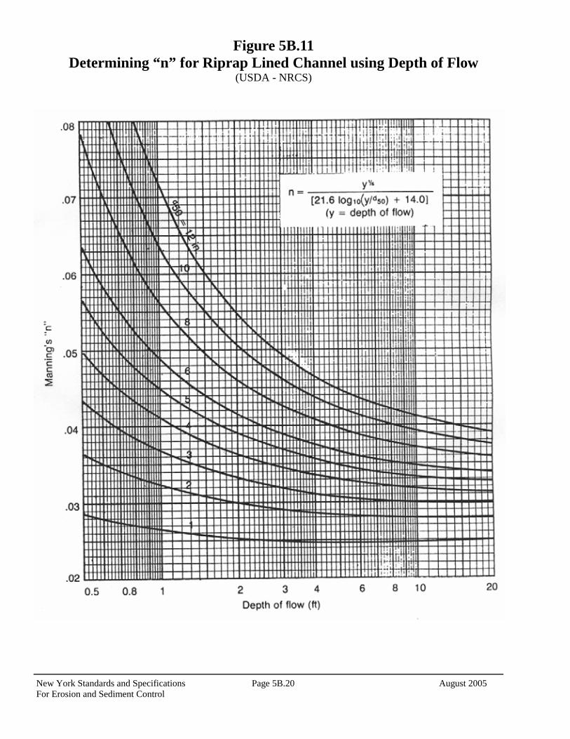
Riprap Determine from Figure 5B.11 on page 5B.19
Gabion 0.030
2. Riprap gradation and filter (bedding) are generally designed in accordance with criteria set forth in the National Cooperative Highway Research Program Report 108, available from the University Microfilm International, 300 N. Ree Road, Ann Arbor, Michigan 48016, Publication No. PB-00839; or the Hydraulic Engineering Circular No. 11, prepared by the U.S. Bureau of Public Roads, available from Federal Highway Administration, 400 7th Street, S.W., Washington, D.C. 20590, HNG-31, or the procedure in the USDA-NRCS’s Engineering Field Manual, Chapter 16. Velocity
1. Maximum design velocity shall be as shown below. Except for short transition sections, flow with a channel gradient within the range of 0.7 to 1.3 of this

New York Standards and Specifications Page 5B.18 August 2005 For Erosion and Sediment Control
flow’s critical slope must be avoided unless the channel is straight. Velocities exceeding critical will be restricted to straight reaches.
Design Flow Depth Maximum Velocity (ft.) (ft./sec.) 0.0 – 0.5 25 0.5 – 1.0 15 Greater than 1.0 10
2. Waterways or outlets with velocities exceeding critical shall discharge into an energy dissipater to reduce velocity to less than critical, or to a velocity the downstream soil and vegetative conditions will allow.
Cross Section The cross section shall be triangular, parabolic, or trapezoidal. Monolithic concrete or gabions may be rectangular. Freeboard The minimum freeboard for lined waterways or outlets shall be 0.25 feet above design high water in areas where erosion resistant vegetation cannot be grown adjacent to the paved side slopes. No freeboard is required where good vegetation can be grown and is maintained. Side Slope Steepest permissible side slopes, horizontal to vertical will be as follows:
1. Non-Reinforced Concrete Hand-placed, formed concrete Height of lining, 1.5 ft or less…………. Vertical Hand placed screened concrete or mortared In-place flagstone Height of lining, less than 2 ft…………. 1 to 1 Height of lining, more than 2 ft……….. 2 to 1 2. Slip form concrete: Height of lining, less than 3 ft………… 1 to 1 3. Rock Riprap………………………………. 2 to 1 4. Gabions…………………………………… Vertical 5. Pre-cast Concrete Sections……………….. Vertical
Lining Thickness Minimum lining thickness shall be as follows: 1. Concrete………………..4 in. (In most problem areas, shall be 5 in. with welded wire fabric reinforcing.) 2. Rock Riprap……1.5 x maximum stone size plus thickness of filter or bedding. 3. Flagstone…………..4 in. including mortar bed.
Related Structures Side inlets, drop structures, and energy dissipaters shall meet the hydraulic and structural requirements of the site. Filters or Bedding Filters or bedding to prevent piping, reduce uplift pressure, and collect water will be used as required and will be designed in accordance with sound engineering principles. Weep holes and drains should be provided as needed. Concrete Concrete used for lining shall be so proportioned that it is plastic enough for thorough consolidation and stiff enough to stay in place on side slopes. A dense product will be required. A mix that can be certified as suitable to produce a minimum strength of at least 3,000 pounds per square inch will be required. Cement used shall be Portland Cement, Type I, II, IV, or V. Aggregate used shall have a maximum diameter of 1 ½ inches. Weep holes should be provided in concrete footings and retaining walls to allow free drainage of water. Pipe used for weep holes shall be non-corrosive. Mortar Mortar used for mortared in-place flagstone shall consist of a mix of cement, sand, and water. Follow directions on the bag of mortar for proper mixing of mortar and water. Contraction Joints Contraction joints in concrete linings, where required, shall be formed transversely to a depth of about one third the thickness of the lining at a uniform spacing in the range of 10 to 15 feet. Rock Riprap or Flagstone Stone used for riprap or gabions shall be dense and hard enough to withstand exposure to air, water, freezing, and thawing. Flagstone shall be flat for ease of placement and have the strength to resist exposure and breaking. Rock riprap maximum size shall be as follows:
Velocity, f.p.s. dmax, inches 5.0 6 8.5 12 10 18 12 24 15 36 A complete riprap gradations is provided in Table 5B.4, page 5B.38.

August 2005 Page 5B.19 New York Standards and Specifications For Erosion and Sediment Control
Cutoff Walls Cutoff walls shall be used at the beginning and ending of concrete lining. For rock riprap lining, cutoff walls shall be keyed into the channel bottom and at both ends of the lining. Construction Specifications
1. The foundation area shall be cleared of trees, stumps, roots, sod, loose rock, or other objectionable material.
2. The cross-section shall be excavated to the neat lines
and grades as shown on the plans. Over-excavated areas shall be backfilled with moist soil compacted to the density of the surrounding material.
3. No abrupt deviations from design grade or horizontal
alignment shall be permitted. 4. Concrete linings shall be placed to the thickness
shown on the plans and finished in a workmanlike manner. Adequate precautions shall be taken to
protect freshly placed concrete from extreme (hot or cold) temperatures, to ensure proper curing.
5. Filter bedding and rock riprap shall be placed to line
and grade in the manner specified. 6. Construction operation shall be done in such a manner
that erosion, air pollution, and water pollution will be minimized and held within legal limits. The completed job shall present a workmanlike appearance. All disturbed areas shall be vegetated or otherwise protected against soil erosion.
Maintenance Pavement or lining should be maintained as built to prevent undermining and deterioration. Existing trees next to pavements should be removed, as roots can cause uplift damage. Vegetation next to pavement should be maintained in good condition to prevent scouring if the pavement is overtopped. See Standard and Specifications for Permanent Critical Area Seeding on page 3.5.
New York Standards and Specifications Page 5B.20 August 2005 For Erosion and Sediment Control
Figure 5B.11 Determining “n” for Riprap Lined Channel using Depth of Flow
(USDA - NRCS)

August 2005 Page 5B.21 New York Standards and Specifications For Erosion and Sediment Control
STANDARD AND SPECIFICATIONS FOR
ROCK OUTLET PROTECTION
Definition A section of rock protection placed at the outlet end of the culverts, conduits, or channels. Purpose The purpose of the rock outlet protection is to reduce the depth, velocity, and energy of water, such that the flow will not erode the receiving downstream reach. Scope This standard applies to the planning, design, and construction of rock riprap and gabions for protection of downstream areas. It does not apply to rock lining of channels or streams. Conditions Where Practice Applies This practice applies where discharge velocities and energies at the outlets of culverts, conduits, or channels are sufficient to erode the next downstream reach. This applies to: 1. Culvert outlets of all types. 2. Pipe conduits from all sediment basins, dry storm water ponds, and permanent type ponds. 3. New channels constructed as outlets for culverts and conduits.
Design Criteria
The design of rock outlet protection depends entirely on the location. Pipe outlet at the top of cuts or on slopes steeper than 10 percent, cannot be protected by rock aprons or riprap sections due to re-concentration of flows and high velocities encountered after the flow leaves the apron. Many counties and state agencies have regulations and design procedures already established for dimensions, type and size of materials, and locations where outlet protection is required. Where these requirements exist, they shall be followed. Tailwater Depth The depth of tailwater immediately below the pipe outlet must be determined for the design capacity of the pipe. If the tailwater depth is less than half the diameter of the outlet pipe, and the receiving stream is wide enough to accept divergence of the flow, it shall be classified as a Minimum Tailwater Condition; see Figure 5B.12 on page 5B.25 as an example. If the tailwater depth is greater than half the pipe diameter and the receiving stream will continue to confine the flow, it shall be classified as a Maximum Tailwater Condition; see Figure 5B.13 on page 5B.26 as an example. Pipes which outlet onto flat areas with no defined channel may be assumed to have a Minimum Tailwater Condition; see Figure 5B.12 on page 5B.25 as an example.
Apron Size The apron length and width shall be determined from the curves according to the tailwater conditions: Minimum Tailwater – Use Figure 5B.12 on page 5B.25 Maximum Tailwater – Use Figure 5B.13 on page 5B.26 If the pipe discharges directly into a well defined channel, the apron shall extend across the channel bottom and up the channel banks to an elevation one foot above the maximum tailwater depth or to the top of the bank, whichever is less. The upstream end of the apron, adjacent to the pipe, shall have a width two (2) times the diameter of the outlet pipe, or conform to pipe end section if used.

New York Standards and Specifications Page 5B.22 August 2005 For Erosion and Sediment Control
Bottom Grade The outlet protection apron shall be constructed with no slope along its length. There shall be no overfall at the end of the apron. The elevation of the downstream end of the apron shall be equal to the elevation of the receiving channel or adjacent ground. Alignment The outlet protection apron shall be located so that there are no bends in the horizontal alignment. Materials The outlet protection may be done using rock riprap, grouted riprap, or gabions. Riprap shall be composed of a well-graded mixture of stone size so that 50 percent of the pieces, by weight, shall be larger than the d50 size determined by using the charts. A well-graded mixture, as used herein, is defined as a mixture composed primarily of larger stone sizes, but with a sufficient mixture of other sizes to fill the smaller voids between the stones. The diameter of the largest stone size in such a mixture shall be 1.5 times the d50 size. Thickness
The minimum thickness of the riprap layer shall be 1.5 times the maximum stone diameter for d50 of 15 inches or less; and 1.2 times the maximum stone size for d50 greater than 15 inches. The following chart lists some examples:
Stone Quality Stone for riprap shall consist of field stone or rough unhewn quarry stone. The stone shall be hard and angular and of a quality that will not disintegrate on exposure to water or weathering. The specific gravity of the individual stones shall be at least 2.5. Recycled concrete equivalent may be used provided it has a
density of at least 150 pounds per cubic foot, and does not have any exposed steel or reinforcing bars. Filter A filter is a layer of material placed between the riprap and the underlying soil surface to prevent soil movement into and through the riprap. Riprap shall have a filter placed under it in all cases. A filter can be of two general forms: a gravel layer or a plastic filter cloth. The plastic filter cloth can be woven or non-woven monofilament yarns, and shall meet these base requirements: thickness 20-60 mils, grab strength 90-120 lbs; and shall conform to ASTM D-1777 and ASTM D-1682. Gravel filter blanket, when used, shall be designed by comparing particle sizes of the overlying material and the base material. Design criteria are available in Standard and Specification for Riprap Slope Protection on page 5B.57. Gabions Gabions shall be made of hexagonal triple twist mesh with heavily galvanized steel wire. The maximum linear dimension of the mesh opening shall not exceed 4 ½ inches and the area of the mesh opening shall not exceed 10 square inches. Gabions shall be fabricated in such a manner that the sides, ends, and lid can be assembled at the construction site into a rectangular basket of the specified sizes. Gabions shall be of single unit construction and shall be installed according to manufacturers recommendations. The area on which the gabion is to be installed shall be graded as shown on the drawings. Foundation conditions shall be the same as for placing rock riprap, and filter cloth shall be placed under all gabions. Where necessary, key, or tie, the structure into the bank to prevent undermining of the main gabion structure. Maintenance Once a riprap outlet has been installed, the maintenance needs are very low. It should be inspected after high flows for evidence of scour beneath the riprap or for dislodged stones. Repairs should be made immediately. Design Procedure 1. Investigate the downstream channel to assure that
nonerosive velocities can be maintained. 2. Determine the tailwater condition at the outlet to
establish which curve to use. 3. Enter the appropriate chart with the design discharge to
D50
(inches)
dmax
(inches)
Minimum Blanket Thickness
(inches)
4 6 9
6 9 14
9 14 20
12 18 27
15 22 32
18 27 32
21 32 38
24 36 43

August 2005 Page 5B.23 New York Standards and Specifications For Erosion and Sediment Control
determine the riprap size and apron length required. It is noted that references to pipe diameters in the charts are based on full flow. For other than full pipe flow, the parameters of depth of flow and velocity must be used to adjust the design discharges.
4. Calculate apron width at the downstream end if a flare
section is to be employed.
Examples Example 1: Pipe Flow (full) with discharge to unconfined section. Given: A circular conduit flowing full. Q = 280 cfs, diam. = 66 in., tailwater (surface) is 2 ft.
above pipe invert (minimum tailwater condition). Find: Read d50 = 1.2 and apron length (La) = 38 ft. Apron width = diam. + La = 5.5 + 38 = 43.5 ft. Use: d50 = 15”, dmax = 22”, blanket thickness = 32” Example 2: Box Flow (partial) with high tailwater Given: A box conduit discharging under partial flow conditions. A concrete box 5.5 ft. x 10 ft. flowing 5.0 ft. deep, Q = 600 cfs and tailwater surface is 5 ft. above invert (max.
tailwater condition). Since this is not full pipe and does not directly fit the nomograph assumptions of Figure 7B.13 substitute depth as the diameter, to find a discharge equal to full pipe flow for that diameter, in this case 60 inches. Since, Q = AV and A = π D2 4 First, compute velocity: V = (Q/A) = (600/(5) (10)) = 12 fps Then substituting:
Q = π D2 x V = 3.14 (5 ft)2 x 12 fps = 236 cfs 4 4
At the intersection of the curve d = 60 in. and Q = 236 cfs, read d50 = 0.4 ft. Then reading the d = 60 in. curve, read apron length (La) = 40 ft.
Apron width, W = conduit width + (6.4)(La) = 10 + (0.4)(40) = 26 ft. Example 3: Open Channel Flow with Discharge to Unconfined Section Given: A trapezoidal concrete channel 5 ft. wide with 2:1 side slopes is flowing 2 ft. deep, Q = 180 cfs (velocity = 10 fps) and the tailwater surface downstream is 0.8 ft. (minimum tailwater condition). Find: Using similar principles as Example 2, compute equivalent discharge for a 2 foot, using depth as a diameter, circular pipe flowing full at 10 feet per second. Velocity: Q = π (2ft)2 x 10 fps = 31.4 cfs 4 At intersection of the curve, d = 24 in. and Q = 32 cfs, read
d50 = 0.6 ft. Then reading the d = 24 in. curve, read apron length (La) =
20 ft. Apron width, W = bottom width of channel + La = 5 + 20 =
25 ft. Example 4: Pipe flow (partial) with discharge to a confined section Given: A 48 in. pipe is discharging with a depth of 3 ft. Q = 100 cfs, and discharge velocity of 10 fps (established from partial flow analysis) to a confined trapezoidal channel with a 2 ft. bottom, 2:1 side slopes, n = .04, and grade of 0.6%. Calculation of the downstream channel (by Manning’s Equation) indicates a normal depth of 3.1 ft. and normal velocity of 3.9 fps. Since the receiving channel is confined, the maximum tailwater condition controls. Find: discharge using previous principles:
Q = π (3ft)2 x 10 fps = 71 cfs 4
At the intersection of d = 36 in. and Q = 71 cfs, read d50 = 0.3 ft. Reading the d = 36” curve, read apron length (La) = 30 ft. Since the maximum flow depth in this reach is 3.1 ft., that is the minimum depth of riprap to be maintained for the entire length.

New York Standards and Specifications Page 5B.24 August 2005 For Erosion and Sediment Control
Construction Specifications 1. The subgrade for the filter, riprap, or gabion shall be
prepared to the required lines and grades. Any fill required in the subgrade shall be compacted to a density of approximately that of the surrounding undisturbed material.
2. The rock or gravel shall conform to the specified
grading limits when installed respectively in the riprap or filter.
3. Filter cloth shall be protected from punching, cutting,
or tearing. Any damage other than an occasional small hole shall be repaired by placing another piece of cloth over the damaged part or by completely replacing the cloth. All overlaps, whether for repairs or for joining two pieces of cloth shall be a minimum of one foot.
4. Stone for the riprap or gabion outlets may be placed by
equipment. Both shall each be constructed to the full course thickness in one operation and in such a manner as to avoid displacement of underlying materials. The stone for riprap or gabion outlets shall be delivered and placed in a manner that will ensure that it is reasonably homogenous with the smaller stones and spalls filling the voids between the larger stones. Riprap shall be placed in a manner to prevent damage to the filter blanket or filter cloth. Hand placement will be required to the extent necessary to prevent damage to the permanent works.

August 2005 Page 5B.25 New York Standards and Specifications For Erosion and Sediment Control
Figure 5B.12 Outlet Protection Design—Minimum Tailwater Condition
(Design of Outlet Protection from a Round Pipe Flowing Full, Minimum Tailwater Condition: Tw < 0.5Do) (USDA - NRCS)

New York Standards and Specifications Page 5B.26 August 2005 For Erosion and Sediment Control
Figure 5B.13 Outlet Protection Design—Maximum Tailwater Condition
(Design of Outlet Protection from a Round Pipe Flowing Full, Maximum Tailwater Condition: Tw ≥ 0.5Do) (USDA - NRCS)

August 2005 Page 5B.27 New York Standards and Specifications For Erosion and Sediment Control
Figure 5B.14 Riprap Outlet Protection Detail (1)

New York Standards and Specifications Page 5B.28 August 2005 For Erosion and Sediment Control
Figure 5B.15 Riprap Outlet Protection Detail (2)

August 2005 Page 5B.29 New York Standards and Specifications For Erosion and Sediment Control
Figure 5B.16 Riprap Outlet Protection Detail (3)

New York Standards and Specifications Page 5B.30 August 2005 For Erosion and Sediment Control
This Page Intentionally Left blank

August 2005 Page 5B.31 New York Standards and Specifications For Erosion and Sediment Control
STANDARD AND SPECIFICATIONS FOR
GRADE STABILIZATION STRUCTURE
Definition A structure to stabilize the grade or to control head cutting in natural or artificial channels. Scope This standard applies to all types of grade stabilization structures. It does not apply to storm sewers or their component parts. Purpose Grade stabilization structures are used to reduce or prevent excessive erosion by reduction of velocities and grade in the watercourse or by providing channel linings or structures that can withstand the higher velocities. Conditions Where Practice Applies This practice applies to sites where the capability of earth and vegetative measures is exceeded in the safe handling of water at permissible velocities, where excessive grades or overfall conditions are encountered, or where water is to be lowered structurally from one elevation to another. These structures should generally be planned and installed along with, or as a part of, other conservation practices in an overall surface water disposal system. Design Criteria Compliance with Laws and Regulations Design and construction shall be in compliance with state and local laws and regulations. Such compliance is the
responsibility of the landowner or developer. General Designs and specifications shall be prepared for each structure on an individual job basis depending on its purpose, site conditions, and the basic criteria of the conservation practice with which the structure is planned. Typical structures are as follows: 1. Channel linings of concrete, asphalt, half round metal
pipe or other suitable lining materials. These linings should generally be used where channel velocities exceed safe velocities for vegetated channels due to increased grade or a change in channel cross section or where durability of vegetative lining is adversely affected by seasonal changes. Adequate protection will be provided to prevent erosion or scour of both ends of the channel lining.
2. Overfall structures of concrete, metal, rock riprap, or
other suitable material is used to lower water from one elevation to another. These structures are applicable where it is desirable to drop the watercourse elevation over a very short horizontal distance. Adequate protection will be provided to prevent erosion or scour upstream, downstream and along sides of overfall structures. Structures should be located on straight sections of channel with a minimum of 100 feet of straight channel each way.
3. Pipe drops of metal pipe with suitable inlet and outlet
structures. The inlet structure may consist of a vertical section of pipe or similar material, an embankment, or a combination of both. The outlet structure will provide adequate protection against erosion or scour at the pipe outlet.
Capacity Structures that are designed to operate in conjunction with other erosion control practices shall have, as a minimum, capacity equal to the bankfull capacity of the channel delivering water to the structures. The minimum design capacity for structures that are not designed to perform in conjunction with other practices shall be that required to handle the peak rate of flow from a 10-year, 24-hour frequency storm or bankfull, whichever is greater. Peak rates of runoff used in determining the capacity requirements shall be determined by TR-55, Urban

New York Standards and Specifications Page 5B.32 August 2005 For Erosion and Sediment Control
Hydrology for Small Watersheds, or other appropriate method. Set the rest of the structure at an elevation that will stabilize the grade of the upstream channel. The outlet should be set at an elevation to assure stability. Outlet velocities should be kept within the allowable limits for the receiving stream. Structural drop spillways need to include a foundation drainage system to reduce hydrostatic loads. Structures which involve the retarding of floodwater or the impoundment of water shall be designed using the criteria set forth in the guidelines for Ponds or Floodwater Retarding Structures, whichever is applicable. Construction Specifications Structures shall be installed according to lines and grades shown on the plan. The foundation for structures shall be cleared of all undesirable materials prior to the installation of the structure. Materials used in construction shall be in conformance with the design frequency and life expectancy of the practice. Earth fill, when used as a part of the structure, shall be placed in 4-inch lifts and hand compacted within 2 feet of the structure.
Seeding, fertilizing, and mulching shall conform to the recommendation specification in Section 3. Construction operations shall be carried out in such a manner that erosion and air and water pollution will be minimized. State and local laws concerning pollution abatement shall be complied with at every site. Locate emergency bypass areas so that floods in excess of structural capacity enter the channel far enough downstream so as not to cause damage to the structure. Maintenance Once properly installed, the maintenance for the grade stabilization structure should be minimal. Inspect the structure periodically and after major storm events. Check fill for piping or extreme settlement. Ensure a good vegetative cover. Check the channel for scour or debris and loss of rock from aprons. Repair or replace failing structures immediately.
August 2005 Page 5B.33 New York Standards and Specifications For Erosion and Sediment Control
STANDARD AND SPECIFICATIONS FOR
PAVED FLUME
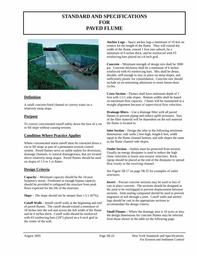
Definition A small concrete-lined channel to convey water on a relatively steep slope. Purpose To convey concentrated runoff safely down the face of a cut or fill slope without causing erosion. Condition Where Practice Applies Where concentrated storm runoff must be conveyed down a cut or fill slope as part of a permanent erosion control system. Paved flumes serve as stable outlets for diversions, drainage channels, or natural drainageways, that are located above relatively steep slopes. Paved flumes should be used on slopes of 1:5 to 1 or flatter. Design Criteria Capacity – Minimum capacity should be the 10-year frequency storm. Freeboard or enough bypass capacity should be provided to safeguard the structure from peak flows expected for the life of the structure. Slope – The slope should not be steeper than 1.5:1 (67%). Cutoff Walls – Install cutoff walls at the beginning and end of paved flumes. The cutoff should extend a minimum of 18 inches into the soil and across the full width of the flume and be 6 inches thick. Cutoff walls should be reinforced with #3 reinforcing bars (3/8”) placed on a 6-inch grid in the center of the wall.
Anchor Lugs – Space anchor lugs a minimum of 10 feet on centers for the length of the flume. They will extend the width of the flume, extend 1 foot into subsoil, be a minimum of 6 inches thick, and be reinforced with #3 reinforcing bars placed on a 6-inch grid. Concrete – Minimum strength of design mix shall be 3000 psi. Concrete thickness shall be a minimum of 6 inches reinforced with #3 reinforcing bars. Mix shall be dense, durable, stiff enough to stay in place on steep slopes, and sufficiently plastic for consolidation. Concrete mix should include an air-entraining admixture to resist freeze-thaw cycles. Cross Section – Flumes shall have minimum depth of 1 foot with 1.5:1 side slopes. Bottom widths shall be based on maximum flow capacity. Chutes will be maintained in a straight alignment because of supercritical flow velocities. Drainage filters – Use a drainage filter with all paved flumes to prevent piping and reduce uplift pressures. Size of the filter material will be dependent on the soil material the flume is located in. Inlet Section – Design the inlet to the following minimum dimensions: side walls 2 feet high, length 6 feet, width equal to the flume channel bottom, and side slopes the same as the flume channel side slopes. Outlet Section – Outlets must be protected from erosion. Usually an energy dissipater is used to reduce the high chute velocities to lower non-erosive velocities. Rock riprap should be placed at the end of the dissipater to spread flow evenly to the receiving channel. See Figure 5B.17 on page 5B.35 for examples of outlet structures. Invert – Precast concrete sections may be used in lieu of cast in place concrete. The sections should be designed at the joint to be overlapped to prevent displacement between sections. Joint sealing compound should be used to prevent migration of soil through a joint. Cutoff walls and anchor lugs should be cast in the appropriate sections to accommodate the design criteria. Small Flumes – Where the drainage area is 10 acres or less, the design dimensions for concrete flumes may be selected from those shown in the table on the following page:

New York Standards and Specifications Page 5B.34 August 2005 For Erosion and Sediment Control
Drainage Area (Acres) 5 10 Min Bottom Width 4 8 Min Inlet Depth (ft) 2 2 Min Channel Depth (ft) 1.3 1.3 Max Channel Slope 1.5:1 1.5:1 Max Side Slope 1.5:1 1.5:1 See Figure 5B.18 on page 5B.36 for details. Construction Specifications 1. The subgrade shall be constructed to the lines and grades shown on the plans. Remove all unsuitable material and replace them if necessary with compacted stable fill materials. Shape subgrade to uniform surface. Where concrete is poured directly on subsoil, maintain it in a moist condition. 2. On fill slopes, the soil adjacent to the chute, for a minimum of 5 feet, must be well compacted.
3. Where drainage filters are placed under the structure, the concrete will not be poured on the filter. A plastic liner, a minimum of 4 mils thick, will be placed to prevent contamination of filter layer. 4. Place concrete for the flume to the thickness shown on the plans and finish according to details. Protect freshly poured concrete from extreme temperatures (hot or cold) and ensure proper curing. 5. Form, reinforce, and pour together cutoff walls, anchor lugs and channel linings. Provide traverse joints to control cracking at 20-foot intervals. Joints can be formed by using a 1/8 inch thick removable template or by sawing to a minimum depth of 1 inch. Flumes longer than 50 feet shall have preformed expansion joints installed. 6. Immediately after construction, all disturbed areas will be final graded and seeded. Maintenance Inspect flumes after each rainfall until all areas adjoining the flume are permanently stabilized. Repair all damage immediately. Inspect outlet and rock riprap to assure presence and stability. Any missing components should be immediately replaced.

August 2005 Page 5B.35 New York Standards and Specifications For Erosion and Sediment Control
Figure 5B.17 Examples of Outlet Structures

New York Standards and Specifications Page 5B.36 August 2005 For Erosion and Sediment Control
Figure 5B.18 Paved Flume

August 2005 Page 5B.37 New York Standards and Specifications For Erosion and Sediment Control
STANDARD AND SPECIFICATIONS FOR
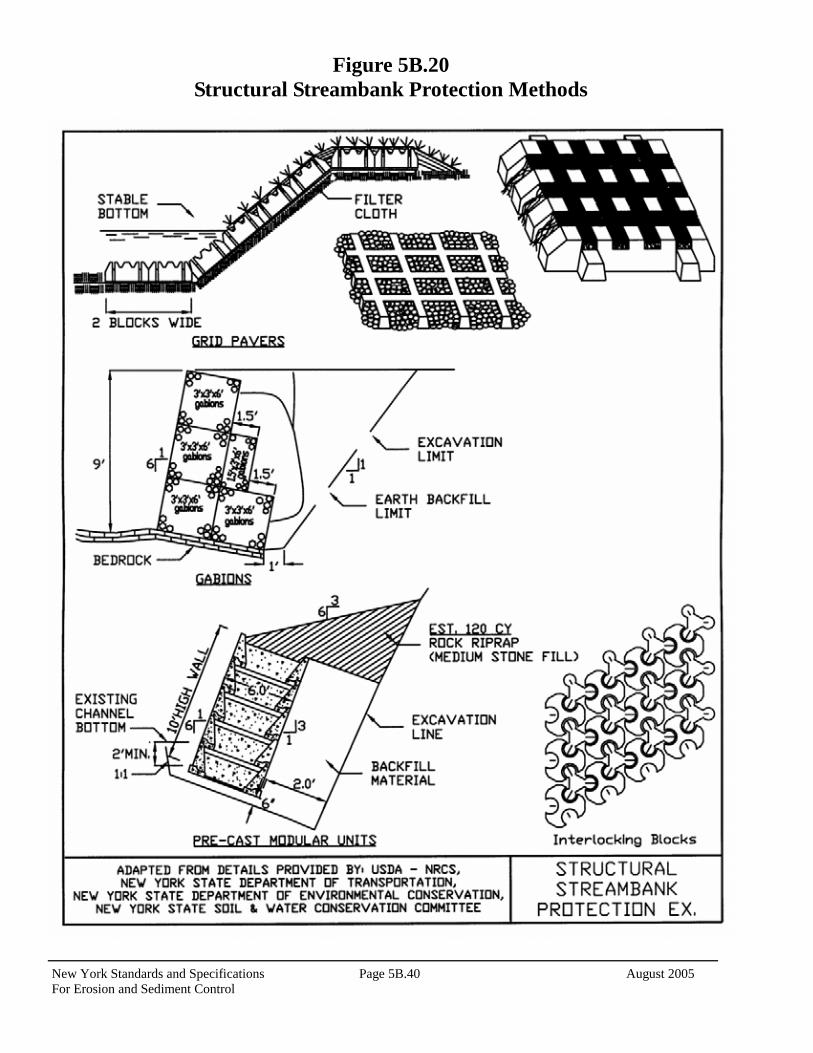
STRUCTURAL STREAMBANK PROTECTION
Definition Stabilization of eroding streambanks by the use of designed structural measures, such as rock riprap, gabions, pre-cast concrete wall units and grid pavers. Purpose To protect exposed or eroded streambanks from the erosive forces of flowing water. Condition Where Practice Applies Generally applicable where flow velocities exceed 6 feet per second or where vegetative streambank protection is inappropriate. Necessary where excessive flows have created an erosive condition on a streambank. Design Criteria • Since each channel is unique, measures for structural
streambank should be installed according to a design based on specific site conditions.
• Develop designs according to the following principles: • Make protective measures compatible with other channel
modifications planned or being carried out in the channel reaches.
• Use the design velocity of the peak discharge of the 10-
year storm or bankfull discharge, whichever is less. Structural measures should be capable of withstanding greater flows without serious damage.
• Ensure that the channel bottom is stable or stabilized by
structural means before installing any permanent bank protection.
• Streambank protection should begin at a stable location and end at a stable point along the bank.
• Changes in alignment should not be done without a
complete analysis of effects on the rest of the stream system for both environmental and stability effects.
• Provisions should be made to maintain and improve fish
and wildlife habitat. For example, restoring lost vegetation will provide valuable shade, food, and/or cover.
• Ensure that all requirements of state law and all permit
requirements of local, state, and federal agencies are met. Construction Specifications
Riprap – Riprap is the most commonly used material to structurally stabilize a streambank. While riprap will provide the structural stabilization necessary, the bank can be enhanced with vegetative material to slow the velocity of water, filter debris, and enhance habitat. See Biotechnical Measures for Erosion and Sediment Control, Section 4, for more information.
1. Bank slope – slopes shall be graded to 2:1 or flatter prior to placing bedding, filter fabric, or riprap.
2. Filter – filters should be placed between the base bank material and the riprap and meet the requirements of criteria listed in the Standards and Specifications for Riprap Slope Protection, page 5B.57.
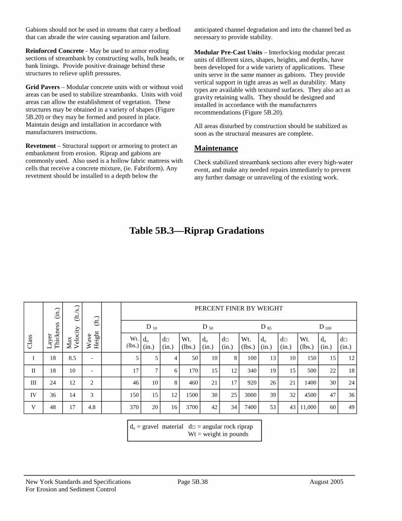
3. Gradation – The gradation of the riprap is dependent on the velocity expected against the bank for the design conditions. See Table 5B.3 on page 5B.38. Once the velocity is known, gradation can be selected from the gradations below. The riprap should extend 2 feet below the channel bottom and be keyed into the bank both at the upstream end and downstream end of the proposed work or reach.
See Figure 5B.19 on page 5B.39 for details. Gabions – Design and install gabions according to manufacturers recommendations. Since these are rectangular, rock-filled wire baskets, they are somewhat flexible in armoring channel bottoms and banks. They can withstand significantly higher velocities for the size stone they contain due to the basket structure. They also stack vertically to act as a retaining wall for constrained areas. (Figure 5B.20).
New York Standards and Specifications Page 5B.38 August 2005 For Erosion and Sediment Control
Gabions should not be used in streams that carry a bedload that can abrade the wire causing separation and failure. Reinforced Concrete - May be used to armor eroding sections of streambank by constructing walls, bulk heads, or bank linings. Provide positive drainage behind these structures to relieve uplift pressures. Grid Pavers – Modular concrete units with or without void areas can be used to stabilize streambanks. Units with void areas can allow the establishment of vegetation. These structures may be obtained in a variety of shapes (Figure 5B.20) or they may be formed and poured in place. Maintain design and installation in accordance with manufacturers instructions. Revetment – Structural support or armoring to protect an embankment from erosion. Riprap and gabions are commonly used. Also used is a hollow fabric mattress with cells that receive a concrete mixture, (ie. Fabriform). Any revetment should be installed to a depth below the
anticipated channel degradation and into the channel bed as necessary to provide stability. Modular Pre-Cast Units – Interlocking modular precast units of different sizes, shapes, heights, and depths, have been developed for a wide variety of applications. These units serve in the same manner as gabions. They provide vertical support in tight areas as well as durability. Many types are available with textured surfaces. They also act as gravity retaining walls. They should be designed and installed in accordance with the manufacturers recommendations (Figure 5B.20). All areas disturbed by construction should be stabilized as soon as the structural measures are complete.
Maintenance Check stabilized streambank sections after every high-water event, and make any needed repairs immediately to prevent any further damage or unraveling of the existing work.
Table 5B.3—Riprap Gradations
Cla
ss
Laye
r Th
ickn
ess
(in.)
Max
V
eloc
ity
(ft./
s.)
Wav
e H
eigh
t (f
t.)
PERCENT FINER BY WEIGHT
Wt. (lbs.)
do (in.)
d□ (in.)
Wt. (lbs.)
do (in.)
d□ (in.)
Wt. (lbs.)
do (in.)
d□ (in.)
Wt. (lbs.)
do (in.)
d□ (in.)
I 18 8.5 - 5 5 4 50 10 8 100 13 10 150 15 12
II 18 10 - 17 7 6 170 15 12 340 19 15 500 22 18
III 24 12 2 46 10 8 460 21 17 920 26 21 1400 30 24
IV 36 14 3 150 15 12 1500 30 25 3000 39 32 4500 47 36
V 48 17 4.8 370 20 16 3700 42 34 7400 53 43 11,000 60 49
D 10 D 50 D 85 D 100
do = gravel material d□ = angular rock riprap Wt = weight in pounds

August 2005 Page 5B.39 New York Standards and Specifications For Erosion and Sediment Control
Figure 5B.19 Riprap Streambank Protection
New York Standards and Specifications Page 5B.40 August 2005 For Erosion and Sediment Control
Figure 5B.20 Structural Streambank Protection Methods

August 2005 Page 5B.41 New York Standards and Specifications For Erosion and Sediment Control
STANDARD AND SPECIFICATIONS FOR
DEBRIS BASIN
Definition A barrier or dam constructed across a waterway or at other suitable locations to form a basin for catching and storing sediment and other waterborne debris. Scope This standard covers the installation of debris basins on sites where: (1) failure of the structure would not result in loss of life or interruption of use or service of public utilities; (2) the drainage area does not exceed 200 acres; and (3) the water surface area at the crest of the auxiliary spillway does not exceed 5 acres. For this purpose of this standard, debris basins are classified according to the following table:
1 Height is measured from the low point of original ground at the downstream toe to the top of dam. 2 Class 1 basins are to be used only where site conditions are such that it is impractical to construct an auxiliary spillway in undisturbed ground.
Purpose To provide a permanent or temporary means of trapping and storing sediment from eroding areas in order to protect properties or stream channels below the installation from damage by excessive sedimentation and debris. Conditions Where Practice Applies Where physical conditions or land ownership preclude the treatment of the sediment source by the installation of erosion control measures to reduce runoff and erosion. It may also be used as a permanent or temporary measure during grading and development of areas above. If a debris basin is used as a temporary structure, it may be removed once the development is complete and the area is permanently protected against erosion by vegetative or mechanical means. Design Criteria The capacity of the debris basin to the elevation of the crest of the service spillway is to equal the volume of the expected sediment yield from the unprotected portions of the drainage area during the planned useful life of the structure. The minimum volume of sediment in acre feet per year can be determined for various drainage areas under construction from curves on Figure 5B.21 on page 5B.44. NOTE: All Debris Basins will be designed and constructed in accordance with the New York State Department of Environmental Conservation Dam Safety Section, “Guidelines for Design of Dams,” and all applicable permits must be obtained. Spillway Design Runoff will be computed by the USDA-NRCS, TR-55, or other appropriate method. Runoff computations should be based upon the soil cover conditions expected to prevail during the construction period of the development.
For Class 2 basins, the combined capacities of the service and auxiliary spillways will be sufficient to pass the peak rate of runoff from a 50-year frequency storm after adjusting for flood routing. For Class 3 basins, the combined capacities of the service and auxiliary spillways will be sufficient to pass the peak rate of runoff from a 100-year frequency storm.
Class
Maximum Drainage Area (Ac)
Maximum Height1
of Dam (ft)
Auxiliary Spillway Required
Design Storm
Frequency
12 20 5 No —
2 20 10 Yes 50 yrs.
3 200 20 Yes 100 yrs.

New York Standards and Specifications Page 5B.42 August 2005 For Erosion and Sediment Control
Pipe Spillway The pipe spillway will consist of a vertical pipe box type riser jointed to a conduit, which will extend through the embankment and outlet beyond the downstream toe of the fill. The minimum diameter of the conduit will be 8 inches. The service spillway system will be perforated to provide for a gradual drawdown after each storm event. The minimum average capacity of the service spillway will be sufficient to discharge 5 inches of runoff from the drainage area in 24 hours (0.21 cfs per acre of drainage area). The riser of the service spillway shall be a cross-sectional area at least 1.3 times that of the barrel.
1. Crest Elevation: The crest elevation of the riser shall be at least 3 feet below the crest elevation of the embankment.
2. Perforated: Metal pipe risers shall be perforated with
1-1/2 inch diameter holes spaced 8 inches vertically and 10-12 inches horizontally around the pipe. Box type risers shall be ported or have some means for complete drainage of the sediment pool within a 5 day period following storm inflows.
3. Anti-vortex device: An anti-vortex device shall be
installed on the top of the riser. 4. Base: The riser shall have a base attached with a
watertight connection. The base shall have sufficient weight to prevent flotation of the riser.
5. Trash rack: An approved trash rack shall be firmly
attached to the top of the riser if the pipe spillway conveys 25 percent or more of the peak rate of runoff from the design storm.
6. Anti-seepage measures: Anti-seep collars, or seepage
diaphragms, shall be installed around the pipe conduit within the normal saturation zone when any of the following conditions exist:
A. The settled height of dam exceeds 15 ft.
B. The conduit is of smooth pipe 8 inches, or larger, in diameter.
C. The conduit is of corrugated metal pipe 12 inches
in diameter, or larger. The anti-seep collars and their connections to the pipe shall be watertight. The maximum spacing shall be approximately 14 times the minimum projection of the collar measured perpendicular to the pipe. In lieu of anti-seep collars, a seepage diaphragm can be used whose projections are three times the diameter of the pipe in all directions.
7. Outlet protection: Protection against scour at the discharge end of the pipe spillway shall be provided. Protective measures may include structures of the impact basin type, rock riprap, paving, revetment, excavation of plunge pool or use of other approved methods.
Auxiliary Spillway
Class 2 and 3 basins: An auxiliary spillway shall be excavated in undisturbed ground whenever site conditions permit. The auxiliary spillway cross section shall be trapezoidal with a minimum bottom width of 8 feet. Class 1 basins: The embankment may be used as an auxiliary spillway. In these cases, the downstream slope of the embankment shall be 5:1 or flatter and the embankment must be immediately protected against erosion by means such as sodding, rock riprap, asphalt coating, or other approved methods.
1. Capacity: The minimum capacity of the auxiliary spillway shall be that required to pass the peak rate of runoff from the design storm, less any reduction due to flow in the pipe spillway.
2. Velocities: The maximum allowable velocity of flow
in the exit channel shall be 6 feet per second for vegetated channels. For channels with erosion protection other than vegetation, velocities shall be in the safe range for the type of protection used.
3. Erosion protection: Provide for erosion protection by
vegetation or by other suitable means such as rock riprap, asphalt, concrete, etc.
4. Freeboard: Freeboard is the difference between the
design flow elevation in the auxiliary spillway and the top of the settled embankment. The minimum freeboard for Class 2 and Class 3 basins shall be 1 foot.
Embankment (Earth Fill) Class 1 basins: The minimum top width shall be 10 feet. The upstream slope shall be no steeper than 3:1. The downstream slope shall be no steeper than 5:1. Class 2 basins: The minimum top width shall be 8 feet. The combined upstream and downstream side slopes shall not be less than 5:1 with neither slope steeper than 2½:1. Class 3 basins: The minimum top width shall be 10 feet. Side slopes shall be no steeper than 3:1. Embankment (other than Earth Fill) Class 1 basins only: The embankment may be constructed

August 2005 Page 5B.43 New York Standards and Specifications For Erosion and Sediment Control
of the following materials:
1. Pressure treated timber crib – rock filled 2. Precast reinforced concrete crib – rock filled 3. Gabions
When the above material is used for the embankment, a principal spillway is not required; however, the dam shall be pervious to allow for drainage during time of low inflow. Basins constructed of the above materials should be used only when the sediment to be trapped is coarse-grained material such as well graded gravel (GW) or poorly graded gravel (GP) material (Unified Soil Classification System). Construction Specifications Site Preparation Areas under the embankment and any structural works shall be cleared, grubbed, and the topsoil stripped to remove trees, vegetation, roots, and other objectionable material. In order to facilitate cleanout and restoration, the pool area will be cleared of all brush and excess trees. Cutoff Trench A cutoff trench shall be excavated along the centerline of dam on earth fill embankments to a depth of at least 1.0 foot into a layer of slowly permeable material. The minimum depth shall be 2 feet. The cutoff trench shall extend up both abutments to the riser crest elevation. The minimum bottom width shall be 4 feet, but wide enough to permit operation of compaction equipment. The side slopes shall be the same as those for embankment. The trench shall be kept free from standing water during the backfilling operations. Embankment The fill material shall be taken from approved designated borrow areas. It shall be free of roots, woody vegetation, oversized stones, rocks, or other objectionable material. Areas on which fill is to be placed shall be scarified prior to placement of fill. The fill material should contain sufficient moisture so that it can be formed into a ball without crumbling. If water can be squeezed out of the ball, it is too wet for proper compaction. Fill material will be placed in 6 to 9 inch layers and shall be continuous over the entire length of the fill. Compaction will be obtained by routing the hauling equipment over the fill so that the entire surface of the fill is traversed by at least one track width of the equipment, or compaction shall be achieved by the use of a compactor. The embankment shall be constructed to an elevation 10 percent higher than the design height to allow for settlement if compaction is obtained with hauling equipment. If compactors are used for compaction, the overbuild may be reduced to 5 percent.
Pipe Spillway The riser shall be solidly attached to the barrel and all connections shall be watertight. The barrel and riser shall be placed on a firm foundation. The fill material around the pipe spillway will be placed in 4-inch layers and compacted to at least the same density as the adjacent embankment. Auxiliary Spillway (Class 2 and 3 basins) The auxiliary spillway shall be installed in undisturbed earth unless otherwise specified in the plan. The lines and grades must conform to those shown on the plans as nearly as skillful operation of the excavating equipment will permit. Embankment (other than Earth Fill) The rock used to fill cribbing or gabions will be hard and durable and of an approved size and gradation. Erosion and Pollution Control Construction operations will be carried out in such a manner that erosion and water pollution will be minimized. State and local laws concerning pollution abatement shall be complied with. Safety State requirements shall be met concerning fencing and signs warning the public of hazards of soft sediment and floodwater. Seeding Seeding, fertilizing, and mulching shall conform to the recommendations in Section 5, Vegetative Measures for Erosion and Sediment Control, of this manual. Final Disposal In the case of temporary structures, when the intended purpose has been accomplished and the drainage area properly stabilized, the embankment and resulting silt deposits are to be leveled, or otherwise disposed of in accordance with the plan.

New York Standards and Specifications Page 5B.44 August 2005 For Erosion and Sediment Control
Figure 5B.21 One-Year Debris Basin Sediment Capacity (USDA - NRCS)
Example: A 10 acre area under con-struction in an area whose RUSLE R value is 100, requires 1.2 acre-feet for basin sediment capacity.
(R v
alue
)

August 2005 Page 5B.45 New York Standards and Specifications For Erosion and Sediment Control
STANDARD AND SPECIFICATIONS FOR
SUBSURFACE DRAIN
Definition A conduit, such as tile, pipe, or tubing, installed beneath the ground surface, which intercepts, collects, and/or conveys drainage water. Purpose A subsurface drain may serve one or more of the following purposes:
1. Improve the environment for vegetative growth by
regulating the water table and groundwater flow.
2. Intercept and prevent water movement into a wet area.
3. Relieve artesian pressures.
4. Remove surface runoff.
5. Provide internal drainage of slopes to improve their
stability and reduce erosion.
6. Provide internal drainage behind bulkheads, retaining
walls, etc.
7. Replace existing subsurface drains that are interrupted
or destroyed by construction operations.
8. Provide subsurface drainage for dry storm water
management structures.
9. Improve dewatering of sediment in sediment basins.
(See Standard and Specification for Sediment Basins
in Section 5A).
Conditions Where Practice Applies
Subsurface drains are used in areas having a high water table or where subsurface drainage is required. The soil shall have enough depth and permeability to permit installation of an effective system. This standard does not apply to storm drainage systems or foundation drains. Regulatory restrictions may apply if wetlands are present. An outlet for the drainage system shall be available, either by gravity flow or by pumping. The outlet shall be adequate for the quantity of water to be discharged without causing damage above or below the point of discharge and shall comply with all state and local laws. Design Criteria The design and installation shall be based on adequate surveys and on-site soils investigations. Required Capacity of Drains The required capacity shall be determined by one or more of the following:
1. Where sub-surface drainage is to be uniform over an
area through a systematic pattern of drains, a drainage coefficient of 1 inch to be removed in 24 hours shall be used; see Drain Chart, Figure 5B.22 on page 5B.48.
2. Where sub-surface drainage is to be by a random
interceptor system, a minimum inflow rate of 0.5 cfs per 1,000 feet of line shall be used to determine the required capacity. If actual field tests and measurements of flow amounts are available, they may be used for determining capacity.
For interceptor subsurface drains on sloping land, increase the inflow rate as follows:
Land Slope Increase Inflow Rate By
2-5 percent 10 percent 5-12 percent 20 percent Over 12 percent 30 percent
3. Additional design capacity must be provided if
surface water is allowed to enter the system.
New York Standards and Specifications Page 5B.46 August 2005 For Erosion and Sediment Control
Size of Subsurface Drain The size of subsurface drains shall be determined from the drain chart found on Figures 5B.22 on page 5B.48. All subsurface drains shall have a nominal diameter, which equals or exceeds four (4) inches. Depth and Spacing The minimum depth of cover of subsurface drains shall be 24 inches where possible. The minimum depth of cover may be reduced to 15 inches where it is not possible to attain the 24 inch depth and where the drain is not subject to equipment loading or frost action. Roots from some types of vegetation can plug drains, as the drains get closer to the surface. The spacing of drain laterals will be dependent on the permeability of the soil, the depth of installation of the drains and degree of drainage required. Generally, drains installed 36 inches deep and spaced 50 feet center-to-center will be adequate. For more specific information, see the New York Drainage Guide (USDA-NRCS). Minimum Velocity and Grade The minimum grade for subsurface drains shall be 0.10 percent. Where surface water enters the system a velocity of not less than 2 feet per second shall be used to establish the minimum grades. Provisions shall be made for preventing debris or sediment from entering the system by means of filters or collection and periodic removal of sediment from installed traps. Materials for Subsurface Drains Acceptable subsurface drain materials include perforated, continuous closed joint conduits of polyethylene plastic, concrete, corrugated metal, asbestos cement, bituminized fiber, polyvinyl chloride, and clay tile. The conduit shall meet strength and durability requirements of the site. Loading The allowable loads on subsurface drain conduits shall be based on the trench and bedding conditions specified for the job. A factor of safety of not less than 1.5 shall be used in computing the maximum allowable depth of cover for a particular type of conduit. Envelopes and Envelope Materials Envelopes shall be used around subsurface drains for proper bedding and to provide better flow into the conduit. Not less than three inches of envelope material shall be used for
sand/gravel envelopes. Where necessary to improve the characteristics of flow of groundwater into the conduit, more envelope material may be required. Where county regulations do not allow sand/gravel envelopes, but require a special type and size of envelope material, they shall be followed. Envelope material shall be placed to the height of the uppermost seepage strata. Behind bulkheads and retaining walls, it shall go to within twelve inches of the top of the structure. This standard does not cover the design of filter materials where needed. Materials used for envelopes shall not contain materials which will cause an accumulation of sediment in the conduit or render the envelope unsuitable for bedding of the conduit. Envelope materials shall consist of either filter cloth or sand/gravel material, which shall pass a 1 ½ inch sieve, 90 to 100 percent shall pass a ¾ inch sieve, and not more than 10 percent shall pass a No. 60 sieve. Filter cloth envelope can be either woven or non-woven monofilatment yarns and shall have a sieve opening ranging from 40 to 80. The envelope shall be placed in such a manner that once the conduit is installed, it shall completely encase the conduit. The conduit shall be placed and bedded in a sand/gravel envelope. A minimum of three inches depth of envelope materials shall be placed on the bottom of a conventional trench. The conduit shall be placed on this and the trench completely filled with envelope material to minimum depth of 3 inches above the conduit. Soft or yielding soils under the drain shall be stabilized where required and lines protected from settlement by adding gravel or other suitable material to the trench, by placing the conduit on plank or other rigid support, or by using long sections of perforated or watertight pipe with adequate strength to ensure satisfactory subsurface drain performance. Use of Heavy Duty Corrugated Plastic Drainage Tubing Heavy duty corrugated drainage tubing shall be specified where rocky or gravelly soils are expected to be encountered during installation operations. The quality of tubing will also be specified when cover over this tubing is expected to exceed 24 inches for 4, 5, 6, or 8 inch tubing. Larger size tubing designs will be handled on an individual job basis. Auxiliary Structure and Subsurface Drain Protection The outlet shall be protected against erosion and undermining of the conduit, against damaging periods of submergence, and against entry of rodents or other animals
August 2005 Page 5B.47 New York Standards and Specifications For Erosion and Sediment Control
into the subsurface drain. An animal guard shall be installed on the outlet end of the pipe. A swinging animal guard shall be used if surface water enters the pipe. A continuous 10-foot section of corrugated metal, cast iron, polyvinyl chloride, or steel pipe without perforations shall be used at the outlet end of the line and shall outlet 1.0 foot above the normal elevation of low flow in the outlet ditch or above mean high tide in tidal areas. No envelope material shall be used around the 10-foot section of pipe. Two-thirds of the pipe shall be buried in the ditch bank and the cantilevered section shall extend to a point above the toe of the ditch side slope. If not possible, the side slope shall be protected from erosion. Conduits under roadways and embankments shall be watertight and designed to exclude debris and prevent sediment from entering the conduit. Lines flowing under pressure shall be designed to withstand the resulting pressures and velocity of flow. Surface waterways shall be used where feasible. The upper end of each subsurface drain line shall be capped with a tight fitting cap of the same material as the conduit or other durable material unless connected to a structure. Construction Specifications
1. Deformed, warped, or otherwise damaged pipe or tubing shall not be used.
2. All subsurface drains shall be laid to a uniform line
and covered with envelope material. The pipe or tubing shall be laid with the perforations down and oriented symmetrically about the vertical centerline. Connections will be made with manufactured functions comparable in strength with the specified pipe or tubing unless otherwise specified. The method of placement and bedding shall be as specified on the drawing.
3. Envelope material shall consist of filter cloth or a
sand/gravel (which shall pass the 1 ½ inch sieve, 90 to 100 percent shall pass ¾ inch sieve, and not more than 10 percent shall pass the No. 60 sieve).
4. The upper end of each subsurface drain line shall be
capped with a tight fittings cap of the same material as the conduit or other durable material unless connected to a structure.
5. A continuous 10-foot section of corrugated metal, cast
iron, polyvinyl chloride, or steel pipe without perforations shall be used at the outlet end of the line. No envelope material shall be used around the 10-foot section of the pipe. An animal guard shall be installed on the outlet end of the pipe.
6. Earth backfill material shall be placed in the trench in
such a manner that displacement of the drain will not occur.
7. Where surface water is entering the system, the pipe
outlet section of the system shall contain a swing type trash and animal guard.

New York Standards and Specifications Page 5B.48 August 2005 For Erosion and Sediment Control
Figure 5B.22 Drain Chart—Corrugated Plastic Drain Tubing (USDA - NRCS)

August 2005 Page 5B.49 New York Standards and Specifications For Erosion and Sediment Control
STANDARD AND SPECIFICATIONS FOR
LANDGRADING
Definition Reshaping of the existing land surface in accordance with a plan as determined by engineering survey and layout. Purpose The purpose of a landgrading specification is to provide for erosion control and vegetative establishment on those areas where the existing land surface is to be reshaped by grading according to plan. Design Criteria The grading plan should be based upon the incorporation of building designs and street layouts that fit and utilize existing topography and desirable natural surrounding to avoid extreme grade modifications. Information submitted must provide sufficient topographic surveys and soil investigations to determine limitations that must be imposed on the grading operation related to slope stability, effect on adjacent properties and drainage patterns, measures for drainage and water removal, and vegetative treatment, etc. Many counties have regulations and design procedures already established for land grading and cut and fill slopes. Where these requirements exist, they shall be followed. The plan must show existing and proposed contours of the area(s) to be graded. The plan shall also include practices for erosion control, slope stabilization, safe disposal of runoff water and drainage, such as waterways, lined ditches, reverse slope benches (include grade and cross section), grade stabilization structures, retaining walls, and surface and subsurface drains. The plan shall also include phasing
of these practices. The following shall be incorporated into the plan:
1. Provisions shall be made to safely conduct surface runoff to storm drains, protected outlets, or to stable water courses to ensure that surface runoff will not damage slopes or other graded areas; see standards and specifications for Grassed Waterway, Diversion, Grade Stabilization Structure.
2. Cut and fill slopes that are to be stabilized with
grasses shall not be steeper than 2:1. When slopes exceed 2:1, special design and stabilization consideration are required and shall be adequately shown on the plans. (Note: Where the slope is to be mowed, the slope should be no steeper than 3:1, although 4:1 is preferred because of safety factors related to mowing steep slopes.)
3. Reverse slope benches or diversion shall be provided
whenever the vertical interval (height) of any 2:1 slope exceeds 20 feet; for 3:1 slope it shall be increased to 30 feet and for 4:1 to 40 feet. Benches shall be located to divide the slope face as equally as possible and shall convey the water to a stable outlet. Soils, seeps, rock outcrops, etc., shall also be taken into consideration when designing benches.
A. Benches shall be a minimum of six feet wide to
provide for ease of maintenance. B. Benches shall be designed with a reverse slope of
6:1 or flatter to the toe of the upper slope and with a minimum of one foot in depth. Bench gradient to the outlet shall be between 2 percent and 3 percent, unless accompanied by appropriate design and computations.
C. The flow length within a bench shall not exceed
800 feet unless accompanied by appropriate design and computations; see Standard and Specifications for Diversion on page 5B.1
4. Surface water shall be diverted from the face of all
cut and/or fill slopes by the use of diversions, ditches and swales or conveyed downslope by the use of a designed structure, except where:
A. The face of the slope is or shall be stabilized and
the face of all graded slopes shall be protected from surface runoff until they are stabilized.

New York Standards and Specifications Page 5B.50 August 2005 For Erosion and Sediment Control
B. The face of the slope shall not be subject to any concentrated flows of surface water such as from natural drainage ways, graded swales, downspouts, etc.
C. The face of the slope will be protected by special
erosion control materials, sod, gravel, riprap, or other stabilization method.
5. Cut slopes occurring in ripable rock shall be serrated
as shown in Figure 5B.23 on page 5B.51. The serrations shall be made with conventional equipment as the excavation is made. Each step or serration shall be constructed on the contour and will have steps cut at nominal two-foot intervals with nominal three-foot horizontal shelves. These steps will vary depending on the slope ratio or the cut slope. The nominal slope line is 1 ½: 1. These steps will weather and act to hold moisture, lime, fertilizer, and seed thus producing a much quicker and longer-lived vegetative cover and better slope stabilization. Overland flow shall be diverted from the top of all serrated cut slopes and carried to a suitable outlet.
6. Subsurface drainage shall be provided where
necessary to intercept seepage that would otherwise adversely affect slope stability or create excessively wet site conditions.
7. Slopes shall not be created so close to property lines
as to endanger adjoining properties without adequately protecting such properties against sedimentation, erosion, slippage, settlement, subsidence, or other related damages.
8. Fill material shall be free of brush, rubbish, rocks,
logs, stumps, building debris, and other objectionable material. It should be free of stones over two (2) inches in diameter where compacted by hand or mechanical tampers or over eight (8) inches in diameter where compacted by rollers or other equipment. Frozen material shall not be placed in the fill nor shall the fill material be placed on a frozen foundation.
9. Stockpiles, borrow areas, and spoil shall be shown on
the plans and shall be subject to the provisions of this Standard and Specifications.
10. All disturbed areas shall be stabilized structurally or
vegetatively in compliance with the Standard and Specifications for Critical Area Treatment in Section 3.
Construction Specifications See Figures 5B.23 and 5B.24 for details.
1. All graded or disturbed areas, including slopes, shall be protected during clearing and construction in accordance with the erosion and sediment control plan until they are adequately stabilized.
2. All erosion and sediment control practices and
measures shall be constructed, applied and maintained in accordance with the sediment control plan and the “New York Standards and Specifications for Erosion and Sediment Control.”
3. Topsoil required for the establishment of vegetation
shall be stockpiled in amount necessary to complete finished grading of all exposed areas.
4. Areas to be filled shall be cleared, grubbed, and
stripped of topsoil to remove trees, vegetation, roots, or other objectionable material.
5. Areas that are to be topsoiled shall be scarified to a
minimum depth of four inches prior to placement of topsoil.
6. All fills shall be compacted as required to reduce
erosion, slippage, settlement, subsidence, or other related problems. Fill intended to support buildings, structures, and conduits, etc., shall be compacted in accordance with local requirements or codes.
7. All fill shall be placed and compacted in layers not to
exceed 9 inches in thickness. 8. Except for approved landfills or nonstructural fills, fill
material shall be free of frozen particles, brush, roots, sod, or other foreign objectionable materials that would interfere with, or prevent, construction of satisfactory fills.
9. Frozen material or soft, mucky or highly compressible
materials shall not be incorporated into fill slopes or structural fills.
10. Fill shall not be placed on saturated or frozen surfaces. 11. All benches shall be kept free of sediment during all
phases of development. 12. Seeps or springs encountered during construction shall
be handled in accordance with the Standard and Specification for Subsurface Drain on page 5B.44 or other approved methods.
13. All graded areas shall be permanently stabilized
immediately following finished grading. 14. Stockpiles, borrow areas, and spoil areas shall be
shown on the plans and shall be subject to the provisions of this Standard and Specifications.

August 2005 Page 5B.51 New York Standards and Specifications For Erosion and Sediment Control
Figure 5B.23 Typical Section of Serrated Cut Slope
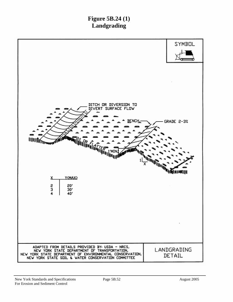
New York Standards and Specifications Page 5B.52 August 2005 For Erosion and Sediment Control
Figure 5B.24 (1) Landgrading

August 2005 Page 5B.53 New York Standards and Specifications For Erosion and Sediment Control
Figure 5B.24 (2) Landgrading —Construction Specifications

New York Standards and Specifications Page 5B.54 August 2005 For Erosion and Sediment Control
This Page Intentionally Left blank

August 2005 Page 5B.55 New York Standards and Specifications For Erosion and Sediment Control
STANDARD AND SPECIFICATIONS FOR
SURFACE ROUGHENING
Definition Roughening a bare soil surface whether through creating horizontal grooves across a slope, stair-stepping, or tracking with construction equipment.
Purpose To aid the establishment of vegetative cover from seed, to reduce runoff velocity and increase infiltration, and to reduce erosion and provide for trapping of sediment. Conditions Where Practice Applies All construction slopes require surface roughening to facilitate stabilization with vegetation, particularly slopes steeper than 3:1. Design Criteria There are many different methods to achieve a roughened soil surface on a slope. No specific design criteria is required. However, the selection of the appropriate method depends on the type of slope. Methods include tracking, grooving, and stair-stepping. Steepness, mowing requirements, and/or a cut or fill slope operation are all factors considered in choosing a roughening method. Construction Specifications A. Cut Slope, No mowing.
1. Stair-step grade or groove cut slopes with a gradient steeper than 3:1 (Figure 5B.25).
2. Use stair-step grading on any erodible material soft
enough to be ripped with a bulldozer. Slopes of soft rock with some soil are particularly suited to stair-step grading.
3. Make the vertical cut distance less than the
horizontal distance, and slightly slope the horizontal position of the “step” to the vertical wall.
4. Do not make vertical cuts more than 2 feet in soft
materials or 3 feet in rocky materials. Grooving uses machinery to create a series of ridges and depressions that run perpendicular to the slope following the contour. Groove using any appropriate implement that can be safely operated on the slope, such as disks, tillers, spring harrows, or the teeth of a front-end loader bucket. Do not make the grooves less than 3 inches deep or more than 15 inches apart. B. Fill Slope, No mowing
1. Place fill to create slopes with a gradient steeper than 3:1 in lifts 9 inches or less and properly compacted. Ensure the face of the slope consists of loose, uncompacted fill 4 to 6 inches deep. Use grooving as described above to roughen the slope, if necessary.
2. Do not blade or scrape the final slope face. C. Cuts/Fills, Mowed Maintenance
1. Make mowed slopes no steeper than 3:1. 2. Roughen these areas to shallow grooves by normal
tilling, disking, harrowing, or use of cultipacker-seeder. Make the final pass of such tillage equipment on the contour.
3. Make grooves at least 1 inch deep and a maximum
of 10 inches apart. 4. Excessive roughness is undesirable where mowing
is planned. Tracking should be used primarily in sandy soils to avoid undue compaction of the soil surface. Tracking is generally not as effective as the other roughening methods described. (It has been used as a method to track down mulch.) Operate tracked machinery up and down the slope to leave horizontal depressions in the soil. Do not back-blade during the final grading operation.

New York Standards and Specifications Page 5B.56 August 2005 For Erosion and Sediment Control
Figure 5B.25 Surface Roughening

August 2005 Page 5B.57 New York Standards and Specifications For Erosion and Sediment Control
STANDARD AND SPECIFICATIONS FOR
RIPRAP SLOPE PROTECTION
Definition A layer of stone designed to protect and stabilize areas subject to erosion. Purpose To protect the soil surface from erosive forces and/or improve the stability of soil slopes that are subject to seepage or have poor soil structure. Conditions Where Practice Applies Riprap is used for cut and fill slopes subject to seepage, erosion, or weathering, particularly where conditions prohibit the establishment of vegetation. Riprap is also used for channel side slopes and bottoms, streambanks, grade sills, on shorelines subject to erosion, and at inlets and outlets to culverts, bridges, slope drains, grade stabilization structures, and storm drains. Design Criteria Gradation – Riprap should be a well-graded mixture with 50% by weight larger than the specified design size. The diameter of the largest stone size in such a mixture should be 1.5 times the d50 size with smaller sizes grading down to 1 inch. The designer should select the size or sizes that equal or exceed that minimum size based on riprap gradations commercially available in the area. Thickness – The minimum layer thickness should be 1.5 times the maximum stone diameter, but in no case less than 6 inches.
Quality – Stone for riprap should be hard, durable field or quarry materials. They should be angular and not subject to breaking down when exposed to water or weathering. The specific gravity should be at least 2.5. Size – The sizes of stones used for riprap protection are determined by purpose and specific site conditions:
1. Slope Stabilization – Riprap stone for slope stabilization not subject to flowing water or wave action should be sized for the proposed grade. The gradient of the slope to be stabilized should be less than the natural angle of repose of the stone selected. Angles of repose of riprap stones may be estimated from Figure 5B.26.
Riprap used for surface stabilization of slopes does not add significant resistance to sliding or slope failure and should not be considered a retaining wall. Slopes approaching 1.5:1 may require special stability analysis. The inherent stability of the soil must be satisfactory before riprap is used for surface stabilization.
2. Outlet Protection – Design criteria for sizing stone
and determining dimensions of riprap aprons are presented in Standards and Specifications for Rock Outlet Protection.
3. Streambank Protection – Design criteria for sizing
stone for stability of channel bank are presented in Standard and Specifications for Structural Streambank Protection.
Filter Blanket – A filter blanket is a layer of material placed between the riprap and the underlying soil to prevent soil movement into or through the riprap. A suitable filter may consist of a well-graded gravel or sand-gravel layer or a synthetic filter fabric manufactured for this purpose. The design of a gravel filter blanket is based on the ratio of particle size in the overlying filter material to that of the base material in accordance with the criteria below. Multiple layers may be designed to affect a proper filter if necessary. A gravel filter blanket should have the following relationship for a stable design: d15 filter ≤ 5 d85 base

New York Standards and Specifications Page 5B.58 August 2005 For Erosion and Sediment Control
d15 filter 5 < d50 base ≤ 40
and d50 filter ≤ 40 d50 base Filter refers to the overlying material while base refers to the underlying material. These relationships must hold between the base and filter and the filter and riprap to prevent migration of material. In some cases, more than one filter may be needed. Each filter layer should be a minimum of 6 inches thick, unless an acceptable filter fabric is used. A synthetic filter fabric may be used with or in place of gravel filters. The following particle size relationships should exist: 1. Filter fabric covering a base containing 50% or less by
weight of fine particles (#200 sieve size):
a. d85 base (mm) EOS*filter fabric (mm) >1 b. total open area of filter fabric should not exceed 36%
2. Filter fabric covering other soils:
a. EOS is no larger than 0.21 mm (#70 sieve size)
b. total open area of filter fabric should not exceed 10%
*EOS – Equivalent opening size compared to a U.S. standard sieve size. No filter fabric should have less than 4% open area or an EOS less than U.S. Standard Sieve #100 (0.15 mm). The permeability of the fabric must be greater than that of the soil. The fabric may be made of woven or nonwoven monofilament yarns and should meet the following minimum requirements: Thickness 20-60 mils grab strength 90-120 lbs. conform to ASTM D-1682 or ASTM D-177 Filter blankets should always be provided where seepage is significant or where flow velocity and duration of flow or turbulence may cause underlying soil particles to move though the riprap. Construction Specifications Subgrade Preparation – Prepare the subgrade for riprap
and filter to the required lines and grades shown on the plans. Compact any fill required in the subgrade to a density approximating that of the undisturbed material or overfill depressions with riprap. Remove brush, trees, stumps, and other objectionable material. Cut the subgrade sufficiently deep so that the finished grade of the riprap will be at the elevation of the surrounding area. Channels should be excavated sufficiently to allow placement of the riprap in a manner such that the finished inside dimensions and grade of the riprap meet design specifications. Sand and gravel filter blanket – Place the filter blanket immediately after the ground foundation is prepared. For gravel, spread filter stone in a uniform layer to the specified depth. Where more than one layer of filter material is used, spread the layers with minimal mixing. Synthetic filter fabric – Place the cloth directly on the prepared foundation. Overlap the edges by at least 2 feet, and space the anchor pins every 3 feet along the overlap. Bury the upper and lower ends of the cloth a minimum of 12 inches below ground. Take precautions not to damage the cloth by dropping the riprap. If damage occurs, remove the riprap and repair the sheet by adding another layer of filter fabric with a minimum overlap of 12 inches around the damaged area. Where large stones are to be placed, a 4-inch layer of fine sand or gravel is recommended to protect the filter cloth. Filter fabric is not recommended as a filter on slopes steeper than 2 horizontal to 1 vertical. Stone placement – Placement of the riprap should follow immediately after placement of the filter. Place riprap so that it forms dense, well-graded mass of stone with a minimum of voids. The desired distribution of stones throughout the mass may be obtained by selective loading at the quarry and controlled dumping during final placement. Place riprap to its full thickness in one operation. Do not place riprap by dumping through chutes or other methods that cause segregation of stone sizes. Be careful not to dislodge the underlying base or filter when placing the stones. The toe of the riprap should be keyed into a stable foundation at its base as shown in Figure 5B.27—Typical Riprap Slope Protection Detail. The toe should be excavated to a depth of 2.0 feet. The design thickness of the riprap should extend a minimum of 3 feet horizontally from the slope. The finished slope should be free of pockets of small stone or clusters of large stones. Hand placing may be necessary to achieve proper distribution of stone sizes to produce a relatively smooth, uniform surface. The finished grade of the riprap should blend with the surrounding area.
Maintenance Riprap should be inspected periodically for scour or dislodged stones. Control weed and brush growth as needed.

August 2005 Page 5B.59 New York Standards and Specifications For Erosion and Sediment Control
Figure 5B.26 Angles of Repose of Riprap Stones (FHWA)
Figure 5B.27 Typical Riprap Slope Protection Detail
6” Gravel filter (or geotextile)
T
3’ min
2’ min

New York Standards and Specifications Page 5B.60 August 2005 For Erosion and Sediment Control
This Page Intentionally Left blank

August 2005 Page 5B.61 New York Standards and Specifications For Erosion and Sediment Control
STANDARD AND SPECIFICATIONS FOR
RETAINING WALLS
Definition A structural wall constructed and located to prevent soil movement. Purpose To retain soil in place and prevent slope failures and movement of material down steep slopes. Conditions Where Practice Applies A retaining wall may be used where site constraints will not allow slope shaping and seeding to stabilize an area. Slope areas that demonstrate seepage problems or experience erosive conditions at the toe can utilize retaining walls to help stabilize these areas. Retaining walls can be built from mortared block or stone, cast-in-place concrete, railroad ties, gabions, and more recently, precast concrete modular units and segmented walls that form a gravity retaining wall (see Figure 5B.28 and 5B.29). These precast units allow for ease and quickness of installation while their granular backfill provides drainage. Selection of materials and type of wall should be based on hazard potential, load conditions, soil parameters, groundwater conditions, site constraints, and aesthetics. Design Criteria The design of any retaining wall structure must address the aspects of foundation bearing capacity, sliding, overturning, drainage and loading systems. These are complex systems and all but the smallest retaining walls should be designed by a licensed engineer.
Bearing Capacity – A minimum factor of safety of 1.5 should be maintained as the ratio of the ultimate bearing capacity to the designed unit loading. Spread footers and other methods may be used to meet factor requirements. Sliding – A minimum factor of 2.0 should be maintained against sliding. This factor can be reduced to 1.5 when passive pressures on the front of the wall are ignored. Overturning – A minimum factor of safety of 1.5 should be used as the ratio of the resisting moment (that which tends to keep the wall in place) to the overturning moment. Drainage – Unless adequate provisions are made to control both surface and groundwater behind the retaining wall, a substantial increase in active pressures tending to slide or overturn the wall will result. When backfill is sloped down to a retaining wall, surface drainage should be provided. Drainage systems with adequate outlets should be provided behind retaining walls that are placed in cohesive soils. Drains should be graded or protected by filters so soil material will not move through the drainfill. Load systems – Several different loads or combination of loads need to be considered when designing a retaining wall. The minimum load is the level backfill that the wall is being constructed to retain. Its unit weight will vary depending on its composition. Additional loads such as line loads, surcharge loads, or slope fills, will add to make the composite design load system for the wall. Construction Specifications Concrete Walls
1. Foundation will be prepared by excavating to the lines and grades shown on the drawings and removing all objectionable material.
2. Subgrade will be compacted and kept moist at least 2
hours prior to placement of concrete. 3. Steel reinforcing will be in accordance with the
schedule on the drawings and kept free of rust, scale, or dirt.
4. Exposed edges will be chamfered ¾ inches. 5. Drainfill will meet the gradations shown on the
drawings.

New York Standards and Specifications Page 5B.62 August 2005 For Erosion and Sediment Control
6. Weep holes will be provided as drain outlets as shown on the drawings.
7. Concrete will be poured and cured in accordance with
American Concrete Institute (ACI) specifications. Precast Units
1. Foundation will be prepared by excavating to the lines and grades shown on the drawings.
2. Subgrade will be compacted and trimmed to receive
the leveling beam. 3. Precast units will be placed in accordance with the
manufacturers recommendation. 4. Granular fill placed in the precast bins shall be placed
in 3-foot lifts, leveled off and compacted with a plate vibrator.
Segmented Walls
1. Foundation will be prepared by excavating to the lines and grades shown on the drawings.
2. Sub-grade will be compacted and screeded to form the
base for the first course of wall units. 3. Units will be placed in accordance with the
manufacturers recommendations, with each succeeding lift anchored and pinned as specified.
4. Granular fill will be placed behind the segmented wall to provide drainage. It shall be compacted with a plate vibrator. A drainage outlet will be provided as specified on the construction drawings.
Gabions
1. Foundation will be prepared by excavating to the lines and grades shown on the drawings.
2. Subgrade will be compacted and leveled to receive
first layer of gabions. The first row will be keyed into the existing grade at the toe, a minimum of 1.5 feet.
3. Gabions will be placed according to the manufacturers
recommendations. 4. Gabions will be filled with stone or crushed rock from
4 to 8 inches in diameter. 5. In corrosive environments, gabion wire should be
coated with Poly Vinyl Chloride (PVC). Maintenance Once in place, a retaining wall should require little maintenance. They should be inspected annually for signs of tipping, clogged drains, or soil subsidence. If such conditions exist, they should be corrected immediately.

August 2005 Page 5B.63 New York Standards and Specifications For Erosion and Sediment Control
Figure 5B.28 Retaining Wall Examples

New York Standards and Specifications Page 5B.64 August 2005 For Erosion and Sediment Control
Figure 5B.29 Segmented Retaining Wall

August 2005 Page 5B.65 New York Standards and Specifications For Erosion and Sediment Control
References 1. Natural Resources Conservation Service, USDA. 1992. Engineering Field Handbook. Washington, DC.
2. New York State Department of Transportation. Standards and Specifications. Albany, NY.
3. North Carolina Sedimentation Control Commission. 1998. Erosion and Sediment Control Planning and Design Manual.
4. Schwab, O., et. al. 1955. Soil and Water Conservation Engineering. Glenn John Wiley & Sons, Inc. New York.
5. Soil Conservation Service, USDA. October 1977. National Handbook of Conservation Practices. Washington, DC.
6. Soil Conservation Service, USDA. September 1987. Drainage Guide for New York State. Syracuse, NY.


![Katalog 2016 Türkçe Web - · PDF fileTechnical Specifications Topology Paralleling Redundancy [ N+1 ] Control Protection Type Standards Efficiency Static-Maintenance Bypass Power](https://img.pdfslide.tips/doc/110x75/5ab5cd357f8b9ab47e8d417d/katalog-2016-trke-web-specifications-topology-paralleling-redundancy-n1-control.jpg)