Embed Size (px)
Citation preview
[1]
NHD‐C0216CZ‐FSW‐FBW‐3V3 COG (Chip‐on‐Glass) Liquid Crystal Display Module
NHD‐ Newhaven Display C0216‐ COG, 2 lines x 16 characters CZ‐ Model F‐ Transflective SW‐ Side White LED Backlight F‐ FSTN (+) B‐ 6:00 View Angle W‐ Wide Temp (‐20 c ~ +70 c) 3V3‐ 3Vdd, 3V Backlight RoHS Compliant
Newhaven Display International, Inc. 2511 Technology Drive, Suite 101 Elgin IL, 60124 Ph: 847‐844‐8795 Fax: 847‐844‐8796
www.newhavendisplay.com [email protected] [email protected]
[2]
Document Revision History Revision Date Description Changed by
0 11/11/2008 Initial Release 1 8/26/2009 User guide reformat BE 2 10/9/2009 Updated Electrical Characteristics MC 3 10/22/2009 Font Table Revision BE 4 10/27/2009 Updated the Block Diagram MC 5 11/19/2009 Updated backlight supply current MC 6 12/18/2009 Pin description updated BE
Functions and Features • 2 lines x 16 characters • Built‐in controller (ST7032 or equivalent) • 5x8 dots with cursor • 4‐line SPI MPU interface • 1/16 duty, 1/5 bias
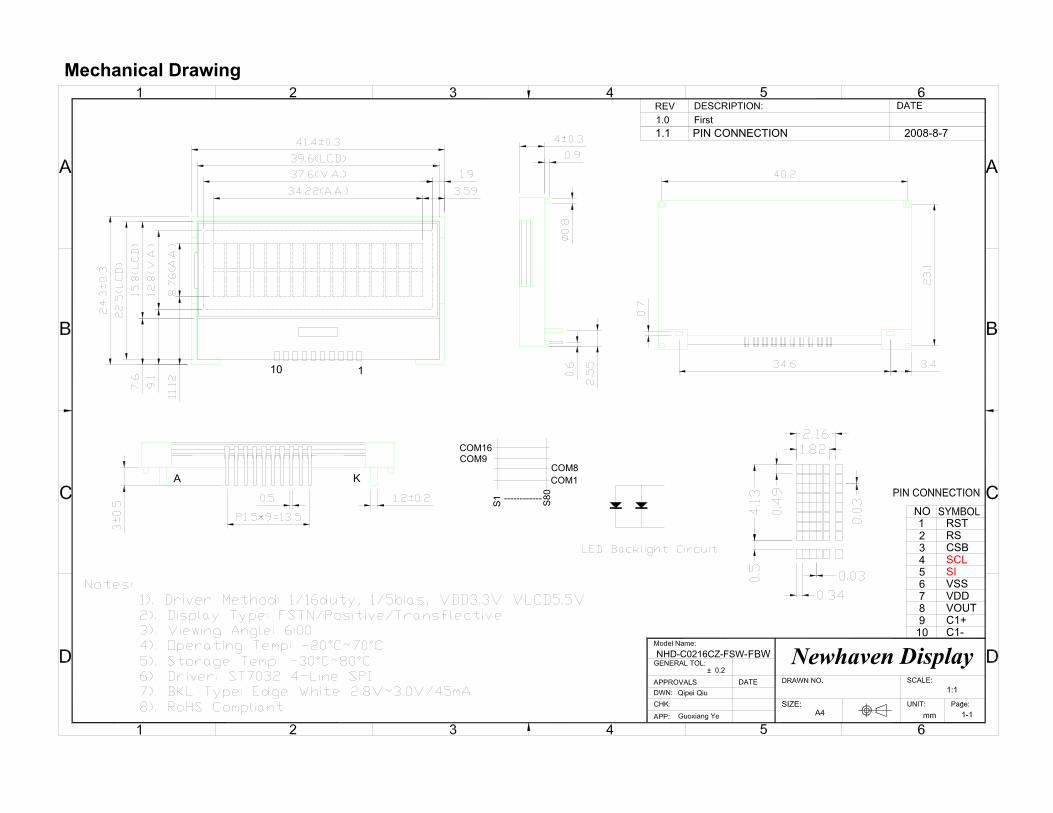
Mechanical Drawing
4
910
6
87
5
RST1
32
NO
110
RSCSBSCLSIVSSVDDVOUTC1+C1-
NHD-C0216CZ-FSW-
A K
------------
COM9COM16
S1 S80
COM8COM1
7-8-8002NOITCENNOC NIP1.1
yalpsiD nevahweNFBW
[4]
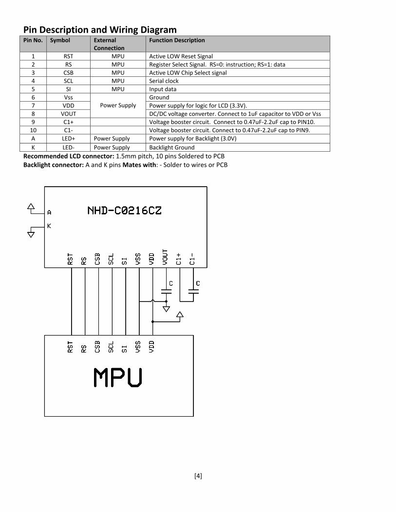
Pin Description and Wiring Diagram Pin No. Symbol External
Connection Function Description
1 RST MPU Active LOW Reset Signal2 RS MPU Register Select Signal. RS=0: instruction; RS=1: data 3 CSB MPU Active LOW Chip Select signal 4 SCL MPU Serial clock5 SI MPU Input data6 Vss
Power Supply
Ground7 VDD Power supply for logic for LCD (3.3V).8 VOUT DC/DC voltage converter. Connect to 1uF capacitor to VDD or Vss9 C1+ Voltage booster circuit. Connect to 0.47uF‐2.2uF cap to PIN10. 10 C1‐ Voltage booster circuit. Connect to 0.47uF‐2.2uF cap to PIN9. A LED+ Power Supply Power supply for Backlight (3.0V)K LED‐ Power Supply Backlight Ground
Recommended LCD connector: 1.5mm pitch, 10 pins Soldered to PCB Backlight connector: A and K pins Mates with: ‐ Solder to wires or PCB
[5]
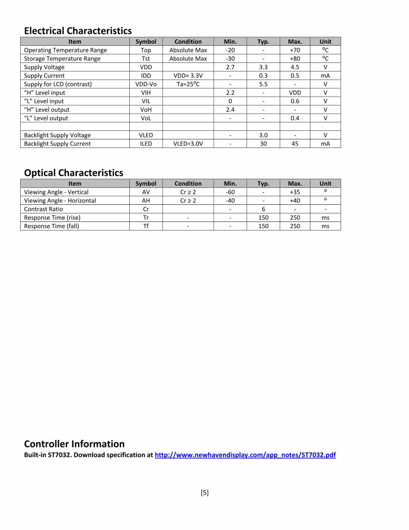
Electrical Characteristics Item Symbol Condition Min. Typ. Max. Unit
Operating Temperature Range Top Absolute Max ‐20 ‐ +70 ⁰C Storage Temperature Range Tst Absolute Max ‐30 ‐ +80 ⁰C Supply Voltage VDD 2.7 3.3 4.5 V Supply Current IDD VDD= 3.3V ‐ 0.3 0.5 mASupply for LCD (contrast) VDD‐Vo Ta=25⁰C ‐ 5.5 ‐ V “H” Level input VIH 2.2 ‐ VDD V “L” Level input VIL 0 ‐ 0.6 V “H” Level output VoH 2.4 ‐ ‐ V “L” Level output VoL ‐ ‐ 0.4 V Backlight Supply Voltage VLED ‐ 3.0 ‐ V Backlight Supply Current ILED VLED=3.0V ‐ 30 45 mA
Optical Characteristics Item Symbol Condition Min. Typ. Max. Unit
Viewing Angle ‐ Vertical AV Cr ≥ 2 ‐60 ‐ +35 ⁰ Viewing Angle ‐ Horizontal AH Cr ≥ 2 ‐40 ‐ +40 ⁰ Contrast Ratio Cr ‐ 6 ‐ ‐ Response Time (rise) Tr ‐ ‐ 150 250 msResponse Time (fall) Tf ‐ ‐ 150 250 ms
Controller Information Built‐in ST7032. Download specification at http://www.newhavendisplay.com/app_notes/ST7032.pdf
[6]
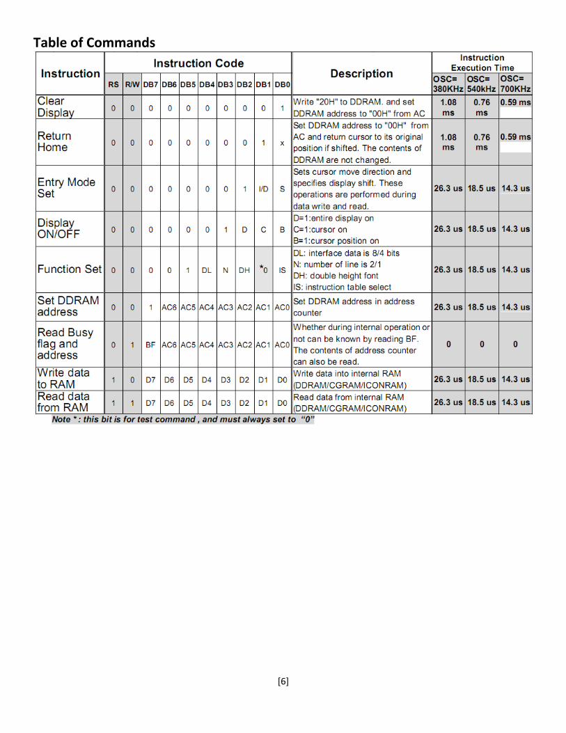
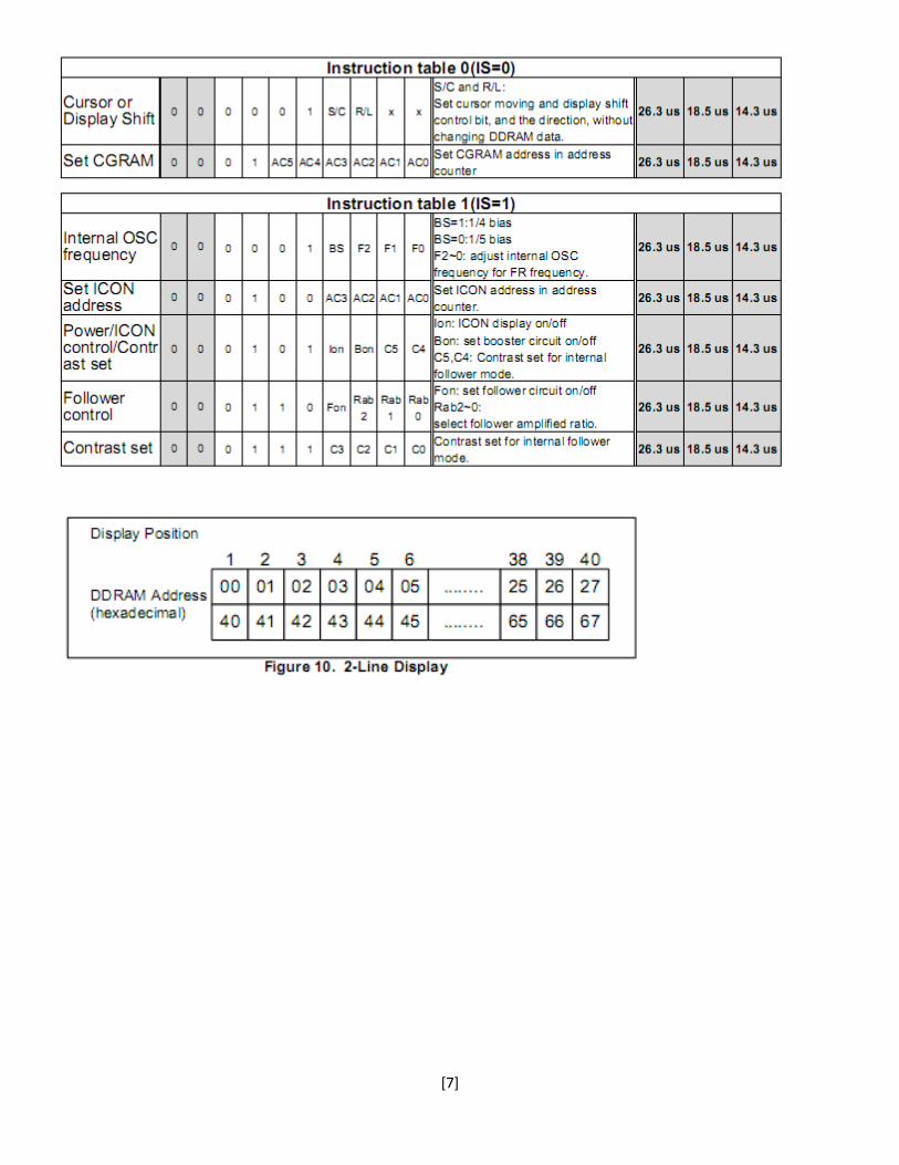
Table of Commands
[7]
[8]
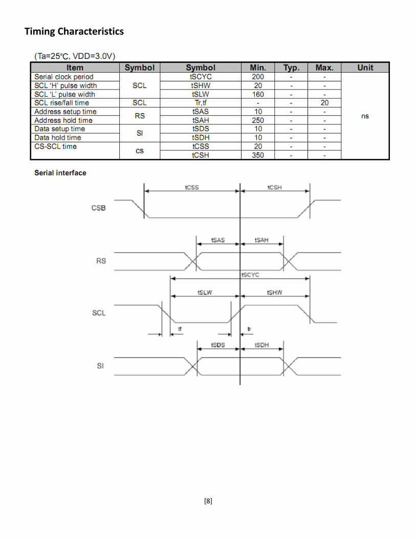
Timing Characteristics
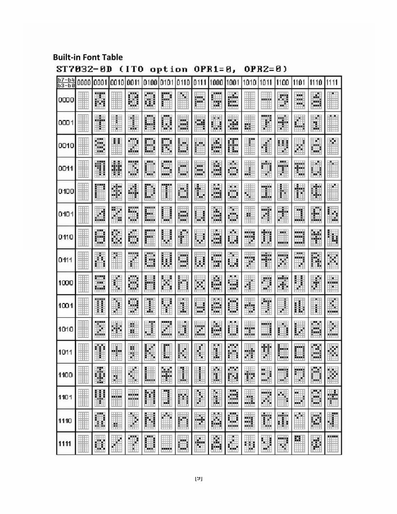
[9]
[10]
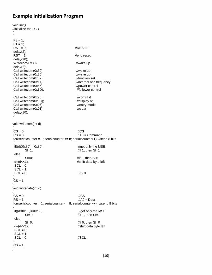
Example Initialization Program void init() //initialize the LCD { P3 = 1; P1 = 1; RST = 0; //RESET delay(2); RST = 1; //end reset delay(20); Writecom(0x30); //wake up delay(2); Call writecom(0x30); //wake up Call writecom(0x30); //wake up Call writecom(0x39); //function set Call writecom(0x14); //internal osc frequency Call writecom(0x56); //power control Call writecom(0x6D); //follower control Call writecom(0x70); //contrast Call writecom(0x0C); //display on Call writecom(0x06); //entry mode Call writecom(0x01); //clear delay(10); } void writecom(int d) { CS = 0; //CS RS = 0; //A0 = Command for(serialcounter = 1; serialcounter <= 8; serialcounter++) //send 8 bits { if((d&0x80)==0x80) //get only the MSB SI=1; //if 1, then SI=1 else SI=0; //if 0, then SI=0 d=(d<<1); //shift data byte left SCL = 0; SCL = 1; SCL = 0; //SCL } CS = 1; } void writedata(int d) { CS = 0; //CS RS = 1; //A0 = Data for(serialcounter = 1; serialcounter <= 8; serialcounter++) //send 8 bits { if((d&0x80)==0x80) //get only the MSB SI=1; //if 1, then SI=1 else SI=0; //if 0, then SI=0 d=(d<<1); //shift data byte left SCL = 0; SCL = 1; SCL = 0; //SCL } CS = 1; }
[11]
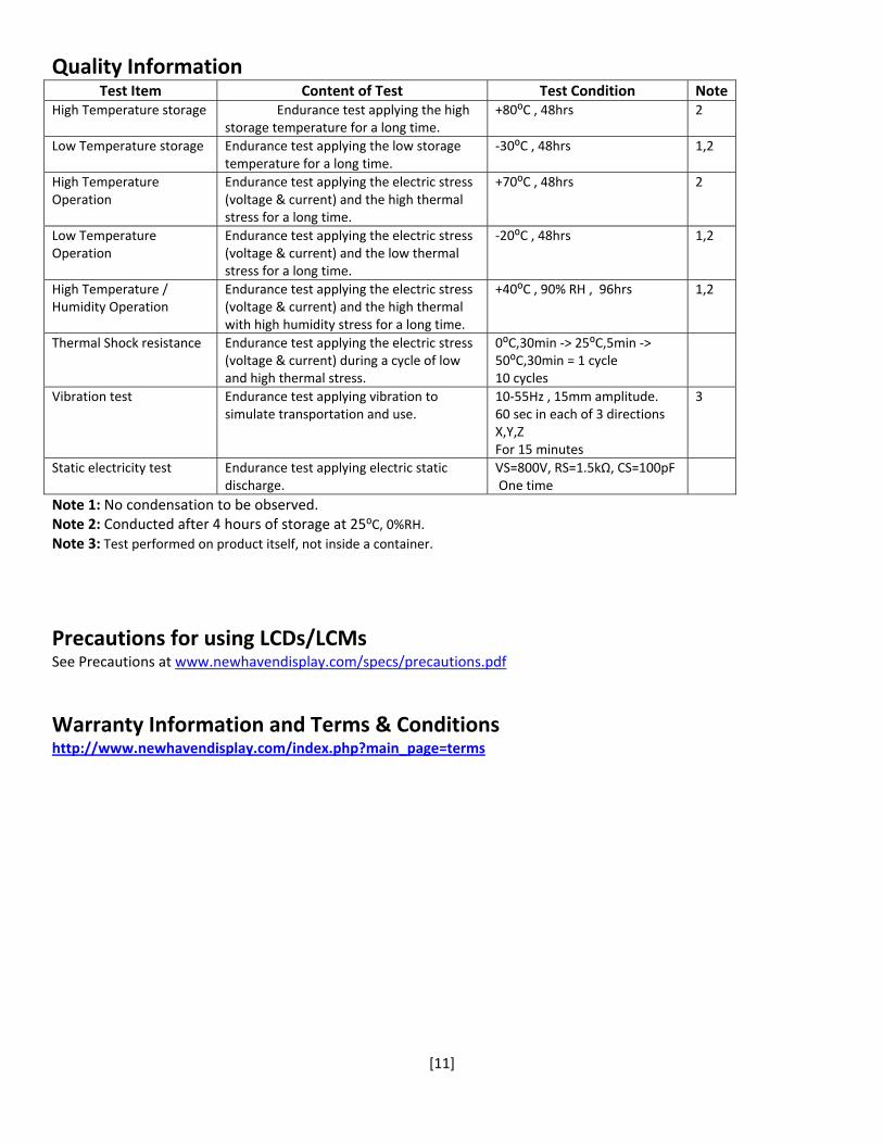
Quality Information Test Item Content of Test Test Condition Note
High Temperature storage Endurance test applying the high storage temperature for a long time.
+80⁰C , 48hrs 2
Low Temperature storage Endurance test applying the low storage temperature for a long time.
‐30⁰C , 48hrs 1,2
High Temperature Operation
Endurance test applying the electric stress (voltage & current) and the high thermal stress for a long time.
+70⁰C , 48hrs 2
Low Temperature Operation
Endurance test applying the electric stress (voltage & current) and the low thermal stress for a long time.
‐20⁰C , 48hrs 1,2
High Temperature / Humidity Operation
Endurance test applying the electric stress (voltage & current) and the high thermal with high humidity stress for a long time.
+40⁰C , 90% RH , 96hrs 1,2
Thermal Shock resistance Endurance test applying the electric stress (voltage & current) during a cycle of low and high thermal stress.
0⁰C,30min ‐> 25⁰C,5min ‐> 50⁰C,30min = 1 cycle 10 cycles
Vibration test Endurance test applying vibration to simulate transportation and use.
10‐55Hz , 15mm amplitude. 60 sec in each of 3 directions X,Y,Z For 15 minutes
3
Static electricity test Endurance test applying electric static discharge.
VS=800V, RS=1.5kΩ, CS=100pF One time
Note 1: No condensation to be observed. Note 2: Conducted after 4 hours of storage at 25⁰C, 0%RH. Note 3: Test performed on product itself, not inside a container.
Precautions for using LCDs/LCMs See Precautions at www.newhavendisplay.com/specs/precautions.pdf
Warranty Information and Terms & Conditions http://www.newhavendisplay.com/index.php?main_page=terms