Embed Size (px)
Citation preview
DATASHEET
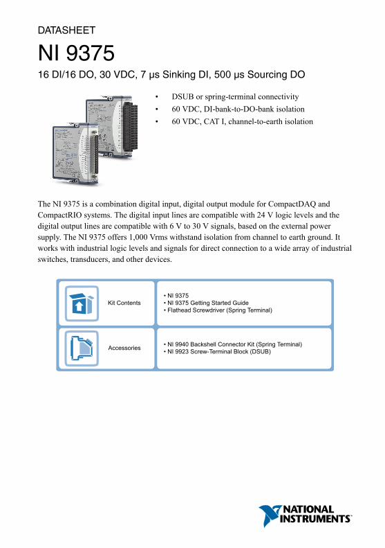
NI 937516 DI/16 DO, 30 VDC, 7 μs Sinking DI, 500 μs Sourcing DO
• DSUB or spring-terminal connectivity• 60 VDC, DI-bank-to-DO-bank isolation• 60 VDC, CAT I, channel-to-earth isolation
The NI 9375 is a combination digital input, digital output module for CompactDAQ andCompactRIO systems. The digital input lines are compatible with 24 V logic levels and thedigital output lines are compatible with 6 V to 30 V signals, based on the external powersupply. The NI 9375 offers 1,000 Vrms withstand isolation from channel to earth ground. Itworks with industrial logic levels and signals for direct connection to a wide array of industrialswitches, transducers, and other devices.
Kit Contents
Accessories
• NI 9375• NI 9375 Getting Started Guide• Flathead Screwdriver (Spring Terminal)
• NI 9940 Backshell Connector Kit (Spring Terminal)• NI 9923 Screw-Terminal Block (DSUB)

ConnectivityUpdate RateDirectionChannelsSignal LevelsProduct Name
Spring-Terminal, DSUBSinking Input,Sourcing Output
8 DI, 8 DO12 V, 24 VNI 9375
Screw-Terminal, Spring-Terminal, DSUB
100 µsSinking Input8 DINI 9421
DSUB7 µsSinking Input32 DINI 9425
Screw-Terminal,Spring-Terminal
100 µsSourcing Output8 DO6 V to 30 VNI 9472
DSUB500 µsSourcing Output32 DO6 V to 30 VNI 9476
C SERIES DIGITAL MODULE COMPARISON
12 V, 24 V
12 V to 24 V
7 µs (DI),500 µs (DO)
NI C Series Overview
NI provides more than 100 C Series modules for measurement, control, and communicationapplications. C Series modules can connect to any sensor or bus and allow for high-accuracymeasurements that meet the demands of advanced data acquisition and control applications.• Measurement-specific signal conditioning that connects to an array of sensors and signals• Isolation options such as bank-to-bank, channel-to-channel, and channel-to-earth ground• -40 °C to 70 °C temperature range to meet a variety of application and environmental
needs• Hot-swappable
The majority of C Series modules are supported in both CompactRIO and CompactDAQplatforms and you can move modules from one platform to the other with no modification.
2 | ni.com | NI 9375 Datasheet

CompactRIO
CompactRIO combines an open-embedded architecturewith small size, extreme ruggedness, and C Seriesmodules in a platform powered by the NI LabVIEWreconfigurable I/O (RIO) architecture. Each systemcontains an FPGA for custom timing, triggering, andprocessing with a wide array of available modular I/O tomeet any embedded application requirement.
CompactDAQ
CompactDAQ is a portable, rugged data acquisition platformthat integrates connectivity, data acquisition, and signalconditioning into modular I/O for directly interfacing to anysensor or signal. Using CompactDAQ with LabVIEW, youcan easily customize how you acquire, analyze, visualize,and manage your measurement data.
Software
LabVIEW Professional Development System for Windows
• Use advanced software tools for large project development• Generate code automatically using DAQ Assistant and Instrument
I/O Assistant• Use advanced measurement analysis and digital signal processing• Take advantage of open connectivity with DLLs, ActiveX,
and .NET objects• Build DLLs, executables, and MSI installers
NI LabVIEW FPGA Module
• Design FPGA applications for NI RIO hardware• Program with the same graphical environment used for desktop and
real-time applications• Execute control algorithms with loop rates up to 300 MHz• Implement custom timing and triggering logic, digital protocols, and
DSP algorithms• Incorporate existing HDL code and third-party IP including Xilinx IP
generator functions• Purchase as part of the LabVIEW Embedded Control and Monitoring
Suite
NI 9375 Datasheet | © National Instruments | 3

NI LabVIEW Real-Time Module
• Design deterministic real-time applications with LabVIEWgraphical programming
• Download to dedicated NI or third-party hardware for reliableexecution and a wide selection of I/O
• Take advantage of built-in PID control, signal processing, andanalysis functions
• Automatically take advantage of multicore CPUs or setprocessor affinity manually
• Take advantage of real-time OS, development and debuggingsupport, and board support
• Purchase individually or as part of a LabVIEW suite
NI 9375 Circuitry
Bank Isolation
DI COM
DI
ReceiverCircuitry
NI 9375
DO COM
Vsup
Device
DO
+
–
+
–
• The bank of 16 digital input channels and the bank of 16 digital output channels on theNI 9375 are isolated from each other and isolated from earth ground.
• The NI 9375 internally limits current signals connected to DI.• The NI 9375 has sinking inputs. Sinking inputs provide a path to COM when the sourcing
device connected to the NI 9375 drives current or applies voltage to DI.• The NI 9375 has sourcing outputs. Sourcing outputs drive current from Vsup to DO when
the channel is on.
Tip For more information about sinking inputs and sourcing outputs, visit ni.com/info and enter the Info Code sinksource.
4 | ni.com | NI 9375 Datasheet

Allowable Current Per ModuleThe NI 9375 has a per module continuous output current specification. Use the followingequation to determine whether the total module current of your loads for channels that areturned on are within the specification.
Figure 1. Total Module Current Equation�DO0 2+ �DO1 2+…+ �DO15 2 = Total Module CurrentFor example, an NI 9375 with spring terminal with two channels at 250 mA, six channels at125 mA, and eight channels at 62 mA has the following per module continuous output current.
Figure 2. Total Module Current Example250mA 2 * 2 + 125mA 2 * 6 + 62mA 2 * 8 = 0.25 A2NI 9375 SpecificationsThe following specifications are typical for the range -40 °C to 70 °C unless otherwise noted.All voltages are relative to COM unless otherwise noted.
Caution Do not operate the NI 9375 in a manner not specified in this document.Product misuse can result in a hazard. You can compromise the safety protectionbuilt into the product if the product is damaged in any way. If the product isdamaged, return it to NI for repair.
Input/Output CharacteristicsNumber of channels 32 channels: 16 digital input and 16 digital
output
Digital InputInput type Sinking
Input voltage range 0 VDC to 30 VDC
Digital logic levels
OFF state
Input voltage ≤5 V
Input current ≤150 μA
NI 9375 Datasheet | © National Instruments | 5

ON state
Input voltage ≥10 V
Input current ≥330 μA
Hysteresis
Input voltage 1.7 V minimum
Input current 50 μA minimum
Input impedance 30 kΩ ±5%
Setup time1 1 μs maximum
Update/transfer time2 7 μs maximum
Digital OutputOutput type Sourcing
Power-on output state Channels off
External power supply voltage range(Vsup)
6 VDC to 30 VDC
Continuous output current (IO)
NI 9375 with spring terminal
All channels on 125 mA maximum (per channel)
One channel on 500 mA maximum
Per module 0.25 A2
NI 9375 with DSUB
All channels on 100 mA maximum (per channel)
One channel on 400 mA maximum
Per module 0.16 A2 maximum
Output impedance (RO) 0.3 Ω maximum
Output voltage (VO) Vsup - (IORO)
Reversed-voltage protection None
Current limiting None
Vsup current consumption 18 mA
1 Setup time is the amount of time input signals must be stable before reading from the module.2 Update/transfer time is the maximum time the software takes to read data from the module. The
update/transfer is valid when the module is used in a CompactRIO system. When used in othersystems, driver software and system latencies impact this time.
6 | ni.com | NI 9375 Datasheet

Update/transfer time3 7 μs maximum
Propagation delay4 500 μs maximum
Related InformationAllowable Current Per Module on page 5
Power RequirementsPower consumption from chassis
Active mode 450 mW maximum
Sleep mode 25 μW maximum
Thermal dissipation (at 70 °C)
Active mode 1.5 W maximum
Sleep mode 0.6 W maximum
Physical CharacteristicsIf you need to clean the module, wipe it with a dry towel.
Tip For two-dimensional drawings and three-dimensional models of the C Seriesmodule and connectors, visit ni.com/dimensions and search by module number.
Spring-terminal wiring
Gauge 0.08 mm2 to 1.0 mm2 (28 AWG to 18 AWG)copper conductor wire
Wire strip length 7 mm (0.28 in.) of insulation stripped from theend
Temperature rating 90 °C minimum
Wires per spring terminal One wire per spring terminal
Connector securement
Securement type Screw flanges provided
Torque for screw flanges 0.2 N · m (1.80 lb · in.)
Weight
NI 9375 with spring terminal 159 g (5.6 oz)
NI 9375 with DSUB 148 g (5.3 oz)
3 Update/transfer time is the maximum time the software takes to write data to the module. Theupdate/transfer is valid when the module is used in a CompactRIO system. When used in othersystems, driver software and system latencies impact this time.
4 Propagation delay is the amount of time it takes the output signals to change state after beingwritten to.
NI 9375 Datasheet | © National Instruments | 7
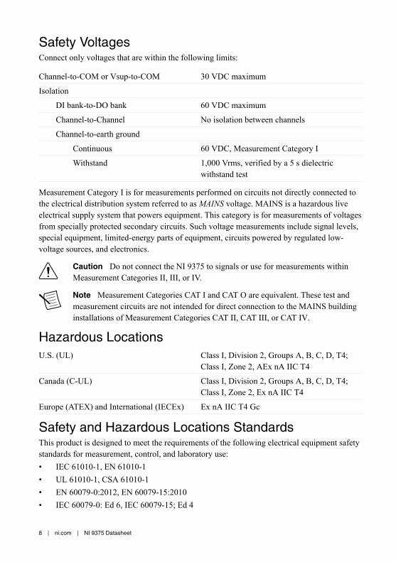
Safety VoltagesConnect only voltages that are within the following limits:
Channel-to-COM or Vsup-to-COM 30 VDC maximum
Isolation
DI bank-to-DO bank 60 VDC maximum
Channel-to-Channel No isolation between channels
Channel-to-earth ground
Continuous 60 VDC, Measurement Category I
Withstand 1,000 Vrms, verified by a 5 s dielectricwithstand test
Measurement Category I is for measurements performed on circuits not directly connected tothe electrical distribution system referred to as MAINS voltage. MAINS is a hazardous liveelectrical supply system that powers equipment. This category is for measurements of voltagesfrom specially protected secondary circuits. Such voltage measurements include signal levels,special equipment, limited-energy parts of equipment, circuits powered by regulated low-voltage sources, and electronics.
Caution Do not connect the NI 9375 to signals or use for measurements withinMeasurement Categories II, III, or IV.
Note Measurement Categories CAT I and CAT O are equivalent. These test andmeasurement circuits are not intended for direct connection to the MAINS buildinginstallations of Measurement Categories CAT II, CAT III, or CAT IV.
Hazardous LocationsU.S. (UL) Class I, Division 2, Groups A, B, C, D, T4;
Class I, Zone 2, AEx nA IIC T4
Canada (C-UL) Class I, Division 2, Groups A, B, C, D, T4;Class I, Zone 2, Ex nA IIC T4
Europe (ATEX) and International (IECEx) Ex nA IIC T4 Gc
Safety and Hazardous Locations StandardsThis product is designed to meet the requirements of the following electrical equipment safetystandards for measurement, control, and laboratory use:• IEC 61010-1, EN 61010-1• UL 61010-1, CSA 61010-1• EN 60079-0:2012, EN 60079-15:2010• IEC 60079-0: Ed 6, IEC 60079-15; Ed 4
8 | ni.com | NI 9375 Datasheet

• UL 60079-0; Ed 5, UL 60079-15; Ed 3• CSA 60079-0:2011, CSA 60079-15:2012
Note For UL and other safety certifications, refer to the product label or the OnlineProduct Certification section.
Electromagnetic CompatibilityThis product meets the requirements of the following EMC standards for electrical equipmentfor measurement, control, and laboratory use:• EN 61326-1 (IEC 61326-1): Class A emissions; Industrial immunity• EN 55011 (CISPR 11): Group 1, Class A emissions• AS/NZS CISPR 11: Group 1, Class A emissions• FCC 47 CFR Part 15B: Class A emissions• ICES-001: Class A emissions
Note For EMC declarations and certifications, refer to the Online ProductCertification section.
CE Compliance This product meets the essential requirements of applicable European Directives, as follows:• 2014/35/EU; Low-Voltage Directive (safety)• 2014/30/EU; Electromagnetic Compatibility Directive (EMC)• 94/9/EC; Potentially Explosive Atmospheres (ATEX)
Online Product CertificationRefer to the product Declaration of Conformity (DoC) for additional regulatory complianceinformation. To obtain product certifications and the DoC for this product, visit ni.com/certification, search by model number or product line, and click the appropriate link in theCertification column.
Shock and VibrationTo meet these specifications, you must panel mount the system.
Operating vibration
Random (IEC 60068-2-64) 5 grms, 10 Hz to 500 Hz
Sinusoidal (IEC 60068-2-6) 5 g, 10 Hz to 500 Hz
Operating shock (IEC 60068-2-27) 30 g, 11 ms half sine; 50 g, 3 ms half sine;18 shocks at 6 orientations
NI 9375 Datasheet | © National Instruments | 9

EnvironmentalRefer to the manual for the chassis you are using for more information about meeting thesespecifications.
Operating temperature(IEC 60068-2-1, IEC 60068-2-2)
-40 °C to 70 °C
Storage temperature(IEC 60068-2-1, IEC 60068-2-2)
-40 °C to 85 °C
Ingress protection IP40
Operating humidity (IEC 60068-2-78) 10% RH to 90% RH, noncondensing
Storage humidity (IEC 60068-2-78) 5% RH to 95% RH, noncondensing
Pollution Degree 2
Maximum altitude 2,000 m
Indoor use only.
Environmental ManagementNI is committed to designing and manufacturing products in an environmentally responsiblemanner. NI recognizes that eliminating certain hazardous substances from our products isbeneficial to the environment and to NI customers.
For additional environmental information, refer to the Minimize Our Environmental Impactweb page at ni.com/environment. This page contains the environmental regulations anddirectives with which NI complies, as well as other environmental information not included inthis document.
Waste Electrical and Electronic Equipment (WEEE)EU Customers At the end of the product life cycle, all NI products must bedisposed of according to local laws and regulations. For more information abouthow to recycle NI products in your region, visit ni.com/environment/weee.
电子信息产品污染控制管理办法(中国 RoHS)中国客户 National Instruments 符合中国电子信息产品中限制使用某些有害物
质指令(RoHS)。关于 National Instruments 中国 RoHS 合规性信息,请登录
ni.com/environment/rohs_china。(For information about China RoHScompliance, go to ni.com/environment/rohs_china.)
10 | ni.com | NI 9375 Datasheet

Refer to the NI Trademarks and Logo Guidelines at ni.com/trademarks for information on NI trademarks. Other product andcompany names mentioned herein are trademarks or trade names of their respective companies. For patents covering NIproducts/technology, refer to the appropriate location: Help»Patents in your software, the patents.txt file on your media, or theNational Instruments Patent Notice at ni.com/patents. You can find information about end-user license agreements (EULAs)and third-party legal notices in the readme file for your NI product. Refer to the Export Compliance Information at ni.com/legal/export-compliance for the NI global trade compliance policy and how to obtain relevant HTS codes, ECCNs, and otherimport/export data. NI MAKES NO EXPRESS OR IMPLIED WARRANTIES AS TO THE ACCURACY OF THE INFORMATIONCONTAINED HEREIN AND SHALL NOT BE LIABLE FOR ANY ERRORS. U.S. Government Customers: The data contained inthis manual was developed at private expense and is subject to the applicable limited rights and restricted data rights as set forthin FAR 52.227-14, DFAR 252.227-7014, and DFAR 252.227-7015.
© 2011—2016 National Instruments. All rights reserved.
374644A-02 Feb16