Embed Size (px)
Citation preview

GETTING STARTED GUIDE
NI 98621-Port, High-Speed CAN Module
Français Deutsch 日本語 한국어 简体中文
ni.com/manuals

This document explains how to connect to the NationalInstruments 9862.
The NI 9862 module requires the latest NI-XNET software to beinstalled. The latest version of the NI-XNET software is at ni.com/downloads.
Note Before you begin, complete the software andhardware installation procedures in your chassisdocumentation.
Note The guidelines in this document are specific tothe NI 9862. The other components in the system mightnot meet the same safety ratings. Refer to thedocumentation for each component in the system todetermine the safety and EMC ratings for the entiresystem.
Safety GuidelinesOperate the NI 9862 only as described in this document.
2 | ni.com | NI 9862 Getting Started Guide
Hot Surface This icon denotes that the componentmay be hot. Touching this component may result inbodily injury.
Caution Do not operate the NI 9862 in a manner notspecified in this document. Product misuse can result ina hazard. You can compromise the safety protectionbuilt into the product if the product is damaged in anyway. If the product is damaged, return it to NationalInstruments for repair.
Safety Guidelines for Hazardous LocationsThe NI 9862 is suitable for use in Class I, Division 2, Groups A,B, C, D, T4 hazardous locations; Class I, Zone 2, AEx nA IIC T4and Ex nA IIC T4 hazardous locations; and nonhazardouslocations only. Follow these guidelines if you are installing theNI 9862 in a potentially explosive environment. Not followingthese guidelines may result in serious injury or death.
Caution Do not disconnect I/O-side wires orconnectors unless power has been switched off or thearea is known to be nonhazardous.
NI 9862 Getting Started Guide | © National Instruments | 3
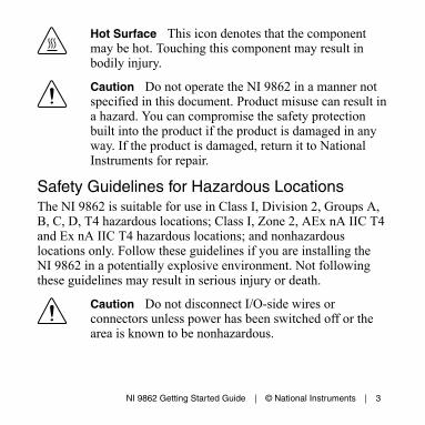
Caution Do not remove modules unless power hasbeen switched off or the area is known to benonhazardous.
Caution Substitution of components may impairsuitability for Class I, Division 2.
Caution For Division 2 and Zone 2 applications,install the system in an enclosure rated to at least IP54as defined by IEC/EN 60079-15.
Caution For Zone 2 applications, install a protectiondevice between the CAN signals and the NI 9862 CANpins. The device must prevent the CAN Port-to-COMvoltage from exceeding 55 V if there is a transientovervoltage condition.
Special Conditions for Hazardous Locations Use inEurope and InternationallyThe NI 9862 has been evaluated as Ex nA IIC T4 Gc equipmentunder DEMKO Certificate No. 07 ATEX 0626664X and isIECEx 14.0089X certified. Each NI 9862 is marked II 3G andis suitable for use in Zone 2 hazardous locations, in ambienttemperatures of -40 °C ≤ Ta ≤ 70 °C. If you are using the NI 9862
4 | ni.com | NI 9862 Getting Started Guide

in Gas Group IIC hazardous locations, you must use the device inan NI chassis that has been evaluated as Ex nC IIC T4, Ex IICT4, Ex nA IIC T4, or Ex nL IIC T4 equipment.
Caution You must make sure that transientdisturbances do not exceed 140% of the rated voltage.
Caution The system shall only be used in an area ofnot more than Pollution Degree 2, as defined inIEC 60664-1.
Caution The system shall be mounted in anATEX/IECEx-certified enclosure with a minimumingress protection rating of at least IP54 as defined inIEC/EN 60079-15.
Caution The enclosure must have a door or coveraccessible only by the use of a tool.
Wiring the NI 9862The NI 9862 has one 9-pin male D-Sub connector that providesconnections to a CAN bus. The NI 9862 has pins for CAN_H and
NI 9862 Getting Started Guide | © National Instruments | 5

CAN_L, to which you connect the CAN bus signals. Connectthese signals using twisted-pair cable.
The port has two common pins (COM) that are internallyconnected to the module’s isolated reference and serve as thereference ground for CAN_H and CAN_L. You can connect theCAN bus reference ground (sometimes referred to as CAN_V-) toone or both COM pins. The port also has an optional shield pin,SHLD, that you can connect to a shielded CAN cable.Connecting SHLD may improve signal integrity and EMCperformance in a noisy environment.
Caution You must use a UL listed ITE power supplymarked LPS with the NI 9862.
The NI 9862 requires an external power supply of +9 to +30 V tooperate. Supply power to the NI 9862 VSUP pin.
Note Power on VSUP is required for CAN operation.
The NI 9862 pinout is listed in Table 1.
The NI 9862 features software-selectable bus termination forHigh-Speed CAN transceivers. On the NI 9862, you can enable
6 | ni.com | NI 9862 Getting Started Guide

120 Ω termination resistors between CAN_H and CAN_Lthrough an API call. Table 3 lists recommended terminationresistor values.
Table 1. Pin Assignments for the NI 9862
Connector Pin Signal
6789
12345
1 No Connection (NC)
2 CAN_L
3 COM
4 NC
5 SHLD
6 COM
7 CAN_H
8 NC
9 VSUP
NI 9862 Getting Started Guide | © National Instruments | 7

CAN Bus Topology and TerminationA CAN bus consists of two or more CAN nodes cabled together.The CAN_H and CAN_L pins of each node are connected to themain CAN bus cable through a short connection known as a“stub.” The pair of signal wires, CAN_H and CAN_L, constitutesa transmission line. If the transmission line is not terminated,each signal change on the bus causes reflections that may causecommunication errors. Because the CAN bus is bidirectional,both ends of the cable must be terminated. However, thisrequirement does not mean that every node on the bus shouldhave a termination resistor; only the two nodes at the far end ofthe cable should have termination resistors.
Figure 1 shows a simplified diagram of a CAN bus with multipleCAN nodes and proper termination resistor (Rt) locations.
8 | ni.com | NI 9862 Getting Started Guide

Figure 1. CAN Bus Topology and Termination Resistor Locations
CANNode
CANNode
CANNode
Rt Rt
CANNode
CAN_H
CAN_L
CAN_H
CAN_L
CA
N_H
CA
N_L
CA
N_H
CA
N_L
Bus Cable Length
StubLength
Connecting a CAN Bus to the NI 9862You can connect the NI 9862 port to any location on a CAN bus.Figure 2 shows one example of connecting the NI 9862 directlyto one CAN node.
NI 9862 Getting Started Guide | © National Instruments | 9
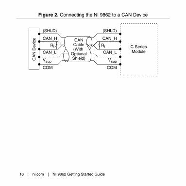
Figure 2. Connecting the NI 9862 to a CAN Device
C SeriesModule
CA
N D
evic
e
Rt
CANCable(With
OptionalShield)
(SHLD)
CAN_H
CAN_L
Vsup
COM
Rt
(SHLD)
CAN_H
CAN_L
Vsup
COM
10 | ni.com | NI 9862 Getting Started Guide

Cabling Requirements for the NI 9862
Cable SpecificationsCables should meet the physical medium requirements specifiedin ISO 11898, shown in Table 2. Belden cable (3084A) meets allthese requirements and should be suitable for most applications.
Table 2. ISO 11898 Specifications for Characteristics of a CAN_H andCAN_L Pair of Wires
Characteristic Value
Impedance 95 Ω min,
120 Ω nominal,
140 Ω max
Length-related resistance 70 mΩ/m nominal
Specific line delay 5 ns/m nominal
NI 9862 Getting Started Guide | © National Instruments | 11
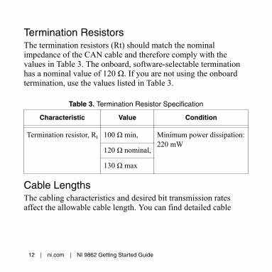
Termination ResistorsThe termination resistors (Rt) should match the nominalimpedance of the CAN cable and therefore comply with thevalues in Table 3. The onboard, software-selectable terminationhas a nominal value of 120 Ω. If you are not using the onboardtermination, use the values listed in Table 3.
Table 3. Termination Resistor Specification
Characteristic Value Condition
Termination resistor, Rt 100 Ω min, Minimum power dissipation:220 mW
120 Ω nominal,
130 Ω max
Cable LengthsThe cabling characteristics and desired bit transmission ratesaffect the allowable cable length. You can find detailed cable
12 | ni.com | NI 9862 Getting Started Guide

length recommendations in the ISO 11898, CiA DS 102, andDeviceNet specifications.
ISO 11898 specifies 40 m total cable length with a maximumstub length of 0.3 m for a bit rate of 1 Mb/s. The ISO 11898specification says that significantly longer cable lengths may beallowed at lower bit rates, but you should analyze each node forsignal integrity problems.
Number of CAN NodesThe maximum number of nodes depends on the electricalcharacteristics of the nodes on the network. If all nodes meet theISO 11898 requirements, you can connect at least 30 nodes to thebus. You can connect higher numbers of nodes if the nodes’electrical characteristics do not degrade signal quality below ISO11898 signal level specifications.
The NI 9862 electrical characteristics allow at least 110 CANports on a network.
NI 9862 Getting Started Guide | © National Instruments | 13

NI 9862 Hardware OverviewThe NI 9862 has one full-featured CAN port that is isolated fromthe other modules in the system. The port has a Bosch DCANCAN controller that is CAN 2.0B-compatible and fully supportsboth 11-bit and 29-bit identifiers. The port also has an NXPTJA1041AT High-Speed CAN transceiver that is fullycompatible with the ISO 11898 standard and supports baud ratesup to 1 Mbps.
Figure 3. NI 9862 Hardware Overview
Ext PwrSupply
Required
RxTx
CANController
CAN_H
CAN_LCAN
Transceiver
RxTx
COM
Vsup+_
14 | ni.com | NI 9862 Getting Started Guide
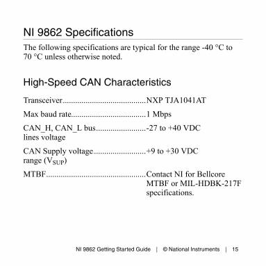
NI 9862 SpecificationsThe following specifications are typical for the range -40 °C to70 °C unless otherwise noted.
High-Speed CAN Characteristics
...........................................................Transceiver NXP TJA1041AT
...........................................................Max baud rate 1 Mbps
...........................................................CAN_H, CAN_L buslines voltage
-27 to +40 VDC
...........................................................CAN Supply voltagerange (VSUP)
+9 to +30 VDC
...........................................................MTBF Contact NI for BellcoreMTBF or MIL-HDBK-217Fspecifications.
NI 9862 Getting Started Guide | © National Instruments | 15
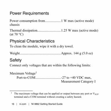
Power Requirements
...........................................................Power consumption fromchassis
1 W max (active mode)
...........................................................Thermal dissipation(at 70 °C)
1.25 W max (active mode)
Physical CharacteristicsTo clean the module, wipe it with a dry towel.
...........................................................Weight Approx. 144 g (5.0 oz)
SafetyConnect only voltages that are within the following limits:
Maximum Voltage1
...................................................Port-to-COM -27 to +40 VDC max,Measurement Category I
1 The maximum voltage that can be applied or output between any port or VSUPterminal and a COM terminal without creating a safety hazard.
16 | ni.com | NI 9862 Getting Started Guide

IsolationPort-to-earth ground
...........................................Continuous 60 VDC,Measurement Category I
...........................................Withstand 1,000 Vrms, verified by a 5 sdielectric withstand test
Measurement Category I is for measurements performed oncircuits not directly connected to the electrical distribution systemreferred to as MAINS voltage. MAINS is a hazardous liveelectrical supply system that powers equipment. This category isfor measurements of voltages from specially protected secondarycircuits. Such voltage measurements include signal levels, specialequipment, limited-energy parts of equipment, circuits poweredby regulated low-voltage sources, and electronics.
Note Do not connect the NI 9862 to signals or use formeasurements within Measurement Categories II, III,or IV.
NI 9862 Getting Started Guide | © National Instruments | 17
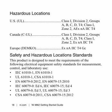
Hazardous Locations
...........................................................U.S. (UL) Class I, Division 2, GroupsA, B, C, D, T4; Class I,Zone 2, AEx nA IIC T4
...........................................................Canada (C-UL) Class I, Division 2, GroupsA, B, C, D, T4; Class I,Zone 2, Ex nA IIC T4
...........................................................Europe (DEMKO) Ex nA IIC T4 Gc
Safety and Hazardous Locations StandardsThis product is designed to meet the requirements of thefollowing electrical equipment safety standards for measurement,control, and laboratory use:• IEC 61010-1, EN 61010-1• UL 61010-1, CSA 61010-1• EN 60079-0:2012, EN 60079-15:2010• IEC 60079-0: Ed 6, IEC 60079-15; Ed 4• UL 60079-0; Ed 5, UL 60079-15; Ed 3• CSA 60079-0:2011, CSA 60079-15:2012
18 | ni.com | NI 9862 Getting Started Guide
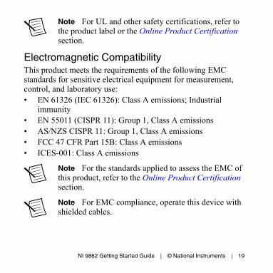
Note For UL and other safety certifications, refer tothe product label or the Online Product Certificationsection.
Electromagnetic CompatibilityThis product meets the requirements of the following EMCstandards for sensitive electrical equipment for measurement,control, and laboratory use:• EN 61326 (IEC 61326): Class A emissions; Industrial
immunity• EN 55011 (CISPR 11): Group 1, Class A emissions• AS/NZS CISPR 11: Group 1, Class A emissions• FCC 47 CFR Part 15B: Class A emissions• ICES-001: Class A emissions
Note For the standards applied to assess the EMC ofthis product, refer to the Online Product Certificationsection.
Note For EMC compliance, operate this device withshielded cables.
NI 9862 Getting Started Guide | © National Instruments | 19

CE Compliance This product meets the essential requirements of applicableEuropean Directives, as follows:• 2014/35/EU; Low-Voltage Directive (safety)• 2014/30/EU; Electromagnetic Compatibility Directive
(EMC)• 94/9/EC; Potentially Explosive Atmospheres (ATEX)
Online Product CertificationRefer to the product Declaration of Conformity (DoC) foradditional regulatory compliance information. To obtain productcertifications and the DoC for this product, visit ni.com/certification, search by model number or product line, and clickthe appropriate link in the Certification column.
20 | ni.com | NI 9862 Getting Started Guide

Shock and VibrationTo meet these specifications, you must panel mount the system.
Operating vibration...................................................Random (IEC60068-2-64)
5 grms, 10 Hz to 500 Hz
...................................................Sinusoidal (IEC60068-2-6)
5 g, 10 Hz to 500 Hz
...........................................................Operating shock (IEC60068-2-27)
30 g, 11 ms half sine; 50 g,3 ms half sine;18 shocks at 6 orientations
NI 9862 Getting Started Guide | © National Instruments | 21

EnvironmentalRefer to the manual for the chassis you are using for moreinformation about meeting these specifications.
...........................................................Operating temperature(IEC 60068-2-1,IEC 60068-2-2)
-40 °C to 70 °C
...........................................................Storage temperature(IEC 60068-2-1,IEC 60068-2-2)
-40 °C to 85 °C
...........................................................Ingress protection IP40
...........................................................Operating humidity(IEC 60068-2-78)
10% RH to 90% RH,noncondensing
...........................................................Storage humidity(IEC 60068-2-78)
5% RH to 95% RH,noncondensing
...........................................................Pollution Degree 2
...........................................................Maximum altitude 2,000 m
Indoor use only.
22 | ni.com | NI 9862 Getting Started Guide
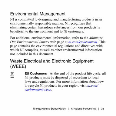
Environmental ManagementNI is committed to designing and manufacturing products in anenvironmentally responsible manner. NI recognizes thateliminating certain hazardous substances from our products isbeneficial to the environment and to NI customers.
For additional environmental information, refer to the MinimizeOur Environmental Impact web page at ni.com/environment. Thispage contains the environmental regulations and directives withwhich NI complies, as well as other environmental informationnot included in this document.
Waste Electrical and Electronic Equipment(WEEE)
EU Customers At the end of the product life cycle, allNI products must be disposed of according to locallaws and regulations. For more information about howto recycle NI products in your region, visit ni.com/environment/weee.
NI 9862 Getting Started Guide | © National Instruments | 23
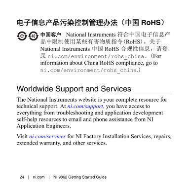
电子信息产品污染控制管理办法(中国 RoHS)
中国客户 National Instruments 符合中国电子信息产品中限制使用某些有害物质指令(RoHS)。关于National Instruments 中国 RoHS 合规性信息,请登录 ni.com/environment/rohs_china。(Forinformation about China RoHS compliance, go toni.com/environment/rohs_china.)
Worldwide Support and ServicesThe National Instruments website is your complete resource fortechnical support. At ni.com/support, you have access toeverything from troubleshooting and application developmentself-help resources to email and phone assistance from NIApplication Engineers.
Visit ni.com/services for NI Factory Installation Services, repairs,extended warranty, and other services.
24 | ni.com | NI 9862 Getting Started Guide

Visit ni.com/register to register your National Instrumentsproduct. Product registration facilitates technical support andensures that you receive important information updates from NI.
A Declaration of Conformity (DoC) is our claim of compliancewith the Council of the European Communities using themanufacturer’s declaration of conformity. This system affords theuser protection for electromagnetic compatibility (EMC) andproduct safety. You can obtain the DoC for your product byvisiting ni.com/certification. If your product supports calibration,you can obtain the calibration certificate for your product at ni.com/calibration.
National Instruments corporate headquarters is located at11500 North Mopac Expressway, Austin, Texas, 78759-3504.National Instruments also has offices located around the world.For telephone support in the United States, create your servicerequest at ni.com/support or dial 1 866 ASK MYNI (275 6964).For telephone support outside the United States, visit theWorldwide Offices section of ni.com/niglobal to access the branchoffice websites, which provide up-to-date contact information,support phone numbers, email addresses, and current events.
NI 9862 Getting Started Guide | © National Instruments | 25

Refer to the NI Trademarks and Logo Guidelines at ni.com/trademarks for information onNational Instruments trademarks. Other product and company names mentioned herein aretrademarks or trade names of their respective companies. For patents covering NationalInstruments products/technology, refer to the appropriate location: Help»Patents in your software,the patents.txt file on your media, or the National Instruments Patent Notice at ni.com/patents. You can find information about end-user license agreements (EULAs) and third-partylegal notices in the readme file for your NI product. Refer to the Export Compliance Information atni.com/legal/export-compliance for the National Instruments global trade compliance policyand how to obtain relevant HTS codes, ECCNs, and other import/export data. NI MAKES NOEXPRESS OR IMPLIED WARRANTIES AS TO THE ACCURACY OF THE INFORMATIONCONTAINED HEREIN AND SHALL NOT BE LIABLE FOR ANY ERRORS. U.S. GovernmentCustomers: The data contained in this manual was developed at private expense and is subject tothe applicable limited rights and restricted data rights as set forth in FAR 52.227-14, DFAR252.227-7014, and DFAR 252.227-7015.
© 2010—2015 National Instruments. All rights reserved.
373243E-01 Mar15