Embed Size (px)
Citation preview
ECTI2010
New Approaches To An Indium Ion Optical New Approaches To An Indium Ion Optical Frequency StandardFrequency Standard
Kazuhiro HAYASAKAKazuhiro HAYASAKA
National Institute of Information and Communications National Institute of Information and Communications Technology(NICT)Technology(NICT)
ee--mail:[email protected]:[email protected]
1
ECTI2010
OutlineOutline1. Introduction
2. New approaches
3. Status of the project(0)In+-Ca+ chain synthesis(1)quantum logic spectroscopy(2)VUV excitation(3)1S0-3P1 excitation
4.Summary
2
ECTI2010
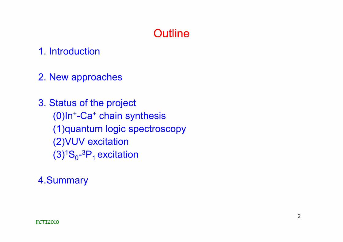
Motivation: smaller frequency uncertaintyMotivation: smaller frequency uncertainty40Ca+ optical clock at NICT
3
1st system: no magnetic shield
2nd system: with magnetic shield
However, fractional uncertainty is limited to in the order of 10-15
due to quadrupole shift, black body radiation(BBR) shift
need of IIIA ions (B+, Al+, Ga+, In+, Th+) for smaller fractional uncertainty
2P1/2
2S1/2
729nm
866nm
2D3/2
2D5/2397nm
40Ca+
(411THz)411 042 129 776 393.2 (1.0) HzInnsbruck, PRL.102, 023002 (2009)
411 042 129 776 390 (7) Hz(2×10-14)
Appl. Phys. Expr. 1,067011(2008)
clock pulse duration 4ms
clock pulse duration 20ms
ECTI2010
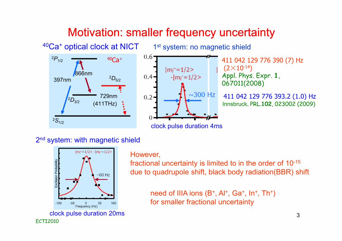
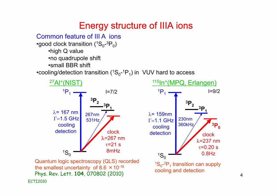
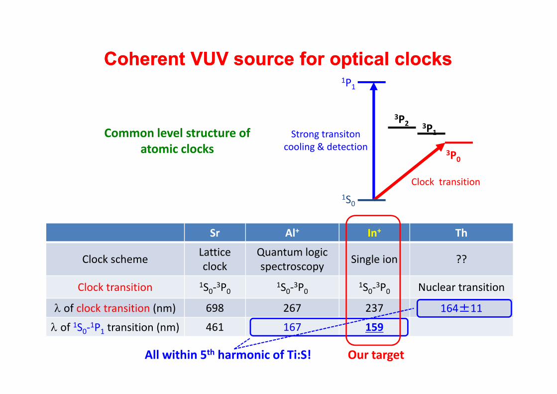
Energy structure of IIIA ionsEnergy structure of IIIA ionsCommon feature of III A ions•good clock transition (1S0-3P0)
•high Q value•no quadrupole shift•small BBR shift
•cooling/detection transition (1S0-1P1) in VUV hard to access
4
Quantum logic spectroscopy (QLS) recorded the smallest uncertainty of 8.6 ×10⁻¹⁸
Phys. Rev. Lett. 104, 070802 (2010)
1S0-3P1 transition can supplycooling and detection
27Al+(NIST)
1S0
l= 167 nm G=1.5 GHz
coolingdetection
1P1
clockl=267 nmt=21 s8mHz
3P1
3P2
115In+(MPQ, Erlangen)
1S0
l= 159nm G=1.1 GHz
coolingdetection
1P1
3P0
clockl=237 nmt=0.20 s
0.8Hz
3P1
3P2
230nm 360kHz
267nm 531Hz
I=7/2 I=9/2
ECTI2010
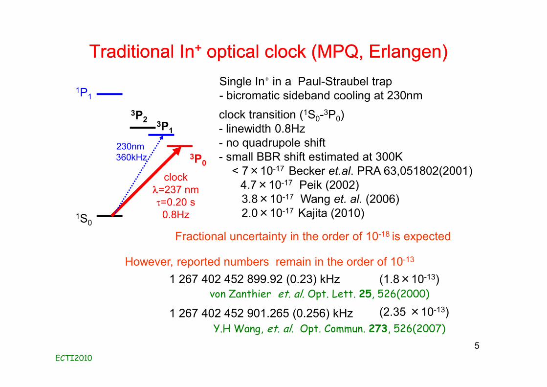
Traditional InTraditional In++ optical clock (MPQ, Erlangen)optical clock (MPQ, Erlangen)
5
3P0
1S0
1P1
clockl=237 nmt=0.20 s
0.8Hz
3P1
3P2
230nm 360kHz
1 267 402 452 901.265 (0.256) kHz (2.35 ×10⁻¹³)Y.H Wang, et. al. Opt. Commun. 273, 526(2007)
1 267 402 452 899.92 (0.23) kHzvon Zanthier et. al. Opt. Lett. 25, 526(2000)
(1.8×10⁻¹³)
Single In+ in a Paul-Straubel trap- bicromatic sideband cooling at 230nmclock transition (1S0-3P0)- linewidth 0.8Hz- no quadrupole shift- small BBR shift estimated at 300K
< 7×10-17 Becker et.al. PRA 63,051802(2001)4.7×10⁻¹⁷ Peik (2002)3.8×10⁻¹⁷ Wang et. al. (2006)2.0×10⁻¹⁷ Kajita (2010)
However, reported numbers remain in the order of 10-13
Fractional uncertainty in the order of 10-18 is expected
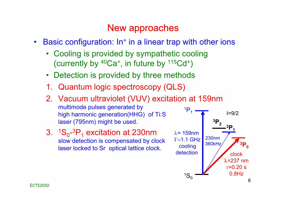
New approachesNew approaches• Basic configuration: In+ in a linear trap with other ions
• Cooling is provided by sympathetic cooling(currently by 40Ca+, in future by 115Cd+)
• Detection is provided by three methods1. Quantum logic spectroscopy (QLS)2. Vacuum ultraviolet (VUV) excitation at 159nm
multimode pulses generated byhigh harmonic generation(HHG) of Ti:Slaser (795nm) might be used.
3. 1S0-3P1 excitation at 230nm slow detection is compensated by clocklaser locked to Sr optical lattice clock.
ECTI20106
1S0
l= 159nm G=1.1 GHz
coolingdetection
1P1
3P0
clockl=237 nmt=0.20 s
0.8Hz
3P1
3P2
230nm 360kHz
I=9/2
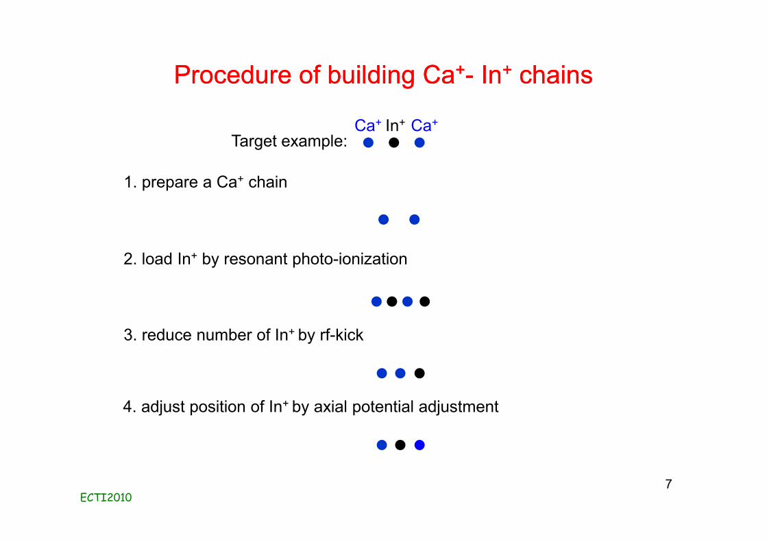
Procedure of building CaProcedure of building Ca++-- InIn++ chainschains
ECTI2010
1. prepare a Ca+ chain
2. load In+ by resonant photo-ionization
3. reduce number of In+ by rf-kick
4. adjust position of In+ by axial potential adjustment
Target example:Ca+ Ca+In+
7
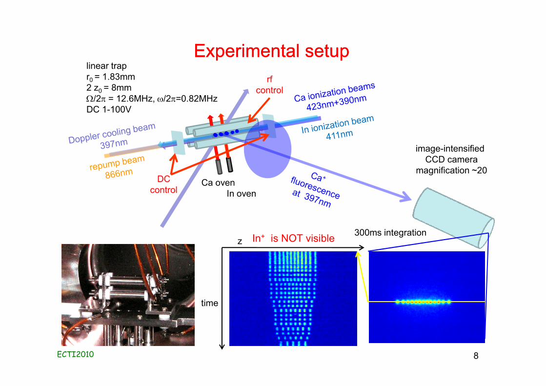
Experimental setupExperimental setuplinear trapr0 = 1.83mm2 z0 = 8mmW/2p = 12.6MHz, w/2p=0.82MHzDC 1-100V
In oven
image-intensified CCD camera
magnification ~20
time
300ms integrationz
Ca oven
In+ is NOT visible
rfcontrol
DCcontrol
ECTI2010 8
ECTI 2010
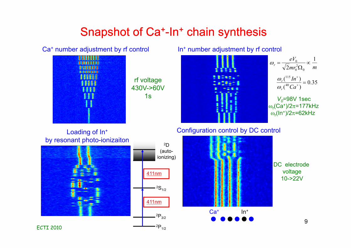
Snapshot of CaSnapshot of Ca++--InIn++ chain synthesischain synthesis
9Ca+ In+
Ca+ number adjustment by rf control
Loading of In+
by resonant photo-ionizaiton
In+ number adjustment by rf control
Configuration control by DC control
rf voltage430V->60V
1s
mmreV
r1
2 020
0 µW
=w
35.0)()(
40
115
=+
+
CaIn
r
r
ww
V0=98V 1secwr(Ca+)/2p=177kHzwr(In+)/2p=62kHz
DC electrodevoltage
10->22V
2P1/2
2P3/2
2S1/2
411nm
2D(auto-
ionizing)
411nm
ECTI 2010
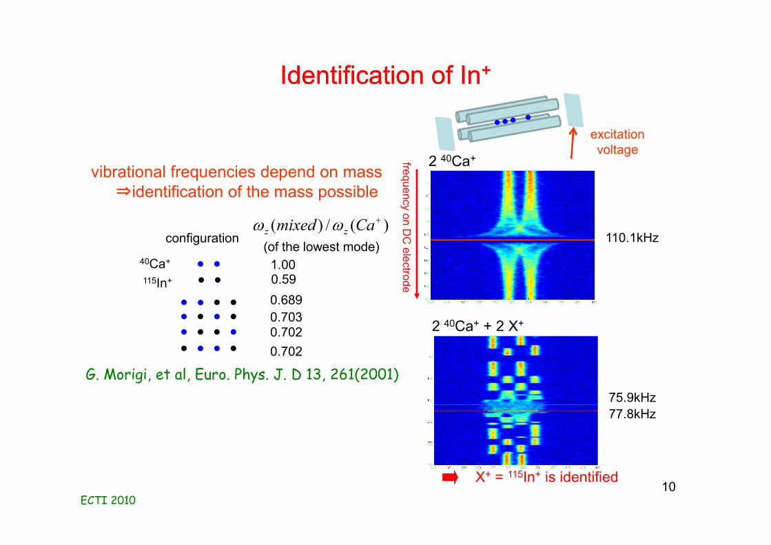
Identification of InIdentification of In++
75.9kHz77.8kHz
2 40Ca+ + 2 X+
)(/)( +Camixed zz ww
40Ca+ 1.00115In+ 0.59
0.6890.7030.7020.702
vibrational frequencies depend on mass⇒identification of the mass possible
110.1kHz
2 40Ca+frequency on DC
electrode
X+ = 115In+ is identified
configuration(of the lowest mode)
G. Morigi, et al, Euro. Phys. J. D 13, 261(2001)
excitation voltage
10
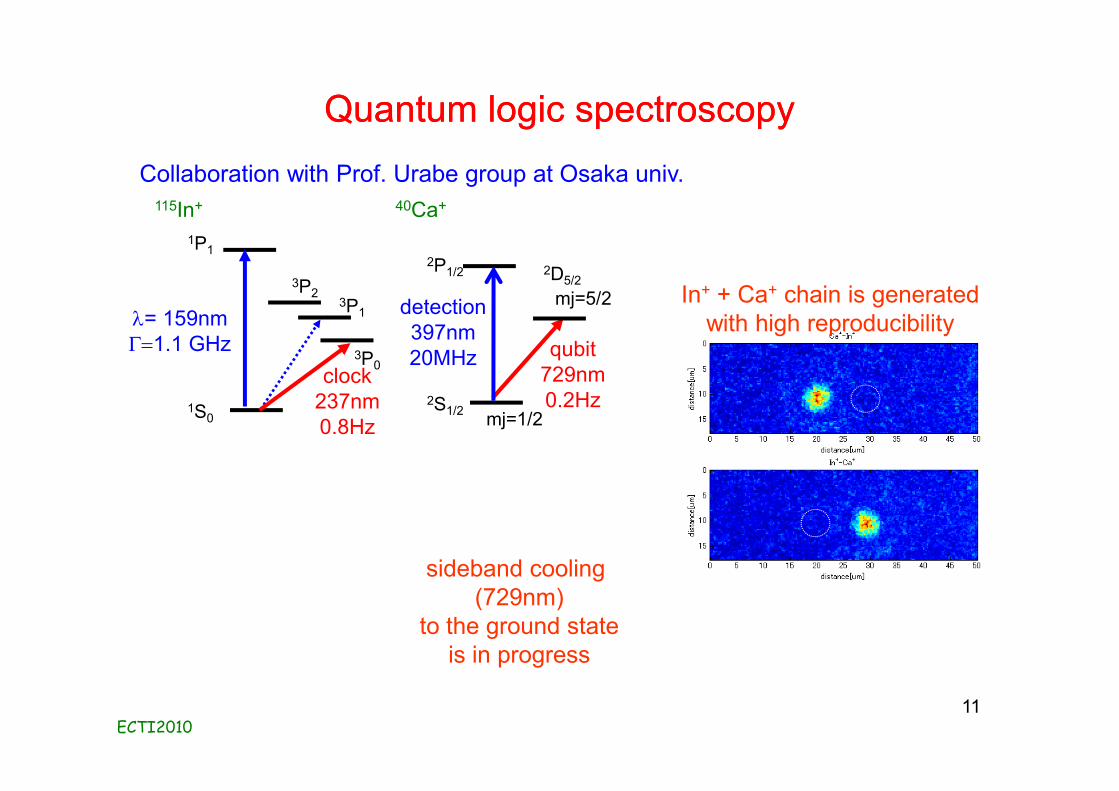
Quantum logic spectroscopyQuantum logic spectroscopy
ECTI201011
1S0
1P1
3P1
3P2
3P0clock237nm0.8Hz
2S1/2
2P1/2
detection397nm20MHz qubit
729nm0.2Hz
mj=1/2
mj=5/22D5/2
l= 159nm G=1.1 GHz
10 s 50mm
sideband cooling (729nm)
to the ground stateis in progress
Collaboration with Prof. Urabe group at Osaka univ.115In+ 40Ca+
In+ + Ca+ chain is generated with high reproducibility
1S0
Strong transitoncooling & detection
1P1
3P0
Clock transition
3P1
3P2
Sr Al+ In+ Th
Clock schemeLattice clock
Quantum logic spectroscopy
Single ion ??
Clock transition 1S0-3P01S0-3P0
1S0-3P0 Nuclear transition
l of clock transition (nm) 698 267 237 164±11
l of 1S0-1P1 transition (nm) 461 167 159
Common level structure of atomic clocks
All within 5th harmonic of Ti:S! Our target
Coherent VUV source for optical clocksCoherent VUV source for optical clocks
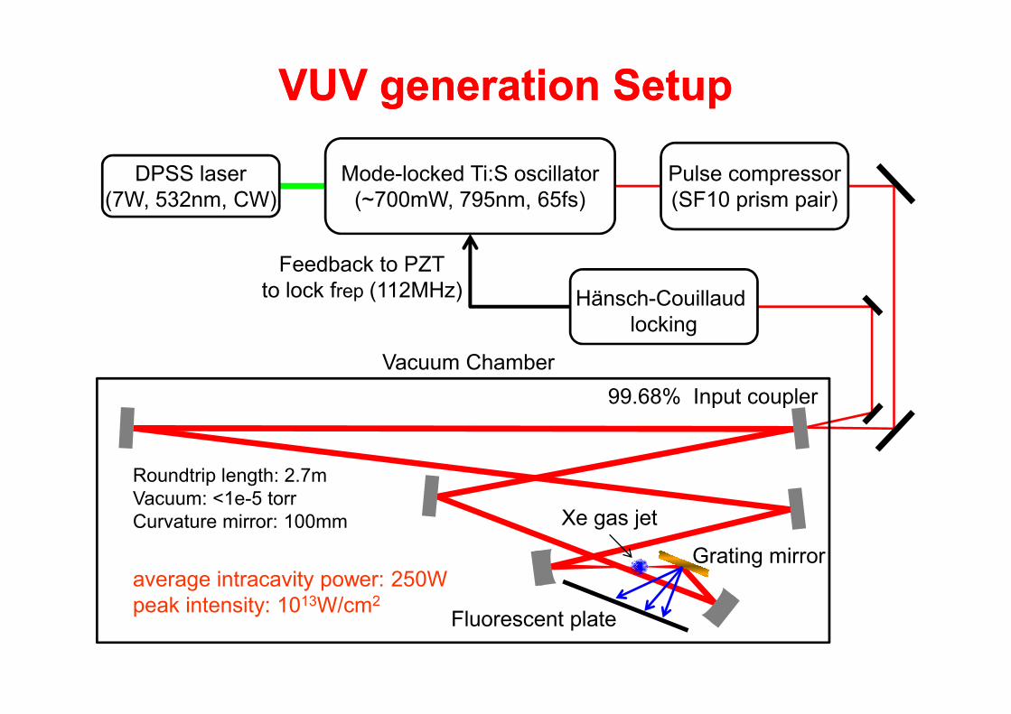
Mode-locked Ti:S oscillator(~700mW, 795nm, 65fs)
Pulse compressor(SF10 prism pair)
DPSS laser(7W, 532nm, CW)
Feedback to PZTto lock frep (112MHz)
Vacuum Chamber
Grating mirror
Fluorescent plate
Xe gas jet
99.68% Input coupler
Hänsch-Couillaudlocking
VUV generation SetupVUV generation Setup
Roundtrip length: 2.7mVacuum: <1e-5 torrCurvature mirror: 100mm
average intracavity power: 250Wpeak intensity: 1013W/cm2
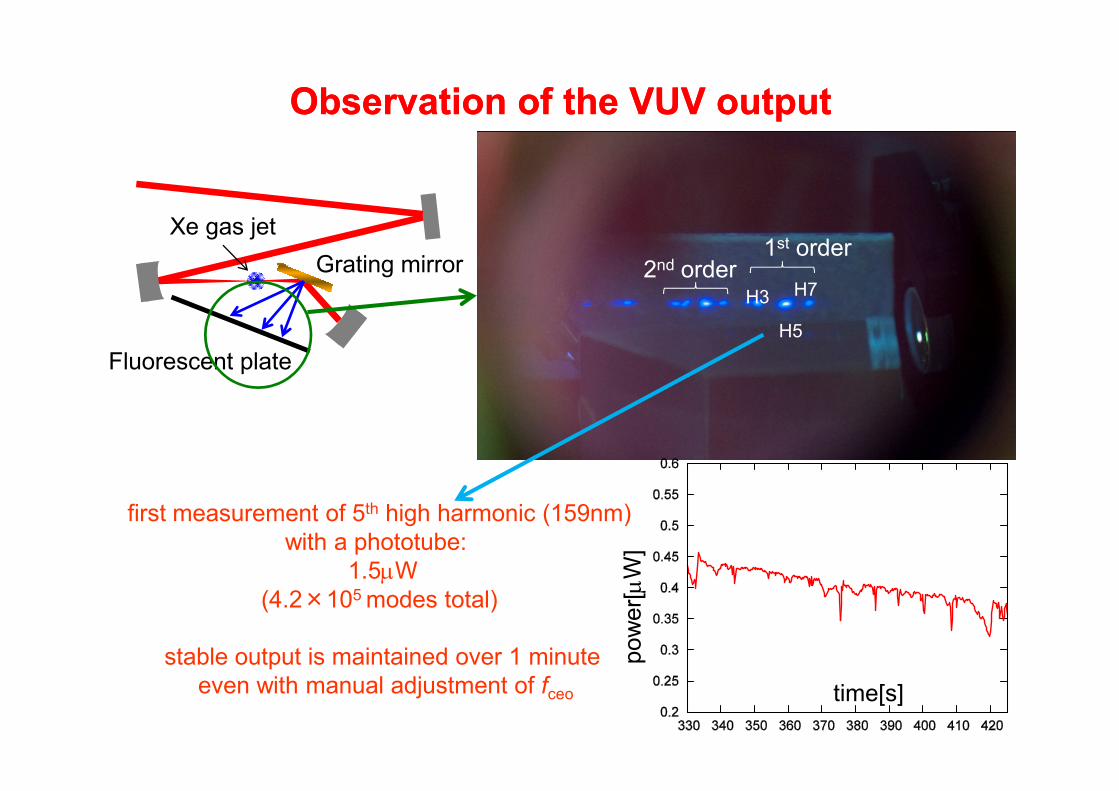
H3
H5
H7
1st order2nd orderGrating mirror
Fluorescent plate
Xe gas jet
Observation of the VUV outputObservation of the VUV output
first measurement of 5th high harmonic (159nm) with a phototube:
1.5mW(4.2×10⁵ modes total)
stable output is maintained over 1 minute even with manual adjustment of fceo time[s]
pow
er[m
W]
*Fiber laser based system at JILA: 50uW at 153nm (7th)!!
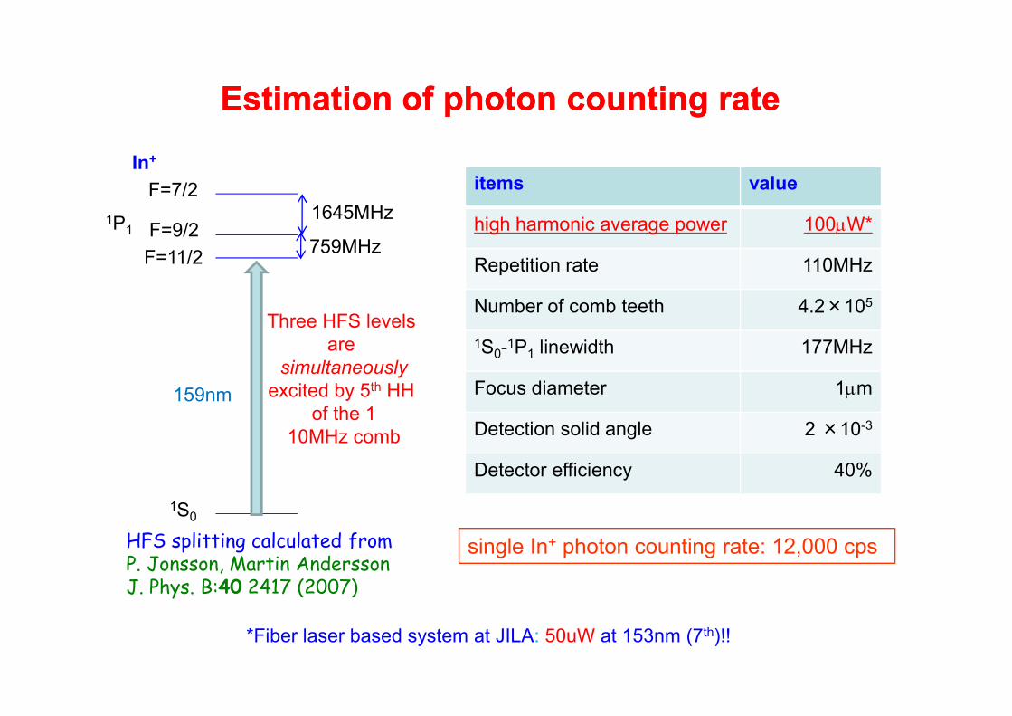
Estimation of photon counting rateEstimation of photon counting rate
items value
high harmonic average power 100mW*
Repetition rate 110MHz
Number of comb teeth 4.2×10⁵
1S0-1P1 linewidth 177MHz
Focus diameter 1mm
Detection solid angle 2 ×10⁻³
Detector efficiency 40%
1S0
1P1
F=7/2
F=9/2F=11/2
In+
759MHz
1645MHz
159nm
Three HFS levels are
simultaneouslyexcited by 5th HH
of the 110MHz comb
HFS splitting calculated fromP. Jonsson, Martin AnderssonJ. Phys. B:40 2417 (2007)
single In+ photon counting rate: 12,000 cps
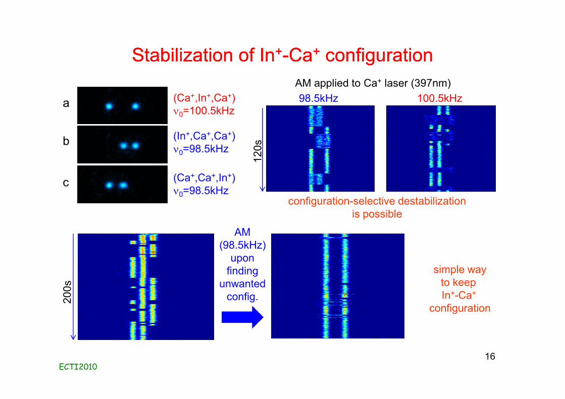
Stabilization of InStabilization of In++--CaCa++ configurationconfiguration
ECTI201016
(Ca+,In+,Ca+)n0=100.5kHz
(In+,Ca+,Ca+)n0=98.5kHz
(Ca+,Ca+,In+)n0=98.5kHz
200s
AM applied to Ca+ laser (397nm)98.5kHz
120s
100.5kHz
configuration-selective destabilizationis possible
AM(98.5kHz)
uponfinding
unwantedconfig.
simple wayto keep In+-Ca+
configuration
a
b
c
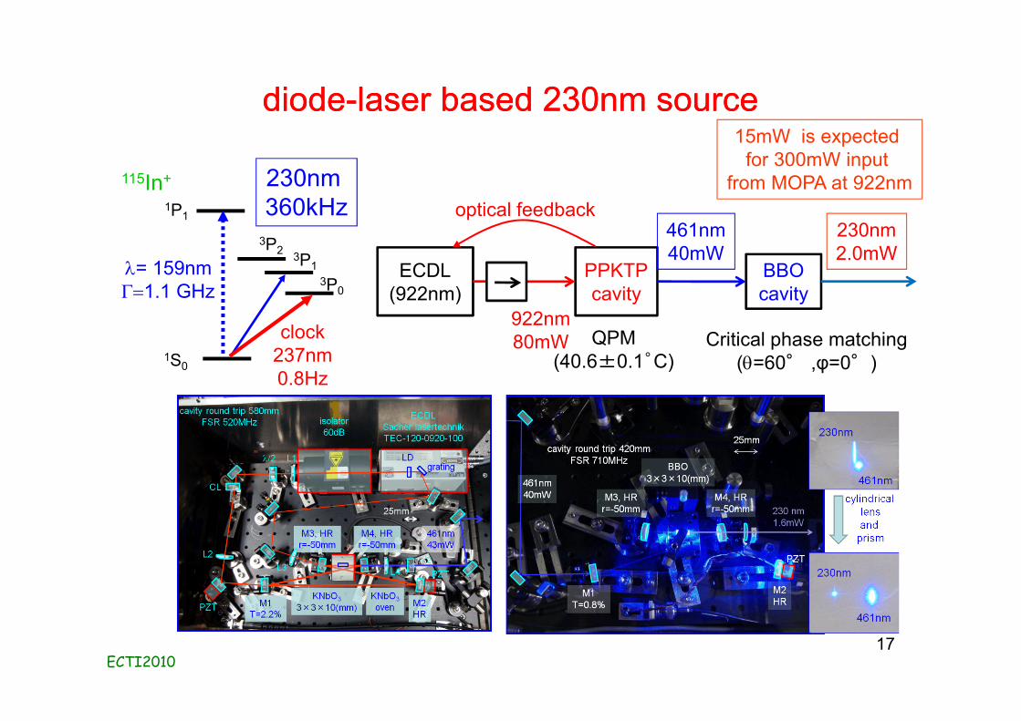
diodediode--laser based 230nm sourcelaser based 230nm source
ECTI201017
1S0
1P1
3P1
3P2
3P0
115In+
clock237nm0.8Hz
230nm 360kHz
l= 159nm G=1.1 GHz
ECDL(922nm)
PPKTPcavity
BBOcavity
922nm80mW
461nm40mW
230nm2.0mW
optical feedback
QPM(40.6±0.1゜C)
Critical phase matching(q=60° ,φ=0°)
15mW is expected for 300mW input
from MOPA at 922nm
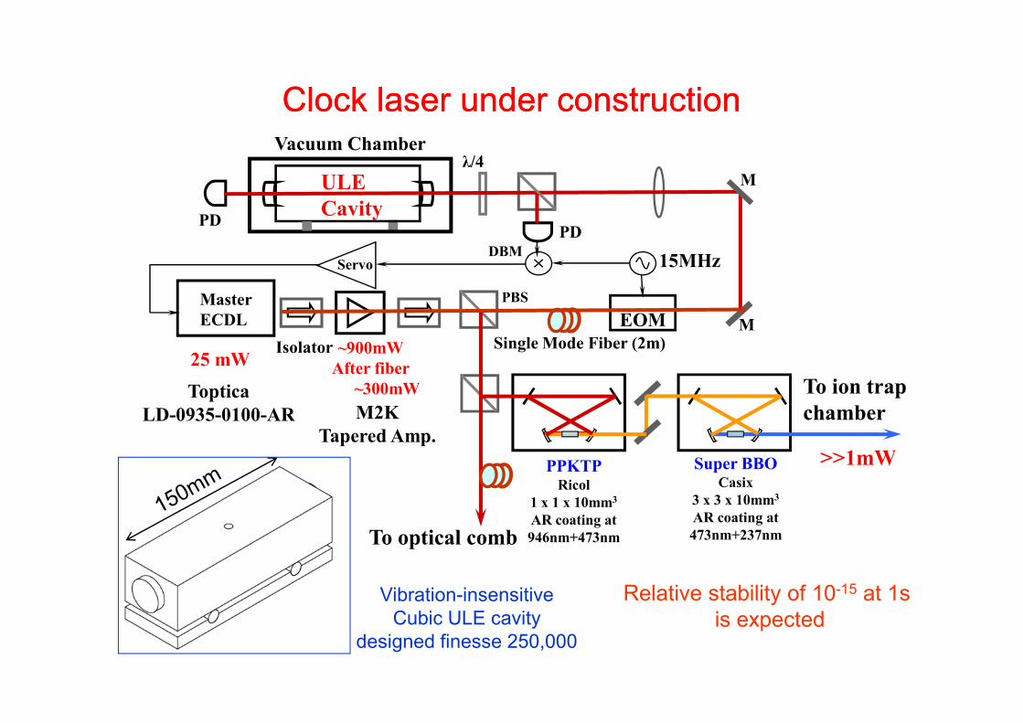
Vacuum Chamberλ/4
Isolator
PDPD
M
MPBSMaster
ECDL EOMSingle Mode Fiber (2m)
ServoDBM 15MHz
ULECavity
M2KTapered Amp.
25 mW ~900mWAfter fiber
~300mWTopticaLD-0935-0100-AR
PPKTPRicol
1 x 1 x 10mm3
AR coating at 946nm+473nm
Super BBOCasix
3 x 3 x 10mm3
AR coating at 473nm+237nm
>>1mW
To optical comb
To ion trap chamber
Clock laser under constructionClock laser under construction
Relative stability of 10-15 at 1s is expected
Vibration-insensitiveCubic ULE cavity
designed finesse 250,000
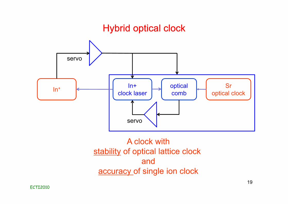
Hybrid optical clock Hybrid optical clock
ECTI201019
In+
A clock withstability of optical lattice clock
andaccuracy of single ion clock
Sroptical clock
optical comb
In+clock laser
servo
servo
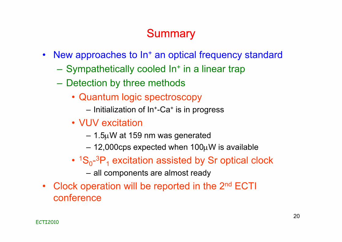
SummarySummary
• New approaches to In+ an optical frequency standard– Sympathetically cooled In+ in a linear trap– Detection by three methods
• Quantum logic spectroscopy– Initialization of In+-Ca+ is in progress
• VUV excitation– 1.5mW at 159 nm was generated– 12,000cps expected when 100mW is available
• 1S0-3P1 excitation assisted by Sr optical clock– all components are almost ready
• Clock operation will be reported in the 2nd ECTI conference
ECTI201020