Embed Size (px)
Citation preview
中実回転油圧シリンダNON-THROUGH-HOLE ROTATING HYDRAULIC CYLINDER
HH11CHH11CHH11CHH11C
取扱説明書INSTRUCTION MANUAL
豊和工業株式会社HOWA MACHINERY, LTD.
重要重要重要重要本取扱説明書をよく読み,内容を十分理解した
上でこの製品を使用してください。
この取扱説明書は大切に保管し,製品の所有者
が変わった場合,この説明書も新しい所有者に
手渡してください。
IMPORTANTBe sure to read this instruction manualthoroughly before operating the rotatingcylinder.Please save this manual. When ownershipof this product is transferred, submit thismanual to the new owner.
目 次
はじめに ・・・・・・・・・・・・・・・・・・・・・・・・・・・・・・・・・・・・・・・・・・・・・・・・・・・・・・ 1
安全についてのインフォメーション ・・・・・・・・・・・・・・・・・・・・・・・・・・・・・・ 1
安全のために ・・・・・・・・・・・・・・・・・・・・・・・・・・・・・・・・・・・・・・・・・・・・・・・・・・ 2
1.構造と作動
1.1 形番表示 ・・・・・・・・・・・・・・・・・・・・・・・・・・・・・・・・・・・・・・・・・・・・・・・ 5
1.2 構造と作動 ・・・・・・・・・・・・・・・・・・・・・・・・・・・・・・・・・・・・・・・・・・・・・・・ 5
2.仕様 ・・・・・・・・・・・・・・・・・・・・・・・・・・・・・・・・・・・・・・・・・・・・・・・・・・・・・・ 6
3.取付け方法
3.1 シリンダアダプタ ・・・・・・・・・・・・・・・・・・・・・・・・・・・・・・・・・・・・・・・ 8
3.2 コネクチングロッド ・・・・・・・・・・・・・・・・・・・・・・・・・・・・・・・・・・・・・ 9
3.3 取付け・回り止め ・・・・・・・・・・・・・・・・・・・・・・・・・・・・・・・・・・・・・・ 10
3.4 配管 ・・・・・・・・・・・・・・・・・・・・・・・・・・・・・・・・・・・・・・・・・・・・・・・・・・ 11
3.5 ドレンポート ・・・・・・・・・・・・・・・・・・・・・・・・・・・・・・・・・・・・・・・・・・・・ 11
3.6 油圧ユニット・作動油・油圧回路 ・・・・・・・・・・・・・・・・・・・・・・・・ 12
3.7 リミットスイッチの調整 ・・・・・・・・・・・・・・・・・・・・・・・・・・・・・・・・・・ 13
3.8 ストローク規制 ・・・・・・・・・・・・・・・・・・・・・・・・・・・・・・・・・・・・・・・・ 13
3.9 試運転 ・・・・・・・・・・・・・・・・・・・・・・・・・・・・・・・・・・・・・・・・・・・・・・・・ 13
4.保守・点検
4.1 作動油の点検 ・・・・・・・・・・・・・・・・・・・・・・・・・・・・・・・・・・・・・・・・・・ 14
4.2 分解・パーツリスト ・・・・・・・・・・・・・・・・・・・・・・・・・・・・・・・・・・・・ 15
限定保証 ・・・・・・・・・・・・・・・・・・・・・・・・・・・・・・・・・・・・・・・・・・・・・・・・・・・・・ 17
-1-
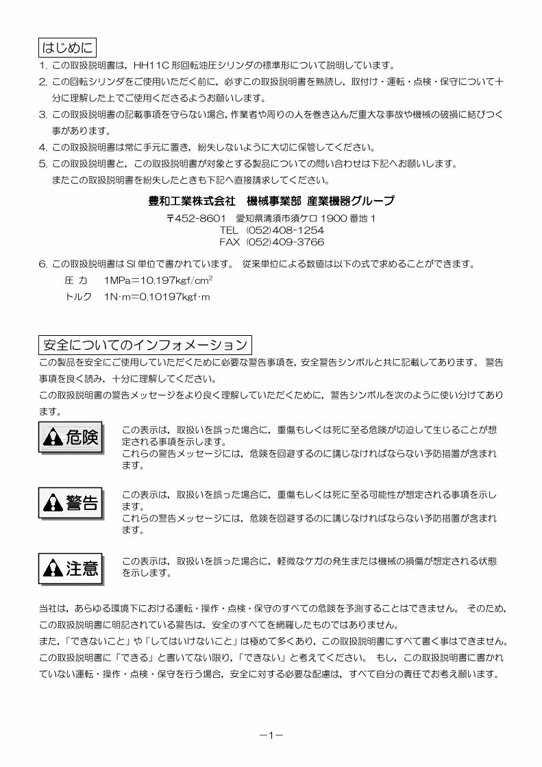
1. この取扱説明書は,HH11C 形回転油圧シリンダの標準形について説明しています。
2. この回転シリンダをご使用いただく前に,必ずこの取扱説明書を熟読し,取付け・運転・点検・保守について十
分に理解した上でご使用くださるようお願いします。
3. この取扱説明書の記載事項を守らない場合,作業者や周りの人を巻き込んだ重大な事故や機械の破損に結びつく
事があります。
4. この取扱説明書は常に手元に置き,紛失しないように大切に保管してください。
5. この取扱説明書と,この取扱説明書が対象とする製品についての問い合わせは下記へお願いします。
またこの取扱説明書を紛失したときも下記へ直接請求してください。
豊和工業株式会社豊和工業株式会社豊和工業株式会社豊和工業株式会社 機械事業部機械事業部機械事業部機械事業部 産業機器産業機器産業機器産業機器グループグループグループグループ
〒452-8601 愛知県清須市須ケ口 1900 番地 1
TEL (052)408-1254
FAX (052)409-3766
6. この取扱説明書は SI 単位で書かれています。 従来単位による数値は以下の式で求めることができます。
圧 力 1MPa=10.197kgf/cm2
トルク 1N・m=0.10197kgf・m
この製品を安全にご使用していただくために必要な警告事項を,安全警告シンボルと共に記載してあります。 警告
事項を良く読み,十分に理解してください。
この取扱説明書の警告メッセージをより良く理解していただくために,警告シンボルを次のように使い分けてあり
ます。
当社は,あらゆる環境下における運転・操作・点検・保守のすべての危険を予測することはできません。 そのため,
この取扱説明書に明記されている警告は,安全のすべてを網羅したものではありません。
また,「できないこと」や「してはいけないこと」は極めて多くあり,この取扱説明書にすべて書く事はできません。
この取扱説明書に「できる」と書いてない限り,「できない」と考えてください。 もし,この取扱説明書に書かれ
ていない運転・操作・点検・保守を行う場合,安全に対する必要な配慮は,すべて自分の責任でお考え願います。
はじめに
安全についてのインフォメーション
この表示は,取扱いを誤った場合に,重傷もしくは死に至る危険が切迫して生じることが想
定される事項を示します。
これらの警告メッセージには,危険を回避するのに講じなければならない予防措置が含まれ
ます。
この表示は,取扱いを誤った場合に,重傷もしくは死に至る可能性が想定される事項を示し
ます。
これらの警告メッセージには,危険を回避するのに講じなければならない予防措置が含まれ
ます。
この表示は,取扱いを誤った場合に,軽微なケガの発生または機械の損傷が想定される状態
を示します。
危険危険危険危険
警告警告警告警告
注意注意注意注意
-2-
ご使用の前に特に知っておいていただきたいこと,守っていただきたいことをまとめています。 必ずお読みくださ
い。
安全のために
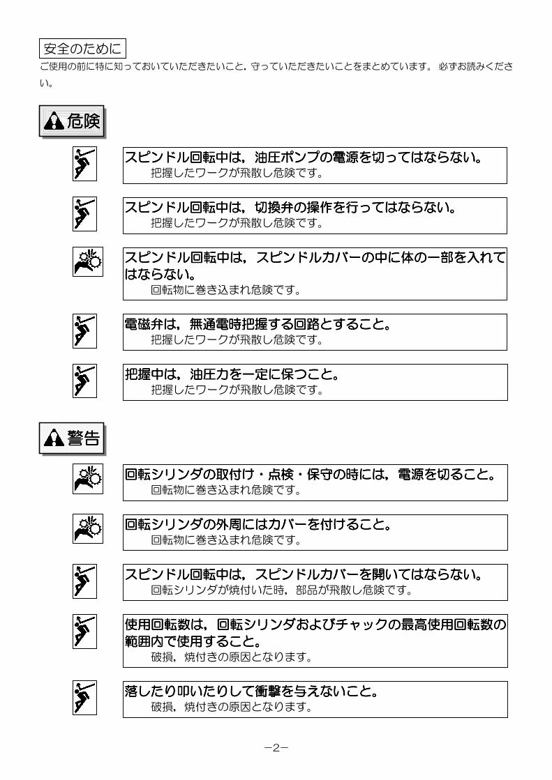
スピンドルスピンドルスピンドルスピンドル回転中回転中回転中回転中はははは,,,,油圧油圧油圧油圧ポンプポンプポンプポンプのののの電源電源電源電源をををを切切切切ってはならないってはならないってはならないってはならない。。。。把握したワークが飛散し危険です。
スピンドルスピンドルスピンドルスピンドル回転中回転中回転中回転中はははは,,,,切換弁切換弁切換弁切換弁のののの操作操作操作操作をををを行行行行ってはならないってはならないってはならないってはならない。。。。把握したワークが飛散し危険です。
スピンドルスピンドルスピンドルスピンドル回転中回転中回転中回転中はははは,,,,スピンドルカバースピンドルカバースピンドルカバースピンドルカバーのののの中中中中にににに体体体体のののの一部一部一部一部をををを入入入入れてれてれてれて
はならないはならないはならないはならない。。。。回転物に巻き込まれ危険です。
電磁弁電磁弁電磁弁電磁弁はははは,,,,無通電時把握無通電時把握無通電時把握無通電時把握するするするする回路回路回路回路とすることとすることとすることとすること。。。。把握したワークが飛散し危険です。
把握中把握中把握中把握中はははは,,,,油圧力油圧力油圧力油圧力をををを一定一定一定一定にににに保保保保つことつことつことつこと。。。。把握したワークが飛散し危険です。
回転回転回転回転シリンダシリンダシリンダシリンダのののの取付取付取付取付けけけけ・・・・点検点検点検点検・・・・保守保守保守保守のののの時時時時にはにはにはには,,,,電源電源電源電源をををを切切切切ることることることること。。。。回転物に巻き込まれ危険です。
回転回転回転回転シリンダシリンダシリンダシリンダのののの外周外周外周外周にはにはにはにはカバーカバーカバーカバーをををを付付付付けることけることけることけること。。。。回転物に巻き込まれ危険です。
スピンドルスピンドルスピンドルスピンドル回転中回転中回転中回転中はははは,,,,スピンドルカバースピンドルカバースピンドルカバースピンドルカバーをををを開開開開いてはならないいてはならないいてはならないいてはならない。。。。回転シリンダが焼付いた時,部品が飛散し危険です。
使用回転数使用回転数使用回転数使用回転数はははは,,,,回転回転回転回転シリンダシリンダシリンダシリンダおよびおよびおよびおよびチャックチャックチャックチャックのののの最高使用回転数最高使用回転数最高使用回転数最高使用回転数のののの
範囲内範囲内範囲内範囲内でででで使用使用使用使用することすることすることすること。。。。破損,焼付きの原因となります。
落落落落したりしたりしたりしたり叩叩叩叩いたりしていたりしていたりしていたりして衝撃衝撃衝撃衝撃をををを与与与与えないことえないことえないことえないこと。。。。破損,焼付きの原因となります。
危険危険危険危険
警告警告警告警告
-3-
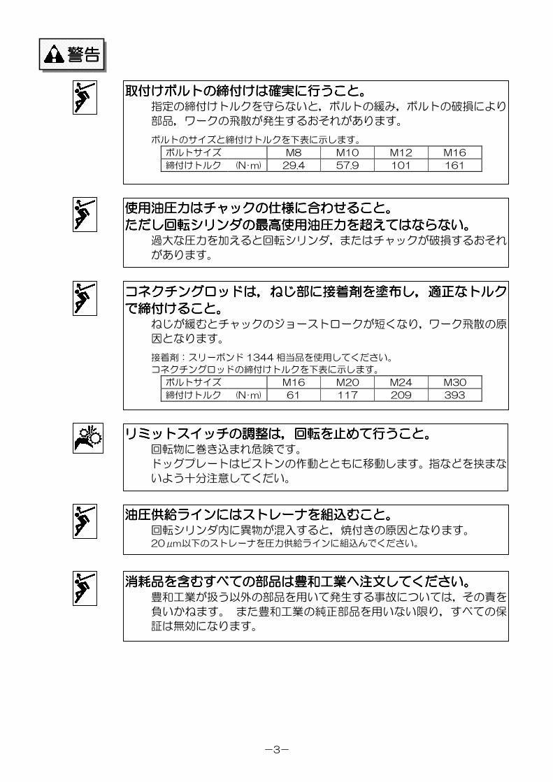
取付取付取付取付けけけけボルトボルトボルトボルトのののの締付締付締付締付けはけはけはけは確実確実確実確実にににに行行行行うことうことうことうこと。。。。指定の締付けトルクを守らないと,ボルトの緩み,ボルトの破損により
部品,ワークの飛散が発生するおそれがあります。
ボルトのサイズと締付けトルクを下表に示します。
ボルトサイズ M8 M10 M12 M16
締付けトルク (N・m) 29.4 57.9 101 161
使用油圧力使用油圧力使用油圧力使用油圧力ははははチャックチャックチャックチャックのののの仕様仕様仕様仕様にににに合合合合わせることわせることわせることわせること。。。。
ただしただしただしただし回転回転回転回転シリンダシリンダシリンダシリンダのののの最高使用油圧力最高使用油圧力最高使用油圧力最高使用油圧力をををを超超超超えてはならないえてはならないえてはならないえてはならない。。。。過大な圧力を加えると回転シリンダ,またはチャックが破損するおそれ
があります。
コネクチングロッドコネクチングロッドコネクチングロッドコネクチングロッドはははは,,,,ねじねじねじねじ部部部部にににに接着剤接着剤接着剤接着剤をををを塗布塗布塗布塗布しししし,,,,適正適正適正適正ななななトルクトルクトルクトルク
でででで締付締付締付締付けることけることけることけること。。。。ねじが緩むとチャックのジョーストロークが短くなり,ワーク飛散の原
因となります。
接着剤:スリーボンド 1344 相当品を使用してください。
コネクチングロッドの締付けトルクを下表に示します。
ボルトサイズ M16 M20 M24 M30
締付けトルク (N・m) 61 117 209 393
油圧供給油圧供給油圧供給油圧供給ラインラインラインラインにはにはにはにはストレーナストレーナストレーナストレーナをををを組込組込組込組込むことむことむことむこと。。。。回転シリンダ内に異物が混入すると,焼付きの原因となります。20μm以下のストレーナを圧力供給ラインに組込んでください。
消耗品消耗品消耗品消耗品をををを含含含含むすべてのむすべてのむすべてのむすべての部品部品部品部品はははは豊和工業豊和工業豊和工業豊和工業へへへへ注文注文注文注文してくださいしてくださいしてくださいしてください。。。。豊和工業が扱う以外の部品を用いて発生する事故については,その責を
負いかねます。 また豊和工業の純正部品を用いない限り,すべての保
証は無効になります。
警告警告警告警告
リミットスイッチリミットスイッチリミットスイッチリミットスイッチのののの調整調整調整調整はははは,,,,回転回転回転回転をををを止止止止めてめてめてめて行行行行うことうことうことうこと。。。。回転物に巻き込まれ危険です。
ドッグプレートはピストンの作動とともに移動します。指などを挟まな
いよう十分注意してくだい。

-4-
注意注意注意注意
回転回転回転回転シリンダシリンダシリンダシリンダのののの取付取付取付取付けけけけ,,,,取外取外取外取外しのしのしのしの時時時時,,,,吊吊吊吊りりりりベルトベルトベルトベルトをををを使用使用使用使用することすることすることすること。。。。手を滑らして回転シリンダを落したり,腰をいためたりするおそれがあ
ります。
作動油作動油作動油作動油をををを給油給油給油給油するときはするときはするときはするときは,,,,電源電源電源電源をををを切切切切りりりり火気厳禁火気厳禁火気厳禁火気厳禁のことのことのことのこと。。。。引火するおそれがあります。
-5-
1111....構造構造構造構造とととと作動作動作動作動
1.1 1.1 1.1 1.1 形番表示形番表示形番表示形番表示
HH11C 形中実形回転油圧シリンダは次のように分類されます。
1.1.1.1.2222 構造構造構造構造とととと作動作動作動作動
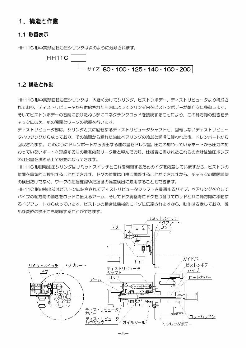
HH11C 形中実形回転油圧シリンダは,大きく分けてシリンダ,ピストンボデー,ディストリビュータより構成さ
れており,ディストリビュータから供給された圧油によってシリンダ内をピストンボデーが軸方向に移動します。
そしてピストンボデーの右端に設けたねじ部にコネクチングロッドを接続することにより,この軸方向の動きをチ
ャックに伝え,爪の開閉とワークの把握を行います。
ディストリビュータ部は,シリンダと共に回転するディストリビュータシャフトと,回転しないディストリビュー
タハウジングから成っており,その隙間から漏れた油はベアリングの冷却と潤滑に使われた後,ドレンポートから
回収されます。 このようにドレンポートから流出する油の量をドレン量,圧力の加わっているポートから圧力の加
わっていないポートへ短絡する油の量を内部リーク量と呼んでおり,仕様表に書かれたこれらの合計は油圧ポンプ
の吐出量を決める上で必要になってきます。
HH11C 形回転油圧シリンダはリミットスイッチとこれを開閉するためのドグを内蔵していますから,ピストンの
位置を電気的に検出することができます。ドグの位置は自由に調整することができますから,チャックの開閉状態
の検出だけでなく,ワークの把握確認や把握径の偏差検出に応用することもできます。
HH11C 形の検出部はピストンに結合されてディストリビュータシャフトを貫通するパイプ,ベアリングを介して
パイプの軸方向の動きをロッドに伝えるアーム,そしてドグ調整溝にドグを取付けてロッドと共に軸方向に移動す
るドグプレートから成っています。ピストンの動きは機械的にドグに伝達されますから,動作は安定しており,微
小な変位の検出にも対応することができます。
HHHHHHHH11111111CCCC
80808080・・・・100100100100・・・・125125125125・・・・140140140140・・・・160160160160・・・・200200200200サイズ
-6-
2222....仕様仕様仕様仕様
・・・・仕様仕様仕様仕様
HH11C形式番号
仕様
80 100 125 140 160 200
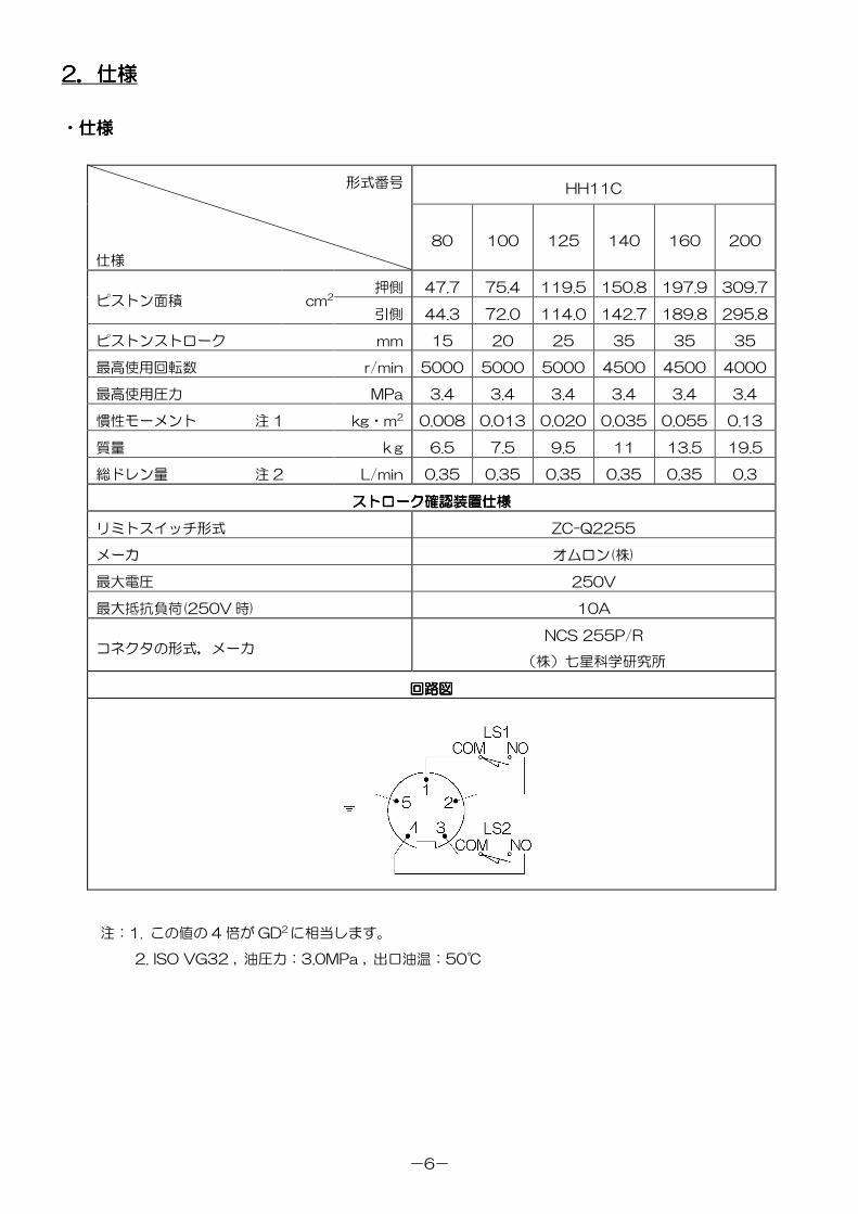
押側 47.7 75.4 119.5 150.8 197.9 309.7ピストン面積 cm2
引側 44.3 72.0 114.0 142.7 189.8 295.8
ピストンストローク mm 15 20 25 35 35 35
最高使用回転数 r/min 5000 5000 5000 4500 4500 4000
最高使用圧力 MPa 3.4 3.4 3.4 3.4 3.4 3.4
慣性モーメント 注 1 kg・m2 0.008 0.013 0.020 0.035 0.055 0.13
質量 kg 6.5 7.5 9.5 11 13.5 19.5
総ドレン量 注 2 L/min 0.35 0.35 0.35 0.35 0.35 0.3
ストロークストロークストロークストローク確認装置仕様確認装置仕様確認装置仕様確認装置仕様
リミトスイッチ形式 ZC-Q2255
メーカ オムロン(株)
最大電圧 250V
最大抵抗負荷(250V 時) 10A
コネクタの形式,メーカNCS 255P/R
(株)七星科学研究所
回路図回路図回路図回路図
注:1. この値の 4 倍が GD2 に相当します。
2. ISO VG32 , 油圧力:3.0MPa , 出口油温:50℃
-7-
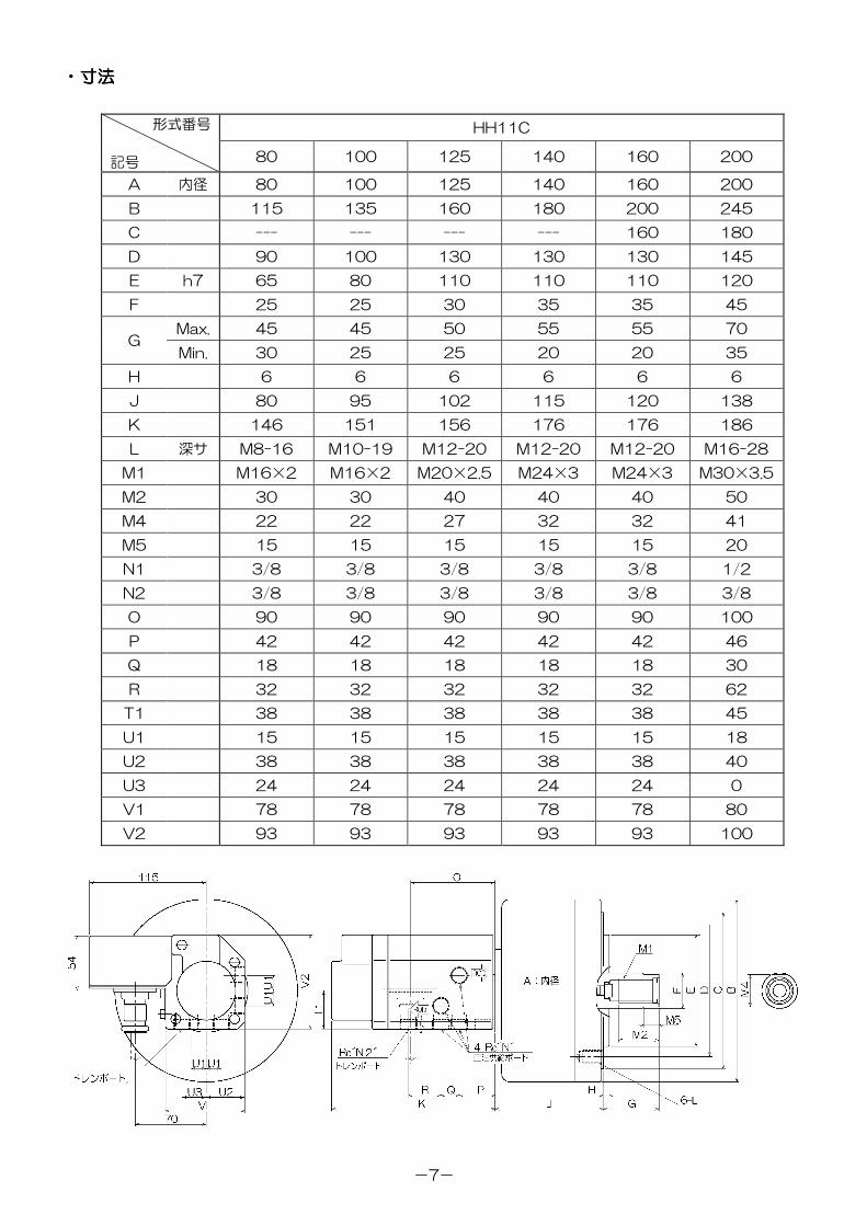
・・・・寸法寸法寸法寸法
HH11C形式番号
記号 80 100 125 140 160 200
A 内径 80 100 125 140 160 200
B 115 135 160 180 200 245
C --- --- --- --- 160 180
D 90 100 130 130 130 145
E h7 65 80 110 110 110 120
F 25 25 30 35 35 45
Max. 45 45 50 55 55 70G
Min. 30 25 25 20 20 35
H 6 6 6 6 6 6
J 80 95 102 115 120 138
K 146 151 156 176 176 186
L 深サ M8-16 M10-19 M12-20 M12-20 M12-20 M16-28
M1 M16×2 M16×2 M20×2.5 M24×3 M24×3 M30×3.5
M2 30 30 40 40 40 50
M4 22 22 27 32 32 41
M5 15 15 15 15 15 20
N1 3/8 3/8 3/8 3/8 3/8 1/2
N2 3/8 3/8 3/8 3/8 3/8 3/8
O 90 90 90 90 90 100
P 42 42 42 42 42 46
Q 18 18 18 18 18 30
R 32 32 32 32 32 62
T1 38 38 38 38 38 45
U1 15 15 15 15 15 18
U2 38 38 38 38 38 40
U3 24 24 24 24 24 0
V1 78 78 78 78 78 80
V2 93 93 93 93 93 100
-8-
3333....取付取付取付取付けけけけ方法方法方法方法
回転シリンダを取付けるスピンドル後端の形状は,規格統一がされておらず千差万別であるのが実情ですから,最
も代表的な形状を一例として取上げます。
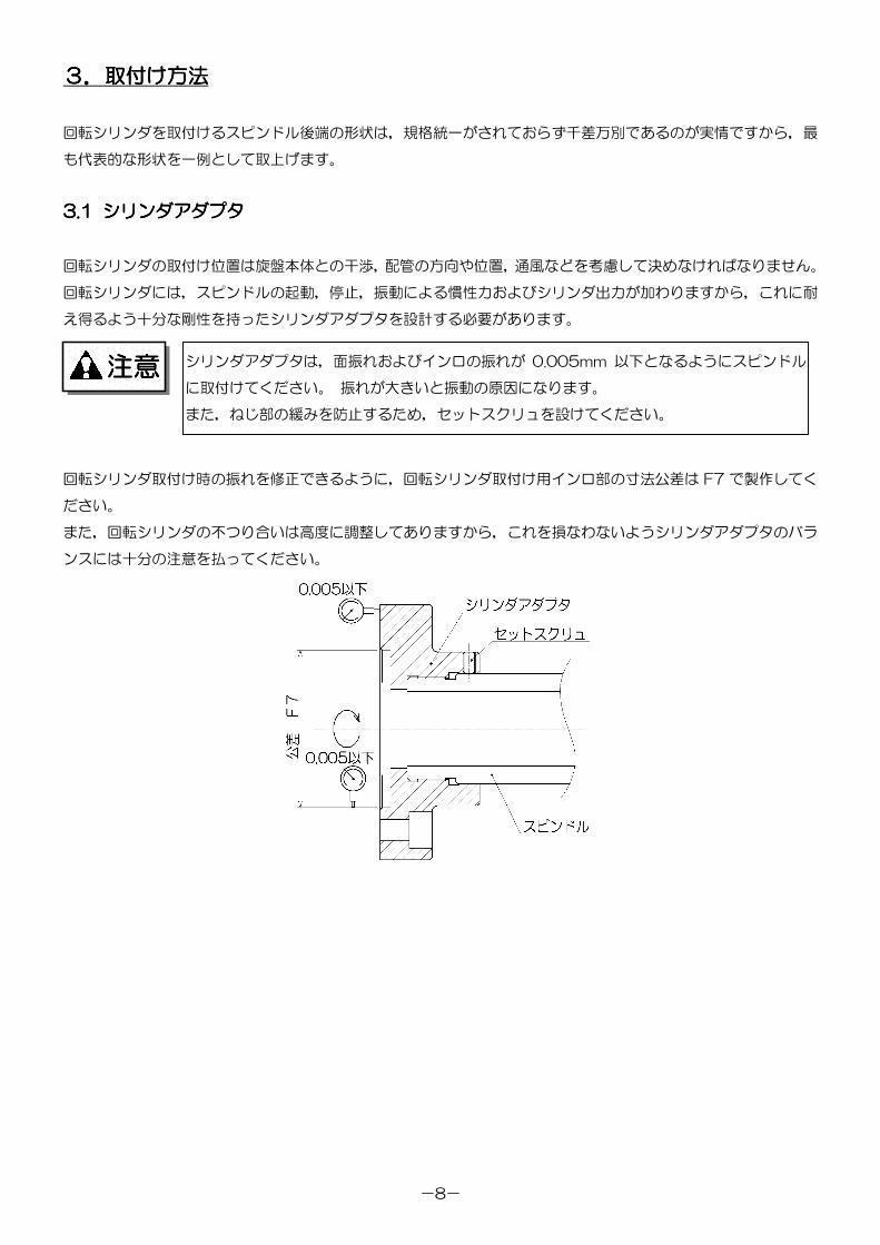
3.13.13.13.1 シリンダアダプタシリンダアダプタシリンダアダプタシリンダアダプタ
回転シリンダの取付け位置は旋盤本体との干渉,配管の方向や位置,通風などを考慮して決めなければなりません。
回転シリンダには,スピンドルの起動,停止,振動による慣性力およびシリンダ出力が加わりますから,これに耐
え得るよう十分な剛性を持ったシリンダアダプタを設計する必要があります。
回転シリンダ取付け時の振れを修正できるように,回転シリンダ取付け用インロ部の寸法公差は F7 で製作してく
ださい。
また,回転シリンダの不つり合いは高度に調整してありますから,これを損なわないようシリンダアダプタのバラ
ンスには十分の注意を払ってください。
シリンダアダプタは,面振れおよびインロの振れが 0.005mm 以下となるようにスピンドル
に取付けてください。 振れが大きいと振動の原因になります。
また,ねじ部の緩みを防止するため,セットスクリュを設けてください。
注意注意注意注意
-9-
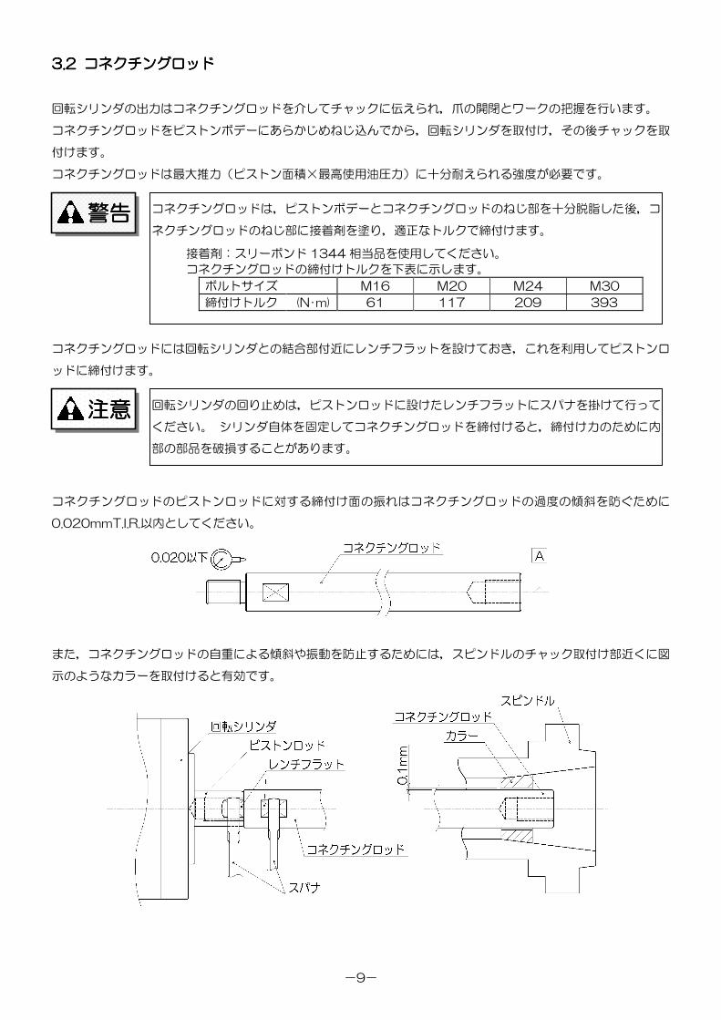
3.23.23.23.2 コネクチングロッドコネクチングロッドコネクチングロッドコネクチングロッド
回転シリンダの出力はコネクチングロッドを介してチャックに伝えられ,爪の開閉とワークの把握を行います。
コネクチングロッドをピストンボデーにあらかじめねじ込んでから,回転シリンダを取付け,その後チャックを取
付けます。
コネクチングロッドは最大推力(ピストン面積×最高使用油圧力)に十分耐えられる強度が必要です。
コネクチングロッドには回転シリンダとの結合部付近にレンチフラットを設けておき,これを利用してピストンロ
ッドに締付けます。
コネクチングロッドのピストンロッドに対する締付け面の振れはコネクチングロッドの過度の傾斜を防ぐために
0.020mmT.I.R.以内としてください。
また,コネクチングロッドの自重による傾斜や振動を防止するためには,スピンドルのチャック取付け部近くに図
示のようなカラーを取付けると有効です。
コネクチングロッドは,ピストンボデーとコネクチングロッドのねじ部を十分脱脂した後,コ
ネクチングロッドのねじ部に接着剤を塗り,適正なトルクで締付けます。
接着剤:スリーボンド 1344 相当品を使用してください。
コネクチングロッドの締付けトルクを下表に示します。
ボルトサイズ M16 M20 M24 M30
締付けトルク (N・m) 61 117 209 393
回転シリンダの回り止めは,ピストンロッドに設けたレンチフラットにスパナを掛けて行って
ください。 シリンダ自体を固定してコネクチングロッドを締付けると,締付け力のために内
部の部品を破損することがあります。
警告警告警告警告
注意注意注意注意
-10-
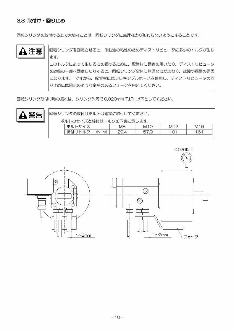
3.3.3.3.3 3 3 3 取付取付取付取付けけけけ・・・・回回回回りりりり止止止止めめめめ
回転シリンダを取付ける上で大切なことは,回転シリンダに無理な力が加わらないようにすることです。
回転シリンダ取付け時の振れは,シリンダ外周で 0.020mm T.I.R. 以下としてください。
回転シリンダの取付けボルトは確実に締付けてください。
ボルトのサイズと締付けトルクを下表に示します。
ボルトサイズ M8 M10 M12 M16
締付けトルク (N・m) 29.4 57.9 101 161
回転シリンダを回転させると,作動油の粘性のためディストリビュータに多少のトルクが生じ
ます。
このトルクによって生じる力を受けるために,配管材に鋼管を用いたり,ディストリビュータ
を旋盤の一部へ固定したりすると,回転シリンダ全体に無理な力が加わり,故障や振動の原因
になります。 ですから,配管材にはフレキシブルホースを使用し,ディストリビュータの回
り止めには図示のような余裕のあるフォークを用いてください。
警告警告警告警告
注意注意注意注意
-11-
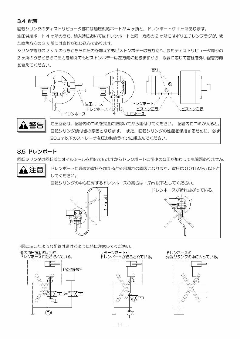
3.3.3.3.4 4 4 4 配管配管配管配管
回転シリンダのディストリビュータ部には油圧供給ポートが 4 ヶ所と,ドレンポートが 1 ヶ所あります。
油圧供給ポート 4 ヶ所のうち,納入時においてはドレンポートと同一方向の 2 ヶ所にはポリエチレンプラグが,ま
た直角方向の 2 ヶ所には盲栓がねじ込んであります。
シリンダ寄りの 2 ヶ所のうちどちらに圧力を加えてもピストンボデーは右方向へ,またディストリビュータ寄りの
2 ヶ所のうちどちらに圧力を加えてもピストンボデーは左方向に動きますから,必要に応じて盲栓を外し配管方向
を変えてください。
3.3.3.3.5 5 5 5 ドレンポートドレンポートドレンポートドレンポート
回転シリンダは回転部にオイルシールを用いていますからドレンポートに多少の背圧が加わっても問題ありません。
下図に示したような配管は避けるように特に注意してください。
油圧回路は,配管内のゴミを完全に取除いてから組付けてください。 配管内にゴミが入ると,
回転シリンダ焼付きの原因となります。 また,回転シリンダの性能を保持するために,必ず
20μm以下のストレーナを圧力供給ラインに組込んでください。
ドレンポートに過度の背圧を加えると外部漏れの原因になります。 背圧は 0.015MPa 以下と
してください。
回転シリンダの中心に対するドレンホースの高さは 1.7m 以下としてください。
ドレンホースが折れ曲がっている。
警告警告警告警告
注意注意注意注意
-12-
3.3.3.3.6 6 6 6 油圧油圧油圧油圧ユニットユニットユニットユニット・・・・作動油作動油作動油作動油・・・・油圧回路油圧回路油圧回路油圧回路
回転シリンダ専用に油圧ユニットを設置するときには,使用する回転シリンダの大きさ,許容油圧力,および必要
なチャックの把握力などを考慮して仕様を決定してください。 不必要に大きなモータや吐出量の多すぎるポンプを
使用すると,油温が上昇し弊害が発生するおそれがあります。
通常,回転シリンダ用油圧ユニットは,吐出量 25L/min,圧力 3.5MPa,タンク容量 40~60L 程度のものが使
用されます。
取付機械自体に油圧源がある場合,油圧回路を分岐して使用しても差し支えありませんが,回転シリンダの回路に
は必ず専用の減圧弁および圧力計を設けてください。
作動油は,40℃で 32mm2/sec(ISO VG32 相当)の粘度で,対摩耗性および消泡性のあるものを推奨します。
不適切な作動油を用いると,製品の寿命を著しく縮めることがあります。
回転シリンダを高速回転で連続使用すると,作動油の油温が上昇します。 高温になるとシール材および作動油の劣
化が急速に進行します。 クーラを使用して,油温が 60℃を超えないようにしてください。
油圧源の圧力設定に調圧応答性の悪い減圧弁を用いると,過大なサージ圧が発生し,シリンダ
の作動不良・破損につながりますので,サージ圧を低くおさえるようにしてください。
最低吐出量がドレン量と内部リーク量の合計を下回ると,回転シリンダの内部圧力が保てなく
なりますから,回路設計には十分注意してください。
推奨油種
ダフニースーパーマルチオイル 32
ダイヤモンドルブ RO32
モービル DTE(ライト)
シェルテラスオイル 32
エッソテレッソ 32
作動油を給油するときは,引火を防止するため,電源を切り火気厳禁で実施してください。
注意注意注意注意
注意注意注意注意
注意注意注意注意
-13-
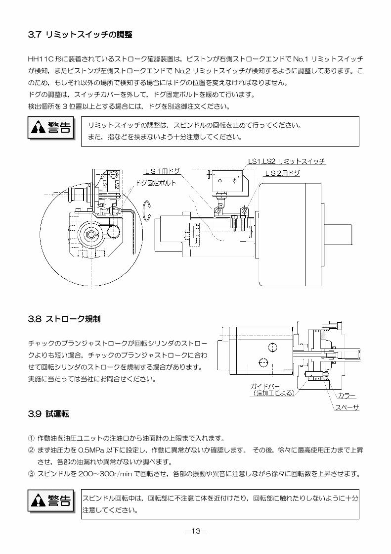
3.3.3.3.7 7 7 7 リミットスイッチリミットスイッチリミットスイッチリミットスイッチのののの調整調整調整調整
HH11C 形に装着されているストローク確認装置は,ピストンが右側ストロークエンドで No.1 リミットスイッチ
が検知,またピストンが左側ストロークエンドで No.2 リミットスイッチが検知するように調整してあります。こ
のため,もしそれ以外の場所で検知する場合にはドグの位置を変えなければなりません。
ドグの調整は,スイッチカバーを外して,ドグ固定ボルトを緩めて行います。
検出個所を 3 位置以上とする場合には,ドグを別途御注文ください。
3.3.3.3.8 8 8 8 ストロークストロークストロークストローク規制規制規制規制
チャックのプランジャストロークが回転シリンダのストロー
クよりも短い場合,チャックのプランジャストロークに合わ
せて回転シリンダのストロークを規制する場合があります。
実施に当たっては当社にお問合せください。
3.3.3.3.9 9 9 9 試運転試運転試運転試運転
① 作動油を油圧ユニットの注油口から油面計の上限まで入れます。
② まず油圧力を 0.5MPa 以下に設定し,作動に異常がないか確認します。 その後,徐々に最高使用圧力まで上昇
させ,各部の油漏れや異常がないか調べます。
③ スピンドルを 200~300r/min で回転させ,各部の振動や異音に注意しながら徐々に回転数を上昇させます。
スピンドル回転中は,回転部に不注意に体を近付けたり,回転部に触れたりしないように十分
注意してください。警告警告警告警告
リミットスイッチの調整は,スピンドルの回転を止めて行ってください。
また,指などを挟まないよう十分注意してください。警告警告警告警告
-14-
4444....保守保守保守保守・・・・点検点検点検点検
4444.1.1.1.1 作動油作動油作動油作動油のののの点検点検点検点検
ベアリングの冷却と潤滑はドレンを利用して行われますから,清浄な作動油を使用する限り特別の潤滑油は必要
ありません。 ですから,作動油を常に点検して清浄に保つことが,この回転シリンダの保守にとって最も大切です。
作動油の点検は次の点に注意して行ってください。
●水分の除去
空気の温度や湿度が高い場合には,水分が油圧ユニットのタンクの底にたまることがありますから,1週間に1
回程度の割合で排出してください。
●ストレーナの洗浄
1ヵ月に1回程度油圧ユニットのストレーナを外し,洗浄油で洗ってから,内側から圧縮空気を吹き込んで異物
を取除いてください。
●作動油の交換
1年に1回程度作動油を交換してください。 交換の際は油温を上げてから行うのが効果的で,古い油はできる
だけ残らないように取出します。 汚れが特にひどい場合は,洗浄油でタンク内部を洗浄すれば効果的です。
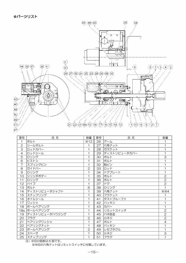
4444....2 2 2 2 分解分解分解分解・・・・パーツリストパーツリストパーツリストパーツリスト
回転シリンダは,正しく取付けて清浄な作動油を使用していれば,きわめて長い寿命を保つことができます。 し
かしもし何らかの原因で故障が生じた場合には,分解して必要に応じて部品を交換しなければなりません。
☆☆☆☆HH11CHH11CHH11CHH11C 形形形形のののの分解手順分解手順分解手順分解手順
① ボルト(47)を外して,ブラケット(40)をカバー(43)とリミットスイッチ(44)とともに外します。
② ボルト(35)を外して,ドグプレート(34)を外します。
③ ディストリビュータカバー(29)とシールボルト(2)を外すと,パイプ(12),アーム(26),ベアリング
(23),ロッド(33)を同時に抜き出すことができます。
④ ベアリングナット(22)とベアリングワッシャ(21)を外した後,ギヤー抜きなどの工具を用いて,ディスト
リビュータハウジング(19)を抜き出します。
⑤ ボルト(13)を外してから,ディストリビュータシャフト(14)のジャッキボルト穴にボルトをねじ込み,こ
れを抜き出します。
⑥ ボルト(1)を外した後,ロッドカバー(3)をジャッキボルト穴に棒先止めねじをねじ込んで外します。
⑦ ピストン(6)とガイドバー(8)を外します。
注意:① シールボルト(2)およびボルト(13)を外すことにより,ディストリビュータ部は分解することなく
取外すことができます。また,シールボルト(2)を外すことにより,ディストリビュータ部を分解する
ことなく,ピストンを取外すことも可能です。
② ディストリビュータの組付け後,ベアリングナット(22)の締め付けトルクは,はじめに 8N・m で締
め付けてから完全に緩め,再び 1.0~1.5N・m で締め付けることにより与圧を発生させます。ベアリン
グの圧入は治具を使用し,傾きのないように注意して行ってください。
回転シリンダのシールや構成部品をピストン作動回数 25 万往復毎に細部まで分解点検し,
シールの摩耗や部品の損傷がある場合は交換してください。注意注意注意注意
-15-
☆☆☆☆パーツリストパーツリストパーツリストパーツリスト
HH11CHH11CHH11CHH11C 形形形形
番号 品 名 数量 番号 品 名 数量
1 ボルト ※12 26 アーム 1
2 シールボルト 1 27 六角ナット 1
3 ロッドカバー 1 28 ガスケット 1
4 ロッドシール 1 29 ディストリビュータカバー 1
5 Oリング 1 30 ボルト 3
6 ピストン 1 31 ボルト 1
7 スプリングピン 1 32 割ピン 1
8 ガイドバー 2 33 ロッド 1
9 Oリング 1 34 ドグプレート 1
10 シリンダボデー 1 35 ボルト 2
11 Oリング 1 36 ボルト 2
12 パイプ 1 37 ドグ 2
13 ボルト 6 38 Oリング 1
14 ディストリビュータシャフト 1 39 六角ナット ※※4
15 スナップリング 1 40 ブラケット 1
16 オイルシール 1 41 ダストプルーファ 1
17 ワッシャ 1 42 パッキン 1
18 ボールベアリング 1 43 カバー 1
18a ボールベアリング 1 44 リミットスイッチ 2
19 ディストリビュータハウジング 1 45 バネ座金 2
20 プラグ 2 46 小ネジ 2
21 ベアリングワッシャ 1 47 ボルト 4
22 ベアリングナット 1 48 パッキン 1
23 ボールベアリング 2 49 レセプタクル 1
24 スペーサ 1 50 小ネジ 3
25 スナップリング 1 51 プラグ 1
注)※印の個数は 6 個です。
※※印の六角ナットはリミットスイッチに付属しています。
-16-
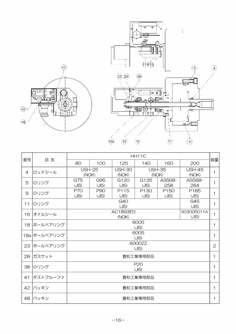
HH11C番号 品 名
80 100 125 140 160 200数量
4 ロッドシールUSH-25
(NOK)
USH-30
(NOK)
USH-35
(NOK)
USH-45
(NOK)1
5 OリングG75
(JIS)
G95
(JIS)
G120
(JIS)
G135
(JIS)
AS568-
258
AS568-
2641
9 OリングP70
(JIS)
P90
(JIS)
P115
(JIS)
P130
(JIS)
P150
(JIS)
P185
(JIS)1
11 OリングG40
(JIS)
G45
(JIS)1
16 オイルシールAC1893E0
(NOK)
S03005011A
(JIS)1
18 ボールベアリング6005
(JIS)1
18a ボールベアリング6005
(JIS)1
23 ボールベアリング6000ZZ
(JIS)2
28 ガスケット 豊和工業専用部品 1
38 OリングP20
(JIS)1
41 ダストプルーファ 豊和工業専用部品 1
42 パッキン 豊和工業専用部品 1
48 パッキン 豊和工業専用部品 1
-17-
限限限限 定定定定 保保保保 証証証証
売り主は製品が,頒布されている仕様条件に従って製造されたもので,材料上および/または仕上げ上欠
陥がないことを保証いたします。
売り主は,工場へ元のまま返品された運送費前払いのもので,売り主が点検して材料および/または仕上
げに欠陥があると判断した製品は,売り主の自由意志で,修理もしくは交換をいたします。 前記のものに
ついては,それが売り主の保証違反に対する唯一の救済となるものとします。
売売売売りりりり主主主主はははは,,,,これにこれにこれにこれに限定限定限定限定されるわけではありませんがされるわけではありませんがされるわけではありませんがされるわけではありませんが,,,,市場性市場性市場性市場性やややや市販性市販性市販性市販性にににに関関関関するするするする保証保証保証保証,,,,特定特定特定特定のののの目的目的目的目的またはまたはまたはまたは用用用用
途途途途にににに関関関関するするするする保証保証保証保証,,,,もしくはもしくはもしくはもしくは特許侵害特許侵害特許侵害特許侵害にににに対対対対するするするする保証保証保証保証などなどなどなど本保証条件以外本保証条件以外本保証条件以外本保証条件以外のものはのものはのものはのものは,,,,明示明示明示明示のののの保証保証保証保証であろうとであろうとであろうとであろうと黙示黙示黙示黙示
のののの保証保証保証保証であろうとであろうとであろうとであろうと,,,,なんらのなんらのなんらのなんらの保証保証保証保証もいたしませんもいたしませんもいたしませんもいたしません。。。。売売売売りりりり主主主主はははは,,,,いかなるいかなるいかなるいかなる直接的損害直接的損害直接的損害直接的損害,,,,付帯的付帯的付帯的付帯的もしくはもしくはもしくはもしくは間接的間接的間接的間接的
なななな損害金損害金損害金損害金,,,,あるいはあるいはあるいはあるいは欠陥製品欠陥製品欠陥製品欠陥製品もしくはもしくはもしくはもしくは製品製品製品製品のののの使用使用使用使用にににに起因起因起因起因するするするする損害金損害金損害金損害金またはまたはまたはまたは費用費用費用費用についてはについてはについてはについては,,,,なんらなんらなんらなんら責任責任責任責任はなはなはなはな
いものといたしますいものといたしますいものといたしますいものといたします。。。。
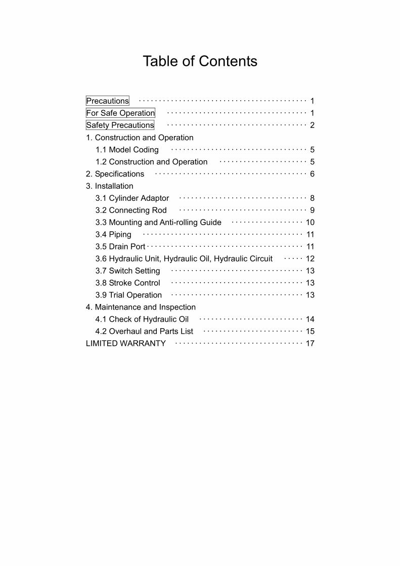
Table of Contents
Precautions ・・・・・・・・・・・・・・・・・・・・・・・・・・・・・・・・・・・・・・・・・・ 1
For Safe Operation ・・・・・・・・・・・・・・・・・・・・・・・・・・・・・・・・・・・ 1
Safety Precautions ・・・・・・・・・・・・・・・・・・・・・・・・・・・・・・・・・・・ 2
1. Construction and Operation
1.1 Model Coding ・・・・・・・・・・・・・・・・・・・・・・・・・・・・・・・・・・ 5
1.2 Construction and Operation ・・・・・・・・・・・・・・・・・・・・・・ 5
2. Specifications ・・・・・・・・・・・・・・・・・・・・・・・・・・・・・・・・・・・・・・ 6
3. Installation
3.1 Cylinder Adaptor ・・・・・・・・・・・・・・・・・・・・・・・・・・・・・・・・ 8
3.2 Connecting Rod ・・・・・・・・・・・・・・・・・・・・・・・・・・・・・・・・ 9
3.3 Mounting and Anti-rolling Guide ・・・・・・・・・・・・・・・・・・ 10
3.4 Piping ・・・・・・・・・・・・・・・・・・・・・・・・・・・・・・・・・・・・・・・・ 11
3.5 Drain Port・・・・・・・・・・・・・・・・・・・・・・・・・・・・・・・・・・・・・・・ 11
3.6 Hydraulic Unit, Hydraulic Oil, Hydraulic Circuit ・・・・・ 12
3.7 Switch Setting ・・・・・・・・・・・・・・・・・・・・・・・・・・・・・・・・・ 13
3.8 Stroke Control ・・・・・・・・・・・・・・・・・・・・・・・・・・・・・・・・・ 13
3.9 Trial Operation ・・・・・・・・・・・・・・・・・・・・・・・・・・・・・・・・・ 13
4. Maintenance and Inspection
4.1 Check of Hydraulic Oil ・・・・・・・・・・・・・・・・・・・・・・・・・・ 14
4.2 Overhaul and Parts List ・・・・・・・・・・・・・・・・・・・・・・・・・ 15
LIMITED WARRANTY ・・・・・・・・・・・・・・・・・・・・・・・・・・・・・・・・ 17
- 1 -
1. This instruction manual describes model HH11C Rotating Hydraulic Cylinder Standard Model.2. Please read this manual carefully and fully understand the procedures for installation,
operation, inspection, and maintenance before operating the rotating cylinder.3. Ignoring any instructions in this manual may result in a serious accident or machine damage,
leading to injury to the operator or personnel near the machine.4. Please save this manual and keep it handy at all times.5. Please contact us (phone and fax numbers are shown below) for information regarding this
manual and the objective product. Another copy of this manual is also available from thefollowing address:
HOWA MACHINERY, LTD.INDUSTRIAL EQUIPMENT GROUP
MACHINERY DIVISION1900-1, SUKAGUCHI, KIYOSU, AICHI, 452-8601 JAPAN
Phone : International access code-81-052-408-1254Facsimile: International access code-81-052-409-3766
6. The values of this manual are described in SI unit system. Values of former unit system canbe obtained by following calculations.
Pressure 1MPa=10.197kgf/cm2
Torque 1N・m=0.10197kgf・m
This manual contains warning messages for safe operation that are indicated by Safety AlertSymbols. Carefully read and fully understand these messages.The danger levels of the Safety Alert Symbols are defined below.
It is impossible to predict all hazardous situations that may occur during operation, inspection,and maintenance of the rotating cylinder under various circumstances.Accordingly, the warning messages described in this manual do not cover all hazardoussituations.Also, there are too many operations that cannot or should not be performed using the rotatingcylinder to be completely described in this manual.We cannot assume any responsibility for damage or accidents caused through operation,inspection, or maintenance of the rotating cylinder that is not specified in this manual.
Precautions
For Safe Operation
Indicates an imminently hazardous situation which, if not avoided, willresult in death or serious injury. These warning massages include thepreventive actions those are indispensable to avoid danger.
WARNING
CAUTION
DANGER
Indicates a potentially hazardous situation which, if not avoided, couldresult in death or serious injury. These warning massages include thepreventive actions those are indispensable to avoid danger.
Indicates a potentially hazardous situation which, if not avoided, couldresult in minor injury or machine damage.
- 2 -
Read and understand the following precautions before using the rotating cylinder, and observethem during operation.
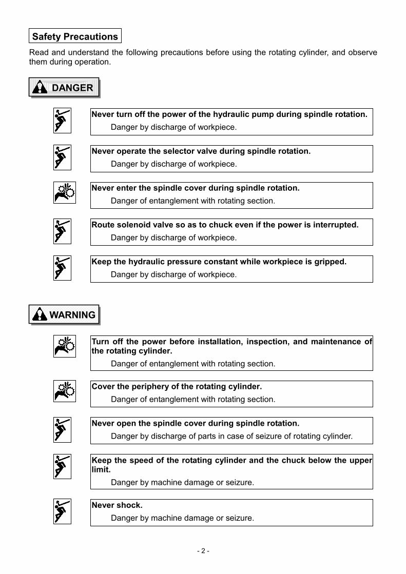
Safety Precautions
DANGER
Never turn off the power of the hydraulic pump during spindle rotation.
Danger by discharge of workpiece.
Never operate the selector valve during spindle rotation.
Danger by discharge of workpiece.
Never enter the spindle cover during spindle rotation.
Danger of entanglement with rotating section.
Route solenoid valve so as to chuck even if the power is interrupted.
Danger by discharge of workpiece.
Keep the hydraulic pressure constant while workpiece is gripped.
Danger by discharge of workpiece.
WARNING
Turn off the power before installation, inspection, and maintenance ofthe rotating cylinder.
Danger of entanglement with rotating section.
Cover the periphery of the rotating cylinder.
Danger of entanglement with rotating section.
Never open the spindle cover during spindle rotation.
Danger by discharge of parts in case of seizure of rotating cylinder.
Keep the speed of the rotating cylinder and the chuck below the upperlimit.
Danger by machine damage or seizure.
Never shock.
Danger by machine damage or seizure.
- 3 -
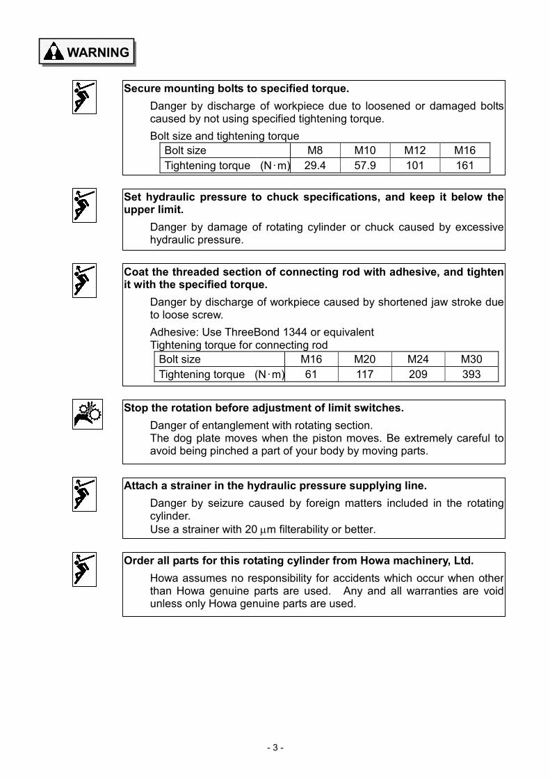
WARNING
Secure mounting bolts to specified torque.
Danger by discharge of workpiece due to loosened or damaged boltscaused by not using specified tightening torque.
Bolt size and tightening torque
Bolt size M8 M10 M12 M16
Tightening torque (N・m) 29.4 57.9 101 161
Set hydraulic pressure to chuck specifications, and keep it below theupper limit.
Danger by damage of rotating cylinder or chuck caused by excessivehydraulic pressure.
Coat the threaded section of connecting rod with adhesive, and tightenit with the specified torque.
Danger by discharge of workpiece caused by shortened jaw stroke dueto loose screw.
Adhesive: Use ThreeBond 1344 or equivalentTightening torque for connecting rod
Bolt size M16 M20 M24 M30
Tightening torque (N・m) 61 117 209 393
Attach a strainer in the hydraulic pressure supplying line.
Danger by seizure caused by foreign matters included in the rotatingcylinder.
Use a strainer with 20 µm filterability or better.
Order all parts for this rotating cylinder from Howa machinery, Ltd.
Howa assumes no responsibility for accidents which occur when otherthan Howa genuine parts are used. Any and all warranties are voidunless only Howa genuine parts are used.
Stop the rotation before adjustment of limit switches.
Danger of entanglement with rotating section.The dog plate moves when the piston moves. Be extremely careful toavoid being pinched a part of your body by moving parts.

- 4 -
CAUTION
Use lifting belt when attaching or detaching rotating cylinder.
Danger by dropping of rotating cylinder from your hands. Danger by anexcessive stress causing your lumbar injury.
Turn off the power source before supplying hydraulic oil. Keep fire andflame away during supplying.
Danger by flaming of hydraulic oil.
- 5 -
1. Construction and Operation
1.1 Model Coding
Model HH11C non-through-hole rotating hydraulic cylinder is model coded as follows:
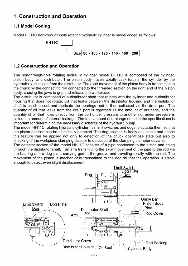
1.2 Construction and Operation
The non-through-hole rotating hydraulic cylinder model HH11C is composed of the cylinder,piston body, and distributor. The piston body travels axially back forth in the cylinder by thehydraulic oil supplied from the distributor. The axial movement of the piston body is transmitted tothe chuck by the connecting rod connected to the threaded section on the right end of the pistonbody, causing the jaws to grip and release the workpiece.The distributor is composed of a distributor shaft that rotates with the cylinder and a distributorhousing that does not rotate. Oil that leaks between the distributor housing and the distributorshaft is used to cool and lubricate the bearings and is then collected via the drain port. Thequantity of oil that leaks from the drain port is regarded as the amount of drainage, and thequantity of oil that flows directly from the port under pressure to another not under pressure iscalled the amount of internal leakage. The total amount of drainage noted in the specifications isimportant for determining the necessary discharge of the hydraulic pump.The model HH11C rotating hydraulic cylinder has limit switches and dogs to actuate them so thatthe piston position can be electrically detected. The dog position is freely adjustable and hencethis feature can be applied not only to detection of the chuck open/close state but also tochecking of the workpiece clamping state or to detection of the clamping diameter deviation.The detector section of the model HH11C consists of a pipe connected to the piston and goingthrough the distributor shaft, an arm transmitting the axial movement of the pipe to the rod viathe bearing and a dog plate carrying god in the groove and traveling axially with the rod. Themovement of the piston is mechanically transmitted to the dog so that the operation is stableenough to detect even slight displacement.
HH11C
80・・・・100・・・・125・・・・140・・・・160・・・・200Size
- 6 -
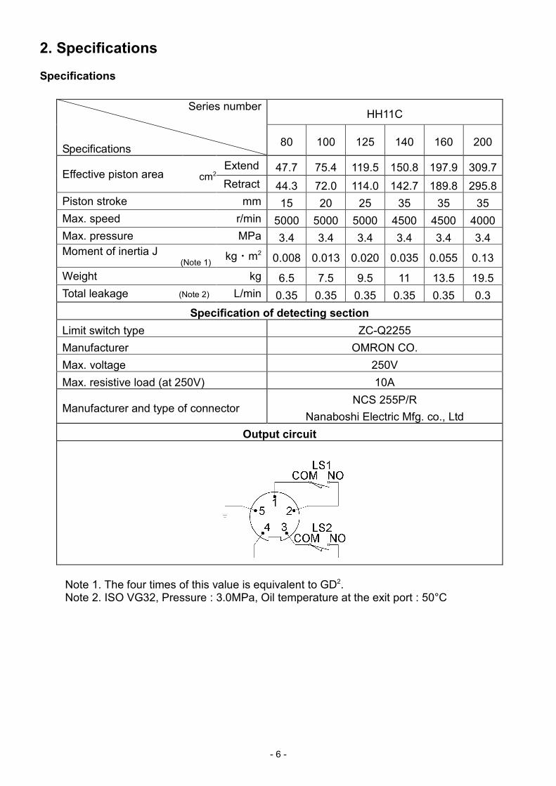
2. Specifications
Specifications
HH11CSeries number
Specifications80 100 125 140 160 200
Extend 47.7 75.4 119.5 150.8 197.9 309.7Effective piston area cm2
Retract 44.3 72.0 114.0 142.7 189.8 295.8
Piston stroke mm 15 20 25 35 35 35
Max. speed r/min 5000 5000 5000 4500 4500 4000
Max. pressure MPa 3.4 3.4 3.4 3.4 3.4 3.4
Moment of inertia J(Note 1)
kg・m20.008 0.013 0.020 0.035 0.055 0.13
Weight kg 6.5 7.5 9.5 11 13.5 19.5
Total leakage (Note 2) L/min 0.35 0.35 0.35 0.35 0.35 0.3
Specification of detecting section
Limit switch type ZC-Q2255
Manufacturer OMRON CO.
Max. voltage 250V
Max. resistive load (at 250V) 10A
Manufacturer and type of connectorNCS 255P/R
Nanaboshi Electric Mfg. co., Ltd
Output circuit
Note 1. The four times of this value is equivalent to GD2.Note 2. ISO VG32, Pressure : 3.0MPa, Oil temperature at the exit port : 50°C
- 7 -
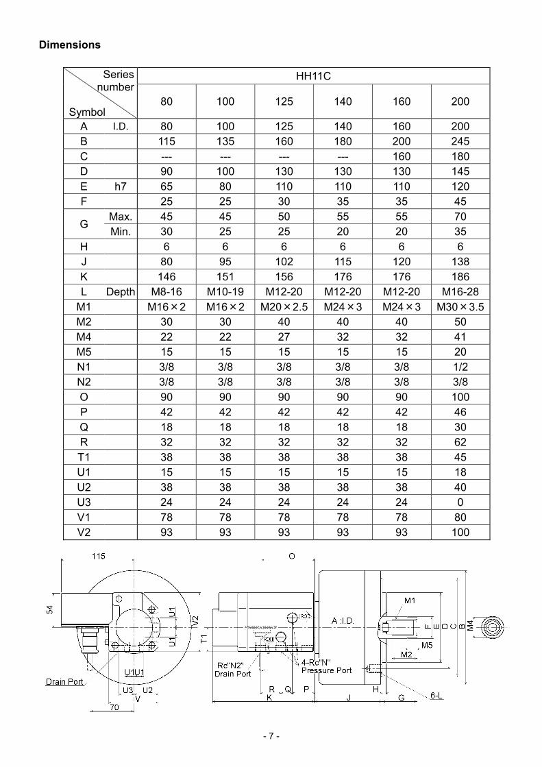
Dimensions
HH11CSeriesnumber
Symbol80 100 125 140 160 200
A I.D. 80 100 125 140 160 200
B 115 135 160 180 200 245
C --- --- --- --- 160 180
D 90 100 130 130 130 145
E h7 65 80 110 110 110 120
F 25 25 30 35 35 45
Max. 45 45 50 55 55 70G
Min. 30 25 25 20 20 35
H 6 6 6 6 6 6
J 80 95 102 115 120 138
K 146 151 156 176 176 186
L Depth M8-16 M10-19 M12-20 M12-20 M12-20 M16-28
M1 M16×2 M16×2 M20×2.5 M24×3 M24×3 M30×3.5
M2 30 30 40 40 40 50
M4 22 22 27 32 32 41
M5 15 15 15 15 15 20
N1 3/8 3/8 3/8 3/8 3/8 1/2
N2 3/8 3/8 3/8 3/8 3/8 3/8
O 90 90 90 90 90 100
P 42 42 42 42 42 46
Q 18 18 18 18 18 30
R 32 32 32 32 32 62
T1 38 38 38 38 38 45
U1 15 15 15 15 15 18
U2 38 38 38 38 38 40
U3 24 24 24 24 24 0
V1 78 78 78 78 78 80
V2 93 93 93 93 93 100
- 8 -
3. Installation
The rear end of the spindle to which the rotating cylinder is attached has various configurations.Here, a typical rear end configuration is shown as an example.
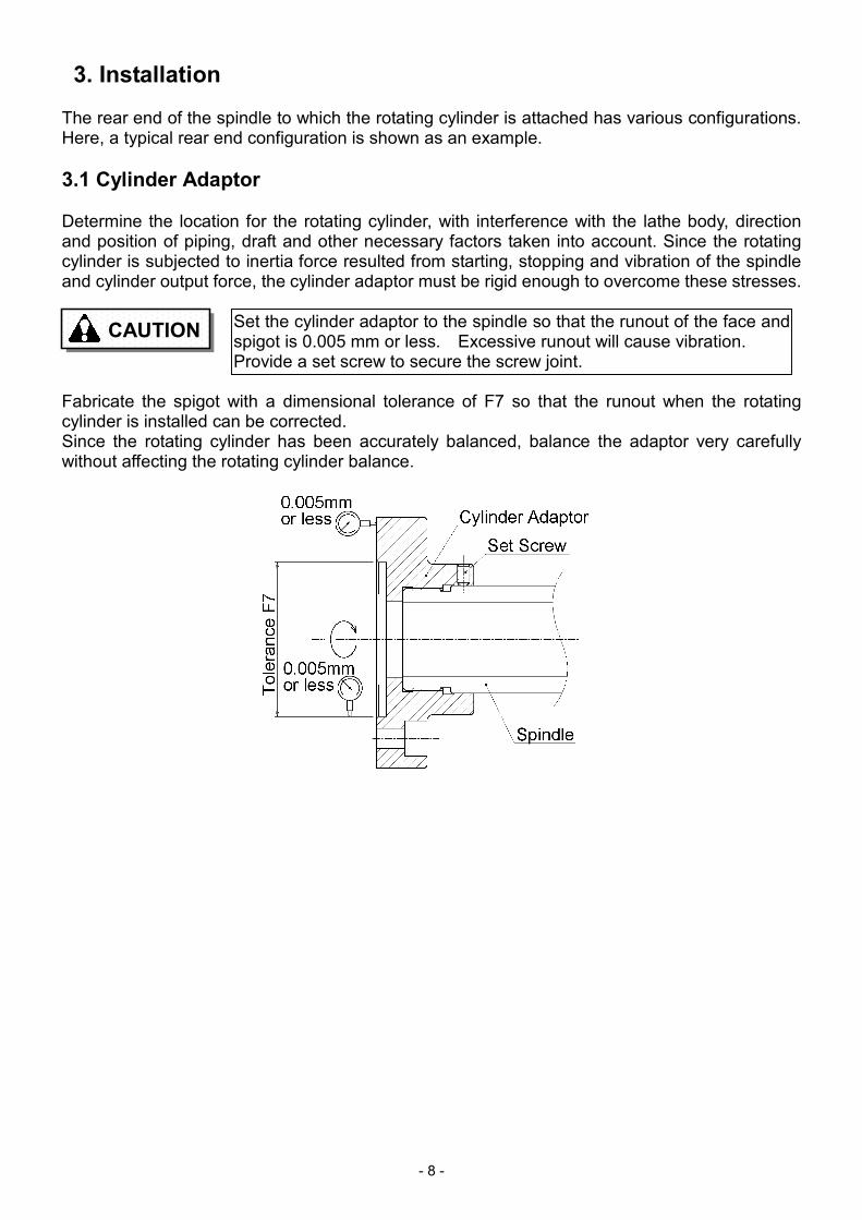
3.1 Cylinder Adaptor
Determine the location for the rotating cylinder, with interference with the lathe body, directionand position of piping, draft and other necessary factors taken into account. Since the rotatingcylinder is subjected to inertia force resulted from starting, stopping and vibration of the spindleand cylinder output force, the cylinder adaptor must be rigid enough to overcome these stresses.
Fabricate the spigot with a dimensional tolerance of F7 so that the runout when the rotatingcylinder is installed can be corrected.Since the rotating cylinder has been accurately balanced, balance the adaptor very carefullywithout affecting the rotating cylinder balance.
CAUTIONSet the cylinder adaptor to the spindle so that the runout of the face andspigot is 0.005 mm or less. Excessive runout will cause vibration.Provide a set screw to secure the screw joint.
- 9 -
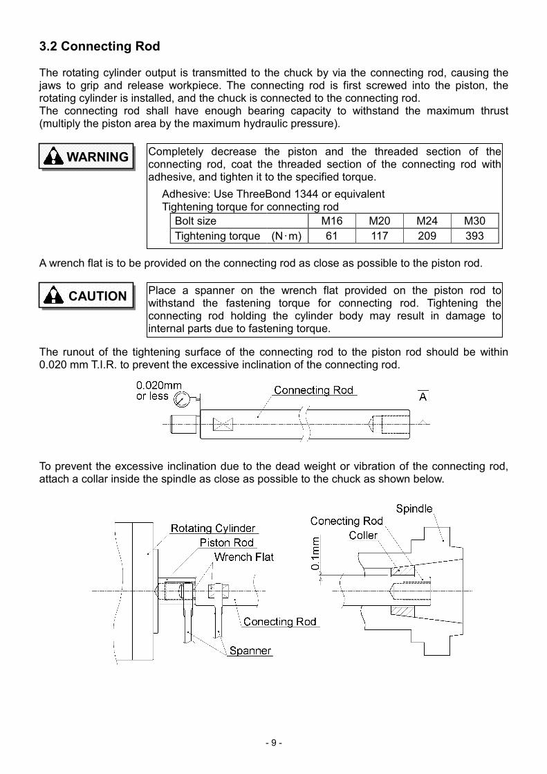
3.2 Connecting Rod
The rotating cylinder output is transmitted to the chuck by via the connecting rod, causing thejaws to grip and release workpiece. The connecting rod is first screwed into the piston, therotating cylinder is installed, and the chuck is connected to the connecting rod.The connecting rod shall have enough bearing capacity to withstand the maximum thrust(multiply the piston area by the maximum hydraulic pressure).
A wrench flat is to be provided on the connecting rod as close as possible to the piston rod.
The runout of the tightening surface of the connecting rod to the piston rod should be within0.020 mm T.I.R. to prevent the excessive inclination of the connecting rod.
To prevent the excessive inclination due to the dead weight or vibration of the connecting rod,attach a collar inside the spindle as close as possible to the chuck as shown below.
WARNINGCompletely decrease the piston and the threaded section of theconnecting rod, coat the threaded section of the connecting rod withadhesive, and tighten it to the specified torque.
Adhesive: Use ThreeBond 1344 or equivalentTightening torque for connecting rod
Bolt size M16 M20 M24 M30
Tightening torque (N・m) 61 117 209 393
CAUTIONPlace a spanner on the wrench flat provided on the piston rod towithstand the fastening torque for connecting rod. Tightening theconnecting rod holding the cylinder body may result in damage tointernal parts due to fastening torque.
- 10 -
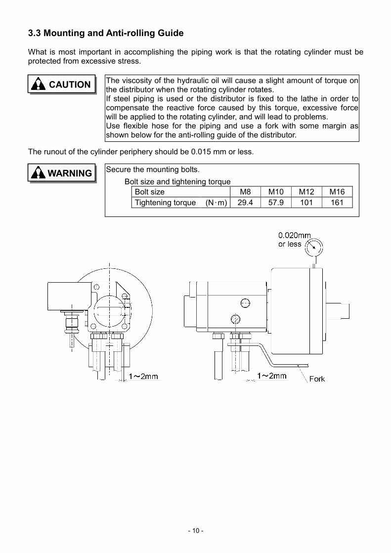
3.3 Mounting and Anti-rolling Guide
What is most important in accomplishing the piping work is that the rotating cylinder must beprotected from excessive stress.
The runout of the cylinder periphery should be 0.015 mm or less.
CAUTIONThe viscosity of the hydraulic oil will cause a slight amount of torque onthe distributor when the rotating cylinder rotates.If steel piping is used or the distributor is fixed to the lathe in order tocompensate the reactive force caused by this torque, excessive forcewill be applied to the rotating cylinder, and will lead to problems.Use flexible hose for the piping and use a fork with some margin asshown below for the anti-rolling guide of the distributor.
WARNINGSecure the mounting bolts.
Bolt size and tightening torque
Bolt size M8 M10 M12 M16
Tightening torque (N・m) 29.4 57.9 101 161
- 11 -
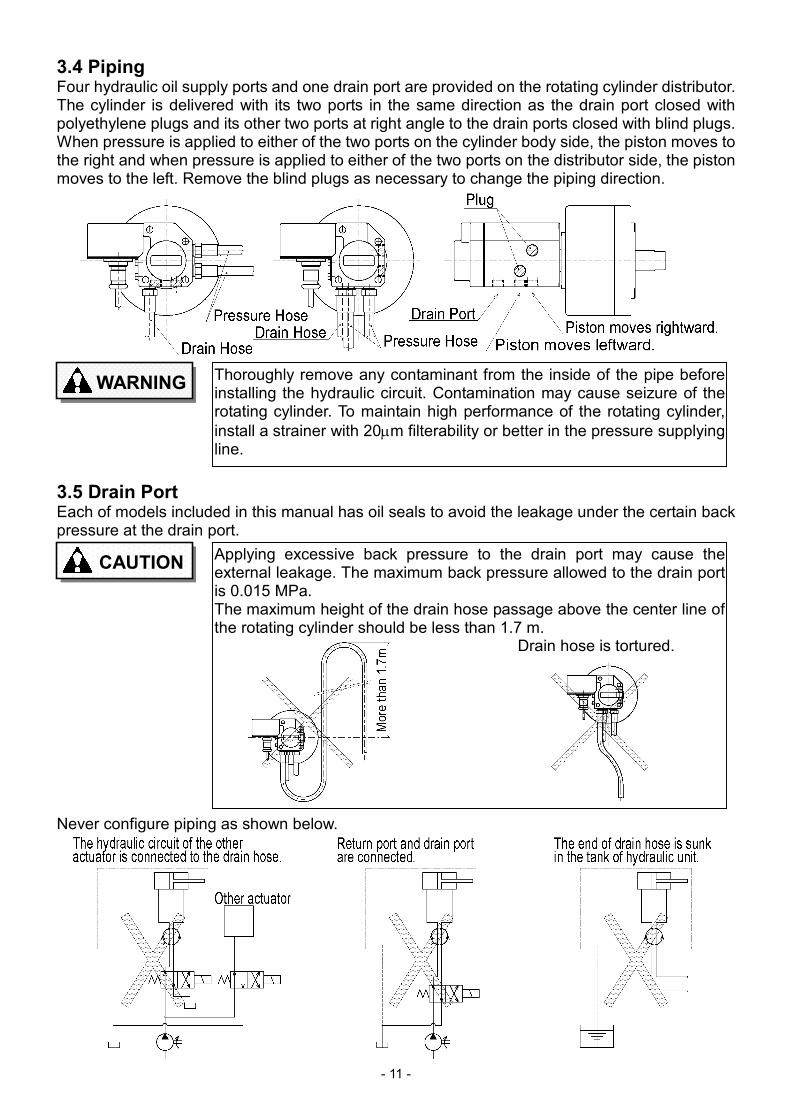
3.4 PipingFour hydraulic oil supply ports and one drain port are provided on the rotating cylinder distributor.The cylinder is delivered with its two ports in the same direction as the drain port closed withpolyethylene plugs and its other two ports at right angle to the drain ports closed with blind plugs.When pressure is applied to either of the two ports on the cylinder body side, the piston moves tothe right and when pressure is applied to either of the two ports on the distributor side, the pistonmoves to the left. Remove the blind plugs as necessary to change the piping direction.
3.5 Drain PortEach of models included in this manual has oil seals to avoid the leakage under the certain backpressure at the drain port.
Never configure piping as shown below.
WARNINGThoroughly remove any contaminant from the inside of the pipe beforeinstalling the hydraulic circuit. Contamination may cause seizure of therotating cylinder. To maintain high performance of the rotating cylinder,
install a strainer with 20µm filterability or better in the pressure supplyingline.
CAUTIONApplying excessive back pressure to the drain port may cause theexternal leakage. The maximum back pressure allowed to the drain portis 0.015 MPa.The maximum height of the drain hose passage above the center line ofthe rotating cylinder should be less than 1.7 m. Drain hose is tortured.
- 12 -
3.6 Hydraulic Unit, Hydraulic Oil, Hydraulic Circuit
When providing a dedicated pump unit for the hydraulic unit, determine the pump specificationsby taking the cylinder size, permissible oil pressure, required gripping force, etc. intoconsideration. Do not use a motor with too much power or a pump with excessive deliverycapacity, because the oil temperature will rise and this may cause problems.The specifications of the pump unit for the rotating cylinder are as follows:
Delivery:25 L/min Max. pressure:3.5 MPa Tank capacity:40 - 60 LIf the hydraulic unit is located in a machine on which the chuck is mounted, its circuit can bebranched for chuck operation. In this case, a dedicated pressure reducing valve and pressuregage must be provided in the circuit of the rotating cylinder.
We recommend using hydraulic oil that has viscosity of 32mm2/sec at 40°C (ISO VG32)equivalent with abrasion resistance as well as defoaming characteristics. Inappropriate hydraulicoil may extremely shorten the product life.
Recommended oil types are :Daphne Super Multi Oil 32Diamond Lub RO 32Mobil DTE (Light)Shell Tellus Oil 32Esso Teresso 32
Continuous high speed operation causes a considerable increase of the oil temperature,resulting in rapid deterioration of the sealing materials and the hydraulic oil. Keep the oiltemperature below 60°C using a cooler.
CAUTIONKeep the surge pressure low. If the pressure of the hydraulic unit isadjusted using a pressure reducing valve with low response speed,excessive surge pressure will be generated, resulting in malfunction ordamage to the rotating cylinder.
CAUTIONIf the minimum discharge is less than the total amount of drainage andinternal leakage, it becomes impossible to maintain the internal pressureof the rotating cylinder. Pay attention to this point when designing thehydraulic circuit.
CAUTIONTurn off the power source before supplying hydraulic oil. Keep fire andflame away during supplying.
- 13 -
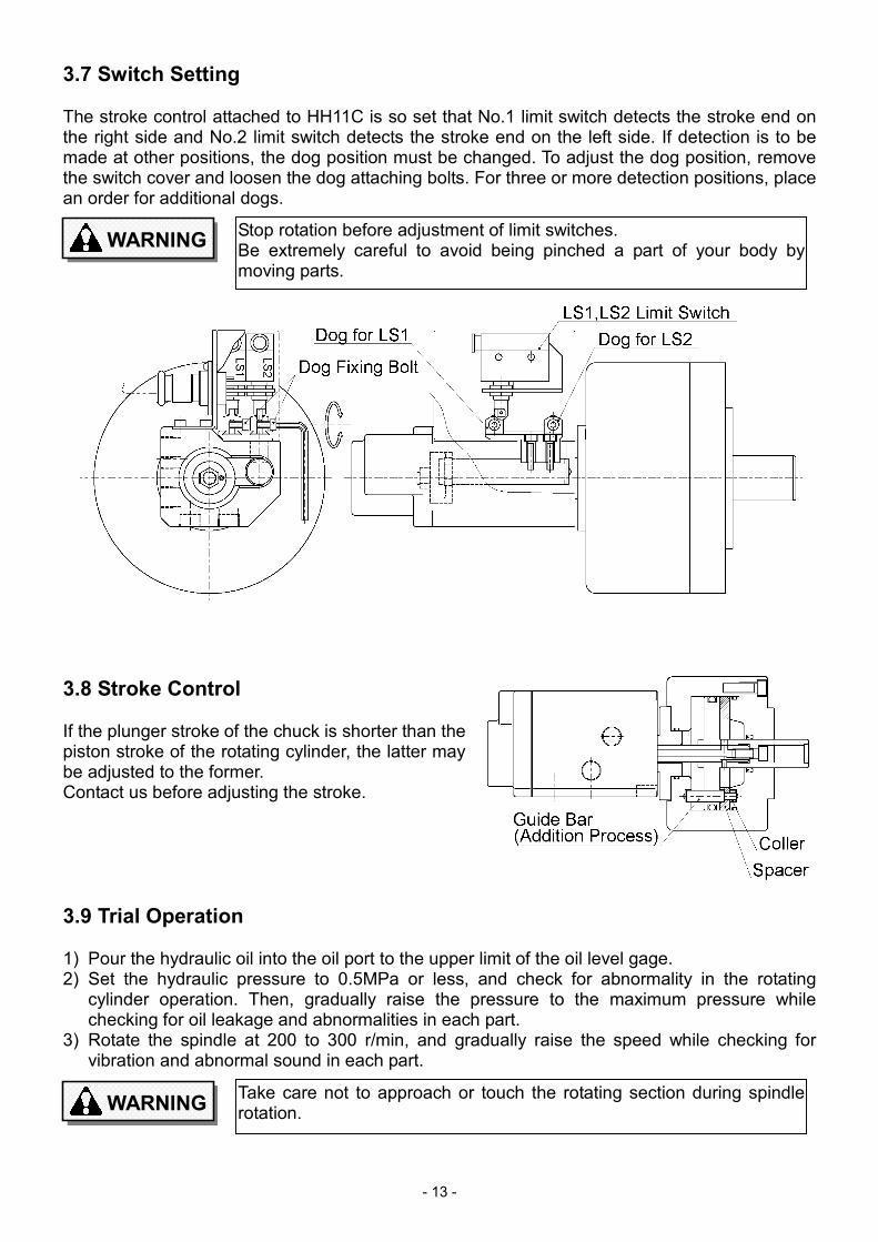
3.7 Switch Setting
The stroke control attached to HH11C is so set that No.1 limit switch detects the stroke end onthe right side and No.2 limit switch detects the stroke end on the left side. If detection is to bemade at other positions, the dog position must be changed. To adjust the dog position, removethe switch cover and loosen the dog attaching bolts. For three or more detection positions, placean order for additional dogs.
3.8 Stroke Control
If the plunger stroke of the chuck is shorter than thepiston stroke of the rotating cylinder, the latter maybe adjusted to the former.Contact us before adjusting the stroke.
3.9 Trial Operation
1) Pour the hydraulic oil into the oil port to the upper limit of the oil level gage.2) Set the hydraulic pressure to 0.5MPa or less, and check for abnormality in the rotating
cylinder operation. Then, gradually raise the pressure to the maximum pressure whilechecking for oil leakage and abnormalities in each part.
3) Rotate the spindle at 200 to 300 r/min, and gradually raise the speed while checking forvibration and abnormal sound in each part.
WARNINGTake care not to approach or touch the rotating section during spindlerotation.
WARNINGStop rotation before adjustment of limit switches.Be extremely careful to avoid being pinched a part of your body bymoving parts.
- 14 -
4. Maintenance and Inspection
4.1 Check of Hydraulic Oil
The bearing is cooled and lubricated with drain so that any special lubricating oil is not necessaryas long as the hydraulic oil is clean. Therefore, for the sake of maintenance of this rotatingcylinder, it is most important to keep the hydraulic oil clean at all times. Check the hydraulic oil inthe following respects.
● Remove of condensation
When the temperature or humidity is high, condensation may be accumulated on the bottomof the hydraulic unit tank. Remove condensation once a week.
● Cleaning of strainer
Remove and clean the strainer of the hydraulic unit once a month by washing it in flushing oiland blowing compressed air through it from the inside.
● Change of hydraulic oil
Change the hydraulic oil once a year. Preheating the oil helps when changing the oil.Replace the old oil entirely with fresh oil. If the old oil is extremely contaminated, clean theinterior of the tank with flushing oil before replacing it with fresh oil.
4.2 Overhaul and Parts List
The rotating cylinder will remain in excellent operating condition for many years as long as it isproperly installed and the hydraulic oil is clean. If failure should occur for any reason,disassemble the rotating cylinder and replace defective parts if necessary.
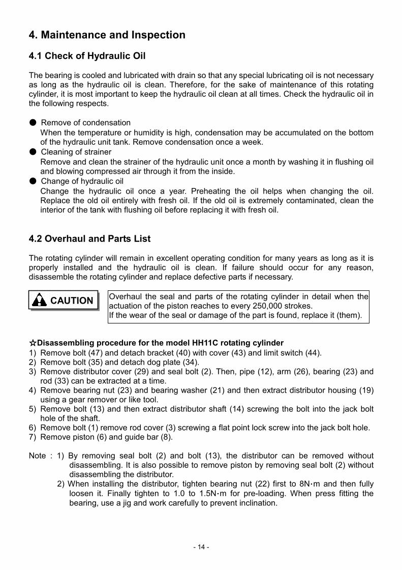
☆☆☆☆Disassembling procedure for the model HH11C rotating cylinder
1) Remove bolt (47) and detach bracket (40) with cover (43) and limit switch (44).2) Remove bolt (35) and detach dog plate (34).3) Remove distributor cover (29) and seal bolt (2). Then, pipe (12), arm (26), bearing (23) and
rod (33) can be extracted at a time.4) Remove bearing nut (23) and bearing washer (21) and then extract distributor housing (19)
using a gear remover or like tool.5) Remove bolt (13) and then extract distributor shaft (14) screwing the bolt into the jack bolt
hole of the shaft.6) Remove bolt (1) remove rod cover (3) screwing a flat point lock screw into the jack bolt hole.7) Remove piston (6) and guide bar (8).
Note : 1) By removing seal bolt (2) and bolt (13), the distributor can be removed withoutdisassembling. It is also possible to remove piston by removing seal bolt (2) withoutdisassembling the distributor.
2) When installing the distributor, tighten bearing nut (22) first to 8N・m and then fully
loosen it. Finally tighten to 1.0 to 1.5N・m for pre-loading. When press fitting thebearing, use a jig and work carefully to prevent inclination.
CAUTIONOverhaul the seal and parts of the rotating cylinder in detail when theactuation of the piston reaches to every 250,000 strokes.If the wear of the seal or damage of the part is found, replace it (them).
- 15 -
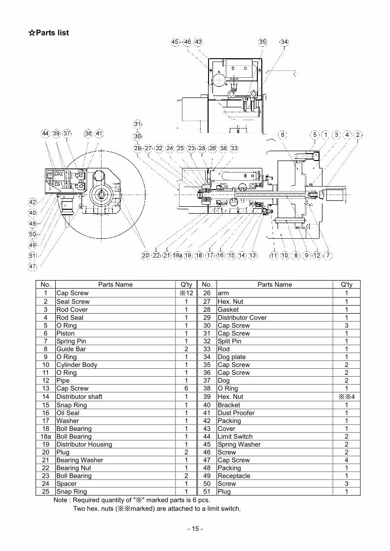
☆☆☆☆Parts list
No. Parts Name Q'ty No. Parts Name Q'ty
1 Cap Screw ※12 26 arm 1
2 Seal Screw 1 27 Hex. Nut 1
3 Rod Cover 1 28 Gasket 1
4 Rod Seal 1 29 Distributor Cover 1
5 O Ring 1 30 Cap Screw 3
6 Piston 1 31 Cap Screw 1
7 Spring Pin 1 32 Split Pin 1
8 Guide Bar 2 33 Rod 1
9 O Ring 1 34 Dog plate 1
10 Cylinder Body 1 35 Cap Screw 2
11 O Ring 1 36 Cap Screw 2
12 Pipe 1 37 Dog 2
13 Cap Screw 6 38 O Ring 1
14 Distributor shaft 1 39 Hex. Nut ※※4
15 Snap Ring 1 40 Bracket 1
16 Oil Seal 1 41 Dust Proofer 1
17 Washer 1 42 Packing 1
18 Boll Bearing 1 43 Cover 1
18a Boll Bearing 1 44 Limit Switch 2
19 Distributor Housing 1 45 Spring Washer 2
20 Plug 2 46 Screw 2
21 Bearing Washer 1 47 Cap Screw 4
22 Bearing Nut 1 48 Packing 1
23 Boll Bearing 2 49 Receptacle 1
24 Spacer 1 50 Screw 3
25 Snap Ring 1 51 Plug 1
Note : Required quantity of "※" marked parts is 6 pcs.
Two hex. nuts (※※marked) are attached to a limit switch.
- 16 -
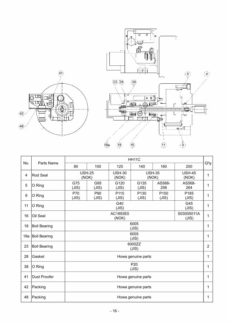
HH11CNo. Parts Name
80 100 125 140 160 200Q'ty
4 Rod SealUSH-25(NOK)
USH-30(NOK)
USH-35(NOK)
USH-45(NOK)
1
5 O RingG75(JIS)
G95(JIS)
G120(JIS)
G135(JIS)
AS568-258
AS568-264
1
9 O RingP70(JIS)
P90(JIS)
P115(JIS)
P130(JIS)
P150(JIS)
P185(JIS)
1
11 O RingG40(JIS)
G45(JIS)
1
16 Oil SealAC1893E0
(NOK)S03005011A
(JIS)1
18 Boll Bearing6005(JIS)
1
18a Boll Bearing6005(JIS)
1
23 Boll Bearing6000ZZ
(JIS)2
28 Gasket Howa genuine parts 1
38 O RingP20(JIS)
1
41 Dust Proofer Howa genuine parts 1
42 Packing Howa genuine parts 1
48 Packing Howa genuine parts 1
- 17 -
LIMITED WARRANTY
20061226
Seller warrants its products to be manufactured in accordance with publishedspecifications and free from defects in material and/or workmanship.Seller, at its option, will repair or replace any products returned intact to the factory,transportation charges prepaid, which seller, upon inspection, shall determine to bedefective in material and/or workmanship. The foregoing shall constitute the sole remedyfor any breach of seller's warranty.Seller makes no warranties, either express or implied, except as provided herein,including without limitation thereof, warranties as to marketability, merchantability,for a particular purpose or use, or against infringement of any patent. In no eventshall seller be liable for any direct, incidental or consequential damages of anynature, or losses or expenses resulting from any defective product or the use of anyproduct.