Embed Size (px)
Citation preview

Zeszyty Problemowe – Maszyny Elektryczne Nr 83/2009 173
Filip Kutt, Michał Michna, Piotr Chrzan, Mieczysław Ronkowski Politechnika Gdańska, Gdańsk
NONLINEAR MODEL OF A SYNCHRONOUS GENERATOR FOR ANALYSIS OF MORE ELECTRIC AIRCRAFT POWER SYSTEMS
NIELINIOWY MODEL GENERATORA SYNCHRONICZNEGODO ANALIZY SYSTEMU ELEKTROENERGETYCZNEGO
NA POKŁADZIE NOWOCZESNEGO SAMOLOTU
Abstract: A nonlinear model for studying a variable-speed synchronous generator (SG) in more electric air-craft (MEA) power system has been developed. The saturation effects of the SG magnetic circuit have been considered. The model has been implemented in the Synopys/Saber simulation environment. The modelling language MAST has been used to elaborate the SG model. The model exhibit a network with the same number of external terminals/ports as the real SG, and represents its behaviour in terms of the electrical (stator and ro-tor windings) and mechanical (shaft) variables as well. The main advantage of the approach is the ease of de-scribing MEA power system in terms of its topology. Thus, normal and fault operation of any MEA power system can be effectively investigated. The presented simulation results have proved that the proposed ap-proach can be recommended for analysis of MEA power systems.
1. Introduction A lot of efforts are currently done into deve-lopment on the concept of the more electric air-craft (MEA) for the electrical design system of commercial aircraft, usable by the business and regional aircraft and rotorcraft as well. The fun-damental MEA concept, which removes hyd-raulic, pneumatic and gearbox driven subsys-tems in favour of electrical driven subsystems, has necessitated the development of high per-formance starter/generator systems and compact lightweight electric drives and servo subsys-tems. As a consequence high power synchro-nous generators (SG) are required to supply the increased electrical power needs on board[4, 5, 9, 11, 12].In MEA power systems SG are driven directly by variable speed prime movers (jet engines), and therefore, operate as variable frequency machines. Compared with the conventional constant frequency generator (50/60 Hz for uti-lity grid and 400 Hz for aircraft systems), the GCU for the variable frequency system must deal with significant variations in operating points and associated dynamics due to a wide frequency range (greater than 2:1 in some MEA systems).A typical electric power generator in MEA ap-plications is actually composed of two synchro-nous machines, a rectifier and a small perma-nent magnet generator (PMG), on the same shaft [5, 10]. One synchronous machine is the
main generator and the other smaller lower rat-ing machine with its field winding on the statorworks as the brushless exciter. For the evaluation of aircraft on-board electric power systems and electric servo systems with regard to their weight, behaviour and reliability a novel modelling and simulation tools are being developed [2]. One essential requirement for a simulation environment of MEA power systems consisting of many nonlinear compo-nents is mutliphysical modelling that allows to simulate all aircraft systems, which use diffe-rent forms of power, in one integrated model. Different physical domains have to be consi-dered in the simulation of complex aircraft sys-tems with high computational efficiency. The integrated model uses component models, that are being delivered by the equipment manufac-turers, to compose an integrated aircraft sys-tems model.A key technique in achieving this is the use of an advanced network solver such as Synop-sys/Saber based on a mixed-signal hardware description language called MAST [13, 14].While using the modelling language MAST you are not only able to develop the various mathe-matical-based models you need, but are also able to develop mixed-signal and multi-physical (mixed-technology) models. Moreover, MAST models can be made at any level of abstraction – from simple transfer function descriptions, to
Zeszyty Problemowe – Maszyny Elektryczne Nr 83/2009174
detailed physics-based descriptions. And they can be mixed throughout multiple levels of hierarchy.The importance of SG in MEA power systems has been well recognized. They are highly nonlinear, complex electromechanical device, whose dynamic behaviour directly impacts the performance and reliability of the power system network [3, 5, 10, 11, 12]. To analyze the dy-namic behaviour of the SG, an effective and ac-curate simulation model is desired. However, it is difficult to develop such a model due to thenonlinear inductances of the SG windings. Fur-ther, the model needs to account for dynamics involving electrical and mechanical domains.In the paper [9] a background has been dis-cussed for using the MAST language to model a SG for investigating the multi-physical power behaviour of MEA power systems. However, the magnetic circuit saturation effects have not been considered. This paper describes the use of the Synop-sys/Saber and MAST language for modellingthe SG magnetic saturation in both the q- and d-axis while keeping the terminal characteris-tics of the machine in the physical domain. This approach simplifies the interconnection of the machine model with power electronic recti-fiers/converters. It has been shown that this SG model is computationally efficient and suitable for dynamic time-domain MEA power system studies.
1. SG modelling
1.1. Hypothesis and assumptions
A SG, according to its degree of freedom, can be represented as a multi-port electromechani-cal converter with pair of terminals (ports), which are the windings and shaft terminals (ports).The structure of a SG model depends upon the assumed modelling of the energy transforma-tion, energy conversion, energy accumulation and energy dissipation processes in SG. For developing the SG model in terms of its ports/terminals variables, i.e., especially for MEA power system analysis and design, the general equations of motion of SG are recalled, and next a combined variables transformationsfrom the natural stator as bs cs axes to q d 0 axes, and vice versa, are performed under the conventional assumptions [1, 3, 6, 7, 8, 9, 10,11].
1.2. Model equations and its implementations into MAST language
Voltages, currents and flux-linkages equa-tions in terms of q d 0 axes variables:
tirv qs
dseqssqs d
d (1)
tirv ds
qsedssds d
d (2)
tirv 0s0ss0s d
d (3)
tir kqkqkq d
d0
(4)
tirv fd
fdfdfd d
d (5)
tir kdkdkd d
d0
(6)
where, me p ; p – number of pole pairs,
m - angular rotor (mechanical) speed.
The above equations in terms of MAST lan-guage:iqs: vqs = Rs*iqs + we*phids + d_by_dt(phiqs) #ids: vds = Rs*ids - we*phiqs + d_by_dt(phids) #i0s: v0s = Rs*i0s + d_by_dt(phi0s) #ikq: 0 = Rkq*ikq + d_by_dt(phikq) #ifd: vfd = Rfd*ifd + d_by_dt(phifd) #ikd: 0 = Rkd*ikd + d_by_dt(phikd) #
Torque and angular speed equations:
mmm
em Bt
JTT
d
d(7)
tm d
d (8)
dsqsqsdse iipT
2
3(9)
The above equations in terms of MAST lan-guage:# torque equationvisc = Bm*wmTe = 3/2*p*((phids*iqs)-(phiqs*ids)) tq_Nm(rotor) += Te - visc – mommom= d_by_dt(Jw*wm)alpha: wm=d_by_dt(alpha)
1.3. Modelling magnetic saturation effects
Most of the methods currently being used to calculate the saturated values of inductances are based on the open circuit saturation curve for magnetizing inductances, and on the short-circuit saturation curve for leakage inductances

Zeszyty Problemowe – Maszyny Elektryczne Nr 83/2009 175
as a reference to find the saturation-dependent inductances in functional forms [1, 4, 7, 8, 11].In general, for a given saturation curve = (i), the inductances can be expressed as
followsi
L
and i
L_
. Where, L is re-
ferred to as static (chord slope) saturated induc-
tance, and L as dynamic (tangent-slope or incremental) inductance. It should be noticed that when the flux linkage is assumed as a state variable then the dynamic inductance is not necessary.The model of saturation effects can be further developed by assuming a fictitious equivalent coil (i.e. the magnetic axis of the fictitious equivalent coil coincides with the resultant MMF due to the total current i) which carries a current i producing a flux-linkage .It should be noted that the approach making use of the unique magnetization characteristic can be applied directly to smooth-air-gap machine. In the salient-pole machine, because of the physical saliency, in general, the magnetizing flux-linkage space vector is not coaxial with the magnetizing current space vector (the resultant flux wave is not collinear with the resultant MMF wave). Thus it is more problematic to characterise the saturation level in the saturated salient-pole machine than in the saturated smooth-air-gap machine, where the magneti-zing flux-linkage space vector is coaxial with the magnetizing-current vector and where the amplitude of the magnetizing flux-linkage space vector is a non-linear function of the magnetizing current. However, it may be as-sumed that the pole tips and/or the teeth are the most saturated parts of the magnetic circuit, and therefore, as for the smooth-air-gap machine, in each axis the saturation level is determined by the amplitude of the magnetizing-current space vector.According to the above consideration the mag-netic saturation of the SG magnetic circuit can be represented by the following characteristic:
mm if (10)
where, the total magnetizing current im is re-ferred to the turns of field winding, and is de-fined as following:
22mqmdm iii (11)
kddsfdfd
md iiik
i 1
(12)
kqqsfd
mq iik
i 1
(13)
where, coefficient md
sfdfd L
Lk
The coefficient kfd refers the mutual stator–field inductance Lsfd to the magnetizing induc-tance Lmd.To represent the characteristics mm if for
the q and d axes flux-linkages, in terms of the SG inductances, the following functions are used:
mqmsatsatmq
mdmsatsatmd
LikL
LikL
_
_(14)
where, ksat – saturation coefficient, Lmd_sat, Lmq_sat – saturated magnetizing inductances in d and q axis respectively; Lmd, Lmq - unsaturated magnetizing inductances in d and q axis respec-tively. It has been assumed that the coefficient ksat has the same value for the magnetic circuit in q and d axes, respectively.Using the above relations the SG flux linkages, used in the equations (1)–(6) and (9), are de-fined as following:
kqqsmqsatqslsqs iiLkiL (15)
remkdfddsmdsatdslsds iiiLkiL (16)
slss iL 00 (17)
kqqsmqsatkqlkqkq iiLkiL (18)
kdfddsmdsatfdlfdfd iiiLkiL (19)
kdfddsmdsatkdlkdkd iiiLkiL (20)
where, rem – remanence flux.
The saturation coefficient ksat is evaluated using the no-load voltage characteristic. This charac-teristic is measured as following: open circuit terminal voltage Vq0 versus field current Ir (ac-tual field current), and open circuit terminal voltage Vq0rem versus remanence flux rem .
Using the equations (1) and (16) for the no-load case of the SG, we have:
dseqV 0 (21)
Zeszyty Problemowe – Maszyny Elektryczne Nr 83/2009176
remeremqV 0
remfdsatmdds iL _ (22)
Using the equations (21) and (22) the saturated magnetizing inductance Lmd_sat and saturation coefficient ksat can be calculated as following:
re
remqq
r
remdssatmd I
VV
IL
00
_
(23)
sfd
satmdsat L
Lk _ (24)
where, the value of the mutual inductance Lsfd is evaluated as satmdsfd LL _maxTo implement the no-load voltage characteristic(saturation characteristic) of SG into the MAST language the table look-up tool (TLU) of the MAST language is used as aforeign routine. The fallowing assumptions are used for this ap-proximations: (i) linear interpolation, (ii) linear extrapolation at low and high ends of the no-load characteristic, respectively.The data file containing the points of the no-load characteristic is elaborated as follows:
field current(A)
0.000 60.300 170.400 230.575 29…
no-load voltage RMS (V)
In the parameter section of the SG MAST model the following data preprocessing have been done:# TLU data pre-processing (performs data check-ing, sorting and grid filling.)
datap=tlu(0,1,sat_file,"",sat_interp,sat_extrap)# TLU returns the sample points array for the in-dependent variable
sp1=tlu(1,addr(datap),1,sat_density) Sample Point Array
In the values section the TLU function is called to return the output value of the function for the given input values as following:#------TLU Function EvaluationVq0=tlu(2,addr(datap),im)v_rem=tlu(2,addr(datap),0)
andLmdsat=sqrt(2)*vq0/(im*sat_rpm*math_pi*p/30) phifd_rem=sqrt(2)*v_rem/(sat_rpm*math_pi*p/30)Ksat=Lmdsat/Lsfd# saturation coefficient
The flux linkages equations (15)-(20) of the SG in terms of MAST language are following:
phiqs = Lls*iqs + ksat*Lmq*(iqs+ikq)
phids = Lls*ids + ksat*Lmd*(ids + ifd + ikd)+phifd_rem
phi0s = Lls*i0s
phikq = Llkq*ikq + ksat*Lmq*(iqs + ikq)
phifd = Llfd*ifd + ksat*Lmd*(ids + ifd + ikd)
phikd = Llkd*ikd + ksat*Lmd*(ids + ifd + ikd)
2. SG simulations using Synopsys/SaberTo verify the proposed SG modelling approach,taking into account the saturation of magnetic circuit, the no-load and short circuit tests have been simulated. The tests have been carried out for a SG of the type GCe64o/1 produced by ELMOR.
2.1. No-load test
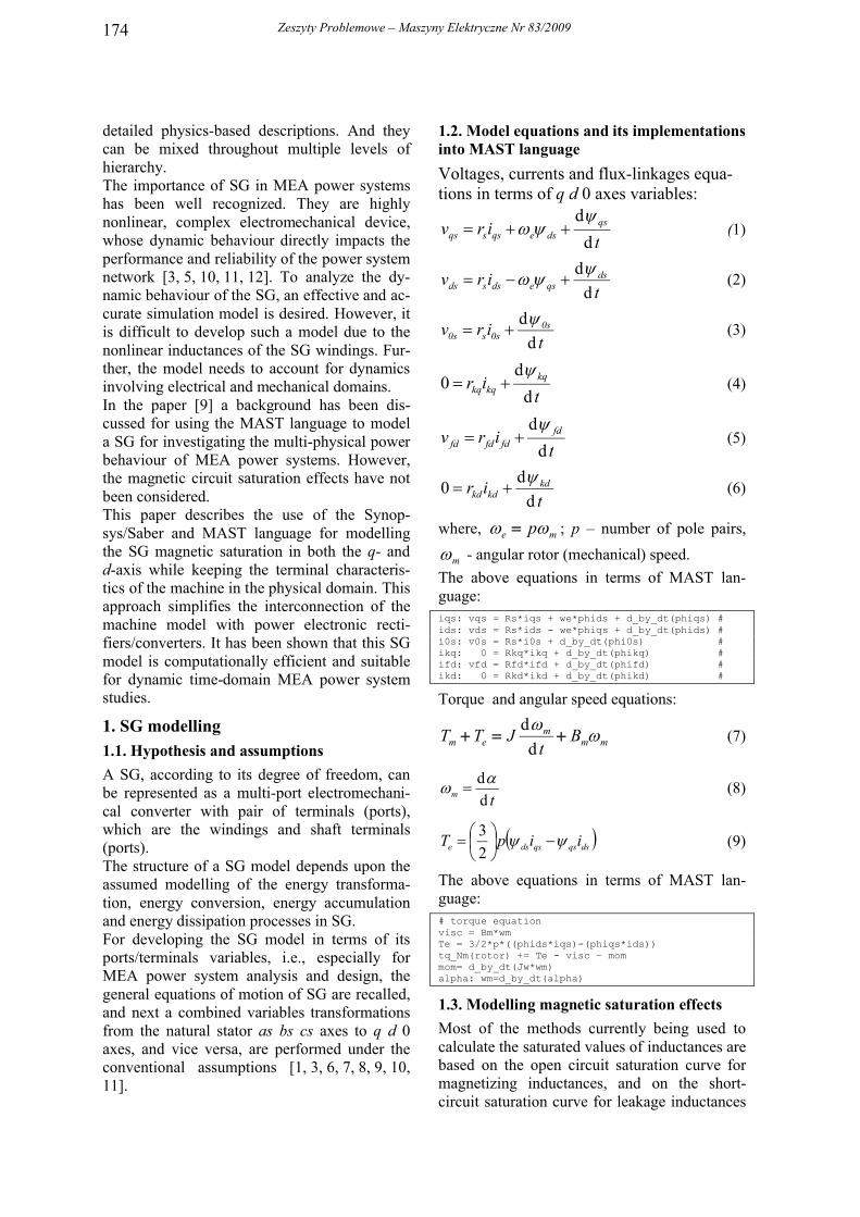
The topology of the simulated SG circuits is shown in Fig. 1, where the machine model is denoted by “ref:SME2009”. The “inside” of this model contain the equations and formulae presented in section 2. The results of the no-load test are shown in Fig. 2 and Fig. 3.
Fig. 1. Topology of the simulated SG circuitsfor no load test
2.2. 3-phase short circuit test
The topology of the simulated SG circuit is shown in Fig.4, where the machine model is denoted by “ref:SME2009”. The “inside” of this model contain the equations and formulae presented in section 2. The results of the short circuit test are shown in Fig. 5 and Fig. 6. The constant angular speed oeration of the SG has been assumed.The simulation results have shown that mag-netic saturation has an influence on the tested SG current values. The difference for the arma-ture currents is about 6%. It has to be noticed that this relatively small difference refers to the

Zeszyty Problemowe – Maszyny Elektryczne Nr 83/2009 177
short circuit test, when the saturation level is low due to the armature demagnetization. The difference will be much lager for the SG tran-sient states under loaded conditions.The comparison of the simulation and measured results for the studied SG will be presented at the conference.
Fig. 2. Open circuit voltage versus field cur-rent: measured (+) and simulation (-) results
Fig. 3. Coefficient ksat, saturated inductance Lmdsat and open circuit voltage versus field cur-rent: measured (+) and simulation (-) results
Fig. 4. Topology of the simulated SG circuits for short circuit test
Fig. 5. Simulation results of the short circuittest (ir – field current current, ias – armature current – at the time of the short circuit the ar-mature voltage has maximum value: linear (red line) and nonlinear (green line) magnetic cir-cuit
Fig. 6. Simulation results of the short circuittest (ir – field current, ias – armature current –at the time of the short circuit the armature voltage has zero value: linear (red line) and nonlinear (green line) magnetic circuit
3. ConclusionsA nonlinear model for studying a variable-speed synchronous generator (SG) in more elec-tric aircraft (MEA) power system has been de-veloped. The saturation effects of the SG mag-netic circuit have been considered. The model has been implemented in the Synopys/Saber simulation environment. The modelling lan-guage MAST has been used to elaborate the SG model. The model exhibit a network with the same number of external terminals/ports as the real SG, and represents its behaviour in terms of the electrical (stator and rotor windings) and mechanical (shaft) variables as well. The main advantage of the approach is the ease of des-cribing MEA power system in terms of its to-pology. Thus, normal and fault operation of any

Zeszyty Problemowe – Maszyny Elektryczne Nr 83/2009178
MEA power system can be effectively investi-gated. The presented simulation results have proved that the proposed approach can be re-commended for analysis of MEA power sys-tems.
4. Bibliography [1] Aliprantis D.C., Sudhoff S.D., Kuhn B.T.: ASynchronous Machine Model With Saturation and Ar-bitrary Rotor Network Representation. IEEE Transac-tions on Energy Conversion, vol. 20, no. 3, September 2005, pp. 584-594[2] Bals J., Hofer G., Pfeiffer A., Schallert C.: Ob-ject-Oriented Inverse Modelling of Multi-Domain Air-craft Equipment Systems with Modelica. 3rd Interna-tional Modelica Conference, November 3-4, 2003, pp.377-384[3] Bruck F.M., Himmelstoss, F.A.: Modelling and simulation of a synchronous machine. 6th Workshop on Computers in Power Electronics, 19-22 July, 1998, pp. 81-86[4] Engelsman J. K., Wells J. R., Walters E. A., Lamm P. T., Daniels M.: Development of a Simulation Model for an Aircraft Electrical Main Generator. Ap-plied Power Electronics Conference and Exposition, 2008. APEC 2008. Twenty-Third Annual IEEE, pp.1679-1684[5] Gieras J. F.: Advancements in Electric Machines.Springer Verlag 2008[6] Krause P.C.: Analysis of electric machinery.McGraw-Hill, USA, 1986[7] Kudła J.: Modele matematyczne maszyn elek-trycznych prądu przemiennego uwzględniające nasy-cenie magnetyczne rdzeni. Zeszyty Naukowe Pol. Ślą-skiej, Nr 1683, Gliwie 2005[8] Levi E.: Modelling of Magnetic Saturation in Smooth Air-Gap Synchronous Machines. IEEE Trans-actions on Energy Conversion, Vol. 12, No. 2, June 1997, pp. 151-156
[9] Michna M., Kutt F., Chrzan P., Ronkowski M.: Modelling and analysis of a synchronous generator in more electric aircraft power system using Synop-sys/Saber simulator. Proc. International XVI Sympo-sium Micromachines & Servosystems, Straszyn, Pol-and, 14-18.09.2008, pp. 1-10[10] Rosado S., Xiangfei M., Francis G., Fei Wang, Boroyevich D.: Model-Based Digital Generator Con-trol Unit for a Variable Frequency Synchronous Gene-rator With Brushless Exciter. IEEE Transaction on Energy Conversion 2008, pp. 42-52[11] Tantawy A., Koutsoukos X., Biswas G.: Aircraft AC generators: Hybrid system modeling and simula-tion. Digital Avionics Systems Conference, 2008. DASC 2008. IEEE/AIAA 27th, pp. 1-11[12] Weimer, J.A.: The role of electric machines and drives in the more electric aircraft. IEEE International Electric Machines and Drives Conference IEMDC'03, 2003. Vol. 1, 1-4 June 2003, pp. 11-15[13] The Designer’s Guide to Analog & Mixed-Signal Modeling - Illustrated withVHDL-AMS and MAST. Version Z-2007.03-SP2, SYNOPSYS, August 2007[14] http://www.synopsys.com
Authors
Filip Kutt, M.Sc., Eng., PhD student, e-mail: [email protected]ł Michna, Ph.D., Eng., e-mail: [email protected] Chrzan, Ph.D., D.Sc., Eng., associate prof., e-mail: [email protected]ław Ronkowski, Ph.D., D.Sc., Eng., associate prof., e-mail: [email protected] University of Technology, Faculty of Electrical and Control Engineering, Narutowicza 11/12, 80-952 Gdańsk, Poland, tel. +(48-58)3472087, fax: +(48-58)3410880