Embed Size (px)
Citation preview
1© KEMET Electronics Corporation • KEMET Tower • One East Broward Boulevard F3025_PMR209 • 3/26/2019Fort Lauderdale, FL 33301 USA • 954-766-2800 • www.kemet.com
One world. One KEMET
Benefits
• Approvals: ENEC, UL, cUL• Rated voltage: 250 VAC 50/60Hz• Capacitance range: 0.047 – 0.47 µF • Capacitance tolerance: ±20%• Resistancerange:22–470Ω• Resistance tolerance: ±30%• Lead Spacing: 15.2 – 25.4 mm• Climatic category: 40/085/56/B, IEC 60068–1• Tape & Reel packaging in accordance with IEC 60286–2• RoHS compliance and lead-free terminations• Operatingtemperaturerangeof−40°Cto+85°C
Overview
Multilayer metallized paper encapsulated and impregnated in self-extinguishing material that meets the requirements of UL 94 V–0.
Applications
For worldwide use in contact protection, contact interference suppression, and transient suppression.
AC Line EMI Suppression and RC Networks
PMR209, Metallized Impregnated Paper, Class X2, 250 VAC
Legacy Part Number System
PMR209 M B 5470 M 047 R30
SeriesRated Voltage
(VAC)Lead Spacing
(mm)Capacitance
Code (pF)Capacitance
ToleranceResistance(Ω) Packaging
RC Snubber, Metallized Paper
M = 250 B = 15.2 C = 20.3 E = 25.4
The last three digits represent
significantfigures.Thefirstdigit
specifiesthetotalnumber of digits.
M = ±20% Resistance Value inΩ
See Ordering Options Table
New KEMET Part Number System
P 409 Q M 473 M 250 A H470Capacitor
ClassSeries
Lead Spacing(mm)
Size Code Capacitance Code (pF)Capacitance
ToleranceRated Voltage
(VAC)Packaging Resistance(Ω)
P= Metallized
Paper
RC Snubber Q = 15.2 C = 20.3 E = 25.4
See Dimension
Table
First two digits representsignificantfigures.Thirddigitspecifiesnumberof
zeros.
M = ±20% 250 = 250 See Ordering Options Table
Hplusfirsttwodigits represent
significantfigures.Thirddigitspecifiesnumber
of zeros.
Not recommended for new design. Replacement series P409 275VAC.

2© KEMET Electronics Corporation • KEMET Tower • One East Broward Boulevard F3025_PMR209 • 3/26/2019Fort Lauderdale, FL 33301 USA • 954-766-2800 • www.kemet.com
Film Capacitors – AC Line EMI Suppression and RC NetworksPMR209, Metallized Impregnated Paper, Class X2, 250 VAC
Benefits cont'd
• Excellent self-healing properties that ensure long life, even when subjected to frequent over-voltages
• Good resistance to ionization due to impregnated paper dielectric
• High dv/dt capability• Impregnated paper ensures excellent stability and reliability
properties, particularly in applications with continuous operation
Ordering Options Table
Lead SpacingNominal
(mm)
Type of Leads and PackagingLead
Length(mm)
KEMET Lead and
Packaging Code
Legacy Lead and
Packaging Code
15.2
Standard Lead and Packaging Options
Bulk (Bag) – Short Leads 6+0/−1 C R06Bulk (Bag) – Maximum Length Leads 30+5/−0 A R30Tape&Reel(StandardReelΦ=360mm) H0= 18.5 ±0.5 L R19T0
20.3
Standard Lead and Packaging Options
Bulk (Tray) – Short Leads 6+0/−1 C R06Bulk (Bag) – Maximum Length Leads 30+5/−0 A R30Tape&Reel(StandardReelΦ=360mm) H0= 18.5 ±0.5 L R19T0
25.4Standard Lead and Packaging Options
Bulk (Bag) – Short Leads 6+0/−1 C R06Bulk (Tray) – Maximumn Length Leads 30+5/−0 A R30
Not recommended for new design. Replacement series P409 275VAC.

3© KEMET Electronics Corporation • KEMET Tower • One East Broward Boulevard F3025_PMR209 • 3/26/2019Fort Lauderdale, FL 33301 USA • 954-766-2800 • www.kemet.com
Film Capacitors – AC Line EMI Suppression and RC NetworksPMR209, Metallized Impregnated Paper, Class X2, 250 VAC
Dimensions – Millimeters
L B
FRONT VIEW SIDE VIEW
H
LL
p
d
Size Codep B H L d
Nominal Tolerance Nominal Tolerance Nominal Tolerance Nominal Tolerance Nominal Tolerance
QM 15.2 ±0.4 7.3 Maximum 13.0 Maximum 18.5 Maximum 0.8 ±0.05CE 20.3 ±0.4 7.6 Maximum 14.0 Maximum 24.0 Maximum 0.8 ±0.05CP 20.3 ±0.4 11.3 Maximum 16.5 Maximum 24.0 Maximum 0.8 ±0.05EJ 25.4 ±0.4 12.1 Maximum 19.0 Maximum 30.5 Maximum 1.0 ±0.05EL 25.4 ±0.4 15.3 Maximum 22.0 Maximum 30.5 Maximum 1.0 ±0.05
Note: See the Ordering Options Table for lead length (LL) options.
Not recommended for new design. Replacement series P409 275VAC.
4© KEMET Electronics Corporation • KEMET Tower • One East Broward Boulevard F3025_PMR209 • 3/26/2019Fort Lauderdale, FL 33301 USA • 954-766-2800 • www.kemet.com
Film Capacitors – AC Line EMI Suppression and RC NetworksPMR209, Metallized Impregnated Paper, Class X2, 250 VAC
Performance Characteristics
Rated Voltage 250 VAC 50/60 Hz
Capacitance Range 0.047 – 0.47 µF
Capacitance Tolerance ±20%
Resistance Range 22–470Ω
Resistance Tolerance ±30%
Temperature Range −40°Cto+85°C
Climatic Category 40/085/56/B
Approvals ENEC, UL, cUL
Peak Pulse Voltage 1,000 V
Series Resistance Theseriesresistanceisdefinedat1kHzforRC≥50µsandat100 kHz for RC < 50 µs
Insulation Resistance
Minimum Values Between Terminals
C≤0.33µF ≥3,000MΩ
C > 0.33 µF ≥1,000MΩ•µF
Pulse Current Maximum 12 A repetitive. Maximum 20 A peak for occasional transients.
Test Voltage Between Terminals
The 100% screening factory test is carried out at 1,800 VDC. The voltage level is selected to meet the requirements in applicable equipment standards. All electrical characteristics are checked after the test.
In DC Applications Recommendedvoltage≤630VDC
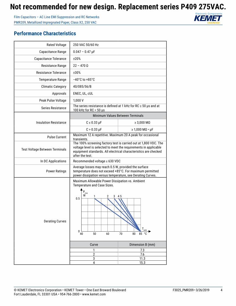
Power RatingsAverage losses may reach 0.5 W, provided the surface temperaturedoesnotexceed+85°C.Formaximumpermittedpower dissipation versus temperature, see Derating Curves.
Derating Curves
Maximum Allowable Power Dissipation vs. Ambient Temperature and Case Sizes.
40
Maximum Allowable Power Dissipation vsAmbient Temperature & Case Sizes
1 2 3 4 5
0
0.5
50 60 70 80 85 °C
Tamb
PmaxW
Curve Dimension B (mm)1 7.32 7.63 11.34 15.3
Not recommended for new design. Replacement series P409 275VAC.
5© KEMET Electronics Corporation • KEMET Tower • One East Broward Boulevard F3025_PMR209 • 3/26/2019Fort Lauderdale, FL 33301 USA • 954-766-2800 • www.kemet.com
Film Capacitors – AC Line EMI Suppression and RC NetworksPMR209, Metallized Impregnated Paper, Class X2, 250 VAC
Environmental Test Data
Test IEC Publication Procedure
Endurance IEC 60384–14 1.25 x VR VAC 50 Hz, once every hour increased to 1,000 VAC for 0.1 second, 1,000 hours at upper rated temperature.
Vibration IEC 60068–2–6 Test Fc 3 directions at 2 hours each, 10 – 500 Hz at 0.75 mm or 98 m/s2
Bump IEC 60068–2–29 Test Eb 4,000 bumps at 390 m/s2
Change of Temperature IEC 60068-2-14 Test Na Upper and lower rated temperature 5 cycles
Active Flammability IEC 60384–14 VR+20surgepulsesat2.5kV(pulseevery5seconds)
Passive Flammability IEC 60384–14 IEC60384–1,IEC60695–11–5Needle-flametest
Damp Heat Steady State IEC 60068–2–78 Test Cab +40°Cand93%RH,56days
Approvals
Certification Body Mark Specification File Number
Intertek Semko AB EN/IEC 60384–14 SE/0140–28D
UL UL 60384–14 CAN/CSA–E60384–14–09 E73869
Environmental Compliance
All KEMET EMI capacitors are RoHS compliant.
Not recommended for new design. Replacement series P409 275VAC.

6© KEMET Electronics Corporation • KEMET Tower • One East Broward Boulevard F3025_PMR209 • 3/26/2019Fort Lauderdale, FL 33301 USA • 954-766-2800 • www.kemet.com
Film Capacitors – AC Line EMI Suppression and RC NetworksPMR209, Metallized Impregnated Paper, Class X2, 250 VAC
Table 1 – Ratings & Part Number Reference
Lead Spacing (p)
Capacitance Value (µF)
Resistance (Ω)
Maximum Dimensions in mm New KEMET Part Number
Legacy Part NumberB H L
15.2 0.047 47 7.3 13.0 18.5 P409QM473M250(1)H470 PMR209MB5470M047(1)15.2 0.047 100 7.3 13.0 18.5 P409QM473M250(1)H101 PMR209MB5470M100(1)20.3 0.1 22 7.6 14.0 24.0 P409CE104M250(1)H220 PMR209MC6100M022(1)20.3 0.1 33 7.6 14.0 24.0 P409CE104M250(1)H330 PMR209MC6100M033(1)20.3 0.1 47 7.6 14.0 24.0 P409CE104M250(1)H470 PMR209MC6100M047(1)20.3 0.1 68 7.6 14.0 24.0 P409CE104M250(1)H680 PMR209MC6100M068(1)20.3 0.1 100 7.6 14.0 24.0 P409CE104M250(1)H101 PMR209MC6100M100(1)20.3 0.1 150 11.3 16.5 24.0 P409CP104M250(1)H151 PMR209MC6100M150(1)20.3 0.1 220 11.3 16.5 24.0 P409CP104M250(1)H221 PMR209MC6100M220(1)20.3 0.1 330 11.3 16.5 24.0 P409CP104M250(1)H331 PMR209MC6100M330(1)20.3 0.1 470 11.3 16.5 24.0 P409CP104M250(1)H471 PMR209MC6100M470(1)20.3 0.22 22 11.3 16.5 24.0 P409CP224M250(1)H220 PMR209MC6220M022(1)20.3 0.22 33 11.3 16.5 24.0 P409CP224M250(1)H330 PMR209MC6220M033(1)20.3 0.22 47 11.3 16.5 24.0 P409CP224M250(1)H470 PMR209MC6220M047(1)20.3 0.22 68 11.3 16.5 24.0 P409CP224M250(1)H680 PMR209MC6220M068(1)20.3 0.22 100 11.3 16.5 24.0 P409CP224M250(1)H101 PMR209MC6220M100(1)20.3 0.22 150 11.3 16.5 24.0 P409CP224M250(1)H151 PMR209MC6220M150(1)20.3 0.22 220 11.3 16.5 24.0 P409CP224M250(1)H221 PMR209MC6220M220(1)25.4 0.22 330 12.1 19.0 30.5 P409EJ224M250(1)H331 PMR209ME6220M330(1)25.4 0.22 470 15.3 22.0 30.5 P409EL224M250(1)H471 PMR209ME6220M470(1)25.4 0.47 33 15.3 22.0 30.5 P409EL474M250(1)H330 PMR209ME6470M033(1)25.4 0.47 47 15.3 22.0 30.5 P409EL474M250(1)H470 PMR209ME6470M047(1)25.4 0.47 68 15.3 22.0 30.5 P409EL474M250(1)H680 PMR209ME6470M068(1)25.4 0.47 100 15.3 22.0 30.5 P409EL474M250(1)H101 PMR209ME6470M100(1)25.4 0.47 150 15.3 22.0 30.5 P409EL474M250(1)H151 PMR209ME6470M150(1)25.4 0.47 220 15.3 22.0 30.5 P409EL474M250(1)H221 PMR209ME6470M220(1)
LeadSpacing (p)
Capacitance Value (µF) Resistance Ω B (mm) H (mm) L (mm) New KEMET
Part NumberLegacy
Part Number
(1) Insert lead and packaging code. See Ordering Options Table for available options.
Not recommended for new design. Replacement series P409 275VAC.

7© KEMET Electronics Corporation • KEMET Tower • One East Broward Boulevard F3025_PMR209 • 3/26/2019Fort Lauderdale, FL 33301 USA • 954-766-2800 • www.kemet.com
Film Capacitors – AC Line EMI Suppression and RC NetworksPMR209, Metallized Impregnated Paper, Class X2, 250 VAC
Soldering Process
The implementation of the RoHS directive has resulted in the selection of SnAuCu (SAC) alloys or SnCu alloys as primary solder. This has increased the liquidus temperature from that of 183ºC for SnPb eutectic alloy to 217 – 221ºC for the new alloys. As a result, the heat stress to the components, even in wave soldering, has increased considerably due to higher pre-heat and wave temperatures. Polypropylene capacitors are especially sensitive to heat (the melting point of polypropylene is 160 – 170ºC). Wave soldering can be destructive, especially for mechanically small polypropylene capacitors (with lead spacing of 5 – 15 mm), andgreatcaremustbetakenduringsoldering.TherecommendedsolderprofilesfromKEMETshouldbeused.ConsultKEMETwith any questions. In general, the wave soldering curve from IEC Publication 61760-1 Edition 2 serves as a solid guideline for successful soldering. See Figure 1.
Reflowsolderingisnotrecommendedforthrough-holefilmcapacitors.Exposingcapacitorstoasolderingprofileinexcessoftherecommended limits may result in degradation of or permanent damage to the capacitors.
Do not place the polypropylene capacitor through an adhesive curing oven to cure resin for surface-mount components. Insert through-holepartsaftercuringthesurface-mountparts.ConsultKEMETtodiscusstheactualtemperatureprofileintheoven,ifthrough-hole components must pass through the adhesive curing process. A maximum of two soldering cycles is recommended. Allow time for the capacitor surface temperature to return to a normal temperature before the second soldering cycle.
Manual Soldering Recommendations
Following is the recommendation for manual soldering with a soldering iron.
Soldering iron tip temperature should be set at 350°C(+10°Cmaximum),withthesolderingduration not to exceed more than 3 seconds.
Recommended Soldering Temperature
0
50
100
150
200
250
300
350
400
0 1 2 3 4 5 6 7 8
Soldering Time (seconds)
Sold
erin
g Iro
n Bi
t Tem
pera
ture
(°C)
Wave Soldering Recommendations
0
50
100
150
200
250
300
0 40 80 120 160 200 240
Tem
pera
ture
(°C)
Time (s)
ca 2°C/second
ca 3.5°C/second typical
ca 5°C/second
Cooling
2 +3 seconds maximum
115 °C maxTpreheat
∆T < 150°C
100 °C
Preheating
Typical
First wave Second wave
260°C
Not recommended for new design. Replacement series P409 275VAC.

8© KEMET Electronics Corporation • KEMET Tower • One East Broward Boulevard F3025_PMR209 • 3/26/2019Fort Lauderdale, FL 33301 USA • 954-766-2800 • www.kemet.com
Film Capacitors – AC Line EMI Suppression and RC NetworksPMR209, Metallized Impregnated Paper, Class X2, 250 VAC
Soldering Process cont'd
Wave Soldering Recommendations cont'd1. The table indicates the maximum setup temperature for the soldering process.
Dielectric film
material
Maximum Preheat Temperature Maximum Peak Soldering Temperature
Capacitor Pitch≤10mm
Capacitor Pitch = 15 mm
Capacitor Pitch > 15 mm
Capacitor Pitch≤15mm
Capacitor Pitch > 15 mm
Polyester 130°C 130°C 130°C 270°C 270°C
Polypropylene 100°C 110°C 130°C 260°C 270°C
Paper 130°C 130°C 140°C 270°C 270°C
Polyphenylene Sulphide 150°C 150°C 160°C 270°C 270°C
2. The maximum temperature measured inside the capacitor: set the temperature so that inside the element the maximum temperature is below the limit.
Dielectric Film Material Maximum Temperature Measured Inside the Element
Polyester 160°C
Polypropylene 110°C
Paper 160°C
Polyphenylene Sulphide 160°C
Temperature monitored inside the capacitor.
Selective Soldering Recommendations
Selectivedipsolderingisavariationofreflowsoldering.Inthismethod,theprintedcircuitboardwiththrough-holecomponentstobesolderedispreheatedandtransportedoverthesolderbath,asinnormalflowsoldering,without touching the solder. When the board is over the bath, it is stopped. Pre-designed solder pots are lifted from the bath with molten solder, only at the places of the selected components, and pressed against the lower surface of the board to solder the components.
Thetemperatureprofileforselectivesolderingissimilartothedoublewaveflowsolderingoutlinedinthisdocument.However, instead of two baths, there is only one with a time from 3 to 10 seconds. In selective soldering, the risk of overheatingisgreaterthanindoublewaveflowsoldering.Greatcaremustbetakensothatthepartsdonotoverheat.
Not recommended for new design. Replacement series P409 275VAC.
9© KEMET Electronics Corporation • KEMET Tower • One East Broward Boulevard F3025_PMR209 • 3/26/2019Fort Lauderdale, FL 33301 USA • 954-766-2800 • www.kemet.com
Film Capacitors – AC Line EMI Suppression and RC NetworksPMR209, Metallized Impregnated Paper, Class X2, 250 VAC
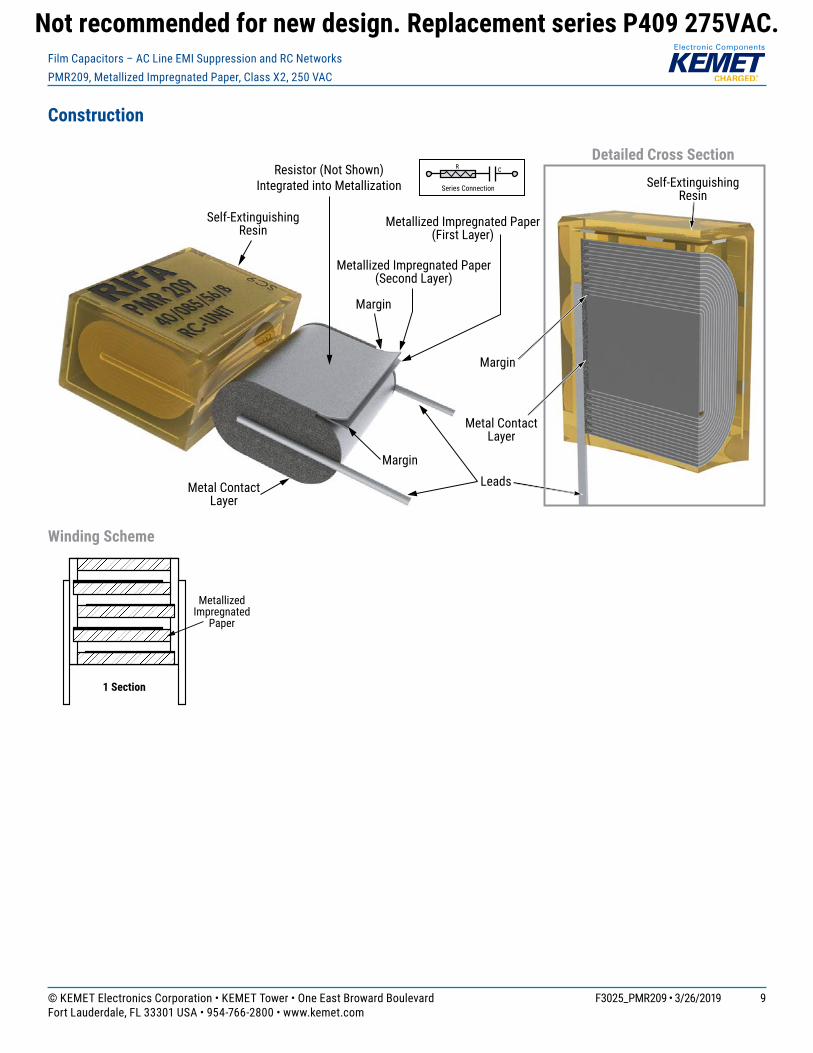
Construction
Detailed Cross Section
Self-Extinguishing Resin
Self-Extinguishing Resin
LeadsMetal Contact Layer
Metal Contact Layer
Margin
Metallized Impregnated Paper(First Layer)
Margin
Margin
Metallized Impregnated Paper(Second Layer)
Resistor (Not Shown) Integrated into Metallization
Single-sided Metallized
Polypropylene Film
FILM WINDING SCHEME OPTIONS
1 Section
Single-sided Metallized
Polypropylene Film
Single-sided Metallized
Polypropylene Film
Single-sided Metallized
Polypropylene Film
Single-sided Metallized Polypropylene Film
2 Sections
3 Sections 4 Sections
Single-sided Metallized
Polypropylene Film
Polypropylene Film Dielectric
1 Section
Double-sided Metallized Polyester Film
3 Sections
Double-sided Metallized Polyester
Carrier Film
Polypropylene Film Dielectric
Double-sided Metallized Polyester
Carrier Film
2 Sections
Polypropylene Film DielectricDouble-sided
Metallized Polyester Carrier
Film
Single-sided Metallized
Polypropylene Film
4 Sections
Polypropylene Film DielectricDouble-sided
Metallized Polyester Carrier
Film
Polypropylene Film Dielectric
1 Section
Polypropylene Film/Foil
2 Sections
Metal Foil Metal Foil
Single-sided Metallized
Polypropylene Film
Polypropylene Film Dielectric
Metallized Polyphenyl-ene Sulfide Film with Vacuum-Evaporated
Aluminum Electrodes
1 Section
Metallized Polyphenylene Sulfide Film (SMR)
Metallized Impregnated
Paper
1 Section
Metallized Impregnated Paper
Single-sided Metallized Polyester
Film
1 Section
Single-sided Metallized Polyester Film
Polypropylene Film Dielec-
tric
1 Section
AXIAL - Polypropylene Film/Foil
2 Sections
Metal Foil
Single-sided Metallized
Polypropylene Film
Polypropylene Film DielectricMetal Foil
Single-sided Metallized
Polypropylene Film
2 Sections
Polypropylene Film Dielectric
Double-sided Metallized
Polyester Carrier Film
Single-sided Metallized
Polypropylene Film
1 Section
AXIAL - Single-sided Metallized Polypropylene Film
Single-sided Metallized Polyester
Film
1 Section
AXIAL - Single-sided Metallized Polyester Film
AXIAL - Double-sided Metallized Polyester Film
Winding Scheme
L
d
pR C
Series Connection
B
H
LL
Not recommended for new design. Replacement series P409 275VAC.

10© KEMET Electronics Corporation • KEMET Tower • One East Broward Boulevard F3025_PMR209 • 3/26/2019Fort Lauderdale, FL 33301 USA • 954-766-2800 • www.kemet.com
Film Capacitors – AC Line EMI Suppression and RC NetworksPMR209, Metallized Impregnated Paper, Class X2, 250 VAC
Marking
BACKFRONT
TOP
Capacitance Resistance,Safety Class
Voltage
Series
IEC Climatic Category
Manufacturing Date Code
Approvals
RC Unit
Self Healing
Packaging Quantities
Size Code
Lead Spacing
(mm)
Thickness (mm)
Height(mm)
Length(mm)
BulkShort Leads
BulkLong Leads
Standard Reel
360 mmLead and Packaging Code C/R06 A/R30 L/R19T0
QM 15.2 7.3 13.0 18.5 600 400 400
CE 20.3 7.6 14.0 24.0 1,530 250 250CP 20.3 11.3 16.5 24.0 1,080 150 180
EJ 25.4 12.1 19.0 30.5 864 100EL 25.4 15.3 22.0 30.5 648 75
Not recommended for new design. Replacement series P409 275VAC.

11© KEMET Electronics Corporation • KEMET Tower • One East Broward Boulevard F3025_PMR209 • 3/26/2019Fort Lauderdale, FL 33301 USA • 954-766-2800 • www.kemet.com
Film Capacitors – AC Line EMI Suppression and RC NetworksPMR209, Metallized Impregnated Paper, Class X2, 250 VAC
Lead Taping & Packaging (IEC 60286–2)
Taping Specifi cation
Dimensions in mm Standard IEC 60286–2
Lead Spacing +6/−0.1 F Formed 7.5 10.2 15.2 20.3 22.5 F
Carrier Tape Width ±0.5 W 18.0 18.0 18.0 18.0 18.0 18+1/−0.5
Hold-Down Tape Width Minimum W0 5.0 5.0 5.0 5.0 5.0
Position of Sprocket Hole ±0.5 W1 9.0 9.0 9.0 9.0 9.0 9+0.75/−0.5
Distance Between Tapes Maximum W2 3.0 3.0 3.0 3.0 3.0 3.0
Sprocket Hole Diameter ±0.2 D0 4.0 4.0 4.0 4.0 4.0 4.0
Feed Hole Lead Spacing ±0.3 P0(1) 12.7(4) 12.7 12.7 12.7 12.7 12.7
Distance Lead – Feed Hole ±0.7 P1 3.75 7.6 5.1 8.9 5.3 P1
Deviation Tape – Plane Maximum ∆p 1.3 1.3 1.3 1.3 1.3 1.3
Lateral Deviation Maximum ∆h 2.0 2.0 2.0 2.0 2.0 2.0
Total Thickness ±0.2 t 0.7 0.7 0.7 0.7 0.9 Maximum 0.9 Maximum
Sprocket Hole/Cap Body Nominal H0(2) 18+2/−0 18+2/−0 18+2/−0 18+2/−0 18.5 ±0.5 18+2/−0
Sprocket Hole/Top of Cap Body Maximum H1(3) 43 43 43 58 58 58 Maximum
(1) Maximum cumulative feed hole error, 1 mm per 20 parts(2) 16.5 mm available on request
(3) Depending on case size(4) 15 mm available on request
Lead Spacing 10.2 – 15.2 mm Lead Spacing 20.3 – 22.5 mm
Formed Leads from 10.2 – 7.5 mm
H1
H0
H0
P0 P1 D0
W2 W0 W1H1
P0
W2
W0
D0
W
t
W1
H1
H0
P0 D0
W2
W1W0
D0P1
∆p ∆p ∆p
∆p ∆p
∆p∆h ∆h
W
∆h∆h
t
∆h ∆h
F F
F = 7.5
W
W
P1
Not recommended for new design. Replacement series P409 275VAC.

12© KEMET Electronics Corporation • KEMET Tower • One East Broward Boulevard F3025_PMR209 • 3/26/2019Fort Lauderdale, FL 33301 USA • 954-766-2800 • www.kemet.com
Film Capacitors – AC Line EMI Suppression and RC NetworksPMR209, Metallized Impregnated Paper, Class X2, 250 VAC
H
TW
Lead Taping & Packaging (IEC 60286–2) cont'd
Ammo Specifi cations
SeriesDimensions (mm)
H W TR4x,R4x+R,R7x,RSB
360 340 59F5A, F5B, F5DF6xx, F8xx
PHExxx, PMExxx, PMRxxx 330 330 50
Reel Specifi cations
SeriesDimensions (mm)
D H WR4x,R4x+R,R7x,RSB
355500
3025 55 (Max)F5A, F5B, F5D
F6xx, F8xx
PHExxx, PMExxx, PMRxxx 360500 30 46 (Max)
Manufacturing Date Code (IEC–60062)
Y = Year, Z = MonthYear Code Month Code2010 A January 12011 B February 22012 C March 32013 D April 42014 E May 52015 F June 62016 H July 72017 J August 82018 K September 92019 L October O2020 M November N2021 N December D2022 P2023 R2024 S2025 T2026 U2027 V2028 W2029 X2030 A
D
W
H
Not recommended for new design. Replacement series P409 275VAC.

13© KEMET Electronics Corporation • KEMET Tower • One East Broward Boulevard F3025_PMR209 • 3/26/2019Fort Lauderdale, FL 33301 USA • 954-766-2800 • www.kemet.com
Film Capacitors – AC Line EMI Suppression and RC NetworksPMR209, Metallized Impregnated Paper, Class X2, 250 VAC
KEMET Electronics Corporation Sales Offi ces
Foracompletelistofourglobalsalesoffices,pleasevisitwww.kemet.com/sales.
DisclaimerAllproductspecifications,statements,informationanddata(collectively,the“Information”)inthisdatasheetaresubjecttochange.Thecustomerisresponsibleforchecking and verifying the extent to which the Information contained in this publication is applicable to an order at the time the order is placed. All Information given herein is believed to be accurate and reliable, but it is presented without guarantee, warranty, or responsibility of any kind, expressed or implied.
StatementsofsuitabilityforcertainapplicationsarebasedonKEMETElectronicsCorporation’s(“KEMET”)knowledgeoftypicaloperatingconditionsforsuchapplications,butarenotintendedtoconstitute–andKEMETspecificallydisclaims–anywarrantyconcerningsuitabilityforaspecificcustomerapplicationoruse.The Information is intended for use only by customers who have the requisite experience and capability to determine the correct products for their application. Any technical advice inferred from this Information or otherwise provided by KEMET with reference to the use of KEMET’s products is given gratis, and KEMET assumesno obligation or liability for the advice given or results obtained.
Although KEMET designs and manufactures its products to the most stringent quality and safety standards, given the current state of the art, isolated component failures may still occur. Accordingly, customer applications which require a high degree of reliability or safety should employ suitable designs or other safeguards (such as installation of protective circuitry or redundancies) in order to ensure that the failure of an electrical component does not result in a risk of personal injuryor property damage.
Although all product–related warnings, cautions and notes must be observed, the customer should not assume that all safety measures are indicted or that other measures may not be required.
KEMET is a registered trademark of KEMET Electronics Corporation.
Not recommended for new design. Replacement series P409 275VAC.