Embed Size (px)
Citation preview

Now we must send the correct signals over the
MOSI line!!!
Design and implementation details on the way to a valid
SPI-LCD interface driver

04/19/23 SPI and LCD , Copyright M. Smith, ECE, University of Calgary, Canada
2 / 24
To be tackled today
All the new SPI stuff about “trying to get the code to work”• We want the code “to work in someway – even if very
slowly”
• Later we could “refactor the code for speed”Meaning if I can find the time to get the DMA to work (and it is easy to do) we will get that bit going in Lab. 4 as a bonus (or is very easy as part of Lab. 4
Look at first 3 tasks of Lab. 4

04/19/23 SPI and LCD , Copyright M. Smith, ECE, University of Calgary, Canada
3 / 24
Review -- Master / Slave conceptSlave Select (Chip Select)We put a value into the Blackfin
SPI_TDBR register
Blackfin sends out active low chip select signal PF5
Blackfin sends out the “value-bits” on the MOSI signal.
Slave accepts signal as SS1 is connected to PF5
When PF5 line goes high then Slave will send values to the LCD display.
If we get the first step correct – then everything else should happen automatically – provided we have set up the SPI interface correctly

04/19/23 SPI and LCD , Copyright M. Smith, ECE, University of Calgary, Canada
4 / 24
Review -- Blackfin transmits 16 bits using MSB-first format over the MOSI line
DB7, DB6, ………DB1, DB0
RS
1 – LCD data
0 – LCD instruction
R/W
1 – Read from LCD
0 – Write to LCD
E – Enable / Strobe
1 0 – When this line goes from high to the low, then the command is send to (latched into) LCD
To make LCD respond to command 0x4F0Then Blackfin must transmit 0x5F0 ( E High )0x4F0 ( E low )0x5F0 ( E high )
Now we care

04/19/23 SPI and LCD , Copyright M. Smith, ECE, University of Calgary, Canada
5 / 24
LCD_Display (int, char*, char *);First attempt – may refactor later
#include <string.h>
LCD_Display (int lcd, char * type, char *operation) {
if (strcmp(type, “COMMAND”) == 0) { if (strcmp(operation, “CLEAR_SCREEN”) == 0) ClearScreen( );
if (strcmp(operation, “……..”) == 0) Do……..( );
}
if (strcmp(type, “DATA”) == 0) { if (strcmp(operation, “DISPLAY_TEMPERATURE”) == 0) DisplayTemperature( ); else WriteLetter(operation[0]); // First character
}}

04/19/23 SPI and LCD , Copyright M. Smith, ECE, University of Calgary, Canada
6 / 24
We need to toggle that E-flag (and wait) to make “slow” LCD work
#define EN_LINE_HIGH 0x0100#define EN_LINE_LOW 0x0000#define ISDATA 0x400
ClearScreen( ) { WriteSPIASM(EN_LINE_HIGH | 0x0001); WaitABit(40 us); WriteSPIASM(EN_LINE_LOW | 0x0001); WaitABit(1.4 ms); WriteSPIASM(EN_LINE_HIGH | 0x0001); WaitABit(40 us); }
WriteLetter(char letter) { WriteSPIASM(EN_LINE_HIGH | ISDATA | letter); WaitABit(40 us);
WriteSPIASM(EN_LINE_HIGH | ISDATA | letter); WaitABit(40 us);WriteSPIASM(EN_LINE_LOW | ISDATA | letter); WaitABit(40 us);
CursorMove( ); ??????}// Just ONE routine to work -- to make Lab. 4 to work !!!!!!!!!!

04/19/23 SPI and LCD , Copyright M. Smith, ECE, University of Calgary, Canada
7 / 24
SPI-Tests – InitializationSet_SPIregisters_ASM(ulong BAUD_SCALE)
#include <cdefsBF533.h>#define BAUD_SCALE 0x8000 // Make system slow so we can scope the data transfers
TEST(SET_SPI_Registers, ConfigureSPIregisters) {
WatchDataClass<unsigned short> spi_reg(4, pSPI_BAUD, pSPI_CTL, pSPI_FLG, pSPI_STAT);
WATCH_MEMORY_RANGE(spi_reg, (Set_SPIregisters_ASM(BAUD_SCALE)), READ_CHECK | WRITE_CHECK);
// Warning – many of the SPI_STAT bits are W1C – write 1 to clear – DON”T write 0’s
USHORTS_EQUAL(spi_reg.getFinalValue(0), BAUD_SCALE); USHORTS_EQUAL((spi_reg.getStartValue(1) | 0x01 | /* SPE | */ MSTR | CPOL | /* CPHA | */ SIZE),
spi_reg.getFinalValue(1)); USHORTS_EQUAL((spi_reg.getStartValue(2) | FLS5), spi_reg.getFinalValue(2)); USHORTS_EQUAL(spi_reg.getStartValue(3), 1); // Reset value is 1
CHECK(spi_reg.getReadsWrites() == 5); // May be a different number in your code
}

04/19/23 SPI and LCD , Copyright M. Smith, ECE, University of Calgary, Canada
8 / 24
volatile bool transmit_empty; // FLAG / SEMAPHORE
volatile unsigned short transmit_value; // MESSAGE TO ISR
EX_INTERRUPT_HANDLER(SPI_ISR) {SPI_TDBR transmit_value;
transmit_empty = true; Clear the interrupt signal so don’t re-enter ISR}
void WriteSPI(unsigned short int value ) {while (transmit_empty = = false)
/* wait for a signal from the ISR to say ready for next */ ;transmit_empty = false;
transmit_value value; // Store the value as a message for ISR}
Not the “best solution” (that needs DMA stuff) – but would it work?????
WE KNOW WE DON’T NEED THIS LINE

04/19/23 SPI and LCD , Copyright M. Smith, ECE, University of Calgary, Canada
9 / 24
Concept
We write 16-bits (0xFF0A) into SPI_TDBR Hardware transfers this to SHIFT register
• SPI_TDBR now empty – new interrupt occurs For next 16 ticks of SPI clock
• Hardware sends out 1 bit from shift register over MOSI line to SLAVE each clock tick – speeds up to 25 MHz per bit
• Hardware receives 1 bit over MISO line from the SLAVE and puts into shift register each clock tick – speeds up to 25 MHz per bit
Hardware transfers shift register value (from slave) into SPI_RDBR (receive DBR)• SPI_RDBR is now FULL
This transmission over a serial line (16-bits 1 at a time) is much slower than other internal Blackfin operation• Must be handled via interrupt control
0x F F 0 A

04/19/23 SPI and LCD , Copyright M. Smith, ECE, University of Calgary, Canada
10 / 24
Can we write this sort of test to make things work on the SPI interface?
EX_INTERRUPT_HANDLER(spi_ISR);
TEST(WriteSPIValue, ConfigureSPIregisters) {
InitSPI_ASM(0x800); register_handler(?????, SPI_ISR); Set_SIC_IMASK_ASM(0x2000); // Set the SIC_IMASK as we needed to do // in Lab. 3 to make the general purpose timer interrupts work StartSPI( );
WriteSPI(0x0A); // Connect SPI interface to LED’s on logic station WriteSPI(0xFF05); // Values should be there WriteSPI(0x0F0F); // Look at values on MOSI line with scope // SOMETHING should be there EVEN IF INVALID // Need to look at both MOSI and PF5 }

04/19/23 SPI and LCD , Copyright M. Smith, ECE, University of Calgary, Canada
11 / 24
Things we DO and DON’T want to happen
PF5 line
MOSI signal3 words
transmitted
WORD 1 RECEIVEDBY SLAVE BUT NOT
SENT ONTO LCD
PF HIGHSLAVE IGNORES
BLACKFIN
PF LOWSLAVE LISTENS
TO BLACKFIN
WORD 2 RECEIVEDBY SLAVE ANDSENT TO LCD
SLAVE SENDSCOMMAND TO LCD
WORD 3 IGNOREDBY SLAVE AND NOT
SENT ONTO LCD

04/19/23 SPI and LCD , Copyright M. Smith, ECE, University of Calgary, Canada
12 / 24
SPI_registers Hardware Chap. 10-16
SPI Status register – Has SPI finished the transfer?
void WaitWhileSPIF_ASM(low / high)
Wait while SPI low (not finished)

04/19/23 SPI and LCD , Copyright M. Smith, ECE, University of Calgary, Canada
13 / 24
volatile bool transmit_empty; // FLAG / SEMAPHORE
volatile unsigned short transmit_value; // MESSAGE TO ISR
EX_INTERRUPT_HANDLER(SPI_ISR) {SPI_TDBR transmit_value;
transmit_empty = true; Clear the interrupt signal so don’t re-enter ISR}
void WriteSPI(unsigned short int value ) {while (*transmit_empty = = false)
/* wait for a signal from the ISR to say ready for next */ ; WaitWhileSPIF(0x0); /* Wait for HARDWARE SIGNAL */ transmit_empty = false; transmit_value value; // Store the value as a message for ISR}
Not the “best solution” (that needs DMA stuff) – but would it work?????
Don’t need this lineLOOK FOR
SPIF bit instead(SPI_FINISHED)

04/19/23 SPI and LCD , Copyright M. Smith, ECE, University of Calgary, Canada
14 / 24
Would that really work?void WriteSPI(unsigned short int value ) {
WaitWhileSPIF(0x0); /* Wait for HARDWARE SIGNAL */ transmit_value value; // Store the value as a message for ISR}
Possible RACE condition problem Might WriteSPI( ) put many values into the transmit buffer before
ANY are transmitted?
Does it depend on how fast Blackfin is compared to SPI interface
Answer: I don’t know till I try stuff and see if a problem.

04/19/23 SPI and LCD , Copyright M. Smith, ECE, University of Calgary, Canada
15 / 24
PF5 line
MOSI signal3 words
transmitted
WORD 1 RECEIVEDBY SLAVE BUT NOT
SENT ONTO LCD
WORD 2 RECEIVEDBY SLAVE ANDSENT TO LCD
WORD 3 IGNOREDBY SLAVE AND NOT
SENT ONTO LCD

04/19/23 SPI and LCD , Copyright M. Smith, ECE, University of Calgary, Canada
16 / 24
PF5 line
MOSI signal2 words
transmitted
WORD 1 RECEIVEDBY SLAVE BUT NOT
SENT ONTO LCD
WORD 2 RECEIVEDBY SLAVE ANDSENT TO LCD
If look at signal with an “ultra-high-speed”scope then can see PF line go high for“a very short period of time”. Blackfinis “too fast” for interface

04/19/23 SPI and LCD , Copyright M. Smith, ECE, University of Calgary, Canada
17 / 24
Need to slow things down a bitor take different approach?void WriteSPI(unsigned short int value ) {
WaitWhileSPIF(0x0); /* Wait for HARDWARE SIGNAL */ transmit_value value; // Store the value as a message for ISR WaitAwhile(??? How-long is enough); // Is this the right location for the wait?
// DO we need this instead (or perhaps -- as well as) to solve race conditions? // WaitWhileSPIF(0x1); /* Wait for HARDWARE SIGNAL */}
This is beginning to sound like “epi-cycles – on epi-cycles” as we work out how the planets go around the sun.
It might (just work) for this laboratory but we should really be looking at letting the hardware worry about the timing
Put all the messages in a long array
Set DMA registers to point to start of array. Activate both SPI and DMA and let the Blackfin do the job. That is what it was designed for!!!!!!!!!!!!!

04/19/23 SPI and LCD , Copyright M. Smith, ECE, University of Calgary, Canada
18 / 24
WORD 1 RECEIVEDBY SLAVE AND
SENT ONTO LCD
WORD 2 RECEIVEDBY SLAVE ANDSENT TO LCD
WORD 3 RECEIVEDBY SLAVE AND
SENT ONTO LCD
VALUES GOING TO LCD

04/19/23 SPI and LCD , Copyright M. Smith, ECE, University of Calgary, Canada
19 / 24
So do we think we are in good shape to get Lab. 4 started?
Task 1 – same as Task 1 in Lab. 3
Set up the Lab4 and Lab4Test directories Make the Lab4.prj and Lab4Test projects Write a simple Lab4main to check that the Blackfin and
the 50-pin cable are still working Check that all the Lab1, Lab2 and Lab3 tests work. Select
“exclude from build” for Lab2 and Lab3 tests if you want. • Remove the _FCT_Lab3.cpp file
• Don’t forget to “Refresh connections” using the GUI interface

04/19/23 SPI and LCD , Copyright M. Smith, ECE, University of Calgary, Canada
20 / 24
Lets not tackle too many things at once. Show ability to recognize commands and data -- Task 2extern volatile bool centigrade;extern volatile short int temperature;
char *LCDcommands[ ] = { "COMMAND", "INIT_LCD", "COMMAND", "CLEAR_SCREEN",
"COMMAND", "MOVE_TO_LINE_1", "COMMAND", "CLEAR_LINE_1", "DATA", "4", "DATA", "1", "DATA", "5",
"COMMAND", "MOVE_TO_LINE_2", "COMMAND", "CLEAR_LINE_2", "DATA_TEMPERATURE", "TEMPERATURE_DISPLAY", NULL, NULL};

04/19/23 SPI and LCD , Copyright M. Smith, ECE, University of Calgary, Canada
21 / 24
Lab 4 main( ) – first attemptSimulate the LCD screen
int main( ) {
long int switch_result = 0; Initialize_ProgrammableFlagsASM( ); InitializeLEDInterfaceASM( );
char **pt = LCDcommands; // Point to the start of the commands char *type_of_operation = NULL; // what needs to be done char *which_operation = NULL;
centigrade = true; temperature = 40; while (*pt != NULL) { // While there are commands to do type_of_operation = *pt++; which_operation = *pt++; LCD_Display( LCD_SIMULATION, type_of_operation, which_operation); }}
04/19/23 SPI and LCD , Copyright M. Smith, ECE, University of Calgary, Canada
22 / 24
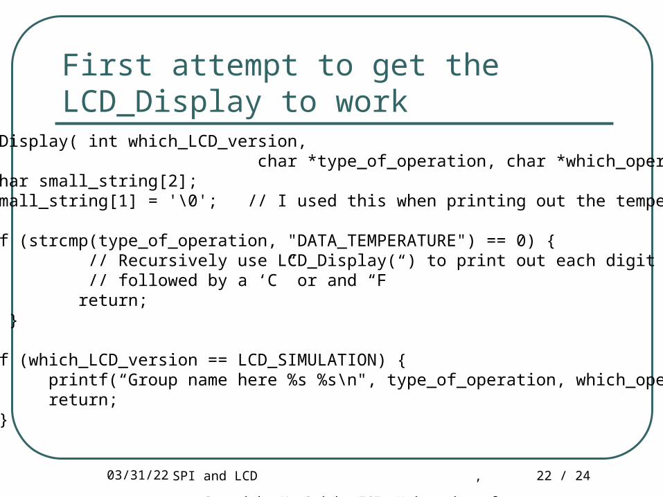
First attempt to get the LCD_Display to work
void LCD_Display( int which_LCD_version, char *type_of_operation, char *which_operation) { char small_string[2]; small_string[1] = '\0'; // I used this when printing out the temperature if (strcmp(type_of_operation, "DATA_TEMPERATURE") == 0) { // Recursively use LCD_Display( ) to print out each digit of temperature // followed by a ‘C” or and “F” return; }
if (which_LCD_version == LCD_SIMULATION) { printf(“Group name here %s %s\n", type_of_operation, which_operation); return; }}

04/19/23 SPI and LCD , Copyright M. Smith, ECE, University of Calgary, Canada
23 / 24
Task 3 – Test out the interface -- Lights Connect the special Blackfin interface (logic lab) CJ7 and
CJ8 lines to the logic lab lights – make sure that the bit order and wires are correct, otherwise you will be paying $2 into the Zoo Christmas “support a family fund”
Connect the MOSI, PF5 and CLK lines Download and run the program “SPILightstrial.dxe”
• The lights will flash from right-to-left if the wires are hooked up correctly
• If you press and release SW3, then the program will stop
Later, when the LCD needs testing we will use this program again

04/19/23 SPI and LCD , Copyright M. Smith, ECE, University of Calgary, Canada
24 / 24
Information taken from Analog Devices On-line Manuals with permission http://www.analog.com/processors/resources/technicalLibrary/manuals/
Information furnished by Analog Devices is believed to be accurate and reliable. However, Analog Devices assumes no responsibility for its use or for any infringement of any patent other rights of any third party which may result from its use. No license is granted by implication or otherwise under any patent or patent right of Analog Devices. Copyright Analog Devices, Inc. All rights reserved.