Embed Size (px)
Citation preview
NUMERICAL ANALYSIS OF HEAT TRANSFER ENHANCEMENT WITH THE USE OF γ- AL2O3/WATER NANOFLUID AND LONGITUDINAL RIBS IN A
CURVED DUCT
by
Hosseinali SOLTANIPOUR a*, Parisa CHOUPANI b, and Iraj MIRZAEE c
a Department of Mechanical Engineering, Urmia University of Technology, Urmia, Iran
b Department of Mechanical Engineering, University of Tabriz, Tabriz, Iran
c Department of Mechanical Engineering, Urmia University, Urmia, Iran
This paper presents a numerical investigation of heat transfer augmentation using internal longitudinal ribs and γ- Al2o3/ water nanofluid in a stationary curved square duct. The flow is assumed 3D, steady, laminar, and incompressible with constant properties. Computations have been done by solving Navier- Stokes and energy equations utilizing finite volume method. Water has been selected as the base fluid and thermo- physical properties of γ- Al2o3/ water nanofluid have been calculated using available correlations in the literature. The effects of Dean number, rib size and particle volume fraction on the heat transfer coefficient and pressure drop have been examined. Results show that nanoparticles can increase the heat transfer coefficient considerably. For any fixed Dean number, relative heat transfer rate (The ratio of the heat transfer coefficient in case the of γ- Al2o3/ water nanofluid to the base fluid) increases as the particle volume fraction increases; however, the addition of nanoparticle to the base fluid is more useful for low Dean numbers. In the case of water flow, results indicate that the ratio of heat transfer rate of ribbed duct to smooth duct is nearly independent of Dean number. Noticeable heat transfer enhancement, compared to water flow in smooth duct, can be achieved when γ- Al2o3/ water nanofluid is used as the working fluid in ribbed duct.
Key words: curved duct, Dean number, laminar flow, heat transfer enhancement, particle volume fraction
1. Introduction
The subject of heat transfer augmentation is of significant interest in developing high-
performance thermal systems. Generally, Convective heat transfer can be increased passively by
different methods such as changing the flow geometry or improving the effective thermal behaviors of
the working fluid. The first approach deals with structuring the flow and temperature fields by
geometrical modifications using roughness elements, ribs, turbulators, or vortex generators. In the case
of heat transfer in the curved ducts, which is the main subject of this paper, some researchers
investigated the rib or fin effects on heat transfer augmentation. Numerical study of [1] showed that,
the rib-induced heat transfer augmentation is attributed to the promotion of secondary vortex motion.
S. W. Chang et al. [2] showed that, augmented Nusselt numbers in the static rib-roughened curved
duct fall in the range of 1.2–1.45 times of smooth-wall duct. P. K. Papadopoulos et al. [3] studied the
laminar incompressible developing flow in a curved square duct with four longitudinal fins. They
found that fin height plays an important role on heat transfer enhancement. In the curved pipes, the
numerical results of [4] showed that presence of internal fins causes the secondary flows to separate
into small regions among the fins and more vortices are generated relative to the finless. They
obtained an optimum fin height about 0.8 of pipe radius for Dean numbers less than 100.
In the second approach, various techniques have been proposed to enhance the heat transfer
performance of working fluids. In fact, conventional heat transfer fluids, including oil, water, and
ethylene glycol mixture are poor heat transfer fluids; considering this fact, numerous methods have
been taken to improve the thermal conductivity of these fluids by suspending nano- sized particle
materials in liquids. Choi et al. [5] showed that by adding a small amount (less than 1% by volume) of
nanoparticles into the conventional liquids, the thermal conductivity of the fluid increases up to
approximately two times. Several researches [6-9] stated that with low concentration of nanoparticles
(1–5 Vol%), the thermal conductivity of the suspensions can be increased more than 20%. Heris et al.
[10] performed laminar convective heat transfer experiments on CuO/water and Al2o3/water
nanofluids and concluded that the heat transfer enhancement by nanofluids depends on several factors,
including nanoparticle type, size, base fluid temperature, flow regime and the boundary conditions.
Nguyen et al. [11] experimentally investigated the heat transfer characteristics of Al2o3/water
nanofluids for an electronic cooling application. They found that with 6.8% particle volume
concentration, the heat transfer coefficient is increased as much as 40% compared to the base fluid.
From the numerical viewpoint, Akbarinia and Behzadmehr [12] presented a study of nanofluids under
mixed laminar convection in a curved tube. They compared the variations of Nusselt number with
Grashof number for various volume percentages of Al2o3 nanoparticles in water. They found that for
large Grashof number the skin friction reduces. Wen and Ding [13] studied Al2o3/water nanofluid heat
transfer for laminar flow under constant wall heat flux boundary condition, and reported that the heat
transfer coefficient increases with increasing the Reynolds number and nanoparticle concentration,
particularly at the entrance region. They expressed that thermal developing length for nanofluid was
greater than the base fluid. Heris et al. [14] presented a solution for enhancement of laminar forced
convection with a nanofluid flowing in a tube under constant wall temperature boundary condition
using the homogeneous model. They assumed that the flow and energy equations of the base fluid are
not affected by the presence of the suspended particles. Recently, experimental investigations of [15]
showed heat transfer enhancement capabilities of coolants with suspended nanoparticles (Al2o3
dispersed in water) for radial flow in cooling device. For steady, laminar radial flow of a nanofluid
between a heated disk and a flat plate with axial coolant injection, the results showed that the Nusselt
number increases with particle volume fraction and Reynolds number, and decreases by increasing
disk spacing.
This paper investigates the heat transfer enhancement using γ- Al2o3/ water nanofluid flow in a
curved square duct with internal longitudinal ribs. The effects of three important parameters,
including Dean number, the rib size and the particle volume fraction of on the heat transfer coefficient
and pressure drop is presented in the following sections.
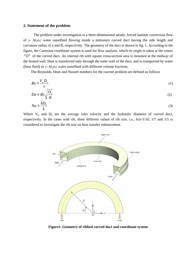
2. Statement of the problem
The problem under investigation is a three-dimensional steady, forced laminar convection flow
of γ- Al2o3/ water nanofluid flowing inside a stationary curved duct having the side length and
curvature radius of a and R, respectively. The geometry of the duct is shown in fig. 1. According to the
figure, the Cartesian coordinate system is used for flow analysis, which its origin is taken at the center
”“O of the curved duct. An internal rib with square cross-section area is mounted at the midway of
the heated wall. Heat is transferred only through the outer wall of the duct, and is transported by water
(base fluid) or γ- Al2o3/ water nanofluid with different volume fractions.
The Reynolds, Dean and Nusselt numbers for the current problem are defined as follows
ν
hin DVRe = (1)
R
DReDe h= (2)
k
DhNu h= (3)
Where Vin and Dh are the average inlet velocity and the hydraulic diameter of curved duct,
respectively. In the cases with rib, three different values of rib size, i.e., h/a=1/10, 1/7 and 1/5 is
considered to investigate the rib size on heat transfer enhancement.
Figure1. Geometry of ribbed curved duct and coordinate system
3. Governing equations and boundary conditions
Most of the nanoparticles used in heat transfer applications, have extremely small dimensions
(finer than 40 nm); so it has been suggested that these particles may be easily fluidized and
consequently, considered as a conventional single-phase fluid. Therefore, the effective thermophysical
properties of nanofluids can be expressed as a function of the properties of both constituents and their
respective concentrations [16, 17]. Thus, governing equations as known for single-phase fluids can be
employed for nanofluids. Under such conditions, and assuming 3D, steady, laminar, incompressible
flow with constant fluid properties and negligible viscous dissipation in the energy equation, the
general conservation equations in the vectorial form can be written as
Continuity equation
0)( =Vdiv ρ (4) Momentum equation
VPVVdiv 2)( ∇+∇−= µρ (5)
Energy equation
)()( TkdivTCVdiv p ∇=ρ (6)
Where, V is the velocity vector and P is the static pressure. All fluid properties are evaluated at the reference temperature that is the fluid inlet temperature Tin.
The governing equations of the fluid flow are non-linear and partial differential equations,
subjected to the following boundary conditions. At the duct inlet section, uniform axial velocity (Vin)
and temperature (Tin) are specified. At the outlet section, atmospheric pressure boundary condition is
adopted. On the walls of the duct and rib surfaces, the no-slip boundary condition prevails. The
constant heat flux is specified only on the outer wall, whereas other walls of the curved duct are
assumed to be adiabatic.
The average local convective heat transfer coefficient )(θh is defined by
)()()(
mw θθθ
TT
"qh
−= (7)
Where )(w θT is the average local temperature of the outer wall and )(m θT is the local bulk fluid
temperature which given by
∫
∫=UdAC
UTdACT
P
P
w )(ρ
ρθ (8)
Where U is the axial velocity and, A is the cross-sectional area perpendicular to the axial direction.
And finally, the average heat transfer coefficient on the outer wall, h can be computed as
∫= ow
ow
)(1
dAhA
h θ (9)
4. Thermophysical properties of the γ- Al2o3 nanofluid
Assuming that the γ- Al2o3 nanoparticles are dispersed uniformly within water and form a
homogeneous mixture, knowing the properties of the constituents and their respective concentrations,
the effective properties of γ- Al2o3/ water nanofluid can be evaluated using some classical formulas as
well- known for two- phase fluids. In the following equations, the subscripts ‘p’, ‘bf’ and ‘nf’ refer to
the particles, the base-fluid and the nanofluid, respectively
pbfnf )1( ρφρφρ +−= (10)
)()()1()( pPbfPnfP CCC φφ +−= (11)
)137123( 2
bfnf ++= φφµµ . (12)
)1722974( 2
bfnf ++= φφ ..kk (13)
Equations (10) and (11) are general relationships used to compute the density and specific heat
for a classical two- phase mixture [17], while eq. (12) has been obtained by performing a least-square
curve fitting of some scarce experimental data available for the mixtures considered [6, 7, and 18].
In recent years, many research groups focused on theoretical prediction and experimental determination of nanofluids thermophysical properties. According to the literature review, one can conclude that even for the same nanofluids, different research groups reported inconsistent correlations for the effective thermal conductivity and viscosity of nanofluids[19-22]. So, further research is needed to identify the accurate correlations for nanofluids properties. Despite probable errors in the viscosity and thermal conductivity given by eqs. (12) and (13), these correlations have been adopted in this study because of their simplicity.
5. Numerical method and grid system
Computational fluid dynamics (CFD) was used for solving this problem. The system of
governing eqs. (4–6) were solved by control volume approach. Control-volume technique converts the
governing equations to a set of algebraic equations that can be solved numerically. The control volume
approach employs the conservation statement or physical law represented by the entire governing
equations over finite control volumes. First order upwind scheme was employed to discretize the
convection terms, while the central differencing scheme was used for diffusion terms. Pressure and
velocity were coupled using SIMPLE algorithm [23]. Linear systems resulting from discretization
schemes were solved using Gauss–Seidel linear equation solver. For all simulations performed in the
present study, converged solutions were considered when the residuals resulting from iterative process
for all governing equations were lower than 10−7.
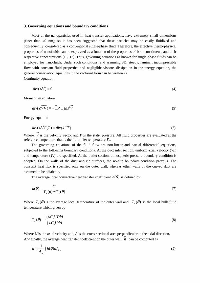
In order to ensure grid independency, three grid sizes were submitted to an extensive testing of
results. Comparison of different grid system results (for the average heat transfer coefficient and
pressure drop in the case De=2000 and h/a=1/5) is shown in tab. 1. It is observed that the grid system
50×50×100 (50× 50 on the cross-sectional plane and 100 nodes along the axial direction) has
satisfactory independency with respect to the number of elements used. Consequently, aforementioned
grid was adopted for different geometries and flow conditions.
Table1. The grid independency study
Grid size sd
rd
h
h
sd
rd
P
P
∆∆
504040 ××
1005050 ××
1206060 ××
1.20
1.35
1.36
1.58
1.53
1.51
6. Validation of the present simulation
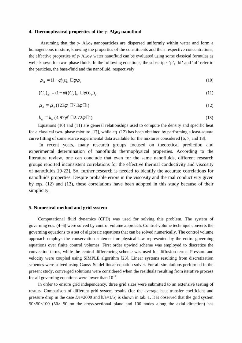
There exists, to our knowledge, no experimental result regarding the case of the flow and heat
transfer of nanofluids in a curved duct. Therefore, in order to validate the computer model, we have
had to compare our numerical results with available data obtained for conventional fluids. To examine
the accuracy of present results, we first compared numerical results with experimental data of [24].
The comparison is illustrated in fig. 2, wherein the variation of axial velocity at two cross-sectional
planes (i.e., θ=36 and 90°) for water flow inside a curved duct as a function of distance along the
radial location (at z=0) is presented. As shown in fig. 2, the calculated distributions of axial velocity
demonstrate good agreement with the measured results.
Figure2. Axial velocity as a function of the radial location at in the midplane of the cross-section for De = 226
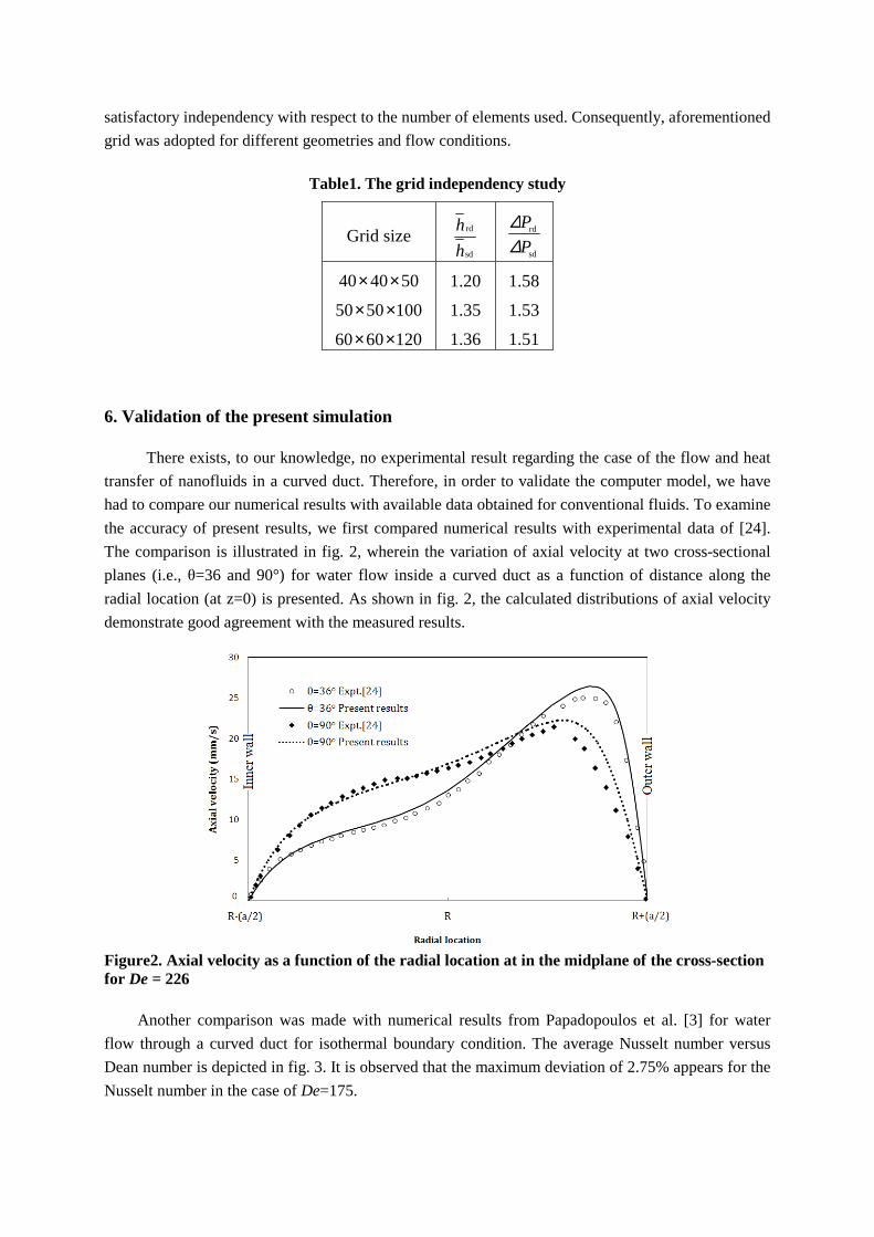
Another comparison was made with numerical results from Papadopoulos et al. [3] for water
flow through a curved duct for isothermal boundary condition. The average Nusselt number versus
Dean number is depicted in fig. 3. It is observed that the maximum deviation of 2.75% appears for the
Nusselt number in the case of De=175.
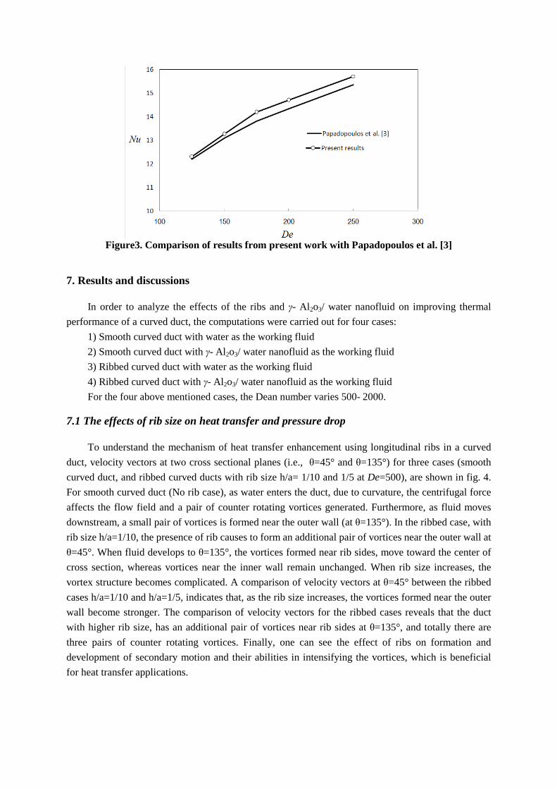
Figure3. Comparison of results from present work with Papadopoulos et al. [3]
7. Results and discussions
In order to analyze the effects of the ribs and γ- Al2o3/ water nanofluid on improving thermal
performance of a curved duct, the computations were carried out for four cases:
1) Smooth curved duct with water as the working fluid
2) Smooth curved duct with γ- Al2o3/ water nanofluid as the working fluid
3) Ribbed curved duct with water as the working fluid
4) Ribbed curved duct with γ- Al2o3/ water nanofluid as the working fluid
For the four above mentioned cases, the Dean number varies 500- 2000.
7.1 The effects of rib size on heat transfer and pressure drop
To understand the mechanism of heat transfer enhancement using longitudinal ribs in a curved
duct, velocity vectors at two cross sectional planes (i.e., θ=45° and θ=135°) for three cases (smooth
curved duct, and ribbed curved ducts with rib size h/a= 1/10 and 1/5 at De=500), are shown in fig. 4.
For smooth curved duct (No rib case), as water enters the duct, due to curvature, the centrifugal force
affects the flow field and a pair of counter rotating vortices generated. Furthermore, as fluid moves
downstream, a small pair of vortices is formed near the outer wall (at θ=135°). In the ribbed case, with
rib size h/a=1/10, the presence of rib causes to form an additional pair of vortices near the outer wall at
θ=45°. When fluid develops to θ=135°, the vortices formed near rib sides, move toward the center of
cross section, whereas vortices near the inner wall remain unchanged. When rib size increases, the
vortex structure becomes complicated. A comparison of velocity vectors at θ=45° between the ribbed
cases h/a=1/10 and h/a=1/5, indicates that, as the rib size increases, the vortices formed near the outer
wall become stronger. The comparison of velocity vectors for the ribbed cases reveals that the duct
with higher rib size, has an additional pair of vortices near rib sides at θ=135°, and totally there are
three pairs of counter rotating vortices. Finally, one can see the effect of ribs on formation and
development of secondary motion and their abilities in intensifying the vortices, which is beneficial
for heat transfer applications.
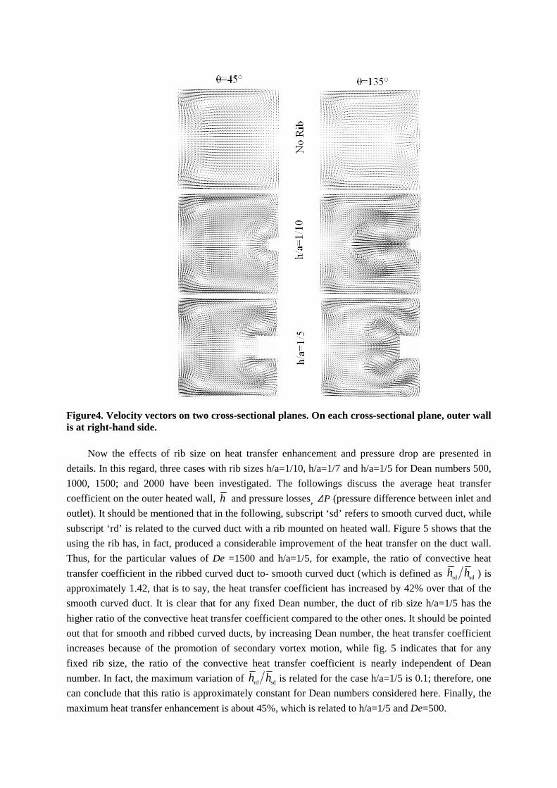
Figure4. Velocity vectors on two cross-sectional planes. On each cross-sectional plane, outer wall is at right-hand side.
Now the effects of rib size on heat transfer enhancement and pressure drop are presented in
details. In this regard, three cases with rib sizes h/a=1/10, h/a=1/7 and h/a=1/5 for Dean numbers 500,
1000, 1500; and 2000 have been investigated. The followings discuss the average heat transfer
coefficient on the outer heated wall, h and pressure losses, P∆ (pressure difference between inlet and
outlet). It should be mentioned that in the following, subscript ‘sd’ refers to smooth curved duct, while
subscript ‘rd’ is related to the curved duct with a rib mounted on heated wall. Figure 5 shows that the
using the rib has, in fact, produced a considerable improvement of the heat transfer on the duct wall.
Thus, for the particular values of De =1500 and h/a=1/5, for example, the ratio of convective heat
transfer coefficient in the ribbed curved duct to- smooth curved duct (which is defined as sdrd hh ) is
approximately 1.42, that is to say, the heat transfer coefficient has increased by 42% over that of the
smooth curved duct. It is clear that for any fixed Dean number, the duct of rib size h/a=1/5 has the
higher ratio of the convective heat transfer coefficient compared to the other ones. It should be pointed
out that for smooth and ribbed curved ducts, by increasing Dean number, the heat transfer coefficient
increases because of the promotion of secondary vortex motion, while fig. 5 indicates that for any
fixed rib size, the ratio of the convective heat transfer coefficient is nearly independent of Dean
number. In fact, the maximum variation of sdrd hh is related for the case h/a=1/5 is 0.1; therefore, one
can conclude that this ratio is approximately constant for Dean numbers considered here. Finally, the
maximum heat transfer enhancement is about 45%, which is related to h/a=1/5 and De=500.
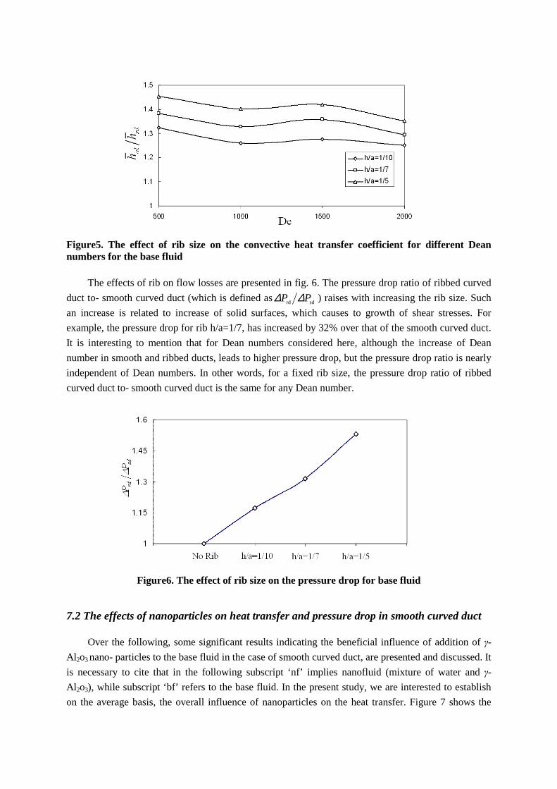
Figure5. The effect of rib size on the convective heat transfer coefficient for different Dean numbers for the base fluid
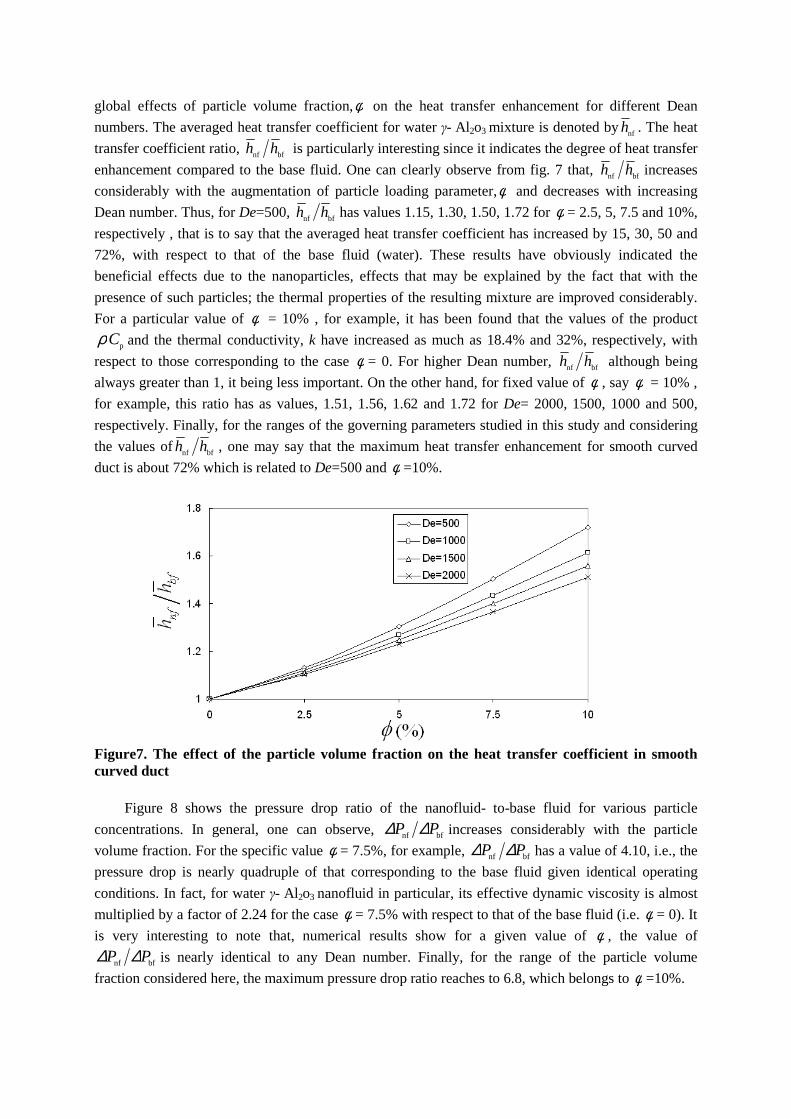
The effects of rib on flow losses are presented in fig. 6. The pressure drop ratio of ribbed curved
duct to- smooth curved duct (which is defined as sdrd PP ∆∆ ) raises with increasing the rib size. Such
an increase is related to increase of solid surfaces, which causes to growth of shear stresses. For
example, the pressure drop for rib h/a=1/7, has increased by 32% over that of the smooth curved duct.
It is interesting to mention that for Dean numbers considered here, although the increase of Dean
number in smooth and ribbed ducts, leads to higher pressure drop, but the pressure drop ratio is nearly
independent of Dean numbers. In other words, for a fixed rib size, the pressure drop ratio of ribbed
curved duct to- smooth curved duct is the same for any Dean number.
Figure6. The effect of rib size on the pressure drop for base fluid
7.2 The effects of nanoparticles on heat transfer and pressure drop in smooth curved duct
Over the following, some significant results indicating the beneficial influence of addition of γ-
Al2o3 nano- particles to the base fluid in the case of smooth curved duct, are presented and discussed. It
is necessary to cite that in the following subscript ‘nf’ implies nanofluid (mixture of water and γ-
Al2o3), while subscript ‘bf’ refers to the base fluid. In the present study, we are interested to establish
on the average basis, the overall influence of nanoparticles on the heat transfer. Figure 7 shows the
global effects of particle volume fraction,φ on the heat transfer enhancement for different Dean
numbers. The averaged heat transfer coefficient for water γ- Al2o3 mixture is denoted bynfh . The heat
transfer coefficient ratio, bfnf hh is particularly interesting since it indicates the degree of heat transfer
enhancement compared to the base fluid. One can clearly observe from fig. 7 that, bfnf hh increases
considerably with the augmentation of particle loading parameter,φ and decreases with increasing
Dean number. Thus, for De=500, bfnf hh has values 1.15, 1.30, 1.50, 1.72 for φ = 2.5, 5, 7.5 and 10%,
respectively , that is to say that the averaged heat transfer coefficient has increased by 15, 30, 50 and
72%, with respect to that of the base fluid (water). These results have obviously indicated the
beneficial effects due to the nanoparticles, effects that may be explained by the fact that with the
presence of such particles; the thermal properties of the resulting mixture are improved considerably.
For a particular value of φ = 10% , for example, it has been found that the values of the product
pCρ and the thermal conductivity, k have increased as much as 18.4% and 32%, respectively, with
respect to those corresponding to the case φ = 0. For higher Dean number, bfnf hh although being
always greater than 1, it being less important. On the other hand, for fixed value of φ , say φ = 10% ,
for example, this ratio has as values, 1.51, 1.56, 1.62 and 1.72 for De= 2000, 1500, 1000 and 500,
respectively. Finally, for the ranges of the governing parameters studied in this study and considering
the values of bfnf hh , one may say that the maximum heat transfer enhancement for smooth curved
duct is about 72% which is related to De=500 and φ =10%.
Figure7. The effect of the particle volume fraction on the heat transfer coefficient in smooth curved duct
Figure 8 shows the pressure drop ratio of the nanofluid- to-base fluid for various particle
concentrations. In general, one can observe, bfnf PP ∆∆ increases considerably with the particle
volume fraction. For the specific value φ = 7.5%, for example, bfnf PP ∆∆ has a value of 4.10, i.e., the
pressure drop is nearly quadruple of that corresponding to the base fluid given identical operating
conditions. In fact, for water γ- Al2o3 nanofluid in particular, its effective dynamic viscosity is almost
multiplied by a factor of 2.24 for the case φ = 7.5% with respect to that of the base fluid (i.e. φ = 0). It
is very interesting to note that, numerical results show for a given value of φ , the value of
bfnf PP ∆∆ is nearly identical to any Dean number. Finally, for the range of the particle volume
fraction considered here, the maximum pressure drop ratio reaches to 6.8, which belongs to φ =10%.
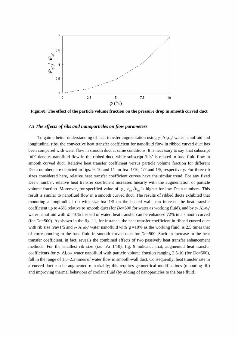
Figure8. The effect of the particle volume fraction on the pressure drop in smooth curved duct
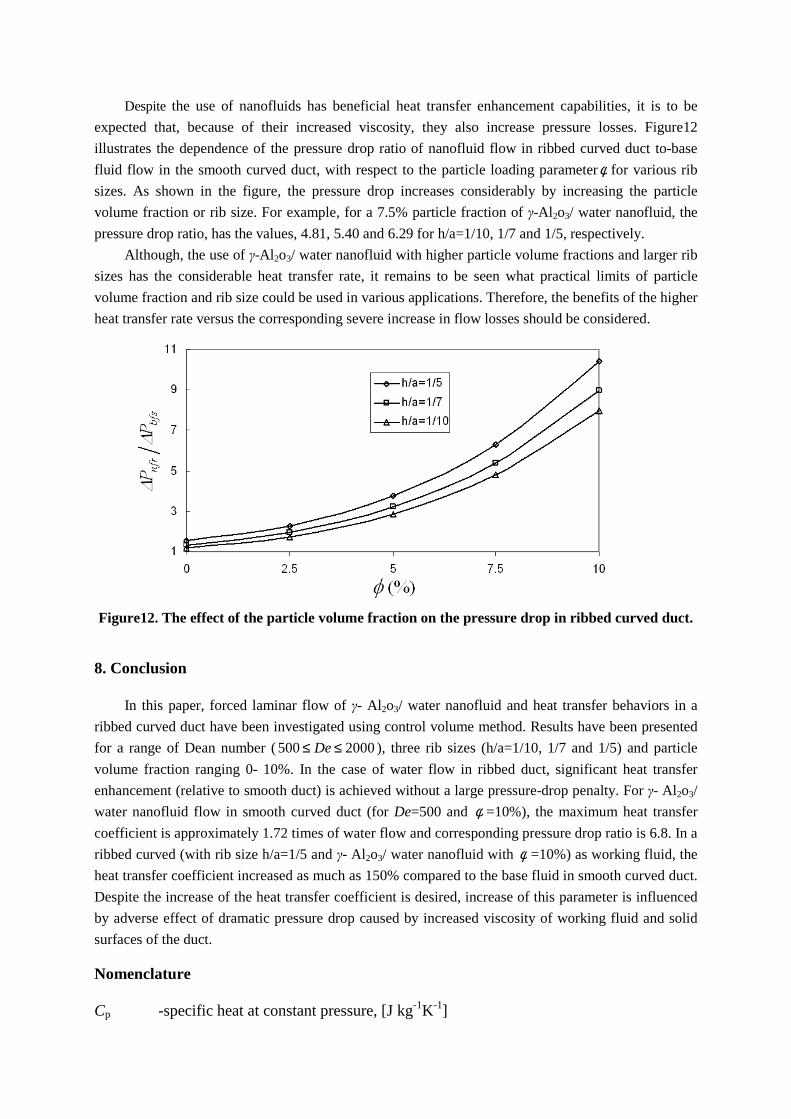
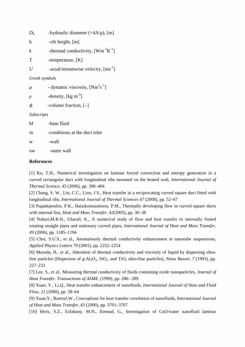
7.3 The effects of ribs and nanoparticles on flow parameters
To gain a better understanding of heat transfer augmentation using γ- Al2o3/ water nanofluid and
longitudinal ribs, the convective heat transfer coefficient for nanofluid flow in ribbed curved duct has
been compared with water flow in smooth duct at same conditions. It is necessary to say that subscript
‘nfr’ denotes nanofluid flow in the ribbed duct, while subscript ‘bfs’ is related to base fluid flow in
smooth curved duct. Relative heat transfer coefficient versus particle volume fraction for different
Dean numbers are depicted in figs. 9, 10 and 11 for h/a=1/10, 1/7 and 1/5, respectively. For three rib
sizes considered here, relative heat transfer coefficient curves have the similar trend. For any fixed
Dean number, relative heat transfer coefficient increases linearly with the augmentation of particle
volume fraction. Moreover, for specified value of φ , bfsnfr hh is higher for low Dean numbers. This
result is similar to nanofluid flow in a smooth curved duct. The results of ribbed ducts exhibited that
mounting a longitudinal rib with size h/a=1/5 on the heated wall, can increase the heat transfer
coefficient up to 45% relative to smooth duct (for De=500 for water as working fluid), and by γ- Al2o3/
water nanofluid with φ =10% instead of water, heat transfer can be enhanced 72% in a smooth curved
(for De=500). As shown in the fig. 11, for instance, the heat transfer coefficient in ribbed curved duct
with rib size h/a=1/5 and γ- Al2o3/ water nanofluid with φ =10% as the working fluid, is 2.5 times that
of corresponding to the base fluid in smooth curved duct for De=500. Such an increase in the heat
transfer coefficient, in fact, reveals the combined effects of two passively heat transfer enhancement
methods. For the smallest rib size (i.e. h/a=1/10), fig. 9 indicates that, augmented heat transfer
coefficients for γ- Al2o3/ water nanofluid with particle volume fraction ranging 2.5-10 (for De=500),
fall in the range of 1.5–2.3 times of water flow in smooth-wall duct. Consequently, heat transfer rate in
a curved duct can be augmented remarkably; this requires geometrical modifications (mounting rib)
and improving thermal behaviors of coolant fluid (by adding of nanoparticles to the base fluid).
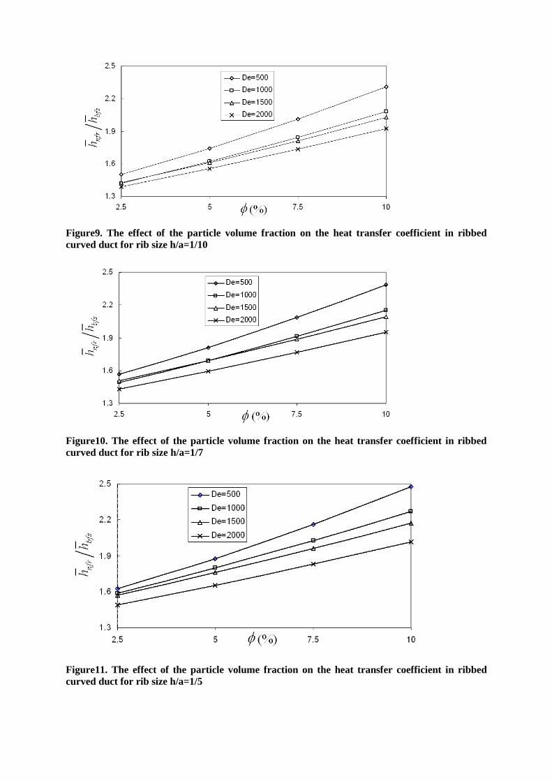
Figure9. The effect of the particle volume fraction on the heat transfer coefficient in ribbed curved duct for rib size h/a=1/10
Figure10. The effect of the particle volume fraction on the heat transfer coefficient in ribbed curved duct for rib size h/a=1/7
Figure11. The effect of the particle volume fraction on the heat transfer coefficient in ribbed curved duct for rib size h/a=1/5
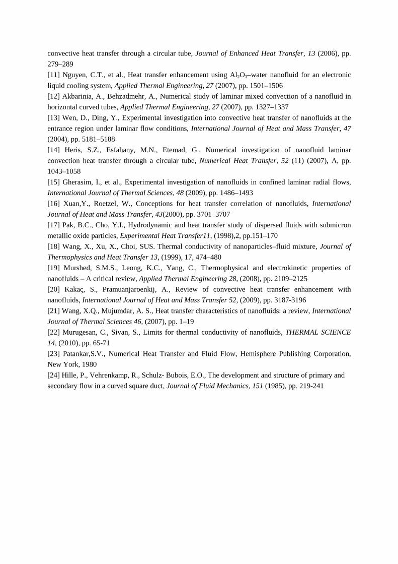
Despite the use of nanofluids has beneficial heat transfer enhancement capabilities, it is to be
expected that, because of their increased viscosity, they also increase pressure losses. Figure12
illustrates the dependence of the pressure drop ratio of nanofluid flow in ribbed curved duct to-base
fluid flow in the smooth curved duct, with respect to the particle loading parameterφ for various rib
sizes. As shown in the figure, the pressure drop increases considerably by increasing the particle
volume fraction or rib size. For example, for a 7.5% particle fraction of γ-Al 2o3/ water nanofluid, the
pressure drop ratio, has the values, 4.81, 5.40 and 6.29 for h/a=1/10, 1/7 and 1/5, respectively.
Although, the use of γ-Al 2o3/ water nanofluid with higher particle volume fractions and larger rib
sizes has the considerable heat transfer rate, it remains to be seen what practical limits of particle
volume fraction and rib size could be used in various applications. Therefore, the benefits of the higher
heat transfer rate versus the corresponding severe increase in flow losses should be considered.
Figure12. The effect of the particle volume fraction on the pressure drop in ribbed curved duct.
8. Conclusion
In this paper, forced laminar flow of γ- Al2o3/ water nanofluid and heat transfer behaviors in a
ribbed curved duct have been investigated using control volume method. Results have been presented
for a range of Dean number ( 2000500 ≤≤ De ), three rib sizes (h/a=1/10, 1/7 and 1/5) and particle
volume fraction ranging 0- 10%. In the case of water flow in ribbed duct, significant heat transfer
enhancement (relative to smooth duct) is achieved without a large pressure-drop penalty. For γ- Al2o3/
water nanofluid flow in smooth curved duct (for De=500 and φ =10%), the maximum heat transfer
coefficient is approximately 1.72 times of water flow and corresponding pressure drop ratio is 6.8. In a
ribbed curved (with rib size h/a=1/5 and γ- Al2o3/ water nanofluid with φ =10%) as working fluid, the
heat transfer coefficient increased as much as 150% compared to the base fluid in smooth curved duct.
Despite the increase of the heat transfer coefficient is desired, increase of this parameter is influenced
by adverse effect of dramatic pressure drop caused by increased viscosity of working fluid and solid
surfaces of the duct.
Nomenclature
Cp -specific heat at constant pressure, [J kg-1K-1]
Dh -hydraulic diameter (=4A/p), [m]
h -rib height, [m]
k -thermal conductivity, [Wm-1K-1]
T -temperature, [K]
U -axial/streamwise velocity, [ms-1]
Greek symbols
� - dynamic viscosity, [Nm2s-1]
ρ -density, [kg m-3]
� -volume fraction, [–]
Subscripts
bf -base fluid
in -conditions at the duct inlet
w -wall
ow -outer wall
References
[1] Ko, T.H., Numerical investigation on laminar forced convection and entropy generation in a
curved rectangular duct with longitudinal ribs mounted on the heated wall, International Journal of
Thermal Science, 45 (2006), pp. 390–404
[2] Chang, S. W., Lin, C.C., Liou, J.S., Heat transfer in a reciprocating curved square duct fitted with
longitudinal ribs, International Journal of Thermal Sciences 47 (2008), pp. 52–67
[3] Papadopoulos, P.K., Hatzikonstantinou, P.M., Thermally developing flow in curved square ducts
with internal fins, Heat and Mass Transfer, 42(2005), pp. 30–38
[4] Nobari,M.R.H., Gharali, K., A numerical study of flow and heat transfer in internally finned
rotating straight pipes and stationary curved pipes, International Journal of Heat and Mass Transfer,
49 (2006), pp. 1185–1194
[5] Choi, S.U.S., et al., Anomalously thermal conductivity enhancement in nanotube suspensions,
Applied Physics Letters 79 (2001), pp. 2252–2254
[6] Masuda, H., et al., Alteration of thermal conductivity and viscosity of liquid by dispersing ultra-
fine particles (Dispersion of g-Al2O3, SiO2, and TiO2 ultra-fine particles), Netsu Bussei, 7 (1993), pp.
227–233
[7] Lee, S., et al., Measuring thermal conductivity of fluids containing oxide nanoparticles, Journal of
Heat Transfer. Transactions of ASME, (1999), pp. 280– 289
[8] Xuan, Y., Li,Q., Heat transfer enhancement of nanofluids, International Journal of Heat and Fluid
Flow, 21 (2000), pp. 58–64
[9] Xuan,Y., Roetzel,W., Conceptions for heat transfer correlation of nanofluids, International Journal
of Heat and Mass Transfer, 43 (2000), pp. 3701–3707
[10] Heris, S.Z., Esfahany, M.N., Etemad, G., Investigation of CuO/water nanofluid laminar
convective heat transfer through a circular tube, Journal of Enhanced Heat Transfer, 13 (2006), pp.
279–289
[11] Nguyen, C.T., et al., Heat transfer enhancement using Al2O3–water nanofluid for an electronic
liquid cooling system, Applied Thermal Engineering, 27 (2007), pp. 1501–1506
[12] Akbarinia, A., Behzadmehr, A., Numerical study of laminar mixed convection of a nanofluid in
horizontal curved tubes, Applied Thermal Engineering, 27 (2007), pp. 1327–1337
[13] Wen, D., Ding, Y., Experimental investigation into convective heat transfer of nanofluids at the
entrance region under laminar flow conditions, International Journal of Heat and Mass Transfer, 47
(2004), pp. 5181–5188
[14] Heris, S.Z., Esfahany, M.N., Etemad, G., Numerical investigation of nanofluid laminar
convection heat transfer through a circular tube, Numerical Heat Transfer, 52 (11) (2007), A, pp.
1043–1058
[15] Gherasim, I., et al., Experimental investigation of nanofluids in confined laminar radial flows,
International Journal of Thermal Sciences, 48 (2009), pp. 1486–1493
[16] Xuan,Y., Roetzel, W., Conceptions for heat transfer correlation of nanofluids, International
Journal of Heat and Mass Transfer, 43(2000), pp. 3701–3707
[17] Pak, B.C., Cho, Y.I., Hydrodynamic and heat transfer study of dispersed fluids with submicron
metallic oxide particles, Experimental Heat Transfer11, (1998),2, pp.151–170
[18] Wang, X., Xu, X., Choi, SUS. Thermal conductivity of nanoparticles–fluid mixture, Journal of
Thermophysics and Heat Transfer 13, (1999), 17, 474–480
[19] Murshed, S.M.S., Leong, K.C., Yang, C., Thermophysical and electrokinetic properties of
nanofluids – A critical review, Applied Thermal Engineering 28, (2008), pp. 2109–2125
[20] Kakaç, S., Pramuanjaroenkij, A., Review of convective heat transfer enhancement with
nanofluids, International Journal of Heat and Mass Transfer 52, (2009), pp. 3187-3196
[21] Wang, X.Q., Mujumdar, A. S., Heat transfer characteristics of nanofluids: a review, International
Journal of Thermal Sciences 46, (2007), pp. 1–19
[22] Murugesan, C., Sivan, S., Limits for thermal conductivity of nanofluids, THERMAL SCIENCE
14, (2010), pp. 65-71
[23] Patankar,S.V., Numerical Heat Transfer and Fluid Flow, Hemisphere Publishing Corporation,
New York, 1980
[24] Hille, P., Vehrenkamp, R., Schulz- Bubois, E.O., The development and structure of primary and
secondary flow in a curved square duct, Journal of Fluid Mechanics, 151 (1985), pp. 219-241