Embed Size (px)
Citation preview
Jeroen HovingDelft University of [email protected]
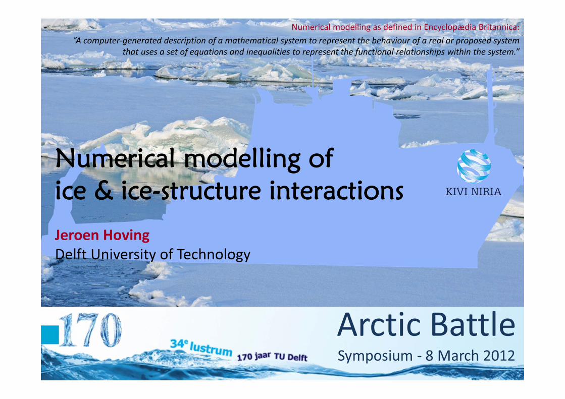
Numerical modelling of ice & ice-structure interactions
Jeroen HovingDelft University of Technology
Numerical modelling as defined in Encyclopædia Britannica:“A computer‐generated description of a mathematical system to represent the behaviour of a real or proposed system
that uses a set of equations and inequalities to represent the functional relationships within the system.”

Jeroen HovingDelft University of [email protected]
Numerical modelling is widely used for applications in Arctic Engineering: Flow of ice sheets Thermodynamic growth & decay of ice Response of sea ice to climate variations Ice concentrations Oceanography
2Arctic Battle Symposium ‐ Friday, 09 March 2012
Current uses for numerical modelling
Terwisscha van Scheltinga, Myers & Pietrzak,A finite element sea ice model of the Canadian Arctic Archipelago,Ocean Dynamics 60, 1539‐1558, 2010
Modeled mean ice thickness for September 1979‐2009

Jeroen HovingDelft University of [email protected]
3Arctic Battle Symposium ‐ Friday, 09 March 2012
Numerical applications for ice-structure interaction
Current and past numerical modelling for ice‐structure interaction: Phenomenological modelling of dynamic ice‐structure interaction, by:
Kärnä ‐ VTT Finland / Huang & Liu ‐ CAS China Ice‐structure interaction between ships and broken ice, by:
Sayed, Frederking & Barker ‐ NRC Canada / Løset ‐ NTNU Norway ‘Simplistic’ ice‐structure interaction models based on static ice loads from
ISO19906 combined with Ansys, by: Hidding & Bonnafoux, MSc. DUT/SBM

Jeroen HovingDelft University of [email protected]
4Arctic Battle Symposium ‐ Friday, 09 March 2012
Our purpose for numerical modelling
We are however interested in: The behaviour of ice when its loaded The way ice fails against different types of structures, and thus The loads that ice sheets or ice floes exert on offshore structures
Our focus is the interaction of offshore structures with first‐year level ice, because: Loads due to level ice floes are norm‐
ative over those due to broken ice fields It is the most common ice feature at
locations considered for developmentThus, for now, neglecting the critical ice loadsdue to for example ice ridges or icebergs

Jeroen HovingDelft University of [email protected]
5Arctic Battle Symposium ‐ Friday, 09 March 2012
Typical properties of ice
Ice is a heterogeneous natural material Ice is anisotropic Ice has a variable shape that is unknown and therefore uncertain Ice‐structure interactions are large scale scaled model tests

Jeroen HovingDelft University of [email protected]
6Arctic Battle Symposium ‐ Friday, 09 March 2012
Model-scale versus full-scale tests
At first, from scaled model tests:“Failure of sea ice was thought to be well‐described by plastic limit analysis”(Plastic limit analysis = Linear elasticity until the critical stress is reached, then yield until total failure)
But when some full‐scale data became available, it was found that:“The measured forces exerted by moving ice on an oil platform may be an order of magnitude smaller than the predictions based on laboratory tests!”
This is due to the size effect on structural strength: Statistical size effect Energetic (or deterministic) size effect

Jeroen HovingDelft University of [email protected]
Nominal strength:No Size Effect:
Size Effect:
7Arctic Battle Symposium ‐ Friday, 09 March 2012
The principle of size effect
RigidStructure
RigidStructure
aD
bD
2NPCD
2 2
22
aaN a
bN bb
f D DfDf D
2 2
22
aaN a
bN bb
f D DfDf D
log N
log D
No Size Effect
Size Effect Ice Floe
Ice Floe
P
P

Jeroen HovingDelft University of [email protected]
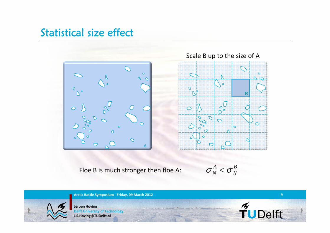
The average of the nominal strength of all specimen in floe A is the same as the nominal strength of floe A
8Arctic Battle Symposium ‐ Friday, 09 March 2012
Statistical size effect
A
Jeroen HovingDelft University of [email protected]
9Arctic Battle Symposium ‐ Friday, 09 March 2012
Statistical size effect
A BN N Floe B is much stronger then floe A:
Scale B up to the size of A
A
B

Jeroen HovingDelft University of [email protected]
10Arctic Battle Symposium ‐ Friday, 09 March 2012
Statistical size effect
An ice floe is as strong as its weakest link The bigger the floe, the higher the chance on a relatively weak spot
A
B
C
Ice floe A will not fail at specimen B, but for example at specimen C!

Jeroen HovingDelft University of [email protected]
11Arctic Battle Symposium ‐ Friday, 09 March 2012
Energetic size effect
When loaded, tiny cracks appear atweak spots in the ice
Under continuous loading, these cracks propagate due to peak stresses at the crack tip and stress relief in the surrounding ice, i.e. stress redistribution
The strength of an ice floe then depends on the energy dissipation due to crack propagation, which is independent of the floe size.
In large ice floes, crack propagation occurs at relatively lower stressesthen crack propagation in small ice floes.

Jeroen HovingDelft University of [email protected]
12Arctic Battle Symposium ‐ Friday, 09 March 2012
Influence size effect on ice-failure
So generally, we can state that: “The nominal strength of ice decreases relative to the floe size”
Due to the size effect, ice can be considered a quasi‐brittle material: Small ice floes interacting with small structures:
Macro‐failure in a more ductile manner due to distributed micro‐cracking Large ice floes interacting with large structures:
Macro‐failure in an almost perfect brittle manner
Also the relative velocity between an ice floe and a structure influences the way an ice floe fails during ice‐structure interaction: Low velocities ductile High velocities brittle

Jeroen HovingDelft University of [email protected]
13Arctic Battle Symposium ‐ Friday, 09 March 2012
Preferred practice due to the size effect
1. Create a numerical model that:‐ captures the desired phenomena, and‐ includes the size effect
2. Perform scale‐model tests
3. Tune the parameters of the numerical model to the scale‐model tests
4. Use the resulting numerical model to obtain results for full‐scale situations
This is known as: “Numerical Upscaling”

Jeroen HovingDelft University of [email protected]
14Arctic Battle Symposium ‐ Friday, 09 March 2012
Numerical approaches
The choice of the model and thus the numerical approach to be used, mainly depends on the scale of the phenomena one wishes to capture
The different scales are: Macro Global phenomena Meso Local phenomena Micro Microstructure phenomena Nano Molecular phenomena
Macro‐scale modelling for global phenomena: Continuum models can sometimes be (partially) solved analytically Numerically solving these models requires relatively short calculation time Continuum models do not capture all properties of an ice floe

Jeroen HovingDelft University of [email protected]
The ice floe is modelled as a hexagonal system of rigid particles Other geometrical configurations of the particles can be made
The interaction between any 2 adjacent particles is described by kinematic elements that may have various properties:
15Arctic Battle Symposium ‐ Friday, 09 March 2012
Meso-scale modelling: the hexagonal lattice
Hooke Kelvin‐Voigt Prandtl Bingham Bingham‐Kelvin‐Voigt

Jeroen HovingDelft University of [email protected]
16Arctic Battle Symposium ‐ Friday, 09 March 2012
A hexagonal lattice with Kelvin-Voigt elements
At every node in the lattice, we have 2 equations of motion, respectively describing the equilibria in x‐ and z‐direction:
The properties of the particles and the kinematic elements may be varied, enabling inhomogeneity
M u Cu Ku F t
2j
5j 6j
1j
3j 4j
j
z
x
6
1
6
1
ˆ cos
ˆ sin
x e j j xj
z e j j zj
Mu K e F t
Mu K e F t
xF t
zF t

Jeroen HovingDelft University of [email protected]
When the force in an element between 2 adjacent nodes becomes too large, a crack appears and that element is deleted
Using a regular mesh, crack propagation is mesh dependent, therefore the mesh is randomized
17Arctic Battle Symposium ‐ Friday, 09 March 2012
Crack propagation in the lattice
Jeroen HovingDelft University of [email protected]
18Arctic Battle Symposium ‐ Friday, 09 March 2012
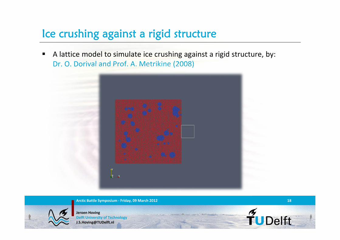
Ice crushing against a rigid structure
A lattice model to simulate ice crushing against a rigid structure, by: Dr. O. Dorival and Prof. A. Metrikine (2008)

Jeroen HovingDelft University of [email protected]
With the aim to improve usability and to limit calculation time, we divide the floe into 2 segments: The part of the ice floe close to the ice‐struc‐
ture interaction is modelled with high detailusing the discrete lattice to account for the nonlinear behaviour of the ice
At a distance from the ice‐structure inter‐action, the behaviour of the ice floe is linear and thus modelled as a linear continuum
We then couple the discrete lattice and thecontinuum such that the wave reflection atthe lattice‐continuum interface is minimal
19Arctic Battle Symposium ‐ Friday, 09 March 2012
Perspective: A coupled discrete-continuous model
LinearModel
RigidStructureDetailed
Model

Jeroen HovingDelft University of [email protected]
Dynamic stiffness is “The ratio between a dynamic load and its response”
The dynamic stiffness is described by the force‐displacement relation in the frequency domain as:
The force‐displacement relation in the time domain is then found applying the inverse Laplace transform, and is found as the convolution of χ(t) and u(t):
20Arctic Battle Symposium ‐ Friday, 09 March 2012
A non-reflective lattice-continuum interface
Linear Continuum
Discretelattice
RigidStructure
Lattice‐Continuum Interface
, , ,E
F u
0
t
F t t u d

Jeroen HovingDelft University of [email protected]
Extending the model into 3D by adding the vertical dimension allows for: Clearance of rubble under the ice sheet The option to model the bending of an ice floe against a conical structure
21Arctic Battle Symposium ‐ Friday, 09 March 2012
Perspective: Extension into 3D
ContinuumLattice
RigidStructure
Hydralab IV – HyIII‐HSVA‐04 – Kärnä et al.

Jeroen HovingDelft University of [email protected]
22Arctic Battle Symposium ‐ Friday, 09 March 2012
Numerical modelling of ice-structure interaction
The models that can be studied analytically often do not capture the phenomena that are observed in reality during ice‐structure interaction
Scale model tests give insight in the phenomena of ice‐structure interaction but can not be scaled straightforwardly to actual size problems
To obtain a better description and understanding of ice and ice‐structure interaction, it is a necessity to model these phenomena numerically
Additionally, numerical models are preferred over model‐ and full‐scale tests for cost effective design

Jeroen HovingDelft University of [email protected]
23Arctic Battle Symposium ‐ Friday, 09 March 2012
Thank you!


![4 IGT Master 2017.pptx [Read-Only] - ethz.ch€“ ABAQUS Examples Constitutive & Numerical Modelling in Geotechnics 0 ... Theoretische und experimentelle Bodenmechanik …](https://img.pdfslide.tips/doc/110x75/5ac1ae167f8b9a213f8d5ce8/4-igt-master-2017pptx-read-only-ethzch-abaqus-examples-constitutive-numerical.jpg)