Embed Size (px)
Citation preview
Outubro de 2011
Universidade do MinhoEscola de Engenharia
Nuno André Carvalho Sousa
Patterned surfaces of poly (lactic acid) and starch – poly (lactic acid) blend prepared by reverse breath figures, the effect of: solvent, substrate and vapour
UM
inho
|201
1 N
uno
Andr
é C
arva
lho
Sous
a P
att
ern
ed
su
rfa
ces
of
po
ly (
lact
ic a
cid
) a
nd
sta
rch
– p
oly
(la
ctic
aci
d)
ble
nd
pre
pa
red
by
reve
rse
bre
ath
fig
ure
s, t
he
eff
ect
of:
so
lve
nt,
su
bst
rate
an
d v
ap
ou
r
Dissertação de Mestrado Ciclo de Estudos Integrados Conducentes ao Grau de Mestre em Engenharia Biomédica Área de Especialização: Biomateriais, Reabilitação e Biomecânica
Trabalho realizado sob a orientação do Professor Doutor Rui Luís Reis
Outubro de 2011
Universidade do MinhoEscola de Engenharia
Nuno André Carvalho Sousa
Patterned surfaces of poly (lactic acid) and starch – poly (lactic acid) blend prepared by reverse breath figures, the effect of: solvent, substrate and vapour
iii
Acknowledgements
Gostaria de agradecer ao Professor Rui Reis por todo o apoio como orientador deste
projecto. Pela sua disponibilidade e compreensão que sempre demonstrou e, principalmente,
pelo encorajamento constante em prol de um trabalho cada vez melhor. Agradeço ainda à
Doutora Ana Rita Duarte, pela sua ajuda e todos os úteis conselhos, pela paciência e por todo o
apoio, obrigado.
Pelo incentivo em integrar o programa ERASMUS e pela ajuda no planeamento desse
período da minha vida gostaria de agradecer ao Professor João F. Mano.
Gostaria também de agradecer a todos os investigadores e staff do grupo 3B’s –
Biomateriais, Biodegradáveis e Biomiméticos
I would like to thank Professor Claudio Migliaresi and Doctor Devid Maniglio the guidance
and transmitted knowledge, but also to everybody in BIOTech Center that directly or indirectly
contributed to my work for make me feel at home and teach me something that any university or
school could ever teach me: practical knowledge. Thank you all very much!
To my unforgettable friends, from all over the world, made during this short but rich
period of my live, I would like to thank you all.
E obrigado David por teres partilhado esta experiência comigo.
Obrigado Maria
Um obrigada a todos os meus colegas e amigos de Engenharia Biomédica da
Universidade do Minho, que ao longo destes últimos anos partilharam todo o tipo de
experiências e histórias comigo.
A toda a minha família, primos, tios e avós, muito obrigado.
Por último, gostaria de agradecer aos meus pais. Obrigado por tudo
v
Abstract
Thin polymeric films and patterns hold great promise for several applications. Many
micro or nanofabrication techniques allow designing regular and ordered materials. With these
techniques, good architecture reproducibility as well as porosity control of the structure can be
obtained, using a vast range of polymers, including biodegradable (natural or synthetic)
polymers. This work dealt with the fabrication of patterned surfaces with regular geometry by
using templating techniques, breath figures (BF) and reverse breath figures (RBF) in an in-house
built microfabrication system.
For this purpose we have prepared biodegradable polymeric patterns of poly (lactic acid)
(PLA) and a starch – poly (lactic acid) blend (SPLA) with different morphologies in this in-house
built system. The PLA and SPLA dissolved in chloroform and toluene (TL) (1%wt) were exposed to
a vapour atmosphere with mixtures of water (H2O) and methanol (MeOH). Three types of
patterned surfaces were obtained, particles, porous films or an intermediate pattern, where both
particles and film coexist.
The structures developed, by this novel approach to create biodegradable materials using
a natural based polymer, could have potential applications in tissue engineering or cell growth, by
themselves or as a coating for other materials. These applications consist in the use a
combination of living cells and a support structure in which cell attach, grow and proliferate. Due
to this kind of potential applications of the materials created, they should meet specific
characteristics; in particular the used material should be non-toxic and possess high cell/tissue
biocompatibility so that they will not give rise to any unfavorable behavior. Moreover, it should
have a determinate surface to permit cell adhesion.
Scan electron microscopy (SEM) imaging was used to observe the morphology of the
structures created Thermal analysis differential scanning calorimetry (DSC) and gel permeation
chromatography (GPC) were carried out to characterize the PLA. Also the cell adhesion and
growth on the surfaces created was tested. This was performed with the aid of MTS assay,
fluorescence microscope and SEM.
After MTS evaluation proved the non-cytotoxicity of the materials, preliminary biological
tests were done by seeding on the surfaces osteoblasts cell lines. SEM imaging and fluorescence
microscopy evidenced morphology and cell adhesion and growth behavior over the patterns.

vi
vii
Resumo
Filmes poliméricos finos e superfícies com padrões são uma grande promessa para
diversas aplicações. Muitas técnicas de micro ou nano-fabricação permitem projetar materiais
regulares e ordenados. Estas técnicas permitem boa reprodutibilidade, arquitetura, bem como o
controle da porosidade da estrutura, usando uma vasta gama de polímeros, incluindo polímeros
biodegradáveis (naturais ou sintéticos). Este trabalho lidou com o fabrico de superfícies com
padrões de geometria regular, utilizando técnicas de templating, breath figures (BF) e reverse
breath figures (RBF) utilizando um sistema de microfabricação.
Para este efeito, preparamos superfícies biodegradáveis com diferentes morfologias, de
poli (ácido láctico) (PLA) e uma mistura de amido - poli (ácido láctico) SPLA neste sistema. PLA e
(SPLA) dissolvido em clorofórmio e tolueno (TL) (1 % em peso) foram expostos a uma atmosfera
de vapor com misturas de água (H2O) e metanol (MeOH). Três tipos de superfícies com padrões
foram obtidos, partículas, filmes porosos ou um padrão intermédio, onde partículas e filme
poroso coexistem.
As estruturas desenvolvidas, por esta nova abordagem para criar materiais
biodegradáveis, utilizando um polímero natural, podem ter potenciais aplicações em engenharia
de tecidos ou para crescimento de células, por si próprias ou como revestimentos de outros
materiais. Estas aplicações, usam uma combinação de células vivas e uma estrutura de apoio
na qual a célula se pode aderir, crescer e proliferar. Devido a estas possíveis aplicações dos
materiais obtidos, estes devem atender a características específicas, em particular o material
deve ser não-tóxico, e possuir boa biocompatibilidade, para que não dê origem a qualquer
comportamento prejudicial. Além disso, ele deve ter uma determinada superfície para permitir a
adesão celular.
Microscopia eletrônica de varrimento (SEM), foi utilizada para analisar a morfologia das
estruturas criadas, análises térmicas: varredura diferencial de calorimetria (DSC) e cromatografia
de permeação de gel (GPC), foram realizadas para caracterizar o PLA. Também a adesão celular
e crescimento nas superfícies criadas foi testado. Esta foi realizada com o auxílio de ensaio MTS,
microscopia de fluorescência e SEM. Depois da avaliação por MTS comprovar a não
citotoxicidade dos materiais, testes preliminares biológicos foram feitos através do seeding de
uma linha celular de osteoblastos sobre as superfícies criadas. SEM evidenciou padrões de
morfologia e adesão celular e comportamento de crescimento.

viii
ix
Table of contents
Acknowledgements ................................................................................................................... iii
Abstract ..................................................................................................................................... v
Resumo ................................................................................................................................... vii
Abbreviations ........................................................................................................................... xiii
List of Figures .......................................................................................................................... xv
List of Tables ........................................................................................................................... xix
General Introduction ......................................................................................... 1
1| Motivation and outline ................................................................................................... 3
2| Polymeric films formation .............................................................................................. 5
2.1. Replication techniques .................................................................................................... 5
2.1.1. Microimprinting lithography ........................................................................................................................................... 5
2.1.2. Soft lithography ............................................................................................................................................................. 6
2.2. Rapid prototyping techniques .......................................................................................... 6
2.2.1. Three-dimensional printing ............................................................................................................................................ 7
2.2.2. Laser stereolithography ................................................................................................................................................. 7
2.3. Laser micropatterning ....................................................................................................................................... 8
3| Microsphere production methods ................................................................................... 8
3.1. Single emulsion technique .............................................................................................. 8
3.2. Double emulsion technique ............................................................................................. 9
3.3. Microfluidics ................................................................................................................... 9
3.4. Polymerization techniques ............................................................................................. 10
3.4.1. Normal polymerization ................................................................................................................................................ 10
3.4.2. Interfacial polymerization ............................................................................................................................................. 10
3.5. Phase separation coacervation technique ...................................................................... 11
3.6. Spray drying and spray congealing ................................................................................ 11
3.7. Solvent extraction .......................................................................................................... 11
4| Breath figures pattern .................................................................................................. 12
4.1. Historical considerations ............................................................................................... 13
4.2. Influencing factors for BF formation ............................................................................... 14
4.3. Some literature results review ....................................................................................... 15
4.4. Reverse breath figures for microspheres formation ........................................................ 16
x
5| Biomedical uses of microstructured films and microspheres ........................................... 17
5.1. Biodegradable polymers for microstructured films and microspheres ............................. 17
5.1.1. Controlled drug delivery ............................................................................................................................................... 18
5.1.2. Tissue engineering and cell growth .............................................................................................................................. 18
5.2. Polymers of natural origin ............................................................................................. 19
5.2.1. Starch ......................................................................................................................................................................... 20
5.3. Synthetic polymers ....................................................................................................... 21
5.3.1. Poly (Lactic Acid) - PLA ................................................................................................................................................ 22
6| Starch and poly (lactic acid) blends ............................................................................... 23
7| Conclusion and future perspectives ............................................................................... 23
8| References .................................................................................................................. 24
Materials and Methods .................................................................................... 29
1| Materials .................................................................................................................... 31
2| Methods ..................................................................................................................... 31
2.1. PLA and SPLA solutions ................................................................................................ 31
2.2. Microspheres production and porous films creation ....................................................... 31
2.3. Characterization ........................................................................................................... 33
2.4. Surface tension and contact angle ................................................................................. 33
2.5. Differential scanning calorimetry (DSC) ......................................................................... 34
2.6. Gel permeation chromatography (GPC) ......................................................................... 34
2.7. In vitro studies .............................................................................................................. 35
2.7.1. Cell seeding and culture .............................................................................................................................................. 35
2.7.2. Cell adhesion and morphology ..................................................................................................................................... 35
2.7.3. Cell viability assay ....................................................................................................................................................... 35
3| References .................................................................................................................. 36
xi
Patterned Surfaces of Poly (Lactic Acid) and Starch – Poly (Lactic Acid) Blend Prepared by Reverse Breath Figures, the Effect of: Solvent, Substrate and Vapour ..................................................................................................................... 37
1| Introduction ................................................................................................................ 40
2| Materials and methods ................................................................................................ 43
2.1. Materials ...................................................................................................................... 43
2.2. Methods ....................................................................................................................... 43
2.2.1. PLA and SPLA solutions .............................................................................................................................................. 43
2.2.2. Microspheres production and porous films creation ..................................................................................................... 43
2.2.3. Characterization .......................................................................................................................................................... 45
2.2.4. Contact angle .............................................................................................................................................................. 45
2.2.5. Differential scanning calorimetry (DSC) ........................................................................................................................ 45
2.2.6. Gel permeation chromatography (GPC) ........................................................................................................................ 45
2.3. In vitro studies .............................................................................................................. 46
2.3.1. Cell seeding and culture .............................................................................................................................................. 46
2.3.2. Cell adhesion and morphology ..................................................................................................................................... 46
2.3.3. Cell viability assay ....................................................................................................................................................... 46
3| Results and discussion ................................................................................................ 47
3.1. Mechanism of ordered porous/particles patterns formation ........................................... 47
3.2. Influence of temperature, substrate and solution concentration ...................................... 48
3.3. Solvent influence ........................................................................................................... 53
3.4. Non-solvent influence .................................................................................................... 57
3.5. Intermediate conditions ................................................................................................. 59
3.6. Polymer influence ......................................................................................................... 62
3.7. Cell culture ................................................................................................................... 64
4| Conclusions ................................................................................................................ 69
5| References ................................................................................................................. 70
General Conclusions and Future Perspectives ................................................... 73
1| General conclusions and future research ...................................................................... 75
2| References ................................................................................................................. 76

xii
xiii
Abbreviations
AAO Anodic Aluminum Oxide
BF Breath Figures
CAD Computer-Aid Design
CHCl3 Chloroform
CS2 Carbon Disulfide
DSC Differential Scanning Calorimetry
GPC Gel Permeation Chromatography
H2O Water
HSP Hansen Solubility Parameters
MeOH Methanol
MW Molecular Weight
O/W Oil/Water
O/W/O Oil/Water/Oil
PDMS Polydimethylsiloxane
PET Polyethylene Theraphthalate
PLA Poly (Lactic Acid)
PPEs Poly(Paraphenylene Ethynylene)s
PPS Poly(Para-Phenylene)-Block-PS
PS Polystyrene
RBF Reverse Breath Figures
RED Relative Energy Difference
SE Secondary Electron
SEM Scan Electron Microscopy
SPLA Starch – Poly (Lactic Acid) Blend
SPS Star Polystyrene
TE Tissue Engineering
Tg Transition Temperature
TL Toluene

xiv
xv
List of Figures
Figure 1.1. SEM of a 50 mm thick PDMS membrane with 100 mm holes [12]. .......................... 5
Figure 1.2. SEM images of anodic aluminum oxide (AAO) nanomold having nanopores for hot
embossing method [16]. ............................................................................................................ 6
Figure 1.3. Porous film produced by soft lithography [17]. .......................................................... 6
Figure 1.4. Cellular-type structure produced by laser stereolithography [13]. ............................... 7
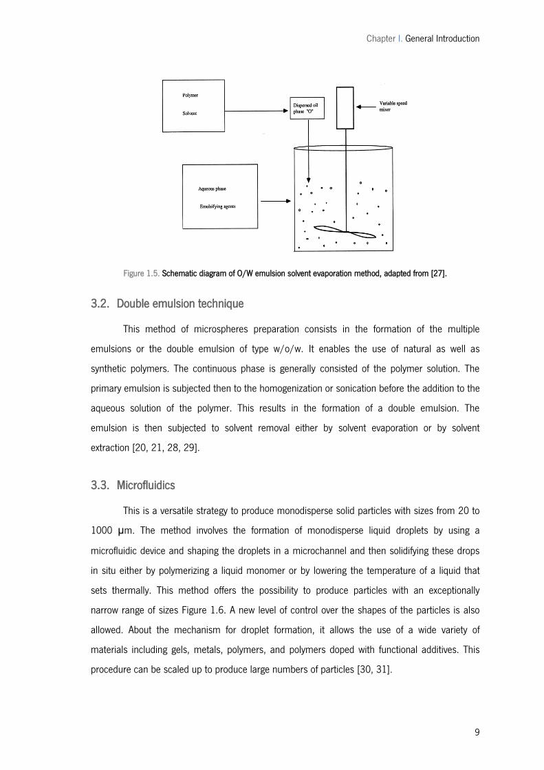
Figure 1.5. Schematic diagram of O/W emulsion solvent evaporation method, adapted from
[27]. .......................................................................................................................................... 9
Figure 1.6. Optical microscopy images of polyTPGDA particles, by microfluids [30]. ..................10
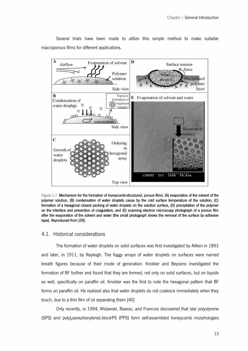
Figure 1.7. Mechanism for the formation of honeycomb-structured, porous films: (A)
evaporation of the solvent of the polymer solution, (B) condensation of water droplets cause
by the cold surface temperature of the solution, (C) formation of a hexagonal closest packing
of water droplets on the solution surface, (D) precipitation of the polymer on the interface and
prevention of coagulation, and (E) scanning electron microscopy photograph of a porous film
after the evaporation of the solvent and water (the small photograph shows the removal of the
surface by adhesive tape). Reproduced from [39]. ....................................................................13
Figure 1.8. Schematic illustrations (side views) and corresponding snapshots (top views; bar:
10 μm) from the in-situ observation for the bas-relief pattern-imprinting process. Reproduced
from [15]. ................................................................................................................................16
Figure 1.9. Microsphere patterns prepared by reverse breath figures method [50]. ...................16
Figure 1.10. Molecular structure of starch. ...............................................................................21
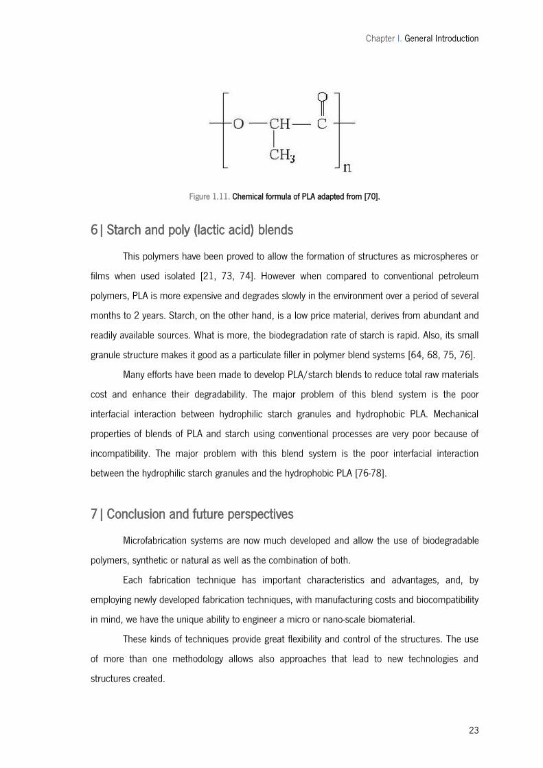
Figure 1.11. Chemical formula of PLA adapted from [70]. ........................................................23
Figure 2.1. a) Static system for breath figures; b) flow system for breath figures. ......................31
Figure 2.2. Mechanism of breath figures creation, adapted from [1]. ........................................32
Figure 3.1. Flow system for breath figures. ...............................................................................43
Figure 3.2. Mechanism of breath figures creation, adapted from [8]. ........................................44
Figure 3.3. Method for a) spheres creation; b) porous films creation, adapted from [8]. ............48
Figure 3.4. Microscopy picture of the process, a) before the polymer introduction and b) after
the polymer introduction. .........................................................................................................49
Figure 3.5. SEM of spheres/particles created for process optimization at 50ºC a) – d) glass,
e) – h) PET, i) – l) Teflon, m) – p) silicon, q) – t) silicone with pattern. ......................................51
xvi
Figure 3.6. Contact angle of substrates with water. .................................................................. 52
Figure 3.7. PLA structures created and size distribution a) non-solvent water, solvent toluene;
b) non-solvent water, solvent chloroform; c) non-solvent methanol, solvent toluene; d) non-
solvent methanol, solvent chloroform (scale bar - 20μm). ......................................................... 54
Figure 3.8. SPLA structures created and size distribution a) non-solvent water, solvent toluene;
b) non-solvent water, solvent chloroform; c) non-solvent methanol, solvent toluene; d) non-
solvent methanol, solvent chloroform (scale bar - 20μm). ......................................................... 55
Figure 3.9. a) PLA - toluene drop over 50% - 50% of MeOH Water solution for contact angle
measurement, resulting "sphere"; b) 25% - 75% of MeOH Water solution drop over PLA -
toluene for contact angle measurement, resulting porous film. ................................................. 58
Figure 3.10. Contact angle of: a) water - MeOH mixtures over polymer solution, and b)
polymer solution over water - MeOH mixtures. .......................................................................... 59
Figure 3.11. Co-existence of structures, with porous spheres/semi-spheres: a) PLA – TL with
a 50:50 atmosphere; b) SPLA - TL with a 20:80 water methanol atmosphere and spheres
inside the pores: c) PLA – chloroform with a 75:25 atmosphere; d) SPLA – chloroform with a
75:25 atmosphere. .................................................................................................................. 60
Figure 3.12. SEM results for SPLA - chloroform solutions using a water methanol mixtures as
non-solvent, a) water, to b) 80:20, c) 75:25, d) 70:30, e) 50:50, f) 30:70, g) 25:75, h) 20:80,
i) MeOH; (scale bar: 10 μm). ................................................................................................... 61
Figure 3.13. (a); Txy diagram for methanol/water (b) activity coefficient plot for
methanol/water [40]. .............................................................................................................. 61
Figure 3.14. PLA GPC for molecular weight determination. ....................................................... 63
Figure 3.15. Thermograph of PLA grains and thermograph of PLA film after dissolution in
chlorophorm. ........................................................................................................................... 64
Figure 3.16. MTS results for cell growth after 24 hours of culture. ............................................ 65
Figure 3.17. Cell growth on glass a) after 24 h and b) after 72 h (scale bar 200 μm)................ 65
Figure 3.18. Cell growth on PLA structures: porous film a) after 24 h, b) after 72 h;
intermediate pattern c) after 24 h, d) after 72 h and spheres e) after 24 h and f) after 72 h
(scale bar 200 μm). ................................................................................................................ 66
Figure 3.19. Cell growth on SPLA structures: porous film a) after 24 h, b) after 72 h;
intermediate pattern c) after 24 h and spheres d) after 72 h (scale bar 200 μm). ..................... 68
xvii
Figure 3.20. SEM images of cells over a) porous film pattern (PLA – chloroform, 100:0 vapour
phase) after 24 h; b) glass after 72 h; c) microspheres pattern (PLA – chloroform, 0:100
vapour phase) after 24 h; d) microsphere pattern (SPLA – toluene, 0:100 vapour phase) after
72 h; (scale bar 200 μm). .......................................................................................................69

xviii
xix
List of Tables
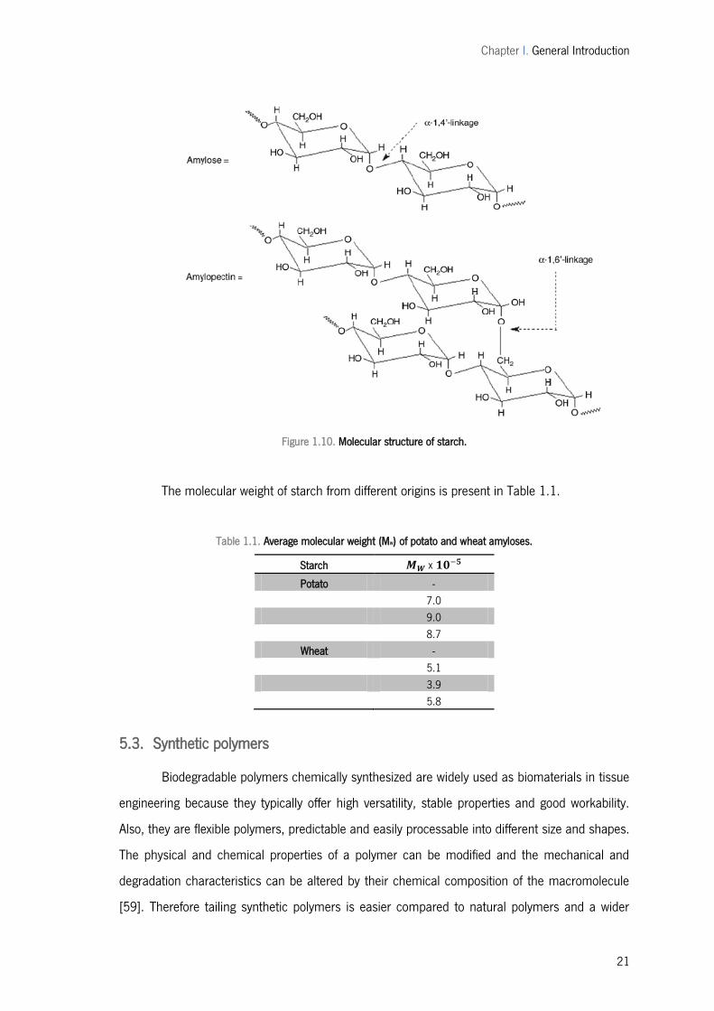
Table 1.1. Average molecular weight (MW) of potato and wheat amyloses. .................................21
Table 3.1. Range of H2O:MeOH (%) used as non-solvent during the process. ............................ 45
Table 3.2. Surface tension of solvents and non-solvents depending of the temperature [31,
32]. ........................................................................................................................................ 52
Table 3.3. Physical properties of solvents and non-solvents [31]. ............................................. 54
Table 3.4. HSP parameters for PLA, solvents and non-solvents and their affinity [20, 35-38] 56
Table 3.5. values for non-solvent affinity for solvent. ............................................................ 57
Table 3.6. Surface tension in mN/m for the specified mass % at 25 ºC, for aqueous solution
[31]. ....................................................................................................................................... 61

xx

Chapter I. General Introduction
1
CHAPTER I.
GENERAL INTRODUCTION

Chapter I. General Introduction
2
Chapter I. General Introduction
3
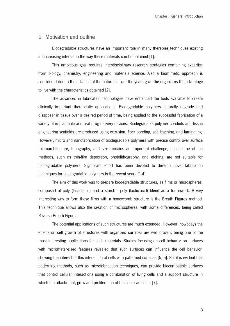
1| Motivation and outline
Biodegradable structures have an important role in many therapies techniques existing
an increasing interest in the way these materials can be obtained [1].
This ambitious goal requires interdisciplinary research strategies combining expertise
from biology, chemistry, engineering and materials science. Also a biomimetic approach is
considered due to the advance of the nature all over the years gave the organisms the advantage
to live with the characteristics obtained [2].
The advances in fabrication technologies have enhanced the tools available to create
clinically important therapeutic applications. Biodegradable polymers naturally degrade and
disappear in tissue over a desired period of time, being applied to the successful fabrication of a
variety of implantable and oral drug delivery devices. Biodegradable polymer conduits and tissue
engineering scaffolds are produced using extrusion, fiber bonding, salt leaching, and laminating.
However, micro and nanofabrication of biodegradable polymers with precise control over surface
microarchitecture, topography, and size remains an important challenge, once some of the
methods, such as thin-film deposition, photolithography, and etching, are not suitable for
biodegradable polymers. Significant effort has been devoted to develop novel fabrication
techniques for biodegradable polymers in the recent years [1-4].
The aim of this work was to prepare biodegradable structures, as films or microspheres,
composed of poly (lactic-acid) and a starch - poly (lactic-acid) blend as a framework. A very
interesting way to form these films with a honeycomb structure is the Breath Figures method.
This technique allows also the creation of microspheres, with some differences, being called
Reverse Breath Figures.
The potential applications of such structures are much extended. However, nowadays the
effects on cell growth of structures with organized surfaces are well proven, being one of the
most interesting applications for such materials. Studies focusing on cell behavior on surfaces
with micrometer-sized features revealed that such surfaces can influence the cell behavior,
showing the interest of this interaction of cells with patterned surfaces [5, 6]. So, it is evident that
patterning methods, such as microfabrication techniques, can provide biocompatible surfaces
that control cellular interactions using a combination of living cells and a support structure in
which the attachment, grow and proliferation of the cells can occur [7].
Chapter I. General Introduction
4
Due to the nature of the applications of this kind of material, the materials should meet
specific characteristics like non-toxicity, and a high cell or tissue biocompatibility. Moreover, it
should have a determinate surface to permit cell adhesion [8].
The present chapter provides an overview of the microspheres production techniques
and of the developments in micro- and nanofabrication technologies that allow the production of
patterned surfaces, having the templating techniques used in this work a further discussion.
Additionally, the focus will be on how the knowledge obtained using these materials can
be incorporated to design biocompatible materials for various biomedical applications such as
basic cell biology, as referred before for the porous films case, or drug delivery systems, for
microspheres, referring also the materials considered more suitable for this applications.
Chapter I. General Introduction
5
2| Polymeric films formation
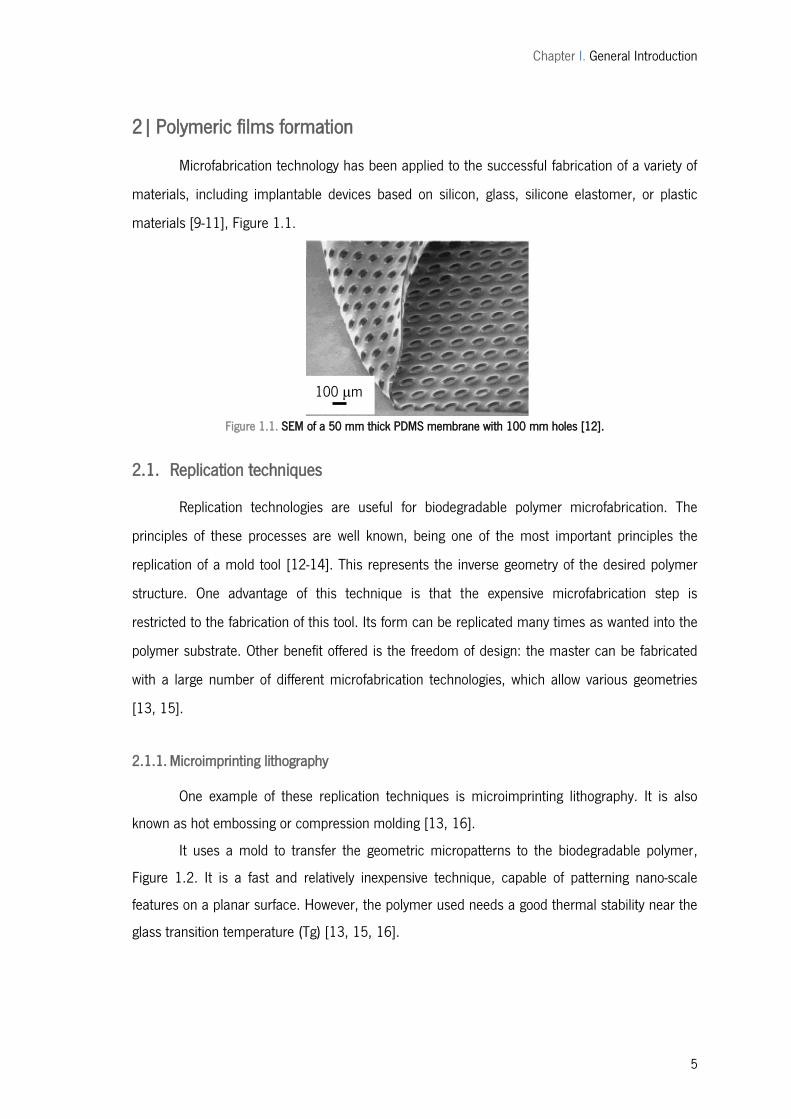
Microfabrication technology has been applied to the successful fabrication of a variety of
materials, including implantable devices based on silicon, glass, silicone elastomer, or plastic
materials [9-11], Figure 1.1.
Figure 1.1. SEM of a 50 mm thick PDMS membrane with 100 mm holes [12].
2.1. Replication techniques
Replication technologies are useful for biodegradable polymer microfabrication. The
principles of these processes are well known, being one of the most important principles the
replication of a mold tool [12-14]. This represents the inverse geometry of the desired polymer
structure. One advantage of this technique is that the expensive microfabrication step is
restricted to the fabrication of this tool. Its form can be replicated many times as wanted into the
polymer substrate. Other benefit offered is the freedom of design: the master can be fabricated
with a large number of different microfabrication technologies, which allow various geometries
[13, 15].
2.1.1. Microimprinting lithography
One example of these replication techniques is microimprinting lithography. It is also
known as hot embossing or compression molding [13, 16].
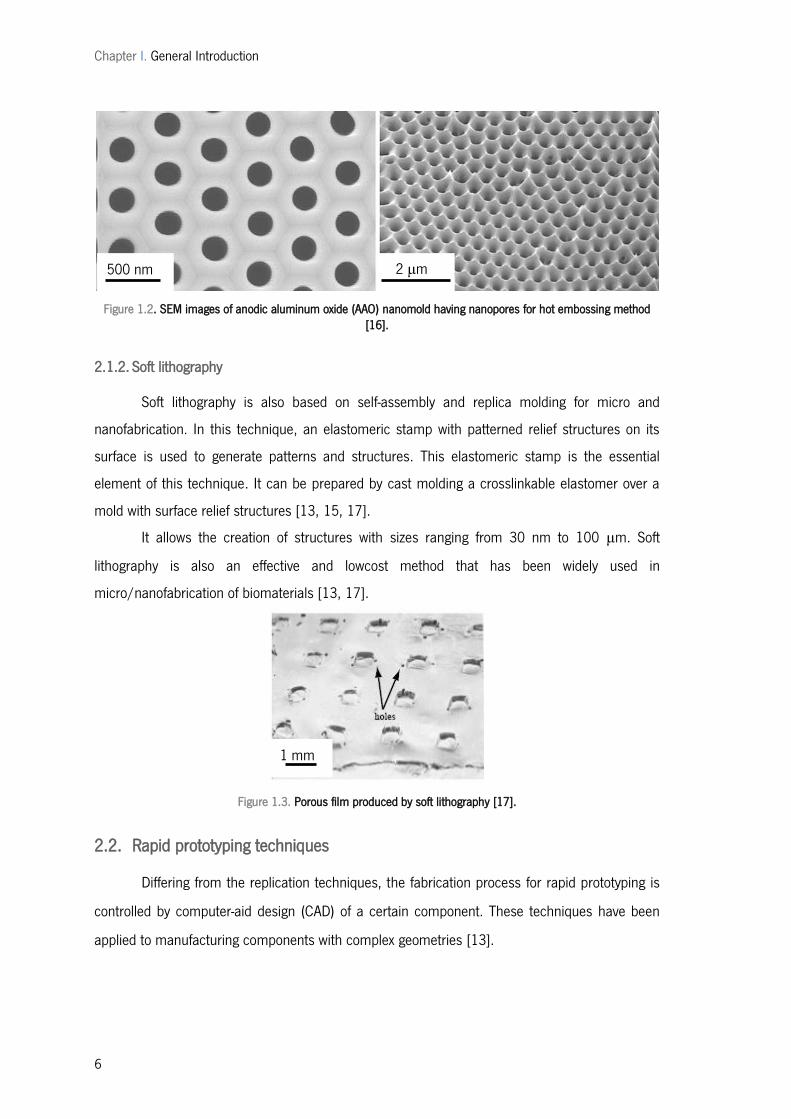
It uses a mold to transfer the geometric micropatterns to the biodegradable polymer,
Figure 1.2. It is a fast and relatively inexpensive technique, capable of patterning nano-scale
features on a planar surface. However, the polymer used needs a good thermal stability near the
glass transition temperature (Tg) [13, 15, 16].
100 μm
Chapter I. General Introduction
6
Figure 1.2. SEM images of anodic aluminum oxide (AAO) nanomold having nanopores for hot embossing method [16].
2.1.2. Soft lithography
Soft lithography is also based on self-assembly and replica molding for micro and
nanofabrication. In this technique, an elastomeric stamp with patterned relief structures on its
surface is used to generate patterns and structures. This elastomeric stamp is the essential
element of this technique. It can be prepared by cast molding a crosslinkable elastomer over a
mold with surface relief structures [13, 15, 17].
It allows the creation of structures with sizes ranging from 30 nm to 100 μm. Soft
lithography is also an effective and lowcost method that has been widely used in
micro/nanofabrication of biomaterials [13, 17].
Figure 1.3. Porous film produced by soft lithography [17].
2.2. Rapid prototyping techniques
Differing from the replication techniques, the fabrication process for rapid prototyping is
controlled by computer-aid design (CAD) of a certain component. These techniques have been
applied to manufacturing components with complex geometries [13].
1 mm
500 nm 2 μm
Chapter I. General Introduction
7
Methods including direct deposition, which is essentially micro-scale extrusion, selective
laser sintering, three-dimensional printing, and stereolithography have been used in these
methods [13, 18].
2.2.1. Three-dimensional printing
Three-dimensional printing has the capability to fabricate microstructures with a high
controll and resolution, also for the interior of the component. Also aided by a CAD model, it
builds the desired material layer by layer with detailed information for every layer. Each layer
consists in a thin distribution of powder spread over the surface of a powder bed. This powder is
bounded by a material, selectively where the object is to be formed by a technology similar to ink-
jet printing. The support of the powder lowers and the next powder layer can be spread repeating
the process all over again, until the part is completed, when unbound powder is removed, leaving
the fabricated part [13, 19].
2.2.2. Laser stereolithography
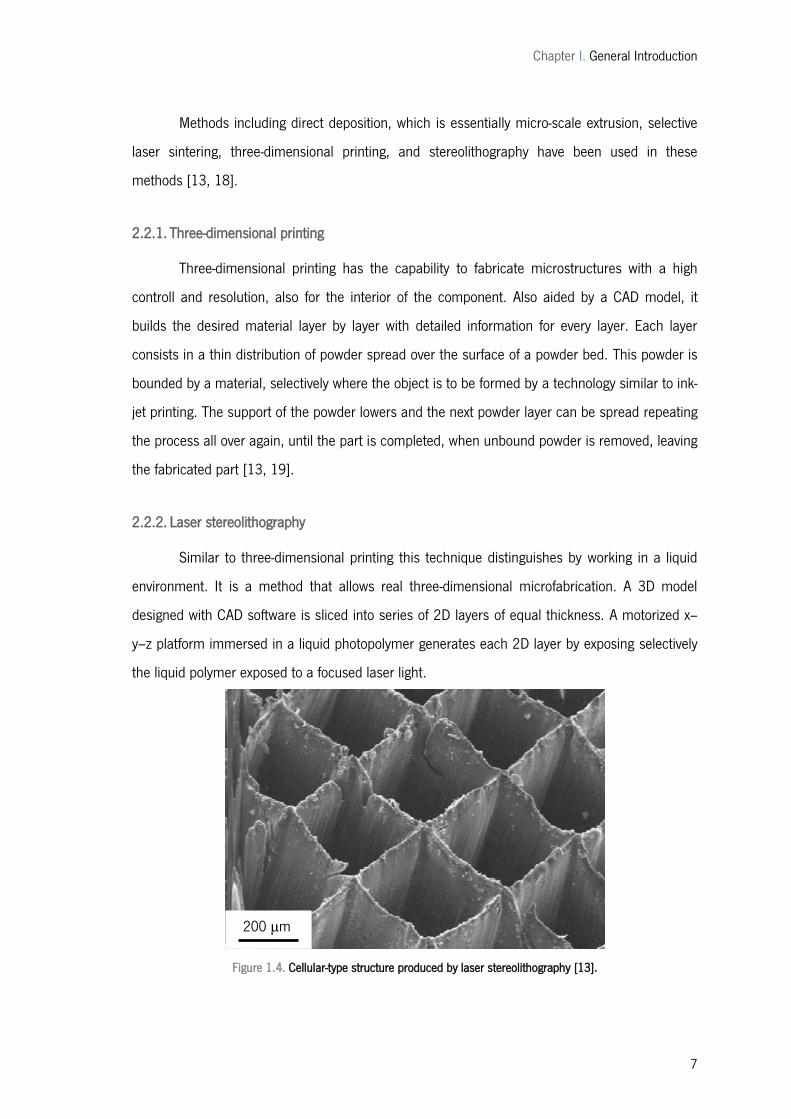
Similar to three-dimensional printing this technique distinguishes by working in a liquid
environment. It is a method that allows real three-dimensional microfabrication. A 3D model
designed with CAD software is sliced into series of 2D layers of equal thickness. A motorized x–
y–z platform immersed in a liquid photopolymer generates each 2D layer by exposing selectively
the liquid polymer exposed to a focused laser light.
Figure 1.4. Cellular-type structure produced by laser stereolithography [13].
200 μm
Chapter I. General Introduction
8
The polymer solidifies in the focal point only, forming layer after layer of the object
according to the design. This layer-by-layer fabrication technique enables complex internal
features such as complex passageways and curved surfaces [13].
2.3. Laser micropatterning
Using lasers to pattern biodegradable polymers, the setup this technique consists of four
main parts: a laser system, a beam delivery system, a micrometer-resolution x–y sample stage,
and an online monitoring system. Different patterns such as microholes or micron-sized channel
type patterns can be obtained [13].
Another potential for laser ablation is surface modification of microfabricated structures
with new structures formation[13].
3| Microsphere production methods
Other important kind of polymeric materials are microspheres. Over the past 25 years,
biodegradable polymer microspheres have been investigated mostly for drug delivery
applications, including but not limited to vaccines, tumor treatment, drug delivery, and control of
inflammation, depending on microsphere physical properties such as polymer molecular weight,
monomer composition, and microsphere size [9, 20-24].
3.1. Single emulsion technique
The polymers dissolved in aqueous medium are then dispersed in non-aqueous medium like
oil [20, 21, 25].
Emulsion–solvent evaporation method is applied to fabricate microspheres very commonly.
The fabricating process consists in the complete dissolution of the polymer, followed by an
emulsification. The emulsified suspension is then stirred, and the solvent is evaporated, Figure
1.6 [25-28].
Chapter I. General Introduction
9
Figure 1.5. Schematic diagram of O/W emulsion solvent evaporation method, adapted from [27].
3.2. Double emulsion technique
This method of microspheres preparation consists in the formation of the multiple
emulsions or the double emulsion of type w/o/w. It enables the use of natural as well as
synthetic polymers. The continuous phase is generally consisted of the polymer solution. The
primary emulsion is subjected then to the homogenization or sonication before the addition to the
aqueous solution of the polymer. This results in the formation of a double emulsion. The
emulsion is then subjected to solvent removal either by solvent evaporation or by solvent
extraction [20, 21, 28, 29].
3.3. Microfluidics
This is a versatile strategy to produce monodisperse solid particles with sizes from 20 to
1000 μm. The method involves the formation of monodisperse liquid droplets by using a
microfluidic device and shaping the droplets in a microchannel and then solidifying these drops
in situ either by polymerizing a liquid monomer or by lowering the temperature of a liquid that
sets thermally. This method offers the possibility to produce particles with an exceptionally
narrow range of sizes Figure 1.6. A new level of control over the shapes of the particles is also
allowed. About the mechanism for droplet formation, it allows the use of a wide variety of
materials including gels, metals, polymers, and polymers doped with functional additives. This
procedure can be scaled up to produce large numbers of particles [30, 31].

Chapter I. General Introduction
10
Figure 1.6. Optical microscopy images of polyTPGDA particles, by microfluids [30].
3.4. Polymerization techniques
The polymerization techniques conventionally used for the preparation of the microspheres
are mainly divided in two groups, normal polymerization and interfacial polymerization. Both are
carried out in liquid phase [20].
3.4.1. Normal polymerization
It is carried out using different techniques as bulk, suspension, precipitation, emulsion
and micellar polymerization processes. In bulk, a monomer or a mixture of monomers along with
the initiator or catalyst is usually heated to initiate polymerization. Polymer so obtained may be
molded as microspheres. Suspension polymerization also referred as bead or pearl
polymerization. It is carried out by heating the monomer or mixture of monomers as droplets
dispersion in a continuous aqueous phase. The droplets may also contain an initiator and other
additives. Emulsion polymerization differs from suspension polymerization as due to the presence
of the initiator in the aqueous phase, which later on diffuses to the surface of micelles. Bulk
polymerization has an advantage, the formation of pure polymers [20].
3.4.2. Interfacial polymerization
It involves the reaction of various monomers at the interface between the two immiscible
liquid phases to form a film of polymer that essentially envelops the dispersed phase [20].
One of the advantages is the rapid polymerization, initiated by ions present in the
medium. The monomer dissolved in a mixture of oil and organic solvent, is then slowly extruded
through a needle into a well-stirred aqueous solution containing surfactant. The resulting colloidal
suspension can be concentrated by evaporation under vacuum. The main disadvantage of this
technique is the use of organic solvents required for the external phase. Washing of solvents and
replacement by water represents a time-consuming and difficult procedure [32].
120 μm
Chapter I. General Introduction
11
3.5. Phase separation coacervation technique
This process is based on the principle of decreasing the solubility of the polymer in
organic phase to affect the formation of polymer rich phase called the coacervates. In this
method, a solution of the polymer to which an incompatible polymer is added causing the phase
separation of the first polymer. Addition of non-solvent results in the solidification of polymer. PLA
microspheres have been prepared by this method by using butadiene as incompatible polymer
[33]. The process variables are very important since the rate of achieving the coacervates
determines the distribution of the polymer film, the particle size and agglomeration of the formed
particles. The agglomeration must be avoided by stirring the suspension using a suitable speed
stirrer since, as the process of microspheres formation begins, the formed polymerize globules
start to stick and form the agglomerates. Therefore the process variables are critical, as they
control the kinetic of the formed particles since there is no defined state of equilibrium
achievement [20, 26].
3.6. Spray drying and spray congealing
These methods are based on the drying of the mist of the polymer and drug in the air.
Depending upon the removal of the solvent or cooling of the solution, the two processes are
named spray drying and spray congealing respectively. The polymer is first dissolved in a suitable
volatile organic solvent such as dichloromethane, acetone, etc. This is then atomized in a stream
of hot air. The atomization leads to the formation of small droplets or a fine mist from which the
solvent evaporates instantaneously leading the formation of the microspheres in a size range 1-
100 μm. Microparticles are separated from the hot air by means of the cyclone separator while
the traces of solvent are removed by vacuum drying. One of the major advantages of the process
is feasibility of operation under aseptic conditions [20, 26, 34].
3.7. Solvent extraction
Also called solvent evaporation method, it is used for the preparation of microparticles,
involves removal of the organic phase by extraction of the organic solvent. The method involves
water miscible organic solvents such as isopropanol. Organic phase is removed by extraction with
water. This process decreases the hardening time for the microspheres. The rate of solvent
Chapter I. General Introduction
12
removal by extraction method depends on the temperature of water, ratio of emulsion volume to
water and the solubility profile of the polymer [10, 20, 27].
4| Breath figures pattern
Each microfabrication offers specific characteristics and advantages, although, there are
reasons why a particular device would not be microfabricated. If only a few devices are needed
and the dimensions are reasonable, it is often possible to machine them conventionally.
Microfabrication, usually, has long development times, depending on the complexity of the
system [35].
So, besides the traditional processes that can be used to obtain patterned surfaces,
more recent alternative methodologies have been suggested. One of the methods to create
materials with microstructured surfaces with increasing interest, being referred as a convenient
and cheap method, utilizes the condensation of monodisperse water droplets on polymer
solution, forming honeycomb porous films, usually known as breath figures method [6].
The fabrication strategies for this process are based in two features: firstly the size of the
template is fixed, and also the template is often sacrificial but, in most cases, not produced with
trivial ease, particularly if monodisperse templates are employed. A dynamic templating method
for polymers and other materials that utilizes a nontoxic and easily available templating medium
would be an attractive proposition: Breath figures, the fog created by exhaling onto a cold
surface, fit that bill and are able to create periodic structures within a size range of 50 nm to 20
μm, i.e., over almost three orders of magnitude. Figure 1.7 presents the mechanism for breath
figures creation.
These polymeric materials nanostructured and microstructured, have many potential
applications that had already been proposed and still remain to be explored. Firstly, they can be
used in many places where porous materials or spheres are required, such as light-weight
materials or drug delivery systems [36]. At the same time, the highly ordered nature of the pore
arrays brings about many new possible applications. One is the use as photonic-band-gap
materials, which have attracted much research attention recently. Another is the use in biology
for cell culturing and tissue engineering and in optoelectronics such as solar cells. Moreover, they
may be of interest as catalytic surfaces and sorption media, selective membranes, sensors,
absorbents, etc [37, 38].
Chapter I. General Introduction
13
Several trials have been made to utilize this simple method to make suitable
macroporous films for different applications.
Figure 1.7. Mechanism for the formation of honeycomb-structured, porous films: (A) evaporation of the solvent of the polymer solution, (B) condensation of water droplets cause by the cold surface temperature of the solution, (C) formation of a hexagonal closest packing of water droplets on the solution surface, (D) precipitation of the polymer on the interface and prevention of coagulation, and (E) scanning electron microscopy photograph of a porous film after the evaporation of the solvent and water (the small photograph shows the removal of the surface by adhesive tape). Reproduced from [39].
4.1. Historical considerations
The formation of water droplets on solid surfaces was first investigated by Aitken in 1893
and later, in 1911, by Rayleigh. The foggy arrays of water droplets on surfaces were named
breath figures because of their mode of generation. Knobler and Beysens investigated the
formation of BF further and found that they are formed, not only on solid surfaces, but on liquids
as well, specifically on paraffin oil. Knobler was the first to note the hexagonal pattern that BF
forms on paraffin oil. He realized also that water droplets do not coalesce immediately when they
touch, due to a thin film of oil separating them [40]
Only recently, in 1994, Widawski, Rawiso, and Francois discovered that star polystyrene
(SPS) and poly(para-phenylene)-block-PS (PPS) form self-assembled honeycomb morphologies
Chapter I. General Introduction
14
(BF arrays, BF) when a drop of the polymeric solution in carbon disulfide was exposed to a flow
of moist air. Francois and co-workers claimed that the BF were formed by a Marangoni-type
convection of condensing water droplets; it was concluded that SPS and block copolymers,
containing a PS sequence, were useful for forming polymer BF [40, 41]. It was reasoned that
only such polymers would be able to encapsulate the water droplets with a thin polymer
membrane. Srinivasarao and Han independently demonstrated that carboxylated as well as
unmodified PS form highly ordered and well-developed bubble arrays when cast from CS2 and
chloroform, respectively. Neither a block copolymer nor SPS architecture seems necessary for
the formation of BF [40, 42].
4.2. Influencing factors for BF formation
The exact mechanism of BF formation is not known in detail. Each given class of polymer
or material system that forms BF could operate by a slightly different mechanism [43, 44]. It may
not be a single, generally applicable mechanism for BF formation. There are, however, important
information that can be drawn from published data. An attractive mechanism for the gestation of
BF was developed by Srinivasarao: the formation and subsequent solidification of BF was
recognized as the root cause for the hexagonally arranged arrays of air bubbles in thin polymer
films [42, 45]. When moist air is blown over a surface of the polymer solution its temperature
decreases. Water droplets nucleate on the surface and subsequently grow. After some time, non-
coalescing droplets form and organize on the surface into a hexagonally ordered and highly
mobile array. These arrays do not coalesce, but start to sink into the solution of the polymer. The
remaining solvent and the water are evaporated after, leaving a monolayer. In all cases, however,
an imprint of the water droplets, now as an air bubble array, is left in the polymeric matrix [44-
47].
Chapter I. General Introduction
15
4.3. Some literature results review
As referred before, the mechanistic of BF formation is complex, even being considered a
simple templating methodology, it has complex thermodynamic, kinetic, and entropic
fundaments that are widely discussed but not well defined [39, 40].
Even with the difficulty to completely understand the complex process some information
can be obtained from the results present in the publish data. Linear PS does not form well-
ordered bubble arrays under most conditions. However, linear PS does form BF under some
conditions, for example carboxylate-terminated (PS) dissolved in CS2, or a linear non-end-
functionalized PS in chloroform, had successful formed honeycomb microporous films. The same
was claimed for other polymers, like mostly polymers with spherical shapes (either block
copolymers or star polymers) considered to form bubble arrays. However, under the correct
conditions, rigid-rod conjugated polymers such as poly(paraphenylene ethynylene)s (PPEs),
polythiophenes, polyfluorenes, and nitrocellulose alike form well-developed and monodisperse BF
as well [39, 40].
Different forms of the pores and conformations of the films can be obtained by this
technique. Distorting the hexagonal arrays obtained rectangular, almost square, or triangular
symmetries can be obtained [48]. Microporous films formed from poly(ε-caprolactone) or from
the polyacrylamide were mechanically deformed. Hexagons are topologically equivalent to
rectangles, squares, and triangles. As a consequence, it was possible to compress or stretch the
microporous poly(caprolactone) films, grown on a water surface, to 0.2–4 times their original
size. [38, 40, 48].
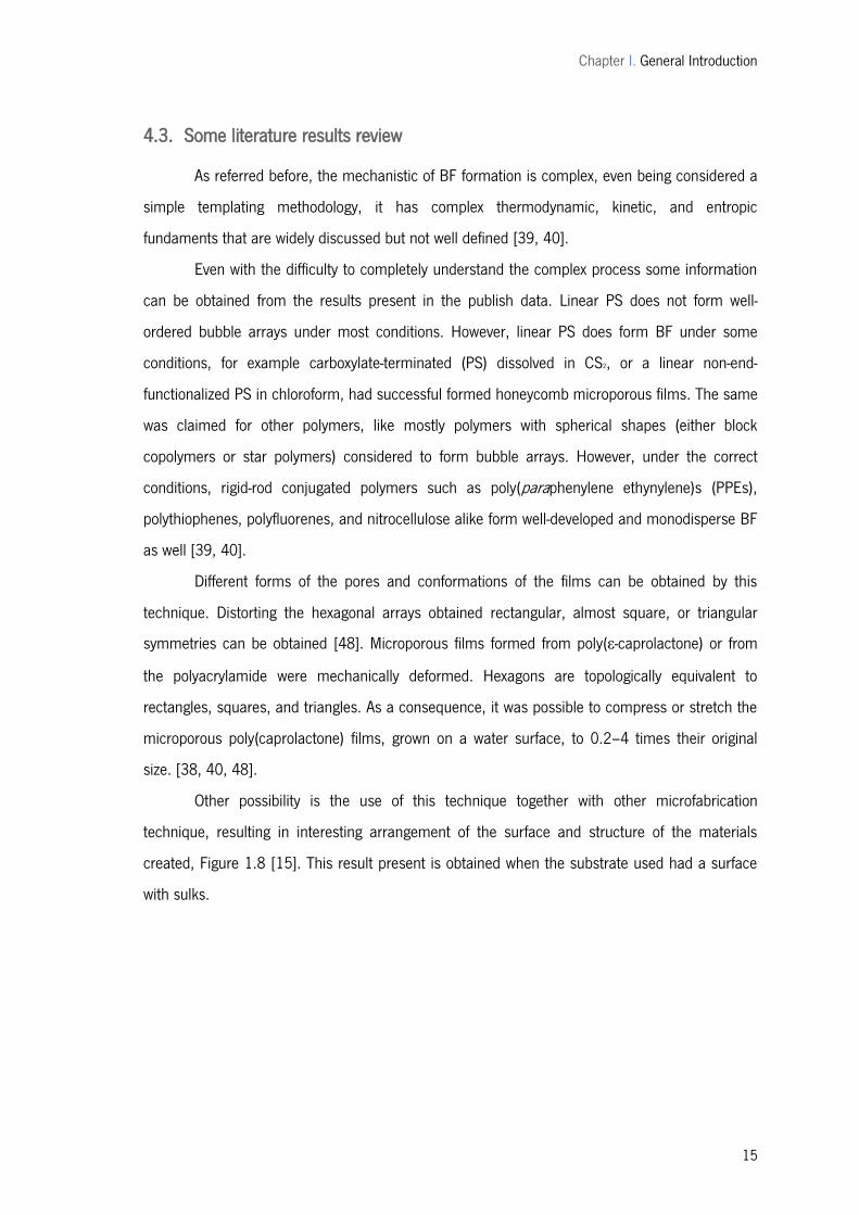
Other possibility is the use of this technique together with other microfabrication
technique, resulting in interesting arrangement of the surface and structure of the materials
created, Figure 1.8 [15]. This result present is obtained when the substrate used had a surface
with sulks.
Chapter I. General Introduction
16
Figure 1.8. Schematic illustrations (side views) and corresponding snapshots (top views; bar: 10 μm) from the in-situ observation for the bas-relief pattern-imprinting process. Reproduced from [15].
4.4. Reverse breath figures for microspheres formation
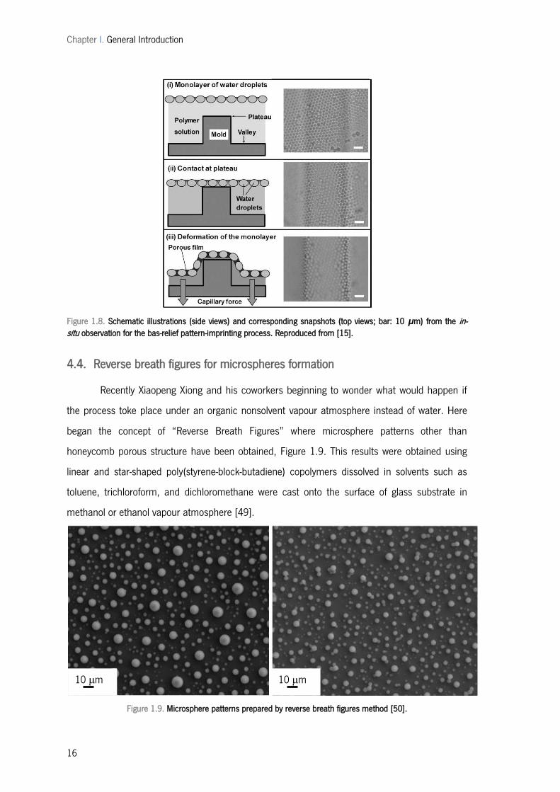
Recently Xiaopeng Xiong and his coworkers beginning to wonder what would happen if
the process toke place under an organic nonsolvent vapour atmosphere instead of water. Here
began the concept of ―Reverse Breath Figures‖ where microsphere patterns other than
honeycomb porous structure have been obtained, Figure 1.9. This results were obtained using
linear and star-shaped poly(styrene-block-butadiene) copolymers dissolved in solvents such as
toluene, trichloroform, and dichloromethane were cast onto the surface of glass substrate in
methanol or ethanol vapour atmosphere [49].
Figure 1.9. Microsphere patterns prepared by reverse breath figures method [50].
10 μm 10 μm
Chapter I. General Introduction
17
5| Biomedical uses of microstructured films and microspheres
With an understanding of the technology, we can now examine the many applications of
microfabrication to biology and medicine. Nowadays, microfabricated devices used as tools for
molecular biology and biochemistry as well as for medicine (such as blood pressure sensors) is a
current practice. They represent one of the few areas where microfabrication has already made a
large impact on biomedical field [3, 7]. Though, microfabricated devices can also be used to
interrogate and manipulate cells themselves [6].
For the case of microspheres, they are most employed in the administration of
medication. Microspheres offer advantages relatively to others materials because they can be
ingested or injected; they can be tailored for desired release profiles and in some cases can even
provide organ-targeted release. They also hold sufficient strength and durability.
5.1. Biodegradable polymers for microstructured films and microspheres
The use of biodegradable polymers for biomedical applications has increased
dramatically, over the past decade. The most important biomedical applications of biodegradable
polymers are in the areas of controlled drug delivery systems, in the forms of implants and
devices for bone and dental repairs [51]. They showed to be non-toxic and biocompatible as well
as their degradation products which, in most cases, occur naturally in the body.
They are also suitable, and many times the most obvious option for the kind of structures
studied in this work, as for the case of the spheres, mostly used in controlled drug delivery
systems usually fabricated from biodegradable polymers.
For the case of the porous films, the microfabrication systems have been successful
employed to fabricate polymeric devices. However, the usual methods create structures that
when implanted remain in the biological tissue if not removed surgically. However, the recovery
of these small-scale devices from tissues is difficult. For this the application of biodegradable
polymers that would naturally degrade and disappear in tissue over a desired period of time, like
the one created in this study is considered advantageous. Micro and nano-fabrication or pattern
techniques with precise control over surface microarchitecture, topography, and size are still an
important challenge in this area of biodegradable polymers [52-54].
Chapter I. General Introduction
18
5.1.1. Controlled drug delivery
As referred previously, the most common methods of sustained drug delivery are as
injectable micro or nanospheres or as subcutaneous implant systems, which involve some
diffusion or erosion matrix [55, 56]. Controlled drug delivery has applications not only in
medicine but also in veterinary and agrochemical fields [51].
The initial drug release systems involved incorporation of the active substance into a
polymer matrix, which can be implanted into the patient in various ways. The surface erosion is
particularly important for drug delivery systems and with lower drug loading more effective
entrapment occurs, and although it has been shown that porosity is initially poor, surface erosion
does occur followed by greater water penetration [13, 51, 57].
5.1.2. Tissue engineering and cell growth
Advances in tissue culture and tissue engineering have generated research into novel
methods of producing biodegradable networks that are effective for a variety of applications both
as hard and soft scaffolds.
Biodegradable polymeric films, like the ones obtained in this work, have been applied in
cell growth or tissue engineering with success [58, 59]. They offer a number of advantages over
other materials for developing materials for in tissue engineering. The key advantages include the
ability to tailor mechanical properties and degradation kinetics to suit various applications. The
fabrication into various shapes with desired pore morphologic features conducive to tissue in-
growth is also an interesting point of investigation for this kind of structures and materials [59].
Attempts to find tissue-engineered solutions to cure different injuries have made
necessary the development of new polymers that meet a number of demanding requirements.
These requirements range from the ability of the material to provide mechanical support during
tissue growth and gradually degrade to biocompatible products to more demanding requirements
such as the ability to incorporate cells or growth factors, when talking of scaffolds [60].
Many of the currently available degradable polymers do not fulfill all of these
requirements and significant chemical changes to their structure may be required if they are to
be formulated for such applications [61].
A material used in tissue engineering or as a cell support must satisfy a number of
requirements. These include biocompatibility, biodegradation to non toxic products within the
Chapter I. General Introduction
19
time frame required for the application, processability to complicated shapes with appropriate
porosity, ability to support cell growth and proliferation, and appropriate mechanical properties
[3].
Biodegradable polymers can be either natural or synthetic. The general criteria for
selecting a polymer for use as a degradable biomaterial are to match the mechanical properties
and the degradation rate to the needs of the application.
5.2. Polymers of natural origin
Economic and environmental aspects are contributing to the growing interest in natural
polymers as choice for biodegradable materials, due to their low toxicity, low manufacture costs,
low disposal costs, and renewability. Different natural materials have been studied and proposed
for the preparation of scaffolds in tissue engineering (TE), such as proteins (collagen, silk fibroin),
polysaccharides chitosan, hyaluronic acid, alginates, starch-based materials, bacterial cellulose,
dextrans), and microbial origin polyesters [62, 63].
Regarding natural polymers, polysaccharides are the most frequently employed in
biomedical applications Polysaccharides consist of a large variety of polymers biosynthesized in
wood, plants, algae, and marine crustaceans, but also produced by bacteria and fungi. They may
be structural components, provide carbon and energy reserves for cells or may be excreted as
plant exudates or as microbial exopolysaccharides. They are characterized from a wide range of
glycosidic linked structures based on about 40 different monosaccharides [62-64].
Polysaccharides may be homopolysaccharides, composed of a single monosaccharide
unit, or heteropolysaccharides, containing two or more sugar moieties. They can be linear or
branched, and may have single or mixed linkage between monosaccharides units. Various
substituent, such as acyl groups, amino acids or inorganic residues can be present in
polysaccharides structure. The widest diversity of polysaccharides is produced by prokaryotic
cells, although many carbohydrate polymers may derive from eukaryotes (algae, plants, or
animals) [62].
Polysaccharides have a great number of properties which makes them an excellent
material for tissue engineering applications, such as non-toxicity, renewability, water solubility,
stability to variations of pH, and they can be chemically modified to achieve high swelling in water
Chapter I. General Introduction
20
as well as being biofunctionalized. However, they have low mechanical, thermal, and chemical
stability [62].
5.2.1. Starch
Among the natural polymers, starch is one of most interest polysaccharides. It is
regenerated from carbon dioxide and water by photosynthesis in plants. Owing to its complete
biodegradability, low cost and renewability, starch is considered as a promising candidate for
developing sustainable materials. In view of this, starch has been receiving growing attention over
the last years. Many efforts have been exerted to develop starch-based polymers for conserving
the petrochemical resources, reducing environmental impact and searching more applications.
Other reason why it is a promising polymer is because of its inherent biodegradability,
overwhelming abundance and renewability. It is composed of a mixture of glycans that plants
synthesize and deposited in the chloroplasts as their principal food reserve [62, 64, 65].
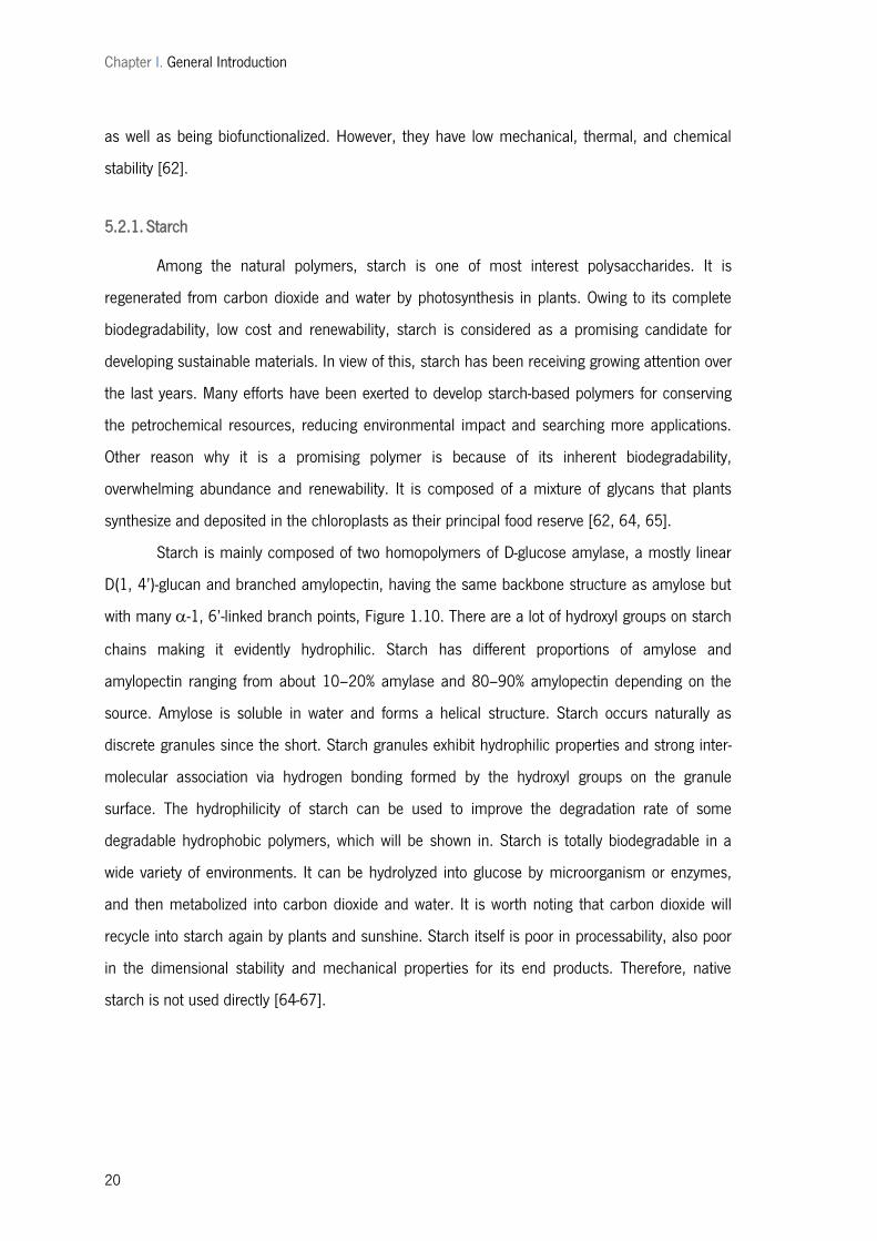
Starch is mainly composed of two homopolymers of D-glucose amylase, a mostly linear
D(1, 4’)-glucan and branched amylopectin, having the same backbone structure as amylose but
with many -1, 6’-linked branch points, Figure 1.10. There are a lot of hydroxyl groups on starch
chains making it evidently hydrophilic. Starch has different proportions of amylose and
amylopectin ranging from about 10–20% amylase and 80–90% amylopectin depending on the
source. Amylose is soluble in water and forms a helical structure. Starch occurs naturally as
discrete granules since the short. Starch granules exhibit hydrophilic properties and strong inter-
molecular association via hydrogen bonding formed by the hydroxyl groups on the granule
surface. The hydrophilicity of starch can be used to improve the degradation rate of some
degradable hydrophobic polymers, which will be shown in. Starch is totally biodegradable in a
wide variety of environments. It can be hydrolyzed into glucose by microorganism or enzymes,
and then metabolized into carbon dioxide and water. It is worth noting that carbon dioxide will
recycle into starch again by plants and sunshine. Starch itself is poor in processability, also poor
in the dimensional stability and mechanical properties for its end products. Therefore, native
starch is not used directly [64-67].
Chapter I. General Introduction
21
Figure 1.10. Molecular structure of starch.
The molecular weight of starch from different origins is present in Table 1.1.
Table 1.1. Average molecular weight (MW) of potato and wheat amyloses.
Starch x
Potato - 7.0 9.0 8.7
Wheat - 5.1 3.9 5.8
5.3. Synthetic polymers
Biodegradable polymers chemically synthesized are widely used as biomaterials in tissue
engineering because they typically offer high versatility, stable properties and good workability.
Also, they are flexible polymers, predictable and easily processable into different size and shapes.
The physical and chemical properties of a polymer can be modified and the mechanical and
degradation characteristics can be altered by their chemical composition of the macromolecule
[59]. Therefore tailing synthetic polymers is easier compared to natural polymers and a wider

Chapter I. General Introduction
22
range of shape and properties can be obtained; furthermore the final result is more predictable.
Degradation rate of scaffolds can be adapted to the required applications by selecting specific
polymers, copolymers or blends. Most of these polymers undergo to a simple hydrolytic
degradation. However, biocompatibility of synthetic polymers is generally lower then natural
polymers. in vivo. Among the most used of these bioresorbable polymers, as implantable
devices, is poly (lactic acid) (PLA) or blends of this [2, 60].
5.3.1. Poly (Lactic Acid) - PLA
PLA is one of the most important biodegradable polyesters with many excellent
properties and has been widely applied in many fields, especially for biomedical area. PLA
possesses good biocompatibility and processability, as well as high strength and modulus.
However, PLA is very brittle under tension and bend loads and develops serious physical aging
during application. Moreover, PLA is a much more expensive material than the common
industrial polymers [68-71].
Poly (lactic acid) (PLA) belongs to the family of aliphatic polyesters commonly made from
- hydroxy acids, which include polyglycolic acid or polymandelic acid, and are considered
biodegradable and compostable. PLA is a thermoplastic, high-strength, high-modulus polymer
that can be made from annually renewable resources to yield articles for use in either the
industrial packaging field or the biocompatible/bioabsorbable medical device market. It is easily
processed on standard plastics equipment to yield molded parts, film, or fibers. It is one of the
few polymers in which the stereochemical structure can easily be modified by polymerizing a
controlled mixture of the L- or D-isomers to yield high-molecular-weight amorphous or crystalline
polymers. Chemical structure of PLA is present in Figure 1.11. PLA is degraded by simple
hydrolysis of the ester bond and does not require the presence of enzymes to catalyze this
hydrolysis. The rate of degradation is dependent on the size and shape of the article, the isomer
ratio and the temperature of hydrolysis. PLA degradation is dependent on time, temperature, low-
molecular-weight impurities, and catalyst concentration. Catalysts and oligomers decrease the
degradation temperature and increase the degradation rate of PLA. In addition, they can cause
viscosity and rheological changes, fuming during processing and poor mechanical properties [68,
70-72].
Chapter I. General Introduction
23
Figure 1.11. Chemical formula of PLA adapted from [70].
6| Starch and poly (lactic acid) blends
This polymers have been proved to allow the formation of structures as microspheres or
films when used isolated [21, 73, 74]. However when compared to conventional petroleum
polymers, PLA is more expensive and degrades slowly in the environment over a period of several
months to 2 years. Starch, on the other hand, is a low price material, derives from abundant and
readily available sources. What is more, the biodegradation rate of starch is rapid. Also, its small
granule structure makes it good as a particulate filler in polymer blend systems [64, 68, 75, 76].
Many efforts have been made to develop PLA/starch blends to reduce total raw materials
cost and enhance their degradability. The major problem of this blend system is the poor
interfacial interaction between hydrophilic starch granules and hydrophobic PLA. Mechanical
properties of blends of PLA and starch using conventional processes are very poor because of
incompatibility. The major problem with this blend system is the poor interfacial interaction
between the hydrophilic starch granules and the hydrophobic PLA [76-78].
7| Conclusion and future perspectives
Microfabrication systems are now much developed and allow the use of biodegradable
polymers, synthetic or natural as well as the combination of both.
Each fabrication technique has important characteristics and advantages, and, by
employing newly developed fabrication techniques, with manufacturing costs and biocompatibility
in mind, we have the unique ability to engineer a micro or nano-scale biomaterial.
These kinds of techniques provide great flexibility and control of the structures. The use
of more than one methodology allows also approaches that lead to new technologies and
structures created.
Chapter I. General Introduction
24
Some important methods for the preparation of nanoparticulate, together with their
advantages and disadvantages, were also summarized in this work, as important biodegradable
structures.
There are now numerous preparation methods available for particles producing, and
important technological advances have been achieved. Simple, safe, and reproducible techniques
are now available to prepare spheres. Depending on the characteristics needed, it is now
possible to choose the best method of preparation and the best polymer to achieve the desired
results.
Despite these technological challenges, nanoparticles have shown great promise for
many applications, in particular biomedical applications such as drug delivery systems.
The need to be non-toxic or the simplification of the procedure to allow economic scale-
up, are things to have in mind when producing this kind of materials both for microspheres and
porous films.
The technique described by Rayleigh and Aitken, breath figures, at the beginning of the
20th century was proved to be a reliable choice to create ordered structures. The BF method is a
simple and effective templating tool, with potential applications as cell-growth media, and
refractive-index materials, and, if smaller bubbles are examined, for photovoltaic applications.
Outstanding issues remain, such as making very small and very large pores reliably and from any
polymeric material. Effective backfilling to obtain compounded micro- and nanoscale materials
presents exciting challenges to be met in the future of these arrays.
It is a versatile technique, that recently have showed to be a facile way to prepare a
microsphere pattern, with some differences leading to the reverse breath figure method. The
advantage of this approach is its simplicity: a microsphere pattern can be obtained by simply
casting a polymer solution onto a glass substrate in the vapour of up to the complete evaporation
of the solvent, when talking of reverse breath figures. The porous film pattern can be as easily
obtained replacing the vapour phase for water instead of an organic solvent.
8| References
1. Förch, R., et al., Surface Design: Applications in Bioscience and Nanotechnology. 2009: John Wiley & Sons.
2. Cheung, H.-Y., et al., A critical review on polymer-based bio-engineered materials for scaffold development. Composites Part B: Engineering, 2007. 38(3): p. 291-300.
Chapter I. General Introduction
25
3. Khademhosseini, A., et al., Microscale technologies for tissue engineering and biology. Proceedings of the National Academy of Sciences of the United States of America, 2006. 103(8): p. 2480-2487.
4. Won Mook, C. and O.O. Park, A soft-imprint technique for submicron structure fabrication via in situ polymerization. Nanotechnology, 2004. 15(1): p. 135.
5. Galeotti, F., et al., Breath figures-mediated microprinting allows for versatile applications in molecular biology. European Polymer Journal, 2009. 45(11): p. 3027-3034.
6. Alves, N.M., et al., Controlling Cell Behavior Through the Design of Polymer Surfaces. Small, 2010. 6(20): p. 2208-2220.
7. Ookura, R., et al., Stabilization of Micropatterned Polymer Films as Artificial Extracellular Matrices for Tissue Engineering. Molecular Crystals and Liquid Crystals Science and Technology. Section A. Molecular Crystals and Liquid Crystals, 1999. 337(1): p. 461-464.
8. Uchida, T., et al. Fabrication of biodegradable scaffolds by use of self-assembled magnetic sugar particles as a casting template. in Robotics and Automation, 2008. ICRA 2008. IEEE International Conference on. 2008.
9. Hans, M.L. and A.M. Lowman, Biodegradable nanoparticles for drug delivery and targeting. Current Opinion in Solid State and Materials Science, 2002. 6(4): p. 319-327.
10. Rötting, O., et al., Polymer microfabrication technologies. Microsystem Technologies, 2002. 8(1): p. 32-36.
11. Deniz, K.A. and L. Chang, Microfabrication technology for polycaprolactone, a biodegradable polymer. Journal of Micromechanics and Microengineering, 2000. 10(1): p. 80.
12. Alom Ruiz, S. and C.S. Chen, Microcontact printing: A tool to pattern. Soft Matter, 2007. 3(2): p. 168-177.
13. Lu, Y., Micro and nano-fabrication of biodegradable polymers for drug delivery. Advanced Drug Delivery Reviews, 2004. 56(11): p. 1621-1633.
14. O’Dwyer, C., et al., Atomic nanolithography patterning of submicron features: writing an organic self-assembled monolayer with cold, bright Cs atom beams. Nanotechnology, 2005. 16(9): p. 1536.
15. Ohzono, T., T. Nishikawa, and M. Shimomura, One-step fabrication of polymer thin films with lithographic bas-relief micro-pattern and self-organized micro-porous structure. Journal of Materials Science, 2004. 39(6): p. 2243-2247.
16. Lee, H., et al., Replication of nanostructures on microstructures by intermediate film mold inserted hot embossing process. Microsystem Technologies, 2008. 14(8): p. 1149-1155.
17. Vozzi, G., et al., Fabrication of PLGA scaffolds using soft lithography and microsyringe deposition. Biomaterials, 2003. 24(14): p. 2533-2540.
18. Fan, H., et al., Rapid prototyping of patterned functional nanostructures. Nature, 2000. 405(6782): p. 56-60.
19. Wu, B.M., et al., Solid free-form fabrication of drug delivery devices. Journal of Controlled Release, 1996. 40(1-2): p. 77-87.
20. Rajeev A, J., The manufacturing techniques of various drug loaded biodegradable poly(lactide-co-glycolide) (PLGA) devices. Biomaterials, 2000. 21(23): p. 2475-2490.
21. Sinha, M., USE OF BIODEGRADABLE MICRO AND NANO-PARTICLES IN VACCINE DELIVERY. 2011. Vol. 2. 2011.
Chapter I. General Introduction
26
22. Matsumoto, A., et al., A novel preparation method for PLGA microspheres using non-halogenated solvents. Journal of Controlled Release, 2008. 129(3): p. 223-227.
23. Zhao, Y., Z. Zhang, and H. Dang, Preparation of tin nanoparticles by solution dispersion. Materials Science and Engineering: A, 2003. 359(1-2): p. 405-407.
24. Haruma, K., Functional polymer microspheres. Progress in Polymer Science, 2000. 25(8): p. 1171-1210.
25. Chung, T.-W., Y.-Y. Huang, and Y.-Z. Liu, Effects of the rate of solvent evaporation on the characteristics of drug loaded PLLA and PDLLA microspheres. International Journal of Pharmaceutics, 2001. 212(2): p. 161-169.
26. Berkland, C., K. Kim, and D.W. Pack, Fabrication of PLG microspheres with precisely controlled and monodisperse size distributions. Journal of Controlled Release, 2001. 73(1): p. 59-74.
27. O'Donnell, P.B. and J.W. McGinity, Preparation of microspheres by the solvent evaporation technique. Advanced Drug Delivery Reviews, 1997. 28(1): p. 25-42.
28. Rosca, I.D., F. Watari, and M. Uo, Microparticle formation and its mechanism in single and double emulsion solvent evaporation. Journal of Controlled Release, 2004. 99(2): p. 271-280.
29. Zambaux, M.F., et al., Influence of experimental parameters on the characteristics of poly(lactic acid) nanoparticles prepared by a double emulsion method. Journal of Controlled Release, 1998. 50(1-3): p. 31-40.
30. Xu, S., et al., Generation of Monodisperse Particles by Using Microfluidics: Control over Size, Shape, and Composition. Angewandte Chemie International Edition, 2005. 44(25): p. 3799-3799.
31. Shah, R.K., et al., Designer emulsions using microfluidics. Materials Today, 2008. 11(4): p. 18-27.
32. Pinto Reis, C., et al., Nanoencapsulation I. Methods for preparation of drug-loaded polymeric nanoparticles. Nanomedicine: Nanotechnology, Biology and Medicine, 2006. 2(1): p. 8-21.
33. Thomasin, C., et al., Drug microencapsulation by PLA/PLGA coacervation in the light of thermodynamics. 1. Overview and theoretical considerations. Journal of Pharmaceutical Sciences, 1998. 87(3): p. 259-268.
34. Takashima, Y., et al., Spray-drying preparation of microparticles containing cationic PLGA nanospheres as gene carriers for avoiding aggregation of nanospheres. International Journal of Pharmaceutics, 2007. 343(1-2): p. 262-269.
35. Voldman, J., M.L. Gray, and M.A. Schmidt, Microfabrication in Biology and Medicine. Annual Review of Biomedical Engineering, 1999. 1(1): p. 401-425.
36. Freiberg, S. and X.X. Zhu, Polymer microspheres for controlled drug release. International Journal of Pharmaceutics, 2004. 282(1-2): p. 1-18.
37. Zhang, Y. and C. Wang, Micropatterning of Proteins on 3D Porous Polymer Film Fabricated by Using the Breath-Figure Method. Advanced Materials, 2007. 19(7): p. 913-916.
38. Song, L., et al., Facile Microstructuring of Organic Semiconducting Polymers by the Breath Figure Method: Hexagonally Ordered Bubble Arrays in Rigid Rod-Polymers. Advanced Materials, 2004. 16(2): p. 115-118.
39. Stenzel, M.H., C. Barner-Kowollik, and T.P. Davis, Formation of honeycomb-structured, porous films via breath figures with different polymer architectures. Journal of Polymer Science Part A: Polymer Chemistry, 2006. 44(8): p. 2363-2375.
Chapter I. General Introduction
27
40. Bunz, U.H.F., Breath Figures as a Dynamic Templating Method for Polymers and Nanomaterials. Advanced Materials, 2006. 18(8): p. 973-989.
41. Maillard, M., et al., Rings and Hexagons Made of Nanocrystals: A Marangoni Effect. The Journal of Physical Chemistry B, 2000. 104(50): p. 11871-11877.
42. Srinivasarao, M., et al., Three-Dimensionally Ordered Array of Air Bubbles in a Polymer Film. Science, 2001. 292(5514): p. 79-83.
43. Madej, W., et al., Breath Figures in Polymer and Polymer Blend Films Spin-Coated in Dry and Humid Ambience. Langmuir, 2008. 24(7): p. 3517-3524.
44. Karthaus, O., et al., Water-Assisted Formation of Micrometer-Size Honeycomb Patterns of Polymers. Langmuir, 2000. 16(15): p. 6071-6076.
45. Limaye, A.V., et al., Evidence for Convective Effects in Breath Figure Formation on Volatile Fluid Surfaces. Physical Review Letters, 1996. 76(20): p. 3762-3765.
46. Sharma, V., et al., Effect of solvent choice on breath-figure-templated assembly of ―holey‖ polymer films. EPL, 2010. 91(3): p. 38001.
47. Servoli, E., G.A. Ruffo, and C. Migliaresi, Interplay of kinetics and interfacial interactions in breath figure templating – A phenomenological interpretation. Polymer, 2010. 51(11): p. 2337-2344.
48. Nishikawa, T., et al., Micropatterns Based on Deformation of a Viscoelastic Honeycomb Mesh. Langmuir, 2003. 19(15): p. 6193-6201.
49. Xiong, X., et al., Microsphere Pattern Prepared by a ―Reverse‖ Breath Figure Method, in Macromolecules. 2009. p. 9351–9356.
50. Xiong, X., et al., Microsphere Pattern Prepared by a ―Reverse‖ Breath Figure Method. Macromolecules, 2009. 42(23): p. 9351-9356.
51. Amass, W., A. Amass, and B. Tighe, A review of biodegradable polymers: uses, current developments in the synthesis and characterization of biodegradable polyesters, blends of biodegradable polymers and recent advances in biodegradation studies. Polymer International, 1998. 47(2): p. 89-144.
52. Miller, C., et al., Oriented Schwann cell growth on micropatterned biodegradable polymer substrates. Biomaterials, 2001. 22(11): p. 1263-1269.
53. Lai, K.L., M.H. Hon, and I.C. Leu, Pattern formation on polymer resist by solvent-assisted nanoimprinting with PDMS mold as a solvent transport medium. Journal of Micromechanics and Microengineering, 2011. 21(7): p. 075013.
54. Li, G., et al., The nanofabrication of polydimethylsiloxane using a focused ion beam. Nanotechnology, 2009. 20(14): p. 145301.
55. Sinha, V.R. and A. Trehan, Biodegradable microspheres for protein delivery. Journal of Controlled Release, 2003. 90(3): p. 261-280.
56. Berkland, C., et al., Microsphere size, precipitation kinetics and drug distribution control drug release from biodegradable polyanhydride microspheres. Journal of Controlled Release, 2004. 94(1): p. 129-141.
57. Ahmed, A., C. Bonner, and T.A. Desai, Bioadhesive microdevices with multiple reservoirs: a new platform for oral drug delivery. Journal of Controlled Release, 2002. 81(3): p. 291-306.
58. Hou, X., K.-L. Choy, and J. Yan, Deposition of biodegradable poly (d,l-lactic acid) films using aerosol-assisted method. Surface and Coatings Technology, 2008. 202(21): p. 5175-5179.
59. Gunatillake, P.A. and R. Adhikari, Biodegradable synthetic polymers for tissue engineering. European cells & materials, 2003. 5: p. 1-16; discussion 16.
Chapter I. General Introduction
28
60. Rezwan, K., et al., Biodegradable and bioactive porous polymer/inorganic composite scaffolds for bone tissue engineering. Biomaterials, 2006. 27(18): p. 3413-3431.
61. Salgado, A.J., O.P. Coutinho, and R.L. Reis, Bone Tissue Engineering: State of the Art and Future Trends. Macromolecular Bioscience, 2004. 4(8): p. 743-765.
62. Malafaya, P.B., G.A. Silva, and R.L. Reis, Natural–origin polymers as carriers and scaffolds for biomolecules and cell delivery in tissue engineering applications. Advanced Drug Delivery Reviews, 2007. 59(4-5): p. 207-233.
63. Martins, A.M., et al., Natural origin scaffolds with in situ pore forming capability for bone tissue engineering applications. Acta Biomaterialia, 2008. 4(6): p. 1637-1645.
64. Gomes, M.E., et al., Influence of the Porosity of Starch-Based Fiber Mesh Scaffolds on the Proliferation and Osteogenic Differentiation of Bone Marrow Stromal Cells Cultured in a Flow Perfusion Bioreactor. Tissue Engineering, 2006. 12(4): p. 801-809.
65. Buléon, A., et al., Starch granules: structure and biosynthesis. International Journal of Biological Macromolecules, 1998. 23(2): p. 85-112.
66. Elvira, C., et al., Starch-based biodegradable hydrogels with potential biomedical applications as drug delivery systems. Biomaterials, 2002. 23(9): p. 1955-1966.
67. Tester, R.F., J. Karkalas, and X. Qi, Starch—composition, fine structure and architecture. Journal of Cereal Science, 2004. 39(2): p. 151-165.
68. Auras, R.A., et al., Poly(lactic Acid): Synthesis, Structures, Properties, Processing, and Applications. 2010: John Wiley & Sons.
69. Lim, L.T., R. Auras, and M. Rubino, Processing technologies for poly(lactic acid). Progress in Polymer Science, 2008. 33(8): p. 820-852.
70. Garlotta, D., A Literature Review of Poly(Lactic Acid). Journal of Polymers and the Environment, 2001. 9(2): p. 63-84.
71. Athanasiou, K.A., G.G. Niederauer, and C.M. Agrawal, Sterilization, toxicity, biocompatibility and clinical applications of polylactic acid/ polyglycolic acid copolymers. Biomaterials, 1996. 17(2): p. 93-102.
72. Martin, O. and L. Avérous, Poly(lactic acid): plasticization and properties of biodegradable multiphase systems. Polymer, 2001. 42(14): p. 6209-6219.
73. Birnbaum, D.T., J.D. Kosmala, and L. Brannon-Peppas, Optimization of Preparation Techniques for Poly(Lactic Acid-Co-Glycolic Acid) Nanoparticles. Journal of Nanoparticle Research, 2000. 2(2): p. 173-181.
74. Gonzalez, M.F., R.A. Ruseckaite, and T.R. Cuadrado, Structural changes of polylactic-acid (PLA) microspheres under hydrolytic degradation. Journal of Applied Polymer Science, 1999. 71(8): p. 1223-1230.
75. Huneault, M.A. and H. Li, Morphology and properties of compatibilized polylactide/thermoplastic starch blends. Polymer, 2007. 48(1): p. 270-280.
76. Willett, J.L. and R.L. Shogren, Processing and properties of extruded starch/polymer foams. Polymer, 2002. 43(22): p. 5935-5947.
77. Schwach, E., J.-L. Six, and L. Avérous, Biodegradable Blends Based on Starch and Poly(Lactic Acid): Comparison of Different Strategies and Estimate of Compatibilization. Journal of Polymers and the Environment, 2008. 16(4): p. 286-297.
78. Wang, N., J. Yu, and X. Ma, Preparation and characterization of thermoplastic starch/PLA blends by one-step reactive extrusion. Polymer International, 2007. 56(11): p. 1440-1447.

Chapter II. Materials and Methods
29
CHAPTER II.
MATERIALS AND METHODS

Chapter II. Materials and Methods
30
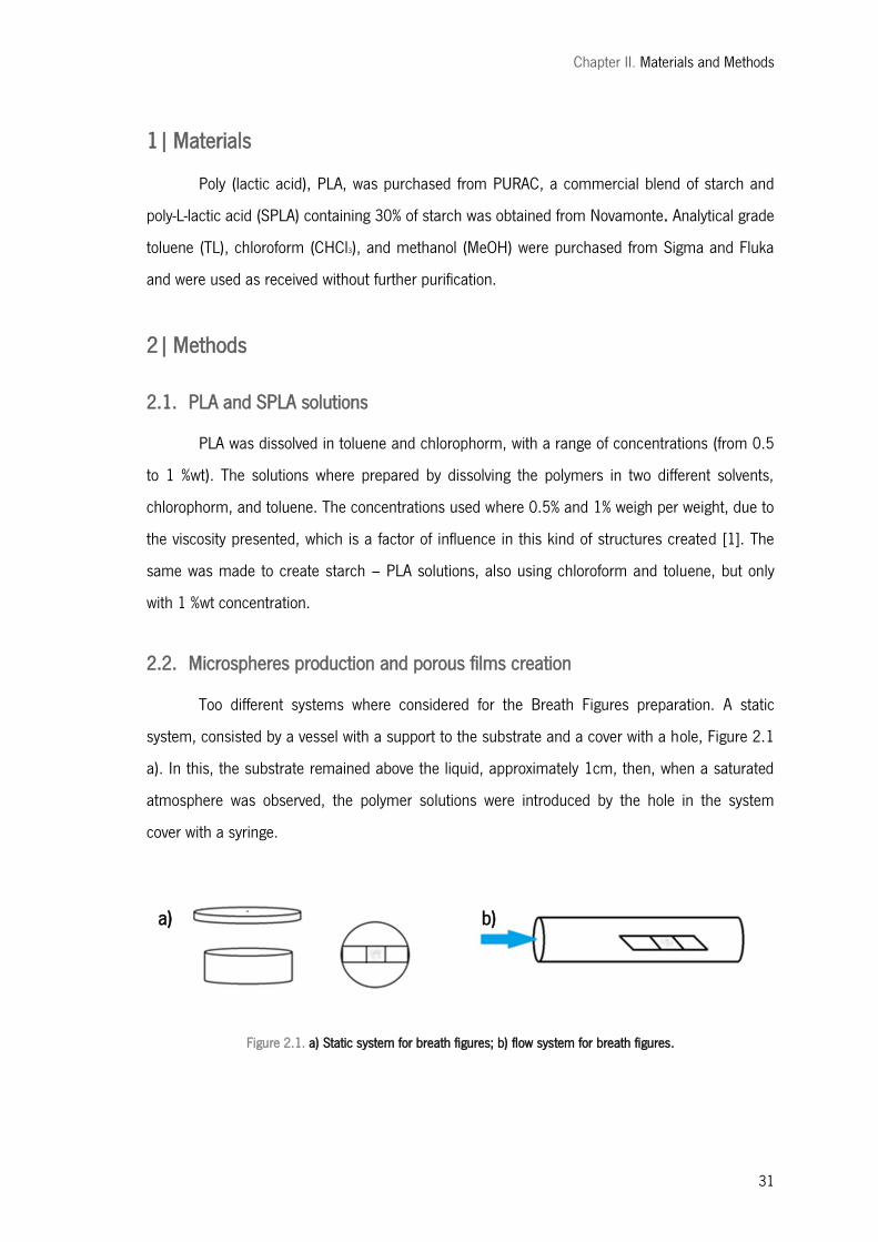
Chapter II. Materials and Methods
31
1| Materials
Poly (lactic acid), PLA, was purchased from PURAC, a commercial blend of starch and
poly-L-lactic acid (SPLA) containing 30% of starch was obtained from Novamonte. Analytical grade
toluene (TL), chloroform (CHCl3), and methanol (MeOH) were purchased from Sigma and Fluka
and were used as received without further purification.
2| Methods
2.1. PLA and SPLA solutions
PLA was dissolved in toluene and chlorophorm, with a range of concentrations (from 0.5
to 1 %wt). The solutions where prepared by dissolving the polymers in two different solvents,
chlorophorm, and toluene. The concentrations used where 0.5% and 1% weigh per weight, due to
the viscosity presented, which is a factor of influence in this kind of structures created [1]. The
same was made to create starch – PLA solutions, also using chloroform and toluene, but only
with 1 %wt concentration.
2.2. Microspheres production and porous films creation
Too different systems where considered for the Breath Figures preparation. A static
system, consisted by a vessel with a support to the substrate and a cover with a hole, Figure 2.1
a). In this, the substrate remained above the liquid, approximately 1cm, then, when a saturated
atmosphere was observed, the polymer solutions were introduced by the hole in the system
cover with a syringe.
Figure 2.1. a) Static system for breath figures; b) flow system for breath figures.
a) b)
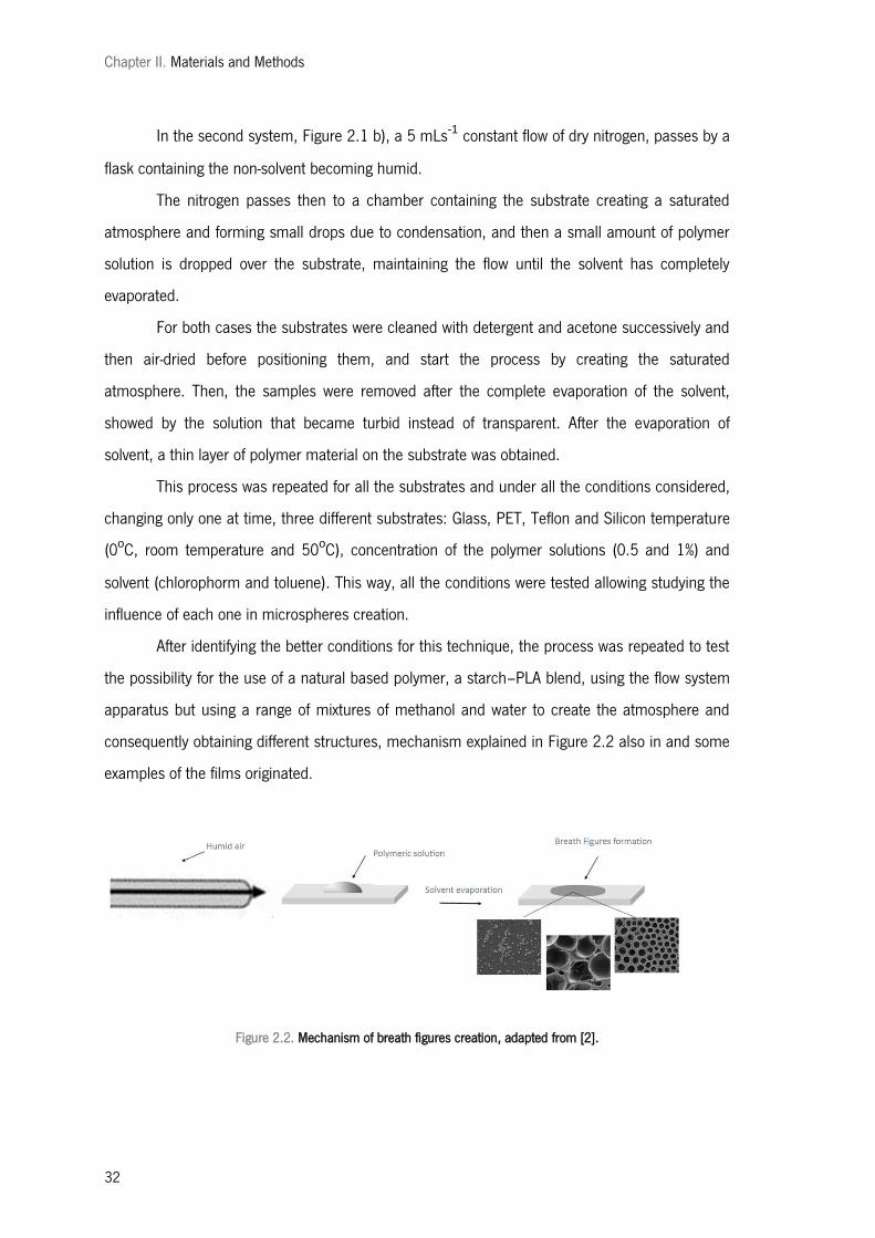
Chapter II. Materials and Methods
32
In the second system, Figure 2.1 b), a 5 mLs-1 constant flow of dry nitrogen, passes by a
flask containing the non-solvent becoming humid.
The nitrogen passes then to a chamber containing the substrate creating a saturated
atmosphere and forming small drops due to condensation, and then a small amount of polymer
solution is dropped over the substrate, maintaining the flow until the solvent has completely
evaporated.
For both cases the substrates were cleaned with detergent and acetone successively and
then air-dried before positioning them, and start the process by creating the saturated
atmosphere. Then, the samples were removed after the complete evaporation of the solvent,
showed by the solution that became turbid instead of transparent. After the evaporation of
solvent, a thin layer of polymer material on the substrate was obtained.
This process was repeated for all the substrates and under all the conditions considered,
changing only one at time, three different substrates: Glass, PET, Teflon and Silicon temperature
(0oC, room temperature and 50oC), concentration of the polymer solutions (0.5 and 1%) and
solvent (chlorophorm and toluene). This way, all the conditions were tested allowing studying the
influence of each one in microspheres creation.
After identifying the better conditions for this technique, the process was repeated to test
the possibility for the use of a natural based polymer, a starch–PLA blend, using the flow system
apparatus but using a range of mixtures of methanol and water to create the atmosphere and
consequently obtaining different structures, mechanism explained in Figure 2.2 also in and some
examples of the films originated.
Figure 2.2. Mechanism of breath figures creation, adapted from [2].
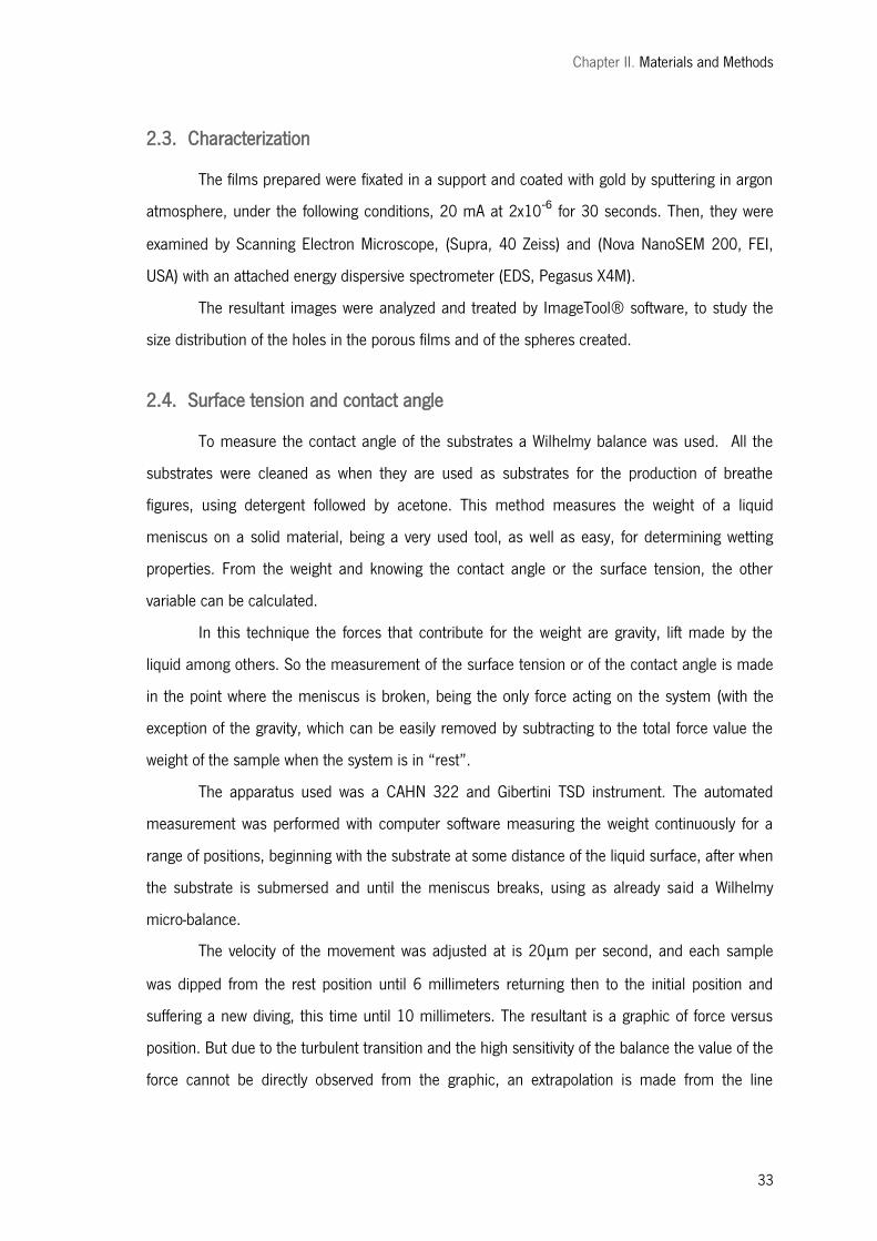
Chapter II. Materials and Methods
33
2.3. Characterization
The films prepared were fixated in a support and coated with gold by sputtering in argon
atmosphere, under the following conditions, 20 mA at 2x10⁻⁶ for 30 seconds. Then, they were
examined by Scanning Electron Microscope, (Supra, 40 Zeiss) and (Nova NanoSEM 200, FEI,
USA) with an attached energy dispersive spectrometer (EDS, Pegasus X4M).
The resultant images were analyzed and treated by ImageTool® software, to study the
size distribution of the holes in the porous films and of the spheres created.
2.4. Surface tension and contact angle
To measure the contact angle of the substrates a Wilhelmy balance was used. All the
substrates were cleaned as when they are used as substrates for the production of breathe
figures, using detergent followed by acetone. This method measures the weight of a liquid
meniscus on a solid material, being a very used tool, as well as easy, for determining wetting
properties. From the weight and knowing the contact angle or the surface tension, the other
variable can be calculated.
In this technique the forces that contribute for the weight are gravity, lift made by the
liquid among others. So the measurement of the surface tension or of the contact angle is made
in the point where the meniscus is broken, being the only force acting on the system (with the
exception of the gravity, which can be easily removed by subtracting to the total force value the
weight of the sample when the system is in ―rest‖.
The apparatus used was a CAHN 322 and Gibertini TSD instrument. The automated
measurement was performed with computer software measuring the weight continuously for a
range of positions, beginning with the substrate at some distance of the liquid surface, after when
the substrate is submersed and until the meniscus breaks, using as already said a Wilhelmy
micro-balance.
The velocity of the movement was adjusted at is 20μm per second, and each sample
was dipped from the rest position until 6 millimeters returning then to the initial position and
suffering a new diving, this time until 10 millimeters. The resultant is a graphic of force versus
position. But due to the turbulent transition and the high sensitivity of the balance the value of the
force cannot be directly observed from the graphic, an extrapolation is made from the line

Chapter II. Materials and Methods
34
presented in the intermediate positions to obtain the value. Two different values were obtained
corresponding to the advance or receding of the substrate.
To measure the contact angle between two liquids, solution and atmosphere, the tensile
drop method was used, with OCA20 equipment (DataPhysics, Germany). This was performed at
room temperature dropping a small amount of the liquid considered to have higher surface
tension over the one with lowest. The quantity of liquid was measured with a syringe monitored
by a micrometric screw. The observation of the angle was made directly with the aid of a camera
and software that calculates the resultant angles. The results correspond to the average value of
at least 5 measurements.
2.5. Differential scanning calorimetry (DSC)
Differential scanning calorimetry (DSC) (DCS 30 Mettler-Toledo, USA) was performed on
the PLA before and after the dissolution to investigate possible modifications. Approximately 5-10
mg samples were placed in aluminum DSC pans. The samples underwent a heating scan from
0oC to 200oC; heating rate was fixed at 10oCmin-1 and cooling rate at 100oCmin-1 under
nitrogen flux of 10 mLmin-1.
Evaluations on the obtained graphs were performed by STARe – Thermal analysis
software.
Second order phase transition, that is glass transition temperature (Tg) and first order
phase transition endothermic and exothermic peaks were detected.
2.6. Gel permeation chromatography (GPC)
Weight average molecular weight of the used synthetic polymers used was determined by
gel permeation chromatography (GPC, Spectra System P1500) by using a Shodex K-804 column
(Shodex, Tokyo, Japan) and a KG pre-column. Chloroform was used as solvent for the polymers
and 1 m/min eluent constant flux was applied.
The Universal Calibration method with polystyrene standards was used to obtain a
calibration curve.
Chapter II. Materials and Methods
35
2.7. In vitro studies
2.7.1. Cell seeding and culture
A, human osteogenic sarcoma cell line (SAOS-2 cell line), were maintained in DMEM
(Dulbecco’s modified Eagle’s medium; Sigma-Aldrich, Germany) supplemented with 10% heat-
inactivated fetal bovine serum (Biochrom AG, Germany) and 1% antibiotic–antimycotic solution
(Gibco, UK). Cells were cultured in a humidified incubator at 37 ºC in a 5% CO2 atmosphere.
Confluent cells were harvested and seeded in the different surfaces as follows. PLA,
SPLA and glass substrates were distributed in a 24- well cell culture plate (Costar®, Corning,
USA). 1 ml of a suspension of osteoblast-like cells with a concentration of 4 x 10⁴ cells/ml.
These were statically cultured for 1 and 3 days under the culture conditions previously described.
2.7.2. Cell adhesion and morphology
Cells were stained with calcein and observed under a fluorescent microscope in order to
evaluate the cell distribution within the surface of the substrate. The green fluorescence indicates
the viability of the cells cultured on the matrices.
To evaluate further the cell morphology, the cells–substrates were fixed with 10%
formalin (Sigma-Aldrich, Germany) for 15 minutes and then were washed with PBS. Afterwards,
the matrixes were dehydrated through a graded series of ethanol and allowed to dry overnight.
Finally, they were sputter-coated and analyzed by SEM.
2.7.3. Cell viability assay
The cell viability was determined using the MTS assay. This assay is based on the
bioreduction of a tetrazolium compound, 3-(4,5-dimethylthiazol-2-yl)-5-(3-carboxymethoxyphenyl)-
2-(4-sulphofenyl)-2H-tetrazolium (MTS) (Promega, USA), into a water-soluble brown formazan
product. This was quantified by UV-spectroscopy, reading the formazan absorbance at 490 nm in
a microplate reader (Bio-Tek, Synergie HT, USA). Results were compared to the cell viability on
the tissue culture polystyrene plate, as means of assay control. Three samples were analyzed.

Chapter II. Materials and Methods
36
3| References
1. Xiong, X., et al., Microsphere Pattern Prepared by a ―Reverse‖ Breath Figure Method. Macromolecules, 2009. 42(23): p. 9351-9356.
2. Bunz, U.H.F., Breath Figures as a Dynamic Templating Method for Polymers and Nanomaterials. Advanced Materials, 2006. 18(8): p. 973-989.
Chapter III. Patterned surfaces of poly (lactic acid) and starch – poly (lactic acid) blend prepared by reverse breath figures, the effect of: solvent, substrate and vapour
37
CHAPTER III.
PATTERNED SURFACES OF POLY (LACTIC ACID) AND STARCH
– POLY (LACTIC ACID) BLEND PREPARED BY REVERSE
BREATH FIGURES, THE EFFECT OF: SOLVENT, SUBSTRATE
AND VAPOUR

Chapter III. Patterned surfaces of poly (lactic acid) and starch – poly (lactic acid) blend prepared by reverse breath figures, the effect of: solvent, substrate and vapour
38
Chapter III. Patterned surfaces of poly (lactic acid) and starch – poly (lactic acid) blend prepared by reverse breath figures, the effect of: solvent, substrate and vapour
39
Patterned surfaces of poly (lactic acid) and starch – poly (lactic acid) blend prepared by reverse breath figures, the effect of: solvent, substrate and
vapour
Nuno Sousa 1-2, Ana R. Duarte 1-2, Devid Maniglio 3, João Mano 1-2, Claudio Migliaresi 3,Rui L. Reis 1-2
1 3B's Research Group – Biomaterials, Biodegradables and Biomimetics, University of Minho, Headquarters of the European Institute of Excellence on Tissue Engineering and Regenerative Medicine, AvePark, 4806-909 Taipas, Guimarães, Portugal
2 ICVS/3B’s - PT Government Associate Laboratory, Braga/Guimarães, Portugal
3 BIOtech e Department of Materials Engineering and Industrial Technologies, INSTM Research Unit e University of Trento, via delle Regole 101, Mattarello, 38100 Trento, Italy
ABSTRACT
Biodegradable structures formed of a natural based material, such as microspheres or
porous films with a high level of regularity are interesting targets for studies. They have a range of
uses in medical field, with a lot of possible applications. A very interesting way to form films with
a honeycomb structure is Breath Figures (BF) method. This technique allows also the creation of
microspheres, with some differences being called Reverse Breath Figures (RBF). In this work,
poly (lactic acid) - PLA, and a starch poly (lactic acid) blend - SPLA spheres and films have been
prepared. In a first step an in-house built system was used to produce only spheres, in order to
determine the best conditions for the process and to evaluate their influence, such as
temperature or concentration of the solutions, but also the influence of the different substrates
considering also different surfaces morphologies, leading to a range of conditions where the
results are equivalent, obtaining an reproducible process. Next the formation of spheres, films
and even situations where booth cases coexist were studied. Scaning electron microscopy (SEM)
imaging was used to observe the morphology of the structures created Thermal analysis
differential scanning calorimetry (DSC) and gel permeation chromatography (GPC) were
performed to characterize the PLA. Cell adhesion was analyzed by fluorescence microscope and
SEM. Citotoxicity of the structures prepared was evaluated by MTS assay.
Keywords: Breath figures, reverse breath figures, templating, patterns, PLA, natural polymers, biomedical applications.
Chapter III. Patterned surfaces of poly (lactic acid) and starch – poly (lactic acid) blend prepared by reverse breath figures, the effect of: solvent, substrate and vapour
40
1| Introduction
Macroporous polymeric films have a lot of potential applications, specifically in medical
area, being a target of many studies [1-4]. Thin films by themselves or used as a coating have a
vast range of potential biomedical applications. Some of the most interesting applications pass by
their use as scaffolds for cell growth or tissue engineering purposes [5, 6]. One of the methods to
create these materials with increasing interest, being referred as a convenient and cheap
method, uses the condensation of monodisperse water droplets on polymer solution, forming
honeycomb macroporous films, usually known as breath figures method. This process was first
described in 1911, by Rayleigh, reporting the formation of water droplets in a hexagonal array on
cold surfaces. Later François et al, studied the formation of porous film when cast down a
polymer on a surface under a humid air flow. The relation between these works shows that
honeycomb-structured porous films are the result of breath figure formation [5, 7-9].
The film formation happens with the rapid evaporation of the solvent under a flow of
humid air, obtaining a self-assembled ordered honeycomb film, where a polymer surface
contains holes preferentially well distributed and organized. Recent studies on this process
demonstrate that many factors influence the process, such as polymer molecular weight (Mw),
solvent properties, and humidity [10-12]
Recently Xiaopeng Xiong and coworkers beginning to wonder what would happen if the
process toke place under an organic nonsolvent vapour atmosphere instead of water. Here began
the concept of reverse breath figures where microsphere patterns rather than honeycomb porous
structure have been obtained. These results were obtained using linear and star-shaped
poly(styrene-block-butadiene) copolymers dissolved in solvents such as toluene, chloroform, and
dichloromethane which were cast onto the surface of glass substrate in methanol or ethanol
vapour atmosphere [13].
This denomination of RBF was based on the difference when compared to the studies
where honeycomb porous films were obtained. In the case of BF the polymer solution solidifies
while drops of water remain dispersed on its surface [8]. Contrarily, in the so-called reverse
breath figures by Xiong the process is thought to happen the opposite way, the condensed liquid
keeps dispersed amounts of polymeric solution dispersed as solvent evaporates, consisting
thereby in the reverse of the breath figure process [13].
Chapter III. Patterned surfaces of poly (lactic acid) and starch – poly (lactic acid) blend prepared by reverse breath figures, the effect of: solvent, substrate and vapour
41
This work dealt with this new method to study the properties of the microspheres and
films crated as well as the influence of some parameters. The process should be simple and
reproducible, so that microspheres with the same properties and characteristics can be
produced.
In both conventional and reverse breath figures methods there are a lot of influence
factors, which makes it difficult to explain in detail the exact mechanism of RBFs formation. Each
given class of polymer or material system that forms RBFs could operate by a slightly different
mechanism under determinate conditions [13].
These factors of influence affect the kind of structure created, as well as its morphology.
For the case of reverse breath figures the mechanism of the microsphere formation studies
showed to be favorable when the surface tension of the polymer solution is 1.5 mN/m higher
than that of the condensed liquid, differing from regular breath figures [13]. Other important
factors to consider are the nature of the substrate and the way it interacts with the liquids, the
contact angle or surface tension. The viscosity of the polymer solution is also an important factor
that influences the fabrication of the patterns [7, 8, 10, 13-15].
Initially only star-shaped polystyrene architecture generated honeycomb-structured films,
whereas linear polystyrene failed to form regular patterns, then some reports about breath figures
method state that it happens only with some specific polymers. But presently, reports have
emerged showing the versatility of the process, and many architectures and polymers can be
used for this process, existing successful studies for a wide range of polymers; for example, rod–
coil block copolymers, block copolymers, conjugated polymers, amphiphilic copolymers,
dendronized polymers, star polymers and others [7, 13, 14]. However, as showed by several of
these studies, the polymers require a certain level of segment density that allows timely
precipitation of the polymer around the water droplets. This fact shows once again the versatility
of the process, although it is not yet known its effect on reverse breath figures instead of regular
ones [7, 8, 11, 13, 14].
Due to their characteristics biodegradable polymer are usually selected for biomedical
applications such as sutures or carries for drug delivery, this last being the most common use for
polymeric spheres. In this studies poly(a-ester)s (e.g. PLA) are one of the most discussed . They
have been shown to be non-toxic and biocompatible also as their degradation products, which is
a very important factor in materials in contact with human body and whose degradation occur
naturally in the body [1, 4, 16-21].
Chapter III. Patterned surfaces of poly (lactic acid) and starch – poly (lactic acid) blend prepared by reverse breath figures, the effect of: solvent, substrate and vapour
42
Other interesting materials can be considered as a possibility for this kind of structures,
namely natural polymers. Economic and environmental aspects are contributing to the growing
interest in natural polymers, due to their biodegradability, low toxicity, low manufacture costs, low
disposal costs, and renewability. Different natural materials have been proposed for biomedical
applications, such as proteins (collagen, silk fibroin), polysaccharides (chitosan, hyaluronic acid,
alginates, starch-based materials, bacterial cellulose, dextrans), and microbial origin polyesters.
Polysaccharides consist of a large variety of polymers biosynthesized in wood, plants, algae, and
marine crustaceans, but also produced by bacteria and fungi. They may be structural
components, provide carbon and energy reserves for cells or may be excreted as plant exudates
or as microbial exopolysaccharides [21, 22].
One of these polymers that is a good solution in this area of biomaterials is starch, being
one of the most promising natural polymers because of its inherent biodegradability,
overwhelming abundance and renewability. This is a carbohydrate that is commercially extracted
from various botanical sources (e.g. wheat, maize, potato) [22]. Starch by itself is difficult to
process. And one way to overcome this difficulty and to maintain the material biodegradability,
consists of combining it with another biodegradable polymer [23-27]. This way, some
researchers have proposed starch-based materials, blends of starch with different synthetic
polymers, such as poly (lactic acid), as materials with potential for biomedical applications,
namely as porous scaffolds, scaffolds for bone tissue engineering applications, bone cements
and as drug delivery systems. In these studies these materials have been shown to be
biocompatible in vitro, and to possess a good in vivo performance. More recently, these materials
have been shown to permit the adhesion of endothelial cells [24, 27]
A very important feature of most natural origin materials when considered for biomedical
applications is the reaction of the host to degradation products (in the case of starch, degradation
products are oligosaccharides that can be readily metabolized to produce energy). Starch has
been extensively used for drug delivery applications.
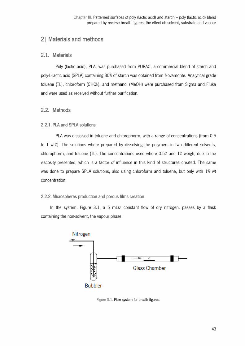
Chapter III. Patterned surfaces of poly (lactic acid) and starch – poly (lactic acid) blend prepared by reverse breath figures, the effect of: solvent, substrate and vapour
43
2| Materials and methods
2.1. Materials
Poly (lactic acid), PLA, was purchased from PURAC, a commercial blend of starch and
poly-L-lactic acid (SPLA) containing 30% of starch was obtained from Novamonte. Analytical grade
toluene (TL), chloroform (CHCl3), and methanol (MeOH) were purchased from Sigma and Fluka
and were used as received without further purification.
2.2. Methods
2.2.1. PLA and SPLA solutions
PLA was dissolved in toluene and chlorophorm, with a range of concentrations (from 0.5
to 1 wt%). The solutions where prepared by dissolving the polymers in two different solvents,
chlorophorm, and toluene (TL). The concentrations used where 0.5% and 1% weigh, due to the
viscosity presented, which is a factor of influence in this kind of structures created. The same
was done to prepare SPLA solutions, also using chloroform and toluene, but only with 1% wt
concentration.
2.2.2. Microspheres production and porous films creation
In the system, Figure 3.1, a 5 mLs-1 constant flow of dry nitrogen, passes by a flask
containing the non-solvent, the vapour phase.
Figure 3.1. Flow system for breath figures.
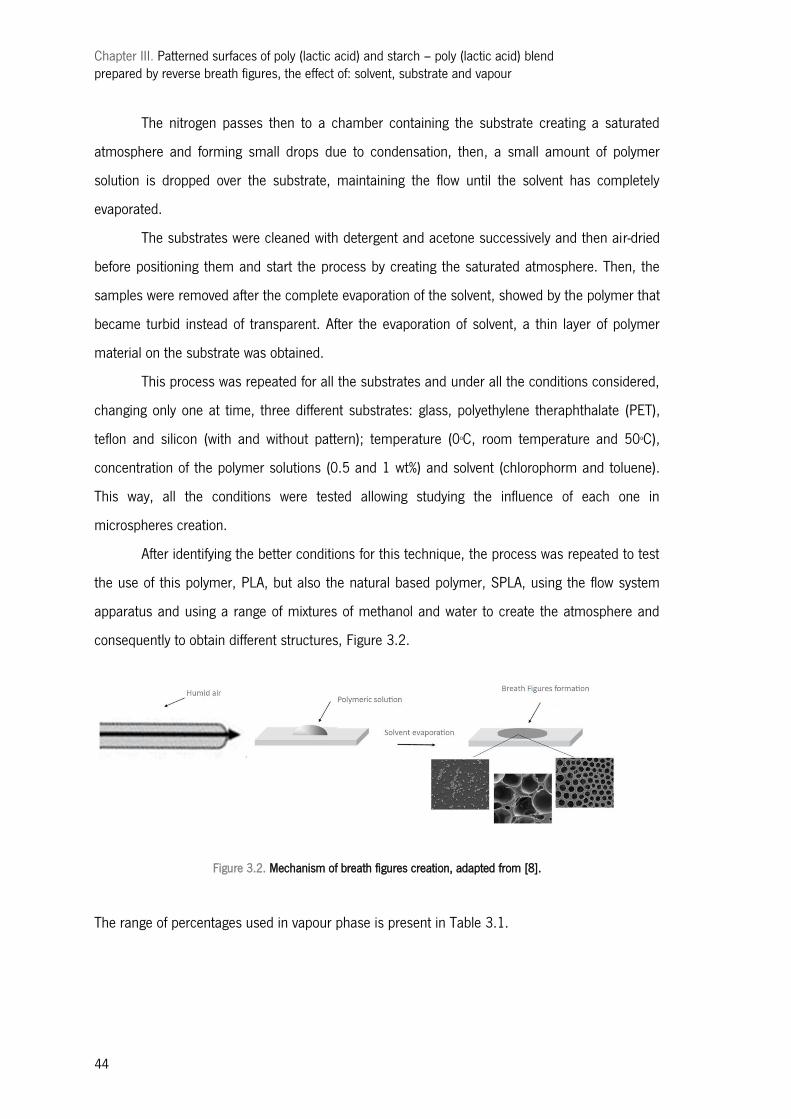
Chapter III. Patterned surfaces of poly (lactic acid) and starch – poly (lactic acid) blend prepared by reverse breath figures, the effect of: solvent, substrate and vapour
44
The nitrogen passes then to a chamber containing the substrate creating a saturated
atmosphere and forming small drops due to condensation, then, a small amount of polymer
solution is dropped over the substrate, maintaining the flow until the solvent has completely
evaporated.
The substrates were cleaned with detergent and acetone successively and then air-dried
before positioning them and start the process by creating the saturated atmosphere. Then, the
samples were removed after the complete evaporation of the solvent, showed by the polymer that
became turbid instead of transparent. After the evaporation of solvent, a thin layer of polymer
material on the substrate was obtained.
This process was repeated for all the substrates and under all the conditions considered,
changing only one at time, three different substrates: glass, polyethylene theraphthalate (PET),
teflon and silicon (with and without pattern); temperature (0oC, room temperature and 50oC),
concentration of the polymer solutions (0.5 and 1 wt%) and solvent (chlorophorm and toluene).
This way, all the conditions were tested allowing studying the influence of each one in
microspheres creation.
After identifying the better conditions for this technique, the process was repeated to test
the use of this polymer, PLA, but also the natural based polymer, SPLA, using the flow system
apparatus and using a range of mixtures of methanol and water to create the atmosphere and
consequently to obtain different structures, Figure 3.2.
Figure 3.2. Mechanism of breath figures creation, adapted from [8].
The range of percentages used in vapour phase is present in Table 3.1.
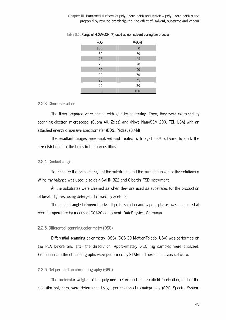
Chapter III. Patterned surfaces of poly (lactic acid) and starch – poly (lactic acid) blend prepared by reverse breath figures, the effect of: solvent, substrate and vapour
45
Table 3.1. Range of H2O:MeOH (%) used as non-solvent during the process.
H2O MeOH 100 0 80 20 75 25 70 30 50 50 30 70 25 75 20 80 0 100
2.2.3. Characterization
The films prepared were coated with gold by sputtering. Then, they were examined by
scanning electron microscope, (Supra 40, Zeiss) and (Nova NanoSEM 200, FEI, USA) with an
attached energy dispersive spectrometer (EDS, Pegasus X4M).
The resultant images were analyzed and treated by ImageTool® software, to study the
size distribution of the holes in the porous films.
2.2.4. Contact angle
To measure the contact angle of the substrates and the surface tension of the solutions a
Wilhelmy balance was used, also as a CAHN 322 and Gibertini TSD instrument.
All the substrates were cleaned as when they are used as substrates for the production
of breath figures, using detergent followed by acetone.
The contact angle between the two liquids, solution and vapour phase, was measured at
room temperature by means of OCA20 equipment (DataPhysics, Germany).
2.2.5. Differential scanning calorimetry (DSC)
Differential scanning calorimetry (DSC) (DCS 30 Mettler-Toledo, USA) was performed on
the PLA before and after the dissolution. Approximately 5-10 mg samples were analyzed.
Evaluations on the obtained graphs were performed by STARe – Thermal analysis software.
2.2.6. Gel permeation chromatography (GPC)
The molecular weights of the polymers before and after scaffold fabrication, and of the
cast film polymers, were determined by gel permeation chromatography (GPC; Spectra System
Chapter III. Patterned surfaces of poly (lactic acid) and starch – poly (lactic acid) blend prepared by reverse breath figures, the effect of: solvent, substrate and vapour
46
P1500) by using a Shodex K-804 column (Shodex, Tokyo, Japan) and a KG pre-column with 1
ml/min eluent constant flux. Chloroform was the solvent and the instrument was calibrated by
using standards.
2.3. In vitro studies
2.3.1. Cell seeding and culture
A human osteogenic sarcoma cell line (SAOS-2), were maintained in DMEM (Dulbecco’s
modified Eagle’s medium; Sigma-Aldrich, Germany) supplemented with 10% heat-inactivated fetal
bovine serum (Biochrom AG, Germany) and 1% antibiotic–antimycotic solution (Gibco, UK). Cells
were cultured in a humidified incubator at 37 ºC in a 5% CO2 atmosphere.
Confluent cells were harvested and seeded in the different surfaces as follows. PLA,
SPLA and glass substrates were distributed in a 24- well cell culture plate (Costar®, Corning,
USA). 1 ml of a suspension of osteoblast-like cells with a concentration of 4 x 10⁴ cells/ml.
These were statically cultured for 1 and 3 days under the culture conditions previously described.
2.3.2. Cell adhesion and morphology
Cells were stained with calcein and observed under a fluorescent microscope in order to
evaluate the cell distribution within the surface of the substrate. The green fluorescence indicates
the viability of the cells cultured on the matrices.
To evaluate further the cell morphology, the cells–substrates were fixed with 10%
formalin (Sigma-Aldrich, Germany) for 15 minutes and then were washed with PBS. Afterwards,
the matrixes were dehydrated through a graded series of ethanol and allowed to dry overnight.
Finally, they were sputter-coated and analyzed by SEM.
2.3.3. Cell viability assay
The cell viability was determined using the MTS assay. This assay is based on the
bioreduction of a tetrazolium compound, 3-(4,5-dimethylthiazol-2-yl)-5-(3-carboxymethoxyphenyl)-
2-(4-sulphofenyl)-2H-tetrazolium (MTS) (Promega, USA), into a water-soluble brown formazan
product. This was quantified by UV-spectroscopy, reading the formazan absorbance at 490 nm in
a microplate reader (Bio-Tek, Synergie HT, USA). Results were compared to the cell viability on
Chapter III. Patterned surfaces of poly (lactic acid) and starch – poly (lactic acid) blend prepared by reverse breath figures, the effect of: solvent, substrate and vapour
47
the tissue culture polystyrene plate, as means of assay control. Three samples per time point
were analysed.
3| Results and discussion
3.1. Mechanism of ordered porous/particles patterns formation
The formation process of honeycomb ordered morphology structures and its formation
mechanisms have been widely investigated. It has been though that a templating mechanism
was the origin of the order films obtained. The condensation phenomenon belongs to breath
figures, representing the patterns formed when moist air contact with a cold surface [8, 11, 14].
Many of these studies support the theory defended by Steyer et al., suggesting that
growth of breath figures on liquids occurs through three stages. In the initial stage for films
formation, water droplets grow isolated and the surface coverage is low. The average diameter of
droplets increases with time, due to weakening of interdroplet interactions. In the intermediate
stage water droplets are separated by liquid film. This second stage leads to uniformity of the
film. Size of droplets and the distance between them are the major influence factor for these
films organization. In the late stage a constant surface coverage and coalescence between
droplets dominates. The breath figures are captured by the polymer in solution avoiding
coalescence. So shape, periodicity and regularity of holes are determined by the corresponding
water droplets structure. The presence of ordered structures depends on the mobility of the
droplets on the solution surface that tend to aggregate to ordered packing due to the existent
attractive surface forces between condensed water droplets. As explained by thermocapillary flow
through Marangoni or Rayleigh convection, due to evaporation, the layer of solution is subjected
to a temperature gradient between the solution surface and the substrate that then induces a
surface tension gradient. As surface energy is minimized by decreasing the surface tension areas
corresponding to cooler region, the solution with water droplets on its surface is then pulled from
the hotter area to the cooler area [14, 28-30].
This division of the process in three distinct steps can easily be noticed in the spheres
case as well. The first stage is characterized by the formation and growth of non solvent drops,
mostly in the substrate surface. Once polymer is introduced on the substrate a saturated
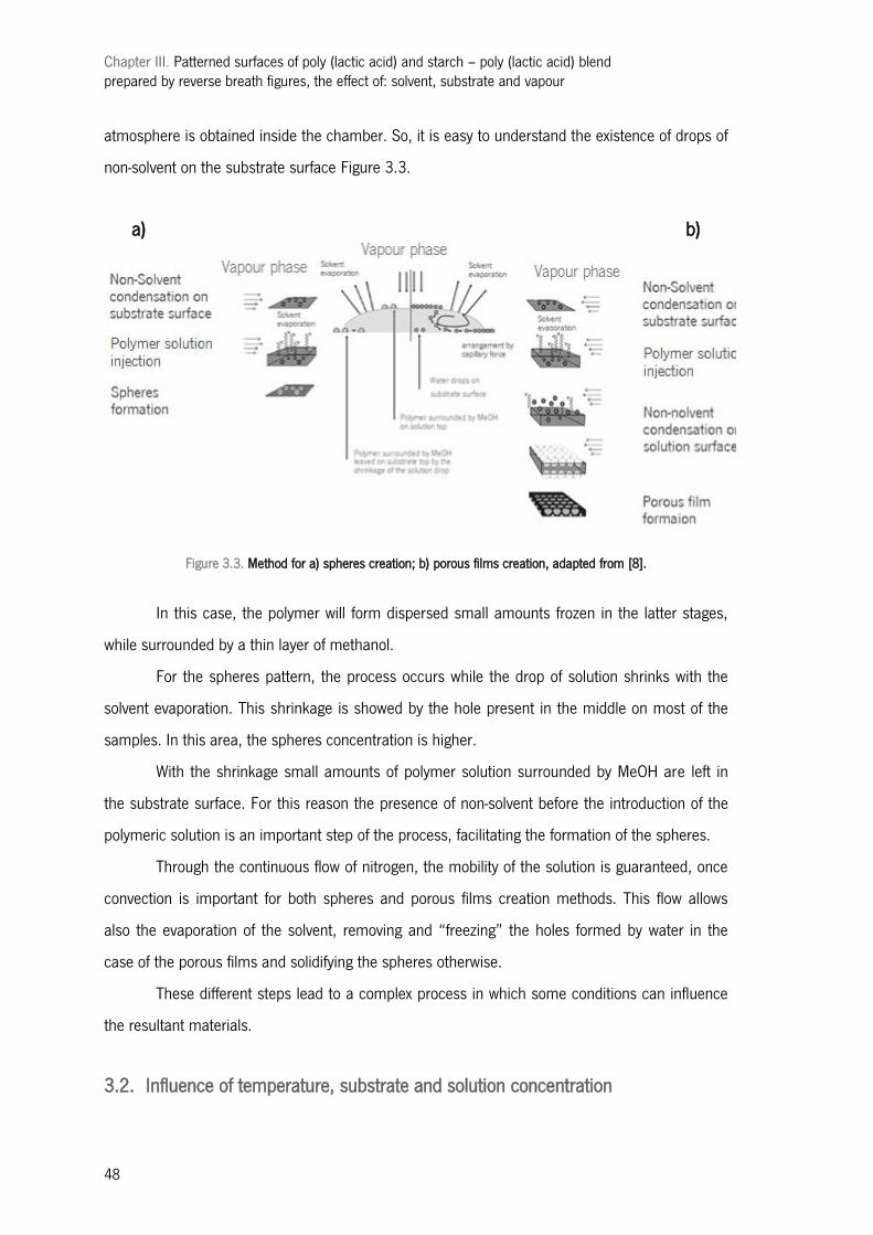
Chapter III. Patterned surfaces of poly (lactic acid) and starch – poly (lactic acid) blend prepared by reverse breath figures, the effect of: solvent, substrate and vapour
48
atmosphere is obtained inside the chamber. So, it is easy to understand the existence of drops of
non-solvent on the substrate surface Figure 3.3.
Figure 3.3. Method for a) spheres creation; b) porous films creation, adapted from [8].
In this case, the polymer will form dispersed small amounts frozen in the latter stages,
while surrounded by a thin layer of methanol.
For the spheres pattern, the process occurs while the drop of solution shrinks with the
solvent evaporation. This shrinkage is showed by the hole present in the middle on most of the
samples. In this area, the spheres concentration is higher.
With the shrinkage small amounts of polymer solution surrounded by MeOH are left in
the substrate surface. For this reason the presence of non-solvent before the introduction of the
polymeric solution is an important step of the process, facilitating the formation of the spheres.
Through the continuous flow of nitrogen, the mobility of the solution is guaranteed, once
convection is important for both spheres and porous films creation methods. This flow allows
also the evaporation of the solvent, removing and ―freezing‖ the holes formed by water in the
case of the porous films and solidifying the spheres otherwise.
These different steps lead to a complex process in which some conditions can influence
the resultant materials.
3.2. Influence of temperature, substrate and solution concentration
a) b)

Chapter III. Patterned surfaces of poly (lactic acid) and starch – poly (lactic acid) blend prepared by reverse breath figures, the effect of: solvent, substrate and vapour
49
PLA was dissolved in TL and chlorophorm, with a concentration in solution of 1wt% and
0.5wt%.Upon casting a drop of these polymer solutions on a substrate, a glass slide, PET, teflon
or silicon with and without patterned surface, in MeOH vapour atmosphere, the solution surface
turned turbid as usual in reverse breath figure process and the usual breath figures method,
easily explained the rapid evaporation of the volatile solvent. This results in the cooling of the
solution surface and the condensation of MeOH vapour into droplets, which disperses in the
polymer solution afterwards. After the complete evaporation of the solvent, microspheres were
left dispersed on the substrate surface, [13].
Figure 3.4. Microscopy picture of the process, a) before the polymer introduction and b) after the polymer introduction.
Figure 3.4 presents a microscope image of the RBF method, where the non-solvent used
was MeOH, is easily noticed that when the polymer is introduced, some drops of methanol were
already dispersed over the substrate surface.
It was observed that the condensed liquid droplets coalesce, while the polymer solution
shrinks to forming dispersed microdroplets, forming the sphere pattern. In comparison, when
water was used in the vapour phase the coalescence of droplets was not observed. One possible
explanation for this fact can be the thermocapillary effects and to the encapsulation by the
surrounding polymer solution (and consequent precititantion) of the drops in place, whose size
dictated the pore size. The same can be said for the spheres, where the size is defined not by the
water but by the polymeric solution when solidifying evolved on the non-solvent (methanol).
This stage of the work allowed the optimization of the process showing the best
conditions of temperature, substrate and solution (concentration and solvent). The non-solvent
used was methanol which was chosen instead of others such us ethanol, due to its higher
surface tension and potential to lead to better results. Another reason is the already mentioned
a) b)
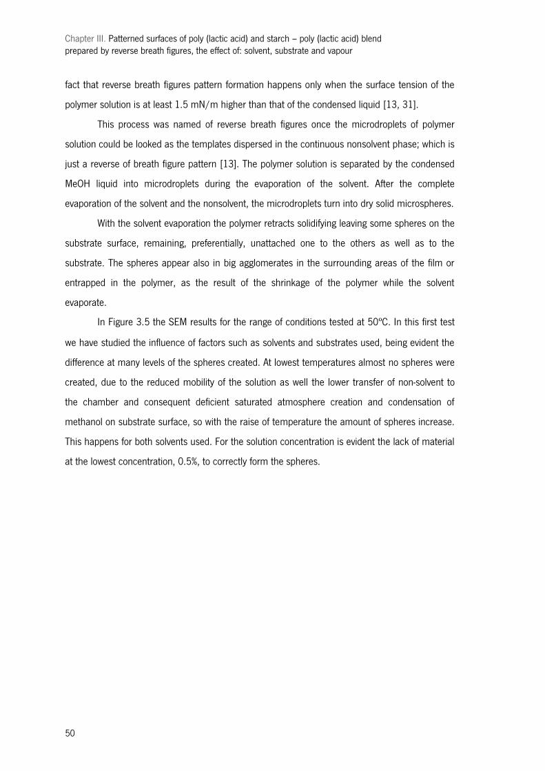
Chapter III. Patterned surfaces of poly (lactic acid) and starch – poly (lactic acid) blend prepared by reverse breath figures, the effect of: solvent, substrate and vapour
50
fact that reverse breath figures pattern formation happens only when the surface tension of the
polymer solution is at least 1.5 mN/m higher than that of the condensed liquid [13, 31].
This process was named of reverse breath figures once the microdroplets of polymer
solution could be looked as the templates dispersed in the continuous nonsolvent phase; which is
just a reverse of breath figure pattern [13]. The polymer solution is separated by the condensed
MeOH liquid into microdroplets during the evaporation of the solvent. After the complete
evaporation of the solvent and the nonsolvent, the microdroplets turn into dry solid microspheres.
With the solvent evaporation the polymer retracts solidifying leaving some spheres on the
substrate surface, remaining, preferentially, unattached one to the others as well as to the
substrate. The spheres appear also in big agglomerates in the surrounding areas of the film or
entrapped in the polymer, as the result of the shrinkage of the polymer while the solvent
evaporate.
In Figure 3.5 the SEM results for the range of conditions tested at 50ºC. In this first test
we have studied the influence of factors such as solvents and substrates used, being evident the
difference at many levels of the spheres created. At lowest temperatures almost no spheres were
created, due to the reduced mobility of the solution as well the lower transfer of non-solvent to
the chamber and consequent deficient saturated atmosphere creation and condensation of
methanol on substrate surface, so with the raise of temperature the amount of spheres increase.
This happens for both solvents used. For the solution concentration is evident the lack of material
at the lowest concentration, 0.5%, to correctly form the spheres.
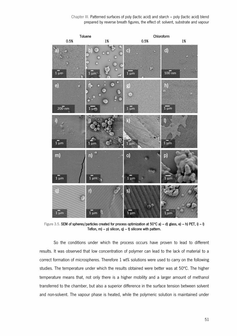
Chapter III. Patterned surfaces of poly (lactic acid) and starch – poly (lactic acid) blend prepared by reverse breath figures, the effect of: solvent, substrate and vapour
51
Toluene Chloroform 0.5% 1% 0.5% 1%
Figure 3.5. SEM of spheres/particles created for process optimization at 50ºC a) – d) glass, e) – h) PET, i) – l)
Teflon, m) – p) silicon, q) – t) silicone with pattern.
So the conditions under which the process occurs have proven to lead to different
results. It was observed that low concentration of polymer can lead to the lack of material to a
correct formation of microspheres. Therefore 1 wt% solutions were used to carry on the following
studies. The temperature under which the results obtained were better was at 50ºC. The higher
temperature means that, not only there is a higher mobility and a larger amount of methanol
transferred to the chamber, but also a superior difference in the surface tension between solvent
and non-solvent. The vapour phase is heated, while the polymeric solution is maintained under
a) b) c) d)
e) f) g) h)
i) j) k) l)
m) n) o) p)
q) r) s) t)
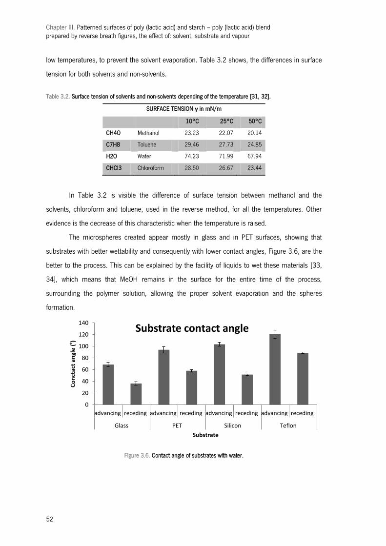
Chapter III. Patterned surfaces of poly (lactic acid) and starch – poly (lactic acid) blend prepared by reverse breath figures, the effect of: solvent, substrate and vapour
52
low temperatures, to prevent the solvent evaporation. Table 3.2 shows, the differences in surface
tension for both solvents and non-solvents.
Table 3.2. Surface tension of solvents and non-solvents depending of the temperature [31, 32].
SURFACE TENSION γ in mN/m
10°C 25°C 50°C
CH4O Methanol 23.23 22.07 20.14
C7H8 Toluene 29.46 27.73 24.85
H2O Water 74.23 71.99 67.94
CHCl3 Chloroform 28.50 26.67 23.44
In Table 3.2 is visible the difference of surface tension between methanol and the
solvents, chloroform and toluene, used in the reverse method, for all the temperatures. Other
evidence is the decrease of this characteristic when the temperature is raised.
The microspheres created appear mostly in glass and in PET surfaces, showing that
substrates with better wettability and consequently with lower contact angles, Figure 3.6, are the
better to the process. This can be explained by the facility of liquids to wet these materials [33,
34], which means that MeOH remains in the surface for the entire time of the process,
surrounding the polymer solution, allowing the proper solvent evaporation and the spheres
formation.
Figure 3.6. Contact angle of substrates with water.
0
20
40
60
80
100
120
140
advancing receding advancing receding advancing receding advancing receding
Glass PET Silicon Teflon
Co
nct
act
angl
e (
º )
Substrate
Substrate contact angle
Chapter III. Patterned surfaces of poly (lactic acid) and starch – poly (lactic acid) blend prepared by reverse breath figures, the effect of: solvent, substrate and vapour
53
After this stage of the work the best conditions for the process were identified. The
concentration was observed to influence the quantity of material, and consequently the form of
the structures obtained, leading the higher concentration (1 %wt) to the best results. Regarding
the temperature of the vapour phase was possible to observe that with the raise of temperature
the amount of spheres increases due to the fact that the atmosphere is more easily obtained and
the mobility if the polymer solution is guaranteed.
The wettability of the substrate seems to control the process in the way that if the
substrate is not capable of maintain the non-solvent the formation of spheres does not occur
correctly.
3.3. Solvent influence
Using the same methodology, PLA and SPLA dissolved in toluene and chloroform 1% wt
were casted on a glass substrate under a vapour atmosphere (at 50ºC) with the designed
stoichiometric molar percentage of MeOH and water in order to evaluate the effect of solvent and
non-solvent. Structures with porous films patterns, microspheres patterns and mixtures of both
have been prepared.
Regarding the solvent chosen it is thought that it is the vapour pressure tha influences
the most the results obtained. Although as showed by former studies, the vapour pressure of TL
is higher than that of water only for a range of temperatures but only porous honeycomb patterns
can be prepared when using TL as the solvent and water in the vapour phase [13, 15]. Our
observations show, however that, the vapour pressure of MeOH is always higher than that of TL,
and microsphere patterns were always obtained by using TL as the solvent and MeOH as the
vapour, in conformity with former studies [13]. This indicates that the vapour pressure is not the
key factor influencing the kind of structures created; but it has influence in their morphology and
order. Solvents and non-solvents properties are present in Table 3.3.
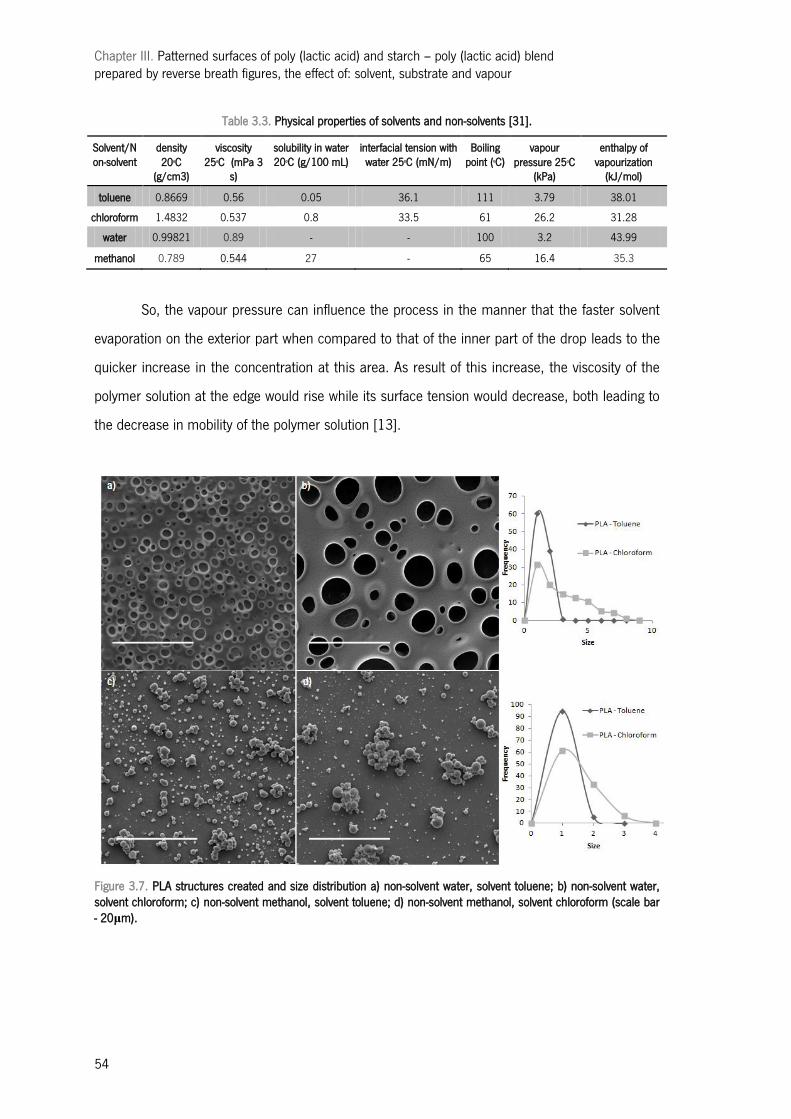
Chapter III. Patterned surfaces of poly (lactic acid) and starch – poly (lactic acid) blend prepared by reverse breath figures, the effect of: solvent, substrate and vapour
54
Table 3.3. Physical properties of solvents and non-solvents [31].
Solvent/Non-solvent
density 20oC
(g/cm3)
viscosity 25oC (mPa 3
s)
solubility in water 20oC (g/100 mL)
interfacial tension with water 25oC (mN/m)
Boiling point (oC)
vapour pressure 25oC
(kPa)
enthalpy of vapourization
(kJ/mol)
toluene 0.8669 0.56 0.05 36.1 111 3.79 38.01
chloroform 1.4832 0.537 0.8 33.5 61 26.2 31.28
water 0.99821 0.89 - - 100 3.2 43.99
methanol 0.789 0.544 27 - 65 16.4 35.3
So, the vapour pressure can influence the process in the manner that the faster solvent
evaporation on the exterior part when compared to that of the inner part of the drop leads to the
quicker increase in the concentration at this area. As result of this increase, the viscosity of the
polymer solution at the edge would rise while its surface tension would decrease, both leading to
the decrease in mobility of the polymer solution [13].
Figure 3.7. PLA structures created and size distribution a) non-solvent water, solvent toluene; b) non-solvent water, solvent chloroform; c) non-solvent methanol, solvent toluene; d) non-solvent methanol, solvent chloroform (scale bar - 20μm).

Chapter III. Patterned surfaces of poly (lactic acid) and starch – poly (lactic acid) blend prepared by reverse breath figures, the effect of: solvent, substrate and vapour
55
Figure 3.8. SPLA structures created and size distribution a) non-solvent water, solvent toluene; b) non-solvent water, solvent chloroform; c) non-solvent methanol, solvent toluene; d) non-solvent methanol, solvent chloroform (scale bar - 20μm).
When water was used as vapour phase, a range of films were observed depending on the
conditions used, the solvent or the polymer chosen. It is obvious that the most ordered film is
obtained using SPLA dissolved in toluene. The pore size distribution when this solvent is used is
narrower, and different from the disperse distribution in chloroform cases; Figure 3.7 a) and b).
The solvent with lower vapour pressure and higher surface tension, toluene, leads then to
better results, because of the slower evaporation time. This means that the spheres have time to
form correctly with a more perfect shape, also the slower shrinkage of the polymer allows the
formation of discrete spheres.
The formation of honeycomb structures has been considered to depend on the
thermodynamic affinity between polymer and solvent. For instance in the study made by Tian and
co-workers [35], they investigated the behavior of polyphenylene oxide (PPO) in various solvents
and concluded that a thin polymer film can be formed on the surface of water droplets only for
good solvents. This film decreases the surface tension between the solvent and the water
droplets, thus hindering their coalescence.
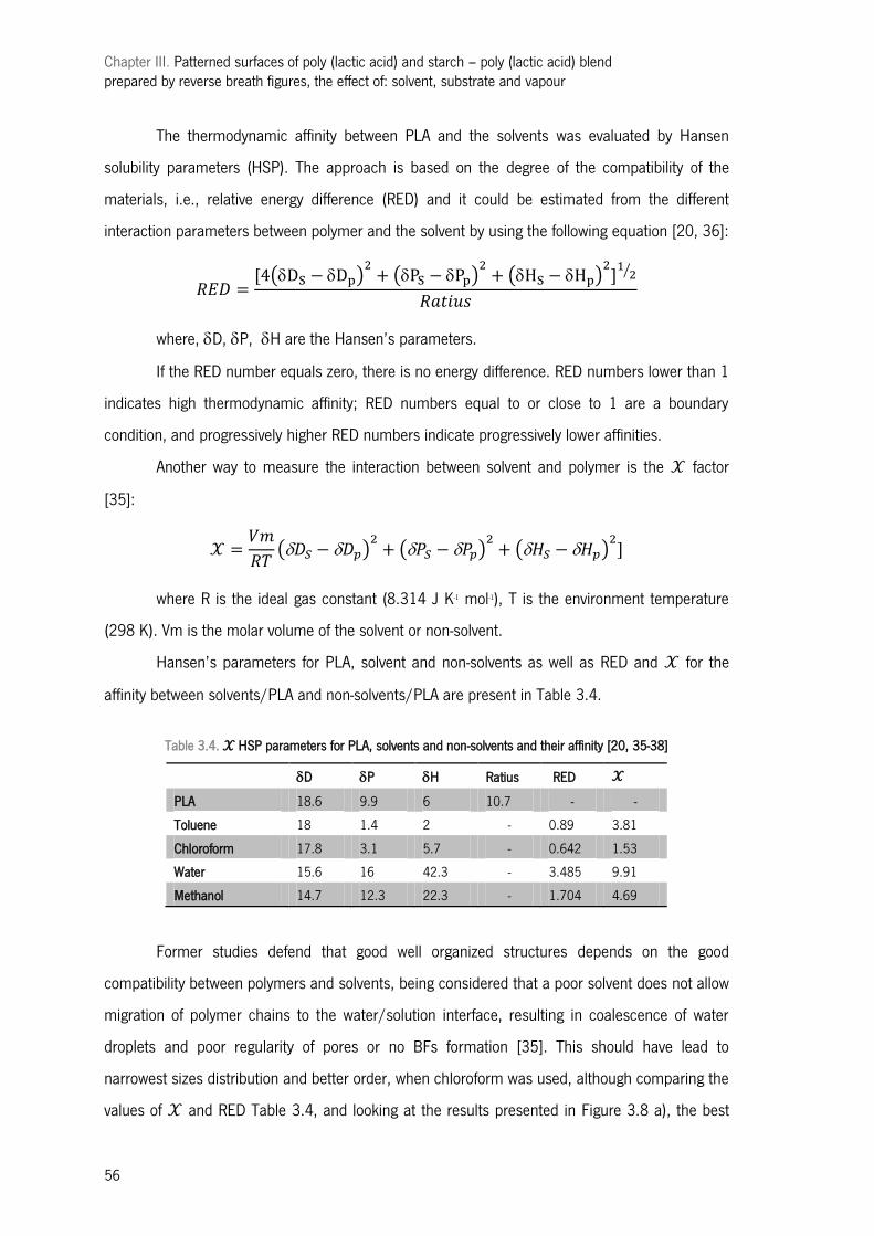
Chapter III. Patterned surfaces of poly (lactic acid) and starch – poly (lactic acid) blend prepared by reverse breath figures, the effect of: solvent, substrate and vapour
56
The thermodynamic affinity between PLA and the solvents was evaluated by Hansen
solubility parameters (HSP). The approach is based on the degree of the compatibility of the
materials, i.e., relative energy difference (RED) and it could be estimated from the different
interaction parameters between polymer and the solvent by using the following equation [20, 36]:
where, D, P, H are the Hansen’s parameters.
If the RED number equals zero, there is no energy difference. RED numbers lower than 1
indicates high thermodynamic affinity; RED numbers equal to or close to 1 are a boundary
condition, and progressively higher RED numbers indicate progressively lower affinities.
Another way to measure the interaction between solvent and polymer is the factor
[35]:
where R is the ideal gas constant (8.314 J K-1 mol-1), T is the environment temperature
(298 K). Vm is the molar volume of the solvent or non-solvent.
Hansen’s parameters for PLA, solvent and non-solvents as well as RED and for the
affinity between solvents/PLA and non-solvents/PLA are present in Table 3.4.
Table 3.4. HSP parameters for PLA, solvents and non-solvents and their affinity [20, 35-38]
D P H Ratius RED
PLA 18.6 9.9 6 10.7 - -
Toluene 18 1.4 2 - 0.89 3.81
Chloroform 17.8 3.1 5.7 - 0.642 1.53
Water 15.6 16 42.3 - 3.485 9.91
Methanol 14.7 12.3 22.3 - 1.704 4.69
Former studies defend that good well organized structures depends on the good
compatibility between polymers and solvents, being considered that a poor solvent does not allow
migration of polymer chains to the water/solution interface, resulting in coalescence of water
droplets and poor regularity of pores or no BFs formation [35]. This should have lead to
narrowest sizes distribution and better order, when chloroform was used, although comparing the
values of and RED Table 3.4, and looking at the results presented in Figure 3.8 a), the best
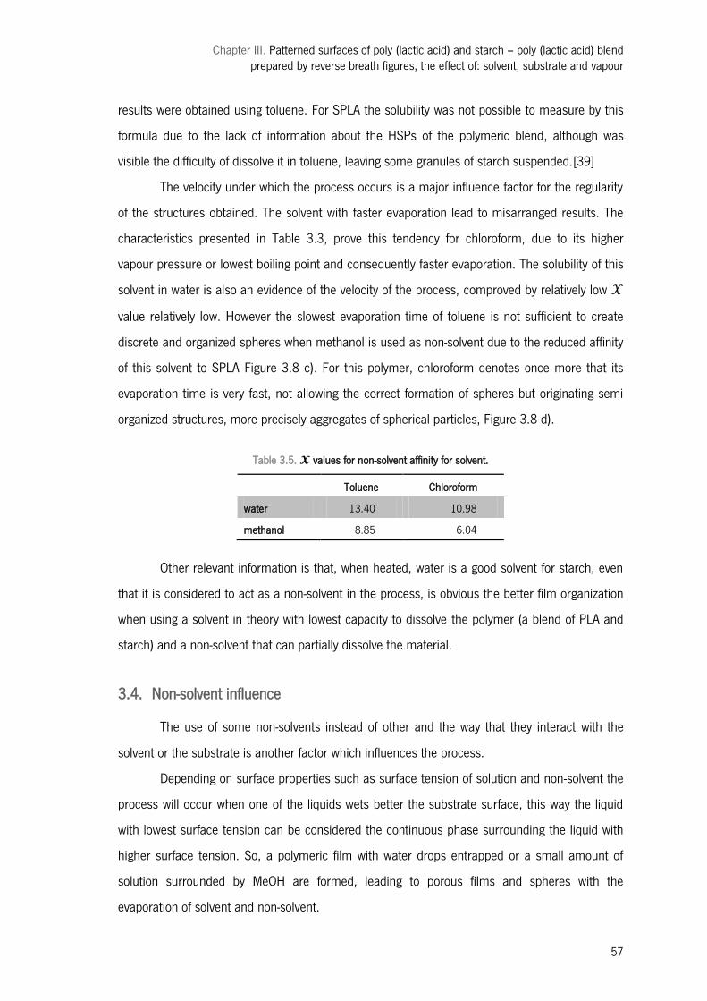
Chapter III. Patterned surfaces of poly (lactic acid) and starch – poly (lactic acid) blend prepared by reverse breath figures, the effect of: solvent, substrate and vapour
57
results were obtained using toluene. For SPLA the solubility was not possible to measure by this
formula due to the lack of information about the HSPs of the polymeric blend, although was
visible the difficulty of dissolve it in toluene, leaving some granules of starch suspended.[39]
The velocity under which the process occurs is a major influence factor for the regularity
of the structures obtained. The solvent with faster evaporation lead to misarranged results. The
characteristics presented in Table 3.3, prove this tendency for chloroform, due to its higher
vapour pressure or lowest boiling point and consequently faster evaporation. The solubility of this
solvent in water is also an evidence of the velocity of the process, comproved by relatively low
value relatively low. However the slowest evaporation time of toluene is not sufficient to create
discrete and organized spheres when methanol is used as non-solvent due to the reduced affinity
of this solvent to SPLA Figure 3.8 c). For this polymer, chloroform denotes once more that its
evaporation time is very fast, not allowing the correct formation of spheres but originating semi
organized structures, more precisely aggregates of spherical particles, Figure 3.8 d).
Table 3.5. values for non-solvent affinity for solvent.
Toluene Chloroform
water 13.40 10.98
methanol 8.85 6.04
Other relevant information is that, when heated, water is a good solvent for starch, even
that it is considered to act as a non-solvent in the process, is obvious the better film organization
when using a solvent in theory with lowest capacity to dissolve the polymer (a blend of PLA and
starch) and a non-solvent that can partially dissolve the material.
3.4. Non-solvent influence
The use of some non-solvents instead of other and the way that they interact with the
solvent or the substrate is another factor which influences the process.
Depending on surface properties such as surface tension of solution and non-solvent the
process will occur when one of the liquids wets better the substrate surface, this way the liquid
with lowest surface tension can be considered the continuous phase surrounding the liquid with
higher surface tension. So, a polymeric film with water drops entrapped or a small amount of
solution surrounded by MeOH are formed, leading to porous films and spheres with the
evaporation of solvent and non-solvent.
a) b)
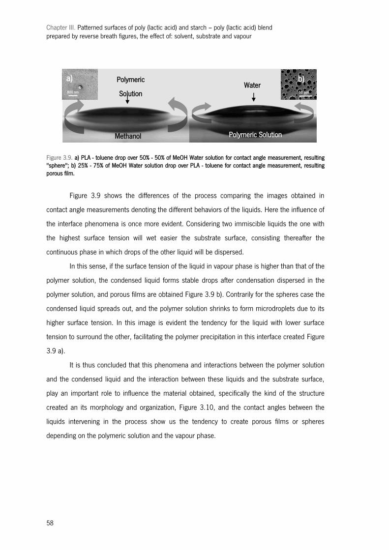
Chapter III. Patterned surfaces of poly (lactic acid) and starch – poly (lactic acid) blend prepared by reverse breath figures, the effect of: solvent, substrate and vapour
58
Figure 3.9. a) PLA - toluene drop over 50% - 50% of MeOH Water solution for contact angle measurement, resulting "sphere"; b) 25% - 75% of MeOH Water solution drop over PLA - toluene for contact angle measurement, resulting porous film.
Figure 3.9 shows the differences of the process comparing the images obtained in
contact angle measurements denoting the different behaviors of the liquids. Here the influence of
the interface phenomena is once more evident. Considering two immiscible liquids the one with
the highest surface tension will wet easier the substrate surface, consisting thereafter the
continuous phase in which drops of the other liquid will be dispersed.
In this sense, if the surface tension of the liquid in vapour phase is higher than that of the
polymer solution, the condensed liquid forms stable drops after condensation dispersed in the
polymer solution, and porous films are obtained Figure 3.9 b). Contrarily for the spheres case the
condensed liquid spreads out, and the polymer solution shrinks to form microdroplets due to its
higher surface tension. In this image is evident the tendency for the liquid with lower surface
tension to surround the other, facilitating the polymer precipitation in this interface created Figure
3.9 a).
It is thus concluded that this phenomena and interactions between the polymer solution
and the condensed liquid and the interaction between these liquids and the substrate surface,
play an important role to influence the material obtained, specifically the kind of the structure
created an its morphology and organization, Figure 3.10, and the contact angles between the
liquids intervening in the process show us the tendency to create porous films or spheres
depending on the polymeric solution and the vapour phase.
50 μm 800 nm
Polymeric
Solution Water
Polymeric Solution Methanol
a) b)
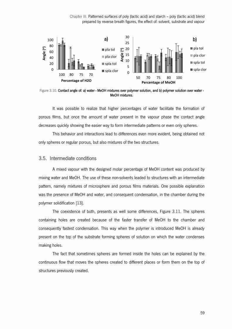
Chapter III. Patterned surfaces of poly (lactic acid) and starch – poly (lactic acid) blend prepared by reverse breath figures, the effect of: solvent, substrate and vapour
59
0
20
40
60
80
100
100 80 75 70
An
gle
(o)
Percentage of H2O
pla tol
pla clor
spla tol
spla clor 0
5
10
15
20
25
30
50 70 75 80 100
An
gle
(o)
Percentage of MeOH
pla tol
pla clor
spla tol
spla clor
Figure 3.10. Contact angle of: a) water - MeOH mixtures over polymer solution, and b) polymer solution over water - MeOH mixtures.
It was possible to realize that higher percentages of water facilitate the formation of
porous films, but once the amount of water present in the vapour phase the contact angle
decreases quickly showing the easier way to form intermediate patterns or even only spheres.
This behavior and interactions lead to differences even more evident, being obtained not
only spheres or regular porous, but also mixtures of the two structures.
3.5. Intermediate conditions
A mixed vapour with the designed molar percentage of MeOH content was produced by
mixing water and MeOH. The use of these non-solvents leaded to structures with an intermediate
pattern, namely mixtures of microsphere and porous films materials. One possible explanation
was the presence of MeOH and water, and consequent condensation, in the chamber during the
polymer solidification [13].
The coexistence of both, presents as well some differences, Figure 3.11. The spheres
containing holes are created because of the faster transfer of MeOH to the chamber and
consequently fastest condensation. This way when the polymer is introduced MeOH is already
present on the top of the substrate forming spheres of solution on which the water condenses
making holes.
The fact that sometimes spheres are formed inside the holes can be explained by the
continuous flow that moves the spheres created to different places or form them on the top of
structures previously created.
a) b)
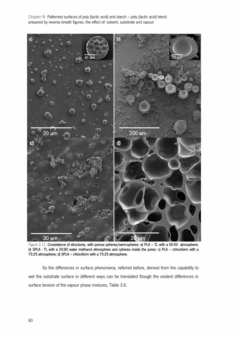
Chapter III. Patterned surfaces of poly (lactic acid) and starch – poly (lactic acid) blend prepared by reverse breath figures, the effect of: solvent, substrate and vapour
60
Figure 3.11. Co-existence of structures, with porous spheres/semi-spheres: a) PLA – TL with a 50:50 atmosphere; b) SPLA - TL with a 20:80 water methanol atmosphere and spheres inside the pores: c) PLA – chloroform with a 75:25 atmosphere; d) SPLA – chloroform with a 75:25 atmosphere.
So the differences in surface phenomena, referred before, derived from the capability to
wet the substrate surface in different ways can be translated though the evident differences in
surface tension of the vapour phase mixtures, Table 3.6.
20 μm
a) b)
c) d)
20 μm 200 nm
20 μm 20 μm
40 μm
d) c)
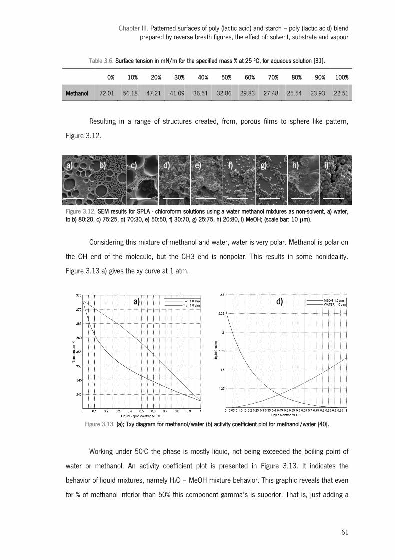
Chapter III. Patterned surfaces of poly (lactic acid) and starch – poly (lactic acid) blend prepared by reverse breath figures, the effect of: solvent, substrate and vapour
61
Table 3.6. Surface tension in mN/m for the specified mass % at 25 ºC, for aqueous solution [31].
0% 10% 20% 30% 40% 50% 60% 70% 80% 90% 100%
Methanol 72.01 56.18 47.21 41.09 36.51 32.86 29.83 27.48 25.54 23.93 22.51
Resulting in a range of structures created, from, porous films to sphere like pattern,
Figure 3.12.
Figure 3.12. SEM results for SPLA - chloroform solutions using a water methanol mixtures as non-solvent, a) water, to b) 80:20, c) 75:25, d) 70:30, e) 50:50, f) 30:70, g) 25:75, h) 20:80, i) MeOH; (scale bar: 10 μm).
Considering this mixture of methanol and water, water is very polar. Methanol is polar on
the OH end of the molecule, but the CH3 end is nonpolar. This results in some nonideality.
Figure 3.13 a) gives the xy curve at 1 atm.
Figure 3.13. (a); Txy diagram for methanol/water (b) activity coefficient plot for methanol/water [40].
Working under 50oC the phase is mostly liquid, not being exceeded the boiling point of
water or methanol. An activity coefficient plot is presented in Figure 3.13. It indicates the
behavior of liquid mixtures, namely H2O – MeOH mixture behavior. This graphic reveals that even
for % of methanol inferior than 50% this component gamma’s is superior. That is, just adding a
a) c) b) d) e) f) g) h) i)
a) d)
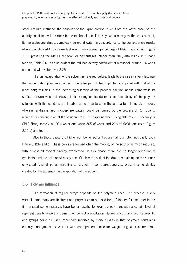
Chapter III. Patterned surfaces of poly (lactic acid) and starch – poly (lactic acid) blend prepared by reverse breath figures, the effect of: solvent, substrate and vapour
62
small amount methanol the behavior of the liquid diverse much from the water case, so the
activity coefficient will be close to the methanol one. This way, when mostly methanol is present,
its molecules are almost completely surround water, in concordance to the contact angle results
where this showed to decrease fast even if only a small percentage of MeOH was added, Figure
3.10, prevailing the MeOH behavior for percentages inferior than 50%, also visible in surface
tension, Table 3.6. It’s also evident the reduced activity coefficient of methanol, around 1.6 when
compared with water, over 2.25.
The fast evaporation of the solvent as referred before, leads to the rise in a very fast way
the concentration polymer solution in the outer part of the drop when compared with that of the
inner part; resulting in the increasing viscosity of the polymer solution at the edge while its
surface tension would decrease, both leading to the decrease in flow ability of the polymer
solution. With this condensed microdroplets can coalesce in these area templating giant pores;
whereas, a disarranged microsphere pattern could be formed by the process of RBF due to
increase in concentration of the solution drop. This happens when using chloroform, especially in
SPLA films, namely in 100% water and when 80% of water and 20% of MeOH are used; Figure
3.12 a) and b).
Also in these cases the higher number of pores has a small diameter, not easily seen
Figure 3.12b) and d). These pores are formed when the mobility of the solution is much reduced,
with almost all solvent already evaporated. In this phase there are no longer temperature
gradients, and the solution viscosity doesn’t allow the sink of the drops, remaining on the surface
only creating small pores more like concavities. In some areas are also present some blanks,
created by the extremely fast evaporation of the solvent.
3.6. Polymer influence
The formation of regular arrays depends on the polymers used. The process is very
versatile, and many architectures and polymers can be used for it. Although for the order in the
film created some materials have better results, for example polymers with a certain level of
segment density, once this permit their correct precipitation. Hydrophobic chains with hydrophilic
end groups could be used, other fact reported by many studies is that polymers containing
carboxy end groups as well as with appropriated molecular weight originated better films.
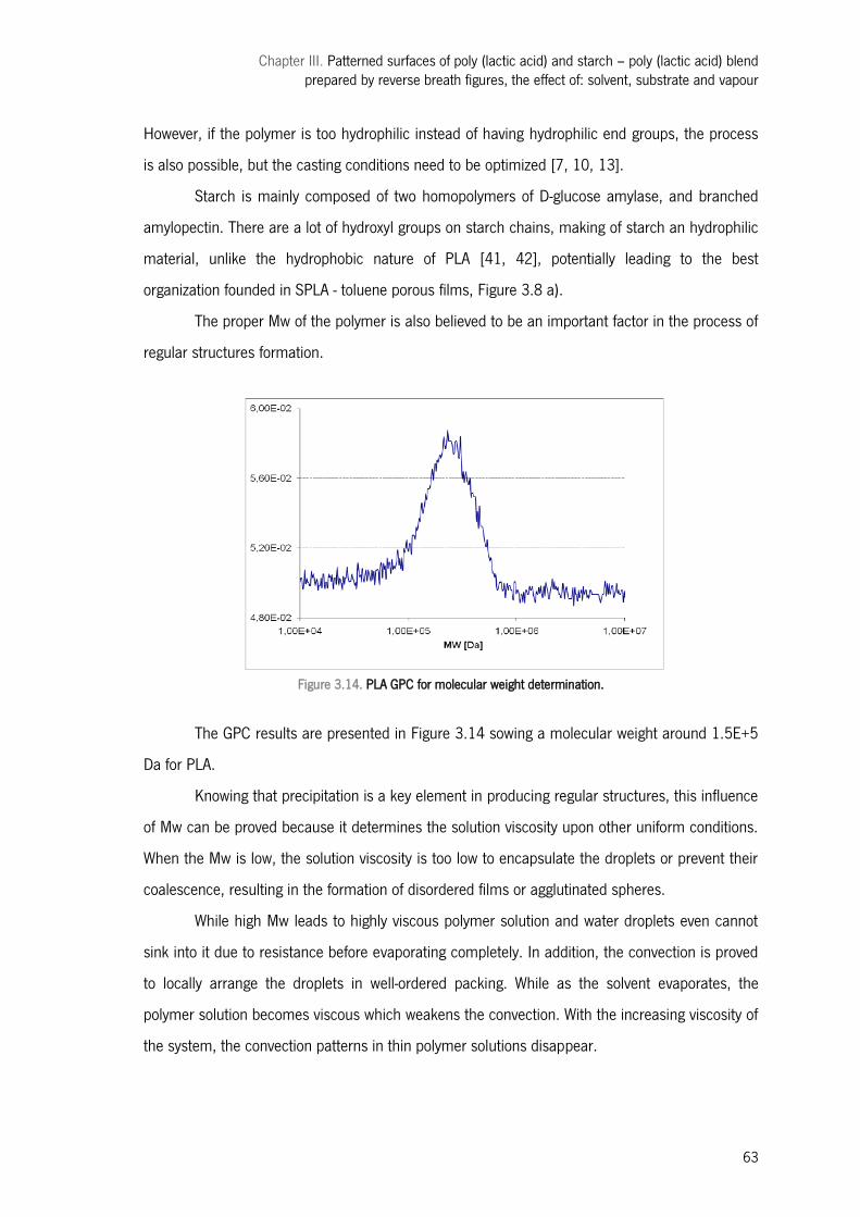
Chapter III. Patterned surfaces of poly (lactic acid) and starch – poly (lactic acid) blend prepared by reverse breath figures, the effect of: solvent, substrate and vapour
63
However, if the polymer is too hydrophilic instead of having hydrophilic end groups, the process
is also possible, but the casting conditions need to be optimized [7, 10, 13].
Starch is mainly composed of two homopolymers of D-glucose amylase, and branched
amylopectin. There are a lot of hydroxyl groups on starch chains, making of starch an hydrophilic
material, unlike the hydrophobic nature of PLA [41, 42], potentially leading to the best
organization founded in SPLA - toluene porous films, Figure 3.8 a).
The proper Mw of the polymer is also believed to be an important factor in the process of
regular structures formation.
Figure 3.14. PLA GPC for molecular weight determination.
The GPC results are presented in Figure 3.14 sowing a molecular weight around 1.5E+5
Da for PLA.
Knowing that precipitation is a key element in producing regular structures, this influence
of Mw can be proved because it determines the solution viscosity upon other uniform conditions.
When the Mw is low, the solution viscosity is too low to encapsulate the droplets or prevent their
coalescence, resulting in the formation of disordered films or agglutinated spheres.
While high Mw leads to highly viscous polymer solution and water droplets even cannot
sink into it due to resistance before evaporating completely. In addition, the convection is proved
to locally arrange the droplets in well-ordered packing. While as the solvent evaporates, the
polymer solution becomes viscous which weakens the convection. With the increasing viscosity of
the system, the convection patterns in thin polymer solutions disappear.
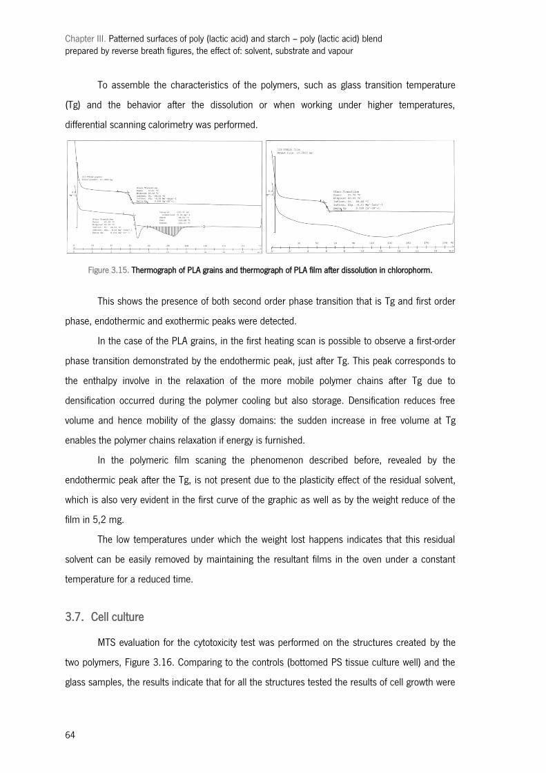
Chapter III. Patterned surfaces of poly (lactic acid) and starch – poly (lactic acid) blend prepared by reverse breath figures, the effect of: solvent, substrate and vapour
64
To assemble the characteristics of the polymers, such as glass transition temperature
(Tg) and the behavior after the dissolution or when working under higher temperatures,
differential scanning calorimetry was performed.
Figure 3.15. Thermograph of PLA grains and thermograph of PLA film after dissolution in chlorophorm.
This shows the presence of both second order phase transition that is Tg and first order
phase, endothermic and exothermic peaks were detected.
In the case of the PLA grains, in the first heating scan is possible to observe a first-order
phase transition demonstrated by the endothermic peak, just after Tg. This peak corresponds to
the enthalpy involve in the relaxation of the more mobile polymer chains after Tg due to
densification occurred during the polymer cooling but also storage. Densification reduces free
volume and hence mobility of the glassy domains: the sudden increase in free volume at Tg
enables the polymer chains relaxation if energy is furnished.
In the polymeric film scaning the phenomenon described before, revealed by the
endothermic peak after the Tg, is not present due to the plasticity effect of the residual solvent,
which is also very evident in the first curve of the graphic as well as by the weight reduce of the
film in 5,2 mg.
The low temperatures under which the weight lost happens indicates that this residual
solvent can be easily removed by maintaining the resultant films in the oven under a constant
temperature for a reduced time.
3.7. Cell culture
MTS evaluation for the cytotoxicity test was performed on the structures created by the
two polymers, Figure 3.16. Comparing to the controls (bottomed PS tissue culture well) and the
glass samples, the results indicate that for all the structures tested the results of cell growth were
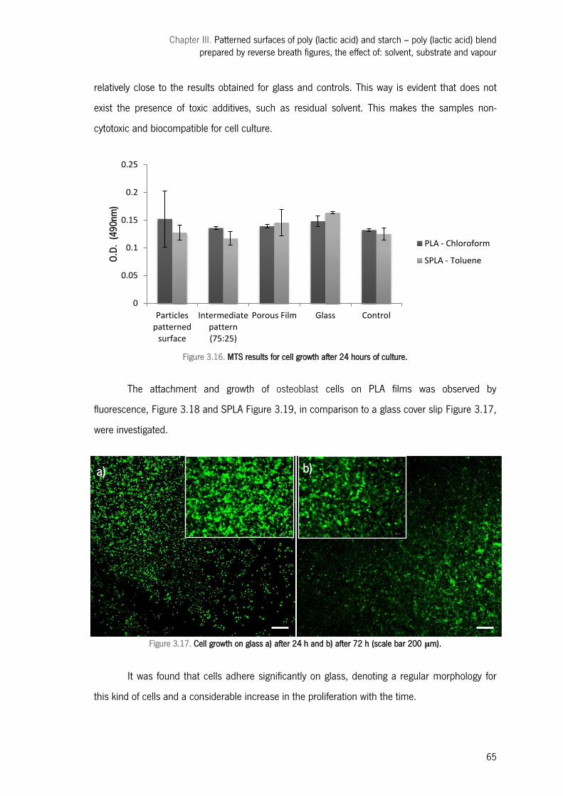
Chapter III. Patterned surfaces of poly (lactic acid) and starch – poly (lactic acid) blend prepared by reverse breath figures, the effect of: solvent, substrate and vapour
65
relatively close to the results obtained for glass and controls. This way is evident that does not
exist the presence of toxic additives, such as residual solvent. This makes the samples non-
cytotoxic and biocompatible for cell culture.
Figure 3.16. MTS results for cell growth after 24 hours of culture.
The attachment and growth of osteoblast cells on PLA films was observed by
fluorescence, Figure 3.18 and SPLA Figure 3.19, in comparison to a glass cover slip Figure 3.17,
were investigated.
b
Figure 3.17. Cell growth on glass a) after 24 h and b) after 72 h (scale bar 200 μm).
It was found that cells adhere significantly on glass, denoting a regular morphology for
this kind of cells and a considerable increase in the proliferation with the time.
0
0.05
0.1
0.15
0.2
0.25
Particles patterned
surface
Intermediate pattern (75:25)
Porous Film Glass Control
O.D.
(49
0nm
)
PLA - Chloroform
SPLA - Toluene
a) b)
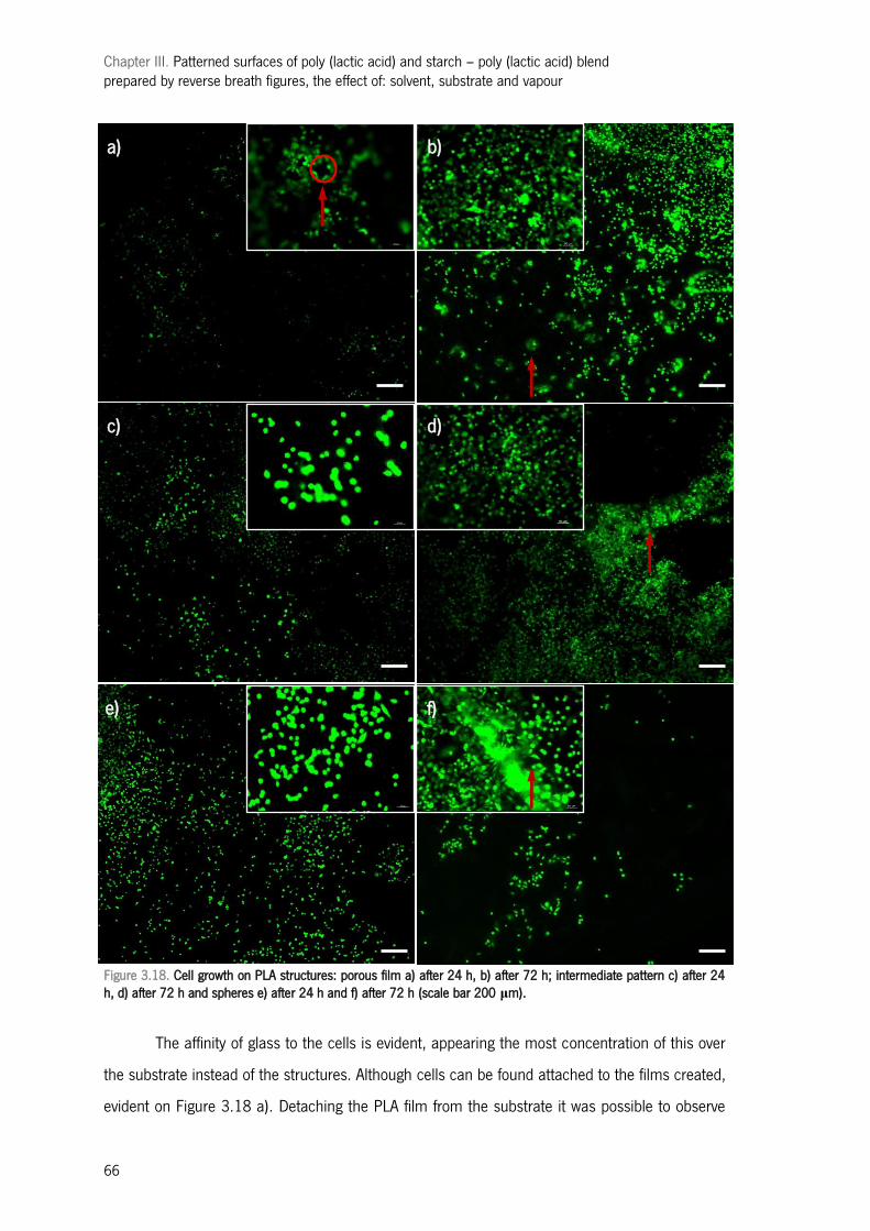
Chapter III. Patterned surfaces of poly (lactic acid) and starch – poly (lactic acid) blend prepared by reverse breath figures, the effect of: solvent, substrate and vapour
66
Figure 3.18. Cell growth on PLA structures: porous film a) after 24 h, b) after 72 h; intermediate pattern c) after 24 h, d) after 72 h and spheres e) after 24 h and f) after 72 h (scale bar 200 μm).
The affinity of glass to the cells is evident, appearing the most concentration of this over
the substrate instead of the structures. Although cells can be found attached to the films created,
evident on Figure 3.18 a). Detaching the PLA film from the substrate it was possible to observe
a) b)
c) d)
e) f)
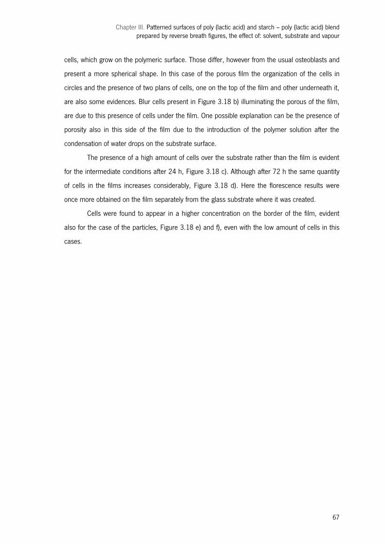
Chapter III. Patterned surfaces of poly (lactic acid) and starch – poly (lactic acid) blend prepared by reverse breath figures, the effect of: solvent, substrate and vapour
67
cells, which grow on the polymeric surface. Those differ, however from the usual osteoblasts and
present a more spherical shape. In this case of the porous film the organization of the cells in
circles and the presence of two plans of cells, one on the top of the film and other underneath it,
are also some evidences. Blur cells present in Figure 3.18 b) illuminating the porous of the film,
are due to this presence of cells under the film. One possible explanation can be the presence of
porosity also in this side of the film due to the introduction of the polymer solution after the
condensation of water drops on the substrate surface.
The presence of a high amount of cells over the substrate rather than the film is evident
for the intermediate conditions after 24 h, Figure 3.18 c). Although after 72 h the same quantity
of cells in the films increases considerably, Figure 3.18 d). Here the florescence results were
once more obtained on the film separately from the glass substrate where it was created.
Cells were found to appear in a higher concentration on the border of the film, evident
also for the case of the particles, Figure 3.18 e) and f), even with the low amount of cells in this
cases.
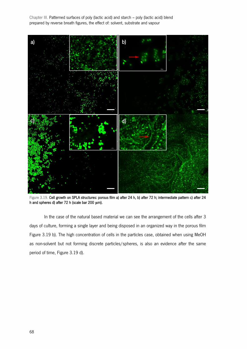
Chapter III. Patterned surfaces of poly (lactic acid) and starch – poly (lactic acid) blend prepared by reverse breath figures, the effect of: solvent, substrate and vapour
68
Figure 3.19. Cell growth on SPLA structures: porous film a) after 24 h, b) after 72 h; intermediate pattern c) after 24 h and spheres d) after 72 h (scale bar 200 μm).
In the case of the natural based material we can see the arrangement of the cells after 3
days of culture, forming a single layer and being disposed in an organized way in the porous film
Figure 3.19 b). The high concentration of cells in the particles case, obtained when using MeOH
as non-solvent but not forming discrete particles/spheres, is also an evidence after the same
period of time, Figure 3.19 d).
a) b)
c) d)
b)
Chapter III. Patterned surfaces of poly (lactic acid) and starch – poly (lactic acid) blend prepared by reverse breath figures, the effect of: solvent, substrate and vapour
69
Figure 3.20. SEM images of cells over a) porous film pattern (PLA – chloroform, 100:0 vapour phase) after 24 h; b) glass after 72 h; c) microspheres pattern (PLA – chloroform, 0:100 vapour phase) after 24 h; d) microsphere pattern (SPLA – toluene, 0:100 vapour phase) after 72 h; (scale bar 200 μm).
SEM imaging, Figure 3.20, evidenced once more the results referred before. It was found
that not all the films attach cells equally well, even for the same material but changing the
structures created, being evident some common characteristics however, as the different
conformation of the cells, when appearing over the structures instead of the substrate, or the
preference of the cells for the glass instead of the polymeric film.
4| Conclusions
In this paper, we showed that is possible to obtain ordered structures of not only
biodegradable polymers but also of natural based polymers using the reverse breath figures
technique. PLA and SPLA structures with a variety of structures were obtained via this templating
method, by varying the conditions; properties of polymer solution and processing conditions.
b) a)
c) d)
Chapter III. Patterned surfaces of poly (lactic acid) and starch – poly (lactic acid) blend prepared by reverse breath figures, the effect of: solvent, substrate and vapour
70
According to our results the entire process is governed by the interplay of different
environmental conditions and others influence factors such as the polymeric solution and non-
solvents used characteristics. In particular, interfacial tension between the evaporating solvent
and condensing non-solvent, and the differences of surface tension of those, mainly accounts for
the structure created and regulates the ability of polymer solution to surround water droplets, or
methanol to surround little drops of polymer solution.
The velocity of the process, and so the way how solvent evaporates influences the
organization of the structures created. Here we have the major influence factors for the process
regularity and reproducibility; like the thermodynamic affinities between polymer and solvent or
non-solvent and solvent; as well as other characteristics of the solvent such as water miscibility,
boiling point, and vapour pressure being also key parameters. The solid substrate plays also an
important role, permitting only the correct structure formation if easy wettable.
A range of applications have been suggested for these structures, porous films or spheres
patterned. Films can be used as templates to prepare aluminum cups or microlenses. But, due to
the biodegradable nature of the materials created in this work and their viability as a cell growth
material its possible application for tissue engineering is a very interesting way of apply these
structures.
Acknowledgements: The authors would like to thank Cristina Correia for her help on the fluorescence microscope.
5| References
1. Rezwan, K., et al., Biodegradable and bioactive porous polymer/inorganic composite scaffolds for bone tissue engineering. Biomaterials, 2006. 27(18): p. 3413-3431.
2. Gottschalch, F., et al., Polymer issues in nanoimprinting technique. Solid-State Electronics, 1999. 43(6): p. 1079-1083.
3. Vozzi, G., et al., Fabrication of PLGA scaffolds using soft lithography and microsyringe deposition. Biomaterials, 2003. 24(14): p. 2533-2540.
4. Cheung, H.-Y., et al., A critical review on polymer-based bio-engineered materials for scaffold development. Composites Part B: Engineering, 2007. 38(3): p. 291-300.
5. Khademhosseini, A., et al., Microscale technologies for tissue engineering and biology. Proceedings of the National Academy of Sciences of the United States of America, 2006. 103(8): p. 2480-2487.
6. Alves, N.M., et al., Controlling Cell Behavior Through the Design of Polymer Surfaces. Small, 2010. 6(20): p. 2208-2220.
Chapter III. Patterned surfaces of poly (lactic acid) and starch – poly (lactic acid) blend prepared by reverse breath figures, the effect of: solvent, substrate and vapour
71
7. Stenzel, M.H., C. Barner-Kowollik, and T.P. Davis, Formation of honeycomb-structured, porous films via breath figures with different polymer architectures. Journal of Polymer Science Part A: Polymer Chemistry, 2006. 44(8): p. 2363-2375.
8. Bunz, U.H.F., Breath Figures as a Dynamic Templating Method for Polymers and Nanomaterials. Advanced Materials, 2006. 18(8): p. 973-989.
9. Galeotti, F., et al., Breath figures-mediated microprinting allows for versatile applications in molecular biology. European Polymer Journal, 2009. 45(11): p. 3027-3034.
10. Peng, J., et al., The influencing factors on the macroporous formation in polymer films by water droplet templating. Polymer, 2004. 45(2): p. 447-452.
11. Connal, L.A. and G.G. Qiao, Preparation of Porous Poly(dimethylsiloxane)-Based Honeycomb Materials with Hierarchal Surface Features and Their Use as Soft-Lithography Templates. Advanced Materials, 2006. 18(22): p. 3024-3028.
12. Boker, A., et al., Hierarchical nanoparticle assemblies formed by decorating breath figures. Nat Mater, 2004. 3(5): p. 302-306.
13. Xiong, X., et al., Microsphere Pattern Prepared by a ―Reverse‖ Breath Figure Method. Macromolecules, 2009. 42(23): p. 9351-9356.
14. Xiong, X., et al., Kinetic control of preparing honeycomb patterned porous film by the method of breath figure. Reactive and Functional Polymers, 2011. 71(9): p. 964-971.
15. Ferrari, E., P. Fabbri, and F. Pilati, Solvent and Substrate Contributions to the Formation of Breath Figure Patterns in Polystyrene Films. Langmuir, 2011. 27(5): p. 1874-1881.
16. Lim, L.T., R. Auras, and M. Rubino, Processing technologies for poly(lactic acid). Progress in Polymer Science, 2008. 33(8): p. 820-852.
17. Fukuhira, Y., et al., Biodegradable honeycomb-patterned film composed of poly(lactic acid) and dioleoylphosphatidylethanolamine. Biomaterials, 2006. 27(9): p. 1797-1802.
18. Ramakrishna, S., et al., Biomedical applications of polymer-composite materials: a review. Composites Science and Technology, 2001. 61(9): p. 1189-1224.
19. Martin, O. and L. Avérous, Poly(lactic acid): plasticization and properties of biodegradable multiphase systems. Polymer, 2001. 42(14): p. 6209-6219.
20. Auras, R.A., et al., Poly(lactic Acid): Synthesis, Structures, Properties, Processing, and Applications. 2010: John Wiley & Sons.
21. Martins, A.M., et al., Natural origin scaffolds with in situ pore forming capability for bone tissue engineering applications. Acta Biomaterialia, 2008. 4(6): p. 1637-1645.
22. Malafaya, P.B., G.A. Silva, and R.L. Reis, Natural–origin polymers as carriers and scaffolds for biomolecules and cell delivery in tissue engineering applications. Advanced Drug Delivery Reviews, 2007. 59(4-5): p. 207-233.
23. Wang, N., et al., Influence of formamide and water on the properties of thermoplastic starch/poly(lactic acid) blends. Carbohydrate Polymers, 2008. 71(1): p. 109-118.
24. Schwach, E., J.-L. Six, and L. Avérous, Biodegradable Blends Based on Starch and Poly(Lactic Acid): Comparison of Different Strategies and Estimate of Compatibilization. Journal of Polymers and the Environment, 2008. 16(4): p. 286-297.
25. Wang, N., J. Yu, and X. Ma, Preparation and characterization of thermoplastic starch/PLA blends by one-step reactive extrusion. Polymer International, 2007. 56(11): p. 1440-1447.
26. Huneault, M.A. and H. Li, Morphology and properties of compatibilized polylactide/thermoplastic starch blends. Polymer, 2007. 48(1): p. 270-280.
27. Elvira, C., et al., Starch-based biodegradable hydrogels with potential biomedical applications as drug delivery systems. Biomaterials, 2002. 23(9): p. 1955-1966.
Chapter III. Patterned surfaces of poly (lactic acid) and starch – poly (lactic acid) blend prepared by reverse breath figures, the effect of: solvent, substrate and vapour
72
28. Limaye, A.V., et al., Evidence for Convective Effects in Breath Figure Formation on Volatile Fluid Surfaces. Physical Review Letters, 1996. 76(20): p. 3762-3765.
29. Maillard, M., et al., Rings and Hexagons Made of Nanocrystals: A Marangoni Effect. The Journal of Physical Chemistry B, 2000. 104(50): p. 11871-11877.
30. Stowell, C. and B.A. Korgel, Self-Assembled Honeycomb Networks of Gold Nanocrystals. Nano Letters, 2001. 1(11): p. 595-600.
31. Lide, D., CRC Handbook of Chemistry and Physics, 88th Edition (CRC Handbook of Chemistry & Physics). 2007: CRC Press.
32. Souc kova , M., J. Klomfar, and J. Pa tek, Measurement and Correlation of the Surface Tension−Temperature Relation for Methanol. Journal of Chemical & Engineering Data, 2008. 53(9): p. 2233-2236.
33. Hartland, S., Surface and interfacial tension: measurement, theory, and applications. 2004: Marcel Dekker.
34. Binks, B.P. and J.H. Clint, Solid Wettability from Surface Energy Components: Relevance to Pickering Emulsions. Langmuir, 2002. 18(4): p. 1270-1273.
35. Tian, Y., et al., The formation of honeycomb structure in polyphenylene oxide films. Polymer, 2006. 47(11): p. 3866-3873.
36. Agrawal, A., et al., Constrained nonlinear optimization for solubility parameters of poly(lactic acid) and poly(glycolic acid)—validation and comparison. Polymer, 2004. 45(25): p. 8603-8612.
37. Hansen, C.M., Hansen solubility parameters : a user's handbook. 2000, Boca Raton, Fla.: CRC Press.
38. Barton, A.F.M., CRC handbook of solubility parameters and other cohesion parameters. 1983: CRC Press.
39. Mitchell, W.A., Starch solubility. Journal of Chemical Education, 1977. 54(2): p. 132. 40. Luyben, W.L. and A.I.o.C. Engineers, Distillation design and control using Aspen
simulation. 2006: Wiley-Interscience. 41. Tester, R.F., J. Karkalas, and X. Qi, Starch—composition, fine structure and architecture.
Journal of Cereal Science, 2004. 39(2): p. 151-165. 42. Buléon, A., et al., Starch granules: structure and biosynthesis. International Journal of
Biological Macromolecules, 1998. 23(2): p. 85-112.
Chapter IV. General conclusions and future perspectives
73
CHAPTER IV.
GENERAL CONCLUSIONS AND FUTURE PERSPECTIVES

Chapter IV. General conclusions and future perspectives
74
Chapter IV. General conclusions and future perspectives
75
1| General conclusions and future research
By using two different polymers; PLA and SPLA, under different vapour environments
different polymeric structures were prepared. The innovative technique used, breath figures, is a
simple and effective templating tools, as well as versatile technique, that creates porous well
organized films. Recently this technique showed to be also a facile way to prepare microspheres
pattern, with some differences, called reverse breath figure method [1, 2].
The process showed to be advantageous due to its simplicity: a microsphere pattern can
be obtained by simply casting a polymer solution onto a glass substrate exposed to a vapour
phase until the complete evaporation of the solvent, when talking of reverse breath figures [2].
The porous film pattern can be as easily obtained replacing the vapour phase for water instead of
an organic solvent [3]. The mechanisms influencing the method and the structures created were
studied as well as their potential applications as cell-growth media [4].
So, the possibility to obtain ordered structures of biodegradable polymers, synthetic as
well as natural based, using the breath figure and the reverse breath figures technique was
proven. PLA and SPLA structures with a variety of patterns were obtained via this templating
method, by varying the conditions; properties of polymer solution and processing conditions.
According to the results the entire process is governed by the interplay of different
environmental conditions and others influence factors such as the polymeric solution and non-
solvents used. In particular, differences in surface tension between the evaporating solvent and
condensing non-solvent, regulates the ability of polymer solution to surround water droplets, or
methanol to surround little drops of polymer solution. When using mixtures of both non-solvents
an intermediate pattern was obtained, showing the presence of both liquids in the vapour phase
[5]. This dictate the kind of structure created, however the order and regularity of these
structures seems to be controlled by others factors. The velocity of the process, and the way the
solvent evaporates was proven to be one of those factors. Being possible to affirm that a very fast
process, produced by rapid evaporation lead to less structured patterns.
Other factors for the process regularity and reproducibility, like the thermodynamic
affinities between polymer and solvent or non-solvent and solvent; as well as other characteristics
of the solvent such as water miscibility, boiling point, and vapour pressure being also key
parameters were also observed. The solid substrate plays also an important role, permitting only
the correct structure formation if easy wettable [6].
Chapter IV. General conclusions and future perspectives
76
The viability of the structures created as a cell growth material was tested by MTS assay,
denoting the non toxicity of the materials, and calcein using osteoblast cell line. It was found that
not all the films attach cells equally well, even for the same material but changing the structures
created., being evident some common characteristics however, as the different conformation of
the cells, when appearing over the structures instead of the substrate, or the preference of the
cells for the glass instead of the polymeric film.
However, both fluorescence microscopy and SEM showed osteoblasts growing on the
polymeric surface. Those differ, however from the usual osteoblasts and present a more
spherical shape. In this case of the porous film the organization of the cells in circles and the
presence of two plans of cells, one on the top of the film and other underneath it, are also some
evidences
A limitation of this study is that the results were derived from an in vitro experimental
model. Therefore, the biocompatibility of the polymeric material is still not completely clear. A
further direction of this study could be to clarify these points using more extensive cellular
studies. Despite of the referred limitation, the data derived from this study suggests great
promise for the future of these biomaterials with a range of possible applications, as isolated
patterns or as coatings for other materials.
2| References
1. Bunz, U.H.F., Breath Figures as a Dynamic Templating Method for Polymers and Nanomaterials. Advanced Materials, 2006. 18(8): p. 973-989.
2. Xiong, X., et al., Microsphere Pattern Prepared by a ―Reverse‖ Breath Figure Method. Macromolecules, 2009. 42(23): p. 9351-9356.
3. Song, L., et al., Facile Microstructuring of Organic Semiconducting Polymers by the Breath Figure Method: Hexagonally Ordered Bubble Arrays in Rigid Rod-Polymers. Advanced Materials, 2004. 16(2): p. 115-118.
4. Galeotti, F., et al., Breath figures-mediated microprinting allows for versatile applications in molecular biology. European Polymer Journal, 2009. 45(11): p. 3027-3034.
5. Xiong, X., et al., Kinetic control of preparing honeycomb patterned porous film by the method of breath figure. Reactive and Functional Polymers, 2011. 71(9): p. 964-971.
6. Ferrari, E., P. Fabbri, and F. Pilati, Solvent and Substrate Contributions to the Formation of Breath Figure Patterns in Polystyrene Films. Langmuir, 2011. 27(5): p. 1874-1881.