Embed Size (px)
Citation preview
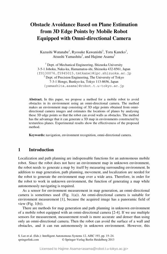
S. Lee et al. (Eds.): Intelligent Autonomous Systems 12, AISC 193, pp. 15–24. springerlink.com © Springer-Verlag Berlin Heidelberg 2013
Obstacle Avoidance Based on Plane Estimation from 3D Edge Points by Mobile Robot
Equipped with Omni-directional Camera
Kazushi Watanabe1, Ryosuke Kawanishi1, Toru Kaneko1, Atsushi Yamashita2, and Hajime Asama2
1 Dept. of Mechanical Engineering, Shizuoka University 3-5-1 Johoku, Naka-ku, Hamamatsu-shi, Shizuoka 432-8561, Japan {f0130076,f5945015,tmtkane}@ipc.shizuoka.ac.jp
2 Dept. of Precision Engineering, The University of Tokyo 7-3-1 Hongo, Bunkyo-ku, Tokyo 113-8656, Japan
{yamashita,asama}@robot.t.u-tokyo.ac.jp
Abstract. In this paper, we propose a method for a mobile robot to avoid obstacles in its environment using an omni-directional camera. The method makes an environment map consisting of 3D edge points obtained from omni-directional camera images and estimates the locations of planes by analysing these 3D edge points so that the robot can avoid walls as obstacles. The method has the advantage that it can generate a 3D map in environments constructed by textureless planes. Experimental results show the effectiveness of the proposed method.
Keywords: navigation, environment recognition, omni-directional camera.
1 Introduction
Localization and path planning are indispensable functions for an autonomous mobile robot. Since the robot does not have an environment map in unknown environment, the robot needs to generate a map by itself by measuring surrounding environment. In addition to map generation, path planning, movement, and localization are needed for the robot to generate the environment map over a wide area. Therefore, in order for the robot to work in unknown environment, the function of generating a map while autonomously navigating is required.
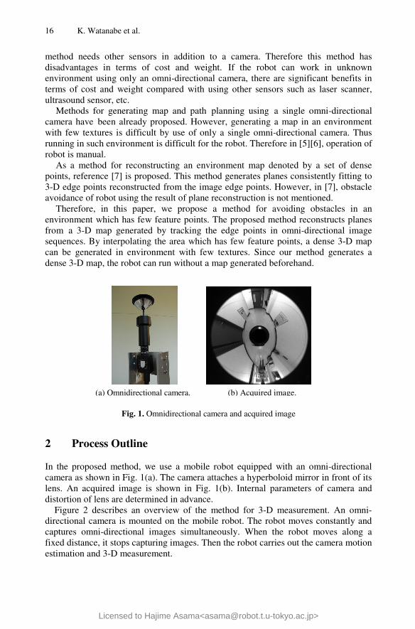
As a sensor for environment measurement in map generation, an omni-directional camera is sometimes used (Fig. 1(a)). An omni-directional camera is suitable for environment measurement [1], because the acquired image has a panoramic field of view (Fig. 1(b)).
There are methods for map generation and path planning in unknown environment of a mobile robot equipped with an omni-directional camera [2-4]. If we use multiple sensors for measurement, measurement result is more accurate and denser than using only an omni-directional camera. Then the robot can avoid the surface of a wall and obstacles, and it can run autonomously in unknown environment. However, this
Licensed to Hajime Asama<[email protected]>
16 K. Watanabe et al.
method needs other sensors in addition to a camera. Therefore this method has disadvantages in terms of cost and weight. If the robot can work in unknown environment using only an omni-directional camera, there are significant benefits in terms of cost and weight compared with using other sensors such as laser scanner, ultrasound sensor, etc.
Methods for generating map and path planning using a single omni-directional camera have been already proposed. However, generating a map in an environment with few textures is difficult by use of only a single omni-directional camera. Thus running in such environment is difficult for the robot. Therefore in [5][6], operation of robot is manual.
As a method for reconstructing an environment map denoted by a set of dense points, reference [7] is proposed. This method generates planes consistently fitting to 3-D edge points reconstructed from the image edge points. However, in [7], obstacle avoidance of robot using the result of plane reconstruction is not mentioned.
Therefore, in this paper, we propose a method for avoiding obstacles in an environment which has few feature points. The proposed method reconstructs planes from a 3-D map generated by tracking the edge points in omni-directional image sequences. By interpolating the area which has few feature points, a dense 3-D map can be generated in environment with few textures. Since our method generates a dense 3-D map, the robot can run without a map generated beforehand.
Fig. 1. Omnidirectional camera and acquired image
2 Process Outline
In the proposed method, we use a mobile robot equipped with an omni-directional camera as shown in Fig. 1(a). The camera attaches a hyperboloid mirror in front of its lens. An acquired image is shown in Fig. 1(b). Internal parameters of camera and distortion of lens are determined in advance.
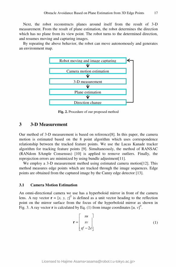
Figure 2 describes an overview of the method for 3-D measurement. An omni-directional camera is mounted on the mobile robot. The robot moves constantly and captures omni-directional images simultaneously. When the robot moves along a fixed distance, it stops capturing images. Then the robot carries out the camera motion estimation and 3-D measurement.
(a) Omnidirectional camera. (b) Acquired image.
Licensed to Hajime Asama<[email protected]>
Obstacle Avoidance Based on Plane Estimation from 3D Edge Points 17
Next, the robot reconstructs planes around itself from the result of 3-D measurement. From the result of plane estimation, the robot determines the direction which has no plane from its view point. The robot turns to the determined direction, and resumes moving and capturing images.
By repeating the above behavior, the robot can move autonomously and generates an environment map.
Fig. 2. Procedure of our proposed method
3 3-D Measurement
Our method of 3-D measurement is based on reference[8]. In this paper, the camera motion is estimated based on the 8 point algorithm which uses correspondence relationship between the tracked feature points. We use the Lucas Kanade tracker algorithm for tracking feature points [9]. Simultaneously, the method of RANSAC (RANdom SAmple Consensus) [10] is applied to remove outliers. Finally, the reprojection errors are minimized by using bundle adjustment[11].
We employ a 3-D measurement method using estimated camera motion[12]. This method measures edge points which are tracked through the image sequences. Edge points are obtained from the captured image by the Canny edge detector [13].
3.1 Camera Motion Estimation
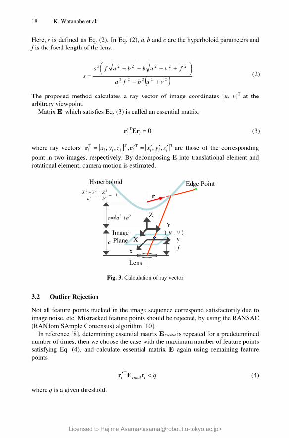
An omni-directional camera we use has a hyperboloid mirror in front of the camera lens. A ray vector r = [x, y, z]T is defined as a unit vector heading to the reflection point on the mirror surface from the focus of the hyperboloid mirror as shown in Fig. 3. A ray vector r is calculated by Eq. (1) from image coordinates [u, v]T.
−=
csf
sv
su
2
r (1)
Robot moving and image capturing
Camera motion estimation
3-D measurement
Plane estimation
Direction change
Licensed to Hajime Asama<[email protected]>
18 K. Watanabe et al.
Here, s is defined as Eq. (2). In Eq. (2), a, b and c are the hyperboloid parameters and f is the focal length of the lens.
The proposed method calculates a ray vector of image coordinates [u, v]T at the arbitrary viewpoint.
Matrix E which satisfies Eq. (3) is called an essential matrix.
where ray vectors [ ] [ ]TTTT ,,,,, iiiiiiii zyxzyx ′′′=′= rr are those of the corresponding
point in two images, respectively. By decomposing E into translational element and rotational element, camera motion is estimated.
Fig. 3. Calculation of ray vector
3.2 Outlier Rejection
Not all feature points tracked in the image sequence correspond satisfactorily due to image noise, etc. Mistracked feature points should be rejected, by using the RANSAC (RANdom SAmple Consensus) algorithm [10].
In reference [8], determining essential matrix Eis repeated for a predetermined number of times, then we choose the case with the maximum number of feature points satisfying Eq. (4), and calculate essential matrix E again using remaining feature points.
where q is a given threshold.
( )22222
22222
vubfa
fvubbafas
s
+−
++++
= (2)
0T =′ ii Err (3)
qirandi <′ rEr T (4)
12
2
2
22
−=−+b
Z
a
YX
22 bac +=
f c
r
y
x
Z
Y
X ( u , v )
Hyperboloid Edge Point
Image Plane
Lens
Licensed to Hajime Asama<[email protected]>
Obstacle Avoidance Based on Plane Estimation from 3D Edge Points 19
3.3 Decision of Feature Point Number
In [8], the optimum number of feature points to use in measurement is automatically decided by defining it as the number of feature points including the maximum number of outliers in a range in which camera movement is still estimated precisely enough. From the above, Eq. (5) and (6) are given as follows:
where iO is the number of outliers and i is the number of extracted feature points.
Equation (5) represents the slope of the straight line calculated by the least squares method, so ( )kζ shows the increase in the number of outliers when the number of
the extracted feature points changes from k to ( )k+ω . ( )kζ is calculated stably
by setting ω appropriately. In Eq. (6), t is a given threshold. The largest value of k which satisfies Eq. (6) is determined as the optimal number of extraction to camera motion estimation.
4 Plane Reconstruction
We employ the method in [7] for reconstructing planes. In [7], planes fitting to edge points are reconstructed if they satisfy visibility constraints.
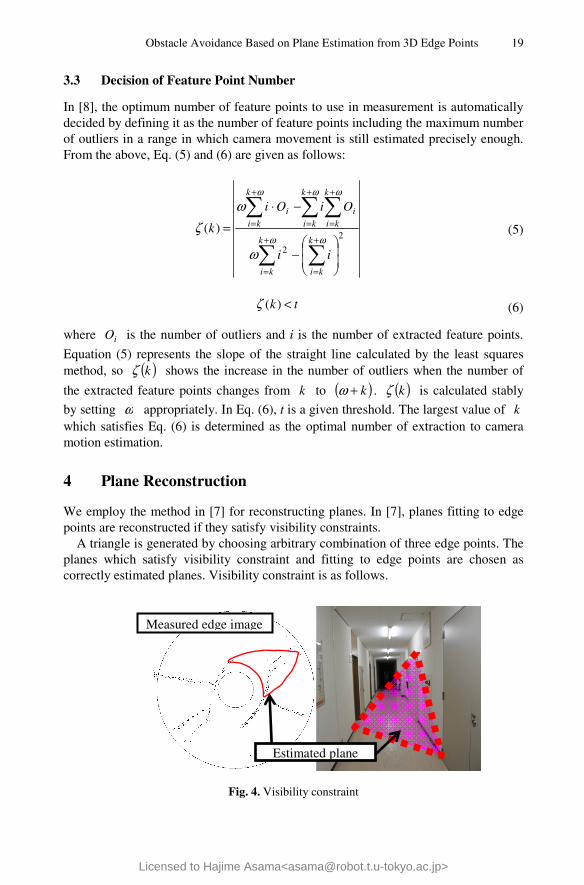
A triangle is generated by choosing arbitrary combination of three edge points. The planes which satisfy visibility constraint and fitting to edge points are chosen as correctly estimated planes. Visibility constraint is as follows.
Fig. 4. Visibility constraint
2
2
)(
−
−⋅
=
+
=
+
=
+
=
+
=
+
=
ωω
ωωω
ω
ωζ
k
ki
k
ki
k
kii
k
ki
k
kii
ii
OiOi
k (5)
tk <)(ζ (6)
Estimated plane
Measured edge image
Licensed to Hajime Asama<[email protected]>
20 K. Watanabe et al.
If an estimated plane exists in real environment, objects behind the plane are invisible. Contrarily, if there exists an object visible through an estimated plane, the plane is determined as a plane which is inconsistent with the real environment (Fig. 4). This plane is said to offence visibility constraint. Estimated planes which are inconsistent with the real environment are excluded by applying visibility constraint.
5 Obstacle Avoidance
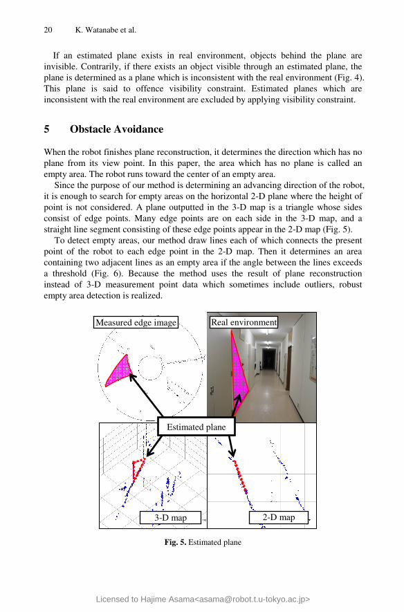
When the robot finishes plane reconstruction, it determines the direction which has no plane from its view point. In this paper, the area which has no plane is called an empty area. The robot runs toward the center of an empty area.
Since the purpose of our method is determining an advancing direction of the robot, it is enough to search for empty areas on the horizontal 2-D plane where the height of point is not considered. A plane outputted in the 3-D map is a triangle whose sides consist of edge points. Many edge points are on each side in the 3-D map, and a straight line segment consisting of these edge points appear in the 2-D map (Fig. 5).
To detect empty areas, our method draw lines each of which connects the present point of the robot to each edge point in the 2-D map. Then it determines an area containing two adjacent lines as an empty area if the angle between the lines exceeds a threshold (Fig. 6). Because the method uses the result of plane reconstruction instead of 3-D measurement point data which sometimes include outliers, robust empty area detection is realized.
Fig. 5. Estimated plane
2-D map
Real environment
3-D map
Estimated plane
Measured edge image
Licensed to Hajime Asama<[email protected]>
Obstacle Avoidance Based on Plane Estimation from 3D Edge Points 21
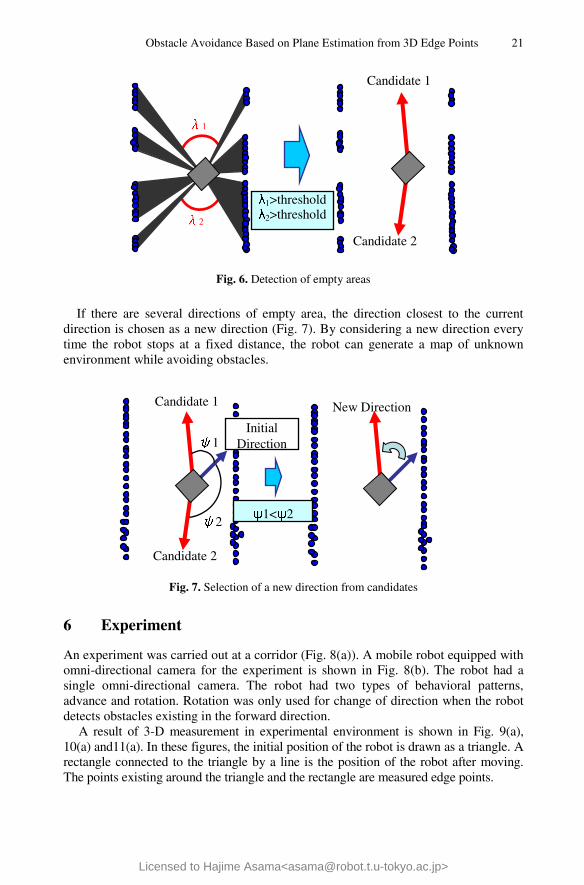
Fig. 6. Detection of empty areas
If there are several directions of empty area, the direction closest to the current direction is chosen as a new direction (Fig. 7). By considering a new direction every time the robot stops at a fixed distance, the robot can generate a map of unknown environment while avoiding obstacles.
Fig. 7. Selection of a new direction from candidates
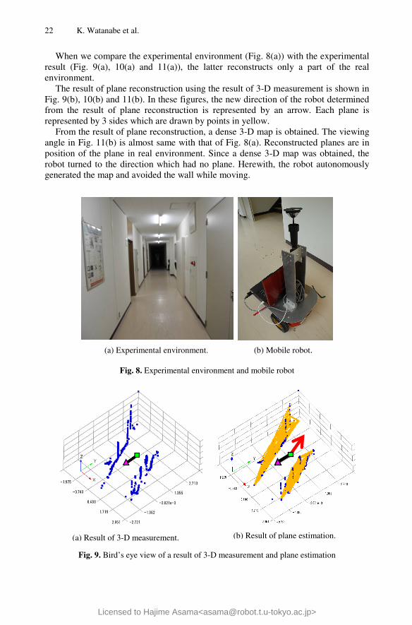
6 Experiment
An experiment was carried out at a corridor (Fig. 8(a)). A mobile robot equipped with omni-directional camera for the experiment is shown in Fig. 8(b). The robot had a single omni-directional camera. The robot had two types of behavioral patterns, advance and rotation. Rotation was only used for change of direction when the robot detects obstacles existing in the forward direction.
A result of 3-D measurement in experimental environment is shown in Fig. 9(a), 10(a) and11(a). In these figures, the initial position of the robot is drawn as a triangle. A rectangle connected to the triangle by a line is the position of the robot after moving. The points existing around the triangle and the rectangle are measured edge points.
Candidate 2
λ1
λ2
Candidate 1
λ1>thresholdλ2>threshold
Candidate 2
ψ1
ψ2
New Direction
Initial Direction
ψ1<ψ2
Candidate 1
Licensed to Hajime Asama<[email protected]>
22 K. Watanabe et al.
When we compare the experimental environment (Fig. 8(a)) with the experimental result (Fig. 9(a), 10(a) and 11(a)), the latter reconstructs only a part of the real environment.
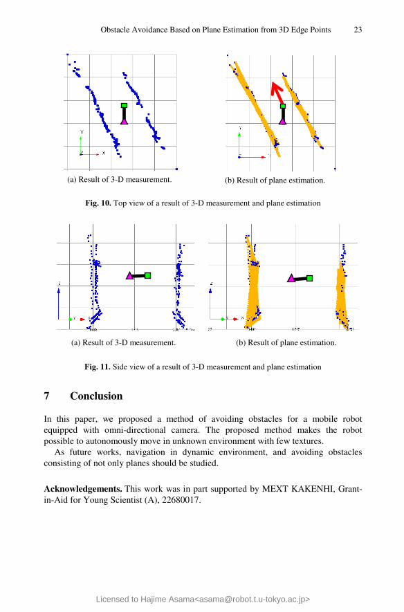
The result of plane reconstruction using the result of 3-D measurement is shown in Fig. 9(b), 10(b) and 11(b). In these figures, the new direction of the robot determined from the result of plane reconstruction is represented by an arrow. Each plane is represented by 3 sides which are drawn by points in yellow.
From the result of plane reconstruction, a dense 3-D map is obtained. The viewing angle in Fig. 11(b) is almost same with that of Fig. 8(a). Reconstructed planes are in position of the plane in real environment. Since a dense 3-D map was obtained, the robot turned to the direction which had no plane. Herewith, the robot autonomously generated the map and avoided the wall while moving.
(a) Experimental environment. (b) Mobile robot.
Fig. 8. Experimental environment and mobile robot
Fig. 9. Bird’s eye view of a result of 3-D measurement and plane estimation
(a) Result of 3-D measurement. (b) Result of plane estimation.
Licensed to Hajime Asama<[email protected]>
Obstacle Avoidance Based on Plane Estimation from 3D Edge Points 23
Fig. 10. Top view of a result of 3-D measurement and plane estimation
Fig. 11. Side view of a result of 3-D measurement and plane estimation
7 Conclusion
In this paper, we proposed a method of avoiding obstacles for a mobile robot equipped with omni-directional camera. The proposed method makes the robot possible to autonomously move in unknown environment with few textures.
As future works, navigation in dynamic environment, and avoiding obstacles consisting of not only planes should be studied.
Acknowledgements. This work was in part supported by MEXT KAKENHI, Grant-in-Aid for Young Scientist (A), 22680017.
(a) Result of 3-D measurement. (b) Result of plane estimation.
(b) Result of plane estimation. (a) Result of 3-D measurement.
Licensed to Hajime Asama<[email protected]>
24 K. Watanabe et al.
References
1. Geyer, C., Daniilidis, K.: Omnidirectional Video. The Visual Computer 19(6), 405–416 (2003)
2. Wang, C., Thorpe, C.: Simultaneous Localization and Mapping with Detection and Tracking of Moving Objects. In: Proceedings of the 2002 IEEE International Conference on Robotics and Automation, pp. 2918–3004 (2002)
3. Kim, D., Sun, J., Rehg, S.M., Bobick, A.F.: Traversability Classification Using Unsupervised On-line Visual Learning for Outdoor Robot Navigation. In: Proceedings of the 2006 IEEE International Conference on Robotics and Automation, pp. 518–525 (2006)
4. Konolige, K., Agrawal, M., Bolles, R.C., Cowan, C., Fischler, M., Gerkey, B.P.: Outdoor Mapping and Navigation Using Stereo Vision. In: Proceedings of the International Symposium on Experimental Robotics, pp. 1–12 (2006)
5. Morioka, H., Sangkyu, Y., Hasegawa, O.: Vision-based Mobile Robot’s SLAM and Navigation in Crowded Environments. In: Proceeding of the 2010 IEEE/RSJ International Conference on Intelligent Robots and Systems, pp. 1–4 (2010)
6. Iwasa, H., Aihara, N., Yokoya, N., Takemura, H.: Memory-based Self-Localization Using Omnidirectional Images. Systems and Computers in Japan 34(5), 56–68 (2003)
7. Tomono, M.: Plane Reconstruction with a Stereo Camera in Non-textured Envirionments. In: Proceeding of the 17th Robotics Symposia, pp. 463–468 (2011) (in Japanese)
8. Kawanishi, R., Yamashita, A., Kaneko, T.: Three-Dimensional Environment Model Construction from an Omnidirectional Image Sequence. Journal of Robotics and Mechatronics 21(5), 574–582 (2009)
9. Shi, J., Tomasi, C.: Good Features to Track. In: Proceedings of the 1994 IEEE Computer Society Conference on Computer Vision and Pattern Recognition, pp. 593–600 (1994)
10. Fischler, M.A., Bolles, R.C.: Random Sample Consensus: A Paradigm for Model Fitting with Applications to Image Analysis and Automated Cartography. Communications of the ACM 24(6), 381–395 (1981)
11. Triggs, B., McLauchlan, P.F., Hartley, R.I., Fitzgibbon, A.W.: Bundle Adjustment – A Modern Synthesis. In: Triggs, B., Zisserman, A., Szeliski, R. (eds.) ICCV-WS 1999. LNCS, vol. 1883, pp. 298–372. Springer, Heidelberg (2000)
12. Tomono, M.: Dense Object Modeling for 3-D Map Building Using Segment-based Surface Interpolation. In: Proceedings of the 2006 IEEE International Conference on Robotics and Automation, pp. 2609–2614 (2006)
13. Canny, J.F.: A Computational Approach to Edge Detection. IEEE Transactions on Pattern Analysis and Machine Intelligence PAMI-8(6), 679–698 (1986)
Licensed to Hajime Asama<[email protected]>

Advances in Intelligent Systemsand Computing 193
Editor-in-Chief
Prof. Janusz KacprzykSystems Research InstitutePolish Academy of Sciencesul. Newelska 601-447 WarsawPolandE-mail: [email protected]
For further volumes:http://www.springer.com/series/11156

Sukhan Lee, Hyungsuck Cho, Kwang-Joon Yoon,and Jangmyung Lee (Eds.)
Intelligent AutonomousSystems 12
Volume 1: Proceedings of the 12th InternationalConference IAS-12, Held June 26–29, 2012Jeju Island, Korea
ABC
Licensed to Hajime Asama<[email protected]>
EditorsSukhan LeeCollege of Information andCommunication EngineeringSungkyunkwan UniversityGyeonggi-DoKorea
Hyungsuck ChoDaegu Gyeongbuk Institute of Scienceand TechnologyDaeguKorea
Kwang-Joon YoonKonkuk UniversitySeoulKorea
Jangmyung LeeDepartment of Electronics EngineeringPusan National UniversityPusanKorea
ISSN 2194-5357 e-ISSN 2194-5365ISBN 978-3-642-33925-7 e-ISBN 978-3-642-33926-4DOI 10.1007/978-3-642-33926-4Springer Heidelberg New York Dordrecht London
Library of Congress Control Number: 2012948092
c© Springer-Verlag Berlin Heidelberg 2013This work is subject to copyright. All rights are reserved by the Publisher, whether the whole or part of thematerial is concerned, specifically the rights of translation, reprinting, reuse of illustrations, recitation, broad-casting, reproduction on microfilms or in any other physical way, and transmission or information storageand retrieval, electronic adaptation, computer software, or by similar or dissimilar methodology now knownor hereafter developed. Exempted from this legal reservation are brief excerpts in connection with reviewsor scholarly analysis or material supplied specifically for the purpose of being entered and executed on acomputer system, for exclusive use by the purchaser of the work. Duplication of this publication or partsthereof is permitted only under the provisions of the Copyright Law of the Publisher’s location, in its cur-rent version, and permission for use must always be obtained from Springer. Permissions for use may beobtained through RightsLink at the Copyright Clearance Center. Violations are liable to prosecution underthe respective Copyright Law.The use of general descriptive names, registered names, trademarks, service marks, etc. in this publicationdoes not imply, even in the absence of a specific statement, that such names are exempt from the relevantprotective laws and regulations and therefore free for general use.While the advice and information in this book are believed to be true and accurate at the date of publication,neither the authors nor the editors nor the publisher can accept any legal responsibility for any errors oromissions that may be made. The publisher makes no warranty, express or implied, with respect to the materialcontained herein.
Printed on acid-free paper
Springer is part of Springer Science+Business Media (www.springer.com)
Licensed to Hajime Asama<[email protected]>