Embed Size (px)
Citation preview
MEQ-2000 24/96 Multimode Equalizer
DSP-blue
Software Version: 1.52 and higher
OC03
OC03
OC03
meq-2000(O/P)_E 2003.9.6 11:43 AM 페이지2
MEQ-2000 (DSPblue) 24/96 MULTIMODE EQUALIZER
24/96 MULTIMODE EQUALIZER
3
RISK OF ELECTRIC SHOCKDO NOT OPEN
CAUTION
The symbols shown above are internationally accepted symbols thatwarn of potential hazards with electrical products. The lightning flashwith arrowhead in an equilateral triangle means that there are danger-ous voltages present within the unit. The exclamation point in an equilat-eral triangle indicates that it is necessary for the user to refer to the own-er’s manual.These symbols warn that there are no user serviceable parts inside theunit. Do not open the unit. Do not attempt to service the unit yourself.Refer all servicing to qualified personnel. Opening the chassis for anyreason will void the manufacturer’s warranty. Do not get the unit wet. Ifliquid is spilled on the unit, shut it off immediately and take it to a dealerfor service. Disconnect the unit during storms to prevent damage.
DECLARATION OF CONFORMITY:
This equipment has been tested and found to comply with the followinginternational Standards for Electromagnetic Compatibility and ElectricalSafety:
EMC:Radio Disturbance (EU): EN55013 (1994)Harmonics (EU): EN61000/3/2 (1995)
&Flicker (EU): EN61000/3/3 (1995)Immunity (EU): EN50082/1 (1997)
SAFETY:
Electrical Safety (EU): EN60065 (1998)
For continued compliance with international EMC legislationensure that all input and output cables are wired with the cable screenconnected to Pin 1 of the XLR connectors. The input XLR Pin 1 is in anycase connected to the chassis via a low value capacitor, providing highimmunity from ground loops whilst ensuring good EMC performance.The best solution is to connect the Pin 1 directly to the chassis at inputand output assuming the interconnected devices are balanced and withPin 1 also grounded to the chassis (see Appendix II: Jumpers for details).
TRADEMARK NOTICE:The software included in this unit is licensed byAlgorithmixⓇ GmbH, Germany. All rights reserved.
WARNINGFOR YOUR PROTECTION PLEASE READ THE FOLLOWING:
WATER AND MOISTURE: Unit should not be used near water (e.g. neara bathtub, washbowl, kitchen sink, laundry tub, in a wet basement, ornear a swimming pool, etc). Care should be taken so that objects do notfall and liquids are not spilled into the enclosure through openings.EXCESSIVE HEAT: This unit has to be placed in a rack with adequateventilation. Do not install near any heat sources such as radiators, heatregisters, stoves or other apparatus (including amplifiers) that produceheat.POWER SOURCES: The unit should be connected to a power supplyonly of the type described in the operating instructions or as marked onthe unit. Check that correct operating voltage is set on the rear panelvoltage switch/fuse holder before connecting mains power.GROUNDING OR POLARIZATION: Precautions should be taken so thatthe grounding or polarization means of an unit is not defeated. Themains power cord is fitted with a safety earth (ground). Do not operatethis unit with this connection removed.POWER CORD PROTECTION: Power supply cords should be routed sothat they are not likely to be walked on or pinched by items placed uponor against them, paying particular attention to cords at plugs, conve-nience receptacles, and the point where they exit from the unit.SERVICING: To reduce the risk of fire or electric shock, the user shouldnot attempt to service the unit beyond that described in the operatinginstructions. All other servicing should be referred to qualified servicepersonnel. EXTERNALLY ACCESSIBLE FUSE RECEPTACLE: Replace fuse with sametype and rating only.MULTIPLE-INPUT VOLTAGE: This equipment may require the use of adifferent line cord, attachment plug, or both, depending on the availablepower source at installation. Connect this equipment only to the powersource indicated on the equipment rear panel. To reduce the risk of fireor electric shock, refer servicing to qualified service personnel or equiva-lent.LITHIUM BATTERY: This product may contain a lithium battery. There isdanger of explosion if the battery is incorrectly replaced. Replace onlywith an Eveready CR 2032 or equivalent. Make sure the battery isinstalled with the correct polarity. Discard used batteries according tomanufacturer’s instructions.
Attention! Cet appareil doit être relié à la terre.Attention! Risque de choc électrique; ne pas ouvrir.Attention! Risque de choc ne pas oter les capots. Aucune pièce accessi-ble à l’intérieur. S’adresser à un technicien qualifé.Attention! Por réduire le risque d’incendie ou de choc électrique, ne paslaisser l’appareil sous la plouie ou à l’humidité.
Achtung! Dieses Gerät muss schutzgeerdet sein.Achtung! Gefahr eines elektrischen Stromschlags. Gehäuse nicht öffnen.Achtung! Keine vom Benutzer zu bedienenden Teile im Geräteinneren.Überlassen Sie das Gerät zu Servicezwecken nur geschultemFachpersonal. Um Brandgefahr oder das Risiko eines elektrischenSchlags auszuschliessen, das Gerät vor Nässe und Feuchtigkeitschützen.
Advertencia! Este equipo debe estar conectado a tierra.Precaución! Riesgo de descarga eléctrica. No abrir.Precaución! Riesgo de descarga eléctrica. No desmontar las tapas.Piezas interiores no reparables por el usuario. Reparable sólo por per-sonal cualificado.Advertencia! Para recucir el riesgo de incendio o de descarga eléctricano exponga este producto a la lluvia o humedad.
meq-2000(O/P)_E 2003.9.6 11:43 AM 페이지3
24/96 MULTIMODE EQUALIZER MEQ-2000 (DSPblue)
24/96 MULTIMODE EQUALIZER
WelcomeWelcomeCongratulation for the purchasing MEQ-2000, a state-of-the-art digital multimode equalizer with extendedfrequency range. It is a result of a professional cooperation between two audio companies: ALGORITHMIX,having great expertise in developing high-precision audio signal processing algorithms and DSP hardware,and INTER-M, very well known for its high-quality engineering and manufacturing technology in the field ofprofessional audio equipment.
Thanks to high-quality AD/DA converters, the constant internal sampling rate of 96 kHz, and very preciselow-noise digital filters the MEQ-2000 delivers warm analog sound and outstanding digital features.The MEQ-2000 is the first member of the DSP-2000 family. Further devices will follow. To minimize thelearning time when operating different devices, we have tried to keep the same man-machine interface forevery family member. We color-coded the front panels to help distinguish between them. Your MEQ-2000is blue, therefore the name: DSP blue.
We wish you great enjoyment and satisfaction when using your multimode equalizer, whether you are arecording, mastering, or reinforcement engineer.
4
meq-2000(O/P)_E 2003.9.6 11:43 AM 페이지4
24/96 MULTIMODE EQUALIZER
ContentsContents1. INTRODUCTION ...............................................................................................................1
2. TYPICAL APPLICATIONS..................................................................................................2
3. MAIN FEATURES...............................................................................................................2
4. GETTING STARTED4-1. Front Panel Controls ............................................................................................................34-2. Rear Panel Controls .............................................................................................................44-3. Signal Flow Diagram...........................................................................................................54-4. Operating Modes................................................................................................................64-5. Quick Start .........................................................................................................................7
5. SETUP MENU5-1. Device Status ......................................................................................................................85-2. General Concept of Setup Screen .......................................................................................105-3. Parametric Equalizer – PEQ ...............................................................................................125-4. Graphic Equalizer – GEQ..................................................................................................145-5. Notch and Cut Filters – CUT ...............................................................................................165-6. Delay – DELAY..................................................................................................................185-7. Compressor/Limiter – COM/LIM ........................................................................................205-8. Limiter – LIMITER ...............................................................................................................235-9. Real-Time Analyzer – RTA..................................................................................................255-10. Level Adjustment – LEVELS ...............................................................................................275-11. Reference Generator – GEN.............................................................................................295-12. Setup Menu Structure.......................................................................................................32
6. UTILITY MENU6-1. Device Status ....................................................................................................................336-2. System Configuration – CONFIG........................................................................................356-3. Typical Digital Interconnections ..........................................................................................396-4. Remote Control – REMOTE.................................................................................................406-5. ADC Calibration – ADCAL.................................................................................................416-6. Device Security Lock – LOCK..............................................................................................426-7. Device ID-Numbers – ID.....................................................................................................436-8. Auxiliary Functions – AUXILIARY ........................................................................................446-9. Software Update – UPDT ...................................................................................................456-10. Utility Menu Structure ......................................................................................................46
7. MEMORY MENU ............................................................................................................47
8. TECHNICAL SPECIFICATIONS .......................................................................................50
9. LIMITED WARRANTY......................................................................................................55
APPENDIX I : SysEx Definitions .................................................................................................56APPENDIX II : Jumpers .............................................................................................................78
OFFICE :653-5 BANGHAK-DONG, DOBONG-KU, SEOUL, KOREA TEL : 82-2-2289-8140~8, FAX : 82-2-2289-8149
Home Page : http://www.inter-m.comE-mail : [email protected]
meq-2000(O/P)_E 2003.9.6 11:43 AM 페이지1
24/96 MULTIMODE EQUALIZER MEQ-2000 (DSPblue)
INTRODUCTION
IntroductionIntroduction
MEQ-2000 24/96 MULTIMODE EQUALIZER, also called DSPblue, is the first member of our new digitalaudio 19” processor family, the DSP-2000. Because of high-quality converters, internal sampling rateremaining 96 kHz and the power of very precise digital signal processing functions, the MEQ-2000 deliverswarm analog sound and outstanding features. 6-band notch, low-cut, and high-cut filters support the 31-band graphic equalizer and 8-band parametric equalizer. For sound finishing in mastering mode, a com-bined limiter/compressor is available and for loudspeaker protection in reinforcement mode, a reliablepeak-limiter is provided. A separate delay in every input channel permits adjusting the sound for differentloudspeaker or spot microphone positions. The processor offers two fully independent channels which canbe coupled for stereo use.
In connection with other members of the DSP-2000 audio processor family, the MEQ-2000 remains in the24/96 digital domain through the whole audio processing path, maintaining the highest signal fidelity. Thedithering and noise shaping options at the output of the processing chain take care of the audio quality iftailoring down to 16-bit CD.
The MEQ-2000 incorporates high-quality 24bit/96kHz AD and DA converters, as well as a sophisticatedsample rate converter allowing digital input to accept every sample frequency between 20 kHz and 100kHz and digital output to deliver every typical sample frequency used in digital audio.
The remote control capability via MIDI or RS-232 permits cascading the devices with other members of theDSP-2000 family or third party equipment and conveniently controlling the parameters over a PC compatiblecomputer equipped with proprietary remote software.
The MEQ-2000 is an ideal universal tool for every recording, mastering, and reinforcement engineer.
1
meq-2000(O/P)_E 2003.9.6 11:43 AM 페이지1
MEQ-2000 (DSPblue) 24/96 MULTIMODE EQUALIZER
APPLICATIONS / MAIN FEATURES
Typical ApplicationsTwo-channel or stereo digital mastering equalizer:
- Analog and digital tracking, mixing and mastering- Sound shaping and compression- Critical material processing (notch, high-cut, low-cut)- Conversion between different analog and digital formats.
Two-channel or stereo digital sound reinforcement equalizer:
- Sound field control- Balancing of the room characteristics- Microphone alignment- Speaker compensation and protection- Feedback reduction (optionally with the DSP1 module) - Automatic room measurement (optionally with the DSP1 module)
Main Features
Typical ApplicationsTwo-channel or stereo digital recording/mastering equalizer:
- analog and digital tracking, mixing and mastering- sound shaping and compression- critical material processing (notch, high-cut, low-cut)- conversion between different analog and digital formats- sensitive treatment of solo tracks
Two-channel or stereo digital sound reinforcement equalizer:
- sound field control- balancing of the room characteristics- microphone alignment- speaker compensation and protection- manual feedback reduction - automatic room measurement
Main Features- High-End 24-bit 96 kHz A/D and D/A Converters- Digital I/O on AES/EBU or S/PDIF with comprehensive Sample Rate Conversion
Input Rates: 20 – 100 kHz, Output Rates: 32, 44.1, 48, 64, 88.2, 96 kHz - Superior THD+N performance ( < 0.001% ) for the crystal clear sound - 40-bit Internal Signal Path to maintain increased head-room and low-level signals- Up to 80-bit Processing Accuracy for the lowest digital distortion- Internal Sampling Frequency always on 96 kHz to achieve analog-like processing- Inherent System Delay less than 1 ms - Extended Frequency Bandwidth up to 31.5 kHz- Output Dither at 16, 20, or 24 bits - 8-Band Fully Parametric Equalizer:
Low Shelving, 6 x Bell, High Shelving- Low-Cut and High-Cut Filters with switchable slopes- 6-Band Notch Filters for feedback suppression- 31-Band Graphic Equalizer- Visually displayed filter curves- True Peak Limiter for loudspeaker protection - Mastering Limiter/Compressor with Adaptive Knee and Auto-Release - Absolutely seamless filter parameter update- Intuitive Programming and Real-Time Navigation Interface- Unique Parameter Wheel with built-in dynamic behavior for convenient parameter entry - Two Temporary Preset buttons for real-time setup comparison - 64 Factory and 128 User Presets- Remote Control via MIDI or RS-232- Software Update via Internet and RS-232
2
meq-2000(O/P)_E 2003.9.6 11:43 AM 페이지2
Front Panel Controls
24/96 MULTIMODE EQUALIZER MEQ-2000 (DSPblue)
GETTING STARTED / FRONT PANEL
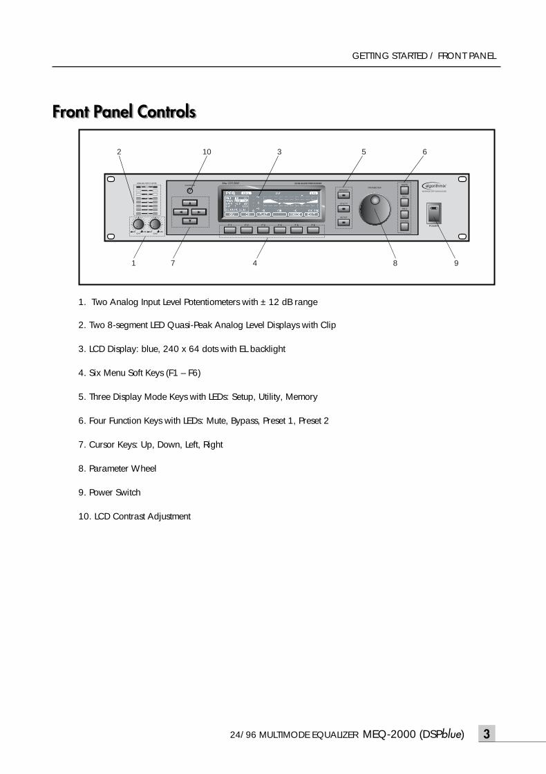
Front Panel Controls
1. Two Analog Input Level Potentiometers with ± 12 dB range
2. Two 8-segment LED Quasi-Peak Analog Level Displays with Clip
3. LCD Display: blue, 240 x 64 dots with EL backlight
4. Six Menu Soft Keys (F1 – F6)
5. Three Display Mode Keys with LEDs: Setup, Utility, Memory
6. Four Function Keys with LEDs: Mute, Bypass, Preset 1, Preset 2
7. Cursor Keys: Up, Down, Left, Right
8. Parameter Wheel
9. Power Switch
10. LCD Contrast Adjustment
3
7
3
4 8 91
10 5 62
meq-2000(O/P)_E 2003.9.6 11:43 AM 페이지3
MEQ-2000 (DSPblue) 24/96 MULTIMODE EQUALIZER
GETTING STARTED / REAR PANEL
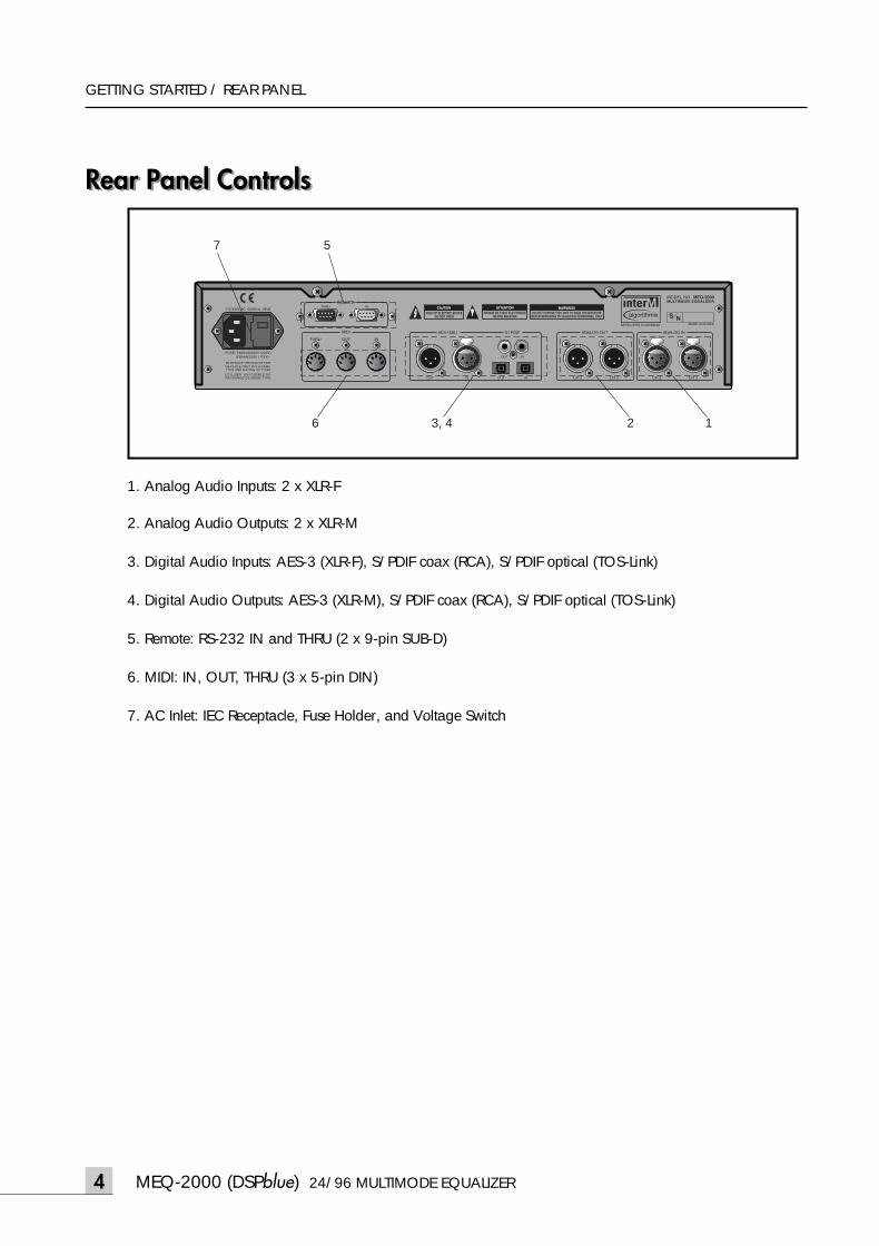
Rear Panel ControlsRear Panel Controls
1. Analog Audio Inputs: 2 x XLR-F
2. Analog Audio Outputs: 2 x XLR-M
3. Digital Audio Inputs: AES-3 (XLR-F), S/PDIF coax (RCA), S/PDIF optical (TOS-Link)
4. Digital Audio Outputs: AES-3 (XLR-M), S/PDIF coax (RCA), S/PDIF optical (TOS-Link)
5. Remote: RS-232 IN and THRU (2 x 9-pin SUB-D)
6. MIDI: IN, OUT, THRU (3 x 5-pin DIN)
7. AC Inlet: IEC Receptacle, Fuse Holder, and Voltage Switch
THRU OUT IN
THRU IN
MIDI
REMOTE
INOUT INOUT
INOUT
CH 2 CH 1 CH 2 CH 1
AES / EBU S / PDIF ANALOG INANALOG OUT
5
3, 4
7
6 2 1
4
meq-2000(O/P)_E 2003.9.6 11:43 AM 페이지4
24/96 MULTIMODE EQUALIZER MEQ-2000 (DSPblue)
GETTING STARTED / SIGNAL FLOW
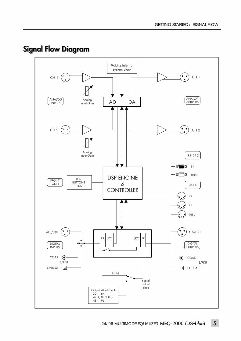
Signal Flow DiagramSignal Flow Diagram
S/PDIF
96kHz internalsystem clock
CH 1
CH 2
ANALOGINPUTS
FRONTPANEL
AES/EBU
COAX
S/PDIF
SRC
Fs IN
digitaloutputclock
OPTICAL
COAX
AES/EBU
THRU
OUT
IN
THRU
IN
CH 2
CH 1
ANALOGOUTPUTS
MIDI
RS 232
DIGITALOUTPUTS
Output Word Clock 32, 64 44.1, 88.2 kHz 48, 96
OPTICAL
DIGITALINPUTS
LCDBUTTONS
LEDS
DSP ENGINE&
CONTROLLER
AD DAAnalogInput Gain
AnalogInput Gain
RX SRC TX
5
meq-2000(O/P)_E 2003.9.6 11:43 AM 페이지5
MEQ-2000 (DSPblue) 24/96 MULTIMODE EQUALIZER
GETTING STARTED / OPERATING MODES
Operating ModesOperating ModesThe MEQ-2000 is intended for different applications:
- recording- mixing- mastering- sound reinforcement- acoustical measurements
In the UTILITY menu a special configuration function (CONFIG, Page 35) is implemented. It allows variousmodule configurations, optimized for the different applications mentioned above. All the modules in theaudio processing chain can be used simultaneously. The device can be used in dual-channel mode with twoindependent channels or in different mono modes. In dual-channel mode all processing functions can be setup independent pro channel, or coupled to the stereo mode.
The signal flow diagram in the previous section shows that the MEQ-2000 accepts and outputs every kind ofprofessional and consumer audio formats:
- electronically balanced analog inputs, also well accepting unbalanced sources- electronically balanced audio outputs, also compatible with asymmetrical loads- every kind of digital audio inputs and outputs: XLR, coaxial and optical compatible with all current audio standards: AES/EBU or AES –3, SPDIF, IEC 958 and EIAJ CP-340 (all transformer balanced)
The digital audio inputs accept every sampling frequency between 20 kHz and 100 kHz. The output sam-pling frequency can be chosen to any typical sampling frequency today used: 32 kHz, 44.1 kHz, 48 kHz,64 kHz, 88.2 kHz and 96 kHz. Digital audio signals up to 24 bits are accepted at the input and providedat the output.
For more technical details look at Section 8, Technical Specifications.
6
meq-2000(O/P)_E 2003.9.6 11:43 AM 페이지6
24/96 MULTIMODE EQUALIZER MEQ-2000 (DSPblue)
GETTING STARTED / QUICK START
Quick StartQuick Start- Your MEQ-2000/DSPblue was carefully manufactured, tested, burned in, and packaged in our factory.Before you proceed further, check to be sure the following items are included in the packaging box:
· MEQ-2000 Multimode Equalizer· Operating Manual· Power Cord
- Save all packing materials. They are intended to protect the unit during shipping, and in the unlikely eventthat your MEQ-2000 requires service.
- If you are a plug-and-play-and-read-later user, follow these simple instructions and get on your way. Fora professional, the intuitive man-machine interface on your MEQ-2000 will be clear within minutes.
- Be sure that the power switch in your MEQ-2000 is OFF and the devices you want to use as source andreceiver are also switched off.
- Connect a line level audio source (preferably balanced) to the analog inputs and the analog outputs tobalanced line inputs of a mixing console or active loudspeakers. Later you can also check the digital audioinput/output of your MEQ-2000.
- Be sure that the voltage selector on the rear panel is in the right position: 230V or 115V dependent on thecountry you are. Plug in the power cord and switch on the MEQ-2000 as well as interconnected devices.
- Setup the proper Analog Input Level with the potentiometers on the left side of the front panel carefullyobserving Input Level Meters to avoid clipping.
- Hit the UTILITY button and check in the Device Status screen if the analog input and output are selected; ifno, press the button CONFIG, select the analog input and output, and confirm with the EXIT button.
- Check if the signal is going thru by pressing BYPASS button.
- Press the SETUP button and select one of the familiar names like PEQ or GEQ associated with the functionbuttons F1 – F5; hit one of the buttons, e.g., GEQ and you will get in the GEQ menu; switch ON GEQ withthe ON button (appears inverted) and start to change the parameters with cursor keys and parameterwheel. Enjoy your first experiences and look for details in this Operating Manual.
7
meq-2000(O/P)_E 2003.9.6 11:43 AM 페이지7
MEQ-2000 (DSPblue) 24/96 MULTIMODE EQUALIZER
SETUP MENU / STATUS
8
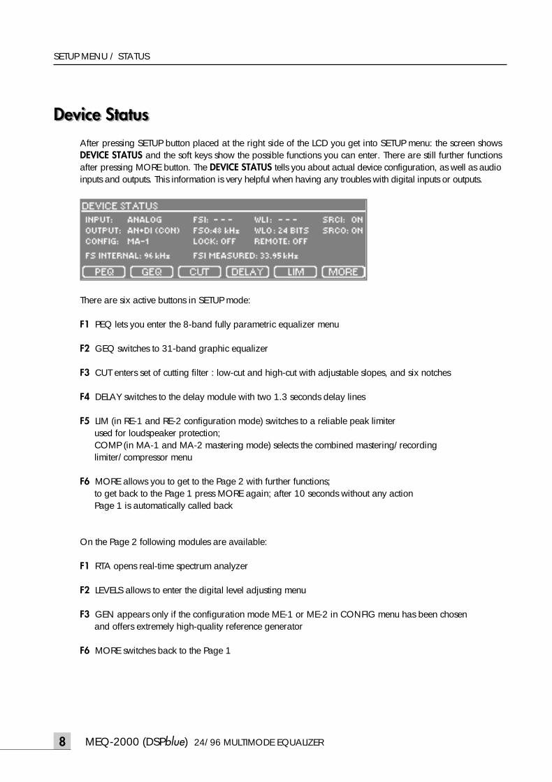
Device StatusDevice StatusAfter pressing SETUP button placed at the right side of the LCD you get into SETUP menu: the screen showsDEVICE STATUS and the soft keys show the possible functions you can enter. There are still further functionsafter pressing MORE button. The DEVICE STATUS tells you about actual device configuration, as well as audioinputs and outputs. This information is very helpful when having any troubles with digital inputs or outputs.
There are six active buttons in SETUP mode:
F1 PEQ lets you enter the 8-band fully parametric equalizer menu
F2 GEQ switches to 31-band graphic equalizer
F3 CUT enters set of cutting filter : low-cut and high-cut with adjustable slopes, and six notches
F4 DELAY switches to the delay module with two 1.3 seconds delay lines
F5 LIM (in RE-1 and RE-2 configuration mode) switches to a reliable peak limiter used for loudspeaker protection;COMP (in MA-1 and MA-2 mastering mode) selects the combined mastering/recording limiter/compressor menu
F6 MORE allows you to get to the Page 2 with further functions;to get back to the Page 1 press MORE again; after 10 seconds without any action Page 1 is automatically called back
On the Page 2 following modules are available:
F1 RTA opens real-time spectrum analyzer
F2 LEVELS allows to enter the digital level adjusting menu
F3 GEN appears only if the configuration mode ME-1 or ME-2 in CONFIG menu has been chosen and offers extremely high-quality reference generator
F6 MORE switches back to the Page 1
meq-2000(O/P)_E 2003.9.6 11:43 AM 페이지8
24/96 MULTIMODE EQUALIZER MEQ-2000 (DSPblue)
SETUP MENU / STATUS
The DEVICE STATUS screen delivers important information:
- INPUT shows the input chosen in the CONFIG menu; if a digital input has been selected and it is receiving valid digital audio signal the format of the incomingsignal in parenthesis is shown:professional (PRO), or consumer (CON).
- FSI, WLI if a digital input has been selected and it is receiving a valid digital audio signal the samplingfrequency (FSI) and wordlength (WLI) are shown as indicated in the status bits of the incoming digital sig-nal (they are not measured, only extracted)
- SRCI tells if the input sampling rate converter is active
- OUTPUT shows the output chosen in CONFIG menu;if the digital output has been selected the chosen format is shown in parenthesis: professional (PRO) or consumer (CON)
- FSO, WLO if the digital output has been selected FSO shows the sampling frequency and WLO thewordlength as set up in CONFIG
- SRCO tells if the output sampling rate converter is active
- CONFIG indicates the module configuration as chosen in CONFIG menu
- LOCK informs if the buttons and parameter wheel on the front panel are set locked or unlocked in theDEVICE LOCK menu
- REMOTE indicates the type of remote interface: RS-232, MIDI or OFF, as selected in REMOTE Controlmenu
- INTERNAL FS tells that the internal sampling frequency is always 96 kHz
- FSI MEASURED shows the actual sampling frequency of the signal at chosen digital input as measured byMEQ-2000; a result between 0 - 40 kHz (not very close to 32 kHz) indicates usually that there is no valid signal at thedigital input; the FSI in the first line may not agree with the actual measured frequency; it can be wrong or not indicated at all
9
meq-2000(O/P)_E 2003.9.6 11:43 AM 페이지9
MEQ-2000 (DSPblue) 24/96 MULTIMODE EQUALIZER
SETUP MENU / CONCEPT OF SETUP SCREEN
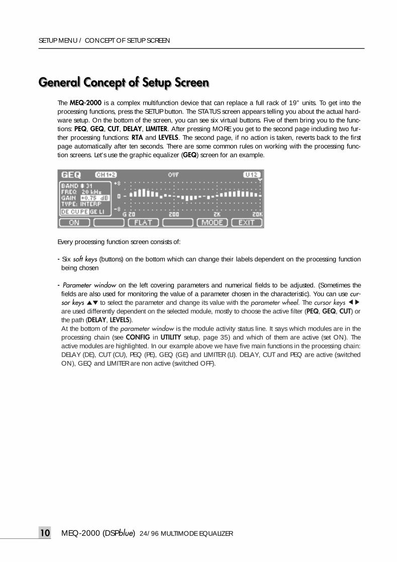
General Concept of Setup ScreenGeneral Concept of Setup ScreenThe MEQ-2000 is a complex multifunction device that can replace a full rack of 19” units. To get into theprocessing functions, press the SETUP button. The STATUS screen appears telling you about the actual hard-ware setup. On the bottom of the screen, you can see six virtual buttons. Five of them bring you to the func-tions: PEQ, GEQ, CUT, DELAY, LIMITER. After pressing MORE you get to the second page including two fur-ther processing functions: RTA and LEVELS. The second page, if no action is taken, reverts back to the firstpage automatically after ten seconds. There are some common rules on working with the processing func-tion screens. Let’s use the graphic equalizer (GEQ) screen for an example.
Every processing function screen consists of:
- Six soft keys (buttons) on the bottom which can change their labels dependent on the processing functionbeing chosen
- Parameter window on the left covering parameters and numerical fields to be adjusted. (Sometimes thefields are also used for monitoring the value of a parameter chosen in the characteristic). You can use cur-sor keys ▲▼ to select the parameter and change its value with the parameter wheel. The cursor keys ◀▶are used differently dependent on the selected module, mostly to choose the active filter (PEQ, GEQ, CUT) orthe path (DELAY, LEVELS).At the bottom of the parameter window is the module activity status line. It says which modules are in theprocessing chain (see CONFIG in UTILITY setup, page 35) and which of them are active (set ON). Theactive modules are highlighted. In our example above we have five main functions in the processing chain:DELAY (DE), CUT (CU), PEQ (PE), GEQ (GE) and LIMITER (LI). DELAY, CUT and PEQ are active (switchedON), GEQ and LIMITER are non active (switched OFF).
10
meq-2000(O/P)_E 2003.9.6 11:43 AM 페이지10
24/96 MULTIMODE EQUALIZER MEQ-2000 (DSPblue)
SETUP MENU / CONCEPT OF SETUP SCREEN
Four soft keys have in every processing function the same meaning:
F1 ON turns the function ON or OFF; ON status is shown by inverting the button (in our example the GEQis OFF)
F2 CH is active only if you work with independent channels in so called dual-channel mode. This mode canbe activated in the MODE menu by switching the parameter CH LINK to OFF. In another case, i.e., if theboth channels are linked, the F2 button stays empty
F5 MODE brings you to the advanced setup options that are normally changed rarely after you have dis-covered your favorite setup.
F6 EXIT switches back to the LCD screen with the main SETUP window showing the system status and allow-ing selection of other functions as the one selected before.
The soft keys F2, F3 and F4 have different functions dependent on the chosen processing module.
In the upper status line you can see the name of the chosen processing function, channel number (CH1,CH2, or CH1+2 if channels are linked), the overflow warning field OVF, the digital input warning field, andthe preset number. The output overflow warns you against clipping with the flashing OVF field if the audiosignal at the output has exceeded clipping level. This can happen if you boost the signal with the equalizerwithout correcting the overall gain (e.g., with GEQ MASTER GAIN in our example).
If you have selected a digital input in the CONFIG menu (see page 35) and for any reason no valid signal isprovided to this input, in the upper status line a flashing message *UNLOCKED* appears and the input ismuted. In such case you need to search for the reason.
Due to the unique proprietary movement control algorithm, AlgoDyn™, the parameter adjustment with theparameter wheel is exceptionally convenient in MEQ-2000. Two normally opposite requirements -- bigadjustment steps and the finest resolution -- are possible now only with the parameter wheel, without annoy-ing range switching. The increment or decrement value of a given parameter is dependent on the speed youturn the wheel. While speeding up you can reach big values very quickly, when turning slowly you canadjust parameters with the finest steps available.
11
meq-2000(O/P)_E 2003.9.6 11:43 AM 페이지11
MEQ-2000 (DSPblue) 24/96 MULTIMODE EQUALIZER
SETUP MENU / PEQ
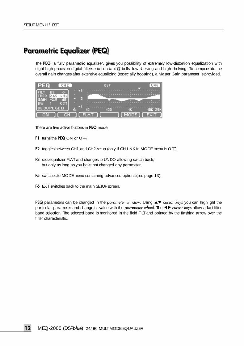
Parametric Equalizer (PEQ)Parametric Equalizer (PEQ)The PEQ, a fully parametric equalizer, gives you possibility of extremely low-distortion equalization witheight high-precision digital filters: six constant-Q bells, low shelving and high shelving. To compensate theoverall gain changes after extensive equalizing (especially boosting), a Master Gain parameter is provided.
There are five active buttons in PEQ mode:
F1 turns the PEQ ON or OFF.
F2 toggles between CH1 and CH2 setup (only if CH LINK in MODE menu is OFF).
F3 sets equalizer FLAT and changes to UNDO allowing switch back, but only as long as you have not changed any parameter.
F5 switches to MODE menu containing advanced options (see page 13).
F6 EXIT switches back to the main SETUP screen.
PEQ parameters can be changed in the parameter window. Using ▲▼ cursor keys you can highlight theparticular parameter and change its value with the parameter wheel. The ◀▶cursor keys allow a fast filterband selection. The selected band is monitored in the field FILT and pointed by the flashing arrow over thefilter characteristic.
12
meq-2000(O/P)_E 2003.9.6 11:43 AM 페이지12
24/96 MULTIMODE EQUALIZER MEQ-2000 (DSPblue)
SETUP MENU / PEQ
Parameters adjustable or monitored in parameter window:
- FILT shows the filter band or master gain selected with ◀▶ cursor keys: M GAIN (master gain), LS (low shelving), B1 up to B6 (bell no. 1 to 6), HS (high shelving)
- FREQ sets up the filter center frequency (for bells) or corner frequency (for shelvings) in the extended audiofrequency range from 10 Hz to 25 kHz in 1/12 octave steps
- GAIN changes the boost or cut value for the active filter and Master Gain;two amplitude ranges can be selected in MODE menu: ±8 dB with 0.125 dB/step and ±16 dB with 0.25 dB/step
- BW (or Q) selects the filter bandwidth of the active bell filter in the range from 1/12 octave to 2 octaves innine steps (or if using Q from 17.31 to 0.667); bandwidth units which are convenient for you can beselected in MODE menu
- SLP appears instead of BW (or Q) when LS (low shelv) or HS (high shelv) is chosen in FILT; it selects the shelving slope: 3, 6 or 9 dB/oct
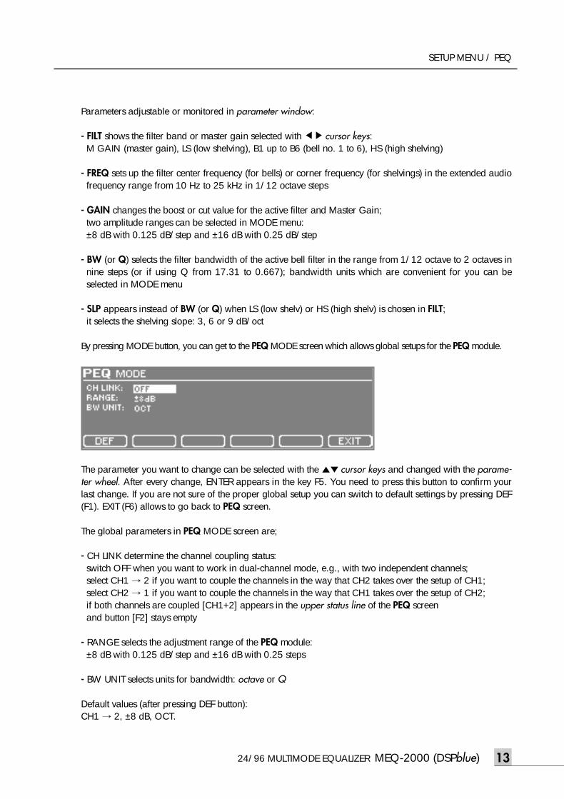
By pressing MODE button, you can get to the PEQ MODE screen which allows global setups for the PEQ module.
The parameter you want to change can be selected with the ▲▼ cursor keys and changed with the parame-ter wheel. After every change, ENTER appears in the key F5. You need to press this button to confirm yourlast change. If you are not sure of the proper global setup you can switch to default settings by pressing DEF(F1). EXIT (F6) allows to go back to PEQ screen.
The global parameters in PEQ MODE screen are;
- CH LINK determine the channel coupling status:switch OFF when you want to work in dual-channel mode, e.g., with two independent channels; select CH1 → 2 if you want to couple the channels in the way that CH2 takes over the setup of CH1;select CH2 → 1 if you want to couple the channels in the way that CH1 takes over the setup of CH2;if both channels are coupled [CH1+2] appears in the upper status line of the PEQ screen and button [F2] stays empty
- RANGE selects the adjustment range of the PEQ module: ±8 dB with 0.125 dB/step and ±16 dB with 0.25 steps
- BW UNIT selects units for bandwidth: octave or Q
Default values (after pressing DEF button):CH1 → 2, ±8 dB, OCT.
13
meq-2000(O/P)_E 2003.9.6 11:43 AM 페이지13
MEQ-2000 (DSPblue) 24/96 MULTIMODE EQUALIZER
SETUP MENU / GEQ
Graphic Equalizer (GEQ)Graphic Equalizer (GEQ)The GEQ gives you a possibility of a precise 1/3-octave equalization with 31 constant-Q filters equallyspaced in the range from 20 Hz to 20 kHz.
There are five active buttons in GEQ mode:
F1 turns the GEQ ON or OFF.
F2 toggles between CH1 and CH2 setup (only if CH LINK in MODE menu is OFF).
F3 sets equalizer FLAT and changes to UNDO allowing switch back, but only as long as you have not changed any parameter.
F5 switches to MODE menu containing advanced options (see page 15).
F6 EXIT switches back to the main SETUP screen.
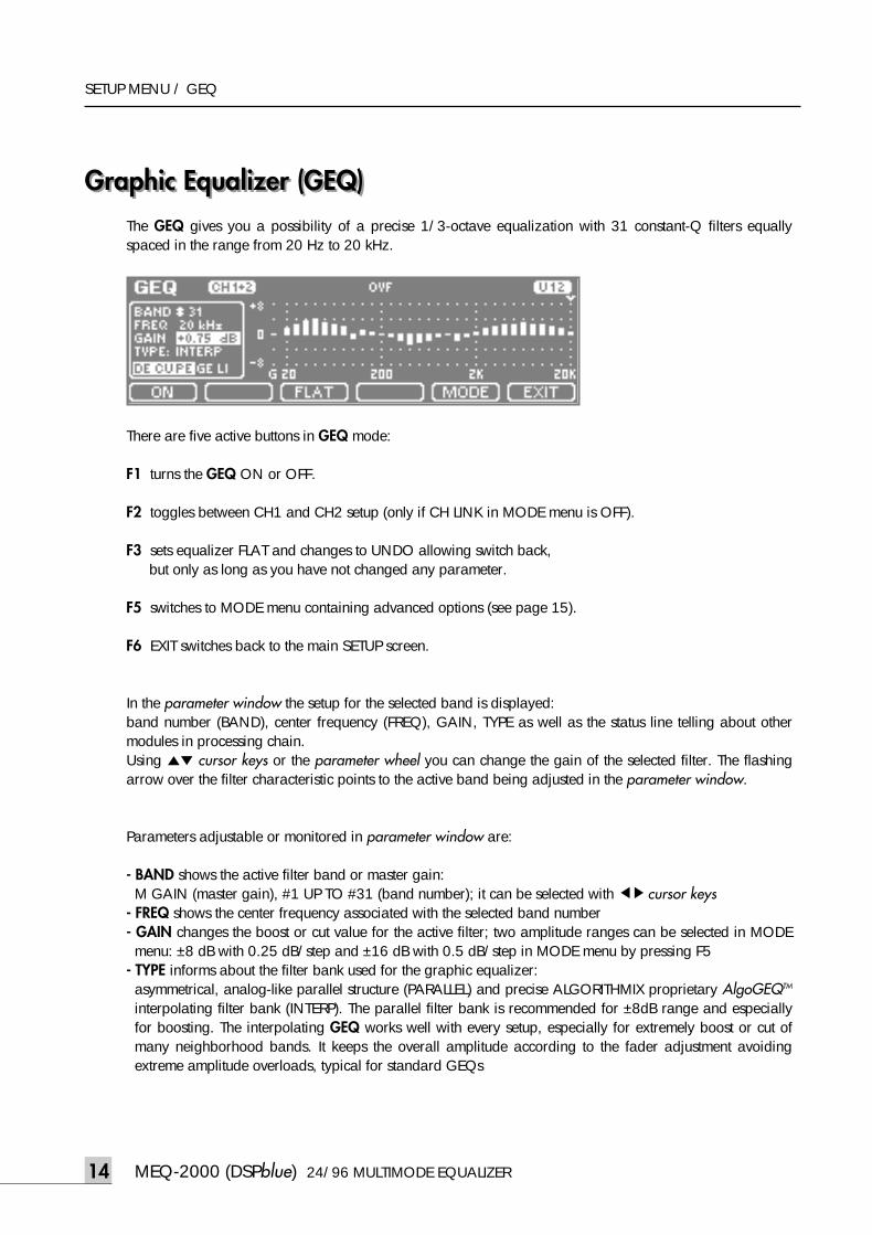
In the parameter window the setup for the selected band is displayed: band number (BAND), center frequency (FREQ), GAIN, TYPE as well as the status line telling about othermodules in processing chain.Using ▲▼ cursor keys or the parameter wheel you can change the gain of the selected filter. The flashingarrow over the filter characteristic points to the active band being adjusted in the parameter window.
Parameters adjustable or monitored in parameter window are:
- BAND shows the active filter band or master gain: M GAIN (master gain), #1 UP TO #31 (band number); it can be selected with ◀▶cursor keys
- FREQ shows the center frequency associated with the selected band number- GAIN changes the boost or cut value for the active filter; two amplitude ranges can be selected in MODEmenu: ±8 dB with 0.25 dB/step and ±16 dB with 0.5 dB/step in MODE menu by pressing F5
- TYPE informs about the filter bank used for the graphic equalizer:asymmetrical, analog-like parallel structure (PARALLEL) and precise ALGORITHMIX proprietary AlgoGEQTM
interpolating filter bank (INTERP). The parallel filter bank is recommended for ±8dB range and especiallyfor boosting. The interpolating GEQ works well with every setup, especially for extremely boost or cut ofmany neighborhood bands. It keeps the overall amplitude according to the fader adjustment avoidingextreme amplitude overloads, typical for standard GEQs
14
meq-2000(O/P)_E 2003.9.6 11:43 AM 페이지14
24/96 MULTIMODE EQUALIZER MEQ-2000 (DSPblue)
SETUP MENU / GEQ
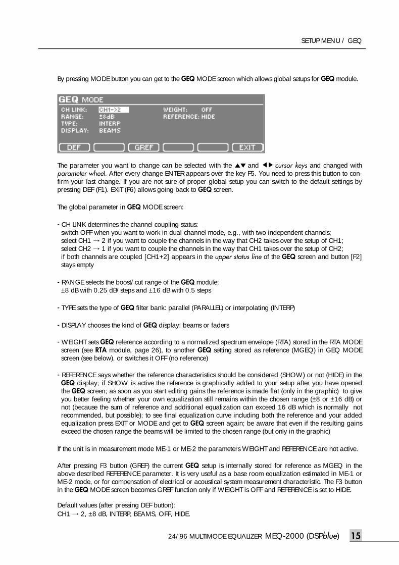
By pressing MODE button you can get to the GEQ MODE screen which allows global setups for GEQ module.
The parameter you want to change can be selected with the ▲▼ and ◀▶ cursor keys and changed withparameter wheel. After every change ENTER appears over the key F5. You need to press this button to con-firm your last change. If you are not sure of proper global setup you can switch to the default settings bypressing DEF (F1). EXIT (F6) allows going back to GEQ screen.
The global parameter in GEQ MODE screen:
- CH LINK determines the channel coupling status:switch OFF when you want to work in dual-channel mode, e.g., with two independent channels; select CH1 → 2 if you want to couple the channels in the way that CH2 takes over the setup of CH1;select CH2 → 1 if you want to couple the channels in the way that CH1 takes over the setup of CH2;if both channels are coupled [CH1+2] appears in the upper status line of the GEQ screen and button [F2]stays empty
- RANGE selects the boost/cut range of the GEQ module: ±8 dB with 0.25 dB/steps and ±16 dB with 0.5 steps
- TYPE sets the type of GEQ filter bank: parallel (PARALLEL) or interpolating (INTERP)
- DISPLAY chooses the kind of GEQ display: beams or faders
- WEIGHT sets GEQ reference according to a normalized spectrum envelope (RTA) stored in the RTA MODEscreen (see RTA module, page 26), to another GEQ setting stored as reference (MGEQ) in GEQ MODEscreen (see below), or switches it OFF (no reference)
- REFERENCE says whether the reference characteristics should be considered (SHOW) or not (HIDE) in theGEQ display; if SHOW is active the reference is graphically added to your setup after you have openedthe GEQ screen; as soon as you start editing gains the reference is made flat (only in the graphic) to giveyou better feeling whether your own equalization still remains within the chosen range (±8 or ±16 dB) ornot (because the sum of reference and additional equalization can exceed 16 dB which is normally notrecommended, but possible); to see final equalization curve including both the reference and your addedequalization press EXIT or MODE and get to GEQ screen again; be aware that even if the resulting gainsexceed the chosen range the beams will be limited to the chosen range (but only in the graphic)
If the unit is in measurement mode ME-1 or ME-2 the parameters WEIGHT and REFERENCE are not active.
After pressing F3 button (GREF) the current GEQ setup is internally stored for reference as MGEQ in theabove described REFERENCE parameter. It is very useful as a base room equalization estimated in ME-1 orME-2 mode, or for compensation of electrical or acoustical system measurement characteristic. The F3 buttonin the GEQ MODE screen becomes GREF function only if WEIGHT is OFF and REFERENCE is set to HIDE.
Default values (after pressing DEF button):CH1 → 2, ±8 dB, INTERP, BEAMS, OFF, HIDE.
15
meq-2000(O/P)_E 2003.9.6 11:43 AM 페이지15
MEQ-2000 (DSPblue) 24/96 MULTIMODE EQUALIZER
SETUP MENU / CUT
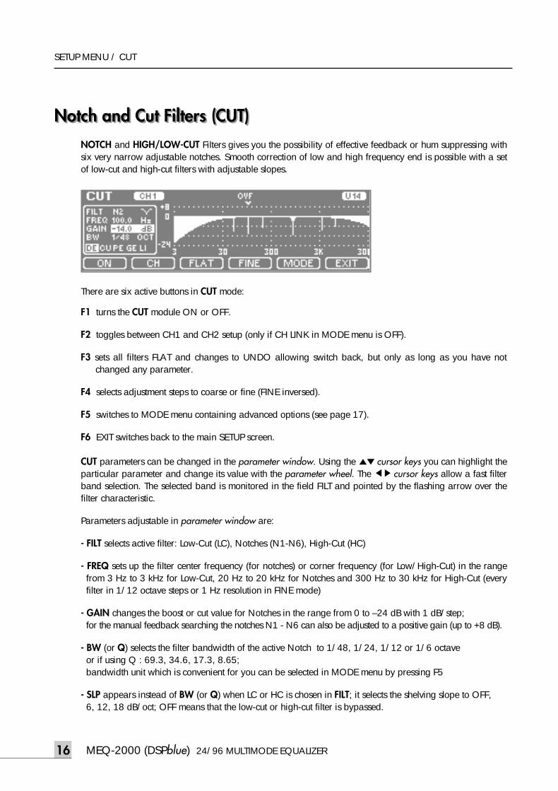
Notch and Cut Filters (CUT)Notch and Cut Filters (CUT)NOTCH and HIGH/LOW-CUT Filters gives you the possibility of effective feedback or hum suppressing withsix very narrow adjustable notches. Smooth correction of low and high frequency end is possible with a setof low-cut and high-cut filters with adjustable slopes.
There are six active buttons in CUT mode:
F1 turns the CUT module ON or OFF.
F2 toggles between CH1 and CH2 setup (only if CH LINK in MODE menu is OFF).
F3 sets all filters FLAT and changes to UNDO allowing switch back, but only as long as you have notchanged any parameter.
F4 selects adjustment steps to coarse or fine (FINE inversed).
F5 switches to MODE menu containing advanced options (see page 17).
F6 EXIT switches back to the main SETUP screen.
CUT parameters can be changed in the parameter window. Using the ▲▼ cursor keys you can highlight theparticular parameter and change its value with the parameter wheel. The ◀▶cursor keys allow a fast filterband selection. The selected band is monitored in the field FILT and pointed by the flashing arrow over thefilter characteristic.
Parameters adjustable in parameter window are:
- FILT selects active filter: Low-Cut (LC), Notches (N1-N6), High-Cut (HC)
- FREQ sets up the filter center frequency (for notches) or corner frequency (for Low/High-Cut) in the rangefrom 3 Hz to 3 kHz for Low-Cut, 20 Hz to 20 kHz for Notches and 300 Hz to 30 kHz for High-Cut (everyfilter in 1/12 octave steps or 1 Hz resolution in FINE mode)
- GAIN changes the boost or cut value for Notches in the range from 0 to –24 dB with 1 dB/step;for the manual feedback searching the notches N1 - N6 can also be adjusted to a positive gain (up to +8 dB).
- BW (or Q) selects the filter bandwidth of the active Notch to 1/48, 1/24, 1/12 or 1/6 octave or if using Q : 69.3, 34.6, 17.3, 8.65; bandwidth unit which is convenient for you can be selected in MODE menu by pressing F5
- SLP appears instead of BW (or Q) when LC or HC is chosen in FILT; it selects the shelving slope to OFF, 6, 12, 18 dB/oct; OFF means that the low-cut or high-cut filter is bypassed.
16
meq-2000(O/P)_E 2003.9.6 11:43 AM 페이지16
24/96 MULTIMODE EQUALIZER MEQ-2000 (DSPblue)
SETUP MENU / CUT
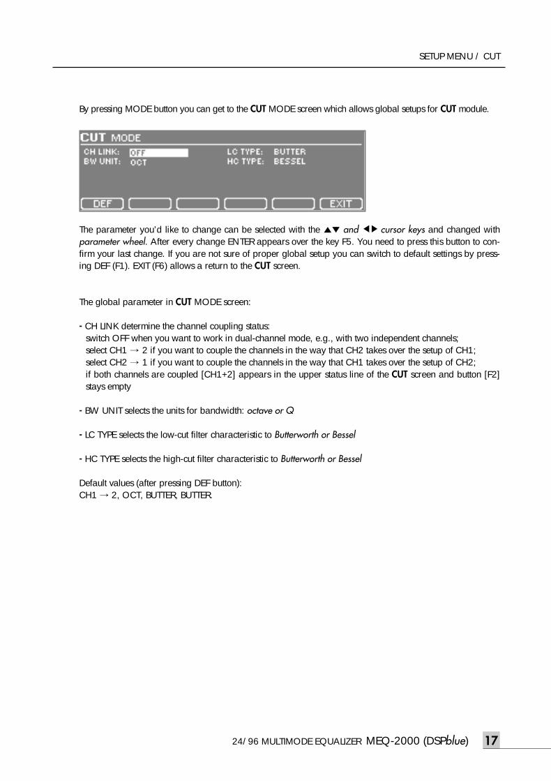
By pressing MODE button you can get to the CUT MODE screen which allows global setups for CUT module.
The parameter you’d like to change can be selected with the ▲▼ and ◀▶ cursor keys and changed withparameter wheel. After every change ENTER appears over the key F5. You need to press this button to con-firm your last change. If you are not sure of proper global setup you can switch to default settings by press-ing DEF (F1). EXIT (F6) allows a return to the CUT screen.
The global parameter in CUT MODE screen:
- CH LINK determine the channel coupling status:switch OFF when you want to work in dual-channel mode, e.g., with two independent channels; select CH1 → 2 if you want to couple the channels in the way that CH2 takes over the setup of CH1;select CH2 → 1 if you want to couple the channels in the way that CH1 takes over the setup of CH2;if both channels are coupled [CH1+2] appears in the upper status line of the CUT screen and button [F2]stays empty
- BW UNIT selects the units for bandwidth: octave or Q
- LC TYPE selects the low-cut filter characteristic to Butterworth or Bessel
- HC TYPE selects the high-cut filter characteristic to Butterworth or Bessel
Default values (after pressing DEF button):CH1 → 2, OCT, BUTTER, BUTTER.
17
meq-2000(O/P)_E 2003.9.6 11:43 AM 페이지17
MEQ-2000 (DSPblue) 24/96 MULTIMODE EQUALIZER
SETUP MENU / DELAY
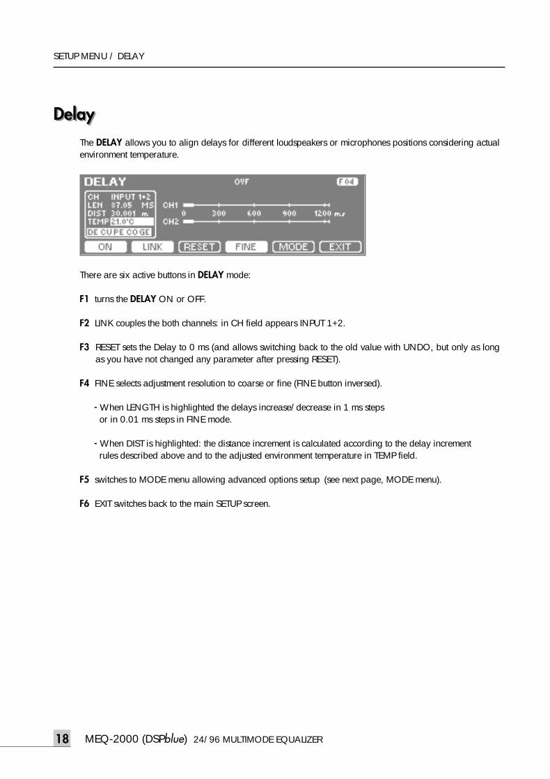
DelayDelayThe DELAY allows you to align delays for different loudspeakers or microphones positions considering actualenvironment temperature.
There are six active buttons in DELAY mode:
F1 turns the DELAY ON or OFF.
F2 LINK couples the both channels: in CH field appears INPUT 1+2.
F3 RESET sets the Delay to 0 ms (and allows switching back to the old value with UNDO, but only as longas you have not changed any parameter after pressing RESET).
F4 FINE selects adjustment resolution to coarse or fine (FINE button inversed).
- When LENGTH is highlighted the delays increase/decrease in 1 ms steps or in 0.01 ms steps in FINE mode.
- When DIST is highlighted: the distance increment is calculated according to the delay increment rules described above and to the adjusted environment temperature in TEMP field.
F5 switches to MODE menu allowing advanced options setup (see next page, MODE menu).
F6 EXIT switches back to the main SETUP screen.
18
meq-2000(O/P)_E 2003.9.6 11:43 AM 페이지18
24/96 MULTIMODE EQUALIZER MEQ-2000 (DSPblue)
SETUP MENU / DELAY
DELAY parameters can be changed in the parameter window. Using the ▲▼ cursor keys you can highlightthe particular parameter and change its value with the parameter wheel. The ◀▶ cursor keys allow fasttoggling between channels (only if LINK is inactive).
Parameters adjustable in parameter window are:
- CH (or ◀▶cursor keys) selects active channel (only if LINK is OFF): IN CH1 - input channel 1 IN CH2 - input channel 2
- LEN sets the DELAY length in the range 0-1240 milliseconds in 1 ms (COARSE) or 0.01 ms (FINE) steps
- DIST sets the distance in meters in the range 0 to approx. 430 m (delay time in LEN is computed dependingon DIST and TEMP)
- TEMP selects the environment temperature in the range from 0 to 50 degrees Celsius with 0.5 degree stepor from 32 to 121 degrees Fahrenheit with 1 degree step; the temperature unit, Celsius or Fahrenheit, canbe selected in the MODE menu (F5)
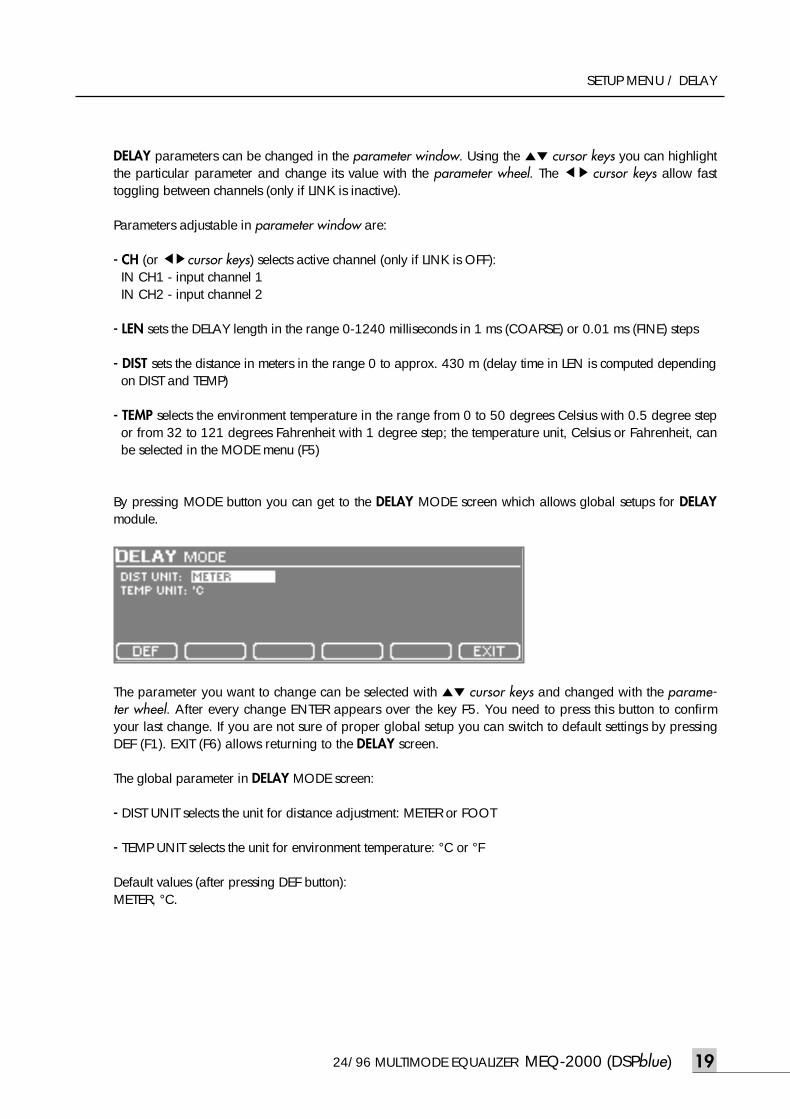
By pressing MODE button you can get to the DELAY MODE screen which allows global setups for DELAYmodule.
The parameter you want to change can be selected with ▲▼ cursor keys and changed with the parame-ter wheel. After every change ENTER appears over the key F5. You need to press this button to confirmyour last change. If you are not sure of proper global setup you can switch to default settings by pressingDEF (F1). EXIT (F6) allows returning to the DELAY screen.
The global parameter in DELAY MODE screen:
- DIST UNIT selects the unit for distance adjustment: METER or FOOT
- TEMP UNIT selects the unit for environment temperature: °C or °F
Default values (after pressing DEF button):METER, °C.
19
meq-2000(O/P)_E 2003.9.6 11:43 AM 페이지19
MEQ-2000 (DSP blue) 24/96 MULTIMODE EQUALIZER
SETUP MENU / COM/LIM
Compressor/Limiter
20
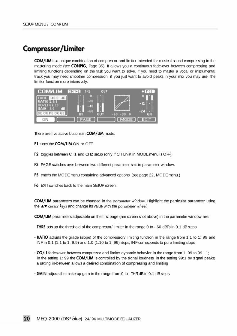
Compressor/LimiterCOM/LIM is a unique combination of compressor and limiter intended for musical sound compressing in themastering mode (see CONPIG, Page 35). It allows you a continuous fade-over between compressing andlimiting functions depending on the task you want to solve. If you need to master a vocal or instrumentaltrack you may need smoother compression, if you just want to avoid peaks in your mix you may use thelimiter function more intensively.
There are five active buttons in COM/LIM mode:
F1 turns the COM/LIM ON or OFF.
F2 toggles between CH1 and CH2 setup (only if CH LINK in MODE menu is OFF).
F3 PAGE switches over between two different parameter sets in parameter window.
F5 enters the MODE menu containing advanced options. (see page 22, MODE menu.)
F6 EXIT switches back to the main SETUP screen.
COM/LIM parameters can be changed in the parameter window. Highlight the particular parameter usingthe ▲▼cursor keys and change its value with the parameter wheel.
COM/LIM parameters adjustable on the first page (see screen shot above) in the parameter window are:
- THRE sets up the threshold of the compressor/limiter in the range 0 to - 60 dBFs in 0.1 dB steps
- RATIO adjusts the grade (slope) of the compression/limiting function in the range from 1:1 to 1: 99 andINF in 0.1 (1:1 to 1: 9.9) and 1.0 (1:10 to 1: 99) steps; INF corresponds to pure limiting slope
- CO/LI fades over between compressor and limiter dynamic behavior in the range from 1: 99 to 99 : 1; in the setting 1: 99 the COM/LIM is controlled by the signal loudness, in the setting 99:1 by signal peaks;a setting in-between allows a desired combination of compressing and limiting
- GAIN adjusts the make-up gain in the range from 0 to –THR dB in 0.1 dB steps.
meq-2000(O/P)_E 2003.9.6 11:43 AM 페이지20
24/96 MULTIMODE EQUALIZER MEQ-2000 (DSP blue)
SETUP MENU / COM/LIM
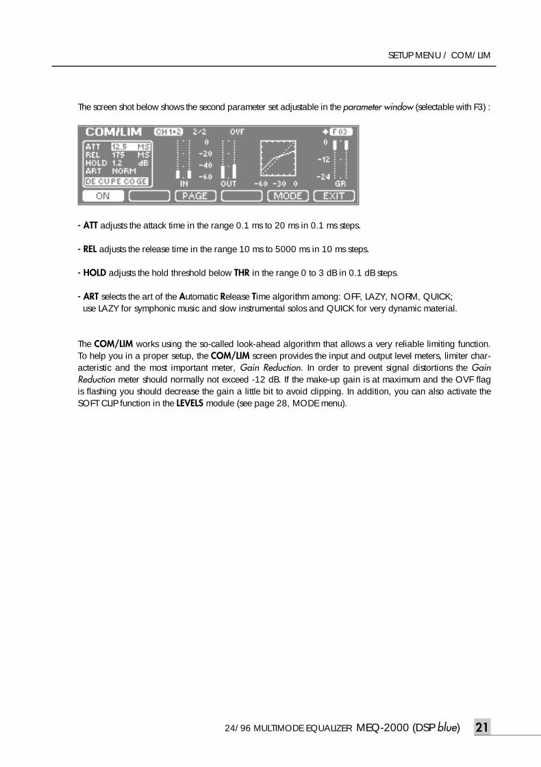
The screen shot below shows the second parameter set adjustable in the parameter window (selectable with F3) :
- ATT adjusts the attack time in the range 0.1 ms to 20 ms in 0.1 ms steps.
- REL adjusts the release time in the range 10 ms to 5000 ms in 10 ms steps.
- HOLD adjusts the hold threshold below THR in the range 0 to 3 dB in 0.1 dB steps.
- ART selects the art of the Automatic Release Time algorithm among: OFF, LAZY, NORM, QUICK; use LAZY for symphonic music and slow instrumental solos and QUICK for very dynamic material.
The COM/LIM works using the so-called look-ahead algorithm that allows a very reliable limiting function.To help you in a proper setup, the COM/LIM screen provides the input and output level meters, limiter char-acteristic and the most important meter, Gain Reduction. In order to prevent signal distortions the GainReduction meter should normally not exceed -12 dB. If the make-up gain is at maximum and the OVF flagis flashing you should decrease the gain a little bit to avoid clipping. In addition, you can also activate theSOFT CLIP function in the LEVELS module (see page 28, MODE menu).
21
meq-2000(O/P)_E 2003.9.6 11:43 AM 페이지21
MEQ-2000 (DSP blue) 24/96 MULTIMODE EQUALIZER22 MEQ-2000 (DSP blue) 24/96 MULTIMODE EQUALIZER22
SETUP / COM/LIM
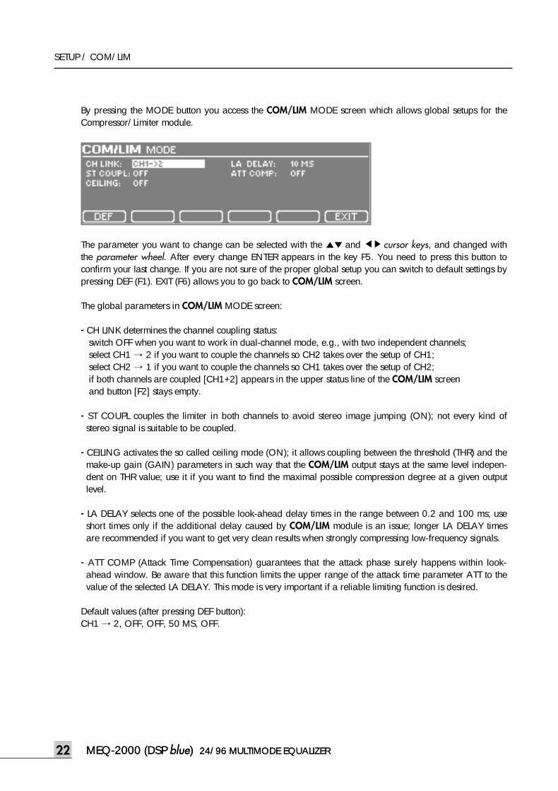
By pressing the MODE button you access the COM/LIM MODE screen which allows global setups for theCompressor/Limiter module.
The parameter you want to change can be selected with the ▲▼ and ◀▶ cursor keys, and changed withthe parameter wheel. After every change ENTER appears in the key F5. You need to press this button toconfirm your last change. If you are not sure of the proper global setup you can switch to default settings bypressing DEF (F1). EXIT (F6) allows you to go back to COM/LIM screen.
The global parameters in COM/LIM MODE screen:
- CH LINK determines the channel coupling status:switch OFF when you want to work in dual-channel mode, e.g., with two independent channels;select CH1 → 2 if you want to couple the channels so CH2 takes over the setup of CH1;select CH2 → 1 if you want to couple the channels so CH1 takes over the setup of CH2;if both channels are coupled [CH1+2] appears in the upper status line of the COM/LIM screen and button [F2] stays empty.
- ST COUPL couples the limiter in both channels to avoid stereo image jumping (ON); not every kind ofstereo signal is suitable to be coupled.
- CEILING activates the so called ceiling mode (ON); it allows coupling between the threshold (THR) and themake-up gain (GAIN) parameters in such way that the COM/LIM output stays at the same level indepen-dent on THR value; use it if you want to find the maximal possible compression degree at a given outputlevel.
- LA DELAY selects one of the possible look-ahead delay times in the range between 0.2 and 100 ms; useshort times only if the additional delay caused by COM/LIM module is an issue; longer LA DELAY timesare recommended if you want to get very clean results when strongly compressing low-frequency signals.
- ATT COMP (Attack Time Compensation) guarantees that the attack phase surely happens within look-ahead window. Be aware that this function limits the upper range of the attack time parameter ATT to thevalue of the selected LA DELAY. This mode is very important if a reliable limiting function is desired.
Default values (after pressing DEF button):CH1 → 2, OFF, OFF, 50 MS, OFF.
meq-2000(O/P)_E 2003.9.6 11:43 AM 페이지22
24/96 MULTIMODE EQUALIZER MEQ-2000 (DSPblue) 23
SETUP MENU / LIMITER
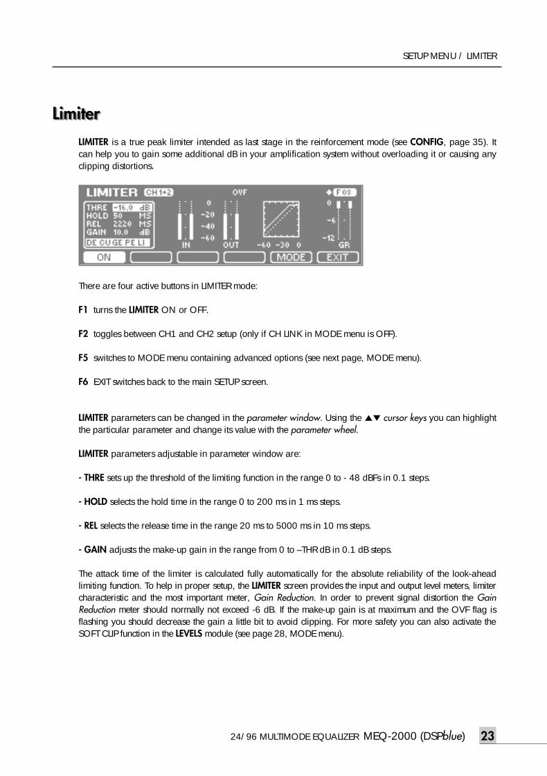
LimiterLimiterLIMITER is a true peak limiter intended as last stage in the reinforcement mode (see CONFIG, page 35). Itcan help you to gain some additional dB in your amplification system without overloading it or causing anyclipping distortions.
There are four active buttons in LIMITER mode:
F1 turns the LIMITER ON or OFF.
F2 toggles between CH1 and CH2 setup (only if CH LINK in MODE menu is OFF).
F5 switches to MODE menu containing advanced options (see next page, MODE menu).
F6 EXIT switches back to the main SETUP screen.
LIMITER parameters can be changed in the parameter window. Using the ▲▼ cursor keys you can highlightthe particular parameter and change its value with the parameter wheel.
LIMITER parameters adjustable in parameter window are:
- THRE sets up the threshold of the limiting function in the range 0 to - 48 dBFs in 0.1 steps.
- HOLD selects the hold time in the range 0 to 200 ms in 1 ms steps.
- REL selects the release time in the range 20 ms to 5000 ms in 10 ms steps.
- GAIN adjusts the make-up gain in the range from 0 to –THR dB in 0.1 dB steps.
The attack time of the limiter is calculated fully automatically for the absolute reliability of the look-aheadlimiting function. To help in proper setup, the LIMITER screen provides the input and output level meters, limitercharacteristic and the most important meter, Gain Reduction. In order to prevent signal distortion the GainReduction meter should normally not exceed -6 dB. If the make-up gain is at maximum and the OVF flag isflashing you should decrease the gain a little bit to avoid clipping. For more safety you can also activate theSOFT CLIP function in the LEVELS module (see page 28, MODE menu).
meq-2000(O/P)_E 2003.9.6 11:43 AM 페이지23
SETUP MENU / LIMITER
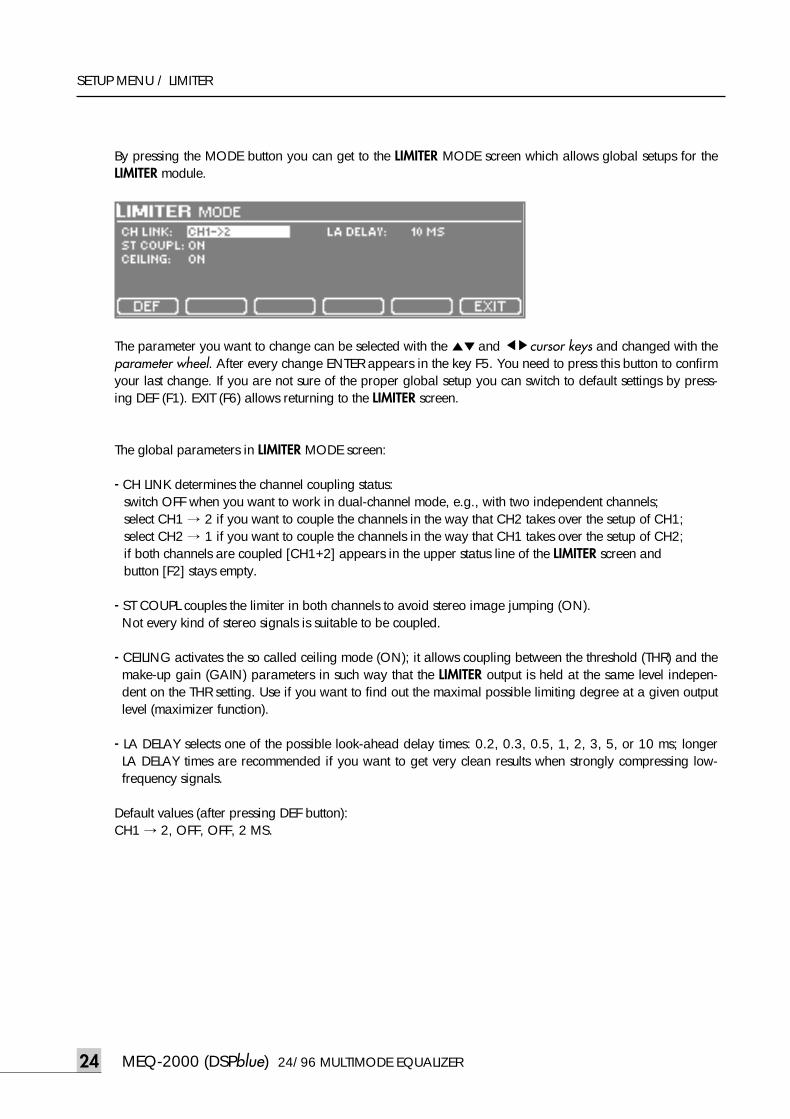
By pressing the MODE button you can get to the LIMITER MODE screen which allows global setups for theLIMITER module.
The parameter you want to change can be selected with the ▲▼and ◀▶cursor keys and changed with theparameter wheel. After every change ENTER appears in the key F5. You need to press this button to confirmyour last change. If you are not sure of the proper global setup you can switch to default settings by press-ing DEF (F1). EXIT (F6) allows returning to the LIMITER screen.
The global parameters in LIMITER MODE screen:
- CH LINK determines the channel coupling status:switch OFF when you want to work in dual-channel mode, e.g., with two independent channels; select CH1 → 2 if you want to couple the channels in the way that CH2 takes over the setup of CH1;select CH2 → 1 if you want to couple the channels in the way that CH1 takes over the setup of CH2;if both channels are coupled [CH1+2] appears in the upper status line of the LIMITER screen and button [F2] stays empty.
- ST COUPL couples the limiter in both channels to avoid stereo image jumping (ON). Not every kind of stereo signals is suitable to be coupled.
- CEILING activates the so called ceiling mode (ON); it allows coupling between the threshold (THR) and themake-up gain (GAIN) parameters in such way that the LIMITER output is held at the same level indepen-dent on the THR setting. Use if you want to find out the maximal possible limiting degree at a given outputlevel (maximizer function).
- LA DELAY selects one of the possible look-ahead delay times: 0.2, 0.3, 0.5, 1, 2, 3, 5, or 10 ms; longerLA DELAY times are recommended if you want to get very clean results when strongly compressing low-frequency signals.
Default values (after pressing DEF button):CH1 → 2, OFF, OFF, 2 MS.
MEQ-2000 (DSPblue) 24/96 MULTIMODE EQUALIZER24
meq-2000(O/P)_E 2003.9.6 11:43 AM 페이지24
24/96 MULTIMODE EQUALIZER MEQ-2000 (DSPblue) 25
SETUP MENU / RTA
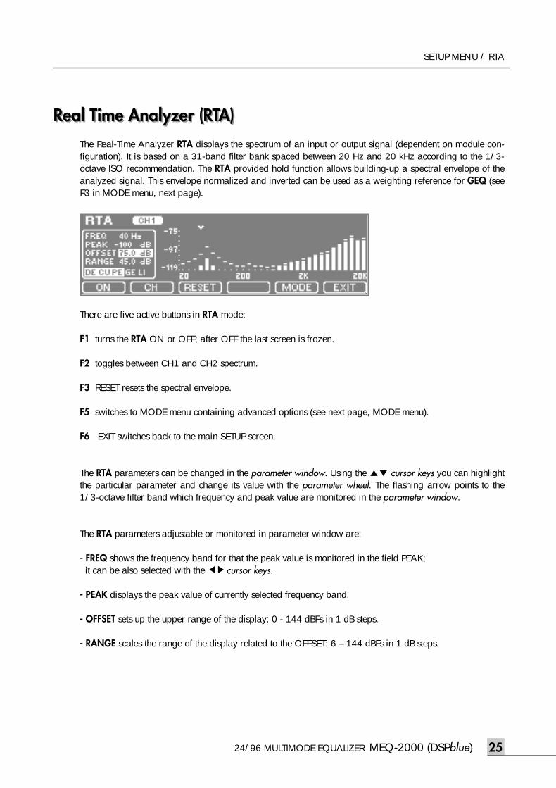
Real Time Analyzer (RTA)Real Time Analyzer (RTA)The Real-Time Analyzer RTA displays the spectrum of an input or output signal (dependent on module con-figuration). It is based on a 31-band filter bank spaced between 20 Hz and 20 kHz according to the 1/3-octave ISO recommendation. The RTA provided hold function allows building-up a spectral envelope of theanalyzed signal. This envelope normalized and inverted can be used as a weighting reference for GEQ (seeF3 in MODE menu, next page).
There are five active buttons in RTA mode:
F1 turns the RTA ON or OFF; after OFF the last screen is frozen.
F2 toggles between CH1 and CH2 spectrum.
F3 RESET resets the spectral envelope.
F5 switches to MODE menu containing advanced options (see next page, MODE menu).
F6 EXIT switches back to the main SETUP screen.
The RTA parameters can be changed in the parameter window. Using the ▲▼ cursor keys you can highlightthe particular parameter and change its value with the parameter wheel. The flashing arrow points to the1/3-octave filter band which frequency and peak value are monitored in the parameter window.
The RTA parameters adjustable or monitored in parameter window are:
- FREQ shows the frequency band for that the peak value is monitored in the field PEAK; it can be also selected with the ◀▶cursor keys.
- PEAK displays the peak value of currently selected frequency band.
- OFFSET sets up the upper range of the display: 0 - 144 dBFs in 1 dB steps.
- RANGE scales the range of the display related to the OFFSET: 6 – 144 dBFs in 1 dB steps.
meq-2000(O/P)_E 2003.9.6 11:43 AM 페이지25
MEQ-2000 (DSPblue) 24/96 MULTIMODE EQUALIZER26
SETUP MENU / RTA
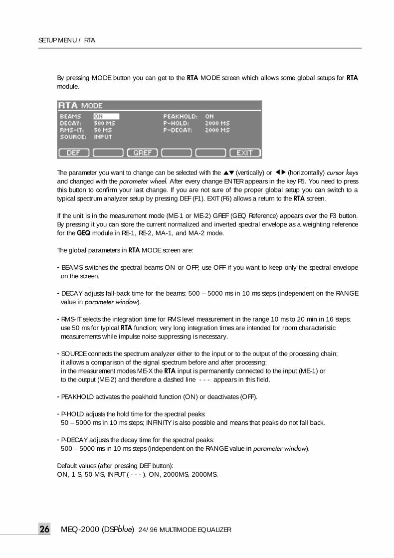
By pressing MODE button you can get to the RTA MODE screen which allows some global setups for RTAmodule.
The parameter you want to change can be selected with the ▲▼ (vertically) or ◀▶ (horizontally) cursor keysand changed with the parameter wheel. After every change ENTER appears in the key F5. You need to pressthis button to confirm your last change. If you are not sure of the proper global setup you can switch to atypical spectrum analyzer setup by pressing DEF (F1). EXIT (F6) allows a return to the RTA screen.
If the unit is in the measurement mode (ME-1 or ME-2) GREF (GEQ Reference) appears over the F3 button.By pressing it you can store the current normalized and inverted spectral envelope as a weighting referencefor the GEQ module in RE-1, RE-2, MA-1, and MA-2 mode.
The global parameters in RTA MODE screen are:
- BEAMS switches the spectral beams ON or OFF; use OFF if you want to keep only the spectral envelopeon the screen.
- DECAY adjusts fall-back time for the beams: 500 – 5000 ms in 10 ms steps (independent on the RANGEvalue in parameter window).
- RMS-IT selects the integration time for RMS level measurement in the range 10 ms to 20 min in 16 steps; use 50 ms for typical RTA function; very long integration times are intended for room characteristic measurements while impulse noise suppressing is necessary.
- SOURCE connects the spectrum analyzer either to the input or to the output of the processing chain;it allows a comparison of the signal spectrum before and after processing;in the measurement modes ME-X the RTA input is permanently connected to the input (ME-1) or to the output (ME-2) and therefore a dashed line - - - appears in this field.
- PEAKHOLD activates the peakhold function (ON) or deactivates (OFF).
- P-HOLD adjusts the hold time for the spectral peaks: 50 – 5000 ms in 10 ms steps; INFINITY is also possible and means that peaks do not fall back.
- P-DECAY adjusts the decay time for the spectral peaks: 500 – 5000 ms in 10 ms steps (independent on the RANGE value in parameter window).
Default values (after pressing DEF button):ON, 1 S, 50 MS, INPUT ( - - - ), ON, 2000MS, 2000MS.
meq-2000(O/P)_E 2003.9.6 11:43 AM 페이지26
Level Adjustment
24/96 MULTIMODE EQUALIZER MEQ-2000 (DSPblue) 27
SETUP MENU / LEVELS
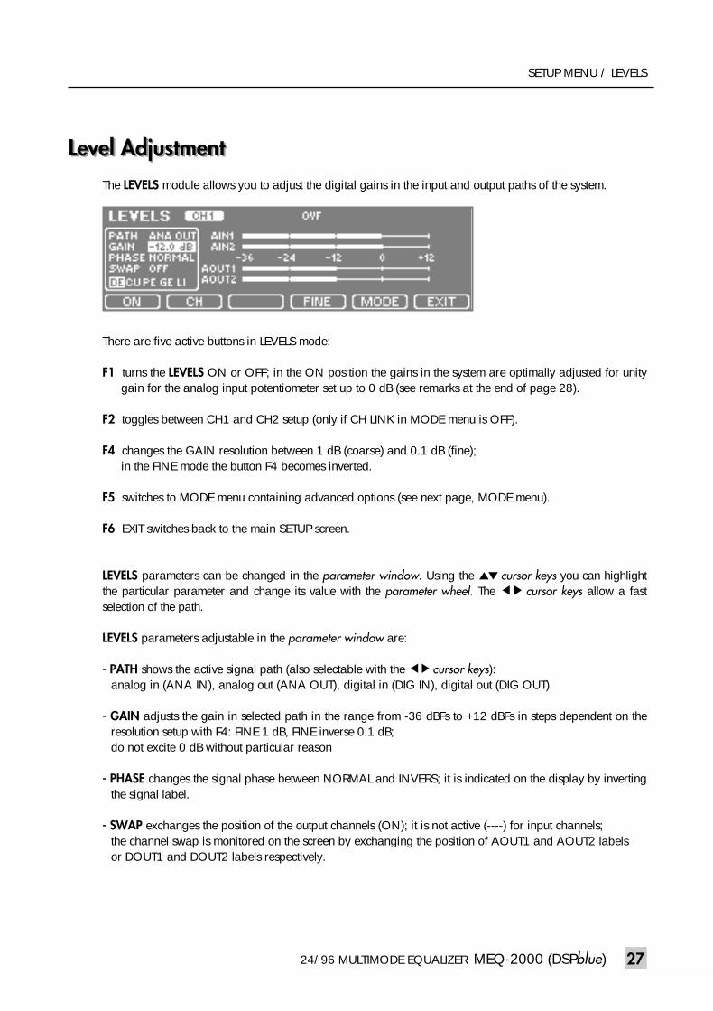
Level AdjustmentThe LEVELS module allows you to adjust the digital gains in the input and output paths of the system.
There are five active buttons in LEVELS mode:
F1 turns the LEVELS ON or OFF; in the ON position the gains in the system are optimally adjusted for unitygain for the analog input potentiometer set up to 0 dB (see remarks at the end of page 28).
F2 toggles between CH1 and CH2 setup (only if CH LINK in MODE menu is OFF).
F4 changes the GAIN resolution between 1 dB (coarse) and 0.1 dB (fine);in the FINE mode the button F4 becomes inverted.
F5 switches to MODE menu containing advanced options (see next page, MODE menu).
F6 EXIT switches back to the main SETUP screen.
LEVELS parameters can be changed in the parameter window. Using the ▲▼ cursor keys you can highlightthe particular parameter and change its value with the parameter wheel. The ◀▶ cursor keys allow a fastselection of the path.
LEVELS parameters adjustable in the parameter window are:
- PATH shows the active signal path (also selectable with the ◀▶cursor keys): analog in (ANA IN), analog out (ANA OUT), digital in (DIG IN), digital out (DIG OUT).
- GAIN adjusts the gain in selected path in the range from -36 dBFs to +12 dBFs in steps dependent on theresolution setup with F4: FINE 1 dB, FINE inverse 0.1 dB; do not excite 0 dB without particular reason
- PHASE changes the signal phase between NORMAL and INVERS; it is indicated on the display by invertingthe signal label.
- SWAP exchanges the position of the output channels (ON); it is not active (----) for input channels; the channel swap is monitored on the screen by exchanging the position of AOUT1 and AOUT2 labels or DOUT1 and DOUT2 labels respectively.
meq-2000(O/P)_E 2003.9.6 11:43 AM 페이지27
MEQ-2000 (DSPblue) 24/96 MULTIMODE EQUALIZER28
SETUP MENU / LEVELS
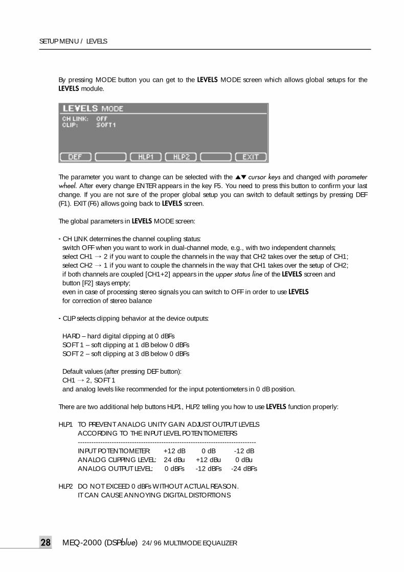
By pressing MODE button you can get to the LEVELS MODE screen which allows global setups for theLEVELS module.
The parameter you want to change can be selected with the ▲▼ cursor keys and changed with parameterwheel. After every change ENTER appears in the key F5. You need to press this button to confirm your lastchange. If you are not sure of the proper global setup you can switch to default settings by pressing DEF(F1). EXIT (F6) allows going back to LEVELS screen.
The global parameters in LEVELS MODE screen:
- CH LINK determines the channel coupling status:switch OFF when you want to work in dual-channel mode, e.g., with two independent channels; select CH1 → 2 if you want to couple the channels in the way that CH2 takes over the setup of CH1;select CH2 → 1 if you want to couple the channels in the way that CH1 takes over the setup of CH2;if both channels are coupled [CH1+2] appears in the upper status line of the LEVELS screen and button [F2] stays empty;even in case of processing stereo signals you can switch to OFF in order to use LEVELSfor correction of stereo balance
- CLIP selects clipping behavior at the device outputs:
HARD – hard digital clipping at 0 dBFsSOFT 1 – soft clipping at 1 dB below 0 dBFsSOFT 2 – soft clipping at 3 dB below 0 dBFs
Default values (after pressing DEF button):CH1 → 2, SOFT 1 and analog levels like recommended for the input potentiometers in 0 dB position.
There are two additional help buttons HLP1, HLP2 telling you how to use LEVELS function properly:
HLP1 TO PREVENT ANALOG UNITY GAIN ADJUST OUTPUT LEVELS ACCORDING TO THE INPUT LEVEL POTENTIOMETERS-------------------------------------------------------------------------------INPUT POTENTIOMETER: +12 dB 0 dB -12 dBANALOG CLIPPING LEVEL: 24 dBu +12 dBu 0 dBuANALOG OUTPUT LEVEL: 0 dBFs -12 dBFs -24 dBFs
HLP2 DO NOT EXCEED 0 dBFs WITHOUT ACTUAL REASON.IT CAN CAUSE ANNOYING DIGITAL DISTORTIONS
meq-2000(O/P)_E 2003.9.6 11:43 AM 페이지28
24/96 MULTIMODE EQUALIZER MEQ-2000 (DSPblue) 29
SETUP MENU / GEN
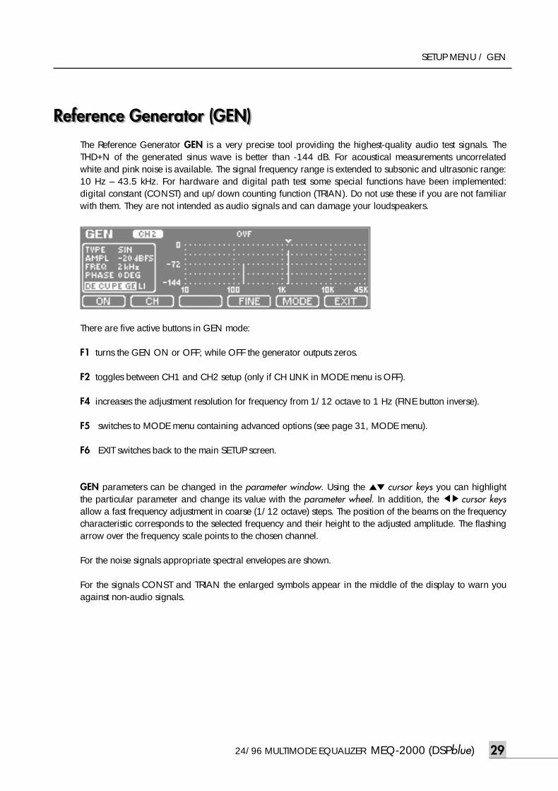
Reference Generator (GEN)Reference Generator (GEN)The Reference Generator GEN is a very precise tool providing the highest-quality audio test signals. TheTHD+N of the generated sinus wave is better than -144 dB. For acoustical measurements uncorrelatedwhite and pink noise is available. The signal frequency range is extended to subsonic and ultrasonic range:10 Hz – 43.5 kHz. For hardware and digital path test some special functions have been implemented:digital constant (CONST) and up/down counting function (TRIAN). Do not use these if you are not familiarwith them. They are not intended as audio signals and can damage your loudspeakers.
There are five active buttons in GEN mode:
F1 turns the GEN ON or OFF; while OFF the generator outputs zeros.
F2 toggles between CH1 and CH2 setup (only if CH LINK in MODE menu is OFF).
F4 increases the adjustment resolution for frequency from 1/12 octave to 1 Hz (FINE button inverse).
F5 switches to MODE menu containing advanced options (see page 31, MODE menu).
F6 EXIT switches back to the main SETUP screen.
GEN parameters can be changed in the parameter window. Using the ▲▼ cursor keys you can highlightthe particular parameter and change its value with the parameter wheel. In addition, the ◀▶cursor keysallow a fast frequency adjustment in coarse (1/12 octave) steps. The position of the beams on the frequencycharacteristic corresponds to the selected frequency and their height to the adjusted amplitude. The flashingarrow over the frequency scale points to the chosen channel.
For the noise signals appropriate spectral envelopes are shown.
For the signals CONST and TRIAN the enlarged symbols appear in the middle of the display to warn youagainst non-audio signals.
meq-2000(O/P)_E 2003.9.6 11:43 AM 페이지29
MEQ-2000 (DSPblue) 24/96 MULTIMODE EQUALIZER30
SETUP MENU / GEN
GEN parameters adjustable in parameter window are:
- TYPE selects the type of the generated test signal: SIN (sinus), FREQ SW (sinus frequency sweep), PINK(pink noise), WHITE (white noise), CONST (digital constant), TRIAN (digital up/down counter)
- AMPL adjusts the signal amplitude in the range: -144 to 0 dBFs in 0.1 dB steps for 24-bit output (scalesautomatically to the BIT WIDTH in MODE screen: -120 dBFs for 20-bit and -96 dBFs for 16-bit output)
- FREQ adjusts the sinus frequency: 10 Hz – 43.5 kHz in 1/12 octave (coarse) or 1 Hz steps (fine)
- PHASE adjusts the relative phase of the CH2 sinus wave: 0 – 360 degrees in 1 degree steps (only if CHLINK in MODE menu is OFF); therefore for CH1 the phase is not indicated (----)
For signal type FREQ SW the parameter window changes to AMPL, F RAN and STEP; F RAN (frequencyrange) allows to switch between STAND (standard = 20 Hz – 20 kHz) and EXTEN (extended = 10 Hz –43,5 kHz). STEP determines the sweep frequency interval: 1/3, 1/6, or 1/12 octave.
For signal types PINK and WHITE only AMPL parameter is active.
For signal type CONST the parameter AMPL changes to VALUE which can be selected from 10 typicalhexadecimal constants: 000000, FFFFFF, 555555, AAAAAA, 7FFFFF, 800000, F0F0F0, 0F0F0F,CCCCCC, 333333. FREQ and PHASE are inactive.
For signal type TRAIN the parameter window changes to RANGE, LEN and STEP. RANGE can be set to 16,20, or 24 bit. LEN (length) says how many samples the same value should be repeated (1 – 32), and STEPsets the digital increment (1 – 16 samples).
Do not select the signals CONST and TRAIN if you are not familiar with them. They are not intended asaudio signals and can damage your loudspeakers.
meq-2000(O/P)_E 2003.9.6 11:43 AM 페이지30
24/96 MULTIMODE EQUALIZER MEQ-2000 (DSPblue) 31
SETUP MENU / GEN
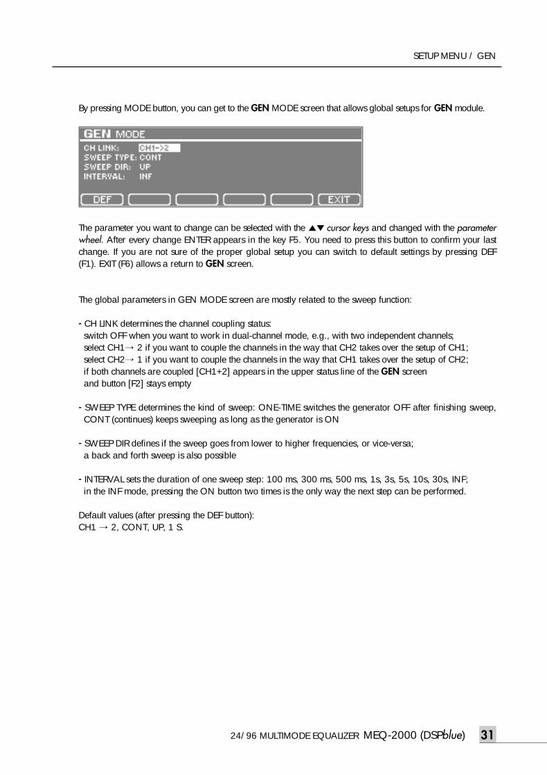
By pressing MODE button, you can get to the GEN MODE screen that allows global setups for GEN module.
The parameter you want to change can be selected with the ▲▼ cursor keys and changed with the parameterwheel. After every change ENTER appears in the key F5. You need to press this button to confirm your lastchange. If you are not sure of the proper global setup you can switch to default settings by pressing DEF(F1). EXIT (F6) allows a return to GEN screen.
The global parameters in GEN MODE screen are mostly related to the sweep function:
- CH LINK determines the channel coupling status:switch OFF when you want to work in dual-channel mode, e.g., with two independent channels; select CH1→ 2 if you want to couple the channels in the way that CH2 takes over the setup of CH1;select CH2→ 1 if you want to couple the channels in the way that CH1 takes over the setup of CH2;if both channels are coupled [CH1+2] appears in the upper status line of the GEN screen and button [F2] stays empty
- SWEEP TYPE determines the kind of sweep: ONE-TIME switches the generator OFF after finishing sweep,CONT (continues) keeps sweeping as long as the generator is ON
- SWEEP DIR defines if the sweep goes from lower to higher frequencies, or vice-versa; a back and forth sweep is also possible
- INTERVAL sets the duration of one sweep step: 100 ms, 300 ms, 500 ms, 1s, 3s, 5s, 10s, 30s, INF;in the INF mode, pressing the ON button two times is the only way the next step can be performed.
Default values (after pressing the DEF button):CH1 → 2, CONT, UP, 1 S.
meq-2000(O/P)_E 2003.9.6 11:43 AM 페이지31
MEQ-2000 (DSPblue) 24/96 MULTIMODE EQUALIZER32
SETUP MENU / STRUCTURE
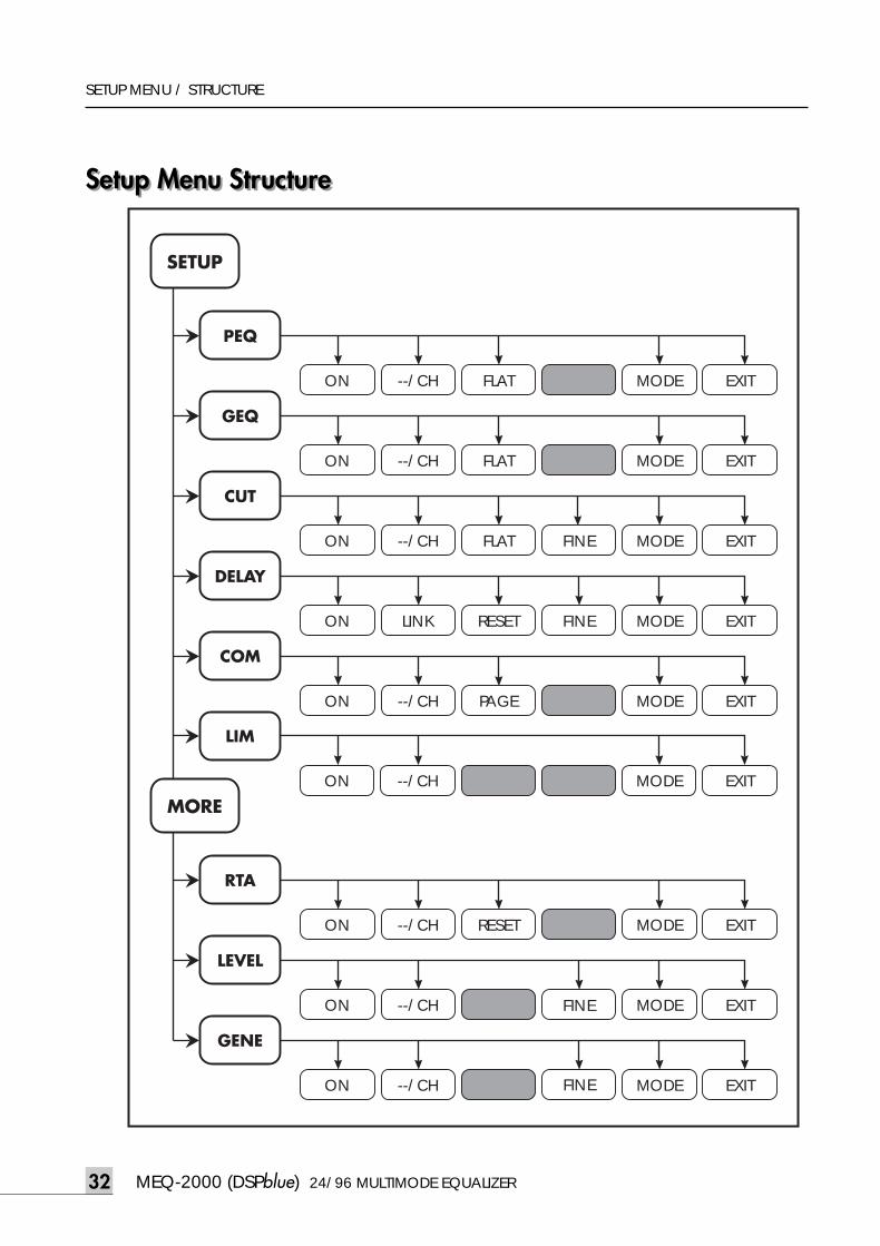
Setup Menu StructureSetup Menu Structure
SETUP
MORE
PEQ
ON --/CH FLAT PEQ MODE EXIT
GEQ
ON --/CH FLAT FINE MODE EXIT
CUT
ON --/CH FLAT FINE MODE EXIT
DELAY
ON LINK RESET FINE
FINE
MODE EXIT
COM
ON --/CH PAGE PEQ MODE EXIT
RTA
ON --/CH RESET GEN MODE EXIT
LEVEL
ON --/CH FLAT MODE EXIT
GENE
ON --/CH FLAT MODE EXIT
LIM
ON --/CH RESET FINE MODE EXIT
FINE
meq-2000(O/P)_E 2003.9.6 11:43 AM 페이지32
24/96 MULTIMODE EQUALIZER MEQ-2000 (DSPblue) 33
UTILITY MENU / DEVICE STATUS
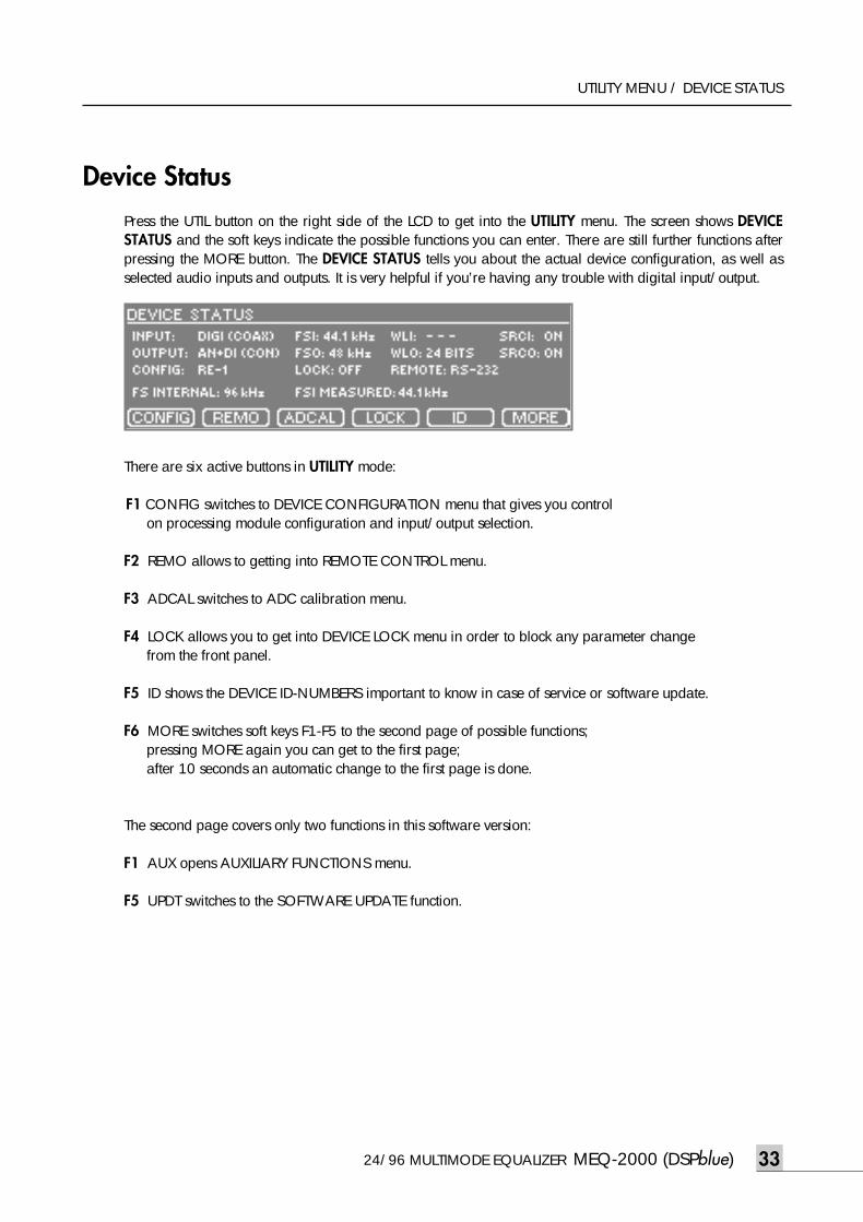
Device StatusPress the UTIL button on the right side of the LCD to get into the UTILITY menu. The screen shows DEVICESTATUS and the soft keys indicate the possible functions you can enter. There are still further functions afterpressing the MORE button. The DEVICE STATUS tells you about the actual device configuration, as well asselected audio inputs and outputs. It is very helpful if you’re having any trouble with digital input/output.
There are six active buttons in UTILITY mode:
F1 CONFIG switches to DEVICE CONFIGURATION menu that gives you control on processing module configuration and input/output selection.
F2 REMO allows to getting into REMOTE CONTROL menu.
F3 ADCAL switches to ADC calibration menu.
F4 LOCK allows you to get into DEVICE LOCK menu in order to block any parameter change from the front panel.
F5 ID shows the DEVICE ID-NUMBERS important to know in case of service or software update.
F6 MORE switches soft keys F1-F5 to the second page of possible functions; pressing MORE again you can get to the first page; after 10 seconds an automatic change to the first page is done.
The second page covers only two functions in this software version:
F1 AUX opens AUXILIARY FUNCTIONS menu.
F5 UPDT switches to the SOFTWARE UPDATE function.
meq-2000(O/P)_E 2003.9.6 11:43 AM 페이지33
MEQ-2000 (DSPblue) 24/96 MULTIMODE EQUALIZER34
UTILITY MENU / DEVICE STATUS
The DEVICE STATUS screen delivers important information:
- INPUT shows the input chosen in the CONFIG menu; if a digital input has been selected and it is receivingvalid digital audio signal the format of the incoming signal in parenthesis is shown:professional (PRO), or consumer (CON).
- FSI, WLI if a digital input has been selected and it is receiving a valid digital audio signal the samplingfrequency (FSI) and wordlength (WSI) are shown as indicated in the status bits of the incoming digital sig-nal (they are not measured, only extracted)
- SRCI tells if the input sampling rate converter is active
- OUTPUT shows the output chosen in CONFIG menu;if the digital output has been selected the chosen format is shown in parenthesis: professional (PRO) or consumer (CON)
- FSO, WLO if the digital output has been selected FSO shows the sampling frequency and WLO thewordlength as set up in CONFIG (DIO)
- SRCO tells if the output sampling rate converter is active
- CONFIG indicates the module configuration as chosen in CONFIG menu
- LOCK informs if the buttons and parameter wheel on the front panel are set locked or unlocked in theDEVICE LOCK menu
- REMOTE indicates the type of remote interface: RS-232, MIDI or OFF, as selected in REMOTE menu
- INTERNAL FS tells that the internal sampling frequency is always 96 kHz
- FSI MEASURED shows the actual sampling frequency of the signal at chosen digital input as measured by MEQ-2000; a result below 20 kHz indicates usually that there is no valid signal at the digitalinput; the FSI in the first line is indicated as declared in the status bits of the incoming signal and thereforemay not agree with the actual measured frequency; it can be wrong or not indicated at all.
meq-2000(O/P)_E 2003.9.6 11:43 AM 페이지34
24/96 MULTIMODE EQUALIZER MEQ-2000 (DSPblue) 35
UTILITY MENU / CONFIG
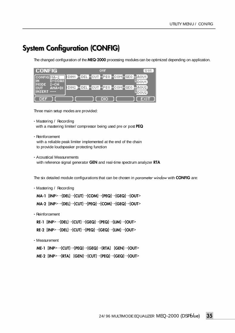
System Configuration (CONFIG)System Configuration (CONFIG)The changed configuration of the MEQ-2000 processing modules can be optimized depending on application.
Three main setup modes are provided:
- Mastering / Recordingwith a mastering limiter/compressor being used pre or post PEQ
- Reinforcementwith a reliable peak limiter implemented at the end of the chain to provide loudspeaker protecting function
- Acoustical Measurementswith reference signal generator GEN and real-time spectrum analyzer RTA
The six detailed module configurations that can be chosen in parameter window with CONFIG are:
- Mastering / Recording
MA-1 [INP>→[DEL]→[CUT]→[COM]→[PEQ]→[GEQ]→[OUT>
MA-2 [INP>→[DEL]→[CUT]→[PEQ]→[COM]→[GEQ]→[OUT>
- Reinforcement
RE-1 [INP>→[DEL]→[CUT]→[GEQ]→[PEQ]→[LIM]→[OUT>
RE-2 [INP>→[DEL]→[CUT]→[PEQ]→[GEQ]→[LIM]→[OUT>
- Measurement
ME-1 [INP>→[CUT]→[PEQ]→[GEQ]→[RTA] [GEN]→[OUT>
ME-2 [INP>→[RTA] [GEN]→[CUT]→[PEQ]→[GEQ]→[OUT>
meq-2000(O/P)_E 2003.9.6 11:43 AM 페이지35
MEQ-2000 (DSPblue) 24/96 MULTIMODE EQUALIZER36
UTILITY MENU / CONFIG
There are four active buttons in CONFIG mode:
F1 DEF changes settings in the parameter window to a factory default setting (See below).
F4 DIO opens a submenu for setup of the digital output.
F5 ENTER confirms the last changes.
F6 EXIT switches back to the UTILITY menu.
CONFIG parameters can be changed in the parameter window. Using the ▲▼ cursor keys you can highlightthe particular parameter and change its value with the parameter wheel. The ◀▶cursor keys have no function.
After changing any parameter in the CONFIG parameter window, ENTER appears over the F5 button. Toconfirm the last changes press ENTER.
Be aware about the fact that any configuration change corresponds to a new wiring of the processing mod-ules. Therefore after ENTER a total MUTE for all outputs is always enforced. The reconfiguration takes a fewseconds and in the middle of the screen a message [PROCESSING …] temporarily appears.
Default values (after pressing the DEF button):RE-1, ANA, D-CH, ANA + DIG, OFF.
meq-2000(O/P)_E 2003.9.6 11:43 AM 페이지36
24/96 MULTIMODE EQUALIZER MEQ-2000 (DSPblue) 37
UTILITY MENU / CONFIG
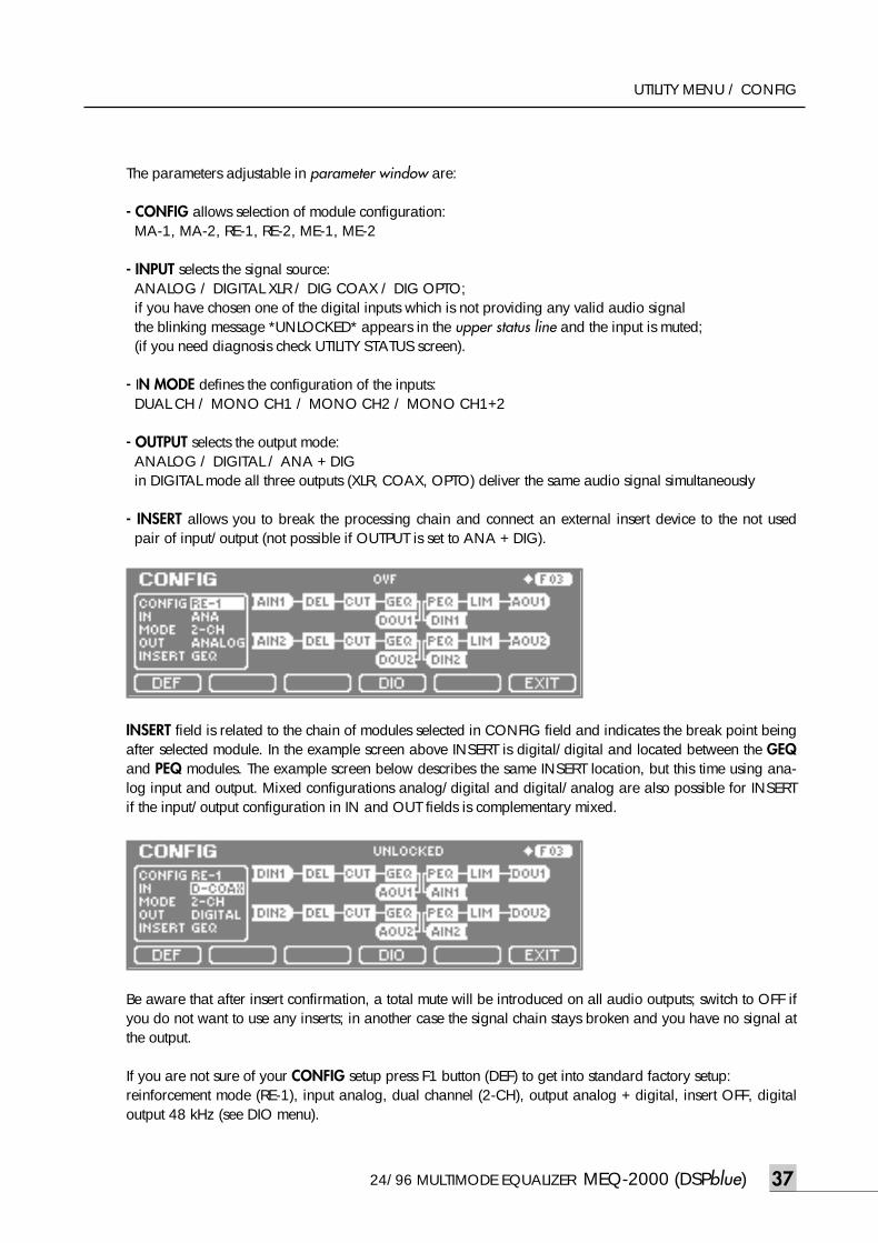
The parameters adjustable in parameter window are:
- CONFIG allows selection of module configuration:MA-1, MA-2, RE-1, RE-2, ME-1, ME-2
- INPUT selects the signal source:ANALOG / DIGITAL XLR / DIG COAX / DIG OPTO;if you have chosen one of the digital inputs which is not providing any valid audio signal the blinking message *UNLOCKED* appears in the upper status line and the input is muted;(if you need diagnosis check UTILITY STATUS screen).
- IN MODE defines the configuration of the inputs:DUAL CH / MONO CH1 / MONO CH2 / MONO CH1+2
- OUTPUT selects the output mode:ANALOG / DIGITAL / ANA + DIGin DIGITAL mode all three outputs (XLR, COAX, OPTO) deliver the same audio signal simultaneously
- INSERT allows you to break the processing chain and connect an external insert device to the not usedpair of input/output (not possible if OUTPUT is set to ANA + DIG).
INSERT field is related to the chain of modules selected in CONFIG field and indicates the break point beingafter selected module. In the example screen above INSERT is digital/digital and located between the GEQand PEQ modules. The example screen below describes the same INSERT location, but this time using ana-log input and output. Mixed configurations analog/digital and digital/analog are also possible for INSERTif the input/output configuration in IN and OUT fields is complementary mixed.
Be aware that after insert confirmation, a total mute will be introduced on all audio outputs; switch to OFF ifyou do not want to use any inserts; in another case the signal chain stays broken and you have no signal atthe output.
If you are not sure of your CONFIG setup press F1 button (DEF) to get into standard factory setup:reinforcement mode (RE-1), input analog, dual channel (2-CH), output analog + digital, insert OFF, digitaloutput 48 kHz (see DIO menu).
meq-2000(O/P)_E 2003.9.6 11:43 AM 페이지37
MEQ-2000 (DSPblue) 24/96 MULTIMODE EQUALIZER38
UTILITY MENU / CONFIG
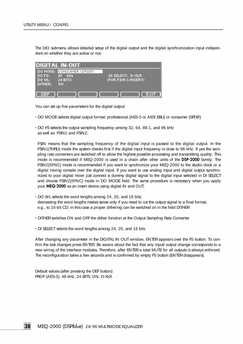
The DIO submenu allows detailed setup of the digital output and the digital synchronization input indepen-dent on whether they are active or not.
You can set up five parameters for the digital output:
- DO MODE selects digital output format: professional (AES-3 or AES/EBU) or consumer (SPDIF)
- DO FS selects the output sampling frequency among 32, 64, 88.1, and 96 kHz as well as FSIN1 and FSIN2;
FSIN means that the sampling frequency of the digital input is passed to the digital output. In theFSIN1(THRU) mode the system checks first if the digital input frequency is close to 96 kHz. If yes the sam-pling rate converters are switched off to allow the highest possible processing and transmitting quality. Thismode is recommended if MEQ-2000 is used in a chain after other units of the DSP-2000 family. TheFSIN2(SYNC) mode is recommended if you want to synchronize your MEQ-2000 to the studio clock or adigital mixing console over the digital input. If you want to use analog input and digital output synchro-nized to your digital mixer just connect a dummy digital signal to the digital input selected in DI SELECTand choose FSIN2(SYNC) mode in DO MODE field. The same procedure is necessary when you applyyour MEQ-2000 as an insert device using digital IN and OUT.
- DO WL selects the word lengths among 24, 20, and 16 bits;decreasing the word lengths makes sense only if you need to cut the output signal to a final format, e.g., to 16-bit CD; in this case a proper dithering can be switched on in the field DITHER
- DITHER switches ON and OFF the dither function at the Output Sampling Rate Converter
- DI SELECT selects the word lengths among 24, 20, and 16 bits
After changing any parameter in the DIGITAL IN OUT window, ENTER appears over the F5 button. To con-firm the last changes press ENTER. Be aware about the fact that any input/output change corresponds to anew wiring of the interface modules. Therefore, after ENTER a total MUTE for all outputs is always enforced.The reconfiguration takes a few seconds and is confirmed by empty F5 button (ENTER disappears).
Default values (after pressing the DEF button):PROF (AES-3), 48 kHz, 24 BITS, ON, D-XLR.
meq-2000(O/P)_E 2003.9.6 11:43 AM 페이지38
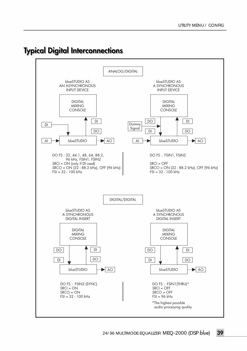
24/96 MULTIMODE EQUALIZER MEQ-2000 (DSP blue) 39
UTILITY MENU / CONFIG
Typical Digital InterconnectionsTypical Digital Interconnections
DI
AI AO AI AO
ANALOG/DIGITAL
blueSTUDIO ASAN ASYNCHRONOUS
INPUT DEVICE
DIGITALMIXING
CONSOLE
blueSTUDIO
blueSTUDIO ASA SYNCHRONOUS
INPUT DEVICE
DIGITALMIXING
CONSOLE
DI
DO
DI
DO
DO
DI
blueSTUDIO
DO FS : 32, 44.1, 48, 64, 88.2, 96 kHz, FSIN1, FSIN2SRCI = ON (only if DI used)SRCO = ON (32 - 88.2 kHz), OFF (96 kHz)FSI = 32 - 100 kHz
DO FS : FSIN1, FSIN2
SRCI = OFFSRCO = ON (32 - 88.2 kHz), OFF (96 kHz)FSI = 32 - 100 kHz
DIGITAL/DIGITAL
AO AO
blueSTUDIO ASA SYNCHRONOUS
DIGITAL INSERT
DIGITALMIXING
CONSOLE
DI
DO
blueSTUDIO
blueSTUDIO ASA SYNCHRONOUS
DIGITAL INSERT
DIGITALMIXING
CONSOLE
DI
DO
DO
DI
DO
DI
blueSTUDIO
DO FS : FSIN2 (SYNC)SRCI = ONSRCO = ON FSI = 32 - 100 kHz
DO FS : FSIN1(THRU)*SRCI = OFFSRCO = OFFFSI = 96 kHz
*The highest possible audio processing quality
DummySignal
meq-2000(O/P)_E 2003.9.6 11:43 AM 페이지39
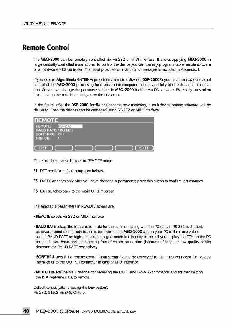
MEQ-2000 (DSPblue) 24/96 MULTIMODE EQUALIZER40
UTILITY MENU / REMOTE
Remote ControlRemote ControlThe MEQ-2000 can be remotely controlled via RS-232 or MIDI interface. It allows applying MEQ-2000 inlarge centrally controlled installations. To control the device you can use any programmable remote softwareor a hardware MIDI controller. The list of possible commands and messages is included in Appendix l.
If you use an Algorithmix/INTER-M proprietary remote software (DSP-2000R) you have an excellent visualcontrol of the MEQ-2000 processing functions on the computer monitor and fully bi-directional communica-tion. So you can change the parameters either in MEQ-2000 itself or via PC software. Especially convenientis to blow up the real-time analyzer on the PC screen.
In the future, after the DSP-2000 family has become new members, a multidevice remote software will bedelivered. Then the devices can be cascaded using RS-232 or MIDI interface.
There are three active buttons in REMOTE mode:
F1 DEF recalls a default setup (see below).
F5 ENTER appears only after you have changed a parameter; press this button to confirm last changes.
F6 EXIT switches back to the main UTILITY screen.
The selectable parameters in REMOTE screen are:
- REMOTE selects RS-232 or MIDI interface
- BAUD RATE selects the transmission rate for the communicating with the PC (only if RS-232 is chosen);be aware about setting both transmission rates in the MEQ-2000 and in your PC to the same value;set the BAUD RATE as high as possible to guarantee less latency in case if you display the RTA on the PCscreen; if you have problems getting free-of-errors connection (because of long, or low-quality cable)decrease the BAUD RATE respectively
- SOFFTHRU says if the remote control input stream has to be conveyed to the THRU connector for RS-232interface or to the OUTPUT connector in case of MIDI interface
- MIDI CH selects the MIDI channel for receiving the MUTE and BYPASS commands and for transmitting the RTA real-time data to remote.
Default values (after pressing the DEF button):RS-232, 115.2 kBits/S, OFF, 0.
meq-2000(O/P)_E 2003.9.6 11:43 AM 페이지40
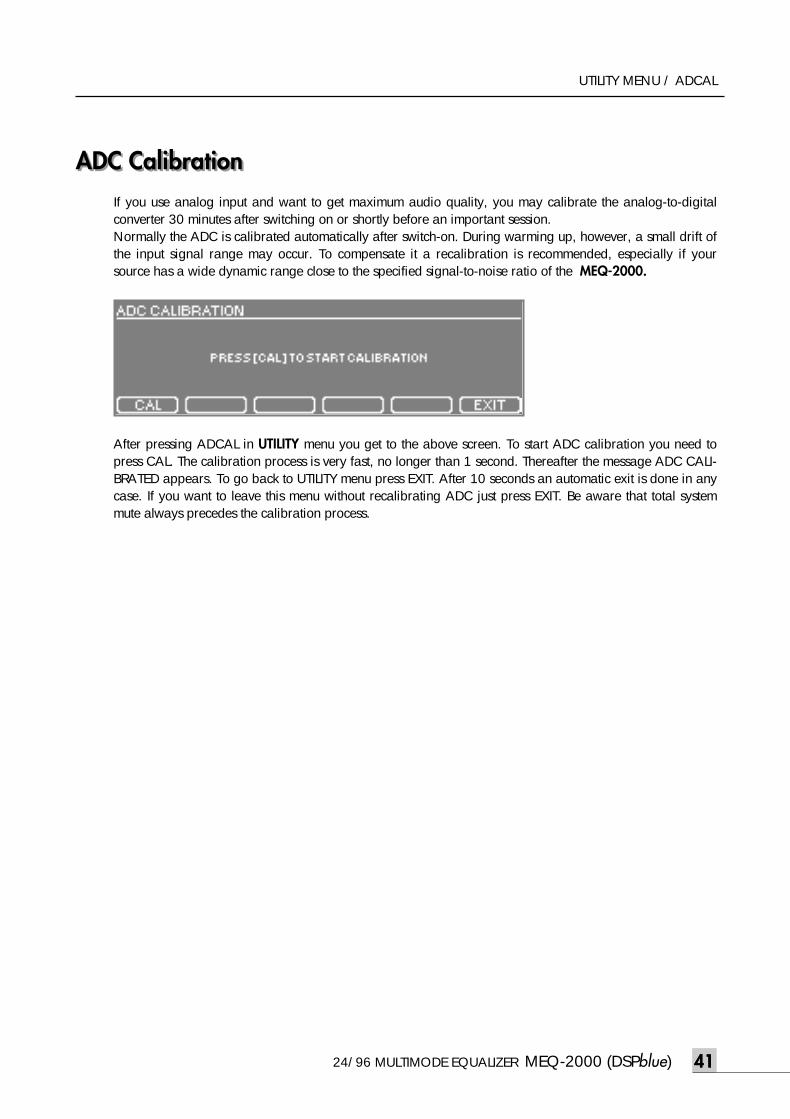
ADC Calibration
24/96 MULTIMODE EQUALIZER MEQ-2000 (DSPblue) 41
UTILITY MENU / ADCAL
ADC Calibration If you use analog input and want to get maximum audio quality, you may calibrate the analog-to-digitalconverter 30 minutes after switching on or shortly before an important session.Normally the ADC is calibrated automatically after switch-on. During warming up, however, a small drift ofthe input signal range may occur. To compensate it a recalibration is recommended, especially if yoursource has a wide dynamic range close to the specified signal-to-noise ratio of the MEQ-2000.
After pressing ADCAL in UTILITY menu you get to the above screen. To start ADC calibration you need topress CAL. The calibration process is very fast, no longer than 1 second. Thereafter the message ADC CALI-BRATED appears. To go back to UTILITY menu press EXIT. After 10 seconds an automatic exit is done in anycase. If you want to leave this menu without recalibrating ADC just press EXIT. Be aware that total systemmute always precedes the calibration process.
41
meq-2000(O/P)_E 2003.9.6 11:43 AM 페이지41
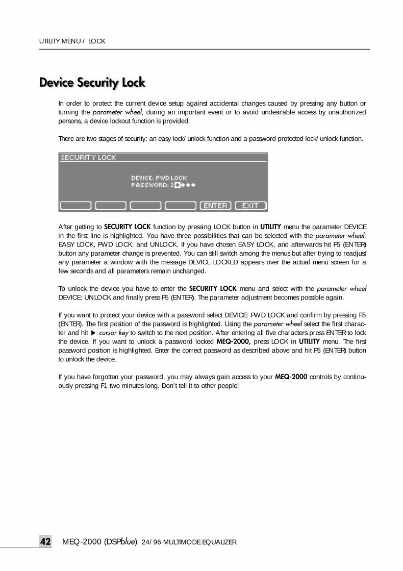
MEQ-2000 (DSPblue) 24/96 MULTIMODE EQUALIZER42
UTILITY MENU / LOCK
Device Security LockDevice Security LockIn order to protect the current device setup against accidental changes caused by pressing any button orturning the parameter wheel, during an important event or to avoid undesirable access by unauthorizedpersons, a device lockout function is provided.
There are two stages of security: an easy lock/unlock function and a password protected lock/unlock function.
After getting to SECURITY LOCK function by pressing LOCK button in UTILITY menu the parameter DEVICEin the first line is highlighted. You have three possibilities that can be selected with the parameter wheel:EASY LOCK, PWD LOCK, and UNLOCK. If you have chosen EASY LOCK, and afterwards hit F5 (ENTER)button any parameter change is prevented. You can still switch among the menus but after trying to readjustany parameter a window with the message DEVICE LOCKED appears over the actual menu screen for afew seconds and all parameters remain unchanged.
To unlock the device you have to enter the SECURITY LOCK menu and select with the parameter wheelDEVICE: UNLOCK and finally press F5 (ENTER). The parameter adjustment becomes possible again.
If you want to protect your device with a password select DEVICE: PWD LOCK and confirm by pressing F5(ENTER). The first position of the password is highlighted. Using the parameter wheel select the first charac-ter and hit ▶ cursor key to switch to the next position. After entering all five characters press ENTER to lockthe device. If you want to unlock a password locked MEQ-2000, press LOCK in UTILITY menu. The firstpassword position is highlighted. Enter the correct password as described above and hit F5 (ENTER) buttonto unlock the device.
If you have forgotten your password, you may always gain access to your MEQ-2000 controls by continu-ously pressing F1 two minutes long. Don’t tell it to other people!
42
meq-2000(O/P)_E 2003.9.6 11:43 AM 페이지42
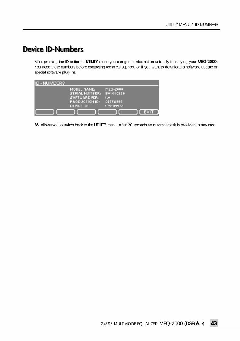
Device ID-Numbers
24/96 MULTIMODE EQUALIZER MEQ-2000 (DSPblue) 43
UTILITY MENU / ID NUMBERS
Device ID-Numbers After pressing the ID button in UTILITY menu you can get to information uniquely identifying your MEQ-2000.You need these numbers before contacting technical support, or if you want to download a software update orspecial software plug-ins.
F6 allows you to switch back to the UTILITY menu. After 20 seconds an automatic exit is provided in any case.
43
meq-2000(O/P)_E 2003.9.6 11:43 AM 페이지43
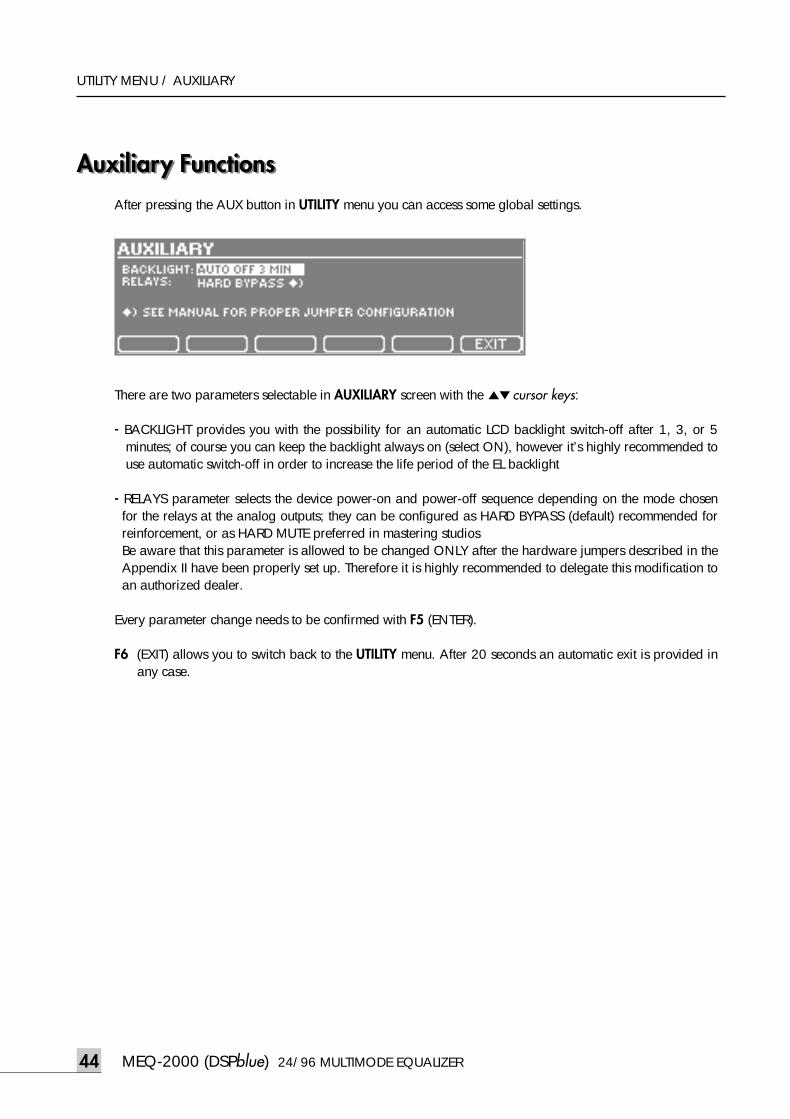
MEQ-2000 (DSPblue) 24/96 MULTIMODE EQUALIZER44
UTILITY MENU / AUXILIARY
Auxiliary FunctionsAuxiliary FunctionsAfter pressing the AUX button in UTILITY menu you can access some global settings.
There are two parameters selectable in AUXILIARY screen with the ▲▼cursor keys:
- BACKLIGHT provides you with the possibility for an automatic LCD backlight switch-off after 1, 3, or 5minutes; of course you can keep the backlight always on (select ON), however it’s highly recommended touse automatic switch-off in order to increase the life period of the EL backlight
- RELAYS parameter selects the device power-on and power-off sequence depending on the mode chosenfor the relays at the analog outputs; they can be configured as HARD BYPASS (default) recommended forreinforcement, or as HARD MUTE preferred in mastering studios Be aware that this parameter is allowed to be changed ONLY after the hardware jumpers described in theAppendix II have been properly set up. Therefore it is highly recommended to delegate this modification toan authorized dealer.
Every parameter change needs to be confirmed with F5 (ENTER).
F6 (EXIT) allows you to switch back to the UTILITY menu. After 20 seconds an automatic exit is provided inany case.
meq-2000(O/P)_E 2003.9.6 11:43 AM 페이지44
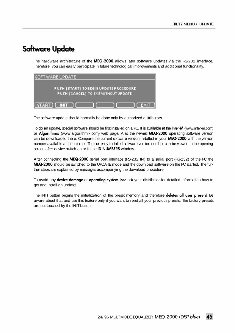
24/96 MULTIMODE EQUALIZER MEQ-2000 (DSP blue) 45
UTILITY MENU / UPDATE
Software Update Software Update The hardware architecture of the MEQ-2000 allows later software updates via the RS-232 interface.Therefore, you can easily participate in future technological improvements and additional functionality.
The software update should normally be done only by authorized distributors.
To do an update, special software should be first installed on a PC. It is available at the Inter-M (www.inter-m.com)or Algorithmix (www.algorithmix.com) web page. Also the newest MEQ-2000 operating software versioncan be downloaded there. Compare the current software version installed in your MEQ-2000 with the versionnumber available at the Internet. The currently installed software version number can be viewed in the openingscreen after device switch-on or in the ID-NUMBERS window.
After connecting the MEQ-2000 serial port interface (RS-232 IN) to a serial port (RS-232) of the PC theMEQ-2000 should be switched to the UPDATE mode and the download software on the PC started. The fur-ther steps are explained by messages accompanying the download procedure.
To avoid any device damage or operating system lose ask your distributor for detailed information how toget and install an update!
The INIT button begins the initialization of the preset memory and therefore deletes all user presets! Beaware about that and use this feature only if you want to reset all your previous presets. The factory presetsare not touched by the INIT button.
meq-2000(O/P)_E 2003.9.6 11:43 AM 페이지45
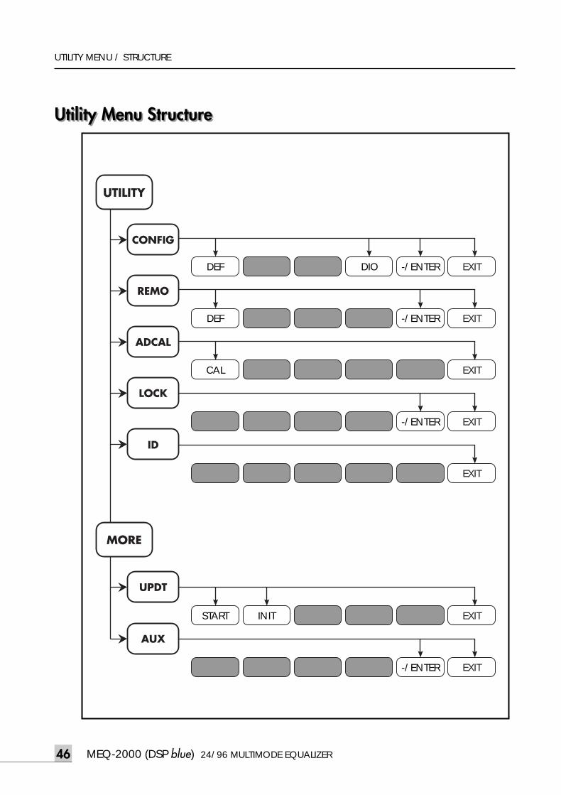
UTILITY MENU / STRUCTURE
Utility Menu StructureUtility Menu Structure
UTILITY
MORE
CONFIG
REMO
ADCAL
LOCK
ID
UPDT
START INIT EXIT
AUX
EXIT
EXIT
LOCK -/ENTER
-/ENTER
EXIT
CAL EXIT
-/ENTER EXIT
DEF
DEF
--/CH DIO -/ENTER EXIT
MEQ-2000 (DSP blue) 24/96 MULTIMODE EQUALIZER46
meq-2000(O/P)_E 2003.9.6 11:43 AM 페이지46
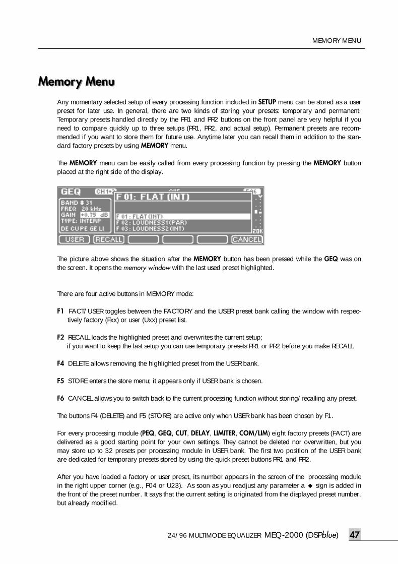
24/96 MULTIMODE EQUALIZER MEQ-2000 (DSPblue) 47
MEMORY MENU
Memory MenuMemory MenuAny momentary selected setup of every processing function included in SETUP menu can be stored as a userpreset for later use. In general, there are two kinds of storing your presets: temporary and permanent.Temporary presets handled directly by the PR1 and PR2 buttons on the front panel are very helpful if youneed to compare quickly up to three setups (PR1, PR2, and actual setup). Permanent presets are recom-mended if you want to store them for future use. Anytime later you can recall them in addition to the stan-dard factory presets by using MEMORY menu.
The MEMORY menu can be easily called from every processing function by pressing the MEMORY buttonplaced at the right side of the display.
The picture above shows the situation after the MEMORY button has been pressed while the GEQ was onthe screen. It opens the memory window with the last used preset highlighted.
There are four active buttons in MEMORY mode:
F1 FACT/USER toggles between the FACTORY and the USER preset bank calling the window with respec-tively factory (Fxx) or user (Uxx) preset list.
F2 RECALL loads the highlighted preset and overwrites the current setup; if you want to keep the last setup you can use temporary presets PR1 or PR2 before you make RECALL.
F4 DELETE allows removing the highlighted preset from the USER bank.
F5 STORE enters the store menu; it appears only if USER bank is chosen.
F6 CANCEL allows you to switch back to the current processing function without storing/recalling any preset.
The buttons F4 (DELETE) and F5 (STORE) are active only when USER bank has been chosen by F1.
For every processing module (PEQ, GEQ, CUT, DELAY, LIMITER, COM/LIM) eight factory presets (FACT) aredelivered as a good starting point for your own settings. They cannot be deleted nor overwritten, but youmay store up to 32 presets per processing module in USER bank. The first two position of the USER bankare dedicated for temporary presets stored by using the quick preset buttons PR1 and PR2.
After you have loaded a factory or user preset, its number appears in the screen of the processing modulein the right upper corner (e.g., F04 or U23). As soon as you readjust any parameter a ◆ sign is added inthe front of the preset number. It says that the current setting is originated from the displayed preset number,but already modified.
meq-2000(O/P)_E 2003.9.6 11:43 AM 페이지47
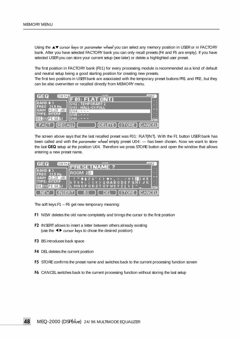
MEQ-2000 (DSPblue) 24/96 MULTIMODE EQUALIZER48
MEMORY MENU
Using the ▲▼cursor keys or parameter wheel you can select any memory position in USER or in FACTORYbank. After you have selected FACTORY bank you can only recall presets (F4 and F5 are empty). If you haveselected USER you can store your current setup (see later) or delete a highlighted user preset.
The first position in FACTORY bank (F01) for every processing module is recommended as a kind of defaultand neutral setup being a good starting position for creating new presets.The first two positions in USER bank are associated with the temporary preset buttons PR1 and PR2, but theycan be also overwritten or recalled directly from MEMORY menu.
The screen above says that the last recalled preset was F01: FLAT(INT). With the F1 button USER bank hasbeen called and with the parameter wheel empty preset U04: --- has been chosen. Now we want to storethe last GEQ setup at the position U04. Therefore we press STORE button and open the window that allowsentering a new preset name.
The soft keys F1 – F6 get new temporary meaning:
F1 NEW deletes the old name completely and brings the cursor to the first position
F2 INSERT allows to insert a letter between others already existing (use the ◀▶cursor keys to chose the desired position)
F3 BS introduces back space
F4 DEL deletes the current position
F5 STORE confirms the preset name and switches back to the current processing function screen
F6 CANCEL switches back to the current processing function without storing the last setup
meq-2000(O/P)_E 2003.9.6 11:43 AM 페이지48
24/96 MULTIMODE EQUALIZER MEQ-2000 (DSPblue) 49
MEMORY MENU
By using the function keys described above and the parameter wheel to select the alphanumeric characters,you can easily enter new names or correct existing names. A preset name can consist of up to 16 characters.Using the ◀▶cursor keys you can jump to the next position in the preset name and enter the next character,or to any previous position and delete, insert or change an existing character. To speed up scrolling throughthe characters a fast jump to numbers or letters is possible with the ▲▼ cursor keys.
If you want to overwrite an already existing user preset you will be asked if you really want to do this. Youneed to confirm with YES or go back to the preset window in order to select a free preset location. The fac-tory presets cannot be overwritten.
You can copy presets by recalling and storing them in another location with old, modified, or new name.
Any user preset can be deleted by pressing DEL (F4) button in MEMORY menu.
For your convenience there are two direct temporary preset buttons on the right side of the parameter wheelcalled PR1 and PR2. They are very helpful if you quickly want to compare up to three different setups of thesame functions without mute and any annoying sound distortions. After you have found out first interestingsetup press MEMORY and afterwards PR1 (or PR2) button. Now you can modify your current setup andstore the new adjustment pressing MEMORY and afterwards the PR2 (PR1) button. If the PR1 or PR2 con-tains the setup being on the screen the LED inside of the respective button is lightning. Now you can againchange the setup (the temporary preset LED switches OFF). Switching ON and OFF the buttons PR1 and PR2(the PR1 and PR2 toggle) you can easily compare between three setups, without using the MEMORY button:two stored in temporary presets and the last one on in the current LCD screen. If you correctly follow theFLAT / UNDO rules you can even switch among three setups and FLAT for GEQ, PEQ and CUT functions.
In the UTILITY group you can make presets regarding to the MEQ-2000 configuration and general setup. Inthe CONFIG menu you can recall eight typical module and in/out configurations stored in the FACTORYbank. Of course, you can also store your own CONFIG settings (up to eight).
MEQ-2000 also provides so called Global Presets which include the complete setup of the whole unit. Theycan be recalled after pressing UTILITY and MEMORY buttons. At the moment there are two factory presetsstored: GENERAL DEFAULT and MEASUREMENT1. The first one corresponds to the default application set-up that is downloaded in the factory before shipment. The second preset is recommended to recall beforestarting audio performance measurements. It takes care of transparent setting of all parameters (processingOFF, nominal levels, and soft clip OFF). In the USER bank there are four positions for individual GlobalPresets. They are especially advantageous if the MEQ-2000 is used by a few persons; everyone can createhis own global setup corresponding to his basic setting. Note that in Global Presets the entire device config-uration is stored, inclusive modules which have no individual presets, e.g., LEVELS.
After you have loaded a factory or user global preset, its number appears in the screen of every processingmodule in the right upper corner (e.g., GF1 or GU3). As soon as you readjust any parameter a ◆ sign isadded in the front of the preset number. It says that the current setting is originated from the displayed pre-set number, but already modified.
meq-2000(O/P)_E 2003.9.6 11:43 AM 페이지49
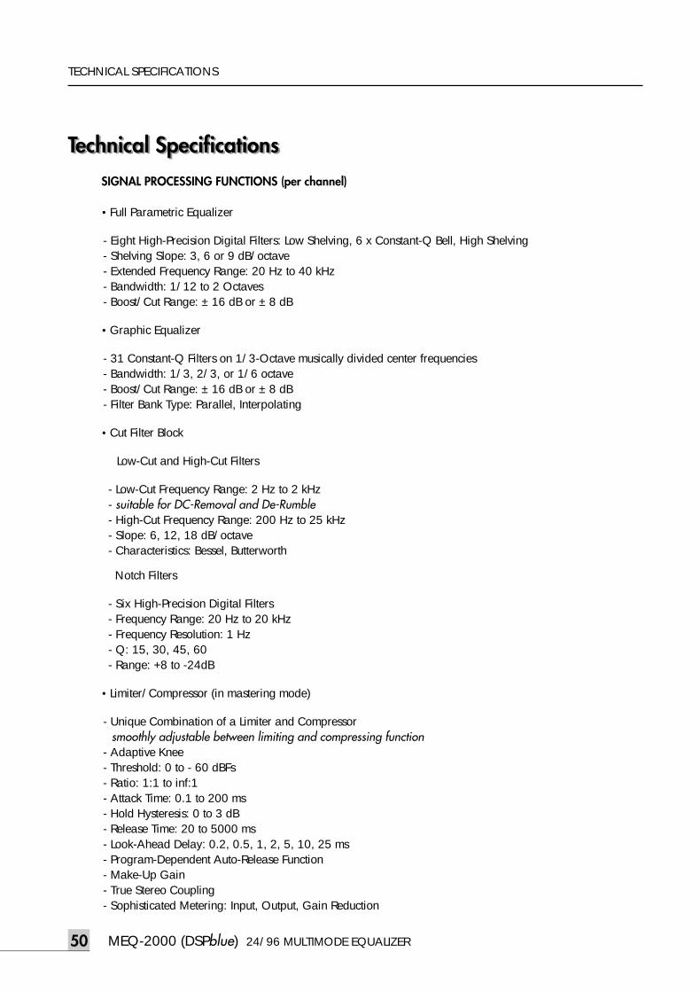
MEQ-2000 (DSPblue) 24/96 MULTIMODE EQUALIZER50
TECHNICAL SPECIFICATIONS
Technical SpecificationsTechnical SpecificationsSIGNAL PROCESSING FUNCTIONS (per channel)
•Full Parametric Equalizer
- Eight High-Precision Digital Filters: Low Shelving, 6 x Constant-Q Bell, High Shelving- Shelving Slope: 3, 6 or 9 dB/octave - Extended Frequency Range: 20 Hz to 40 kHz- Bandwidth: 1/12 to 2 Octaves- Boost/Cut Range: ± 16 dB or ± 8 dB
•Graphic Equalizer
- 31 Constant-Q Filters on 1/3-Octave musically divided center frequencies- Bandwidth: 1/3, 2/3, or 1/6 octave- Boost/Cut Range: ± 16 dB or ± 8 dB- Filter Bank Type: Parallel, Interpolating
•Cut Filter Block
Low-Cut and High-Cut Filters
- Low-Cut Frequency Range: 2 Hz to 2 kHz - suitable for DC-Removal and De-Rumble - High-Cut Frequency Range: 200 Hz to 25 kHz- Slope: 6, 12, 18 dB/octave- Characteristics: Bessel, Butterworth
Notch Filters
- Six High-Precision Digital Filters- Frequency Range: 20 Hz to 20 kHz- Frequency Resolution: 1 Hz- Q: 15, 30, 45, 60- Range: +8 to -24dB
•Limiter/Compressor (in mastering mode)
- Unique Combination of a Limiter and Compressorsmoothly adjustable between limiting and compressing function
- Adaptive Knee- Threshold: 0 to - 60 dBFs- Ratio: 1:1 to inf:1- Attack Time: 0.1 to 200 ms- Hold Hysteresis: 0 to 3 dB- Release Time: 20 to 5000 ms- Look-Ahead Delay: 0.2, 0.5, 1, 2, 5, 10, 25 ms- Program-Dependent Auto-Release Function- Make-Up Gain- True Stereo Coupling- Sophisticated Metering: Input, Output, Gain Reduction
meq-2000(O/P)_E 2003.9.6 11:43 AM 페이지50
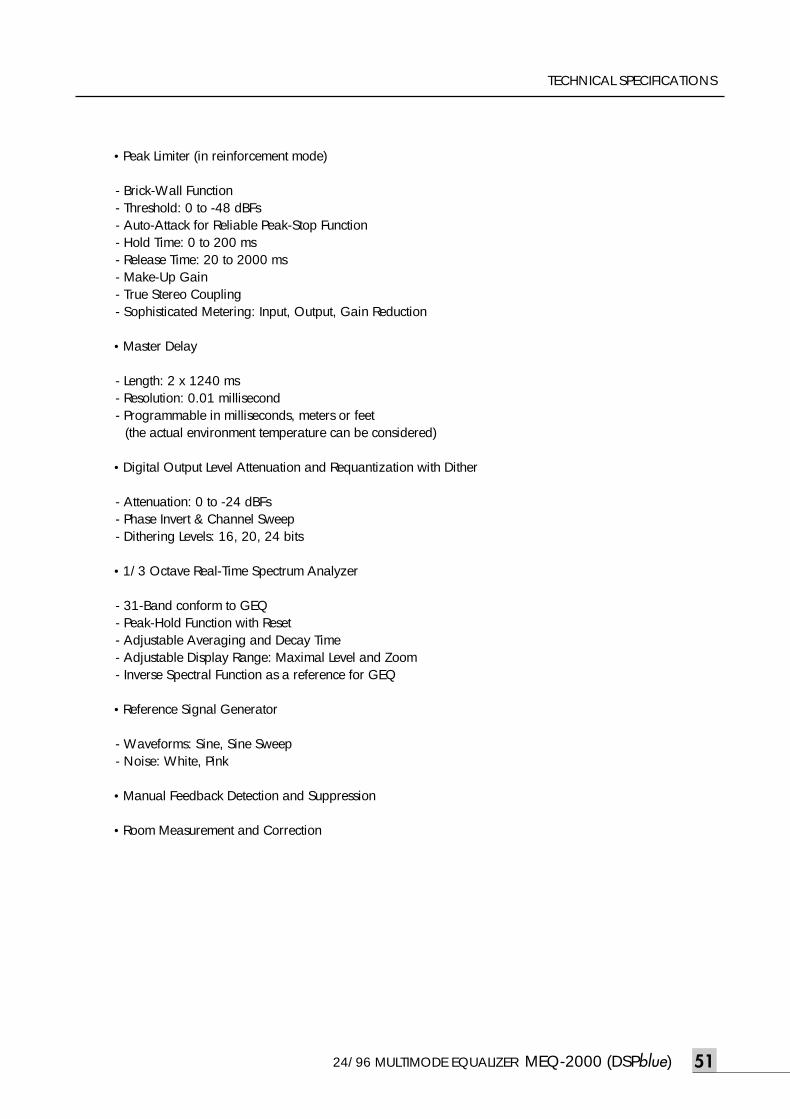
24/96 MULTIMODE EQUALIZER MEQ-2000 (DSPblue) 51
TECHNICAL SPECIFICATIONS
•Peak Limiter (in reinforcement mode)
- Brick-Wall Function- Threshold: 0 to -48 dBFs- Auto-Attack for Reliable Peak-Stop Function - Hold Time: 0 to 200 ms- Release Time: 20 to 2000 ms- Make-Up Gain- True Stereo Coupling- Sophisticated Metering: Input, Output, Gain Reduction
•Master Delay
- Length: 2 x 1240 ms- Resolution: 0.01 millisecond- Programmable in milliseconds, meters or feet
(the actual environment temperature can be considered)
•Digital Output Level Attenuation and Requantization with Dither
- Attenuation: 0 to -24 dBFs- Phase Invert & Channel Sweep- Dithering Levels: 16, 20, 24 bits
•1/3 Octave Real-Time Spectrum Analyzer
- 31-Band conform to GEQ- Peak-Hold Function with Reset- Adjustable Averaging and Decay Time- Adjustable Display Range: Maximal Level and Zoom- Inverse Spectral Function as a reference for GEQ
•Reference Signal Generator
- Waveforms: Sine, Sine Sweep- Noise: White, Pink
•Manual Feedback Detection and Suppression
•Room Measurement and Correction
meq-2000(O/P)_E 2003.9.6 11:43 AM 페이지51
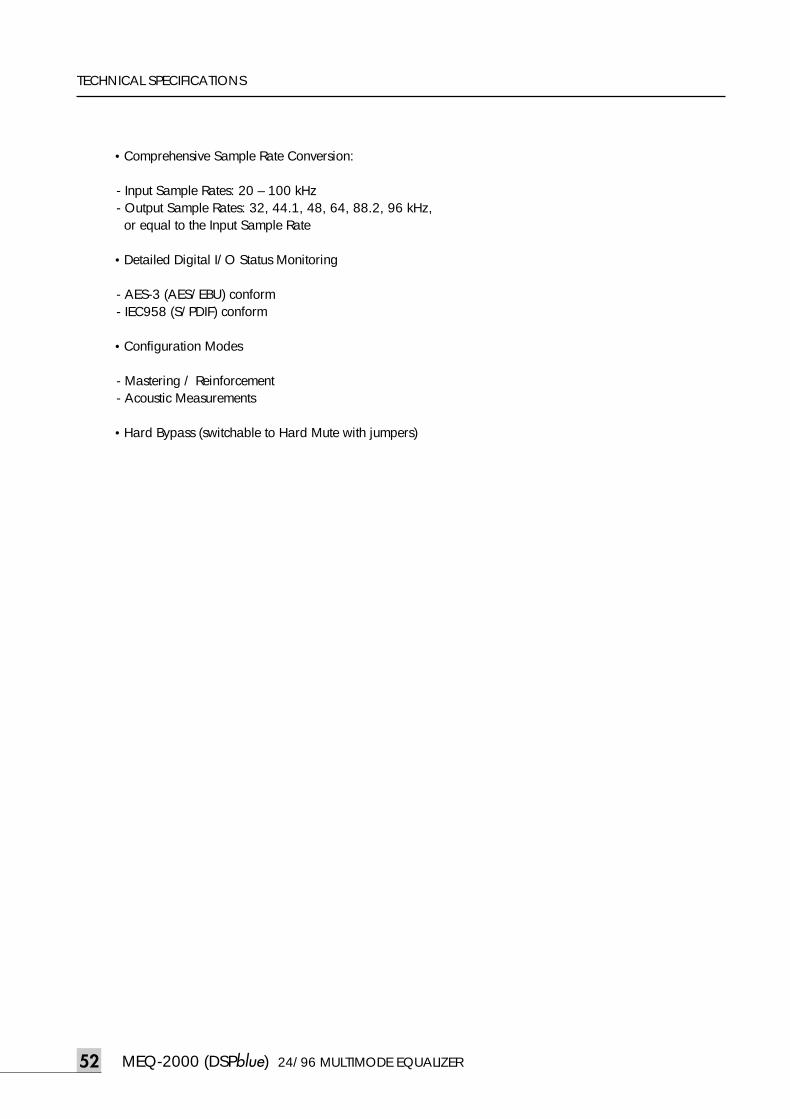
MEQ-2000 (DSPblue) 24/96 MULTIMODE EQUALIZER52
TECHNICAL SPECIFICATIONS
•Comprehensive Sample Rate Conversion:
- Input Sample Rates: 20 – 100 kHz- Output Sample Rates: 32, 44.1, 48, 64, 88.2, 96 kHz,or equal to the Input Sample Rate
•Detailed Digital I/O Status Monitoring
- AES-3 (AES/EBU) conform- IEC958 (S/PDIF) conform
•Configuration Modes
- Mastering / Reinforcement- Acoustic Measurements
•Hard Bypass (switchable to Hard Mute with jumpers)
meq-2000(O/P)_E 2003.9.6 11:43 AM 페이지52
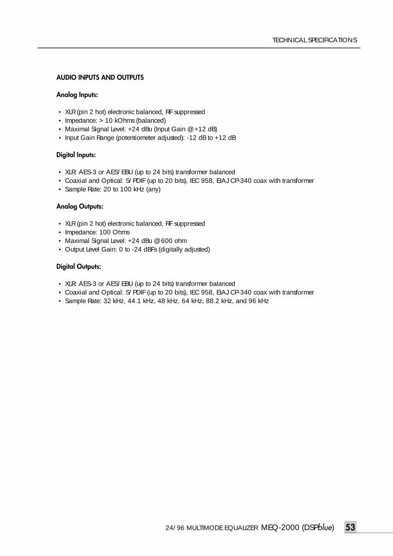
24/96 MULTIMODE EQUALIZER MEQ-2000 (DSPblue) 53
TECHNICAL SPECIFICATIONS
AUDIO INPUTS AND OUTPUTS
Analog Inputs:
• XLR (pin 2 hot) electronic balanced, RF suppressed• Impedance: > 10 kOhms (balanced)• Maximal Signal Level: +24 dBu (Input Gain @ +12 dB)• Input Gain Range (potentiometer adjusted): -12 dB to +12 dB
Digital Inputs:
• XLR: AES-3 or AES/EBU (up to 24 bits) transformer balanced• Coaxial and Optical: S/PDIF (up to 20 bits), IEC 958, EIAJ CP-340 coax with transformer • Sample Rate: 20 to 100 kHz (any)
Analog Outputs:
• XLR (pin 2 hot) electronic balanced, RF suppressed• Impedance: 100 Ohms• Maximal Signal Level: +24 dBu @ 600 ohm • Output Level Gain: 0 to -24 dBFs (digitally adjusted)
Digital Outputs:
• XLR: AES-3 or AES/EBU (up to 24 bits) transformer balanced• Coaxial and Optical: S/PDIF (up to 20 bits), IEC 958, EIAJ CP-340 coax with transformer • Sample Rate: 32 kHz, 44.1 kHz, 48 kHz, 64 kHz, 88.2 kHz, and 96 kHz
meq-2000(O/P)_E 2003.9.6 11:43 AM 페이지53
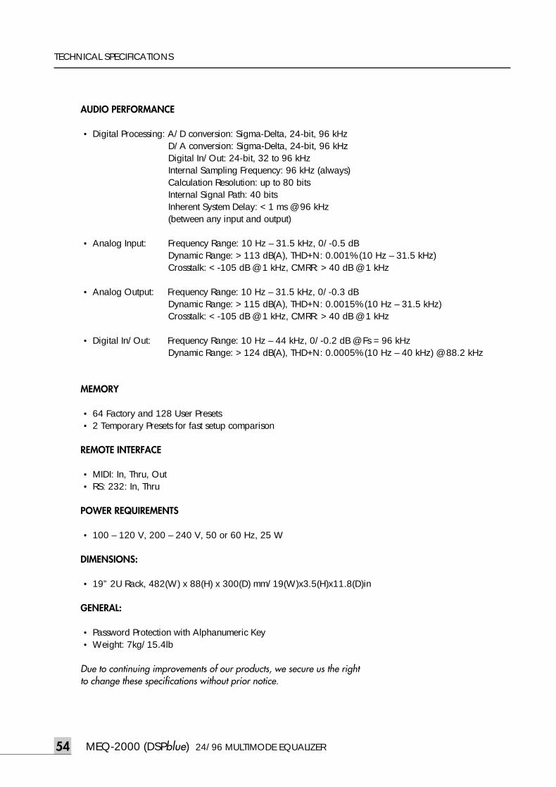
MEQ-2000 (DSPblue) 24/96 MULTIMODE EQUALIZER54
TECHNICAL SPECIFICATIONS
AUDIO PERFORMANCE
• Digital Processing: A/D conversion: Sigma-Delta, 24-bit, 96 kHzD/A conversion: Sigma-Delta, 24-bit, 96 kHzDigital In/Out: 24-bit, 32 to 96 kHzInternal Sampling Frequency: 96 kHz (always) Calculation Resolution: up to 80 bitsInternal Signal Path: 40 bits Inherent System Delay: < 1 ms @ 96 kHz(between any input and output)
• Analog Input: Frequency Range: 10 Hz – 31.5 kHz, 0/-0.5 dBDynamic Range: > 113 dB(A), THD+N: 0.001% (10 Hz – 31.5 kHz)Crosstalk: < -105 dB @ 1 kHz, CMRR: > 40 dB @ 1 kHz
• Analog Output: Frequency Range: 10 Hz – 31.5 kHz, 0/-0.3 dBDynamic Range: > 115 dB(A), THD+N: 0.0015% (10 Hz – 31.5 kHz)Crosstalk: < -105 dB @ 1 kHz, CMRR: > 40 dB @ 1 kHz
• Digital In/Out: Frequency Range: 10 Hz – 44 kHz, 0/-0.2 dB @ Fs = 96 kHz Dynamic Range: > 124 dB(A), THD+N: 0.0005% (10 Hz – 40 kHz) @ 88.2 kHz
MEMORY
• 64 Factory and 128 User Presets • 2 Temporary Presets for fast setup comparison
REMOTE INTERFACE
• MIDI: In, Thru, Out• RS: 232: In, Thru
POWER REQUIREMENTS
• 100 – 120 V, 200 – 240 V, 50 or 60 Hz, 25 W
DIMENSIONS:
• 19” 2U Rack, 482(W) x 88(H) x 300(D) mm/19(W)x3.5(H)x11.8(D)in
GENERAL:
• Password Protection with Alphanumeric Key• Weight: 7kg/15.4lb
Due to continuing improvements of our products, we secure us the right to change these specifications without prior notice.
meq-2000(O/P)_E 2003.9.6 11:43 AM 페이지54
24/96 MULTIMODE EQUALIZER MEQ-2000 (DSPblue) 55
LIMITED WARRANTY
Limited WarrantyLimited WarrantyAll exported products are subject to warranty and services to be specified and provided by the authorizeddistributor for each country.
In Korea INTER-M warrants this product to be free from defects in material and workmanship for a periodof one (1) year from the date of purchase PROVIDED, however, that this limited warranty is extended onlyto the original retail purchaser and for causes arising out of defects in material or workmanship.
Defects caused by unauthorized modifications, misuse, negligence, accidents, or any use of this product thatis not in accordance with the instructions provided in this manual are not covered by this warranty.
meq-2000(O/P)_E 2003.9.6 11:43 AM 페이지55
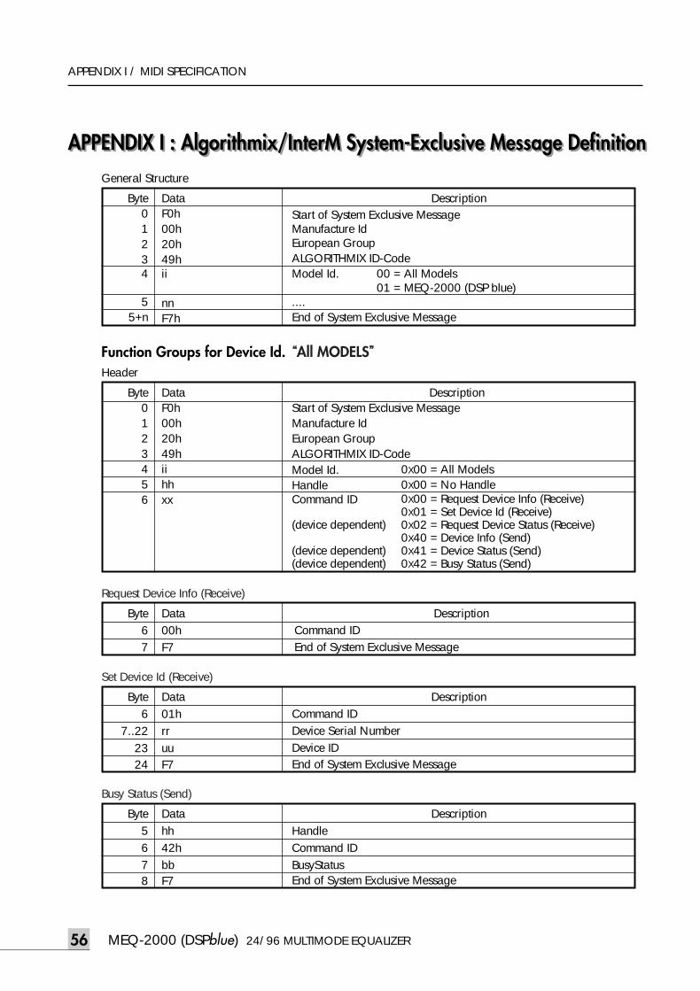
APPENDIX I : Algorithmix/InterM System-Exclusive Message Definition
MEQ-2000 (DSPblue) 24/96 MULTIMODE EQUALIZER56
APPENDIX I / MIDI SPECIFICATION
APPENDIX I : Algorithmix/InterM System-Exclusive Message Definition
Byte01234
55+n
DataF0h00h20h49hii
nnF7h
DescriptionStart of System Exclusive MessageManufacture IdEuropean GroupALGORITHMIX ID-Code Model Id. 00 = All Models
01 = MEQ-2000 (DSP blue)....End of System Exclusive Message
Byte0123456
DataF0h00h20h49hiihhxx
DescriptionStart of System Exclusive MessageManufacture IdEuropean GroupALGORITHMIX ID-Code Model Id.Handle Command ID
(device dependent)
(device dependent) (device dependent)
0X00 = All Models0X00 = No Handle 0X00 = Request Device Info (Receive)0X01 = Set Device Id (Receive)0X02 = Request Device Status (Receive)0X40 = Device Info (Send)0X41 = Device Status (Send)0X42 = Busy Status (Send)
Byte67
Data00hF7
DescriptionCommand IDEnd of System Exclusive Message
Byte6
7..222324
Data01hrruuF7
DescriptionCommand IDDevice Serial NumberDevice IDEnd of System Exclusive Message
Byte567 8
Datahh42hbbF7
DescriptionHandleCommand IDBusyStatusEnd of System Exclusive Message
General Structure
Header
Function Groups for Device Id. “All MODELS”
Request Device Info (Receive)
Set Device Id (Receive)
Busy Status (Send)
meq-2000(O/P)_E 2003.9.6 11:43 AM 페이지56
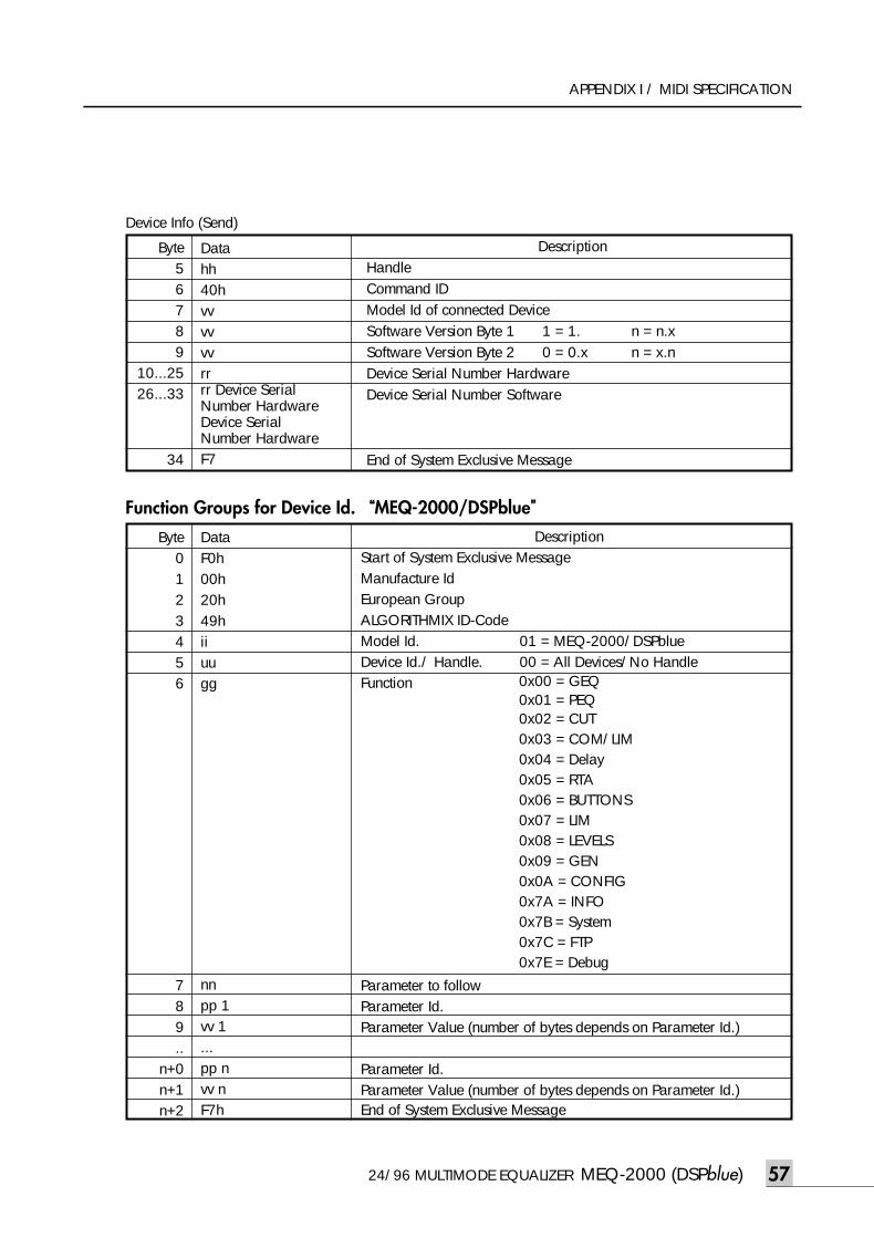
24/96 MULTIMODE EQUALIZER MEQ-2000 (DSPblue) 57
APPENDIX I / MIDI SPECIFICATION
Byte56789
10...2526...33
34
Datahh40hvvvvvvrrrr Device SerialNumber HardwareDevice SerialNumber HardwareF7
DescriptionHandleCommand IDModel Id of connected DeviceSoftware Version Byte 1 1 = 1. n = n.xSoftware Version Byte 2 0 = 0.x n = x.nDevice Serial Number HardwareDevice Serial Number Software
End of System Exclusive Message
Function Groups for Device Id. “MEQ-2000/DSPblue”
Byte0123456
789..
n+0n+1n+2
DataF0h00h20h49hiiuugg
nnpp 1vv 1...pp nvv nF7h
DescriptionStart of System Exclusive MessageManufacture IdEuropean GroupALGORITHMIX ID-CodeModel Id. 01 = MEQ-2000/DSPblueDevice Id./ Handle. 00 = All Devices/No HandleFunction
Parameter to followParameter Id.Parameter Value (number of bytes depends on Parameter Id.)
Parameter Id.Parameter Value (number of bytes depends on Parameter Id.)End of System Exclusive Message
0x00 = GEQ0x01 = PEQ0x02 = CUT0x03 = COM/LIM0x04 = Delay0x05 = RTA0x06 = BUTTONS0x07 = LIM0x08 = LEVELS0x09 = GEN0x0A = CONFIG0x7A = INFO0x7B = System0x7C = FTP0x7E = Debug
Device Info (Send)
meq-2000(O/P)_E 2003.9.6 11:43 AM 페이지57
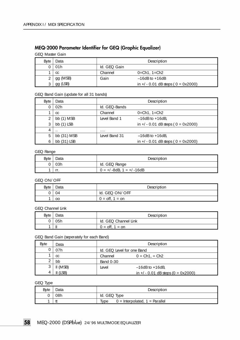
MEQ-2000 (DSPblue) 24/96 MULTIMODE EQUALIZER58
APPENDIX I / MIDI SPECIFICATION
MEQ-2000 Parameter Identifier for GEQ (Graphic Equalizer)
58
Byte0123
Data01hccgg (MSB)gg (LSB)
Byte01
Data03hrr.
Byte01
Data04oo
Byte01
Data05hll
Byte0123456
Data02hccbb (1) MSBbb (1) LSB .. bb (31) MSBbb (31) LSB
Byte01234
Data07hccbbll (MSB)II (LSB)
Description
Id. GEQ Level for one BandChannel 0 = Ch1, = Ch2 Band 0-30Level –16dB to +16dB,
in +/- 0.01 dB steps (0 = 0x2000)
Byte01
Data08htt
GEQ Master Gain
GEQ Band Gain (update for all 31 bands)
GEQ Range
GEQ ON/OFF
GEQ Channel Link
GEQ Band Gain (seperately for each Band)
GEQ Type
DescriptionId. GEQ GainChannel 0=Ch1, 1=Ch2 Gain –16dB to +16dB
in +/- 0.01 dB steps ( 0 = 0x2000)
DescriptionId. GEQ-BandsChannel 0=Ch1, 1=Ch2 Level Band 1 –16dB to +16dB,
in +/- 0.01 dB steps ( 0 = 0x2000)….Level Band 31 –16dB to +16dB,
in +/- 0.01 dB steps ( 0 = 0x2000)
DescriptionId. GEQ Range0 = +/-8dB, 1 = +/-16dB
DescriptionId. GEQ ON/OFF0 = off, 1 = on
DescriptionId. GEQ Channel Link0 = off, 1 = on
DescriptionId. GEQ TypeType 0 = Interpolated, 1 = Parallel
meq-2000(O/P)_E 2003.9.6 11:43 AM 페이지58
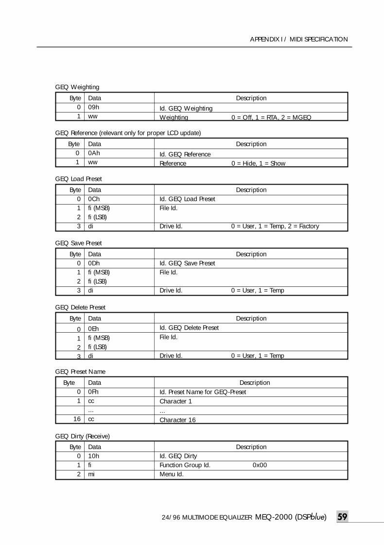
24/96 MULTIMODE EQUALIZER MEQ-2000 (DSPblue) 59
APPENDIX I / MIDI SPECIFICATION
59
GEQ Weighting
Byte01
Data09hww
Byte01
16
Data0Fhcc...cc
DescriptionId. Preset Name for GEQ-PresetCharacter 1...Character 16
Byte012
Data10hfi mi
Description
Id. GEQ WeightingWeighting 0 = Off, 1 = RTA, 2 = MGEQ
Byte01
Data0Ahww
Description
Id. GEQ ReferenceReference 0 = Hide, 1 = Show
DescriptionId. GEQ Load PresetFile Id.
Drive Id. 0 = User, 1 = Temp, 2 = Factory
Byte0123
Data0Chfi (MSB)fi (LSB)di
DescriptionId. GEQ Save PresetFile Id.
Drive Id. 0 = User, 1 = Temp
Byte0123
Data0Dhfi (MSB)fi (LSB)di
DescriptionId. GEQ Delete PresetFile Id.
Drive Id. 0 = User, 1 = Temp
Byte
0123
Data
0Ehfi (MSB)fi (LSB)di
GEQ Reference (relevant only for proper LCD update)
GEQ Load Preset
GEQ Save Preset
GEQ Delete Preset
GEQ Preset Name
GEQ Dirty (Receive)
DescriptionId. GEQ Dirty Function Group Id. 0x00Menu Id.
meq-2000(O/P)_E 2003.9.6 11:43 AM 페이지59
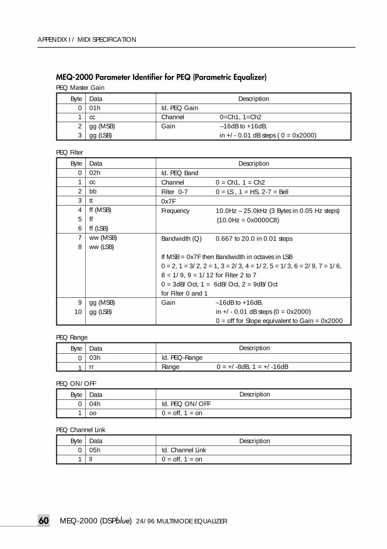
MEQ-2000 (DSPblue) 24/96 MULTIMODE EQUALIZER6060
APPENDIX I / MIDI SPECIFICATION
MEQ-2000 Parameter Identifier for PEQ (Parametric Equalizer)
Byte01
Data03h Id. PEQ-Rangerr Range 0 = +/-8dB, 1 = +/-16dB
Byte01
Data04h Id. PEQ ON/OFFoo 0 = off, 1 = on
Description
Byte0123
Data01hccgg (MSB)gg (LSB)
Byte012345678
910
Data02hccbbttff (MSB)ff ff (LSB)ww (MSB)ww (LSB)
gg (MSB)gg (LSB)
DescriptionId. PEQ BandChannel 0 = Ch1, 1 = Ch2 Filter 0-7 0 = LS , 1 = HS, 2-7 = Bell0x7FFrequency 10.0Hz – 25.0kHz (3 Bytes in 0.05 Hz steps)
(10.0Hz = 0x0000C8)
Bandwidth (Q) 0.667 to 20.0 in 0.01 steps
If MSB = 0x7F then Bandwidth in octaves in LSB 0 = 2, 1 = 3/2, 2 = 1, 3 = 2/3, 4 = 1/2, 5 = 1/3, 6 = 2/9, 7 = 1/6, 8 = 1/9, 9 = 1/12 for Filter 2 to 70 = 3dB/Oct, 1 = 6dB/Oct, 2 = 9dB/Oct for Filter 0 and 1 Gain –16dB to +16dB,
in +/- 0.01 dB steps (0 = 0x2000)0 = off for Slope equivalent to Gain = 0x2000
PEQ Master Gain
PEQ Filter
PEQ Range
PEQ ON/OFF
Byte01
Data05h Id. Channel Linkll 0 = off, 1 = on
Description
PEQ Channel Link
DescriptionId. PEQ GainChannel 0=Ch1, 1=Ch2 Gain –16dB to +16dB,
in +/- 0.01 dB steps ( 0 = 0x2000)
Description
meq-2000(O/P)_E 2003.9.6 11:43 AM 페이지60
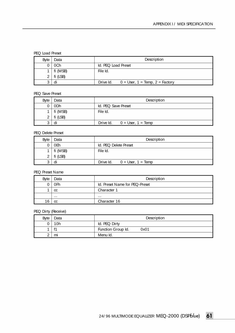
Description
Description
Description
24/96 MULTIMODE EQUALIZER MEQ-2000 (DSPblue) 6161
APPENDIX I / MIDI SPECIFICATION
Byte0123
Data0Ch Id. PEQ Load Presetfi (MSB) File Id.fi (LSB)di Drive Id. 0 = User, 1 = Temp, 2 = Factory
Description
Byte01
16
Data0Fh Id. Preset Name for PEQ-Presetcc Character 1... ...cc Character 16
Byte0123
Data0Dh Id. PEQ Save Presetfi (MSB) File Id.fi (LSB)di Drive Id. 0 = User, 1 = Temp
Description
Byte0123
Data0Eh Id. PEQ Delete Presetfi (MSB) File Id.fi (LSB)di Drive Id. 0 = User, 1 = Temp
Byte012
PEQ Load Preset
PEQ Save Preset
PEQ Delete Preset
PEQ Preset Name
PEQ Dirty (Receive)
Data10h Id. PEQ Dirtyf1 Function Group Id. 0x01mi Menu Id.
meq-2000(O/P)_E 2003.9.6 11:43 AM 페이지61
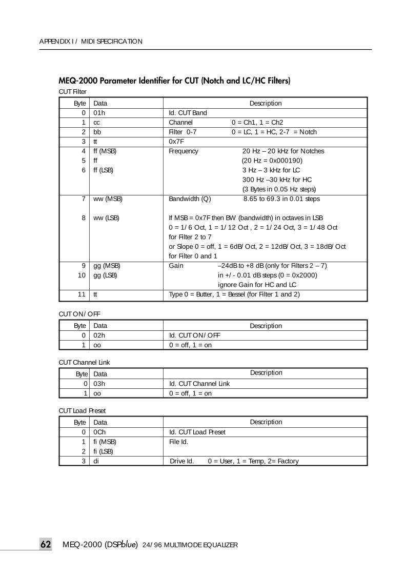
Description
MEQ-2000 (DSPblue) 24/96 MULTIMODE EQUALIZER62
APPENDIX I / MIDI SPECIFICATION
MEQ-2000 Parameter Identifier for CUT (Notch and LC/HC Filters)
Byte01
Data02h Id. CUT ON/OFFoo 0 = off, 1 = on
Description
Byte0123456
7
8
910
11
Data01hccbbttff (MSB)ff ff (LSB)
ww (MSB)
ww (LSB)
gg (MSB)gg (LSB)
tt
DescriptionId. CUT BandChannel 0 = Ch1, 1 = Ch2 Filter 0-7 0 = LC, 1 = HC, 2-7 = Notch0x7FFrequency 20 Hz – 20 kHz for Notches
(20 Hz = 0x000190)3 Hz – 3 kHz for LC 300 Hz –30 kHz for HC(3 Bytes in 0.05 Hz steps)
Bandwidth (Q) 8.65 to 69.3 in 0.01 steps
If MSB = 0x7F then BW (bandwidth) in octaves in LSB 0 = 1/6 Oct, 1 = 1/12 Oct , 2 = 1/24 Oct, 3 = 1/48 Oct for Filter 2 to 7or Slope 0 = off, 1 = 6dB/Oct, 2 = 12dB/Oct, 3 = 18dB/Oct for Filter 0 and 1Gain –24dB to +8 dB (only for Filters 2 – 7)
in +/- 0.01 dB steps (0 = 0x2000)ignore Gain for HC and LC
Type 0 = Butter, 1 = Bessel (for Filter 1 and 2)
CUT Filter
CUT ON/OFF
Byte01
Data03h Id. CUT Channel Linkoo 0 = off, 1 = on
CUT Channel Link
Byte0123
Data0Ch Id. CUT Load Presetfi (MSB) File Id.fi (LSB)di Drive Id. 0 = User, 1 = Temp, 2= Factory
CUT Load Preset
Description
meq-2000(O/P)_E 2003.9.6 11:43 AM 페이지62
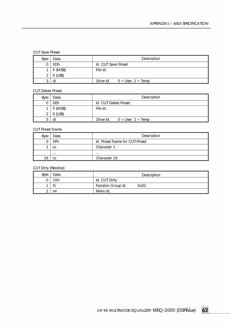
Description
Description
DescriptionByte0123
Data0Dh Id. CUT Save Presetfi (MSB) File Id.fi (LSB)di Drive Id. 0 = User, 1 = Temp
24/96 MULTIMODE EQUALIZER MEQ-2000 (DSPblue) 63
APPENDIX I / MIDI SPECIFICATION
CUT Save Preset
Byte0123
Data0Eh Id. CUT Delete Presetfi (MSB) File Id.fi (LSB)di Drive Id. 0 = User, 1 = Temp
CUT Delete Preset
Byte01
16
Data0Fh Id. Preset Name for CUT-Presetcc Character 1... ...cc Character 16
CUT Preset Name
Byte012
Data10h Id. CUT Dirtyf1 Function Group Id. 0x02 mi Menu Id.
Description
CUT Dirty (Receive)
meq-2000(O/P)_E 2003.9.6 11:43 AM 페이지63
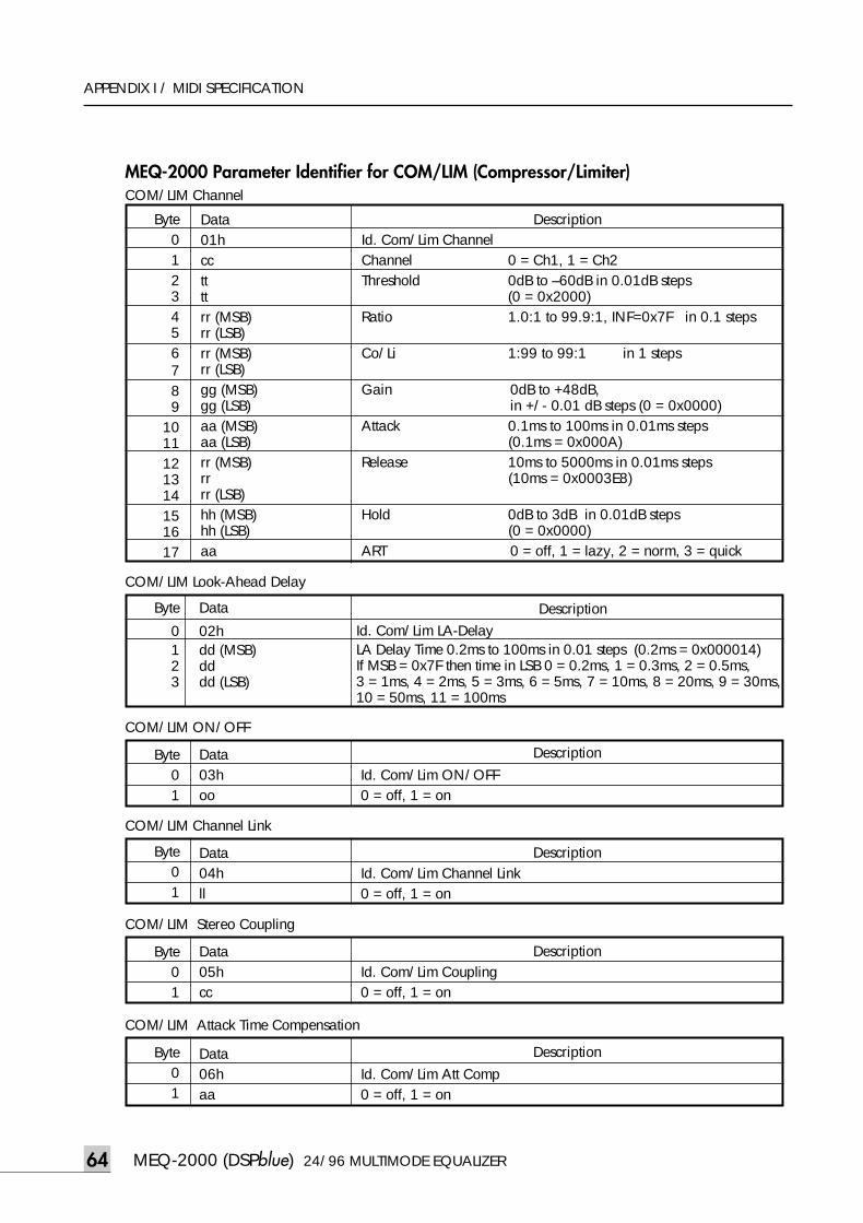
MEQ-2000 (DSPblue) 24/96 MULTIMODE EQUALIZER64
APPENDIX I / MIDI SPECIFICATION
MEQ-2000 Parameter Identifier for COM/LIM (Compressor/Limiter)
Byte01
Data03h Id. Com/Lim ON/OFFoo 0 = off, 1 = on
Description
Byte0123456789
1011121314151617
Data01hccttttrr (MSB)rr (LSB)rr (MSB)rr (LSB)gg (MSB)gg (LSB)aa (MSB)aa (LSB)rr (MSB)rrrr (LSB)hh (MSB)hh (LSB)aa
DescriptionId. Com/Lim ChannelChannel 0 = Ch1, 1 = Ch2 Threshold 0dB to –60dB in 0.01dB steps
(0 = 0x2000)Ratio 1.0:1 to 99.9:1, INF=0x7F in 0.1 steps
Co/Li 1:99 to 99:1 in 1 steps
Gain 0dB to +48dB,in +/- 0.01 dB steps (0 = 0x0000)
Attack 0.1ms to 100ms in 0.01ms steps(0.1ms = 0x000A)
Release 10ms to 5000ms in 0.01ms steps(10ms = 0x0003E8)
Hold 0dB to 3dB in 0.01dB steps(0 = 0x0000)
ART 0 = off, 1 = lazy, 2 = norm, 3 = quick
COM/LIM Channel
COM/LIM ON/OFF
Byte01
Data04h Id. Com/Lim Channel Linkll 0 = off, 1 = on
Description
COM/LIM Channel Link
Byte
0123
Data
02hdd (MSB) dddd (LSB)
COM/LIM Look-Ahead Delay
DescriptionId. Com/Lim LA-DelayLA Delay Time 0.2ms to 100ms in 0.01 steps (0.2ms = 0x000014)If MSB = 0x7F then time in LSB 0 = 0.2ms, 1 = 0.3ms, 2 = 0.5ms,3 = 1ms, 4 = 2ms, 5 = 3ms, 6 = 5ms, 7 = 10ms, 8 = 20ms, 9 = 30ms,10 = 50ms, 11 = 100ms
Byte01
Data05h Id. Com/Lim Couplingcc 0 = off, 1 = on
Description
COM/LIM Stereo Coupling
Byte01
Data06h Id. Com/Lim Att Compaa 0 = off, 1 = on
Description
COM/LIM Attack Time Compensation
meq-2000(O/P)_E 2003.9.6 11:43 AM 페이지64
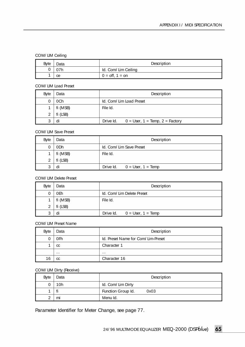
24/96 MULTIMODE EQUALIZER MEQ-2000 (DSPblue) 65
APPENDIX I / MIDI SPECIFICATION
Byte
0
1
2
3
Data
0Dh Id. Com/Lim Save Preset
fi (MSB) File Id.
fi (LSB)
di Drive Id. 0 = User, 1 = Temp
Description
COM/LIM Save Preset
Byte
0
1
2
3
Data
0Eh Id. Com/Lim Delete Preset
fi (MSB) File Id.
fi (LSB)
di Drive Id. 0 = User, 1 = Temp
Description
COM/LIM Delete Preset
Byte
0
1
16
Data
0Fh Id. Preset Name for Com/Lim-Preset
cc Character 1
... ...
cc Character 16
Description
COM/LIM Preset Name
Byte
0
1
2
Data
10h Id. Com/Lim Dirty
fi Function Group Id. 0x03
mi Menu Id.
Description
COM/LIM Dirty (Receive)
Byte
0
1
2
3
Data
0Ch Id. Com/Lim Load Preset
fi (MSB) File Id.
fi (LSB)
di Drive Id. 0 = User, 1 = Temp, 2 = Factory
Description
COM/LIM Load Preset
Byte01
Data07h Id. Com/Lim Ceilingce 0 = off, 1 = on
Description
COM/LIM Ceiling
Parameter Identifier for Meter Change, see page 77.
meq-2000(O/P)_E 2003.9.6 11:43 AM 페이지65
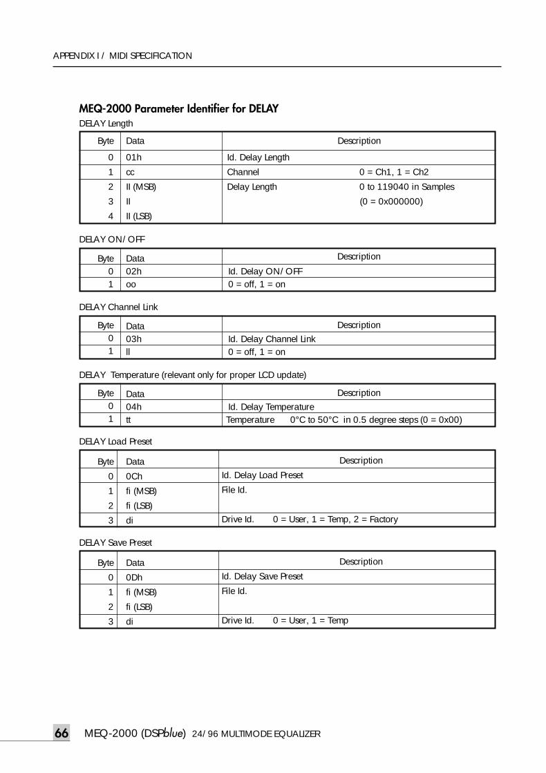
MEQ-2000 (DSPblue) 24/96 MULTIMODE EQUALIZER66
APPENDIX I / MIDI SPECIFICATION
MEQ-2000 Parameter Identifier for DELAY
Byte01
Data02h Id. Delay ON/OFFoo 0 = off, 1 = on
Description
DELAY ON/OFF
Byte01
Data03h Id. Delay Channel Linkll 0 = off, 1 = on
Description
DELAY Channel Link
Byte
0
1
2
3
Data
0Ch
fi (MSB)
fi (LSB)
di
DELAY Load Preset
Description
Id. Delay Load Preset
File Id.
Drive Id. 0 = User, 1 = Temp, 2 = Factory
Byte01
Data04h Id. Delay Temperaturett Temperature 0°C to 50°C in 0.5 degree steps (0 = 0x00)
Description
DELAY Temperature (relevant only for proper LCD update)
Byte
0
1
2
3
4
Data
01h
cc
II (MSB)
II
II (LSB)
Description
DELAY Length
Id. Delay Length
Channel 0 = Ch1, 1 = Ch2
Delay Length 0 to 119040 in Samples
(0 = 0x000000)
Byte
0
1
2
3
Data
0Dh
fi (MSB)
fi (LSB)
di
DELAY Save Preset
Description
Id. Delay Save Preset
File Id.
Drive Id. 0 = User, 1 = Temp
meq-2000(O/P)_E 2003.9.6 11:43 AM 페이지66
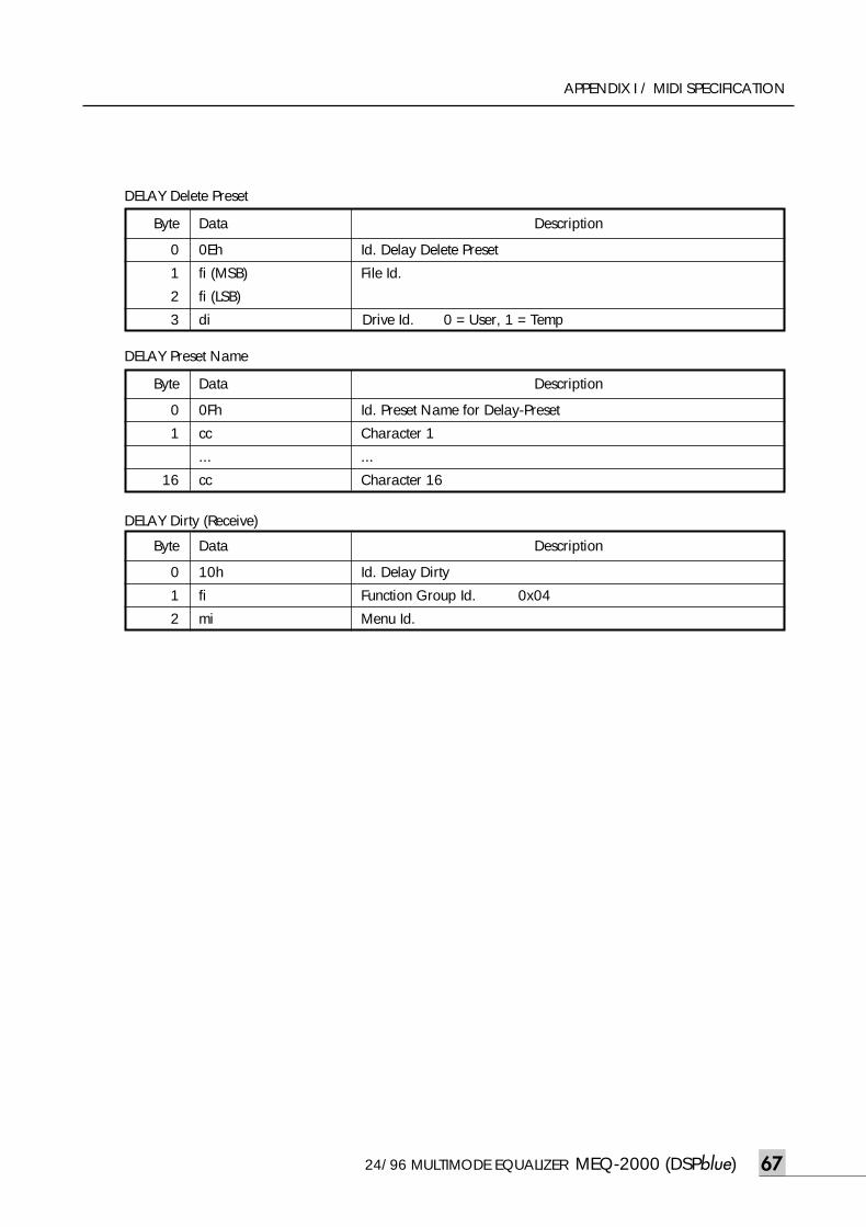
24/96 MULTIMODE EQUALIZER MEQ-2000 (DSPblue) 67
APPENDIX I / MIDI SPECIFICATION
Byte
0
1
2
3
Data
0Eh Id. Delay Delete Preset
fi (MSB) File Id.
fi (LSB)
di Drive Id. 0 = User, 1 = Temp
Description
DELAY Delete Preset
Byte
0
1
16
Data
0Fh Id. Preset Name for Delay-Preset
cc Character 1
... ...
cc Character 16
Description
DELAY Preset Name
Byte
0
1
2
Data
10h Id. Delay Dirty
fi Function Group Id. 0x04
mi Menu Id.
Description
DELAY Dirty (Receive)
meq-2000(O/P)_E 2003.9.6 11:43 AM 페이지67
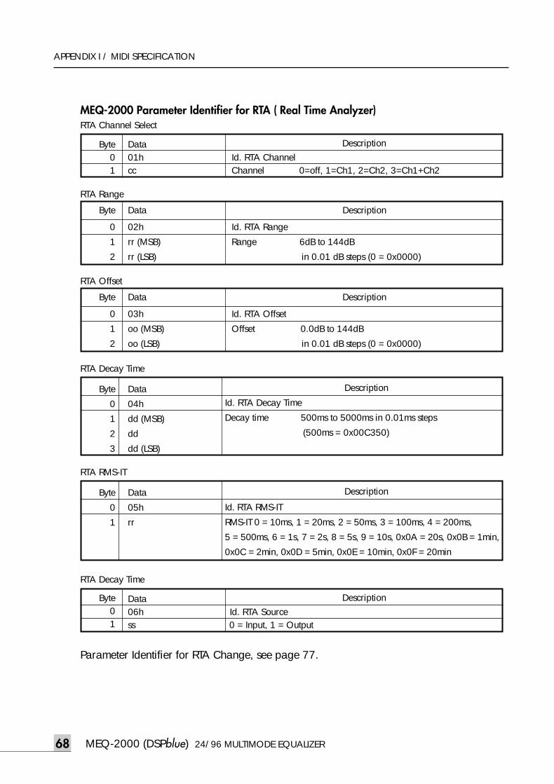
MEQ-2000 (DSPblue) 24/96 MULTIMODE EQUALIZER68
APPENDIX I / MIDI SPECIFICATION
MEQ-2000 Parameter Identifier for RTA ( Real Time Analyzer)
Byte01
Data01h Id. RTA Channelcc Channel 0=off, 1=Ch1, 2=Ch2, 3=Ch1+Ch2
Description
RTA Channel Select
Byte
0
1
2
3
Data
04h
dd (MSB)
dd
dd (LSB)
RTA Decay Time
Description
Id. RTA Decay Time
Decay time 500ms to 5000ms in 0.01ms steps
(500ms = 0x00C350)
Byte01
Data06h Id. RTA Sourcess 0 = Input, 1 = Output
Description
RTA Decay Time
Byte
0
1
Data
05h
rr
RTA RMS-IT
Description
Id. RTA RMS-IT
RMS-IT 0 = 10ms, 1 = 20ms, 2 = 50ms, 3 = 100ms, 4 = 200ms,
5 = 500ms, 6 = 1s, 7 = 2s, 8 = 5s, 9 = 10s, 0x0A = 20s, 0x0B = 1min,
0x0C = 2min, 0x0D = 5min, 0x0E = 10min, 0x0F = 20min
Byte
0
1
2
Data
03h Id. RTA Offset
oo (MSB) Offset 0.0dB to 144dB
oo (LSB) in 0.01 dB steps (0 = 0x0000)
Description
RTA Offset
Byte
0
1
2
Data
02h Id. RTA Range
rr (MSB) Range 6dB to 144dB
rr (LSB) in 0.01 dB steps (0 = 0x0000)
Description
RTA Range
Parameter Identifier for RTA Change, see page 77.
meq-2000(O/P)_E 2003.9.6 11:43 AM 페이지68
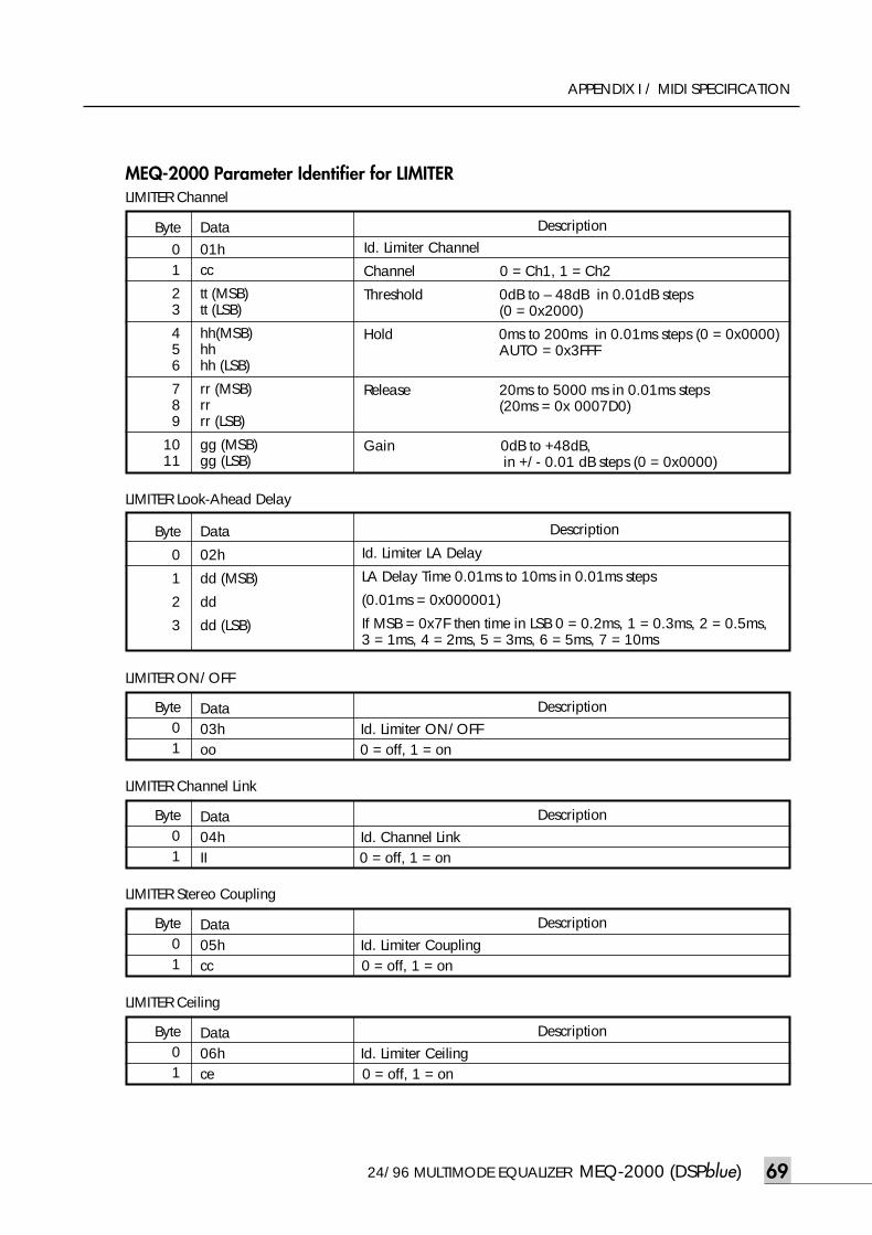
24/96 MULTIMODE EQUALIZER MEQ-2000 (DSPblue) 69
APPENDIX I / MIDI SPECIFICATION
MEQ-2000 Parameter Identifier for LIMITER
Byte01
23
456
789
1011
Data01hcc
tt (MSB)tt (LSB)
hh(MSB)hhhh (LSB)
rr (MSB)rrrr (LSB)
gg (MSB)gg (LSB)
Description
LIMITER Channel
Byte
0
1
2
3
Data
02h
dd (MSB)
dd
dd (LSB)
LIMITER Look-Ahead Delay
Description
Id. Limiter LA Delay
LA Delay Time 0.01ms to 10ms in 0.01ms steps
(0.01ms = 0x000001)
If MSB = 0x7F then time in LSB 0 = 0.2ms, 1 = 0.3ms, 2 = 0.5ms,3 = 1ms, 4 = 2ms, 5 = 3ms, 6 = 5ms, 7 = 10ms
Byte01
Data03h Id. Limiter ON/OFFoo 0 = off, 1 = on
Description
LIMITER ON/OFF
Id. Limiter Channel
Channel 0 = Ch1, 1 = Ch2
Threshold 0dB to – 48dB in 0.01dB steps(0 = 0x2000)
Hold 0ms to 200ms in 0.01ms steps (0 = 0x0000) AUTO = 0x3FFF
Release 20ms to 5000 ms in 0.01ms steps (20ms = 0x 0007D0)
Gain 0dB to +48dB,in +/- 0.01 dB steps (0 = 0x0000)
Byte01
Data04h Id. Channel LinkII 0 = off, 1 = on
Description
LIMITER Channel Link
Byte01
Data05h Id. Limiter Couplingcc 0 = off, 1 = on
Description
LIMITER Stereo Coupling
Byte01
Data06h Id. Limiter Ceilingce 0 = off, 1 = on
Description
LIMITER Ceiling
meq-2000(O/P)_E 2003.9.6 11:43 AM 페이지69
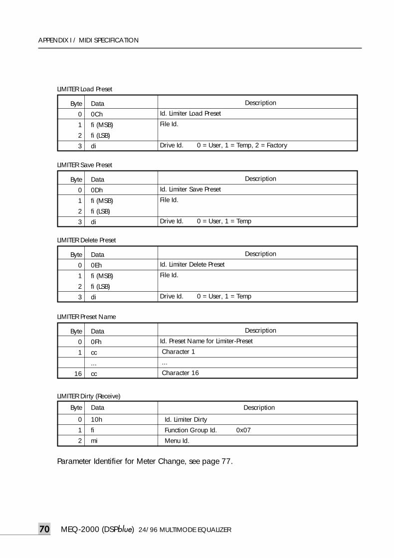
MEQ-2000 (DSPblue) 24/96 MULTIMODE EQUALIZER70
APPENDIX I / MIDI SPECIFICATION
Byte
0
1
2
3
Data
0Ch
fi (MSB)
fi (LSB)
di
LIMITER Load Preset
Description
Id. Limiter Load Preset
File Id.
Drive Id. 0 = User, 1 = Temp, 2 = Factory
Byte
0
1
2
3
Data
0Dh
fi (MSB)
fi (LSB)
di
LIMITER Save Preset
Description
Id. Limiter Save Preset
File Id.
Drive Id. 0 = User, 1 = Temp
Byte
0
1
2
3
Data
0Eh
fi (MSB)
fi (LSB)
di
LIMITER Delete Preset
Description
Id. Limiter Delete Preset
File Id.
Drive Id. 0 = User, 1 = Temp
Byte
0
1
16
Data
0Fh
cc
...
cc
LIMITER Preset Name
Description
Id. Preset Name for Limiter-Preset
Character 1
...
Character 16
Byte
0
1
2
Data
10h Id. Limiter Dirty
fi Function Group Id. 0x07
mi Menu Id.
Description
LIMITER Dirty (Receive)
Parameter Identifier for Meter Change, see page 77.
meq-2000(O/P)_E 2003.9.6 11:43 AM 페이지70
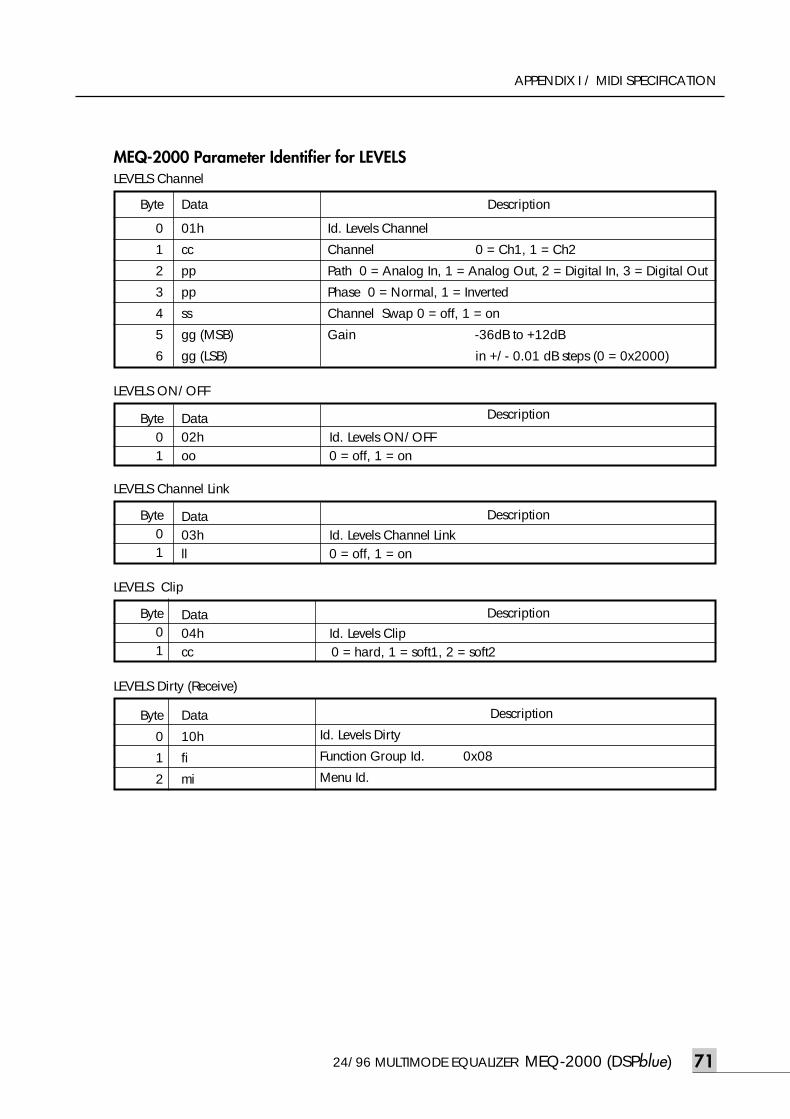
24/96 MULTIMODE EQUALIZER MEQ-2000 (DSPblue) 71
APPENDIX I / MIDI SPECIFICATION
MEQ-2000 Parameter Identifier for LEVELS
Byte01
Data02h Id. Levels ON/OFFoo 0 = off, 1 = on
Description
LEVELS ON/OFF
Byte01
Data03h Id. Levels Channel Linkll 0 = off, 1 = on
Description
LEVELS Channel Link
Byte
0
1
2
Data
10h
fi
mi
LEVELS Dirty (Receive)
Description
Id. Levels Dirty
Function Group Id. 0x08
Menu Id.
Byte01
Data04h Id. Levels Clipcc 0 = hard, 1 = soft1, 2 = soft2
Description
LEVELS Clip
Byte
0
1
2
3
4
5
6
Data
01h
cc
pp
pp
ss
gg (MSB)
gg (LSB)
Description
LEVELS Channel
Id. Levels Channel
Channel 0 = Ch1, 1 = Ch2
Path 0 = Analog In, 1 = Analog Out, 2 = Digital In, 3 = Digital Out
Phase 0 = Normal, 1 = Inverted
Channel Swap 0 = off, 1 = on
Gain -36dB to +12dB
in +/- 0.01 dB steps (0 = 0x2000)
meq-2000(O/P)_E 2003.9.6 11:43 AM 페이지71
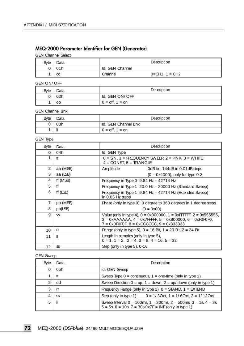
MEQ-2000 (DSPblue) 24/96 MULTIMODE EQUALIZER72
APPENDIX I / MIDI SPECIFICATION
MEQ-2000 Parameter Identifier for GEN (Generator)
Byte01
Data01h Id. GEN Channelcc Channel 0=CH1, 1 = CH2
Description
GEN Channel Select
Byte01
Data02h Id. GEN ON/OFFoo 0 = off, 1 = on
Description
GEN ON/OFF
Byte01
Data03h Id. GEN Channel Linkll 0 = off, 1 = on
Description
GEN Channel Link
Byte01
23456
789
1011
12
Data04htt
aa (MSB)aa (LSB)ff (MSB)ffff (LSB)
pp (MSB)pp(LSB)vv
rr
ll
ss
Description
GEN Type
Id. GEN Type0 = SIN, 1 = FREQUENCY SWEEP, 2 = PINK, 3 = WHITE 4 = CONST, 5 = TRIANGLE
Amplitude 0dB to –144dB in 0.01dB steps (0 = 0x4000), only for type 0-3
Frequency in Type 0 9.84 Hz – 42714 HzFrequency in Type 1 20.0 Hz – 20000 Hz (Standard Sweep)Frequency in Type 1 9.84 Hz – 42714 Hz (Extended Sweep)in 0.05 Hz stepsPhase (only in type 0), 0 degree to 360 degrees in 1 degree steps
(0 = 0x00)Value (only in type 4), 0 = 0x000000, 1 = 0xFFFFFF, 2 = 0x555555,3 = 0xAAAAAA, 4 = 0x7FFFFF, 5 = 0x800000, 6 = 0xF0F0F0,7 = 0x0F0F0F, 8 = 0xCCCCCC, 9 = 0x333333Range (only in type 5), 0 = 16 Bit, 1 = 20 Bit, 2 = 24 BitLength in samples (only in type 5), 0 = 1, 1 = 2, 2 = 4, 3 = 8, 4 = 16, 5 = 32Step (only in type 5), 0-16
Byte
0
1
2
3
4
5
Data
05h
tt
dd
rr
ss
ii
Description
GEN Sweep
Id. GEN Sweep
Sweep Type 0 = continuous, 1 = one-time (only in type 1)
Sweep Direction 0 = up, 1 = down, 2 = up/down (only in type 1)
Frequency Range (only in type 1) 0 = STAND, 1 = EXTEND
Step (only in type 1) 0 = 1/3Oct, 1 = 1/6Oct, 2 = 1/12Oct
Sweep Interval 0 = 100ms, 1 = 300ms, 2 = 500ms, 3 = 1s, 4 = 3s,5 = 5s, 6 = 10s, 7 = 30s 0x7F = INF (only in type 1)
meq-2000(O/P)_E 2003.9.6 11:43 AM 페이지72
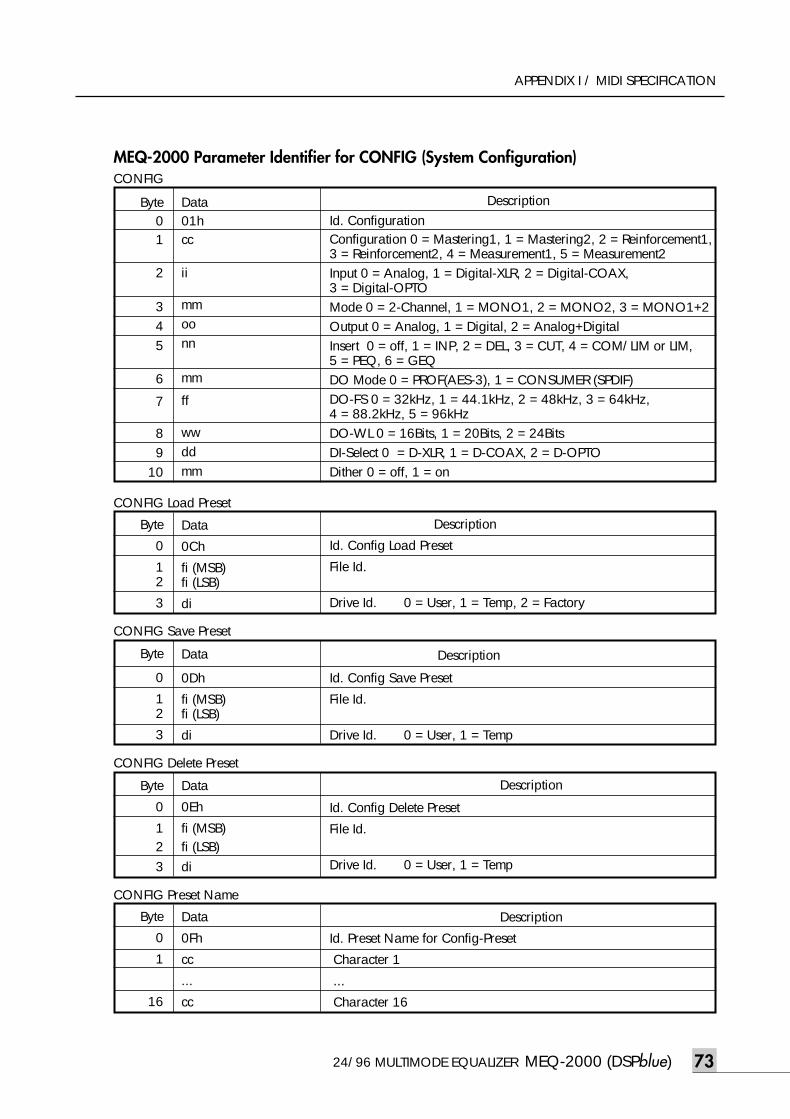
24/96 MULTIMODE EQUALIZER MEQ-2000 (DSPblue) 73
APPENDIX I / MIDI SPECIFICATION
MEQ-2000 Parameter Identifier for CONFIG (System Configuration)
Byte01
2
345
6
7
89
10
Data01hcc
ii
mmoonn
mm
ff
wwddmm
Description
CONFIG
Id. Configuration Configuration 0 = Mastering1, 1 = Mastering2, 2 = Reinforcement1,3 = Reinforcement2, 4 = Measurement1, 5 = Measurement2 Input 0 = Analog, 1 = Digital-XLR, 2 = Digital-COAX,3 = Digital-OPTOMode 0 = 2-Channel, 1 = MONO1, 2 = MONO2, 3 = MONO1+2Output 0 = Analog, 1 = Digital, 2 = Analog+DigitalInsert 0 = off, 1 = INP, 2 = DEL, 3 = CUT, 4 = COM/LIM or LIM,5 = PEQ, 6 = GEQDO Mode 0 = PROF(AES-3), 1 = CONSUMER (SPDIF)DO-FS 0 = 32kHz, 1 = 44.1kHz, 2 = 48kHz, 3 = 64kHz, 4 = 88.2kHz, 5 = 96kHzDO-WL 0 = 16Bits, 1 = 20Bits, 2 = 24BitsDI-Select 0 = D-XLR, 1 = D-COAX, 2 = D-OPTODither 0 = off, 1 = on
Byte
0
12
3
Data
0Ch
fi (MSB)fi (LSB)
di
CONFIG Load Preset
Description
Id. Config Load Preset
File Id.
Drive Id. 0 = User, 1 = Temp, 2 = Factory
Byte
0
12
3
Data
0Dh
fi (MSB)fi (LSB)
di
CONFIG Save Preset
Description
Id. Config Save Preset
File Id.
Drive Id. 0 = User, 1 = Temp
Byte
0
123
Data
0Eh
fi (MSB)fi (LSB)di
CONFIG Delete Preset
Description
Id. Config Delete Preset
File Id.
Drive Id. 0 = User, 1 = Temp
Byte
0
1
16
Data
0Fh
cc
...
cc
CONFIG Preset Name
Description
Id. Preset Name for Config-Preset
Character 1
...
Character 16
meq-2000(O/P)_E 2003.9.6 11:43 AM 페이지73
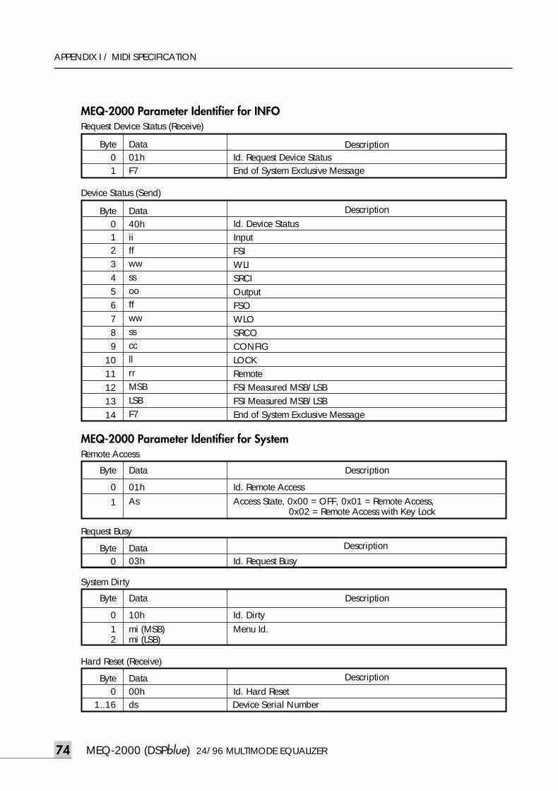
MEQ-2000 (DSPblue) 24/96 MULTIMODE EQUALIZER74
APPENDIX I / MIDI SPECIFICATION
MEQ-2000 Parameter Identifier for INFO
Byte0123456789
1011121314
Data40hiiffwwssooffwwssccllrrMSBLSBF7
Description
Device Status (Send)
Id. Device StatusInputFSIWLISRCIOutputFSOWLOSRCOCONFIGLOCKRemoteFSI Measured MSB/LSBFSI Measured MSB/LSBEnd of System Exclusive Message
Byte01
Data01h Id. Request Device Status F7 End of System Exclusive Message
Description
Request Device Status (Receive)
MEQ-2000 Parameter Identifier for System
Byte0
Data03h Id. Request Busy
DescriptionRequest Busy
Byte
012
Data
10h Id. Dirtymi (MSB) Menu Id.mi (LSB)
Description
System Dirty
Byte
0
1
Data
01h Id. Remote AccessAs Access State, 0x00 = OFF, 0x01 = Remote Access,
0x02 = Remote Access with Key Lock
Description
Remote Access
Byte0
1..16
Data00h Id. Hard Reset ds Device Serial Number
Description
Hard Reset (Receive)
meq-2000(O/P)_E 2003.9.6 11:43 AM 페이지74
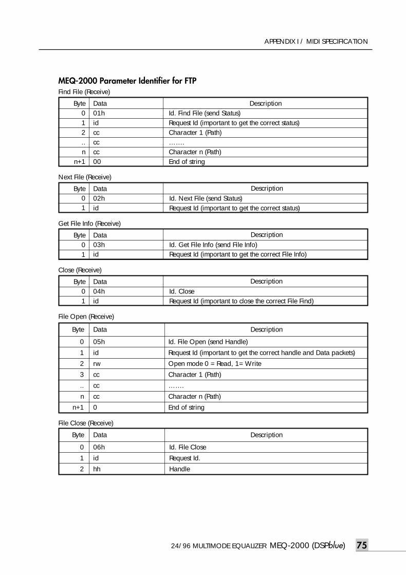
24/96 MULTIMODE EQUALIZER MEQ-2000 (DSPblue) 75
APPENDIX I / MIDI SPECIFICATION
Byte
0
1
2
Data
06h Id. File Close
id Request Id.
hh Handle
Description
File Close (Receive)
MEQ-2000 Parameter Identifier for FTP
Byte01
Data02h Id. Next File (send Status)id Request Id (important to get the correct status)
Next File (Receive)
Byte012..n
n+1
Data01h idcccccc00
Find File (Receive)
DescriptionId. Find File (send Status)Request Id (important to get the correct status)Character 1 (Path)…….Character n (Path)End of string
Byte01
Data03h Id. Get File Info (send File Info)id Request Id (important to get the correct File Info)
Get File Info (Receive)
Byte01
Data04h Id. Closeid Request Id (important to close the correct File Find)
Close (Receive)
Byte
0
1
2
3
..
n
n+1
Data
05h
id
rw
cc
cc
cc
0
Description
File Open (Receive)
Id. File Open (send Handle)
Request Id (important to get the correct handle and Data packets)
Open mode 0 = Read, 1= Write
Character 1 (Path)
…….
Character n (Path)
End of string
Description
Description
Description
meq-2000(O/P)_E 2003.9.6 11:43 AM 페이지75
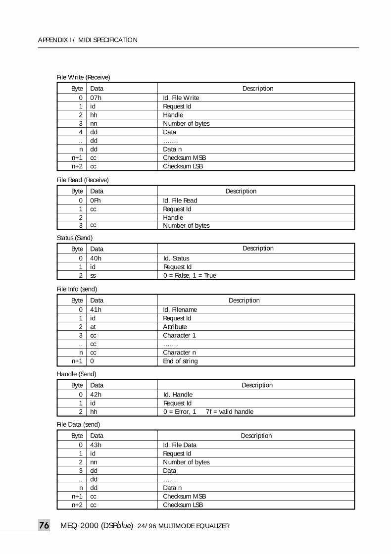
MEQ-2000 (DSPblue) 24/96 MULTIMODE EQUALIZER76
APPENDIX I / MIDI SPECIFICATION
Byte01234..n
n+1n+2
Data07h idhhnnddddddcccc
File Write (Receive)
DescriptionId. File WriteRequest Id HandleNumber of bytesData…….Data n Checksum MSB Checksum LSB
Byte0123
Data0Fhcc
cc
File Read (Receive)
DescriptionId. File ReadRequest Id HandleNumber of bytes
Byte012
Data40h Id. Statusid Request Id ss 0 = False, 1 = True
Description
Status (Send)
Byte012
Data42h Id. Handleid Request Id hh 0 = Error, 1 7f = valid handle
Description
Handle (Send)
Byte0123..n
n+1
Data41h idatcccccc0
File Info (send)
DescriptionId. FilenameRequest Id AttributeCharacter 1…….Character n End of string
Byte0123..n
n+1n+2
Data43h idnnddddddcccc
File Data (send)
DescriptionId. File DataRequest Id Number of bytesData…….Data n Checksum MSB Checksum LSB
meq-2000(O/P)_E 2003.9.6 11:43 AM 페이지76
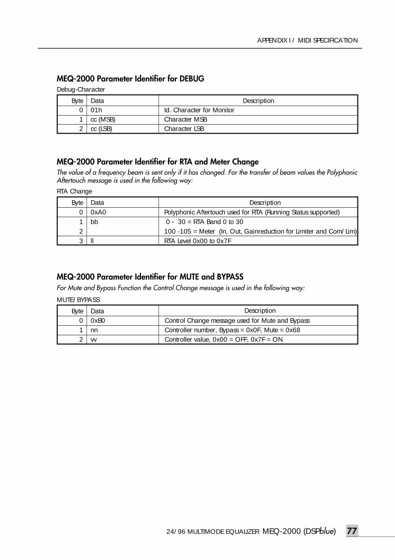
24/96 MULTIMODE EQUALIZER MEQ-2000 (DSPblue) 77
APPENDIX I / MIDI SPECIFICATION
MEQ-2000 Parameter Identifier for DEBUG
Byte0123
Data0xA0bb
ll
RTA Change
DescriptionPolyphonic Aftertouch used for RTA (Running Status supported)0 - 30 = RTA Band 0 to 30
100 -105 = Meter (In, Out, Gainreduction for Limiter and Com/Lim)RTA Level 0x00 to 0x7F
Byte012
Data01hcc (MSB)cc (LSB)
Debug-Character
MEQ-2000 Parameter Identifier for RTA and Meter ChangeThe value of a frequency beam is sent only if it has changed. For the transfer of beam values the PolyphonicAftertouch message is used in the following way:
Byte012
Data0xB0 Control Change message used for Mute and Bypassnn Controller number, Bypass = 0x0F, Mute = 0x68vv Controller value, 0x00 = OFF, 0x7F = ON
Description
MUTE/BYPASS
MEQ-2000 Parameter Identifier for MUTE and BYPASSFor Mute and Bypass Function the Control Change message is used in the following way:
DescriptionId. Character for MonitorCharacter MSBCharacter LSB
meq-2000(O/P)_E 2003.9.6 11:43 AM 페이지77
Appendix II : JumpersAppendix II : Jumpers
The MEQ-2000 is configured for interconnection with a proper developed equipment using balanced ana-log inputs and outputs and grounding of pin 7 as defined in the reference literature. (see special issue ofAES JOURNAL, Volume 43, Number 6, 1995 June)Many companies, however, do not follow these rules and cause problems with ground loops and RF noise.Actually we do not like to support all this mess, but if you discover any invincible problems with hum in non-conforming devices, or asymmetrical sources and loads you may check different jumpers settings for analoginputs and outputs.
CH1 input J1 Pin 1 openJ2 Pin 1 signal ground J3 Pin 1 housing ground *)J4 Pin 1 housing ground
& signal ground overcapacitors (default)
CH2 input J5 Pin 1 openJ6 Pin 1 signal ground J7 Pin 1 housing ground *)J8 Pin 1 housing ground
& signal ground overcapacitors (default)
CH1 output J17 Pin 1 signal groundJ18 Pin 1 housing ground
(default)
CH2 output J26 Pin 1 signal groundJ27 Pin 1 housing ground
(default)
*) It is highly recommended that the Pin 1 in all inputs and outputs in the device chain is chassis grounded.
Normally the MEQ-2000 is delivered with Hard Bypass function. There is a possibility to switch the jumpersto the Hard Mute mode. In this case the cables BYP-L1/L2 and BYP-R1/R2 have to be removed and thejumpers J13, J14, J15, J16, J22, J23, J24, J25 put in. Finally a software reconfiguration has to be done inin AUX window in UTILITY menu. If for any reason you permanently need –12 dB lower output level than specified, you can change thejumpers J11 and J12 on the analog board from position 1-2 to 2-3.Also on the MIDI, RS-232, and Digital Input/Output boards, a signal ground or ground lift are possible ifnecessary in extreme cases.
All the changes described in Section 6 can be done ONLY by authorized personal.
MEQ-2000 (DSPblue) 24/96 MULTIMODE EQUALIZER
APPENDIX II / JUMPERS
78
meq-2000(O/P)_E 2003.9.6 11:43 AM 페이지78

MADE IN KOREA9007978310
meq-2000(O/P)_E 2003.9.6 11:43 AM 페이지1