Embed Size (px)
Citation preview

OCCURRENCE AND ORIGIN OF SHALLOW GAS HYDRATES OF THE EASTERN MARGIN OF JAPAN SEA AS REVEALED BY CALYPSO AND
CASQ CORINGS OF R/V MARION DUFRESNE
Ryo Matsumoto and Yoshitaka Kakuwa The University of Tokyo, Hongo Tokyo 113-0033
JAPAN
Manabu Tanahashi National Institute of Advanced Industrial Science and Technology
C-7 Tsukuba Ibaraki 305-8567 JAPAN
MD179 Shipboard Scientists
ABSTRACT Thermogenic gas hydrate accumulates in shallow sediments to form "hydrate mounds", 200-500 m across and 20-40 m high, which are often associated with methane seeps, bacterial mats, and carbonate crusts. Gas chimneys, 1-2 km in diameter, well develop below the surface gas hydrate accumulation zones. On the other hand, deep subsurface gas hydrates have been inferred from strong BSRs at 110-130 mbsf. In June 2010, R/V Marion Dufresne sailed to the area to delineate the entire sequence of gas hydrate-bearing mound and to reach down to the deep-seated gas hydrate deposits. Robust box corer CASQ penetrated down to 10 mbsf on hydrate mounds and recovered mixed-gas hydrate and carbonates with soupy sediments, whereas giant piston corer Calypso could not penetrate through the mixed hydrate-carbonate zones, but often bent or broken. Calypso corer was, however, powerful to penetrate through the sediments off mounds as deep as 40 mbsf and recovered deep subsurface gas hydrate of mixed thermogenic-microbial methane. Calypso has also revealed complete sequence of gas hydrate bearing sediments. The sequence is represented by Unit I: 3-6 m thick bioturbated units, Unit II: 20-35 m thick beds composed of dark gray thinly laminated units interbedded with bioturbated units, occasional debris flow deposits and ash layers, and Unit III: 5 m+ thick bioturbated and massive units. Units I/II and Units II/III have been dated as approximately 10 ka and 100 ka, respectively. Dark gray, laminated units are likely to have deposited in stagnant bottom waters during the low stand of glacial or stadial episodes. The relation between gas hydrate mounds and the stratigraphy give critical constraints on the growth of gas hydrate mounds and mechanism of gas hydrate accumulation during the glacial-interglacial perturbation.
Keywords: mound and pockmark, gas hydrate, Japan Sea, giant piston corer, Marion Dufresne
Corresponding author: Phone/Fax: +81-3-5841-4522 E-mail: [email protected]
INTRODUCTION Large pockmarks and mounds, 50 to 500 m in diameter and 10 to 50 m deep and high, respectively, were found on the crest of NNE-SSW trending ridges, Umitaka spur and Joetsu
knoll, at water depth of 900-1000 m in the Joetsu basin, eastern margin of Japan Sea (Fig. 1). Piston coring and ROV dives have identified visible gas hydrates in the form of layer, platy and nodular concentration or fracture filling veins in surface
Proceedings of the 7th International Conference on Gas Hydrates (ICGH 2011), Edinburgh, Scotland, United Kingdom, July 17-21, 2011.

sediments and even on the mounds on the spur and knoll. Gigantic methane plumes, 600-700 m high, and gas venting have been observed on and around the mounds in close association with bacterial mats and carbonate crusts and concretions [1,2]. ROV and AUV have found exposures of massive gas hydrate on the mounds. The mounds were presumably formed as swells caused by massive accumulation of gas hydrates, but piston coring recovered only a few meters thick gas hydrate bearing sediments from top of the mounds probably because the PC penetration was blocked by the mixture of massive gas hydrate and carbonate concretions. The Joetsu basin is located in the southern end of the tectonic mobile zone corresponding to the incipient convergent boundary between the eastward moving Amrian micro-plate, the eastern edge of the Eurasian plate, and the North American plate. Formation of a series of ridges, troughs and basins were initiated by tectonic inversion of the stress-field from extension to compression at around 2-3 Ma [3]. The Umitaka spur and Joetsu knoll are regarded as uplifted antiforms bounded by eastward dipping reverse faults. Seismic profiles have demonstrated a few 100 m to a few km wide vertical seismic anomaly zones, called "gas chimney," characterized by acoustically chaotic to transparent zones.
Reflections of bedding planes around the chimney are traceable into the chimney, suggesting that the sediments in the chimneys are not reworked, not derived from below but mostly of in-situ origin. Thus the gas chimneys capped by mounds are not "mud volcanoes" but effective conduits for the migration of gas and gas-bearing fluids. Foraminifer's study revealed that the LGM (Last Glacial Maximum) sediments are extremely poor in benthic forams. However, Rutherfordoides rotundata, benthic foram characteristic to CH4-enriched, low oxygen environments, occurs in the LGM laminated layer. The forma is significantly depleted in isotopic heavy carbon (13C) [4]. Sea level fall of 130 m during the LGM may have caused instability and massive dissociation of subsurface gas hydrate. Occurrence of R. rotundata and negative excursion of 13C seem to indicate a sharp influence of methane during the LGM. However, on the other hand, anoxic conditions of Japan Sea during the LGM have also been explained as the results of restricted vertical circulation within totally enclosed Japan Sea basin [5]. To the contrary, thinly laminated, dark colored units repeatedly occur in the Quaternary Japan Sea sediments corresponding to the episodic warm interval (interstadial). Close relation between the climatic warming and instability of gas hydrate has been proposed for the Quaternary Santa Barbara Basin sediments [6]. What caused the instability of
Figure 1 Map showing the location of the study area of Joetsu basin in the eastern margin of Japan Sea. The study area is situated on the incipient convergent boundary between the Amurian plate of the Eurasian Plate and the North American Plate. Arrows indicate the relative motion of the Pacific Plate and Amurian Plate against the North American Plate.

Japan Sea gas hydrates? Were there any impact of the dissociation of subsurface gas hydrates on marine and perhaps land environments during the glacial periods? High-resolution stratigraphy, and sedimentological and geochemical studies of gas hydrate bearing sediments are crucial to answer the questions as to the environmental impact of gas hydrates. CALYPSO AND CASQ CORING Major objectives of R/V Le Marion Dufresne expedition (MD179) in the Joetsu basin June 15 to 26, 2010 were to (1) retrieve deeper sediment cores from the mounds to determine the depth and amount of gas hydrate of the mounds, and to (2) recover undisturbed sediments down to at least 100 ka to test gas hydrate hypothesis for the Quaternary environmental change. Robust box cores CASQ, 25cm x 25 cm x 9 to 12 m long, were deployed with the weight of 2 or 4 tons on the "hardground" of gas hydrate mounds, while giant piston corer Calypso with the weight of 2 or 4 tons, 10 cm in diameter x 15 to 50 m long, were used for long core sampling. Calypso recovered 40 m long continuous sediment cores down to >100ka, however, the deployments on gas hydrate mounds were rejected by hardground, and bend or broken, not successful to recover deep gas hydrate sediments, while CASQ penetrated down to ~10 m deep, and mixed gas hydrate and carbonate concretion were recovered. Core-recovery was, however, often 10 to 50% due to dissociation of gas hydrate during core recovery. During coring and core retrieval, gas hydrate in cores should be stable in low temperature and high-pressure condition of the bottom and intermediate waters, while the hydrates should start to dissociate at
around the depth of water of 270 mbsl at which the temperature drastically increases to the surface water. Pressure build up by an intensive methane release from gas hydrate caused violent blow out from both the top and bottom of the corer (Fig. 2). Locations of coring sites are shown in Figures 3 and 4. Core ID of CASQ is indicated by denote "C" and Calypso gravity by "G". On the Umitaka spur (Fig. 3), MD179-3296 was dropped near the edge of a pockmark. MD179-3297C, 3303C, 3305G, 3306, 3298, 3307C, 3300C, and 3309 were all deployed on mounds but 3303C, 3298, and 3309 failed to penetrate down through gas hydrate and carbonate mixture and severely bent or broken. MD179-3299, 3301, 3304 on the spur and MD179-3303 in the trough were all successful to take long cores to represent reference section on the spur. On the Joetsu knoll (Fig. 4), MD179-3314G was deployed on the mound, where ROV identified large gas hydrate exposures, but the core recovery was nothing. Another mound site, 3318C, took 1.9 m long gas hydrate bearing sediments with lots of carbonate concretions. MD179-3319 and 3324C were deployed on landslide to examine the timing and mechanism of collapse and slide. MD179-3320 is located on debris flow deposits at the foot of the slide. Unnamed ridge sites, MD179-3308 and 3312 showed good recovery, 31 m and 41 m long sediment cores, respectively. LITHOFACIES AND STRATIGRAPHY Lithology and the sedimentary sequence of sediment cores well demonstrate the characteristics of the location (Fig. 5). Reference cores taken from flat seafloor on the spur (MD179-3296, 3304, 3299), knoll (3320), and the trough between the spur and knoll (3313), and
Figure 2 Gas and gas hydrate blow out at sea surface upon recovery of MD179-3305 (left) and gas and mud blow out from MD179-3317 on deck (right).
terrace on a ridge (3312) show typical Quaternary sedimentary sequence, which is primarily composed of inter-bedded, dark colored thinly laminated unit and bioturbated massive unit with occasional intercalation of a few mm to 5 cm thick regional and local ash beds. Ages of the sediments were determined by 14C dating of the tests of foraminifers, wood fragments, or determined by
the chronology of regional tephra. Oldest tephra, Toya (112ka) was encountered at 27 mbsf in MD179-3312. Age-depth relation at MD179-3312 has been constructed by 14C ages and tephra chronology (Fig. 6). Sedimentation rate for the recent 90,000 years is surprisingly constant at 25.6 cm/ky, while the rate decrease down to 18.8 cm/ky for 90 ky to 122 kyBP.
Figure 3. Map showing the coring site on the Umitaka spur during the MD179 expedition.
Figure 4 Map showing the coring site on the Joetsu knoll and the Unnamed ridge during the MD179 expedition.

F
igur
e 5
Age
-dep
th c
orre
lati
on a
t MD
179-
3312
on
the
Unn
amed
rid
ge.

Bar code alongside the columns represents dark and light color change. Thirty thinly laminated units (TL layer) have been recognized in in dark colored part of the core MD179-3312 taken from a terrace on the crest of unnamed ridge NE of the Umitaka spur (Fig. 4). Two to three meter thick thinly laminated unit (TL 2) occurs at around 2 to 6 mbsf in almost all sites except for intensively deformed, chaotic sections of the gas hydrate mounds. TL-2, dated approximately 15 to 25 ka, represents the anoxic condition of the low stand in LGM, while the another TL layers may correspond to the warm climate episodes (interstadial) of the last glacial [6,7]. Symbol of gas hydrate in long cores indicates strong but not direct evidence of the occurrence of gas hydrate such as soupy horizon in ash and sand layers and sharp negative anomaly of chloride concentration (See interstitial water chemistry). Based on the sedimentary sequences observed in reference sites, 122 kys sedimentary sequence of the Joetsu basin are divided into three parts in descending order. Unit I : 3 to 6 m thick, massive to weakly bioturbated unit, Unit II : 20 to 35 m thick, inter-bedded, dark colored thinly laminated unit with light colored weakly laminated to
massive unit, and Unit III : > 5 to 8 m thick, slightly bioturbated unit with abundant ash beds. Unit boundary I/II and II/III are placed on the top of thick laminated unit TL-2 of approximately 10ka and at regional tephra SK of 100ka (Fig. 5). Short cores, MD179-3306 and 3318C, taken from gas hydrate mounds are entirely composed of mixture of gas hydrates and carbonate concretions in dark gray mud. MD179-3306 is only 3.4 m thick but mud-stained stainless tube indicates that the corer penetrated down to 10 m deep. The core 3306 violently blew out on deck, splashing large amount of gas hydrate, mud, fluids and gases. Gas hydrate and carbonate mixture is likely to develop at least 10 m below seafloor. MD179-3317, deployed in the center of pockmark on the Joetsu knoll, is composed of thick pile of reworked clasts and debris flow deposits. The 14C ages of wood fragments indicate that the collapse of the pockmark edge and debris flows occurred even after the LGM. Weakly laminated unit at 2 t o 2.5 mbsf, probably the uppermost part of TL-2, should be younger than 14 ka. Pockmarks of the study area have been considered to be inactive; no methane plumes, no gas hydrate, no bacterial mats. However, the sediments at MD179-3317 contain large and massive gas hydrate at two horizons. Gas chemistry suggests that gas hydrates of MD179- 3317 are significantly affected by 13C-depleted microbial methane, different from shallow and surface gas hydrates on the mounds. INTERSTITIAL WATER CHEMISTRY Interstitial waters were squeezed onboard and stored in glass vial for laboratory experiments (Tomaru et al., this volume). Figure 7 shows the depth profile of chlorine concentration (mMol/L) of cores taken from different locations. Cores on gas hydrate mounds, MD179-3306, shows anomalously high concentration even at shallow depth intervals, while at the pockmark site, MD179-3317, chlorine concentration increases with depth with sharp negative spikes at 19.5mbsf and 30.0 to 31.0 mbsf. Hypersaline waters observed at MD179-3306 and 3317 are due to the formation of gas hydrate. Gas hydrate excludes salt from the lattice, resulting in high chlorine concentration in residual waters. The mixing with ambient pore waters is to dilute hypersaline residual waters. Therefore, the existence of hypersaline waters is a clue to identify rapid precipitation of gas hydrate. Low salinity spikes as an evidence of gas hydrate was detected only at
Figure 6 Age-depth correlation at MD179-3312 on the Unnamed ridge.

two horizons, but the chlorine profile at MD179-3317 seems to indicate a wide and intensive distribution of invisible gas hydrate in debris flow deposits of the pockmark. Chlorine in basin floor core, MD179-3313, is nearly constant at 450-500 mMol/L of the sea water level, while the cores in an inactive pockmark, MD179-3296, and at the edge of inactive pockmark, MD179-3304, demonstrate a weak decreasing trend with depth (Fig. 7). The profiles imply a build up of hyposaline water mass at depths, presumably reflecting massive dissociation of subsurface gas hydrate at around the base of gas hydrate stability as proposed by [8]. OCCURRENCE AND CHARACTERISTICS OF GAS HYDRATES Upon recovery on deck, all the piston cores were scanned with IR detector to identify low temperature anomaly due to endothermic dissociation of gas hydrate during core recovery. Cold spots were immediately drilled by hand-held drilling machine to release and collect gases derived from gas hydrate. Gas hydrate bearing zones were cut and opened before normal core handling procedure for quick observation of the textural relation and sampling of fresh gas hydrates for further analysis. CASQ box cores were opened on deck within one hour after recovery for observation, description and sampling.
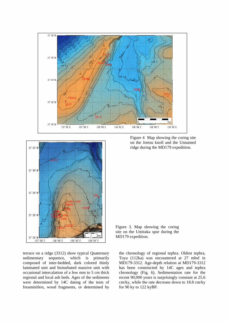
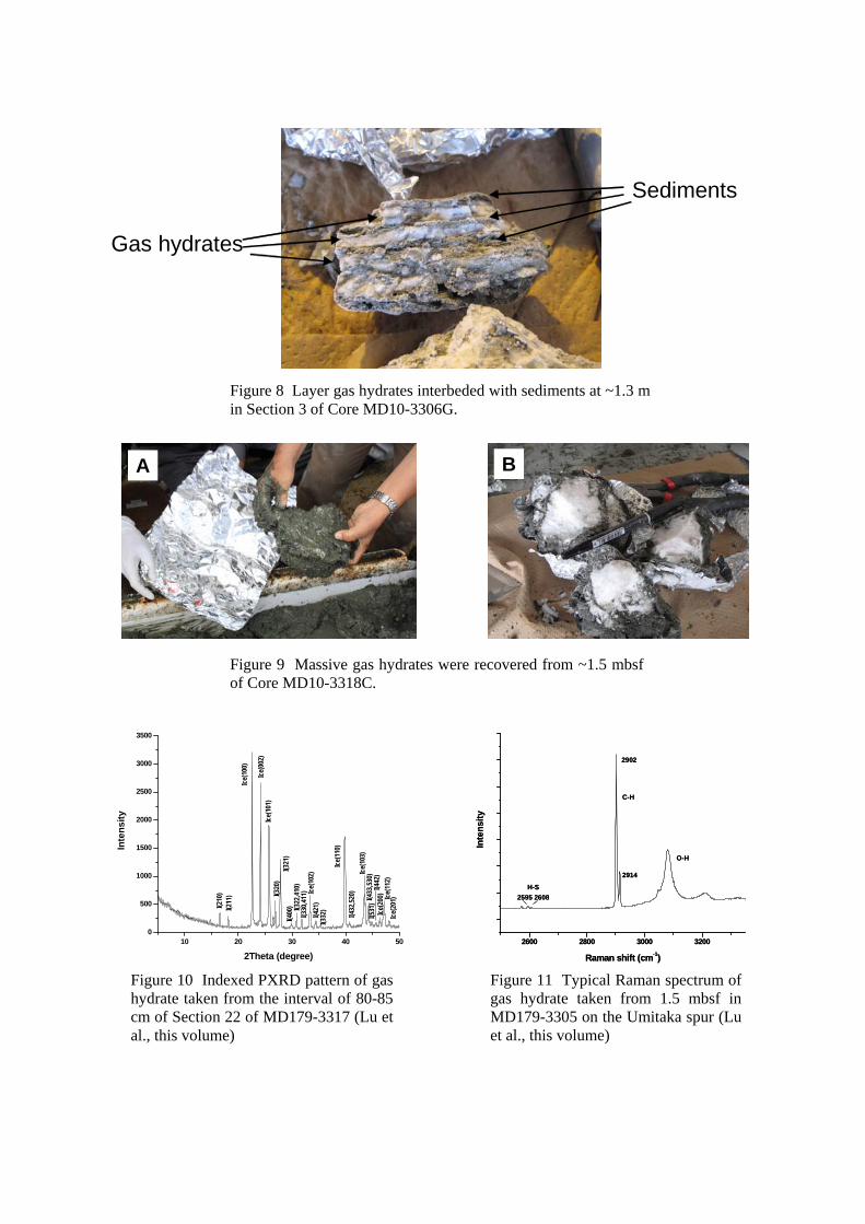
Because of an intensive dissociation of gas hydrate, gas hydrate bearing CASQ cores were strongly disturbed with occasional soupy horizons. Gas hydrate in Calypso piston cores often occurs as platy, layer to lenticular aggregates parallel to the bedding (Fig. 8), seems to have grown in lithologic boundaries or fractures, whereas CASQ cores often yield a few cm long broken chunks or irregularly shaped nodules. Largest rounded nodule, 15 to 18 cm in diameter (Fig. 9), was retrieved from the Joetsu knoll. Gas hydrate often occurs in close association with carbonate concretions of various size and shape. The carbonate concretions are observed to be composed of aragonite, high magnesian calcite, or dolomite with low carbon isotopic composition [9]. This seems to imply that gas hydrate formation took place in shallow sediments where methane-induced carbonates were precipitated in relation with anaerobic methane oxidation [1]. Structural characterization has been conducted at Steacie Institute for Molecular Sciences, NRC Canada (Lu et al., this volume). Powder XRD analysis by Bruker D8 Advance Powder X-ray diffractmeter has revealed that the gas hydrates from the study area are all structure I as shown in Figure 10. Raman spectrometry with an Acton SpectroPro 2500i has identified anomalous peaks at 2595 and 2608 cm-1 stand for hydrogen sulfide in the large and small case of sI gas hydrate,
Figure 7 Depth profile of chlorine concentration (mMol/L) of the
interstitial waters (Tomaru et al., this volume).
Sediments
Gas hydrates
A B
Figure 8 Layer gas hydrates interbeded with sediments at ~1.3 m in Section 3 of Core MD10-3306G.
Figure 9 Massive gas hydrates were recovered from ~1.5 mbsf of Core MD10-3318C.
10 20 30 40 500
500
1000
1500
2000
2500
3000
3500
Inte
nsi
ty
2Theta (degree)
MD10-3317Section 2~80 cm
I(210
)I(2
11)
Ice(
100)
Ice(
002)
Ice(
101)
Ice(
102)
Ice(
110)
Ice(
103)
Ice(
200) Ic
e(11
2)Ic
e(20
1)
I(320
)I(3
21)
I(400
) I(322
,410
)I(3
30,4
11)
I(421
)I(3
32)
I(432
,520
)
I(433
,530
)I(5
31)
I(442
)
2600 2800 3000 3200
Inte
ns
ity
Raman shift (cm-1)
H-S
C-H
O-H
2902
2914
2595 2608
2600 2800 3000 3200
Inte
ns
ity
Raman shift (cm-1)
H-S
C-H
O-H
2902
2914
2595 2608
Figure 10 Indexed PXRD pattern of gas hydrate taken from the interval of 80-85 cm of Section 22 of MD179-3317 (Lu et al., this volume)
Figure 11 Typical Raman spectrum of gas hydrate taken from 1.5 mbsf in MD179-3305 on the Umitaka spur (Lu et al., this volume)

respectively. Large peaks at 2902 and 2914 cm-1 (Fig. 11) are from the methane molecules in the large and small cages of sI. The analytical results strongly suggest that the Joetsu gas hydrates were formed in shallow sediments above the sulfate-methane interface (SMI), well consistent with shallow occurrence gas hydrates and the close association with methane induced carbonates. 13C OF HEADSPACE GAS Gases dissolved in the interstitial waters were extracted and collected in headspace and measured for molecular and isotopic compositions (Hachikubo et al., this volume). Figure 12 shows the depth profile of 13C of methane, which widely ranges from -97.5‰VPDB, typical microbial methane to -30.0‰VPDB, typical thermogenic methane. Methane from the active mound sites, MD179-3318 and 3306, are predominated by 13C-enriched thermogenic methane, ranging in 13C between -59 to -31‰VPDB, while those from the basin floor site, MD179-3313, are composed of microbial methane ranging between -97.5 to -71.0‰VPDB. The reference site, 3296, active pockmark site, 3317, and inactive pockmark site, 3296, are plotted in the intermediate range (Fig. 12), suggesting variably mixed microbial and thermogenic methane. 13C of methane at 4 sites except for active mounds increases with depth (Fig. 12). The depth profile may suggest microbial
methane production at shallow depths just below the sulfate-methane interface at a few mbsf. SUMMARY - FORMATIVE PROCESSES OF GAS HYDRATES 1. Sedimentary sequence on and around the gas hydrate bearing Umitaka spur and Joetsu knoll is made up of three units: Unit I (0 to 10ka; 3 to 6 m thick), Unit II (10 to 100ka; 20 to 35 m thick), and Unit III (100ka+; 8 m+). Sediment fill in pockmark exhibits the standard sequence made up of Units I, II and III, suggesting that the pockmarks on the spur and knoll are older than 120ka, MIS 5e. 2. Two to three meter thick, dark colored thinly laminated unit (TL-2) well develop at 3 to 6 mbsf all over the study area. However, the unit never occurs in sediments recovered from gas hydrate mounds. This seems to suggest that shallow accumulation of gas hydrate and precipitation of CH4-carbonates entirely disturbed the original sedimentary structures of TL units and still continue to build up the hydrate mounds. 3. Pockmark of MD179-3317 is filled by reworked debris dated 14ka to 24ka. The entire sequence of the core is strongly affected by gas hydrate formation as suggested by hypersaline waters. This also implies that the hydrate precipitation is very recent phenomena. 4. Shallow gas hydrates are predominated by thermogenic gas as well as gas venting from the
Figure 12 Depth profile of the 13C of methane in the
headspace gas extracted from the interstitial waters (Hachikubo et al., this volume)
sea floor. Massive nodular gas hydrate at the bottom of MD179-3317, which may represent subsurface gas hydrate, is strongly affected by microbial gas. This implies that deep gas hydrate, which is responsible for BSR, is composed of mixed microbial and thermogenic gases. 5. Rapid formation of gas hydrates on and within gas hydrate mounds is strongly suggested by hypersaline residual waters. 6. To the contrary, low salinity water is explained to have been derived from the deep-seated "hypo-saline" water pools, which could be ascribed to the massive dissociation of subsurface gas hydrate at 100 to 130 mbsf, the base of gas hydrate stability. Build up of the hyposaline pool may be related with the formation of pockmark. If this is the case, sea level fall at MIS 6 and termination 2 events may be responsible for the development of the pockmarks, and perhaps the environmental perturbation of Japan Sea. ACKNOWLEDGEMENTS We thank IPEV coring experts and crews of R/V Marion Dufresne for their tremendous efforts to make the expedition MD179 successful and fruitful. This study has been financially supported by the cooperative research project of the MH21 Research Consortium Japan and the Grant-in-Aid from the Japan Society for the Promotion of Science, KAKENHI to RM, 19204049. REFERENCES [1] Matsumoto, R., 2005, Methane plumes over a marine gas hydrate system in the eastern margin of Japan Sea: A possible mechanism for the transportation of subsurface methane to shallow waters. Proceedings of the 5th International Conference on Gas Hydrates, Trondheim, 749-754. [2] Matsumoto, R., et al., 2009, Formation and collapse of gas hydrate deposits in high methane flux area of the Joetsu basin, eastern margin of Japan Sea. Journal of Geography, 118, 43-71. [3] Sato, H., 1994, The relationship between late Cenozoic tectonic events and stress-field and basin development in northeast Japan. Journal of Geophysical Research, 99, 22261-22274. [4] Nakagawa, H., Suzuki, M., Takeuchi, E., and Matsumoto, R., 2009, Lithofacies and Foraminiferal Stratigraphy for the Last 32,000 years in the methane seep area of Umitaka spur off Joetsu. Journal of Geography, 118, 969-985.
[5] Oba, T., 1984, Stable isotopic ratio of oxygen and carbon - from the analysis of KH-79-3, C-3 core - . Earth Monthly, 63, 558-566. [6] Kennett, J. P., Cannariato, K. G., Hendy, I. L. and Behl, R. J., 2000, Carbon isotopic evidence for methane hydrate instability during the Quaternary interstadials. Science, 288, 128-133. [7] Nakajima, T., Furukawa, K., Ikehara, K., Katayama, H., Kikawa, E., Joshima, M., and Seto, K., 1996, Marine sediments and Late Quaternary stratigraphy with special reference to the formation of dark layers. Journal of Geol. Soc. Japan, 102, 125-138. [8] Hiruta, A., Snyder, G.T., and Matsumoto, R., 2009, Geochemical constraints for the formation and dessociation of gas hydrate in an area of high methane flux, eastern margin of Japan Sea. Earth and Planetary Science Letters, [9] Sanno, R., 2009MS, Origin and the U-Th ages of carbonate concretions of gas hydrate field, Joetsu basin, eastern margin of Japan Sea. Master Thesis, Graduate School of Science, University of Tokyo.