Embed Size (px)
Citation preview

HYDROFEST 2015
The Hydrographic Society in Scotland
Offshore Operations and Project Execution
Geophysical Site Surveys
Chris Almond Senior Geophysicist Fugro Survey Limited
22/04/2015

HYDROFEST 2015
The Hydrographic Society in Scotland
Presentation Summary: Office-based Personnel
Project Awarded – Pre Offshore Phase Offshore Execution of Project
Role of the Geophysicist
Role of the Surveyor & Processing Surveyor
End of Survey – Final Interpretation and Report
in the Office
HYDROFEST 2015
The Hydrographic Society in Scotland
Fugro Survey Limited: • Part of Fugro’s Survey division. − Positioning/Construction support − Geophysical surveys
Office-based personnel: • Operations – Personnel and logistics for offshore staff • Commercial – Tender compilation and submission and contracts • Construction – Provide surveying and processing personnel to ROV construction jobs • Positioning – Provide survey personnel and equipment to rig moves and geotechnical vessels • Geoscience – Geophysical offshore acquisition, in office interpretation and report compilation • Data Centre – Offshore processing, onshore processing, GIS & charting

HYDROFEST 2015
The Hydrographic Society in Scotland
Project Awarded – Pre-offshore Phase
• Handover from Commercial department. • Geophysicist background information: − Previous reports in the area − Geological charts (e.g. British Geological Survey charts) − Seismic velocities from nearby previous surveys • Surveyor/Processor background information: − Historical data in the area − Background infrastructure CAD files to aid in navigation safety − Production of chart templates

HYDROFEST 2015
The Hydrographic Society in Scotland
Offshore Execution – The Survey Team
• Onshore: − Vessel PM, main point of contact between survey vessel and client − Geoscience Team Leader, final report and deliverables coordinator • Offshore : − 1 Party Chief – Overall in charge of the geophysical survey − 2 Online Surveyors (Day/Night) – Operate navigational and positioning equipment − 1 Senior Surveyor – Oversees survey operations and produces preliminary navigation
and bathymetry files (If not dedicated processor) − 1 Technical Coordinator – Responsible for maintenance, set up and safe operation of
all survey equipment − 4 Engineers (Day/Night) – Operate and maintain survey equipment − QC Geophysicist(s) – QC acquired data and carry out preliminary interpretation and
create preliminary reports Optional crew depending on survey type/requirements can include geotechnical geologists, environmentalists, seismic processor and additional geophysicists.
HYDROFEST 2015
The Hydrographic Society in Scotland
Offshore Execution – Survey Types
Requirements from each department on and offshore varies depending on type of survey:
Geophysical Site Survey
• 2D High-resolution seismic data • Single channel seismic profiler (mini-air gun, sparker etc.) • Sub-bottom profiler (chirp, pinger etc,) • Side scan sonar (Both high and low frequency) • Multibeam echo sounder
HYDROFEST 2015
The Hydrographic Society in Scotland
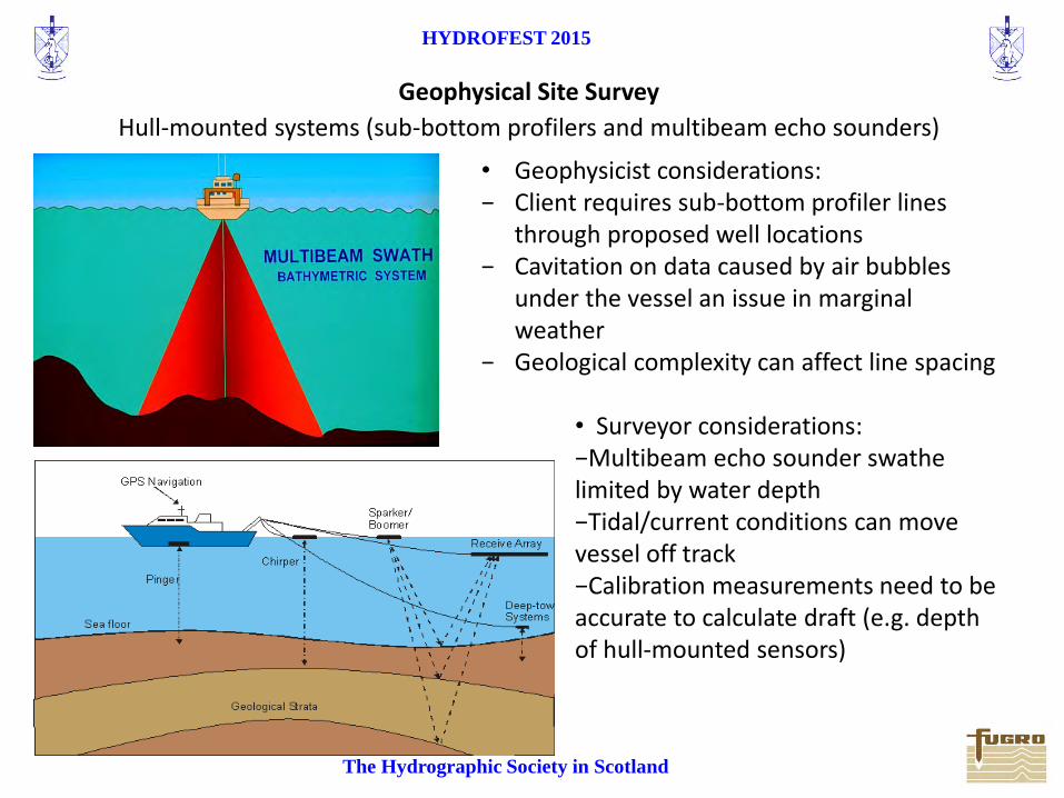
Geophysical Site Survey
Hull-mounted systems (sub-bottom profilers and multibeam echo sounders)
• Geophysicist considerations: − Client requires sub-bottom profiler lines
through proposed well locations − Cavitation on data caused by air bubbles
under the vessel an issue in marginal weather
− Geological complexity can affect line spacing
• Surveyor considerations: −Multibeam echo sounder swathe limited by water depth −Tidal/current conditions can move vessel off track −Calibration measurements need to be accurate to calculate draft (e.g. depth of hull-mounted sensors)
HYDROFEST 2015
The Hydrographic Society in Scotland
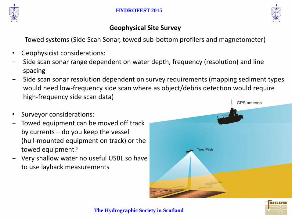
Towed systems (Side Scan Sonar, towed sub-bottom profilers and magnetometer)
• Geophysicist considerations: − Side scan sonar range dependent on water depth, frequency (resolution) and line
spacing − Side scan sonar resolution dependent on survey requirements (mapping sediment types
would need low-frequency side scan where as object/debris detection would require high-frequency side scan data)
• Surveyor considerations: − Towed equipment can be moved off track
by currents – do you keep the vessel (hull-mounted equipment on track) or the towed equipment?
− Very shallow water no useful USBL so have to use layback measurements
Geophysical Site Survey

HYDROFEST 2015
The Hydrographic Society in Scotland
Geophysical Site Survey
2D High-Resolution seismic
• Geophysicist considerations: − Processing-intensive (usually requires day and night shifts) − Equipment setup and deployment − Seismic tow diagrams − Drift of streamer off track (feather
angles)
• Surveyor considerations: − Towed equipment needs
referencing to tow points (need for accurate measurements)
− 1200m streamer increasing line turn times/diameters
− Single direction turns of vessel

HYDROFEST 2015
The Hydrographic Society in Scotland
AUV Surveys
• AUV’s are ideal for large scale field development surveys in deep water. • AUV is equipped with: − Multibeam echo sounder − Side scan sonar − chirp sub-bottom profiler − Tile camera • Capable of >40 hour ‘missions’.
• Geophysicist considerations: − After 40 hours of acquisition
there is a lot of data to process in a short time.
− AUV surveys are often very large field development surveys so there’s a lot of data to keep track of and interpret. • Surveyor considerations: − Shorter line turns are required to maximise survey acquisition creating complex line
plans. − AUV track is pre-planned, however due to changing priorities, obstructions or
deteriorating weather the AUV track can be modified online.

HYDROFEST 2015
The Hydrographic Society in Scotland
Individual Roles - Offshore
Geophysicist
• Quality Control (QC) of the survey data − Identify any poor-quality data and assess the need for re-runs; compile accurate logs − Check data coverage • Preliminary interpretation − Preliminary SSS interpretation for hazards/obstructions close to planned infrastructure
and for environmental sampling locations − SBP interpretation for geotechnical locations − 2DHR brute stack analysis for seismic anomalies (potential shallow gas)
• Liaise with Environmentalists/Geotechnical operators to locate sampling locations and
with surveyors to prioritise run orders, re-runs, multibeam and SSS coverage and processing requirements
• Preliminary reports and operations (technical) reports

HYDROFEST 2015
The Hydrographic Society in Scotland
Individual Roles - Offshore
Surveyor/Processing Surveyor
• Main duties offshore: − Calibrations − Where is the equipment? − Where are we and where are we going? − Where is the data?
HYDROFEST 2015
The Hydrographic Society in Scotland
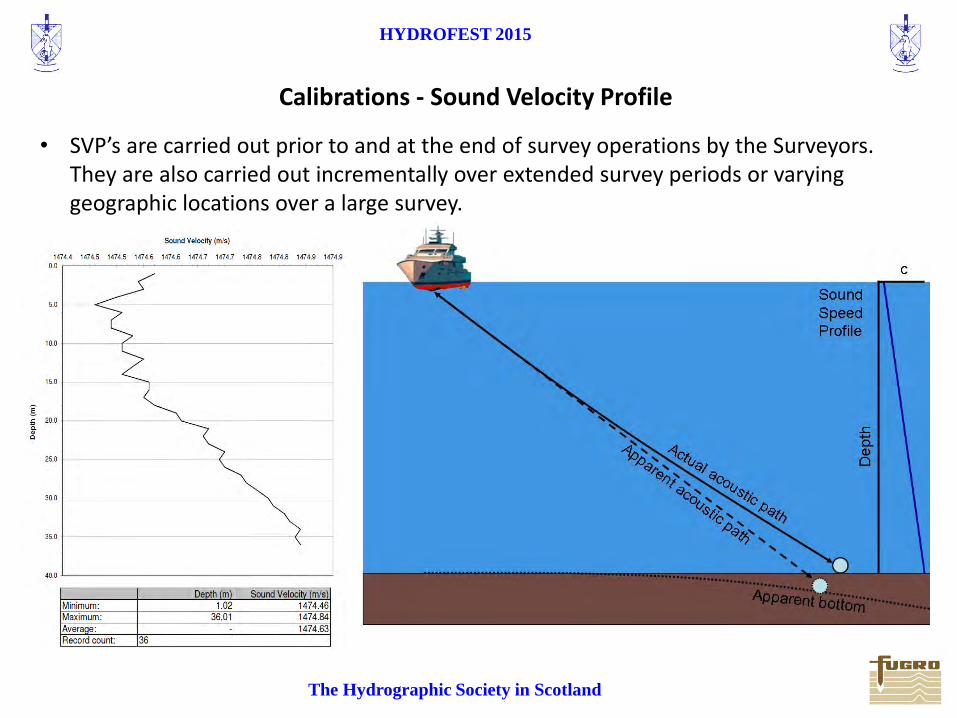
Calibrations - Sound Velocity Profile
• SVP’s are carried out prior to and at the end of survey operations by the Surveyors. They are also carried out incrementally over extended survey periods or varying geographic locations over a large survey.
HYDROFEST 2015
The Hydrographic Society in Scotland
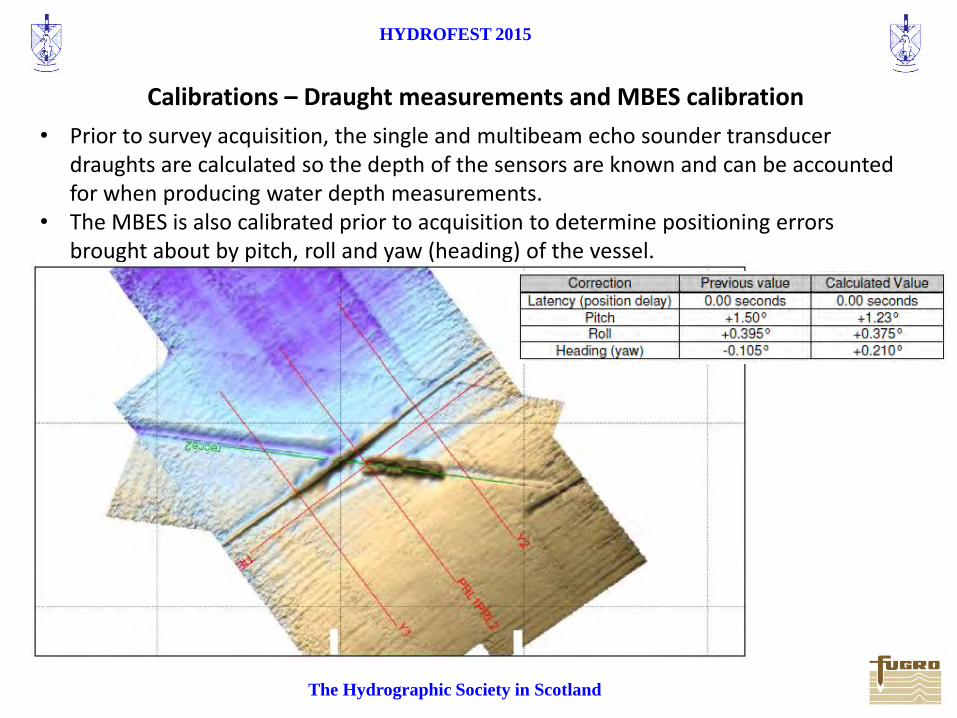
Calibrations – Draught measurements and MBES calibration
• Prior to survey acquisition, the single and multibeam echo sounder transducer draughts are calculated so the depth of the sensors are known and can be accounted for when producing water depth measurements.
• The MBES is also calibrated prior to acquisition to determine positioning errors brought about by pitch, roll and yaw (heading) of the vessel.

HYDROFEST 2015
The Hydrographic Society in Scotland
Where is the equipment?
• In order to accurately map the sea floor and sub-seabed we need to know where the survey equipment is and where it is sampling.
• All sensors, tow points and vessel-mounted equipment are referenced to the vessels common reference point (CRP).
• All towed equipment is fixed to specific tow points, referenced to CRP. • To map all the tow points and equipment the surveyors create ‘fixed
vessel offset diagrams’.
HYDROFEST 2015
The Hydrographic Society in Scotland
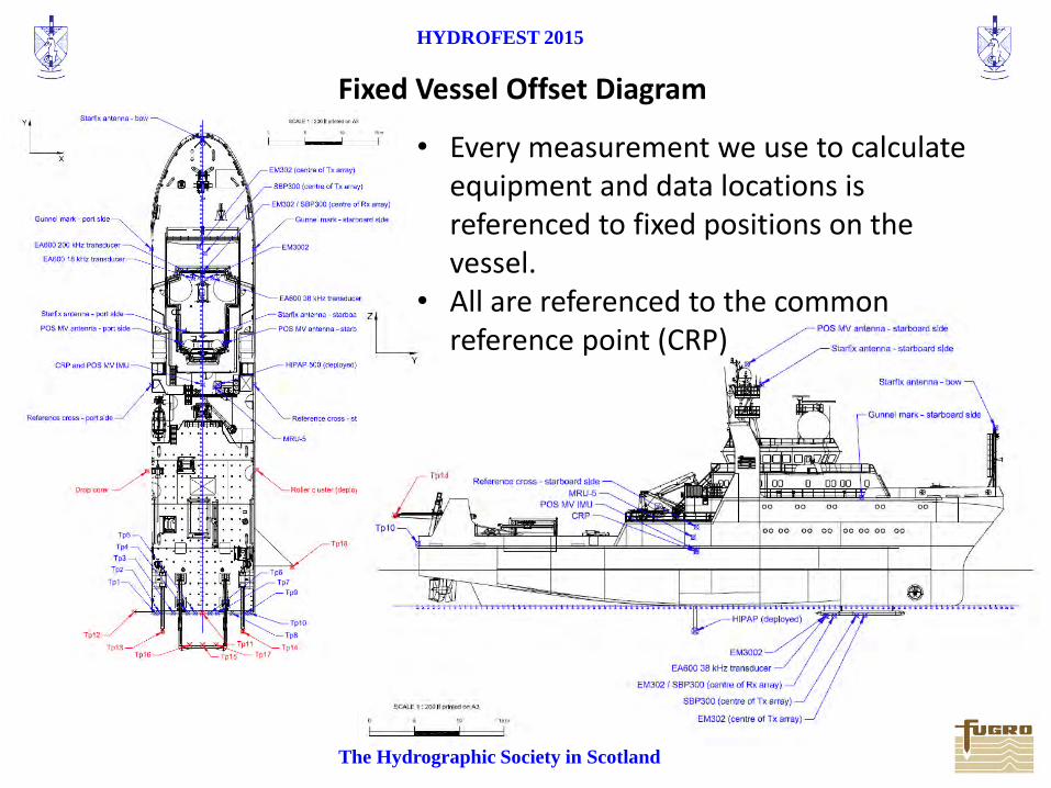
Fixed Vessel Offset Diagram
• Every measurement we use to calculate equipment and data locations is referenced to fixed positions on the vessel.
• All are referenced to the common reference point (CRP)
HYDROFEST 2015
The Hydrographic Society in Scotland
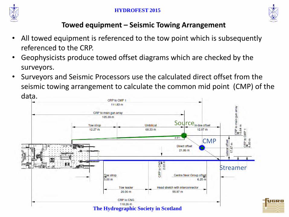
Towed equipment – Seismic Towing Arrangement
• All towed equipment is referenced to the tow point which is subsequently referenced to the CRP.
• Geophysicists produce towed offset diagrams which are checked by the surveyors.
• Surveyors and Seismic Processors use the calculated direct offset from the seismic towing arrangement to calculate the common mid point (CMP) of the data.
Source
Streamer
CMP
HYDROFEST 2015
The Hydrographic Society in Scotland
Where are we and where are we going?
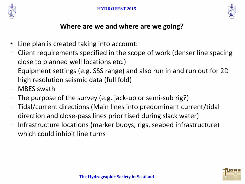
• Line plan is created taking into account: − Client requirements specified in the scope of work (denser line spacing
close to planned well locations etc.) − Equipment settings (e.g. SSS range) and also run in and run out for 2D
high resolution seismic data (full fold) − MBES swath − The purpose of the survey (e.g. jack-up or semi-sub rig?) − Tidal/current directions (Main lines into predominant current/tidal
direction and close-pass lines prioritised during slack water) − Infrastructure locations (marker buoys, rigs, seabed infrastructure)
which could inhibit line turns

HYDROFEST 2015
The Hydrographic Society in Scotland
Where are we and where are we going?
Survey line plans
Semi-submersible Rig Survey Jack-up Rig Site Survey
Densely-spaced survey lines close to proposed well location for accurate geohazard identification & Foundation conditions
larger survey area and wider-spaced survey lines to produce shallow soils charts for anchoring conditions (anchor radius often >1500m)

HYDROFEST 2015
The Hydrographic Society in Scotland
Where are we and where are we going?
Survey line plans
Field development survey (AUV Survey)
5km
HYDROFEST 2015
The Hydrographic Society in Scotland
Where is the Data?
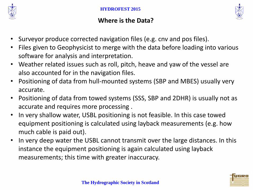
• Surveyor produce corrected navigation files (e.g. cnv and pos files). • Files given to Geophysicist to merge with the data before loading into various
software for analysis and interpretation. • Weather related issues such as roll, pitch, heave and yaw of the vessel are
also accounted for in the navigation files. • Positioning of data from hull-mounted systems (SBP and MBES) usually very
accurate. • Positioning of data from towed systems (SSS, SBP and 2DHR) is usually not as
accurate and requires more processing . • In very shallow water, USBL positioning is not feasible. In this case towed
equipment positioning is calculated using layback measurements (e.g. how much cable is paid out).
• In very deep water the USBL cannot transmit over the large distances. In this instance the equipment positioning is again calculated using layback measurements; this time with greater inaccuracy.
HYDROFEST 2015
The Hydrographic Society in Scotland
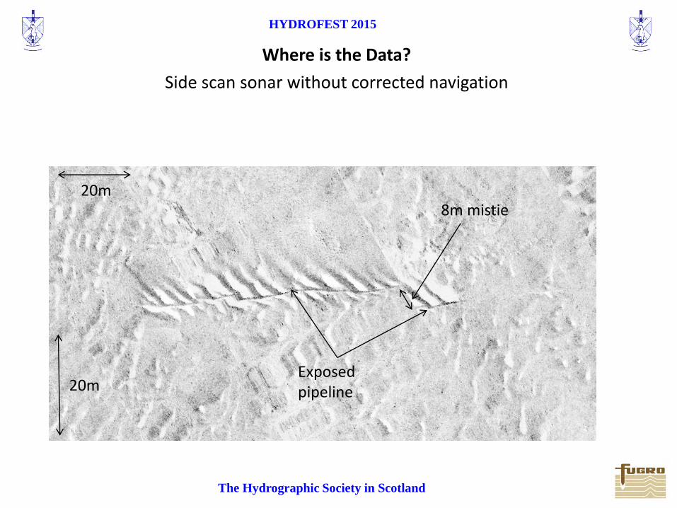
Side scan sonar without corrected navigation
8m mistie
Where is the Data?
20m
20m Exposed pipeline
HYDROFEST 2015
The Hydrographic Society in Scotland
8m
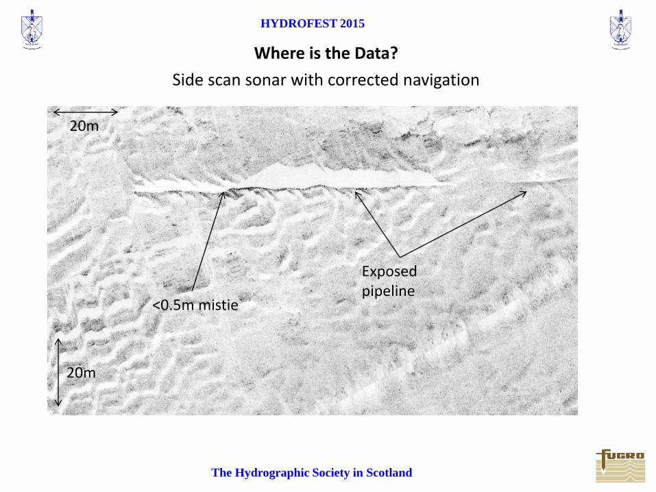
<0.5m mistie
Side scan sonar with corrected navigation
Where is the Data?
20m
20m
Exposed pipeline

HYDROFEST 2015
The Hydrographic Society in Scotland
End of Offshore Operations – Back to the Office
• Before completion of the survey, Surveyors and Geophysicists check data coverage, quality and positioning.
• The Party Chief checks it all over for final QC.
• At all times there is close liaison with the Client Representative.
• A back-up of all the data is created and sent to the office for final interpretation and report writing.
HYDROFEST 2015
The Hydrographic Society in Scotland
What the survey was all about - Data
Data interpretation and report writing
• The positioning files (if made offshore) are checked or created by a Processor. • Final seismic files (segy) are produced by a Seismic Processor and given to
interpretation Geophysicist. • The final bathymetry is processed • A Geophysicist completes final interpretation of the various data sets. • The final report is then written including information about; water depths,
seabed gradients, seabed obstructions, shallow soils, sub-seabed lithologies and potential geohazards.
• The report is then issued along with GIS deliverables (GIS copy of all charts and copy of interpretation) to the client prior to drilling/emplacement of infrastructure.
HYDROFEST 2015
The Hydrographic Society in Scotland
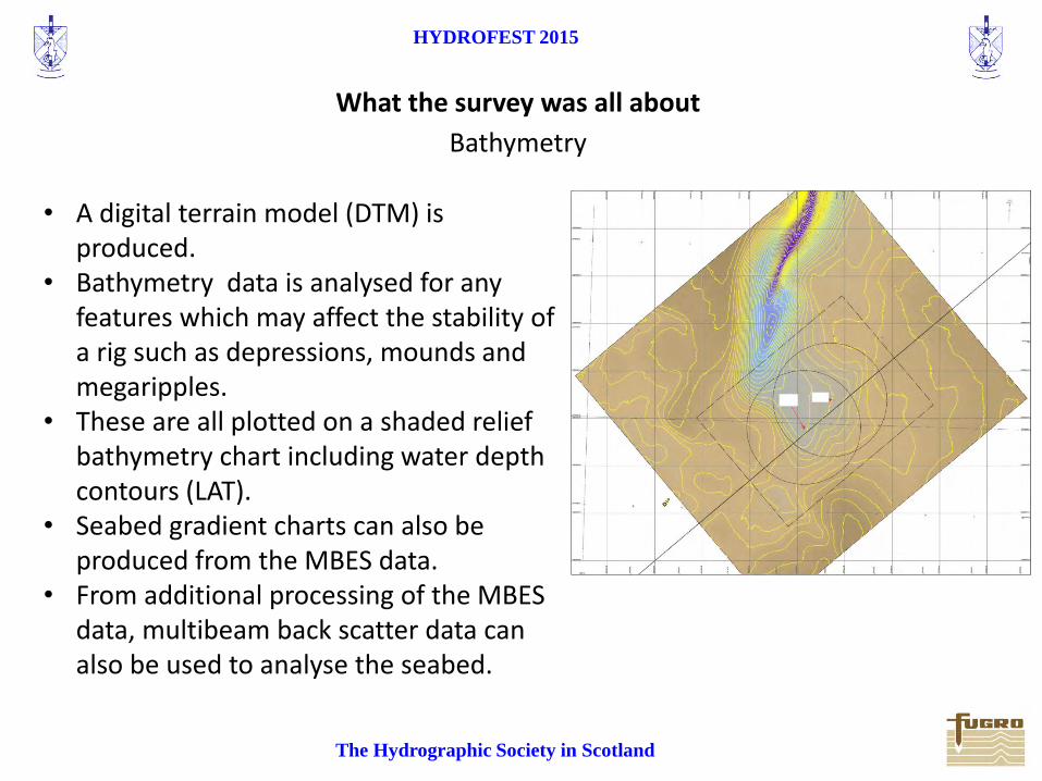
What the survey was all about
• A digital terrain model (DTM) is produced.
• Bathymetry data is analysed for any features which may affect the stability of a rig such as depressions, mounds and megaripples.
• These are all plotted on a shaded relief bathymetry chart including water depth contours (LAT).
• Seabed gradient charts can also be produced from the MBES data.
• From additional processing of the MBES data, multibeam back scatter data can also be used to analyse the seabed.
Bathymetry
HYDROFEST 2015
The Hydrographic Society in Scotland
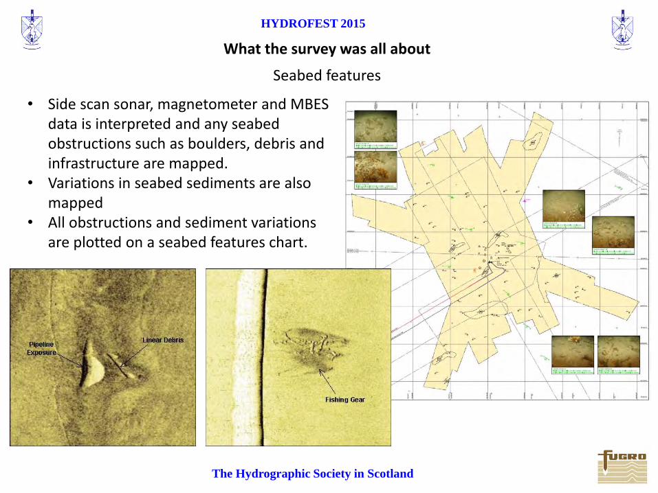
What the survey was all about
• Side scan sonar, magnetometer and MBES data is interpreted and any seabed obstructions such as boulders, debris and infrastructure are mapped.
• Variations in seabed sediments are also mapped
• All obstructions and sediment variations are plotted on a seabed features chart.
Seabed features
HYDROFEST 2015
The Hydrographic Society in Scotland
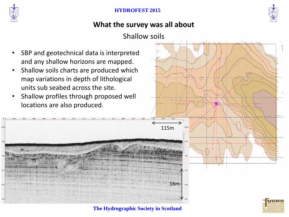
What the survey was all about
• SBP and geotechnical data is interpreted and any shallow horizons are mapped.
• Shallow soils charts are produced which map variations in depth of lithological units sub seabed across the site.
• Shallow profiles through proposed well locations are also produced.
Shallow soils
16m
115m
HYDROFEST 2015
The Hydrographic Society in Scotland
What the survey was all about
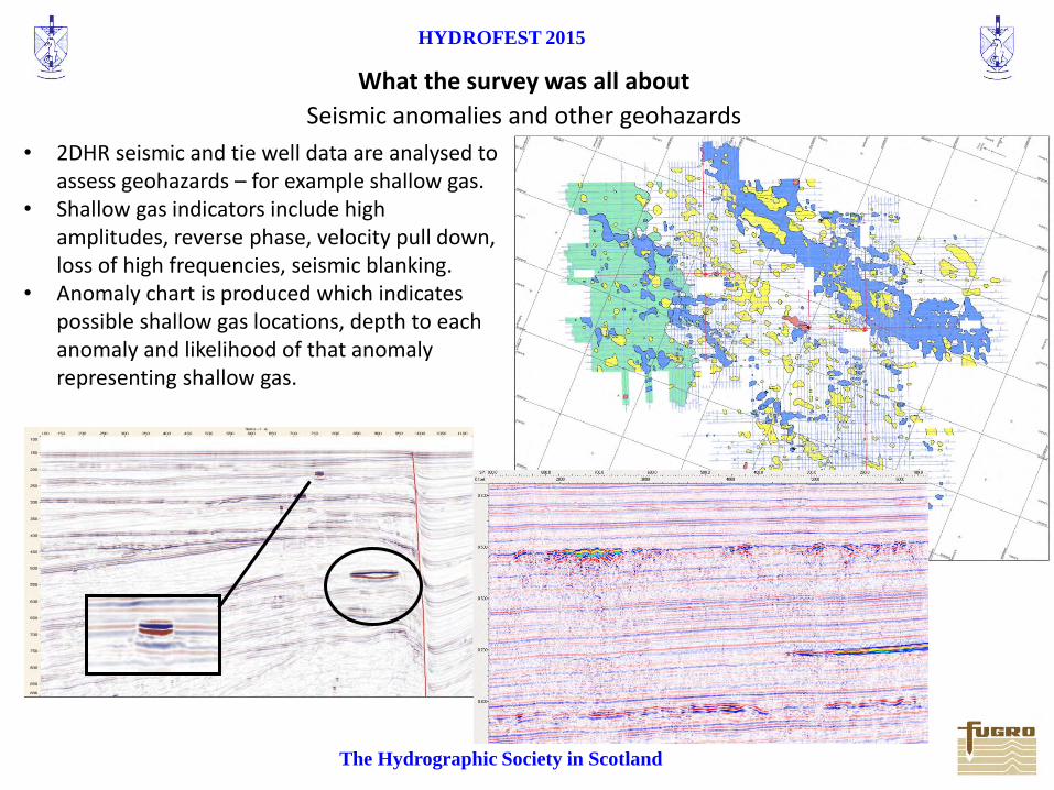
• 2DHR seismic and tie well data are analysed to assess geohazards – for example shallow gas.
• Shallow gas indicators include high amplitudes, reverse phase, velocity pull down, loss of high frequencies, seismic blanking.
• Anomaly chart is produced which indicates possible shallow gas locations, depth to each anomaly and likelihood of that anomaly representing shallow gas.
Seismic anomalies and other geohazards
HYDROFEST 2015
The Hydrographic Society in Scotland
What the survey was all about
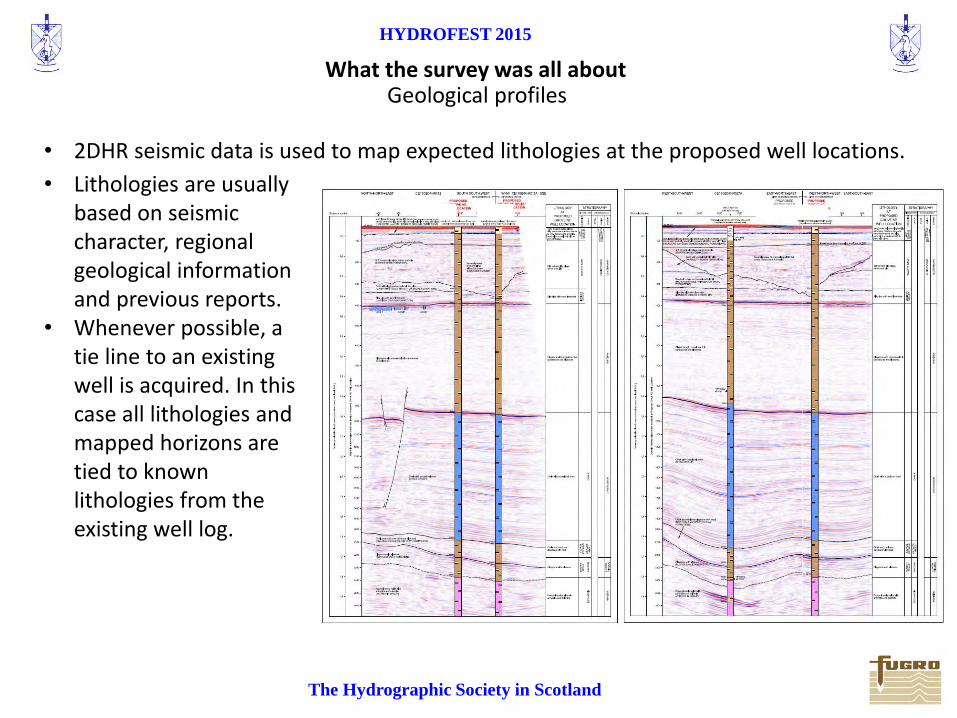
• 2DHR seismic data is used to map expected lithologies at the proposed well locations.
• Lithologies are usually based on seismic character, regional geological information and previous reports.
• Whenever possible, a tie line to an existing well is acquired. In this case all lithologies and mapped horizons are tied to known lithologies from the existing well log.
Geological profiles

HYDROFEST 2015
The Hydrographic Society in Scotland
Thank you
Any Questions?
Chris Almond Fugro Survey Limited
22/04/2015


![ADVERTSING Creative Execution[1]](https://img.pdfslide.tips/doc/110x75/5448ae2cafaf9f39088b4d58/advertsing-creative-execution1.jpg)