Embed Size (px)
Citation preview

GENERAL CATALOGUE
LOOSE
CS10
MOT98
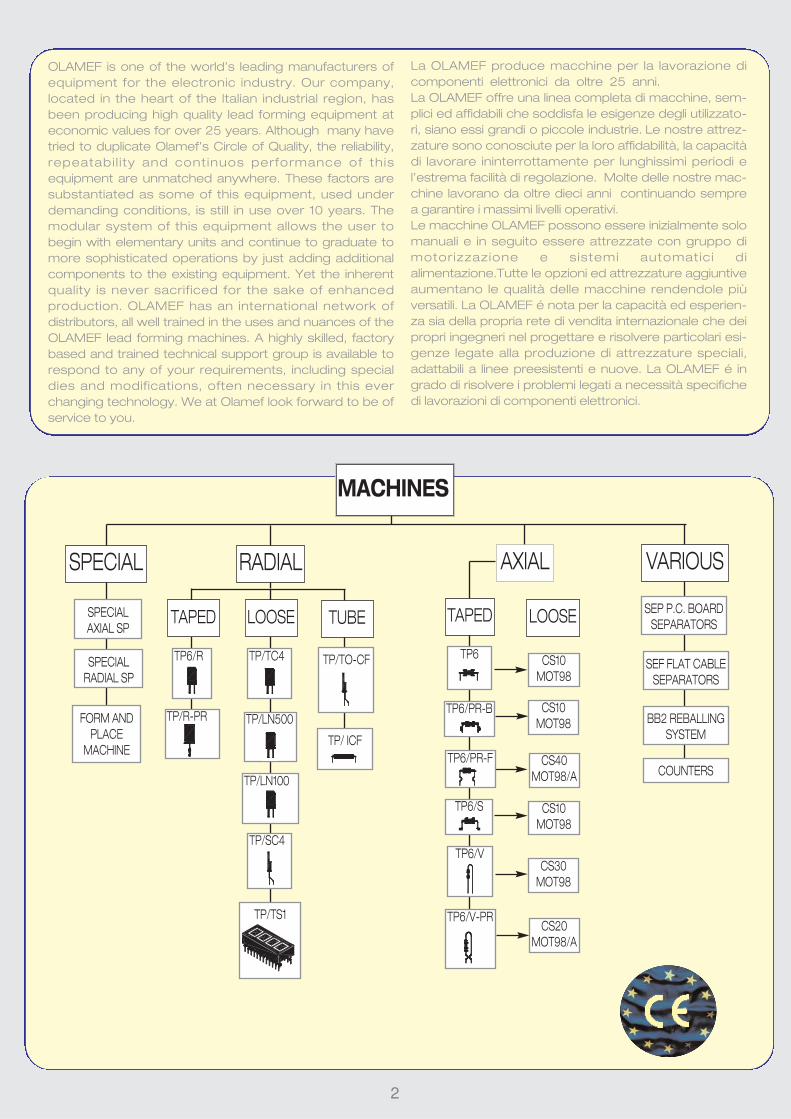
La OLAMEF produce macchine per la lavorazione di
componenti elettronici da oltre 25 anni.
La OLAMEF offre una linea completa di macchine, sem-
plici ed affidabili che soddisfa le esigenze degli utilizzato-
ri, siano essi grandi o piccole industrie. Le nostre attrez-
zature sono conosciute per la loro affidabilità, la capacità
di lavorare ininterrottamente per lunghissimi periodi e
l’estrema facilità di regolazione. Molte delle nostre mac-
chine lavorano da oltre dieci anni continuando sempre
a garantire i massimi livelli operativi.
Le macchine OLAMEF possono essere inizialmente solo
manuali e in seguito essere attrezzate con gruppo di
motor izzazione e sistemi automatic i di
alimentazione.Tutte le opzioni ed attrezzature aggiuntive
aumentano le qualità delle macchine rendendole più
versatili. La OLAMEF é nota per la capacità ed esperien-
za sia della propria rete di vendita internazionale che dei
propri ingegneri nel progettare e risolvere particolari esi-
genze legate alla produzione di attrezzature speciali,
adattabili a linee preesistenti e nuove. La OLAMEF é in
grado di risolvere i problemi legati a necessità specifiche
di lavorazioni di componenti elettronici.
TP/TS1
MACHINES
RADIAL AXIAL
2
TP/SC4
TP/LN100
TP/LN500
LOOSE TUBETAPED
TP6/R
TP/R-PR
TP/TC4 TP6
TP6/V
TP6/S
TP6/PR-B
TP6/PR-F
TP6/V-PR
TP/TO-CF
TAPED
TP/ ICF
SEF FLAT CABLE
SEPARATORS
VARIOUS
OLAMEF is one of the world’s leading manufacturers of
equipment for the electronic industry. Our company,
located in the heart of the Italian industrial region, has
been producing high quality lead forming equipment at
economic values for over 25 years. Although many have
tried to duplicate Olamef’s Circle of Quality, the reliability,
repeatabi l i ty and cont inuos performance of this
equipment are unmatched anywhere. These factors are
substantiated as some of this equipment, used under
demanding conditions, is still in use over 10 years. The
modular system of this equipment allows the user to
begin with elementary units and continue to graduate to
more sophisticated operations by just adding additional
components to the existing equipment. Yet the inherent
quality is never sacrificed for the sake of enhanced
production. OLAMEF has an international network of
distributors, all well trained in the uses and nuances of the
OLAMEF lead forming machines. A highly skilled, factory
based and trained technical support group is available to
respond to any of your requirements, including special
dies and modifications, often necessary in this ever
changing technology. We at Olamef look forward to be of
service to you.
CS10
MOT98
CS40
MOT98/A
CS10
MOT98
CS30
MOT98
CS20
MOT98/A
SEP P.C. BOARD
SEPARATORS
BB2 REBALLING
SYSTEM
COUNTERS
SPECIAL
SPECIAL
RADIAL SP
SPECIAL
AXIAL SP
FORM AND
PLACE
MACHINE
3
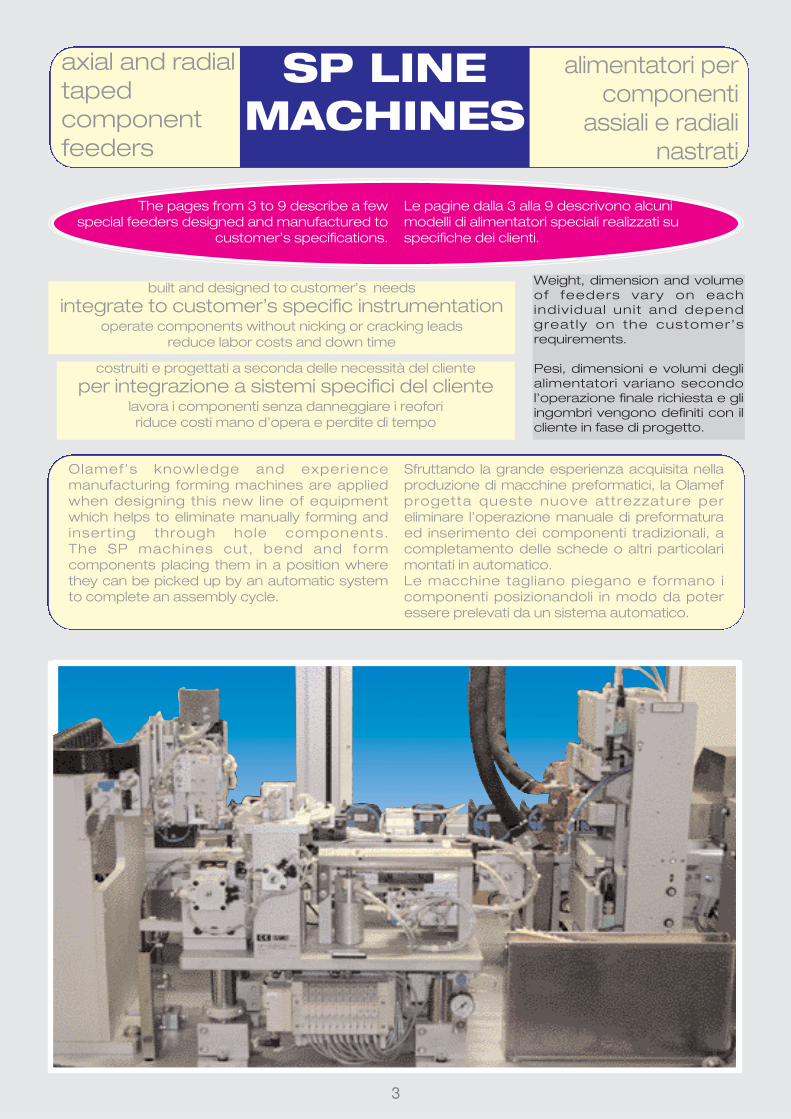
axial and radialtapedcomponentfeeders
SP LINE
MACHINES
alimentatori percomponenti
assiali e radialinastrati
built and designed to customer’s needs
integrate to customer’s specific instrumentationoperate components without nicking or cracking leads
reduce labor costs and down time
The pages from 3 to 9 describe a few
special feeders designed and manufactured to
customer’s specifications.
Le pagine dalla 3 alla 9 descrivono alcuni
modelli di alimentatori speciali realizzati su
specifiche dei clienti.
Olamef’s knowledge and experience
manufacturing forming machines are applied
when designing this new line of equipment
which helps to eliminate manually forming and
insert ing through hole components.
The SP machines cut, bend and form
components placing them in a position where
they can be picked up by an automatic system
to complete an assembly cycle.
Sfruttando la grande esperienza acquisita nella
produzione di macchine preformatici, la Olamef
progetta queste nuove attrezzature per
eliminare l’operazione manuale di preformatura
ed inserimento dei componenti tradizionali, a
completamento delle schede o altri particolari
montati in automatico.
Le macchine tagliano piegano e formano i
componenti posizionandoli in modo da poter
essere prelevati da un sistema automatico.
costruiti e progettati a seconda delle necessità del cliente
per integrazione a sistemi specifici del clientelavora i componenti senza danneggiare i reofori
riduce costi mano d’opera e perdite di tempo
Weight, dimension and volume
of feeders vary on each
indiv idual unit and depend
great ly on the customer’s
requirements.
Pesi, dimensioni e volumi degli
alimentatori variano secondo
l’operazione finale richiesta e gli
ingombri vengono definiti con il
cliente in fase di progetto.

4
SP
22.05
alimentatore pneu-matico passo passo
taglio piega schiac-ciatura diodi nastrati
pneumatic step by
step feeder to cut &swage axial tapedcomponents
SP
22.06
alimentatore pneu-matico passo passo
taglio terminalinastrati metallici
step by steppneumatic feederfor cutting metaltaped terminals
SP
22.08
alimentatore pneumaticoper resistenze assiali
pneumatic step by step
feeder for cutting & bendingtaped axial components

5
lungh. = 62 cm
largh. = 30 cm
alt. = 82 cm
imballo = 62x62x82 cm
volume = 0,31m3
peso macchina = 52 kg
peso lordo = 53 kg
cassa legno = 68 kg
TP7 macchina automaticataglia piega forma
componenti assialinastrati
automatic cutting,bending and formingmachine for taped
axial components
Special automatic machine designed to cut,
bend and form axial taped components to
customer’s specifications. The mechanical
design of the SP line machine has been used
for the TP7 machine with the addition of a PLC
which controls the operation of the pneumatic
cylinders. The tape feeds horizontally and the
components are processed one by one with
the leads held and secured on both sides of the
body before the cut and during the forming
operations to avoid any possible damage to the
components.
E’ una macchina automatica speciale progetta-
ta per il taglio, la piega e la preformatura di com-
ponenti assiali nastrati su specifiche del cliente.
Utilizza la meccanica dell’ormai collaudata linea
SP e viene fornita completamente automatica
con un PLC che comanda i cilindri pneumatici.
L’avanzamento del nastro avviene su asse oriz-
zontale ed i componenti vengono lavorati sin-
golarmente con operazione verticale dall’alto
verso il basso. I reofori del componente vengo-
no bloccati a destra e a sinistra del corpo prima
del taglio e durante le operazioni di preformatu-
ra in modo da evitare ogni possibilità di danneg-
giare i componenti.
speed = 1.200 parts/hour
produzione = 1.200 pezzi/ora
electrical power = 220 v or 110 v - 50hz – 50va alimentazione = 220 v o 110 v- 50hz – 50va
length = 62 cm
width = 30 cm
height = 82 cm
dimensions = 62x62x82 cm
volume = 0,31m3
machine weight = 52 kg
gross weight = 53 kg
crated weight = 68 kg

6
automatic step bystep machine forcutting, formingand positioningtaped radial filters
SP
34.01
macchinaautomatica taglio
preformatura eposizionamento
filtri nastrati
SP34.01 automatic step by step machine for
cutting, forming and positioning taped radial
filters.
This is an example of an automatic hand
“manipulator” that Olamef designed and
manufactured to pick up radial components
from tape, to operate lead bending or forming
at intermediate sites and to position the finished
part where the customer needs it.
La SP34.01 è macchina automatica per il taglio,
la preformatura e il posizionamento filtri.
E’ un esempio di manipolatore che la Olamef
realizza per prelevare i componenti radiali dal
nastro, effettuare lavorazioni ai reofori in una o
più postazioni intermedie e per posizionare il
componente dove necessita il cliente.

7
macchinapneumatica taglio
registrabile epreformaturacondensatori
nastrati
SP
27.02
pneumaticmachine foradjustable cut andform for tapedcapacitors
SP27.02 is a pneumatic machine for adjustable
cut and form to p=8 mm for taped capacitors at
p=12,7 mm.
To increase production, two grippers are utilized
by this model to move components between
the two operation strokes at the same time,
thus reducing time.
La SP 27.02 è una macchina pneumatica taglio
registrabile e la preformatura a p=8 di conden-
satori nastrati a p=12,7.
Per aumentare la produzione questo modello
utilizza due pinze che contemporaneamente
spostano i componenti fra le due fasi di lavoro,
quindi diminuendo il tempo ciclo.

macchinaautomatica,pneumatica
avanzamentonastro, centratura,taglio e forma per
transistors Hallnastrati
SP 26automatic,pneumatic cuttingand formingmachine for tapedHall transistors
SP26 is an automatic, pneumatic cutting and
forming machine for taped hall transistors.
This machine was designed to operate Hall
Transistors which are very delicate and weak
and need perfect positioning on the forming die.
The model SP26 is equipped with a pneumatic
centring gripper that locks the body of the
component. After cutting the component from
the tape the gripper moves it to the subsequent
step (i.e. 90° bending, SMD form or other forms)
and finally places it into a bin or into a set point
where a mechanical hand (robot) can pick it up.
La SP26 è macchina automatica, pneumatica
avanzamento nastro, centratura, taglio e forma
per transistors Hall nastrati.
Questa macchina è stata studiata per la lavora-
zione dei transistor Hall, i quali sono molto deli-
cati e necessitano di molta precisione nel posi-
zionamento sulla matrice di preformatura. Il
modello SP26 infatti utilizza una pinza pneumati-
ca di centraggio e blocca il corpo del compo-
nente. Dopo il taglio dal nastro lo sposta alla
fase successiva (piega a 90°, forma a SMD o
preformature varie) ed infine lo deposita in un
cassettino oppure in un punto fisso per il prelie-
vo da parte di una mano meccanica (robot).
8
SP26.06
Automatic, pneumatic
cutting & bending
machine for taped
radial Hall transistors.
Macchina automatica,
pneumatica per il taglio
e la piega dei transistor
SP26.05
Automatic, pneumatic
cutting & 90° bending
machine for taped
radial Hall transistors.
Macchina automatica,
pneumatica per il taglio
e la piega a 90° dei
Transistor Hall

macchinapneumatica taglio
preformatura adisegno termistori
nastrati
pneumatic machinefor cutting andforming taped thermistors tocustomer’s specifications
9
SP
27.01
alimentatore pneu-matico passo
passo per tagliocomponenti radiali
nastrati
SP21
SP21 pneumatic
step by step
feeder to cut
taped radial
components
(to fit robot
systems)
alimentatore
pneumatico
passo passo
per taglio com-
ponenti radiali
nastrati
SP27.01 pneumatic machine for cutting and forming
taped thermistors to customer’s specifications
macchina pneumatica taglio preformatura a disegno
termistori nastrati
pneumatic step bystep feeder for cuttaped radial components(fit robot systems)

10
Grazie all’esperienza maturata nella realizzazione di centinaia
di alimentatori speciali sia per componenti assiali che radiali
(SP21, SP22, SP26, SP27) la Olamef ha realizzato questa
inseritrice da banco per componenti tradizionali.
Può essere fornita come stazione individuale applicabile
anche direttamente sul nastro della linea SMD, oppure può
essere realizzato un banco di inserimento con più moduli,
ognuno dei quali realizza una forma specifica su componenti
assiali o radiali e li inserisce automaticamente sulle schede
alimentate da un nastro trasportatore.
Entrambe i sistemi sono realizzati secondo le richieste del
cliente e possono inserire, oltre ai componenti assiali e radiali,
anche transistors (TO-220), integrati, connettori ed altri com-
ponenti da stecca.
Thanks to the experience matured with the manufacturing of
hundreds special feeders for axial and radial components
(SP21, SP22, SP26, SP27) Olamef designed this bench
placement machine for through hole components.
It is an automatic machine designed for cutting, bending and
eventual ly forming taped axial components that wi l l
subsequently be inserted into a circuit Board by the same
machine‚s manipulator. The machine can be supplied in
different versions:
It can operate as a selfstanding station with manual load and
unload of the P.C.Boards; it can be located in line. In this case
the components are inserted into the P. C. Board which is
directly positioned on a conveyor belt or on a load/unload
system and this will make the operation fully automatic.
It can be realised on customer’s request and beside axial and
radial parts it can be designed to place also TO-220
transistors, ICs, connectors and other components in tube.
inseritrice
automatica per
componenti
tradizionali
automatic
placement machine
for traditional
components
SP
2006
new

11
400200 BR6
Reel Holder Braccio porta bobina
7915030/31 MOT98MOTORMOTORE
21.0011 TNSWaste tape ejector Espulsore nastro di scarto
Il modello TP6/R viene utilizzato per tagliare i com-ponenti radiali nastrati.La macchina può essere for-nita in due versioni per lavorare due tipi più comunidi nastratura, cioé con fori a passo 12,7 o 15 mm.
The machine Model TP6/R is designed forcutting radial components on tape. It can besupplied in two versions for two types of tape:i.e. with hole pitch = 12,7 or 15mm (.5 or .59”).
MM IN
min max min max
L 2 10 .078 .393
d 0,4 1 .015 .039
D 1 14 0.39 .55
LENGTH = 23 cm
WIDTH = 18 cm
HEIGHT = 21 cm
PACKING = 39x25x26 cm
VOLUME: 0,025 m3
MACHINE WEIGHT = 4 kg
GROSS WEIGHT = 5 kg
LUNG. = 23 cm
LARGH. = 18 cm
ALT. = 21 cm
IMBALLO = 39x25x26 cm
VOLUME = 0,025 m3
PESO MACCHINA = 4 kg
PESO LORDO = 5 kg
30.OL21 P.12,7 mm (0,5”)
30.OL22 P.15 mm (.59”)
cutting machinefor taped radialcomponents
TP6/R macchina taglia componenti
radiali nastrati
LEAD DIA. = 0,4 - 1 mm
(.015-.039”)
PRODUCTION = 20.000 p/h
DIAM. REOFORO = 0,4 - 1 mm
PRODUZIONE = 20.000 p/h
optional accessories accessori opzionali
Ease of set up and use - Facilità di uso e regolazione No maintenance needed - Non richiede manutenzione

12
pneumaticcutting formingmachine fortaped radialcomponents
TP
R-PR
macchinapneumaticataglia formacomponenti
radiali nastrati
SMS preforming assembly (see next page) for the
TP/R-PR machine. SMS is not included in the machine
price and needs to be ordered separately.
SMS gruppo di preformatura (vedi pag.successiva) che
deve essere sempre ordinato con la macchina TP/R-PR
non incluso nel costo della macchina
Il modello TP/R-PR è una macchina pneumatica con
comando a pedale per il taglio e la preformatura di
componenti radiali nastrati. Il nastro è alimentato
manualmente all’interno della matrice e la sua posi-
zione è impostata facilmente. Il gruppo di preforma-
tura “SMS” è sempre fornito con premi-filo per man-
tenere i reofori nella corretta posizione durante la
lavorazione della macchina in modo da evitare stress
o danni al componente. La sostituzione dell’”SMS”,
per variare la forma, richiede pochi minuti.
The AS1 is a feeding system designed
for the TP/R-PR machine. It allows to
reach higher production. It can be
supplied to adapt to the two most
common component tape hole
pitches: 12,7 mm(.5”) code 95.OL11
for 110 v and 95.OL12 for 220 v or 15
mm (.59”) code 95.OL13 for 110 v and
95.OL14 for 220 v.
l’AS1 è un sistema automatico adatta-
bile solo alla TP/R-PR. Questa attrez-
zatura consente al la macchina di
effettuare una maggiore produzione.
Può essere fornito in due versioni per
lavorare i due più comuni passi di
nastratura e cioè: 12,7 mm cod.
95.OL12 oppure 15 mm cod. 95.OL14.
LENGTH = 24 cm
WIDTH = 22 cm
HEIGHT = 24 cm
PACKING = 41x53x32 cm
VOLUME = 0,069 m3
MACHINE WEIGHT = 10 kg
GROSS WEIGHT = 12 kg
LUNG. = 24 cm
LARGH. = 22 cm
ALT. = 24 cm
IMBALLO = 41x53x32 cm
VOLUME = 0,069 m3
PESO MACCHINA = 10 kg
PESO LORDO = 12 kg
PRODUZIONE SU TP/R-PR = 7.000 p/h
ALIMENTAZIONE = 220V - 50 Hz -100VA
LUNG. = 50 cm
LARGH. = 60 cm
ALT. = 18 cm
IMBALLO = 60x60x30 cm
VOLUME = 0,108 m3
PESO NETTO = 15 kg
PESO LORDO = 18 kg
PRODUCTION ON TP/R-PR = 7000 p/h
ELECT.SUPPLY = 220 or 110V - 50 Hz - 100 VA
LENGTH = 50 cm
WIDTH = 60 cm
HEIGHT = 18 cm
PACKING = 60x60x30 cm
VOLUME = 0,108 m3
NET WEIGHT = 15 kg
GROSS WEIGHT = 18 kg
AS1COMPLETE WITH PLATE, DRIVING WHEELS
AND SUPPORT FOR TAPE AND REEL.(Cod. 95.OL11 = 110V - 95.OL12 = 220V)
COMPLETO DI PIASTRA, ANELLI DI TRASCINAMENTO E SUPPORTO PER
NASTRO IN BOBINA
TP/R-PR with SMS and AS1
automatic feeding system
TP/R-PR con SMS e AS1
sistema automatico di alimen-
tazione
The model TP/R-PR is a pneumatic machine
with foot pedal control designed for cutting
and forming taped radial components. The
tape is manually fed into the die and position
is easily adjusted. The die assembly “SMS” is
equipped with a wire holder to keep the
leads firm in position during the machine
operation avoiding any stress or damage to
the part. Changing the “SMS” is very quick
and easy.
optional accessories accessori opzionali
TP/R-PR cod. 90.0000
Manual version - Versione manuale

13
MM IN
min max fix min max fix
a 6 13 .236 .511
b 3 10 .118 .393
c 1,4 .055
d 0,4 0,8 .015 .031
D 1 10 .039 .393
MM IN
min max fix min max fix
a 6 13 .236 .511
b 3 10 .118 .393
c 1,4 .055
d 0,4 0,8 .015 .031
D 1 10 .039 .393
MM IN
min max fix min max fix
a 3 .118
c 1,4 .055
d* 0,4 0,8 .015 .031
D 1 10 .039 .393
MM IN
min max fix min max fix
a 3 10 .118 .393
d 0,4 0,8 .015 .031
D 1 10 .039 .393
MM IN
min max fix min max fix
a 3 8 .118 .314
b* 6 .236
d* 0,4 0,8 .015 .031
D* 1 6 .039 .236
MM IN
min max fix min max fix
a 2,5 8 .098 .314
b* 2 .078
c* 2,5 .098
d* 0,4 0,8 .015 .031
D* 1 10 .039 .393
f* 1 .039
MM IN
min max fix min max fix
a 6 9 .236 .354
b 3 6 .118 .236
c 1,4 .055
p* 1,27 .05
SMS/1 STAND OFF- LOCK INSMS/1 DOPPIA ANSA
(Cod. 93.0001)
standard SMS dieassemblies for TP/R-PR machine
SMS gruppi standard di preformatura permacchina TP/R-PR
MM IN
min max fix min max fix
a 6 13 .236 .511
b 3 10 .118 .393
c 1,4 .055
d* 0,4 0,8 .015 .031
D 1 10 .039 .393
E* 2,2 .086
MM IN
min max fix min max fix
a 6 9 .236 .354
b 3 6 .118 .236
c 1,4 .055
p* 1,27 .05
MM IN
min max fix min max fix
a 6 9 .236 .354
b 3 6 .118 .236
c 1,4 .055
p* 1,27 .05
SMS/3 BODY LOCKED ON P.C.BOARDSMS/3 ANSA A BLOCCAGGIO CON CORPO A BATTUTA
(Cod. 93.0003)
SMS/6 90° BENDINGSMS/6 PIEGA A 90°
(Cod. 93.0006)
SMS/11 TO92 CENTER LEAD SPREAD 3 LEAD LOCKSMS/11 TO92 REOFORO CENTRALE SPOSTATO E DOP-
PIA ANSA SU TRE REOFORI(Cod. 93.0011)
SMS/10 T092 CENTER LEAD SPREAD AND LOCKSMS/10 TO92 REOFORO CENTRALE SPOSTATO CON
ANSA A BLOCCAGGIO(Cod. 93.0010)
SMS/8 TO92 CENTER LEAD SPREAD P.1,27 AND CUTSMS/8 TO92 REOFORO CENTRALE SPOSTATO P.1,27
(Cod. 93.0008)
SMS/7 SURFACE MOUNTINGSMS/7 MONTAGGIO IN SUPERFICIE
(Cod. 93.0007)
SMS/5 POLARITYSMS/5 POLARITA’
(Cod. 93.0005)
SMS/4 STRAIGHT CUTSMS/4 SOLO TAGLIO
(Cod. 93.0004)
SMS/2 STAND OFFSMS/2 ANSA IN APPOGGIO
(Cod. 93.0002)
*= quote to be specified upon order
*= quota da comunicare all’ordine

14
Forme realizzatecon SMS speciali
Forms realisedwith special SMS
We are always designing more and more new
forms in order to satisfy the always increasing
customer request for special applications.
Progettiamo sempre molte nuove forme per
soddisfare la crescente esigenza di applicazioni
speciali.

15
cutting machinefor loose radialcomponents
TP
TC4
macchina taglia componenti
radiali sfusi
ELECT.SUPPLY = 220 or 110V - 50 Hz - 50 VA
WIDTH= 27 cm
DEPTH = 47 cm
HEIGHT = 27 cm
PACKING = 40x30x24 cm
VOLUME = 0,028 m3
MACHINE WEIGHT = 12 kg
GROSS WEIGHT = 19 kg
LEAD DIA. = 0,4 - 0,8 mm (.015-.031”)
PRODUCTION = LOOSE 3.000 p/h
TAPED 15.000 p/h
DIAM. REOFORO = 0,4 - 0,8 mm
PRODUZIONE = SFUSO 3.000 p/h
NASTRATO 15.000 p/h
ALIMENTAZIONE = 220V - 50 Hz - 50VA
LARGH.= 27 cm
PROFONDITA’ = 47 cm
ALT. = 27 cm
IMBALLO = 40x30x24 cm
VOLUME = 0,028 m3
PESO MACCHINA = 12 kg
PESO LORDO = 19 kg
MM IN
min max min max
L 3 12 .118 .472
d 0,4 0,8 .015 .031
D 1 15 0.39 .590
BR3 78.0001 (p.12,7mm/.5”)
BR3 78.0002 (p.15mm/.59”)
reel holder
braccio porta bobina
TP/TC4
110v 74.OL21 – 220v 74.OL22
The TP/TC4 machine is designed to cut loose
radial components. The speed and cutting
height are adjustable. The machine stops when
the front cover is removed from the machine.
La macchina TP/TC4 è utilizzata per il taglio di
componenti radiali sfusi. Velocità ed altezza di
taglio regolabili. L’alimentazione s’interrompe
quando lo sportello frontale viene rimosso dalla
macchina.
optional accessories accessori opzionali
This accessory can be
attached to the TP/TC4
machine to allow the quick cut
of radial components in tape
and reel. It is available in two
versions: for tape with 12,7 or
15 mm Pitch.
L’accessorio BR3 può essere
appl icato al la macchina
TP/TC4 quando sia necessario
lavorare componenti radial i
nastrati.
Può essere fornito in due ver-
sioni: per il nastro a passo 12,7
oppure 15 mm.
THE LENGTH OF THE LEADS IN ORIGIN SHALL
BE MINIMUM L + 6 mm (.236”)
LA LUNGHEZZA DEI REOFORI IN ORIGINE DEVE
ESSERE MINIMO L + 6 mm

Very special version can
be designed and
manufactured on
customer’s demand.
Versioni molto speciali
possono essere proget-
tate e prodotte su richie-
sta del cliente
16
TP/LN
500
macchinapneumatica
tagliacomponenti
radiali sfusi
The pneumatic machine
TP/LN-500/1 and /2 cuts the
leads of any kind of radial
components regardless of the
diameter, material, pitch and
form because it uses a cobalt
“guillotine” blade. The upper
plate which determines the
cutting height (standard 3,2mm
.125”) has always to be ordered
separately by the machine
because most of the times they
have to be designed in special
way to be adapted to the
component requested height,
forms and pitches.Additional
plates to increase height can
be supplied upon request
pneumaticcuttingmachine forloose radialcomponents
TP/LN-500/1 34.0001
Cutting area 53x43mm (2.09x1.7”) with Standard
Stationary plate 340111 to be separately orderedArea di lavoro 53x43mm con Piastra Fissa Standard
340111 da essere ordinata separatamente
TP/LN-500/2 34.0002
Cutting area 53x93mm (2.09x3.66”) with Standard
Stationary plate 340211 to be separately ordered
Area di lavoro 53x93mm con Piastra Fissa Standard
340211 da essere ordinata separatamente
La macchina pneumatica
TP/LN-500/1 e /2 può tagliare
componenti radial i sfusi di
qualsiasi tipo, materiale, passo,
forma e diametro dato che uti-
lizza una lama al cobalto tipo
“ghigliottina”.
La piastra superiore che deter-
mina l’altezza di taglio (stan-
dard 3,2mm) deve sempre
essere ordinata separatamen-
te dalla macchina poiché nella
maggioranza dei casi deve
essere progettata in modo
speciale per adattarsi a l le
altezze, forme e passi richiesti.
Piastr ine addiz ional i per
aumentare l’altezza possono
essere fornite a richiesta
LENGTH = 25 cm
WIDTH = 10 cm
HEIGHT = 10 cm
PACKING = 39x25x26 cm
VOLUME = 0,025 m3
MACHINE WEIGHT = 5 kg
GROSS WEIGHT = 6 kg
DIAM. REOFORO = 0,3 - 1,3 mm
PRODUZIONE = 3.000 p/h
LEAD DIA. = 0,3 - 1,3 mm (.011-.051”)
PRODUCTION = 3.000 p/h
LUNG. = 25 cm
LARGH. = 10 cm
ALT. = 10 cm
IMBALLO = 39x25x26 cm
VOLUME = 0,025 m3
PESO MACCHINA = 5 kg
PESO LORDO = 6 kg
MM IN
min max fix min max fix
L 3,2 .125
d 0,3 1.3 .011 .051

17
pneumaticcuttingmachine forloose radial components
TP/LN
100
macchinapneumatica
tagliacomponenti
radiali sfusi
The pneumatic machine TP/LN-100 is used forcutting the leads of loose radial components. Itwas designed to adapt to a very wide range ofradial parts.The upper stationary plate determines thecutting height; the standard is = 3,2 mm (.125 in).Additional plates to increase this height can besupplied upon request, starting from 0,5 mm(.019 inc.).The pneumatic foot pedal controls the stroke ofthe lower plate, which performs a quick cut ofthe leads, without any stress to thecomponents.The plates have a standard grid patern, toaccomodate most types of components. Plateswith special grid patern can be providedupon request.Lateral cuts at most common pitches allow toeasily handle warped leads.
La macchina pneumatica TP/LN-100 é utilizzataper tagliare i reofori dei componenti radiali sfusi.Essa é stata concepita per adattarsi ad unagrandissima varietà di componenti radiali, diqualsiasi passo e forma.La piastra superiore determina l’altezza deltaglio, standard a 3,2mm. Piastrine addizionali apartire da 0,5mm possono essere fornite, arichiesta del cliente, per variare tale quota.Il pedale pneumatico comanda la corsa della pia-stra inferiore, che effettua rapidamente il tagliodei reofori, senza alcuno stress per i componen-ti.Le piastre sono predisposte con foratura stan-dard. Piastre speciali per componenti, passi odiametri particolari possono essere fornite arichiesta.Tagli laterali ai passi più consueti consentono ditrattare con estrema facilità anche reofori defor-mati.
LENGTH = 21 cm
WIDTH = 10 cm
HEIGHT = 10 cm
PACKING = 39x25x26 cm
VOLUME = 0,025 m3
MACHINE WEIGHT = 3 kg
GROSS WEIGHT = 5 kg
LEAD DIA. = 0,3 - 1 mm (.011-.039”)
PRODUCTION = 3.000 p/h
DIAM. REOFORO = 0,3 - 1 mm
PRODUZIONE = 3.000 p/h
LUNG. = 21 cm
LARGH. = 10 cm
ALT. = 10 cm
IMBALLO = 39x25x26 cm
VOLUME = 0,025 m3
PESO MACCHINA = 3 kg
PESO LORDO = 5 kg
MM IN
min max fix min max fix
L 3,2 .125
d 0,3 1 .011 .039
TP/LN-100 - Cod. 36.0001cutting area 45x54 mm (1.77 x2.12”)
area di lavoro 45x54 mm

18
pneumaticcuttingforming machine for loose radialcomponents
macchinapneumaticataglia formacomponenti
radiali sfusi
TP/TS1
TP/SC4
LEAD DIA. = 0,3 - 0,8mm (.011-.031”)
PRODUCTION = 2.000 p/h
DIAM. REOFORO = 0,3 - 0,8 mm
PRODUZIONE = 2.000 p/h
LENGTH = 39 cm
WIDTH = 23 cm
HEIGHT = 14 cm
PACKING = 45x40x27 cm
VOLUME: 0,0486 m3
MACHINE WEIGHT = 13 kg
GROSS WEIGHT = 14 kg
LEAD DIA. = 0,3-1,2 mm.(.011-.047)
PRODUCTION = 2.000 p/h
DIAM. REOFORO = 0,3-1,2mm.
PRODUZIONE = 2.000 p/h
LUNG. = 39 cm
LARGH. = 23 cm
ALT. = 14 cm
IMBALLO = 45x40x27 cm
VOLUME = 0,0486 m3
PESO MACCHINA = 13 kg
PESO LORDO = 14 kg
TP/TS1 18.0000
Standard without forming die
Standard senza matrici
MM IN
min max fix min max fix
A* 6,1 .24
b* 3 .122
c* 1,5 .059
f* 2.54 .1
p* 5,08 .2
p1* 2,54 .1
*= quote to be specified upon order
*= quota da comunicare all’ordine
TP/SC4 16.0000
Standard 2 cylinders
without forming die
Standard 2 cilindri
senza matrici
163000CENTER LEAD SPREAD -
DOUBLE KINK ON OUTER
LEADS
ONLY SUPPLIED WITH TP/SC4
COD. 16.0100
REOFORO CENTRALE SPOSTA-
TO - DOPPIA ANSA SU REOFORI
ESTERNI DIVARICATI
SOLO FORNITO CON TP/SC4
COD. 16.0100
TP/SC4 16.0100
3 cylinders without forming die
3 cilindri senza matrici
LENGTH = 27 cm
WIDTH = 24 cm
HEIGHT = 11 cm
PACKING = 39x25x27 cm
VOLUME = 0,034 m3
MACHINE WEIGHT = 8 kg
GROSS WEIGHT = 10 kg
LUNG. = 27 cm
LARGH. = 24 cm
ALT. = 11 cm
IMBALLO = 39x25x27 cm
VOLUME = 0,034 m3
PESO MACCHINA = 8 kg
PESO LORDO = 10 kg

forme realizzatecon matrici speciali
forms realised with special die assemblies
Ease of set up and usefacilità di regolazione ed uso
No maintenance needed
non richiede manutenzione
19
Sturdy reliable and long lasting equipment
Attrezzatura forte e fatta per durare nel tempo
The pneumatic machines TP/TS1 and TP/SC4 are very
flexible equipment designed for cutting and forming loose
radial components. A large number of dies are designed
and manufactured to real ise the mainly requested
standard forms and special ones. They can be adapted to
both machine apart one (163000) which needs the
activation of a third cylinder that can only be with TP/SC4.
It is possible to equip both machines, on request, with
two wire holders in order to lock the leads between the
body and the operation area
Le macchine pneumatiche TP/TS1 e TP/SC4 sono attrez-
zature estremamente versatili adatte al taglio e la formatu-
ra di componenti radiali sfusi. Un grande numero di matrici
sono state progettate per realizzare forme standard mag-
giormente richieste e soprattutto forme speciali. Esse
possono adattarsi ad entrambe le macchine ad esclusio-
ne di una (163000) che richiede l’attivazione di un terzo
cilindro solo applicabile al modello TP/SC4. su entrambe lemacchine è possibile utilizzare, a richiesta, due premifili per
bloccare i reofori tra il corpo e la zona di preformatura.

20
die assemblies for TP/SC4 and TP/TS1 machines
gruppi matrici per le macchine
TP/SC4 e TP/TS1 160600/180600
STAND OFF-LOCK IN/DOUBLE KINK
DOPPIA ANSA/BLOCCAGGIO SU SCHEDASTAND
P:=2,54 - 5,08 - 7,62 - 10,16 mm (.1 -.2 - .3 - .4”)
MM IN
min max fix min max fix
a 5 15 .196 .590
b 2 12 .078 .472
c 1,4 .055
d 0,4 0,8 .015 .031
D 1 15 .039 .590
160700/180700
STAND OFF-LOCK IN LED/DOUBLE KINK
DOPPIA ANSA LED/BLOCCAGGIO SU SCHEDA
P.2,54 mm (.1”)
160800/180800
STAND OFF-KINK OUTWARD
ANSA ESTERNA IN APPOGGIO SU SCHEDA
P:=2 - 2,54 - 5,08 - 7,62 - 10,16 mm (.78 - .1 -.2 - .3 - .4”)
160900/180900
BODY LOCKED ON P.C.BOARD
CORPO A BATTUTA/BLOCCAGGIO SU SCHEDA
P:=2,54 - 5,08 - 7,62 - 10,16 mm (.1 -.2 - .3 - .4”)
161000/181000
STRAIGHT CUT
SOLO TAGLIO
P:=2,54 - 5,08 - 7,62 - 10,16 mm (.1 -.2 - .3 - .4”)
161100/181100
DIODE BRIDGE 4 LEADS
PONTE DIODO A 4 REOFORI
P.5,08 mm (.2”)
161200/181200
POLARITY
POLARITA’
P.2,54 mm (.1”)
MM IN
min max fix min max fix
a 5 15 .196 .590
b 2 12 .078 .472
c 1,4 .055
D 2 5 .078 .196
MM IN
min max fix min max fix
a 6 16 .236 .629
b 3 13 .118 .511
c 1,4 .055
d 0,4 0,8 .015 .031
D 1 15 .039 .590
MM IN
min max fix min max fix
a 3 .118
c 1,4 .055
d 0,4 0,8 .015 .031
D 1 15 .039 .590
MM IN
min max fix min max fix
a 3 13 .118 .511
d 0,4 0,8 .015 .031
D 1 15 .039 .590
MM IN
min max fix min max fix
a 6 14 .236 .551
b 4 12 .157 .472
c 1,4 .055
d 0,4 0,8 .015 .031
D 1 15 .039 .590
MM IN
min max fix min max fix
a 5 15 .196 .590
b 2 12 .078 .472
c 1,4 .055
D 2 5 .078 .196
E 2,4 .094
MM IN
min max fix min max fix
a 3 8 .118 .314
b* 6 .236
d* 0,4 0,8 .015 .031
D* 1 15 .039 .590
MM IN
min max fix min max fix
a 2,5 8 .098 .314
b* 2 .078
c* 2,5 .098
d* 0,4 0,8 .015 .031
D* 1 15 .039 .590
MM IN
min max fix min max fix
a 6 16 .236 .629
b 3 13 .118 .511
c 1,4 .055
d 0,4 0,8 .015 .031
D 1 15 .039 .590
161300/181300
90° BENDING
PIEGA A 90°
161400/181400
SURFACE MOUNTING
MONTAGGIO IN SUPERFICIE
161500/181500
STAND OFF/KINK INWARD
APPOGGIO ANSA INTERNAP:=2 - 2,54 - 5,08 - 7,62 - 10,16 mm (.78 - .1 -.2 - .3 - .4)
21
MM IN
min max fix min max fix
a 5 8 .196 .314
b 2 5 .078 .196
c 1,4 .055
d* 0,4 0,8 .015 .031
D 1 15 .039 .590
p1* 2,54 .1
p* 5,08 .2
MM IN
min max fix min max fix
a 5 8 .196 .314
b 2 5 .078 .196
c 1,4 .055
d* 0,4 0,8 .015 .031
D 1 15 .039 .590
p1* 5,08 .2
p* 2,54 .1
MM IN
min max fix min max fix
a 7 13 .275 .511
b 4 10 .157 .393
c 1,4 .055
p* 2,54 .1
MM IN
min max fix min max fix
a 3 5 .118 .196
b* 5 .196
f* 6 .216
p 5,08 .2
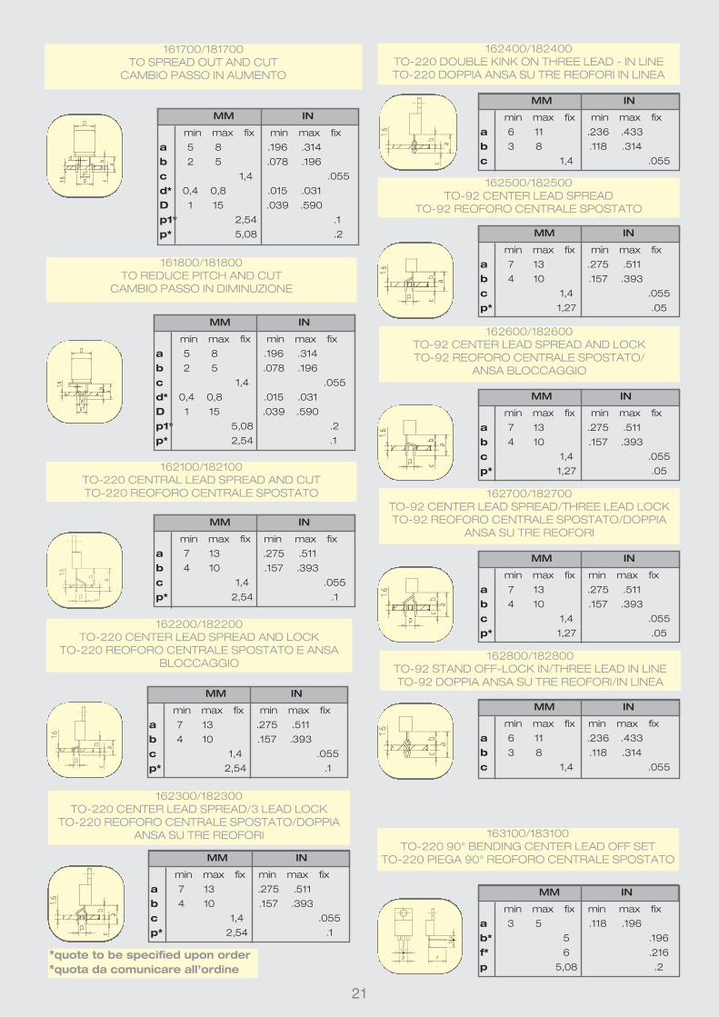
161700/181700
TO SPREAD OUT AND CUT
CAMBIO PASSO IN AUMENTO
161800/181800
TO REDUCE PITCH AND CUT
CAMBIO PASSO IN DIMINUZIONE
162100/182100
TO-220 CENTRAL LEAD SPREAD AND CUT
TO-220 REOFORO CENTRALE SPOSTATO
163100/183100
TO-220 90° BENDING CENTER LEAD OFF SET
TO-220 PIEGA 90° REOFORO CENTRALE SPOSTATO
MM IN
min max fix min max fix
a 7 13 .275 .511
b 4 10 .157 .393
c 1,4 .055
p* 2,54 .1
MM IN
min max fix min max fix
a 6 11 .236 .433
b 3 8 .118 .314
c 1,4 .055
MM IN
min max fix min max fix
a 7 13 .275 .511
b 4 10 .157 .393
c 1,4 .055
p* 1,27 .05
MM IN
min max fix min max fix
a 7 13 .275 .511
b 4 10 .157 .393
c 1,4 .055
p* 1,27 .05
MM IN
min max fix min max fix
a 7 13 .275 .511
b 4 10 .157 .393
c 1,4 .055
p* 1,27 .05
MM IN
min max fix min max fix
a 7 13 .275 .511
b 4 10 .157 .393
c 1,4 .055
p* 2,54 .1
MM IN
min max fix min max fix
a 6 11 .236 .433
b 3 8 .118 .314
c 1,4 .055
162800/182800
TO-92 STAND OFF-LOCK IN/THREE LEAD IN LINE
TO-92 DOPPIA ANSA SU TRE REOFORI/IN LINEA
162700/182700
TO-92 CENTER LEAD SPREAD/THREE LEAD LOCK
TO-92 REOFORO CENTRALE SPOSTATO/DOPPIA
ANSA SU TRE REOFORI
162600/182600
TO-92 CENTER LEAD SPREAD AND LOCK
TO-92 REOFORO CENTRALE SPOSTATO/
ANSA BLOCCAGGIO
162500/182500
TO-92 CENTER LEAD SPREAD
TO-92 REOFORO CENTRALE SPOSTATO
162400/182400
TO-220 DOUBLE KINK ON THREE LEAD - IN LINE
TO-220 DOPPIA ANSA SU TRE REOFORI IN LINEA
162300/182300
TO-220 CENTER LEAD SPREAD/3 LEAD LOCK
TO-220 REOFORO CENTRALE SPOSTATO/DOPPIA
ANSA SU TRE REOFORI
162200/182200
TO-220 CENTER LEAD SPREAD AND LOCK
TO-220 REOFORO CENTRALE SPOSTATO E ANSA
BLOCCAGGIO
*quote to be specified upon order
*quota da comunicare all’ordine

22
TP
TO-CF
macchina
taglia forma
transistors da
stecca
TP/TO-CF is an automatic machine designed to
cut and form transistors in tube (TO-220,
TO-218, TO-126). All strokes are controlled by a
PLC. The complete operation is fully automatic
and each form needs a dedicated die.
Two wire holders lock the leads before the
cutting forming operations.
Special forms to customers specifications are
available upon request.
La TP/TO-CF è una macchina automatica utiliz-
zata per eseguire il taglio e la forma di transi-
stors in stecca (TO-220, TO-218, TO-126). Le
lavorazioni vengono impostate e controllate tra-
mite un PLC. L‚operazione è completamente
automatica e ciascuna forma richiede matrici
dedicate. Due premi filo bloccano i reofori prima
della fase di taglio e preformatura. Forme spe-
ciali possono essere realizzate su richiesta e
specifiche del cliente.
Speed = 3000 p/h
Produzione 3000 p/h
ALIMENTAZIONE = 220V – 50HZ – 50 VA
LUNGH. = 55 CM
LARGH. = 40 CM
ALT. = 65 CM
IMBALLO = 70X50X80
VOLUME = .28M3
PESO MACCHINA = 40 KG
PESO LORDO = 44 KG
CASSA DI LEGNO = 55 KG
TP/TO-CF 13.OL01 = 110v
TP/TO-CF 13.OL02 = 220v
Without dies - senza matrici
cutting forming
machine for
transistors
in tube
ELECTRICAL POWER = 220V –110V – 50HZ 50VA
LENGTH = 55 CM
WIDTH = 40 CM
HEIGHT = 65 CM
DIMENSIONS = 70X50X80
VOLUME = .28M3
MACHINE WEIGHT = 40 KG
GROSS WEIGHT = 44 KG
CRATED WEIGHT = 55 KG

23
standard die assembliesfor TP/TO-CF machine
gruppi matricistandard per la
macchina TP/TO-CF
MM IN
min max fix min max fix
a 3 13 .118 .511
131000
STRAIGHT CUT
SOLO TAGLIO
MM IN
min max fix min max fix
a 3 8 .118 .314
b* 6 .236
131300
90° BENDING
PIEGA A 90°
MM IN
min max fix min max fix
a 2,5 8 .098 .314
b* 2 .078
c* 2,5 .098
131400
SURFACE MOUNTING
MONTAGGIO IN SUPERFICIE
MM IN
min max fix min max fix
a 7 13 .275 .511
b 4 10 .157 .393
c 1,4 .055
p* 2,54 .1
132100
CENTRAL LEAD SPREAD AND CUT
REOFORO CEONTRALE SPOSTATO E TAGLIO
MM IN
min max fix min max fix
a 7 13 .275 .511
b 4 10 .157 .393
c 1,4 .055
p* 2,54 .1
132200
CENTER LEAD SPREAD AND LOCK
REOFORO CENTRALE SPOSTATO
E ANSA A BLOCCAGGIO
MM IN
min max fix min max fix
a 7 13 .275 .511
b 4 10 .157 .393
c 1,4 .055
p* 2,54 .1
132300
CENTER LEAD SPREAD/3 LEAD LOCK
REOFORO CENTRALE SPOSTATO
DOPPIA ANSA SU TRE REOFORI
MM IN
min max fix min max fix
a 6 11 .236 .433
b 3 8 .118 .314
c 1,4 .055
132400
DOUBLE KINK ON THREE LEAD – IN LINE
DOPPIA ANSA SU TRE REOFORI IN LINEA
MM IN
min max fix min max fix
a 3 5 .118 .196
b* 5 .196
f* 6 .216
p 5,08 .2
133100
90° BENDING CENTER LEAD OFF SET
PIEGA 90° REOFORO CENTRALE SPOSTATO
*quote to be specified upon order
*quota da comunicare all’ordine

24
forme realizzate conmatrici speciali per la macchina TP/TO-CF
forms realised with special die assembliesfor TP/TO-CF machine

25
formingmachine for IC’s components intube
TP
IC-F
macchina forma
reofori integrati
da stecca
standard pitches / passi standard =
7,62 mm – 15,24 mm (.3”- 6”)
available upon request/ disponibili a richiesta =
10,16 mm – 19,05 mm – 22,86 mm (.4”-.75”-.9”)
LENGTH = 28
WIDTH = 18
HEIGHT = 22
PACKING = 39x25x26
VOLUME = 0,025 m3
MACHINE WEIGHT = 7 kg
GROSS WEIGHT = 9 kg
PRODUCTION = 1 tube/6 seconds
LUNG. = 28 cm
LARGH. = 18 cm
ALT. = 22 cm
IMBALLO = 39x25x26 cm
VOLUME = 0,025 m3
PESO MACCHINA = 7 kg
PESO LORDO = 9 kg
PRODUZIONE = 1 stecca/6 secondi
The model TP/IC-F is designed for
straightening the leads of IC
components to facilitate their insertion
onto the P. C. Board. The machine is
suppl ied with the necessary tube
holders to accommodate standard
components having .3 and .6” Pitch.
Il modello TP/IC-F serve per raddrizzare,
portare a passo I reofori dei componenti
integrati per sveltire il loro assemblaggio
sulle schede elettroniche. Con la mac-
china vengono forniti i porta stecche
necessari per lavorare componenti con
passo standard .3 e .6”.
TP/IC-F 77.OL01
manual dip lead forming machine
macchina manuale forma reofori integrati
motor MOT-ICF
64.OL01 - 110 v
64.OL02 -220 v
optional accessories accessori opzionali

26
cutting and bendingmachine for axialcomponents
TP6 macchinataglia piega
componentiassiali
optional accessories accessori opzionali
400200 BR6 reel holder
braccio porta bobina
21.0011 TNS
waste tape ejector
espulsore nastro di scarto
LENGTH = 23 cm
WIDTH = 18 cm
HEIGHT = 21 cm
PACKING = 39x25x26 cm
VOLUME = 0,025 m3
MACHINE WEIGHT = 5 kg
GROSS WEIGHT = 6 kg
LEAD DIA. = 0,4-1,4 mm (.015-.055”)
PRODUCTION = TAPED 50000 p/h
LOOSE 5000 p/h
DIAM. REOFORO = 0,4 - 1,4 mm
PRODUZIONE = NASTRATO 50.000 p/h
SFUSO 5.000 p/h
LUNG. = 23 cm
LARGH. = 18 cm
ALT. = 21 cm
IMBALLO = 39x25x26 cm
VOLUME = 0,025 m3
PESO MACCHINA = 5 kg
PESO LORDO = 6 kg
7915030/31 MOT98
motor – motore
51.0100 CS10
feeder for loose components
caricatore per componenti sfusi
200240
complete body guide
guida del corpo
completa
20.OL01 TP6
sturdy,
reliable and long lasting
equipment. Can be motorized.
Easy to set up and use no
maintenance required
qualità ed affidabilità per durare nel
tempo. Possibilità di essere moto-
rizzata. Facilità di uso e regola-
zione.Non richiede manu-
tenzione
TP6 with delrin toothed discs 20.OL11 standard
20.OL12 reinforced to prevent marking the leads .
TP6 con tamburi dentat i in delr in 20.OL11
standard 20.OL12 rinforzata per non segnare i reofori

This system automatically adjusts the bending wheels, reducing the set-up time and making it easier.
This system is available with the following versions of the TP6 machine: TP6/1/97 – TP6/4/97 and TP6/6/97.
Warning= the maximum pitch possible with the /97 system is 40 mm and the maximum “B” is 10 mm.
27
TP6/97 version
The model TP6 is designed for cutting and
bending taped axial components with lead
diameter from 0,4 to 1,4mm (.015 to .055”). The
high quality and reliability of this machine ensure
the best operation for a very long time. No
maintenance is required.
Il modello TP6 è utilizzato per il taglio e la piega-
tura di componenti assiali nastrati aventi diame-
tro del reoforo da 0,4 a 1,4mm. La qualità ed
affidabilità di questa macchina consente di ope-
rare per anni senza rischi di usura delle parti
meccaniche e con pochi interventi di manuten-
zione per lo più consigliata per la pulizia dei
dischi dentati.
TP6/1
STANDARD VERSION- VERSIONE STANDARD
(Cod.20.OL01 - 20.0L01/97)
TP6/6
REDUCED BENDING -
VARIABLE PITCH
PIEGA RIDOTTA -
PASSO VARIABILE
(Cod.20.OL06 - 20.0L06/97)
MM IN
min max min max
P 6,5 60 .255 2.362
B 4 13 .157 .511
c 1,2 .047
L 50 1.968
d 0,4 1,3 .015 .051
D 0,4 16 .015 .629
MM IN
min max min max
P 5,08 60 .2 2.362
B 4 13 .157 .511
c 0,8 .031
L 50 1.968
d 0,4 0,8 .015 .031
D 0,4 10 .015 .039
TP6/4
EXTRA REINFORCED BENDING
PIEGA EXTRA RINFORZATA
(Cod.20.OL04 - 20.0L04/97)
MM IN
min max min max
P 10,16 60 .4 2.362
B 5 13 .196 .511
c 2,4 .094
L 50 1.968
d 0,6 1,4 .023 .055
D 0,6 16 .023 .629
code 20.0L07 P 5,08 .2
code 20.0L09 P 7,62 .3code 20.0L10 P 10,16 .4
MM IN
min max min max
B 4 10 .157 .393
c 0,5 .019
d 0,4 0,6 .015 .023
D 0,4 4 .015 .157
Sistema di posizionamento automatico dei coltelli di piega applicabile ad alcune versioni della macchina
TP6 che diventano TP6/1/97 – TP6/4/97 – TP6/6/97.
Attenzione= in questo caso il passo massimo diventa 40
mm e la quota “B” massima è di 10 mm.
TP6/7 -TP6/9 -TP6/10
REDUCED BENDING FIX PITCH
PIEGA RIDOTTA PASSO FISSO
(Cod.20.OL07-Cod.20.OL09-Cod.20.OL10)

28
cutting bendingformingmachine for axialcomponents
TP6
PR-B
macchina taglia piega forma componenti
assiali
LUNG. = 23 cm
LARGH. = 18 cm
ALT. = 21 cm
IMBALLO = 39x25x26 cm
VOLUME = 0,025 m3
PESO MACCHINA = 6 kg
PESO LORDO = 8 kg
LENGTH = 23 cm
WIDTH = 18 cm
HEIGHT = 21 cm
PACKING = 39x25x26 cm
VOLUME = 0,025 m3
MACHINE WEIGHT = 6 kg
GROSS WEIGHT = 8 kg
LEAD DIA. = 1-1,4 mm (.039-.055”)
PRODUCTION = TAPED 25000 p/h
LOOSE 5000 p/h
DIAM. REOFORO = 1 - 1,4 mm
PRODUZIONE = NASTRATO 25.000 p/h
SFUSO 5.000 p/h
optional accessories accessori opzionali
400200 BR6 reel holder
braccio porta bobina
21.0011 TNS
waste tape ejector
espulsore nastro di scarto
7915030/31 MOT98
motor – motore
51.0100 CS10
feeder for loose components
caricatore per componenti sfusi
200240 complete body
guide
guida del corpo
completa
TP6/PR-B with delrin toothed discs 40.OL11 standard
40. OL12 reinforced to prevent marking the leads
TP6/PR-B con tamburi dentati in delrin 40.OL11 standard
40.OL12 rinforzata per non segnare i reofori

29
TP6/PR-B/97 version
This system automatically adjusts
the bending wheels, reducing the
set-up time and making it easier.
This system is available with all
versions of TP6/PR-B machine.
Warning= the maximum pitch
possible with the /97 system is 40
mm. and the maximum “B” is 10
mm.
Sistema di posizionamento auto-
matico dei coltelli di piega applicabi-
le a tutte le versioni della macchina
TP6/PR-B.
Attenzione= in questo caso il passo
massimo diventa 40 mm e la quota
“B” massima è di 10 mm.
The model TP6/PR-B is designed for
cutt ing-forming and bending taped axial
components. The “stand-off” form keeps the
body off the P. C. Board. The machine handles
components with lead diameter from 1 to 1,4 mm
(.039 to .055”).
Il modello TP6/PR-B viene utilizzato per tagliare-
formare e piegare componenti assiali nastrati allo
scopo di distanziare il corpo dalla scheda. Si pos-
sono lavorare componenti aventi diametro del
reoforo da 1 a 1,4 mm.
TP6/PR-B
STANDARD
VERSIONS
VERSIONI
STANDARD
(Cod.40.OL01 -
40.OL04 - 40.OL11)
TP6/PR-B
REINFORCED
VERSIONS
VERSIONI
RINFORZATE
(Cod.40.OL02 -
40.OL05 - 40.OL12)
code 40.0L01 z 3.1 fix .122 fix
code 40.0L11 z 3.9 fix .153 fix code 40.0L04 z 5 fix .196 fix
MM IN
min max min max
P 10,16 60 .4 2.362
B 10 14 .393 .551
C 2,4 .094
L 50 1.968
d 1 1,4 .039 .055
D 1 16 .039 .629
h 7 11 .275 .433
code 40.0L02 z 3.1 fix .122 fix
code 40.0L12 z 3.9 fix .153 fix code 40.0L05 z 5 fix .196 fix
With TP6/PR-B it is possible to
eliminate the preforming
operation by replacing the
cutting/forming wheels with
only cutting wheel.
Con la TP6/PR-B é possibile
escludere la preformatura
sostituendo i coltelli di
taglio/sagoma con speciali col-
telli di solo taglio.
MM IN
min max min max
P 6,5 60 .255 2.362
B 10 14 .393 .551
C 1,2 .047
L 50 1.968
d 1 1,3 .039 .051
D 1 16 .039 .629
h 7 11 .275 .433
sturdy,
reliable and long
lasting equipment.
Can be motorized.
Easy to set up and use
no maintenance required
qualità ed affidabilità per
durare nel tempo.
Possibilità di essere moto-
rizzata. Facilità di uso e
regolazione.Non
richiede manuten-
zione

30
cutting bendingformingmachine for axialcomponents
TP6
PR-F
macchina taglia piega forma componenti
assiali
“U” bending only for 43.0L01 and 43.0L02
Gruppo piega a “U” per 43.0L01 e 43.0L02
( Cod. 420650)
MM IN
min max min max
P 10.16 60.96 .4 1.2
L 50 1.968
c 1,2 .047
B 6 12 .236 .472
d 0,5 0,9 .019 .035
D 0,5 8 .019 .314
LENGTH = 49 cm
WIDTH = 24 cm
HEIGHT = 22 cm
PACKING = 41x31x28 cm
VOLUME = 0,035 m3
MACHINE WEIGHT = 14 kg
CRATED WEIGHT= 22 kg
PRODUCTION = TAPED 7000 p/h
LOOSE 5000 p/h
PRODUZIONE = NASTRATO 7.000 p/h
SFUSO 5.000 p/h
LUNG. = 49 cm
LARGH. = 24 cm
ALT. = 22 cm
IMBALLO = 41x31x28 cm
VOLUME = 0,035 m3
PESO MACCHINA = 14 kg
PESO LORDO (cassa di
legno) = 22 kg
optional accessories accessori opzionali
400200 BR6 reel holder
braccio porta bobina
21.0013 TNS
waste tape ejector
espulsore nastro di scarto
7915032/33 MOT98/A
motor – motore
51.0400 CS40
feeder for loose components
caricatore per componenti sfusi
200240 complete body guide
guida del corpo completa
Bends and cuts
leads without nicking
or cracking components.
Built to customer specifica-
tions. Capable to be motor-
ized. Easy to set up and use.
No maintenance needed.
Piega e taglia I reofori senza mar-
cature o rotture al corpo dei com-
ponenti. Può essere personaliz-
zata secondo le specifiche del
cliente. Possibilità di essere
motorizzata. Facilità di uso e
regolazione. Non richie-
de manutenzione.

31
TP6/PR-F/1 standard 43.OL01
The model TP6/PR-F is designed for cutting
and forming axial taped components.
Versions:
43.OL01 for lead Ø 0,5 to 0,9 mm (.19 to .035”)
43.OL02 for lead Ø 0,8 to 1 mm (.031 to .039”)
43.OL03 for lead Ø 1 to 1,3 mm (.039 to .051”)
Die assemblies designed for each one of the
version need to be ordered separately
depending on the form required. It is possible to
order special forms, supplying Olamef with
drawings and specifications.
Il modello TP6/PR-F è utilizzato per formare
componenti assiali nastrati.
Versioni:
43.OL01 per reoforo da Ø 0,5 a 0,9 mm
43.OL02 per reoforo da Ø 0,8 a 1 mm
43.OL03 per reoforo da Ø 1 a 1,3 mm
I gruppi di preformatura devono essere ordinati
fra i modelli disponibili in base alla forma che si
desidera ottenere ed alla versione di macchina
prescelta. E’ possibile richiedere anche forme
speciali su disegno e specifiche del cliente.
STAND OFF ASSEMBLY-
GRUPPO ANSA
IN APPOGGIO 2,5 mm
(Cod.420800)
LOCK IN ASSEMBLY
GRUPPO ANSA
A BLOCCAGGIO
(Cod.420850)
MM IN
min max min max
P 10.16 60.96 .4 2.4
L 50 1.968
c 1,2 .047
h 4,5 8 .177 .314
B 7,5 11 .295 .433
d 0,6 0,9 .023 .035
D 0,6 8 .023 .314
z 3 4,5 .118 .177
REDUCED PITCH ASSEMBLY
GRUPPO PASSO
IN DIMINUZIONE
(Cod.420900) LOCK IN ASSEMBLY
GRUPPO ANSA
A BLOCCAGGIO
(Cod.420950)
BODY LOCKED ON PCB
GRUPPO CORPO A BATTUTA
(Cod.421000)
MM IN
min max min max
P 10,16 60,96 .4 2.4
L 50 1.968
c 1,2 .047
B 5 8 .196 .314
d 0,5 0,8 .019 .031
D 2 8 .078 .314
MM IN
min max min max
P 10.16 60.96 .4 2.4
L 50 1.023
c 1,2 .047
h 4,5 8 .177 .314
B 7,5 11 .295 .433
d 0,5 0,8 .019 .031
D 0,5 8 .019 .314
z 3 4 .118 .157MM IN
min max min max
P 7,62 58,42 .3 2.3
L 50 1.968
c 1,2 .047
h 5 9 .196 .354
B 7 11 .275 .433
d 0,5 0,9 .019 .035
D 0,5 8 .019 .314
z 2 4 .078 .157
E 1,27 .05
MM IN
min max min max
P 10.16 60.96 .4 2.4
L 50 1.968
c 1,2 .047
h 6,5 9,5 .255 .374
B 8,5 11,5 .334 .452
d 0,5 0.9 .019 .035
D 0,5 8 .019 .314
z 2 4 .078 .157
STAND OFF ASSEMBLY
GRUPPO ANSA
IN APPOGGIO 3 mm
(Cod.420750)
MM IN
min max min max
P 10.16 60.96 .4 2.4
L 50 1.968
c 1,2 .047
h 6 9 .236 .354
B 8 11 .314 .433
d 0,5 0.9 .019 .035
D 0,5 8 .019 .314
z 2 4 .078 .157

32
MM IN
min max min max
P 7,62 58,42 .3 2.3
L 50 1.968
c 1,5 .059
h 6 12 .236 .472
B 8 14 .314 .551
d 0,8 1 .031 .039
D 0,8 8 .031 .314
z 2 4 .078 .157
E 1,27 .05
REDUCED PITCH ASSEMBLY
GRUPPO PASSO
IN DIMINUZIONE
(Cod.420900)
MM IN
min max min max
P 10.16 60.96 .4 2.4
L 50 1.968
c 1,5 .059
h 7 12 .275 .472
B 9 14 .354 .551
d 0,8 1 .031 .039
D 0,8 8 .031 .314
z 2 4 .078 .157
STAND OFF ASSEMBLY-
GRUPPO ANSA
IN APPOGGIO 3 mm
(Cod.420750)
MM IN
min max min max
P 10,16 58,42 .4 2.3
L 50 1.968
c 2,5 .098
h 9 16 .354 .629
B 11 18 .433 .708
d 1 1,3 .039 .051
D 1 8 .039 .314
z 2 4 .078 .157
E 1,27 .05
REDUCED PITCH ASSEMBLY
GRUPPO PASSO IN DIMINUZIONE
(Cod.430900)
STAND OFF ASSEMBLY
GRUPPO ANSA
IN APPOGGIO
(Cod.430700)
MM IN
min max min max
P 12.7 60.96 .5 2.4
L 50 1.968
c 2,5 .098
h 11 16 .433 .629
B 13 18 .511 .708
d 1 1,3 .039 .051
D 1 8 .039 .314
z 2 4 .078 .157
MM IN
min max min max
P 10.16 60.96 .4 2.4
L 50 1.968
c 1,5 .059
h 5,5 11 .216 .433
B 8,5 14 .334 .551
d 0,8 1 .031 .039
D 0,8 8 .031 .314
z 3 4,5 .118 .177
LOCK IN ASSEMBLY
GRUPPO ANSA
A BLOCCAGGIO
(Cod.420950)
“U” BENDING ONLY
GRUPPO PIEGA A “U”
(Cod.430650)
MM IN
min max min max
P 12.7 60.96 .5 2.4
L 50 1.968
c 2,5 .098
B 13 18 .511 .708
d 1 1,3 .039 .051
D 1 8 .039 .314
rinforzata43.OL02
reinforced43.OL02
extrarinforzata43.OL03
extrareinforced43.OL03
TP6/PR-F/2
TP6/PR-F/3

33
macchina taglia
piega formacomponenti
assiali permontaggio in
superficie
TP6/S
25.OL01 TP6/S
optional accessories accessori opzionali
400200 BR6 reel holder
braccio porta bobina
21.0011 TNS
waste tape ejector
espulsore nastro di scarto
7915030/31 MOT98
motor – motore
51.0100 CS10
feeder for loose components
caricatore per componenti sfusi
The TP6/S machine is
designed for cutting and
bending axial components
for surface mount. The
standard version offers the
most common dimensions.Special versions to cus-
tomer’s specifications are
available upon request.
Il modello TP6/S è utilizzato
per tagliare e piegare com-
ponenti assiali per montag-
gio in superficie. La versio-
ne standard realizza quote
comunemente usate. E’
necessario conoscere le
specifiche del componente,
sia originale che formato al
momento dell’ordine
LENGTH = 23 cm
WIDTH = 18 cm
HEIGHT = 21 cm
PACKING = 39x25x26 cm
VOLUME = 0,025 m3
MACHINE WEIGHT = 5 kg
GROSS WEIGHT = 6 kg
PRODUCTION = TAPED 50.000 p/h
LOOSE 5.000 p/h
PRODUZIONE = NASTRATO 50.000 p/h
SFUSO 5.000 p/h
LUNG. = 23 cm
LARGH. = 18 cm
ALT. = 21 cm
IMBALLO = 39x25x26 cm
VOLUME = 0,025 m3
PESO MACCHINA = 5 kg
PESO LORDO = 6 kg
MM IN
min max min max
P 12 47 .472 1.850
C 1,5 10 .059 .393
L 40 1.574
D 0,4 16 .015 .629
d* 0,6 fix .023 fix
B* 2 fix .078 fix
h* 2,5 fix .098 fix
*= quote to be specified upon order
*= quota da comunicare all’ordine
cutting bending
forming machine
for axial
components for
surface mounting

34
macchina taglia
piega compo-
nenti assiali per
montaggio
verticale
cutting bending
machine for axial
components
vertical
mounting
TP6/V
optional accessories accessori opzionali
400200 BR6 reel holder
braccio porta bobina
21.0011 TNS
waste tape ejector
espulsore nastro di scarto
7915030/31 MOT98
motor – motore
51.0300 CS30
feeder for loose components
caricatore per componenti sfusi
200240 complete body guide
guida del corpo completa
80.OL01 TP6/V
LENGTH = 23 cm
WIDTH = 18 cm
HEIGHT = 21 cm
PACKING = 39x25x26 cm
VOLUME = 0,025 m3
MACHINE WEIGHT = 5 kg
GROSS WEIGHT = 6 kg
LUNG. = 23 cm
LARGH. = 18 cm
ALT. = 21 cm
IMBALLO = 39x25x26 cm
VOLUME = 0,025 m3
PESO MACCHINA = 5 kg
PESO LORDO = 6 kg
PRODUCTION = TAPED 50.000 p/h
LOOSE 5.000 p/h
PRODUZIONE = NASTRATO 50.000 p/h
SFUSO 5.000 p/h
sturdy,
reliable and long
lasting equipment.
Can be motorized.
Easy to set up and use
no maintenance required
qualità ed affidabilità per
durare nel tempo.
Possibilità di essere moto-rizzata. Facilità di uso e
regolazione.Non
richiede manuten-
zione
LEAD DIA. = 0,5-0,8 mm - 0,8-.1,3 mm
(.019- .031” - .031 - .051”)
DIAM. REOFORO = 0,5 - 0,8 mm
0,8 - 1,3 mm

35
TP6/V/1 STANDARD VERSION PITCH 2,54 mm (.1”) TP6/V/1 VERSIONE STANDARD PASSO 2,54
mm(Cod. 80.OL01)
TP6/V/3 PITCH 3,8 mm (.15”)TP6/V/3 PASSO 3,8 mm
(Cod.80.OL03)
TP6/V/4 PITCH 5,08 mm (.2”)TP6/V/4 PASSO 5,08 mm
(Cod.80.OL04)
TP6/V/5 PITCH 7,62 mm (.3”)TP6/V/5 PASSO 7,62 mm
(Cod.80.OL05)
TP6/V/21 PITCH 3,8 mm (.15”)TP6/V/21 PASSO 3,8 mm
(Cod.80.OL21)
STANDARD VERSIONS FOR COMPONENTS WITH LEAD
DIAMETER 0,5 TO 0,8 mm (.019 TO .031 inch)
VERSIONI STANDARD PER COMPONENTI CON DIAMETRO
REOFORO DA 0,5 A 0,8 mm
TP6/V/22 PITCH 5,08 mm (.2”)TP6/V/22 PASSO 5,08 mm
(Cod.80.OL22)
TP6/V/23 PITCH 7,62 mm (.3”)TP6/V/23 PASSO 7,62 mm
(Cod.80.OL23)
STANDARD VERSIONS FOR COMPONENTS WITH LEAD
DIAMETER 0,8 TO 1,3 mm (.031 TO .051 inch)
VERSIONI STANDARD PER COMPONENTI CON DIAMETRO
REOFORO DA 0,8 A 1,3 mm
MM IN
min max min max
A 2 6 .078 .236
L 15 .590
F 3 8 .118 .314
D 0,5 3 .019 .118
d 0,5 0,8 .019 .031
P 2,54 fix .1 fix
MM IN
min max min max
A 2,5 6 .098 .236
L 15 .590
F 3 8 .118 .314
D 0,5 5 .019 .196
d 0,5 0,8 .019 .031
P 3,8 fix .15 fix
MM IN
min max min max
A 3 7 .118 .275
L 15 .590
F 3 8 .118 .314
D 0,5 8 .019 .314
d 0,5 0,8 .019 .031
P 5,08 fix .2 fix
MM IN
min max min max
A 4 7 .157 .275
L 15 .590
F 3 8 .118 .314
D 0,5 10 .019 .393
d 0,5 0,8 .019 .031
P 7,62 fix .3 fix
MM IN
min max min max
A 6 9 .236 .354
L 15 .590
F 3 8 .118 .314
D 0,8 10 .031 .393
d 0,8 1,3 .031 .051
P 7,62 fix .3 fix
MM IN
min max min max
A 5 9 .196 .354
L 15 .590
F 3 8 .118 .314
D 0,8 8 .031 .314
d 0,8 1,3 .031 .051
P 5,08 fix .2 fix
MM IN
min max min max
A 4 9 .157 .354
L 15 .590
F 3 8 .118 .314
D 0,8 5 .031 .196
d 0,8 1,3 .031 .051
P 3,8 fix .15 fix
The TP6/V machine is designed for cutting and
bending taped axial components for vertical
mounting. Two versions are available: one for
components with lead diameters from 0,5 to
0,8mm (.019 to .031”) and the other for lead
diameters from 0,8 to 1,3mm (.031 to .051”). The
bending pitch is determined by the bending cam
supplied and it can be changed by replacing
this cam with a different one.
Il modello TP6/V è utilizzato per tagliare e piega-
re i componenti assiali nastrati per montaggio in
verticale. Sono disponibili due versioni: una per
componenti aventi diametro del reoforo da 0,5 a
0,8mm e l’altra per diametro da 0,8 a 1,3mm. Il
passo di piegatura, determinato dalla cam forni-
ta, può essere variato sostituendo la cam con
un’altra avente larghezza diversa.

36
macchina taglia
piega forma
componenti
assiali per
montaggio
verticale
TP6
V-PR
cutting bending
forming machine
for axial
components
vertical mounting
LENGTH = 49 cm
WIDTH = 18cm
HEIGHT = 22 cm
PACKING = 41x31x28 cm
VOLUME = 0,035 m3
MACHINE WEIGHT = 11 kg
GROSS WEIGHT = 12 kg
LEAD DIA. = 0,5-0,8 mm (.019-.031”)
PRODUCTION = TAPED 7000 p/h
LOOSE 5000 p/h
DIAM. REOFORO = 0,5 - 0,8 mm
PRODUZIONE = NASTRATO 7.000 p/h
SFUSO 5.000 p/h
LUNG. = 49 cm
LARGH. = 18 cm
ALT. = 22 cm
IMBALLO = 41x31x28 cm
VOLUME = 0,035 m3
PESO MACCHINA = 11 kg
PESO LORDO = 12 kg
optional accessories accessori opzionali
400200 BR6 reel holder
braccio porta bobina
21.0013 TNS
waste tape ejector
espulsore nastro di scarto
7915032/33 MOT98/A
motor – motore51.0200 CS20
feeder for loose components
caricatore per componenti sfusi
200240 complete body guide
guida del corpo completa
86.OL01 TP6/V-PR
sturdy,
reliable and long
lasting equipment.
Can be motorized.
Easy to set up and use
no maintenance required
qualità ed affidabilità per
durare nel tempo.
Possibilità di essere moto-
rizzata. Facilità di uso e
regolazione.Non
richiede manuten-
zione

37
PREFORMING ASSEMBLY P. 2,54 mm (.1”) TP6/V-PR/1 CON GRUPPO PASSO 2,54 mm
(Cod. 86.OL01)
PREFORMING ASSEMBLY P. 5,08 mm (.2”) TP6/V-PR/2 CON GRUPPO PASSO 5,08 mm
(Cod. 86.OL02)
MM IN
min max min max
A 2,8 5 .110 .196
L 3 15 .118 .590
F 4,3 10 .169 .393
C 1,5 5 .059 .196
e 1,2 4 .047 .157
b 1 1 .039 .039
d 0,5 0,8 .019 .031
D 0,5 4 .019 .157
P 2,54 fix .1 fix
MM IN
min max min max
A 3 5 .118 .196
L 3 15 .118 .590
F 4,3 10 .169 .393
C 1,5 5 .059 .196
e 1,2 4 .047 .157
b 1 1 .039 .039
d 0,5 0,8 .019 .031
D 0,5 8 .019 .314
P 5,08 fix .2 fix
IT IS POSSIBLE TO ELIMINATE THE PREFORMING
OPERATION TO OBTAIN ONLY THE “V”
BENDING OF COMPONENTS
E’ POSSIBILE ELIMINARE LA PREFORMATURA ED
OTTENERE LA SOLA PIEGA A “V” DEI COMPONENTI
Bends and cuts leads without
nicking or cracking components. Built to
customer specifications. Capable to be
motorized. Easy to set up and use.
No maintenance needed.
Piega e taglia I reofori
senza marcature o rotture al corpo
dei componenti. Può essere personaliz-
zata secondo le specifiche del cliente.
Possibilità di essere motorizzata. Facilità
di uso e regolazione. Non chiede
manutenzione.
The model TP6/V-PR is designed for cutting,
bending and forming taped axial components for
vertical mounting. The standard form locks the
components into the P.C.Board. All dimensions
are adjustable. This model handles components
with lead diameters from 0,5 to 0,8mm (.019 to
.031”). Special versions can be manufactured to
form leads having different dimensions.
La macchina TP6/V-PR è utilizzata per tagliare,
piegare e formare componenti assiali per mon-
taggio verticale. La forma realizzata serve a bloc-
care il componente sulla scheda. Le quote sono
quasi tutte regolabili. La macchina lavora compo-
nenti con diametro di reoforo da 0,5 a 0,8mm.
Versioni speciali possono essere progettate per
formare reofori di dimensioni maggiori.
Pitch and form are determined by
the die assembly supplied
Il passo e la forma sono determinati
dalla matrice fornita

38
SEF 3 separatore fili percavi piatti
versione manualemotorizzabile
flat cable separatormanual version
SEF 1 separatore fili percavi piatti
versione manuale
Il modello SEF 1 è utilizzato per la separazione dei
fili dei cavi piatti. Può essere fornita per due passi
di separazione: 1,27 mm (i fili vengono separati
singolarmente Cod. 73.OL01) o 2,54 mm (i fili
vengono separati a coppie Cod. 73.OL02).
Questa macchina è adatta alla separazione delle
estremità di cavi con larghezza massima di 33
mm.
The model SEF 3 is designed for
separating wires of f lat cables. Two
different pitches of separation can be
suppl ied: 1,27 mm (the wires are
individually separated Code 71.OL01) or
2,54 mm (the wires are separated by
couples Code 71.OL02). This machine is
suitable for separating flat cables having
maximum width of 66mm. This model
can be motorised with our MOT98 (code
7915030 220V or 7915031 110V). With
this verion it is possible to separate the
cable from the edges and inside
sections.
Il modello SEF 3 è utilizzato per la se-
parazione dei f i l i dei cavi piatti . Può
essere fornita per due passi di sepa-
razione: 1,27 mm (i fili vengono separati
singolarmente Cod. 71.OL01) o 2,54 mm
(i fili vengono separati a coppie Cod.
71.OL02). Questa macchina è adatta alla
lavorazione di cavi con larghezza massi-
ma di 66 mm. Questo model lo può
essere motorizzato con l'applicazione del
MOT98 (cod. 7915030). Con questo
modello è possibile separare i fili anche
per tratti interni del cavo.
SEF 3 manual version
versione manuale
71.OL01 p. 1,27mm (.05”)
71.OL02 p. 2,54mm (.01”)
The model SEF 1 is designed for separating wires
of flat cables. Two different pitches of separation
can be suppl ied: 1,27 mm (the wires are
individually separated Code 73.OL01) or 2,54 mm
(the wires are separated by couples Code
73.OL02). This version is a "bench" manual
machine suitable for separating edges of flat
cables having maximum width of 33mm.
SEF 1 flat cable separator manual version
SEF 1. separatore fili per cavi piatti versione manuale
73.OL01 p.1,27mm (.05”)
73.OL02 p.2,54mm (.1”)
flat cable separatormanual or motorisedversion

39
Re-balling kit designed for repairing BGAs and
re-positioning of soldering balls. Use the kit when:
you wish to re-use a BGA after desoldering it; you
need to re-use prototype BGAs; when you need
to mount soldering balls for a small lot of BGA
production. It requires 5atm compressed air, air
tube 6/4mm. Standard kit is formed by: base for
BGA positioning, centering adaptor, top adaptor
for soldering paste, top adaptor for soldering
balls, tools.
Kit per la riparazione dei BGA e riposizionamento
sfere di saldatura. Si usa il BB2 quando: si vuole
riutilizzare il BGA o quando necessita di dissalda-
tura; quando c’è la necessità di riutilizzare proto-
tipi di BGA; quando è necessario montare sfere
di saldatura su produzioni limitate di BGA.
Necessita di aria compressa pari a 5 atm e tubo
aria 6/4mm. Il kit è formato da: base per posizio-
namento del BGA, adattatore centraggio, adatta-
tore superiore per pasta saldante, adattatore
superiore per sfere di stagno e set di utensili.
riposizionatore
sfere di stagnoBB2bga reballing
system
1.
The Centering device is
necessary to properly position
the BGA.
Il centratore viene utilizzato per
la corretta posizione del BGA
2.
Soldering paste/glue placement
on BGA.
Collocazione colla/pasta saldan-
te sul BGA.
3.
Soldering balls placement
Collocazione sfere saldanti
BB2 code 98.0000

40
macchinamanuale
o motorizzataper separazione
schede
SEP1
SEP1M
manual or
motorized
pc board
separator
packing = 80x32x42
machine weight =
SEP1 kg. 24 SEP1M kg. 27
gross weight =SEP1 kg. 27
SEP1M kg. 30SEP1M elect.supply = 220v/110v – 50hz – 80va
imballo = 80x32x42
peso macchina = SEP1 kg. 24 SEP1M kg. 27
peso lordo =SEP1 kg. 27
SEP1M kg. 30SEP1M alimentazione = 220v/110v – 50hz – 80va
Manual or motorized machine suitable to separatepre-assembled Electronic Board. Precise, reliableand safe. The PCB is manually fed between the
lower and upper blades using the scoring as
reference. By pushing the board horizontally, the
blade rotation starts offering in a sharp and
accurate cut. The blade height is adjustable
depending on the thickness of the PCB.
Macchina manuale o motorizzata per la separazio-ne di schede elettroniche pre-assemblate.Precisa, sicura, affidabile. La scheda viene manual-
mente inserita fra la lama inferiore e quella superio-re usando lo scoring come riferimento, spingendola scheda in senso orizzontale si esegue il taglio inmodo netto ed accurato. La posizione della lamasuperiore è regolabile in modo da stabilire ladistanza necessaria fra le due lame.
separation length 380 mm
lunghezza separazione 380 mmadjustable speed
velocita’ variabile
SEP1 code 100.0000 SEP1M code 100.0001 = 110 v SEP1M code 100.0002= 220 v

41
macchinamanuale
o motorizzata
per separazioneschede
SEP2
SEP2M
manual or
motorized
pc board
separator
SEP2 code 103.0000SEP2-600 code 104.0000
SEP2 and SEP2M are manual and motorized PC
Board separators designed for scored and preassembled PCBs. The scored board is placed onthe lower l inear blade. Separation length is450mm. With the SEP2 the handle is used tomove the upper circular blade while with theSEP2M the upper blade run is controlled by a footpedal and the length of this run can be
programmed through push buttons located onthe main control panel. The distance between theupper circular blade and the lower linear blade canbe adjusted. The height of the front and back supporting tables is also adjustable.
I modelli SEP2 e SEP2M sono macchine manuali emotorizzate che consentono la separazione dischede pre-incise e pre-montate. La lama lineareinferiore facilita il posizionamento della schedausando la pre incisione come riferimento. La lun-ghezza di taglio è 450mm. Con il modello manualeSEP2 la maniglia viene usata per spostare la lamacircolare superiore; con il modello motorizzatoSEP2M la corsa della lama viene comandata daun pedale, la lunghezza della corsa può essereimpostata tramite pulsanti posti sul pannello dicontrollo. La distanza fra la lama circolare superio-re e la lama lineare inferiore è regolabile. I piani disupporto schede, anteriore e posteriore, possonoessere regolati in altezza.
SEP2M code 103.0001 =110 v
SEP2M code 103.0002 = 220 v SEP2M-600 code 104.0001 =110 vSEP2M-600 code 104.0002 = 220 v
packing=90x55x55machine weight:SEP2 = 32SEP2M = 45gross weight:SEP2 = 36
SEP2M = 49SEP2M elect.supply =
220v/110v – 50hz – 80va
imballo=90x55x55
peso macchina = SEP2 = 32
SEP2M = 45peso lordo =SEP2 = 36
SEP2M = 49SEP2M alimentazione =220v/110v – 50hz – 80va
A= 1,0 - 3,2 mm
B = min. 0,3 mmmax 0,8 mm
C = min. 0,25 mm

42

43
COUNTY radial and axial tape reading
COUNTY lettura componenti radiali e assiali
COUNTY with support for rolled
bandolier, handle and printer
COUNTY con Supporto Bobina,
maniglia e stampante
(Cod.8301.023 + Cod. 8301.025
+ Cod. 8301.090)
COUNTY with SMD tape adaptor,
support for rolled bandolier and handle
COUNTY con adattatore , supporto
Bobina SMD e maniglia
(Cod.8301.018 + Cod.8301.028
+ Cod. 8301.030)
counter fortaped axial andradialcomponents
COUNTY contapezzi percomponentiassiali radiali
nastrati
ELECT.SUPPLY = 220 or 110V
LENGTH = cm 13
WIDTH = cm 24
HEIGHT = cm 12
PACKING = cm 24x32x18
VOLUME = m3 0,013
COUNTY WEIGHT = KG.3
GROSS WEIGHT = KG.4
ALIMENTAZIONE = 220V
LUNG. = cm 13
LARGH. = cm 24
ALT. = cm 12
IMBALLO = cm 24x32x18
VOLUME = m30,013
PESO COUNTY = KG.3
PESO LORDO = KG.4
Il Contapezzi digitale a microcomputer ese-gue il conteggio di componenti nastrati assialie radiali e componenti SMD con l’aggiuntadell’apposito adattatore.Il conteggio può avvenire in entrambe le dire-zioni (destra o sinistra). E’ dotato di divisoreda 1 a 19.Il conteggio può avvenire in modo TOTALIZ-ZATORE o in modo PRESET, con allarmeacustico al raggiungimento del numero dicomponenti desiderato.Test di calibrazione e procedura di auto dia-gnosi.Memoria ultimo valore contato e condizioni.
The County is a microcomputer based instrument which counts radial and axial components on tape. With the optional SMD adaptor it can also count SMDcomponents.It counts in both directions (right or left). It isequipped with a divider from 1 to 19 and aTOTALIZER mode counting or PRESET mode,with an alarm that starts when the desiredcomponent number has been reached.Calibration test and self diagnostic procedure,last counting value and condition memory.
VERSIONI COUNTY
COUNTY contapezzi 220 v. 50-60hz
Cod. 8301.051
COUNTY contapezzi 220 v. 50-60hz
con accumulatore, relè ausiliario,
uscita stampante, orologio Cod.
8301.072
COUNTY contapezzi 110 v. 50-60hz
Cod. 8301.053
COUNTY contapezzi 110 v. 50-60hz
con accumulatore, relè ausiliario,
uscita stampante, orologio Cod.
8301.074
COUNTY VERSIONS
COUNTY 220 v. 50-60hz
Cod. 8301.051
COUNTY 220 v. 50-60hz with
accumulator, auxiliary relay,
printer output, watch Cod.
8301.072
COUNTY 110 v. 50-60hz
Cod. 8301.053
COUNTY 110 v. 50-60hz with
accumulator, auxiliary relay,
printer output, watch
Cod. 8301.074

44
COUNTY-S
Motorized counter for SMD
Contapezzi motorizzata per SMD
(Cod.8301.101 - 8301.103 )
EMPTY REEL( 8301.110)
Aluminium made
Inner 150/outer 350 mm diameter
Easily chargeable
Height of the tape 8 to 56 mm
BOBINA VUOTA (Cod 8301.110)
Per avvolgimento temporaneo, in allu-
minio
Diametro int. 150 mm est. 350 mm
Facilmente caricabile
Altezza del nastro da 8 a 56 mm
Display: 6 digitsMaximum counting speed: 100/pcs/sec
1 piece per holeAccuracy: +/- 1 piece
Holes per component: 1 to 99
Maximum tape height: 56 mmMaximum reel diameter: 400 mm
UP/DOWN countingPartial counting memory
PRESET MODE
Variable feeding speedStep by step 1 component at a time
RS232C serial output for host computer orthermal Label printer
8301.101 COUNTY-S - 220/240V 50-
60Hz
8301.103 COUNTY-S - 110V 50-60Hz
Display: 6 cifre a LED alta efficienza
Velocità massima di conteggio: 100 pz/sec(1 comp. per foro)
Precisione: +/- 1 pezzoNumero dei fori per componente: da 1 a 99
Altezza massima nastro: 56 mm
Diametro massimo bobina: 400 mmConteggio UP/DOWN
Memoria di accumulo dei totali parzialiFunzionamento in PRESET
Velocità di avanzamento regolabile
Avanzamento step by step: 1 componenteper volta
Collegamento seriale RS232C con compu-ter esterno o stampante di etichette
8301.101 COUNTY-S - 220/240V 50-60Hz
8301.103 COUNTY-S -110V 50-60Hz
Motorized counter for taped SMD component
counting. This machine works in a simple way by
counting the holes on the tape.It can operate in
two different ways. Totalizer: components are
counted from a zero reference, tape feed is
motorized and the counter automatically stops at
the tape end, to prevent loss of the total. Preset
mode: the desired component number is keyed
on the keyboard and the counter automatically
stops when it reaches the corresponding
component. All functions are easy to operate by
the help of interactive messages on the display,
while system status is monitored by means of
LEDS near the control keys. Motion control
procedures are extremely simple, while special
functions are grouped in a separate section on
the keyboard in order to prevent operator
errors.The memory funct ion al lows part ia l
counting for the same component type and
memory call can show at any time the memorycontents without loss of the actual counting data.Step number indication (division factor) is always
present, showed on a two-digit display.
La County S esegue il conteggio di componenti
SMD nastrati. Il conteggio viene effettuato con-
tando i fori del nastro di supporto. Vi sono due
modalità di funzionamento:Totalizzatore: i com-
ponenti vengono contati a partire dallo zero, il
movimento è motorizzato e la contapezzi si
ferma automaticamente a fine nastro per non
perdere il conteggio. Preselezione: viene impo-
stato il numero di componenti desiderato e la
contapezzi si porta automaticamente nella posi-
zione corrispondente al numero di componenti
selezionato. Tutte le funzioni della macchina sono
guidate tramite messaggi sul display mentre lo
stato di funzionamento è segnalato da led posti
in corrispondenza del comando. Estremamente
semplice è la gestione del movimento, le funzioni
speciali sono raggruppate sulla tastiera in una
sezione separata per evitare errori. La funzione
memoria permette di accumulare i conteggi par-
ziali di uno stesso componente, nonché di richia-mare il valore totale in qualsiasi momento, senzaperdere i dati reali del conteggio. L’indicazione
del numero di passi per componente (fattore di
divisione) è sempre presente, visualizzata su un
display a due cifre.

45
La stampante termica 8301.090 può essere colle-
gata alle County-S modello 8301.101 - 8301.103 e
alle County Modello 8301.072 e 8301.074
The thermo adhesive label printer 8301.090 can
be attached to the County-S model 8301.101 -
8301.103 and also to Counters 8301.072 and
8301.074.
Bilancia elettronica digitale di alta qualità e
precisione per uso nei magazzini, negli
uffici, nei laboratori, non omologata per
utilizzazione nei pubblici esercizi.
County with digital display for component
counting. Its high quality and precision
make it suitable for offices, stores and
laboratories.
STAMPANTE DI ETICHETTE
Stampante termica per etichette adesive.Possibilità di stampare:
Peso totale
Peso unitario
Quantità pesi
Alimentatore 110-230Vac e cavo di segnale
inclusi
Per COUNTY W - Modello Stampante Codice
8301.223
Per COUNTY-S e COUNTY - Modello Stampante
Codice 8301.090
ROTOLO Carta termica per Stampante (Cod.
8301.091) rotolo 20mt di carta termica adesiva.
Può fornire, a seconda della quantita di dati, da
300 a 500 etichette.
THERMAL LABEL PRINTER
Thermo-Adhesive Label Printer.
With the possibility to print the following data:
Total weight
Unit weight
Total quantity
AC Adaptor 110-230Vac and data Cable included
for COUNTY W - Printer Model Code 8301.223
For COUNTY-S and COUNTY - Printer Model Code
8301.090
THERMO-ADHESIVE ROLL PAPER (Code 8301.091) 20m
length. Depending on the quantity of data to be printed, it
is possible to obtain 300 to 500 labels.
Technical features:
System: strain gauge
Display: 3 groups of 14mm backlighted LCDs
Main: 110-120-220-240Vac 50/60Hz
Internal rechargeable battery
Display resolution: 1/30.000
Internal resolution: 1/480.000
Plate size: 334X245mm
Operating temperature: 0+40°C.
COUNTY W COUNTING SCALE - HIGH RESOLUTION NEW
MODEL
COUNTY W BILANCIA CONTAPEZZI - ALTA RISOLUZIONE
NUOVO MODELLO
Code ris. display ris. int. peso unit. min.
Model cap. max display res. int. res. min. unit weight
l8301.190 3.000 g. 0,1 g. 0,01 g. 0,1 g.
8301.191 6.000 g. 0,2 g. 0,02 g. 0,2 g.8301.192 15.000 g. 0,5 g. 0,05 g. 0,5 g.
8301.193 30.000 g. 1 g. 0,1 g. 1 g.
OPTIONAL:
(to be installed before shipment - da installare prima della
spedizione)
RS 232 C SERIAL OUTPUT- USCITA RS 232C
( Cod. 8301.195)
PRINTER INTERFACE -INTERFACCIA STAMPANTE
( Cod. 8301.196)
Caratteristiche tecniche:
Sistema: cella di carico strain gauge
Display: a cristalli liquidi, 14mm retroilluminato
Alimentazione = 110-120-220-240 Vac 50/60Hz
Batteria interna ricaricabile
Risoluzione display: 1/30.000
Risoluzione interna: 1/480.000
Dimenzioni piatto: 334X245mm
Temperatura di esercizio: 0+40°c

46
PRODUZIONE = 50.000 p/h
LUNGH = cm 23
LARGH = cm 19
ALT = cm 20
IMBALLO = cm 39 x 25 x 26
VOLUME = m3 0,025
PESO MACCHINE = KG.5
PESO LORDO =KG.6
TP6
EC
manual cuttingbending machinefor axial components
The machine model TP6-EC is designed for
cutting and bending taped axial components
with lead diameter from 0,4 to 1,3mm(.015” to
.051”).
The desired operation is adjusted in a quick and
precise way.
TP6/1-EC STANDARDVERSION
(cod. 23.OL01)
MM IN
min max min max
P 6,5 60 .255 2.362
B 4 13 .157 .511
c 1,2 .047
L 50 1.968
d 0,4 1,3 .015 .051
D 0,4 16 .015 .629
code 23.0L07 P 5,08 .2
code 23.0L09 P 7,62 .3code 23.0L10 P 10,16 .4
MM IN
min max min max
B 4 10 .157 .393
c 0,5 .019
d 0,4 0,6 .015 .023
D 0,4 4 .015 .157
MM IN
min max min max
P 10,16 60 .4 2.362
B 5 13 .196 .511
c 2,4 .094
L 50 1.968
d 0,6 1,4 .023 .055
D 0,6 16 .023 .629
TP6/6 EC
REDUCED BENDING
VARIABLE PITCH
(Cod.23.OL06)
MM IN
min max min max
P 5,08 60 .2 2.362
B 4 13 .157 .511
c 0,8 .031
L 50 1.968
d 0,4 0,8 .015 .031
D 0,4 10 .015 .039
TP6/4 EC EXTRA
REINFORCED BENDING
(Cod.23.OL04)
TP6/7 EC REDUCED BENDING
FIX PITCH (Cod.23.OL07)
taglia-piegamanuale
componentiassiali nastrati
PRODUCTION = 50.000 p/h
LENGTH = cm 23
WIDTH = cm 19
HEIGHT = cm 20
PACKING = cm 39 x 25 x 26 -
VOLUME = m3 0,025
MACHINE WEIGHT = KG.5
GROSS WEIGHT =KG.6
Il modello TP6-EC è una macchina manuale per
tagliare e piegare componenti assiali nastrati
con diametro del reoforo da 0,4 a 1,3 mm.
Le quote di lavorazione vengono impostate in
modo rapido e preciso

47
MM IN
min max min max
L 2 10 .078 .393
d 0,4 1 .015 .039
D 1 14 0.39 .55
PRODUCTION =
20.000 p/hLENGTH = cm 23
WIDTH = cm 19
HEIGHT = cm 20
PACKING = cm 39 x 25
x 26
VOLUME = m3 0,025
MACHINE WEIGHT =
KG.3
GROSS WEIGHT = KG.5
LEAD DIAMETER 0,5 TO 0,8 ( .019” to .031”)
TP6/V/1-EC STANDARD VERSION PITCH 2,54 mm (.10”) (Cod. 81.OL01)
MM IN
min max min max
A 2 6 .078 .236
L 15 .590
F 3 8 .118 .314
D 0,5 3 .019 .118
d 0,5 0,8 .019 .031
P **2,54 fix ** .1 fix
MM IN
. min max min max
A 4 9 .157 .354
L 15 .590
F 3 8 .118 .314
D 0,8 5 .031 .196
d 0,8 1,3 .031 .051
P ** 3,8 fix **.15 fix
LEAD DIAMETER 0,8 TO 1,3 mm( .031” to .051”)
TP6/V/21 EC PITCH 3,8 mm (.15”) (Cod. 81.OL21)
TP6/R-EC (Cod.31.OL21 )
manual cuttingbending machinefor axial componentsvertical mounting
macchina manualetaglia-piega
componenti assialimontaggio verticale
TP6/V
EC
manual cuttingmachinefor taped radialcomponents
macchinamanuale taglia
componentiradiali nastrati
TP6/R
EC
Il modello TP6/V-EC è una macchina manuale per
tagliare e piegare, per montaggio in verticale, compo-
nenti assiali nastrati con diametro del reoforo da 0,5 a
0,9 e da 0,8 a 1,3 . Il passo di piegatura, determinato
dalla cam fornita, può essere variato, sostituendo la
cam con un’altra avente larghezza diversa.
The machine ModelTP6/R-EC is designed for
cutt ing radial
components in tape.The
high quality and reliability
of this machine ensurethe best operation for a
very long t ime.
La macchina model lo
TP6/R-EC è utilizzata pertagl iare componenti
radiali nastrati.
La qualità e l’affidabilità di
queste macchine con-
sentono di operare per
anni senza r ischio di
usura delle parti mecca-
niche.
PRODUCTION = 50.000 p/h
LENGTH = cm 23
WIDTH = cm 19
HEIGHT = cm 22
PACKING = cm 39 x 25 x 26 -
VOLUME = m3 0,025
MACHINE WEIGHT = KG.5
GROSS WEIGHT =KG.6
PRODUZIONE = 50.000 p/h
LUNGHEZZA = cm 23
LARGHEZZA = cm 19
ALTEZZA = cm 22
IMBALLO = cm 39 x 25 x 26 -
VOLUME = m3 0,025
PESO MACCHINA = KG.5
PESO LORDO =KG.6
PRODUZIONE =
20.000 p/hLUNGHEZZA = cm 23
LARGHEZZA = cm 19
ALTEZZA = cm 20
IMBALLO =
cm 39 x 25 x 26
VOLUME = m3 0,025
PESO MACCHINA =
KG.3
PESO LORDO =KG.5
The machine Model TP6/V-EC is designed for cutting
and bending taped axial components for vertical
mounting. For components with lead diameter from
0.5 to 0.8 mm (.019 to .031”) and for lead diameter
from 0.8 to 1.3 mm (.031 to .051”). The bending pitch,
which is determined by the bending cam supplied, can
be changed by replacing the cam with one of different
thickness.