Embed Size (px)
Citation preview
Operating instructions Electronic pressure sensor
PF265x
7060
67/0
0 0
6/20
11
UK

2
Contents1 Preliminary note 3
11 Symbols used 32 Safety instructions 33 Functions and features 4
31 Applications 44 Function 4
41 Processing of the measured signals 442 Pressure monitoring / switching function 543 Pressure monitoring/ analogue function 5
5 Installation76 Electrical connection 87 Operating and display elements 108 Menu 11
81 Menu structure 1182 Menu explanation 12
9 Parameter setting 1391 Parameter setting general 1392 Configuring the display (optional) 1493 Setting the output signal 15
931 Setting the output function 15932 Setting the switching limits 15933 Scaling the analogue value 15
94 User settings (optional) 15941 Zero-point calibration 15942 Calibration reset 15943 Setting the delay time for the switching outputs 16944 Setting the output polarity 16945 Setting the damping for the switching signal 16945 Setting the damping for the analogue signal 16
95 Service functions 16951 Reading the min/max values for the system pressure 16

3
UK
1 Preliminary note1.1 Symbols used
Instruction> Reaction, result[…] Designation of buttons, switches or indications→ Cross-reference
Important note Non-compliance can result in malfunctions or interference
2 Safety instructions• Read this ducument before installing the unit Ensure that the product is suit-
able for your application without any restrictions• Non-adherence to the operating instructions or technical data can lead to
personal injury and/or damage to property• Inallapplicationscheckcomplianceoftheproductmaterials(→12Technical
data) with the media to be measured• Use in gases at pressures > 25 bar only after contacting the manufacturer ifm• ForunitswithcULusapprovalandthescopeofvaliditycULus→6Electrical
connection
10 Operation 16101 Read the set parameter values 17102 Fault indication 17103 Cleaning of the filter cover 17
11 Scale drawing 1812 Technicaldata 19
121 Setting ranges 21

4
3 Functions and featuresThepressuresensordetectsthesystempressureofmachinesandinstallations.
3.1 ApplicationsTypeofpressure:relativepressure
Order no. Measuring range Permissible overload pressure Bursting pressure
bar inHg bar inHg bar inHgPF2609 -099100 -3030 20 590 50 1 475
bar PSI bar PSI bar PSIPF2652 -1100 -101450 200 2 900 650 9 425PF2653 -125 -15363 100 1 450 350 5 070PF2654 -0510 -7145 50 725 150 2 175PF2656 -01325 -18363 20 290 50 725
mbar PSI bar PSI bar PSIPF2657 -501 000 -07145 10 145 30 450
mbar inH2O bar inH2O bar inH2OPF2658 -13250 -50100 10 4 000 30 12 000
MPa = bar ÷ 10 / kPa = bar × 100
Static and dynamic overpressures exceeding the indicated overload pres-sure are to be avoided by taking appropriate measuresTheindicatedburstingpressuremustnotbeexceeded.Eveniftheburst-ing pressure is exceeded only for a short time, the unit can be destroyed NOTE:Riskofinjury!
4 Function4.1 Processing of the measured signals• Theunitdisplaysthecurrentsystempressure.• It generates 2 output signals according to the parameter setting
OUT1 •switching signal for pressure limit values
OUT2•switching signal for pressure limit values•analogue signal 420 mA•analogue signal 010 V

5
UK
4.2 Pressure monitoring / switching functionOUTxchangesitsswitchingstateifitisaboveorbelowthesetswitchinglimits(SPx,rPx).Thefollowingswitchingfunctionscanbeselected:• Hysteresisfunction/normallyopen:[OUx]=[Hno](→fig.1).• Hysteresisfunction/normallyclosed:[OUx]=[Hnc](→fig.1).
First the set point (SPx) is set, then the reset point (rPx) at the requested distance
• Windowfunction/normallyopen:[OUx]=[Fno](→fig.2).• Windowfunction/normallyclosed:[OUx]=[Fnc](→fig.2).
ThewidthofthewindowcanbesetbymeansofthedistancebetweenSPxandrPx SPx = maximum value, rPx = minimum value
1 2
P = system pressure; HY = hystereris; FE = window
4.3 Pressure monitoring/ analogue functionTheanaloguesignalcanbeset.• [OU2] defines whether the set measuring range is provided as a 420 mA
signal ([OU2] = [I]) or a 010 V signal ([OU2] = [U])• By setting the parameter ASP you define the measured value at which the
output signal is 4 mA / 0 V• By setting the parameter AEP you define the measured value at which the
output signal is 20 mA / 10 VMinimum distance between [ASP] and [AEP] = 25 % of the final value of the measuringrange(turndown1:4).

6
Current outputFactory setting Measuring range scaled
P = system pressure, MEW = final value of the measuring range
Theoutputsignalisbetween4and20mA.Itisalsoindicated:• Systempressureabovethemeasuringrange:outputsignal>20mA.• Systempressurebelowthemeasuringrange:outputsignalbetween4and
32 mAVoltage output
Factory setting Measuring range scaled
P = system pressure, MEW = final value of the measuring range
Theoutputsignalisbetween0and10V.Itisalsoindicated:• Systempressureabovethemeasuringrange:outputsignal>10V.

7
UK
5 InstallationEnsure that no pressure is applied to the installation while mounting or removing the sensor.
Slightly grease the thread of the sensor using a lubricating paste which is suitable and approved for the application.
Screw the sensor into a G 1 process fitting.
Tighten the sensor with a spanner.Tightening torque: 20 Nm.
A
41
⎩⎨⎧
A = rotatable housing
The unit is adaptable for various G 1 process fittings. G 1 process adapters to be ordered separately as accessories.
Mount the adapter (C) to the sen-sor.
Fix sensor + adapter by means of a coupling nut, a clamp flange or similar (B) to the process connec-tion.
If it is not possible to slide the fixing element (B) down over the top of the sensor: slide it up over the bottom of the sensor before the adapter is mounted.
C
B

8
Montage des Adapters Slightly grease the contact areas between the sensor and adapter using a lubricating paste which is suitable and approved for the ap-plication.
Screw the unit into the adapter until it is hand-tight. Do not damage the sealing chamfers.
Clamp sensor and adapter into a clamping device (D). Tighten the clamping device only slightly so that the adapter does not warp. The sealing chamfers (E) must not be damaged.
Tighten the sensor using a span-ner .Tightening torque: 20 Nm.
DE
41
Welding adapterFirst weld the adapter, then mount the sensor. Follow the instructions included with the adapter.
6 Electrical connectionThe unit must be connected by a qualified electrician.The national and international regulations for the installation of electrical equipment must be adhered to.Voltage supply to EN50178, SELV, PELV.
9
UK
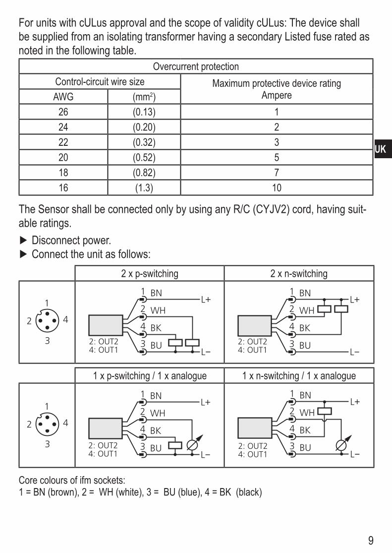
ForunitswithcULusapprovalandthescopeofvaliditycULus:Thedeviceshallbe supplied from an isolating transformer having a secondary Listed fuse rated as noted in the following table
Overcurrent protectionControl-circuit wire size Maximum protective device rating
AmpereAWG (mm2)26 (013) 124 (020) 222 (032) 320 (052) 518 (082) 716 (13) 10
TheSensorshallbeconnectedonlybyusinganyR/C(CYJV2)cord,havingsuit-able ratings
Disconnect power Connecttheunitasfollows:
2 x p-switching 2 x n-switching
L
L+
3
4
2
1
BU
BK
WH
BN
2: OUT24: OUT1 L
L+
3
4
2
1
BU
BK
WH
BN
2: OUT24: OUT1
1 x p-switching / 1 x analogue 1 x n-switching / 1 x analogue
L
L+
3
4
2
1
BU
BK
WH
BN
2: OUT24: OUT1 L
L+
3
4
2
1
BU
BK
WH
BN
2: OUT24: OUT1
Corecoloursofifmsockets:1 = BN (brown), 2 = WH (white), 3 = BU (blue), 4 = BK (black)

10
7 Operating and display elements
1: 7-segment display - Display of the system pressure1), - display of parameters and parameter values
2: 2 x LED red - Switching status; lights if output I / II has switched
3: Set button - Setting of the parameter values (scrolling by holding pressed; incremental by pressing briefly)
4: Mode/Enter button - Selection of the parameters and acknowledgement of the parameter values
1)3-digitdisplayintheminusrange:-.XX=-0,XXPSIindicationforPF2652:1/10ofthePSIvalueisdisplayed.

11
UK
8 Menu8.1 Menu structure
RUN
MS
M
M
MS
M
MS
MS
M
MS
M
MS
MS
M
MS
M
S
MS
M
MS
M
MS
M
MS
M
MS
M
MS
M
MS
M
RUNM
M
MM
M
M
M
S
MM
S
MM
S
MM
SM
S
S
M
OU2 = Hno, Hnc, Fno, FncOU2 = I, U

12
8.2 Menu explanationSP1/rP1 Maximum / minimum value for system pressure, at which output 1 changes
its switching statusOU1 OutputfunctionforOUT1:
•Switchingsignalforthelimitvalues:hysteresisfunction[H..]orwindowfunction [F ], normally open [ no] or normally closed [ nc] each
OU2 OutputfunctionforOUT2:•Switchingsignalforthelimitvalues:hysteresisfunction[H..]orwindow
function [F ], normally open [ no] or normally closed [ nc] each•Analogue signal for the current system pressure:4...20mA[I],0...10V[U].
SP2/rP2 Maximum / minimum value for system pressure, at which output 2 changes its switching status
ASP Analoguestartpointforthesystempressure:measuredvalueatwhich4 mA / 0 V are output
AEP Analogueendpointforthesystempressure:measuredvalueatwhich20 mA / 10 V are output
EF Extended functions / Opening menu level 2HI Maximum value memory for the system pressure
LO Minimum value memory for the system pressureCOF Zero point calibrationCAr Calibration reset
dS1/dS2 Switch-ondelayforOUT1/OUT2.dr1/dr2 ResetdelayforOUT1/OUT2.
P-n Outputpolarity:pnp/npndAP Damping for the switching outputsdAA Damping for the analogue signaldiS Update rate and orientation of the displayUni Standard unit of measurement for the system pressure

13
UK
9 Parameter settingDuring the parameter setting process the unit remains in the operating mode It continues its monitoring function with the existing parameters until parameter set-ting has been terminated
9.1 Parameter setting generalEachparametersettingrequires3steps:
1 Selecting parameter Press [Mode/Enter] until the re-quested parameter is displayed Mode/Enter Set
2 Setting the parameter value Press [Set] and keep the buton pressed
> Current setting value of the param-eter bit flashes for 5 s
> After5s:Settingvalueischanged:incremental by pressing briefly or scrolling by holding pressed
Mode/Enter Set
Thenumericalvaluesareincrementedcontinuously.Ifthevalueistobereduced:Letthedisplaymovetothemaximumsettingvalue.Thenthecyclestartsagainattheminimum setting value
3 Acknowledge parameter value Press [Mode/Enter] briefly
> Theparameterisdisplayedagain.Thenewsettingvalueisstored.
Mode/Enter Set
Set more parameters Start again with step 1
Finishing parameter setting Press [Mode/Enter] several times until the current measured value is displayed or wait for 15 s
> Theunitreturnstotheoperatingmode.

14
• Changing from menu level 1 to menu level 2 Press [Mode/Enter] until [EF] is displayed. Press [Set] briefly
> Thefirstparameterofthesubmenuisdisplayed(here:[HI]).
• Locking / unlocking Theunitcanbelockedelectronicallytopreventunintentionalwrongsettings.
Ensure that the unit is in the normal operating mode Press [Mode/Enter] + [Set] for 10 s
> Indication goes out briefly (acknowledgement of locking / unlocking)Units are delivered from the factory in the unlocked stateWith the unit in the locked state [Loc] is indicated briefly when you tryto change parameter values
• TimeoutIf no button is pressed for 15 s while the parameters are being set, the unit returns to the operating mode with unchanged values
9.2 Configuring the display (optional) Select[Uni]andsettheunitofmeasurement:
- bAr (= bar / mbar), - PSI, - PA (= MPa / kPa) - H2O (= inH2O, only PF2658), - inH (= inHg, only PF2609)
Select [diS] and set update rate and orientation of the display - [d1]:Updateofthemeasuredvalueevery50ms. - [d2]:Updateofthemeasuredvalueevery200ms. - [d3]:Updateofthemeasuredvalueevery600ms. - [Ph] = display of the measured peak value remains for a short time (peak hold)
- [rd1],[rd2],[rd3],[rPh]:Displayliked1,d2,d3,Ph;rotatedby180°. - [OFF]:Thedisplayisdeactivatedintheoperatingmode.Ifoneofthebuttons is pressed, the current measured value is displayed for 15 s AnotherpressoftheMode/EnterbuttonopenstheDisplaymode.TheLEDs remain active even if the display is deactivated
15
UK
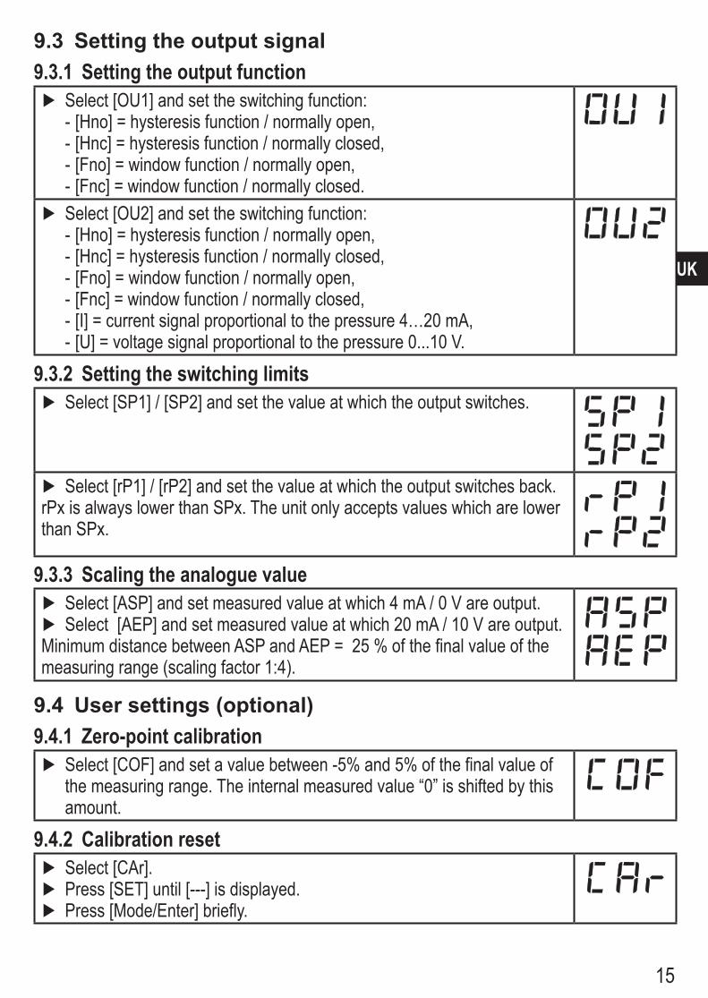
9.3 Setting the output signal9.3.1 Setting the output function
Select[OU1]andsettheswitchingfunction: - [Hno] = hysteresis function / normally open, - [Hnc] = hysteresis function / normally closed, - [Fno] = window function / normally open, - [Fnc] = window function / normally closed
Select[OU2]andsettheswitchingfunction: - [Hno] = hysteresis function / normally open, - [Hnc] = hysteresis function / normally closed, - [Fno] = window function / normally open, - [Fnc] = window function / normally closed, - [I] = current signal proportional to the pressure 4…20 mA, - [U] = voltage signal proportional to the pressure 010 V
9.3.2 Setting the switching limits Select [SP1] / [SP2] and set the value at which the output switches
Select [rP1] / [rP2] and set the value at which the output switches backrPxisalwayslowerthanSPx.Theunitonlyacceptsvalueswhicharelowerthan SPx
9.3.3 Scaling the analogue value Select [ASP] and set measured value at which 4 mA / 0 V are output Select [AEP] and set measured value at which 20 mA / 10 V are output
Minimum distance between ASP and AEP = 25 % of the final value of the measuringrange(scalingfactor1:4).
9.4 User settings (optional)9.4.1 Zero-point calibration
Select [COF] and set a value between -5% and 5% of the final value of themeasuringrange.Theinternalmeasuredvalue“0”isshiftedbythisamount
9.4.2 Calibration reset Select [CAr] Press[SET]until[---]isdisplayed. Press [Mode/Enter] briefly

16
9.4.3 Setting the delay time for the switching outputs[dS1]/[dS2]=switch-ondelayforOUT1/OUT2.[dr1]/[dr2]=switch-offdelayforOUT1/OUT2.
Select [dS1], [dS2], [dr1] or [dr2], set value between 01 und 50 s (at 00 the delay time is not active)
9.4.4 Setting the output polarity
Select [P-n] and set [PnP] or [nPn]
9.4.5 Setting the damping for the switching signal Select [dAP] and set value between 001 and 400 s (at 000 = [dAP] is not active)
dAP value = response time between pressure change and change of the switching status in seconds[dAP]influencestheswitchingfrequency:fmax = 1 ÷ 2dAP [dAP] also affects the display
9.4.5 Setting the damping for the analogue signal Select[dAA]andsetavalue:0,0-0,1-0,5or2,0s(at0.0=[dAA]isnotactive)
dAA value = response time between pressure change and change of the analogue signal in seconds
9.5 Service functions9.5.1 Reading the min./max. values for the system pressure
[Select [HI] or [LO], press [Set] briefly[HI] = maximum value, [LO] = minimum value
Deletememory: Select [HI] or [LO] Press[SET]until[---]isdisplayed. Press [Mode/Enter] briefly
10 OperationAfter power on of the supply voltage the unit is in the Run mode (= normal opera-tion) It carries out its measurement and evaluation functions and generates output signals according to the set parametersOperatingindicators→7Operatinganddisplayelements.

17
UK
10.1 Read the set parameter values Press [Mode/Enter] until the requested parameter is displayed Press [Set] briefly
> Theunitdisplaysthecorrespondingparametervalueforabout15s.Afteranother 15 s the unit returns to the Run mode
10.2 Fault indication[OL] Overload (presure above measuring range of the sensor)[UL] Underload (pressure below measuring range of the sensor)[SC1] Flashing:shortcircuitintheswitchingoutput1*.[SC2] Flashing:shortcircuitintheswitchingoutput2*.[SC] Flashing:shortcircuitinbothswitchingoutputs*.*Theoutputconcernedisswitchedoffaslongastheshortcircuitexists.
10.3 Cleaning of the filter coverIf viscous and residues producing media clog the filter cover of the sen-sor (and thus reduce the measuring accuracy slightly), you can clean it
Unscrew the filter cover (B) (use a pair of pliers with plastic-covered jaws for this)
Clean the cover thoroughly A B
Thevent(A)shouldonlybecleanedbyskilledpersonnelandwithutmostcare.Possible medium residues must not be compressed and pressed into the vent Thiscouldclogthefiltersystemandreducethemeasuringaccuracyofthesensor
Screw the filter cover again tightly

18
11 Scale drawing PF2609, PF2653PF2658
Dimensions are in millimeters1:display;2:programmingbuttone

19
UK
PF2652
Dimensions are in millimeters
12 Technical dataOperating voltag [V] 2030 DC Current consumption [mA] < 60 Current rating [mA] 2 x 250 Short-circuit / reverse polarity / overload protection, integrated watchdogVoltage drop [V] < 2 Power-on delay time [s] 02 Min response time switching outputs [ms] 3Switching frequency [Hz] ≤170Analogue output 420 mA / 010 V Max.loadcurrentoutput[Ω] (Ub - 10) x 50 Min.loadwithvoltageoutput[Ω] 2000 Min response time analog output [ms] 3

20
Accuracy / deviation (in % of the span)1)
- Characteristics deviation (linearity incl hysteresis and repeatability)2) < ± 06- Linearity < ± 05- Hysteresis < ± 01- Repeatability (with temperature fluctuations < 10 K) < ± 01- Long-term stability (in % of the span per year)< ± 01Temperaturecoefficient(TC)inthecompensatedtemperaturerange0...80°C(in%ofthespan per 10 K)
PF2609, PF2652PF2657 PF2658GreatestTCofthezeropoint < ± 01 < ± 01GreatestTCofthespan < ± 02 < ± 04
Materials (wetted parts) (PF2609, PF2653PF2658) stainlesssteel316L/1.4435;surfacecharacteristics:Ra<0.4/Rz4 ceramics(99.9%Al2O3);PTFEMaterials (wetted parts) (PF2652) stainlesssteel316L/1.4435;surfacecharacteristics:Ra<0.4/Rz4 ceramics;PTFEHousing materials stainlesssteel316L/1.4404;PBT(Pocan); PC(Makrolon);PEI;EPDM/X(Santoprene);FPM(Viton)Protection IP 67Protection class IIIInsulationresistance[MΩ] > 100 (500 V DC)Shock resistance [g] 50 (DIN / IEC 68-2-27, 11ms)Vibration resistance [g] 20 (DIN / IEC 68-2-6, 10 - 2000 Hz)Switching cycles min 100 millionOperatingtemperature[°C] -2580Mediumtemperature[°C] -2580Storagetemperature[°C] -40100EMCEN61000-4-2ESD: 4 / 8 KV EN61000-4-3HFradiated: 10 V/m EN61000-4-4Burst: 2 KV EN61000-4-6HFconducted: 10 V
1)allindicationsarereferredtoaturndownof1:12) limit value setting to DIN 16086

21
UK
12.1 Setting rangesSP1/SP2 rP1/rP2 ASP AEP
ΔPmin max min max min max min max
PF26
09 bar 1) -097 100 -099 098 -099 -020 -050 100 001inHg -29 30 -30 29 -30 -6 -15 30 1kPa -97 100 -99 98 -99 -20 -50 100 1
PF26
52 bar 00 1000 -05 995 -10 750 240 1000 01PSI 2) 0 1450 -10 1440 -10 1090 350 1450 10MPa 1) 000 100 -005 995 -010 750 240 100 001
PF26
53 bar -08 250 -09 249 -10 188 53 250 01PSI -12 363 -13 362 -15 272 76 363 1
MPa 1) -008 250 -009 249 -010 188 053 250 001
PF26
54 bar 1) -045 999 -050 994 -050 749 200 999 001PSI -7 145 -7 144 -7 109 29 145 1kPa -45 999 -50 994 -50 749 200 999 1
PF26
56 bar 1) -011 250 -012 249 -013 188 050 250 001PSI -16 363 -17 362 -18 272 73 363 01kPa -11 250 -12 249 -13 188 50 250 1
PF26
57 mbar -45 999 -50 994 -50 749 200 999 1PSI -07 145 -07 144 -07 109 29 145 01kPa -45 999 -50 994 -50 749 200 999 01
PF26
58 mbar -11 250 -12 249 -13 188 50 250 1kPa -11 250 -12 249 -13 188 50 250 01
inH2O -44 100 -48 996 -50 749 201 100 011)displayintheminusrange:-.XX=-0,XX2)display:1/10ofthePSIvalueΔP=increments
More information at wwwifmcom


![Pressure ur Sensors [圧力センサ] Sensor Applications Micro-Pressure Range Low-Pressure Range High-Pressure Range Gas pressure control, washing machine water level control, filter](https://img.pdfslide.tips/doc/110x75/5b04aa5f7f8b9a4e538e1a10/pressure-ur-sensors-sensor-applications-micro-pressure-range-low-pressure.jpg)