Embed Size (px)
Citation preview

A-1
1
OperatingInstructionsforInstronModel4400‐SeriesLoadFrames
John D. Williams and David E. Farrow
SAFETY FIRST TheInstron®4400loadframegenerateshighforces.Thecapacityoftheframeis100kN(thatis,
22.5kipsor11.3tons).Theframedoesnotknowthedifferencebetweenasteelplateandyourhand.Alwaysfollowinstructions.NEVERWORKALONE.
Beawarethatthelargeamountofenergystoredinaspecimenduringelasticdeformationmaybereleased suddenly when fracture occurs; small fragments may be launched. SAFETY GLASSESMUSTBEWORNATALLTIMESINTHEAREA.
Protect yourself and the equipment always. Leave the mechanical limit stops as set. STAYCLEAROFMOVINGPARTS.
Improperuse of the equipmentmay causedamage and ISHAZARDOUS. Use the fixtures asinstructedandwithinspecifiedlimits.Forexample,bendingasteelbarwellbeyondyieldproducesexcessive lateral forces on the bending fixtures. If in doubt,ASK. Report any hazards or injuriesimmediatelytothepersonnelinchargeofthelab.
Figure1.Instron4400‑seriesloadframe.
Note:Larger,olderversioncontrolconsoleshown

Instron4400‑SeriesLoadFrames
2
Introduction The InstronModel 4483 load frame (Figure
1) applies tensile and compressive forces bymeans of a moving crosshead. The frame isdesignedas“arigid,stablestructurewithahighstiffnessvalue.”
In Figure 2, theprotective curtainhas beentemporarily removed to show one of thecounter‑rotating lead screws that raise andlower the crosshead. In the base, the motordrives the lead screws througha series of beltsandpulleys. Anencodersensesmotor rotationforcrossheadspeedcontrol,crossheadposition‑ing, and position data acquisition. Do notremovetheprotectivecurtains.
Figure2.Instron4400‑seriesloadframewithprotectivecurtainremoved.
Force is sensed by a 100kN (22.5kip) loadcellboltedtothecrosshead. Thespecimensareloadedbyfixturesthatarepinnedintotheframebaseplatebelowthespecimentestareaandtheload cell above the specimen test area. Anextensometermaybeusedtomeasuredeflectionof the specimen. The outputs of the load cellforce transducer and extensometer are voltagesthat are converted to engineering units by theframecontrolleranddisplayedonacomputer.
Load Frame Control The ON‑OFF switch on the frame panel
(Figure3)controlspowertotheframe.DONOTswitchthepoweroff.Iftheswitchisoff,consultyour TA. All lab tests are runwith the clutchspeedcontrolintheLOWposition.InLOW,themaximum crosshead speed is 50mm/min(2in/min) and themaximum load range of theframe is 100kN (22.5kips). In HIGH, rates to500mm/min (20in/min) are possible; however,theloadlimitis25kN(5.6kips).
Figure3.Framepanel.
Totheleftoftheclutchspeedcontrol istheemergency stop; press it only when there isdanger topersonnel or a risk of damage to theframe,specimen,orfixtures.
Several machine functions may becontrolled manually using the control console(Figure4),includingcrossheadpositioning.
Figure4.Controlconsole.
Instron4400‑SeriesLoadFrames
3
Machinestatusindicatorsarelocatedonthecontrolconsole.Atthetopareframepowerandframe readiness status indicators. Just belowthose, on the right, are the GL RESET (gagelength reset) button and status indicator,crosshead FINE POSITION thumbwheel, andcrossheadjoggingbuttons.Thegreysections,atthemiddle left to lower left, contain crossheadtest direction indicators, a red crosshead STOPbuttonandindicator,andacrossheadRETURNbuttonandindicator.UsetheJOGUPandJOGDOWN buttons and the FINE POSITIONthumbwheeltopositionthecrosshead.PressingGL RESET will define the present crossheadpositionaszero. PressingRETURNwill returnthecrossheadtothezerogagelengthcrossheadposition if it is not there already. Obviously,greatcaremustbeexercisedinitsuse.
For laboratory experiments, the controlfunctions are performed by Instron Bluehill®software running on a computer, which isinterfaced to the load frame controller. Real‑time extension (crosshead position), load, andstrainnumericalreadoutsare locatedacrossthetopofthecomputerscreen.
Theindicatedloadduringthetestshouldbethe load transmitted to the specimen, thus loadcell balancing (zeroing) is performed withoutthespecimeninstalled.Thisisdonebyselectingthe load‑cell icon at the top of the computerscreenandthenclickingon“Balance”.Theloadreading(atthetopofthescreen)shouldthenbenearly zero. It should be necessary to balancetheloadcellonlyonceduringanylabperiod.
Tensile Test Setup and Conduct The appropriate Bluehill® test method (the
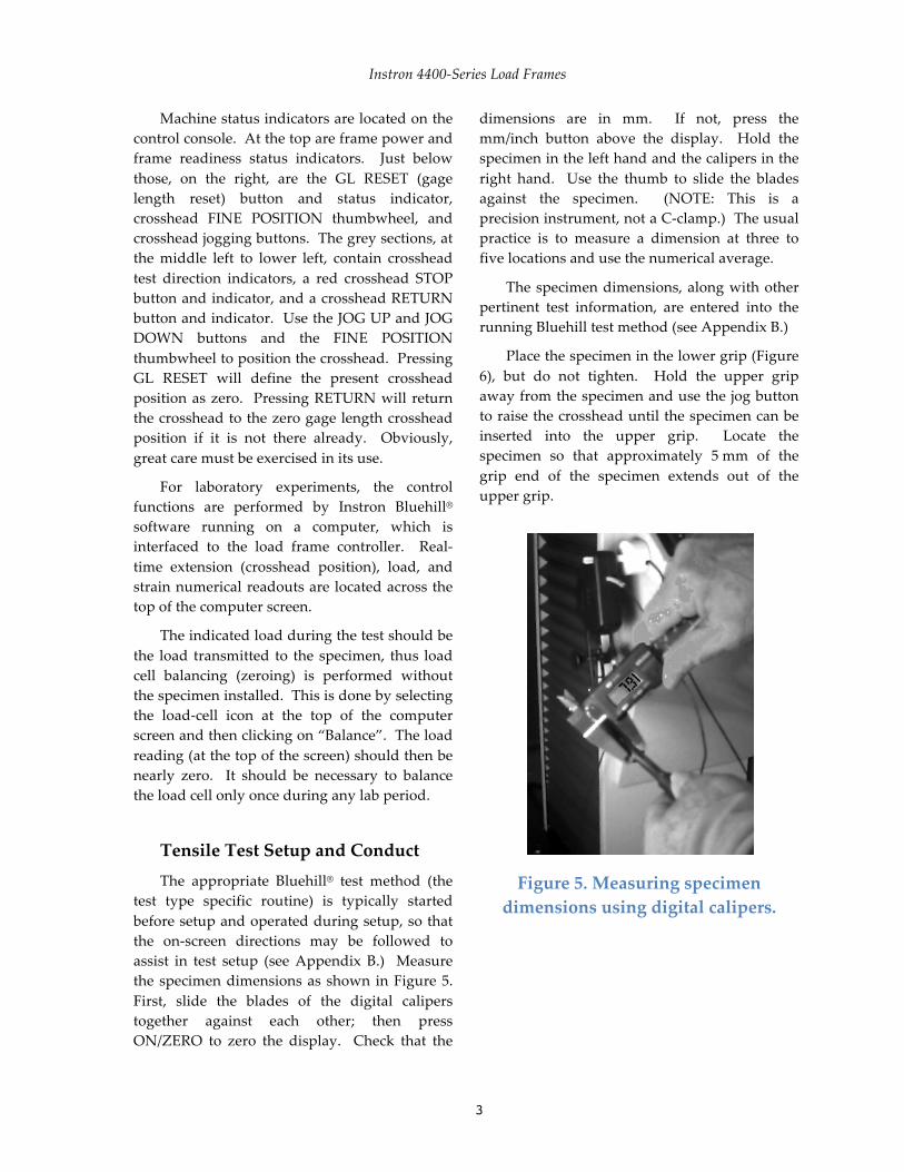
test type specific routine) is typically startedbeforesetupandoperatedduringsetup,sothatthe on‑screen directions may be followed toassist in test setup (seeAppendix B.) Measurethespecimendimensionsas shown inFigure5.First, slide the blades of the digital caliperstogether against each other; then pressON/ZERO to zero the display. Check that the
dimensions are in mm. If not, press themm/inch button above the display. Hold thespecimeninthelefthandandthecalipersintheright hand. Use the thumb to slide the bladesagainst the specimen. (NOTE: This is aprecisioninstrument,notaC‑clamp.)Theusualpractice is to measure a dimension at three tofivelocationsandusethenumericalaverage.
Thespecimendimensions,alongwithotherpertinent test information, are entered into therunningBluehilltestmethod(seeAppendixB.)
Placethespecimeninthelowergrip(Figure6), but do not tighten. Hold the upper gripawayfromthespecimenandusethejogbuttontoraisethecrossheaduntilthespecimencanbeinserted into the upper grip. Locate thespecimen so that approximately 5mm of thegrip end of the specimen extends out of theuppergrip.
Figure5.Measuringspecimendimensionsusingdigitalcalipers.

Instron4400‑SeriesLoadFrames
4
Figure6.Placingtensiletestspecimeninlowergrip.
Figure7.Tighteningtheuppergrip.
Tighten the upper grip first (Figure 7).(NOTE: The upper grip swivels on a U‑joint;therefore,thespecimenmaybebentifthelowergrip is tightened first.) Using the jog button,lower the crosshead to center the specimenbetweenthegrips.
The grip inserts are shaped to providewedge action so that they grip more firmly asthe test progresses. The gripped ends of thespecimen should be free of scale and oil. The
grip should be tightened “firmly” withoutforcing.
Figure8.Tighteningthelowergrip.
Tighten the lower grip (Figure 8). A smallload may be introduced when the grip istightened; however, this load (typically 0.5 to1.0kN formetal specimens) is small comparedwith the testing loads. If the load isnot small,loosenthegripandtightenitagain.
Press GL RESET to initialize the crossheadposition and set the extension display on thecomputerscreen tozero. ThegreenLEDlightstoindicatezeroextensionposition.
If an extensometer is not used, proceed tothe final check. Otherwise, continue withextensometerinstallation.
Extensometer Installation Slide the extensometer (Figure 9) off the
yellow hanger on the test frame. Press theknobstoengagetheconestosetthegagelengthof the extensometer. (NOTE: Hold theextensometerwith theknobsat the topand thesignalwireatthebottom.)

Instron4400‑SeriesLoadFrames
5
Figure9.Extensometer,showingknobstosetgagelength.
Continue to hold the knobs and open thespring clips only enough to slide theextensometer knife edges onto the specimen(Figure10).Thebodyoftheextensometermustbe oriented to the front (or back) of the testframe to avoid contact with the grips. Centertheextensometerverticallywithinthespecimengage section. Ascertain that the clips seat theextensometer firmly on the specimen. Releasetheknobs.
Figure10.Placingextensometerontensiletestspecimen.
Thestrainindicatoronthecomputerscreenshoulddisplayavaluewithintherangeof±5%.Ifitisoutsidethisrange,consultyourTA.
Allthephysicalsetupisnowcomplete.Onthe computer, click on BALANCE STRAIN in
the running Bluehill® test method. The strainindicatoronthecomputerscreenshoulddisplaynearly zero. (NOTE: The displayed strain isusually not exactly zero. The extensometer isextremely sensitive and even very smallchanges, including those caused by vibrations,aredetected.).
Final Check Perform a final check of the entire setup:
• Verify that the load, extension and strainreadouts on the computer screen aredisplayingreasonablenumbers.
• Verifythatthefixturesandthespecimenareproperlyinstalled.
• Verify that the test section is clear of tools,cables,bodyparts,etc.
• Verifythatthesafetyshieldsareinplace.
If these conditions are satisfied, then theInstron 4400 is ready to run the test. ClickSTARTonthecomputerscreentobeginthetest.(SeeAppendixB.)
After the Test The appearance of the specimen fracture
surfaces is important for the analysis of testresults.Becarefultoprotectthesesurfaces.
• Becertain that themachinehasstopped. Ifnot, press the red STOP button on thecontrolconsole.
• Carefullyremovetheextensometerfromthespecimen and place it back on its hanger.Usetheholeinthebodyoftheextensometertohangitup.
• Loosen the lower grip (using the oppositerotationfromFigure8).
• Swing the upper grip out of line andcarefully slide the lower portion of thespecimenupfromthelowergrip.
• Support theupperportionof thespecimen,and then loosen the upper grip (using theopposite rotation from Figure 7). Removethespecimenupperportion.

Instron4400‑SeriesLoadFrames
6
• Measurethefinalspecimendimensionsandenterthedataontoyourdatasheetsandintothe running Bluehill test method on thecomputer.
• Finish the test sample in the Bluehillsoftware(seeAppendixB).
Theframeisnowreadyforanothertest.
Revised 7/12


![[Ppt] mfr instron](https://img.pdfslide.tips/doc/110x75/587379111a28ab3c1a8b6e39/ppt-mfr-instron.jpg)