Embed Size (px)
Citation preview
Page
Revision C: Updated 2/7/2018
Operation and Installation Manual
G-Scale Graphics 5860 Crooked Stick Dr.
Windsor, CO 80550 970-581-3567
www.GScaleGraphics.net
Revision G: Updated 2/7/2018
The Next Generation of
Page 2
Contents
Page Overview ………………………………………………………………………….. 3 The Radio System ……………………………………………………………….. 4 The TrackSide R/C Control Board ……………………………….………...……. 4 Installation ……………………………………………………….…….…………. 5 Operation …………………..……………………………………..……….……… 6 Interactive Remote Transmitter ………………………………………………… 7 Shutdowns ……………………………………………………………………….. 8 Transmitter Command Summary ……………………………………..……….. 9,10 Trouble Shooting ………………………………….…………...…..……..……… 11 User Programming ………………………….....……..……………………..…… 12 Specifications ……………………..……..…………………………………..…… 13 Meanwell Power Supplies ………………………………………………………. 14
Page 3
Overview
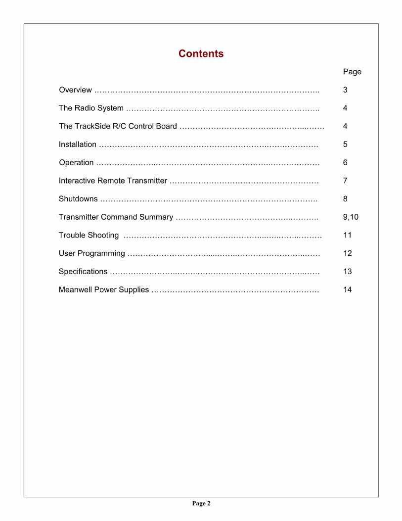
RailBoss 4 - Trackside R/C (Radio Control) is an electronic speed control designed for remote control of track powered large scale trains. The pocket sized transmitter allows you to control and follow your trains anywhere, without being tied down to a “control panel”. A regulated DC power supply (e.g. 24V, 5-10A) must be used to supply power to the Trackside R/C unit, which then throttles the PWM (Pulse Width Modulated) voltage to the track via radio control. The pocket sized TX (Transmitter) controls the Trackside base station via 2.4GHZ DSSS radio signals.
No modifications to locomotives required Pocket sized transmitter Precise speed control Up to 10 amps of track power User programmable
The Trackside base station can pass up to 10 amps of current from the power supply to your track. That is more than enough to handle one or more locomotives pulling a full train. Typical current draw for one locomotive motor is around 1 Amp. User programmable options give you control over operating parameters, without the need for a computer. 1) NOT for use with older unregulated power packs like PH Hobbies and MRC 6200. Many low cost train “Power
Packs” do not have regulated DC outputs. Their outputs contain a high content of AC voltage that will damage the Trackside R/C unit. If in doubt, please call us.
2) Locomotives containing DCC decoders that also allow operation on regular DC voltage may not operate prop-erly with the Trackside R/C. Our PWM output signal makes some DCC boards think they are in DCC mode.
3) PWM may affect the lighting circuits of some locomotives.
Wiring Diagram
Page 4
The Radio System The TrackSide R/C uses a new high-tech 2.4GHZ system designed for in-dustrial use. The range is excellent, up to 400 ft. with the Standard Transmit-ter, or up to 800 ft. with the Long Range Transmitter. Best reception will be obtained with line-of-sight between the TrackSide base station and the TX. Raising the RX above ground level may also improve reception, if needed. Each Trackside base station “learns” its transmitter and will only respond to that transmitter and no others. Multiple TrackSide R/C systems can be used in the same location to run multiple loops of track, without interference. There are no channels or frequency selections to worry about. The 6-button handheld transmitter uses long lasting replaceable batteries. There is no on/off switch. It is always ready to use, and only transmits while a button is pressed. Keep the transmitter in your pocket or attached to a neck lanyard. One transmitter can control two base units, and therefore two separate trains.
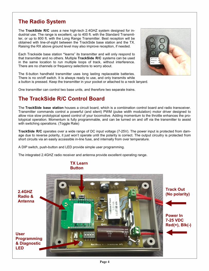
The TrackSide R/C Control Board The TrackSide base station houses a circuit board, which is a combination control board and radio transceiver. Transmitter commands control a powerful (and silent) PWM (pulse width modulation) motor driver designed to allow nice slow prototypical speed control of your locomotive. Adding momentum to the throttle enhances the pro-totypical operation. Momentum is fully programmable, and can be turned on and off via the transmitter to assist with switching operations. (Toggle Rate) TrackSide R/C operates over a wide range of DC input voltage (7-25V). The power input is protected from dam-age due to reverse polarity, it just won’t operate until the polarity is correct. The output circuitry is protected from short circuits via an easily accessible in-line fuse, and internally from over temperature. A DIP switch, push-button and LED provide simple user programming. The integrated 2.4GHZ radio receiver and antenna provide excellent operating range.
User Programming & Diagnostic LED
Track Out (No polarity)
2.4GHZ Radio & Antenna
TX Learn Button
Power In 7-25 VDC Red(+), Blk(-)
Page 5
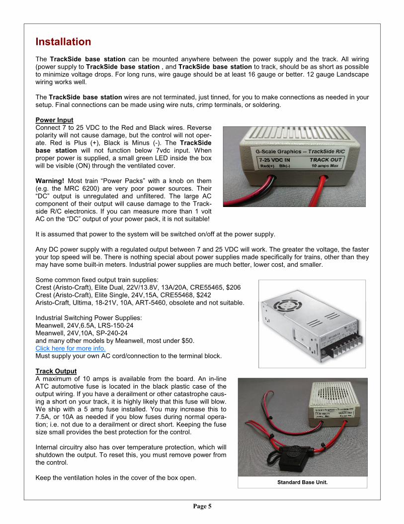
Installation The TrackSide base station can be mounted anywhere between the power supply and the track. All wiring (power supply to TrackSide base station , and TrackSide base station to track, should be as short as possible to minimize voltage drops. For long runs, wire gauge should be at least 16 gauge or better. 12 gauge Landscape wiring works well. The TrackSide base station wires are not terminated, just tinned, for you to make connections as needed in your setup. Final connections can be made using wire nuts, crimp terminals, or soldering. Power Input Connect 7 to 25 VDC to the Red and Black wires. Reverse polarity will not cause damage, but the control will not oper-ate. Red is Plus (+), Black is Minus (-). The TrackSide base station will not function below 7vdc input. When proper power is supplied, a small green LED inside the box will be visible (ON) through the ventilated cover. Warning! Most train “Power Packs” with a knob on them (e.g. the MRC 6200) are very poor power sources. Their “DC” output is unregulated and unfiltered. The large AC component of their output will cause damage to the Track-side R/C electronics. If you can measure more than 1 volt AC on the “DC” output of your power pack, it is not suitable! It is assumed that power to the system will be switched on/off at the power supply. Any DC power supply with a regulated output between 7 and 25 VDC will work. The greater the voltage, the faster your top speed will be. There is nothing special about power supplies made specifically for trains, other than they may have some built-in meters. Industrial power supplies are much better, lower cost, and smaller. Some common fixed output train supplies: Crest (Aristo-Craft), Elite Dual, 22V/13.8V, 13A/20A, CRE55465, $206 Crest (Aristo-Craft), Elite Single, 24V,15A, CRE55468, $242 Aristo-Craft, Ultima, 18-21V, 10A, ART-5460, obsolete and not suitable. Industrial Switching Power Supplies: Meanwell, 24V,6.5A, LRS-150-24 Meanwell, 24V,10A, SP-240-24 and many other models by Meanwell, most under $50. Click here for more info. Must supply your own AC cord/connection to the terminal block. Track Output A maximum of 10 amps is available from the board. An in-line ATC automotive fuse is located in the black plastic case of the output wiring. If you have a derailment or other catastrophe caus-ing a short on your track, it is highly likely that this fuse will blow. We ship with a 5 amp fuse installed. You may increase this to 7.5A, or 10A as needed if you blow fuses during normal opera-tion; i.e. not due to a derailment or direct short. Keeping the fuse size small provides the best protection for the control. Internal circuitry also has over temperature protection, which will shutdown the output. To reset this, you must remove power from the control. Keep the ventilation holes in the cover of the box open.
Meanwell Industrial Power Supply SP-240-24
Standard Base Unit.
Page 6
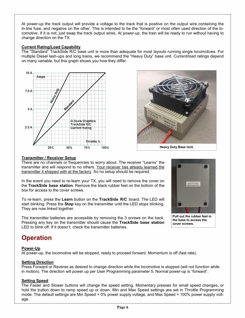
At power-up the track output will provide a voltage to the track that is positive on the output wire containing the in-line fuse, and negative on the other. This is intended to be the “forward” or most often used direction of the lo-comotive. If it is not, just swap the track output wires. At power-up, the train will be ready to run without having to change direction on the TX. Current Rating/Load Capability The “Standard” TrackSide R/C base unit is more than adequate for most layouts running single locomotives. For multiple Diesel lash-ups and long trains, we recommend the “Heavy Duty” base unit. Current/load ratings depend on many variable, but this graph shows you how they differ.
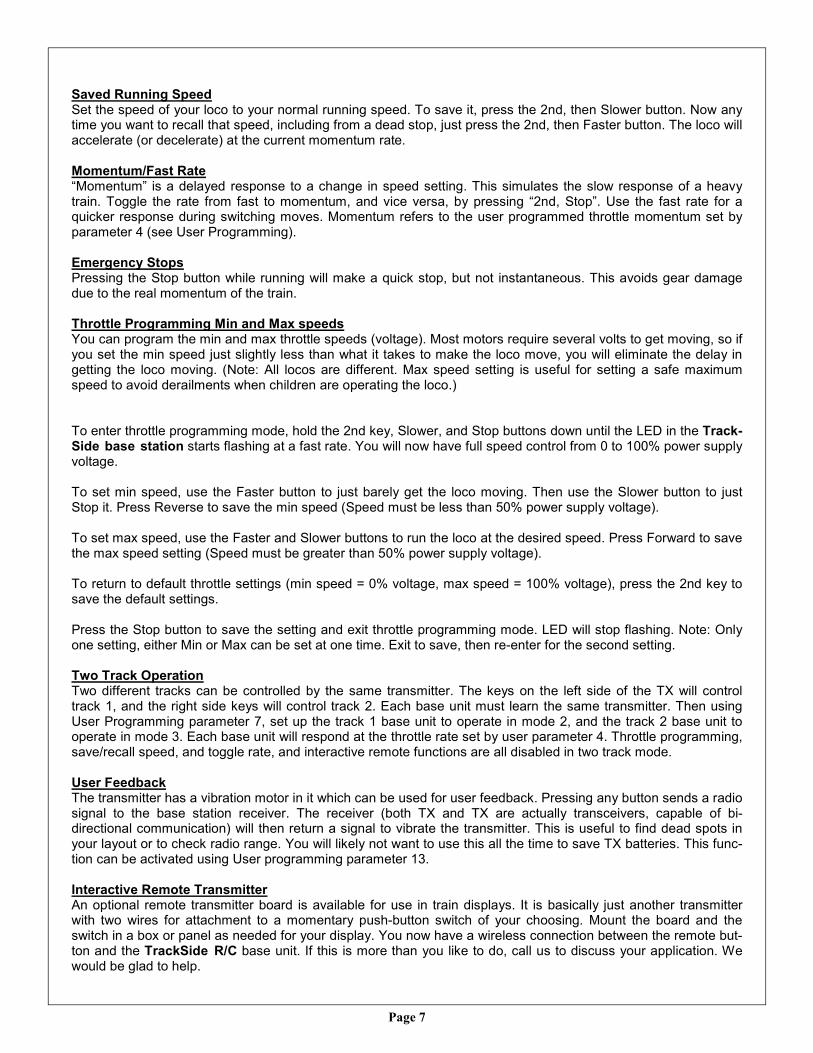
Transmitter / Receiver Setup There are no channels or frequencies to worry about. The receiver “Learns” the transmitter and will respond to no others. Your receiver has already learned the transmitter it shipped with at the factory. So no setup should be required. In the event you need to re-learn your TX, you will need to remove the cover on the TrackSide base station. Remove the black rubber feet on the bottom of the box for access to the cover screws. To re-learn, press the Learn button on the TrackSide R/C board. The LED will start blinking. Press the Stop key on the transmitter until the LED stops blinking. They are now linked together. The transmitter batteries are accessible by removing the 3 screws on the back. Pressing any key on the transmitter should cause the TrackSide base station LED to blink off. If it doesn’t, check the transmitter batteries.
Operation
Power-Up At power-up, the locomotive will be stopped, ready to proceed forward. Momentum is off (fast rate). Setting Direction Press Forward or Reverse as desired to change direction while the locomotive is stopped (will not function while in motion). The direction will power up per User Programming parameter 5. Normal power-up is “forward”. Setting Speed The Faster and Slower buttons will change the speed setting. Momentary presses for small speed changes, or hold the button down to ramp speed up or down. Min and Max Speed settings are set in Throttle Programming mode. The default settings are Min Speed = 0% power supply voltage, and Max Speed = 100% power supply volt-age.
Pull out the rubber feet in the base to access the cover screws.
Heavy Duty Base Unit.
Page 7
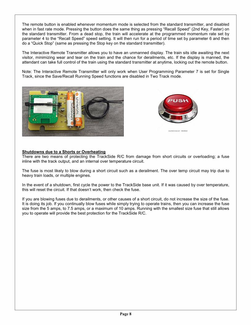
Saved Running Speed Set the speed of your loco to your normal running speed. To save it, press the 2nd, then Slower button. Now any time you want to recall that speed, including from a dead stop, just press the 2nd, then Faster button. The loco will accelerate (or decelerate) at the current momentum rate. Momentum/Fast Rate “Momentum” is a delayed response to a change in speed setting. This simulates the slow response of a heavy train. Toggle the rate from fast to momentum, and vice versa, by pressing “2nd, Stop”. Use the fast rate for a quicker response during switching moves. Momentum refers to the user programmed throttle momentum set by parameter 4 (see User Programming). Emergency Stops Pressing the Stop button while running will make a quick stop, but not instantaneous. This avoids gear damage due to the real momentum of the train. Throttle Programming Min and Max speeds You can program the min and max throttle speeds (voltage). Most motors require several volts to get moving, so if you set the min speed just slightly less than what it takes to make the loco move, you will eliminate the delay in getting the loco moving. (Note: All locos are different. Max speed setting is useful for setting a safe maximum speed to avoid derailments when children are operating the loco.) To enter throttle programming mode, hold the 2nd key, Slower, and Stop buttons down until the LED in the Track-Side base station starts flashing at a fast rate. You will now have full speed control from 0 to 100% power supply voltage. To set min speed, use the Faster button to just barely get the loco moving. Then use the Slower button to just Stop it. Press Reverse to save the min speed (Speed must be less than 50% power supply voltage). To set max speed, use the Faster and Slower buttons to run the loco at the desired speed. Press Forward to save the max speed setting (Speed must be greater than 50% power supply voltage). To return to default throttle settings (min speed = 0% voltage, max speed = 100% voltage), press the 2nd key to save the default settings. Press the Stop button to save the setting and exit throttle programming mode. LED will stop flashing. Note: Only one setting, either Min or Max can be set at one time. Exit to save, then re-enter for the second setting. Two Track Operation Two different tracks can be controlled by the same transmitter. The keys on the left side of the TX will control track 1, and the right side keys will control track 2. Each base unit must learn the same transmitter. Then using User Programming parameter 7, set up the track 1 base unit to operate in mode 2, and the track 2 base unit to operate in mode 3. Each base unit will respond at the throttle rate set by user parameter 4. Throttle programming, save/recall speed, and toggle rate, and interactive remote functions are all disabled in two track mode. User Feedback The transmitter has a vibration motor in it which can be used for user feedback. Pressing any button sends a radio signal to the base station receiver. The receiver (both TX and TX are actually transceivers, capable of bi-directional communication) will then return a signal to vibrate the transmitter. This is useful to find dead spots in your layout or to check radio range. You will likely not want to use this all the time to save TX batteries. This func-tion can be activated using User programming parameter 13. Interactive Remote Transmitter An optional remote transmitter board is available for use in train displays. It is basically just another transmitter with two wires for attachment to a momentary push-button switch of your choosing. Mount the board and the switch in a box or panel as needed for your display. You now have a wireless connection between the remote but-ton and the TrackSide R/C base unit. If this is more than you like to do, call us to discuss your application. We would be glad to help.
Page 8
The remote button is enabled whenever momentum mode is selected from the standard transmitter, and disabled when in fast rate mode. Pressing the button does the same thing as pressing “Recall Speed” (2nd Key, Faster) on the standard transmitter. From a dead stop, the train will accelerate at the programmed momentum rate set by parameter 4 to the “Recall Speed” speed setting. It will then run for a period of time set by parameter 6 and then do a “Quick Stop” (same as pressing the Stop key on the standard transmitter). The Interactive Remote Transmitter allows you to have an unmanned display. The train sits idle awaiting the next visitor, minimizing wear and tear on the train and the chance for derailments, etc. If the display is manned, the attendant can take full control of the train using the standard transmitter at anytime, locking out the remote button. Note: The Interactive Remote Transmitter will only work when User Programming Parameter 7 is set for Single Track, since the Save/Recall Running Speed functions are disabled in Two Track mode. Shutdowns due to a Shorts or Overheating There are two means of protecting the TrackSide R/C from damage from short circuits or overloading; a fuse inline with the track output, and an internal over temperature circuit. The fuse is most likely to blow during a short circuit such as a derailment. The over temp circuit may trip due to heavy train loads, or multiple engines. In the event of a shutdown, first cycle the power to the TrackSide base unit. If it was caused by over temperature, this will reset the circuit. If that doesn’t work, then check the fuse. If you are blowing fuses due to derailments, or other causes of a short circuit, do not increase the size of the fuse. It is doing its job. If you continually blow fuses while simply trying to operate trains, then you can increase the fuse size from the 5 amps, to 7.5 amps, or a maximum of 10 amps. Running with the smallest size fuse that still allows you to operate will provide the best protection for the TrackSide R/C.
Page 9
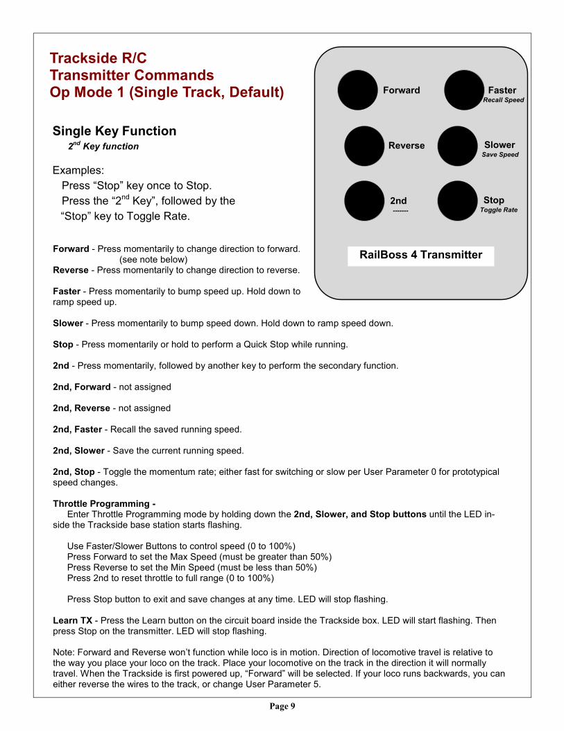
Trackside R/C Transmitter Commands Op Mode 1 (Single Track, Default)
Single Key Function 2
nd Key function
Examples:
Press “Stop” key once to Stop.
Press the “2nd Key”, followed by the
“Stop” key to Toggle Rate.
Forward - Press momentarily to change direction to forward. (see note below) Reverse - Press momentarily to change direction to reverse. Faster - Press momentarily to bump speed up. Hold down to ramp speed up. Slower - Press momentarily to bump speed down. Hold down to ramp speed down. Stop - Press momentarily or hold to perform a Quick Stop while running. 2nd - Press momentarily, followed by another key to perform the secondary function. 2nd, Forward - not assigned 2nd, Reverse - not assigned 2nd, Faster - Recall the saved running speed.
2nd, Slower - Save the current running speed. 2nd, Stop - Toggle the momentum rate; either fast for switching or slow per User Parameter 0 for prototypical speed changes. Throttle Programming - Enter Throttle Programming mode by holding down the 2nd, Slower, and Stop buttons until the LED in-side the Trackside base station starts flashing. Use Faster/Slower Buttons to control speed (0 to 100%) Press Forward to set the Max Speed (must be greater than 50%) Press Reverse to set the Min Speed (must be less than 50%) Press 2nd to reset throttle to full range (0 to 100%) Press Stop button to exit and save changes at any time. LED will stop flashing. Learn TX - Press the Learn button on the circuit board inside the Trackside box. LED will start flashing. Then press Stop on the transmitter. LED will stop flashing. Note: Forward and Reverse won’t function while loco is in motion. Direction of locomotive travel is relative to the way you place your loco on the track. Place your locomotive on the track in the direction it will normally travel. When the Trackside is first powered up, “Forward” will be selected. If your loco runs backwards, you can either reverse the wires to the track, or change User Parameter 5.
FasterRecall Speed
StopToggle Rate
2nd-------
RailBoss 4 Transmitter
Forward
Reverse SlowerSave Speed
Page 10
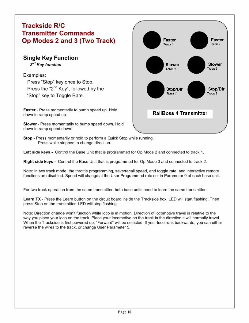
Trackside R/C Transmitter Commands Op Modes 2 and 3 (Two Track)
Single Key Function 2
nd Key function
Examples:
Press “Stop” key once to Stop.
Press the “2nd Key”, followed by the
“Stop” key to Toggle Rate.
Faster - Press momentarily to bump speed up. Hold down to ramp speed up. Slower - Press momentarily to bump speed down. Hold down to ramp speed down. Stop - Press momentarily or hold to perform a Quick Stop while running. Press while stopped to change direction. Left side keys - Control the Base Unit that is programmed for Op Mode 2 and connected to track 1. Right side keys - Control the Base Unit that is programmed for Op Mode 3 and connected to track 2. Note: In two track mode, the throttle programming, save/recall speed, and toggle rate, and interactive remote functions are disabled. Speed will change at the User Programmed rate set in Parameter 0 of each base unit. For two track operation from the same transmitter, both base units need to learn the same transmitter. Learn TX - Press the Learn button on the circuit board inside the Trackside box. LED will start flashing. Then press Stop on the transmitter. LED will stop flashing. Note: Direction change won’t function while loco is in motion. Direction of locomotive travel is relative to the way you place your loco on the track. Place your locomotive on the track in the direction it will normally travel. When the Trackside is first powered up, “Forward” will be selected. If your loco runs backwards, you can either reverse the wires to the track, or change User Parameter 5.
Page 11
Trouble Shooting
Nothing seems to be working … Cycle power to reset a possible over temperature trip. Check the power. The TrackSide LED should be ON. You should measure between 7 and 25 volts DC ap-
plied to power input wires (Red +, Black -). Check the fuse. If it is blowing during normal operation (not due to a short during derailment), you may in-
crease the size from 5A to 7.5A, or 10A. The wires are connected to an internal terminal strip. Open the box and check for loose wires. Pressing any button on the transmitter should cause the TrackSide LED to blink off. If not, check the trans-
mitter batteries. Replace with AAAA alkaline batteries (Available on our website, if needed). The transmitter doesn't work at all. Did the receiver successfully “Learn” the transmitter? Open the transmitter case and make sure the batteries and green module are both fully seated. Replace the batteries with a AAAA alkaline cells, available on our website. Erratic throttle behavior? Reset throttle to default full range values using throttle programming procedure
(See Throttle Programming). The loco doesn’t start moving until I hold the Faster button for a long time. The voltage is ramping from 0 volts to that required to move the loco. You can eliminate this dead time by
programming the Min Speed setting to a higher value. (See Throttle Programming). However, this setting may be different for each loco.
The loco starts moving as soon as I turn it on. Program the Min Speed setting to a lower value. The locos runs in reverse at power up. Reverse the wires at the track output. The loco won’t run as fast as I like even though I keep trying to increase the speed setting … Maximum speed is determined by your power supply voltage or the Max Speed setting. You need more
voltage or you may need to restore the default throttle programming settings. I can’t change direction with the loco stopped. While the loco may be stopped, the track voltage still isn’t close enough to zero volts to allow the direction
change. Get into the habit of always pressing the Stop button to insure voltage goes to zero. If the lights in your loco are acting funny, not working well, or perhaps flickering, it may be due to the PWM
(Pulse Width Modulation) output of the track throttle. It won’t cause any harm to your loco, but it can be cor-rected, if desired, by using a PWM to Linear Converter made by Crest; P/N CRE-57091A. This will provide a pure DC output to the track and loco.
Notes: 1) Many low cost train “Power Packs” do not have regulated DC outputs. Their outputs contain a high content of
AC voltage that will damage the Trackside R/C unit. It will overheat and burn up the driver stage. If in doubt, please call us. The DC output of your power pack should measure less than 1 volt AC (measured on the AC scale of your meter).
2) Locomotives containing DCC decoders that also allow operation on regular DC voltage may not operate prop-erly with the Trackside R/C. Our PWM output signal makes the DCC board think it is in DCC mode. Removing the DCC board and making direct connections between the track pickups and the locomotives motor(s) will solve this problem.
Page 12
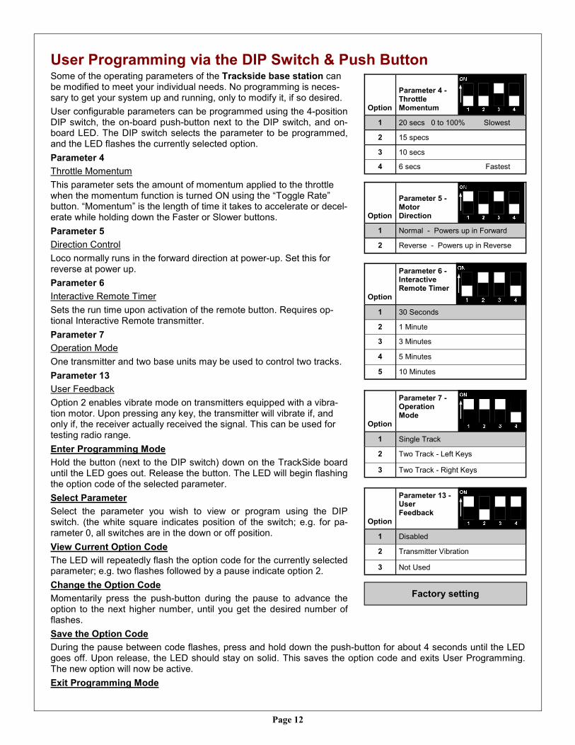
User Programming via the DIP Switch & Push Button Some of the operating parameters of the Trackside base station can be modified to meet your individual needs. No programming is neces-sary to get your system up and running, only to modify it, if so desired.
User configurable parameters can be programmed using the 4-position DIP switch, the on-board push-button next to the DIP switch, and on-board LED. The DIP switch selects the parameter to be programmed, and the LED flashes the currently selected option.
Parameter 4
Throttle Momentum
This parameter sets the amount of momentum applied to the throttle when the momentum function is turned ON using the “Toggle Rate” button. “Momentum” is the length of time it takes to accelerate or decel-erate while holding down the Faster or Slower buttons.
Parameter 5
Direction Control
Loco normally runs in the forward direction at power-up. Set this for reverse at power up.
Parameter 6
Interactive Remote Timer
Sets the run time upon activation of the remote button. Requires op-tional Interactive Remote transmitter.
Parameter 7
Operation Mode
One transmitter and two base units may be used to control two tracks.
Parameter 13
User Feedback
Option 2 enables vibrate mode on transmitters equipped with a vibra-tion motor. Upon pressing any key, the transmitter will vibrate if, and only if, the receiver actually received the signal. This can be used for testing radio range.
Enter Programming Mode
Hold the button (next to the DIP switch) down on the TrackSide board until the LED goes out. Release the button. The LED will begin flashing the option code of the selected parameter.
Select Parameter
Select the parameter you wish to view or program using the DIP switch. (the white square indicates position of the switch; e.g. for pa-rameter 0, all switches are in the down or off position.
View Current Option Code
The LED will repeatedly flash the option code for the currently selected parameter; e.g. two flashes followed by a pause indicate option 2.
Change the Option Code
Momentarily press the push-button during the pause to advance the option to the next higher number, until you get the desired number of flashes.
Save the Option Code
During the pause between code flashes, press and hold down the push-button for about 4 seconds until the LED goes off. Upon release, the LED should stay on solid. This saves the option code and exits User Programming. The new option will now be active.
Exit Programming Mode
Factory setting
Option
Parameter 4 - Throttle Momentum
1 20 secs 0 to 100% Slowest
2 15 specs
3 10 secs
4 6 secs Fastest
Option
Parameter 7 - Operation Mode
1 Single Track
2 Two Track - Left Keys
3 Two Track - Right Keys
Option
Parameter 6 - Interactive Remote Timer
1 30 Seconds
2 1 Minute
3 3 Minutes
4 5 Minutes
5 10 Minutes
Option
Parameter 5 - Motor Direction
1 Normal - Powers up in Forward
2 Reverse - Powers up in Reverse
Option
Parameter 13 - User Feedback
1 Disabled
2 Transmitter Vibration
3 Not Used
Page 13
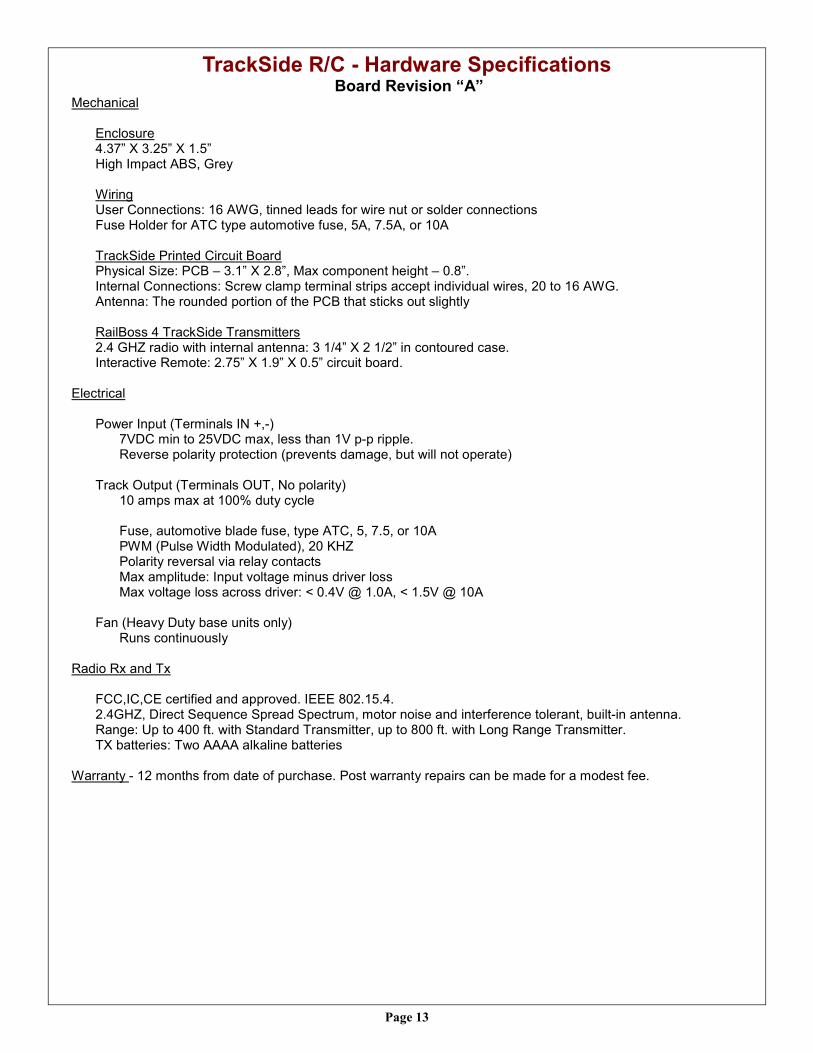
TrackSide R/C - Hardware Specifications Board Revision “A”
Mechanical Enclosure 4.37” X 3.25” X 1.5” High Impact ABS, Grey Wiring User Connections: 16 AWG, tinned leads for wire nut or solder connections Fuse Holder for ATC type automotive fuse, 5A, 7.5A, or 10A TrackSide Printed Circuit Board Physical Size: PCB – 3.1” X 2.8”, Max component height – 0.8”. Internal Connections: Screw clamp terminal strips accept individual wires, 20 to 16 AWG. Antenna: The rounded portion of the PCB that sticks out slightly RailBoss 4 TrackSide Transmitters 2.4 GHZ radio with internal antenna: 3 1/4” X 2 1/2” in contoured case. Interactive Remote: 2.75” X 1.9” X 0.5” circuit board.
Electrical Power Input (Terminals IN +,-) 7VDC min to 25VDC max, less than 1V p-p ripple.
Reverse polarity protection (prevents damage, but will not operate) Track Output (Terminals OUT, No polarity)
10 amps max at 100% duty cycle Fuse, automotive blade fuse, type ATC, 5, 7.5, or 10A PWM (Pulse Width Modulated), 20 KHZ Polarity reversal via relay contacts Max amplitude: Input voltage minus driver loss Max voltage loss across driver: < 0.4V @ 1.0A, < 1.5V @ 10A
Fan (Heavy Duty base units only) Runs continuously
Radio Rx and Tx
FCC,IC,CE certified and approved. IEEE 802.15.4. 2.4GHZ, Direct Sequence Spread Spectrum, motor noise and interference tolerant, built-in antenna. Range: Up to 400 ft. with Standard Transmitter, up to 800 ft. with Long Range Transmitter. TX batteries: Two AAAA alkaline batteries
Warranty - 12 months from date of purchase. Post warranty repairs can be made for a modest fee.
Page 14
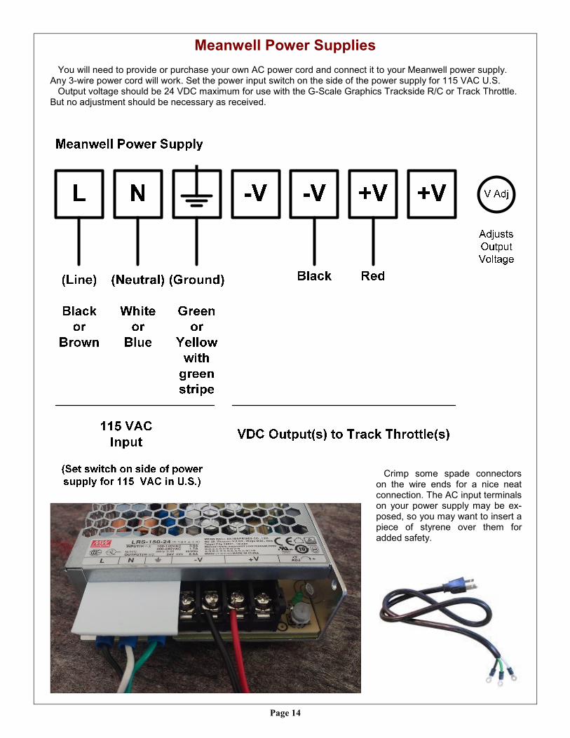
Meanwell Power Supplies
You will need to provide or purchase your own AC power cord and connect it to your Meanwell power supply. Any 3-wire power cord will work. Set the power input switch on the side of the power supply for 115 VAC U.S. Output voltage should be 24 VDC maximum for use with the G-Scale Graphics Trackside R/C or Track Throttle. But no adjustment should be necessary as received.
Crimp some spade connectors on the wire ends for a nice neat connection. The AC input terminals on your power supply may be ex-posed, so you may want to insert a piece of styrene over them for added safety.