Embed Size (px)
Citation preview
HRX-OM-S004 1
st edition: Jul. 2014 Rev. G: Nov. 2017
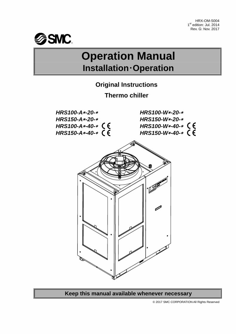
Operation Manual Installation・Operation
Original Instructions
Thermo chiller
HRS100-A-20-
HRS150-A-20-
HRS100-A-40-
HRS150-A-40-
HRS100-W-20-
HRS150-W-20-
HRS100-W-40-
HRS150-W-40-
Keep this manual available whenever necessary
© 2017 SMC CORPORATION All Rights Reserved
To the users
Thank you for purchasing SMC’s Thermo chiller (hereinafter referred to as the “product”).
For safety and long life of the product, be sure to read this operation manual (hereinafter referred to as the
“manual”) and clearly understand the contents.
Be sure to read and follow all instructions noted with “Warning” or “Caution” in this manual.
This manual is intended to explain the installation and operation of the product. Only people who
understand the basic operation of the product through this manual or who perform installation and
operation of or have basic knowledge about industrial machines are allowed to work on the product.
This manual and other documents attached to the product do not constitute a contract, and will not
affect any existing agreements or commitments.
It is strictly prohibited to copy this manual entirely or partially for the use by a third party without prior
permission from SMC.
Note: This manual is subject to possible change without prior notice.
HRX-OM-S004 Contents
HRS Series
Contents Chapter 1 Safety Instructions ........................................................... 1-1
1.1 Before using the product ........................................................................................ 1-1
1.2 Reading the Manual ................................................................................................ 1-1
1.3 Hazards .................................................................................................................... 1-2
1.3.1 Level of hazards .................................................................................................................. 1-2
1.3.2 Definition of “Serious injury” and “Minor injury” ................................................................... 1-2
1.4 Product Label .......................................................................................................... 1-3
1.5 Safety Measures ...................................................................................................... 1-4
1.5.1 Safety Instructions for Use .................................................................................................. 1-4
1.5.2 Personal protective equipment ............................................................................................ 1-4
1.6 Emergency Measures.............................................................................................. 1-5
1.7 Waste disposal ........................................................................................................ 1-5
1.7.1 Disposal of refrigerant and compressor oil.......................................................................... 1-5
1.7.2 Disposal of product .............................................................................................................. 1-5
1.8 Material Safety Data Sheet (MSDS) ........................................................................ 1-6
Chapter 2 Name and Function of Parts ............................................ 2-1
2.1 Model number of product ....................................................................................... 2-1
2.2 Name and Function of Parts ................................................................................... 2-2
2.2.1 HRS100/150-A-20/40 (In case of air cooled type) ............................................................ 2-2
2.2.2 HRS100/150-W-20/40 (In case of water cooled type) ....................................................... 2-3
2.3 Function of Parts ..................................................................................................... 2-4
2.4 Operation display panel .......................................................................................... 2-5
Chapter 3 Transport and Setting Up ................................................. 3-1
3.1 Transport.................................................................................................................. 3-1
3.1.1 Transportation using forklift and hanging ............................................................................ 3-2
3.1.2 Transportation using casters ............................................................................................... 3-3
3.2 Installation ............................................................................................................... 3-4
3.2.1 Environment ........................................................................................................................ 3-4
3.2.2 Location ............................................................................................................................... 3-6
3.2.3 Installation and Maintenance Space ................................................................................... 3-8
3.3 Installation ............................................................................................................... 3-9
3.3.1 Installation ........................................................................................................................... 3-9
3.3.2 Electrical wiring .................................................................................................................. 3-11
3.3.3 Preparation and wiring of power supply cable .................................................................. 3-13
3.3.4 Contact input/output communicatin wiring ........................................................................ 3-18
3.3.5 Wiring of run/stop signal input・Remote signal input ......................................................... 3-19
3.3.6 Wiring of external switch signal input ................................................................................ 3-21
3.3.7 Wiring of contact output signal .......................................................................................... 3-24
3.3.8 RS-485 communication wiring .......................................................................................... 3-25
HRX-OM-S004 Contents
HRS Series
3.3.9 RS-232C communication wiring ........................................................................................ 3-26
3.4 Piping ...................................................................................................................... 3-27
3.5 Circulating Fluid Supply ........................................................................................ 3-31
3.5.1 Automatic fluid-fill function ................................................................................................. 3-31
3.5.2 Fill of fluid without using auto fluid-fill function .................................................................. 3-33
3.5.3 For option K “Fluid-fill port” ................................................................................................ 3-35
Chapter 4 Starting the Product ......................................................... 4-1
4.1 Before Starting ......................................................................................................... 4-1
4.2 Preparation for Start ................................................................................................ 4-2
4.2.1 Power supply ....................................................................................................................... 4-2
4.2.2 Option B [Earth leakage breaker] ........................................................................................ 4-2
4.2.3 For HRS100/150-**-20-B1,HRS100/150-**-40 .................................................................... 4-3
4.2.4 Setting of circulating fluid temperature ................................................................................ 4-3
4.3 Preparation of circulating fluid ............................................................................... 4-4
4.4 Operation Start and Stop ......................................................................................... 4-7
4.4.1 Starting the product ............................................................................................................. 4-7
4.4.2 Stopping the product ............................................................................................................ 4-8
4.5 Check items during startup ..................................................................................... 4-9
4.6 Adjustment of Circulating Fluid flow rate .............................................................. 4-9
Chapter 5 Display and setting of various functions ....................... 5-1
5.1 List of function ......................................................................................................... 5-1
5.2 Function.................................................................................................................... 5-2
5.2.1 Key operations ..................................................................................................................... 5-2
5.2.2 List of parameters ................................................................................................................ 5-4
5.3 Main Display ............................................................................................................. 5-7
5.3.1 Main Display ........................................................................................................................ 5-7
5.3.2 Items on the main display .................................................................................................... 5-7
5.4 Alarm Menu .............................................................................................................. 5-8
5.4.1 Alarm menu ......................................................................................................................... 5-8
5.4.2 Items shown on the alarm menu display ............................................................................. 5-8
5.5 Check monitor menu ............................................................................................... 5-9
5.5.1 Check monitor menu ............................................................................................................ 5-9
5.5.2 Checking with the Inspection monitor menu ........................................................................ 5-9
5.6 Key-lock .................................................................................................................. 5-13
5.6.1 Key-lock ............................................................................................................................. 5-13
5.6.2 Key-lock setting / checking ................................................................................................ 5-14
5.7 Run timer, stop timer function .............................................................................. 5-15
5.7.1 Run timer and stop timer function ...................................................................................... 5-15
5.7.2 Setting and checking of Run timer and stop timer function ............................................... 5-17
5.8 Ready completion (TEMP READY) signal ............................................................ 5-19
HRX-OM-S004 Contents
HRS Series
5.8.1 Ready completion (TEMP READY) signal ........................................................................ 5-19
5.8.2 Ready completion (TEMP READY) signal setting / checking ........................................... 5-20
5.9 Offset function ....................................................................................................... 5-22
5.9.1 Offset function ................................................................................................................... 5-22
5.9.2 Usage example of offset function ...................................................................................... 5-23
5.9.3 Setting/checking of offset function..................................................................................... 5-25
5.10 Operation Restoration after Power Failure .......................................................... 5-27
5.10.1 Operation restoration function after power failure ............................................................. 5-27
5.10.2 Setting/checking of the operation restoration function ...................................................... 5-28
5.11 Anti-freezing function ........................................................................................... 5-29
5.11.1 Anti-freezing function ......................................................................................................... 5-29
5.11.2 Setting/checking of anti-freezing function ......................................................................... 5-31
5.12 Key Operation Sound Setting ............................................................................... 5-32
5.12.1 Key operation sound setting .............................................................................................. 5-32
5.12.2 Setting/checking of the button operation sound ................................................................ 5-32
5.13 Temperature unit Change ..................................................................................... 5-33
5.13.1 Temperature unit change................................................................................................... 5-33
5.13.2 Setting/checking of temperature unit change .................................................................... 5-33
5.14 Pressure unit Change ........................................................................................... 5-34
5.14.1 Pressure unit change ........................................................................................................ 5-34
5.14.2 Setting/checking of pressure unit change ......................................................................... 5-34
5.15 Data reset function ................................................................................................ 5-35
5.15.1 Data reset function ............................................................................................................ 5-35
5.15.2 How to operate reset function ........................................................................................... 5-35
5.16 Accumulated Operating Time Reset Function .................................................... 5-36
5.16.1 Accumulated operating time reset function ....................................................................... 5-36
5.16.2 How to operate accumulated operating time reset function .............................................. 5-36
5.17 Warming up function ............................................................................................. 5-40
5.17.1 Warming up function.......................................................................................................... 5-40
5.17.2 Setting/checking of warming up function ........................................................................... 5-41
5.18 Anti-snow coverage function ............................................................................... 5-43
5.18.1 Anti-snow coverage function ............................................................................................. 5-43
5.18.2 Setting/checking of anti-snow coverage function .............................................................. 5-44
5.19 Alarm buzzer sound setting.................................................................................. 5-45
5.19.1 Alarm buzzer sound setting ............................................................................................... 5-45
5.19.2 Setting/checking of alarm buzzer sound ........................................................................... 5-45
5.20 Alarm customizing function ................................................................................. 5-46
5.20.1 Alarm customizing function ............................................................................................... 5-46
5.20.2 Setting and checking of the alarm customizing function ................................................... 5-51
5.20.3 Setting of temperature alarm monitoring method and alarm generation timing ................ 5-65
HRX-OM-S004 Contents
HRS Series
5.21 Communication function ....................................................................................... 5-73
5.21.1 Communication function .................................................................................................... 5-73
5.21.2 Setting/checking of communication function ..................................................................... 5-73
Chapter 6 Alarm Notification and Troubleshooting ........................ 6-1
6.1 Alarm Notification .................................................................................................... 6-1
6.2 Alarm buzzer stop .................................................................................................... 6-3
6.3 Troubleshooting ....................................................................................................... 6-4
6.3.1 Alarm contents, causes, and troubleshooting...................................................................... 6-4
6.3.2 How to release the thermal relay trip and circuit protector .................................................. 6-8
6.3.3 How to release the pump thermal trip ................................................................................ 6-10
6.4 Other Errors ........................................................................................................... 6-11
Chapter 7 Control, Inspection and Cleaning ................................... 7-1
7.1 Quality Control of Circulating Fluid and Facility Water ......................................... 7-1
7.2 Inspection and Cleaning .......................................................................................... 7-2
7.2.1 Daily check .......................................................................................................................... 7-2
7.2.2 Monthly check ...................................................................................................................... 7-3
7.2.3 Inspection every 3 months ................................................................................................... 7-4
7.2.4 Inspection every 6 months ................................................................................................... 7-6
7.2.5 Inspection during winter season .......................................................................................... 7-7
7.3 Consumables ........................................................................................................... 7-7
7.4 Operation Stop for an Extended Period of Time .................................................... 7-8
7.4.1 Discharge of the circulating fluid .......................................................................................... 7-8
7.4.2 Discharge of the facility water (Water-cooled type) ............................................................. 7-9
Chapter 8 Documents ....................................................................... 8-1
8.1 Specifications .......................................................................................................... 8-1
8.1.1 HRS100/150-A-20- ........................................................................................................... 8-1
8.1.2 HRS100/150-A-40- ........................................................................................................... 8-2
8.1.3 HRS100/150-W-20- .......................................................................................................... 8-3
8.1.4 HRS100/150-W-40- .......................................................................................................... 8-4
8.1.5 Refrigerant with GWP reference .......................................................................................... 8-5
8.1.6 Communication specification ............................................................................................... 8-5
8.2 Outline dimensions .................................................................................................. 8-6
8.2.1 HRS100/150-A-20/40-...................................................................................................... 8-6
8.2.2 HRS100/150-W-20/40-..................................................................................................... 8-7
8.3 Flow diagram ............................................................................................................ 8-8
8.3.1 HRS100/150-A-20/40-...................................................................................................... 8-8
8.3.2 HRS100/150-W-20/40-..................................................................................................... 8-9
8.4 Cooling capacity .................................................................................................... 8-10
8.4.1 HRS100-A-20/40- ........................................................................................................... 8-10
8.4.2 HRS150-A-20/40- ........................................................................................................... 8-10
HRX-OM-S004 Contents
HRS Series
8.4.3 HRS100-W-20/40- .......................................................................................................... 8-11
8.4.4 HRS150-W-20/40- .......................................................................................................... 8-11
8.5 Pump capacity ....................................................................................................... 8-12
8.5.1 HRS100/150-A/W-20/40- ............................................................................................... 8-12
8.6 Types of Hazard Labels (HRS--40-) ............................................................ 8-13
8.6.1 Positions of danger warning label ..................................................................................... 8-14
8.7 Standards ............................................................................................................... 8-15
8.8 Sample DoC. .......................................................................................................... 8-16
8.9 Daily Check Sheet ................................................................................................. 8-18
Chapter 9 Product Warranty ............................................................. 9-1

HRX-OM-S004 Contents
HRS Series
HRX-OM-S004 Chapter 1 Safety Instructions
HRS Series 1.1Before using the product 1-1
Chapter 1 Safety Instructions
1.1 Before using the product This chapter is intended to specifically describe the safety related issues
for handling the product. Read this before handling the product.
The product is a cooling device using circulating fluid. SMC does not take any responsibility for any problems that may arise from using the product for other purposes.
This product is not designed for a clean room. It generates dust from the internal components such as pump and fan motor.
The product is operated at high voltage and contains components which become hot and rotate. If a component needs to be replaced or repaired, contact a specialized vendor for parts and service.
All personnel who work with or around the product should read and understand the safety related information in this manual carefully before starting work.
The safety manager is responsible for strictly observing safety standards, but responsibility in respect to safety standards during daily work resides with each individual operator and maintainance personnel.
Do not use the materials that rust or corrode for the circulating fluid and facility water circuits. Using the materials that tend to rust or corrode may cause clogs or/and leakages of the circulating fluid and facility water circuits. In case of using these kind of materials, consider and carry out some prevention against the rusting or corrosion by the customer side.
This manual must be kept available to operators whenever necessary.
1.2 Reading the Manual This manual contains symbols to help identify important actions when installing, operating or maintaining the product.
Before using the product be sure to read and understand all the
important actions highlighted in this manual.
This sign indicates actions that must be followed.
This sign indicates prohibited actions.
HRX-OM-S004 Chapter 1 Safety Instructions
1.3 Hazards HRS Series 1-2
1.3 Hazards 1.3.1 Level of hazards
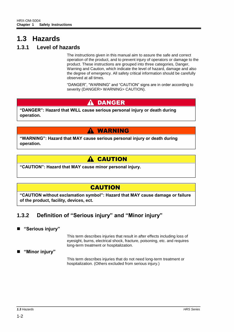
The instructions given in this manual aim to assure the safe and correct operation of the product, and to prevent injury of operators or damage to the product. These instructions are grouped into three categories, Danger, Warning and Caution, which indicate the level of hazard, damage and also the degree of emergency. All safety critical information should be carefully observed at all times.
“DANGER”, “WARNING” and “CAUTION” signs are in order according to severity (DANGER> WARNING> CAUTION).
1.3.2 Definition of “Serious injury” and “Minor injury”
“Serious injury”
This term describes injuries that result in after effects including loss of eyesight, burns, electrical shock, fracture, poisoning, etc. and requires long-term treatment or hospitalization.
“Minor injury”
This term describes injuries that do not need long-term treatment or hospitalization. (Others excluded from serious injury.)
“WARNING”: Hazard that MAY cause serious personal injury or death during
operation.
“DANGER”: Hazard that WILL cause serious personal injury or death during
operation.
“CAUTION”: Hazard that MAY cause minor personal injury.
“CAUTION without exclamation symbol”: Hazard that MAY cause damage or failure
of the product, facility, devices, ect.
HRX-OM-S004 Chapter 1 Safety Instructions
HRS Series 1.4Product Label 1-3
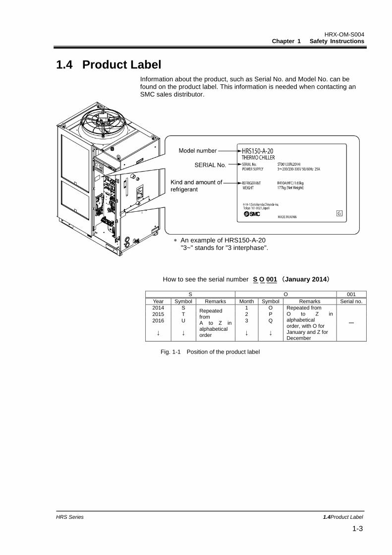
1.4 Product Label Information about the product, such as Serial No. and Model No. can be found on the product label. This information is needed when contacting an SMC sales distributor.
How to see the serial number S O 001 (January 2014)
S O 001
Year Symbol Remarks Month Symbol Remarks Serial no.
2014 S Repeated from A to Z in alphabetical order
1 O Repeated from O to Z in alphabetical order, with O for January and Z for December
-
2015 T 2 P
2016 U 3 Q
↓ ↓ ↓ ↓
Fig. 1-1 Position of the product label
An example of HRS150-A-20 "3~" stands for "3 interphase".
HRX-OM-S004 Chapter 1 Safety Instructions
1.5 Safety Measures HRS Series 1-4
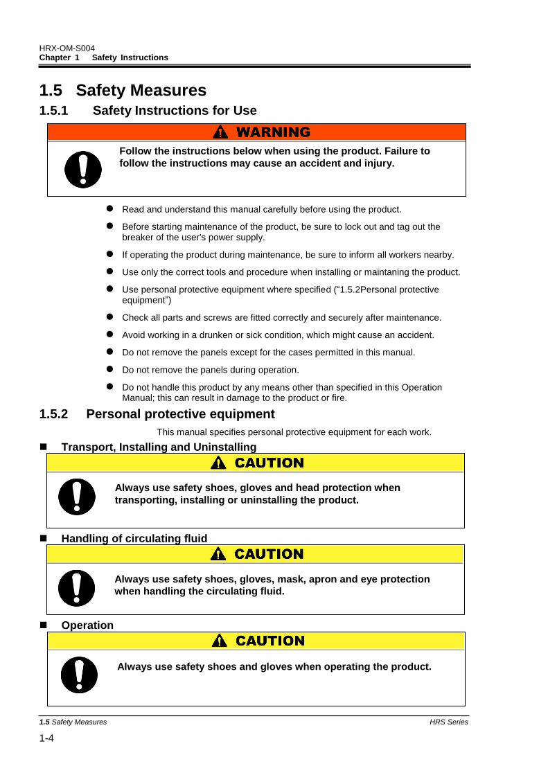
1.5 Safety Measures 1.5.1 Safety Instructions for Use
Read and understand this manual carefully before using the product.
Before starting maintenance of the product, be sure to lock out and tag out the breaker of the user's power supply.
If operating the product during maintenance, be sure to inform all workers nearby.
Use only the correct tools and procedure when installing or maintaning the product.
Use personal protective equipment where specified (“1.5.2Personal protective equipment”)
Check all parts and screws are fitted correctly and securely after maintenance.
Avoid working in a drunken or sick condition, which might cause an accident.
Do not remove the panels except for the cases permitted in this manual.
Do not remove the panels during operation.
Do not handle this product by any means other than specified in this Operation Manual; this can result in damage to the product or fire.
1.5.2 Personal protective equipment
This manual specifies personal protective equipment for each work.
Transport, Installing and Uninstalling
Handling of circulating fluid
Operation
Always use safety shoes, gloves, mask, apron and eye protection
when handling the circulating fluid.
Always use safety shoes, gloves and head protection when
transporting, installing or uninstalling the product.
Follow the instructions below when using the product. Failure to
follow the instructions may cause an accident and injury.
Always use safety shoes and gloves when operating the product.
HRX-OM-S004 Chapter 1 Safety Instructions
HRS Series 1.6Emergency Measures 1-5
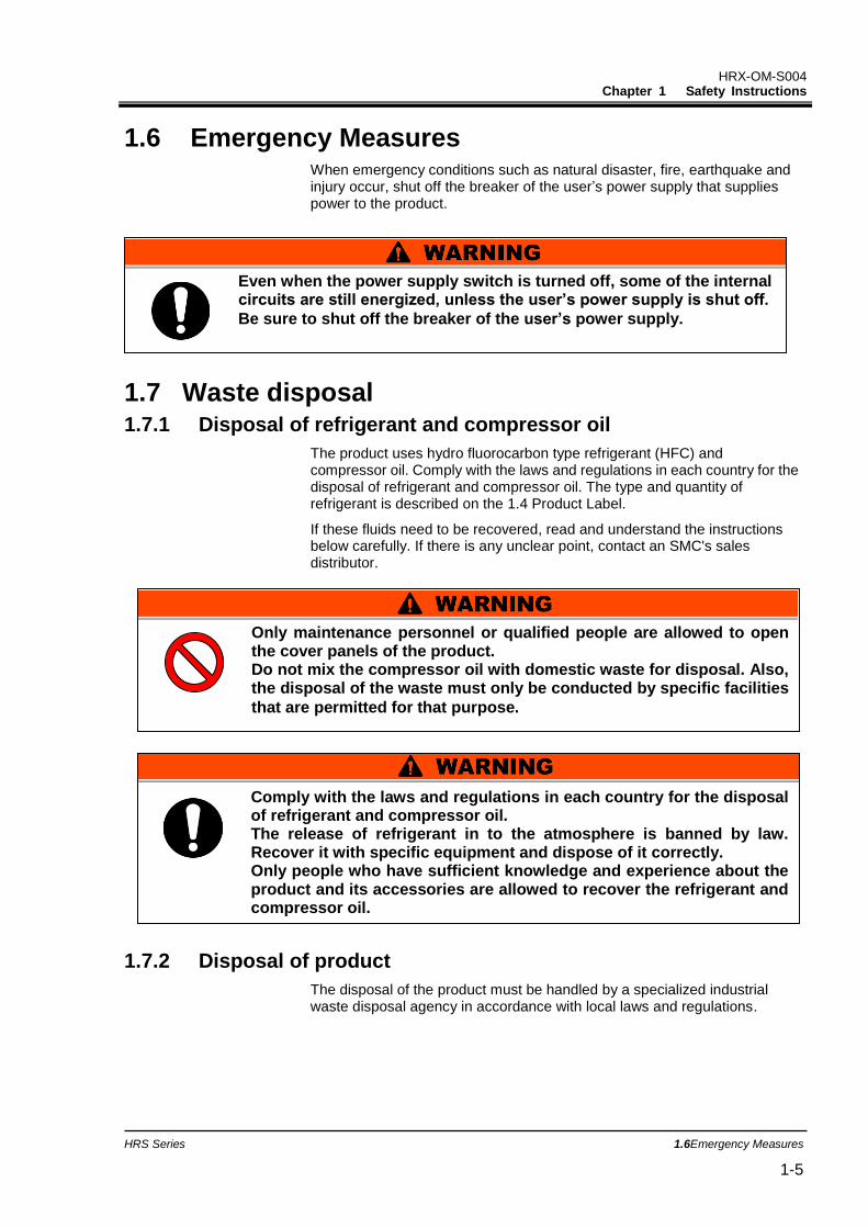
1.6 Emergency Measures When emergency conditions such as natural disaster, fire, earthquake and injury occur, shut off the breaker of the user’s power supply that supplies power to the product.
1.7 Waste disposal 1.7.1 Disposal of refrigerant and compressor oil
The product uses hydro fluorocarbon type refrigerant (HFC) and compressor oil. Comply with the laws and regulations in each country for the disposal of refrigerant and compressor oil. The type and quantity of refrigerant is described on the 1.4 Product Label.
If these fluids need to be recovered, read and understand the instructions below carefully. If there is any unclear point, contact an SMC's sales distributor.
1.7.2 Disposal of product
The disposal of the product must be handled by a specialized industrial waste disposal agency in accordance with local laws and regulations.
Only maintenance personnel or qualified people are allowed to open the cover panels of the product. Do not mix the compressor oil with domestic waste for disposal. Also, the disposal of the waste must only be conducted by specific facilities
that are permitted for that purpose.
Even when the power supply switch is turned off, some of the internal circuits are still energized, unless the user’s power supply is shut off.
Be sure to shut off the breaker of the user’s power supply.
Comply with the laws and regulations in each country for the disposal of refrigerant and compressor oil. The release of refrigerant in to the atmosphere is banned by law. Recover it with specific equipment and dispose of it correctly. Only people who have sufficient knowledge and experience about the product and its accessories are allowed to recover the refrigerant and compressor oil.
HRX-OM-S004 Chapter 1 Safety Instructions
1.8 Material Safety Data Sheet (MSDS) HRS Series 1-6
1.8 Material Safety Data Sheet (MSDS) If the material safety data sheets of chemicals used in this product are needed, contact an SMC's sales distributor.
Any chemicals used by the user must be accompanied by an MSDS.
HRX-OM-S004 Chapter 2 Name and Function of Parts
HRS Series 2.1Model number of product 2-1
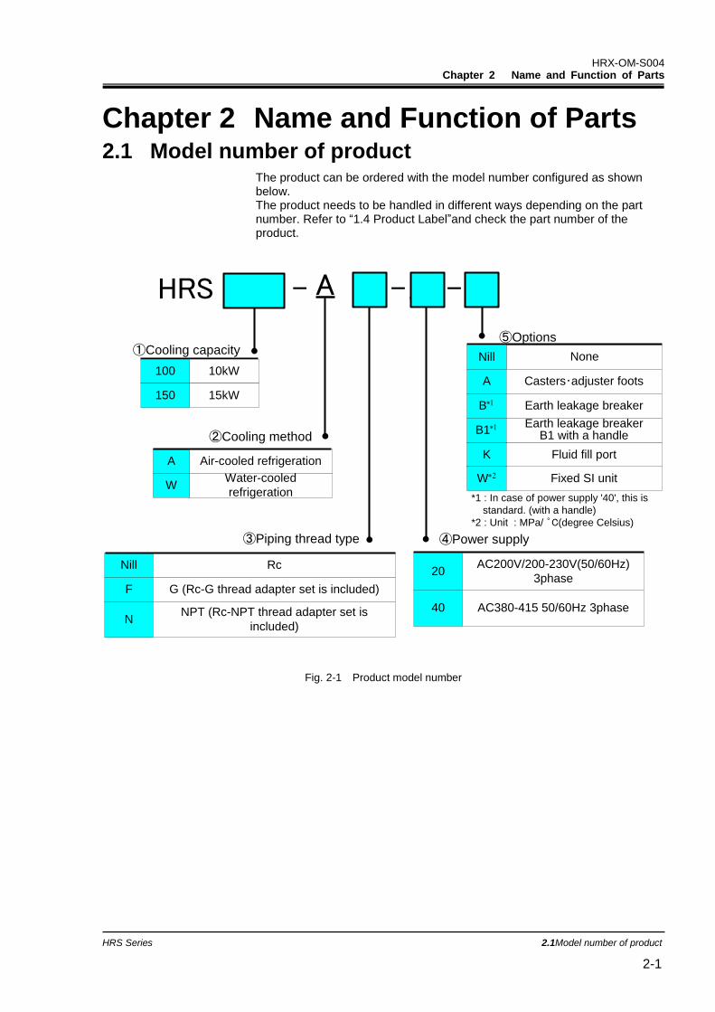
Chapter 2 Name and Function of Parts 2.1 Model number of product
The product can be ordered with the model number configured as shown below. The product needs to be handled in different ways depending on the part number. Refer to “1.4 Product Label”and check the part number of the product.
HRS
①Cooling capacity
②Cooling method
③Piping thread type ④Power supply
- - -
⑤Options
A Air-cooled refrigeration
NoneNill
Nill Rc
F G (Rc-G thread adapter set is included)
NNPT (Rc-NPT thread adapter set is
included)
A 20
100 10kW
WWater-cooled
refrigeration
150 15kW
Casters・adjuster footsA
20AC200V/200-230V(50/60Hz)
3phase
Earth leakage breakerB
40 AC380-415 50/60Hz 3phase
Fluid fill portK
*1 : In case of power supply '40', this is
standard. (with a handle)
*2 : Unit : MPa/ ゜C(degree Celsius)
Earth leakage breakerB1 with a handleB1
Fixed SI unitW
Fig. 2-1 Product model number
HRX-OM-S004 Chapter 2 Name and Function of Parts
2.2 Name and Function of Parts HRS Series 2-2
2.2 Name and Function of Parts
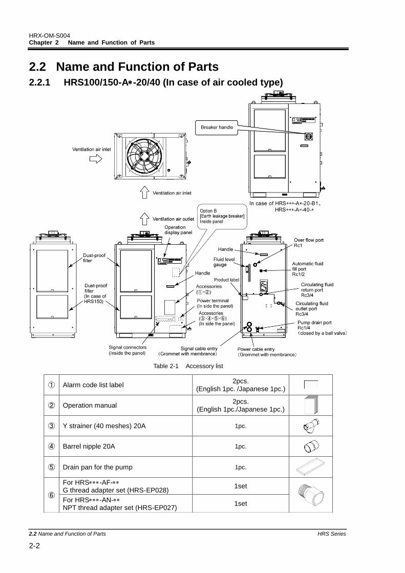
2.2.1 HRS100/150-A-20/40 (In case of air cooled type)
Fig. 2-2 Names of the parts (This drawing shows “HRS150-A-20”.)
Table 2-1 Accessory list
① Alarm code list label 2pcs.
(English 1pc. /Japanese 1pc.)
② Operation manual 2pcs.
(English 1pc./Japanese 1pc.)
③ Y strainer (40 meshes) 20A 1pc.
④ Barrel nipple 20A 1pc.
⑤ Drain pan for the pump 1pc.
⑥
For HRS-AF- G thread adapter set (HRS-EP028)
1set
For HRS-AN- NPT thread adapter set (HRS-EP027)
1set
HRX-OM-S004 Chapter 2 Name and Function of Parts
HRS Series 2.2Name and Function of Parts 2-3
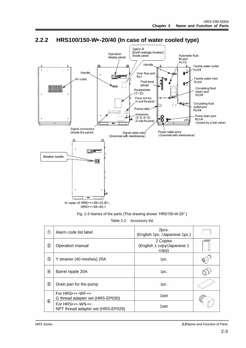
2.2.2 HRS100/150-W-20/40 (In case of water cooled type)
Fig. 2-3 Names of the parts (This drawing shows “HRS150-W-20”.)
Table 2-2 Accessory list
① Alarm code list label 2pcs.
(English 1pc. /Japanese 1pc.)
② Operation manual 2 Copies
(English 1 copy/Japanese 1 copy)
③ Y strainer (40 meshes) 20A 1pc.
④ Barrel nipple 20A 1pc.
⑤ Drain pan for the pump 1pc.
⑥
For HRS-WF- G thread adapter set (HRS-EP030)
1set
For HRS-WN- NPT thread adapter set (HRS-EP029)
1set
HRX-OM-S004 Chapter 2 Name and Function of Parts
2.3 Function of Parts HRS Series 2-4
2.3 Function of Parts The function of parts is as follows.
Table 2-3 Function of parts
Name Function
Operation display panel Runs and stops the product and performs settings such as the circulating fluid temperature. For details, refer to ’’2.4 Operation display panel’’.
Fluid level gauge Indicates the circulating fluid level of the tank. Confirm the level is between HIGH and LOW. For details, refer to “3.5Circulating Fluid”.
Product label Shows the product information such as model number and serial number. For details, refer to ‘’1.4 Product Label’’.
Circulating fluid outlet port The circulating fluid flows out from the outlet port.
Circulating fluid return port The circulating fluid returns to the return port.
Pump drain port This drain port to drain the circulating fluid out of the tank and the pump.
Automatic fluid fill port Piping to the automatic fluid filling port enables easy supply of the circulating fluid through the ball tap in the reservoir.The supply pressure should be within the range of 0.2 to 0.5MPa.
Overflow port Be sure to connect piping from this port to sump pit to discharge the exsess circulating fluid that caused by fluid level rising.
Dust-proof filter Inserted to prevent that the dust and contamination are clung on the air cooled condensers directly. Clean the filter periodically. For details, refer to “7.2.2Monthly check”.
Power cable entry Insert the power cable to the power cable entry and connect it to the power terminal. For details, refer to “3.3.2Electrical wiring” and “3.3.3Preparation and wiring of power supply cable”.
Power terminal
Signal cable entry Insert the signal cable to the signal cable entry and connect it to the signal
connectors. For details, refer to “3.3.5 Wiring of run/stop signal input・Remote signal input”, “3.3.6Wiring of external switch signal input”,
“3.3.7Wiring of contact output signal”, “3.3.8RS-485 communication wiring” , “3.3.9RS-232C communication wiring or the Operation manual Communication function.
Signal connecors
Earth leakage breaker (When option B [Earth leakage breaker]I is selected.
Shuts off the power supply to the internal eqipment of the product. (Parts energized remained in the product) Refer to “3.3.2Electrical wiring” for the earth leakage breaker.
Earth leakage breaker with breaker handle
(For HRS--20-B1,
HRS--40)
Shuts off the power supply to the internal equipment of the product. (Parts energized remained in the product. ) Refer to “3.3.2Electrical wiring” for the earth leakage breaker.
Facility water inlet port Supply facility water to the inlet port.
Facility water outlet port Facility water is discharged from the outlet port and returns to the user’s facility water system.
HRX-OM-S004 Chapter 2 Name and Function of Parts
HRS Series 2.4Operation display panel 2-5
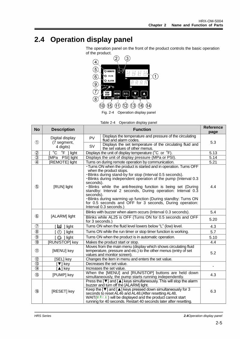
2.4 Operation display panel The operation panel on the front of the product controls the basic operation of the product.
Fig. 2-4 Operation display panel
Table 2-4 Operation display panel
No Description Function Reference
page
① Digital display (7 segment,
4 digits)
PV Displays the temperature and pressure of the circulating fluid and alarm codes.
5.3 SV
Displays the set temperature of the circulating fluid and the set values of other menus.
② [ oC
oF ] light Displays the unit of display temperature (
oC or
oF). 5.13
③ [MPa PSI] light Displays the unit of display pressure (MPa or PSI). 5.14 ④ [REMOTE] light Turns on during remote operation by communication. 5.21
⑤ [RUN] light
・Turns ON when the product is started and in operation. Turns OFF when the product stops. ・Blinks during stand-by for stop (Interval 0.5 seconds). ・Blinks during independent operation of the pump (Interval 0.3 seconds). ・Blinks while the anti-freezing function is being set (During standby: Interval 2 seconds, During operation: Interval 0.3 seconds). ・Blinks during warming up function (During standby: Turns ON for 0.5 seconds and OFF for 3 seconds, During operation: Interval 0.3 seconds.)
4.4
⑥ [ALARM] light Blinks with buzzer when alarm occurs (Interval 0.3 seconds). 5.4
Blinks while AL25 is OFF (Turns ON for 0.5 seconds and OFF for 3 seconds.)
5.20
⑦ [ ] light Turns ON when the fluid level lowers below “L” (low) level. 4.3
⑧ [ ] light Turns ON while the run timer or stop timer function is working. 5.7
⑨ [ ] light Turns ON when the product is in automatic operation. 5.10
⑩ [RUN/STOP] key Makes the product start or stop. 4.4
⑪ [MENU] key Moves from the main menu (display which shows circulating fluid temperature, pressure and etc.) to the other menus (entry of set values and monitor screen). 5.2
⑫ [SEL] key Changes the item in menu and enters the set value. ⑬ [▼] key Decreases the set value.
- ⑭ [▲] key Increases the set value.
⑮ [PUMP] key When the [MENU] and [RUN/STOP] buttons are held down simultaneously, the pump starts running independently.
4.3
⑯ [RESET] key
Press the [▼] and [▲] keys simultaneously. This will stop the alarm buzzer and turn off the [ALARM] light.
6.3 Keep the [▼] and [▲] keys pressed down simultaneously for 3 seconds to reset AL46 and AL48.(After resetting AL48, WAIT( ) will be displayed and the product cannot start running for 40 seconds. Restart 40 seconds later after resetting.

HRX-OM-S004 Chapter 2 Name and Function of Parts
2.4 Operation display panel HRS Series 2-6
HRX-OM-S004 Chapter 3 Transport and Setting Up
HRS Series 3.1Transport 3-1
Chapter 3 Transport and Setting Up
3.1 Transport The product is heavy and has potential danger at transport. Also, to prevent damage and breakage of the product, be sure to follow the instructions for shown below for transport.
When the product is carried by using folklift, make sure that the folk dose not damage the cover panels and piping port.
Drain the residual fluid from the piping as much as possible to prevent any spillage.
Never lay the product on its side. The compressor oil will leak in to the refrigerant piping, which may cause early failure of the compressor.
Be sure to use all the four eye bolts when sling the product. The slant angle of each rope should be 60 degrees oe less.
When moving the product by a folklift, insert the fork into the right psitions referring to 3.1.1Moving by forklift and slinging should be done by persons who have the licenses.
Only persons who have sufficient knowledge and experience about the product and system are allowed to transport and set up the product.
Especially pay attention to personal safety.
HRX-OM-S004 Chapter 3 Transport and Setting Up
3.1 Transport HRS Series 3-2
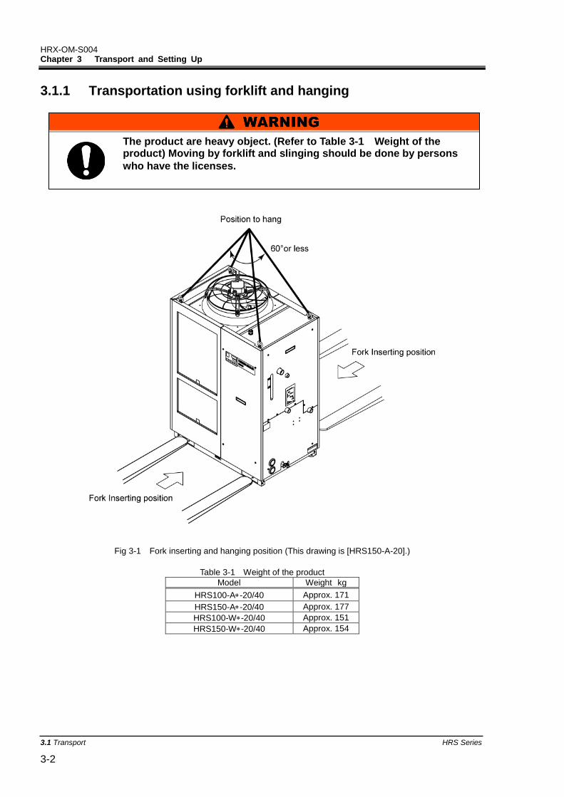
3.1.1 Transportation using forklift and hanging
Fig 3-1 Fork inserting and hanging position (This drawing is [HRS150-A-20].)
Table 3-1 Weight of the product
Model Weight kg
HRS100-A-20/40 Approx. 171
HRS150-A-20/40 Approx. 177
HRS100-W-20/40 Approx. 151
HRS150-W-20/40 Approx. 154
The product are heavy object. (Refer to Table 3-1 Weight of the product) Moving by forklift and slinging should be done by persons
who have the licenses.
HRX-OM-S004 Chapter 3 Transport and Setting Up
HRS Series 3.1Transport 3-3
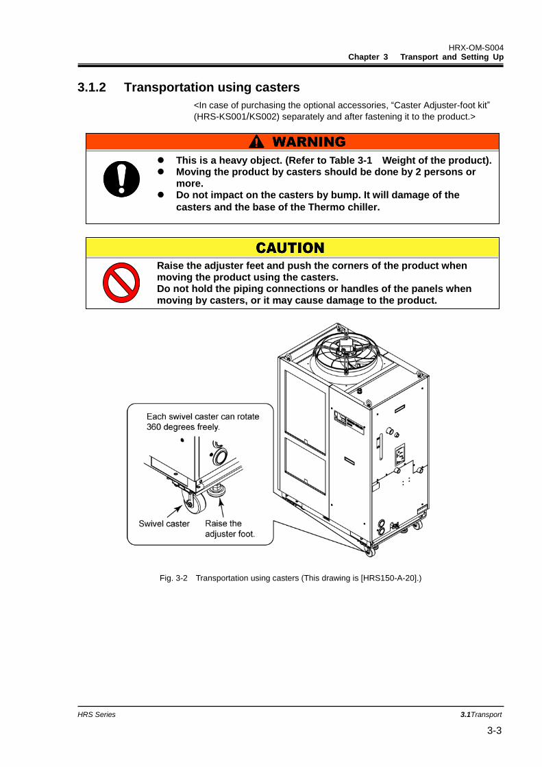
3.1.2 Transportation using casters
<In case of purchasing the optional accessories, “Caster Adjuster-foot kit”
(HRS-KS001/KS002) separately and after fastening it to the product.>
Fig. 3-2 Transportation using casters (This drawing is [HRS150-A-20].)
Raise the adjuster feet and push the corners of the product when moving the product using the casters. Do not hold the piping connections or handles of the panels when moving by casters, or it may cause damage to the product.
This is a heavy object. (Refer to Table 3-1 Weight of the product). Moving the product by casters should be done by 2 persons or
more. Do not impact on the casters by bump. It will damage of the
casters and the base of the Thermo chiller.
HRX-OM-S004 Chapter 3 Transport and Setting Up
3.2 Installation HRS Series 3-4
3.2 Installation
3.2.1 Environment
The product must not be operated, installed, stored or transported in the following conditions. Potential malfunction or damage to the product may occur if these instructions are disregarded.
The product is not designed for clean room. The pump and ventilating fan inside the product generate particles.
Location that is exposed to steam, salt water or oil.
Location that is exposed to dust or powder material.
Location that is exposed to corrosive gas, organic solvent, chemical solution, or flammable gas (the product is not explosion-proof)
Location where the ambient temperature is out of the following range: During transportation or storage: -15 to 50°C (No water or circulating fluid in the piping.) During operation: -5 to 45°C
Location where condensation forms on the inside electrical parts.
Location that is exposed to direct sunlight or heat radiation.
Location that is near heat sources and poor in ventilation.
Location that is subjected to abrupt changes in temperature.
Location that is subjected to strong electromagnetic noise (intense electric field, intense magnetic field, or surges).
Keep the product uplight on a rigid and flat floor which can resist the weight of the product, and take measures to prevent the product from tipping over. Improper installation may cause water leakage, tipping, damage of the product or injure the operator.
Keep the ambient temperature of the product between -5 to 45oC. Operation out of this ambient temperature range may cause a malfunction of the product. Operating the product in an environment temperature of 45 oC may reduce the heat discharging efficiency of the heat exchanger and the safety device may function, resulting in the product operation stoppage.
The installer/end user is responsible for carrying out a acoustic noise risk assessment on the equipment after
installation and taking appropriate measures as required.
Do not set up the product in places possibly exposed to leakage of flammable gas. Should any flammable gas stay around the product,
the product may cause a fire.
HRX-OM-S004 Chapter 3 Transport and Setting Up
HRS Series 3.2Installation 3-5
Location that is subjected to static electricity, or conditions where static electricity can discharge to the product.
Location that is subjected to strong high frequencies raditation (microwaves).
Location that is subjected to potential lightening srtike.
Location where the product is affected by strong vibrations or impacts.
Condition that applies external force or weight causing the product to be damaged.
Location without adequate space for maintenance as required.
Location that is exposed to splash of the water that is higher than IPX4.
Refer to the below for product installation or operation in an environment temperature of 10
oC or less.
Location at altitude of 3000m or higher (except during product storage and transport). Refer to the below for details.
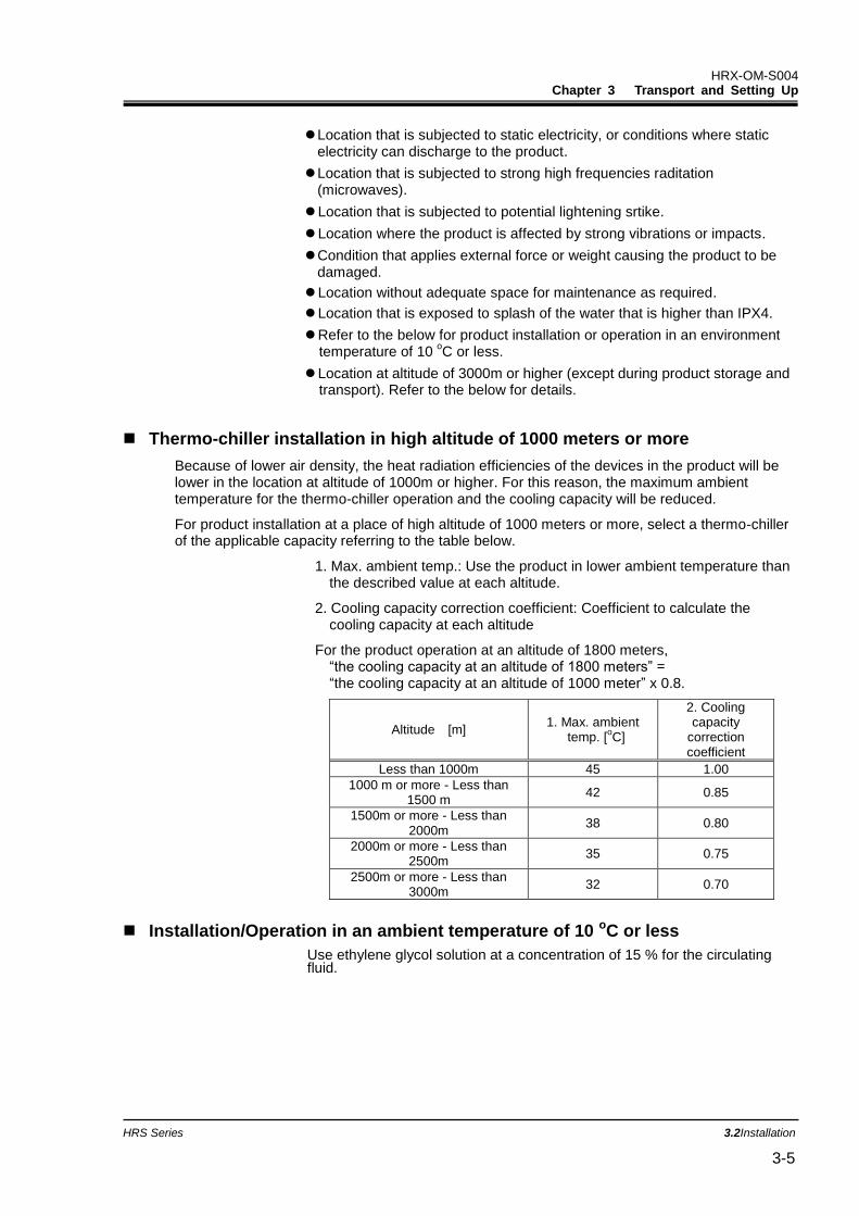
Thermo-chiller installation in high altitude of 1000 meters or more
Because of lower air density, the heat radiation efficiencies of the devices in the product will be lower in the location at altitude of 1000m or higher. For this reason, the maximum ambient temperature for the thermo-chiller operation and the cooling capacity will be reduced.
For product installation at a place of high altitude of 1000 meters or more, select a thermo-chiller of the applicable capacity referring to the table below.
1. Max. ambient temp.: Use the product in lower ambient temperature than the described value at each altitude.
2. Cooling capacity correction coefficient: Coefficient to calculate the cooling capacity at each altitude
For the product operation at an altitude of 1800 meters, “the cooling capacity at an altitude of 1800 meters” = “the cooling capacity at an altitude of 1000 meter” x 0.8.
Installation/Operation in an ambient temperature of 10 oC or less
Use ethylene glycol solution at a concentration of 15 % for the circulating fluid.
Altitude [m] 1. Max. ambient
temp. [oC]
2. Cooling capacity
correction coefficient
Less than 1000m 45 1.00
1000 m or more - Less than 1500 m
42 0.85
1500m or more - Less than 2000m
38 0.80
2000m or more - Less than 2500m
35 0.75
2500m or more - Less than 3000m
32 0.70
HRX-OM-S004 Chapter 3 Transport and Setting Up
3.2 Installation HRS Series 3-6
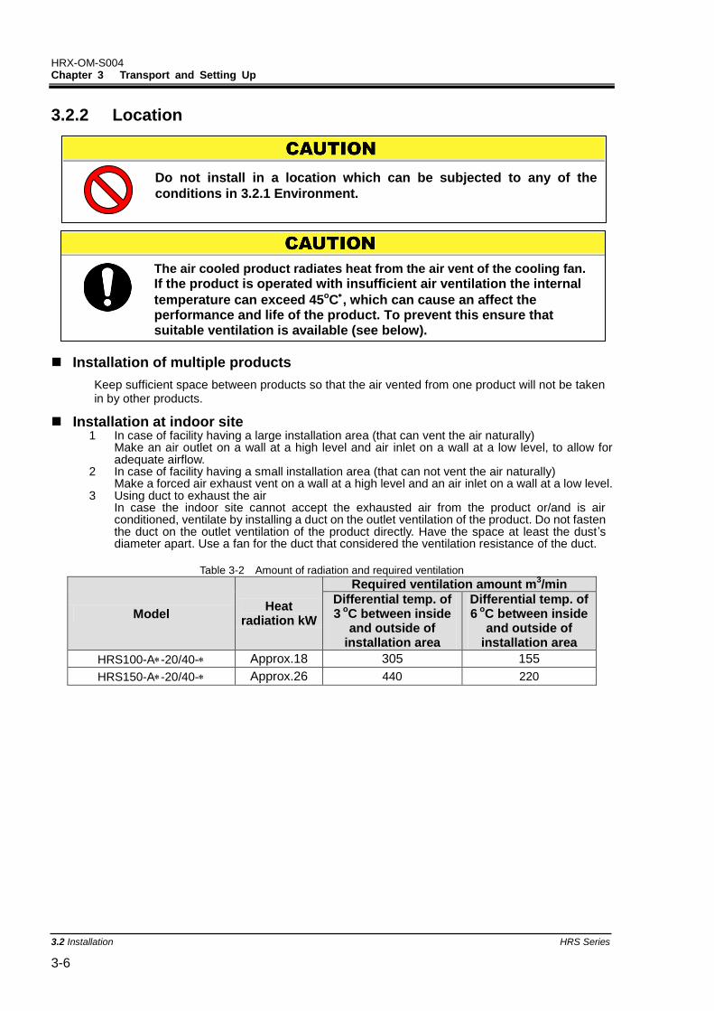
3.2.2 Location
Installation of multiple products
Keep sufficient space between products so that the air vented from one product will not be taken in by other products.
Installation at indoor site 1 In case of facility having a large installation area (that can vent the air naturally)
Make an air outlet on a wall at a high level and air inlet on a wall at a low level, to allow for adequate airflow.
2 In case of facility having a small installation area (that can not vent the air naturally) Make a forced air exhaust vent on a wall at a high level and an air inlet on a wall at a low level.
3 Using duct to exhaust the air In case the indoor site cannot accept the exhausted air from the product or/and is air conditioned, ventilate by installing a duct on the outlet ventilation of the product. Do not fasten the duct on the outlet ventilation of the product directly. Have the space at least the dust’s diameter apart. Use a fan for the duct that considered the ventilation resistance of the duct.
Table 3-2 Amount of radiation and required ventilation
Model Heat
radiation kW
Required ventilation amount m3/min
Differential temp. of 3
oC between inside and outside of
installation area
Differential temp. of 6
oC between inside and outside of
installation area
HRS100-A-20/40- Approx.18 305 155
HRS150-A-20/40- Approx.26 440 220
The air cooled product radiates heat from the air vent of the cooling fan.
If the product is operated with insufficient air ventilation the internal
temperature can exceed 45oC, which can cause an affect the performance and life of the product. To prevent this ensure that suitable ventilation is available (see below).
Do not install in a location which can be subjected to any of the
conditions in 3.2.1 Environment.
HRX-OM-S004 Chapter 3 Transport and Setting Up
HRS Series 3.2Installation 3-7
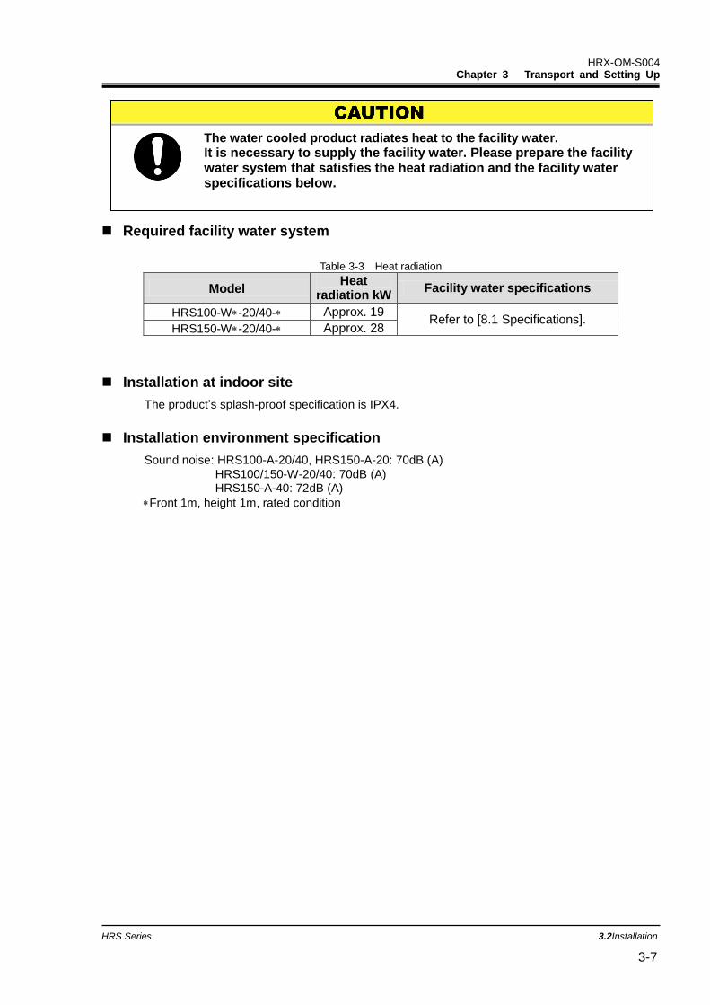
Required facility water system
Table 3-3 Heat radiation
Model Heat
radiation kW Facility water specifications
HRS100-W-20/40- Approx. 19 Refer to [8.1 Specifications].
HRS150-W-20/40- Approx. 28
Installation at indoor site
The product’s splash-proof specification is IPX4.
Installation environment specification
Sound noise: HRS100-A-20/40, HRS150-A-20: 70dB (A)
HRS100/150-W-20/40: 70dB (A) HRS150-A-40: 72dB (A)
Front 1m, height 1m, rated condition
The water cooled product radiates heat to the facility water.
It is necessary to supply the facility water. Please prepare the facility water system that satisfies the heat radiation and the facility water specifications below.
HRX-OM-S004 Chapter 3 Transport and Setting Up
3.2 Installation HRS Series 3-8
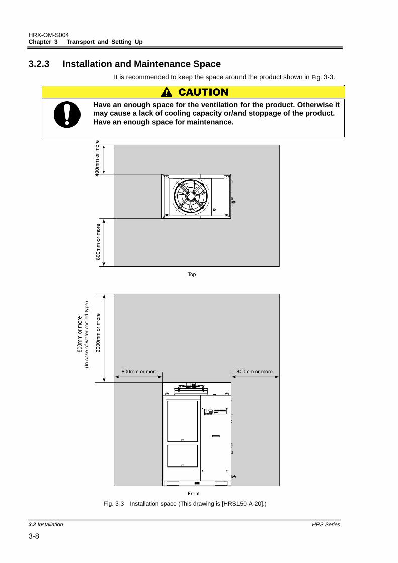
3.2.3 Installation and Maintenance Space
It is recommended to keep the space around the product shown in Fig. 3-3.
Fig. 3-3 Installation space (This drawing is [HRS150-A-20].)
Have an enough space for the ventilation for the product. Otherwise it may cause a lack of cooling capacity or/and stoppage of the product.
Have an enough space for maintenance.
HRX-OM-S004 Chapter 3 Transport and Setting Up
HRS Series 3.3Installation 3-9
3.3 Installation 3.3.1 Installation
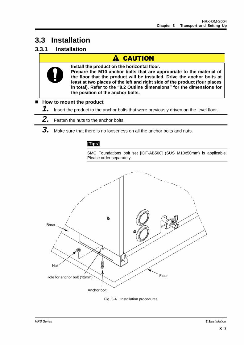
How to mount the product
1. Insert the product to the anchor bolts that were previously driven on the level floor.
2. Fasten the nuts to the anchor bolts.
3. Make sure that there is no looseness on all the anchor bolts and nuts.
[Tips]
SMC Foundations bolt set [IDF-AB500] (SUS M10x50mm) is applicable. Please order separately.
Fig. 3-4 Installation procedures
Install the product on the horizontal floor. Prepare the M10 anchor bolts that are appropriate to the material of the floor that the product will be installed. Drive the anchor bolts at least at two places of the left and right side of the product (four places in total). Refer to the “8.2 Outline dimensions” for the dimensions for
the position of the anchor bolts.
HRX-OM-S004 Chapter 3 Transport and Setting Up
3.3 Installation HRS Series 3-10
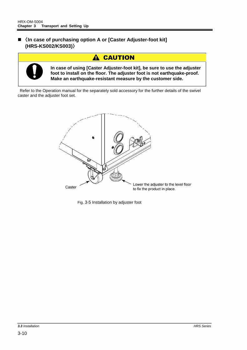
〈In case of purchasing option A or [Caster Adjuster-foot kit]
(HRS-KS002/KS003)〉
Refer to the Operation manual for the separately sold accessory for the further details of the swivel caster and the adjuster foot set.
Fig. 3-5 Installation by adjuster foot
In case of using [Caster Adjuster-foot kit], be sure to use the adjuster foot to install on the floor. The adjuster foot is not earthquake-proof.
Make an earthquake-resistant measure by the customer side.
HRX-OM-S004 Chapter 3 Transport and Setting Up
HRS Series 3.3Installation 3-11
3.3.2 Electrical wiring
Do not modify the intenal electrical wiring of the product. Incorrect wiring may cause electrical shock or fire. Also, modifing the internal wiring will void the product’s warranty. NEVER connect the ground to water line, gas pipe or lightening conductor.
The installation of electrical equipment and wiring work should be performed only by personnel with sufficient knowledge and experience.
Be sure to shut off the user’s power supply. Wiring with the product energized is strictly prohibited.
The wiring must be conducted using cables complying with “Table 3-4” and firmly and secured to the product to prevent the external force of cables being applied to the terminals. Incomplete wiring or improper securing of wiring may cause electrical shock, excessive heat and fire.
Ensure a stable power supply with no voltage surges. Ensure that an Earth Leakage Breaker is used in the power supply
of the product. See “Table 3-4”. Use a power supply suitable for the specifications of the product.
Be sure to connect the ground connection. Ensure that a lock out facility is availble on the power supply. Each product must have its own separate Earth Leakage Breaker.
Otherwise there can be a risk of electric shock or fire. Ensure that no harmonics are superimposed at power supply.
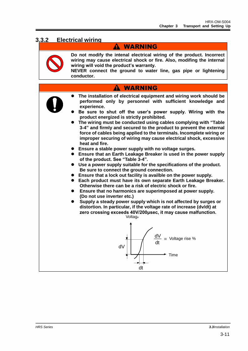
(Do not use inverter etc.) Supply a steady power supply which is not affected by surges or
distortion. In particular, if the voltage rate of increase (dv/dt) at
zero crossing exceeds 40V/200μsec, it may cause malfunction.
V
dV
dt
dt = Voltage ratio
on zero-cross point
dV
t
Voltage rise %
Time
Voltage
HRX-OM-S004 Chapter 3 Transport and Setting Up
3.3 Installation HRS Series 3-12
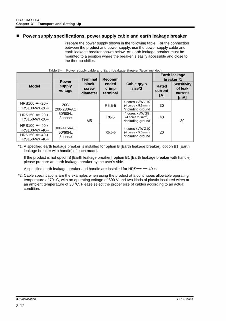
Power supply specifications, power supply cable and earth leakage breaker
Prepare the power supply shown in the following table. For the connection between the product and power supply, use the power supply cable and earth leakage breaker shown below. An earth leakage breaker must be mounted to a position where the breaker is easily accessible and close to the thermo-chiller.
Table 3-4 Power supply cable and Earth Leakage Breaker(Recommended)
Model Power supply
voltage
Terminal
block
screw
diameter
Recomm
ended
crimp
terminal
Cable qty. x
size*2
Earth leakage
breaker *1
Rated current
[A]
Sensitivity of leak current
[mA]
HRS100-A-20-
HRS100-W-20- 200/
200-230VAC 50/60Hz 3phase
M5
R5.5-5 4 cores x AWG10 (4 cores x 5.5mm
2)
*including ground 30
30
HRS150-A-20-HRS150-W-20-
R8-5 4 cores x AWG8 (4 cores x 8mm
2)
*including ground 40
HRS100-A-40-
HRS100-W-40- 380-415VAC
50/60Hz 3phase
R5.5-5 4 cores x AWG10 (4 cores x 5.5mm
2)
*including ground 20
HRS150-A-40-HRS150-W-40-
*1: A specified earth leakage breaker is installed for option B [Earth leakage breaker], option B1 [Earth leakage breaker with handle] of each model.
If the product is not option B [Earth leakage breaker], option B1 [Earth leakage breaker with handle] please prepare an earth leakage breaker by the user’s side.
A specified earth leakage breaker and handle are installed for HRS--40-.
*2: Cable specifications are the examples when using the product at a continuous allowable operating temperature of 70
oC, with an operating voltage of 600 V and two kinds of plastic insulated wires at
an ambient temperature of 30 oC. Please select the proper size of cables according to an actual
condition.
HRX-OM-S004 Chapter 3 Transport and Setting Up
HRS Series 3.3Installation 3-13
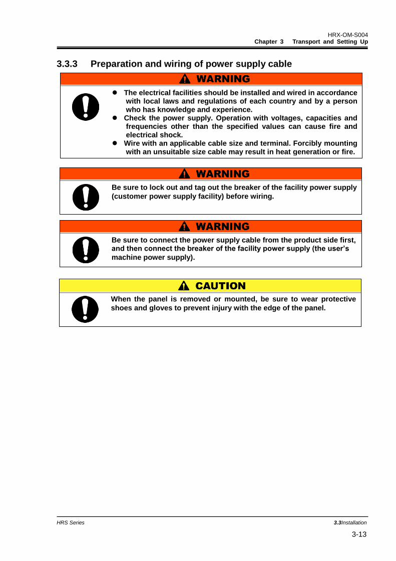
3.3.3 Preparation and wiring of power supply cable
Be sure to lock out and tag out the breaker of the facility power supply
(customer power supply facility) before wiring.
The electrical facilities should be installed and wired in accordance with local laws and regulations of each country and by a person who has knowledge and experience.
Check the power supply. Operation with voltages, capacities and frequencies other than the specified values can cause fire and electrical shock.
Wire with an applicable cable size and terminal. Forcibly mounting with an unsuitable size cable may result in heat generation or fire.
Be sure to connect the power supply cable from the product side first, and then connect the breaker of the facility power supply (the user’s
machine power supply).
When the panel is removed or mounted, be sure to wear protective
shoes and gloves to prevent injury with the edge of the panel.
HRX-OM-S004 Chapter 3 Transport and Setting Up
3.3 Installation HRS Series 3-14
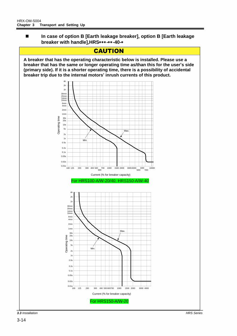
In case of option B [Earth leakage breaker], option B [Earth leakage
breaker with handle],HRS--40-
A breaker that has the operating characteristic below is installed. Please use a breaker that has the same or longer operating time as/than this for the user’s side (primary side). If it is a shorter operating time, there is a possibility of accidental
breaker trip due to the internal motors’ inrush currents of this product.
100 125 200 300 400 500600
700 1000 1500 2000 300040005000
60007000
10000
0.02s
0.01s
0.05s
0.1s
0.2s
0.5s
1s
2s
5s
10s
20s
30s
1min
2min
4min
6min
10min14min20min
30min
1h
2h
4h
Min.
Opera
ting t
ime
Current (% for breaker capacity)
Max.
For HRS100-A/W-20/40, HRS150-A/W-40
4h
2h
1h
30min
20min
14min10min
6min
4min
2min
1min
30s
20s
10s
5s
2s
1s
0.5s
0.2s
0.1s
0.05s
0.02s
0.01s100 125 200 300 400 500 600700 1000 1500 2000 3000 4000
Current (% for breaker capacity)
Opera
ting t
ime
Min.
Max.
For HRS150-A/W-20
HRX-OM-S004 Chapter 3 Transport and Setting Up
HRS Series 3.3Installation 3-15
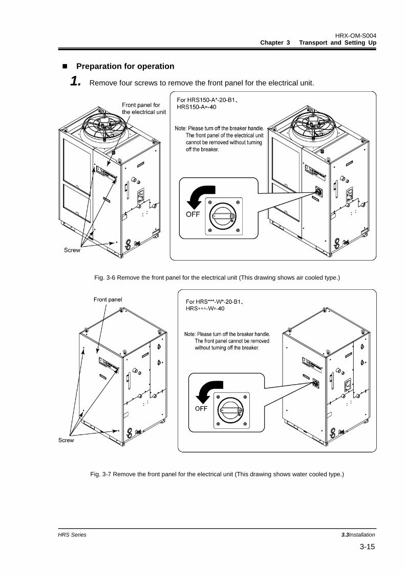
Preparation for operation
1. Remove four screws to remove the front panel for the electrical unit.
Fig. 3-6 Remove the front panel for the electrical unit (This drawing shows air cooled type.)
Fig. 3-7 Remove the front panel for the electrical unit (This drawing shows water cooled type.)
HRX-OM-S004 Chapter 3 Transport and Setting Up
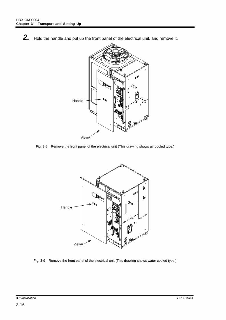
3.3 Installation HRS Series 3-16
2. Hold the handle and put up the front panel of the electrical unit, and remove it.
Fig. 3-8 Remove the front panel of the electrical unit (This drawing shows air cooled type.)
Fig. 3-9 Remove the front panel of the electrical unit (This drawing shows water cooled type.)
HRX-OM-S004 Chapter 3 Transport and Setting Up
HRS Series 3.3Installation 3-17
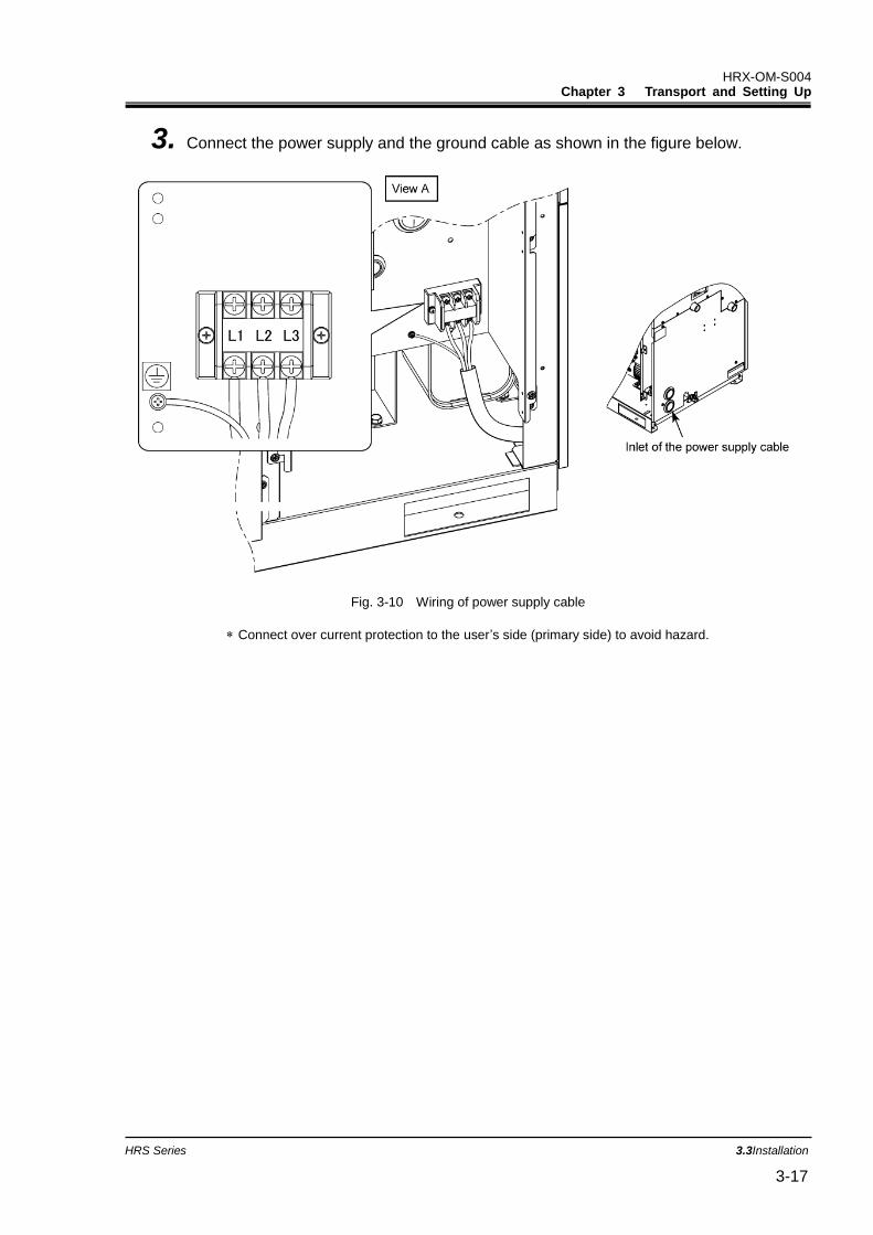
3. Connect the power supply and the ground cable as shown in the figure below.
Fig. 3-10 Wiring of power supply cable
Connect over current protection to the user’s side (primary side) to avoid hazard.
HRX-OM-S004 Chapter 3 Transport and Setting Up
3.3 Installation HRS Series 3-18
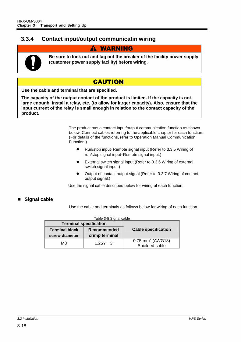
3.3.4 Contact input/output communicatin wiring
The product has a contact input/output communication function as shown below. Connect cables referring to the applicable chapter for each function. (For details of the functions, refer to Operation Manual Communication Function.)
Run/stop input・Remote signal input (Refer to 3.3.5 Wiring of
run/stop signal input・Remote signal input.)
External switch signal input (Refer to 3.3.6 Wiring of external switch signal input.)
Output of contact output signal (Refer to 3.3.7 Wiring of contact output signal.)
Use the signal cable described below for wiring of each function.
Signal cable
Use the cable and terminals as follows below for wiring of each function.
Table 3-5 Signal cable
Terminal specification
Cable specification Terminal block
screw diameter
Recommended
crimp terminal
M3 1.25Y-3 0.75 mm
2 (AWG18)
Shielded cable
Be sure to lock out and tag out the breaker of the facility power supply
(customer power supply facility) before wiring.
Use the cable and terminal that are specified.
The capacity of the output contact of the product is limited. If the capacity is not large enough, install a relay, etc. (to allow for larger capacity). Also, ensure that the input current of the relay is small enough in relation to the contact capacity of the product.
HRX-OM-S004 Chapter 3 Transport and Setting Up
HRS Series 3.3Installation 3-19
3.3.5 Wiring of run/stop signal input・Remote signal input
Run/Stop signal input and remote signal input enable the product to operate/stop or switched DIO REMOTE and DIO LOCAL remotely by applying a contact signal input. This chapter illustrates examples of wiring.
Select DIO mode as the communication mode to activate the run/stop signal input and remote signal input after wiring referring to Operation Manual Communication Function.
[Tips]
This product has two input signals. These can be customized depending on the customer’s application.
Table 3-6 Power supply, contact specifications
Name Terminal NO. Specification
Power supply output 5, 6, 7 (24VDC)
DC 24V ±10% 500mA MAX1
13,14, 15 (24V COM)
Contact input signal 1 3 (Contact input signal 1)
-Run/stop signal input
-External switch
signal input2
Switch the input on the operation display panel. Refer to the Operation manual communication function for details.
11 (Common of contact input signal 1)
Contact input signal 2
4 (Contact input signal 2) -Run/stop signal input
-Remote signal input
-External switch
signal input2
12 (Common of contact input signal 2)
*1: To use the power of the device, the total load current must be 500mA or less. If the load is 500mA or more, the internal fuse will be cut to protect the product and the alarm [AL21 DC line fuse cut] will be generated. Refer to Chapter 6 for handling of alarms.
*2: Refer to 3.3.6 Wiring of external switch signal input.
1. Prepare the switch (power supply voltage: 24VDC, contact capacity: 35mA or more,
minimum load current: 5mA), and a signal cable (See “Table 3-5 Signal cable”).
HRX-OM-S004 Chapter 3 Transport and Setting Up
3.3 Installation HRS Series 3-20
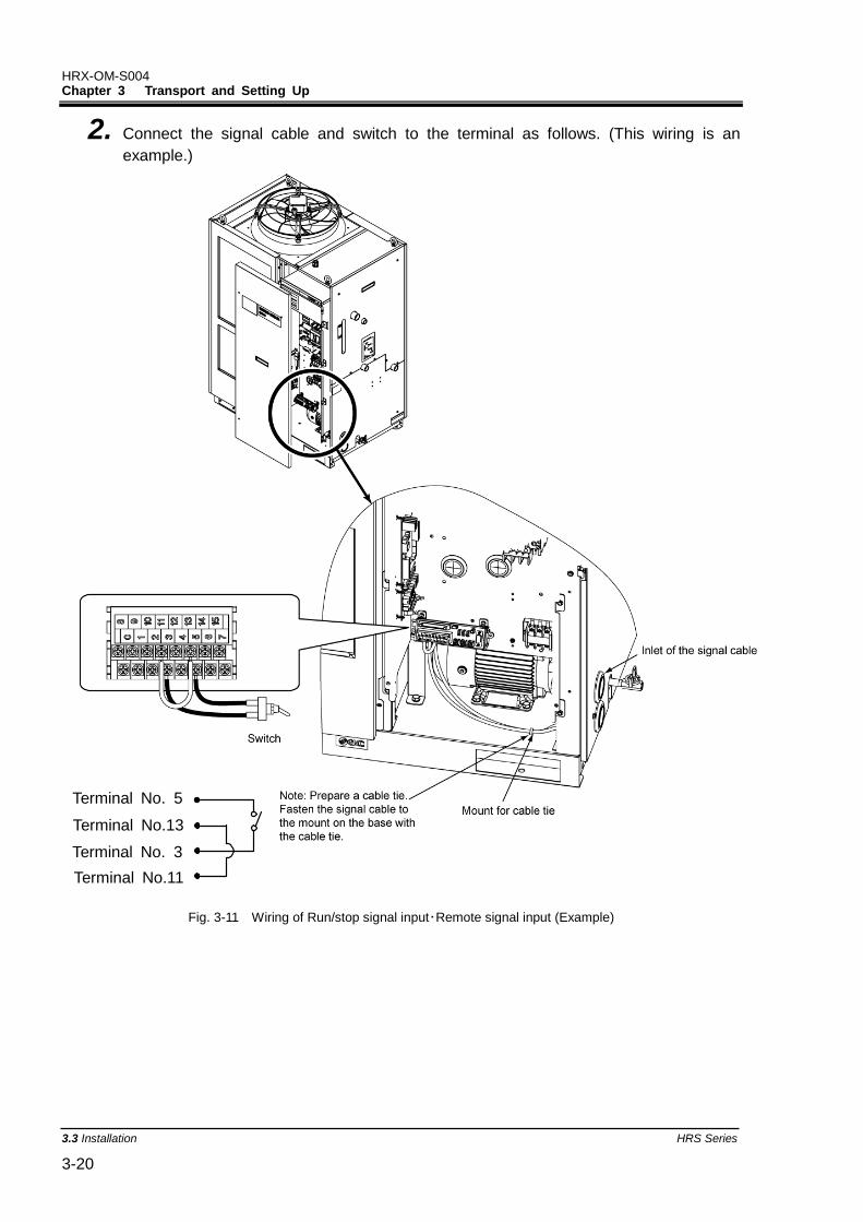
2. Connect the signal cable and switch to the terminal as follows. (This wiring is an
example.)
Fig. 3-11 Wiring of Run/stop signal input・Remote signal input (Example)
Terminal No. 5
Terminal No.13
Te
inal No. 3
Terminal No.11
Terminal No. 3
HRX-OM-S004 Chapter 3 Transport and Setting Up
HRS Series 3.3Installation 3-21
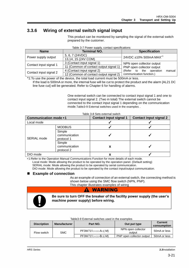
3.3.6 Wiring of external switch signal input
This product can be monitored by sampling the signal of the external switch prepared by the customer.
Table 3-7 Power supply, contact specifications
Name Terminal NO. Specification
Power supply output 5, 6, 7 (24VDC)
24VDC ±10% 500mA MAX1
13,14, 15 (24V COM)
Contact input signal 1 3 (Contact input signal 1) NPN open collector output
PNP open collector output (Refer to the operation manual communication function.)
11 (Common of contact output signal 1)
Contact input signal 2 4 (Contact input signal 2)
12 (Common of contact output signal 2)
*1:To use the power of the device, the total load current must be 500mA or less.
If the load is 500mA or more, the internal fuse will be cut to protect the product and the alarm [AL21 DC line fuse cut] will be generated. Refer to Chapter 6 for handling of alarms.
One external switch can be connected to contact input signal 1 and one to contact input signal 2. (Two in total) The external switch cannot be connected to the contact input signal 1 depending on the communication mode.Table3-9 External switches used in the examples .
Table 3-8 Sets external switch
Communication mode 1 Contact input signal 1 Contact input signal 2
Local mode ✓ ✓
SERIAL mode
MODBUS ✓ ✓
Simple communication protocol 1
✓ ✓
Simple communication protocol 2
x ✓
DIO mode x ✓
1:Refer to the Operation Manual Communications Function for more details of each mode. Local mode: Mode allowing the product to be operated by the operation panel. (Default setting) SERIAL mode: Mode allowing the product to be operated by serial communication. DIO mode: Mode allowing the product to be operated by the contact input/output communication.
Example of connection As an example of connection of an external switch, the connecting method is shown below using the SMC flow switch (NPN, PNP). This chapter illustrates examples of wiring
Table3-9 External switches used in the examples
Discription Manufacturer Part NO. Out put type Current
consumption
Flow switch SMC PF3W711□-□□-A□(-M)
NPN open collector output
50mA or less
PF3W711□-□□-B□(-M) PNP open collector output 50mA or less
Be sure to turn OFF the breaker of the facility power supply (the user’s
machine power supply) before wiring.
HRX-OM-S004 Chapter 3 Transport and Setting Up
3.3 Installation HRS Series 3-22
Flow switch
3
6
5
11
Terminal No. 14
Blue(DC COM)
Brown(DC 24V)
Black (Output1)
11
6
13
3
14
Terminal No.
Terminal No.
Terminal No.
Terminal No.
Blue(DC COM)
Brown(DC 24V)
Black (Output1)
Terminal No.
Terminal No.
Terminal No.
Terminal No.
Terminal No.
Flow switch
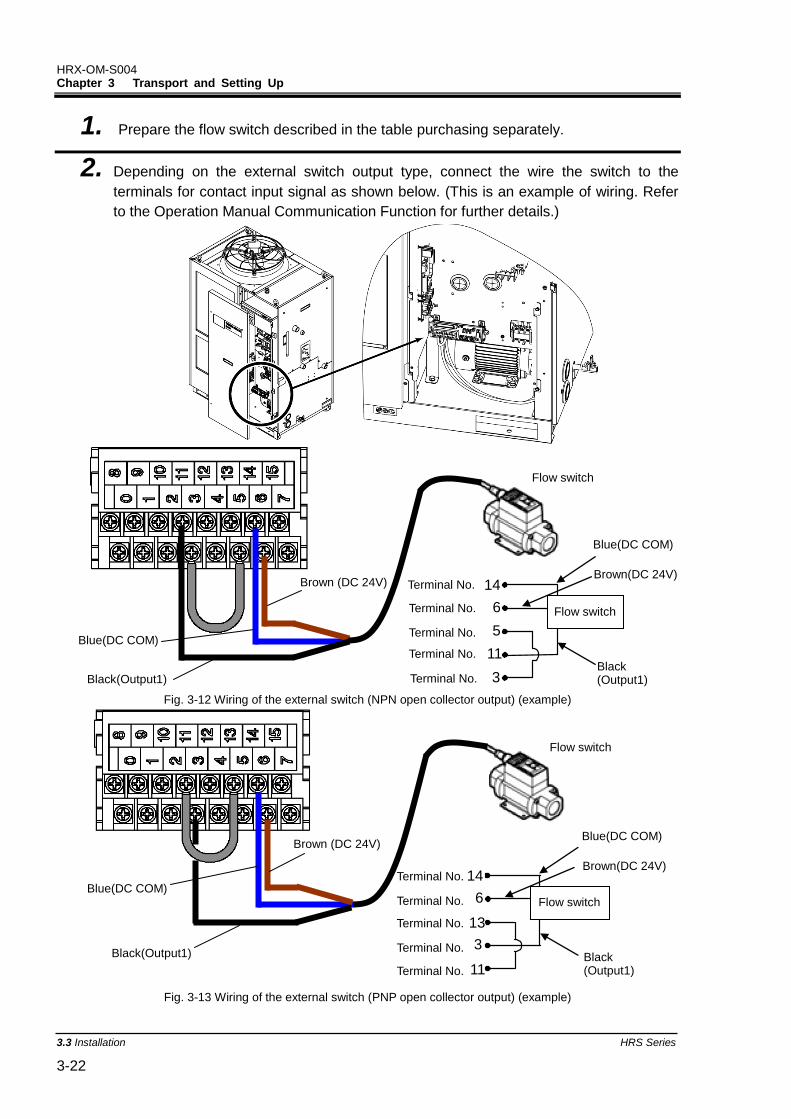
1. Prepare the flow switch described in the table purchasing separately.
2. Depending on the external switch output type, connect the wire the switch to the
terminals for contact input signal as shown below. (This is an example of wiring. Refer
to the Operation Manual Communication Function for further details.)
Fig. 3-12 Wiring of the external switch (NPN open collector output) (example)
Fig. 3-13 Wiring of the external switch (PNP open collector output) (example)
Flow switch
Brown (DC 24V)
Blue(DC COM)
Black(Output1)
Flow switch
Brown (DC 24V)
Blue(DC COM)
Black(Output1)
HRX-OM-S004 Chapter 3 Transport and Setting Up
HRS Series 3.3Installation 3-23
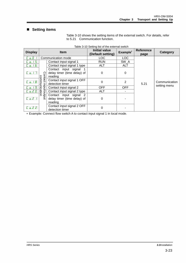
Setting items
Table 3-10 shows the setting items of the external switch. For details, refer to 5.21 Communication function.
Table 3-10 Setting list of the external switch
Display Item Initial value
(Default setting) Example
Reference page
Category
Communication mode LOC LOC
5.21 Communication setting menu
Conta
ct in
put/o
utp
ut
com
mu
nic
atio
n
Contact input signal 1 RUN SW_A
Contact input signal 1 type ALT ALT
Contact input signal 1 delay timer (time delay) of reading
0 0
Contact input signal 1 OFF detection timer
0 2
Contact input signal 2 OFF OFF
Contact input signal 2 type ALT -
Contact input signal 2 delay timer (time delay) of reading
0 -
Contact input signal 2 OFF detection timer
0 -
Example: Connect flow switch A to contact input signal 1 in local mode.
HRX-OM-S004 Chapter 3 Transport and Setting Up
3.3 Installation HRS Series 3-24
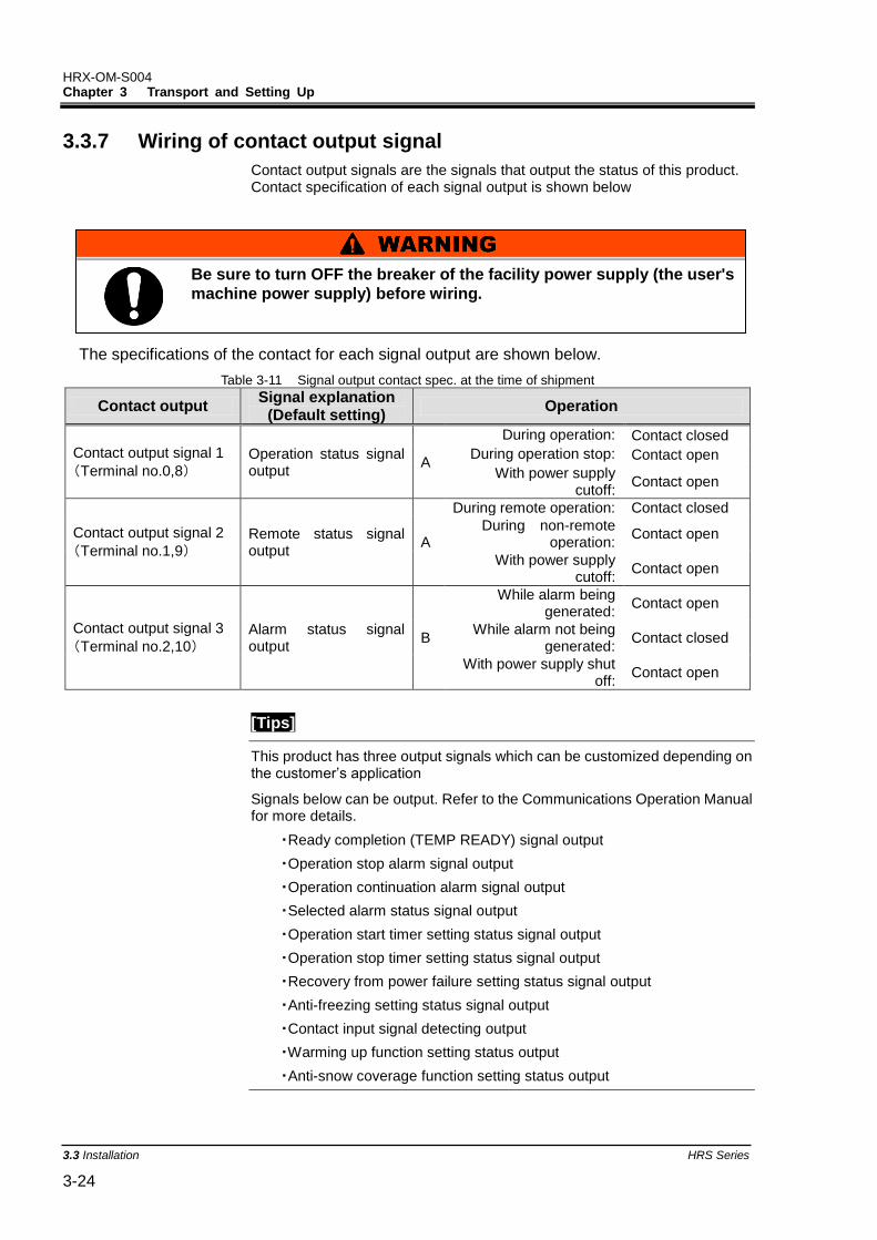
3.3.7 Wiring of contact output signal
Contact output signals are the signals that output the status of this product. Contact specification of each signal output is shown below
The specifications of the contact for each signal output are shown below.
Table 3-11 Signal output contact spec. at the time of shipment
Contact output Signal explanation
(Default setting) Operation
Contact output signal 1
(Terminal no.0,8) Operation status signal output
A
During operation: Contact closed
During operation stop: Contact open
With power supply cutoff:
Contact open
Contact output signal 2
(Terminal no.1,9) Remote status signal output
A
During remote operation: Contact closed
During non-remote operation:
Contact open
With power supply cutoff:
Contact open
Contact output signal 3
(Terminal no.2,10) Alarm status signal output
B
While alarm being generated:
Contact open
While alarm not being generated:
Contact closed
With power supply shut off:
Contact open
[Tips]
This product has three output signals which can be customized depending on the customer’s application
Signals below can be output. Refer to the Communications Operation Manual for more details.
・Ready completion (TEMP READY) signal output
・Operation stop alarm signal output
・Operation continuation alarm signal output
・Selected alarm status signal output
・Operation start timer setting status signal output
・Operation stop timer setting status signal output
・Recovery from power failure setting status signal output
・Anti-freezing setting status signal output
・Contact input signal detecting output
・Warming up function setting status output
・Anti-snow coverage function setting status output
Be sure to turn OFF the breaker of the facility power supply (the user's
machine power supply) before wiring.
HRX-OM-S004 Chapter 3 Transport and Setting Up
HRS Series 3.3Installation 3-25
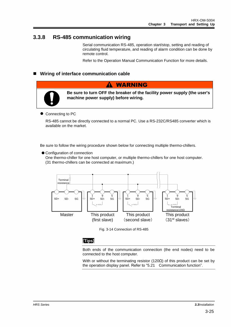
3.3.8 RS-485 communication wiring
Serial communication RS-485, operation start/stop, setting and reading of circulating fluid temperature, and reading of alarm condition can be done by remote control.
Refer to the Operation Manual Communication Function for more details.
Wiring of interface communication cable
Connecting to PC
RS-485 cannot be directly connected to a normal PC. Use a RS-232C/RS485 converter which is
available on the market.
Be sure to follow the wiring procedure shown below for connecting multiple thermo-chillers.
Configuration of connection
One thermo-chiller for one host computer, or multiple thermo-chillers for one host computer.
(31 thermo-chillers can be connected at maximum.)
Fig. 3-14 Connection of RS-485
[Tips]
Both ends of the communication connection (the end nodes) need to be connected to the host computer.
With or without the terminating resistor (120Ω) of this product can be set by the operation display panel. Refer to “5.21 Communication function”.
1
SD+5
SG
9
SD-SD+ SD- SG
Terminal
resistance
Master This product
(first slave)
1
SD+5
SG
9
SD-
This product
(second slave)
1
SD+5
SG
9
SD-
This product
(31st slaves)
Terminal
resistance120Ω
Be sure to turn OFF the breaker of the facility power supply (the user's
machine power supply) before wiring.
HRX-OM-S004 Chapter 3 Transport and Setting Up
3.3 Installation HRS Series 3-26
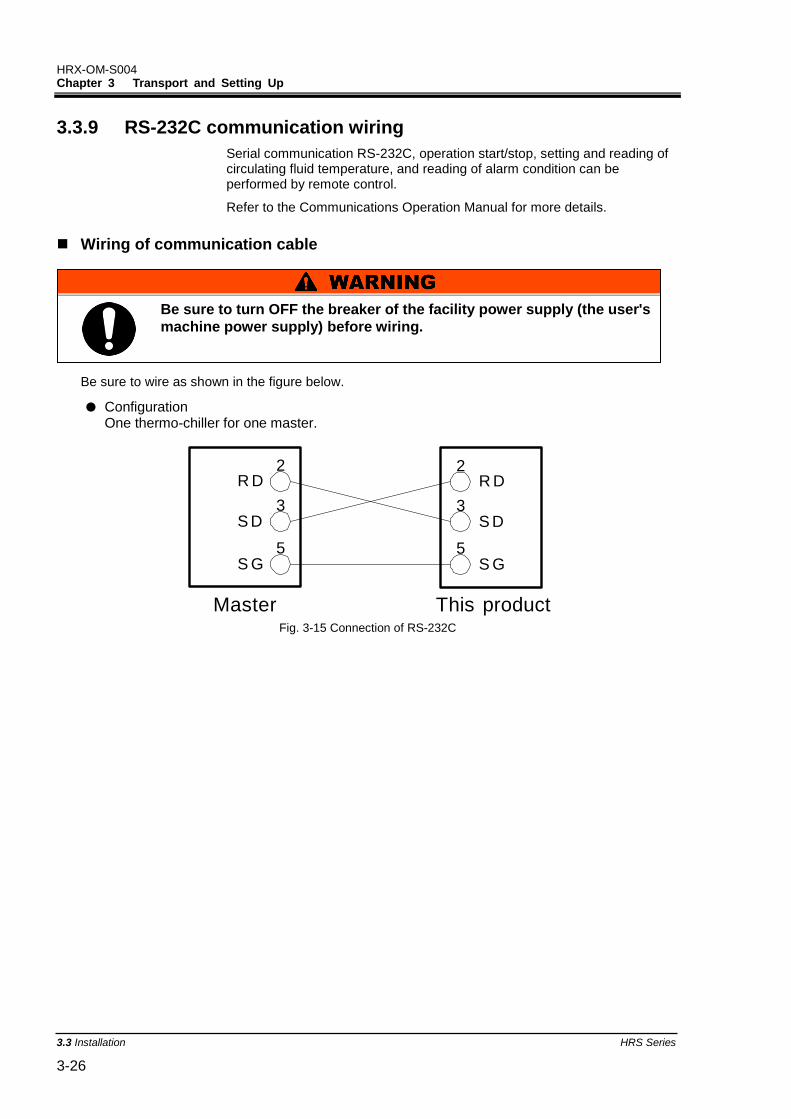
3.3.9 RS-232C communication wiring
Serial communication RS-232C, operation start/stop, setting and reading of circulating fluid temperature, and reading of alarm condition can be performed by remote control.
Refer to the Communications Operation Manual for more details.
Wiring of communication cable
Be sure to wire as shown in the figure below.
Configuration One thermo-chiller for one master.
Fig. 3-15 Connection of RS-232C
2
3
5
R D
S D
S G
2
3
5
R D
S D
S G
Master This product
Be sure to turn OFF the breaker of the facility power supply (the user's
machine power supply) before wiring.
HRX-OM-S004 Chapter 3 Transport and Setting Up
HRS Series 3.4Piping 3-27
Connect piping firmly. Incorrect piping might cause leakage of supplied or drained fluid and wet surrounding area and facility.
Use caution not to allow dust and foreign matter to enter the water circuit, etc. during connection of piping.
Securely connect the piping at the piping port with specific wrench when tightening.
Incorrect piping can burst in service. Use non-corrosive material for fluid contact parts of circulating
fluid and/or facility water. Using the materials that tend to rust or corrode may cause clogging or/and leakages of the circulating fluid and facility water circuits. In case of using these kinds of materials, consider and carry out some prevention against the rusting or corrosion by the customer side.
Do not generate a rapid change of pressure by water hammer, etc. Internal parts of the product and/or the piping may be damaged.
Facility water temperature of the facility water outlet port might rise up to approx.60deg.C.
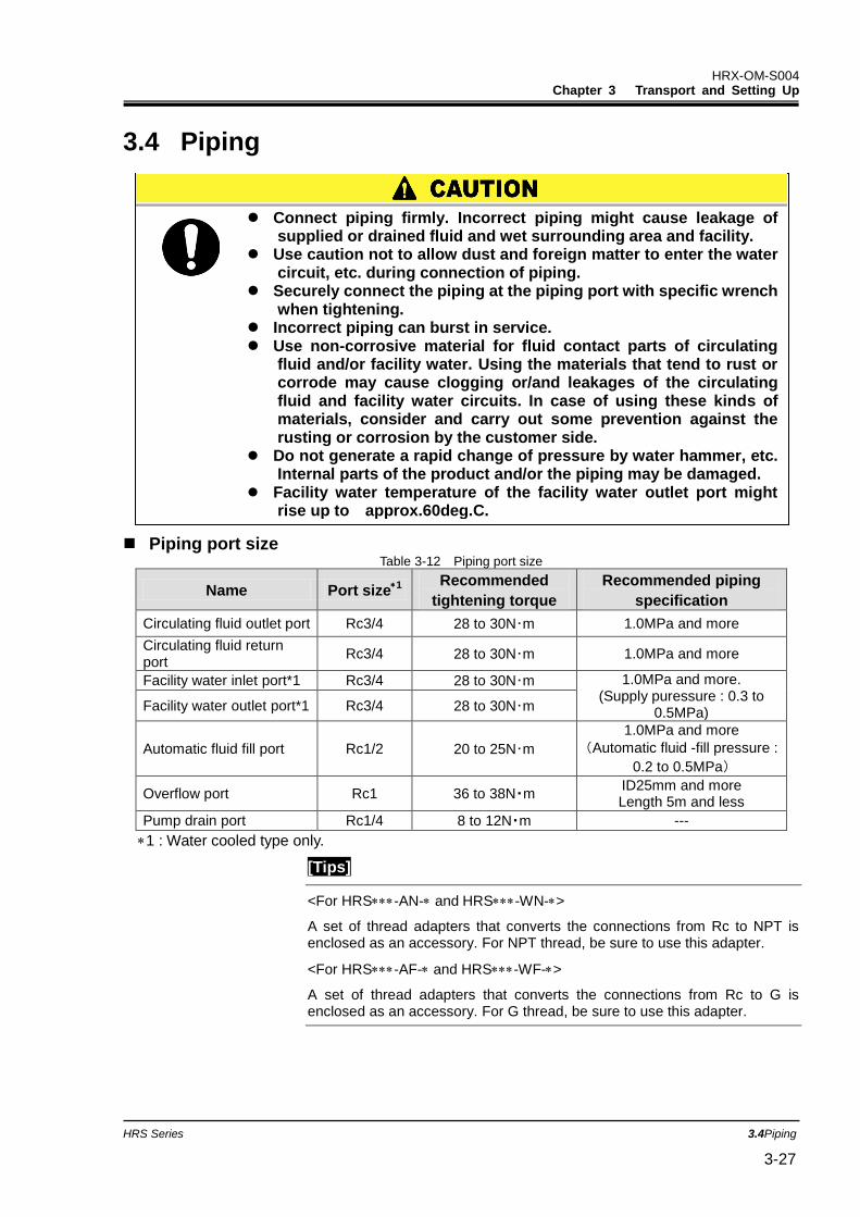
3.4 Piping
Piping port size Table 3-12 Piping port size
Name Port size1
Recommended
tightening torque
Recommended piping
specification
Circulating fluid outlet port Rc3/4 28 to 30N・m 1.0MPa and more
Circulating fluid return port
Rc3/4 28 to 30N・m 1.0MPa and more
Facility water inlet port*1 Rc3/4 28 to 30N・m 1.0MPa and more. (Supply puressure : 0.3 to
0.5MPa) Facility water outlet port*1 Rc3/4 28 to 30N・m
Automatic fluid fill port Rc1/2 20 to 25N・m
1.0MPa and more
(Automatic fluid -fill pressure :
0.2 to 0.5MPa)
Overflow port Rc1 36 to 38N・m ID25mm and more Length 5m and less
Pump drain port Rc1/4 8 to 12N・m ---
1 : Water cooled type only.
[Tips]
<For HRS-AN- andHRS-WN->
A set of thread adapters that converts the connections from Rc to NPT is enclosed as an accessory. For NPT thread, be sure to use this adapter.
<For HRS-AF- and HRS-WF->
A set of thread adapters that converts the connections from Rc to G is enclosed as an accessory. For G thread, be sure to use this adapter.
HRX-OM-S004 Chapter 3 Transport and Setting Up
3.4 Piping HRS Series 3-28
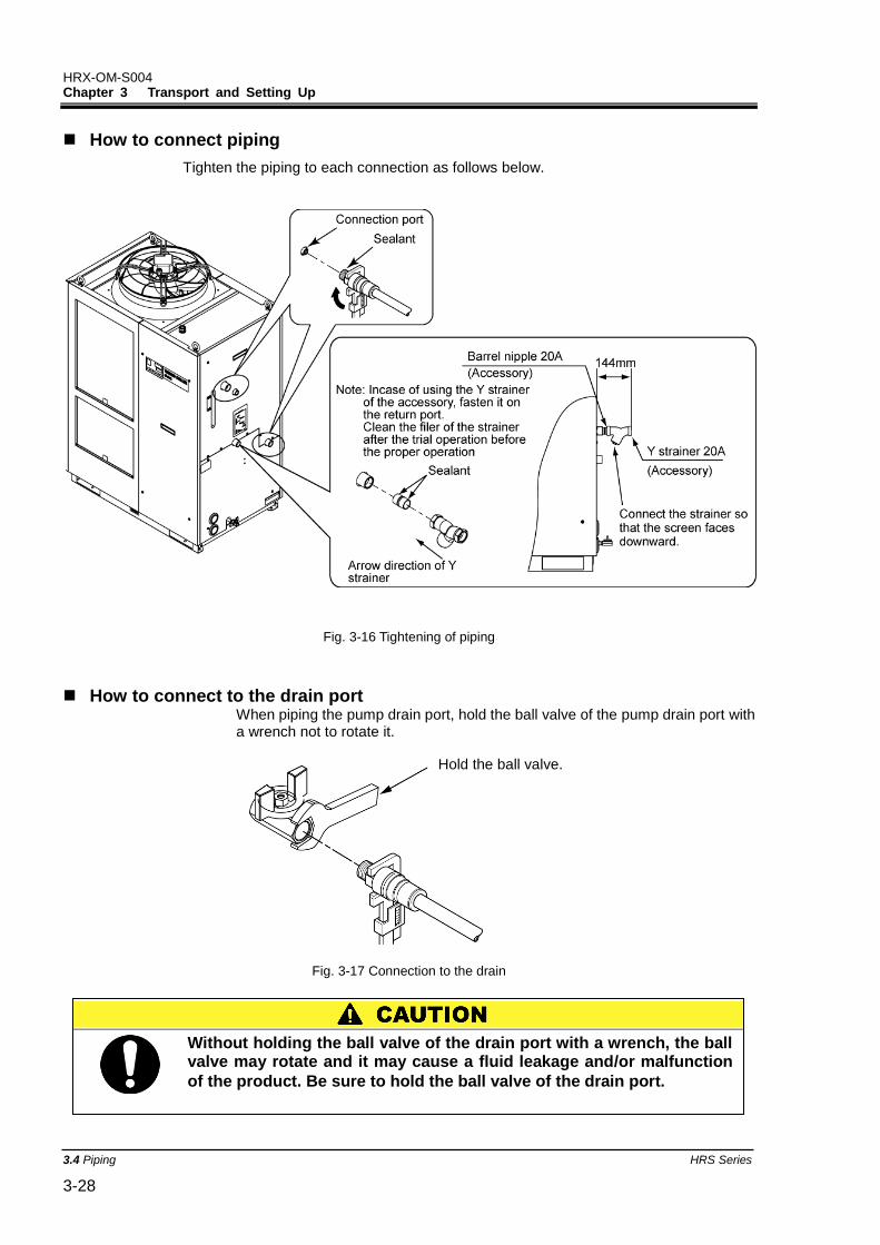
How to connect piping
Tighten the piping to each connection as follows below.
Fig. 3-16 Tightening of piping
How to connect to the drain port When piping the pump drain port, hold the ball valve of the pump drain port with a wrench not to rotate it.
Fig. 3-17 Connection to the drain
Hold the ball valve.
Without holding the ball valve of the drain port with a wrench, the ball valve may rotate and it may cause a fluid leakage and/or malfunction
of the product. Be sure to hold the ball valve of the drain port.
HRX-OM-S004 Chapter 3 Transport and Setting Up
HRS Series 3.4Piping 3-29
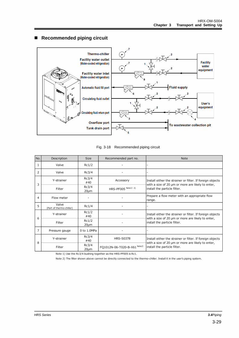
Recommended piping circuit
Fig. 3-18 Recommended piping circuit
No. Description Size Recommended part no. Note
1 Valve Rc1/2 - -
2 Valve Rc3/4 - -
Y-strainerRc3/4
#40Accessory
FilterRc3/4
20μmHRS-PF005 Note1)2)
4 Flow meter - -Prepare a flow meter with an appropriate flow
range.
5Valve
(Part of thermo-chiller)Rc1/4 - -
Y-strainerRc1/2
#40-
FilterRc1/2
20μm-
7 Pressure gauge 0 to 1.0MPa - -
Y-strainerRc3/4
#40HRS-S0378
FilterRc3/4
20μmFQ1012N-06-T020-B-X61 Note2)
Note 1) Use the Rc3/4 bushing together as the HRS-PF005 is Rc1.
Note 2) The filter shown above cannot be directly connected to the thermo-chiller. Install it in the user’s piping system.
3
Install either the strainer or filter. If foreign objects
with a size of 20 μm or more are likely to enter,
install the particle filter.
6
Install either the strainer or filter. If foreign objects
with a size of 20 μm or more are likely to enter,
install the particle filter.
8
Install either the strainer or filter. If foreign objects
with a size of 20 μm or more are likely to enter,
install the particle filter.
HRX-OM-S004 Chapter 3 Transport and Setting Up
3.4 Piping HRS Series 3-30
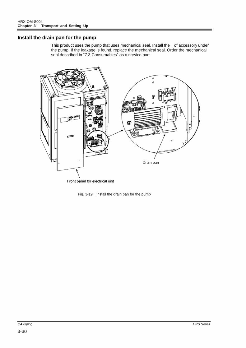
Install the drain pan for the pump
This product uses the pump that uses mechanical seal. Install the of accessory under the pump. If the leakage is found, replace the mechanical seal. Order the mechanical seal described in “7.3 Consumables” as a service part.
Fig. 3-19 Install the drain pan for the pump
HRX-OM-S004 Chapter 3 Transport and Setting Up
HRS Series 3.5Circulating Fluid Supply 3-31
3.5 Circulating Fluid Supply 3.5.1 Automatic fluid-fill function
Open the fluid supply valve that is connected to the automatic water fill port.
Fluid supply starts and stops automatically with the ball tap in the tank.
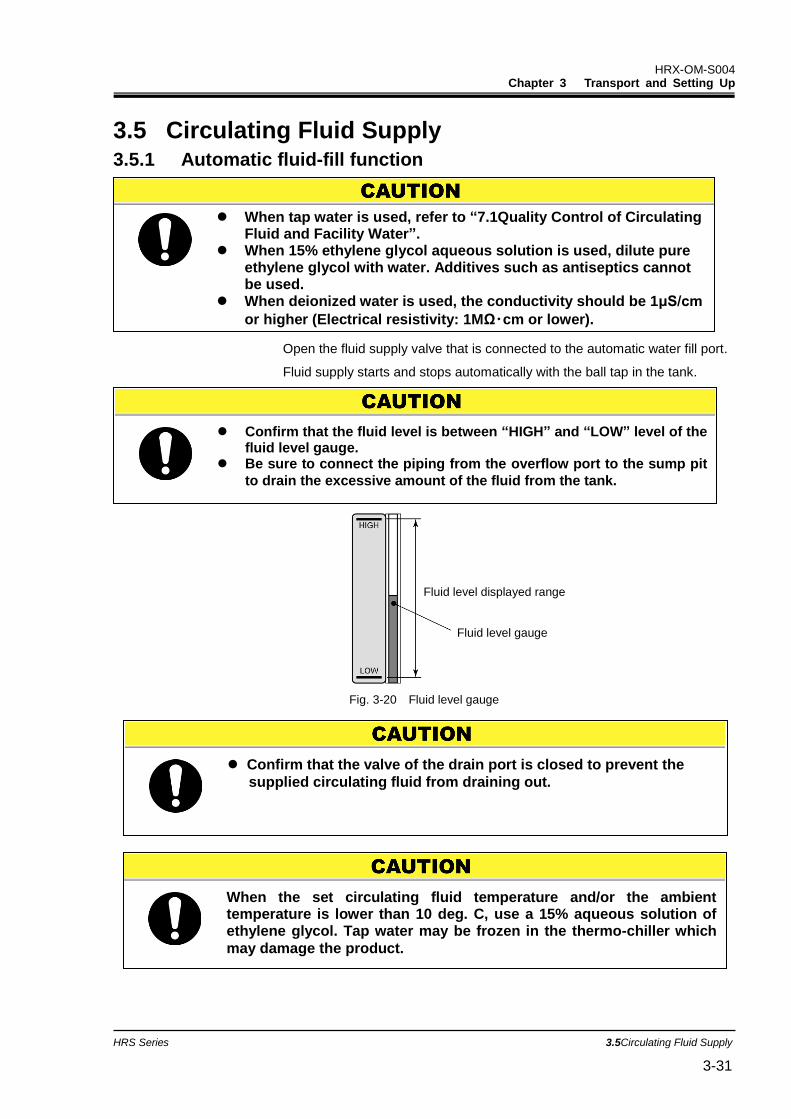
Fig. 3-20 Fluid level gauge
When the set circulating fluid temperature and/or the ambient temperature is lower than 10 deg. C, use a 15% aqueous solution of ethylene glycol. Tap water may be frozen in the thermo-chiller which
may damage the product.
Confirm that the valve of the drain port is closed to prevent the
supplied circulating fluid from draining out.
Confirm that the fluid level is between “HIGH” and “LOW” level of the fluid level gauge.
Be sure to connect the piping from the overflow port to the sump pit
to drain the excessive amount of the fluid from the tank.
Fluid level displayed range
Fluid level gauge
When tap water is used, refer to “7.1Quality Control of Circulating Fluid and Facility Water”.
When 15% ethylene glycol aqueous solution is used, dilute pure ethylene glycol with water. Additives such as antiseptics cannot be used.
When deionized water is used, the conductivity should be 1μS/cm
or higher (Electrical resistivity: 1MΩ・cm or lower).
HRX-OM-S004 Chapter 3 Transport and Setting Up
3.5 Circulating Fluid Supply HRS Series 3-32
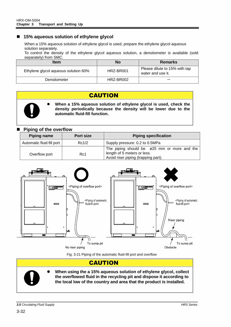
15% aqueous solution of ethylene glycol
When a 15% aqueous solution of ethylene glycol is used, prepare the ethylene glycol aqueous solution separately. To control the density of the ethylene glycol aqueous solution, a densitometer is available (sold separately) from SMC.
Item No Remarks
Ethylene glycol aqueous solution 60% HRZ-BR001 Please dilute to 15% with tap
water and use it.
Densitometer HRZ-BR002 -
Piping of the overflow
Piping name Port size Piping specification
Automatic fluid fill port Rc1/2 Supply pressure: 0.2 to 0.5MPa
Overflow port Rc1
The piping should be ø25 mm or more and the length of 5 meters or less. Avoid riser piping (trapping part).
Fig. 3-21 Piping of the automatic fluid-fill port and overflow
When using the a 15% aqueous solution of ethylene glycol, collect the overflowed fluid in the recycling pit and dispose it according to
the local low of the country and area that the product is installed.
When a 15% aqueous solution of ethylene glycol is used, check the density periodically because the density will be lower due to the
automatic fluid-fill function.
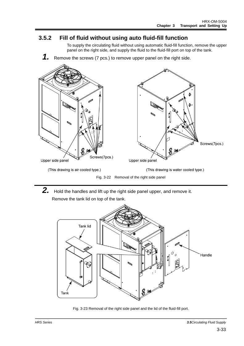
HRX-OM-S004 Chapter 3 Transport and Setting Up
HRS Series 3.5Circulating Fluid Supply 3-33
3.5.2 Fill of fluid without using auto fluid-fill function
To supply the circulating fluid without using automatic fluid-fill function, remove the upper
panel on the right side, and supply the fluid to the fluid-fill port on top of the tank.
1. Remove the screws (7 pcs.) to remove upper panel on the right side.
Fig. 3-22 Removal of the right side panel
2. Hold the handles and lift up the right side panel upper, and remove it.
Remove the tank lid on top of the tank.
Fig. 3-23 Removal of the right side panel and the lid of the fluid-fill port.
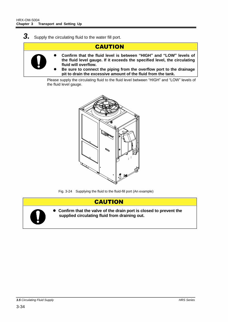
HRX-OM-S004 Chapter 3 Transport and Setting Up
3.5 Circulating Fluid Supply HRS Series 3-34
3. Supply the circulating fluid to the water fill port.
Please supply the circulating fluid to the fluid level between “HIGH” and “LOW” levels of the fluid level gauge.
Fig. 3-24 Supplying the fluid to the fluid-fill port (An example)
Confirm that the valve of the drain port is closed to prevent the supplied circulating fluid from draining out.
Confirm that the fluid level is between “HIGH” and “LOW” levels of the fluid level gauge. If it exceeds the specified level, the circulating fluid will overflow.
Be sure to connect the piping from the overflow port to the drainage pit to drain the excessive amount of the fluid from the tank.
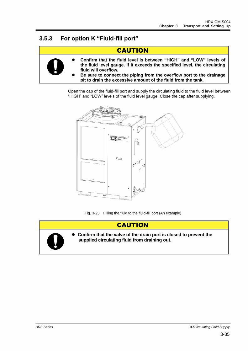
HRX-OM-S004 Chapter 3 Transport and Setting Up
HRS Series 3.5Circulating Fluid Supply 3-35
3.5.3 For option K “Fluid-fill port”
Open the cap of the fluid-fill port and supply the circulating fluid to the fluid level between
“HIGH” and “LOW” levels of the fluid level gauge. Close the cap after supplying.
Fig. 3-25 Filling the fluid to the fluid-fill port (An example)
Confirm that the fluid level is between “HIGH” and “LOW” levels of the fluid level gauge. If it exceeds the specified level, the circulating fluid will overflow.
Be sure to connect the piping from the overflow port to the drainage pit to drain the excessive amount of the fluid from the tank.
Confirm that the valve of the drain port is closed to prevent the supplied circulating fluid from draining out.

HRX-OM-S004 Chapter 3 Transport and Setting Up
3.5 Circulating Fluid Supply HRS Series 3-36
HRX-OM-S004 Chapter 4 Starting the Product
HRS Series 4.1Before Starting 4-1
Chapter 4 Starting the Product
4.1 Before Starting Check the following points before starting the product.
Installation state
Check the product is installed horizontally.
Check that there are no heavy objects on the product, and the external piping is not applying excessive force to the product.
Connection of cables
Check that the power, ground and I/O signal cables (to be supplied by user) are correctly connected.
Circulating fluid piping
Check that the circulating fluid piping is correctly connected to the inlet and outlet.
Piping to automatic water fill port
Confirm that the piping to the automatic water fill port is correctly connected.
Piping to overflow port
Piping must be connected to the overflow port regardless of using or not using the automatic water fill function.
Confirm that the piping to the overflow port is correctly connected.
Fluid level gauge
Confirm that the fluid level is between ‘HIGH’ and ‘LOW’ levels of the fluid level gauge.
Facility water piping (For water cooled type)
Check that the piping is correctly connected to the facility water inlet and outlet ports.
Confirm that the facility water source is in operation.
Confirm that the facility water circuit is not closed with a valve, etc.
[Tips]
A water control valve is mounted inside the water cooled type thermo-chiller. For the water cooled type, facility water may not run without operating the product.
Only people who have sufficient knowledge and experience about the product and its accessories are allowed to start and stop the product.
Facility water quality must satisfy the quality standard shown in “Table 7-1 Quality Control of Circulating Fluid and Facility Water” and the conditions shown in “8.1 Specifications”
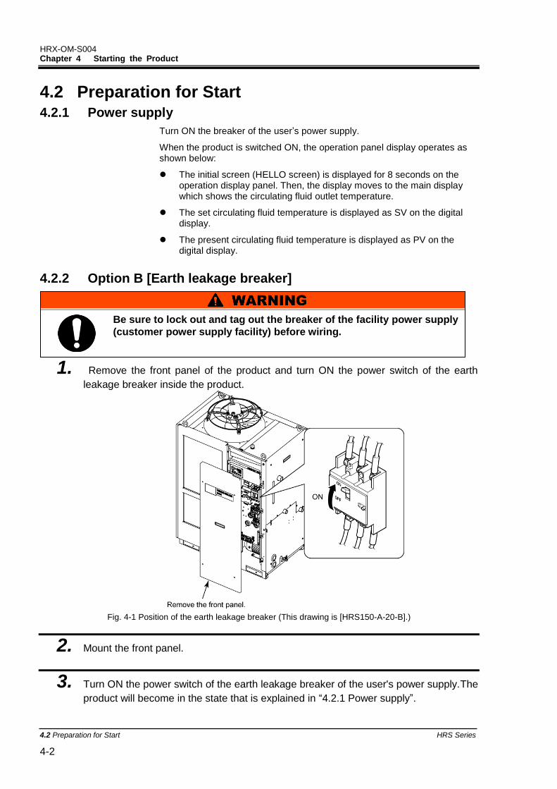
HRX-OM-S004 Chapter 4 Starting the Product
4.2 Preparation for Start HRS Series 4-2
4.2 Preparation for Start 4.2.1 Power supply
Turn ON the breaker of the user’s power supply.
When the product is switched ON, the operation panel display operates as shown below:
The initial screen (HELLO screen) is displayed for 8 seconds on the operation display panel. Then, the display moves to the main display which shows the circulating fluid outlet temperature.
The set circulating fluid temperature is displayed as SV on the digital display.
The present circulating fluid temperature is displayed as PV on the digital display.
4.2.2 Option B [Earth leakage breaker]
1. Remove the front panel of the product and turn ON the power switch of the earth
leakage breaker inside the product.
Fig. 4-1 Position of the earth leakage breaker (This drawing is [HRS150-A-20-B].)
2. Mount the front panel.
3. Turn ON the power switch of the earth leakage breaker of the user's power supply.The
product will become in the state that is explained in “4.2.1 Power supply”.
Be sure to lock out and tag out the breaker of the facility power supply
(customer power supply facility) before wiring.
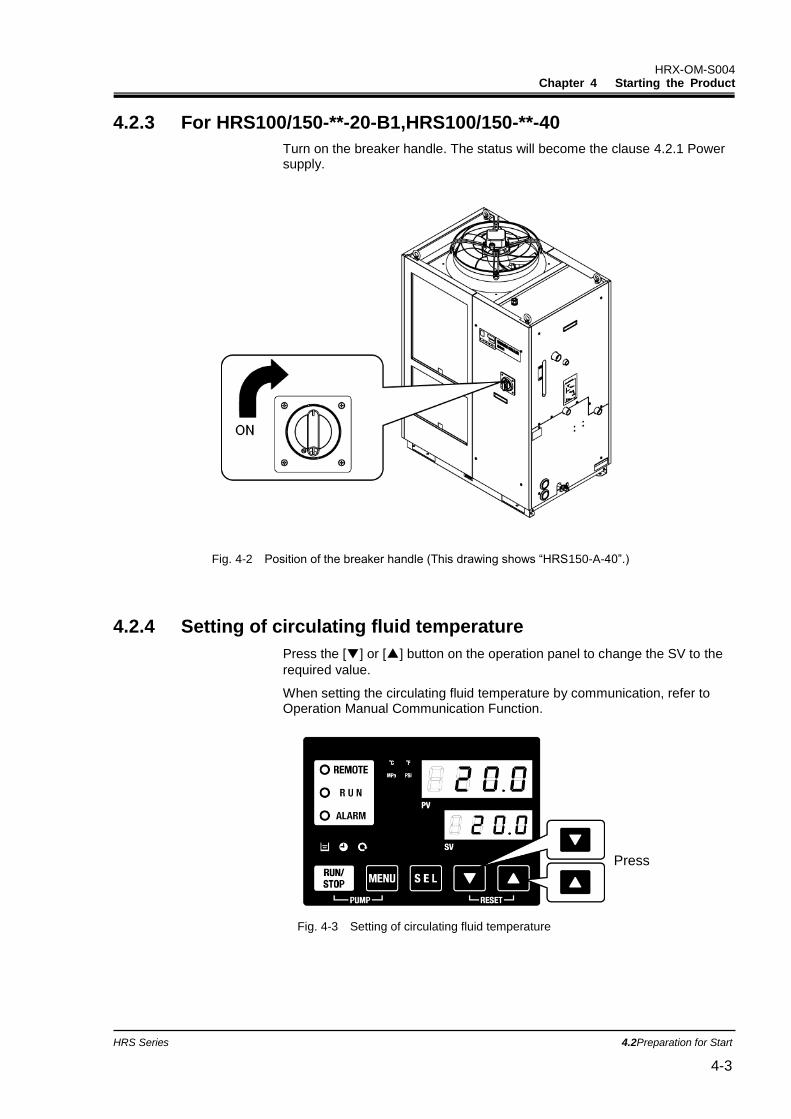
HRX-OM-S004 Chapter 4 Starting the Product
HRS Series 4.2Preparation for Start 4-3
Press
4.2.3 For HRS100/150-**-20-B1,HRS100/150-**-40
Turn on the breaker handle. The status will become the clause 4.2.1 Power supply.
Fig. 4-2 Position of the breaker handle (This drawing shows “HRS150-A-40”.)
4.2.4 Setting of circulating fluid temperature
Press the [▼] or [▲] button on the operation panel to change the SV to the
required value.
When setting the circulating fluid temperature by communication, refer to Operation Manual Communication Function.
Fig. 4-3 Setting of circulating fluid temperature
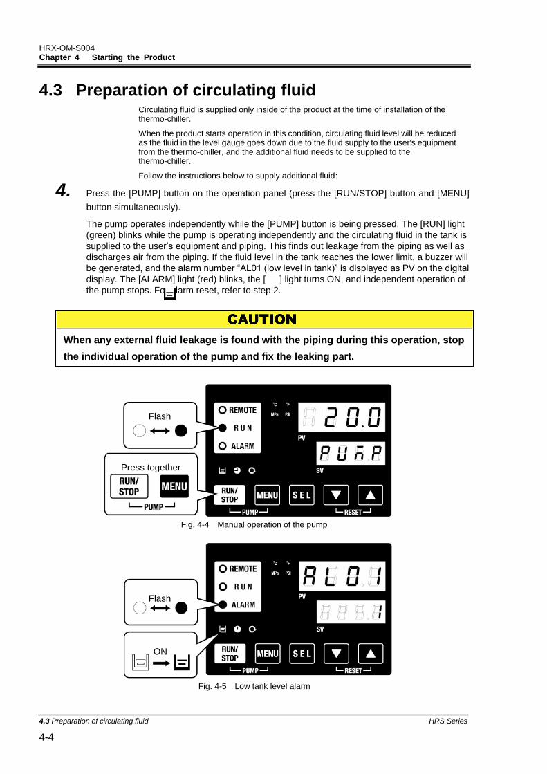
HRX-OM-S004 Chapter 4 Starting the Product
4.3 Preparation of circulating fluid HRS Series 4-4
4.3 Preparation of circulating fluid Circulating fluid is supplied only inside of the product at the time of installation of the thermo-chiller.
When the product starts operation in this condition, circulating fluid level will be reduced as the fluid in the level gauge goes down due to the fluid supply to the user's equipment from the thermo-chiller, and the additional fluid needs to be supplied to the thermo-chiller.
Follow the instructions below to supply additional fluid:
4. Press the [PUMP] button on the operation panel (press the [RUN/STOP] button and [MENU]
button simultaneously).
The pump operates independently while the [PUMP] button is being pressed. The [RUN] light
(green) blinks while the pump is operating independently and the circulating fluid in the tank is
supplied to the user’s equipment and piping. This finds out leakage from the piping as well as
discharges air from the piping. If the fluid level in the tank reaches the lower limit, a buzzer will
be generated, and the alarm number “AL01 (low level in tank)” is displayed as PV on the digital
display. The [ALARM] light (red) blinks, the [ ] light turns ON, and independent operation of
the pump stops. For alarm reset, refer to step 2.
Fig. 4-4 Manual operation of the pump
Fig. 4-5 Low tank level alarm
When any external fluid leakage is found with the piping during this operation, stop
the individual operation of the pump and fix the leaking part.
Flash
Press together
Flash
ON

HRX-OM-S004 Chapter 4 Starting the Product
HRS Series 4.3Preparation of circulating fluid 4-5
5. Press the [RESET] button (press the [▼] and [▲] buttons simultaneously) to stop the
alarm buzzer.
Fig. 4-6 Alarm receipt
6. Fluid supply using automatic water fill function has been started. Operation shown in
step 5 can be performed after some minutes.
Reset alarms on the ”Alarm menu” screen. Alarm reset is not accepted from any
screen except the "Alarm menu" screen. Refer to 5.2.1 Key operations.
Flash
Press together
ON
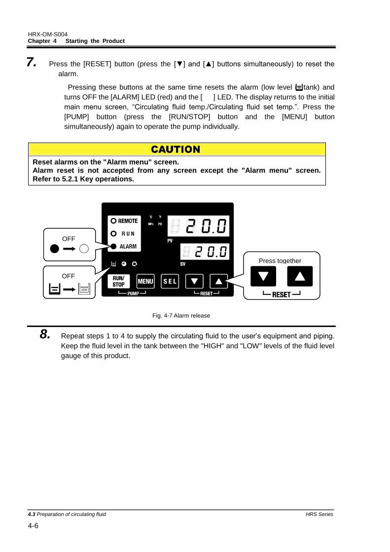
HRX-OM-S004 Chapter 4 Starting the Product
4.3 Preparation of circulating fluid HRS Series 4-6
7. Press the [RESET] button (press the [▼] and [▲] buttons simultaneously) to reset the
alarm.
Pressing these buttons at the same time resets the alarm (low level in tank) and
turns OFF the [ALARM] LED (red) and the [ ] LED. The display returns to the initial
main menu screen, “Circulating fluid temp./Circulating fluid set temp.”. Press the
[PUMP] button (press the [RUN/STOP] button and the [MENU] button
simultaneously) again to operate the pump individually.
Fig. 4-7 Alarm release
8. Repeat steps 1 to 4 to supply the circulating fluid to the user’s equipment and piping.
Keep the fluid level in the tank between the "HIGH" and "LOW" levels of the fluid level
gauge of this product.
Reset alarms on the "Alarm menu" screen. Alarm reset is not accepted from any screen except the "Alarm menu" screen.
Refer to 5.2.1 Key operations.
Press together
(0.7in)
(0.7in)
(0.7in)
OFF
OFF
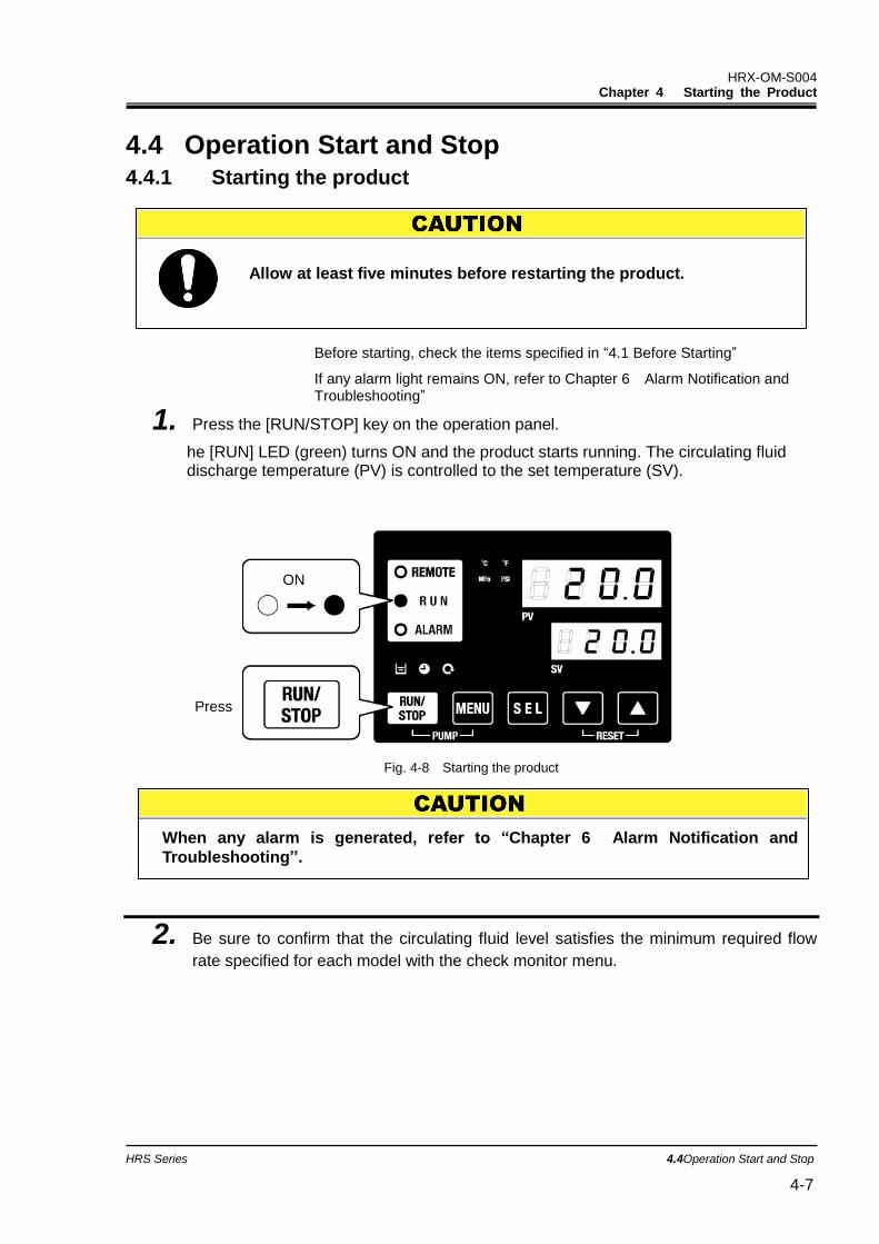
HRX-OM-S004 Chapter 4 Starting the Product
HRS Series 4.4Operation Start and Stop 4-7
4.4 Operation Start and Stop 4.4.1 Starting the product
Before starting, check the items specified in “4.1 Before Starting”
If any alarm light remains ON, refer to Chapter 6 Alarm Notification and Troubleshooting”
1. Press the [RUN/STOP] key on the operation panel.
he [RUN] LED (green) turns ON and the product starts running. The circulating fluid discharge temperature (PV) is controlled to the set temperature (SV).
Fig. 4-8 Starting the product
2. Be sure to confirm that the circulating fluid level satisfies the minimum required flow
rate specified for each model with the check monitor menu.
ON
Press
When any alarm is generated, refer to “Chapter 6 Alarm Notification and
Troubleshooting’’.
Allow at least five minutes before restarting the product.
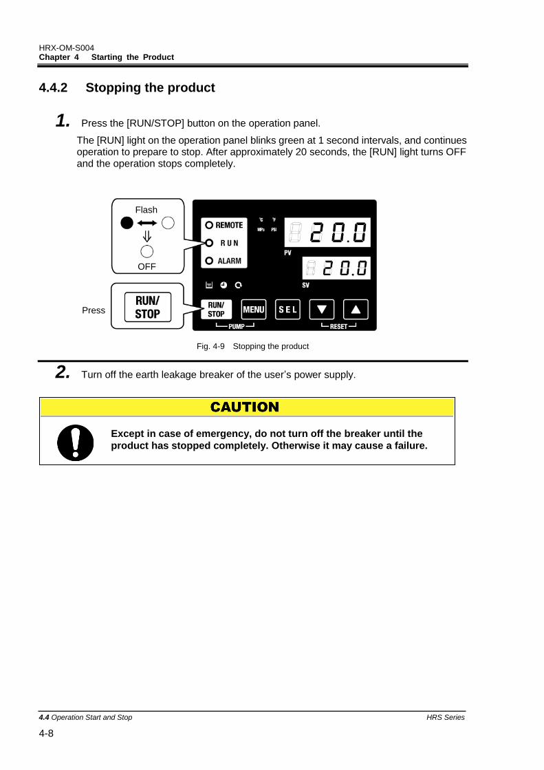
HRX-OM-S004 Chapter 4 Starting the Product
4.4 Operation Start and Stop HRS Series 4-8
Except in case of emergency, do not turn off the breaker until the
product has stopped completely. Otherwise it may cause a failure.
4.4.2 Stopping the product
1. Press the [RUN/STOP] button on the operation panel.
The [RUN] light on the operation panel blinks green at 1 second intervals, and continues operation to prepare to stop. After approximately 20 seconds, the [RUN] light turns OFF and the operation stops completely.
Fig. 4-9 Stopping the product
2. Turn off the earth leakage breaker of the user’s power supply.
Flash
OFF
等
Press
HRX-OM-S004 Chapter 4 Starting the Product
HRS Series 4.5Check items during startup 4-9
4.5 Check items during startup Check the following items after starting the product.
Confirm that there is leakage from the piping.
Confirm that no circulating fluid is discharged from the pump drain port.
Confirm that the circulating fluid pressure is within the specification range.
Confirm that the fluid level shown by the fluid level gauge is within the specification range.
4.6 Adjustment of Circulating Fluid flow rate When the circulating fluid flow rate is smaller than the minimum required, the product may fail to maintain the performance. And there is possibility of occurring overload of the pump. Refer to Fig. 3-18 Recommended piping circuit, and adjust the flow rate with the
manual valve to the required pressure or flow rate while monitoring the pressure and/or flow rate.
[Tips]
Regarding the minimum operation flow rate, refer to “8.1 Specifications”.
When any abnormality is found, press the [STOP] button to stop the product operation, and then turn OFF the breaker of the user’s power
supply.

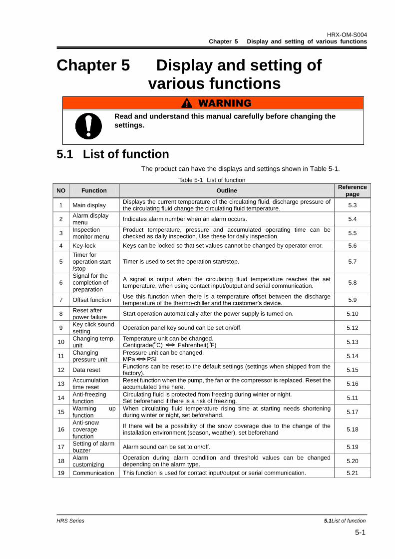
HRX-OM-S004 Chapter 5 Display and setting of various functions
HRS Series 5.1List of function 5-1
Chapter 5 Display and setting of various functions
5.1 List of function The product can have the displays and settings shown in Table 5-1.
Table 5-1 List of function
NO Function Outline Reference
page
1 Main display Displays the current temperature of the circulating fluid, discharge pressure of the circulating fluid change the circulating fluid temperature.
5.3
2 Alarm display menu
Indicates alarm number when an alarm occurs. 5.4
3 Inspection monitor menu
Product temperature, pressure and accumulated operating time can be checked as daily inspection. Use these for daily inspection.
5.5
4 Key-lock Keys can be locked so that set values cannot be changed by operator error. 5.6
5 Timer for operation start /stop
Timer is used to set the operation start/stop. 5.7
6 Signal for the completion of preparation
A signal is output when the circulating fluid temperature reaches the set temperature, when using contact input/output and serial communication.
5.8
7 Offset function Use this function when there is a temperature offset between the discharge temperature of the thermo-chiller and the customer’s device.
5.9
8 Reset after power failure
Start operation automatically after the power supply is turned on. 5.10
9 Key click sound setting
Operation panel key sound can be set on/off. 5.12
10 Changing temp. unit
Temperature unit can be changed. Centigrade(
oC) ⇔ Fahrenheit(
oF)
5.13
11 Changing pressure unit
Pressure unit can be changed. MPa⇔PSI
5.14
12 Data reset Functions can be reset to the default settings (settings when shipped from the factory).
5.15
13 Accumulation time reset
Reset function when the pump, the fan or the compressor is replaced. Reset the accumulated time here.
5.16
14 Anti-freezing function
Circulating fluid is protected from freezing during winter or night. Set beforehand if there is a risk of freezing.
5.11
15 Warming up function
When circulating fluid temperature rising time at starting needs shortening during winter or night, set beforehand.
5.17
16 Anti-snow coverage function
If there will be a possibility of the snow coverage due to the change of the installation environment (season, weather), set beforehand
5.18
17 Setting of alarm buzzer
Alarm sound can be set to on/off. 5.19
18 Alarm customizing
Operation during alarm condition and threshold values can be changed depending on the alarm type.
5.20
19 Communication This function is used for contact input/output or serial communication. 5.21
Read and understand this manual carefully before changing the
settings.
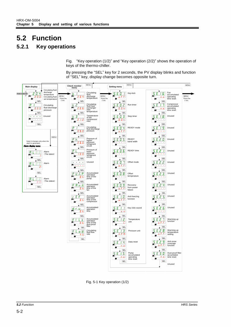
HRX-OM-S004 Chapter 5 Display and setting of various functions
5.2 Function HRS Series 5-2
5.2 Function 5.2.1 Key operations
Fig. “Key operation (1/2)” and “Key operation (2/2)” shows the operation of keys of the thermo-chiller.
By pressing the “SEL” key for 2 seconds, the PV display blinks and function of “SEL” key, display change becomes opposite turn.
PV
SV
Circulating fluid
discharge
temperature
Circulating fluid
set temperature
Circulating
fluid discharge
pressure
Main display
Circulatingfluiddischargetemperature
Circulatingfluid heatexchangerinlettemperature
Check monitormenu
Temperatureof thecompressorinlet.
PV
SV
PV
SV
PV
SV
PV
SV
Circulatingfluid dischargepressure
PV
SV
Pressure ofhigherpressurerefrigerantcircuit
PV
SV
Pressure oflowerpressurerefrigerantcircuit
Accumulatedoperationtime of thepump
Accumulatedoperationtime of thefan
Accumulatedoperationtime of thecompressor
Accumulatedoperationtime
PV
SV
PV
SV
PV
SV
PV
SV
Key-lock
Run timer
Setting menu
Stop timer
READY mode
READY
band width
READY time
Offset mode
Offset
temperature
Recovery
from power
failure
Anti-freezing
function
Data reset
Pumpaccumulatedoperatingtime reset
Fanaccumulatedoperatingtime reset
Compressoraccumulatedoperatingtime reset
Key click sound
Temperature
unit
Pressure unit
Alarm
(The latest)
Alarm
Alarm display menu
Alarm
(The oldest)
PV
SV
PV
SV
PV
SV
Note) It changes only when the
alarm is generated.
PV
SV
PV
SV
Power supply ON
PV
SV
Press the
2 sec.
PV
SV
Unused
PV
SV
SEL
Unused
PV
SV
PV
SV
Unused
Unused
SEL
Unused
PV
SV
Unused
Unused
PV
SV
PV
SV
SEL
SEL
SEL
SEL
SEL
SEL
SEL
SEL
SEL
SEL
SEL
SEL
SEL
SEL
SEL
SEL
SEL
SEL
SEL
SEL
SEL
SEL
SEL
MENU
MENU
Press the
2 sec.
MENU
MENUMENU
Unused
PV
SV
SEL
PV
SV
SEL
Accumulatedoperationtime of thedust-prooffilter
PV
SV
PV
SV
PV
SV
PV
SV
PV
SV
PV
SV
PV
SV
PV
SV
PV
SV
PV
SV
PV
SV
PV
SV
PV
SV
PV
SV
PV
SV
SEL
SEL
SEL
SEL
SEL
SEL
SEL
SEL
SEL
SEL
SEL
SEL
SEL
SEL
SEL
PV
SV
PV
SV
SEL
SEL
PV
SV
PV
SV
PV
SV
SEL
SEL
SEL
PV
SV
SEL
PV
SV
Warming upfunction
Warming uptemperaturesetting
Anti-snowcoveragefunction
Dust-proof filteraccumlatedtime reset
MENU
Press the
2 sec.
MENU
SEL
Criculatingfluid flowratePV
SV
SEL
Unused
Unused
Unused
Unused
Fig. 5-1 Key operation (1/2)
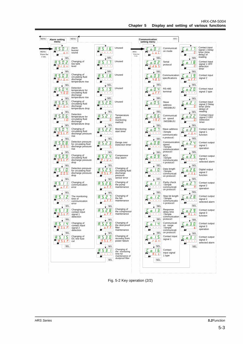
HRX-OM-S004 Chapter 5 Display and setting of various functions
HRS Series 5.2Function 5-3
MENU
Changing ofcontact inputsignal 1detection
Alarmbuzzersound
Changing oflow tanklevel
Changing ofcirculating fluiddischargetemperature rise
Detectiontemperature forcirculating fluiddischargetemperature rise
Changing ofcirculating fluiddischargetemperature drop
Detectiontemperature forcirculating fluiddischargetemperature drop
Changing ofcirculating fluiddischarge pressurerise
Detection pressurefor circulating fluiddischarge pressurerise
Changing ofcommunicationerror
The monitoringtime ofcommunicationerror
Changing ofcirculating fluiddischarge pressuredrop
Detection pressurefor circulating fluiddischarge pressuredrop
Changing ofcontact inputsignal 2detection
Unused
Unused
Changing ofDC line fusecut
Unused
PV
SV
PV
SV
Unused
Unused
PV
SV
PV
SV
PV
SV
SEL
SEL
SEL
SEL
Press the
2 sec.
MENUAlarm settingmenu
MENU
Communicati
on mode
Serial
protocol
Communication
specifications
RS-485
terminal
Slave
address
(MODBUS)
Communicati
on speed
(MODBUS)
Slave address
(Simple
communicatio
n protocol)
Communicationspeed(Simplecommunicationprotocol)
Responsedelay time(Simplecommunicationprotocol)
Communication range(Simplecommunication protocol)
MENU
BCC(Simplecommunication protocol)
Data length(Simplecommunication protocol)
Parity check(Simplecommunication protocol)
Stop bit length(Simplecommunication protocol)
Contact input
signal 1
Contact
input signal
1 type
Contact input
signal 2
Contact input
signal 2 type
Contact output
signal 1
function
Contact output
signal 1
operation
Contact output
signal 1
selected alarm
Digital output
signal 2
function
Contact output
signal 3
selected alarm
Contact output
signal 2
operation
Contact output
signal 2
selected alarm
Contact output
signal 3
function
Contact output
signal 3
operation
PV
SV
PV
SV
PV
SV
PV
SV
PV
SV
PV
SV
PV
SV
PV
SV
PV
SV
PV
SV
PV
SV
PV
SV
PV
SV
PV
SV
PV
SV
PV
SV
PV
SV
PV
SV
PV
SV
PV
SV
PV
SV
PV
SV
PV
SV
PV
SV
PV
SV
PV
SV
SV
Press the
2 sec.
Contact inputsignal 1 Delaytimer (timedelay) ofreading
Contact inputsignal 1 OFFdetectiontimer
PV
SV
PV
SV
Contact inputsignal 2 Delaytimer (timedelay) ofreading
Contact inputsignal 2 OFFDetectiontimer
PV
SV
PV
SV
SEL
SEL
SEL
SEL
SEL
SEL
SEL
SEL
SEL
SEL
SEL
SEL
SEL
SEL
SEL
SEL
SEL
SEL
SEL
SEL
SEL
SEL
SEL
SEL
SEL
SEL
SEL
SEL
SEL
SEL
SEL
PV
MENU
SEL
PV
SV
PV
SV
SEL
PV
SV
SEL
SEL
Temperaturealarmmonitoringmethod
Monitoringstart timer
Range overDetection timer
PV
SV
PV
SV
PV
SV
PV
SV
PV
SV
PV
SV
PV
SV
PV
SV
PV
SV
PV
SV
PV
SV
PV
SV
PV
SV
PV
SV
PV
SV
SEL
SEL
SEL
SEL
SEL
SEL
SEL
SEL
SEL
SEL
SEL
SEL
SEL
SEL
SEL
PV
SV
PV
SV
SEL
SEL
SV
SEL
SV
SEL
SV
SEL
SV
SEL
SV
Compressorstop alarm
Changing ofcirculating fluiddischargepressuresensor error
Changing ofthe pumpmaintenance
Changing ofthe fanmaintenance
Changing ofthe compressormaintenance
Changing ofthe dust-prooffiltermaintenance
Changing ofrecovery frompower failure
Communicationsetting menu
SV
PV
Changing ofthe monitoringtime formaintenance ofdustproof filter
SEL
SEL
Fig. 5-2 Key operation (2/2)
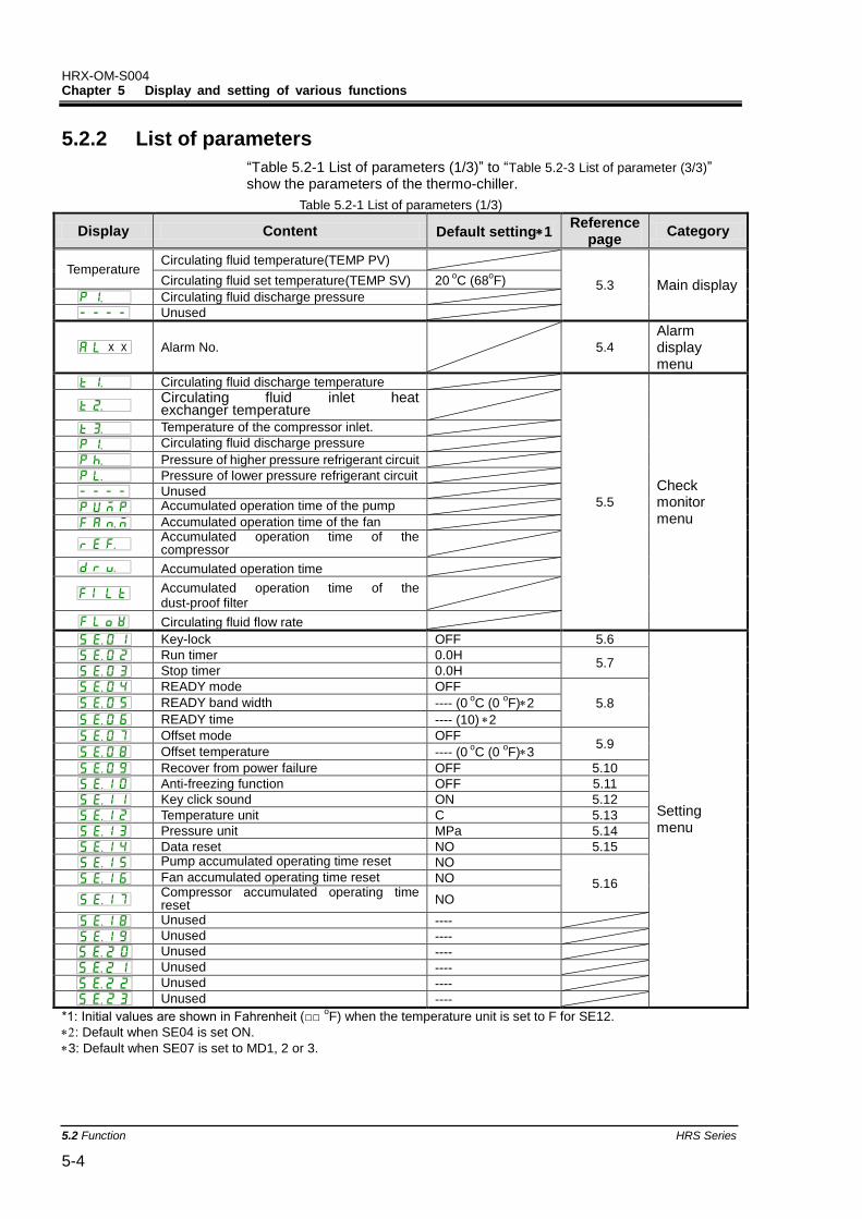
HRX-OM-S004 Chapter 5 Display and setting of various functions
5.2 Function HRS Series 5-4
5.2.2 List of parameters
“Table 5.2-1 List of parameters (1/3)” to “Table 5.2-3 List of parameter (3/3)” show the parameters of the thermo-chiller.
Table 5.2-1 List of parameters (1/3)
Display Content Default setting1 Reference
page Category
Temperature Circulating fluid temperature(TEMP PV)
5.3 Main display Circulating fluid set temperature(TEMP SV) 20 o
C (68oF)
Circulating fluid discharge pressure
Unused
Alarm No.
5.4
Alarm display menu
Circulating fluid discharge temperature
5.5
Check monitor menu
Circulating fluid inlet heat exchanger temperature
Temperature of the compressor inlet.
Circulating fluid discharge pressure
Pressure of higher pressure refrigerant circuit
Pressure of lower pressure refrigerant circuit
Unused
Accumulated operation time of the pump
Accumulated operation time of the fan
Accumulated operation time of the compressor
Accumulated operation time
Accumulated operation time of the dust-proof filter
Circulating fluid flow rate
Key-lock OFF 5.6
Setting menu
Run timer 0.0H 5.7
Stop timer 0.0H
READY mode OFF
5.8 READY band width ---- (0 o
C (0 oF)2
READY time ---- (10)2
Offset mode OFF 5.9
Offset temperature ---- (0 o
C (0 oF)3
Recover from power failure OFF 5.10
Anti-freezing function OFF 5.11
Key click sound ON 5.12
Temperature unit C 5.13
Pressure unit MPa 5.14
Data reset NO 5.15
Pump accumulated operating time reset NO
5.16 Fan accumulated operating time reset NO
Compressor accumulated operating time reset NO
Unused ----
Unused ----
Unused ----
Unused ----
Unused ----
Unused ----
*1: Initial values are shown in Fahrenheit (□□ oF) when the temperature unit is set to F for SE12.
: Default when SE04 is set ON.
3: Default when SE07 is set to MD1, 2 or 3.
X X
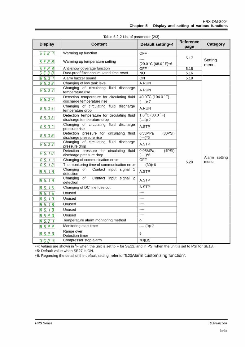
HRX-OM-S004 Chapter 5 Display and setting of various functions
HRS Series 5.2Function 5-5
Table 5.2-2 List of parameter (2/3)
Display Content Default setting4 Reference
page Category
Warming up function OFF
5.17 Setting menu
Warming up temperature setting ----
(20.0 o
C (68.0 ゚ F)6
Anti-snow coverage function OFF 5.18
Dust-proof filter accumulated time reset NO 5.16
Alarm buzzer sound ON 5.19
Alarm setting menu
Changing of low tank level A.RUN
5.20
Changing of circulating fluid discharge temperature rise
A.RUN
Detection temperature for circulating fluid discharge temperature rise
40.0 o
C (104.0 ゚ F)
(----)7
Changing of circulating fluid discharge temperature drop
A.RUN
Detection temperature for circulating fluid discharge temperature drop
1.0 o
C (33.8 ゚ F)
(----)7
Changing of circulating fluid discharge pressure rise
A.STP
Detection pressure for circulating fluid discharge pressure rise
0.55MPa (80PSI) (----)*6
Changing of circulating fluid discharge pressure drop
A.STP
Detection pressure for circulating fluid discharge pressure drop
0.05MPa (4PSI) (----)*6
Changing of communication error OFF
The monitoring time of communication error ---- (30)6
Changing of Contact input signal 1 detection
A.STP
Changing of Contact input signal 2 detection
A.STP
Changing of DC line fuse cut A.STP
Unused ----
Unused ----
Unused ----
Unused ----
Unused ----
Temperature alarm monitoring method 0
Monitoring start timer ---- (0)7
Range over Detection timer
5
Compressor stop alarm P.RUN
: Values are shown in oF when the unit is set to F for SE12, and in PSI when the unit is set to PSI for SE13.
5: Default value when SE27 is ON.
6: Regarding the detail of the default setting, refer to “5.20Alarm customizing function”.
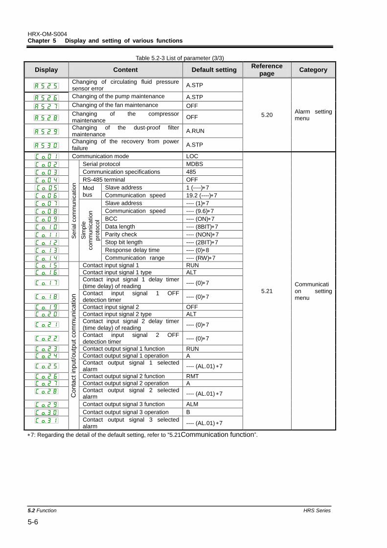
HRX-OM-S004 Chapter 5 Display and setting of various functions
5.2 Function HRS Series 5-6
Table 5.2-3 List of parameter (3/3)
Display Content Default setting Reference
page Category
Changing of circulating fluid pressure sensor error
A.STP
5.20 Alarm setting menu
Changing of the pump maintenance A.STP
Changing of the fan maintenance OFF
Changing of the compressor maintenance
OFF
Changing of the dust-proof filter maintenance
A.RUN
Changing of the recovery from power failure
A.STP
Communication mode LOC
5.21 Communication setting menu
Se
ria
l com
mu
nic
atio
n
Serial protocol MDBS
Communication specifications 485
RS-485 terminal OFF
Mod bus
Slave address 1 (----)7
Communication speed 19.2 (----)7
Sim
ple
co
mm
unic
ation
pro
toco
l
Slave address ---- (1)7
Communication speed ---- (9.6)7
BCC ---- (ON)7
Data length ---- (8BIT)7
Parity check ---- (NON)7
Stop bit length ---- (2BIT)7
Response delay time ---- (0)8
Communication range ---- (RW)7
Conta
ct
input/
outp
ut
co
mm
unic
atio
n
Contact input signal 1 RUN
Contact input signal 1 type ALT
Contact input signal 1 delay timer (time delay) of reading
---- (0)7
Contact input signal 1 OFF detection timer
---- (0)7
Contact input signal 2 OFF
Contact input signal 2 type ALT
Contact input signal 2 delay timer (time delay) of reading
---- (0)7
Contact input signal 2 OFF detection timer
---- (0)7
Contact output signal 1 function RUN
Contact output signal 1 operation A
Contact output signal 1 selected alarm
---- (AL.01)7
Contact output signal 2 function RMT
Contact output signal 2 operation A
Contact output signal 2 selected alarm
---- (AL.01)7
Contact output signal 3 function ALM
Contact output signal 3 operation B
Contact output signal 3 selected alarm
---- (AL.01)7
7: Regarding the detail of the default setting, refer to “5.21Communication function”.
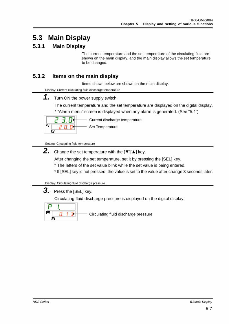
HRX-OM-S004 Chapter 5 Display and setting of various functions
HRS Series 5.3Main Display 5-7
5.3 Main Display 5.3.1 Main Display
The current temperature and the set temperature of the circulating fluid are shown on the main display, and the main display allows the set temperature to be changed.
5.3.2 Items on the main display
Items shown below are shown on the main display.
Display: Current circulating fluid discharge temperature
1. Turn ON the power supply switch.
The current temperature and the set temperature are displayed on the digital display.
* “Alarm menu” screen is displayed when any alarm is generated. (See “5.4”)
Setting: Circulating fluid temperature
2. Change the set temperature with the [▼][▲] key.
After changing the set temperature, set it by pressing the [SEL] key.
* The letters of the set value blink while the set value is being entered.
* If [SEL] key is not pressed, the value is set to the value after change 3 seconds later.
Display: Circulating fluid discharge pressure
3. Press the [SEL] key.
Circulating fluid discharge pressure is displayed on the digital display.
PV
SV
PV
SV
Current discharge temperature
Set Temperature
Circulating fluid discharge pressure
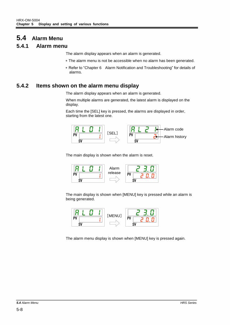
HRX-OM-S004 Chapter 5 Display and setting of various functions
5.4 Alarm Menu HRS Series 5-8
5.4 Alarm Menu
5.4.1 Alarm menu
The alarm display appears when an alarm is generated.
The alarm menu is not be accessible when no alarm has been generated.
Refer to “Chapter 6 Alarm Notification and Troubleshooting” for details of alarms.
5.4.2 Items shown on the alarm menu display
The alarm display appears when an alarm is generated.
When multiple alarms are generated, the latest alarm is displayed on the display.
Each time the [SEL] key is pressed, the alarms are displayed in order, starting from the latest one.
The main display is shown when the alarm is reset.
The main display is shown when [MENU] key is pressed while an alarm is being generated.
The alarm menu display is shown when [MENU] key is pressed again.
PV
SV
PV
SV
PV
SV
PV
SV
PV
SV
PV
SV
Alarm code
Alarm history [SEL]
[MENU]
Alarm release
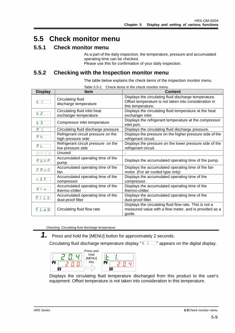
HRX-OM-S004 Chapter 5 Display and setting of various functions
HRS Series 5.5Check monitor menu 5-9
5.5 Check monitor menu 5.5.1 Check monitor menu
As a part of the daily inspection, the temperature, pressure and accumulated operating time can be checked. Please use this for confirmation of your daily inspection.
5.5.2 Checking with the Inspection monitor menu
The table below explains the check items of the inspection monitor menu. Table 5.5-1 Check items in the check monitor menu
Display Item Content
Circulating fluid discharge temperature
Displays the circulating fluid discharge temperature. Offset temperature is not taken into consideration in this temperature.
Circulating fluid inlet heat exchanger temperature
Displays the circulating fluid temperature at the heat exchanger inlet.
Compressor inlet temperature Displays the refrigerant temperature at the compressor inlet port.
Circulating fluid discharge pressure Displays the circulating fluid discharge pressure.
Refrigerant circuit pressure on the high pressure side
Displays the pressure on the higher pressure side of the refrigerant circuit.
Refrigerant circuit pressure on the low pressure side
Displays the pressure on the lower pressure side of the refrigerant circuit.
Unused -
Accumulated operating time of the pump
Displays the accumulated operating time of the pump.
Accumulated operating time of the fan
Displays the accumulated operating time of the fan motor. (For air cooled type only)
Accumulated operating time of the compressor
Displays the accumulated operating time of the compressor.
Accumulated operating time of the thermo-chiller
Displays the accumulated operating time of the thermo-chiller.
Accumulated operating time of the dust-proof filter
Displays the accumulated operating time of the dust-proof filter.
Circulating fluid flow rate Displays the circulating fluid flow rate. This is not a measured value with a flow meter, and is provided as a guide.
Checking: Circulating fluid discharge temperature
1. Press and hold the [MENU] button for approximately 2 seconds.
Circulating fluid discharge temperature display ” ” appears on the digital display.
Displays the circulating fluid temperature discharged from this product to the user's equipment. Offset temperature is not taken into consideration in this temperature.
PV
SV
PV
SV
Press and hold
[MENU] key
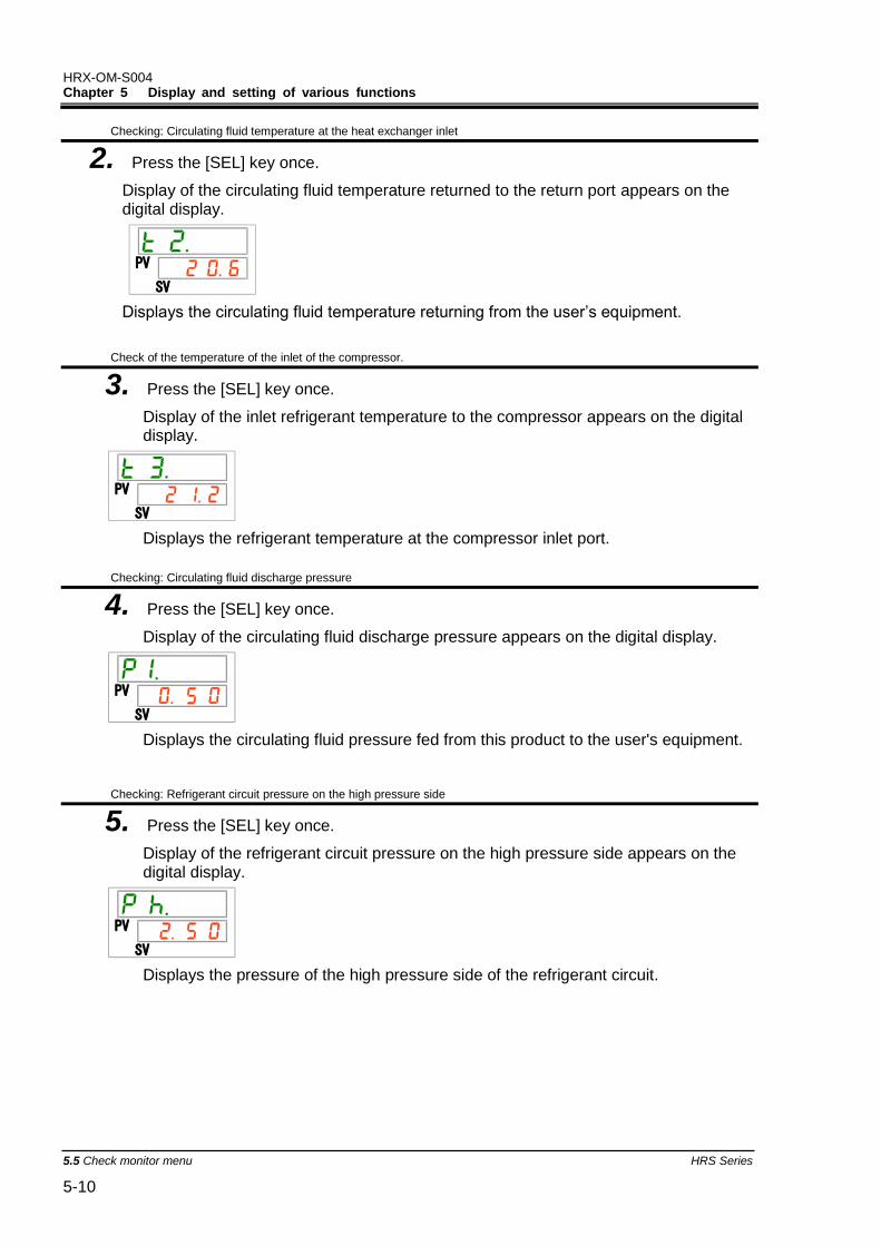
HRX-OM-S004 Chapter 5 Display and setting of various functions
5.5 Check monitor menu HRS Series 5-10
Checking: Circulating fluid temperature at the heat exchanger inlet
2. Press the [SEL] key once.
Display of the circulating fluid temperature returned to the return port appears on the digital display.
Displays the circulating fluid temperature returning from the user’s equipment.
Check of the temperature of the inlet of the compressor.
3. Press the [SEL] key once.
Display of the inlet refrigerant temperature to the compressor appears on the digital display.
Displays the refrigerant temperature at the compressor inlet port.
Checking: Circulating fluid discharge pressure
4. Press the [SEL] key once.
Display of the circulating fluid discharge pressure appears on the digital display.
Displays the circulating fluid pressure fed from this product to the user's equipment.
Checking: Refrigerant circuit pressure on the high pressure side
5. Press the [SEL] key once.
Display of the refrigerant circuit pressure on the high pressure side appears on the digital display.
Displays the pressure of the high pressure side of the refrigerant circuit.
PV
SV
PV
SV
PV
SV
PV
SV

HRX-OM-S004 Chapter 5 Display and setting of various functions
HRS Series 5.5Check monitor menu 5-11
Checking: Refrigerant circuit pressure on the low pressure side
6. Press the [SEL] key once.
Display of the refrigerant circuit pressure on the low pressure side appears on the digital display.
Checking: Accumulated operating time of the pump
7. Press the [SEL] key once.
Display of the accumulated operating time of the pump appears on the digital display.
Refer to the table below for details of the display.
Table 5.5-2 Time display
Accumulated time Displayed value
0h to 999h to
1,000h to 99,999h to
100,000h Return to
AL28 Pump maintenance alarm is generated when the accumulated operating time of the
pump reaches 8,000 hours ( ) (when set to “A.RUN”). For more details, refer to “Chapter 6 Alarm Notification and Troubleshooting”.
Checking: Accumulated operating time of the fan
8. Press the [SEL] key once.
Display of the accumulated operating time of the fan appears on the digital display.
Refer to “Table 5.5-2” for the display. AL29 Fan maintenance alarm is generated when the accumulated operating time of
the fan motor reaches 30,000 hours ( ) (when set to “A.RUN”). For details, refer to “Chapter 6 Alarm Notification and Troubleshooting”.
PV
SV
PV
SV
PV
SV

HRX-OM-S004 Chapter 5 Display and setting of various functions
5.5 Check monitor menu HRS Series 5-12
Checking: Accumulated operating time of the compressor
9. Press the [SEL] key once.
Display of the accumulated operating time of the compressor appears on the digital display.
Refer to “Table 5.5-2” for the display. AL30 Compressor maintenance alarm is generated when the accumulated operating
time of the compressor reaches 30,000 hours ( ) (when set to “A.RUN”). For more details, refer to “Chapter 6 Alarm Notification and Troubleshooting”.
Checking: Accumulated operating time of the thermo-chiller
10. Press the [SEL] key once.
The accumulated operating time of the thermo-chiller appears on the digital display.
Refer to “Table 5.5-2” for the display.
Checking: Accumulated operating time of the dust-proof filter
11. Press the [SEL] key once.
Display of the accumulated operating time of the dust-proof filter appears on the digital display.
Refer to “Table 5.5-2” for the display.
AL40 Dust-proof filter maintenance alarm is generated when the accumulated
operating time of the dust-proof filter reaches 500 hours ( ) (when set to “A.RUN”). For more details, refer to “Chapter 6 Alarm Notification and
Troubleshooting”.
Checking: Circulating fluid flow rate
12. Press the [SEL] key once.
Display of the circulating fluid flow rate appears on the digital display.
Circulating fluid flow rate of this product is displayed as a guide. Unit: L/min.
This is not a measured value, and is provided as a guide.
PV
SV
PV
SV
PV
SV
PV
SV
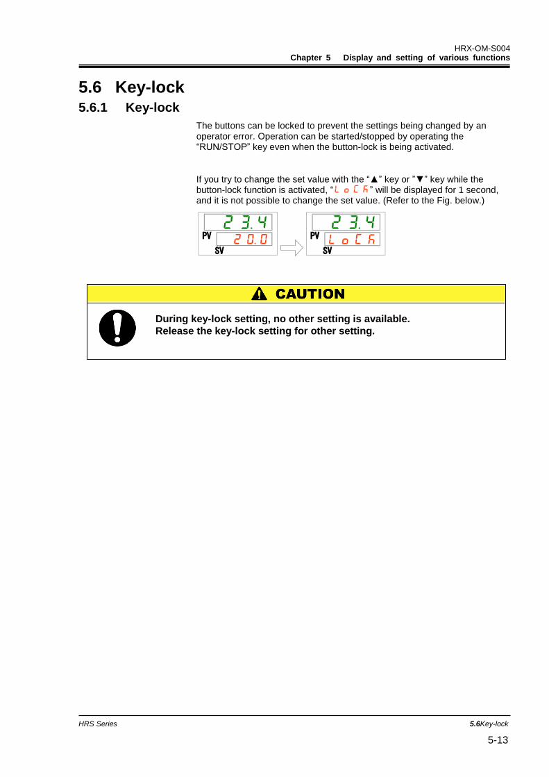
HRX-OM-S004 Chapter 5 Display and setting of various functions
HRS Series 5.6Key-lock 5-13
5.6 Key-lock 5.6.1 Key-lock
The buttons can be locked to prevent the settings being changed by an operator error. Operation can be started/stopped by operating the “RUN/STOP” key even when the button-lock is being activated.
If you try to change the set value with the “▲” key or ”▼” key while the button-lock function is activated, “ ” will be displayed for 1 second, and it is not possible to change the set value. (Refer to the Fig. below.)
PV
SV
PV
SV
During key-lock setting, no other setting is available.
Release the key-lock setting for other setting.
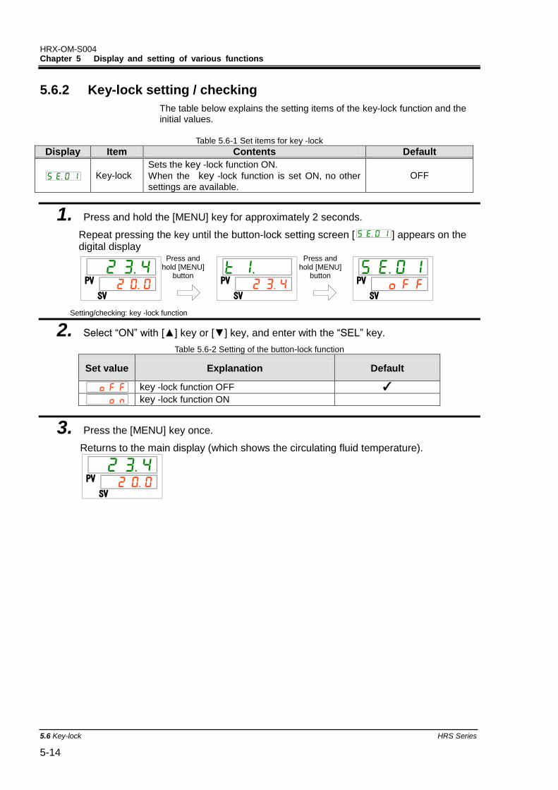
HRX-OM-S004 Chapter 5 Display and setting of various functions
5.6 Key-lock HRS Series 5-14
5.6.2 Key-lock setting / checking
The table below explains the setting items of the key-lock function and the initial values.
Table 5.6-1 Set items for key -lock
Display Item Contents Default
Key-lock Sets the key -lock function ON.
When the key -lock function is set ON, no other
settings are available.
OFF
1. Press and hold the [MENU] key for approximately 2 seconds.
Repeat pressing the key until the button-lock setting screen [ ] appears on the digital display
Setting/checking: key -lock function
2. Select “ON” with [▲] key or [▼] key, and enter with the “SEL” key.
Table 5.6-2 Setting of the button-lock function
Set value Explanation Default
key -lock function OFF ✓
key -lock function ON
3. Press the [MENU] key once.
Returns to the main display (which shows the circulating fluid temperature).
PV
SV
PV
SV
PV
SV
PV
SV
Press and hold [MENU]
button
[MENU]
Press and hold
Press and hold [MENU]
button
HRX-OM-S004 Chapter 5 Display and setting of various functions
HRS Series 5.7Run timer, stop timer function 5-15
5.7 Run timer, stop timer function 5.7.1 Run timer and stop timer function
This function starts or stops operation of the product automatically when the set time has passed. The time can be set according to the user’s working hours. Set the circulating fluid temperature in advance.
[Run timer] is a function to start operation after a set time. [Stop timer] is a function to stop operation after a set time. It is possible to set both [Run timer] and [Stop timer]. The set time of both the [Run timer] and [Stop timer] can be 99.5 hours at maximum, in 0.5 hour units.
[When communication is used]
If the communication mode is DIO REMOTE or SERIAL mode, this function does not operate. DIO REMOTE and SERIAL mode operation/stop signals have priority.
●Run timer
・Run timer starts operation after the set time.
If the thermo-chiller is already operating or the pump is operating independently, this function does not operate even when the set time has passed.
Operation can start when the product condition is normal and there is no alarm generated.
・The [ ] light turns ON when the run timer is set. The [ ] light is turned
OFF when the operation is started by the run timer.
The [ ] light does not turn OFF while the stop timer is being activated.
・The run timer setting is reset when the main power supply is cut or a
power failure occurs. Please set it again.
●Stop timer
・The [ ]light turns ON when the stop timer is set. The [ ] light turns
OFF when the operation is stopped by the stop timer.
The [ ] light does not turn OFF while the run timer is being activated・The
stop timer setting is reset when the main power supply is stopped or a power failure occurs. Please set it again.
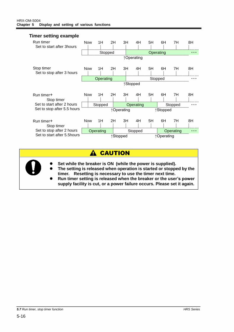
HRX-OM-S004 Chapter 5 Display and setting of various functions
5.7 Run timer, stop timer function HRS Series 5-16
Timer setting example
Run timer Set to start after 3hours
Now 1H 2H 3H 4H 5H 6H 7H 8H
Stopped Operating ・・・
↑Operating
Stop timer Set to stop after 3 hours
Now 1H 2H 3H 4H 5H 6H 7H 8H
Operating Stopped ・・・
↑Stopped
Run timer+
Stop timer Set to start after 2 hours Set to stop after 5.5 hours
Now 1H 2H 3H 4H 5H 6H 7H 8H
Stopped Operating Stopped ・・・
↑Operating ↑Stopped
Run timer+
Stop timer Set to stop after 2 hours Set to start after 5.5hours
Now 1H 2H 3H 4H 5H 6H 7H 8H
Operating Stopped Operating ・・・
↑Stopped ↑Operating
Set while the breaker is ON (while the power is supplied). The setting is released when operation is started or stopped by the
timer. Resetting is necessary to use the timer next time. Run timer setting is released when the breaker or the user’s power
supply facility is cut, or a power failure occurs. Please set it again.
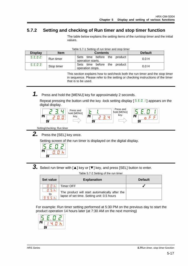
HRX-OM-S004 Chapter 5 Display and setting of various functions
HRS Series 5.7Run timer, stop timer function 5-17
5.7.2 Setting and checking of Run timer and stop timer function
The table below explains the setting items of the run/stop timer and the initial values.
Table 5.7-1 Setting of run timer and stop timer
Display Item Contents Default
Run timer Sets time before the product operation starts.
0.0 H
Stop timer Sets time before the product operation stops.
0.0 H
This section explains how to set/check both the run timer and the stop timer in sequence. Please refer to the setting or checking instructions of the timer that is to be used.
1. Press and hold the [MENU] key for approximately 2 seconds.
Repeat pressing the button until the key -lock setting display [ ] appears on the digital display.
Setting/checking: Run timer
2. Press the [SEL] key once.
Setting screen of the run timer is displayed on the digital display.
3. Select run timer with [▲] key or [▼] key, and press [SEL] button to enter.
Table 5.7-2 Setting of the run timer
Set value Explanation Default
Timer OFF ✓
to
The product will start automatically after the lapse of set time. Setting unit: 0.5 hours
For example: Run timer setting performed at 5:30 PM on the previous day to start the product operation 14 hours later (at 7:30 AM on the next morning)
PV
SV
PV
SV
PV
SV
PV
SV
PV
SV
Press and
hold [MENU] key.
Press and hold [MENU]
key.
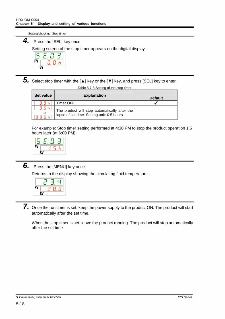
HRX-OM-S004 Chapter 5 Display and setting of various functions
5.7 Run timer, stop timer function HRS Series 5-18
Setting/checking: Stop timer
4. Press the [SEL] key once.
Setting screen of the stop timer appears on the digital display.
5. Select stop timer with the [▲] key or the [▼] key, and press [SEL] key to enter.
Table 5.7-3 Setting of the stop timer
Set value Explanation
Default
Timer OFF ✓
to
The product will stop automatically after the lapse of set time. Setting unit: 0.5 hours
For example: Stop timer setting performed at 4:30 PM to stop the product operation 1.5 hours later (at 6:00 PM).
6. Press the [MENU] key once.
Returns to the display showing the circulating fluid temperature.
7. Once the run timer is set, keep the power supply to the product ON. The product will start
automatically after the set time.
When the stop timer is set, leave the product running. The product will stop automatically after the set time.
PV
SV
PV
SV
PV
SV
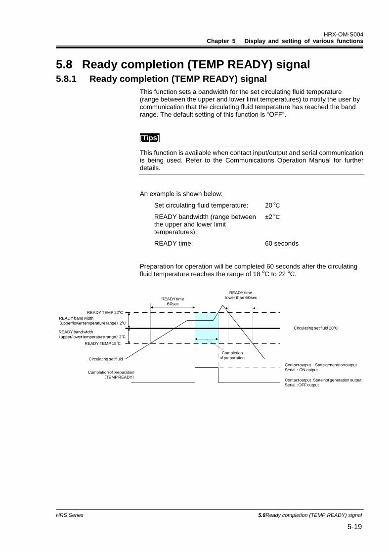
HRX-OM-S004 Chapter 5 Display and setting of various functions
HRS Series 5.8Ready completion (TEMP READY) signal 5-19
5.8 Ready completion (TEMP READY) signal 5.8.1 Ready completion (TEMP READY) signal
This function sets a bandwidth for the set circulating fluid temperature (range between the upper and lower limit temperatures) to notify the user by communication that the circulating fluid temperature has reached the band range. The default setting of this function is “OFF”.
[Tips]
This function is available when contact input/output and serial communication is being used. Refer to the Communications Operation Manual for further details.
An example is shown below:
Set circulating fluid temperature: 20 oC
READY bandwidth (range between the upper and lower limit temperatures):
±2 oC
READY time: 60 seconds
Preparation for operation will be completed 60 seconds after the circulating fluid temperature reaches the range of 18
oC to 22
oC.
Circulating set fluid 20℃
READY TEMP 22℃
READY TEMP 18℃
READY band width
(upper/lower temperature range) 2℃
READY band width
(upper/lower temperature range) 2℃
Circulating set fluid
READY time
60sec
Completion
of preparation
READY time
lower than 60sec
Contact output:State generation output
Serial:ON output
Contact output:State not generation output
Serial :OFF output
Completion of preparation
(TEMP READY)
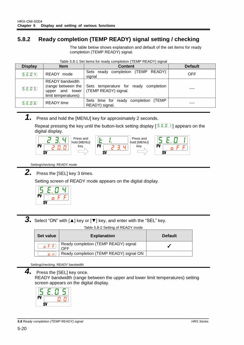
HRX-OM-S004 Chapter 5 Display and setting of various functions
5.8 Ready completion (TEMP READY) signal HRS Series 5-20
5.8.2 Ready completion (TEMP READY) signal setting / checking
The table below shows explanation and default of the set items for ready completion (TEMP READY) signal.
Table 5.8-1 Set items for ready completion (TEMP READY) signal
Display Item Content Default
READY mode Sets ready completion (TEMP READY) signal
OFF
READY bandwidth (range between the upper and lower limit temperatures)
Sets temperature for ready completion (TEMP READY) signal.
----
READY time Sets time for ready completion (TEMP READY) signal.
----
1. Press and hold the [MENU] key for approximately 2 seconds.
Repeat pressing the key until the button-lock setting display [ ] appears on the digital display.
Setting/checking: READY mode
2. Press the [SEL] key 3 times.
Setting screen of READY mode appears on the digital display.
3. Select “ON” with [▲] key or [▼] key, and enter with the “SEL” key.
Table 5.8-2 Setting of READY mode
Set value Explanation Default
Ready completion (TEMP READY) signal OFF
✓
Ready completion (TEMP READY) signal ON
Setting/checking: READY bandwidth
4. Press the [SEL] key once. READY bandwidth (range between the upper and lower limit temperatures) setting screen appears on the digital display.
PV
SV
PV
SV
PV
SV
PV
SV
PV
SV
Press and hold [MENU]
key.
Press and hold [MENU]
key.
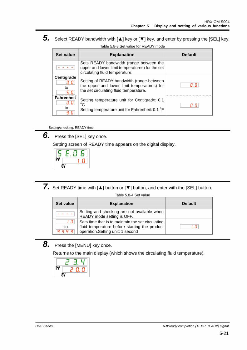
HRX-OM-S004 Chapter 5 Display and setting of various functions
HRS Series 5.8Ready completion (TEMP READY) signal 5-21
5. Select READY bandwidth with [▲] key or [▼] key, and enter by pressing the [SEL] key.
Table 5.8-3 Set value for READY mode
Set value Explanation Default
Sets READY bandwidth (range between the upper and lower limit temperatures) for the set circulating fluid temperature.
Centigrade
to
Setting of READY bandwidth (range between the upper and lower limit temperatures) for the set circulating fluid temperature. Setting temperature unit for Centigrade: 0.1 oC
Setting temperature unit for Fahrenheit: 0.1 oF
Fahrenheit
to
Setting/checking: READY time
6. Press the [SEL] key once.
Setting screen of READY time appears on the digital display.
7. Set READY time with [▲] button or [▼] button, and enter with the [SEL] button.
Table 5.8-4 Set value
Set value Explanation Default
Setting and checking are not available when READY mode setting is OFF.
to
Sets time that is to maintain the set circulating fluid temperature before starting the product operation.Setting unit: 1 second
8. Press the [MENU] key once.
Returns to the main display (which shows the circulating fluid temperature).
PV
SV
PV
SV
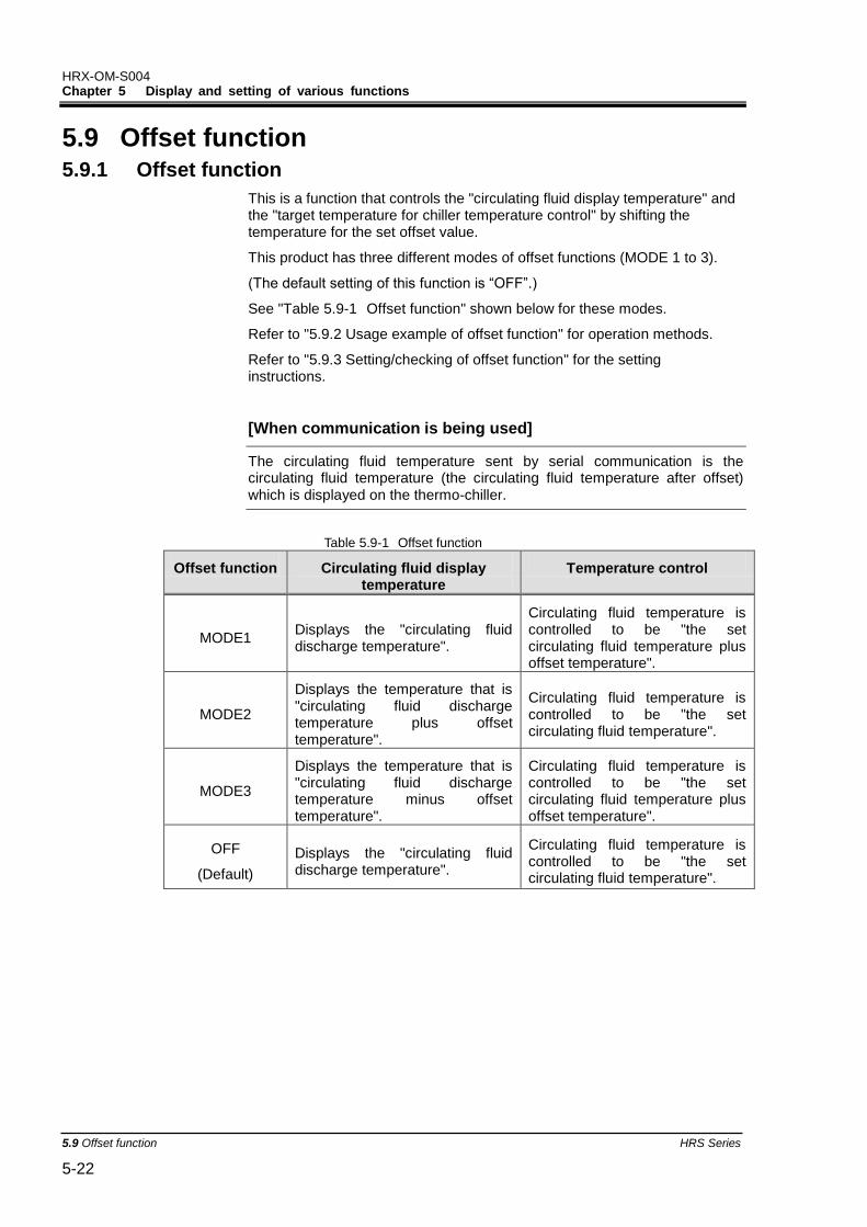
HRX-OM-S004 Chapter 5 Display and setting of various functions
5.9 Offset function HRS Series 5-22
5.9 Offset function 5.9.1 Offset function
This is a function that controls the "circulating fluid display temperature" and the "target temperature for chiller temperature control" by shifting the temperature for the set offset value.
This product has three different modes of offset functions (MODE 1 to 3).
(The default setting of this function is “OFF”.)
See "Table 5.9-1 Offset function" shown below for these modes.
Refer to "5.9.2 Usage example of offset function" for operation methods.
Refer to "5.9.3 Setting/checking of offset function" for the setting instructions.
[When communication is being used]
The circulating fluid temperature sent by serial communication is the circulating fluid temperature (the circulating fluid temperature after offset) which is displayed on the thermo-chiller.
Table 5.9-1 Offset function
Offset function Circulating fluid display temperature
Temperature control
MODE1 Displays the "circulating fluid discharge temperature".
Circulating fluid temperature is controlled to be "the set circulating fluid temperature plus offset temperature".
MODE2
Displays the temperature that is "circulating fluid discharge temperature plus offset temperature".
Circulating fluid temperature is controlled to be "the set circulating fluid temperature".
MODE3
Displays the temperature that is "circulating fluid discharge temperature minus offset temperature".
Circulating fluid temperature is controlled to be "the set circulating fluid temperature plus offset temperature".
OFF
(Default)
Displays the "circulating fluid discharge temperature".
Circulating fluid temperature is controlled to be "the set circulating fluid temperature".
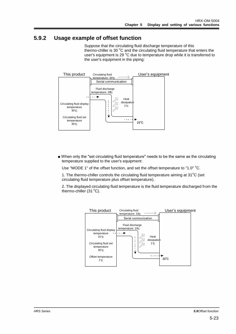
HRX-OM-S004 Chapter 5 Display and setting of various functions
HRS Series 5.9Offset function 5-23
5.9.2 Usage example of offset function
Suppose that the circulating fluid discharge temperature of this thermo-chiller is 30
oC and the circulating fluid temperature that enters the
user's equipment is 29 oC due to temperature drop while it is transferred to
the user's equipment in the piping:
■ When only the "set circulating fluid temperature" needs to be the same as the circulating temperature supplied to the user's equipment:
Use "MODE 1" of the offset function, and set the offset temperature to "1.0" oC.
1. The thermo-chiller controls the circulating fluid temperature aiming at 31oC (set
circulating fluid temperature plus offset temperature).
2. The displayed circulating fluid temperature is the fluid temperature discharged from the thermo-chiller (31
oC).
Circulating fluid display temperature
31 ℃
Circulating fluid set temperature
30 ℃
Offset temperature 1 ℃
This product User’s equipment
Serial communication
Fluid discharge temperature: 31 ℃
30℃
Circulating fluid temperature: 31 ℃
Heat dissipation
1 ℃
Circulating fluid display temperature
30 ℃
Circulating fluid set temperature
30 ℃
This product User’s equipment
Serial communication
Fluid discharge temperature: 30 ℃
Heat dissipation
1 ℃
29℃
Circulating fluid temperature: 30 ℃

HRX-OM-S004 Chapter 5 Display and setting of various functions
5.9 Offset function HRS Series 5-24
■ When only the "displayed circulating fluid temperature" needs to be the same as the circulating temperature supplied to the user's equipment:
Use "MODE 2" of the offset function, and set the offset temperature to "-1.0" oC.
1. The thermo-chiller controls the circulating fluid temperature aiming at 30oC (set
circulating fluid temperature).
2. 29 oC (the actual fluid temperature of 30
oC minus the offset temperature of 1
oC) will
be displayed as the circulating fluid temperature.
■ When both the "set circulating fluid temperature" and the "displayed circulating fluid temperature" need to be the same as the circulating temperature supplied to the user's equipment:
Use "MODE 3" of the offset function, and set the offset temperature to "1.0" oC.
1. The thermo-chiller controls the circulating fluid temperature aiming at 31oC (set
circulating fluid temperature plus offset temperature).
2. The displayed circulating fluid temperature is the fluid temperature discharged from the thermo-chiller (31
oC minus the offset temperature).
Circulating fluid display temperature
29 ℃
Circulating fluid set temperature
30 ℃
Offset temperature -1 ℃
This product User’s equipment
Serial communication
Fluid discharge temperature: 30 ℃
29℃
Circulating fluid temperature: 29 ℃
Heat dissipation
1 ℃
Circulating fluid display temperature
30 ℃
Circulating fluid set temperature
30 ℃
Offset temperature 1 ℃
This product User’s equipment
Serial communication
Fluid discharge temperature: 31 ℃
30℃
Circulating fluid temperature: 30 ℃
Heat dissipation
1 ℃
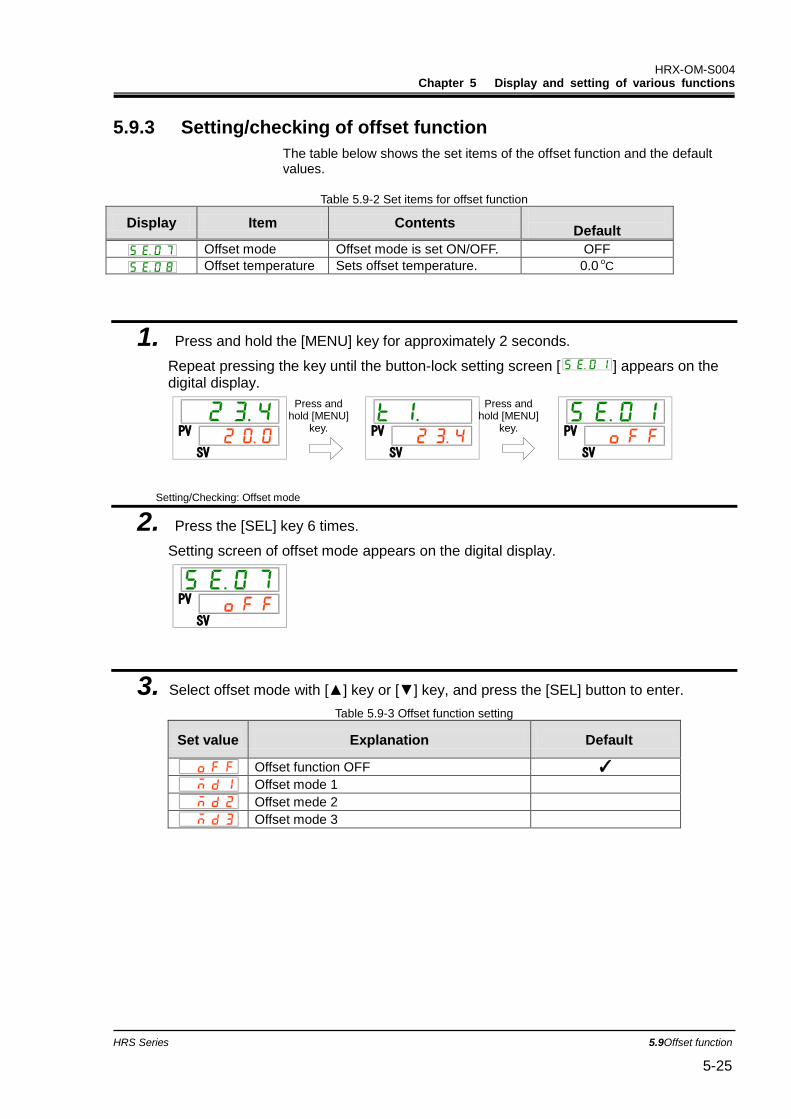
HRX-OM-S004 Chapter 5 Display and setting of various functions
HRS Series 5.9Offset function 5-25
5.9.3 Setting/checking of offset function
The table below shows the set items of the offset function and the default values.
Table 5.9-2 Set items for offset function
Display Item Contents
Default
Offset mode Offset mode is set ON/OFF. OFF
Offset temperature Sets offset temperature. 0.0 oC
1. Press and hold the [MENU] key for approximately 2 seconds.
Repeat pressing the key until the button-lock setting screen [ ] appears on the digital display.
Setting/Checking: Offset mode
2. Press the [SEL] key 6 times.
Setting screen of offset mode appears on the digital display.
3. Select offset mode with [▲] key or [▼] key, and press the [SEL] button to enter.
Table 5.9-3 Offset function setting
Set value Explanation Default
Offset function OFF ✓
Offset mode 1
Offset mede 2
Offset mode 3
PV
SV
PV
SV
PV
SV
PV
SV
Press and hold [MENU]
key.
Press and hold [MENU]
key.
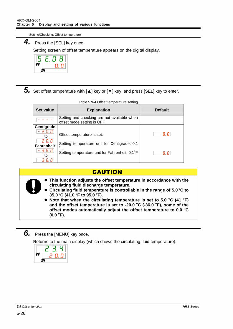
HRX-OM-S004 Chapter 5 Display and setting of various functions
5.9 Offset function HRS Series 5-26
Setting/Checking: Offset temperature
4. Press the [SEL] key once.
Setting screen of offset temperature appears on the digital display.
5. Set offset temperature with [▲] key or [▼] key, and press [SEL] key to enter.
Table 5.9-4 Offset temperature setting
Set value Explanation Default
Setting and checking are not available when offset mode setting is OFF.
Centigrade
to
Offset temperature is set. Setting temperature unit for Centigrade: 0.1 oC
Setting temperature unit for Fahrenheit: 0.1oF
Fahrenheit
to
6. Press the [MENU] key once.
Returns to the main display (which shows the circulating fluid temperature).
PV
SV
PV
SV
This function adjusts the offset temperature in accordance with the circulating fluid discharge temperature.
Circulating fluid temperature is controllable in the range of 5.0 oC to 35.0 oC (41.0 oF to 95.0 oF).
Note that when the circulating temperature is set to 5.0 oC (41 oF) and the offset temperature is set to -20.0 oC (-36.0 oF), some of the offset modes automatically adjust the offset temperature to 0.0 oC
(0.0 oF).
HRX-OM-S004 Chapter 5 Display and setting of various functions
HRS Series 5.10Operation Restoration after Power Failure 5-27
5.10 Operation Restoration after Power Failure 5.10.1 Operation restoration function after power failure
When the power supply is cut due to power failure, etc., this function restarts the operation when the power supply restores, retaining the conditions before the power cut.
[When communication is being used]
If the communication mode is DIO REMOTE or SERIAL mode (MODBUS), this function does not operate. DIO REMOTE and SERIAL mode (MODBUS) operation/stop signals have priority.
The [ ] light turns ON when the operation restoration function is set. The default setting of this function is “OFF”. (AL41 “Power stoppage” alarm does not occur.)
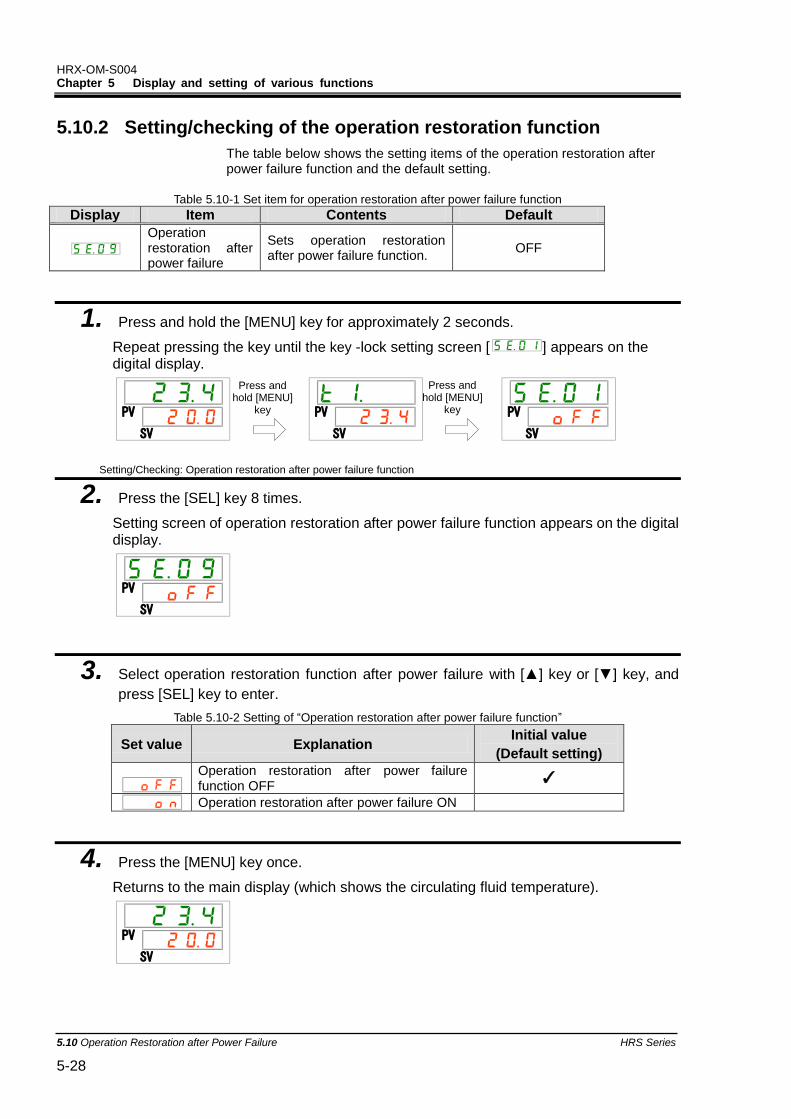
HRX-OM-S004 Chapter 5 Display and setting of various functions
5.10 Operation Restoration after Power Failure HRS Series 5-28
5.10.2 Setting/checking of the operation restoration function
The table below shows the setting items of the operation restoration after power failure function and the default setting.
Table 5.10-1 Set item for operation restoration after power failure function
Display Item Contents Default
Operation restoration after power failure
Sets operation restoration after power failure function.
OFF
1. Press and hold the [MENU] key for approximately 2 seconds.
Repeat pressing the key until the key -lock setting screen [ ] appears on the digital display.
Setting/Checking: Operation restoration after power failure function
2. Press the [SEL] key 8 times.
Setting screen of operation restoration after power failure function appears on the digital display.
3. Select operation restoration function after power failure with [▲] key or [▼] key, and
press [SEL] key to enter.
Table 5.10-2 Setting of “Operation restoration after power failure function”
Set value Explanation Initial value
(Default setting)
Operation restoration after power failure function OFF
✓
Operation restoration after power failure ON
4. Press the [MENU] key once.
Returns to the main display (which shows the circulating fluid temperature).
PV
SV
PV
SV
PV
SV
PV
SV
PV
SV
Press and hold [MENU]
key
Press and hold [MENU]
key
HRX-OM-S004 Chapter 5 Display and setting of various functions
HRS Series 5.11Anti-freezing function 5-29
5.11 Anti-freezing function 5.11.1 Anti-freezing function
This function prevents freezing of the circulating fluid while the product stops operation in the winter season with heat generated by automatically operating the pump.
When there is a possibility of the circulating fluid freezing due to changes in the installation or operating environment (e.g. season, weather), set this function ON in advance.
If the circulating fluid temperature falls down to 3 oC or less, the
pump starts operation automatically.
Heat generated by the pump operation warms up the circulating fluid. When the circulating fluid temperature reaches 5 o
C or higher, the pump stops operation automatically.
Repeated automatic operation start and stop of the pump maintains the circulating fluid temperature to 3
oC to 3
oC to prevent
the circulating fluid from being frozen.
When the anti-freezing function is set ON, the [RUN] light blinks every 2 seconds while the pump is in the standby state (while the pump stops operation). The [RUN] light blinks every 0.3 seconds during the automatic operation of the pump. The default setting of this function is “OFF”.
This function does not prevent the automatic water fill circuit from being frozen. Countermeasures against freezing of the automatic water fill circuit should be taken with the user's equipment.
Note that when the warming up function is ON, the warming up function has a priority over the anti-freezing function, and the anti-freezing function will not be activated. (See “5.17 Warming up function”)
Keep the power supply ON for this function. This function does not
start when the power is OFF.
HRX-OM-S004 Chapter 5 Display and setting of various functions
5.11 Anti-freezing function HRS Series 5-30
This function can be activated only when the power supply is ON and the thermo-chiller is not operating.
Fully open the valve or manual bypass valve that is arranged by the user to make it possible for the circulating fluid to circulate when the pump starts automatic operation.
In extremely cold weather, the heat generated by the pump operation may not be enough to prevent freezing of the circulating fluid.
During the automatic operation, the pump does not stop even if the "RUN/STOP" button is pressed. To stop the pump, turn the power supply OFF or turn this function OFF.
This function does not prevent the automatic water fill circuit from being frozen. Countermeasures against freezing of the automatic
water fill circuit should be taken with the user's equipment.
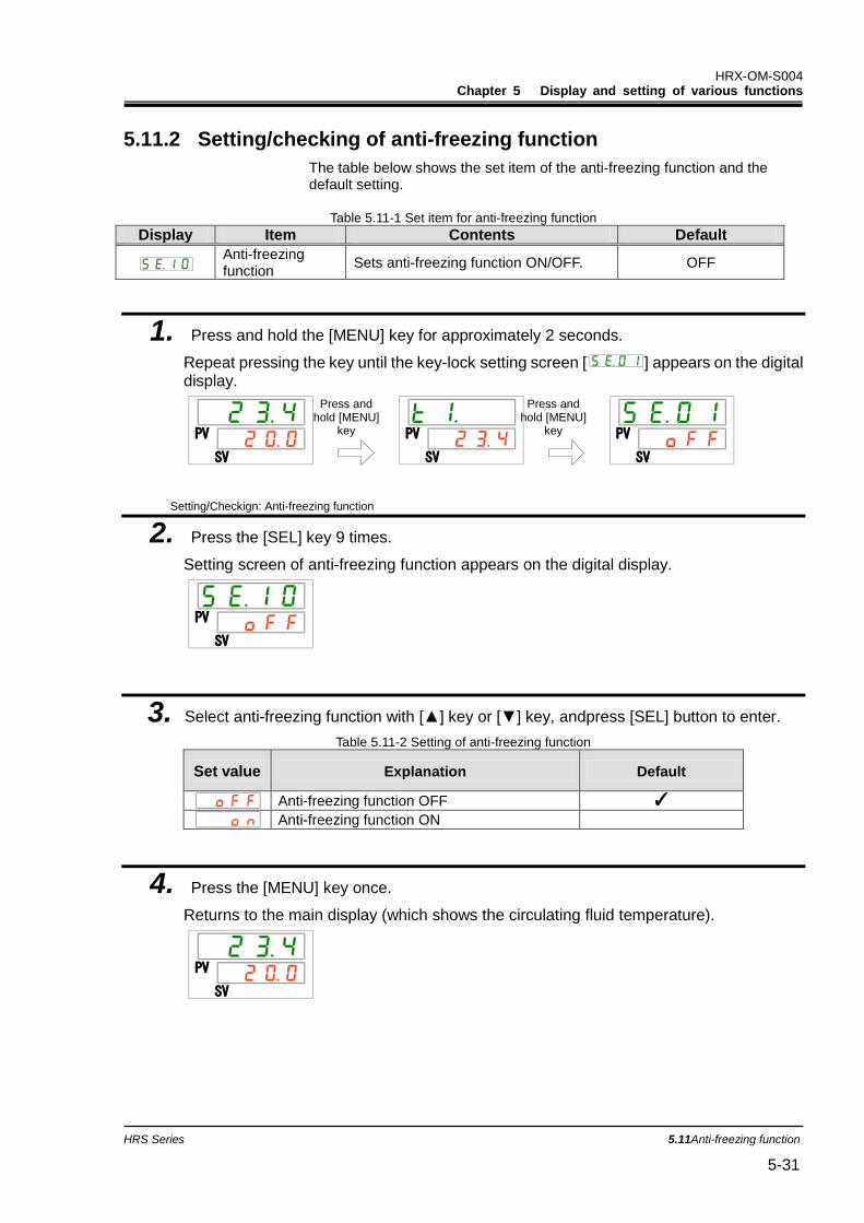
HRX-OM-S004 Chapter 5 Display and setting of various functions
HRS Series 5.11Anti-freezing function 5-31
5.11.2 Setting/checking of anti-freezing function
The table below shows the set item of the anti-freezing function and the default setting.
Table 5.11-1 Set item for anti-freezing function
Display Item Contents Default
Anti-freezing function
Sets anti-freezing function ON/OFF. OFF
1. Press and hold the [MENU] key for approximately 2 seconds.
Repeat pressing the key until the key-lock setting screen [ ] appears on the digital display.
Setting/Checkign: Anti-freezing function
2. Press the [SEL] key 9 times.
Setting screen of anti-freezing function appears on the digital display.
3. Select anti-freezing function with [▲] key or [▼] key, andpress [SEL] button to enter.
Table 5.11-2 Setting of anti-freezing function
Set value Explanation Default
Anti-freezing function OFF ✓
Anti-freezing function ON
4. Press the [MENU] key once.
Returns to the main display (which shows the circulating fluid temperature).
PV
SV
PV
SV
PV
SV
PV
SV
PV
SV
Press and hold [MENU]
key
Press and hold [MENU]
key
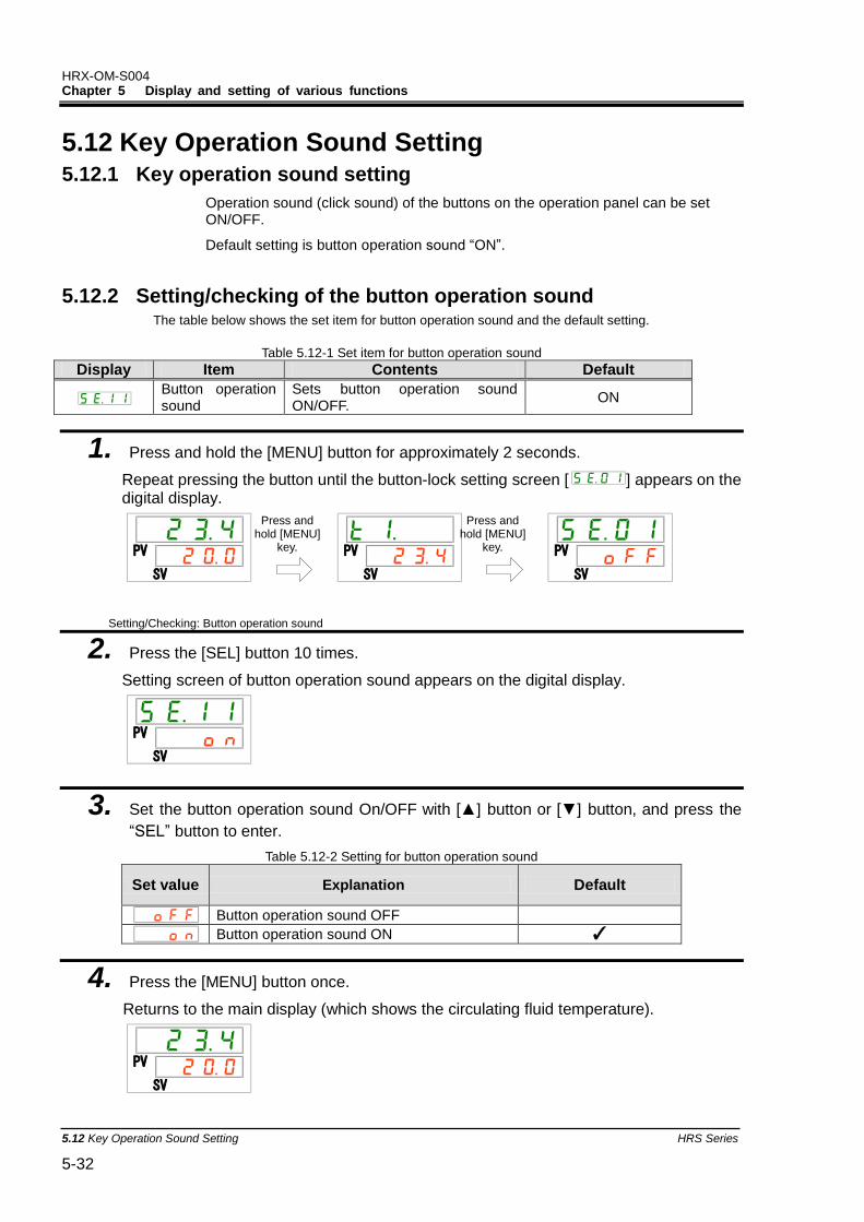
HRX-OM-S004 Chapter 5 Display and setting of various functions
5.12 Key Operation Sound Setting HRS Series 5-32
5.12 Key Operation Sound Setting 5.12.1 Key operation sound setting
Operation sound (click sound) of the buttons on the operation panel can be set ON/OFF.
Default setting is button operation sound “ON”.
5.12.2 Setting/checking of the button operation sound The table below shows the set item for button operation sound and the default setting.
Table 5.12-1 Set item for button operation sound
Display Item Contents Default
Button operation sound
Sets button operation sound ON/OFF.
ON
1. Press and hold the [MENU] button for approximately 2 seconds.
Repeat pressing the button until the button-lock setting screen [ ] appears on the digital display.
Setting/Checking: Button operation sound
2. Press the [SEL] button 10 times.
Setting screen of button operation sound appears on the digital display.
3. Set the button operation sound On/OFF with [▲] button or [▼] button, and press the
“SEL” button to enter.
Table 5.12-2 Setting for button operation sound
Set value Explanation Default
Button operation sound OFF
Button operation sound ON ✓
4. Press the [MENU] button once.
Returns to the main display (which shows the circulating fluid temperature).
PV
SV
PV
SV
PV
SV
PV
SV
PV
SV
Press and hold [MENU]
key.
Press and hold [MENU]
key.
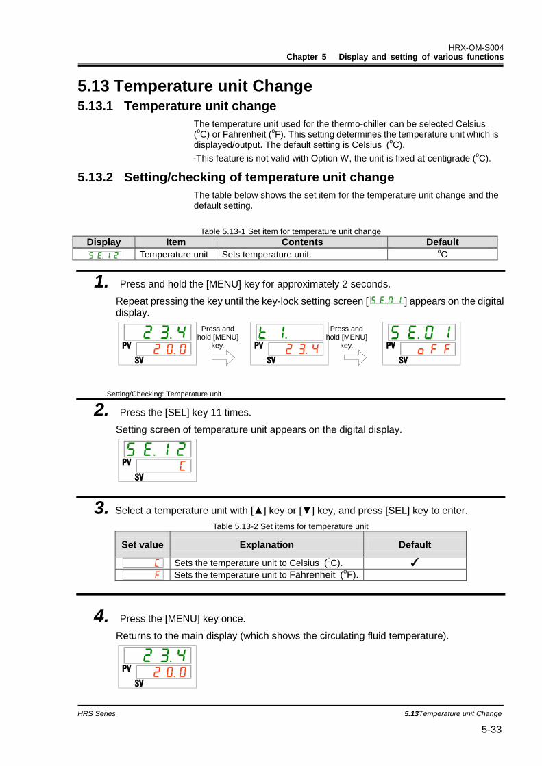
HRX-OM-S004 Chapter 5 Display and setting of various functions
HRS Series 5.13Temperature unit Change 5-33
5.13 Temperature unit Change 5.13.1 Temperature unit change
The temperature unit used for the thermo-chiller can be selected Celsius (oC) or Fahrenheit (
oF). This setting determines the temperature unit which is
displayed/output. The default setting is Celsius (oC).
-This feature is not valid with Option W, the unit is fixed at centigrade (oC).
5.13.2 Setting/checking of temperature unit change
The table below shows the set item for the temperature unit change and the default setting.
Table 5.13-1 Set item for temperature unit change
Display Item Contents Default
Temperature unit Sets temperature unit. oC
1. Press and hold the [MENU] key for approximately 2 seconds.
Repeat pressing the key until the key-lock setting screen [ ] appears on the digital display.
Setting/Checking: Temperature unit
2. Press the [SEL] key 11 times.
Setting screen of temperature unit appears on the digital display.
3. Select a temperature unit with [▲] key or [▼] key, and press [SEL] key to enter.
Table 5.13-2 Set items for temperature unit
Set value Explanation Default
Sets the temperature unit to Celsius (oC). ✓
Sets the temperature unit to Fahrenheit (oF).
4. Press the [MENU] key once.
Returns to the main display (which shows the circulating fluid temperature).
PV
SV
PV
SV
PV
SV
PV
SV
PV
SV
Press and hold [MENU]
key.
Press and hold [MENU]
key.
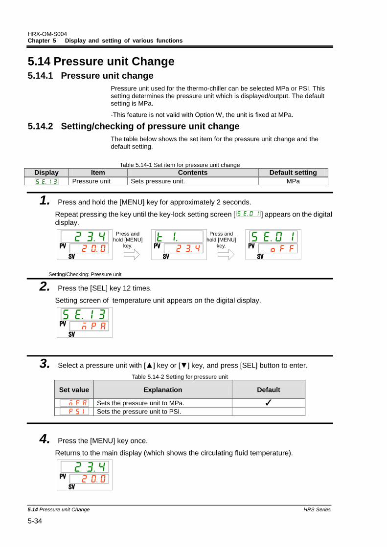
HRX-OM-S004 Chapter 5 Display and setting of various functions
5.14 Pressure unit Change HRS Series 5-34
5.14 Pressure unit Change 5.14.1 Pressure unit change
Pressure unit used for the thermo-chiller can be selected MPa or PSI. This setting determines the pressure unit which is displayed/output. The default setting is MPa.
-This feature is not valid with Option W, the unit is fixed at MPa.
5.14.2 Setting/checking of pressure unit change
The table below shows the set item for the pressure unit change and the default setting.
Table 5.14-1 Set item for pressure unit change
Display Item Contents Default setting
Pressure unit Sets pressure unit. MPa
1. Press and hold the [MENU] key for approximately 2 seconds.
Repeat pressing the key until the key-lock setting screen [ ] appears on the digital display.
Setting/Checking: Pressure unit
2. Press the [SEL] key 12 times.
Setting screen of temperature unit appears on the digital display.
3. Select a pressure unit with [▲] key or [▼] key, and press [SEL] button to enter.
Table 5.14-2 Setting for pressure unit
Set value Explanation Default
Sets the pressure unit to MPa. ✓
Sets the pressure unit to PSI.
4. Press the [MENU] key once.
Returns to the main display (which shows the circulating fluid temperature).
PV
SV
PV
SV
PV
SV
PV
SV
PV
SV
Press and hold [MENU]
key.
Press and hold [MENU]
key.
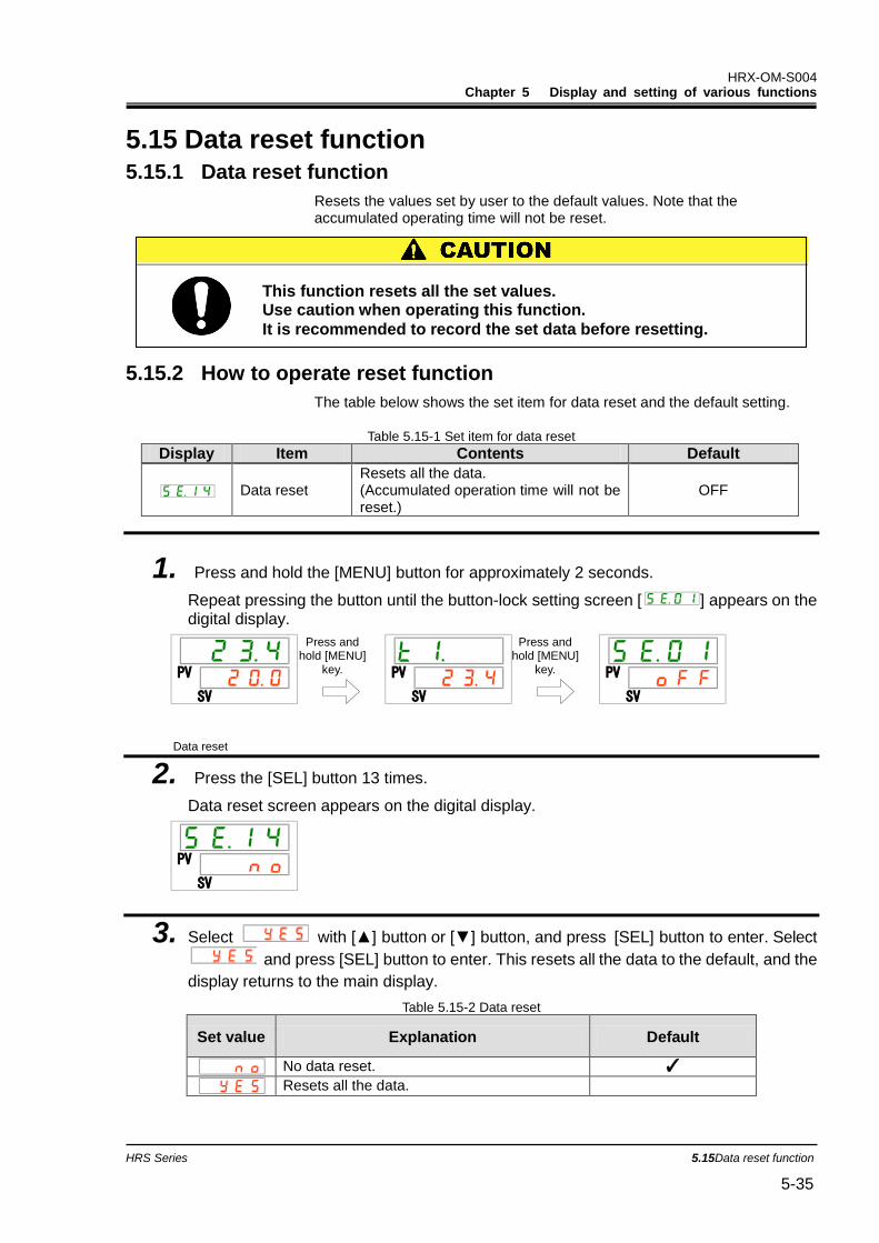
HRX-OM-S004 Chapter 5 Display and setting of various functions
HRS Series 5.15Data reset function 5-35
5.15 Data reset function 5.15.1 Data reset function
Resets the values set by user to the default values. Note that the accumulated operating time will not be reset.
5.15.2 How to operate reset function
The table below shows the set item for data reset and the default setting.
Table 5.15-1 Set item for data reset
Display Item Contents Default
Data reset Resets all the data. (Accumulated operation time will not be reset.)
OFF
1. Press and hold the [MENU] button for approximately 2 seconds.
Repeat pressing the button until the button-lock setting screen [ ] appears on the digital display.
Data reset
2. Press the [SEL] button 13 times.
Data reset screen appears on the digital display.
3. Select with [▲] button or [▼] button, and press [SEL] button to enter. Select
and press [SEL] button to enter. This resets all the data to the default, and the
display returns to the main display.
Table 5.15-2 Data reset
Set value Explanation Default
No data reset. ✓
Resets all the data.
PV
SV
PV
SV
PV
SV
PV
SV
Press and hold [MENU]
key.
Press and hold [MENU]
key.
This function resets all the set values. Use caution when operating this function.
It is recommended to record the set data before resetting.
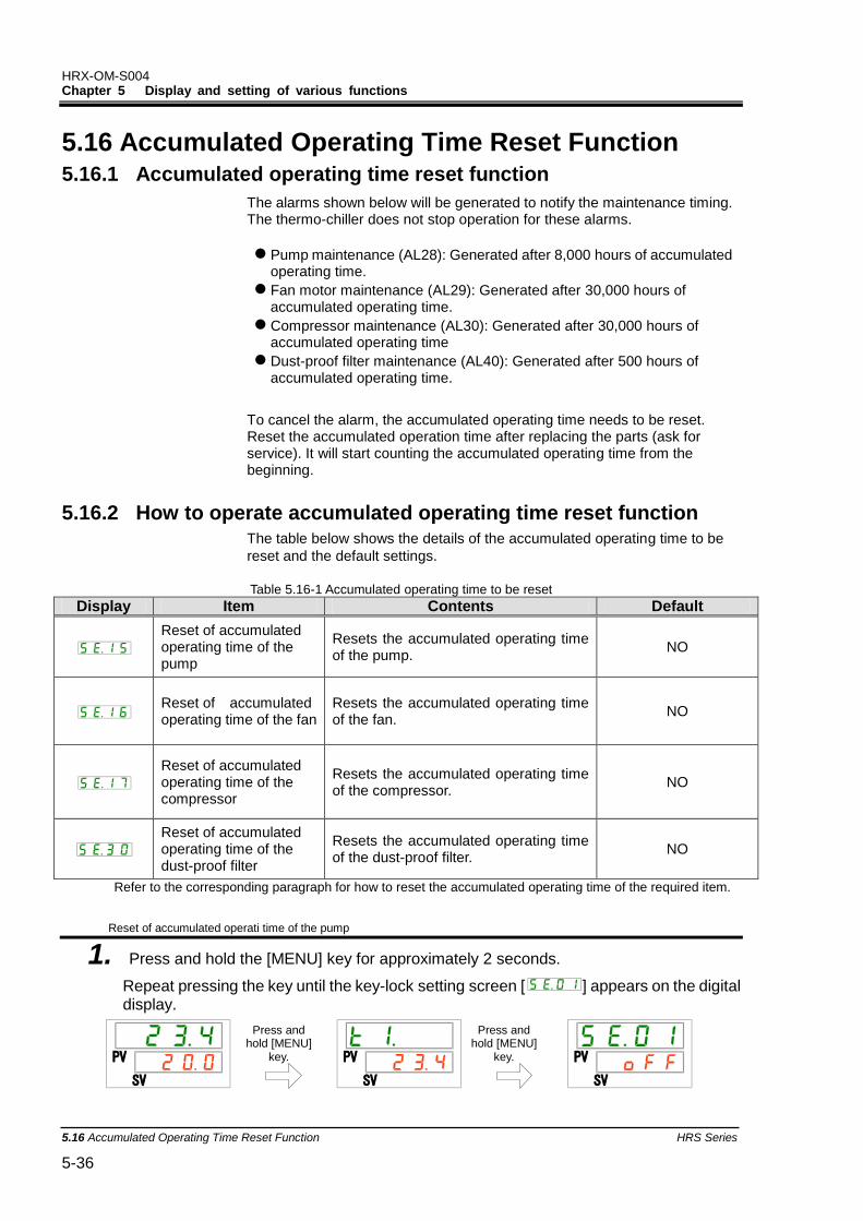
HRX-OM-S004 Chapter 5 Display and setting of various functions
5.16 Accumulated Operating Time Reset Function HRS Series 5-36
5.16 Accumulated Operating Time Reset Function 5.16.1 Accumulated operating time reset function
The alarms shown below will be generated to notify the maintenance timing. The thermo-chiller does not stop operation for these alarms.
Pump maintenance (AL28): Generated after 8,000 hours of accumulated operating time.
Fan motor maintenance (AL29): Generated after 30,000 hours of accumulated operating time.
Compressor maintenance (AL30): Generated after 30,000 hours of accumulated operating time
Dust-proof filter maintenance (AL40): Generated after 500 hours of accumulated operating time.
To cancel the alarm, the accumulated operating time needs to be reset. Reset the accumulated operation time after replacing the parts (ask for service). It will start counting the accumulated operating time from the beginning.
5.16.2 How to operate accumulated operating time reset function The table below shows the details of the accumulated operating time to be
reset and the default settings.
Table 5.16-1 Accumulated operating time to be reset
Display Item Contents Default
Reset of accumulated operating time of the pump
Resets the accumulated operating time of the pump.
NO
Reset of accumulated operating time of the fan
Resets the accumulated operating time of the fan.
NO
Reset of accumulated operating time of the compressor
Resets the accumulated operating time of the compressor.
NO
Reset of accumulated operating time of the dust-proof filter
Resets the accumulated operating time of the dust-proof filter.
NO
Refer to the corresponding paragraph for how to reset the accumulated operating time of the required item. Reset of accumulated operati time of the pump
1. Press and hold the [MENU] key for approximately 2 seconds.
Repeat pressing the key until the key-lock setting screen [ ] appears on the digital display.
PV
SV
PV
SV
PV
SV
Press and hold [MENU]
key.
Press and hold [MENU]
key.
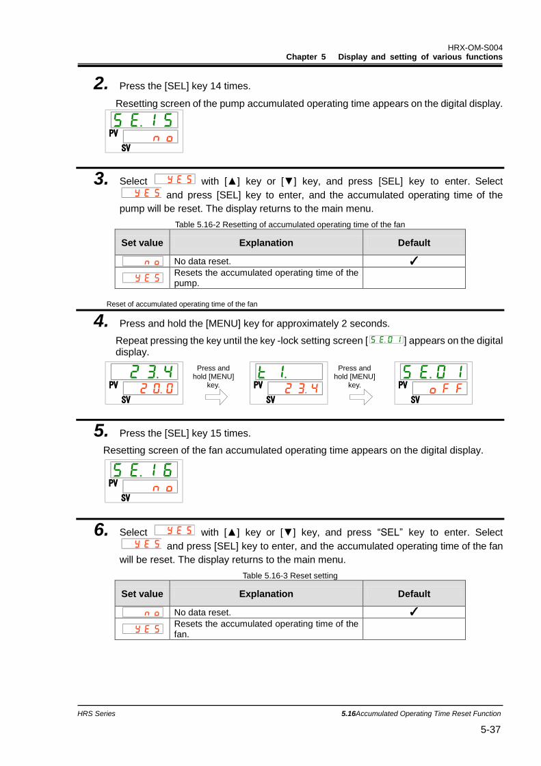
HRX-OM-S004 Chapter 5 Display and setting of various functions
HRS Series 5.16Accumulated Operating Time Reset Function 5-37
2. Press the [SEL] key 14 times.
Resetting screen of the pump accumulated operating time appears on the digital display.
3. Select with [▲] key or [▼] key, and press [SEL] key to enter. Select
and press [SEL] key to enter, and the accumulated operating time of the
pump will be reset. The display returns to the main menu.
Table 5.16-2 Resetting of accumulated operating time of the fan
Set value Explanation Default
No data reset. ✓
Resets the accumulated operating time of the pump.
Reset of accumulated operating time of the fan
4. Press and hold the [MENU] key for approximately 2 seconds.
Repeat pressing the key until the key -lock setting screen [ ] appears on the digital display.
5. Press the [SEL] key 15 times.
Resetting screen of the fan accumulated operating time appears on the digital display.
6. Select with [▲] key or [▼] key, and press “SEL” key to enter. Select
and press [SEL] key to enter, and the accumulated operating time of the fan
will be reset. The display returns to the main menu.
Table 5.16-3 Reset setting
Set value Explanation Default
No data reset. ✓
Resets the accumulated operating time of the fan.
PV
SV
PV
SV
PV
SV
PV
SV
PV
SV
Press and hold [MENU]
key.
Press and hold [MENU]
key.
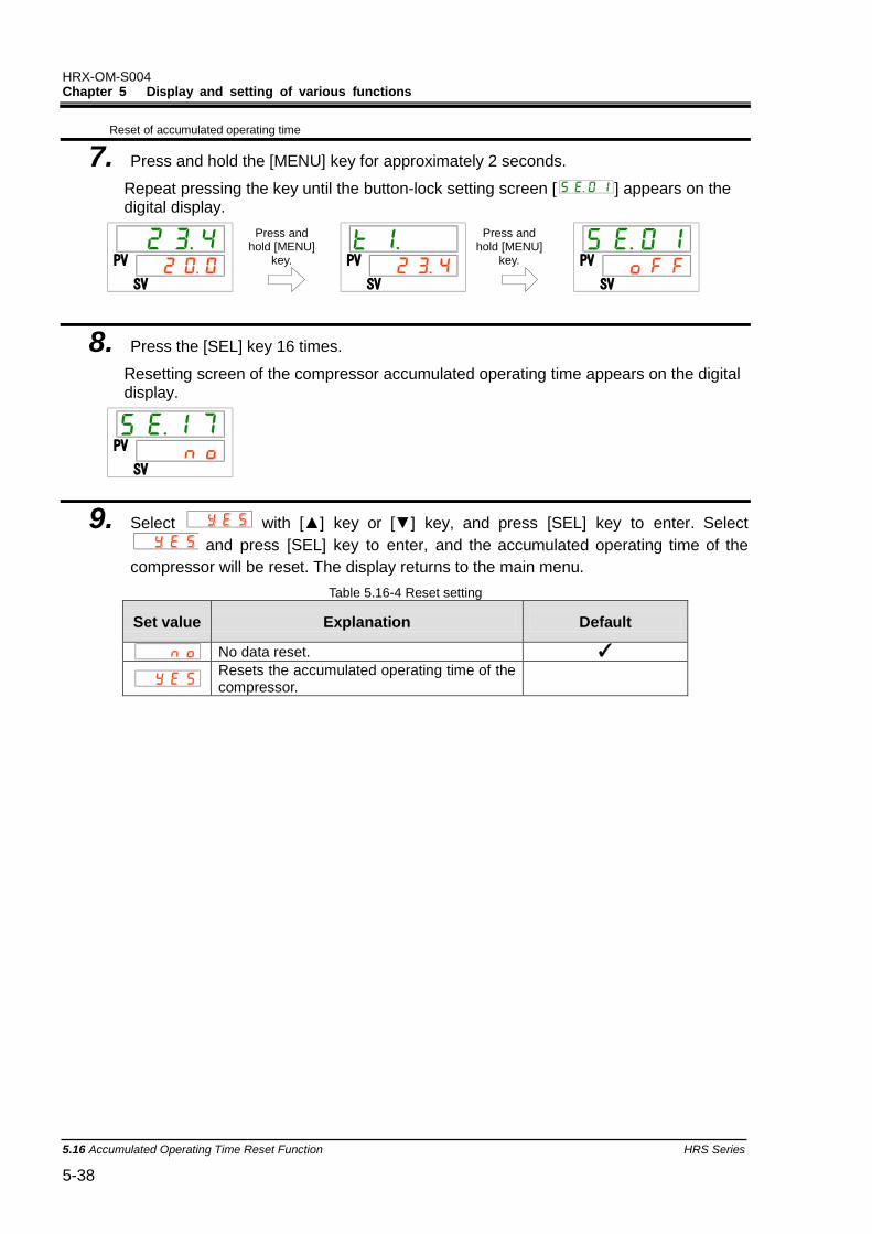
HRX-OM-S004 Chapter 5 Display and setting of various functions
5.16 Accumulated Operating Time Reset Function HRS Series 5-38
Reset of accumulated operating time
7. Press and hold the [MENU] key for approximately 2 seconds.
Repeat pressing the key until the button-lock setting screen [ ] appears on the digital display.
8. Press the [SEL] key 16 times.
Resetting screen of the compressor accumulated operating time appears on the digital display.
9. Select with [▲] key or [▼] key, and press [SEL] key to enter. Select
and press [SEL] key to enter, and the accumulated operating time of the
compressor will be reset. The display returns to the main menu.
Table 5.16-4 Reset setting
Set value Explanation Default
No data reset. ✓
Resets the accumulated operating time of the compressor.
PV
SV
PV
SV
PV
SV
PV
SV
Press and hold [MENU]
key.
Press and hold [MENU]
key.
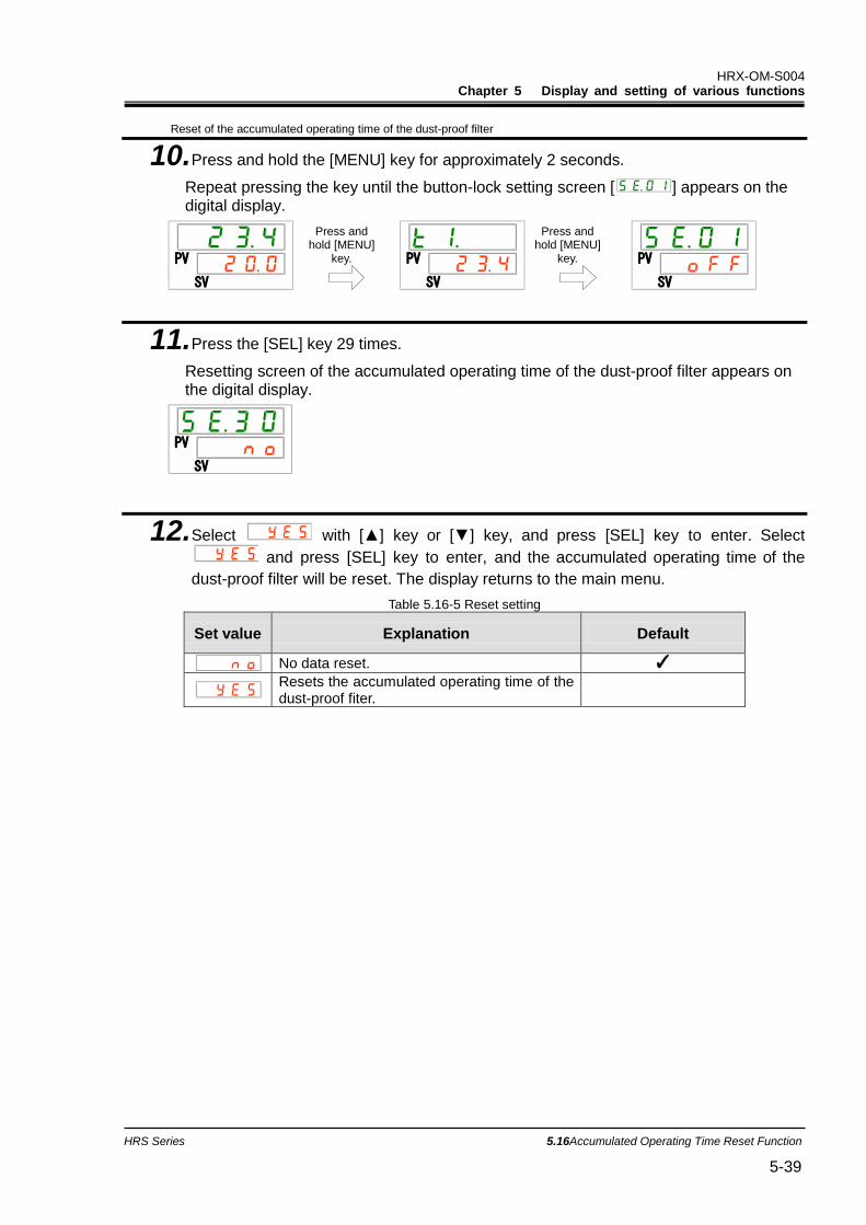
HRX-OM-S004 Chapter 5 Display and setting of various functions
HRS Series 5.16Accumulated Operating Time Reset Function 5-39
Reset of the accumulated operating time of the dust-proof filter
10. Press and hold the [MENU] key for approximately 2 seconds.
Repeat pressing the key until the button-lock setting screen [ ] appears on the digital display.
11. Press the [SEL] key 29 times.
Resetting screen of the accumulated operating time of the dust-proof filter appears on the digital display.
12. Select with [▲] key or [▼] key, and press [SEL] key to enter. Select
and press [SEL] key to enter, and the accumulated operating time of the
dust-proof filter will be reset. The display returns to the main menu.
Table 5.16-5 Reset setting
Set value Explanation Default
No data reset. ✓
Resets the accumulated operating time of the dust-proof fiter.
PV
SV
PV
SV
PV
SV
PV
SV
Press and hold [MENU]
key.
Press and hold [MENU]
key.
HRX-OM-S004 Chapter 5 Display and setting of various functions
5.17 Warming up function HRS Series 5-40
5.17 Warming up function 5.17.1 Warming up function
This function maintains the circulating fluid temperature to the set warming-up temperature with heat generated by automatically operating the pump in the winter season or at night.
When the time required for increasing the temperature of the circulating fluid needs to be shortened at startup, set this function ON in advance.
- The pump automatically keeps operating until the circulating fluid temperature becomes 2
oC higher than the set warming up temperature.
- The pump automatically stops operating when the circulating fluid temperature becomes 2
oC higher than the set warming up temperature.
- The pump automatically restarts operating when the circulating fluid temperature decreases 2
oC lower than the set warming up temperature.
When the warming up function is set ON, the [RUN] light repeats turning ON for 0.5 seconds and OFF for 3 seconds while it is on standby (when the pump is not operating).
The [RUN] light blinks every 0.3 seconds during the automatic operation of the pump.
The default setting of this function is “OFF”.
Note that when the warming up function is ON, the warming up function has a priority over the anti-freezing function, and the anti-freezing function will not be activated.
Keep the power supply ON for this function.
This function does not operate when the power is OFF.
This function can be activated only when the power supply is ON and the thermo-chiller is not operating.
Fully open the valve or manual by-pass valve that is arranged by the user to make it possible for the circulating fluid to circulate when the pump starts automatic operation.
In extremely cold weather, the circulating fluid temperature may not increase to the set temperature.
During the automatic operation, the pump does not stop operation even if the "RUN/STOP" button is pressed.
To stop the pump, turn the power supply OFF or turn this function
OFF.
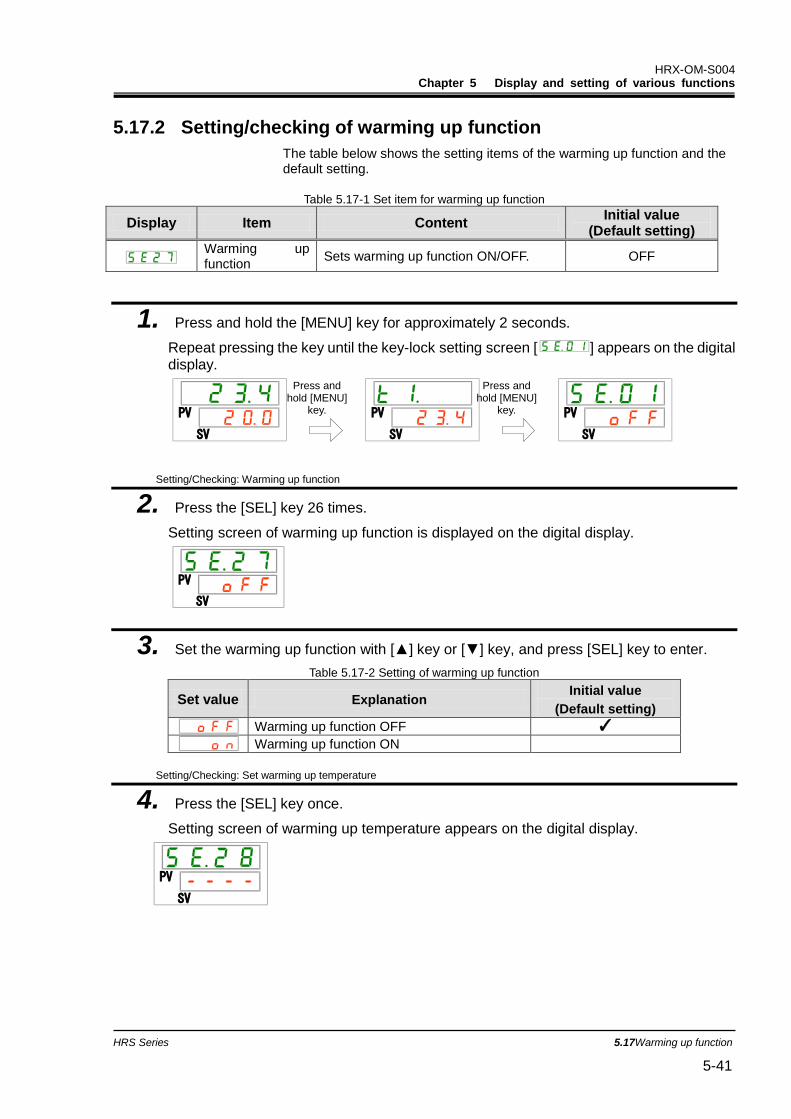
HRX-OM-S004 Chapter 5 Display and setting of various functions
HRS Series 5.17Warming up function 5-41
5.17.2 Setting/checking of warming up function
The table below shows the setting items of the warming up function and the default setting.
Table 5.17-1 Set item for warming up function
Display Item Content Initial value
(Default setting)
Warming up function
Sets warming up function ON/OFF. OFF
1. Press and hold the [MENU] key for approximately 2 seconds.
Repeat pressing the key until the key-lock setting screen [ ] appears on the digital display.
Setting/Checking: Warming up function
2. Press the [SEL] key 26 times.
Setting screen of warming up function is displayed on the digital display.
3. Set the warming up function with [▲] key or [▼] key, and press [SEL] key to enter.
Table 5.17-2 Setting of warming up function
Set value Explanation Initial value
(Default setting)
Warming up function OFF ✓
Warming up function ON
Setting/Checking: Set warming up temperature
4. Press the [SEL] key once.
Setting screen of warming up temperature appears on the digital display.
PV
SV
PV
SV
PV
SV
PV
SV
PV
SV
Press and hold [MENU]
key.
Press and hold [MENU]
key.
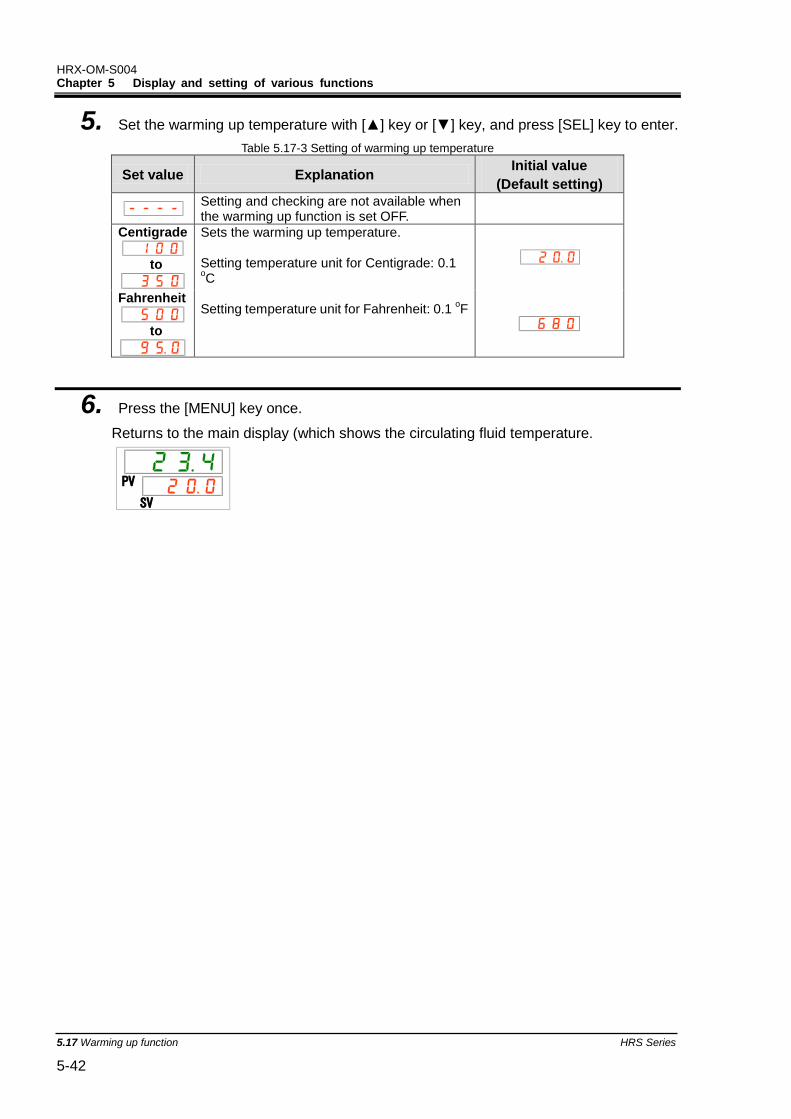
HRX-OM-S004 Chapter 5 Display and setting of various functions
5.17 Warming up function HRS Series 5-42
5. Set the warming up temperature with [▲] key or [▼] key, and press [SEL] key to enter.
Table 5.17-3 Setting of warming up temperature
Set value Explanation Initial value
(Default setting)
Setting and checking are not available when the warming up function is set OFF.
Centigrade
to
Sets the warming up temperature. Setting temperature unit for Centigrade: 0.1 oC
Setting temperature unit for Fahrenheit: 0.1
oF
Fahrenheit
to
6. Press the [MENU] key once.
Returns to the main display (which shows the circulating fluid temperature.
PV
SV
HRX-OM-S004 Chapter 5 Display and setting of various functions
HRS Series 5.18Anti-snow coverage function 5-43
5.18 Anti-snow coverage function 5.18.1 Anti-snow coverage function
This function prevents snow coverage on the exhaust port on top of the product during the winter time by automatically operating the fan periodically.
When there is a possibility of snow coverage due to changes in the installation or operating environment (e.g. season, weather), set this function ON in advance.
●During the product operation
The fan repeats operation with the maximum rotating cycle for 1 minute and with the normal rotating cycle for 29 minutes.
●During the product stoppage
The fan repeats operation with the maximum rotating cycle for 1 minute and operation stop for 29 minutes.
When the anti-snow coverage function is set ON, this function keeps operating and rotates the fan in the way shown in "During the product stoppage" above even when the compressor and/or pump stops operation due to any alarms.
Keep the power supply ON for this function. This function does not operate when the power is OFF.
This function does not operate for water-cooled type.
When the amount of snowfall on the product is too large, snow-coverage may not be avoided completely.
When the [RUN/STOP] button is pressed during automatic operation of the fan, it is possible to start/stop the product operation, but it is not possible to start/stop the automatic operation of the fan.
To stop the fan, turn the power supply OFF or turn this function OFF.
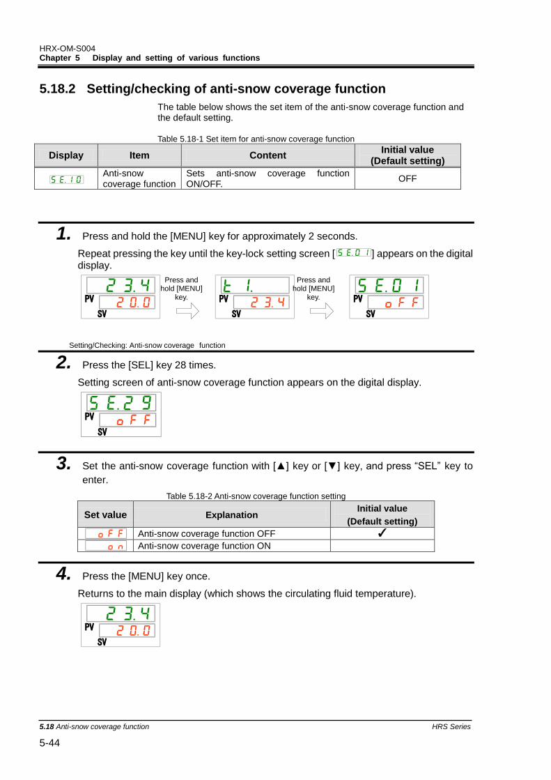
HRX-OM-S004 Chapter 5 Display and setting of various functions
5.18 Anti-snow coverage function HRS Series 5-44
5.18.2 Setting/checking of anti-snow coverage function
The table below shows the set item of the anti-snow coverage function and the default setting.
Table 5.18-1 Set item for anti-snow coverage function
Display Item Content Initial value
(Default setting)
Anti-snow coverage function
Sets anti-snow coverage function ON/OFF.
OFF
1. Press and hold the [MENU] key for approximately 2 seconds.
Repeat pressing the key until the key-lock setting screen [ ] appears on the digital display.
Setting/Checking: Anti-snow coverage function
2. Press the [SEL] key 28 times.
Setting screen of anti-snow coverage function appears on the digital display.
3. Set the anti-snow coverage function with [▲] key or [▼] key, and press “SEL” key to
enter.
Table 5.18-2 Anti-snow coverage function setting
Set value Explanation Initial value
(Default setting)
Anti-snow coverage function OFF ✓
Anti-snow coverage function ON
4. Press the [MENU] key once.
Returns to the main display (which shows the circulating fluid temperature).
PV
SV
PV
SV
PV
SV
PV
SV
PV
SV
Press and hold [MENU]
key.
Press and hold [MENU]
key.
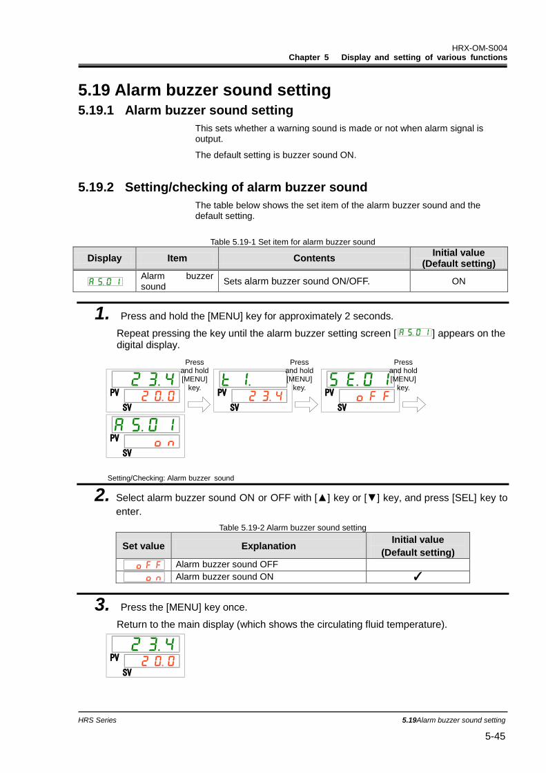
HRX-OM-S004 Chapter 5 Display and setting of various functions
HRS Series 5.19Alarm buzzer sound setting 5-45
5.19 Alarm buzzer sound setting 5.19.1 Alarm buzzer sound setting
This sets whether a warning sound is made or not when alarm signal is output.
The default setting is buzzer sound ON.
5.19.2 Setting/checking of alarm buzzer sound
The table below shows the set item of the alarm buzzer sound and the default setting.
Table 5.19-1 Set item for alarm buzzer sound
Display Item Contents Initial value
(Default setting)
Alarm buzzer sound
Sets alarm buzzer sound ON/OFF. ON
1. Press and hold the [MENU] key for approximately 2 seconds.
Repeat pressing the key until the alarm buzzer setting screen [ ] appears on the digital display.
Setting/Checking: Alarm buzzer sound
2. Select alarm buzzer sound ON or OFF with [▲] key or [▼] key, and press [SEL] key to
enter.
Table 5.19-2 Alarm buzzer sound setting
Set value Explanation Initial value
(Default setting)
Alarm buzzer sound OFF
Alarm buzzer sound ON ✓
3. Press the [MENU] key once.
Return to the main display (which shows the circulating fluid temperature).
PV
SV
PV
SV
PV
SV
PV
SV
PV
SV
Press and hold [MENU]
key.
Press and hold [MENU]
key.
Press and hold [MENU]
key.
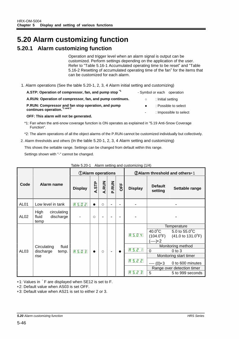
HRX-OM-S004 Chapter 5 Display and setting of various functions
5.20 Alarm customizing function HRS Series 5-46
5.20 Alarm customizing function 5.20.1 Alarm customizing function
Operation and trigger level when an alarm signal is output can be customized. Perform settings depending on the application of the user. Refer to “Table 5.16-1 Accumulated operating time to be reset” and “Table 5.16-2 Resetting of accumulated operating time of the fan” for the items that can be customized for each alarm.
1. Alarm operations (See the table 5.20-1, 2, 3, 4 Alarm initial setting and customizing)
A.STP: Operation of compressor, fan, and pump stop *1
A.RUN: Operation of compressor, fan, and pump continues.
P.RUN: Compressor and fan stop operation, and pump continues operation.
*1 and 2
OFF: This alarm will not be generated.
- Symbol or each operation
○ : Initial setting
● : Possible to select
- : Impossible to select
*1: Fan when the anti-snow coverage function is ON operates as explained in "5.19 Anti-Snow Coverage Function".
*2: The alarm operations of all the object alarms of the P.RUN cannot be customized individually but collectively.
2. Alarm thresholds and others (In the table 5.20-1, 2, 3, 4 Alarm setting and customizing)
This shows the settable range. Settings can be changed from default within this range.
Settings shown with "-" cannot be changed.
Table 5.20-1 Alarm setting and customizing (1/4)
Code Alarm name
①Alarm operations ②Alarm threshold and others1
Display
A.S
TP
A.R
UN
P.R
UN
OF
F
Display Default setting
Settable range
AL01 Low level in tank ● ○ - - - -
AL02 High circulating fluid discharge temp
- ○ - - - - -
AL03 Circulating fluid discharge temp. rise
● ○ - ●
Temperature
40.0oC
(104.0oF)
(----)2
5.0 to 55.0oC
(41.0 to 131.0oF)
Monitoring method
0 0 to 3
Monitoring start timer
---- (0)3 0 to 600 minutes
Range over detection timer
5 5 to 999 seconds
1: Values in ゚ F are displayed when SE12 is set to F.
2: Default value when AS03 is set OFF.
3: Default value when AS21 is set to either 2 or 3.
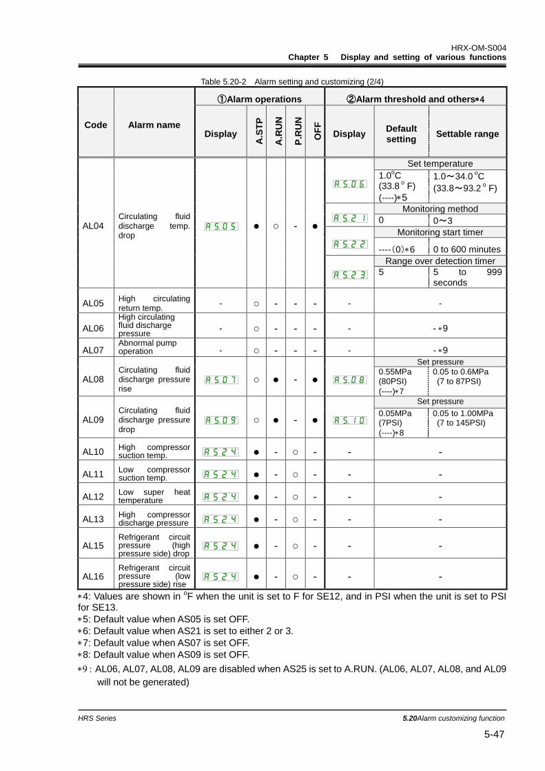
HRX-OM-S004 Chapter 5 Display and setting of various functions
HRS Series 5.20Alarm customizing function 5-47
Table 5.20-2 Alarm setting and customizing (2/4)
Code Alarm name
①Alarm operations ②Alarm threshold and others
Display
A.S
TP
A.R
UN
P.R
UN
OF
F
Display Default setting
Settable range
AL04 Circulating fluid discharge temp. drop
● ○ - ●
Set temperature
1.0oC
(33.8 o F)
(----)5
1.0~34.0 oC
(33.8~93.2 o F)
Monitoring method
0 0~3
Monitoring start timer
----(0)6 0 to 600 minutes
Range over detection timer
5 5 to 999 seconds
AL05 High circulating return temp.
- ○ - - - - -
AL06
High circulating fluid discharge pressure
- ○ - - - - - 9
AL07 Abnormal pump operation - ○ - - - - - 9
AL08 Circulating fluid discharge pressure rise
○ ● - ●
Set pressure
0.55MPa (80PSI)
(----)7
0.05 to 0.6MPa (7 to 87PSI)
AL09 Circulating fluid discharge pressure drop
○ ● - ●
Set pressure
0.05MPa (7PSI)
(----)8
0.05 to 1.00MPa (7 to 145PSI)
AL10 High compressor suction temp. ● - ○ - - -
AL11 Low compressor suction temp. ● - ○ - - -
AL12 Low super heat temperature ● - ○ - - -
AL13 High compressor discharge pressure ● - ○ - - -
AL15 Refrigerant circuit pressure (high pressure side) drop
● - ○ - - -
AL16 Refrigerant circuit pressure (low pressure side) rise
● - ○ - - -
4: Values are shown in oF when the unit is set to F for SE12, and in PSI when the unit is set to PSI
for SE13.
5: Default value when AS05 is set OFF.
6: Default value when AS21 is set to either 2 or 3.
7: Default value when AS07 is set OFF.
8: Default value when AS09 is set OFF.
AL06, AL07, AL08, AL09 are disabled when AS25 is set to A.RUN. (AL06, AL07, AL08, and AL09
will not be generated)
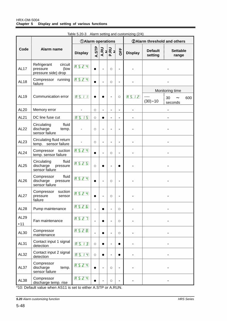
HRX-OM-S004 Chapter 5 Display and setting of various functions
5.20 Alarm customizing function HRS Series 5-48
Table 5.20-3 Alarm setting and customizing (2/4)
Code Alarm name
①Alarm operations ②Alarm threshold and others
Display
A.S
TP
A.R
U
N
P.R
U
N
OF
F
Display Default setting
Settable range
AL17 Refrigerant circuit pressure (low pressure side) drop
● - ○ - - -
AL18 Compressor running failure ● - ○ - - -
AL19 Communication error ● ● - ○
Monitoring time
---- (30)10
30 ~ 600
seconds
AL20 Memory error - ○ - - - - -
AL21 DC line fuse cut ○ ● - - - -
AL22 Circulating fluid discharge temp. sensor failure
- ○ - - - - -
AL23 Circulating fluid return temp. sensor failure
- ○ - - - - -
AL24 Compressor suction temp. sensor failure ● - ○ - - -
AL25 Circulating fluid discharge pressure sensor failure
○ ● - ● - -
AL26 Compressor fluid discharge pressure sensor failure
● - ○ - - -
AL27 Compressor suction pressure sensor failure
● - ○ - - -
AL28 Pump maintenance - ● - ○ - -
AL29
11 Fan maintenance
- ● - ○ - -
AL30 Compressor maintenance - ● - ○ - -
AL31 Contact input 1 signal detection ○ ● - ● - -
AL32 Contact input 2 signal detection ○ ● - ● - -
AL37 Compressor discharge temp. sensor failure
● - ○ - - -
AL38 Compressor discharge temp. rise ● - ○ - - -
*10: Default value when AS11 is set to either A.STP or A.RUN.
HRX-OM-S004 Chapter 5 Display and setting of various functions
HRS Series 5.20Alarm customizing function 5-49
*11: Water-cooled type model does not generate this alarm.
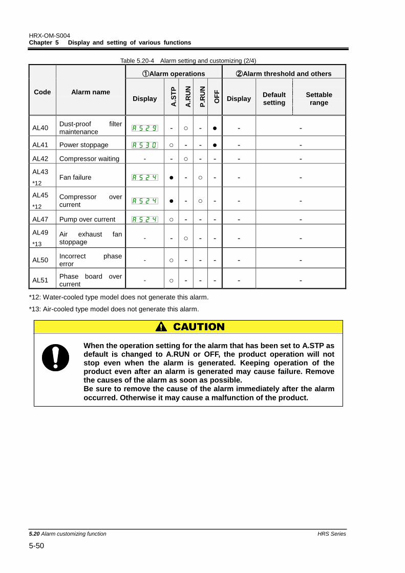
HRX-OM-S004 Chapter 5 Display and setting of various functions
5.20 Alarm customizing function HRS Series 5-50
Table 5.20-4 Alarm setting and customizing (2/4)
Code Alarm name
①Alarm operations ②Alarm threshold and others
Display
A.S
TP
A.R
UN
P.R
UN
OF
F
Display Default setting
Settable range
AL40 Dust-proof filter maintenance - ○ - ● - -
AL41 Power stoppage ○ - - ● - -
AL42 Compressor waiting - - ○ - - - -
AL43
*12 Fan failure ● - ○ - - -
AL45
*12
Compressor over current ● - ○ - - -
AL47 Pump over current ○ - - - - -
AL49
*13
Air exhaust fan stoppage
- - ○ - - - -
AL50 Incorrect phase error
- ○ - - - - -
AL51 Phase board over current
- ○ - - - - -
*12: Water-cooled type model does not generate this alarm.
*13: Air-cooled type model does not generate this alarm.
When the operation setting for the alarm that has been set to A.STP as default is changed to A.RUN or OFF, the product operation will not stop even when the alarm is generated. Keeping operation of the product even after an alarm is generated may cause failure. Remove the causes of the alarm as soon as possible. Be sure to remove the cause of the alarm immediately after the alarm
occurred. Otherwise it may cause a malfunction of the product.
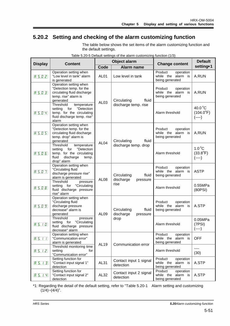
HRX-OM-S004 Chapter 5 Display and setting of various functions
HRS Series 5.20Alarm customizing function 5-51
5.20.2 Setting and checking of the alarm customizing function
The table below shows the set items of the alarm customizing function and the default settings.
Table 5.20-5 Default settings of the alarm customizing function (1/3)
Display Content Object alarm
Change content Default
setting1 Code Alarm name
Operation setting when "Low level in tank" alarm is generated
AL01 Low level in tank Product operation while the alarm is being generated
A.RUN
Operation setting when "Detection temp. for the circulating fluid discharge temp. rise" alarm is generated
AL03 Circulating fluid discharge temp. rise
Product operation while the alarm is being generated
A.RUN
Threshold temperature setting for "Detection temp. for the circulating fluid discharge temp. rise" alarm
Alarm threshold
40.0 oC
(104.0oF)
(----)
Operation setting when "Detection temp. for the circulating fluid discharge temp. drop" alarm is generated
AL04 Circulating fluid discharge temp. drop
Product operation while the alarm is being generated
A.RUN
Threshold temperature setting for "Detection temp. for the circulating fluid discharge temp. drop" alarm
Alarm threshold
1.0 oC
(33.8oF)
(----)
Operation setting when "Circulating fluid discharge pressure rise" alarm is generated
AL08 Circulating fluid discharge pressure rise
Product operation while the alarm is being generated
ASTP
Threshold pressure setting for "Circulating fluid discharge pressure rise" alarm
Alarm threshold 0.55MPa (80PSI)
Operation setting when "Circulating fluid discharge pressure decrease" alarm is generated AL09
Circulating fluid discharge pressure drop
Product operation while the alarm is being generated
A.STP
Threshold pressure setting for "Circulating fluid discharge pressure decrease" alarm
Alarm threshold
0.05MPa (7PSI) (----)
Operation setting when "Communication error" alarm is generated
AL19 Communication error
Product operation while the alarm is being generated
OFF
Threshold monitoring time setting for "Communication error"
Alarm threshold ---- (30)
Setting function for "Contact input signal 1" detection
AL31 Contact input 1 signal detection
Product operation while the alarm is being generated
A.STP
Setting function for "Contact input signal 2" detection
AL32 Contact input 2 signal detection
Product operation while the alarm is being generated
A.STP
*1: Regarding the detail of the default setting, refer to “Table 5.20-1 Alarm setting and customizing (1/4)~(4/4)”.

HRX-OM-S004 Chapter 5 Display and setting of various functions
5.20 Alarm customizing function HRS Series 5-52
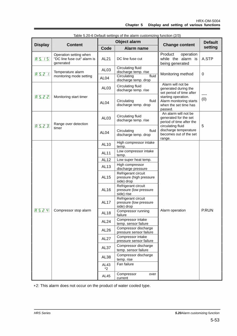
HRX-OM-S004 Chapter 5 Display and setting of various functions
HRS Series 5.20Alarm customizing function 5-53
Table 5.20-6 Default settings of the alarm customizing function (2/3)
Display Content Object alarm
Change content Default setting Code Alarm name
Operation setting when "DC line fuse cut" alarm is generated
AL21 DC line fuse cut
Product operation while the alarm is being generated
A.STP
Temperature alarm monitoring mode setting
AL03 Circulating fluid discharge temp. rise
Monitoring method 0 AL04
Circulating fluid discharge temp. drop
Monitoring start timer
AL03 Circulating fluid discharge temp. rise
Alarm will not be generated during the set period of time after starting operation. Alarm monitoring starts when the set time has passed.
---- (0)
AL04 Circulating fluid discharge temp. drop
Range over detection timer
AL03 Circulating fluid discharge temp. rise
An alarm will not be generated for the set period of time after the circulating fluid discharge temperature becomes out of the set range.
5
AL04 Circulating fluid discharge temp. drop
Compressor stop alarm
AL10 High compressor intake temp.
Alarm operation P.RUN
AL11 Low compressor intake temp.
AL12 Low super heat temp.
AL13 High compressor discharge pressure
AL15 Refrigerant circuit pressure (high pressure side) drop
AL16 Refrigerant circuit pressure (low pressure side) rise
AL17 Refrigerant circuit pressure (low pressure side) drop
AL18 Compressor running failure
AL24 Compressor intake temp. sensor failure
AL26 Compressor discharge pressure sensor failure
AL27 Compressor intake pressure sensor failure
AL37 Compressor discharge
temp. sensor failure
AL38 Compressor discharge
temp. rise
AL43 *2
Fan failure
AL45 Compressor over current
2: This alarm does not occur on the product of water cooled type.
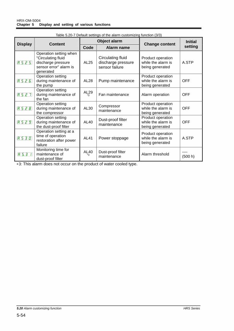
HRX-OM-S004 Chapter 5 Display and setting of various functions
5.20 Alarm customizing function HRS Series 5-54
Table 5.20-7 Default settings of the alarm customizing function (3/3)
Display Content Object alarm
Change content Initial
setting Code Alarm name
Operation setting when "Circulating fluid discharge pressure sensor error" alarm is generated
AL25
Circulating fluid discharge pressure sensor failure
Product operation while the alarm is being generated
A.STP
Operation setting during maintenance of the pump
AL28 Pump maintenance Product operation while the alarm is being generated
OFF
Operation setting during maintenance of the fan
AL29 *3 Fan maintenance Alarm operation OFF
Operation setting during maintenance of the compressor
AL30 Compressor maintenance
Product operation while the alarm is being generated
OFF
Operation setting during maintenance of the dust-proof filter
AL40 Dust-proof filter maintenance
Product operation while the alarm is being generated
OFF
Operation setting at a time of operation restoration after power failure
AL41 Power stoppage Product operation while the alarm is being generated
A.STP
Monitoring time for maintenance of dust-proof filter
AL40 *3
Dust-proof filter maintenance
Alarm threshold ---- (500 h)
3: This alarm does not occur on the product of water cooled type.
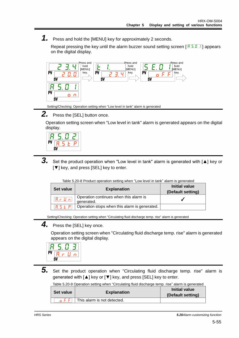
HRX-OM-S004 Chapter 5 Display and setting of various functions
HRS Series 5.20Alarm customizing function 5-55
1. Press and hold the [MENU] key for approximately 2 seconds.
Repeat pressing the key until the alarm buzzer sound setting screen [ ] appears on the digital display.
Setting/Checking: Operation setting when "Low level in tank" alarm is generated
2. Press the [SEL] button once.
Operation setting screen when "Low level in tank" alarm is generated appears on the digital display.
3. Set the product operation when "Low level in tank" alarm is generated with [▲] key or
[▼] key, and press [SEL] key to enter.
Table 5.20-8 Product operation setting when “Low level in tank” alarm is generated
Set value Explanation Initial value
(Default setting)
Operation continues when this alarm is generated.
✓
Operation stops when this alarm is generated.
Setting/Checking: Operation setting when "Circulating fluid discharge temp. rise" alarm is generated
4. Press the [SEL] key once.
Operation setting screen when "Circulating fluid discharge temp. rise" alarm is generated appears on the digital display.
5. Set the product operation when "Circulating fluid discharge temp. rise" alarm is
generated with [▲] key or [▼] key, and press [SEL] key to enter.
Table 5.20-9 Operation setting when “Circulating fluid discharge temp. rise” alarm is generated
Set value Explanation Initial value
(Default setting)
This alarm is not detected.
PV
SV
PV
SV
PV
SV
PV
SV
PV
SV
PV
SV
Press and hold
[MENU] key.
Press and hold
[MENU] key.
Press and hold
[MENU] key.
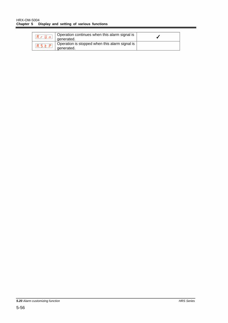
HRX-OM-S004 Chapter 5 Display and setting of various functions
5.20 Alarm customizing function HRS Series 5-56
Operation continues when this alarm signal is generated.
✓
Operation is stopped when this alarm signal is generated.
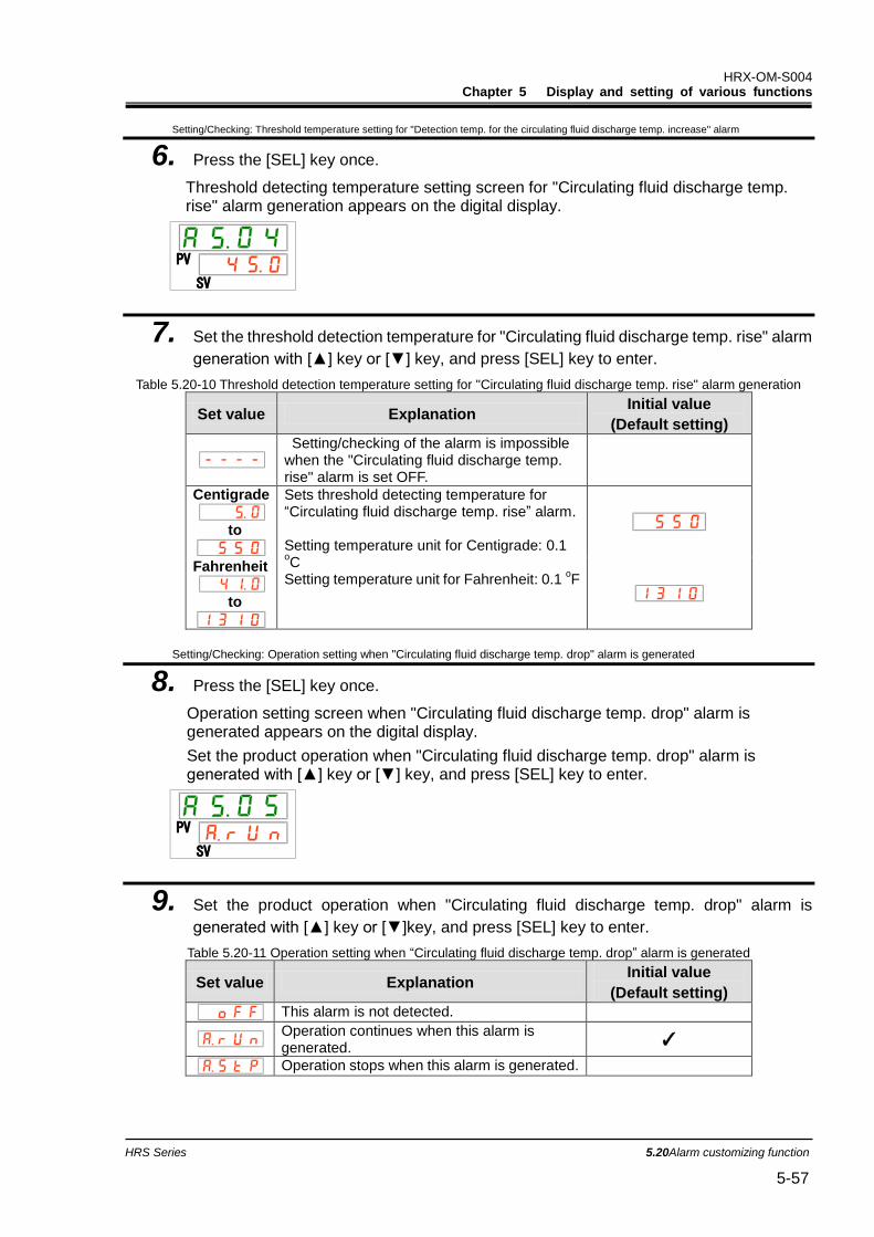
HRX-OM-S004 Chapter 5 Display and setting of various functions
HRS Series 5.20Alarm customizing function 5-57
Setting/Checking: Threshold temperature setting for "Detection temp. for the circulating fluid discharge temp. increase" alarm
6. Press the [SEL] key once.
Threshold detecting temperature setting screen for "Circulating fluid discharge temp. rise" alarm generation appears on the digital display.
7. Set the threshold detection temperature for "Circulating fluid discharge temp. rise" alarm
generation with [▲] key or [▼] key, and press [SEL] key to enter.
Table 5.20-10 Threshold detection temperature setting for "Circulating fluid discharge temp. rise" alarm generation
Set value Explanation Initial value
(Default setting)
Setting/checking of the alarm is impossible when the "Circulating fluid discharge temp. rise" alarm is set OFF.
Centigrade
to
Sets threshold detecting temperature for “Circulating fluid discharge temp. rise” alarm. Setting temperature unit for Centigrade: 0.1 oC
Setting temperature unit for Fahrenheit: 0.1 oF
Fahrenheit
to
Setting/Checking: Operation setting when "Circulating fluid discharge temp. drop" alarm is generated
8. Press the [SEL] key once.
Operation setting screen when "Circulating fluid discharge temp. drop" alarm is generated appears on the digital display.
Set the product operation when "Circulating fluid discharge temp. drop" alarm is generated with [▲] key or [▼] key, and press [SEL] key to enter.
9. Set the product operation when "Circulating fluid discharge temp. drop" alarm is
generated with [▲] key or [▼]key, and press [SEL] key to enter.
Table 5.20-11 Operation setting when “Circulating fluid discharge temp. drop” alarm is generated
Set value Explanation Initial value
(Default setting)
This alarm is not detected.
Operation continues when this alarm is generated.
✓
Operation stops when this alarm is generated.
PV
SV
PV
SV

HRX-OM-S004 Chapter 5 Display and setting of various functions
5.20 Alarm customizing function HRS Series 5-58
Setting/Checking: Threshold detecting temperature setting for "Circulating fluid discharge temp. drop" alarm generation
10. Press the [SEL] key once.
Threshold detecting temperature setting screen for "Circulating fluid discharge temp. drop" alarm generation appears on the digital display.
11. Set the threshold detecting temperature for "Circulating fluid discharge temp. drop"
alarm generation with [▲] key or [▼] key, and press [SEL] key to enter.
Table 5.20-12 Threshold detecting temperature for "Circulating fluid discharge temp. drop" alarm
Set value Explanation Initial value
(Default setting)
Setting/checking of the alarm is impossible when the "Circulating fluid discharge temp. drop" alarm is set OFF.
Centigrade
to
Sets threshold detecting temperature for "Circulating fluid discharge temp. drop" alarm Setting temperature unit for Centigrade: 0.1 oC
Setting temperature unit for Fahrenheit: 0.1 oF
Fahrenheit
to
Setting/Checking: Operation setting when "Circulating fluid discharge pressure rise" alarm is generated
12. Press the [SEL] key once.
Operation setting screen when "Circulating fluid discharge pressure rise" alarm is generated appears on the digital display.
13. Set the product operation when "Circulating fluid discharge pressure rise" alarm is
generated with [▲] key or [▼] key, and press [SEL] key to enter.
Table 5.20-13 Operation setting when “Circulating fluid discharge pressure rise” alarm is generated
Set value Explanation Initial value
(Default setting)
This alarm is not detected.
Operation continues when this alarm is generated.
✓
Operation stops when this alarm is generated.
PV
SV
PV
SV
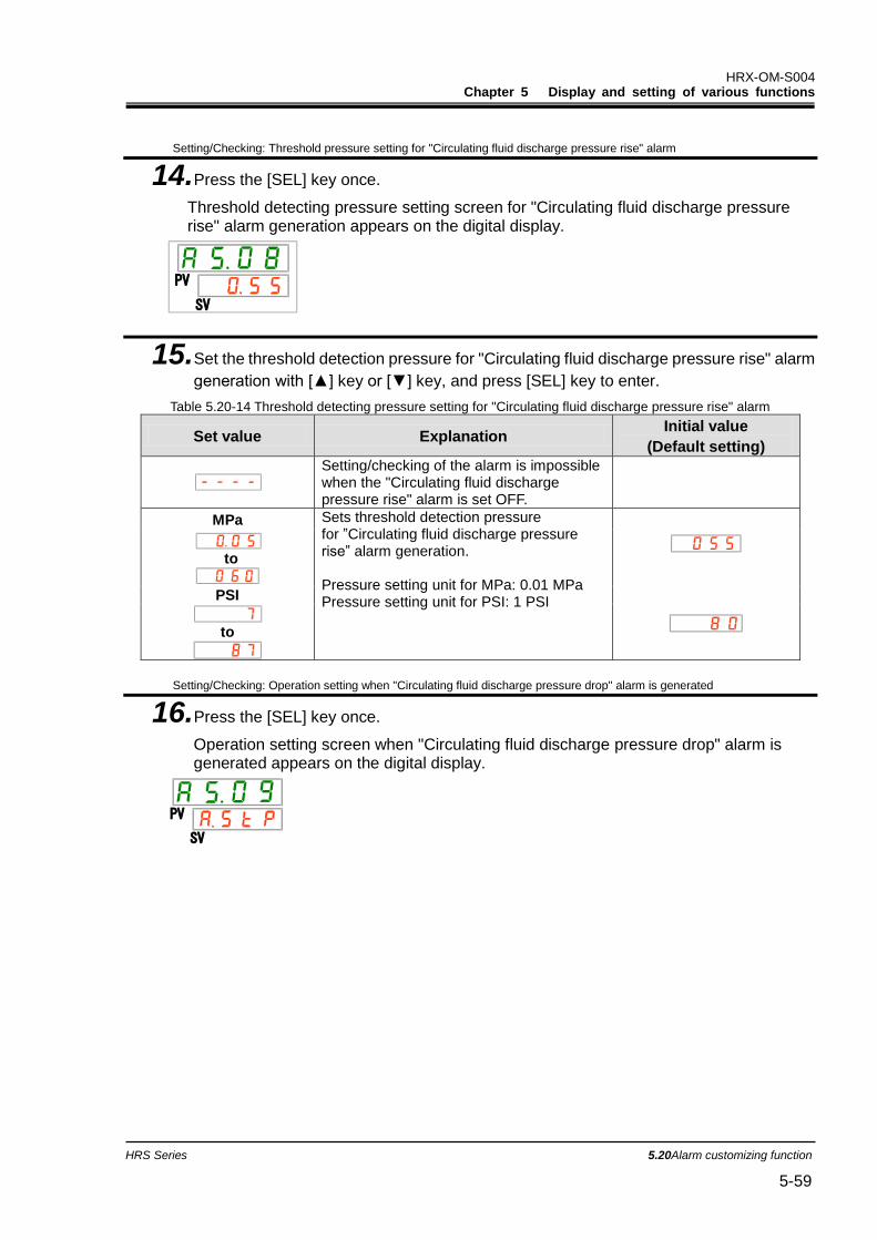
HRX-OM-S004 Chapter 5 Display and setting of various functions
HRS Series 5.20Alarm customizing function 5-59
Setting/Checking: Threshold pressure setting for "Circulating fluid discharge pressure rise" alarm
14. Press the [SEL] key once.
Threshold detecting pressure setting screen for "Circulating fluid discharge pressure rise" alarm generation appears on the digital display.
PV
SV
15. Set the threshold detection pressure for "Circulating fluid discharge pressure rise" alarm
generation with [▲] key or [▼] key, and press [SEL] key to enter.
Table 5.20-14 Threshold detecting pressure setting for "Circulating fluid discharge pressure rise" alarm
Set value Explanation Initial value
(Default setting)
Setting/checking of the alarm is impossible when the "Circulating fluid discharge pressure rise" alarm is set OFF.
MPa Sets threshold detection pressure for ”Circulating fluid discharge pressure rise” alarm generation. Pressure setting unit for MPa: 0.01 MPa Pressure setting unit for PSI: 1 PSI
to
PSI
to
Setting/Checking: Operation setting when "Circulating fluid discharge pressure drop" alarm is generated
16. Press the [SEL] key once.
Operation setting screen when "Circulating fluid discharge pressure drop" alarm is generated appears on the digital display.
PV
SV
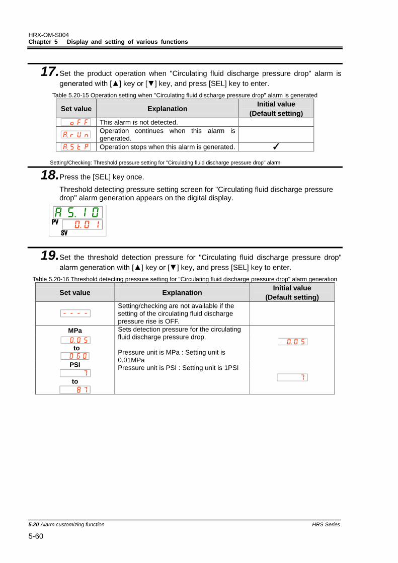
HRX-OM-S004 Chapter 5 Display and setting of various functions
5.20 Alarm customizing function HRS Series 5-60
17. Set the product operation when "Circulating fluid discharge pressure drop" alarm is
generated with [▲] key or [▼] key, and press [SEL] key to enter.
Table 5.20-15 Operation setting when "Circulating fluid discharge pressure drop" alarm is generated
Set value Explanation Initial value
(Default setting)
This alarm is not detected.
Operation continues when this alarm is generated.
Operation stops when this alarm is generated. ✓
Setting/Checking: Threshold pressure setting for "Circulating fluid discharge pressure drop" alarm
18. Press the [SEL] key once.
Threshold detecting pressure setting screen for "Circulating fluid discharge pressure drop" alarm generation appears on the digital display.
19. Set the threshold detection pressure for "Circulating fluid discharge pressure drop"
alarm generation with [▲] key or [▼] key, and press [SEL] key to enter.
Table 5.20-16 Threshold detecting pressure setting for "Circulating fluid discharge pressure drop" alarm generation
Set value Explanation Initial value
(Default setting)
Setting/checking are not available if the setting of the circulating fluid discharge pressure rise is OFF.
MPa Sets detection pressure for the circulating fluid discharge pressure drop. Pressure unit is MPa : Setting unit is 0.01MPa Pressure unit is PSI : Setting unit is 1PSI
to
PSI
to
PV
SV
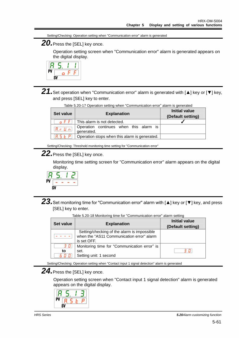
HRX-OM-S004 Chapter 5 Display and setting of various functions
HRS Series 5.20Alarm customizing function 5-61
Setting/Checking: Operation setting when "Communication error" alarm is generated
20. Press the [SEL] key once.
Operation setting screen when "Communication error" alarm is generated appears on the digital display.
21. Set operation when "Communication error" alarm is generated with [▲] key or [▼] key,
and press [SEL] key to enter.
Table 5.20-17 Operation setting when “Communication error” alarm is generated
Set value Explanation Initial value
(Default setting)
This alarm is not detected. ✓
Operation continues when this alarm is generated.
Operation stops when this alarm is generated.
Setting/Checking: Threshold monitoring time setting for "Communication error"
22. Press the [SEL] key once.
Monitoring time setting screen for "Communication error" alarm appears on the digital display.
PV
SV
23. Set monitoring time for "Communication error" alarm with [▲] key or [▼] key, and press
[SEL] key to enter.
Table 5.20-18 Monitoring time for "Communication error" alarm setting
Set value Explanation Initial value
(Default setting)
Setting/checking of the alarm is impossible when the "AS11 Communication error" alarm is set OFF.
to
Monitoring time for “Communication error” is set. Setting unit: 1 second
Setting/Checking: Operation setting when "Contact input 1 signal detection" alarm is generated
24. Press the [SEL] key once.
Operation setting screen when "Contact input 1 signal detection" alarm is generated appears on the digital display.
PV
SV
PV
SV
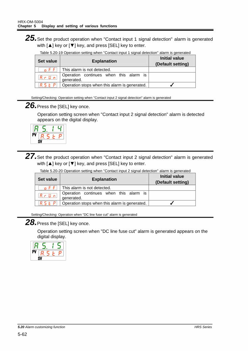
HRX-OM-S004 Chapter 5 Display and setting of various functions
5.20 Alarm customizing function HRS Series 5-62
25. Set the product operation when "Contact input 1 signal detection" alarm is generated
with [▲] key or [▼] key, and press [SEL] key to enter.
Table 5.20-19 Operation setting when "Contact input 1 signal detection" alarm is generated
Set value Explanation Initial value
(Default setting)
This alarm is not detected.
Operation continues when this alarm is generated.
Operation stops when this alarm is generated. ✓
Setting/Checking: Operation setting when "Contact input 2 signal detection" alarm is generated
26. Press the [SEL] key once.
Operation setting screen when "Contact input 2 signal detection" alarm is detected appears on the digital display.
27. Set the product operation when "Contact input 2 signal detection" alarm is generated
with [▲] key or [▼] key, and press [SEL] key to enter.
Table 5.20-20 Operation setting when "Contact input 2 signal detection" alarm is generated
Set value Explanation Initial value
(Default setting)
This alarm is not detected.
Operation continues when this alarm is generated.
Operation stops when this alarm is generated. ✓
Setting/Checking: Operation when "DC line fuse cut" alarm is generated
28. Press the [SEL] key once.
Operation setting screen when "DC line fuse cut" alarm is generated appears on the digital display.
PV
SV
PV
SV
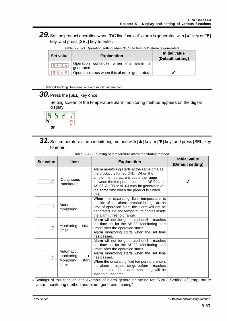
HRX-OM-S004 Chapter 5 Display and setting of various functions
HRS Series 5.20Alarm customizing function 5-63
29. Set the product operation when "DC line fuse cut" alarm is generated with [▲] key or [▼]
key, and press [SEL] key to enter.
Table 5.20-21 Operation setting when "DC line fuse cut" alarm is generated
Set value Explanation Initial value
(Default setting)
Operation continues when this alarm is generated.
Operation stops when this alarm is generated. ✓
Setting/Checking: Temperature alarm monitoring method
30. Press the [SEL] key once.
Setting screen of the temperature alarm monitoring method appears on the digital display.
31. Set temperature alarm monitoring method with [▲] key or [▼] key, and press [SEL] key
to enter.
Table 5.20-22 Setting of temperature alarm monitoring method
Set value Item Explanation Initial value
(Default setting)
Continuous monitoring
Alarm monitoring starts at the same time as the product is turned ON. When the ambient temperature is out of the range between the temperatures set for AS.04 and AS.06, AL.03 or AL.04 may be generated at the same time when the product is turned ON.
✓
Automatic monitoring
When the circulating fluid temperature is outside of the alarm threshold range at the time of operation start, the alarm will not be generated until the temperature comes inside the alarm threshold range.
Monitoring start timer
Alarm will not be generated until it reaches the time set for the AS.22 "Monitoring start timer" after the operation starts. Alarm monitoring starts when the set time has passed.
Automatic monitoring + Monitoring start timer
Alarm will not be generated until it reaches the time set for the AS.22 "Monitoring start timer" after the operation starts. Alarm monitoring starts when the set time has passed. When the circulating fluid temperature enters the alarm threshold range before it reaches the set time, the alarm monitoring will be started at that time.
Settings of this function and example of alarm generating timing for “5.20.3 Setting of temperature alarm monitoring method and alarm generation timing".
PV
SV
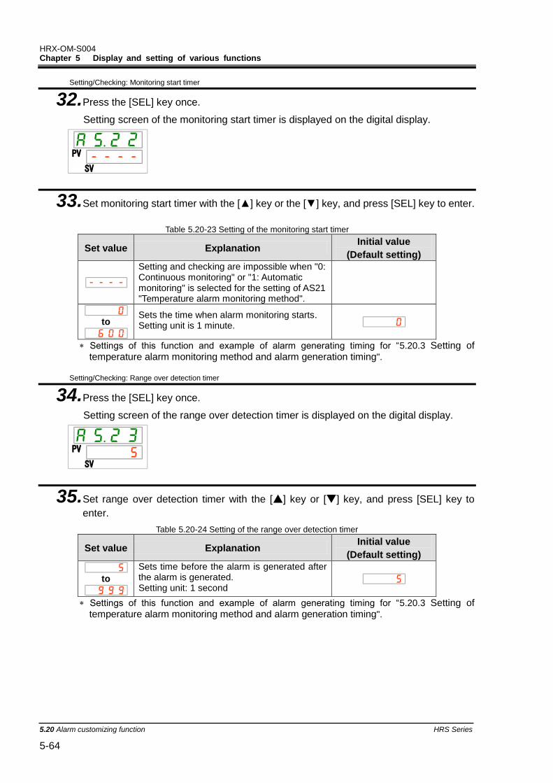
HRX-OM-S004 Chapter 5 Display and setting of various functions
5.20 Alarm customizing function HRS Series 5-64
Setting/Checking: Monitoring start timer
32. Press the [SEL] key once.
Setting screen of the monitoring start timer is displayed on the digital display.
33. Set monitoring start timer with the [▲] key or the [▼] key, and press [SEL] key to enter.
Table 5.20-23 Setting of the monitoring start timer
Set value Explanation Initial value
(Default setting)
Setting and checking are impossible when "0: Continuous monitoring" or "1: Automatic monitoring" is selected for the setting of AS21 "Temperature alarm monitoring method".
to
Sets the time when alarm monitoring starts. Setting unit is 1 minute.
Settings of this function and example of alarm generating timing for “5.20.3 Setting of temperature alarm monitoring method and alarm generation timing".
Setting/Checking: Range over detection timer
34. Press the [SEL] key once.
Setting screen of the range over detection timer is displayed on the digital display.
35. Set range over detection timer with the [▲] key or [▼] key, and press [SEL] key to
enter.
Table 5.20-24 Setting of the range over detection timer
Set value Explanation Initial value
(Default setting)
to
Sets time before the alarm is generated after the alarm is generated. Setting unit: 1 second
Settings of this function and example of alarm generating timing for “5.20.3 Setting of temperature alarm monitoring method and alarm generation timing".
PV
SV
PV
SV
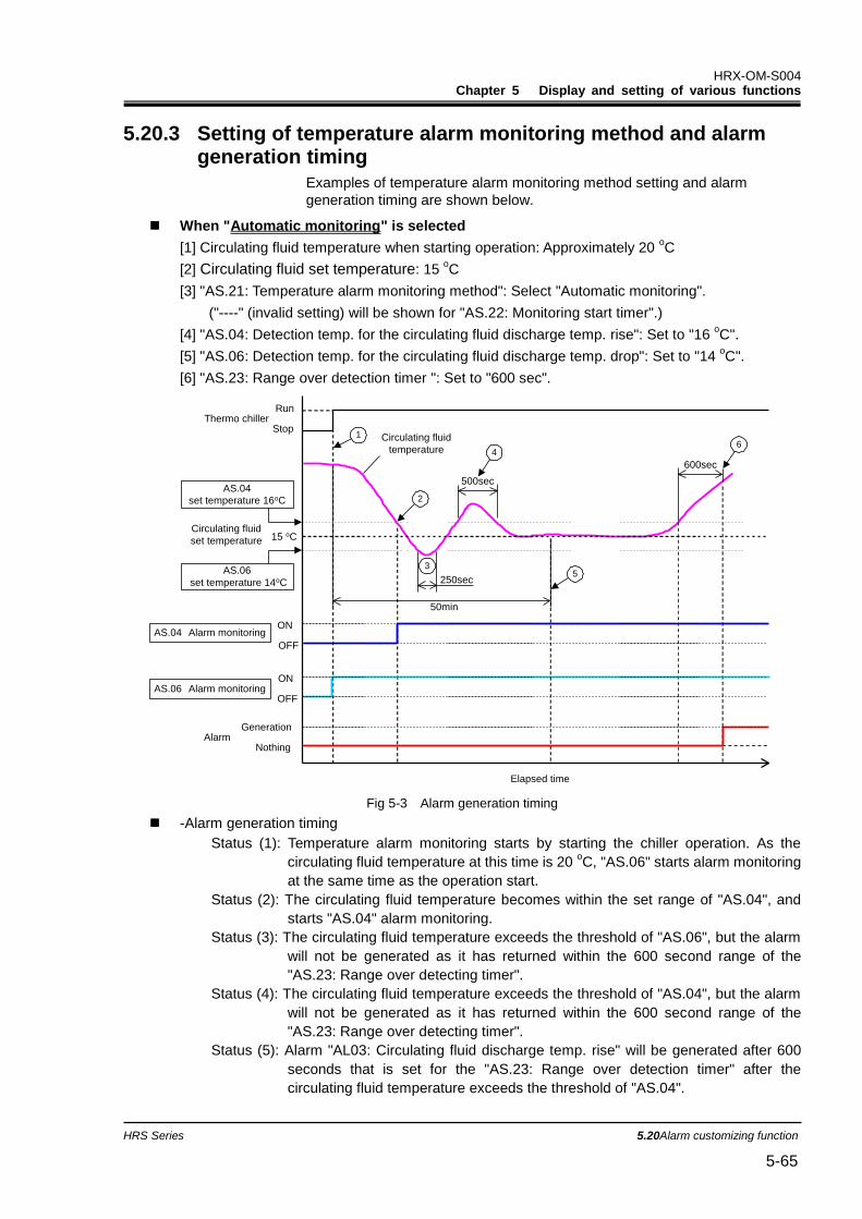
HRX-OM-S004 Chapter 5 Display and setting of various functions
HRS Series 5.20Alarm customizing function 5-65
5.20.3 Setting of temperature alarm monitoring method and alarm generation timing
Examples of temperature alarm monitoring method setting and alarm
generation timing are shown below.
When "Automatic monitoring" is selected
[1] Circulating fluid temperature when starting operation: Approximately 20 oC
[2] Circulating fluid set temperature: 15 oC
[3] "AS.21: Temperature alarm monitoring method": Select "Automatic monitoring".
("----" (invalid setting) will be shown for "AS.22: Monitoring start timer".)
[4] "AS.04: Detection temp. for the circulating fluid discharge temp. rise": Set to "16 oC".
[5] "AS.06: Detection temp. for the circulating fluid discharge temp. drop": Set to "14 oC".
[6] "AS.23: Range over detection timer ": Set to "600 sec".
Fig 5-3 Alarm generation timing
-Alarm generation timing
Status (1): Temperature alarm monitoring starts by starting the chiller operation. As the
circulating fluid temperature at this time is 20 oC, "AS.06" starts alarm monitoring
at the same time as the operation start.
Status (2): The circulating fluid temperature becomes within the set range of "AS.04", and
starts "AS.04" alarm monitoring.
Status (3): The circulating fluid temperature exceeds the threshold of "AS.06", but the alarm
will not be generated as it has returned within the 600 second range of the
"AS.23: Range over detecting timer".
Status (4): The circulating fluid temperature exceeds the threshold of "AS.04", but the alarm
will not be generated as it has returned within the 600 second range of the
"AS.23: Range over detecting timer".
Status (5): Alarm "AL03: Circulating fluid discharge temp. rise" will be generated after 600
seconds that is set for the "AS.23: Range over detection timer" after the
circulating fluid temperature exceeds the threshold of "AS.04".
Thermo chillerRun
Stop
Circulating fluid
set temperature 15 oC
AS.04 Alarm monitoringON
OFF
AlarmGeneration
Nothing
50min
600sec
Circulating fluid
temperature
ON
OFF
250sec
500sec
Elapsed time
AS.04
set temperature 16oC
AS.06
set temperature 14oC
1
2
4
35
6
AS.06 Alarm monitoring
HRX-OM-S004 Chapter 5 Display and setting of various functions
5.20 Alarm customizing function HRS Series 5-66
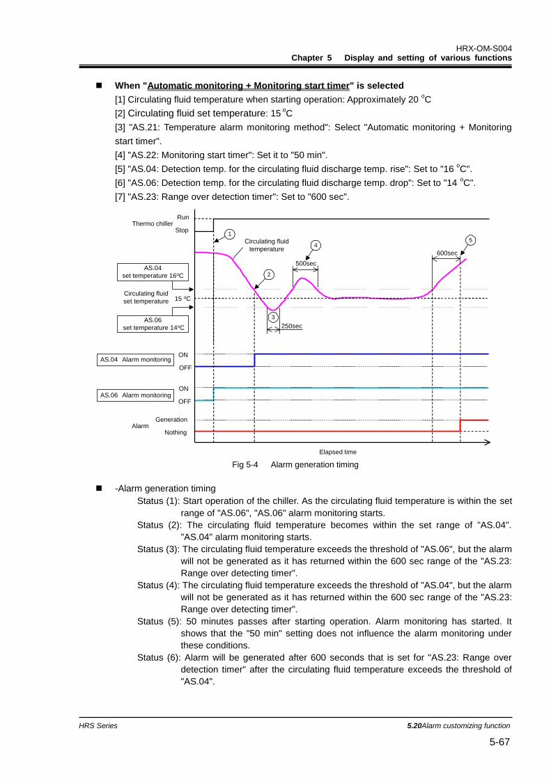
HRX-OM-S004 Chapter 5 Display and setting of various functions
HRS Series 5.20Alarm customizing function 5-67
When "Automatic monitoring + Monitoring start timer" is selected
[1] Circulating fluid temperature when starting operation: Approximately 20 oC
[2] Circulating fluid set temperature: 15 oC
[3] "AS.21: Temperature alarm monitoring method": Select "Automatic monitoring + Monitoring
start timer".
[4] "AS.22: Monitoring start timer": Set it to "50 min".
[5] "AS.04: Detection temp. for the circulating fluid discharge temp. rise": Set to "16 oC".
[6] "AS.06: Detection temp. for the circulating fluid discharge temp. drop": Set to "14 oC".
[7] "AS.23: Range over detection timer": Set to "600 sec".
Fig 5-4 Alarm generation timing
-Alarm generation timing
Status (1): Start operation of the chiller. As the circulating fluid temperature is within the set
range of "AS.06", "AS.06" alarm monitoring starts.
Status (2): The circulating fluid temperature becomes within the set range of "AS.04".
"AS.04" alarm monitoring starts.
Status (3): The circulating fluid temperature exceeds the threshold of "AS.06", but the alarm
will not be generated as it has returned within the 600 sec range of the "AS.23:
Range over detecting timer".
Status (4): The circulating fluid temperature exceeds the threshold of "AS.04", but the alarm
will not be generated as it has returned within the 600 sec range of the "AS.23:
Range over detecting timer".
Status (5): 50 minutes passes after starting operation. Alarm monitoring has started. It
shows that the "50 min" setting does not influence the alarm monitoring under
these conditions.
Status (6): Alarm will be generated after 600 seconds that is set for "AS.23: Range over
detection timer" after the circulating fluid temperature exceeds the threshold of
"AS.04".
600sec
250sec
500sec
1
2
4
3
5
Thermo chillerRun
Stop
Circulating fluid
set temperature 15 oC
AS.04 Alarm monitoringON
OFF
AlarmGeneration
Nothing
ON
OFF
AS.04
set temperature 16oC
AS.06
set temperature 14oC
AS.06 Alarm monitoring
Circulating fluid
temperature
Elapsed time
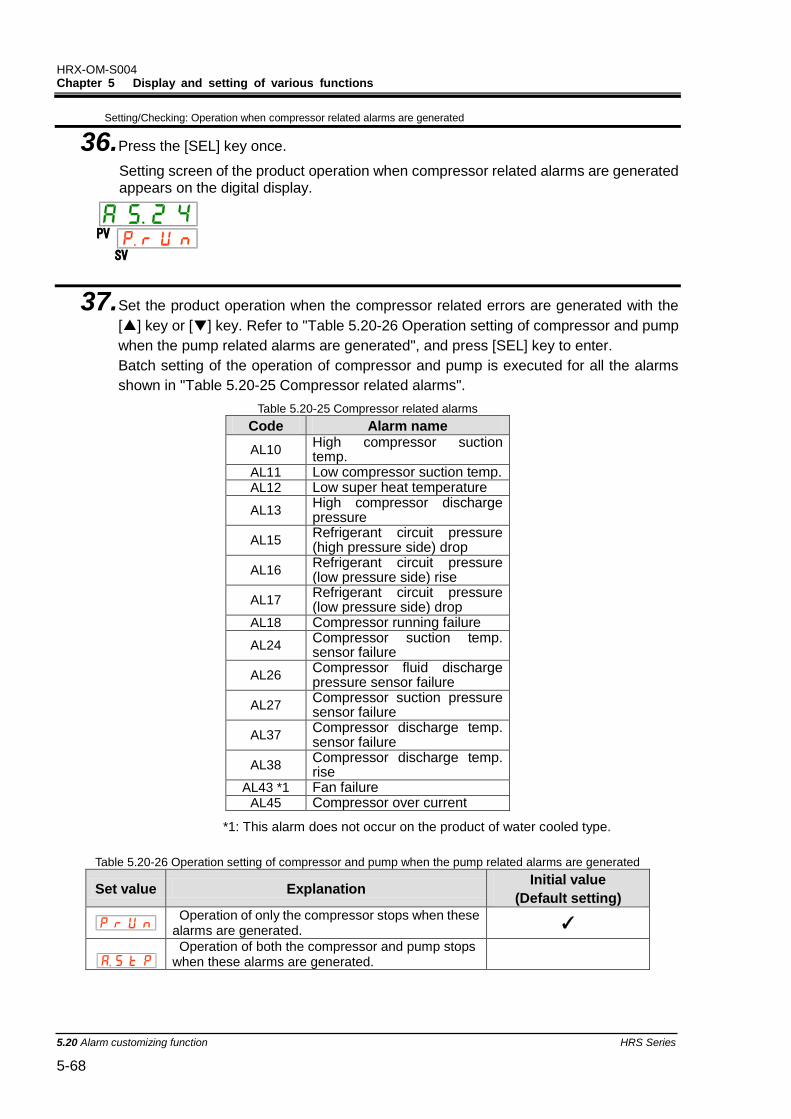
HRX-OM-S004 Chapter 5 Display and setting of various functions
5.20 Alarm customizing function HRS Series 5-68
Setting/Checking: Operation when compressor related alarms are generated
36. Press the [SEL] key once.
Setting screen of the product operation when compressor related alarms are generated appears on the digital display.
PV
SV
37. Set the product operation when the compressor related errors are generated with the
[▲] key or [▼] key. Refer to "Table 5.20-26 Operation setting of compressor and pump
when the pump related alarms are generated", and press [SEL] key to enter.
Batch setting of the operation of compressor and pump is executed for all the alarms
shown in "Table 5.20-25 Compressor related alarms".
Table 5.20-25 Compressor related alarms
Code Alarm name
AL10 High compressor suction temp.
AL11 Low compressor suction temp. AL12 Low super heat temperature
AL13 High compressor discharge pressure
AL15 Refrigerant circuit pressure (high pressure side) drop
AL16 Refrigerant circuit pressure (low pressure side) rise
AL17 Refrigerant circuit pressure (low pressure side) drop
AL18 Compressor running failure
AL24 Compressor suction temp. sensor failure
AL26 Compressor fluid discharge pressure sensor failure
AL27 Compressor suction pressure sensor failure
AL37 Compressor discharge temp. sensor failure
AL38 Compressor discharge temp. rise
AL43 *1 Fan failure AL45 Compressor over current
*1: This alarm does not occur on the product of water cooled type.
Table 5.20-26 Operation setting of compressor and pump when the pump related alarms are generated
Set value Explanation Initial value
(Default setting)
Operation of only the compressor stops when these alarms are generated.
✓
Operation of both the compressor and pump stops when these alarms are generated.
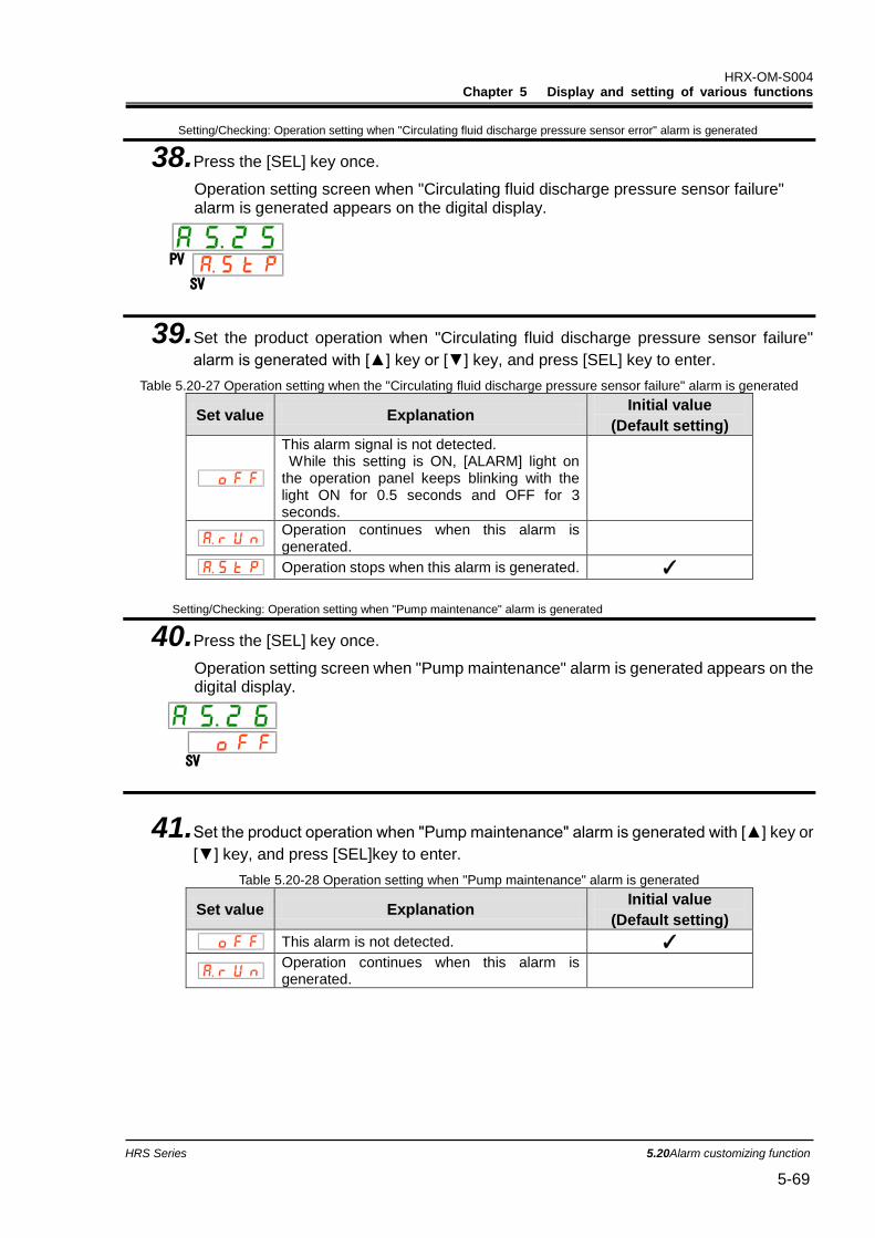
HRX-OM-S004 Chapter 5 Display and setting of various functions
HRS Series 5.20Alarm customizing function 5-69
Setting/Checking: Operation setting when "Circulating fluid discharge pressure sensor error" alarm is generated
38. Press the [SEL] key once.
Operation setting screen when "Circulating fluid discharge pressure sensor failure" alarm is generated appears on the digital display.
PV
SV
39. Set the product operation when "Circulating fluid discharge pressure sensor failure"
alarm is generated with [▲] key or [▼] key, and press [SEL] key to enter.
Table 5.20-27 Operation setting when the "Circulating fluid discharge pressure sensor failure" alarm is generated
Set value Explanation Initial value
(Default setting)
This alarm signal is not detected. While this setting is ON, [ALARM] light on the operation panel keeps blinking with the light ON for 0.5 seconds and OFF for 3 seconds.
Operation continues when this alarm is generated.
Operation stops when this alarm is generated. ✓
Setting/Checking: Operation setting when "Pump maintenance" alarm is generated
40. Press the [SEL] key once.
Operation setting screen when "Pump maintenance" alarm is generated appears on the digital display.
SV
41. Set the product operation when "Pump maintenance" alarm is generated with [▲] key or
[▼] key, and press [SEL]key to enter.
Table 5.20-28 Operation setting when "Pump maintenance" alarm is generated
Set value Explanation Initial value
(Default setting)
This alarm is not detected. ✓
Operation continues when this alarm is generated.
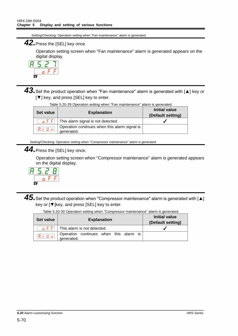
HRX-OM-S004 Chapter 5 Display and setting of various functions
5.20 Alarm customizing function HRS Series 5-70
Setting/Checking: Operation setting when "Fan maintenance" alarm is generated
42. Press the [SEL] key once.
Operation setting screen when "Fan maintenance" alarm is generated appears on the digital display.
SV
43. Set the product operation when "Fan maintenance" alarm is generated with [▲] key or
[▼] key, and press [SEL] key to enter.
Table 5.20-29 Operation setting when "Fan maintenance" alarm is generated
Set value Explanation Initial value
(Default setting)
This alarm signal is not detected. ✓
Operation continues when this alarm signal is generated.
Setting/Checking: Operation setting when "Compressor maintenance" alarm is generated
44. Press the [SEL] key once.
Operation setting screen when "Compressor maintenance" alarm is generated appears on the digital display.
SV
45. Set the product operation when "Compressor maintenance" alarm is generated with [▲]
key or [▼]key, and press [SEL] key to enter.
Table 5.20-30 Operation setting when “Compressor maintenance” alarm is generated
Set value Explanation Initial value
(Default setting)
This alarm is not detected. ✓
Operation continues when this alarm is generated.
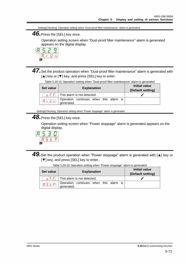
HRX-OM-S004 Chapter 5 Display and setting of various functions
HRS Series 5.20Alarm customizing function 5-71
Setting/Checking: Operation setting when "Dust-proof filter maintenance" alarm is generated
46. Press the [SEL] key once.
Operation setting screen when "Dust-proof filter maintenance" alarm is generated appears on the digital display.
SV
47. Set the product operation when "Dust-proof filter maintenance" alarm is generated with
[▲] key or [▼] key, and press [SEL] key to enter.
Table 5.20-31 Operation setting when "Dust-proof filter maintenance" alarm is generated
Set value Explanation Initial value
(Default setting)
This alarm is not detected. ✓
Operation continues when this alarm is generated.
Setting/Checking: Operation setting when "Power stoppage" alarm is generated
48. Press the [SEL] key once.
Operation setting screen when "Power stoppage" alarm is generated appears on the digital display.
SV
49. Set the product operation when "Power stoppage" alarm is generated with [▲] key or
[▼] key, and press [SEL] key to enter..
Table 5.20-32 Operation setting when "Power stoppage" alarm is generated
Set value Explanation Initial value
(Default setting)
This alarm is not detected. ✓
Operation continues when this alarm is generated.
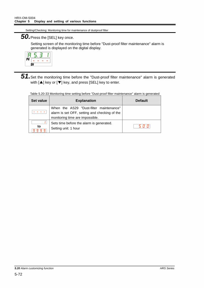
HRX-OM-S004 Chapter 5 Display and setting of various functions
5.20 Alarm customizing function HRS Series 5-72
Setting/Checking: Monitoring time for maintenance of dustproof filter
50. Press the [SEL] key once.
Setting screen of the monitoring time before "Dust-proof filter maintenance" alarm is generated is displayed on the digital display.
51. Set the monitoring time before the "Dust-proof filter maintenance" alarm is generated
with [▲] key or [▼] key, and press [SEL] key to enter.
Table 5.20-33 Monitoring time setting before "Dust-proof filter maintenance" alarm is generated
Set value Explanation Default
When the AS29 "Dust-filter maintenance"
alarm is set OFF, setting and checking of the
monitoring time are impossible.
to
Sets time before the alarm is generated.
Setting unit: 1 hour
SV
PV
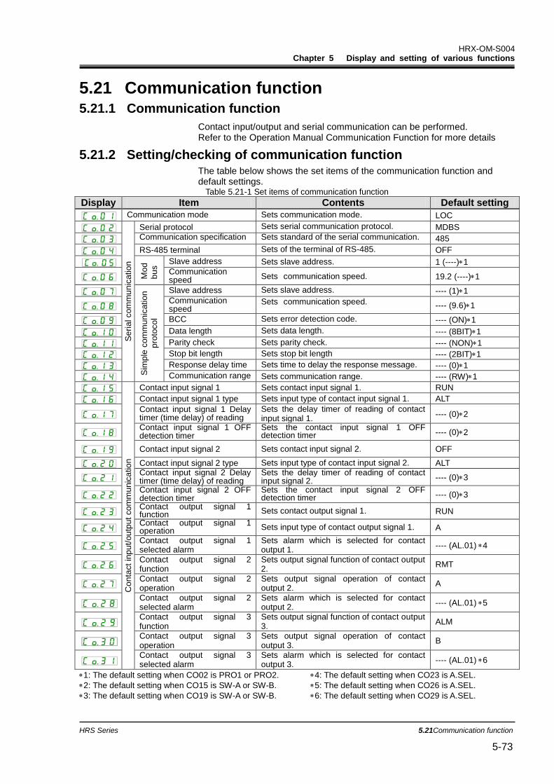
HRX-OM-S004 Chapter 5 Display and setting of various functions
HRS Series 5.21Communication function 5-73
5.21 Communication function 5.21.1 Communication function
Contact input/output and serial communication can be performed. Refer to the Operation Manual Communication Function for more details
5.21.2 Setting/checking of communication function The table below shows the set items of the communication function and default settings.
Table 5.21-1 Set items of communication function
Display Item Contents Default setting
Communication mode Sets communication mode. LOC
Se
ria
l com
mu
nic
atio
n
Serial protocol Sets serial communication protocol. MDBS
Communication specification Sets standard of the serial communication. 485
RS-485 terminal Sets of the terminal of RS-485. OFF
Mo
d
bu
s Slave address Sets slave address. 1 (----)1
Communication speed Sets communication speed. 19.2 (----)1
Sim
ple
co
mm
unic
atio
n
pro
toco
l
Slave address Sets slave address. ---- (1)1
Communication speed
Sets communication speed. ---- (9.6)1
BCC Sets error detection code. ---- (ON)1
Data length Sets data length. ---- (8BIT)1
Parity check Sets parity check. ---- (NON)1
Stop bit length Sets stop bit length ---- (2BIT)1
Response delay time Sets time to delay the response message. ---- (0)1
Communication range Sets communication range. ---- (RW)1
Con
tact
inp
ut/
ou
tput
co
mm
unic
atio
n
Contact input signal 1 Sets contact input signal 1. RUN
Contact input signal 1 type Sets input type of contact input signal 1. ALT
Contact input signal 1 Delay timer (time delay) of reading
Sets the delay timer of reading of contact input signal 1.
---- (0)2
Contact input signal 1 OFF detection timer
Sets the contact input signal 1 OFF detection timer ---- (0)2
Contact input signal 2 Sets contact input signal 2. OFF
Contact input signal 2 type Sets input type of contact input signal 2. ALT
Contact input signal 2 Delay timer (time delay) of reading
Sets the delay timer of reading of contact input signal 2. ---- (0)3
Contact input signal 2 OFF detection timer
Sets the contact input signal 2 OFF detection timer ---- (0)3
Contact output signal 1 function Sets contact output signal 1. RUN
Contact output signal 1 operation Sets input type of contact output signal 1. A
Contact output signal 1 selected alarm
Sets alarm which is selected for contact output 1.
---- (AL.01)4
Contact output signal 2 function
Sets output signal function of contact output 2.
RMT
Contact output signal 2 operation
Sets output signal operation of contact output 2.
A
Contact output signal 2 selected alarm
Sets alarm which is selected for contact output 2.
---- (AL.01)5
Contact output signal 3 function
Sets output signal function of contact output 3.
ALM
Contact output signal 3 operation
Sets output signal operation of contact output 3.
B
Contact output signal 3 selected alarm
Sets alarm which is selected for contact output 3.
---- (AL.01)6
1: The default setting when CO02 is PRO1 or PRO2. 4: The default setting when CO23 is A.SEL.
2: The default setting when CO15 is SW-A or SW-B. 5: The default setting when CO26 is A.SEL.
3: The default setting when CO19 is SW-A or SW-B. 6: The default setting when CO29 is A.SEL.
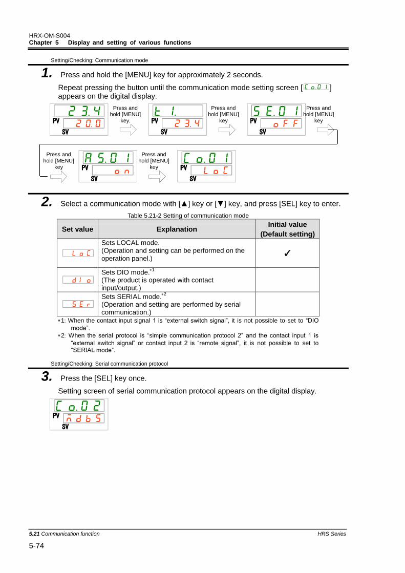
HRX-OM-S004 Chapter 5 Display and setting of various functions
5.21 Communication function HRS Series 5-74
Setting/Checking: Communication mode
1. Press and hold the [MENU] key for approximately 2 seconds.
Repeat pressing the button until the communication mode setting screen [ ] appears on the digital display.
2. Select a communication mode with [▲] key or [▼] key, and press [SEL] key to enter.
Table 5.21-2 Setting of communication mode
Set value Explanation Initial value
(Default setting)
Sets LOCAL mode. (Operation and setting can be performed on the operation panel.)
✓
Sets DIO mode.1
(The product is operated with contact input/output.)
Sets SERIAL mode.2
(Operation and setting are performed by serial communication.)
1: When the contact input signal 1 is “external switch signal”, it is not possible to set to “DIO
mode”. 2: When the serial protocol is “simple communication protocol 2” and the contact input 1 is
“external switch signal” or contact input 2 is “remote signal”, it is not possible to set to “SERIAL mode”.
Setting/Checking: Serial communication protocol
3. Press the [SEL] key once.
Setting screen of serial communication protocol appears on the digital display.
PV
SV
PV
SV
PV
SV
PV
SV
PV
SV
PV
SV
Press and hold [MENU]
key.
Press and hold [MENU]
key
Press and hold [MENU]
key
Press and hold [MENU]
key
Press and hold [MENU]
key
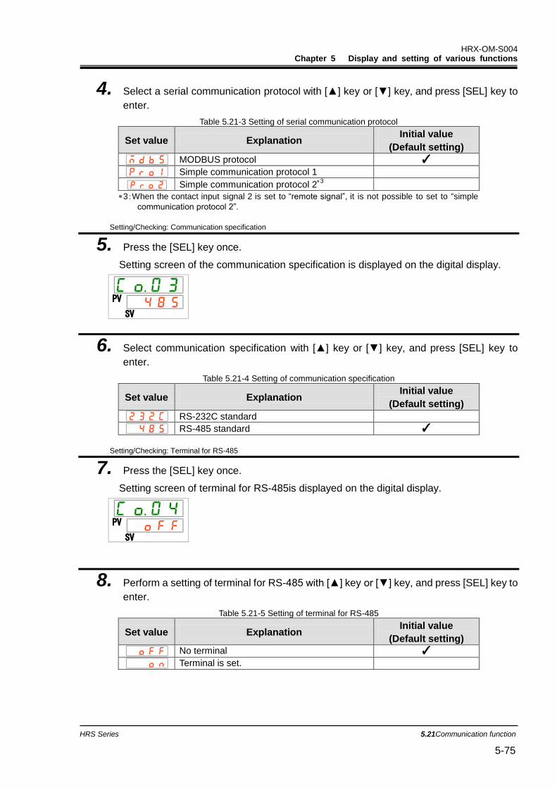
HRX-OM-S004 Chapter 5 Display and setting of various functions
HRS Series 5.21Communication function 5-75
4. Select a serial communication protocol with [▲] key or [▼] key, and press [SEL] key to
enter.
Table 5.21-3 Setting of serial communication protocol
Set value Explanation Initial value
(Default setting)
MODBUS protocol ✓
Simple communication protocol 1
Simple communication protocol 23
3:When the contact input signal 2 is set to “remote signal”, it is not possible to set to “simple
communication protocol 2”.
Setting/Checking: Communication specification
5. Press the [SEL] key once.
Setting screen of the communication specification is displayed on the digital display.
6. Select communication specification with [▲] key or [▼] key, and press [SEL] key to
enter.
Table 5.21-4 Setting of communication specification
Set value Explanation Initial value
(Default setting)
RS-232C standard
RS-485 standard ✓
Setting/Checking: Terminal for RS-485
7. Press the [SEL] key once.
Setting screen of terminal for RS-485is displayed on the digital display.
8. Perform a setting of terminal for RS-485 with [▲] key or [▼] key, and press [SEL] key to
enter.
Table 5.21-5 Setting of terminal for RS-485
Set value Explanation Initial value
(Default setting)
No terminal ✓
Terminal is set.
PV
SV
PV
SV
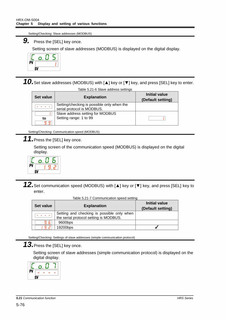
HRX-OM-S004 Chapter 5 Display and setting of various functions
5.21 Communication function HRS Series 5-76
Setting/Checking: Slave addresses (MODBUS)
9. Press the [SEL] key once.
Setting screen of slave addresses (MODBUS) is displayed on the digital display.
10. Set slave addresses (MODBUS) with [▲] key or [▼] key, and press [SEL] key to enter.
Table 5.21-6 Slave address settings
Set value Explanation Initial value
(Default setting)
Setting/checking is possible only when the serial protocol is MODBUS.
to
Slave address setting for MODBUS Setting range: 1 to 99
Setting/Checking: Communication speed (MODBUS)
11. Press the [SEL] key once.
Setting screen of the communication speed (MODBUS) is displayed on the digital display.
12. Set communication speed (MODBUS) with [▲] key or [▼] key, and press [SEL] key to
enter.
Table 5.21-7 Communication speed setting
Set value Explanation Initial value
(Default setting)
Setting and checking is possible only when the serial protocol setting is MODBUS.
9600bps
19200bps ✓
Setting/Checking: Settings of slave addresses (simple communication protocol)
13. Press the [SEL] key once.
Setting screen of slave addresses (simple communication protocol) is displayed on the digital display.
PV
SV
PV
SV
PV
SV
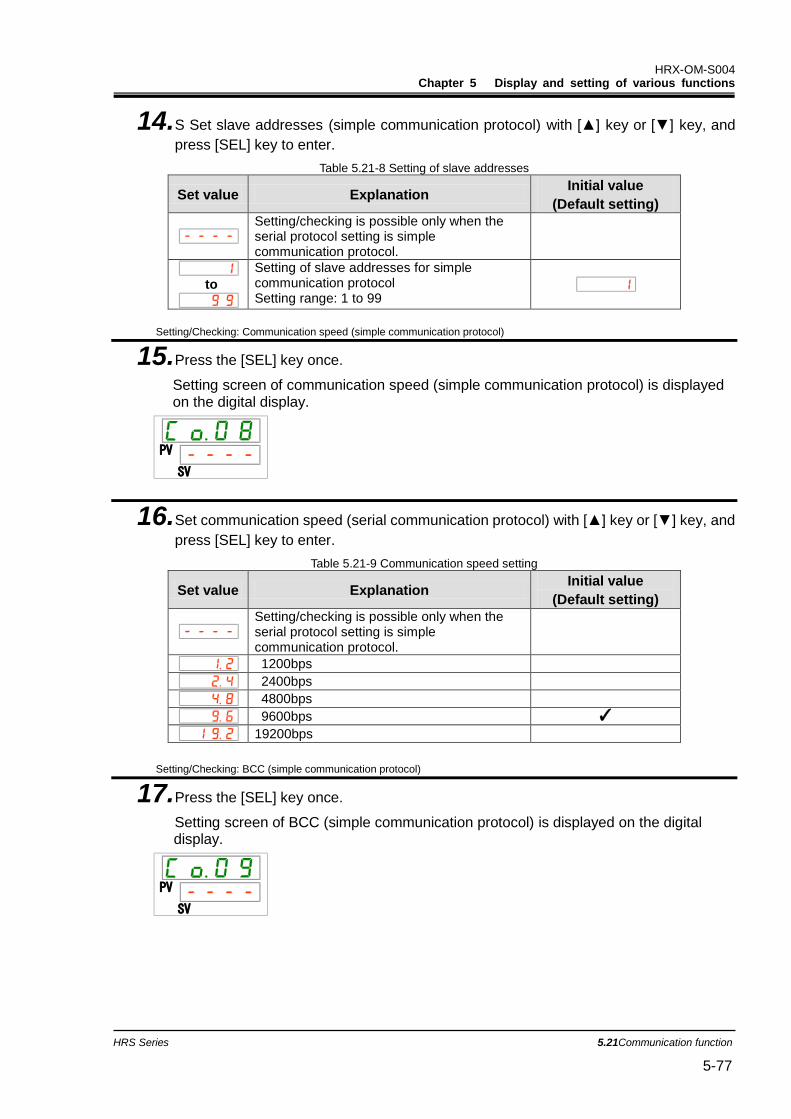
HRX-OM-S004 Chapter 5 Display and setting of various functions
HRS Series 5.21Communication function 5-77
14. S Set slave addresses (simple communication protocol) with [▲] key or [▼] key, and
press [SEL] key to enter.
Table 5.21-8 Setting of slave addresses
Set value Explanation Initial value
(Default setting)
Setting/checking is possible only when the serial protocol setting is simple communication protocol.
to
Setting of slave addresses for simple communication protocol Setting range: 1 to 99
Setting/Checking: Communication speed (simple communication protocol)
15. Press the [SEL] key once.
Setting screen of communication speed (simple communication protocol) is displayed on the digital display.
16. Set communication speed (serial communication protocol) with [▲] key or [▼] key, and
press [SEL] key to enter.
Table 5.21-9 Communication speed setting
Set value Explanation Initial value
(Default setting)
Setting/checking is possible only when the serial protocol setting is simple communication protocol.
1200bps
2400bps
4800bps
9600bps ✓
19200bps
Setting/Checking: BCC (simple communication protocol)
17. Press the [SEL] key once.
Setting screen of BCC (simple communication protocol) is displayed on the digital display.
PV
SV
PV
SV
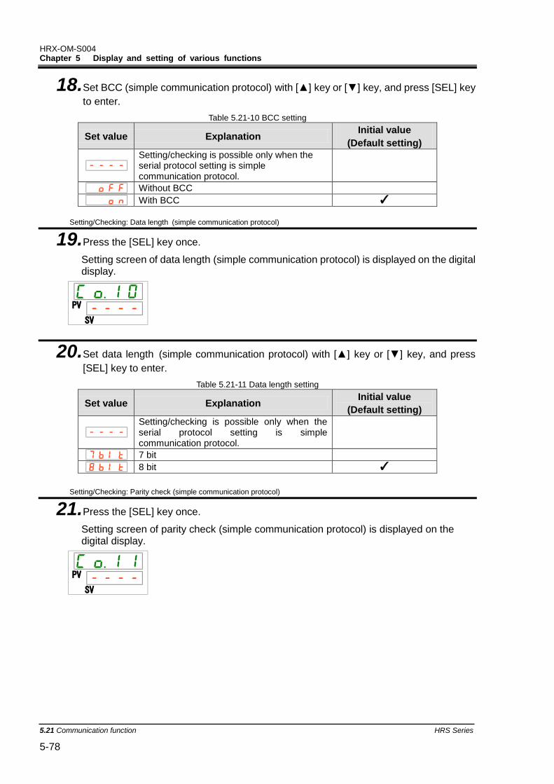
HRX-OM-S004 Chapter 5 Display and setting of various functions
5.21 Communication function HRS Series 5-78
18. Set BCC (simple communication protocol) with [▲] key or [▼] key, and press [SEL] key
to enter.
Table 5.21-10 BCC setting
Set value Explanation Initial value
(Default setting)
Setting/checking is possible only when the serial protocol setting is simple communication protocol.
Without BCC
With BCC ✓
Setting/Checking: Data length (simple communication protocol)
19. Press the [SEL] key once.
Setting screen of data length (simple communication protocol) is displayed on the digital display.
20. Set data length (simple communication protocol) with [▲] key or [▼] key, and press
[SEL] key to enter.
Table 5.21-11 Data length setting
Set value Explanation Initial value
(Default setting)
Setting/checking is possible only when the serial protocol setting is simple communication protocol.
7 bit
8 bit ✓
Setting/Checking: Parity check (simple communication protocol)
21. Press the [SEL] key once.
Setting screen of parity check (simple communication protocol) is displayed on the digital display.
PV
SV
PV
SV
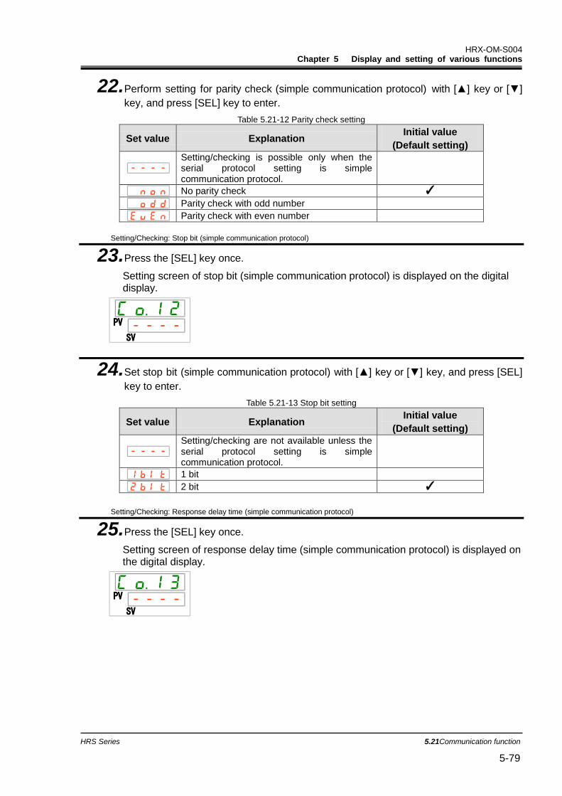
HRX-OM-S004 Chapter 5 Display and setting of various functions
HRS Series 5.21Communication function 5-79
22. Perform setting for parity check (simple communication protocol) with [▲] key or [▼]
key, and press [SEL] key to enter.
Table 5.21-12 Parity check setting
Set value Explanation Initial value
(Default setting)
Setting/checking is possible only when the serial protocol setting is simple communication protocol.
No parity check ✓
Parity check with odd number
Parity check with even number
Setting/Checking: Stop bit (simple communication protocol)
23. Press the [SEL] key once.
Setting screen of stop bit (simple communication protocol) is displayed on the digital display.
24. Set stop bit (simple communication protocol) with [▲] key or [▼] key, and press [SEL]
key to enter.
Table 5.21-13 Stop bit setting
Set value Explanation Initial value
(Default setting)
Setting/checking are not available unless the serial protocol setting is simple communication protocol.
1 bit
2 bit ✓
Setting/Checking: Response delay time (simple communication protocol)
25. Press the [SEL] key once.
Setting screen of response delay time (simple communication protocol) is displayed on the digital display.
PV
SV
PV
SV
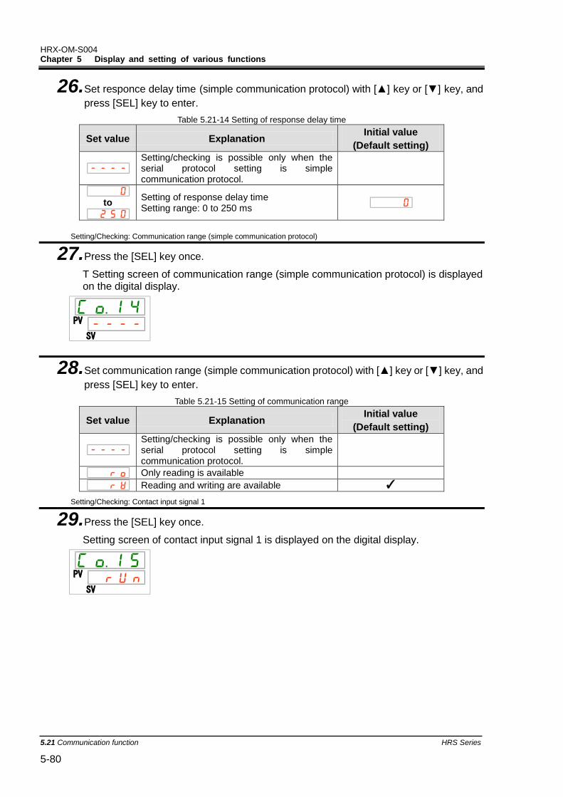
HRX-OM-S004 Chapter 5 Display and setting of various functions
5.21 Communication function HRS Series 5-80
26. Set responce delay time (simple communication protocol) with [▲] key or [▼] key, and
press [SEL] key to enter.
Table 5.21-14 Setting of response delay time
Set value Explanation Initial value
(Default setting)
Setting/checking is possible only when the serial protocol setting is simple communication protocol.
to
Setting of response delay time Setting range: 0 to 250 ms
Setting/Checking: Communication range (simple communication protocol)
27. Press the [SEL] key once.
T Setting screen of communication range (simple communication protocol) is displayed on the digital display.
28. Set communication range (simple communication protocol) with [▲] key or [▼] key, and
press [SEL] key to enter.
Table 5.21-15 Setting of communication range
Set value Explanation Initial value
(Default setting)
Setting/checking is possible only when the serial protocol setting is simple communication protocol.
Only reading is available
Reading and writing are available ✓
Setting/Checking: Contact input signal 1
29. Press the [SEL] key once.
Setting screen of contact input signal 1 is displayed on the digital display.
PV
SV
PV
SV
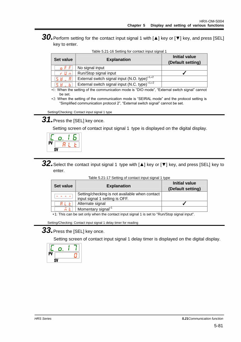
HRX-OM-S004 Chapter 5 Display and setting of various functions
HRS Series 5.21Communication function 5-81
30. Perform setting for the contact input signal 1 with [▲] key or [▼] key, and press [SEL]
key to enter.
Table 5.21-16 Setting for contact input signal 1
Set value Explanation Initial value
(Default setting)
No signal input
Run/Stop signal input ✓
External switch signal input (N.O. type)1,2
External switch signal input (N.C. type)1,2
: When the setting of the communication mode is “DIO mode”, “External switch signal” cannot
be set. : When the setting of the communication mode is “SEIRAL mode” and the protocol setting is
“Simplified communication protocol 2”, “External switch signal” cannot be set.
Setting/Checking: Contact input signal 1 type
31. Press the [SEL] key once.
Setting screen of contact input signal 1 type is displayed on the digital display.
32. Select the contact input signal 1 type with [▲] key or [▼] key, and press [SEL] key to
enter.
Table 5.21-17 Setting of contact input signal 1 type
Set value Explanation Initial value
(Default setting)
Setting/checking is not available when contact input signal 1 setting is OFF.
Alternate signal ✓
Momentary signal1
1: This can be set only when the contact input signal 1 is set to "Run/Stop signal input".
Setting/Checking: Contact input signal 1 delay timer for reading
33. Press the [SEL] key once.
Setting screen of contact input signal 1 delay timer is displayed on the digital display.
PV
SV
PV
SV
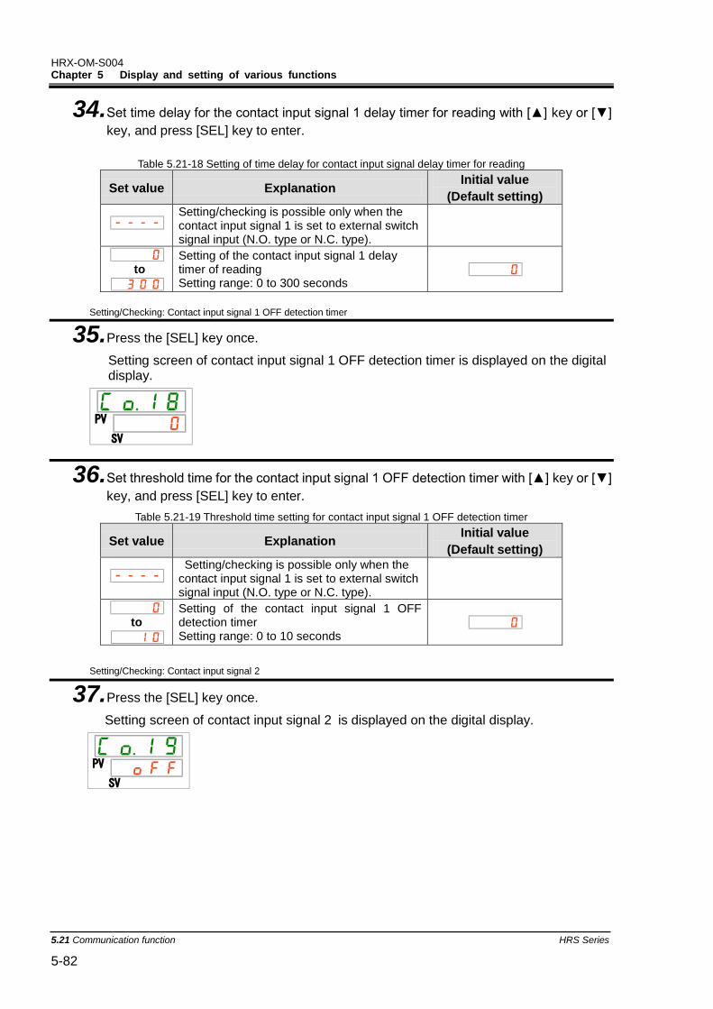
HRX-OM-S004 Chapter 5 Display and setting of various functions
5.21 Communication function HRS Series 5-82
34. Set time delay for the contact input signal 1 delay timer for reading with [▲] key or [▼]
key, and press [SEL] key to enter.
Table 5.21-18 Setting of time delay for contact input signal delay timer for reading
Set value Explanation Initial value
(Default setting)
Setting/checking is possible only when the contact input signal 1 is set to external switch signal input (N.O. type or N.C. type).
to
Setting of the contact input signal 1 delay timer of reading Setting range: 0 to 300 seconds
Setting/Checking: Contact input signal 1 OFF detection timer
35. Press the [SEL] key once.
Setting screen of contact input signal 1 OFF detection timer is displayed on the digital display.
36. Set threshold time for the contact input signal 1 OFF detection timer with [▲] key or [▼]
key, and press [SEL] key to enter.
Table 5.21-19 Threshold time setting for contact input signal 1 OFF detection timer
Set value Explanation Initial value
(Default setting)
Setting/checking is possible only when the contact input signal 1 is set to external switch signal input (N.O. type or N.C. type).
to
Setting of the contact input signal 1 OFF detection timer Setting range: 0 to 10 seconds
Setting/Checking: Contact input signal 2
37. Press the [SEL] key once.
Setting screen of contact input signal 2 is displayed on the digital display.
PV
SV
PV
SV
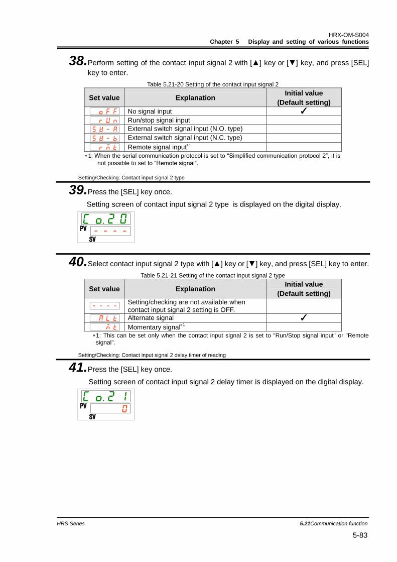
HRX-OM-S004 Chapter 5 Display and setting of various functions
HRS Series 5.21Communication function 5-83
38. Perform setting of the contact input signal 2 with [▲] key or [▼] key, and press [SEL]
key to enter.
Table 5.21-20 Setting of the contact input signal 2
Set value Explanation Initial value
(Default setting)
No signal input ✓
Run/stop signal input
External switch signal input (N.O. type)
External switch signal input (N.C. type)
Remote signal input1
1: When the serial communication protocol is set to “Simplified communication protocol 2”, it is
not possible to set to “Remote signal”.
Setting/Checking: Contact input signal 2 type
39. Press the [SEL] key once.
Setting screen of contact input signal 2 type is displayed on the digital display.
40. Select contact input signal 2 type with [▲] key or [▼] key, and press [SEL] key to enter.
Table 5.21-21 Setting of the contact input signal 2 type
Set value Explanation Initial value
(Default setting)
Setting/checking are not available when contact input signal 2 setting is OFF.
Alternate signal ✓
Momentary signal1
1: This can be set only when the contact input signal 2 is set to "Run/Stop signal input" or "Remote signal".
Setting/Checking: Contact input signal 2 delay timer of reading
41. Press the [SEL] key once.
Setting screen of contact input signal 2 delay timer is displayed on the digital display.
PV
SV
PV
SV
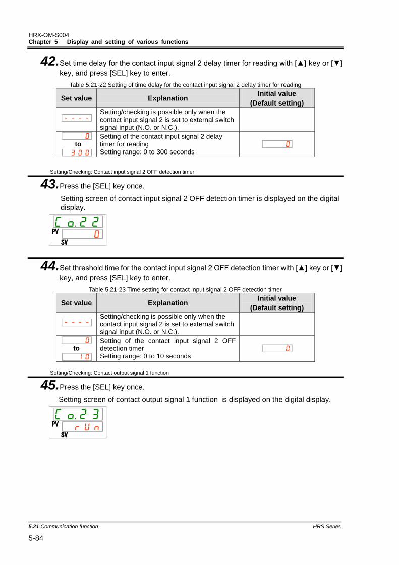
HRX-OM-S004 Chapter 5 Display and setting of various functions
5.21 Communication function HRS Series 5-84
42. Set time delay for the contact input signal 2 delay timer for reading with [▲] key or [▼]
key, and press [SEL] key to enter.
Table 5.21-22 Setting of time delay for the contact input signal 2 delay timer for reading
Set value Explanation Initial value
(Default setting)
Setting/checking is possible only when the contact input signal 2 is set to external switch signal input (N.O. or N.C.).
to
Setting of the contact input signal 2 delay timer for reading Setting range: 0 to 300 seconds
Setting/Checking: Contact input signal 2 OFF detection timer
43. Press the [SEL] key once.
Setting screen of contact input signal 2 OFF detection timer is displayed on the digital display.
44. Set threshold time for the contact input signal 2 OFF detection timer with [▲] key or [▼]
key, and press [SEL] key to enter.
Table 5.21-23 Time setting for contact input signal 2 OFF detection timer
Set value Explanation Initial value
(Default setting)
Setting/checking is possible only when the contact input signal 2 is set to external switch signal input (N.O. or N.C.).
to
Setting of the contact input signal 2 OFF detection timer Setting range: 0 to 10 seconds
Setting/Checking: Contact output signal 1 function
45. Press the [SEL] key once.
Setting screen of contact output signal 1 function is displayed on the digital display.
PV
SV
PV
SV
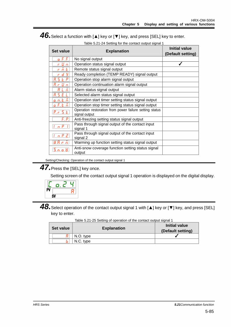
HRX-OM-S004 Chapter 5 Display and setting of various functions
HRS Series 5.21Communication function 5-85
46. Select a function with [▲] key or [▼] key, and press [SEL] key to enter.
Table 5.21-24 Setting for the contact output signal 1
Set value Explanation Initial value
(Default setting)
No signal output
Operation status signal output ✓
Remote status signal output
Ready completion (TEMP READY) signal output
Operation stop alarm signal output
Operation continuation alarm signal output
Alarm status signal output
Selected alarm status signal output
Operation start timer setting status signal output
Operation stop timer setting status signal output
Operation restoration from power failure setting status signal output
Anti-freezing setting status signal output
Pass through signal output of the contact input signal 1
Pass through signal output of the contact input signal 2
Warming up function setting status signal output
Anti-snow coverage function setting status signal output
Setting/Checking: Operation of the contact output signal 1
47. Press the [SEL] key once.
Setting screen of the contact output signal 1 operation is displayed on the digital display.
48. Select operation of the contact output signal 1 with [▲] key or [▼] key, and press [SEL]
key to enter.
Table 5.21-25 Setting of operation of the contact output signal 1
Set value Explanation Initial value
(Default setting)
N.O. type ✓
N.C. type
PV
SV
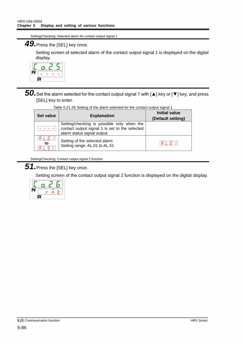
HRX-OM-S004 Chapter 5 Display and setting of various functions
5.21 Communication function HRS Series 5-86
Setting/Checking: Selected alarm for contact output signal 1
49. Press the [SEL] key once.
Setting screen of selected alarm of the contact output signal 1 is displayed on the digital display.
50. Set the alarm selected for the contact output signal 1 with [▲] key or [▼] key, and press
[SEL] key to enter.
Table 5.21-26 Setting of the alarm selected for the contact output signal 1
Set value Explanation Initial value
(Default setting)
Setting/checking is possible only when the contact output signal 1 is set to the selected alarm status signal output.
to
Setting of the selected alarm Setting range: AL.01 to AL.51
Setting/Checking: Contact output signal 2 function
51. Press the [SEL] key once.
Setting screen of the contact output signal 2 function is displayed on the digital display.
PV
SV
PV
SV

HRX-OM-S004 Chapter 5 Display and setting of various functions
HRS Series 5.21Communication function 5-87
52. Select a function with [▲] key or [▼] key, and press [SEL] key to enter.
Table 5.21-27 Setting for the contact output signal 2
Set value Explanation Initial value
(Default setting)
No signal output
Operation status signal output
Remote status signal output ✓
Ready completion (TEMP READY) signal output
Operation stop alarm signal output
Operation continuation alarm signal output
Alarm status signal output
Selected alarm status signal output
Operation start timer setting status signal output
Operation stop timer setting status signal output
Operation restoration from power failure setting status signal output
Anti-freezing setting status signal output
Pass through signal output of the contact input signal 1
Pass through signal output of the contact input signal 2
Warming up function setting status signal output
Anti-snow coverage function setting status output
Setting/Checking: Contact output signal 2 operation
53. Press the [SEL] key once.
Setting screen of the contact output signal 2 operation is displayed on the digital display.
54. Set the operation type of the contact output signal 2 with [▲] key or [▼] key, and press
[SEL] key to enter.
Table 5.21-28 Operation type setting for the contact output signal 2
Set value Explanation Initial value
(Default setting)
N.O. type ✓
N.C. type
PV
SV
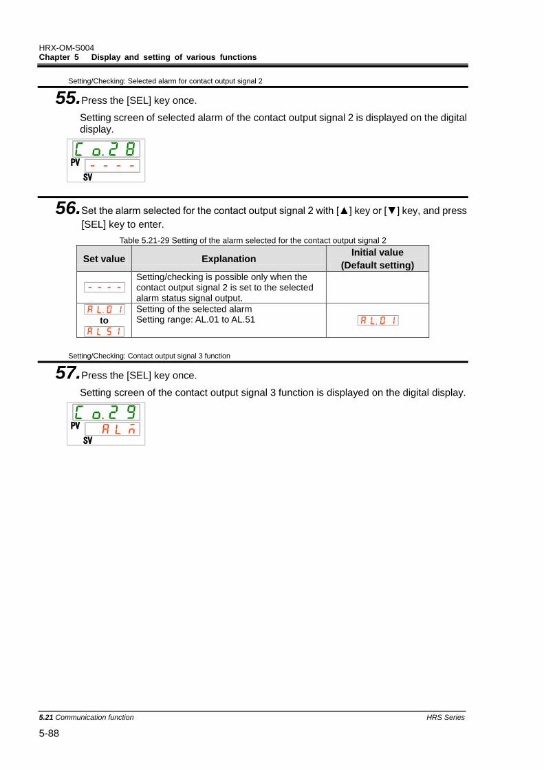
HRX-OM-S004 Chapter 5 Display and setting of various functions
5.21 Communication function HRS Series 5-88
Setting/Checking: Selected alarm for contact output signal 2
55. Press the [SEL] key once.
Setting screen of selected alarm of the contact output signal 2 is displayed on the digital display.
56. Set the alarm selected for the contact output signal 2 with [▲] key or [▼] key, and press
[SEL] key to enter.
Table 5.21-29 Setting of the alarm selected for the contact output signal 2
Set value Explanation Initial value
(Default setting)
Setting/checking is possible only when the contact output signal 2 is set to the selected alarm status signal output.
to
Setting of the selected alarm Setting range: AL.01 to AL.51
Setting/Checking: Contact output signal 3 function
57. Press the [SEL] key once.
Setting screen of the contact output signal 3 function is displayed on the digital display.
PV
SV
PV
SV
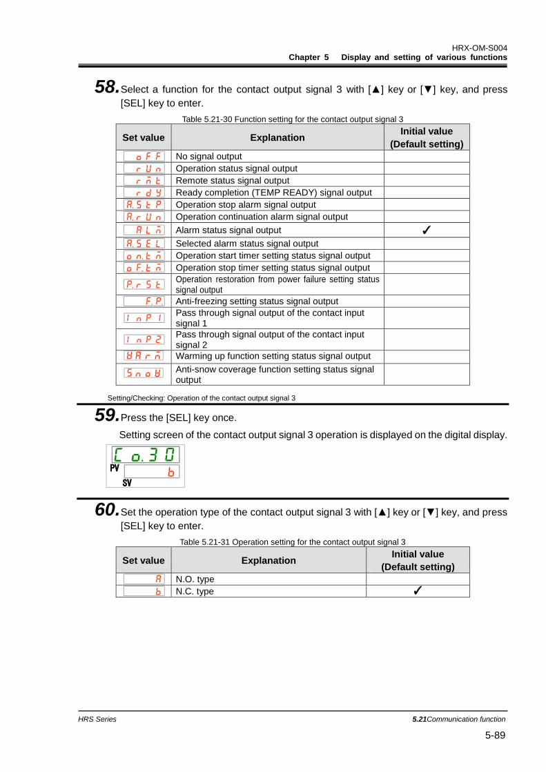
HRX-OM-S004 Chapter 5 Display and setting of various functions
HRS Series 5.21Communication function 5-89
58. Select a function for the contact output signal 3 with [▲] key or [▼] key, and press
[SEL] key to enter.
Table 5.21-30 Function setting for the contact output signal 3
Set value Explanation Initial value
(Default setting)
No signal output
Operation status signal output
Remote status signal output
Ready completion (TEMP READY) signal output
Operation stop alarm signal output
Operation continuation alarm signal output
Alarm status signal output ✓
Selected alarm status signal output
Operation start timer setting status signal output
Operation stop timer setting status signal output
Operation restoration from power failure setting status signal output
Anti-freezing setting status signal output
Pass through signal output of the contact input signal 1
Pass through signal output of the contact input signal 2
Warming up function setting status signal output
Anti-snow coverage function setting status signal output
Setting/Checking: Operation of the contact output signal 3
59. Press the [SEL] key once.
Setting screen of the contact output signal 3 operation is displayed on the digital display.
60. Set the operation type of the contact output signal 3 with [▲] key or [▼] key, and press
[SEL] key to enter.
Table 5.21-31 Operation setting for the contact output signal 3
Set value Explanation Initial value
(Default setting)
N.O. type
N.C. type ✓
PV
SV
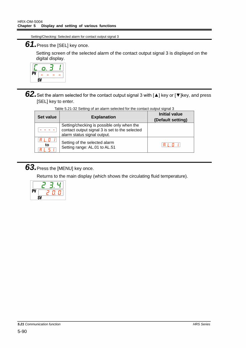
HRX-OM-S004 Chapter 5 Display and setting of various functions
5.21 Communication function HRS Series 5-90
Setting/Checking: Selected alarm for contact output signal 3
61. Press the [SEL] key once.
Setting screen of the selected alarm of the contact output signal 3 is displayed on the digital display.
62. Set the alarm selected for the contact output signal 3 with [▲] key or [▼]key, and press
[SEL] key to enter.
Table 5.21-32 Setting of an alarm selected for the contact output signal 3
Set value Explanation Initial value
(Default setting)
Setting/checking is possible only when the contact output signal 3 is set to the selected alarm status signal output.
to
Setting of the selected alarm Setting range: AL.01 to AL.51
63. Press the [MENU] key once.
Returns to the main display (which shows the circulating fluid temperature).
PV
SV
PV
SV
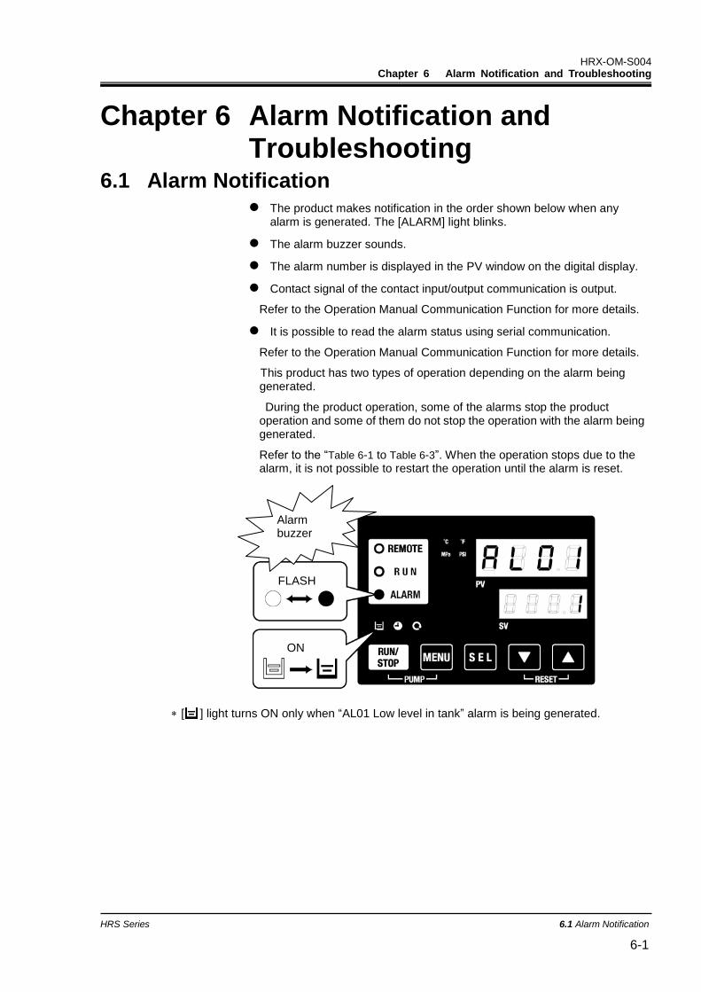
HRX-OM-S004 Chapter 6 Alarm Notification and Troubleshooting
HRS Series 6.1 Alarm Notification 6-1
Chapter 6 Alarm Notification and Troubleshooting
6.1 Alarm Notification The product makes notification in the order shown below when any
alarm is generated. The [ALARM] light blinks.
The alarm buzzer sounds.
The alarm number is displayed in the PV window on the digital display.
Contact signal of the contact input/output communication is output.
Refer to the Operation Manual Communication Function for more details.
It is possible to read the alarm status using serial communication.
Refer to the Operation Manual Communication Function for more details.
This product has two types of operation depending on the alarm being generated.
During the product operation, some of the alarms stop the product operation and some of them do not stop the operation with the alarm being generated.
Refer to the “Table 6-1 to Table 6-3”. When the operation stops due to the alarm, it is not possible to restart the operation until the alarm is reset.
[ ] light turns ON only when “AL01 Low level in tank” alarm is being generated.
ON
Alarm buzzer
FLASH
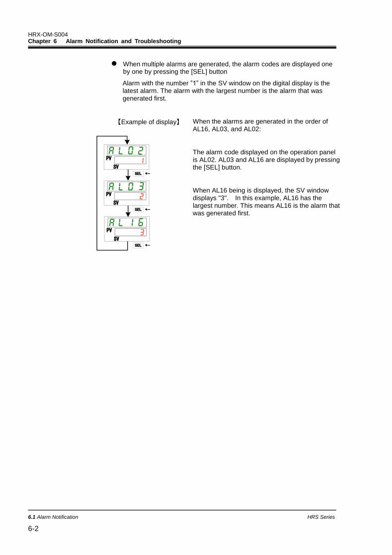
HRX-OM-S004 Chapter 6 Alarm Notification and Troubleshooting
6.1 Alarm Notification HRS Series
6-2
When multiple alarms are generated, the alarm codes are displayed one by one by pressing the [SEL] button
Alarm with the number ”1” in the SV window on the digital display is the latest alarm. The alarm with the largest number is the alarm that was generated first.
【Example of display】
PV
SV
PV
SV
PV
SVSEL キー
SEL キー
SEL キー
When the alarms are generated in the order of AL16, AL03, and AL02:
The alarm code displayed on the operation panel is AL02. AL03 and AL16 are displayed by pressing the [SEL] button.
When AL16 being is displayed, the SV window displays "3". In this example, AL16 has the largest number. This means AL16 is the alarm that was generated first.
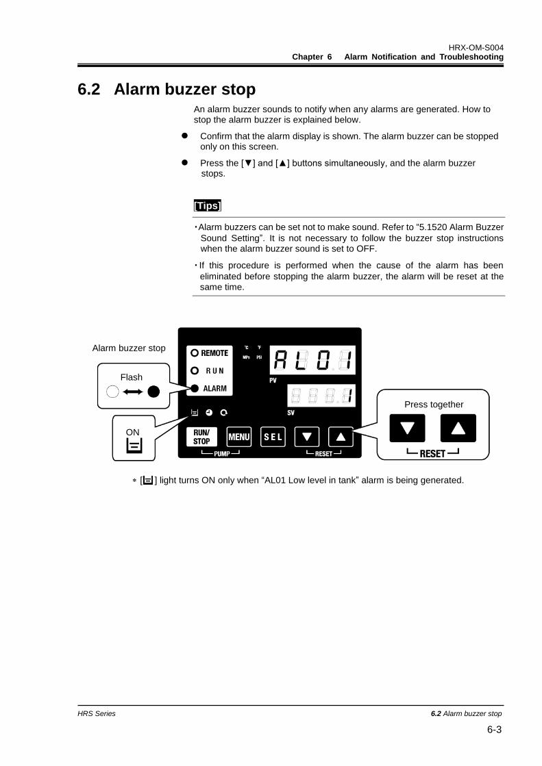
HRX-OM-S004 Chapter 6 Alarm Notification and Troubleshooting
HRS Series 6.2 Alarm buzzer stop 6-3
6.2 Alarm buzzer stop An alarm buzzer sounds to notify when any alarms are generated. How to stop the alarm buzzer is explained below.
Confirm that the alarm display is shown. The alarm buzzer can be stopped only on this screen.
Press the [▼] and [▲] buttons simultaneously, and the alarm buzzer stops.
[Tips]
・Alarm buzzers can be set not to make sound. Refer to “5.1520 Alarm Buzzer
Sound Setting”. It is not necessary to follow the buzzer stop instructions when the alarm buzzer sound is set to OFF.
・ If this procedure is performed when the cause of the alarm has been
eliminated before stopping the alarm buzzer, the alarm will be reset at the same time.
[ ] light turns ON only when “AL01 Low level in tank” alarm is being generated.
Flash
ON
Press together
Alarm buzzer stop
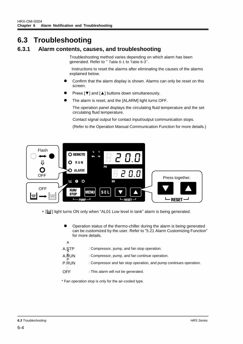
HRX-OM-S004 Chapter 6 Alarm Notification and Troubleshooting
6.3 Troubleshooting HRS Series
6-4
6.3 Troubleshooting 6.3.1 Alarm contents, causes, and troubleshooting
Troubleshooting method varies depending on which alarm has been generated. Refer to ’’ Table 6-1 to Table 6-3’’.
Instructions to reset the alarms after eliminating the causes of the alarms explained below.
Confirm that the alarm display is shown. Alarms can only be reset on this screen.
Press [▼] and [▲] buttons down simultaneously.
The alarm is reset, and the [ALARM] light turns OFF.
The operation panel displays the circulating fluid temperature and the set circulating fluid temperature.
Contact signal output for contact input/output communication stops.
(Refer to the Operation Manual Communication Function for more details.)
[ ] light turns ON only when “AL01 Low level in tank” alarm is being generated.
Operation status of the thermo-chiller during the alarm is being generated can be customized by the user. Refer to “5.21 Alarm Customizing Function” for more details.
A.STP
:
* Fan operation stop is only for the air-cooled type.
A.STP : Compressor, pump, and fan stop operation.
A.RUN : Compressor, pump, and fan continue operation.
P.RUN : Compressor and fan stop operation, and pump continues operation.
OFF : This alarm will not be generated.
OFF
OFF
Press together.
Flash
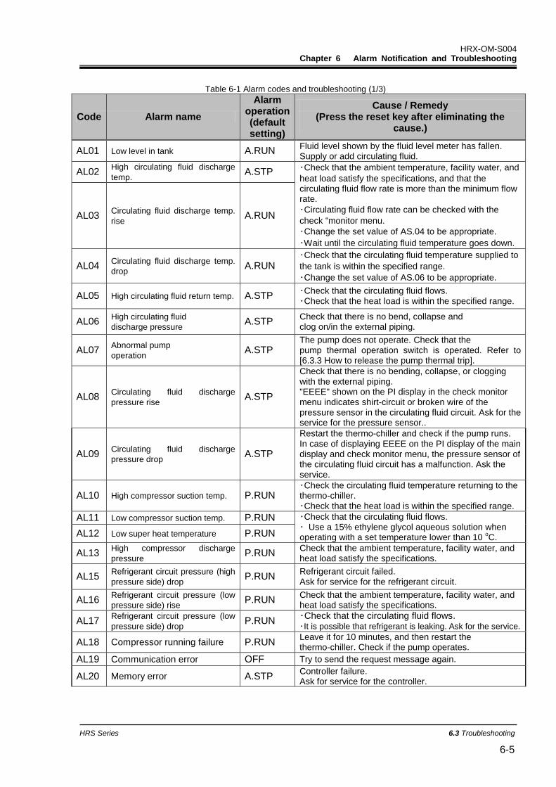
HRX-OM-S004 Chapter 6 Alarm Notification and Troubleshooting
HRS Series 6.3 Troubleshooting 6-5
Table 6-1 Alarm codes and troubleshooting (1/3)
Code Alarm name
Alarm operation (default setting)
Cause / Remedy (Press the reset key after eliminating the
cause.)
AL01 Low level in tank A.RUN Fluid level shown by the fluid level meter has fallen. Supply or add circulating fluid.
AL02 High circulating fluid discharge
temp. A.STP ・Check that the ambient temperature, facility water, and
heat load satisfy the specifications, and that the circulating fluid flow rate is more than the minimum flow rate.
・Circulating fluid flow rate can be checked with the
check “monitor menu.
・Change the set value of AS.04 to be appropriate.
・Wait until the circulating fluid temperature goes down.
AL03 Circulating fluid discharge temp.
rise A.RUN
AL04 Circulating fluid discharge temp.
drop A.RUN
・Check that the circulating fluid temperature supplied to
the tank is within the specified range.
・Change the set value of AS.06 to be appropriate.
AL05 High circulating fluid return temp. A.STP ・Check that the circulating fluid flows. ・Check that the heat load is within the specified range.
AL06 High circulating fluid
discharge pressure A.STP
Check that there is no bend, collapse and clog on/in the external piping.
AL07 Abnormal pump
operation A.STP
The pump does not operate. Check that the pump thermal operation switch is operated. Refer to [6.3.3 How to release the pump thermal trip].
AL08 Circulating fluid discharge
pressure rise A.STP
Check that there is no bending, collapse, or clogging with the external piping. "EEEE" shown on the PI display in the check monitor menu indicates shirt-circuit or broken wire of the pressure sensor in the circulating fluid circuit. Ask for the service for the pressure sensor..
AL09 Circulating fluid discharge
pressure drop A.STP
Restart the thermo-chiller and check if the pump runs. In case of displaying EEEE on the PI display of the main display and check monitor menu, the pressure sensor of the circulating fluid circuit has a malfunction. Ask the service.
AL10 High compressor suction temp. P.RUN ・Check the circulating fluid temperature returning to the thermo-chiller. ・Check that the heat load is within the specified range.
AL11 Low compressor suction temp. P.RUN ・Check that the circulating fluid flows. ・ Use a 15% ethylene glycol aqueous solution when operating with a set temperature lower than 10
oC. AL12 Low super heat temperature P.RUN
AL13 High compressor discharge
pressure P.RUN
Check that the ambient temperature, facility water, and heat load satisfy the specifications.
AL15 Refrigerant circuit pressure (high
pressure side) drop P.RUN
Refrigerant circuit failed. Ask for service for the refrigerant circuit.
AL16 Refrigerant circuit pressure (low
pressure side) rise P.RUN
Check that the ambient temperature, facility water, and heat load satisfy the specifications.
AL17 Refrigerant circuit pressure (low
pressure side) drop P.RUN
・Check that the circulating fluid flows. ・It is possible that refrigerant is leaking. Ask for the service.
AL18 Compressor running failure P.RUN Leave it for 10 minutes, and then restart the thermo-chiller. Check if the pump operates.
AL19 Communication error OFF Try to send the request message again.
AL20 Memory error A.STP Controller failure. Ask for service for the controller.
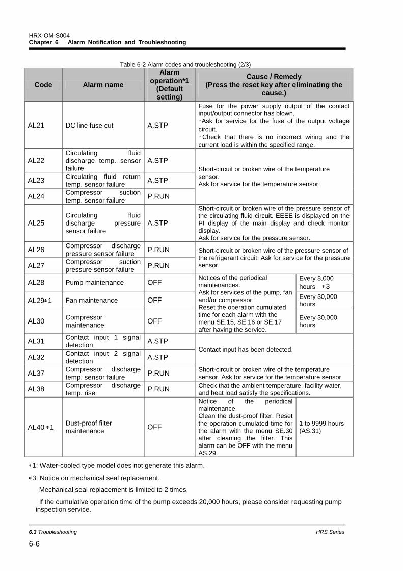
HRX-OM-S004 Chapter 6 Alarm Notification and Troubleshooting
6.3 Troubleshooting HRS Series
6-6
Table 6-2 Alarm codes and troubleshooting (2/3)
Code Alarm name
Alarm operation*1
(Default setting)
Cause / Remedy (Press the reset key after eliminating the
cause.)
AL21 DC line fuse cut A.STP
Fuse for the power supply output of the contact input/output connector has blown.
・Ask for service for the fuse of the output voltage
circuit.
・Check that there is no incorrect wiring and the
current load is within the specified range.
AL22 Circulating fluid discharge temp. sensor failure
A.STP
Short-circuit or broken wire of the temperature sensor. Ask for service for the temperature sensor.
AL23 Circulating fluid return temp. sensor failure
A.STP
AL24 Compressor suction temp. sensor failure
P.RUN
AL25 Circulating fluid discharge pressure sensor failure
A.STP
Short-circuit or broken wire of the pressure sensor of the circulating fluid circuit. EEEE is displayed on the PI display of the main display and check monitor display. Ask for service for the pressure sensor.
AL26 Compressor discharge pressure sensor failure
P.RUN Short-circuit or broken wire of the pressure sensor of the refrigerant circuit. Ask for service for the pressure sensor. AL27
Compressor suction pressure sensor failure
P.RUN
AL28 Pump maintenance OFF Notices of the periodical maintenances. Ask for services of the pump, fan and/or compressor. Reset the operation cumulated time for each alarm with the menu SE.15, SE.16 or SE.17 after having the service.
Every 8,000
hours 3
AL291 Fan maintenance OFF Every 30,000 hours
AL30 Compressor maintenance
OFF Every 30,000 hours
AL31 Contact input 1 signal detection
A.STP Contact input has been detected.
AL32 Contact input 2 signal detection
A.STP
AL37 Compressor discharge temp. sensor failure
P.RUN Short-circuit or broken wire of the temperature sensor. Ask for service for the temperature sensor.
AL38 Compressor discharge temp. rise
P.RUN Check that the ambient temperature, facility water, and heat load satisfy the specifications.
AL40 1 Dust-proof filter maintenance
OFF
Notice of the periodical maintenance. Clean the dust-proof filter. Reset the operation cumulated time for the alarm with the menu SE.30 after cleaning the filter. This alarm can be OFF with the menu AS.29.
1 to 9999 hours (AS.31)
1: Water-cooled type model does not generate this alarm.
3: Notice on mechanical seal replacement.
Mechanical seal replacement is limited to 2 times.
If the cumulative operation time of the pump exceeds 20,000 hours, please consider requesting pump inspection service.
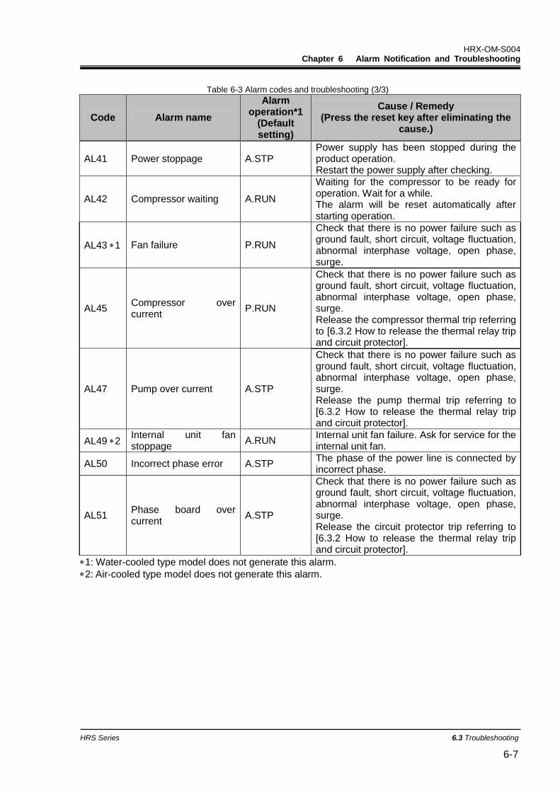
HRX-OM-S004 Chapter 6 Alarm Notification and Troubleshooting
HRS Series 6.3 Troubleshooting 6-7
Table 6-3 Alarm codes and troubleshooting (3/3)
Code Alarm name
Alarm operation*1
(Default setting)
Cause / Remedy (Press the reset key after eliminating the
cause.)
AL41 Power stoppage A.STP Power supply has been stopped during the product operation. Restart the power supply after checking.
AL42 Compressor waiting A.RUN
Waiting for the compressor to be ready for operation. Wait for a while. The alarm will be reset automatically after starting operation.
AL43 1 Fan failure P.RUN
Check that there is no power failure such as ground fault, short circuit, voltage fluctuation, abnormal interphase voltage, open phase, surge.
AL45 Compressor over current
P.RUN
Check that there is no power failure such as ground fault, short circuit, voltage fluctuation, abnormal interphase voltage, open phase, surge. Release the compressor thermal trip referring to [6.3.2 How to release the thermal relay trip and circuit protector].
AL47 Pump over current A.STP
Check that there is no power failure such as ground fault, short circuit, voltage fluctuation, abnormal interphase voltage, open phase, surge. Release the pump thermal trip referring to [6.3.2 How to release the thermal relay trip and circuit protector].
AL49 2 Internal unit fan stoppage
A.RUN Internal unit fan failure. Ask for service for the internal unit fan.
AL50 Incorrect phase error A.STP The phase of the power line is connected by incorrect phase.
AL51 Phase board over current
A.STP
Check that there is no power failure such as ground fault, short circuit, voltage fluctuation, abnormal interphase voltage, open phase, surge. Release the circuit protector trip referring to [6.3.2 How to release the thermal relay trip and circuit protector].
1: Water-cooled type model does not generate this alarm.
2: Air-cooled type model does not generate this alarm.
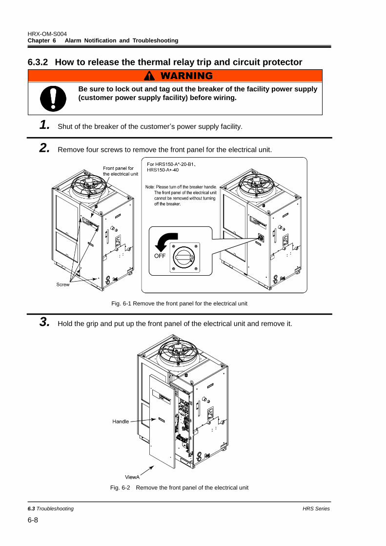
HRX-OM-S004 Chapter 6 Alarm Notification and Troubleshooting
6.3 Troubleshooting HRS Series
6-8
6.3.2 How to release the thermal relay trip and circuit protector
1. Shut of the breaker of the customer’s power supply facility.
2. Remove four screws to remove the front panel for the electrical unit.
Fig. 6-1 Remove the front panel for the electrical unit
3. Hold the grip and put up the front panel of the electrical unit and remove it.
Fig. 6-2 Remove the front panel of the electrical unit
Be sure to lock out and tag out the breaker of the facility power supply
(customer power supply facility) before wiring.
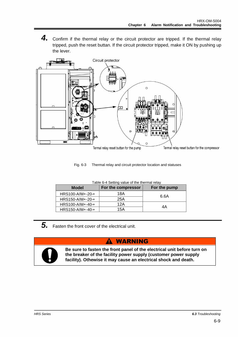
HRX-OM-S004 Chapter 6 Alarm Notification and Troubleshooting
HRS Series 6.3 Troubleshooting 6-9
4. Confirm if the thermal relay or the circuit protector are tripped. If the thermal relay
tripped, push the reset buttan. If the circuit protector tripped, make it ON by pushing up
the lever.
Fig. 6-3 Thermal relay and circuit protector location and statuses
Table 6-4 Setting value of the thermal relay
Model For the compressor For the pump
HRS100-A/W-20- 18A 6.6A
HRS150-A/W-20- 25A
HRS100-A/W-40- 12A 4A
HRS150-A/W-40- 15A
5. Fasten the front cover of the electrical unit.
Be sure to fasten the front panel of the electrical unit before turn on the breaker of the facility power supply (customer power supply
facility). Othewise it may cause an electrical shock and death.
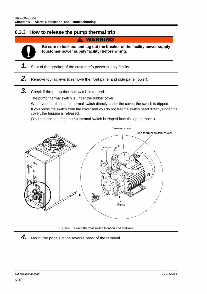
HRX-OM-S004 Chapter 6 Alarm Notification and Troubleshooting
6.3 Troubleshooting HRS Series
6-10
6.3.3 How to release the pump thermal trip
1. Shut of the breaker of the customer’s power supply facility.
2. Remove four screws to remove the front panel and side panel(lower).
3. Check if the pump thermal switch is tripped.
The pump thermal switch is under the rubber cover.
When you feel the pump thermal switch directly under the cover, the switch is tripped.
If you press the switch from the cover and you do not feel the switch head directly under the cover, the tripping is released.
(You can not see if the pump thermal switch is tripped from the appearance.)
Fig. 6-4 Pump thermal switch location and statuses
4. Mount the panels in the reverse order of the removal.
Be sure to lock out and tag out the breaker of the facility power supply
(customer power supply facility) before wiring.

HRX-OM-S004 Chapter 6 Alarm Notification and Troubleshooting
HRS Series 6.4 Other Errors 6-11
6.4 Other Errors How to check other errors
The causes and remedies for failures that are not indicated by alarm numbers are shown in ’’Table 6-5’’.
Table 6-5 Possible causes and countermeasures for failures without alarm number
Content of failure Possible cause Countermeasure
The operation panel displays nothing.
The breaker of the user’s power supply or/and the optional breaker is/are not turned ON.
Turn ON the breaker.
The breaker of the user’s power supply or the optional breaker has failed.
Replace the breaker.
No power supply. (e.g. Breaker(s) in the power supplying route has not been turned ON.)
Supply the power.
The breaker for the user’s facility or the optional breaker has tripped due to short-circuit or leakage of electricity.
Repair the short-circuited part or the electricity leaking part.
The [RUN] light does not turn ON when the [RUN/STOP] button is pressed.
Communication setting has been turned ON.
Check if the communication setting has been turned ON.
Failure of the [RUN] light Replace the controller.
Failure of the [RUN/STOP] button Replace the controller.
* Check the supply voltage with a tester.

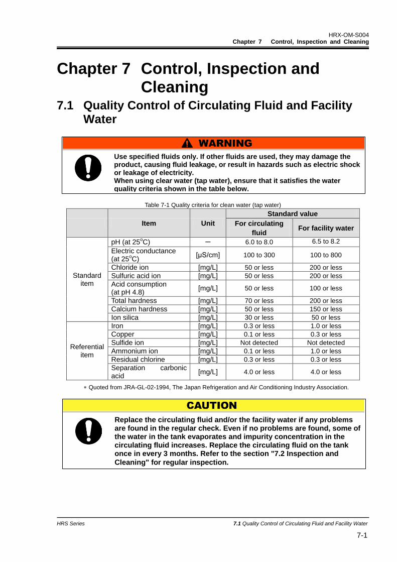
HRX-OM-S004 Chapter 7 Control, Inspection and Cleaning
HRS Series 7.1 Quality Control of Circulating Fluid and Facility Water 7-1
Chapter 7 Control, Inspection and Cleaning
7.1 Quality Control of Circulating Fluid and Facility Water
Table 7-1 Quality criteria for clean water (tap water)
Item Unit
Standard value
For circulating
fluid For facility water
Standard item
pH (at 25oC) - 6.0 to 8.0 6.5 to 8.2
Electric conductance (at 25
oC)
[μS/cm] 100 to 300 100 to 800
Chloride ion [mg/L] 50 or less 200 or less
Sulfuric acid ion [mg/L] 50 or less 200 or less
Acid consumption (at pH 4.8)
[mg/L] 50 or less 100 or less
Total hardness [mg/L] 70 or less 200 or less
Calcium hardness [mg/L] 50 or less 150 or less
Ion silica [mg/L] 30 or less 50 or less
Referential item
Iron [mg/L] 0.3 or less 1.0 or less
Copper [mg/L] 0.1 or less 0.3 or less
Sulfide ion [mg/L] Not detected Not detected
Ammonium ion [mg/L] 0.1 or less 1.0 or less
Residual chlorine [mg/L] 0.3 or less 0.3 or less
Separation carbonic acid
[mg/L] 4.0 or less 4.0 or less
Quoted from JRA-GL-02-1994, The Japan Refrigeration and Air Conditioning Industry Association.
Replace the circulating fluid and/or the facility water if any problems are found in the regular check. Even if no problems are found, some of the water in the tank evaporates and impurity concentration in the circulating fluid increases. Replace the circulating fluid on the tank once in every 3 months. Refer to the section "7.2 Inspection and
Cleaning" for regular inspection.
Use specified fluids only. If other fluids are used, they may damage the product, causing fluid leakage, or result in hazards such as electric shock or leakage of electricity. When using clear water (tap water), ensure that it satisfies the water quality criteria shown in the table below.
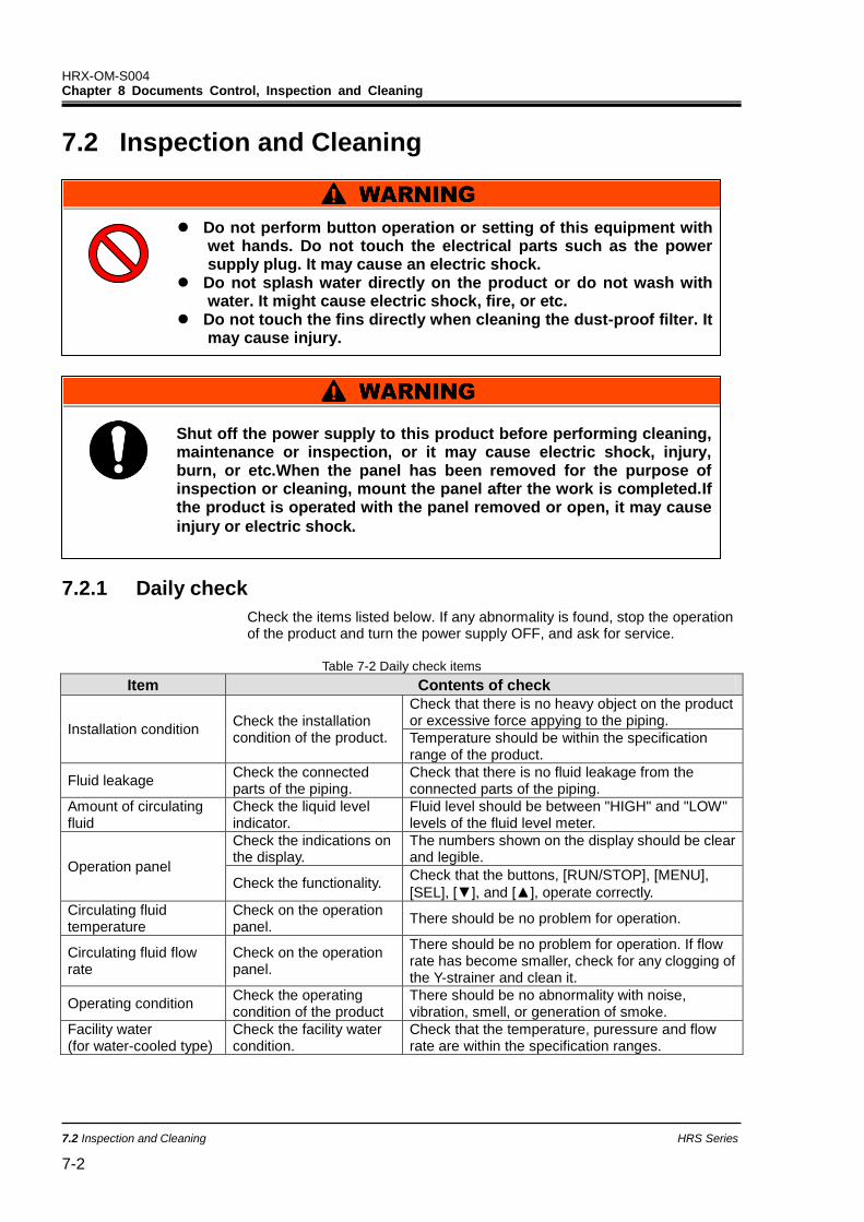
HRX-OM-S004 Chapter 8 Documents Control, Inspection and Cleaning
7.2 Inspection and Cleaning HRS Series
7-2
7.2 Inspection and Cleaning
7.2.1 Daily check
Check the items listed below. If any abnormality is found, stop the operation of the product and turn the power supply OFF, and ask for service.
Table 7-2 Daily check items
Item Contents of check
Installation condition Check the installation condition of the product.
Check that there is no heavy object on the product or excessive force appying to the piping.
Temperature should be within the specification range of the product.
Fluid leakage Check the connected parts of the piping.
Check that there is no fluid leakage from the connected parts of the piping.
Amount of circulating fluid
Check the liquid level indicator.
Fluid level should be between "HIGH" and "LOW" levels of the fluid level meter.
Operation panel
Check the indications on the display.
The numbers shown on the display should be clear and legible.
Check the functionality. Check that the buttons, [RUN/STOP], [MENU],
[SEL], [▼], and [▲], operate correctly.
Circulating fluid temperature
Check on the operation panel.
There should be no problem for operation.
Circulating fluid flow rate
Check on the operation panel.
There should be no problem for operation. If flow rate has become smaller, check for any clogging of the Y-strainer and clean it.
Operating condition Check the operating condition of the product
There should be no abnormality with noise, vibration, smell, or generation of smoke.
Facility water (for water-cooled type)
Check the facility water condition.
Check that the temperature, puressure and flow rate are within the specification ranges.
Do not perform button operation or setting of this equipment with wet hands. Do not touch the electrical parts such as the power supply plug. It may cause an electric shock.
Do not splash water directly on the product or do not wash with water. It might cause electric shock, fire, or etc.
Do not touch the fins directly when cleaning the dust-proof filter. It may cause injury.
Shut off the power supply to this product before performing cleaning, maintenance or inspection, or it may cause electric shock, injury, burn, or etc.When the panel has been removed for the purpose of inspection or cleaning, mount the panel after the work is completed.If the product is operated with the panel removed or open, it may cause
injury or electric shock.
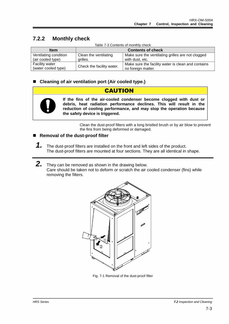
HRX-OM-S004 Chapter 7 Control, Inspection and Cleaning
HRS Series 7.2 Inspection and Cleaning 7-3
7.2.2 Monthly check Table 7-3 Contents of monthly check
Item Contents of check
Ventilating condition (air cooled type)
Clean the ventilating grilles.
Make sure the ventilating grilles are not clogged with dust, etc.
Facility water (water cooled type)
Check the facility water. Make sure the facility water is clean and contains no foreign matter.
Cleaning of air ventilation port (Air cooled type.)
Clean the dust-proof filters with a long bristled brush or by air blow to prevent the fins from being deformed or damaged.
Removal of the dust-proof filter
1. The dust-proof filters are installed on the front and left sides of the product. The dust-proof filters are mounted at four sections. They are all identical in shape.
2. They can be removed as shown in the drawing below. Care should be taken not to deform or scratch the air cooled condenser (fins) while removing the filters.
Fig. 7-1 Removal of the dust-proof filter
If the fins of the air-cooled condenser become clogged with dust or debris, heat radiation performance declines. This will result in the reduction of cooling performance, and may stop the operation because
the safety device is triggered.
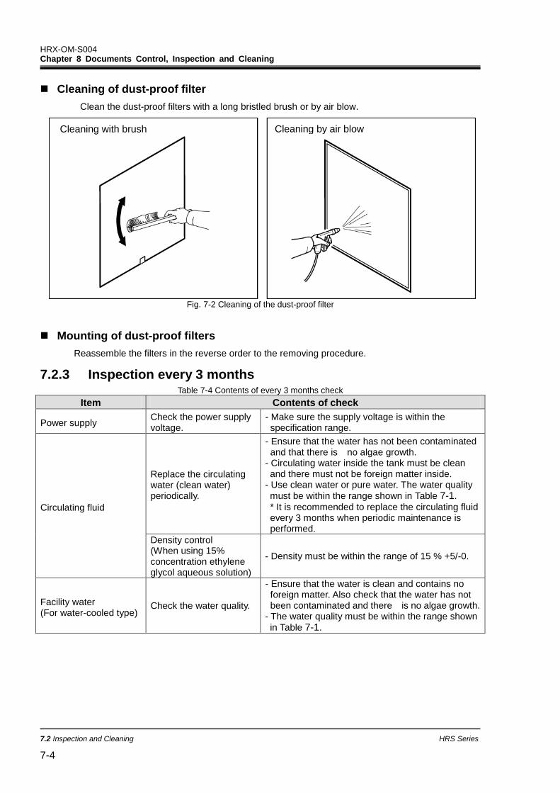
HRX-OM-S004 Chapter 8 Documents Control, Inspection and Cleaning
7.2 Inspection and Cleaning HRS Series
7-4
Cleaning of dust-proof filter
Clean the dust-proof filters with a long bristled brush or by air blow.
Fig. 7-2 Cleaning of the dust-proof filter
Mounting of dust-proof filters
Reassemble the filters in the reverse order to the removing procedure.
7.2.3 Inspection every 3 months Table 7-4 Contents of every 3 months check
Item Contents of check
Power supply Check the power supply voltage.
- Make sure the supply voltage is within the specification range.
Circulating fluid
Replace the circulating water (clean water) periodically.
- Ensure that the water has not been contaminated and that there is no algae growth.
- Circulating water inside the tank must be clean and there must not be foreign matter inside.
- Use clean water or pure water. The water quality
must be within the range shown in Table 7-1.
* It is recommended to replace the circulating fluid every 3 months when periodic maintenance is performed.
Density control (When using 15% concentration ethylene glycol aqueous solution)
- Density must be within the range of 15 % +5/-0.
Facility water (For water-cooled type)
Check the water quality.
- Ensure that the water is clean and contains no foreign matter. Also check that the water has not been contaminated and there is no algae growth.
- The water quality must be within the range shown
in Table 7-1.
Cleaning with brush Cleaning by air blow
HRX-OM-S004 Chapter 7 Control, Inspection and Cleaning
HRS Series 7.2 Inspection and Cleaning 7-5
Replacement of circulating fluid
Replace the circulating fluid with new clean fluid periodically, or it may get algae or decompose.
Circulating fluid to be supplied in the tank should satisfy the water quality specified in “Table 7-1”.
When using 15% ethylene glycol solution, check that the concentration is within the range of 15% +5/-0.
Do NOT use chlorine-based or such types of detergents or cleansers.
When using the Y strainer provided as an accessory for piping, clean the screen mesh inside the strainer at the same time as when replacing the circulating fluid.
Ensure that there is no circulating fluid in the thermo-chiller, user's equipment, and piping. Remove the cap and take out the screen mesh inside, and clean the screen mesh with compressed air or detergent. Use caution not to damage the screen mesh.
Clean the customer's facility water system (water cooled type)
Clean the customer's facility water system and replace facility water.
Facility water quality must satisfy the criteria specified in “Table 7-1”
If there is foreign matter accumulated or clogging in the facility water system, pressure loss increases with less flow rate, and it may damage
the screen mesh.
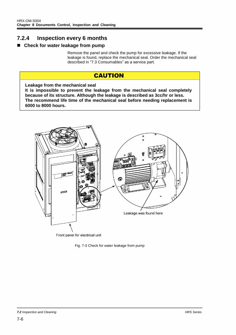
HRX-OM-S004 Chapter 8 Documents Control, Inspection and Cleaning
7.2 Inspection and Cleaning HRS Series
7-6
7.2.4 Inspection every 6 months
Check for water leakage from pump
Remove the panel and check the pump for excessive leakage. If the leakage is found, replace the mechanical seal. Order the mechanical seal described in “7.3 Consumables” as a service part.
Fig. 7-3 Check for water leakage from pump
Leakage from the mechanical seal It is impossible to prevent the leakage from the mechanical seal completely because of its structure. Although the leakage is described as 3cc/hr or less. The recommend life time of the mechanical seal before needing replacement is
6000 to 8000 hours.
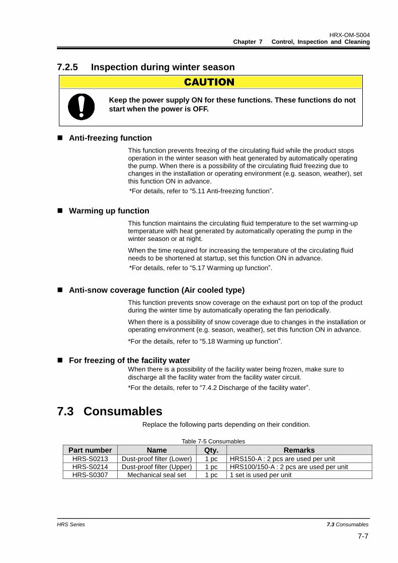
HRX-OM-S004 Chapter 7 Control, Inspection and Cleaning
HRS Series 7.3 Consumables 7-7
7.2.5 Inspection during winter season
Anti-freezing function
This function prevents freezing of the circulating fluid while the product stops operation in the winter season with heat generated by automatically operating the pump. When there is a possibility of the circulating fluid freezing due to changes in the installation or operating environment (e.g. season, weather), set this function ON in advance.
*For details, refer to “5.11 Anti-freezing function”.
Warming up function
This function maintains the circulating fluid temperature to the set warming-up temperature with heat generated by automatically operating the pump in the winter season or at night.
When the time required for increasing the temperature of the circulating fluid needs to be shortened at startup, set this function ON in advance.
*For details, refer to “5.17 Warming up function”.
Anti-snow coverage function (Air cooled type)
This function prevents snow coverage on the exhaust port on top of the product during the winter time by automatically operating the fan periodically.
When there is a possibility of snow coverage due to changes in the installation or operating environment (e.g. season, weather), set this function ON in advance.
*For the details, refer to “5.18 Warming up function”.
For freezing of the facility water When there is a possibility of the facility water being frozen, make sure to
discharge all the facility water from the facility water circuit.
*For the details, refer to “7.4.2 Discharge of the facility water”.
7.3 Consumables Replace the following parts depending on their condition.
Table 7-5 Consumables
Part number Name Qty. Remarks HRS-S0213 Dust-proof filter (Lower) 1 pc HRS150-A : 2 pcs are used per unit
HRS-S0214 Dust-proof filter (Upper) 1 pc HRS100/150-A : 2 pcs are used per unit
HRS-S0307 Mechanical seal set 1 pc 1 set is used per unit
Keep the power supply ON for these functions. These functions do not
start when the power is OFF.
HRX-OM-S004 Chapter 8 Documents Control, Inspection and Cleaning
7.4 Operation Stop for an Extended Period of Time HRS Series
7-8
7.4 Operation Stop for an Extended Period of Time If there is a concern that the product will not be operated for an extended period of time or there is a possibility of freezing in the winter time, take the measures according to the instructions shown below.
1. Turn OFF the earth leakage breaker of the user’s power supply. (Turn OFF the breaker
for the optional breaker for option B [Earth leakage breaker], option B [Earth leakage
breaker with handle].)
2. Discharge all the circulating fluid completely from the thermo-chiller.
Please refer to ’’7.4.1 Discharge of the circulating fluid’’ for the method of drain the circulating fluid from the product.
3. After discharging the circulating fluid, cover the product with a sheet (to be prepared by
user) before storing the product.
7.4.1 Discharge of the circulating fluid
1. Turn OFF the breaker of the user’s power supply.
2. Close the valve at the automatic water fill port.
3. Open the ball valve at the pump drain port, and discharge the circulating fluid.
4. Confirm that all the circulating fluid has been discharged completely from the user’s
equipment and piping, and then purge air to the circulating fluid outlet port of the
product.
5. Close the ball valve after discharging the circulating fluid.
Before discharging the circulating fluid, stop the user’s equipment
and release the residual pressure.
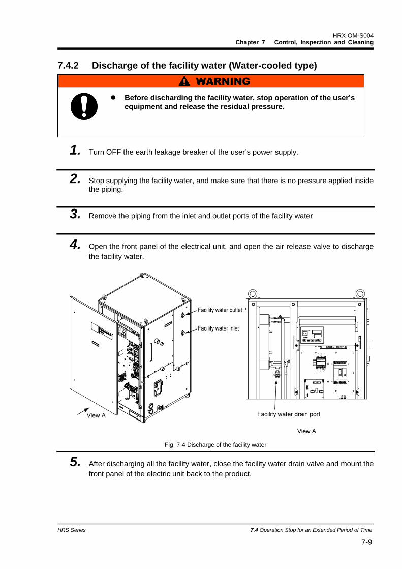
HRX-OM-S004 Chapter 7 Control, Inspection and Cleaning
HRS Series 7.4 Operation Stop for an Extended Period of Time 7-9
7.4.2 Discharge of the facility water (Water-cooled type)
1. Turn OFF the earth leakage breaker of the user’s power supply.
2. Stop supplying the facility water, and make sure that there is no pressure applied inside the piping.
3. Remove the piping from the inlet and outlet ports of the facility water
4. Open the front panel of the electrical unit, and open the air release valve to discharge
the facility water.
Fig. 7-4 Discharge of the facility water
5. After discharging all the facility water, close the facility water drain valve and mount the
front panel of the electric unit back to the product.
Before discharding the facility water, stop operation of the user’s
equipment and release the residual pressure.

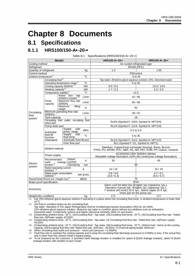
HRX-OM-S004 Chapter 8 Documents
HRS Series 8.1 Specifications 8-1
Chapter 8 Documents 8.1 Specifications
8.1.1 HRS100/150-A-20- Table 8-1 Specifications [HRS100/150-A-20-]
Model HRS100-A-20- HRS150-A-20-
Cooling method Air-cooled refrigerated type
Refrigerant R410A (HFC)
Quantity of refrigerant kg 1.3 1.65
Control method PIDcontrol
Ambient temperature1 oC -5 to 45
Circulating fluid system
Circulating fluid2 Tap water, Ethylene glycol aqueous solution 15%, Deionized water
Operating temperature range1 oC 5 to 35
Cooling capacity 50/60Hz 3 kW 9.0 / 9.5 13.0 / 14.5
Heating capacity4 kW 1.7 / 2.2 2.5 / 3.0
Temperature stability5 oC ±1.0
Pump capacity
Rated flow rate 50/60Hz (Outlet)
6 L/min 42 / 56
Maximum flow rate 50/60Hz
L/min 55 / 68
Maximum lifting height
m 50
Minimum operating flow rate 50/60Hz
7 L/min 28 / 42
Tank capacity L 18 Circulating fluid outlet, circulating fluid return port Rc3/4 (Symbol F: G3/4, Symbol N: NPT3/4)
Pump drain port Rc1/4 (Symbol F: G1/4, Symbol N: NPT1/4)
Automatic fluid fill function (Standard)
Supply side press. range MPa 0.2 to 0.5
Supply side fluid temp.
oC 5 to 35
Automatic fluid fill port Rc1/2 (Symbol F: G1/2, Symbol N: NPT1/2) Over flow port Rc1 (Symbol F: G1, Symbol N: NPT1)
Wetted material Stainless, Cupper(Heat exchanger brazing), Brass, Bronze
PTFE, PU, EPDM, PVC, NBR, PE, NR, PBT, POM, PP, Carbon, Ceramic
Electric system
Power supply AC200/200-230V 50/60Hz 3phase
Allowable voltage fluctuation ±10% (No continuous voltage fluctuation) Recommended earth leakage breaker
8
Rated current A 30 40
Sensitivity mA 30 Rated operating current 50/60Hz
5 A 14 / 15 16 / 19
Rated power consumption 50/60Hz5
kW (kVA) 3.8 / 4.8
(4.9 / 5.3) 4.7 / 6.1
(5.6 / 6.7)
Sound level (Front 1m / Height 1m)5 dB(A) 70
Water-proof specification IPX4
Accessory
Alarm cord list label 2pc.(English 1pc./Japanese 1pc.), Operation manual 2pc. (English 1pc./Japanese 1pc.),
Y strainer (40 mesh) 20 A 1pc., Barrel nipple 20 A 1pc. Drain pan for the pump 1pc.
Weight(dry condition) kg 171 177 1 Use 15% ethylene glycol aqueous solution if operating in a place where the circulating fluid temp. or ambient temperature is lower than
10 oC 2 Use fluid in condition below as the circulating fluid.
Tap water: Standard of The Japan Refregeration And Air Conditioning Industry Association (JRA GL-02-1994) 15% ethylene glycol aqueous solution: diluted by tap water in condition above without any additives such as antiseptics. Deionized water: Conductivity 1μS/cm and higher (electrical resistivity 1MΩ・cm and lower)
3 (1)Operating ambient temp.: 32 oC, (2)Circulating fluid : Tap water, (3)Circulating fluid temp.: 20 oC, (4)Criculating fluid flow rate : Rated flow rate, (5)Power supply: AC200V
4 (1)Operating ambient temp.: 32 oC, (2)Circulating fluid : Tap water, (3) Circulating fluid flow rate : Rated flow rate, (4)Power supply: AC200V
5 (1)Operating ambient temp.: 32 oC, (2)Circulating fluid : Tap water, (3)Circulating fluid temp.: 20 oC, (4)Heat load : Same as the cooling capacity, (5)Circulating fluid flow rate: Rated flow rate, (6)Power : AC200V, (7) External piping length: Minimum.
6 When circulating fluid outlet port pressure – return port pressure = 0.25MPa. 7 Fluid flow rate to maintain the cooling capacity and to keep the circulating fluid discharge puressure to 0.5MPa or less. If the actual flow
rate is lower than this, please install a bypass piping. 8 To be prepared by the customer. A specified earth leakage breaker is installed for option B [Earth leakage breaker], option B [Earth
leakage breaker with handle] of each model.
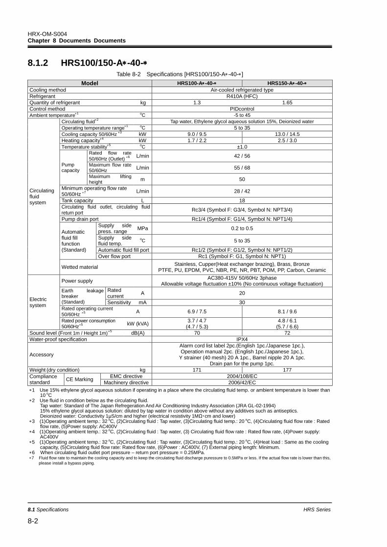
HRX-OM-S004 Chapter 8 Documents Documents
8.1 Specifications HRS Series
8-2
8.1.2 HRS100/150-A-40- Table 8-2 Specifications [HRS100/150-A-40-]
Model HRS100-A-40- HRS150-A-40-
Cooling method Air-cooled refrigerated type
Refrigerant R410A (HFC)
Quantity of refrigerant kg 1.3 1.65
Control method PIDcontrol
Ambient temperature1 oC -5 to 45
Circulating fluid system
Circulating fluid2 Tap water, Ethylene glycol aqueous solution 15%, Deionized water
Operating temperature range1 oC 5 to 35
Cooling capacity 50/60Hz 3 kW 9.0 / 9.5 13.0 / 14.5
Heating capacity4 kW 1.7 / 2.2 2.5 / 3.0
Temperature stability5 oC ±1.0
Pump capacity
Rated flow rate
50/60Hz (Outlet) 6
L/min 42 / 56
Maximum flow rate 50/60Hz
L/min 55 / 68
Maximum lifting height
m 50
Minimum operating flow rate 50/60Hz
7
L/min 28 / 42
Tank capacity L 18
Circulating fluid outlet, circulating fluid return port
Rc3/4 (Symbol F: G3/4, Symbol N: NPT3/4)
Pump drain port Rc1/4 (Symbol F: G1/4, Symbol N: NPT1/4)
Automatic fluid fill function (Standard)
Supply side press. range
MPa 0.2 to 0.5
Supply side fluid temp.
oC 5 to 35
Automatic fluid fill port Rc1/2 (Symbol F: G1/2, Symbol N: NPT1/2)
Over flow port Rc1 (Symbol F: G1, Symbol N: NPT1)
Wetted material Stainless, Cupper(Heat exchanger brazing), Brass, Bronze
PTFE, PU, EPDM, PVC, NBR, PE, NR, PBT, POM, PP, Carbon, Ceramic
Electric system
Power supply AC380-415V 50/60Hz 3phase
Allowable voltage fluctuation ±10% (No continuous voltage fluctuation)
Earth leakage breaker
(Standard)
Rated current
A 20
Sensitivity mA 30 Rated operating current
50/60Hz 5
A 6.9 / 7.5 8.1 / 9.6
Rated power consumption
50/60Hz5
kW (kVA) 3.7 / 4.7
(4.7 / 5.3) 4.8 / 6.1
(5.7 / 6.6)
Sound level (Front 1m / Height 1m)5 dB(A) 70 72
Water-proof specification IPX4
Accessory
Alarm cord list label 2pc.(English 1pc./Japanese 1pc.), Operation manual 2pc. (English 1pc./Japanese 1pc.),
Y strainer (40 mesh) 20 A 1pc., Barrel nipple 20 A 1pc. Drain pan for the pump 1pc.
Weight(dry condition) kg 171 177
Compliance standard
CE Marking EMC directive 2004/108/EC
Machinery directive 2006/42/EC
1 Use 15% ethylene glycol aqueous solution if operating in a place where the circulating fluid temp. or ambient temperature is lower than 10 oC
2 Use fluid in condition below as the circulating fluid. Tap water: Standard of The Japan Refregeration And Air Conditioning Industry Association (JRA GL-02-1994) 15% ethylene glycol aqueous solution: diluted by tap water in condition above without any additives such as antiseptics. Deionized water: Conductivity 1μS/cm and higher (electrical resistivity 1MΩ・cm and lower)
3 (1)Operating ambient temp.: 32 oC, (2)Circulating fluid : Tap water, (3)Circulating fluid temp.: 20 oC, (4)Criculating fluid flow rate : Rated flow rate, (5)Power supply: AC400V
4 (1)Operating ambient temp.: 32 oC, (2)Circulating fluid : Tap water, (3) Circulating fluid flow rate : Rated flow rate, (4)Power supply: AC400V
5 (1)Operating ambient temp.: 32 oC, (2)Circulating fluid : Tap water, (3)Circulating fluid temp.: 20 oC, (4)Heat load : Same as the cooling capacity, (5)Circulating fluid flow rate: Rated flow rate, (6)Power : AC400V, (7) External piping length: Minimum.
6 When circulating fluid outlet port pressure – return port pressure = 0.25MPa. 7 Fluid flow rate to maintain the cooling capacity and to keep the circulating fluid discharge puressure to 0.5MPa or less. If the actual flow rate is lower than this,
please install a bypass piping.
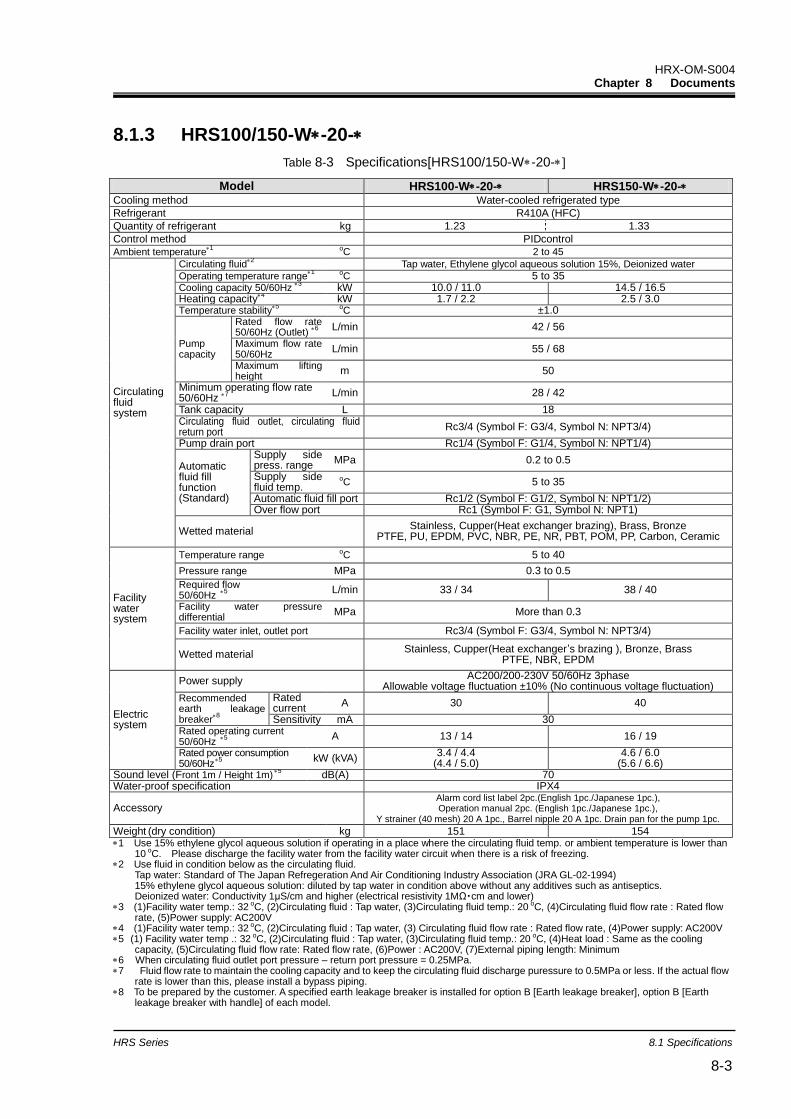
HRX-OM-S004 Chapter 8 Documents
HRS Series 8.1 Specifications 8-3
8.1.3 HRS100/150-W-20-
Table 8-3 Specifications[HRS100/150-W-20-
Model HRS100-W-20- HRS150-W-20- Cooling method Water-cooled refrigerated type
Refrigerant R410A (HFC)
Quantity of refrigerant kg 1.23 1.33
Control method PIDcontrol
Ambient temperature1 oC 2 to 45
Circulating fluid system
Circulating fluid2 Tap water, Ethylene glycol aqueous solution 15%, Deionized water
Operating temperature range1 oC 5 to 35
Cooling capacity 50/60Hz 3 kW 10.0 / 11.0 14.5 / 16.5
Heating capacity4 kW 1.7 / 2.2 2.5 / 3.0
Temperature stability5 oC ±1.0
Pump capacity
Rated flow rate 50/60Hz (Outlet)
6
L/min 42 / 56
Maximum flow rate 50/60Hz
L/min 55 / 68
Maximum lifting height
m 50
Minimum operating flow rate 50/60Hz
7
L/min 28 / 42
Tank capacity L 18 Circulating fluid outlet, circulating fluid return port
Rc3/4 (Symbol F: G3/4, Symbol N: NPT3/4)
Pump drain port Rc1/4 (Symbol F: G1/4, Symbol N: NPT1/4)
Automatic fluid fill function (Standard)
Supply side press. range
MPa 0.2 to 0.5
Supply side fluid temp.
oC 5 to 35
Automatic fluid fill port Rc1/2 (Symbol F: G1/2, Symbol N: NPT1/2) Over flow port Rc1 (Symbol F: G1, Symbol N: NPT1)
Wetted material Stainless, Cupper(Heat exchanger brazing), Brass, Bronze
PTFE, PU, EPDM, PVC, NBR, PE, NR, PBT, POM, PP, Carbon, Ceramic
Facility water system
Temperature range oC 5 to 40
Pressure range MPa 0.3 to 0.5
Required flow 50/60Hz
5
L/min 33 / 34 38 / 40
Facility water pressure differential
MPa More than 0.3
Facility water inlet, outlet port Rc3/4 (Symbol F: G3/4, Symbol N: NPT3/4)
Wetted material Stainless, Cupper(Heat exchanger’s brazing ), Bronze, Brass
PTFE, NBR, EPDM
Electric system
Power supply AC200/200-230V 50/60Hz 3phase
Allowable voltage fluctuation ±10% (No continuous voltage fluctuation) Recommended earth leakage breaker
8
Rated current
A 30 40
Sensitivity mA 30 Rated operating current 50/60Hz
5
A 13 / 14 16 / 19
Rated power consumption 50/60Hz5
kW (kVA)
3.4 / 4.4 (4.4 / 5.0)
4.6 / 6.0 (5.6 / 6.6)
Sound level (Front 1m / Height 1m)5 dB(A) 70
Water-proof specification IPX4
Accessory Alarm cord list label 2pc.(English 1pc./Japanese 1pc.), Operation manual 2pc. (English 1pc./Japanese 1pc.),
Y strainer (40 mesh) 20 A 1pc., Barrel nipple 20 A 1pc. Drain pan for the pump 1pc.
Weight(dry condition) kg 151 154 1 Use 15% ethylene glycol aqueous solution if operating in a place where the circulating fluid temp. or ambient temperature is lower than
10 oC. Please discharge the facility water from the facility water circuit when there is a risk of freezing. 2 Use fluid in condition below as the circulating fluid.
Tap water: Standard of The Japan Refregeration And Air Conditioning Industry Association (JRA GL-02-1994) 15% ethylene glycol aqueous solution: diluted by tap water in condition above without any additives such as antiseptics. Deionized water: Conductivity 1μS/cm and higher (electrical resistivity 1MΩ・cm and lower)
3 (1)Facility water temp.: 32 oC, (2)Circulating fluid : Tap water, (3)Circulating fluid temp.: 20 oC, (4)Circulating fluid flow rate : Rated flow rate, (5)Power supply: AC200V
4 (1)Facility water temp.: 32 oC, (2)Circulating fluid : Tap water, (3) Circulating fluid flow rate : Rated flow rate, (4)Power supply: AC200V 5 (1) Facility water temp .: 32 oC, (2)Circulating fluid : Tap water, (3)Circulating fluid temp.: 20 oC, (4)Heat load : Same as the cooling
capacity, (5)Circulating fluid flow rate: Rated flow rate, (6)Power : AC200V, (7)External piping length: Minimum 6 When circulating fluid outlet port pressure – return port pressure = 0.25MPa. 7 Fluid flow rate to maintain the cooling capacity and to keep the circulating fluid discharge puressure to 0.5MPa or less. If the actual flow
rate is lower than this, please install a bypass piping. 8 To be prepared by the customer. A specified earth leakage breaker is installed for option B [Earth leakage breaker], option B [Earth
leakage breaker with handle] of each model.
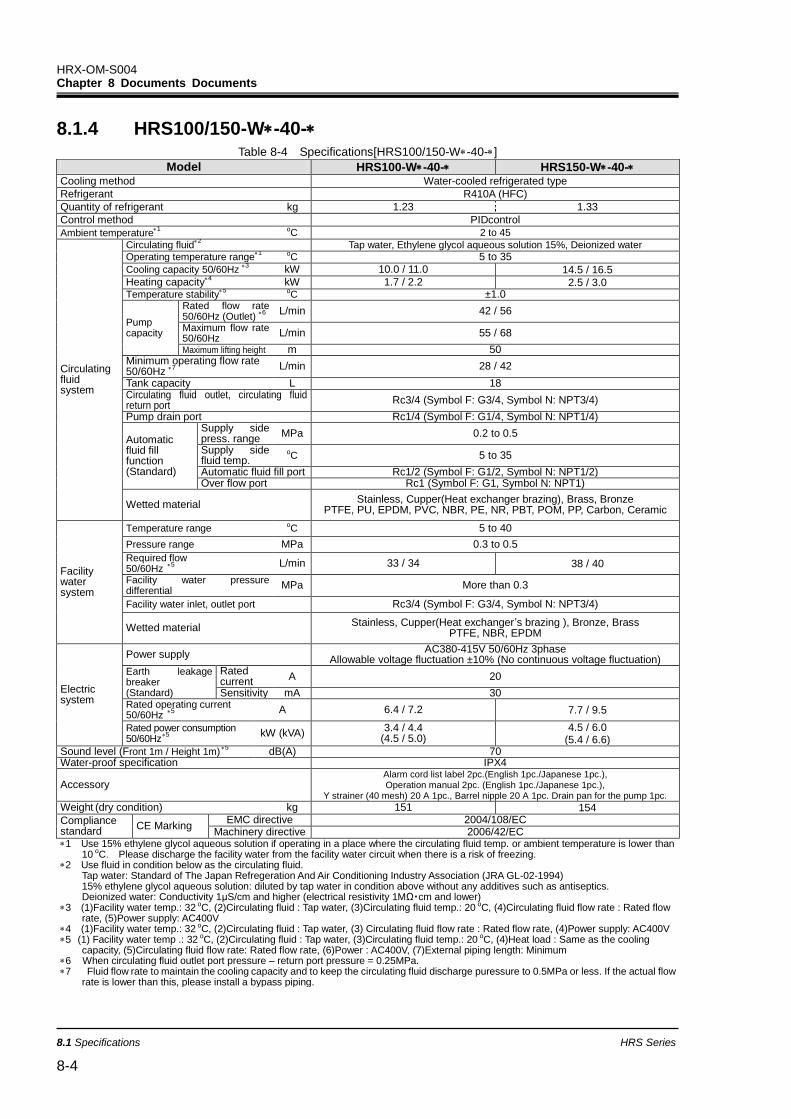
HRX-OM-S004 Chapter 8 Documents Documents
8.1 Specifications HRS Series
8-4
8.1.4 HRS100/150-W-40- Table 8-4 Specifications[HRS100/150-W-40-]
Model HRS100-W-40- HRS150-W-40- Cooling method Water-cooled refrigerated type
Refrigerant R410A (HFC)
Quantity of refrigerant kg 1.23 1.33
Control method PIDcontrol
Ambient temperature1 oC 2 to 45
Circulating fluid system
Circulating fluid2 Tap water, Ethylene glycol aqueous solution 15%, Deionized water
Operating temperature range1 oC 5 to 35
Cooling capacity 50/60Hz 3 kW 10.0 / 11.0 14.5 / 16.5
Heating capacity4 kW 1.7 / 2.2 2.5 / 3.0
Temperature stability5 oC ±1.0
Pump capacity
Rated flow rate 50/60Hz (Outlet)
6
L/min 42 / 56
Maximum flow rate 50/60Hz
L/min 55 / 68
Maximum lifting height m 50 Minimum operating flow rate 50/60Hz
7
L/min 28 / 42
Tank capacity L 18 Circulating fluid outlet, circulating fluid return port
Rc3/4 (Symbol F: G3/4, Symbol N: NPT3/4)
Pump drain port Rc1/4 (Symbol F: G1/4, Symbol N: NPT1/4)
Automatic fluid fill function (Standard)
Supply side press. range
MPa 0.2 to 0.5
Supply side fluid temp.
oC 5 to 35
Automatic fluid fill port Rc1/2 (Symbol F: G1/2, Symbol N: NPT1/2) Over flow port Rc1 (Symbol F: G1, Symbol N: NPT1)
Wetted material Stainless, Cupper(Heat exchanger brazing), Brass, Bronze
PTFE, PU, EPDM, PVC, NBR, PE, NR, PBT, POM, PP, Carbon, Ceramic
Facility water system
Temperature range oC 5 to 40
Pressure range MPa 0.3 to 0.5
Required flow 50/60Hz
5
L/min 33 / 34 38 / 40
Facility water pressure differential
MPa More than 0.3
Facility water inlet, outlet port Rc3/4 (Symbol F: G3/4, Symbol N: NPT3/4)
Wetted material Stainless, Cupper(Heat exchanger’s brazing ), Bronze, Brass
PTFE, NBR, EPDM
Electric system
Power supply AC380-415V 50/60Hz 3phase
Allowable voltage fluctuation ±10% (No continuous voltage fluctuation) Earth leakage breaker (Standard)
Rated current
A 20
Sensitivity mA 30 Rated operating current 50/60Hz
5
A 6.4 / 7.2 7.7 / 9.5
Rated power consumption 50/60Hz5
kW (kVA)
3.4 / 4.4 (4.5 / 5.0)
4.5 / 6.0 (5.4 / 6.6)
Sound level (Front 1m / Height 1m)5 dB(A) 70
Water-proof specification IPX4
Accessory Alarm cord list label 2pc.(English 1pc./Japanese 1pc.), Operation manual 2pc. (English 1pc./Japanese 1pc.),
Y strainer (40 mesh) 20 A 1pc., Barrel nipple 20 A 1pc. Drain pan for the pump 1pc.
Weight(dry condition) kg 151 154
Compliance standard
CE Marking EMC directive 2004/108/EC
Machinery directive 2006/42/EC 1 Use 15% ethylene glycol aqueous solution if operating in a place where the circulating fluid temp. or ambient temperature is lower than
10 oC. Please discharge the facility water from the facility water circuit when there is a risk of freezing. 2 Use fluid in condition below as the circulating fluid.
Tap water: Standard of The Japan Refregeration And Air Conditioning Industry Association (JRA GL-02-1994) 15% ethylene glycol aqueous solution: diluted by tap water in condition above without any additives such as antiseptics. Deionized water: Conductivity 1μS/cm and higher (electrical resistivity 1MΩ・cm and lower)
3 (1)Facility water temp.: 32 oC, (2)Circulating fluid : Tap water, (3)Circulating fluid temp.: 20 oC, (4)Circulating fluid flow rate : Rated flow rate, (5)Power supply: AC400V
4 (1)Facility water temp.: 32 oC, (2)Circulating fluid : Tap water, (3) Circulating fluid flow rate : Rated flow rate, (4)Power supply: AC400V 5 (1) Facility water temp .: 32 oC, (2)Circulating fluid : Tap water, (3)Circulating fluid temp.: 20 oC, (4)Heat load : Same as the cooling
capacity, (5)Circulating fluid flow rate: Rated flow rate, (6)Power : AC400V, (7)External piping length: Minimum 6 When circulating fluid outlet port pressure – return port pressure = 0.25MPa. 7 Fluid flow rate to maintain the cooling capacity and to keep the circulating fluid discharge puressure to 0.5MPa or less. If the actual flow
rate is lower than this, please install a bypass piping.
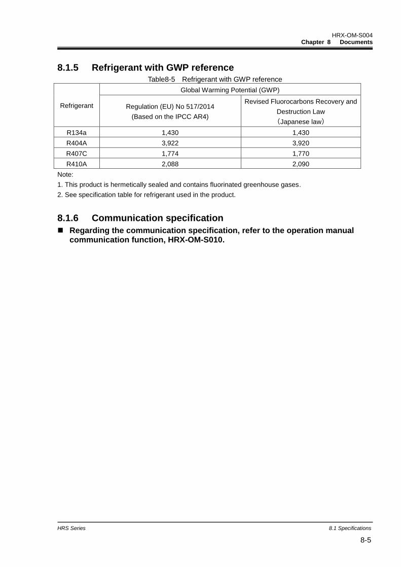
HRX-OM-S004 Chapter 8 Documents
HRS Series 8.1 Specifications 8-5
8.1.5 Refrigerant with GWP reference Table8-5 Refrigerant with GWP reference
Refrigerant
Global Warming Potential (GWP)
Regulation (EU) No 517/2014
(Based on the IPCC AR4)
Revised Fluorocarbons Recovery and
Destruction Law
(Japanese law)
R134a 1,430 1,430
R404A 3,922 3,920
R407C 1,774 1,770
R410A 2,088 2,090
Note:
1. This product is hermetically sealed and contains fluorinated greenhouse gases.
2. See specification table for refrigerant used in the product.
8.1.6 Communication specification
Regarding the communication specification, refer to the operation manual communication function, HRX-OM-S010.
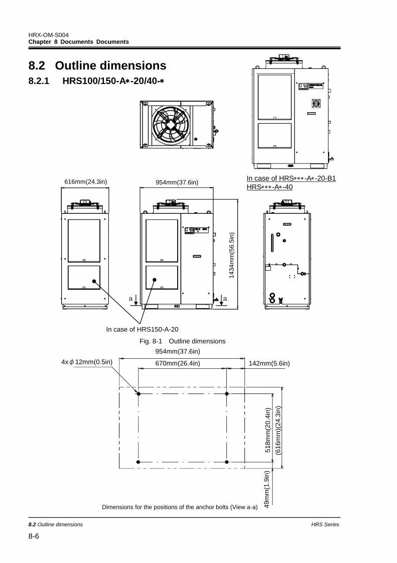
HRX-OM-S004 Chapter 8 Documents Documents
8.2 Outline dimensions HRS Series
8-6
49m
m(1
.9in
)
954mm(37.6in)
670mm(26.4in)
518m
m(2
0.4
in)
(616m
m)(
24.3
in)
4xφ12mm(0.5in) 142mm(5.6in)
49m
m(1
.9in
)
8.2 Outline dimensions
8.2.1 HRS100/150-A-20/40-
Fig. 8-1 Outline dimensions
954mm(37.6in) 616mm(24.3in)
1434
mm
(56
.5in
)
a a
Dimensions for the positions of the anchor bolts (View a-a)
In case of HRS150-A-20
In case of HRS-A-20-B1
HRS-A-40
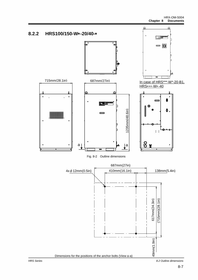
HRX-OM-S004 Chapter 8 Documents
HRS Series 8.2 Outline dimensions 8-7
8.2.2 HRS100/150-W-20/40-
Fig. 8-2 Outline dimensions
Dimensions for the positions of the anchor bolts (View a-a)
687mm(27in)
617m
m(2
4.3
in)
410mm(16.1in)
(715m
m)(
28.1
in)
138mm(5.4in) 4xφ12mm(0.5in)
49m
m(1
.9in
)
715mm(28.1in) 687mm(27in)
1235
mm
(48
.6in
)
a a
687mm(27in) 715mm(28.1in)
1235
mm
(48
.6in
)
a a
In case of HRS***-W*-20-B1,
HRS-W-40
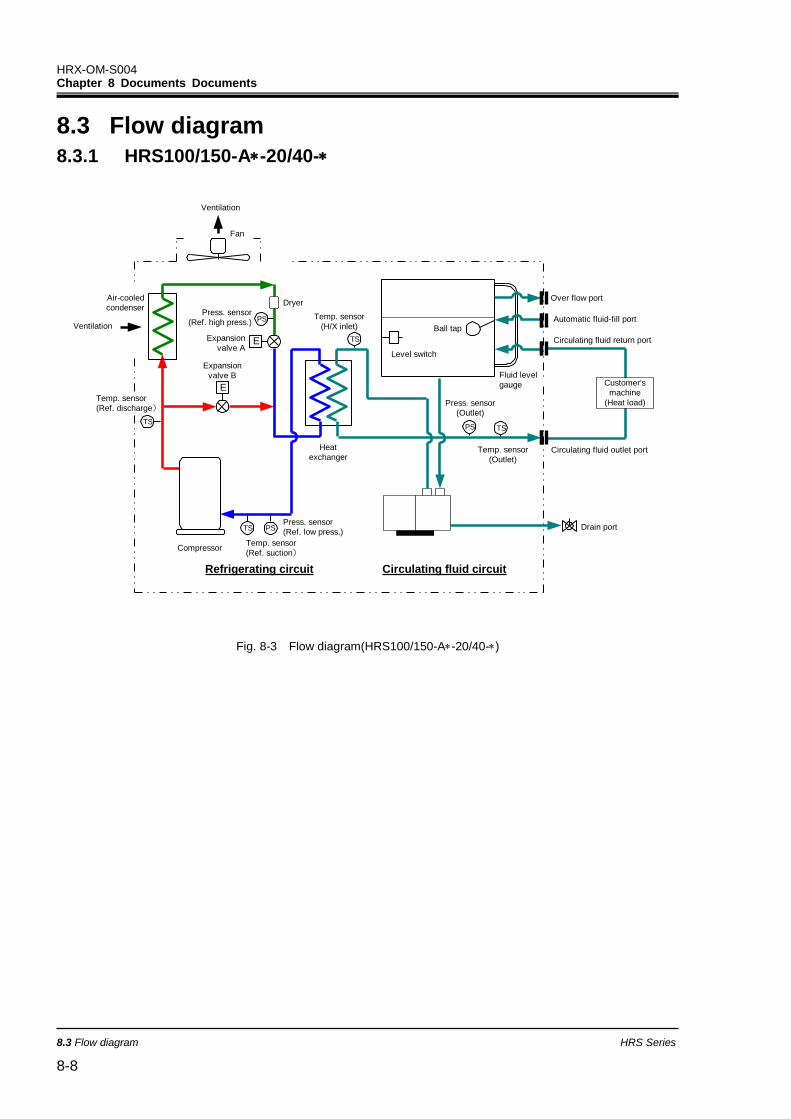
HRX-OM-S004 Chapter 8 Documents Documents
8.3 Flow diagram HRS Series
8-8
8.3 Flow diagram
8.3.1 HRS100/150-A-20/40-
Compressor
Expansion
valve B
Expansion
valve A
DryerPress. sensor
(Ref. high press.)
Heat
exchanger
Press. sensor
(Ref. low press.)
Fan
Level switch
Ball tap
Press. sensor
(Outlet)
Temp. sensor
(Outlet)
Fluid level
gauge
Over flow port
Automatic fluid-fill port
Circulating fluid return port
Circulating fluid outlet port
Ventilation
E
E
Temp. sensor
(Ref. suction)
Ventilation
Air-cooled
condenser
Refrigerating circuit Circulating fluid circuit
TS
PS
PS
Temp. sensor
(H/X inlet)
Drain port
TS
Temp. sensor
(Ref. discharge)
PS TS
TS
Customer's
machine
(Heat load)
Fig. 8-3 Flow diagram(HRS100/150-A-20/40-)
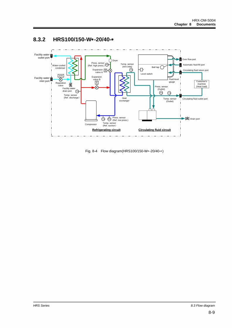
HRX-OM-S004 Chapter 8 Documents
HRS Series 8.3 Flow diagram 8-9
8.3.2 HRS100/150-W-20/40-
Compressor
Expansion
valve B
Expansion
valve A
DryerPress. sensor
(Ref. high press.)
Heat
exchanger
Press. sensor
(Ref. low press.)
Level switch
Ball tap
Press. sensor
(Outlet)
Temp. sensor
(Outlet)
Fluid level
gauge
Over flow port
Automatic fluid-fill port
Circulating fluid return port
Circulating fluid outlet port
E
E
Temp. sensor
(Ref. suction)
Refrigerating circuit Circulating fluid circuit
TS
PS
PS
Temp. sensor
(H/X inlet)
Drain port
TS
Temp. sensor
(Ref. discharge)
PS TS
TS
Customer's
machine
(Heat load)
Water-cooled
condenser
Facility water
outlet port
Regulation
valve
Facility water
inlet port
WPR
Facility water
drain port
Fig. 8-4 Flow diagram(HRS100/150-W-20/40-)

HRX-OM-S004 Chapter 8 Documents Documents
8.4 Cooling capacity HRS Series
8-10
8.4 Cooling capacity
8.4.1 HRS100-A-20/40-
Fig. 8-5 Cooling capacity(HRS100-A-20/40-)
8.4.2 HRS150-A-20/40-
Fig. 8-6 Cooling capacity(HRS150-A-20/40-)
: Ambient temperature: 32 o
C
: Ambient temperature: 40oC
: Ambient temperature: 45 o
C
: Ambient temperature: 32 o
C
: Ambient temperature: 40oC
: Ambient temperature: 45 o
C
50Hz 60Hz
50Hz 60Hz
0
2
4
6
8
10
12
14
5 10 15 20 25 30 35
Circulating fluid temperature [oC]
Co
olin
g c
ap
acity [kW
]
0
2
4
6
8
10
12
14
5 10 15 20 25 30 35
Circulating fluid temperature [oC]
Co
olin
g c
ap
acity [kW
]
0
2
4
6
8
10
12
14
16
18
5 10 15 20 25 30 35
Circulating fluid temperature [oC]
Coolin
g c
apacity
[kW
]
0
2
4
6
8
10
12
14
16
18
5 10 15 20 25 30 35
Circulating fluid temperature [oC]
Coolin
g c
apacity
[kW
]
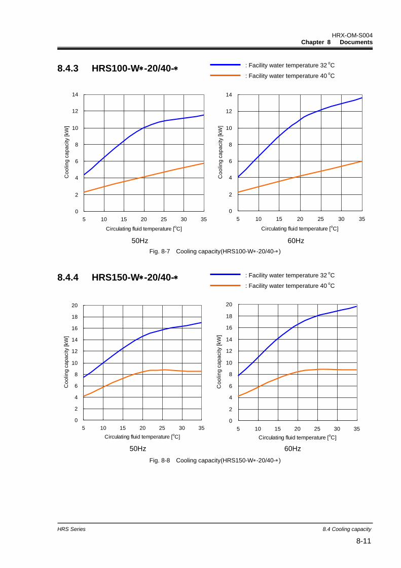
HRX-OM-S004 Chapter 8 Documents
HRS Series 8.4 Cooling capacity 8-11
8.4.3 HRS100-W-20/40-
Fig. 8-7 Cooling capacity(HRS100-W-20/40-)
8.4.4 HRS150-W-20/40-
Fig. 8-8 Cooling capacity(HRS150-W-20/40-)
: Facility water temperature 32 oC
: Facility water temperature 40 oC
50Hz 60Hz
50Hz 60Hz
0
2
4
6
8
10
12
14
5 10 15 20 25 30 35
Circulating fluid temperature [oC]
Co
olin
g c
ap
acity [kW
]
0
2
4
6
8
10
12
14
5 10 15 20 25 30 35
Circulating fluid temperature [oC]
Co
olin
g c
ap
acity [kW
]
0
2
4
6
8
10
12
14
16
18
20
5 10 15 20 25 30 35
Circulating fluid temperature [oC]
Co
olin
g c
ap
acity [kW
]
0
2
4
6
8
10
12
14
16
18
20
5 10 15 20 25 30 35
Circulating fluid temperature [oC]
Co
olin
g c
ap
acity [kW
]
: Facility water temperature 32 oC
: Facility water temperature 40 oC
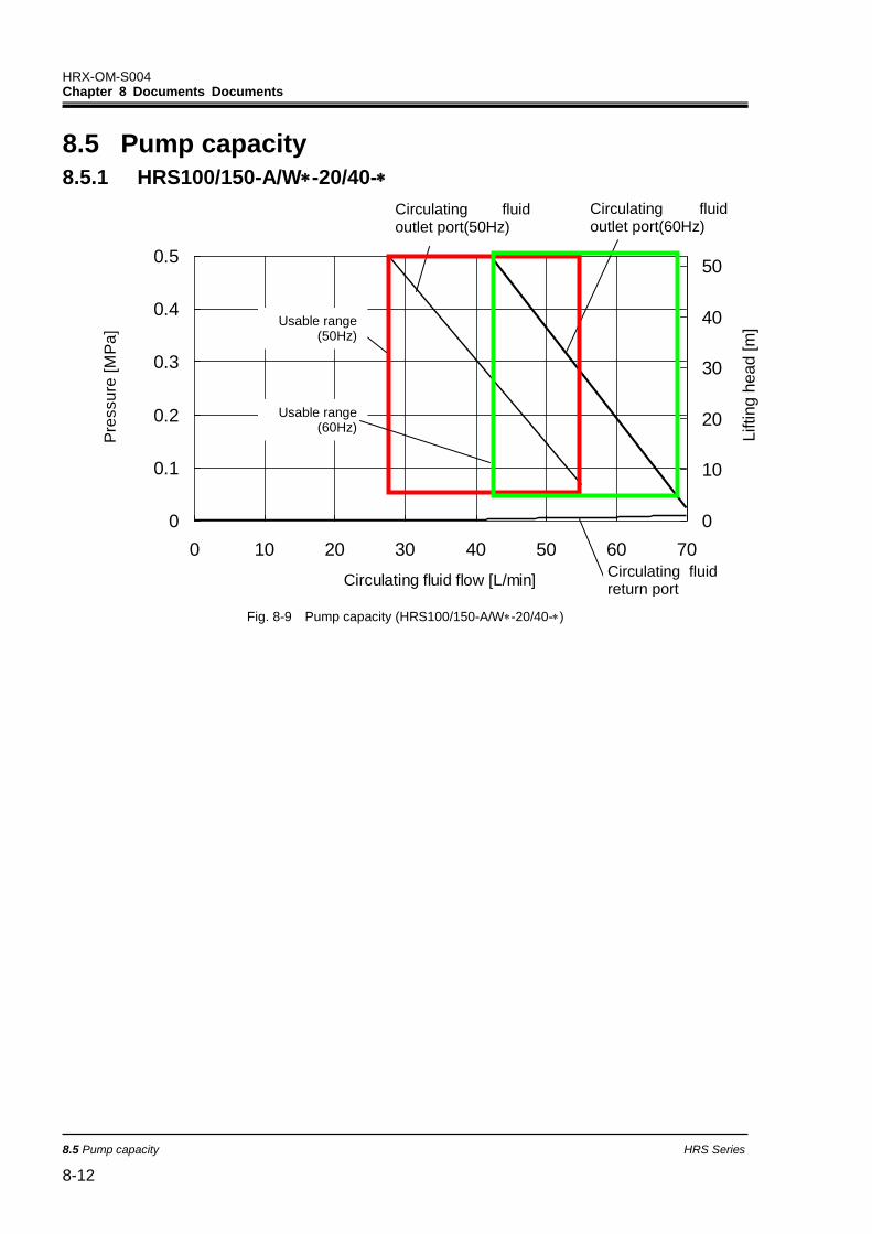
HRX-OM-S004 Chapter 8 Documents Documents
8.5 Pump capacity HRS Series
8-12
8.5 Pump capacity
8.5.1 HRS100/150-A/W-20/40-
Fig. 8-9 Pump capacity (HRS100/150-A/W-20/40-)
0
0.1
0.2
0.3
0.4
0.5
0 10 20 30 40 50 60 70
Circulating fluid flow [L/min]
Pre
ssu
re [
MP
a]
0
10
20
30
40
50
Lifting h
ead [m
]
Circulating fluid return port
Circulating fluid outlet port(60Hz)
Circulating fluid outlet port(50Hz)
Usable range (60Hz)
Usable range (50Hz)
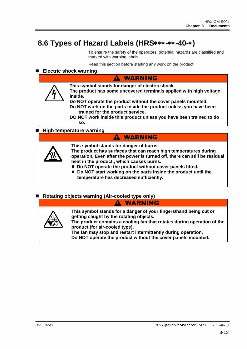
HRX-OM-S004 Chapter 8 Documents
HRS Series 8.6 - -40- 8-13
8.6 Types of Hazard Labels (HRS--40-) To ensure the safety of the operators, potential hazards are classified and marked with warning labels.
Read this section before starting any work on the product.
Electric shock warning
High temperature warning
Rotating objects warning (Air-cooled type only)
This symbol stands for danger of electric shock. The product has some uncovered terminals applied with high voltage inside. Do NOT operate the product without the cover panels mounted. Do NOT work on the parts inside the product unless you have been
trained for the product service. DO NOT work inside this product unless you have been trained to do
so. DO NOT work inside this product unless you have been trained to do
so. DO NOT work inside this product unless you have been trained to do
so. DO NOT work inside this product unless you have been trained to do
so. DO NOT work inside this product unless you have been trained to do
so. DO NOT work inside this product unless you have been trained to do
so. DO NOT work inside this product unless you have been trained to do
so. DO NOT work inside this product unless you have been trained to do
so. DO NOT work inside this product unless you have been trained to do
so. DO NOT work inside this product unless you have been trained to do
so. DO NOT work inside this product unless you have been trained to do
so. DO NOT work inside this product unless you have been trained to do
so. DO NOT work inside this product unless you have been trained to do
so. DO NOT work inside this product unless you have been trained to do
so.
DO NOT work inside this product unless you
have been trained to do so. .
This symbol stands for danger of burns. The product has surfaces that can reach high temperatures during operation. Even after the power is turned off, there can still be residual heat in the product., which causes burns. Do NOT operate the product without cover panels fitted. Do NOT start working on the parts inside the product until the
temperature has decreased sufficiently.
This symbol stands for a danger of your fingers/hand being cut or getting caught by the rotating objects. The product contains a cooling fan that rotates during operation of the product (for air-cooled type).The fan may stop and restart intermittently during operation. Do NOT operate the product without the cover panels mounted.
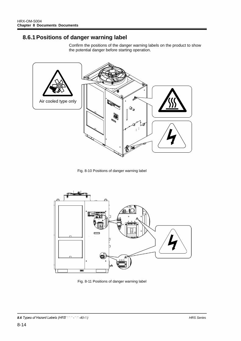
HRX-OM-S004 Chapter 8 Documents Documents
8.6 - -40- HRS Series
8-14
8.6.1 Positions of danger warning label
Confirm the positions of the danger warning labels on the product to show the potential danger before starting operation.
Fig. 8-10 Positions of danger warning label
Fig. 8-11 Positions of danger warning label
Air cooled type only
HRX-OM-S004 Chapter 8 Documents
HRS Series 8.7 Standards 8-15
8.7 Standards This product complies with the standards shown below:
Table 8-5 Standards
Standard Model
CE Mark EMC Directive 2004/108/EC
HRS--40- Machinery Directive 2006/42/EC
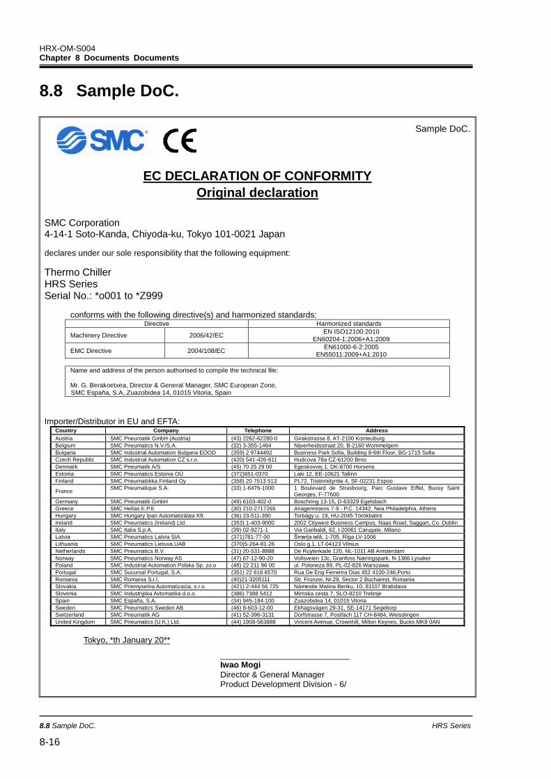
HRX-OM-S004 Chapter 8 Documents Documents
8.8 Sample DoC. HRS Series
8-16
8.8 Sample DoC.
Sample DoC.
EC DECLARATION OF CONFORMITY
Original declaration
SMC Corporation 4-14-1 Soto-Kanda, Chiyoda-ku, Tokyo 101-0021 Japan
declares under our sole responsibility that the following equipment:
Thermo Chiller HRS Series Serial No.: *o001 to *Z999
conforms with the following directive(s) and harmonized standards: Directive Harmonized standards
Machinery Directive 2006/42/EC EN ISO12100:2010
EN60204-1:2006+A1:2009
EMC Directive 2004/108/EC EN61000-6-2:2005
EN55011:2009+A1:2010
Name and address of the person authorised to compile the technical file: Mr. G. Berakoetxea, Director & General Manager, SMC European Zone, SMC España, S.A,.Zuazobidea 14, 01015 Vitoria, Spain
Importer/Distributor in EU and EFTA:
Country Company Telephone Address
Austria SMC Pneumatik GmbH (Austria) (43) 2262-62280-0 Girakstrasse 8, AT-2100 Korneuburg
Belgium SMC Pneumatics N.V./S.A. (32) 3-355-1464 Nijverheidsstraat 20, B-2160 Wommelgem
Bulgaria SMC Industrial Automation Bulgaria EOOD (359) 2 9744492 Business Park Sofia, Building 8-6th Floor, BG-1715 Sofia
Czech Republic SMC Industrial Automation CZ s.r.o. (420) 541-426-611 Hudcova 78a CZ-61200 Brno
Denmark SMC Pneumatik A/S (45) 70 25 29 00 Egeskovvej 1, DK-8700 Horsens
Estonia SMC Pneumatics Estonia OÜ (372)651-0370 Laki 12, EE-10621 Tallinn
Finland SMC Pneumatiikka Finland Oy (358) 20 7513 513 PL72, Tiistinniityntie 4, SF-02231 Espoo
France SMC Pneumatique S.A. (33) 1-6476-1000 1 Boulevard de Strasbourg, Parc Gustave Eiffel, Bussy Saint
Georges, F-77600
Germany SMC Pneumatik GmbH (49) 6103-402-0 Boschring 13-15, D-63329 Egelsbach
Greece SMC Hellas E.P.E (30) 210-2717265 Anagenniseos 7-9 - P.C. 14342, Nea Philadelphia, Athens
Hungary SMC Hungary Ipari Automatizálási Kft. (36) 23-511-390 Torbágy u. 19, HU-2045 Törökbálint
Ireland SMC Pneumatics (Ireland) Ltd. (353) 1-403-9000 2002 Citywest Business Campus, Naas Road, Saggart, Co. Dublin
Italy SMC Italia S.p.A. (39) 02-9271-1 Via Garibaldi, 62, l-20061 Carugate, Milano
Latvia SMC Pneumatics Latvia SIA (371)781-77-00 Šmerļa ielā, 1-705, Rīga LV-1006
Lithuania SMC Pneumatics Lietuva,UAB (370)5-264-81-26 Oslo g.1, LT-04123 Vilnius
Netherlands SMC Pneumatics B.V. (31) 20-531-8888 De Ruyterkade 120, NL-1011 AB Amsterdam
Norway SMC Pneumatics Norway AS (47) 67-12-90-20 Vollsveien 13c, Granfoss Næringspark, N-1366 Lysaker
Poland SMC Industrial Automation Polska Sp. zo.o (48) 22 211 96 00 ul. Poloneza 89, PL-02-826 Warszawa
Portugal SMC Sucursal Portugal, S.A. (351) 22 616 6570 Rua De Eng Ferrerira Dias 452 4100-246,Porto
Romania SMC Romania S.r.l. (40)21-3205111 Str. Frunzei, Nr.29, Sector 2 Bucharest, Romania
Slovakia SMC Priemyselna Automatizacia, s.r.o. (421) 2-444 56 725 Námestie Matina Benku, 10, 81107 Bratislava
Slovenia SMC Industrijska Avtomatika d.o.o. (386) 7388 5412 Mirnska cesta 7, SLO-8210 Trebnje
Spain SMC España, S.A. (34) 945-184-100 Zuazobidea 14, 01015 Vitoria
Sweden SMC Pneumatics Sweden AB (46) 8-603-12-00 Ekhagsvägen 29-31, SE-14171 Segeltorp
Switzerland SMC Pneumatik AG (41) 52-396-3131 Dorfstrasse 7, Postfach 117 CH-8484, Weisslingen
United Kingdom SMC Pneumatics (U.K.) Ltd. (44) 1908-563888 Vincent Avenue, Crownhill, Milton Keynes, Bucks MK8 0AN
Tokyo, *th January 20**
Iwao Mogi
Director & General Manager Product Development Division - 6/

HRX-OM-S004 Chapter 8 Documents
HRS Series 8.8 Sample DoC. 8-17
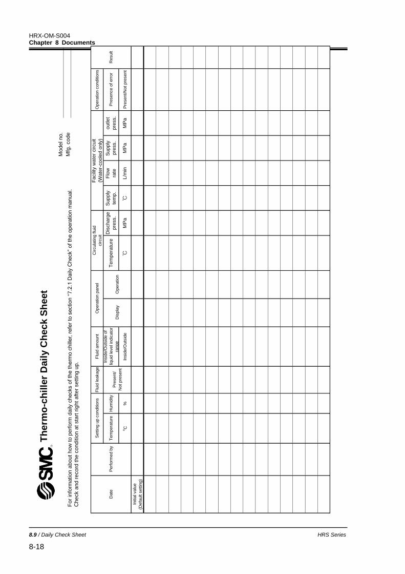
HRX-OM-S004 Chapter 8 Documents
8.9 / Daily Check Sheet HRS Series
8-18
8.9 Daily Check Sheet
Fo
r in
form
atio
n a
bout how
to p
erf
orm
daily
checks o
f th
e t
herm
o c
hill
er, r
efe
r to
sectio
n “
7.2
.1 D
aily
Check”
of th
e o
pera
tio
n m
anual.
Check a
nd r
ecord
the c
onditio
n a
t sta
rt r
ight aft
er
sett
ing u
p.
Th
erm
o-c
hille
r D
ail
y C
he
ck
Sh
eet
Mo
del no.
Mfg
. code
Opera
tion c
onditio
ns
Pre
sence o
f err
or
Pre
sent/N
ot pre
sent
outlet
pre
ss.
MP
a
Supply
pre
ss.
MP
a
Flo
w
rate
L/m
in
Supply
tem
p.
℃
Dis
charg
e
pre
ss.
MP
a
Tem
pera
ture
℃
Flu
id a
mount
Insid
e/O
uts
ide o
f
liquid
level in
dic
ato
r
range
Insid
e/O
uts
ide
Flu
id leakage
Hum
idity
%
Tem
pera
ture
oC
Initia
l valu
e
(Defa
ult s
ettin
g)
Pre
sent/
Not pre
sent
Settin
g u
p c
onditio
ns
Perf
orm
ed b
yD
ate
Result
Opera
tion p
anel
Opera
tion
Dis
pla
y
Facili
ty w
ate
r circuit
(Wate
r-coole
d o
nly
)
Circula
ting flu
id
circuit
HRX-OM-S004 Chapter 9 Product Warranty
HRS Series Product Warranty 9-1
Chapter 9 Product Warranty
1. Period
The warranty period of the product is 1 year in service or 1.5 years after the product is delivered whichever comes first.
2. Scope
For any failure reported within the warranty period which is clearly our responsibility, replacement parts will be provided. In that case, removed parts shall become the property of SMC. This guarantee applies only to our product independently, and not to any other damage incurred due to the failure of the product.
3. Content
1. We guarantee that the product will operate normally if it is installed under maintenance and control in accordance with the Operation Manual, and operated under the conditions specified in the catalog or contracted separately.
2. We guarantee that the product does not have any defects in components, materials or assembly.
3. We guarantee that the product complies with the outline dimensions provided.
4. The following situations are out of scope of this warranty. (1) The product was incorrectly installed or connected with other equipment. (2) The product was under insufficient maintenance and control or incorrectly handled. (3) The product was operated outside of the specifications. (4) The product was modified or altered in construction. (5) The failure was a secondary failure of the product caused by the failure of equipment
connected to the product. (6) The failure was caused by a natural disaster such as an earthquake, typhoon, or flood, or by
an accident or fire. (7) The failure was caused by operation different from that shown in the Operation Manual or
outside of the specifications. (8) The checks and maintenance specified (daily checks and regular checks) were not
performed. (9) The failure was caused by the use of circulating fluid or facility water other than those
specified. (10) The failure occurred naturally over time (such as discoloration of a painted or plated face). (11) The failure does not affect the functioning of the product (such as new sounds, noises and
vibrations). (12) The failure was due to the “Installation Environment” specified in the Operation Manual. (13) The failure was caused by the customer disregarding “6. Request to customers”.
4. Agreement
If there is any doubt about anything specified in “2. Scope” and "3. Content”, it shall be resolved by agreement between the customer and SMC.
5. Disclaimer
(1) Expenses for daily and regular checks (2) Expenses for repairs performed by other companies (3) Expenses for transfer, installation and removal of the product (4) Expenses for replacement of parts other than those in this product, or for the supply of liquids (5) Inconvenience and loss due to product failure (such as telephone bills, compensation for
workplace closure, and commercial losses) (6) Expenses and compensation not covered in “2. Scope”.
HRX-OM-S004 Chapter 8 Documents Product Warranty
Product Warranty HRS Series 9-2
6. Request to customers
Proper use and maintenance are essential to assure safe use of this product. Be sure to satisfy the following preconditions. Please note that we may refuse to carry out warranted repair if these preconditions have been disregarded.
(1) Use the product following the instructions for handling described in the Operation Manual. (2) Perform checks and maintenance (daily checks and regular checks) specified in the
Operation Manual and Maintenance Manual. (3) Record the check and maintenance results on the daily check sheet attached to the
Operation Manual and Maintenance Manual.
7. Request for Warranted Repair
For warranted repair, please contact the supplier you purchased this product from.
Warranted repair shall be on a request basis.
Repair shall be provided free of charge in accordance with the warranty period, preconditions and terms defined above. Therefore, a fee will be charged for any repairs if a failure is detected after the end of the warranty period.


4-14-1, Sotokanda, Chiyoda-ku, Tokyo 101-0021 JAPAN Tel: + 81 3 5207 8249 Fax: +81 3 5298 5362 URL http://www.smcworld.com Note: Specifications are subject to change without prior notice and any obligation on the part of the manufacturer. © 2017 SMC Corporation All Rights Reserved