Embed Size (px)
Citation preview

T144H x4 Plus
OPERATOR’S MANUAL
ENGLISHORIGINAL MANUAL
M O P 1 5 0 9 1 4 0 5


Compact rough terrain reach truckAUSA T144H x4 Plus
above chassis number 352 68954
ORIGINAL MANUAL


Thank you for choosing this AUSA Compact rough terrain forklift with horizontal arm (hereafter “forklift”), which offers the best levels of performance, safety and working comfort. Remember that “you” are the key to maintaining these characteristics. Correct use of the forklift will enable you to take full advantage of the features it has to offer.
You should read and understand this Manual before operating the forklift. Its purpose is to provide instructions for those persons in contact with the machine and especially for the machine’s operator. Its content will help you to better understand the AUSA forklift, and teach all you need to know about starting it, driving techniques, maintenance and care, designed uses of the forklift and safety instructions to be followed.
AUSA cannot be held responsible for any damages caused by the improper use of the forklift.For any queries, complaints or spare parts orders, contact your Official AUSA Representative or Dealer.
For further information you may call, write, FAX or email to:
AUSA Center, S. L. U.P.O.B. 194
08243 MANRESA (Barcelona), SPAINTel. 34-938 747 552 / 938 747 311
Fax: 34-938 736 139 / 938 741 211 / 938 741 255E-mail: [email protected]
Web: http://www.ausa.com
AUSA is continually improving its products and reserves the right to make such improvements without incurring any obligation to make changes to forklifts previously sold. Therefore, claims cannot be made based on the data, illustrations and descriptions set forth in this manual.Use only original AUSA spare parts. Only thus can you guarantee that the forklift will continue to give the same level of technical performance as when purchased.No changes should be made to the forklift without prior authorisation from the manufacturer.Keep this manual in the document holder situated into the cabin, at the rear right part of the roof (fig.1).
Store the manual with care, including after having fully read the document, to ensure that you can refer to it in the future and clarify any doubts. Should you have any difficulty understanding this manual, or any paragraph in the manual, contact your Official AUSA Representative or Dealer.
TAURULIFT T144H x4 Plus 3
Foreword
(fi g.
1)

The manual consists of five sections:
Section 1 GENERAL INFORMATIONSection 2 SPECIAL SAFETY INFORMATIONSection 3 OPERATING INSTRUCTIONSSection 4 PERIODIC MAINTENANCE OPERATIONSSection 5 DIAGRAMS AND CHARTS
Section 1, “GENERAL INFORMATION”, includes general information on the main parts of the machine. This section also lists details of part references and technical characteristics, etc.Section 2, “SPECIAL SAFETY INFORMATION”, is aimed at personnel in charge of the correct operation of the machine, repairs and maintenance, and, for companies with a large number of machines, the safety manager.This section also includes the requirements which managers must satisfy and key items of indispensable safety information.Section 3, “OPERATING INSTRUCTIONS” mainly targets operators. This section illustrates all control devices and instruments and includes instructions on how to use the forklift: from starting the engine, to parking and leaving the forklift.Section 4, “PERIODIC MAINTENANCE OPERATIONS”, mainly targets operators, and specifically the maintenance manager and personnel. This section includes information on the planned maintenance program, the regularity of operations, which liquids and lubricants to use, greasing points, etc.Section 5, “DIAGRAMS AND CHARTS” includes tables and related documents: load charts, wiring and hydraulic diagrams, etc.
All sections are divided into chapters and paragraphs.Checking the “INDEX” is the quickest and easiest means of finding information.
NOTEShould conflict be identified between the content of this manual and the actual operation of the machine, this may be due to the manual relating to a more recent version of the machine or to the manual not having been updated since modifications to the machine.In this case, contact your Official AUSA Representative or Dealer to clarify any doubts or obtain another version of this manual.
Optional equipmentOptional equipment is indicated as follows: (if fitted).Optional equipment will only be supplied at the express request of the customer, for specific versions or countries.
TAURULIFT T144H x4 Plus4
Introduction

When using the machine, you may find yourself in situations in which specific considerations or explicit explanations are required.Should a situation imply a risk for your safety or that of others, or the operating order or correct use of the machine, this manual uses SPECIAL SYMBOLS and includes specific instructions.Although simply reading this information will not remove the risk, the understanding and application of the indications will assist in the correct use of the machine.Seven special (safety) symbols are used in the manual. These symbols are displayed next to key words classifying the degree of danger involved. Each symbol will assist in identifying the corresponding risk and indicates the action to be taken to avoid the risk. The text may be accompanied with illustrations in some cases.The following is a list of the special (safety) symbols in order of importance:
DANGERIndicates situations which, if the appropriate safety precautions are not taken for yourself and others, imply serious risks for the physical integrity of the people involved, and may even include a risk of death.
ELECTRIC HAZARDSIndicates situations which, if the appropriate safety precautions are not taken for yourself and others, imply serious risks for the physical integrity of the people involved, and may even include a risk of death.
WARNINGIndicates situations relating to your safety and that of others, which imply low risks of accidents or injury, or the ineffective operation of the machine.
CAUTION
Indicates situations relating to the operation of the machine.
ENVIRONMENTAL PROTECTION
The text following this symbol includes information on recycling and environmental information.
NOTE
Indicates any additional information required to complete instructions.
TAURULIFT T144H x4 Plus 5
Symbols

WARNINGWhen reading this manual, pay close attention to the special symbols and explanations next to these symbols.
TAURULIFT T144H x4 Plus6

GENERAL INFORMATION ...................................................................................... 8
SPECIAL SAFETY MESSAGES ............................................................................... 34
OPERATING THE FORKLIFT ................................................................................. 45
PERIODIC MAINTENANCE OPERATIONS ............................................................. 94
DIAGRAMS AND CHARTS ...................................................................................... 124
EC CERTIFICATE OF CONFORMITY ...................................................................... 141
TAURULIFT T144H x4 Plus 7
Index

Section 1
INDEX
1.1 HOW TO IDENTIFY YOUR MACHINE .................................................. 91.1.1 Machine directions ................................................................................ 91.1.2 Warning plates and labels on the machine ........................................... 101.1.3 Symbols used on the machine .............................................................. 20
1.2 HOW TO IDENTIFY THE MACHINE ..................................................... 211.2.1 Model and type...................................................................................... 211.2.2 Manufacturer ......................................................................................... 211.2.3 Identification plates ............................................................................... 211.2.4 Ec marking ............................................................................................ 221.2.5 Frame number ....................................................................................... 221.2.6 Engine number ...................................................................................... 22
1.3 ACCEPTABLE USE ................................................................................ 231.3.1 Acceptable use ...................................................................................... 231.3.2 Improper use ......................................................................................... 231.3.3 Operator risks ........................................................................................ 241.3.4 Applicable standards ............................................................................ 241.3.5 Safety devices ....................................................................................... 26
1.4 GENERAL DESCRIPTION ..................................................................... 271.4.1 Main parts .............................................................................................. 271.4.2 Description of the main parts ................................................................ 281.4.3 Optional accessories ............................................................................. 29
1.5 TECHNICAL DATA ................................................................................. 291.5.1 Diesel engine ......................................................................................... 291.5.2 Transmission .......................................................................................... 291.5.3 Steering ................................................................................................. 301.5.4 Brakes .................................................................................................... 301.5.5 Standard tyres ....................................................................................... 301.5.6 Service temperature .............................................................................. 301.5.7 Hydraulic circuit ..................................................................................... 311.5.8 Capacity/dimensions ............................................................................. 311.5.9 Forks ...................................................................................................... 311.5.10 Electrical equipment .............................................................................. 311.5.11 Vibration and noise levels ...................................................................... 311.5.12 Measurements ....................................................................................... 32
1.6 DURATION OF USE ............................................................................. 33
1.7 ACCESSORIES INCLUDED .................................................................. 331.7.1 Documentation provided ....................................................................... 33
TAURULIFT T144H x4 Plus8
General information

1.1 How to identify your machine
1.1.1 MACHINE DIRECTIONS
The terms right, left, forward and back, when used in this manual, refer to these positions from the operator’s seat looking forwards. These references will be particularly useful to identify the different machine parts (front, rear, etc.) mentioned in this manual.
(fi g. 1)
TAURULIFT T144H x4 Plus 9

1.1.2 WARNING PLATES AND LABELS ON THE MACHINE
This paragraph and paragraph 1.2.3 of this manual show the warning plates and labels placed on standard machines and those equipped with options.
IMPORTANTTake time to learn these plates and labels. Check that they are readable. Clean and replace damaged or unreadable (text or graphics) items.Use a clean cloth, water and soap to clean plates and labels. Do not use solvents, gasoline, etc. Should a plate or label be placed on a component to be replaced, check that the plate or label is transferred to the new component.
LABEL:
JOYSTICK FUNCTIONS
REFERENCE: DESCRIPTION: QUANTITY:
35.12012.01 INFO LABEL 170X75 JOYSTICK 1
LOCATION:
Inside the cab, to the right of the driver, stuck on the side wall.
LABEL:
JOYSTICK FUNCTIONS (INVERSE CONTROLS)(OPTIONAL)
REFERENCE: DESCRIPTION: QUANTITY:
35.12012.02 INFO LABEL 170X75 JOYSTICK 1
LOCATION:
Inside the cab, to the right of the driver, stuck on the side wall.
TAURULIFT T144H x4 Plus10

LABEL:
STANDARD WHEEL PNEUMATIC PRESSURE
REFERENCE: DESCRIPTION: QUANTITY:
01.12104.00 PRESSURE INFO LABEL 4/57 4
LOCATION:
On the front and rear mud guards, fitted over the tyre aperture.
LABEL:
OPTIONAL WHEEL PNEUMATIC PRESSURE
REFERENCE: DESCRIPTION: QUANTITY:
01.12107.00 PRESSURE INFO LABEL 6.5/96 4
LOCATION:
On the front and rear mud guards, fitted over the tyre aperture.
LABEL:
AUSA LOGO
REFERENCE: DESCRIPTION: QUANTITY:
32.12111.00 AUSA LABEL 194X194 3
LOCATION:
On the front and rear side walls of the arm.
TAURULIFT T144H x4 Plus 11

LABEL:
AUSA LOGO PLATE
REFERENCE: DESCRIPTION: QUANTITY:
46.08099.00 AUSA LOGO PLATE 1
LOCATION:
In the center of the front cover of the cab.
LABEL:
EUROPEAN AUTHORISATION
REFERENCE: DESCRIPTION: QUANTITY:
45.19101.00 EC INFO LABEL 70X70 1
LOCATION:
Inside the cab, to the right of the driver, stuck on the side wall.
LABEL:
OPERATOR WARNING
REFERENCE: DESCRIPTION: QUANTITY:
02.00777.00 INFO LABEL 50X120 1
LOCATION:
Inside the cab, to the right of the driver, stuck on the side wall.
TAURULIFT T144H x4 Plus12
LABEL:
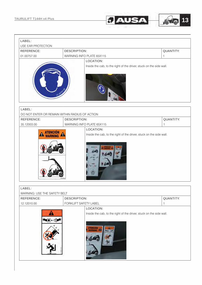
USE EAR PROTECTION
REFERENCE: DESCRIPTION: QUANTITY:
01.00757.00 WARNING INFO PLATE 65X115 1
LOCATION:
Inside the cab, to the right of the driver, stuck on the side wall.
LABEL:
DO NOT ENTER OR REMAIN WITHIN RADIUS OF ACTION
REFERENCE: DESCRIPTION: QUANTITY:
35.12003.00 WARNING INFO PLATE 65X115 1
LOCATION:
Inside the cab, to the right of the driver, stuck on the side wall.
LABEL:
WARNING: USE THE SAFETY BELT
REFERENCE: DESCRIPTION: QUANTITY:
12.12010.00 FORKLIFT SAFETY LABEL 1
LOCATION:
Inside the cab, to the right of the driver, stuck on the side wall.
TAURULIFT T144H x4 Plus 13

LABEL:
HYDRAULIC OIL SPECIFICATIONS
REFERENCE: DESCRIPTION: QUANTITY:
43.01352.20 INFO LABEL 70X32 HYDRAULIC OIL 1
LOCATION:
In the engine compartment, above the hydraulic oil tank
LABEL:
COMBUSTION ENGINE OIL SPECIFICATIONS
REFERENCE: DESCRIPTION: QUANTITY:
43.01170.02 INFO LABEL 90X45 1
LOCATION:
In the engine compartment, inside the cover
LABEL:
FAN DANGER WARNING
REFERENCE: DESCRIPTION: QUANTITY:
02.00766.00 INFO LABEL 40X80 1
LOCATION:
In the engine compartment, above the radiator
TAURULIFT T144H x4 Plus14

LABEL:
AUSA LABEL
REFERENCE: DESCRIPTION: QUANTITY:
09.09902.01 INFO LABEL 54.5X270 1
LOCATION:
In the rear upper part of the cab
LABEL:
4WD
REFERENCE: DESCRIPTION: QUANTITY:
02.20003.00 INFO LABEL 50x50 1
LOCATION:
On the right side cover
LABEL:
MACHINE MODEL
REFERENCE: DESCRIPTION: QUANTITY:
35.12011.00 INDICATOR 171X45 T144H MODEL 2
LOCATION:
On the side walls of the machine
TAURULIFT T144H x4 Plus 15
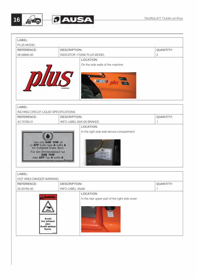
LABEL:
PLUS MODEL
REFERENCE: DESCRIPTION: QUANTITY:
09.09900.00 INDICATOR 175X90 PLUS MODEL 2
LOCATION:
On the side walls of the machine
LABEL:
INCHING CIRCUIT LIQUID SPECIFICATIONS
REFERENCE: DESCRIPTION: QUANTITY:
43.70780.01 INFO LABEL 60X100 BRAKES 1
LOCATION:
In the right side wall service compartment
LABEL:
HOT AREA DANGER WARNING
REFERENCE: DESCRIPTION: QUANTITY:
02.00765.00 INFO LABEL 40x80 1
LOCATION:
In the rear upper part of the right side cover
TAURULIFT T144H x4 Plus16

LABEL:
HOISTING POINTS
REFERENCE: DESCRIPTION: QUANTITY:
32.12120.00 HOISTING POINT INFO LABEL 4
LOCATION:
At two points on the left side wall of the cab, and one point on the right side wall of the cab and the rear part of the horizontal arm
LABEL:
ENGINE COVER LOCK WARNING
REFERENCE: DESCRIPTION: QUANTITY:
35.12005.00 INFO LABEL 75X160 1
LOCATION:
In the engine compartment, inside the cover
LABEL:
NOISE 104 dB
REFERENCE: DESCRIPTION: QUANTITY:
09.12014.00 NOISE LABEL 100X90 1
LOCATION:
Inside de cab, to the right of the driver, stuck on the side wall
TAURULIFT T144H x4 Plus 17

LABEL:
STANDARD MACHINE LOAD DIAGRAM
REFERENCE: DESCRIPTION: QUANTITY:
35.12013.00 LOAD LABEL 130X150 1
LOCATION:
Inside the cab, the driver’s right, stuck to the side.
LABEL:
MACHINE LOAD CHART OPTIONS
REFERENCE: DESCRIPTION: QUANTITY:
35.12014.00 LOAD LABEL 130X150 1
LOCATION:
Inside the cab, the driver’s right, stuck to the side.
LABEL:
EMISSION CONTROL INFORMATION (in EPA engine’s flexibility program)
REFERENCE: DESCRIPTION: QUANTITY:
57.12018.00 INDICATIVE STICKER EMISSION CONTROL 1
LOCATION:
Inside the cab, the driver’s right, stuck to the side.
TAURULIFT T144H x4 Plus18

LABEL:
KOREA APPROVAL (only Korean market)
REFERENCE: DESCRIPTION: QUANTITY:
n/a INDICATIVE ENGINE APPROVAL 1
LOCATION:
Into the engine compartment on the right side of cylinder head cover.
TAURULIFT T144H x4 Plus 19

1.1.3 SYMBOLS USED ON THE MACHINE
This paragraph shows the symbols placed on the controls and instruments of standard machines, or those fitted with optional equipment. These symbols comply with standards (ISO).
IMPORTANT
Take time to learn these symbols and their meanings.
TAURULIFT T144H x4 Plus20
SYMBOL MEANING SYMBOL MEANING SYMBOL MEANING
Emergency lights Parking Brake Pre-heating plugs
Windscreen wiper Battery charge Rotating beacon
Windscreen washer Engine oil pressure Forward drive indicator
Fan/heating Arm rising Reverse drive indicator
Engine coolant temperature Arm lowering Auxiliary hydraulic function
Work light (if fitted) Forks tilted forwards Continuous and high flow
Low beam lights Forks tilted backwards
Turning indicators Clogged air filter

1.2 How to identify the machine
IMPORTANTCheck that the instructions manual is the right version for the machine in question.Please indicate model number, date of purchase and frame and serial number when consulting AUSA or your dealer for any matter. This information can be found on the identification plate. We recommend you make a record of these numbers in the spaces provided below for handy reference and keep it in your files.
Date of purchase:.................................................................Frame number: .....................................................................Engine number: ....................................................................
1.2.1 MODEL AND TYPE
AUSA T144H x4 Plus compact off-road reach truck
1.2.2 MANUFACTURER
AUSA Center, S. L. U.P.O.B. 194. 194
08243 MANRESA (Barcelona), SPAINTel. 34-938 747 552 / 938 747 311
Fax: 34-938 736 139 / 938 741 211 / 938 741 255E-mail: [email protected]
Web: http: //www.ausa.com
1.2.3 IDENTIFICATION PLATES
Machine identification plate.Located inside the cab, to the right of the driver.This plate mentions information such as the machine model, frame number, engine number, year of manufacture, etc.
Identification plates of the main components.Plates for all components which are not directly manufactured by AUSA, (e.g.: engines, pumps, etc.) will be directly attached to these components at the points where the respective manufacturers had originally located the plates.
TAURULIFT T144H x4 Plus 21
(fi g.
1)
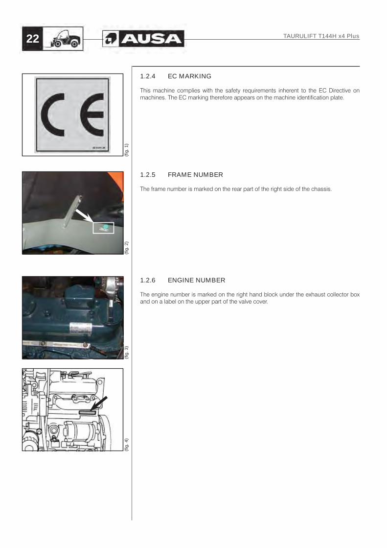
1.2.4 EC MARKING
This machine complies with the safety requirements inherent to the EC Directive on machines. The EC marking therefore appears on the machine identification plate.
1.2.5 FRAME NUMBER
The frame number is marked on the rear part of the right side of the chassis.
1.2.6 ENGINE NUMBER
The engine number is marked on the right hand block under the exhaust collector box and on a label on the upper part of the valve cover.
TAURULIFT T144H x4 Plus22
(fi g.
4)
(fi g.
3)
(fi g.
1)
(fi g.
2)
1.3 Acceptable use
1.3.1 ACCEPTABLE USE
The Compact off-road forklifts have been designed and manufactured to lift, handle and transport agricultural and industrial products via accessories and equipment manufactured or authorised by AUSA. This does not include the following:
- Suspended loads. Should the forklift be used to carry suspended loads, take the appropriate precautions or consult an authorised AUSA dealer.
- Lifting people. Should the forklift be used to lift people, obtain information on applicable legislation as per each country and take the appropriate precautions or consult an authorised AUSA dealer.
Any other use should be considered outside of the intended use and therefore improper.Close adherence to the operation, maintenance and repair conditions specified by the manufacturer is essential for good use of this machine.Driving, maintenance and repair of the forklift must only be entrusted to duly trained personnel, who have the required tools and know the intervention and safety procedures relating to the forklift.Health and safety at work and risk prevention standards should be respected during all transport, maintenance or repair operations. When driving on public roads current legislation must be adhered to (Highway code).
CAUTIONNo modifications or other interventions of any type may be carried out on the machine, with the exception of repairs and maintenance. Should the machine be modified in any way without the authorisation of AUSA or an Official AUSA Representative or Dealer, this will automatically nullify compliance of the machine with Directive 2006/42/EC.
1.3.2 IMPROPER USE
Improper use is understood to be the use of the forklift in such a way that it does not meet with the criteria and instructions of this manual and in such a way that said use may cause harm to persons or equipment.
DANGERThe following are some of the most frequent and dangerous instances of improper use:
- Carrying people on the forklift or an accessory or item of equipment.- Lack of strict compliance with the instructions for use and maintenance set
out in this manual.- Exceeding load limits for the forklift.- Working on unstable, unconsolidated ground or on the edge of ditches and
trenches.- Operating crosswise on slopes.- Working during storms.- Operating on slopes steeper than recommended.- Using accessories or equipment for purposes other than those intended.- Using accessories or equipment not authorised or manufactured by AUSA.- Operating in locations with a risk of fire or explosions.- Operating in confined or unventilated locations.
TAURULIFT T144H x4 Plus 23
1.3.3 OPERATOR RISKS
Certain risks could be caused by operators during their work. For example:- Risks caused by working excessively fast or carrying loads at excessive heights
in view of the load or working environment.- Risks caused by applying methods incorrectly when controlling or replacing a
hydraulic valve (residual pressure - uncontrolled movements).- Risks caused by applying methods incorrectly when dismantling parts such
as e.g. cylinders without having attached all mobile parts appropriately (risk of mobile parts accidentally falling).
- Risks caused by the machine accidentally tipping over without use of the seatbelt.
1.3.4 APPLICABLE STANDARDS
The following standards have been adopted to ensure operator safety during the analysis of risks for the forklift:
Directive Title2006/42/EC Directive on safety for machinery.2004/108/EC Directive on Electromagnetic compatibility.2006/95/EC Directive on low voltage.2000/14/EC*2005/88 Directive on noise emission in the environment by equipment for
use outdoors.
Standard Title
EN 1726 Safety of industrial forklifts. Self-propelled forklifts with a capacity of up to 10 000 kg
EN ISO 21281 Self-propelled industrial forklifts. Rules for the construction and layout of pedals.
EN ISO 12100-1 Safety of machinery. Basic concepts, general principles for design. Part 1: Basic terminology, methodology.
EN ISO 12100-2 Safety of machinery. Basic concepts, general principles for design. Part 2: Technical principles and specifications.
EN 1175-2 Safety of industrial forklifts. Electrical requirements. Part 2: General requirements of internal combustion engine powered forklifts.
EN ISO 13564 Safety of industrial forklifts. Self-powered industrial forklifts - Visibility test methods and verification.
ISO 3287 Self-propelled industrial forklifts. Control systems.
TAURULIFT T144H x4 Plus24

EN ISO 3449 Earth Moving machinery – Falling object protective structures. Laboratory tests and performance requirements.
EN ISO 3471 Earth Moving machinery – Roll-over protective structures. Laboratory tests and performance requirements.
ISO 3776 Tractors for agriculture - Seat belt anchorages.
ISO 3795 Road vehicles, tractors and machinery for agriculture and forestry. Determination of the burning behaviour of internal materials.
ISO 5053 Industrial forklifts. Terminology.
ISO 6055 High-lift rider forklifts. Overhead guards. Specification and testing.
ISO 6292 Powered industrial forklifts and tractors. Brake performance and component strength.
ISO 9533 Earth Moving Machinery. Sound test method for machine-mounted forward and reverse warning alarm. Sound test method.
EN 13059 Safety of industrial forklifts. Test methods for measuring vibration.
EN 61000-6-3 Electromagnetic compatibility - Generic emission standard. Part 3.
EN 61000-6-1 Electromagnetic compatibility - Generic immunity standard. Part 1.
EN 60204-1 Safety of machinery - Electrical equipment of machines - Part 1.
AS 1418.19-2007 Specifies requirements for self-propelled non-slewing and slewing telescopic handlers not greater than 5 either side of the longitudinal axis of seated rider-operated telescopic handlers.
TAURULIFT T144H x4 Plus 25

1.3.5 SAFETY DEVICES
Control of engine start-up- the machine may only be started if the forward-reverse switch is set to “NEUTRAL”.- machine start-up, in forklifts equipped with Continuous and high flow, only can be
accomplished with the Continuous flow switch in position “0”.
Check valves in all cylinders:
A) Check valve in the horizontal arm lifting actuator.
B) Check valve in the tilt actuator of the fork carriage plate.
TAURULIFT T144H x4 Plus26
(fi g.
2)
(fi g.
1)

1.4 General description
1.4.1 MAIN PARTS
1 - Forks2 - Fork carriage for accessories and tools3 - Horizontal arm4 - Engine cover5 - Driver’s cab as per ROPS -FOPS standards6 - Left hand rearview mirror7 - Rear axle (2WD version only)8 - Chassis9 - Front axle10 - Hydraulic gear motor (4WD version only)11 - Headlights and signal lights (if fitted)12- Steering wheel13 - Driver’s seat with seatbelt14 - Rotating beacon
TAURULIFT T144H x4 Plus 27
(fi g.
1)

1.4.2 DESCRIPTION OF THE MAIN PARTS
Hydrostatic transmissionThis is an assembly of components enabling the movement of the machine. The assembly mainly consists of:
- variable-flow hydrostatic pump connected to the combustion engine via an elastic coupling.
- a hydraulic unit fitted on the differential pinion of the front axle.- two radial piston hydrostatic motors, one on each wheel, for the rear axle. - a hydraulic fluid filter in the tank suction line.- a cooler for the hydraulic oil circuit.
EngineDiesel. 4 cylinders, 4 strokes. Water cooled.
Front axleThe front axle transmits the movement from the hydraulic unit to the wheels
TyresThe machine is equipped with tyres with the appropriate dimensions for the maximum load accepted on the forklift.Should tyres be changed, systematically replace them with tyres with the same dimensions and load carrying properties.
Horizontal arm hydraulic circuitThis system includes a two-bodies gear pump, with one body for steering and a second for the movements of the horizontal arm, directly connected to the hydrostatic pump.
Brake circuitThis assembly consists of two independent circuits:
- the effect of the initial part of pedal travel will be slow approach or “inching”.- during the final part of pedal travel, the solenoid valve activating the front axle
brake disk assembly will be directly actuated.
The parking brake is a negative system and actuates the disk assembly of the service brake (hydraulic actuation). This brake is activated using a switch located to the left of the instrument panel, facing the operator.
Driver’s cabAuthorised driver’s cab satisfying the provisions of EN ISO 3449 & EN ISO 3471 (ROPS & FOPS).
Towing hook (if fitted)The machine may be fitted with a rear connection and pull authorised trailers.
TAURULIFT T144H x4 Plus28

1.4.3 OPTIONAL ACCESSORIES
The machine may be fitted with a range of optional accessories: contact your Official AUSA Representative or Dealer
IMPORTANTCheck if your machine is equipped with optional accessories.The optional accessories can modify the forklift weight and dimensions.
1.5 Technical data1.5.1 DIESEL ENGINE
KUBOTA V1505-E3B brand: water cooled, four cylinder, four stroke with electric starter.According to EPA exhaust emissions regulation (for some specific markets) and exhaust emissions Directives, 97/68 and 2004/26.
Inner diameter and stroke: 78 x 78.4 mmTotal displacement: 1494 cc
Power:22.7 Kw / 30.8 CV at 2600 rpm, according to Standard SAE J- 1995
1.5.2 TRANSMISSION
Front axle with conical unit (drive pinion and crown).Hydrostatic system with variable flow pump and hydraulic unit (radial piston motor).permanent 4WD with radial piston hydrostatic wheel motors.Maximum service pressure: 345 bar.
Maximum Speed: 17 km/h
Gear direction (forward / reverse) can be changed using an electric switch on the lower part of the joystick handle to the right of the driver’s seat.
When the direction is selected, the indicator in the form of an arrow pointing in the corresponding direction will light up.
Differential blocking is achieved using an electric switch on the lower part of the joystick handle to the right of the driver’s seat.
TAURULIFT T144H x4 Plus 29

1.5.3 STEERING
“ORBITROL” hydraulic system. Actuates on the rear axle via one double-direction actuator. .Maximum service pressure: 180 bar.
1.5.4 BRAKES
Service and parking brake: with oil bath disks on the front axle. Hydraulically powered.
1.5.5 STANDARD TYRES 4 identical tyres
Standard tyres: TT OPEN CENTER tyre sizes: 11.0/65-12” - (8PR).Inflation pressure for the front and rear tyres: 4 bar.
Optional tyres: Tyre sizes: 27x10 / 12” TT-(14PR).Inflation pressure for the front and rear tyres: 6.5 bar.
1.5.6 SERVICE TEMPERATURE
Standard machine: -15ºC to 40ºC.
Optional: -20ºC to 40ºC.
TAURULIFT T144H x4 Plus30

1.5.7 HYDRAULIC CIRCUIT
A two-bodies gear pump with a 6 cc flow body for steering and a 8 cc flow body for the auxiliaries in standard machine and 8 cc flow body for steering an 18 cc for the auxiliaries in machine with Continuous and high flow (at 1500 rpm) connected to the hydrostatic pump. Two spool control valve and 1 solenoid selector for moving the auxiliary hydraulic take-off (if fitted).Maximum service pressure: 240 bar.32 l hydraulic fluid tank.
1.5.8 CAPACITY/DIMENSIONS
Unladen weight (with full tanks): 2400 kg. See machine identification plate.Nominal load: 1350 kg.Maximum height for lifting: 4000 mmRotation of the fork carriage (with the arm horizontal): from +68 º to -12ºPay Load at maximum height and with load center at 500 mm. or 600 mm
Standard: 1350 KgFork carriage with side-shift: 1250 Kg Fork carriage with hydraulic quick attach: 1150 KgFork carriage with hydraulic quick attach and side-shift: 1000 Kg
Maximum Weight, 3500 kg. See machine identification plate.Total width, 4WD version: 1410 mmMaximum gradient (fully loaded) 26%Outer turning radius (mm) for the 4WD version: 2982 mm
1.5.9 FORKS
FloatingDimensions: 1000 x 100 x 35 mm
1.5.10 ELECTRICAL EQUIPMENT
Electrical starting motor of 1.0 Kw- 12V /70Ah battery.- 12V / 360W alternator.- Diesel pre-heating plugs.- Rotating beacon- Horn- Acoustic warning for reverse direction.
1.5.11 VIBRATION AND NOISE LEVELS
Sound level:Guaranteed sound level (as per directive 2000/14/EC on noise emission in the environment by equipment for use outdoors):
• Lwa = 104 dB (A)
Acoustic pressure in the operator’s cab:Weighted sound level (A) measured as per standards EN 12053 and ISO 4871:
• Lpa = 85 dB (A) • Measuring uncertainty: 2.56 dB (A)
Level of vibrations generated by the machine:Mean quadratic value weighted on the basis of the acceleration applied to the upper members: < 2.5 m/s2
Mean quadratic value weighted on the basis of the acceleration applied to the body: < 0.5 m/s2.
TAURULIFT T144H x4 Plus 31
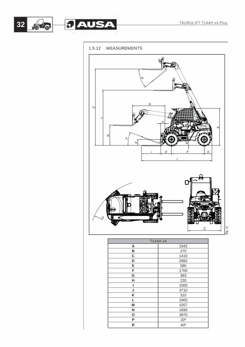
1.5.12 MEASUREMENTS
T144H x4A 1942B 270C 1410D 2982E 580F 1700G 383H 230I 1000J 3710K 310L 2900M 1057N 1690O 3970P 20ºR 40º
(fi g.
1)
TAURULIFT T144H x4 Plus32

1.6 Duration of use
The effective life cycle of the machine is 8000 hours providing that all checks, periodic maintenance operations and overhauls defined in the manual are carried out.
DANGERThe forklift may not be used beyond this period without an overhaul and testing by an Official/authorised AUSA Representative or Dealer.
1.7 Accessories included
The following equipment is supplied with the machine as standard:
Wheel wrench
1.7.1 DOCUMENTATION PROVIDED
The following are provided with the machine:- Instructions and maintenance manual for the forklift- Instructions and maintenance manual for the KUBOTA engine- Maintenance records book for AUSA machines
TAURULIFT T144H x4 Plus 33

Section 2
INDEX
2.1 GENERAL INFORMATION..................................................................... 35
2.2 PREREQUISITES FOR PERSONNEL .................................................... 362.2.1 Prerequisites for operators .................................................................... 362.2.2 Prerequisites for personnel in charge of maintenance ......................... 362.2.3 Work and maintenance clothing............................................................ 372.2.4 Personal protection equipment ............................................................. 37
2.3 SAFETY STANDARDS ........................................................................... 382.3.1 Working area ......................................................................................... 382.3.2 Prior preparation .................................................................................... 392.3.3 During work and maintenance .............................................................. 412.3.4 Parking the forklift and cutting the engine ............................................. 44
2.4 SAFETY DEVICES .................................................................................. 44
2.5 OVERLOAD SYSTEM ............................................................................. 44
TAURULIFT T144H x4 Plus34
Special safety messages

2.1 General information
AUSA manufactures its forklifts in accordance with the relevant protection requirements defined in current legislation for countries in the European Economic Community, with regard dangers of any kind, which may present a risk to health or life, providing the machine is used and maintained in accordance with these directives. Any hazard caused by improper use, not complying with these instructions or others specifically provided with the forklift, will be the responsibility of the user and not AUSA.
This section gives instructions on how the forklift must be used as per the provisions of the 2006/42/EC Directive on the Safety of machinery.
WARNINGThe instructions mentioned in this manual are those recommended by AUSA; More appropriate methods with equivalent safety levels for the start-up, use and repair of the machine may exist, in view of the area of operation, available resources at all times and the assessment of the risks inherent to the work station in question.Most accidents occuring with machines, during operation, maintenance or repairs, are due to a lack of attention to basic safety precautions. Therefore, it is necessary to pay constant attention to the reactions which may occur at each interaction with the machine.This manual uses safety symbols to indicate the potentially most dangerous situations.
IMPORTANTIdentifying potentially dangerous situations before they happen can help to avoid accidents.Under all circumstances, should it be necessary to proceed in a manner differing from that described in the manual, ensure that:- the procedures to be applied are not explicitly prohibited;- these methods are safe, i.e. they satisfy the standards and descriptions
mentioned in this section of the manual.- these methods do not cause direct or indirect damage to the machine,
making it unsafe.
IMPORTANTIf in doubt, always ask! Contact your Official AUSA Representative or Dealer should you have any questions
TAURULIFT T144H x4 Plus 35
2.2 Prerequisites for personnel
You are the “KEY” to the safety so think...- Before you begin using a forklift that you are not familiar with, you should read
this operator manual carefully and consult your superior if you have any doubts. The forklift should only be used by authorised and duly trained personnel.
2.2.1 PREREQUISITES FOR OPERATORS
Operators which use the machine occasionally or regularly (e.g. for transport) must satisfy the following requirements:
Medical requirementsOperators must not consume alcohol, drugs or other substances which may alter the physical or mental state of the person, and consequently their ability to operate the machine, prior to and during work.
Physical requirementsOperators must have normal hearing and visual abilities, satisfactory coordination and the ability to execute the functions required to operate the machine in a safe manner, as specified in this manual.
Intellectual requirements and attitudeOperators must be able to understand and apply current standards and safety instructions; Operators must be able to pay attention and take the necessary decisions to ensure their safety and that of others; they must make every effort to execute tasks correctly and in a responsible manner.
Prior learningOperators must have carefully read and understood this manual and all graphics and diagrams therein, as well as all informative and warning plates and labels displayed both in this manual and on machines. Operators must receive specialist training on all elements of the operation and use of the machine.
2.2.2 PREREQUISITES FOR PERSONNEL IN CHARGE OF MAINTENANCE
Personnel in charge of the maintenance of the machine must be qualified, and have received mechanical training in the maintenance of earth moving machines in general, and must necessarily satisfy the following prerequisites:
Physical requirementsOperators must have normal hearing and visual abilities, satisfactory coordination and the ability to execute the functions required to maintain the machine in a safe manner, as specified in this manual.
Intellectual requirements and attitudeOperators must be able to understand and apply current standards for preventive maintenance and safety instructions; Operators must be able to pay attention and take the necessary decisions to ensure their safety and that of others; they must make every effort to execute tasks correctly and in a responsible manner.
Prior learningOperators must have carefully read and understood this manual and all graphics and diagrams therein, as well as all informative and warning plates and labels displayed both in this manual and on machines. Operators must receive specialist training on all elements of the operation, maintenance and use of the machine.
TAURULIFT T144H x4 Plus36

IMPORTANTAccording to the applicable national legislation, operators may be required to validate prior training or aptitude to operate the machine in the form of a permit (or log) issued either by the employer or a government or private body.Operators should obtain information locally.
IMPORTANTRoutine machine maintenance will not involve the execution of complex technical operations. Therefore, most of these operations may be carried out by the operator simply by following the instructions provided in this manual.
2.2.3 WORK AND MAINTENANCE CLOTHING
The appropriate equipment and material for the function in question and the prevention of accidents must be used when operating the machine or carrying out maintenance or repair operations. The final equipment will be selected on the basis of the assessment of risk for each work station; however, generally speaking, the following recommendations apply:
- A comfortable close fitting work suit or other clothing which cannot be caught in moving components. Wear reflective clothing if appropriate.
- Protective helmet.- Protective gloves.- Safety boots.- Ear protection- Safety goggles, if applicable.
2.2.4 PERSONAL PROTECTION EQUIPMENT
You are the vehicle operator, think...Make sure that you are issued with all the necessary personal protection equipment (PPE) to carry out your work safely, for instance: hard hat, ear protection, warm clothes, reflective equipment, safety goggles, masks, etc.The operation of the forklift whilst wearing bracelets, chains, loose clothing, with long hair which is not tied back, etc. is not recommended due to the risk of catching in controls, rotating parts, cracks, etc.
IMPORTANT
Only use approved accident prevention equipment in good condition.
(fi g.
1)
TAURULIFT T144H x4 Plus 37

2.3 Safety standards
2.3.1 WORKING AREA
Depending on the work area, remember....- If there is a risk of fire or explosion in the working area, either because of goods
stored or because of possible fluid or gas leaks, check that the forklift is fitted with a sufficient degree of fire protection.
- If you have to work in closed spaces, make sure that the area is well ventilated in order to prevent the excessive build-up of exhaust fumes. Always turn the engine off when it is not needed.
- To drive the forklift on public roads, all necessary approvals and licenses must be obtained in accordance with the current legislation in the country of use, and all signs and safety elements required by legislation must be satisfied.
- In some countries, the forklift may be used without lighting in full daylight or in areas which are sufficiently lit.
Always account for the characteristics of the planned working area. Carefully study the working area: consider the area in view of the dimensions and movements of the machine.
ELECTROMAGNETIC COMPATIBILITY
This machine complies with current legislation on electromagnetic compatibility; however, should the machine be used in areas with devices that are highly sensitive to electromagnetic interference, make sure that they will not be affected.
ELECTRIC HAZARDSPay special attention to nearby airborne electric lines. Always maintain the horizontal arm at a safe distance from these lines to reduce the risk of electric discharges.
MINIMUM DISTANCE TO BE MAINTAINED, DEPENDING ON THE VOLTAGE OF THE ELECTRIC LINE9m from wood pylons, 15m from metal pylons.
CONTACT WITH LOW VOLTAGE ELECTRIC LINES OR ACCIDENTAL DISCHARGES FROM THE LATTER IMPLY A RISK OF DEATH OR SERIOUS INJURY.BEFORE STARTING WORK IN AREAS WHICH ARE POTENTIALLY DANGEROUS DUE TO ELECTRIC HAZARDS, CONTACT THE OWNER OF THE ELECTRIC LINE TO CHECK IF DISCONNECTION IS NOT REQUIRED PRIOR TO WORKING NEAR TO THE LINE.
DANGER
It is prohibited to use the machine with electric devices during storms.
TAURULIFT T144H x4 Plus38

WARNINGCheck that the ground to be covered by the machine is sufficiently solid to avoid compromising the stability of the machine.- Check the best route to reach the working area.- Do not allow anybody to enter within the radius of action of the machine
during operation.- Keep the working area tidy when operating the machine: do not leave
stray objects within the working area as they may imply a risk for machine movements. Keep the driving area clear of all objects or tools that could move about and might obstruct a control, preventing you from using the control when required.
2.3.2 PRIOR PREPARATION
When starting up the forklift
WARNINGPlace the machine in its working position and check that the machine is on the level.
Before starting operations:
- Check that maintenance operations are carried out carefully, and that the specified time intervals are applied (see section 4 on “MAINTENANCE”).
- Check that enough fuel exists in view of autonomy, to avoid the risk of the engine stopping suddenly during a critical manoeuvre. Always stop the engine before refuelling and never smoke during the process. Do not mix gasoline or alcohol with the fuel.
- Carefully clean the instruments, plates and labels, lights, rear view mirrors and wing mirrors (if fitted).
- Check that all safety devices fitted on the machine operate correctly and in the working area.
- Should any difficulties or problems of any type arise, immediately notify your superior. Do not start any job without complying with safety requirements. If you notice any anomaly while using the forklift, inform the maintenance service immediately.
- It is prohibited to make tideover repairs simply to be able to start work.
TAURULIFT T144H x4 Plus 39

Before starting work with the forklift, clean up any possible oil or fuel which may have leaked, clean and remove any grease from your hands and the soles of your shoes and remember to check the following items:
- Tyre pressure and tread condition.- Check brake functioning.- Check for any leaks in the hydraulics, fuel and cooling system, etc.- Check that all protectors, covers and safety end stops props are correctly
positioned and properly attached.- Check that there are no cracks or other structural defects visible to the naked
eye.- Check the correct operation of all controls.- Check levels of fluids and lubricants: • fuel. • inching circuit fluid. • hydraulic fluid. • coolant. • engine oil- Check the seatbelts and their mountings are in good condition and properly
fixed. Carefully inspect the condition of this device paying special attention to: • cuts or loose threads on the belt. • wear or damage to fittings, including anchor points. • incorrect functioning of the seat belt buckle or retracting roller. • loose seams or stitching.- Check that all covers, locks and other safety elements are correctly positioned.
The removal of safety devices such as the engine cover is prohibited with the exception of for maintenance purposes. Should it be necessary to remove these devices, stop the engine, and pay close attention during the operation. Replace the devices before starting the engine and operating the machine.
- Check the correct functioning of alarms and signalling devices (for example: acoustic warning, obstruction indicator for the air admission filter, etc.)
- Check that all the information and safety plates on the forklift are clean and in good condition. Danger warning signals must not be removed, covered or unreadable.
- Check that the lighting and signalling system is clean and working properly (if fitted).
- Check the electric battery connections and the level of electrolyte.- Adjust the seat position so that you are comfortable and can easily reach the
controls.- Do not start the forklift or operate the controls unless you are in the operator’s
seat.- To ensure your safety should the machine roll over, do not forget to correctly
adjust and fasten the seat belt.
TAURULIFT T144H x4 Plus40

2.3.3 DURING WORK AND MAINTENANCE
When operating the forklift, do not forget to...- Keep hands, feet and the whole body in general inside the area provided for the
operator.- Pay special attention to work on slopes, move slowly, avoid being situated
crosswise and do not operate slopes which exceed the recommended gradient. A slope within the recommended gradient does not mean that this slope can be manoeuvred on with absolute safety under any load, terrain or handling conditions. Descend slopes in reverse gear, i.e. with the load in the most stable direction.
- It is not recommended to operate on slopes greater than 15% under any circumstances.
- Give way to any pedestrians you might come across while driving.- The forklift must not be used to carry people, other than the driver, or to lift people
if approved and authorised systems are not fitted for this purpose.- Do not overload the forklift or handle loads which displace the centre of gravity
of the forklift outside of limits. Carry out manoeuvres gently, especially when changing direction on slippery ground.
- Do not carry unstable, unfastened or overlarge loads. If very large or wide loads must be handled, take all possible precautions to avoid hitting items in the surrounding area and other potential accidents.
- Before handling loads from a lorry or trailer, ensure that the latter is appropriately positioned and that the brakes are set.
- If using an accessory, check acceptable loads for the forklift + accessory configuration (which will differ from figures for the standard configuration) prior to use.
- Ensure that you have good visibility of the track, if the load obstructs visibility, drive in reverse gear and increase precautions.
- When approaching a crossroads with poor visibility, slow down, sound your horn and move forwards slowly in accordance with the amount of visibility available.
- The speed of the forklift should be adjusted to the working conditions and area at all times. Systematically driving the machine at maximum speed may represent a danger to the operator and the surrounding area.
- Check that the resistance of the ground on which you are driving is sufficient for the loaded forklift, in particular when accessing bridges, embankments, slabbed areas, loading areas, etc.
- Before reversing the forklift, the operator should check that doing so will not put at risk either the machine itself or nearby people or objects.
- Do not drive with the horizontal arm lifted.- Do not activate two horizontal arm movements simultaneously.- Keep your mind completely on the job in hand. The safety of both the driver and
others depends on the care taken when driving.- Depending on the ground, try to raise as little dust as possible while moving
about driving.- The forklift is not designed to tow other machines. If, for any reason, this operation
is indispensable, check that the machine has sufficient pulling power.- Advance carefully and slowly; If the trailer is not fitted with an inertia brake, make
sure that the brakes are strong enough for both the forklift mass and that of the trailer.
• If the machine rolls over, it is important that the driver avoids being trapped between the machine and the ground. To prevent this we recommend the following:
• Try to remain within the operator cab.• Grasp the steering wheel firmly.• Push feet firmly against the floor plate of the cab.• Try to keep as far away from the point of impact as possible.
TAURULIFT T144H x4 Plus 41
Take care when loading and unloading the forklift...- If concrete spills onto the road surface, remove it before it hardens.
While working, carrying out maintenance or repairs, extreme precaution must be taken. Your safety depends on it...
- Never stop carrying out forklift maintenance. Specialised personnel should be assigned to this job, equipped with the necessary tools and appropriate instructions. Only authorised personnel should carry out maintenance and repair work.
- Check the best route to reach the working area.- It is prohibited to transit or remain under suspended weights or machine parts
which are only supported by hydraulic pistons, chains or cables.- Maintain the handles and footholds used to enter and operate the machine clean
and free of oil and grease to avoid slipping or falling.- Face the machine when entering or exiting the cab or other raised parts. Never
face away from the machine.- It is prohibited to enter or exit the machine during operation.- It is prohibited to leave the control panel when the machine is operating.- Unless unavoidable, all interventions on the forklift should be carried out with the
engine switched off, without any load and with all blocking and locking devices engaged.
- It is prohibited to stop or undertake any kind of intervention in the area between the wheels of the machine while the engine is running. The engine must be stopped.
- Some operations are easier to carry out with the horizontal arm lifted. Before doing so, precautions must be taken to prevent the arm from accidentally lowering using the devices designed for this purpose for each specific forklift model.
- Maintenance or repairs may not be carried out without the appropriate lighting.- Direct the spot light beams to ensure that personnel are not blinded.- Before handling cables or electric devices, check that connections are correct
and that the devices are operational.- is prohibited to connect wet plugs.- When carrying out any repair work, make especially sure that the battery terminals
are protected, so that they cannot accidentally be shorted out by a tool, part, etc.- Before carrying out any electrical welding on the forklift, disconnect the battery to
avoid possible damage to electric and electronic equipment.- It is prohibited to lubricate, clean or adjust mechanical components while moving.- Operations which require the use of specific tools may not be carried out without
these tools.- Do not use tools in an unsatisfactory condition or in an improper manner (e.g.
use a clip instead of a fixed clamp).- Regular checks should also be carried out on all those elements whose excessive
wear or aging could lead to a risk of accident, for example: hydraulic pipes, brake lining, tyre tread, etc.
- Should operator protection suffer an impact that induces a crack or permanent deformity, as this is a safety element, it must be replaced with a new item.
- All modifications which affect the capacity and safety of the forklift must be authorised by the manufacturer or by an official industrial actor, with an update to instruction manuals and plates if necessary.
- The manufacturer will not be held responsible for any incidences or accidents caused by the use of non-original spare parts or by repairs carried out by unauthorised workshops.
TAURULIFT T144H x4 Plus42

- When replacing tyres, ensure that they are the correct replacements and follow the tyre manufacturer’s safety instructions. For safety reasons, split rim wheels must not be used (wheels consisting of two rims bolted together).
- The forklift should be lifted for handling or inspection purposes using the points on the machine designed for this purpose, as indicated in this manual, and using devices with an adequate capacity.
- If the forklift needs to be towed, use a tow bar whenever possible, or if none is available, a cable that is strong enough for the job. In either case, it should be fixed onto the point indicated by the manufacturer and the manoeuvre should be carried out at a speed of no more than 10 Km/h. When driving a towed forklift, pay attention to the position of your hands on the steering wheel, to ensure that an unexpected turn of the wheel does not cause you injury.
- Ensure that the towing truck has adequate towing and braking capacities to be able to perform this operation.
- If the forklift needs to be transported on a lorry platform:• Ensure that only a minimum amount of fuel remains in the tank.• Apply the forklift brakes.• Apply chocks to the wheels and fix them to the truck bed.• Anchor the machine firmly to the truck bed using slings or other methods to
prevent any kind of movement.- This forklift is hydrostatically controlled, should it be necessary to tow the
machine, before doing so, follow the instructions indicated in this manual for the disconnection of the hydrostatic unit, therefore facilitating towing and eliminating any risk for the hydrostatic unit.
- When changing a tyre, make sure that it is fitted with the tread pattern facing the right way.
- Before carrying out any work on the engine cooling system, wait for the temperature of the coolant to drop enough for the coolant reservoir cap to be removed safely.
- In order to avoid allergic reactions and other hazards affecting the skin, replenishing of fuel or other fluids should be carried out wearing protective gloves.
- Before disconnecting fluid systems, make sure there is no pressure in them, that they no longer contain hot fluid, and take steps to avoid unexpected spills.
- Checks should be periodically carried out on the hydraulic system to detect any possible leaks or misalignment on the safety valves which could lead to a risk situation.
DANGER
Only authorised personnel may carry out interventions on the hydraulic system.
- It is prohibited to smoke or use flames in locations with a risk of fire or in the presence of fuel, oil or batteries.
- Avoid leaving containers or tanks containing fuel in areas which are not designed for the storage of fuel.
- Handle inflammable or dangerous substances with care.- After maintenance or repair operations, before starting up the machine, check
that no tools, gates or other materials remain between moving parts, in the suction air ducts or in the cooling air circuit.
TAURULIFT T144H x4 Plus 43

- When executing manoeuvres with guidance from a person outside the forklift, only one person must transmit signals and indications.
- All orders issued by managers must be complied with.- Avoid interference during complex operations or manoeuvres,- Avoid distracting or frightening operators without reason.- When completing an operation, do not leave the machine in a potentially
dangerous configuration.- Be environmentally friendly. When changing oil, fluids, tyres, batteries, etc., take
the used materials to the corresponding recycling centres. If you handle or scrap silencers or catalytic silencers which contain mineral fibre-based absorbent materials, protect your skin with the appropriate gloves and clothing and take the materials to approved disposal sites for this class of materials.
- Similarly, at the end of the useful life of the machine, hand it to an authorised scrap centre.
2.3.4 PARKING THE FORKLIFT AND CUTTING THE ENGINE
When leaving the forklift...- Turn the engine off and switch off the ignition. Place the horizontal arm in the
horizontal position.- Place all controls in the neutral (standby) position.- Put the parking brake on.- Block all mechanisms which impede use of the forklift by unauthorised persons;
the starter circuit in particular, by removing the ignition key. If you must leave the forklift on a slope, block the wheels with suitable chocks in
addition to putting the parking brake on.- Leave the forklift parked in areas specifically designated for this purpose, and not
in locations where it prevents people from passing or blocks exits or access to stairways or emergency equipment.
2.4 Safety devices
DANGERVarious safety devices are fitted on the machine and must never be modified or removed (see chap. 4.3.15).Regularly check the effectiveness of these devices. Should these devices not be in perfect operating order, stop work immediately and repair or replace.For information on how to check safety devices (see chap. 4.3.16)
2.5 Overload system
The overload system assists operators in using the machine safely via the use of visual and back-up alarm if the machine is reaching roll-over limits and the situation is therefore dangerous. This device only indicates the forwards roll-over point; other factors play a role in the stability and safety of the machine, therefore, under no circumstances should the overload system be used as a guide when assessing the load to be handled. Acceptable loads are indicated on the load charts shown on the machine and in this manual.Under no circumstances may this device replace the operator’s judgment. Operators are responsible for working in safe conditions and complying with the safety standards defined. While working, carrying out maintenance or repairs, extreme precaution must be taken. Your safety depends on it...
TAURULIFT T144H x4 Plus44

Section 3
INDEX
3.1 BEFORE ENTERING THE MACHINE .................................................... 47
3.2 ACCESSING THE MACHINE ................................................................. 473.2.1 Accessing the cab ................................................................................. 473.2.2 Adjusting the seat .................................................................................. 483.2.3 Adjusting the seat belt ........................................................................... 493.2.4 Adjusting the rear view mirrors .............................................................. 49
3.3 CONTROL PANEL ................................................................................. 503.3.1 Controls ................................................................................................. 503.3.2 Engine controls ...................................................................................... 523.3.2.1 Ignition switch ........................................................................................ 523.3.2.2 Forward/reverse (fnr) selector ............................................................... 523.3.2.3 Multi-function lever (if fitted): ................................................................. 533.3.2.4 Light switch for road use ....................................................................... 543.3.2.5 Brakes .................................................................................................... 543.3.2.6 Accelerator control ................................................................................ 553.3.2.6.1 Throttle pedal ......................................................................................... 553.3.2.6.2 Manual throttle control (if fitted)............................................................. 553.3.2.7 Auxiliary driving controls ........................................................................ 553.3.3 Dials, indicators and warning lights ...................................................... 573.3.3.1 Dials and indicators ............................................................................... 573.3.3.2 Indicators and warning lights ................................................................ 583.3.4 Joystick .................................................................................................. 593.3.4.1 Selection of movements ........................................................................ 603.3.4.1.1 Standard machine ................................................................................. 603.3.4.1.2 Inverse controls (optional) ..................................................................... 603.3.4.2 Lifting/lowering of the horizontal arm .................................................... 613.3.4.3 Forward/backward tilt of the fork carriage............................................. 623.3.4.3.1 Standard machine ................................................................................. 623.3.4.3.2 Inverse controls (optional) ..................................................................... 623.3.4.4 Extension/retraction of the extending arm ............................................ 623.3.4.4.1 Standard machine ................................................................................. 623.3.4.4.2 Inverse controls (optional) ..................................................................... 623.3.4.5 Auxiliaries hydraulic take-off (if fitted) .................................................... 633.3.4.5.1 4Th valve ............................................................................................... 633.3.4.5.2 5Th valve (if fitted) ................................................................................ 633.3.4.6 Attachment of tools ............................................................................... 64
3.4 START-UP .............................................................................................. 673.4.1 Before starting the engine ..................................................................... 673.4.1.1 Start-up check list .................................................................................. 673.4.2 Start-up .................................................................................................. 683.4.3 Start the engine using an external source ............................................. 693.4.4 Start up at low temperatures ................................................................. 703.4.5 Start-up of the machine ......................................................................... 703.4.6 Parking the forklift and cutting the engine ............................................. 70
TAURULIFT T144H x4 Plus 45
Operating the forklift

This section aims to supply the operator with a basis to gradually learn how to operate the forklift.Once seated in the driver’s cab and having made preliminary adjustments, the operator must identify and learn the position of the different controls and instruments.This process is essential in ensuring that the operator is able to work effectively or carry out rapid punctual operations if suddenly required to guarantee the safety of the operator and the machine.Learn to use and predict the reactions of the forklift.Learn to use controls in an open area, free of obstacles, in a safe manner without people nearby. Never use controls suddenly, apply caution until certain of the effect of the controls on the machine.
3.5 USE OF THE FORKLIFT ....................................................................... 713.5.1 Machine nominal load ........................................................................... 723.5.1.1 Load center (fig. 1) ................................................................................ 723.5.1.2 Load capacity ....................................................................................... 733.5.2 Use of the load chart ............................................................................. 743.5.2.1 Load charts (except usa and australia) ................................................. 753.5.2.2 Load charts (usa market) ...................................................................... 763.5.2.3 Load charts (australian market) ............................................................ 773.5.3 Overload system ................................................................................... 783.5.3.1 Overload calibration procedure............................................................. 793.5.3.2 Usage (standard machines) .................................................................. 803.5.3.3 Usage (optional / standard for australian market) ................................ 813.5.4 Handling loads ...................................................................................... 823.5.4.1 Forks cover (if fitted) (fig. 1) .................................................................. 823.5.4.2 Adjustment of forks ............................................................................... 823.5.4.3 Working phases ..................................................................................... 833.5.5 Replacement of attachments ................................................................ 843.5.6 Transporting towed loads ...................................................................... 87
3.6 TRANSPORT OF THE MACHINE ......................................................... 873.6.1 Towing a damaged machine ................................................................. 873.6.2 Transfer by road and jobs ..................................................................... 893.6.3 Loading the machine with a crane ........................................................ 903.6.4 Transporting with another forklift (if fitted) ............................................. 913.6.5 Transport on another vehicle ................................................................. 913.6.6 Parking and non-operational machines ................................................ 923.6.6.1 Short stops ............................................................................................ 923.6.6.2 Extended stops ..................................................................................... 923.6.7 Cleaning and washing the machine ...................................................... 933.6.7.1 Cleaning instructions ............................................................................. 933.6.7.2 Washing the machine ............................................................................ 933.6.8 Elimination ............................................................................................. 933.6.8.1 Elimination of batteries .......................................................................... 93
TAURULIFT T144H x4 Plus46
Preamble

3.1 Before entering the machine
Check and clean- Clean all windows, lights, rear view mirrors (if fitted).- Check that bolts, joints and screws are tightened and positioned as appropriate.- Check that no oil, fuel or coolant leaks exist.
Check tyres- Check tyre pressure. Refer to the “Tyre pressure” chapter in the PERIODIC MAINTENANCE
OPERATIONS section.- Check that tyres have no cuts and that the tyre fabric has no visible breakages
with deformation.
WARNINGThe explosion of a tyre can cause serious injury. Do not use the machine with damaged or low-pressure tyres or tyres with excessive wear.
3.2 Accessing the machine
3.2.1 ACCESSING THE CAB
WARNINGAlways check that your hands and sole are dry and clean before entering the driver’s cab. Do not hold on to or pull on the steering wheel to access the operator’s cab. Hold the handle provided for this purpose and always place your foot on the cab step to avoid slipping both when entering and exiting the cab.
Access the forklift cab from the left side.
(fi g.
1)
1
TAURULIFT T144H x4 Plus 47

3.2.2 ADJUSTING THE SEAT
The seat must be carefully adjusted to provide a safe and comfortable driving position for the operator. The forklift’s seat is fitted with devices enabling the adjustment of the height, backrest position, and distance from the pedals.
- Adjusting the distance of the seat from the pedals: A device is fitted enabling the seat to be moved forward or back to adjust the
distance from the pedals. To adjust the seat, turn the lever (1) and push the seat in the desired direction. Once in position, release the lever and ensure that the seat remains blocked in the selected position.
- Tilting the seat backrest: The angle of the back can be adjusted as desired. Rotate the knob (2), and set
the backrest to the desired position.- Adjust the position of the backrest: Rotate the knob (3) clockwise to increase back pressure, and anti-clockwise to
reduce this pressure.
(fi g.
2)
(fi g.
3)
(fi g.
1)
1
3
2
TAURULIFT T144H x4 Plus48

3.2.3 ADJUSTING THE SEAT BELT
To fasten the seatbelt, insert the anchor point (1) into the buckle (2) until you hear the locking “click”. To unfasten the seat belts, press button (3). The seat belt adapts to the body of the passenger using it, giving them freedom of movement but adjusting the belt to the physical constitution of the road. If the machine is parked on a steep slope, the reel retracting roller could become locked; this is normal. Additionally the reel retracting roller blocks the strap belt every time the strap belt is suddenly pulled or in case of sharp braking, collisions or turning operations at high speed.
3.2.4 ADJUSTING THE REAR VIEW MIRRORS
The machine is equipped with an external rear view mirror:
- The lefthand mirror (1) is fitted on the upper lefthand upright of the cab and provides a view of the area behind and to the left of the machine. Adjust the position by manually turning the mirror.
(fi g.
2)
(fi g.
1)
2
3
1
1
TAURULIFT T144H x4 Plus 49

3.3 Control panel3.3.1 CONTROLS
1 - Splash guard2 - Turning indicator switch / windscreen wiper (if fitted)3 - Fuse box4 - Joystick5 - Inching pedal and service brake6 - Hazard light switch (if fitted)7 - Parking brake switch8- Button (No application in this model)9 - Road light switch10 - Throttle pedal11 - Ignition switch12 - Hour-meter13 - Seat14 - Work lights switch15 - Rotating beacon switch16 - Heating fan switch (if fitted)17- Continuous and high flow 18- Horn switch19- Turning indicator20- Pre-heating indicator21- Battery charge warning light22- Coolant temperature warning light23- Combustion engine oil pressure warning light24- Air filter clogging warning light25- Road light indicator26- Steering wheel27- Arm rest28- Overload system
1
4
27
13
262
3
5
28
10
TAURULIFT T144H x4 Plus50

3
4
8
19
15
7 9 11 16 12 6
14
20 21 22 23 24 25
18
17
TAURULIFT T144H x4 Plus 51
3.3.2 ENGINE CONTROLS
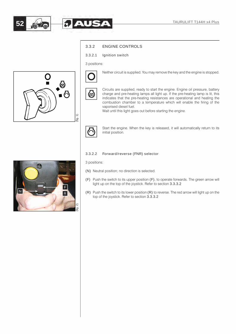
3.3.2.1 Ignition switch
3 positions:
Neither circuit is supplied. You may remove the key and the engine is stopped.
Circuits are supplied, ready to start the engine. Engine oil pressure, battery charge and pre-heating lamps all light up. If the pre-heating lamp is lit, this indicates that the pre-heating resistances are operational and heating the combustion chamber to a temperature which will enable the firing of the vaporised diesel fuel.Wait until this light goes out before starting the engine.
Start the engine. When the key is released, it will automatically return to its initial position.
3.3.2.2 Forward/reverse (FNR) selector
3 positions:
(N) Neutral position; no direction is selected.
(F) Push the switch to its upper position (F), to operate forwards. The green arrow will light up on the top of the joystick. Refer to section 3.3.3.2
(R) Push the switch to its lower position (R) to reverse. The red arrow will light up on the top of the joystick. Refer to section 3.3.3.2
(fi g.
1)
(fi g.
2)
NF
R
TAURULIFT T144H x4 Plus52
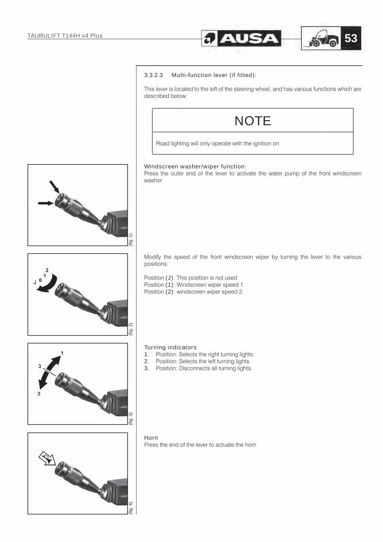
3.3.2.3 Multi-function lever (if fitted):
This lever is located to the left of the steering wheel, and has various functions which are described below:
NOTE
Road lighting will only operate with the ignition on
Windscreen washer/wiper function:Press the outer end of the lever to activate the water pump of the front windscreen washer
Modify the speed of the front windscreen wiper by turning the lever to the various positions:
Position (J): This position is not usedPosition (1): Windscreen wiper speed 1Position (2): windscreen wiper speed 2
Turning indicators1. Position: Selects the right turning lights.2. Position: Selects the left turning lights.3. Position: Disconnects all turning lights.
HornPress the end of the lever to actuate the horn
(fi g.
1)
(fi g.
2)
(fi g.
3)
(fi g.
4)
TAURULIFT T144H x4 Plus 53

Lights selector lever (if fitted):This lever controls the light change function together with the switch 3.3.2.4
Pull on this lever in position (2) to flash the head lights, irrespective of the position of switch 3.3.2.4 . The lever will return to position (0) after release.
3.3.2.4 Light switch for road use
This switch is located on the lower right side of the splash guard, between the rotating beacon and the work light switches. This switch has three positions:
Switch in position (0): Lights out.Switch in position (1): Position lights selectedSwitch in position (2) and lights selector lever in position (0): Low beam selectedSwitch in position (2) and lights selector lever in position (1): High beam selected
3.3.2.5 Brakes
Inching pedal and service brakePress the pedal (1) to bring the machine gradually to a stop. You may accelerate the engine to move the horizontal arm more rapidly. Press the pedal to the floor to gradually activate the service brake.Slowly release the pedal. The machine will start to move.
Parking BrakeThe negative parking brake, can be actuated by pressing the switch on the instrument panel to the right of the splash guard. When the parking brake is actuated, the switch light comes on. Press the switch again to release the parking brake. When the parking brake is released, the switch light is off.
DANGERDo not use the parking brake to slow the machine down, with the exception of emergencies, as this could lead to a serious risk of bodily injury for the operator.
WARNINGA 3-second delay applies when the parking brake is activated. Apply pressure to the service brake pedal until the parking brake has activated.
(fi g.
4)
(fi g.
1)
1
(fi g.
3)
0
1
2
(fi g.
2)
TAURULIFT T144H x4 Plus54

3.3.2.6 Accelerator control
3.3.2.6.1 Throttle pedalApply pressure on the pedal (1) to control engine speed and consequently, the speed of the machine. The lower section of this plate is equipped with an adjustable stop.
3.3.2.6.2 Manual throttle control (if fitted)The Manual throttle control (2), is placed on the right side of the operator’s seat, in front of the Joystick.
- Turning the handle (A) to the left, the engine revs up.- Turning the handle (A) to the left, the engine revs down to iddle. - It may also be actuated by pressing the button (B) and pulling or pushing the
handle.
3.3.2.7 Auxiliary driving controls
Rotating beaconThis switch has two positions: ON/OFF.
Hazard ligths switch (if fitted)This switch has two positions: ON/OFF and activates the simultaneous and flashing illumination of the turning lights.
(fi g.
2)
(fi g.
1)
a2
a1
(fi g.
4)
(fi g.
3)
aB
aA
TAURULIFT T144H x4 Plus 55

Working lights (if fitted)Switch located on the instrument panel, to the right of the splash guard, between the road lights switch and the heating fan switch. This switch has two positions: ON/OFF, which activate the working lights.
Heating fan switch (if fitted)The fan speed switch (A) has three positions:
0. OFF1. Selects low speed2. Selects high speed
Back-up alarm:The back-up alarm is operated using the button (B) located on the right side of the splash guard.
Continuous and high flow switch (if fitted)
The Continuous and high flow switch (C) has 3 positions:
0. OFF1. Continuous flow connected with pressure through hydraulic female quick action
coupling (E) and tank through male quick action coupling (D)2. Continuous flow connected with pressure through hydraulic male quick action
coupling (D) and tank through female quick action coupling (E)
0
1
(fi g.
2)
A
0
1
2
2
(fi g.
1)
(fi g.
3)
B
(fi g.
4)
C
(fi g.
5)DE
TAURULIFT T144H x4 Plus56

Overload system disable switch (if fitted):Button located on the right side of the splash guard. This button needs to be handly pressed:
The fuction disable the overload system permiting to extend the arm over the limit.
WARNINGWorking with the overload system disabled can cause the forklift to roll-over and imply serious risks for the safety of the operator. Use this function with great care and re-activate the overload system after the emergency situation has been solved.
Hot air temperature regulator (if fitted)The hot air temperature regulator (A), is located to the left of the driver’s seat.
• Rotate counter-clockwise to reduce the air temperature.• Rotate clockwise to increase the temperature of the air entering the driver’s cab.• The amount of hot air can be regulated using the fan speed switch, located on
the instrument panel.
3.3.3 DIALS, INDICATORS AND WARNING LIGHTS
3.3.3.1 Dials and indicators
Fuel levelLocated to the left of the driver, above the fuel tank, this dial indicates the level of fuel in the tank.
Hour-meterThis display indicates the operating time for the machine.
(fi g.
3)
(fi g.
4)
(fig.
1)
(fi g.
2)
aA
TAURULIFT T144H x4 Plus 57

3.3.3.2 Indicators and warning lights
Parking brake ON light. When this light is on, the parking brake is activated.
This indicator lights up to show that the forklift is set to forward operation.(Green light over the joystick)
This indicator lights up to show that the forklift is set to reverse.(Red light over the joystick)
Low battery warning light. Indicates that the alternator is not charging adequately.
Low engine oil pressure warning light. Indicates that the engine oil pressure is not adequate.
This indicator lights up when high beam have been selected
Pre-heating resistances indicator. Indicates the pre-heating phase for engine resistances. Wait until this light goes out before starting the engine.
Air filter clogged warning light. Indicates that the engine’s air suction filter is clogged. Clean or replace the filter element immediately.
Excessive increase in engine coolant temperature warning light. Indicates an excessive rise in temperature of the forklift’s engine coolant.
TAURULIFT T144H x4 Plus58

3.3.4 JOYSTICK
The forklift is equipped with a joystick to control the movements of the extending arm using the hydraulic distributor.The joystick is equipped with two buttons (5) to tilt the fork carriage forward or back and (6) to operate the auxiliary hydraulic circuit (Hydraulic Quick Fit).If the joystick can move in all four directions (right/left, forward/reverse), the extending arm may be extended/retracted and the fork carriage may be tilted forward/back.
IMPORTANT
Refer to 3.3.4.1. for more information on joystick functions
IMPORTANTHold the joystick correctly and move with caution. The speed of the movement of the actuators depends on the position towards which the lever is moving: a small displacement will lead to a small movement by actuators and vice versa; moving the lever to maximum will lead to the actuator moving at maximum speed.
WARNINGThe joystick must only be actuated when the operator is seated correctly in the driver’s seat.
WARNINGBefore operating the joystick, check that nobody is present in the radius of action of the machine.
(fi g.
1)
(fi g.
2)
5 6
TAURULIFT T144H x4 Plus 59

(fi g.
1)
A
D
BC
a5 a6
(fi g.
2)
A
D
BC
a5 a6
(fi g.
3)
D
a5 a6
C
3.3.4.1 Selection of movements
The joystick can be used to execute the following movements, when the operator is in the driver’s seat:
3.3.4.1.1 Standard machine- lift/lower the fork carriage:
move the joystick as shown in (A) - (B).- extend/retract the extending arm:
move the joystick as shown in (C) - (D).- forward/back tilt of the fork carriage:
press the button (5) and move the joystick as shown in (C) - (D).- 4th valve:
press the button (6) and move the joystick as shown in (C) - (D) (see section 3.3.4.5).
- 5th valve (if fitted): press both buttons (5) and (6) at the same time and move the joystick as shown in (C) - (D) (see section 3.3.4.5).
3.3.4.1.2 Inverse controls (optional)- lift/lower the fork carriage:
move the joystick as shown in (A) - (B).- forward/back tilt of the fork carriage:
move the joystick as shown in (C) - (D).- extend/retract the extending arm:
press the button (5) and move the joystick as shown in (C) - (D).- 4th valve:
press the button (6) and move the joystick as shown in (C) - (D) (see section 3.3.4.5).
- 5th valve (if fitted): press both buttons (5) and (6) at the same time and move the joystick as shown in (C) - (D). (see section 3.3.4.5)
DANGERBefore operating the joystick, check that nobody is present in the radius of action of the machine. Should anybody be present, clear the area before operating the forklift.
TAURULIFT T144H x4 Plus60

3.3.4.2 Lifting/lowering of the horizontal arm
To move the Horizontal arm:
WARNINGBefore moving the horizontal arm, check that nobody is present in the radius of action of the machine.
- Place the joystick in its central position.- Move the joystick carefully as shown in (B) to lift the arm or as shown in (A) to
lower the arm.
IMPORTANT
Refer to 3.3.4.1. for more information on joystick functions
(fi g.
2)
B
A
(fi g.
1)
A
B
TAURULIFT T144H x4 Plus 61

3.3.4.3 Forward/backward tilt of the fork carriage
To tilt the fork carriage forward or back:
3.3.4.3.1 Standard machine- Place the joystick in its central position and press (5).- Move the joystick carefully as shown in (C) to tilt the fork carriage backwards, or
as shown in (D), to tilt it forwards.
3.3.4.3.2 Inverse controls (optional)- Place the joystick in its central position.- Move the joystick carefully as shown in (C) to tilt the fork carriage backwards, or
as shown in (D), to tilt it forwards.
3.3.4.4 Extension/retraction of the extending arm
To extend and retract the extending arm.
3.3.4.4.1 Standard machine- Place the joystick in its central position.- Move the joystick carefully as shown in (C) to extend the arm, or as shown in (D),
to retract.
3.3.4.4.2 Inverse controls (optional)- Place the joystick in its central position and press (5).- Press button (5), and move the joystick carefully as shown in (D) to extend the
arm, or as shown in (C), to retract.
WARNINGBefore moving the extending arm, check that nobody is present in the radius of action of the machine.
(fi g.
1)
DC
a5
(fi g.
4)
D
a5
C
(fi g.
2)
D
C
(fi g.
3)
D
C
TAURULIFT T144H x4 Plus62

3.3.4.5 Auxiliaries hydraulic take-off (if fitted)
WARNINGBefore moving the horizontal arm, check that nobody is present in the radius of action of the machine.
3.3.4.5.1 4th valve- Place the joystick in its central position and press (6).- Press button (6), and move the joystick as shown in (D) or as shown in (C)
to give pressure to hydraulic male quick action coupling (E) and tank through hydraulic female quick action coupling (F), move the joystick as shown in (D) to give pressure to hydraulic female quick action coupling (F) and tank through hydraulic male quick action coupling (E)
3.3.4.5.2 5th valve (if fitted)- Place the joystick in its central position and press both buttons (5) and (6) at the
same time.- Press both buttons (5) and (6) at the same time and move the joystick as shown
in (C) to give pressure to hydraulic female quick action coupling (G) and tank through hydraulic male quick action coupling (H), move the joystick as shown in (D) to give pressure to hydraulic male quick action coupling (H) and tank through hydraulic female quick action coupling (G)
(fi g.
1)
D
Ca6
(fi g.
3)
D
Ca6
(fi g.
4)
a5
(fi g.
2)aF aE
aG aH
TAURULIFT T144H x4 Plus 63
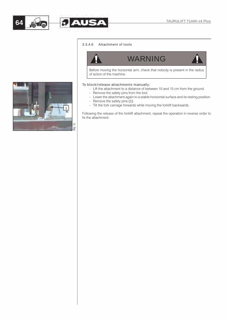
(fi g.
1)
1
3.3.4.6 Attachment of tools
WARNINGBefore moving the horizontal arm, check that nobody is present in the radius of action of the machine.
To block/release attachments manually:- Lift the attachment to a distance of between 10 and 15 cm from the ground.- Remove the safety pins from the tool.- Lower the attachment again to a stable horizontal surface and its resting position.- Remove the safety pins (1)- Tilt the fork carriage forwards while moving the forklift backwards.
Following the release of the forklift attachment, repeat the operation in reverse order to fix the attachment.
TAURULIFT T144H x4 Plus64
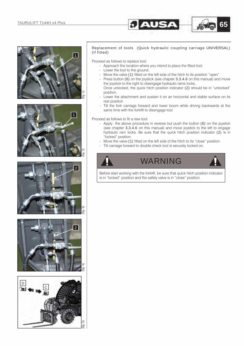
Replacement of tools (Quick hydraulic coupling carriage UNIVERSAL) (if fitted)
Proceed as follows to replace tool:- Approach the location where you intend to place the fitted tool.- Lower the tool to the ground.- Move the valve (1) fitted on the left side of the hitch to its position “open”.- Press button (6) on the joystick (see chapter 3.3.4.6 on this manual) and move
the joystick to the right to disengage hydraulic rams locks.Once unlocked, the quick hitch position indicator (2) should be in “unlocked” position.
- Lower the attachment and sustain it on an horizontal and stable surface on its rest position
- Tilt the fork carriage forward and lower boom while driving backwards at the same time with the forklift to disengage tool.
Proceed as follows to fit a new tool:- Apply the above procedure in reverse but push the button (6) on the joystick
(see chapter 3.3.4.6 on this manual) and move joystick to the left to engage hydraulic ram locks. Be sure that the quick hitch position indicator (2) is in “locked” position.
- Move the valve (1) fitted on the left side of the hitch to its “close” position.- Tilt carriage forward to double check tool is securely locked on.
WARNINGBefore start working with the forklift, be sure that quick hitch position indicator is in “locked” position and the safety valve is in “close” position.
(fi g.
1)
1
Closed
(fi g.
2)
1
Open
(fi g.
3)
2
Unlocked
(fi g.
4)
2
Locked
(fi g.
5)
CD
TAURULIFT T144H x4 Plus 65

(fi g.
1)
1
Closed
(fi g.
2)
1
Open
(fi g.
3)
2
Unlocked
(fi g.
4)
2
Locked
(fi g.
5)
CD
Replacement of tools (Quick hydraulic coupling carriage EURO8) (if fitted)
Proceed as follows to replace tool:- Approach the location where you intend to place the fitted tool.- Lower the tool to the ground.- Move the valve (1) fitted on the left side of the hitch to its position “open”.- Push the button (6) on the joystick (see chapter 3.3.4.6 on this manual) and
move the joystick to the right to disengage the attachment. Both cylinders rods (one on each side) come in.Once unlocked, the cylinder rod (2) should be in “unlocked” position.
- Lower the attachment and sustain it on an horizontal and stable surface on its rest position
- Tilt the fork carriage forward and lower boom while driving backwards at the same time with the forklift to disengage tool.
Proceed as follows to fit a new tool:- Apply the above procedure in reverse but push the button (6) on the joystick
(see chapter 3.3.4.6 on this manual) and move joystick to the left to engage the attachment. Both cylinders rods (one on each side) come out.Once locked, the cylinder rod (2) should be in “locked” position.
- Move the valve (1) fitted on the left side of the hitch to its “close” position.- Tilt carriage forward to double check tool is securely locked on.
WARNINGBefore start working with the forklift, be sure that quick hitch position indicator is in “locked” position and the safety valve is in “close” position.
CAUTION
Only use equipment authorized and designates by AUSA for this type of forklift.
TAURULIFT T144H x4 Plus66

3.4 START-UP3.4.1 BEFORE STARTING THE ENGINE
- Check tyre pressure and condition.- Familiarise yourself with the controls and ensure that they function correctly.- Verify that steering operates freely.- Activate the throttle pedal various times to ensure it operates freely. It must return
to the original position when released.- Activate the brake pedal to ensure that the brakes function correctly. The pedal
must return to the original position when released.- Ensure that the joystick operates freely.- Check fuel, engine oil, hydraulic oil, coolant and inching circuit fluid levels.- Check for oil leaks on the engine, in the transmission components or in the
hydraulic circuit.- Clean the lights and the lamps (if fitted).- Ensure that the engine cover is correctly covered.- Ensure that the seatbelt is correctly secured.
Before starting the day, carefully inspect this device with special attention to:• Cuts or threading on the belt.• Wear or damage to anchor points.• Poor functioning of the seat belt buckle or the retracting roller.• Loose threads or poor stitching.
- If transporting cargo, respect the load capacity. Ensure that the cargo is properly distributed.
- Review the engine parts while it is off. Check fixings.- Check that the starter switch, headlights, turning lights, lamps and the back-up
alarm are functioning correctly.- Start the engine and drive forward slowly a short distance and press the brake
pedal to check the brakes.
Correct any problem you may have found before operating the forklift. Consult an authorised AUSA dealer if necessary.
3.4.1.1 Start-up check list
With the ignition, check the correct operation of the following devices:
- Forward/reverse selector.- Starter switch.
TAURULIFT T144H x4 Plus 67

3.4.2 START-UP
For safety reasons when starting the forklift, the operator must be seated with the seat belt fastened, the parking brake must be applied, and the operator must check that the joystick and the FNR switch are in the neutral position and Continuous and high flow switch (D) should be in “0” position (if fitted).Insert the key into the starter switch and turn it to position (B) until the pre-heat indicator turns off, press the throttle pedal a 1/4 of the way and turn the key to position (C) until the engine starts. Do not hold this position for more than 15 seconds. If the engine does not start repeat the previous operations. Wait for 30 seconds between each try.
CAUTIONIf the indicators / warning lights do not go out when the engine starts to run, stop the engine immediately and identify the causes of the incorrect operation.
IMPORTANT
It is not possible to start the engine if the FNR switch is not in a neutral position.
DANGERAfter starting the engine, the engine will continue to run if the operator leaves the driver’s cab. Do not go far from the driver’s cab without stopping the engine, lowering the arm to the ground, and applying the parking brake.
(fi g.
2)
D
(fi g.
1)
AB
C
0
1
2
TAURULIFT T144H x4 Plus68

3.4.3 START THE ENGINE USING AN EXTERNAL SOURCE
DANGERWhen starting the engine using an external source of energy, by connecting to the battery of another machine, check that the two resources do not enter into contact to avoid the possible protection of sparks. The batteries emit a flammable gas which sparks could ignite, leading to the battery exploding.Do not smoke when checking the level of electrolyte.Keep metal items such as buckles, watch straps, etc. at a distance from the positive cable (+) of the battery, as they may cause a short circuit between this pole and nearby metal components, and consequently the operator may be burnt. The external or emergency battery must have the same nominal voltage and capacity as the forklift battery.
If the engine cannot start due to a flat battery, another 12V booster battery can be used together with the corresponding jump leads to connect the two batteries. If you use the battery of another machine or forklift, avoid the two machines touching.
1- Apply the forklift’s parking brake.2- Remove the right side cover.3- Connect the positive (+) cable to the positive (+) battery terminal and connect the
negative (-) cable to the negative (-) battery terminal (fig. 1).4- Start the forklift in the normal way.5- Disconnect the cables from the terminals and the connections, starting with the
positive (+) terminals.
DANGEROnly use a 12V battery, as all other devices (battery chargers, etc.) could lead to the battery exploding or damage to the battery unit.
(fi g.
1)
TAURULIFT T144H x4 Plus 69

3.4.4 START UP AT LOW TEMPERATURES
The use of oils with suitable SAE viscosity in view of ambient temperatures is recommended for cold starts.Consult the instructions and maintenance manual of the manufacturer of the engine for this purpose.
Cold starting the engine:
- Set the FNR switch to neutral.- Select the starter switch to ignition and wait until the resistance pre-heating
indicator goes out. Press the accelerator pedal to the floor and start the engine by turning the starter switch to the start position. Once the engine has started, release the switch and reduce engine speed to idle. Wait for a few minutes before starting operation, to allow the engine oil to heat gradually and optimise lubrication.
- If the engine has been started using an external source of power, remove the connectors (refer to chapter 3.4.3).
3.4.5 START-UP OF THE MACHINE
Once the engine has reached service temperature, check that all controls are set to their resting positions and that the FNR switch is set to neutral. Proceed as follows:
- Select forward/reverse as required.- Release the parking brake.- Gradually apply pressure to the accelerator pedal to start movement.
WARNINGDo not activate the forwards/reverse selector while the machine is moving. The machine would suddenly change direction, putting the operator in real danger.
3.4.6 PARKING THE FORKLIFT AND CUTTING THE ENGINE
Always park the forklift on level ground, either at the end of the day or in order to carry out any maintenance work, as follows:
- Gradually release the accelerator pedal and apply light pressure on the service brake pedal.
- Set the FNR switch to neutral.- Put the parking brake on.- Release the service brake pedal.- Lower the attachment fitted on the horizontal arm to the ground.- Run the engine at idle for 1 minute, if the forklift has been working at full load. Turn
the starter key to position “0”, remove the key and take the key with you. Never leave the key in the parked forklift.
- Lower the driver’s cab and lock using the cab door key (if fitted).- Chocking the wheels with suitable blocks is also recommended.
(fi g.
1)
TAURULIFT T144H x4 Plus70

3.5 Use of the forklift
DANGERAlways exit the driver’s cab backwards. Make sure that your boots and hands are clean and dry. Hold on to the supports and handles to avoid falling or tripping.
DANGERSet the parking brake whenever the forklift stops, to prevent any undesired movements.
This chapter defines a few techniques and procedures for the use of the machine equipped with a standard fork in safe conditions. Apply the indications of the “OPTIONAL EQUIPMENT” chapter when using different equipment.
WARNINGExamine the working area and check the possible presence of dangerous situations before using the forklift. Check that no holes, embankments, or border areas exist which could sink in, and check for other factors which could compromise the control of the forklift.
ELECTRIC HAZARDSPay special attention to electric lines. Check the position, ensuring that no part of the forklift moves less than 6 metres from any electric line.
WARNINGTo ensure maximum safety when using the forklift, always weigh the loads to be handled.Refer to the load chart located inside the cab, to the right of the driver.
TAURULIFT T144H x4 Plus 71

3.5.1 MACHINE NOMINAL LOAD
The Rated Capacity of this machine is the weight the machine is capable of lifting under safe operating conditions. The lifting capacity of a machine is determined by the height and weight limits of the load. Poor ground conditions as well as shape of the load may reduce the weight that can be safely lifted. Overloading the forks can make the machine unstable, hard to handle, and may be in danger of tipping over.Inspect the load you intend to lift and make certain it is within the limits of the Load Capacity Chart.
3.5.1.1 Load Center (fig. 1)
To rate the lifting capacity of forklifts manufacturers have standardized on a certain size of load. The rated capacity of this forklift is based on a cube measuring 1 m., in all three dimensions with the center of gravity in the center of this cube. This is known as 500 mm or 600 mm or 24 in (depending on models and markets) load center from both the vertical face of the mast and from the lifting surface of the forks. lt is important to keep load center in mind for as the load center increases the lifting capacity of the machine decreases.
(fig.
1) 6
00 m
m
1 m
1 m
1 m
load center600 mm
(fig.
1) 5
00 m
m
1 m
1 m
load center500 mm
(fig.
1) 2
4 in
39 in
39 in
39 in
load center24 in
TAURULIFT T144H x4 Plus72
3.5.1.2 Load Capacity
Standard machine:With the load center of the load at 500 mm. from vertical face of the forks, the T144H / T144H x4 has a rated capacity of 2976 lbs.(1350 Kg.)
With the load center of the load at 600 mm. from vertical face of the forks, the T144H / T144H x4 has a rated capacity of 2976 lbs.(1350 Kg.)
With the load center of the load at 24 in. from vertical face of the forks, the T144H / T144H x4 has a rated capacity of 2976 lbs.(1350 Kg.)
Machine with side-shift:With the load center of the load at 500 mm. from vertical face of the forks, the T144H / T144H x4 has a rated capacity of 2755 lbs.(1250 Kg.)
With the load center of the load at 600 mm. from vertical face of the forks, the T144H / T144H x4 has a rated capacity of 2755 lbs.(1250 Kg.)
With the load center of the load at 24 in. from vertical face of the forks, the T144H / T144H x4 has a rated capacity of 2755 lbs.(1250 Kg.)
Machine with quick attach fork carriage:With the load center of the load at 500 mm. from vertical face of the forks, the T144H / T144H x4 has a rated capacity of 2353 lbs.(1150 Kg.)
With the load center of the load at 600 mm. from vertical face of the forks, the T144H / T144H x4 has a rated capacity of 2353 lbs.(1150 Kg.)
With the load center of the load at 24 in. from vertical face of the forks, the T144H / T144H x4 has a rated capacity of 2353 lbs.(1150 Kg.)
Machine with quick attach fork carriage and side-shift:With the load center of the load at 500 mm. from vertical face of the forks, the T144H / T144H x4 has a rated capacity of 2205 lbs.(1000 Kg.)
With the load center of the load at 600 mm. from vertical face of the forks, the T144H / T144H x4 has a rated capacity of 2205 lbs.(1000 Kg.)
With the load center of the load at 24 in. from vertical face of the forks, the T144H / T144H x4 has a rated capacity of 2205 lbs.(1000 Kg.)
If the load is too heavy split it and re-stack it. Use of attachments other than the pallet forks that came with this machine may reduce lifting capacity and affect other machine handling characteristics.
Reproduced copies of the Load Charts are included in the section 3.5.2 on this Operator’s and Safety Manual. Study the Load Capacity Chart of your machine carefully and make certain you understand it before lifting loads on the forks
TAURULIFT T144H x4 Plus 73

3.5.2 USE OF THE LOAD CHART
The chart showing the loads which can be carried per arm elevation is displayed inside the cab to the right of the driver.The chart indicates load limits for the machine.Always consult these charts to ensure safe operations.
WARNINGThe charts shown here are for information only. Only use the charts in the forklift to determine load limits.
WARNINGThe charts displayed in the forklift apply when the machine is stopped on solid level ground.Lift loads a few centimetres and check stability before lifting entirely.
TAURULIFT T144H x4 Plus74

3.5.2.1 Load charts (except USA and Australia)
Standard machine (load center of the load at 500 mm., 600 mm or 24 in)
Machine with quick attach fork carriage ()(load center of the load at 500 mm., 600 mm or 24 in)
Machine with side-shift ()(load center of the load at 500 mm., 600 mm or 24 in)
Machine with quick attach fork carriage and side-shift ()(load center of the load at 500 mm., 600 mm or 24 in)
TAURULIFT T144H x4 Plus 75

3.5.2.2 Load charts (USA market)
Standard machine (load center of the load at 500 mm. or 600 mm)
Machine with side-shift ()(load center of the load at 500 mm. or 600 mm)
TAURULIFT T144H x4 Plus76

3.5.2.3 Load charts (Australian market)
Standard machine (load center of the load at 600 mm)
Machine with quick attach fork carriage ()(load center of the load at or 600 mm)
Machine with side-shift ()(load center of the load at 600 mm)
TAURULIFT T144H x4 Plus 77

3.5.3 OVERLOAD SYSTEM
The overload system is fitted on the rear axle (A) and indicates the gradual change in stability of the machine. This device will warn the operator before critical conditions are achieved.
(fi g.
1)
A
TAURULIFT T144H x4 Plus78

3.5.3.1 Overload calibration procedure
The calibration procedure is as follows:• Connect the calibration tool (A) in the dash panel socket (B)• Place the machine in a flat surface, with the fork carriage perpendicular against the
arm and the wheels in straight position
Perform the calibration with the machine loaded, respecting the weights indicated in the following chart:
Model with: Setting with initial load
Mechanical carriage (stardard) 700 KG
Hydraulic SSL type carriage 570 KG
Side shift +Load rest + Hydraulic SSL type carriage 500 KG
Setting P2 (fig. 3)1. Start the engine2. Extend the arm completely3. Press during 5 seconds P1 + P2 and an acoustic signal will be heard to confirm the
entrance into the configuration modus.4. Insert the following adjusting sequence:
Press 2 times P2Press 3 times P1Press 3 times P2Press 2 times P1
Keep pressed P2. If the setting has been performed correctly a slow and permanent acoustic signal will be heard. If the setting is incorrect the acoustic signal is fast and discontinuous
Setting P1 (fig. 4)1. Start the engine2. Retract the arm completely3. Press during 5 seconds P1 + P2 and an acoustic signal will be heard to confirm the
entrance into the configuration modus.4. Insert the following adjusting sequence:
Press 2 times P2Press 3 times P1Press 3 times P2Press 2 times P1
Keep pressed P1. If the setting has been performed correctly a slow and permanent acoustic signal will be heard. If the setting is incorrect the acoustic signal is fast and discontinuous
WARNINGWhen the configuration time is expired, steps for entering into the configuration modus and adjustment should be repeated again
Once the calibration is over, it is convenient to make a test with the maximum load of the machine, which is:
Model with: Setting with maximum load
Mechanical carriage (stardard) 1300 KG
Hydraulic SSL type carriage 1200 KG
Side shift + Load rest + Hydraulic SSL type carriage 1000 KG
(fi g.
2)
B
(fi g.
3)
(fi g.
1)
AP1
P2
(fi g.
4)
TAURULIFT T144H x4 Plus 79

3.5.3.2 Usage (standard machines)
The green power indicator (1) will come on once the electric contact is made. When using the machine, the LEDS bar will gradually light up to indicate stability conditions.
Green LEDS: LEDS will indicate normal working conditions if the percentage of rollover moment varies between 0 & 89 of the tolerance, i.e. the machine is stable.Yellow LEDS: indicating that the machine is nearing instability: the percentage of the rollover moment varies between 90 & 100 of the tolerance.The system is set to pre-alarm: the warning light (2) comes on and the audio alarm sounds at intervals.
WARNING
The overload system blocks the extension and lower movements of the arm.
Red LEDS: danger of roll-over: the percentage of the rollover moment varies exceeds 100 of tolerance. The warning light (2) is on and the audio alarm sounds constantly. At this point, it is recommended to only lift or retract the extended arm.
WARNING
The overload system blocks the extension and lower movements of the arm.
DANGERThe stability indicator must not be used to check the load to be lifted: this indicator is only designed to indicate possible unbalance on the machine along the longitudinal axis. This unbalance may also be caused by sudden use of the joystick during the handling of loads. Should more lights come on during the operation, use joystick force with care and handle more delicately.
(fi g.
1)
2
1
TAURULIFT T144H x4 Plus80
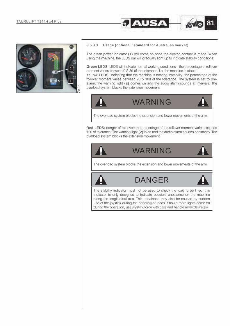
3.5.3.3 Usage (optional / standard for Australian market)
The green power indicator (1) will come on once the electric contact is made. When using the machine, the LEDS bar will gradually light up to indicate stability conditions.
Green LEDS: LEDS will indicate normal working conditions if the percentage of rollover moment varies between 0 & 89 of the tolerance, i.e. the machine is stable.Yellow LEDS: indicating that the machine is nearing instability: the percentage of the rollover moment varies between 90 & 100 of the tolerance. The system is set to pre-alarm: the warning light (2) comes on and the audio alarm sounds at intervals. The overload system blocks the extension movement.
WARNING
The overload system blocks the extension and lower movements of the arm.
Red LEDS: danger of roll-over: the percentage of the rollover moment varies exceeds 100 of tolerance. The warning light (2) is on and the audio alarm sounds constantly. The overload system blocks the extension movement.
WARNING
The overload system blocks the extension and lower movements of the arm.
DANGERThe stability indicator must not be used to check the load to be lifted: this indicator is only designed to indicate possible unbalance on the machine along the longitudinal axis. This unbalance may also be caused by sudden use of the joystick during the handling of loads. Should more lights come on during the operation, use joystick force with care and handle more delicately.
(fi g.
1)
2
1
TAURULIFT T144H x4 Plus 81

3.5.4 HANDLING LOADS
3.5.4.1 Forks cover (if fitted) (fig. 1)
This forklift equips a forks cover (A) fastened with safety chains, according to the German road traffic regulations.
Disassembling the forks coverApproach the location where you intend to place the forks cover
- Release the locking carabiner of the safety chains- Take out the fasten chains (B)- Lower the forks until the cover rests on the ground- Drive reverse slowly in order to extract the forks cover of the forklift
Assembling the forks coverFor re-assembling the forks cover, proceed in reverse order to the procedure described above.
WARNINGTight the fasten chains to prevent the forks cover going out and prevent shakes during the traffic
3.5.4.2 Adjustment of forks
The forks must be adjusted in terms of width depending on the load to be handled. Proceed as follows:
Floating forks (standard configuration):
- Loosen the attachment screws (1).- Lift the forks and slide over the bolts until the desired distance is reached.- Re-tighten the attachment screws (1).
WARNING- The centre of the load must always be between the two forks.- Make sure that you know the weight of the load before starting handling.- Do not exceed allowable load.- Refer to and apply the maximum loads indicated on the load chart.- Separate the forks as far as the load to be handled allows.
(fi g.
1)
1
1
(fi g.
1)
AB
TAURULIFT T144H x4 Plus82

3.5.4.3 Working phases
Once the width of the forks has been adjusted correctly, the forklift is prepared for use.This process involves three phases: loading, transport and unloading.
Loading phase.- Approach the load to be moved perpendicularly.- Introduce the full length of the forks under the load and lift a few centimetres from
the ground.- Tilt the forks backwards to ensure the correct loading of the forklift.
Unbalanced loads- Identify the centre of gravity of the load. When handling packaged loads, this
may be actually marked on the box.- Place the forklift to move the centre of gravity of the load to the centre of the forks.- Grip/release the load. This will depend on the type of load handled. It the load is
on a pallet, apply the procedure for palletized loads. Should no pallet be used, it may be necessary to secure the load on the forks using the appropriate fastening devices. Stop the engine before allowing anybody to come near to the forks.
WARNINGIf it is not possible to identify the centre of gravity of the load, do the following: attempt to lift the load from various different positions until the load remains securely stable on the forks. Do not lift the load more than a few centimetres from the ground, when considering how to lift the load.Pay close attention when using the horizontal arm and the fork carriage with an unbalanced load.
Transport phase.- Avoid starting to transfer or braking in a sudden manner.- Move up to the unloading point while paying maximum attention and maintaining
the load a maximum of 20-30 cm from the ground.- Select the appropriate speed for the type of ground over which the machine
moves to avoid jumps or skids and losing the load.- Pay special attention to work on slopes, move slowly, avoid being situated
crosswise and do not operate slopes which exceed the recommended gradient. A slope within the recommended gradient does not mean that this slope can be manoeuvred on with absolute safety under any load, terrain or handling conditions. Descend slopes in reverse gear, i.e. with the load in the most stable direction.
Unloading phase.- Approach the unloading area with the wheels straight and reduce speed
gradually, leaving enough space to handle the horizontal arm.- Apply the parking brake and set the FNR switch to neutral.- Maintain the load a few centimetres over the unloading point, with the forks
horizontal.- Lower the load until the forks are free of weight.- Withdraw the forks by reversing the forklift, and modifying the height of the
horizontal arm while the forks come out from under the load.- After having completely released the forks from the load, switch to translation
position.- Release the parking brake and prepare for a new job cycle.
WARNINGNever displace the machine in any direction with a load lifted more than 20-30 cm from the ground.This implies a risk of roll-over or losing the load.
TAURULIFT T144H x4 Plus 83

3.5.5 REPLACEMENT OF ATTACHMENTS
Proceed as follows to replace the attachment mechanically:- Approach the location where you intend to place the fitted attachment.- Lower the attachment to the ground.- Extract the safety pins from the attachment bolts.- Remove the attachment bolts.- Lift the arm (approximately 10-15 cm)- Tilt the optional equipment forwards.- Slowly lower the horizontal arm and lower the attachment to the ground again.- Slowly retract to release the attachment from the forklift’s horizontal arm.
To fit a new attachment, apply the above procedure in reverse order.
DANGERAfter each replacement of a attachment , and after any operation fitting an item of equipment, visually check the attachments, as an incorrectly fitted attachment could cause serious accidents.
CAUTION
Only use equipment authorised and designated by AUSA for this type of forklift.
(fi g.
2)
(fi g.
1)
TAURULIFT T144H x4 Plus84

Replacement of tools (Quick hydraulic coupling carriage UNIVERSAL) (if fitted)
Proceed as follows to replace tool:- Approach the location where you intend to place the fitted tool.- Lower the tool to the ground.- Move the valve (1) fitted on the left side of the hitch to its position “open”.- Press button (6) on the joystick (see chapter 3.3.4.6 on this manual) and move
the joystick to the right to disengage hydraulic rams locks.Once unlocked, the quick hitch position indicator (2) should be in “unlocked” position.
- Lower the attachment and sustain it on an horizontal and stable surface on its rest position
- Tilt the fork carriage forward and lower boom while driving backwards at the same time with the forklift to disengage tool.
Proceed as follows to fit a new tool:- Apply the above procedure in reverse but push the button (6) on the joystick
(see chapter 3.3.4.6 on this manual) and move joystick to the left to engage hydraulic ram locks. Be sure that the quick hitch position indicator (2) is in “locked” position.
- Move the valve (1) fitted on the left side of the hitch to its “close” position.- Tilt carriage forward to double check tool is securely locked on.
WARNINGBefore start working with the forklift, be sure that quick hitch position indicator is in “locked” position and the safety valve is in “close” position.
(fi g.
1)
1
Closed
(fi g.
2)
1
Open
(fi g.
3)
2
Unlocked
(fi g.
4)
2
Locked
(fi g.
5)
CD
TAURULIFT T144H x4 Plus 85

Replacement of tools (Quick hydraulic coupling carriage EURO8) (if fitted)
Proceed as follows to replace tool:- Approach the location where you intend to place the fitted tool.- Lower the tool to the ground.- Move the valve (1) fitted on the left side of the hitch to its position “open”.- Push the button (6) on the joystick (see chapter 3.3.4.6 on this manual) and
move the joystick to the right to disengage the attachment. Both cylinders rods (one on each side) come in.Once unlocked, the cylinder rod (2) should be in “unlocked” position.
- Lower the attachment and sustain it on an horizontal and stable surface on its rest position
- Tilt the fork carriage forward and lower boom while driving backwards at the same time with the forklift to disengage tool.
Proceed as follows to fit a new tool:- Apply the above procedure in reverse but push the button (6) on the joystick
(see chapter 3.3.4.6 on this manual) and move joystick to the left to engage the attachment. Both cylinders rods (one on each side) come out.Once locked, the cylinder rod (2) should be in “locked” position.
- Move the valve (1) fitted on the left side of the hitch to its “close” position.- Tilt carriage forward to double check tool is securely locked on.
WARNINGBefore start working with the forklift, be sure that quick hitch position indicator is in “locked” position and the safety valve is in “close” position.
CAUTION
Only use equipment authorized and designates by AUSA for this type of forklift.
(fi g.
1)
1
Closed
(fi g.
2)
1
Open
(fi g.
3)
2
Unlocked
(fi g.
4)
2
Locked
(fi g.
5)
CD
TAURULIFT T144H x4 Plus86

3.5.6 TRANSPORTING TOWED LOADS
The forklift can be equipped with a tow ball with a diameter of 50 mm as an option.
WARNINGTowed masses on flat ground must not exceed:Trailer without brakes: 750 kg.Trailer with brakes: 1250 kg.
WARNING- Avoid attaching excessively heavy trailers.- The load on the towing hook must never exceed 100 kg.- Do not apply sudden translation movements due to the high risk of accidents.- For safety reasons, do not tow trailers without an independent braking
system.- Before reversing to secure a trailer, check that nobody is present between
the machine and the trailer. Those in charge of signalling must be located at the safety distance and clearly visible for the operator.
3.6 Transport of the machine
3.6.1 TOWING A DAMAGED MACHINE
Towing the forklift is only advisable in cases of breakdown when there is no other alternative, as this may seriously damage the hydrostatic transmission. Whenever possible, it is recommended to repair the machine where it is halted.It towing is obligatory, apply the following procedure:
- Tow for short distances and at slow speeds.- Use a rigid towing bar.- Set the FNR switch to neutral.- If possible, start the engine to assist with steering and braking.- If this is not possible, release the negative brake to start the engine. To this end,
remove the rubber plug in the rear part of the hydraulic unit and place a M12 screw in the hole (A). Subsequently apply torque of 42 Nm to release the brake.(fi
g. 2
)(fi
g. 1
)
TAURULIFT T144H x4 Plus 87

- Use the service tool to unlock the negative brake and tighten the screw in the piston (A).
- Tighten the nut (B) until the motor shaft turns freely.
Then remove the seat as follows:- Move the seat cushion backwards and loosen the front screws (B) from the
base.- Move the seat cushion forwards and loosen the rear screws (C) from the base.
Refer to paragraph 3.2.2 for seat movements.
- The central screws of the hydrostatic pump’s maximum (D) pressure valves must be fully tightened (but not excessively). Loosen the locking-nuts for this purpose.
Once the forklift is repaired, loosen the screw (A) in the hydraulic unit and re-loosen the screws (D) on the maximum pressure valves of the hydrostatic pump again and re-tighten the locking -nuts.
CAUTIONThe forklift is fitted with a hook for future towing should the machine be damaged.
(fi g.
3)
D
C C
D
(fi g.
4)E E
(fi g.
1)
A
(fi g.
2)
B
TAURULIFT T144H x4 Plus88

3.6.2 TRANSFER BY ROAD AND JOBS
When driving the machine down public roads, ensure strict compliance with applicable traffic standards in the country of work.Always apply the following standards in all events:
- Use the protection device on the fork ends (if fitted) or, with floating forks, place the forks in the translation position.
- Check that the lights, the audio alarm and the turning lights are fully operational (if fitted)
- Start the forklift and connect the rotating beacon.- Select forward operation.- The machine velocity will depend on the engine speed.
WARNINGThe use of public roads may be authorised depending on applicable legislation per country.
TAURULIFT T144H x4 Plus 89
(fi g.
1)

3.6.3 LOADING THE MACHINE WITH A CRANE
When the forklift is loaded onto a truck using a crane and a cable or sling:
• Hook the cable or sling on the points provided for this purpose on the machine. - RIGHT SIDE: using the holes created (A) in the front part of the cab and in the
rear part of the horizontal arm. - LEFT SIDE: using the holes created (B) in the front and rear parts of the
horizontal arm.• Always carry out this operation with the machine unloaded.• Before hoisting check that the cable or sling is firmly hooked and that both the
crane and the cable or sling have sufficient capacity to lift the load• During hoisting do not allow any person to be on the forklift or any spectators
within a 5m radius.• Always undertake this operation on flat and horizontal ground• Use guide ropes or other systems to avoid the machine pivoting or turning.
Also take into account the following recommendations.• The slings must be long enough to form an angle wider than 40° with the
horizontal.• Always elevate the machine in the most horizontal position possible.
To lift the machine, use resources with adequate loading characteristics for the weight of the forklift. Technical data is indicated in the section on TECHNICAL DATA in this manual and printed on the identification plate of the machine.
TAURULIFT T144H x4 Plus90
(fi g.
1)
(fi g.
4)
(fi g.
2)
(fi g.
3)
B
A
Angle between the sling and the vertical line Vertical line on
c.d.g.
1 Point left side lifting(Ø40 hole)

3.6.4 TRANSPORTING WITH ANOTHER FORKLIFT (IF FITTED)
The forklift may be fitted with an optional accessory in the lower right part to lift the machine using another forklift.
WARNINGTo lift the machine, use another forklift with the adequate loading characteristics for the weight of the machine. Technical data is indicated in the section on “TECHNICAL DATA” in this manual and printed on the identification plate of the machine.
Start by checking that the resistance of the ground on which you will be driving is sufficient for the loaded forklift, in particular when accessing bridges, embankments, slabbed areas, loading areas, etc.
3.6.5 TRANSPORT ON ANOTHER VEHICLE
When transporting the forklift on a truck bed or low loader, carefully follow the advice given in the following chart:
WARNINGBefore raising the forklift onto a trailer or truck bed, make certain that the ramp is strong enough to support the weight of the forklift and that the truck bed surface is free from debris, oil, grease or ice.- Do not transport the forklift with the fuel tank full.- Make certain your seatbelt is properly fastened.- Move the forklift slowly and carefully up or down the loading ramps.- Set the FNR switch to neutral.- Apply the forklift’s parking brake.- Lower the forks as far as possible, or, should no forks be fitted, any optional
equipment fitted, until it reaches the trailer.- Cut the engine and remove the key from the ignition switch.- Close the driver’s cab (if a lock is fitted).- Placing chocks at all four wheels is also recommended.- Secure the forklift to the platform using the appropriate attachment systems
(chains, straps or slings), which must be sufficiently resistant and appropriate for this purpose.
Once the machine is loaded on the truck/trailer, add chocks for the front and rear wheels.Subsequently, firmly secure the forklift to the platform to prevent any movement by attaching the systems shown in figure (2).
TAURULIFT T144H x4 Plus 91
(fi g.
2)
(fi g.
1)

3.6.6 PARKING AND NON-OPERATIONAL MACHINES
3.6.6.1 Short stops
Whenever the forklift is parked, either at the end of the day or in order to carry out any maintenance work, it should be parked on level ground.Apply the forklift’s parking brake. Run the engine at idle for 1 minute, if the forklift has been working at full load. Then turn the ignition key to position “A” to stop the engine. Chocking the wheels with suitable blocks is also recommended in case the parking brake fails.Remove the key from the ignition, close the cab, and take it with you. Never leave the key in the parked forklift.
3.6.6.2 Extended stops
Should it be necessary to park the forklift for an extended period of inactivity, the following is recommended in addition to the guidance mentioned for short stops:
- Wash the forklift carefully.- After washing, carefully dry all parts using a pressurised air jet.- Completely lubricate the forklift.- Carry out a general inspection and replace any damaged parts.- Paint damaged areas.- Dismantle the battery and place in a dry location after having lubricated the
terminals with vaseline. If the battery is temporarily used for other purposes, regularly check the charge level.
- Fill the fuel tank to avoid inner parts rusting.- Park the forklift in a dry, covered and ventilated location.- Start the engine at least once monthly, and run at idle for approximately 10
minutes.
In extreme climates, empty the coolant from the radiator.
IMPORTANTDuring extended periods of inactivity, also remember that periodic maintenance must be carried out and close attention must be paid to all liquids and elements which may age.In all events, before starting the forklift, carry out a complete overhaul checking all mechanical, hydraulic and electric parts.
TAURULIFT T144H x4 Plus92

3.6.7 CLEANING AND WASHING THE MACHINE
3.6.7.1 Cleaning instructions
Comply with the following instructions to clean the machine in a satisfactory manner:
- Clean parts of oil or grease using solvents or volatile mineral alcohol.- Remove all protective substances (rust inhibitor, grease, wax, etc.)- If signs of rust appear on metal parts of the forklift, clean using an emery board
and cover with an appropriate protection substance (rust inhibitor, varnish, oil, etc.).
- When the forklift is used in salt water areas (beach areas, etc.), rinse with clean water to preserve the forklift and its components.
- When the forklift is operated in muddy conditions, rinsing the dumper is recommended to preserve the forklift and its components.
Lubrication of metallic parts is highly recommended.This must be performed at the end of each operation day.
3.6.7.2 Washing the machine
External washingDuring the washing process, care must be taken to avoid aiming the pressurised water jet at the air intake (air filter), battery, instrument panel, alternator and other electrical equipment since this can damage the components.
Interior washingWash the inside of the machine using, water, a bucket and a sponge. Do not use low-pressure water jets. Finish by wiping with a clean cloth.
Washing the engineWash the engine after having covered the air suction filter to protect against water.
3.6.8 ELIMINATION
3.6.8.1 Elimination of batteries
ENVIRONMENTAL PROTECTION
Dispatch all used batteries to the appropriate recycling centres. Should leaks of substances such as acid or lead occur, which may be dangerous for individuals or the environment, take the emergency action required to reduce impact.
TAURULIFT T144H x4 Plus 93

Section 4
INDEX
4.1 LUBRICANTS, SAFETY AND HYGIENE STANDARDS ......................... 95
4.2 SCHEDULED MAINTENANCE .............................................................. 964.2.1 Lubrication and maintenance chart ...................................................... 97
4.3 MAINTENANCE OPERATIONS ............................................................ 994.3.1 Access to engine, cab and tank compartments ................................... 1004.3.2 Supply circuit ......................................................................................... 1024.3.3 Grease ................................................................................................... 1044.3.4 Tyres and wheels ................................................................................... 1054.3.5 Brakes & inching ................................................................................... 1064.3.5.1 Inching circuit fluid level check.............................................................. 1064.3.6 Engine air filter ....................................................................................... 1074.3.7 Engine coolant circuit ............................................................................ 1074.3.8 Oil tank level check................................................................................ 1094.3.8.1 Replacing hydraulic fluid ....................................................................... 1104.3.8.2 Hydraulic oil strainer filter ...................................................................... 1104.3.9 Replacing the hydrostatic transmission filter cartridge ......................... 1114.3.9.1 Hydrostatic transmission filter ............................................................... 1114.3.9.2 Regulation of the pressure regulation valves in the hydraulic circuit .... 1124.3.9.3 Hydraulic hoses ..................................................................................... 1124.3.10 Front axle differential oil level ................................................................ 1134.3.10.1 Front differential ..................................................................................... 1134.3.11 Checking safety devices ....................................................................... 1144.3.12 Engine oil ............................................................................................... 1154.3.13 Alternator belt ........................................................................................ 117
4.4 ELECTRIC INSTALLATION .................................................................... 1184.4.1 Battery ................................................................................................... 1184.4.2 Fuses - relays ........................................................................................ 1194.4.3 12V supply lamps .................................................................................. 120
4.5 LIQUIDS AND LUBRICANTS ................................................................. 1214.5.1 Refuelling ............................................................................................... 1214.5.2 Product details ...................................................................................... 1214.5.2.1 Engine oil ............................................................................................... 1214.5.2.2 Lubricants, oils and filter cartridges ...................................................... 1224.5.2.3 Fuel ........................................................................................................ 1224.5.2.4 Greases ................................................................................................. 1234.5.2.5 Inching circuit ........................................................................................ 123
TAURULIFT T144H x4 Plus94
Periodic maintenance
operations

Careful and regular maintenance is necessary to ensure a safe and operational machine for the operator. Therefore, after work in extreme conditions (muddy ground, dusty area, heavy work, etc.) the washing, greasing and maintenance of the vehicle is recommended.Always check that all parts are in correct working order, that oil has not leaked, that protective and safety devices are effective. Should this not be the case, identify and eliminate the causes of the incident. Scheduled maintenance operations are carried out on the basis of the hours of operation carried out by the machine. Check and ensure that the hour counter remains operational to ensure the correct definition of maintenance intervals. Should the scheduled maintenance standards indicated in this manual not be complied with, the AUSA warranty will automatically be cancelled.
IMPORTANTCarefully comply with the specific instructions and maintenance manual supplied with the forklift for engine maintenance standards
4.1 Lubricants, safety and hygiene standards
HygieneShould oils come into extended contact with the skin, this may cause irritation. Therefore, it is recommended to use protective goggles and rubber gloves.After having handled oils it is recommended that you wash your hands carefully using water and soap.
StorageAlways store oils in a closed location out of the reach of children. Never leave lubricants in open containers, and without a label indicating content.
EliminationOil left in the environment, whether new or used, is serious pollution.Carefully store new oil, and store waste oil in special containers for future elimination by specialist collection centres.
SpillageIn case of the accidental loss of oil, intervene to enable absorption with sand or aggregates of an appropriate type. Collect the compound created and ensure it is eliminated as chemical waste.
EmergenciesEyes: In case of contact with the eyes, rinse abundantly with running water. Should the
irritation continue, contact the nearest Emergency centre.
Ingestion: Should oil be ingested, do not force the person to vomit. Call a doctor.
Skin: Should the skin come into excessive and extended contact with oil, wash with soap and water.
Fire: Should a fire start, use carbon dioxide, dry powder or foam extinguishers. Do not use water.
TAURULIFT T144H x4 Plus 95
Preamble

4.2 Scheduled maintenance- In maintenance operations only use original AUSA spare parts. This is
the only way to guarantee that your forklift will remain as technically efficient as when it was purchased.
- On this forklift as with any other, there are parts and systems which are subject to wear and misalignment, which may affect reliability and operator safety, the environment and the area, e.g. exhaust fume emissions, etc.Necessary maintenance must be carried out periodically to ensure that the machine is kept in a condition similar to when it left the factory.In accordance with Work Group Directives, inspections of these systems must be carried out periodically and the results recorded on the forms provided by the Work Authorities of each country. (89/655/EEC and RD1215/97).Even if repairs must be carried out with the engine running, perform all repairs and maintenance operations on the forklift while unloaded, with the forward/reverse selection set to neutral and the wheels blocked to prevent the forklift from moving.Unless otherwise specified, do not start the engine during maintenance operations.Never use a flame to check fluid levels.
- Be environmentally friendly.When changing oils or other fluids, use an appropriate container to collect the fluid and ensure that you are not harming the environment during the operations and take all replaced materials (batteries, coolant, tyres, etc.) to the appropriate recycling centres.In cases of leaks of substances which could be harmful to people or the environment, urgently take the necessary actions to reduce the impact, e.g. in oil leaks, plug the leak, place a container to collect the oil, spread absorbent material or pick up and remove the contaminated ground if necessary.
- Roadside breakdown.In the case of a breakdown when driving on a road, you must use the warning triangles (if fitted).
TAURULIFT T144H x4 Plus96

4.2.1 LUBRICATION AND MAINTENANCE CHART
EVERY
I: Inspect, check, clean, lubricate and replace if necessary
Initi
al in
spec
tion
(50
h)
Eve
ry 1
00 h
.
Eve
ry 2
00 h
.
Eve
ry 4
00 h
.
Eve
ry 5
00 h
.
Eve
ry 8
00 h
.
Eve
ry 1
000
h.
Eve
ry 1
500
h.
Eve
ry 3
000
h.
Dai
ly
Wee
kly
Mon
thly
Ann
ualy
Eve
ry 2
yea
rs
C: Clean
L: Lubricate
R: Replace
ENGINE
Oil and oil filter (1) R R I R
Engine and exhaust attachments / supports I
Visual inspection of exhaust fumes I
Valve clearance (6) I
Engine operation / idle / max. R.P.M./ vibrations I
Control / status / losses / components in the engine compartment I I
Alternator belt I I R R
COOLING CIRCUIT
Check the pressure in the cooling system (6) I
Radiator status / cleanliness of the outside of the radiator (4) I C
Radiator hoses and clamps I R
Radiator fins (inside) C
Coolant (3) (6) I R
SUPPLY / COMBUSTION SYSTEM
Air filter cartridge and casing (4) C R(5) R
Air filter intake air tubes (6) I R
Fuel ducts / connections / clamps I R(2)
Fuel filter cartridge (6) R
Fuel pre-filter (1) R R
Fuel tank (6) C
Fuel injection nozzle pressure (2) (6) I
Injection pump (timing) (2) (6) I
Fuel injection timer (2) (6) I
ELECTRICAL SYSTEM
Battery electrolyte I I
Battery connections I
Instrument panel warning lights indicators (3) I
Battery I R
Damage to electrical cables and loose connections I
Lights and signalling (if applicable) I
HYDRAULIC OIL
Oil strainer filter (inside the tank) R R I
Transmission cartridge filter (1) C C
Fork compensation system R R
Damage to hydraulic connections and hoses I
Hydraulic actuator stop valves I
Condition of hydraulic actuator seals and rods I
Condition of hydraulic hoses I
Condición de las mangueras hidráulicas REPLACE EVERY 6 YEARS AT LEAST
(1) Initial inspection. Initial maintenance is very important and must not be neglected.(2) Must be performed by an authorized AUSA dealer.(3) Section on daily inspections.(4) More often in severe operating conditions such as sandy or dusty areas, areas with snow, or wet or muddy areas.(5) ... or after cleaning 6 times.(6) Only replace if necessary.
TAURULIFT T144H x4 Plus 97

EVERY
I: Inspect, check, clean, lubricate and replace if necessary
Initi
al in
spec
tion
(50
h)
Eve
ry 1
00 h
.
Eve
ry 2
00 h
.
Eve
ry 4
00 h
.
Eve
ry 5
00 h
.
Eve
ry 8
00 h
.
Eve
ry 1
000
h.
Eve
ry 1
500
h.
Eve
ry 3
000
h.
Dai
ly
Wee
kly
Mon
thly
Ann
ualy
Eve
ry 2
yea
rs
C: Clean
L: Lubricate
R: Replace
GREASING POINTS
Cables I L
Greasing nipples (see section on "GREASING POINTS") L
Control articulations (accelerator, lifting actuators, etc.) L
HYDRAULIC UNIT AND HYDRAULIC MOTORS
Oil leaks I
AXLES (FRONT AND REAR)
Front axle differential oil (1) R I R R
Oil leaks I
Wheel nut torque I
Chassis attachment screw torque I
Tyre condition and pressure I
BRAKES & INCHING
Inching circuit fluid R I
Effectiveness of the service and parking brake I
STEERING
Steering actuator I
Steering alignment I
BODYWORK / CHASSIS
Cab I C
Cab lock (if fitted) I
Set of bolts and articulations I
Safety belts I
Floor deck I/C
Decks and protection I
Plates and labels I
Engine compartment cover locks I
Counterweight fastenings I
HORIZONTAL ARM
Fork carriage I
Extending arm sections C L
Guides C/L I
(1) Initial inspection. Initial maintenance is very important and must not be neglected.(2) Must be performed by an authorized AUSA dealer.(3) Section on daily inspections.(4) More often in severe operating conditions such as sandy or dusty areas, areas with snow, or wet or muddy areas.(5) ... or after cleaning 6 times.(6) Only replace if necessary.
TAURULIFT T144H x4 Plus98

4.3 Maintenance operations
DANGERAll maintenance interventions must be carried out with the engine stopped, the parking brake set, the tools on the ground and the FNR switch in the neutral position.
WARNINGBefore carrying out any maintenance operation requiring the hoisting of a component, e.g. the horizontal arm or the cab, attach the hoisted component in a stable and secure manner, before carrying out any action.
WARNINGInterventions on the hydraulic circuit must be carried out by personnel with basic knowledge of hydraulics and with the appropriate tools. Pressure should never exceed the figures indicated in the “TECHNICAL DATA” section of this Manual.
WARNINGBefore carrying out operations on hoses or on hydraulic components, check that there is no pressure in the system. Proceed as follows:- Stop the machine engine. Leaving the driver’s seat is not recommended.- Re-energize the ignition.- Release the parking brake and move the joystick towards the possible
positions to discharge the pressure from the hydraulic circuit.
CAUTIONThe high pressure conducts in the hydrostatic unit may only be replaced by qualified personnel. Any impurity in the closed circuit may cause the rapid deterioration of the transmission.
CAUTIONBefore intervening on any component in the hydraulic circuit, carefully clean the surrounding area.
ENVIRONMENTAL PROTECTION
The handling and elimination of used oil is regulated by applicable standards. Dispatch all used oil to the appropriate recycling centres.
TAURULIFT T144H x4 Plus 99

4.3.1 ACCESS TO ENGINE, CAB AND TANK COMPARTMENTS
Engine compartment
You must open the engine protective cover to carry out any intervention inside the engine compartment. In addition, the side walls of the rear wheel can be removed.The rear part of the cover is fitted with a lock. The inner right part of the cover is also fitted with a mechanical catch to hold the cover open.
The following may be accessed from the engine compartment:
- Combustion engine.- Engine air filter.- Engine oil fill plug.- Fuel filter- Fuel pre-filter- Coolant circuit reservoir.
To access the engine compartment:
- Cut the engine and set the parking brake.- Open the lock by pulling the tab backwards (A). The lock is fitted with a tamper-
proof system (B) requiring a padlock not supplied with the forklift.- Lift the cover by holding the lock until the mechanical blocking device is actuated
(C).- To close the cover: pull the mechanical blocking device (C) and hold the cover
until it is closed and positioned for reblocking with the lock (A).
To access the side walls of the engine:
- Loosen the screws (D) and remove the cover (E).
(fi g.
1)
A
(fi g.
2)
(fi g.
3)
(fi g.
4)
B
C
D
E
D
TAURULIFT T144H x4 Plus100

DANGERApproach with care. Some engine parts could be very hot. Use protective gloves.
The right side cover may be removed to simplify maintenance operations. An inspection gate also exists in each cab floor panel
To access components located behind the right side cover:
- Loosen the 4 attachment screws (A) located in the upper flap and remove the cover.
The following are accessible after removing the cover:
- Inching circuit fluid.- Battery- Transmission hydraulic filter
To access components located under the cab floor plate:
- Loosen the 4 attachment screws (B) located around the plate.
Hydraulic fluid and fuel tank
The fuel and hydraulic fluid tanks are located on the left side of the forklift.
- Fuel tank (C).- Hydraulic fluid tank (D).
(fi g.
1)(fi
g. 2
)
AA
B
B
B
B
(fi g.
3)
C
D
TAURULIFT T144H x4 Plus 101

4.3.2 SUPPLY CIRCUIT
WARNINGNever mix oil with the fuel. The forklift has a 4-stroke engine. Oil must be added in the engine only.
Draining the fuel tank.
(A) Tank drainage plug.
Fuel can be drained via the plug situated on the lower part of the tank.
- Clean the area around the fuel drainage cap plug.- Place a container underneath the fuel drain plug. - Unscrew the plug.- Change the seal in the fuel drain plug. Clean the tank seal area and the oil
drainage plug and replace the plug.
Ensure that there are no leaks from the fuel drain plug.
WARNING
Clean any fuel spillage.
Changing the fuel pre-filter.
Lift the cover and access the left side of the engine. Locate the fuel pre-filter.
(B) Pre-filter(C) Flanges
Remove the fixing flanges brackets and the filter. Ensure that the new filter is located in the correct direction as indicated by the arrow marked on the filter housing.
WARNINGAlways replace this component. Under no circumstances should you attempt to clean it.
Changing the fuel filter.
Unscrew the fuel filter cartridge located on the left part of the engine and remove it from its support.
(D) Fuel filter
Clean the base and cover the joint of the new filter with clean oil. Screw in the filter element once again and tighten, do not use mechanical tools.
(fi g.
1)
A
(fi g.
2)B
C
C
(fi g.
3)
D
TAURULIFT T144H x4 Plus102

Fuel system air vent
(E) Fuel pump air vent plug
To avoid accidents:
WARNINGDo not drain the engine while hot, as the drain can lead fuel to fall in the hot exhaust collector box, possibly causing fire.
The fuel system air vent is necessary if:1. The fuel filter and pipes have been disconnected and then re-connected2. The fuel tank is empty3. Before using the engine after an extended period of storage.
The fuel system must be pressurised via the electrical fuel pump of the fuel system.
PROCEDURE:1. Loosen the fuel filter air vent with a few rotations.2. Tighten the plug again when bubbles cease to appear.3. Open the air vent plug in the upper part of the injection pump.4. Re-tighten the plug when bubbles cease to appear.
IMPORTANTAlways maintain the fuel injection pump air vent plug closed, except when draining. The engine may suddenly cut out if the plug is open.
(fi g.
1)
E
TAURULIFT T144H x4 Plus 103

4.3.3 GREASE
CAUTIONBefore injecting lubricating grease in the grease nipples, clean carefully to prevent, mud, dust or other foreign bodies mixing in the grease thereby reducing or even cancelling out lubrication properties.
Regularly grease the forklift to ensure it is effective and extend its life.Inject lubricating grease via the grease nipples using a pump.Stop greasing as soon as fresh grease appears in the filling holes.Greasing points are indicated in the following figures:
- The symbol indicates greasing points for the pump.
- The symbol indicates greasing points for brush.
(fi g.
1)
(fi g.
3)
(fi g.
4)
(fi g.
5)
(fi g.
6)
(fi g.
8)
(fi g.
7)
(fi g.
2)
TAURULIFT T144H x4 Plus104

4.3.4 TYRES AND WHEELS
Unless it is essential for the type of work to be carried out, the use of solid tyres is not recommended, as this increase the effects of impacts on the transmission and the operator.Occasionally, the wheel nuts must be removed in order to apply lubricant. This operation is very important when the forklift is used in salt water or muddy environments. Remove the wheel nuts one by one, lubricate each one and screw them on again.
Re-tighten the wheelsWheel nuts should be re-tightened every week or every 50 hours of operation.
Wheel nut torque loading:Front wheels: 150 ± 20 Nm.Rear wheels: 250 ± 25 Nm.
Tyre pressureWe recommend that the following instructions are applied:
- Park the forklift on flat ground with the engine off.- Always inflate the tyres when they are cold, to the pressure indicated in the
TECHNICAL DATA section of this manual before beginning work with the forklift.
- Tyre pressure changes according to the temperature and altitude. Recheck the pressure if one of these conditions changes.
- Checking the pressure and inflating the tyre, must be carried out with a pressure meter in good operational condition and equipped with a nozzle which has a safety clamp, to avoid it slipping from the tyre valve during inflation.
- Use gloves to avoid any injury to the hands by any incorrect function of the air nozzle.
- If the tyre is being inflated away from the forklift, first protect it with a special protection cage designed for this purpose.
- Carrying an anti-puncture repair kit is recommended.
Tyre/Wheel condition.Check the tyres for possible damage or wear. Replace if necessary. Do not rotate the tyres if they are directional.For correct operation their rotation must maintain a specific direction.
Removing the wheel. (fig. 1)Loosen the nuts and raise the forklift. Place a support beneath it. Remove the nuts and then remove the wheel.When assembling, apply lubricant to the threads. Slowly tighten the nuts in a criss-cross sequence, applying a final torque of 150 ±20 Nm. or +/- 25 Nm.
(A) Coned part of the wheel nut
WARNINGTyre pressure largely affects the steering and stability of the forklift. Low tyre pressure can lead to deflation and spin out. High tyre pressure can lead to a blow out. Always apply the recommended pressure. As the tyre pressure is high, do not use a manual pump. Inflating the wheels could be dangerous if the operation is not carried out with caution. If possible, it is recommended that this operation be carried out by specialists in the field.
(fi g.
1)
A
TAURULIFT T144H x4 Plus 105

4.3.5 BRAKES & INCHING
- Contact an authorised AUSA dealer for any anomaly on the brake system.
The incorrect operation of the inching system may be due to the presence of air in the circuit.
To bleed the inching circuit:
- Fill the tank (D) to maximum and check that the tank does not empty during the bleeding operation (re-fill should the tank empty). Leave the tank cover open.
- Bleed using the hydrostatic pump fitted under the seat.- Bleeding the inching circuit is a two-person job.- During bleeding, the pedal will be activated rapidly when applying pressure, and
slowly when releasing, to avoid damaging the o ring in the brake pump (fig. 1) which would cause substantial damage.
Procedure:
- Firstly, remove the rubber protection covering the hydrostatic pump inching circuit (A) bleed screw. Insert a transparent tube (B) in the bleed screw (A). Immerse the other end of the tube in a container filled with fluid as per section 4.5.2.4 of this manual (fig. 2).
- Loosen the bleed screw using a spanner (C). Then press the pedal (2nd person) to ensure rapid lowering and slow rising. Repeat this operation several times until the fluid flows down the transparent tube (B) without bubbles, then press the bleeder (A) with the pedal to the floor.
- Repeat the operation as often as necessary, checking that the tank is always full to prevent any air entering piping. After the operation, fill the tank (D) until the indicated level (MAX.).
- If the fluid needs changing, empty the circuit starting with the tank (D), aspiring the fluid using a syringe or similar. Fill the tank (D) with new fluid and open the bleeding screw to let the used fluid evacuate until new fluid starts to appear. Then close the bleeding screw with the pedal to the floor and bleed the circuits again, as explained previously.
4.3.5.1 Inching circuit fluid level check
The level of oil in the circuit must be maintained at tank mark (MAX.) (D) which is housed behind the right side cover.
(fi g.
3)
(fi g.
2)
(fi g.
1)
C
B
A
D
TAURULIFT T144H x4 Plus106

4.3.6 ENGINE AIR FILTER
Clean the engine air filter on a daily basis and replace the cartridge if necessary.
Clean or replace the air filter cartridge
- Cut the engine and set the parking brake.- Open the cover (A).- Extract the air filter cartridge (B)- Clean the inside of the filter (A)- Clean the cartridge using a compressed air jet (pressure must not exceed 6 bars
/ 87 PSI) directed towards the outside of the cartridge.- Check that there are no cracks on the filter by shining a light inside.- Refit the cartridge (B), apply a bit of grease on the cartridge seal (B), checking
that it is mounted correctly.- Close the cover (A) by pressing the fastener clips.
CAUTIONThe filter must be replaced immediately should the indicator in the instrument panel light up
4.3.7 ENGINE COOLANT CIRCUIT
Consult the LIQUIDS AND LUBRICANTS section of this Manual for the specifications of the coolant liquid to be used.
WARNINGNever remove the tank plug if the engine is hot. Wait until the engine is cold. Wait for approximately 20 minutes.
Coolant level
(C) Upper radiator cap.
Check via the tank.
(D) Reservoir
Lift the cover.With the forklift on a level surface, the liquid must be between the MIN. and MAX. levels marked on the tank.
(fi g.
1)
(fi g.
2)
A
B
(fi g.
3)
C
D
TAURULIFT T144H x4 Plus 107

CAUTIONWhen checking the level at a temperature lower than 20°C (68°F), the level may be below the MIN mark.Add coolant up to MAX. mark if required. Never exceed the maximum level.Use a funnel to avoid spills.Place and tighten the filling cap correctly and close the cover.
CAUTIONA cooling system which requires coolant frequently indicates that there are leaks or engine problems. See an authorised AUSA dealer.
Changing the coolant.
(A) Cylinder block drainage tap.(B) Radiator drainage tap access cover.
This change should be carried out every 2 years or when the circuit is emptied for repair. To do so the following operations are carried out: - Remove the cover located in the rear right wheel housing.
- Loosen the (A) cylinder block drainage cap, located on the right side of the engine, to drain it.
- Access the lowest point on the radiator and locate the hose (B), which must be disconnected to drain the water from inside the radiator at this point.
- Before filling the circuit, the engine drainage tap must be tightened and the hose must be reconnected.
- Filling is carried out using the upper radiator cap and the reservoir.- Start the engine and wait until the thermostat is open.- Then with the engine cold, check the level in the reservoir.
Check the replacement schedule in the LUBRICATION AND MAINTENANCE CHART or replace when the circuit is emptied for repairs.
(fi g.
1)
(fi g.
2)
B
A
TAURULIFT T144H x4 Plus108

Radiator
(C) Radiator fins
Periodically check the radiator area for its cleanliness.Inspect the radiator fins. They must be clean, free of mud, dirt, leaves or any other deposit that would prevent the radiators cooling properly. Never clean the radiators when hot with your bare hands. Use gloves to remove external dirt. Allow the radiators to cool down before cleaning.If water is available in the working area, rinse the radiator fins with a hose and low pressure water.
WARNING
Do not use high pressure water, only use low pressure water.
Be careful not to damage the radiators when cleaning the fins. Do not use any sharp object or tool that could damage the fins. The fins are purposely thin parts to allow efficient cooling.
See an authorised AUSA dealer to check the correct performance of the cooling system.
4.3.8 OIL TANK LEVEL CHECK
DANGERFine jets of pressurised hydraulic fluid can penetrate the skin. Never use your hands to check losses of any type. Use a bit of board or similar.
Check the level of hydraulic fluid on a daily basis via the optical level (B). If necessary, add oil through the filling cap (A).
WARNINGCheck the level of oil with the forklift in road translation configuration (horizontal arm lowered).
(fi g.
1)
C
(fi g.
3)
B
(fi g.
2)
A
TAURULIFT T144H x4 Plus 109

4.3.8.1 Replacing hydraulic fluid
Proceed as follows to replace hydraulic fluid:
1. Stop the machine on flat ground and check that the parking brake is activated.2. Place an appropriate container in the lower section of the tank to collect the fluid.3. Loosen the oil outlet plug (A) and leave the fluid to collect in the container.4. Remove the support from the suction hydraulic fluid filter (B), as per the procedure
indicated in paragraph 4.3.9.1 5. Extract the tank filter (C), and unscrew from its support (B).6. Wash the tank carefully with diesel and dry with a compressed air jet.7. Re-screw the filter onto its support (B).8. Place this support in the tank, with its seal, and secure using the appropriate
screws.9. Tighten the hydraulic fluid outlet plug in the tank.10. Add new fluid up to the mark, after having checked that the fluid type corresponds
to the specifications of paragraph 4.5.2.2
IMPORTANT
Replace the oil when warm, when contamination particles are in suspension.
ENVIRONMENTAL PROTECTION
The handling and elimination of used oil is regulated by applicable standards. Dispatch all used oil to the appropriate recycling centres.
4.3.8.2 Hydraulic oil strainer filter
Proceed as follows to replace the hydraulic oil strainer filter cartridge:
1. Stop the machine on flat ground and check that the parking brake is activated.2. Remove the support (D), with the corresponding screws and unscrew the strainer.3. Check that the tank is clean before re-fitting the filter and support (D).4. Add new oil.
(fi g.
1)
A
(fi g.
2)
C
B
(fi g.
3)
D
TAURULIFT T144H x4 Plus110

4.3.9 REPLACING THE HYDROSTATIC TRANSMISSION FILTER CARTRIDGE
4.3.9.1 Hydrostatic transmission filter
The hydrostatic transmission circuit is equipped with a filter cartridge. The filter should be changed at the intervals indicated in the LUBRICATION AND MAINTENANCE CHART.
(A) Filter cartridge
To replace the cartridge filter:
1. Stop the machine on flat ground and check that the parking brake is activated.2. Place a container under the filter to collect oil leaks.
3. Unscrew the cartridge filter and remove from the support. 4. Clean the base and cover the seal joint of the new filter element with clean oil. 5. Fill the new filter cartridge with clean hydraulic fluid. 6. Screw in the filter element once again and tighten by hand, do not use mechanical
tools.
WARNINGTake particular care when tightening the filter cartridge in its support because if it is incorrectly tightened, it could cause the suction circuit to take in external air causing transmission failure.Clean any oil spillage.Start the engine and leave running idle for a few minutes.Stop the engine.Wait for a few seconds and then check the level of hydraulic fluid. Refill if necessary.Dispose of the fluid and filter cartridge in authorised centres.
IMPORTANTHydraulic fluid filter cartridges cannot be re-used after washing under any circumstances.They must be replaced by new cartridges of the type recommended by the manufacturer (see paragraph 4.5.2.2).
IMPORTANT
Drain oil while hot and contamination is in suspension.
(fi g.
1)
A
TAURULIFT T144H x4 Plus 111

4.3.9.2 Regulation of the pressure regulation valves in the hydraulic circuit (fig. 1, 2)
There are two safety valves to avoid over-pressure in the steering circuit and the arm movement circuits.
(A) Steering circuit safety valve(B) Arm movement system safety valve.
The first is located on the hydraulic steering circuit and the second on the control valve. These valves are set at the correct working pressure in the factory, but the settings need to be checked periodically and adjusted if necessary. This work must only be done by trained mechanics with knowledge of hydraulics and with the appropriate tools. Pressure should never exceed the figures indicated in the TECHNICAL DATA section of this Manual.
- Hydraulic steering valve: Remove the cap by unscrewing it and turn the internal screw with a screwdriver in a clockwise direction to increase the hydraulic pressure and anti-clockwise to reduce it.
- Circuit pressure regulation valve: Remove the plastic cap, loosen the locknut and turn the screw in a clockwise direction to increase the hydraulic pressure and anti-clockwise to reduce it.
4.3.9.3 Hydraulic hoses
All hydraulic hoses must be changed at least every 6 years.
(fi g.
2)
(fi g.
1)
A
B
TAURULIFT T144H x4 Plus112

4.3.10 FRONT AXLE DIFFERENTIAL OIL LEVEL
4.3.10.1 Front differential
To check differential oil level:
- Stop the machine on flat ground and check that the parking brake is activated.- Unscrew the level plug (A) and check that the oil is level with the filling hole.- If necessary, add oil through the same filling hole (C) until oil appears (A).- Rescrew the cap again (A).
To replace the oil:
- Place a container of the appropriate size under the drain plug (B).- Unscrew the drain plug (B) and the level plug (A) and allow the differential oil to
completely drain.- Replace and tighten the oil drainage plug (B).- Complete the oil level using filling hole (C) until the level is reached.- Replace and tighten the level (A) and filling (C) plugs.
(fi g.
1)
A
B
C
TAURULIFT T144H x4 Plus 113

4.3.11 CHECKING SAFETY DEVICES
Checking the parking brake switch (systematically before use)
To check that the switch is operational, simply reverse or move forward without releasing the parking brake, with switch light (A) ON. The machine should not move. Should this not be the case, contact your authorised AUSA dealer.
Checking check valves (at 1 or 2 monthly intervals)
Controlled check valves enable the position of the load to be maintained, including if a hydraulic connection or hose breaks.
To check the correct operation of a valve, proceed as indicated below:
- Load a weight equivalent to maximum load capacity onto the horizontal arm (approx. 1300 Kg.).
- Lift the load a few centimeters above the ground (max. 10 cm)..- Loosen the oil tubes on the cylinder for which the check valve must be examined
carefully.
During testing, the load must remain in its blocked position, even if oil is leaked from the circuit. If the load moves, replace the valve. Contact your authorised AUSA dealer for this purpose.
(fi g.
3)
(fi g.
2)
(fi g.
1)
A
TAURULIFT T144H x4 Plus114

DANGERBefore carrying out operations on hydraulic components or lines, check that there is no pressure in the system. To this end, after having cut the engine, move the joystick (in both directions) to discharge the pressure in the hydraulic circuit.
DANGERWhen handling the hydraulic system, the following is recommended:- Wear protective goggles.- Wear protective gloves.- Wear safety boots.- Wear clothing which is suitable for the job.- Use a protective shield to protect from pressurized oil leaks.- Carry out testing in an open and restricted area, to prevent unauthorised
individuals nearing the radius of action of the machine.- Place the component to be tested in safe conditions and ensure that the
action taken does not induce uncontrolled movement by the machine.
4.3.12 ENGINE OIL
Engine oil level
CAUTION:Frequently check the level and refill if necessary. Do not exceed the maximum level. Operating the engine with an inappropriate oil level could severely damage the engine. Clean any spills.
With the vehicle on a level surface and the engine stopped and cold, check the oil level in the following way.
(A) Dipstick
- Pull the oil level dipstick, remove it from its housing and clean it with a clean cloth- Place the dipstick in its housing.- Remove it once again from the housing and check the oil level. It must be up to
or equal to the upper level mark
(B) Full (C) Add (D) Operating range
- Add oil up to the upper level mark if required.- To add oil, remove the oil level dipstick. Place a funnel in the oil filling hole located
on the top of the engine.
(E) Filling hole
Do not exceed the maximum level.
- Properly cover the oil filling hole and correctly store the oil level dipstick.
(fi g.
1)
(fi g.
2)
AE
B
C
D
TAURULIFT T144H x4 Plus 115

Changing the oil and the oil filterChanging the oil and the oil filter should be carried out at the intervals indicated in the LUBRICATION AND MAINTENANCE CHART in this Manual.
WARNING!The first engine oil change should be carried out at the 50 hour service. Initial maintenance is very important and must not be neglected.
(F) Oil drainage plug
- Oil changes should be carried out when the oil is warm.- Secure the forklift on a level surface.- Remove the dipstick.- Clean the area around the oil drainage plug.- Place a container underneath the oil drainage area.- Loosen the oil drainage plug.
Allow the oil to drain for a while.Unscrew the oil filter cartridge located on the right side and remove it from its support.
WARNINGThe engine oil could be very hot. In order to prevent burns, does not unscrew the filter if the engine is hot.Wait until the engine oil is warm.
(G) Oil filter cartridge
Clean the base and cover the seal joint of the new filter element with clean oil.Screw in the filter element once again and tighten by hand, do not use mechanical tools.
WARNING!- Clean any oil spill on the engine.- Clean the area around the oil drainage plug.- Refill the engine as per the recommended oil level.- See the LIQUIDS AND LUBRICANTS section of the Manual for capacities.- Start the engine and leave running idle for a few minutes.- Ensure that there are no leaks in any of the oil filter areas and on the oil drainage
plug.- Stop the engine.- Wait a few moments to allow the oil to flow towards the engine crankcase and
then check the oil level.- Refill if necessary.- Dispose of the oil in appropriately authorised centres.
(fi g.
1)
(fi g.
2)G
F
TAURULIFT T144H x4 Plus116

4.3.13 ALTERNATOR BELT
Adjusting fan belt tension
CAUTION!
To avoid personal injury:• Be sure to stop the engine and remove the key before checking the belt tension.• Be sure to reinstall all components already removed after maintenance or
cheking.
Proper fan belt tension is when a deflection of between 7 and 9 mm (0,28 to 0,35 in.), when the belt is under a load of 10 kgf (22,1 lbs) in the middle of the span.
1. Stop the engine and remove the ignition key.2. Apply moderate thumb pressure to the belt between the pulleys.3. If the tension is incorrect, loosen the alternator mounting bolts and,
using a lever placed between the alternator and the engine block, pull the alternator out until belt falls within acceptable limits.
4. Replace the belt if damaged.
IMPORTANT: If the belt is loosen or damaged, it could result in overheats or insufficient charging. Correct or replace belt.
DANGERAll maintenance interventions must be carried out with the engine stopped, the parking brake set, the tools or forks on the ground and the FNR switch in the neutral position.
DANGERBefore carrying out any maintenance operation requiring the hoisting of a component, attach the hoisted component in a stable and secure manner, before carrying out the action.
(fi g.
1)
TAURULIFT T144H x4 Plus 117

4.4 Electric installation4.4.1 BATTERY
- Check the level of electrolyte in the battery after every 250 hours of operation; top up with distilled water if necessary.
- Ensure that the fluid covers the elements by 5-6 mm (2-2’3 in) and that all cells have the necessary level.
- Check that all cables are firmly secured to the battery terminals. Always use a fixed clamp to tighten connectors rather than alligator clips.
- Protect the terminals by covering with pure vaseline.- If the machine is liable to not be used for a lengthy period, it is recommended to
dismantle the battery and place in a dry location.
DANGER- The electrolyte in the battery contains sulphuric acid which may cause burns
if it comes into contact with the skin or eyes. Wear protective goggles and gloves and move the battery carefully to avoid electrolyte leakage. Keep all metal objects (watches, rings, chains) at a distance from the battery, as they may cause a short circuit and burns.
- Before connecting or disconnecting the battery, turn off all of the switches in the cab.
- To disconnect the battery, remove the negative terminal (-) from the ground.- Connect the positive terminal (+) first.- Recharge the battery at a distance from the machine in a well ventilated
area.- Never approach the battery with objects which may produce sparks, bare
flames or with cigarettes.- Avoid placing metal objects on the battery. This could cause dangerous
short circuits, especially during recharging.- Given that electrolyte is highly corrosive, avoid any contact with the forklift
chassis or with electric or electronic components. Should contact occur, contact your authorised AUSA dealer.
DANGERDanger of explosion or short circuit. An explosive mixture of hydrogen gas will form during the recharging of the battery.
DANGER
Never add sulphuric acid, only use distilled water.
TAURULIFT T144H x4 Plus118
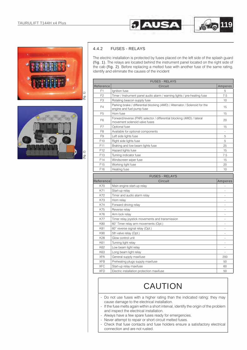
4.4.2 FUSES - RELAYS
The electric installation is protected by fuses placed on the left side of the splash guard (fig. 1). The relays are located behind the instrument panel located on the right side of the cab (fig. 2). Before replacing a melted fuse with another fuse of the same rating, identify and eliminate the causes of the incident
FUSES - RELAYS
Reference Circuit Amperes
F1 Ignition fuse 5
F2 Timer / Instrument panel audio alarm / warning lights / pre-heating fuse 7.5
F3 Rotating beacon supply fuse 10
F4Parking brake / differential blocking (4WD) / Alternator / Solenoid for the engine and fuel pump fuse
15
F5 Horn fuse 15
F6Forward/reverse (FNR) selector / differential blocking (4WD) / lateral movement solenoid valve fuses
20
F7 Optional fuse 15
F8 Available for optional components -
F9 Left side lights fuse 5
F10 Right side lights fuse 5
F11 Braking and low beam lights fuse 25
F12 Hazard lights fuse 15
F13 Turning indicator fuse 7.5
F14 Windscreen wiper fuse 15
F15 Working light fuse 20
F16 Heating fuse 10
FUSES - RELAYSReference Circuit Amperes
K70 Main engine start-up relay -
K71 Start-up relay -
K72 Timer and audio alarm relay -
K73 Horn relay -
K74 Forward driving relay -
K75 Reverse relay -
K76 Arm lock relay -
K77 Timer relay joystick movements and transmission -
K80 60” Timer relay arm movements (Opt.) -
K81 60” reverse signal relay (Opt.) -
K90 5th valve relay (Opt.) -
K28 Glow control unit -
K61 Turning light relay -
K62 Low beam light relay -
K63 Long beam light relay -
XFA General supply maxifuse 200
XFB Preheating plugs supply maxifuse 50
XFC Start-up relay maxifuse 60
XFD Electric installation protection maxifuse 50
CAUTION- Do not use fuses with a higher rating than the indicated rating: they may
cause damage to the electrical installation.- If the fuse melts again within a short interval, identify the origin of the problem
and inspect the electrical installation.- Always have a few spare fuses ready for emergencies.- Never attempt to repair or short circuit melted fuses.- Check that fuse contacts and fuse holders ensure a satisfactory electrical
connection and are not rusted.
(fi g.
2)
(fi g.
1)
TAURULIFT T144H x4 Plus 119

4.4.3 12V SUPPLY LAMPS
12V SUPPLY LAMPS
Use Voltage Type Standards Socket type Power
Front low beam/road lights 12V H4 ECE-R 37 P 20 d 55 / 60W
Front side lights 12V R5W ECE-R 37 BA 15 s 5W
Front turning lights 12V R5W ECE-R 37 BA 15 s 21W
Rear turning lights 12V PY21W ECE-R 37 BAU 15 s 21W
Rear braking/tail lights 12V P21/5W ECE-R 37 BAY 15 d 21/5W
Rotating beacon 12V H1 ECE-R 37 P 14.5 S 55W
Dials/indicators 12V - - B 8.5 d 1.5W
Registration plate light 12V C5W ECE-R 37 SV 8.5 5W
Reverse/working light 12V H3 ECE-R 37 PK 22 s 35W
WARNINGThe lamps have a high operating temperature. Before touching a lamp with your fingers, check that it has cooled down enough.
IMPORTANTDo not touch the halogen lamp bulb with your fingers (H3 type socket) as this could cause unrepairable damage (use a clean cloth or paper tissue). If necessary, clean the bulb using a paper tissue imbibed with ethyl alcohol.
TAURULIFT T144H x4 Plus120

4.5 Liquids and lubricants4.5.1 REFUELLING
Component Product Capacity (litres)
Details of the product in the
paragraph
Diesel engine Engine oil 5.1 4.5.2.1
Fuel tank Diesel 55 4.5.2.3
Hydraulic system tank Hydraulic fluid 32 4.5.2.2
Front differential Transmission oil 1.6 4.5.2.2
Inching and brake fluid tank Hydraulic fluid 1 4.5.2.5
4.5.2 PRODUCT DETAILS
4.5.2.1 Engine oil
Use the oil defined by the manufacturer of the diesel engine (consult the instructions handbook with machine documentation).Use oil for four stroke engines which meets requirements MIL-L-2104C / API CD or above. Always check the API quality on the oil container label to ensure that it is the required quality. Your forklift leaves the factory with SAE 20W40 oil viscosity. However, depending on the climate, consult the chart to select the most appropriate viscosity (fig.1). If oils of different brand names are used, ensure that you completely empty the oil pan before adding the new oil.REF. recommends oil for Diesel engines REPSOL AUSA EFFICIENT Reference 461.00099.00.
(fi g.
1)
TAURULIFT T144H x4 Plus 121

4.5.2.2 Lubricants, oils and filter cartridges
The machine is refuelled with the following lubricant oils:
Use Specifications
Differential Transmission oil SAE 80W90 or SAE 90 as per API GL5 / MIL-L-2105B
Hydraulic installation
Hydraulic oil ISO grade VG-46 as ISO 6743/4-HV DIN-51524 Part 3 HVLP (standard)
VG32 for ambient temperatures normally lower than 50 ºF (10 ºC).
VG46 for ambient temperatures between 50 ºF to 104 ºF (10 ºC and 40 ºC).
VG68 for ambient temperatures normally higher than 104 ºF (40 ºC).
CAUTIONAvoid mixing oils of different types and characteristics: risk of anomalies and components breaking.
Filter cartridges:
Filter Capacity l/1’ Filtration Code
Transmission cartridge filter (upper part of the tank)
90 10 μ 70.10048.00
Oil strainer (inside the tank) 100 125 μ 35.10051.00
4.5.2.3 Fuel
Use automotive clean diesel (class A), which preferably meets 98/70/EEC standard amended by standard 2003/17 or the equivalent EN 590 standard. In Spain RD 1728/1999 applies. For the USA market, it must meet Grades 1D and 2D of the ASTM D975 standard, in supplies which do not meet these standards, the sulphur content should never exceed 0.5% mass. In principal, the use of REM type bio diesel or similar is not recommended. In case of use, the proportion used should not exceed 5% of the fuel mix.Consult the details included in the instructions for the diesel engine.
TAURULIFT T144H x4 Plus122
4.5.2.4 Greases
When greasing the machine, use:
Lithium-base grease Type EP2 At all greasing points with pump.
CAUTIONAvoid mixing greases of different types and characteristics, and do not use greases with lower characteristics.
4.5.2.5 Inching circuit
Use Specifications
Inching circuitHydraulic fluid SAE 10W or ATF liquid according to CAT TO-4 / TO-2 or ALLISON C-4 / C-3
WARNINGTo avoid serious damage to the brake system, do not use fluids other than the recommended one, or mix different fluids for topping up.
TAURULIFT T144H x4 Plus 123

Section 5
INDEX
5.1 SCREW TORQUES ............................................................................... 125
5.2 FORKLIFT ACTUATION HYDRAULIC DIAGRAM .................................. 1265.2.1 Standard machine ................................................................................. 1265.2.2 Inverse controls machine ...................................................................... 1275.2.3 Máquina flujo continuo y de alto caudal ............................................... 128
5.3 TRANSMISION HYDRAULIC DIAGRAM ................................................ 129
5.4 WIRING DIAGRAM ................................................................................ 130
5.5 IDENTIFICATION OF DEFECTS IN HYDRAULIC TRANSMISSIONS..... 141
TAURULIFT T144H x4 Plus124
Diagrams and Charts
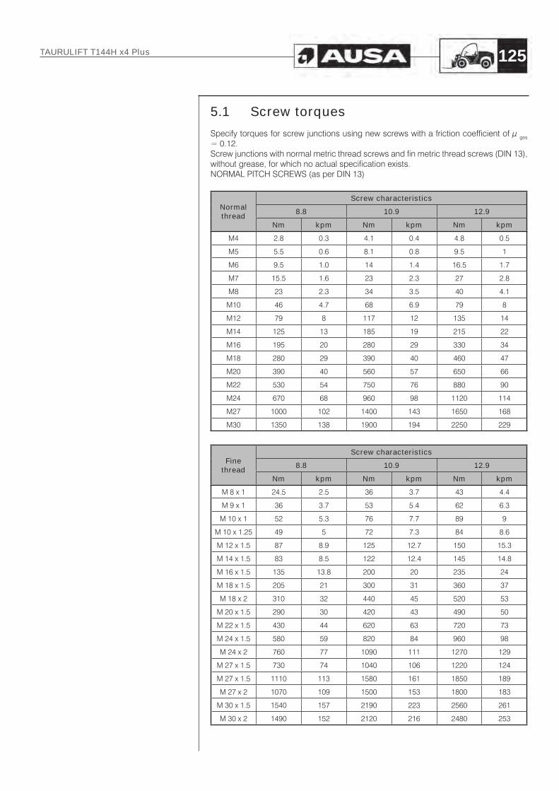
5.1 Screw torques
Specify torques for screw junctions using new screws with a friction coefficient of μ ges = 0.12.Screw junctions with normal metric thread screws and fin metric thread screws (DIN 13), without grease, for which no actual specification exists.NORMAL PITCH SCREWS (as per DIN 13)
Normal thread
Screw characteristics
8.8 10.9 12.9
Nm kpm Nm kpm Nm kpm
M4 2.8 0.3 4.1 0.4 4.8 0.5
M5 5.5 0.6 8.1 0.8 9.5 1
M6 9.5 1.0 14 1.4 16.5 1.7
M7 15.5 1.6 23 2.3 27 2.8
M8 23 2.3 34 3.5 40 4.1
M10 46 4.7 68 6.9 79 8
M12 79 8 117 12 135 14
M14 125 13 185 19 215 22
M16 195 20 280 29 330 34
M18 280 29 390 40 460 47
M20 390 40 560 57 650 66
M22 530 54 750 76 880 90
M24 670 68 960 98 1120 114
M27 1000 102 1400 143 1650 168
M30 1350 138 1900 194 2250 229
Fine thread
Screw characteristics
8.8 10.9 12.9
Nm kpm Nm kpm Nm kpm
M 8 x 1 24.5 2.5 36 3.7 43 4.4
M 9 x 1 36 3.7 53 5.4 62 6.3
M 10 x 1 52 5.3 76 7.7 89 9
M 10 x 1.25 49 5 72 7.3 84 8.6
M 12 x 1.5 87 8.9 125 12.7 150 15.3
M 14 x 1.5 83 8.5 122 12.4 145 14.8
M 16 x 1.5 135 13.8 200 20 235 24
M 18 x 1.5 205 21 300 31 360 37
M 18 x 2 310 32 440 45 520 53
M 20 x 1.5 290 30 420 43 490 50
M 22 x 1.5 430 44 620 63 720 73
M 24 x 1.5 580 59 820 84 960 98
M 24 x 2 760 77 1090 111 1270 129
M 27 x 1.5 730 74 1040 106 1220 124
M 27 x 1.5 1110 113 1580 161 1850 189
M 27 x 2 1070 109 1500 153 1800 183
M 30 x 1.5 1540 157 2190 223 2560 261
M 30 x 2 1490 152 2120 216 2480 253
TAURULIFT T144H x4 Plus 125

5.2 FORKLIFT ACTUATION HYDRAULIC DIAGRAM
5.2.1 STANDARD MACHINE
TAURULIFT T144H x4 Plus126

5.2.2 INVERSE CONTROLS MACHINE
TAURULIFT T144H x4 Plus 127

5.2.3 MÁQUINA FLUJO CONTINUO Y DE ALTO CAUDAL
TAURULIFT T144H x4 Plus128

5.3 TRANSMISION HYDRAULIC DIAGRAM
TAURULIFT T144H x4 Plus 129
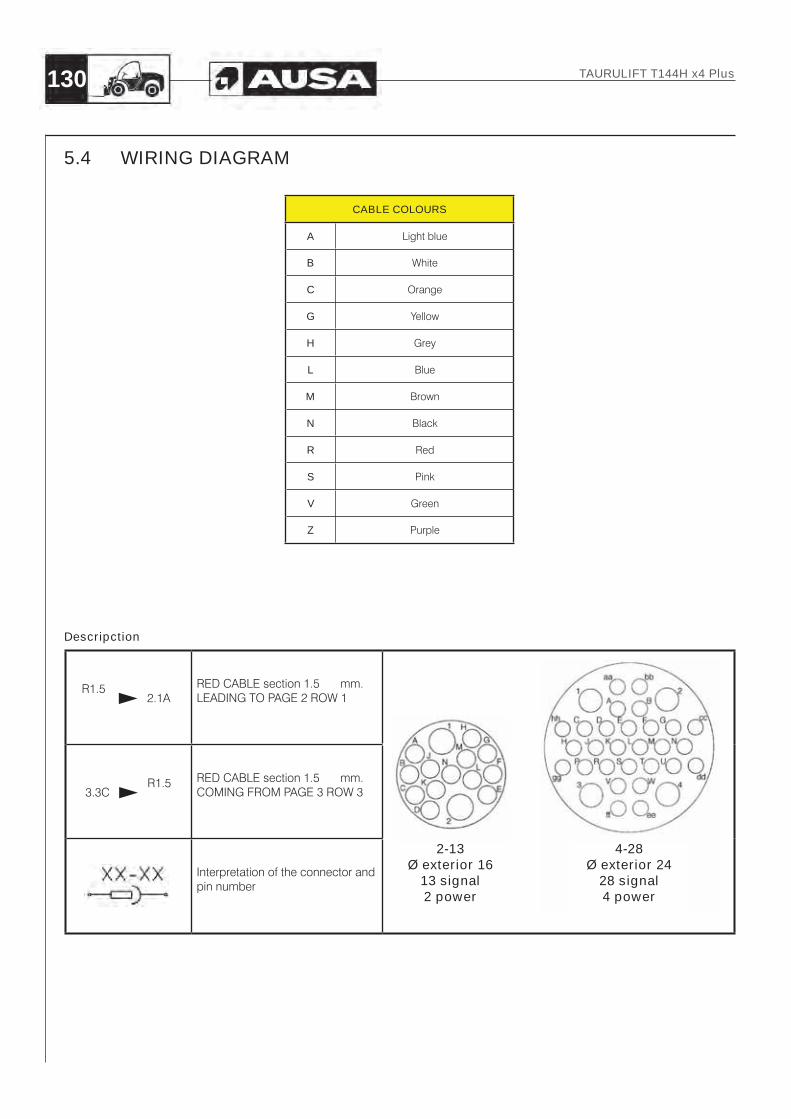
5.4 WIRING DIAGRAM
CABLE COLOURS
A Light blue
B White
C Orange
G Yellow
H Grey
L Blue
M Brown
N Black
R Red
S Pink
V Green
Z Purple
R1.5 2.1A
RED CABLE section 1.5 mm. LEADING TO PAGE 2 ROW 1
3.3C R1.5 RED CABLE section 1.5 mm.
COMING FROM PAGE 3 ROW 3
Interpretation of the connector and pin number
Descripction
2-13Ø exterior 16
13 signal2 power
4-28Ø exterior 24
28 signal4 power
TAURULIFT T144H x4 Plus130
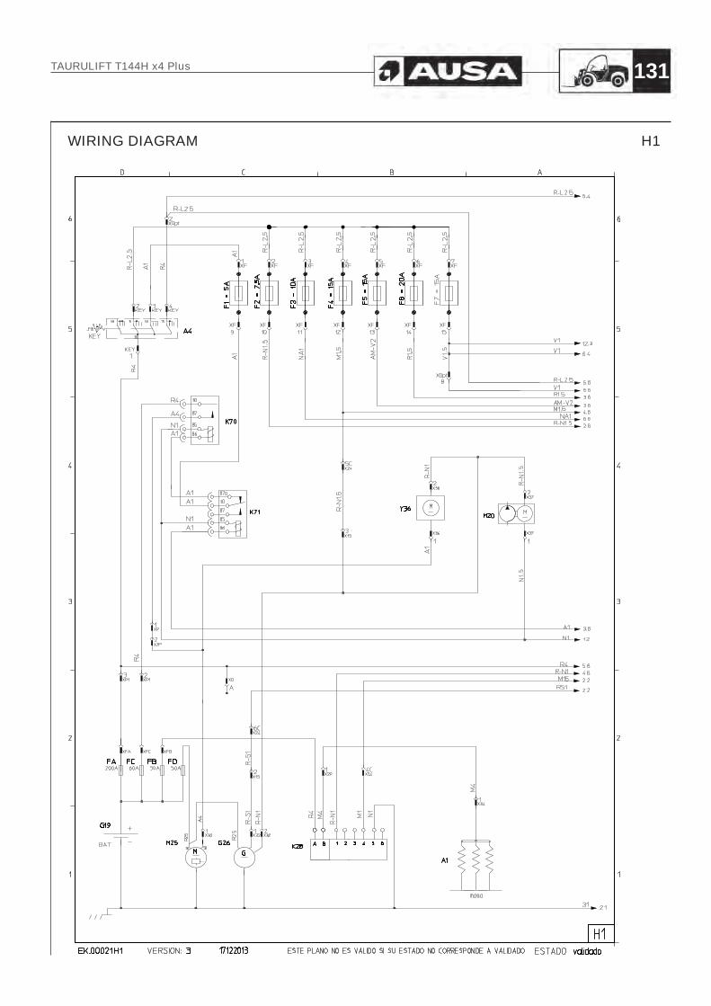
WIRING DIAGRAM H1
TAURULIFT T144H x4 Plus 131

WIRING DIAGRAM H2
TAURULIFT T144H x4 Plus132

WIRING DIAGRAM H3
TAURULIFT T144H x4 Plus 133

WIRING DIAGRAM H4
TAURULIFT T144H x4 Plus134

WIRING DIAGRAM H5
TAURULIFT T144H x4 Plus 135

WIRING DIAGRAM H6
TAURULIFT T144H x4 Plus136
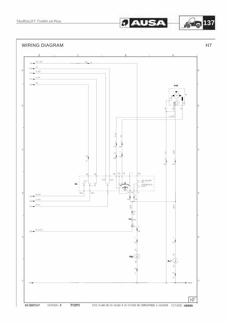
WIRING DIAGRAM H7
TAURULIFT T144H x4 Plus 137

WIRING DIAGRAM H8
TAURULIFT T144H x4 Plus138

WIRING DIAGRAM
Item Description Sh.
A1 Glow plug 1
A2 Hours counter 3
A3 Dashboard buzzer 3
A4 Contact key 1
A5 Heater Fan conenctor 6
A39 Horn 3
A60 Heater 6
C.CARGA Charge cell 8.(11)
F1 Start fuse 1
F2Hourcounter,Dashboard buzzer and indicators, glow control unit fuse
1
F3 Beacon light fuse 1
F4Park brake trans. X4 engine stop solenoid. Alter & fuel pump fuse
1
F5 Claxon fuse 1
F6 F-R gear, trans. x4 and opt. 3a EV fuse 1
F7 Optional fuse 1
F9 Left side posittion light fuse 5
F10 Right side posittion fuse 5
F11 Low-beam lights and broke fuse 5
F12 Warning light fuse 5
F13 Indicators fuse 5
F14 Wipper fuse 7
F15 Working light fuse 6
F16 Heating fuse 6
FA Batery maln fuse 1
FB Glow Control Unit Fuse 1
FC Start relay fuse 1
FD Electrical installation protection fuse 1
G19 Battery 1
G26 Alternator 1
H1 Right front light (turning light + position light) 5
H2 Left front light (turning light + position light) 5
H3 Right rear light (turning light + position light + brake light) 5
H4 Left rear light (turning light + position light + brake light) 5
H5 Beacon light 6
H6 Working light fuse 6
H7.A Rear gear buzzer without function stop (2 cables) 3
H7.B Rear gear buzzer without function stop (3 cables) 3
H8 Battery charge indicator 2
H9 License plate light 5
H10 Glow control Unit Indicator 2
H11 Air filter indicator 2
H12 Indicator lights indicator 5
H13 High-beam indicator 5
H14 Oil preassure indicator 2
H15 Water temperature indicator 2
H16 Right front low/high-beamlight 5
H17 Left front low/high-beamlight 5
H18 Rear gear light 3
I1 Key for disconnecting stability indicator alarm buzzer 7
K28 Glow Control Unit 1
K61 Warning and indicator lights relay 5
K62 Low-beam lights relay 5
K63 High-beam lights relay 5
K70 Start relay 1
Item Description Sh.
K71 Starting permission relay 1
K72 Hour counter and buzzer relay 3
K73 Horn relay 3
K74 Forward gear relay 3
K75 Rear gear relay 3
K76 Arm lock relay 3
K77 Timer relay for allowing joystick movements and transmission 4
K8060" timer relay for allowing movement of the telehandler arm (optional)
11
K81 60" timer invertion signal relay (opt.) 11
K90 5th solenoid activation relay (opt.) 4
M45 Wipper engine 7
M46 Windehield washer water pump 7
M20 Electric fuel pump 1
M25 Starter 1
MLT Rear windehield engine 7
MS Seat switch 4
S1 Minimum all pressure switch 2
S2 Air filter pressure switch 2
S3 Brake micro switch 4
S4 Indicator 7
S5 lights and wipper joystick 2
S6 Heating switch 6
S7 Beacon light switch 6
S8 Working light switch 6
S9 Parking broke switch 4
S10 Warning lights switch 5
S11 Position + low-beam lights switch 5
S12 Horn switch 3
S13 continuous flow switch 6
S50 60" telelehandler arm unlocking switch 11
S100 Joystick standard T133H x2 STD 4
S101 x4 transmission solenoid button 4
S103 3a EV button 4
S104 4a EV button 4
ST3 Stability indicator 8.(11)
Y1 Forward gear solenoid 3
Y2 Rear gear solenoid 3
Y3A 3rd solenoid 4
Y36 Engine stop solenoid 1
Y4A 4th solenoid 4
Y5A 5th solenoid 4
Y6 direction 1continuous flow solenoid 6
Y7 direction 2 continuous flow solenoid 6
YB1 Blocking solenoid 1 3
YB2 Blocking solenoid 2 3
YF Negative Brake solenoid 4
YL Inching pressure switch 4
YS1 Block joystick hydraulic movements valve 1 4
YS2 Block joystick hydraulic movements valve 2 4
YT x4 transmission solenoid 4
X100 Programming conenctor 8.(11)
XE Charge instrument 14 way connector 8.(11)
XEC Charge instrument 10 way connector 8.(11)
TAURULIFT T144H x4 Plus 139

WIRING DIAGRAM H11
TAURULIFT T144H x4 Plus140
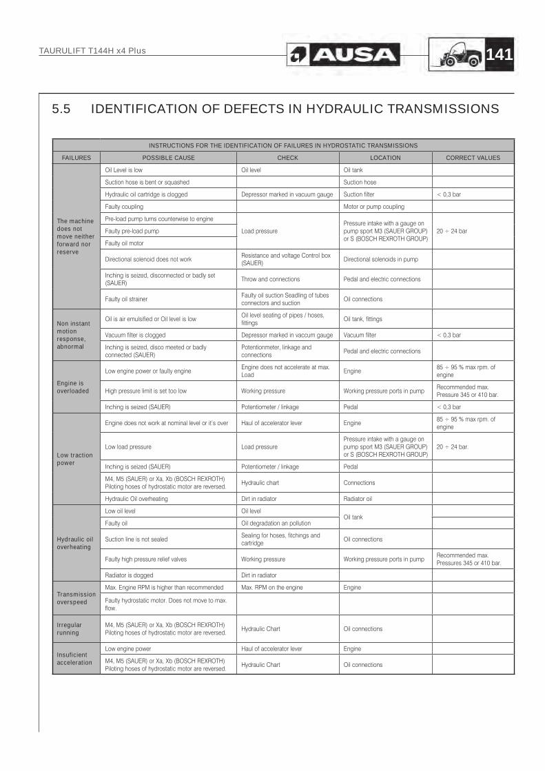
5.5 IDENTIFICATION OF DEF ECTS IN HYDRAULIC TRANSMISSIONS
INSTRUCTIONS FOR THE IDENTIFICATION OF FAILURES IN HYDROSTATIC TRANSMISSIONS
FAILURES POSSIBLE CAUSE CHECK LOCATION CORRECT VALUES
The machine does not move neither forward nor reserve
Oil Level is low Oil level Oil tank
Suction hose is bent or squashed Suction hose
Hydraulic oil cartridge is clogged Depressor marked in vacuum gauge Suction filter < 0,3 bar
Faulty coupling Motor or pump coupling
Pre-load pump turns counterwise to engine
Load pressurePressure intake with a gauge on pump sport M3 (SAUER GROUP) or S (BOSCH REXROTH GROUP)
20 ÷ 24 barFaulty pre-load pump
Faulty oil motor
Directional solenoid does not workResistance and voltage Control box (SAUER)
Directional solenoids in pump
Inching is seized, disconnected or badly set (SAUER)
Throw and connections Pedal and electric connections
Faulty oil strainerFaulty oil suction Seadling of tubes connectors and suction
Oil connections
Non instant motion response, abnormal
Oil is air emulsified or Oil level is lowOil level seating of pipes / hoses, fittings
Oil tank, fittings
Vacuum filter is clogged Depressor marked in vaccum gauge Vacuum filter < 0,3 bar
Inching is seized, disco meeted or badly connected (SAUER)
Potentionmeter, linkage and connections
Pedal and electric connections
Engine is overloaded
Low engine power or faulty engineEngine does not accelerate at max. Load
Engine85 ÷ 95 % max rpm. of engine
High pressure limit is set too low Working pressure Working pressure ports in pumpRecommended max. Pressure 345 or 410 bar.
Inching is seized (SAUER) Potentiometer / linkage Pedal < 0,3 bar
Low traction power
Engine does not work at nominal level or it’s over Haul of accelerator lever Engine85 ÷ 95 % max rpm. of engine
Low load pressure Load pressurePressure intake with a gauge on pump sport M3 (SAUER GROUP) or S (BOSCH REXROTH GROUP)
20 ÷ 24 bar.
Inching is seized (SAUER) Potentiometer / linkage Pedal
M4, M5 (SAUER) or Xa, Xb (BOSCH REXROTH) Piloting hoses of hydrostatic motor are reversed.
Hydraulic chart Connections
Hydraulic Oil overheating Dirt in radiator Radiator oil
Hydraulic oil overheating
Low oil level Oil levelOil tank
Faulty oil Oil degradation an pollution
Suction line is not sealedSealing for hoses, fitchings and cartridge
Oil connections
Faulty high pressure relief valves Working pressure Working pressure ports in pumpRecommended max. Pressures 345 or 410 bar.
Radiator is dogged Dirt in radiator
Transmission overspeed
Max. Engine RPM is higher than recommended Max. RPM on the engine Engine
Faulty hydrostatic motor. Does not move to max. flow.
Irregular running
M4, M5 (SAUER) or Xa, Xb (BOSCH REXROTH) Piloting hoses of hydrostatic motor are reversed.
Hydraulic Chart Oil connections
Insuficient acceleration
Low engine power Haul of accelerator lever Engine
M4, M5 (SAUER) or Xa, Xb (BOSCH REXROTH) Piloting hoses of hydrostatic motor are reversed.
Hydraulic Chart Oil connections
TAURULIFT T144H x4 Plus 141

EC Certificate of Conformity
AUSA Center, S.L.U. Tel. 34-93 87 47 311 Cra. de Vic, Km. 2,8 - P.O.B. 194 Fax 34-93 874 12 11 08243 MANRESA (Barcelona) España Web: http://www.ausa.com
D U P L I C A T E
EC DECLARATION OF CONFORMITY
The manufacturer AUSA Center, S.L.U., established on Ctra. De Vic, km 2.8, 08243 – Manresa Barcelona – Spain, declares that the machine assigned below:
Generic denomination: SELF – PROPELLED VARIABLE REACH TRUCKModel/Type : T XXX XSerial number: XXXXXXXX
fulfils all relevant provisions of the machinery Directive 2006/42/EC
and it conforms with the next European Directives:
Electromagnetic Compatibility Directive 2004/108/EC
Sound level Directives of machinery used outdoors, 2000/14/EC and 2005/88/EC
Exhaust emissions Directives, 97/68 and 2004/26
and also it conforms with the following harmonized European Standards:
EN 1459 - Safety of industrial trucks. Self-propelled variable reach trucks.
The certification procedure has been carried out in accordance with the provisions relating to non-dangerous machinery in the above mentioned Directives.
Name and address of the person authorized to compile the technical file:
Ctra. De Vic, km 2.8, 08243, Manresa, Barcelona, Spain
Signed by
Given at Manresa on day/month/year