Embed Size (px)
DESCRIPTION
OptiX OSN 6800 Hardware Description (V100R003), old version of Huawei OSN6800.Thunder-link.com provide Huawei OSN6800 retail and wholesale, faster delivery and lower price.
Citation preview
Hardware Description
OptiX OSN 6800 Intelligent Optical Transport PlatformV100R003
Issue 01
Date 2007-12-25
HUAWEI TECHNOLOGIES CO., LTD.
Huawei Technologies Co., Ltd. provides customers with comprehensive technical support and service. Please feel free to contact our local office or company headquarters.
Huawei Technologies Co., Ltd.
Address: Huawei Industrial BaseBantian, LonggangShenzhen 518129People's Republic of China
Website: http://www.huawei.com
Email: [email protected]
Product VersionOptiX OSN 6800/3800 V100R003
Copyright © Huawei Technologies Co., Ltd. 2007. All rights reserved.No part of this document may be reproduced or transmitted in any form or by any means without prior written consent of Huawei Technologies Co., Ltd.
Trademarks and Permissions
and other Huawei trademarks are trademarks of Huawei Technologies Co., Ltd.
All other trademarks and trade names mentioned in this document are the property of their respective holders.
NoticeThe information in this document is subject to change without notice. Every effort has been made in the preparation of this document to ensure accuracy of the contents, but all statements, information, and recommendations in this document do not constitute the warranty of any kind, express or implied.
Issue 01 (2007-12-25) Commercial in Confidence Page 2 of 664

OptiX OSN 6800 Intelligent Optical Transport Platform V100R003
Hardware Description
About This Document
AuthorPrepared by Xxxx xxxxx Date 2005-06-24
Reviewed by
Xxxxx xxxx Date 2005-06-26
Approved by
Xxxx xxxxx Date 2006-06-29
SummaryThis document provides information for xxxxx.
This document includes:
Chapter Details
Chapter 1 Cabinet This chapter describes the mechanical structure and technical specifications of the cabinet.
Chapter 2 Subrack This chapter describes the mechanical structure, technical specifications, and interfaces of the subrack.
Chapter 3 Frame This chapter describes the structure of the DCM frame and CRPC frame.
Chapter 4 Overview of boards This chapter describes the classification and appearance of boards.
Chapter 5 Optical Transponder Unit
This chapter describes the function and the working principle of optical transponder units.
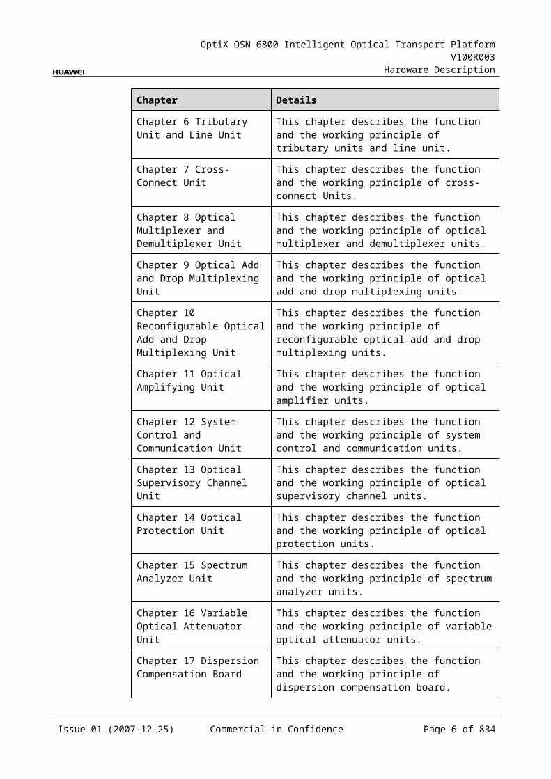
Chapter 6 Tributary Unit and Line Unit
This chapter describes the function and the working principle of tributary units and line unit.
Chapter 7 Cross-Connect Unit
This chapter describes the function and the working principle of cross-connect Units.
Issue 01 (2007-12-25) Commercial in Confidence Page 3 of 664

OptiX OSN 6800 Intelligent Optical Transport Platform V100R003
Hardware Description
Chapter Details
Chapter 8 Optical Multiplexer and Demultiplexer Unit
This chapter describes the function and the working principle of optical multiplexer and demultiplexer units.
Chapter 9 Optical Add and Drop Multiplexing Unit
This chapter describes the function and the working principle of optical add and drop multiplexing units.
Chapter 10 Reconfigurable Optical Add and Drop Multiplexing Unit
This chapter describes the function and the working principle of reconfigurable optical add and drop multiplexing units.
Chapter 11 Optical Amplifying Unit
This chapter describes the function and the working principle of optical amplifier units.
Chapter 12 System Control and Communication Unit
This chapter describes the function and the working principle of system control and communication units.
Chapter 13 Optical Supervisory Channel Unit
This chapter describes the function and the working principle of optical supervisory channel units.
Chapter 14 Optical Protection Unit
This chapter describes the function and the working principle of optical protection units.
Chapter 15 Spectrum Analyzer Unit
This chapter describes the function and the working principle of spectrum analyzer units.
Chapter 16 Variable Optical Attenuator Unit
This chapter describes the function and the working principle of variable optical attenuator units.
Chapter 17 Dispersion Compensation Board
This chapter describes the function and the working principle of dispersion compensation board.
Chapter 18 Cables This chapter describes the cables of the OptiX OSN 6800.
Appendix A Indicators This chapter describes the indicators of the OptiX OSN 6800.
Appendix B Bar Code for Boards
This chapter describes the bar codes of the boards used in the OptiX OSN 6800.
Appendix C Parameter Description
This chapter describes the parameters of the boards used in the OptiX OSN 6800.
Appendix D Quick Reference Table of the Units
This chapter describes the basic function of the optical transponder units and the tributary and line unit and the specifications of the boards used in the OptiX OSN 6800.
Appendix E Power Consumption, Weight and Valid Slots of Boards
This chapter describes the power consumption, weight and slots of the boards used in the OptiX OSN 6800.
Issue 01 (2007-12-25) Commercial in Confidence Page 4 of 664
OptiX OSN 6800 Intelligent Optical Transport Platform V100R003
Hardware Description
Chapter Details
Appendix F Glossary This appendix lists the terms that are used in this document.
Appendix G Acronyms and Abbreviations
This appendix lists the acronyms and abbreviations that are used in this document.
HistoryIssue
Details Date Author Approved by
01 Creation 2007-03-14 Xxx xxx Xxx xxxxxx
Issue 01 (2007-12-25) Commercial in Confidence Page 5 of 664

OptiX OSN 6800 Intelligent Optical Transport Platform V100R003
Hardware Description
Contents
1 Cabinet...........................................................................................................................271.1 Cabinet Structure........................................................................................................................... 271.2 Configuration of the Integrated Cabinet.........................................................................................281.3 Specifications................................................................................................................................ 291.4 DC Power Distribution Box............................................................................................................29
2 Subrack..........................................................................................................................332.1 Structure........................................................................................................................................ 332.2 Slot Description............................................................................................................................. 352.3 Fan Area........................................................................................................................................ 382.4 PIU................................................................................................................................................ 40
2.4.1 Version Description...............................................................................................................402.4.2 Application............................................................................................................................ 412.4.3 Functions and Features........................................................................................................412.4.4 Front Panel........................................................................................................................... 412.4.5 Valid Slots............................................................................................................................. 422.4.6 Specifications of the PIU.......................................................................................................42
2.5 Data Communication and Equipment Maintenance Interfaces......................................................422.5.1 Interfaces in the Interface Area.............................................................................................432.5.2 Interfaces on the Front Panel of the AUX Board...................................................................442.5.3 PIN Assignment of Interfaces................................................................................................46
3 Frame............................................................................................................................. 533.1 DCM Frame................................................................................................................................... 533.2 CRPC Frame................................................................................................................................. 54
4 Overview of Boards.......................................................................................................554.1 Board Appearance and Dimensions..............................................................................................55
4.1.1 Appearance and Dimensions................................................................................................554.1.2 Laser Safety Label................................................................................................................57
4.2 Bar Code for Boards...................................................................................................................... 584.2.1 Overview............................................................................................................................... 584.2.2 Characteristic Code..............................................................................................................59
4.3 Board Category............................................................................................................................. 59
Issue 01 (2007-12-25) Commercial in Confidence Page 7 of 664
OptiX OSN 6800 Intelligent Optical Transport Platform V100R003
Hardware Description
5 Optical Transponder Unit.............................................................................................635.1 ECOM............................................................................................................................................ 63
5.1.1 Version Description...............................................................................................................635.1.2 Application............................................................................................................................ 635.1.3 Functions and Features........................................................................................................645.1.4 Working Principle and Signal Flow........................................................................................655.1.5 Front Panel........................................................................................................................... 675.1.6 Valid Slots............................................................................................................................. 695.1.7 NM Configuration Reference................................................................................................695.1.8 Specifications of the ECOM..................................................................................................70
5.2 L4G................................................................................................................................................ 735.2.1 Version Description...............................................................................................................735.2.2 Application............................................................................................................................ 735.2.3 Functions and Features........................................................................................................745.2.4 Working Principle and Signal Flow........................................................................................755.2.5 Front Panel........................................................................................................................... 775.2.6 Valid Slots............................................................................................................................. 795.2.7 Characteristic Code for the L4G...........................................................................................795.2.8 NM Configuration Reference................................................................................................795.2.9 Specifications of the L4G......................................................................................................80
5.3 LDGD............................................................................................................................................ 845.3.1 Version Description...............................................................................................................845.3.2 Application............................................................................................................................ 845.3.3 Functions and Features........................................................................................................855.3.4 Working Principle and Signal Flow........................................................................................865.3.5 Front Panel........................................................................................................................... 885.3.6 Valid Slots............................................................................................................................. 905.3.7 Characteristic Code for the LDGD........................................................................................905.3.8 NM Configuration Reference................................................................................................915.3.9 Specifications of the LDGD...................................................................................................91
5.4 LDGS............................................................................................................................................. 965.4.1 Version Description...............................................................................................................965.4.2 Application............................................................................................................................ 965.4.3 Functions and Features........................................................................................................965.4.4 Working Principle and Signal Flow........................................................................................975.4.5 Front Panel........................................................................................................................... 995.4.6 Valid Slots........................................................................................................................... 1015.4.7 Characteristic Code for the LDGS.......................................................................................1015.4.8 NM Configuration Reference..............................................................................................1015.4.9 Specifications of the LDGS.................................................................................................102
5.5 LOG............................................................................................................................................. 1065.5.1 Version Description.............................................................................................................106
Issue 01 (2007-12-25) Commercial in Confidence Page 8 of 664
OptiX OSN 6800 Intelligent Optical Transport Platform V100R003
Hardware Description
5.5.2 Application.......................................................................................................................... 1065.5.3 Functions and Features......................................................................................................1075.5.4 Working Principle and Signal Flow......................................................................................1085.5.5 Front Panel.........................................................................................................................1105.5.6 Valid Slots........................................................................................................................... 1125.5.7 Characteristic Code for the LOG.........................................................................................1125.5.8 NM Configuration Reference...............................................................................................1125.5.9 Specifications of the LOG...................................................................................................113
5.6 LOM............................................................................................................................................. 1185.6.1 Version Description.............................................................................................................1185.6.2 Application........................................................................................................................... 1185.6.3 Functions and Features......................................................................................................1185.6.4 Working Principle and Signal Flow......................................................................................1205.6.5 Front Panel......................................................................................................................... 1225.6.6 Valid Slots........................................................................................................................... 1235.6.7 Characteristic Code for the LOM........................................................................................1235.6.8 NM Configuration Reference..............................................................................................1245.6.9 Specifications of the LOM...................................................................................................125
5.7 LQMD.......................................................................................................................................... 1305.7.1 Version Description.............................................................................................................1305.7.2 Application.......................................................................................................................... 1305.7.3 Functions and Features......................................................................................................1315.7.4 Working Principle and Signal Flow......................................................................................1335.7.5 Front Panel......................................................................................................................... 1345.7.6 Valid Slots........................................................................................................................... 1365.7.7 Characteristic Code for the LQMD......................................................................................1365.7.8 NM Configuration Reference..............................................................................................1375.7.9 Specifications of the LQMD................................................................................................138
5.8 LQMS.......................................................................................................................................... 1435.8.1 Version Description.............................................................................................................1435.8.2 Application.......................................................................................................................... 1445.8.3 Functions and Features......................................................................................................1445.8.4 Working Principle and Signal Flow......................................................................................1465.8.5 Front Panel......................................................................................................................... 1475.8.6 Valid Slots........................................................................................................................... 1495.8.7 Characteristic Code for the LQMS......................................................................................1495.8.8 NM Configuration Reference..............................................................................................1495.8.9 Specifications of the LQMS.................................................................................................150
5.9 LSX.............................................................................................................................................. 1565.9.1 Version Description.............................................................................................................1565.9.2 Application.......................................................................................................................... 1565.9.3 Functions and Features......................................................................................................157
Issue 01 (2007-12-25) Commercial in Confidence Page 9 of 664
OptiX OSN 6800 Intelligent Optical Transport Platform V100R003
Hardware Description
5.9.4 Working Principle and Signal Flow......................................................................................1585.9.5 Front Panel......................................................................................................................... 1605.9.6 Valid Slots........................................................................................................................... 1615.9.7 Characteristic Code for the LSX.........................................................................................1615.9.8 NM Configuration Reference..............................................................................................1615.9.9 Specifications of the LSX....................................................................................................162
5.10 LSXL.......................................................................................................................................... 1675.10.1 Version Description...........................................................................................................1675.10.2 Application........................................................................................................................ 1675.10.3 Functions and Features....................................................................................................1675.10.4 Working Principle and Signal Flow....................................................................................1695.10.5 Front Panel....................................................................................................................... 1705.10.6 Valid Slots......................................................................................................................... 1715.10.7 Characteristic Code for the LSXL......................................................................................1715.10.8 NM Configuration Reference............................................................................................1725.10.9 Specifications of the LSXL................................................................................................172
5.11 LSXLR....................................................................................................................................... 1755.11.1 Version Description...........................................................................................................1755.11.2 Application......................................................................................................................... 1755.11.3 Functions and Features....................................................................................................1755.11.4 Working Principle and Signal Flow....................................................................................1765.11.5 Front Panel........................................................................................................................ 1775.11.6 Valid Slots......................................................................................................................... 1795.11.7 Characteristic Code for the LSXLR...................................................................................1795.11.8 NM Configuration Reference.............................................................................................1795.11.9 Specifications of the LSXLR..............................................................................................180
5.12 LSXR......................................................................................................................................... 1815.12.1 Version Description...........................................................................................................1815.12.2 Application........................................................................................................................ 1815.12.3 Functions and Features....................................................................................................1825.12.4 Working Principle and Signal Flow....................................................................................1835.12.5 Front Panel....................................................................................................................... 1845.12.6 Valid Slots......................................................................................................................... 1865.12.7 Characteristic Code for the LSXR.....................................................................................1865.12.8 NM Configuration Reference............................................................................................1865.12.9 Specifications of the LSXR...............................................................................................187
5.13 LWX2......................................................................................................................................... 1905.13.1 Version Description...........................................................................................................1905.13.2 Application........................................................................................................................ 1905.13.3 Functions and Features....................................................................................................1905.13.4 Working Principle and Signal Flow....................................................................................1915.13.5 Front Panel....................................................................................................................... 193
Issue 01 (2007-12-25) Commercial in Confidence Page 10 of 664
OptiX OSN 6800 Intelligent Optical Transport Platform V100R003
Hardware Description
5.13.6 Valid Slots......................................................................................................................... 1945.13.7 Characteristic Code for the LWX2.....................................................................................1945.13.8 NM Configuration Reference............................................................................................1955.13.9 Specifications of the LWX2...............................................................................................196
5.14 LWXD........................................................................................................................................ 2025.14.1 Version Description...........................................................................................................2025.14.2 Application........................................................................................................................ 2025.14.3 Functions and Features....................................................................................................2025.14.4 Working Principle and Signal Flow....................................................................................2035.14.5 Front Panel....................................................................................................................... 2055.14.6 Valid Slots......................................................................................................................... 2065.14.7 Characteristic Code for the LWXD....................................................................................2065.14.8 NM Configuration Reference............................................................................................2075.14.9 Specifications of the LWXD...............................................................................................208
5.15 LWXS........................................................................................................................................ 2145.15.1 Version Description...........................................................................................................2145.15.2 Application........................................................................................................................ 2145.15.3 Functions and Features....................................................................................................2145.15.4 Working Principle and Signal Flow....................................................................................2155.15.5 Front Panel....................................................................................................................... 2175.15.6 Valid Slots......................................................................................................................... 2185.15.7 Characteristic Code for the LWXS....................................................................................2185.15.8 NM Configuration Reference............................................................................................2185.15.9 Specifications of the LWXS...............................................................................................219
5.16 TMX........................................................................................................................................... 2255.16.1 Version Description...........................................................................................................2255.16.2 Application........................................................................................................................ 2255.16.3 Functions and Features....................................................................................................2255.16.4 Working Principle and Signal Flow....................................................................................2275.16.5 Front Panel....................................................................................................................... 2285.16.6 Valid Slots......................................................................................................................... 2295.16.7 Characteristic Code for the TMX.......................................................................................2295.16.8 NM Configuration Reference............................................................................................2295.16.9 Specifications of the TMX.................................................................................................230
6 Tributary Unit and Line Unit.......................................................................................2376.1 NS2............................................................................................................................................. 237
6.1.1 Version Description.............................................................................................................2376.1.2 Application.......................................................................................................................... 2376.1.3 Functions and Features......................................................................................................2376.1.4 Working Principle and Signal Flow......................................................................................2396.1.5 Front Panel......................................................................................................................... 240
Issue 01 (2007-12-25) Commercial in Confidence Page 11 of 664
OptiX OSN 6800 Intelligent Optical Transport Platform V100R003
Hardware Description
6.1.6 Valid Slots........................................................................................................................... 2426.1.7 Characteristic Code for the NS2.........................................................................................2426.1.8 NM Configuration Reference..............................................................................................2426.1.9 Specifications of the NS2....................................................................................................243
6.2 TBE............................................................................................................................................. 2466.2.1 Version Description.............................................................................................................2466.2.2 Application.......................................................................................................................... 2466.2.3 Functions and Features......................................................................................................2476.2.4 Working Principle and Signal Flow......................................................................................2496.2.5 Front Panel......................................................................................................................... 2516.2.6 Valid Slots........................................................................................................................... 2536.2.7 NM Configuration Reference..............................................................................................2536.2.8 Specifications of the TBE....................................................................................................254
6.3 TDG............................................................................................................................................. 2586.3.1 Version Description.............................................................................................................2586.3.2 Application.......................................................................................................................... 2586.3.3 Functions and Features......................................................................................................2586.3.4 Working Principle and Signal Flow......................................................................................2596.3.5 Front Panel......................................................................................................................... 2606.3.6 Valid Slots........................................................................................................................... 2626.3.7 NM Configuration Reference..............................................................................................2626.3.8 Specifications of the TDG...................................................................................................263
6.4 TDX............................................................................................................................................. 2656.4.1 Version Description.............................................................................................................2656.4.2 Application.......................................................................................................................... 2656.4.3 Functions and Features......................................................................................................2666.4.4 Working Principle and Signal Flow......................................................................................2676.4.5 Front Panel......................................................................................................................... 2686.4.6 Valid Slots........................................................................................................................... 2706.4.7 NM Configuration Reference..............................................................................................2706.4.8 Specifications of the TDX....................................................................................................271
6.5 TQM............................................................................................................................................ 2726.5.1 Version Description.............................................................................................................2726.5.2 Application.......................................................................................................................... 2726.5.3 Functions and Features......................................................................................................2736.5.4 Working Principle and Signal Flow......................................................................................2746.5.5 Front Panel......................................................................................................................... 2756.5.6 Valid Slots........................................................................................................................... 2776.5.7 NM Configuration Reference..............................................................................................2776.5.8 Specifications of the TQM...................................................................................................278
6.6 TQS............................................................................................................................................. 2826.6.1 Version Description.............................................................................................................282
Issue 01 (2007-12-25) Commercial in Confidence Page 12 of 664
OptiX OSN 6800 Intelligent Optical Transport Platform V100R003
Hardware Description
6.6.2 Application.......................................................................................................................... 2826.6.3 Functions and Features......................................................................................................2826.6.4 Working Principle and Signal Flow......................................................................................2836.6.5 Front Panel......................................................................................................................... 2846.6.6 Valid Slots........................................................................................................................... 2866.6.7 NM Configuration Reference..............................................................................................2866.6.8 Specifications of the TQS...................................................................................................287
7 Cross-connect Unit.....................................................................................................2917.1 XCS............................................................................................................................................. 291
7.1.1 Version Description.............................................................................................................2917.1.2 Application.......................................................................................................................... 2917.1.3 Functions and Features......................................................................................................2917.1.4 Working Principle and Signal Flow......................................................................................2927.1.5 Front Panel......................................................................................................................... 2937.1.6 Valid Slots........................................................................................................................... 2947.1.7 Specifications of the XCS...................................................................................................294
8 Optical Multiplexer and Demultiplexer Unit..............................................................2958.1 D40.............................................................................................................................................. 295
8.1.1 Version Description.............................................................................................................2958.1.2 Application.......................................................................................................................... 2958.1.3 Functions and Features......................................................................................................2958.1.4 Working Principle and Signal Flow......................................................................................2968.1.5 Front Panel......................................................................................................................... 2978.1.6 Valid Slots........................................................................................................................... 3018.1.7 Characteristic Code for the D40..........................................................................................3018.1.8 NM Configuration Reference..............................................................................................3028.1.9 Specifications of the D40....................................................................................................302
8.2 D40V........................................................................................................................................... 3038.2.1 Version Description.............................................................................................................3038.2.2 Application.......................................................................................................................... 3038.2.3 Functions and Features......................................................................................................3048.2.4 Working Principle and Signal Flow......................................................................................3048.2.5 Front Panel......................................................................................................................... 3058.2.6 Valid Slots........................................................................................................................... 3098.2.7 Characteristic Code for the D40V.......................................................................................3098.2.8 NM Configuration Reference..............................................................................................3098.2.9 Specifications of the D40V..................................................................................................310
8.3 FIU............................................................................................................................................... 3118.3.1 Version Description.............................................................................................................3118.3.2 Application........................................................................................................................... 3118.3.3 Functions and Features......................................................................................................312
Issue 01 (2007-12-25) Commercial in Confidence Page 13 of 664
OptiX OSN 6800 Intelligent Optical Transport Platform V100R003
Hardware Description
8.3.4 Working Principle and Signal Flow......................................................................................3128.3.5 Front Panel......................................................................................................................... 3148.3.6 Valid Slots........................................................................................................................... 3158.3.7 Characteristic Code for the FIU..........................................................................................3158.3.8 NM Configuration Reference..............................................................................................3168.3.9 Specifications of the FIU.....................................................................................................316
8.4 ITL............................................................................................................................................... 3178.4.1 Version Description.............................................................................................................3178.4.2 Application.......................................................................................................................... 3178.4.3 Functions and Features......................................................................................................3188.4.4 Working Principle and Signal Flow......................................................................................3188.4.5 Front Panel......................................................................................................................... 3198.4.6 Valid Slots........................................................................................................................... 3218.4.7 Characteristic Code for the ITL...........................................................................................3218.4.8 NM Configuration Reference..............................................................................................3228.4.9 Specifications of the ITL......................................................................................................322
8.5 M40............................................................................................................................................. 3238.5.1 Version Description.............................................................................................................3238.5.2 Application.......................................................................................................................... 3238.5.3 Functions and Features......................................................................................................3248.5.4 Working Principle and Signal Flow......................................................................................3248.5.5 Front Panel......................................................................................................................... 3258.5.6 Valid Slots........................................................................................................................... 3298.5.7 Characteristic Code for the M40.........................................................................................3298.5.8 NM Configuration Reference..............................................................................................3298.5.9 Specifications of the M40....................................................................................................330
8.6 M40V........................................................................................................................................... 3318.6.1 Version Description.............................................................................................................3318.6.2 Application.......................................................................................................................... 3318.6.3 Functions and Features......................................................................................................3318.6.4 Working Principle and Signal Flow......................................................................................3328.6.5 Front Panel......................................................................................................................... 3338.6.6 Valid Slots........................................................................................................................... 3378.6.7 Characteristic Code for the M40V.......................................................................................3378.6.8 NM Configuration Reference..............................................................................................3378.6.9 Specifications of the M40V.................................................................................................338
9 Optical Add and Drop Multiplexing Unit....................................................................3419.1 CMR2.......................................................................................................................................... 341
9.1.1 Version Description.............................................................................................................3419.1.2 Application.......................................................................................................................... 3419.1.3 Functions and Features......................................................................................................341
Issue 01 (2007-12-25) Commercial in Confidence Page 14 of 664
OptiX OSN 6800 Intelligent Optical Transport Platform V100R003
Hardware Description
9.1.4 Working Principle and Signal Flow......................................................................................3429.1.5 Front Panel......................................................................................................................... 3429.1.6 Valid Slots........................................................................................................................... 3449.1.7 Characteristic Code for the CMR2......................................................................................3449.1.8 NM Configuration Reference..............................................................................................3459.1.9 Specifications of the CMR2.................................................................................................345
9.2 CMR4.......................................................................................................................................... 3479.2.1 Version Description.............................................................................................................3479.2.2 Application.......................................................................................................................... 3479.2.3 Functions and Features......................................................................................................3479.2.4 Working Principle and Signal Flow......................................................................................3489.2.5 Front Panel......................................................................................................................... 3489.2.6 Valid Slots........................................................................................................................... 3509.2.7 Characteristic Code for the CMR4......................................................................................3509.2.8 NM Configuration Reference..............................................................................................3519.2.9 Specifications of the CMR4.................................................................................................352
9.3 DMR1.......................................................................................................................................... 3539.3.1 Version Description.............................................................................................................3539.3.2 Application.......................................................................................................................... 3539.3.3 Functions and Features......................................................................................................3549.3.4 Working Principle and Signal Flow......................................................................................3549.3.5 Front Panel......................................................................................................................... 3559.3.6 Valid Slots........................................................................................................................... 3579.3.7 NM Configuration Reference..............................................................................................3579.3.8 Specifications...................................................................................................................... 358
9.4 MR2............................................................................................................................................. 3599.4.1 Version Description.............................................................................................................3599.4.2 Application.......................................................................................................................... 3599.4.3 Functions and Features......................................................................................................3599.4.4 Working Principle and Signal Flow......................................................................................3609.4.5 Front Panel......................................................................................................................... 3609.4.6 Valid Slots........................................................................................................................... 3629.4.7 Characteristic Code for the MR2.........................................................................................3629.4.8 NM Configuration Reference..............................................................................................3639.4.9 Specifications of the MR2...................................................................................................363
9.5 MR4............................................................................................................................................. 3649.5.1 Version Description.............................................................................................................3649.5.2 Application.......................................................................................................................... 3649.5.3 Functions and Features......................................................................................................3659.5.4 Working Principle and Signal Flow......................................................................................3659.5.5 Front Panel......................................................................................................................... 3669.5.6 Valid Slots........................................................................................................................... 368
Issue 01 (2007-12-25) Commercial in Confidence Page 15 of 664
OptiX OSN 6800 Intelligent Optical Transport Platform V100R003
Hardware Description
9.5.7 Characteristic Code for of MR4...........................................................................................3689.5.8 NM Configuration Reference..............................................................................................3699.5.9 Specifications of the MR4...................................................................................................369
9.6 MR8............................................................................................................................................. 3719.6.1 Version Description.............................................................................................................3719.6.2 Application.......................................................................................................................... 3719.6.3 Functions and Features......................................................................................................3719.6.4 Working Principle and Signal Flow......................................................................................3729.6.5 Front Panel......................................................................................................................... 3729.6.6 Valid Slots........................................................................................................................... 3749.6.7 Characteristic Code for the MR8.........................................................................................3749.6.8 NM Configuration Reference..............................................................................................3759.6.9 Specifications of the MR8...................................................................................................376
9.7 SBM2........................................................................................................................................... 3779.7.1 Version Description.............................................................................................................3779.7.2 Application.......................................................................................................................... 3779.7.3 Functions and Features......................................................................................................3789.7.4 Working Principle and Signal Flow......................................................................................3789.7.5 Front Panel......................................................................................................................... 3799.7.6 Valid Slots........................................................................................................................... 3819.7.7 NM Configuration Reference..............................................................................................3819.7.8 Specifications of the SBM2.................................................................................................382
10 Reconfigurable Optical Add and Drop Multiplexing Unit.......................................38310.1 RMU9........................................................................................................................................ 383
10.1.1 Version Description...........................................................................................................38310.1.2 Application........................................................................................................................ 38310.1.3 Functions and Features....................................................................................................38410.1.4 Working Principle and Signal Flow....................................................................................38510.1.5 Front Panel....................................................................................................................... 38610.1.6 Valid Slots......................................................................................................................... 38810.1.7 NM Configuration Reference............................................................................................38810.1.8 Specifications of the RMU9...............................................................................................389
10.2 ROAM........................................................................................................................................ 39010.2.1 Version Description...........................................................................................................39010.2.2 Application........................................................................................................................ 39010.2.3 Functions and Features....................................................................................................39110.2.4 Working Principle and Signal Flow....................................................................................39210.2.5 Front Panel....................................................................................................................... 39310.2.6 Valid Slots......................................................................................................................... 39610.2.7 NM Configuration Reference............................................................................................39610.2.8 Specifications of the ROAM..............................................................................................397
Issue 01 (2007-12-25) Commercial in Confidence Page 16 of 664
OptiX OSN 6800 Intelligent Optical Transport Platform V100R003
Hardware Description
10.3 WSD9........................................................................................................................................ 39810.3.1 Version Description...........................................................................................................39810.3.2 Application........................................................................................................................ 39910.3.3 Functions and Features....................................................................................................40010.3.4 Working Principle and Signal Flow....................................................................................40110.3.5 Front Panel....................................................................................................................... 40210.3.6 Valid Slots......................................................................................................................... 40410.3.7 NM Configuration Reference............................................................................................40410.3.8 Specifications of the WSD9..............................................................................................405
10.4 WSM9........................................................................................................................................ 40710.4.1 Version Description...........................................................................................................40710.4.2 Application........................................................................................................................ 40810.4.3 Functions and Features....................................................................................................40810.4.4 Working Principle and Signal Flow....................................................................................40910.4.5 Front Panel....................................................................................................................... 41010.4.6 Valid Slots......................................................................................................................... 41210.4.7 NM Configuration Reference............................................................................................41310.4.8 Specifications of the WSM9..............................................................................................413
10.5 WSMD4..................................................................................................................................... 41510.5.1 Version Description...........................................................................................................41510.5.2 Application........................................................................................................................ 41510.5.3 Functions and Features....................................................................................................41610.5.4 Working Principle and Signal Flow....................................................................................41610.5.5 Front Panel....................................................................................................................... 41810.5.6 Valid Slots......................................................................................................................... 41910.5.7 NM Configuration Reference............................................................................................42010.5.8 Specifications of the WSMD4...........................................................................................421
11 Optical Amplifying Unit.............................................................................................42311.1 CRPC........................................................................................................................................ 423
11.1.1 Version Description...........................................................................................................42311.1.2 Application......................................................................................................................... 42311.1.3 Functions and Features....................................................................................................42411.1.4 Working Principle and Signal Flow....................................................................................42411.1.5 Front Panel........................................................................................................................ 42511.1.6 Valid Slots......................................................................................................................... 42611.1.7 Dip Switch and Jumper.....................................................................................................42711.1.8 Characteristic Code for of CRPC......................................................................................42811.1.9 NM Configuration Reference.............................................................................................42811.1.10 Specifications of the CRPC.............................................................................................428
11.2 HBA........................................................................................................................................... 42911.2.1 Version Description...........................................................................................................429
Issue 01 (2007-12-25) Commercial in Confidence Page 17 of 664
OptiX OSN 6800 Intelligent Optical Transport Platform V100R003
Hardware Description
11.2.2 Application......................................................................................................................... 42911.2.3 Functions and Features....................................................................................................43011.2.4 Working Principle and Signal Flow....................................................................................43111.2.5 Front Panel........................................................................................................................ 43111.2.6 Valid Slots......................................................................................................................... 43311.2.7 Characteristic Code for the HBA.......................................................................................43311.2.8 NM Configuration Reference.............................................................................................43411.2.9 Specifications of the HBA..................................................................................................435
11.3 OAU1......................................................................................................................................... 43611.3.1 Version Description...........................................................................................................43611.3.2 Application......................................................................................................................... 43611.3.3 Functions and Features....................................................................................................43611.3.4 Working Principle and Signal Flow....................................................................................43711.3.5 Front Panel........................................................................................................................ 43811.3.6 Valid Slots......................................................................................................................... 44011.3.7 Characteristic Code for the OAU1.....................................................................................44011.3.8 NM Configuration Reference.............................................................................................44111.3.9 Specifications of the OAU1...............................................................................................441
11.4 OBU1......................................................................................................................................... 44311.4.1 Version Description...........................................................................................................44311.4.2 Application......................................................................................................................... 44311.4.3 Functions and Features....................................................................................................44311.4.4 Working Principle and Signal Flow....................................................................................44411.4.5 Front Panel........................................................................................................................ 44511.4.6 Valid Slots......................................................................................................................... 44711.4.7 Characteristic Code for the OBU1.....................................................................................44711.4.8 NM Configuration Reference.............................................................................................44811.4.9 Specifications of the OBU1...............................................................................................448
11.5 OBU2......................................................................................................................................... 45011.5.1 Version Description...........................................................................................................45011.5.2 Application......................................................................................................................... 45011.5.3 Functions and Features....................................................................................................45011.5.4 Working Principle and Signal Flow....................................................................................45111.5.5 Front Panel........................................................................................................................ 45211.5.6 Valid Slots......................................................................................................................... 45411.5.7 Characteristic Code for the OBU2.....................................................................................45411.5.8 NM Configuration Reference.............................................................................................45511.5.9 Specifications of the OBU2...............................................................................................455
12 System Control and Communication Unit..............................................................45712.1 SCC........................................................................................................................................... 457
12.1.1 Version Description...........................................................................................................457
Issue 01 (2007-12-25) Commercial in Confidence Page 18 of 664
OptiX OSN 6800 Intelligent Optical Transport Platform V100R003
Hardware Description
12.1.2 Application........................................................................................................................ 45712.1.3 Functions and Features....................................................................................................45712.1.4 Working Principle and Signal Flow....................................................................................45812.1.5 Front Panel....................................................................................................................... 45912.1.6 Valid Slots......................................................................................................................... 46112.1.7 DIP Switch and Jumper....................................................................................................46112.1.8 Specifications of the SCC.................................................................................................461
12.2 AUX........................................................................................................................................... 46212.2.1 Version Description...........................................................................................................46212.2.2 Application........................................................................................................................ 46212.2.3 Functions and Features....................................................................................................46212.2.4 Working Principle and Signal Flow....................................................................................46212.2.5 Front Panel....................................................................................................................... 46312.2.6 Valid Slots......................................................................................................................... 46512.2.7 DIP Switch and Jumper....................................................................................................46512.2.8 Specifications of the AUX..................................................................................................465
13 Optical Supervisory Channel Unit...........................................................................46713.1 SC1........................................................................................................................................... 467
13.1.1 Version Description...........................................................................................................46713.1.2 Application........................................................................................................................ 46713.1.3 Functions and Features....................................................................................................46813.1.4 Working Principle and Signal Flow....................................................................................46813.1.5 Front Panel....................................................................................................................... 46913.1.6 Valid Slots......................................................................................................................... 47113.1.7 NM Configuration Reference............................................................................................47113.1.8 Specifications of the SC1..................................................................................................472
13.2 SC2........................................................................................................................................... 47213.2.1 Version Description...........................................................................................................47213.2.2 Application........................................................................................................................ 47213.2.3 Functions and Features....................................................................................................47313.2.4 Working Principle and Signal Flow....................................................................................47413.2.5 Front Panel....................................................................................................................... 47513.2.6 Valid Slots......................................................................................................................... 47613.2.7 NM Configuration Reference............................................................................................47613.2.8 Specifications of the SC2..................................................................................................477
14 Optical Protection Unit.............................................................................................47914.1 DCP........................................................................................................................................... 479
14.1.1 Version Description...........................................................................................................47914.1.2 Application........................................................................................................................ 47914.1.3 Functions and Features....................................................................................................48014.1.4 Working Principle and Signal Flow....................................................................................481
Issue 01 (2007-12-25) Commercial in Confidence Page 19 of 664

OptiX OSN 6800 Intelligent Optical Transport Platform V100R003
Hardware Description
14.1.5 Front Panel....................................................................................................................... 48314.1.6 Valid Slots......................................................................................................................... 48614.1.7 NM Configuration Reference............................................................................................48614.1.8 Specifications of the DCP.................................................................................................487
14.2 OLP........................................................................................................................................... 48814.2.1 Version Description...........................................................................................................48814.2.2 Application........................................................................................................................ 48814.2.3 Functions and Features....................................................................................................48914.2.4 Working Principle and Signal Flow....................................................................................48914.2.5 Front Panel....................................................................................................................... 49114.2.6 Valid Slots......................................................................................................................... 49314.2.7 NM Configuration Reference............................................................................................49314.2.8 Specifications of the OLP..................................................................................................494
14.3 SCS........................................................................................................................................... 49514.3.1 Version Description...........................................................................................................49514.3.2 Application........................................................................................................................ 49514.3.3 Functions and Features....................................................................................................49614.3.4 Working Principle and Signal Flow....................................................................................49614.3.5 Front Panel....................................................................................................................... 49714.3.6 Valid Slots......................................................................................................................... 49914.3.7 NM Configuration Reference............................................................................................49914.3.8 Specifications of the SCS.................................................................................................500
15 Spectrum Analyzer Unit............................................................................................50115.1 MCA4........................................................................................................................................ 501
15.1.1 Version Description...........................................................................................................50115.1.2 Application........................................................................................................................ 50115.1.3 Functions and Features....................................................................................................50115.1.4 Working Principle and Signal Flow....................................................................................50215.1.5 Front Panel....................................................................................................................... 50315.1.6 Valid Slots......................................................................................................................... 50415.1.7 Characteristic Code for the MCA4....................................................................................50415.1.8 NM Configuration Reference............................................................................................50515.1.9 Specifications of the MCA4...............................................................................................505
15.2 MCA8........................................................................................................................................ 50615.2.1 Version Description...........................................................................................................50615.2.2 Application........................................................................................................................ 50615.2.3 Functions and Features....................................................................................................50615.2.4 Working Principle and Signal Flow....................................................................................50715.2.5 Front Panel....................................................................................................................... 50815.2.6 Valid Slots......................................................................................................................... 50915.2.7 Characteristic Code for the MCA8....................................................................................509
Issue 01 (2007-12-25) Commercial in Confidence Page 20 of 664
OptiX OSN 6800 Intelligent Optical Transport Platform V100R003
Hardware Description
15.2.8 NM Configuration Reference............................................................................................51015.2.9 Specifications of the MCA8...............................................................................................510
15.3 WMU.......................................................................................................................................... 51115.3.1 Version Description...........................................................................................................51115.3.2 Application.........................................................................................................................51115.3.3 Functions and Features....................................................................................................51215.3.4 Working Principle and Signal Flow....................................................................................51215.3.5 Front Panel....................................................................................................................... 51315.3.6 Valid Slots......................................................................................................................... 51515.3.7 NM Configuration Reference............................................................................................51515.3.8 Specifications of the WMU................................................................................................515
16 Variable Optical Attenuator Unit..............................................................................51716.1 VA1............................................................................................................................................ 517
16.1.1 Version Description...........................................................................................................51716.1.2 Application........................................................................................................................ 51716.1.3 Functions and Features....................................................................................................51816.1.4 Working Principle and Signal Flow....................................................................................51816.1.5 Front Panel....................................................................................................................... 51916.1.6 Valid Slots......................................................................................................................... 52116.1.7 Characteristic Code for the VA1........................................................................................52116.1.8 NM Configuration Reference............................................................................................52116.1.9 Specifications of the VA1..................................................................................................522
16.2 VA4............................................................................................................................................ 52316.2.1 Version Description...........................................................................................................52316.2.2 Application........................................................................................................................ 52316.2.3 Functions and Features....................................................................................................52416.2.4 Working Principle and Signal Flow....................................................................................52416.2.5 Front Panel....................................................................................................................... 52516.2.6 Valid Slots......................................................................................................................... 52716.2.7 Characteristic Code for the VA4........................................................................................52716.2.8 NM Configuration Reference............................................................................................52716.2.9 Specifications of the VA4..................................................................................................528
17 Dispersion Compensation Unit................................................................................53117.1 DCU........................................................................................................................................... 531
17.1.1 Version Description...........................................................................................................53117.1.2 Application........................................................................................................................ 53117.1.3 Functions and Features....................................................................................................53217.1.4 Working Principle and Signal Flow....................................................................................53217.1.5 Front Panel....................................................................................................................... 53317.1.6 Valid Slots......................................................................................................................... 53417.1.7 Characteristic Code for the DCU.......................................................................................534
Issue 01 (2007-12-25) Commercial in Confidence Page 21 of 664
OptiX OSN 6800 Intelligent Optical Transport Platform V100R003
Hardware Description
17.1.8 NM Configuration Reference............................................................................................53417.1.9 Specifications of the DCU.................................................................................................535
18 Cables.........................................................................................................................53718.1 Power Cables and Grounding Cables.......................................................................................537
18.1.1 Cabinet -48 V/BGND/PGND Power Cables......................................................................53718.1.2 Subrack Power Cables.....................................................................................................540
18.2 Optical Fibers............................................................................................................................ 54118.2.1 Classification..................................................................................................................... 54118.2.2 Connectors....................................................................................................................... 542
18.3 Grounding Cables...................................................................................................................... 54418.3.1 Cabinet Door Grounding Cables.......................................................................................54418.3.2 PDU Grounding Cable......................................................................................................544
18.4 Alarm Cables............................................................................................................................. 54518.4.1 Cabinet Indicator Cable....................................................................................................54518.4.2 Alarm Interface Cable.......................................................................................................54718.4.3 Alarm Concatenating/Inter-Subrack Concatenating Cable................................................548
18.5 Management Cables................................................................................................................. 55018.5.1 OAM Serial Port Cable......................................................................................................550
A Indicators.....................................................................................................................553A.1 Cabinet Indicators....................................................................................................................... 553A.2 Subrack Indicator........................................................................................................................ 553A.3 Board Indicators.......................................................................................................................... 554A.4 Fan Indicator............................................................................................................................... 556A.5 PIU Indicator............................................................................................................................... 557
B Bar Code for Boards...................................................................................................559B.1 Overview..................................................................................................................................... 559B.2 Characteristic Code for OTUs.....................................................................................................560
B.2.1 Characteristic Code for DWDM OTUs................................................................................560B.2.2 Characteristic Code for DWDM Wavelength-Tunable OTUs..............................................562B.2.3 Characteristic Code for CWDM OTUs................................................................................562
B.3 Characteristic Code for Line Unit................................................................................................563B.4 Characteristic Code for FOADMs................................................................................................563
B.4.1 Characteristic Code for the CMR2......................................................................................563B.4.2 Characteristic Code for the CMR4......................................................................................564B.4.3 Characteristic Code for the MR2........................................................................................564B.4.4 Characteristic Code for of MR4..........................................................................................565B.4.5 Characteristic Code for the MR8........................................................................................565
B.5 Characteristic Code for MCAs.....................................................................................................566B.5.1 Characteristic Code for the MCA4......................................................................................566B.5.2 Characteristic Code for the MCA8......................................................................................566
B.6 Characteristic Code for OAUs.....................................................................................................567
Issue 01 (2007-12-25) Commercial in Confidence Page 22 of 664
OptiX OSN 6800 Intelligent Optical Transport Platform V100R003
Hardware Description
B.6.1 Characteristic Code for the OAU1......................................................................................567B.6.2 Characteristic Code for the OBU1......................................................................................567B.6.3 Characteristic Code for of CRPC........................................................................................568
B.7 Characteristic Code for Optical MUX/DMUX Units......................................................................568B.7.1 Characteristic Code for the D40.........................................................................................568B.7.2 Characteristic Code for the D40V.......................................................................................569B.7.3 Characteristic Code for the FIU..........................................................................................569B.7.4 Characteristic Code for the M40.........................................................................................570B.7.5 Characteristic Code for the M40V......................................................................................570
B.8 Characteristic Code for VOAs.....................................................................................................570B.8.1 Characteristic Code for the VA1.........................................................................................571B.8.2 Characteristic Code for the VA4.........................................................................................571
C Parameter Description...............................................................................................573C.1 Optical Transponder Units (OTUs), Tributary Units and Line Units.............................................573
C.1.1 Path Use Status................................................................................................................. 573C.1.2 Optical Interface Loopback.................................................................................................574C.1.3 Service Type....................................................................................................................... 575C.1.4 Client Service Bearer Rate (M)..........................................................................................576C.1.5 Port Mapping...................................................................................................................... 576C.1.6 Laser Status....................................................................................................................... 577C.1.7 Automatic Laser Shutdown.................................................................................................578C.1.8 Current Bearer Rate (M).....................................................................................................578C.1.9 Service Mode..................................................................................................................... 579C.1.10 FEC Working State...........................................................................................................579C.1.11 FEC Type.......................................................................................................................... 580C.1.12 PAUSE Frame Flow Control.............................................................................................580C.1.13 Configure Wavelength No./Wavelength (nm)/Frequency (THz)........................................581C.1.14 Configure Band Type........................................................................................................582C.1.15 Maximum Packet Length..................................................................................................582C.1.16 Ethernet Working Mode....................................................................................................583C.1.17 LPT Enabled..................................................................................................................... 583C.1.18 Path Loopback................................................................................................................. 584C.1.19 SD Trigger Condition........................................................................................................584C.1.20 FC Distance Extension.....................................................................................................585
C.2 Optical Multiplexing Units (MUXs) and Optical Demultiplexing Units (DMUXs)..........................585C.2.1 Optical Interface Attenuation Ratio (dB).............................................................................585C.2.2 Threshold of Input Power Loss (dBm)................................................................................586C.2.3 Configure Band.................................................................................................................. 586C.2.4 Configure Working Band Parity..........................................................................................587C.2.5 Actual Band........................................................................................................................ 587C.2.6 Actual Working Band Parity................................................................................................588
Issue 01 (2007-12-25) Commercial in Confidence Page 23 of 664
OptiX OSN 6800 Intelligent Optical Transport Platform V100R003
Hardware Description
C.3 Optical Add/Drop Multiplexing Units (OADMs)............................................................................588C.3.1 Configure Wavelength No./Add-Drop Wavelength (nm)/Frequency (THz).........................588C.3.2 Configure Band Type..........................................................................................................589
C.4 Reconfigurable Optical Add and Drop Multiplexing Unit (ROADMs)...........................................589C.4.1 Threshold of Input Power Loss (dBm)................................................................................589C.4.2 Wavelength Target Power (dBm)........................................................................................590C.4.3 Optical Interface Attenuation Ratio (dB).............................................................................590C.4.4 Maximum Attenuation Ratio (dB)........................................................................................591C.4.5 Minimum Attenuation Ratio (dB).........................................................................................591C.4.6 Configure Band.................................................................................................................. 591C.4.7 Configure Working Band Parity..........................................................................................592C.4.8 Actual Band........................................................................................................................ 592C.4.9 Actual Working Band Parity................................................................................................593
C.5 Optical Amplifier Units................................................................................................................. 593C.5.1 Threshold of Input Power Loss (dBm)................................................................................593C.5.2 Laser Status....................................................................................................................... 594C.5.3 Gain (dB)............................................................................................................................ 594C.5.4 Nominal Gain (dB)..............................................................................................................595C.5.5 Nominal Gain Upper Threshold (dB)..................................................................................595C.5.6 Nominal Gain Lower Threshold (dB)..................................................................................596C.5.7 Rated Optical Power (dBm)................................................................................................596C.5.8 Board Work Type................................................................................................................597C.5.9 Configure Band.................................................................................................................. 597C.5.10 Configure Working Band Parity........................................................................................598C.5.11 Actual Band...................................................................................................................... 598C.5.12 Actual Working Band Parity..............................................................................................599
C.6 Optical Supervisory Channel Units (OSCs)................................................................................599C.6.1 Optical Interface Loopback.................................................................................................599C.6.2 Laser Status....................................................................................................................... 600
C.7 Optical Protection Units..............................................................................................................600C.7.1 Threshold of Input Power Loss (dBm)................................................................................600C.7.2 Initial Variance Value Between Primary and Secondary Input Power (dB).........................601C.7.3 Variance Threshold Between Primary and Secondary Input Power (dB)...........................601
C.8 Spectrum Analyzer Units.............................................................................................................602C.8.1 Optical Monitoring..............................................................................................................602C.8.2 Monitor Interval (min).........................................................................................................603C.8.3 Wavelength Monitor Status................................................................................................603C.8.4 Configure Band.................................................................................................................. 604C.8.5 Configure Working Band Parity..........................................................................................604C.8.6 Actual Band........................................................................................................................ 605C.8.7 Actual Working Band Parity................................................................................................605
C.9 Variable Optical Attenuator Units (VOAs)....................................................................................606
Issue 01 (2007-12-25) Commercial in Confidence Page 24 of 664
OptiX OSN 6800 Intelligent Optical Transport Platform V100R003
Hardware Description
C.9.1 Optical Interface Attenuation Ratio (dB).............................................................................606C.9.2 Maximum Attenuation Ratio (dB)........................................................................................606C.9.3 Minimum Attenuation Ratio (dB).........................................................................................607C.9.4 Path Use Status................................................................................................................. 607C.9.5 Configure Band.................................................................................................................. 608C.9.6 Configure Working Band Parity..........................................................................................608C.9.7 Actual Band........................................................................................................................ 609C.9.8 Actual Working Band Parity................................................................................................609C.9.9 Threshold of Input Power Loss (dBm)................................................................................610
D Quick Reference Table of the Units...........................................................................611D.1 OTUs, Tributary Boards and Line Boards Specification..............................................................611
D.1.1 OTUs, Tributary Boards and Line Boards Specification on the Client Side........................611D.1.2 OTUs, Tributary Boards and Line Boards Specification on the WDM Side........................621
D.2 Optical Amplifying Unit Specification...........................................................................................626D.3 Other Unit Specification..............................................................................................................628D.4 MON Interface Optical Split Ratio...............................................................................................630D.5 Basic Functions of OTUs, Tributary Boards and Line Boards.....................................................630D.6 Loopback Function of OTUs, Tributary Boards and Line Boards................................................632D.7 Protection mode of OTUs, Tributary Boards and Line Boards....................................................633D.8 Electrical cross-connection of OTUs, Tributary Boards and Line Boards....................................635
E Power Consumption, Weight and Valid Slots of Boards.........................................637
F Glossary.......................................................................................................................645
G Acronyms and Abbreviations........................................................................................651
Issue 01 (2007-12-25) Commercial in Confidence Page 25 of 664
OptiX OSN 6800 Intelligent Optical Transport Platform V100R003
Hardware Description
1 Cabinet
1.1 Cabinet StructureThe OptiX OSN 6800 Intelligent Optical Transmission Platform (OptiX OSN 6800 for short) has hardware such as cabinet, subrack, DCM frame and board.
The OptiX OSN 6800 takes subracks as the basic working units. The subrack of the OptiX OSN 6800 has independent power supply and can be installed in ETSI 300 mm rear column cabinet, standard ETSI 300 mm cabinet, or a 23-inch open rack.
In typical configuration, the OptiX OSN 6800 is installed in ETSI 300 mm rear column cabinet.
The main frame of the ETSI 300 mm rear column cabinet is a rack with a door fixed at the front, a rear door with air vents fixed at the back and movable side doors at both sides. Figure 1-1 shows the appearance of an OptiX OSN 6800 ETSI 300 mm rear column cabinet.
Issue 01 (2007-12-25) Commercial in Confidence Page 27 of 664
OptiX OSN 6800 Intelligent Optical Transport Platform V100R003
Hardware Description
Figure 1-1 Appearance of an ETSI 300 mm rear column cabinet
W
H
D
1.2 Configuration of the Integrated CabinetThe ETSI cabinets can be of two heights respectively. Cabinets of different types can be configured with different quantity of OptiX OSN 6800 subracks.
Table 1-1 lists the full configuration of cabinets of different heights. When the cabinet is not fully configured, configure the subracks from bottom to top.
Issue 01 (2007-12-25) Commercial in Confidence Page 28 of 664
OptiX OSN 6800 Intelligent Optical Transport Platform V100R003
Hardware Description
Table 1-1 Full configuration of cabinets of different heights
Item 2.2-m high cabinet
2.6-m high cabinet
23-inch open rack
Quantity of configurable subracks in a ETSI 300 mm middle-column cabinet
4 4 -
Quantity of configurable subracks in a standard ETSI 300 mm cabinet
3 4 -
Quantity of configurable subracks in a 23-inch open rack
- - 4
NOTEHuawei Technologies Co.,Ltd. only provides the ETSI 300 mm middle-column cabinet and standard ETSI 300 mm cabinet.
1.3 SpecificationsThe specifications of the integrated cabinet include dimensions, weight, maximum power, voltage, and so on.
Table 1-2 lists the technical specifications of the two types of cabinets.
Table 1-1 Technical specifications of the cabinet
Item 2.2-m high cabinet
2.6-m high cabinet
Dimensions 600 mm (W) × 300 mm (D) ×2200 mm (H)
600 mm (W) × 300 mm (D) × 2600 mm (H)
Weight 69 kg 80 kg
Maximum power consumption (full configuration)
4800 W 4800 W
Normal working voltage –48 V/–60 V DC –48 V/–60 V DC
Working voltage range –38.4 V to –72 V DC –38.4 V to –72 V DC
1.4 DC Power Distribution BoxA DC power distribution box is mounted at the top part of a cabinet. Its input interface area is divided into two parts: part A and part B.Each part contains two power input terminals and two power grounding terminals. That is, on the DC power distribution box, there are eight terminals in total.
Issue 01 (2007-12-25) Commercial in Confidence Page 29 of 664

OptiX OSN 6800 Intelligent Optical Transport Platform V100R003
Hardware Description
Based on the current of the power supply equipment in the equipment room, there are two power supply modes:
When the current of each power input is 63 A, four power inputs are required. When the current of each power input is 100 A to 128 A inclusive, one power
input is required for part A and part B, respectively. That is, two inputs in total are required. In this mode, a junction box need be mounted. For details about the junction box, refer to Junction Box.
The power distribution box consists of part A and part B for mutual backup. Part A and part B access two –48 V DC power each.
For the two working inputs, the RTN1(+) and NEG1(-), and the RTN2(+) and NEG2(-) in part A are connected.
For the two protection inputs, the RTN1(+) and NEG1(-), and the RTN2(+) and NEG2(-) in part B are connected.
The PDU provides twelve power output interfaces (For the OptiX OSN 6800, both parts A and B use only power switches SW2, SW3, SW4 and SW5 which correspond to four subracks respectively from bottom up.) to supply power to the subracks in the cabinet. Figure 1-2 shows the front panel of the DC power distribution box.
Figure 1-1 Front panel of the DC power distribution box
NEG2(-)
INPUT
RTN2(+)RTN1(+) NEG1(-) NEG2(-)
INPUT
RTN2(+)RTN1(+) NEG1(-)
SW1 SW3SW2 SW4
ON
OFFSW5 SW6 SW1 SW3SW2 SW4
ON
OFFSW5 SW6
OUTPUT1 2 3 4 5 6
OUTPUT1 2 3 4 5 6
1 2 3
4 4
2 13
1. Output cable terminal 2. Grounding screw
3. Input cable terminal 4. Power switch
Output cable terminal: There are six output cable terminals in each part, which lead in the power cables connected to the subracks.
Grounding screw: It is used to access the protection grounding cable. Input cable terminal: Part A and part B connect to two -48 V DC power cables
and two power grounding cables, respectively. Totally, the input cable terminals lead in four -48 V DC power cables and four power grounding cables.
Power switch: There are six power switches matched for the corresponding output cable terminals in each part so as to control the power supply of each subrack.
Figure 1-3 shows the internal cable connection of the DC power distribution box.
Issue 01 (2007-12-25) Commercial in Confidence Page 30 of 664
OptiX OSN 6800 Intelligent Optical Transport Platform V100R003
Hardware Description
Figure 1-2 Internal cable connection of the DC power distribution box
INPUT
++
ON
OFF
ON
OFF
OUTPUT
--INPUT
++ --
OUTPUT------
- - - - - -+ + + + + + - - - - - -+ + + + + +
In part A, the input cable terminals RTN1(+) and NEG1(-) are in one group. They supply power to output cable terminals 1, 2, and 3. The corresponding power switches are respectively SW1, SW2, and SW3.
In part A, the input cable terminals RTN2(+) and NEG2(-) are in one group. They supply power to output cable terminals 4, 5, and 6. The corresponding power switches are respectively SW4, SW5, and SW6.
Part B is the same.
Junction BoxWhen the current of each power input is 100 A to 128 A inclusive, a junction box need be mounted. One input is required for part A and part B, respectively. That is, two inputs in total are required. In this case, a power distribution box need be mounted on each part. Figure 1-4 and Figure 1-5 show the structure and mounting position of the junction box.
Figure 1-1 Junction box structure
Issue 01 (2007-12-25) Commercial in Confidence Page 31 of 664
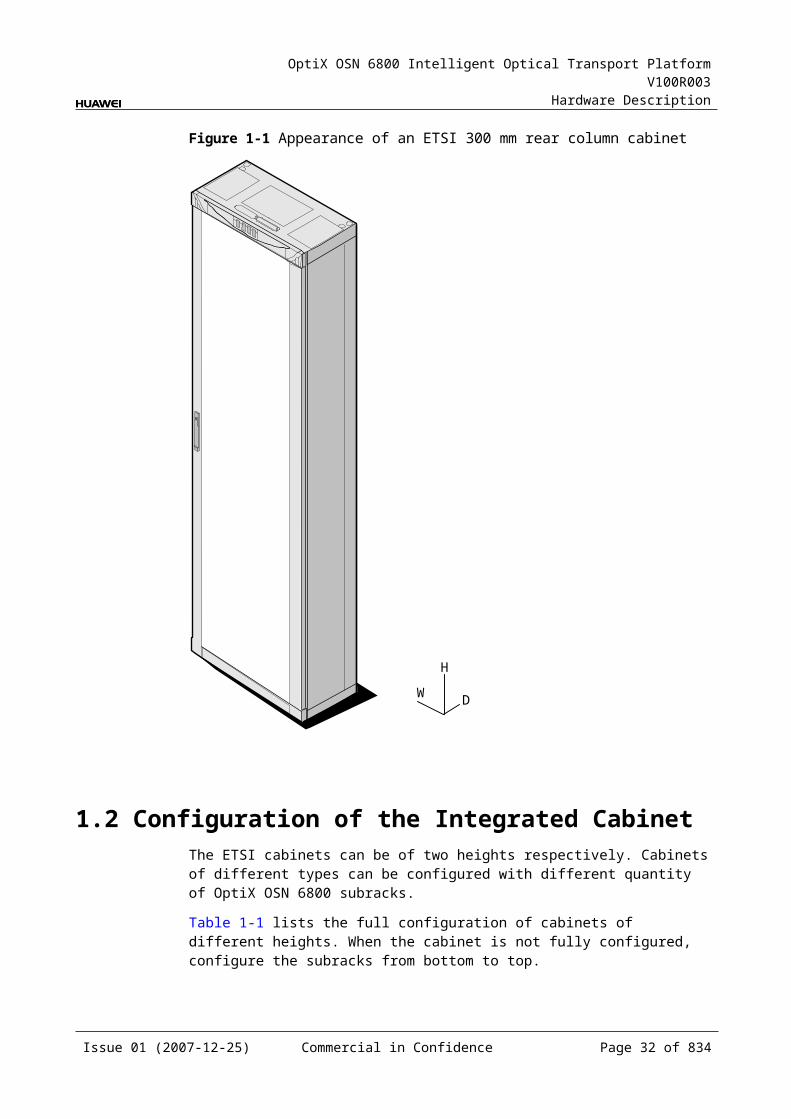
OptiX OSN 6800 Intelligent Optical Transport Platform V100R003
Hardware Description
Figure 1-2 Junction box mounting position
Issue 01 (2007-12-25) Commercial in Confidence Page 32 of 664
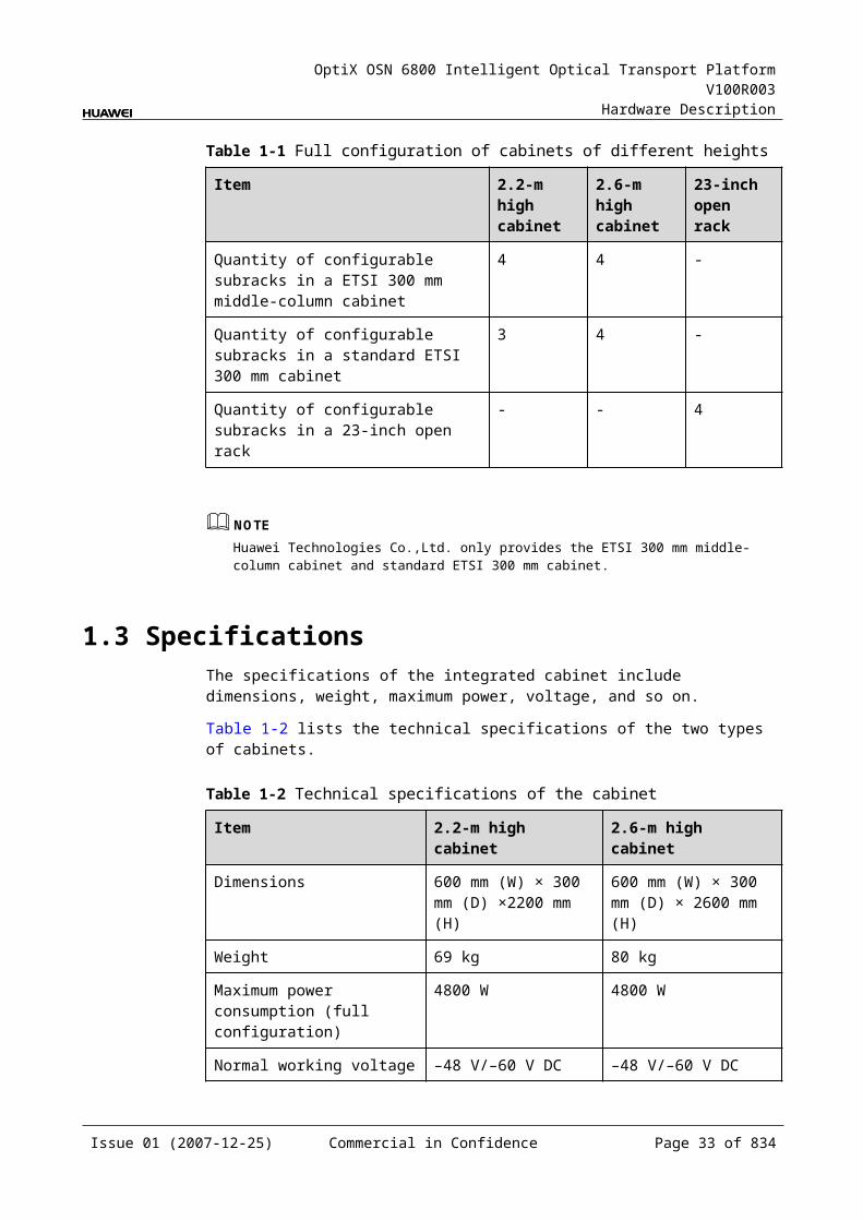
OptiX OSN 6800 Intelligent Optical Transport Platform V100R003
Hardware Description
2 Subrack
2.1 StructureThe OptiX OSN 6800 takes subracks as the basic working units. The subrack of the OptiX OSN 6800 has independent power supply.
Figure 2-1 shows the structure of the subrack.
Figure 2-1 OptiX OSN 6800 subrack structure diagram
1
2
3
456
7
1. Indicator 2. Board area
3. Fiber cabling area
4. Fan tray assembly
5. Air filter 6. Fiber spool
7. Mounting ear
NOTEThe interface area is behind the indicator panel in the upper part of the subrack. Remove the indicator panel before you connect cables.
Indicators: They indicate the running status and alarm status of the subrack.
Issue 01 (2007-12-25) Commercial in Confidence Page 33 of 664

OptiX OSN 6800 Intelligent Optical Transport Platform V100R003
Hardware Description
Board area: All service boards are in this area. Totally 21 slots are available. Fiber cabling area: Fiber jumpers from the ports on the front panel of the boards
are routed to the area before reaching the matched side of the cabinet. The mechanical VOA is also installed in this area.
Fan tray assembly: This area contains 10 fans for ventilation and heat dissipation of the subrack.
Air filter: It protects the subrack from outside dust in the air. It needs to be taken out and cleaned periodically.
Fiber spool: The fiber spool serves to coil the extra fibers. Fixed fiber spools are on two sides of the subrack. The fibers whose extras are coiled in the fiber spool on the cabinet side enter another subrack.
Mounting ears: They fix the subrack in the cabinet. Interface area: This area is behind the subrack indicator panel, providing
functional interfaces such as management interface, inter-subrack communication interface, alarm output and cascading interface, alarm input and output interface.
Table 2-1 and Table 2-2 lists the technical specifications of the OptiX OSN 6800 subrack.
Table 2-1 Technical specifications of the subrack
Item Specification
Dimensions 487 mm (W) × 295 mm (D) × 400 mm (H)
Weight (empty subracka) 13 kg
Maximum power consumption 1200 W
Rated working current 30 A
Nominal working voltage –48 V/–60 V DC
Working voltage range –38.4 V to –72 V DC
a: The empty subrack means no board is installed in the board area, and no fan tray assembly and no air filter is installed.
Table 2-2 Technical specifications of the fan tray assembly
Item Specification
Dimensions 493.7 mm (W)× 266.6 mm (D) × 56.1 mm (H)
Weight 3.6 kg
Power consumption 120 W
Table 2-3 lists the power consumption of the common units in the OptiX OSN 6800.
Issue 01 (2007-12-25) Commercial in Confidence Page 34 of 664
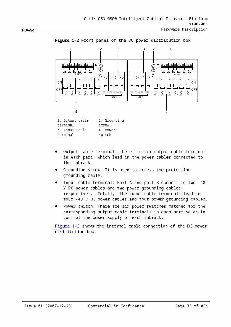
OptiX OSN 6800 Intelligent Optical Transport Platform V100R003
Hardware Description
Table 2-3 Power consumption of the common units in the OptiX OSN 6800
Unit Name Maximum Power Consumptiona
Remarks
Subrack OTU subrack 640 W It is the power consumption when the subrack is installed with seventeen OTU10G (LSX), one SCC, two PIUs, one AUX, and one fan tray assembly.
OTM subrack 520 W It is the power consumption when the subrack is installed with one M40V, one D40V, one OAU, one OBU, eight OTU10G (LSX), one SCC, two PIUs, one AUX, and one fan tray assembly.
OLA subrack 270 W It is the power consumption when the subrack is installed with seventeen two OBU101, two OBU103, four VA1, one SC2, one SCC, two PIUs, one AUX, and one fan tray assembly.
OADM subrack
380 W It is the power consumption when the subrack is installed with two OAU101, four VA1, two MR4, four OTU10G, one SC2, one SCC, two PIUs, one AUX, and one fan tray assembly.
Cabinet OTM cabinet (40×10Gbits)
1800 W It is the power consumption when the cabinet is installed with two OTU subrack and one OTM subrack.
a: Indicates that the power consumption of the subrack and cabinet is the value in a certain configuration. The value is for reference only. The actual power consumption of the chassis and cabinet is calculation based on the power consumption of each module.
NOTEThe power consumption value in the table is the measured value when the ambient temperature is 25 . During the starting up of the equipment or in high or low temperature, the power consumption of the equipment increases. Hence, the actual power consumption of the equipment is 1.2 to 1.5 times of the value in the table.
2.2 Slot DescriptionThe board area of the subrack has 21 slots, defined as IU1 to IU21 from left to right.
Slots of the subrack is shown in Figure 2-2
Issue 01 (2007-12-25) Commercial in Confidence Page 35 of 664
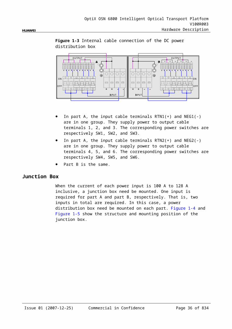
OptiX OSN 6800 Intelligent Optical Transport Platform V100R003
Hardware Description
Figure 2-1 Slots of the subrack
IU5
IU4
IU6
IU7
IU8
XCS
XCS I
U12
IU13
IU14
IU15
IU16
SCC
SCC
PIU
PIU
AUX
IU3
IU2
IU1
IU11I
UIU
9 10
17
18
/ /IU
IU
//Board area
VOA area12
34
56
78
IU19
IU20
IU21
IU1-IU18 are for service boards. IU21 is for the AUX. IU19 and IU20 are for the PIU. IU18 is for the active SCC. IU17 is available for the standby SCC or the other service boards. IU9 is available for the active XCS or for the other service boards. IU10 is available for the standby XCS or for the other service boards.
Mapping of Pair Slots Pair slots refer to a pair of slots whose resident boards' overhead can be processed by the buses on the backplanes. For the two boards in the paired slots, the inter-board cross-connection can be directly configured, and the cross-connect grooming of services can be realized without the cross-connect board. The OptiX OSN 6800 supports seven pair slots, which are IU1 and IU2, IU3 and IU4, IU5 and IU6, IU7 and IU8, IU11 and IU12, IU13 and IU14, IU15 and IU16.
Mapping of Boards and SlotsTable 2-4 shows the mapping between boards and slots of the OptiX OSN 6800.
Table 2-1 Mapping between boards and slots of the OptiX OSN 6800
Board Available slot
AUX IU21
CMR2 IU1-IU17
CMR4 IU1-IU17
D40 IU1-IU15
Issue 01 (2007-12-25) Commercial in Confidence Page 36 of 664
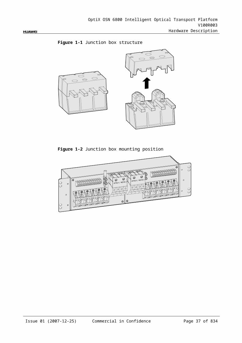
OptiX OSN 6800 Intelligent Optical Transport Platform V100R003
Hardware Description
Board Available slot
D40V IU1-IU15
DCP IU1-IU17
DCU IU1-IU17
DMR1 IU1-IU17
ECOM IU1-IU8, IU11-IU16
FIU IU1-IU17
HBA IU2-IU16
ITL IU1-IU17
L4G IU1-IU8, IU11-IU16
LDGD IU1-IU8, IU11-IU16
LDGS IU1-IU8, IU11-IU16
LOG IU1-IU8, IU11-IU16
LOM IU1-IU8, IU11-IU16
LQMS IU1-IU8, IU11-IU16
LQMD IU1-IU8, IU11-IU16
LSX IU1-IU17
LSXL IU1-IU14
LSXLR IU1-IU14
LSXR IU1-IU17
LWX2 IU1-IU17
LWXD IU1-IU17
LWXS IU1-IU17
M40 IU1-IU15
M40V IU1-IU15
MCA4 IU1-IU16
MCA8 IU1-IU16
MR2 IU1-IU17
MR4 IU1-IU17
MR8 IU1-IU16
NS2 IU1-IU8, IU11-IU16
OAU1 IU2-IU17
Issue 01 (2007-12-25) Commercial in Confidence Page 37 of 664
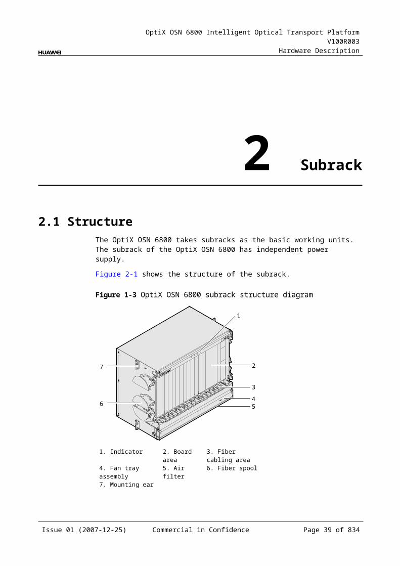
OptiX OSN 6800 Intelligent Optical Transport Platform V100R003
Hardware Description
Board Available slot
OBU1 IU1-IU17
OBU2 IU2-IU17
OLP IU1-IU17
RMU9 IU1-IU17
ROAM IU1-IU15
SBM2 IU1-IU17
SC1 IU1-IU17
SC2 IU1-IU17
SCC IU17, IU18
SCS IU1-IU17
TBE IU1-IU8, IU11-IU16
TDX IU1-IU8, IU11-IU16
TDG IU1-IU8, IU11-IU16
TMX IU1-IU17
TQS IU1-IU8, IU11-IU16
TQM IU1-IU8, IU11-IU16
VA1 IU1-IU17
VA4 IU1-IU17
WMU IU1-IU17
WSM9 IU1-IU15
WSD9 IU1-IU15
WSMD4 IU1-IU16
XCS IU9, IU10
2.3 Fan AreaIn the OptiX OSN 6800 system, each subrack has a fan area. A fan area consists of fan tray assembly and air filter. The air filter can be drawn out and be cleaned.
AppearanceFigure 2-3 shows the appearance of a fan area.
Issue 01 (2007-12-25) Commercial in Confidence Page 38 of 664
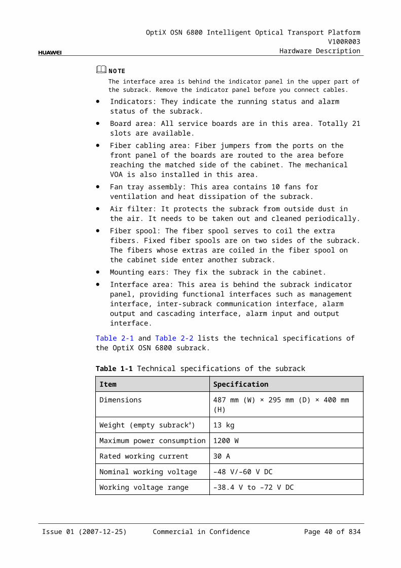
OptiX OSN 6800 Intelligent Optical Transport Platform V100R003
Hardware Description
Figure 2-1 Appearance of a fan area
1
2
3
1. Air filter 2. Fan running indicators 3. Fans (ten in total)
Functions and Features
Table 2-1 Functions
Function Describes
Basic function Realizes heat dissipation on an NE, so that the NE is able to work normally and effectively under the designed temperature.
Commissioning control
Realizes intelligent speed regulating of fans. The speed varies automatically with the temperature.
The fan speed can be manually adjusted.
The fan area realizes heat dissipation on an NE. Hence, the NE is able to work normally and effectively under the designed temperature. The fan tray assembly is located on the lower part of the subrack. It adopts blowing method, forming an air duct from bottom to top. Other boards in the subrack are installed vertically, that is, the boards are parallel to the air duct. This design ensures reliable heat dissipation.
Figure 2-4, Figure 2-5 shows the heat dissipation and ventilation system in the OptiX OSN 6800.
Issue 01 (2007-12-25) Commercial in Confidence Page 39 of 664
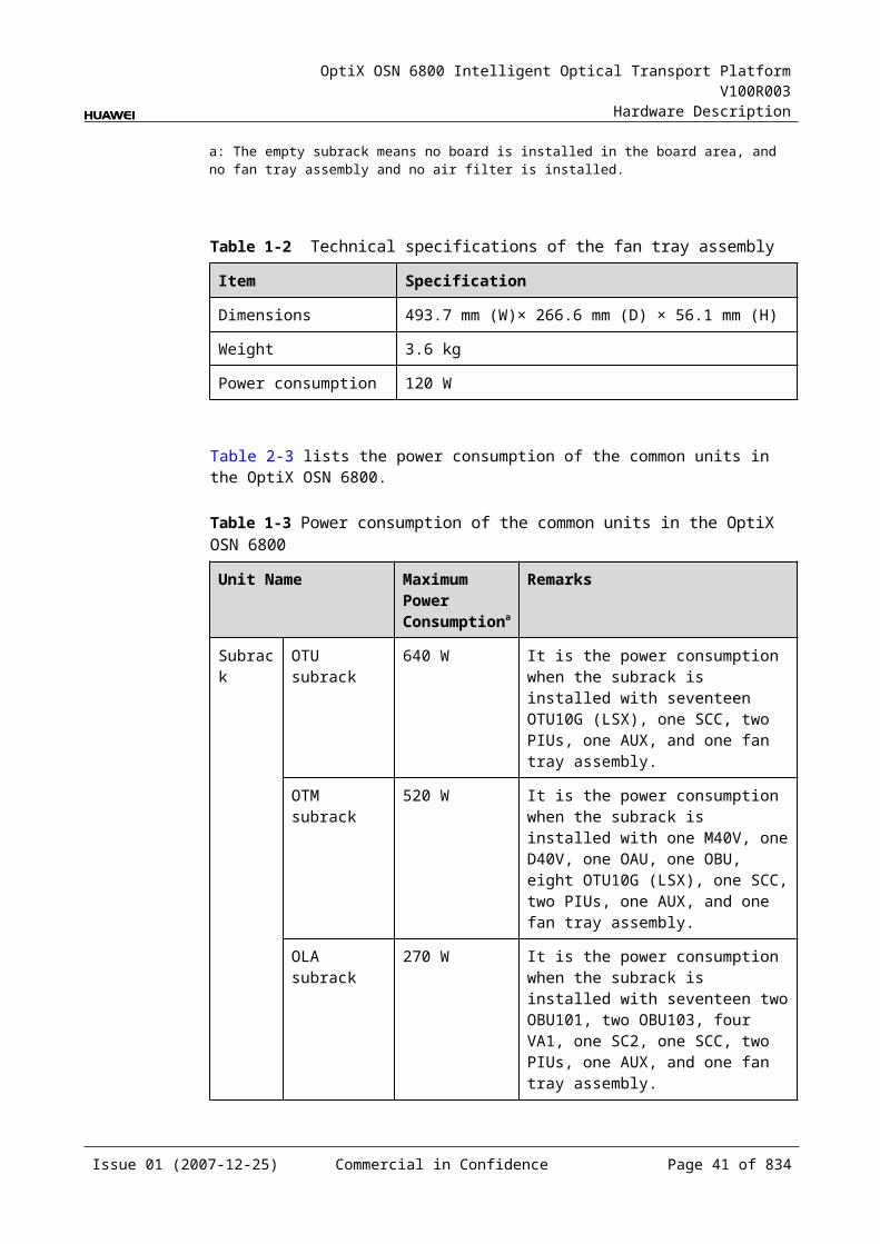
OptiX OSN 6800 Intelligent Optical Transport Platform V100R003
Hardware Description
Figure 2-2 Single-subrack heat dissipation and ventilation system
Air outlet
Board area
Optical fiberlaying area
Fan tray assembly
Air inlet
Figure 2-3 Multi-subrack heat dissipation and ventilation system
Air outlet
Board area
Optical fiberlaying area
Fan tray assembly
Air inlet
Airduct frame
NOTEWhen multiple subracks are used, an airduct frame is required to help in heat dissipation.
2.4 PIUPIU: Power Interface Unit
2.4.1 Version DescriptionOnly one functional version of the PIU board is available, that is TN11.
Issue 01 (2007-12-25) Commercial in Confidence Page 40 of 664
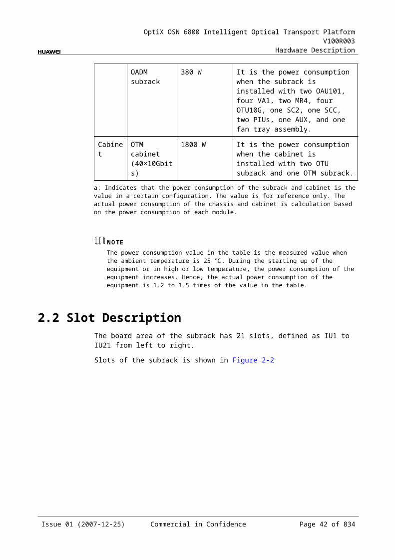
OptiX OSN 6800 Intelligent Optical Transport Platform V100R003
Hardware Description
2.4.2 ApplicationThe OptiX OSN 6800 is configured with two PIU boards. The two boards provide power supplies to the system with 1+1 hot backup.
2.4.3 Functions and FeaturesThe PIU is an power interface unit. It accesses DC power and provides protection and filtering functions.
For detailed functions and features, refer to Table 2-6.
Table 2-1 Functions and features of the PIU
Function and Feature
Description
Basic function Accesses DC power from –38.4 V to –72 V for the system. Provides protection and filtering functions for the accessed power. Provides the fan tray assembly with a 48 V DC power after voltage reduction.
2.4.4 Front PanelThere are indicators and interfaces on the board front panel.
Appearance of the Front PanelFigure 2-6 shows the PIU front panel.
Figure 2-1 PIU front panel
RUN
NEG
(-)R
TN(+)
PIU
IndicatorsThere is one indicator on the front panel.
Running status indicator (RUN) - green
Issue 01 (2007-12-25) Commercial in Confidence Page 41 of 664
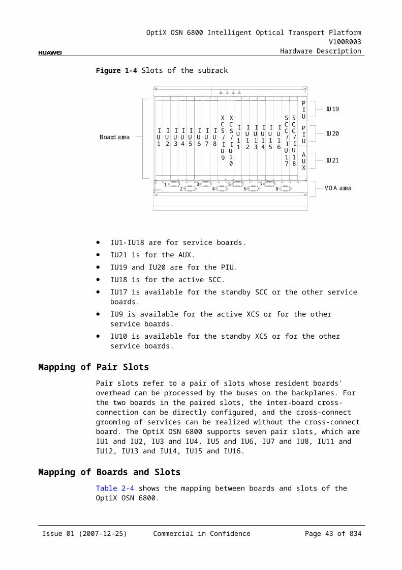
OptiX OSN 6800 Intelligent Optical Transport Platform V100R003
Hardware Description
InterfaceThere is only one power interface on the front panel of the PIU board. The interface is used to access the DC power from –38.4 V to –72 V.
2.4.5 Valid SlotsThe PIU occupies one slot. The valid slots for the PIU are IU19 and IU20.
2.4.6 Specifications of the PIUSpecifications include performance indexes, dimensions, weight and power consumption.
Performance Indexes
Table 2-1 Performance Indexes of the PIU Board
Item Unit Value
Number of DC input power supplies - 1
Input DC power voltage range V DC –38.4 to –72
Input DC power current A ≤30
Mechanical Specifications Dimensions of front panel: 28 mm X 65 mm Weight: 0.5 kg
Power Consumption The maximum power consumption: 35 W
2.5 Data Communication and Equipment Maintenance Interfaces
The OptiX OSN 6800 provides abundant interfaces for data communication and equipment maintenance.
These interfaces are located in the interface area of the subrack and on the front panel of the AUX, as shown in Figure 2-7.
Issue 01 (2007-12-25) Commercial in Confidence Page 42 of 664
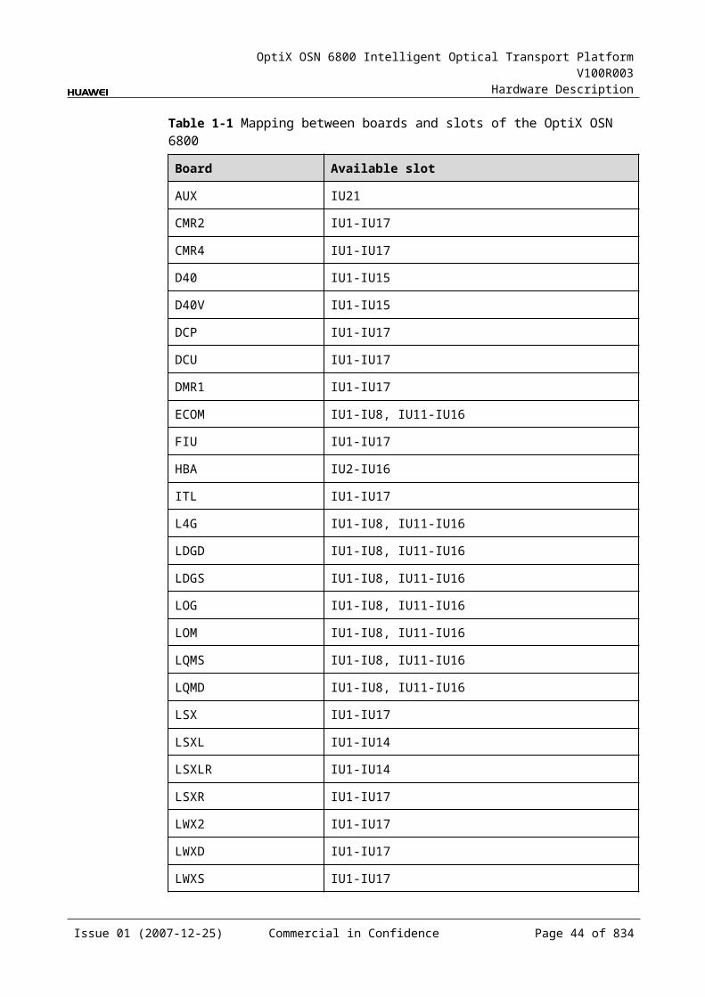
OptiX OSN 6800 Intelligent Optical Transport Platform V100R003
Hardware Description
Figure 2-1 Interfaces of the OptiX OSN 6800 subrack
Fan
ETH3COM ALM02ALM01 ALM03 ALM04 ALMI2ALMI1 LAMP1 ALMP2SERIAL
SCC
SCC
STATACTPROGSRVPWRAPWRBPWRCALMC
RESET
LAMP TEST
ALM CUT
SubRACK_ID
RUN
NEG
(-)R
TN(+)
PIU
AUX
STATPROG
NM
_ETH
1N
M_E
TH2
ETH
1E
TH2
xcs
xcs
STATACTPROGSRV
NOTEThe interface area is behind the indicator panel in the upper part of the subrack. Remove the indicator panel before you connect cables.
2.5.1 Interfaces in the Interface AreaThe interface area provides functional interfaces such as management interface, inter-subrack communication interface, alarm output and cascading interface, alarm input and output interface.
The interface area is behind the indicator panel in the upper part of the subrack. Figure 2-8 shows the front panel.
Figure 2-1 Interfaces in the interface area
ETH3COM ALM02ALM01 ALM03 ALM04 ALMI2ALMI1 LAMP1 LAMP2SERIAL
Description of interfaces in the interface area is list in Table 2-8.
Issue 01 (2007-12-25) Commercial in Confidence Page 43 of 664
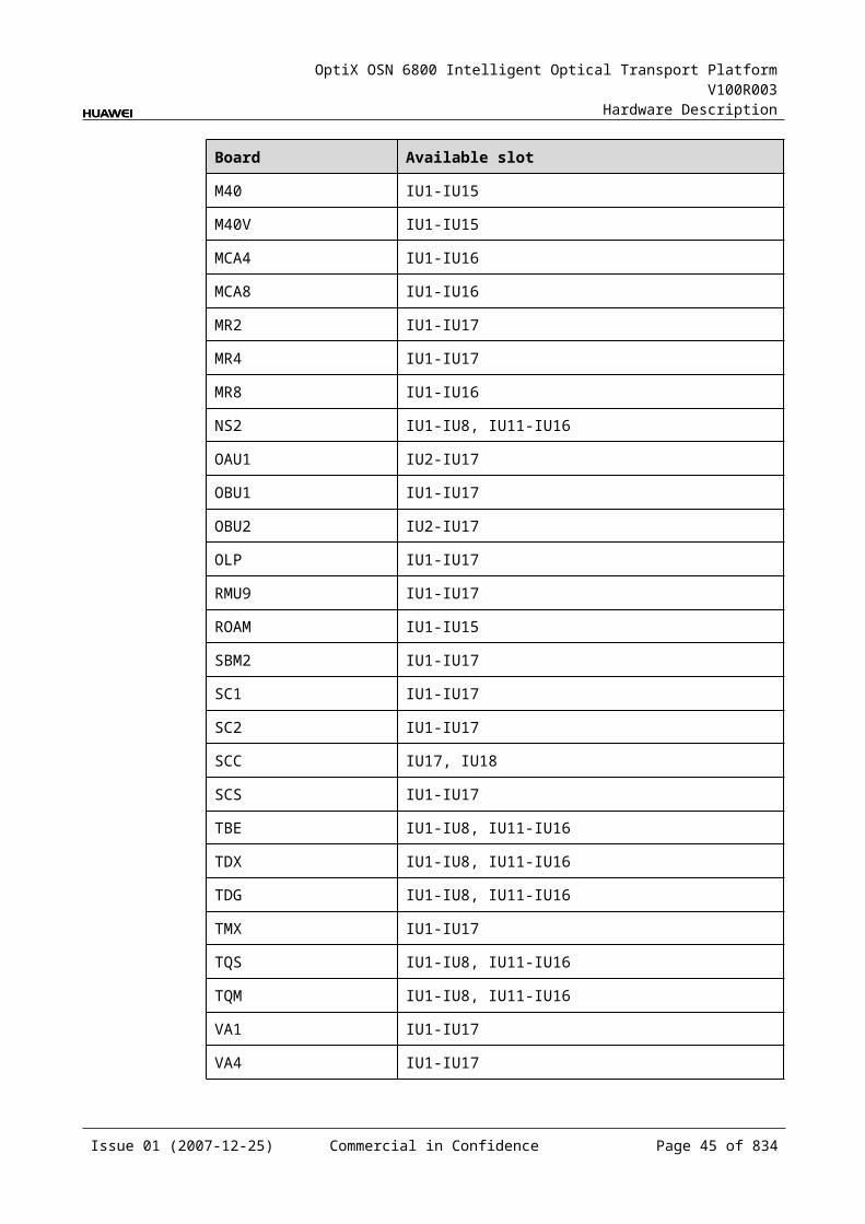
OptiX OSN 6800 Intelligent Optical Transport Platform V100R003
Hardware Description
Table 2-1 Description of interfaces in the interface area
Interface Silk-screen
Connector
Function
Commissioning interface
COM RJ-45 It is for the commissioning.
Inter-subrack communication interface
ETH3 RJ-45 Connects the ETH1/ETH2/ETH3 interface on one subrack through a network cable to such interfaces on the other subracks to achieve the communication between the master subrack and slave subracks.
Alarm output and cascading interface
ALMO1 ALMO2 ALMO3 ALMO4
RJ-45 The definitions for the pins of the ALM01 and ALM02 interfaces are the same. The two interfaces are used for output/cascading, respectively. The definitions for the pins of the ALM03 and ALM04 interfaces are the same. The two interfaces are used for output/cascading, respectively.Alarm outputs are sent to the DC power distribution cabinet through the output interface and the cascading interface. You can configure it to be the other outputs to realize integrated display of alarms. The OptiX OSN 6800 provides eight alarm outputs. Defaults of the first three are critical alarm, major alarm, and minor alarm. The other five are reserved. Alarm outputs can be cascaded.
OAM interface SERIAL DB9 The OAM interface is a serial NM interface, providing functions of serial NM and supporting X.25 protocol. When this interface is a COA management interface, it can manage external equipment such as COA, TDA, and DCU. The interface rate is 9.6 kbit/s.
Alarm input interface
ALMI1 ALMI2
RJ45 External alarm signal input function is designed for requirements when the alarm signals of the external systems (such as the environment monitory) need remote monitoring.The OptiX OSN 6800 provides eight alarm inputs. The name of the eight alarms can be configured to cooperate with the external system to realize remote monitoring of external alarms.
Subrack alarm output and cascading interface
LAMP1 LAMP2
RJ45 This interface drives the running indicators and alarm indicators of the cabinet that holds the subrack.
2.5.2 Interfaces on the Front Panel of the AUX BoardThe AUX board provides NM interface, NM cascading interface, inter-subrack normal and emergent communication interface.
Figure 2-9 shows the front panel of the AUX. The AUX is inserted in slot IU21.
Issue 01 (2007-12-25) Commercial in Confidence Page 44 of 664
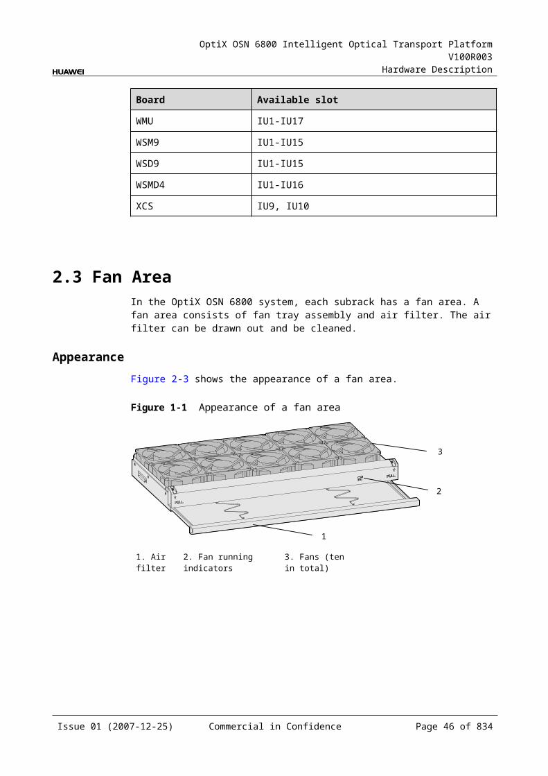
OptiX OSN 6800 Intelligent Optical Transport Platform V100R003
Hardware Description
Figure 2-1 Interfaces on the front panel of the AUX
AUX
STAT
PROG
NM
_ETH
1N
M_E
TH2
ETH
1E
TH2
Description of interfaces on the front panel of the AUX board is list in Table 2-9.
Table 2-1 Description of interfaces on the front panel of the AUX board
Interface Silk-screen
Connector
Function
NE management interface
NM_ETH1/NM_ETH2
RJ-45 Connects the network interface on the OptiX OSN 6800 through a network cable to that on the T2000 server to achieve the management of the T2000 over the OptiX OSN 6800.
Connects the NM_ETH1/NM_ETH2 network interface on one NE through a network cable to that on another NE to achieve communication between NEs.
Inter-subrack communication interface
ETH1/ETH2
RJ-45 Connects the ETH1/ETH2/ETH3 interface on one subrack through a network cable to such interfaces on the other subracks to achieve the communication between the master subrack and slave subracks.
Issue 01 (2007-12-25) Commercial in Confidence Page 45 of 664
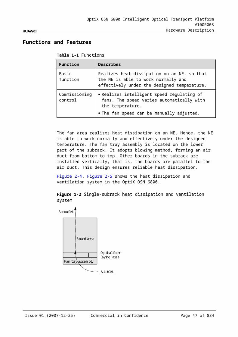
OptiX OSN 6800 Intelligent Optical Transport Platform V100R003
Hardware Description
2.5.3 PIN Assignment of InterfacesThe interfaces of the OptiX OSN 6800 used for data communication and equipment maintenance use the RJ-45 and the DB9 connectors. The pin assignment figures and the functions of the pins are given in this section.
Pin assignment of the RJ-45 ConnectorFigure 2-10 shows the pin assignment of the RJ-45 connector.
Figure 2-1 Pin assignment of the RJ-45 connector
. 18 7 6 5 4 3 2
Pin Assignment of the DB9 ConnectorFigure 2-11 shows the pin assignment of the DB9 connector.
Figure 2-1 Pin assignment of the DB9 connector
1
2
3
4
5
6
7
8
9
Pin Assignment of the COM InterfaceFor the pin assignment of the COM inerface, refer to Table 2-10 .
Issue 01 (2007-12-25) Commercial in Confidence Page 46 of 664
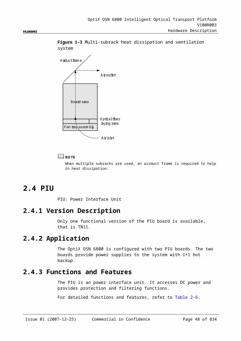
OptiX OSN 6800 Intelligent Optical Transport Platform V100R003
Hardware Description
Table 2-1 Pin assignment of the COM interface
Pin Signal Function
1 ETNTX_P_1 Transmits the data positive
2 ETNTX_N_1 Transmits the data negative
3 ETNRX_P_1 Receives the data positive
4 NC Not connected
5 NC Not connected
6 ETNRX_N_1 Receives data negative
7 NC Not connected
8 NC Not connected
Pin Assignment of the ETH3 InterfaceFor the pin assignment of the ETH3 interface, refer to Table 2-11.
Table 2-1 Pin assignment of the ETH3 interface
Pin Signal Function
1 ETH3_TXP Transmits the data positive for inter-subrack ordinary communications
2 ETH3_TXN Transmits the data negative for inter-subrack ordinary communications
3 ETH3_RXP Receives the data positive for inter-subrack ordinary communications
4 ETH3_CRIT_TXP Transmits the data positive for inter-subrack emergent communications
5 ETH3_CRIT_TXN Transmits the data negative for inter-subrack emergent communications
6 ETH3_RXN Receives the data negative for inter-subrack ordinary communications
7 ETH3_CRIT_RXP Receives the data positive for inter-subrack emergent communications
8 ETH3_CRIT_RXN Receives the data negative for inter-subrack emergent communications
Pin Assignment of the ALMO1 and the ALMO2 InterfacesFor the pin assignment of the ALMO1 and the ALMO2 interfaces, refer to Table 2-12.
Issue 01 (2007-12-25) Commercial in Confidence Page 47 of 664
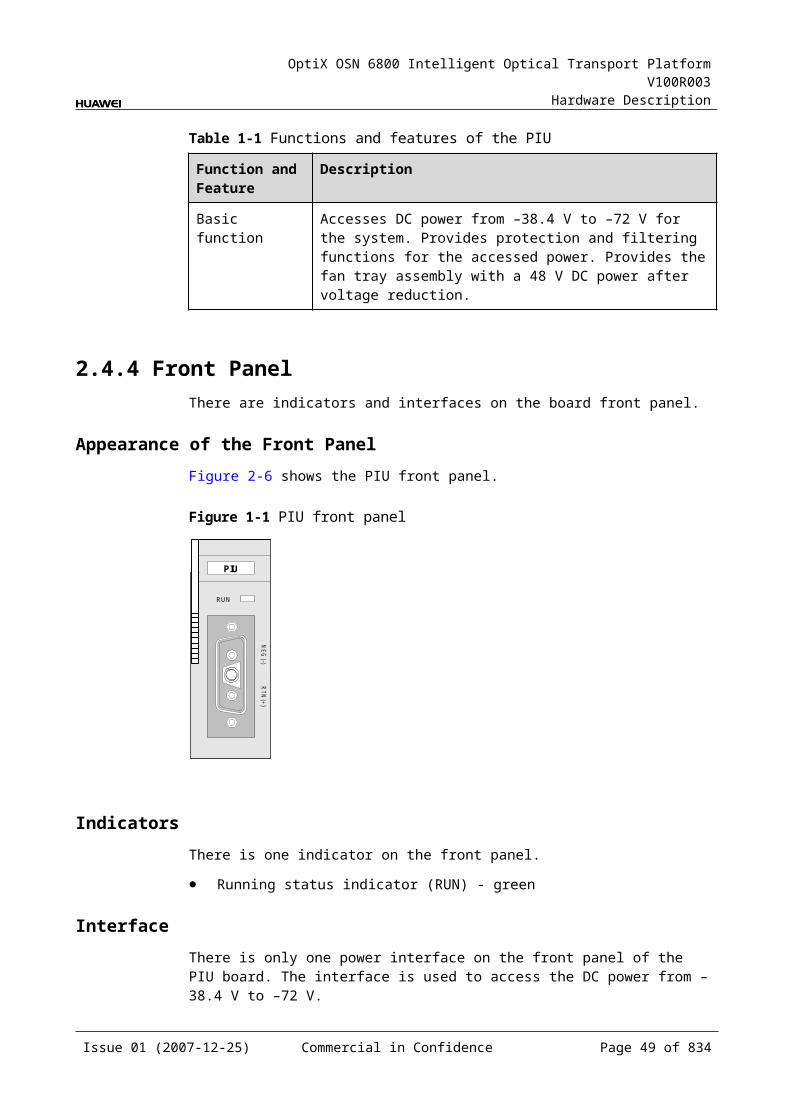
OptiX OSN 6800 Intelligent Optical Transport Platform V100R003
Hardware Description
Table 2-1 Pin assignment of the ALMO1 and ALMO2 interfaces
Pin Signal Funciton
1 CRIT_SWITCH_OUTP Outputs the critical alarm signal positive
2 CRIT_SWITCH_OUTN Outputs the critical alarm signal negative
3 MAJ_SWITCH_OUTP Outputs the major alarm signal positive
4 ALM_SWITCH_OUT1P Outputs the minor alarm signal positive
5 ALM_SWITCH_OUT1N Outputs the minor alarm signal negative
6 MAJ_SWITCH_OUTN Outputs the major alarm signal negative
7 ALM_SWITCH_OUT2P Alarm signal output 1 positive
8 ALM_SWITCH_OUT2N Alarm signal output 1 negative
Pin Assignment of the ALMO3 and the ALMO4 InterfacesFor the pin assignment of the ALMO3 and the ALMO4 interfaces, refer to Table 2-13.
Table 2-1 Pin assignment of the ALMO3 and the ALMO4 interfaces
Pin Signal Function
1 ALM_SWITCH_OUT3P Alarm signal output 2 positive
2 ALM_SWITCH_OUT3N Alarm signal output 2 negative
3 ALM_SWITCH_OUT4P Alarm signal output 3 positive
4 ALM_SWITCH_OUT5P Alarm signal output 4 positive
5 ALM_SWITCH_OUT5N Alarm signal output 4 negative
6 ALM_SWITCH_OUT4N Alarm signal output 3 negative
7 ALM_SWITCH_OUT6P Alarm signal output 5 positive
8 ALM_SWITCH_OUT6N Alarm signal output 5 negative
Pin Assignment of the SERIAL InterfaceFor the pin assignment of the SERIAL interface, refer to Table 2-14.
Table 2-1 Pin assignment of the SERIAL interface
Pin Signal Function
1 N.C Not defined
2 RXD Receive end of data
Issue 01 (2007-12-25) Commercial in Confidence Page 48 of 664
OptiX OSN 6800 Intelligent Optical Transport Platform V100R003
Hardware Description
Pin Signal Function
3 TXD Transmit end of data
4 DTR Data terminal equipment ready
5 GND Ground
6 F_RS232RX F&f receive end of data
7 F_RS232TX F&f transmit end of data
8 GND GND
9 5VOADM Power supply for OADM
Pin Assignment of the ALMI1 InterfaceFor the pin assignment of the ALMI1 interface, refer to Table 2-15.
Table 2-1 Pin assignment of the ALMI1 interface
Pin Signal Function
1 SWITCHI_IN1 Alarm input 1
2 GND Ground
3 SWITCHI_IN2 Alarm input 2
4 SWITCHI_IN3 Alarm input 3
5 GND Ground
6 GND Ground
7 SWITCHI_IN4 Alarm input 4
8 GND Ground
Pin Assignment of the ALMI2 InterfaceFor the pin assignment of the ALMI2 interface, refer to Table 2-16.
Table 2-1 Pin assignment of the ALMI2
Pin Signal Function
1 SWITCHI_IN5 Alarm input 5
2 GND Ground
3 SWITCHI_IN6 Alarm input 6
4 SWITCHI_IN7 Alarm input 7
Issue 01 (2007-12-25) Commercial in Confidence Page 49 of 664
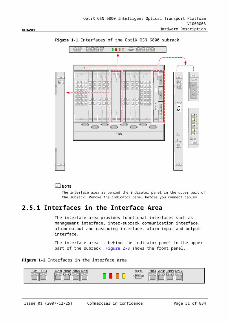
OptiX OSN 6800 Intelligent Optical Transport Platform V100R003
Hardware Description
Pin Signal Function
5 GND Ground
6 GND Ground
7 SWITCHI_IN8 Alarm input 8
8 GND Ground
Pin Assignment of the LAMP1 and the LAMP2 InterfacesFor the pin assignment of the LAMP1 and the LAMP2 interfaces, refer to Table 2-17.
Table 2-1 Pin assignment of the LAMP1 and the LAMP2 interfaces
Pin Signal Function
1 CRIT_ALMP Critical alarm signal positive
2 CRIT_ALMN Critical alarm signal negative
3 MAJ_ALMP Major alarm signal positive
4 RUNP Power indicating signal positive
5 RUNN Power indicating signal negative
6 MAJ_ALMN Major alarm signal positive
7 MIN_ALMP Minor alarm signal positive
8 MIN_ALMN Minor alarm signal negative
Pin Assignment of the NM-ETH1 InterfaceFor the pin assignment of the NM-ETH1 interface, refer to Table 2-18.
Table 2-1 Pin assignment of the NM-ETH1 interface
Pin Signal Function
1 NM_ETNTXP NM communications, transmits the data positive
2 NM_ETNTXN NM communications, transmits the data negative
3 NM_ETNRXP NM communications, receives the data positive
4 N C Not connected.
5 N C Not connected.
6 NM_ETNRXN NM communications, receives the data negative
7 N C Not connected.
Issue 01 (2007-12-25) Commercial in Confidence Page 50 of 664
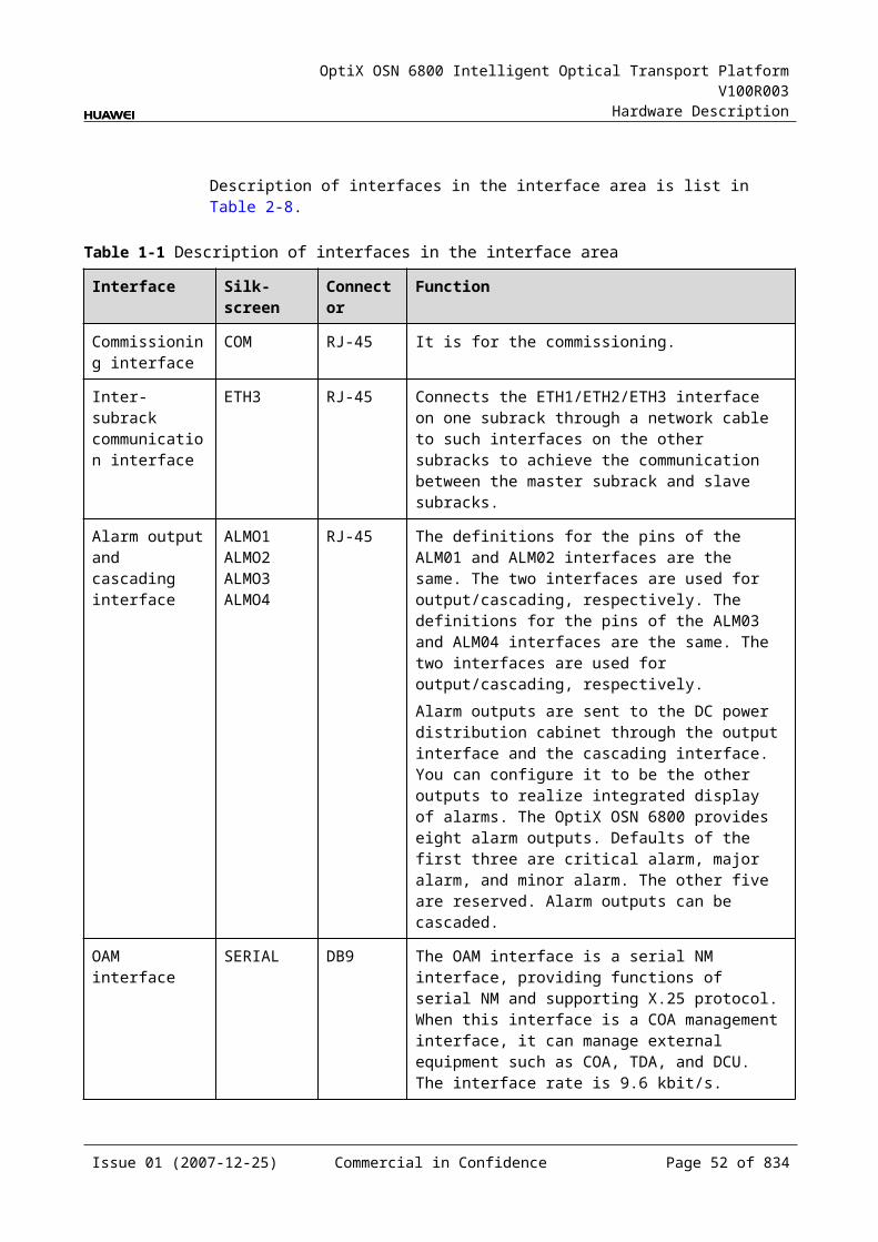
OptiX OSN 6800 Intelligent Optical Transport Platform V100R003
Hardware Description
Pin Signal Function
8 N C Not connected.
Pin Assignment of the NM-ETH2 InterfaceFor the pin assignment of the NM-ETH2 interface, refer to Table 2-19.
Table 2-1 Pin assignment of the NM-ETH2 interface
Pin
Signal Function
1 NMJL_ETNTXP Transmits the concatenated data positive for NM communications
2 NMJL_ETNTXN Transmits the concatenated data negative for NM communications
3 NMJL_ETNRXP Receives the concatenated data positive for NM communications
4 N C Not connected
5 N C Not connected
6 NMJL_ETNRXN Receives the concatenated data negative for NM communications
7 N C Not connected
8 N C Not connected
Pin Assignment of the ETH1 InterfaceFor the pin assignment of the ETH1 interface, refer to Table 2-20.
Table 2-1 Pin assignment of the ETH1 interface
Pin
Signal Function
1 ETH1_TXP Transmits the data positive for inter-subrack ordinary communications
2 ETH1_TXN Transmits the data negative for inter-subrack ordinary communications
3 ETH1_RXP Receives the data positive for inter-subrack ordinary communications
4 ETH1_CRIT_TXP Transmits the data positive for inter-subrack emergent communications
Issue 01 (2007-12-25) Commercial in Confidence Page 51 of 664

OptiX OSN 6800 Intelligent Optical Transport Platform V100R003
Hardware Description
Pin
Signal Function
5 ETH1_CRIT_TXN Transmits the data negative for inter-subrack emergent communications
6 ETH1_RXN Receives the data negative for inter-subrack ordinary communications
7 ETH1_CRIT_RXP Receives the data positive for inter-subrack emergent communications
8 ETH1_CRIT_RXN Receives the data negative for inter-subrack emergent communications
Pin Assignment of the ETH2 InterfaceFor the pin assignment of the ETH2 interface, refer to Table 2-21.
Table 2-1 Pin assignment of the ETH2 interface
Pin
Signal Function
1 ETH2_TXP Transmits the data positive for inter-subrack ordinary communications
2 ETH2_TXN Transmits the data negative for inter-subrack ordinary communications
3 ETH2_RXP Receives the data positive for inter-subrack ordinary communications
4 ETH2_CRIT_TXP Transmits the data positive for inter-subrack emergent communications
5 ETH2_CRIT_TXN Transmits the data negative for inter-subrack emergent communications
6 ETH2_RXN Receives the data negative for inter-subrack ordinary communications
7 ETH2_CRIT_RXP Receives the data positive for inter-subrack emergent communications
8 ETH2_CRIT_RXN Receives the data negative for inter-subrack emergent communications
Issue 01 (2007-12-25) Commercial in Confidence Page 52 of 664
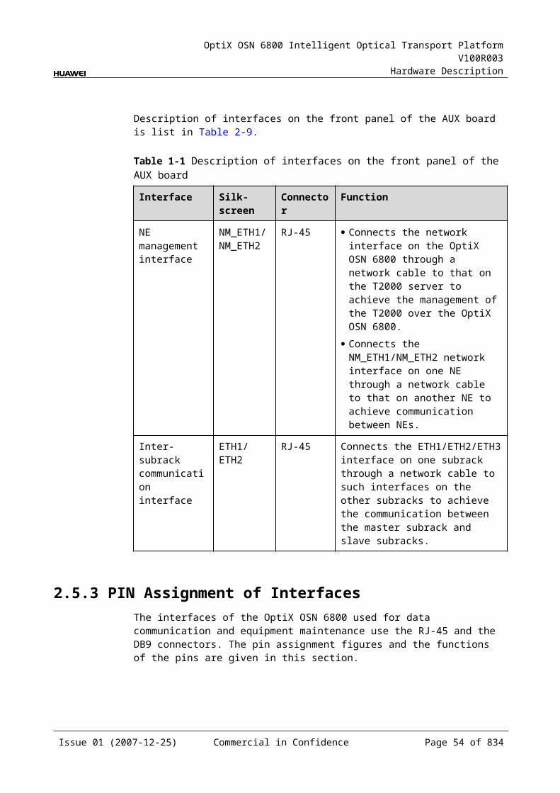
OptiX OSN 6800 Intelligent Optical Transport Platform V100R003
Hardware Description
3 Frame
3.1 DCM FrameThe DCM frame can be used to hold DCM modules which compensate the positive dispersion of transmitting fiber, so as to maintain the original shape of the signal pulse.
The OptiX OSN 6800 provides eight types of DCMs of eight compensation distance specifications: 5 km, 10 km, 20 km, 40 km, 60 km, 80 km, 100 km and 120 km.
Each DCM frame can hold two DCMs at most. The DCM frame is fixed onto the columns of the cabinet by mounting brackets and screws, as shown in Figure 3-1.
Figure 3-1 DCM frame in the cabinet
2
1
1. Cabinet column
2. DCM frame 3. DCMs
Issue 01 (2007-12-25) Commercial in Confidence Page 53 of 664
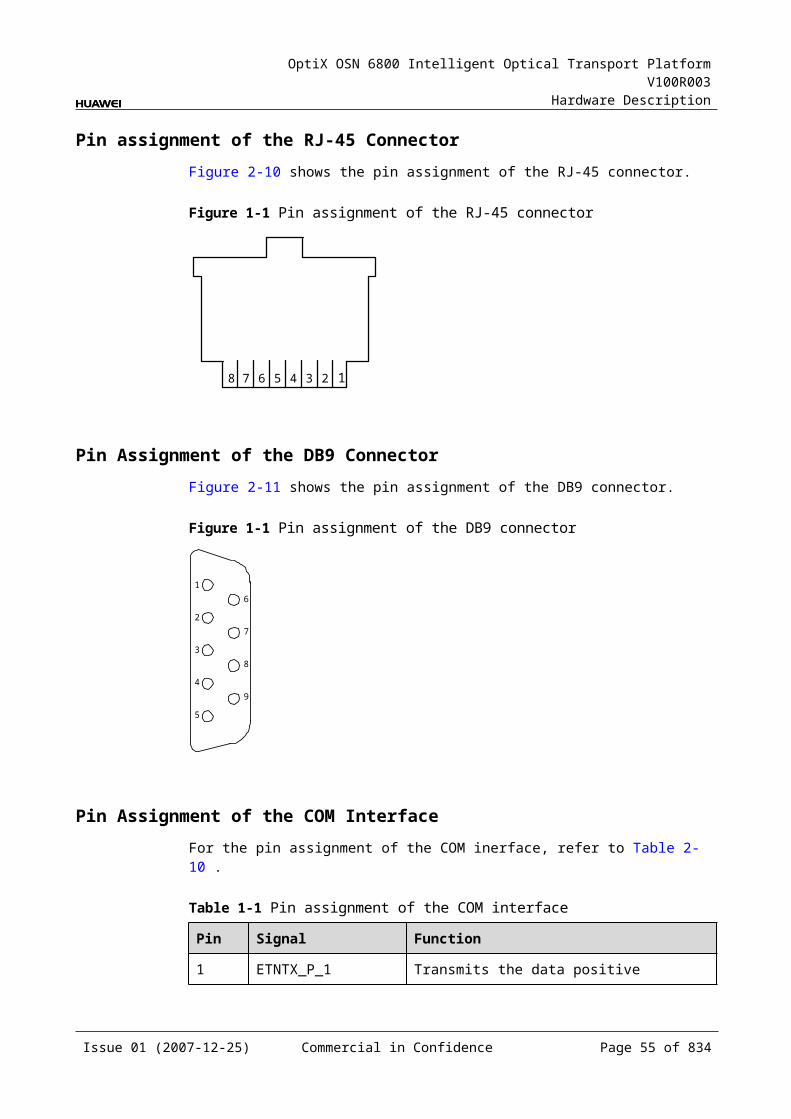
OptiX OSN 6800 Intelligent Optical Transport Platform V100R003
Hardware Description
3.2 CRPC FrameCRPC frame is used to place CRPC board, fan tray assembly and power supply box. The frame is installed into the cabinet.
Figure 3-2 shows the appearance of a CRPC frame. In the middle of the frame, the one with the front panel is the CRPC board. The fan tray assembly is at the left of the board. At the right are two power supplies as mutual backup.
Figure 3-1 Appearance of CRPC frame
1
2
3
1: Fan tray assembly
2: CRPC board 3: Power distribution box
Table 3-1 Mechanical specifications of the CRPC frame
Item Value
Mechanical Specifications 535 mm (W) × 257 mm (D) × 86 mm (H)
Weight 3 kg
Issue 01 (2007-12-25) Commercial in Confidence Page 54 of 664
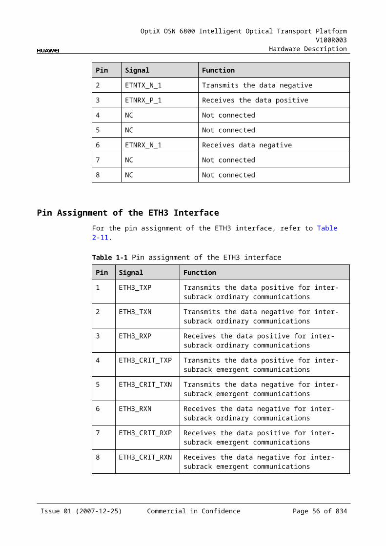
OptiX OSN 6800 Intelligent Optical Transport Platform V100R003
Hardware Description
4 Overview of Boards
4.1 Board Appearance and Dimensions4.1.1 Appearance and Dimensions
CAUTIONAlways wear an ESD wrist strap when holding the board, and make sure the ESD wrist strap is well grounded, thus to prevent the static from damaging the board.
Table 4-1 shows the board appearance and dimensions of the OptiX OSN 6800.
Table 4-1 The board appearance and dimensions
Board appearance
Board name
Number of slots occupied
Height (mm)
Width (mm)
Depth (mm)
L4G 1 264.6 25.4 220.0
Issue 01 (2007-12-25) Commercial in Confidence Page 55 of 664
OptiX OSN 6800 Intelligent Optical Transport Platform V100R003
Hardware Description
Board appearance
Board name
Number of slots occupied
Height (mm)
Width (mm)
Depth (mm)
OAU1 2 264.6 50.8 220.0
M40 3 264.6 76.2 220.0
AUX 1 107.6 28.4 220.0
Issue 01 (2007-12-25) Commercial in Confidence Page 56 of 664
OptiX OSN 6800 Intelligent Optical Transport Platform V100R003
Hardware Description
Board appearance
Board name
Number of slots occupied
Height (mm)
Width (mm)
Depth (mm)
LSXL 4 264.6 101.6 220.0
4.1.2 Laser Safety LabelLasers are of four safety levels according to the value of the output power.
WARNINGIt is strictly forbidden to stare into the optical interface during the installation and maintenance of the fiber, because the laser beam inside the optical fiber would hurt your eyes.
Table 4-2 shows the laser levels of the unit.
Table 4-1 Laser levels
Laser Level Label Reference Power Range
Class 1CLASS 1LASER
PRODUCT
<10.00 dBm (<10.00 mW)
Class 1M
CLASS 1M LASERPRODUCT
LASERRADIATION
DO NOT VIEW DIRECTLYWITH OPTICALINSTRUMENTS
10.00 dBm – 22.15 dBm (10.00 mW – 164 mW)
Issue 01 (2007-12-25) Commercial in Confidence Page 57 of 664
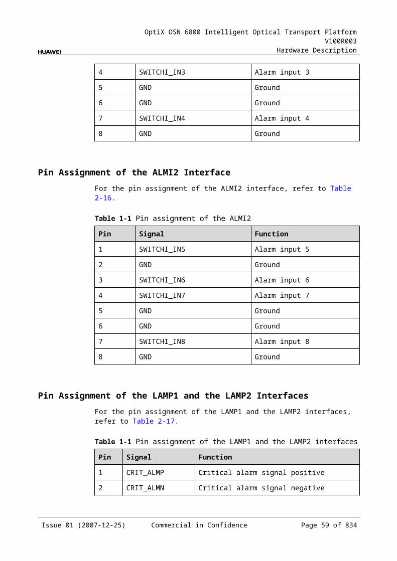
OptiX OSN 6800 Intelligent Optical Transport Platform V100R003
Hardware Description
Laser Level Label Reference Power Range
Class 3B
CLASS 3B LASERPRODUCT
AVOID EXPOSURETO BEAM
LASERRADIATION
22.15 dBm – 27.00 dBm (164.00 mW – 500.00 mW)
Class 4 LASERRADIATION
AVOID EYE OR SKINEXPOSURE TO DIRECT OR
SCATTERED RADIATION
CLASS 4 LASERPRODUCT
>27.00 dBm (>500.00 mW)
4.2 Bar Code for BoardsThere is a bar code on the front panel of each board, from which the basic information about the board can be obtained, such as the BOM code, delivery information, board version, board name, and board characteristic code.
4.2.1 OverviewThere is a bar code on the front panel of each board, from which the basic information about the board can be obtained, such as the BOM code, delivery information, board version, board name, and board model number. The bar code of some of such boards also include a characteristic code. The board characteristic code comprises the information about frequency of signals, type of the optical module, wavelength, and so on.
Figure 4-1 and Figure 4-2 shows a bar code.
Figure 4-1 Description of the bar code (example 1)
2102313242 1059000003 19210PA
BOM
Deliveryinformation
Board version(TN11)
Boardname
Characteristiccode
TN1M1L4GY 01
Board modelnumber
Environmentalfriendliness flag
(Y: Environmentallyfriendly)
Issue 01 (2007-12-25) Commercial in Confidence Page 58 of 664
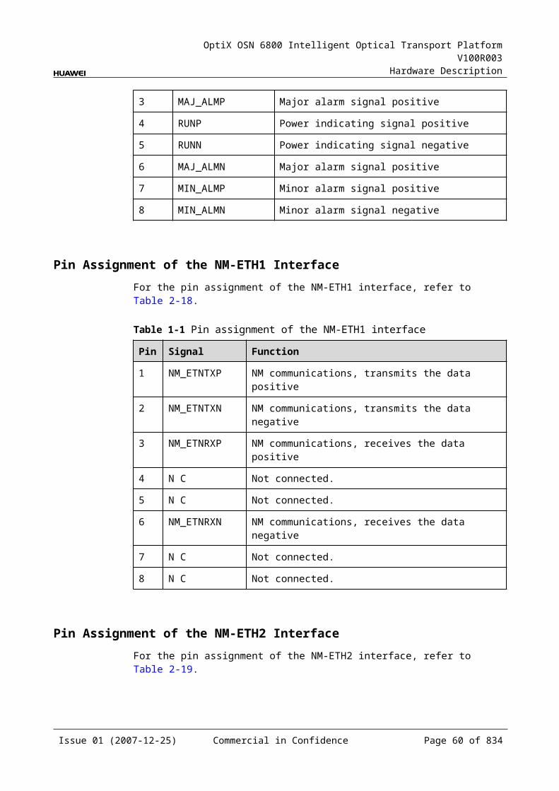
OptiX OSN 6800 Intelligent Optical Transport Platform V100R003
Hardware Description
Figure 4-2 Description of the bar code (example 2)
030FBQ1073000001 -94509520
Last four numbers ofthe BOM
TN11MR4N 01
Environmentalfriendliness flag
Deliveryinformation
Board name
Board version
Characteristiccode
Board modelnumber
(N: Environmentallyunfriendly)
4.2.2 Characteristic CodeFor the detailed description of the board characteristic code, refer to Appendix B.
4.3 Board CategoryThe OptiX OSN 6800 has 14 kinds of boards.
Optical transponder unit Optical multiplexer and demultiplexer unit Optical add and drop multiplexing unit Reconfigurable optical add and drop multiplexing unit Tributary unit Line unit Cross-connect unit Optical amplifier unit Optical supervisory channel unit System control and communication unit Optical protection unit Spectrum analyzer unit Variable optical attenuator unit Dispersion compensation unit
Table 4-3 shows the board list.
Issue 01 (2007-12-25) Commercial in Confidence Page 59 of 664
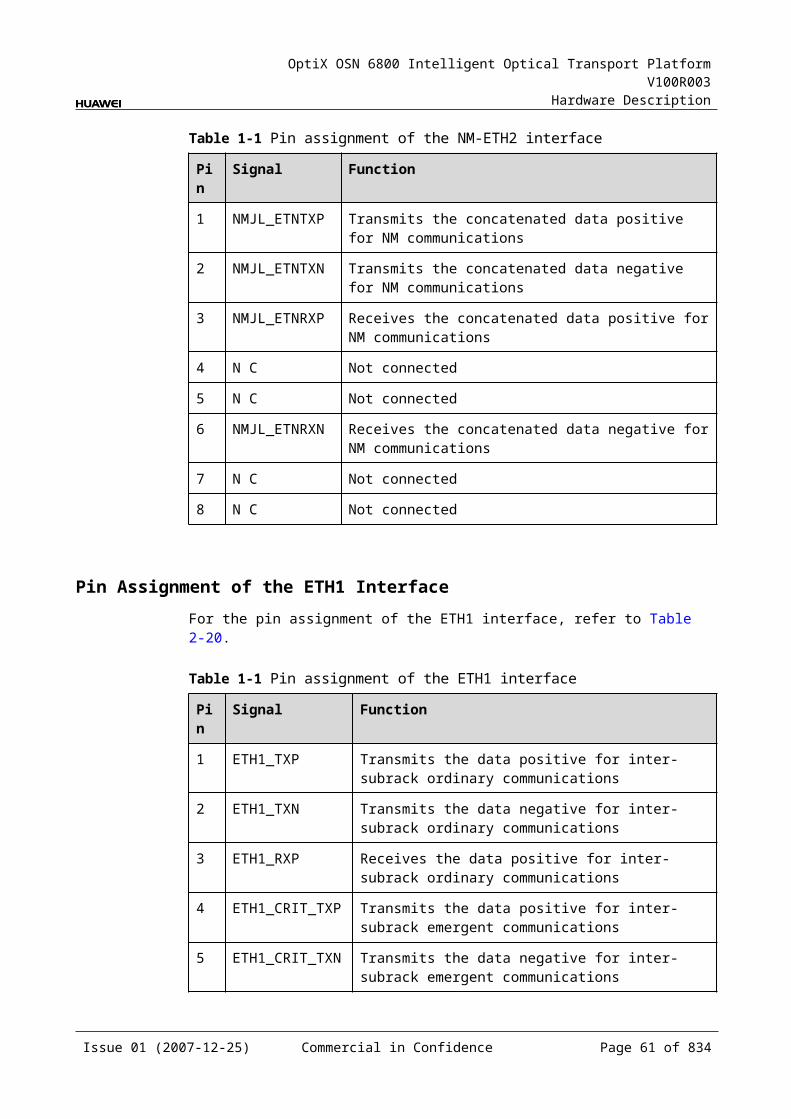
OptiX OSN 6800 Intelligent Optical Transport Platform V100R003
Hardware Description
Table 4-1 Board list
Board category Board name
Board description
Optical transponder unit
ECOM Enhanced communication interface unit
L4G Line wavelength conversion unit with 4xgigabit Ethernet line capacity
LDGS 2 x Gigabit Ethernet unit,single fed and single receiving
LDGD 2 x Gigabit Ethernet unit,dual fed and selective receiving
LOG 8 x Gigabit Ethernet unit
LOM 8-port multi-service multiplexing & optical wavelength conversion board (AFEC)
LQMS 4-channel multi-rate (100Mbit/s-2.5Gbit/s) wavelength conversion unit, single fed and single receiving
LQMD 4-channel multi-rate (100Mbit/s-2.5Gbit/s) wavelength conversion unit, dual fed and selective receiving
LSX 10 Gbit/s wavelength conversion unit
LSXL 40Gbit/s wavelength conversion board
LSXLR 40Gbit/s wavelength conversion relay unit
LSXR 10 Gbit/s wavelength conversion relay unit
LWXS Arbitrary rate (16Mbit/s-2.5Gbit/s) wavelength conversion board (single transmit)
LWXD Arbitrary rate (16Mbit/s-2.5Gbit/s) wavelength conversion board (double transmit)
LWX2 Arbitrary rate (16Mbit/s-2.5Gbit/s) dual-wavelength conversion board
TMX 4 channels STM-16/OTU1 asynchronism mux OTU-2 wavelength conversion board
Optical multiplexer and demultiplexer unit
M40 40-channel multiplexing unit
D40 40-channel demultiplexing unit
M40V 40-channel multiplexing unit with VOA
D40V 40-channel demultiplexing unit with VOA
FIU Fiber interface unit
Issue 01 (2007-12-25) Commercial in Confidence Page 60 of 664
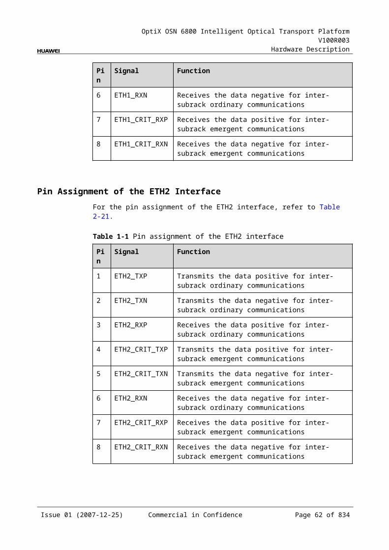
OptiX OSN 6800 Intelligent Optical Transport Platform V100R003
Hardware Description
Board category Board name
Board description
ITL Interleaver Board
Optical add and drop multiplexing unit
MR2 2-channel optical add/drop multiplexing unit
MR4 4-channel optical add/drop multiplexing unit
MR8 8-channel optical add/drop multiplexing unit
CMR2 CWDM 2-channel optical add/drop multiplexing unit
CMR4 CWDM 4-channel optical add/drop multiplexing unit
DMR1 CWDM 1-channel bidirectional optical add/drop multiplexing unit
SBM2 2-channel CWDM single-fiber bi-directional add/drop board
Reconfigurable optical add and drop multiplexing unit
ROAM Reconfigurable optical adding board
WSM9 9-port wavelength selective switching multiplexing board
WSD9 9-port wavelength selective switching demultiplexing board
RMU9 9-Port ROADM multiplexing board
WSMD4 4-Port Wavelength Selective Switching Multiplexer and Demultiplexer Board
Tributary unit TBE 10 Gigabit Ethernet tributary board
TDX 2 x 10G Tributary Service Processing Board
TQM 4 x multi-rate tributary service processing unit
TDG 2 x GE tributary service processing unit
TQS 4 x STM-16/OC-48/OTU1 tributary service processing unit
Line unit NS2 4 x ODU1 multiplexing OTU2 optical interface unit
Cross-connect unit XCS Cross-connect and clock unit
Optical amplifier unit HBA High-power Booster Amplifier Board
OAU1 Optical amplifying unit
OBU1 Optical booster unit
OBU2 Optical booster unit
Issue 01 (2007-12-25) Commercial in Confidence Page 61 of 664
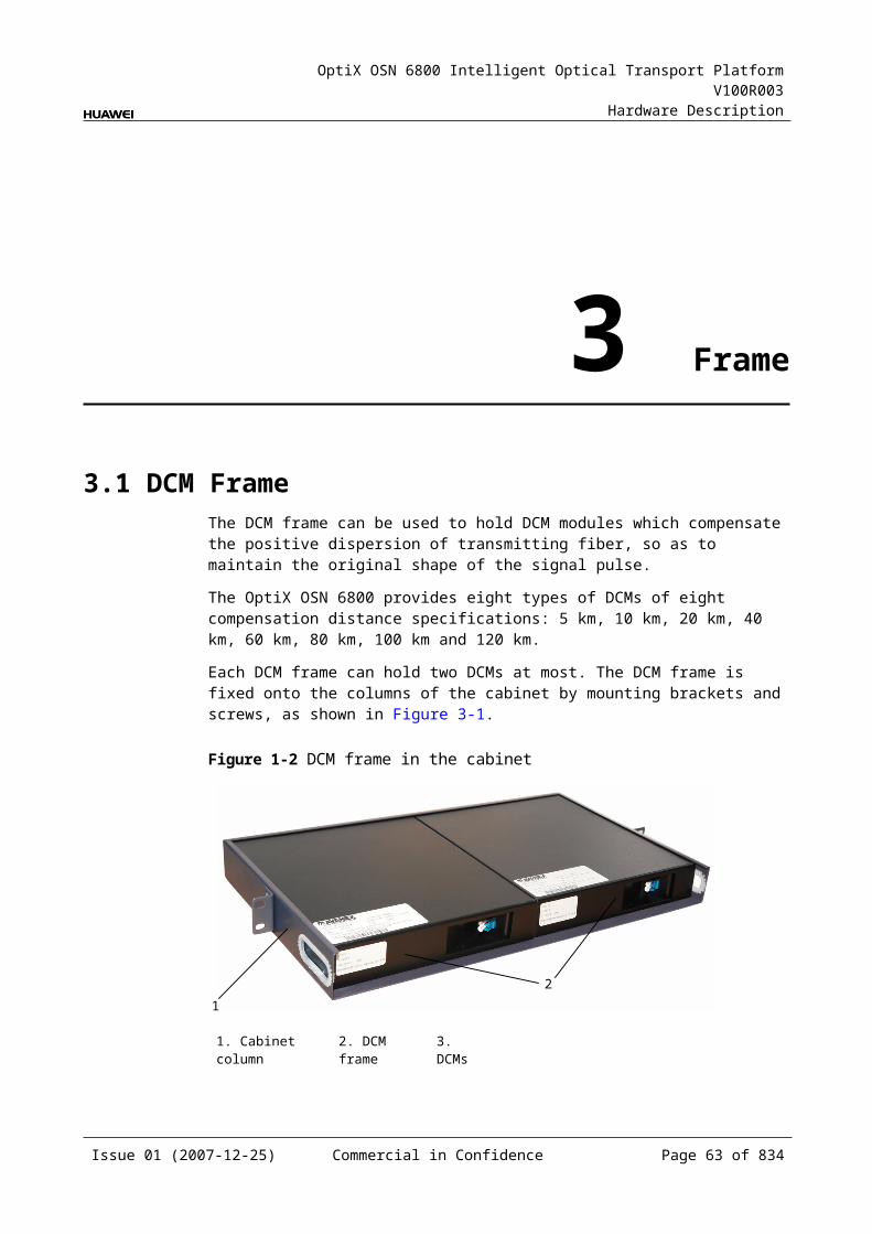
OptiX OSN 6800 Intelligent Optical Transport Platform V100R003
Hardware Description
Board category Board name
Board description
CRPC Case-shape Raman pump amplifier unit for C-band
Optical supervisory channel unit
SC1 Unidirectional optical supervisory channel unit
SC2 Bi-directional optical supervisory channel unit
System control and communication unit
SCC System control and communication Unit
AUX System auxiliary interface unit
Optical protection unit
DCP 2-channel optical path Protection unit
OLP Optical line protection unit
SCS Sync optical channel separator unit
Spectrum analyzer unit
MCA4 4-channel spectrum analyzer unit
MCA8 8-channel spectrum analyzer unit
WMU Wavelength Monitored Unit
Variable optical attenuator unit
VA1 1-channel variable optical attenuator unit
VA4 4-channel variable optical attenuator unit
Dispersion compensation unit
DCU Dispersion Compensation Board
Issue 01 (2007-12-25) Commercial in Confidence Page 62 of 664
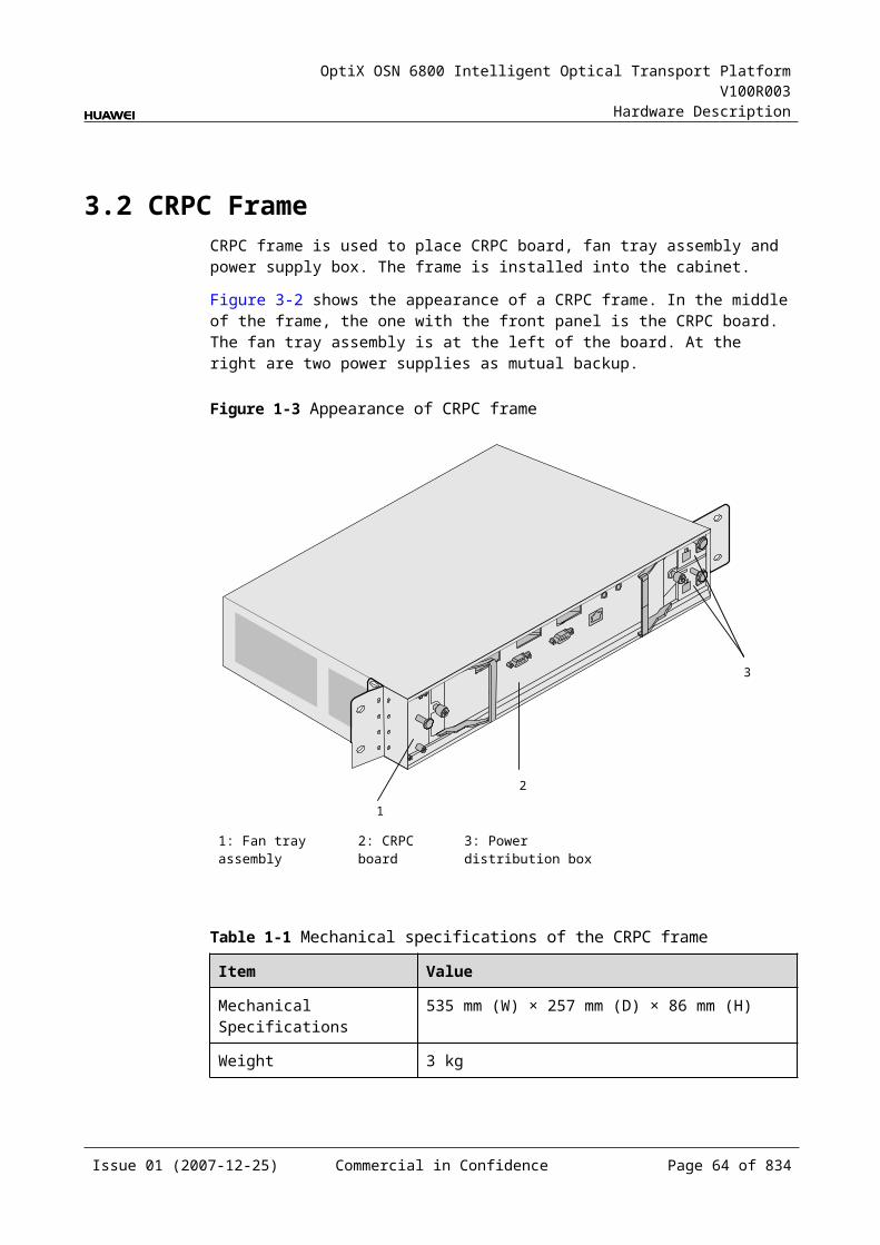
OptiX OSN 6800 Intelligent Optical Transport Platform V100R003
Hardware Description
5 Optical Transponder Unit
5.1 ECOMECOM: enhanced communication interface unit
5.1.1 Version DescriptionOnly one functional version of the ECOM board is available, that is TN11.
5.1.2 ApplicationThe ECOM board is used to achieve the DCN communication between the OptiX OSN 6800 and the OptiX OSN 900A, and to converge/deconverge 8xFE services to/from 1xGE service.
Application Scenario 1: Achieving DCN Communication between the OptiX OSN 6800 and the OptiX OSN 900A
The management signal and service signal of the OptiX OSN 900A are together transmitted to the OptiX OSN 6800 over the line. The FIU board of the OptiX OSN 6800 separates the signal received into management signal and service signal. The service signal is processed by the OTU board. The management signal is accessed by the ECOM board through the FE port and then is transmitted to the SCC board through the backplane.
For the position of the ECOM in the network with the OptiX OSN 6800 and OptiX OSN 900A, see Figure 5-1.
Issue 01 (2007-12-25) Commercial in Confidence Page 63 of 664
OptiX OSN 6800 Intelligent Optical Transport Platform V100R003
Hardware Description
Figure 5-1 Position of the ECOM in the network with the OptiX OSN 6800 and OptiX OSN 900A
ECOM
OptiX OSN900A
Service signalOTU
OTU
6800SCC
ETH×8
OptiX OSN900A
OptiX OSN×8
FIU
FIU
signalManagement
Service signal
signalManagement
NOTEEach FIU board of the OptiX OSN 6800 accesses the signals from only one OptiX OSN 900A.
Application Scenario 2: Converging/Deconverging 8xFE Services to/from 1xGE Services
When used for convergence or deconvergence, the ECOM board can be used only in the CWDM system. For the position of the ECOM in the WDM system, see Figure 5-2.
Figure 5-1 Position of the ECOM in the WDM system
MUX
DMUX
ECOM ECOM
1
8
1
8
FE
Client side
GE GE
FE
GEGE
Client side
DMUX
MUX
5.1.3 Functions and FeaturesThe main functions and features supported by the ECOM are cross-connection at the electrical layer and wavelength tunable.
For detailed functions and features, refer to Table 5-1.
Issue 01 (2007-12-25) Commercial in Confidence Page 64 of 664
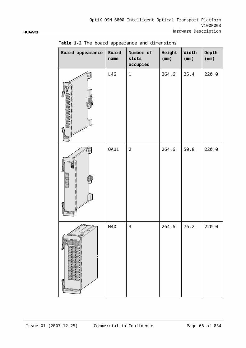
OptiX OSN 6800 Intelligent Optical Transport Platform V100R003
Hardware Description
Table 5-1 Functions and features of the ECOM
Function and Feature
Description
Basic function Achieves the DCN communication between the OptiX OSN 6800and the OptiX OSN 900A.
Converges/deconverges 8xFE services to/from 1xGE services.
Client-side service type
FE
WDM specification Supports the CWDM specifications.
Cross-connect capabilities
Supports the transmission of one GE signal each to working/protection cross-connection boards respectively through the backplane. Supports the transmission of one GE signal to the paired slots through the backplane.
Tunable wavelength function
Not Supported
Alarms and performance events monitoring
Provides remote monitoring (RMON) of the Ethernet service.
Provides the function of optical power detection and the function to report the alarms and performance events of the board.
ALS function Not Supported
eSFP Supports the enhanced small form-factor pluggable optical module on the client side.
Loopback WDM side Inloop Supported
Outloop Not Supported
Client side Inloop Supported
Outloop Supported
5.1.4 Working Principle and Signal FlowThe ECOM consists of the client-side optical module, WDM-side optical module, L2 module, cross-connect module, and control and communication module.
Figure 5-3 shows the functional modules and signal flow of the ECOM.
Issue 01 (2007-12-25) Commercial in Confidence Page 65 of 664
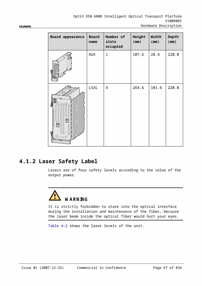
OptiX OSN 6800 Intelligent Optical Transport Platform V100R003
Hardware Description
Figure 5-1 Functional modules and signal flow of the ECOM
SCC
8L2
module
RX1TX1RX8TX8
FE
INOUT
GE
FE
Cross-connectmodule
GEBackplane
Client-side
opticalmodule
WDM-side
opticalmodule
Control and communication module
In Transmit DirectionThe client-side optical module receives FE service signals. These FE signals are converted into electrical signals and sent to the L2 module.
The L2 module:
Sends the eight FE signals to the backplane. When the ECOM is used as an convergence board, the L2 module converges
the eight FE signals into one GE signal with a maximum bandwidth of 1.25 Gbit/s and sends it to the cross-connect module.
The cross-connect module:
Sends one GE signal to a WDM-side optical module. Sends one GE signals to cross-connection board or a board in the paired slot
through the backplane to realize the grooming of electrical signals. Receives the electrical signals sent from cross-connection board or a board in
the paired slot through the backplane, multiplexes the signals into one GE signal, and sends the signal to a WDM-side optical module.
The WDM-side optical module converts the electrical signal into the GE optical signal, and sends the optical signal to the WDM side.
In Receive DirectionThe WDM-side optical module receives one GE optical signal, converts it into an electrical signal, and sends the converted signal to the cross-connect and service processing module.
The cross-connect module:
Sends the GE signal to the L2 module. Sends the GE signal to cross-connection board or a board in the paired slot
through the backplane to realize the grooming of electrical signals. Receives the electrical signal sent from cross-connection board or a board in the
paired slot through the backplane and sends the signal to the L2 module.
Issue 01 (2007-12-25) Commercial in Confidence Page 66 of 664
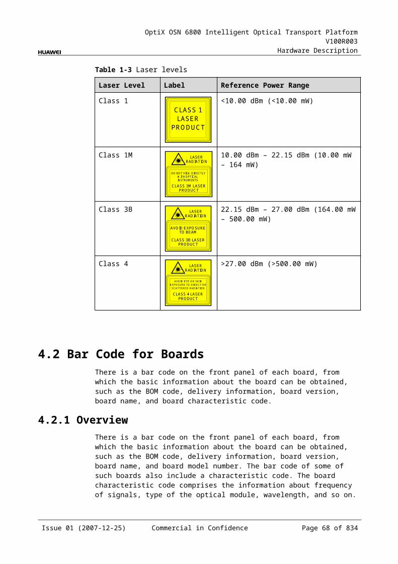
OptiX OSN 6800 Intelligent Optical Transport Platform V100R003
Hardware Description
The L2 module:
Demultiplexes the GE signal and sends the signals to the client-side optical module.
Sends the FE signals transmitted from the backplane to the corresponding FE port on the client-side optical module according to the VLAN ID.
The client-side optical module converts the electrical signals into optical signals and sends the converted signals to the client-side equipment by TXn.
Cross-Connect Module This module realizes the grooming of electrical signals between the ECOM and
the board in the paired slot or the cross-connect board through the backplane. The grooming service signals are GE signals. This module realizes the cross-connection of one service signal each through
the working/protection cross-connection boards respectively. This module realizes the cross-connection of one service signal between the
boards in paired slots.
Control and Communication ModuleThe control and communication module realizes the control, monitoring and communications management of each functional module of the board.
The control and communication module collects the information, such as the alarms and performance events, working status, and voltage detection, of each functional module of the board and reports to the SCC.
Receiving the commands from the SCC, the control and communication module controls and coordinates the functional modules of the board in working.
5.1.5 Front PanelThere are indicators, interfaces and laser safety label on the ECOM front panel.
Appearance of the Front PanelFigure 5-4 shows the ECOM front panel.
Issue 01 (2007-12-25) Commercial in Confidence Page 67 of 664
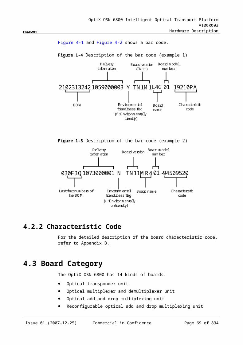
OptiX OSN 6800 Intelligent Optical Transport Platform V100R003
Hardware Description
Figure 5-1 ECOM front panel
ECOM
ECOM
STATACTPROGSRV
CLASS 1LASER
PRODUCT
TX2
RX
2TX
3R
X3
TX4
RX
4TX
5R
X5
TX6
RX
6TX
1R
X1
INO
UT
TX7
RX
7TX
8R
X8
IndicatorsThere are four indicators on the front panel.
Board hardware status indicator (STAT) – dual-colored (red, green) Service active status indicator (ACT) – green Board software status indicator (PROG) – dual-colored (red, green) Service alarm indicator (SRV) – triple-colored (red, green, yellow)
InterfacesThere are 18 optical interfaces on the ECOM front panel. Table 5-2 lists the type and function of each interface.
Issue 01 (2007-12-25) Commercial in Confidence Page 68 of 664
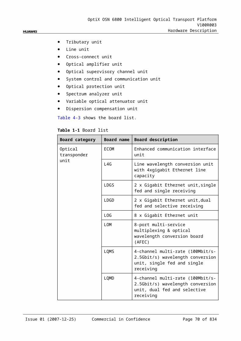
OptiX OSN 6800 Intelligent Optical Transport Platform V100R003
Hardware Description
Table 5-1 Types and functions of the ECOM interfaces
Interface
Type
Function
IN LC Receives the single-channel signal from the optical demultiplexer unit or the optical add and drop multiplexing unit.
OUT LC Transmits the single-channel signal to the optical multiplexer unit or the optical add and drop multiplexing unit.
TX1-TX8 LC Transmits the service signal to the client-side equipment.
RX1-RX8 LC Receives the service signal from the client-side equipment.
Laser Safety LevelThe laser safety level of the optical interface is CLASS 1.
The maximum output optical power of each optical interface is lower than 10 dBm (10 mW).
5.1.6 Valid SlotsThe ECOM occupies one slot. The valid slots for the ECOM are IU1–IU8 and IU11–IU16.
5.1.7 NM Configuration ReferenceNM configuration reference includes the reference information needed during the configuration of boards through the T2000.
Display of Optical InterfacesThe serial numbers of the optical interfaces on the panel of the board displayed on the NM are listed in Table 5-3.
Table 5-1 Serial numbers of the interfaces of the ECOM displayed on the NM
Interface on the Panel Interface on the NM
IN/OUT 1
TX1/RX1 3
TX2/RX2 4
TX3/RX3 5
TX4/RX4 6
TX5/RX5 7
TX6/RX6 8
TX7/RX7 9
Issue 01 (2007-12-25) Commercial in Confidence Page 69 of 664
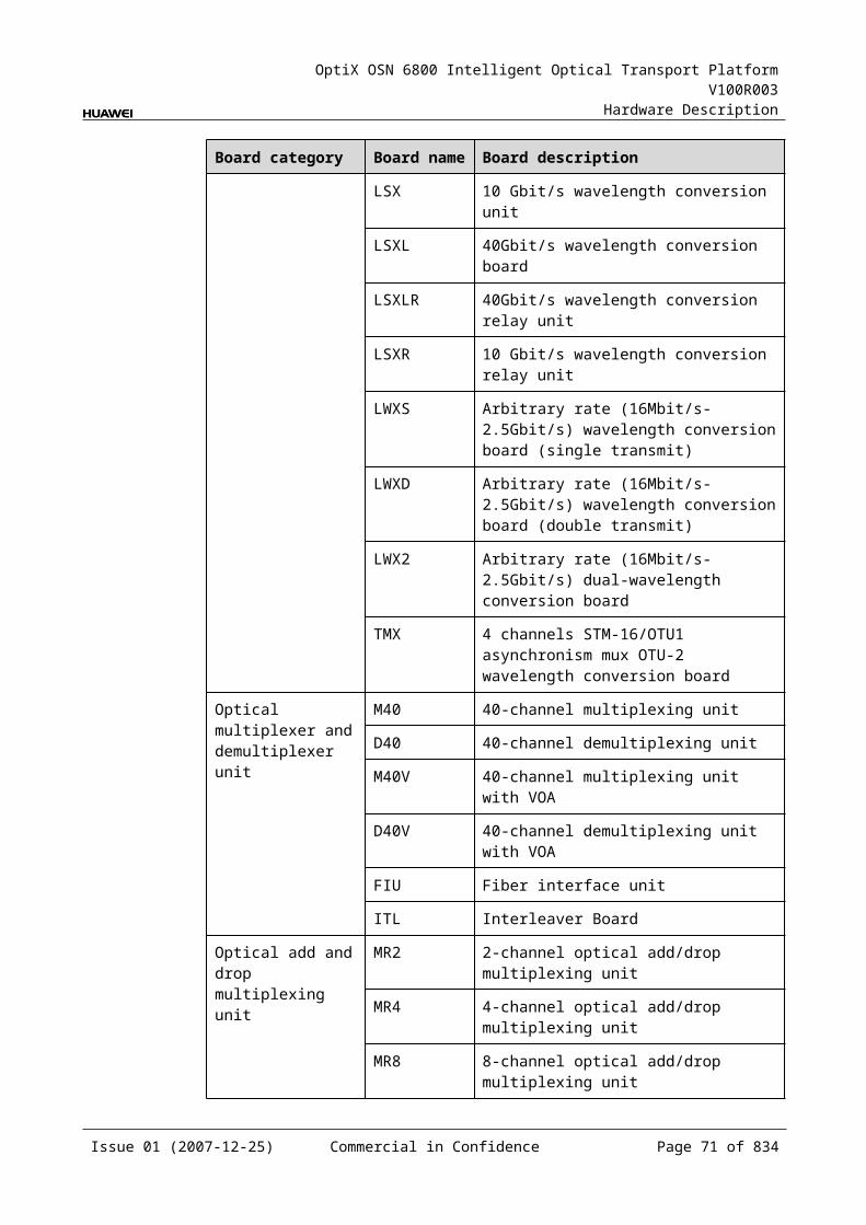
OptiX OSN 6800 Intelligent Optical Transport Platform V100R003
Hardware Description
Interface on the Panel Interface on the NM
TX8/RX8 10
NOTEThe number of an interface displayed on the T2000 in fact indicates a pair of physical optical interfaces, of which one is used to transmit signals and the other is used to receive signals.
Configuration ParametersPath Use Status
Optical Interface Loopback
Laser Status
Configure Wavelength No./Wavelength (nm)/Frequency (THz)
Configure Band Type
LPT Enabled
5.1.8 Specifications of the ECOMSpecifications include optical specifications, dimensions, weight, and power consumption.
Specifications of Optical Module at the Client Side
Table 5-1 Specifications of optical module at the client side(FE)
Item Unit
Value
Optical Module Type 100BASE-FX1310 nm
100BASE-FX1310 nm
Line code format – NRZ NRZ
Target distance km 40 2
Transmitter parameter specifications at point S
Maximum mean launched power
dBm 0 –14
Minimum mean launched power
dBm –5 –19
Minimum extinction ratio dB 10 10
Operating wavelength range
nm 1310 1310
Eye pattern mask – IEEE802.3z-compliant IEEE802.3z-compliant
Issue 01 (2007-12-25) Commercial in Confidence Page 70 of 664
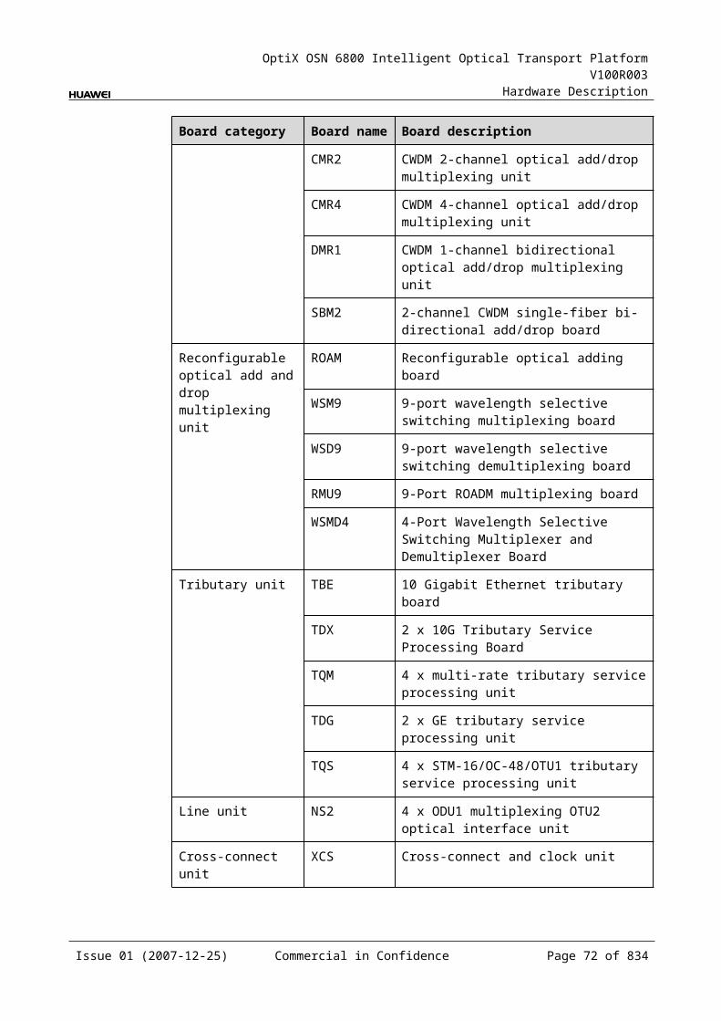
OptiX OSN 6800 Intelligent Optical Transport Platform V100R003
Hardware Description
Item Unit
Value
Optical Module Type 100BASE-FX1310 nm
100BASE-FX1310 nm
Receiver parameter specifications at point R
Receiver type – PIN PIN
Receiver sensitivity(EOL) dBm –30 –30
Minimum receiver overload
dBm –10 –14
Table 5-2 Specifications of eSFP CWDM optical module at the client side(FE)
Item Unit
Value
Optical Module Type
1.25Gbit/s Multi-rate (eSFP CWDM)
2.67Gbit/s Multi-rate (eSFP CWDM)
Line code format – NRZ NRZ
Target distance km 40 80
Transmitter parameter specifications at point S
Maximum mean launched power
dBm 5 5
Minimum mean launched power
dBm 0 0
Minimum extinction ratio
dB 9 8.2
Operating wavelength range
nm 1471 to 1611 1471 to 1611
Central wavelength deviation
nm ±6.5 ±6.5
Maximum –20 dB spectral width
nm 1.0 1.0
Minimum side mode suppression ratio
dB 30 30
Eye pattern mask – IEEE802.3z-compliant G.957-compliant
Receiver parameter specifications at point R
Receiver type – PIN APD
Operating wavelength range
nm 1270 to 1620 1270 to 1620
Issue 01 (2007-12-25) Commercial in Confidence Page 71 of 664
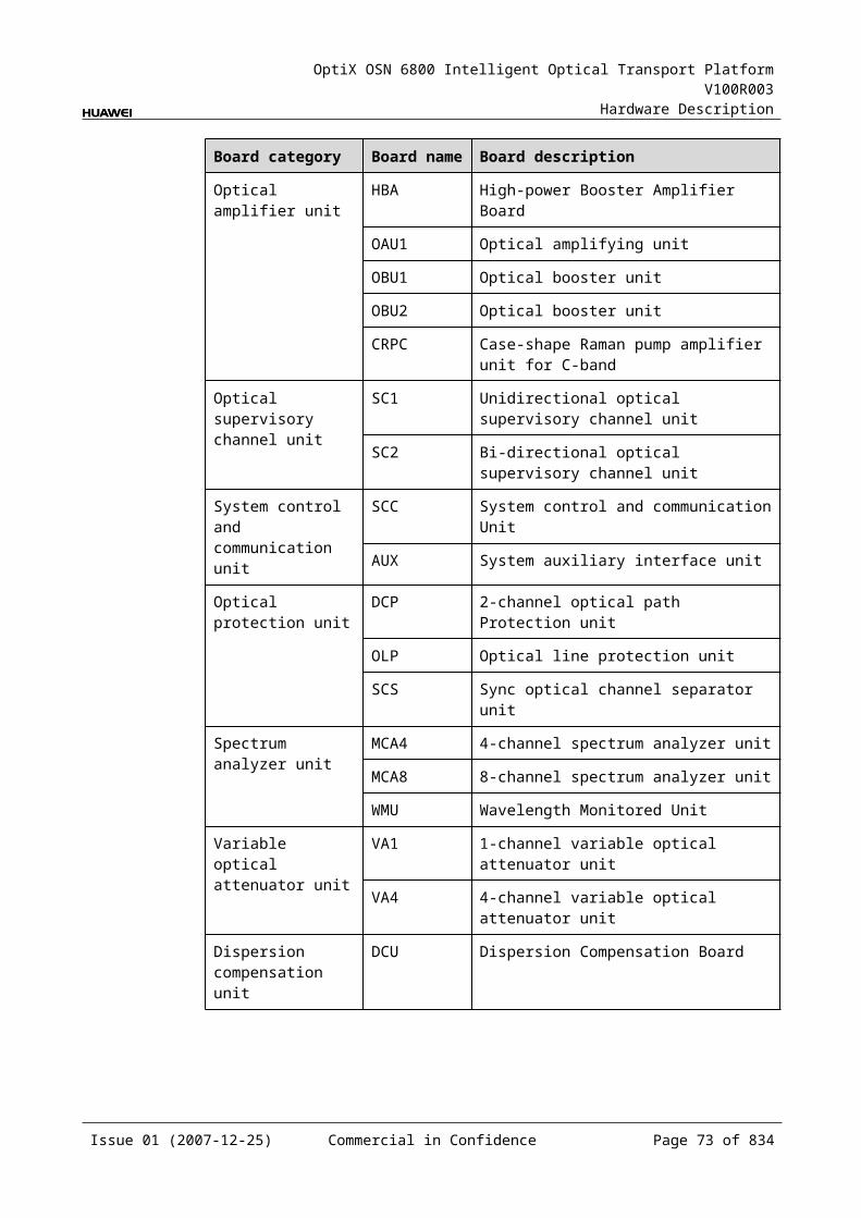
OptiX OSN 6800 Intelligent Optical Transport Platform V100R003
Hardware Description
Item Unit
Value
Optical Module Type
1.25Gbit/s Multi-rate (eSFP CWDM)
2.67Gbit/s Multi-rate (eSFP CWDM)
Receiver sensitivity dBm -19 –28
Minimum receiver overload
dBm -3 –9
Maximum reflectance
dB –27 –27
Specifications of Optical Module at the CWDM Side
Table 5-1 Specifications of eSFP CWDM optical module at the CWDM side
Item Unit
Value
Optical Module Type
1.25Gbit/s Multi-rate (eSFP CWDM)
2.67Gbit/s Multi-rate (eSFP CWDM)
Line code format – NRZ NRZ
Target distance km 40 80
Transmitter parameter specifications at point S
Operating wavelength range
nm 1471 to 1611 1471 to 1611
Maximum mean launched power
dBm 5 5
Minimum mean launched power
dBm 0 0
Minimum extinction ratio
dB 9 8.2
Central wavelength deviation
nm ±6.5 ±6.5
Maximum –20 dB spectral width
nm 1 1
Minimum side mode suppression ratio
dB 30 30
Eye pattern mask – IEEE802.3z-compliant G.957-compliant
Receiver parameter specifications at point R
Receiver type – PIN APD
Issue 01 (2007-12-25) Commercial in Confidence Page 72 of 664
OptiX OSN 6800 Intelligent Optical Transport Platform V100R003
Hardware Description
Item Unit
Value
Optical Module Type
1.25Gbit/s Multi-rate (eSFP CWDM)
2.67Gbit/s Multi-rate (eSFP CWDM)
Operating wavelength range
nm 1270 to 1620 1270 to 1620
Receiver sensitivity dBm -19 –28
Minimum receiver overload
dBm -3 –9
Maximum reflectance
dB –27 –27
Mechanical Specifications Dimensions of board (PCB): 245.1 mm (H) x 220 mm (D) x 2 mm (T) Dimensions of front panel: 264.6 mm (H) x 25.4 mm (W) Weight: 2.43 lb (1.01 kg)
Power Consumption The maximum power consumption at 25 : 19.6 W The maximum power consumption at 55 : 21.6 W
5.2 L4GL4G: line wavelength conversion unit with 4xGigabit Ethernet line capacity
5.2.1 Version DescriptionOnly one functional version of the L4G board is available, that is TN11.
5.2.2 ApplicationThe L4G is a type of optical transponder unit. The L4G realizes the conversion between six GE signals and ITU-T Recommendation-compliant WDM signals.
For the position of the L4G in the WDM system, see Figure 5-5.
Issue 01 (2007-12-25) Commercial in Confidence Page 73 of 664
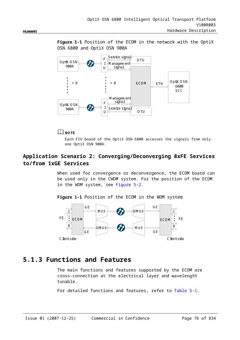
OptiX OSN 6800 Intelligent Optical Transport Platform V100R003
Hardware Description
Figure 5-1 Position of the L4G in the WDM system
Client side WDM side
MUX
DMUX
L4G
DMUX
MUX
L4G
1
6
1
6
G.694.1 G.694.1
GE
GE GE
GE
WDM side Client side
NOTEThe client-side six pairs of optical interfaces can access services at a maximum rate of 5 Gbit/s.
5.2.3 Functions and FeaturesThe main functions and features supported by the L4G are wavelength conversion, cross-connection at the electrical layer, OTN interfaces and ESC.
For detailed functions and features, refer to Table 5-7.
Table 5-1 Functions and features of the L4G
Function and Feature
Description
Basic function Converges up to six non-full bandwidth GE service signals into four GE service signals and multiplexes these four signals into an OTU 5G/FEC 5G signal. Converts the signals into standard DWDM wavelength compliant with ITU-T G.694.1 or the standard CWDM wavelength compliant with ITU-T G.694.2. The reverse process is similar.
Client-side service type
GE
Cross-connect capabilities
Supports the grooming of four channels of GE services each to working/protection cross-connection boards respectively through the backplane. Supports the transmission of four GE signals to the paired slots through the backplane.
OTN function Provides the OTU5G interface on WDM-side. Supports the mapping of GE signals into OTU1 signals. Supports SM and PM functions for OTU5G and ODU5G. Supports TCM function for ODU5G.
WDM specification
Supports the DWDM and CWDM specifications.
Tunable wavelength function
Supports the tunable wavelength optical module. Equipped with this module, the board can tune the optical signal output at the WDM side within the range of the 40 wavelengths in C-band with the channel spacing of 100 GHz.
Issue 01 (2007-12-25) Commercial in Confidence Page 74 of 664
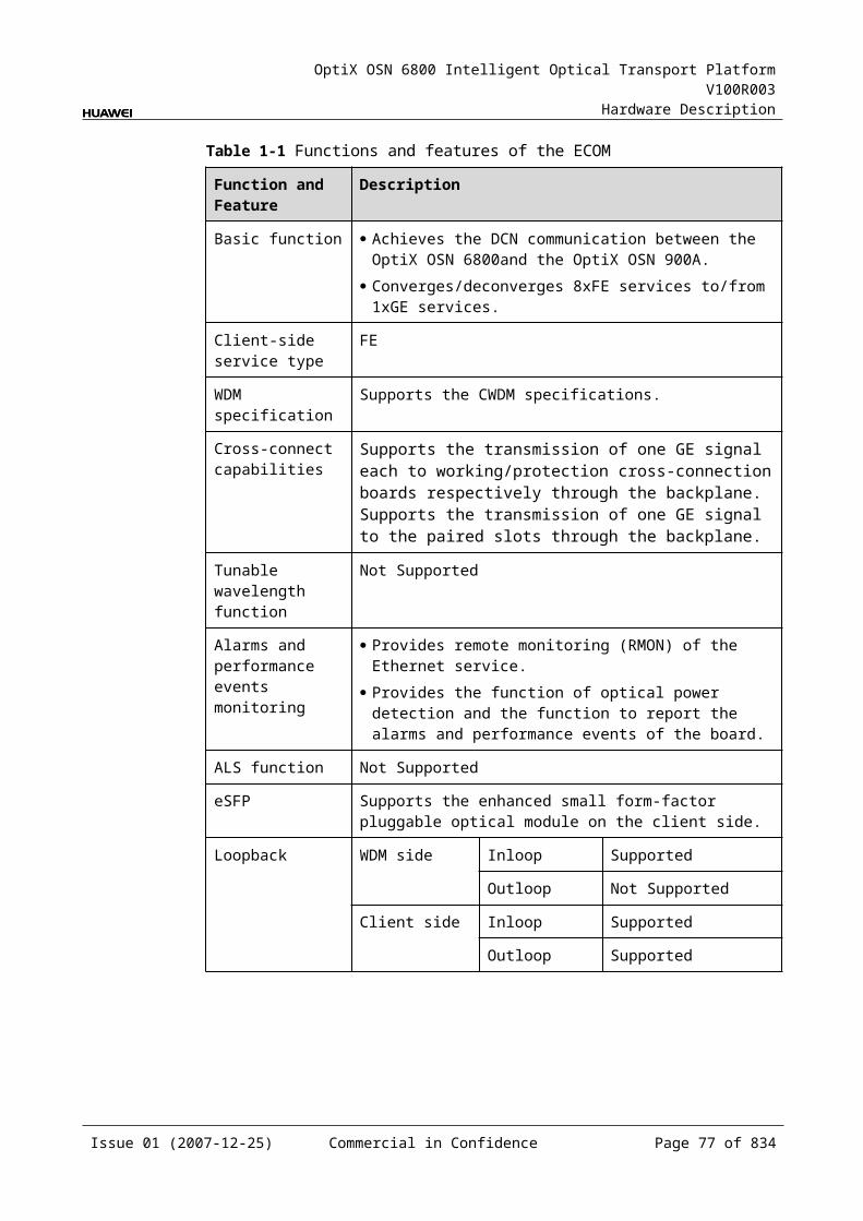
OptiX OSN 6800 Intelligent Optical Transport Platform V100R003
Hardware Description
Function and Feature
Description
ESC function Supports the ESC function, transmitting the supervisory signal within the service signal.
FEC encoding Adopts FEC encoding compliant with the ITU-T G.975.
Alarms and performance events monitoring
Provides the monitoring of the BIP8 bit error count so as to help to locate the failures of the line.
Provides the WDM-side monitoring of the items such as the bias current and temperature of the laser as well as the optical power.
Supports the monitoring of the alarms and performance events of the OTN.
ALS function Provides the ALS function. With the ALS function enabled, the corresponding optical output laser is automatically shut down if no signals are received.
Protection scheme
Supports the SW SNCP. Supports the VLAN SNCP. Supports the client-side 1+1 protection. Supports the intra-board 1+1 protection. Supports the OWSP protection.
eSFP Supports the enhanced small form-factor pluggable optical module on the client side.
Loopback WDM side Inloop Supported
Outloop Supported
Client side MAC Supported
PHY Supported
5.2.4 Working Principle and Signal FlowThe L4G consists of the client-side optical module, WDM-side optical module, L2 module, cross-connect and service processing module, control and communication module.
Figure 5-6 shows the functional modules and signal flow of the L4G.
Issue 01 (2007-12-25) Commercial in Confidence Page 75 of 664
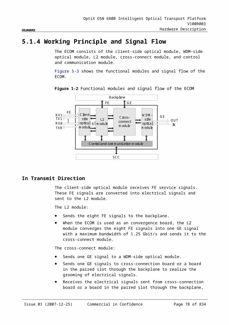
OptiX OSN 6800 Intelligent Optical Transport Platform V100R003
Hardware Description
Figure 5-1 Functional modules and signal flow of the L4G
OTN 5G
WDM-side
opticalmodule
Control and communication module
SCC
Client side WDM sideBackplane
GE
Cross-connect and
serviceprocessing
module
Client-side
opticalmodule
6
6
L2module
4
4
GE
GE
OTU 5G/FEC 5G
OTU 5G/FEC 5G
RX1
TX1
OUT
IN
RX6
TX6
In Transmit DirectionThe client-side optical module receives a maximum of six non-full bandwidth GE service signals. These GE signals are converted into electrical signals and sent to the L2 module.
The L2 module converges the six signals into four GE signals with a maximum bandwidth of 1.25 Gbit/s and sends them to the cross-connect and service processing module.
The cross-connect and service processing module monitors the performance of client-side services, then
Multiplexes the four signals into one OTU 5G/FEC 5G signal and sends the signal to a WDM-side optical module, or
Sends the four signals to cross-connection board or a board in the paired slot through the backplane to realize the grooming of electrical signals, or
Receives the electrical signals sent from cross-connection board or a board in the paired slot through the backplane, multiplexes the signals into one OTU 5G/FEC 5G signal, and sends the signal to a WDM-side optical module.
The WDM-side optical module converts the OTN electrical signal into the OTN optical signal, ITU-T Recommendation-compliant DWDM signal, and sends the optical signal to the WDM side.
In Receive DirectionThe WDM-side optical module receives an OTU 5G/FEC 5G optical signal, converts it into an electrical signal, and sends the converted signal to the cross-connect and service processing module.
The cross-connect and service processing module extracts and processes the overhead bytes, monitors the WDM-side performance, and demultiplexes the OTN optical signal into four 1.25 Gbit/s GE signals. Then, this module
Sends the four signals to the L2 module, or
Issue 01 (2007-12-25) Commercial in Confidence Page 76 of 664
OptiX OSN 6800 Intelligent Optical Transport Platform V100R003
Hardware Description
Sends the four signals to cross-connection board or a board in the paired slot through the backplane to realize the grooming of electrical signals, or
Receives the electrical signal sent from cross-connection board or a board in the paired slot through the backplane and sends the signal to the L2 module.
The L2 module demultiplexes the four signals into six client-side signals of corresponding rates and sends the signals to the client-side optical module.
The client-side optical module converts the six electrical signals into optical signals and sends the converted signals to the client-side equipment.
Cross-Connect and Service Processing Module This module realizes the grooming of electrical signals between the L4G and the
board in the paired slot or the cross-connect board through the backplane. The grooming service signals are GE signals. This module realizes the cross-connection of four service signals each through
the working/protection cross-connection boards respectively. This module realizes the cross-connection of four service signals between the
boards in paired slots. This module extracts and processes overhead bytes. This module monitors the performance of services. This module multiplexes and demultiplexes services. This module implements the encapsulation of OTN signals.
Control and Communication ModuleThe control and communication module realizes the control, monitoring and communications management of each functional module of the board.
The control and communication module collects the information, such as the alarms and performance events, working status, and voltage detection, of each functional module of the board and reports to the SCC.
Receiving the commands from the SCC, the control and communication module controls and coordinates the functional modules of the board in working.
5.2.5 Front PanelThere are indicators, interfaces and laser safety label on the L4G front panel.
Appearance of the Front PanelFigure 5-7 shows the L4G front panel.
Issue 01 (2007-12-25) Commercial in Confidence Page 77 of 664
OptiX OSN 6800 Intelligent Optical Transport Platform V100R003
Hardware Description
Figure 5-1 L4G front panel
L4G
L4G
STATACTPROGSRV
CLASS 1LASER
PRODUCT
TX2
RX
2TX
3R
X3
TX4
RX
4TX
5R
X5
TX6
RX
6O
UT
INTX
1R
X1
IndicatorsThere are four indicators on the front panel.
Board hardware status indicator (STAT) – dual-colored (red, green) Service active status indicator (ACT) – green Board software status indicator (PROG) – dual-colored (red, green) Service alarm indicator (SRV) – triple-colored (red, green, yellow)
InterfacesThere are 14 optical interfaces on the L4G front panel. Table 5-8 lists the type and function of each interface.
Issue 01 (2007-12-25) Commercial in Confidence Page 78 of 664

OptiX OSN 6800 Intelligent Optical Transport Platform V100R003
Hardware Description
Table 5-1 Types and functions of the L4G interfaces
Interface
Type
Function
IN LC Receives the single-channel signal from the optical demultiplexer unit or the optical add and drop multiplexing unit.
OUT LC Transmits the single-channel signal to the optical multiplexer unit or the optical add and drop multiplexing unit.
TX1–TX6 LC Transmits the service signal to the client-side equipment.
RX1–RX6 LC Receives the service signal from the client-side equipment.
Laser Safety LevelThe laser safety level of the optical interface is CLASS 1.
The maximum output optical power of each optical interface is lower than 10 dBm (10 mW).
5.2.6 Valid SlotsThe L4G occupies one slot. The valid slots for the L4G are IU1–IU8 and IU11–IU16.
5.2.7 Characteristic Code for the L4GThe board characteristic code comprises the information about frequency of signals, type of the optical module, wavelength, and so on.
For the detailed description of the characteristic code for the board, refer to B.2 Characteristic Code for OTUs.
5.2.8 NM Configuration ReferenceNM configuration reference includes the reference information needed during the configuration of boards through the T2000.
Display of Optical InterfacesThe serial numbers of the optical interfaces on the panel of the board displayed on the NM are listed in Table 5-9.
Table 5-1 Serial numbers of the interfaces of the L4G displayed on the NM
Interface on the Panel Interface on the NM
IN/OUT 1
TX1/RX1 3
TX2/RX2 4
TX3/RX3 5
Issue 01 (2007-12-25) Commercial in Confidence Page 79 of 664
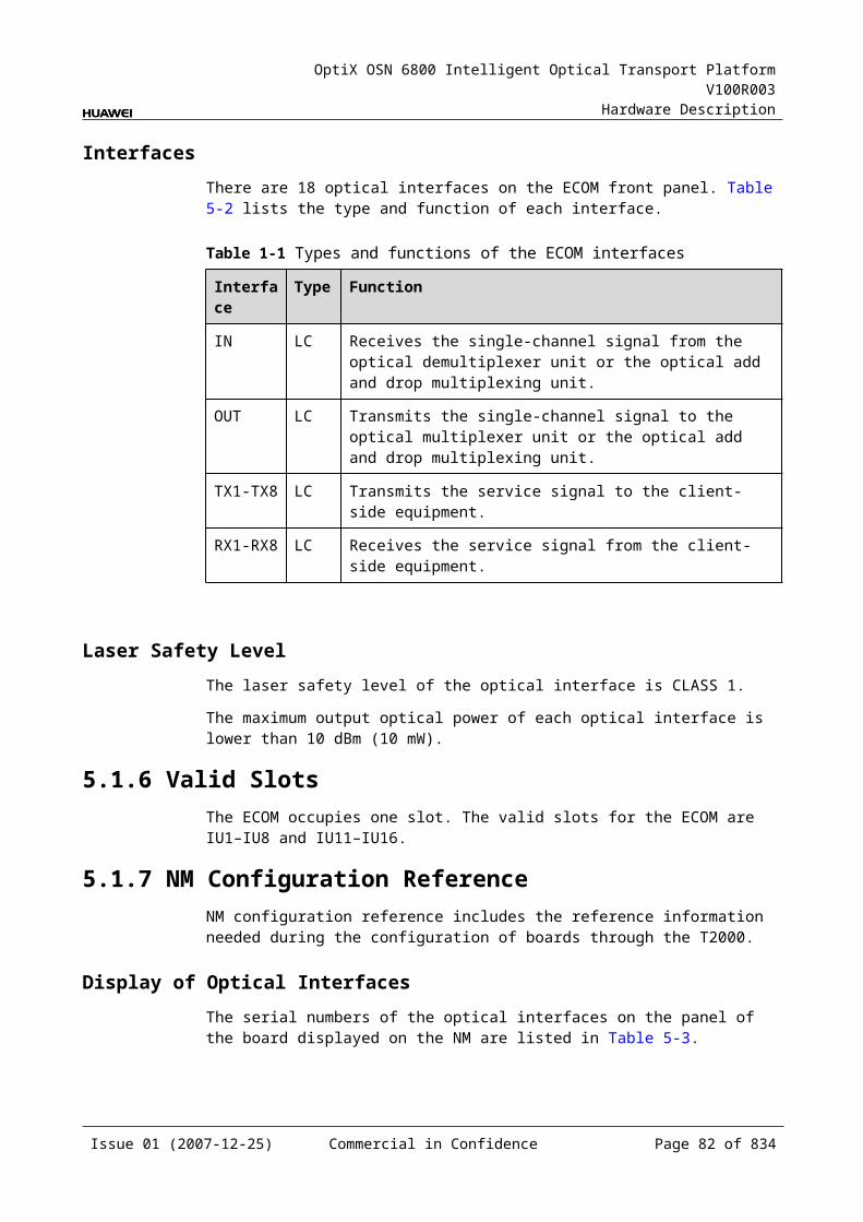
OptiX OSN 6800 Intelligent Optical Transport Platform V100R003
Hardware Description
Interface on the Panel Interface on the NM
TX4/RX4 6
TX5/RX5 7
TX6/RX6 8
NOTEThe number of an interface displayed on the T2000 in fact indicates a pair of physical optical interfaces, of which one is used to transmit signals and the other is used to receive signals.
Configuration ParametersPath Use Status
Optical Interface Loopback
Laser Status
Automatic Laser Shutdown
Service Mode
FEC Working State
Configure Wavelength No./Wavelength (nm)/Frequency (THz)
Configure Band Type
LPT Enabled
5.2.9 Specifications of the L4GSpecifications include optical specifications, dimensions, weight, and power consumption.
Specifications of Optical Module at the Client Side
Table 5-1 Specifications of GE optical module at the client side
Item Unit Value
Optical Module Type
2.125 Gbit/s Multi-rate
1000 BASE-LX-10 km
1000 BASE-LX-40 km
1000 BASE-ZX-80 km
Line code format – NRZ NRZ NRZ NRZ
Target distance km 0.5 10 40 80
Transmitter parameter specifications at point S
Issue 01 (2007-12-25) Commercial in Confidence Page 80 of 664
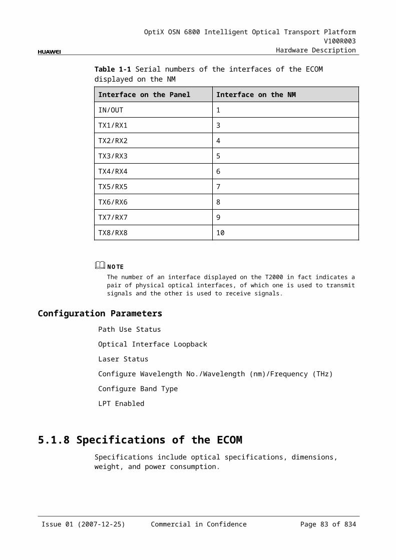
OptiX OSN 6800 Intelligent Optical Transport Platform V100R003
Hardware Description
Item Unit Value
Optical Module Type
2.125 Gbit/s Multi-rate
1000 BASE-LX-10 km
1000 BASE-LX-40 km
1000 BASE-ZX-80 km
Operating wavelength range
nm 830 to 860 1270 to 1355 1270 to 1355 1500 to 1580
Maximum mean launched power
dBm –2.5 –3 0 5
Minimum mean launched power
dBm –9.5 –11.5 –4.5 –2
Minimum extinction ratio dB 9 9 9 9
Eye pattern mask – IEEE802.3z-compliant
Receiver parameter specifications at point R
Receiver type – PIN PIN PIN PIN
Operating wavelength range
nm 770 to 860 1270 to 1355 1270 to 1355 1500 to 1580
Receiver sensitivity dBm –17 –19 –20 –22
Minimum receiver overload
dBm 0 –3 –3 –3
Specifications of eSFP CWDM Optical Module at the Client Side
Table 5-1 Specifications of eSFP CWDM optical module at the client side
Item Unit
Value
Optical Module Type
1.25Gbit/s Multi-rate (eSFP CWDM)-40km
1.25Gbit/s Multi-rate (eSFP CWDM)-80km
Line code format – NRZ NRZ
Target distance km 40 80
Transmitter parameter specifications at point S
Operating wavelength range
nm 1471 to 1611 1471 to 1611
Maximum mean launched power
dBm 5 5
Minimum mean launched power
dBm 0 0
Issue 01 (2007-12-25) Commercial in Confidence Page 81 of 664
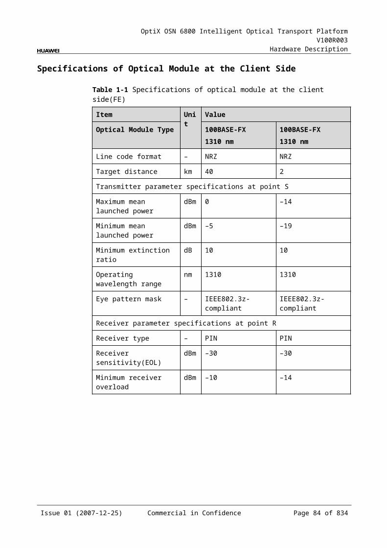
OptiX OSN 6800 Intelligent Optical Transport Platform V100R003
Hardware Description
Item Unit
Value
Optical Module Type
1.25Gbit/s Multi-rate (eSFP CWDM)-40km
1.25Gbit/s Multi-rate (eSFP CWDM)-80km
Minimum extinction ratio
dB 9 8.2
Central wavelength deviation
nm ±6.5 ±6.5
Maximum –20 dB spectral width
nm 1.0 1.0
Minimum side mode suppression ratio
dB 30 30
Eye pattern mask – IEEE802.3z-compliant
Receiver parameter specifications at point R
Receiver type – PIN APD
Operating wavelength range
nm 1270 to 1620 1270 to 1620
Receiver sensitivity dBm –19 –28
Minimum receiver overload
dBm –3 –9
Maximum reflectance
dB –27 –27
Specifications of Optical Module at the DWDM Side
Table 5-1 Specifications of optical module at the DWDM side
Item Unit Value
Optical Module Type 3400 ps/nm
6400 ps/nm
3400 ps/nm- tunable
Line code format – NRZ NRZ NRZ
Transmitter parameter specifications at point S
Maximum mean launched power
dBm 2 –1 4
Minimum mean launched power
dBm –2 –5 0
Minimum extinction ratio dB 10 10 10
Central frequency THz 192.10 to 196.00
Issue 01 (2007-12-25) Commercial in Confidence Page 82 of 664
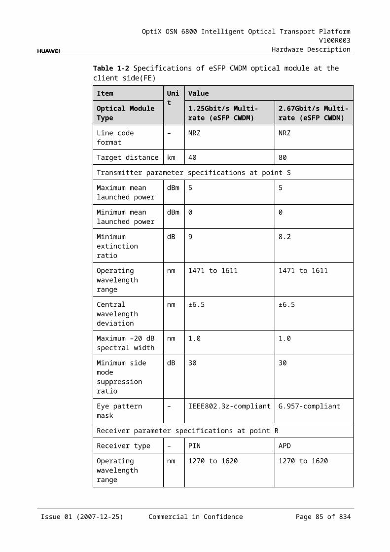
OptiX OSN 6800 Intelligent Optical Transport Platform V100R003
Hardware Description
Item Unit Value
Optical Module Type 3400 ps/nm
6400 ps/nm
3400 ps/nm- tunable
Central frequency deviation GHz ±10
Maximum –20 dB spectral width
nm 0.3 0.3 0.3
Minimum side mode suppression ratio
dB 35 35 35
Dispersion tolerance ps/nm 3400 6400 3400
Receiver parameter specifications at point R
Receiver type – APD APD APD
Operating wavelength range nm 1200 to 1650
Receiver sensitivity dBm –25 –25 –25
Minimum receiver overload dBm –9 –9 –9
Maximum reflectance dB –27 –27 –27
Specifications of Optical Module at the CWDM Side
Table 5-1 Specifications of optical module at the CWDM side
Item Unit Value
Optical Module Type 5G CWDM
Line code format – NRZ
Transmitter parameter specifications at point S
Maximum mean launched power dBm 5
Minimum mean launched power dBm 2.5
Minimum extinction ratio dB 5
Central wavelength nm 1271 to 1451
Central wavelength deviation nm ±6.5
Maximum –20 dB spectral width nm 0.3
Minimum side mode suppression ratio dB 35
Dispersion tolerance ps/nm 400
Receiver parameter specifications at point R
Receiver type – APD
Issue 01 (2007-12-25) Commercial in Confidence Page 83 of 664
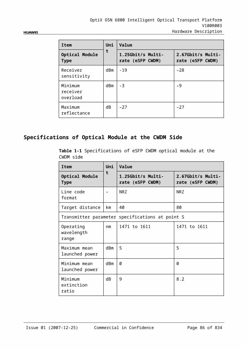
OptiX OSN 6800 Intelligent Optical Transport Platform V100R003
Hardware Description
Item Unit Value
Optical Module Type 5G CWDM
Operating wavelength range nm 1200 to 1650
Receiver sensitivity dBm –25
Minimum receiver overload dBm –9
Maximum reflectance dB –27
Mechanical Specifications Dimensions of board (PCB): 245.1 mm (H) x 220 mm (D) x 2 mm (T) Dimensions of front panel: 264.6 mm (H) x 25.4 mm (W) Weight: 3.08 lb (1.4 kg)
Power ConsumptionBoard Optical Module
TypeThe maximum power consumption at 25
The maximum power consumption at 55
TN11L4G NRZ-fixed(D)(5G)(3400 ps/nm6400 ps/nm)
50.0 55.0
NRZ-fixed(C)(5G)(3400 ps/nm)
45.0 50.0
NRZ-tunable(5G)(3400 ps/nm)
53.0 58.0
5.3 LDGDLDGD:2xGigabit Ethernet unit, dual fed and selective receiving
5.3.1 Version DescriptionOnly one functional version of the LDGD board is available, that is TN11.
5.3.2 ApplicationThe LDGD is a type of optical transponder unit. The LDGD realizes the conversion between two GE signals and ITU-T Recommendation-compliant WDM signals, and the dual fed and selective receiving function on the WDM side.
For the position of the LDGD in the WDM system, see Figure 5-8.
Issue 01 (2007-12-25) Commercial in Confidence Page 84 of 664
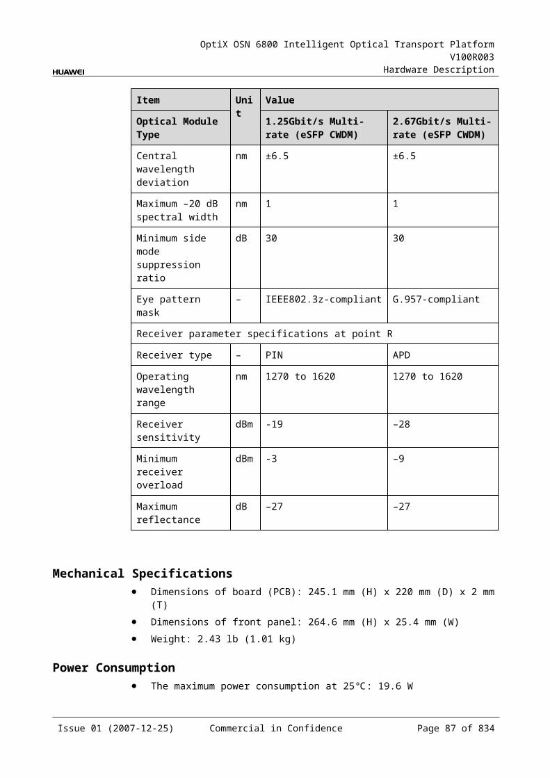
OptiX OSN 6800 Intelligent Optical Transport Platform V100R003
Hardware Description
Figure 5-1 Position of the LDGD in the WDM system
MUX
DMUX
LDGD
DMUX
MUX
LDGD
1
2
1
2
G.694.1/G.694.2
G.694.1/G.694.2
GE
GE GE
GEDMUX
MUX
DMUX
MUX
Client side WDM side WDM side Client side
5.3.3 Functions and FeaturesThe main functions and features supported by the LDGD are wavelength conversion, cross-connection at the electrical layer, OTN interfaces and ESC.
For detailed functions and features, refer to Table 5-14.
Table 5-1 Functions and features of the LDGD
Function and Feature
Description
Basic function Multiplexes two GE optical signals into one OTU1/STM-16 signal and converts the signal into standard DWDM wavelength compliant with ITU-T G.694.1 or the standard CWDM wavelength compliant with ITU-T G.694.2. The reverse process is similar.
Realizes the dual fed and selective receiving function on the WDM side.
Client-side service type
GE
Cross-connect capabilities
Supports the grooming of two channels of GE services each to working/protection cross-connection boards respectively through the backplane. Supports the transmission of two GE signals to the paired slots through the backplane.
OTN function Provides the OTU1 interface on WDM-side. Supports the OTN frame format and overhead processing
by referring to the ITU-T G.709. Supports the mapping of GE signals into OTU1 signals. The
mapping process is compliant with ITU-T G.709. Supports SM and PM functions for OTU1 and ODU1. Supports TCM function for ODU1.
WDM specification Supports the DWDM and the CWDM specifications.
Issue 01 (2007-12-25) Commercial in Confidence Page 85 of 664
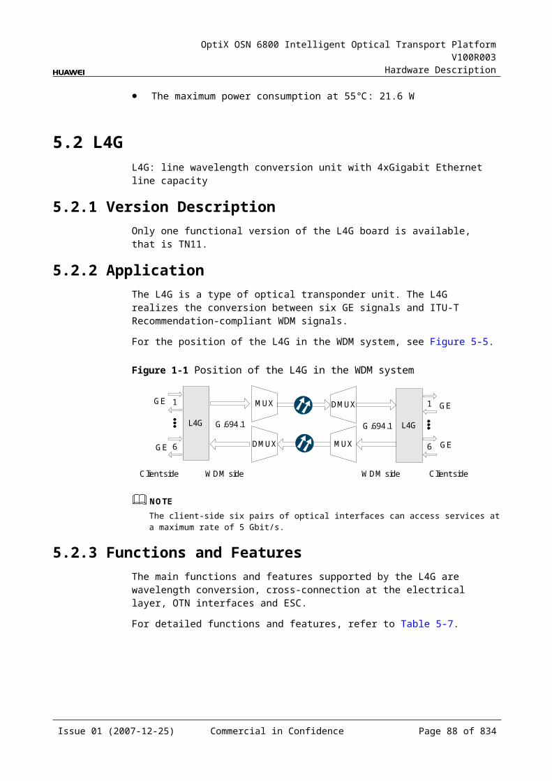
OptiX OSN 6800 Intelligent Optical Transport Platform V100R003
Hardware Description
Function and Feature
Description
Tunable wavelength function
Supports the tunable wavelength optical module. Equipped with this module, the board can tune the optical signal output at the WDM side within the range of the 40 wavelengths in C-band with the channel spacing of 100 GHz.
ESC function Supports the ESC function, transmitting the supervisory signal within the service signal.
FEC encoding Adopts FEC encoding compliant with the ITU-T G.975.
Alarms and performance events monitoring
Provides the monitoring of the BIP8 bit error count so as to help to locate the failures of the line.
Provides the WDM-side monitoring of the items such as the bias current and temperature of the laser as well as the optical power.
Supports the monitoring of the alarms and performance events of the OTN.
ALS function Provides the ALS function. With the ALS function enabled, the corresponding optical output laser is automatically shut down if no signals are received.
Protection scheme Supports the SW SNCP. Supports the client-side 1+1 protection. Supports the intra-board 1+1 protection.
eSFP Supports the enhanced small form-factor pluggable optical module on the client side.
Loopback WDM side Inloop Supported
Outloop Supported
Client side Inloop Supported
Outloop Supported
5.3.4 Working Principle and Signal FlowThe LDGD consists of the client-side optical module, WDM-side optical module, cross-connect and service processing module, and control and communication module.
Figure 5-9 shows the functional modules and signal flow of the LDGD.
Issue 01 (2007-12-25) Commercial in Confidence Page 86 of 664
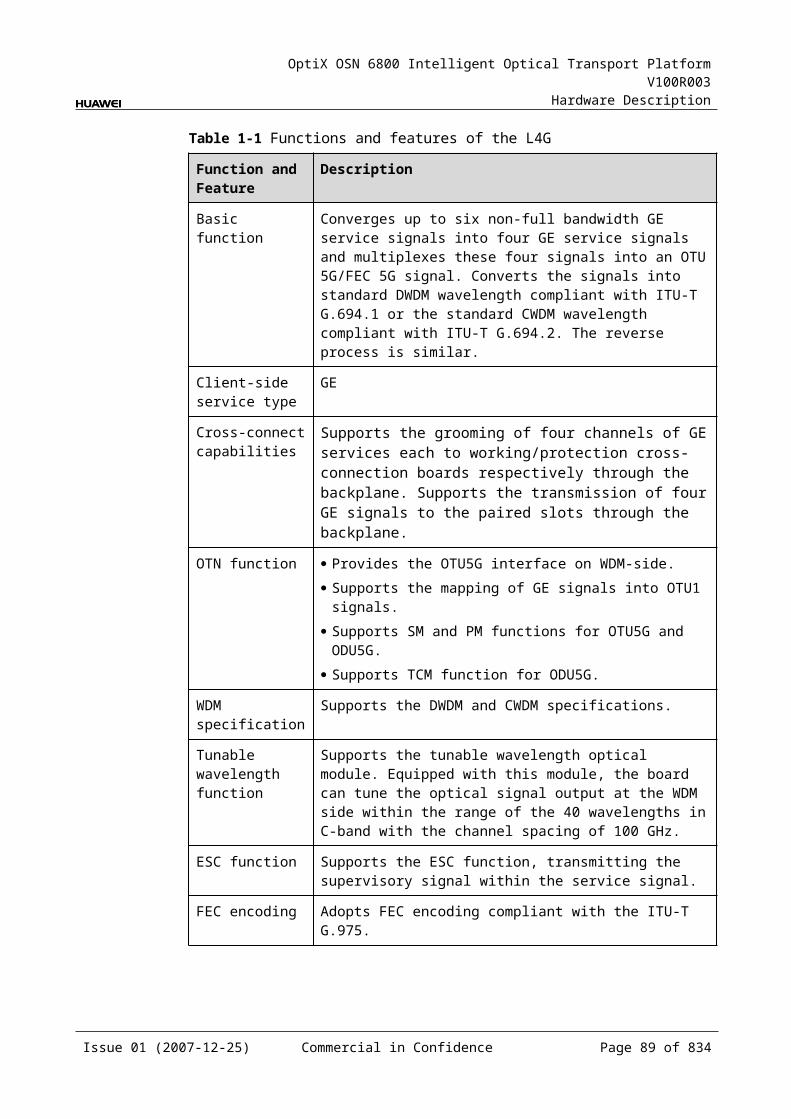
OptiX OSN 6800 Intelligent Optical Transport Platform V100R003
Hardware Description
Figure 5-1 Functional modules and signal flow of the LDGD
Control and communication module
SCC
Backplane
GE
Cross-connect andservice processing
module
Client-side
opticalmodule
WDM-side
opticalmodule
Client side WDM side
STM-16/OTU1
STM-16/OTU1
GE
GE
RX1
TX1
OUT1
IN1
RX2
TX2
OUT2
IN2
In Transmit DirectionThe client-side optical module receives two GE service signals compliant with IEEE 802.3z. These GE signals are converted into electrical signals and sent to the cross-connect and service processing module.
The cross-connect and service processing module monitors the performance of client-side services, then
Multiplexes the two signals into one STM-16 or OTU1 signal and sends the signal to a WDM-side optical module, or
Sends the two signals to cross-connection board or a board in the paired slot through the backplane to realize the grooming of electrical signals, or
Receives the electrical signals sent from cross-connection board or a board in the paired slot through the backplane, multiplexes the signals into one STM-16 or OTU1 signal, and sends the signal to a WDM-side optical module.
The WDM-side optical module converts the electrical signal into ITU-T G.694.1-compliant standard DWDM signal or ITU-T G.694.2-compliant standard CWDM signal. The module divides the signal into two and then sends the two signals to the WDM side.
In Receive DirectionThe WDM-side optical module receives two OTU1 or STM-16 optical signals and converts them into electrical signals.
The cross-connect and service processing module selects one signal and demultiplexes it into two 1.25 Gbit/s GE signals. The module extracts and processes the overhead bytes and monitors the WDM-side performance at the same time. Then this module
Sends the two signals to the client-side optical module, or Sends the two signals to cross-connection board or a board in the paired slot
through the backplane to realize the grooming of electrical signals, or
Issue 01 (2007-12-25) Commercial in Confidence Page 87 of 664
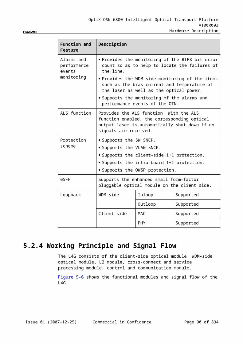
OptiX OSN 6800 Intelligent Optical Transport Platform V100R003
Hardware Description
Receives the electrical signal sent from cross-connection board or a board in the paired slot through the backplane and sends the signal to the client-side optical module.
The client-side optical module converts the two electrical signals into optical signals and then sends the signals to the client-side equipment.
Cross-Connect and Service Processing Module This module realizes the grooming of electrical signals between the LDGD and
the board in the paired slot or the cross-connect board through the backplane. The grooming service signals are GE signals. This module realizes the cross-connection of two service signals each through
the working/protection cross-connection boards respectively. This module realizes the cross-connection of two service signals between the
boards in paired slots. This module selects the services. This module extracts and processes overhead bytes. This module monitors the performance of services. This module multiplexes and demultiplexes services. This module implements the encapsulation of OTN signals.
Control and Communication ModuleThe control and communication module realizes the control, monitoring and communications management of each functional module of the board.
The control and communication module collects the information, such as the alarms and performance events, working status, and voltage detection, of each functional module of the board and reports to the SCC.
Receiving the commands from the SCC, the control and communication module controls and coordinates the functional modules of the board in working.
5.3.5 Front PanelThere are indicators, interfaces and laser safety label on the LDGD front panel.
Appearance of the Front PanelFigure 5-10 shows the LDGD front panel.
Issue 01 (2007-12-25) Commercial in Confidence Page 88 of 664
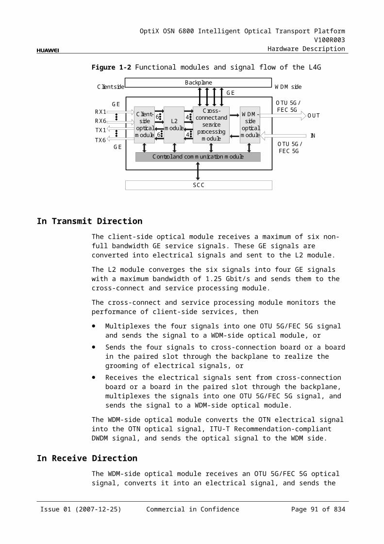
OptiX OSN 6800 Intelligent Optical Transport Platform V100R003
Hardware Description
Figure 5-1 LDGD front panel
LDGD
LDGD
STATACTPROGSRV
CLASS 1LASER
PRODUCT
OU
T1IN
1O
UT2
IN2
TX1
RX
1TX
2R
X2
IndicatorsThere are four indicators on the front panel.
Board hardware status indicator (STAT) – dual-colored (red, green) Service active status indicator (ACT) – green Board software status indicator (PROG) – dual-colored (red, green) Service alarm indicator (SRV) – triple-colored (red, green, yellow)
InterfacesThere are eight optical interfaces on the LDGD front panel. Table 5-15 lists the type and function of each interface.
Issue 01 (2007-12-25) Commercial in Confidence Page 89 of 664
OptiX OSN 6800 Intelligent Optical Transport Platform V100R003
Hardware Description
Table 5-1 Types and functions of the LDGD interfaces
Interface Type
Function
IN1–IN2 LC Receives the single-channel signal from the optical demultiplexer unit or the optical add and drop multiplexing unit.
OUT1–OUT2 LC Transmits the single-channel signal to the optical multiplexer unit or the optical add and drop multiplexing unit.
TX1–TX2 LC Transmits the service signal to the client-side equipment.
RX1–RX2 LC Receives the service signal from the client-side equipment.
Laser Safety LevelThe laser safety level of the optical interface is CLASS 1.
The maximum output optical power of each optical interface is lower than 10 dBm (10 mW).
5.3.6 Valid SlotsThe LDGD occupies one slot. The valid slots for the LDGD are IU1–IU8 and IU11–IU16.
5.3.7 Characteristic Code for the LDGDThe characteristic code for the LDGD consists of eight digits, respectively indicating the frequency values of two channels of optical signals on the WDM side.
The detailed information of the characteristic code is given in Table 5-16.
Table 5-1 Characteristic code for the LDGD
Code Meaning Description
The first four digits
The frequency of forth optical signal
The last four digits of the frequency value of the first channel of signals on the WDM side.
The last four digits
The frequency of forth optical signal
The last four digits of the frequency value of the second channel of signals on the WDM side.
For example, the characteristic code for the TN11LWX2 is 92109220.
"9210" indicates the frequency of the first channel of optical signals on the WDM side is 192.10 THz.
"9220" indicates the frequency of the second channel of optical signals on the WDM side is 192.20 THz.
Issue 01 (2007-12-25) Commercial in Confidence Page 90 of 664

OptiX OSN 6800 Intelligent Optical Transport Platform V100R003
Hardware Description
5.3.8 NM Configuration ReferenceNM configuration reference includes the reference information needed during the configuration of boards through the T2000.
Display of Optical InterfacesThe serial numbers of the optical interfaces on the panel of the board displayed on the NM are listed in Table 5-17.
Table 5-1 Serial numbers of the interfaces of the LDGD displayed on the NM
Interface on the Panel Interface on the NM
IN1/OUT1 1
IN2/OUT2 2
TX1/RX1 3
TX2/RX2 4
NOTEThe number of an interface displayed on the T2000 in fact indicates a pair of physical optical interfaces, of which one is used to transmit signals and the other is used to receive signals.
Configuration ParametersPath Use Status
Optical Interface Loopback
Laser Status
Automatic Laser Shutdown
Service Mode
FEC Working State
Configure Wavelength No./Wavelength (nm)/Frequency (THz)
Configure Band Type
Maximum Packet Length
Ethernet Working Mode
LPT Enabled
5.3.9 Specifications of the LDGDSpecifications include optical specifications, dimensions, weight, and power consumption.
Issue 01 (2007-12-25) Commercial in Confidence Page 91 of 664

OptiX OSN 6800 Intelligent Optical Transport Platform V100R003
Hardware Description
Specifications of Optical Module at the Client Side
Table 5-1 Specifications of GE optical module at the client side
Item Unit
Value
Optical Module Type 2.125 Gbit/s Multi-rate
1000 BASE-LX-10 km
1000 BASE-LX-40 km
1000 BASE-ZX-80 km
Line code format – NRZ NRZ NRZ NRZ
Target distance km 0.5 10 40 80
Transmitter parameter specifications at point S
Operating wavelength range nm 830 to 860 1270 to 1355 1270 to 1355 1500 to 1580
Maximum mean launched power
dBm –2.5 –3 0 5
Minimum mean launched power
dBm –9.5 –11.5 –4.5 –2
Minimum extinction ratio dB 9 9 9 9
Eye pattern mask – IEEE802.3z-compliant
Receiver parameter specifications at point R
Receiver type – PIN PIN PIN PIN
Operating wavelength range nm 770 to 860 1270 to 1355 1270 to 1355 1500 to 1580
Receiver sensitivity dBm –17 –19 –20 –22
Minimum receiver overload dBm 0 –3 –3 –3
Specifications of eSFP CWDM Optical Module at the Client Side
Table 5-1 Specifications of eSFP CWDM optical module at the client side
Item Unit
Value
Optical Module Type
1.25Gbit/s Multi-rate (eSFP CWDM)-40km
1.25Gbit/s Multi-rate (eSFP CWDM)-80km
Line code format – NRZ NRZ
Target distance km 40 80
Transmitter parameter specifications at point S
Operating wavelength range
nm 1471 to 1611 1471 to 1611
Issue 01 (2007-12-25) Commercial in Confidence Page 92 of 664
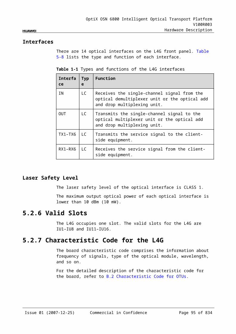
OptiX OSN 6800 Intelligent Optical Transport Platform V100R003
Hardware Description
Item Unit
Value
Optical Module Type
1.25Gbit/s Multi-rate (eSFP CWDM)-40km
1.25Gbit/s Multi-rate (eSFP CWDM)-80km
Maximum mean launched power
dBm 5 5
Minimum mean launched power
dBm 0 0
Minimum extinction ratio
dB 9 8.2
Central wavelength deviation
nm ±6.5 ±6.5
Maximum –20 dB spectral width
nm 1.0 1.0
Minimum side mode suppression ratio
dB 30 30
Eye pattern mask – IEEE802.3z-compliant
Receiver parameter specifications at point R
Receiver type – PIN APD
Operating wavelength range
nm 1270 to 1620 1270 to 1620
Receiver sensitivity dBm –19 –28
Minimum receiver overload
dBm –3 –9
Maximum reflectance
dB –27 –27
Specifications of Optical Module at the DWDM Side
Table 5-1 Specifications of optical module at the DWDM side
Item Unit Value
Optical Module Type 12800 ps/nm- PIN
12800 ps/nm-APD
6500 ps/nm- PIN
3200 ps/nm- 2mW- APD
12800 ps/nm- tunable
Line code format – NRZ NRZ NRZ NRZ NRZ
Transmitter parameter specifications at point S
Issue 01 (2007-12-25) Commercial in Confidence Page 93 of 664
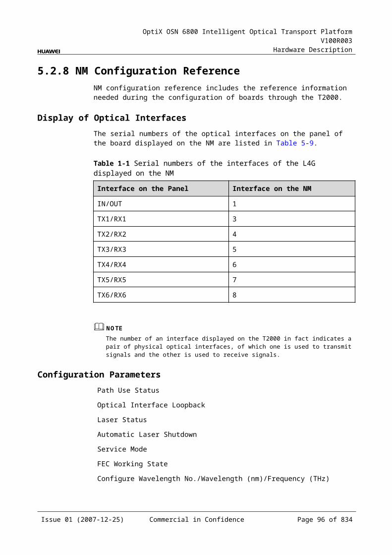
OptiX OSN 6800 Intelligent Optical Transport Platform V100R003
Hardware Description
Item Unit Value
Optical Module Type 12800 ps/nm- PIN
12800 ps/nm-APD
6500 ps/nm- PIN
3200 ps/nm- 2mW- APD
12800 ps/nm- tunable
Maximum mean launched power
dBm –4 –4 0 0 0
Minimum mean launched power
dBm –8 –8 –5 –5 –5
Minimum extinction ratio dB 10 10 8.2 8.2 10
Central frequency THz 192.10 to 196.00
Central frequency deviation
GHz ±10
Maximum –20 dB spectral width
nm 0.2 0.2 0.5 0.5 0.2
Minimum side mode suppression ratio
dB 35 35 30 30 35
Dispersion tolerance ps/nm 12800 12800 6500 3200 12800
Eye pattern mask – G.957 - compliant
Receiver parameter specifications at point R
Receiver type – PIN APD PIN APD APD
Operating wavelength range
nm 1200 to 1650
Receiver sensitivity dBm –18 –25 –18 –25 –30
Minimum receiver overload
dBm 0 –9 0 –9 –9
Maximum reflectance dB –27 –27 –27 –27 –27
Specifications of Optical Module at the CWDM Side
Table 5-1 Specifications of optical module at the CWDM side
Item Unit Value
Optical Module Type 1600 ps/nm-4mW
Line code format – NRZ
Transmitter parameter specifications at point S
Maximum mean launched power dBm 2
Issue 01 (2007-12-25) Commercial in Confidence Page 94 of 664
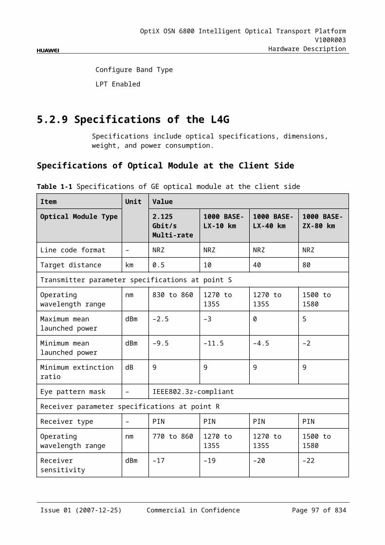
OptiX OSN 6800 Intelligent Optical Transport Platform V100R003
Hardware Description
Item Unit Value
Optical Module Type 1600 ps/nm-4mW
Minimum mean launched power dBm –0.5
Minimum extinction ratio dB 8.2
Central wavelength nm 1271 to 1611
Central wavelength deviation nm ≤±6.5
Maximum –20 dB spectral width nm 1
Minimum side mode suppression ratio dB 30
Dispersion tolerance ps/nm 1600
Eye pattern mask –
Receiver parameter specifications at point R
Receiver type – APD
Operating wavelength range nm 1200 to 1650
Receiver sensitivity dBm –28
Minimum receiver overload dBm –9
Maximum reflectance dB –27
Mechanical Specifications Dimensions of board (PCB): 245.1 mm (H) x 220 mm (D) x 2 mm (T) Dimensions of front panel: 264.6 mm (H) x 25.4 mm (W) Weight: 3.08 lb (1.4 kg)
Power ConsumptionBoard Optical Module
TypeThe maximum power consumption at 25
The maximum power consumption at 55
TN11LDGD Fixed(2.5G) 12800 ps/nm-PIN12800 ps/nm-APD6500 ps/nm-PIN3200 ps/nm-2mW-APD
34.0 37.4
Tunable(2.5G) (12800 ps/nm)
36.0 39.6
Issue 01 (2007-12-25) Commercial in Confidence Page 95 of 664
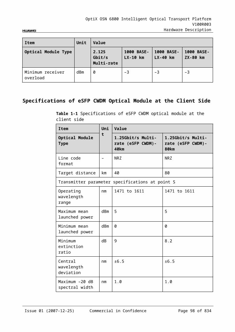
OptiX OSN 6800 Intelligent Optical Transport Platform V100R003
Hardware Description
5.4 LDGSLDGS:2xGigabit Ethernet unit, single fed and single receiving
5.4.1 Version DescriptionOnly one functional version of the LDGS board is available, that is TN11.
5.4.2 ApplicationThe LDGS is a type of optical transponder unit. The LDGS realizes the conversion between two GE signals and ITU-T Recommendation-compliant WDM signals.
For the position of the LDGS in the WDM system, see Figure 5-11.
Figure 5-1 Position of the LDGS in the WDM system
MUX
DMUX
LDGS
DMUX
MUX
LDGS
1
2
1
2
G.694.1/G.694.2
G.694.1/G.694.2
GE
GE GE
GE
Client side WDM side WDM side Client side
5.4.3 Functions and FeaturesThe main functions and features supported by the LDGS are wavelength conversion, cross-connection at the electrical layer, OTN interfaces and ESC.
For detailed functions and features, refer to Table 5-22.
Table 5-1 Functions and features of the LDGS
Function and Feature
Description
Basic function Multiplexes two GE optical signals into one 2.5 Gbit/s OTU1/STM-16 signal and converts the signal into standard DWDM wavelength compliant with ITU-T G.694.1 or the standard CWDM wavelength compliant with ITU-T G.694.2. The reverse process is similar.
Cross-connect capabilities
Supports the grooming of two channels of GE services each to working/protection cross-connection boards respectively through the backplane. Supports the transmission of two GE signals to the paired slots through the backplane.
Issue 01 (2007-12-25) Commercial in Confidence Page 96 of 664
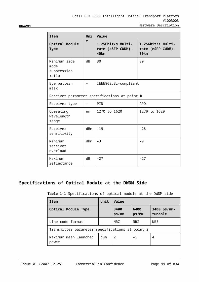
OptiX OSN 6800 Intelligent Optical Transport Platform V100R003
Hardware Description
Function and Feature
Description
OTN function Provides the OTU1 interface on WDM-side. Supports the OTN frame format and overhead processing
by referring to the ITU-T G.709. Supports the mapping of GE signals into OTU1 signals. The
mapping process is compliant with ITU-T G.709. Supports SM and PM functions for OTU1 and ODU1. Supports TCM function for ODU1.
WDM specification
Supports the DWDM and the CWDM specifications.
Tunable wavelength function
Supports the tunable wavelength optical module. Equipped with this module, the board can tune the optical signal output at the WDM side within the range of the 40 wavelengths in C-band with the channel spacing of 100 GHz.
ESC function Supports the ESC function, transmitting the supervisory signal within the service signal.
FEC encoding Adopts FEC encoding compliant with the ITU-T G.975.
Alarms and performance events monitoring
Provides the monitoring of the BIP8 bit error count so as to help to locate the failures of the line.
Provides the WDM-side monitoring of the items such as the bias current and temperature of the laser as well as the optical power.
Supports the monitoring of the alarms and performance events of the OTN.
ALS function Provides the ALS function. With the ALS function enabled, the corresponding optical output laser is automatically shut down if no signals are received.
Protection scheme
Supports the SW SNCP. Supports the client-side 1+1 protection.
eSFP Supports the enhanced small form-factor pluggable optical module on the client side.
Loopback WDM side Inloop Supported
Outloop Supported
Client side Inloop Supported
Outloop Supported
Issue 01 (2007-12-25) Commercial in Confidence Page 97 of 664
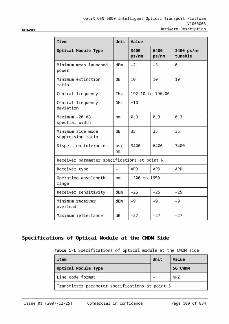
OptiX OSN 6800 Intelligent Optical Transport Platform V100R003
Hardware Description
5.4.4 Working Principle and Signal FlowThe LDGS consists of the client-side optical module, WDM-side optical module, cross-connect and service processing module, and control and communication module.
Figure 5-12 shows the functional modules and signal flow of the LDGS.
Figure 5-1 Functional modules and signal flow of the LDGS
OTN 5G
WDM-side
opticalmodule
Control and communication module
SCC
Backplane
GE
Cross-connect andservice processing
module
Client-side
opticalmodule
Client side WDM side
STM-16/OTU1
STM-16/OTU1
GE
GE
RX1
TX1
OUT
IN
RX2
TX2
In Transmit DirectionThe client-side optical module receives two GE service signals compliant with IEEE 802.3z. These GE signals are converted into electrical signals and sent to the cross-connect and service processing module.
The cross-connect and service processing module monitors the performance of client-side services, then
Multiplexes the two signals into one STM-16 or OTU1 signal and sends the signal to a WDM-side optical module, or
Sends the two signals to the cross-connection board or a board in the paired slot through the backplane to realize the grooming of electrical signals, or
Receives the electrical signals sent from the cross-connection board or a board in the paired slot through the backplane, multiplexes the signals into one STM-16 or OTU1 signal, and sends the signal to a WDM-side optical module.
The WDM-side optical module converts the electrical signal into ITU-T G.694.1-compliant standard DWDM signal or ITU-T G.694.2-compliant standard CWDM signal and sends the signal to the WDM side.
In Receive DirectionThe WDM-side optical module receives one OTU1 or STM-16 optical signal and converts it into an electrical signal.
Issue 01 (2007-12-25) Commercial in Confidence Page 98 of 664
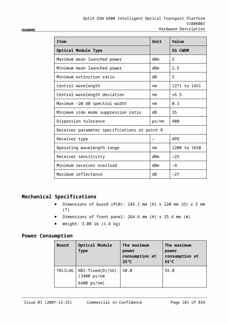
OptiX OSN 6800 Intelligent Optical Transport Platform V100R003
Hardware Description
The cross-connect and service processing module demultiplexes the signal into two 1.25 Gbit/s GE signals, extracts and processes the overhead bytes, and monitors the WDM-side performance. Then, the module
Sends the two signals to the client-side optical module, or Sends the two signals to the cross-connection board or a board in the paired slot
through the backplane to realize the grooming of electrical signals, or Receives the electrical signal sent from the cross-connection board or a board in
the paired slot through the backplane and sends the signal to the client-side optical module.
The client-side optical module converts the two electrical signals into optical signals and then sends the signals to the client-side equipment.
Cross-Connect and Service Processing Module This module realizes the grooming of electrical signals between LDGS and the
board in paired slot or with the cross-connect board through the backplane. The grooming service signals are GE signals. This module realizes the cross-connection of two service signals each through
the working/protection cross-connection boards respectively. This module realizes the cross-connection of two service signals between the
boards in paired slots. This module extracts and processes overhead bytes. This module monitors the performance of services. This module multiplexes and demultiplexes services. This module implements the encapsulation of OTN signals.
Control and Communication ModuleThe control and communication module realizes the control, monitoring and communications management of each functional module of the board.
The control and communication module collects the information, such as the alarms and performance events, working status, and voltage detection, of each functional module of the board and reports to the SCC.
Receiving the commands from the SCC, the control and communication module controls and coordinates the functional modules of the board in working.
5.4.5 Front PanelThere are indicators, interfaces and laser safety label on the LDGS front panel.
Appearance of the Front PanelFigure 5-13 shows the LDGS front panel.
Issue 01 (2007-12-25) Commercial in Confidence Page 99 of 664
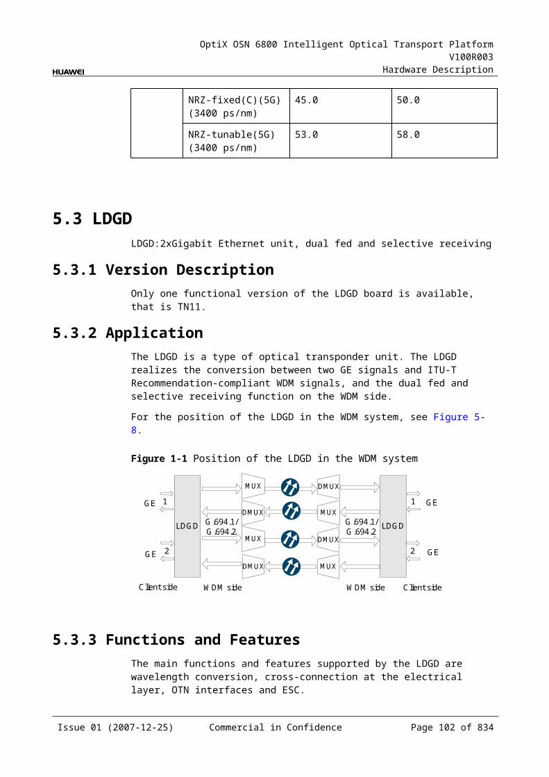
OptiX OSN 6800 Intelligent Optical Transport Platform V100R003
Hardware Description
Figure 5-1 LDGS front panel
LDGS
LDGS
CLASS 1LASER
PRODUCT
STATACTPROGSRV
TX1
RX
1TX
2R
X2
OU
TIN
IndicatorsThere are four indicators on the front panel.
Board hardware status indicator (STAT) – dual-colored (red, green) Service active status indicator (ACT) – green Board software status indicator (PROG) – dual-colored (red, green) Service alarm indicator (SRV) – triple-colored (red, green, yellow)
InterfacesThere are six optical interfaces on the LDGD front panel. Table 5-23 lists the type and function of each interface.
Issue 01 (2007-12-25) Commercial in Confidence Page 100 of 664
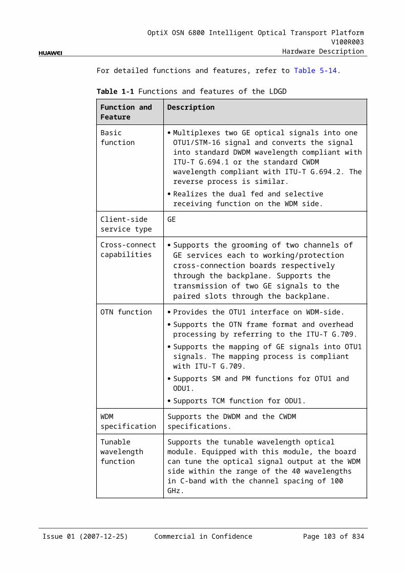
OptiX OSN 6800 Intelligent Optical Transport Platform V100R003
Hardware Description
Table 5-1 Types and functions of the LDGS interfaces
Interface
Type
Function
IN LC Receives the single-channel signal from the optical demultiplexer unit or the optical add and drop multiplexing unit.
OUT LC Transmits the single-channel signal to the optical multiplexer unit or the optical add and drop multiplexing unit.
TX1–TX2 LC Transmits the service signal to the client-side equipment.
RX1–RX2 LC Receives the service signal from the client-side equipment.
Laser Safety LevelThe laser safety level of the optical interface is CLASS 1.
The maximum output optical power of each optical interface is lower than 10 dBm (10 mW).
5.4.6 Valid SlotsThe LDGS occupies one slot. The valid slots for the LDGS are IU1–IU8 and IU11–IU16.
5.4.7 Characteristic Code for the LDGSThe board characteristic code comprises the information about frequency of signals, type of the optical module, wavelength, and so on.
For the detailed description of the characteristic code for the board, refer to B.2 Characteristic Code for OTUs.
5.4.8 NM Configuration ReferenceNM configuration reference includes the reference information needed during the configuration of boards through the T2000.
Display of Optical InterfacesThe serial numbers of the optical interfaces on the panel of the board displayed on the NM are listed in Table 5-24.
Table 5-1 Serial numbers of the interfaces of the LDGS displayed on the NM
Interface on the Panel Interface on the NM
IN/OUT 1
TX1/RX1 3
TX2/RX2 4
Issue 01 (2007-12-25) Commercial in Confidence Page 101 of 664
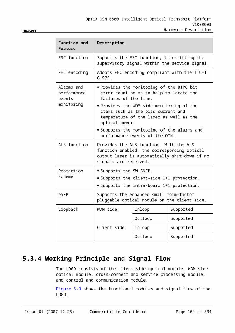
OptiX OSN 6800 Intelligent Optical Transport Platform V100R003
Hardware Description
NOTEThe number of an interface displayed on the T2000 in fact indicates a pair of physical optical interfaces, of which one is used to transmit signals and the other is used to receive signals.
Configuration ParametersPath Use Status
Optical Interface Loopback
Laser Status
Automatic Laser Shutdown
Service Mode
FEC Working State
Configure Wavelength No./Wavelength (nm)/Frequency (THz)
Configure Band Type
Maximum Packet Length
Ethernet Working Mode
LPT Enabled
5.4.9 Specifications of the LDGSSpecifications include optical specifications, dimensions, weight, and power consumption.
Specifications of Optical Module at the Client Side
Table 5-1 Specifications of GE optical module at the client side
Item Unit
Value
Optical Module Type 2.125 Gbit/s Multi-rate
1000 BASE-LX-10 km
1000 BASE-LX-40 km
1000 BASE-ZX-80 km
Line code format – NRZ NRZ NRZ NRZ
Target distance km 0.5 10 40 80
Transmitter parameter specifications at point S
Operating wavelength range nm 830 to 860 1270 to 1355 1270 to 1355 1500 to 1580
Maximum mean launched power
dBm –2.5 –3 0 5
Minimum mean launched power
dBm –9.5 –11.5 –4.5 –2
Issue 01 (2007-12-25) Commercial in Confidence Page 102 of 664
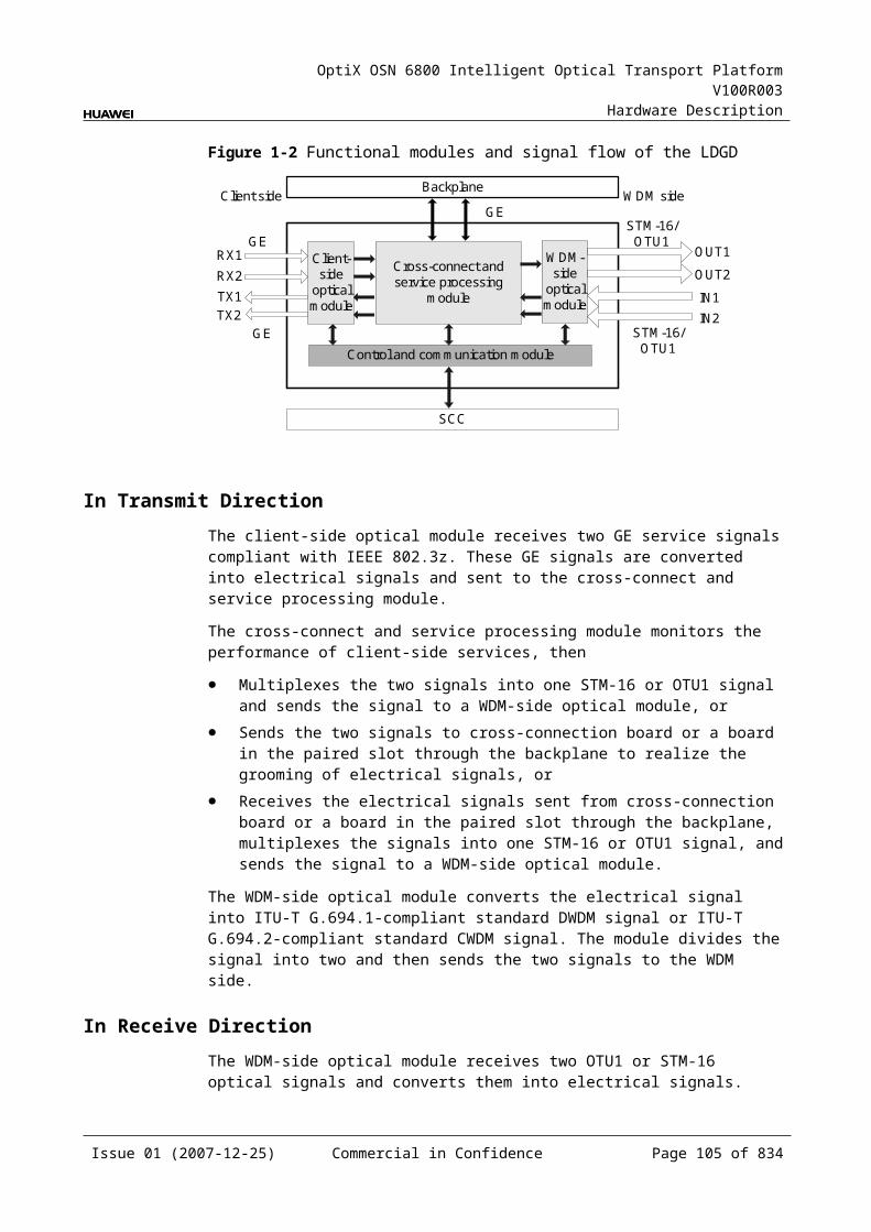
OptiX OSN 6800 Intelligent Optical Transport Platform V100R003
Hardware Description
Item Unit
Value
Optical Module Type 2.125 Gbit/s Multi-rate
1000 BASE-LX-10 km
1000 BASE-LX-40 km
1000 BASE-ZX-80 km
Minimum extinction ratio dB 9 9 9 9
Eye pattern mask – IEEE802.3z-compliant
Receiver parameter specifications at point R
Receiver type – PIN PIN PIN PIN
Operating wavelength range nm 770 to 860 1270 to 1355 1270 to 1355 1500 to 1580
Receiver sensitivity dBm –17 –19 –20 –22
Minimum receiver overload dBm 0 –3 –3 –3
Specifications of eSFP CWDM oOptical Module at the Client Side
Table 5-1 Specifications of eSFP CWDM optical module at the client side
Item Unit
Value
Optical Module Type
1.25Gbit/s Multi-rate (eSFP CWDM)-40km
1.25Gbit/s Multi-rate (eSFP CWDM)-80km
Line code format – NRZ NRZ
Target distance km 40 80
Transmitter parameter specifications at point S
Operating wavelength range
nm 1471 to 1611 1471 to 1611
Maximum mean launched power
dBm 5 5
Minimum mean launched power
dBm 0 0
Minimum extinction ratio
dB 9 8.2
Central wavelength deviation
nm ±6.5 ±6.5
Maximum –20 dB spectral width
nm 1.0 1.0
Minimum side mode suppression ratio
dB 30 30
Issue 01 (2007-12-25) Commercial in Confidence Page 103 of 664
OptiX OSN 6800 Intelligent Optical Transport Platform V100R003
Hardware Description
Item Unit
Value
Optical Module Type
1.25Gbit/s Multi-rate (eSFP CWDM)-40km
1.25Gbit/s Multi-rate (eSFP CWDM)-80km
Eye pattern mask – IEEE802.3z-compliant
Receiver parameter specifications at point R
Receiver type – PIN APD
Operating wavelength range
nm 1270 to 1620 1270 to 1620
Receiver sensitivity dBm –19 –28
Minimum receiver overload
dBm –3 –9
Maximum reflectance
dB –27 –27
Specifications of Optical Module at the DWDM Side
Table 5-1 Specifications of optical module at the DWDM side
Item Unit Value
Optical Module Type 12800 ps/nm- PIN
12800 ps/nm-APD
6500 ps/nm- PIN
3200 ps/nm- 2mW- APD
12800 ps/nm- tunable
Line code format – NRZ NRZ NRZ NRZ NRZ
Transmitter parameter specifications at point S
Maximum mean launched power
dBm –1 –1 3 3 3
Minimum mean launched power
dBm –5 –5 –2 –2 –2
Minimum extinction ratio dB 10 10 8.2 8.2 10
Central frequency THz 192.10 to 196.00
Central frequency deviation GHz ±10
Maximum –20 dB spectral width
nm 0.2 0.2 0.5 0.5 0.2
Minimum side mode suppression ratio
dB 35 35 30 30 35
Dispersion tolerance ps/nm 12800 12800 6500 3200 12800
Issue 01 (2007-12-25) Commercial in Confidence Page 104 of 664
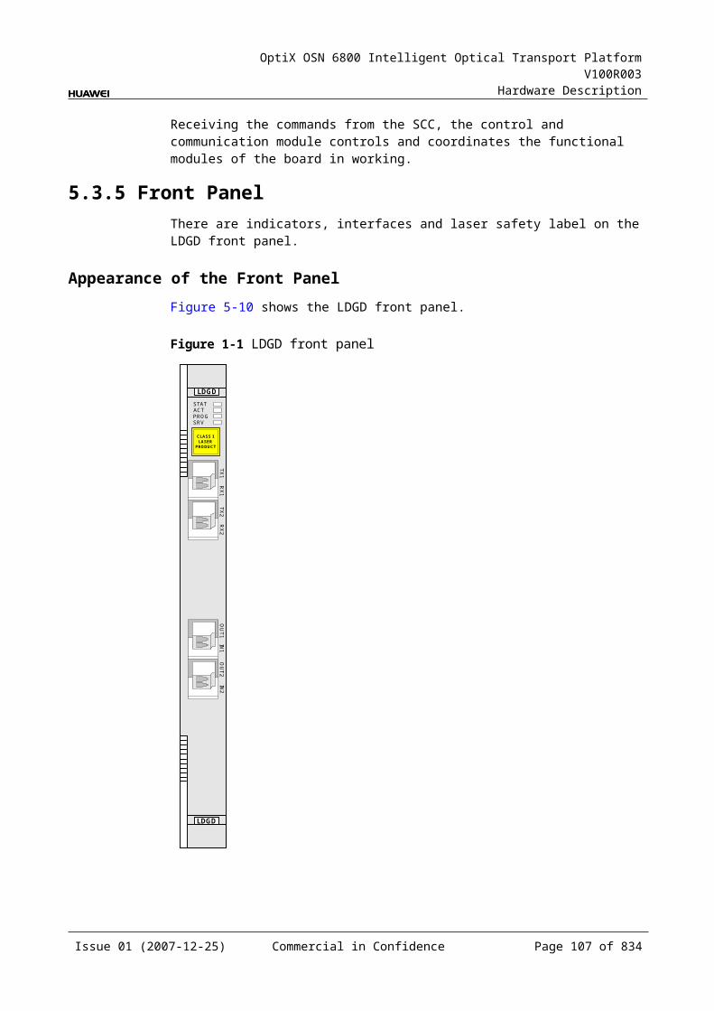
OptiX OSN 6800 Intelligent Optical Transport Platform V100R003
Hardware Description
Item Unit Value
Optical Module Type 12800 ps/nm- PIN
12800 ps/nm-APD
6500 ps/nm- PIN
3200 ps/nm- 2mW- APD
12800 ps/nm- tunable
Eye pattern mask – G.957-compliant
Receiver parameter specifications at point R
Receiver type – PIN APD PIN APD APD
Operating wavelength range nm 1200 to 1650
Receiver sensitivity dBm –18 –25 –18 –25 –30
Minimum receiver overload dBm 0 –9 0 –9 –9
Maximum reflectance dB –27 –27 –27 –27 –27
Specifications of Optical Module at the CWDM Side
Table 5-1 Specifications of optical module at the CWDM side
Item Unit Value
Optical Module Type 1600 ps/nm-4mW
Line code format – NRZ
Transmitter parameter specifications at point S
Maximum mean launched power dBm 5
Minimum mean launched power dBm 2.5
Minimum extinction ratio dB 8.2
Central wavelength nm 1271 to 1611
Central wavelength deviation nm ≤±6.5
Maximum –20 dB spectral width nm 1
Minimum side mode suppression ratio dB 30
Dispersion tolerance ps/nm 1600
Eye pattern mask –
Receiver parameter specifications at point R
Receiver type – APD
Operating wavelength range nm 1200 to 1650
Receiver sensitivity dBm –28
Issue 01 (2007-12-25) Commercial in Confidence Page 105 of 664
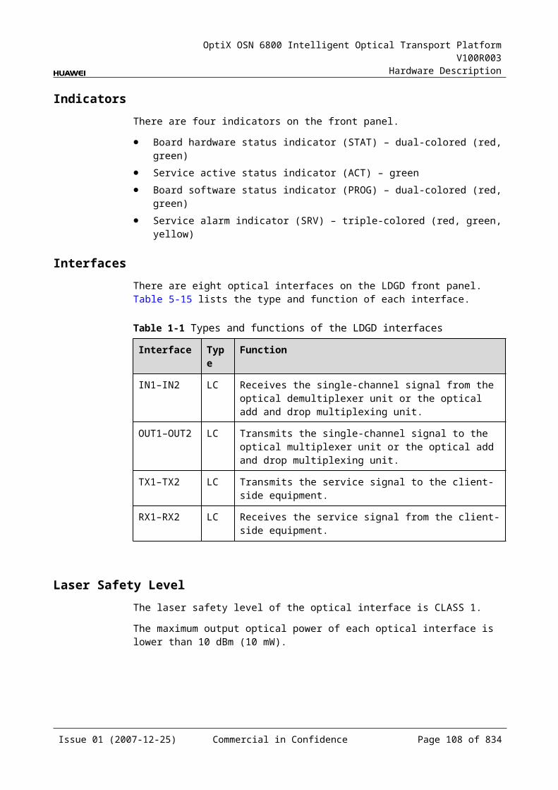
OptiX OSN 6800 Intelligent Optical Transport Platform V100R003
Hardware Description
Item Unit Value
Optical Module Type 1600 ps/nm-4mW
Minimum receiver overload dBm –9
Maximum reflectance dB –27
Mechanical Specifications Dimensions of board (PCB): 245.1 mm (H) x 220 mm (D) x 2 mm (T) Dimensions of front panel: 264.6 mm (H) x 25.4 mm (W) Weight: 2.64 lb (1.2 kg)
Power ConsumptionBoard Optical Module
TypeThe maximum power consumption at 25
The maximum power consumption at 55
TN11LDGS Fixed(2.5G) (12800 ps/nm-PIN12800 ps/nm-APD6500 ps/nm-PIN3200 ps/nm-2mW-APD)
32.0 35.2
Tunable(2.5G) (12800 ps/nm)
34.0 37.4
5.5 LOGLOG: 8 x Gigabit Ethernet unit
5.5.1 Version DescriptionOnly one functional version of the LOG board is available, that is TN11.
5.5.2 ApplicationThe LOG is a type of optical transponder unit. It is applied for conversion between eight channels of GE service optical signals and ITU-T Recommendation-compliant OTU2 optical signals.
For the position of the LOG in the WDM system, see Figure 5-14.
Issue 01 (2007-12-25) Commercial in Confidence Page 106 of 664
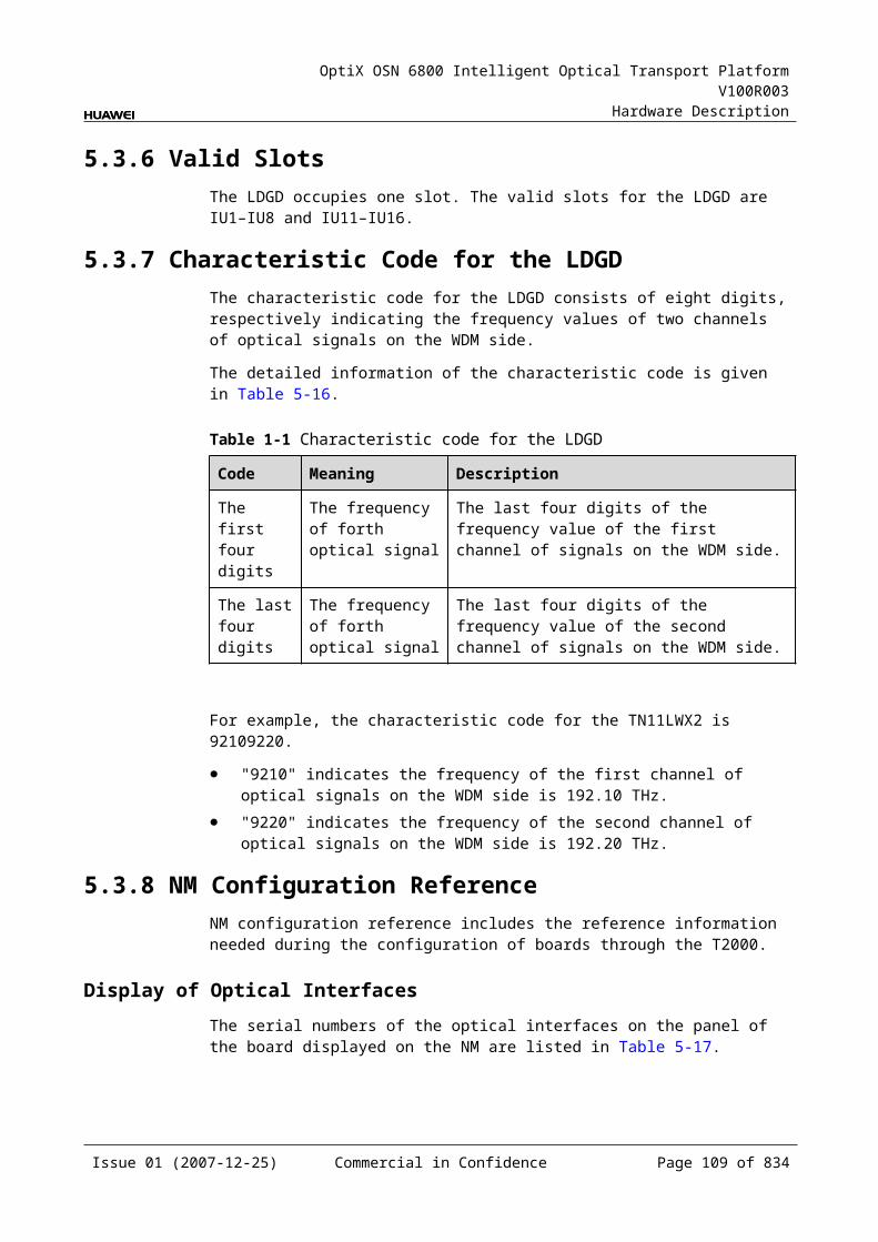
OptiX OSN 6800 Intelligent Optical Transport Platform V100R003
Hardware Description
Figure 5-1 Position of the LOG in the WDM system
Client side WDM side
MUX
DMUX
LOG
DMUX
MUX
LOG
1
8
1
8
G.694.1 G.694.1
WDM side Client side
GE GE
5.5.3 Functions and FeaturesThe main functions and features supported by the LOG are wavelength conversion, cross-connection at the electrical layer, OTN interfaces and ESC.
For detailed functions and features, refer to Table 5-29.
Table 5-1 Functions and features of the LOG
Function and Feature
Description
Basic function Multiplexes eight channels of GE service optical signals into one channel of OTU2 optical signals and converse them to DWDM standard wavelength that comply with ITU-T Recommendation G.694.1. It can also perform the reverse process.
Client-side service type
GE
Cross-connect capabilities
Supports the grooming of eight channels of GE services each to working/protection cross-connection boards respectively through the backplane. Supports the transmission of eight GE signals to the paired slots through the backplane.
OTN function Provides the OTU2 interface on WDM-side. Supports the OTN frame format and overhead processing
by referring to the ITU-T G.709. Supports the mapping of GE signals into OTU2/OTU2V
signals. The mapping process is compliant with ITU-T G.709.
Supports SM and PM functions for OTU2 and ODU2. Supports TCM function for ODU2.
WDM specification Supports the DWDM specifications.
Issue 01 (2007-12-25) Commercial in Confidence Page 107 of 664
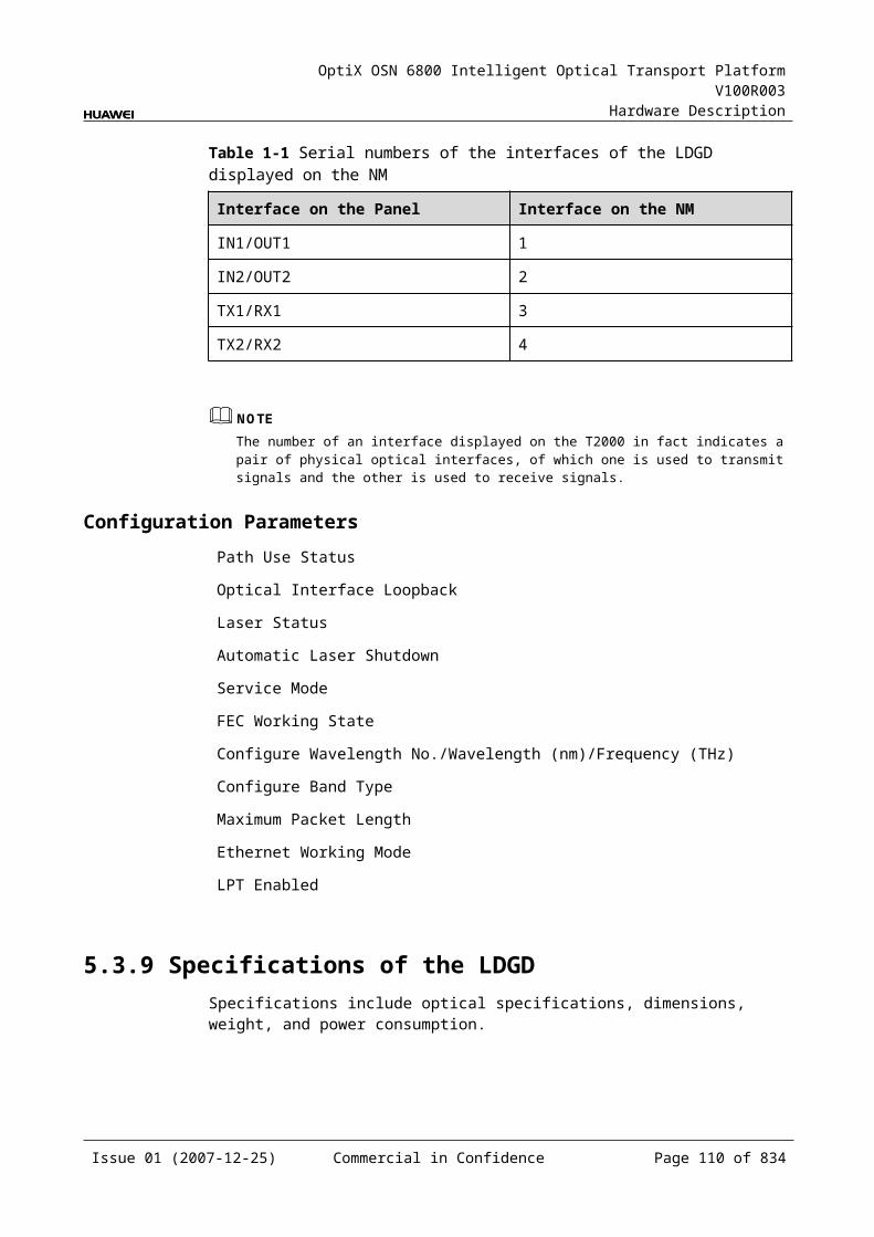
OptiX OSN 6800 Intelligent Optical Transport Platform V100R003
Hardware Description
Function and Feature
Description
Tunable wavelength function
Supports the tunable wavelength optical module. Equipped with this module, the board can tune the optical signal output at the WDM side within the range of: 40 wavelengths in C-band with the channel spacing of 100
GHz 80 wavelengths in C-band with the channel spacing of 50
GHz
ESC function Supports the ESC function, transmitting the supervisory signal within the service signal.
FEC encoding Supports FEC encoding compliant with the ITU-T G.975 and AFEC encoding compliant with the ITU-T G.975.1.
Alarms and performance events monitoring
Provides the monitoring of the BIP8 bit error count so as to help to locate the failures of the line.
Provides the WDM-side monitoring of the items such as the bias current and temperature of the laser as well as the optical power.
Supports the monitoring of the alarms and performance events of the OTN.
ALS function Provides the ALS function. With the ALS function enabled, the corresponding optical output laser is automatically shut down if no signals are received.
Protection scheme Supports the SW SNCP. Supports the client-side 1+1 protection. Supports the intra-board 1+1 protection. Supports the OWSP protection.
eSFP Supports the enhanced small form-factor pluggable optical module on the client side.
Loopback WDM side Inloop Supported
Outloop Supported
Client side Inloop Supported
Outloop Supported
5.5.4 Working Principle and Signal FlowThe LOG consists of the client-side optical module, WDM-side optical module, cross-connect and service processing module, and control and communication module.
Figure 5-15 shows the functional modules and signal flow of the LOG.
Issue 01 (2007-12-25) Commercial in Confidence Page 108 of 664
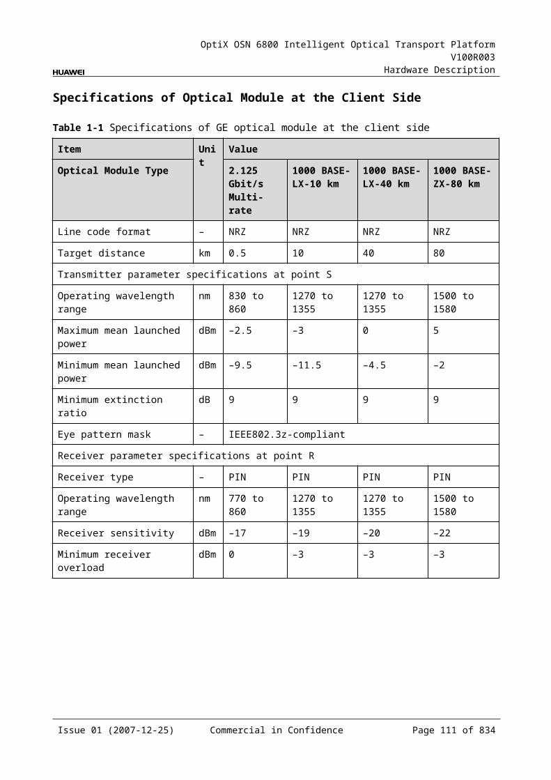
OptiX OSN 6800 Intelligent Optical Transport Platform V100R003
Hardware Description
Figure 5-1 Functional modules and signal flow of the LOG
OTU2
OTU2
Control and communication module
SCC
Backplane
Cross-connect andservice processing
module
Client-side
opticalmodule
WDM-side
opticalmodule
8
8
8
8
Client side WDM side
GE
GE
GE
In Transmit DirectionThe client-side optical module receives eight GE signals with IEEE 802.3z feature. It converts the optical signals into electrical signals and sends them to the cross-connect and service processing module.
The cross-connect and service processing module monitors the performance of client-side services, then
Multiplexes the eight signals into one OTU2 signal and sends the signal to a WDM-side optical module, or
Sends the eight signals to the cross-connection board or a board in the paired slot through the backplane to realize the grooming of electrical signals, or
Receives the electrical signals sent from cross-connection board or a board in the paired slot through the backplane, multiplexes the signals into one OTU2 signal, and sends the signal to a WDM-side optical module.
The WDM-side optical module converts the electrical signal into ITU-T G.694.1-compliant standard DWDM signal and sends the signal to the WDM side.
In Receive DirectionThe WDM-side optical module receives a OTU2 optical signal and converts the it into electrical signal.
The cross-connect and service processing module extracts and processes the overhead bytes, monitors the WDM-side performance, and demultiplexes the signal into eight GE signals at 1.25 Gbit/s rate. Then, the module
Sends the eight signals to the client-side optical module, or Sends the eight signals to the cross-connection board or a board in the paired
slot through the backplane to realize the grooming of electrical signals, or Or it receives the electrical signals sent from cross-connection board or a board
in the paired slot through the backplane, multiplexes the signals into optical signals, and sends the signals to a WDM-side optical module.
Issue 01 (2007-12-25) Commercial in Confidence Page 109 of 664
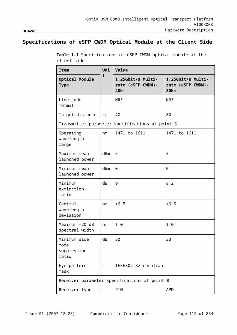
OptiX OSN 6800 Intelligent Optical Transport Platform V100R003
Hardware Description
The client-side optical module converts the eight electrical signals into optical signals and then sends the signals to the client side.
Cross-Connect and Service Processing Module This module realizes the grooming of electrical signals between the LOG and the
board in the paired slot or the cross-connect board through the backplane. The grooming service signals are GE signals. This module realizes the cross-connection of eight service signals each through
the working/protection cross-connection boards respectively. This module realizes the cross-connection of eight service signals between the
boards in paired slots. This module extracts and processes overhead bytes. This module monitors the performance of services. This module multiplexes and demultiplexes GE services. This module implements the encapsulation of OTN signals.
Control and Communication ModuleThe control and communication module realizes the control, monitoring and communications management of each functional module of the board.
The control and communication module collects the information, such as the alarms and performance events, working status, and voltage detection, of each functional module of the board and reports to the SCC.
Receiving the commands from the SCC, the control and communication module controls and coordinates the functional modules of the board in working.
5.5.5 Front PanelThere are indicators, interfaces and laser safety label on the LOG front panel.
Appearance of the Front PanelFigure 5-16 shows the LOG front panel.
Issue 01 (2007-12-25) Commercial in Confidence Page 110 of 664

OptiX OSN 6800 Intelligent Optical Transport Platform V100R003
Hardware Description
Figure 5-1 LOG front panel
STATACTPROGSRV
TX2
RX
2TX
3R
X3
TX4
RX
4TX
5R
X5
TX6
RX
6TX
1R
X1
TX7
RX
7TX
8R
X8
OU
TIN
CLASS 1LASER
PRODUCT
LOG
LOG
IndicatorsThere are four indicators on the front panel.
Board hardware status indicator (STAT) – dual-colored (red, green) Service active status indicator (ACT) – green Board software status indicator (PROG) – dual-colored (red, green) Service alarm indicator (SRV) – triple-colored (red, green, yellow)
InterfacesThere are 18 optical interfaces on the LOG front panel.Table 5-30 lists the type and function of each interface.
Issue 01 (2007-12-25) Commercial in Confidence Page 111 of 664
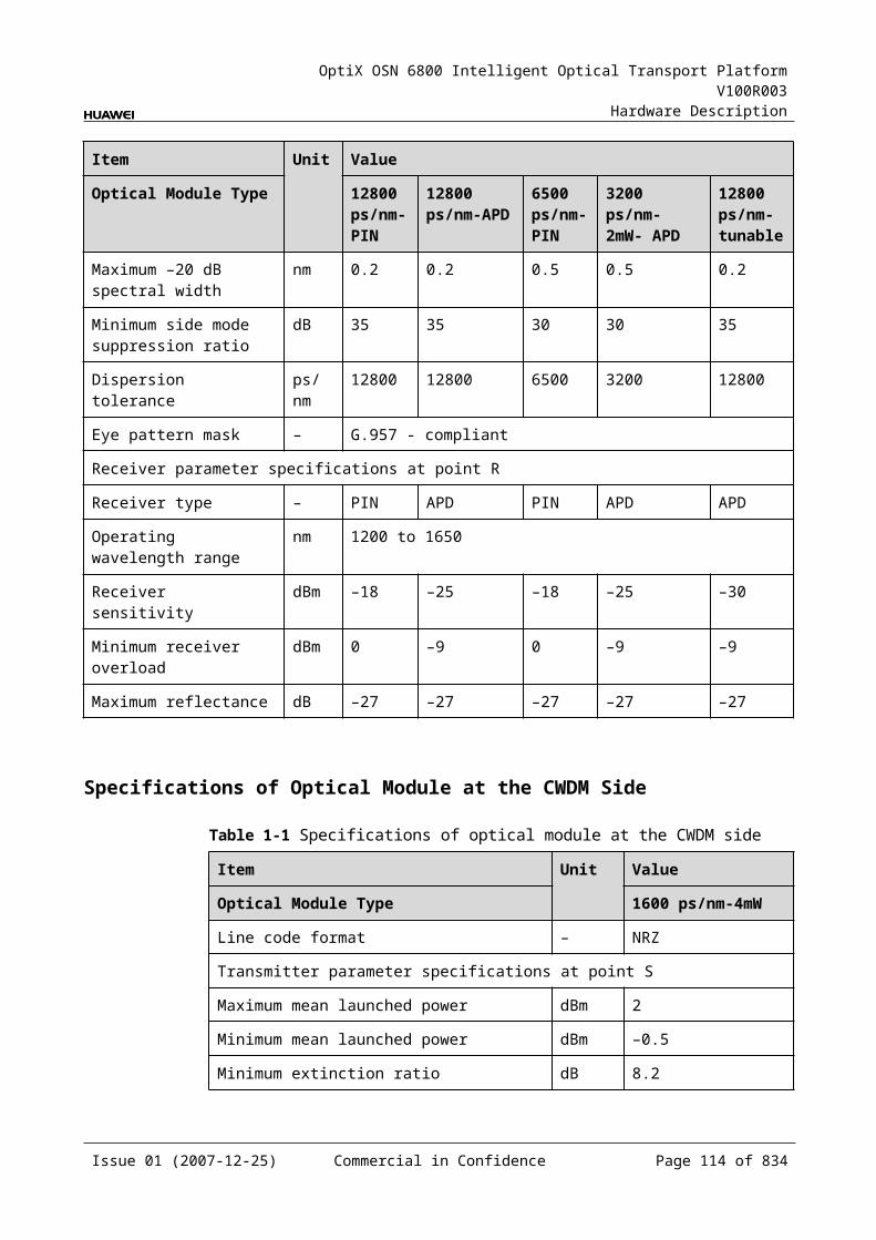
OptiX OSN 6800 Intelligent Optical Transport Platform V100R003
Hardware Description
Table 5-1 Types and functions of the LOG interfaces
Interface
Type
Function
IN LC Receives the single-channel signal from the optical demultiplexer unit or the optical add and drop multiplexing unit.
OUT LC Transmits the single-channel signal to the optical multiplexer unit or the optical add and drop multiplexing unit.
TX1-TX8 LC Transmits the service signal to the client-side equipment.
RX1-RX8 LC Receives the service signal from the client-side equipment.
Laser Safety LevelThe laser safety level of the optical interface is CLASS 1.
The maximum output optical power of each optical interface is lower than 10 dBm (10 mW).
5.5.6 Valid SlotsThe LOG occupies one slot. The valid slots for the LOG are IU1–IU8 and IU11–IU16.
5.5.7 Characteristic Code for the LOGThe board characteristic code comprises the information about frequency of signals, type of the optical module, wavelength, and so on.
For the detailed description of the characteristic code for the board, refer to B.2 Characteristic Code for OTUs.
5.5.8 NM Configuration ReferenceNM configuration reference includes the reference information needed during the configuration of boards through the T2000.
Display of Optical InterfacesThe serial numbers of the optical interfaces on the panel of the board displayed on the NM are listed in Table 5-31.
Table 5-1 Serial numbers of the interfaces of the LOG displayed on the NM
Interface on the Panel Interface on the NM
IN/OUT 1
TX1/RX1 3
TX2/RX2 4
TX3/RX3 5
Issue 01 (2007-12-25) Commercial in Confidence Page 112 of 664
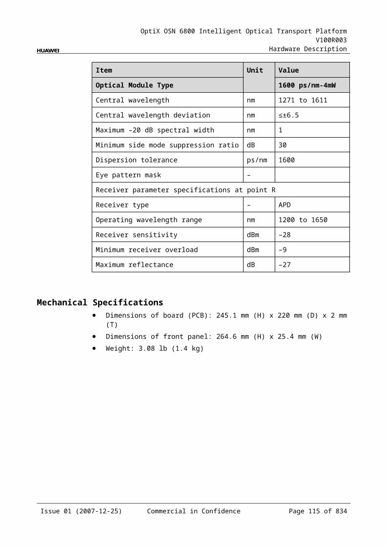
OptiX OSN 6800 Intelligent Optical Transport Platform V100R003
Hardware Description
Interface on the Panel Interface on the NM
TX4/RX4 6
TX5/RX5 7
TX6/RX6 8
TX7/RX7 9
TX8/RX8 10
NOTEThe number of an interface displayed on the T2000 in fact indicates a pair of physical optical interfaces, of which one is used to transmit signals and the other is used to receive signals.
Configuration ParametersPath Use Status
Optical Interface Loopback
Laser Status
Automatic Laser Shutdown
FEC Working State
FEC Type
Configure Wavelength No./Wavelength (nm)/Frequency (THz)
Configure Band Type
Maximum Packet Length
Ethernet Working Mode
5.5.9 Specifications of the LOGSpecifications include optical specifications, dimensions, weight, and power consumption.
Issue 01 (2007-12-25) Commercial in Confidence Page 113 of 664
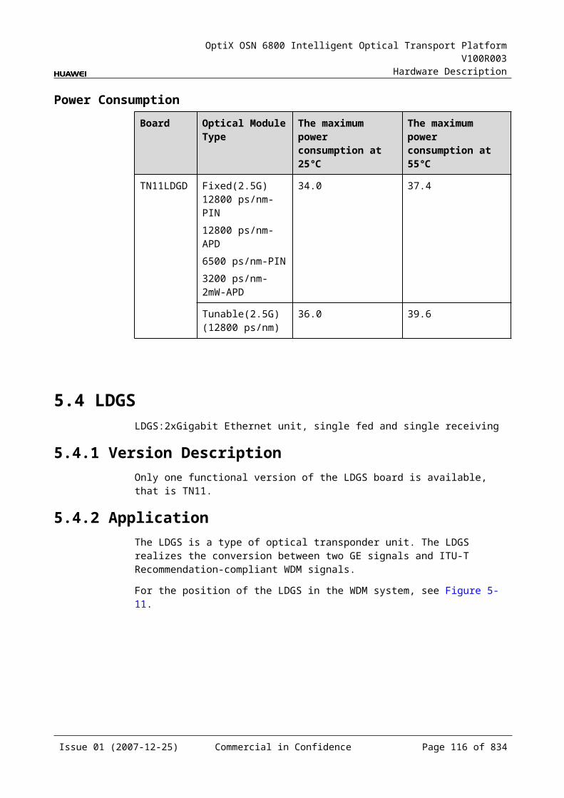
OptiX OSN 6800 Intelligent Optical Transport Platform V100R003
Hardware Description
Specifications of optical module at the client side
Table 5-1 Specifications of GE optical module at the client side
Item Unit
Value
Optical Module Type 2.125G Multirate
1000 BASE-LX-10 km
1000 BASE-LX-40 km
1000 BASE-ZX-80 km
Line code format – NRZ NRZ NRZ NRZ
Target distance km 0.5 10 40 80
Transmitter parameter specifications at point S
Operating wavelength range nm 830 to 860 1270 to 1355 1270 to 1355 1500 to 1580
Maximum mean launched power dBm –2.5 –3 0 5
Minimum mean launched power dBm –9.5 –11.5 –4.5 –2
Minimum extinction ratio dB 9 9 9 9
Eye pattern mask – IEEE802.3z-compliant
Receiver parameter specifications at point R
Receiver type – PIN PIN PIN PIN
Operating wavelength range nm 770 to 860 1270 to 1355 1270 to 1355 1500 to 1580
Receiver sensitivity dBm –17 –19 –20 –22
Minimum receiver overload dBm 0 –3 –3 –3
Table 5-2 Specifications of eSFP CWDM optical module at the client side
Item Unit
Value
Optical Module Type 1.25Gbit/s Multi-rate (eSFP CWDM)-40km
2.67Gbit/s Multi-rate(eSFP CWDM)-80km
Line code format – NRZ NRZ
Target distance km 40 80
Transmitter parameter specifications at point S
Operating wavelength range nm 1471 to 1611 1471 to 1611
Maximum mean launched power dBm 5 5
Minimum mean launched power dBm 0 0
Minimum extinction ratio dB 9 8.2
Issue 01 (2007-12-25) Commercial in Confidence Page 114 of 664
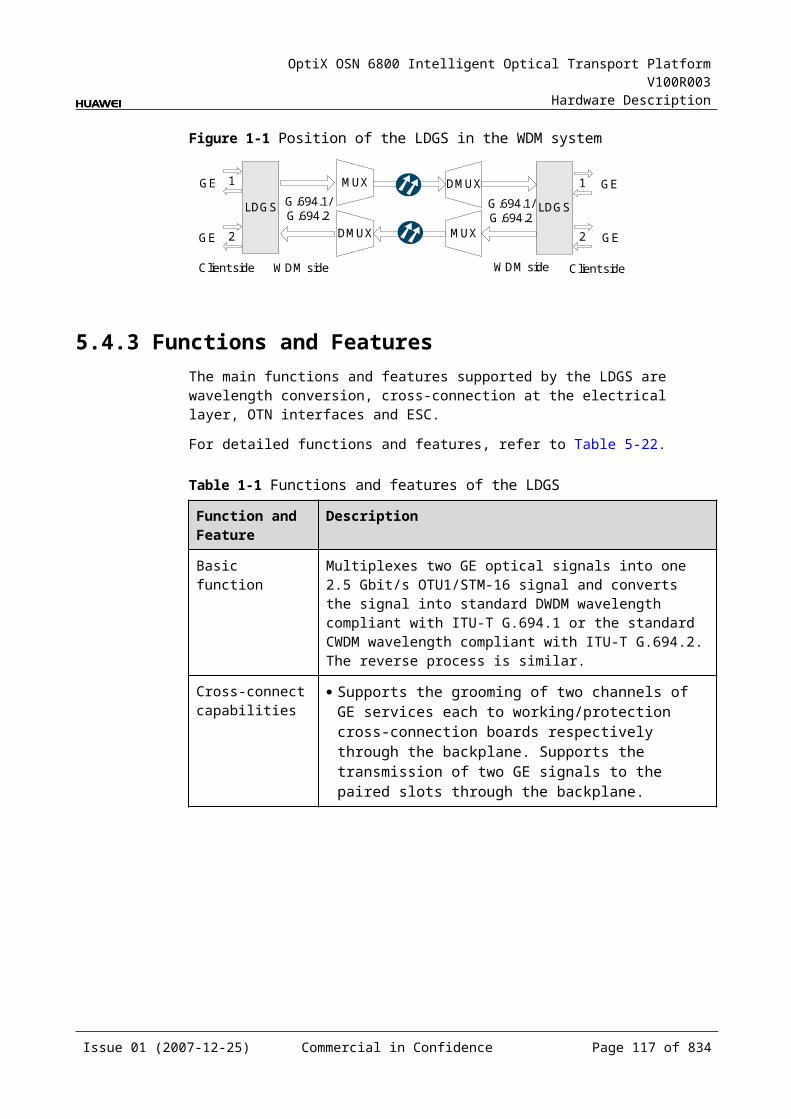
OptiX OSN 6800 Intelligent Optical Transport Platform V100R003
Hardware Description
Item Unit
Value
Optical Module Type 1.25Gbit/s Multi-rate (eSFP CWDM)-40km
2.67Gbit/s Multi-rate(eSFP CWDM)-80km
Central wavelength deviation nm ±6.5 ±6.5
Maximum –20 dB spectral width nm 1 1
Minimum side mode suppression ratio
dB 30 30
Eye pattern mask – IEEE802.3z-compliant G.957-compliant
Receiver parameter specifications at point R
Receiver type – PIN APD
Operating wavelength range nm 1270 to 1620 1270 to 1620
Receiver sensitivity dBm –19 –28
Minimum receiver overload dBm –3 –9
Maximum reflectance dB –27 –27
Specifications of optical module at the DWDM side
Table 5-1 Specifications of fixed optical module at the DWDM side
Item Unit Value
Optical Module Type
800 ps/nm 1600 ps/nm 800 ps/nm
Line code format – NRZ- 40 channels fixed
NRZ- 40 channels fixed
NRZ- 80 channels fixed
Transmitter parameter specifications at point S
Maximum mean launched power
dBm 2 4 2
Minimum mean launched power
dBm –3 0 –3
Minimum extinction ratio
dB 10 9 10
Central frequency THz 192.10 to 196.00
Central frequency deviation
GHz ±10 ±10 ±5
Maximum –20 dB spectral width
nm 0.3 0.3 0.3
Issue 01 (2007-12-25) Commercial in Confidence Page 115 of 664
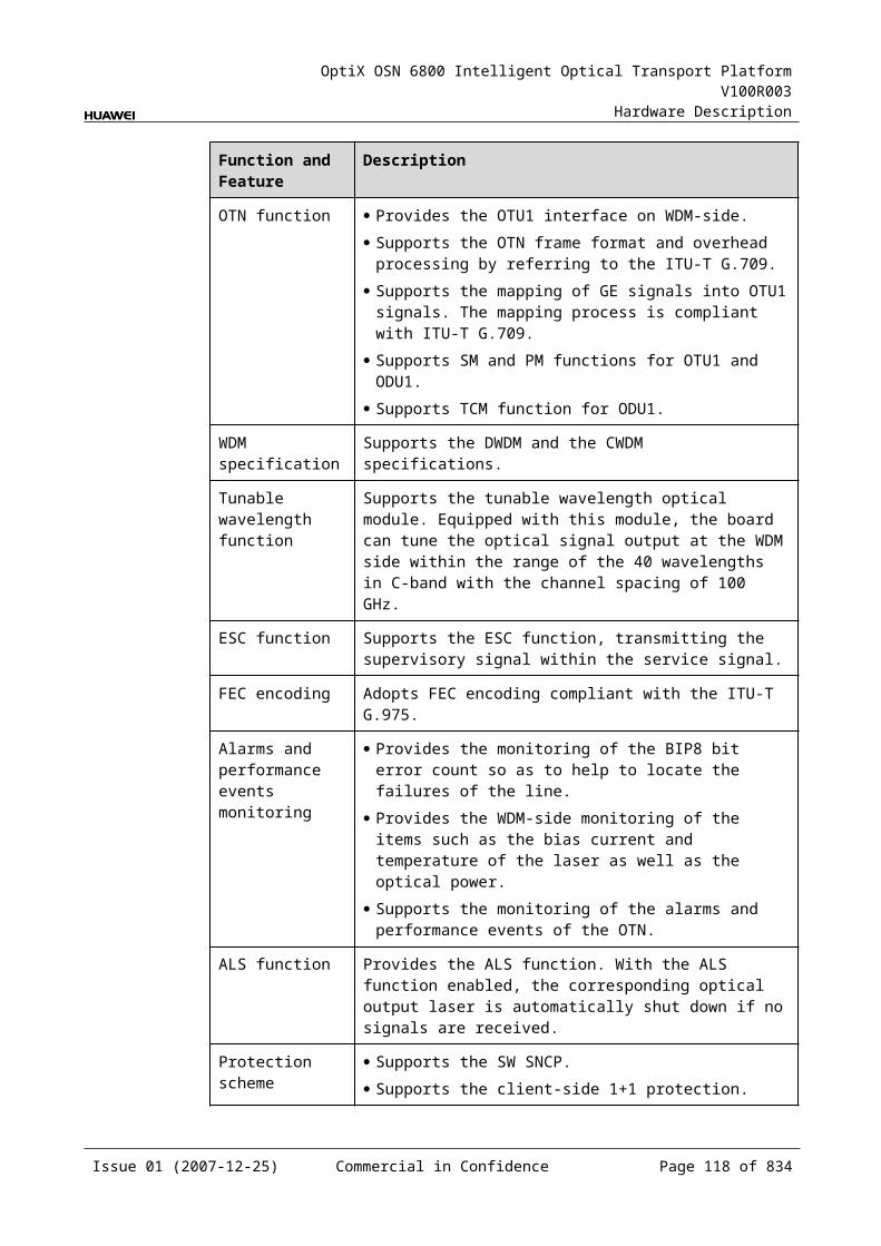
OptiX OSN 6800 Intelligent Optical Transport Platform V100R003
Hardware Description
Item Unit Value
Optical Module Type
800 ps/nm 1600 ps/nm 800 ps/nm
Minimum side mode suppression ratio
dB 35 35 35
Dispersion tolerance ps/nm 800 1600 800
Receiver parameter specifications at point R
Receiver type – PIN APD PIN
Operating wavelength range
nm 1200 to 1650
Receiver sensitivity (FEC on) EOL
dBm –16 –26 –16
Minimum receiver overload
dBm 0 –9 0
Maximum reflectance dB –27 –27 –27
Table 5-2 Specifications of tunable optical module at the DWDM side
Item Unit Value
Optical Module Type 1200 ps/nm - tunable- PIN
1200 ps/nm - tunable- APD
4800 ps/nm -ODB- tunable
800 ps/nm- DRZ-tunable
Line code format – NRZ- 80 channels tunable
NRZ- 80 channels tunable
ODB- 80 channels tunable
DRZ- 80 channels tunable
Transmitter parameter specifications at point S
Maximum mean launched power
dBm 2 2 2 2
Minimum mean launched power
dBm –3 –3 –3 –3
Minimum extinction ratio dB 10 10 NAa 10
Central frequency THz 192.10 to 196.05
Central frequency deviation
GHz ±5 ±5 ±5 ±5
Maximum –20 dB spectral width
nm 0.3 0.3 0.3 0.3
Issue 01 (2007-12-25) Commercial in Confidence Page 116 of 664
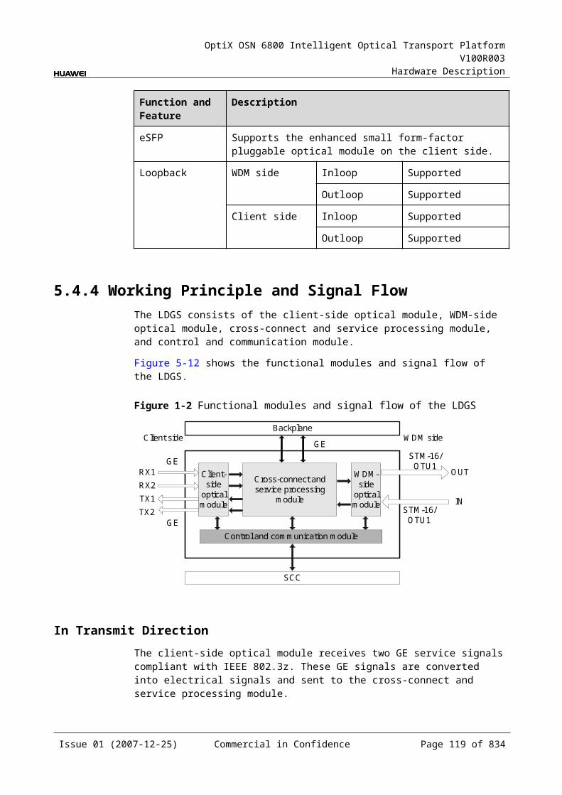
OptiX OSN 6800 Intelligent Optical Transport Platform V100R003
Hardware Description
Item Unit Value
Optical Module Type 1200 ps/nm - tunable- PIN
1200 ps/nm - tunable- APD
4800 ps/nm -ODB- tunable
800 ps/nm- DRZ-tunable
Minimum side mode suppression ratio
dB 35 35 35 35
Dispersion tolerance ps/nm 1200 1200 4800 800
Receiver parameter specifications at point R
Receiver type – PIN APD APD PIN
Operating wavelength range
nm 1200 to 1650
Receiver sensitivity (FEC on) EOL
dBm –16 –26 –26 –16
Minimum receiver overload
dBm 0 –9 –9 0
Maximum reflectance dB –27 –27 –27 –27
a: The ODB code pattern has three levels, and thus extinction ratio is not needed.
Mechanical Specifications Dimensions of board (PCB): 245.1 mm (H) x 220 mm (D) x 2 mm (T) Dimensions of front panel: 264.6 mm (H) x 25.4 mm (W) Weight: 3.53 lb (1.6 kg)
Power ConsumptionBoard Optical Module Type The maximum
power consumption at 25
The maximum power consumption at 55
TN11LOG NRZ-fixed(10G)(800 ps/nm-40 channels fixed1600 ps/nm-40 channels fixed
49.5 54.5
NRZ-tunable(10G)(1200 ps/nm-PIN-80 channels tunable1200 ps/nm-APD-80 channels tunable)
50.0 55.0
DRZ-tunable(10G) (800 ps/nm-80 channels tunable)
51.2 56.1
Issue 01 (2007-12-25) Commercial in Confidence Page 117 of 664
OptiX OSN 6800 Intelligent Optical Transport Platform V100R003
Hardware Description
ODB-tunable(10G) (4800 ps/nm-80 channels tunable)
55.0 60.5
5.6 LOMLOM: 8-port multi-service multiplexing & optical wavelength conversion board (AFEC)
5.6.1 Version DescriptionOnly one functional version of the LOM board is available, that is TN11.
5.6.2 ApplicationThe LOM is a type of optical transponder unit. The LOM multiplexes a maximum of eight GE/FC100/FICON, four FC200/FICON 2G, or two FC400 signals into one OTU2 signal. It also realizes conversion between these signals and ITU-T Recommendation-compliant WDM signals. The LOM board supports FC extension and ensures that the signal width does not decrease during long-haul transmission of FC services.
For the position of the LOM in the WDM system, see Figure 5-17.
Figure 5-1 Position of the LOM in the WDM system
Client side WDM side
MUX
DMUX
LOM
DMUX
MUX
LOM
1
8
1
8
G.694.1 G.694.1
WDM side Client side
GE/FC100/FC200/FC400/FICON/FICON 2G
GE/FC100/FC200/FC400/FICON/FICON 2G
NOTE For GE, FC100, and FICON services, the eight pairs of optical interfaces on the client side
are all available. For FICON 2G and FC200 services, though any optical interface can access the FICON 2G
or FC200 services, only any two of the first and last four optical interfaces can access the FICON 2G or FC200 services at the same time.
For FC400 services, the client-side TX1/RX1 and TX5/RX5 are available.
5.6.3 Functions and FeaturesThe main functions and features supported by the LOM are wavelength conversion, OTN interfaces and ESC.
For detailed functions and features, refer to Table 5-36.
Issue 01 (2007-12-25) Commercial in Confidence Page 118 of 664
OptiX OSN 6800 Intelligent Optical Transport Platform V100R003
Hardware Description
Table 5-1 Functions and features of the LOM
Function and Feature
Description
Basic function Multiplexes eight channels of GE/FC100/FICON services, four FC200/FICON 2G services, or two FC400 service optical signals into one channel of OTU2 optical signals and converse them to DWDM standard wavelength that comply with ITU-T Recommendation G.694.1. It can also perform the reverse process.
Supports hybrid transmission of the services mentioned above. The overall bandwidth of the first and last four optical interfaces should be equal to or less than 4 Gbit/s, respectively.
The LOM board supports FC extension and ensures that the data width does not decrease during long-haul transmission of FC services. For FC100/FC200/FC400 services, the maximum transmission distance of the WDM side is 3000 km.
Client-side service type
GE/FC100/FC200/FC400/FICON/FICON 2G
OTN function Provides the OTU2 interface on WDM-side. Supports the OTN frame format and overhead processing by
referring to the ITU-T G.709. Supports the mapping of GE/FC100/FC200/FC400 signals into
OTU2/OTU2V signals. The mapping process is compliant with ITU-T G.709.
Supports SM and PM functions for OTU2 and ODU2. Supports TCM function for ODU2.
WDM specification
Supports the DWDM specifications.
Tunable wavelength function
Supports the tunable wavelength optical module. Equipped with this module, the board can tune the optical signal output at the WDM side within the range of: 40 wavelengths in C-band with the channel spacing of 100
GHz 80 wavelengths in C-band with the channel spacing of 50 GHz
ESC function Supports the ESC function, transmitting the supervisory signal within the service signal.
FEC encoding Supports FEC encoding compliant with the ITU-T G.975 and AFEC encoding compliant with the ITU-T G.975.1.
Alarms and performance events monitoring
Provides the function of optical power detection and the function to report the alarms and performance events of the board.
Issue 01 (2007-12-25) Commercial in Confidence Page 119 of 664

OptiX OSN 6800 Intelligent Optical Transport Platform V100R003
Hardware Description
Function and Feature
Description
ALS function Provides the ALS function. With the ALS function enabled, the corresponding optical output laser is automatically shut down if no signals are received.
Protection scheme
Supports the client-side 1+1 protection. Supports the intra-board 1+1 protection. Supports the OWSP protection.
eSFP Supports the enhanced small form-factor pluggable optical module on the client side.
Loopback WDM side Inloop Supported
Outloop Supported
Client side Inloop Supported
Outloop Supported
5.6.4 Working Principle and Signal FlowThe LOM consists of the client-side optical module, WDM-side optical module, service processing module, and control and communication module.
Figure 5-18 shows the functional modules and signal flow of the LOM.
Figure 5-1 Functional modules and signal flow of the LOM
WDM-side
opticalmodule
Control and communication module
SCC
Serviceprocessing
module
Client-side
opticalmodule
OTU2
Client side WDM side
8
8
8
8 OTU2
GE/FC100/FC200/FC400/FICON/FICON 2G
Issue 01 (2007-12-25) Commercial in Confidence Page 120 of 664
OptiX OSN 6800 Intelligent Optical Transport Platform V100R003
Hardware Description
NOTE For GE, FC100, and FICON services, the eight pairs of optical interfaces on the client side
are all available. For FICON 2G and FC200 services, though any optical interface can access the FICON 2G
or FC200 services, only any two of the first and last four optical interfaces can access the FICON 2G or FC200 services at the same time.
For FC400 services, the client-side TX1/RX1 and TX5/RX5 are available.
In Transmit DirectionThe client-side optical module receives eight GE/FC100/FICON signals, four FC200/FICON 2G signals, or two FC400 services. It converts the optical signals into electrical signals and sends them to the service processing module.
The service processing module monitors the performance of client-side services. Then it multiplexes the signals into one OTU2 signal and sends the signal to a WDM-side optical module.
The WDM-side optical module converts the electrical signal into ITU-T G.694.1-compliant standard DWDM signal and sends the signal to the WDM side.
In Receive DirectionThe WDM-side optical module receives a OTU2 optical signal and converts the it into electrical signal.
The service processing module extracts and processes the overhead bytes, monitors the WDM-side performance, and demultiplexes the signal into eight GE/FC100/FICON signals, or four FC200/FICON 2G signals, or two FC400 service electrical signals.
The client-side optical module converts the eight electrical signals into optical signals and then sends the signals to the client side.
Service Processing Module This module extracts and processes overhead bytes. This module monitors the performance of services. This module multiplexes and demultiplexes services. This module implements the encapsulation of OTN signals. This module provides FC distance extension.
Control and Communication ModuleThe control and communication module realizes the control, monitoring and communications management of each functional module of the board.
The control and communication module collects the information, such as the alarms and performance events, working status, and voltage detection, of each functional module of the board and reports to the SCC.
Receiving the commands from the SCC, the control and communication module controls and coordinates the functional modules of the board in working.
Issue 01 (2007-12-25) Commercial in Confidence Page 121 of 664
OptiX OSN 6800 Intelligent Optical Transport Platform V100R003
Hardware Description
5.6.5 Front PanelThere are indicators and interfaces on the LOM front panel.
Appearance of the Front PanelFigure 5-19 shows the LOM front panel.
Figure 5-1 LOM front panel
WSD9
WSD9
LASERRADIATION
DO NOT VIEW DIRECTLYWITH OPTICALINSTRUMENTS
CLASS 1M LASERPRODUCT
STATACTPROGSRV
DM
1D
M2
DM
3D
M4
EX
PO
IND
M5
DM
6M
ON
OM
ON
ID
M7
DM
8
WSD9
WSD9
LASERRADIATION
DO NOT VIEW DIRECTLYWITH OPTICALINSTRUMENTS
CLASS 1M LASERPRODUCT
STATACTPROGSRV
DM
1D
M2
DM
3D
M4
EX
PO
IND
M5
DM
6M
ON
OM
ON
ID
M7
DM
8
WSD9
WSD9
LASERRADIATION
DO NOT VIEW DIRECTLYWITH OPTICALINSTRUMENTS
CLASS 1M LASERPRODUCT
STATACTPROGSRV
DM
1D
M2
DM
3D
M4
EX
PO
IND
M5
DM
6M
ON
OM
ON
ID
M7
DM
8
WSD9
WSD9
LASERRADIATION
DO NOT VIEW DIRECTLYWITH OPTICALINSTRUMENTS
CLASS 1M LASERPRODUCT
STATACTPROGSRV
DM
1D
M2
DM
3D
M4
EX
PO
IND
M5
DM
6M
ON
OM
ON
ID
M7
DM
8
WSD9
WSD9
LASERRADIATION
DO NOT VIEW DIRECTLYWITH OPTICALINSTRUMENTS
CLASS 1M LASERPRODUCT
STATACTPROGSRV
DM
1D
M2
DM
3D
M4
EX
PO
IND
M5
DM
6M
ON
OM
ON
ID
M7
DM
8
WSD9
WSD9
LASERRADIATION
DO NOT VIEW DIRECTLYWITH OPTICALINSTRUMENTS
CLASS 1M LASERPRODUCT
STATACTPROGSRV
DM
1D
M2
DM
3D
M4
EX
PO
IND
M5
DM
6M
ON
OM
ON
ID
M7
DM
8
LOM
LOM
STATACTPROGSRV
RX
2TX
3R
X3
TX4
RX
4TX
1R
X1
TX2
TX5
RX
5TX
6R
X6
TX7
RX
7TX
8R
X8
LINK/ACT1LINK/ACT2LINK/ACT3LINK/ACT4LINK/ACT5LINK/ACT6LINK/ACT7LINK/ACT8
OU
TIN
IndicatorsThere are twelve indicators on the front panel.
Board hardware status indicator (STAT) – dual-colored (red, green) Service active status indicator (ACT) – green Board software status indicator (PROG) – dual-colored (red, green) Service alarm indicator (SRV) – triple-colored (red, green, yellow)
Issue 01 (2007-12-25) Commercial in Confidence Page 122 of 664
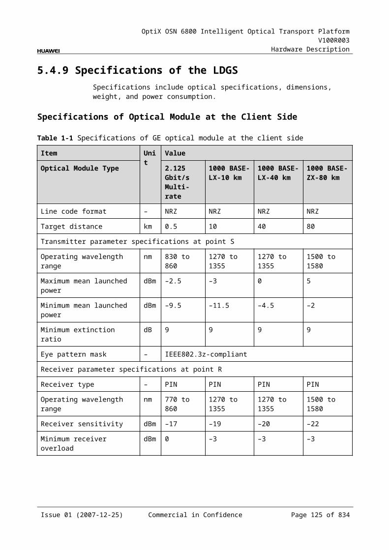
OptiX OSN 6800 Intelligent Optical Transport Platform V100R003
Hardware Description
Data port connection/data transceive indicator (LINK/ACTn) – green
InterfacesThere are 18 optical interfaces on the LOM front panel. Table 5-37 lists the type and function of each interface.
Table 5-1 Types and functions of the LOM interfaces
Interface
Type
Function
IN LC Receives the single-channel signal from the optical demultiplexer unit or the optical add and drop multiplexing unit.
OUT LC Transmits the single-channel signal to the optical multiplexer unit or the optical add and drop multiplexing unit.
TX1-TX8 LC Transmits the service signal to the client-side equipment.
RX1-RX8 LC Receives the service signal from the client-side equipment.
NOTE For GE, FC100, and FICON services, the eight pairs of optical interfaces on the client side
are all available. For FICON 2G and FC200 services, though any optical interface can access the FICON 2G
or FC200 services, only any two of the first and last four optical interfaces can access the FICON 2G or FC200 services at the same time.
For FC400 services, the client-side TX1/RX1 and TX5/RX5 are available.
Laser Safety LevelThe laser safety level of the optical interface is CLASS 1.
The maximum output optical power of each optical interface is lower than 10 dBm (10 mW).
5.6.6 Valid SlotsThe LOM occupies two slots. The valid slots for the LOM are IU1-IU8 and IU11-IU16 in the subrack.
The back connector of the board is mounted to the backplane along the left slot of the two occupied slots in the subrack, so the slot number of the LOM board displayed on the NM is the number of the left slot.
For example, if the LOM occupies slots IU1 and IU2, the slot number of the LOM displayed on the NM is IU1.
5.6.7 Characteristic Code for the LOMThe board characteristic code comprises the information about frequency of signals, type of the optical module, wavelength, and so on.
Issue 01 (2007-12-25) Commercial in Confidence Page 123 of 664
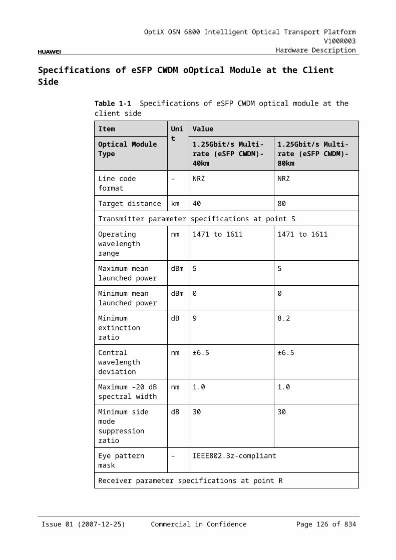
OptiX OSN 6800 Intelligent Optical Transport Platform V100R003
Hardware Description
For the detailed description of the characteristic code for the board, refer to B.2 Characteristic Code for OTUs.
5.6.8 NM Configuration ReferenceNM configuration reference includes the reference information needed during the configuration of boards through the T2000.
Display of Optical InterfacesThe serial numbers of the optical interfaces on the panel of the board displayed on the NM are listed in Table 5-38.
Table 5-1 Serial numbers of the interfaces of the LOM displayed on the NM
Interface on the Panel Interface on the NM
IN/OUT 1
TX1/RX1 3
TX2/RX2 4
TX3/RX3 5
TX4/RX4 6
TX5/RX5 7
TX6/RX6 8
TX7/RX7 9
TX8/RX8 10
NOTEThe number of an interface displayed on the T2000 in fact indicates a pair of physical optical interfaces, of which one is used to transmit signals and the other is used to receive signals.
Configuration ParametersPath Use Status
Optical Interface Loopback
Service Type
Laser Status
Automatic Laser Shutdown
FEC Working State
FEC Type
Configure Wavelength No./Wavelength (nm)/Frequency (THz)
Configure Band Type
Issue 01 (2007-12-25) Commercial in Confidence Page 124 of 664
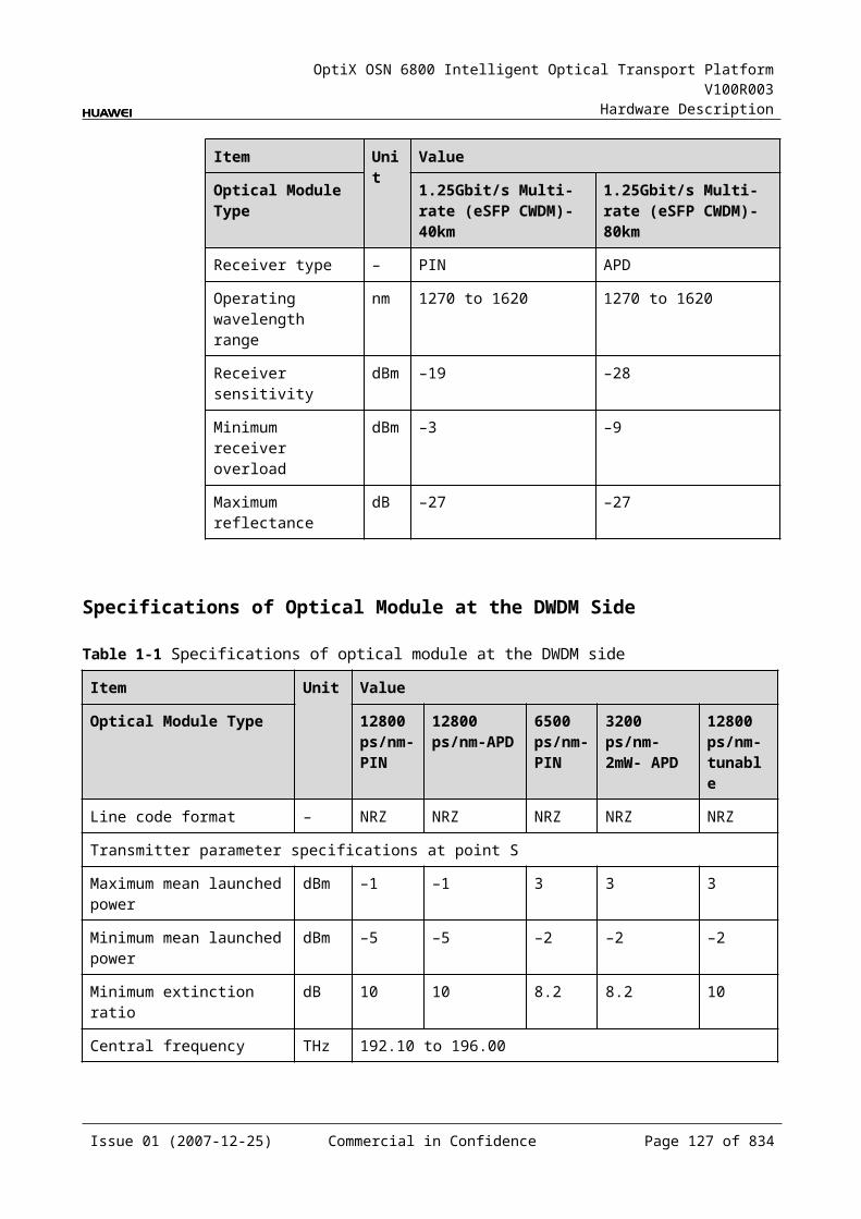
OptiX OSN 6800 Intelligent Optical Transport Platform V100R003
Hardware Description
Maximum Packet Length
Ethernet Working Mode
FC Distance Extension
5.6.9 Specifications of the LOMSpecifications include optical specifications, dimensions, weight, and power consumption.
Specifications of Optical Module at the Client Side
Table 5-1 Specifications of GE optical module at the client side
Item Unit
Value
Optical Module Type 2.125G Multirate
1000 BASE-LX-10 km
1000 BASE-LX-40 km
1000 BASE-ZX-80 km
Line code format – NRZ NRZ NRZ NRZ
Target distance km 0.5 10 40 80
Transmitter parameter specifications at point S
Operating wavelength range
nm 830 to 860 1270 to 1355 1270 to 1355 1500 to 1580
Maximum mean launched power
dBm –2.5 –3 0 5
Minimum mean launched power
dBm –9.5 –11.5 –4.5 –2
Minimum extinction ratio dB 9 9 9 9
Eye pattern mask – IEEE802.3z-compliant
Receiver parameter specifications at point R
Receiver type – PIN PIN PIN PIN
Operating wavelength range
nm 770 to 860 1270 to 1355 1270 to 1355 1500 to 1580
Receiver sensitivity dBm –17 –19 –20 –22
Minimum receiver overload dBm 0 –3 –3 –3
Issue 01 (2007-12-25) Commercial in Confidence Page 125 of 664
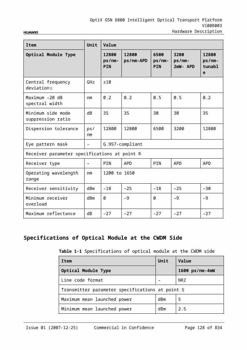
OptiX OSN 6800 Intelligent Optical Transport Platform V100R003
Hardware Description
Table 5-2 Specifications of FC optical module at the client side
Item Unit
Value
Optical Module Type
FC400 Module FC100/FC200/FICON/FICON 2G module
Multimode
Single mode
Multimode Single mode
Line code format – NRZ NRZ NRZ NRZ
Target distance km 0.3 10 0.5 2
Transmitter parameter specifications at point S
Transmitter parameter specifications at point S
nm 830 to 860 1270 to 1355
830 to 860 1266 to 1360
Maximum mean launched power
dBm –1 –2 –2.5 –3
Minimum mean launched power
dBm –9 –8 –9.5 –10
Eye pattern mask – Compliant with Fiber Channel-physical interface (FC-PI-2) parameter template
Receiver parameter specifications at point R
Receiver type – PIN PIN PIN PIN
Operating wavelength range
nm 770 to 860 1260 to 1600
770 to 860 1270 to 1580
Receiver sensitivity dBm –14 –16 –17 –18
Minimum receiver overload
dBm 0 0 0 0
Maximum reflectance dB –12 –12 –12 –27
Table 5-3 Specifications of eSFP CWDM optical module at the client side
Item Unit
Value
Optical Module Type
1.25Gbit/s Multi-rate(eSFP CWDM)-40km
2.67Gbit/s Multi-rate (eSFP CWDM)-80km
Line code format – NRZ NRZ
Target distance km 40 80
Transmitter parameter specifications at point S
Issue 01 (2007-12-25) Commercial in Confidence Page 126 of 664
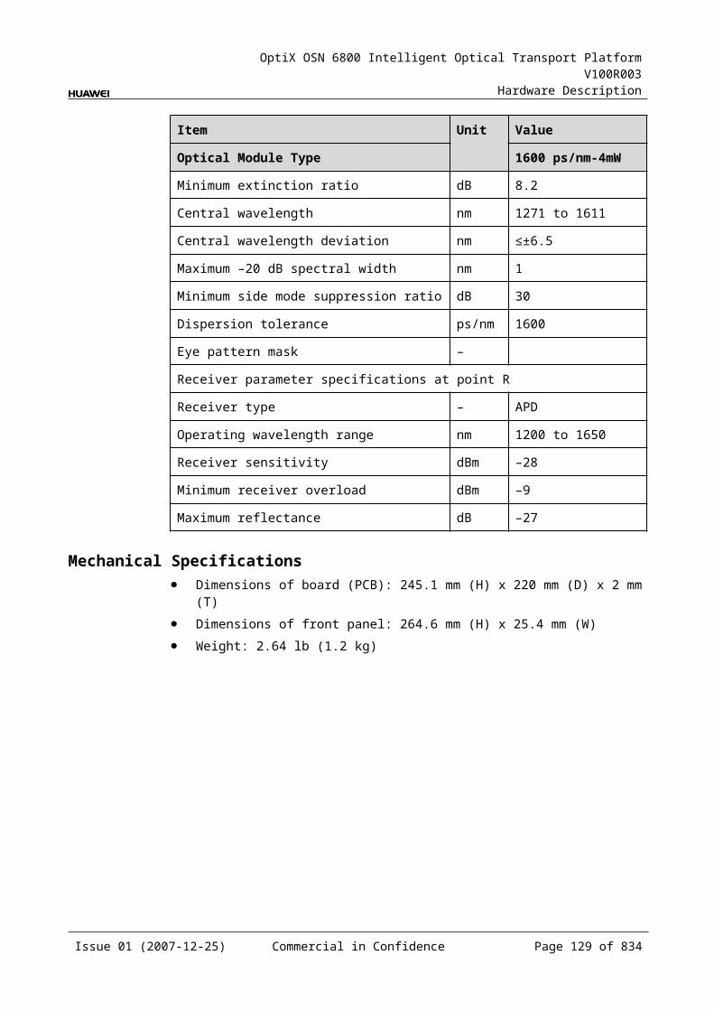
OptiX OSN 6800 Intelligent Optical Transport Platform V100R003
Hardware Description
Item Unit
Value
Optical Module Type
1.25Gbit/s Multi-rate(eSFP CWDM)-40km
2.67Gbit/s Multi-rate (eSFP CWDM)-80km
Operating wavelength range
nm 1471 to 1611 1471 to 1611
Maximum mean launched power
dBm 5 5
Minimum mean launched power
dBm 0 0
Minimum extinction ratio
dB 9 8.2
Central wavelength deviation
nm ±6.5 ±6.5
Maximum –20 dB spectral width
nm 1 1
Minimum side mode suppression ratio
dB 30 30
Eye pattern mask – IEEE802.3z-compliant G.957-compliant
Receiver parameter specifications at point R
Receiver type – PIN APD
Operating wavelength range
nm 1270 to 1620 1270 to 1620
Receiver sensitivity
dBm –19 –28
Minimum receiver overload
dBm –3 –9
Maximum reflectance
dB –27 –27
Issue 01 (2007-12-25) Commercial in Confidence Page 127 of 664
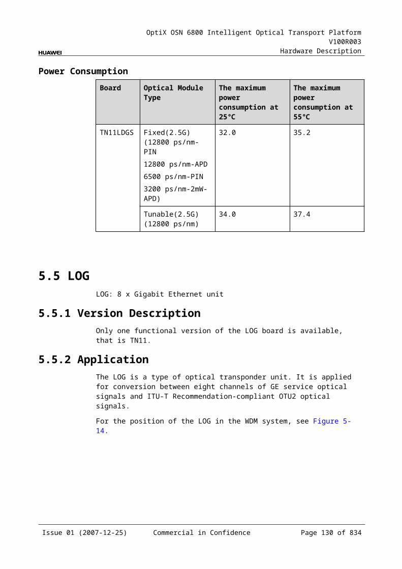
OptiX OSN 6800 Intelligent Optical Transport Platform V100R003
Hardware Description
Specifications of Optical Module at the DWDM Side
Table 5-1 Specifications of fixed optical module at the DWDM side
Item Unit Value
Optical Module Type
800 ps/nm 1600 ps/nm 800 ps/nm
Line code format – NRZ- 40 channels fixed
NRZ- 40 channels fixed
NRZ- 80 channels fixed
Transmitter parameter specifications at point S
Maximum mean launched power
dBm 2 4 2
Minimum mean launched power
dBm –3 0 –3
Minimum extinction ratio
dB 10 9 10
Central frequency THz 192.10 to 196.00
Central frequency deviation
GHz ±10 ±10 ±5
Maximum –20 dB spectral width
nm 0.3 0.3 0.3
Minimum side mode suppression ratio
dB 35 35 35
Dispersion tolerance ps/nm 800 1600 800
Receiver parameter specifications at point R
Receiver type – PIN APD PIN
Operating wavelength range
nm 1200 to 1650
Receiver sensitivity (FEC on) EOL
dBm –16 –26 –16
Minimum receiver overload
dBm 0 –9 0
Maximum reflectance dB –27 –27 –27
Issue 01 (2007-12-25) Commercial in Confidence Page 128 of 664
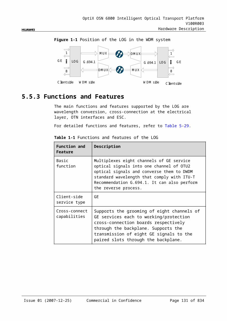
OptiX OSN 6800 Intelligent Optical Transport Platform V100R003
Hardware Description
Table 5-2 Specifications of tunable optical module at the DWDM side
Item Unit Value
Optical Module Type 1200 ps/nm - tunable- PIN
1200 ps/nm - tunable- APD
4800 ps/nm -ODB- tunable
800 ps/nm- DRZ-tunable
Line code format – NRZ- 80 channels tunable
NRZ- 80 channels tunable
ODB- 80 channels tunable
DRZ- 80 channels tunable
Transmitter parameter specifications at point S
Maximum mean launched power
dBm 2 2 2 2
Minimum mean launched power
dBm –3 –3 –3 –3
Minimum extinction ratio dB 10 10 NAa 10
Central frequency THz 192.10 to 196.05
Central frequency deviation GHz ±5 ±5 ±5 ±5
Maximum –20 dB spectral width
nm 0.3 0.3 0.3 0.3
Minimum side mode suppression ratio
dB 35 35 35 35
Dispersion tolerance ps/nm 1200 1200 4800 800
Receiver parameter specifications at point R
Receiver type – PIN APD APD PIN
Operating wavelength range nm 1200 to 1650
Receiver sensitivity (FEC on) EOL
dBm –16 –26 –26 –16
Minimum receiver overload dBm 0 –9 –9 0
Maximum reflectance dB –27 –27 –27 –27
a: The ODB code pattern has three levels, and thus extinction ratio is not needed.
Mechanical Specifications Dimensions of board (PCB): 245.1 mm (H) x 220 mm (D) x 2 mm (T) Dimensions of front panel: 264.6 mm (H) x 50.8 mm (W) Weight: 5.11 lb (2.32 kg)
Issue 01 (2007-12-25) Commercial in Confidence Page 129 of 664
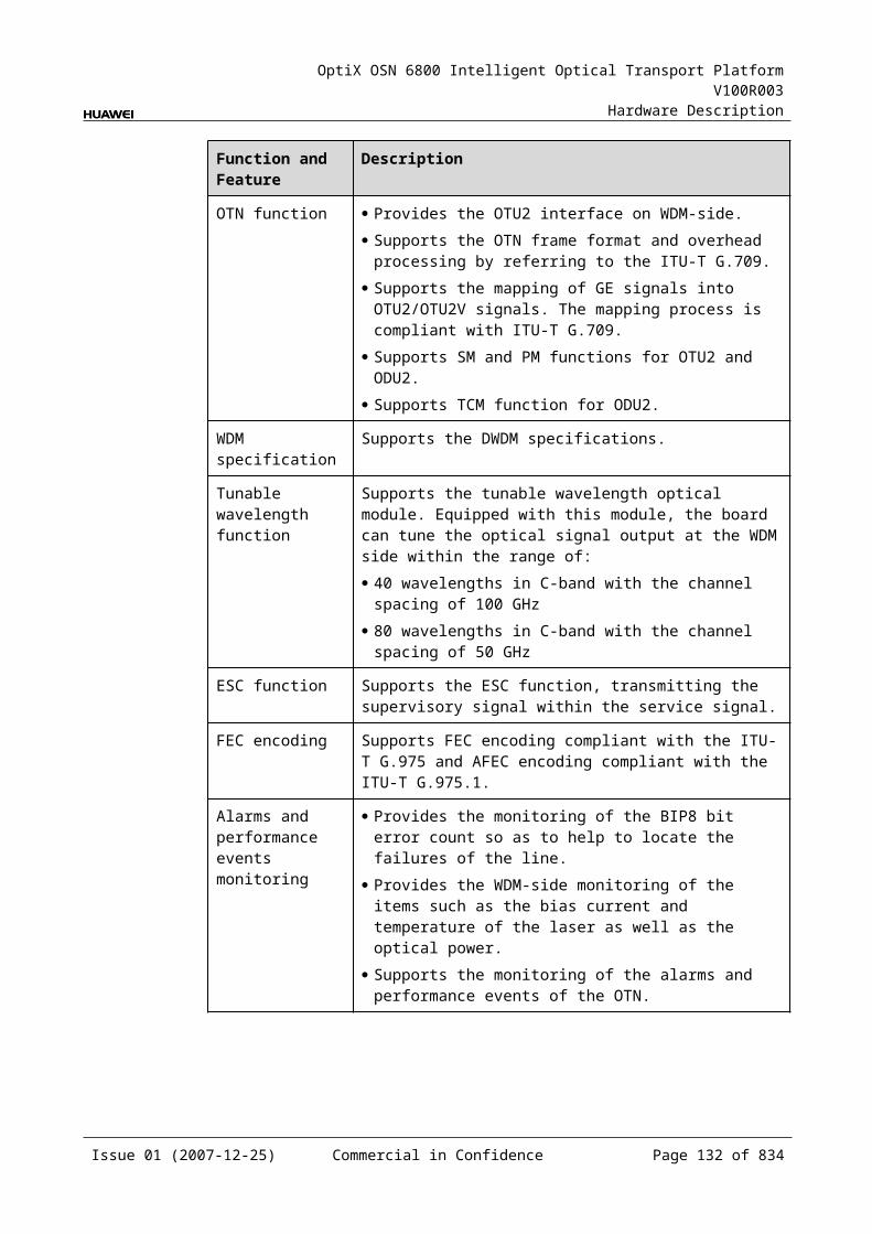
OptiX OSN 6800 Intelligent Optical Transport Platform V100R003
Hardware Description
Power ConsumptionBoard Optical Module Type The maximum
power consumption at 25
The maximum power consumption at 55
TN11LOM NRZ-fixed(10G)(800 ps/nm-40 channels fixed1600 ps/nm-40 channels fixed
92.7 101.7
NRZ-tunable(10G)(1200 ps/nm-PIN-80 channels tunable1200 ps/nm-APD-80 channels tunable)
92.9 101.9
DRZ-tunable(10G) (800 ps/nm-80 channels tunable)
93.4 102.7
ODB-tunable(10G) (4800 ps/nm-80 channels tunable)
98.2 108.0
5.7 LQMDLQMD: 4-channel multi-rate (100 Mbit/s-2.5 Gbit/s) wavelength conversion unit, dual fed and selective receiving
5.7.1 Version DescriptionOnly one functional version of the LQMD board is available, that is TN11.
5.7.2 ApplicationThe LQMD is a type of optical transponder unit. The LQMD realizes the conversion between signals at the rate between 100 Mbit/s–2.5 Gbit/s and ITU-T Recommendation-compliant WDM signals, and the dual fed and selective receiving function on the WDM side.
For the position of the LQMD in the WDM system, see Figure 5-20.
Issue 01 (2007-12-25) Commercial in Confidence Page 130 of 664
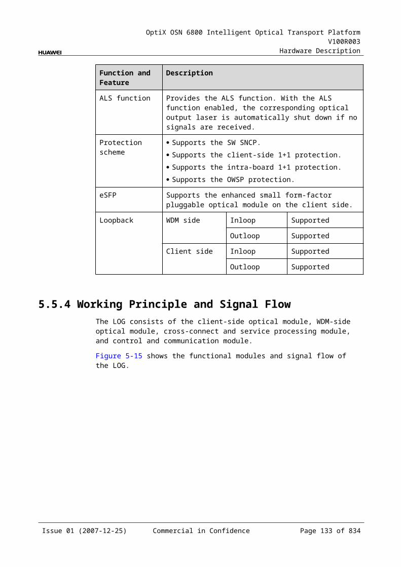
OptiX OSN 6800 Intelligent Optical Transport Platform V100R003
Hardware Description
Figure 5-1 Position of the LQMD in the WDM system
LQMD LQMD
1
4
1
4100Mbit/s-2.5Gbit/s
100Mbit/s-2.5Gbit/s
100Mbit/s-2.5Gbit/s
100Mbit/s-2.5Gbit/s
MUX
DMUX
DMUX
MUX
G.694.1/G.694.2
G.694.1/G.694.2
DMUX
MUX
DMUX
MUX
Client side WDM side WDM side Client side
NOTE The client-side four pairs of optical interfaces can access services at a maximum rate of 2.5
Gbit/s. There is only one pair of optical interface (TX1/RX1) that supports services at a maximum
rate of 2.5 Gbit/s.
5.7.3 Functions and FeaturesThe main functions and features supported by the LQMD are wavelength conversion, cross-connection at the electrical layer, OTN interfaces and ESC.
For detailed functions and features, refer to Table 5-44.
Table 5-1 Functions and features of the LQMD
Function and Feature
Description
Basic function Multiplexes four optical signals at the rate between 100 Mbit/s and 2.5 Gbit/s into a 2.5 Gbit/s optical signal and converts it into the standard DWDM wavelength compliant with ITU-T G.694.1 or the standard CWDM wavelength compliant with ITU-T G.694.2. The reverse process is similar.
With this board, many services, such as the data services (Ethernet services), SAN services (ESCON, FC/FICON), video services (DVB), and voice services (SDH/SONET), can be transmitted by the same wavelength.
Realizes the dual fed and selective receiving function on the WDM side.
Client-side service type
STM-16, STM-4, STM-1, OC-48, OC-12, OC-3, FC200, FC100, GE, FE, ESCON, DVB-ASI, FICON, FICON 2G
Cross-connect capabilities
Supports the transmission of four signals at the rate between 100 Mbit/s and 2.5 Gbit/s to the paired slots through the backplane.
Issue 01 (2007-12-25) Commercial in Confidence Page 131 of 664
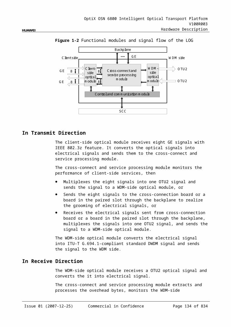
OptiX OSN 6800 Intelligent Optical Transport Platform V100R003
Hardware Description
Function and Feature
Description
OTN function Provides the OTU1 interface on WDM-side. Supports the OTN frame format and overhead processing by
referring to the ITU-T G.709. Supports the mapping and multiplexing of
GE/FC100/FC200/STM-1/OC-3/STM-4/OC-12/STM-16/OC-48/ESCON/ signals into OTU1 signals. The mapping process is compliant with ITU-T G.709.
Supports SM and PM functions for OTU1 and ODU1. Supports TCM function for ODU1.
WDM specification
Supports the DWDM and the CWDM specifications.
Tunable wavelength function
Supports the tunable wavelength optical module. Equipped with this module, the board can tune the optical signal output at the WDM side within the range of the 40 wavelengths in C-band with the channel spacing of 100 GHz.
ESC function Supports the ESC function, transmitting the supervisory signal within the service signal.
FEC encoding Adopts FEC encoding compliant with the ITU-T G.975.
Alarms and performance events monitoring
Provides the monitoring of the BIP8 bit error count so as to help to locate the failures of the line.
Provides the WDM-side monitoring of the items such as the bias current and temperature of the laser as well as the optical power.
Supports the monitoring of the alarms and performance events of the OTN.
ALS function Provides the ALS function. With the ALS function enabled, the corresponding optical output laser is automatically shut down if no signals are received.
Protection scheme
Supports the SW SNCP. Supports the client-side 1+1 protection. Supports the intra-board 1+1 protection.
eSFP Supports the enhanced small form-factor pluggable optical module on the client side.
Loopback WDM side Inloop Supported
Outloop Supported
Client side Inloop Supported
Outloop Supported
Issue 01 (2007-12-25) Commercial in Confidence Page 132 of 664
OptiX OSN 6800 Intelligent Optical Transport Platform V100R003
Hardware Description
5.7.4 Working Principle and Signal FlowThe LQMD consists of the client-side optical module, WDM-side optical module, cross-connect and service processing module, and control and communication module.
Figure 5-21 shows the functional modules and signal flow of the LQMD.
Figure 5-1 Functional modules and signal flow of the LQMD
Control and communication module
SCC
Backplane
100Mbit/s-2.5Gbit/s
Cross-connect andservice processing
module
Client-side
opticalmodule
WDM-side
opticalmodule
4
4
Client side WDM side
OTU1
OTU1100Mbit/s-2.5Gbit/s
100Mbit/s-2.5Gbit/s
RX1
TX1
IN2
RX4
TX4
OUT1
OUT2IN1
NOTE The client-side four pairs of optical interfaces can access services at a maximum rate of 2.5
Gbit/s. There is only one pair of optical interface (TX1/RX1) that supports services at a maximum
rate of 2.5 Gbit/s.
In Transmit DirectionThe client-side optical module receives four optical signals at the rate between 100 Mbit/s and 2.5 Gbit/s. It converts the optical signals into electrical signals and sends them to the cross-connect and service processing module.
The cross-connect and service processing module monitors the performance of client-side services, then
Multiplexes the four signals into one OTU1 signal and sends the signal to a WDM-side optical module, or
Sends the four signals to the board in the paired slot through the backplane to realize the grooming of electrical signals, or
Receives the electrical signals sent from the board in the paired slot through the backplane, multiplexes the signals into one OTU1 signal, and sends the signal to a WDM-side optical module.
The WDM-side optical module converts the electrical signal into ITU-T G.694.1-compliant standard DWDM signal or ITU-T G.694.2-compliant standard CWDM signal. This module divides the signal into two and sends the two signals to the WDM side.
Issue 01 (2007-12-25) Commercial in Confidence Page 133 of 664
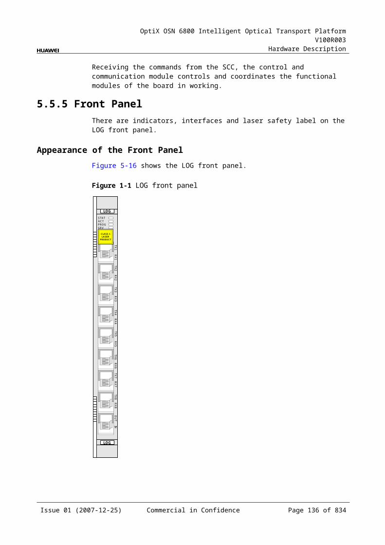
OptiX OSN 6800 Intelligent Optical Transport Platform V100R003
Hardware Description
In Receive DirectionThe WDM-side optical module receives two OTU1 signals at the rate of 2.5 Gbit/s and converts them into electrical signals.
The cross-connect and service processing module selects one signal and demultiplexes the signal into four signals, extracts and processes the overhead bytes, and monitors the WDM-side performance. Then, the module
Sends the four signals to the client-side optical module, or Sends the four signals to the board in the paired slot through the backplane to
realize the grooming of electrical signals, or Receives the electrical signal sent from the board in the paired slot through the
backplane and sends the signal to the client-side optical module.
The client-side optical module converts the four electrical signals into optical signals and then sends the signals to the client-side equipment.
Cross-Connect and Service Processing Module This module realizes the grooming of electrical signals between the LQMD and
the board in the paired slot through the backplane. The grooming service signals are client-side signals at the rate between 100
Mbit/s and 2.5 Gbit/s. This module realizes the cross-connection of four service signals between the
boards in paired slots. This module selects the service. This module extracts and processes overhead bytes. This module monitors the performance of services. This module multiplexes and demultiplexes services. This module implements the encapsulation of OTN signals.
Control and Communication ModuleThe control and communication module realizes the control, monitoring and communications management of each functional module of the board.
The control and communication module collects the information, such as the alarms and performance events, working status, and voltage detection, of each functional module of the board and reports to the SCC.
Receiving the commands from the SCC, the control and communication module controls and coordinates the functional modules of the board in working.
5.7.5 Front PanelThere are indicators, interfaces and laser safety label on the LQMD front panel.
Appearance of the Front PanelFigure 5-22 shows the LQMD front panel.
Issue 01 (2007-12-25) Commercial in Confidence Page 134 of 664
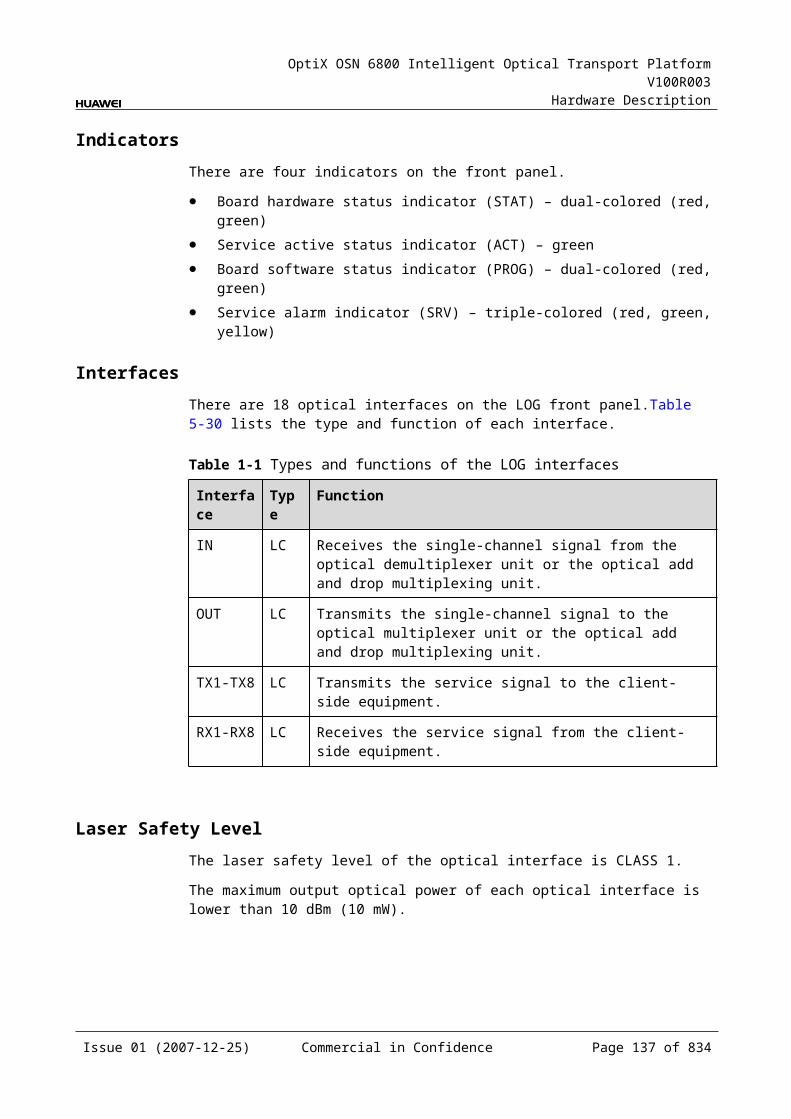
OptiX OSN 6800 Intelligent Optical Transport Platform V100R003
Hardware Description
Figure 5-1 LQMD front panel
LQMD
LQMD
STATACTPROGSRV
CLASS 1LASER
PRODUCT
TX2
RX
2TX
3R
X3
TX4
RX
4O
UT1
IN1
OU
T2IN
2TX
1R
X1
IndicatorsThere are four indicators on the front panel.
Board hardware status indicator (STAT) – dual-colored (red, green) Service active status indicator (ACT) – green Board software status indicator (PROG) – dual-colored (red, green) Service alarm indicator (SRV) – triple-colored (red, green, yellow)
InterfacesThere are 12 optical interfaces on the LQMD front panel. Table 5-45 lists the type and function of each interface.
Issue 01 (2007-12-25) Commercial in Confidence Page 135 of 664
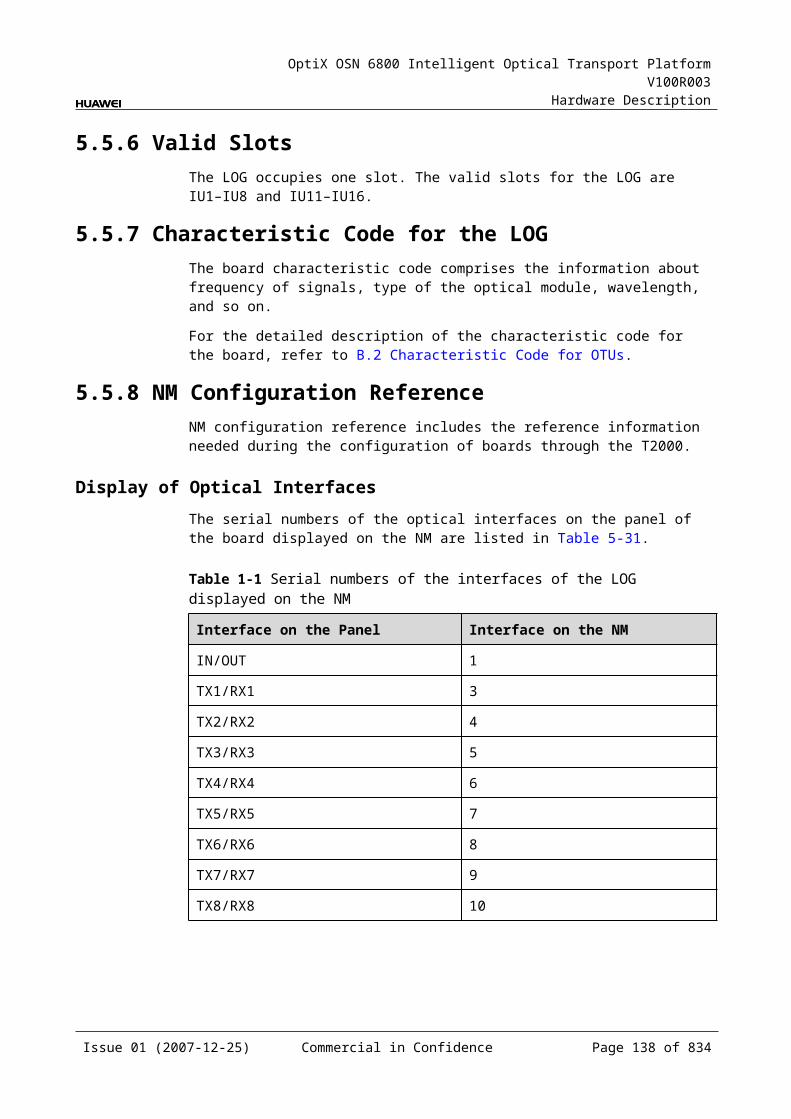
OptiX OSN 6800 Intelligent Optical Transport Platform V100R003
Hardware Description
Table 5-1 Types and functions of the LQMD interfaces
Interface Type
Function
IN1–IN2 LC Receives the single-channel signal from the optical demultiplexer unit or the optical add and drop multiplexing unit.
OUT1–OUT2 LC Transmits the single-channel signal to the optical multiplexer unit or the optical add and drop multiplexing unit.
TX1–TX4 LC Transmits the service signal to the client-side equipment.
RX1–RX4 LC Receives the service signal from the client-side equipment.
NOTE The client-side four pairs of optical interfaces can access services at a maximum rate of 2.5
Gbit/s. There is only one pair of optical interface (TX1/RX1) that supports services at a maximum
rate of 2.5 Gbit/s.
Laser Safety LevelThe laser safety level of the optical interface is CLASS 1.
The maximum output optical power of each optical interface is lower than 10 dBm (10 mW).
5.7.6 Valid SlotsThe LQMD occupies one slot. The valid slots for the LQMD are IU1–IU8 and IU11–IU16.
5.7.7 Characteristic Code for the LQMDThe characteristic code for the LQMD consists of eight digits, respectively indicating the frequency values of two channels of optical signals on the WDM side.
The detailed information of the characteristic code is given in Table 5-46.
Table 5-1 Characteristic code for the LQMD
Code Meaning Description
The first four digits
The frequency of forth optical signal
The last four digits of the frequency value of the first channel of signals on the WDM side.
The last four digits
The frequency of forth optical signal
The last four digits of the frequency value of the second channel of signals on the WDM side.
For example, the characteristic code for the TN11LQMD is 92109220.
Issue 01 (2007-12-25) Commercial in Confidence Page 136 of 664
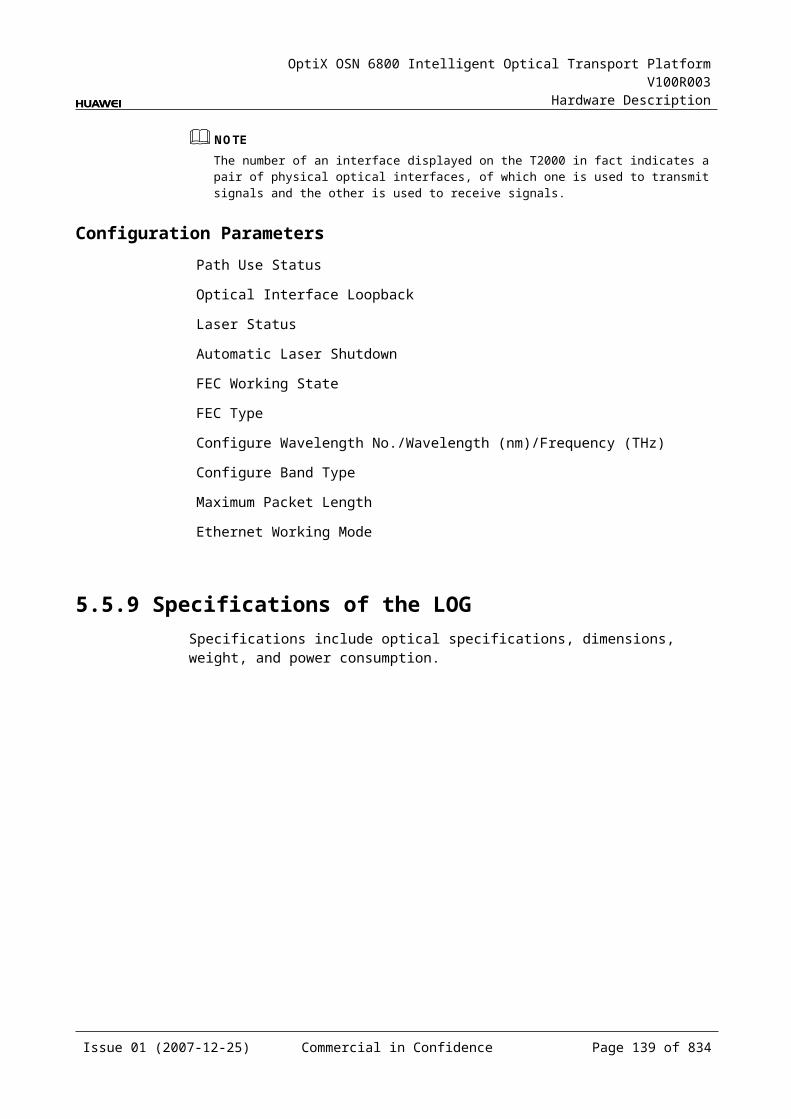
OptiX OSN 6800 Intelligent Optical Transport Platform V100R003
Hardware Description
"9210" indicates the frequency of the first channel of optical signals on the WDM side is 192.10 THz.
"9220" indicates the frequency of the second channel of optical signals on the WDM side is 192.20 THz.
5.7.8 NM Configuration ReferenceNM configuration reference includes the reference information needed during the configuration of boards through the T2000.
Display of Optical InterfacesThe serial numbers of the optical interfaces on the panel of the board displayed on the NM are listed in Table 5-47.
Table 5-1 Serial numbers of the interfaces of the LQMD displayed on the NM
Interface on the Panel Interface on the NM
IN1/OUT1 1
IN2/OUT2 2
TX1/RX1 3
TX2/RX2 4
TX3/RX3 5
TX4/RX4 6
NOTEThe number of an interface displayed on the T2000 in fact indicates a pair of physical optical interfaces, of which one is used to transmit signals and the other is used to receive signals.
Configuration ParametersPath Use Status
Optical Interface Loopback
Service Type
Laser Status
Automatic Laser Shutdown
FEC Working State
Configure Wavelength No./Wavelength (nm)/Frequency (THz)
Configure Band Type
Maximum Packet Length
Ethernet Working Mode
Issue 01 (2007-12-25) Commercial in Confidence Page 137 of 664
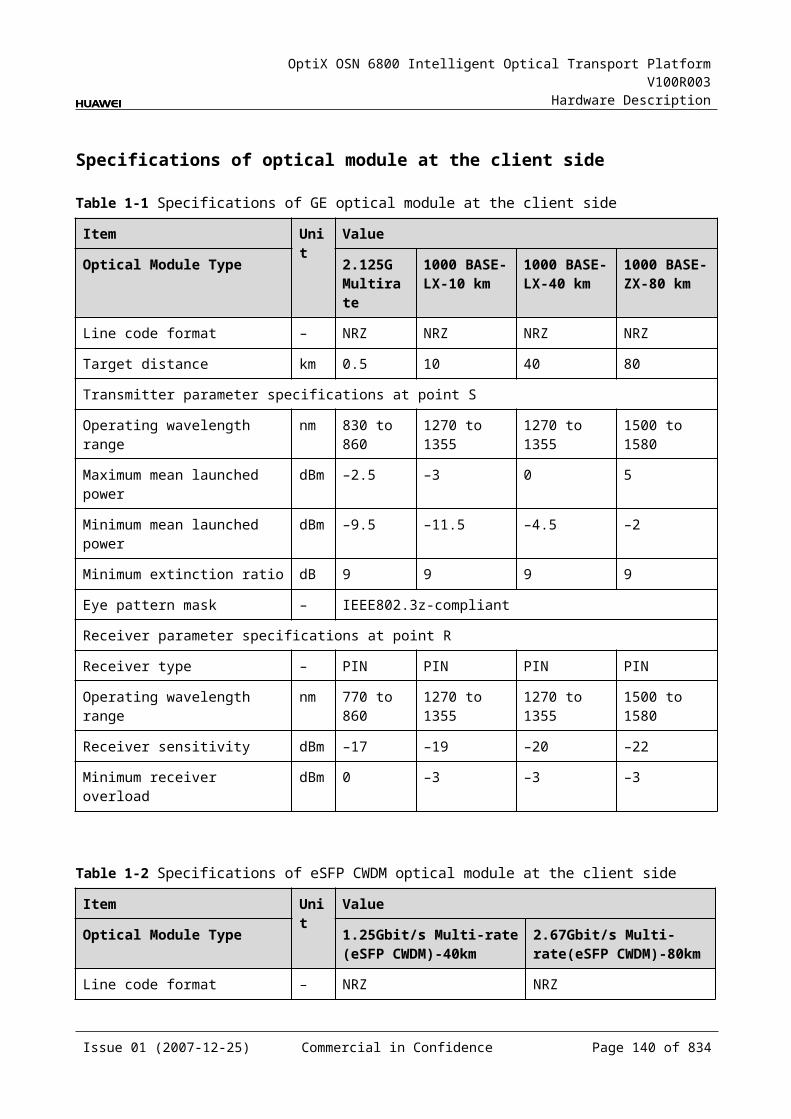
OptiX OSN 6800 Intelligent Optical Transport Platform V100R003
Hardware Description
LPT Enabled
5.7.9 Specifications of the LQMDSpecifications include optical specifications, dimensions, weight, and power consumption.
Specifications of SDH Optical Module at the Client SideNOTEI-16 module, S-16.1 module, L-16.1 module and L-16.2 module can be used to access STM-16, FC200, FC100, GE, STM-4, ESCON, STM-1, DVB-ASI, and FE signals. The specifications listed above completely apply to STM-16 signals. The actual values may be slightly different from these specifications when the accessed signals are FC200, FC100, GE, STM-4, ESCON, STM-1, DVB-ASI, or FE signals.
Table 5-1 Specifications of SDH optical module at the client side
Item Unit
Value
Optical Module Type I-16 S-16.1 L-16.1 L-16.2
Line code format – NRZ NRZ NRZ NRZ
Optical source type – MLM SLM SLM SLM
Target distance km 2 15 40 80
Transmitter parameter specifications at point S
Operating wavelength range
nm 1266 to 1360
1260 to 1360
1280 to 1335
1500 to 1580
Maximum mean launched power
dBm –3 0 3 3
Minimum mean launched power
dBm –10 –5 –2 –2
Minimum extinction ratio dB 8.2 8.2 8.2 8.2
Maximum –20 dB spectral width
nm NA 1 1 1
Minimum side mode suppression ratio
dB NA 30 30 30
Eye pattern mask – G.957-compliant
Receiver parameter specifications at point R
Receiver type – PIN PIN APD APD
Operating wavelength range
nm 1266 to 1360
1260 to 1360
1280 to 1335
1500 to 1580
Receiver sensitivity dBm –18 –18 –27 –28
Issue 01 (2007-12-25) Commercial in Confidence Page 138 of 664
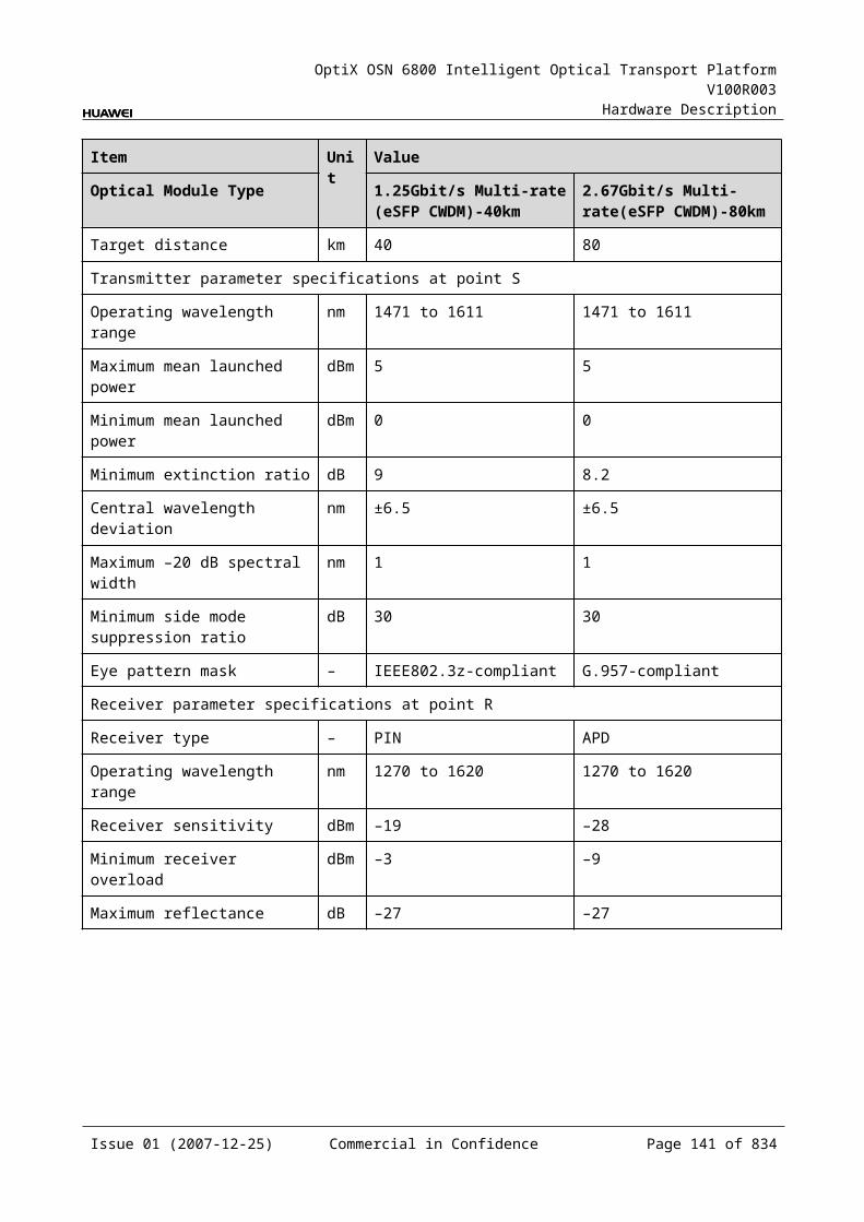
OptiX OSN 6800 Intelligent Optical Transport Platform V100R003
Hardware Description
Item Unit
Value
Optical Module Type I-16 S-16.1 L-16.1 L-16.2
Minimum receiver overload
dBm –3 0 –9 –9
Maximum reflectance dB –27 –27 –27 –27
Specifications of GE Optical Module at the Client SideNOTE2.125 Gbit/s Multi-rate module can be used to access FC200, GE, FC100, and FE signals. The specifications listed above completely apply to FC200 signals. The actual values may be slightly different from these specifications when the accessed signals are GE, FC100, or FE signals.
NOTE1000 BASE-LX-10 km module, 1000 BASE-LX-40 km module and 1000 BASE-ZX-80 km module can be used to access GE, FC100, STM-4, ESCON, STM-1, FE and DVB-ASI signals. The specifications listed above completely apply to GE signals. The actual values may be slightly different from these specifications when the accessed signals are FC100, STM-4, ESCON, STM-1, FE, or DVB-ASI signals.
Table 5-1 Specifications of GE optical module at the client side
Item Unit
Value
Optical Module Type
2.125 Gbit/s Multi-rate
1000 BASE-LX-10 km
1000 BASE-LX-40 km
1000 BASE-ZX-80 km
Line code format – NRZ NRZ NRZ NRZ
Target distance km 0.5 10 40 80
Transmitter parameter specifications at point S
Operating wavelength range
nm 830 to 860 1270 to 1355 1270 to 1355 1500 to 1580
Maximum mean launched power
dBm –2.5 –3 0 5
Minimum mean launched power
dBm –9.5 –11.5 –4.5 –2
Minimum extinction ratio
dB 9 9 9 9
Eye pattern mask – IEEE802.3z-compliant
Receiver parameter specifications at point R
Receiver type – PIN PIN PIN PIN
Issue 01 (2007-12-25) Commercial in Confidence Page 139 of 664

OptiX OSN 6800 Intelligent Optical Transport Platform V100R003
Hardware Description
Item Unit
Value
Optical Module Type
2.125 Gbit/s Multi-rate
1000 BASE-LX-10 km
1000 BASE-LX-40 km
1000 BASE-ZX-80 km
Operating wavelength range
nm 770 to 860 1270 to 1355 1270 to 1355 1500 to 1580
Receiver sensitivity dBm –17 –19 –20 –22
Minimum receiver overload
dBm 0 –3 –3 –3
Specifications of eSFP CWDM Optical Module at the Client SideNOTE1.25Gbit/s Multi-rate module (eSFP CWDM) can be used to access GE, FC100, STM4, ESCON, STM1, FE, DVB-ASI signals. The specifications listed above completely apply to GE signals. The actual values may be slightly different from these specifications when the accessed signals are FC100, STM4, ESCON, STM1, FE, DVB-ASI.
NOTE2.5Gbit/sMulti-rate module (eSFP CWDM) can be used to access STM16, FC200, FC100, GE, STM4, ESCON, STM1, DVB-ASI, FE signals. The specifications listed above completely apply to STM16 signals. The actual values may be slightly different from these specifications when the accessed signals are FC200, FC100, GE, STM4, ESCON, STM1, DVB-ASI, FE signals.
Table 5-1 Specifications of eSFP CWDM optical module at the client side
Item Unit
Value
Optical Module Type
1.25Gbit/s Multi-rate (eSFP CWDM)
2.67Gbit/s Multi-rate (eSFP CWDM)
Line code format – NRZ NRZ
Target distance km 40 80
Transmitter parameter specifications at point S
Operating wavelength range
nm 1471 to 1611 1471 to 1611
Maximum mean launched power
dBm 5 5
Minimum mean launched power
dBm 0 0
Minimum extinction ratio
dB 9 8.2
Central wavelength deviation
nm ±6.5 ±6.5
Issue 01 (2007-12-25) Commercial in Confidence Page 140 of 664

OptiX OSN 6800 Intelligent Optical Transport Platform V100R003
Hardware Description
Item Unit
Value
Optical Module Type
1.25Gbit/s Multi-rate (eSFP CWDM)
2.67Gbit/s Multi-rate (eSFP CWDM)
Maximum –20 dB spectral width
nm 1.0 1.0
Minimum side mode suppression ratio
dB 30 30
Eye pattern mask – IEEE802.3z-compliant G.957-compliant
Receiver parameter specifications at point R
Receiver type – PIN APD
Operating wavelength range
nm 1270 to 1620 1270 to 1620
Receiver sensitivity dBm –19 –28
Minimum receiver overload
dBm –3 –9
Maximum reflectance
dB –27 –27
Specifications of Optical Module at the DWDM Side
Table 5-1 Specifications of optical module at the DWDM side
Item Unit Value
Optical Module Type
12800 ps/nm- PIN
12800 ps/nm-APD
6500 ps/nm- PIN
3200 ps/nm- 2mW- APD
12800 ps/nm- tunable
Line code format – NRZ NRZ NRZ NRZ NRZ
Transmitter parameter specifications at point S
Maximum mean launched power
dBm –4 –4 0 0 0
Minimum mean launched power
dBm –8 –8 –5 –5 –5
Minimum extinction ratio
dB 10 10 8.2 8.2 10
Central frequency THz 192.10 to 196.00
Issue 01 (2007-12-25) Commercial in Confidence Page 141 of 664
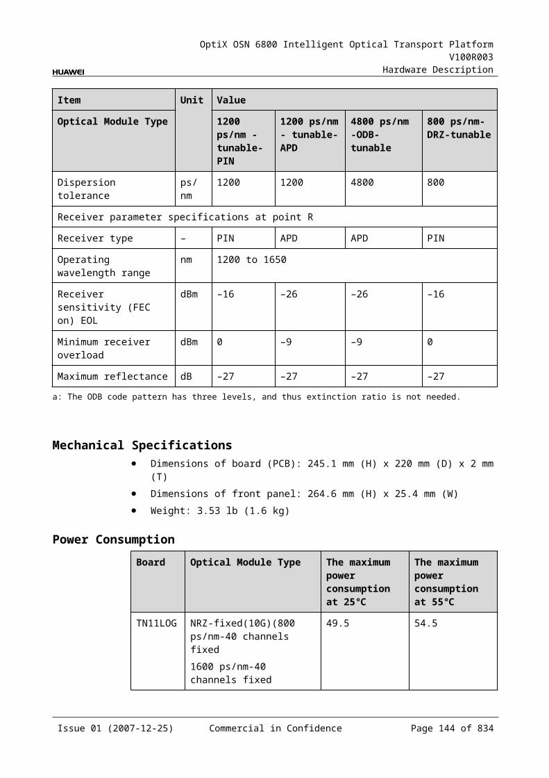
OptiX OSN 6800 Intelligent Optical Transport Platform V100R003
Hardware Description
Item Unit Value
Optical Module Type
12800 ps/nm- PIN
12800 ps/nm-APD
6500 ps/nm- PIN
3200 ps/nm- 2mW- APD
12800 ps/nm- tunable
Central frequency deviation
GHz ±10
Maximum –20 dB spectral width
nm 0.2 0.2 0.5 0.5 0.2
Minimum side mode suppression ratio
dB 35 35 30 30 35
Dispersion tolerance ps/nm 12800 12800 6500 3200 12800
Eye pattern mask – G.957 - compliant
Receiver parameter specifications at point R
Receiver type – PIN APD PIN APD APD
Operating wavelength range
nm 1200 to 1650
Receiver sensitivity dBm –18 –25 –18 –25 –30
Minimum receiver overload
dBm 0 –9 0 –9 –9
Maximum reflectance dB –27 –27 –27 –27 –27
Specifications of Optical Module at the CWDM Side
Table 5-1 Specifications of optical module at the CWDM side
Item Unit Value
Optical Module Type 1600 ps/nm-4mW
Line code format – NRZ
Transmitter parameter specifications at point S
Maximum mean launched power dBm 2
Minimum mean launched power dBm –0.5
Minimum extinction ratio dB 8.2
Central wavelength nm 1271 to 1611
Central wavelength deviation nm ≤±6.5
Maximum –20 dB spectral width nm 1
Issue 01 (2007-12-25) Commercial in Confidence Page 142 of 664
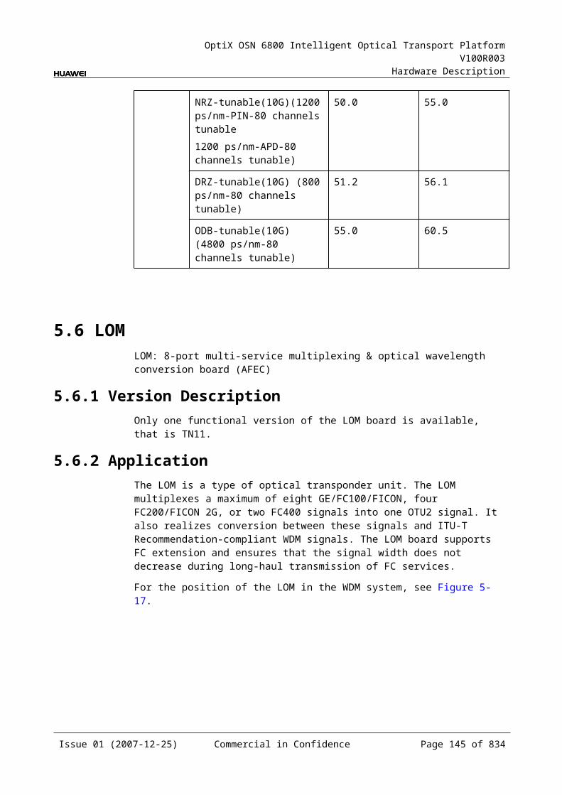
OptiX OSN 6800 Intelligent Optical Transport Platform V100R003
Hardware Description
Item Unit Value
Optical Module Type 1600 ps/nm-4mW
Minimum side mode suppression ratio dB 30
Dispersion tolerance ps/nm 1600
Eye pattern mask –
Receiver parameter specifications at point R
Receiver type – APD
Operating wavelength range nm 1200 to 1650
Receiver sensitivity dBm –28
Minimum receiver overload dBm –9
Maximum reflectance dB –27
Mechanical Specifications Dimensions of board (PCB): 245.1 mm (H) x 220 mm (D) x 2 mm (T) Dimensions of front panel: 264.6 mm (H) x 25.4 mm (W) Weight: 3.08 lb (1.4 kg)
Power ConsumptionBoard Optical Module
TypeThe maximum power consumption at 25
The maximum power consumption at 55
TN11LQMD Fixed(2.5G) (12800 ps/nm-PIN12800 ps/nm-APD6500 ps/nm-PIN3200 ps/nm-2mW-APD)
54.9 60.4
Tunable(2.5G) (12800 ps/nm)
59.1 65.1
5.8 LQMSLQMS: 4-channel multi-rate (100 Mbit/s-2.5 Gbit/s) wavelength conversion unit, single fed and single receiving
Issue 01 (2007-12-25) Commercial in Confidence Page 143 of 664
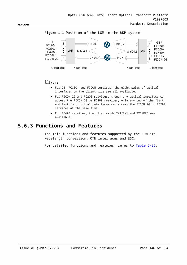
OptiX OSN 6800 Intelligent Optical Transport Platform V100R003
Hardware Description
5.8.1 Version DescriptionOnly one functional version of the LQMS board is available, that is TN11.
5.8.2 ApplicationThe LQMS is a type of optical transponder unit. The LQMS realizes the conversion between signals at the rate between 100 Mbit/s–2.5 Gbit/s and ITU-T Recommendation-compliant WDM signals.
For the position of the LQMS in the WDM system, see Figure 5-23.
Figure 5-1 Position of the LQMS in the WDM system
MUX
DMUX
LQMS
DMUX
MUX
LQMS
1
4
1
4
G.694.1/G.694.2
G.694.1/G.694.2
100Mbit/s-2.5Gbit/s
100Mbit/s-2.5Gbit/s 100Mbit/s-2.5Gbit/s
100Mbit/s-2.5Gbit/s
Client side WDMside
WDMside Client side
NOTE The client-side four pairs of optical interfaces can access services at a maximum rate of 2.5
Gbit/s. There is only one pair of optical interface (TX1/RX1) that supports services at a maximum
rate of 2.5 Gbit/s.
5.8.3 Functions and FeaturesThe main functions and features supported by the LQMS are wavelength conversion, cross-connection at the electrical layer, OTN interfaces and ESC.
For detailed functions and features, refer to Table 5-53.
Table 5-1 Functions and features of the LQMS
Function and Feature
Description
Basic function Multiplexes four optical signals at the rate between 100 Mbit/s and 2.5 Gbit/s into a 2.5 Gbit/s optical signal and converts it into the standard DWDM wavelength compliant with ITU-T G.694.1 or the standard CWDM wavelength compliant with ITU-T G.694.2. The reverse process is similar. With this board, many services, such as the data services (Ethernet services), SAN services (ESCON, FC/FICON), video services (DVB), and voice services (SDH/SONET), can be transmitted by the same wavelength.
Client-side service type
STM-16, STM-4, STM-1, OC-48, OC-12, OC-3, FC200, FC100, GE, FE, ESCON, DVB-ASI, FICON, FICON 2G
Issue 01 (2007-12-25) Commercial in Confidence Page 144 of 664
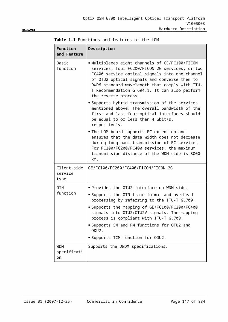
OptiX OSN 6800 Intelligent Optical Transport Platform V100R003
Hardware Description
Function and Feature
Description
Cross-connect capabilities
Supports the transmission of four signals at the rate between 100 Mbit/s and 2.5 Gbit/s to the paired slots through the backplane.
OTN function Provides the OTU1 interface on WDM-side. Supports the OTN frame format and overhead processing by
referring to the ITU-T G.709. Supports the mapping and multiplexing of
GE/FC100/FC200/STM-1/OC-3/STM-4/OC-12/STM-16/OC-48/ESCON/ signals into OTU1 signals. The mapping process is compliant with ITU-T G.709.
Supports SM and PM functions for OTU1 and ODU1. Supports TCM function for ODU1.
WDM specification
Supports the DWDM and the CWDM specifications.
Tunable wavelength function
Supports the tunable wavelength optical module. Equipped with this module, the board can tune the optical signal output at the WDM side within the range of the 40 wavelengths in C-band with the channel spacing of 100 GHz.
ESC function Supports the ESC function, transmitting the supervisory signal within the service signal.
FEC encoding Supports FEC encoding compliant with the ITU-T G.975 and AFEC encoding compliant with the ITU-T G.975.1.
Alarms and performance events monitoring
Provides the monitoring of the BIP8 bit error count so as to help to locate the failures of the line.
Provides the WDM-side monitoring of the items such as the bias current and temperature of the laser as well as the optical power.
Supports the monitoring of the alarms and performance events of the OTN.
ALS function Provides the ALS function. With the ALS function enabled, the corresponding optical output laser is automatically shut down if no signals are received.
Protection scheme
Supports the SW SNCP. Supports the client-side 1+1 protection.
eSFP Supports the enhanced small form-factor pluggable optical module on the client side.
Loopback WDM side Inloop Supported
Outloop Supported
Client side Inloop Supported
Issue 01 (2007-12-25) Commercial in Confidence Page 145 of 664

OptiX OSN 6800 Intelligent Optical Transport Platform V100R003
Hardware Description
Function and Feature
Description
Outloop Supported
5.8.4 Working Principle and Signal FlowThe LQMS consists of the client-side optical module, WDM-side optical module, cross-connect and service processing module, and control and communication module.
Figure 5-24 shows the functional modules and signal flow of the LQMS.
Figure 5-1 Functional modules and signal flow of the LQMS
Control and communication module
SCC
Backplane
Cross-connect andservice processing
module
Client-side
opticalmodule
WDM-side
opticalmodule
4
4
100Mbit/s-2.5Gbit/sClient side WDM side
OTU1
OTU1100Mbit/s-2.5Gbit/s
100Mbit/s-2.5Gbit/s
RX1
TX1IN
RX4
TX4
OUT
NOTE The client-side four pairs of optical interfaces can access services at a maximum rate of 2.5
Gbit/s. There is only one pair of optical interface (TX1/RX1) that supports services at a maximum
rate of 2.5 Gbit/s.
In Transmit DirectionThe client-side optical module receives four optical signals at the rate between 100 Mbit/s and 2.5 Gbit/s. It converts the optical signals into electrical signals and sends them to the cross-connect and service processing module.
The cross-connect and service processing module monitors the performance of client-side services, then
Multiplexes the four signals into one OTU1 signal and sends the signal to a WDM-side optical module, or
Sends the four signals to the board in the paired slot through the backplane to realize the grooming of electrical signals, or
Issue 01 (2007-12-25) Commercial in Confidence Page 146 of 664
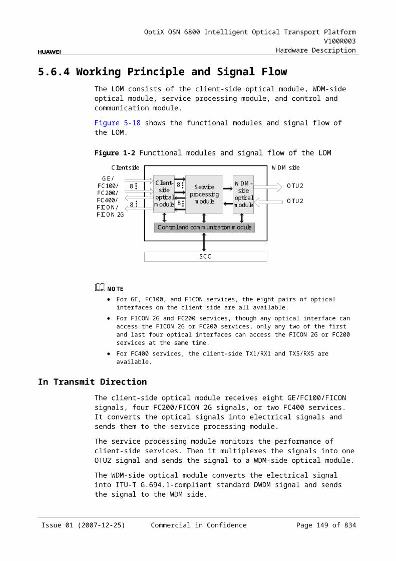
OptiX OSN 6800 Intelligent Optical Transport Platform V100R003
Hardware Description
Receives the electrical signals sent from the board in the paired slot through the backplane, multiplexes the signals into one OTU1 signal, and sends the signal to a WDM-side optical module.
The WDM-side optical module converts the electrical signal into ITU-T G.694.1-compliant standard DWDM signal or ITU-T G.694.2-compliant standard CWDM signal and sends the signal to the WDM side.
In Receive DirectionThe WDM-side optical module receives a OTU1 optical signal at the rate of 2.5 Gbit/s and converts them into electrical signals.
The cross-connect and service processing module demultiplexes the signal into four signals, extracts and processes the overhead bytes, and monitors the WDM-side performance. Then, the module
Sends the four signals to the client-side optical module, or Sends the four signals to the board in the paired slot through the backplane to
realize the grooming of electrical signals, or Receives the electrical signal sent from the board in the paired slot through the
backplane and sends the signal to the client-side optical module.
The client-side optical module converts the four electrical signals into optical signals and then sends the signals to the client-side equipment.
Cross-Connect and Service Processing Module This module realizes the grooming of electrical signals between the LQMS and
the board in the paired slot through the backplane. The grooming service signals are client-side signals at the rate between 100
Mbit/s and 2.5 Gbit/s. This module realizes the cross-connection of four service signals between the
boards in paired slots. This module extracts and processes overhead bytes. This module monitors the performance of services. This module multiplexes and demultiplexes services. This module implements the encapsulation of OTN signals.
Control and Communication ModuleThe control and communication module realizes the control, monitoring and communications management of each functional module of the board.
The control and communication module collects the information, such as the alarms and performance events, working status, and voltage detection, of each functional module of the board and reports to the SCC.
Receiving the commands from the SCC, the control and communication module controls and coordinates the functional modules of the board in working.
5.8.5 Front PanelThere are indicators, interfaces and laser safety label on the LQMS front panel.
Issue 01 (2007-12-25) Commercial in Confidence Page 147 of 664
OptiX OSN 6800 Intelligent Optical Transport Platform V100R003
Hardware Description
Appearance of the Front PanelFigure 5-25 shows the LQMS front panel.
Figure 5-1 LQMS front panel
LQMS
LQMS
STATACTPROGSRV
CLASS 1LASER
PRODUCT
RX
2TX
3R
X3
TX4
RX
4O
UT
INTX
1R
X1
TX2
IndicatorsThere are four indicators on the front panel.
Board hardware status indicator (STAT) – dual-colored (red, green) Service active status indicator (ACT) – green Board software status indicator (PROG) – dual-colored (red, green) Service alarm indicator (SRV) – triple-colored (red, green, yellow)
Issue 01 (2007-12-25) Commercial in Confidence Page 148 of 664
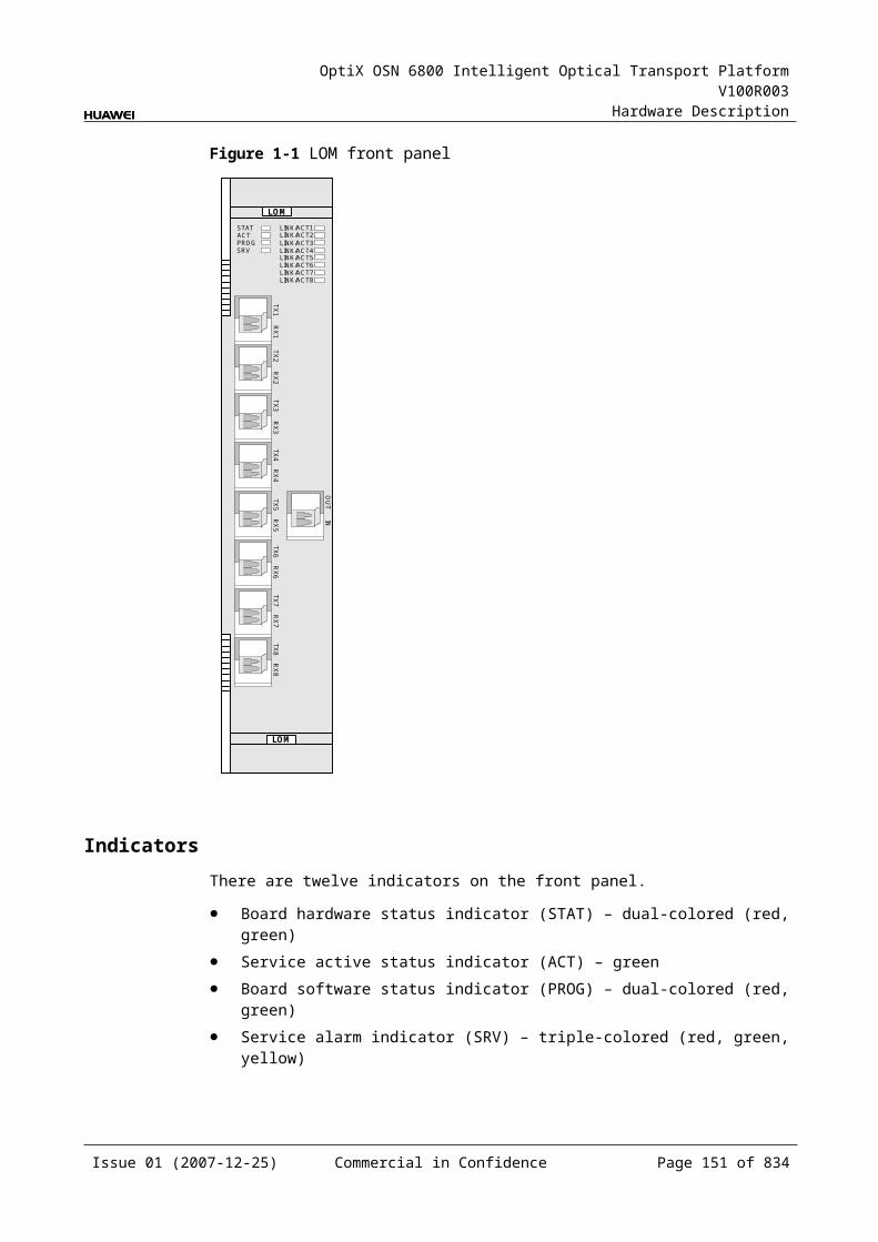
OptiX OSN 6800 Intelligent Optical Transport Platform V100R003
Hardware Description
InterfacesThere are 10 optical interfaces on the LQMS front panel. Table 5-54 lists the type and function of each interface.
Table 5-1 Types and functions of the LQMS interfaces
Interface
Type
Function
IN LC Receives the single-channel signal from the optical demultiplexer unit or the optical add and drop multiplexing unit.
OUT LC Transmits the single-channel signal to the optical multiplexer unit or the optical add and drop multiplexing unit.
TX1–TX4 LC Transmits the service signal to the client-side equipment.
RX1–RX4 LC Receives the service signal from the client-side equipment.
NOTE The client-side four pairs of optical interfaces can access services at a maximum rate of 2.5
Gbit/s. There is only one pair of optical interface (TX1/RX1) that supports services at a maximum
rate of 2.5 Gbit/s.
Laser Safety LevelThe laser safety level of the optical interface is CLASS 1.
The maximum output optical power of each optical interface is lower than 10 dBm (10 mW).
5.8.6 Valid SlotsThe LQMS occupies one slot. The valid slots for the LQMS are IU1–IU8 and IU11–IU16.
5.8.7 Characteristic Code for the LQMSThe board characteristic code comprises the information about frequency of signals, type of the optical module, wavelength, and so on.
For the detailed description of the characteristic code for the board, refer to B.2 Characteristic Code for OTUs.
5.8.8 NM Configuration ReferenceNM configuration reference includes the reference information needed during the configuration of boards through the T2000.
Display of Optical InterfacesThe serial numbers of the optical interfaces on the panel of the board displayed on the NM are listed in Table 5-55.
Issue 01 (2007-12-25) Commercial in Confidence Page 149 of 664
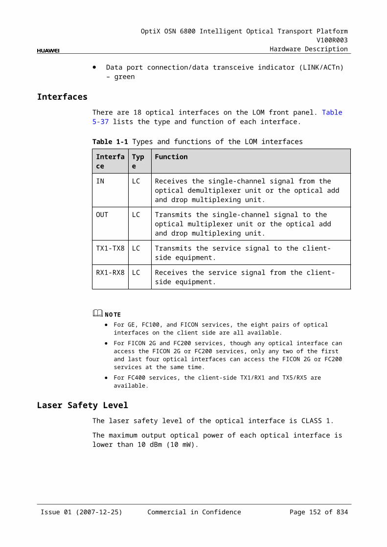
OptiX OSN 6800 Intelligent Optical Transport Platform V100R003
Hardware Description
Table 5-1 Serial numbers of the interfaces of the LQMS displayed on the NM
Interface on the Panel Interface on the NM
IN/OUT 1
TX1/RX1 3
TX2/RX2 4
TX3/RX3 5
TX4/RX4 6
NOTEThe number of an interface displayed on the T2000 in fact indicates a pair of physical optical interfaces, of which one is used to transmit signals and the other is used to receive signals.
Configuration ParametersPath Use Status
Optical Interface Loopback
Service Type
Laser Status
Automatic Laser Shutdown
FEC Working State
Configure Wavelength No./Wavelength (nm)/Frequency (THz)
Configure Band Type
Maximum Packet Length
Ethernet Working Mode
LPT Enabled
5.8.9 Specifications of the LQMSSpecifications include optical specifications, dimensions, weight, and power consumption.
Specifications of SDH Optical Module at the Client SideNOTEI-16 module, S-16.1 module, L-16.1 module and L-16.2 module can be used to access STM-16, FC200, FC100, GE, STM-4, ESCON, STM-1, DVB-ASI, and FE signals. The specifications listed above completely apply to STM-16 signals. The actual values may be slightly different from these specifications when the accessed signals are FC200, FC100, GE, STM-4, ESCON, STM-1, DVB-ASI, or FE signals.
Issue 01 (2007-12-25) Commercial in Confidence Page 150 of 664
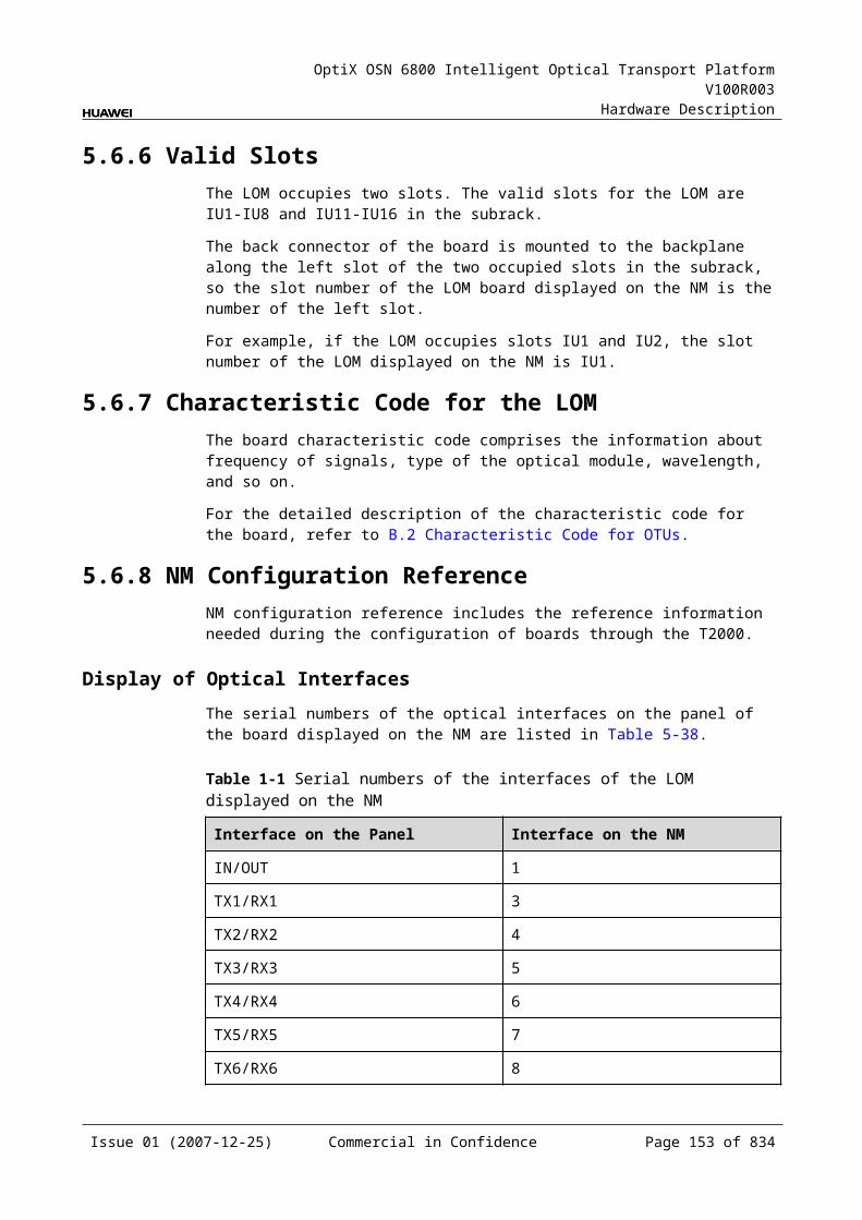
OptiX OSN 6800 Intelligent Optical Transport Platform V100R003
Hardware Description
Table 5-1 Specifications of SDH optical module at the client side
Item Unit
Value
Optical Module Type I-16 S-16.1 L-16.1 L-16.2
Line code format – NRZ NRZ NRZ NRZ
Optical source type – MLM SLM SLM SLM
Target distance km 2 15 40 80
Transmitter parameter specifications at point S
Operating wavelength range
nm 1266 to 1360
1260 to 1360
1280 to 1335
1500 to 1580
Maximum mean launched power
dBm –3 0 3 3
Minimum mean launched power
dBm –10 –5 –2 –2
Minimum extinction ratio dB 8.2 8.2 8.2 8.2
Maximum –20 dB spectral width
nm NA 1 1 1
Minimum side mode suppression ratio
dB NA 30 30 30
Eye pattern mask – G.957-compliant
Receiver parameter specifications at point R
Receiver type – PIN PIN APD APD
Operating wavelength range
nm 1266 to 1360
1260 to 1360
1280 to 1335
1500 to 1580
Receiver sensitivity dBm –18 –18 –27 –28
Minimum receiver overload
dBm –3 0 –9 –9
Maximum reflectance dB –27 –27 –27 –27
Specifications of GE Optical Module at the Client SideNOTE2.125 Gbit/s Multi-rate module can be used to access FC200, GE, FC100, and FE signals. The specifications listed above completely apply to FC200 signals. The actual values may be slightly different from these specifications when the accessed signals are GE, FC100, or FE signals.
Issue 01 (2007-12-25) Commercial in Confidence Page 151 of 664
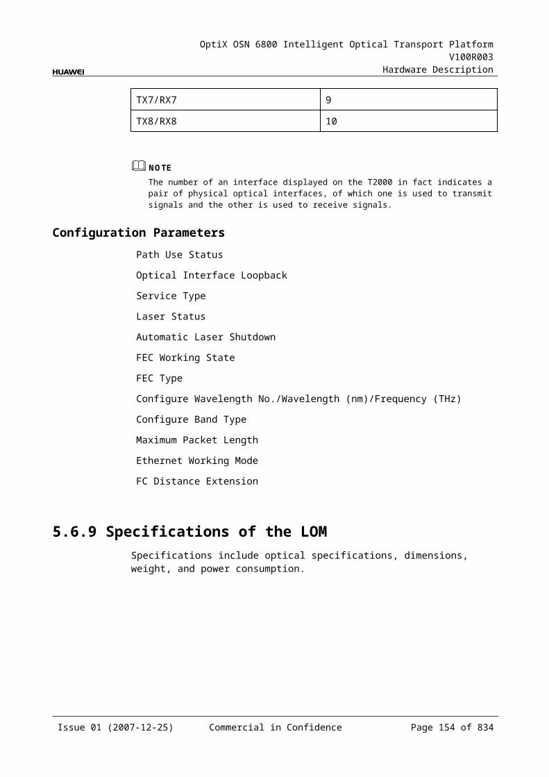
OptiX OSN 6800 Intelligent Optical Transport Platform V100R003
Hardware Description
NOTE1000 BASE-LX-10 km module, 1000 BASE-LX-40 km module and 1000 BASE-ZX-80 km module can be used to access GE, FC100, STM-4, ESCON, STM-1, FE and DVB-ASI signals. The specifications listed above completely apply to GE signals. The actual values may be slightly different from these specifications when the accessed signals are FC100, STM-4, ESCON, STM-1, FE, or DVB-ASI signals.
Table 5-1 Specifications of GE optical module at the client side
Item Unit
Value
Optical Module Type
2.125 Gbit/s Multi-rate
1000 BASE-LX-10 km
1000 BASE-LX-40 km
1000 BASE-ZX-80 km
Line code format – NRZ NRZ NRZ NRZ
Target distance km 0.5 10 40 80
Transmitter parameter specifications at point S
Operating wavelength range
nm 830 to 860 1270 to 1355
1270 to 1355
1500 to 1580
Maximum mean launched power
dBm –2.5 –3 0 5
Minimum mean launched power
dBm –9.5 –11.5 –4.5 –2
Minimum extinction ratio
dB 9 9 9 9
Eye pattern mask – IEEE802.3z-compliant
Receiver parameter specifications at point R
Receiver type – PIN PIN PIN PIN
Operating wavelength range
nm 770 to 860 1270 to 1355
1270 to 1355
1500 to 1580
Receiver sensitivity
dBm –17 –19 –20 –22
Minimum receiver overload
dBm 0 –3 –3 –3
Specifications of eSFP CWDM Optical Module at the Client SideNOTE1.25Gbit/s Multi-rate module (eSFP CWDM) can be used to access GE, FC100, STM4, ESCON, STM1, FE, DVB-ASI signals. The specifications listed above completely apply to GE signals. The actual values may be slightly different from these specifications when the accessed signals are FC100, STM4, ESCON, STM1, FE, DVB-ASI.
Issue 01 (2007-12-25) Commercial in Confidence Page 152 of 664
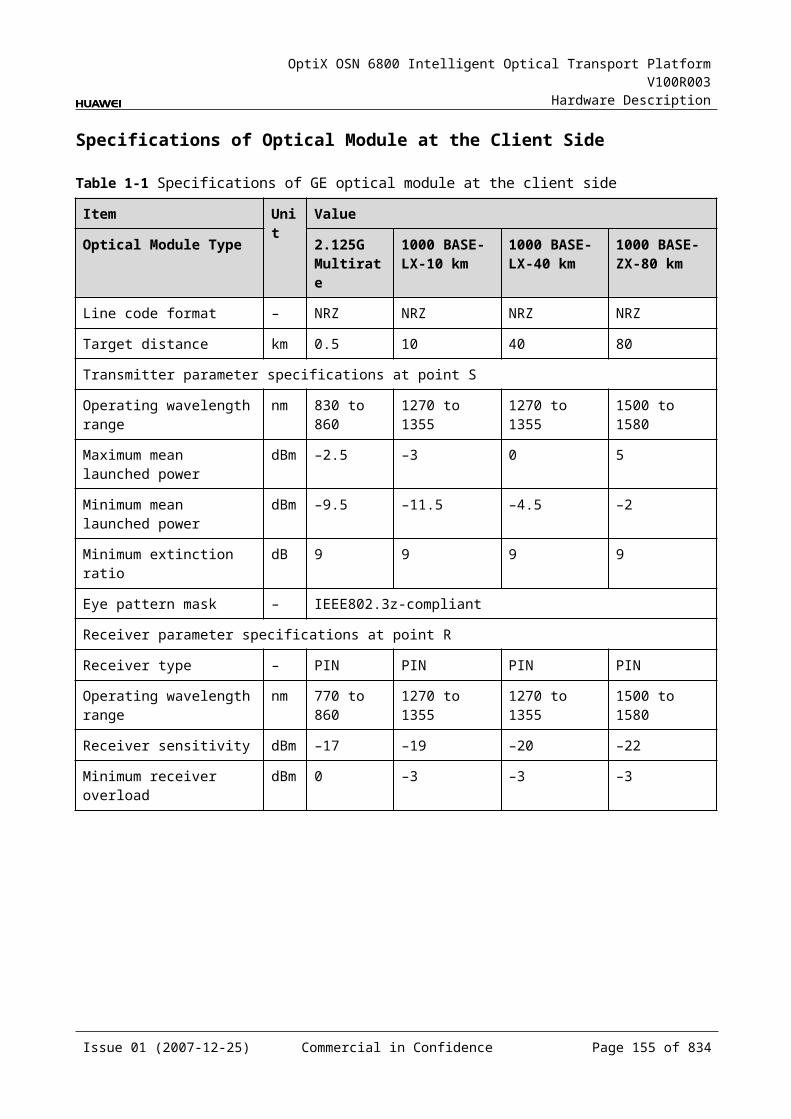
OptiX OSN 6800 Intelligent Optical Transport Platform V100R003
Hardware Description
NOTE2.5Gbit/sMulti-rate module (eSFP CWDM) can be used to access STM16, FC200, FC100, GE, STM4, ESCON, STM1, DVB-ASI, FE signals. The specifications listed above completely apply to STM16 signals. The actual values may be slightly different from these specifications when the accessed signals are FC200, FC100, GE, STM4, ESCON, STM1, DVB-ASI, FE signals.
Table 5-1 Specifications of eSFP CWDM optical module at the client side
Item Unit
Value
Optical Module Type
1.25Gbit/s Multi-rate (eSFP CWDM)
2.67Gbit/s Multi-rate (eSFP CWDM)
Line code format – NRZ NRZ
Target distance km 40 80
Transmitter parameter specifications at point S
Operating wavelength range
nm 1471 to 1611 1471 to 1611
Maximum mean launched power
dBm 5 5
Minimum mean launched power
dBm 0 0
Minimum extinction ratio
dB 9 8.2
Central wavelength deviation
nm ±6.5 ±6.5
Maximum –20 dB spectral width
nm 1.0 1.0
Minimum side mode suppression ratio
dB 30 30
Eye pattern mask – IEEE802.3z-compliant G.957-compliant
Receiver parameter specifications at point R
Receiver type – PIN APD
Operating wavelength range
nm 1270 to 1620 1270 to 1620
Receiver sensitivity dBm –19 –28
Minimum receiver overload
dBm –3 –9
Maximum reflectance
dB –27 –27
Issue 01 (2007-12-25) Commercial in Confidence Page 153 of 664
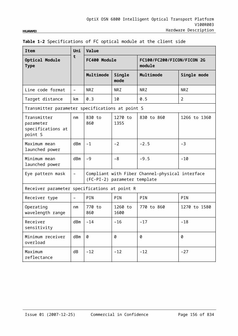
OptiX OSN 6800 Intelligent Optical Transport Platform V100R003
Hardware Description
Specifications of Optical Module at the DWDM Side
Table 5-1 Specifications of optical module at the DWDM side
Item Unit Value
Optical Module Type
12800 ps/nm- PIN
12800 ps/nm-APD
6500 ps/nm- PIN
3200 ps/nm- 2mW- APD
12800 ps/nm- tunable
Line code format – NRZ NRZ NRZ NRZ NRZ
Transmitter parameter specifications at point S
Maximum mean launched power
dBm –1 –1 3 3 3
Minimum mean launched power
dBm –5 –5 –2 –2 –2
Minimum extinction ratio dB 10 10 8.2 8.2 10
Central frequency THz 192.10 to 196.00
Central frequency deviation
GHz ±10
Maximum –20 dB spectral width
nm 0.2 0.2 0.5 0.5 0.2
Minimum side mode suppression ratio
dB 35 35 30 30 35
Dispersion tolerance ps/nm 12800 12800 6500 3200 12800
Eye pattern mask – G.957-compliant
Receiver parameter specifications at point R
Receiver type – PIN APD PIN APD APD
Operating wavelength range
nm 1200 to 1650
Receiver sensitivity dBm –18 –25 –18 –25 –30
Minimum receiver overload
dBm 0 –9 0 –9 –9
Maximum reflectance dB –27 –27 –27 –27 –27
Issue 01 (2007-12-25) Commercial in Confidence Page 154 of 664
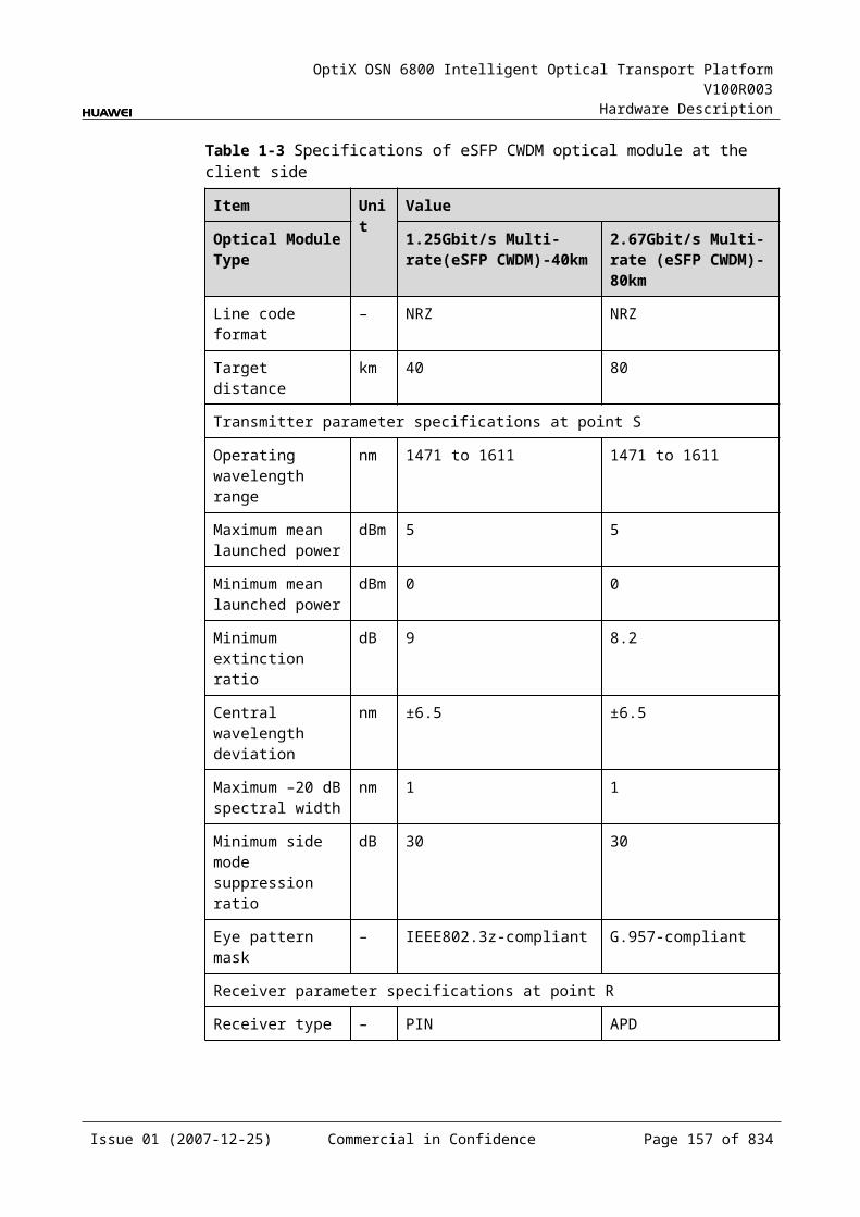
OptiX OSN 6800 Intelligent Optical Transport Platform V100R003
Hardware Description
Specifications of Optical Module at the CWDM Side
Table 5-1 Specifications of optical module at the CWDM side
Item Unit Value
Optical Module Type 1600 ps/nm-4mW
Line code format – NRZ
Transmitter parameter specifications at point S
Maximum mean launched power dBm 5
Minimum mean launched power dBm 2.5
Minimum extinction ratio dB 8.2
Central wavelength nm 1271 to 1611
Central wavelength deviation nm ≤±6.5
Maximum –20 dB spectral width nm 1
Minimum side mode suppression ratio dB 30
Dispersion tolerance ps/nm 1600
Eye pattern mask –
Receiver parameter specifications at point R
Receiver type – APD
Operating wavelength range nm 1200 to 1650
Receiver sensitivity dBm –28
Minimum receiver overload dBm –9
Maximum reflectance dB –27
Mechanical Specifications Dimensions of board (PCB): 245.1 mm (H) x 220 mm (D) x 2 mm (T) Dimensions of front panel: 264.6 mm (H) x 25.4 mm (W) Weight: 2.86 lb (1.3 kg)
Issue 01 (2007-12-25) Commercial in Confidence Page 155 of 664
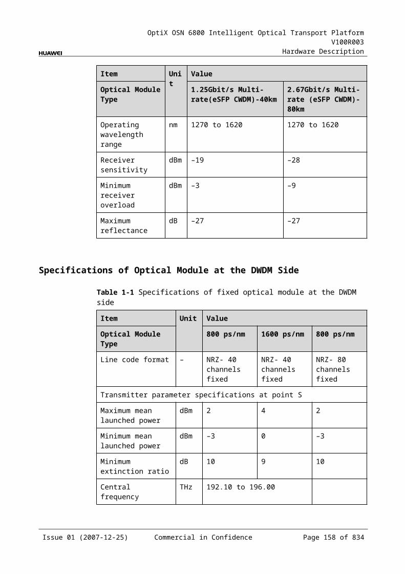
OptiX OSN 6800 Intelligent Optical Transport Platform V100R003
Hardware Description
Power ConsumptionBoard Optical Module
TypeThe maximum power consumption at 25
The maximum power consumption at 55
TN11LQMS Fixed(2.5G) (12800 ps/nm-PIN12800 ps/nm-APD6500 ps/nm-PIN3200 ps/nm-2mW-APD)
53.2 58.5
Tunable(2.5G) (12800 ps/nm)
57.8 63.6
5.9 LSXLSX: 10 Gbit/s wavelength conversion unit
5.9.1 Version DescriptionTwo functional versions of the LSX board are available: TN11 and TN12. The main difference between the two versions lies in whether the board of different versions supports the FC-1000 service.
Table 5-61lists the version description of the LSX.
Table 5-1 Version description of the LSX
Item Description
Functional version
Two functional versions of the LSX board are available: TN11 and TN12.
Similarity Supports to process the STM-64, OC-192, 10GE LAN, 10GE WAN and OTU2 services.
Difference The TN12LSX board supports FC1200 service.
Replacement The TN12LSX board can replace the TN11LSX board, but after the replacement, the SCC software need be upgraded.The TN11LSX board, however, cannot replace the TN12LSX board.
Issue 01 (2007-12-25) Commercial in Confidence Page 156 of 664
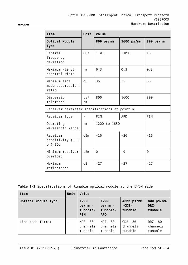
OptiX OSN 6800 Intelligent Optical Transport Platform V100R003
Hardware Description
5.9.2 ApplicationThe LSX is a type of optical transponder unit, serving to map one channel of 10 Gbit/s service signals into OTU2 or OTU2v signals and realizing the conversion between the 10 Gbit/s service signal and the ITU-T Recommendation-compliant.
For the position of the LSX in the WDM system, see Figure 5-26.
Figure 5-1 Position of the LSX in the WDM system
MUX
DMUX
LSX
DMUX
MUX
LSXG.694.1 G.694.1
10GE LAN /10GE WAN /STM-64/OC-192/OTU2/
Client side WDM side WDM side Client side
FC1200
10GE LAN /10GE WAN /STM-64/OC-192/OTU2/FC1200
NOTE Client-side service type of the TN11LSX is 10GE LAN, 10GE WAN, STM-64, OC-192 and
OTU2. Client-side service type of the TN12LSX is 10GE LAN, 10GE WAN, STM-64, OC-192,
OTU2 and FC1200.
5.9.3 Functions and FeaturesThe main functions and features supported by the LSX are wavelength conversion, OTN interfaces and ESC.
For detailed functions and features, refer to Table 5-62.
Table 5-1 Functions and features of the LSX
Function and Feature
Description
Basic function Serving to map one channel of 10 Gbit/s service signals into OTU2 or OTU2v signals and realizing the conversion between the 10Gbit/s service signal and the ITU-T Recommendation-compliant
Client-side service type
TN11LSX: 10GE LAN, 10GE WAN, STM-64, OC-192, OTU2TN12LSX: 10GE LAN, 10GE WAN, STM-64, OC-192, OTU2, FC1200
Issue 01 (2007-12-25) Commercial in Confidence Page 157 of 664
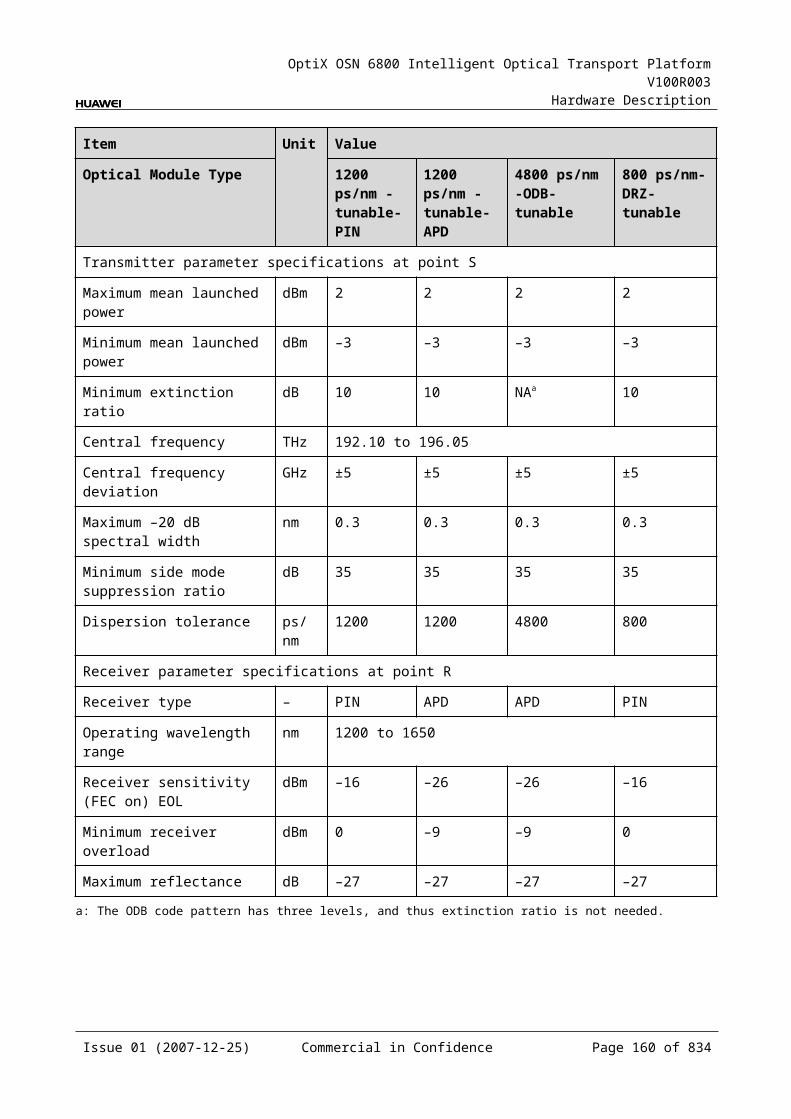
OptiX OSN 6800 Intelligent Optical Transport Platform V100R003
Hardware Description
Function and Feature
Description
OTN function Provides the OTU2 interface on WDM-side. Supports the OTN frame format and overhead processing by
referring to the ITU-T G.709. Supports the mapping of 10GE LAN/10GE WAN/STM-64/OC-
192/OTU2 into OTU2/OTU2V signals, and the transparence mapping of 10GE LAN into OTU2V signals.
Supports SM and PM functions for OTU2 and ODU2. Supports TCM function for ODU2. Supports PM and TCM non-intrusive monitoring for ODU2.
WDM specification
Supports DWDM specifications.
Tunable wavelength function
Supports the tunable wavelength optical module. Equipped with this module, the board can tune the optical signal output at the WDM side within the range of: 40 wavelengths in C-band with the channel spacing of 100
GHz 80 wavelengths in C-band with the channel spacing of 50 GHz
ESC function Supports the ESC function, transmitting the supervisory signal within the service signal.
FEC encoding Supports FEC encoding compliant with the ITU-T G.975 and AFEC encoding compliant with the ITU-T G.975.1.
Alarms and performance events monitoring
Provides the function of optical power detection and the function to report the alarms and performance events of the board.
ALS function Provides the ALS function. With the ALS function enabled, the corresponding optical output laser is automatically shut down if no signals are received.
Protection scheme
Supports the client-side 1+1 protection. Supports the intra-board 1+1 protection. Supports the OWSP protection.
XFP Supports the 10 Gbit/s small form-factor pluggable optical module on the client side.
Loopback WDM side Inloop Supported
Outloop Supported
Client side Inloop Supported
Outloop Supported
Issue 01 (2007-12-25) Commercial in Confidence Page 158 of 664

OptiX OSN 6800 Intelligent Optical Transport Platform V100R003
Hardware Description
5.9.4 Working Principle and Signal FlowThe LSX consists of the client-side optical module, WDM-side optical module, service processing module, and control and communication module.
Figure 5-27 shows the functional modules and signal flow of the LSX.
Figure 5-1 Functional modules and signal flow of the LSX
WDM-side
opticalmodule
Control and communication module
SCC
Serviceprocessing
module
Client-side
opticalmodule
Client side WDM side10GE LAN/10GE
WAN/STM-64/OC-192/OTU2
OTU2/OTU2v
OTU2/OTU2v10GE LAN/10GE
WAN/STM-64/OC-192/OTU2
RX
TX IN
OUT
FC1200
FC1200
NOTE Client-side service type of the tn11LSX is 10GE LAN, 10GE WAN, STM-64, OC-192 and
OTU2. Client-side service type of the tn12LSX is 10GE LAN, 10GE WAN, STM-64, OC-192, OTU2
and FC1200.
In Transmit DirectionThe client-side optical module receives a 10 Gbit/s signal (for example, 10GE LAN, 10GE WAN, STM-64, OC-192, OTU2), and converts the signal into an electrical one before sending it to the service processing module.
The service processing module monitors the performance of the client-side services and converts the signal into the OTU2 or OTU2v signal needed by the client side, before sending it to the WDM-side optical module.
The WDM-side optical module converts the electrical signal into the standard DWDM signal compliant with ITU-T G.694.1 and sends the signal to the WDM side.
In Receive DirectionThe WDM-side optical module receives one OTU2 or OTU2v optical signal and converts it into an electrical signal.
The service processing module converts the signal into the 10 Gbit/s signal, extracts and processes the overhead bytes, and monitors the WDM-side performance. Then the signal is sent to the client-side optical module.
The client-side optical module converts the electrical signal into an optical signal and sends the converted signal to the client-side equipment.
Issue 01 (2007-12-25) Commercial in Confidence Page 159 of 664
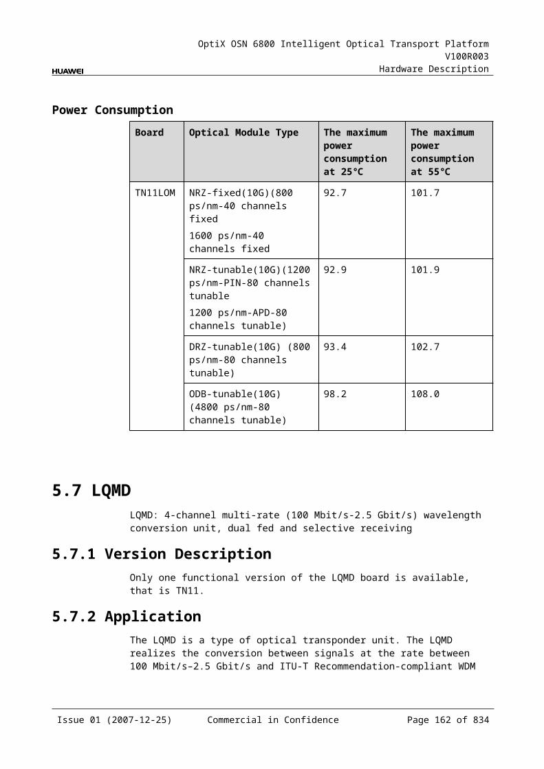
OptiX OSN 6800 Intelligent Optical Transport Platform V100R003
Hardware Description
Service Processing Module This module extracts and processes overhead bytes. This module monitors the performance of services. This module implements the encapsulation of OTN signals.
Control and Communication ModuleThe control and communication module realizes the control, monitoring and communications management of each functional module of the board.
The control and communication module collects the information, such as the alarms and performance events, working status, and voltage detection, of each functional module of the board and reports to the SCC.
Receiving the commands from the SCC, the control and communication module controls and coordinates the functional modules of the board in working.
5.9.5 Front PanelThere are indicators, interfaces and laser safety label on the LSX front panel.
Appearance of the Front PanelFigure 5-28 shows the LSX front panel.
Issue 01 (2007-12-25) Commercial in Confidence Page 160 of 664
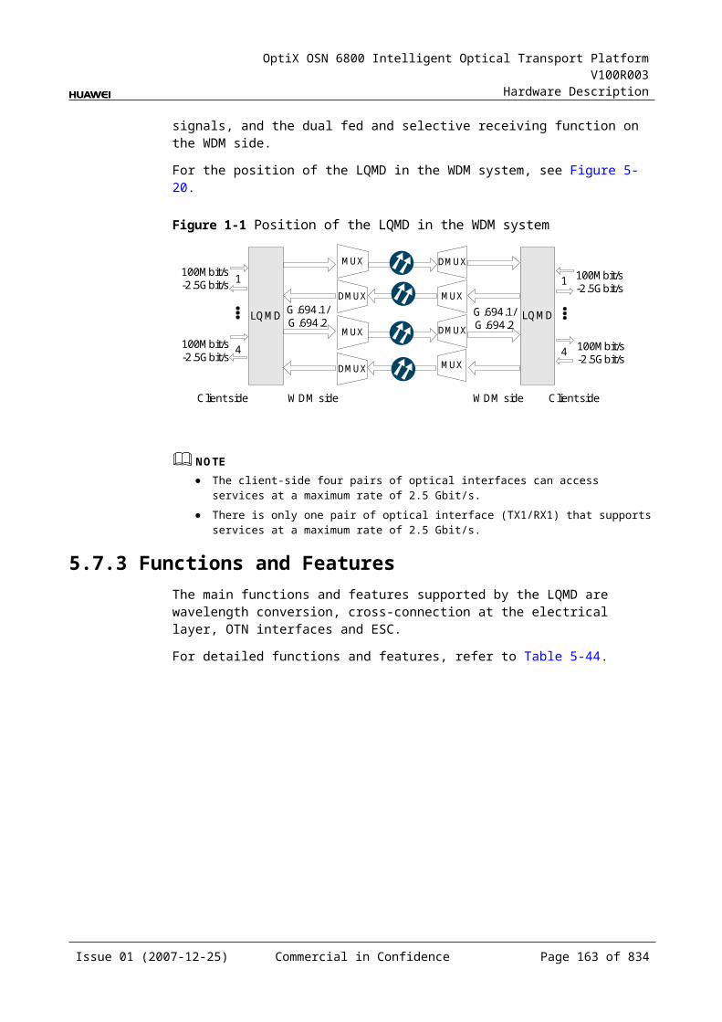
OptiX OSN 6800 Intelligent Optical Transport Platform V100R003
Hardware Description
Figure 5-1 LSX front panel
LSX
LSX
CLASS 1LASER
PRODUCT
STATACTPROGSRV
OU
TIN
TXR
X
IndicatorsThere are four indicators on the front panel.
Board hardware status indicator (STAT) – dual-colored (red, green) Service active status indicator (ACT) – green Board software status indicator (PROG) – dual-colored (red, green) Service alarm indicator (SRV) – triple-colored (red, green, yellow)
InterfacesThere are four optical interfaces on the LSX front panel. Table 5-63 lists the type and function of each interface.
Issue 01 (2007-12-25) Commercial in Confidence Page 161 of 664
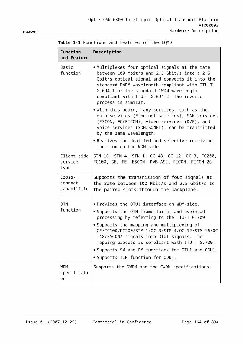
OptiX OSN 6800 Intelligent Optical Transport Platform V100R003
Hardware Description
Table 5-1 Types and functions of the LSX interfaces
Interface
Type
Function
IN LC Receives the single-channel signal from the optical demultiplexer unit or the optical add and drop multiplexing unit.
OUT LC Transmits the single-channel signal to the optical multiplexer unit or the optical add and drop multiplexing unit.
TX LC Transmits the service signal to the client-side equipment.
RX LC Receives the service signal from the client-side equipment.
Laser Safety LevelThe laser safety level of the optical interface is CLASS 1.
The maximum output optical power of each optical interface is lower than 10 dBm (10 mW).
5.9.6 Valid SlotsThe LSX occupies one slot. The valid slots for the LSX are IU1–IU17.
5.9.7 Characteristic Code for the LSXThe board characteristic code comprises the information about frequency of signals, type of the optical module, wavelength, and so on.
For the detailed description of the characteristic code for the board, refer to B.2 Characteristic Code for OTUs.
5.9.8 NM Configuration ReferenceNM configuration reference includes the reference information needed during the configuration of boards through the T2000.
Display of Optical InterfacesThe serial numbers of the optical interfaces on the panel of the board displayed on the NM are listed in Table 5-64.
Table 5-1 Serial numbers of the interfaces of the LSX displayed on the NM
Interface on the Panel Interface on the NM
IN/OUT 1
TX/RX 3
Issue 01 (2007-12-25) Commercial in Confidence Page 162 of 664
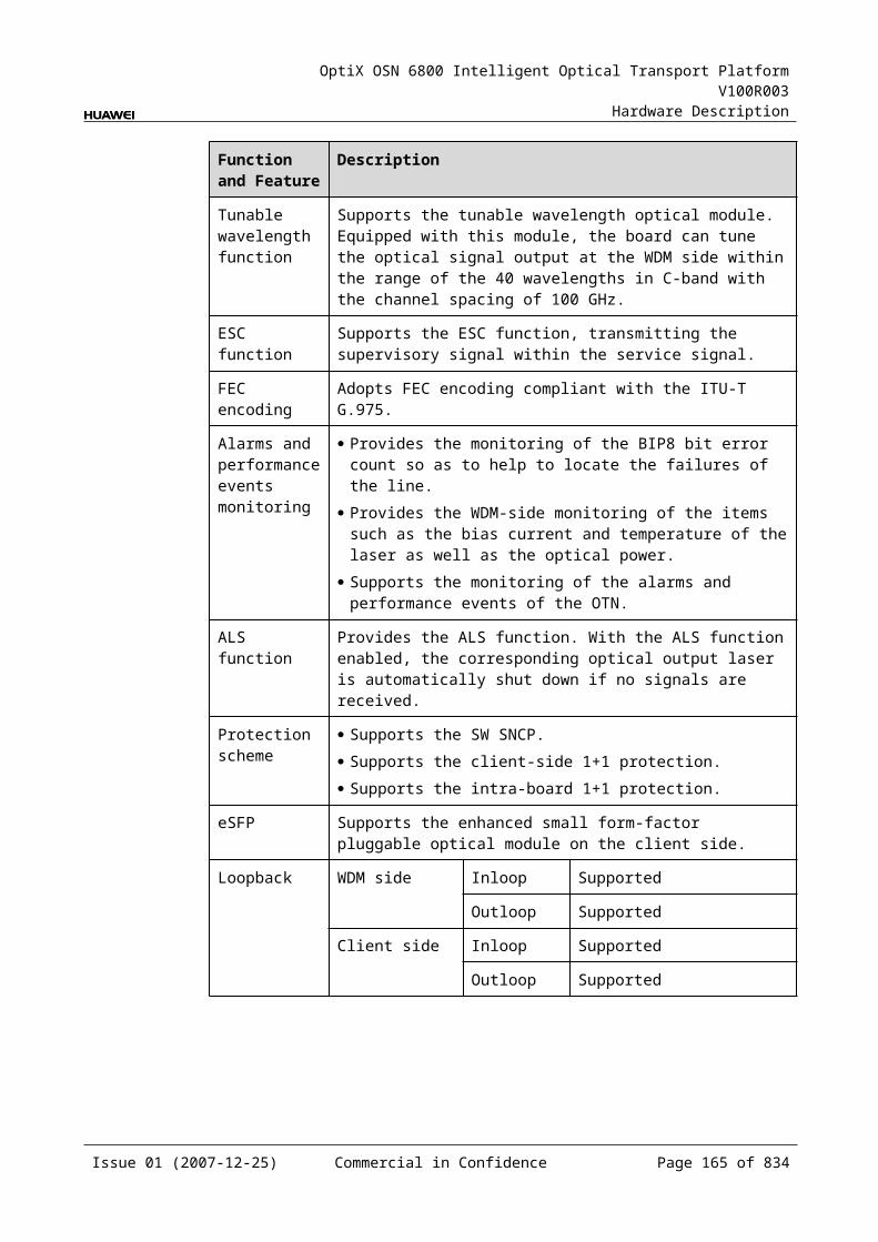
OptiX OSN 6800 Intelligent Optical Transport Platform V100R003
Hardware Description
NOTEThe number of an interface displayed on the T2000 in fact indicates a pair of physical optical interfaces, of which one is used to transmit signals and the other is used to receive signals.
Configuration ParametersPath Use Status
Optical Interface Loopback
Service Type
Port Mapping
Laser Status
Automatic Laser Shutdown
FEC Working State
FEC Type
PAUSE Frame Flow Control
Configure Wavelength No./Wavelength (nm)/Frequency (THz)
Configure Band Type
LPT Enabled
5.9.9 Specifications of the LSXSpecifications include optical specifications, dimensions, weight, and power consumption.
Specifications of Optical Module at the Client SideNOTE10 Gbit/s Multi-rate -10km module and 10 Gbit/s Multi-rate -40km module can be used to access OC192, STM-64, 10GE, and OTU2 signals. The specifications listed following completely apply to OTU2 signals. The actual values may be slightly different from these specifications when the accessed signals are OC192, STM-64, or 10GE signals.
Table 5-1 Specifications of optical module at the client side
Item Unit
Value
Optical Module Type
10 Gbit/s Multirate -10km
10 Gbit/s Multirate -40km
10Gbit/s Multirate -80km
10Gbit/s Single rate -0.3km
Line code format
– NRZ NRZ NRZ NRZ
Optical source type
– SLM SLM SLM MLM
Issue 01 (2007-12-25) Commercial in Confidence Page 163 of 664
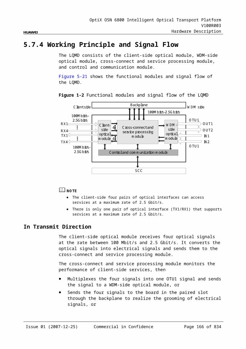
OptiX OSN 6800 Intelligent Optical Transport Platform V100R003
Hardware Description
Item Unit
Value
Optical Module Type
10 Gbit/s Multirate -10km
10 Gbit/s Multirate -40km
10Gbit/s Multirate -80km
10Gbit/s Single rate -0.3km
Target distance km 10 40 80 0.3
Transmitter parameter specifications at point S
Operating wavelength range
nm 1290 to 1330
1530 to 1565
1530 to 1565
840 to 860
Maximum mean launched power
dBm –1 2 4 –1.3
Minimum mean launched power
dBm –6 –1 0 –7.3
Minimum extinction ratio
dB 6 8.2 9 3
Maximum –20 dB spectral width
nm NA NA NA NA
Minimum side mode suppression ratio
dB 30 30 30 30
Eye pattern mask
– G.691-compliant
Receiver parameter specifications at point R
Receiver type – PIN PIN APD PIN
Operating wavelength range
nm 1290 to 1330
1530 to 1565
1270 to 1600
840 to 860
Receiver sensitivity
dBm –11 –14 –24 –7.5
Minimum receiver overload
dBm 0.5 –1 –7 –1
Maximum reflectance
dB NA NA NA NA
Issue 01 (2007-12-25) Commercial in Confidence Page 164 of 664
OptiX OSN 6800 Intelligent Optical Transport Platform V100R003
Hardware Description
Specifications of Optical Module at the DWDM Side
Table 5-1 Specifications of fixed optical module at the DWDM side
Item Unit Value
Optical Module Type
800 ps/nm 1600 ps/nm 800 ps/nm
Line code format – NRZ- 40 channels fixed
NRZ- 40 channels fixed
NRZ- 80 channels fixed
Transmitter parameter specifications at point S
Maximum mean launched power
dBm 2 4 2
Minimum mean launched power
dBm –3 0 –3
Minimum extinction ratio
dB 10 9 10
Central frequency THz 192.10 to 196.00
Central frequency deviation
GHz ±10 ±10 ±5
Maximum –20 dB spectral width
nm 0.3 0.3 0.3
Minimum side mode suppression ratio
dB 35 35 35
Dispersion tolerance ps/nm 800 1600 800
Receiver parameter specifications at point R
Receiver type – PIN APD PIN
Operating wavelength range
nm 1200 to 1650
Receiver sensitivity (FEC on) EOL
dBm –16 –26 –16
Minimum receiver overload
dBm 0 –9 0
Maximum reflectance dB –27 –27 –27
Issue 01 (2007-12-25) Commercial in Confidence Page 165 of 664
OptiX OSN 6800 Intelligent Optical Transport Platform V100R003
Hardware Description
Table 5-2 Specifications of tunable optical module at the DWDM side
Item Unit Value
Optical Module Type 1200 ps/nm - tunable- PIN
1200 ps/nm - tunable- APD
4800 ps/nm -ODB- tunable
800 ps/nm- DRZ-tunable
Line code format – NRZ- 80 channels tunable
NRZ- 80 channels tunable
ODB- 80 channels tunable
DRZ- 80 channels tunable
Transmitter parameter specifications at point S
Maximum mean launched power
dBm 2 2 2 2
Minimum mean launched power
dBm –3 –3 –3 –3
Minimum extinction ratio dB 10 10 NAa 10
Central frequency THz 192.10 to 196.05
Central frequency deviation GHz ±5 ±5 ±5 ±5
Maximum –20 dB spectral width
nm 0.3 0.3 0.3 0.3
Minimum side mode suppression ratio
dB 35 35 35 35
Dispersion tolerance ps/nm 1200 1200 4800 800
Receiver parameter specifications at point R
Receiver type – PIN APD APD PIN
Operating wavelength range nm 1200 to 1650
Receiver sensitivity (FEC on) EOL
dBm –16 –26 –26 –16
Minimum receiver overload dBm 0 –9 –9 0
Maximum reflectance dB –27 –27 –27 –27
a: The ODB code pattern has three levels, and thus extinction ratio is not needed.
Mechanical Specifications Dimensions of board (PCB): 245.1 mm (H) x 220 mm (D) x 2 mm (T) Dimensions of front panel: 264.6 mm (H) x 25.4 mm (W) Weight: 2.86 lb (1.3 kg)
Issue 01 (2007-12-25) Commercial in Confidence Page 166 of 664

OptiX OSN 6800 Intelligent Optical Transport Platform V100R003
Hardware Description
Power ConsumptionPower Consumption of TN11LSX
Board Optical Module Type The maximum power consumption at 25
The maximum power consumption at 55
TN11LSX NRZ-fixed(10G)(800 ps/nm-40 channels fixed1600 ps/nm-40 channels fixed
47.7 52.3
NRZ-tunable(10G)(1200 ps/nm-PIN-80 channels tunable1200 ps/nm-APD-80 channels tunable)
47.9 52.5
DRZ-tunable(10G) (800 ps/nm-80 channels tunable)
49.7 52.7
ODB-tunable(10G) (4800 ps/nm-80 channels tunable)
52.7 55.7
Power Consumption of TN12LSX
Board Optical Module Type The maximum power consumption at 25
The maximum power consumption at 55
TN12LSX NRZ-fixed(10G) (800 ps/nm-40 channels fixed1600 ps/nm-40 channels fixed
32.0 38.4
NRZ-tunable(10G) (1200 ps/nm-PIN-80 channels tunable1200 ps/nm-APD-80 channels tunable)
32.2 38.6
DRZ-tunable(10G) (800 ps/nm-80 channels tunable)
34.0 40.8
ODB-tunable(10G) (4800 ps/nm-80 channels tunable)
36.0 43.2
Issue 01 (2007-12-25) Commercial in Confidence Page 167 of 664
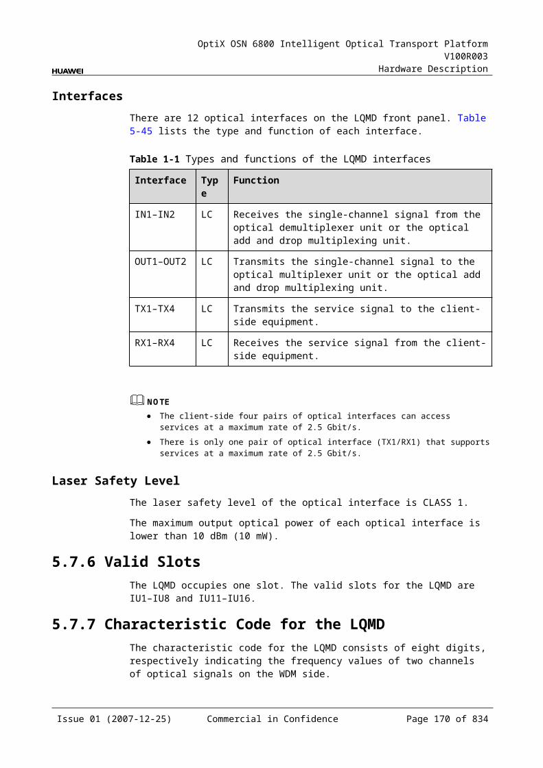
OptiX OSN 6800 Intelligent Optical Transport Platform V100R003
Hardware Description
5.10 LSXLLSXL: 40Gbit/s wavelength conversion board
5.10.1 Version DescriptionOnly one functional version of the LSXL board is available, that is TN11.
5.10.2 ApplicationThe LSXL is a type of optical transponder unit. The LSXL realizes the conversion between one STM-256/OC-768 signal and ITU-T G.692 Recommendation-compliant OTU3 signal.
For the position of the LSXL in the WDM system, see Figure 5-29.
Figure 5-1 Position of the LSXL in the WDM system
Client sideWDM side
MUX
DMUX
LSXL
DMUX
MUX
LSXLG.692 G.692STM-256/OC-768
STM-256/OC-768
Client side WDM side
5.10.3 Functions and FeaturesThe main functions and features supported by the LSXL are tunable wavelength function, OTN interfaces and ESC function.
For detailed functions and features, refer to Table 5-68.
Table 5-1 Functions and features of the LSXL
Function and Feature
Description
Basic function Maps one STM-256/OC-768 signal into one OTU3 optical signal and converts the signal into ITU-T G.692-compliant standard DWDM wavelength. It also performs the reverse process.
Client-side service type
STM-256, OC-768
Issue 01 (2007-12-25) Commercial in Confidence Page 168 of 664
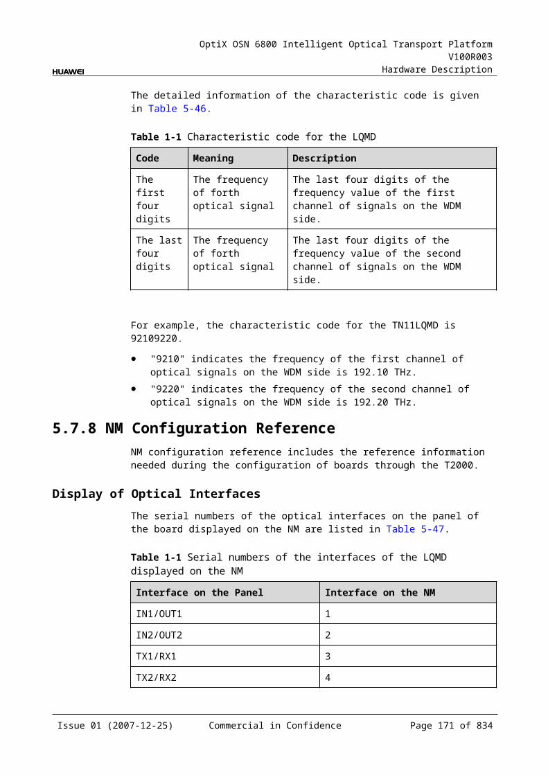
OptiX OSN 6800 Intelligent Optical Transport Platform V100R003
Hardware Description
Function and Feature
Description
OTN function Provides the OTU3 interface on WDM-side. Supports the OTN frame format and overhead processing
by referring to the ITU-T G.709. Supports the mapping of STM-256/OC-768 signals into
OTU3/OTU3V signals. Supports SM and PM functions for OTU3 and ODU3. Supports TCM function for ODU3.
WDM specification Supports the DWDM specifications.
Tunable wavelength function
Supports the tunable wavelength optical module. Equipped with this module, the board can tune the optical signal output at the WDM side within the range of: 40 wavelengths in C-band with the channel spacing of 100
GHz 80 wavelengths in C-band with the channel spacing of 50
GHz
ESC function Supports the ESC function, transmitting the supervisory signal within the service signal.
FEC encoding Adopts FEC encoding and AFEC encoding.
Alarms and performance events monitoring
Provides the monitoring of the BIP8 bit error count so as to help to locate the failures of the line.
Provides the WDM-side monitoring of the items such as the bias current and temperature of the laser as well as the optical power.
Supports the monitoring of the alarms and performance events of the OTN.
ALS function Provides the ALS function. With the ALS function enabled, the corresponding optical output laser is automatically shut down if no signals are received.
Protection scheme Supports the client-side 1+1 protection. Supports the intra-board 1+1 protection. Supports the OWSP protection.
Loopback Client side Inloop Not supported
Outloop Not supported
WDM side Inloop Supported
Outloop Supported
Issue 01 (2007-12-25) Commercial in Confidence Page 169 of 664
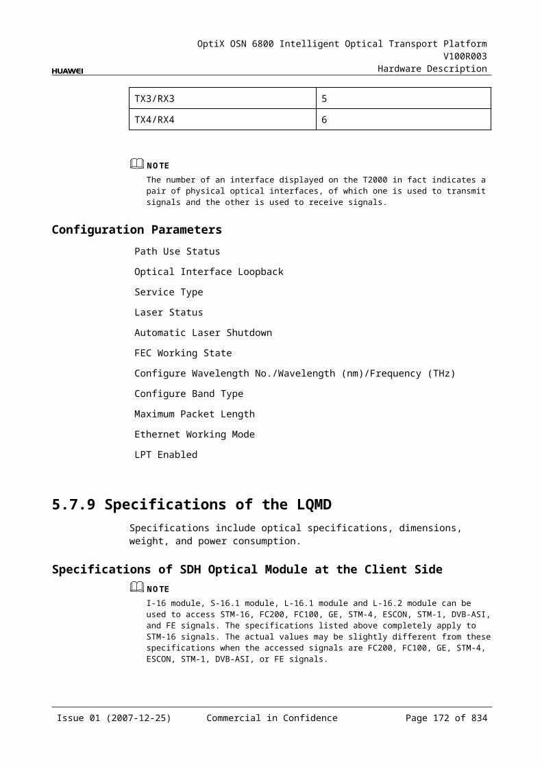
OptiX OSN 6800 Intelligent Optical Transport Platform V100R003
Hardware Description
5.10.4 Working Principle and Signal FlowThe LSXL consists of the client-side optical module, WDM-side optical module, service processing module, and control and communication module.
Figure 5-30 shows the functional modules and signal flow of the LSXL.
Figure 5-1 Functional modules and signal flow of the LSXL
SCC
Client side WDM side
STM-256/OC-768 OTU3
OTU3 STM-256/OC-768
RX
TX IN
OUTClient-side
opticalmodule
serviceprocessing
module
Control and communication module
WDM-side
opticalmodule
In Transmit DirectionThe client-side optical module receives one STM-256/OC-768 signal, and converts the signal into an electrical one before sending it to the service processing module.
The service processing module encodes the client-side services and monitors the performance of the services.
The WDM-side optical module converts the electrical signal into the standard DWDM signal compliant with ITU-T G.692 and sends the signal to the WDM side.
In Receive DirectionThe WDM-side optical module receives one OTU3 optical signal and converts it into an electrical signal.
The service processing module provides tunable dispersion compensation for the signal followed by a series of signal processing activities: FEC/AFEC correction, overhead processing and performance monitoring. Then it demaps the signal into one STM-256 signal at rate of 39.813 Gbit/s and sends the STM-256 signal to the client-side optical module.
The client-side optical module converts the electrical signal into an optical signal and sends the converted signal to the client-side equipment.
Service Processing Module Adds, drops and processes overhead. Monitors the performance of services. Maps and demaps STM-256/OC-768 services.
Issue 01 (2007-12-25) Commercial in Confidence Page 170 of 664
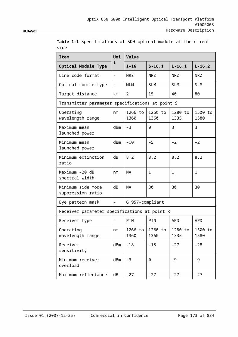
OptiX OSN 6800 Intelligent Optical Transport Platform V100R003
Hardware Description
Control and Communication ModuleThe control and communication module realizes the control, monitoring and communications management of each functional module of the board.
The control and communication module collects the information, such as the alarms and performance events, working status, and voltage detection, of each functional module of the board and reports to the SCC.
Receiving the commands from the SCC, the control and communication module controls and coordinates the functional modules of the board in working.
5.10.5 Front PanelThere are indicators, interfaces and laser safety label on the LSXL front panel.
Appearance of the Front PanelFigure 5-31 shows the LSXL front panel.
Figure 5-1 LSXL front panel
LSXL
LSXL
STATACTPROGSRV
TXR
X
OU
TIN
CLASS 1LASER
PRODUCT
Issue 01 (2007-12-25) Commercial in Confidence Page 171 of 664
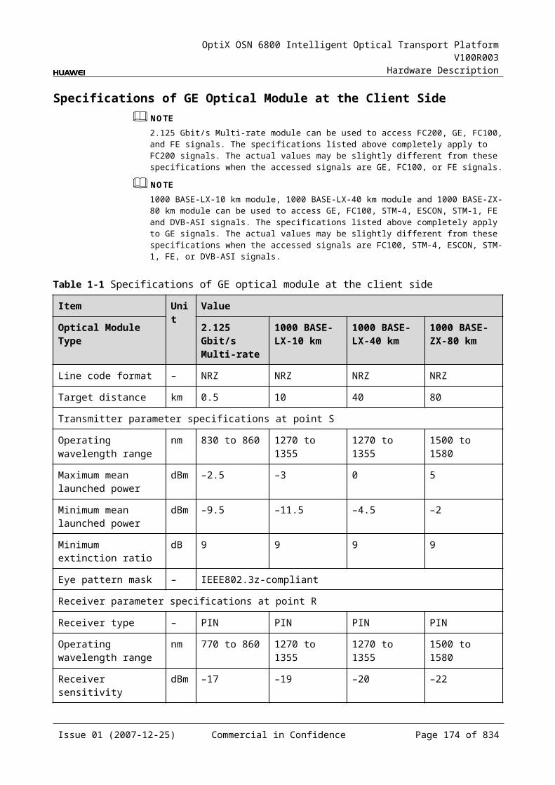
OptiX OSN 6800 Intelligent Optical Transport Platform V100R003
Hardware Description
IndicatorsThere are four indicators on the front panel.
Board hardware status indicator (STAT) – dual-colored (red, green) Service active status indicator (ACT) – green Board software status indicator (PROG) – dual-colored (red, green) Service alarm indicator (SRV) – triple-colored (red, green, yellow)
InterfacesThere are 4 optical interfaces on the LSXL front panel. Table 5-69 lists the type and function of each interface.
Table 5-1 Types and functions of the LSXL interfaces
Interface
Type
Function
IN LC Receives the single-channel signal from the optical demultiplexer unit or the optical add and drop multiplexing unit.
OUT LC Transmits the single-channel signal to the optical multiplexer unit or the optical add and drop multiplexing unit.
TX LC Transmits the service signal to the client-side equipment.
RX LC Receives the service signal from the client-side equipment.
Laser Safety LevelThe laser safety level of the optical interface is CLASS 1.
The maximum output optical power of each optical interface is lower than 10 dBm (10 mW).
5.10.6 Valid SlotsThe LSXL occupies four slots. The valid slots for the LSXL are IU1–IU14 in the subrack.
The back connector of the board is mounted to the backplane along the left slot in the subrack, so the slot number of the LSXL board displayed on the NM is the number of the left one of the four occupied slots.
For example, if the LSXL occupies slots IU1, IU2, IU3 and IU4, the slot number of the LSXL displayed on the NM is IU1.
5.10.7 Characteristic Code for the LSXLThe board characteristic code comprises the information about frequency of signals, type of the optical module, wavelength, and so on.
Issue 01 (2007-12-25) Commercial in Confidence Page 172 of 664
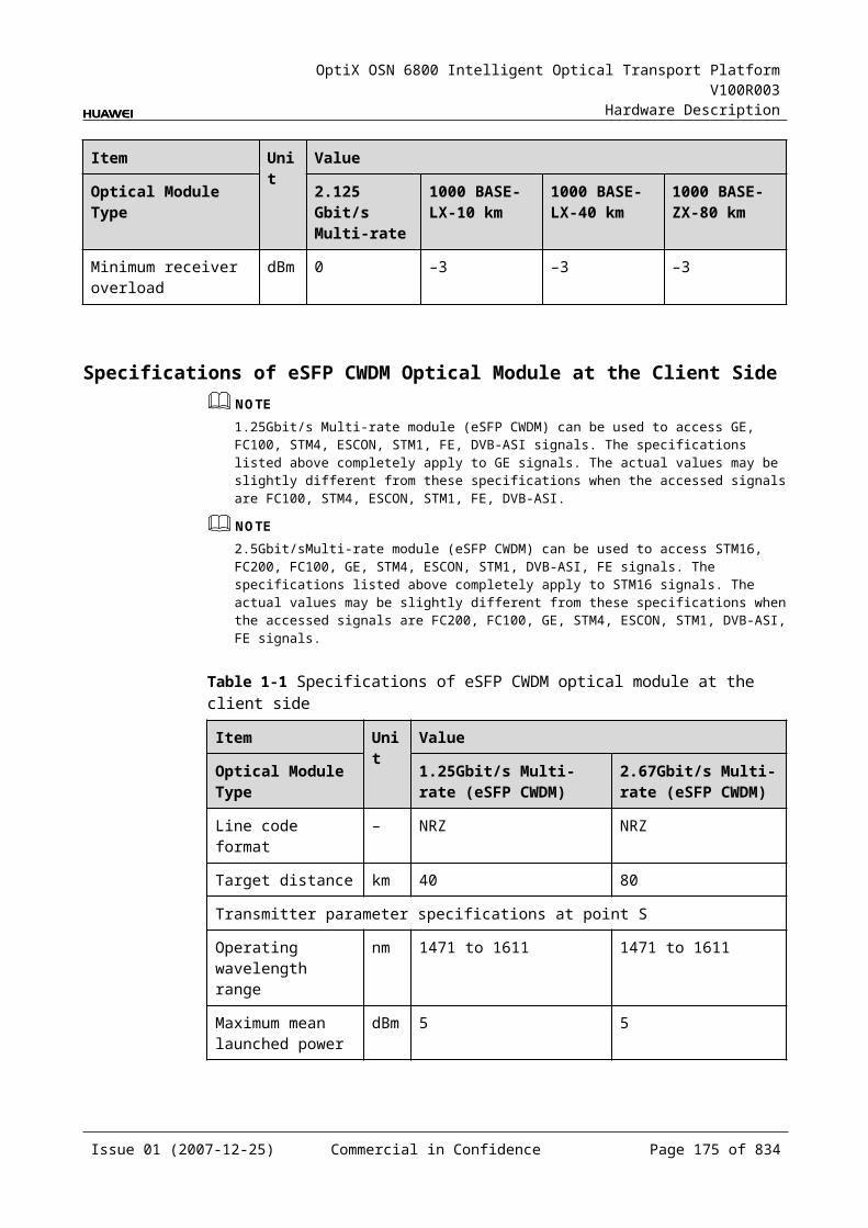
OptiX OSN 6800 Intelligent Optical Transport Platform V100R003
Hardware Description
For the detailed description of the characteristic code for the board, refer to B.2 Characteristic Code for OTUs.
5.10.8 NM Configuration ReferenceNM configuration reference includes the reference information needed during the configuration of boards through the T2000.
Display of Optical InterfacesThe serial numbers of the optical interfaces on the panel of the board displayed on the NM are listed in Table 5-70.
Table 5-1 Serial numbers of the interfaces of the LSXL displayed on the NM
Interface on the Panel Interface on the NM
IN/OUT 1
TX/RX 3
NOTEThe number of an interface displayed on the T2000 in fact indicates a pair of physical optical interfaces, of which one is used to transmit signals and the other is used to receive signals.
Configuration ParametersPath Use Status
Optical Interface Loopback
Laser Status
Automatic Laser Shutdown
Service Type
FEC Working State
FEC Type
Configure Wavelength No./Wavelength (nm)/Frequency (THz)
Configure Band Type
5.10.9 Specifications of the LSXLSpecifications include optical specifications, dimensions, weight, and power consumption.
Issue 01 (2007-12-25) Commercial in Confidence Page 173 of 664
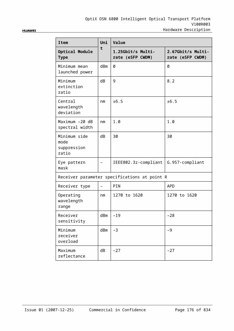
OptiX OSN 6800 Intelligent Optical Transport Platform V100R003
Hardware Description
Specifications of Optical Module at the client Side
Table 5-1 Specifications of optical module at the client side
Item Unit Value
Optical Module Type Transponder
Line code format – NRZ
Transmitter parameter specifications at point S
Operating wavelength range nm 1530 to 1565
Maximum mean launched power dBm 3
Minimum mean launched power dBm 0
Minimum extinction ratio dB 8.2
Minimum side mode suppression ratio dB 35
Dispersion tolerance ps/nm 40
Receiver parameter specifications at point R
Receiver type – PIN
Operating wavelength range nm 1480 to 1570
Receiver sensitivity dBm –5
Minimum receiver overload dBm 3
Maximum reflectance dB –27
Specifications of Optical Module at the DWDM Side
Table 5-1 Specifications of optical module at the DWDM side
Item Unit Value
Optical Module Type Transponder
Line code format – ODB Tunable DRZ Tunable
Transmitter parameter specifications at point S
Operating frequency range THz 192.10 to 196.05
192.10 to 196.00
Maximum mean launched power dBm 0 0
Minimum mean launched power dBm –5 –5
Minimum extinction ratio dB 8.2 8.2
Central frequency deviation GHz ±5 ±5
Issue 01 (2007-12-25) Commercial in Confidence Page 174 of 664
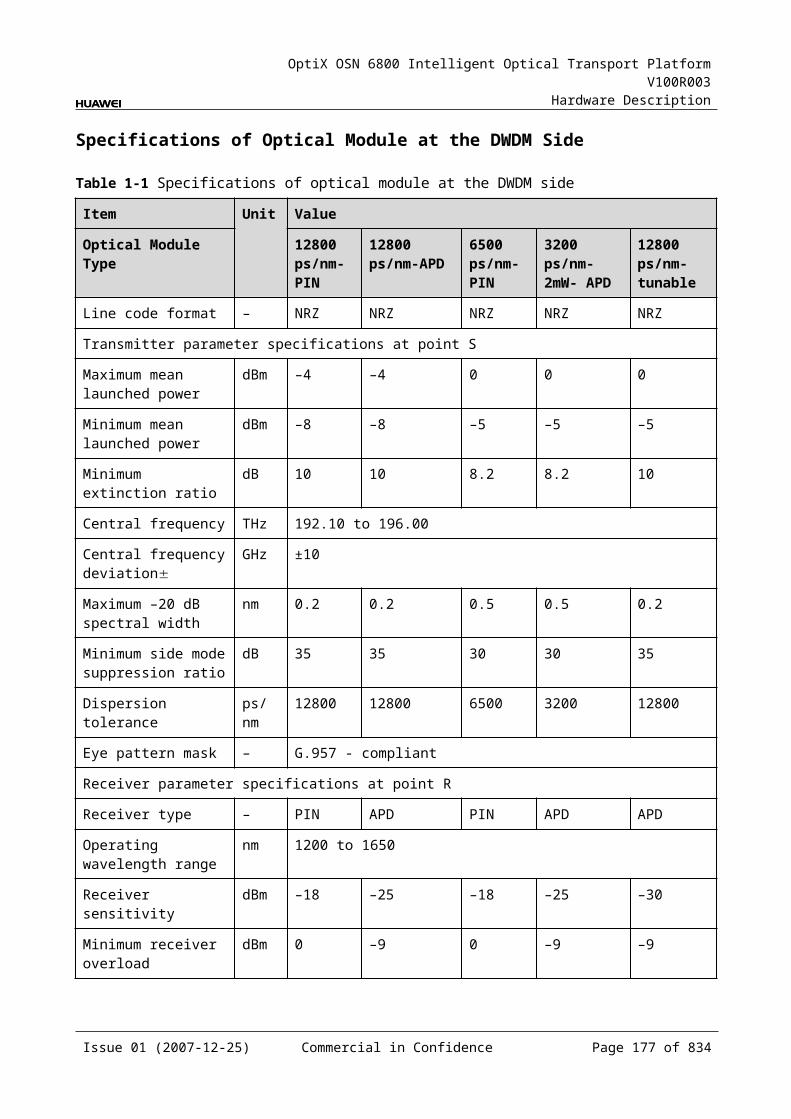
OptiX OSN 6800 Intelligent Optical Transport Platform V100R003
Hardware Description
Item Unit Value
Optical Module Type Transponder
Maximum –20 dB spectral width nm 0.6 0.95
Minimum side mode suppression ratio
dB 35 NA
Dispersion tolerance ps/nm ±400 ±400
Receiver parameter specifications at point R
Receiver type – PIN PIN
Operating wavelength range nm 1529 to 1561 1529 to 1561
Receiver sensitivity (FEC on) EOL dBm -14 -14
Minimum receiver overload (FEC on)
dBm 0 0
Maximum reflectance dB –27 –27
Mechanical SpecificationsThe LSXL consists of three main boards: board A, board B and board C. The mechanical dimension of each main board is provided below:
Board A: 235.0 mm (H) x 220 mm (D) x 2.2 mm (T) Board B: 245.1 mm (H) x 220 mm (D) x 2 mm (T) Board C: 73.5 mm (H) x 72 mm (D) x 2 mm (T) Dimensions of front panel: 264.6 mm (H) x 101.6 mm (W) Weight: 11.02 lb (5 kg)
Power ConsumptionBoard Optical Module Type The
maximum power consumption at 25
The maximum power consumption at 55
TN11LSXL DRZ-tunable(40G)(Transponder) 103.0 110.0
ODB-tunable(40G)(Transponder)
98.0 105.0
Issue 01 (2007-12-25) Commercial in Confidence Page 175 of 664
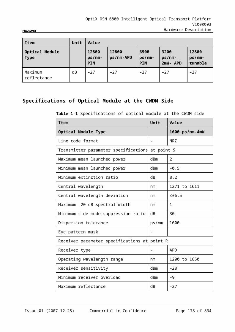
OptiX OSN 6800 Intelligent Optical Transport Platform V100R003
Hardware Description
5.11 LSXLRLSXLR: 40Gbit/s wavelength conversion relay unit
5.11.1 Version DescriptionThe available hardware versions of the LSXLR is TN11.
5.11.2 ApplicationThe LSXLR is a type of optical transponder unit. Used in an electrical REG station in the system, the LSXLR realizes the electrical regeneration of the corresponding optical signal.
For the position of the LSXLR in the WDM system, see Figure 5-32.
Figure 5-1 Position of the LSXLR in the WDM system
WDM side
DMUX
MUX LSXLR
MUX
DMUX
G. 692 G. 692
LSXLR
WDM side
5.11.3 Functions and FeaturesThe main functions and features supported by the LSXLR are tunable wavelength function, OTN interfaces and ESC.
For detailed functions and features, refer to Table 5-73.
Table 5-1 Functions and features of the LSXLR
Function and Feature
Description
Basic function The board is used in an electrical REG station in the system, realizing the electrical regeneration of corresponding optical signals.
Regenerating rate OTU3/OTU3V
Issue 01 (2007-12-25) Commercial in Confidence Page 176 of 664
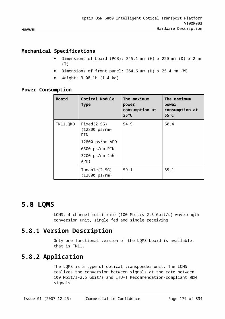
OptiX OSN 6800 Intelligent Optical Transport Platform V100R003
Hardware Description
Function and Feature
Description
OTN function Provides the OTU3/OTU3V interface on WDM-side. Supports the OTN frame format and overhead
processing by referring to the ITU-T G.709. Supports SM and PM functions for OTU3 and ODU3. Supports TCM function for ODU3. Supports PM and TCM non-intrusive monitoring for
ODU3.
WDM specification Supports the DWDM specifications.
Tunable wavelength function
Supports the tunable wavelength optical module. Equipped with this module, the board can tune the optical signal output at the WDM side within the range of: 40 wavelengths in C-band with the channel spacing of
100 GHz 80 wavelengths in C-band with the channel spacing of
50 GHz
ESC function Supports the ESC function, transmitting the supervisory signal within the service signal.
FEC encoding Adopts FEC encoding and AFEC encoding.
Alarms and performance events monitoring
Provides the monitoring of the BIP8 bit error count so as to help to locate the failures of the line.
Provides the WDM-side monitoring of the items such as the bias current and temperature of the laser as well as the optical power.
Supports the monitoring of the alarms and performance events of the OTN.
ALS function Provides the ALS function. With the ALS function enabled, the corresponding optical output laser is automatically shut down if no signals are received.
Protection scheme Not supported
Loopback Not supported
5.11.4 Working Principle and Signal FlowThe LSXLR consists of WDM-side optical module, the electrical regenerating module, and control and communication module.
Figure 5-33 shows the functional modules and signal flow of the LSXLR.
Issue 01 (2007-12-25) Commercial in Confidence Page 177 of 664
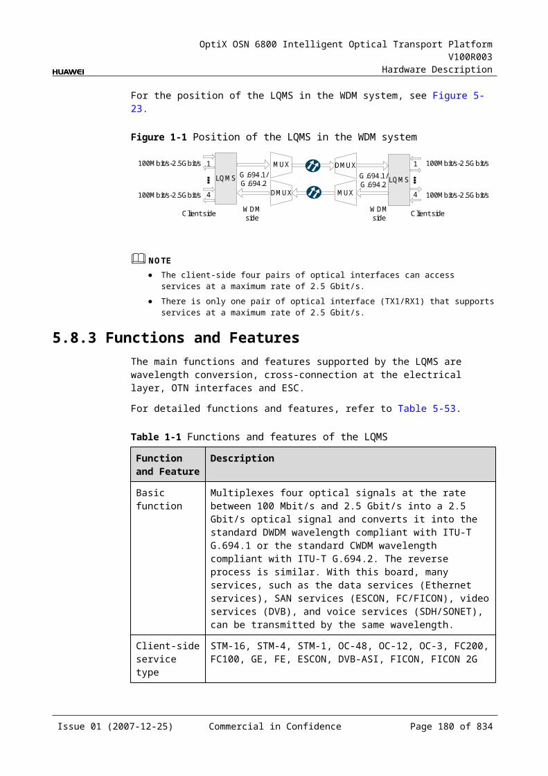
OptiX OSN 6800 Intelligent Optical Transport Platform V100R003
Hardware Description
Figure 5-1 Functional modules and signal flow of the LSXLR
WDM side
SCC
Electricalregenerating
module
IN
OUT
WDM-side
opticalmodule
Control andcommunication module
Signal FlowAs a unidirectional electrical regenerating board, the LSXLR processes only one channel. The WDM-side optical module receives one standard DWDM OTU3 signal compliant with the ITU-T G.692 and converts it into an electrical signal.
Then, the electrical signal is reshaped, regenerated and retimed by the electrical regenerating module before being sent back to the WDM-side optical module. The WDM-side optical module converts the electrical signal into a standard DWDM OTU3 signal compliant with the ITU-T G.692 and sends the converted signal to the WDM side.
Electrical Regenerating ModuleThe electrical regenerating module reshapes, regenerates and retimes the electrical signal.
Control and Communication ModuleThe control and communication module realizes the control, monitoring and communications management of each functional module of the board.
The control and communication module collects the information, such as the alarms and performance events, working status, and voltage detection, of each functional module of the board and reports to the SCC.
Receiving the commands from the SCC, the control and communication module controls and coordinates the functional modules of the board in working.
5.11.5 Front PanelThere are indicators, interfaces and laser safety label on the LSXLR front panel.
Appearance of the Front PanelFigure 5-34 shows the LSXLR front panel.
Issue 01 (2007-12-25) Commercial in Confidence Page 178 of 664
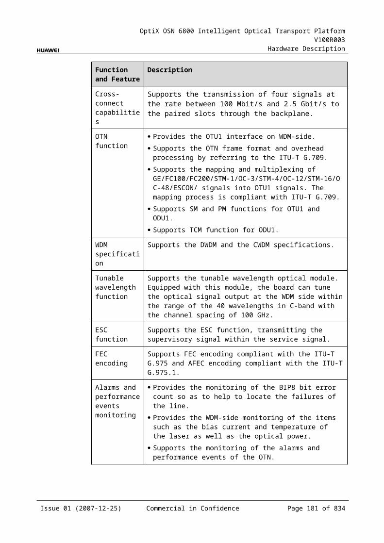
OptiX OSN 6800 Intelligent Optical Transport Platform V100R003
Hardware Description
Figure 5-1 LSXLR front panel
LSXLR
LSXLR
STATACTPROGSRV
OU
TIN
CLASS 1LASER
PRODUCT
IndicatorsThere are four indicators on the front panel.
Board hardware status indicator (STAT) – dual-colored (red, green) Service active status indicator (ACT) – green Board software status indicator (PROG) – dual-colored (red, green) Service alarm indicator (SRV) – triple-colored (red, green, yellow)
InterfacesThere are 2 optical interfaces on the LSXLR front panel. Table 5-74 lists the type and function of each interface.
Issue 01 (2007-12-25) Commercial in Confidence Page 179 of 664
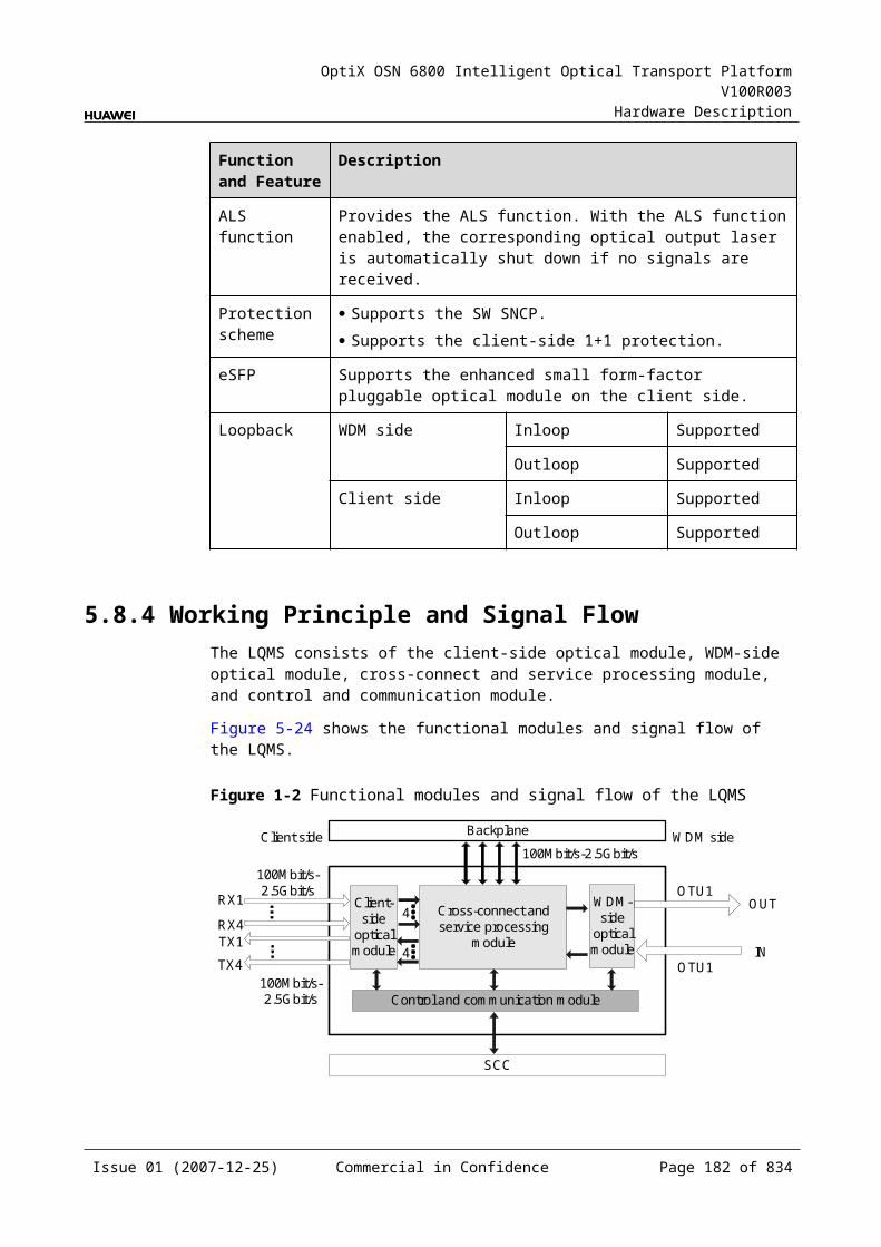
OptiX OSN 6800 Intelligent Optical Transport Platform V100R003
Hardware Description
Table 5-1 Types and functions of the LSXLR interfaces
Interface
Type
Function
IN LC Receives the single-channel signal from the optical demultiplexer unit or the optical add and drop multiplexing unit.
OUT LC Transmits the single-channel signal to the optical multiplexer unit or the optical add and drop multiplexing unit.
Laser Safety LevelThe laser safety level of the optical interface is CLASS 1.
The maximum output optical power of each optical interface is lower than 10 dBm (10 mW).
5.11.6 Valid SlotsThe LSXLR occupies four slots. The valid slots for the LSXLR are IU1–IU14 in the subrack.
The back connector of the board is mounted to the backplane along the left slot in the subrack, so the slot number of the LSXLR board displayed on the NM is the number of the left one of the four occupied slots.
For example, if the LSXLR occupies slots IU1, IU2, IU3 and IU4, the slot number of the LSXLR displayed on the NM is IU1.
5.11.7 Characteristic Code for the LSXLRThe board characteristic code comprises the information about frequency of signals, type of the optical module, wavelength, and so on.
For the detailed description of the characteristic code for the board, refer to B.2 Characteristic Code for OTUs.
5.11.8 NM Configuration ReferenceNM configuration reference includes the reference information needed during the configuration of boards through the T2000.
Display of Optical InterfacesThe serial numbers of the optical interfaces on the panel of the board displayed on the NM are listed in Table 5-75.
Table 5-1 Serial numbers of the interfaces of the LSXLR displayed on the NM
Interface on the Panel Interface on the NM
IN 1
OUT 2
Issue 01 (2007-12-25) Commercial in Confidence Page 180 of 664
OptiX OSN 6800 Intelligent Optical Transport Platform V100R003
Hardware Description
NOTEThe number of an interface displayed on the T2000 in fact indicates a pair of physical optical interfaces, of which one is used to transmit signals and the other is used to receive signals.
Configuration ParametersPath Use Status
Laser Status
Automatic Laser Shutdown
FEC Working State
Configure Wavelength No./Wavelength (nm)/Frequency (THz)
Configure Band Type
5.11.9 Specifications of the LSXLRSpecifications include optical specifications, dimensions, weight, and power consumption.
Specifications of Optical Module at the DWDM Side
Table 5-1 Specifications of optical module at the DWDM side
Item Unit Value
Optical Module Type Transponder
Line code format – ODB Tunable DRZ Tunable
Transmitter parameter specifications at point S
Operating frequency range THz 192.10 to 196.05
192.10 to 196.00
Maximum mean launched power dBm 0 0
Minimum mean launched power dBm –5 –5
Minimum extinction ratio dB 8.2 8.2
Central frequency deviation GHz ±5 ±5
Maximum –20 dB spectral width nm 0.6 0.95
Minimum side mode suppression ratio
dB 35 NA
Dispersion tolerance ps/nm ±400 ±400
Receiver parameter specifications at point R
Receiver type – PIN PIN
Issue 01 (2007-12-25) Commercial in Confidence Page 181 of 664
OptiX OSN 6800 Intelligent Optical Transport Platform V100R003
Hardware Description
Item Unit Value
Optical Module Type Transponder
Operating wavelength range nm 1529 to 1561 1529 to 1561
Receiver sensitivity (FEC on) EOL dBm -14 -14
Minimum receiver overload (FEC on)
dBm 0 0
Maximum reflectance dB –27 –27
Mechanical SpecificationsThe LSXLR consists of three main boards: board A, board B and board C. The mechanical dimension of each main board is provided below:
Board A: 235.0 mm (H) x 220 mm (D) x 2.2 mm (T) Board B: 245.1 mm (H) x 220 mm (D) x 2 mm (T) Board C: 73.5 mm (H) x 72 mm (D) x 2 mm (T) Dimensions of front panel: 264.6 mm (H) x 101.6 mm (W) Weight: 6.72 lb (3.05 kg)
Power Consumption The maximum power consumption at 25 : 82 W The maximum power consumption at 55 : 85 W
5.12 LSXRLSXR: 10 Gbit/s wavelength conversion relay unit
5.12.1 Version DescriptionOnly one functional version of the LSXR board is available, that is TN11.
5.12.2 ApplicationThe LSXR is a type of optical transponder unit. Used in an electrical REG station in the system, the LSXR realizes the electrical regeneration of the corresponding optical signal.
For the position of the LSXR in the WDM system, see Figure 5-35.
Issue 01 (2007-12-25) Commercial in Confidence Page 182 of 664

OptiX OSN 6800 Intelligent Optical Transport Platform V100R003
Hardware Description
Figure 5-1 Position of the LSXR in the WDM system
DMUX
MUX LSXR
MUX
DMUX
G.694.1 G.694.1
LSXR
WDM side WDM side
WDM side WDM side
5.12.3 Functions and FeaturesThe main functions and features supported by the LSXR are wavelength conversion, OTN interfaces and ESC.
For detailed functions and features, refer to Table 5-77.
Table 5-1 Functions and features of the LSXR
Function and Feature
Description
Basic function The board is used in an electrical REG station in the system, realizing the electrical regeneration of corresponding optical signals.
Regenerating rate OTU2/OTU2V
OTN function Provides the OTU2 interface on WDM-side. Supports the OTN frame format and overhead
processing by referring to the ITU-T G.709. Supports SM and PM functions for OTU2 and ODU2. Supports TCM function for ODU2. Supports PM and TCM non-intrusive monitoring for
ODU2.
WDM specification Supports DWDM specifications.
Tunable wavelength function
Supports the tunable wavelength optical module. Equipped with this module, the board can tune the optical signal output at the WDM side within the range of: 40 wavelengths in C-band with the channel spacing of
100 GHz 80 wavelengths in C-band with the channel spacing of
50 GHz
ESC function Supports the ESC function, transmitting the supervisory signal within the service signal.
Issue 01 (2007-12-25) Commercial in Confidence Page 183 of 664
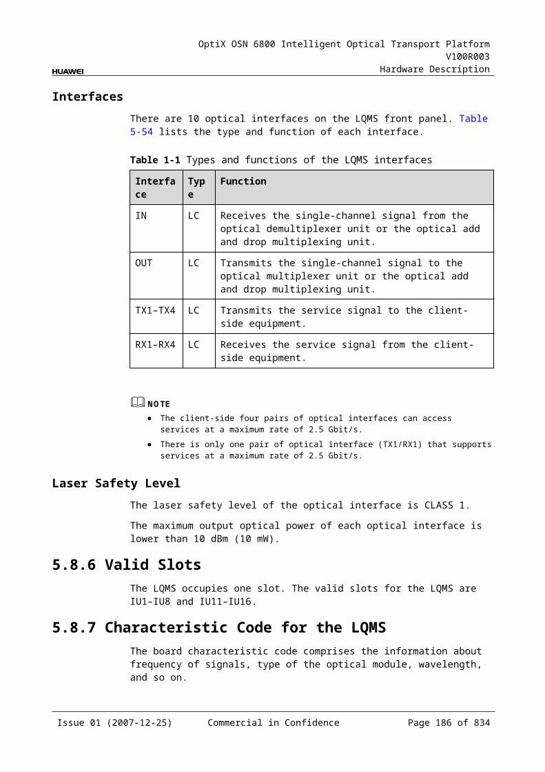
OptiX OSN 6800 Intelligent Optical Transport Platform V100R003
Hardware Description
Function and Feature
Description
FEC encoding Supports FEC encoding compliant with the ITU-T G.975 and AFEC encoding compliant with the ITU-T G.975.1.
Alarms and performance events monitoring
Provides the monitoring of the BIP8 bit error count so as to help to locate the failures of the line.
Provides the WDM-side monitoring of the items such as the bias current and temperature of the laser as well as the optical power.
Supports the monitoring of the alarms and performance events of the OTN.
ALS function Provides the ALS function. With the ALS function enabled, the corresponding optical output laser is automatically shut down if no signals are received.
Protection scheme Not supported
Loopback Not supported
5.12.4 Working Principle and Signal FlowThe LSXR consists of WDM-side optical module, the electrical regenerating module, and control and communication module.
Figure 5-36 shows the functional modules and signal flow of the LSXR.
Figure 5-1 Functional modules and signal flow of the LSXR
WDM side
Control andcommunication module
SCC
WDM-side
opticalmodule
Electricalregenerating
module
IN
OUT
Signal FlowAs a unidirectional electrical regenerating board, the LSXR processes only one channel. The WDM-side optical module receives one standard DWDM OTU2/OTU2v signal compliant with the ITU-T G.694.1 and converts it into an electrical signal.
Issue 01 (2007-12-25) Commercial in Confidence Page 184 of 664
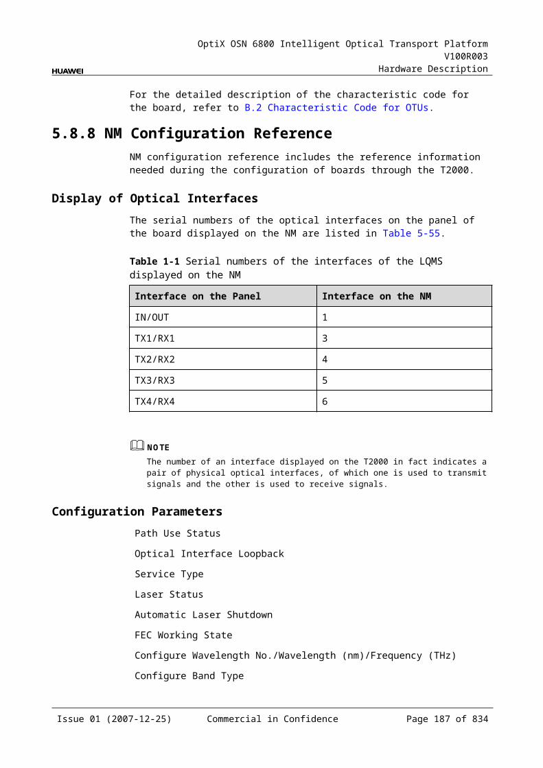
OptiX OSN 6800 Intelligent Optical Transport Platform V100R003
Hardware Description
Then, the electrical signal is reshaped, regenerated and retimed by the electrical regenerating module before being sent back to the WDM-side optical module. The WDM-side optical module converts the electrical signal into a standard DWDM OTU2/OTU2v signal compliant with the ITU-T G.694.1 and sends the converted signal to the WDM side.
Electrical Regenerating ModuleThe electrical regenerating module reshapes, regenerates and retimes the electrical signal.
Control and Communication ModuleThe control and communication module realizes the control, monitoring and communications management of each functional module of the board.
The control and communication module collects the information, such as the alarms and performance events, working status, and voltage detection, of each functional module of the board and reports to the SCC.
Receiving the commands from the SCC, the control and communication module controls and coordinates the functional modules of the board in working.
5.12.5 Front PanelThere are indicators, interfaces and laser safety label on the LSXR front panel.
Appearance of the Front PanelFigure 5-37 shows the LSXR front panel.
Issue 01 (2007-12-25) Commercial in Confidence Page 185 of 664
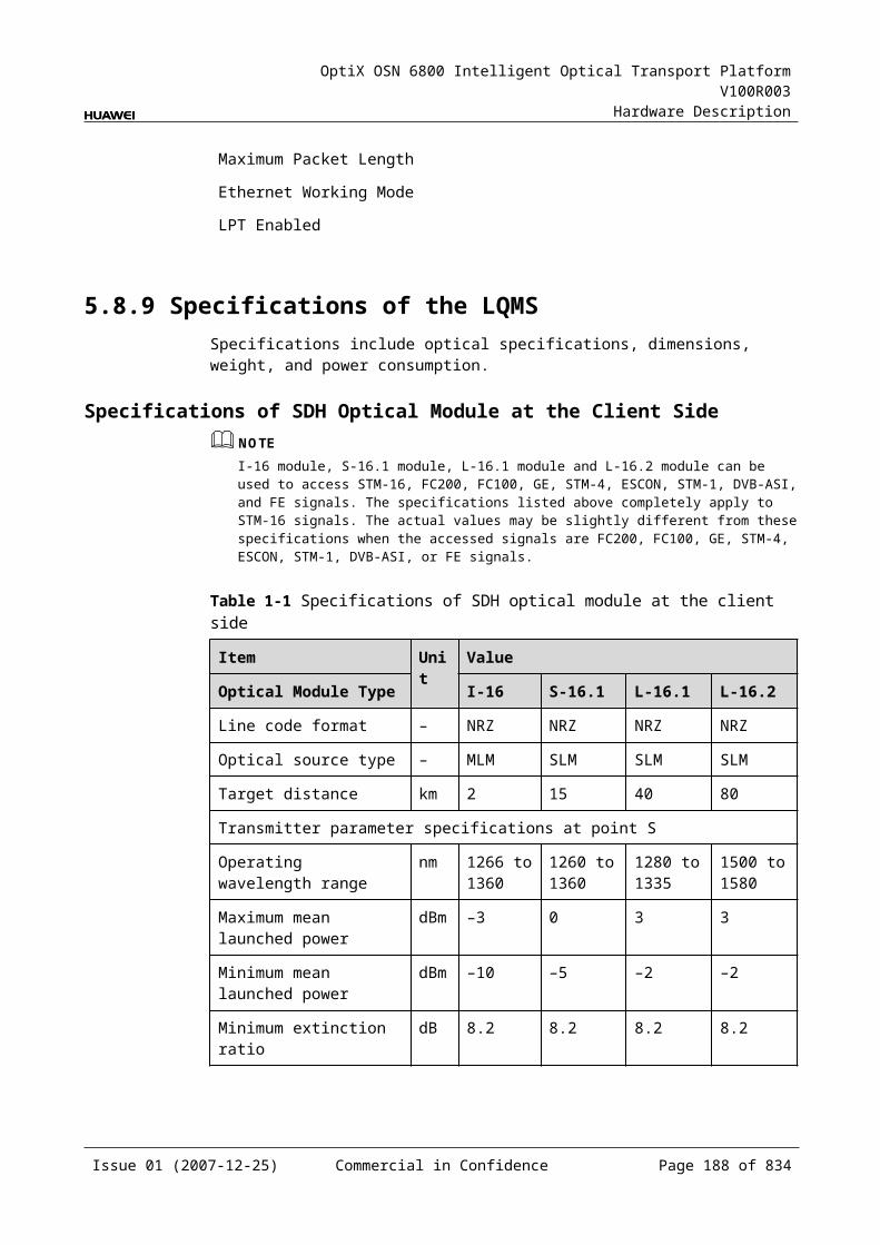
OptiX OSN 6800 Intelligent Optical Transport Platform V100R003
Hardware Description
Figure 5-1 LSXR front panel
LSXR
LSXR
CLASS 1LASER
PRODUCT
STATACTPROGSRV
OU
TIN
IndicatorsThere are four indicators on the front panel.
Board hardware status indicator (STAT) – dual-colored (red, green) Service active status indicator (ACT) – green Board software status indicator (PROG) – dual-colored (red, green) Service alarm indicator (SRV) – triple-colored (red, green, yellow)
InterfacesThere are two optical interfaces on the LSXR front panel. Table 5-78 lists the type and function of each interface.
Issue 01 (2007-12-25) Commercial in Confidence Page 186 of 664
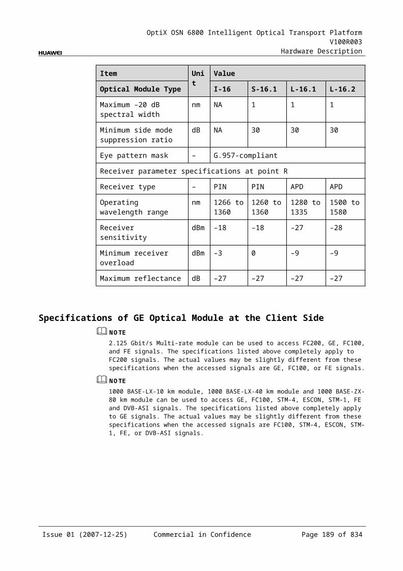
OptiX OSN 6800 Intelligent Optical Transport Platform V100R003
Hardware Description
Table 5-1 Types and functions of the LSXR interfaces
Interface
Type
Function
IN LC Receives the single-channel signal from the optical demultiplexer unit or the optical add and drop multiplexing unit.
OUT LC Transmits the single-channel signal to the optical multiplexer unit or the optical add and drop multiplexing unit.
Laser Safety LevelThe laser safety level of the optical interface is CLASS 1.
The maximum output optical power of each optical interface is lower than 10 dBm (10 mW).
5.12.6 Valid SlotsThe LSXR occupies one slot. Valid slots for the LSXR are IU1–IU17.
5.12.7 Characteristic Code for the LSXRThe board characteristic code comprises the information about frequency of signals, type of the optical module, wavelength, and so on.
For the detailed description of the characteristic code for the board, refer to B.2 Characteristic Code for OTUs.
5.12.8 NM Configuration ReferenceNM configuration reference includes the reference information needed during the configuration of boards through the T2000.
Display of Optical InterfacesThe serial numbers of the optical interfaces on the panel of the board displayed on the NM are listed in Table 5-79.
Table 5-1 Serial numbers of the interfaces of the LSXR displayed on the NM
Interface on the Panel Interface on the NM
IN/OUT 1
NOTEThe number of an interface displayed on the T2000 in fact indicates a pair of physical optical interfaces, of which one is used to transmit signals and the other is used to receive signals.
Issue 01 (2007-12-25) Commercial in Confidence Page 187 of 664
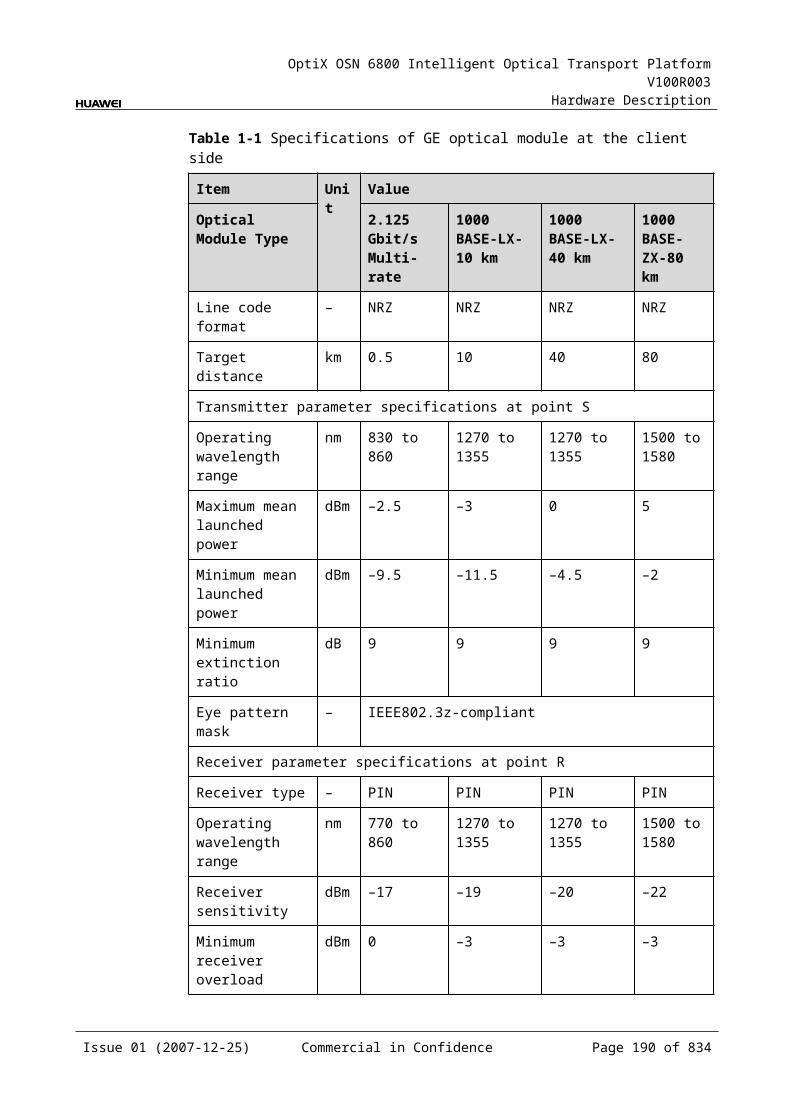
OptiX OSN 6800 Intelligent Optical Transport Platform V100R003
Hardware Description
Configuration ParametersPath Use Status
Laser Status
Automatic Laser Shutdown
FEC Working State
Configure Wavelength No./Wavelength (nm)/Frequency (THz)
Configure Band Type
5.12.9 Specifications of the LSXRSpecifications include optical specifications, dimensions, weight, and power consumption.
Specifications of Optical Module at the DWDM Side
Table 5-1 Specifications of fixed optical module at the DWDM side
Item Unit Value
Optical Module Type
800 ps/nm 1600 ps/nm 800 ps/nm
Line code format – NRZ- 40 channels fixed
NRZ- 40 channels fixed
NRZ- 80 channels fixed
Transmitter parameter specifications at point S
Maximum mean launched power
dBm 2 4 2
Minimum mean launched power
dBm –3 0 –3
Minimum extinction ratio
dB 10 9 10
Central frequency THz 192.10 to 196.00
Central frequency deviation
GHz ±10 ±10 ±5
Maximum –20 dB spectral width
nm 0.3 0.3 0.3
Minimum side mode suppression ratio
dB 35 35 35
Dispersion tolerance ps/nm 800 1600 800
Receiver parameter specifications at point R
Issue 01 (2007-12-25) Commercial in Confidence Page 188 of 664
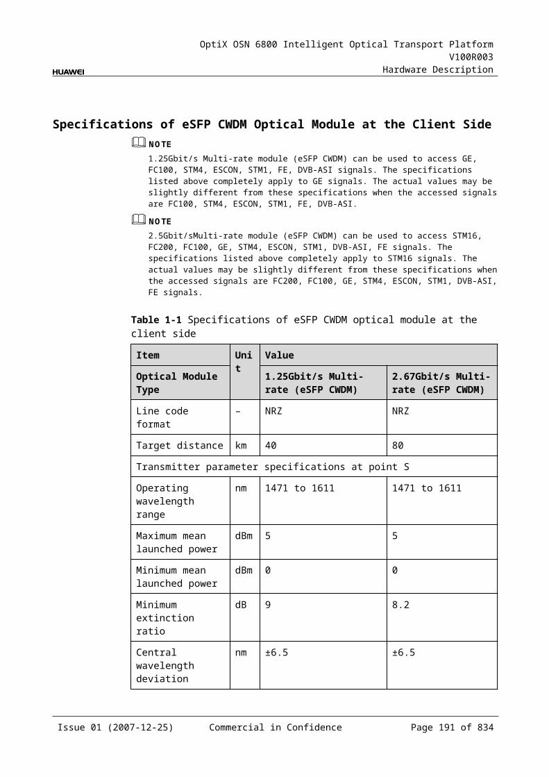
OptiX OSN 6800 Intelligent Optical Transport Platform V100R003
Hardware Description
Item Unit Value
Optical Module Type
800 ps/nm 1600 ps/nm 800 ps/nm
Receiver type – PIN APD PIN
Operating wavelength range
nm 1200 to 1650
Receiver sensitivity (FEC on) EOL
dBm –16 –26 –16
Minimum receiver overload
dBm 0 –9 0
Maximum reflectance dB –27 –27 –27
Table 5-2 Specifications of tunable optical module at the DWDM side
Item Unit Value
Optical Module Type
1200 ps/nm - tunable- PIN
1200 ps/nm - tunable- APD
4800 ps/nm -ODB- tunable
800 ps/nm- DRZ-tunable
Line code format – NRZ- 80 channels tunable
NRZ- 80 channels tunable
ODB- 80 channels tunable
DRZ- 80 channels tunable
Transmitter parameter specifications at point S
Maximum mean launched power
dBm 2 2 2 2
Minimum mean launched power
dBm –3 –3 –3 –3
Minimum extinction ratio dB 10 10 NAa 10
Central frequency THz 192.10 to 196.05
Central frequency deviation
GHz ±5 ±5 ±5 ±5
Maximum –20 dB spectral width
nm 0.3 0.3 0.3 0.3
Minimum side mode suppression ratio
dB 35 35 35 35
Dispersion tolerance ps/nm 1200 1200 4800 800
Receiver parameter specifications at point R
Receiver type – PIN APD APD PIN
Issue 01 (2007-12-25) Commercial in Confidence Page 189 of 664
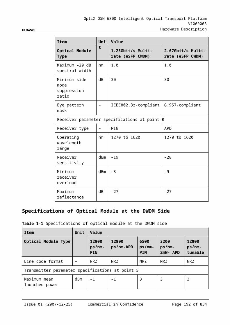
OptiX OSN 6800 Intelligent Optical Transport Platform V100R003
Hardware Description
Item Unit Value
Optical Module Type
1200 ps/nm - tunable- PIN
1200 ps/nm - tunable- APD
4800 ps/nm -ODB- tunable
800 ps/nm- DRZ-tunable
Operating wavelength range
nm 1200 to 1650
Receiver sensitivity (FEC on) EOL
dBm –16 –26 –26 –16
Minimum receiver overload
dBm 0 –9 –9 0
Maximum reflectance dB –27 –27 –27 –27
a: The ODB code pattern has three levels, and thus extinction ratio is not needed.
Mechanical Specifications Dimensions of board (PCB): 245.1 mm (H) x 220 mm (D) x 2 mm (T) Dimensions of front panel: 264.6 mm (H) x 25.4 mm (W) Weight: 2.64 lb (1.2 kg)
Power ConsumptionBoard Optical Module Type The
maximum power consumption at 25
The maximum power consumption at 55
TN11LSXR NRZ-fixed(10G)(800 ps/nm-40 channels fixed1600 ps/nm-40 channels fixed
34.8 38.3
NRZ-tunable(10G)(1200 ps/nm-PIN-80 channels tunable1200 ps/nm-APD-80 channels tunable)
35.0 38.5
DRZ-tunable(10G) (800 ps/nm-80 channels tunable)
36.8 40.3
ODB-tunable(10G) (4800 ps/nm-80 channels tunable)
39.8 43.3
Issue 01 (2007-12-25) Commercial in Confidence Page 190 of 664
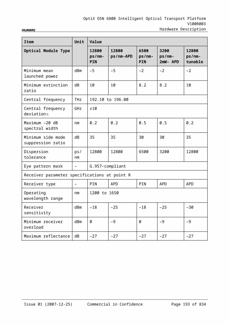
OptiX OSN 6800 Intelligent Optical Transport Platform V100R003
Hardware Description
5.13 LWX2LWX2: arbitrary rate (16Mbit/s-2.5Gbit/s) dual-wavelength conversion board
5.13.1 Version DescriptionOnly one functional version of the LWX2 board is available, that is TN11.
5.13.2 ApplicationThe LWX2 is a type of optical transponder unit. The LWX2 realizes the conversion between two optical signals at the rate between 16 Mbit/s and 2.5 Gbit/s and the ITU-T Recommendation-compliant WDM signals.
For the position of the LWX2 in the WDM system, see Figure 5-38.
Figure 5-1 Position of the LWX2 in the WDM system
16Mbit/s-2.5Gbit/s
16Mbit/s-2.5Gbit/s
LWX2 LWX2
1
2
1
2
16Mbit/s-2.5Gbit/s
16Mbit/s-2.5Gbit/s
G.694.1/G.694.2
G.694.1/G.694.2
Client side WDM side WDM side Client side
MUX
DMUX
DMUX
MUX
DMUX
MUX
DMUX
MUX
5.13.3 Functions and FeaturesThe main functions and features supported by the LWX2 are wavelength conversion and ESC.
For detailed functions and features, refer to Table 5-82.
Table 5-1 Functions and features of the LWX2
Function and Feature
Description
Basic function Receives two optical signals at the rate between 16 Mbit/s and 2.5 Gbit/s and converts them into the standard DWDM wavelengths compliant with the ITU-T G.694.1 or the standard CWDM wavelengths compliant with the ITU-T G.694.2. The reverse process is similar.
Client-side service type
STM-16, STM-4, STM-1, OC-48, OC-12, OC-3, FC200, FC100, GE, FE, FDDI, ESCON, DVB-ASI/SDI, FICON, FICON 2G, HDTV
Issue 01 (2007-12-25) Commercial in Confidence Page 191 of 664
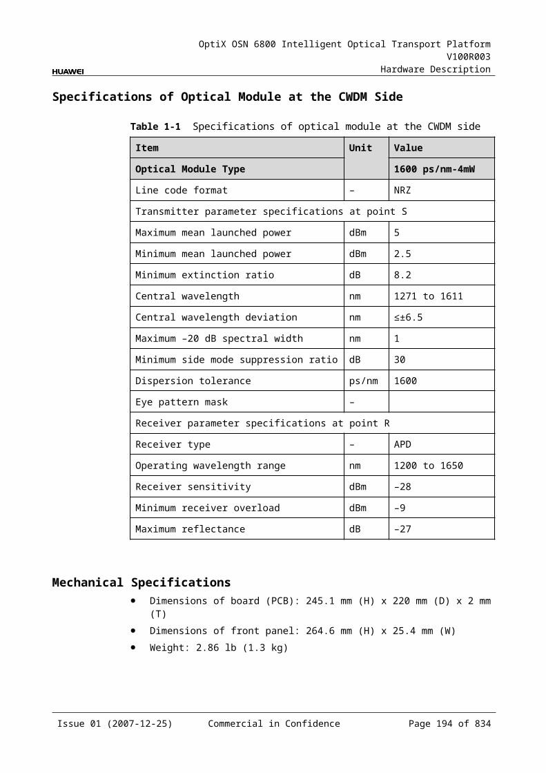
OptiX OSN 6800 Intelligent Optical Transport Platform V100R003
Hardware Description
Function and Feature
Description
WDM specification
Supports the DWDM and CWDM specifications.
Tunable wavelength function
Supports the tunable wavelength optical module. Equipped with this module, the board can tune the optical signal output at the WDM side within the range of the 40 wavelengths in C-band with the channel spacing of 100 GHz.
ESC function Supports the ESC function, transmitting the supervisory signal within the service signal.
Alarms and performance events monitoring
Provides the monitoring of the BIP8 bit error count so as to help to locate the failures of the line.
Provides the WDM-side monitoring of the items such as the bias current and temperature of the laser as well as the optical power.
ALS function Provides the ALS function. With the ALS function enabled, the corresponding optical output laser is automatically shut down if no signals are received.
Protection scheme
Supports the client-side 1+1 protection.
eSFP Supports the enhanced small form-factor pluggable optical module on the client side.
Loopback WDM side Inloop Supported
Outloop Supported
Client side Inloop Supported
Outloop Supported
5.13.4 Working Principle and Signal FlowThe LWX2 consists of the client-side optical module, WDM-side optical module, service processing module, and control and communication module.
Figure 5-39 shows the functional modules and signal flow of the LWX2.
Issue 01 (2007-12-25) Commercial in Confidence Page 192 of 664
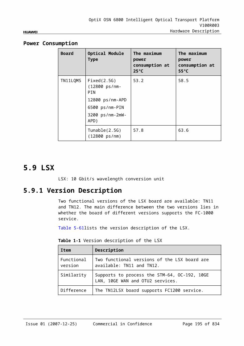
OptiX OSN 6800 Intelligent Optical Transport Platform V100R003
Hardware Description
Figure 5-1 Functional modules and signal flow of the LWX2
OTN 5G
WDM-side
opticalmodule
Control and communication module
SCC
Serviceprocessing
module
Client-side
opticalmodule
Client side WDM side
16Mbit/s-2.5Gbit/s
16Mbit/s-2.5Gbit/s
16Mbit/s-2.5Gbit/s
16Mbit/s-2.5Gbit/s
RX1
TX1
OUT1
IN1OUT2
IN2
RX2
TX2
In Transmit DirectionThe client-side optical module receives two signals at the rate between 16 Mbit/s and 2.5 Gbit/s and converts the signals into electrical ones before sending them to the service processing module.
The service processing module transmits the electrical signals transparently and monitors the performance of the client-side services. Then the module sends the signals to the WDM-side optical module.
The WDM-side optical module converts the electrical signals into the ITU-T G.694.1-compliant DWDM signals or the ITU-T G.694.2-compliant CWDM signals and sends the signals to the WDM side.
In Receive DirectionThe WDM-side optical module receives two optical signals at the rate between 16 Mbit/s and 2.5 Gbit/s and converts the signals into electrical ones before sending them to the service processing module.
The service processing module transmits the electrical signals transparently, extracts and processes the overhead bytes, and monitors the performance of the WDM-side services. Then the module sends the signals to the client-side optical module.
The client-side optical module converts the electrical signals into the required optical signals at the rate between 16 Mbit/s and 2.5 Gbit/s and sends them to the client-side equipment.
Service Processing Module This module extracts and processes overhead bytes. This module monitors the performance of services. This module transmits services transparently.
Control and Communication ModuleThe control and communication module realizes the control, monitoring and communications management of each functional module of the board.
Issue 01 (2007-12-25) Commercial in Confidence Page 193 of 664
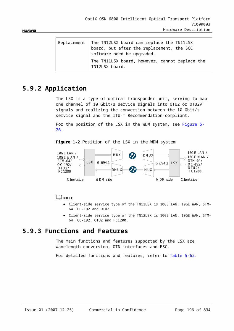
OptiX OSN 6800 Intelligent Optical Transport Platform V100R003
Hardware Description
The control and communication module collects the information, such as the alarms and performance events, working status, and voltage detection, of each functional module of the board and reports to the SCC.
Receiving the commands from the SCC, the control and communication module controls and coordinates the functional modules of the board in working.
5.13.5 Front PanelThere are indicators, interfaces and laser safety label on the LWX2 front panel.
Appearance of the Front PanelFigure 5-40 shows the LWX2 front panel.
Figure 5-1 LWX2 front panel
LWX2
LWX2
CLASS 1LASER
PRODUCT
STATACTPROGSRV
TX1
RX
1TX
2R
X2
OU
T1IN
1O
UT2
IN2
Issue 01 (2007-12-25) Commercial in Confidence Page 194 of 664
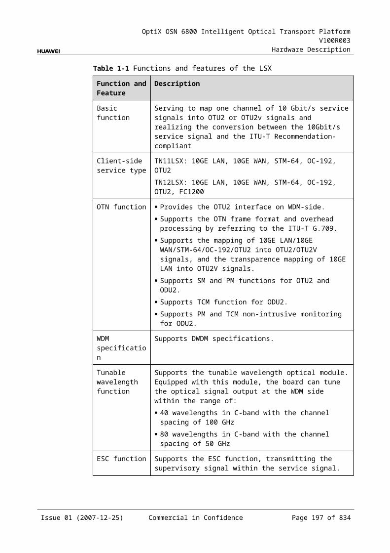
OptiX OSN 6800 Intelligent Optical Transport Platform V100R003
Hardware Description
IndicatorsThere are four indicators on the front panel.
Board hardware status indicator (STAT) – dual-colored (red, green) Service active status indicator (ACT) – green Board software status indicator (PROG) – dual-colored (red, green) Service alarm indicator (SRV) – triple-colored (red, green, yellow)
InterfacesThere are 8 optical interfaces on the LWX2 front panel. Table 5-83 lists the type and function of each interface.
Table 5-1 Types and functions of the LWX2 interfaces
Interface Type
Function
IN1-IN2 LC Receives the single-channel signal from the optical demultiplexer unit or the optical add and drop multiplexing unit.
OUT1-OUT2 LC Transmits the single-channel signal to the optical multiplexer unit or the optical add and drop multiplexing unit.
TX1-TX2 LC Transmits the service signal to the client-side equipment.
RX1-RX2 LC Receives the service signal from the client-side equipment.
Laser Safety LevelThe laser safety level of the optical interface is CLASS 1.
The maximum output optical power of each optical interface is lower than 10 dBm (10 mW).
5.13.6 Valid SlotsThe LWX2 occupies one slot. The valid slots for the LWX2 are IU1-IU17.
5.13.7 Characteristic Code for the LWX2The characteristic code for the LWX2 consists of eight digits, respectively indicating the frequency values of two channels of optical signals on the WDM side.
The detailed information of the characteristic code is given in Table 5-84.
Issue 01 (2007-12-25) Commercial in Confidence Page 195 of 664
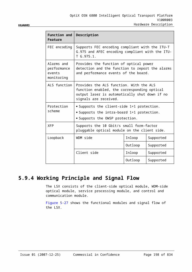
OptiX OSN 6800 Intelligent Optical Transport Platform V100R003
Hardware Description
Table 5-1 Characteristic code for the LWX2
Code Meaning Description
The first four digits
The frequency of forth optical signal
The last four digits of the frequency value of the first channel of signals on the WDM side.
The last four digits
The frequency of forth optical signal
The last four digits of the frequency value of the second channel of signals on the WDM side.
For example, the characteristic code for the TN11LWX2 is 92109220.
"9210" indicates the frequency of the first channel of optical signals on the WDM side is 192.10 THz.
"9220" indicates the frequency of the second channel of optical signals on the WDM side is 192.20 THz.
5.13.8 NM Configuration ReferenceNM configuration reference includes the reference information needed during the configuration of boards through the T2000.
Display of Optical InterfacesThe serial numbers of the optical interfaces on the panel of the board displayed on the NM are listed in Table 5-85.
Table 5-1 Serial numbers of the interfaces of the LWX2 displayed on the NM
Interface on the Panel Interface on the NM
IN1/OUT1 1
IN2/OUT2 3
TX1/RX1 5
TX2/RX2 6
NOTEThe number of an interface displayed on the T2000 in fact indicates a pair of physical optical interfaces, of which one is used to transmit signals and the other is used to receive signals.
Issue 01 (2007-12-25) Commercial in Confidence Page 196 of 664
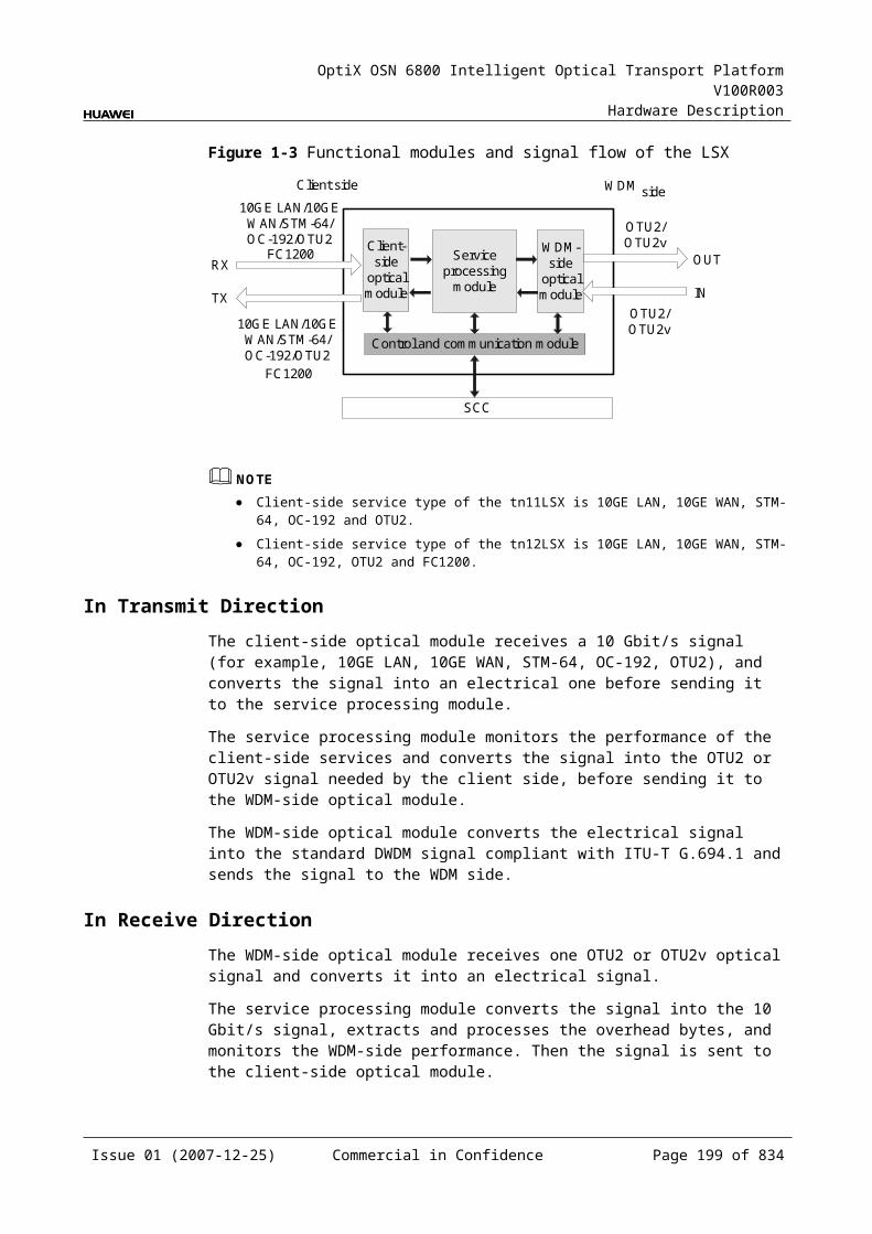
OptiX OSN 6800 Intelligent Optical Transport Platform V100R003
Hardware Description
Configuration ParametersPath Use Status
Optical Interface Loopback
Service Type
Client Service Bearer Rate (M)
Laser Status
Automatic Laser Shutdown
Current Bearer Rate (M)
Configure Wavelength No./Wavelength (nm)/Frequency (THz)
Configure Band Type
5.13.9 Specifications of the LWX2Specifications include optical specifications, dimensions, weight, and power consumption.
Specifications of Optical Module at the Client SideNOTEI-16 module, S-16.1 module, L-16.1 module and L-16.2 module can be used to access STM-16, FC200, FC100, GE, STM-4, ESCON, STM-1, DVB-ASI, and FE signals. The specifications listed above completely apply to STM-16 signals. The actual values may be slightly different from these specifications when the accessed signals are FC200, FC100, GE, STM-4, ESCON, STM-1, DVB-ASI, or FE signals.
NOTE2.125 Gbit/s Multi-rate module is used to access FC200, GE, FC100 and FE signals. The specifications listed above completely apply to FC200 signals. The actual values may be slightly different from these specifications when the accessed signals are GE, FC100, or FE signals.
Table 5-1 Specifications of optical module at the client side
Item Unit
Value
Optical Module Type
2.125 Gbit/s Multi-rate
I-16 S-16.1 L-16.2
Line code format – NRZ NRZ NRZ NRZ
Optical source type – MLM MLM SLM SLM
Target distance km 0.5 2 15 80
Transmitter parameter specifications at point S
Operating wavelength range
nm 830 to 860 1266 to 1360
1260 to 1360
1500 to 1580
Issue 01 (2007-12-25) Commercial in Confidence Page 197 of 664
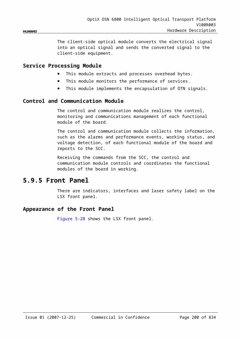
OptiX OSN 6800 Intelligent Optical Transport Platform V100R003
Hardware Description
Item Unit
Value
Optical Module Type
2.125 Gbit/s Multi-rate
I-16 S-16.1 L-16.2
Maximum mean launched power
dBm –2.5 –3 0 3
Minimum mean launched power
dBm –9.5 –10 –5 –2
Minimum extinction ratio
dB 9 8.2 8.2 8.2
Maximum –20 dB spectral width
nm NA NA 1 1
Minimum side mode suppression ratio
dB NA NA 30 30
Eye pattern mask – IEEE802.3z-compliant G.957-compliant
Receiver parameter specifications at point R
Receiver type – PIN PIN PIN APD
Operating wavelength range
nm 770 to 860 1200 to 1650
1200 to 1650
1200 to 1650
Receiver sensitivity dBm –17 –18 –18 –28
Minimum receiver overload
dBm 0 –3 0 –9
Maximum reflectance
dB NA –27 –27 –27
Specifications of eSFP CWDM Optical Module at the Client SideNOTE1.25Gbit/s Multi-rate module (eSFP CWDM) can be used to access GE, FC100, STM4, ESCON, STM1, FE, DVB-ASI signals. The specifications listed above completely apply to GE signals. The actual values may be slightly different from these specifications when the accessed signals are FC100, STM4, ESCON, STM1, FE, DVB-ASI.
NOTE2.5Gbit/sMulti-rate module (eSFP CWDM) can be used to access STM16, FC200, FC100, GE, STM4, ESCON, STM1, DVB-ASI, FE signals. The specifications listed above completely apply to STM16 signals. The actual values may be slightly different from these specifications when the accessed signals are FC200, FC100, GE, STM4, ESCON, STM1, DVB-ASI, FE signals.
Issue 01 (2007-12-25) Commercial in Confidence Page 198 of 664
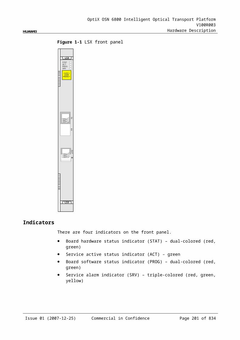
OptiX OSN 6800 Intelligent Optical Transport Platform V100R003
Hardware Description
Table 5-1 Specifications of eSFP CWDM optical module at the client side
Item Unit
Value
Optical Module Type
1.25Gbit/s Multi-rate (eSFP CWDM)
2.67Gbit/s Multi-rate (eSFP CWDM)
Line code format – NRZ NRZ
Target distance km 40 80
Transmitter parameter specifications at point S
Operating wavelength range
nm 1471 to 1611 1471 to 1611
Maximum mean launched power
dBm 5 5
Minimum mean launched power
dBm 0 0
Minimum extinction ratio
dB 9 8.2
Central wavelength deviation
nm ±6.5 ±6.5
Maximum –20 dB spectral width
nm 1.0 1.0
Minimum side mode suppression ratio
dB 30 30
Eye pattern mask – IEEE802.3z-compliant G.957-compliant
Receiver parameter specifications at point R
Receiver type – PIN APD
Operating wavelength range
nm 1270 to 1620 1270 to 1620
Receiver sensitivity dBm –19 –28
Minimum receiver overload
dBm –3 –9
Maximum reflectance
dB –27 –27
Issue 01 (2007-12-25) Commercial in Confidence Page 199 of 664
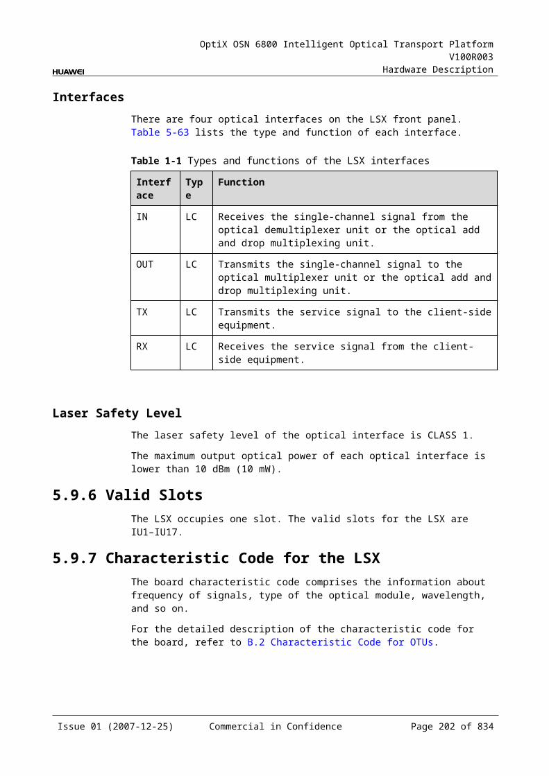
OptiX OSN 6800 Intelligent Optical Transport Platform V100R003
Hardware Description
Table 5-2 Specifications of eSFP DWDM optical module at the client side
Item Unit
Value
Optical Module Type
2.67Gbit/s Multi-rate (eSFP DWDM)
Line code format – NRZ
Target distance km 120
Transmitter parameter specifications at point S
Operating frequency range
THz 192.1 to 196.0
Maximum mean launched power
dBm 3
Minimum mean launched power
dBm 0
Minimum extinction ratio
dB 8.5
Central frequency deviation
GHz ±12.5
Maximum –20 dB spectral width
nm NA
Minimum side mode suppression ratio
dB 30
Eye pattern mask – 5% margin are required for the eye pattern of STM-16 services and equivalent OTU1 services.
Receiver parameter specifications at point R
Receiver type – APD
Receiver sensitivity dBm –28
Minimum receiver overload
dBm –9
Maximum reflectance dB –27
Issue 01 (2007-12-25) Commercial in Confidence Page 200 of 664
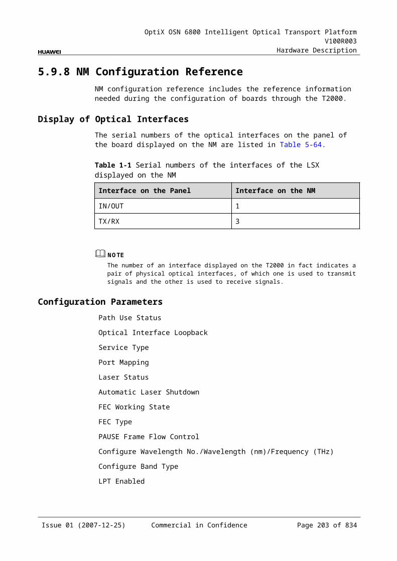
OptiX OSN 6800 Intelligent Optical Transport Platform V100R003
Hardware Description
Specifications of Optical Module at the DWDM Side
Table 5-1 Specifications of optical module at the DWDM side
Item Unit Value
Optical Module Type
12800ps/nm-PINa
12800ps/nm-APDa
6500 ps/nm -PIN
3200 ps/nm -2mW-APD
Line code format – NRZ NRZ NRZ NRZ
Transmitter parameter specifications at point S
Maximum mean launched power
dBm –1 –1 3 3
Minimum mean launched power
dBm –5 –5 –2 –2
Minimum extinction ratio
dB 10 10 8.2 8.2
Central frequency THz 192.10 to 196.00
Central frequency deviation
GHz ±10
Maximum –20 dB spectral width
nm 0.2 0.2 0.5 0.5
Minimum side mode suppression ratio
dB 35 35 30 30
Dispersion tolerance ps/nm 12800 12800 6500 3200
Eye pattern mask – G.957-compliant
Receiver parameter specifications at point R
Receiver type – PIN APD PIN APD
Operating wavelength range
nm 1200 to 1650
Receiver sensitivity dBm –18 –25 –18 –25
Minimum receiver overload
dBm 0 –9 0 –9
Maximum reflectance
dB –27 –27 –27 –27
a: The 12800ps/nm-PIN and 12800ps/nm-APD modules do not support pilot tone modulation mode.
Issue 01 (2007-12-25) Commercial in Confidence Page 201 of 664
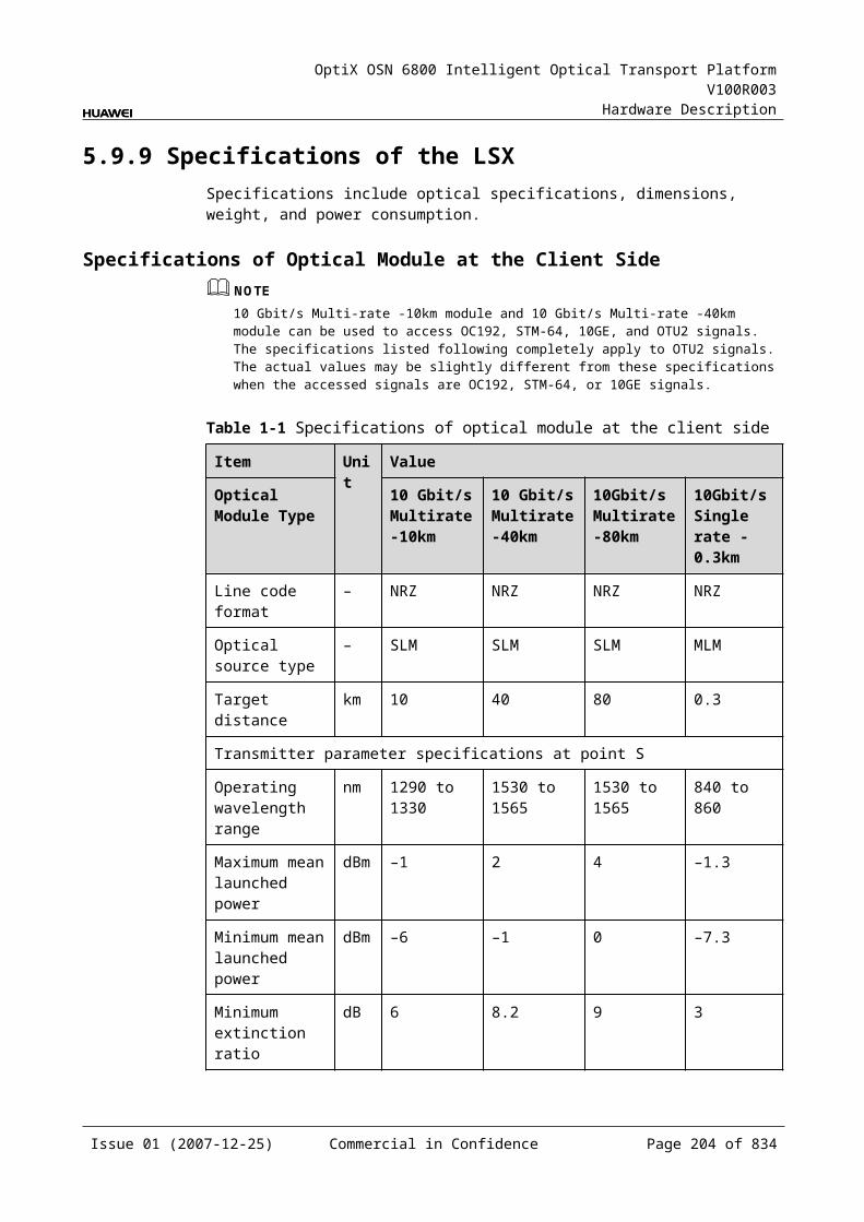
OptiX OSN 6800 Intelligent Optical Transport Platform V100R003
Hardware Description
Specifications of Optical Module at the CWDM Side
Table 5-1 Specifications of optical module at the CWDM side
Item Unit Value
Optical Module Type 1600 ps/nm-4mW
Line code format – NRZ
Transmitter parameter specifications at point S
Maximum mean launched power dBm 5
Minimum mean launched power dBm 2.5
Minimum extinction ratio dB 8.2
Central wavelength nm 1271 to 1611
Central wavelength deviation nm ≤±6.5
Maximum –20 dB spectral width nm 1
Minimum side mode suppression ratio dB 30
Dispersion tolerance ps/nm 1600
Eye pattern mask –
Receiver parameter specifications at point R
Receiver type – APD
Operating wavelength range nm 1200 to 1650
Receiver sensitivity dBm –28
Minimum receiver overload dBm –9
Maximum reflectance dB –27
Mechanical Specifications Dimensions of board (PCB): 245.1 mm (H) x 220 mm (D) x 2 mm (T) Dimensions of front panel: 264.6 mm (H) x 25.4 mm (W) Weight: 2.86 lb (1.3 kg)
Power Consumption The maximum power consumption at 25 : 38.5 W The maximum power consumption at 55 : 42.4 W
Issue 01 (2007-12-25) Commercial in Confidence Page 202 of 664
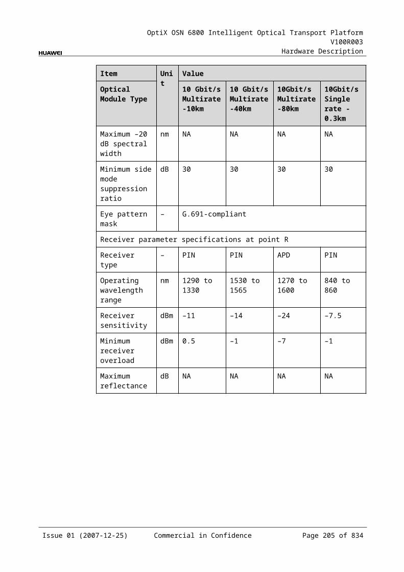
OptiX OSN 6800 Intelligent Optical Transport Platform V100R003
Hardware Description
5.14 LWXDLWXD: arbitrary rate (16Mbit/s-2.5Gbit/s) wavelength conversion board (double transmit)
5.14.1 Version DescriptionOnly one functional version of the LWXD board is available, that is TN11.
5.14.2 ApplicationThe LWXD is a type of optical transponder unit. The LWXD realizes the conversion between the optical signal at the rate between 16 Mbit/s and 2.5 Gbit/s and the ITU-T Recommendation-compliant WDM signal, and the dual fed and selective receiving function on the WDM side.
For the position of the LWXD in the WDM system, see Figure 5-41.
Figure 5-1 Position of the LWXD in the WDM system
LWXD LWXD16Mbit/s
-2.5Gbit/s16Mbit/s
-2.5Gbit/sMUX
DMUX
DMUX
MUX
G.694.1/G.694.2
G.694.1/G.694.2
DMUX
MUX
DMUX
MUX
Client side WDM side WDM side Client side
5.14.3 Functions and FeaturesThe main functions and features supported by the LWXD are wavelength conversion and ESC.
For detailed functions and features, refer to Table 5-91.
Table 5-1 Functions and features of the LWXD
Function and Feature
Description
Basic function Receives a signal at the rate between 16 Mbit/s and 2.5 Gbit/s and converts the signal into the standard DWDM wavelength compliant with the ITU-T G.694.1 or the standard CWDM wavelength compliant with the ITU-T G.694.2. The reverse process is similar.
Realizes the dual fed and selective receiving function on the WDM side.
Issue 01 (2007-12-25) Commercial in Confidence Page 203 of 664
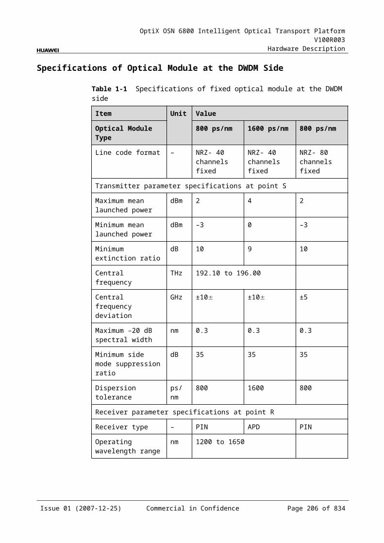
OptiX OSN 6800 Intelligent Optical Transport Platform V100R003
Hardware Description
Function and Feature
Description
Client-side service type
STM-16, STM-4, STM-1, OC-48, OC-12, OC-3, FC200, FC100, GE, FE, FDDI, ESCON, DVB-ASI/SDI, FICON, FICON 2G, HDTV
WDM specification
Supports the DWDM and CWDM specifications.
Tunable wavelength function
Supports the tunable wavelength optical module. Equipped with this module, the board can tune the optical signal output at the WDM side within the range of the 40 wavelengths in C-band with the channel spacing of 100 GHz.
ESC function Supports the ESC function, transmitting the supervisory signal within the service signal.
Alarms and performance events monitoring
Provides the monitoring of the BIP8 bit error count so as to help to locate the failures of the line.
Provides the WDM-side monitoring of the items such as the bias current and temperature of the laser as well as the optical power.
ALS function Provides the ALS function. With the ALS function enabled, the corresponding optical output laser is automatically shut down if no signals are received.
Protection scheme
Supports the client-side 1+1 protection. Supports the intra-board 1+1 protection.
eSFP Supports the enhanced small form-factor pluggable optical module on the client side.
Loopback WDM side Inloop Supported
Outloop Supported
Client side Inloop Supported
Outloop Supported
5.14.4 Working Principle and Signal FlowThe LWXD consists of the client-side optical module, WDM-side optical module, service processing module, and control and communication module.
Figure 5-42 shows the functional modules and signal flow of the LWXD.
Issue 01 (2007-12-25) Commercial in Confidence Page 204 of 664
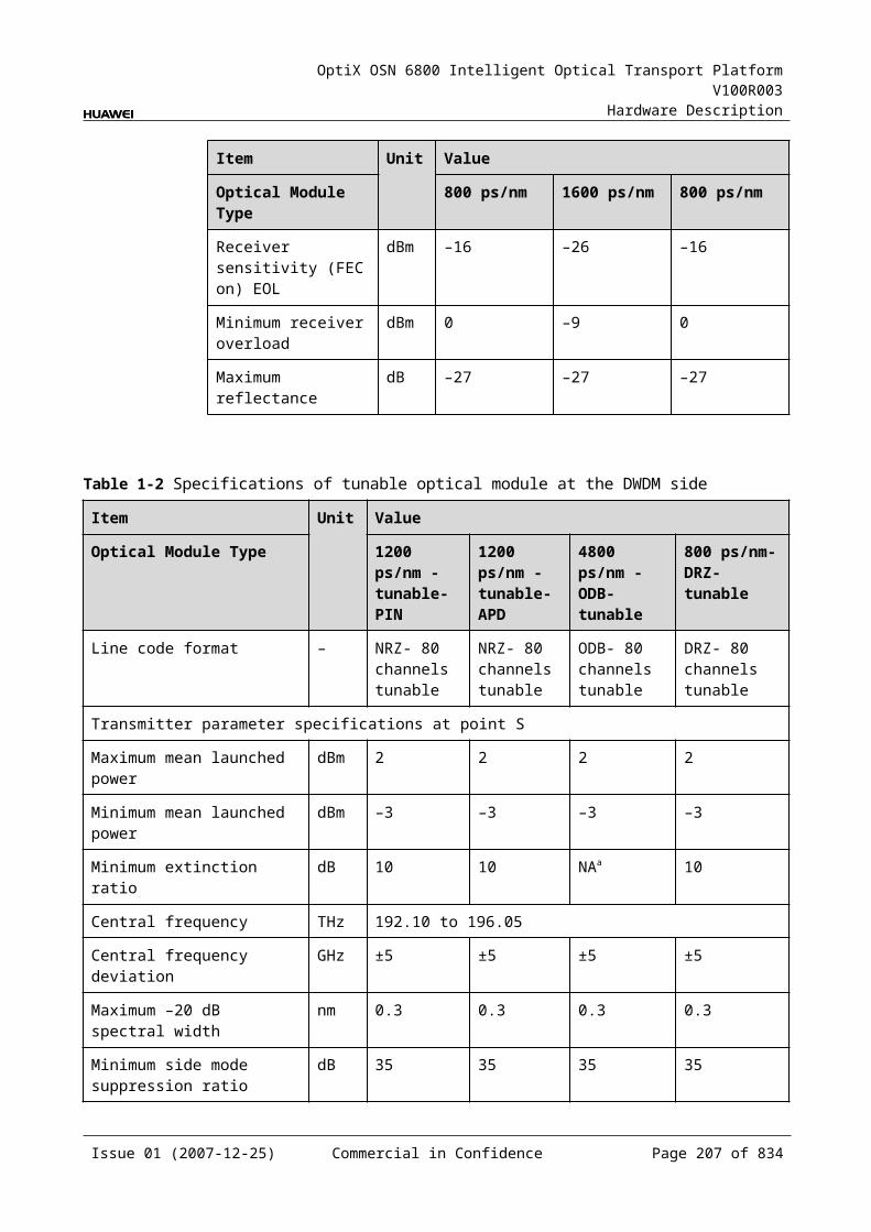
OptiX OSN 6800 Intelligent Optical Transport Platform V100R003
Hardware Description
Figure 5-1 Functional modules and signal flow of the LWXD
OTN 5G
WDM-side
opticalmodule
Control and communication module
SCC
Serviceprocessing
module
Client-side
opticalmodule
Client side WDM side
16Mbit/s-2.5Gbit/s
16Mbit/s-2.5Gbit/s
16Mbit/s-2.5Gbit/s
16Mbit/s-2.5Gbit/s
RX
TX
OUT1
IN1OUT2
IN2
In Transmit DirectionThe client-side optical module receives a signal at the rate between 16 Mbit/s and 2.5 Gbit/s and converts the signal into an electrical one before sending it to the service processing module.
The service processing module transmits the electrical signal transparently and monitors the performance of the client-side services. Then the module sends the signal to the WDM-side optical module.
The WDM-side optical module converts the electrical signal into the ITU-T G.694.1-compliant DWDM signal or the ITU-T G.694.2-compliant CWDM signal. The module divides the signal into two and sends them to the WDM side.
In Receive DirectionThe WDM-side optical module receives two optical signals at the rate between 16 Mbit/s and 2.5 Gbit/s and converts the signals into electrical signals before sending them to the service processing module.
The service processing module selects one signal and transmit it transparently. At the same time, the module extracts and processes the overhead bytes, monitors the performance of the WDM-side services, and then sends the signal to the client-side optical module.
The client-side optical module converts the electrical signal into the required optical signal at the rate between 16 Mbit/s and 2.5 Gbit/s and sends it to the client-side equipment.
Service Processing Module This module selects services. This module extracts and processes overhead bytes. This module monitors the performance of services. This module transmits services transparently.
Issue 01 (2007-12-25) Commercial in Confidence Page 205 of 664
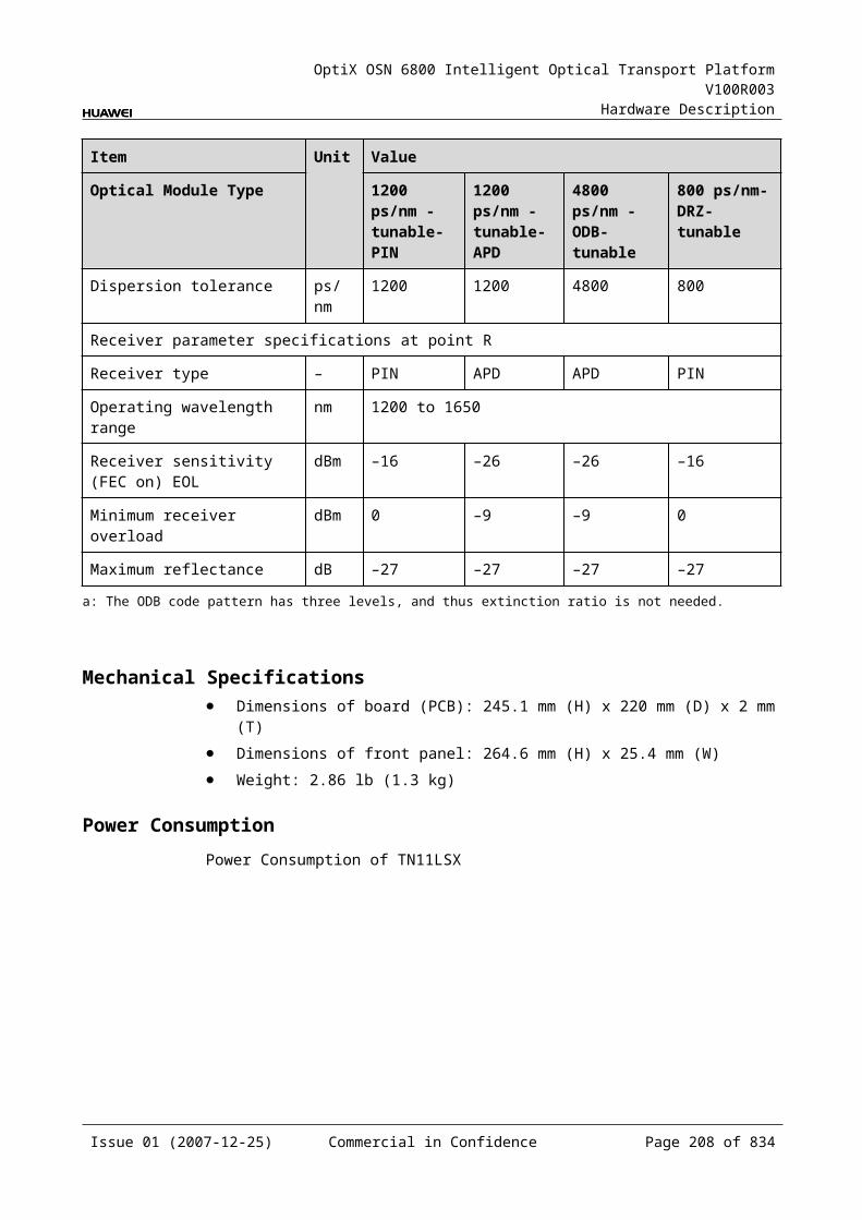
OptiX OSN 6800 Intelligent Optical Transport Platform V100R003
Hardware Description
Control and Communication ModuleThe control and communication module realizes the control, monitoring and communications management of each functional module of the board.
The control and communication module collects the information, such as the alarms and performance events, working status, and voltage detection, of each functional module of the board and reports to the SCC.
Receiving the commands from the SCC, the control and communication module controls and coordinates the functional modules of the board in working.
5.14.5 Front PanelThere are indicators, interfaces and laser safety label on the LWXD front panel.
Appearance of the Front PanelFigure 5-43 shows the LWXD front panel.
Figure 5-1 LWXD front panel
LWXD
LWXD
CLASS 1LASER
PRODUCT
STATACTPROGSRV
TX1
RX
1O
UT1
IN1
OU
T2IN
2
Issue 01 (2007-12-25) Commercial in Confidence Page 206 of 664
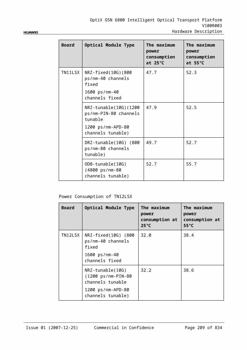
OptiX OSN 6800 Intelligent Optical Transport Platform V100R003
Hardware Description
IndicatorsThere are four indicators on the front panel.
Board hardware status indicator (STAT) – dual-colored (red, green) Service active status indicator (ACT) – green Board software status indicator (PROG) – dual-colored (red, green) Service alarm indicator (SRV) – triple-colored (red, green, yellow)
InterfacesThere are six optical interfaces on the LWXD front panel. Table 5-92 lists the type and function of each interface.
Table 5-1 Types and functions of the LWXD interfaces
Interface Type
Function
IN1-IN2 LC Receives the single-channel signal from the optical demultiplexer unit or the optical add and drop multiplexing unit.
OUT1-OUT2 LC Transmits the single-channel signal to the optical multiplexer unit or the optical add and drop multiplexing unit.
TX LC Transmits the service signal to the client-side equipment.
RX LC Receives the service signal from the client-side equipment.
Laser Safety LevelThe laser safety level of the optical interface is CLASS 1.
The maximum output optical power of each optical interface is lower than 10 dBm (10 mW).
5.14.6 Valid SlotsThe LWXD occupies one slot. The valid slots for the LWXD are IU1–IU17.
5.14.7 Characteristic Code for the LWXDThe characteristic code for the LWXD consists of eight digits, respectively indicating the frequency values of two channels of optical signals on the WDM side.
The detailed information of the characteristic code is given in Table 5-93.
Issue 01 (2007-12-25) Commercial in Confidence Page 207 of 664

OptiX OSN 6800 Intelligent Optical Transport Platform V100R003
Hardware Description
Table 5-1 Characteristic code for the LWXD
Code Meaning Description
The first four digits
The frequency of forth optical signal
The last four digits of the frequency value of the first channel of signals on the WDM side.
The last four digits
The frequency of forth optical signal
The last four digits of the frequency value of the second channel of signals on the WDM side.
For example, the characteristic code for the TN11LWX2 is 92109220.
"9210" indicates the frequency of the first channel of optical signals on the WDM side is 192.10 THz.
"9220" indicates the frequency of the second channel of optical signals on the WDM side is 192.20 THz.
5.14.8 NM Configuration ReferenceNM configuration reference includes the reference information needed during the configuration of boards through the T2000.
Display of Optical InterfacesThe serial numbers of the optical interfaces on the panel of the board displayed on the NM are listed in Table 5-94.
Table 5-1 Serial numbers of the interfaces of the LWXD displayed on the NM
Interface on the Panel Interface on the NM
IN1/OUT1 1
IN2/OUT2 2
TX/RX 3
NOTEThe number of an interface displayed on the T2000 in fact indicates a pair of physical optical interfaces, of which one is used to transmit signals and the other is used to receive signals.
Issue 01 (2007-12-25) Commercial in Confidence Page 208 of 664
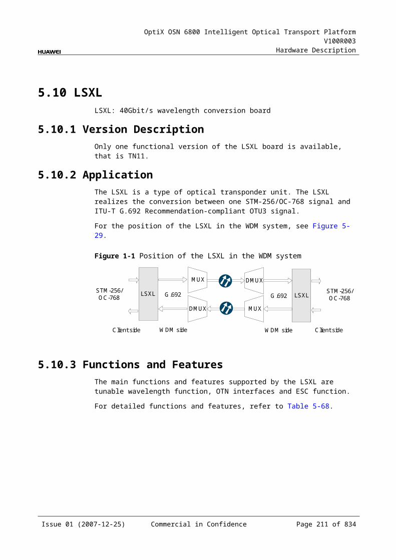
OptiX OSN 6800 Intelligent Optical Transport Platform V100R003
Hardware Description
Configuration ParametersPath Use Status
Optical Interface Loopback
Service Type
Client Service Bearer Rate (M)
Laser Status
Automatic Laser Shutdown
Current Bearer Rate (M)
Configure Wavelength No./Wavelength (nm)/Frequency (THz)
Configure Band Type
5.14.9 Specifications of the LWXDSpecifications include optical specifications, dimensions, weight, and power consumption.
Specifications of optical module at the client sideNOTEI-16 module, S-16.1 module, L-16.1 module and L-16.2 module can be used to access STM-16, FC200, FC100, GE, STM-4, ESCON, STM-1, DVB-ASI, and FE signals. The specifications listed above completely apply to STM-16 signals. The actual values may be slightly different from these specifications when the accessed signals are FC200, FC100, GE, STM-4, ESCON, STM-1, DVB-ASI, or FE signals.
NOTE2.125 Gbit/s Multi-rate module is used to access FC200, GE, FC100 and FE signals. The specifications listed above completely apply to FC200 signals. The actual values may be slightly different from these specifications when the accessed signals are GE, FC100, or FE signals.
Table 5-1 Specifications of optical module at the client side
Item Unit
Value
Optical Module Type
2.125 Gbit/s Multi-rate
I-16 S-16.1 L-16.2
Line code format – NRZ NRZ NRZ NRZ
Optical source type – MLM MLM SLM SLM
Target distance km 0.5 2 15 80
Transmitter parameter specifications at point S
Operating wavelength range
nm 830 to 860 1266 to 1360
1260 to 1360
1500 to 1580
Issue 01 (2007-12-25) Commercial in Confidence Page 209 of 664
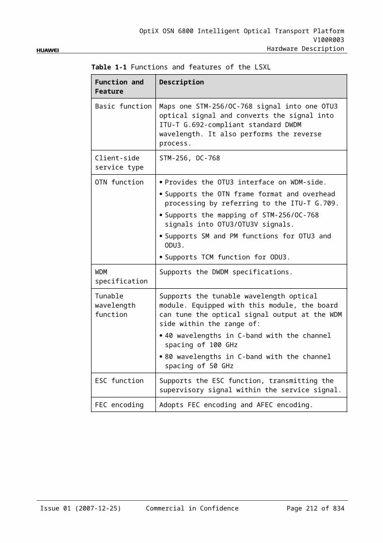
OptiX OSN 6800 Intelligent Optical Transport Platform V100R003
Hardware Description
Item Unit
Value
Optical Module Type
2.125 Gbit/s Multi-rate
I-16 S-16.1 L-16.2
Maximum mean launched power
dBm –2.5 –3 0 3
Minimum mean launched power
dBm –9.5 –10 –5 –2
Minimum extinction ratio
dB 9 8.2 8.2 8.2
Maximum –20 dB spectral width
nm NA NA 1 1
Minimum side mode suppression ratio
dB NA NA 30 30
Eye pattern mask – IEEE802.3z-compliant G.957-compliant
Receiver parameter specifications at point R
Receiver type – PIN PIN PIN APD
Operating wavelength range
nm 770 to 860 1200 to 1650
1200 to 1650
1200 to 1650
Receiver sensitivity dBm –17 –18 –18 –28
Minimum receiver overload
dBm 0 –3 0 –9
Maximum reflectance
dB NA –27 –27 –27
Specifications of eSFP CWDM Optical Module at the Client SideNOTE1.25Gbit/s Multi-rate module (eSFP CWDM) can be used to access GE, FC100, STM4, ESCON, STM1, FE, DVB-ASI signals. The specifications listed above completely apply to GE signals. The actual values may be slightly different from these specifications when the accessed signals are FC100, STM4, ESCON, STM1, FE, DVB-ASI.
NOTE2.5Gbit/sMulti-rate module (eSFP CWDM) can be used to access STM16, FC200, FC100, GE, STM4, ESCON, STM1, DVB-ASI, FE signals. The specifications listed above completely apply to STM16 signals. The actual values may be slightly different from these specifications when the accessed signals are FC200, FC100, GE, STM4, ESCON, STM1, DVB-ASI, FE signals.
Issue 01 (2007-12-25) Commercial in Confidence Page 210 of 664
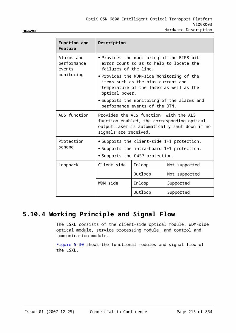
OptiX OSN 6800 Intelligent Optical Transport Platform V100R003
Hardware Description
Table 5-1 Specifications of eSFP CWDM optical module at the client side
Item Unit
Value
Optical Module Type
1.25Gbit/s Multi-rate (eSFP CWDM)
2.67Gbit/s Multi-rate (eSFP CWDM)
Line code format – NRZ NRZ
Target distance km 40 80
Transmitter parameter specifications at point S
Operating wavelength range
nm 1471 to 1611 1471 to 1611
Maximum mean launched power
dBm 5 5
Minimum mean launched power
dBm 0 0
Minimum extinction ratio
dB 9 8.2
Central wavelength deviation
nm ±6.5 ±6.5
Maximum –20 dB spectral width
nm 1.0 1.0
Minimum side mode suppression ratio
dB 30 30
Eye pattern mask – IEEE802.3z-compliant G.957-compliant
Receiver parameter specifications at point R
Receiver type – PIN APD
Operating wavelength range
nm 1270 to 1620 1270 to 1620
Receiver sensitivity dBm –19 –28
Minimum receiver overload
dBm –3 –9
Maximum reflectance
dB –27 –27
Issue 01 (2007-12-25) Commercial in Confidence Page 211 of 664
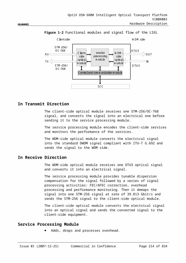
OptiX OSN 6800 Intelligent Optical Transport Platform V100R003
Hardware Description
Table 5-2 Specifications of eSFP DWDM optical module at the client side
Item Unit
Value
Optical Module Type
2.67Gbit/s Multi-rate (eSFP DWDM)
Line code format – NRZ
Target distance km 120
Transmitter parameter specifications at point S
Operating frequency range
THz 192.1 to 196.0
Maximum mean launched power
dBm 3
Minimum mean launched power
dBm 0
Minimum extinction ratio
dB 8.5
Central frequency deviation
GHz ±12.5
Maximum –20 dB spectral width
nm NA
Minimum side mode suppression ratio
dB 30
Eye pattern mask – 5% margin are required for the eye pattern of STM-16 services and equivalent OTU1 services.
Receiver parameter specifications at point R
Receiver type – APD
Receiver sensitivity dBm –28
Minimum receiver overload
dBm –9
Maximum reflectance dB –27
Issue 01 (2007-12-25) Commercial in Confidence Page 212 of 664
OptiX OSN 6800 Intelligent Optical Transport Platform V100R003
Hardware Description
Specifications of Optical Module at the DWDM Side
Table 5-1 Specifications of optical module at the DWDM side
Item Unit Value
Optical Module Type 12800ps/nm-PINa
12800ps/nm-APDa
6500 ps/nm -PIN
3200 ps/nm -2mW-APD
12800 ps/nm- tunable
Line code format – NRZ NRZ NRZ NRZ NRZ
Transmitter parameter specifications at point S
Maximum mean launched power
dBm –4 –4 0 0 0
Minimum mean launched power
dBm –8 –8 –5 –5 –5
Minimum extinction ratio dB 10 10 8.2 8.2 10
Central frequency THz 192.10 to 196.00
Central frequency deviation
GHz ±10
Maximum –20 dB spectral width
nm 0.2 0.2 0.5 0.5 0.2
Minimum side mode suppression ratio
dB 35 35 30 30 35
Dispersion tolerance ps/nm 12800 12800 6500 3200 12800
Eye pattern mask – G.957-compliant
Receiver parameter specifications at point R
Receiver type – PIN APD PIN APD APD
Operating wavelength range
nm 1200 to 1650
Receiver sensitivity dBm –18 –25 –18 –25 –30
Minimum receiver overload
dBm 0 –9 0 –9 –9
Maximum reflectance dB –27 –27 –27 –27 –27
a: The 12800ps/nm-PIN and 12800ps/nm-APD modules do not support pilot tone modulation mode.
Issue 01 (2007-12-25) Commercial in Confidence Page 213 of 664
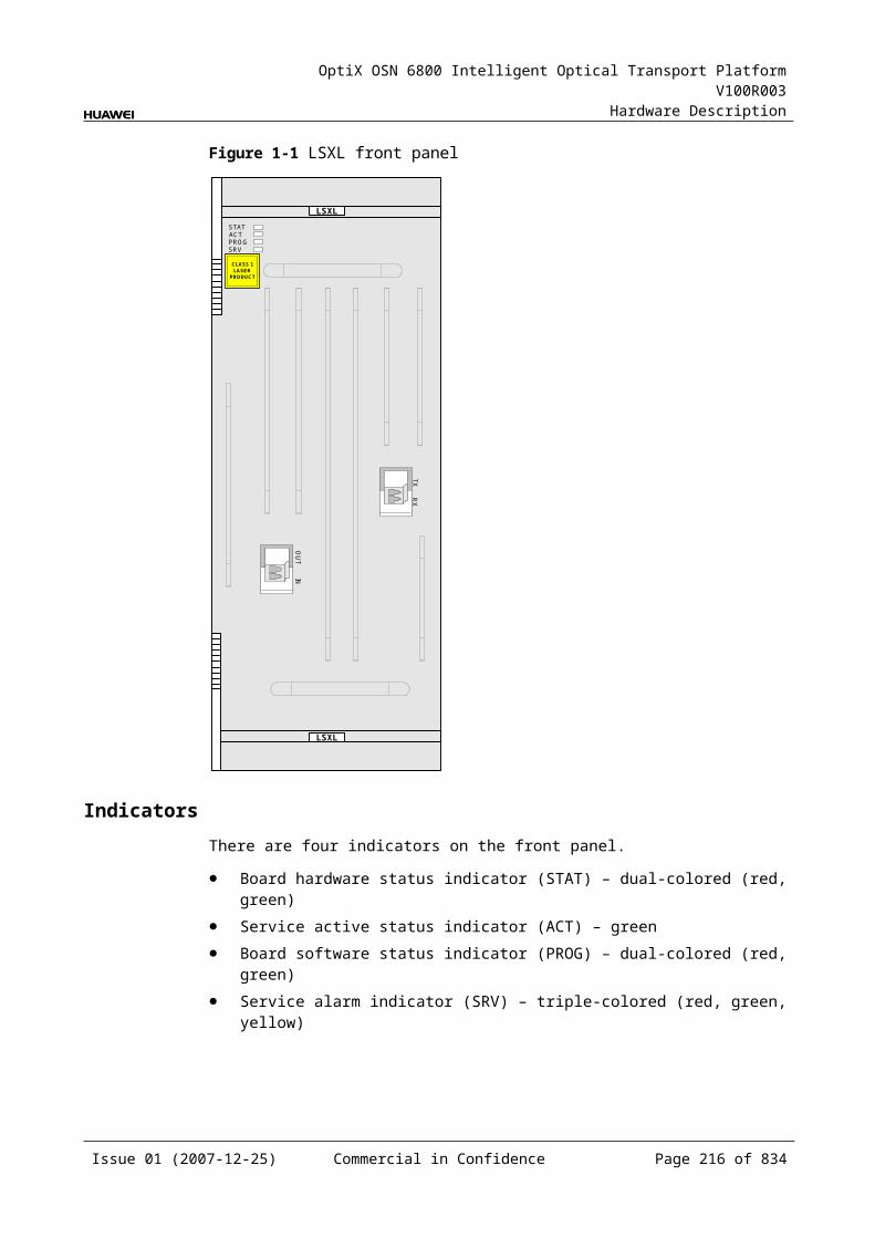
OptiX OSN 6800 Intelligent Optical Transport Platform V100R003
Hardware Description
Specifications of Optical Module at the CWDM Side
Table 5-1 Specifications of optical module at the CWDM side
Item Unit Value
Optical Module Type 1600 ps/nm-4mW
Line code format – NRZ
Transmitter parameter specifications at point S
Maximum mean launched power dBm 2
Minimum mean launched power dBm –0.5
Minimum extinction ratio dB 8.2
Central wavelength nm 1271 to 1611
Central wavelength deviation nm ≤±6.5
Maximum –20 dB spectral width nm 1
Minimum side mode suppression ratio dB 30
Dispersion tolerance ps/nm 1600
Eye pattern mask –
Receiver parameter specifications at point R
Receiver type – APD
Operating wavelength range nm 1200 to 1650
Receiver sensitivity dBm –28
Minimum receiver overload dBm –9
Maximum reflectance dB –27
Mechanical Specifications Dimensions of board (PCB): 245.1 mm (H) x 220 mm (D) x 2 mm (T) Dimensions of front panel: 264.6 mm (H) x 25.4 mm (W) Weight: 2.64 lb (1.2 kg)
Power Consumption The maximum power consumption at 25: 35.8 W The maximum power consumption at 55: 39.4 W
Issue 01 (2007-12-25) Commercial in Confidence Page 214 of 664
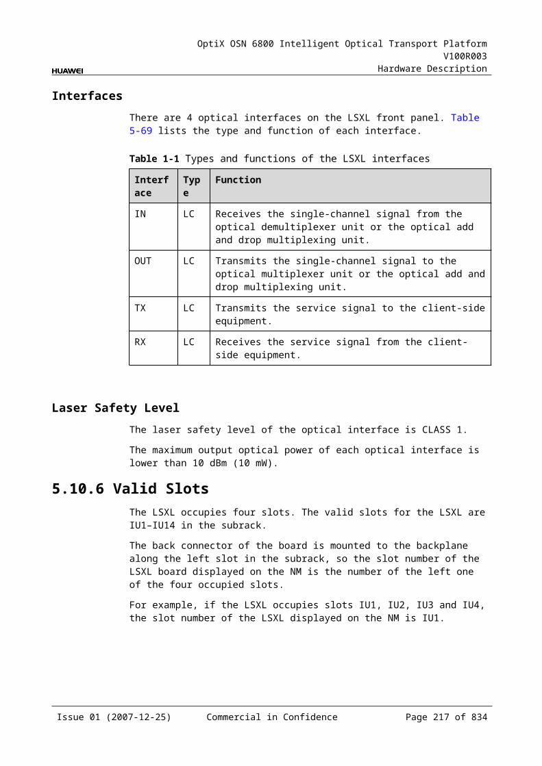
OptiX OSN 6800 Intelligent Optical Transport Platform V100R003
Hardware Description
5.15 LWXSLWXS: arbitrary rate (16Mbit/s-2.5Gbit/s) wavelength conversion board (single transmit)
5.15.1 Version DescriptionOnly one functional version of the LWXS board is available, that is TN11.
5.15.2 ApplicationThe LWXS is a type of optical transponder unit. The LWXS realizes the conversion between the optical signal at the rate between 16 Mbit/s and 2.5 Gbit/s and the ITU-T Recommendation-compliant WDM signal.
For the position of the LWXS in the WDM system, see Figure 5-44
Figure 5-1 Position of the LWXS in the WDM system
MUX
DMUX
LWXS
DMUX
MUX
LWXSG.694.1/G.694.2
G.694.1/G.694.2
16Mbit/s-2.5Gbit/s
16Mbit/s-2.5Gbit/s
Client side WDMside
WDMside Client side
5.15.3 Functions and FeaturesThe main functions and features supported by the LWXS are wavelength conversion and ESC.
For detailed functions and features, refer to Table 5-100.
Table 5-1 Functions and features of the LWXS
Function and Feature
Description
Basic function Receives a signal at the rate between 16 Mbit/s and 2.5 Gbit/s and converts the signal into the standard DWDM wavelength compliant with the ITU-T G.694.1 or the standard CWDM wavelength compliant with the ITU-T G.694.2. The reverse process is similar.
Client-side service type
STM-16, STM-4, STM-1, OC-48, OC-12, OC-3, FC200, FC100, GE, FE, FDDI, ESCON, DVB-ASI/SDI, FICON, FICON 2G, HDTV
WDM specification Supports the DWDM and CWDM specifications.
Issue 01 (2007-12-25) Commercial in Confidence Page 215 of 664
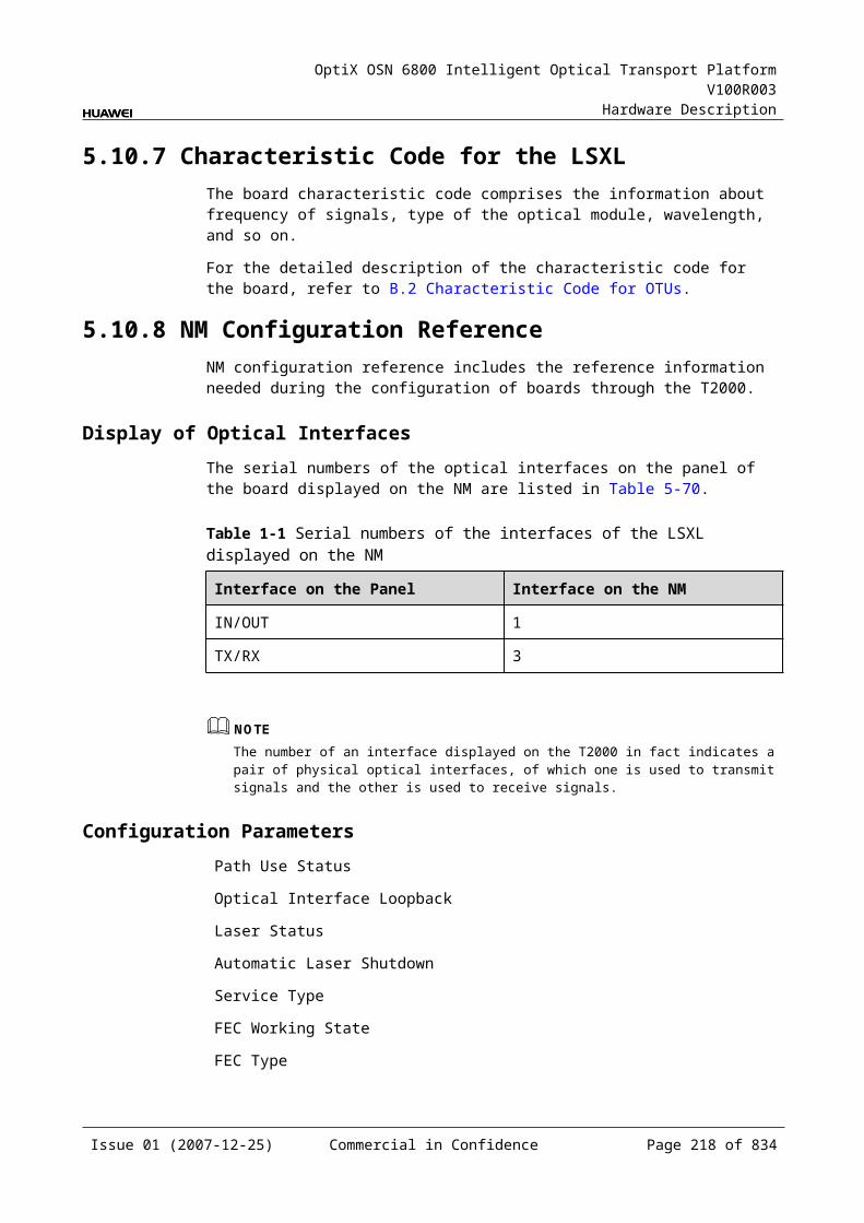
OptiX OSN 6800 Intelligent Optical Transport Platform V100R003
Hardware Description
Function and Feature
Description
Tunable wavelength function
Supports the tunable wavelength optical module. Equipped with this module, the board can tune the optical signal output at the WDM side within the range of the 40 wavelengths in C-band with the channel spacing of 100 GHz.
ESC function Supports the ESC function, transmitting the supervisory signal within the service signal.
Alarms and performance events monitoring
Provides the monitoring of the BIP8 bit error count so as to help to locate the failures of the line.
Provides the WDM-side monitoring of the items such as the bias current and temperature of the laser as well as the optical power.
ALS function Provides the ALS function. With the ALS function enabled, the corresponding optical output laser is automatically shut down if no signals are received.
Protection scheme Supports the client-side 1+1 protection.
eSFP Supports the enhanced small form-factor pluggable optical module on the client side.
Loopback WDM side Inloop Supported
Outloop Supported
Client side Inloop Supported
Outloop Supported
5.15.4 Working Principle and Signal FlowThe LWXS consists of the client-side optical module, WDM-side optical module, service processing module, and control and communication module.
Figure 5-45 shows the functional modules and signal flow of the LWXS.
Issue 01 (2007-12-25) Commercial in Confidence Page 216 of 664
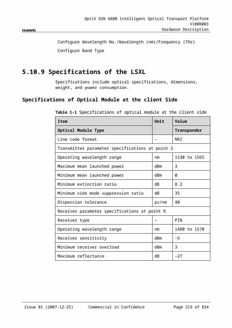
OptiX OSN 6800 Intelligent Optical Transport Platform V100R003
Hardware Description
Figure 5-1 Functional modules and signal flow of the LWXS
OTN 5G
WDM-side
opticalmodule
Control and communication module
SCC
Serviceprocessing
module
Client-side
opticalmodule
Client side WDM side
16Mbit/s-2.5Gbit/s
16Mbit/s-2.5Gbit/s
16Mbit/s-2.5Gbit/s
16Mbit/s-2.5Gbit/s
RX
TX
OUT
IN
In Transmit DirectionThe client-side optical module receives a signal at the rate between 16 Mbit/s and 2.5 Gbit/s and converts the signal into an electrical one before sending it to the service processing module.
The service processing module transmits the electrical signal transparently and monitors the performance of the client-side services. Then the module sends the signal to the WDM-side optical module.
The WDM-side optical module converts the electrical signal into the ITU-T G.694.1-compliant DWDM signal or the ITU-T G.694.2-compliant CWDM signal and sends the signal to the WDM side.
In Receive DirectionThe WDM-side optical module receives an optical signal at the rate between 16 Mbit/s and 2.5 Gbit/s and converts the signal into an electrical signal before sending it to the service processing module.
The service processing module transparently transmits the signal, extracts and processes the overhead bytes, and monitors the performance of the WDM-side services. Then, the module sends the signal to the client-side optical module.
The client-side optical module converts the electrical signal into the required optical signal at the rate between 16 Mbit/s and 2.5 Gbit/s and sends it to the client-side equipment.
Service Processing Module This module extracts and processes overhead bytes. This module monitors the performance of services. This module transmits services transparently.
Issue 01 (2007-12-25) Commercial in Confidence Page 217 of 664
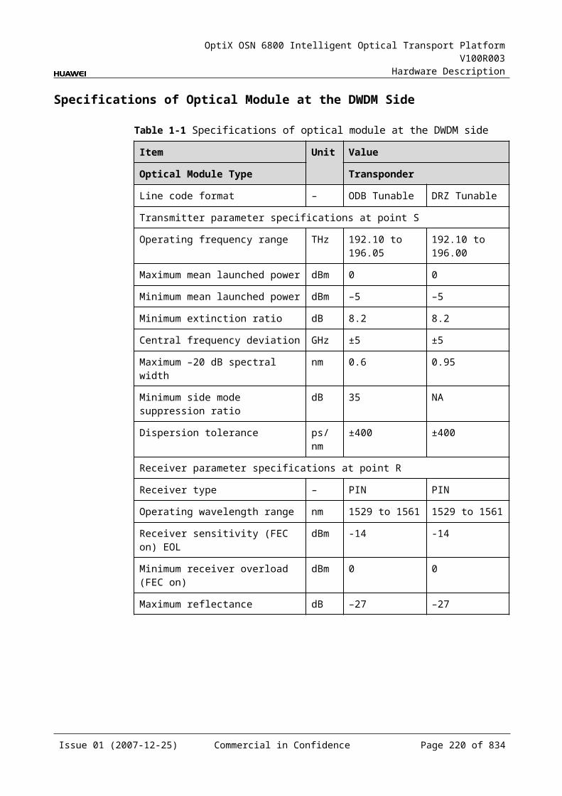
OptiX OSN 6800 Intelligent Optical Transport Platform V100R003
Hardware Description
Control and Communication ModuleThe control and communication module realizes the control, monitoring and communications management of each functional module of the board.
The control and communication module collects the information, such as the alarms and performance events, working status, and voltage detection, of each functional module of the board and reports to the SCC.
Receiving the commands from the SCC, the control and communication module controls and coordinates the functional modules of the board in working.
5.15.5 Front PanelThere are indicators, interfaces and laser safety label on the LWXS front panel.
Appearance of the Front PanelFigure 5-46 shows the LWXS front panel.
Figure 5-1 LWXS front panel
LWXS
LWXS
CLASS 1LASER
PRODUCT
STATACTPROGSRV
OU
TIN
TX1
RX
1
Issue 01 (2007-12-25) Commercial in Confidence Page 218 of 664
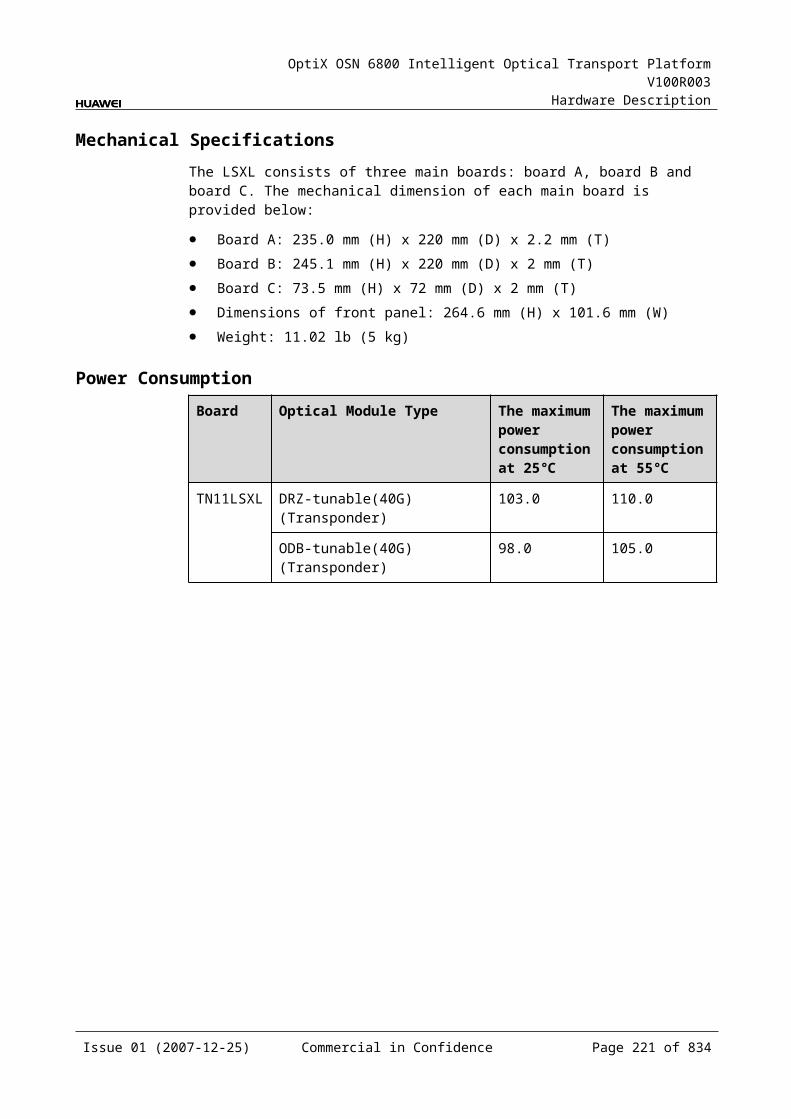
OptiX OSN 6800 Intelligent Optical Transport Platform V100R003
Hardware Description
IndicatorsThere are four indicators on the front panel.
Board hardware status indicator (STAT) – dual-colored (red, green) Service active status indicator (ACT) – green Board software status indicator (PROG) – dual-colored (red, green) Service alarm indicator (SRV) – triple-colored (red, green, yellow)
InterfacesThere are four optical interfaces on the LWXS front panel. Table 5-101 lists the type and function of each interface.
Table 5-1 Types and functions of the LWXS interfaces
Interface
Type
Function
IN LC Receives the single-channel signal from the optical demultiplexer unit or the optical add and drop multiplexing unit.
OUT LC Transmits the single-channel signal to the optical multiplexer unit or the optical add and drop multiplexing unit.
TX LC Transmits the service signal to the client-side equipment.
RX LC Receives the service signal from the client-side equipment.
Laser Safety LevelThe laser safety level of the optical interface is CLASS 1.
The maximum output optical power of each optical interface is lower than 10 dBm (10 mW).
5.15.6 Valid SlotsThe LWXS occupies one slot. The valid slots for the LWXS are IU1–IU17.
5.15.7 Characteristic Code for the LWXSThe board characteristic code comprises the information about frequency of signals, type of the optical module, wavelength, and so on.
For the detailed description of the characteristic code for the board, refer to B.2 Characteristic Code for OTUs.
5.15.8 NM Configuration ReferenceNM configuration reference includes the reference information needed during the configuration of boards through the T2000.
Issue 01 (2007-12-25) Commercial in Confidence Page 219 of 664
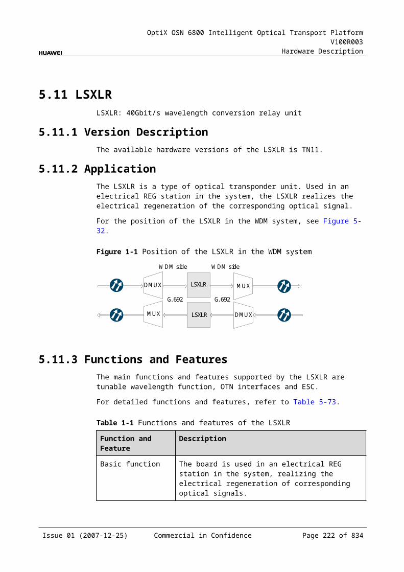
OptiX OSN 6800 Intelligent Optical Transport Platform V100R003
Hardware Description
Display of Optical InterfacesThe serial numbers of the optical interfaces on the panel of the board displayed on the NM are listed in Table 5-102.
Table 5-1 Serial numbers of the interfaces of the LWX2 displayed on the NM
Interface on the Panel Interface on the NM
IN/OUT 1
TX/RX 3
NOTEThe number of an interface displayed on the T2000 in fact indicates a pair of physical optical interfaces, of which one is used to transmit signals and the other is used to receive signals.
Configuration ParametersPath Use Status
Optical Interface Loopback
Service Type
Client Service Bearer Rate (M)
Laser Status
Automatic Laser Shutdown
Current Bearer Rate (M)
Configure Wavelength No./Wavelength (nm)/Frequency (THz)
Configure Band Type
5.15.9 Specifications of the LWXSSpecifications include optical specifications, dimensions, weight, and power consumption.
Specifications of Optical Module at the Client SideNOTEI-16 module, S-16.1 module, L-16.1 module and L-16.2 module can be used to access STM-16, FC200, FC100, GE, STM-4, ESCON, STM-1, DVB-ASI, and FE signals. The specifications listed above completely apply to STM-16 signals. The actual values may be slightly different from these specifications when the accessed signals are FC200, FC100, GE, STM-4, ESCON, STM-1, DVB-ASI, or FE signals.
Issue 01 (2007-12-25) Commercial in Confidence Page 220 of 664
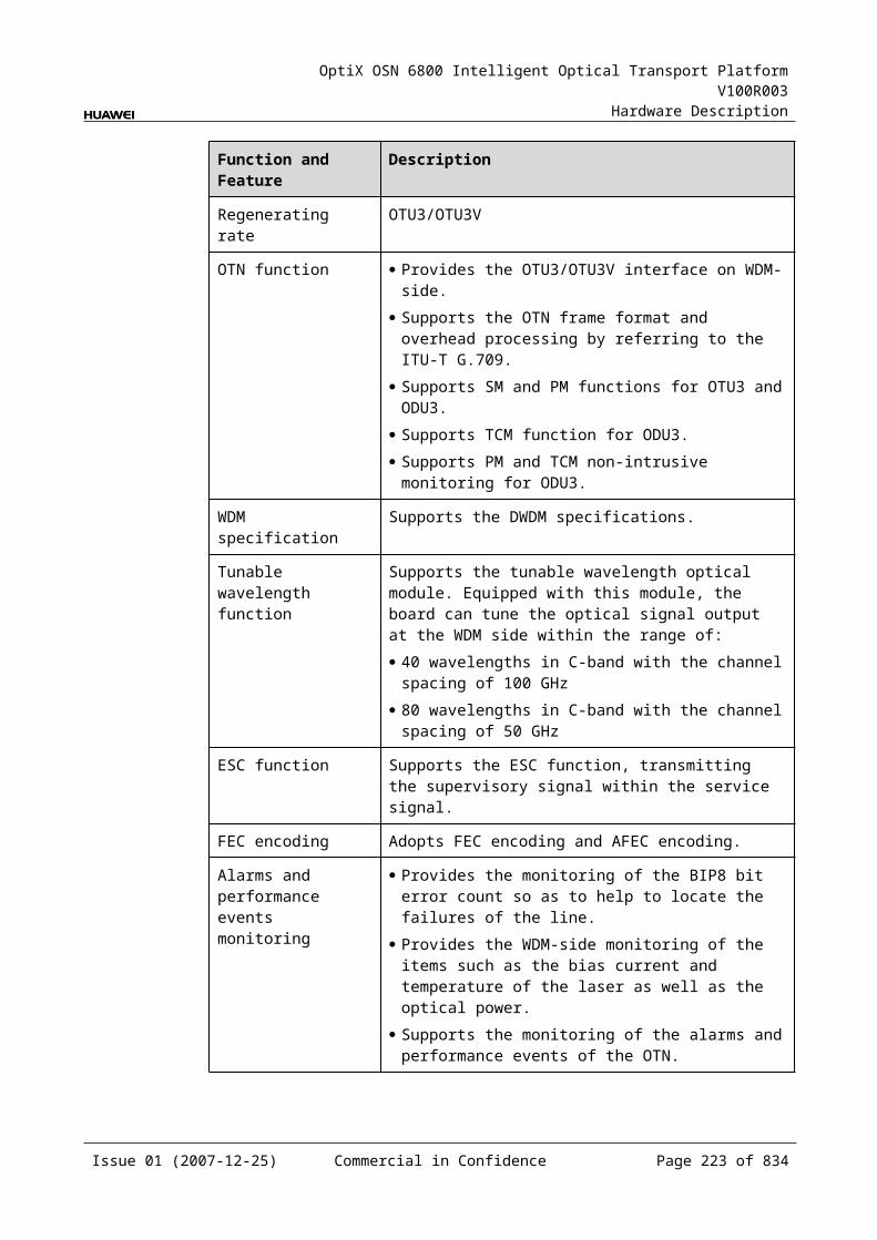
OptiX OSN 6800 Intelligent Optical Transport Platform V100R003
Hardware Description
NOTE2.125 Gbit/s Multi-rate module is used to access FC200, GE, FC100 and FE signals. The specifications listed above completely apply to FC200 signals. The actual values may be slightly different from these specifications when the accessed signals are GE, FC100, or FE signals.
Table 5-1 Specifications of optical module at the client side
Item Unit
Value
Optical Module Type
2.125 Gbit/s Multi-rate
I-16 S-16.1 L-16.2
Line code format – NRZ NRZ NRZ NRZ
Optical source type – MLM MLM SLM SLM
Target distance km 0.5 2 15 80
Transmitter parameter specifications at point S
Operating wavelength range
nm 830 to 860 1266 to 1360
1260 to 1360
1500 to 1580
Maximum mean launched power
dBm –2.5 –3 0 3
Minimum mean launched power
dBm –9.5 –10 –5 –2
Minimum extinction ratio
dB 9 8.2 8.2 8.2
Maximum –20 dB spectral width
nm NA NA 1 1
Minimum side mode suppression ratio
dB NA NA 30 30
Eye pattern mask – IEEE802.3z-compliant G.957-compliant
Receiver parameter specifications at point R
Receiver type – PIN PIN PIN APD
Operating wavelength range
nm 770 to 860 1200 to 1650
1200 to 1650
1200 to 1650
Receiver sensitivity dBm –17 –18 –18 –28
Minimum receiver overload
dBm 0 –3 0 –9
Maximum reflectance
dB NA –27 –27 –27
Issue 01 (2007-12-25) Commercial in Confidence Page 221 of 664
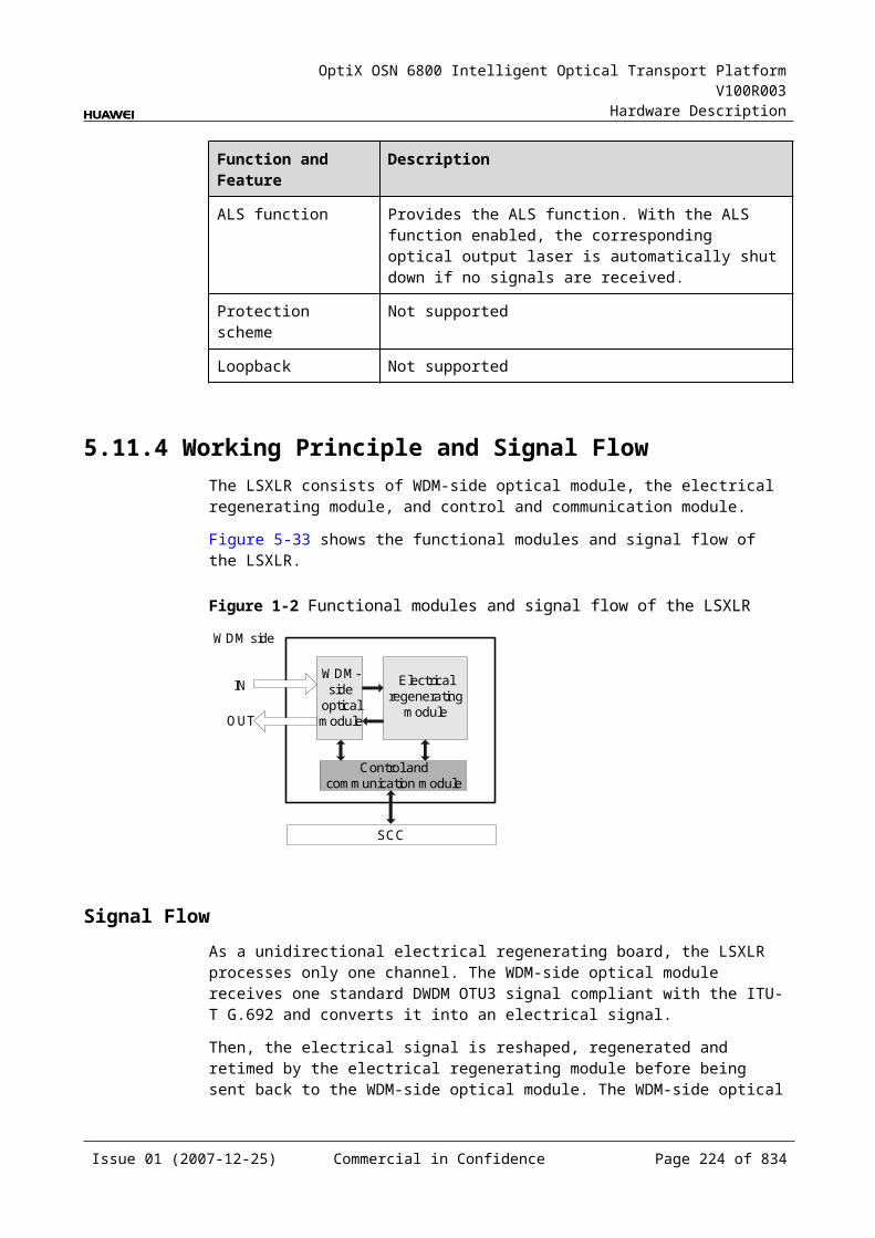
OptiX OSN 6800 Intelligent Optical Transport Platform V100R003
Hardware Description
Specifications of eSFP CWDM Optical Module at the Client SideNOTE1.25Gbit/s Multi-rate module (eSFP CWDM) can be used to access GE, FC100, STM4, ESCON, STM1, FE, DVB-ASI signals. The specifications listed above completely apply to GE signals. The actual values may be slightly different from these specifications when the accessed signals are FC100, STM4, ESCON, STM1, FE, DVB-ASI.
NOTE2.5Gbit/sMulti-rate module (eSFP CWDM) can be used to access STM16, FC200, FC100, GE, STM4, ESCON, STM1, DVB-ASI, FE signals. The specifications listed above completely apply to STM16 signals. The actual values may be slightly different from these specifications when the accessed signals are FC200, FC100, GE, STM4, ESCON, STM1, DVB-ASI, FE signals.
Table 5-1 Specifications of eSFP CWDM optical module at the client side
Item Unit
Value
Optical Module Type
1.25Gbit/s Multi-rate (eSFP CWDM)
2.67Gbit/s Multi-rate (eSFP CWDM)
Line code format – NRZ NRZ
Target distance km 40 80
Transmitter parameter specifications at point S
Operating wavelength range
nm 1471 to 1611 1471 to 1611
Maximum mean launched power
dBm 5 5
Minimum mean launched power
dBm 0 0
Minimum extinction ratio
dB 9 8.2
Central wavelength deviation
nm ±6.5 ±6.5
Maximum –20 dB spectral width
nm 1.0 1.0
Minimum side mode suppression ratio
dB 30 30
Eye pattern mask – IEEE802.3z-compliant G.957-compliant
Receiver parameter specifications at point R
Receiver type – PIN APD
Operating wavelength range
nm 1270 to 1620 1270 to 1620
Receiver sensitivity dBm –19 –28
Issue 01 (2007-12-25) Commercial in Confidence Page 222 of 664
OptiX OSN 6800 Intelligent Optical Transport Platform V100R003
Hardware Description
Item Unit
Value
Optical Module Type
1.25Gbit/s Multi-rate (eSFP CWDM)
2.67Gbit/s Multi-rate (eSFP CWDM)
Minimum receiver overload
dBm –3 –9
Maximum reflectance
dB –27 –27
Table 5-2 Specifications of eSFP DWDM optical module at the client side
Item Unit
Value
Optical Module Type
2.67Gbit/s Multi-rate (eSFP DWDM)
Line code format – NRZ
Target distance km 120
Transmitter parameter specifications at point S
Operating frequency range
THz 192.1 to 196.0
Maximum mean launched power
dBm 3
Minimum mean launched power
dBm 0
Minimum extinction ratio
dB 8.5
Central frequency deviation
GHz ±12.5
Maximum –20 dB spectral width
nm NA
Minimum side mode suppression ratio
dB 30
Eye pattern mask – 5% margin are required for the eye pattern of STM-16 services and equivalent OTU1 services.
Receiver parameter specifications at point R
Receiver type – APD
Receiver sensitivity dBm –28
Minimum receiver overload
dBm –9
Issue 01 (2007-12-25) Commercial in Confidence Page 223 of 664
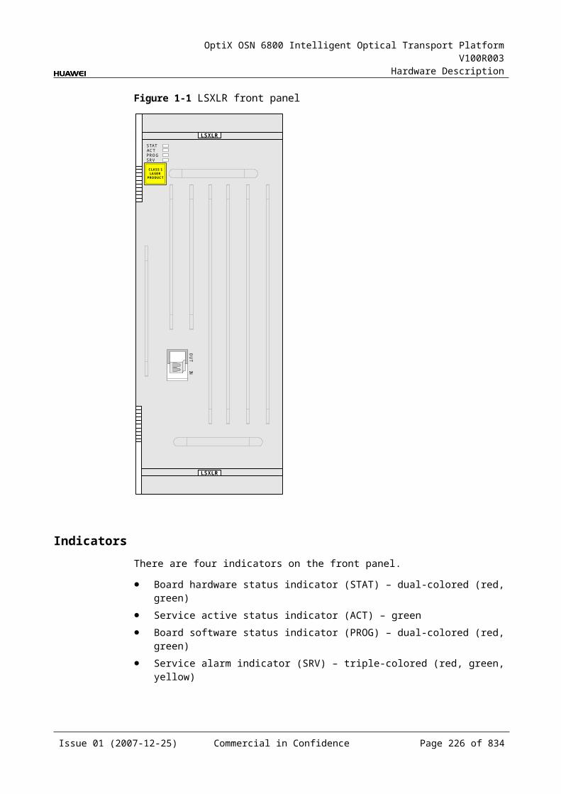
OptiX OSN 6800 Intelligent Optical Transport Platform V100R003
Hardware Description
Item Unit
Value
Optical Module Type
2.67Gbit/s Multi-rate (eSFP DWDM)
Maximum reflectance dB –27
Issue 01 (2007-12-25) Commercial in Confidence Page 224 of 664
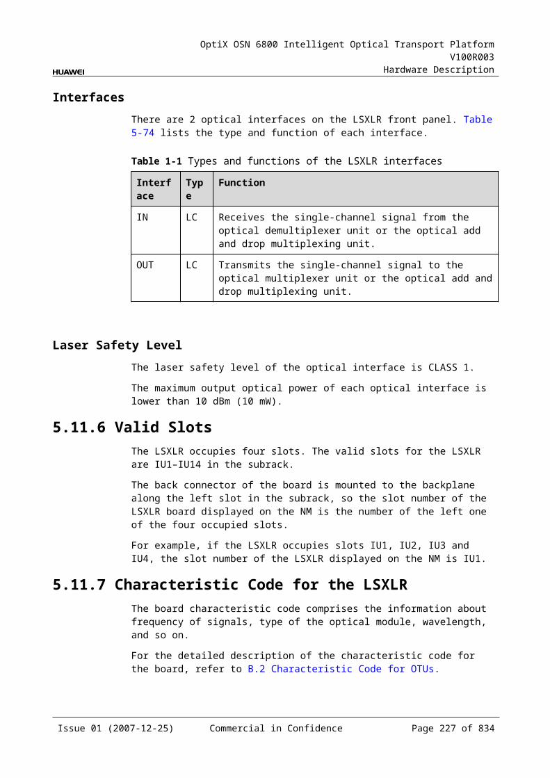
OptiX OSN 6800 Intelligent Optical Transport Platform V100R003
Hardware Description
Specifications of Optical Module at the DWDM Side
Table 5-1 Specifications of optical module at the DWDM side
Item Unit Value
Optical Module Type 12800ps/nm-PINa
12800ps/nm-APDa
6500 ps/nm -PIN
3200 ps/nm -2mW-APD
12800 ps/nm- tunable
Line code format – NRZ NRZ NRZ NRZ NRZ
Transmitter parameter specifications at point S
Maximum mean launched power
dBm –1 –1 3 3 3
Minimum mean launched power
dBm –5 –5 –2 –2 –2
Minimum extinction ratio dB 10 10 8.2 8.2 10
Central frequency THz 192.10 to 196.00
Central frequency deviation GHz ±10
Maximum –20 dB spectral width
nm 0.2 0.2 0.5 0.5 0.2
Minimum side mode suppression ratio
dB 35 35 30 30 35
Dispersion tolerance ps/nm 12800 12800 6500 3200 12800
Eye pattern mask – G.957-compliant
Receiver parameter specifications at point R
Receiver type – PIN APD PIN APD APD
Operating wavelength range nm 1200 to 1650
Receiver sensitivity dBm –18 –25 –18 –25 –30
Minimum receiver overload dBm 0 –9 0 –9 –9
Maximum reflectance dB –27 –27 –27 –27 –27
a: The 12800ps/nm-PIN and 12800ps/nm-APD modules do not support pilot tone modulation mode.
Issue 01 (2007-12-25) Commercial in Confidence Page 225 of 664
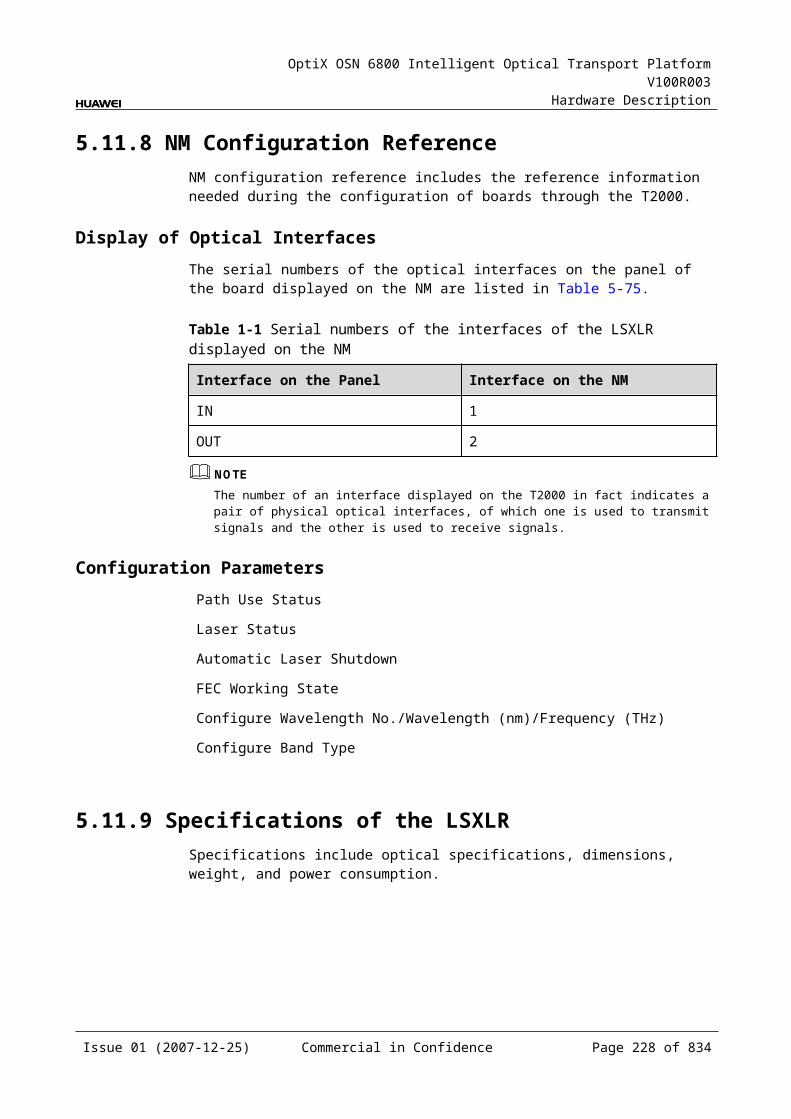
OptiX OSN 6800 Intelligent Optical Transport Platform V100R003
Hardware Description
Specifications of Optical Module at the CWDM Side
Table 5-1 Specifications of optical module at the CWDM side
Item Unit Value
Optical Module Type 1600 ps/nm-4mW
Line code format – NRZ
Transmitter parameter specifications at point S
Maximum mean launched power dBm 5
Minimum mean launched power dBm 2.5
Minimum extinction ratio dB 8.2
Central wavelength nm 1271 to 1611
Central wavelength deviation nm ≤±6.5
Maximum –20 dB spectral width nm 1
Minimum side mode suppression ratio dB 30
Dispersion tolerance ps/nm 1600
Eye pattern mask –
Receiver parameter specifications at point R
Receiver type – APD
Operating wavelength range nm 1200 to 1650
Receiver sensitivity dBm –28
Minimum receiver overload dBm –9
Maximum reflectance dB –27
Mechanical Specifications Dimensions of board (PCB): 245.1 mm (H) x 220 mm (D) x 2 mm (T) Dimensions of front panel: 264.6 mm (H) x 25.4 mm (W) Weight: 2.42 lb (1.1 kg)
Power Consumption The maximum power consumption at 25: 33.9 W The maximum power consumption at 55: 37.3 W
Issue 01 (2007-12-25) Commercial in Confidence Page 226 of 664

OptiX OSN 6800 Intelligent Optical Transport Platform V100R003
Hardware Description
5.16 TMXTMX: 4 channels STM-16/OTU1 asynchronism mux OTU-2 wavelength conversion board
5.16.1 Version DescriptionOnly one functional version of the TMX board is available, that is TN11.
5.16.2 ApplicationThe TMX is a type of optical transponder unit. The TMX multiplexes four STM-16/OC-48/OTU1 service signals into one OTU2 signal. It also realizes conversion between these signals and ITU-T Recommendation-compliant WDM signals.
For the position of the L4G in the WDM system, see Figure 5-47.
Figure 5-1 Position of the TMX in the WDM system
Client side WDM side
MUX
DMUX
TMX
DMUX
MUX
TMX
1
4
1
4
G.694.1 G.694.1
WDM side Client side
STM-16/OC-48/OTU1
STM-16/OC-48/OTU1
5.16.3 Functions and FeaturesThe main functions and features supported by the TMX are wavelength conversion, OTN interfaces and ESC.
For detailed functions and features, refer to Table 5-108.
Table 5-1 Functions and features of the TMX
Function and Feature
Description
Basic function Multiplexes four channels of STM-16/OC-48/OTU1 service optical signals into one channel of OTU2 optical signals and converse them to DWDM standard wavelength that comply with ITU-T Recommendation G.694.1. It can also perform the reverse process.
Client-side service type
STM-16/OC-48/OTU1 (without FEC)
Issue 01 (2007-12-25) Commercial in Confidence Page 227 of 664
OptiX OSN 6800 Intelligent Optical Transport Platform V100R003
Hardware Description
Function and Feature
Description
OTN function Provides the OTU2/OTU2V interface on WDM-side. Supports the OTN frame format and overhead
processing by referring to the ITU-T G.709. Supports 4×ODU1 asynchronous multiplexing into
ODU2. Supports SM and PM functions for OTU1 and ODU1. Supports TCM function for ODU1. Supports PM and TCM non-intrusive monitoring for
ODU1.
WDM specification Supports the DWDM specifications.
Tunable wavelength function
Supports the tunable wavelength optical module. Equipped with this module, the board can tune the optical signal output at the WDM side within the range of: 40 wavelengths in C-band with the channel spacing of
100 GHz 80 wavelengths in C-band with the channel spacing of
50 GHz
ESC function Supports the ESC function, transmitting the supervisory signal within the service signal.
FEC encoding Supports FEC encoding compliant with the ITU-T G.975 and AFEC encoding compliant with the ITU-T G.975.1.
Alarms and performance events monitoring
Provides the monitoring of the BIP8 bit error count so as to help to locate the failures of the line.
Provides the WDM-side monitoring of the items such as the bias current and temperature of the laser as well as the optical power.
Supports the monitoring of the alarms and performance events of the OTN.
ALS function Provides the ALS function. With the ALS function enabled, the corresponding optical output laser is automatically shut down if no signals are received.
Protection scheme Supports the client-side 1+1 protection. Supports the intra-board 1+1 protection. Supports the OWSP protection.
eSFP Supports the enhanced small form-factor pluggable optical module on the client side.
Loopback WDM side Inloop Supported
Outloop Supported
Client side Inloop Supported
Issue 01 (2007-12-25) Commercial in Confidence Page 228 of 664
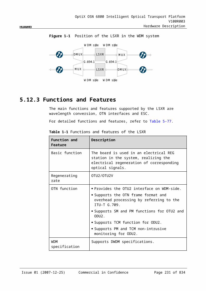
OptiX OSN 6800 Intelligent Optical Transport Platform V100R003
Hardware Description
Function and Feature
Description
Outloop Supported
5.16.4 Working Principle and Signal FlowThe TMX consists of the client-side optical module, WDM-side optical module, service processing module, and control and communication module.
Figure 5-48 shows the functional modules and signal flow of the TMX.
Figure 5-1 Functional modules and signal flow of the TMX
WDM-side
opticalmodule
Control and communication module
SCC
Serviceprocessing
module
Client-side
opticalmodule
OTU2
Client side WDM side
4
4
4
4 OTU2
STM-16/OC-48/OTU1
STM-16/OC-48/OTU1
In Transmit DirectionThe client-side optical module receives four STM-16/OC-48/OTU1 service optical signals. It converts the optical signals into electrical signals and sends them to the service processing module.
The service processing module monitors the performance of client-side services. Then it multiplexes the signals into one OTU2 signal and sends the signal to a WDM-side optical module.
The WDM-side optical module converts the electrical signal into ITU-T G.694.1-compliant standard DWDM signal and sends the signal to the WDM side.
In Receive DirectionThe WDM-side optical module receives one OTU2 optical signal and converts the it into electrical signal.
The service processing module extracts and processes the overhead bytes, monitors the WDM-side performance, and demultiplexes the signal into four STM-16/OC-48/OTU1 service electrical signals.
The client-side optical module converts the eight electrical signals into optical signals and then sends the signals to the client side.
Issue 01 (2007-12-25) Commercial in Confidence Page 229 of 664
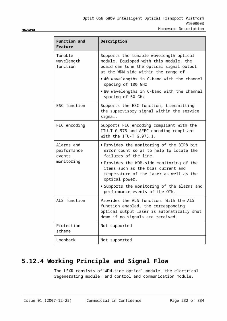
OptiX OSN 6800 Intelligent Optical Transport Platform V100R003
Hardware Description
Service Processing Module This module extracts and processes overhead bytes. This module monitors the performance of services. This module multiplexes and demultiplexes services. This module implements the encapsulation of OTN signals.
Control and Communication ModuleThe control and communication module realizes the control, monitoring and communications management of each functional module of the board.
The control and communication module collects the information, such as the alarms and performance events, working status, and voltage detection, of each functional module of the board and reports to the SCC.
Receiving the commands from the SCC, the control and communication module controls and coordinates the functional modules of the board in working.
5.16.5 Front PanelThere are indicators, interfaces and laser safety label on the TMX front panel.
Appearance of the Front PanelFigure 5-49 shows the TMX front panel.
Issue 01 (2007-12-25) Commercial in Confidence Page 230 of 664
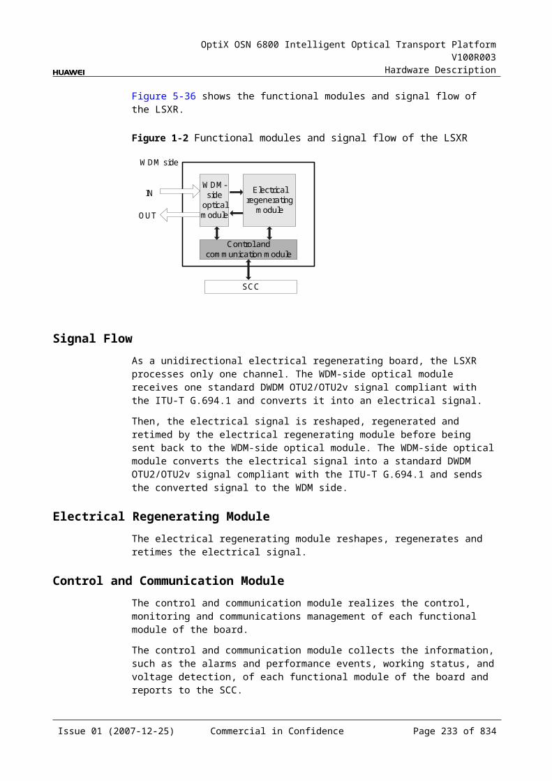
OptiX OSN 6800 Intelligent Optical Transport Platform V100R003
Hardware Description
Figure 5-1 TMX front panel
STATACTPROGSRV
CLASS 1LASER
PRODUCT
TX1
RX
1TX
2R
X2
TX3
RX
3TX
4R
X4
OU
TIN
TMX
TMX
IndicatorsThere are four indicators on the front panel.
Board hardware status indicator (STAT) – dual-colored (red, green) Service active status indicator (ACT) – green Board software status indicator (PROG) – dual-colored (red, green) Service alarm indicator (SRV) – triple-colored (red, green, yellow)
InterfacesThere are 10 optical interfaces on the TMX front panel.Table 5-109 lists the type and function of each interface.
Issue 01 (2007-12-25) Commercial in Confidence Page 231 of 664
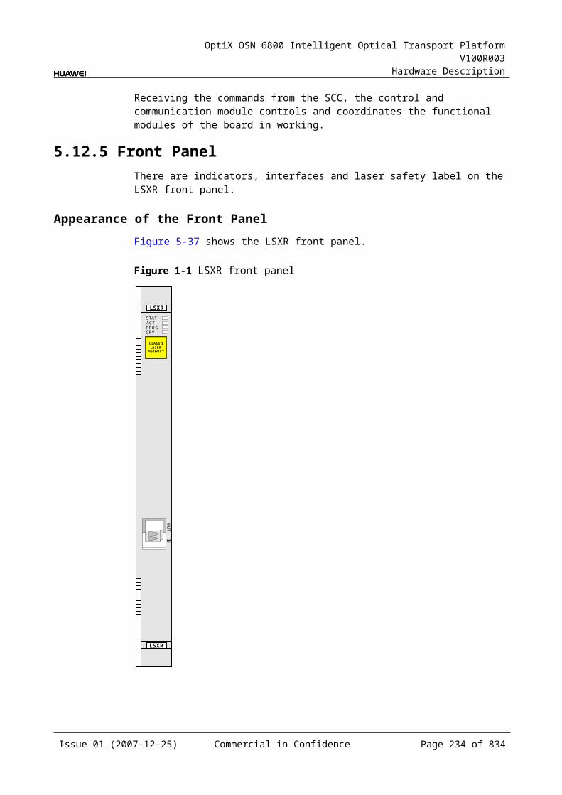
OptiX OSN 6800 Intelligent Optical Transport Platform V100R003
Hardware Description
Table 5-1 Types and functions of the TMX interfaces
Interface
Type
Function
IN LC Receives the single-channel signal from the optical demultiplexer unit or the optical add and drop multiplexing unit.
OUT LC Transmits the single-channel signal to the optical multiplexer unit or the optical add and drop multiplexing unit.
TX1-TX4 LC Transmits the service signal to the client-side equipment.
RX1-RX4 LC Receives the service signal from the client-side equipment.
Laser Safety LevelThe laser safety level of the optical interface is CLASS 1.
The maximum output optical power of each optical interface is lower than 10 dBm (10 mW).
5.16.6 Valid SlotsThe TMX occupies one slot. The valid slots for the TMX are IU1–IU17.
5.16.7 Characteristic Code for the TMXThe board characteristic code comprises the information about frequency of signals, type of the optical module, wavelength, and so on.
For the detailed description of the characteristic code for the board, refer to B.2 Characteristic Code for OTUs.
5.16.8 NM Configuration ReferenceNM configuration reference includes the reference information needed during the configuration of boards through the T2000.
Display of Optical InterfacesThe serial numbers of the optical interfaces on the panel of the board displayed on the NM are listed in Table 5-110.
Table 5-1 Serial numbers of the interfaces of the TMX displayed on the NM
Interface on the Panel Interface on the NM
IN/OUT 1
TX1/RX1 3
TX2/RX2 4
TX3/RX3 5
Issue 01 (2007-12-25) Commercial in Confidence Page 232 of 664
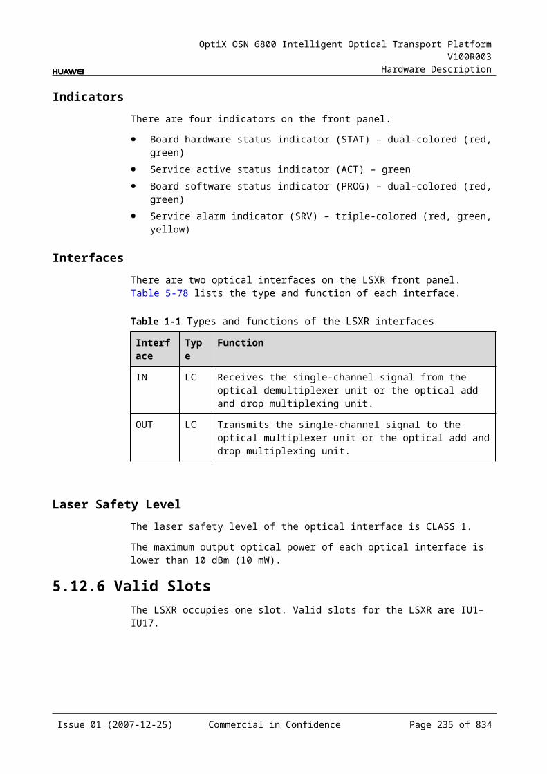
OptiX OSN 6800 Intelligent Optical Transport Platform V100R003
Hardware Description
TX4/RX4 6
NOTEThe number of an interface displayed on the T2000 in fact indicates a pair of physical optical interfaces, of which one is used to transmit signals and the other is used to receive signals.
Configuration ParametersPath Use Status
Optical Interface Loopback
Service Type
Laser Status
Automatic Laser Shutdown
FEC Working State
FEC Type
Configure Wavelength No./Wavelength (nm)/Frequency (THz)
Configure Band Type
5.16.9 Specifications of the TMXSpecifications include optical specifications, dimensions, weight, and power consumption.
Specifications of optical module at the client side
Table 5-1 Specifications of optical module at the client side
Item Unit
Value
Optical Module Type I-16 S-16.1
L-16.1 L-16.2
Line code format – NRZ NRZ NRZ NRZ
Optical source type – MLM SLM SLM SLM
Target distance km 2 15 40 80
Transmitter parameter specifications at point S
Operating wavelength range nm 1266 to 1360
1260 to 1360
1280 to 1335
1500 to 1580
Maximum mean launched power
dBm –3 0 3 3
Issue 01 (2007-12-25) Commercial in Confidence Page 233 of 664
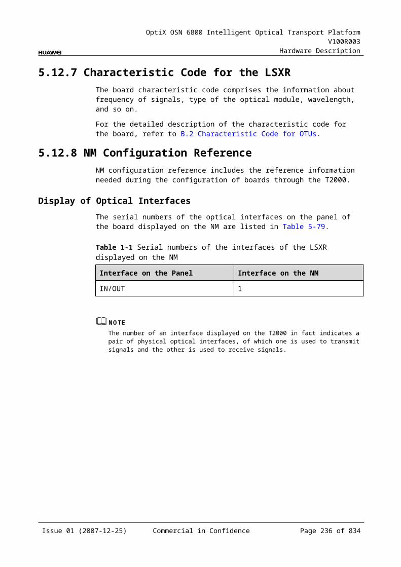
OptiX OSN 6800 Intelligent Optical Transport Platform V100R003
Hardware Description
Item Unit
Value
Optical Module Type I-16 S-16.1
L-16.1 L-16.2
Minimum mean launched power
dBm –10 –5 –2 –2
Minimum extinction ratio dB 8.2 8.2 8.2 8.2
Maximum –20 dB spectral width
nm NA 1 1 1
Minimum side mode suppression ratio
dB NA 30 30 30
Eye pattern mask – G.957-compliant
Receiver parameter specifications at point R
Receiver type – PIN PIN APD APD
Operating wavelength range nm 1270 to 1580
1270 to 1580
1280 to 1335
1500 to 1580
Receiver sensitivity dBm –18 –18 –27 –28
Minimum receiver overload dBm –3 0 –9 –9
Maximum reflectance dB –27 –27 –27 –27
Remark - These modules access STM-16 and OTU1 services. The indexes listed in the table above are applicable for the STM-16 services. When the module accesses OTU1 services, the indexes are slightly different.
Table 5-2 Specifications of eSFP CWDM optical module at the client side
Item Unit
Value
Optical Module Type 2.67Gbit/s Multi-rate (eSFP CWDM)
Line code format – NRZ
Target distance km 80
Operating wavelength range nm 1471 to 1611
Maximum mean launched power dBm 5
Minimum mean launched power dBm 0
Minimum extinction ratio dB 8.2
Central wavelength deviation nm ±6.5
Issue 01 (2007-12-25) Commercial in Confidence Page 234 of 664
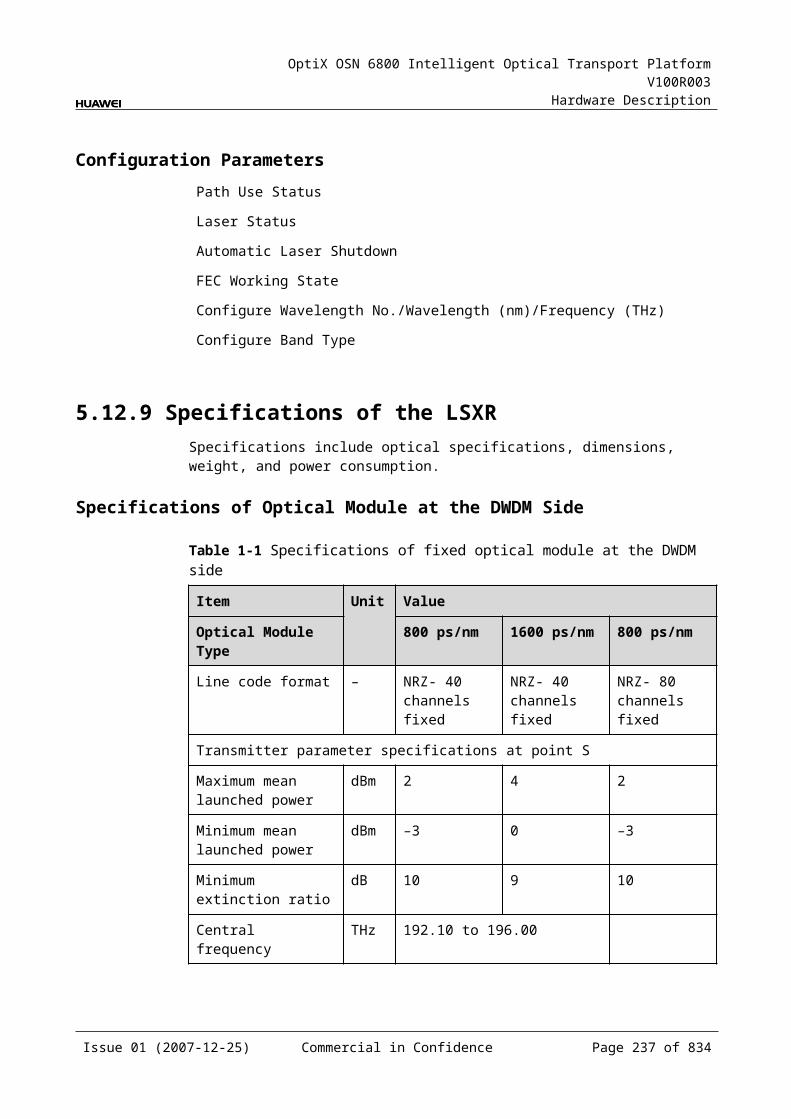
OptiX OSN 6800 Intelligent Optical Transport Platform V100R003
Hardware Description
Item Unit
Value
Optical Module Type 2.67Gbit/s Multi-rate (eSFP CWDM)
Maximum –20 dB spectral width nm 1
Minimum side mode suppression ratio
dB 30
Eye pattern mask – G.957-compliant
Receiver type – APD
Operating wavelength range nm 1270 to 1620
Receiver sensitivity dBm –28
Minimum receiver overload dBm –9
Maximum reflectance dB –27
Table 5-3 Specifications of eSFP DWDM optical module at the client side
Item Unit
Value
Optical Module Type
2.67Gbit/s Multi-rate (eSFP DWDM)
Line code format – NRZ
Target distance km 120
Transmitter parameter specifications at point S
Operating frequency range
THz 192.1 to 196.0
Maximum mean launched power
dBm 3
Minimum mean launched power
dBm 0
Minimum extinction ratio
dB 8.5
Central frequency deviation
GHz ±12.5
Maximum –20 dB spectral width
nm NA
Minimum side mode suppression ratio
dB 30
Eye pattern mask – 5% margin are required for the eye pattern of STM-16 services and equivalent OTU1 services.
Issue 01 (2007-12-25) Commercial in Confidence Page 235 of 664
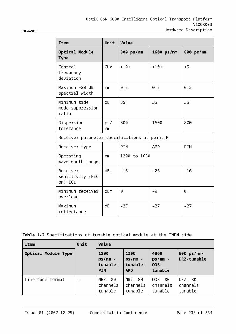
OptiX OSN 6800 Intelligent Optical Transport Platform V100R003
Hardware Description
Item Unit
Value
Optical Module Type
2.67Gbit/s Multi-rate (eSFP DWDM)
Receiver parameter specifications at point R
Receiver type – APD
Receiver sensitivity dBm –28
Minimum receiver overload
dBm –9
Maximum reflectance dB –27
Specifications of optical module at the DWDM side
Table 5-1 Specifications of fixed optical module at the DWDM side
Item Unit Value
Optical Module Type
800 ps/nm 1600 ps/nm 800 ps/nm
Line code format – NRZ- 40 channels fixed
NRZ- 40 channels fixed
NRZ- 80 channels fixed
Transmitter parameter specifications at point S
Maximum mean launched power
dBm 2 4 2
Minimum mean launched power
dBm –3 0 –3
Minimum extinction ratio
dB 10 9 10
Central frequency THz 192.10 to 196.00
Central frequency deviation
GHz ±10 ±10 ±5
Maximum –20 dB spectral width
nm 0.3 0.3 0.3
Minimum side mode suppression ratio
dB 35 35 35
Dispersion tolerance ps/nm 800 1600 800
Receiver parameter specifications at point R
Receiver type – PIN APD PIN
Issue 01 (2007-12-25) Commercial in Confidence Page 236 of 664
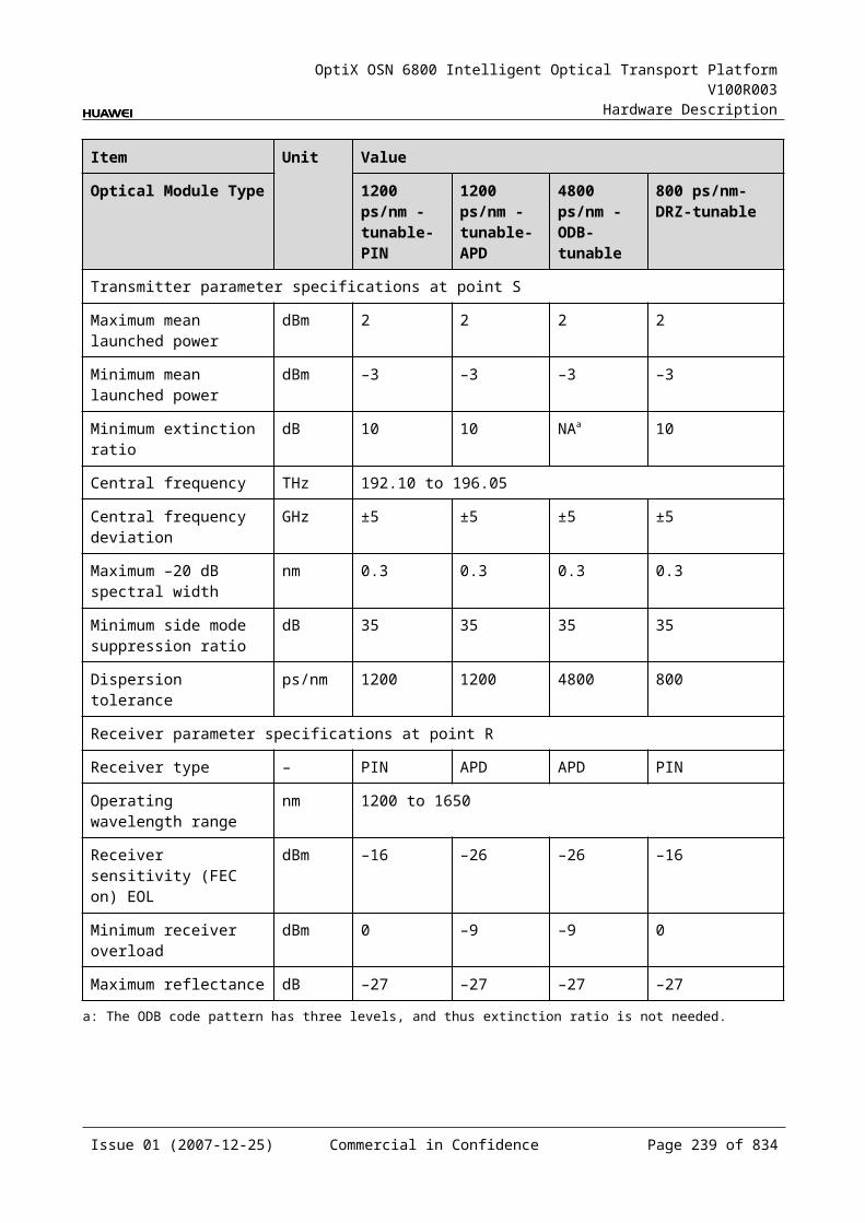
OptiX OSN 6800 Intelligent Optical Transport Platform V100R003
Hardware Description
Item Unit Value
Optical Module Type
800 ps/nm 1600 ps/nm 800 ps/nm
Operating wavelength range
nm 1200 to 1650
Receiver sensitivity (FEC on) EOL
dBm –16 –26 –16
Minimum receiver overload
dBm 0 –9 0
Maximum reflectance dB –27 –27 –27
Table 5-2 Specifications of tunable optical module at the DWDM side
Item Unit Value
Optical Module Type
1200 ps/nm - tunable- PIN
1200 ps/nm - tunable- APD
4800 ps/nm -ODB- tunable
800 ps/nm- DRZ-tunable
Line code format – NRZ- 80 channels tunable
NRZ- 80 channels tunable
ODB- 80 channels tunable
DRZ- 80 channels tunable
Transmitter parameter specifications at point S
Maximum mean launched power
dBm 2 2 2 2
Minimum mean launched power
dBm –3 –3 –3 –3
Minimum extinction ratio
dB 10 10 NAa 10
Central frequency THz 192.10 to 196.05
Central frequency deviation
GHz ±5 ±5 ±5 ±5
Maximum –20 dB spectral width
nm 0.3 0.3 0.3 0.3
Minimum side mode suppression ratio
dB 35 35 35 35
Dispersion tolerance ps/nm 1200 1200 4800 800
Receiver parameter specifications at point R
Receiver type – PIN APD APD PIN
Issue 01 (2007-12-25) Commercial in Confidence Page 237 of 664
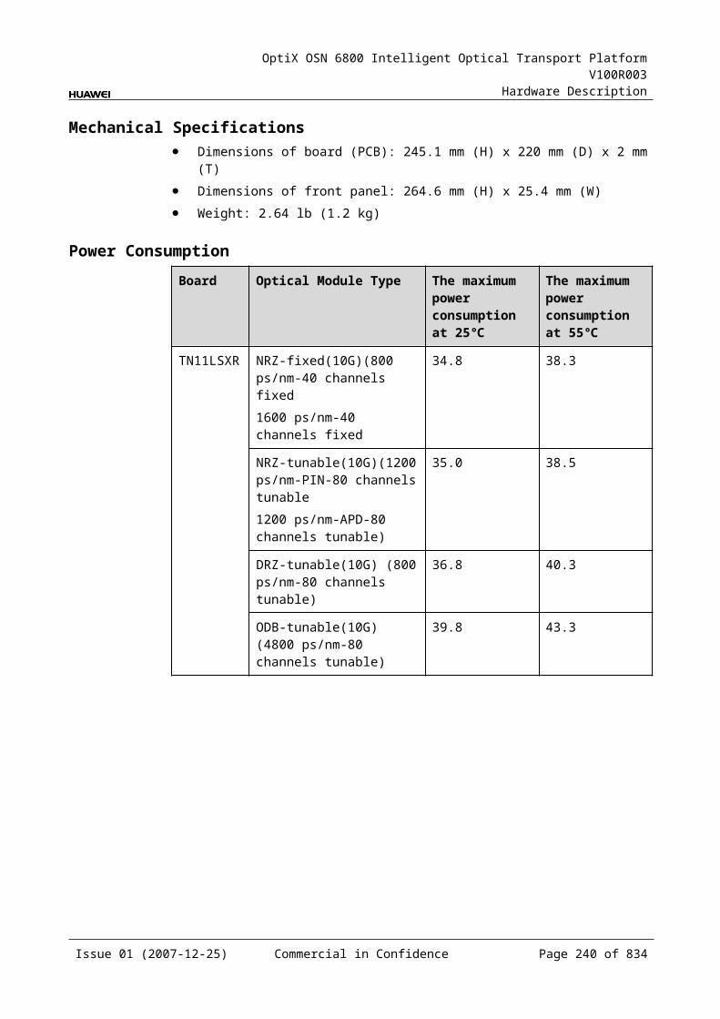
OptiX OSN 6800 Intelligent Optical Transport Platform V100R003
Hardware Description
Item Unit Value
Optical Module Type
1200 ps/nm - tunable- PIN
1200 ps/nm - tunable- APD
4800 ps/nm -ODB- tunable
800 ps/nm- DRZ-tunable
Operating wavelength range
nm 1200 to 1650
Receiver sensitivity (FEC on) EOL
dBm –16 –26 –26 –16
Minimum receiver overload
dBm 0 –9 –9 0
Maximum reflectance dB –27 –27 –27 –27
a: The ODB code pattern has three levels, and thus extinction ratio is not needed.
Mechanical Specifications Dimensions of board (PCB): 245.1 mm (H) x 220 mm (D) x 2 mm (T) Dimensions of front panel: 264.6 mm (H) x 25.4 mm (W) Weight: 3.09 lb (1.4 kg)
Issue 01 (2007-12-25) Commercial in Confidence Page 238 of 664
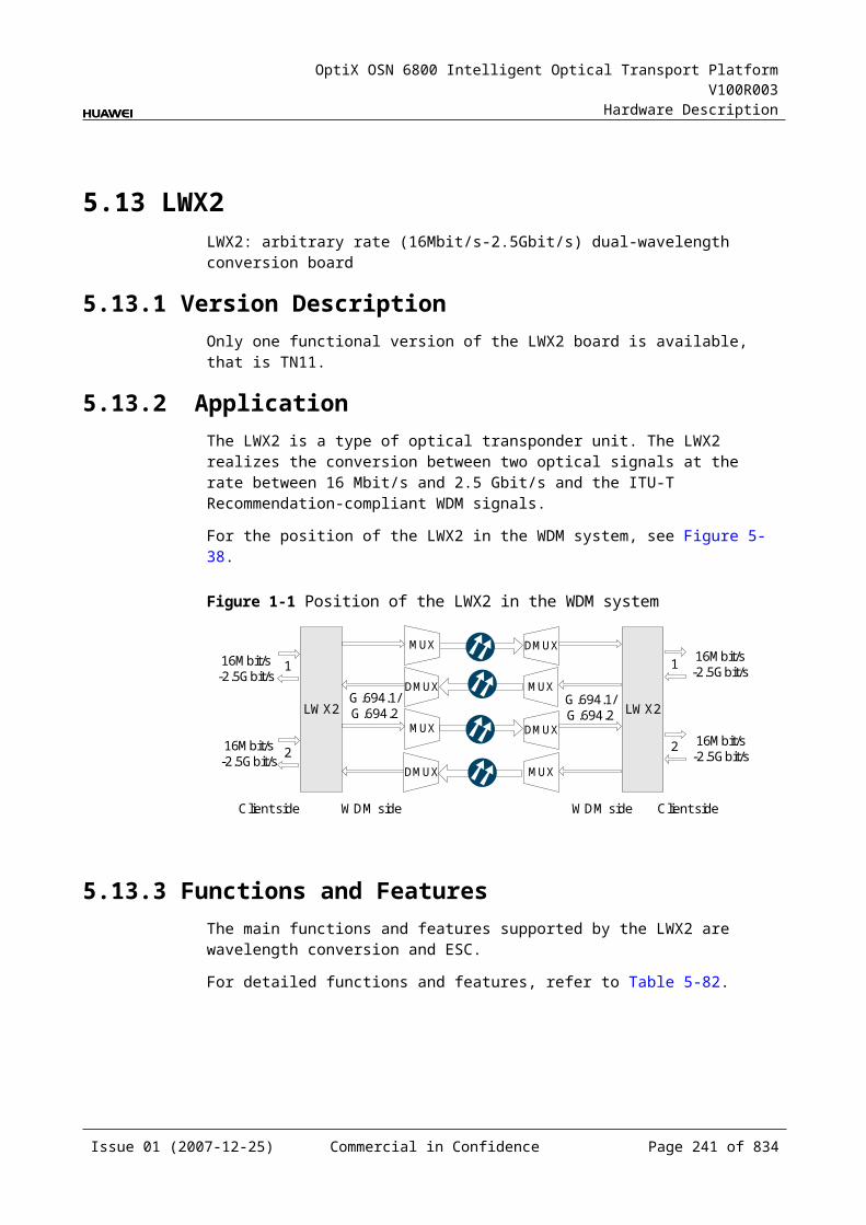
OptiX OSN 6800 Intelligent Optical Transport Platform V100R003
Hardware Description
Power ConsumptionBoard Optical Module
TypeThe maximum power consumption at 25
The maximum power consumption at 55
TN11TMX NRZ-fixed(10G) (800 ps/nm-40 channels fixed1600 ps/nm-40 channels fixed
40.3 44.3
NRZ-tunable(10G) (1200 ps/nm-PIN-80 channels tunable1200 ps/nm-APD-80 channels tunable)
42.1 46.4
DRZ-tunable(10G) (800 ps/nm-80 channels tunable)
42.4 46.6
ODB-tunable(10G) (4800 ps/nm-80 channels tunable)
46.5 51.2
Issue 01 (2007-12-25) Commercial in Confidence Page 239 of 664
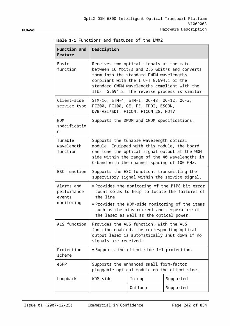
OptiX OSN 6800 Intelligent Optical Transport Platform V100R003
Hardware Description
6 Tributary Unit and Line Unit
6.1 NS2NS2: 4 x ODU1 multiplexing OTU2 optical interface unit
6.1.1 Version DescriptionOnly one functional version of the NS2 board is available, that is TN11.
6.1.2 ApplicationThe NS2 is a type of line unit. The NS2 realizes the conversion between four cross-connect ODU1 signals and the ITU-T Recommendation-compliant WDM OTU2 signals.
For the position of the NS2 in the WDM system, see Figure 6-1.
Figure 6-1 Position of the NS2 in the WDM system
MUX
DMUX
NS2
DMUX
MUX
1
4
1
4
G.694.1 G.694.1TQS NS2 TQS
1
4
1
4
Client side WDM side WDM side Client side
6.1.3 Functions and FeaturesThe main functions and features supported by the NS2 are cross-connection at the electrical layer, OTN interfaces and ESC.
For detailed functions and features, refer to Table 6-1.
Issue 01 (2007-12-25) Commercial in Confidence Page 241 of 664
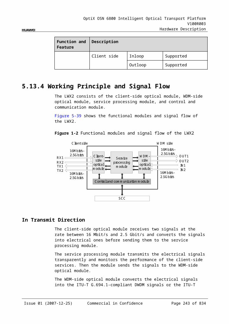
OptiX OSN 6800 Intelligent Optical Transport Platform V100R003
Hardware Description
Table 6-1 Functions and features of the NS2
Function and feature
Description
Basic function Maps four ODU1 signals sent from the cross-connection board or a board in the paired slot into an OTU2 signal and converts the signal into a standard DWDM signal compliant with ITU-T G.694.1. The reverse process is similar.
Cross-connect capabilities
Supports the cross-connection of four ODU1 signals between the NS2 and the cross-connect board or the board in the paired slot.
OTN function Provides the OTU2/OTU2V interface on WDM-side. Supports the OTN frame format and overhead
processing by referring to the ITU-T G.709. Supports 4×ODU1 asynchronous multiplexing into
ODU2. Supports SM and PM functions for OTU2 and ODU2. Supports TCM function for ODU1 and ODU2. Supports PM and TCM non-intrusive monitoring for
ODU1.
WDM specification Supports the DWDM specifications.
Tunable wavelength function
Supports the tunable wavelength optical module. Equipped with this module, the board can tune the optical signal output at the WDM side within the range of: 40 wavelengths in C-band with the channel spacing of
100 GHz 80 wavelengths in C-band with the channel spacing of
50 GHz
ESC function Supports the ESC function, transmitting the supervisory signal within the service signal.
FEC encoding Adopts FEC encoding compliant with the ITU-T G.975 and AFEC encoding compliant with the ITU-T G.975.1.
Alarms and performance events monitoring
Provides the monitoring of the BIP8 bit error count so as to help to locate the failures of the line.
Provides the WDM-side monitoring of the items such as the bias current and temperature of the laser as well as the optical power.
Supports the monitoring of the alarms and performance events of the OTN.
ALS function Provides the ALS function. With the ALS function enabled, the corresponding optical output laser is automatically shut down if no signals are received.
Protection scheme Supports the ODUk SNCP.
Issue 01 (2007-12-25) Commercial in Confidence Page 242 of 664
OptiX OSN 6800 Intelligent Optical Transport Platform V100R003
Hardware Description
Function and feature
Description
Loopback WDM side Inloop Supported
Outloop Supported
Client side Not supported
Path Loopback Supported
6.1.4 Working Principle and Signal FlowThe NS2 consists of the WDM-side optical module, cross-connect and service processing module, and control and communication module.
Figure 6-2 shows the functional modules and signal flow of the NS2.
Figure 6-1 Functional modules and signal flow of the NS2
WDM-side
opticalmodule
Control and communication module
SCC
Backplane
ODU1
Cross-connect andservice processing
module
WDM side
OTU2
OTU2OUT
IN
In Transmit DirectionThe WDM-side optical module receives one OTU2 optical signal and converts it into an electrical signal before sending it to the cross-connect and service processing module.
The cross-connect and service processing module monitors the performance of the services. Then, it demultiplexes the OTU2 signal into four ODU1 signals and sends them to the cross-connection board or a board in the paired slot through the backplane to realize the grooming of electrical signals.
In Receive DirectionThe cross-connect and service processing board receives the electrical signals sent from the cross-connection board or a board in the paired slot, extracts and processes overhead bytes, and monitors the performance of signals. Then, the signals are multiplexed into an OTU2 electrical signal and sent to the WDM-side optical module.
Issue 01 (2007-12-25) Commercial in Confidence Page 243 of 664
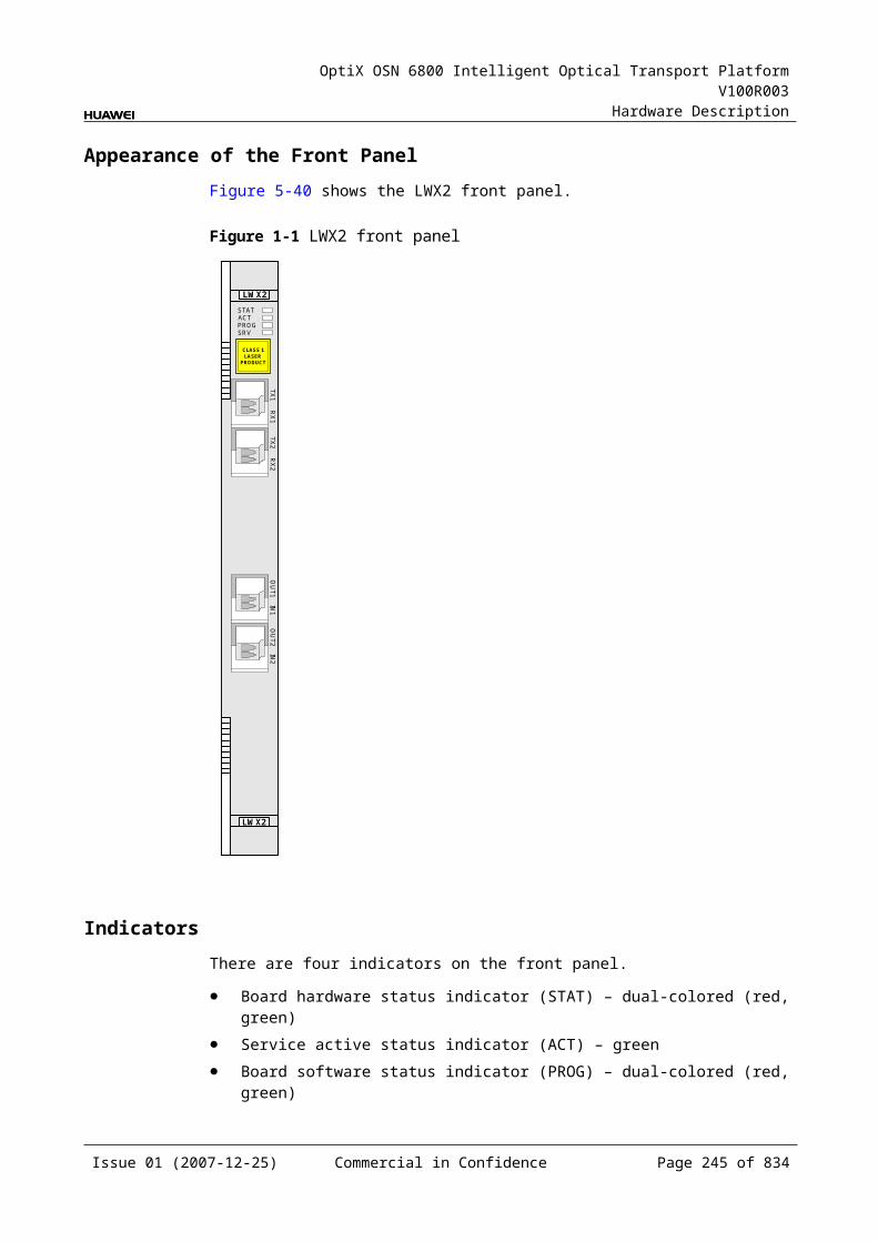
OptiX OSN 6800 Intelligent Optical Transport Platform V100R003
Hardware Description
The WDM-side optical module converts the electrical signal into an optical signal and outputs the standard DWDM signal compliant with ITU-T G.694.1 or the standard CWDM signal compliant with ITU-T G.694.2.
Cross-Connect and Service Processing Module This module realizes the grooming of electrical signals between the NS2 and the
board in the paired slot or the cross-connect board through the backplane. The grooming service signals are ODU1 signals. This module realizes the cross-connection of four service signals. This module extracts and processes overhead bytes. This module monitors the performance of services. This module multiplexes and demultiplexes services. This module implements the encapsulation of OTN signals.
Control and Communication ModuleThe control and communication module realizes the control, monitoring and communications management of each functional module of the board.
The control and communication module collects the information, such as the alarms and performance events, working status, and voltage detection, of each functional module of the board and reports to the SCC.
Receiving the commands from the SCC, the control and communication module controls and coordinates the functional modules of the board in working.
6.1.5 Front PanelThere are indicators, interfaces and laser safety label on the NS2 front panel.
Appearance of the Front PanelFigure 6-3 shows the NS2 front panel.
Issue 01 (2007-12-25) Commercial in Confidence Page 244 of 664
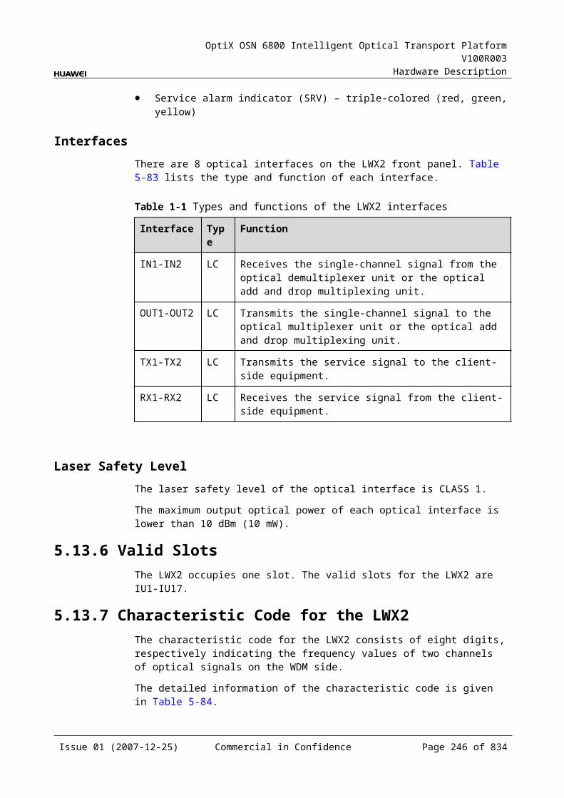
OptiX OSN 6800 Intelligent Optical Transport Platform V100R003
Hardware Description
Figure 6-1 NS2 front panel
NS2
NS2
CLASS 1LASER
PRODUCT
STATACTPROGSRV
OU
TIN
IndicatorsThere are four indicators on the front panel.
Board hardware status indicator (STAT) – dual-colored (red, green) Service active status indicator (ACT) – green Board software status indicator (PROG) – dual-colored (red, green) Service alarm indicator (SRV) – triple-colored (red, green, yellow)
InterfacesThere are two optical interfaces on the NS2 front panel. Table 6-2 lists the type and function of each interface.
Issue 01 (2007-12-25) Commercial in Confidence Page 245 of 664
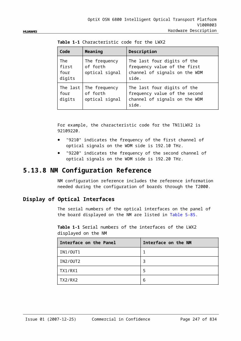
OptiX OSN 6800 Intelligent Optical Transport Platform V100R003
Hardware Description
Table 6-1 Types and functions of the NS2 interfaces
Interface
Type
Function
IN LC Receives the single-channel signal from the optical demultiplexer unit or the optical add and drop multiplexing unit.
OUT LC Transmits the single-channel signal to the optical multiplexer unit or the optical add and drop multiplexing unit.
Laser Safety LevelThe laser safety level of the optical interface is CLASS 1.
The maximum output optical power of each optical interface is lower than 10 dBm (10 mW).
6.1.6 Valid SlotsThe NS2 occupies one slot. The valid slots for the NS2 are IU1–IU8 and IU11–IU16.
6.1.7 Characteristic Code for the NS2The board characteristic code comprises the information about frequency of signals, type of the optical module, wavelength, and so on.
For the detailed description of the characteristic code for the board, refer to B.3 Characteristic Code for Line Unit.
6.1.8 NM Configuration ReferenceNM configuration reference includes the reference information needed during the configuration of boards through the T2000.
Display of Optical InterfacesThe serial numbers of the optical interfaces on the panel of the board displayed on the NM are listed in Table 6-3.
Table 6-1 Serial numbers of the interfaces of the NS2 displayed on the NM
Interface on the Panel Interface on the NM
IN/OUT 1
NOTEThe number of an interface displayed on the T2000 in fact indicates a pair of physical optical interfaces, of which one is used to transmit signals and the other is used to receive signals.
Issue 01 (2007-12-25) Commercial in Confidence Page 246 of 664

OptiX OSN 6800 Intelligent Optical Transport Platform V100R003
Hardware Description
Configuration ParametersPath Use Status
Optical Interface Loopback
Laser Status
Automatic Laser Shutdown
FEC Working State
FEC Type
Configure Wavelength No./Wavelength (nm)/Frequency (THz)
Configure Band Type
Path Loopback
6.1.9 Specifications of the NS2Specifications include optical specifications, dimensions, weight, and power consumption.
Specifications of Optical Module at the DWDM Side
Table 6-1 Specifications of fixed optical module at the DWDM side
Item Unit Value
Optical Module Type
800 ps/nm 1600 ps/nm 800 ps/nm
Line code format – NRZ- 40 channels fixed
NRZ- 40 channels fixed
NRZ- 80 channels fixed
Transmitter parameter specifications at point S
Maximum mean launched power
dBm 2 4 2
Minimum mean launched power
dBm –3 0 –3
Minimum extinction ratio
dB 10 9 10
Central frequency THz 192.10 to 196.00
Central frequency deviation
GHz ±10 ±10 ±5
Maximum –20 dB spectral width
nm 0.3 0.3 0.3
Issue 01 (2007-12-25) Commercial in Confidence Page 247 of 664

OptiX OSN 6800 Intelligent Optical Transport Platform V100R003
Hardware Description
Item Unit Value
Optical Module Type
800 ps/nm 1600 ps/nm 800 ps/nm
Minimum side mode suppression ratio
dB 35 35 35
Dispersion tolerance ps/nm 800 1600 800
Receiver parameter specifications at point R
Receiver type – PIN APD PIN
Operating wavelength range
nm 1200 to 1650
Receiver sensitivity (FEC on) EOL
dBm –16 –26 –16
Minimum receiver overload
dBm 0 –9 0
Maximum reflectance dB –27 –27 –27
Table 6-2 Specifications of tunable optical module at the DWDM side
Item Unit Value
Optical Module Type
1200 ps/nm - tunable- PIN
1200 ps/nm - tunable- APD
4800 ps/nm -ODB- tunable
800 ps/nm- DRZ-tunable
Line code format – NRZ- 80 channels tunable
NRZ- 80 channels tunable
ODB- 80 channels tunable
DRZ- 80 channels tunable
Transmitter parameter specifications at point S
Maximum mean launched power
dBm 2 2 2 2
Minimum mean launched power
dBm –3 –3 –3 –3
Minimum extinction ratio
dB 10 10 NAa 10
Central frequency THz 192.10 to 196.05
Central frequency deviation
GHz ±5 ±5 ±5 ±5
Maximum –20 dB spectral width
nm 0.3 0.3 0.3 0.3
Issue 01 (2007-12-25) Commercial in Confidence Page 248 of 664

OptiX OSN 6800 Intelligent Optical Transport Platform V100R003
Hardware Description
Item Unit Value
Optical Module Type
1200 ps/nm - tunable- PIN
1200 ps/nm - tunable- APD
4800 ps/nm -ODB- tunable
800 ps/nm- DRZ-tunable
Minimum side mode suppression ratio
dB 35 35 35 35
Dispersion tolerance ps/nm 1200 1200 4800 800
Receiver parameter specifications at point R
Receiver type – PIN APD APD PIN
Operating wavelength range
nm 1200 to 1650
Receiver sensitivity (FEC on) EOL
dBm –16 –26 –26 –16
Minimum receiver overload
dBm 0 –9 –9 0
Maximum reflectance
dB –27 –27 –27 –27
a: The ODB code pattern has three levels, and thus extinction ratio is not needed.
Mechanical Specifications Dimensions of board (PCB): 245.1 mm (H) x 220 mm (D) x 2 mm (T) Dimensions of front panel: 264.6 mm (H) x 25.4 mm (W) Weight: 2.64 lb (1.2 kg)
Power ConsumptionBoard Optical Module
TypeThe maximum power consumption at 25
The maximum power consumption at 55
TN11NS2 NRZ-fixed(10G) (800 ps/nm-40 channels fixed1600 ps/nm-40 channels fixed)
38.0 41.8
NRZ-tunable(10G) (1200 ps/nm-PIN-80 channels tunable1200 ps/nm-APD-80 channels tunable)
39.0 42.9
Issue 01 (2007-12-25) Commercial in Confidence Page 249 of 664

OptiX OSN 6800 Intelligent Optical Transport Platform V100R003
Hardware Description
Board Optical Module Type
The maximum power consumption at 25
The maximum power consumption at 55
DRZ-tunable(10G) (800 ps/nm-80 channels tunable)
41.0 45.1
ODB-tunable(10G) (4800 ps/nm-80 channels tunable)
44.0 48.4
6.2 TBETBE: 10 Gigabit Ethernet tributary board
6.2.1 Version DescriptionOnly one functional version of the TBE board is available, that is TN11.
6.2.2 ApplicationThe TBE is a type of tributary unit. Converges eight GE services and a maximum of 16 cross-connect GE services into one 10GE service and deconverges one 10GE service into multiple GE services; converges multiple flat-rate GE services into one full-rate GE service; realizes transparent transmission of GE-GE services.
Application Scenario 1: Converging/Deconverging 8xGE Services and a Maximum of 16 Cross-Connect GE Services to/from One 10GE Services
For the position of the TBE in the WDM system, see Figure 6-4.
Issue 01 (2007-12-25) Commercial in Confidence Page 250 of 664

OptiX OSN 6800 Intelligent Optical Transport Platform V100R003
Hardware Description
Figure 6-1 Position of the TBE in the WDM system
TBE8×GEGE
GE
10GE
OADM A OADM B
Local client side
GE
Application Scenario 2: Transparent Transmission of GE-GE ServicesFor the position of the TBE in the WDM system, see Figure 6-5.
Figure 6-1 Position of the TBE in the WDM system
4
G.694.1GE
GE
TBE
L4G
L4G
GE
G.694.1 GE
TBE
L4G
L4G
GE
8
GE1
8
11
GE GE
Client side WDM sideWDM side Client side
MUX
DMUX
DMUX
MUX4
1
4
1
4
1
6.2.3 Functions and FeaturesThe main function and feature supported by the TBE is cross-connection at the electrical layer and ALS.
For detailed functions and features, refer to Table 6-6.
Issue 01 (2007-12-25) Commercial in Confidence Page 251 of 664

OptiX OSN 6800 Intelligent Optical Transport Platform V100R003
Hardware Description
Table 6-1 Functions and features of the TBE
Function and Feature
Description
Basic function Converges eight GE services and a maximum of 16 cross-connect GE services into one 10GE service and deconverges one 10GE service into multiple GE services.
Converges multiple flat-rate GE services into one full-rate GE service.
Realizes transparent transmission of GE-GE services.The reverse process is similar.
Client-side service type
FE optical signal, FE electric signal, GE optical signal, GE electric signal, 10GE LAN, 10GE WAN
Cross-connect capabilities
Supports cross-connecting eight GE signals to the central working/protection cross-connect board.
Supports the cross-connection of eight GE signals between the TBE and the board in the paired slot through the backplane.
Alarms and performance events monitoring
Supports the monitoring of the alarms and performance events of the 10GE WAN.
ALS function Provides the ALS function. With the ALS function enabled, the corresponding optical output laser is automatically shut down if no signals are received.
QinQ Supports Stacking VLAN.
QoS (Quality of Service)
Supports CAR (committed access rate) and CoS (class of service).
ETH OAM Supports IEEE802.1ah-compliant ETH OAM protocol.
LAG (Link Aggregation Group)
Supports the aggregation group protocol to aggregate services from IP port to Trunk port; supports manual and static link aggregation; supports payload equalization and non-payload equalization.
VLAN broadcast Supports VLAN-based service group broadcast.
CVLAN group port Supports a group of CVLAN to be used as one VLAN.
Layer 2 switching Supports the MAC address learning and aging.
Flow control Supports IEEE802.3X-compliant Ethernet flow control protocol and flow control termination.
EPL (Ethernet Private Line)
Provides point-to-point EPL dedicated line.
EVPL (Ethernet Virtual Private Line)
Provides point-to-multipoint EVPL dedicated line and supports VLAN-based switching.
Issue 01 (2007-12-25) Commercial in Confidence Page 252 of 664

OptiX OSN 6800 Intelligent Optical Transport Platform V100R003
Hardware Description
Function and Feature
Description
Port working mode
10GE optical interface: 10GE-LAN, 10GE-WANGE optical interface: 1000MFULL, auto-negotiationGE electric interface: auto-negotiationFE optical interface: 100MFULLFE electric interface: 10MHALF, 10MFULL, 100MHALF, 100MFULL, auto-negotiation
Protection scheme Supports the intra-board 1+1 protection. Supports the client-side 1+1 protection. Supports the SW SNCP. Supports the VLAN SNCP. 10GE optical interface /GE optical interface /FE optical
interface: Supports the BPS protection.
eSFP Supports the enhanced small form-factor pluggable optical module on the client side.
XFP Supports the 10 Gbit/s small form-factor pluggable optical module on the client side.
Loopback 10GE optical interface
MAC Inloop Supported
Outloop Supported
PHY Inloop Supported
Outloop Supported
GE optical interface
MAC Inloop Supported
Outloop Not supported
PHY Inloop Supported
Outloop Not supported
GE electric interface
MAC Inloop Supported
Outloop Not supported
PHY Inloop Supported
Outloop Supported
FE optical interface
MAC Inloop Supported
Outloop Not supported
PHY Inloop Supported
Outloop Not supported
FE electric interface
MAC Inloop Supported
Outloop Not supported
Issue 01 (2007-12-25) Commercial in Confidence Page 253 of 664
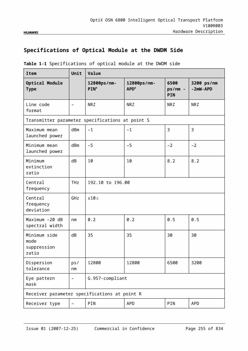
OptiX OSN 6800 Intelligent Optical Transport Platform V100R003
Hardware Description
Function and Feature
Description
PHY Inloop Supported
Outloop Supported
6.2.4 Working Principle and Signal FlowThe TBE consists of the client-side GE module, client-side 10GE module, L2 module, GE service cross-connect module, and control and communication module.
Figure 6-6 shows the functional modules and signal flow of the TBE.
Figure 6-1 Functional modules and signal flow of the TBE
SCC
Backplane
GE
GE servicecross-
connectmodule
Client-side GEmodule
10GE
GE8
8 L2module
16
16
RX1TX1RX8TX8
RXTX
10GEside 10GE
module
16
Client-
Control and communication module
Client side
In Transmit DirectionThe client-side optical module receives eight GE service signals. These GE signals are converted into electrical signals and sent to the L2 module.
The GE service cross-connect module receives a maximum of 24 GE electrical signals, and then transmits the electrical signals to the L2 module.
The L2 module multiplexes the electrical signals into one 10GE signal and then transmits the 10GE signal to the client-side 10GE module; or the L2 board converges multiple channels into one GE signal and then transmits it to the client-side GE optical module or GE service cross-connect module.
The WDM-side GE module converts the GE electrical signal into the GE optical signal, and sends the optical signal to the WDM side through TX1-TX8, or the WDM-side 10GE module converts the 10GE electrical signal into the 10GE optical signal, and sends the optical signal to the WDM side through TX.
Issue 01 (2007-12-25) Commercial in Confidence Page 254 of 664
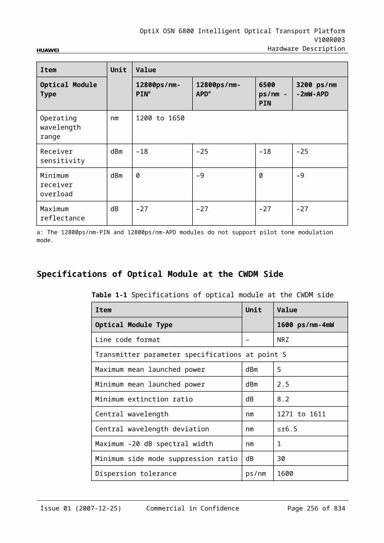
OptiX OSN 6800 Intelligent Optical Transport Platform V100R003
Hardware Description
In Receive DirectionThe client-side 10GE module receives an 10GE optical signal, converts it into an electrical signal, and sends the converted signal to the L2 module.
The L2 module demultiplexes the electrical signal into multiple channels of GE signals and then transmits them to the GE service cross-connect module or the client-side GE optical module.
The GE service cross-connect module transmits the GE signals to the cross-connection board or a board in the paired slot through the backplane.
The client-side GE module converts eight GE electrical signals into optical signals and sends them to the client-side equipment.
GE Service Cross-Connect Module This module realizes the grooming of electrical signals between the TBE and the
cross-connect board or the boards in paired slots through the backplane. The grooming service signals are GE signals. This module realizes the cross-connection of eight GE signals between the
boards in paired slots. This module realizes cross-connecting eight GE signals to the central
working/protection cross-connect board through the backplane.
Control and Communication ModuleThe control and communication module realizes the control, monitoring and communications management of each functional module of the board.
The control and communication module collects the information, such as the alarms and performance events, working status, and voltage detection, of each functional module of the board and reports to the SCC.
Receiving the commands from the SCC, the control and communication module controls and coordinates the functional modules of the board in working.
6.2.5 Front PanelThere are indicators, interfaces and laser safety label on the TBE front panel.
Appearance of the Front PanelFigure 6-7 shows the TBE front panel.
Issue 01 (2007-12-25) Commercial in Confidence Page 255 of 664
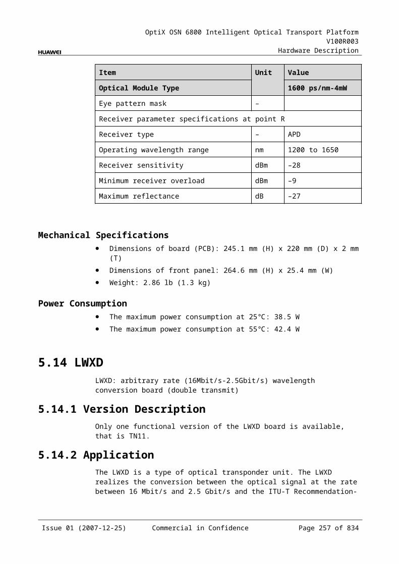
OptiX OSN 6800 Intelligent Optical Transport Platform V100R003
Hardware Description
Figure 6-1 TBE front panel
TBE
TBE
STATACTPROGSRV
RX
2TX
3R
X3
TX4
RX
4TX
1R
X1
TX2
RX
6TX
7R
X7
TX8
RX
8TX
5R
X5
TX6
TXR
X
CLASS 1LASER
PRODUCT
IndicatorsThere are four indicators on the front panel.
Board hardware status indicator (STAT) – dual-colored (red, green) Service active status indicator (ACT) – green Board software status indicator (PROG) – dual-colored (red, green) Service alarm indicator (SRV) – triple-colored (red, green, yellow)
InterfacesThere are eighteen optical interfaces on the TBE front panel. Table 6-7 lists the type and function of each interface.
Issue 01 (2007-12-25) Commercial in Confidence Page 256 of 664
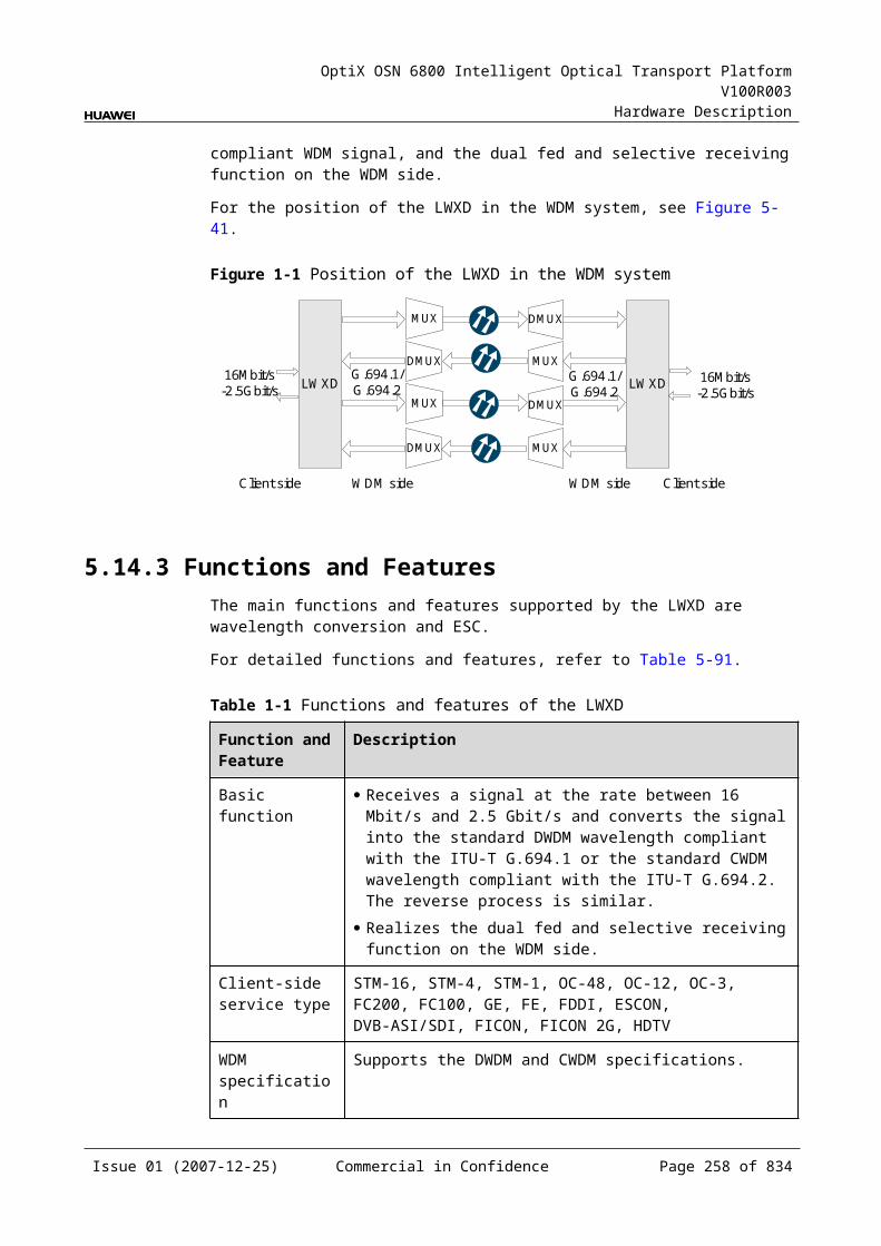
OptiX OSN 6800 Intelligent Optical Transport Platform V100R003
Hardware Description
Table 6-1 Types and functions of the TBE interfaces
Interface
Type
Function
TX1-TX8 LC Transmits the GE service signal to the client-side equipment.
TX LC Transmits the 10 GE service signal to the client-side equipment.
RX1-RX8 LC Receives the GE service signal from the client-side equipment.
RX LC Receives the 10 GE service signal from the client-side equipment.
Laser Safety LevelThe laser safety level of the optical interface is CLASS 1.
The maximum output optical power of each optical interface is lower than 10 dBm (10 mW).
6.2.6 Valid SlotsThe TBE occupies one slot. The valid slots for the TBE are IU1–IU8 and IU11–IU16.
6.2.7 NM Configuration ReferenceNM configuration reference includes the reference information needed during the configuration of boards through the T2000.
Display of Optical InterfacesThe serial numbers of the optical interfaces on the panel of the board displayed on the NM are listed in Table 6-8.
Table 6-1 Serial numbers of the interfaces of the TBE displayed on the NM
Interface on the Panel Interface on the NM
TX1/RX1 3
TX2/RX2 4
TX3/RX3 5
TX4/RX4 6
TX5/RX5 7
TX6/RX6 8
TX7/RX7 9
TX8/RX8 10
Issue 01 (2007-12-25) Commercial in Confidence Page 257 of 664
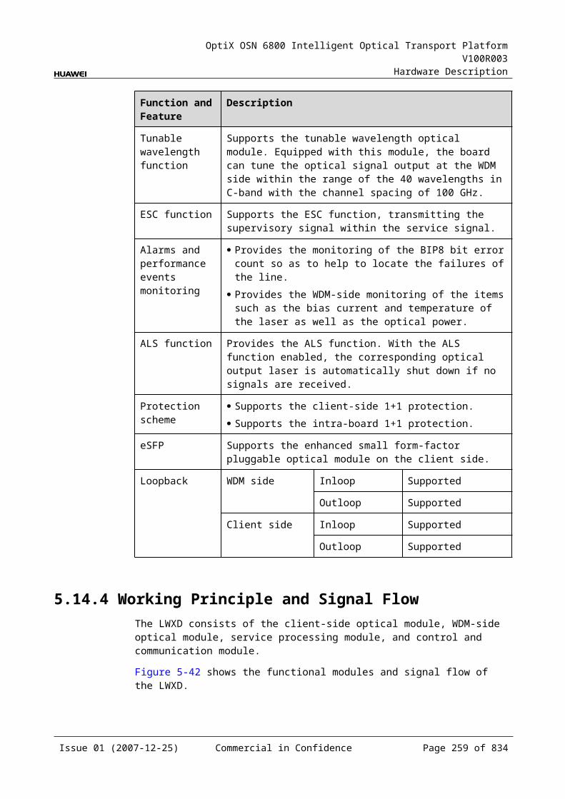
OptiX OSN 6800 Intelligent Optical Transport Platform V100R003
Hardware Description
Interface on the Panel Interface on the NM
TX/RX 11
NOTEThe number of an interface displayed on the T2000 in fact indicates a pair of physical optical interfaces, of which one is used to transmit signals and the other is used to receive signals.
Configuration ParametersLaser Status
Automatic Laser Shutdown
Configure Wavelength No./Wavelength (nm)/Frequency (THz)
Configure Band Type
LPT Enabled
6.2.8 Specifications of the TBESpecifications include optical specifications, dimensions, weight, and power consumption.
Specifications of Optical Module at the Client Side
Table 6-1 Specifications of optical module at the client side(FE)
Item Unit
Value
Optical Module Type 100BASE-FX1310 nm
100BASE-FX1310 nm
Line code format – NRZ NRZ
Target distance km 40 2
Transmitter parameter specifications at point S
Maximum mean launched power
dBm 0 –14
Minimum mean launched power
dBm –5 –19
Minimum extinction ratio dB 10 10
Operating wavelength range
nm 1310 1310
Eye pattern mask – IEEE802.3z-compliant IEEE802.3z-compliant
Receiver parameter specifications at point R
Issue 01 (2007-12-25) Commercial in Confidence Page 258 of 664
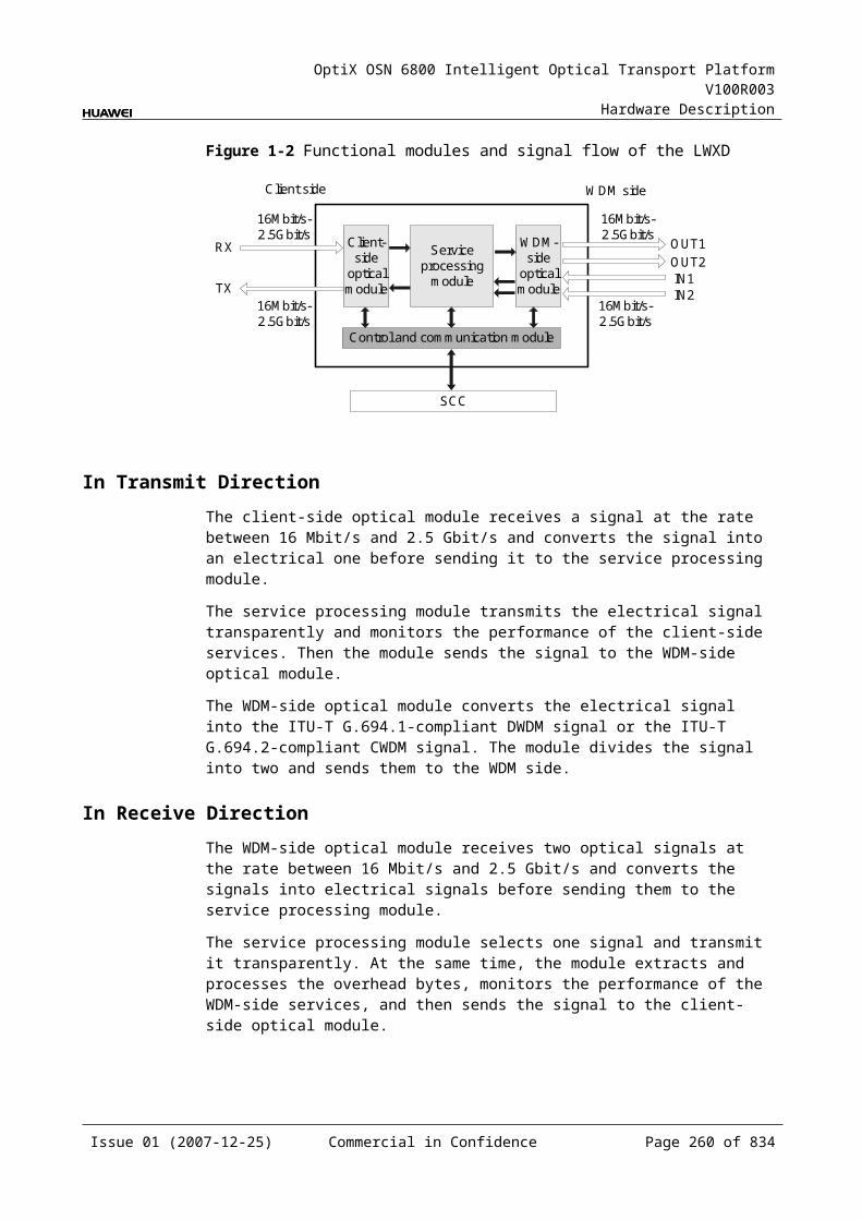
OptiX OSN 6800 Intelligent Optical Transport Platform V100R003
Hardware Description
Item Unit
Value
Optical Module Type 100BASE-FX1310 nm
100BASE-FX1310 nm
Receiver type – PIN PIN
Receiver sensitivity(EOL) dBm –30 –30
Minimum receiver overload
dBm –10 –14
Table 6-2 Specifications of GE optical module at the client side
Item Unit
Value
Optical Module Type 2.125G Multirate
1000 BASE-LX-10 km
1000 BASE-LX-40 km
1000 BASE-ZX-80 km
Line code format – NRZ NRZ NRZ NRZ
Target distance km 0.5 10 40 80
Transmitter parameter specifications at point S
Operating wavelength range nm 830 to 860 1270 to 1355 1270 to 1355 1500 to 1580
Maximum mean launched power dBm –2.5 –3 0 5
Minimum mean launched power dBm –9.5 –11.5 –4.5 –2
Minimum extinction ratio dB 9 9 9 9
Eye pattern mask – IEEE802.3z-compliant
Receiver parameter specifications at point R
Receiver type – PIN PIN PIN PIN
Operating wavelength range nm 770 to 860 1270 to 1355 1270 to 1355 1500 to 1580
Receiver sensitivity dBm –17 –19 –20 –22
Minimum receiver overload dBm 0 –3 –3 –3
NOTEWhen accessing 1000 BASE-T services, the specifications of the electrical interface comply with the IEEE Std 802.3.
Issue 01 (2007-12-25) Commercial in Confidence Page 259 of 664
OptiX OSN 6800 Intelligent Optical Transport Platform V100R003
Hardware Description
Table 6-3 Specifications of eSFP CWDM optical module at the client side
Item Unit
Value
Optical Module Type
1.25Gbit/s Multi-rate(eSFP CWDM)-40km
2.67Gbit/s Multi-rate (eSFP CWDM)-80km
Line code format – NRZ NRZ
Target distance km 40 80
Transmitter parameter specifications at point S
Operating wavelength range
nm 1471 to 1611 1471 to 1611
Maximum mean launched power
dBm 5 5
Minimum mean launched power
dBm 0 0
Minimum extinction ratio
dB 9 8.2
Central wavelength deviation
nm ±6.5 ±6.5
Maximum –20 dB spectral width
nm 1 1
Minimum side mode suppression ratio
dB 30 30
Eye pattern mask – IEEE802.3z-compliant G.957-compliant
Receiver parameter specifications at point R
Receiver type – PIN APD
Operating wavelength range
nm 1270 to 1620 1270 to 1620
Receiver sensitivity
dBm –19 –28
Minimum receiver overload
dBm –3 –9
Maximum reflectance
dB –27 –27
Issue 01 (2007-12-25) Commercial in Confidence Page 260 of 664

OptiX OSN 6800 Intelligent Optical Transport Platform V100R003
Hardware Description
Table 6-4 Specifications of XFP optical module at the client side
Item Unit Value
Optical Module Type 10Gbit/s Multirate-10km
10Gbit/s Multirate-40km
10Gbit/s Multirate-80km
10Gbit/s Multirate-0.3km
Line code format – NRZ NRZ NRZ NRZ
Optical source type – SLM SLM SLM MLM
Target distance km 10 40 80 0.3
Transmitter parameter specifications at point S
Operating wavelength range nm 1290 to 1330 1530 to 1565 1530 to 1565
840 to 860
Maximum mean launched power
dBm –1 2 4 –1.3
Minimum mean launched power
dBm –6 –1 0 –7.3
Minimum extinction ratio dB 6 8.2 9 3
Maximum –20 dB spectral width
nm NA NA NA NA
Minimum side mode suppression ratio
dB 30 30 30 30
Eye pattern mask – G.691-compliant
Receiver parameter specifications at point R
Receiver type – PIN PIN APD PIN
Operating wavelength range nm 1290 to 1330 1530 to 1565 1270 to 1600
840 to 860
Receiver sensitivity dBm –11 –14 –24 –7.5
Minimum receiver overload dBm 0.5 –1 –7 –1
Maximum reflectance dB NA NA NA NA
Mechanical Specifications Dimensions of board (PCB): 245.1 mm (H) x 220 mm (D) x 2 mm (T) Dimensions of front panel: 264.6 mm (H) x 25.4 mm (W) Weight: 2.86 lb (1.3 kg)
Power Consumption The maximum power consumption at 25: 40.7 W The maximum power consumption at 55: 44.8 W
Issue 01 (2007-12-25) Commercial in Confidence Page 261 of 664
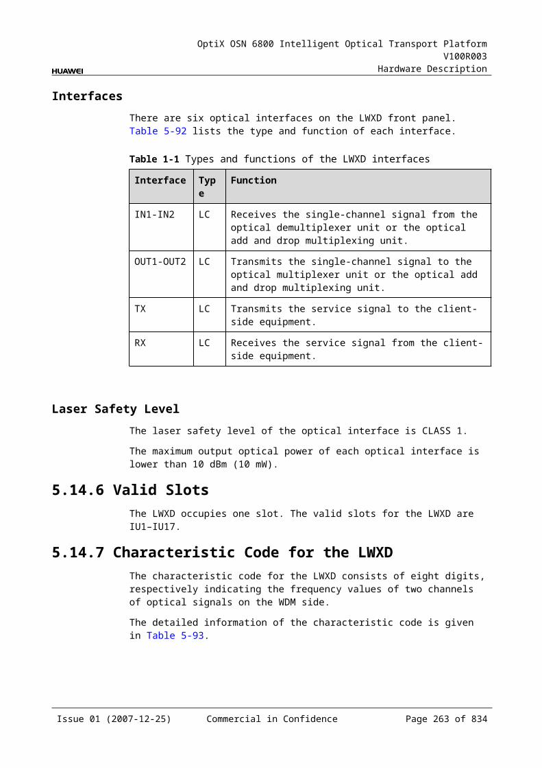
OptiX OSN 6800 Intelligent Optical Transport Platform V100R003
Hardware Description
6.3 TDGTDG: 2 x GE tributary service processing unit
6.3.1 Version DescriptionOnly one functional version of the TDG board is available, that is TN11.
6.3.2 ApplicationThe TDG is a type of tributary unit. The TDG realizes the conversion between two GE optical signals and two GE electrical signals or one ODU1 electrical signal through cross-connection.
For the position of the TDG in the WDM system, see Figure 6-8.
Figure 6-1 Position of the TDG in the WDM system
MUX
DMUX
NS2
DMUX
MUX
G.694.1 G.694.1
GE
GE
TDG NS2 TDG
GE
GE
Client sideWDMside
WDMside Client side
6.3.3 Functions and FeaturesThe main function and feature supported by the TDG is cross-connection at the electrical layer.
For detailed functions and features, refer to Table 6-13.
Table 6-1 Functions and features of the TDG
Function and Feature
Description
Basic function Realizes the conversion between two GE optical signals and two GE electrical signals or one ODU1 electrical signal through the cross-connect board or with the board in the paired slot.
Client-side service type
GE
Cross-connect capabilities
Supports the cross-connection of an ODU1 signal and two GE signals between the TDG and the cross-connect board or the board in the paired slot through the backplane.
Alarms and performance events monitoring
Provides the monitoring of the BIP8 bit error count so as to help to locate the failures of the line.
Supports the monitoring of the alarms and performance events of the OTN.
Issue 01 (2007-12-25) Commercial in Confidence Page 262 of 664
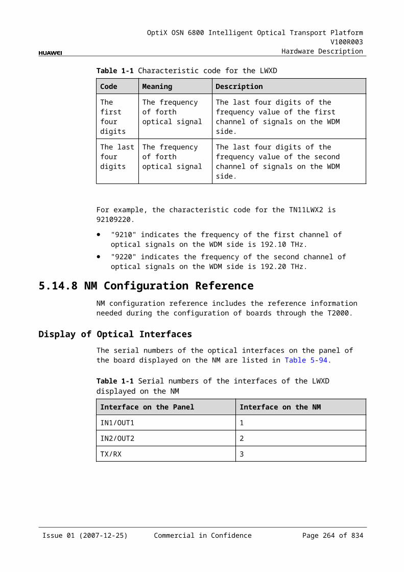
OptiX OSN 6800 Intelligent Optical Transport Platform V100R003
Hardware Description
Function and Feature
Description
ALS function Provides the ALS function. With the ALS function enabled, the corresponding optical output laser is automatically shut down if no signals are received.
Protection scheme Supports the SW SNCP. Supports the ODUk SNCP. Supports the client-side 1+1 protection.
eSFP Supports the enhanced small form-factor pluggable optical module on the client side.
Loopback WDM side Not supported
Client side Inloop Supported
Outloop Supported
6.3.4 Working Principle and Signal FlowThe TDG consists of the client-side optical module, cross-connect and service processing module, and control and communication module.
Figure 6-9 shows the functional modules and signal flow of the TDG.
Figure 6-1 Functional modules and signal flow of the TDG
GE
Control and communication module
SCC
Backplane
Cross-connect andservice processing
module
Client-side
opticalmodule
ODU1Client side
GE
RX1
TX1RX2
TX2
In Transmit DirectionThe client-side optical module receives two GE service signals compliant with IEEE 802.3z. These GE signals are converted into electrical signals and sent to the cross-connect and service processing module.
The cross-connect and service processing module monitors the performance of client-side services, then
Issue 01 (2007-12-25) Commercial in Confidence Page 263 of 664

OptiX OSN 6800 Intelligent Optical Transport Platform V100R003
Hardware Description
Sends the two signals to the cross-connection board or a board in the paired slot through the backplane to realize the grooming of electrical signals, or
Multiplexes the two signals into one OTU1 signal and sends the signal to the cross-connection board or a board in the paired slot through the backplane to realize the grooming of electrical signals.
In Receive DirectionThe cross-connect and service processing module receives the signal sent from the cross-connection board or a board in the paired slot through the backplane, extracts and processes overhead bytes, and monitors the performance of signals. Then,
If the signals are two GE signals, they are sent to the client-side optical module. If the signal is an ODU1 signal, it is demultiplexed into two GE signals before
being sent to the client-side optical module.
The client-side optical module converts two GE electrical signals into optical signals and sends them to the client-side equipment.
Cross-Connect and Service Processing Module This module realizes the grooming of electrical signals through the cross-
connect board or between the boards in paired slots. This module realizes the cross-connection of one ODU1 signal. This module realizes the cross-connection of two GE signals between the
boards in paired slots. This module extracts and processes overhead bytes. This module monitors the performance of services. This module multiplexes and demultiplexes services. This module implements the encapsulation of OTN signals.
Control and Communication ModuleThe control and communication module realizes the control, monitoring and communications management of each functional module of the board.
The control and communication module collects the information, such as the alarms and performance events, working status, and voltage detection, of each functional module of the board and reports to the SCC.
Receiving the commands from the SCC, the control and communication module controls and coordinates the functional modules of the board in working.
6.3.5 Front PanelThere are indicators, interfaces and laser safety label on the TDG front panel.
Appearance of the Front PanelFigure 6-10 shows the TDG front panel.
Issue 01 (2007-12-25) Commercial in Confidence Page 264 of 664
OptiX OSN 6800 Intelligent Optical Transport Platform V100R003
Hardware Description
Figure 6-1 TDG front panel
TDG
TDG
CLASS 1LASER
PRODUCT
STATACTPROGSRV
TX1
RX
1TX
2R
X2
IndicatorsThere are four indicators on the front panel.
Board hardware status indicator (STAT) – dual-colored (red, green) Service active status indicator (ACT) – green Board software status indicator (PROG) – dual-colored (red, green) Service alarm indicator (SRV) – triple-colored (red, green, yellow)
InterfacesThere are four optical interfaces on the TDG front panel. Table 6-14 lists the type and function of each interface.
Issue 01 (2007-12-25) Commercial in Confidence Page 265 of 664
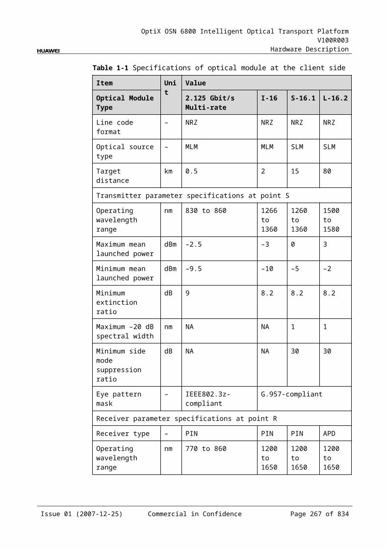
OptiX OSN 6800 Intelligent Optical Transport Platform V100R003
Hardware Description
Table 6-1 Types and functions of the TDG interfaces
Interface
Type
Function
TX1–TX2 LC Transmits the service signal to the client-side equipment.
RX1–RX2 LC Receives the service signal from the client-side equipment.
Laser Safety LevelThe laser safety level of the optical interface is CLASS 1.
The maximum output optical power of each optical interface is lower than 10 dBm (10 mW).
6.3.6 Valid SlotsThe TDG occupies one slot. The valid slots for the TDG are IU1–IU8 and IU11–IU16.
6.3.7 NM Configuration ReferenceNM configuration reference includes the reference information needed during the configuration of boards through the T2000.
Display of Optical InterfacesThe serial numbers of the optical interfaces on the panel of the board displayed on the NM are listed in Table 6-15.
Table 6-1 Serial numbers of the interfaces of the TDG displayed on the NM
Interface on the Panel Interface on the NM
TX1/RX1 3
TX2/RX2 4
NOTEThe number of an interface displayed on the T2000 in fact indicates a pair of physical optical interfaces, of which one is used to transmit signals and the other is used to receive signals.
Issue 01 (2007-12-25) Commercial in Confidence Page 266 of 664
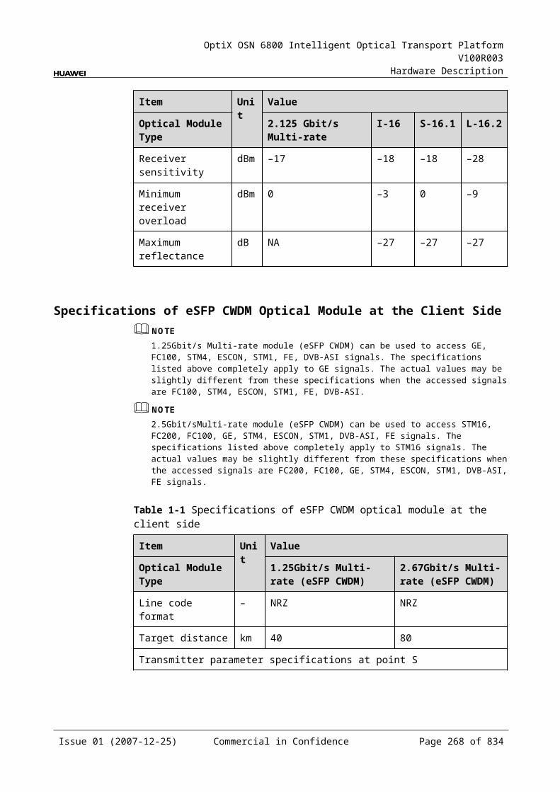
OptiX OSN 6800 Intelligent Optical Transport Platform V100R003
Hardware Description
Configuration ParametersPath Use Status
Optical Interface Loopback
Laser Status
Automatic Laser Shutdown
Maximum Packet Length
Ethernet Working Mode
LPT Enabled
6.3.8 Specifications of the TDGSpecifications include optical specifications, dimensions, weight, and power consumption.
Specifications of Optical Module at the Client Side
Table 6-1 Specifications of GE optical module at the client side
Item Unit
Value
Optical Module Type
2.125 Gbit/s Multi-rate
1000 BASE-LX-10 km
1000 BASE-LX-40 km
1000 BASE-ZX-80 km
Line code format – NRZ NRZ NRZ NRZ
Target distance km 0.5 10 40 80
Transmitter parameter specifications at point S
Operating wavelength range
nm 830 to 860 1270 to 1355
1270 to 1355
1500 to 1580
Maximum mean launched power
dBm –2.5 –3 0 5
Minimum mean launched power
dBm –9.5 –11.5 –4.5 –2
Minimum extinction ratio
dB 9 9 9 9
Eye pattern mask – IEEE802.3z-compliant
Receiver parameter specifications at point R
Receiver type – PIN PIN PIN PIN
Issue 01 (2007-12-25) Commercial in Confidence Page 267 of 664
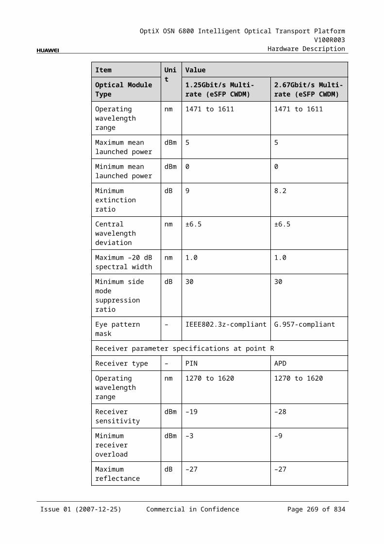
OptiX OSN 6800 Intelligent Optical Transport Platform V100R003
Hardware Description
Item Unit
Value
Optical Module Type
2.125 Gbit/s Multi-rate
1000 BASE-LX-10 km
1000 BASE-LX-40 km
1000 BASE-ZX-80 km
Operating wavelength range
nm 770 to 860 1270 to 1355
1270 to 1355
1500 to 1580
Receiver sensitivity dBm –17 –19 –20 –22
Minimum receiver overload
dBm 0 –3 –3 –3
Specifications of eSFP CWDM Optical Module at the Client Side
Table 6-1 Specifications of eSFP CWDM optical module at the client side
Item Unit
Value
Optical Module Type
1.25Gbit/s Multi-rate (eSFP CWDM)-40km
1.25Gbit/s Multi-rate (eSFP CWDM)-80km
Line code format – NRZ NRZ
Target distance km 40 80
Transmitter parameter specifications at point S
Operating wavelength range
nm 1471 to 1611 1471 to 1611
Maximum mean launched power
dBm 5 5
Minimum mean launched power
dBm 0 0
Minimum extinction ratio
dB 9 8.2
Central wavelength deviation
nm ±6.5 ±6.5
Maximum –20 dB spectral width
nm 1.0 1.0
Minimum side mode suppression ratio
dB 30 30
Eye pattern mask – IEEE802.3z-compliant
Receiver parameter specifications at point R
Issue 01 (2007-12-25) Commercial in Confidence Page 268 of 664
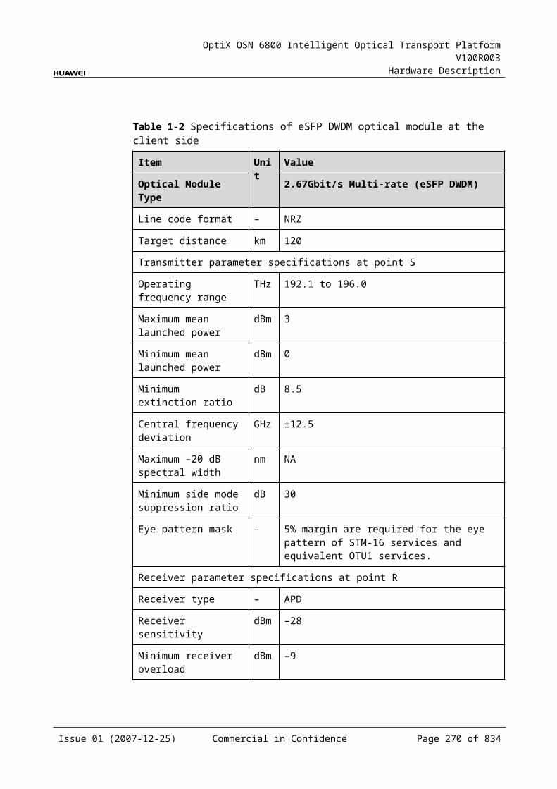
OptiX OSN 6800 Intelligent Optical Transport Platform V100R003
Hardware Description
Item Unit
Value
Optical Module Type
1.25Gbit/s Multi-rate (eSFP CWDM)-40km
1.25Gbit/s Multi-rate (eSFP CWDM)-80km
Receiver type – PIN APD
Operating wavelength range
nm 1270 to 1620 1270 to 1620
Receiver sensitivity dBm –19 –28
Minimum receiver overload
dBm –3 –9
Maximum reflectance
dB –27 –27
Mechanical Specifications Dimensions of board (PCB): 245.1 mm (H) x 220 mm (D) x 2 mm (T) Dimensions of front panel: 264.6 mm (H) x 25.4 mm (W) Weight: 2.42 lb (1.1 kg)
Power Consumption The maximum power consumption at 25: 29.7 W The maximum power consumption at 55: 32.7 W
6.4 TDXTDX: 2 x 10G Tributary Service Processing Board
6.4.1 Version DescriptionOnly one functional version of the TDX board is available, that is TN11.
6.4.2 ApplicationThe TDX is a type of tributary unit. The TDX realizes the conversion between two 10GE LAN/STM-64/OC-192 optical signals and eight 2.5Gbit/s ODU1 virtual concatenation electrical signals through cross-connection.
For the position of the TDX in the WDM system, see Figure 6-11.
Issue 01 (2007-12-25) Commercial in Confidence Page 269 of 664

OptiX OSN 6800 Intelligent Optical Transport Platform V100R003
Hardware Description
Figure 6-1 Position of the TDX in the WDM system
MUX
DMUX
NS2
G.694.1 G.694.1
STM-6410GE LAN
TDX TDX
STM-6410GE LAN
STM-6410GE LAN
STM-6410GE LAN
NS2
NS2
NS2
4
4
4
4
OC-192
OC-192 OC-192
OC-192
Client side WDM side Client sideWDM side
MUX
DMUX
6.4.3 Functions and FeaturesThe main function and feature supported by the TDX is cross-connection at the electrical layer.
For detailed functions and features, refer to Table 6-18.
Table 6-1 Functions and features of the TDX
Function and Feature
Description
Basic function Realizes the conversion between two 10GE LAN/STM-64/OC-192 optical signals and eight ODU1 virtual concatenation electrical signals.
Client-side service type
10GE LAN, 10GE WAN, STM-64, OC-192
Cross-connect capabilities
Supports the cross-connection of eight ODU1 signals between the TDX and the cross-connect board or the board in the paired slot through the backplane.
Alarms and performance events monitoring
Provides the monitoring of the BIP8 bit error count so as to help to locate the failures of the line.
Supports the monitoring of the alarms and performance events of the OTN.
ALS function Provides the ALS function. With the ALS function enabled, the corresponding optical output laser is automatically shut down if no signals are received.
Protection scheme Supports the ODUk SNCP. Supports the client-side 1+1 protection. Supports the ODUk SPRing protection.
XFP Supports the 10 Gbit/s small form-factor pluggable optical module on the client side.
Loopback WDM side Not supported
Client side Inloop Supported
Issue 01 (2007-12-25) Commercial in Confidence Page 270 of 664
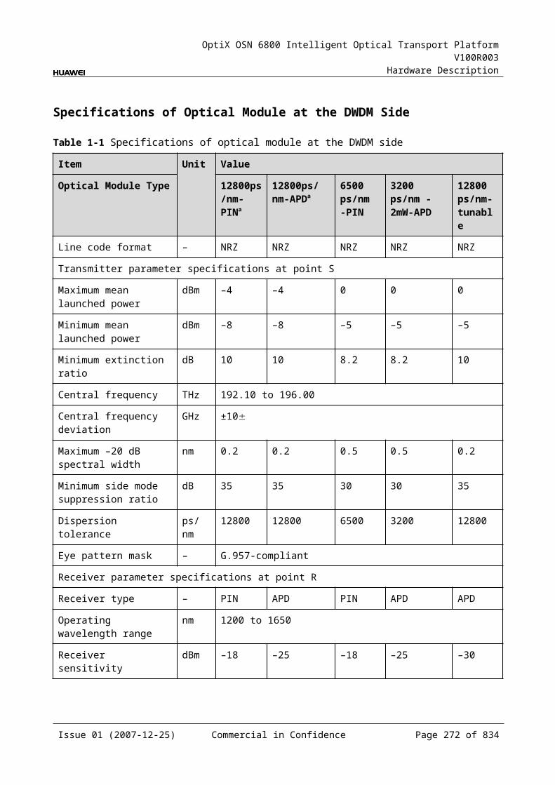
OptiX OSN 6800 Intelligent Optical Transport Platform V100R003
Hardware Description
Function and Feature
Description
Outloo[ Supported
6.4.4 Working Principle and Signal FlowThe TDX consists of the client-side optical module, cross-connect and service processing module, and control and communication module.
Figure 6-12 shows the functional modules and signal flow of the TDX.
Figure 6-1 Functional modules and signal flow of the TDX
SCC
ODU1
10G LAN
RX1
TX1RX2
TX2
STM-64
10G LANSTM-64
810G WAN
10G WAN
BackplaneClient side
Cross-connect andservice processing
module
Control and communication module
Client-side
opticalmodule
In Transmit DirectionThe client-side optical module receives two 10Gbit/s service signals. These signals are converted into electrical signals and sent to the cross-connect and service processing module.
The cross-connect and service processing module monitors the performance of client-side services, then maps the two electrical signals into eight 0DU1 signals, and sends the eight ODU1 signals to the cross-connection board or a board in the paired slot through the backplane to realize the grooming of electrical signals.
In Receive DirectionThe cross-connect and service processing module receives the signal sent from the cross-connection board or a board in the paired slot through the backplane, extracts and processes overhead bytes, and monitors the performance of signals. Then, multiplex the ODU1 signal into two 10GE signal, and sent them to the client-side optical module.
The client-side optical module converts two 10GE electrical signals into optical signals and sends them to the client-side equipment.
Issue 01 (2007-12-25) Commercial in Confidence Page 271 of 664
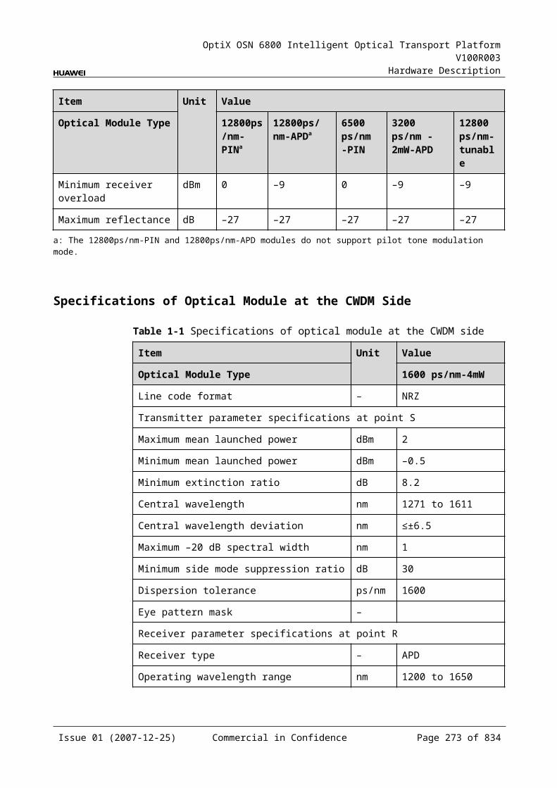
OptiX OSN 6800 Intelligent Optical Transport Platform V100R003
Hardware Description
Cross-Connect and Service Processing Module This module realizes the grooming of electrical signals through the cross-
connect board or between the boards in paired slots. This module realizes the cross-connection of eight ODU1 signals. This module extracts and processes overhead bytes. This module monitors the performance of services. This module multiplexes and demultiplexes services. This module implements the encapsulation of OTN signals.
Control and Communication ModuleThe control and communication module realizes the control, monitoring and communications management of each functional module of the board.
The control and communication module collects the information, such as the alarms and performance events, working status, and voltage detection, of each functional module of the board and reports to the SCC.
Receiving the commands from the SCC, the control and communication module controls and coordinates the functional modules of the board in working.
6.4.5 Front PanelThere are indicators, interfaces and laser safety label on the TDX front panel.
Appearance of the Front PanelFigure 6-13 shows the TDX front panel.
Issue 01 (2007-12-25) Commercial in Confidence Page 272 of 664
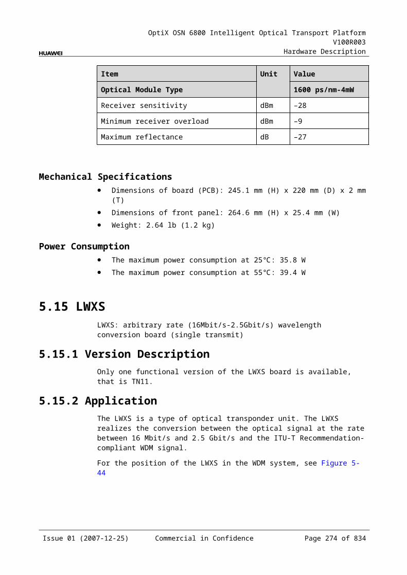
OptiX OSN 6800 Intelligent Optical Transport Platform V100R003
Hardware Description
Figure 6-1 TDX front panel
TDX
TDX
LASERRADIATION
DO NOT VIEW DIRECTLYWITH OPTICALINSTRUMENTS
CLASS 1M LASERPRODUCT
STATACTPROGSRV
TX1
RX
1TX
2R
X2
IndicatorsThere are four indicators on the front panel.
Board hardware status indicator (STAT) – dual-colored (red, green) Service active status indicator (ACT) – green Board software status indicator (PROG) – dual-colored (red, green) Service alarm indicator (SRV) – triple-colored (red, green, yellow)
InterfacesThere are four optical interfaces on the TDX front panel.Table 6-19 lists the type and function of each interface.
Issue 01 (2007-12-25) Commercial in Confidence Page 273 of 664
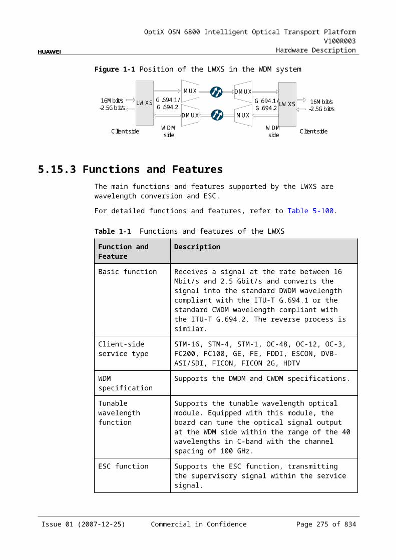
OptiX OSN 6800 Intelligent Optical Transport Platform V100R003
Hardware Description
Table 6-1 Types and functions of the TDX interfaces
Interface
Type
Function
TX1-TX2 LC Transmits the service signal to the client-side equipment.
RX1-RX2 LC Receives the service signal from the client-side equipment.
Laser Safety LevelThe laser safety level of the optical interface is CLASS 1.
The maximum output optical power of each optical interface is lower than 10 dBm (10 mW).
6.4.6 Valid SlotsThe TDX occupies one slot. The valid slots for the TDX are IU1–IU8 and IU11–IU16.
6.4.7 NM Configuration ReferenceNM configuration reference includes the reference information needed during the configuration of boards through the T2000.
Display of Optical InterfacesThe serial numbers of the optical interfaces on the panel of the board displayed on the NM are listed in Table 6-20.
Table 6-1 Serial numbers of the interfaces of the TDX displayed on the NM
Interface on the Panel Interface on the NM
TX1/RX1 3
TX2/RX2 4
NOTEThe number of an interface displayed on the T2000 in fact indicates a pair of physical optical interfaces, of which one is used to transmit signals and the other is used to receive signals.
Configuration ParametersPath Use Status
Optical Interface Loopback
Service Type
Laser Status
Automatic Laser Shutdown
Issue 01 (2007-12-25) Commercial in Confidence Page 274 of 664
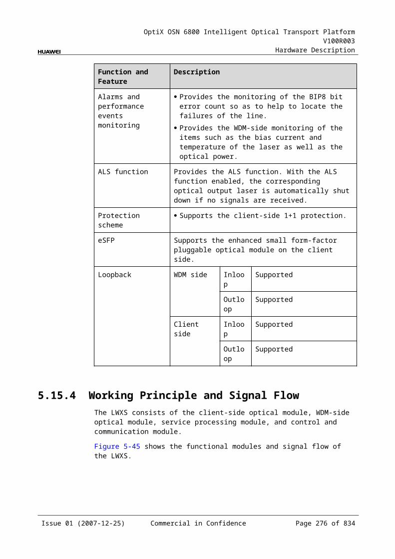
OptiX OSN 6800 Intelligent Optical Transport Platform V100R003
Hardware Description
PAUSE Frame Flow Control
Configure Wavelength No./Wavelength (nm)/Frequency (THz)
Configure Band Type
Maximum Packet Length
LPT Enabled
6.4.8 Specifications of the TDXSpecifications include optical specifications, dimensions, weight, and power consumption.
Specifications of Optical Module at the Client Side
Table 6-1 Specifications of XFP optical module at the client side
Item Unit
Value
Optical Module Type 10Gbit/s Multirate-10km
10Gbit/s Multirate-40km
10Gbit/s Multirate-80km
10Gbit/s Multirate-0.3km
Line code format – NRZ NRZ NRZ NRZ
Optical source type – SLM SLM SLM MLM
Target distance km 10 40 80 0.3
Transmitter parameter specifications at point S
Operating wavelength range
nm 1290 to 1330 1530 to 1565 1530 to 1565 840 to 860
Maximum mean launched power
dBm –1 2 4 –1.3
Minimum mean launched power
dBm –6 –1 0 –7.3
Minimum extinction ratio dB 6 8.2 9 3
Maximum –20 dB spectral width
nm NA NA NA NA
Minimum side mode suppression ratio
dB 30 30 30 30
Eye pattern mask – G.691-compliant
Receiver parameter specifications at point R
Receiver type – PIN PIN APD PIN
Issue 01 (2007-12-25) Commercial in Confidence Page 275 of 664
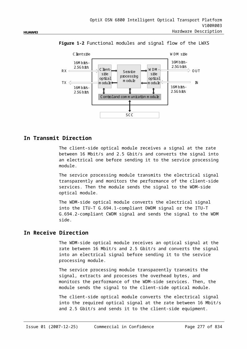
OptiX OSN 6800 Intelligent Optical Transport Platform V100R003
Hardware Description
Item Unit
Value
Optical Module Type 10Gbit/s Multirate-10km
10Gbit/s Multirate-40km
10Gbit/s Multirate-80km
10Gbit/s Multirate-0.3km
Operating wavelength range
nm 1290 to 1330 1530 to 1565 1270 to 1600 840 to 860
Receiver sensitivity dBm –11 –14 –24 –7.5
Minimum receiver overload dBm 0.5 –1 –7 –1
Maximum reflectance dB NA NA NA NA
Mechanical Specifications Dimensions of board (PCB): 245.1 mm (H) x 220 mm (D) x 2 mm (T) Dimensions of front panel: 264.6 mm (H) x 25.4 mm (W) Weight: 2.75 lb (1.25 kg)
Power Consumption The maximum power consumption at 25: 78.0 W The maximum power consumption at 55: 80.0 W
6.5 TQMTQM: 4 x multi-rate tributary service processing unit
6.5.1 Version DescriptionOnly one functional version of the TQM board is available, that is TN11.
6.5.2 ApplicationThe TQM is a type of tributary unit. The TQM realizes the conversion between four optical signals at the rate between 100 Mbit/s and 2.5 Gbit/s and four client-side electrical signals or one ODU1 electrical signal through cross-connection.
For the position of the TQM in the WDM system, see Figure 6-14.
Figure 6-1 Position of the TQM in the WDM system
MUX
DMUX
NS2
DMUX
MUX
1
4
1
4
G.694.1 G.694.1
100Mbit/s-2.5Gbit/s
100Mbit/s-2.5Gbit/s
TQM NS2 TQM
100Mbit/s-2.5Gbit/s
100Mbit/s-2.5Gbit/s
Client side WDM side WDM side Client side
Issue 01 (2007-12-25) Commercial in Confidence Page 276 of 664
OptiX OSN 6800 Intelligent Optical Transport Platform V100R003
Hardware Description
NOTE The client-side four pairs of optical interfaces can access services at a maximum rate of 2.5
Gbit/s. There is only one pair of optical interface (TX1/RX1) that supports services at a maximum
rate of 2.5 Gbit/s.
6.5.3 Functions and FeaturesThe main function and feature supported by the TQM is cross-connection at the electrical layer.
For detailed functions and features, refer to Table 6-22.
Table 6-1 Functions and features of the TQM
Function and Feature
Description
Basic function Converts four optical signals at the rate between 100 Mbit/s and 2.5 Gbit/s into four client-side electrical signals or one ODU1 electrical signal and sends the signals to the backplane for further cross-connection.
Client-side service type
STM-16, STM-4, STM-1, OC-48, OC-12, OC-3, FC200, FC100, GE, FE, ESCON, DVB-ASI, FICON, FICON 2G
Cross-connect capabilities
Supports the cross-connection of four signals at the rate between 100 Mbit/s and 2.5 Gbit/s between the boards in paired slots.
Supports the cross-connection of one ODU1 signal between the TQM and the cross-connect board or the board in the paired slot.
Alarms and performance events monitoring
Provides the monitoring of the BIP8 bit error count so as to help to locate the failures of the line.Supports the monitoring of the alarms and performance events of the OTN.
ALS function Provides the ALS function. With the ALS function enabled, the corresponding optical output laser is automatically shut down if no signals are received.
Protection scheme Supports the SW SNCP. Supports the ODUk SNCP. Supports the client-side 1+1 protection.
eSFP Supports the enhanced small form-factor pluggable optical module on the client side.
Loopback WDM side Not supported
Client side Inloop Supported
Outloop Supported
Issue 01 (2007-12-25) Commercial in Confidence Page 277 of 664

OptiX OSN 6800 Intelligent Optical Transport Platform V100R003
Hardware Description
6.5.4 Working Principle and Signal FlowThe TQM consists of the client-side optical module, cross-connect and service processing module, and control and communication module.
Figure 6-15 shows the functional modules and signal flow of the TQM.
Figure 6-1 Functional modules and signal flow of the TQM
Control and communication module
SCC
Backplane
Cross-connect and serviceprocessing module
Client-side
opticalmodule
100Mbit/s-2.5Gbit/s ODU1
4
4
Client side
100Mbit/s-2.5Gbit/s
RX1
TX1RX4
TX4 100Mbit/s-2.5Gbit/s
NOTE The client-side four pairs of optical interfaces can access services at a maximum rate of 2.5
Gbit/s. There is only one pair of optical interface (TX1/RX1) that supports services at a maximum
rate of 2.5 Gbit/s.
In Transmit DirectionThe client-side optical module receives four optical signals at the rate between 100 Mbit/s and 2.5 Gbit/s and converts them into electrical signals before sending them to the cross-connect and service processing module.
The cross-connect and service processing module monitors the performance of the client-side services, then
Sends the four signals to the cross-connection board or a board in the paired slot through the backplane to realize the grooming of electrical signals, or
Multiplexes the four signals into one ODU1 signal and sends the signal to the cross-connection board or a board in the paired slot through the backplane to realize the grooming of electrical signals.
In Receive DirectionThe cross-connect and service processing module receives the signal sent from the cross-connection board or a board in the paired slot through the backplane, extracts and processes overhead bytes, and monitors the performance of signals. Then,
Issue 01 (2007-12-25) Commercial in Confidence Page 278 of 664
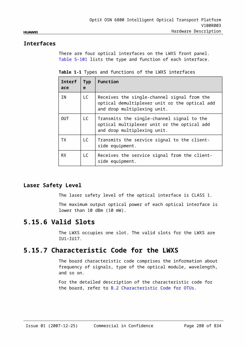
OptiX OSN 6800 Intelligent Optical Transport Platform V100R003
Hardware Description
If the signals are four signals at the rate between 100 Mbit/s and 2.5 Gbit/s, they are sent to the client-side optical module.
If the signal is an ODU1 signal, it is demultiplexed into four signals at the rate between 100 Mbit/s and 2.5 Gbit/s the client side needed before being sent to the client-side optical module.
The client-side optical module converts four electrical signals into optical signals and sends them to the client-side equipment.
Cross-Connect and Service Processing Module This module realizes the grooming of electrical signals between the boards in
paired slots or with the cross-connect board through the backplane. This module realizes the cross-connection of four signals at the rate between
100 Mbit/s and 2.5 Gbit/s between the boards in paired slots. This module realizes the cross-connection of one ODU1 signal through the
cross-connect board or between the boards in paired slots. This module extracts and processes overhead bytes. This module monitors the performance of services. This module multiplexes and demultiplexes services. This module implements the encapsulation of OTN signals.
Control and Communication ModuleThe control and communication module realizes the control, monitoring and communications management of each functional module of the board.
The control and communication module collects the information, such as the alarms and performance events, working status, and voltage detection, of each functional module of the board and reports to the SCC.
Receiving the commands from the SCC, the control and communication module controls and coordinates the functional modules of the board in working.
6.5.5 Front PanelThere are indicators, interfaces and laser safety label on the TDG front panel.
Appearance of the Front PanelFigure 6-16 shows the TQM front panel.
Issue 01 (2007-12-25) Commercial in Confidence Page 279 of 664
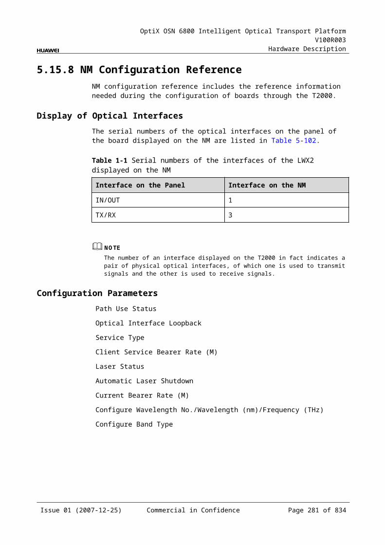
OptiX OSN 6800 Intelligent Optical Transport Platform V100R003
Hardware Description
Figure 6-1 TQM front panel
TQM
TQM
STATACTPROGSRV
CLASS 1LASER
PRODUCT
RX
2TX
3R
X3
TX4
RX
4TX
1R
X1
TX2
IndicatorsThere are four indicators on the front panel.
Board hardware status indicator (STAT) – dual-colored (red, green) Service active status indicator (ACT) – green Board software status indicator (PROG) – dual-colored (red, green) Service alarm indicator (SRV) – triple-colored (red, green, yellow)
InterfacesThere are eight optical interfaces on the TQM front panel. Table 6-23 lists the type and function of each interface.
Issue 01 (2007-12-25) Commercial in Confidence Page 280 of 664
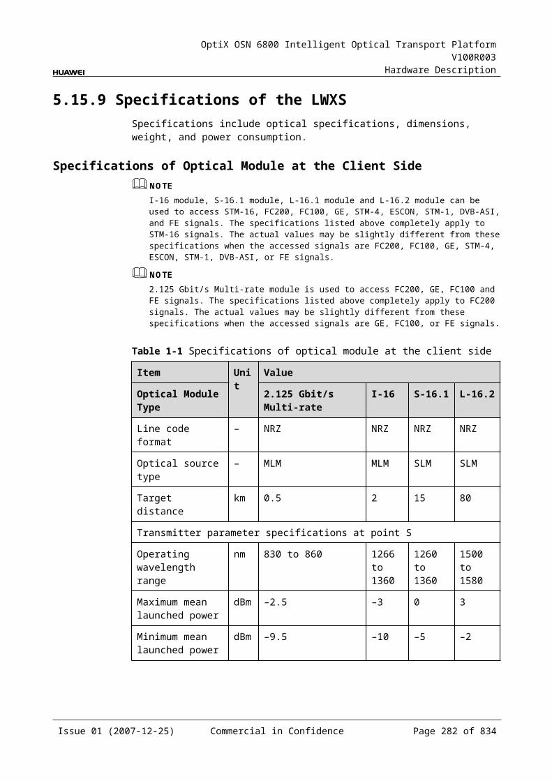
OptiX OSN 6800 Intelligent Optical Transport Platform V100R003
Hardware Description
Table 6-1 Types and functions of the TQM interfaces
Interface
Type
Function
TX1–TX4 LC Transmits the service signal to the client-side equipment.
RX1–RX4 LC Receives the service signal from the client-side equipment.
NOTE The client-side four pairs of optical interfaces can access services at a maximum rate of 2.5
Gbit/s. There is only one pair of optical interface (TX1/RX1) that supports services at a maximum
rate of 2.5 Gbit/s.
Laser Safety LevelThe laser safety level of the optical interface is CLASS 1.
The maximum output optical power of each optical interface is lower than 10 dBm (10 mW).
6.5.6 Valid SlotsThe TQM occupies one slot. The valid slots for the TQM are IU1–IU8 and IU11–IU16.
6.5.7 NM Configuration ReferenceNM configuration reference includes the reference information needed during the configuration of boards through the T2000.
Display of Optical InterfacesThe serial numbers of the optical interfaces on the panel of the board displayed on the NM are listed in Table 6-24.
Table 6-1 Serial numbers of the interfaces of the TQM displayed on the NM
Interface on the Panel Interface on the NM
TX1/RX1 3
TX2/RX2 4
TX3/RX3 5
TX4/RX4 6
NOTEThe number of an interface displayed on the T2000 in fact indicates a pair of physical optical interfaces, of which one is used to transmit signals and the other is used to receive signals.
Issue 01 (2007-12-25) Commercial in Confidence Page 281 of 664
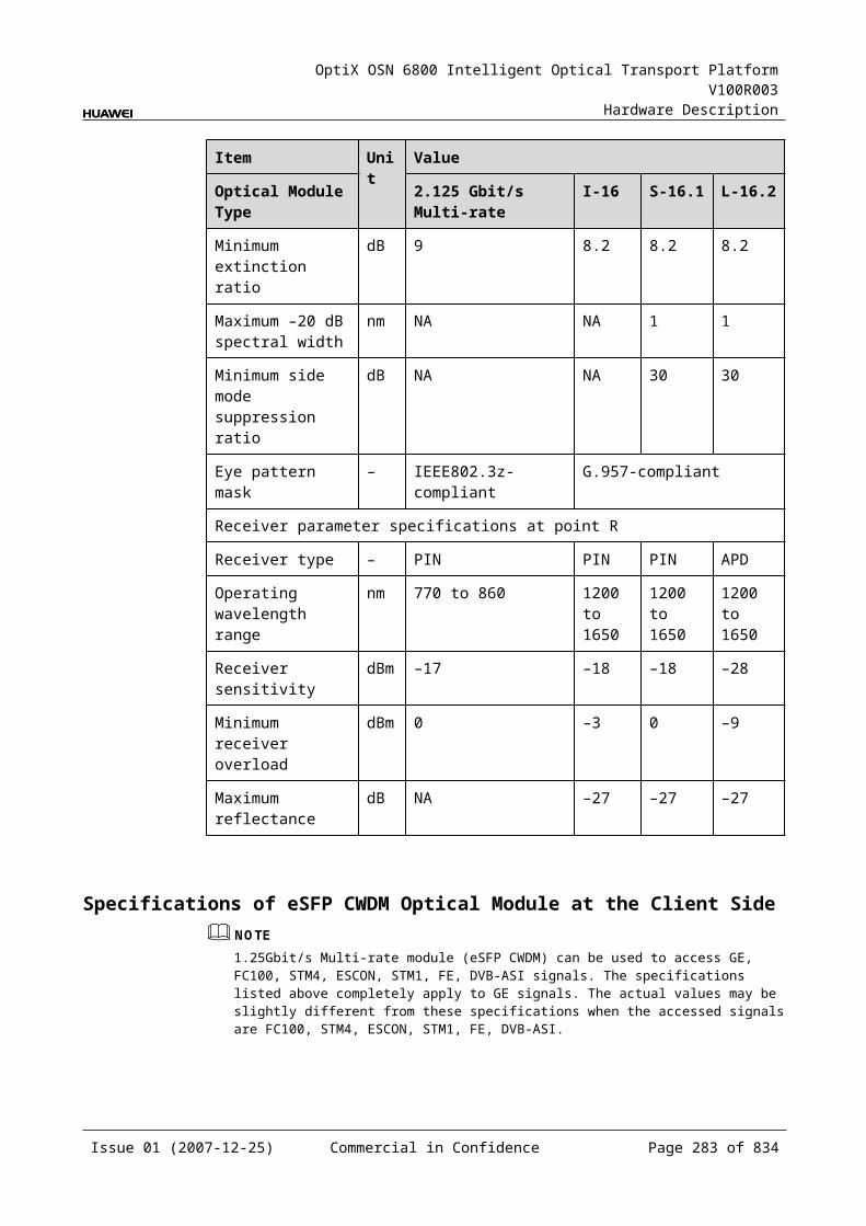
OptiX OSN 6800 Intelligent Optical Transport Platform V100R003
Hardware Description
Configuration ParametersPath Use Status
Optical Interface Loopback
Service Type
Laser Status
Automatic Laser Shutdown
Maximum Packet Length
Ethernet Working Mode
LPT Enabled
6.5.8 Specifications of the TQMSpecifications include optical specifications, dimensions, weight, and power consumption.
Specifications of SDH optical module at the client sideNOTEI-16 module, S-16.1 module, L-16.1 module and L-16.2 module can be used to access STM-16, FC200, FC100, GE, STM-4, ESCON, STM-1, DVB-ASI, and FE signals. The specifications listed above completely apply to STM-16 signals. The actual values may be slightly different from these specifications when the accessed signals are FC200, FC100, GE, STM-4, ESCON, STM-1, DVB-ASI, or FE signals.
Table 6-1 Specifications of SDH optical module at the client side
Item Unit
Value
Optical Module Type I-16 S-16.1 L-16.1 L-16.2
Line code format – NRZ NRZ NRZ NRZ
Optical source type – MLM SLM SLM SLM
Target distance km 2 15 40 80
Transmitter parameter specifications at point S
Operating wavelength range
nm 1266 to 1360
1260 to 1360
1280 to 1335
1500 to 1580
Maximum mean launched power
dBm –3 0 3 3
Minimum mean launched power
dBm –10 –5 –2 –2
Minimum extinction ratio dB 8.2 8.2 8.2 8.2
Issue 01 (2007-12-25) Commercial in Confidence Page 282 of 664
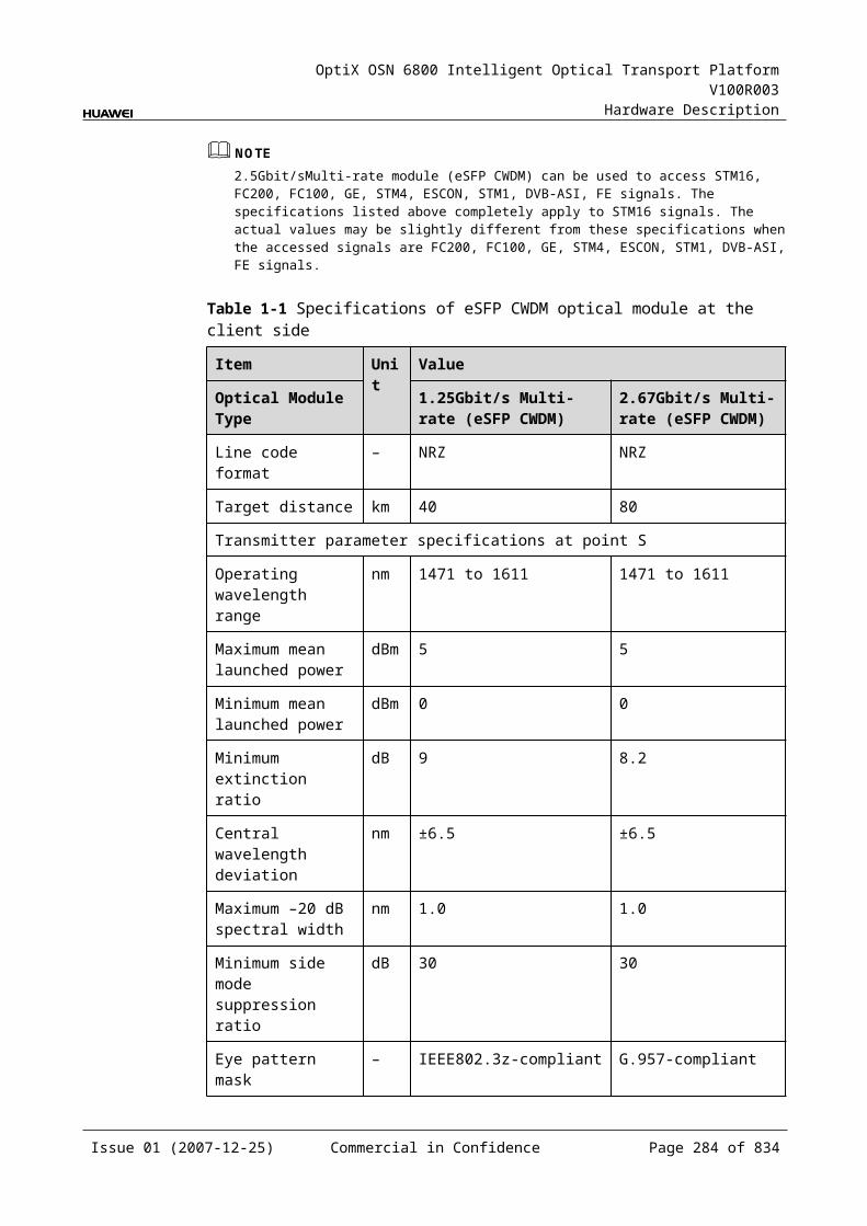
OptiX OSN 6800 Intelligent Optical Transport Platform V100R003
Hardware Description
Item Unit
Value
Optical Module Type I-16 S-16.1 L-16.1 L-16.2
Maximum –20 dB spectral width
nm NA 1 1 1
Minimum side mode suppression ratio
dB NA 30 30 30
Eye pattern mask – G.957-compliant
Receiver parameter specifications at point R
Receiver type – PIN PIN APD APD
Operating wavelength range
nm 1266 to 1360
1260 to 1360
1280 to 1335
1500 to 1580
Receiver sensitivity dBm –18 –18 –27 –28
Minimum receiver overload
dBm –3 0 –9 –9
Maximum reflectance dB –27 –27 –27 –27
Specifications of GE Optical Module at the Client SideNOTE2.125Gbit/s Multi-rate module can be used to access FC200, GE, FC100, and FE signals. The specifications listed above completely apply to FC200 signals. The actual values may be slightly different from these specifications when the accessed signals are GE, FC100, or FE signals.
NOTE1000 BASE-LX-10 km module, 1000 BASE-LX-40 km module and 1000 BASE-ZX-80 km module can be used to access GE, FC100, STM-4, ESCON, STM-1, FE and DVB-ASI signals. The specifications listed above completely apply to GE signals. The actual values may be slightly different from these specifications when the accessed signals are FC100, STM-4, ESCON, STM-1, FE, or DVB-ASI signals.
Table 6-1 Specifications of GE optical module at the client side
Item Unit
Value
Optical Module Type
2.125 Gbit/s Multi-rate
1000 BASE-LX-10 km
1000 BASE-LX-40 km
1000 BASE-ZX-80 km
Line code format – NRZ NRZ NRZ NRZ
Target distance km 0.5 10 40 80
Transmitter parameter specifications at point S
Issue 01 (2007-12-25) Commercial in Confidence Page 283 of 664
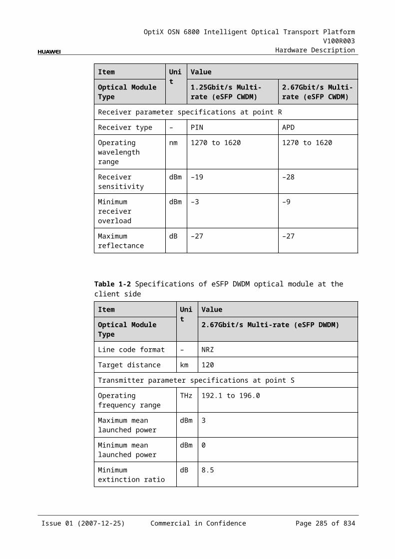
OptiX OSN 6800 Intelligent Optical Transport Platform V100R003
Hardware Description
Item Unit
Value
Optical Module Type
2.125 Gbit/s Multi-rate
1000 BASE-LX-10 km
1000 BASE-LX-40 km
1000 BASE-ZX-80 km
Operating wavelength range
nm 830 to 860 1270 to 1355
1270 to 1355
1500 to 1580
Maximum mean launched power
dBm –2.5 –3 0 5
Minimum mean launched power
dBm –9.5 –11.5 –4.5 –2
Minimum extinction ratio
dB 9 9 9 9
Eye pattern mask – IEEE802.3z-compliant
Receiver parameter specifications at point R
Receiver type – PIN PIN PIN PIN
Operating wavelength range
nm 770 to 860 1270 to 1355
1270 to 1355
1500 to 1580
Receiver sensitivity dBm –17 –19 –20 –22
Minimum receiver overload
dBm 0 –3 –3 –3
Specifications of eSFP CWDM Optical Module at the Client SideNOTE1.25Gbit/s Multi-rate module (eSFP CWDM) can be used to access GE, FC100, STM4, ESCON, STM1, FE, DVB-ASI signals. The specifications listed above completely apply to GE signals. The actual values may be slightly different from these specifications when the accessed signals are FC100, STM4, ESCON, STM1, FE, DVB-ASI.
NOTE2.5Gbit/sMulti-rate module (eSFP CWDM) can be used to access STM16, FC200, FC100, GE, STM4, ESCON, STM1, DVB-ASI, FE signals. The specifications listed above completely apply to STM16 signals. The actual values may be slightly different from these specifications when the accessed signals are FC200, FC100, GE, STM4, ESCON, STM1, DVB-ASI, FE signals.
Table 6-1 Specifications of eSFP CWDM optical module at the client side
Item Unit
Value
Optical Module Type
1.25Gbit/s Multi-rate (eSFP CWDM)
2.67Gbit/s Multi-rate (eSFP CWDM)
Line code format – NRZ NRZ
Issue 01 (2007-12-25) Commercial in Confidence Page 284 of 664
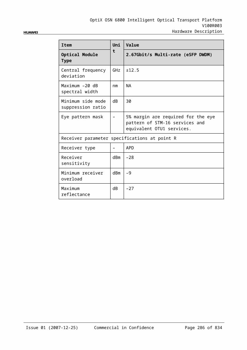
OptiX OSN 6800 Intelligent Optical Transport Platform V100R003
Hardware Description
Item Unit
Value
Optical Module Type
1.25Gbit/s Multi-rate (eSFP CWDM)
2.67Gbit/s Multi-rate (eSFP CWDM)
Target distance km 40 80
Transmitter parameter specifications at point S
Operating wavelength range
nm 1471 to 1611 1471 to 1611
Maximum mean launched power
dBm 5 5
Minimum mean launched power
dBm 0 0
Minimum extinction ratio
dB 9 8.2
Central wavelength deviation
nm ±6.5 ±6.5
Maximum –20 dB spectral width
nm 1.0 1.0
Minimum side mode suppression ratio
dB 30 30
Eye pattern mask – IEEE802.3z-compliant G.957-compliant
Receiver parameter specifications at point R
Receiver type – PIN APD
Operating wavelength range
nm 1270 to 1620 1270 to 1620
Receiver sensitivity dBm –19 –28
Minimum receiver overload
dBm –3 –9
Maximum reflectance
dB –27 –27
Mechanical Specifications Dimensions of board (PCB): 245.1 mm (H) x 220 mm (D) x 2 mm (T) Dimensions of front panel: 264.6 mm (H) x 25.4 mm (W) Weight: 2.64 lb (1.2 kg)
Power Consumption The maximum power consumption at 25: 50.8 W
Issue 01 (2007-12-25) Commercial in Confidence Page 285 of 664
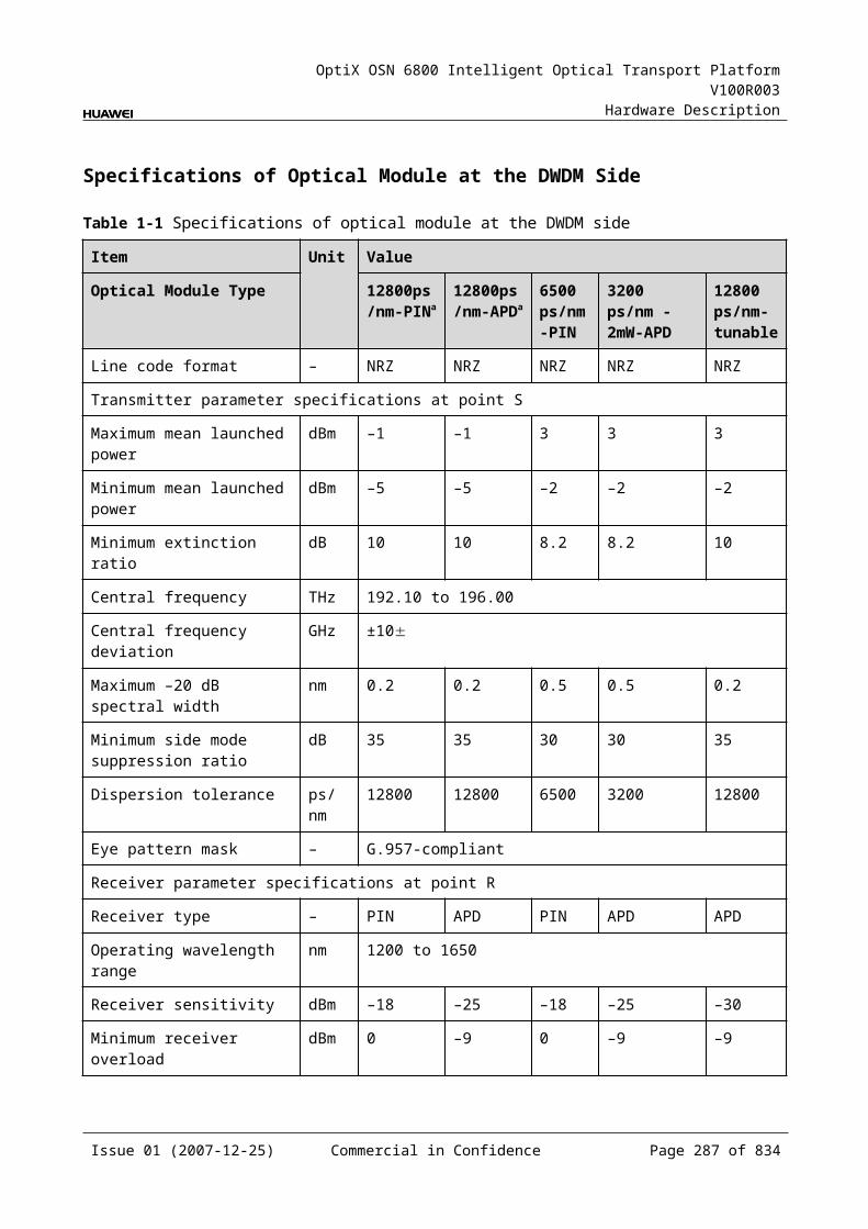
OptiX OSN 6800 Intelligent Optical Transport Platform V100R003
Hardware Description
The maximum power consumption at 55: 55.9 W
6.6 TQSTQS: 4 x STM-16/OC-48/OTU1 tributary service processing unit
6.6.1 Version DescriptionOnly one functional version of the TQS board is available, that is TN11.
6.6.2 ApplicationThe TQS is a type of tributary unit. The TQS realizes the conversion between four STM-16/OC-48/OTU1 optical signals and four ODU1 electrical signals.
For the position of the TQS in the WDM system, see Figure 6-17.
Figure 6-1 Position of the TQS in the WDM system
STM-16/OC-48/OTU1
STM-16/OC-48/OTU1
MUX
DMUX
NS2
DMUX
MUX
1
4
1
4
G.694.1 G.694.1TQS NS2 TQS
1
4
1
4
Client side WDM side WDM side Client side
STM-16/OC-48/OTU1
STM-16/OC-48/OTU1
6.6.3 Functions and FeaturesThe main functions and features supported by the TQS are cross-connection at the electrical layer, OTN interfaces and ESC.
For detailed functions and features, refer to Table 6-28.
Table 6-1 Functions and features of the TQS
Function and Feature
Description
Basic function Converts four STM-16/OC-48/OTU1 optical signals into ODU1 signals and sends the signals to the backplane for further cross-connection. The reverse process is similar.
Client-side service type
STM-16, OC-48, OTU1
Cross-connect capabilities
Supports the cross-connection of four ODU1 signals between the TQS and the cross-connect board or the board in the paired slot.
OTN function Supports the OTN frame format and overhead processing by referring to the ITU-T G.709.
Issue 01 (2007-12-25) Commercial in Confidence Page 286 of 664
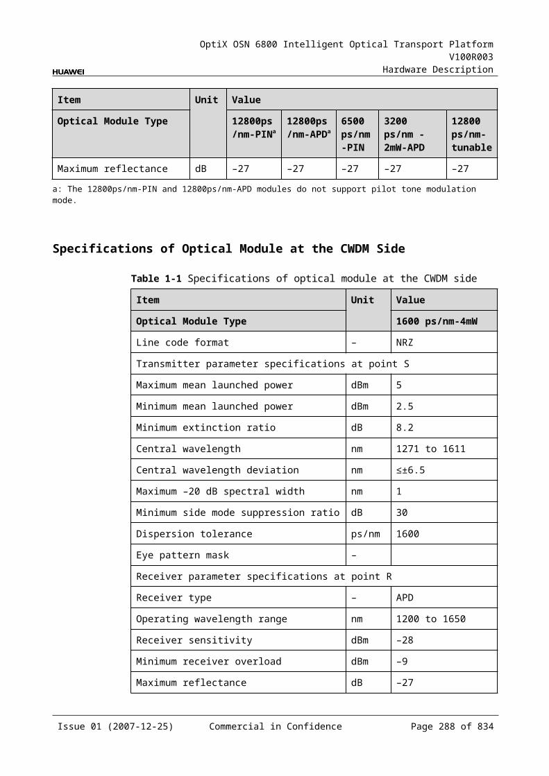
OptiX OSN 6800 Intelligent Optical Transport Platform V100R003
Hardware Description
Function and Feature
Description
ESC function Supports the ESC function, transmitting the supervisory signal within the service signal.
FEC encoding Adopts FEC encoding compliant with the ITU-T G.975.
Alarms and performance events monitoring
Provides the monitoring of the BIP8 bit error count so as to help to locate the failures of the line.
Supports the monitoring of the alarms and performance events of the OTN.
ALS function Provides the ALS function. With the ALS function enabled, the corresponding optical output laser is automatically shut down if no signals are received.
Protection scheme Supports the ODUk SNCP. Supports the client-side 1+1 protection.
eSFP Supports the enhanced small form-factor pluggable optical module on the client side.
Loopback WDM side Not supported
Client side Inloop Supported
Outloop Supported
6.6.4 Working Principle and Signal FlowThe TQS consists of the client-side optical module, cross-connect and service processing module, and control and communication module.
Figure 6-18 shows the functional modules and signal flow of the TQS.
Figure 6-1 Functional modules and signal flow of the TQS
ODU1
Control and communication module
SCC
Backplane
Cross-connect andservice processing
module
Client-side
opticalmodule
4
4
Client side
STM-16/OC-48/OTU1
STM-16/OC-48/OTU1
RX1
TX1RX4
TX4
Issue 01 (2007-12-25) Commercial in Confidence Page 287 of 664
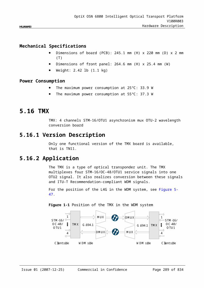
OptiX OSN 6800 Intelligent Optical Transport Platform V100R003
Hardware Description
In Transmit DirectionThe client-side optical module receives four STM-16/OC-48/OTU1 optical signals and converts them into electrical signals before sending them to the cross-connect and service grooming module.
The cross-connect and service processing module monitors the performance of the client-side services and maps the four signals into four ODU1 signals. Then, the signals are sent to the cross-connection board or a board in the paired slot to realize the grooming of electrical signals.
In Receive DirectionThe cross-connect and service processing module receives the signals sent from the cross-connection board or a board in the paired slot through the backplane, extracts and processes overhead bytes, and monitors the performance of signals. Then, the signal is converted to signals that the client-side needed and sent to the client-side optical module.
The client-side optical module converts the four electrical signals into optical signals and sends them to the client-side equipment.
Cross-Connect and Service Processing Module This module realizes the grooming of electrical signals between the boards in
paired slots or with the cross-connect board through the backplane. This module realizes the cross-connection of four ODU1 signals. This module extracts and processes overhead bytes. This module monitors the performance of services. This module implements the encapsulation of OTN signals.
Control and Communication ModuleThe control and communication module realizes the control, monitoring and communications management of each functional module of the board.
The control and communication module collects the information, such as the alarms and performance events, working status, and voltage detection, of each functional module of the board and reports to the SCC.
Receiving the commands from the SCC, the control and communication module controls and coordinates the functional modules of the board in working.
6.6.5 Front PanelThere are indicators, interfaces and laser safety label on the TQS front panel.
Appearance of the Front PanelFigure 6-19 shows the TQS front panel.
Issue 01 (2007-12-25) Commercial in Confidence Page 288 of 664
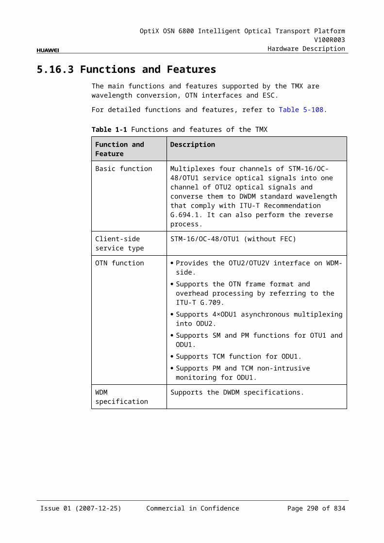
OptiX OSN 6800 Intelligent Optical Transport Platform V100R003
Hardware Description
Figure 6-1 TQS front panel
TQS
TQS
STATACTPROGSRV
CLASS 1LASER
PRODUCT
RX
2TX
3R
X3
TX4
RX
4TX
1R
X1
TX2
IndicatorsThere are four indicators on the front panel.
Board hardware status indicator (STAT) – dual-colored (red, green) Service active status indicator (ACT) – green Board software status indicator (PROG) – dual-colored (red, green) Service alarm indicator (SRV) – triple-colored (red, green, yellow)
InterfacesThere are eight optical interfaces on the TQS front panel. Table 6-29 lists the type and function of each interface.
Issue 01 (2007-12-25) Commercial in Confidence Page 289 of 664
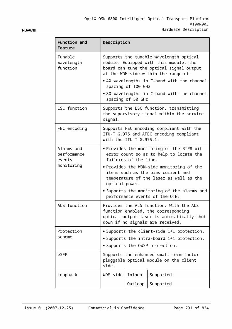
OptiX OSN 6800 Intelligent Optical Transport Platform V100R003
Hardware Description
Table 6-1 Types and functions of the TQS interfaces
Interface
Type
Function
TX1–TX4 LC Transmits the service signal to the client-side equipment.
RX1–RX4 LC Receives the service signal from the client-side equipment.
Laser Safety LevelThe laser safety level of the optical interface is CLASS 1.
The maximum output optical power of each optical interface is lower than 10 dBm (10 mW).
6.6.6 Valid SlotsThe TQS occupies one slot. The valid slots for the TQS are IU1–IU8 and IU11–IU16.
6.6.7 NM Configuration ReferenceNM configuration reference includes the reference information needed during the configuration of boards through the T2000.
Display of Optical InterfacesThe serial numbers of the optical interfaces on the panel of the board displayed on the NM are listed in Table 6-30.
Table 6-1 Serial numbers of the interfaces of the TQS displayed on the NM
Interface on the Panel Interface on the NM
TX1/RX1 3
TX2/RX2 4
TX3/RX3 5
TX4/RX4 6
NOTEThe number of an interface displayed on the T2000 in fact indicates a pair of physical optical interfaces, of which one is used to transmit signals and the other is used to receive signals.
Issue 01 (2007-12-25) Commercial in Confidence Page 290 of 664
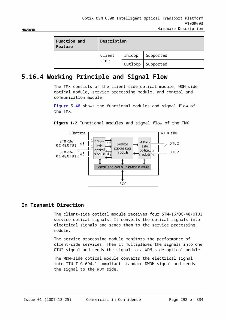
OptiX OSN 6800 Intelligent Optical Transport Platform V100R003
Hardware Description
Configuration ParametersPath Use Status
Optical Interface Loopback
Service Type
Laser Status
Automatic Laser Shutdown
FEC Working State
6.6.8 Specifications of the TQSSpecifications include optical specifications, dimensions, weight, and power consumption.
Specifications of SDH Optical Module at the Client SideNOTEThis module is used to access STM-16 and OTU1 signals. The specificaions listed above completely apply to STM-16 signals. The actual values may be slightly different from these specifications when the accessed signals are OTU1 signals.
Table 6-1 Specifications of SDH optical module at the client side
Item Unit
Value
Optical Module Type I-16 S-16.1 L-16.1 L-16.2
Line code format – NRZ NRZ NRZ NRZ
Optical source type – MLM SLM SLM SLM
Target distance km 2 15 40 80
Transmitter parameter specifications at point S
Operating wavelength range
nm 1266 to 1360
1260 to 1360
1280 to 1335
1500 to 1580
Maximum mean launched power
dBm –3 0 3 3
Minimum mean launched power
dBm –10 –5 –2 –2
Minimum extinction ratio dB 8.2 8.2 8.2 8.2
Maximum –20 dB spectral width
nm NA 1 1 1
Minimum side mode suppression ratio
dB NA 30 30 30
Issue 01 (2007-12-25) Commercial in Confidence Page 291 of 664
OptiX OSN 6800 Intelligent Optical Transport Platform V100R003
Hardware Description
Item Unit
Value
Optical Module Type I-16 S-16.1 L-16.1 L-16.2
Eye pattern mask – G.957-compliant
Receiver parameter specifications at point R
Receiver type – PIN PIN APD APD
Operating wavelength range
nm 1266 to 1360
1260 to 1360
1280 to 1335
1500 to 1580
Receiver sensitivity dBm –18 –18 –27 –28
Minimum receiver overload
dBm –3 0 –9 –9
Maximum reflectance dB –27 –27 –27 –27
Specifications of eSFP CWDM Optical Module at the Client SideNOTE2.67 Gbit/s Multi-rate module (eSFP CWDM) can be used to access STM16, OC-48, OTU1 signals. The specifications listed above completely apply to OTU1 signals. The actual values may be slightly different from these specifications when the accessed signals are STM16, OC-48.
Table 6-1 Specifications of eSFP CWDM optical module at the client side
Item Unit
Value
Optical Module Type 2.67Gbit/s Multi-rate (eSFP CWDM)
Line code format – NRZ
Target distance km 80
Transmitter parameter specifications at point S
Operating wavelength range nm 1471 to 1611
Maximum mean launched power dBm 5
Minimum mean launched power dBm 0
Minimum extinction ratio dB 8.2
Central wavelength deviation nm ±6.5
Maximum –20 dB spectral width nm 1.0
Minimum side mode suppression ratio
dB 30
Eye pattern mask – G.957-compliant
Issue 01 (2007-12-25) Commercial in Confidence Page 292 of 664
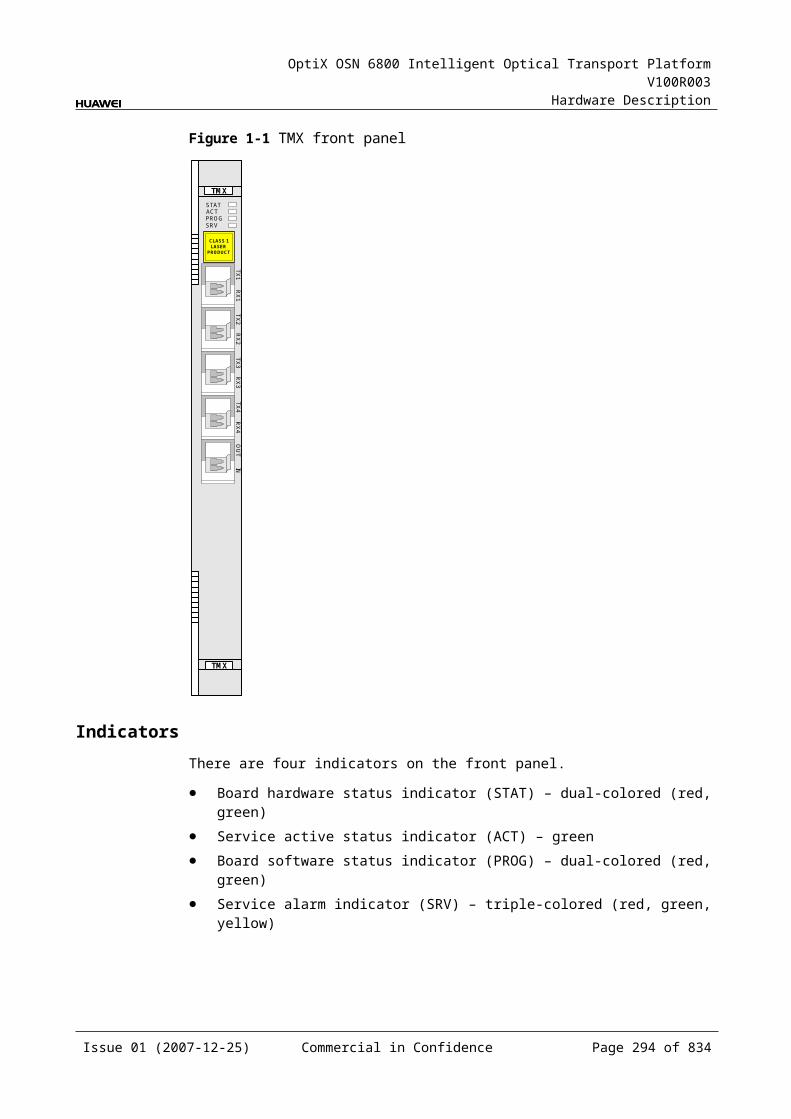
OptiX OSN 6800 Intelligent Optical Transport Platform V100R003
Hardware Description
Item Unit
Value
Optical Module Type 2.67Gbit/s Multi-rate (eSFP CWDM)
Receiver parameter specifications at point R
Receiver type – APD
Operating wavelength range nm 1270 to 1620
Receiver sensitivity dBm –28
Minimum receiver overload dBm –9
Maximum reflectance dB –27
Table 6-2 Specifications of eSFP DWDM optical module at the client side
Item Unit
Value
Optical Module Type
2.67Gbit/s Multi-rate (eSFP DWDM)
Line code format – NRZ
Target distance km 120
Transmitter parameter specifications at point S
Operating frequency range
THz 192.1 to 196.0
Maximum mean launched power
dBm 3
Minimum mean launched power
dBm 0
Minimum extinction ratio
dB 8.5
Central frequency deviation
GHz ±12.5
Maximum –20 dB spectral width
nm NA
Minimum side mode suppression ratio
dB 30
Eye pattern mask – 5% margin are required for the eye pattern of STM-16 services and equivalent OTU1 services.
Receiver parameter specifications at point R
Receiver type – APD
Issue 01 (2007-12-25) Commercial in Confidence Page 293 of 664
OptiX OSN 6800 Intelligent Optical Transport Platform V100R003
Hardware Description
Item Unit
Value
Optical Module Type
2.67Gbit/s Multi-rate (eSFP DWDM)
Receiver sensitivity dBm –28
Minimum receiver overload
dBm –9
Maximum reflectance dB –27
Mechanical Specifications Dimensions of board (PCB): 245.1 mm (H) x 220 mm (D) x 2 mm (T) Dimensions of front panel: 264.6 mm (H) x 25.4 mm (W) Weight: 2.64 lb (1.2 kg)
Power Consumption The maximum power consumption at 25: 43.0 W The maximum power consumption at 55: 47.3 W
Issue 01 (2007-12-25) Commercial in Confidence Page 294 of 664
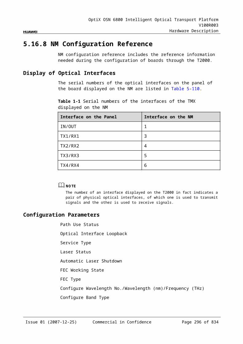
OptiX OSN 6800 Intelligent Optical Transport Platform V100R003
Hardware Description
7 Cross-connect Unit
7.1 XCSXCS: cross-connect and clock unit
7.1.1 Version DescriptionOnly one functional version of the XCS board is available, that is TN11.
7.1.2 ApplicationThe XCS is a type of cross-connect unit. The XCS realizes the cross-connection of services.
For the position of the XCS in the WDM system, see Figure 7-1.
Figure 7-1 Position of the XCS in the WDM system
OTU
OA
OA
OTU
M40
D40
OTU
OTU
OA
OA
D40
M40
OTU
OTU
OTU
OTU
1
1
40
1
40
1
40
XCS
XCS
XCS40
XCS
7.1.3 Functions and FeaturesThe main function and feature of the XCS is the cross-connection at the electrical layer.
For detailed functions and features, refer to Table 7-1.
Issue 01 (2007-12-25) Commercial in Confidence Page 295 of 664
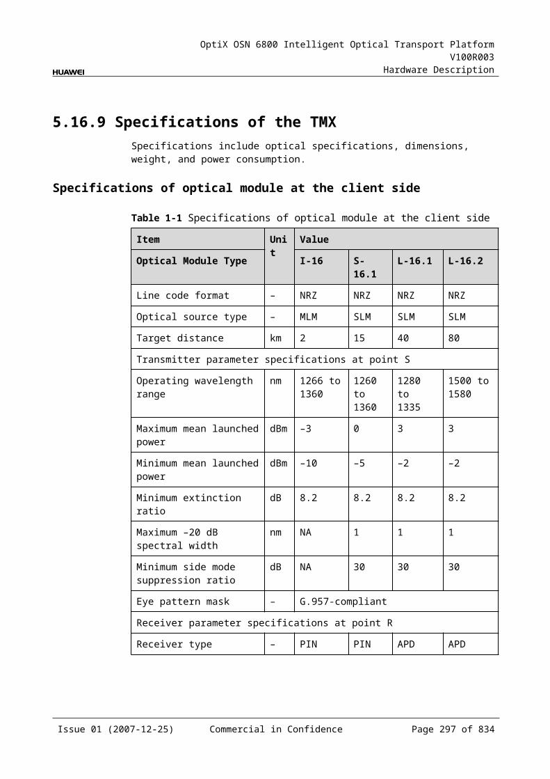
OptiX OSN 6800 Intelligent Optical Transport Platform V100R003
Hardware Description
Table 7-1 Functions and features of the XCS
Function and Feature
Description
Basic function Grooms services.
Cross-connect function
Supports the integrated grooming of ODU1 signals or GE services.Supports a maximum cross-connect and grooming capacity of 320 Gbit/s for ODU1 signals. Supports a maximum cross-connect and grooming capacity of 160 Gbit/s for GE services.
Active/standby backup
Provides the 1+1 hot backup.
Switching mode Supports the manual switching and auto switching.Supports only the non-revertive switching.
7.1.4 Working Principle and Signal FlowThe XCS consists of the cross-connect module and the control and communication module.
Figure 7-2 shows the functional modules and signal flow of the XCS.
Figure 7-1 Functional modules and signal flow of the XCS
Cross-connectmodule
SCC
Backplane
Control and communicationmodule
Cross-Connect ModuleThe cross-connect module receives the data of each service board from the backplane. It performs the grooming of ODU1 signals or GE granules at the electrical layer, then sends the signals to each service board and implements the cross-connection.
Issue 01 (2007-12-25) Commercial in Confidence Page 296 of 664
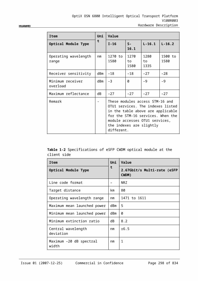
OptiX OSN 6800 Intelligent Optical Transport Platform V100R003
Hardware Description
Control and Communication ModuleThe control and communication module realizes the control, monitoring and communications management of each functional module of the board.
The control and communication module collects the information, such as the alarms and performance events, working status, and voltage detection, of each functional module of the board and reports to the SCC.
Receiving the commands from the SCC, the control and communication module controls and coordinates the functional modules of the board in working.
7.1.5 Front PanelThere are indicators on the XCS front panel.
Appearance of the Front PanelFigure 7-3 shows the XCS front panel.
Figure 7-1 XCS front panel
XCS
XCS
STATACTPROGSRV
Issue 01 (2007-12-25) Commercial in Confidence Page 297 of 664
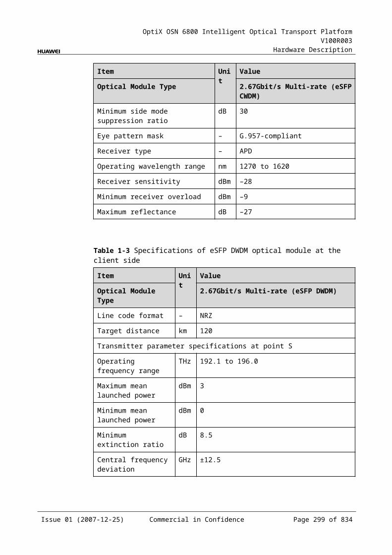
OptiX OSN 6800 Intelligent Optical Transport Platform V100R003
Hardware Description
IndicatorsThere are four indicators on the front panel.
Board hardware status indicator (STAT) – dual-colored (red, green) Service active status indicator (ACT) – green Board software status indicator (PROG) – dual-colored (red, green) Service alarm indicator (SRV) – triple-colored (red, green, yellow)
InterfacesThe XCS does not provide external interfaces.
7.1.6 Valid SlotsThe XCS occupies one slot. The valid slots for the XCS are IU9 and IU10.
7.1.7 Specifications of the XCSSpecifications include optical specifications, dimensions, weight, and power consumption.
Mechanical Specifications Dimensions of board (PCB): 245.1 mm (H) x 220 mm (D) x 2 mm (T) Dimensions of front panel: 264.6 mm (H) x 25.4 mm (W) Weight: 2.20 lb (1.0 kg)
Power Consumption The maximum power consumption at 25:20.0 W The maximum power consumption at 55:22.0 W
Issue 01 (2007-12-25) Commercial in Confidence Page 298 of 664
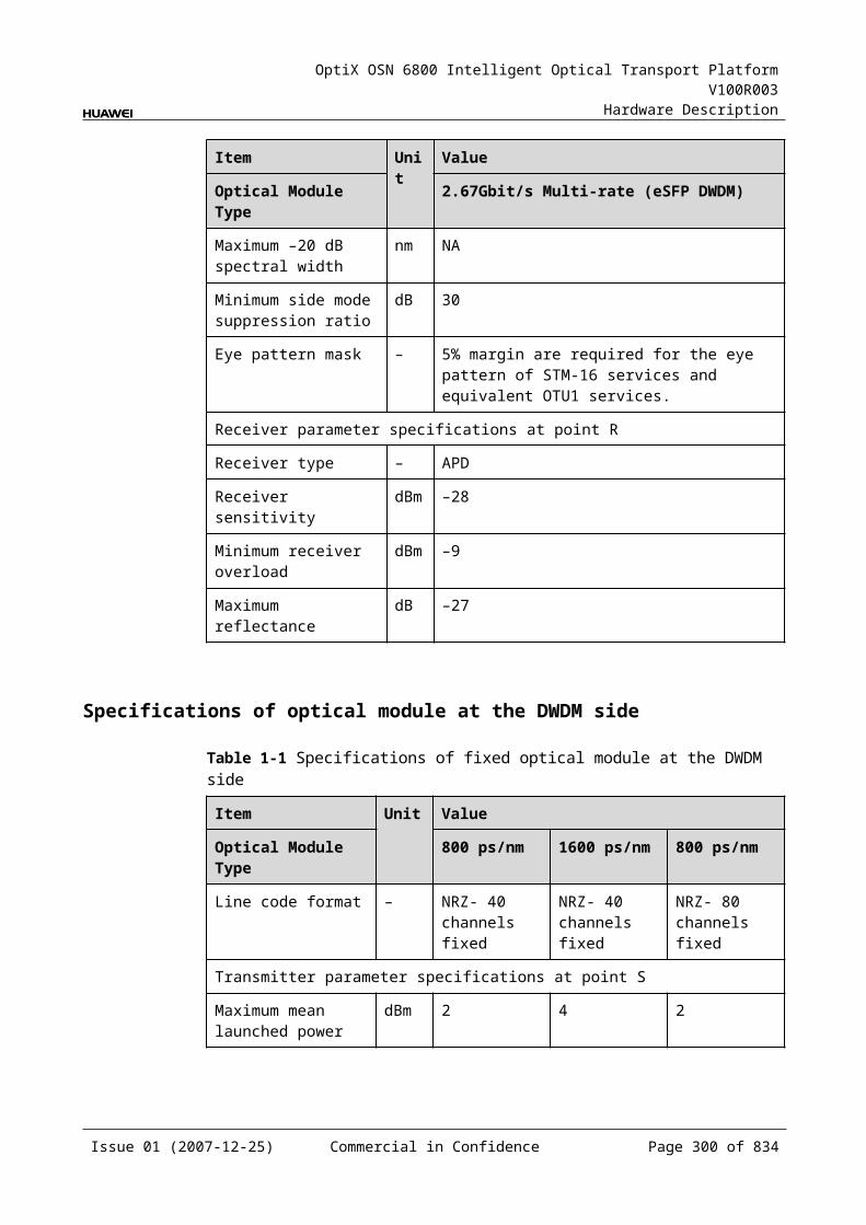
OptiX OSN 6800 Intelligent Optical Transport Platform V100R003
Hardware Description
8 Optical Multiplexer and Demultiplexer Unit
8.1 D40D40: 40-channel demultiplexing unit
8.1.1 Version DescriptionOnly one functional version of the D40 board is available, that is TN11.
8.1.2 ApplicationThe D40 is a type of optical demultiplexer unit. The D40 realizes the demultiplexing of one optical signal into a maximum of 40 ITU-T Recommendation-compliant WDM signals.
For the position of the D40 in the WDM system, see Figure 8-1.
Figure 8-1 Position of the D40 in the WDM system
OTUOA
OA
OTUM40
D40OTU
OTU
OA
OA
D40
M40
OTU
OTU
OTU
OTU
1
40
1
40
1
40
1
40
8.1.3 Functions and FeaturesThe main functions and features supported by the D40 are demultiplexing, online optical performance monitoring, alarms and performance events monitoring.
For detailed functions and features, refer to Table 8-1
Issue 01 (2007-12-25) Commercial in Confidence Page 299 of 664
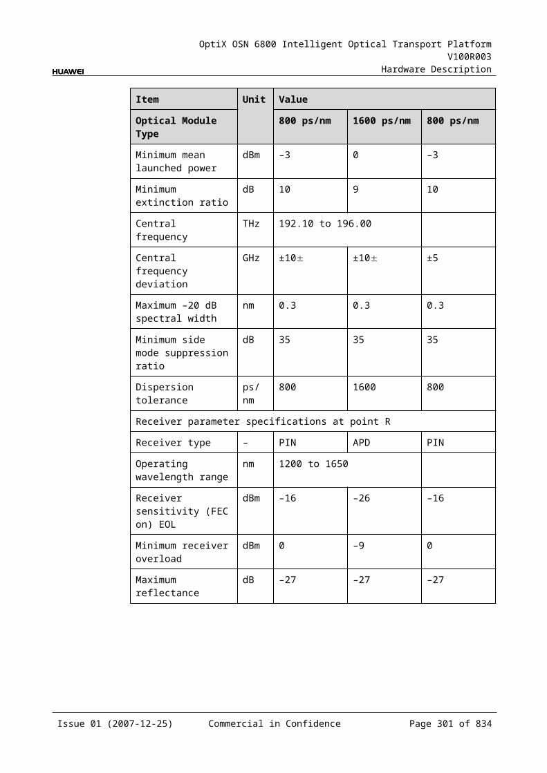
OptiX OSN 6800 Intelligent Optical Transport Platform V100R003
Hardware Description
Table 8-1 Functions and features of the D40
Function and Feature
Description
Basic function Demultiplexes main path signal to a maximum of 40 channels of service. Demultiplexes one main path into 40 C_EVEN channels. Demultiplexes one main path into 40 C_ODD channels.
Online optical performance monitoring
Provides the online monitoring interface. A small amount of optical signal can be output to the spectrum analyzer or spectrum analyzer unit through the interface so as to monitor the spectrum and optical performance of the multi-channel signal without interrupting the services.
Alarms and performance events monitoring
Provides the function of optical power detection and the function to report the alarms and performance events of the board.
8.1.4 Working Principle and Signal FlowThe D40 consists of the optical splitter, demultiplexing module and control and communication module.
Figure 8-2 shows the functional modules and signal flow of the D40.
Figure 8-1 Functional modules and signal flow of the D40
D02D01
D40
Control and communicationmodule
SCC
Demultiplexingmodule
Opticalsplitter
MONIN
Optical SplitterThe optical splitter divides a signal into two signals at different power. The primary signal is sent to the demultiplxing module. The other signal is sent to the MON interface for optical spectrum detection and monitoring.
The optical power of the MON interface is 10/90 of the optical power of the OUT interface, that means the optical power of the MON interface is lower than that of the OUT interface by 10 dB.
Issue 01 (2007-12-25) Commercial in Confidence Page 300 of 664
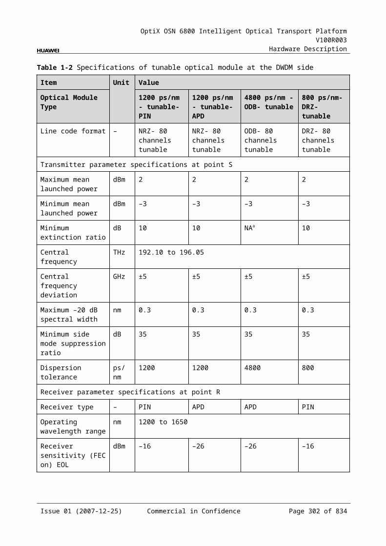
OptiX OSN 6800 Intelligent Optical Transport Platform V100R003
Hardware Description
Demultiplexing ModuleThe signal is demultiplexed into 40 wavelengths by the demultiplexing module and then sent to the OTU.
Control and Communication ModuleThe control and communication module realizes the control, monitoring and communications management of each functional module of the board.
The control and communication module collects the information, such as the alarms and performance events, working status, and voltage detection, of each functional module of the board and reports to the SCC.
Receiving the commands from the SCC, the control and communication module controls and coordinates the functional modules of the board in working.
8.1.5 Front PanelThere are indicators, interfaces and laser safety label on the D40 front panel.
Appearance of the Front PanelFigure 8-3 shows the D40 front panel.
Issue 01 (2007-12-25) Commercial in Confidence Page 301 of 664
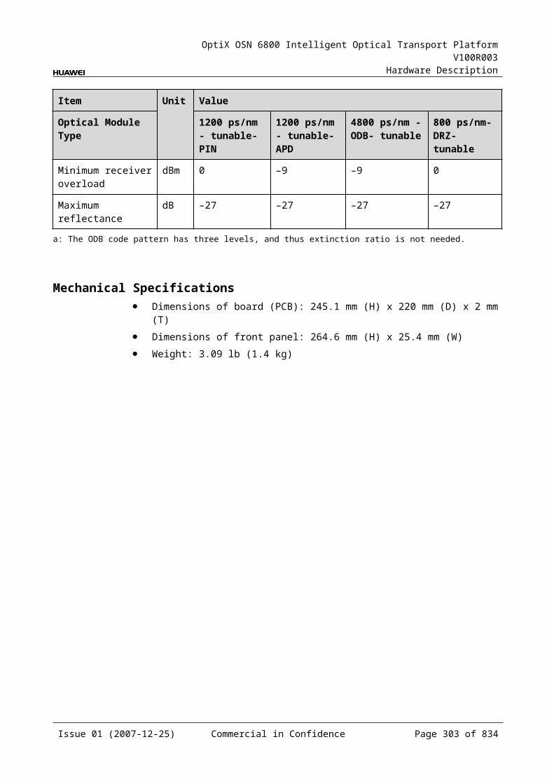
OptiX OSN 6800 Intelligent Optical Transport Platform V100R003
Hardware Description
Figure 8-1 D40 front panel
D40
D40
STATACTPROGSRV
CLASS 1LASER
PRODUCT
D01D02D03D04D05D06D07D08D09D10
D11D12D13D14D15D16D17D18D19D20
D21D22D23D24D25D26D27D28D29D30
D31D32D33D34D35D36D37D38D39D40
196.00195.90195.80195.70195.60195.50195.40195.30195.20195.10
195.00194.90194.80194.70194.60194.50
194.20194.10
194.40194.30
194.00193.90193.80193.70193.60193.50
193.20193.10
193.40193.30
193.00192.90192.80192.70192.60192.50
192.20192.10
192.40192.30
D15
D16
D17
D18
D19
D20
D21
D22
D23
D24
D13
D25
D26
D14
D01
D02
D03
D04
D05
D06
D07
D08
D09
D10
MO
ND
11D
12IN
D29
D30
D31
D32
D33
D34
D35
D36
D37
D38
D28
D39
D40
D27
NOTEThere is a table indicating the mapping relationship between interfaces and frequencies pasted onto the front panel.
IndicatorsThere are four indicators on the front panel.
Board hardware status indicator (STAT) – dual-colored (red, green) Service active status indicator (ACT) – green Board software status indicator (PROG) – dual-colored (red, green) Service alarm indicator (SRV) – triple-colored (red, green, yellow)
Issue 01 (2007-12-25) Commercial in Confidence Page 302 of 664
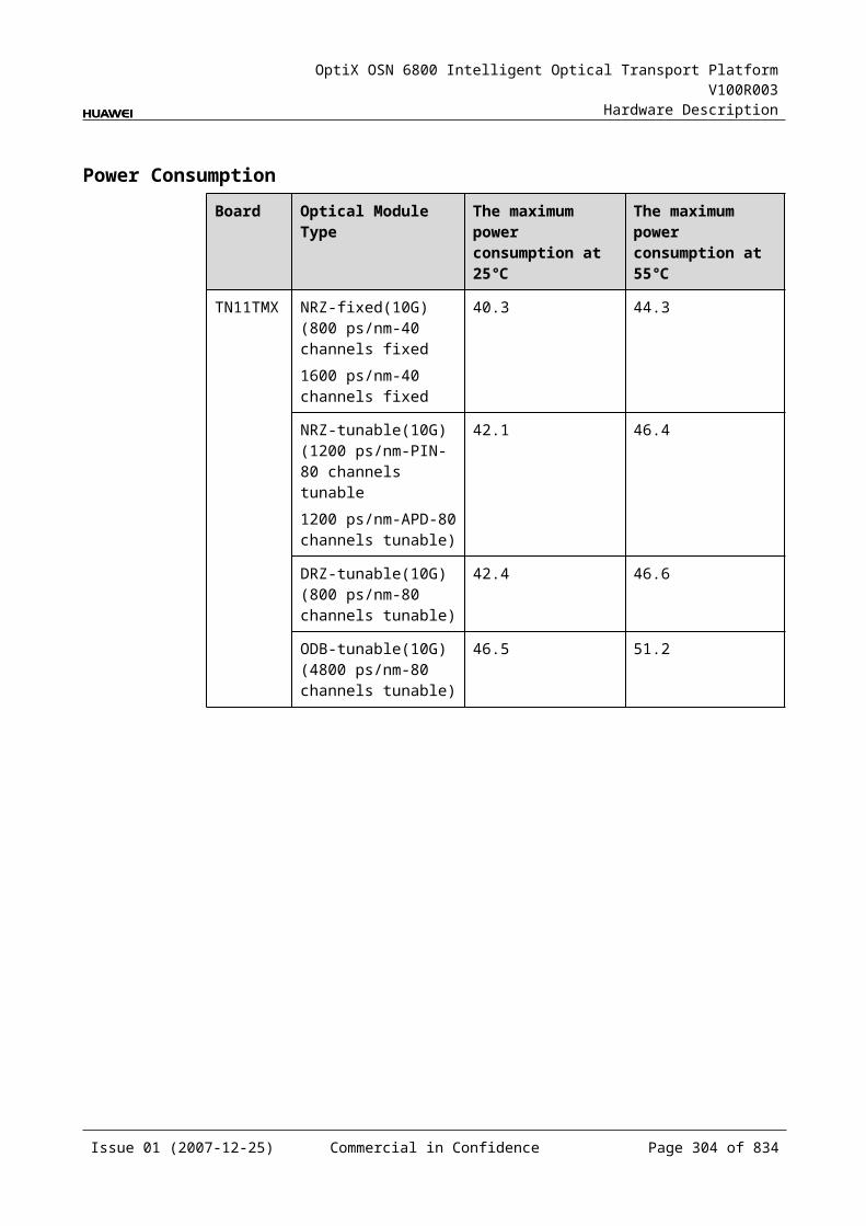
OptiX OSN 6800 Intelligent Optical Transport Platform V100R003
Hardware Description
InterfacesThere are 42 optical interfaces on the D40 front panel. Table 8-2 lists the type and function of each interface.
Table 8-1 Types and functions of the D40 interfaces
Interface
Type
Function
IN LC Connected to an optical amplifier or ITL, receives the signals to be demultiplexed.
D01–D40 LC Transmit demultiplexed signals to the connected "IN" interface of the OTUs.
MON LC Connected to the input interface of the MCA4 or MCA8, accomplishes online monitoring of optical spectrum.The MON port is a 10/90 tap of the total composite signal at the IN port (10dB lower than the actual signal power).
There are 40 output interfaces on the D40 front panel. Table 8-3, Table 8-4 show the mapping between the interfaces, frequency and wavelengths of the D40 board.
Table 8-2 Mapping between the optical interfaces, frequencies and wavelengths of the D40 board (even)
Interface
Frequency (THz)
Wavelength (nm)
Interface
Frequency (THz)
Wavelength (nm)
D01 196.00 1529.55 D21 194.00 1545.32
D02 195.90 1530.33 D22 193.90 1546.12
D03 195.80 1531.12 D23 193.80 1546.92
D04 195.70 1531.90 D24 193.70 1547.72
D05 195.60 1532.68 D25 193.60 1548.51
D06 195.50 1533.47 D26 193.50 1549.32
D07 195.40 1534.25 D27 193.40 1550.12
D08 195.30 1535.04 D28 193.30 1550.92
D09 195.20 1535.82 D29 193.20 1551.72
D10 195.10 1536.61 D30 193.10 1552.52
D11 195.00 1537.40 D31 193.00 1553.33
D12 194.90 1538.19 D32 192.90 1554.13
D13 194.80 1538.98 D33 192.80 1554.94
D14 194.70 1539.77 D34 192.70 1555.75
Issue 01 (2007-12-25) Commercial in Confidence Page 303 of 664
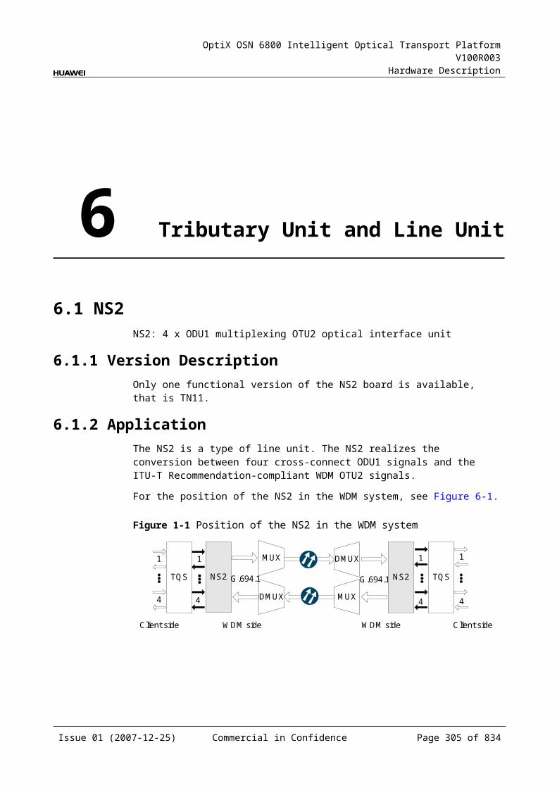
OptiX OSN 6800 Intelligent Optical Transport Platform V100R003
Hardware Description
Interface
Frequency (THz)
Wavelength (nm)
Interface
Frequency (THz)
Wavelength (nm)
D15 194.60 1540.56 D35 192.60 1556.55
D16 194.50 1541.35 D36 192.50 1557.36
D17 194.40 1542.14 D37 192.40 1558.17
D18 194.30 1542.94 D38 192.30 1558.98
D19 194.20 1543.73 D39 192.20 1559.79
D20 194.10 1544.53 D40 192.10 1560.61
Table 8-3 Mapping between the optical interfaces, frequencies and wavelengths of the D40 board (odd)
Interface
Frequency (THz)
Wavelength (nm)
Interface
Frequency (THz)
Wavelength (nm)
D01 196.05 1529.16 D21 194.05 1544.92
D02 195.95 1529.94 D22 193.95 1545.72
D03 195.85 1530.72 D23 193.85 1546.52
D04 195.75 1531.51 D24 193.75 1547.32
D05 195.65 1532.29 D25 193.65 1548.11
D06 195.55 1533.07 D26 193.55 1548.91
D07 195.45 1533.86 D27 193.45 1549.72
D08 195.35 1534.64 D28 193.35 1550.52
D09 195.25 1535.43 D29 193.25 1551.32
D10 195.15 1536.22 D30 193.15 1552.12
D11 195.05 1537.00 D31 193.05 1552.93
D12 194.95 1537.79 D32 192.95 1553.73
D13 194.85 1538.58 D33 192.85 1554.54
D14 194.75 1539.37 D34 192.75 1555.34
D15 194.65 1540.16 D35 192.65 1556.15
D16 194.55 1540.95 D36 192.55 1556.96
D17 194.45 1541.75 D37 192.45 1557.77
D18 194.35 1542.54 D38 192.35 1558.58
D19 194.25 1543.33 D39 192.25 1559.39
Issue 01 (2007-12-25) Commercial in Confidence Page 304 of 664
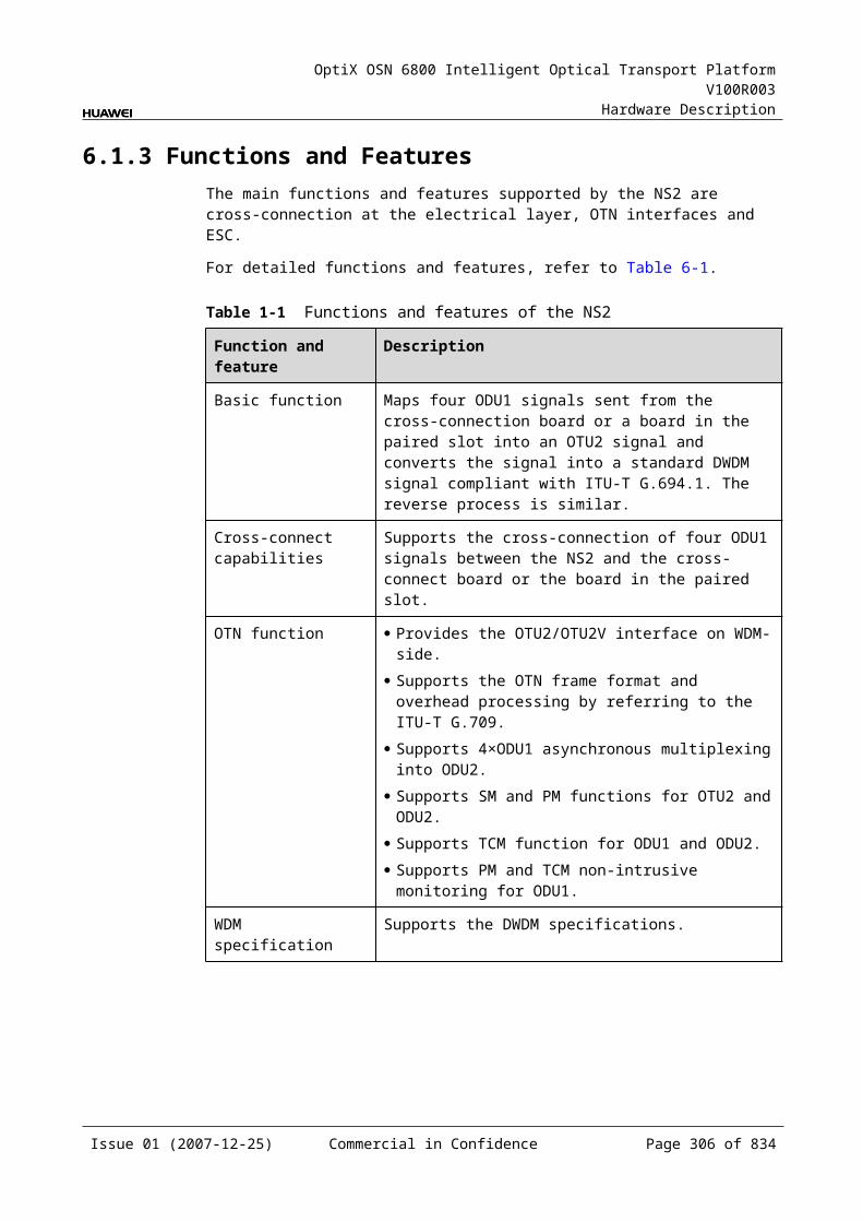
OptiX OSN 6800 Intelligent Optical Transport Platform V100R003
Hardware Description
Interface
Frequency (THz)
Wavelength (nm)
Interface
Frequency (THz)
Wavelength (nm)
D20 194.15 1544.13 D40 192.15 1560.20
Laser Safety LevelThe laser safety level of the optical interface is CLASS 1.
The maximum output optical power of each optical interface is lower than 10 dBm (10 mW).
8.1.6 Valid SlotsThe D40 occupies three slots. The valid slots for the D40 are IU1–IU15 in the subrack.
The back connector of the board is mounted to the backplane along the left slot in the subrack, so the slot number of the D40 board displayed on the NM is the number of the left one of the three occupied slots.
For example, if the D40 occupies slots IU1, IU2 and IU3, the slot number of the D40 displayed on the NM is IU1.
8.1.7 Characteristic Code for the D40The characteristic code for the D40 consists of two characters. One indicates the band. The other indicates whether the wavelengths that bear the optical signals processed by the board are odd or even wavelengths.
The detailed information of the characteristic code is given in Table 8-5.
Table 8-1 Characteristic code for the D40
Code Meaning Description
The first character
Band Indicates the band of the optical signals processed by the board. The value C represents C band; the value L represents L band.
The second character
Odd/Even wavelengths
Indicates whether the wavelengths that bear signals are odd or even wavelengths. The value E represents even wavelengths; the value O represents odd wavelengths.
For example, the characteristic code for the TN11D40 is CE, indicating C band and even wavelengths.
NOTEThe OptiX OSN 6800 products now support only even wavelengths in C band.
Issue 01 (2007-12-25) Commercial in Confidence Page 305 of 664
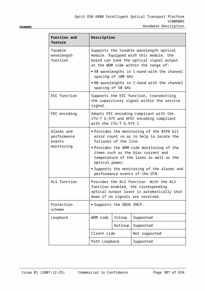
OptiX OSN 6800 Intelligent Optical Transport Platform V100R003
Hardware Description
8.1.8 NM Configuration ReferenceNM configuration reference includes the reference information needed during the configuration of boards through the T2000.
Display of Optical InterfacesThe serial numbers of the optical interfaces on the panel of the board displayed on the NM are listed in Table 8-6.
Table 8-1 Serial numbers of the interfaces of the D40 displayed on the NM
Interface on the Panel Interface on the NM
IN 1
D01-D40 2-41
MON 42
Configuration ParametersThreshold of Input Power Loss (dBm)
8.1.9 Specifications of the D40Specifications include optical specifications, dimensions, weight and power consumption.
Optical SpecificationsTable 8-7 lists the optical specifications of the D40.
Table 8-1 Optical specifications of the D40
Item Unit Value
Adjacent channel spacing GHz 100
Insertion loss dB ≤6.5
Optical return loss dB >40
Operating wavelength range nm 1529–1561
Adjacent channel isolation dB >25
Non-adjacent channel isolation dB >30
Polarization dependent loss dB ≤0.5
Temperature characteristics nm/ <0.002
Issue 01 (2007-12-25) Commercial in Confidence Page 306 of 664
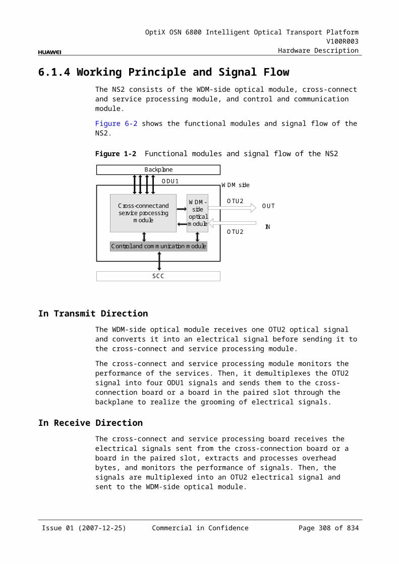
OptiX OSN 6800 Intelligent Optical Transport Platform V100R003
Hardware Description
Item Unit Value
Maximum channel insertion loss difference dB ≤3
-0.5 dB bandwidth nm >0.2
-1 dB bandwidth nm >0.4
-20 dB bandwidth nm <1.4
Mechanical Specifications Dimensions of board (PCB): 245.1 mm (H) x 220 mm (D) x 2 mm (T) Dimensions of front panel: 264.6 mm (H) x 76.2 mm (W) Weight: 4.84 lb (2.2 kg)
Power Consumption The maximum power consumption at 25: 20.0 W The maximum power consumption at 55: 22.0 W
8.2 D40VD40V: 40-channel demultiplexing unit with VOA
8.2.1 Version DescriptionOnly one functional version of the D40V board is available, that is TN11.
8.2.2 ApplicationThe D40V is a type of optical demultiplexer unit. The D40V realizes the demultiplexing of one signal into a maximum of 40 ITU-T Recommendation-compliant WDM signals and adjusts the output optical power of each channel.
For the position of the D40V in the WDM system, see Figure 8-4.
Figure 8-1 Position of the D40V in the WDM system
OTUOA
OA
OTUM40
D40VOTU
OTU
OA
OA
D40V
M40
OTU
OTU
OTU
OTU
1
40
1
40
1
40
1
40
Issue 01 (2007-12-25) Commercial in Confidence Page 307 of 664
OptiX OSN 6800 Intelligent Optical Transport Platform V100R003
Hardware Description
8.2.3 Functions and FeaturesThe main functions and features supported by the D40V are demultiplexing, online optical performance monitoring, alarms and performance events monitoring and optical power adjustment.
For detailed functions and features, refer to Table 8-8.
Table 8-1 Functions and features of the D40V
Function and Feature
Description
Basic function Demultiplexes one signal into a maximum of 40 signals and adjusts the input optical power of each channel. Demultiplexes one main path into 40 C_EVEN channels. Demultiplexes one main path into 40 C_ODD channels.
Online optical performance monitoring
Provides the online monitoring interface. A small amount of optical signal can be output to the spectrum analyzer or spectrum analyzer unit through the interface so as to monitor the spectrum and optical performance of the multi-channel signal without interrupting the services.
Alarms and performance events monitoring
Provides the function of optical power detection and the function to report the alarms and performance events of the board.
Optical power adjustment
Adjusts the optical power of each signal after demultiplexing.
8.2.4 Working Principle and Signal FlowThe D40V consists of the optical splitter, demultiplexing module, VOA module and the control and communication module.
Figure 8-5 shows the functional modules and signal flow of the D40V.
Issue 01 (2007-12-25) Commercial in Confidence Page 308 of 664

OptiX OSN 6800 Intelligent Optical Transport Platform V100R003
Hardware Description
Figure 8-1 Functional modules and signal flow of the D40V
Control and communicationmodule
SCC
Opticalsplitter
MONIN
Demultiplexingmodule
VOA
VOA
VOA
D01
D02
D40
Optical SplitterThe optical splitter divides one input signal into two signals at different power. The main signal is sent to the demultiplexing module. The other signal is sent to the MON interface for the detection and monitoring of optical spectrum.
The optical power of the MON interface is 10/90 of the optical power of the OUT interface, that means the optical power of the MON interface is lower than that of the OUT interface by 10 dB.
Demultiplexing ModuleThe demultiplexing module receives the signal sent from the optical splitter and demultiplexes it into 40 signals, then sends them to the VOA module.
VOA ModuleThe D40V has 40 VOA modules. Each module adjusts the power for one of the 40 channels and sends the adjusted optical signal to the OTU.
Control and Communication ModuleThe control and communication module realizes the control, monitoring and communications management of each functional module of the board.
The control and communication module collects the information, such as the alarms and performance events, working status, and voltage detection, of each functional module of the board and reports to the SCC.
Receiving the commands from the SCC, the control and communication module controls and coordinates the functional modules of the board in working.
8.2.5 Front PanelThere are indicators, interfaces and laser safety label on the D40V front panel.
Issue 01 (2007-12-25) Commercial in Confidence Page 309 of 664
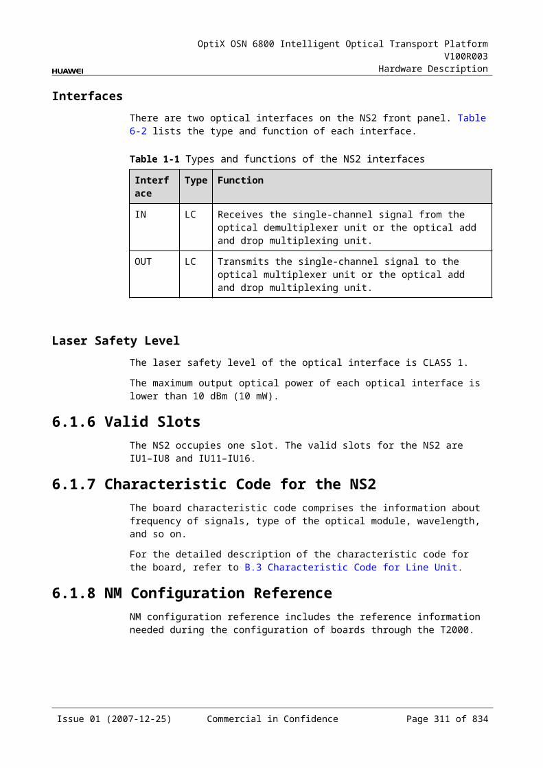
OptiX OSN 6800 Intelligent Optical Transport Platform V100R003
Hardware Description
Appearance of the Front PanelFigure 8-6 shows the D40V front panel.
Figure 8-1 D40V front panel
D40V
D40V
STATACTPROGSRV
CLASS 1LASER
PRODUCT
D01D02D03D04D05D06D07D08D09D10
D11D12D13D14D15D16D17D18D19D20
D21D22D23D24D25D26D27D28D29D30
D31D32D33D34D35D36D37D38D39D40
196.00195.90195.80195.70195.60195.50195.40195.30195.20195.10
195.00194.90194.80194.70194.60194.50
194.20194.10
194.40194.30
194.00193.90193.80193.70193.60193.50
193.20193.10
193.40193.30
193.00192.90192.80192.70192.60192.50
192.20192.10
192.40192.30
D15
D16
D17
D18
D19
D20
D21
D22
D23
D24
D13
D25
D26
D14
D01
D02
D03
D04
D05
D06
D07
D08
D09
D10
MO
ND
11D
12IN
D29
D30
D31
D32
D33
D34
D35
D36
D37
D38
D28
D39
D40
D27
NOTEThere is a table indicating the mapping relationship between interfaces and frequencies pasted onto the front panel.
IndicatorsThere are four indicators on the front panel.
Board hardware status indicator (STAT) – dual-colored (red, green) Service active status indicator (ACT) – green Board software status indicator (PROG) – dual-colored (red, green) Service alarm indicator (SRV) – triple-colored (red, green, yellow)
Issue 01 (2007-12-25) Commercial in Confidence Page 310 of 664

OptiX OSN 6800 Intelligent Optical Transport Platform V100R003
Hardware Description
InterfacesThere are 42 optical interfaces on the D40V front panel. Table 8-9 lists the type and function of each interface.
Table 8-1 Types and functions of the D40V interfaces
Interface
Type
Function
IN LC Connected to an optical amplifier or ITL, receives the signals to be demultiplexed.
D01–D40 LC Connected to the "IN" interface of the OTUs, transmit demultiplexed signals.
MON LC Connected to the input interface of the MCA4 or MCA8, accomplishes online monitoring of optical spectrum.The MON port is a 10/90 tap of the total composite signal at the IN port (10dB lower than the actual signal power).
There are 40 output interfaces on the D40V front panel. Table 8-10, Table 8-11 show the mapping between the optical interfaces, frequencies and wavelengths of the D40V board.
Table 8-2 Mapping between the optical interfaces, frequencies and wavelengths of the D40V board (even)
Interface
Frequency (THz)
Wavelength (nm)
Interface
Frequency (THz)
Wavelength (nm)
D01 196.00 1529.55 D21 194.00 1545.32
D02 195.90 1530.33 D22 193.90 1546.12
D03 195.80 1531.12 D23 193.80 1546.92
D04 195.70 1531.90 D24 193.70 1547.72
D05 195.60 1532.68 D25 193.60 1548.51
D06 195.50 1533.47 D26 193.50 1549.32
D07 195.40 1534.25 D27 193.40 1550.12
D08 195.30 1535.04 D28 193.30 1550.92
D09 195.20 1535.82 D29 193.20 1551.72
D10 195.10 1536.61 D30 193.10 1552.52
D11 195.00 1537.40 D31 193.00 1553.33
D12 194.90 1538.19 D32 192.90 1554.13
D13 194.80 1538.98 D33 192.80 1554.94
Issue 01 (2007-12-25) Commercial in Confidence Page 311 of 664
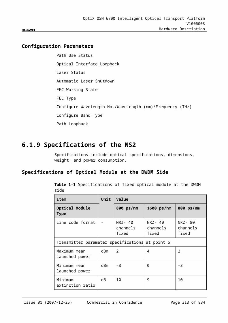
OptiX OSN 6800 Intelligent Optical Transport Platform V100R003
Hardware Description
Interface
Frequency (THz)
Wavelength (nm)
Interface
Frequency (THz)
Wavelength (nm)
D14 194.70 1539.77 D34 192.70 1555.75
D15 194.60 1540.56 D35 192.60 1556.55
D16 194.50 1541.35 D36 192.50 1557.36
D17 194.40 1542.14 D37 192.40 1558.17
D18 194.30 1542.94 D38 192.30 1558.98
D19 194.20 1543.73 D39 192.20 1559.79
D20 194.10 1544.53 D40 192.10 1560.61
Table 8-3 Mapping between the optical interfaces, frequencies and wavelengths of the D40V board (odd)
Interface
Frequency (THz)
Wavelength (nm)
Interface
Frequency (THz)
Wavelength (nm)
D01 196.05 1529.16 D21 194.05 1544.92
D02 195.95 1529.94 D22 193.95 1545.72
D03 195.85 1530.72 D23 193.85 1546.52
D04 195.75 1531.51 D24 193.75 1547.32
D05 195.65 1532.29 D25 193.65 1548.11
D06 195.55 1533.07 D26 193.55 1548.91
D07 195.45 1533.86 D27 193.45 1549.72
D08 195.35 1534.64 D28 193.35 1550.52
D09 195.25 1535.43 D29 193.25 1551.32
D10 195.15 1536.22 D30 193.15 1552.12
D11 195.05 1537.00 D31 193.05 1552.93
D12 194.95 1537.79 D32 192.95 1553.73
D13 194.85 1538.58 D33 192.85 1554.54
D14 194.75 1539.37 D34 192.75 1555.34
D15 194.65 1540.16 D35 192.65 1556.15
D16 194.55 1540.95 D36 192.55 1556.96
D17 194.45 1541.75 D37 192.45 1557.77
D18 194.35 1542.54 D38 192.35 1558.58
Issue 01 (2007-12-25) Commercial in Confidence Page 312 of 664
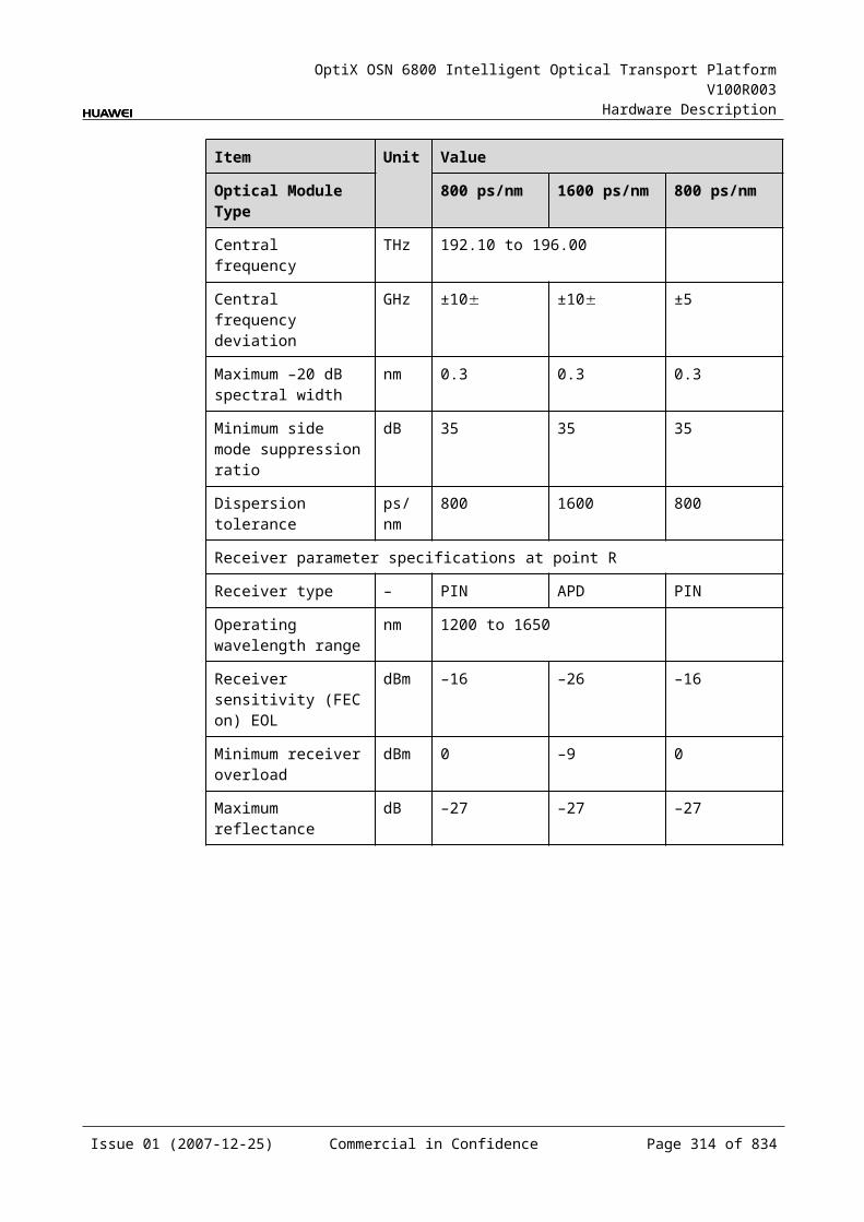
OptiX OSN 6800 Intelligent Optical Transport Platform V100R003
Hardware Description
Interface
Frequency (THz)
Wavelength (nm)
Interface
Frequency (THz)
Wavelength (nm)
D19 194.25 1543.33 D39 192.25 1559.39
D20 194.15 1544.13 D40 192.15 1560.20
Laser Safety LevelThe laser safety level of the optical interface is CLASS 1.
The maximum output optical power of each optical interface is lower than 10 dBm (10 mW).
8.2.6 Valid SlotsThe D40V occupies three slots. The valid slots for the D40V are IU1–IU15 in the subrack.
The back connector of the board is mounted to the backplane along the left slot in the subrack, so the slot number of the D40v board displayed on the NM is the number of the left one of the three occupied slots.
For example, if the D40v occupies slots IU1, IU2 and IU3, the slot number of the D40 displayed on the NM is IU1.
8.2.7 Characteristic Code for the D40VThe characteristic code for the D40V consists of two characters. One indicates the band. The other indicates whether the wavelengths that bear the optical signals processed by the board are odd or even wavelengths.
The detailed information of the characteristic code is given in Table 8-12.
Table 8-1 Characteristic code for the D40V
Code Meaning Description
The first character
Band Indicates the band of the optical signals processed by the board. The value C represents C band; the value L represents L band.
The second character
Odd/Even wavelengths
Indicates whether the wavelengths that bear signals are odd or even wavelengths. The value E represents even wavelengths; the value O represents odd wavelengths.
For example, the characteristic code for the TN11D40V is CE, indicating C band and even wavelengths.
Issue 01 (2007-12-25) Commercial in Confidence Page 313 of 664
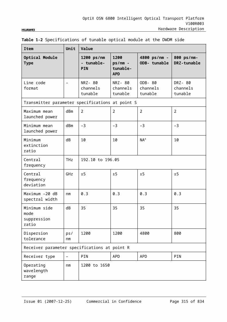
OptiX OSN 6800 Intelligent Optical Transport Platform V100R003
Hardware Description
8.2.8 NM Configuration ReferenceNM configuration reference includes the reference information needed during the configuration of boards through the T2000.
Display of Optical InterfacesThe serial numbers of the optical interfaces on the panel of the board displayed on the NM are listed in Table 8-13.
Table 8-1 Serial numbers of the interfaces of the D40v displayed on the NM
Interface on the Panel Interface on the NM
IN 1
D01-D40 2-41
MON 42
Configuration ParametersOptical Interface Attenuation Ratio (dB)
Threshold of Input Power Loss (dBm)
8.2.9 Specifications of the D40VSpecifications include optical specifications, dimensions, weight, and power consumption.
Optical SpecificationsTable 8-14 lists the optical specifications of the D40V.
Table 8-1 Optical specifications of the D40V
Item Unit Value
Adjacent channel spacing GHz 100
Insertion loss dB ≤8a
Optical return loss dB >40
Operating wavelength range nm 1529–1561
Adjacent channel isolation dB >25
Non-adjacent channel isolation dB >30
Attenuation range dB 0–15
Issue 01 (2007-12-25) Commercial in Confidence Page 314 of 664
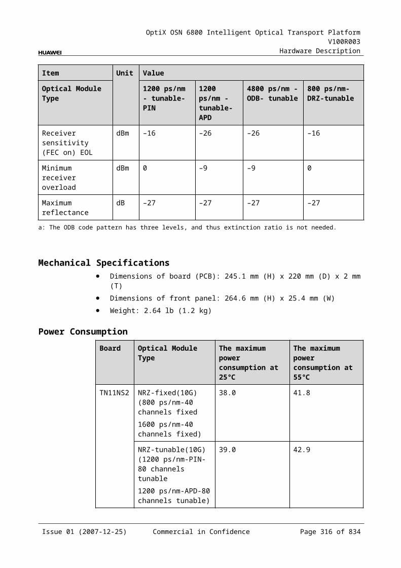
OptiX OSN 6800 Intelligent Optical Transport Platform V100R003
Hardware Description
Item Unit Value
Loss accuracy dB ≤1
Polarization dependent loss dB ≤0.5
Maximum channel insertion loss difference dB ≤3
a: This value can be reached when the attenuation of the VOA is set to 0 dB.
Mechanical Specifications Dimensions of board (PCB): 245.1 mm (H) x 220 mm (D) x 2 mm (T) Dimensions of front panel: 264.6 mm (H) x 76.2 mm (W) Weight: 5.06 lb (2.3 kg)
Power Consumption The maximum power consumption at 25: 38.5 W The maximum power consumption at 55: 42.3 W
8.3 FIUFIU: fiber interface unit
8.3.1 Version DescriptionTwo functional versions of the FIU board are available: TN11 and TN12. There is no difference between the two versions in terms of functionality.
Table 8-15lists the version description of the FIU.
Table 8-1 Version description of the FIU
Item Description
Functional version
Two functional versions of the FIU board are available: TN11 and TN12.
Similarity The TN12FIU works in the same way as the TN11FIU.
Difference None
Replacement The TN11FIU and TN12FIU boards share the same functionality and can be replaced with each other. But after the TN11FIU board is replaced with the TN12FIU board, the SCC software need be upgraded.
8.3.2 ApplicationThe FIU is a type of optical multiplexer and demultiplexer unit. The FIU realizes the multiplexing and demultiplexing of the signals transmitted by the main optical path and the optical supervisory channel.
Issue 01 (2007-12-25) Commercial in Confidence Page 315 of 664
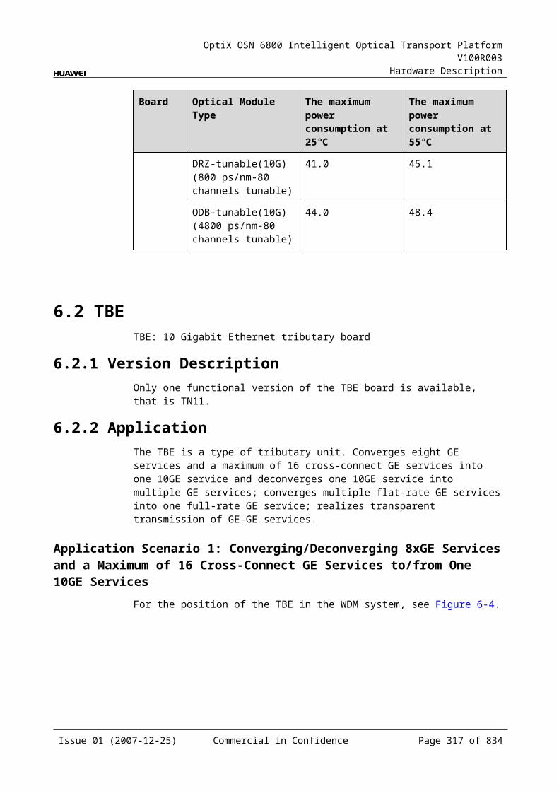
OptiX OSN 6800 Intelligent Optical Transport Platform V100R003
Hardware Description
For the position of the FIU in the WDM system, see Figure 8-7.
Figure 8-1 Position of the FIU in the WDM system
OTUOA
OA
OTUMUX
DMUXOTU
OTU
OA
OA
SC1 FIU FIU SC1
DMUX
MUX
OTU
OTU
OTU
OTU
8.3.3 Functions and FeaturesThe main functions and features supported by the FIU are multiplexing, demultiplexing and online optical performance monitoring.
For detailed functions and features, refer to Table 8-16.
Table 8-1 Functions and features of the FIU
Function and Feature
Description
Basic function Realizes the multiplexing and demultiplexing of signals transmitted by the main path and the optical supervisory channel.
Online optical performance monitoring
Provides the online monitoring interface. A small amount of optical signal can be output to the spectrum analyzer or spectrum analyzer unit through the interface so as to monitor the spectrum and optical performance of the multi-channel signal without interrupting the services.
8.3.4 Working Principle and Signal FlowThe FIU consists of the demultiplexing module, multiplexing module, optical splitter and the control and communication module.
Figure 8-8 shows the functional modules and signal flow of the FIU.
Issue 01 (2007-12-25) Commercial in Confidence Page 316 of 664
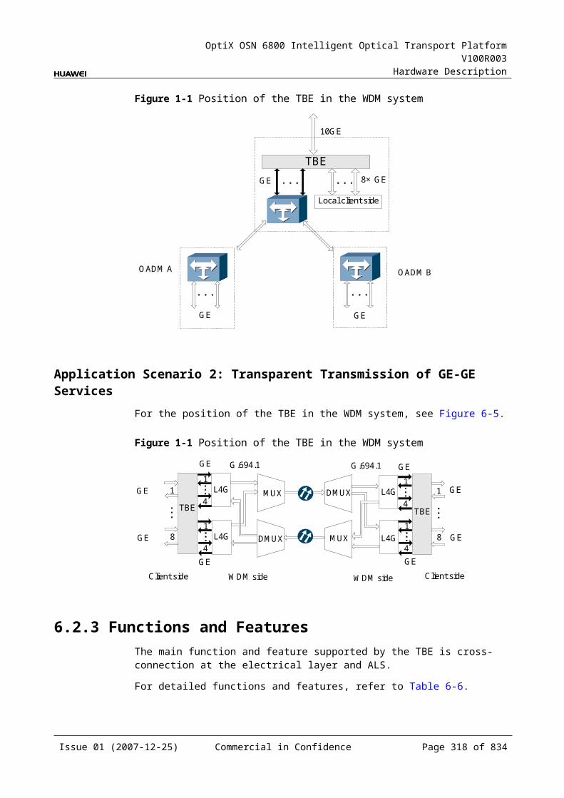
OptiX OSN 6800 Intelligent Optical Transport Platform V100R003
Hardware Description
Figure 8-1 Functional modules and signal flow of the FIU
Demultiplexingmodule
OUT
IN
Multiplexingmodule
TMTC
RCRM Optical
splitter MON
Control and communicationmodule
SCC
Line opticalsignal
Supervisorychannel
Main path
Main path
Supervisorychannel
Line opticalsignal
Demultiplexing Module The optical signal from the line is demultiplexed into the main path and the supervisory channel, then output through the TC interface and TM interface respectively.
Multiplexing ModuleThe main path signal input from the RC interface and the supervisory channel signal input from the RM interface are multiplexed by the multiplexing module, and then are sent to the optical splitter.
Optical SplitterThe optical splitter receives the signal from the multiplexing module and divides it into two signals at different power. The main signal is output through the OUT interface and transmitted on the line. The other signal is output to the MON interface for the detection and monitoring of optical spectrum.
The optical power of the MON interface is 1/99 of the optical power of the OUT interface, that means the optical power of the MON interface is lower than that of the OUT interface by 20 dB.
Control and Communication ModuleThe control and communication module realizes the control, monitoring and communications management of each functional module of the board.
The control and communication module collects the information, such as the alarms and performance events, working status, and voltage detection, of each functional module of the board and reports to the SCC.
Receiving the commands from the SCC, the control and communication module controls and coordinates the functional modules of the board in working.
Issue 01 (2007-12-25) Commercial in Confidence Page 317 of 664
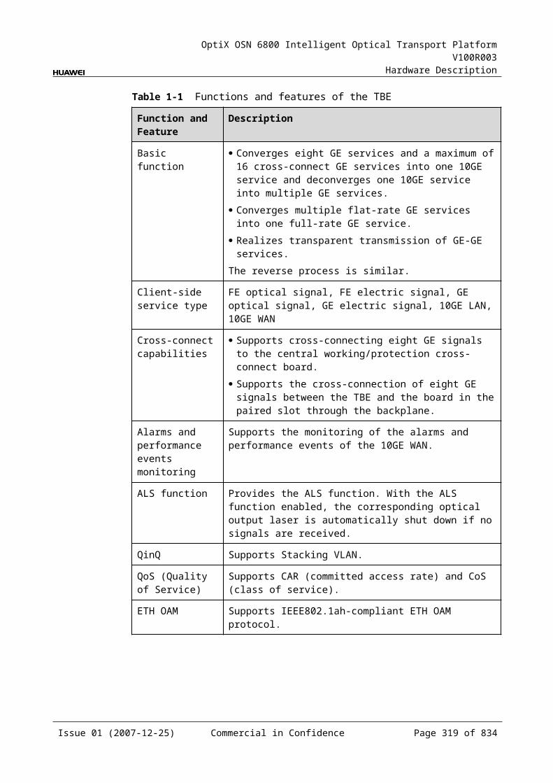
OptiX OSN 6800 Intelligent Optical Transport Platform V100R003
Hardware Description
8.3.5 Front PanelThere are indicators, interfaces and laser safety label on the FIU front panel.
Appearance of the Front PanelFigure 8-9 shows the FIU front panel.
Figure 8-1 FIU front panel
FIU
FIU
STATACTPROGSRV
MO
NO
UT
INTC
RC
TMR
M
LASERRADIATION
DO NOT VIEW DIRECTLYWITH OPTICALINSTRUMENTS
CLASS 1M LASERPRODUCT
IndicatorsThere are four indicators on the front panel.
Board hardware status indicator (STAT) – dual-colored (red, green) Service active status indicator (ACT) – green Board software status indicator (PROG) – dual-colored (red, green) Service alarm indicator (SRV) – triple-colored (red, green, yellow)
Issue 01 (2007-12-25) Commercial in Confidence Page 318 of 664
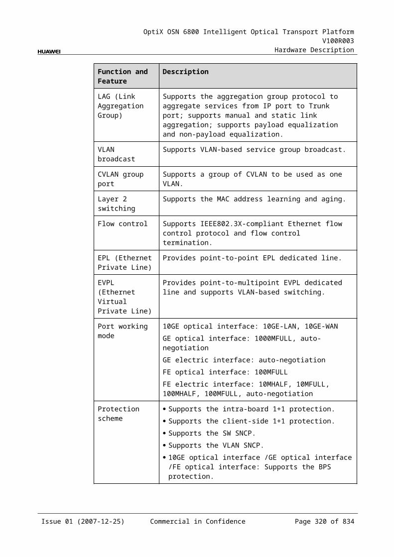
OptiX OSN 6800 Intelligent Optical Transport Platform V100R003
Hardware Description
InterfacesThere are seven optical interfaces on the FIU front panel. Table 8-17 lists the type and function of each interface.
Table 8-1 Types and functions of the FIU interfaces
Interface
Type
Function
IN LC Receives the line signal.
OUT LC Transmits the line signal.
TC LC Transmits the main path signal.
RC LC Receives the main path signal.
TM LC Transmits the 1510nm optical supervisory channel signal.
RM LC Receives the 1510nm optical supervisory channel signal.
MON LC Connected to the input interface of the MCA4 or MCA8, accomplishes online monitoring of optical spectrum.The MON port is a 1/99 tap of the total composite signal at the OUT port (20dB lower than the actual signal power).
Laser Safety LevelThe laser safety level of the optical interface is CLASS 1M.
The maximum output optical power of each optical interface ranges from 10 dBm (10 mW) to 22.15 dBm (164 mW).
8.3.6 Valid SlotsThe FIU occupies one slot. The valid slots for the FIU are IU1–IU17.
8.3.7 Characteristic Code for the FIUThe characteristic code for the FIU consists of one character, indicating the band adopted by the board.
The detailed information of the characteristic code is given in Table 8-18.
Table 8-1 Characteristic code for the FIU
Code Meaning
Description
The first character
Band Indicates the multiplexing solution adopted by the board. The value C represents C band; the value L represents L band.
Issue 01 (2007-12-25) Commercial in Confidence Page 319 of 664
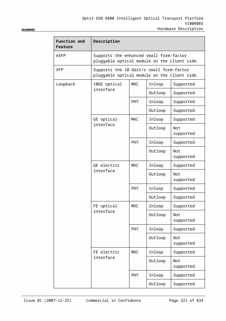
OptiX OSN 6800 Intelligent Optical Transport Platform V100R003
Hardware Description
For example, the characteristic code for the TN11FIU is C, indicating that the optical signals are in C band.
8.3.8 NM Configuration ReferenceNM configuration reference includes the reference information needed during the configuration of boards through the T2000.
Display of Optical InterfacesThe serial numbers of the optical interfaces on the panel of the board displayed on the NM are listed in Table 8-19.
Table 8-1 Serial numbers of the interfaces of the FIU displayed on the NM
Interface on the Panel Interface on the NM
IN/OUT 1
RM/TM 2
RC/TC 3
MON 4
NOTEThe number of an interface displayed on the T2000 in fact indicates a pair of physical optical interfaces, of which one is used to transmit signals and the other is used to receive signals.
Configuration ParametersThreshold of Input Power Loss (dBm)
8.3.9 Specifications of the FIUSpecifications include optical specifications, dimensions, weight, and power consumption.
Optical Specifications
Table 8-1 Optical specifications of the FIU
Interface
Item Unit
Value
– Operating wavelength range nm 1529–1561
– Operating wavelength range of optical supervisory channel
nm 1500–1520
– Optical return loss dB >40
Issue 01 (2007-12-25) Commercial in Confidence Page 320 of 664
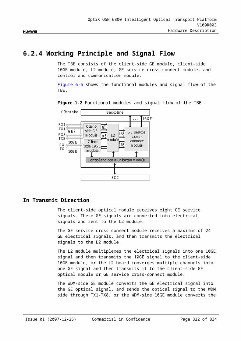
OptiX OSN 6800 Intelligent Optical Transport Platform V100R003
Hardware Description
Interface
Item Unit
Value
IN-TMRM-OUT
Insertion loss dB ≤1.5
IN-TCRC-OUT
Insertion loss dB ≤1
IN-TM Isolation dB >40
IN-TC Isolation dB >12
Mechanical Specifications Dimensions of board (PCB): 245.1 mm (H) x 220 mm (D) x 2 mm (T) Dimensions of front panel: 264.6 mm (H) x 25.4 mm (W) Weight: 2.2 lb (1.0 kg)
Power Consumption The maximum power consumption at 25: 4.2 W The maximum power consumption at 55: 4.6 W
8.4 ITLITL: Interleaver Board
8.4.1 Version DescriptionOnly one functional version of the ITL board is available, that is TN11.
8.4.2 ApplicationThe ITL is a type of optical multiplexer and demultiplexer unit. It multiplexes/demultiplexes optical signals with the channel spacing of 100 GHz into one optical signals with the channel spacing of 50 GHz.
For the position of the ITL in the WDM system, see Figure 8-10.
Issue 01 (2007-12-25) Commercial in Confidence Page 321 of 664
OptiX OSN 6800 Intelligent Optical Transport Platform V100R003
Hardware Description
Figure 8-1 Position of the ITL in the WDM system
OA
OA
1
40
1
40
1
40
1
40
OTU
OTU
OTU
OTU
D40
D40
M40
40
140
1
M40
40
1
40
1
OTU
OTU
OTU
OTU
OTU
OTU
OTU
OTU
D40
D40
OA
OA
OTU
OTU
OTU
OTU
M40
M40
C_EVEN
C_ODD
C_EVEN
C_ODD
C_EVEN
C_ODD
C_EVEN
C_ODD
ITLITL
8.4.3 Functions and FeaturesThe main functions and features supported by the ITL are multiplexing, demultiplexing and detection of the online spectrum.
For detailed functions and features, refer to Table 8-21.
Table 8-1 Functions and features of the ITL
Functions and Features
Description
Basic function Multiplexes /demultiplexes optical signals with the channel spacing of 100 GHz into one optical signals with the channel spacing of 50 GHz in the 80 channels system.
Detection and monitoring of the online spectrum
Provides the online monitoring interface. A small amount of optical signal can be output to the spectrum analyzer or spectrum analyzer unit through the interface so as to monitor the spectrum and optical performance of the multi-channel signal without interrupting the services.
8.4.4 Working Principle and Signal FlowThe ITL consists of interleaver, multiplexing module and optical splitter.
Figure 8-11 shows the functional modules and signal flow of the ITL.
Issue 01 (2007-12-25) Commercial in Confidence Page 322 of 664

OptiX OSN 6800 Intelligent Optical Transport Platform V100R003
Hardware Description
Figure 8-1 Functional modules and signal flow of the ITL
InterleaverINTE
TO100 GHz
Multiplexingmodule
OUTRE
RO100 GHz
50 GHz
50 GHz
MON
Opticalsplitter
InterleaverThe interleaver processes the input signals at 50 GHz channel spacing and converts them into optical signals at 100 GHz channel spacing. Then the optical signals are output through the TO and TE interface, respectively.
Multiplexing moduleThe multiplexing module multiplexes the ODD optical signals at 100 GHz channel spacing that is input through the RO interface and the EVEN optical signals at 100 GHz channel spacing that is input through the RE interface into one optical signals at 50 GHz channel spacing. Then the signals are sent to the optical splitter.
The optical splitter receives the signal from the multiplexing module and divides it into two signals at different power. The main signal is output through the OUT interface and transmitted on the line. The other signal is output to the MON interface for the detection and monitoring of optical spectrum.
The optical power of the MON interface is 10/90 of the optical power of the OUT interface, that means the optical power of the MON interface is lower than that of the OUT interface by 10 dB.
8.4.5 Front PanelThere are indicators, interfaces and laser safety label on the ITL front panel.
Appearance of the Front PanelFigure 8-12 shows the ITL front panel.
Issue 01 (2007-12-25) Commercial in Confidence Page 323 of 664
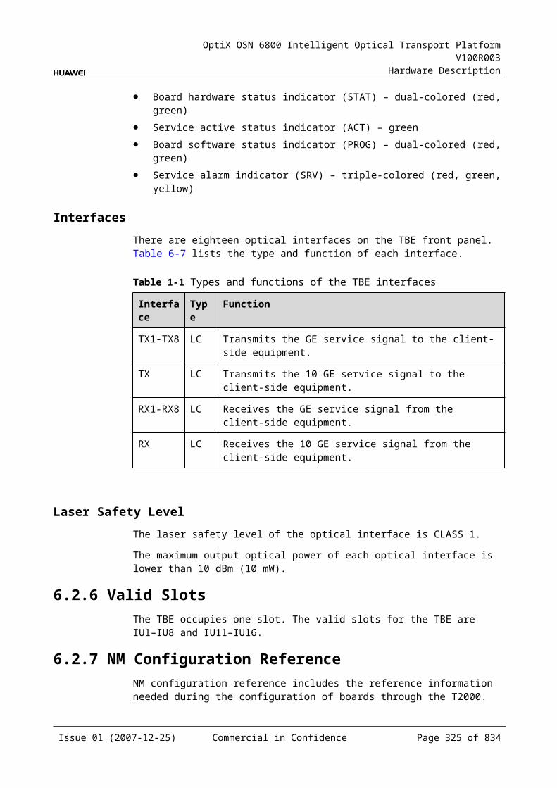
OptiX OSN 6800 Intelligent Optical Transport Platform V100R003
Hardware Description
Figure 8-1 ITL front panel
ITL
ITL
STAT
MO
NO
UT
INTO
RO
TER
E
LASERRADIATION
DO NOT VIEW DIRECTLYWITH OPTICALINSTRUMENTS
CLASS 1M LASERPRODUCT
IndicatorsThere is one indicator on the front panel.
Board hardware status indicator (STAT) – dual-colored (red, green)
InterfacesThere are seven optical interfaces on the ITL front panel.Table 8-22 lists the type and function of each interface.
Issue 01 (2007-12-25) Commercial in Confidence Page 324 of 664
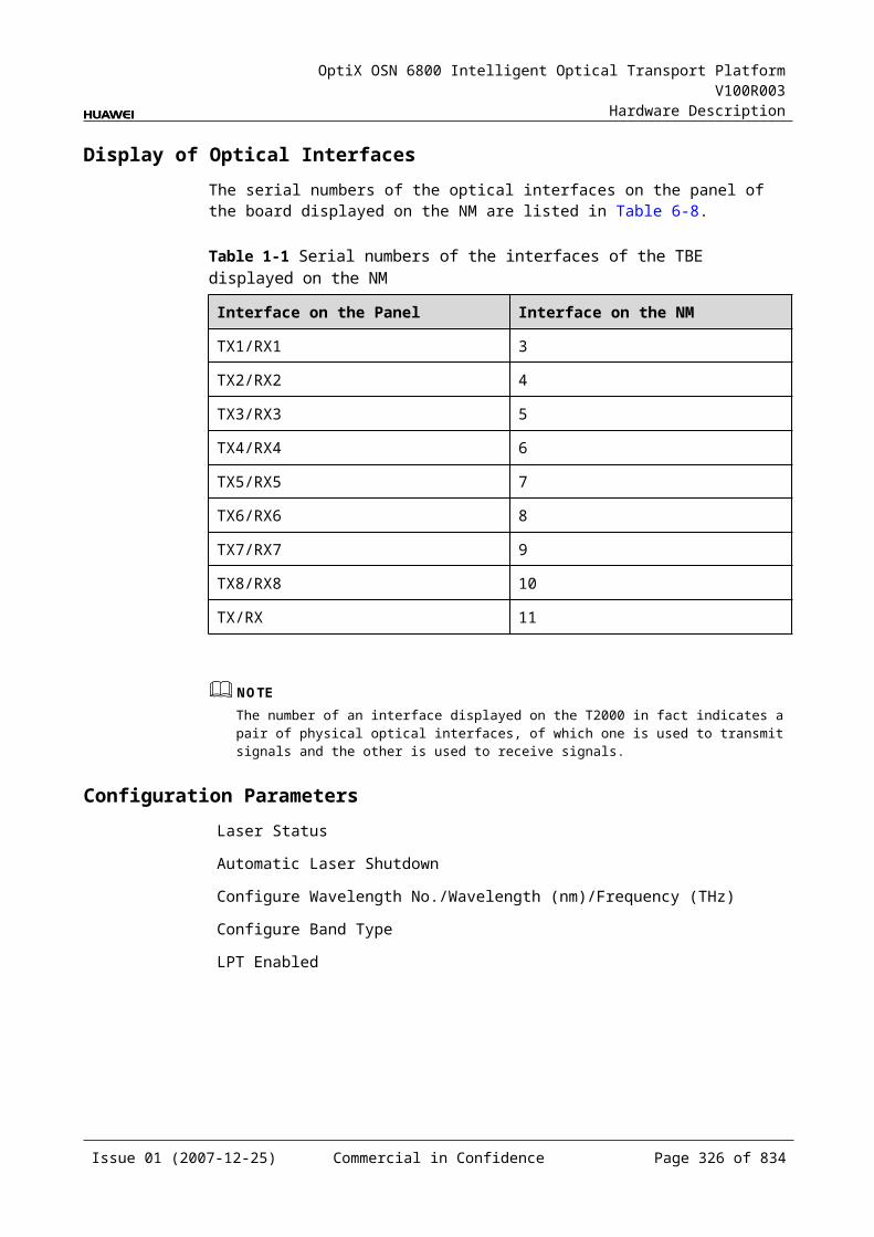
OptiX OSN 6800 Intelligent Optical Transport Platform V100R003
Hardware Description
Table 8-1 Types and functions of the ITL interfaces
Interface
Type
Function
IN LC Accesses the optical signals at 50 GHz channel spacing (C_ODD and C_EVEN multiplexed signals).
OUT LC Outputs the optical signals at 50 GHz channel spacing (C_ODD and C_EVEN multiplexed signals).
TE LC Outputs the optical signals at 100 GHz channel spacing (C_EVEN multiplexed signals).
RE LC Accesses the optical signals at 100 GHz channel spacing (C_EVEN multiplexed signals).
TO LC Outputs the optical signals at 100 GHz channel spacing (C_ODD multiplexed signals).
RO LC Accesses the optical signals at 100 GHz channel spacing (C_ODD multiplexed signals).
MON LC Connects to the input port on the MCA4 or the MCA8 board so that the MCA4 or the MCA8 board can detect the optical spectrum in service.The optical power at the MON interface is 10/90 of the optical power at the OUT interface, that is, the optical power at the MON interface is 10 dB lower than the optical power at the OUT interface.
Laser Safety LevelThe laser safety level of the optical interface is CLASS 1M.
The maximum output optical power of each optical interface ranges from 10 dBm (10 mW) to 22.15 dBm (164 mW).
8.4.6 Valid SlotsThe ITL occupies one slot. The valid slots for the ITL are IU1–IU17.
8.4.7 Characteristic Code for the ITLThe characteristic code for the FIU consists of one character, indicating the band adopted by the board.
The detailed information of the characteristic code is given in Table 8-23.
Issue 01 (2007-12-25) Commercial in Confidence Page 325 of 664
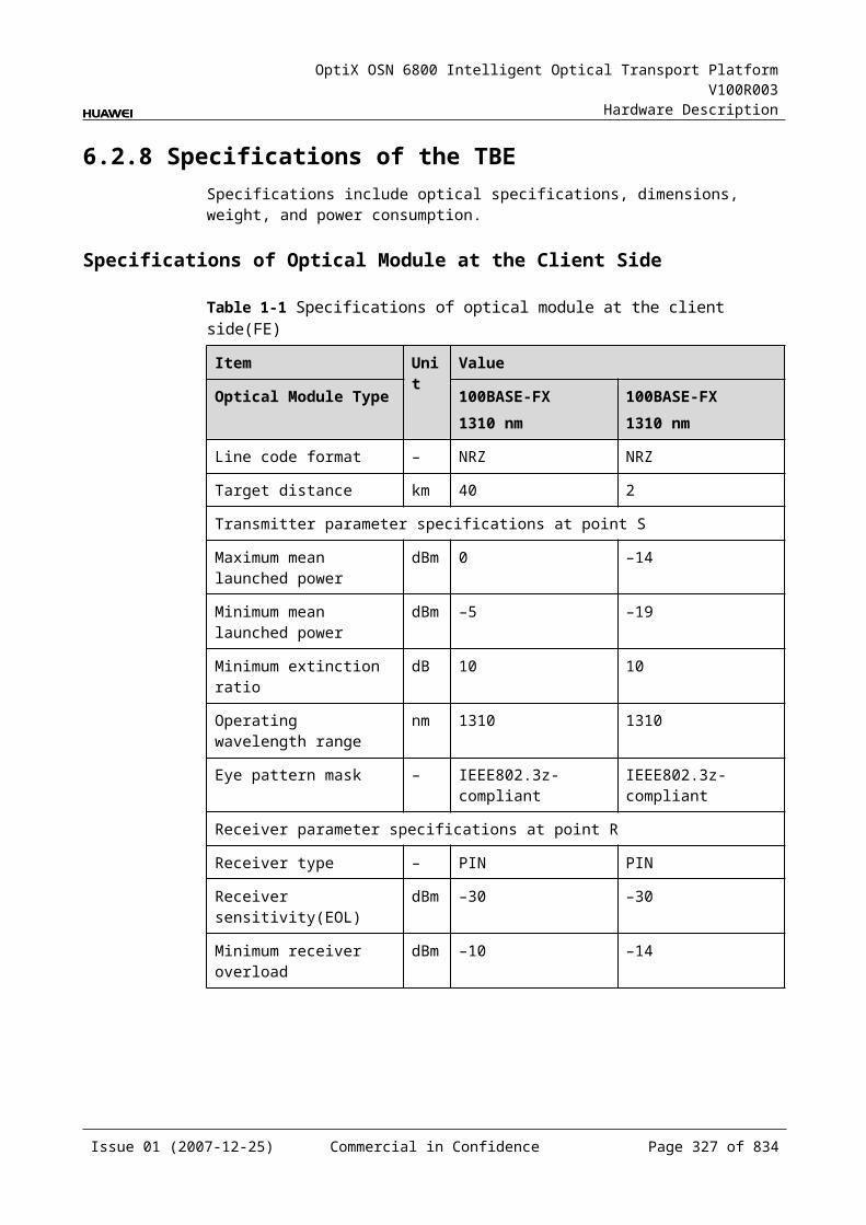
OptiX OSN 6800 Intelligent Optical Transport Platform V100R003
Hardware Description
Table 8-1 Characteristic code for the ITL
Code Meaning
Description
The first character
Band Indicates the multiplexing solution adopted by the board. The value C represents C band; the value L represents L band.
For example, the characteristic code for the ITL is C, indicating that the optical signals are in C band
8.4.8 NM Configuration ReferenceNM configuration reference includes the reference information needed during the configuration of boards through the T2000.
Display of Optical InterfacesThe serial numbers of the optical interfaces on the panel of the board displayed on the NM are listed in Table 8-24.
Table 8-1 Serial numbers of the interfaces of the ITL displayed on the NM
Interface on the Panel Interface on the NM
IN/OUT 1
RE/TE 2
RO/TO 3
MON 4
NOTEThe number of an interface displayed on the T2000 in fact indicates a pair of physical optical interfaces, of which one is used to transmit signals and the other is used to receive signals.
8.4.9 Specifications of the ITLSpecifications include optical specifications, dimensions, weight, and power consumption.
Optical Specifications
Table 8-1 Optical specifications of the ITL
Interface Item Unit Value
– Input channel spacinga GHz 100
– Output channel spacinga GHz 50
Issue 01 (2007-12-25) Commercial in Confidence Page 326 of 664
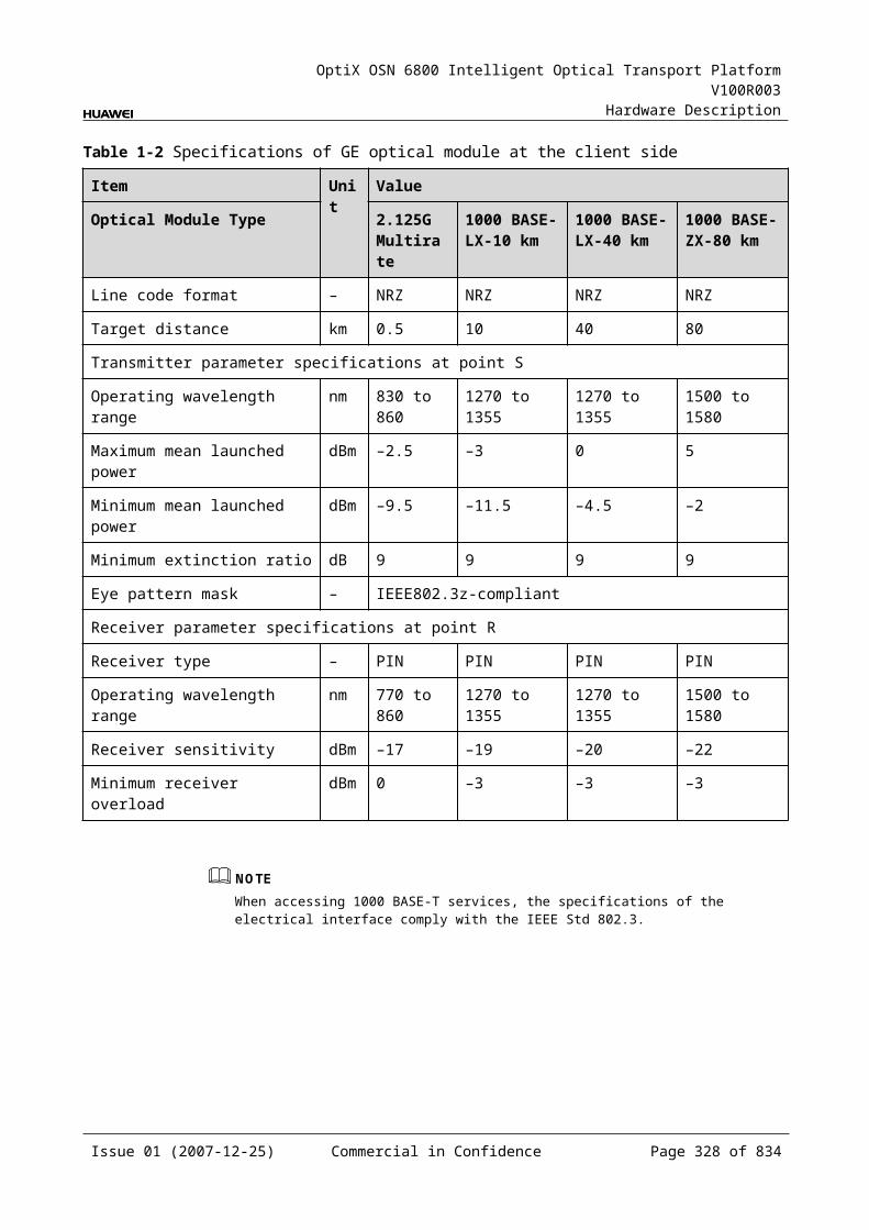
OptiX OSN 6800 Intelligent Optical Transport Platform V100R003
Hardware Description
Interface Item Unit Value
RE-OUTRO-OUT
Insertion loss dB <4.5
IN-TEIN-TO
Insertion loss dB <2.5
RE/RO-OUTIN-TE/TO
Maximum difference of insertion loss dB <1
IN-TEIN-TO
Isolation dB >25
– Optical return loss dB >45
– Directivity dB >45
– PMD ps <0.5
– Polarization dependent loss dB <0.5
– Input optical power range dBm ≤26
a: The input and output ends are defined based on the multiplexing process of the interleaver.
Mechanical Specifications Dimensions of board (PCB): 245.1 mm (H) x 220 mm (D) x 2 mm (T) Dimensions of front panel: 264.6 mm (H) x 25.4 mm (W) Weight: 0.9kg
Power Consumption The maximum power consumption at 25: 0.2W The maximum power consumption at 55: 0.3W
8.5 M40M40: 40-channel multiplexing unit
8.5.1 Version DescriptionOnly one functional version of the M40 board is available, that is TN11.
8.5.2 ApplicationThe M40 is a type of optical multiplexer unit. The M40 realizes the multiplexing of a maximum of 40 ITU-T Recommendation-compliant WDM signals into one fiber.
For the position of the M40 in the WDM system, see Figure 8-13.
Issue 01 (2007-12-25) Commercial in Confidence Page 327 of 664

OptiX OSN 6800 Intelligent Optical Transport Platform V100R003
Hardware Description
Figure 8-1 Position of the M40 in the WDM system
OTUOA
OA
OTUM40
D40OTU
OTU
OA
OA
D40
M40
OTU
OTU
OTU
OTU
1
40
1
40
1
40
1
40
8.5.3 Functions and FeaturesThe main functions and features supported by the M40 are multiplexing, online optical performance monitoring, alarms and performance events monitoring.
For detailed functions and features, refer to Table 8-26.
Table 8-1 Functions and features of the M40
Function and Feature
Description
Basic function Multiplexes a maximum of 40 channels into one fiber. Multiplexes 40 C_EVEN channels into one main path. Multiplexes 40 C_ODD channels into one main path.
Online optical performance monitoring
Provides the online monitoring interface. A small amount of optical signal can be output to the spectrum analyzer or spectrum analyzer unit through the interface so as to monitor the spectrum and optical performance of the multi-channel signal without interrupting the services.
Alarms and performance events monitoring
Provides the function of optical power detection and the function to report the alarms and performance events of the board.
8.5.4 Working Principle and Signal FlowThe M40 consists of the multiplexing module, optical splitter and the control and communication module.
Figure 8-14 shows the functional modules and signal flow of the M40.
Issue 01 (2007-12-25) Commercial in Confidence Page 328 of 664
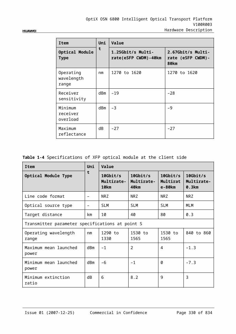
OptiX OSN 6800 Intelligent Optical Transport Platform V100R003
Hardware Description
Figure 8-1 Functional modules and signal flow of the M40
Control and communicationmodule
SCC
Multiplexingmodule Optical
splitter
M02
M01
M40OUT
MON
Multiplexing ModuleThe multiplexing module multiplexes 40 signals into one signal and sends the signal to the optical splitter.
Optical SplitterThe optical splitter receives the signal from the multiplexing module and divides it into two signals at different power. The main signal is output through the OUT interface and transmitted by the main path. The other signal is output to the MON interface for optical spectrum detection and monitoring.
The optical power of the MON interface is 10/90 of the optical power of the OUT interface, that means the optical power of the MON interface is lower than that of the OUT interface by 10 dB.
Control and Communication ModuleThe control and communication module realizes the control, monitoring and communications management of each functional module of the board.
The control and communication module collects the information, such as the alarms and performance events, working status, and voltage detection, of each functional module of the board and reports to the SCC.
Receiving the commands from the SCC, the control and communication module controls and coordinates the functional modules of the board in working.
8.5.5 Front PanelThere are indicators, interfaces and laser safety label on the M40 front panel.
Appearance of the Front PanelFigure 8-15 shows the M40 front panel.
Issue 01 (2007-12-25) Commercial in Confidence Page 329 of 664
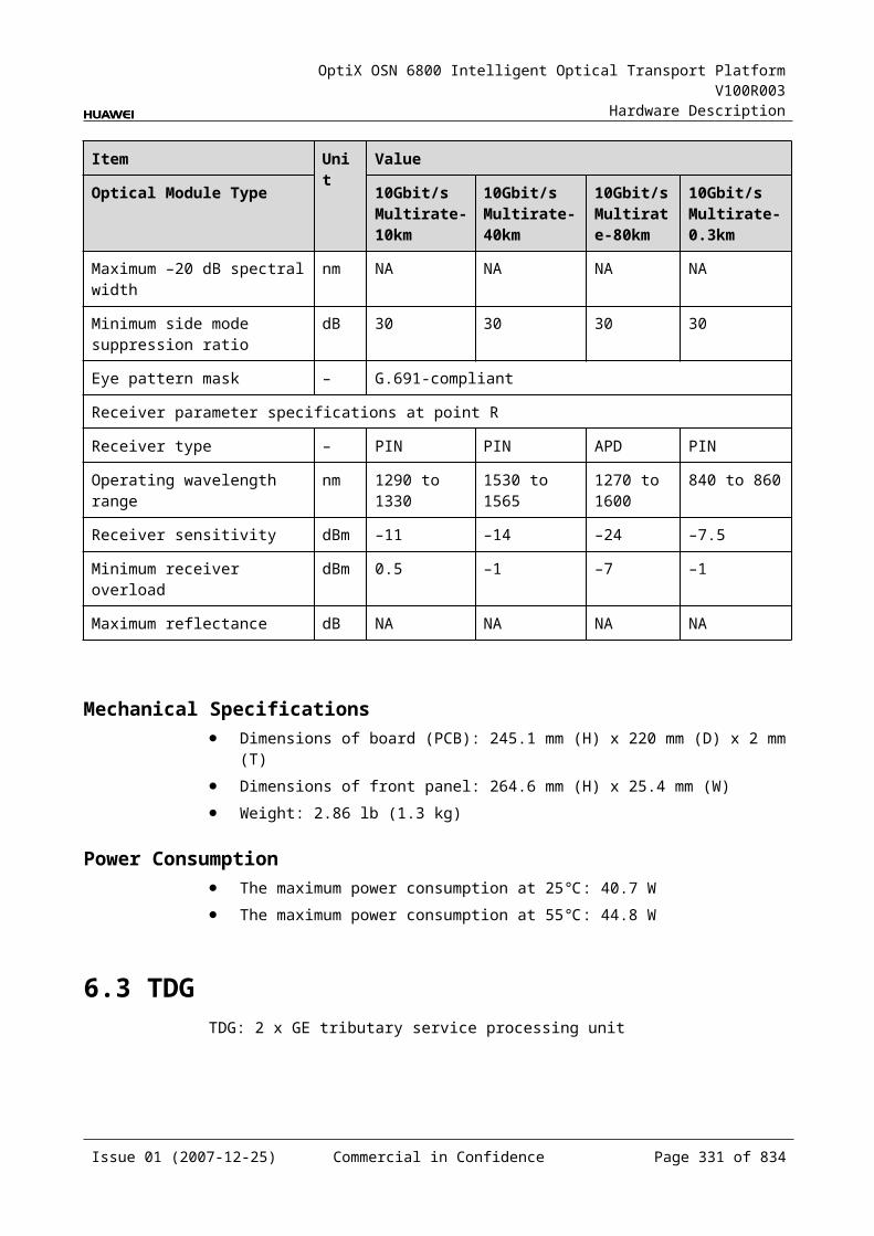
OptiX OSN 6800 Intelligent Optical Transport Platform V100R003
Hardware Description
Figure 8-1 M40 front panel
M40
M40
STATACTPROGSRV
CLASS 1LASER
PRODUCT
M01M02M03M04M05M06M07M08M09M10
M11M12M13M14M15M16M17M18M19M20
M21M22M23M24M25M26M27M28M29M30
M31M32M33M34M35M36M37M38M39M40
196.00195.90195.80195.70195.60195.50195.40195.30195.20195.10
195.00194.90194.80194.70194.60194.50
194.20194.10
194.40194.30
194.00193.90193.80193.70193.60193.50
193.20193.10
193.40193.30
193.00192.90192.80192.70192.60192.50
192.20192.10
192.40192.30
M15
M16
M17
M18
M19
M20
M21
M22
M23
M24
M13
M25
M26
M14
M01
M02
M03
M04
M05
M06
M07
M08
M09
M10
MO
NM
11M
12O
UT
M29
M30
M31
M32
M33
M34
M35
M36
M37
M38
M28
M39
M40
M27
NOTEThere is a table indicating the mapping relationship between interfaces and frequencies pasted onto the front panel.
IndicatorsThere are four indicators on the front panel.
Board hardware status indicator (STAT) – dual-colored (red, green) Service active status indicator (ACT) – green Board software status indicator (PROG) – dual-colored (red, green) Service alarm indicator (SRV) – triple-colored (red, green, yellow)
Issue 01 (2007-12-25) Commercial in Confidence Page 330 of 664
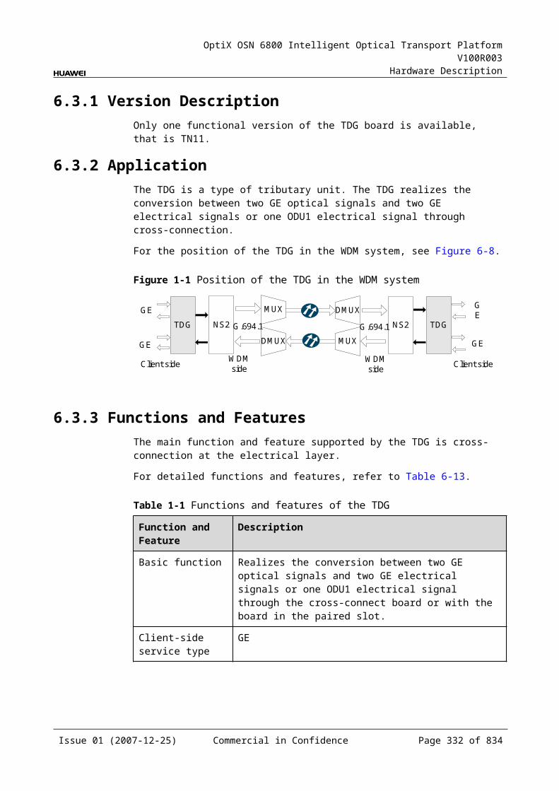
OptiX OSN 6800 Intelligent Optical Transport Platform V100R003
Hardware Description
InterfacesThere are 42 optical interfaces on the M40 front panel. Table 8-27 lists the type and function of each interface.
Table 8-1 Types and functions of the M40 interfaces
Interface
Type
Function
M01–M40 LC Connected to the "OUT" interface of the OTUs, receive the signals to be multiplexed.
OUT LC Connected to an optical amplifying board or ITL, transmits multiplexed signals.
MON LC Connected to the input interface of the MCA4 or MCA8, accomplishes online monitoring of optical spectrum.The MON port is a 10/90 tap of the total composite signal at the OUT port (10dB lower than the actual signal power).
There are 40 output interfaces on the M40 front panel. Table 8-28 and Table 8-29 show the mapping between the interfaces, frequency and wavelengths of the M40 board.
Table 8-2 Mapping between the optical interfaces, frequencies and wavelengths of the M40 board (even)
Interface
Frequency (THz)
Wavelength (nm)
Interface
Frequency (THz)
Wavelength (nm)
M01 196.00 1529.55 M21 194.00 1545.32
M02 195.90 1530.33 M22 193.90 1546.12
M03 195.80 1531.12 M23 193.80 1546.92
M04 195.70 1531.90 M24 193.70 1547.72
M05 195.60 1532.68 M25 193.60 1548.51
M06 195.50 1533.47 M26 193.50 1549.32
M07 195.40 1534.25 M27 193.40 1550.12
M08 195.30 1535.04 M28 193.30 1550.92
M09 195.20 1535.82 M29 193.20 1551.72
M10 195.10 1536.61 M30 193.10 1552.52
M11 195.00 1537.40 M31 193.00 1553.33
M12 194.90 1538.19 M32 192.90 1554.13
M13 194.80 1538.98 M33 192.80 1554.94
Issue 01 (2007-12-25) Commercial in Confidence Page 331 of 664
OptiX OSN 6800 Intelligent Optical Transport Platform V100R003
Hardware Description
Interface
Frequency (THz)
Wavelength (nm)
Interface
Frequency (THz)
Wavelength (nm)
M14 194.70 1539.77 M34 192.70 1555.75
M15 194.60 1540.56 M35 192.60 1556.55
M16 194.50 1541.35 M36 192.50 1557.36
M17 194.40 1542.14 M37 192.40 1558.17
M18 194.30 1542.94 M38 192.30 1558.98
M19 194.20 1543.73 M39 192.20 1559.79
M20 194.10 1544.53 M40 192.10 1560.61
Table 8-3 Mapping between the optical interfaces, frequencies and wavelengths of the M40 board (odd)
Interface
Frequency (THz)
Wavelength (nm)
Interface
Frequency (THz)
Wavelength (nm)
M01 196.05 1529.16 M21 194.05 1544.92
M02 195.95 1529.94 M22 193.95 1545.72
M03 195.85 1530.72 M23 193.85 1546.52
M04 195.75 1531.51 M24 193.75 1547.32
M05 195.65 1532.29 M25 193.65 1548.11
M06 195.55 1533.07 M26 193.55 1548.91
M07 195.45 1533.86 M27 193.45 1549.72
M08 195.35 1534.64 M28 193.35 1550.52
M09 195.25 1535.43 M29 193.25 1551.32
M10 195.15 1536.22 M30 193.15 1552.12
M11 195.05 1537.00 M31 193.05 1552.93
M12 194.95 1537.79 M32 192.95 1553.73
M13 194.85 1538.58 M33 192.85 1554.54
M14 194.75 1539.37 M34 192.75 1555.34
M15 194.65 1540.16 M35 192.65 1556.15
M16 194.55 1540.95 M36 192.55 1556.96
M17 194.45 1541.75 M37 192.45 1557.77
M18 194.35 1542.54 M38 192.35 1558.58
Issue 01 (2007-12-25) Commercial in Confidence Page 332 of 664
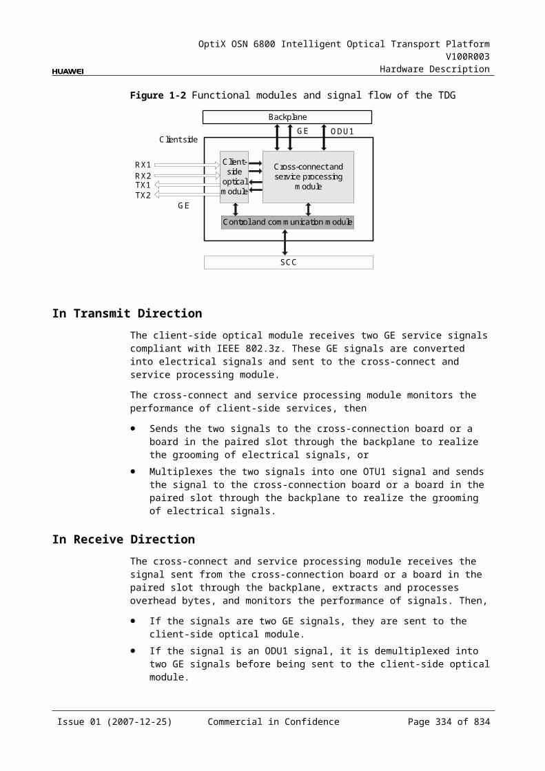
OptiX OSN 6800 Intelligent Optical Transport Platform V100R003
Hardware Description
Interface
Frequency (THz)
Wavelength (nm)
Interface
Frequency (THz)
Wavelength (nm)
M19 194.25 1543.33 M39 192.25 1559.39
M20 194.15 1544.13 M40 192.15 1560.20
Laser Safety LevelThe laser safety level of the optical interface is CLASS 1.
The maximum output optical power of each optical interface is lower than 10 dBm (10 mW).
8.5.6 Valid SlotsThe M40 occupies three slots. The valid slots for the M40 are IU1–IU15 in the subrack.
The back connector of the board is mounted to the backplane along the left slot in the subrack, so the slot number of the M40 board displayed on the NM is the number of the left one of the three occupied slots.
For example, if the M40 occupies slots IU1, IU2, and IU3, the slot number of the M40 displayed on the NM is IU1.
8.5.7 Characteristic Code for the M40The characteristic code for the M40 consists of two characters. One indicates the band. The other indicates whether the wavelengths that bear the optical signals processed by the board are odd or even wavelengths.
The detailed information of the characteristic code is given in Table 8-30.
Table 8-1 Characteristic code for the M40
Code Meaning Description
The first character
Band Indicates the band of the optical signals processed by the board. The value C represents C band; the value L represents L band.
The second character
Odd/Even wavelengths
Indicates whether the wavelengths that bear signals are odd or even wavelengths. The value E represents even wavelengths; the value O represents odd wavelengths.
For example, the characteristic code for the TN11M40 is CE, indicating C band and even wavelengths.
Issue 01 (2007-12-25) Commercial in Confidence Page 333 of 664
OptiX OSN 6800 Intelligent Optical Transport Platform V100R003
Hardware Description
8.5.8 NM Configuration ReferenceNM configuration reference includes the reference information needed during the configuration of boards through the T2000.
Display of Optical InterfacesThe serial numbers of the optical interfaces on the panel of the board displayed on the NM are listed in Table 8-31.
Table 8-1 Serial numbers of the interfaces of the M40 displayed on the NM
Interface on the Panel Interface on the NM
OUT 1
M01-M40 2-41
MON 42
8.5.9 Specifications of the M40Specifications include optical specifications, dimensions, weight, and power consumption.
Optical SpecificationsTable 8-32 lists the optical specifications of the M40.
Table 8-1 Optical specifications of the M40
Item Unit Value
Adjacent channel spacing GHz 100
Insertion loss dB ≤6.5
Optical return loss dB >40
Operating wavelength range nm 1529–1561
Adjacent channel isolation dB >22
Non-adjacent channel isolation dB >25
Polarization dependence loss dB ≤0.5
Temperature characteristics nm/ ≤0.002
Maximum channel insertion loss difference dB ≤3
Mechanical Specifications Dimensions of board (PCB): 245.1 mm (H) x 220 mm (D) x 2 mm (T)
Issue 01 (2007-12-25) Commercial in Confidence Page 334 of 664

OptiX OSN 6800 Intelligent Optical Transport Platform V100R003
Hardware Description
Dimensions of front panel: 264.6 mm (H) x 76.2 mm (W) Weight: 4.84 lb (2.2 kg)
Power Consumption The maximum power consumption at 25: 20.0 W The maximum power consumption at 55: 22.0 W
8.6 M40VM40V: 40-channel multiplexing unit with VOA
8.6.1 Version DescriptionOnly one functional version of the M40V board is available, that is TN11.
8.6.2 ApplicationThe M40V is a type of optical multiplexer unit. The M40V realizes the multiplexing of a maximum of 40 ITU-T Recommendation-compliant WDM signals into one fiber and adjusts the input optical power of each channel.
For the position of the M40V in the WDM system, see Figure 8-16.
Figure 8-1 Position of the M40V in the WDM system
OTUOA
OA
OTUM40V
D40OTU
OTU
OA
OA
D40
M40V
OTU
OTU
OTU
OTU
1
40
1
40
1
40
1
40
8.6.3 Functions and FeaturesThe main functions and features supported by the M40V are multiplexing, online optical performance monitoring, alarms and performance events monitoring and optical power adjustment.
For detailed functions and features, refer to Table 8-33.
Issue 01 (2007-12-25) Commercial in Confidence Page 335 of 664
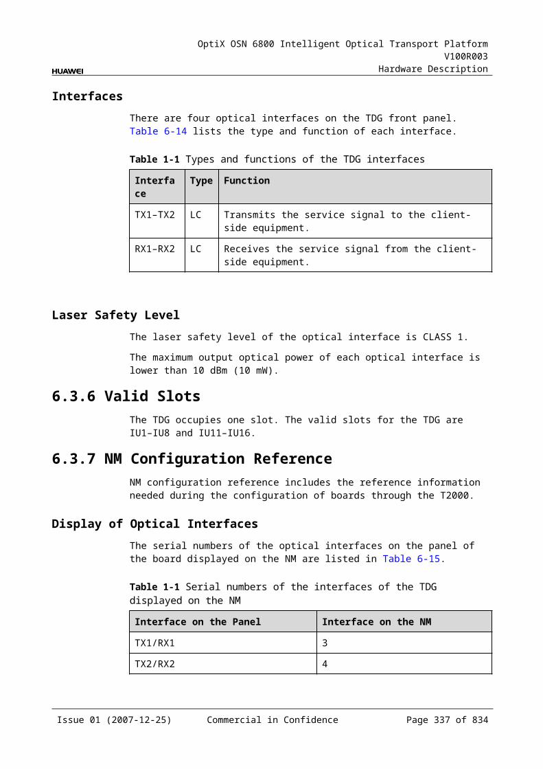
OptiX OSN 6800 Intelligent Optical Transport Platform V100R003
Hardware Description
Table 8-1 Functions and features of the M40V
Function and Feature
Description
Basic function Multiplexes a maximum of 40 signals into one fiber and adjusts the input optical power of each channel. Multiplexes 40 C_EVEN channels into one main path. Multiplexes 40 C_ODD channels into one main path.
Online optical performance monitoring
Provides the online monitoring interface. A small amount of optical signal can be output to the spectrum analyzer or spectrum analyzer unit through the interface so as to monitor the spectrum and optical performance of the multi-channel signal without interrupting the services.
Alarms and performance events monitoring
Provides the function of optical power detection and the function to report the alarms and performance events of the board.
Optical power adjustment
Adjusts the optical power of each signal before multiplexing.
8.6.4 Working Principle and Signal FlowThe M40V consists of the VOA module, multiplexing module, optical splitter and the control and communication module.
Figure 8-17 shows the functional modules and signal flow of the M40V.
Figure 8-1 Functional modules and signal flow of the M40V
Control and communication module
SCC
Opticalsplitter
OUT
MON
Multiplexingmodule
VOA
VOA
VOA
M02
M01
M40
VOA ModuleThe M40V has 40 VOA modules. Each module adjusts the power for one of the 40 channels and sends the adjusted optical signals to the multiplexing module.
Issue 01 (2007-12-25) Commercial in Confidence Page 336 of 664

OptiX OSN 6800 Intelligent Optical Transport Platform V100R003
Hardware Description
Multiplexing ModuleThe multiplexing module multiplexes the adjusted 40 signals into one signal, then sends it to the optical splitter.
Optical SplitterThe optical splitter divides the signal sent from the multiplexing module into two signals at different power. The main signal is output through the OUT interface and transmitted by the main optical path. The other signal is sent to the MON interface for the detection and monitoring of optical spectrum.
The optical power of the MON interface is 10/90 of the optical power of the OUT interface, that means the optical power of the MON interface is lower than that of the OUT interface by 10 dB.
Control and Communication ModuleThe control and communication module realizes the control, monitoring and communications management of each functional module of the board.
The control and communication module collects the information, such as the alarms and performance events, working status, and voltage detection, of each functional module of the board and reports to the SCC.
Receiving the commands from the SCC, the control and communication module controls and coordinates the functional modules of the board in working.
8.6.5 Front PanelThere are indicators, interfaces and laser safety label on the M40V front panel.
Appearance of the Front PanelFigure 8-18 shows the M40V front panel.
Issue 01 (2007-12-25) Commercial in Confidence Page 337 of 664
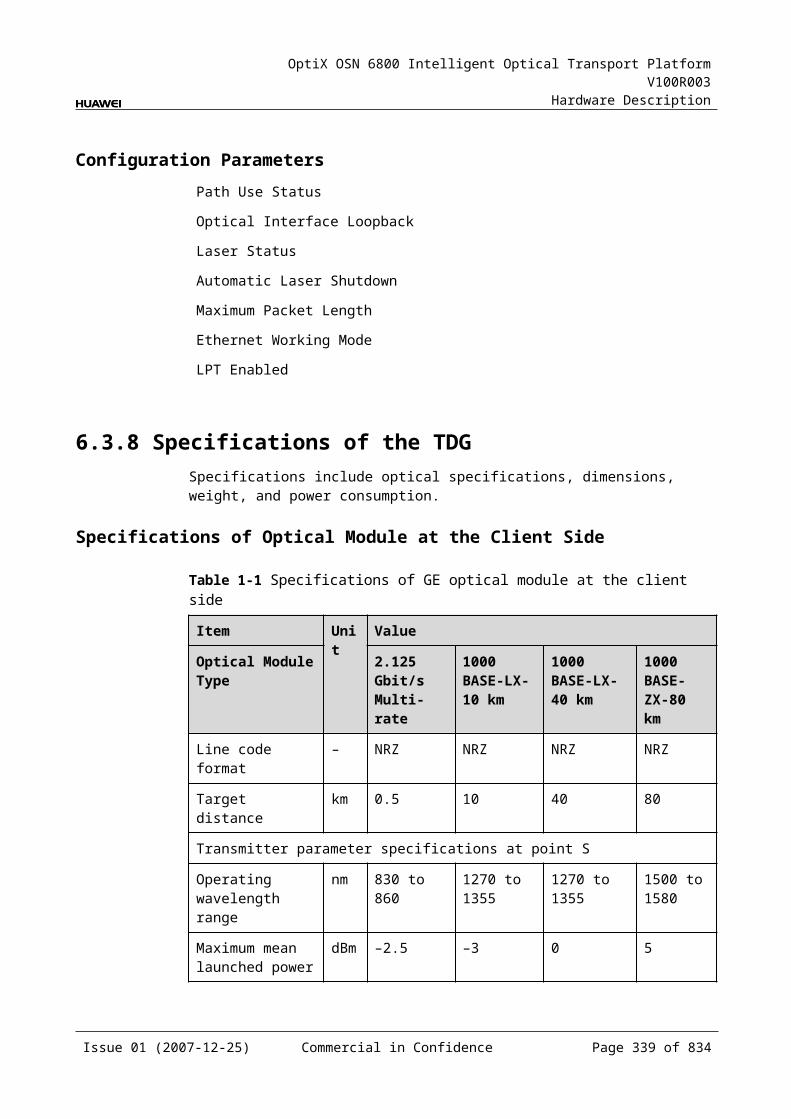
OptiX OSN 6800 Intelligent Optical Transport Platform V100R003
Hardware Description
Figure 8-1 M40V front panel
M40V
M40V
STATACTPROGSRV
CLASS 1LASER
PRODUCT
M01M02M03M04M05M06M07M08M09M10
M11M12M13M14M15M16M17M18M19M20
M21M22M23M24M25M26M27M28M29M30
M31M32M33M34M35M36M37M38M39M40
196.00195.90195.80195.70195.60195.50195.40195.30195.20195.10
195.00194.90194.80194.70194.60194.50
194.20194.10
194.40194.30
194.00193.90193.80193.70193.60193.50
193.20193.10
193.40193.30
193.00192.90192.80192.70192.60192.50
192.20192.10
192.40192.30
M15
M16
M17
M18
M19
M20
M21
M22
M23
M24
M13
M25
M26
M14
M01
M02
M03
M04
M05
M06
M07
M08
M09
M10
MO
NM
11M
12O
UT
M29
M30
M31
M32
M33
M34
M35
M36
M37
M38
M28
M39
M40
M27
NOTEThere is a table indicating the mapping relationship between interfaces and frequencies pasted onto the front panel.
IndicatorsThere are four indicators on the front panel.
Board hardware status indicator (STAT) – dual-colored (red, green) Service active status indicator (ACT) – green Board software status indicator (PROG) – dual-colored (red, green) Service alarm indicator (SRV) – triple-colored (red, green, yellow)
Issue 01 (2007-12-25) Commercial in Confidence Page 338 of 664
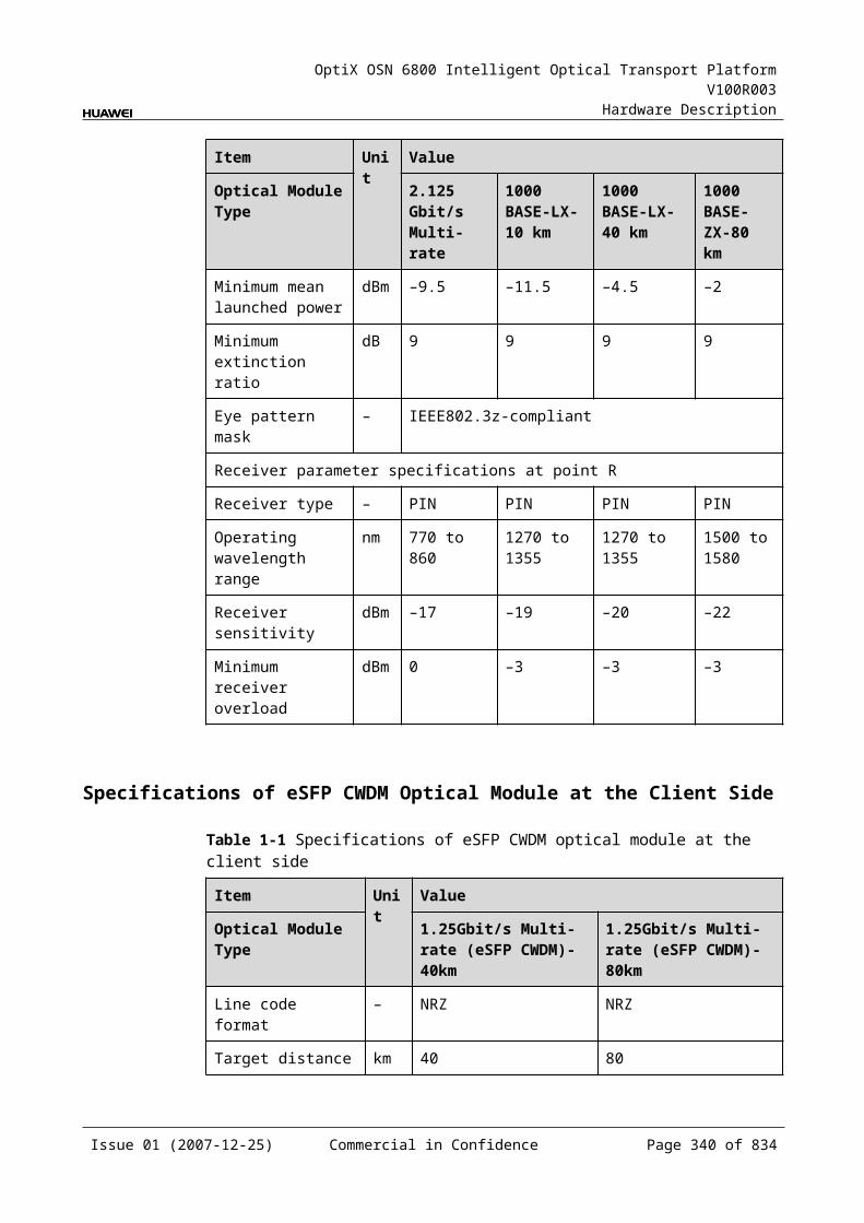
OptiX OSN 6800 Intelligent Optical Transport Platform V100R003
Hardware Description
InterfacesThere are 42 optical interfaces on the M40V front panel.Table 8-34 lists the type and function of each interface.
Table 8-1 Types and functions of the M40V interfaces
Interface
Type
Function
M01–M40 LC Connected to the "OUT" interface of the OTUs, receives the signals to be multiplexed.
OUT LC Connected to an optical amplifier or ITL, transmits the multiplexed signals.
MON LC Connected to the input interface of the MCA4 or MCA8, accomplishes online monitoring of optical spectrum.The MON port is a 10/90 tap of the total composite signal at the OUT port (10dB lower than the actual signal power).
There are 40 output interfaces on the M40V front panel. Table 8-35 and Table 8-36 show the mapping between the interfaces, frequency and wavelengths of the M40V board.
Table 8-2 Mapping between the optical interfaces, frequencies and wavelengths of the M40V board (even)
Interface
Frequency (THz)
Wavelength (nm)
Interface
Frequency (THz)
Wavelength (nm)
M01 196.00 1529.55 M21 194.00 1545.32
M02 195.90 1530.33 M22 193.90 1546.12
M03 195.80 1531.12 M23 193.80 1546.92
M04 195.70 1531.90 M24 193.70 1547.72
M05 195.60 1532.68 M25 193.60 1548.51
M06 195.50 1533.47 M26 193.50 1549.32
M07 195.40 1534.25 M27 193.40 1550.12
M08 195.30 1535.04 M28 193.30 1550.92
M09 195.20 1535.82 M29 193.20 1551.72
M10 195.10 1536.61 M30 193.10 1552.52
M11 195.00 1537.40 M31 193.00 1553.33
M12 194.90 1538.19 M32 192.90 1554.13
M13 194.80 1538.98 M33 192.80 1554.94
Issue 01 (2007-12-25) Commercial in Confidence Page 339 of 664
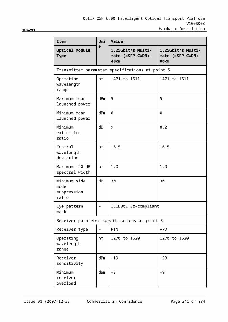
OptiX OSN 6800 Intelligent Optical Transport Platform V100R003
Hardware Description
Interface
Frequency (THz)
Wavelength (nm)
Interface
Frequency (THz)
Wavelength (nm)
M14 194.70 1539.77 M34 192.70 1555.75
M15 194.60 1540.56 M35 192.60 1556.55
M16 194.50 1541.35 M36 192.50 1557.36
M17 194.40 1542.14 M37 192.40 1558.17
M18 194.30 1542.94 M38 192.30 1558.98
M19 194.20 1543.73 M39 192.20 1559.79
M20 194.10 1544.53 M40 192.10 1560.61
Table 8-3 Mapping between the optical interfaces, frequencies and wavelengths of the M40V board (odd)
Interface
Frequency (THz)
Wavelength (nm)
Interface
Frequency (THz)
Wavelength (nm)
M01 196.05 1529.16 M21 194.05 1544.92
M02 195.95 1529.94 M22 193.95 1545.72
M03 195.85 1530.72 M23 193.85 1546.52
M04 195.75 1531.51 M24 193.75 1547.32
M05 195.65 1532.29 M25 193.65 1548.11
M06 195.55 1533.07 M26 193.55 1548.91
M07 195.45 1533.86 M27 193.45 1549.72
M08 195.35 1534.64 M28 193.35 1550.52
M09 195.25 1535.43 M29 193.25 1551.32
M10 195.15 1536.22 M30 193.15 1552.12
M11 195.05 1537.00 M31 193.05 1552.93
M12 194.95 1537.79 M32 192.95 1553.73
M13 194.85 1538.58 M33 192.85 1554.54
M14 194.75 1539.37 M34 192.75 1555.34
M15 194.65 1540.16 M35 192.65 1556.15
M16 194.55 1540.95 M36 192.55 1556.96
M17 194.45 1541.75 M37 192.45 1557.77
M18 194.35 1542.54 M38 192.35 1558.58
Issue 01 (2007-12-25) Commercial in Confidence Page 340 of 664
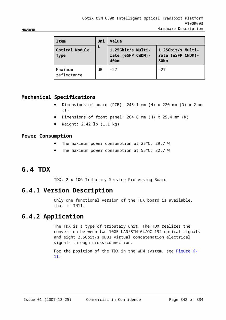
OptiX OSN 6800 Intelligent Optical Transport Platform V100R003
Hardware Description
Interface
Frequency (THz)
Wavelength (nm)
Interface
Frequency (THz)
Wavelength (nm)
M19 194.25 1543.33 M39 192.25 1559.39
M20 194.15 1544.13 M40 192.15 1560.20
Laser Safety LevelThe laser safety level of the optical interface is CLASS 1.
The maximum output optical power of each optical interface is lower than 10 dBm (10 mW).
8.6.6 Valid SlotsThe M40V occupies three slots. The valid slots for the M40V are IU1–IU15 in the subrack.
The back connector of the board is mounted to the backplane along the left slot in the subrack, so the slot number of the M40V board displayed on the NM is the number of the left one of the three occupied slots.
For example, if the M40V occupies slots IU1, IU2, and IU3, the slot number of the M40V displayed on the NM is IU1.
8.6.7 Characteristic Code for the M40VThe characteristic code for the M40V consists of two characters. One indicates the band. The other indicates whether the wavelengths that bear the optical signals processed by the board are odd or even wavelengths.
The detailed information of the characteristic code is given in Table 8-37.
Table 8-1 Characteristic code for the M40V
Code Meaning Description
The first character
Band Indicates the band of the optical signals processed by the board. The value C represents C band; the value L represents L band.
The second character
Odd/Even wavelengths
Indicates whether the wavelengths that bear signals are odd or even wavelengths. The value E represents even wavelengths; the value O represents odd wavelengths.
For example, the characteristic code for the TN11M40V is CE, indicating C band and even wavelengths.
Issue 01 (2007-12-25) Commercial in Confidence Page 341 of 664
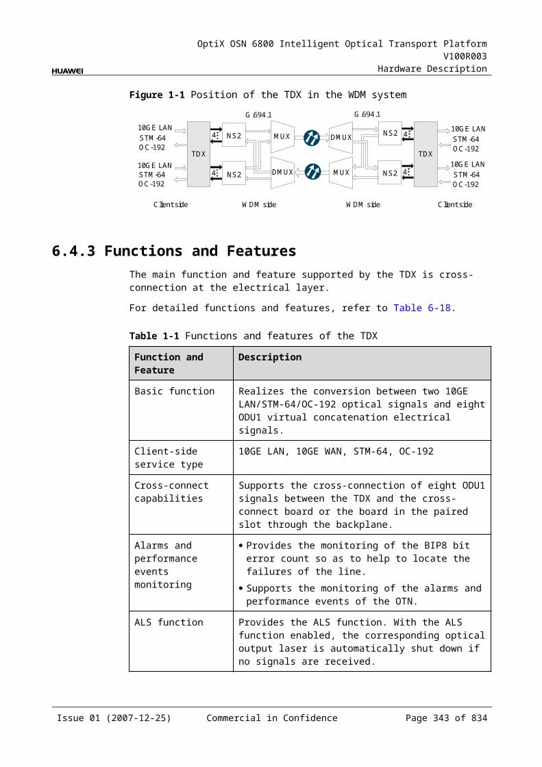
OptiX OSN 6800 Intelligent Optical Transport Platform V100R003
Hardware Description
8.6.8 NM Configuration ReferenceNM configuration reference includes the reference information needed during the configuration of boards through the T2000.
Display of Optical InterfacesThe serial numbers of the optical interfaces on the panel of the board displayed on the NM are listed in Table 8-38.
Table 8-1 Serial numbers of the interfaces of the M40V displayed on the NM
Interface on the Panel Interface on the NM
OUT 1
M01-M40 2-41
MON 42
Configuration ParametersOptical Interface Attenuation Ratio (dB)
8.6.9 Specifications of the M40VSpecifications include optical specifications, dimensions, weight, and power consumption.
Optical SpecificationsTable 8-39 lists the optical specifications of the M40V.
Table 8-1 Optical specifications of the M40V
Item Unit Value
Adjacent channel spacing GHz 100
Insertion loss dB ≤8a
Optical return loss dB >40
Operating wavelength range nm 1529–1561
Adjacent channel isolation dB >22
Non-adjacent channel isolation dB >25
Attenuation range dB 0–15
Loss accuracy dB ≤0.5 ( 0 to 10 )
Issue 01 (2007-12-25) Commercial in Confidence Page 342 of 664
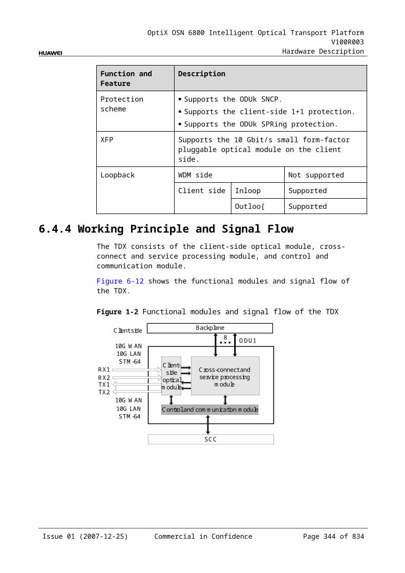
OptiX OSN 6800 Intelligent Optical Transport Platform V100R003
Hardware Description
≤1 ( >10dB )
Polarization dependent loss dB ≤0.5
Maximum channel insertion loss difference dB ≤3
a: This value can be reached when the attenuation of the VOA is set to 0 dB.
Mechanical Specifications Dimensions of board (PCB): 245.1 mm (H) x 220 mm (D) x 2 mm (T) Dimensions of front panel: 264.6 mm (H) x 76.2 mm (W) Weight: 5.06 lb (2.3 kg)
Power Consumption The maximum power consumption at 25: 38.5 W The maximum power consumption at 55: 42.3 W
Issue 01 (2007-12-25) Commercial in Confidence Page 343 of 664
OptiX OSN 6800 Intelligent Optical Transport Platform V100R003
Hardware Description
9 Optical Add and Drop Multiplexing Unit
9.1 CMR2CMR2: CWDM 2-channel optical add/drop multiplexing unit
9.1.1 Version DescriptionOnly one functional version of the CMR2 board is available, that is TN11.
9.1.2 ApplicationThe CMR2 is a type of optical add and drop multiplexing unit. The CMR2 realizes the adding/dropping and multiplexing of two signals.
For the position of the CMR2 in the CWDM system, see Figure 9-1.
Figure 9-1 Position of the CMR2 in the CWDM system
CMR2 CMR2
OTU OTU OTU OTU
Client side Client side
9.1.3 Functions and FeaturesThe main functions and features supported by the CMR2 are adding/dropping and multiplexing of signals, wavelength query, and providing a cascade interface.
For detailed functions and features, refer to Table 9-1.
Issue 01 (2007-12-25) Commercial in Confidence Page 345 of 664
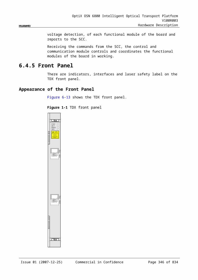
OptiX OSN 6800 Intelligent Optical Transport Platform V100R003
Hardware Description
Table 9-1 Functions and features of the CMR2
Function and Feature
Description
Basic function Adds/Drops and multiplexes two signals to/from the multiplexed signals.
WDM specification
Supports the CWDM specification.
Cascade interface
Provides the interface to cascade another optical add and drop multiplexing board to achieve the expansion.
Wavelength query
Supports the query of the wavelengths for the added/dropped signals.
9.1.4 Working Principle and Signal FlowThe CMR2 consists of the OADM optical module.
Figure 9-2 shows the functional modules and signal flow of the CMR2.
Figure 9-1 Functional modules and signal flow of the CMR2
OADM opticalmodule
IN
OUT
MOMI
D1 D2 A1 A2
In Channel-Adding DirectionThe MI interface receives the signal transmitted by the main path. This signal is multiplexed with two signals added through the A1 and the A2 interfaces by the OADM optical module. Then, the multiplexed signal is transmitted through the OUT interface.
In Channel-Dropping DirectionThe IN interface receives the multiplexed signal sent from the upstream station. The OADM optical module separates two channels from the main path and these two channels are dropped through the D1 and the D2 interfaces. The rest channels are transmitted through the MO interface.
Issue 01 (2007-12-25) Commercial in Confidence Page 346 of 664
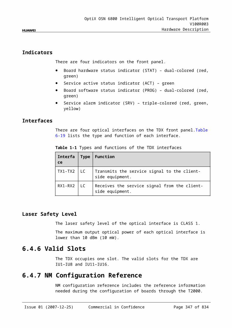
OptiX OSN 6800 Intelligent Optical Transport Platform V100R003
Hardware Description
9.1.5 Front PanelThere is an indicator and eight interfaces on the CMR2 front panel.
Appearance of the Front PanelFigure 9-3 shows the CMR2 front panel.
Figure 9-1 CMR2 front panel
CMR2
CMR2
STAT
LASERRADIATION
DO NOT VIEW DIRECTLYWITH OPTICALINSTRUMENTS
CLASS 1M LASERPRODUCT
OU
TIN
MO
MI
D1
A1
D2
A2
IndicatorsThere is one indicator on the front panel.
Board hardware status indicator (STAT) – dual-colored (red, green)
Issue 01 (2007-12-25) Commercial in Confidence Page 347 of 664
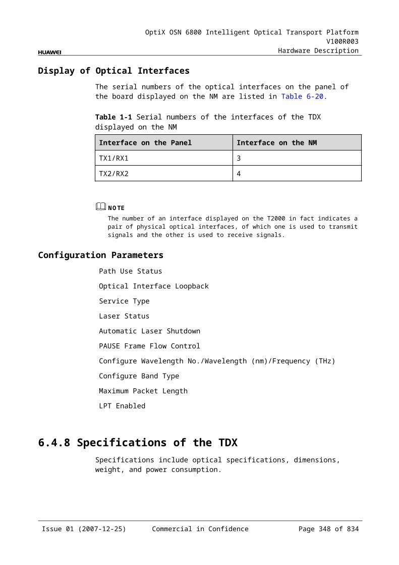
OptiX OSN 6800 Intelligent Optical Transport Platform V100R003
Hardware Description
InterfacesThere are eight optical interfaces on the CMR2 front panel. Table 9-2 lists the type and function of each interface.
Table 9-1 Types and functions of the CMR2 interfaces
Interface
Type
Function
A1–A2 LC Receives the signal sent from the OTU or the integrated client-side equipment.
D1–D2 LC Transmits the signal to the OTU or the integrated client-side equipment.
IN LC Receives the multiplexed signal.
OUT LC Transmits the multiplexed signal.
MI LC Cascade input interface, connected to the output interface of another OADM board.
MO LC Cascade output interface, connected to the input interface of another OADM board.
Laser Safety LevelThe laser safety level of the optical interface is CLASS 1M.
The maximum output optical power of each optical interface ranges from 10 dBm (10 mW) to 22.15 dBm (164 mW).
9.1.6 Valid SlotsThe CMR2 occupies one slot. The valid slots for the CMR2 are IU1–IU17 in the chassis.
9.1.7 Characteristic Code for the CMR2The characteristic code for the CMR2 consists of eight digits, indicating the two wavelengths that bear the signals processed by the board.
The detailed information of the characteristic code is given in Table 9-3.
Table 9-1 Characteristic code for the CMR2
Code Meaning Description
The first four digits
The first wavelength that bears optical signals
Indicate the first wavelength that bears the optical signals processed by the board.
Issue 01 (2007-12-25) Commercial in Confidence Page 348 of 664
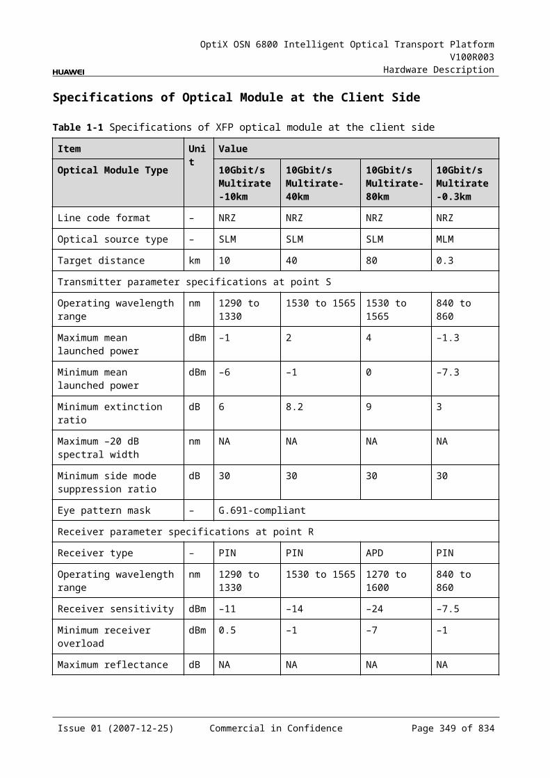
OptiX OSN 6800 Intelligent Optical Transport Platform V100R003
Hardware Description
The last four digits
The second wavelength that bears optical signals
Indicate the second wavelength that bears the optical signals processed by the board.
For example, the characteristic code for the TN11CMR2 is 14711571.
"1471" indicates that the first wavelength is 1471 nm. "1571" indicates that the second wavelength is 1571 nm.
9.1.8 NM Configuration ReferenceNM configuration reference includes the reference information needed during the configuration of boards through the T2000.
Display of Optical InterfacesThe serial numbers of the optical interfaces on the panel of the board displayed on the NM are listed in Table 9-4.
Table 9-1 Serial numbers of the interfaces of the CMR2 displayed on the NM
Interface on the Panel Interface on the NM
A1/D1 1
A2/D2 2
MI/MO 3
IN/OUT 4
NOTEThe number of an interface displayed on the T2000 in fact indicates a pair of physical optical interfaces, of which one is used to transmit signals and the other is used to receive signals.
Configuration ParametersConfigure Wavelength No./Wavelength (nm)/Frequency (THz)
9.1.9 Specifications of the CMR2Specifications include optical specifications, dimensions, weight, and power consumption.
Optical SpecificationsTable 9-5 lists the optical specifications of the CMR2.
Issue 01 (2007-12-25) Commercial in Confidence Page 349 of 664
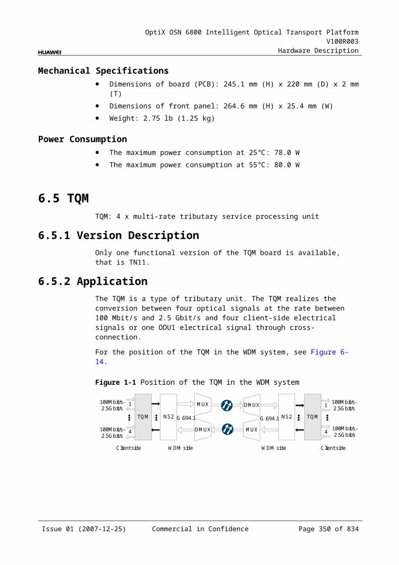
OptiX OSN 6800 Intelligent Optical Transport Platform V100R003
Hardware Description
Table 9-1 Optical specifications of the CMR2
Corresponding interfaces
Item Unit
Value
– Operating wavelength range nm 1271–1611
– Adjacent channel spacing nm 20
IN-D1IN-D2
0.5 dB spectral width nm ≥±6.5
Drop channel insertion loss dB ≤1.5
Adjacent channel isolation dB >25
Non-adjacent channel isolation dB >35
A1-OUTA2-OUT
0.5 dB spectral width nm ≥±6.5
Add channel insertion loss dB ≤1.5
IN-MOMI-OUT
Insertion loss dB ≤1.0
Isolation dB >13
– Optical return loss dB >40
Rules of Adding/Dropping WavelengthThe CMR2 adds/drops and multiplexes two signals to/from the multiplexed signals. There are five groups of wavelengths:
Table 9-1 Rules of adding/dropping wavelength of the CMR2
Group Wavelength (nm)
A1/D1 A2/D2
1 1271 1371
2 1471 1491
3 1511 1531
4 1551 1571
5 1591 1611
Mechanical Specifications Dimensions of board (PCB): 245.1 mm (H) x 220 mm (D) x 2 mm (T) Dimensions of front panel: 264.6 mm (H) x 25.4 mm (W) Weight: 1.76 lb (0.8 kg)
Issue 01 (2007-12-25) Commercial in Confidence Page 350 of 664
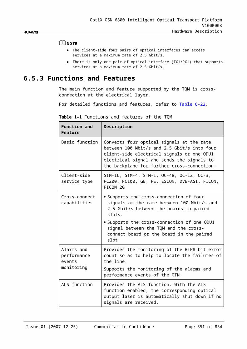
OptiX OSN 6800 Intelligent Optical Transport Platform V100R003
Hardware Description
Power Consumption The maximum power consumption at 25: 0.2 W The maximum power consumption at 55: 0.3 W
Issue 01 (2007-12-25) Commercial in Confidence Page 351 of 664
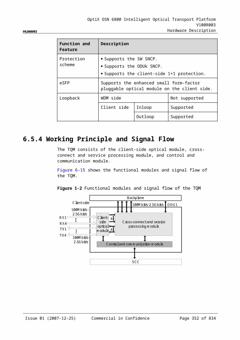
OptiX OSN 6800 Intelligent Optical Transport Platform V100R003
Hardware Description
9.2 CMR4CMR4: CWDM 4-channel optical add/drop multiplexing unit
9.2.1 Version DescriptionOnly one functional version of the CMR4 board is available, that is TN11.
9.2.2 ApplicationThe CMR4 is a type of optical add and drop multiplexing unit. The CMR4 realizes the adding/dropping and multiplexing of four signals.
For the position of the CMR4 in the CWDM system, see Figure 9-4.
Figure 9-1 Position of the CMR4 in the CWDM system
CMR4 CMR4
OTU 4 4OTU OTU OTU
Client side Client side
9.2.3 Functions and FeaturesThe main functions and features supported by the CMR4 are adding/dropping and multiplexing of signals, wavelength query, and providing a cascade interface.
For detailed functions and features, refer to Table 9-7.
Table 9-1 Functions and features of the CMR4
Function and Feature
Description
Basic function Adds/Drops and multiplexes four signals to/from the multiplexed signals.
WDM specification
Supports the CWDM specification.
Cascade interface
Provides the interface to cascade another optical add and drop multiplexing board to achieve the expansion.
Wavelength query
Supports the query of the wavelengths for the added/dropped signals.
Issue 01 (2007-12-25) Commercial in Confidence Page 352 of 664
OptiX OSN 6800 Intelligent Optical Transport Platform V100R003
Hardware Description
9.2.4 Working Principle and Signal FlowThe CMR4 consists of the OADM optical module.
Figure 9-5 shows the functional modules and signal flow of the CMR4.
Figure 9-1 Functional modules and signal flow of the CMR4
OADM opticalmodule
IN
OUT
MOMI
D1 D4 A1 A4
4 4
In Channel-Adding DirectionThe MI interface receives the signal transmitted by the main path. This signal is multiplexed with four signals added through the A1–A4 interfaces by the OADM optical module. Then, the multiplexed signal is transmitted through the OUT interface.
In Channel-Dropping DirectionThe IN interface receives the multiplexed signal sent from the upstream station. The OADM optical module separates four channels from the main path and these four channels are dropped through the D1–D4 interfaces. The rest channels are transmitted through the MO interface.
9.2.5 Front PanelThere is an indicator and 12 interfaces on the CMR4 front panel.
Appearance of the Front PanelFigure 9-6 shows the CMR4 front panel.
Issue 01 (2007-12-25) Commercial in Confidence Page 353 of 664
OptiX OSN 6800 Intelligent Optical Transport Platform V100R003
Hardware Description
Figure 9-1 CMR4 front panel
CMR4
CMR4
STAT
LASERRADIATION
DO NOT VIEW DIRECTLYWITH OPTICALINSTRUMENTS
CLASS 1M LASERPRODUCT
OU
TIN
MO
MI
D1
A1
D2
A2
D3
A3
D4
A4
IndicatorsThere is one indicator on the front panel.
Board hardware status indicator (STAT) – dual-colored (red, green)
InterfacesThere are 12 optical interfaces on the CMR4 front panel. Table 9-8 lists the type and function of each interface.
Issue 01 (2007-12-25) Commercial in Confidence Page 354 of 664
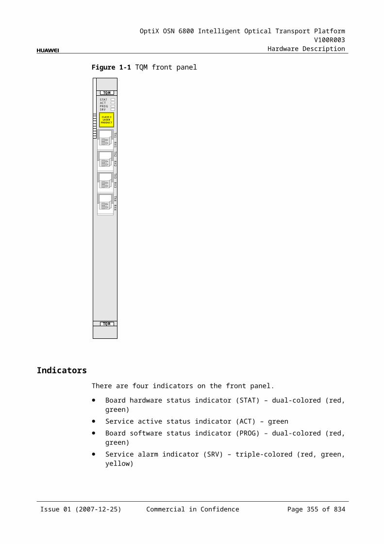
OptiX OSN 6800 Intelligent Optical Transport Platform V100R003
Hardware Description
Table 9-1 Types and functions of the CMR4 interfaces
Interface
Type
Function
A1–A4 LC Receives the signal sent from the OTU or the integrated client-side equipment.
D1–D4 LC Transmits the signal to the OTU or the integrated client-side equipment.
IN LC Receives the multiplexed signal.
OUT LC Transmits the multiplexed signal.
MI LC Cascade input interface, connected to the output interface of another OADM board.
MO LC Cascade output interface, connected to the input interface of another OADM board.
Laser Safety LevelThe laser safety level of the optical interface is CLASS 1M.
The maximum output optical power of each optical interface ranges from 10 dBm (10 mW) to 22.15 dBm (164 mW).
9.2.6 Valid SlotsThe CMR4 occupies one slot. The valid slots for the CMR4 are IU1–IU17.
9.2.7 Characteristic Code for the CMR4The characteristic code for the CMR4 consists of eight digits, indicating the four wavelengths that bear the signals processed by the board.
The detailed information of the characteristic code is given in Table 9-9.
Table 9-1 Characteristic code for the CMR4
Code Meaning Description
The first and the second digits
The first wavelength that bears optical signals
Indicate the middle two digits of the first wavelength that bears the optical signals processed by the board.
The third and the fourth digits
The second wavelength that bears optical signals
Indicate the middle two digits of the second wavelength that bears the optical signals processed by the board.
The fifth and the sixth digits
The third wavelength that bears optical signals
Indicate the middle two digits of the third wavelength that bears the optical signals processed by the board.
Issue 01 (2007-12-25) Commercial in Confidence Page 355 of 664
OptiX OSN 6800 Intelligent Optical Transport Platform V100R003
Hardware Description
Code Meaning Description
The seventh and the eighth digits
The fourth wavelength that bears optical signals
Indicate the middle two digits of the fourth wavelength that bears the optical signals processed by the board.
For example, the characteristic code for the TN11CMR4 is 47495961.
"47" indicates that the first wavelength is 1471 nm. "49" indicates that the second wavelength is 1491 nm. "59" indicates that the third wavelength is 1591 nm. "61" indicates that the fourth wavelength is 1611 nm.
9.2.8 NM Configuration ReferenceNM configuration reference includes the reference information needed during the configuration of boards through the T2000.
Display of Optical InterfacesThe serial numbers of the optical interfaces on the panel of the board displayed on the NM are listed in Table 9-10.
Table 9-1 Serial numbers of the interfaces of the CMR4 displayed on the NM
Interface on the Panel Interface on the NM
A1/D1 1
A2/D2 2
A3/D3 3
A4/D4 4
MI/MO 5
IN/OUT 6
NOTEThe number of an interface displayed on the T2000 in fact indicates a pair of physical optical interfaces, of which one is used to transmit signals and the other is used to receive signals.
Configuration ParametersConfigure Wavelength No./Wavelength (nm)/Frequency (THz)
Issue 01 (2007-12-25) Commercial in Confidence Page 356 of 664
OptiX OSN 6800 Intelligent Optical Transport Platform V100R003
Hardware Description
9.2.9 Specifications of the CMR4Specifications include optical specifications, dimensions, weight, and power consumption.
Optical SpecificationsTable 9-11 lists the optical specifications of the CMR4.
Table 9-1 Optical specifications of the CMR4
Corresponding interfaces
Item Unit
Value
– Operating wavelength range
nm 1291–1611 (1371 nm not included)
– Adjacent channel spacing
nm 20
IN-D1IN-D2IN-D3IN-D4
0.5 dB spectral width nm ≥±6.5
Drop channel insertion loss
dB ≤2
Adjacent channel isolation
dB >25
Non-adjacent channel isolation
dB >35
A1-OUTA2-OUTA3-OUTA4-OUT
0.5 dB spectral width nm ≥±6.5
Add channel insertion loss
dB ≤2
IN-MOMI-OUT
Insertion loss dB ≤1.5
Isolation dB >13
– Optical return loss dB >40
Rules of Adding/Dropping WavelengthThe CMR4 adds/drops and multiplexes four signals to/from the multiplexed signals. There are four groups of wavelengths:
Issue 01 (2007-12-25) Commercial in Confidence Page 357 of 664
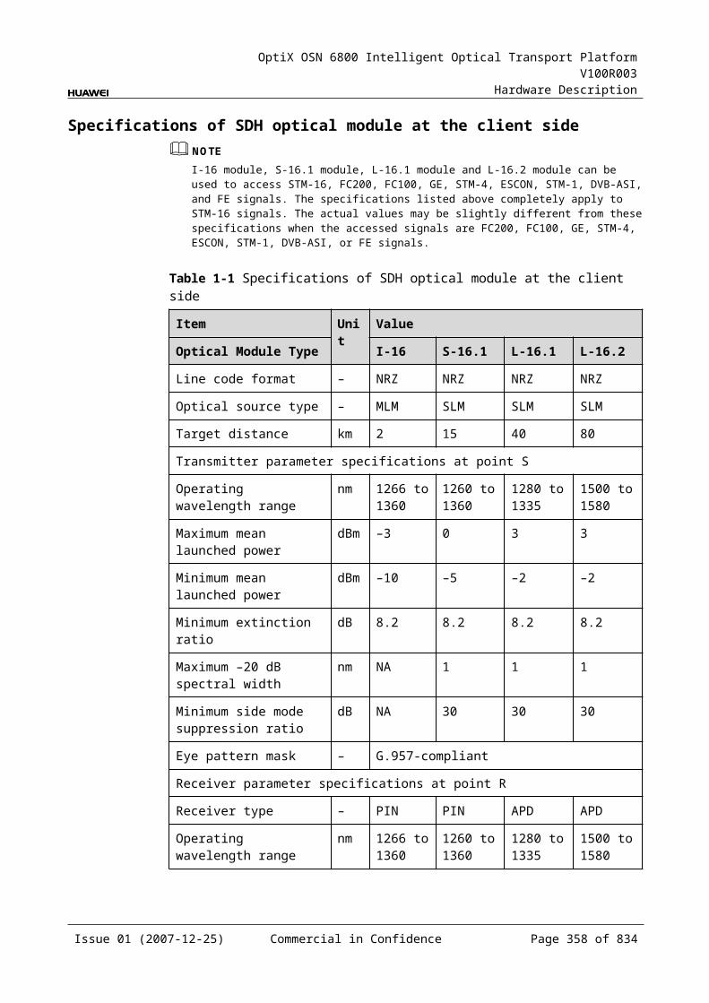
OptiX OSN 6800 Intelligent Optical Transport Platform V100R003
Hardware Description
Table 9-1 Rules of adding/dropping wavelength of the CMR4
Group Wavelength (nm)
A1/D1 A2/D2 A3/D3 A4/D4
1 1291 1311 1331 1351
2 1391 1411 1431 1451
3 1471 1491 1591 1611
4 1511 1531 1551 1571
Mechanical Specifications Dimensions of board (PCB): 245.1 mm (H) x 220 mm (D) x 2 mm (T) Dimensions of front panel: 264.6 mm (H) x 25.4 mm (W) Weight: 1.98 lb (0.9 kg)
Power Consumption The maximum power consumption at 25: 0.2 W The maximum power consumption at 55: 0.3 W
9.3 DMR1DMR1: CWDM 1-channel Bidirectional optical add/drop multiplexing board
9.3.1 Version DescriptionOnly one functional version of the DMR1 board is available, that is TN11.
9.3.2 ApplicationThe DMR1 board is used to add/drop and multiplex a 1310nm wavelength on the east and west directions.
For the position of the DMR1 in the CWDM system, see Figure 9-7.
Issue 01 (2007-12-25) Commercial in Confidence Page 358 of 664
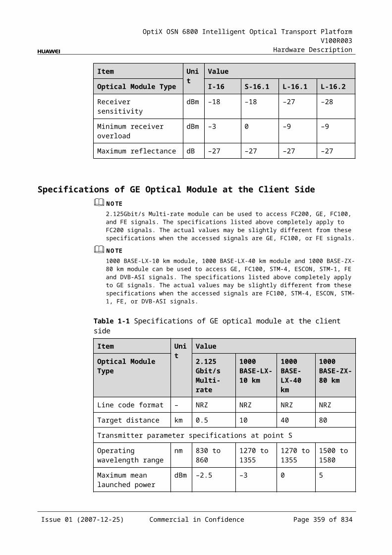
OptiX OSN 6800 Intelligent Optical Transport Platform V100R003
Hardware Description
Figure 9-1 Position of the DMR1 in the CWDM system
OTU OTU
DMR1
OADM
OADM
DMR1
WA ED
WIN
WOUT
WD EA
WMO
WMI EMO
EMIOA OA
OAOA
1310nm
1310nm
1310nm
1310nm
EIN
EOUT
NOTEThe DMR1 board is able to process signals from two directions. In the figure, the two DRM1 boards are actually one physical board.
9.3.3 Functions and FeaturesThe DMR1 board supports add/drop multiplexing, port concatenation and wavelength query.
Table 9-13 provides the detailed features and functions of the DMR1 board.
Table 9-1 Functions and features of the DMR1 board
Functions and Features
Description
Basic functions Adds/drops and multiplexes a 1310nm wavelength on the east and west directions.
WDM specification Supports the CWDM specification.
Supports port concatenation.
Provides the interface to cascade another optical add and drop multiplexing board to achieve the expansion.
Supports wavelength query.
Supports the query of the wavelengths for the added/dropped signals.
9.3.4 Working Principle and Signal FlowThe DMR1 board consists of OADM optical modules.
Figure 9-8 shows the functional modules of the DMR1 board.
Issue 01 (2007-12-25) Commercial in Confidence Page 359 of 664
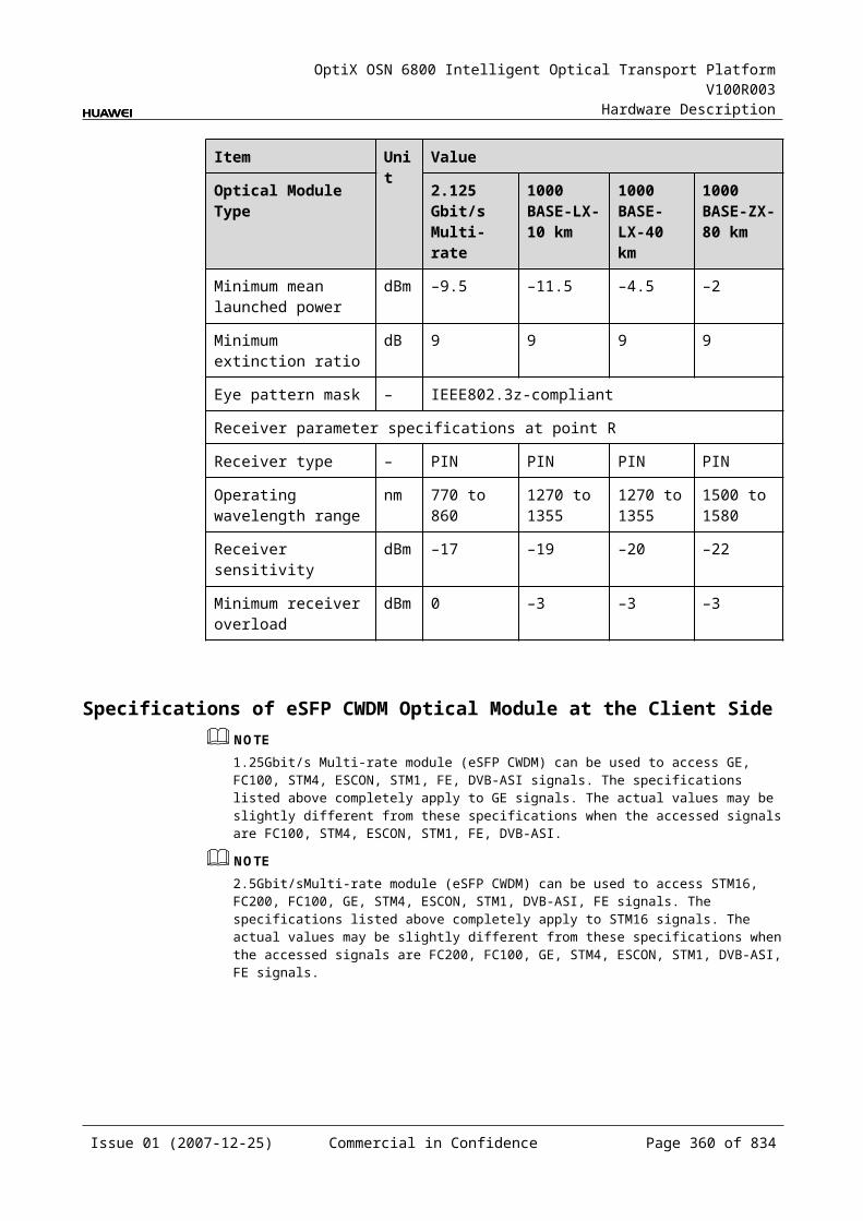
OptiX OSN 6800 Intelligent Optical Transport Platform V100R003
Hardware Description
Figure 9-1 Functional modules of the DMR1 board
OADM
WIN
WOUT EIN
EOUT
WA
WD EA
EDWMI
WMO EMI
EMO
WIN receives signals from west main path. OADM module extracts 1310nm signals from the received signals. The extracted signals are dropped through WD. The remaining signals are connected to other OADM equipment through WMO. Local 1310nm signals are added through EA, and other signals are added through EMI. After multiplexed by OADM module, the signals are sent to east main path by EOUT.
Similarly, EIN receives signals from east main path. OADM module extracts 1310nm signals from the received signals. The extracted signals are dropped through ED. The remaining signals are connected to other OADM equipment through EMO. Local 1310nm signals are added through WA, and other signals are added through WMI. After multiplexed by OADM module, the signals are sent to west main path by WOUT.
9.3.5 Front PanelThere are interfaces on the front panel of the board.
Appearance of the Front PanelFigure 9-9 shows the DMR1 front panel.
Issue 01 (2007-12-25) Commercial in Confidence Page 360 of 664
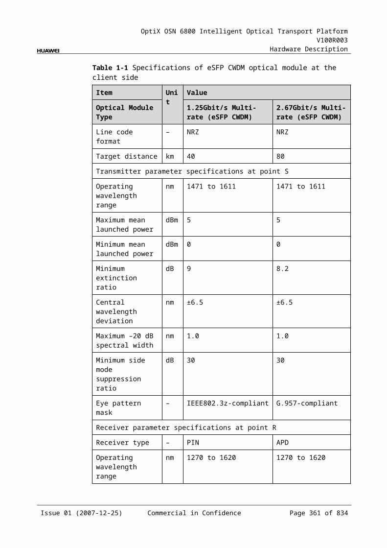
OptiX OSN 6800 Intelligent Optical Transport Platform V100R003
Hardware Description
Figure 9-1 DMR1 front panel
DMR1
DMR1
STAT
WO
UT
WM
OW
MI
EM
OE
MI
WD
WA
LASERRADIATION
DO NOT VIEW DIRECTLYWITH OPTICALINSTRUMENTS
CLASS 1M LASERPRODUCT
ED
EA
EO
UT
WIN
EIN
IndicatorsThere is one indicator on the front panel.
Board hardware status indicator (STAT) – dual-colored (red, green)
InterfacesThere are 12 optical interfaces on the DMR1 board. Table 9-14 lists the type and function of each interface.
Issue 01 (2007-12-25) Commercial in Confidence Page 361 of 664
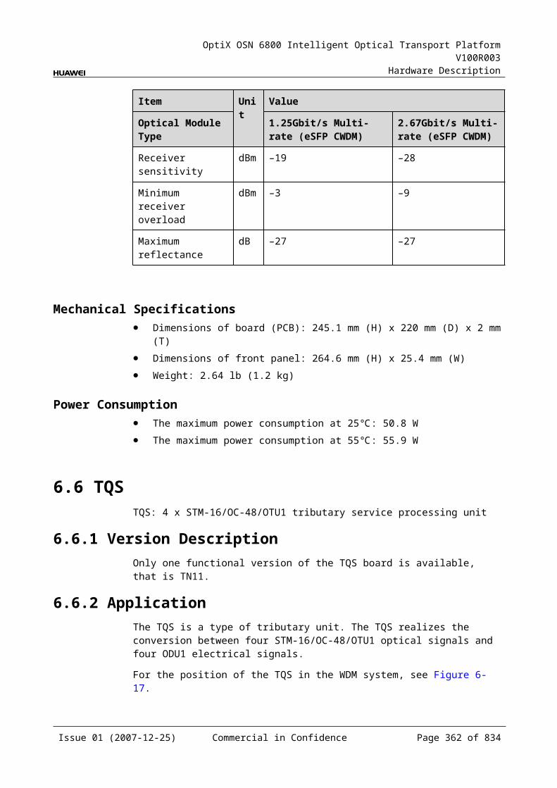
OptiX OSN 6800 Intelligent Optical Transport Platform V100R003
Hardware Description
Table 9-1 Types and functions of the DMR1 interfaces
Interface Type
Function
EA/WA LC Receives the 1310nm optical signals that west and east client-side equipment transmits.
ED/WD LC Transmits 1310nm optical signals to west and east client-side equipment.
EIN/WIN LC Receives the multiplexed signals on west and east main paths.
EOUT/WOUT LC Transmits multiplexed signals to west and east main paths.
EMI/WMI LC Serves as concatenation input optical interface. It connects to the output interfaces on other boards.
EMO/WMO LC Serves as concatenation output optical interface. It connects to the input interfaces on other boards.
Laser Safety LevelThe laser safety level of the optical interface is CLASS 1M.
The maximum output optical power of each optical interface ranges from 10 dBm (10 mW) to 22.15 dBm (164 mW).
9.3.6 Valid SlotsThe DMR1 occupies one slot. The valid slots for the DMR1 are IU1–IU17 in the subrack.
9.3.7 NM Configuration ReferenceNM configuration reference includes the reference information needed during the configuration of boards through the T2000.
Interface DisplayTable 9-15 lists the number on the NM indicating each optical interface on the board.
Table 9-1 Number on the NM indicating each optical interface on the DMR1 board
Interface on Front Panel Number on the NM
WA/WD 1
EA/ED 2
WMI/WMO 3
WIN/WOUT 4
EMI/EMO 5
Issue 01 (2007-12-25) Commercial in Confidence Page 362 of 664
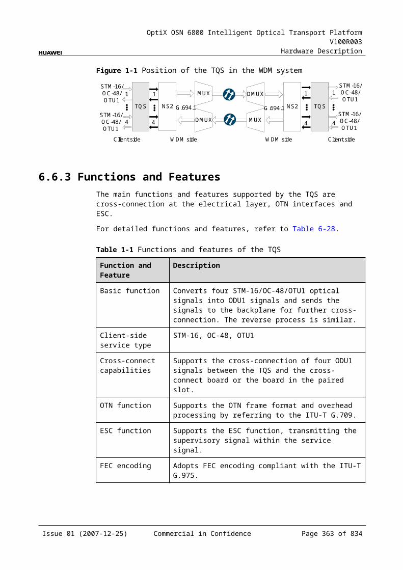
OptiX OSN 6800 Intelligent Optical Transport Platform V100R003
Hardware Description
Interface on Front Panel Number on the NM
EIN/EOUT 6
NOTEThe number of an interface displayed on the T2000 in fact indicates a pair of physical optical interfaces, of which one is used to transmit signals and the other is used to receive signals.
Board Parameter ConfigurationConfigure Wavelength No./Wavelength (nm)/Frequency (THz)
9.3.8 SpecificationsSpecifications include optical specifications, dimensions, weight, and power consumption.
Optical Specifications
Table 9-1 Optical specifications of the DMR1
Corresponding interfaces
Item Unit
Value
EA/ED/WA/WD Operating wavelength range nm 1260–1360
EIN-EDWIN-WD
Drop channel insertion loss dB ≤1
Isolation dB >40
EA-EOUTWA-WOUT
Add channel insertion loss dB ≤1
EIN-EMOEMI-EOUTWIN-WMOWMI-WOUT
Insertion loss dB ≤0.8
Isolation dB ≥25
– Optical return loss dB >40
Rules of Adding/Dropping WavelengthThe DMR1 board adds/drops and multiplexes a 1310nm wavelength on the east and west directions from the multiplexed signals.
Mechanical Specifications Dimensions of board (PCB): 245.1 mm (H) x 220 mm (D) x 2 mm (T)
Issue 01 (2007-12-25) Commercial in Confidence Page 363 of 664
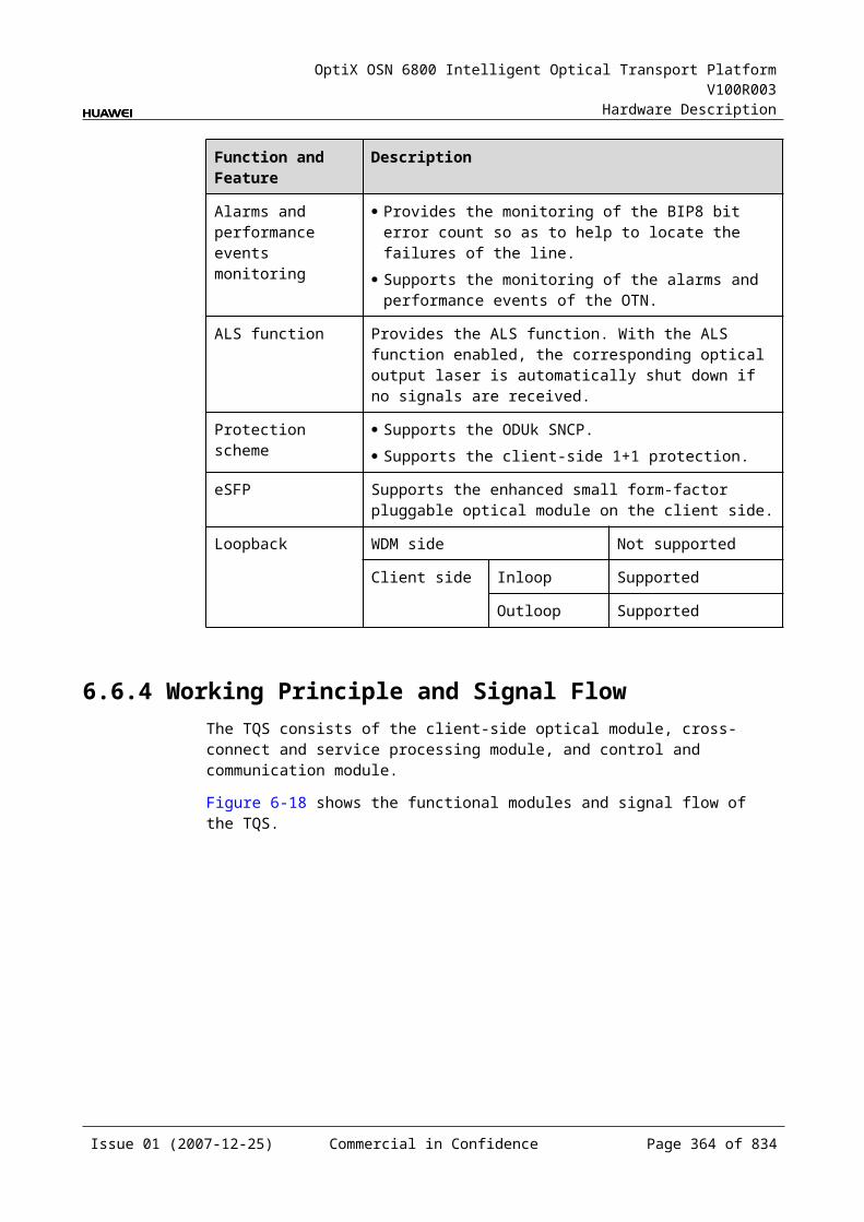
OptiX OSN 6800 Intelligent Optical Transport Platform V100R003
Hardware Description
Dimensions of front panel: 264.6 mm (H) x 25.4 mm (W) Weight: 0.7 kg
Power Consumption The maximum power consumption at 25: 0.2W The maximum power consumption at 55: 0.3W
9.4 MR2MR2: 2-channel optical add/drop multiplexing unit
9.4.1 Version DescriptionOnly one functional version of the MR2 board is available, that is TN11.
9.4.2 ApplicationThe MR2 is a type of optical add and drop multiplexing unit. The MR2 realizes the adding/dropping and multiplexing of two signals.
For the position of the MR2 in the DWDM system, see Figure 9-10.
Figure 9-1 Position of the MR2 in the DWDM system
MR2OA OA
OA OAMR2
OTU OTU OTU OTU
Client side Client side
9.4.3 Functions and FeaturesThe main functions and features supported by the MR2 are adding/dropping and multiplexing of signals, wavelength query, and providing a cascade interface.
For detailed functions and features, refer to Table 9-17.
Issue 01 (2007-12-25) Commercial in Confidence Page 364 of 664
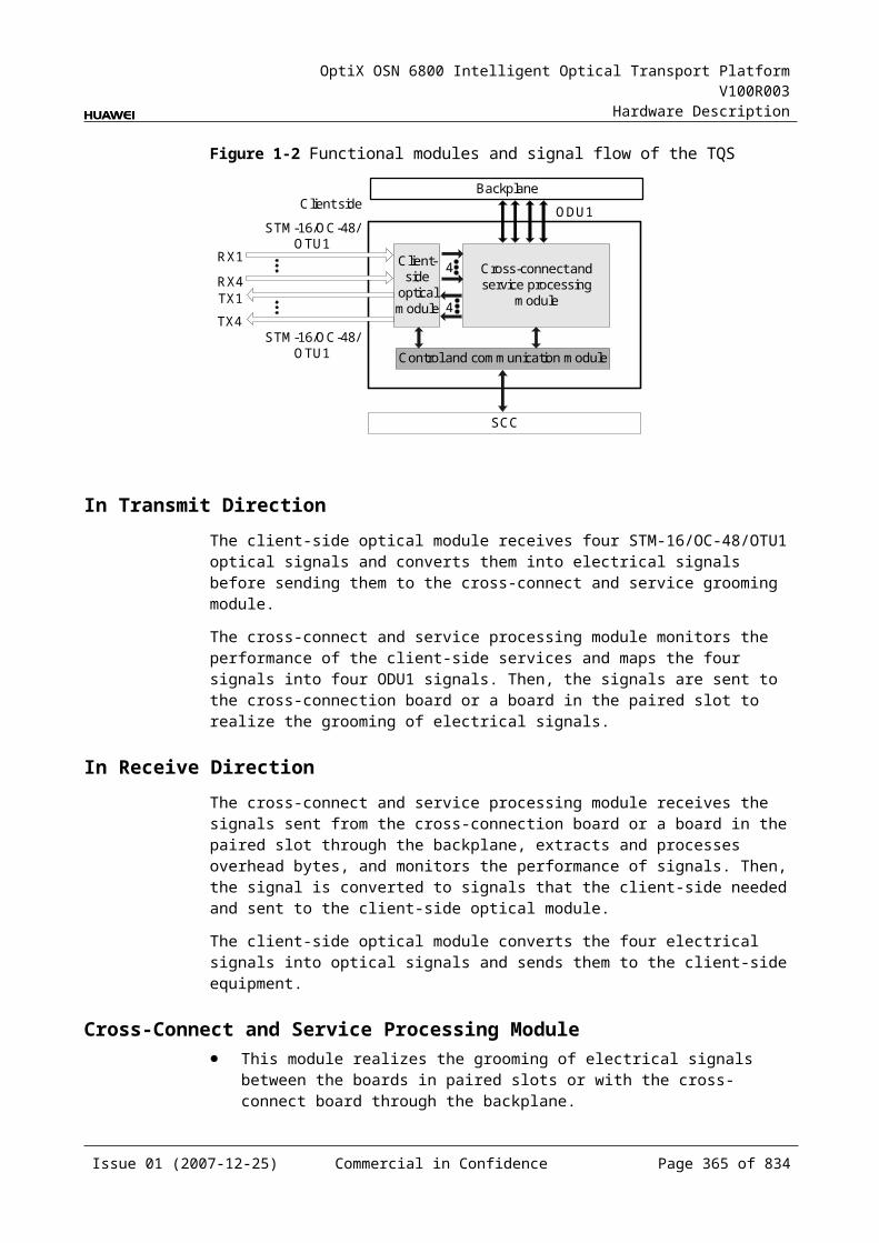
OptiX OSN 6800 Intelligent Optical Transport Platform V100R003
Hardware Description
Table 9-1 Functions and features of the MR2
Function and Feature
Description
Basic function Adds/Drops and multiplexes random two signals to/from the multiplexed signals.
WDM specification
Supports the DWDM specification.
Cascade interface
Provides the interface to cascade another optical add and drop multiplexing board to achieve the expansion.
Wavelength query
Supports the query of the wavelengths for the added/dropped signals.
9.4.4 Working Principle and Signal FlowThe MR2 consists of the OADM optical module.
Figure 9-11 shows the functional modules and signal flow of the MR2.
Figure 9-1 Functional modules and signal flow of MR2
OADM opticalmodule
IN
OUT
MOMI
D1 D2 A1 A2
In Channel-Adding DirectionThe MI interface receives the signal transmitted by the main path. The signal is multiplexed with the two signals added through the A1 and A2 interfaces by the OADM optical module. Then, the multiplexed signal is output through the OUT interface.
In Channel-Dropping DirectionThe IN interface receives the multiplexed signal sent from the upstream station. The OADM optical module separates two channels from the main path and the two channels are dropped through the D1 and D2 interfaces. The rest channels are transmitted through the MO interface.
Issue 01 (2007-12-25) Commercial in Confidence Page 365 of 664

OptiX OSN 6800 Intelligent Optical Transport Platform V100R003
Hardware Description
9.4.5 Front PanelThere is an indicator and eight interfaces on the MR2 front panel.
Appearance of the Front PanelFigure 9-12 shows the MR2 front panel.
Figure 9-1 MR2 front panel
MR2
MR2
STAT
LASERRADIATION
DO NOT VIEW DIRECTLYWITH OPTICALINSTRUMENTS
CLASS 1M LASERPRODUCT
OU
TIN
MO
MI
D1
A1
D2
A2
IndicatorsThere is one indicator on the front panel.
Board hardware status indicator (STAT) – dual-colored (red, green)
Issue 01 (2007-12-25) Commercial in Confidence Page 366 of 664

OptiX OSN 6800 Intelligent Optical Transport Platform V100R003
Hardware Description
InterfacesThere are eight optical interfaces on the MR2 front panel. Table 9-18 lists the type and function of each interface.
Table 9-1 Types and functions of the MR2 interfaces
Interface
Type
Function
A1–A2 LC Receives the signal sent from the OTU or the integrated client-side equipment.
D1–D2 LC Transmits the signal to the OTU or the integrated client-side equipment.
IN LC Receives the multiplexed signal.
OUT LC Transmits the multiplexed signal.
MO LC Cascade output interface, connected to the input interface of another OADM board.
MI LC Cascade input interface, connected to the output interface of another OADM board.
Laser Safety LevelThe laser safety level of the optical interface is CLASS 1M.
The maximum output optical power of each optical interface ranges from 10 dBm (10 mW) to 22.15 dBm (164 mW).
9.4.6 Valid SlotsThe MR2 occupies one slot. The valid slots for the MR2 are IU1–IU17.
9.4.7 Characteristic Code for the MR2The characteristic code for the MR2 consists of eight digits that indicate the frequencies of the two signals processed by the board.
The detailed information of the characteristic code is given in Table 9-19.
Table 9-1 Characteristic code for the MR2
Code Meaning Description
The first four digits
The frequency of the first optical signal
Indicate the last four digits of the frequency that bears the first optical signal.
The last four digits
The frequency of the second optical signal
Indicate the last four digits of the frequency that bears the second optical signal.
Issue 01 (2007-12-25) Commercial in Confidence Page 367 of 664
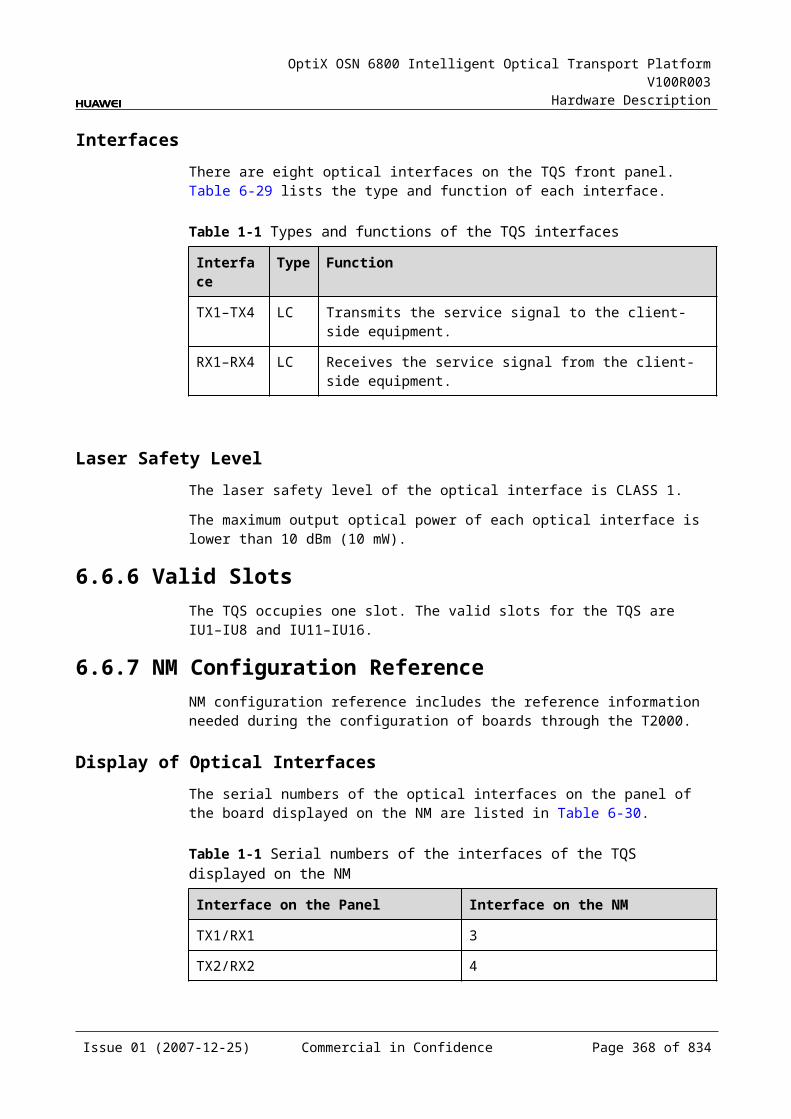
OptiX OSN 6800 Intelligent Optical Transport Platform V100R003
Hardware Description
For example, the characteristic code for the TN11MR2 is 93609370.
"9360" indicates that the frequency of the first optical signal is 193.60 THz. "9370" indicates that the frequency of the second optical signal is 193.70 THz.
9.4.8 NM Configuration ReferenceNM configuration reference includes the reference information needed during the configuration of boards through the T2000.
Display of Optical InterfacesThe serial numbers of the optical interfaces on the panel of the board displayed on the NM are listed in Table 9-20.
Table 9-1 Serial numbers of the interfaces of the MR2 displayed on the NM
Interface on the Panel Interface on the NM
A1/D1 1
A2/D2 2
MI/MO 3
IN/OUT 4
NOTEThe number of an interface displayed on the T2000 in fact indicates a pair of physical optical interfaces, of which one is used to transmit signals and the other is used to receive signals.
Configuration ParametersConfigure Wavelength No./Wavelength (nm)/Frequency (THz)
9.4.9 Specifications of the MR2Specifications include optical specifications, dimensions, weight, and power consumption.
Optical SpecificationsTable 9-21 lists the optical specifications of the MR2.
Table 9-1 Optical specifications of the MR2
Corresponding interfaces
Item Unit
Value
– Operating wavelength range nm 1529–1561
Issue 01 (2007-12-25) Commercial in Confidence Page 368 of 664

OptiX OSN 6800 Intelligent Optical Transport Platform V100R003
Hardware Description
Corresponding interfaces
Item Unit
Value
– Adjacent channel spacing GHz 100
IN-D1IN-D2
0.5 dB spectral width nm ≥±0.11
Drop channel insertion loss dB ≤1.5
Adjacent channel isolation dB >25
Non-adjacent channel isolation dB >35
A1-OUTA2-OUT
0.5 dB spectral width nm ≥±0.11
Add channel insertion loss dB ≤1.5
IN-MOMI-OUT
Insertion loss dB ≤1.0
Isolation dB >13
– Optical return loss dB >40
Rules of Adding/Dropping WavelengthThe MR2 adds/drops and multiplexes random two signals to/from the multiplexed signals. There are no rules of adding/dropping wavelength.
Mechanical Specifications Dimensions of board (PCB): 245.1 mm (H) x 220 mm (D) x 2 mm (T) Dimensions of front panel: 264.6 mm (H) x 25.4 mm (W) Weight: 1.98 lb (0.9 kg)
Power Consumption The maximum power consumption at 25: 0.2 W The maximum power consumption at 55: 0.3 W
9.5 MR4MR4: 4-channel optical add/drop multiplexing unit
9.5.1 Version DescriptionOnly one functional version of the MR4 board is available, that is TN11.
9.5.2 ApplicationThe MR4 is a type of optical add and drop multiplexing unit. The MR4 realizes the adding/dropping and multiplexing of four signals.
For the position of the MR4 in the DWDM system, see Figure 9-13.
Issue 01 (2007-12-25) Commercial in Confidence Page 369 of 664
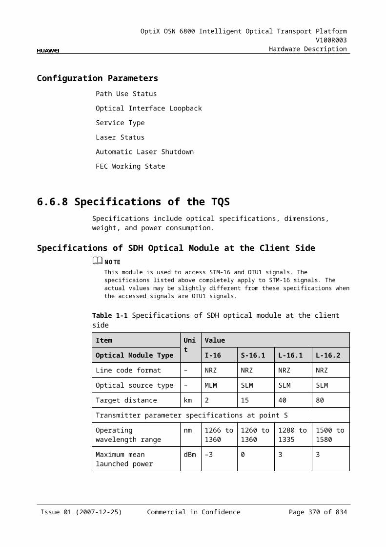
OptiX OSN 6800 Intelligent Optical Transport Platform V100R003
Hardware Description
Figure 9-1 Position of the MR4 in the DWDM system
MR4OA OA
OA OAMR4
OTU 4 4OTU OTU OTU
Client side Client side
9.5.3 Functions and FeaturesThe main functions and features supported by the MR4 are adding/dropping and multiplexing of signals, wavelength query, and providing a cascade interface.
For detailed functions and features, refer to Table 9-22.
Table 9-1 Functions and features of the MR4
Function and Feature
Description
Basic function Adds/Drops and multiplexes consecutive four signals to/from the multiplexed signals.
WDM specification
Supports the DWDM specification.
Cascade interface
Provides the interface to cascade another optical add and drop multiplexing board to achieve the expansion.
Wavelength query
Supports the query of the wavelengths for the added/dropped signals.
9.5.4 Working Principle and Signal FlowThe MR4 consists of the OADM optical module.
Figure 9-14 shows the functional modules and signal flow of the MR4.
Issue 01 (2007-12-25) Commercial in Confidence Page 370 of 664
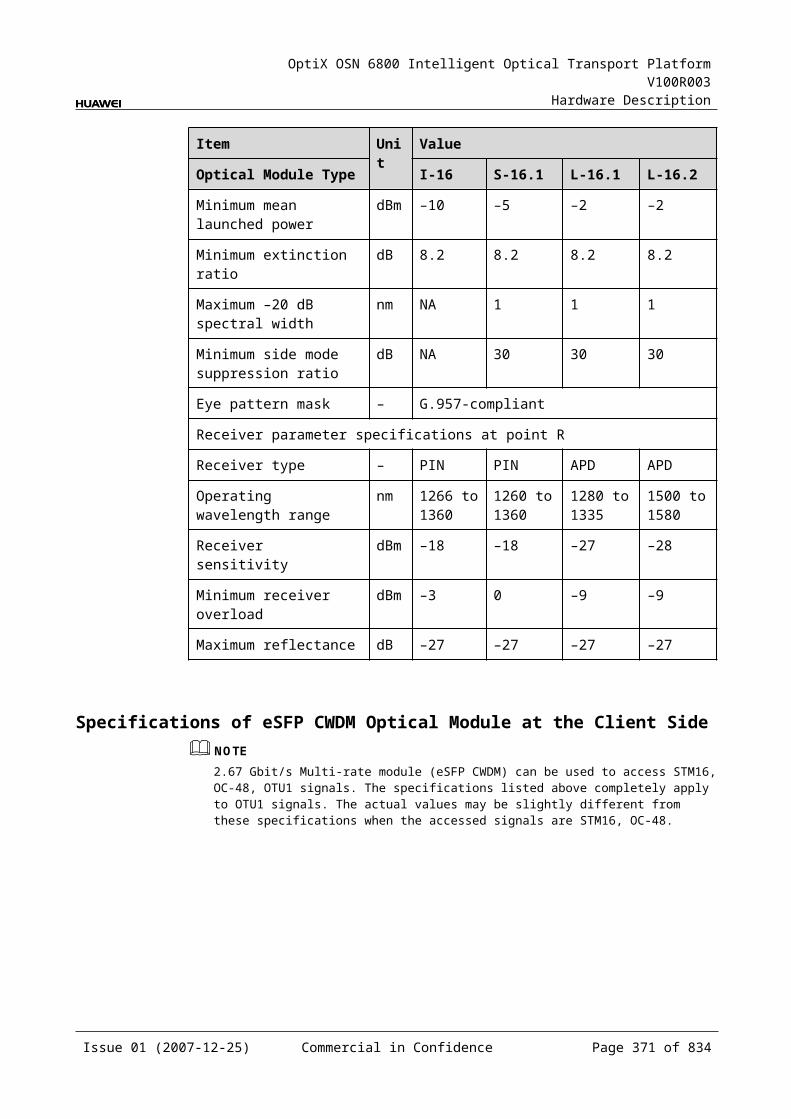
OptiX OSN 6800 Intelligent Optical Transport Platform V100R003
Hardware Description
Figure 9-1 Functional modules and signal flow of the MR4
OADM opticalmodule
IN
OUT
MOMI
D1 D4 A1 A4
4 4
In Channel-Adding DirectionThe MI interface receives the signal transmitted by the main path. The signal is multiplexed with the four signals added through the A1–A4 interfaces by the OADM optical module. Then, the multiplexed signal is output through the OUT interface.
In Channel-Dropping DirectionThe IN interface receives the multiplexed signal sent from the upstream station. The OADM optical module separates four channels from the main path and the four channels are dropped through the D1–D4 interfaces. The rest channels are transmitted through the MO interface.
9.5.5 Front PanelThere is an indicator and 12 interfaces on the MR4 front panel.
Appearance of the Front PanelFigure 9-15 shows the MR4 front panel.
Issue 01 (2007-12-25) Commercial in Confidence Page 371 of 664
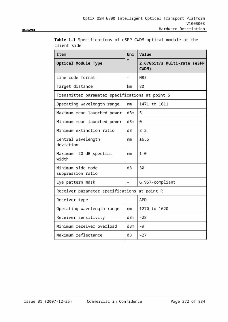
OptiX OSN 6800 Intelligent Optical Transport Platform V100R003
Hardware Description
Figure 9-1 MR4 front panel
MR4
MR4
STAT
LASERRADIATION
DO NOT VIEW DIRECTLYWITH OPTICALINSTRUMENTS
CLASS 1M LASERPRODUCT
OU
TIN
MO
MI
D1
A1
D2
A2
D3
A3
D4
A4
IndicatorsThere is one indicator on the front panel.
Board hardware status indicator (STAT) – dual-colored (red, green)
InterfacesThere are 12 optical interfaces on the MR4 front panel. Table 9-23 lists the type and function of each interface.
Issue 01 (2007-12-25) Commercial in Confidence Page 372 of 664
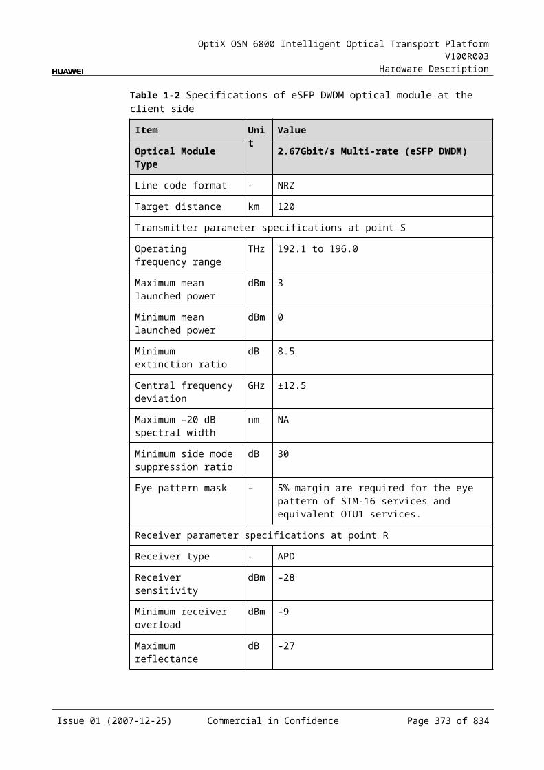
OptiX OSN 6800 Intelligent Optical Transport Platform V100R003
Hardware Description
Table 9-1 Types and functions of the MR4 interfaces
Interface
Type
Function
A1–A4 LC Receives the signal sent from the OTU or the integrated client-side equipment.
D1–D4 LC Transmits the signal to the OTU or the integrated client-side equipment.
IN LC Receives the multiplexed signal.
OUT LC Transmits the multiplexed signal.
MI LC Cascade input interface, connected to the output interface of another OADM board.
MO LC Cascade output interface, connected to the input interface of another OADM board.
Laser Safety LevelThe laser safety level of the optical interface is CLASS 1M.
The maximum output optical power of each optical interface ranges from 10 dBm (10 mW) to 22.15 dBm (164 mW).
9.5.6 Valid SlotsThe MR4 occupies one slot. The valid slots for the MR4 are IU1–IU17.
9.5.7 Characteristic Code for of MR4The characteristic code for the MR4 consists of eight digits that indicate the frequencies of the first and the fourth signals processed by the board.
The detailed information of the characteristic code is given in Table 9-24.
Table 9-1 Characteristic code for the MR4
Code Meaning Description
The first four digits
The frequency of first optical signal
Indicate the last four digits of the frequency that bears the first optical signal processed by the board.
The last four digits
The frequency of forth optical signal
Indicate the last four digits of the frequency that bears the fourth optical signal processed by the board.
For example, the characteristic code for the TN11MR4 is 92109240.
"9210" indicates that the frequency of the first optical signal is 192.10 THz.
Issue 01 (2007-12-25) Commercial in Confidence Page 373 of 664

OptiX OSN 6800 Intelligent Optical Transport Platform V100R003
Hardware Description
"9240" indicates that the frequency of the fourth optical signal is 192.40 THz.
Since the four optical signals processed by the MR4 are in sequence, it is inferred that:
The frequency of the second optical signal is 192.20 THz. The frequency of the third optical signal is 192.30 THz.
9.5.8 NM Configuration ReferenceNM configuration reference includes the reference information needed during the configuration of boards through the T2000.
Display of Optical InterfacesThe serial numbers of the optical interfaces on the panel of the board displayed on the NM are listed in Table 9-25.
Table 9-1 Serial numbers of the interfaces of the MR4 displayed on the NM
Interface on the Panel Interface on the NM
A1/D1 1
A2/D2 2
A3/D3 3
A4/D4 4
MI/MO 5
IN/OUT 6
NOTEThe number of an interface displayed on the T2000 in fact indicates a pair of physical optical interfaces, of which one is used to transmit signals and the other is used to receive signals.
Configuration ParametersConfigure Wavelength No./Wavelength (nm)/Frequency (THz)
9.5.9 Specifications of the MR4Specifications include optical specifications, dimensions, weight, and power consumption.
Optical SpecificationsTable 9-26 lists the optical specifications of the MR4.
Issue 01 (2007-12-25) Commercial in Confidence Page 374 of 664
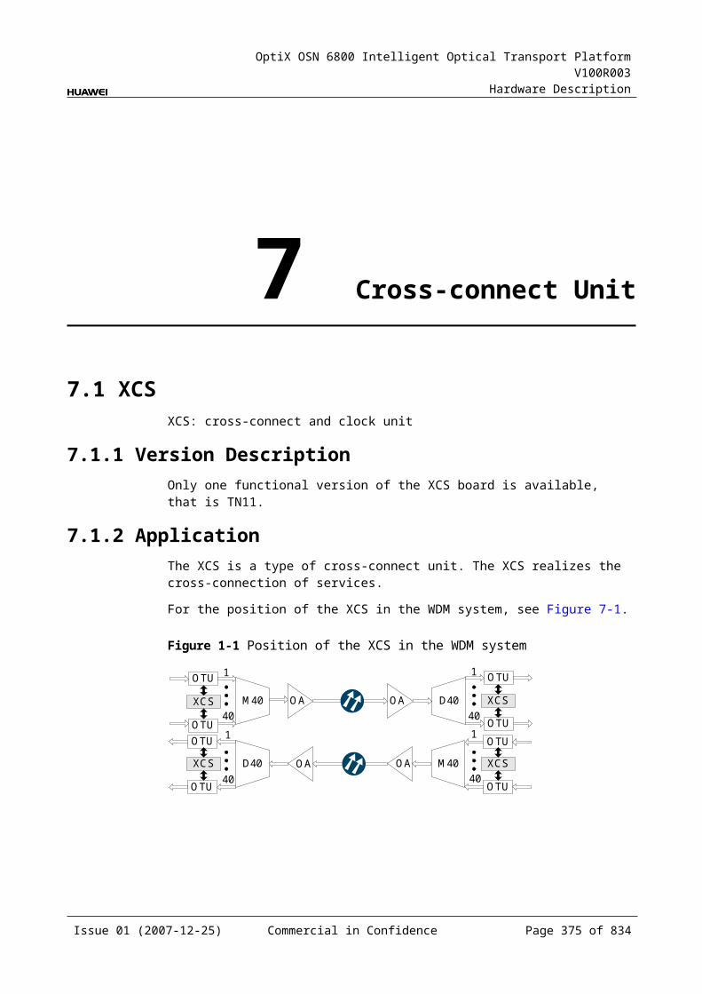
OptiX OSN 6800 Intelligent Optical Transport Platform V100R003
Hardware Description
Table 9-1 Optical specifications of the MR4
Corresponding interfaces
Item Unit
Value
– Operating wavelength range nm 1529–1561
– Adjacent channel spacing GHz 100
IN-D1IN-D2IN-D3IN-D4
0.5 dB spectral width nm ≥±0.11
Drop channel insertion loss dB ≤2.2
Adjacent channel isolation dB >25
Non-adjacent channel isolation dB >35
A1-OUTA2-OUTA3-OUTA4-OUT
0.5 dB spectral width nm ≥±0.11
Add channel insertion loss dB ≤2.2
IN-MOMI-OUT
Insertion loss dB ≤1.5
Isolation dB >13
– Optical return loss dB >40
Rules of Adding/Dropping WavelengthThe MR4 adds/drops and multiplexes consecutive four signals to/from the multiplexed signals. There are ten groups of wavelengths:
Table 9-1 Rules of adding/dropping wavelength of the MR4
Group Wavelength (nm)
A1/D1 A2/D2 A3/D3 A4/D4
1 1560.61 1559.79 1558.98 1558.17
2 1557.36 1556.55 1555.75 1554.94
3 1554.13 1553.33 1552.52 1551.72
4 1550.92 1550.12 1549.32 1548.51
5 1547.72 1546.92 1546.12 1545.32
6 1544.53 1543.73 1542.94 1542.14
7 1541.35 1540.56 1539.77 1538.95
8 1538.19 1537.40 1536.61 1535.82
9 1535.04 1534.25 1533.47 1532.68
Issue 01 (2007-12-25) Commercial in Confidence Page 375 of 664
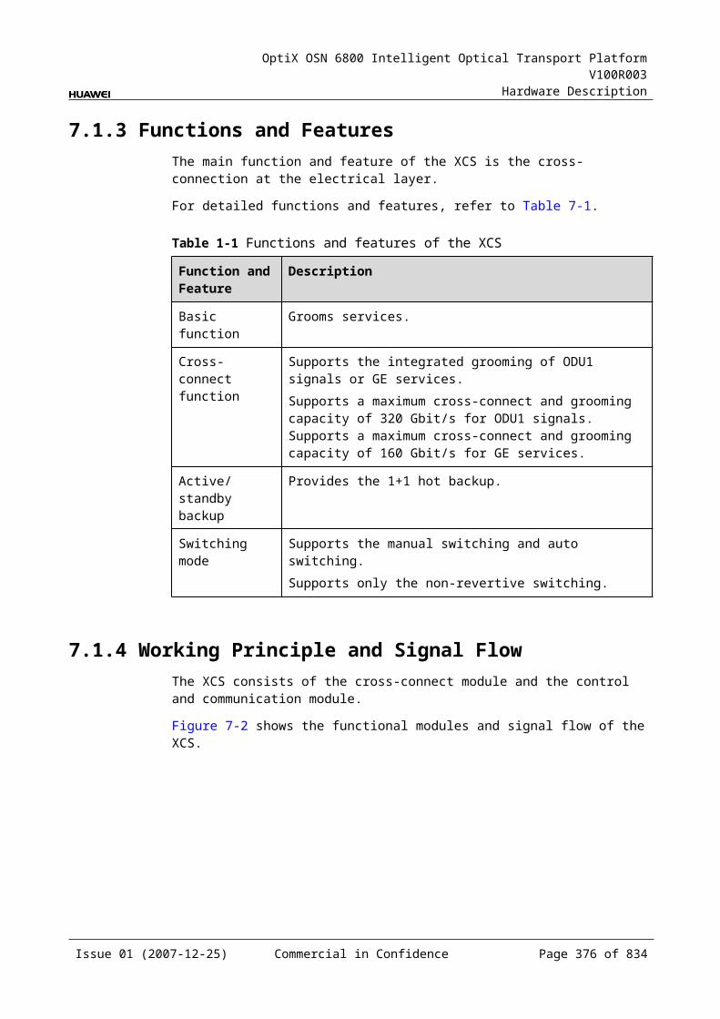
OptiX OSN 6800 Intelligent Optical Transport Platform V100R003
Hardware Description
Group Wavelength (nm)
A1/D1 A2/D2 A3/D3 A4/D4
10 1531.90 1531.12 1530.33 1529.55
Mechanical Specifications Dimensions of board (PCB): 245.1 mm (H) x 220 mm (D) x 2 mm (T) Dimensions of front panel: 264.6 mm (H) x 25.4 mm (W) Weight: 1.98 lb (0.9 kg)
Power Consumption The maximum power consumption at 25: 0.2 W The maximum power consumption at 55: 0.3 W
9.6 MR8MR8: 8-channel optical add/drop multiplexing unit
9.6.1 Version DescriptionOnly one functional version of the MR8 board is available, that is TN11.
9.6.2 ApplicationThe MR8 is a type of optical add and drop multiplexing unit. The MR8 realizes the adding/dropping and multiplexing of eight signals.
For the position of the MR8 in the DWDM system, see Figure 9-16.
Figure 9-1 Position of the MR8 in the DWDM system
MR8OA OA
OA OAMR8
OTU 8 8OTU OTU OTU
Client side Client side
9.6.3 Functions and FeaturesThe main functions and features supported by the MR8 are adding/dropping and multiplexing of signals, wavelength query, and providing a cascade interface.
For detailed functions and features, refer to Table 9-28.
Issue 01 (2007-12-25) Commercial in Confidence Page 376 of 664
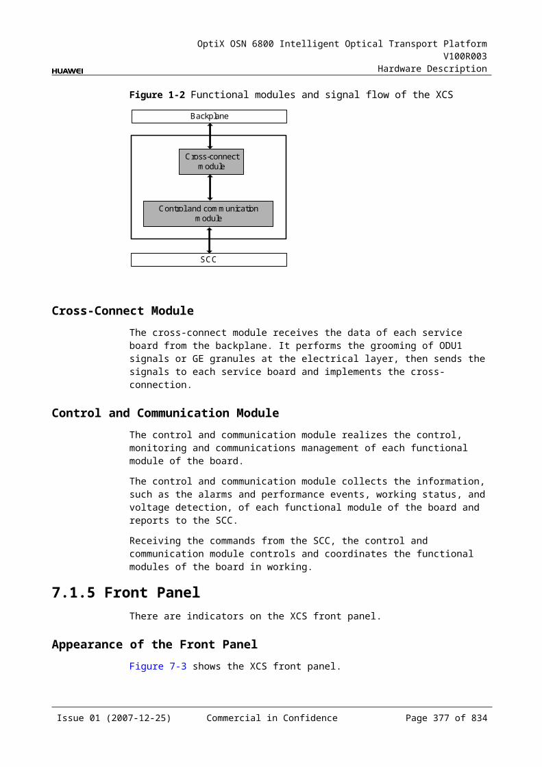
OptiX OSN 6800 Intelligent Optical Transport Platform V100R003
Hardware Description
Table 9-1 Functions and features of the MR8
Function and Feature
Description
Basic function Adds/Drops and multiplexes eight signals to/from the multiplexed signals.
WDM specification Supports the DWDM specification.
Cascade interface Provides the interface to cascade another optical add and drop multiplexing board to achieve the expansion.
Wavelength query Supports the query of the wavelengths for the added/dropped signals.
9.6.4 Working Principle and Signal FlowThe MR8 consists of the OADM optical module.
Figure 9-17 shows the functional modules and signal flow of the MR8.
Figure 9-1 Functional modules and signal flow of the MR8
OADM opticalmodule
IN
OUT
MOMI
D1 D8 A1 A8
88
In Channel-Adding DirectionThe MI interface receives the signal transmitted by the main path. The signal is multiplexed with the eight signals added through the A1–A8 interfaces by the OADM optical module. Then, the multiplexed signal is output through the OUT interface.
In Channel-Dropping DirectionThe IN interface receives the multiplexed signal sent from the upstream station. The OADM optical module separates eight channels from the main path and the eight channels are dropped through the D1–D8 interfaces. The rest channels are transmitted through the MO interface.
9.6.5 Front PanelThere is an indicator and 20 interfaces on the MR8 front panel.
Issue 01 (2007-12-25) Commercial in Confidence Page 377 of 664
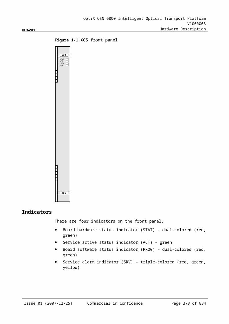
OptiX OSN 6800 Intelligent Optical Transport Platform V100R003
Hardware Description
Appearance of the Front PanelFigure 9-18 shows the MR8 front panel.
Figure 9-1 MR8 front panel
MR8
MR8
LASERRADIATION
DO NOT VIEW DIRECTLYWITH OPTICALINSTRUMENTS
CLASS 1M LASERPRODUCT
STAT
D6
A6
D7
A7
D5
A5
D4
A4
D8
A8
D1
A1
D2
A2
MO
MI
OU
TIN
D3
A3
IndicatorsThere is one indicator on the front panel.
Board hardware status indicator (STAT) – dual-colored (red, green)
InterfacesThere are 20 optical interfaces on the MR8 front panel. Table 9-29 lists the type and function of each interface.
Issue 01 (2007-12-25) Commercial in Confidence Page 378 of 664

OptiX OSN 6800 Intelligent Optical Transport Platform V100R003
Hardware Description
Table 9-1 Types and functions of the MR8 interfaces
Interface
Type
Function
A1–A8 LC Receives the signal sent from the OTU or the integrated client-side equipment.
D1–D8 LC Transmits the signal to the OTU or the integrated client-side equipment.
IN LC Receives the multiplexed signal.
OUT LC Transmits the multiplexed signal.
MI LC Cascade input interface, connected to the output interface of another OADM board.
MO LC Cascade output interface, connected to the input interface of another OADM board.
Laser Safety LevelThe laser safety level of the optical interface is CLASS 1.
The maximum output optical power of each optical interface is lower than 10 dBm (10 mW).
9.6.6 Valid SlotsThe MR8 occupies two slots.The valid slots for the MR8 are IU1–IU16 in the subrack.
The back connector of the board is mounted to the backplane along the left slot in the subrack, so the slot number of the MR8 board displayed on the NM is the number of the left one of the two occupied slots.
For example, if the MR8 occupies slots IU1 and IU2, the slot number of the MR8 displayed on the NM is IU1.
9.6.7 Characteristic Code for the MR8The characteristic code for the MR8 consists of eight digits that indicate the frequencies of the first and the eighth signals processed by the board.
The detailed information of the characteristic code is given in Table 9-30.
Table 9-1 Characteristic code for the MR8
Code Meaning Description
The first four digits
The frequency of the first optical signal
Indicate the last four digits of the frequency that bears the first optical signal processed by the board.
Issue 01 (2007-12-25) Commercial in Confidence Page 379 of 664
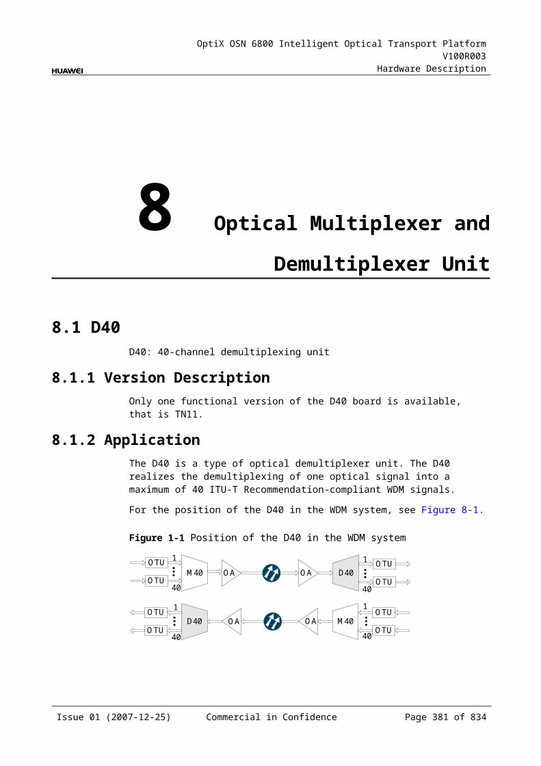
OptiX OSN 6800 Intelligent Optical Transport Platform V100R003
Hardware Description
The last four digits
The frequency of the eighth optical signal
Indicate the last four digits of the frequency that bears the eighth optical signal processed by the board.
For example, the characteristic code for the TN11MR8 is 92109280.
"9210" indicates that the frequency of the first optical signal is 192.10 THz. "9280" indicates that the frequency of the eighth optical signal is 192.80 THz.
Since the eight optical signals processed by the MR8 are in sequence, it is inferred that:
The frequency of the second optical signal is 192.20 THz. The frequency of the third optical signal is 192.30 THz. Inferred from it, the frequency of the seventh signal is 192.70 THz.
9.6.8 NM Configuration ReferenceNM configuration reference includes the reference information needed during the configuration of boards through the T2000.
Display of Optical InterfacesThe serial numbers of the optical interfaces on the panel of the board displayed on the NM are listed in Table 9-31.
Table 9-1 Serial numbers of the interfaces of the MR8 displayed on the NM
Interface on the Panel Interface on the NM
A1/D1 1
A2/D2 2
A3/D3 3
A4/D4 4
A5/D51 5
A6/D6 6
A7/D7 7
A8/D8 8
MI/MO 9
IN/OUT 10
NOTEThe number of an interface displayed on the T2000 in fact indicates a pair of physical optical interfaces, of which one is used to transmit signals and the other is used to receive signals.
Issue 01 (2007-12-25) Commercial in Confidence Page 380 of 664
OptiX OSN 6800 Intelligent Optical Transport Platform V100R003
Hardware Description
Configuration ParametersConfigure Wavelength No./Wavelength (nm)/Frequency (THz)
9.6.9 Specifications of the MR8Specifications include optical specifications, dimensions, weight, and power consumption.
Optical SpecificationsTable 9-32 lists the optical specifications of the MR8.
Table 9-1 Optical specifications of the MR8
Corresponding interfaces
Item Unit
Value
– Operating wavelength range nm 1529–1561
– Adjacent channel spacing GHz 100
IN-D1IN-D2IN-D3IN-D4IN-D5IN-D6IN-D7IN-D8
0.5 dB spectral width nm ≥±0.11
Drop channel insertion loss dB ≤4
Adjacent channel isolation dB >25
Non-adjacent channel isolation dB >35
A1-OUTA2-OUTA3-OUTA4-OUTA5-OUTA6-OUTA7-OUTA8-OUT
0.5 dB spectral width nm ≥±0.11
Add channel insertion loss dB ≤4
IN-MROMRI-OUT
Insertion loss dB ≤3.5
Isolation dB >13
– Optical return loss dB >40
Rules of Adding/Dropping WavelengthThe MR8 adds/drops and multiplexes eight signals to/from the multiplexed signals. There are five groups of wavelengths:
Issue 01 (2007-12-25) Commercial in Confidence Page 381 of 664
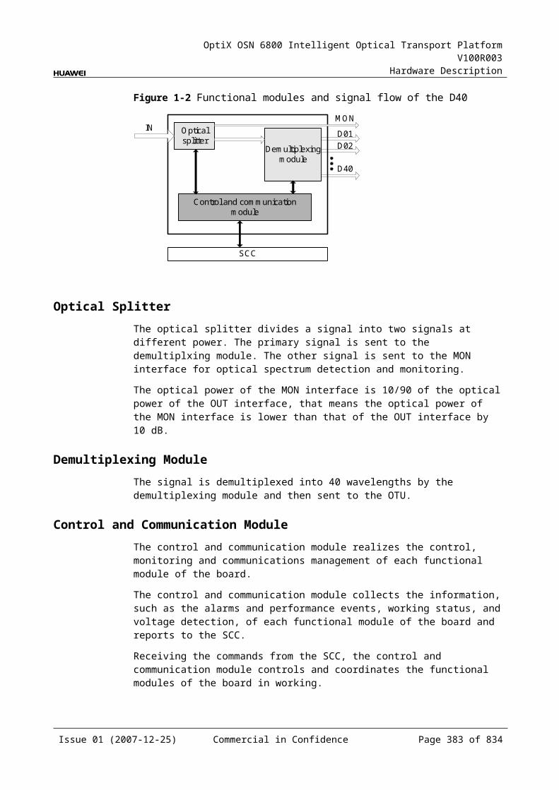
OptiX OSN 6800 Intelligent Optical Transport Platform V100R003
Hardware Description
Table 9-1 Rules of adding/dropping wavelength of the MR8
Group Wavelength (nm)
A1/D1 A2/D2 A3/D3 A4/D4 A5/D5 A6/D6 A7/D7 A8/D8
1 1560.61 1559.79 1558.98 1558.17 1557.36 1556.55 1555.75 1554.94
2 1554.13 1553.33 1552.52 1551.72 1550.92 1550.12 1549.32 1548.51
3 1547.72 1546.92 1546.12 1545.32 1544.53 1543.73 1542.94 1542.14
4 1541.35 1540.56 1539.77 1538.98 1538.19 1537.40 1536.61 1535.82
5 1535.04 1534.25 1533.47 1532.68 1531.90 1531.12 1530.33 1529.55
Mechanical Specifications Dimensions of board (PCB): 245.1 mm (H) x 220 mm (D) x 2 mm (T) Dimensions of front panel: 264.6 mm (H) x 50.8 mm (W) Weight: 2.20 lb (1.0 kg)
Power Consumption The maximum power consumption at 25: 0.2 W The maximum power consumption at 55: 0.3 W
9.7 SBM2SBM2: 2-channel CWDM Single-fiber Bi-Directional Add/Drop board
9.7.1 Version DescriptionOnly one functional version of the SBM2 board is available, that is TN11.
9.7.2 ApplicationThe SBM2 board drops two signals from the multiplexed signals, and at the same time adds another two signals to the multiplexed signals.
For the position of the SBM2 in the CWDM system, see Figure 9-19.
Issue 01 (2007-12-25) Commercial in Confidence Page 382 of 664
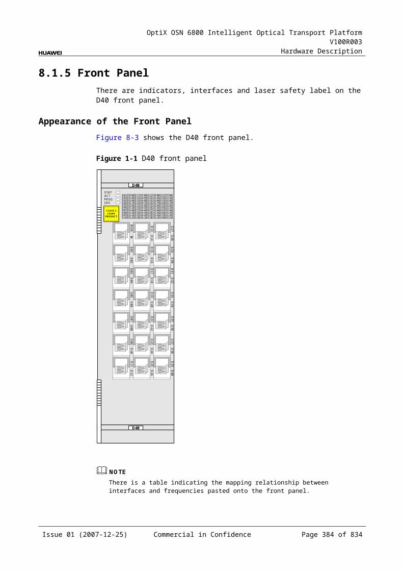
OptiX OSN 6800 Intelligent Optical Transport Platform V100R003
Hardware Description
Figure 9-1 Position of the SBM2 in the CWDM system
SBM2 SBM2
OTU
Client side
OTU OTU OTU
Client side
9.7.3 Functions and FeaturesThe main functions and features supported by the SBM2 are adding/dropping and multiplexing of signals and providing a cascade interface.
For detailed functions and features, refer to Table 9-34.
Table 9-1 Functions and features of the SBM2
Function and Feature
Description
Basic function Drops two signals from the multiplexed signals and add other two signals into the multiplexed signals. The added and dropped optical signals must be of different wavelengths.
WDM specification Supports only the single-fiber dual fed CWDM system.
Cascade interface Provides a cascade optical interface to cascade other single-fiber bi-directional OADM boards.
9.7.4 Working Principle and Signal FlowThe SBM2 consists of the OADM optical module.
Figure 9-20 shows the functional modules and signal flow of the SBM2.
Figure 9-1 Functional modules and signal flow of the SBM2
OADM opticalmodule
EXT LINE
D1 D2A1 A2
Issue 01 (2007-12-25) Commercial in Confidence Page 383 of 664
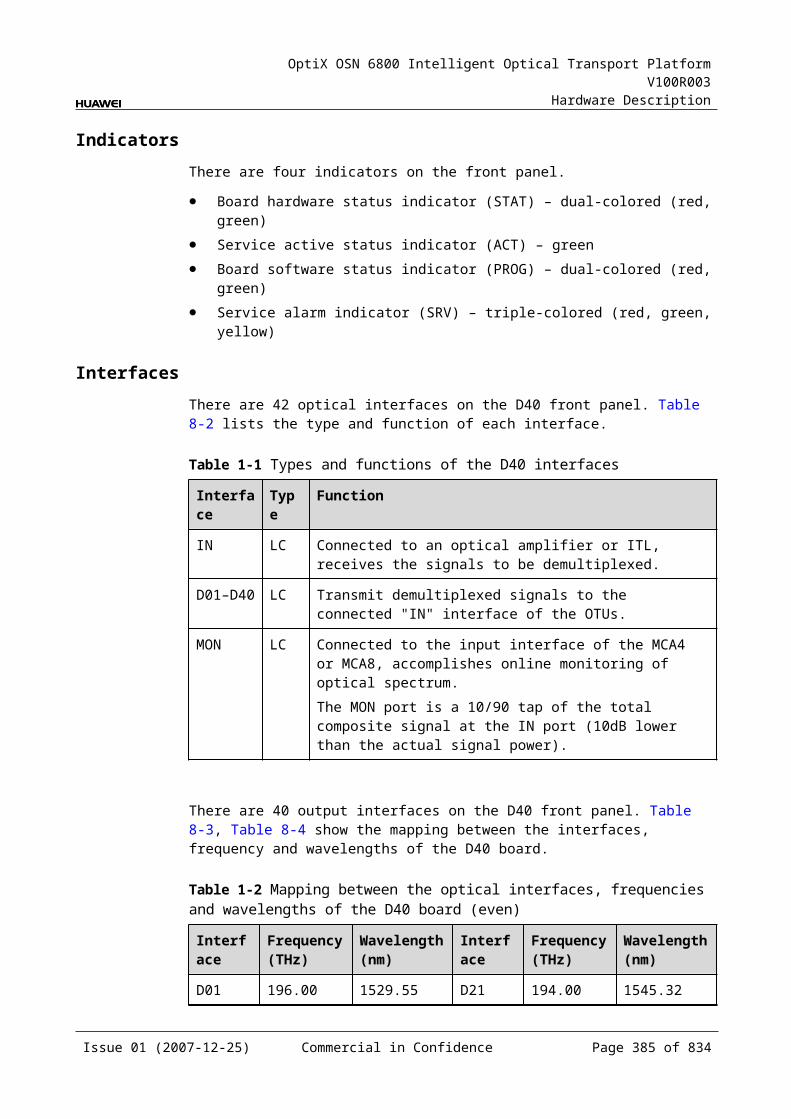
OptiX OSN 6800 Intelligent Optical Transport Platform V100R003
Hardware Description
Signal FlowThe board receives the multiplexed signals through the LINE interface. After the optical module processes the multiplexed signals. Then, the board separates the multiplexed signals into two channels of optical signals and outputs them through the D1 and D2 optical interfaces to the OTU board or integrated client-side equipment. The board also receives two channels of optical signals through the A1 and A2 interfaces and couples them to the multiplexed signals and outputs the coupled signals through the LINE interface.
The EXT interface is used as a cascade interface. It transmits the multiplexed signals to other single-fibre bi-directional OADM boards to add/drop the rest channels of the multiplexed signals.
9.7.5 Front PanelThere are interfaces on the SBM2 front panel.
Appearance of the Front PanelFigure 9-21 shows the SBM2 front panel.
Issue 01 (2007-12-25) Commercial in Confidence Page 384 of 664
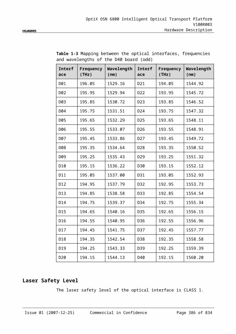
OptiX OSN 6800 Intelligent Optical Transport Platform V100R003
Hardware Description
Figure 9-1 SBM2 front panel
SBM2
SBM2
EX
TD
1A
1
STAT
LASERRADIATION
DO NOT VIEW DIRECTLYWITH OPTICALINSTRUMENTS
CLASS 1M LASERPRODUCT
LINE
D2
A2
IndicatorsThere is one indicator on the front panel.
Board hardware status indicator (STAT) – dual-colored (red, green)
InterfacesThere are six optical interfaces on the SBM2 front panel.Table 9-35 lists the type and function of each interface.
Issue 01 (2007-12-25) Commercial in Confidence Page 385 of 664

OptiX OSN 6800 Intelligent Optical Transport Platform V100R003
Hardware Description
Table 9-1 Types and functions of the SBM2 interfaces
Interface
Type
Function
A1/A2 LC Receives the signal sent from the OTU or the integrated client-side equipment.
D1/D2 LC Transmits the signal to the OTU or the integrated client-side equipment.
LINE LC Receives and transmits multiplexed signals.
EXT LC Cascade interface, transmits the multiplexed signals to other single-fiber bi-directional OADM boards to add/drop the rest channels of the multiplexed signals.
Laser Safety LevelThe laser safety level of the optical interface is CLASS 1M.
The maximum output optical power of each optical interface ranges from 10 dBm (10 mW) to 22.15 dBm (164 mW).
9.7.6 Valid SlotsThe SBM2 occupies one slot.The valid slots for the SBM2 are IU1-IU17.
9.7.7 NM Configuration ReferenceNM configuration reference includes the reference information needed during the configuration of boards through the T2000.
Display of Optical InterfacesThe serial numbers of the optical interfaces on the panel of the board displayed on the NM are listed in Table 9-36.
Table 9-1 Serial numbers of the interfaces of the SBM2 displayed on the NM
Interface on the Panel Interface on the NM
A1 1
D1 2
A2 3
D2 4
LINE 5
EXT 6
Issue 01 (2007-12-25) Commercial in Confidence Page 386 of 664
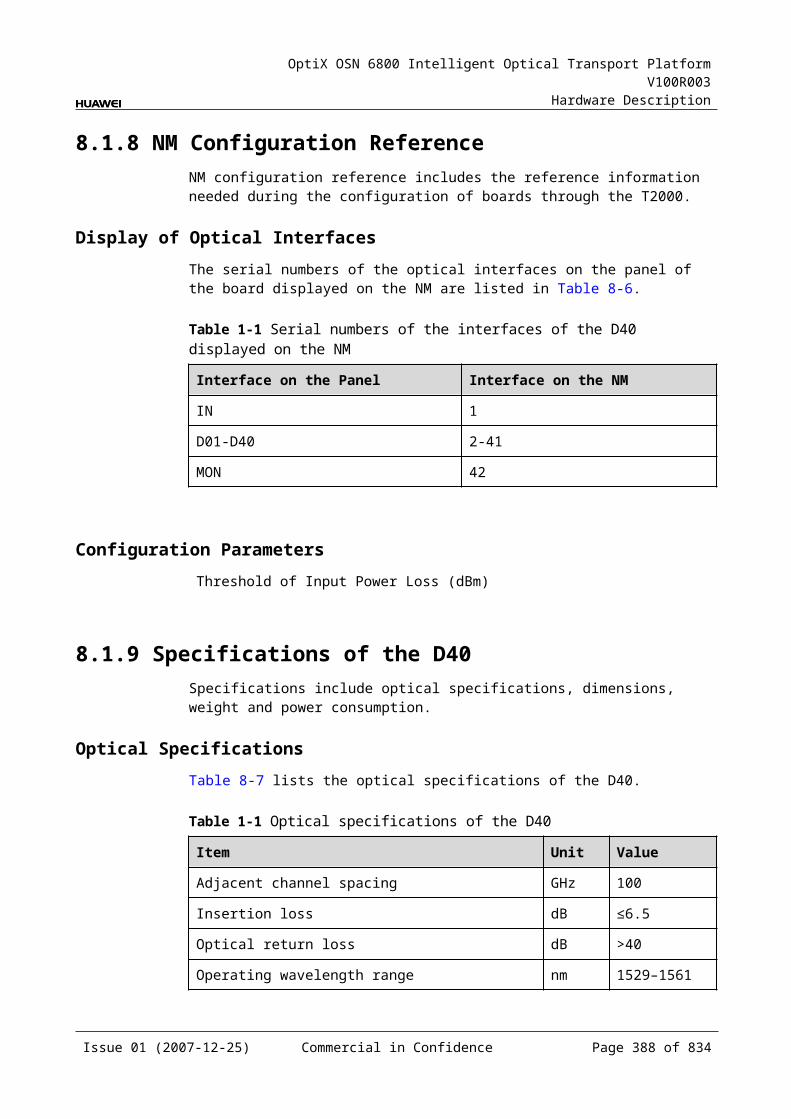
OptiX OSN 6800 Intelligent Optical Transport Platform V100R003
Hardware Description
NOTEThe number of an interface displayed on the T2000 in fact indicates a pair of physical optical interfaces, of which one is used to transmit signals and the other is used to receive signals.
Configuration ParametersThreshold of Input Power Loss (dBm)
Configure Band Type
9.7.8 Specifications of the SBM2Specifications include optical specifications, dimensions, weight, and power consumption.
Optical SpecificationsTable 9-37 lists the optical specifications of the SBM2.
Table 9-1 Optical specifications of the SBM2
Corresponding interfaces
Item Unit
Value
– Operating wavelength range
CWDM nm 1291 to 1611
LINE-D1LINE-D2
Drop channel insertion loss dB ≤3
Isolation dB ≥30
A1-LINEA2-LINE
Add channel insertion loss dB ≤3
Isolation dB ≥30
Optical return loss dB >40
Passthrough loss dB ≤1.5
Mechanical Specifications Dimensions of board (PCB): 245.1 mm (H) x 220 mm (D) x 2 mm (T) Dimensions of front panel: 264.6 mm (H) x 25.4 mm (W) Weight: 1.8 lb (0.82 kg)
Power Consumption The maximum power consumption at 25: 0.2 W The maximum power consumption at 55: 0.3 W
Issue 01 (2007-12-25) Commercial in Confidence Page 387 of 664
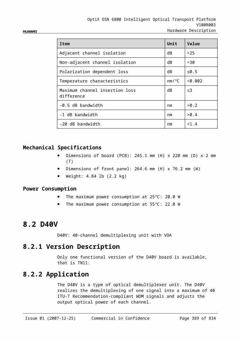
OptiX OSN 6800 Intelligent Optical Transport Platform V100R003
Hardware Description
10 Reconfigurable Optical Add and Drop Multiplexing Unit
10.1 RMU9RMU9: 9-Port ROADM multiplexing board
10.1.1 Version DescriptionOnly one functional version of the RMU9 board is available, that is TN11.
TypeTable 10-1lists the types of the RMU9.
Table 10-1 Type description of the RMU9
Board Type Description
TN11RMU9 01 Processes the even wavelengths in C band.
10.1.2 ApplicationThe RMU9 is a type of reconfigurable optical add and drop multiplexing unit. Used with the WSD9, the RMU9 realizes the wavelength grooming at the nodes in the DWDM network.
The RMU9 can add eight single-channel signal or multi-channel signals to the main path. Being multiplexed by the optical multiplexer unit or optical add and drop multiplexing unit, the multiplexed channels enter the RMU9 through the channel-adding port. As for the single channels, they are directly sent to the RMU9 through the channel-adding port by the optical transponder units.
For the position of the RMU9 in the DWDM system, see Figure 10-1.
Issue 01 (2007-12-25) Commercial in Confidence Page 389 of 664
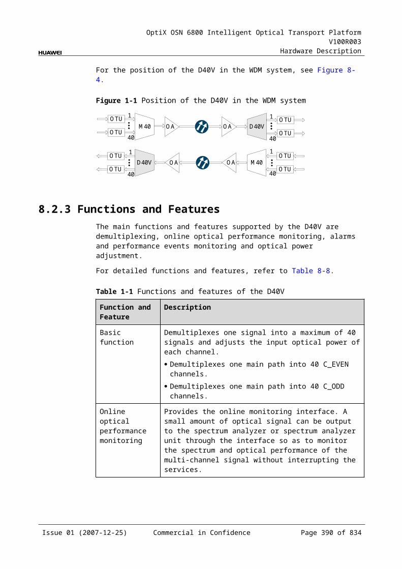
OptiX OSN 6800 Intelligent Optical Transport Platform V100R003
Hardware Description
Figure 10-1 Position of the RMU9 in the DWDM system
DCM
Client-side
O A
RMU9
OTU
OTU
OTU
OTU
OTU
OTU
OTU
OTU
OTU
OTU
OTU
OTU
OTU
OTU
OTU
OTU
O A O A
O A
DCM
WSD9
DMUX
DMUX
WSD9
MUX
RMU9
MUX
Client-side
Client-side Client-side
8 8
8 8
NOTEAn OTU is a transceiver that can process transmitting signals and receiving signals for the same wavelength at the same time.
10.1.3 Functions and FeaturesThe main functions and features supported by the RMU9 are dynamic grooming of wavelengths, online optical performance monitoring, and alarms and performance events monitoring.
For detailed functions and features, refer to Table 10-2.
Table 10-1 Functions and features of the RMU9
Function and Feature
Description
Basic function Adds eight single-channel signal or multi-channel signals to the main path. Used with the OTU with tunable wavelength, the RMU9 realizes the dynamic input of eight channel signals.
WDM specification
Supports the DWDM specification.
Issue 01 (2007-12-25) Commercial in Confidence Page 390 of 664
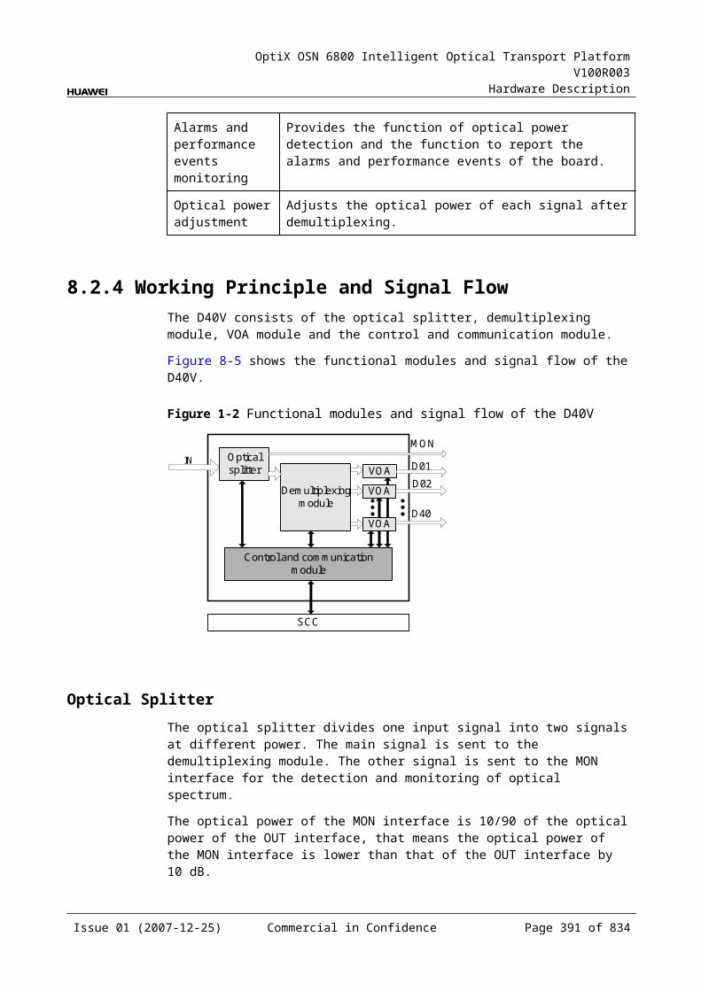
OptiX OSN 6800 Intelligent Optical Transport Platform V100R003
Hardware Description
Function and Feature
Description
Online optical performance monitoring
Provides the online monitoring interface. A small amount of optical signal can be output to the spectrum analyzer or spectrum analyzer unit through the interface so as to monitor the spectrum and optical performance of the multi-channel signal without interrupting the services.
Alarms and performance events monitoring
Provides the function of optical power detection and the function to report the alarms and performance events of the board.
10.1.4 Working Principle and Signal FlowThe RMU9 consists of the optical multiplexing module, coupling module, and control and communication module.
For detailed functions and features, refer to Figure 10-2.
Figure 10-1 Functions and features of the RMU9
SCC
AM1 AM2
Coupling module
Control and communication module
AM3 AM4 AM5 AM6 AM7 AM8
Optical multiplexing module
VOA VOA VOA VOA VOA VOA VOA VOA
Splitter
Splitter
ROA
TOA
EXPI MONI
MONO
OUT
Optical Multiplexing Module and Coupling ModuleThe channels are added through AM1-AM8 interfaces. As for the multi-channel signals to be input, they are multiplexed by the multiplexing unit before entering the AMn interface. As for a single-channel signal to be input, it is directly sent to the AMn interface after being converted by an optical transponder unit.
The TOA interface can be connected to optical amplifying unit to realize cascading. If cascading is not needed, the optical signals should be directly sent to the ROA interface.
Issue 01 (2007-12-25) Commercial in Confidence Page 391 of 664
OptiX OSN 6800 Intelligent Optical Transport Platform V100R003
Hardware Description
The signals input through the EXPI interface and transmitted by the main path are multiplexed with the signals added through the ROA interface at the local station, and then the multiplexed signal are output through the OUT interface.
The VOA module adjusts the optical power for each optical signal added at the local station.
A small amount of optical signals input through the EXPI interface are separated from the main path, and output through the MONI interface. They are used for optical performance detection.
A small amount of optical signals are separated from those output through the TOA interface, and output to the MONO interface. These signals are used for optical performance detection.
Control and Communication ModuleThe control and communication module realizes the control, monitoring and communications management of each functional module of the board.
The control and communication module collects the information, such as the alarms and performance events, working status, and voltage detection, of each functional module of the board and reports to the SCC.
Receiving the commands from the SCC, the control and communication module controls and coordinates the functional modules of the board in working.
10.1.5 Front PanelThere are indicators, interfaces and laser safety label on the RMU9 front panel.
Appearance of the Front PanelFigure 10-3 shows the RMU9 front panel.
Issue 01 (2007-12-25) Commercial in Confidence Page 392 of 664

OptiX OSN 6800 Intelligent Optical Transport Platform V100R003
Hardware Description
Figure 10-1 RMU9 front panel
RMU9
RMU9
STATACTPROGSRV
CLASS 1LASER
PRODUCT
MO
NO
MO
NI
OU
TE
XP
ITO
AR
OA
AM
1A
M2
AM
3A
M4
AM
5A
M6
AM
7A
M8
IndicatorsThere are four indicators on the front panel.
Board hardware status indicator (STAT) – dual-colored (red, green) Service active status indicator (ACT) – green Board software status indicator (PROG) – dual-colored (red, green) Service alarm indicator (SRV) – triple-colored (red, green, yellow)
InterfacesThere are 14 optical interfaces on the RMU9 front panel. Table 10-3 lists the type and function of each interface.
Issue 01 (2007-12-25) Commercial in Confidence Page 393 of 664
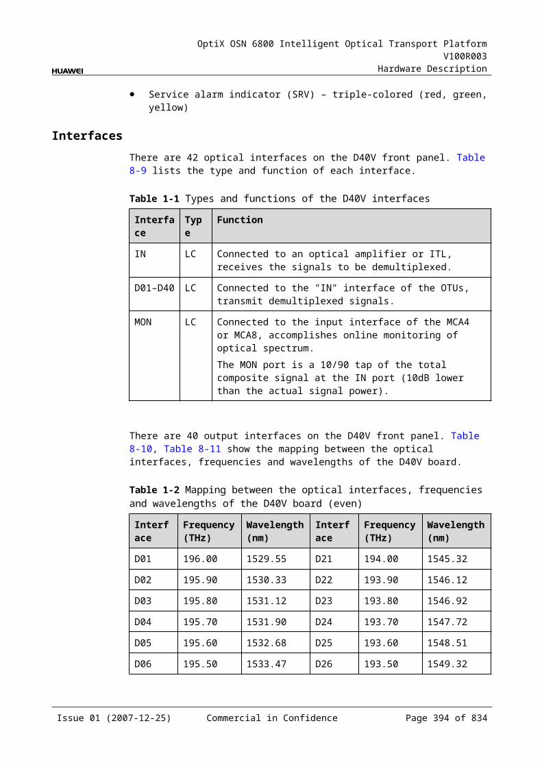
OptiX OSN 6800 Intelligent Optical Transport Platform V100R003
Hardware Description
Table 10-1 Types and functions of the RMU9 interfaces
Interface
Type
Function
AM1–AM8 LC Receive the single-channel signals or multi-channel signals that are to be multiplexed into the main path.
OUT LC Transmits the main path signal.
EXPI LC Receives the main path signal.
MONI LC Connected to the input interface of the spectrum analyzer unit, accomplishes the online detection of the optical spectrum for the input signals transmitted by the main optical path.The MONI port is a 3/97 tap of the total composite signal at the EXPI port (15dB lower than the actual signal power).
MONO LC Connected to the input interface of the spectrum analyzer unit, accomplishes the online detection of optical spectrum for the signals output through the TOA interface.The MONO port is a 3/97 tap of the total composite signal at the TOA port (15dB lower than the actual signal power).
TOA LC Used as the cascade output interface.
ROA LC Used as the cascade input interface.
NOTEWhen cascading is not adopted, the TOA and ROA interfaces should be directly connected by a fiber jumper.
Laser Safety LevelThe laser safety level of the optical interface is CLASS 1.
The maximum output optical power of each optical interface is lower than 10 dBm (10 mW).
10.1.6 Valid SlotsThe RMU9 occupies one slot. The valid slots for the RMU9 are IU1-IU17.
10.1.7 NM Configuration ReferenceNM configuration reference includes the reference information needed during the configuration of boards through the T2000.
Display of Optical InterfacesThe serial numbers of the optical interfaces on the panel of the board displayed on the NM are listed in Table 10-4.
Issue 01 (2007-12-25) Commercial in Confidence Page 394 of 664

OptiX OSN 6800 Intelligent Optical Transport Platform V100R003
Hardware Description
Table 10-1 Serial numbers of the interfaces of the RMU9 displayed on the NM
Interface on the Panel Interface on the NM
EXPI 1
OUT 2
AM1-AM8 3-10
TOA/ROA 11
MONI 12
MONO 13
Configuration ParametersThreshold of Input Power Loss (dBm)
Optical Interface Attenuation Ratio (dB)
Maximum Attenuation Ratio (dB)
Minimum Attenuation Ratio (dB)
10.1.8 Specifications of the RMU9Specifications include optical specifications, dimensions, weight, and power consumption.
Optical SpecificationsTable 10-5 lists the optical specifications of the RMU9.
Table 10-1 Optical specifications of the RMU9
Item Unit Value
Insertion loss EXPI-OUT dB ≤8.5
AMxa-TOA dB ≤12.5b
ROA-OUT dB ≤1.5
Operating wavelength range nm 1529–1561
Optical return loss dB >40
Attenuation range dB 0–15
Polarization dependent loss dB ≤0.5
Issue 01 (2007-12-25) Commercial in Confidence Page 395 of 664

OptiX OSN 6800 Intelligent Optical Transport Platform V100R003
Hardware Description
Item Unit Value
Attenuation accuracy dB ≤1
a: AMx represents the AM1-AM8 interface.
b: This value can be reached when the attenuation of the VOA is set to 0 dB.
Mechanical Specifications Dimensions of board (PCB): 245.1 mm (H) x 220 mm (D) x 2 mm (T) Dimensions of front panel: 264.6 mm (H) x 25.4 mm (W) Weight: 2.42 lb (1.1 kg)
Power Consumption The maximum power consumption at 25: 11 W The maximum power consumption at 55: 12 W
10.2 ROAMROAM: reconfigurable optical adding board
10.2.1 Version DescriptionOnly one functional version of the ROAM board is available, that is TN11.
TypeTable 10-6lists the types of the ROAM.
Table 10-1 Type description of the ROAM
Board Type Description
TN11ROAM 01 Processes the even wavelengths in C band.
02 Processes the odd wavelengths in C band.
10.2.2 ApplicationThe ROAM is a type of reconfigurable optical add and drop multiplexing unit. Used with the optical demultiplexer unit or the optical add and drop multiplexing unit, the ROAM realizes the wavelength grooming at the nodes in the DWDM network.
For the position of the ROAM in the DWDM system, see Figure 10-4.
Issue 01 (2007-12-25) Commercial in Confidence Page 396 of 664
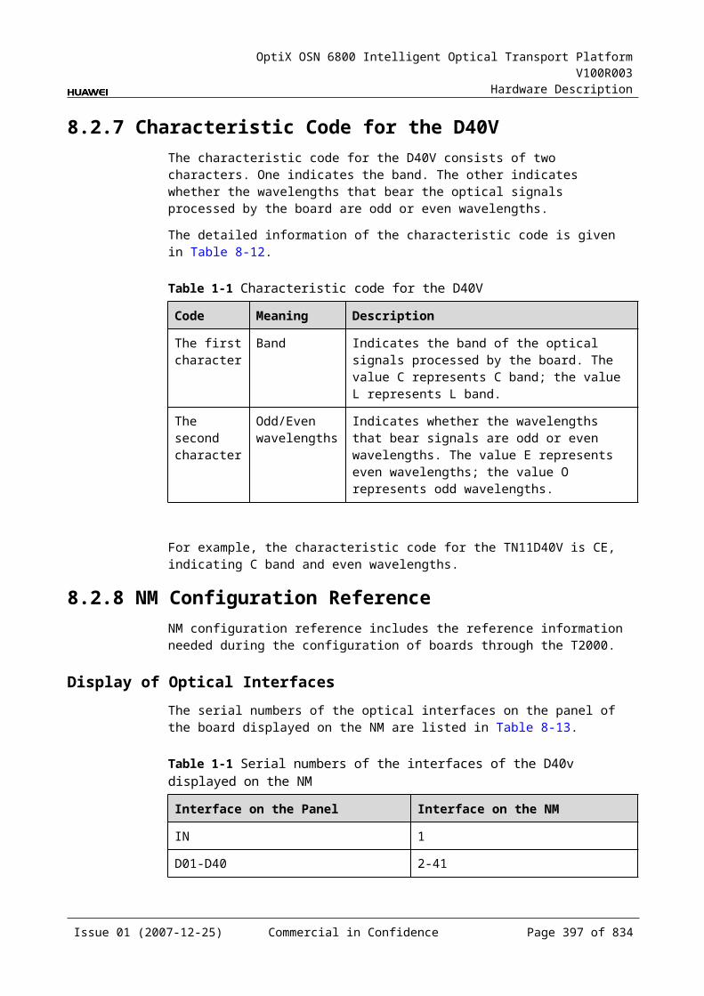
OptiX OSN 6800 Intelligent Optical Transport Platform V100R003
Hardware Description
Figure 10-1 Position of the ROAM in the DWDM system
O A
OTU
OTU
OTU
OTU
O A
O A
DMUX
ROAM
OTU
OTU
OTU
OTU
DMUX
OTU
OTU
ROAM
O A
Client-side Client-side
40 40
NOTEAn OTU is a transceiver that can process transmitting signals and receiving signals for the same wavelength at the same time.
10.2.3 Functions and FeaturesThe main functions and features supported by the ROAM are dynamic grooming of wavelengths, built-in power equilibrium, and alarms and performance events monitoring.
For detailed functions and features, refer to Table 10-7.
Table 10-1 Functions and features of the ROAM
Function and Feature
Description
Basic function Realizes the dynamic adding/dropping, pass-through, and blocking of a maximum of 40 wavelengths withe the demultiplexing board as well as the dynamic grooming of wavelengths for the services on the ring network.
WDM specification Supports the DWDM specification.
Power equilibrium Realizes the wavelength-level equilibrium and control of optical power to flatten the spectrum for the working signals.
Alarms and performance events monitoring
Provides the function of optical power detection and the function to report the alarms and performance events of the board.
Issue 01 (2007-12-25) Commercial in Confidence Page 397 of 664
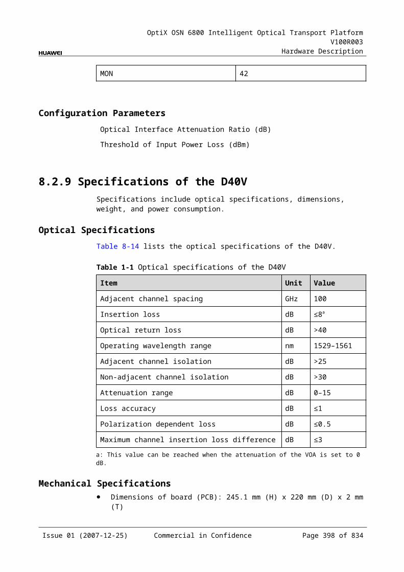
OptiX OSN 6800 Intelligent Optical Transport Platform V100R003
Hardware Description
10.2.4 Working Principle and Signal FlowThe ROAM consists of the planar lightwave circuit (PLC) optical module and the control and communication module.
For detailed functions and features, refer to Figure 10-5.
Figure 10-1 Functions and features of the ROAM
OUT
DM
EXPI
EXPO
PLC optical module
IN
SCC
M01 M02
Optical demultiplexing module
Control and communication module
M40
Optical multiplexing module
PLC Optical ModuleThe main path signal is received through the IN interface. The optical splitter divides the main path signal into two same signals. One signal is output to the optical demultiplexer unit through the DM interface and demultiplexed into single wavelengths dropped at the local station. The other signal passes through and is output through the EXPO interface.
The signals to be added at the local station are received through the corresponding M01–M40 interfaces. These signals are multiplexed with the signal input through the EXPI interface and then output through the OUT interface.
The PLC optical module blocks and terminates the signals dropped at the local station and adjusts the optical power of other signals.
The PLC optical module contains the VOA modules that realize the power adjustment at the wavelength level.
Control and Communication ModuleThe control and communication module realizes the control, monitoring and communications management of each functional module of the board.
The control and communication module collects the information, such as the alarms and performance events, working status, and voltage detection, of each functional module of the board and reports to the SCC.
Issue 01 (2007-12-25) Commercial in Confidence Page 398 of 664
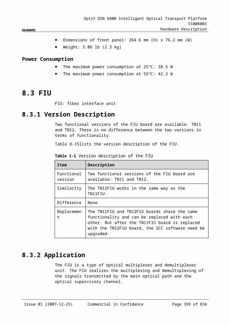
OptiX OSN 6800 Intelligent Optical Transport Platform V100R003
Hardware Description
Receiving the commands from the SCC, the control and communication module controls and coordinates the functional modules of the board in working.
10.2.5 Front PanelThere are indicators, interfaces and laser safety label on the ROAM front panel.
Appearance of the Front PanelFigure 10-6 shows the ROAM front panel.
Figure 10-1 ROAM front panel
ROAM
ROAM
STATACTPROGSRV
LASERRADIATION
DO NOT VIEW DIRECTLYWITH OPTICALINSTRUMENTS
CLASS 1M LASERPRODUCT
M01M02M03M04M05M06M07M08M09M10
M11M12M13M14M15M16M17M18M19M20
M21M22M23M24M25M26M27M28M29M30
M31M32M33M34M35M36M37M38M39M40
196.00195.90195.80195.70195.60195.50195.40195.30195.20195.10
195.00194.90194.80194.70194.60194.50
194.20194.10
194.40194.30
194.00193.90193.80193.70193.60193.50
193.20193.10
193.40193.30
193.00192.90192.80192.70192.60192.50
192.20192.10
192.40192.30
INO
UT
M01
M02
M03
M04
M05
M06
M07
M08
M09
M10
M11
M12
M13
M14
M15
M16
M17
M18
M19
M20
EX
PO
M21
M22
M23
M24
M25
M26
M27
M28
M29
M30
EX
PI
M31
M32
M34
M35
M36
M37
M38
M39
M40
DM
IndicatorsThere are four indicators on the front panel.
Board hardware status indicator (STAT) – dual-colored (red, green)
Issue 01 (2007-12-25) Commercial in Confidence Page 399 of 664
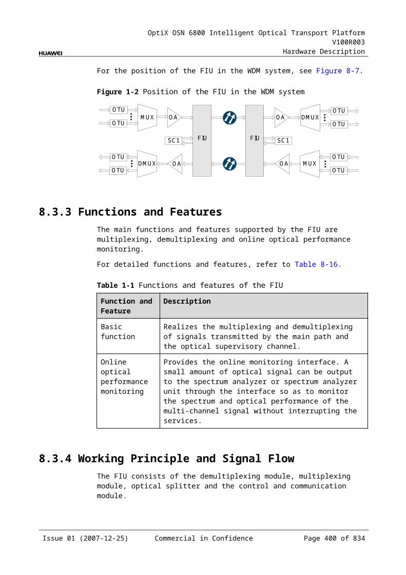
OptiX OSN 6800 Intelligent Optical Transport Platform V100R003
Hardware Description
Service active status indicator (ACT) – green Board software status indicator (PROG) – dual-colored (red, green) Service alarm indicator (SRV) – triple-colored (red, green, yellow)
InterfacesThere are 45 optical interfaces on the ROAM front panel. Table 10-8 lists the type and function of each interface.
Table 10-1 Types and functions of the ROAM interfaces
Interface
Type
Function
M01-M40 LC Add channels from the local station.
DM LC Drops channels to the local station.
OUT LC Transmits the main path signal.
IN LC Receives the main path signal.
EXPO LC Used as the cascade interface to transmit the pass-through signal.
EXPI LC Used as the cascade interface to receive the pass-through signal.
There are 40 output interfaces on the ROAM front panel. Table 10-9 and Table 10-10 show the mapping between the interfaces, frequency and wavelengths of the ROAM board.
Table 10-2 Mapping between the optical interfaces, frequencies and wavelengths of the ROAM board (even)
Interface
Frequency (THz)
Wavelength (nm)
Interface
Frequency (THz)
Wavelength (nm)
M01 196.00 1529.55 M21 194.00 1545.32
M02 195.90 1530.33 M22 193.90 1546.12
M03 195.80 1531.12 M23 193.80 1546.92
M04 195.70 1531.90 M24 193.70 1547.72
M05 195.60 1532.68 M25 193.60 1548.51
M06 195.50 1533.47 M26 193.50 1549.32
M07 195.40 1534.25 M27 193.40 1550.12
M08 195.30 1535.04 M28 193.30 1550.92
M09 195.20 1535.82 M29 193.20 1551.72
Issue 01 (2007-12-25) Commercial in Confidence Page 400 of 664
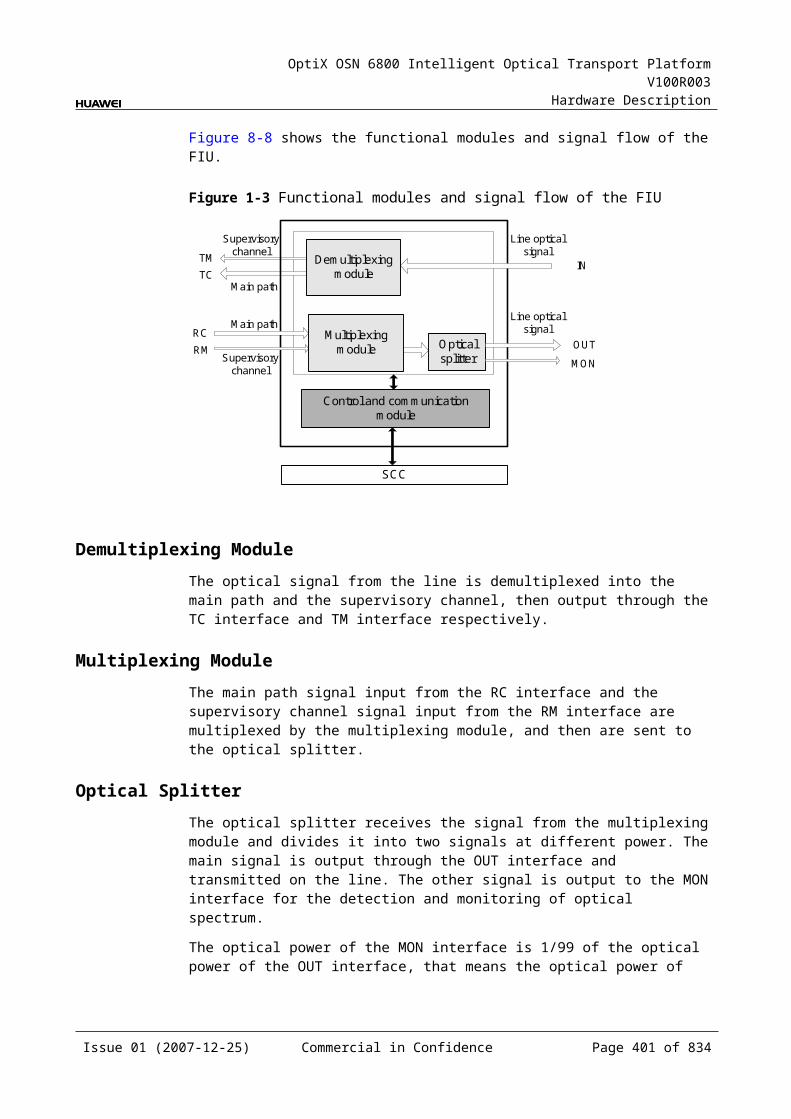
OptiX OSN 6800 Intelligent Optical Transport Platform V100R003
Hardware Description
Interface
Frequency (THz)
Wavelength (nm)
Interface
Frequency (THz)
Wavelength (nm)
M10 195.10 1536.61 M30 193.10 1552.52
M11 195.00 1537.40 M31 193.00 1553.33
M12 194.90 1538.19 M32 192.90 1554.13
M13 194.80 1538.98 M33 192.80 1554.94
M14 194.70 1539.77 M34 192.70 1555.75
M15 194.60 1540.56 M35 192.60 1556.55
M16 194.50 1541.35 M36 192.50 1557.36
M17 194.40 1542.14 M37 192.40 1558.17
M18 194.30 1542.94 M38 192.30 1558.98
M19 194.20 1543.73 M39 192.20 1559.79
M20 194.10 1544.53 M40 192.10 1560.61
Table 10-3 Mapping between the optical interfaces, frequencies and wavelengths of the ROAM board (odd)
Interface
Frequency (THz)
Wavelength (nm)
Interface
Frequency (THz)
Wavelength (nm)
M01 196.05 1529.16 M21 194.05 1544.92
M02 195.95 1529.94 M22 193.95 1545.72
M03 195.85 1530.72 M23 193.85 1546.52
M04 195.75 1531.51 M24 193.75 1547.32
M05 195.65 1532.29 M25 193.65 1548.11
M06 195.55 1533.07 M26 193.55 1548.91
M07 195.45 1533.86 M27 193.45 1549.72
M08 195.35 1534.64 M28 193.35 1550.52
M09 195.25 1535.43 M29 193.25 1551.32
M10 195.15 1536.22 M30 193.15 1552.12
M11 195.05 1537.00 M31 193.05 1552.93
M12 194.95 1537.79 M32 192.95 1553.73
M13 194.85 1538.58 M33 192.85 1554.54
M14 194.75 1539.37 M34 192.75 1555.34
Issue 01 (2007-12-25) Commercial in Confidence Page 401 of 664
OptiX OSN 6800 Intelligent Optical Transport Platform V100R003
Hardware Description
Interface
Frequency (THz)
Wavelength (nm)
Interface
Frequency (THz)
Wavelength (nm)
M15 194.65 1540.16 M35 192.65 1556.15
M16 194.55 1540.95 M36 192.55 1556.96
M17 194.45 1541.75 M37 192.45 1557.77
M18 194.35 1542.54 M38 192.35 1558.58
M19 194.25 1543.33 M39 192.25 1559.39
M20 194.15 1544.13 M40 192.15 1560.20
Laser Safety LevelThe laser safety level of the optical interface is CLASS 1M.
The maximum output optical power of each optical interface ranges from 10 dBm (10 mW) to 22.15 dBm (164 mW).
10.2.6 Valid SlotsThe ROAM occupies three slots. The valid slots for the ROAM are IU1–IU15 in the subrack.
The back connector of the board is mounted to the backplane along the left slot in the subrack, so the slot number of the ROAM board displayed on the NM is the number of the left one of the three occupied slots.
For example, if the ROAM occupies slots IU1, IU2 and IU3, the slot number of the ROAM displayed on the NM is IU1.
10.2.7 NM Configuration ReferenceNM configuration reference includes the reference information needed during the configuration of boards through the T2000.
Display of Optical InterfacesThe serial numbers of the optical interfaces on the panel of the board displayed on the NM are listed in Table 10-11.
Table 10-1 Serial numbers of the interfaces of the ROAM displayed on the NM
Interface on the Panel Interface on the NM
IN 1
EXPO 2
EXPI 3
OUT 4
Issue 01 (2007-12-25) Commercial in Confidence Page 402 of 664

OptiX OSN 6800 Intelligent Optical Transport Platform V100R003
Hardware Description
Interface on the Panel Interface on the NM
DM 5
A01-A40 6-45
Configuration ParametersThreshold of Input Power Loss (dBm)
Wavelength Target Power
10.2.8 Specifications of the ROAMSpecifications include optical specifications, dimensions, weight, and power consumption.
Optical SpecificationsTable 10-12 lists the optical specifications of the ROAM.
Table 10-1 Optical specifications of the ROAM
Item Unit Value
Adjacent channel spacing GHz 100
Insertion loss Mxa-OUT dB ≤9b
IN-DM dB ≤7
EXPI-OUT dB ≤14b
IN-EXPO dB ≤3
Operating wavelength range nm 1529 - 1561
Adjacent channel isolation dB >22
Non-adjacent channel isolation dB >25
Attenuation range dB 0 - 20
Attenuation precision dB <1 (0 to 10dB)
<1.5 ( >10dB )
Polarization dependent loss dB ≤1.5
Module switch time ms ≤50
Extinction ratio dB 30
-0.5 dB bandwidth of adding wavelength nm >0.3
Issue 01 (2007-12-25) Commercial in Confidence Page 403 of 664
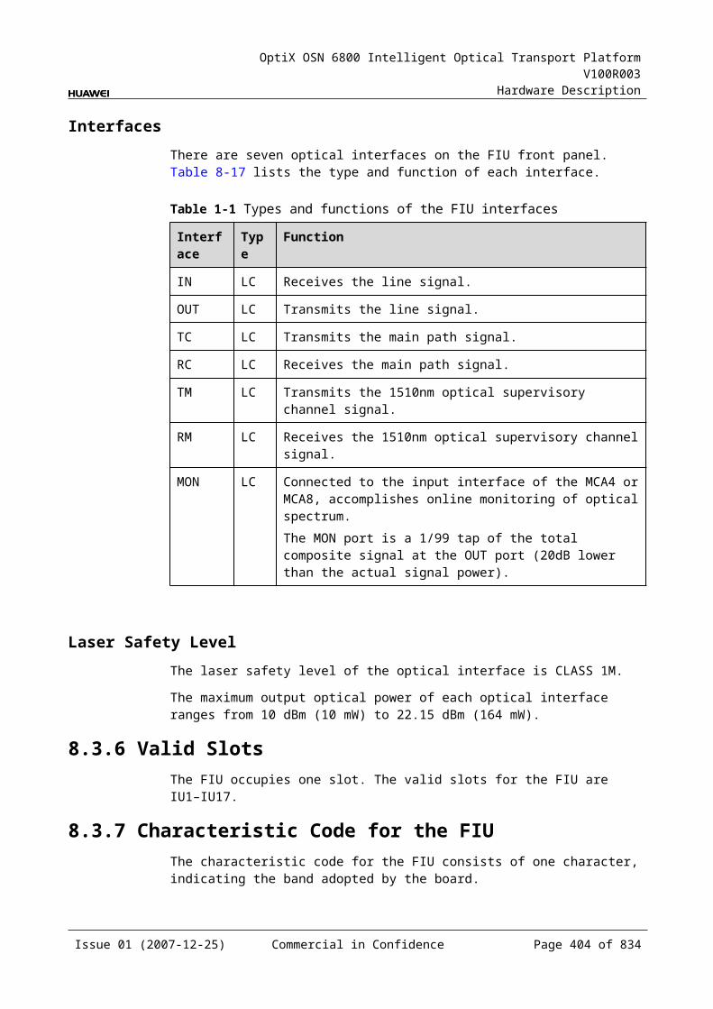
OptiX OSN 6800 Intelligent Optical Transport Platform V100R003
Hardware Description
Item Unit Value
-0.5 dB bandwidth of pass-through wavelength nm >0.2
a: Mx represents the M01–M40 interface.
b: This value can be reached when the attenuation of the VOA is set to 0 dB.
Mechanical Specifications Dimensions of board (PCB): 245.1 mm (H) x 220 mm (D) x 2 mm (T) Dimensions of front panel: 264.6 mm (H) x 76.2 mm (W) Weight: 7.04 lb (3.2 kg)
Power Consumption The maximum power consumption at 25: 66 W The maximum power consumption at 55: 73 W
10.3 WSD9WSD9: 9-port wavelength selective switching demultiplexing board
10.3.1 Version DescriptionThree functional versions of the WSD9 board are available: TN11, TN12 and TN13. The main difference among the three versions is that the channel spacing of the wavelength is different.
VersionTable 10-13 lists the version description of the WSD9.
Table 10-1 Version description of the WSD9
Item Description
Functional version
Three functional versions of the WSD9 board are available: TN11, TN12 and TN13.
Similarity The TN11WSD9, TN12WSD9 and TN13WSD9 boards share the same functioning principle.
Difference The wavelength of the TN11WSD9 board is separated at 100 GHz channel spacing, and the board occupies two slots.The wavelength of the TN12WSD9 board is separated at 100 GHz channel spacing, and the board occupies two slots.The wavelength of the TN13WSD9 board is separated at 50 GHz channel spacing, and the board occupies three slots.
Issue 01 (2007-12-25) Commercial in Confidence Page 404 of 664
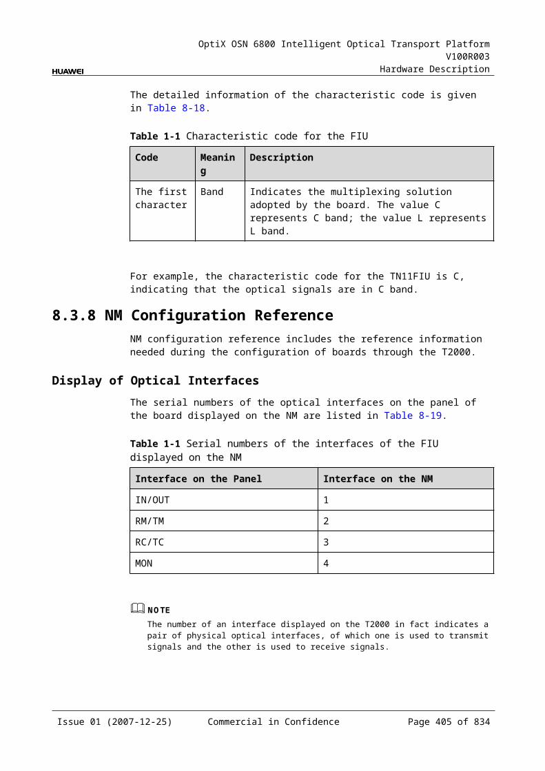
OptiX OSN 6800 Intelligent Optical Transport Platform V100R003
Hardware Description
Item Description
Replacement The TN12WSD9 and TN11WSD9 boards share the same functionality and can be replaced with each other. But after the TN11WSD9 board is replaced with the TN12WSD9 board, the SCC software need be upgraded.The boards of other versions cannot be replaced with each other.
TypeTable 10-14 lists the types of the WSD9.
Table 10-1 Type description of the WSD9
Board Type
Description
TN12WSD9 A01 The wavelength of the board is separated at 100 GHz channel spacing in C band.
TN13WSD9 C01 The wavelength of the board is separated at 50 GHz channel spacing in C band.
10.3.2 ApplicationThe WSD9 is a type of reconfigurable optical add and drop multiplexing unit. Used with the WSM9 or the RMU9, the WSD9 realizes the wavelength grooming at the nodes in the DWDM network.
The single-channel or multi-channel signals to be dropped at the local station are output through the interfaces of the WSD9 based on the configuration.
If the dropped signal is a multi-channel signal, it is sent to the optical demultiplexer unit for demultiplexing. Then, the demultiplexed signals enter corresponding OTUs and are sent to the client-side equipment at the local station.
If the dropped signal is a single-channel signal, it is directly sent to the OTU at the local station.
For the position of the WSD9 in the DWDM system, see Figure 10-7.
Issue 01 (2007-12-25) Commercial in Confidence Page 405 of 664
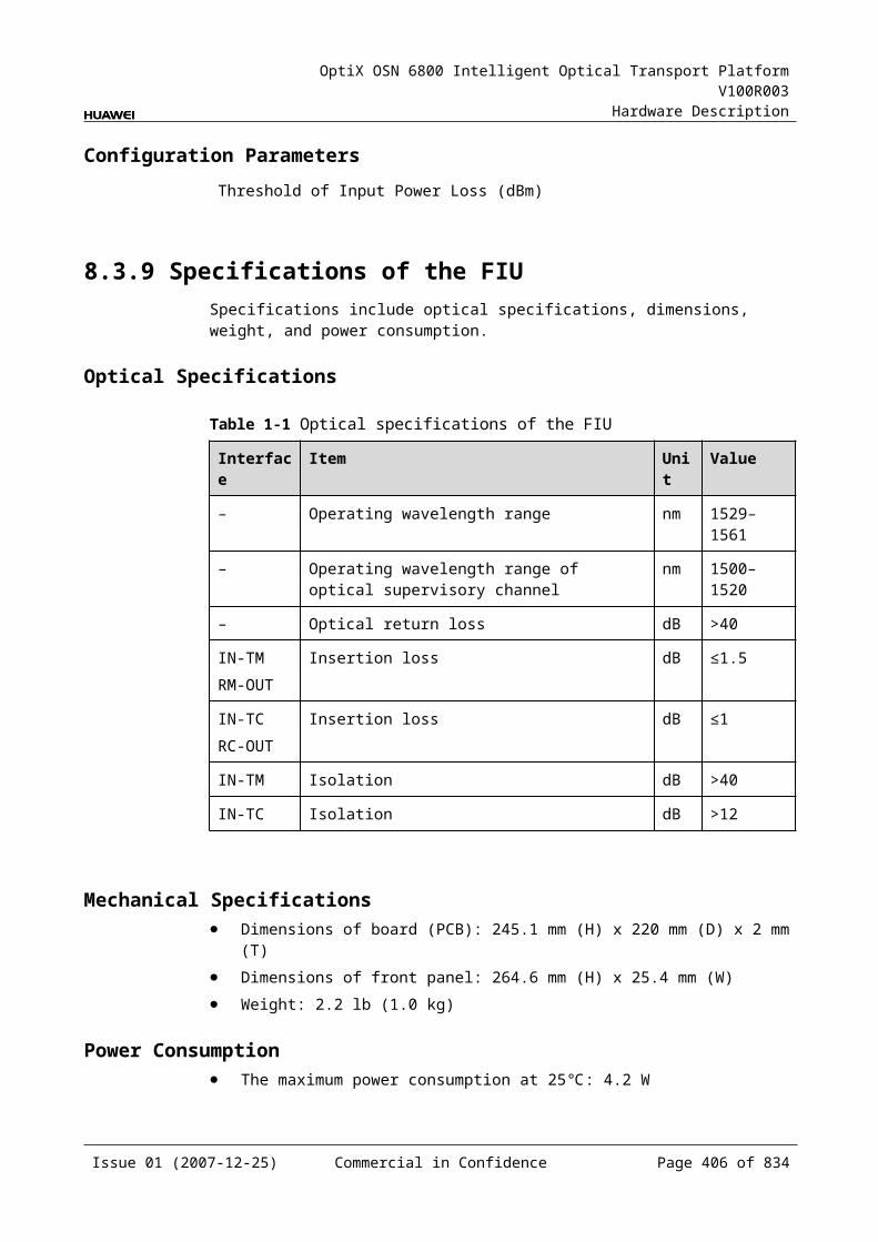
OptiX OSN 6800 Intelligent Optical Transport Platform V100R003
Hardware Description
Figure 10-1 Position of the WSD9 in the DWDM system
DCM
O A
OTU
OTU
OTU
OTU
OTU
OTU
OTU
OTU
OTU
OTU
OTU
OTU
OTU
OTU
OTU
OTU
O A
O A
DCM
WSD9
DMUX
DMUX
WSM9
MUX
WSM9
MUX
WSD9O A
Client-side Client-side
Client-side Client-side
8
88
8
NOTEAn OTU is a transceiver that can process transmitting signals and receiving signals for the same wavelength at the same time.
10.3.3 Functions and FeaturesThe main functions and features supported by the WSD9 are dynamic grooming of wavelengths, online optical performance monitoring, and alarms and performance events monitoring.
For detailed functions and features, refer to Table 10-15.
Table 10-1 Functions and features of the WSD9
Function and Feature
Description
Basic function Configures any wavelengths to any interfaces. A node on the ring or chain network can output any wavelength combination to any interface so as to achieve the dynamic allocation of wavelengths.
WDM specification
Supports the DWDM specification.
Issue 01 (2007-12-25) Commercial in Confidence Page 406 of 664
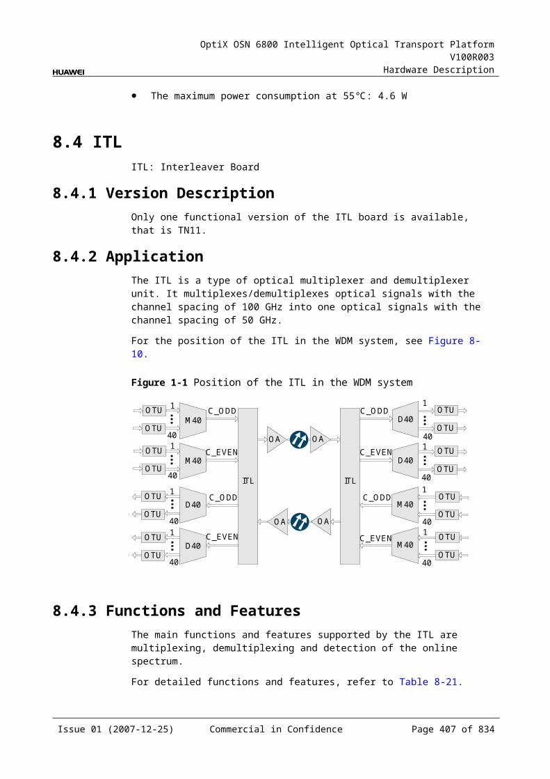
OptiX OSN 6800 Intelligent Optical Transport Platform V100R003
Hardware Description
Function and Feature
Description
Online optical performance monitoring
Provides the online monitoring interface. A small amount of optical signal can be output to the spectrum analyzer or spectrum analyzer unit through the interface so as to monitor the spectrum and optical performance of the multi-channel signal without interrupting the services.
Alarms and performance events monitoring
Provides the function of optical power detection and the function to report the alarms and performance events of the board.
Optical power adjustment
Provides the function to adjust the optical power of each channel.
10.3.4 Working Principle and Signal FlowThe WSD9 consists of the WSS optical module and the control and communication module.
For detailed functions and features, refer to Figure 10-8.
Figure 10-1 Functions and features of the WSD9
WSS optical module
Control and communication module
IN
SCC
DM1
MONI
DM2 DM7DM3 DM4 DM5 DM6 DM8
EXPO
MONO
WSS Optical ModuleThe main path signal is received through the IN interface. The single-channel or multi-channel signals to be dropped at the local station are output through the DM1–DM8 interfaces based on the configuration. Other channels pass through the station and are output through the EXPO interface.
The WSS optical module can combine any wavelengths and transmit the signals through the DM1–DM8 and EXPO interfaces.
Issue 01 (2007-12-25) Commercial in Confidence Page 407 of 664
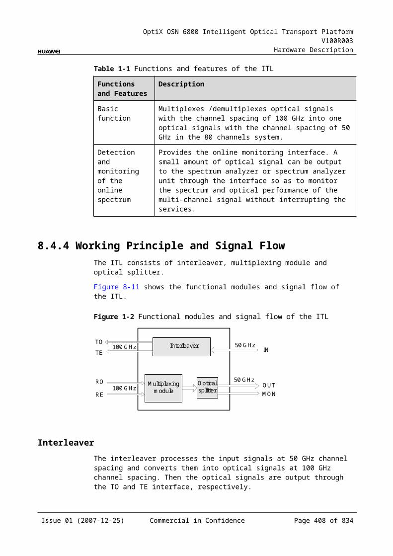
OptiX OSN 6800 Intelligent Optical Transport Platform V100R003
Hardware Description
A small amount of optical signal are separated from those input through the IN interface. These separated signals are output through the MONI interface and used for optical performance monitoring.
A small amount of optical signal are separated from those output through the EXPO interface. Theses separated signals are output through the MONO interface and used for optical performance monitoring.
The WSS optical module contains the VOA module that realizes the power adjustment at the wavelength level.
Control and Communication ModuleThe control and communication module realizes the control, monitoring and communications management of each functional module of the board.
The control and communication module collects the information, such as the alarms and performance events, working status, and voltage detection, of each functional module of the board and reports to the SCC.
Receiving the commands from the SCC, the control and communication module controls and coordinates the functional modules of the board in working.
10.3.5 Front PanelThere are indicators, interfaces and laser safety label on the WSD9 front panel.
Appearance of the Front PanelFigure 10-9 shows the WSD9 front panel.
Issue 01 (2007-12-25) Commercial in Confidence Page 408 of 664
OptiX OSN 6800 Intelligent Optical Transport Platform V100R003
Hardware Description
Figure 10-1 WSD9 front panel
WSD9
WSD9
LASERRADIATION
DO NOT VIEW DIRECTLYWITH OPTICALINSTRUMENTS
CLASS 1M LASERPRODUCT
STATACTPROGSRV
DM
1D
M2
DM
3D
M4
EX
PO
IND
M5
DM
6M
ON
OM
ON
ID
M7
DM
8
WSD9
WSD9
STATACTPROGSRV
LASERRADIATION
DO NOT VIEW DIRECTLYWITH OPTICALINSTRUMENTS
CLASS 1M LASERPRODUCT
DM
1D
M2
DM
3D
M4
EX
PO
IND
M5
DM
6M
ON
OM
ON
ID
M7
DM
8
TN13WSD9TN11WSD9/TN12WSD9
IndicatorsThere are four indicators on the front panel.
Board hardware status indicator (STAT) – dual-colored (red, green) Service active status indicator (ACT) – green Board software status indicator (PROG) – dual-colored (red, green) Service alarm indicator (SRV) – triple-colored (red, green, yellow)
InterfacesThere are 12 optical interfaces on the WSD9 front panel. Table 10-16 lists the type and function of each interface.
Issue 01 (2007-12-25) Commercial in Confidence Page 409 of 664
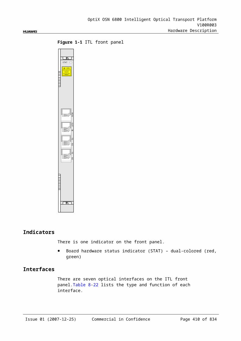
OptiX OSN 6800 Intelligent Optical Transport Platform V100R003
Hardware Description
Table 10-1 Types and functions of the WSD9 interfaces
Interface
Type
Function
DM1-DM8 LC Transmit the single-channel or multi-channel signal separated from the main path. If the signal is a multi-channel signal, it is sent to the optical demultiplexer unit or the optical add and drop multiplexing unit. If the signal is a single-channel signal, it is directly sent to the optical transponder unit.
EXPO LC Transmits the main path signal.
IN LC Receives the main path signal.
MONI LC Connected to the input interface of the spectrum analyzer unit, accomplishes the online optical performance monitoring for the received main path signal.The MONI port is a 3/97 tap of the total composite signal at the IN port (15dB lower than the actual signal power).
MONO LC Connected to the output interface of the spectrum analyzer unit, accomplishes the online optical performance monitoring for the transmitted main path signal.The MONO port is a 3/97 tap of the total composite signal at the EXPO port (15dB lower than the actual signal power).
Laser Safety LevelThe laser safety level of the optical interface is CLASS 1M.
The maximum output optical power of each optical interface ranges from 10 dBm (10 mW) to 22.15 dBm (164 mW).
10.3.6 Valid SlotsThe TN11WSD9 and TN12WSD9 occupies two slots. The TN13WSD9 occupies three slots. The valid slots for the TN11WSD9 and TN12WSD9 are IU1–IU16 in the subrack. The valid slots for the TN13WSD9 are IU1–IU15 in the subrack.
The back connector of the board is mounted to the backplane along the left slot in the subrack, so the slot number of the TN11WSD9 and TN12WSD9 board displayed on the NM is the number of the left one of the two occupied slots, and the slot number of the TN13WSD9 board displayed on the NM is the number of the left one of the three occupied slots.
For example, if the TN11WSD9 occupies slots IU1 and IU2, the slot number of the WSD9 displayed on the NM is IU1. If the TN13WSD9 occupies slots IU1, IU2 and IU3, the slot number of the WSD9 displayed on the NM is IU1.
10.3.7 NM Configuration ReferenceNM configuration reference includes the reference information needed during the configuration of boards through the T2000.
Issue 01 (2007-12-25) Commercial in Confidence Page 410 of 664
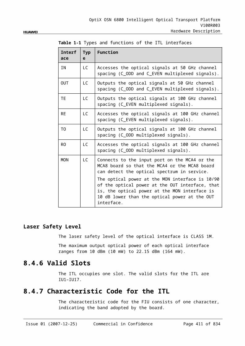
OptiX OSN 6800 Intelligent Optical Transport Platform V100R003
Hardware Description
Display of Optical InterfacesThe serial numbers of the optical interfaces on the panel of the board displayed on the NM are listed in Table 10-17.
Table 10-1 Serial numbers of the interfaces of the WSD9 displayed on the NM
Interface on the Panel Interface on the NM
IN 1
EXPO 2
DM1-DM8 3-10
MONI 11
MONO 12
Configuration ParametersThreshold of Input Power Loss (dBm)
Optical Interface Attenuation Ratio (dB)
Maximum Attenuation Ratio (dB)
Minimum Attenuation Ratio (dB)
10.3.8 Specifications of the WSD9Specifications include optical specifications, dimensions, weight, and power consumption.
Optical SpecificationsTable 10-18 lists the optical specifications of the WSD9.
Table 10-1 Optical specifications of the WSD9
Item Unit Value
Adjacent channel spacing TN11WSD9 GHz 100
TN12WSD9 100
TN13WSD9 50
Insertion loss IN-DMxa
IN-EXPOdB ≤8b
Operating wavelength range nm 1529–1561
0.5 dB spectral width nm >0.35
Issue 01 (2007-12-25) Commercial in Confidence Page 411 of 664
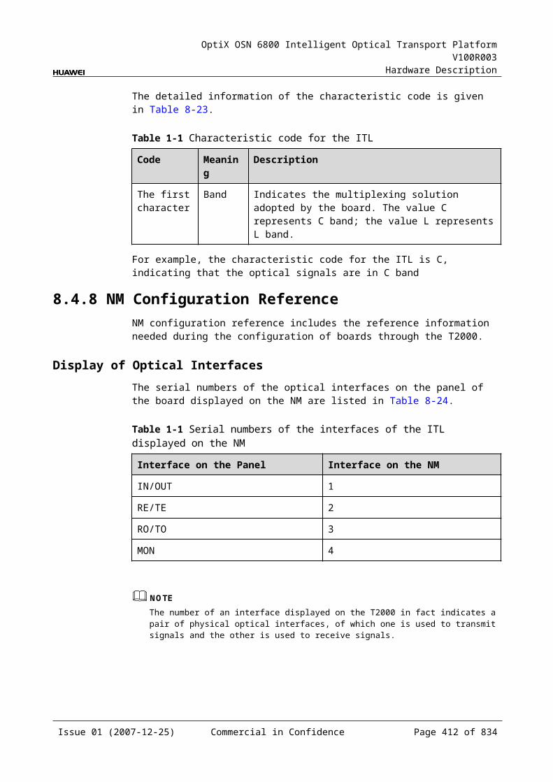
OptiX OSN 6800 Intelligent Optical Transport Platform V100R003
Hardware Description
Item Unit Value
Adjacent channel isolation dB >25
Non-adjacent channel isolation dB >30
Extinction ratio dB ≥35
Reconfiguration time s 3
Optical return loss dB 30
Directivity dB 35
Attenuation range of each of dropping wavelengths dB 0–15
Attenuation precision of each of dropping wavelengths dB ±1
Polarization dependence loss dB ≤1
Dimension - 1×9
a: DMx represents the DM1–DM8 interface.
b: This value can be reached when the attenuation of the VOA is set to 0 dB.
Mechanical Specifications Dimensions of board (PCB): 245.1 mm (H) x 220 mm (D) x 2 mm (T)
Dimensions of front panel:
TN11WSD9: 264.6 mm (H) × 50.8 mm (W) TN12WSD9: 264.6 mm (H) × 50.8 mm (W) TN13WSD9: 264.6 mm (H) × 76.2 mm (W)
Weight:
TN11WSD9: 4.85 lb (2.2 kg) TN12WSD9: 4.85 lb (2.2 kg) TN13WSD9: 10.58 lb (4.8 kg)
Power ConsumptionBoard The maximum power
consumption at 25 (W)The maximum power consumption at 55 (W)
TN11WSD9 17.0 18.7
TN12WSD9 30.0 35.0
TN13WSD9 30.0 35.0
Issue 01 (2007-12-25) Commercial in Confidence Page 412 of 664
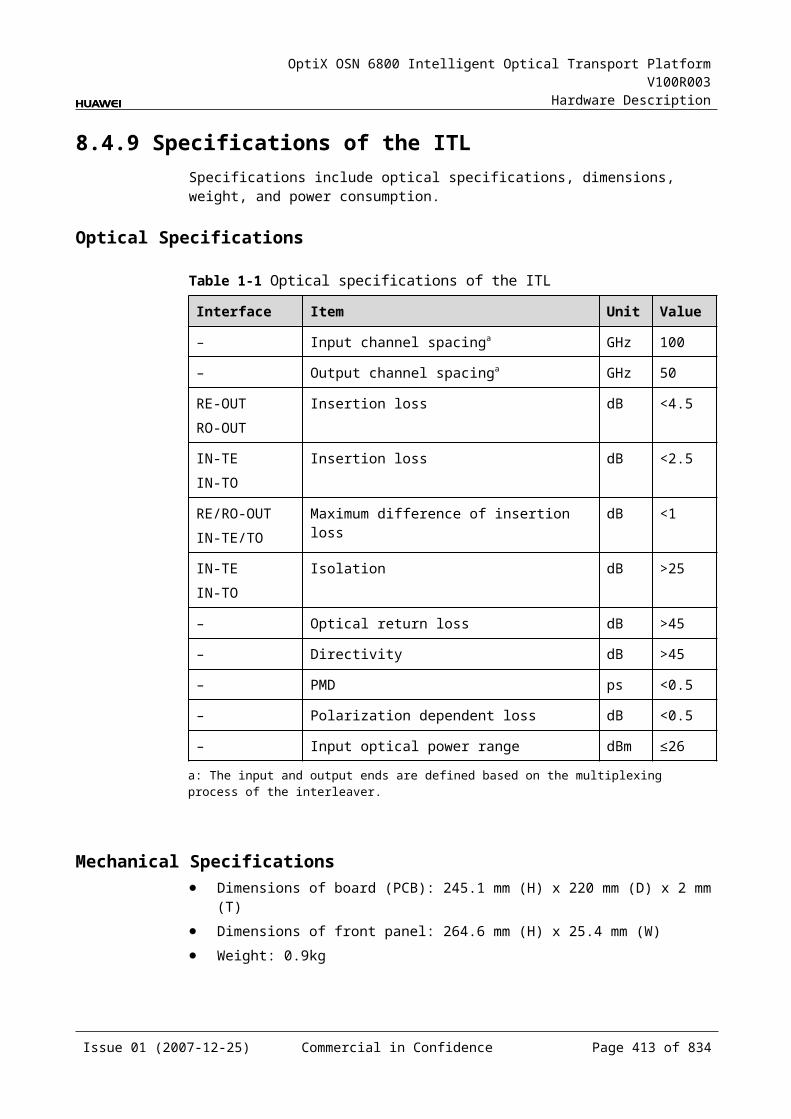
OptiX OSN 6800 Intelligent Optical Transport Platform V100R003
Hardware Description
10.4 WSM9WSM9: 9-port wavelength selective switching multiplexing board
10.4.1 Version DescriptionThree functional versions of the WSM9 board are available: TN11, TN12 and TN13. The main difference among the three versions is that the channel spacing of the wavelength is different.
VersionTable 10-19 lists the version description of the WSM9.
Table 10-1 Version description of the WSM9
Item Description
Functional version
Three functional versions of the WSM9 board are available: TN11, TN12 and TN13.
Similarity The TN11WSM9, TN12WSM9 and TN13WSM9 boards share the same functioning principle.
Difference The wavelength of the TN11WSM9 board is separated at 100 GHz channel spacing, and the board occupies two slots.The wavelength of the TN12WSM9 board is separated at 100 GHz channel spacing, and the board occupies two slots.The wavelength of the TN13WSM9 board is separated at 50 GHz channel spacing, and the board occupies three slots.
Replacement The TN12WSM9 and TN11WSM9 boards share the same functionality and can be replaced with each other. But after the TN11WSM9 board is replaced with the TN12WSM9 board, the SCC software need be upgraded.The boards of other versions cannot be replaced with each other.
TypeTable 10-20 lists the types of the WSM9.
Table 10-1 Type description of the WSM9
Board Type
Description
TN12WSM9 A01 The wavelength of the board is separated at 100 GHz channel spacing in C band.
TN13WSM9 C01 The wavelength of the board is separated at 50 GHz channel spacing in C band.
Issue 01 (2007-12-25) Commercial in Confidence Page 413 of 664
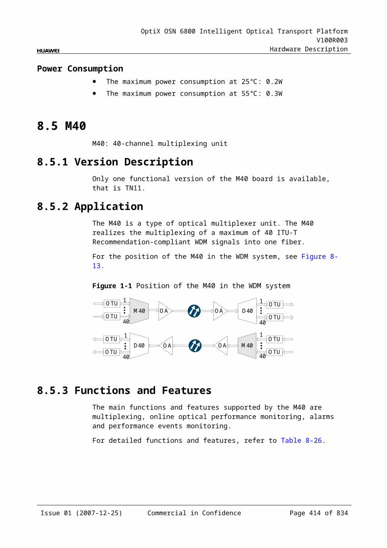
OptiX OSN 6800 Intelligent Optical Transport Platform V100R003
Hardware Description
10.4.2 ApplicationThe WSM9 is a type of reconfigurable optical add and drop multiplexing unit. Used with the WSD9, the WSM9 realizes the wavelength grooming at the nodes in the DWDM network.
The single-channel or multi-channel signals to be added to the main path are input through the interfaces of WSM9.
If the added signal is a mutli-channel signal, it is received after being multiplexed by the optical multiplexer unit. If the added signal is a single-channel signal, it is directly received after being converted by the OTU.
For the position of the WSM9 in the DWDM system, see Figure 10-10.
Figure 10-1 Position of the WSM9 in the DWDM system
DCM
O A
WSM9
OTU
OTU
OTU
OTU
OTU
OTU
OTU
OTU
OTU
OTU
OTU
OTU
OTU
OTU
OTU
OTU
O A O A
O A
DCM
WSD9
DMUX
DMUX
WSD9
MUX
WSM9
MUX
Client-side Client-side
Client-side Client-side
8 8
88
NOTEAn OTU is a transceiver that can process transmitting signals and receiving signals for the same wavelength at the same time.
10.4.3 Functions and FeaturesThe main functions and features supported by the WSM9 are dynamic grooming of wavelengths, online optical performance monitoring, and alarms and performance events monitoring.
For detailed functions and features, refer to Table 10-21.
Issue 01 (2007-12-25) Commercial in Confidence Page 414 of 664
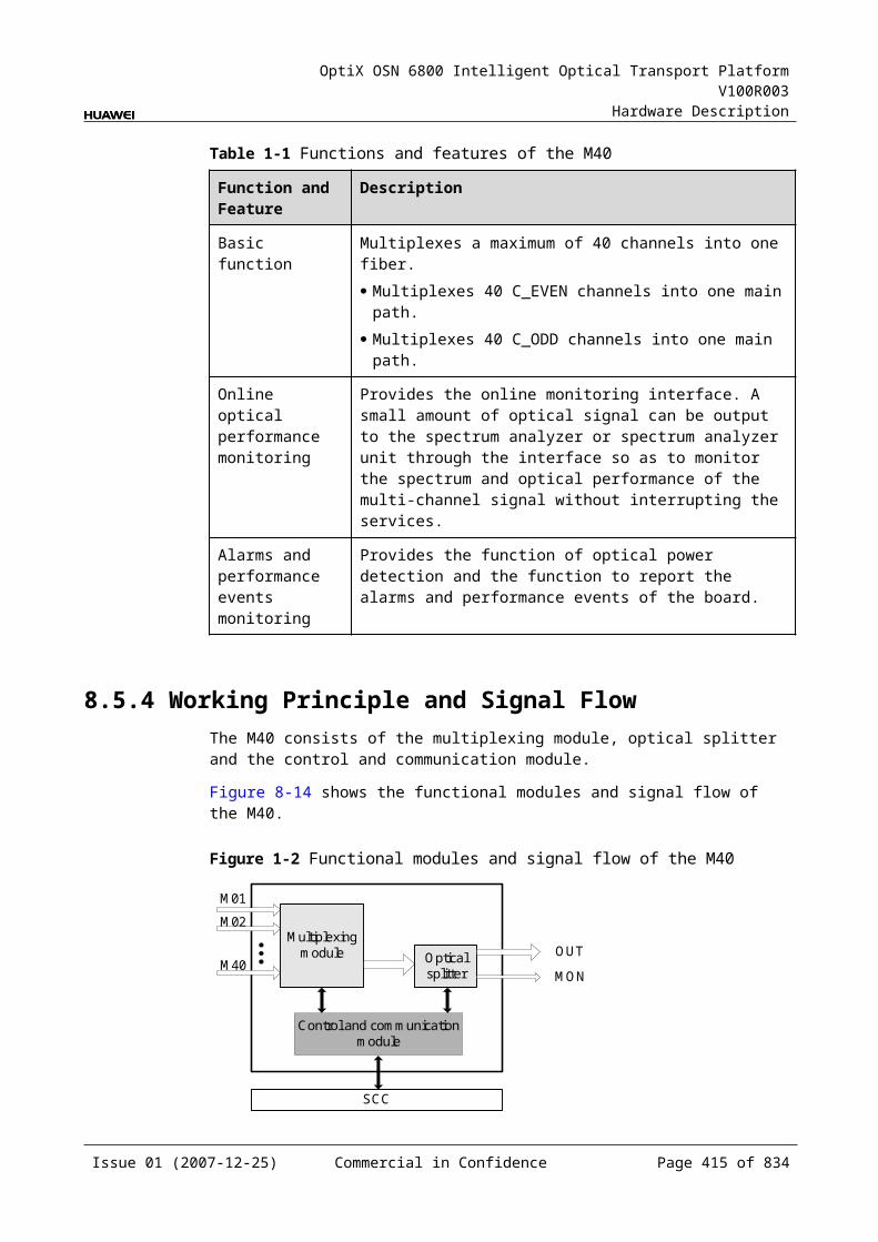
OptiX OSN 6800 Intelligent Optical Transport Platform V100R003
Hardware Description
Table 10-1 Functions and features of the WSM9
Function and Feature
Description
Basic function Configures any wavelengths to any interfaces. A node on the ring or chain network can receive any wavelengths at the local station through any interfaces so as to achieve the dynamic allocation of wavelengths.
WDM specification
Supports the DWDM specification.
Online optical performance monitoring
Provides the online monitoring interface. A small amount of optical signal can be output to the spectrum analyzer or spectrum analyzer unit through the interface so as to monitor the spectrum and optical performance of the multi-channel signal without interrupting the services.
Alarms and performance events monitoring
Provides the function of optical power detection and the function to report the alarms and performance events of the board.
Optical power adjustment
Provides the function to adjust the optical power of each channel.
10.4.4 Working Principle and Signal FlowThe WSM9 consists of the WSS optical module and the control and communication module.
For detailed functions and features, refer to Figure 10-11.
Figure 10-1 Functions and features of the WSM9
AM1 AM2 AM7AM3 AM4 AM5 AM6 AM8
WSS optical module
Control and communication module
SCC
OUT
MONO
EXPI
MONI
Issue 01 (2007-12-25) Commercial in Confidence Page 415 of 664
OptiX OSN 6800 Intelligent Optical Transport Platform V100R003
Hardware Description
WSS Optical ModuleThe single-channel or multi-channel signals to be added at the local station are input through the AM1–AM8 interfaces. The main path signal received through the EXPI interface is multiplexed with the signals added through the AM1–AM8 interfaces. Then, the multiplexed signal is output through the OUT interface.
The WSS optical module can combine any wavelengths and receive the signals through the AM1–AM8 or EXPI interfaces.
A small amount of optical signals are separated from those input through the EXPI interface. These separated signals are output through the MONI interface and used for optical performance monitoring.
A small amount of optical signals are separated from those output through the OUT interface. Theses separated signals are output through the MONO interface and used for optical performance monitoring.
The WSS optical module contains the VOA module that realizes the power adjustment at the wavelength level.
Control and Communication ModuleThe control and communication module realizes the control, monitoring and communications management of each functional module of the board.
The control and communication module collects the information, such as the alarms and performance events, working status, and voltage detection, of each functional module of the board and reports to the SCC.
Receiving the commands from the SCC, the control and communication module controls and coordinates the functional modules of the board in working.
10.4.5 Front PanelThere are indicators, interfaces and laser safety label on the WSM9 front panel.
Appearance of the Front PanelFigure 10-12 shows the WSM9 front panel.
Issue 01 (2007-12-25) Commercial in Confidence Page 416 of 664
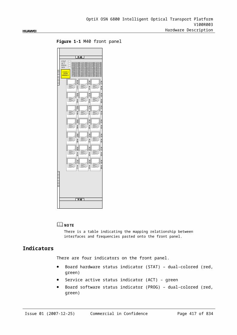
OptiX OSN 6800 Intelligent Optical Transport Platform V100R003
Hardware Description
Figure 10-1 WSM9 front panel
TN13WSM9
WSM9
WSM9
STATACTPROGSRV
LASERRADIATION
DO NOT VIEW DIRECTLYWITH OPTICALINSTRUMENTS
CLASS 1M LASERPRODUCT
AM
1A
M2
AM
3A
M4
OU
TE
XP
IA
M5
AM
6M
ON
OM
ON
IA
M7
AM
8
WSM9
WSM9
CLASS 1LASER
PRODUCT
STATACTPROGSRV
AM
1A
M2
AM
3A
M4
OU
TE
XP
IA
M5
AM
6M
ON
OM
ON
IA
M7
AM
8
TN11WSM9/TN12WSM9
IndicatorsThere are four indicators on the front panel.
Board hardware status indicator (STAT) – dual-colored (red, green) Service active status indicator (ACT) – green Board software status indicator (PROG) – dual-colored (red, green) Service alarm indicator (SRV) – triple-colored (red, green, yellow)
InterfacesThere are 12 optical interfaces on the WSM9 front panel. Table 10-22 lists the type and function of each interface.
Issue 01 (2007-12-25) Commercial in Confidence Page 417 of 664
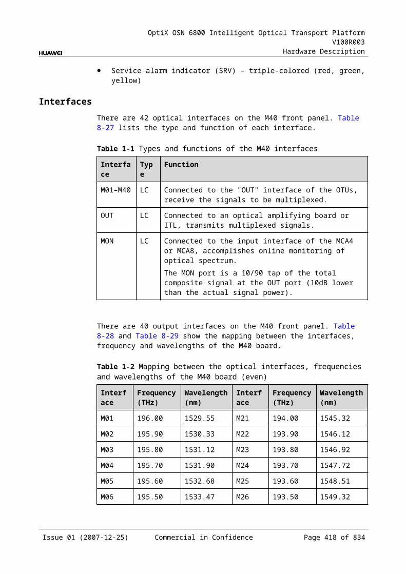
OptiX OSN 6800 Intelligent Optical Transport Platform V100R003
Hardware Description
Table 10-1 Types and functions of the WSM9 interfaces
Interface
Type
Function
AM1-AM8 LC Receive the single-channel signal or multi-channel signal that are to be multiplexed into the main path.
OUT LC Transmits the main path signal.
EXPI LC Receives the main path signal.
MONI LC Connected to the input interface of the spectrum analyzer unit, accomplishes the online optical performance monitoring for the received main path signal.The MONI port is a 3/97 tap of the total composite signal at the EXPI port (15dB lower than the actual signal power).
MONO LC Connected to the output interface of the spectrum analyzer unit, accomplishes the online optical performance monitoring for the transmitted main path signal.The MONO port is a 3/97 tap of the total composite signal at the OUT port (15dB lower than the actual signal power).
Laser Safety LevelTN11WSM9 and TN12WSM9:
The laser safety level of the optical interface is CLASS 1.
The maximum output optical power of each optical interface is lower than 10 dBm (10 mW).
TN13WSM9:
The laser safety level of the optical interface is CLASS 1M.
The maximum output optical power of each optical interface ranges from 10 dBm (10 mW) to 22.15 dBm (164 mW).
10.4.6 Valid SlotsThe TN11WSM9 and TN12WSM9 occupies two slots. The TN13WSM9 occupies three slots. The valid slots for the TN11WSM9 and TN12WSM9 are IU1–IU16 in the subrack. The valid slots for the TN13WSM9 are IU1–IU15 in the subrack.
The back connector of the board is mounted to the backplane along the left slot in the subrack, so the slot number of the TN11WSM9 and TN12WSM9 board displayed on the NM is the number of the left one of the two occupied slots, and the slot number of the TN13WSM9 board displayed on the NM is the number of the left one of the three occupied slots.
For example, if the TN11WSM9 occupies slots IU1 and IU2, the slot number of the WSM9 displayed on the NM is IU1. If the TN13WSM9 occupies slots IU1, IU2 and IU3, the slot number of the TN13WSM9 displayed on the NM is IU1.
Issue 01 (2007-12-25) Commercial in Confidence Page 418 of 664

OptiX OSN 6800 Intelligent Optical Transport Platform V100R003
Hardware Description
10.4.7 NM Configuration ReferenceNM configuration reference includes the reference information needed during the configuration of boards through the T2000.
Display of Optical InterfacesThe serial numbers of the optical interfaces on the panel of the board displayed on the NM are listed in Table 10-23.
Table 10-1 Serial numbers of the interfaces of the WSM9 displayed on the NM
Interface on the Panel Interface on the NM
EXPI 1
OUT 2
AM1-AM8 3-10
MONI 11
MONO 12
Configuration ParametersOptical Interface Attenuation Ratio (dB)
Maximum Attenuation Ratio (dB)
Minimum Attenuation Ratio (dB)
10.4.8 Specifications of the WSM9Specifications include optical specifications, dimensions, weight, and power consumption.
Optical SpecificationsTable 10-24 lists the optical specifications of the WSM9.
Table 10-1 Optical specifications of the WSM9
Item Unit Value
Adjacent channel spacing TN11WSM9 GHz 100
TN12WSM9 100
TN13WSM9 50
Insertion loss AMxa-OUTEXPI-OUT
dB ≤8b
Issue 01 (2007-12-25) Commercial in Confidence Page 419 of 664
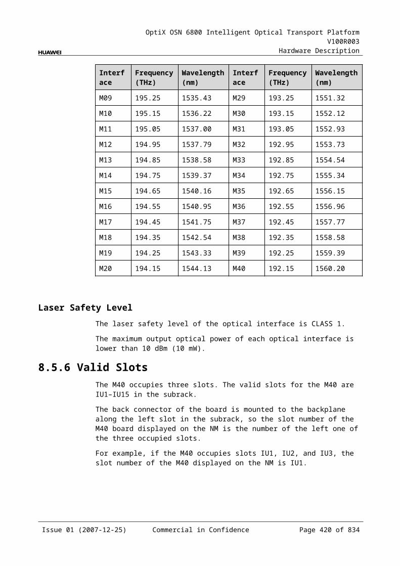
OptiX OSN 6800 Intelligent Optical Transport Platform V100R003
Hardware Description
Item Unit Value
Operating wavelength range nm 1529–1561
0.5 dB spectral width nm >0.35
Adjacent channel isolation dB >25
Non-adjacent channel isolation dB >30
Extinction ratio dB ≥35
Reconfiguration time s 3
Optical return loss dB 30
Directivity dB 35
Attenuation range of each of adding wavelengths dB 0–15
Attenuation precision of each of adding wavelengths dB ±1
Polarization dependence loss dB ≤1
Dimension - 9×1
a: AMx represents the AM1–AM8 interface.
b: This value can be reached when the attenuation of the VOA is set to 0 dB.
Mechanical Specifications Dimensions of board (PCB): 245.1 mm (H) x 220 mm (D) x 2 mm (T)
Dimensions of front panel:
TN11WSM9: 264.6 mm (H) × 50.8 mm (W) TN12WSM9: 264.6 mm (H) × 50.8 mm (W) TN13WSM9: 264.6 mm (H) × 76.2 mm (W)
Weight:
TN11WSM9: 4.85 lb (2.2 kg) TN12WSM9: 4.85 lb (2.2 kg) TN13WSM9: 10.58 lb (4.8 kg)
Power ConsumptionBoard The maximum power
consumption at 25 (W)The maximum power consumption at 55 (W)
TN11WSM9 17.0 18.7
TN12WSM9 30.0 35.0
TN13WSM9 30.0 35.0
Issue 01 (2007-12-25) Commercial in Confidence Page 420 of 664
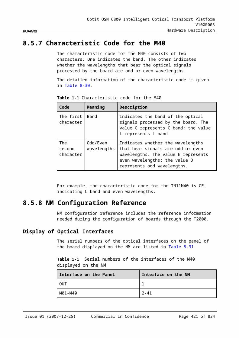
OptiX OSN 6800 Intelligent Optical Transport Platform V100R003
Hardware Description
10.5 WSMD4WSMD4: 4-Port Wavelength Selective Switching Multiplexer and Demultiplexer Board
10.5.1 Version DescriptionOnly one functional version of the WSMD4 board is available, that is TN11.
TypeTable 10-25lists the version description of the WSMD4.
Table 10-1 Version description of the WSMD4
Board Type Description
TN11WSMD4 01 Processes the even wavelengths in C band.
02 Processes the odd wavelengths in C band.
10.5.2 ApplicationThe WSMD4 is a type of reconfigurable optical add and drop multiplexing unit. Used with the optical multiplexer and demultiplexer unit, and the optical add and drop multiplexing unit, WSMD4 realizes the wavelength grooming at the nodes in the DWDM network.
For the position of the WSMD4 in the DWDM system, see Figure 10-13.
Issue 01 (2007-12-25) Commercial in Confidence Page 421 of 664
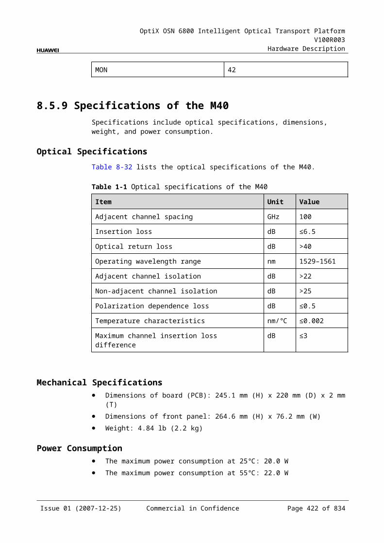
OptiX OSN 6800 Intelligent Optical Transport Platform V100R003
Hardware Description
Figure 10-1 Position of the WSMD4 in the DWDM system
WestODF
EastODFWSMD4 WSMD4
FIU
FIU
WSMD4FIU
FIU
WSMD4
West clientside
NorthODF
SouthODF
East clientside
North clientside
South clientside
10.5.3 Functions and FeaturesThe main functions and features supported by the WSMD4 are service broadcasting, dynamic grooming of wavelengths, online optical performance monitoring, and alarms and performance events monitoring.
For detailed functions and features, refer to Table 10-26.
Table 10-1 Functions and features of the WSMD4
Function and Feature
Description
Basic function Provides service broadcasting function, and configures any wavelengths to any interfaces. A node on the ring or chain network can receive any wavelengths at the local station through any interfaces, and output any wavelength combination to any interface, so as to achieve the dynamic allocation of wavelengths.
WDM specification
Supports the DWDM specification.
Online optical performance monitoring
Provides the online monitoring interface. A small amount of optical signal can be output to the spectrum analyzer or spectrum analyzer unit through the interface so as to monitor the spectrum and optical performance of the multi-channel signal without interrupting the services.
Issue 01 (2007-12-25) Commercial in Confidence Page 422 of 664
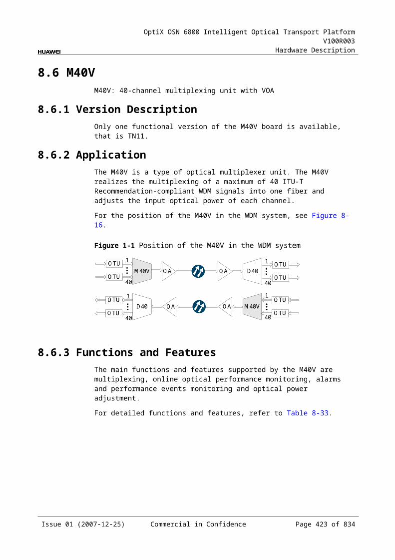
OptiX OSN 6800 Intelligent Optical Transport Platform V100R003
Hardware Description
Function and Feature
Description
Alarms and performance events monitoring
Provides the function of optical power detection and the function to report the alarms and performance events of the board.
Optical power adjustment
Provides the function to adjust the optical power of any add wavelengths at the local station.
10.5.4 Working Principle and Signal FlowThe WSMD4 consists of the WSS optical module, RDU (ROADM Demux Unit) optical module and the control and communication module.
For detailed functions and features, refer to Figure 10-14.
Figure 10-1 Functions and features of the WSMD4
DM1DM2DM3DM4
SCC
MONI
WSS optical moduleOUT
IN RDU optical module
MONO
AM1AM2AM3AM4
Control and communication module
RDU Optical Module and WSS Optical ModuleThe optical signals of the main path is accessed through the IN interface. It is broadcasted into four same optical signals through the RDU optical module. Then, the board outputs the single-channel or multiplexed signals to be dropped at the local station through any of the DM1-DM4 interface as per the configuration. Other wavelengths that are not dropped at the local station are output through the unused interface in the DM1-DM4.
Local add optical signal (single-channel or multiplexed signals) is input to the board through any of the AM1-AM4 optical interface. If multiple wavelengths are to be added, the signals are first sent to the multiplexing unit for processing and then input to the WSMD4 board through the AMn optical interface; if single wavelength is to be added, the signal can be directly input to the WSDM4 board from the optical transponder unit through the AMn interface. Optical signals cross-connected from
Issue 01 (2007-12-25) Commercial in Confidence Page 423 of 664
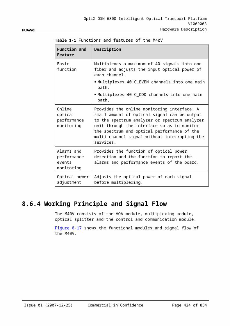
OptiX OSN 6800 Intelligent Optical Transport Platform V100R003
Hardware Description
other directions are input to the board through the AM1-AM4 optical interfaces. Then, they are multiplexed with the added wavelengths at the local station. The multiplexed signals are output through the OUT optical interface.
The WSS optical module can access any combination of wavelengths through any of the following optical interfaces: AM1, AM2, AM3 and AM4.
A small amount of optical signals are separated from those input through the IN interface. These separated signals are output through the MONI interface and used for optical performance monitoring.
A small amount of optical signals are separated from those output through the OUT interface. Theses separated signals are output through the MONO interface and used for optical performance monitoring.
The WSS optical module contains the VOA module that realizes the power adjustment at the wavelength level.
Control and Communication ModuleThe control and communication module realizes the control, monitoring and communications management of each functional module of the board.
The control and communication module collects the information, such as the alarms and performance events, working status, and voltage detection, of each functional module of the board and reports to the SCC.
Receiving the commands from the SCC, the control and communication module controls and coordinates the functional modules of the board in working.
10.5.5 Front PanelThere are indicators, interfaces and laser safety label on the WSMD4 front panel.
Appearance of the Front PanelFigure 10-15 shows the WSMD4 front panel.
Issue 01 (2007-12-25) Commercial in Confidence Page 424 of 664
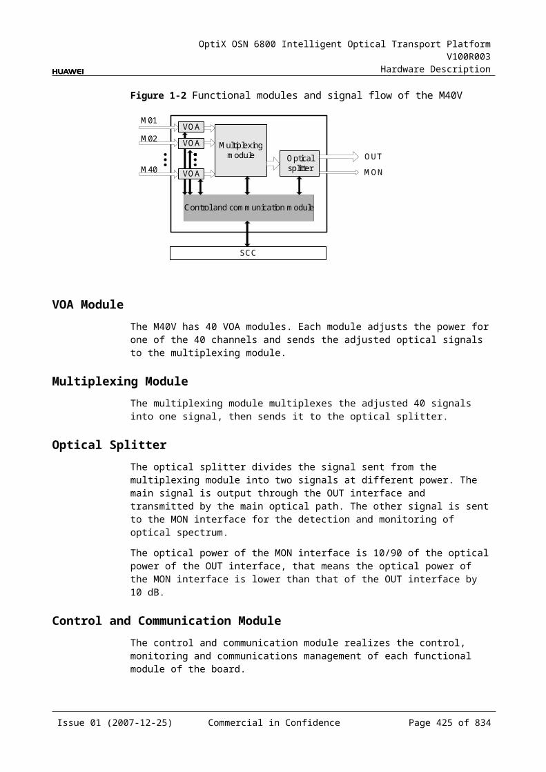
OptiX OSN 6800 Intelligent Optical Transport Platform V100R003
Hardware Description
Figure 10-1 WSMD4 front panel
WSMD4
WSMD4
STATACTPROGSRV
DM
1A
M1
DM
2A
M2
OU
TIN
DM
3A
M3
MO
NO
MO
NI
DM
4A
M4
LASERRADIATION
DO NOT VIEW DIRECTLYWITH OPTICALINSTRUMENTS
CLASS 1M LASERPRODUCT
IndicatorsThere are four indicators on the front panel.
Board hardware status indicator (STAT) – dual-colored (red, green) Service active status indicator (ACT) – green Board software status indicator (PROG) – dual-colored (red, green) Service alarm indicator (SRV) – triple-colored (red, green, yellow)
InterfacesThere are 12 optical interfaces on the WSMD4 front panel. Table 10-27 lists the type and function of each interface.
Issue 01 (2007-12-25) Commercial in Confidence Page 425 of 664

OptiX OSN 6800 Intelligent Optical Transport Platform V100R003
Hardware Description
Table 10-1 Types and functions of the WSMD4 interfaces
Interface
Type
Function
AM1-AM4 LC Receives the single-channel signal or multiplexed signal from the local station or other stations. Then, the accessed signal is multiplexed into the main path.
DM1-DM4 LC Transmits the multiplexed signals to be output at the local station or other stations to the optical demultiplexing unit or the optical add/drop multiplexing unit.
OUT LC Transmits the main path signal.
IN LC Receives the main path signal.
MONI LC Connected to the input interface of the spectrum analyzer unit, accomplishes the online optical performance monitoring for the received main path signal.The MONI port is a 3/97 tap of the total composite signal at the EXPI port (15dB lower than the actual signal power).
MONO LC Connected to the output interface of the spectrum analyzer unit, accomplishes the online optical performance monitoring for the transmitted main path signal.The MONO port is a 3/97 tap of the total composite signal at the OUT port (15dB lower than the actual signal power).
Laser Safety LevelThe laser safety level of the optical interface is CLASS 1M.
The maximum output optical power of each optical interface ranges from 10 dBm (10 mW) to 22.15 dBm (164 mW).
10.5.6 Valid SlotsThe WSMD4 occupies two slots. The valid slots for the WSMD4 are IU1–IU16 in the subrack.
The back connector of the board is mounted to the backplane along the left slot in the subrack, so the slot number of the WSMD4 board displayed on the NM is the number of the left one of the two occupied slots.
For example, if the WSMD4 occupies slots IU1 and IU2, the slot number of the WSMD4 displayed on the NM is IU1.
10.5.7 NM Configuration ReferenceNM configuration reference includes the reference information needed during the configuration of boards through the T2000.
Issue 01 (2007-12-25) Commercial in Confidence Page 426 of 664

OptiX OSN 6800 Intelligent Optical Transport Platform V100R003
Hardware Description
Display of Optical InterfacesThe serial numbers of the optical interfaces on the panel of the board displayed on the NM are listed in Table 10-28.
Table 10-1 Serial numbers of the interfaces of the WSMD4 displayed on the NM
Interface on the Panel Interface on the NM
IN 1
DM1 2
AM1 3
OUT 4
DM2-DM4 5 to 7
AM2-AM4 8 to 10
MONO 11
MONI 12
Configuration ParametersThreshold of Input Power Loss (dBm)
Optical Interface Attenuation Ratio (dB)
Maximum Attenuation Ratio (dB)
Minimum Attenuation Ratio (dB)
Configure Band
Configure Working Band Parity
Actual Band
Actual Working Band Parity
10.5.8 Specifications of the WSMD4Specifications include optical specifications, dimensions, weight, and power consumption.
Optical SpecificationsTable 10-29 lists the optical specifications of the WSMD4.
Issue 01 (2007-12-25) Commercial in Confidence Page 427 of 664

OptiX OSN 6800 Intelligent Optical Transport Platform V100R003
Hardware Description
Table 10-1 Optical specifications of the WSMD4
Item Unit Value
Adjacent channel spacing GHz 100
Operating wavelength range nm 1529–1561
Insertion loss AMxa-OUTIN-DMxa
dB ≤8b
0.5 dB spectral width nm >0.35
Adjacent channel isolation dB >25
Extinction ratio dB ≥35
Reconfiguration time s 3
Optical return loss dB 30
Directivity dB 35
Attenuation range per add wavelength dB 0–15
Attenuation accuracy per add wavelength dB ±1
Polarization dependence loss dB ≤1
Dimension - 4
a: AMx represents the AM1–AM4 interface.
DMx represents the DM1-DM4 interface.
b: This value can be reached when the attenuation of the VOA is set to 0 dB.
Mechanical Specifications Dimensions of board (PCB): 245.1 mm (H) x 220 mm (D) x 2 mm (T) Dimensions of front panel: 264.6 mm (H) x 50.8 mm (W) Weight: 7.05 lb (3.2 kg)
Power Consumption The maximum power consumption at 25: 17.0W The maximum power consumption at 55: 18.7W
Issue 01 (2007-12-25) Commercial in Confidence Page 428 of 664

OptiX OSN 6800 Intelligent Optical Transport Platform V100R003
Hardware Description
11 Optical Amplifying Unit
11.1 CRPCCRPC: case-shape Raman pump amplifier unit for C-band
11.1.1 Version DescriptionOnly one functional version of the CRPC board is available, that is TN11.
11.1.2 ApplicationThe CRPC is a type of optical amplifier unit and adopts the backward pumping technology. It supports the transmission over ultra-long distance and the application of the 40G OTU. It can generate multi-channel pump light of high power. The CRPC must be used with the EDFA.
CAUTIONAlways turn off the pump laser of the CRPC before removing or inserting the fiber of the CRPC.
For the position of the CRPC in the WDM system, see Figure 11-1.
Figure 11-1 Position of the CRPC in the WDM system (backward pumping)
CRPC
CRPC
OTUOBU1
OAU1
MUX
DMUX
OTU
OTU
OTU
OTU
OTU
OTU
OTU
OAU1
OBU1FIU
FIU
FIU
FIU
Clientside
Clientside
Clientside
Clientside
MUX
DMUX
Issue 01 (2007-12-25) Commercial in Confidence Page 429 of 664

OptiX OSN 6800 Intelligent Optical Transport Platform V100R003
Hardware Description
11.1.3 Functions and FeaturesThe main function and feature supported by the CRPC is online optical performance monitoring.
For detailed functions and features, refer to Table 11-1.
Table 11-1 Functions and features of the CRPC
Function and Feature
Description
Basic function Generates multi-channel pump light of high power, providing energy for the amplification of signals in the fiber.
Realizes the distributed online amplification of signals over long distance with wide bandwidth and low noise.
Online optical performance monitoring
Provides the online monitoring interface. A small amount of optical signal can be output to the spectrum analyzer or spectrum analyzer unit through the interface so as to monitor the spectrum and optical performance of the multi-channel signal without interrupting the services.
Alarms and performance events monitoring
Detects the optical power of the pump laser, temperature control current, pump current, and back-facet current.
11.1.4 Working Principle and Signal FlowThe CRPC consists of the pump source module and the control and communication module. The CRPC is used at the receive end of the system, making use of the stimulated Raman scattering effect to amplify the optical signals during transmission. The pump light and the signal light are of different directions. The CRPC must be used with the EDFA.
Figure 11-2 shows the functional modules and signal flow of the CRPC.
Figure 11-1 Functional modules and signal flow of the CRPC
Pump source module
Control and communication module
SCC
LINE
Pumplight
SingalOpticalsplitter
SYS
MON
Issue 01 (2007-12-25) Commercial in Confidence Page 430 of 664

OptiX OSN 6800 Intelligent Optical Transport Platform V100R003
Hardware Description
Signal FlowThe pump source module of the CRPC sends the pump light to the line side through the LINE optical interface. The multiplexed signals are received by the LINE optical interface of the CRPC. The pump source module sends the signals into the demultiplexer to split them into two, among which the service optical signals are output through the SYS interface. A few supervisory signals are output to the multi-channel spectrum analyzer unit (MCA4, MCA8) or test instrument through the MON interface for online optical performance monitoring. The Ethernet interface of the CRPC is connected to the ETH1/ETH2 interface of the AUX or the ETH3 interface of the EFI board for the communications with the SCC.
Pump Source ModuleThe laser in the pump source module generates the pump light and sends the light to the optical line for transmission. This module makes use of the stimulated Raman scattering effect of the fiber to amplify the optical signals during transmission.
Optical Splitter An optical splitter splits one channels of optical signals from the pump source module into two channels of signals of different power. One of the them are output through the SYS interface and transmitted in the main optical path. The other channel of signals are output to the MON interface for spectrum detection and supervising.
The optical power of the MON interface is 1/99 of the optical power of the OUT interface, that means the optical power of the MON interface is lower than that of the OUT interface by 20dB.
Control and Communication ModuleThe control and communication module realizes the control, monitoring and communications management of each functional module of the board.
The control and communication module collects the information, such as the alarms and performance events, working status, and voltage detection, of each functional module of the board and reports to the SCC.
Receiving the commands from the SCC, the control and communication module controls and coordinates the functional modules of the board in working.
11.1.5 Front PanelThere are indicators, interfaces and laser safety label on the CRPC front panel.
Appearance of the Front PanelFigure 11-3 shows the CRPC front panel.
Issue 01 (2007-12-25) Commercial in Confidence Page 431 of 664
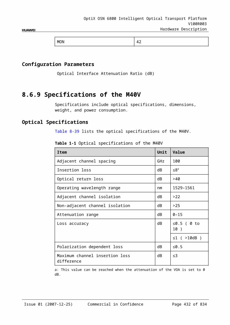
OptiX OSN 6800 Intelligent Optical Transport Platform V100R003
Hardware Description
Figure 11-1 CRPC front panel
:警告 开启电源前,务必连好光纤WARNING: FIBERS MUSTBE CONNECTED SEFOREPOWER UP
!
AVOID EYE OR SKINEXPOSURE TO DIRECT OR
CLASS 4 LASERPRODUCT
SCATTERED RADIATION
LASERRADIATION
ALMCRPC RUN
LINESYSMON
RS232-1 RS232-2 LAN
IndicatorsThere are two indicators on the front panel.
Running status indicator (RUN) - green Service alarm indicator (ALM) - red
InterfacesThere are four optical interfaces on the CRPC front panel. Table 11-2 lists the type and function of each interface.
Table 11-1 Types and functions of the CRPC interfaces
Interface Type Function
LINE LSH/APC Receives the line optical signal.
SYS LC Transmits the amplified signal to the FIU.
MON LC Connected to the MCA4 or MCA8, accomplishes the online performance monitoring.The MON port is a 1/99 tap of the total composite signal at the SYS port (20dB lower than the actual signal power).
LAN RJ-45 Connected to the ETH1 or ETH2 of the AUX interface for the communications with the SCC.
RS232-1/ RS232-2
- RS232 communication interface
Laser Safety LevelThe laser safety level of the optical interface is CLASS 4.
The maximum output optical power of each optical interface is above 27 dBm (500 mW).
11.1.6 Valid SlotsThe CRPC is a case-shaped Raman amplifier. It is put outside the cabinet and not installed in the subrack. Its Ethernet interface is connected to the ETH1 or ETH2 of
Issue 01 (2007-12-25) Commercial in Confidence Page 432 of 664

OptiX OSN 6800 Intelligent Optical Transport Platform V100R003
Hardware Description
the AUX for the communications with the SCC. The logical slots of CRPC is slot 28 to slot 31 on the T2000.
11.1.7 Dip Switch and JumperThere are two groups of jumpers on the CRPC boards. The two groups are identified as J3 and J4.
Figure 11-4 shows the number of each jumper.
Figure 11-1 Jumpers on the CRPC board
CPU
J3J4
1 2
9 10
10
12
9
CRPC
Jumpers 9 to 10 in J3 and 1 to 6 in J4 are used for internal identification on the board. To ensure the normal operation of the board, follow the requirements below to set the jumpers.
Do not connect jumpers 1 to 2 in J3. Do not connect jumpers 3 to 4 in J3. Do not connect jumpers 5 to 6 in J3. Do not connect jumpers 7 to 8 in J3. Do not connect jumpers 9 to 10 in J3. Connect jumpers 1 to 2 in J4. Connect jumpers 3 to 4 in J4. Connect jumpers 5 to 6 in J4.
Jumpers 7–8 and 9–10 in J4 are used to set the IP of the CRPC board. When several CRPC boards are used in an NE, an IP for each board is required to prevent IP conflict. The following are jumper setting regulations:
When jumpers 7–8 and 9–10 in J4 are not connected, the board IP is 192.168.0.28.
When jumpers 7–8 in J4 are connected and jumpers 9–10 are not connected, the board IP is 192.168.0.29.
When jumpers 7–8 in J4 are not connected and jumpers 9–10 are connected, the board IP is 192.168.0.30.
When jumpers 7–8 and 9–10 in J4 are connected, the board IP is 192.168.0.31.
Issue 01 (2007-12-25) Commercial in Confidence Page 433 of 664
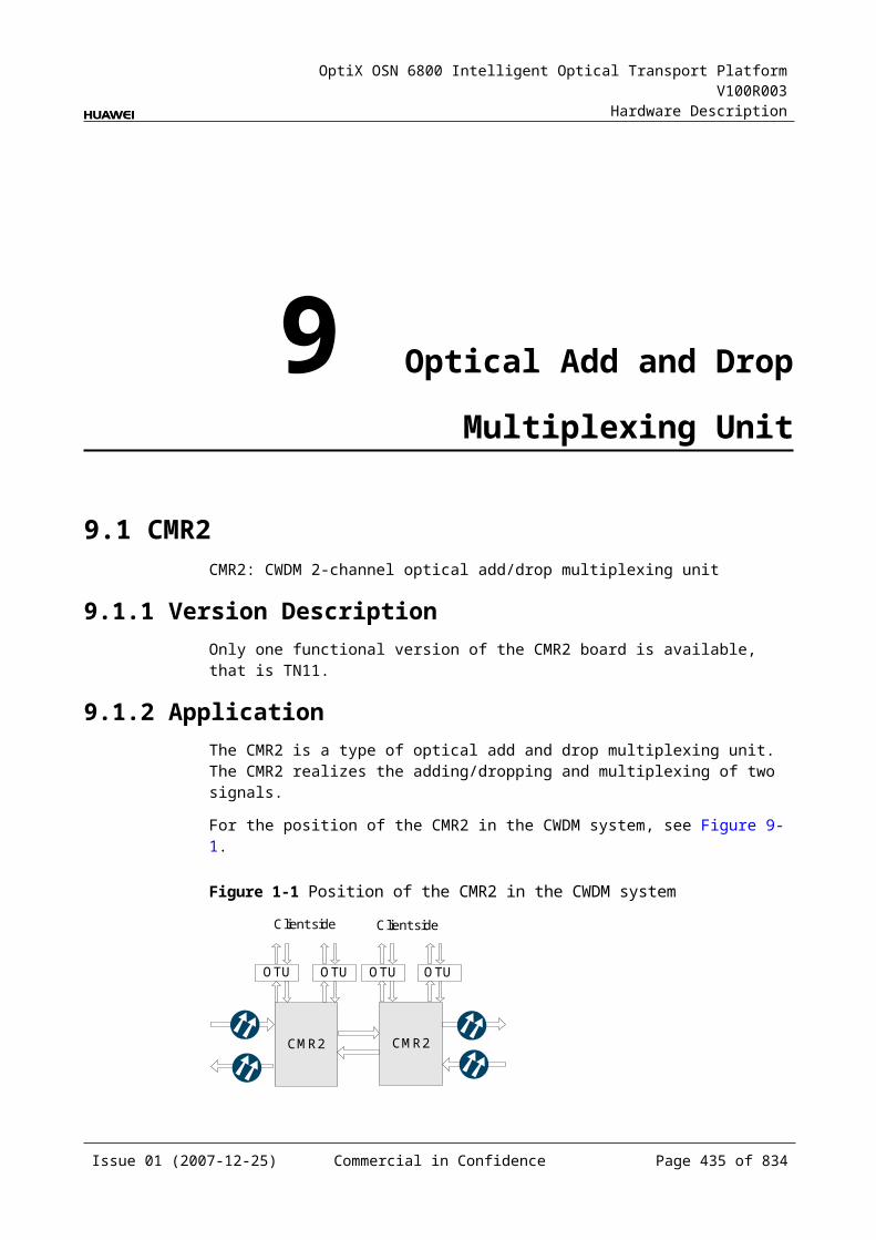
OptiX OSN 6800 Intelligent Optical Transport Platform V100R003
Hardware Description
11.1.8 Characteristic Code for of CRPCThe characteristic code for the CRPC consists of one character and two digits, indicating the gain of the optical signals processed by the board.
The detailed information of the characteristic code is given in Table 11-3.
Table 11-1 Characteristic code for the CRPC
Code Meaning Description
The first character – This character is always G.
The two digits Gain Indicate the gain value.
For example, the characteristic code for the TN11CRPC is G10, indicating 10 dB gain.
11.1.9 NM Configuration ReferenceNM configuration reference includes the reference information needed during the configuration of boards through the T2000.
Display of Optical InterfacesThe serial numbers of the optical interfaces on the panel of the board displayed on the NM are listed in Table 11-4.
Table 11-1 Serial numbers of the interfaces of the CRPC displayed on the NM
Interface on the Panel Interface on the NM
LINE 1
SYS 2
MON 3
Configuration ParametersLaser Status
Board Work Type
11.1.10 Specifications of the CRPCSpecifications include optical specifications and power consumption.
Issue 01 (2007-12-25) Commercial in Confidence Page 434 of 664
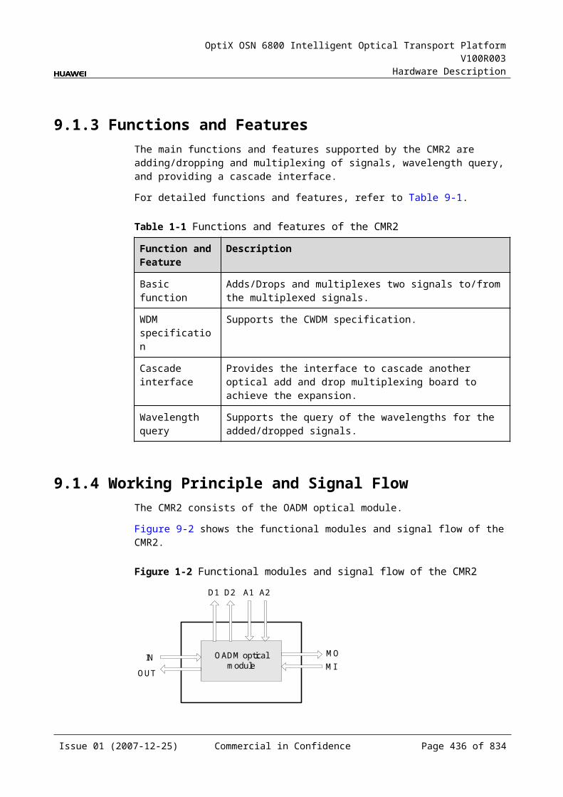
OptiX OSN 6800 Intelligent Optical Transport Platform V100R003
Hardware Description
Optical Specifications
Table 11-1 Optical specifications of the CRPC
Item Unit Value
Pump wavelength range nm 1400-1500
Operating wavelength range nm 1529-1561
Maximum pump power dBm 29
Channel gain on G.652 fiber dB ≥10
Channel gain on LEAF fiber dB ≥12
Effective noise figure on G.652 fiber dB ≤0
Effective noise figure on LEAF fiber dB ≤–1
Polarization dependence loss dB ≤0.5
Output connector type - LSH/APC, LC/PC
Mechanical SpecificationsWeight: 4.0 kg
Power Consumption The maximum power consumption at 25: 110.0 W The maximum power consumption at 55: 121.0 W
11.2 HBAHBA: High-power Booster Amplifier Board
11.2.1 Version DescriptionOnly one functional version of the HBA board is available, that is TN11.
11.2.2 ApplicationThe HBA is a type of optical amplifier unit. The HBA realizes the amplification of optical signals. It can be used at the transmit end.
For the position of the HBA in the WDM system, see Figure 11-5.
Issue 01 (2007-12-25) Commercial in Confidence Page 435 of 664
OptiX OSN 6800 Intelligent Optical Transport Platform V100R003
Hardware Description
Figure 11-1 Position of the HBA in the WDM system
OTUMUX
DMUX
OTU
OTU
OTU
HBA
OAU1
FIU
OTUMUX
DMUX
OTU
OTU
OTU
HBA
OAU1FIU
Clientside
Clientside
Clientside
Clientside
11.2.3 Functions and FeaturesThe main functions and features supported by the HBA are online optical performance monitoring, gain lock, and transient control.
For detailed functions and features, refer to Table 11-6.
Table 11-1 Functions and features of the HBA
Function and Feature
Description
Basic function Only applied on the transmit edge of the OTM station in the system that covers a long fiber span transmission.
Amplifies a maximum of 40 channels with the channel spacing of 100 GHz at the same time.
Supports the system to transmit services over different fiber spans without electrical regeneration.
Typical gain The typical gain of the HBA is 29 dB.
Online optical performance monitoring
Provides the online monitoring interface. A small amount of optical signal can be output to the spectrum analyzer or spectrum analyzer unit through the interface so as to monitor the spectrum and optical performance of the multi-channel signal without interrupting the services.
Gain lock function The EDFA inside the board has the gain lock function. Adding or dropping one or more channels or optical signal fluctuation does not affect the signal gain of other channels.
Transient control function
The EDFA inside the board has the transient control function. When channels are added or dropped, the board can suppress the fluctuation of the optical power in the path so as to realize the smooth upgrading and expansion.
Alarms and performance events monitoring
Detects and reports the optical power. Monitors the temperature of the pump laser. Detects the pump driving current, back-facet current, pump cooling current,
temperature of the pump laser and the ambient temperature of the board.
Issue 01 (2007-12-25) Commercial in Confidence Page 436 of 664

OptiX OSN 6800 Intelligent Optical Transport Platform V100R003
Hardware Description
11.2.4 Working Principle and Signal FlowThe HBA consists of the EDFA optical module and the control and communication module.
Figure 11-6 shows the functional modules and signal flow of the HBA.
Figure 11-1 Functional modules and signal flow of the HBA
EDFA optical moduleIN
SCC
OUT
MON
Control and communication module
Signal FlowThe HBA receives the multiplexed signal and the EDFA optical module amplifies the signal. Then the signals are splitted into two, among which the amplified signals are output through the OUT interface. A few supervisory signals are output to the multi-channel spectrum analyzer unit (MCA4, MCA8, WMU) or test instrument through the MON interface for online optical performance monitoring.
EDFA Optical ModuleThe EDFA optical module amplifies optical signals. The EDFA inside the HBA adopts the technology of automatic gain control to make the gain of each channel change within an allowed range in various working conditions.
Control and Communication ModuleThe control and communication module realizes the control, monitoring and communications management of each functional module of the board.
The control and communication module collects the information, such as the alarms and performance events, working status, and voltage detection, of each functional module of the board and reports to the SCC.
Receiving the commands from the SCC, the control and communication module controls and coordinates the functional modules of the board in working.
11.2.5 Front PanelThere are indicators, interfaces and laser safety label on the HBA front panel.
Appearance of the Front PanelFigure 11-7 shows the HBA front panel.
Issue 01 (2007-12-25) Commercial in Confidence Page 437 of 664
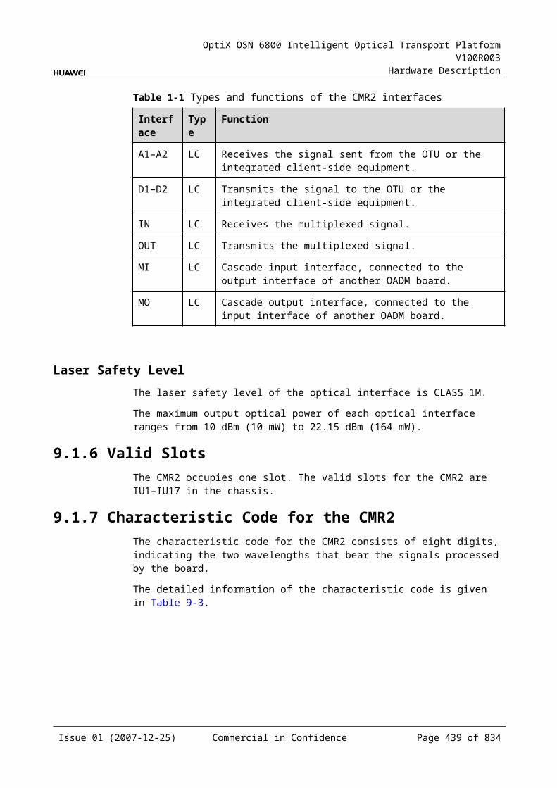
OptiX OSN 6800 Intelligent Optical Transport Platform V100R003
Hardware Description
Figure 11-1 HBA front panel
HBA
HBA
STATACTPROGSRV
MO
NIN
OU
T
LASERRADIATION
AVOID EXPOSURETO BEAM
CLASS 3B LASERPRODUCT
IndicatorsThere are four indicators on the front panel.
Board hardware status indicator (STAT) – dual-colored (red, green) Service active status indicator (ACT) – green Board software status indicator (PROG) – dual-colored (red, green) Service alarm indicator (SRV) – triple-colored (red, green, yellow)
InterfacesThere are three optical interfaces on the HBA front panel.Table 11-7 lists the type and function of each interface.
Issue 01 (2007-12-25) Commercial in Confidence Page 438 of 664
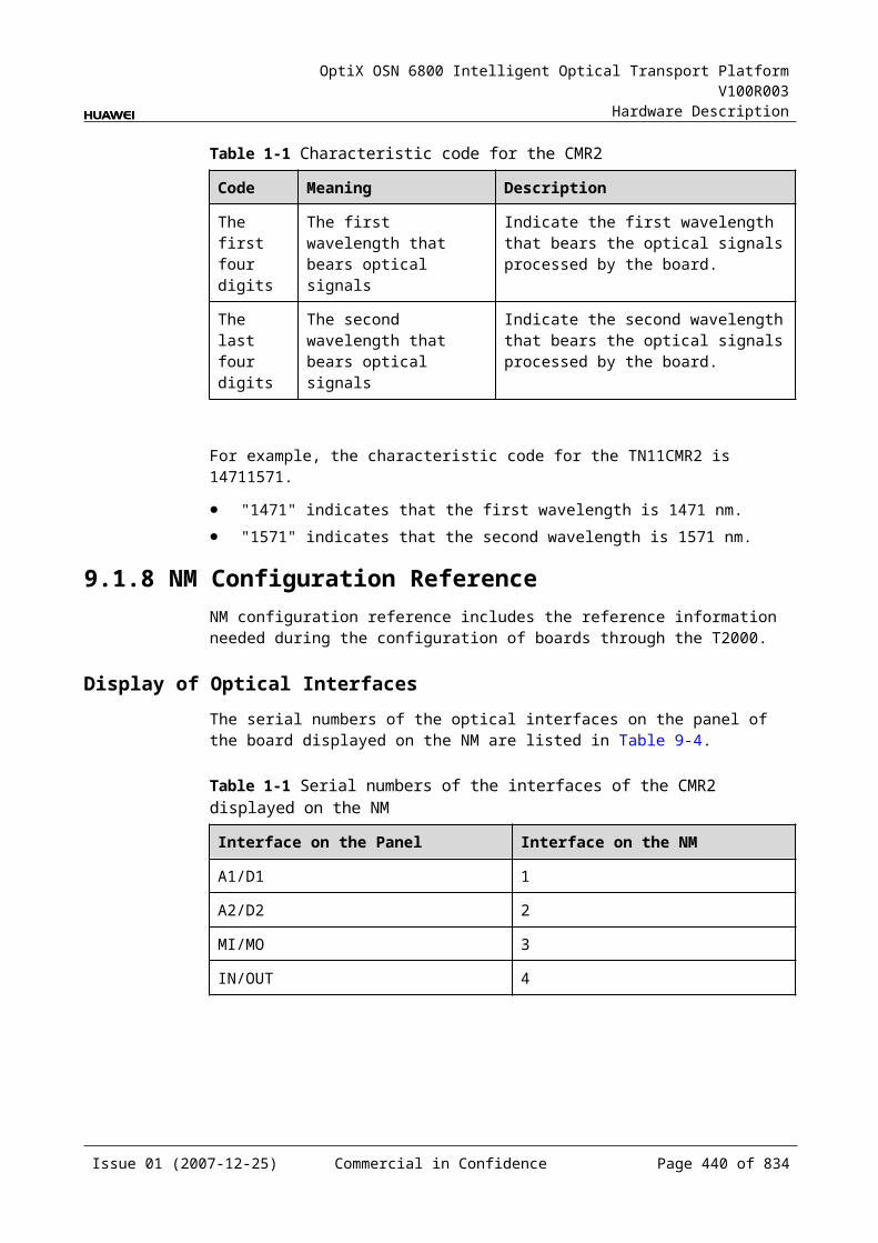
OptiX OSN 6800 Intelligent Optical Transport Platform V100R003
Hardware Description
Table 11-1 Types and functions of the HBA interfaces
Interface
Type Function
IN LC Receives the multiplexed signal to be amplified.
OUT LSH/APC Transmits the amplified signal.
MON LC Connected to the MCA4 or MCA8 or WMU, accomplishes the online performance monitoring.The MON port is a 1/999 tap of the total composite signal at the OUT port (30dB lower than the actual signal power).
Laser Safety LevelThe laser safety level of the optical interface is CLASS 3B.
The maximum output optical power of each optical interface ranges from 22.15 dBm (164 mW) to 27 dBm (500mW).
11.2.6 Valid SlotsThe HBA occupies three slots. The valid slots for the HBA are IU2–IU16 in the subrack.
The back connector of the board is mounted to the backplane along the middle slot of the three occupied slots in the subrack, so the slot number of the HBA board displayed on the NM is the number of the middle slot.
For example, if the HBA occupies slots IU1, IU2 and IU3, the slot number of the HBA displayed on the NM is IU2.
11.2.7 Characteristic Code for the HBAThe characteristic code for the HBA consists of seven characters and digits, indicating the band, the gain range and the maximum nominal input optical power of the signals processed by the board.
The detailed information of the characteristic code is given in Table 11-8.
Table 11-1 Characteristic code for the HBA
Code Meaning Description
The first character Band Indicates the band of the optical signals processed by the board. The value C represents C band; the value L represents L band.
The second character
– The second character is always G.
The third to the fourth digits
Gain The third to the fourth digits indicate the gain value.
Issue 01 (2007-12-25) Commercial in Confidence Page 439 of 664

OptiX OSN 6800 Intelligent Optical Transport Platform V100R003
Hardware Description
Code Meaning Description
The fifth character – The fifth character is always I.
The sixth and the seventh digits
Maximum nominal input optical power
Indicate the maximum nominal input optical power.
For example, the characteristic code for the TN11HBA is G2031I0. CG35I-8. This code indicates that the HBA board is used in C band, the gain is 35 dB, and the maximum nominal input optical power is -8 dBm.
11.2.8 NM Configuration ReferenceNM configuration reference includes the reference information needed during the configuration of boards through the T2000.
Display of Optical InterfacesThe serial numbers of the optical interfaces on the panel of the board displayed on the NM are listed in Table 11-9.
Table 11-1 Serial numbers of the interfaces of the HBA displayed on the NM
Interface on the Panel Interface on the NM
IN 1
OUT 2
MON 3
Configuration ParametersThreshold of Input Power Loss (dBm)
Laser Status
Gain (dB)
Nominal Gain (dB)
Nominal Gain Upper Threshold (dB)
Nominal Gain Lower Threshold (dB)
Rated Optical Power
Configure Band
Configure Working Band Parity
Actual Band
Actual Working Band Parity
Issue 01 (2007-12-25) Commercial in Confidence Page 440 of 664
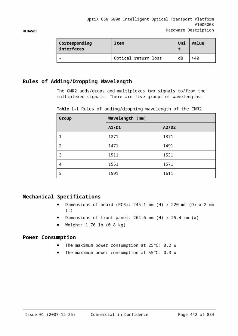
OptiX OSN 6800 Intelligent Optical Transport Platform V100R003
Hardware Description
11.2.9 Specifications of the HBASpecifications include optical specifications, dimensions, weight, and power consumption.
Optical Specifications
Table 11-1 Optical specifications of the HBA
Item Unit Value
Type - TN11HBA
Channel allocation nm 40-channel system: 192.1 THz–196.05 THz10-channel system: Any two of the last 20 wavelengths are spaced at 200 GHz.
Nominal input power range dBm –19 to –3
Typical input power of a single wavelength
dBm 40-channel system: -1910-channel system: -13
Noise figure (NF) dB <8
Output reflectance dB <–45
Nominal output power range dBm 10 to 26
Gain response time on adding/dropping of channels
ms <10
Channel gain dB 29±1
Gain flatness dB ≤2.5
Polarization dependent loss dB <0.5
Polarization mode dispersion ps <0.5
Mechanical Specifications Dimensions of board (PCB): 245.1 mm (H) x 220 mm (D) x 2 mm (T) Dimensions of front panel: 264.6 mm (H) x 76.2 mm (W) Weight: 6.6 lb (3 kg)
Power Consumption The maximum power consumption at 25: 47W The maximum power consumption at 55: 75W
Issue 01 (2007-12-25) Commercial in Confidence Page 441 of 664
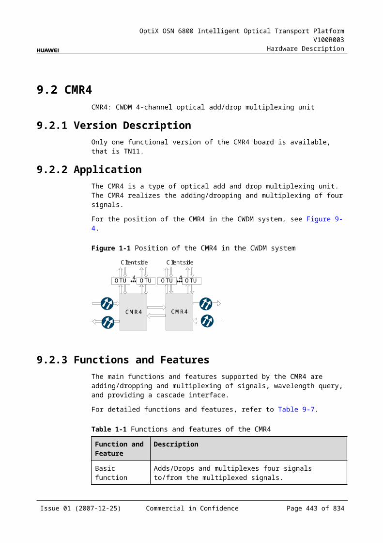
OptiX OSN 6800 Intelligent Optical Transport Platform V100R003
Hardware Description
11.3 OAU1OAU1: optical amplifying unit
11.3.1 Version DescriptionOnly one functional version of the OAU1 board is available, that is TN11.
TypeTable 11-11 lists the types of the OAU1.
Table 11-1 Type description of the OAU1
Unit Type
Description Gain Range
TN11OAU1 01 Amplifies the input optical signals in C band.
20 dB to 31 dB
03 Amplifies the input optical signals in C band.
24 dB to 36 dB
11.3.2 ApplicationThe OAU1 is a type of optical amplifier unit. The OAU1 realizes the amplification of optical signals. It can be used at the transmit end and the receive end.
For the position of the OAU1 in the WDM system, see Figure 11-8.
Figure 11-1 Position of the OAU1 in the WDM system
OTUOAU1
OBU1
MUX
DMUX
OTU
OTU
OTU
DMUX
MUX
OTU
OTU
OTU
OTU
OBU1
OAU1
Clientside
Clientside
Clientside
Clientside
11.3.3 Functions and FeaturesThe main functions and features supported by the OAU1 are gain adjustment, online optical performance monitoring, gain lock, and transient control.
For detailed functions and features, refer to Table 11-12.
Issue 01 (2007-12-25) Commercial in Confidence Page 442 of 664
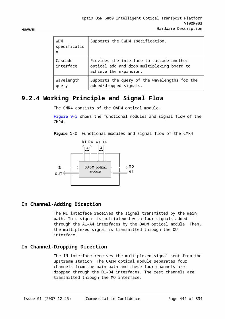
OptiX OSN 6800 Intelligent Optical Transport Platform V100R003
Hardware Description
Table 11-1 Functions and features of the OAU1
Function and Feature
Description
Basic function Amplifies a maximum of 80 channels with the channel spacing of 50 GHz at the same time.
Gain adjustment The OAU1 continuously adjusts the gain from 20 dB to 31 dB based on the input optical power.
Online optical performance monitoring
Provides the online monitoring interface. A small amount of optical signal can be output to the spectrum analyzer or spectrum analyzer unit through the interface so as to monitor the spectrum and optical performance of the multi-channel signal without interrupting the services.
Gain lock function The EDFA inside the board has the gain lock function. Adding or dropping one or more channels or optical signal fluctuation does not affect the signal gain of other channels.
Transient control function
The EDFA inside the board has the transient control function. When channels are added or dropped, the board can suppress the fluctuation of the optical power in the path so as to realize the smooth upgrading and expansion.
Alarms and performance events monitoring
Detects and reports the optical power. Monitors the temperature of the pump laser. Detects the pump driving current, back-facet current, pump cooling current,
temperature of the pump laser and the ambient temperature of the board.
11.3.4 Working Principle and Signal FlowThe OAU1 consists of the EDFA optical module, optical splitter and the control and communication module.
Figure 11-9 shows the functional modules and signal flow of the OAU1.
Figure 11-1 Functional modules and signal flow of the OAU1
EDFA optical module
Control and communication module
IN
SCC
TDC RDC
Opticalsplitter
OUT
MON
Issue 01 (2007-12-25) Commercial in Confidence Page 443 of 664
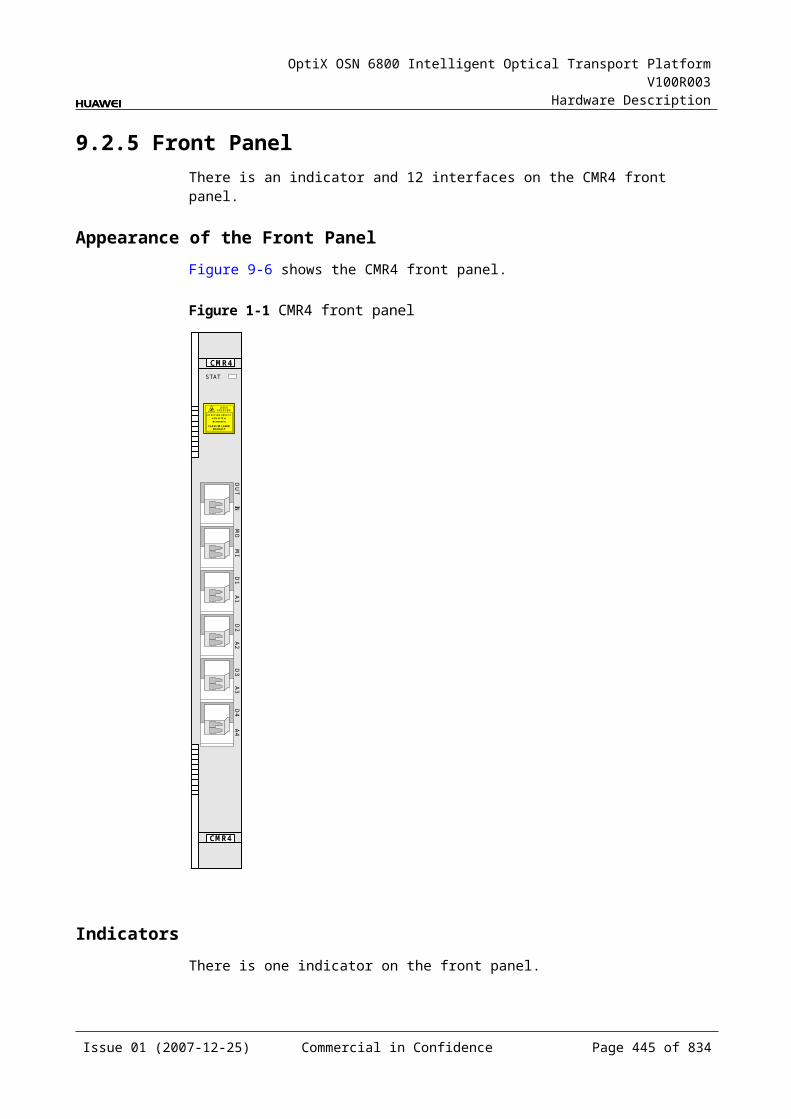
OptiX OSN 6800 Intelligent Optical Transport Platform V100R003
Hardware Description
Signal FlowThe OAU1 receives the multiplexed signal and the EDFA optical module amplifies the signal. After amplification, the OAU1 sends the signal to the DCM through the TDC interface for dispersion compensation. Then, the signal returns to the OAU1 through the RDC interface. Then the signals enter the splitter and separates into two. The amplified optical signals are output through the OUT interface. A few supervisory signals are output to the multi-channel spectrum analyzer unit (MCA4, MCA8) or test instrument through the MON interface for online optical performance monitoring.
EDFA Optical ModuleThe EDFA optical module amplifies optical signals. The EDFA inside the OAU1 adopts the technology of automatic gain control to make the gain of each channel change within an allowed range in various working conditions.
Optical SplitterAn optical splitter splits one channels of optical signals from the EDFA optical module into two channels of signals of different power. The main channel of signals are output through the OUT interface and transmitted in the main optical path. The other channel of signals are output to the MON interface for spectrum detection and supervising.
The optical power of the MON interface is 1/99 of the optical power of the OUT interface, that means the optical power of the MON interface is lower than that of the OUT interface by 20 dB.
Control and Communication ModuleThe control and communication module realizes the control, monitoring and communications management of each functional module of the board.
The control and communication module collects the information, such as the alarms and performance events, working status, and voltage detection, of each functional module of the board and reports to the SCC.
Receiving the commands from the SCC, the control and communication module controls and coordinates the functional modules of the board in working.
11.3.5 Front PanelThere are indicators, interfaces and laser safety label on the OAU1 front panel.
Appearance of the Front PanelFigure 11-10 shows the OAU1 front panel.
Issue 01 (2007-12-25) Commercial in Confidence Page 444 of 664
OptiX OSN 6800 Intelligent Optical Transport Platform V100R003
Hardware Description
Figure 11-1 OAU1 front panel
OAU1
OAU1
LASERRADIATION
DO NOT VIEW DIRECTLYWITH OPTICALINSTRUMENTS
CLASS 1M LASERPRODUCT
STATACTPROGSRV
TDC
PD
CO
UT
INM
ON
IndicatorsThere are four indicators on the front panel.
Board hardware status indicator (STAT) – dual-colored (red, green) Service active status indicator (ACT) – green Board software status indicator (PROG) – dual-colored (red, green) Service alarm indicator (SRV) – triple-colored (red, green, yellow)
InterfacesThere are five optical interfaces on the OAU1 front panel. Table 11-13 lists the type and function of each interface.
Issue 01 (2007-12-25) Commercial in Confidence Page 445 of 664
OptiX OSN 6800 Intelligent Optical Transport Platform V100R003
Hardware Description
Table 11-1 Types and functions of the OAU1 interfaces
Interface
Type Function
IN LC Receives the multiplexed signal to be amplified.
OUT LC Transmits the amplified signal.
TDC/RDC LC Connected to the interface of the DCM for dispersion compensation.
MON LC Connected to the MCA4 or MCA8 or WMU, accomplishes the online performance monitoring.The MON port is a 1/99 tap of the total composite signal at the OUT port (20dB lower than the actual signal power).
Laser Safety LevelThe laser safety level of the optical interface is CLASS 1M.
The maximum output optical power of each optical interface ranges from 10 dBm (10 mW) to 22.15 dBm (164 mW).
11.3.6 Valid SlotsThe OAU1 occupies two slots. The valid slots for the OAU1 are IU2–IU17 in the subrack.
The back connector of the board is mounted to the backplane along the right slot in the subrack, so the slot number of the OAU1 board displayed on the NM is the number of the right one of the two occupied slots.
For example, if the OAU1 occupies slots IU1 and IU2, the slot number of the OAU1 displayed on the NM is IU2.
11.3.7 Characteristic Code for the OAU1The characteristic code for the OAU1 consists of eight characters and digits, indicating the gain range and the maximum nominal input optical power of the signals processed by the board.
The detailed information of the characteristic code is given in Table 11-14.
Table 11-1 Characteristic code for the OAU1
Code Meaning Description
The first character – The first character is always G.
The second to the fifth digits
Gain range Indicate the range within which the gain can be continuously adjusted.
The sixth character – The sixth character is always I.
Issue 01 (2007-12-25) Commercial in Confidence Page 446 of 664
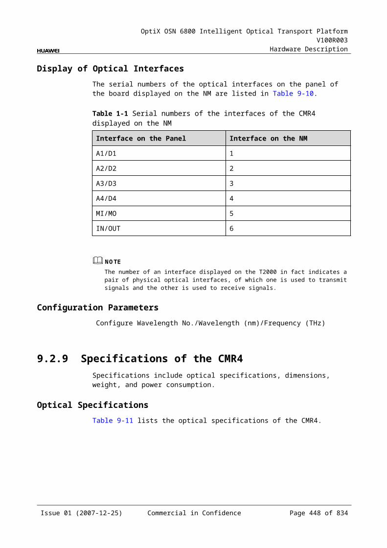
OptiX OSN 6800 Intelligent Optical Transport Platform V100R003
Hardware Description
The seventh and the eighth digits
Maximum nominal input optical power
Indicate the maximum nominal input optical power.
For example, the characteristic code for the TN11OAU1 is G2031I0. This code indicates that the gain can be continuously adjusted from 20 dB to 31 dB and the maximum nominal input optical power is 0 dBm.
11.3.8 NM Configuration ReferenceNM configuration reference includes the reference information needed during the configuration of boards through the T2000.
Display of Optical InterfacesThe serial numbers of the optical interfaces on the panel of the board displayed on the NM are listed in Table 11-15.
Table 11-1 Serial numbers of the interfaces of the OAU1 displayed on the NM
Interface on the Panel Interface on the NM
IN 1
OUT 4
RDC/TDC 5
MON 6
Configuration ParametersThreshold of Input Power Loss (dBm)
Laser Status
Gain (dB)
Nominal Gain (dB)
Nominal Gain Upper Threshold (dB)
Nominal Gain Lower Threshold (dB)
Rated Optical Power
11.3.9 Specifications of the OAU1Specifications include optical specifications, dimensions, weight, and power consumption.
Issue 01 (2007-12-25) Commercial in Confidence Page 447 of 664
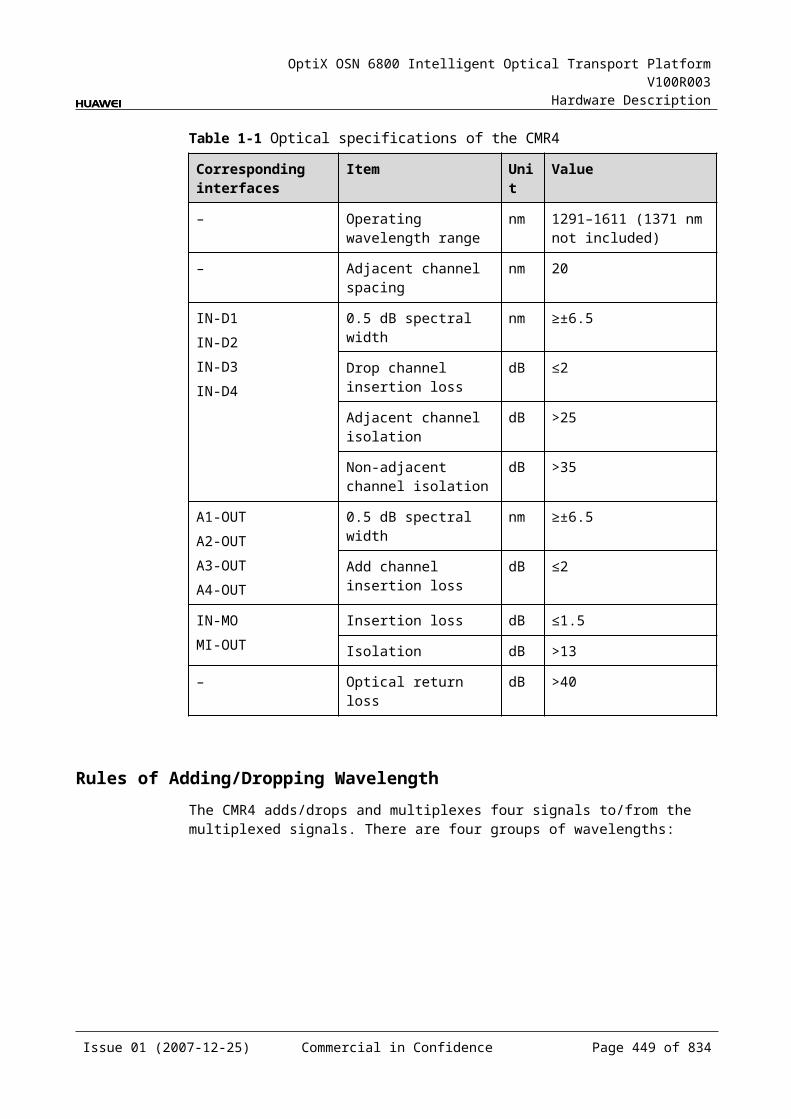
OptiX OSN 6800 Intelligent Optical Transport Platform V100R003
Hardware Description
Optical Specifications
Table 11-1 Optical specifications of the OAU1
Item Unit Value
OAU101 OAU103
Operating wavelength range nm 1529–1561 1529–1561
Nominal gain dB 20 26 31 24 29 36
Nominal input power range dBm –32 to 0
–32 to –6
–32 to –11
–32 to –4
–32 to –9
–32 to –16
Input power range per channel
40 channels
dBm -27 to -16
-32 to -22
-32 to -27
-32 to –20
-32 to –25
-32
80 channels
dBm -30 to -19
-32 to -25
-32 to -30
-32 to –23
-32 to –28
-32
Noise figure (NF)a dB ≤8.5 ≤6.5 ≤5.5 ≤7.5 ≤6.5 ≤5.5
Input reflectance dB <-40 <-40 <-40 <-40 <-40 <-40
Output reflectance dB <-40 <-40 <-40 <-40 <-40 <-40
Pump leakage at input dBm <-20 <-20 <-20 <-20 <-30 <-30
Maximum reflectance tolerance at input
dB -27 -27 -27 -27 -27 -27
Maximum reflectance tolerance at output
dB -27 -27 -27 -27 -27 -27
Maximum total output optical power
dBm 20 20 20 20 20 20
Gain response time on adding/dropping of channels
ms <10 <10 <10 <10 <10 <10
Channel gainb dB 20–23 23–29 29–31 24–36 28–30 30–36
Gain flatness dB ≤2.0 ≤2.0 ≤2.0 ≤2.0 ≤2.0 ≤2.0
Multi-channel gain slope dB/dB ≤2.0 ≤2.0 ≤2.0 ≤2.0 ≤2.0 ≤2.0
Polarization dependent loss dB <0.5 <0.5 <0.5 <0.5 <0.5 <0.5
a: The gain can be adjusted continuously. The noise figure varies with the gain. The previous table lists the noise figure when the noise figure adopts the typical value.
b: In the case of the OAU103, the total gain is 38 dB, and the intermediate insertion loss is 2–14 dB (including the internal VOA insertion loss of 2 dB), that is, the supported gain range is 24–36 dB.
Mechanical Specifications Dimensions of board (PCB): 245.1 mm (H) x 220 mm (D) x 2 mm (T) Dimensions of front panel: 264.6 mm (H) x 50.8 mm (W)
Issue 01 (2007-12-25) Commercial in Confidence Page 448 of 664
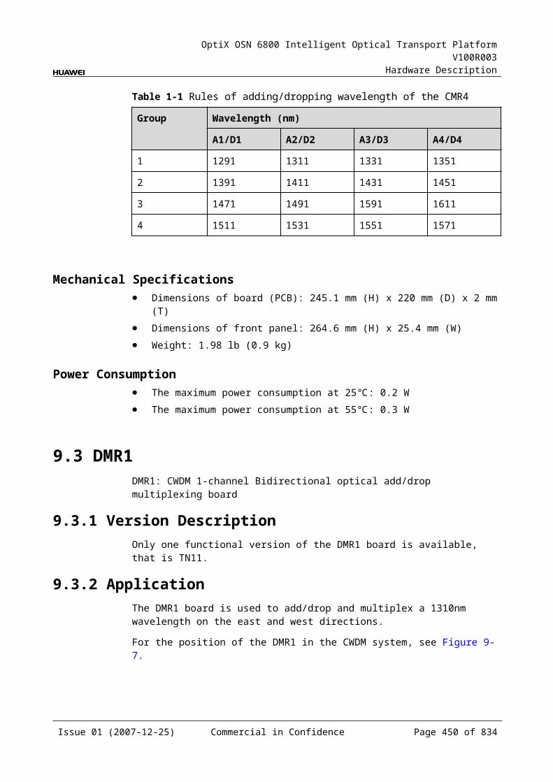
OptiX OSN 6800 Intelligent Optical Transport Platform V100R003
Hardware Description
Weight: 1.8 kg
Power Consumption The maximum power consumption at 25: 33 W The maximum power consumption at 55: 34.3 W
11.4 OBU1OBU1: optical booster unit
11.4.1 Version DescriptionOnly one functional version of the OBU1 board is available, that is TN11.
TypeTable 11-17 lists the types of the OBU1.
Table 11-1 Type description of the OBU1
Unit Type
Description Gain Range
TN11OBU1 01 Amplifies the input optical signals in C band. 20±1.5 dB
03 Amplifies the input optical signals in C band. 23±1.5 dB
04 Amplifies the input optical signals in C band. 17±1.5 dB
11.4.2 ApplicationThe OBU1 is a type of optical amplifier unit. The OBU1 realizes the amplification of optical signals. The OBU1 is of three types: OBU101 OBU103 and OBU104.
For the position of the OBU1 in the WDM system, see Figure 11-11.
Figure 11-1 Position of the OBU1 in the WDM system
OTUClientside OBU1
OBU1
MUX
DMUX
OTU
OTU
OTU
DMUX
MUX
OTU
OTU
OTU
OTU
OBU1
OBU1Clientside
Clientside
Clientside
Issue 01 (2007-12-25) Commercial in Confidence Page 449 of 664
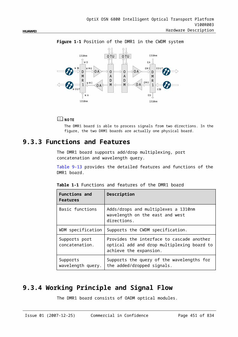
OptiX OSN 6800 Intelligent Optical Transport Platform V100R003
Hardware Description
11.4.3 Functions and FeaturesThe main functions and features supported by the OBU1 are online optical performance monitoring, gain lock, and transient control.
For detailed functions and features, refer to Table 11-18.
Table 11-1 Functions and features of the OBU1
Function and Feature
Description
Basic function Amplifies a maximum of 80 channels with the channel spacing of 50 GHz at the same time.
Typical gain The typical gain of the OBU101 is 20 dB. The typical gain of the OBU103 is 23 dB. The typical gain of the OBU104 is 17 dB.
Online optical performance monitoring
Provides the online monitoring interface. A small amount of optical signal can be output to the spectrum analyzer or spectrum analyzer unit through the interface so as to monitor the spectrum and optical performance of the multi-channel signal without interrupting the services.
Gain lock function The EDFA inside the board has the gain lock function. Adding or dropping one or more channels or optical signal fluctuation does not affect the signal gain of other channels.
Transient control function
The EDFA inside the board has the transient control function. When channels are added or dropped, the board can suppress the fluctuation of the optical power in the path so as to realize the smooth upgrading and expansion.
Alarms and performance events monitoring
Detects and reports the optical power. Monitors the temperature of the pump laser. Detects the pump driving current, back-facet current, pump cooling current,
temperature of the pump laser and the ambient temperature of the board.
11.4.4 Working Principle and Signal FlowThe OBU1 consists of the EDFA optical module and the control and communication module.
Figure 11-12 shows the functional modules and signal flow of the OBU1.
Issue 01 (2007-12-25) Commercial in Confidence Page 450 of 664
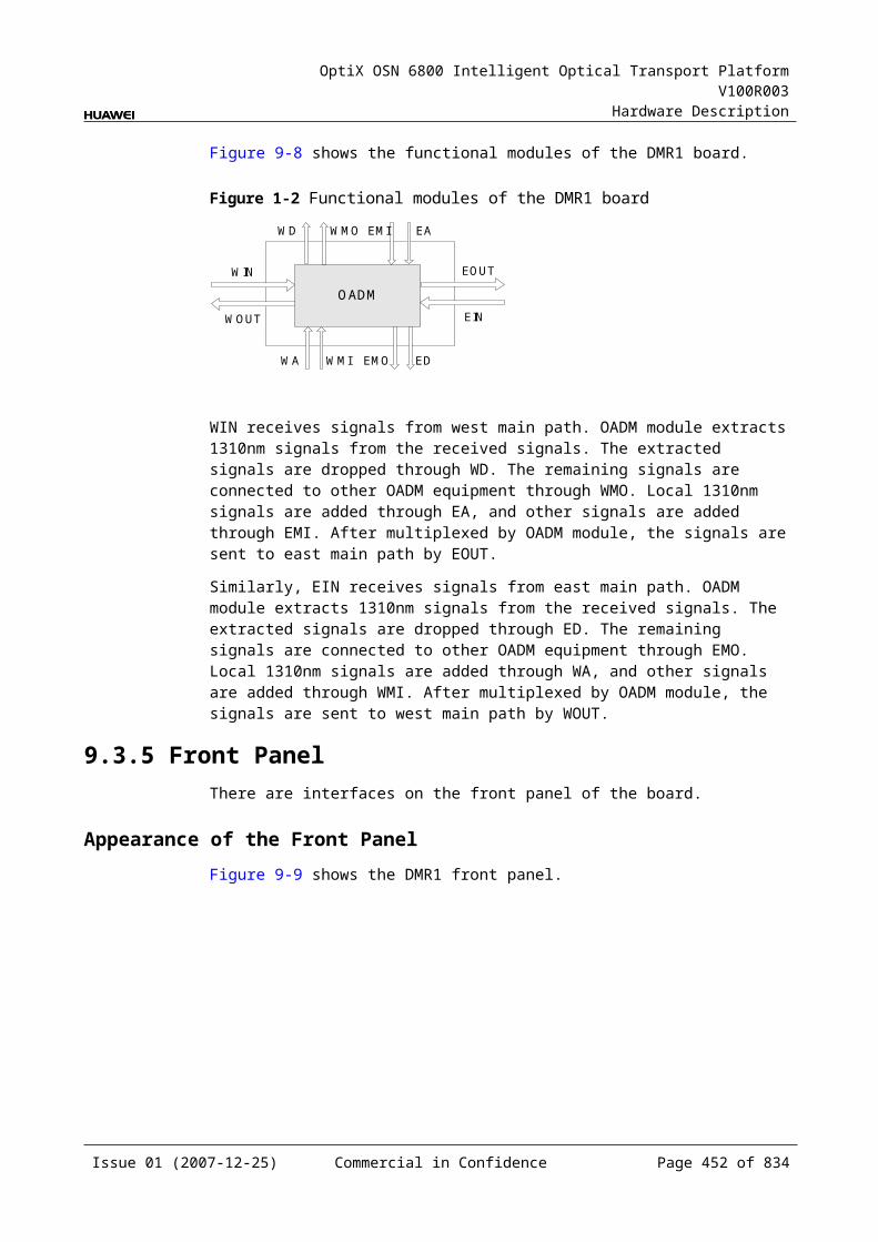
OptiX OSN 6800 Intelligent Optical Transport Platform V100R003
Hardware Description
Figure 11-1 Functional modules and signal flow of the OBU1
EDFA optical module
Control and communication module
IN
SCC
Opticalsplitter
OUT
MON
Signal FlowThe OBU1 receives the multiplexed signal and the EDFA optical module amplifies the signal. Then the signals are sent to the optical splitter to be splitted into two, among which the amplified signals are output through the OUT interface. A few supervisory signals are output to the multi-channel spectrum analyzer unit (MCA4, MCA8) or test instrument through the MON interface for online optical performance monitoring.
EDFA Optical ModuleThe EDFA optical module amplifies optical signals. The EDFA inside the OBU1 adopts the technology of automatic gain control to make the gain of each channel change within an allowed range in various working conditions.
Optical SplitterAn optical splitter splits one channels of optical signals from the EDFA optical module into two channels of signals of different power. One of the them are output through the OUT interface and transmitted in the main optical path. The other channel of signals are output to the MON interface for spectrum detection and supervising.
The optical power of the MON interface is 1/99 of the optical power of the OUT interface, that means the optical power of the MON interface is lower than that of the OUT interface by 20 dB.
Control and Communication ModuleThe control and communication module realizes the control, monitoring and communications management of each functional module of the board.
The control and communication module collects the information, such as the alarms and performance events, working status, and voltage detection, of each functional module of the board and reports to the SCC.
Receiving the commands from the SCC, the control and communication module controls and coordinates the functional modules of the board in working.
11.4.5 Front PanelThere are indicators, interfaces and laser safety label on the OBU1 front panel.
Issue 01 (2007-12-25) Commercial in Confidence Page 451 of 664
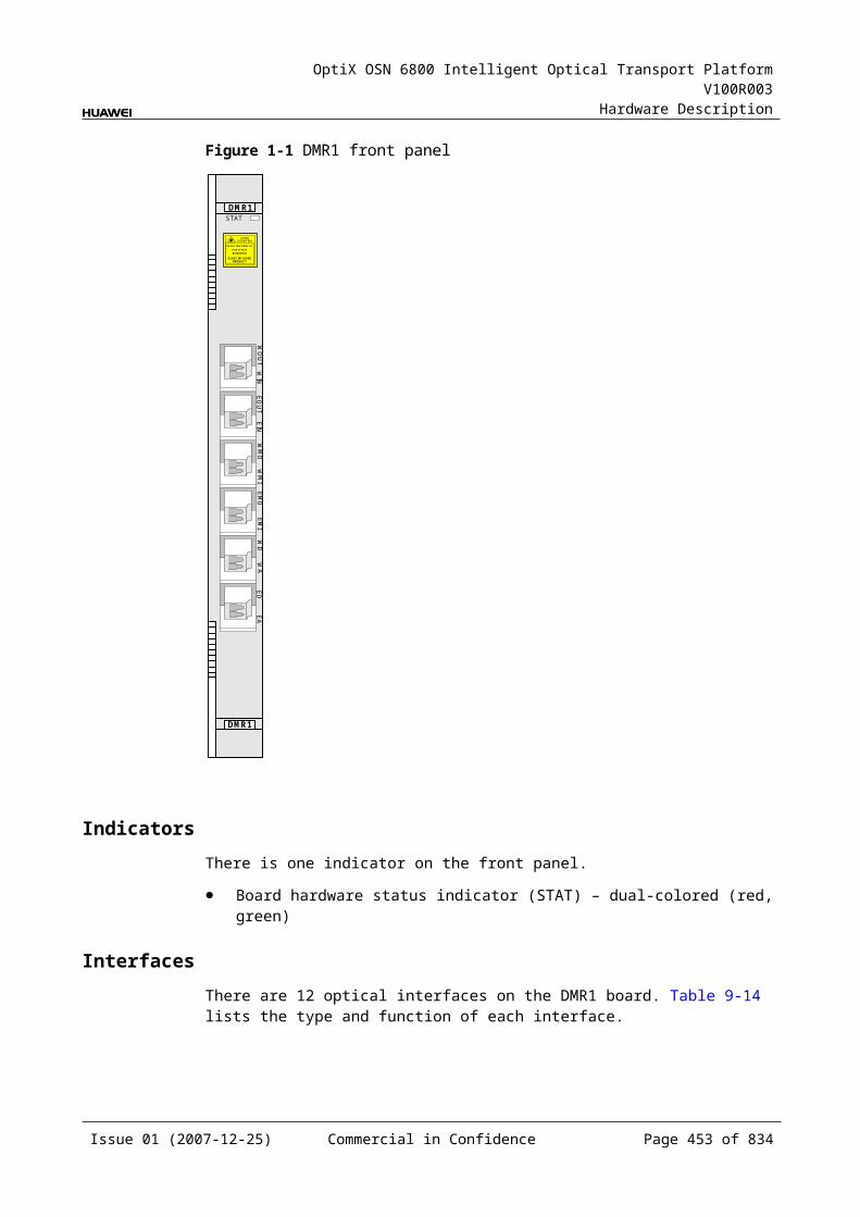
OptiX OSN 6800 Intelligent Optical Transport Platform V100R003
Hardware Description
Appearance of the Front PanelFigure 11-13 shows the OBU1 front panel.
Figure 11-1 OBU1 front panel
OBU1
OBU1
MO
NO
UT
IN
STATACTPROGSRV
LASERRADIATION
DO NOT VIEW DIRECTLYWITH OPTICALINSTRUMENTS
CLASS 1M LASERPRODUCT
IndicatorsThere are four indicators on the front panel.
Board hardware status indicator (STAT) – dual-colored (red, green) Service active status indicator (ACT) – green Board software status indicator (PROG) – dual-colored (red, green) Service alarm indicator (SRV) – triple-colored (red, green, yellow)
Issue 01 (2007-12-25) Commercial in Confidence Page 452 of 664
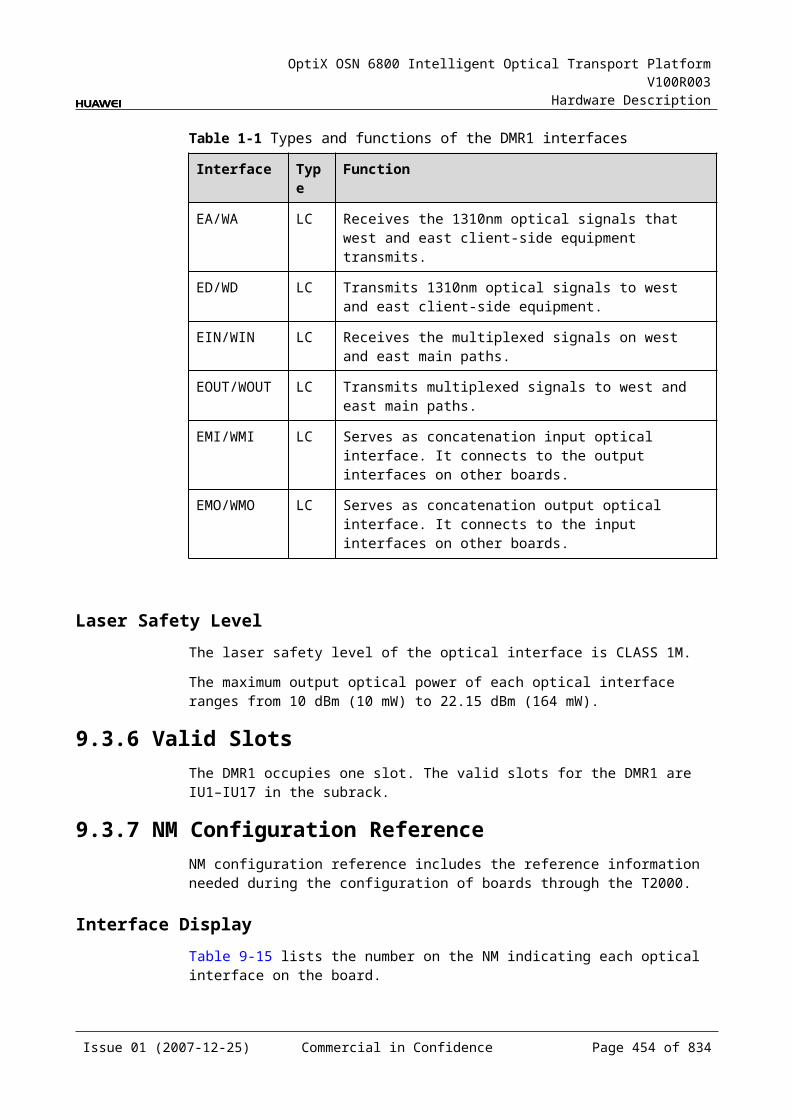
OptiX OSN 6800 Intelligent Optical Transport Platform V100R003
Hardware Description
InterfacesThere are three optical interfaces on the OBU1 front panel. Table 11-19 lists the type and function of each interface.
Table 11-1 Types and functions of the OBU1 interfaces
Interface
Type
Function
IN LC Receives the multiplexed signal to be amplified.
OUT LC Transmits the amplified signal.
MON LC Connected to the MCA4 or MCA8 or WMU, accomplishes the online performance monitoring.The MON port is a 1/99 tap of the total composite signal at the OUT port (20dB lower than the actual signal power).
Laser Safety LevelThe laser safety level of the optical interface is CLASS 1M.
The maximum output optical power of each optical interface ranges from 10 dBm (10 mW) to 22.15 dBm (164 mW).
11.4.6 Valid SlotsThe OBU1 occupies one slot. The valid slots for the OBU1 are IU1–IU17.
11.4.7 Characteristic Code for the OBU1The characteristic code for the OBU1 consists of six characters and digits, indicating the gain and the maximum nominal input optical power of the signals processed by the board.
The detailed information of the characteristic code is given in Table 11-20.
Table 11-1 Characteristic code for the OBU1
Code Meaning Description
The first character
– The first character is always G.
The second and the third digits
Gain The second and the third digits indicate the gain value.
The fourth character
– The fourth character is always I.
The fifth and the sixth digits
Maximum nominal input optical power
The fifth and the sixth digits indicate the maximum nominal input optical power.
Issue 01 (2007-12-25) Commercial in Confidence Page 453 of 664
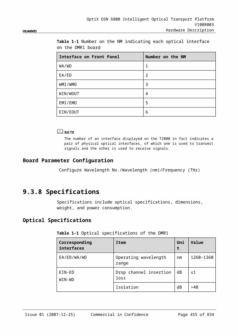
OptiX OSN 6800 Intelligent Optical Transport Platform V100R003
Hardware Description
For example, the characteristic code for the TN11OBU1 is G23I-3. This code indicates that the gain is 23 dB and the maximum nominal input optical power is -3 dBm.
11.4.8 NM Configuration ReferenceNM configuration reference includes the reference information needed during the configuration of boards through the T2000.
Display of Optical InterfacesThe serial numbers of the optical interfaces on the panel of the board displayed on the NM are listed in Table 11-21.
Table 11-1 Serial numbers of the interfaces of the OBU1 displayed on the NM
Interface on the Panel Interface on the NM
IN 1
OUT 2
MON 3
Configuration ParametersThreshold of Input Power Loss (dBm)
Laser Status
Gain (dB)
Nominal Gain (dB)
Nominal Gain Upper Threshold (dB)
Nominal Gain Lower Threshold (dB)
Rated Optical Power
11.4.9 Specifications of the OBU1Specifications include optical specifications, dimensions, weight, and power consumption.
Issue 01 (2007-12-25) Commercial in Confidence Page 454 of 664
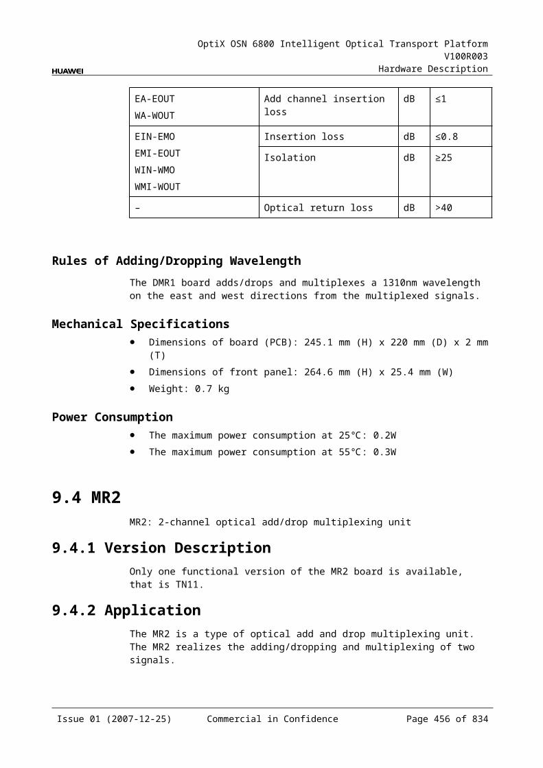
OptiX OSN 6800 Intelligent Optical Transport Platform V100R003
Hardware Description
Optical Specifications
Table 11-1 Optical specifications of the OBU1
Item Unit
Value
OBU101 OBU103 OBU104
Operating wavelength range nm 1529–1561 1529–1561 1529–1561
Nominal input power range dBm -32 to -4 -32 to -3 -32 to -1
Input power range per channel 40 channels dBm -32 to -20 -32 to -19 -32 to -17
80 channels -32 to -23 -32 to -22 -32 to -20
Typical input power of a single wavelength
40 channels dBm -20 -19 -17
80 channels -23 -22 -20
Noise figure (NF) dB ≤5.5 ≤6.0 ≤5.5
Input reflectance dB <-40 <-40 <-40
Output reflectance dB <-40 <-40 <-40
Pump leakage at input dBm <-30 <-30 <-30
Maximum reflectance tolerance at input dB -27 -27 -27
Maximum reflectance tolerance at output dB -27 -27 -27
Maximum total output optical power dBm 16 20 16
Nominal gain dB 20 23 17
Gain response time on adding/dropping of channels ms <10 <10 <10
Channel gain dB 20±1.5 23±1.5 17±1.5
Gain flatness dB ≤2.0 ≤2.0 ≤2.0
Multi-channel gain slope dB ≤2.0 ≤2.0 ≤2.0
Polarization dependent loss dB ≤0.5 ≤0.5 ≤0.5
Mechanical Specifications Dimensions of board (PCB): 245.1 mm (H) x 220 mm (D) x 2 mm (T) Dimensions of front panel: 264.6 mm (H) x 25.4 mm (W) Weight: 1.3 kg
Power ConsumptionThe power consumption of OBU101 and OBU104:
The maximum power consumption at 25: 16 W
Issue 01 (2007-12-25) Commercial in Confidence Page 455 of 664
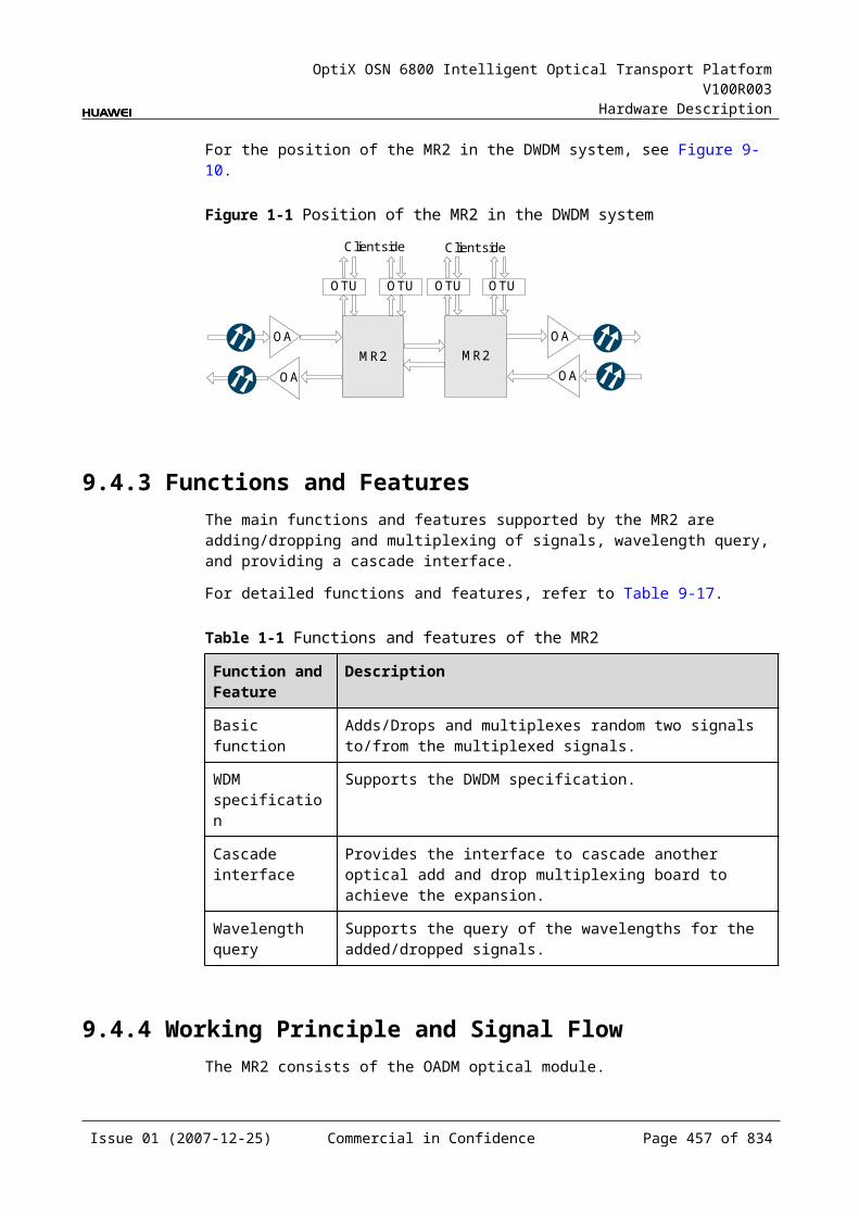
OptiX OSN 6800 Intelligent Optical Transport Platform V100R003
Hardware Description
The maximum power consumption at 55: 17.6 W
The power consumption of OBU103:
The maximum power consumption at 25: 18 W The maximum power consumption at 55: 19.8 W
11.5 OBU2OBU2: optical booster unit
11.5.1 Version DescriptionOnly one functional version of the OBU2 board is available, that is TN11.
11.5.2 ApplicationThe OBU2 is a type of optical amplifier unit. The OBU2 realizes the amplification of optical signals. It can be used at the transmit end and the receive end.
For the position of the OBU2 in the WDM system, see Figure 11-14.
Figure 11-1 Position of the OBU2 in the WDM system
OTUClientside OBU2
OBU2
MUX
DMUX
OTU
OTU
OTU
DMUX
MUX
OTU
OTU
OTU
OTU
OBU2
OBU2Clientside
Clientside
Clientside
11.5.3 Functions and FeaturesThe main functions and features supported by the OBU2 are online optical performance monitoring, gain lock, and transient control.
For detailed functions and features, refer to Table 11-23.
Table 11-1 Functions and features of the OBU2
Function and Feature
Description
Basic function Amplifies a maximum of 80 channels with the channel spacing of 50 GHz at the same time.
Supports the system to transmit services over different fiber spans without using electrical regeneration.
Typical gain The typical gain of the OBU205 is 23 dB.
Issue 01 (2007-12-25) Commercial in Confidence Page 456 of 664
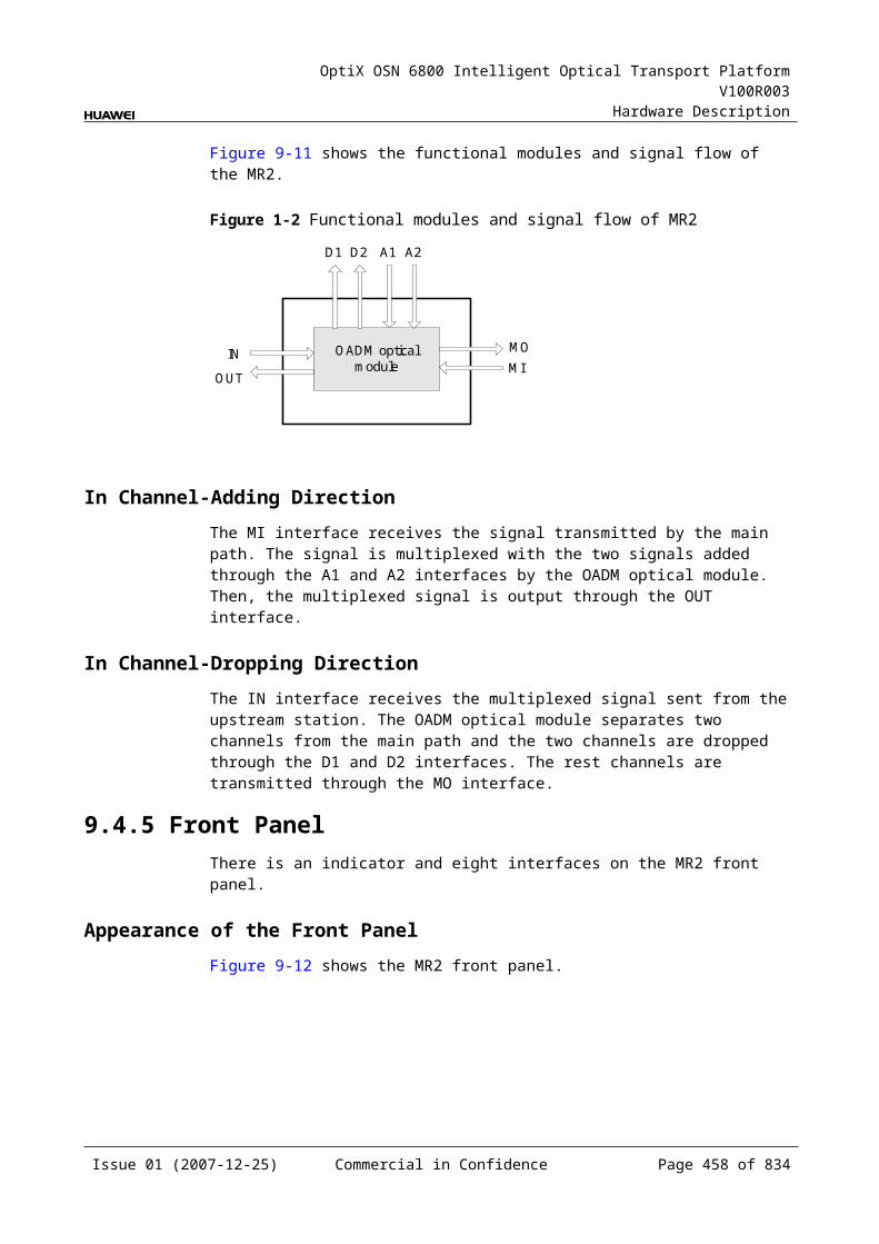
OptiX OSN 6800 Intelligent Optical Transport Platform V100R003
Hardware Description
Function and Feature
Description
Online optical performance monitoring
Provides the online monitoring interface. A small amount of optical signal can be output to the spectrum analyzer or spectrum analyzer unit through the interface so as to monitor the spectrum and optical performance of the multi-channel signal without interrupting the services.
Gain lock function The EDFA inside the board has the gain lock function. Adding or dropping one or more channels or optical signal fluctuation does not affect the signal gain of other channels.
Transient control function
The EDFA inside the board has the transient control function. When channels are added or dropped, the board can suppress the fluctuation of the optical power in the path so as to realize the smooth upgrading and expansion.
Alarms and performance events monitoring
Detects and reports the optical power. Monitors the temperature of the pump laser. Detects the pump driving current, back-facet current, pump cooling current,
temperature of the pump laser and the ambient temperature of the board.
11.5.4 Working Principle and Signal FlowThe OBU2 consists of the EDFA optical module and the control and communication module.
Figure 11-15 shows the functional modules and signal flow of the OBU2.
Figure 11-1 Functional modules and signal flow of the OBU2
EDFA opticalmodule
Control and communication module
IN
SCC
Opticalsplitter
OUT
MON
Signal FlowThe OBU2 receives the multiplexed signal and the EDFA optical module amplifies the signal. Then the signals are sent to the optical splitter to be splitted into two, among which the amplified signals are output through the OUT interface. A few supervisory signals are output to the multi-channel spectrum analyzer unit (MCA4, MCA8) or test instrument through the MON interface for online optical performance monitoring.
Issue 01 (2007-12-25) Commercial in Confidence Page 457 of 664

OptiX OSN 6800 Intelligent Optical Transport Platform V100R003
Hardware Description
EDFA Optical ModuleThe EDFA optical module amplifies optical signals. The EDFA inside the OBU2 adopts the technology of automatic gain control to make the gain of each channel change within an allowed range in various working conditions.
Optical SplitterAn optical splitter splits one channels of optical signals from the EDFA optical module into two channels of signals of different power. One of the them are output through the OUT interface and transmitted in the main optical path. The other channel of signals are output to the MON interface for spectrum detection and supervising.
Control and Communication ModuleThe control and communication module realizes the control, monitoring and communications management of each functional module of the board.
The control and communication module collects the information, such as the alarms and performance events, working status, and voltage detection, of each functional module of the board and reports to the SCC.
Receiving the commands from the SCC, the control and communication module controls and coordinates the functional modules of the board in working.
11.5.5 Front PanelThere are indicators, interfaces and laser safety label on the OBU2 front panel.
Appearance of the Front PanelFigure 11-16 shows the OBU2 front panel.
Issue 01 (2007-12-25) Commercial in Confidence Page 458 of 664
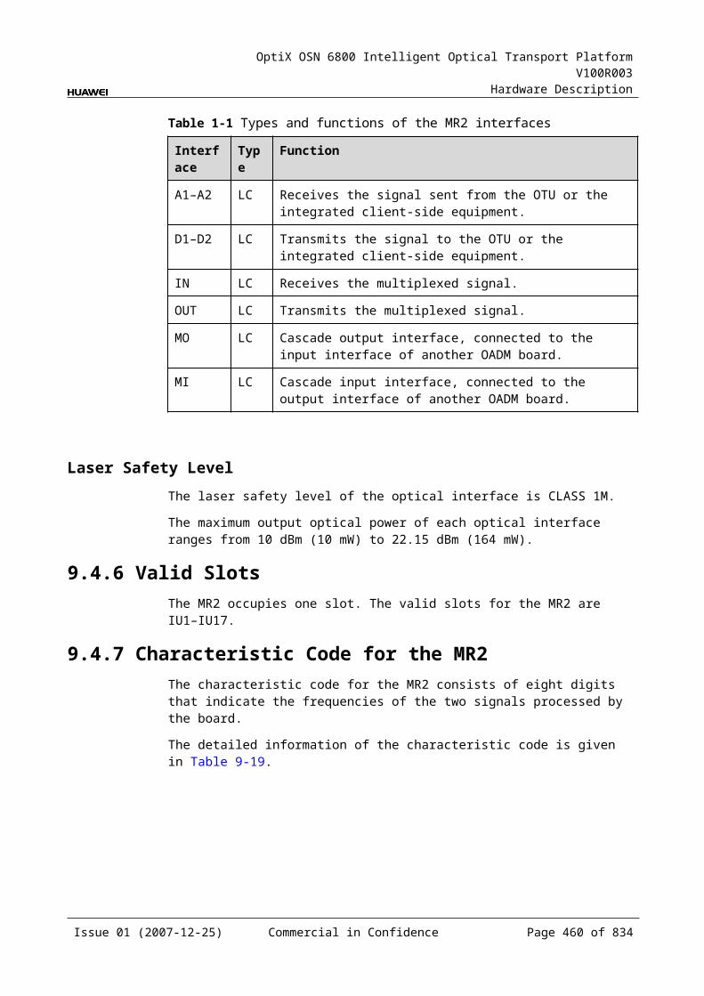
OptiX OSN 6800 Intelligent Optical Transport Platform V100R003
Hardware Description
Figure 11-1 OBU2 front panel
OBU2
OBU2
STATACTPROGSRV
OU
TIN
MO
N
LASERRADIATION
AVOID EXPOSURETO BEAM
CLASS 3B LASERPRODUCT
IndicatorsThere are four indicators on the front panel.
Board hardware status indicator (STAT) – dual-colored (red, green) Service active status indicator (ACT) – green Board software status indicator (PROG) – dual-colored (red, green) Service alarm indicator (SRV) – triple-colored (red, green, yellow)
InterfacesThere are three optical interfaces on the OBU2 front panel. Table 11-24 lists the type and function of each interface.
Issue 01 (2007-12-25) Commercial in Confidence Page 459 of 664
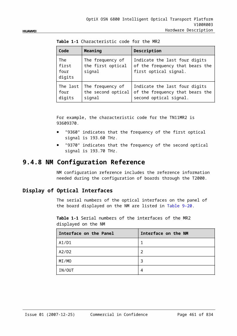
OptiX OSN 6800 Intelligent Optical Transport Platform V100R003
Hardware Description
Table 11-1 Types and functions of the OBU2 interfaces
Interface
Type
Function
IN LC Receives the multiplexed signal to be amplified.
OUT LC Transmits the amplified signal.
MON LC Connected to the MCA4 or MCA8 or WMU, accomplishes the online performance monitoring.The MON port is a 1/99 tap of the total composite signal at the OUT port (20dB lower than the actual signal power).
Laser Safety LevelThe laser safety level of the optical interface is CLASS 3B.
The maximum output optical power of each optical interface ranges from 22.15 dBm (164 mW) to 27 dBm (500mW).
11.5.6 Valid SlotsThe OBU2 occupies two slots. The valid slots for the OBU2 are IU2–IU17 in the subrack.
The back connector of the board is mounted to the backplane along the right slot in the subrack, so the slot number of the OBU2 board displayed on the NM is the number of the right one of the two occupied slots.
For example, if the OBU2 occupies slots IU1 and IU2, the slot number of the OBU2 displayed on the NM is IU2.
11.5.7 Characteristic Code for the OBU2The characteristic code for the OBU2 consists of six characters and digits, indicating the gain range and the maximum nominal input optical power of the signals processed by the board.
The detailed information of the characteristic code is given in Table 11-25.
Table 11-1 Characteristic code for the OBU2
Code Meaning Description
The first character – The first character is always G.
The second and the third digits
Gain The second and the third digits indicate the gain value.
The fourth character – The fourth character is always I.
The fifth and the sixth digits
Maximum nominal input optical power
The fifth and the sixth digits indicate the maximum nominal input optical power.
Issue 01 (2007-12-25) Commercial in Confidence Page 460 of 664
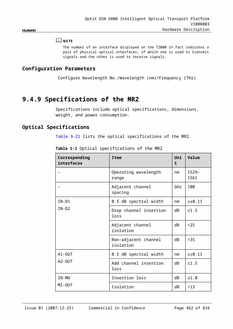
OptiX OSN 6800 Intelligent Optical Transport Platform V100R003
Hardware Description
For example, the characteristic code for the TN11OBU1 is G23I00. This code indicates that the gain is 23 dB and the maximum nominal input optical power is 0 dBm.
11.5.8 NM Configuration ReferenceNM configuration reference includes the reference information needed during the configuration of boards through the T2000.
Display of Optical InterfacesThe serial numbers of the optical interfaces on the panel of the board displayed on the NM are listed in Table 11-26.
Table 11-1 Serial numbers of the interfaces of the OBU2 displayed on the NM
Interface on the Panel Interface on the NM
IN 1
OUT 2
MON 3
Configuration ParametersThreshold of Input Power Loss (dBm)
Laser Status
Gain (dB)
Nominal Gain (dB)
Nominal Gain Upper Threshold (dB)
Nominal Gain Lower Threshold (dB)
Rated Optical Power
Configure Band
Configure Working Band Parity
Actual Band
Actual Working Band Parity
11.5.9 Specifications of the OBU2Specifications include optical specifications, dimensions, weight, and power consumption.
Issue 01 (2007-12-25) Commercial in Confidence Page 461 of 664
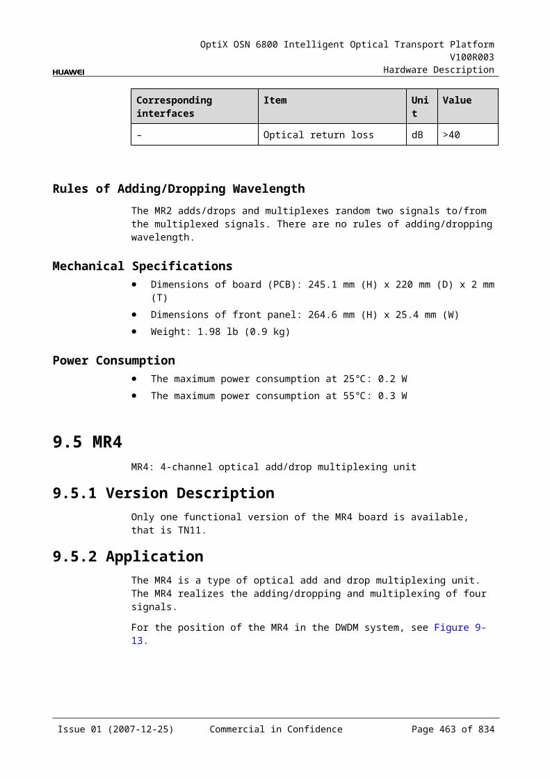
OptiX OSN 6800 Intelligent Optical Transport Platform V100R003
Hardware Description
Optical Specifications
Table 11-1 Optical specifications of the OBU2
Item Unit Value
OBU205
Operating wavelength range nm 1529–1561
Nominal input power range dBm -24 to 0
Input power range per channel 40 Channels dBm -24 to -16
80 Channels -24 to -19
Typical input power of a single wavelength 40 Channels dBm -16
80 Channels -19
Noise figure (NF) dB ≤7.0
Input reflectance dB <-40
Output reflectance dB <-40
Pump leakage at input dBm <-30
Maximum reflectance tolerance at input dB -27
Maximum reflectance tolerance at output dB -27
Maximum total output optical power dBm 23
Nominal gain dB 23
Gain response time on adding/dropping of channels ms <10
Channel gain dB 23±1.5
Gain flatness dB ≤2.0
Multi-channel gain slope dB/dB ≤2.0
Polarization dependent loss dB ≤0.5
Mechanical Specifications Dimensions of board (PCB): 245.1 mm (H) x 220 mm (D) x 2 mm (T) Dimensions of front panel: 264.6 mm (H) x 50.8 mm (W) Weight: 4.19 lb (1.9 kg)
Power Consumption The maximum power consumption at 25: 35.0 W The maximum power consumption at 55: 38.5 W
Issue 01 (2007-12-25) Commercial in Confidence Page 462 of 664
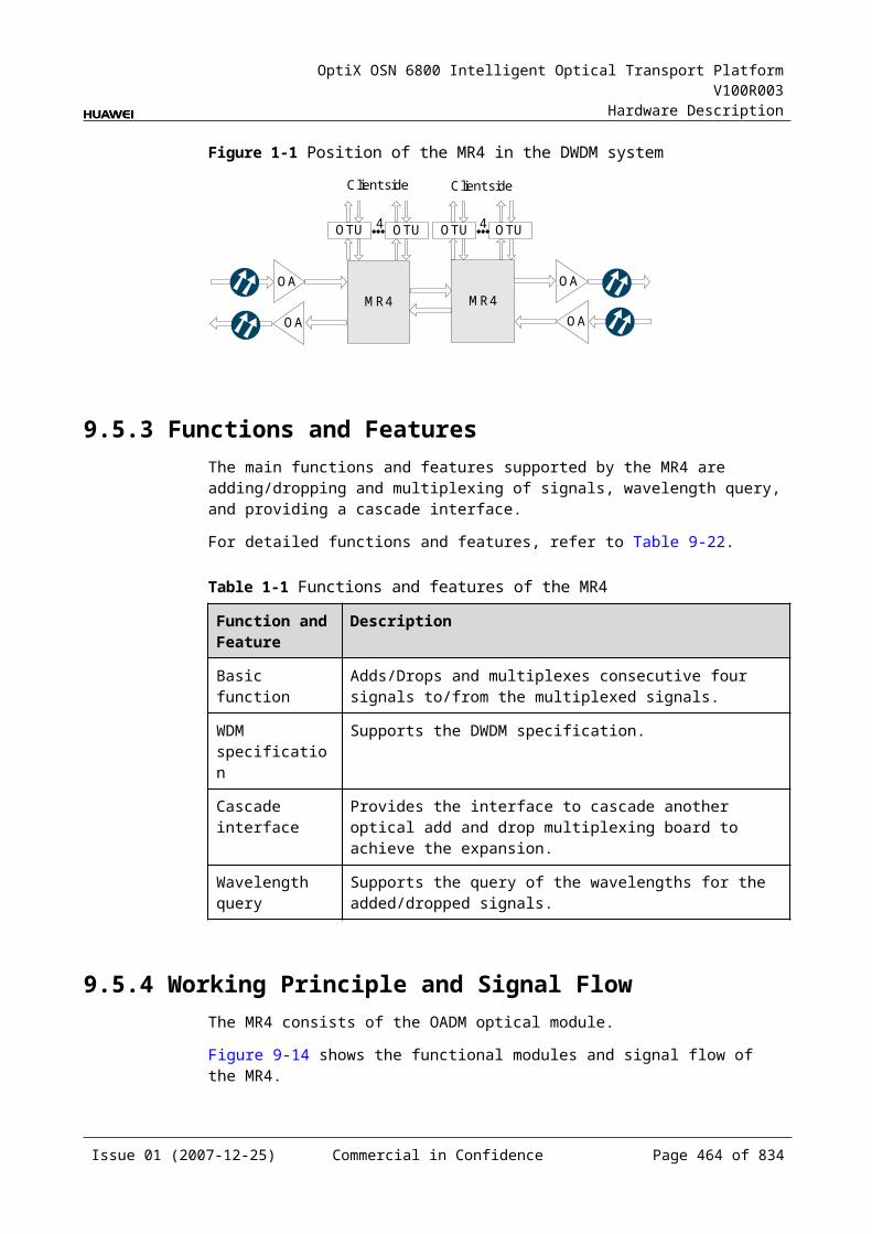
OptiX OSN 6800 Intelligent Optical Transport Platform V100R003
Hardware Description
12 System Control and Communication Unit
12.1 SCCSCC: system control and communication unit
12.1.1 Version DescriptionOnly one functional version of the SCC board is available, that is TN11.
12.1.2 ApplicationThe SCC is a type of system control and communication unit. Working with the network management system to manage each board, the SCC realizes the communications between equipments.
12.1.3 Functions and FeaturesThe main functions and features supported by the SCC are DCC communication, subrack cascading, clock and power supply backup.
For detailed functions and features, refer to Table 12-1.
Table 12-1 Functions and features of the SCC
Function and Feature
Description
Basic function Accomplishes the service grooming, configuration management and alarm output of a subrack.
DCC communication
Supports DCC communication with the NEs for network management.
Active/Standby backup
Supports active/standby backup: There are two SCCs in the system that can provide the 1+1 hot backup. When the active board fails, the standby board becomes active automatically.
Issue 01 (2007-12-25) Commercial in Confidence Page 463 of 664
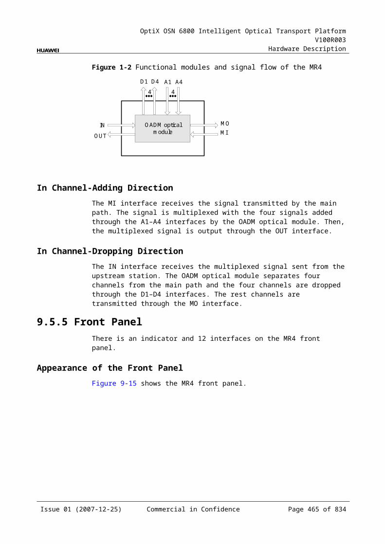
OptiX OSN 6800 Intelligent Optical Transport Platform V100R003
Hardware Description
Function and Feature
Description
Clock function Provides clock source for the system communications.
Subrack cascading
Supports subrack cascading. When subracks are cascaded, the subrack in which the optical layer/overhead processing board is installed is usually selected as the master subrack. A slave subrack cannot be upgraded to a master subrack.The SCC accomplishes different functions based on the mode (master or slave) of the subrack in which it is installed. The SCC in a slave subrack processes the overhead bytes, handles alarms and is in charge of the configuration and grooming of services inside the subrack. Besides these functions, the SCC in a master subrack also processes the overhead bytes and handles the alarms of all its slave subracks. The SCC in the master subrack is connected to the network management system. The configuration commands are issued to the SCC of a slave subrack through the SCC in the master subrack.
Power supply backup
Provides 1:N power supply backup for the system.
12.1.4 Working Principle and Signal FlowThe SCC consists of the overhead processing module, clock module, monitoring module, power supply module, communications module, the CPU and control module.
Figure 12-1 shows the functional modules and signal flow of the SCC.
Figure 12-1 Functional modules and signal flow of the SCC
CPU andcontrolmodule
Communicationsmodule
Clock module
Overheadprocessing
module
Other boards
Other boards
Monitoringmodule
Power supplymodule
Issue 01 (2007-12-25) Commercial in Confidence Page 464 of 664

OptiX OSN 6800 Intelligent Optical Transport Platform V100R003
Hardware Description
Overhead Processing ModuleThe overhead processing module receives overhead signals from the service board and processes the overhead bytes. The 360 DCCs (D1–D3) are processed by the control module. At the same time, the overhead processing module also sends the overhead signals to the service board.
Clock ModuleThe clock module provides the clock source for the system.
Monitoring ModuleThe monitoring module detects whether the boards are in position and reports alarms to the network management system.
Power Supply ModuleThe power supply module supplies power for the SCC. It also provides the entire OSN 6800 system with 3.3 V integrated power backup to protect the 3.3 V power supply of any board in the system.
Communications ModuleThe communications module communicates with other boards.
The module transmits data with other boards through the Ethernet and reports to the network management system.
The module transmits urgent data through the RS485.
CPU and Control ModuleThis module realizes the control, monitoring and management of each functional module of the board.
12.1.5 Front PanelThere are indicators, buttons and an LED indicator on the front panel.
Appearance of the Front PanelFigure 12-2 shows the SCC front panel.
Issue 01 (2007-12-25) Commercial in Confidence Page 465 of 664

OptiX OSN 6800 Intelligent Optical Transport Platform V100R003
Hardware Description
Figure 12-1 SCC front panel
SCC
SCC
STATACTPROGSRVPWRAPWRBPWRCALMC
RESET
LAMP TEST
ALM CUT
SubRACK_ID
IndicatorsThere are eight indicators on the front panel.
Board hardware status indicator (STAT) – dual-colored (red, green) Service active status indicator (ACT) – green Board software status indicator (PROG) – dual-colored (red, green) Service alarm indicator (SRV) – triple-colored (red, green, yellow) System power supply indicator (PWRA)– dual-colored (red, green) System power supply indicator (PWRB)– dual-colored (red, green) Protection power indicator (PWRC)– dual-colored (red, green) Alarm cut-off indicator (ALMC)– green
Issue 01 (2007-12-25) Commercial in Confidence Page 466 of 664
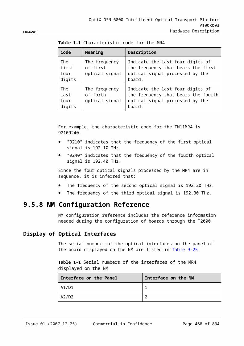
OptiX OSN 6800 Intelligent Optical Transport Platform V100R003
Hardware Description
ButtonsThere are three buttons on the front panel. Table 12-2 lists the function of each button.
Table 12-1 Functions of the SCC buttons
Button Function
RESET Used to reset the SCC.
ALM CUT Used to cut off the audible alarm.
LAMP TEST Used to test all the indicators in the subrack.
LEDThere is an LED indicator on the front panel. Table 12-3 shows the its function.
Table 12-1 Function of the SCC LED indicator
LED indicator
Function
SubRack_ID The LED on the front panel is used to indicate whether the subrack is a primary or a secondary one when subracks are cascaded. "0" indicates that the subrack which the SCC placed is a primary one. "1" to "7" indicates that the subrack which the SCC placed is a secondary one.
InterfacesThe SCC does not provide external interfaces.
12.1.6 Valid SlotsThe SCC occupies one slot. The valid slots for the SCC are IU17 and IU18. By default, the SCC is installed in IU18.
12.1.7 DIP Switch and JumperThere is a three-bit jumper inside the SCC. It is used to switch on or off the power supplied by the battery on the board.
When the board is in normal use, the jumper cap should be installed onto the two pins that are close to the board edge.
12.1.8 Specifications of the SCCSpecifications include dimensions, weight, and power consumption.
Issue 01 (2007-12-25) Commercial in Confidence Page 467 of 664
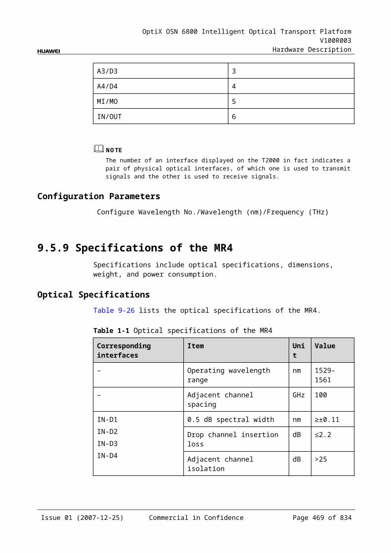
OptiX OSN 6800 Intelligent Optical Transport Platform V100R003
Hardware Description
Mechanical Specifications Dimensions of board (PCB): 245.1 mm (H) x 220 mm (D) x 2 mm (T) Dimensions of front panel: 264.6 mm (H) x 25.4 mm (W) Weight: 2.64 lb (1.2 kg)
Power Consumption The maximum power consumption at 25: 30.0 W The maximum power consumption at 55: 33.0 W
12.2 AUXAUX: system auxiliary interface unit
12.2.1 Version DescriptionOnly one functional version of the AUX board is available, that is TN11.
12.2.2 ApplicationThe AUX is a type of system control and communication unit. It provides various auxiliary interfaces and management interfaces.
12.2.3 Functions and FeaturesThe main functions and features supported by the AUX are providing various auxiliary interfaces and management interfaces.
For detailed functions and features, refer to Table 12-4.
Table 12-1 Functions and features of the AUX
Function and Feature
Description
Basic function Provides the system with various auxiliary interfaces and management interfaces.
Interface Provides the Ethernet communications interface and management interface.Provides the common and the emergent inter-subrack communications interfaces
Setting of subrack ID Sets the subrack ID that contains three bits.
12.2.4 Working Principle and Signal FlowThe AUX consists of the communications module, power supply module, the CPU and control module.
Figure 12-3 shows the functional modules and signal flow of the AUX.
Issue 01 (2007-12-25) Commercial in Confidence Page 468 of 664
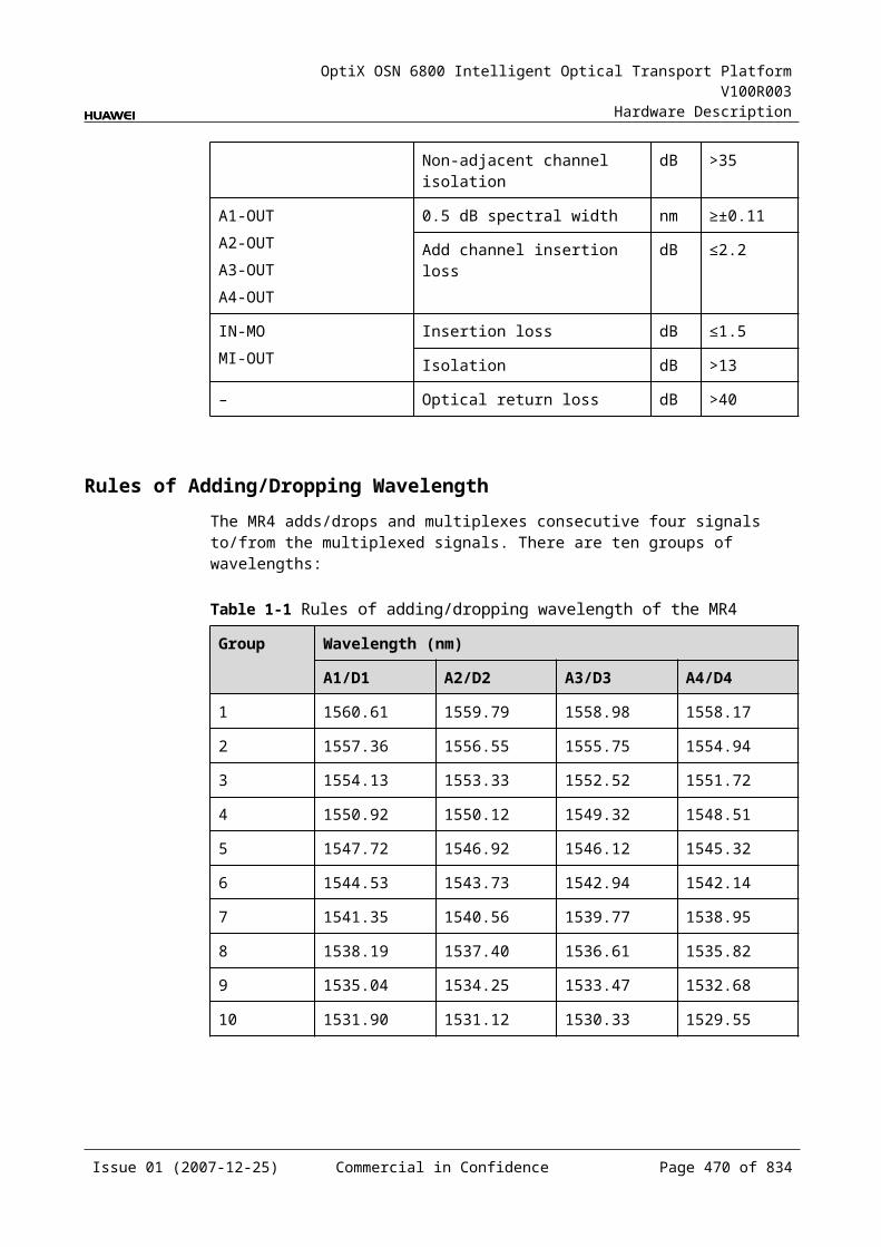
OptiX OSN 6800 Intelligent Optical Transport Platform V100R003
Hardware Description
Figure 12-1 Functional modules and signal flow of the AUX
CPU andcontrolmodule
Other boards
Power supplymodule
Communicationsmodule
Communications ModuleProvides the inter-board communications interface to connect the service boards and the SCC. Realizes the data communications between boards.
Provides the NM interface and the NM cascading interface that are used to connect the NM terminal.
Provides the common and the emergent inter-subrack communications network interfaces.
Power Supply ModuleThe power supply module supplies power for the AUX.
CPU and Control ModuleThe CPU module realizes the control, monitoring and management of the communications module and detects the power supply at the same time.
The control module provides the subrack ID and collects the alarms and performance events of each functional module as well as the clock information.
12.2.5 Front PanelThere are indicators and interfaces on the AUX front panel.
Appearance of the Front PanelFigure 12-4 shows the AUX front panel.
Issue 01 (2007-12-25) Commercial in Confidence Page 469 of 664
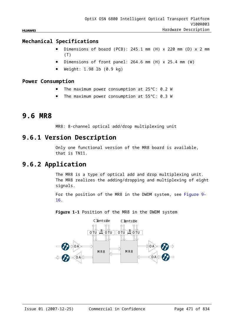
OptiX OSN 6800 Intelligent Optical Transport Platform V100R003
Hardware Description
Figure 12-1 AUX front panel
AUX
STAT
PROG
NM
_ETH
1N
M_E
TH2
ETH
1E
TH2
IndicatorsThere are two indicators on the front panel.
Board hardware status indicator (STAT) – dual-colored (red, green) Board software status indicator (PROG) – dual-colored (red, green)
InterfacesThere are four interfaces on the AUX front panel. Table 12-5 lists the type and function of each interface.
Table 12-1 Types and functions of the AUX interfaces
Interface
Type
Function
NM_ETH1 RJ-45 Connects the network interface on the OptiX OSN 6800 through a network cable to that on the T2000 server to achieve the management of the T2000 over the OptiX OSN 6800.
Connects the NM_ETH1/NM_ETH2 network interface on one NE through a network cable to that on another NE to achieve communication between NEs.
NM_ETH2 RJ-45 Connects the network interface on the OptiX OSN 6800 through a network cable to that on the T2000 server to achieve the management of the T2000 over the OptiX OSN 6800.
Connects the NM_ETH1/NM_ETH2 network interface on one NE through a network cable to that on another NE to achieve communication between NEs.
ETH1 RJ-45 Inter-subrack communications network interfaces
Issue 01 (2007-12-25) Commercial in Confidence Page 470 of 664
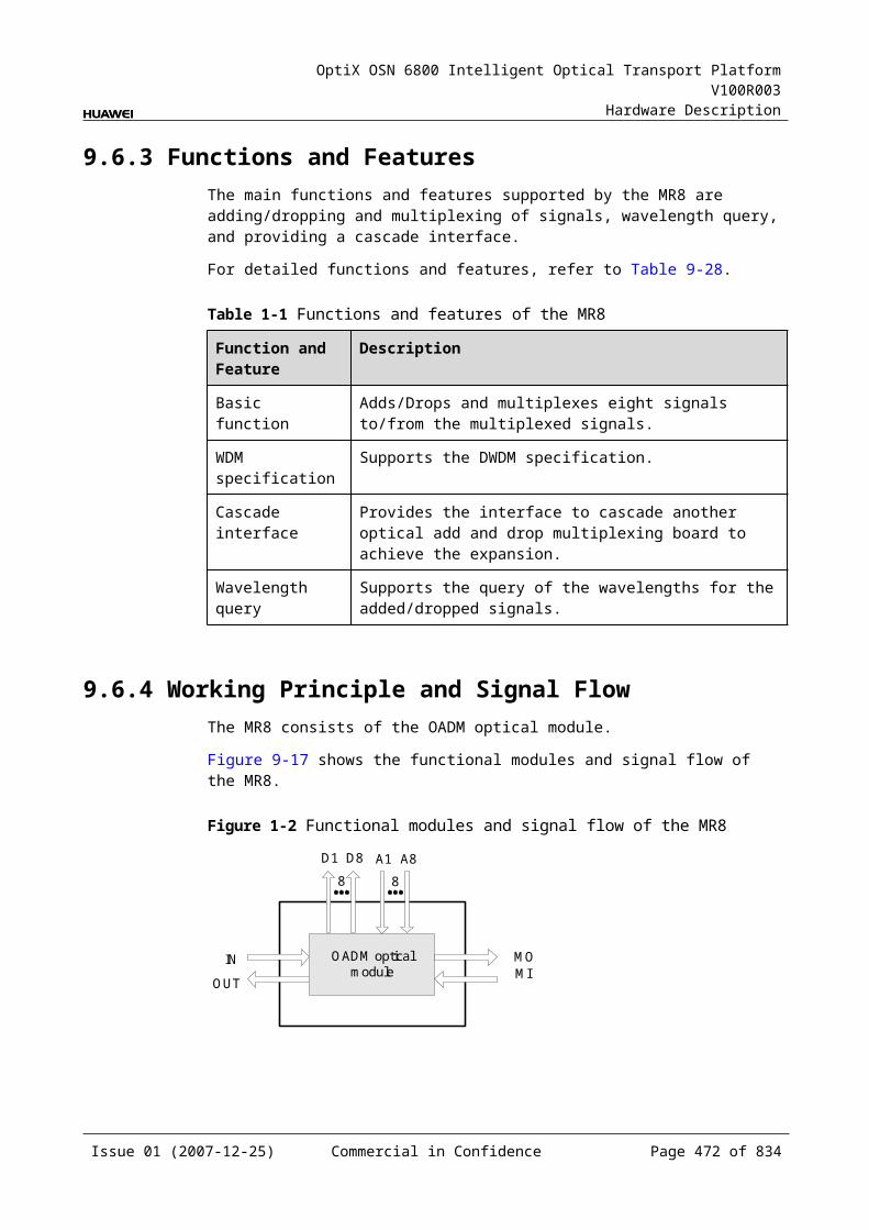
OptiX OSN 6800 Intelligent Optical Transport Platform V100R003
Hardware Description
ETH2 RJ-45 Inter-subrack communications network interfaces
12.2.6 Valid SlotsThe AUX occupies one slot. The valid slot for the AUX is IU21.
12.2.7 DIP Switch and JumperThere is a three-bit jumper inside the AUX, which is used to set the subrack ID.
The SCC detects the subrack ID and identifies whether the subrack is a primary or a secondary one. The result is indicated by the LED indicator of the SCC front panel.
12.2.8 Specifications of the AUXSpecifications include dimensions, weight, and power consumption.
Mechanical Specifications Dimensions of the board (PCB):85 mm (H) x 220 mm (W) x 2mm (T) Dimensions of the front panel: 107.6 mm (height) x 28.4 mm (width) Weight: 1.1 lb (0.5 kg)
Power Consumption The maximum power consumption at 25: 14.0 W The maximum power consumption at 55: 15.4 W
Issue 01 (2007-12-25) Commercial in Confidence Page 471 of 664

OptiX OSN 6800 Intelligent Optical Transport Platform V100R003
Hardware Description
13 Optical Supervisory Channel Unit
13.1 SC1SC1: unidirectional optical supervisory channel unit
13.1.1 Version DescriptionOnly one functional version of the SC1 board is available, that is TN11.
13.1.2 ApplicationThe SC1 is a type of optical supervisory channel unit. The SC1 realizes the processing of one supervisory channel in one direction. It transmits and extracts the overhead information of the system, processes the information and sends it to the SCC.
For the position of the SC1 in the WDM system, see Figure 13-1.
Figure 13-1 Position of the SC1 in the WDM system
NE1 NE2 NE3
OA
OA
SC1FIU
OA
OA
FIU
SC1SC2
OA
FIU
OA
FIU
SCC SCCSCC
In the WDM network that adopts the optical supervisory channel, the NEs can make use of the supervisory channel to transmit supervisory and management data. As shown in Figure 13-1, the user can use the Ethernet to log in to the NE1 to manage the NE1 directly. NE2 and NE3 are remote equipment. They can be remotely
Issue 01 (2007-12-25) Commercial in Confidence Page 473 of 664
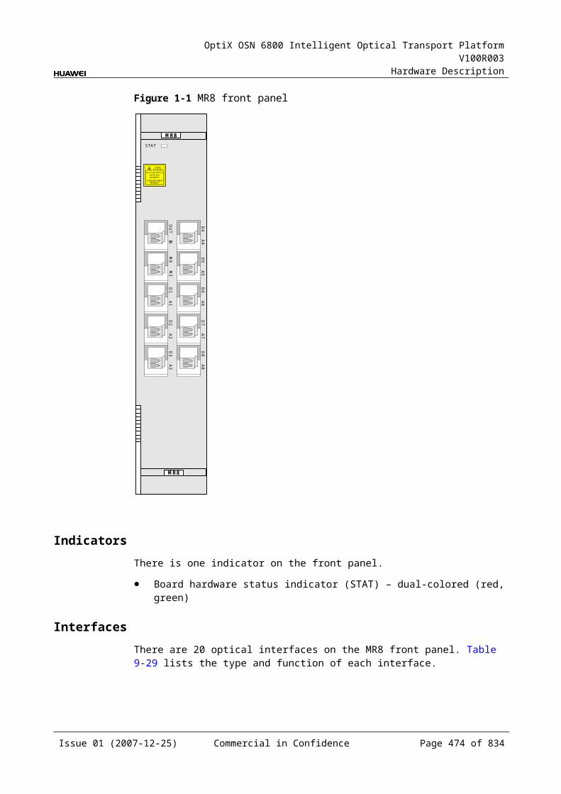
OptiX OSN 6800 Intelligent Optical Transport Platform V100R003
Hardware Description
managed through the supervisory channel when there is no data line connected. In this way, the entire network is under management.
The SCC of NE1 sends the network management (NM) data to the optical supervisory channel (OSC) unit. The OSC unit converts the data into optical signals and sends the signals to the FIU. The supervisory signals are multiplexed with the signals transmitted by the main path. Then, all the signals are transmitted on line. The FIU of NE2 separates the supervisory signals from the line and sends them to the OSC unit of NE2. The OSC unit converts the optical signals into supervisory data and sends the data to the SCC for processing.
13.1.3 Functions and FeaturesThe main functions and features supported by the SC1 are processing and regeneration of optical supervisory signals.
For detailed functions and features, refer to Table 13-1.
Table 13-1 Functions and features of the SC1
Function and Feature
Description
Basic function The SC1 is used to receive, process, and transmit one optical supervisory signal.
Technical features
The OSC has no limitation on the distance between two optical line amplifiers. The failure of an optical line amplifier does not affect the performance of the OSC.The SC1 is independent of the SCC. When the SCC is not in position, the SC1 can still ensure the pass-through of ECC with the boards in the paired slot and monitor other stations .
Regeneration function
The SC1 transmits signals from section to section. It also has the 3R function. In each regenerating station that has optical amplifiers, information can be correctly received and new supervisory signals are added.
Operating wavelength
The signal wavelength of supervisory channel is 1510 nm.
13.1.4 Working Principle and Signal FlowThe SC1 consists of the optical receiving/transmitting module, overhead and clock processing module and the control and communication module.
Figure 13-2 shows the functional modules and signal flow of the SC1.
Issue 01 (2007-12-25) Commercial in Confidence Page 474 of 664
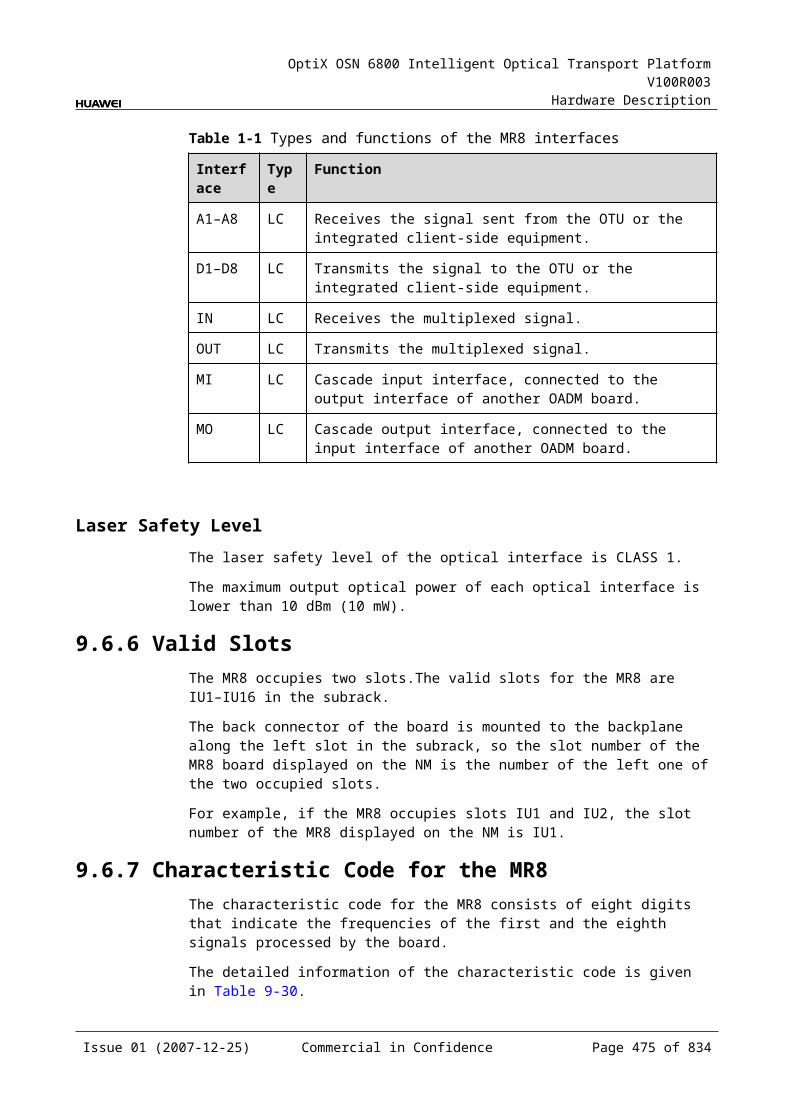
OptiX OSN 6800 Intelligent Optical Transport Platform V100R003
Hardware Description
Figure 13-1 Functional modules and signal flow of the SC1
Opticalreceivingmodule
RM Overhead andclock processing
module
Opticaltransmitting
module
TM
SCC
Control and communication module
Optical Receiving/Transmitting ModuleThe optical receiving module receives the optical supervisory signal from the FIU. It performs O/E conversion and sends the converted signal to the overhead and clock processing module.
The optical transmitting module receives the processed electrical signal from the overhead and clock processing module. It performs E/O conversion and sends the converted signal to the FIU.
Overhead and Clock Processing ModuleThe overhead and clock processing module extracts overhead bytes from the electrical signals, and sends them to the SCC for processing. After the overhead signals are processed by the SCC, this module sends the electrical signals to the optical transmitting module.
The clock processing module is mainly used to extract and process the timing signals and transmit the timing information of the local NE to the next NE.
Control and Communication ModuleThe control and communication module realizes the control, monitoring and communications management of each functional module of the board.
The control and communication module collects the information, such as the alarms and performance events, working status, and voltage detection, of each functional module of the board and reports to the SCC.
Receiving the commands from the SCC, the control and communication module controls and coordinates the functional modules of the board in working.
13.1.5 Front PanelThere are indicators, interfaces and laser safety label on the SC1 front panel.
Appearance of the Front PanelFigure 13-3 shows the SC1 front panel.
Issue 01 (2007-12-25) Commercial in Confidence Page 475 of 664
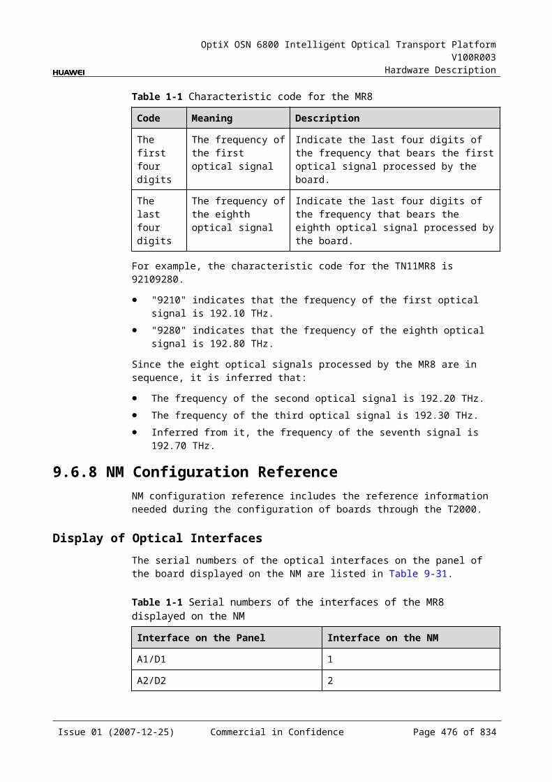
OptiX OSN 6800 Intelligent Optical Transport Platform V100R003
Hardware Description
Figure 13-1 SC1 front panel
SC1
SC1
CLASS 1LASER
PRODUCT
STATACTPROGSRV
TMR
M
EOW
IndicatorsThere are four indicators on the front panel.
Board hardware status indicator (STAT) – dual-colored (red, green) Service active status indicator (ACT) – green Board software status indicator (PROG) – dual-colored (red, green) Service alarm indicator (SRV) – triple-colored (red, green, yellow)
InterfacesThere are two optical interfaces and one orderwire phone interface on the SC1 front panel. Table 13-2 lists the type and function of each interface.
Issue 01 (2007-12-25) Commercial in Confidence Page 476 of 664
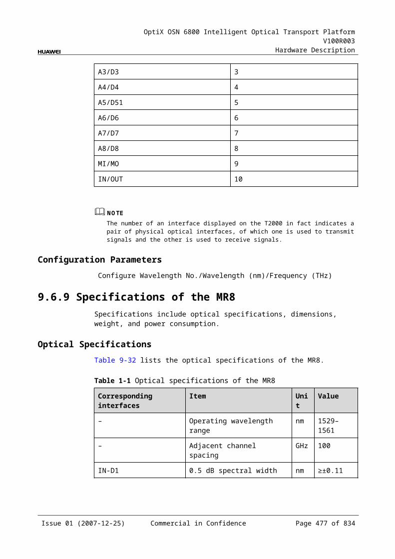
OptiX OSN 6800 Intelligent Optical Transport Platform V100R003
Hardware Description
Table 13-1 Types and functions of the SC1 interfaces
Interface
Type
Function
TM LC Transmits the supervisory signal.
RM LC Receives the supervisory signal.
EOW - Connects to an orderwire phone set through telephone wires, to realize orderwire communication between NEs.
Laser Safety LevelThe laser safety level of the optical interface is CLASS 1.
The maximum output optical power of each optical interface is lower than 10 dBm (10 mW).
13.1.6 Valid SlotsThe SC1 occupies one slot. The valid slots for the SC1 are IU1–IU17.
13.1.7 NM Configuration ReferenceNM configuration reference includes the reference information needed during the configuration of boards through the T2000.
Display of Optical InterfacesThe serial numbers of the optical interfaces on the panel of the board displayed on the NM are listed in Table 13-3.
Table 13-1 Serial numbers of the interfaces of the SC1 displayed on the NM
Interface on the Panel Interface on the NM
RM/TM 1
NOTEThe number of an interface displayed on the T2000 in fact indicates a pair of physical optical interfaces, of which one is used to transmit signals and the other is used to receive signals.
Configuration ParametersOptical Interface Loopback
Laser Status
Issue 01 (2007-12-25) Commercial in Confidence Page 477 of 664
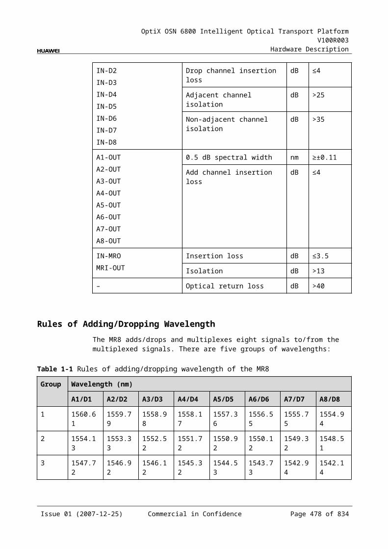
OptiX OSN 6800 Intelligent Optical Transport Platform V100R003
Hardware Description
13.1.8 Specifications of the SC1Specifications include optical specifications, dimensions, weight, and power consumption.
Optical SpecificationsTable 13-4 lists the optical specifications of the SC1.
Table 13-1 Optical specifications of the SC1
Item Unit Value
Signal rate Mbit/s 16.896 4.096
Operating wavelength range nm 1500 to 1520
Signal coding – CMI
Launched optical power dBm 0 to–4
Receiver sensitivity dBm ≤–46 ≤–48
Receiver overload dBm –3
Mechanical Specifications Dimensions of board (PCB): 245.1 mm (H) x 220 mm (D) x 2 mm (T) Dimensions of front panel: 264.6 mm (H) x 25.4 mm (W) Weight: 2.20 lb (1.0 kg)
Power Consumption The maximum power consumption at 25: 13.5 W The maximum power consumption at 55: 14.9 W
13.2 SC2SC2: bi-directional optical supervisory channel unit
13.2.1 Version DescriptionOnly one functional version of the SC2 board is available, that is TN11.
13.2.2 ApplicationThe SC2 is a type of Optical supervisory channel unit. The SC2 realizes the processing of two supervisory channels in opposite directions. It transmits and extracts the overhead information of the system, processes the information and sends it to the SCC.
For the position of the SC2 in the WDM system, see Figure 13-4.
Issue 01 (2007-12-25) Commercial in Confidence Page 478 of 664
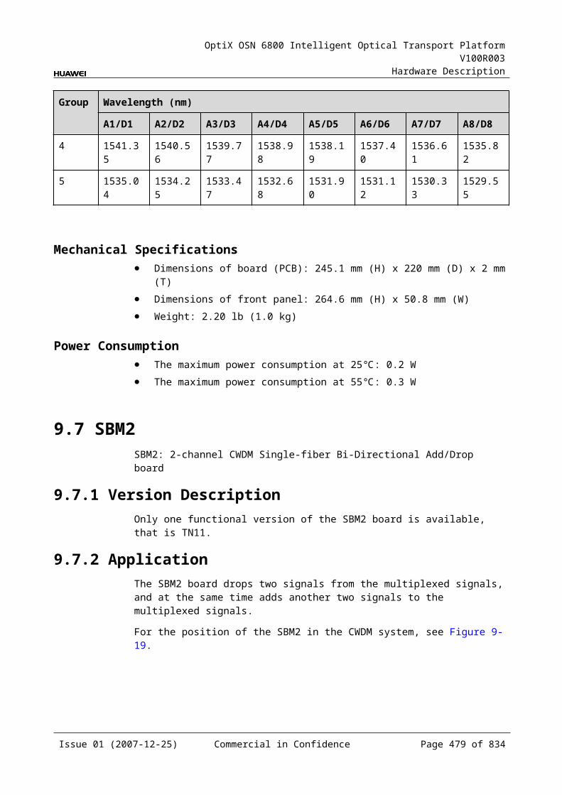
OptiX OSN 6800 Intelligent Optical Transport Platform V100R003
Hardware Description
Figure 13-1 Position of the SC2 in the WDM system
NE1 NE2 NE3
OA
OA
SC1FIU
OA
OA
FIU
SC1SC2
OA
FIU
OA
FIU
SCC SCCSCC
In the WDM network that adopts the optical supervisory channel, the NEs can make use of the supervisory channel to transmit supervisory and management data. As shown in Figure 13-4, the user can use the Ethernet to log in to the NE1 to manage the NE1 directly. NE2 and NE3 are remote equipment. They can be remotely managed through the supervisory channel when there is no data line connected. In this way, the entire network is under management.
The SCC of NE1 sends the network management (NM) data to the optical supervisory channel (OSC) unit. The OSC unit converts the data into optical signals and sends the signals to the FIU. The supervisory signals are multiplexed with the signals transmitted by the main path. Then, all the signals are transmitted on line. The FIU of NE2 separates the supervisory signals from the line and sends them to the OSC unit of NE2. The OSC unit converts the optical signals into supervisory data and sends the data to the SCC for processing.
13.2.3 Functions and FeaturesThe main functions and features supported by the SC2 are processing and regeneration of optical supervisory signals.
For detailed functions and features, refer to Table 13-5.
Table 13-1 Functions and features of the SC2
Function and Feature
Description
Basic function The SC2 is used to receive, process, and transmit two optical supervisory signals.
Technical features
The OSC has no limitation on the distance between two optical line amplifiers. The failure of an optical line amplifier does not affect the performance of the OSC.The SC2 is independent of the SCC. When the SCC is not in position, the SC2 can still ensure the pass-through of ECC with the two optical interfaces and monitor other stations.
Regeneration function
The SC2 transmits signals from section to section. It also has the 3R function. In each regenerating station that has optical amplifiers, information can be correctly received and new supervisory signals are added.
Operating wavelength
The signal wavelength of supervisory channel is 1510 nm.
Issue 01 (2007-12-25) Commercial in Confidence Page 479 of 664

OptiX OSN 6800 Intelligent Optical Transport Platform V100R003
Hardware Description
13.2.4 Working Principle and Signal FlowThe SC2 consists of the optical receiving/transmitting module, overhead and clock processing module, and the control and communication module.
Figure 13-5 shows the functional modules and signal flow of the SC2.
Figure 13-1 Functional modules and signal flow of the SC2
RM1 TM1
SCC
Opticalreceivingmodule
Overhead andclock processing
module
Opticaltransmitting
module
Opticalreceivingmodule
Opticaltransmitting
module
RM2 TM2
Control and communication module
Overhead andclock processing
module
Optical Receiving/Transmitting ModuleThe optical receiving module receives the optical supervisory signal from the FIU. It performs O/E conversion and sends the converted signal to the overhead and clock processing module.
The optical transmitting module receives the processed electrical signal from the overhead and clock processing module. It performs E/O conversion and sends the converted signal to the FIU.
Overhead and Clock Processing ModuleThe overhead and clock processing module extracts overhead bytes from the electrical signals and sends them to the SCC for processing. After the overhead signals are processed by the SCC, this module sends the electrical signals to the optical transmitting module.
The clock processing module is mainly used to extract and process the timing signals and transmit the timing information of the local NE to the next NE.
Control and Communication ModuleThe control and communication module realizes the control, monitoring and communications management of each functional module of the board.
The control and communication module collects the information, such as the alarms and performance events, working status, and voltage detection, of each functional module of the board and reports to the SCC.
Receiving the commands from the SCC, the control and communication module controls and coordinates the functional modules of the board in working.
Issue 01 (2007-12-25) Commercial in Confidence Page 480 of 664
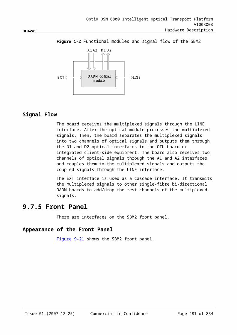
OptiX OSN 6800 Intelligent Optical Transport Platform V100R003
Hardware Description
13.2.5 Front PanelThere are indicators, interfaces and laser safety label on the SC2 front panel.
Appearance of the Front PanelFigure 13-6 shows the SC2 front panel.
Figure 13-1 SC2 front panel
SC2
SC2
STATACTPROGSRV
TM1
RM
1TM
2R
M2
CLASS 1LASER
PRODUCT
EOW
IndicatorsThere are four indicators on the front panel.
Board hardware status indicator (STAT) – dual-colored (red, green) Service active status indicator (ACT) – green Board software status indicator (PROG) – dual-colored (red, green) Service alarm indicator (SRV) – triple-colored (red, green, yellow)
Issue 01 (2007-12-25) Commercial in Confidence Page 481 of 664
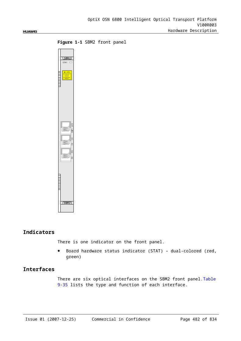
OptiX OSN 6800 Intelligent Optical Transport Platform V100R003
Hardware Description
InterfacesThere are two optical interfaces and one orderwire phone interface on the SC2 front panel. Table 13-6 lists the type and function of each interface.
Table 13-1 Types and functions of the SC2 interfaces
Interface
Type Function
TM1/TM2 LC Transmits the first/second supervisory signal.
RM1/RM2 LC Receives the first/second supervisory signal.
EOW - Connects to an orderwire phone set through telephone wires, to realize orderwire communication between NEs.
Laser Safety LevelThe laser safety level of the optical interface is CLASS 1.
The maximum output optical power of each optical interface is lower than 10 dBm (10 mW).
13.2.6 Valid SlotsThe SC2 occupies one slot. The valid slots for the SC2 are IU1–IU17.
13.2.7 NM Configuration ReferenceNM configuration reference includes the reference information needed during the configuration of boards through the T2000.
Display of Optical InterfacesThe serial numbers of the optical interfaces on the panel of the board displayed on the NM are listed in Table 13-7.
Table 13-1 Serial numbers of the interfaces of the SC2 displayed on the NM
Interface on the Panel Interface on the NM
RM1/TM1 1
RM2/TM2 2
NOTEThe number of an interface displayed on the T2000 in fact indicates a pair of physical optical interfaces, of which one is used to transmit signals and the other is used to receive signals.
Issue 01 (2007-12-25) Commercial in Confidence Page 482 of 664
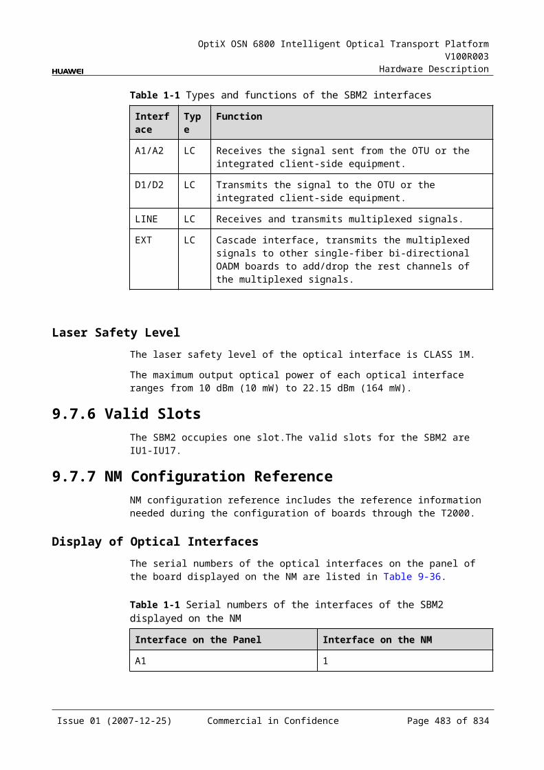
OptiX OSN 6800 Intelligent Optical Transport Platform V100R003
Hardware Description
Configuration ParametersOptical Interface Loopback
Laser Status
13.2.8 Specifications of the SC2Specifications include optical specifications, dimensions, weight, and power consumption.
Optical SpecificationsTable 13-8 lists the optical specifications of the SC2.
Table 13-1 Optical specifications of the SC2
Item Unit Value
Signal rate Mbit/s 16.896 4.096
Operating wavelength range nm 1500 to 1520
Signal coding – CMI
Launched optical power dBm 0 to–4
Receiver sensitivity dBm ≤–46 ≤–48
Receiver overload dBm –3
Mechanical Specifications Dimensions of board (PCB): 245.1 mm (H) x 220 mm (D) x 2 mm (T) Dimensions of front panel: 264.6 mm (H) x 25.4 mm (W) Weight: 2.20 lb (1.0 kg)
Power Consumption The maximum power consumption at 25: 13.5 W The maximum power consumption at 55: 14.9 W
Issue 01 (2007-12-25) Commercial in Confidence Page 483 of 664
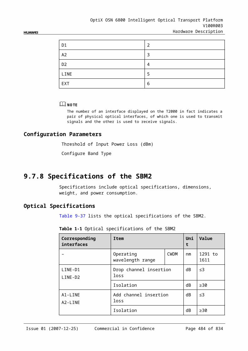
OptiX OSN 6800 Intelligent Optical Transport Platform V100R003
Hardware Description
14 Optical Protection Unit
14.1 DCPDCP: 2-channel optical path protection unit
14.1.1 Version DescriptionOnly one functional version of the DCP board is available, that is TN11.
14.1.2 ApplicationThe DCP is a type of optical protection unit. The DCP realizes the intra-board 1+1 protection, the client-side 1+1 protection and optical wavelength shared protection (OWSP protection).
For the position of the DCP in the WDM system, see Figure 14-1, Figure 14-2 and Figure 14-3.
Figure 14-1 Position of the DCP in the WDM system (intra-board 1+1 protection)
RI22
DCP
TI1
MUX
DMUX
DMUX
MUXTO11
TO12
RI11
RI12
OTU
OTU
DCP
DMUX
MUX
DMUX
MUX
FIU
FIU
FIU
FIU
TO11
RI11
TO12
RI12
TO21
RI21
TO22
RI21
TO21
RI22
TO22
RO1
TI2RO2
RO1TI1
RO2TI2
OTU
OTU
NOTEWhen used for intra-board 1+1 protection, the DCP does not support the 2.5 Gbit/s OTU.
Issue 01 (2007-12-25) Commercial in Confidence Page 485 of 664

OptiX OSN 6800 Intelligent Optical Transport Platform V100R003
Hardware Description
Figure 14-2 Position of the DCP in the WDM system (client-side 1+1 protection)
OTU(P)
OTU(W)
FIU
client-side MUX
DMUX
DMUX
MUX DMUX
MUX
DMUX
MUX
FIU
FIU
FIU
OTU(W)
OTU(P)
DCP
TO11RI11
TO21RI21
TO12RI12
TO22RI22
TI1RO1
TI2RO2
RI11TO11
RI21TO21
RI12TO12
RI22TO22
RO1TI1
RO2TI2
DCP
client-side
NOTEWhen the working OTU and the protection OTU are installed in different subracks, the DCP board can be used for client-side protection.
Figure 14-3 Position of the DCP in the WDM system (OWSP protection)
OTU2 OTU1 OTU2 OTU1
2 x DCP
OTU1 OTU2 OTU1 OTU2
OADM(West)
OADM(East)
FIU
FIU
OADM(West)
FIU OADM(East)FIU
OADM(West)
FIU
FIU
OADM(East)
OADM(East) FIU OADM
(West)FIU
λ2/λ1 λ1/λ2
λ2/λ1λ2λ1
λ1λ2
λ2λ1
λ1λ2
λ2/λ1
λ2/λ1 λ2λ1
λ2λ1
A
B C
D
λ1/λ2
λ1/λ2 λ2/λ1
λ2/λ1(West)(East)
2 x DCP
2 x DCP2 x DCPλ2/λ1
λ1/λ2
λ1/λ2
λ1/λ2
λ1/λ2λ2/λ1
λ1/λ2 λ1λ2
λ1λ2
: : :Direction of theworking signal flow
Direction of theprotection signal flow Optical signal
14.1.3 Functions and FeaturesThe main functions and features supported by the DCP are intra-board 1+1 protection and client-side 1+1 protection.
For detailed functions and features, refer to Table 14-1.
Issue 01 (2007-12-25) Commercial in Confidence Page 486 of 664
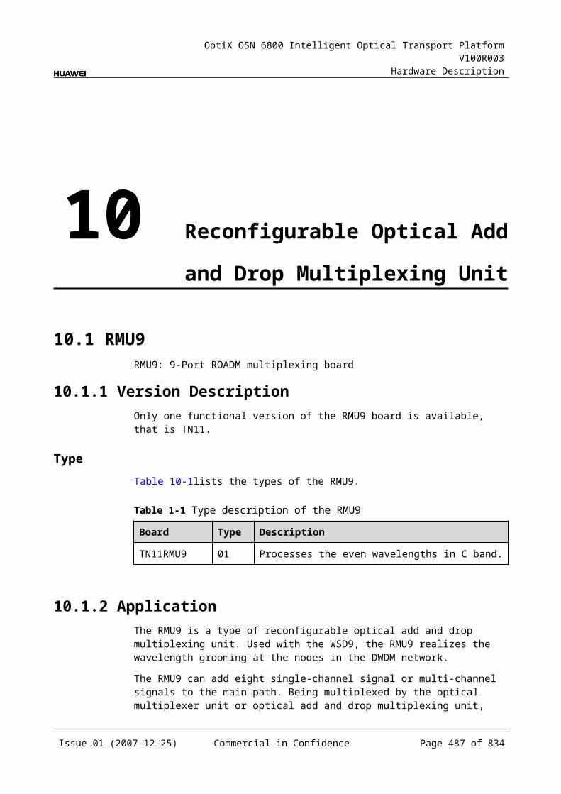
OptiX OSN 6800 Intelligent Optical Transport Platform V100R003
Hardware Description
Table 14-1 Functions and features of the DCP
Function and Feature
Description
Basic function Provides the intra-board 1+1 protection to protect the services of the OTU that has no dual-fed and selective receiving function. Compared with the OLP, the DCP provides protection for two signals so as to realize high-integrated 1+1 protection.
Provides the client-side 1+1 protection, making use of a working OTU and a protection OTU to protect the client-side services.
Provides the OWSP protection. Two pairs of wavelength routes (one east, the other west) are provided for the OTU, forming a protection pair, to achieve the optical wavelength shared protection.
Protection scheme
The intra-board 1+1 protection and client-side 1+1 protection: The protection mode is dual-fed and signal selection and single-end switching. When the performance of the working fiber declines, the system automatically
switches the service from the working path to the protection path. Protection switching is stable and quick because the APS protocol is not needed.
The OWSP protection: The protection mode is dual-fed and signal selection and dual-end switching. When the performance of the working fiber declines, the system automatically
switches the service from the working path to the protection path. Protection switching is stable and quick because the APS protocol is needed.
Protection switching time
The protection switching time of the system is less than 50 ms.
14.1.4 Working Principle and Signal FlowThe DCP consists of the optical splitter, optical switch, and the control and communication module.
Figure 14-4 shows the functional modules and signal flow of the DCP.
Issue 01 (2007-12-25) Commercial in Confidence Page 487 of 664
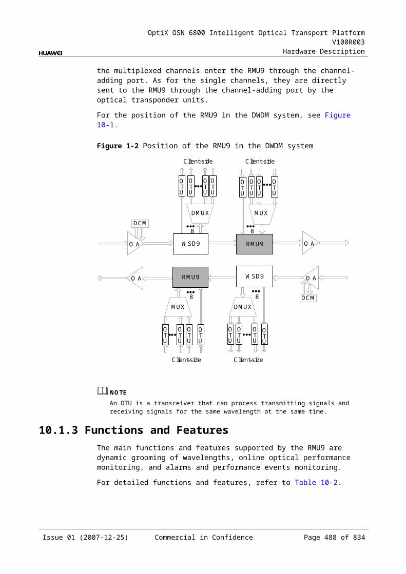
OptiX OSN 6800 Intelligent Optical Transport Platform V100R003
Hardware Description
Figure 14-1 Functional modules and signal flow of the DCP
Optical splitter
Optical switch
Optical splitterTI1 TO11
Control andcommunication module
SCC
RO1
TI2
RO2
TO12
RI11RI12
TO21TO22
RI21RI22Optical switch
Optical SplitterThe optical splitter divides a signal into two signals with the same power and sends them to the working and the protection fibers respectively.
Optical SwitchAt the receiving end, the optical switch selects the optical signal from the working or the protection path.
Control and Communication ModuleThe control and communication module realizes the control, monitoring and communications management of each functional module of the board.
The control and communication module collects the information, such as the alarms and performance events, working status, and voltage detection, of each functional module of the board and reports to the SCC.
Receiving the commands from the SCC, the control and communication module controls and coordinates the functional modules of the board in working.
Switching TypeThere are five switching types listed as follows:
Locked switching: This function is to lock the services on the working path, no matter the working or protection path is good or not.
Forced switching: This function is to force the services to work either on the working or protection path, no matter the working or protection path is good or not.
Automatic switching: If the working path is faulty while the protection path is normal, the services are switched from working path to the protection path. If both paths are faulty, the services are not switched. If the services are
Issue 01 (2007-12-25) Commercial in Confidence Page 488 of 664
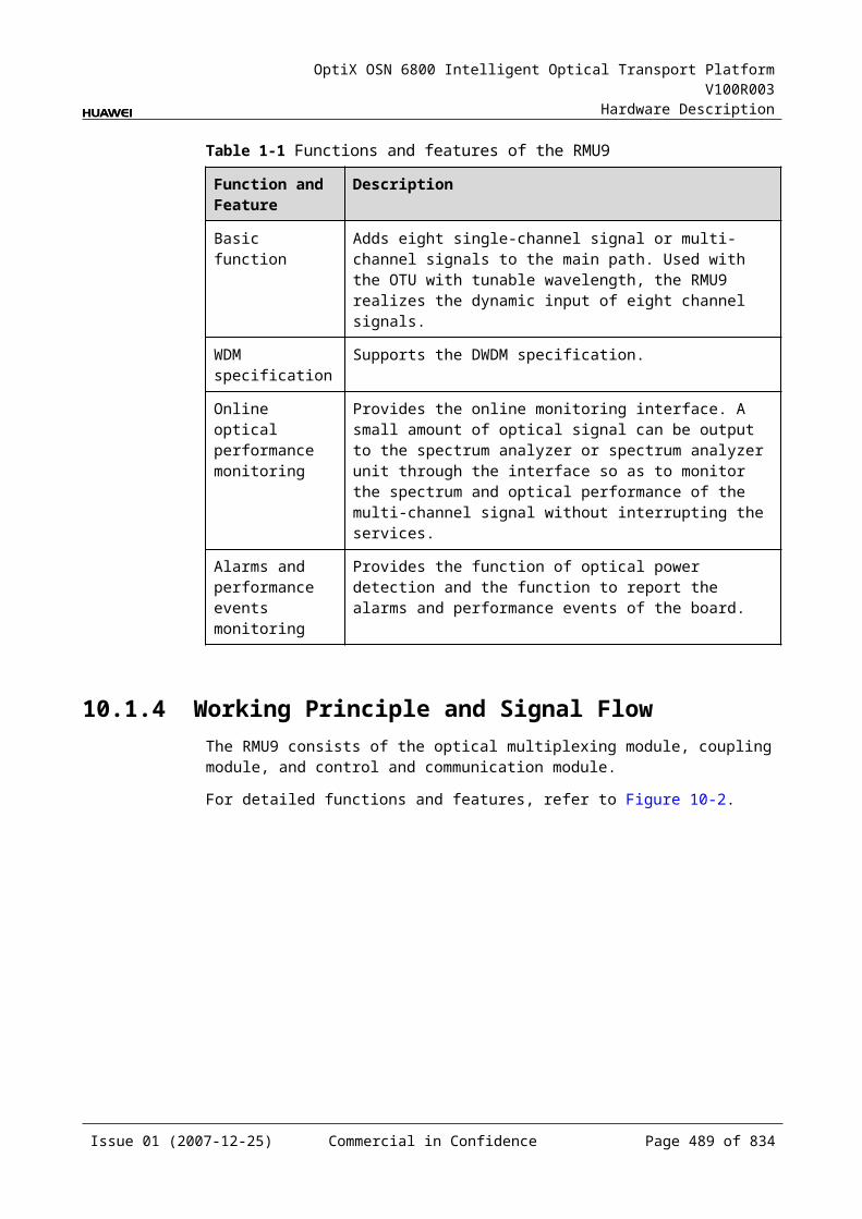
OptiX OSN 6800 Intelligent Optical Transport Platform V100R003
Hardware Description
transmitted on the protection path, the switching status is the same. The working mode can be set to revertive or non-revertive. In revertive mode, if the working path is recovered and confirmed to be normal for a certain period, the services are switched back to the working path. In non-revertive mode, even if the working path is recovered, the services remain on the protection path until a fault occurs to the protection path.
Manual switching: A manual switching command is issued to manually switch services from the working channel to the protection channel or from the latter to the former. Because the priority of manual switching is lower than that of automatic switching, the manual switching is valid only when both the working and protection channels are normal.
Clear switching: This function clears the switching state of the locked switching, forced switching, manual switching and the WTR time of automatic switching. It can not clear the switching state of automatic switching.
The priorities of the switching types from the highest to the lowest are as follows: clear switching > locked switching > forced switching > automatic switching > manual switching. If a higher level protection switching exists, lower level switching cannot be executed successfully. But if only the lower level switching exists, it can be executed successfully.
14.1.5 Front PanelThere are indicators, interfaces and laser safety label on the DCP front panel.
Appearance of the Front PanelFigure 14-5 shows the DCP front panel.
Issue 01 (2007-12-25) Commercial in Confidence Page 489 of 664
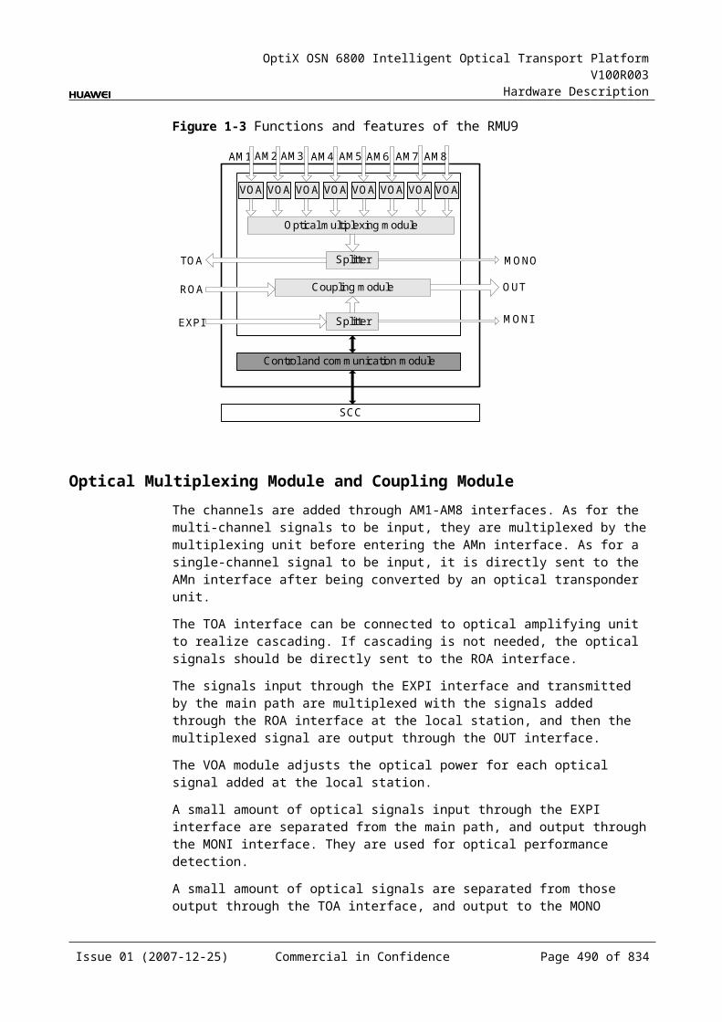
OptiX OSN 6800 Intelligent Optical Transport Platform V100R003
Hardware Description
Figure 14-1 DCP front panel
DCP
DCP
LASERRADIATION
DO NOT VIEW DIRECTLYWITH OPTICALINSTRUMENTS
CLASS 1M LASERPRODUCT
STATACTPROGSRV
TO11
RI11
TO12
RI12
TO21
RI21
TO22
RI22
RO
1TI1
RO
2TI2
IndicatorsThere are four indicators on the front panel.
Board hardware status indicator (STAT) – dual-colored (red, green) Service active status indicator (ACT) – green Board software status indicator (PROG) – dual-colored (red, green) Service alarm indicator (SRV) – triple-colored (red, green, yellow)
InterfacesThere are 12 optical interfaces on the DCP front panel. Table 14-2 lists the type and function of each interface.
Issue 01 (2007-12-25) Commercial in Confidence Page 490 of 664
OptiX OSN 6800 Intelligent Optical Transport Platform V100R003
Hardware Description
Table 14-1 Types and functions of the DCP interfaces
Interface
Type
Function
TI1 LC Receives the first channel of WDM-side signals. (intra-board 1+1 protection)Receives the first channel of client-side signals. (client-side 1+1 protection)Receives one channel of client-side signals. (OWSP protection)
TI2 LC Receives the second channel of WDM-side signals. (intra-board 1+1 protection)Receives the second channel of client-side signals. (client-side 1+1 protection)Receives the optical signals from the adjacent stations. (OWSP protection)
RO1 LC Transmits the first channel of WDM-side signals. (intra-board 1+1 protection)Transmits the first channel of client-side signals. (client-side 1+1 protection)Transmits one WDM-side optical signal to the OTU board. (OWSP protection)
RO2 LC Transmits the second channel of WDM-side signals. (intra-board 1+1 protection)Transmits the second channel of client-side signals. (client-side 1+1 protection)Transmits one optical signal to the adjacent stations. (OWSP protection)
TO11 LC Transmits the first channel of signals to the working multiplexer unit. (intra-board 1+1 protection)Transmits the first channel of signals to the working OTU. (client-side 1+1 protection)Serves as a dual-fed optical interface, transmitting one optical signal to the working router. (OWSP protection)
TO12 LC Transmits the first channel of signals to the protection multiplexer unit. (intra-board 1+1 protection)Transmits the first channel of signals to the protection OTU. (client-side 1+1 protection)Dual fed optical interface, transmitting one optical signal to the protection router. (OWSP protection)
TO21 LC Transmits the second channel of signals to the working multiplexer unit. (intra-board 1+1 protection)Transmits the second channel of signals to the working OTU. (client-side 1+1 protection)Connects to the RI12 interface of another DCP board in the same station by using a fiber.
TO22 LC Transmits the second channel of signals to the protection multiplexer unit. (intra-board 1+1 protection)Transmits the second channel of signals to the protection OTU. (client-side 1+1 protection)Connects to the RI22 interface on the same DCP board by using a fiber. (OWSP protection)
Issue 01 (2007-12-25) Commercial in Confidence Page 491 of 664

OptiX OSN 6800 Intelligent Optical Transport Platform V100R003
Hardware Description
Interface
Type
Function
RI11/RI12
LC Receives the first channel of signals from the working and the protection multiplexer unit. (intra-board 1+1 protection)Receives the first channel of signals from the working and protection OTU. (client-side 1+1 protection)Serve as selective receive interfaces, connecting to the working route and protection route, respectively. (OWSP protection)
RI21/RI22
LC Receives the second channel of signals from the working and the protection multiplexer unit. (intra-board 1+1 protection)Receives the second channel of signals from the working and protection OTU. (client-side 1+1 protection)Connects to the TO12 and TO22 interfaces on the same DCP board, respectively, by using a fiber. (OWSP protection)
Laser Safety LevelThe laser safety level of the optical interface is CLASS 1M.
The maximum output optical power of each optical interface ranges from 10 dBm (10 mW) to 22.15 dBm (164 mW).
14.1.6 Valid SlotsThe DCP occupies one slot. The valid slots for the DCP are IU1–IU17.
14.1.7 NM Configuration ReferenceNM configuration reference includes the reference information needed during the configuration of boards through the T2000.
Display of Optical InterfacesThe serial numbers of the optical interfaces on the panel of the board displayed on the NM are listed in Table 14-3.
Table 14-1 Serial numbers of the interfaces of the DCP displayed on the NM
Interface on the Panel Interface on the NM
TO11/RI11 1
TO12/RI12 2
TO21/RI21 3
TO22/RI22 4
TI1/RO1 5
TI2/RO2 6
Issue 01 (2007-12-25) Commercial in Confidence Page 492 of 664
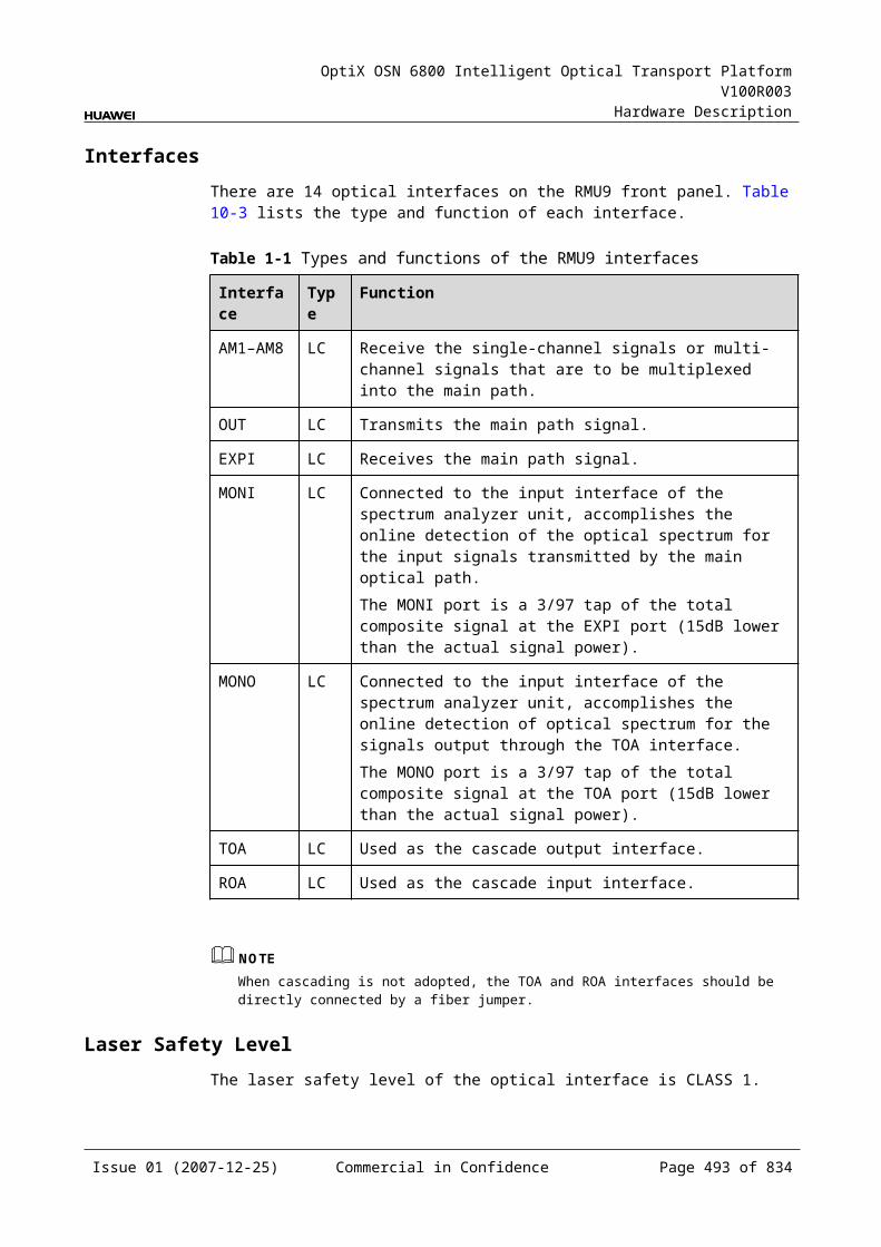
OptiX OSN 6800 Intelligent Optical Transport Platform V100R003
Hardware Description
NOTEThe number of an interface displayed on the T2000 in fact indicates a pair of physical optical interfaces, of which one is used to transmit signals and the other is used to receive signals.
Configuration ParametersThreshold of Input Power Loss (dBm)
Initial Variance Value Between Primary and Secondary Input Power (dB)
Varance Threshold Between Primary and Secondary Input Power (dB)
14.1.8 Specifications of the DCPSpecifications include optical specifications, dimensions, weight, and power consumption.
Optical SpecificationsTable 14-4 lists the optical specifications of the DCP.
Table 14-1 Optical specifications of the DCP
Interface Item Unit
Value
TI1-TO11TI1-TO12TI2-TO21TI2-TO22
Insertion loss at the transmit end
single mode dB ≤4
multimode dB ≤4.5
RI1-RO11RI1-RO12RI2-RO21RI2-RO22
Insertion loss at the receive end
single mode dB ≤1.5
multimode dB ≤2
Range of the input optical power dBm –35 to 7 (SLM)–35 to 0 (MLM)
Switching threshold of optical power difference dB 5
Mechanical Specifications Dimensions of board (PCB): 245.1 mm (H) x 220 mm (D) x 2 mm (T) Dimensions of front panel: 264.6 mm (H) x 25.4 mm (W) Weight: 2.20 lb (1.0 kg)
Power Consumption The maximum power consumption at 25: 6.8 W
Issue 01 (2007-12-25) Commercial in Confidence Page 493 of 664
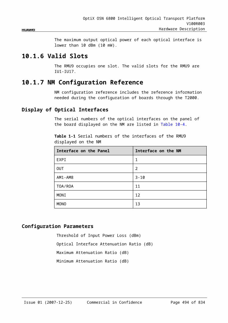
OptiX OSN 6800 Intelligent Optical Transport Platform V100R003
Hardware Description
The maximum power consumption at 55: 7.5 W
14.2 OLPOLP: optical line protection unit
14.2.1 Version DescriptionOnly one functional version of the OLP board is available, that is TN11.
14.2.2 ApplicationThe OLP is a type of optical protection unit. The OLP realizes the optical line protection, intra-board 1+1 protection and the client-side 1+1 protection.
For the position of the OLP in the WDM system, see Figure 14-6, Figure 14-7 and Figure 14-8.
Figure 14-1 Position of the OLP in the WDM system (optical line protection)
OLP
OTU
OTUMUX
DMUXOTU
OTU
FIU
TI
RO
OLP
DMUX
MUX
OTU
OTU
OTU
OTU
FIU
RO
TI
TO1
RI1
TO2
RI2
RI1
TO1
RI2
TO2
NOTEAn OTU is a transceiver that can process transmitting signals and receiving signals for the same wavelength at the same time.
Figure 14-2 Position of the OLP in the WDM system (intra-board 1+1 protection)
OLPMUX
DMUX
DMUX
MUXTO1
TO2
RI1
RI2
OLP
DMUX
MUX
DMUX
MUX
FIU
FIU
FIU
FIU
TO1
RI1
TO2
RI2
TIOTU RO
ROOTUTI
NOTEWhen used for intra-board 1+1 protection, the OLP does not support the 2.5 Gbit/s OTU.
Issue 01 (2007-12-25) Commercial in Confidence Page 494 of 664
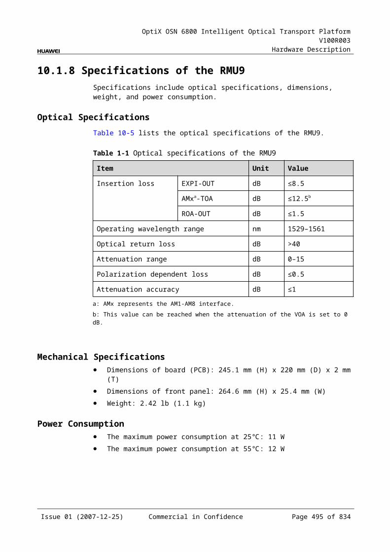
OptiX OSN 6800 Intelligent Optical Transport Platform V100R003
Hardware Description
Figure 14-3 Position of the OLP in the WDM system (client-side 1+1 protection)
client-side MUX
DMUX
DMUX
MUX DMUX
MUX
DMUX
MUX
FIU
FIU
FIU
FIU
OTU(W)
OTU(P)
OLP
TO1RI1
TO2RI2
TIRO
RI1TO1
RI2TO2
OTU(W)
OTU(P)
ROTIOLP
client-side
NOTEWhen the working OTU and the protection OTU are installed in different subracks, the OLP board can be used for client-side protection.
14.2.3 Functions and FeaturesThe main functions and features supported by the OLP are optical line protection, intra-board 1+1 protection and client-side 1+1 protection.
For detailed functions and features, refer to Table 14-5.
Table 14-1 Functions and features of the OLP
Function and Feature
Description
Basic function Provides the optical line protection to ensure the normal receiving of signals when the line fiber fails.Provides the intra-board 1+1 protection to protect the services of the OTU that has no dual-fed and selective receiving function.Provides the client-side 1+1 protection, making use of a working OTU and a protection OTU to protect the client-side services.
Protection scheme The protection mode is dual-fed and signal selection and single-end switching.Protection switching is stable and quick because the APS protocol is not required.
Protection switching time
For the optical line protection, the switching time is less than 100 ms.For the intra-board 1+1 protection and the client-side 1+1 protection, the switching time is less than 50 ms.
14.2.4 Working Principle and Signal FlowThe OLP consists of the optical splitter, optical switch and the control and communication module.
Figure 14-9 shows the functional modules and signal flow of the OLP.
Issue 01 (2007-12-25) Commercial in Confidence Page 495 of 664
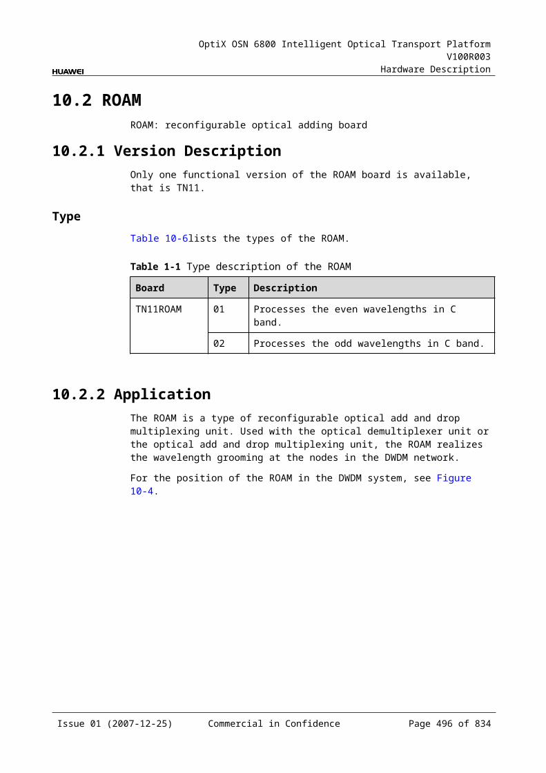
OptiX OSN 6800 Intelligent Optical Transport Platform V100R003
Hardware Description
Figure 14-1 Functional modules and signal flow of the OLP
Optical splitter
SCC
TI
RO
TO1TO2
RI1RI2
Optical switch
Control andcommunication module
Optical SplitterThe optical splitter divides a signal into two signals with the same power and sends them to the working and the protection fibers respectively.
Optical SwitchAt the receiving end, the optical switch selects the optical signal from the working or the protection path.
Control and Communication ModuleThe control and communication module realizes the control, monitoring and communications management of each functional module of the board.
The control and communication module collects the information, such as the alarms and performance events, working status, and voltage detection, of each functional module of the board and reports to the SCC.
Receiving the commands from the SCC, the control and communication module controls and coordinates the functional modules of the board in working.
Switching TypeThere are five switching types listed as follows:
Locked switching: This function is to lock the services on the working path, no matter the working or protection path is good or not.
Forced switching: This function is to force the services to work either on the working or protection path, no matter the working or protection path is good or not.
Automatic switching: If the working path is faulty while the protection path is normal, the services are switched from working path to the protection path. If both paths are faulty, the services are not switched. If the services are transmitted on the protection path, the switching status is the same. The working mode can be set to revertive or non-revertive. In revertive mode, if the working path is recovered and confirmed to be normal for a certain period, the services
Issue 01 (2007-12-25) Commercial in Confidence Page 496 of 664
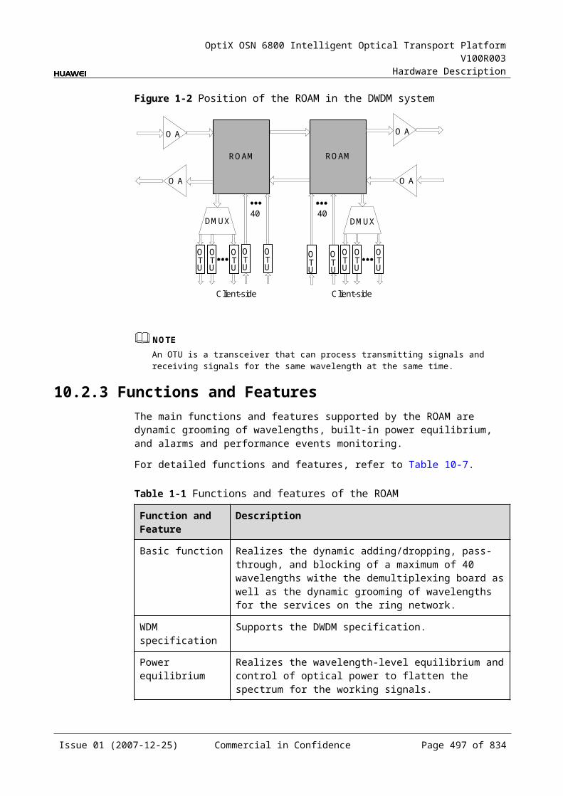
OptiX OSN 6800 Intelligent Optical Transport Platform V100R003
Hardware Description
are switched back to the working path. In non-revertive mode, even if the working path is recovered, the services remain on the protection path until a fault occurs to the protection path.
Manual switching: A manual switching command is issued to manually switch services from the working channel to the protection channel or from the latter to the former. Because the priority of manual switching is lower than that of automatic switching, the manual switching is valid only when both the working and protection channels are normal.
Clear switching: This function clears the switching state of the locked switching, forced switching, manual switching and the WTR time of automatic switching. It can not clear the switching state of automatic switching.
The priorities of the switching types from the highest to the lowest are as follows: clear switching > locked switching > forced switching > automatic switching > manual switching. If a higher level protection switching exists, lower level switching cannot be executed successfully. But if only the lower level switching exists, it can be executed successfully.
14.2.5 Front PanelThere are indicators, interfaces and laser safety label on the OLP front panel.
Appearance of the Front PanelFigure 14-10 shows the OLP front panel.
Issue 01 (2007-12-25) Commercial in Confidence Page 497 of 664
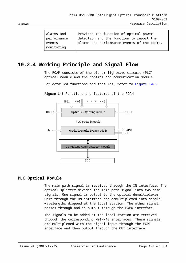
OptiX OSN 6800 Intelligent Optical Transport Platform V100R003
Hardware Description
Figure 14-1 OLP front panel
OLP
OLP
STATACTPROGSRV
LASERRADIATION
DO NOT VIEW DIRECTLYWITH OPTICALINSTRUMENTS
CLASS 1M LASERPRODUCT
TO1
RI1
TO2
RI2
RO
TI
IndicatorsThere are four indicators on the front panel.
Board hardware status indicator (STAT) – dual-colored (red, green) Service active status indicator (ACT) – green Board software status indicator (PROG) – dual-colored (red, green) Service alarm indicator (SRV) – triple-colored (red, green, yellow)
InterfacesThere are six optical interfaces on the OLP front panel. Table 14-6 lists the type and function of each interface.
Issue 01 (2007-12-25) Commercial in Confidence Page 498 of 664
OptiX OSN 6800 Intelligent Optical Transport Platform V100R003
Hardware Description
Table 14-1 Types and functions of the OLP interfaces
Interface
Type Function
TI LC Receives the line signal from the FIU board. (optical line protection)Receives one WDM-side signal. (intra-board 1+1 protection)Receives one client-side signal. (client-side 1+1 protection)
RO LC Transmits the line signal to the FIU board. (optical line protection)Transmits one WDM-side signal. (intra-board 1+1 protection)Transmits one client-side signal. (client-side 1+1 protection)
TO1/TO2 LC Transmits the working and the protection signals to the line side. (optical line protection)Transmits signals to the working and the protection multiplexer unit. (intra-board 1+1 protection)Transmits signals to the working and the protection OTU. (client-side 1+1 protection)
RI1/RI2 LC Receives the working or the protection signal from the line side. (optical line protection)Receives the signals from the working and the protection multiplexer unit. (intra-board 1+1 protection)Receives the signals from the working and protection OTU. (client-side 1+1 protection)
Laser Safety LevelThe laser safety level of the optical interface is CLASS 1M.
The maximum output optical power of each optical interface ranges from 10 dBm (10 mW) to 22.15 dBm (164 mW).
14.2.6 Valid SlotsThe OLP occupies one slot. The valid slots for the OLP are IU1–IU17.
14.2.7 NM Configuration ReferenceNM configuration reference includes the reference information needed during the configuration of boards through the T2000.
Display of Optical InterfacesThe serial numbers of the optical interfaces on the panel of the board displayed on the NM are listed in Table 14-7.
Issue 01 (2007-12-25) Commercial in Confidence Page 499 of 664
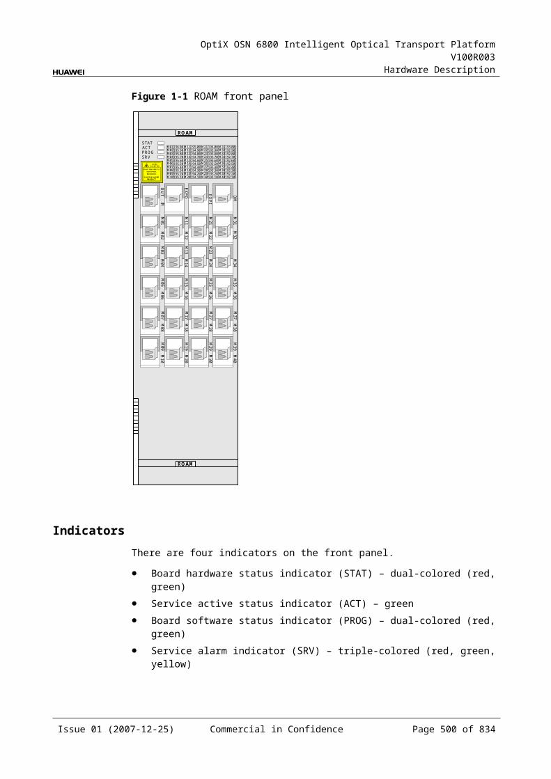
OptiX OSN 6800 Intelligent Optical Transport Platform V100R003
Hardware Description
Table 14-1 Serial numbers of the interfaces of the OLP displayed on the NM
Interface on the Panel Interface on the NM
TO11/RI11 1
TO12/RI12 2
TI/RO 3
NOTEThe number of an interface displayed on the T2000 in fact indicates a pair of physical optical interfaces, of which one is used to transmit signals and the other is used to receive signals.
Configuration ParametersThreshold of Input Power Loss (dBm)
Initial Variance Value Between Primary and Secondary Input Power (dB)
Varance Threshold Between Primary and Secondary Input Power (dB)
14.2.8 Specifications of the OLPSpecifications include optical specifications, dimensions, weight, and power consumption.
Optical SpecificationsTable 14-8 lists the optical specifications of the OLP.
Table 14-1 Optical specifications of the OLP
Interface
Item Unit
Value
TI-TO1TI-TO2
Insertion loss at the transmit end
single mode dB ≤4
multimode dB ≤4.5
RI1-RORI2-RO
Insertion loss at the receive end
single mode dB ≤1.5
multimode dB ≤2
Range of the input optical power dBm –35 to 7 (for single mode)–35 to 0 (for multi-mode)
Switching threshold of optical power difference
dB 5
Issue 01 (2007-12-25) Commercial in Confidence Page 500 of 664
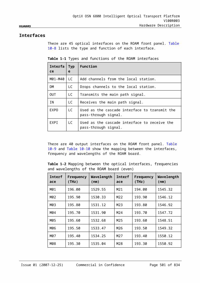
OptiX OSN 6800 Intelligent Optical Transport Platform V100R003
Hardware Description
Mechanical Specifications Dimensions of board (PCB): 245.1 mm (H) x 220 mm (D) x 2 mm (T) Dimensions of front panel: 264.6 mm (H) x 25.4 mm (W) Weight: 1.98 lb (0.9 kg)
Power Consumption The maximum power consumption at 25: 6.0 W The maximum power consumption at 55: 6.6 W
14.3 SCSSCS:sync optical channel separator unit
14.3.1 Version DescriptionOnly one functional version of the SCS board is available, that is TN11.
14.3.2 ApplicationThe SCS is a type of optical protection unit. The SCS realizes the client-side 1+1 protection and Board-level protection (extended mode).
For the position of the SCS in the WDM system, see Figure 14-11 and Figure 14-12.
Figure 14-1 Position of the SCS in the WDM system (client-side 1+1 protection) client-side MUX
DMUX
DMUX
MUX DMUX
MUX
DMUX
MUX
FIU
FIU
FIU
FIU
OTU(W)
OTU(P)
SCS
TO11RI11
TO21RI21
TO12RI12
TO22RI22
TI1RO1
TI2RO2
RI11TO11
RI21TO21
RI12TO12
RI22TO22
OTU(W)
OTU(P)
RO1TI1
RO2TI2
SCS
client-side
Issue 01 (2007-12-25) Commercial in Confidence Page 501 of 664
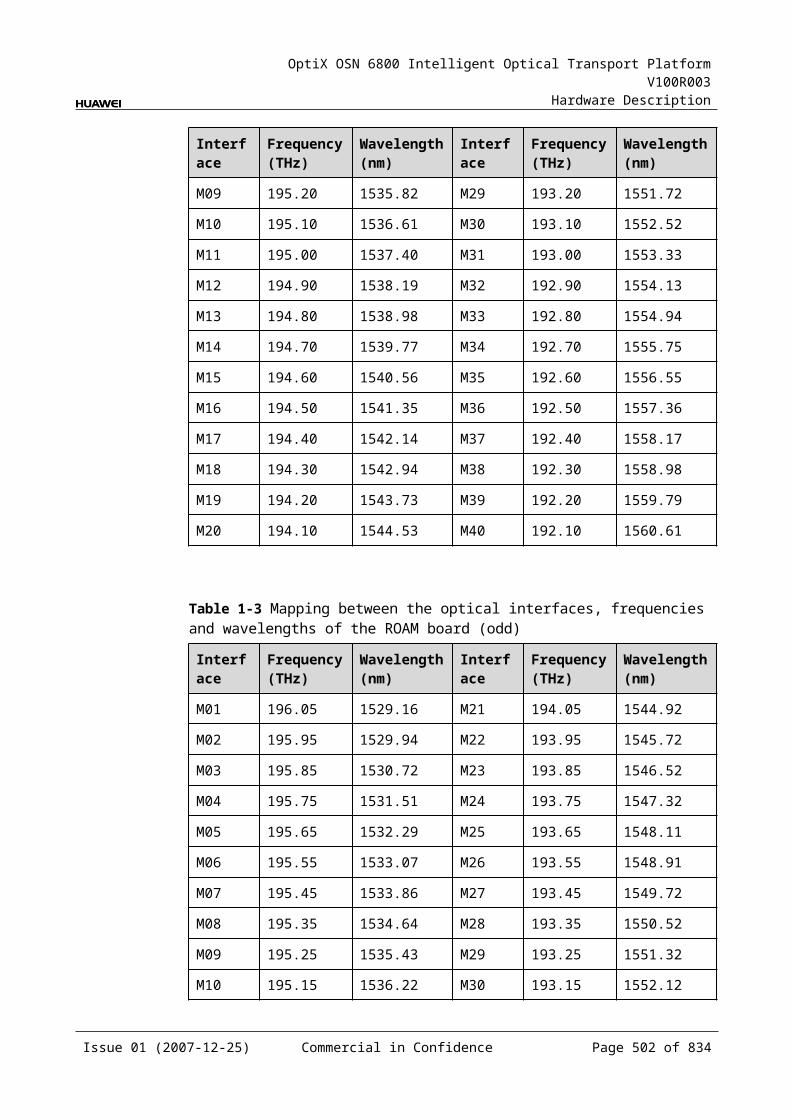
OptiX OSN 6800 Intelligent Optical Transport Platform V100R003
Hardware Description
Figure 14-2 Position of the SCS in the WDM system (board-level protection with extended mode)
FIU
FIU
L4G
TBE2
TBE1
TBE2
TBE1TBE1
TBE2
TBE1
TBE2
L4G
SCS
R1SCS
R1
OADM
OADM
14.3.3 Functions and FeaturesThe main function and feature supported by the SCS is the client-side 1+1 protection.
For detailed functions and features, refer to Table 14-9.
Table 14-1 Functions and features of the SCS
Function and Feature
Description
Basic function Receives signals from the working and the protection OTUs and realizes the client-side 1+1 protection.Receives signals from the working and the protection TBE and realizes the board-level protection (extended mode).
Protection scheme The channel protection supported by the SCS board does not need the support of protocol. Instead, the channel protection executes switching by detecting SD and SF events of the channel.
14.3.4 Working Principle and Signal FlowThe SCS consists of the optical splitter and the optical coupler.
Figure 14-13 shows the functional modules and signal flow of the SCS.
Issue 01 (2007-12-25) Commercial in Confidence Page 502 of 664
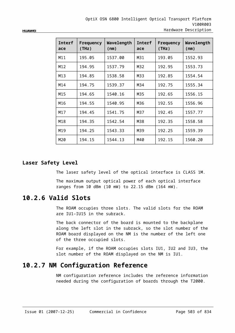
OptiX OSN 6800 Intelligent Optical Transport Platform V100R003
Hardware Description
Figure 14-1 Functional modules and signal flow of the SCS
Optical splitter
Optical coupler
Optical splitterTI1 TO11
RO1
TI2
RO2
TO12
RI11RI12
TO21TO22
RI21RI22Optical coupler
Optical SplitterThe optical splitter divides a signal into two signals with the same power and sends them to the working and the protection OTU respectively.
Optical CouplerAt the receiving end, the optical coupler receives an optical signal sent from the working or the protection OTU and sends the signal to the client-side equipment.
Switching TypeThere are five switching types listed as follows:
Locked switching: This function is to lock the services on the working path, no matter the working or protection path is good or not.
Forced switching: This function is to force the services to work either on the working or protection path, no matter the working or protection path is good or not.
Automatic switching: If the working path is faulty while the protection path is normal, the services are switched from working path to the protection path. If both paths are faulty, the services are not switched. If the services are transmitted on the protection path, the switching status is the same. The working mode can be set to revertive or non-revertive. In revertive mode, if the working path is recovered and confirmed to be normal for a certain period, the services are switched back to the working path. In non-revertive mode, even if the working path is recovered, the services remain on the protection path until a fault occurs to the protection path.
Manual switching: A manual switching command is issued to manually switch services from the working channel to the protection channel or from the latter to the former. Because the priority of manual switching is lower than that of automatic switching, the manual switching is valid only when both the working and protection channels are normal.
Clear switching: This function clears the switching state of the locked switching, forced switching, manual switching and the WTR time of automatic switching. It can not clear the switching state of automatic switching.
The priorities of the switching types from the highest to the lowest are as follows: clear switching > locked switching > forced switching > automatic switching > manual switching. If a higher level protection switching exists, lower level switching cannot be
Issue 01 (2007-12-25) Commercial in Confidence Page 503 of 664
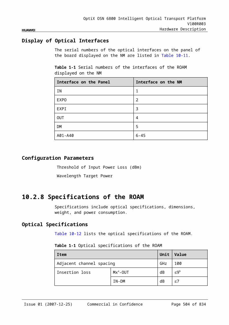
OptiX OSN 6800 Intelligent Optical Transport Platform V100R003
Hardware Description
executed successfully. But if only the lower level switching exists, it can be executed successfully.
14.3.5 Front PanelThere are indicators, interfaces and laser safety label on the SCS front panel.
Appearance of the Front PanelFigure 14-14 shows the SCS front panel.
Figure 14-1 SCS front panel
SCS
SCS
CLASS 1LASER
PRODUCT
TO11
TO12
RI12
TO21
RI21
TO22
RI22
RO
1TI1
RO
2TI2
RI11
STAT
IndicatorsThere is one indicator on the front panel.
Board hardware status indicator (STAT) – dual-colored (red, green)
Issue 01 (2007-12-25) Commercial in Confidence Page 504 of 664
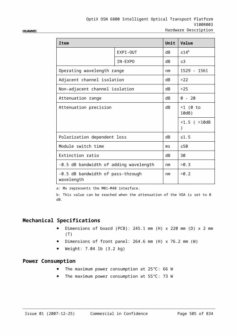
OptiX OSN 6800 Intelligent Optical Transport Platform V100R003
Hardware Description
InterfacesThere are 12 optical interfaces on the SCS front panel. Table 14-10 lists the type and function of each interface.
Table 14-1 Types and functions of the SCS interfaces
Interface Type
Function
TI1/TI2 LC Receives the first/second channel of client-side signals.
RO1/RO2 LC Transmits the first/second channel of client-side signals.
TO11/TO12
LC Transmits the first channel of signals to the working and protection OTU.
TO21/TO22
LC Transmits the second channel of signals to the working and the protection OTU.
RI11/RI12 LC Receives the first channel of signals from the working and protection OTU.
RI21/RI22 LC Receives the second channel of signals from the working and protection OTU.
Laser Safety LevelThe laser safety level of the optical interface is CLASS 1.
The maximum output optical power of each optical interface is lower than 10 dBm (10 mW).
14.3.6 Valid SlotsThe SCS occupies one slot. The valid slots for the SCS are IU1–IU17.
14.3.7 NM Configuration ReferenceNM configuration reference includes the reference information needed during the configuration of boards through the T2000.
Display of Optical InterfacesThe serial numbers of the optical interfaces on the panel of the board displayed on the NM are listed in Table 14-11.
Table 14-1 Serial numbers of the interfaces of the SCS displayed on the NM
Interface on the Panel Interface on the NM
TI1/RO1 1
TO11/RI11 2
TO12/RI12 3
Issue 01 (2007-12-25) Commercial in Confidence Page 505 of 664
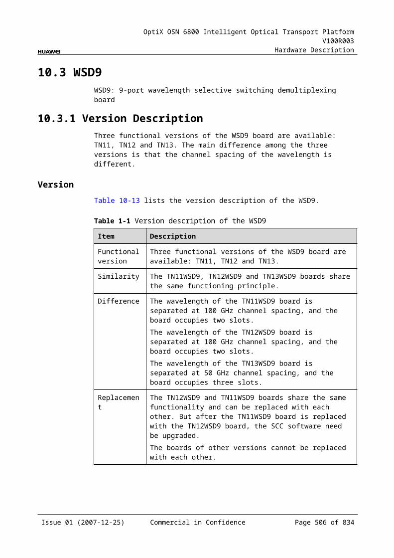
OptiX OSN 6800 Intelligent Optical Transport Platform V100R003
Hardware Description
Interface on the Panel Interface on the NM
TI2/RO2 4
TO21/RI21 5
TO22/RI22 6
NOTEThe number of an interface displayed on the T2000 in fact indicates a pair of physical optical interfaces, of which one is used to transmit signals and the other is used to receive signals.
14.3.8 Specifications of the SCSSpecifications include optical specifications, dimensions, weight, and power consumption.
Optical SpecificationsTable 14-12 lists the optical specifications of the SCS.
Table 14-1 Optical specifications of the SCS
Interface Item Unit Value
TI1-TO11TI1-TO21TI2-TO21TI2-TO22
Splitting insertion loss
single mode dB ≤4
multimode dB ≤4.5
RI11-RO1RI12-RO1RI21-RO2RI22-RO2
Coupling insertion loss
single mode dB ≤4
multimode dB ≤4.5
Mechanical Specifications Dimensions of board (PCB): 245.1 mm (H) x 220 mm (D) x 2 mm (T) Dimensions of front panel: 264.6 mm (H) x 25.4 mm (W) Weight:1.76 lb (0.8 kg)
Power Consumption The maximum power consumption at 25: 0.2 W The maximum power consumption at 55: 0.3 W
Issue 01 (2007-12-25) Commercial in Confidence Page 506 of 664
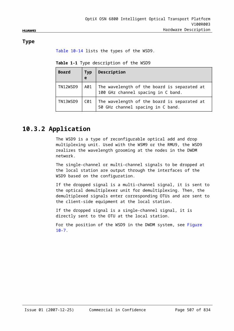
OptiX OSN 6800 Intelligent Optical Transport Platform V100R003
Hardware Description
15 Spectrum Analyzer Unit
15.1 MCA4MCA4: 4-channel spectrum analyzer unit
15.1.1 Version DescriptionOnly one functional version of the MCA4 board is available, that is TN11.
15.1.2 ApplicationThe MCA4 is a type of spectrum analyzer unit. The MCA4 supports spectral analysis for four channels.
For the position of the MCA4 in the WDM system, see Figure 15-1.
Figure 15-1 Position of the MCA4 in the WDM system
OTUOAU OAU
OAUOAU
MUX
DMUX
OTU
OTU
OTU
DMUX
MUX
OTU
OTU
OTU
OTU
MCA4 MCA4
15.1.3 Functions and FeaturesThe main functions and features supported by the MCA4 are spectral analysis, detection and APE.
For detailed functions and features, refer to Table 15-1.
Issue 01 (2007-12-25) Commercial in Confidence Page 507 of 664
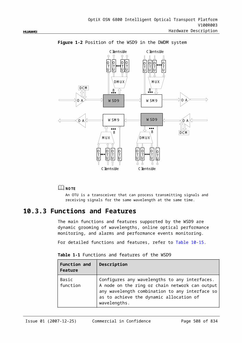
OptiX OSN 6800 Intelligent Optical Transport Platform V100R003
Hardware Description
Table 15-1 Functions and features of the MCA4
Function and Feature
Description
Basic function Provides the spectral analysis for four channels.
Detection function Supports the following detection functions and reports to the SCC. Optical power of the channel Central wavelength Optical signal-to-noise ratio Number of wavelengths in the main optical path
APE function Realizes the APE function in cooperation with other boards.Detects the optical power of each channel.
15.1.4 Working Principle and Signal FlowThe MCA4 consists of the optical switch, spectral analysis module and the control and communication module.
Figure 15-2 shows the functional modules and signal flow of the MCA4.
Figure 15-1 Functional modules and signal flow of the MCA4
Opticalswitch
Control andcommunication module
SCC
Spectralanalysismodule
IN1
IN2
IN3
IN4
Optical SwitchThrough the optical switch, one of the four input signals is selected to be sent to the spectral analysis module.
Spectral Analysis ModuleThe spectral analysis module performs the spectral analysis for the optical signal sent through the optical switch and obtains the data such as optical power, OSNR, number of wavelengths and central wavelength. The data is sent to the CPU for processing. The CPU reports the results to the SCC.
Issue 01 (2007-12-25) Commercial in Confidence Page 508 of 664
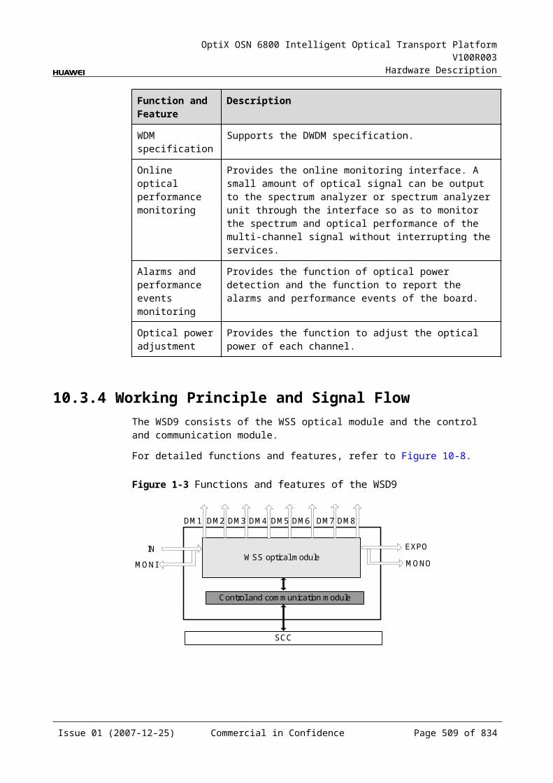
OptiX OSN 6800 Intelligent Optical Transport Platform V100R003
Hardware Description
Control and Communication ModuleThe control and communication module realizes the control, monitoring and communications management of each functional module of the board.
The control and communication module collects the information, such as the alarms and performance events, working status, and voltage detection, of each functional module of the board and reports to the SCC.
Receiving the commands from the SCC, the control and communication module controls and coordinates the functional modules of the board in working.
15.1.5 Front PanelThere are indicators and interfaces on the MCA4 front panel.
Appearance of the Front PanelFigure 15-3 shows the MCA4 front panel.
Figure 15-1 MCA4 front panel
MCA4
MCA4
STATACTPROGSRV
IN1
IN2
IN3
IN4
Issue 01 (2007-12-25) Commercial in Confidence Page 509 of 664
OptiX OSN 6800 Intelligent Optical Transport Platform V100R003
Hardware Description
IndicatorsThere are four indicators on the front panel.
Board hardware status indicator (STAT) – dual-colored (red, green) Service active status indicator (ACT) – green Board software status indicator (PROG) – dual-colored (red, green) Service alarm indicator (SRV) – triple-colored (red, green, yellow)
InterfacesThere are four optical interfaces on the MCA4 front panel.Table 15-2 lists the type and function of each interface.
Table 15-1 Types and functions of the MCA4 interfaces
Interface
Type
Function
IN1–IN4 LC Connected to the "MON" interfaces of other boards to receive optical signals for analysis. The interfaces can be connected to four "MON" interfaces at the same time.
15.1.6 Valid SlotsThe MCA4 occupies two slots. The valid slots for the MCA4 are IU1–IU16 in the subrack.
The back connector of the board is mounted to the backplane along the left slot of the two occupied slots in the subrack, so the slot number of the MCA4 board displayed on the NM is the number of the left slot.
For example, if the MCA4 occupies slots IU1 and IU2, the slot number of the MCA4 displayed on the NM is IU1.
15.1.7 Characteristic Code for the MCA4The characteristic code for the MCA4 consists of one character, indicating the band of the optical signals processed by the board.
The detailed information of the characteristic code is given in Table 15-3.
Table 15-1 Characteristic code for the MCA4
Code Meaning
Description
The first character
Band Indicates the band of the optical signals processed by the board. The value C represents C band. The value L represents L band.
For example, the characteristic code for the TN11MCA4 is C, indicating C band.
Issue 01 (2007-12-25) Commercial in Confidence Page 510 of 664
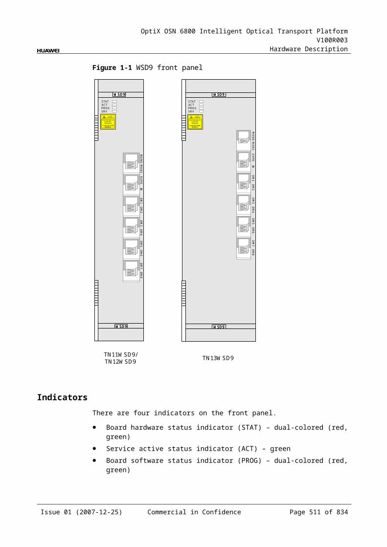
OptiX OSN 6800 Intelligent Optical Transport Platform V100R003
Hardware Description
15.1.8 NM Configuration ReferenceNM configuration reference includes the reference information needed during the configuration of boards through the T2000.
Display of Optical InterfacesThe serial numbers of the optical interfaces on the panel of the board displayed on the NM are listed in Table 15-4.
Table 15-1 Serial numbers of the interfaces of the MCA4 displayed on the NM
Interface on the Panel Interface on the NM
IN1–IN4 1–4
Configuration ParametersOptical Monitoring
Monitor Interval (min.)
Wavelength Monitor Status
15.1.9 Specifications of the MCA4Specifications include optical specifications, dimensions, weight, and power consumption.
Optical SpecificationsTable 15-5 lists the optical specifications of the MCA4.
Table 15-1 Optical specifications of the MCA4
Item Unit Value
Operating wavelength range nm 1529–1561
Detect range for single channel optical power dBm –30 to –10
Detect accuracy for optical power dBm ±1.5
Detect accuracy for OSNR (The detect range for signal-to-noise ratio is 13 dB to 23 dB, and the wavelength spacing is 100 GHz.)
dB ±1.5 (OSNR: 13 to 19)±2 (OSNR: 19 to 23)
Detect accuracy for central wavelength nm ±0.1
Numbers of optical interface pcs 4
Issue 01 (2007-12-25) Commercial in Confidence Page 511 of 664
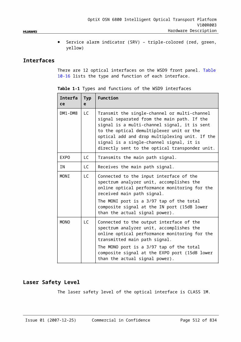
OptiX OSN 6800 Intelligent Optical Transport Platform V100R003
Hardware Description
Mechanical Specifications Dimensions of board (PCB): 245.1 mm (H) x 220 mm (D) x 2 mm (T) Dimensions of front panel: 264.6 mm (H) x 50.8 mm (W) Weight: 4.18 lb (1.9 kg)
Power Consumption The maximum power consumption at 25: 16.0 W The maximum power consumption at 55: 17.6 W
15.2 MCA8MCA8: 8-channel spectrum analyzer unit
15.2.1 Version DescriptionOnly one functional version of the MCA8 board is available, that is TN11.
15.2.2 ApplicationThe MCA8 is a type of Spectrum Analyzer unit. The MCA8 supports spectral analysis for eight channels.
For the position of the MCA8 in the WDM system, see Figure 15-4.
Figure 15-1 Position of the MCA8 in the WDM system
OTUOAU OAU
OAUOAU
MUX
DMUX
OTU
OTU
OTU
DMUX
MUX
OTU
OTU
OTU
OTU
MCA8 MCA8
15.2.3 Functions and FeaturesThe main functions and features supported by the MCA8 are spectral analysis, detection and APE.
For detailed functions and features, refer to Table 15-6.
Issue 01 (2007-12-25) Commercial in Confidence Page 512 of 664
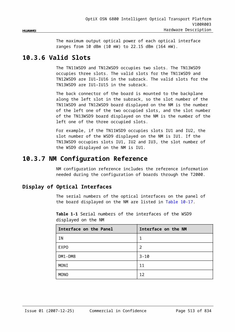
OptiX OSN 6800 Intelligent Optical Transport Platform V100R003
Hardware Description
Table 15-1 Functions and features of the MCA8
Function and Feature
Description
Basic function Provides the spectral analysis for four channels.
Detection function Supports the following detection functions and reports to the SCC. Optical power of the channel Central wavelength Optical signal-to-noise ratio Number of wavelengths in the main optical path
APE function Realizes the APE function in cooperation with other boards.Detects the optical power of each channel.
15.2.4 Working Principle and Signal FlowThe MCA8 consists of the optical switch, spectral analysis module and the control and communication module.
Figure 15-5 shows the functional modules and signal flow of the MCA8.
Figure 15-1 Functional modules and signal flow of the MCA8
Opticalswitch
Control andcommunication module
SCC
Spectralanalysismodule
IN1
IN2
IN8
Optical SwitchThrough the optical switch, one of the eight input signals is selected to be sent to the spectral analysis module.
Spectral Analysis ModuleThe spectral analysis module performs the spectral analysis for the optical signal sent through the optical switch and obtains the data such as optical power, OSNR, number of wavelengths and central wavelength. The data is sent to the CPU for processing. The CPU reports the results to the SCC.
Issue 01 (2007-12-25) Commercial in Confidence Page 513 of 664
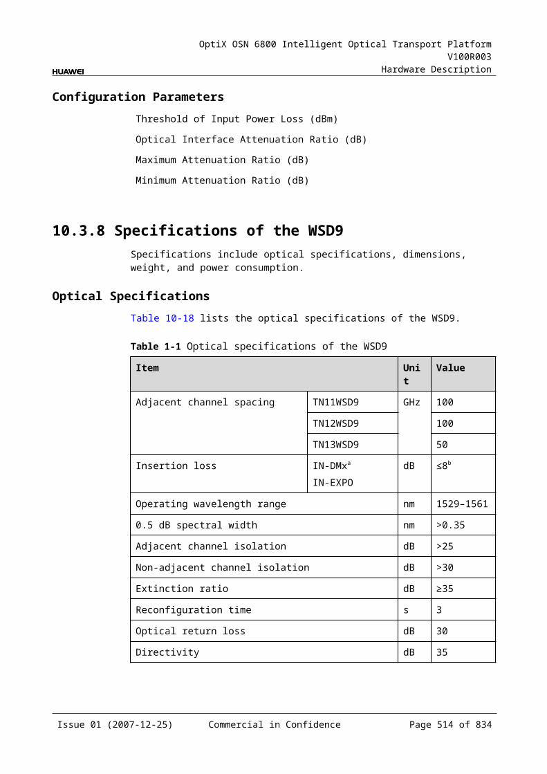
OptiX OSN 6800 Intelligent Optical Transport Platform V100R003
Hardware Description
Control and Communication ModuleThe control and communication module realizes the control, monitoring and communications management of each functional module of the board.
The control and communication module collects the information, such as the alarms and performance events, working status, and voltage detection, of each functional module of the board and reports to the SCC.
Receiving the commands from the SCC, the control and communication module controls and coordinates the functional modules of the board in working.
15.2.5 Front PanelThere are indicators and interfaces on the MCA8 front panel.
Appearance of the Front PanelFigure 15-6 shows the MCA8 front panel.
Figure 15-1 MCA8 front panel
MCA8
MCA8
STATACTPROGSRV
IN3
IN4
IN5
IN6
IN1
IN2
IN7
IN8
Issue 01 (2007-12-25) Commercial in Confidence Page 514 of 664
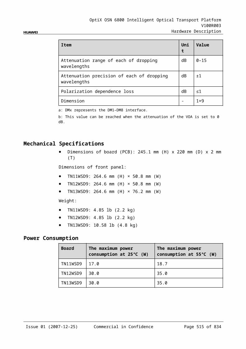
OptiX OSN 6800 Intelligent Optical Transport Platform V100R003
Hardware Description
IndicatorsThere are four indicators on the front panel.
Board hardware status indicator (STAT) – dual-colored (red, green) Service active status indicator (ACT) – green Board software status indicator (PROG) – dual-colored (red, green) Service alarm indicator (SRV) – triple-colored (red, green, yellow)
InterfacesThere are eight optical interfaces on the MCA8 front panel.Table 15-7 lists the type and function of each interface.
Table 15-1 Types and functions of the MCA8 interfaces
Interface
Type
Function
IN1–IN8 LC Connected to the "MON" interfaces of other boards to receive optical signals for analysis. The interfaces can be connected to eight "MON" interfaces at the same time.
15.2.6 Valid SlotsThe MCA8 occupies two slots. The valid slots for the MCA8 are IU1–IU16.
The back connector of the board is mounted to the backplane along the left slot of the two occupied slots in the subrack, so the slot number of the MCA8 board displayed on the NM is the number of the left slot.
For example, if the MCA8 occupies slots IU1 and IU2, the slot number of the MCA8 displayed on the NM is IU1.
15.2.7 Characteristic Code for the MCA8The characteristic code for the MCA8 consists of one character, indicating the band of the optical signals processed by the board.
The detailed information of the characteristic code is given in Table 15-8.
Table 15-1 Characteristic code for the MCA8
Code Meaning
Description
The first character
Band Indicates the band of the optical signals processed by the board. The value C represents C band.The value L represents L band.
For example, the characteristic code for the TN11MCA8 is C, indicating C band.
Issue 01 (2007-12-25) Commercial in Confidence Page 515 of 664
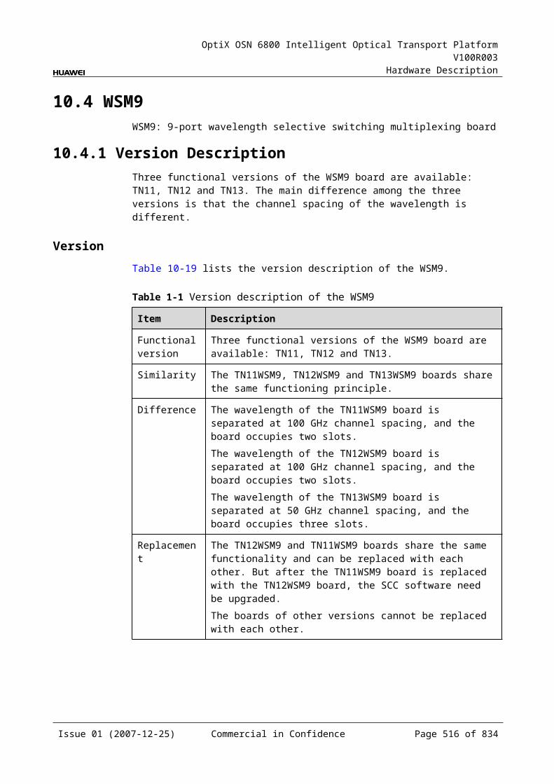
OptiX OSN 6800 Intelligent Optical Transport Platform V100R003
Hardware Description
15.2.8 NM Configuration ReferenceNM configuration reference includes the reference information needed during the configuration of boards through the T2000.
Display of Optical InterfacesThe serial numbers of the optical interfaces on the panel of the board displayed on the NM are listed in Table 15-9.
Table 15-1 Serial numbers of the interfaces of the MCA8 displayed on the NM
Interface on the Panel Interface on the NM
IN1–IN8 1–8
Configuration ParametersOptical Monitoring
Monitor Interval (min.)
Wavelength Monitor Status
15.2.9 Specifications of the MCA8Specifications include optical specifications, dimensions, weight, and power consumption.
Optical SpecificationsTable 15-10 lists the optical specifications of the MCA8.
Table 15-1 Optical specifications of the MCA8
Item Unit Value
Operating wavelength range nm 1529–1561
Detect range for single channel optical power dBm –30 to –10
Detect accuracy for optical power dBm ±1.5
Detect accuracy for OSNR (The detect range for signal-to-noise ratio is 13 dB to 23 dB, and the wavelength spacing is 100 GHz.)
dB ±1.5 (OSNR: 13 to 19)±2 (OSNR: 19 to 23)
Detect accuracy for central wavelength nm ±0.1
Numbers of optical interface pcs 8
Issue 01 (2007-12-25) Commercial in Confidence Page 516 of 664
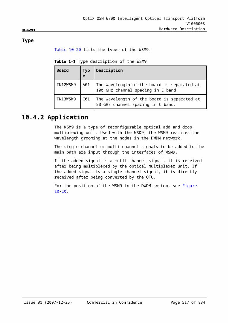
OptiX OSN 6800 Intelligent Optical Transport Platform V100R003
Hardware Description
Mechanical Specifications Dimensions of board (PCB): 245.1 mm (H) x 220 mm (D) x 2 mm (T) Dimensions of front panel: 264.6 mm (H) x 50.8 mm (W) Weight: 4.18 lb (1.9 kg)
Power Consumption The maximum power consumption at 25: 17.0 W The maximum power consumption at 55: 18.7 W
15.3 WMUWMU: Wavelength Monitored Unit
15.3.1 Version DescriptionOnly one functional version of the WMU board is available, that is TN11.
15.3.2 ApplicationThe WMU board realizes the wavelength monitoring in the system with wavelengths at 50 GHz channel spacing.
For the position of the WMU in the WDM system, see Figure 15-7.
Figure 15-1 Position of the WMU in the WDM system
ITL
DMUX
DMUX
MUX
OA
OA
OTU
TU
OTU
TU
O O
MUX
MUX
DMUX
DMUX
ITL
OA
FIU
OA
OSC
WMU
MUX
FIU
WMU
Issue 01 (2007-12-25) Commercial in Confidence Page 517 of 664
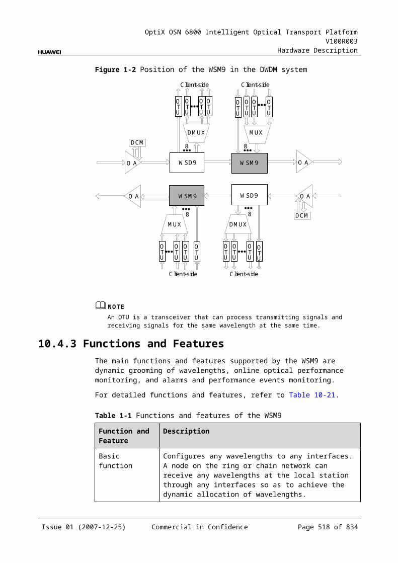
OptiX OSN 6800 Intelligent Optical Transport Platform V100R003
Hardware Description
NOTEOne WMU board can realize the centralized wavelength monitoring in two directions. Figure 15-7 shows the WMU in two places. Actually it refers to the same one WMU board.
15.3.3 Functions and FeaturesThe WMU board supports the centralized monitoring of the wavelengths on the OTU board at the transmit end in the system with wavelengths at 50 GHz channel spacing.
For detailed functions and features, refer to Table 15-11.
Table 15-1 Functions and features of the WMU
Function and Feature
Description
Basic function The board supports the centralized monitoring of the wavelengths on the OTU board at the transmit end in the system with wavelengths at 50 GHz channel spacing; and performs centralized monitoring of the wavelengths on the OTU at the transmit end in a transmission system. In addition, the board can monitor the wavelengths in two different optical transmit directions.
Optical switch The optical switch is used to select the optical signals from the desired transmission direction to monitor.
15.3.4 Working Principle and Signal FlowThe WMU consists of the optical switch, wavelength monitoring module and the control and communication module.
Figure 15-8 shows the functional modules and signal flow of the WMU.
Figure 15-1 Functional modules and signal flow of the WMU
SCC
IN1
IN2
Opticalswitch
Wavelengthmonitoring
module
Control andcommunicate module
Issue 01 (2007-12-25) Commercial in Confidence Page 518 of 664
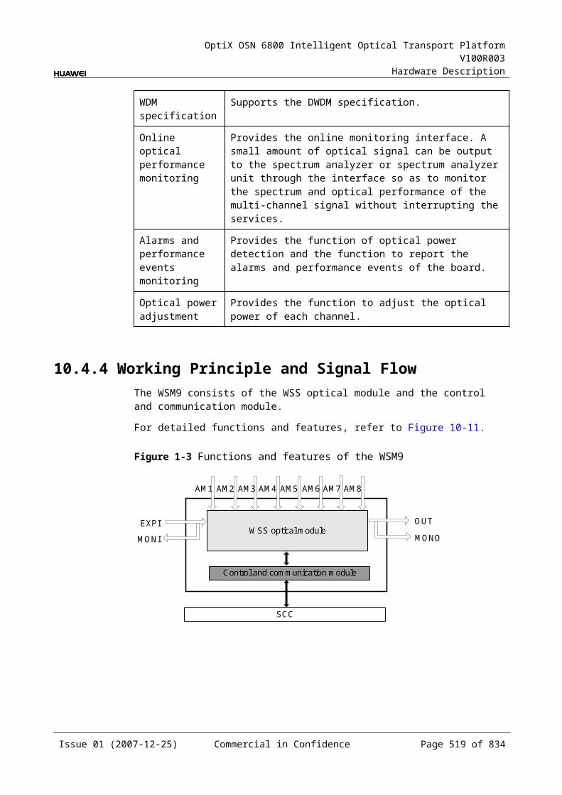
OptiX OSN 6800 Intelligent Optical Transport Platform V100R003
Hardware Description
Optical SwitchThrough the optical switch, one of the two input signals is selected to be sent to the wavelength monitoring module.
Wavelength Monitoring ModuleDetects one multiplexed signal from the optical switch, and reports the wavelength and optical power information to the SCC board.
Control and Communication ModuleThe control and communication module realizes the control, monitoring and communications management of each functional module of the board.
The control and communication module collects the information, such as the alarms and performance events, working status, and voltage detection, of each functional module of the board and reports to the SCC.
Receiving the commands from the SCC, the control and communication module controls and coordinates the functional modules of the board in working.
15.3.5 Front PanelThere are indicators and interfaces on the WMU front panel.
Appearance of the Front PanelFigure 15-9 shows the WMU front panel.
Issue 01 (2007-12-25) Commercial in Confidence Page 519 of 664
OptiX OSN 6800 Intelligent Optical Transport Platform V100R003
Hardware Description
Figure 15-1 WMU front panel
WMU
WMU
STATACTPROGSRV
IN1
IN2
IndicatorsThere are four indicators on the front panel.
Board hardware status indicator (STAT) – dual-colored (red, green) Service active status indicator (ACT) – green Board software status indicator (PROG) – dual-colored (red, green) Service alarm indicator (SRV) – triple-colored (red, green, yellow)
InterfacesThere are two optical interfaces on the WMU front panel.Table 15-12 lists the type and function of each interface.
Issue 01 (2007-12-25) Commercial in Confidence Page 520 of 664
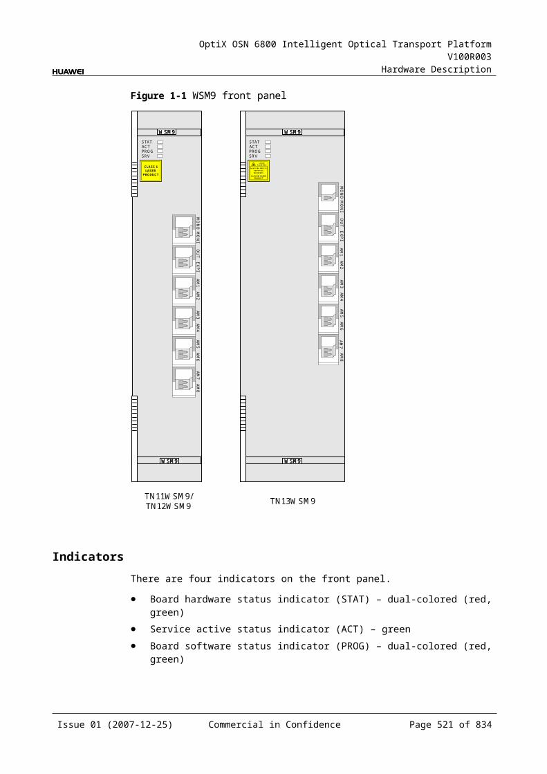
OptiX OSN 6800 Intelligent Optical Transport Platform V100R003
Hardware Description
Table 15-1 Types and functions of the WMU interfaces
Interface
Type
Function
IN1/IN2 LC Connects to the MON optical interface on the optical amplifier boards in two different transmit directions, respectively, for centralized wavelength monitoring.
15.3.6 Valid SlotsThe WMU occupies one slot. The valid slots for the WMU are IU1–IU17 in the subrack.
15.3.7 NM Configuration ReferenceNM configuration reference includes the reference information needed during the configuration of boards through the T2000.
Display of Optical InterfacesThe serial numbers of the optical interfaces on the panel of the board displayed on the NM are listed in Table 15-13.
Table 15-1 Serial numbers of the interfaces of the WMU displayed on the NM
Interface on the Panel Interface on the NM
IN1 1
IN2 2
15.3.8 Specifications of the WMUSpecifications include optical specifications, dimensions, weight, and power consumption.
Optical Specifications
Table 15-1 Optical specifications of the WMU
Item Unit
Value
Operating wavelength range nm 1529–1561
Adjacent channel spacing - Supports the monitoring to system wavelengths with spacing of 50 GHz.
Per-channel input optical power range
dBm -36 to -16
Issue 01 (2007-12-25) Commercial in Confidence Page 521 of 664
OptiX OSN 6800 Intelligent Optical Transport Platform V100R003
Hardware Description
Item Unit
Value
Detect accuracy for central wavelength
GHz <2.5
Detect accuracy for single channel optical power
dB <2
Detect range for Central wavelength offset
GHz -10 to 10
Mechanical Specifications Dimensions of board (PCB): 245.1 mm (H) x 220 mm (D) x 2 mm (T) Dimensions of front panel: 264.6 mm (H) x 25.4 mm (W) Weight: 4.19 lb (1.9kg)
Power Consumption The maximum power consumption at 25: 12W The maximum power consumption at 55: 15W
Issue 01 (2007-12-25) Commercial in Confidence Page 522 of 664
OptiX OSN 6800 Intelligent Optical Transport Platform V100R003
Hardware Description
16 Variable Optical Attenuator Unit
16.1 VA1VA1: 1-channel variable optical attenuator unit
16.1.1 Version DescriptionTwo functional versions of the VA1 board are available: TN11 and TN12. There is no difference between the two versions in terms of functionality.
Table 16-1lists the version description of the VA1.
Table 16-1 Version description of the VA1
Item Description
Functional version Two functional versions of the VA1 board are available: TN11 and TN12.
Similarity The TN12VA1 works in the same way as the TN11VA1.
Difference None
Replacement The TN11VA1 and TN12VA1 boards share the same functionality and can be replaced with each other. But after the TN11VA1 is replaced with the TN12VA1, the SCC software need be upgraded.
16.1.2 ApplicationThe VA1 is a type of variable optical attenuator unit. The VA1 realizes the power adjustment for one signal.
For the position of the VA1 in the WDM system, see Figure 16-1.
Issue 01 (2007-12-25) Commercial in Confidence Page 523 of 664
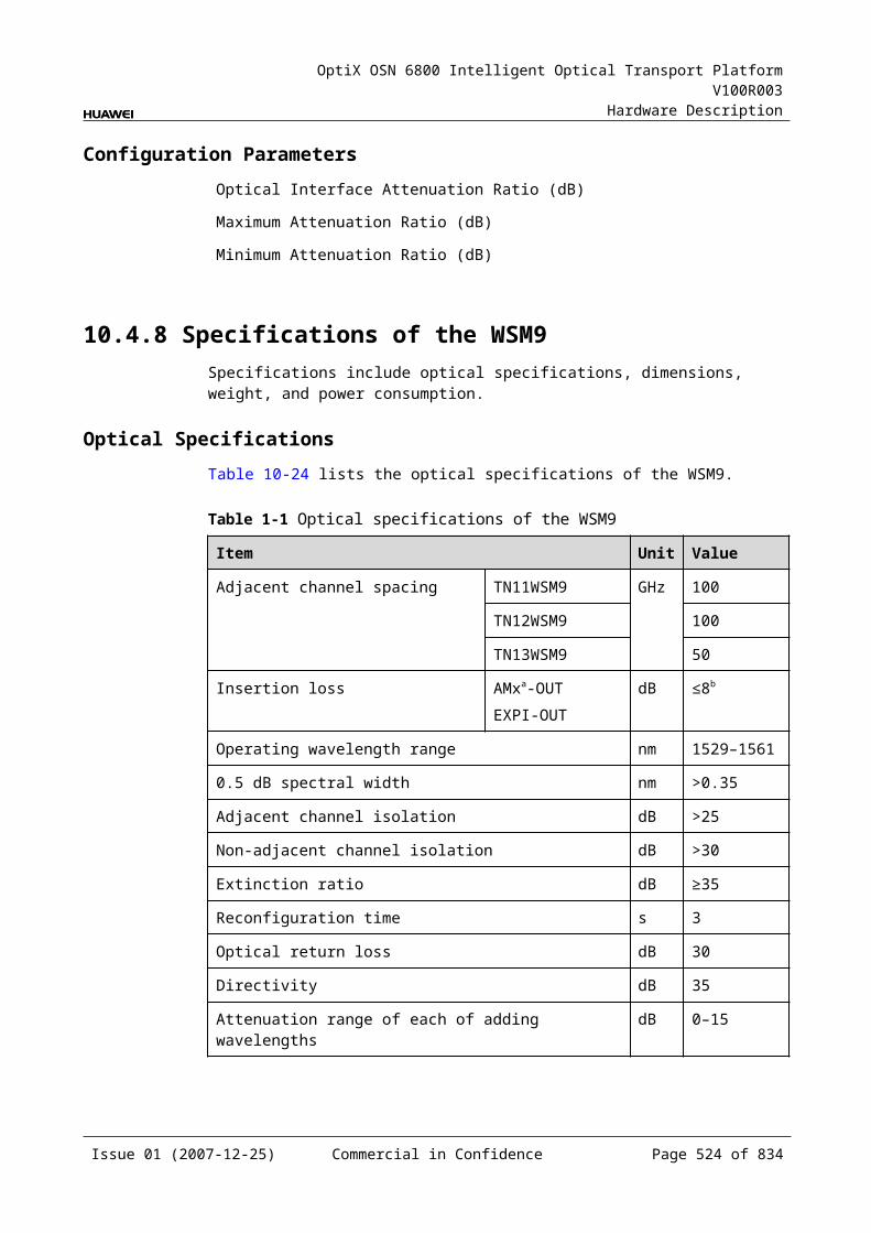
OptiX OSN 6800 Intelligent Optical Transport Platform V100R003
Hardware Description
Figure 16-1 Position of the VA1 in the WDM system
MR2
OA OA
OA OA
MR2
OTU OTU
VA1
OTU OTU
VA1
VA1
VA1
VA1
VA1 VA1 VA1
16.1.3 Functions and FeaturesThe main functions and features supported by the VA1 are optical power adjustment, alarm monitoring and power-off protection.
For detailed functions and features, refer to Table 16-2
Table 16-1 Functions and features of the VA1
Function and Feature
Description
Basic function
Adjusts the optical power of one optical signal according to the control command sent by the SCC.
Alarm monitoring
Detects the input optical power, attenuation and reports various alarms to the SCC.
Power-off protection
Supports the power-off protection to avoid the damages caused by too high optical power to the corresponding optical receiver when the power supply recovers.When there is no power supplied to the VA1, the attenuation of the VA1 changes to its maximum value automatically. Shortly after the power supply recovers, the attenuation of the VA1 still remains its maximum value. When the system begins to work normally, the attenuation automatically changes back to the value set last time.
Attenuation range
The variable attenuation ranges between 1.5 dB and 21.5 dB. The resolution is 0.1 dB.
16.1.4 Working Principle and Signal FlowThe VA1 consists of a variable optical attenuator and the control and communication module.
Figure 16-2 shows the functional modules and signal flow of the VA1.
Issue 01 (2007-12-25) Commercial in Confidence Page 524 of 664
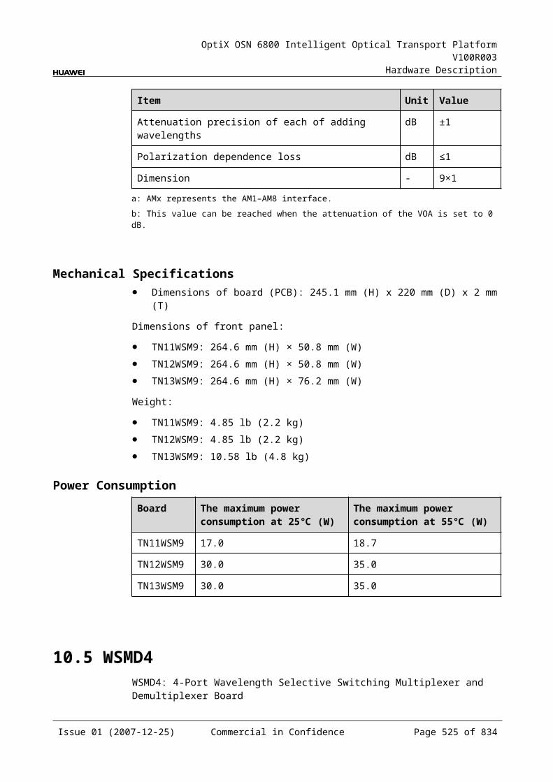
OptiX OSN 6800 Intelligent Optical Transport Platform V100R003
Hardware Description
Figure 16-1 Functional modules and signal flow of the VA1
SCC
IN OUTVariable optical attenuator
Control andcommunication module
The function of the VA1 is to adjust the optical power of the input signals according to the command sent by the SCC to meet the system requirement.
Variable Optical AttenuatorThe variable optical attenuator adjusts the optical power of the input signal.
Control and Communication ModuleThe control and communication module realizes the control, monitoring and communications management of each functional module of the board.
The control and communication module collects the information, such as the alarms and performance events, working status, and voltage detection, of each functional module of the board and reports to the SCC.
Receiving the commands from the SCC, the control and communication module controls and coordinates the functional modules of the board in working.
16.1.5 Front PanelThere are indicators, interfaces and laser safety label on the VA1 front panel.
Appearance of the Front PanelFigure 16-3 shows the VA1 front panel.
Issue 01 (2007-12-25) Commercial in Confidence Page 525 of 664
OptiX OSN 6800 Intelligent Optical Transport Platform V100R003
Hardware Description
Figure 16-1 VA1 front panel
VA1
VA1
STATACTPROGSRV
LASERRADIATION
DO NOT VIEW DIRECTLYWITH OPTICALINSTRUMENTS
CLASS 1M LASERPRODUCT
OU
TIN
IndicatorsThere are four indicators on the front panel.
Board hardware status indicator (STAT) – dual-colored (red, green) Service active status indicator (ACT) – green Board software status indicator (PROG) – dual-colored (red, green) Service alarm indicator (SRV) – triple-colored (red, green, yellow)
InterfacesThere are two optical interfaces on the VA1 front panel. Table 16-3 lists the type and function of each interface.
Issue 01 (2007-12-25) Commercial in Confidence Page 526 of 664
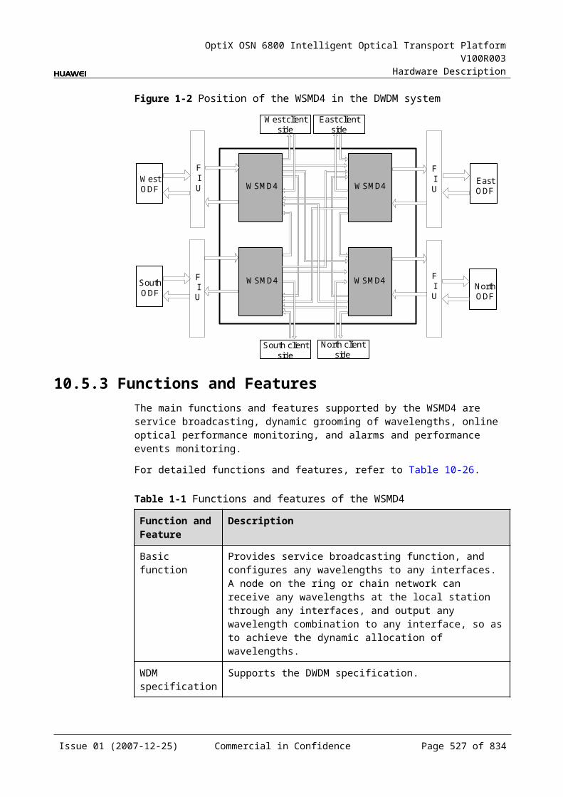
OptiX OSN 6800 Intelligent Optical Transport Platform V100R003
Hardware Description
Table 16-1 Types and functions of the VA1 interfaces
Interface Type Function
IN LC Receives the optical signals to be adjusted.
OUT LC Transmits the adjusted optical signals.
Laser Safety LevelThe laser safety level of the optical interface is CLASS 1M.
The maximum output optical power of each optical interface ranges from 10 dBm (10 mW) to 22.15 dBm (164 mW).
16.1.6 Valid SlotsThe VA1 occupies one slot in a subrack. The valid slots for the VA1 are IU1-IU17.
16.1.7 Characteristic Code for the VA1The characteristic code for the VA1 consists of three digits, indicating the maximum attenuation of the optical signals processed by the board.
The detailed information of the characteristic code is given in Table 16-4.
Table 16-1 Characteristic code for the VA1
Code Meaning Description
The first to the third digits Attenuation value Indicate the maximum attenuation.
For example, the characteristic code for the TN11VA1 is 21.5, indicating that the maximum attenuation value is 21.5 dB.
16.1.8 NM Configuration ReferenceNM configuration reference includes the reference information needed during the configuration of boards through the T2000.
Display of Optical InterfacesThe serial numbers of the optical interfaces on the panel of the board displayed on the NM are listed in Table 16-5.
Table 16-1 Serial numbers of the interfaces of the VA1 displayed on the NM
Interface on the Panel Interface on the NM
IN/OUT 1
Issue 01 (2007-12-25) Commercial in Confidence Page 527 of 664
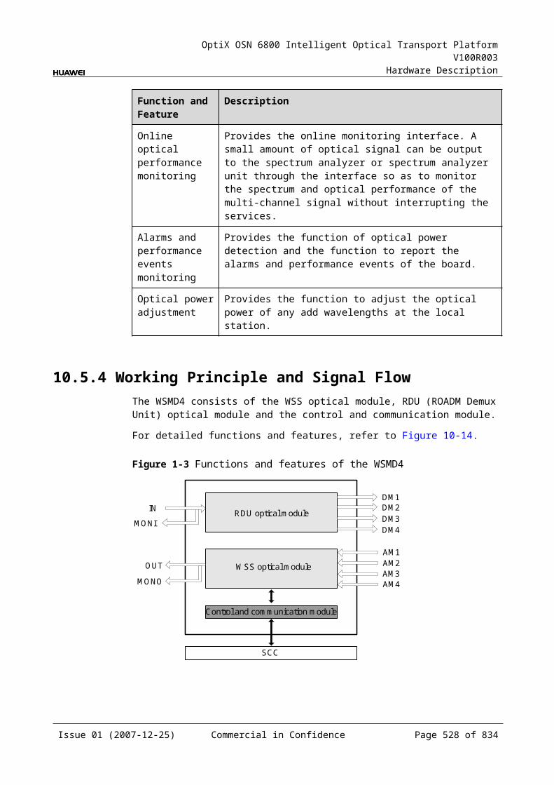
OptiX OSN 6800 Intelligent Optical Transport Platform V100R003
Hardware Description
NOTEThe number of an interface displayed on the T2000 in fact indicates a pair of physical optical interfaces, of which one is used to transmit signals and the other is used to receive signals.
Configuration ParametersOptical Interface Attenuation Ratio (dB)
Maximum Attenuation Ratio (dB)
Minimum Attenuation Ratio (dB)
Path Use Status
16.1.9 Specifications of the VA1Specifications include optical specifications, dimensions, weight, and power consumption.
Optical SpecificationsTable 16-6 lists the optical specifications of the VA1.
Table 16-1 Optical specifications of the VA1
Item Unit
Value
TN11VA1
TN12VA1
IN-OUT Inherent insertion loss dB ≤1.5 ≤1.5
Dynamic attenuation range dB 0–20 0–20
Adjustment accuracy dB 1 1(attenuation≤10dB)1.3(attenuation≤15dB)1.8(attenuation>15dB)
WDL dB 0.5 1.0 (attenuation≤15dB)1.5 (attenuation≤20dB)
PDL dB 0.5 0.7 (attenuation≤15dB)1.0 (attenuation≤20dB)
PMD ps 0.2 0.2
Mechanical Specifications Dimensions of board (PCB): 245.1 mm (H) x 220 mm (D) x 2 mm (T) Dimensions of front panel: 264.6 mm (H) x 25.4 mm (W) Weight: 2.20 lb (1.0 kg)
Issue 01 (2007-12-25) Commercial in Confidence Page 528 of 664
OptiX OSN 6800 Intelligent Optical Transport Platform V100R003
Hardware Description
Power Consumption The maximum power consumption at 25: 6.5 W The maximum power consumption at 55: 7.2 W
16.2 VA4VA4: 4-channel variable optical attenuator unit
16.2.1 Version DescriptionTwo functional versions of the VA4 board are available: TN11 and TN12. There is no difference between the two versions in terms of functionality.
Table 16-7 lists the version description of the VA4.
Table 16-1 Version description of the VA4
Item Description
Functional version Two functional versions of the VA4 board are available: TN11 and TN12.
Similarity The TN12VA4 works in the same way as the TN11VA4.
Difference None
Replacement The TN11VA4 and TN12VA4 boards share the same functionality and can be replaced with each other. But after the TN11VA4 board is replacement with the TN12VA4 board, the SCC software need be upgraded.
16.2.2 ApplicationThe VA4 is a type of variable optical attenuator unit. The VA4 realizes the power adjustment for four optical signals.
For the position of the VA4 in the WDM system, see Figure 16-4.
Figure 16-1 Position of the VA4 in the WDM system
MR2
OA OA
OA OA
MR2
OTU OTU
VA4
OTU OTU
VA4
VA4
VA4
VA4
VA4
VA4
Issue 01 (2007-12-25) Commercial in Confidence Page 529 of 664

OptiX OSN 6800 Intelligent Optical Transport Platform V100R003
Hardware Description
16.2.3 Functions and FeaturesThe main functions and features supported by the VA4 are optical power adjustment, alarm monitoring, and power-off protection.
For detailed functions and features, refer to Table 16-8.
Table 16-1 Functions and features of the VA4
Function and Feature
Description
Basic function Adjusts the optical power of four optical signals respectively according to the control command sent by the SCC.
Alarm monitoring
Detects attenuation and reports various alarms to the SCC.
Power-off protection
Supports the power-off protection to avoid the damages caused by too high optical power to the corresponding optical receiver when the power supply recovers.When there is no power supplied to the VA4, the attenuation of the VA4 changes to its maximum value automatically. Shortly after the power supply recovers, the attenuation of the VA4 still remains its maximum value. When the system begins to work normally, the attenuation automatically changes back to the value set last time.
Attenuation range
The variable attenuation ranges between 1.5 dB and 21.5 dB. The resolution is 0.1 dB.
16.2.4 Working Principle and Signal FlowThe VA4 consists of variable optical attenuators and the control and communication module.
Figure 16-5 shows the functional modules and signal flow of the VA4.
Figure 16-1 Functional modules and signal flow of the VA4
Variable optical attenuator
Variable optical attenuator
Variable optical attenuatorIN1
Control andcommunication module
SCC
IN2
IN3
IN4
OUT1
OUT2
OUT3
OUT4Variable optical attenuator
Issue 01 (2007-12-25) Commercial in Confidence Page 530 of 664
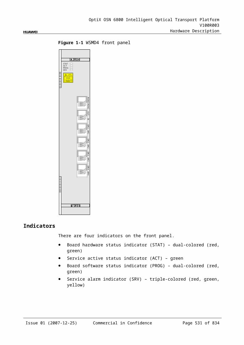
OptiX OSN 6800 Intelligent Optical Transport Platform V100R003
Hardware Description
The function of the VA4 is to adjust the optical power of each signal according to the command sent by the SCC to make the optical power of each channel meet the system requirement. One VA4 can process four signals at the same time. The VA4 adjusts the attenuation of each signal according to the command sent by the SCC.
Variable Optical AttenuatorsOne VA4 has four variable optical attenuators. Each attenuator adjusts the optical power of each input signal.
Control and Communication ModuleThe control and communication module realizes the control, monitoring and communications management of each functional module of the board.
The control and communication module collects the information, such as the alarms and performance events, working status, and voltage detection, of each functional module of the board and reports to the SCC.
Receiving the commands from the SCC, the control and communication module controls and coordinates the functional modules of the board in working.
16.2.5 Front PanelThere are indicators, interfaces and laser safety label on the VA4 front panel.
Appearance of the Front PanelFigure 16-6 shows the VA4 front panel.
Issue 01 (2007-12-25) Commercial in Confidence Page 531 of 664
OptiX OSN 6800 Intelligent Optical Transport Platform V100R003
Hardware Description
Figure 16-1 VA4 front panel
VA4
VA4
LASERRADIATION
DO NOT VIEW DIRECTLYWITH OPTICALINSTRUMENTS
CLASS 1M LASERPRODUCT
STATACTPROGSRV
OU
TIN
OU
T2IN
2O
UT3
IN3
OU
T4IN
4
IndicatorsThere are four indicators on the front panel.
Board hardware status indicator (STAT) – dual-colored (red, green) Service active status indicator (ACT) – green Board software status indicator (PROG) – dual-colored (red, green) Service alarm indicator (SRV) – triple-colored (red, green, yellow)
InterfacesThere are eight optical interfaces on the VA4 front panel. Table 16-9 lists the type and function of each interface.
Issue 01 (2007-12-25) Commercial in Confidence Page 532 of 664
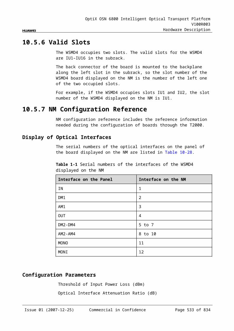
OptiX OSN 6800 Intelligent Optical Transport Platform V100R003
Hardware Description
Table 16-1 Types and functions of the VA4 interfaces
Interface Type Function
IN1–IN4 LC Receives the optical signals to be adjusted.
OUT1–OUT4 LC Transmits the adjusted optical signals.
Laser Safety LevelThe laser safety level of the optical interface is CLASS 1M.
The maximum output optical power of each optical interface ranges from 10 dBm (10 mW) to 22.15 dBm (164 mW).
16.2.6 Valid SlotsThe VA4 occupies one slot. The valid slots for the VA4 are IU1–IU17.
16.2.7 Characteristic Code for the VA4The characteristic code for the VA4 consists of three digits, indicating the maximum attenuation of the optical signals processed by the board.
The detailed information of the characteristic code is given in Table 16-10.
Table 16-1 Characteristic code for the VA4
Code Meaning Description
The first to the third digits Attenuation value Indicate the maximum attenuation.
For example, the characteristic code for the TN11VA4 is 21.5, indicating that the maximum attenuation value is 21.5 dB.
16.2.8 NM Configuration ReferenceNM configuration reference includes the reference information needed during the configuration of boards through the T2000.
Display of Optical InterfacesThe serial numbers of the optical interfaces on the panel of the board displayed on the NM are listed in Table 16-11.
Table 16-1 Serial numbers of the interfaces of the VA4 displayed on the NM
Interface on the Panel Interface on the NM
IN1/OUT1 1
IN2/OUT2 2
Issue 01 (2007-12-25) Commercial in Confidence Page 533 of 664
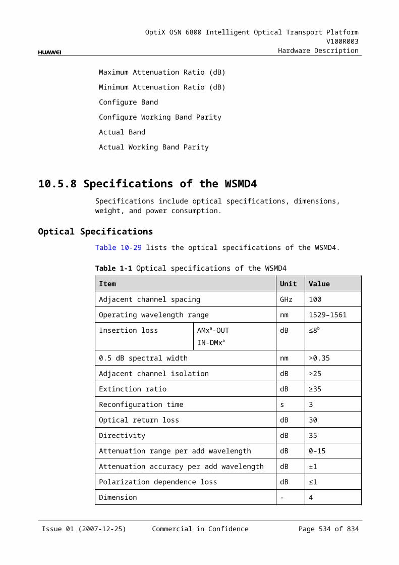
OptiX OSN 6800 Intelligent Optical Transport Platform V100R003
Hardware Description
Interface on the Panel Interface on the NM
IN3/OUT3 3
IN4/OUT4 4
NOTEThe number of an interface displayed on the T2000 in fact indicates a pair of physical optical interfaces, of which one is used to transmit signals and the other is used to receive signals.
Configuration ParametersOptical Interface Attenuation Ratio (dB)
Maximum Attenuation Ratio (dB)
Minimum Attenuation Ratio (dB)
Path Use Status
16.2.9 Specifications of the VA4Specifications include optical specifications, dimensions, weight, and power consumption.
Optical SpecificationsTable 16-12 lists the optical specifications of the VA4.
Table 16-1 Optical specifications of the VA4
Item Unit
Value
TN11VA4
TN12VA4
IN-OUT Inherent insertion loss dB ≤1.5 ≤1.5
Dynamic attenuation range dB 0–20 0–20
Adjustment accuracy dB 1 1(attenuation≤10dB)1.3(attenuation≤15dB)1.8(attenuation>15dB)
WDL dB 0.5 1.0 (attenuation≤15dB)1.5 (attenuation≤20dB)
PDL dB 0.5 0.7 (attenuation≤15dB)1.0 (attenuation≤20dB)
PMD ps 0.2 0.2
Issue 01 (2007-12-25) Commercial in Confidence Page 534 of 664

OptiX OSN 6800 Intelligent Optical Transport Platform V100R003
Hardware Description
Mechanical Specifications Dimensions of board (PCB): 245.1 mm (H) x 220 mm (D) x 2 mm (T) Dimensions of front panel: 264.6 mm (H) x 25.4 mm (W) Weight: 2.20 lb (1.0 kg)
Power Consumption The maximum power consumption at 25: 8.5 W The maximum power consumption at 55: 9.4 W
Issue 01 (2007-12-25) Commercial in Confidence Page 535 of 664
OptiX OSN 6800 Intelligent Optical Transport Platform V100R003
Hardware Description
17 Dispersion Compensation Unit
17.1 DCUDCU: Dispersion Compensation Board
17.1.1 Version DescriptionOnly one functional version of the DCU board is available, that is TN11.
17.1.2 ApplicationThe DCU board is a kind of dispersion compensation board, compensating for the dispersion which is accumulated in an optical transmission system. It is used at the transmit end and the receive end in the transmission system.
For the position of the DCU in the WDM system, see Figure 17-1.
Figure 17-1 Position of the DCU in the WDM system
OBU OAU
OBUOAUDMUXOTU
OTU
DMUX
MUX
OTU
OTU
OTU
OTU
DCU
DCU
OTUMUX
OTU
OBU OAU
OBUOAUDMUXOTU
OTU
DMUX
MUX
OTU
OTU
OTU
OTU
DCU
DCU
OTUMUX
OTU
Issue 01 (2007-12-25) Commercial in Confidence Page 537 of 664
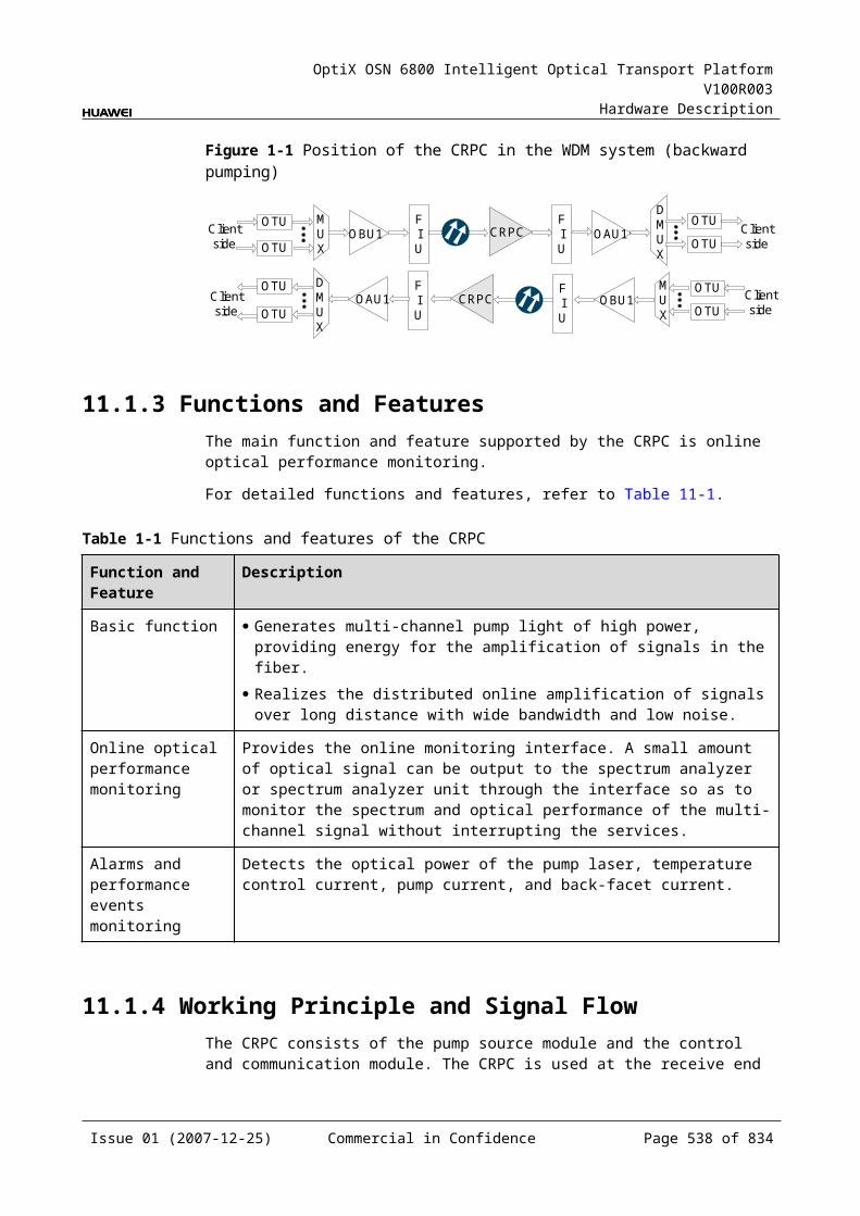
OptiX OSN 6800 Intelligent Optical Transport Platform V100R003
Hardware Description
17.1.3 Functions and FeaturesThe DCU board compensates for the dispersion which is accumulated in the fiber during transmission and compresses optical signal pulse. In this way, the optical signals transmitted can be restored at the output end. In addition, when used together with an optical amplifier board, the DCU board can realize long haul optical transmission.
For detailed functions and features, refer to Table 17-1.
Table 17-1 Functions and features of the DCU
Function and Feature
Description
Basic function Provides dispersion compensation for different transmission distance.
Dispersion compensation method
Compensates for the dispersion accumulated in an optical transmission system, and compresses the optical signal pulse. In this way the optical signals transmitted can be restored at the output end.
Long haul transmission with optical regeneration
Realizes long haul transmission when used together with an optical amplifier board.
17.1.4 Working Principle and Signal FlowThe DCU board mainly contains one dispersion compensation module (DCM). When the DCU board uses different DCM modules, the increased transmission distance due to dispersion compensation is different . The DCU board supports a maximum of eight kinds of DCM module.
Figure 17-2 shows the functional modules and signal flow of the DCU.
Figure 17-1 Functional modules and signal flow of the DCU
SCC
Dispersion compensationmodule
IN OUT
Dispersion Compensation ModuleAfter the optical signal is transmitted for a certain distance, the optical signal pulse is widened because of the positive dispersion accumulated in the system. In this case, the system transmission performance is severely affected. The DCM module employs the negative dispersion borne with the dispersion compensating fiber (DCF)
Issue 01 (2007-12-25) Commercial in Confidence Page 538 of 664
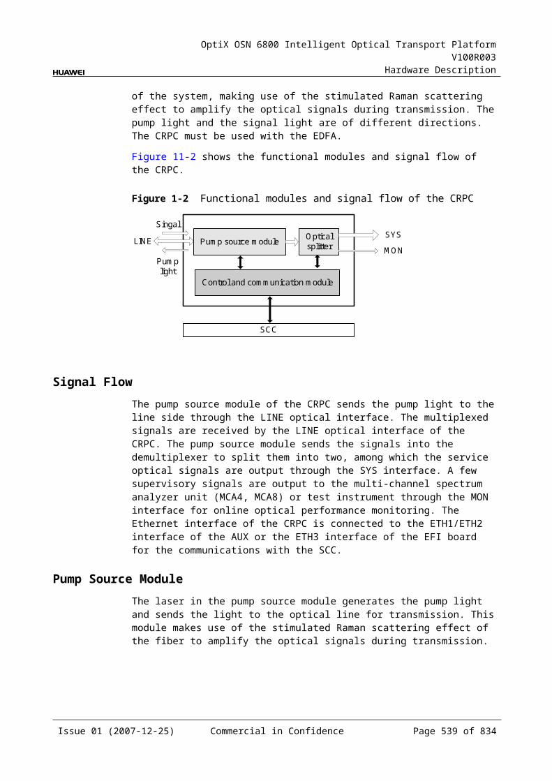
OptiX OSN 6800 Intelligent Optical Transport Platform V100R003
Hardware Description
to offset the positive dispersion in the transmission fiber, and compresses the input optical signal pulse. In this way, the optical signals at the output end are restored back to the original signals.
17.1.5 Front PanelThere are interfaces and laser safety label on the DCU front panel.
Appearance of the Front PanelFigure 17-3 shows the DCU front panel.
Figure 17-1 DCU front panel
DCU
DCU
CLASS 1LASER
PRODUCT
OU
TIN
InterfacesThere are two optical interfaces on the DCU front panel.Table 17-2 lists the type and function of each interface.
Issue 01 (2007-12-25) Commercial in Confidence Page 539 of 664
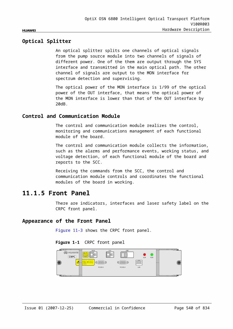
OptiX OSN 6800 Intelligent Optical Transport Platform V100R003
Hardware Description
Table 17-1 Types and functions of the DCU interfaces
Interface
Type
Function
IN LC Accesses the multiplexed signals to be compensated in terms of dispersion.
OUT LC Outputs the multiplexed signals that have been compensated in terms of dispersion.
17.1.6 Valid SlotsThe DCU occupies one slot. The valid slots for the DCU are IU1–IU17.
17.1.7 Characteristic Code for the DCUThe characteristic code for the DCU board consists of characters, indicating the type of the fiber that the board works with and the dispersion compensation distance.
The detailed information of the characteristic code is given in Table 17-3.
Table 17-1 Characteristic code for the DCU
Code Meaning Description
The character before hyphen (-)
Fiber type Type of the fiber that the DCU board works with
The character after hyphen (-)
Dispersion compensation distance
The transmission distance achieved through dispersion compensation
For example, the characteristic code for the TN11DCU is G.655LEAF-40. It indicates that the DCU board works with G.655LEAF fibers, and the dispersion compensation distance is 40 km.
NOTEIf the characteristic code contains varieties of the dispersion compensation distance, the symbol "&" is used to seperate each distance variety.
17.1.8 NM Configuration ReferenceNM configuration reference includes the reference information needed during the configuration of boards through the T2000.
Display of Optical InterfacesThe serial numbers of the optical interfaces on the panel of the board displayed on the NM are listed in Table 17-4.
Issue 01 (2007-12-25) Commercial in Confidence Page 540 of 664
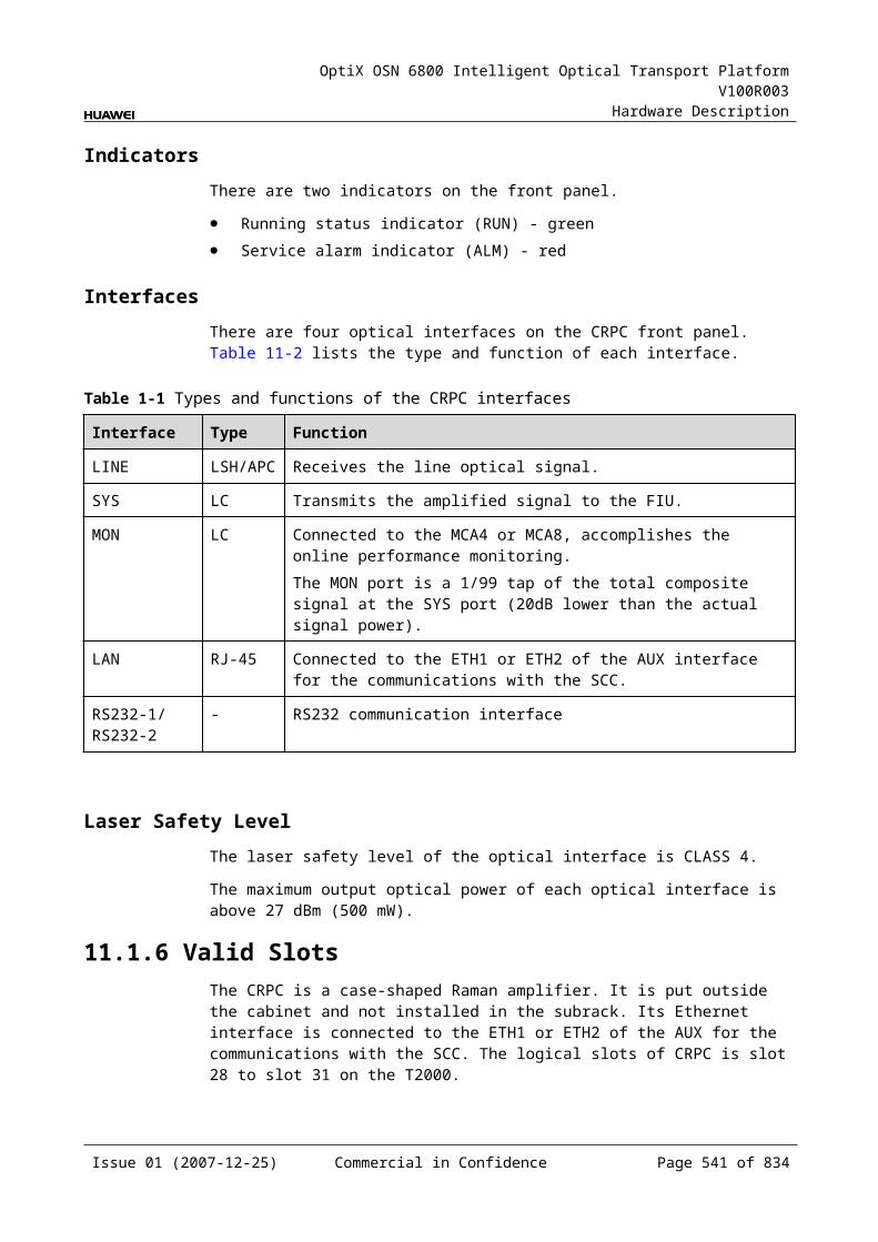
OptiX OSN 6800 Intelligent Optical Transport Platform V100R003
Hardware Description
Table 17-1 Serial numbers of the interfaces of the DCU displayed on the NM
Interface on the Panel Interface on the NM
IN 1
OUT 2
17.1.9 Specifications of the DCUSpecifications include optical specifications, dimensions, weight, and power consumption.
Optical Specifications
Table 17-1 Optical specifications of the DCU
Item Unit
Value
DCU01
DCU02
DCU03
DCU04
DCU05
DCU06
DCU07
DCU08
Typical dispersion compensation distance
km 20 40 60 80 100 120 5 10
Maximum insertion loss
dB 3.3 4.7 6.4 8 9 9.8 2.3 2.6
Dispersion compensation slope
- 90%–110%
Polarization mode dispersion
ps 0.4 0.5 0.6 0.7 0.8 0.8 0.3 0.3
Polarization dependent loss
dB 0.1 0.1 0.1 0.1 0.1 0.1 0.1 0.1
Maximum input power
dBm 20 20 20 20 20 20 20 20
Operating wavelength range
nm 1525–1565
Dispersion compensating fiber type
- G.652 fiber
Issue 01 (2007-12-25) Commercial in Confidence Page 541 of 664
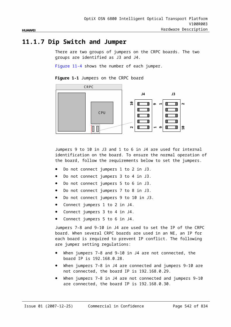
OptiX OSN 6800 Intelligent Optical Transport Platform V100R003
Hardware Description
Mechanical Specifications Dimensions of board (PCB): 245.1 mm (H) x 220 mm (D) x 2 mm (T) Dimensions of front panel: 264.6 mm (H) x 25.4 mm (W) Weight: 1.5 kg
Power Consumption The maximum power consumption at 25: 0.5W The maximum power consumption at 55: 0.5W
Issue 01 (2007-12-25) Commercial in Confidence Page 542 of 664
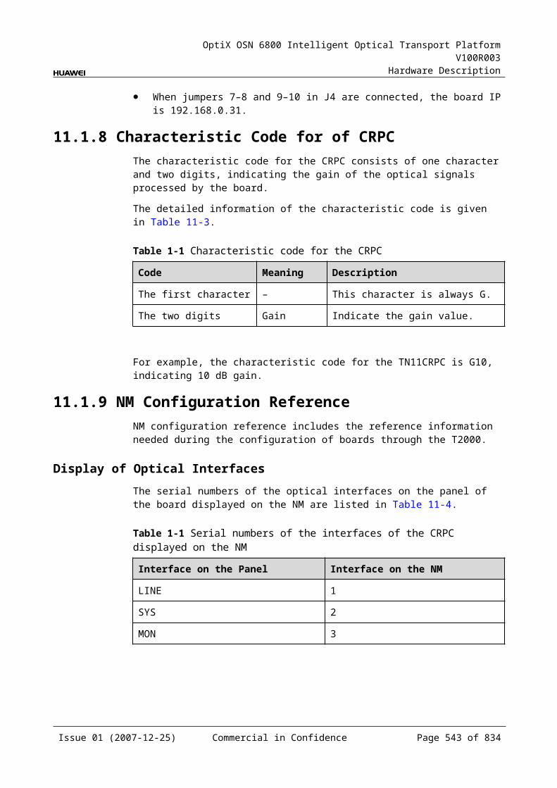
OptiX OSN 6800 Intelligent Optical Transport Platform V100R003
Hardware Description
18 Cables
18.1 Power Cables and Grounding CablesThe OptiX OSN 6800 has cabinet -48 V/BGND/PGND power cables and subrack power cables.
18.1.1 Cabinet -48 V/BGND/PGND Power CablesThe -48 V, BGND, and PGND power cables supply power to devices inside the cabinet. One end of the power cable is connected to the power distribution cabinet and grounding bar in the equipment room. The other end is connected to the DC power distribution box at the cabinet top.
StructureFigure 18-1 shows the structure of the cabinet -48 V power cable and the cabinet BGND grounding cable.Figure 18-2 shows the structure of the cabinet PGND grounding cable.
Figure 18-1 Structure of the cabinet -48 V power cable and cabinet BGND grounding cable
1 2
3
1. Cord end terminal 2. OT naked crimping connector 3. Cable clip
Issue 01 (2007-12-25) Commercial in Confidence Page 543 of 664
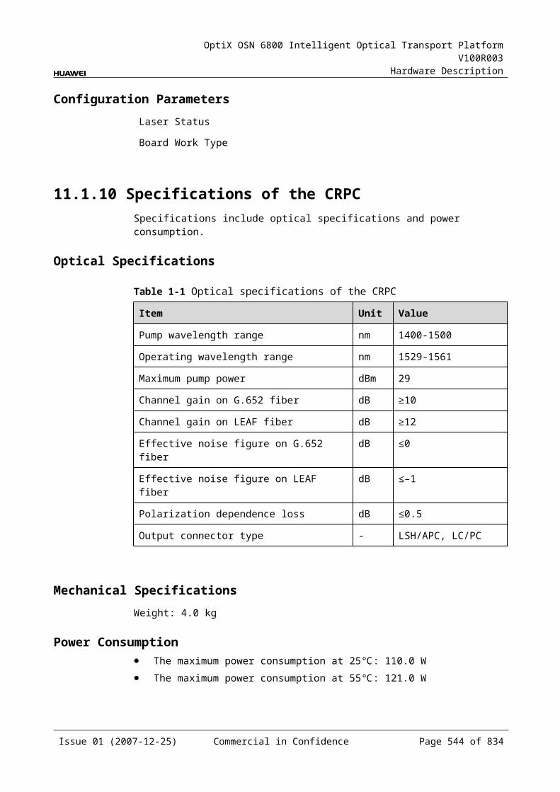
OptiX OSN 6800 Intelligent Optical Transport Platform V100R003
Hardware Description
Figure 18-2 Structure of the cabinet PGND grounding cable
L
1
2
3
4
5
6
1. OT naked crimping connector 2. Cable clip 3. JG two-hole naked crimping connector4. Heat shrink tube 5. Heat shrink tube 6. Cable
Pin AssignmentNone
Technical Parameters
Table 18-1 Technical parameters of the cabinet -48 V/BGND power cables(16 mm2)
Item Description
Cabinet -48 V power cable
Connector 1 Cord end terminal-16 mm2-0.024mm-80A-Insertion depth 16mm-Green
Connector 2 OT naked crimping connector-16 mm2-M8
Type of the cable
Electric power cable-450 V/750 V-227 IEC 02(RV)-16mm2-Blue-85 A
Cabinet BGND grounding cable
Connector 1 Cord end terminal-16 mm2-0.024mm-80A-Insertion depth 16mm-Green
Connector 2 OT naked crimping connector-16 mm2-M8
Type of the cable
Electric power cable-450 V/750 V-227 IEC 02(RV)-16mm2-Black-85 A
Table 18-2 Technical parameters of the cabinet -48 V/BGND power cables(25 mm2)
Item Description
Cabinet -48 V power cable
Connector 1 Cord end terminal-25 mm2-30 mm-75 A-Insertion depth 16 mm-Brown
Issue 01 (2007-12-25) Commercial in Confidence Page 544 of 664
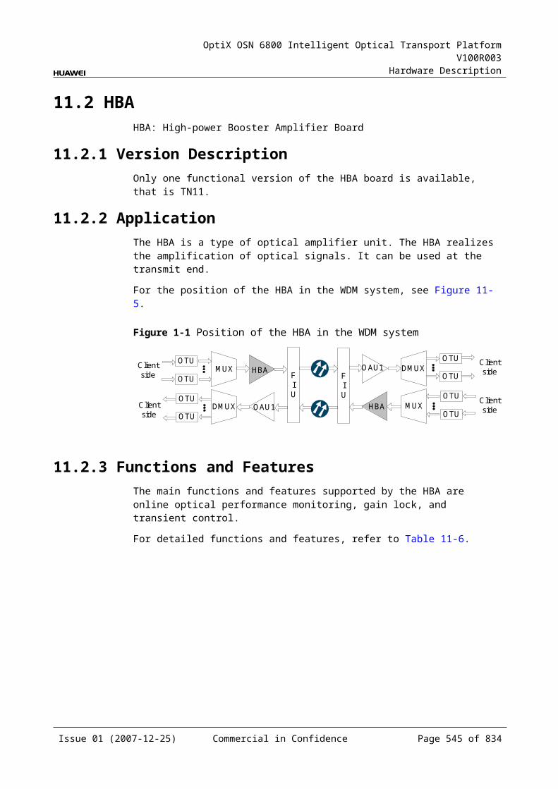
OptiX OSN 6800 Intelligent Optical Transport Platform V100R003
Hardware Description
Connector 2 OT naked crimping connector-25 mm2-M8
Type of the cable
Electric power cable-450 V/750 V-25 mm2-Blue-110 A
Cabinet BGND grounding cable
Connector 1 Cord end terminal-25 mm2-30 mm-75A-Insertion depth 16 mm-Brown
Connector 2 Naked crimping connector-OT type-25 mm2-M8
Type of the cable
Electric power cable-450 V/750 V-25 mm2-Black-110 A
Table 18-3 Technical parameters of the cabinet -48 V/BGND power cables (35 mm2)
Item Description
Cabinet -48 V power cable
Connector 1 Cord end terminal-35mm2-0.03m-105A-Insertion depth 16mm-Cream-colored
Connector 2 OT naked crimping connector-35 mm2-M8
Type of the cable
Electric power cable-750V/450V-227 IEC 02(RV)-35mm2-Blue-135 A
Cabinet BGND grounding cable
Connector 1 Cord end terminal-35mm2-0.03m-105A-Insertion depth 16mm-Cream-colored
Connector 2 OT naked crimping connector-35 mm2-M8
Type of the cable
Electric power cable-750V/450V-227 IEC 02(RV)-35mm2-Black-135 A
Table 18-4 Technical parameters of the cabinet PGND power cables
Item Description
Cabinet PGND grounding cable
Connector 1 OT naked crimping connector-25 mm2-M8
Connector 2 JG dual-hole naked crimping connector-25 mm2-M6-150 A-Tin plating
Type of the cable
Electric power cable-450 V/750 V-25 mm2-Yellow and green-110 A
18.1.2 Subrack Power CablesThe subrack power cables connect the DC power distribution box at the cabinet top and the power interface in the subrack interface area, which lead the -48 V power supply from the top of the cabinet to the subracks. The subrack power cables have been correctly connected before delivery.
Issue 01 (2007-12-25) Commercial in Confidence Page 545 of 664
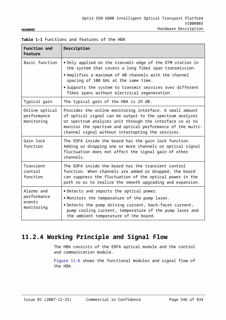
OptiX OSN 6800 Intelligent Optical Transport Platform V100R003
Hardware Description
StructureFigure 18-3 shows the subrack power cable.
Figure 18-1 Structure of the subrack power cable
X1
X3
X2
500L
A
A
A1A2A3
1
W1
W2
2 3
1. Cable connector 2. Cable clip 3. Naked crimping connector
Pin AssignmentFor the pin assignment of subrack power cables, refer to Table 18-5.
Table 18-1 Pin assignment of the subrack power cables
Cable
Cable Connector
Cord End Terminal
Connection Core Color
W2 X1.A1 X2 A1 connects to X2. Blue (-48 V power)
W1 X1.A3 X3 A3 connects to X3. Black (power ground)
Issue 01 (2007-12-25) Commercial in Confidence Page 546 of 664
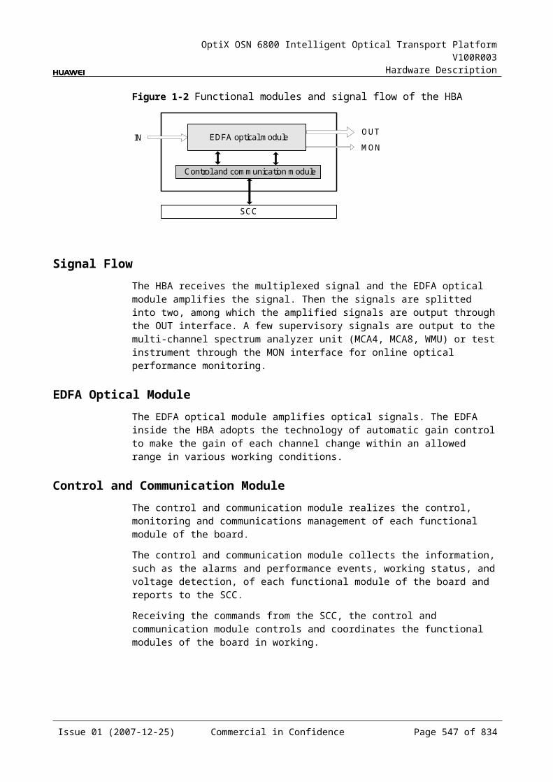
OptiX OSN 6800 Intelligent Optical Transport Platform V100R003
Hardware Description
Technical ParametersThe technical parameters of subrack power cables are listed in Table 18-6.
Table 18-1 Technical parameters of subrack power cables
Item Description
Cable connector X1 Cable connector-D type-3PIN-Female-Solder injection molding type-No middle contact
Cord end terminals X2, X3
Common terminal-Conductor Cross Section-6 mm2-Length 20 mm-30 A-Insertion depth 12 mm-Black
Type of the cable W2
Power cable-450 V/750 V-H07Z-K-6 mm2-Blue-Low Smoke Zero Halogen Cable
Type of the cable W1
Power cable-450 V/750 V-H07Z-K-6 mm2-Black-Low Smoke Zero Halogen Cable
18.2 Optical FibersOptical fibers of the OptiX OSN 6800 can be classified into three types: LC/PC-LC/PC, LC/PC-FC/PC, LC/PC-SC/PC.
18.2.1 ClassificationThe connectors and the length of the fibers are selected based on the results of site survey.
The optical fibers used by the equipment are classified as shown in Table 18-7.
Table 18-1 Classification of optical fiber jumpers
Types of the Connectors at Both Ends
Type of the Cable
LC/PC——LC/PC 2.0 mm single-mode fiber
2.0 mm multimode fiber
LC/PC——FC/PC 2.0 mm single-mode fiber
2.0 mm multimode fiber
LC/PC——SC/PC 2.0 mm single-mode fiber
2.0 mm multimode fiber
LSH/APC——SC/APC 2.0 mm single-mode fiber
2.0 mm multimode fiber
Issue 01 (2007-12-25) Commercial in Confidence Page 547 of 664
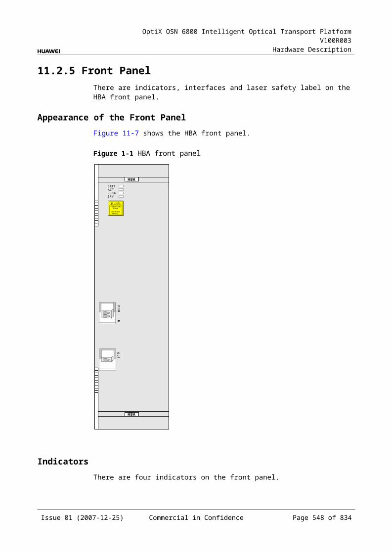
OptiX OSN 6800 Intelligent Optical Transport Platform V100R003
Hardware Description
18.2.2 ConnectorsAll optical interfaces on the front panel of the OptiX OSN 6800 boards are of LC/PC type. LC/PC fiber connectors are used with these board. The optical interfaces on the ODF in the equipment room are generally of FC/PC or SC/PC type. FC/PC or SC/PC fiber connectors are used with them.
The classification of fiber connectors is given in Table 18-8.
Table 18-1 Classification of fiber connectors
Type of Fiber Connectors
Description
LC/PC Plug-in square fiber connector/protruding polished
FC/PC Round fiber connector/protruding polished
SC/PC Square fiber connector/protruding polished
LSH/APC Fiber connector with auto-protective dustproof cap/eight-degree radian surface/protruding polished
The appearances of the fiber connectors are shown in Figure 18-4, Figure 18-5, Figure 18-6and Figure 18-7.
Figure 18-2 LC/PC fiber connector
LC/PC connector
Protective cap
Issue 01 (2007-12-25) Commercial in Confidence Page 548 of 664
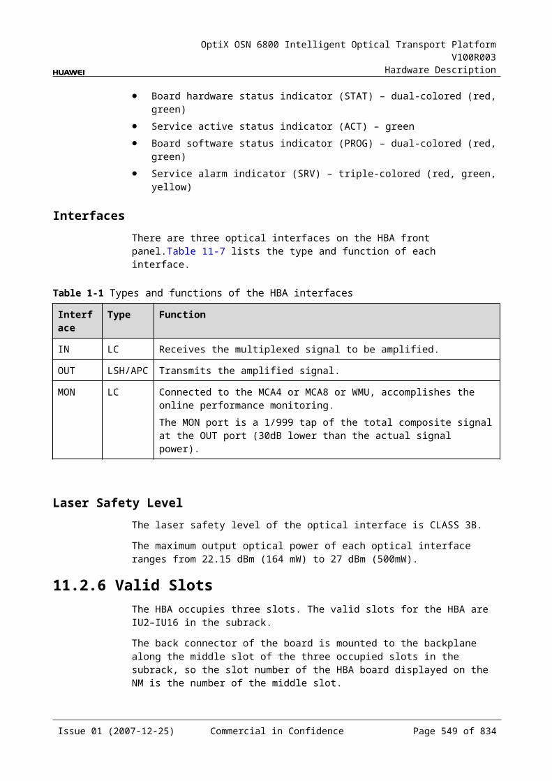
OptiX OSN 6800 Intelligent Optical Transport Platform V100R003
Hardware Description
Figure 18-3 FC/PC fiber connector
Protective cap
FC/PC connector
Figure 18-4 SC/PC fiber connector
SC/PC connector
Protective cap
Figure 18-5 LSH/APC fiber connector
Issue 01 (2007-12-25) Commercial in Confidence Page 549 of 664
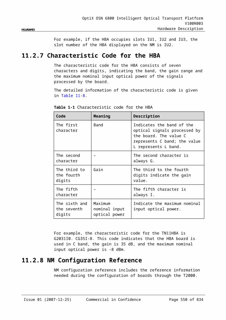
OptiX OSN 6800 Intelligent Optical Transport Platform V100R003
Hardware Description
18.3 Grounding CablesThe OptiX OSN 6800 has grounding cables, including cabinet door grounding cables and a PDU grounding cable.
18.3.1 Cabinet Door Grounding CablesThe cabinet door grounding cables ground the front door, rear door and side doors. The cabinet door grounding cables have been correctly connected before delivery.
StructureFigure 18-8 shows the structure of the cabinet door grounding cables.
Figure 18-1 Structure of the cabinet door grounding cable
1
X1 X2
L
1. OT naked crimping connector
Pin AssignmentNone
Technical ParametersThe technical parameters of the cabinet door grounding cables are listed in Table 18-9.
Table 18-1 Technical parameters of the cabinet door grounding cables
Item Description
Connector X1/X2 Naked crimping terminal-OT-6 mm2-M6-Tin plating-Insulated ring terminal-12-10AWG
Type of the cable Electric power cable-600V-UL1015-0 mm2-10AWG-Yellow/Green-50 A-105 core strand
18.3.2 PDU Grounding CableOne end of the PDU grounding cable is connected to a protection grounding screw of the power distribution box. The other end is connected to the protection grounding
Issue 01 (2007-12-25) Commercial in Confidence Page 550 of 664
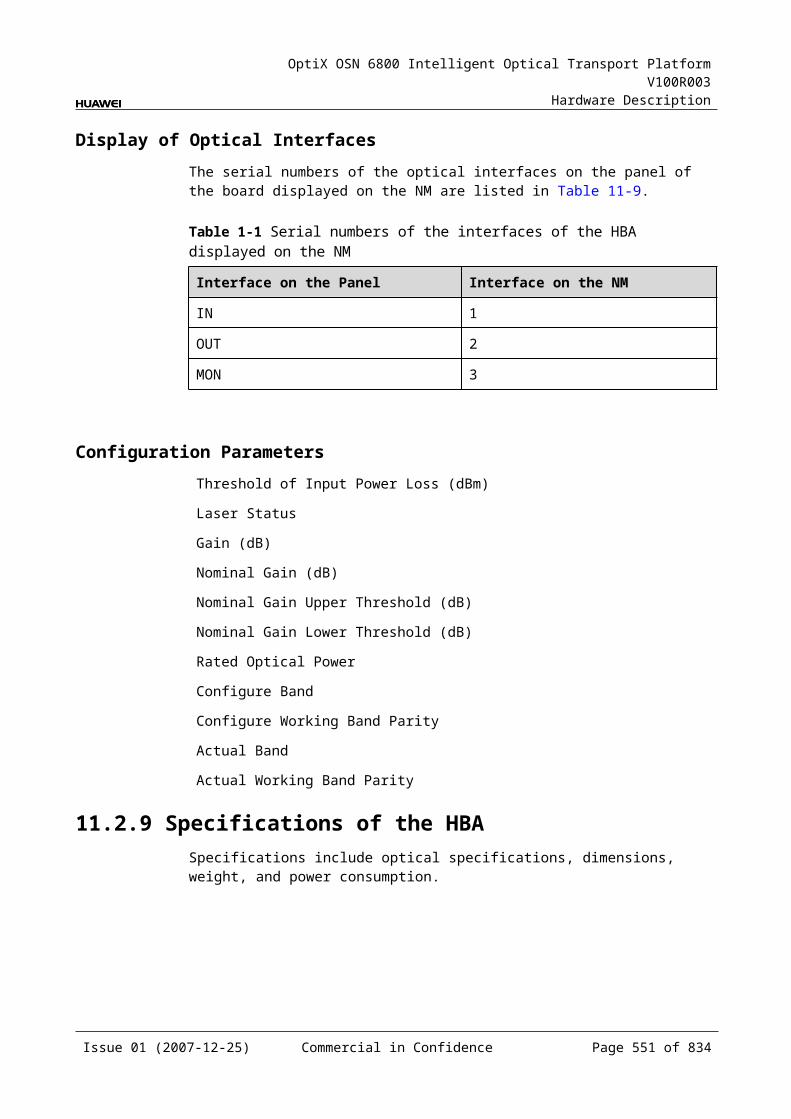
OptiX OSN 6800 Intelligent Optical Transport Platform V100R003
Hardware Description
screw on the top of the cabinet. The PDU grounding cable has been correctly connected before delivery.
StructureFigure 18-9 shows the structure of the PDU grounding cable.
Figure 18-1 Structure of the PDU grounding cable
1 2
X1 X2
1. OT naked crimping connector 2. Heat-shrink tube
Pin AssignmentNone
Technical ParametersThe technical parameters of the PDU grounding cable are listed in Table 18-10.
Table 18-1 Technical parameters of the PDU grounding cable
Item Description
Connector X1/X2 Naked crimping terminal-OT-10-6
Type of the cable Electric power cable-450/750V-227IEC02 (RV)-10 mm2-Yellow/Green-62 A
18.4 Alarm CablesAlarm cables of the OptiX OSN 6800 include cabinet indicator alarm cable, alarm concatenating/inter-subrack concatenating cable, and alarm interface cable.
18.4.1 Cabinet Indicator CableThe cabinet indicator cable is used to cascade the signals of the indicators at different subracks in the same cabinet. One end of the cable is connected to LAMP1 or LAMP2 interface of one subrack. The other end of the cable is connected to LAMP1 or LAMP2 interface of another subrack.
Issue 01 (2007-12-25) Commercial in Confidence Page 551 of 664
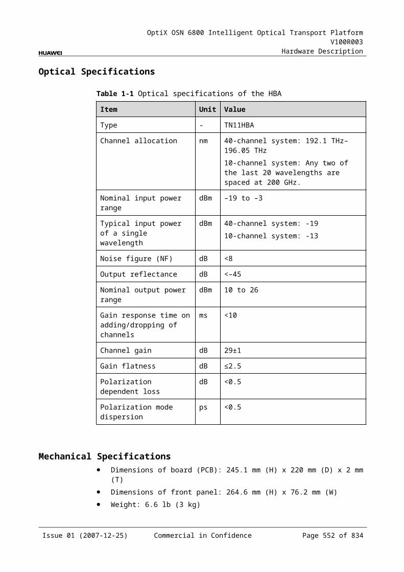
OptiX OSN 6800 Intelligent Optical Transport Platform V100R003
Hardware Description
StructureThe structure of the cable indicator alarm cable is displayed in Figure 18-10.
Figure 18-1 Structure of the cabinet indicator alarm cable
2
X1
L
X2
B
3 4
B12
A
1
A
1
8 View
X3
X4
X5
View
1. Network interface connector 2. Heat-shrink tube
3. Common plug
4. Ordinary connector
Pin AssignmentFor the pin assignment of the cabinet indicator alarm cable, refer to Table 18-11.
Table 18-1 Pin assignment of the cabinet indicator alarm cable
Connector X1 Connectors X2, X3, X4, X5
Color Relationship
X1.4 X2.2 White Pair
X1.5 X2.1 Green
X1.1 X3.2 White Pair
X1.2 X3.1 Blue
X1.3 X4.2 White Pair
X1.6 X4.1 Brown
X1.7 X5.2 White Pair
X1.8 X5.1 Orange
Technical ParametersThe technical parameters of the cabinet indicator alarm cable are listed in Table 18-12.
Issue 01 (2007-12-25) Commercial in Confidence Page 552 of 664
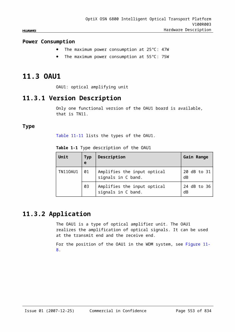
OptiX OSN 6800 Intelligent Optical Transport Platform V100R003
Hardware Description
Table 18-1 Technical parameters of the cabinet indicator alarm cable
Item Description
Connector X1 Network interface connector-8PIN-single row-single port-8bit-shielded-crystal model connector
Connector X2/X3/X4/X5
Common plug-2PIN-single row/2.5 mm
Type of the cable Twisted pair cable -100Ω-SEYPVPV-0.48mm-26AWG-4 pairs-black
Number of cores 8
Core diameter 0.5 mm
18.4.2 Alarm Interface CableThe alarm interface cable between cabinets is connected to the ALMI interface in the EFI board area of the subrack to achieve the input of alarm signals. The OptiX OSN 6800 provides eight alarm outputs. By default, critical, major, and minor alarms use the first three alarm outputs. The other five are reserved. The output alarm signals can be concatenated.
StructureFigure 18-11 shows the structure of the alarm interface cable.
Figure 18-1 Alarm interface cable
A
LX1 X2
View A
8631
1
1. Network interface connector
Pin AssignmentFor the pin assignment of the alarm interface cable, refer to Table 18-13.
Issue 01 (2007-12-25) Commercial in Confidence Page 553 of 664
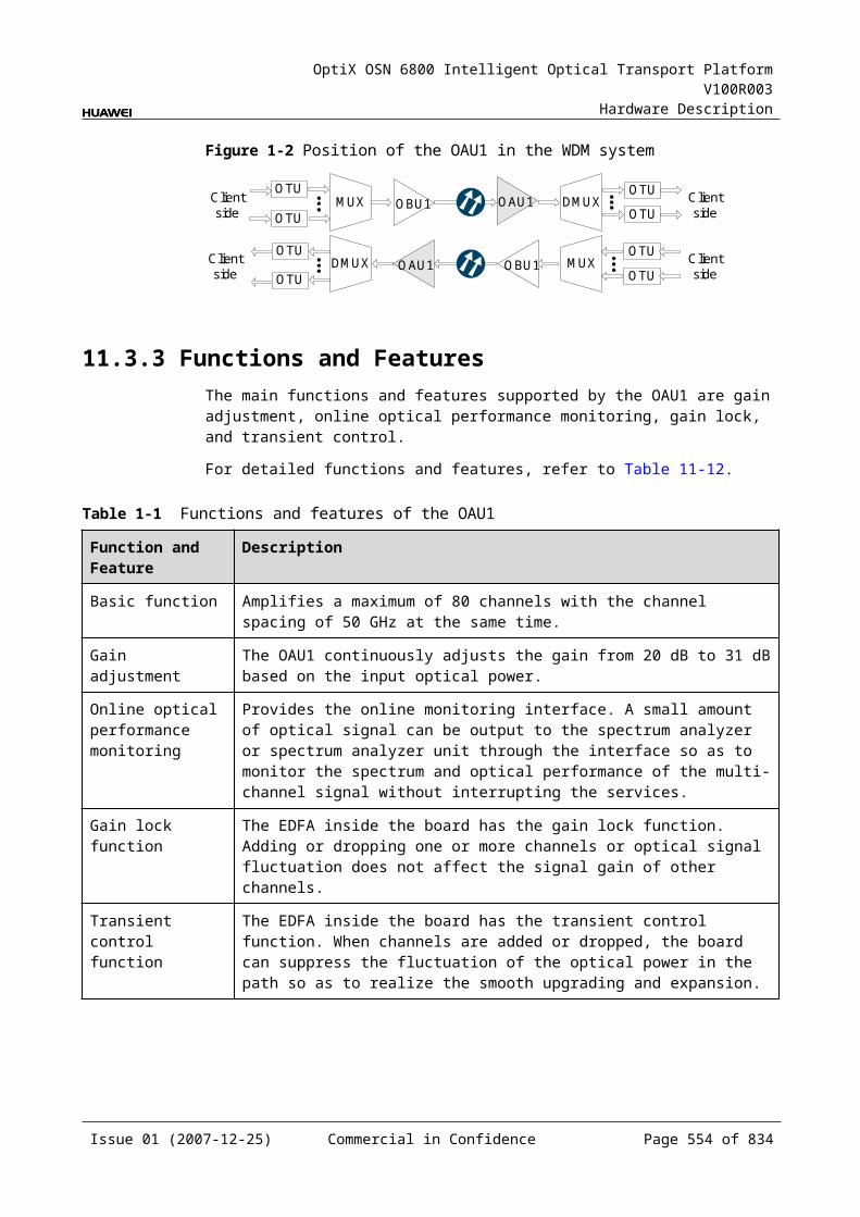
OptiX OSN 6800 Intelligent Optical Transport Platform V100R003
Hardware Description
Table 18-1 Pin assignment of X1
Connector X1 Connector X2 Color Relationship
X1.2 X2.2 Orange Pair
X1.1 X2.1 White-orange
X1.6 X2.6 Green Pair
X1.3 X2.3 White-green
X1.4 X2.4 Blue Pair
X1.5 X2.5 White-blue
X1.8 X2.8 Brown Pair
X1.7 X2.7 White-brown
Technical ParametersThe technical parameters of the alarm interface cable are listed in Table 18-14.
Table 18-1 Technical parameters of the alarm interface cable
Item Description
Connector X1 Network interface connector-8PIN-8bit-unshielded-RJ-45 connector-uniconductor flat cable
Type of the cable W1
Symmetrical twisted pair cable-100Ω-UTPCAT5E-0.5 mm-24AWG-4 pairs-PANTONE 430U-low-smoke and halogen-free cable
Number of cores
8
Core diameter 0.5 mm
18.4.3 Alarm Concatenating/Inter-Subrack Concatenating CableThe inter-subrack indicator/alarm concatenating cable is used to concatenate alarm signals of the different subracks in one cabinet. Both ends of the cable use the RJ-45 connector. Each end is connected to ALMO interface of the EFI in a different subrack.
StructureFigure 18-12 shows the structure of the cable.
Issue 01 (2007-12-25) Commercial in Confidence Page 554 of 664
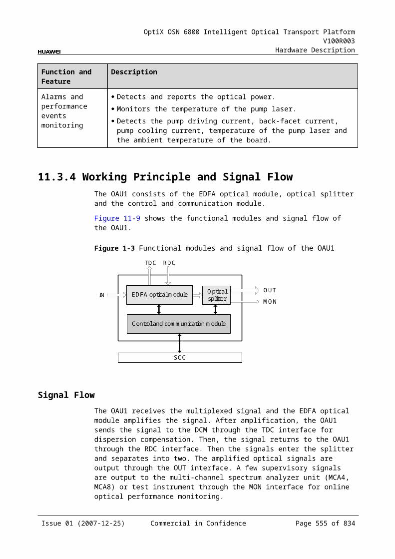
OptiX OSN 6800 Intelligent Optical Transport Platform V100R003
Hardware Description
Figure 18-1 Structure of the alarm concatenating/inter-subrack concatenating cable
1
8
1
8
X1 X2
1
1. Network interface connector–RJ-45
Pin AssignmentFor the pin assignment of the alarm concatenating/inter-subrack concatenating cable, refer to Table 18-15.
Table 18-1 Pin assignment of the alarm concatenating/inter-subrack concatenating cable
Connector X1 Connector X2 Color Relationship
X1.2 X2.2 Orange Pair
X1.1 X2.1 White-orange
X1.6 X2.6 Green Pair
X1.3 X2.3 White-green
X1.4 X2.4 Blue Pair
X1.5 X2.5 White-blue
X1.8 X2.8 Brown Pair
X1.7 X2.7 White-brown
Technical ParametersFor the technical parameters of the alarm concatenating/inter-subrack concatenating cable, refer to Table 18-16.
Issue 01 (2007-12-25) Commercial in Confidence Page 555 of 664

OptiX OSN 6800 Intelligent Optical Transport Platform V100R003
Hardware Description
Table 18-1 Technical parameters of the alarm concatenating/inter-subrack concatenating cable
Item Description
Connector X1/X2 Network interface connector-8PIN-8bit-crystal model connector
Type of the cable Communication cable-8 cores category-5 twisted pair-24AWG
Number of cores 8
Core diameter 0.5 mm
18.5 Management CablesManagement cables of the OptiX OSN 6800 include the OAM serial port cable.
18.5.1 OAM Serial Port CableThe OAM serial port cable is used to connect to the OAM interface.
StructureFigure 18-13 shows the structure of the OAM serial port cable.
Figure 18-1 Structure of the OAM serial port cable
A
1
X1 X2
Pos.9
Pos.1
1. DB9 connector
Issue 01 (2007-12-25) Commercial in Confidence Page 556 of 664
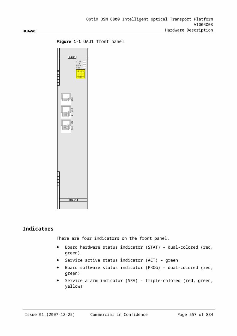
OptiX OSN 6800 Intelligent Optical Transport Platform V100R003
Hardware Description
Pin AssignmentFor the pin assignment of the OAM serial port cable, refer to Table 18-17.
Table 18-1 Pin assignment of the OAM serial port
Connector X1 Connector X2 Relationship
X1.1 X2.1 Pair
X1.5 X2.5
X1.2 X2.2 Pair
X1.3 X2.3
X1.6 X2.6 Pair
X1.7 X2.7
X1.8 X2.8 Pair
X1.9 X2.9
Technical ParametersThe technical parameters of the OAM serial port cable are listed in Table 18-18.
Table 18-1 Technical parameters of the OAM serial port cable
Item Description
Connector X1, X2 Cable connector-D type-9 PIN-Male-Cable welding type
Type Symmetrical twisted-pair cable-100ohm-SEYVP-0.48mm-26AWG-4 pairs-Black
Number of cores 4 pairs
Length 10.0m, 20.0m
Issue 01 (2007-12-25) Commercial in Confidence Page 557 of 664
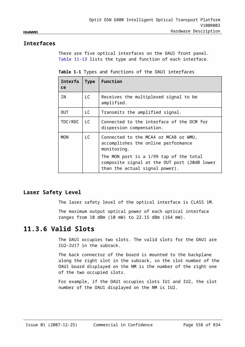
OptiX OSN 6800 Intelligent Optical Transport Platform V100R003
Hardware Description
A Indicators
A.1 Cabinet IndicatorsThere are altogether four indicators in different colors on each cabinet: green, red, orange and yellow.
The corresponding messages of each indicator are listed in Table A-1.
Table A-1 Indicators description of the cabinet
Indicator
Name Status Description
power Power indicator On (green) The cabinet is powered on.
Off The cabinet is not powered on.
critical Critical alarm indicator On (red) There is a critical alarm.
Off There is no critical alarm.
major Major alarm indicator On (Orange) There is a major alarm.
Off There is no major alarm.
minor Minor alarm indicator On (Yellow) There is a minor alarm.
Off There is no minor alarm.
A.2 Subrack IndicatorThere are altogether four indicators in different colors on the subrack of the OptiX OSN 6800: red, orange, yellow and green.
The corresponding messages of each indicator are listed in Table A-2.
Issue 01 (2007-12-25) Commercial in Confidence Page 559 of 664
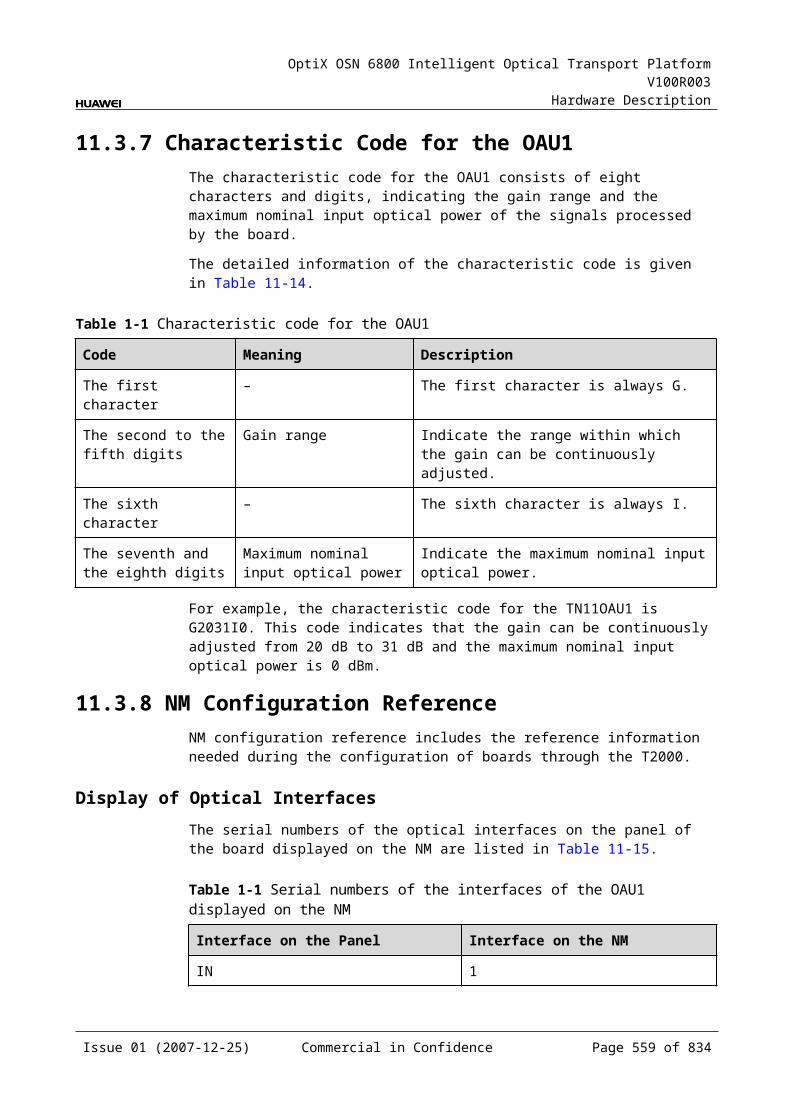
OptiX OSN 6800 Intelligent Optical Transport Platform V100R003
Hardware Description
Table A-1 Indicators description of the subrack
Indicator
Name Status Description
PWR Power indicator On (green) The subrack works normally.
CRI Critical alarm indicator On (red) There is a critical alarm.
MAJ Major alarm indicator On (Orange) There is a major alarm.
MIN Minor alarm indicator On (Yellow) There is a minor alarm.
A.3 Board IndicatorsThere are indicators on the front panel to indicate the status of running and alarm.
The corresponding messages of board indicators are listed inTable A-3 and Table A-4.
Table A-1 Indicator description of the boards
Indicator
Name Status Description
STAT Board Hardware Indicator
On (green) The board works normally.
On (red) The board hardware fails.
Off The board is not powered on.
PROG Board Software Indicator
On (red) Memory check failed/loading unit software failed/the FPGA file is lost/the unit software is lost.
Blinking (red) 100ms on and 100ms off BOOTROM check failed.
Blinking quickly (green)
100ms on and 100ms offWriting FLASH.
Blinking slowly (green)
300ms on and 300ms offBIOS booting/loading FPGA/loading unit software.
On (green) The board software or software for FPGA is uploaded successfully, or the board software is initialized successfully.
SRV Service Alarm Indicator
On (green) Service is normal, no service alarm occurs.
On (red) Critical or major alarm occurs to service.
On (yellow) Minor or remote alarm occurs to service.
Off No service is configured.
Issue 01 (2007-12-25) Commercial in Confidence Page 560 of 664
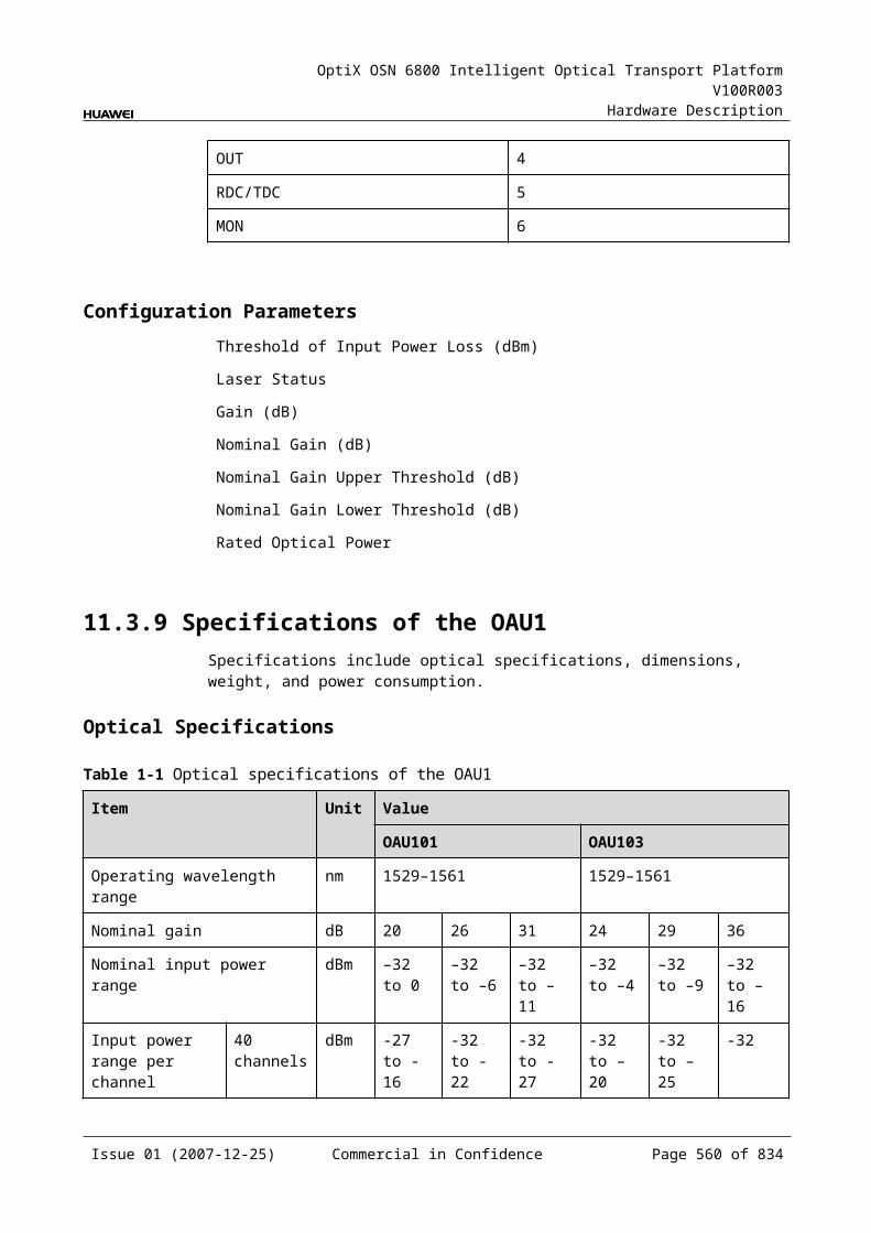
OptiX OSN 6800 Intelligent Optical Transport Platform V100R003
Hardware Description
Indicator
Name Status Description
ACT Service Activation Indicator
On (green) The board is in working mode.The board is in the active mode.
Off The board is not in working mode.The board is in the standby mode.
Blinking quickly (green)
100ms on and 100ms offBacking up the system database in patches.
Table A-2 Indicator description of the SCC board
Indicator
Name Status Description
STAT Board Hardware Indicator
On (green) The board works normally.
On (red) The board hardware fails.
Off The board is not powered on.
PROG Board Software Indicator
On (red) Memory check failed/loading unit software failed/the FPGA file is lost/the unit software is lost.
Blinking (red) 100ms on and 100ms off BOOTROM check failed.
Blinking quickly (green)
100ms on and 100ms offWriting FLASH.
Blinking slowly (green)
300ms on and 300ms offBIOS booting/loading FPGA/loading unit software.
On (green) The board software or software for FPGA is uploaded successfully, or the board software is initialized successfully.
SRV Service Alarm Indicator
On (green) Service is normal, no service alarm occurs.
On (red) Critical or major alarm occurs to service.
On (yellow) Minor or remote alarm occurs to service.
Off No service is configured.
ACT Service Activation Indicator
On (green) The board is in working mode.The board is in the active mode.
Off The board is not in working mode.The board is in the standby mode.
Issue 01 (2007-12-25) Commercial in Confidence Page 561 of 664
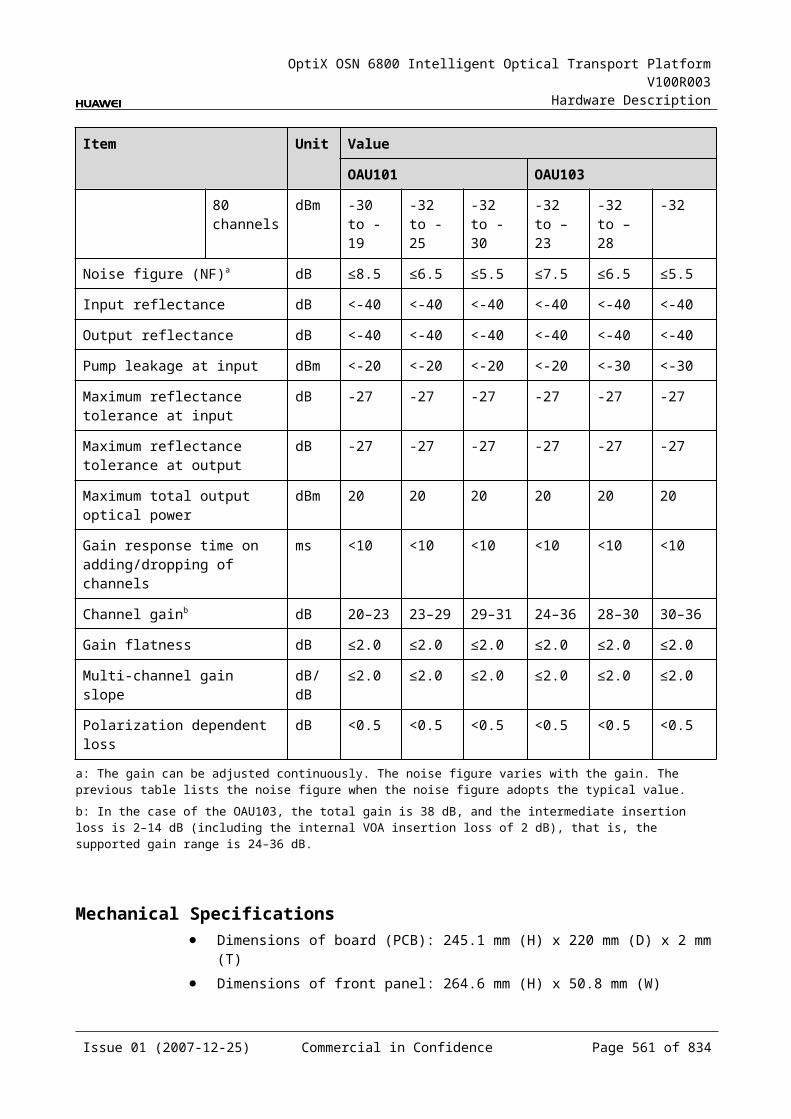
OptiX OSN 6800 Intelligent Optical Transport Platform V100R003
Hardware Description
Indicator
Name Status Description
Blinking quickly (green)
100ms on and 100ms offBacking up the system database in patches.
PWRA Indicator for system power supply
On (green) The –48 V power supply A is normal.
On (red) The –48 V power supply A is faulty (lost or failed).
Off No power supply inputs.
PWRB Indicator for system power supply
On (green) The –48 V power supply B is normal.
On (red) The –48 V power supply B is faulty (lost or failed).
Off No power supply inputs.
PWRC Indicator for protection power supply
On (green) The +3.3 V protection power is normal.
On (red) The +3.3 V protection power is lost.
ALMC Alarm cut indicator
On (green) Currently in permanent alarm cut-off status.
Off Give sound warning upon alarm.
A.4 Fan IndicatorThere is one indicator on the FAN to indicate the status.
The corresponding messages of Fan indicator are listed in Table A-5.
Table A-1 Indicator description of the FAN
Indicator
Name Status Description
STAT Fan indicator
On (green) The fan is normal
On (red) The major alarm exists; two or more fans are faulty.
On (yellow) The minor alarm exists; one fan is faulty.
Off The fan is not powered on, or is absent, or the software is not loaded.
Issue 01 (2007-12-25) Commercial in Confidence Page 562 of 664
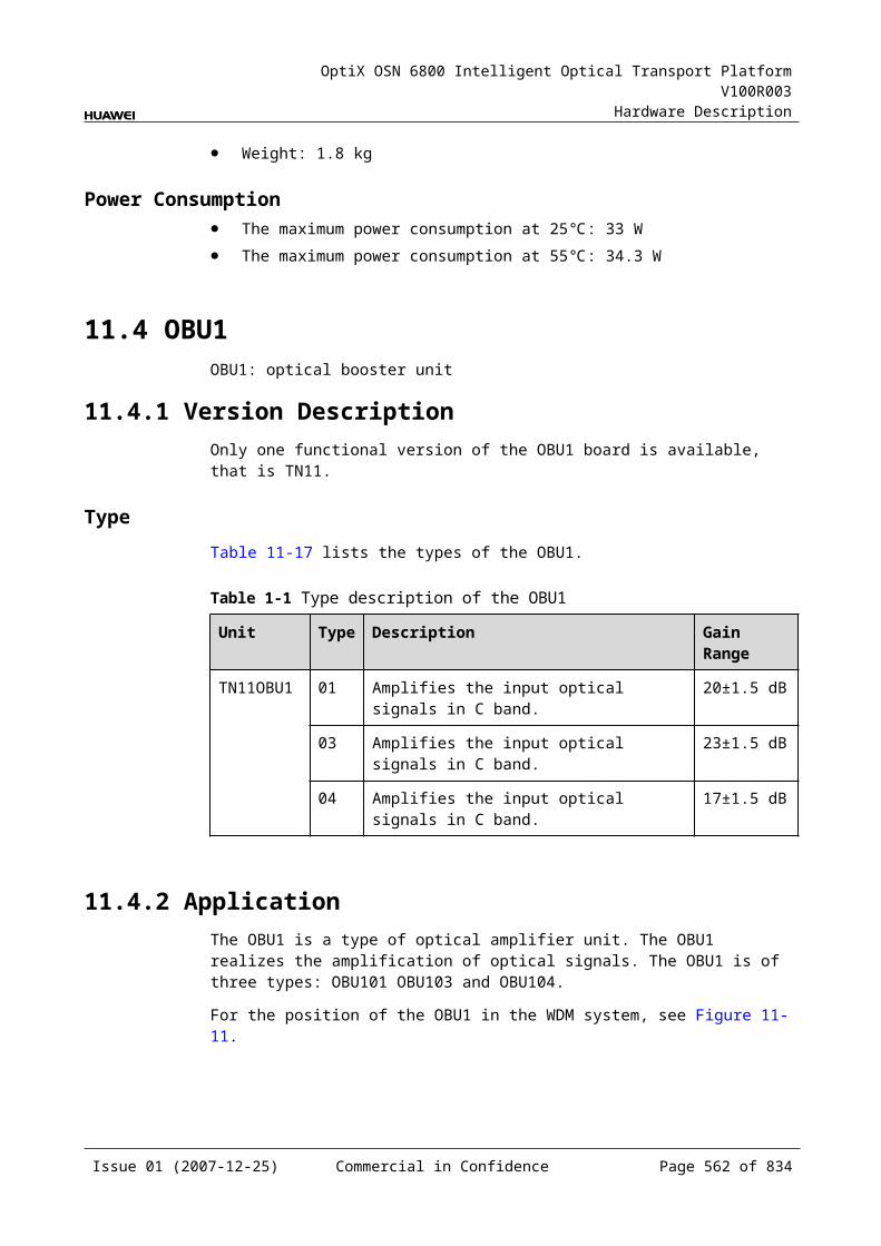
OptiX OSN 6800 Intelligent Optical Transport Platform V100R003
Hardware Description
A.5 PIU IndicatorThere is one indicator on the PIU to indicate the status.
The corresponding messages of each indicator are listed in Table A-6.
Table A-1 Indicators description of the PIU
Indicator
Name Status Description
RUN Running status indicator
On (green) Indicates that the power is accessed normally.
Off Indicates that the power is not accessed.
Issue 01 (2007-12-25) Commercial in Confidence Page 563 of 664
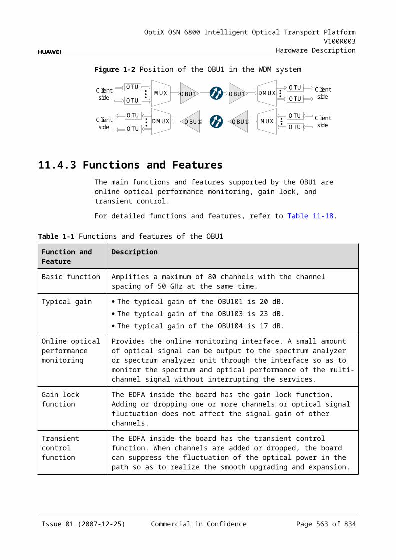
OptiX OSN 6800 Intelligent Optical Transport Platform V100R003
Hardware Description
B Bar Code for Boards
There is a bar code on the front panel of each board, from which the basic information about the board can be obtained, such as the BOM code, delivery information, board version, board name, and board characteristic code.
B.1 OverviewThere is a bar code on the front panel of each board, from which the basic information about the board can be obtained, such as the BOM code, delivery information, board version, board name, and board model number. The bar code of some of such boards also include a characteristic code. The board characteristic code comprises the information about frequency of signals, type of the optical module, wavelength, and so on.
Figure B-1 and Figure B-2 shows a bar code.
Figure B-1 Description of the bar code (example 1)
2102313242 1059000003 19210PA
BOM
Deliveryinformation
Board version(TN11)
Boardname
Characteristiccode
TN1M1L4GY 01
Board modelnumber
Environmentalfriendliness flag
(Y: Environmentallyfriendly)
Issue 01 (2007-12-25) Commercial in Confidence Page 565 of 664
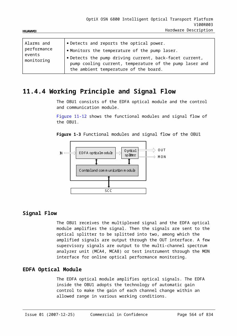
OptiX OSN 6800 Intelligent Optical Transport Platform V100R003
Hardware Description
Figure B-2 Description of the bar code (example 2)
030FBQ1073000001 -94509520
Last four numbers ofthe BOM
TN11MR4N 01
Environmentalfriendliness flag
Deliveryinformation
Board name
Board version
Characteristiccode
Board modelnumber
(N: Environmentallyunfriendly)
B.2 Characteristic Code for OTUsThe characteristic code for OTUs indicates the frequency, type and wavelength of the optical modules in DWDM OTUs, DWDM wavelength-tunable OTUs and CWDM OTUs.
B.2.1 Characteristic Code for DWDM OTUsThe characteristic code for a DWDM OTU consists of digits and characters, indicating the frequency and type of the optical module in the OTU.
Detailed information of the characteristic code is listed in Table B-1.
Table B-1 Characteristic code for a DWDM OTU
Code Meaning Description
The first five digit
The frequency of the DWDM-side optical transmitter module
Indicate the frequency of the DWDM-side optical transmitter module.
The sixth character
The type of the DWDM-side receiving optical module
The value can be A or P. A represents APD. P represents PIN.
The seventh character
The type of the DWDM-side optical transmitter module
The detailed meaning of the character is shown in Table B-2.
NOTEIn the case of the OTU boards with dual fed optical interfaces, such as the LDGD, LQMD, LWXD and LWX2 boards, the characteristic code consists of eight digits. The frequency values of the two channels of optical signals on the WDM side are indicated.
The types of DWDM-side transmitting optical modules are listed in Table B-2.
Issue 01 (2007-12-25) Commercial in Confidence Page 566 of 664
OptiX OSN 6800 Intelligent Optical Transport Platform V100R003
Hardware Description
Table B-2 Types of DWDM-side transmitting optical modules
Character Dispersion (1550 nm) Distance Rate
A 1600ps/nm 80km 2.5G
3200ps/nm 170km 2.5G
800ps/nm 40km 10.66G
3200ps/nm 160km 2.5G
B 1500ps/nm 80km 10.66G
1600ps/nm 80km 10.66G
3200ps/nm 170km 2.5G
C 800ps/nm 40km 10.66G
12800ps/nm 640km 2.5G
6500ps/nm 320km 2.5G
D 12800ps/nm 640km 2.5G
E 6500ps/nm 320km 2.5G
G 800ps/nm 40km 10.71G
H >600ps/nm >30km 10.71G
>600ps/nm >30km 10.66G
K 800ps/nm 40km 10.66G
1800ps/nm 90km 2.66G
L 12800ps/nm 640km 2.66G
12800ps/nm 640km 2.5G
1500ps/nm 80km 10.66G
M >600ps/nm >30km 10.66G
>600ps/nm >30km 10.71G
6400ps/nm 320km 4.9-5.4G
6400ps/nm 320km 10.66G
1500ps/nm 80km 10.71G
3400ps/nm 170km 4.9-5.4G
Z 800ps/nm 40km 10.71G
U >600ps/nm >30km 10.71G
Issue 01 (2007-12-25) Commercial in Confidence Page 567 of 664
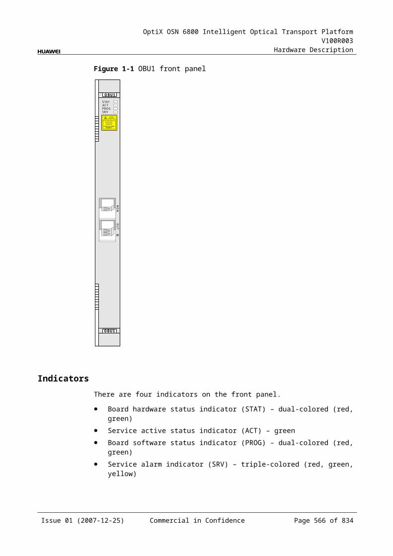
OptiX OSN 6800 Intelligent Optical Transport Platform V100R003
Hardware Description
For example, the characteristic code for the TN11L4G is 19210PA. This code indicates the following features: The frequency of the DWDM-side optical transmitter module is 192.10 THz; PIN is adopted by the DWDM-side receiving optical module; the code of the DWDM-side optical transmitter module is A. For details, refer to Table B-2.
B.2.2 Characteristic Code for DWDM Wavelength-Tunable OTUs
The characteristic code for a DWDM wavelength-tunable OTU consists of characters, indicating the frequency and type of the optical module in the OTU.
Detailed information of the characteristic code is listed in Table B-3.
Table B-1 Characteristic code for a DWDM wavelength-tunable OTU
Code Meaning Description
The first character
Wavelength-tunable T is the abbreviation for Tunable, indicating that the wavelength is tunable.
The second character
The type of the DWDM-side receiving optical module
The value can be A or P. A represents APD. P represents PIN.
The third character
The type of the DWDM-side optical transmitter module
The detailed meaning of the character is shown in Table B-4.
The types of DWDM-side optical transmitter modules are listed in Table B-4.
Table B-2 Types of DWDM-side optical transmitter modules
Character Dispersion (1550 nm)
Distance Rate
T 1200ps/nm 60km 10.71G
12800ps/nm 640km 2.66G
12800ps/nm 640km 2.67G
3400ps/nm 170km 5.33G
-1000 to 1100ps/nm 60km 10.71G
4800ps/nm 240km 11.3G
For example, the characteristic code for the TN11LSX is TAT. This code indicates the following features: This board is a wavelength-tunable OTU; APD is adopted by the DWDM-side receiving optical module; the code of the DWDM-side optical transmitter module is T. For details, refer to Table B-4.
Issue 01 (2007-12-25) Commercial in Confidence Page 568 of 664
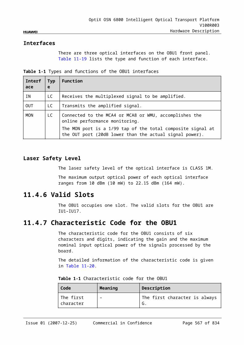
OptiX OSN 6800 Intelligent Optical Transport Platform V100R003
Hardware Description
B.2.3 Characteristic Code for CWDM OTUsThe characteristic code for a CWDM OTU consists of characters, indicating the wavelength and type of the optical module in the OTU.
Detailed information of the characteristic code is listed in Table B-5.
Table B-1 Characteristic code for a CWDM OTU
Code Meaning Description
The first four digits
The wavelength of the CWDM-side transmitting optical module
Indicate the wavelength of the CWDM-side transmitting optical module.
The fifth character
The type of the CWDM-side receiving optical module
The value can be A or P. A represents APD. P represents PIN.
The sixth character
The type of the CWDM-side transmitting optical module
The value can be L or S. L represents long haul. S represents short haul.
NOTEAs for the LWX2 board, only the information of the first wavelength is indicated.
For example, the characteristic code for the TN11LDGS is 1531PS. This code indicates the following features: The wavelength is 1531 nm; PIN is adopted by the CWDM-side receiving optical module; the CWDM-side transmitting optical module is used for short-haul transmission (80 km).
B.3 Characteristic Code for Line UnitThe characteristic code for line unit indicates the frequency, type and wavelength of the DWDM optical modules and DWDM wavelength-tunable optical modules.
The line unit shares the same feature code with the WDM-side DWDM optical module of the wavelength tunable unit. For details, refer to B.2.1 Characteristic Code for DWDM OTUs and B.2.2 Characteristic Code for DWDM Wavelength-Tunable OTUs.
B.4 Characteristic Code for FOADMsThe characteristic code for FOADMs indicates the wavelength or frequency of the optical signals processed by the board.
B.4.1 Characteristic Code for the CMR2The characteristic code for the CMR2 consists of eight digits, indicating the two wavelengths that bear the signals processed by the board.
The detailed information of the characteristic code is given in Table B-1.
Issue 01 (2007-12-25) Commercial in Confidence Page 569 of 664
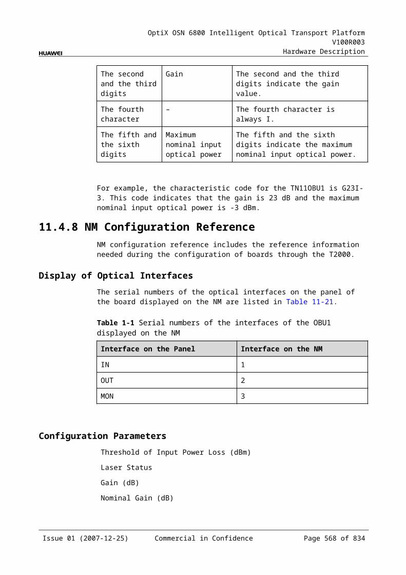
OptiX OSN 6800 Intelligent Optical Transport Platform V100R003
Hardware Description
Table B-1 Characteristic code for the CMR2
Code Meaning Description
The first four digits
The first wavelength that bears optical signals
Indicate the first wavelength that bears the optical signals processed by the board.
The last four digits
The second wavelength that bears optical signals
Indicate the second wavelength that bears the optical signals processed by the board.
For example, the characteristic code for the TN11CMR2 is 14711571.
"1471" indicates that the first wavelength is 1471 nm. "1571" indicates that the second wavelength is 1571 nm.
B.4.2 Characteristic Code for the CMR4The characteristic code for the CMR4 consists of eight digits, indicating the four wavelengths that bear the signals processed by the board.
The detailed information of the characteristic code is given in Table B-1.
Table B-1 Characteristic code for the CMR4
Code Meaning Description
The first and the second digits
The first wavelength that bears optical signals
Indicate the middle two digits of the first wavelength that bears the optical signals processed by the board.
The third and the fourth digits
The second wavelength that bears optical signals
Indicate the middle two digits of the second wavelength that bears the optical signals processed by the board.
The fifth and the sixth digits
The third wavelength that bears optical signals
Indicate the middle two digits of the third wavelength that bears the optical signals processed by the board.
The seventh and the eighth digits
The fourth wavelength that bears optical signals
Indicate the middle two digits of the fourth wavelength that bears the optical signals processed by the board.
For example, the characteristic code for the TN11CMR4 is 47495961.
"47" indicates that the first wavelength is 1471 nm. "49" indicates that the second wavelength is 1491 nm. "59" indicates that the third wavelength is 1591 nm. "61" indicates that the fourth wavelength is 1611 nm.
B.4.3 Characteristic Code for the MR2The characteristic code for the MR2 consists of eight digits that indicate the frequencies of the two signals processed by the board.
Issue 01 (2007-12-25) Commercial in Confidence Page 570 of 664

OptiX OSN 6800 Intelligent Optical Transport Platform V100R003
Hardware Description
The detailed information of the characteristic code is given in Table B-1.
Table B-1 Characteristic code for the MR2
Code Meaning Description
The first four digits
The frequency of the first optical signal
Indicate the last four digits of the frequency that bears the first optical signal.
The last four digits
The frequency of the second optical signal
Indicate the last four digits of the frequency that bears the second optical signal.
For example, the characteristic code for the TN11MR2 is 93609370.
"9360" indicates that the frequency of the first optical signal is 193.60 THz. "9370" indicates that the frequency of the second optical signal is 193.70 THz.
B.4.4 Characteristic Code for of MR4The characteristic code for the MR4 consists of eight digits that indicate the frequencies of the first and the fourth signals processed by the board.
The detailed information of the characteristic code is given in Table B-1.
Table B-1 Characteristic code for the MR4
Code Meaning Description
The first four digits
The frequency of first optical signal
Indicate the last four digits of the frequency that bears the first optical signal processed by the board.
The last four digits
The frequency of forth optical signal
Indicate the last four digits of the frequency that bears the fourth optical signal processed by the board.
For example, the characteristic code for the TN11MR4 is 92109240.
"9210" indicates that the frequency of the first optical signal is 192.10 THz. "9240" indicates that the frequency of the fourth optical signal is 192.40 THz.
Since the four optical signals processed by the MR4 are in sequence, it is inferred that:
The frequency of the second optical signal is 192.20 THz. The frequency of the third optical signal is 192.30 THz.
B.4.5 Characteristic Code for the MR8The characteristic code for the MR8 consists of eight digits that indicate the frequencies of the first and the eighth signals processed by the board.
The detailed information of the characteristic code is given in Table B-1.
Issue 01 (2007-12-25) Commercial in Confidence Page 571 of 664
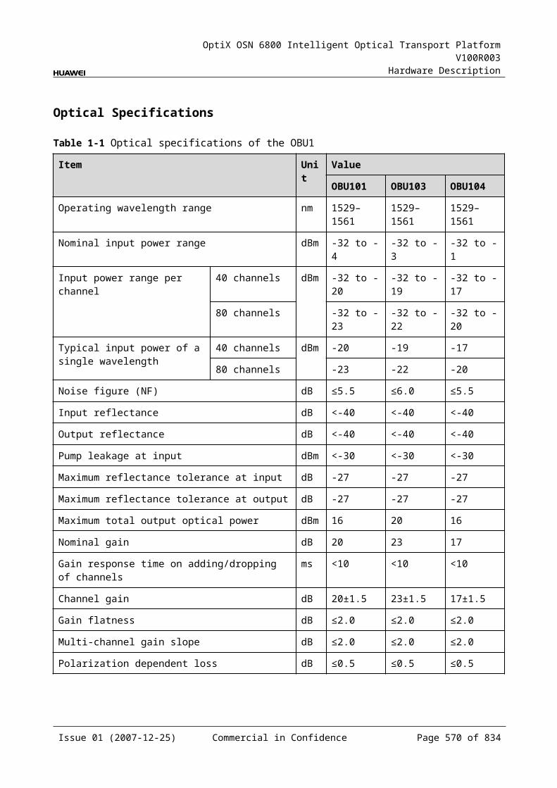
OptiX OSN 6800 Intelligent Optical Transport Platform V100R003
Hardware Description
Table B-1 Characteristic code for the MR8
Code Meaning Description
The first four digits
The frequency of the first optical signal
Indicate the last four digits of the frequency that bears the first optical signal processed by the board.
The last four digits
The frequency of the eighth optical signal
Indicate the last four digits of the frequency that bears the eighth optical signal processed by the board.
For example, the characteristic code for the TN11MR8 is 92109280.
"9210" indicates that the frequency of the first optical signal is 192.10 THz. "9280" indicates that the frequency of the eighth optical signal is 192.80 THz.
Since the eight optical signals processed by the MR8 are in sequence, it is inferred that:
The frequency of the second optical signal is 192.20 THz. The frequency of the third optical signal is 192.30 THz. Inferred from it, the frequency of the seventh signal is 192.70 THz.
B.5 Characteristic Code for MCAsThe characteristic code for MCAs indicates the band of the optical signals processed by the board.
B.5.1 Characteristic Code for the MCA4The characteristic code for the MCA4 consists of one character, indicating the band of the optical signals processed by the board.
The detailed information of the characteristic code is given in Table B-1.
Table B-1 Characteristic code for the MCA4
Code Meaning
Description
The first character
Band Indicates the band of the optical signals processed by the board. The value C represents C band. The value L represents L band.
For example, the characteristic code for the TN11MCA4 is C, indicating C band.
B.5.2 Characteristic Code for the MCA8The characteristic code for the MCA8 consists of one character, indicating the band of the optical signals processed by the board.
The detailed information of the characteristic code is given in Table B-1.
Issue 01 (2007-12-25) Commercial in Confidence Page 572 of 664
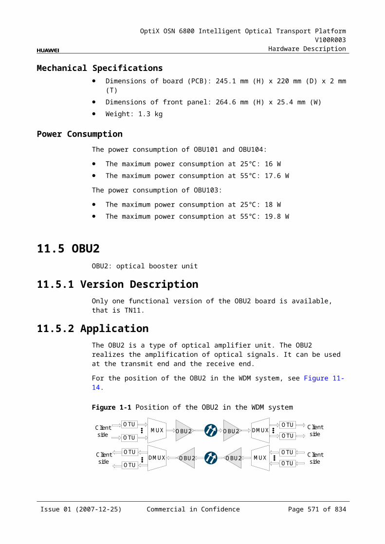
OptiX OSN 6800 Intelligent Optical Transport Platform V100R003
Hardware Description
Table B-1 Characteristic code for the MCA8
Code Meaning
Description
The first character
Band Indicates the band of the optical signals processed by the board. The value C represents C band.The value L represents L band.
For example, the characteristic code for the TN11MCA8 is C, indicating C band.
B.6 Characteristic Code for OAUsThe characteristic code for OAUs indicates the gain, gain range and the maximum nominal input optical power of the optical signals processed by the board.
B.6.1 Characteristic Code for the OAU1The characteristic code for the OAU1 consists of eight characters and digits, indicating the gain range and the maximum nominal input optical power of the signals processed by the board.
The detailed information of the characteristic code is given in Table B-1.
Table B-1 Characteristic code for the OAU1
Code Meaning Description
The first character – The first character is always G.
The second to the fifth digits
Gain range Indicate the range within which the gain can be continuously adjusted.
The sixth character – The sixth character is always I.
The seventh and the eighth digits
Maximum nominal input optical power
Indicate the maximum nominal input optical power.
For example, the characteristic code for the TN11OAU1 is G2031I0. This code indicates that the gain can be continuously adjusted from 20 dB to 31 dB and the maximum nominal input optical power is 0 dBm.
B.6.2 Characteristic Code for the OBU1The characteristic code for the OBU1 consists of six characters and digits, indicating the gain and the maximum nominal input optical power of the signals processed by the board.
The detailed information of the characteristic code is given in Table B-1.
Issue 01 (2007-12-25) Commercial in Confidence Page 573 of 664
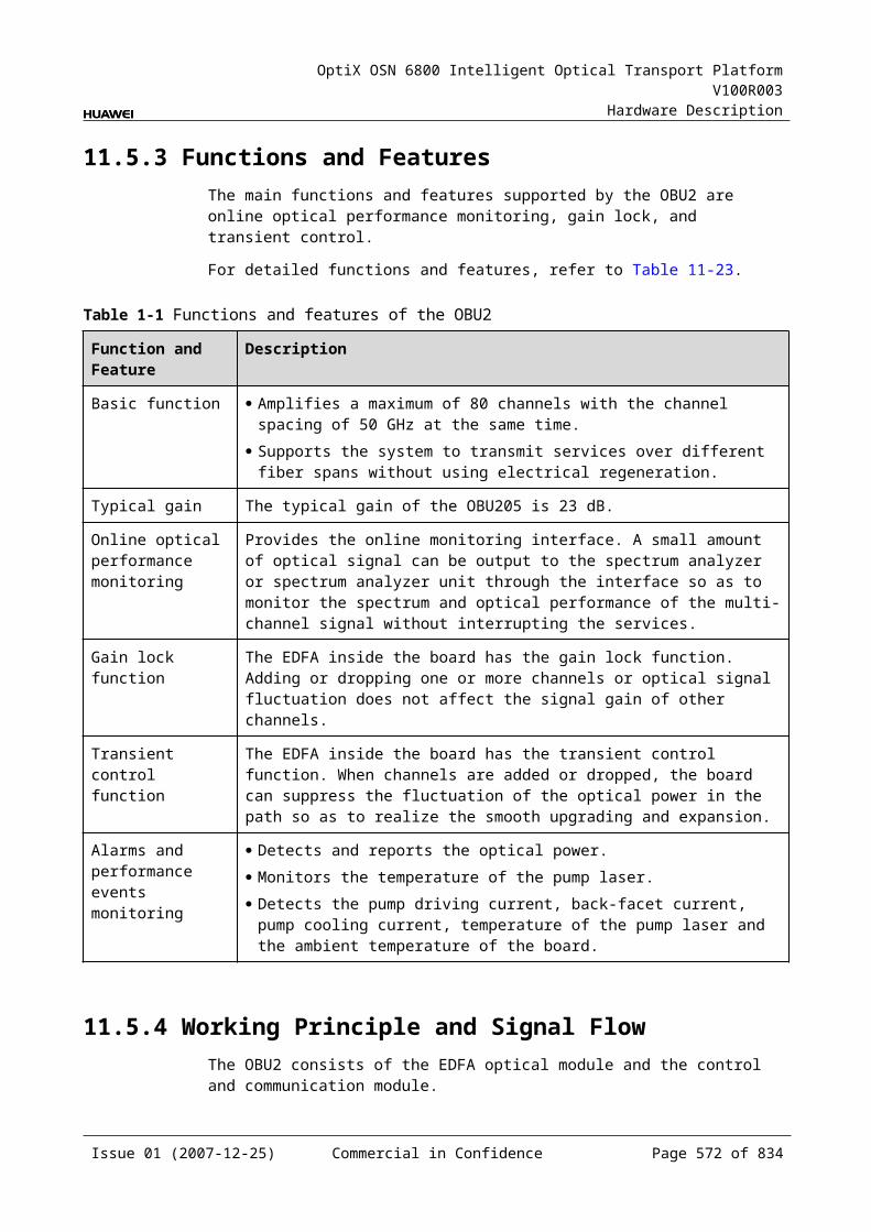
OptiX OSN 6800 Intelligent Optical Transport Platform V100R003
Hardware Description
Table B-1 Characteristic code for the OBU1
Code Meaning Description
The first character – The first character is always G.
The second and the third digits
Gain The second and the third digits indicate the gain value.
The fourth character – The fourth character is always I.
The fifth and the sixth digits
Maximum nominal input optical power
The fifth and the sixth digits indicate the maximum nominal input optical power.
For example, the characteristic code for the TN11OBU1 is G23I-3. This code indicates that the gain is 23 dB and the maximum nominal input optical power is -3 dBm.
B.6.3 Characteristic Code for of CRPCThe characteristic code for the CRPC consists of one character and two digits, indicating the gain of the optical signals processed by the board.
The detailed information of the characteristic code is given in Table B-1.
Table B-1 Characteristic code for the CRPC
Code Meaning Description
The first character – This character is always G.
The two digits Gain Indicate the gain value.
For example, the characteristic code for the TN11CRPC is G10, indicating 10 dB gain.
B.7 Characteristic Code for Optical MUX/DMUX UnitsThe characteristic code for optical MUX/DMUX units indicates the band of the optical signals processed by the board, whether the wavelengths that bear the signals are odd or even wavelengths, and the multiplexing solution adopted by the board.
B.7.1 Characteristic Code for the D40The characteristic code for the D40 consists of two characters. One indicates the band. The other indicates whether the wavelengths that bear the optical signals processed by the board are odd or even wavelengths.
The detailed information of the characteristic code is given in Table B-1.
Issue 01 (2007-12-25) Commercial in Confidence Page 574 of 664
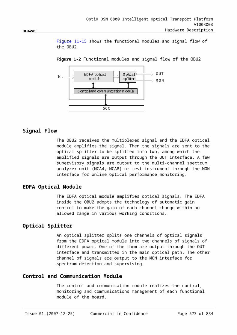
OptiX OSN 6800 Intelligent Optical Transport Platform V100R003
Hardware Description
Table B-1 Characteristic code for the D40
Code Meaning Description
The first character
Band Indicates the band of the optical signals processed by the board. The value C represents C band; the value L represents L band.
The second character
Odd/Even wavelengths
Indicates whether the wavelengths that bear signals are odd or even wavelengths. The value E represents even wavelengths; the value O represents odd wavelengths.
For example, the characteristic code for the TN11D40 is CE, indicating C band and even wavelengths.
NOTEThe OptiX OSN 6800 products now support only even wavelengths in C band.
B.7.2 Characteristic Code for the D40VThe characteristic code for the D40V consists of two characters. One indicates the band. The other indicates whether the wavelengths that bear the optical signals processed by the board are odd or even wavelengths.
The detailed information of the characteristic code is given in Table B-1.
Table B-1 Characteristic code for the D40V
Code Meaning Description
The first character
Band Indicates the band of the optical signals processed by the board. The value C represents C band; the value L represents L band.
The second character
Odd/Even wavelengths
Indicates whether the wavelengths that bear signals are odd or even wavelengths. The value E represents even wavelengths; the value O represents odd wavelengths.
For example, the characteristic code for the TN11D40V is CE, indicating C band and even wavelengths.
B.7.3 Characteristic Code for the FIUThe characteristic code for the FIU consists of one character, indicating the band adopted by the board.
The detailed information of the characteristic code is given in Table B-1.
Table B-1 Characteristic code for the FIU
Code Meaning
Description
The first character
Band Indicates the multiplexing solution adopted by the board. The value C represents C band; the value L represents L band.
Issue 01 (2007-12-25) Commercial in Confidence Page 575 of 664

OptiX OSN 6800 Intelligent Optical Transport Platform V100R003
Hardware Description
For example, the characteristic code for the TN11FIU is C, indicating that the optical signals are in C band.
B.7.4 Characteristic Code for the M40The characteristic code for the M40 consists of two characters. One indicates the band. The other indicates whether the wavelengths that bear the optical signals processed by the board are odd or even wavelengths.
The detailed information of the characteristic code is given in Table B-1.
Table B-1 Characteristic code for the M40
Code Meaning Description
The first character
Band Indicates the band of the optical signals processed by the board. The value C represents C band; the value L represents L band.
The second character
Odd/Even wavelengths
Indicates whether the wavelengths that bear signals are odd or even wavelengths. The value E represents even wavelengths; the value O represents odd wavelengths.
For example, the characteristic code for the TN11M40 is CE, indicating C band and even wavelengths.
B.7.5 Characteristic Code for the M40VThe characteristic code for the M40V consists of two characters. One indicates the band. The other indicates whether the wavelengths that bear the optical signals processed by the board are odd or even wavelengths.
The detailed information of the characteristic code is given in Table B-1.
Table B-1 Characteristic code for the M40V
Code Meaning Description
The first character
Band Indicates the band of the optical signals processed by the board. The value C represents C band; the value L represents L band.
The second character
Odd/Even wavelengths
Indicates whether the wavelengths that bear signals are odd or even wavelengths. The value E represents even wavelengths; the value O represents odd wavelengths.
For example, the characteristic code for the TN11M40V is CE, indicating C band and even wavelengths.
B.8 Characteristic Code for VOAsThe characteristic code for VOAs indicates the maximum attenuation of the optical signals processed by the board.
Issue 01 (2007-12-25) Commercial in Confidence Page 576 of 664

OptiX OSN 6800 Intelligent Optical Transport Platform V100R003
Hardware Description
B.8.1 Characteristic Code for the VA1The characteristic code for the VA1 consists of three digits, indicating the maximum attenuation of the optical signals processed by the board.
The detailed information of the characteristic code is given in Table B-1.
Table B-1 Characteristic code for the VA1
Code Meaning Description
The first to the third digits Attenuation value Indicate the maximum attenuation.
For example, the characteristic code for the TN11VA1 is 21.5, indicating that the maximum attenuation value is 21.5 dB.
B.8.2 Characteristic Code for the VA4The characteristic code for the VA4 consists of three digits, indicating the maximum attenuation of the optical signals processed by the board.
The detailed information of the characteristic code is given in Table B-1.
Table B-1 Characteristic code for the VA4
Code Meaning Description
The first to the third digits Attenuation value Indicate the maximum attenuation.
For example, the characteristic code for the TN11VA4 is 21.5, indicating that the maximum attenuation value is 21.5 dB.
Issue 01 (2007-12-25) Commercial in Confidence Page 577 of 664
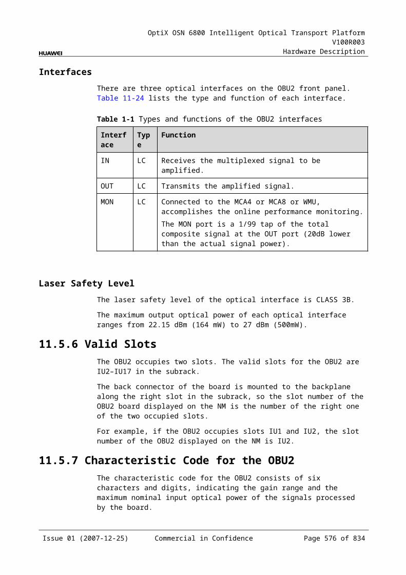
OptiX OSN 6800 Intelligent Optical Transport Platform V100R003
Hardware Description
C Parameter Description
C.1 Optical Transponder Units (OTUs), Tributary Units and Line UnitsC.1.1 Path Use StatusItem Description
Parameter description
Used to set the path use status.
Parameter values Used, Unused
Parameter value description
Default value: Used
Recommended value
Used
Application scenarios
In configuration, commissioning and maintenance stages
Impact on the system
When the Path Use Status of an optical interface is set to Unused, service alarms at this interface are suppressed, which disables the automatic laser turn on function.
Relevant boards OTUs: L4G, LDGS, LDGD, LOG, LOM, ECOM, TMX, LSXL, LSXLR, LQMS, LQMD, LSX, LSXR, LWXS, LWXD, LWX2Tributary units: TDX, TQM, TDG, TQS TSXLLine unit: NS2
Configuration requirements
When the channel is not required, its Path Use Status can be set to Unused. In this case, a command should be issued to shut down the laser of this path; otherwise, an alarm indicates that the laser is forcibly turned on is reported.
Issue 01 (2007-12-25) Commercial in Confidence Page 579 of 664
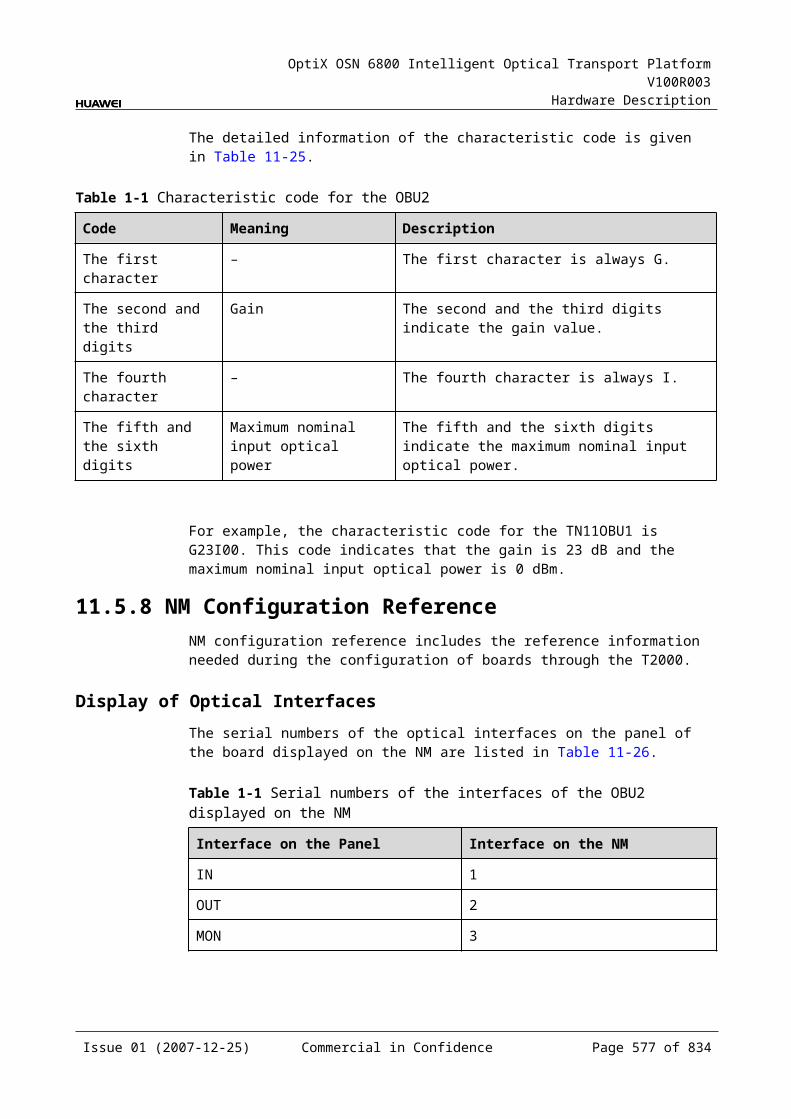
OptiX OSN 6800 Intelligent Optical Transport Platform V100R003
Hardware Description
C.1.2 Optical Interface LoopbackItem Description
Parameter description
Used to set the loopback mode of the current optical interface.
Parameter values Non-Loopback, Outloop, Inloop
Parameter value description
Default value: Non-Loopback Non-Loopback: indicates that the equipment is in normal state. Optical interface loopback is not required when the equipment normally operates.Inloop: indicates a mode that signals to be output from the output interface of the local-end equipment are looped back to the signal input interface of this equipment. Inloop is used to test the signal processing on the board.Outloop: indicates a mode that unprocessed signals accessed to the local-end equipment are directly looped back to the corresponding output interface without the signal structure changed. Outloop is used to test connections between fiber lines and connectors.
Recommended value
Non-Loopback
Application scenarios
In commissioning and maintenance stages
Impact on the system
When the loopback mode is set to Inloop or Outloop, services are interrupted.
Relevant boards OTUs: L4G, LDGS, LDGD, LOG, LOM, ECOM, TMX, LSXL, LQMS, LQMD, LSX, LSXR, LWXS, LWXD, LWX2Tributary units: TDX, TQM, TDG, TQS TSXLLine unit: NS2
Configuration requirements
None
Issue 01 (2007-12-25) Commercial in Confidence Page 580 of 664
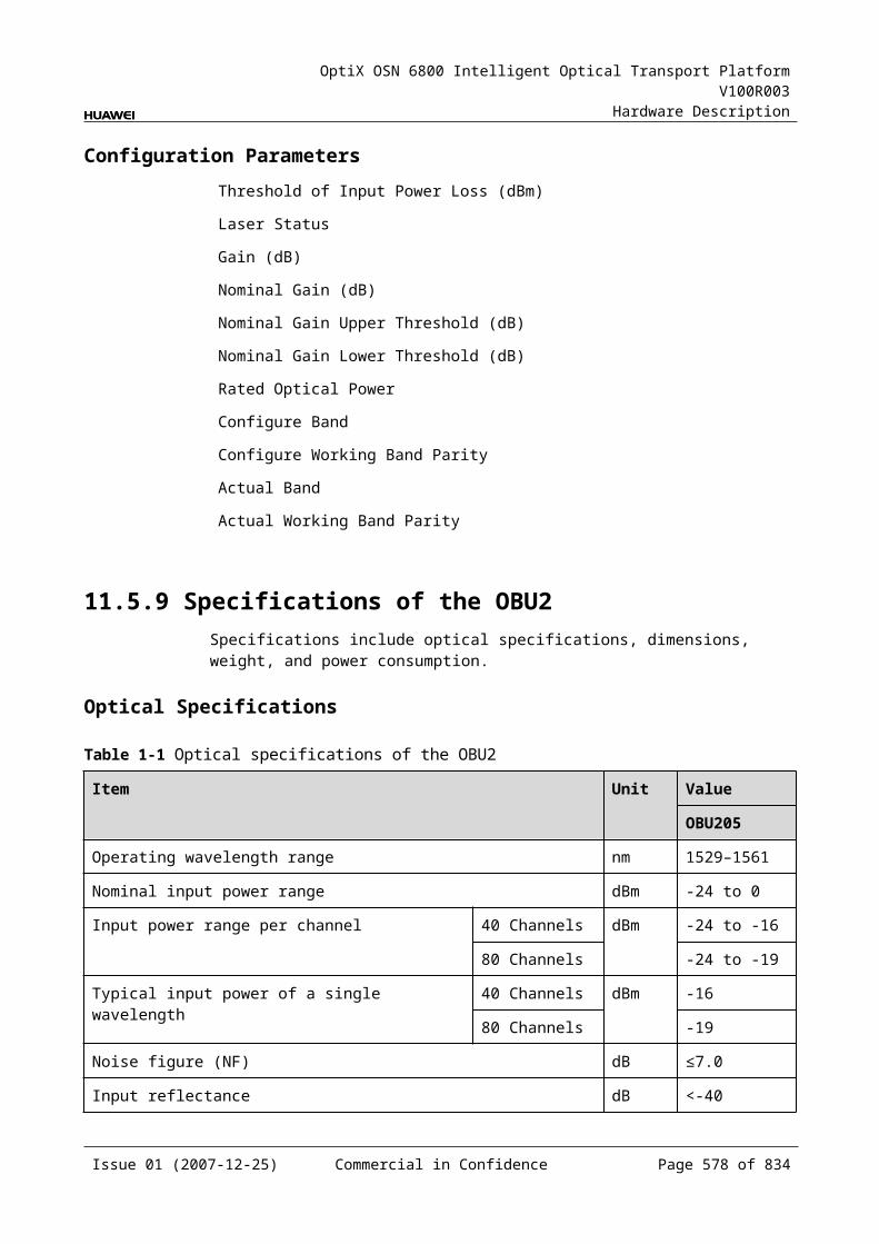
OptiX OSN 6800 Intelligent Optical Transport Platform V100R003
Hardware Description
C.1.3 Service TypeItem Description
Parameter description Used to set the type of services at a client-side optical interface.
Parameter values LQMS, LQMD: GE, FE, STM-1, STM-4, STM-16, OC-3, OC-12, OC-48, FC-100, FC-200, FICON, FICON 2G, DVB-ASI, ESCONLSX: 10GE WAN, 10GE LAN, STM-64, OC-192, OTU-2LWXS, LWXD, LWX2: GE, FE, STM-1, STM-4, STM-16, OC-3, OC-12, OC-48, FC-100, FC-200, FICON, FICON 2G, DVB-ASI, DVB-SDI, ESCONLSXL: STM-256, OC-768LOM: GE, FC100, FC200, FC400, FICON, FICON 2GTMX: STM-16, OC-48, OUT1TDX: 10GELAN, STM-64, OC-192TQM: GE, FE, STM-1, STM-4, STM-16, OC-3, OC-12, OC-48, FC-100, FC-200, FICON, FICON 2G, DVB-ASI, ESCONTQS: OTU1, OC-48, STM-16
Parameter value description (default value)
LQMS, LQMD: STM-4LSX: 10GE LANLWXS, LWXD, LWX2: anyTQM: STM-4TQS: OTU-1
Recommended value None
Application scenarios In configuration, commissioning and maintenance stages
Impact on the system None
Relevant boards OTUs: LQMS, LQMD, LSX, LWXS, LWXD, LWX2, LOM, TMX, LSXLTributary units: TDX, TQM, TQS, TSXL
Configuration requirements
The type of actually accessed services must be the same as the type of configured services. Otherwise, the services are not available. If the LQMS, LQMD or TQM board is configured with electrical-layer cross-connections, the type of services in the corresponding channels cannot be changed.
Issue 01 (2007-12-25) Commercial in Confidence Page 581 of 664
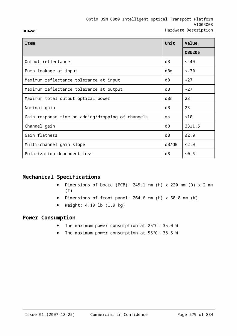
OptiX OSN 6800 Intelligent Optical Transport Platform V100R003
Hardware Description
C.1.4 Client Service Bearer Rate (M)Item Description
Parameter description Used to set the bearer rate of client-side services.
Parameter value range (M) 16.0–2500.0
Parameter value description The bearer rate of client-side services can be set only when the client-side services are of Any type. The set value should equal to the maximum rate of actually accessed services.
Recommended value None
Application scenarios In configuration, commissioning and maintenance stages
Impact on the system A SPEED_OVER alarm is reported when the rate of actually accessed services exceeds the set value.
Relevant boards LWXS, LWXD, LWX2
Configuration requirements (the set value of bearer rate should be the same as the rate of actually accessed services)
Actually accessed services
Set value Actually accessed services
Set value
STM1 155.5 GE 1250
STM4 622 FE 125
STM16 2488.3 FC100 1062
OC3 155.5 FC200 2124
OC12 622 FICON 1062
OC48 2488.3 FICON 2G 2124
HDTV 1485 ESCON 270
DVB-SDI 270 FDDI 125
DVB-ASI 270
C.1.5 Port MappingItem Description
Parameter description
Used to set and query the port mapping.
Parameter values Bit Transparent Mapping (11.1G), MAC Transparent Mapping (10.7G), Bit Transparent Mapping (10.7G)
Parameter value description
Default value: MAC Transparent Mapping (10.7G)
Recommended value
None
Issue 01 (2007-12-25) Commercial in Confidence Page 582 of 664
OptiX OSN 6800 Intelligent Optical Transport Platform V100R003
Hardware Description
Item Description
Application scenarios
In configuration, commissioning and maintenance stages
Impact on the system
None
Relevant boards LSX
Configuration requirements
Services other than 10GE LAN do not require configuring the port mapping. The port mapping of 10GE LAN services can be configured as Bit Transparent Mapping (11.1G), MAC Transparent Mapping (10.7G) or Bit Transparent Mapping (10.7G).Bit Transparent Mapping (11.1G) and Bit Transparent Mapping (10.7G) meet customers' demand for transparent bit transport of 10GE LAN signals.Bit transparently mapped (11.1G) services provide an FEC/AFEC coding gain value equivalent to that of 10G SDH services. Bit transparently mapped (10.7G) services occupy some AFEC areas and thus provide a weaker AFEC coding gain.MAC Transparent Mapping (10.7G) meets customers' demand for transparently transporting 10GE MAC frames only. MAC transparently mapped (10.7G) services have the standard OTU2 frame structure and supports the FEC/AFEC code which is the same as that of 10G bit/s SDH services.
C.1.6 Laser StatusItem Description
Parameter description Used to set the laser Open/Close status.
Parameter values Open, Close Default value: Open
Parameter value description
Open: The laser is turned on to start transmitting services. Close: The laser is turned off to stop service transmitting.
Recommended value Open
Application scenarios In configuration, commissioning and maintenance stages
Impact on the system When the laser is set to Close, services are interrupted.
Relevant boards OTUs: L4G, LDGS, LDGD, LOG, LOM, ECOM, TMX, LSXL, LSXLR, LQMS, LQMD, LSX, LSXR, LWXS, LWXD, LWX2Tributary units: TBE, TDX, TQM, TDG, TQS TSXLLine unit: NS2
Configuration requirements
When an optical interface is unused or is not connected to a fiber, the laser at this interface should be set to Open.
Issue 01 (2007-12-25) Commercial in Confidence Page 583 of 664
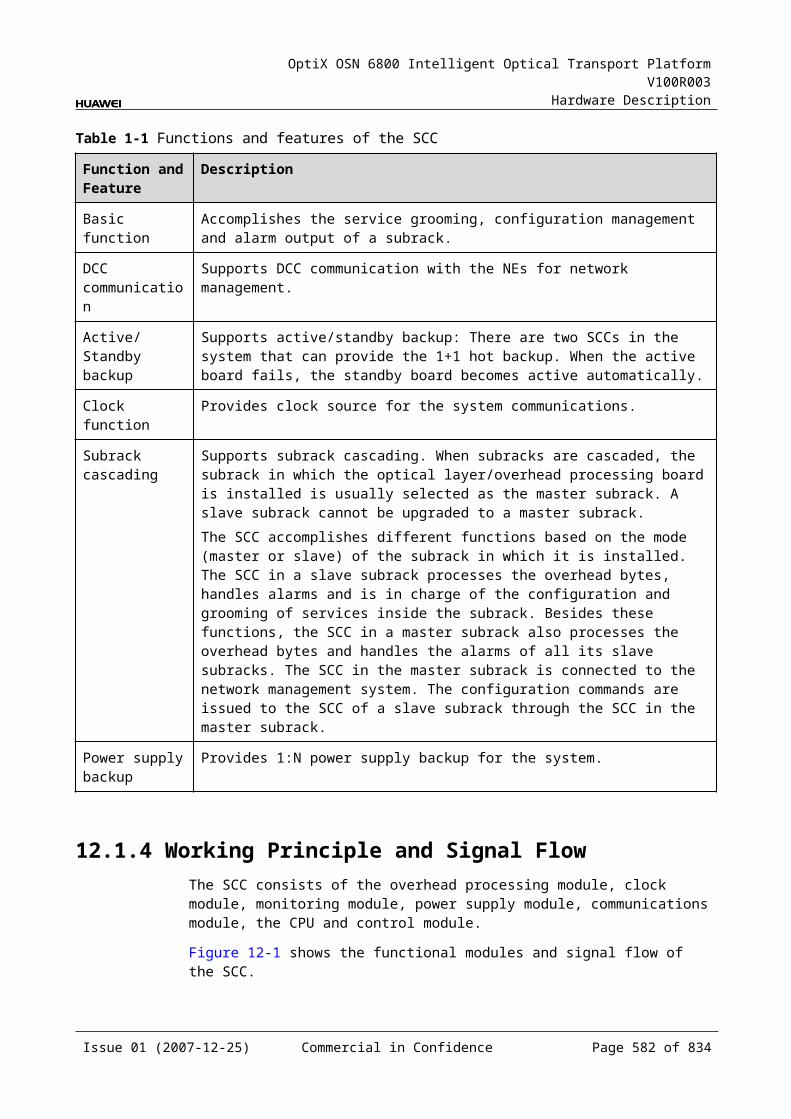
OptiX OSN 6800 Intelligent Optical Transport Platform V100R003
Hardware Description
C.1.7 Automatic Laser ShutdownItem Description
Parameter description
Used to set whether to enable automatic laser shutdown (ALS) of the downstream laser of the local board in the case of loss of received signals. If ALS is enabled, when the received signals are lost, the laser is automatically shut down and stops transmitting signals. ALS prolongs the service life of a laser and avoids injury of laser to human.
Parameter values Enabled, Disabled
Parameter value description
ALS of optical interfaces on OTU client sides and tributary units is set to Enabled by default; that on OTU WDM sides and line units is set to Disabled by default.
Recommended value
ALS of optical interfaces on OTU client sides and tributary units is set to Enabled; that on OTU WDM sides and line units is set to Disabled.
Application scenarios
In configuration and maintenance stages
Impact on the system
None
Relevant boards OTUs: L4G, LDGS, LDGD, LOG, LOM, TMX, LSXL, LSXLR, LQMS, LQMD, LSX, LSXR, LWXS, LWXD, LWX2Tributary units: TBE, TDX, TQM, TDG, TQS TSXLLine unit: NS2
Configuration requirements
If a WDM-side optical interface does not use ESC as the network management communication channel or even is not connected to a fiber, ALS on the WDM side can be set to Enabled to prolong the service life of the laser at the interface.
C.1.8 Current Bearer Rate (M)Item Description
Parameter description Used to query the current bearer rate of client-side services.
Parameter values Queriable only
Parameter value description None
Recommended value None
Application scenarios In configuration, commissioning and maintenance stages
Impact on the system None
Relevant boards LWXS, LWXD, LWX2
Configuration requirements None
Issue 01 (2007-12-25) Commercial in Confidence Page 584 of 664
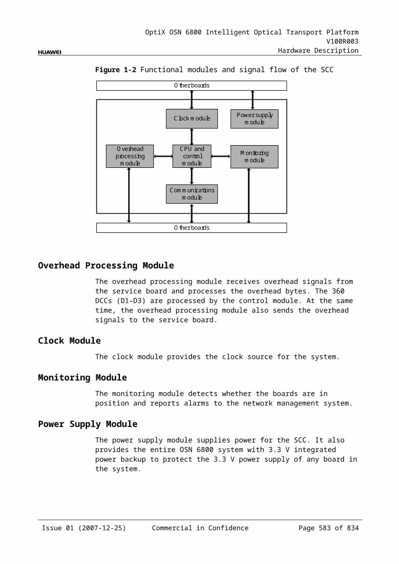
OptiX OSN 6800 Intelligent Optical Transport Platform V100R003
Hardware Description
C.1.9 Service ModeItem Description
Parameter description Used to set the mode of line-side services.
Parameter values OTN, SDH
Parameter value description
Default mode: OTN
Recommended value OTN
Application scenarios In configuration, commissioning and maintenance stages
Impact on the system None
Relevant boards L4G, LDGS, LDGD
Configuration requirements
The mode of line-side services of boards on an NE at the local end should be the same as that at the opposite end. When a local-end board need be connected to an SDH service board of another product, the mode of line-side services should be set to SDH.
C.1.10 FEC Working StateItem Description
Parameter description Used to set and query the FEC working state.
Parameter values Enabled, Disabled
Parameter value description
Default value: Enabled
Recommended value Enabled
Application scenarios In configuration and commissioning stages
Impact on the system Enabling the FEC working state lowers the requirement of optical signal-to-noise ratio (OSNR) at the receive end and stretches the distance between an optical amplifying station and a regenerating station.
Relevant boards OTUs: L4G, LDGS, LDGD, LOG, LOM, TMX, LQMS, LQMD, LSX, LSXL, LSXLR, LSXRTributary unit: TQS Line unit: NS2
Configuration requirements
During configuration, the FEC working states of two corresponding optical interfaces at the two ends of the transport line should be the same. Otherwise, the setting of FEC working states fails.FEC is enabled in most cases unless in scenarios where the requirement of transport delay is extremely high.
Issue 01 (2007-12-25) Commercial in Confidence Page 585 of 664

OptiX OSN 6800 Intelligent Optical Transport Platform V100R003
Hardware Description
C.1.11 FEC TypeItem Description
Parameter description Used to select the FEC type.
Parameter values FEC, AFEC
Parameter value description
Default value: FEC
Recommended value AFEC
Application scenarios In configuration and commissioning stages
Impact on the system None
Relevant boards OTU: LSXL, LOG, LOM, TMX, LSXLine unit: NS2
Configuration requirements
Relationships between service type, port mapping and FEC type: When the service type is 10GE LAN, if the port mapping is without flow
control, the FEC type can be AFEC only; if the port mapping is in other modes, the FEC type is not limited.
FEC types of services other than 10GE LAN are not limited.During configuration, the FEC types of two corresponding optical interfaces at the two ends of the transport line should be the same.
C.1.12 PAUSE Frame Flow ControlItem Description
Parameter description Used to select whether to enable flow control.
Parameter values Enabled, Disabled
Parameter value description
Default value: Enabled
Recommended value Enabled
Application scenarios In configuration and commissioning stages
Impact on the system None
Relevant boards TN11LSX, TDX
Configuration requirements
This parameter can be configured only when the service type is 10GE LAN.
Issue 01 (2007-12-25) Commercial in Confidence Page 586 of 664
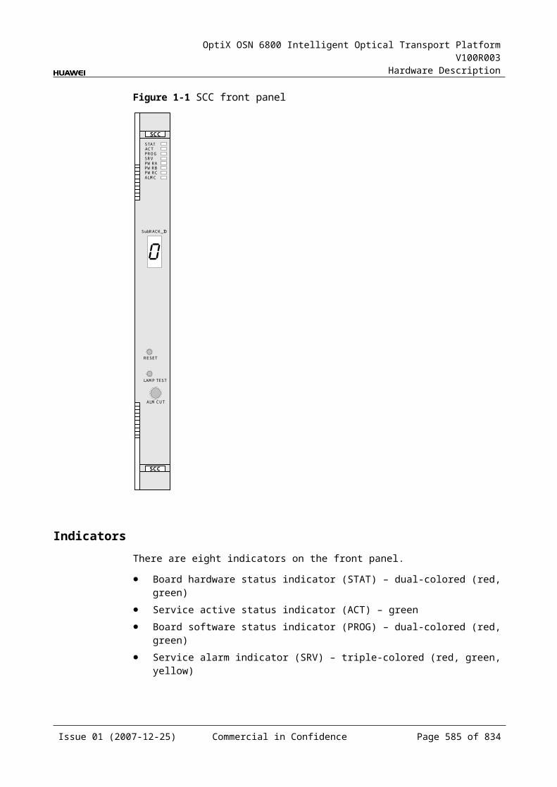
OptiX OSN 6800 Intelligent Optical Transport Platform V100R003
Hardware Description
C.1.13 Configure Wavelength No./Wavelength (nm)/Frequency (THz)Item Description
Parameter description Used to configure the operating wavelength at the WDM-side optical interface of a board.
Parameter values C-band wavelength spacing: 100G (192.100–196.00 THz) CWDM-band wavelength spacing: 20 nm (1271–1611 nm)
Recommended value The operating wavelength of a fixed-wavelength OTU should be set to the actual wavelength of the OTU. The operating wavelength of a tunable-wavelength OTU should be set upon the network wavelength planning.
Application scenarios In configuration stage
Impact on the system The same wavelength should be used for a service in the receive and the transmit directions.
If a service travels through multiple regenerating stations, it is recommended that these regenerating sections use the same wavelength.
It is recommended that the active and standby channels use the same wavelength when the inter-board channel protection or client-side path protection is adopted.
Relevant boards OTU: LOG, LOM, ECOM, TMX, L4G, LDGS, LDGD, LQMS, LQMD, LSX, LSXL, LSXLR, LSXR, LWXS, LWXD, LWX2Line unit: NS2Tributary units: TBE, TDX, TDG, TSXL
Configuration requirements
The configured logic wavelength must be the same as the actual physical wavelength. Otherwise, a CFGDATA_OUTRANGE alarm is reported.As for tunable optical modules, issuing the captioned command directly changes their physical wavelengths (but does not change the band). As for non-tunable optical modules, issuing this command changes their logic wavelengths only.
Issue 01 (2007-12-25) Commercial in Confidence Page 587 of 664
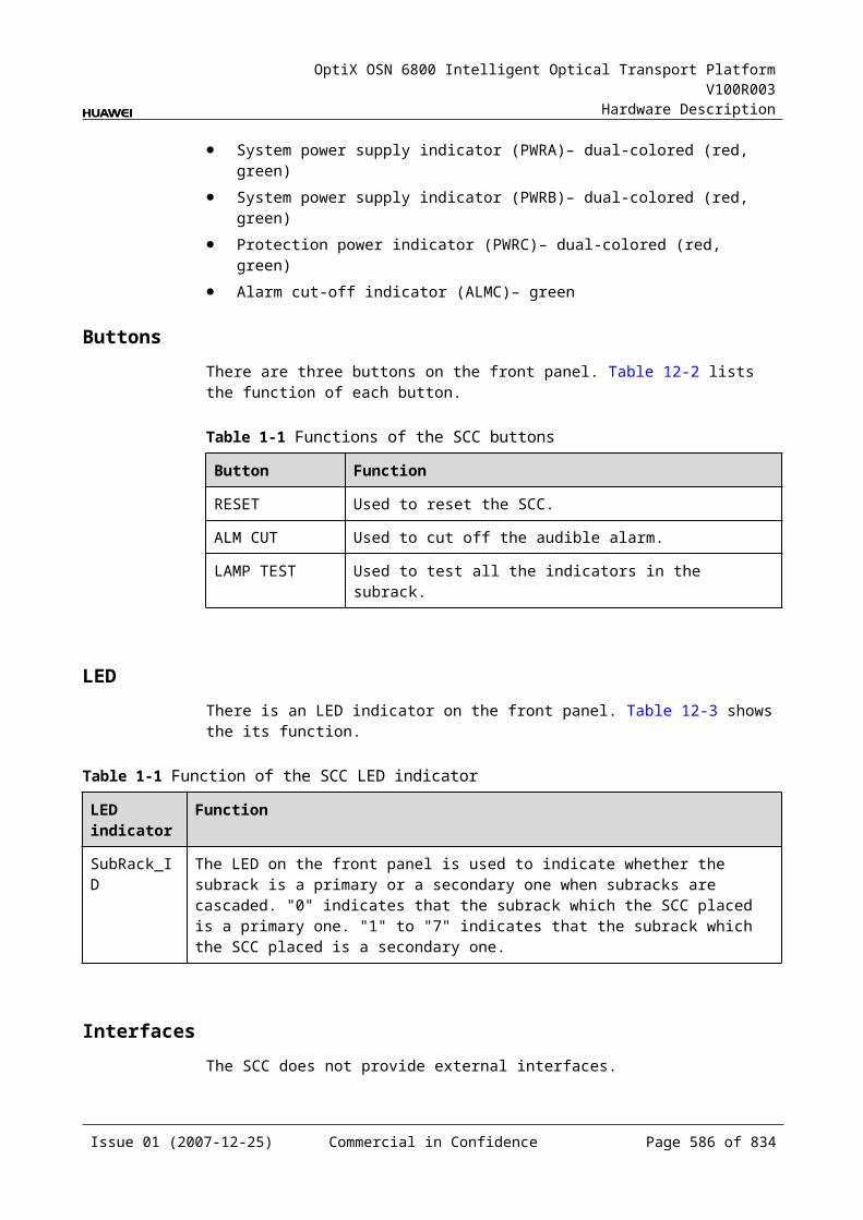
OptiX OSN 6800 Intelligent Optical Transport Platform V100R003
Hardware Description
C.1.14 Configure Band TypeItem Description
Parameter description Used to configure the band type.
Parameter values C, CWDM
Parameter value description
None
Recommended value None
Application scenarios In configuration, commissioning and maintenance stages
Impact on the system None
Relevant boards OTU: LOG, LOM, ECOM, TMX, L4G, LDGS, LDGD, LQMS, LQMD, LSX, LSXL, LSXLR, LSXR, LWXS, LWXD, LWX2Line unit: NS2Tributary units: TBE, TDX, TDG, TSXL
Configuration requirements
The configured logic band must be the same as the actual physical band. Otherwise, a CFGDATA_OUTRANGE alarm is reported.
C.1.15 Maximum Packet LengthItem Description
Parameter description Used to configure the maximum packet length of data services.
Parameter value range (byte)
1518–9600
Parameter value description
Value range: 1518–9600 Default value: 1518
Recommended value 1518
Application scenarios In configuration and commissioning stages
Impact on the system None
Relevant boards OTU: LDGS, LDGD, LOG, LOM, LQMS, LQMDTributary units: TDX, TDG, TQM
Configuration requirements
The maximum packet length can be set when the service type is GE or FE. If a customer requires extra long packets, set the maximum packet length according to the requirement.
Issue 01 (2007-12-25) Commercial in Confidence Page 588 of 664
OptiX OSN 6800 Intelligent Optical Transport Platform V100R003
Hardware Description
C.1.16 Ethernet Working ModeItem Description
Parameter description Used to query and set the Ethernet working mode.
Parameter values Auto-Negotiation, 1000M Full-Duplex
Parameter value description
Default value: Auto-Negotiation
Recommended value Auto-Negotiation
Application scenarios In configuration and commissioning stages
Impact on the system None
Relevant boards OTUs: LDGS, LOG, LOM, LDGD, LQMS, LQMDTributary units: TDG, TQM
Configuration requirements
The Ethernet working mode of the local station should be the same as that of the upstream. If the two ports protect each other, these two active and standby ports must be set to be in the same Ethernet working mode. The LQMS and LQMD boards support the Ethernet working mode setting only when the service type is GE.
C.1.17 LPT EnabledItem Description
Parameter description Used to query and set the Enabled/Disabled state of link state pass through (LPT).
Parameter values Enabled, Disabled
Parameter value description
None
Recommended value Disabled
Application scenarios In configuration and commissioning stages
Impact on the system None
Relevant boards OTUs: L4G, LDGS, LDGD, LQMS, LQMD, LSXTributary units: TBE, TDX, TQM, TDG
Configuration requirements
LPT is valid for only data services. When the router has redundant protection paths, LPT of the access ports of the corresponding routers should be set to Enabled.
Issue 01 (2007-12-25) Commercial in Confidence Page 589 of 664
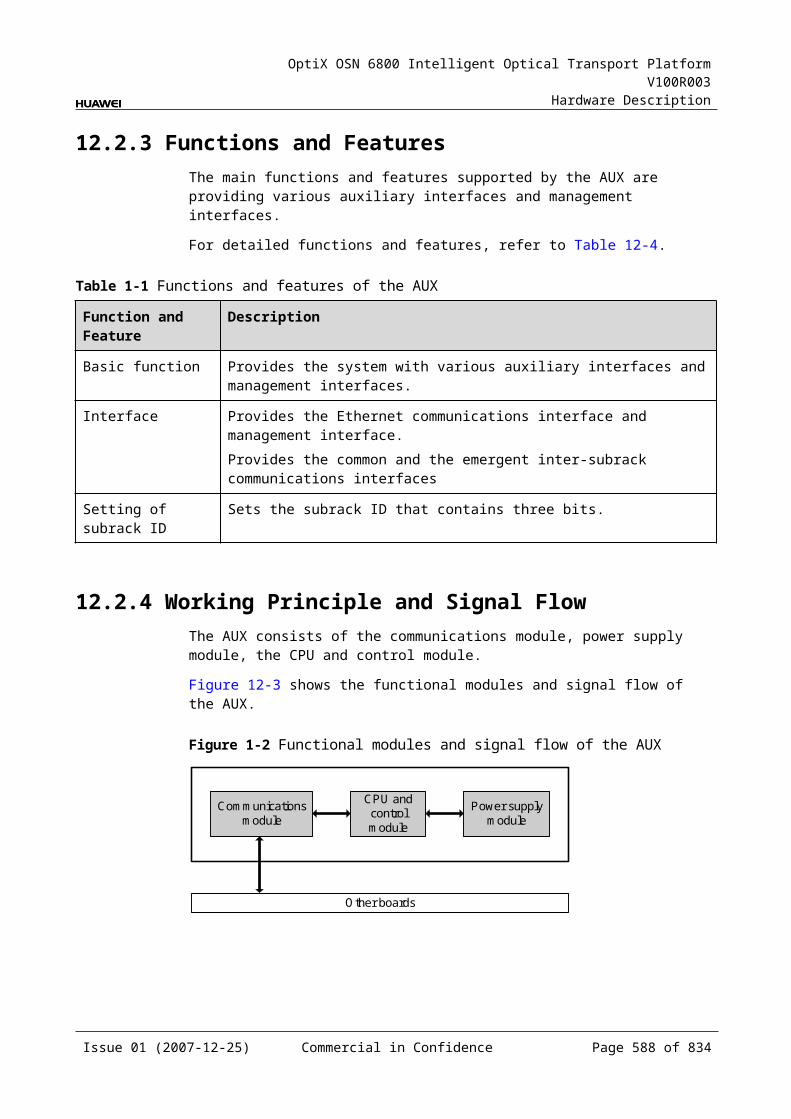
OptiX OSN 6800 Intelligent Optical Transport Platform V100R003
Hardware Description
C.1.18 Path LoopbackItem Description
Parameter description Used to query and set the path loopback.
Parameter values Non-Loopback, Inloop, Outloop
Parameter value description
Non-Loopback: indicates the normal state. Path loopback is not required when the equipment normally operates.Inloop: indicates a mode that signals to be output from the output path of the local-end equipment are looped back to the signal input path of this equipment. Inloop is used to test the signal processing on the board.Outloop: indicates a mode that unprocessed signals accessed to the local-end equipment is directly looped back to the corresponding output path without the signal structure changed. Outloop is used to test connections between fiber lines and connectors.
Recommended value Non-Loopback
Application scenarios In commissioning and maintenance stages
Impact on the system Path loopback interrupts services.
Relevant boards NS2
Configuration requirements
The path loopback should be configured upon the commissioning purpose.
C.1.19 SD Trigger ConditionItem Description
Parameter description Used to configure the trigger condition to perform SD switching on the board.
Parameter values B1_SD, OTUk_DEG, ODUk_PM_DEG, None
Parameter value description
B1_SD: Regeneration section (B1) signal degradeOTUk_DEG: OTUk signal degradeODUk_PM_DEG: ODUk_PM signal degradeNone: No condition is configured for SD switching.
Recommended value Set the value to None.
Application scenarios In commissioning and maintenance stages
Impact on the system When the B1_SD, OTUk_DEG or ODUk_PM_DEG alarm occurs, the protection group might be triggered to perform protection switching.
Relevant boards TDG, TQM
Configuration requirements
Set the value to B1_SD, OTUk_DEG or ODUk_PM_DEG if the protection mechanism needs such a trigger condition.
Issue 01 (2007-12-25) Commercial in Confidence Page 590 of 664

OptiX OSN 6800 Intelligent Optical Transport Platform V100R003
Hardware Description
C.1.20 FC Distance ExtensionItem Description
Parameter description To enable or disable the function for extending the transmission distance for the FC services.
Parameter values enable, disable
Parameter value description
enable: To enable the function for extending the transmission distance for the FC services.disable: To disable the function for extending the transmission distance of FC services.
Recommended value disable
Application scenarios In commissioning and maintenance stage
Impact on the system Extends the transmission distance for the FC services.
Relevant boards LOM
Configuration requirements
When the board accesses FC100/FC200/FC400 services, this parameter must be enabled.
C.2 Optical Multiplexing Units (MUXs) and Optical Demultiplexing Units (DMUXs) C.2.1 Optical Interface Attenuation Ratio (dB)Item Description
Parameter description Used to adjust the attenuation of optical power in the corresponding channels to equalize the optical power of each wavelength.
Parameter value range (dB)
0.0–15.0
Parameter value description
Value range: varies with boards. The value range of optical interface attenuation ratio of a board can be obtained by querying the Maximum Attenuation Ratio and Minimum Attenuation Ratio of the board.Default value: 15 dB (maximum attenuation ratio of the board)
Recommended value Configured upon the engineering optical power planning.
Application scenarios In configuration, commissioning and maintenance stages
Impact on the system Influences the downstream optical power.
Relevant boards M40V, D40V
Issue 01 (2007-12-25) Commercial in Confidence Page 591 of 664
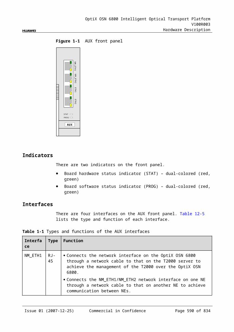
OptiX OSN 6800 Intelligent Optical Transport Platform V100R003
Hardware Description
Item Description
Configuration requirements
The attenuation adjustment amplitude should not be too large. It should be controlled within ±2 dB compared with the original attenuation every time the attenuation is adjusted in a new project. In an expansion project or maintenance, the attenuation adjustment amplitude should be controlled within ±1 dB.
C.2.2 Threshold of Input Power Loss (dBm) Item Description
Parameter description Indicates the lower threshold of input optical power loss (an MUT_LOS alarm is reported).
Parameter values Queriable only
Parameter value description
The default value varies with boards.
Recommended value None
Application scenarios In commissioning and maintenance stages
Impact on the system None
Relevant boards D40, D40V, FIU
Configuration requirements
None
C.2.3 Configure BandItem Description
Parameter description Used to configure type of the working band of a board.
Parameter values C
Parameter value description
Supports only C band.
Recommended value None
Application scenarios In commissioning and maintenance stages
Impact on the system None
Relevant boards FIU, M40, M40V, D40, D40V, ITL
Configuration requirements
None
Issue 01 (2007-12-25) Commercial in Confidence Page 592 of 664
OptiX OSN 6800 Intelligent Optical Transport Platform V100R003
Hardware Description
C.2.4 Configure Working Band ParityItem Description
Parameter description Selects the desired parity of the working band.
Parameter values All, Even, Odd
Parameter value description
All: All 192.10 THz to 196.05 THz odd and even wavelengths at 50 GHz channel spacing in C band. There are 80 wavelengths in total. It is applicable for the FIU and ITL boards.Even: All 192.10 THz to 196.00 THz even wavelengths at 100 GHz channel spacing. There are 40 wavelengths in total. It is applicable for the M40, M40V, D40 and D40V boards.Odd: All 192.15 THz to 196.05 THz odd wavelengths at 100 GHz channel spacing. There are 40 wavelengths in total. It is applicable for the M40, M40V, D40 and D40V boards.
Recommended value Corresponding wavelengths are used according to different requirements.
Application scenarios In commissioning and maintenance stages
Impact on the system None
Relevant boards FIU, M40, M40V, D40, D40V, ITL
Configuration requirements
When configuring the parity of wavelengths on the T2000, make sure that the parity configured is consistent with that of the atual working wavelengths.
C.2.5 Actual BandItem Description
Parameter description Used to query the actual working band of the board.
Parameter values Queriable only
Parameter value description
None
Recommended value None
Application scenarios In commissioning and maintenance stages
Impact on the system None
Relevant boards FIU, M40, M40V, D40, D40V, ITL
Configuration requirements None
Issue 01 (2007-12-25) Commercial in Confidence Page 593 of 664
OptiX OSN 6800 Intelligent Optical Transport Platform V100R003
Hardware Description
C.2.6 Actual Working Band ParityItem Description
Parameter description Used to query the parity of the actual working band of the board.
Parameter values Queriable only
Parameter value description
None
Recommended value None
Application scenarios In commissioning and maintenance stages
Impact on the system None
Relevant boards FIU, M40, M40V, D40, D40V, ITL
Configuration requirements
None
C.3 Optical Add/Drop Multiplexing Units (OADMs)C.3.1 Configure Wavelength No./Add-Drop Wavelength (nm)/Frequency (THz)Item Description
Parameter description Used to configure the operating wavelength at the WDM-side optical interface of a board.
Parameter values C-band wavelength spacing: 100G (192.100–196.00 THz) CWDM-band wavelength spacing: 20 nm (1271–1611 nm)
Parameter value description
MR2, MR4, MR8, MB2: values of C-even 40 wavelengths CMR2, CMR4, DMR1: CWDM-band values
Recommended value None
Application scenarios In configuration, commissioning and maintenance stages
Impact on the system None
Relevant boards MR2, MR4, MR8, MB2, CMR2, CMR4, DMR1
Configuration requirements
The configured logic wavelength must be the same as the actual physical wavelength. Otherwise, a CFGDATA_OUTRANGE alarm is reported.The same wavelength cannot be configured at different optical interfaces of the same board.
Issue 01 (2007-12-25) Commercial in Confidence Page 594 of 664
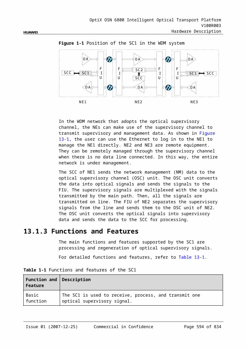
OptiX OSN 6800 Intelligent Optical Transport Platform V100R003
Hardware Description
C.3.2 Configure Band TypeItem Description
Parameter description Used to configure the band type.
Parameter values C
Parameter value description
Supports only C band.
Recommended value The default value varies with boards. Refer to the value obtained on site through the T2000.
Application scenarios In configuration, commissioning and maintenance stages
Impact on the system None
Relevant boards MR2, MR4, MR8, CMR2, CMR4, MB2, DMR1, SBM2
Configuration requirements
None
C.4 Reconfigurable Optical Add and Drop Multiplexing Unit (ROADMs)C.4.1 Threshold of Input Power Loss (dBm) Item Description
Parameter description Indicates the lower threshold of input optical power loss (an MUT_LOS alarm is reported).
Parameter values Queriable only
Parameter value description
The default value varies with boards and subjects to the on-site queried result.
Recommended value None
Application scenarios In commissioning and maintenance stages
Impact on the system None
Relevant boards ROAM, WSD9, RMU9
Configuration requirements
None
Issue 01 (2007-12-25) Commercial in Confidence Page 595 of 664
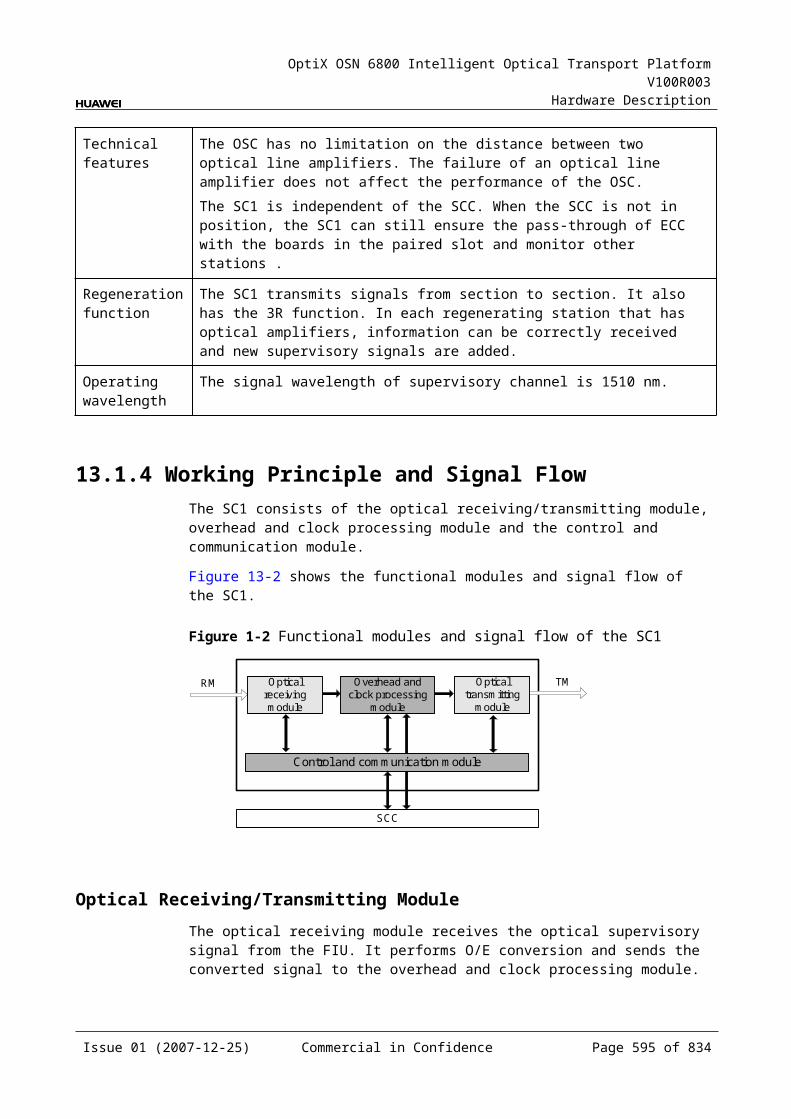
OptiX OSN 6800 Intelligent Optical Transport Platform V100R003
Hardware Description
C.4.2 Wavelength Target Power (dBm)Item Description
Parameter description Applies to the ROAM board only and is used to set the single-wavelength target output optical power after add wavelengths are multiplexed.
Parameter value range (dB)
–32.0 to 8.0
Parameter value description
None
Recommended value Standard single-wavelength input optical power at the IN interface of an optical amplifying unit connected to the OUT interface of an ROAM board.
Application scenarios In configuration, commissioning and maintenance stages
Impact on the system Influences the downstream optical power.
Relevant boards ROAM
Configuration requirements
The configuration of target output optical power takes effect only when optical cross-connections are configured in the corresponding channels.
C.4.3 Optical Interface Attenuation Ratio (dB)Item Description
Parameter description Used to adjust the attenuation of optical power in the corresponding channels to equalize the optical power of each wavelength.
Parameter value range (dB)
WSM9: 0–20WSD9: 0–20RMU9: 0–15
Parameter value description
Value range: varies with boards. The value range of optical interface attenuation ratio of a board can be obtained by querying the Maximum Attenuation Ratio and Minimum Attenuation Ratio of the board.Default value: maximum attenuation ratio of the board
Recommended value Configured upon the engineering optical power planning.
Application scenarios In configuration, commissioning and maintenance stages
Impact on the system Influences the downstream optical power.
Relevant boards WSM9, WSD9, RMU9
Configuration requirements
The attenuation adjustment amplitude should not be too large. It should be controlled within ±2 dB compared with the original attenuation every time the attenuation is adjusted in a new project. In an expansion project or maintenance, the attenuation adjustment amplitude should be controlled within ±1 dB.
Issue 01 (2007-12-25) Commercial in Confidence Page 596 of 664
OptiX OSN 6800 Intelligent Optical Transport Platform V100R003
Hardware Description
C.4.4 Maximum Attenuation Ratio (dB)Item Description
Parameter description Indicates the maximum optical power attenuation ratio of a board.
Parameter values Queriable only
Parameter value description Value type: integers
Recommended value None
Application scenarios In maintenance stage
Impact on the system None
Relevant boards WSM9, WSD9, RMU9
Configuration requirements None
C.4.5 Minimum Attenuation Ratio (dB)Item Description
Parameter description Indicates the minimum optical power attenuation ratio of a board.
Parameter values Queriable only
Parameter value description Value type: integers
Recommended value None
Application scenarios In maintenance stage
Impact on the system None
Relevant boards WSM9, WSD9, RMU9
Configuration requirements None
C.4.6 Configure BandItem Description
Parameter description Used to configure type of the working band of a board.
Parameter values C
Parameter value description Supports only C band.
Recommended value None
Application scenarios In commissioning and maintenance stages
Impact on the system None
Issue 01 (2007-12-25) Commercial in Confidence Page 597 of 664
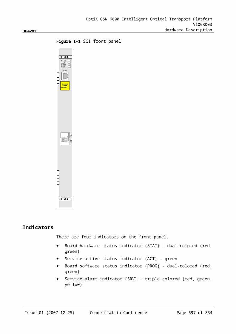
OptiX OSN 6800 Intelligent Optical Transport Platform V100R003
Hardware Description
Item Description
Relevant boards RMU9, ROAM, WSD9, WSM9, WSMD4
Configuration requirements None
C.4.7 Configure Working Band ParityItem Description
Parameter description Selects the desired parity of the working band.
Parameter values All, Even, Odd
Parameter value description
All: All 192.10 THz to 196.05 THz odd and even wavelengths at 50 GHz channel spacing in C band. There are 80 wavelengths in total. It is applicable for the RMU9, TN13WSD9, TN13WSM9 board.Even: All 192.10 THz to 196.00 THz even wavelengths at 100 GHz channel spacing. There are 40 wavelengths in total. It is applicable for the ROAM, WSMD4, TN12WSD9, TN12WSM9, TN11WSD9, TN11WSM9 boards.Odd: All 192.15 THz to 196.05 THz odd wavelengths at 100 GHz channel spacing. There are 40 wavelengths in total. It is applicable for the ROAM, WSMD4, TN12WSD9, TN12WSM9, TN11WSD9, TN11WSM9 boards.
Recommended value Corresponding wavelengths are used according to different requirements.
Application scenarios In commissioning and maintenance stages
Impact on the system None
Relevant boards RMU9, ROAM, WSD9, WSM9, WSMD4
Configuration requirements
When configuring the parity of wavelengths on the T2000, make sure that the parity configured is consistent with that of the atual working wavelengths.
C.4.8 Actual BandItem Description
Parameter description Used to query the actual working band of the board.
Parameter values Queriable only
Parameter value description None
Recommended value None
Application scenarios In commissioning and maintenance stages
Impact on the system None
Relevant boards RMU9, ROAM, WSD9, WSM9, WSMD4
Issue 01 (2007-12-25) Commercial in Confidence Page 598 of 664
OptiX OSN 6800 Intelligent Optical Transport Platform V100R003
Hardware Description
Item Description
Configuration requirements None
C.4.9 Actual Working Band ParityItem Description
Parameter description Used to query the parity of the actual working band of the board.
Parameter values Queriable only
Parameter value description None
Recommended value None
Application scenarios In commissioning and maintenance stages
Impact on the system None
Relevant boards RMU9, ROAM, WSD9, WSM9, WSMD4
Configuration requirements None
C.5 Optical Amplifier UnitsC.5.1 Threshold of Input Power Loss (dBm) Item Description
Parameter description Indicates the lower threshold of input optical power loss (an MUT_LOS alarm is reported).
Parameter values Queriable only
Parameter value description The default value varies with boards and subjects to the on-site queried result.
Recommended value None
Application scenarios In commissioning and maintenance stages
Impact on the system None
Relevant boards OAU1, OBU1, OBU2, HBA
Configuration requirements None
Issue 01 (2007-12-25) Commercial in Confidence Page 599 of 664
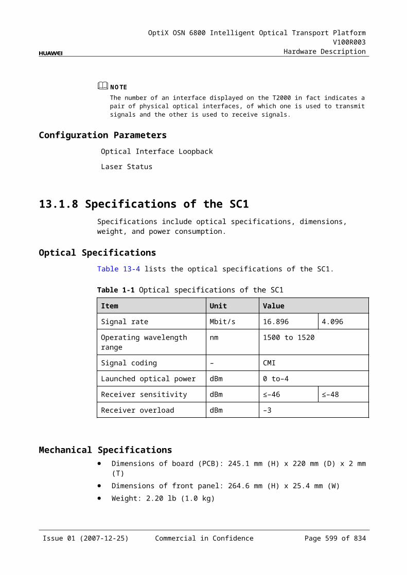
OptiX OSN 6800 Intelligent Optical Transport Platform V100R003
Hardware Description
C.5.2 Laser StatusItem Description
Parameter description Used to set the laser Enabled/Disabled status.
Parameter values Enabled, Disabled .Default value of the OAU1/OBU1: Enabled.Default value of the CRPC: Disabled
Parameter value description Enabled: The laser is turned on to start transmitting services. Disabled: The laser is turned off to stop service transmitting.
Recommended value Enabled
Application scenarios In configuration, commissioning and maintenance stages
Impact on the system When the laser is set to Disabled, services are interrupted.
Relevant boards OAU1, OBU1, CRPC, OBU2, HBA
Configuration requirements When services are normal, the laser of the optical amplifying unit should be set to Enabled.
C.5.3 Gain (dB)Item Description
Parameter description Used to query the optical power gain of the current optical amplifying unit.
Parameter values Queriable only
Parameter value description
None
Recommended value None
Application scenarios In configuration, commissioning and maintenance stages
Impact on the system None
Relevant boards OAU1, OBU1, OBU2, HBA
Configuration requirements
Normally, the queried result should range from the nominal gain minus 2.5 dB to the nominal gain plus 2.5 dB.
Issue 01 (2007-12-25) Commercial in Confidence Page 600 of 664
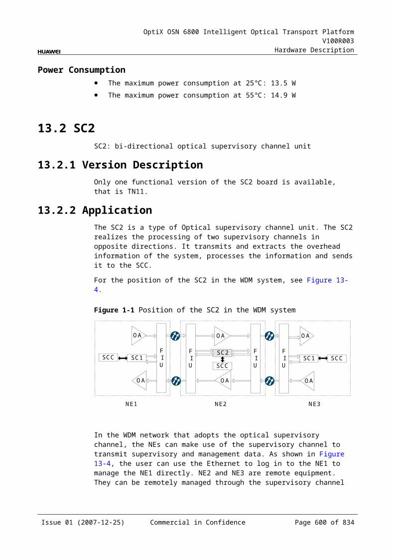
OptiX OSN 6800 Intelligent Optical Transport Platform V100R003
Hardware Description
C.5.4 Nominal Gain (dB)Item Description
Parameter description Used to set and query the gain at optical interfaces to optimize the flatness of optical channels.
Parameter value range (dB)
OAU1: 17.5–31.5OBU101: 17.7–22.7OBU102: 20.7–25.7
Parameter value description
Value range: varies with boards. The nominal gain value range of a board can be obtained by querying the Nominal Gain Upper Threshold and Nominal Gain Lower Threshold of the board. Default value: OAU1: 20 dBOBU101: 20 dBOBU102: 23 dB
Recommended value OAU1: 20 dBOBU101: 20 dBOBU102: 23 dB
Application scenarios In configuration, commissioning and maintenance stages
Impact on the system Gain values influence the performance of downstream services.
Relevant boards OAU1, OBU101, OBU2, HBA
Configuration requirements
The nominal gain should be correctly set upon the network optical power budget. The OBU1 does not require the nominal gain setting and adopts the recommended value.
C.5.5 Nominal Gain Upper Threshold (dB)Item Description
Parameter description Used to query the nominal gain upper threshold.
Parameter values Queriable only
Parameter value description None
Recommended value None
Application scenarios In commissioning and maintenance stages
Impact on the system None
Relevant boards OAU1, OBU1, OBU2, HBA
Configuration requirements None
Issue 01 (2007-12-25) Commercial in Confidence Page 601 of 664

OptiX OSN 6800 Intelligent Optical Transport Platform V100R003
Hardware Description
C.5.6 Nominal Gain Lower Threshold (dB)Item Description
Parameter description Used to query the nominal gain lower threshold.
Parameter values Queriable only
Parameter value description None
Recommended value None
Application scenarios In commissioning and maintenance stages
Impact on the system None
Relevant boards OAU1, OBU1, OBU2, HBA
Configuration requirements None
C.5.7 Rated Optical Power (dBm)Item Description
Parameter description
Used to set and query the single-wavelength rated optical power as the reference value for automatic optical power adjustment. When the optical amplifying unit and ROADM are used for networking, this parameter is set in the optical amplifying unit.
Parameter value range (dBm)
–30.0 to 30.0
Parameter value description
Default value at the input optical interface: –19 dBm.Default value at the output optical interface: 4 dBm.
Recommended value OAU1: input interface: –16 dBm; output interface: 4 dBm OBU101: input interface: –20 dBm; output interface: 0 dBm OBU102: input interface: –19 dBm; output interface: 4 dBm
Application scenarios In configuration, commissioning and maintenance stages
Impact on the system
None
Relevant boards OAU1, OBU1, OBU2, HBA
Configuration requirements
The rated input and output optical power should be configured by referring to the actual configurable input and output range of the optical amplifying unit and should be the same as the input and output values measured when the optical amplifying unit normally operates.
Issue 01 (2007-12-25) Commercial in Confidence Page 602 of 664
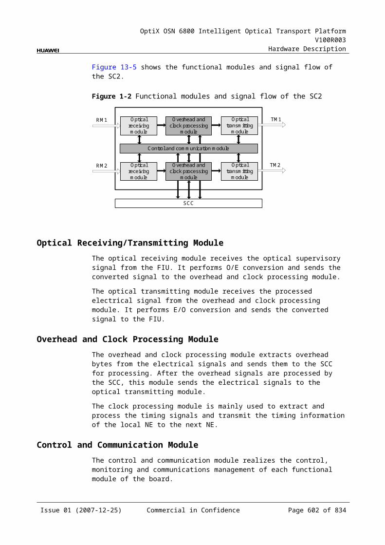
OptiX OSN 6800 Intelligent Optical Transport Platform V100R003
Hardware Description
C.5.8 Board Work TypeItem Description
Parameter description Used to query and set the board work type.
Parameter values C, C+L, L
Parameter value description None
Recommended value C
Application scenarios In configuration, commissioning and maintenance stages
Impact on the system None
Relevant boards CRPC
Configuration requirements None
C.5.9 Configure BandItem Description
Parameter description Used to configure type of the working band of a board.
Parameter values C
Parameter value description Supports only C band.
Recommended value None
Application scenarios In commissioning and maintenance stages
Impact on the system None
Relevant boards CRPC, OAU1, OBU1, OBU2, HBA
Configuration requirements None
Issue 01 (2007-12-25) Commercial in Confidence Page 603 of 664

OptiX OSN 6800 Intelligent Optical Transport Platform V100R003
Hardware Description
C.5.10 Configure Working Band ParityItem Description
Parameter description Selects the desired parity of the working band.
Parameter values All, Even, Odd
Parameter value description
All: All 192.10 THz to 196.05 THz odd and even wavelengths at 50 GHz channel spacing in C band. There are 80 wavelengths in total.It is applicable for the CRPC, OAU1, OBU1, OBU2, HBA boards.Even: All 192.10 THz to 196.00 THz even wavelengths at 100 GHz channel spacing. There are 40 wavelengths in total. It is applicable for the CRPC board.Odd: All 192.15 THz to 196.05 THz odd wavelengths at 100 GHz channel spacing. There are 40 wavelengths in total. It is applicable for the CRPC board.
Recommended value Corresponding wavelengths are used according to different requirements.
Application scenarios In commissioning and maintenance stages
Impact on the system None
Relevant boards CRPC, OAU1, OBU1, OBU2, HBA
Configuration requirements
When configuring the parity of wavelengths on the T2000, make sure that the parity configured is consistent with that of the atual working wavelengths.
C.5.11 Actual BandItem Description
Parameter description Used to query the actual working band of the board.
Parameter values Queriable only
Parameter value description None
Recommended value None
Application scenarios In commissioning and maintenance stages
Impact on the system None
Relevant boards CRPC, OAU1, OBU1, OBU2, HBA
Configuration requirements None
Issue 01 (2007-12-25) Commercial in Confidence Page 604 of 664

OptiX OSN 6800 Intelligent Optical Transport Platform V100R003
Hardware Description
C.5.12 Actual Working Band ParityItem Description
Parameter description Used to query the parity of the actual working band of the board.
Parameter values Queriable only
Parameter value description None
Recommended value None
Application scenarios In commissioning and maintenance stages
Impact on the system None
Relevant boards CRPC, OAU1, OBU1, OBU2, HBA
Configuration requirements None
C.6 Optical Supervisory Channel Units (OSCs)C.6.1 Optical Interface LoopbackItem Description
Parameter description Used to set the loopback mode of the current optical interface.
Parameter values Non-Loopback, Outloop, Inloop
Parameter value description
Default value: Non-Loopback Non-Loopback: indicates the normal state. Path loopback is not required when the equipment normally operates.Inloop: indicates a mode that signals to be output from the output interface of the local-end equipment are looped back to the signal input interface of this equipment. Inloop is used to test the signal processing on the board.Outloop: indicates a mode that unprocessed signals accessed to the local-end equipment are directly looped back to the corresponding output interface without the signal structure changed. Outloop is used to test connections between fiber lines and connectors.
Recommended value Non-Loopback
Application scenarios In commissioning and maintenance stages
Impact on the system When the loopback mode is set to Inloop or Outloop, services in the supervisory channel are interrupted.
Relevant boards SC1, SC2
Configuration requirements
None
Issue 01 (2007-12-25) Commercial in Confidence Page 605 of 664
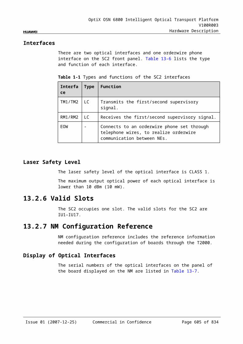
OptiX OSN 6800 Intelligent Optical Transport Platform V100R003
Hardware Description
C.6.2 Laser StatusItem Description
Parameter description Used to set the laser Enabled/Disabled status.
Parameter values Enabled, Disabled Default value: Enabled
Parameter value description Enabled: The laser at an optical interface is turned on. Disabled: The laser at an optical interface is turned off.
Recommended value Enabled
Application scenarios In configuration, commissioning and maintenance stages
Impact on the system None
Relevant boards SC1, SC2
Configuration requirements None
C.7 Optical Protection UnitsC.7.1 Threshold of Input Power Loss (dBm) Item Description
Parameter description Indicates the lower threshold of input optical power loss (an MUT_LOS alarm is reported).
Parameter value range (dBm)
–35.0 to 10.0
Parameter value description
Default value: –35.0
Recommended value –35.0
Application scenarios In commissioning and maintenance stages
Impact on the system This parameter directly influences the SF switching condition of OLP protection, OTU+OLP/DCP intra-board 1+1 protection and client-side 1+1 protection with the OLP/DCP board. The larger the parameter value is, the more likely the SF switching occurs.
Relevant boards DCP, OLP
Configuration requirements
Normally, the threshold should be set to the recommended value. The actual network situation and fiber aging, however, should be considered during the parameter configuration to avoid mis-switching.
Issue 01 (2007-12-25) Commercial in Confidence Page 606 of 664

OptiX OSN 6800 Intelligent Optical Transport Platform V100R003
Hardware Description
C.7.2 Initial Variance Value Between Primary and Secondary Input Power (dB)Item Description
Parameter description Indicates the initial variance value between primary and secondary input power. Initial variance value = initial input power at the primary optical interface – initial input power at the secondary optical interface
Parameter value range (dB)
–10.0 to 10.0
Parameter value description
Default value: 0.0
Recommended value 0.0
Application scenarios In commissioning and maintenance stages
Impact on the system This parameter serves as the SD switching threshold reference value for OLP protection, OTU+OLP/DCP intra-board 1+1 protection and OLP/DCP client-side 1+1 protection with the OLP/DCP board. Variance between primary and secondary input power = input power at the primary optical interface – input power at the secondary optical interface – initial variance During SD switching judgement, if the absolute value of variance between primary and secondary input power reaches the SD switching threshold, SD switching is actuated.
Relevant boards DCP, OLP
Configuration requirements
The parameter should be set upon the actual variance between primary and secondary input power.
C.7.3 Variance Threshold Between Primary and Secondary Input Power (dB)Item Description
Parameter description Used to set the variance threshold between primary and secondary input power at which signals degrade (SD).
Parameter value range (dB)
3.0–8.0
Parameter value description
Default value: 5.0
Recommended value 5.0
Application scenarios In commissioning and maintenance stages
Issue 01 (2007-12-25) Commercial in Confidence Page 607 of 664
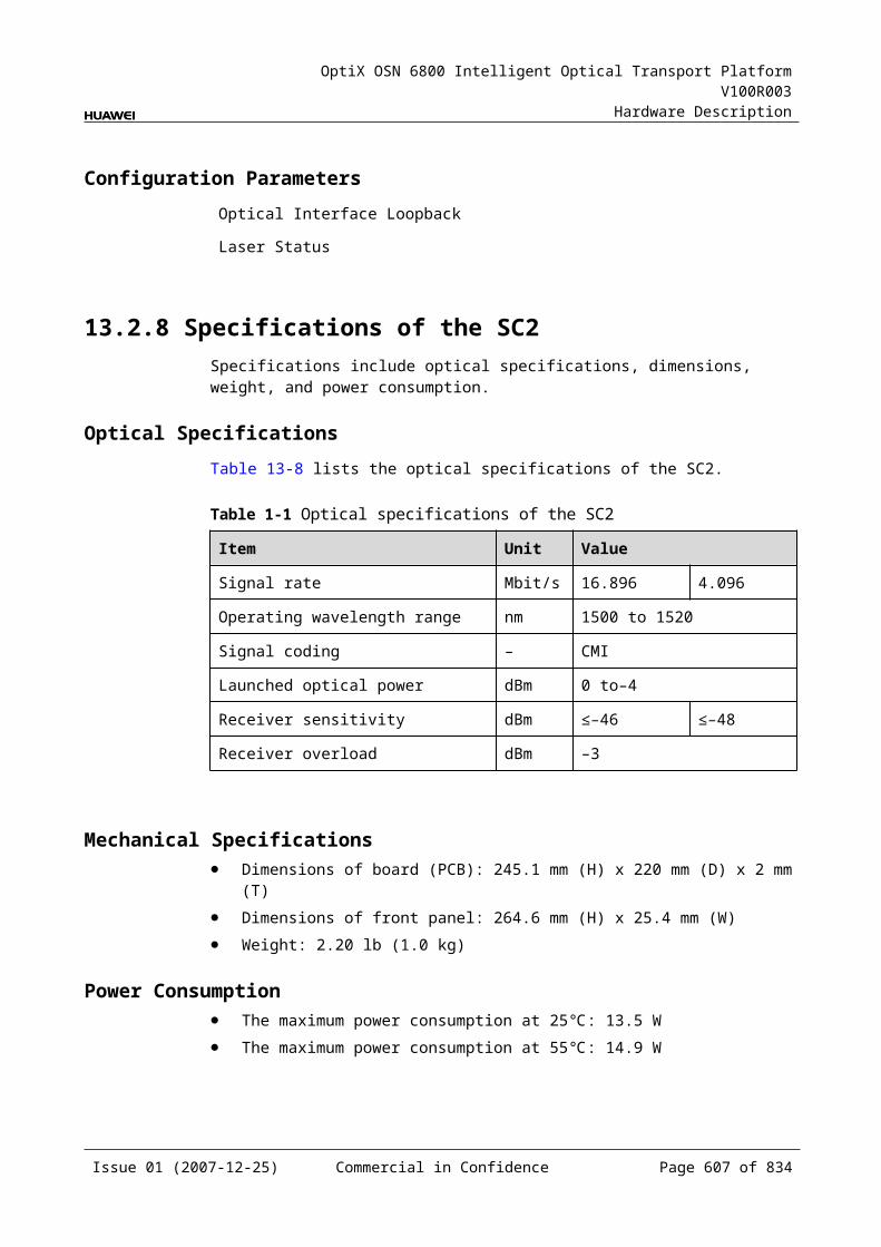
OptiX OSN 6800 Intelligent Optical Transport Platform V100R003
Hardware Description
Item Description
Impact on the system This parameter serves as the SD switching threshold reference value for OLP protection, OTU+OLP/DCP intra-board 1+1 protection and OLP/DCP client-side 1+1 protection with the OLP/DCP board.Variance between primary and secondary input power = input power at the primary optical interface – input power at the secondary optical interface – initial varianceDuring SD switching judgement, if the absolute value of variance between primary and secondary input power reaches the SD switching threshold, SD switching is actuated.
Relevant boards DCP, OLP
Configuration requirements
Generally, the threshold is set to the recommended value. In special cases, the threshold can be adjusted upon the actual on-site situation. When the variance between primary and secondary input power reaches 5 dB, if services in channels with lower optical power are still normal, the threshold can be properly elevated. When the variance between primary and secondary input power is far from reaching 5 dB while services degrade, the threshold should be properly lowered.
C.8 Spectrum Analyzer UnitsC.8.1 Optical MonitoringItem Description
Parameter description Used to set the optical interface monitoring state.
Parameter values Enabled, Disabled
Parameter value description
Default value: Enabled
Recommended value None
Application scenarios In configuration stage
Impact on the system When the monitoring of an optical interface is set to Disabled, the MCA board does not analyze the wavelength at this interface.
Relevant boards MCA4, MCA8
Configuration requirements
The monitoring state of optical interfaces that require monitoring should be set to Enabled.
Issue 01 (2007-12-25) Commercial in Confidence Page 608 of 664
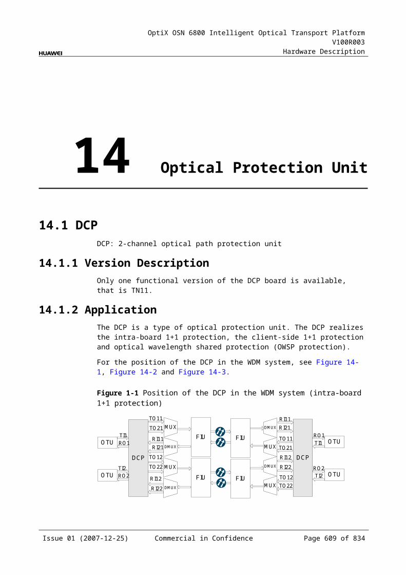
OptiX OSN 6800 Intelligent Optical Transport Platform V100R003
Hardware Description
C.8.2 Monitor Interval (min)Item Description
Parameter description Used to set the supervisory channel of the current board for analyzing the channel status monitor interval.
Parameter value range (min)
5–49995
Parameter value description Default value: 10
Recommended value 10
Application scenarios In configuration stage
Impact on the system None
Relevant boards MCA4, MCA8
Configuration requirements The default value is recommended.
C.8.3 Wavelength Monitor StatusItem Description
Parameter description Used to set whether to monitor the current wavelength.
Parameter values Monitor, No Monitor
Parameter value description Default value: No Monitor
Recommended value It is recommended to set the monitor status of wavelengths that bear services to Monitor.
Application scenarios In configuration stage
Impact on the system None
Relevant boards MCA4, MCA8
Configuration requirements The monitor status of wavelengths that bear services should be set to Monitor.
Issue 01 (2007-12-25) Commercial in Confidence Page 609 of 664
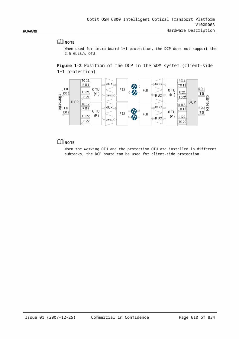
OptiX OSN 6800 Intelligent Optical Transport Platform V100R003
Hardware Description
C.8.4 Configure BandItem Description
Parameter description Used to configure type of the working band of a board.
Parameter values C
Parameter value description Supports only C band.
Recommended value None
Application scenarios In commissioning and maintenance stages
Impact on the system None
Relevant boards MCA4, MCA8
Configuration requirements None
C.8.5 Configure Working Band ParityItem Description
Parameter description Selects the desired parity of the working band.
Parameter values All, Even, Odd
Parameter value description
All: All 192.10 THz to 196.05 THz odd and even wavelengths at 50 GHz channel spacing in C band. There are 80 wavelengths in total. It is applicable for the MCA4 and MCA8 board.Even: All 192.10 THz to 196.00 THz even wavelengths at 100 GHz channel spacing. There are 40 wavelengths in total. It is applicable for the MCA4 and MCA8 board.Odd: All 192.15 THz to 196.05 THz odd wavelengths at 100 GHz channel spacing. There are 40 wavelengths in total. It is applicable for the MCA4 and MCA8 board.
Recommended value Corresponding wavelengths are used according to different requirements.
Application scenarios In commissioning and maintenance stages
Impact on the system None
Relevant boards MCA4, MCA8
Configuration requirements
When configuring the parity of wavelengths on the T2000, make sure that the parity configured is consistent with that of the atual working wavelengths.
Issue 01 (2007-12-25) Commercial in Confidence Page 610 of 664
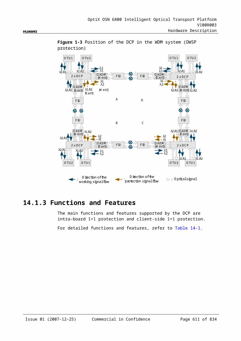
OptiX OSN 6800 Intelligent Optical Transport Platform V100R003
Hardware Description
C.8.6 Actual BandItem Description
Parameter description Used to query the actual working band of the board.
Parameter values Queriable only
Parameter value description None
Recommended value None
Application scenarios In commissioning and maintenance stages
Impact on the system None
Relevant boards MCA4, MCA8
Configuration requirements None
C.8.7 Actual Working Band ParityItem Description
Parameter description Used to query the parity of the actual working band of the board.
Parameter values Queriable only
Parameter value description None
Recommended value None
Application scenarios In commissioning and maintenance stages
Impact on the system None
Relevant boards MCA4, MCA8
Configuration requirements None
Issue 01 (2007-12-25) Commercial in Confidence Page 611 of 664
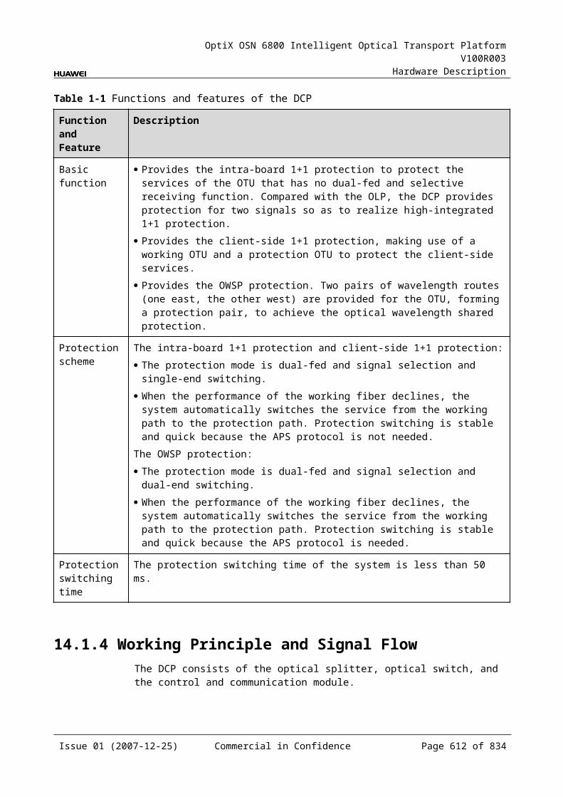
OptiX OSN 6800 Intelligent Optical Transport Platform V100R003
Hardware Description
C.9 Variable Optical Attenuator Units (VOAs)C.9.1 Optical Interface Attenuation Ratio (dB)Item Description
Parameter description Used to adjust the attenuation of optical power in the corresponding channels to meet the requirement of optical power test.
Parameter value range (dB)
Varies with the environment or optical components and subjects to the on-site query result.
Parameter value description
Value range: varies with boards. The value range of optical interface attenuation ratio of a board can be obtained by querying the Maximum Attenuation Ratio and Minimum Attenuation Ratio of the board.Default value: maximum attenuation ratio of the board (21.5 dB)
Recommended value Configured upon the requirement of optical power test.
Application scenarios In configuration, commissioning and maintenance stages
Impact on the system Influences the downstream optical power.
Relevant boards VA1, VA4
Configuration requirements
The attenuation adjustment amplitude should not be too large. It should be controlled within ±2 dB compared with the original attenuation every time the attenuation is adjusted in a new project. In an expansion project or maintenance action, the attenuation adjustment amplitude should be controlled within ±1 dB.
C.9.2 Maximum Attenuation Ratio (dB)Item Description
Parameter description Indicates the maximum optical power attenuation ratio of a board.
Parameter values Queriable only
Parameter value description None
Recommended value None
Application scenarios In maintenance stage
Impact on the system None
Relevant boards VA1, VA4
Configuration requirements None
Issue 01 (2007-12-25) Commercial in Confidence Page 612 of 664
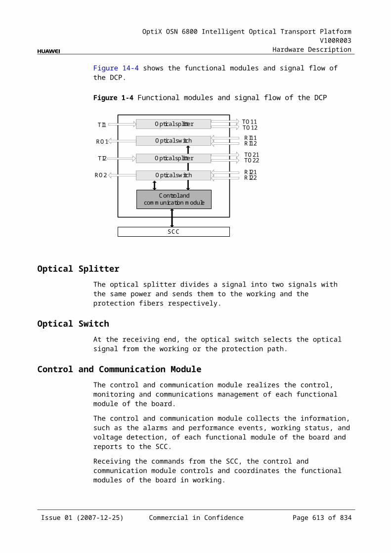
OptiX OSN 6800 Intelligent Optical Transport Platform V100R003
Hardware Description
C.9.3 Minimum Attenuation Ratio (dB)Item Description
Parameter description Indicates the minimum optical power attenuation ratio of a board.
Parameter values Queriable only
Parameter value description None
Recommended value None
Application scenarios In maintenance stage
Impact on the system None
Relevant boards VA1, VA4
Configuration requirements None
C.9.4 Path Use StatusItem Description
Parameter description Used to set the path use status.
Parameter values Used, Unused
Parameter value description
Value type: enumeration Default value: UsedUsed: indicates that the port is in use.Unused: indicates that the port is not in use.
Recommended value Used
Application scenarios In configuration, commissioning and maintenance stages
Impact on the system If the port is set to Unused, alarms generated at this port are suppressed.
Relevant boards VA1, VA4
Configuration requirements
If a port has services, its use status must be set to Used.If the port has no services, its use status should be set to Unused to suppress alarms, generated by the port, of no concerns.
Issue 01 (2007-12-25) Commercial in Confidence Page 613 of 664
OptiX OSN 6800 Intelligent Optical Transport Platform V100R003
Hardware Description
C.9.5 Configure BandItem Description
Parameter description Used to configure type of the working band of a board.
Parameter values C
Parameter value description Supports only C band.
Recommended value None
Application scenarios In commissioning and maintenance stages
Impact on the system None
Relevant boards VA1, VA4
Configuration requirements None
C.9.6 Configure Working Band ParityItem Description
Parameter description Selects the desired parity of the working band.
Parameter values All
Parameter value description
All: All 192.10 THz to 196.05 THz odd and even wavelengths at 50 GHz channel spacing in C band. There are 80 wavelengths in total. It is applicable for the VA1 and VA4 board.
Recommended value Corresponding wavelengths are used according to different requirements.
Application scenarios In commissioning and maintenance stages
Impact on the system None
Relevant boards VA1, VA4
Configuration requirements
When configuring the parity of wavelengths on the T2000, make sure that the parity configured is consistent with that of the atual working wavelengths.
Issue 01 (2007-12-25) Commercial in Confidence Page 614 of 664
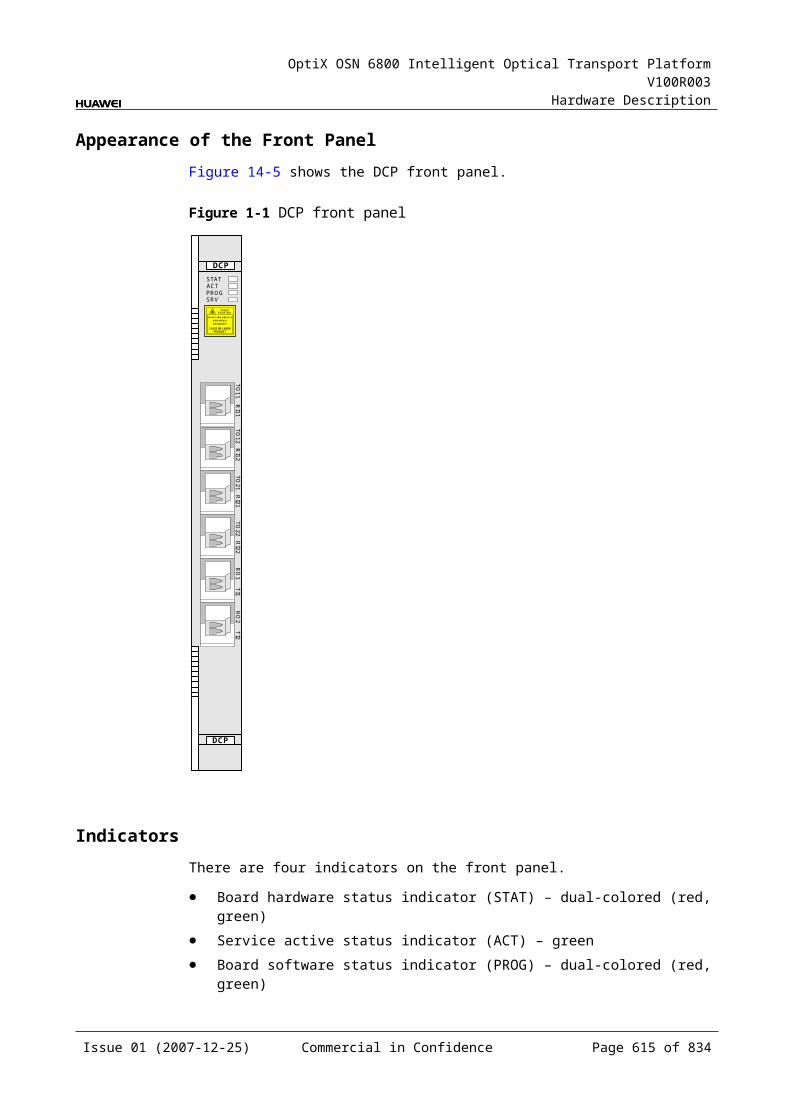
OptiX OSN 6800 Intelligent Optical Transport Platform V100R003
Hardware Description
C.9.7 Actual BandItem Description
Parameter description Used to query the actual working band of the board.
Parameter values Queriable only
Parameter value description None
Recommended value None
Application scenarios In commissioning and maintenance stages
Impact on the system None
Relevant boards VA1, VA4
Configuration requirements None
C.9.8 Actual Working Band ParityItem Description
Parameter description Used to query the parity of the actual working band of the board.
Parameter values Queriable only
Parameter value description None
Recommended value None
Application scenarios In commissioning and maintenance stages
Impact on the system None
Relevant boards VA1, VA4
Configuration requirements None
Issue 01 (2007-12-25) Commercial in Confidence Page 615 of 664
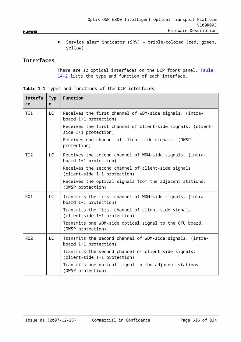
OptiX OSN 6800 Intelligent Optical Transport Platform V100R003
Hardware Description
C.9.9 Threshold of Input Power Loss (dBm)Item Description
Parameter description Indicates the lower threshold of input optical power loss (an MUT_LOS alarm is reported).
Parameter values Queriable only
Parameter value description
The default value varies with boards. Refer to the value obtained on site through the T2000.
Recommended value None
Application scenarios In commissioning and maintenance stages
Impact on the system None
Relevant boards VA1, VA4
Configuration requirements
None
Issue 01 (2007-12-25) Commercial in Confidence Page 616 of 664
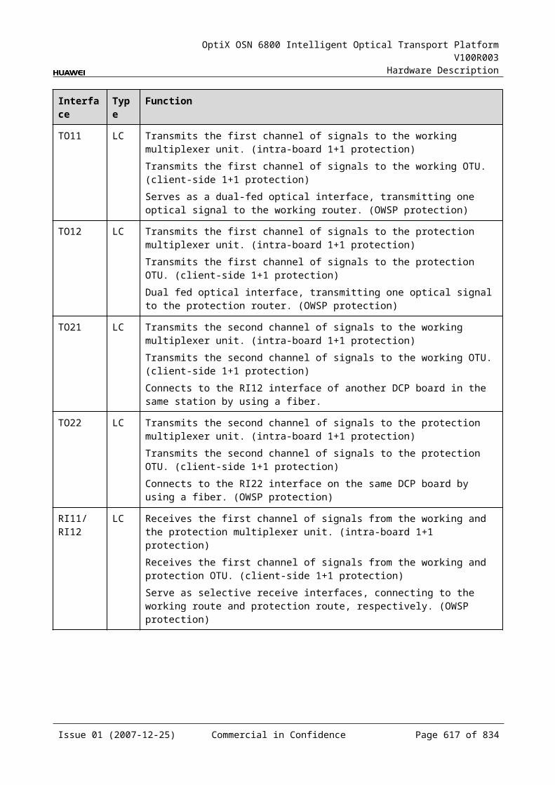
OptiX OSN 6800 Intelligent Optical Transport Platform V100R003
Hardware Description
D Quick Reference Table of the Units
Quick reference tables include those for specifications of optical transponder units, optical amplifier units and other boards, and also the functions of OTUs, tributary boards and line boards.
D.1 OTUs, Tributary Boards and Line Boards Specification
The main specifications of the optical transponder units (OTUs), tributary boards and line boards include the access service type, optical module specifications and optical module type.
D.1.1 OTUs, Tributary Boards and Line Boards Specification on the Client Side
The main client-side specifications of the optical transponder unit (OTU) include the access service type, optical module specifications and optical module type.
Table D-1 Quick reference table for client-side specifications of OTU boards
Board Name
Access Service Type
Optical Module Optical Module Type
Optical Interface Type Supported
Mean Launched Optical Power
Receiver Sensitivity (dBm)
Minimum Overload Point (dBm)
Maximum (dBm)
Minimum (dBm)
ECOM
FE 100 BASE-FX-1310 nm-40km
0 –5 –30 –10 eSFP
100 BASE-FX-1310 nm-2km
–14 –19 –30 –14
1.25 Gbit/s multirate
5 0 –19 –3 eSFP CWDM
Issue 01 (2007-12-25) Commercial in Confidence Page 617 of 664
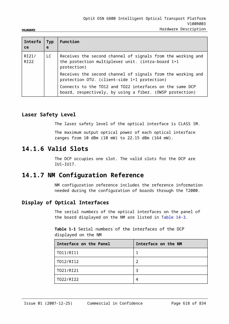
OptiX OSN 6800 Intelligent Optical Transport Platform V100R003
Hardware Description
Board Name
Access Service Type
Optical Module Optical Module Type
Optical Interface Type Supported
Mean Launched Optical Power
Receiver Sensitivity (dBm)
Minimum Overload Point (dBm)
Maximum (dBm)
Minimum (dBm)
2.67 Gbit/s multirate
5 0 –28 –9
L4G GE 2.125 Gbit/s multirate
–2.5 –9.5 –17 0 eSFP
1000 BASE-LX-10 km
–3 –11.5 –19 –3
1000 BASE-LX-40 km
3 –2 –21 –3
1000 BASE-ZX-80 km
5 –2 –21 –3
1.25 Gbit/s multirate-40 km
5 0 –19 –3 eSFP CWDM
1.25 Gbit/s multirate(eSFP CWDM)-80 km
5 0 –28 –9
LDGD GE 2.125 Gbit/s multirate
–2.5 –9.5 –17 0 eSFP
1000 BASE-LX-10 km
–3 –11.5 –19 –3
1000 BASE-LX-40 km
3 –2 –21 –3
1000 BASE-ZX-80 km
5 –2 –21 –3
1.25 Gbit/s multirate
5 0 –19 –3 eSFP CWDM
1.25 Gbit/s multirate-80 km
5 0 –28 –9
LDGS GE 2.125 Gbit/s multirate
–2.5 –9.5 –17 0 eSFP
1000 BASE-LX-10 km
–3 –11.5 –19 –3
1000 BASE-LX-40 km
3 –2 –21 –3
Issue 01 (2007-12-25) Commercial in Confidence Page 618 of 664
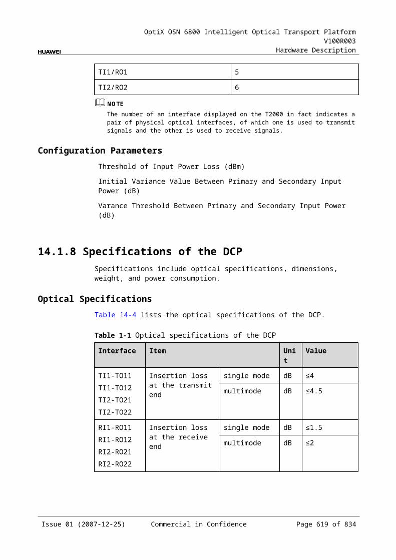
OptiX OSN 6800 Intelligent Optical Transport Platform V100R003
Hardware Description
Board Name
Access Service Type
Optical Module Optical Module Type
Optical Interface Type Supported
Mean Launched Optical Power
Receiver Sensitivity (dBm)
Minimum Overload Point (dBm)
Maximum (dBm)
Minimum (dBm)
1000 BASE-ZX-80 km
5 –2 –21 –3
1.25 Gbit/s multirate-40 km
5 0 –19 –3 eSFP CWDM
1.25 Gbit/s multirate-80 km
5 0 –28 –9
LOG GE 2.125 Gbit/s multirate
–2.5 –9.5 –17 0 eSFP
1000 BASE-LX-10km
–3 –11.5 –19 –3
1000 BASE-LX-40km
0 –4.5 –20 –3
1000 BASE-ZX-80km
5 –2 –22 –3
1.25 Gbit/s multirate
5 0 –19 –3 eSFP CWDM
2.67 Gbit/s multirate
5 0 –28 –9
LOM GE 2.125 Gbit/s multirate
–2.5 –9.5 –17 0 eSFP
1000 BASE-LX-10km
–3 –11.5 –19 –3
1000 BASE-LX-40km
0 –4.5 –20 –3
1000 BASE-ZX-80km
5 –2 –22 –3
FC 100/ FC 200/ FC 400/ FICON/ FICON 2G
FC 400 module-Multimode
–1 –9 –14 0
FC 400 module-Single-mode
–2 –8 –16 0
Issue 01 (2007-12-25) Commercial in Confidence Page 619 of 664
OptiX OSN 6800 Intelligent Optical Transport Platform V100R003
Hardware Description
Board Name
Access Service Type
Optical Module Optical Module Type
Optical Interface Type Supported
Mean Launched Optical Power
Receiver Sensitivity (dBm)
Minimum Overload Point (dBm)
Maximum (dBm)
Minimum (dBm)
FC 100/ FICON /FC 200/ FICON 2G module-Multimode
–2.5 –9.5 –17 0
FC 100/ FICON /FC 200/ FICON 2G module-Single-mode
–3 –10 –18 0
GE/ FC 100/ FC 200
1.25 Gbit/s multirate
5 0 –19 –3 eSFP CWDM
2.67 Gbit/s multirate
5 0 –28 –9
LQMD
FC200/ GE/ FC100/ FE/ FICON/ FICON 2G
2.125 Gbit/s multirate
–2.5 –9.5 –17 0 eSFP
GE/ FC100/ STM-4/ ESCON/ STM-1/ FE/ DVB-ASI/ FICON
1000 BASE-LX-10 km
–3 –11.5 –19 –3
1000 BASE-LX-40 km
3 –2 –21 –3
1000 BASE-ZX-80 km
5 –2 –21 –3
STM-16/ FC200/ FC100/ GE/ STM-4/ ESCON/ STM-1/ DVB-ASI/ FE/ FICON 2G
I-16 –3 –10 –18 –3
S-16.1 0 –5 –18 0
L-16.1 3 –2 –27 –9
L-16.2 3 –2 –28 –9
Issue 01 (2007-12-25) Commercial in Confidence Page 620 of 664
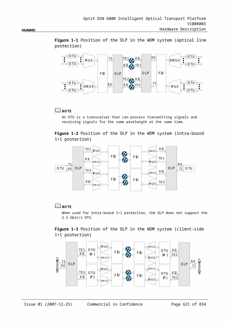
OptiX OSN 6800 Intelligent Optical Transport Platform V100R003
Hardware Description
Board Name
Access Service Type
Optical Module Optical Module Type
Optical Interface Type Supported
Mean Launched Optical Power
Receiver Sensitivity (dBm)
Minimum Overload Point (dBm)
Maximum (dBm)
Minimum (dBm)
GE/ FC100/ STM4/ ESCON/ STM1/ FE/ DVB-ASI
1.25 Gbit/s multirate
5 0 –19 –3 eSFP CWDM
STM16/ FC200/ FC100/ GE/ STM4/ ESCON/ STM1/ DVB-ASI/ FE
2.5 Gbit/s multirate
5 0 –28 –9
LQMS FC200/ GE/ FC100/ FE/ FICON/ FICON 2G
2.125 Gbit/s multirate
–2.5 –9.5 –17 0 eSFP
GE/ FC100/ STM-4/ ESCON/ STM-1/ FE/ DVB-ASI/ FICON
1000 BASE-LX-10 km
–3 –11.5 –19 –3
1000 BASE-LX-40 km
3 –2 –21 –3
1000 BASE-ZX-80 km
5 –2 –21 –3
STM-16/ FC200/ FC100/ GE/ STM-4/ ESCON/ STM-1/ DVB-ASI/ FE/ FICON 2G
I-16 –3 –10 –18 –3
S-16.1 0 –5 –18 0
L-16.1 3 –2 –27 –9
L-16.2 3 –2 –28 –9
Issue 01 (2007-12-25) Commercial in Confidence Page 621 of 664
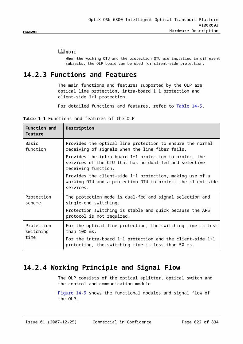
OptiX OSN 6800 Intelligent Optical Transport Platform V100R003
Hardware Description
Board Name
Access Service Type
Optical Module Optical Module Type
Optical Interface Type Supported
Mean Launched Optical Power
Receiver Sensitivity (dBm)
Minimum Overload Point (dBm)
Maximum (dBm)
Minimum (dBm)
GE/ FC100/ STM4/ ESCON/ STM1/ FE/ DVB-ASI
1.25 Gbit/s multirate
5 0 –19 –3 eSFP CWDM
STM16/ FC200/ FC100/ GE/ STM4/ ESCON/ STM1/ DVB-ASI/ FE
2.5 Gbit/s multirate
5 0 –28 –9
LSX 10GE LAN/ 10GE WAN/ STM-64/ OC-192/ OTU2/ FC1200a
10 Gbit/s multirate-10 km
–1 –6 –11 0.5 XFP
10 Gbit/s multirate-40 km
2 –1 –14 –1
10 Gbit/s single-rate-0.3 km
–1.3 –7.3 –7.5 –1
10 Gbit/s multirate-80 km
4 0 –24.0 –7
LSXL STM-256/ OC-768
Transponder 3 0 –5 3 -
LWX2 FC200/ GE/ FC100/ FE
2.125 Gbit/s multirate
–2.5 –9.5 –17 0 eSFP
STM-16/ FC200/ FC100/ GE/ STM-4/ ESCON/ STM-1/ DVB-ASI/ DVB-SDI/ FE/ FICON/ FICON 2G
I-16 –3 –10 –18 –3
S-16.1 0 –5 –18 0
L-16.2 3 –2 –28 –9
Issue 01 (2007-12-25) Commercial in Confidence Page 622 of 664
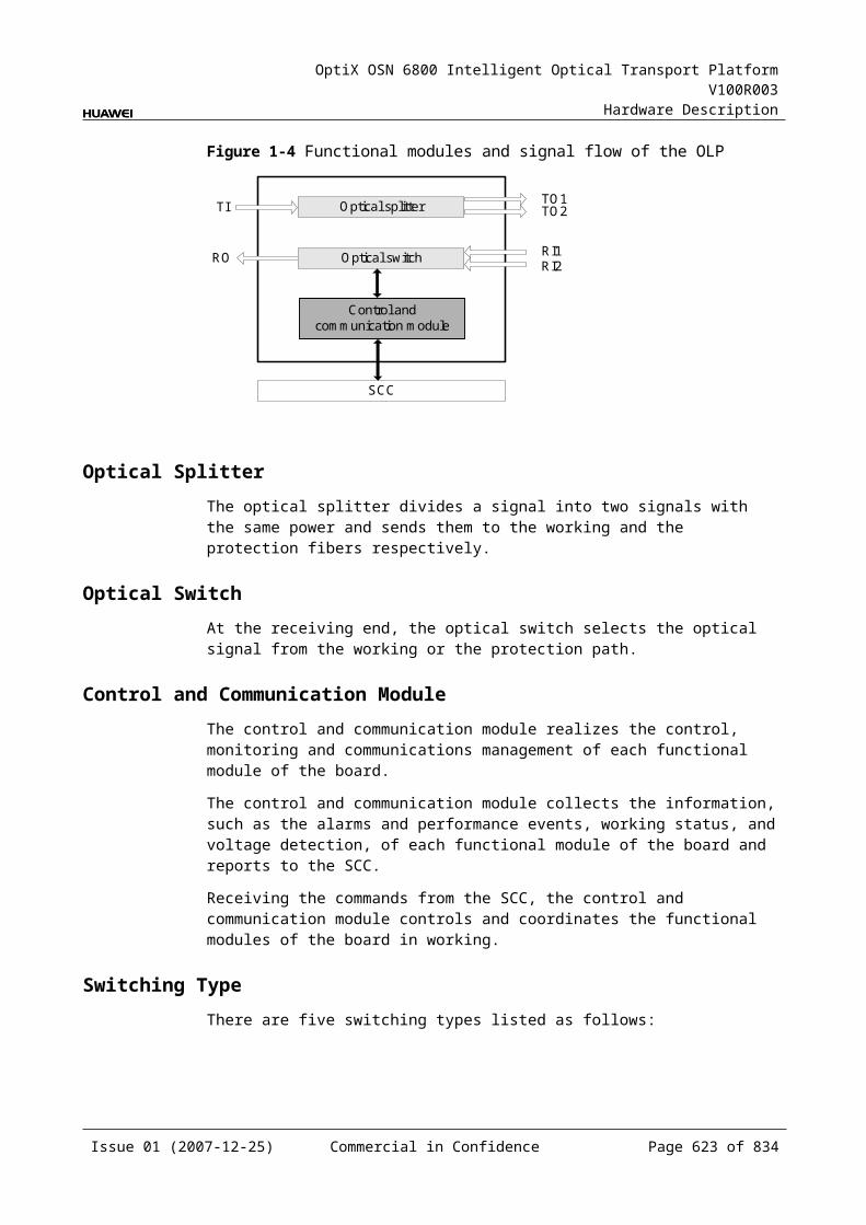
OptiX OSN 6800 Intelligent Optical Transport Platform V100R003
Hardware Description
Board Name
Access Service Type
Optical Module Optical Module Type
Optical Interface Type Supported
Mean Launched Optical Power
Receiver Sensitivity (dBm)
Minimum Overload Point (dBm)
Maximum (dBm)
Minimum (dBm)
GE/ FC100/ STM4/ ESCON/ STM1/ FE/ DVB-ASI
1.25 Gbit/s multirate
5 0 –19 –3 eSFP CWDM
STM16/ FC200/ FC100/ GE/ STM4/ ESCON/ STM1/ DVB-ASI/ FE
2.5 Gbit/s multirate
5 0 –28 –9
LWXD
FC200/ GE/ FC100/ FE/ FICON/ FICON 2G
2.125 Gbit/s multirate
–2.5 –9.5 –17 0 eSFP
STM-16/ FC200/ FC100/ GE/ STM-4/ ESCON/ STM-1/ DVB-ASI/ DVB-SDI/ FE/ FICON/ FICON 2G
I-16 –3 –10 –18 –3
S-16.1 0 –5 –18 0
L-16.2 3 –2 –28 –9
GE/ FC100/ STM4/ ESCON/ STM1/ FE/ DVB-ASI
1.25 Gbit/s multirate
5 0 –19 –3 eSFP CWDM
Issue 01 (2007-12-25) Commercial in Confidence Page 623 of 664
OptiX OSN 6800 Intelligent Optical Transport Platform V100R003
Hardware Description
Board Name
Access Service Type
Optical Module Optical Module Type
Optical Interface Type Supported
Mean Launched Optical Power
Receiver Sensitivity (dBm)
Minimum Overload Point (dBm)
Maximum (dBm)
Minimum (dBm)
STM16/ FC200/ FC100/ GE/ STM4/ ESCON/ STM1/ DVB-ASI/ FE
2.5 Gbit/s multirate
5 0 –28 –9
LWXS FC200/ GE/ FC100/ FE/ FICON/ FICON 2G
2.125 Gbit/s multirate
–2.5 –9.5 –17 0 eSFP
STM-16/ FC200/ FC100/ GE/ STM-4/ ESCON/ STM-1/ DVB-ASI/ DVB-SDI/ FEFICON/ FICON 2G
I-16 –3 –10 –18 –3
S-16.1 0 –5 –18 0
L-16.2 3 –2 –28 –9
GE/ FC100/ STM4/ ESCON/ STM1/ FE/ DVB-ASI
1.25 Gbit/s multirate
5 0 –19 –3 eSFP CWDM
STM16/ FC200/ FC100/ GE/ STM4/ ESCON/ STM1/ DVB-ASI/ FE
2.5 Gbit/s multirate
5 0 –28 –9
TMX STM-16/ OC-48/ OTU1 (without
I-16 –3 –10 –18 –3 eSFP
S-16.1 0 –5 –18 0
L-16.1 3 –2 –27 –9
Issue 01 (2007-12-25) Commercial in Confidence Page 624 of 664

OptiX OSN 6800 Intelligent Optical Transport Platform V100R003
Hardware Description
Board Name
Access Service Type
Optical Module Optical Module Type
Optical Interface Type Supported
Mean Launched Optical Power
Receiver Sensitivity (dBm)
Minimum Overload Point (dBm)
Maximum (dBm)
Minimum (dBm)
FEC) L-16.2 3 –2 –28 –9
2.67 Gbit/s multirate
5 0 –28 –9 eSFP CWDM
2.67 Gbit/s multirate
3 0 –28 –9 eSFP DWDM
TBE FE 100 BASE-FX-1310 nm-40km
0 –5 –30 –10 eSFP
100 BASE-FX-1310 nm-2km
–14 –19 –30 –14
GE/ 10GE LAN/ 10GE WAN
2.125 Gbit/s multirate
–2.5 –9.5 –17 0
I-16 –3 –11.5 –19 –3
S-16.1 0 –4.5 –20 –3
L-16.2 5 –2 –22 –3
10 Gbit/s multirate-10km
–1 –6 –11 0.5 XFP
10 Gbit/s multirate-40 km
2 –1 –14 –1
10 Gbit/s single-rate-0.3 km
–1.3 –7.3 –7.5 –1
10 Gbit/s multirate-80 km
4 0 –24 –7
FE/ GE/ 10GE LAN/ 10GE WAN
1.25 Gbit/s multirate
5 0 –19 –3 eSFP CWDM
2.67 Gbit/s multirate
5 0 –28 –9
TDG GE 2.125 Gbit/s multirate
–2.5 –9.5 –17 0 eSFP
1000 BASE-LX-10 km
–3 –11.5 –19 –3
1000 BASE-LX-40 km
3 –2 –21 –3
Issue 01 (2007-12-25) Commercial in Confidence Page 625 of 664
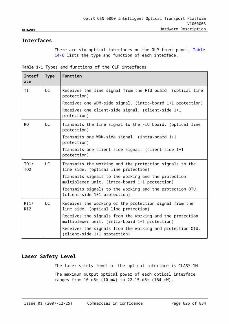
OptiX OSN 6800 Intelligent Optical Transport Platform V100R003
Hardware Description
Board Name
Access Service Type
Optical Module Optical Module Type
Optical Interface Type Supported
Mean Launched Optical Power
Receiver Sensitivity (dBm)
Minimum Overload Point (dBm)
Maximum (dBm)
Minimum (dBm)
1000 BASE-ZX-80 km
5 –2 –21 –3
1.25 Gbit/s multirate-40 km
5 0 –19 –3 eSFP CWDM
1.25 Gbit/s multirate-80 km
5 0 –28 –9
TDX 10GE LAN/ STM-64/ OC-192
10 Gbit/s multirate-10km
–1 –6 –11 0.5 XFP
10 Gbit/s multirate-40 km
2 –1 –14 –1
10 Gbit/s single-rate-0.3 km
–1.3 –7.3 –7.5 –1
10 Gbit/s multirate-80 km
4 0 –24 –7
TQM STM-16/ STM-4/ STM-1/ OC-48/ OC-12/ OC-3/ FC200/ FC100/ GE/ FE/ ESCON/ DVB-ASI/ FICON/ FICON 2G
2.125 Gbit/s multirate
–2.5 –9.5 –17 0 eSFP
1000 BASE-LX-10 km
–3 –11.5 –19 –3
1000 BASE-LX-40 km
3 –2 –21 –3
1000 BASE-ZX-80 km
5 –2 –21 –3
GE/ FC100/ STM4/ ESCON/ STM1/ FE/ DVB-ASI
1.25 Gbit/s multirate)
5 0 –19 –3 eSFP CWDM
Issue 01 (2007-12-25) Commercial in Confidence Page 626 of 664
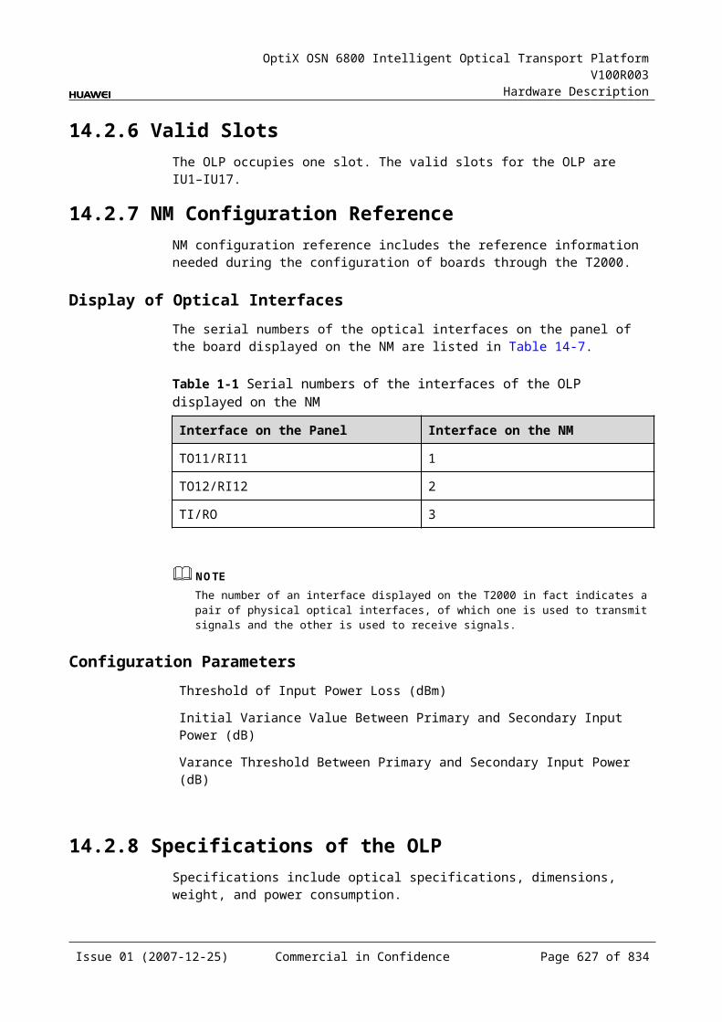
OptiX OSN 6800 Intelligent Optical Transport Platform V100R003
Hardware Description
Board Name
Access Service Type
Optical Module Optical Module Type
Optical Interface Type Supported
Mean Launched Optical Power
Receiver Sensitivity (dBm)
Minimum Overload Point (dBm)
Maximum (dBm)
Minimum (dBm)
STM16/ FC200/ FC100/ GE/ STM4/ ESCON/ STM1/ DVB-ASI/ FE
2.5 Gbit/s multirate)
5 0 –28 –9
TQS STM-16/ OC-48/ OTU1
I-16 –3 –10 –18 –3 eSFP
S-16.1 0 –5 –18 0
L-16.1 3 –2 –27 –9
L-16.2 3 –2 –28 –9
2.67 Gbit/s multirate
5 0 –28 –9 eSFP CWDM
a: Only TN12LSX supports FC1200 service.
D.1.2 OTUs, Tributary Boards and Line Boards Specification on the WDM Side
The main wdm-side specifications of the optical transponder units (OTUs), tributary boards and line boards include the access service type, optical module specifications and optical module type.
Table D-1 Quick reference table for DWDM-side specifications of OTU boards
Board Name
Access Service Type
Optical Module
Optical Interface Type Supported
Mean Launched Optical Power
Receiver Sensitivity (dBm)
Minimum Overload Point (dBm)
Maximum (dBm)
Minimum (dBm)
L4G OTU 5G 3400 ps/nm 2 –2 –25 –9
6400 ps/nm –1 –5 –25 –9
3400 ps/nm- tunable 4 0 –25 –9
LDGD STM-16/ 12800 ps/nm-PIN –4 –8 –18 0
Issue 01 (2007-12-25) Commercial in Confidence Page 627 of 664
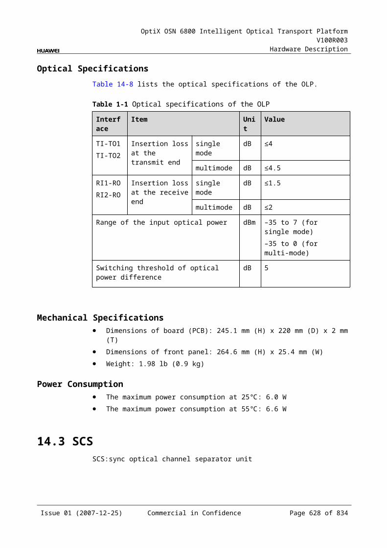
OptiX OSN 6800 Intelligent Optical Transport Platform V100R003
Hardware Description
Board Name
Access Service Type
Optical Module
Optical Interface Type Supported
Mean Launched Optical Power
Receiver Sensitivity (dBm)
Minimum Overload Point (dBm)
Maximum (dBm)
Minimum (dBm)
OTU1 12800 ps/nm-APD –4 –8 –25 –9
6500 ps/nm-PIN 0 –5 –18 0
3200 ps/nm-2mW-APD 0 –5 –25 –9
12800 ps/nm- tunable 0 –4 –30 –9
LDGS STM-16/ OTU1
12800 ps/nm-PIN –1 –5 –18 0
12800 ps/nm-APD –1 –5 –25 –9
6500 ps/nm-PIN 3 –2 –18 0
3200 ps/nm-2mW-APD 3 –2 –25 –9
12800 ps/nm- tunable 3 –1 –30 –9
LOG GE 800 ps/nm 2 –3 –16 0
1600 ps/nm 4 0 –27 –9
1200 ps/nm-tunable-PIN
2 –3 –16 0
1200 ps/nm-tunable-APD
2 –3 –26 –9
4800 ps/nm-ODB-tunable
2 –3 –26 –8
800ps/nm-DRZ-tunable 2 –3 –16 0
LOM GE 800 ps/nm 2 –3 –16 0
1600 ps/nm 4 0 –27 –9
1200 ps/nm-tunable-PIN
2 –3 –16 0
1200 ps/nm-tunable-APD
2 –3 –26 –9
4800 ps/nm-ODB-tunable
2 –3 –26 –8
800ps/nm-DRZ-tunable 2 –3 –16 0
LQMD OTU1 12800 ps/nm-PIN –4 –8 –18 0
12800 ps/nm-APD –4 –8 –25 –9
Issue 01 (2007-12-25) Commercial in Confidence Page 628 of 664
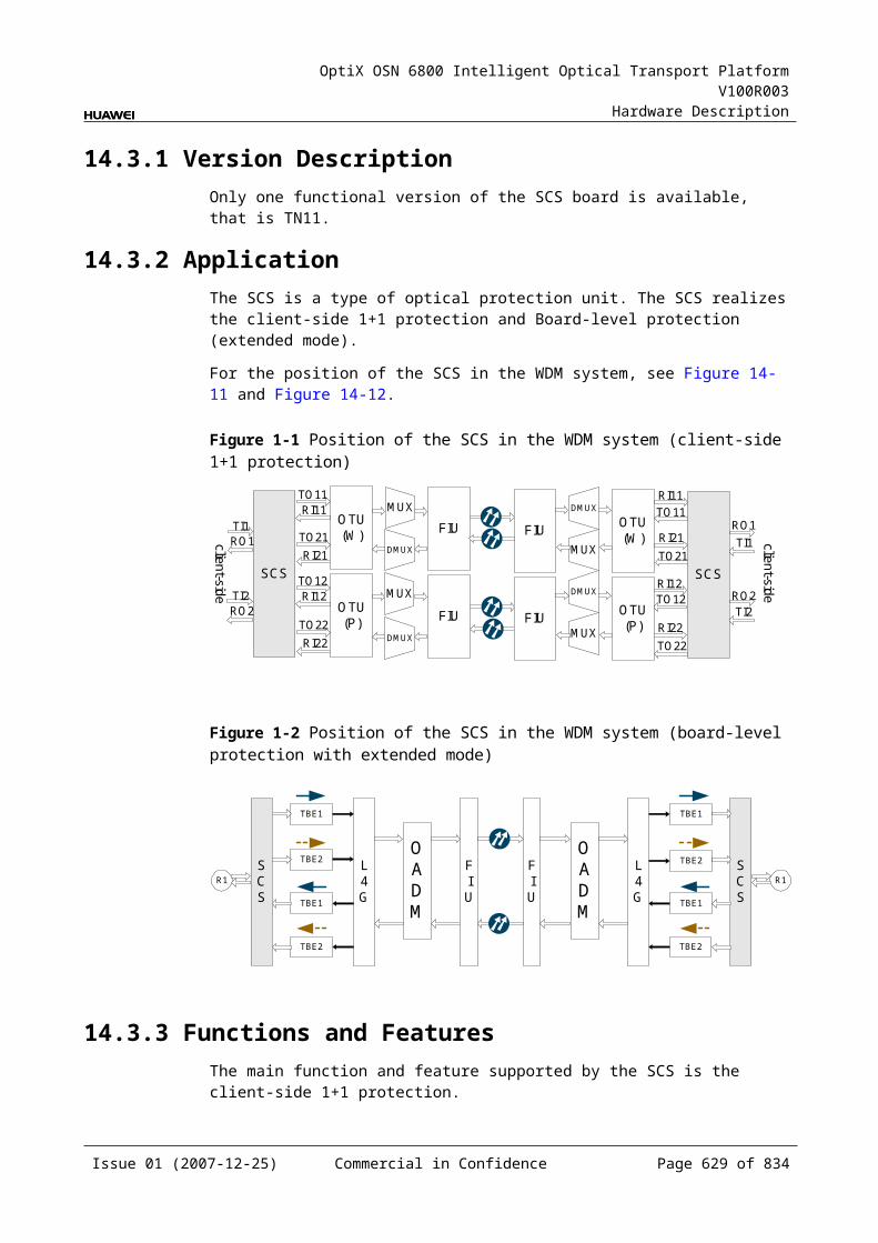
OptiX OSN 6800 Intelligent Optical Transport Platform V100R003
Hardware Description
Board Name
Access Service Type
Optical Module
Optical Interface Type Supported
Mean Launched Optical Power
Receiver Sensitivity (dBm)
Minimum Overload Point (dBm)
Maximum (dBm)
Minimum (dBm)
6500 ps/nm-PIN 0 –5 –18 0
3200 ps/nm-2mW-APD 0 –5 –25 –9
12800 ps/nm-tunable 0 –4 –30 –9
LQMS OTU1 12800 ps/nm-PIN –1 –5 –18 0
12800 ps/nm-APD –1 –5 –25 –9
6500 ps/nm-PIN 3 –2 –18 0
3200 ps/nm-2mW-APD 3 –2 –25 –9
12800 ps/nm- tunable 3 –1 –30 –9
LSX OTU2/ OTU2v
800 ps/nm 2 –3 –16 0
1600 ps/nm 4 0 –26 –9
1200 ps/nm- tunable-PIN
2 –3 –16 0
1200 ps/nm- tunable-APD
2 –3 –26 –9
4800 ps/nm- ODB-tunable
2 –3 –26 –9
800 ps/nm-DRZ-tunable
2 –3 –16 0
LSXL STM-256/ OC-768
ODB-tunable –1 –4 –17 0
DRZ-tunable –1 –5 –17 0
LSXLR OTU3 ODB-tunable –1 –4 –17 0
DRZ-tunable –1 –5 –17 0
LSXR OTU2/ OTU2v
800 ps/nm 2 –3 –16 0
1600 ps/nm 4 0 –26 –9
1200 ps/nm- tunable-PIN
2 –3 –16 0
1200 ps/nm- tunable-APD
2 –3 –26 –9
4800 ps/nm- ODB-tunable
2 –3 –26 –9
Issue 01 (2007-12-25) Commercial in Confidence Page 629 of 664
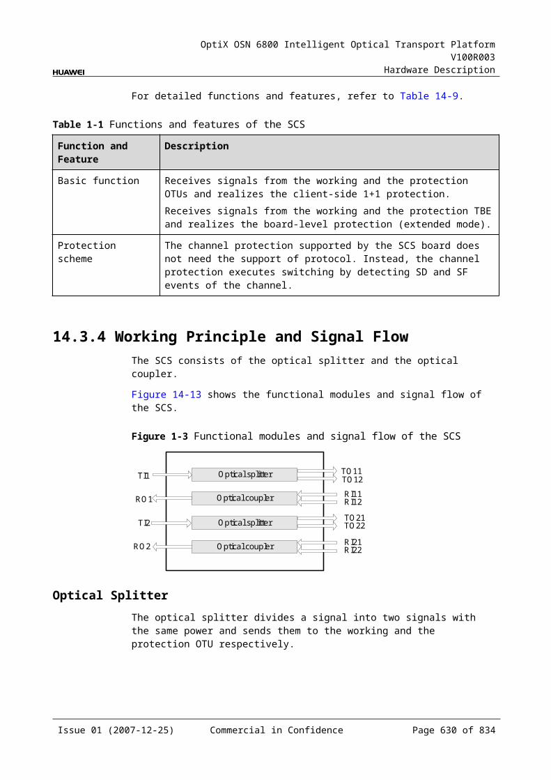
OptiX OSN 6800 Intelligent Optical Transport Platform V100R003
Hardware Description
Board Name
Access Service Type
Optical Module
Optical Interface Type Supported
Mean Launched Optical Power
Receiver Sensitivity (dBm)
Minimum Overload Point (dBm)
Maximum (dBm)
Minimum (dBm)
800ps/nm-DRZ-tunable 2 –3 –16 0
LWX2 STM-16/ FC200/ FC100/ GE/ STM-4/ ESCON/ STM-1/ DVB-ASI/ DVB-SDI/ FEFICON/ FICON 2G
12800ps/nm-PINa –1 –5 –18 0
12800ps/nm-APDa –1 –5 –25 9
6500 ps/nm -PIN 3 –2 –18 0
3200 ps/nm -2mW-APD
3 –2 –25 –9
LWXD STM-16/ FC200/ FC100/ GE/ STM-4/ ESCON/ STM-1/ DVB-ASI/ DVB-SDI/ FEFICON/ FICON 2G
12800ps/nm-PINa –4 –8 –18 0
12800ps/nm-APDa –4 –8 –25 9
6500 ps/nm -PIN 0 –5 –18 0
3200 ps/nm -2mW-APD
0 –5 –25 –9
12800 ps/nm- tunable 0 –4 –30 –9
LWXS STM-16/ FC200/ FC100/ GE/ STM-4/ ESCON/ STM-1/ DVB-ASI/ DVB-SDI/ FEFICON/ FICON 2G
12800ps/nm-PINa –1 –5 –18 0
12800ps/nm-APDa –1 –5 –25 9
6500 ps/nm -PIN 3 –2 –18 0
3200 ps/nm -2mW-APD
3 –2 –25 –9
12800 ps/nm- tunable 3 –1 –30 –9
TMX STM-16/ OC-48/ OTU1 (without FEC)
800 ps/nm 2 –3 –16 0
1600 ps/nm 4 0 –27 –9
1200 ps/nm- tunable-PIN
2 –3 –16 0
1200 ps/nm- tunable-APD
2 –3 –26 –9
4800 ps/nm- ODB-tunable
2 –3 –26 –8
Issue 01 (2007-12-25) Commercial in Confidence Page 630 of 664
OptiX OSN 6800 Intelligent Optical Transport Platform V100R003
Hardware Description
Board Name
Access Service Type
Optical Module
Optical Interface Type Supported
Mean Launched Optical Power
Receiver Sensitivity (dBm)
Minimum Overload Point (dBm)
Maximum (dBm)
Minimum (dBm)
800ps/nm-DRZ-tunable 2 –3 –16 0
NS2 OTU2 800 ps/nm 2 –3 –16 0
1600 ps/nm 4 0 –27 –9
1200 ps/nm- tunable-PIN
2 –3 –16 0
1200 ps/nm- tunable-APD
2 –3 –26 –9
4800 ps/nm- ODB-tunable
2 –3 –26 –9
800ps/nm-DRZ-tunable 2 –3 –16 0
a: The 12800ps/nm-PIN and 12800ps/nm-APD modules do not support pilot tone modulation mode.
Table D-2 Quick reference table for CWDM-side specifications of OTU boards
Board Name
Access Service Type
Optical Module
Optical Interface Type Supported
Mean Launched Optical Power
Receiver Sensitivity (dBm)
Minimum Overload Point (dBm)Maximu
m (dBm)Minimum (dBm)
ECOM FE 1.25 Gbit/s Multirate
5 0 –19 –3
2.67 Gbit/s Multirate
5 0 –28 –9
L4G OTU.5G 3400 ps/nm 5 2.5 –25 –9
LDGD STM-16/ OTU1
1600 ps/nm-4mW
2 –0.5 –28 –9
LDGS STM-16/ OTU1
1600 ps/nm-4mW
5 2.5 –28 –9
LQMD OTU1 1600 ps/nm-4mW
2 –0.5 –28 –9
LQMS OTU1 1600 ps/nm-4mW
5 2.5 –28 –9
Issue 01 (2007-12-25) Commercial in Confidence Page 631 of 664
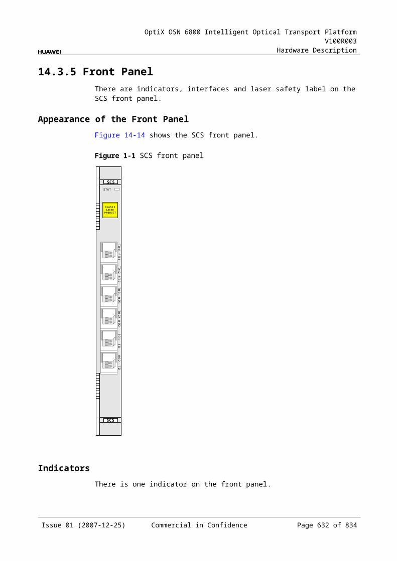
OptiX OSN 6800 Intelligent Optical Transport Platform V100R003
Hardware Description
Board Name
Access Service Type
Optical Module
Optical Interface Type Supported
Mean Launched Optical Power
Receiver Sensitivity (dBm)
Minimum Overload Point (dBm)Maximu
m (dBm)Minimum (dBm)
LWX2 STM-16/ FC200/ FC100/ GE/ STM-4/ ESCON/ STM-1/ DVB-ASI/ DVB-SDI/ FEFICON/ FICON 2G
1600 ps/nm-4mW
5 2.5 –28 –9
LWXD STM-16/ FC200/ FC100/ GE/ STM-4/ ESCON/ STM-1/ DVB-ASI/ DVB-SDI/ FEFICON/ FICON 2G
1600 ps/nm-4mW
2 –0.5 –28 –9
LWXS STM-16/ FC200/ FC100/ GE/ STM-4/ ESCON/ STM-1/ DVB-ASI/ DVB-SDI/ FEFICON/ FICON 2G
1600 ps/nm-4mW
5 2.5 –28 –9
D.2 Optical Amplifying Unit SpecificationThe main specifications of the optical amplifying unit include the operating wavelength range, channel gain, nominal input power range, nominal output power range and maximum output power of a single wavelength.
Table D-1 Quick reference table for optical amplifying unit
Board name
Gain adjustable range (dB)
Nominal Channel gain (dB)
Input power range per channel (dBm)
Typical input power of a single wavelength (dBm)
40 channels
80 channels
40 channels
80 channels
OAU101 20 to 23 20 –32 to –16 –32 to –19 - -
23 to 29 26 –32 to –22 –32 to –25
29 to 31 31 –32 to –27 –32 to –30
OAU103 24 to 28 24 –32 to –20 –32 to –23 - -
28 to 30 29 –32 to –25 –32 to –28
30 to 36 36 –32 –32
Issue 01 (2007-12-25) Commercial in Confidence Page 632 of 664
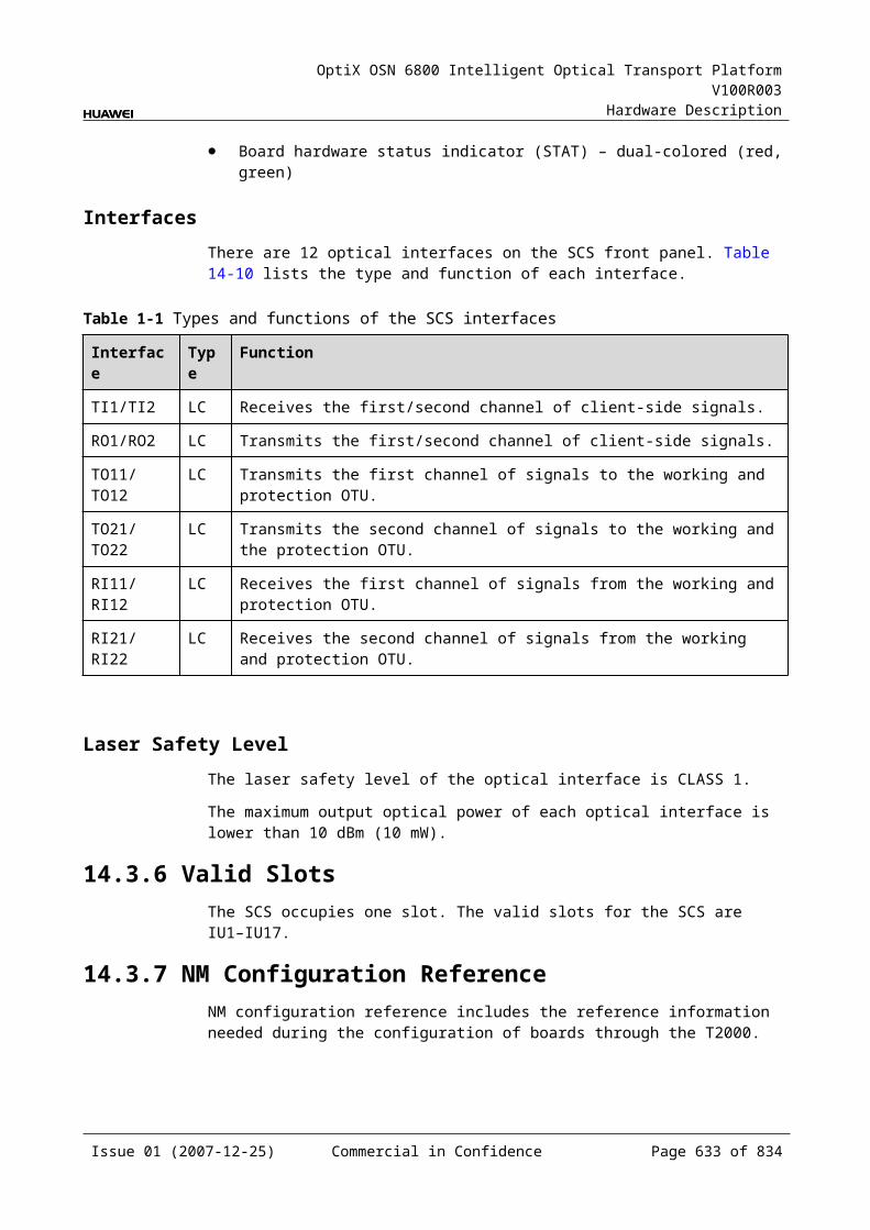
OptiX OSN 6800 Intelligent Optical Transport Platform V100R003
Hardware Description
Board name
Gain adjustable range (dB)
Nominal Channel gain (dB)
Input power range per channel (dBm)
Typical input power of a single wavelength (dBm)
40 channels
80 channels
40 channels
80 channels
OBU101 - 20 –32 to –20 –32 to –23 –20 –23
OBU103 - 23 –32 to –19 –32 to –22 –19 –22
OBU104 - 17 –32 to –17 –32 to –20 –17 –20
OBU205 - 23 –24 to –16 –24 to –16 –16 –19
Table D-2 Quick reference table for CRPC
Board name Channel gain (dB) Maximum pump power (dBm)
G.652 fiber LEAF fiber
CRPC ≥10 ≥12 29
Table D-3 Quick reference table for HBA
Board name
Channel gain (dB)
Typical input power of a single wavelength (dBm)
Nominal input power range (dBm)
Channel allocation (nm)
40 channels
10 channels
40 channels
10 channels
HBA 29 –19 –13 –19 to –3 1529 to 1561
Any two of the last 20 wavelengths are spaced at 200 GHz.
Issue 01 (2007-12-25) Commercial in Confidence Page 633 of 664
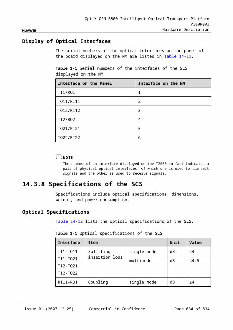
OptiX OSN 6800 Intelligent Optical Transport Platform V100R003
Hardware Description
D.3 Other Unit SpecificationThe main specifications of other boards include the insertion loss values of each board.
Table D-1 Quick reference table for specifications of other boards
Board Name
Insertion Loss (dB)
MR2 IN-MOMI-OUT
≤1.0
Add/drop channel ≤1.5
MR4 IN-MOMI-OUT
≤1.5
Add/drop channel ≤2.2
MR8 IN-MOMI-OUT
≤3.5
Add/drop channel ≤4
CMR2 IN-MOMI-OUT
≤1.0
Add/drop channel ≤1.5
CMR4 IN-MOMI-OUT
≤1.0
Add/drop channel ≤2
DMR1 EIN-EMOEMI-EOUTWIN-WMOWMI-WOUT
≤0.8
Add/drop channel ≤1
SBM2 Add/drop channel ≤3
D40 ≤6.5
D40V ≤8a
FIU IN-TMRM-OUT
≤1.5
IN-TCRC-OUT
≤1
Issue 01 (2007-12-25) Commercial in Confidence Page 634 of 664
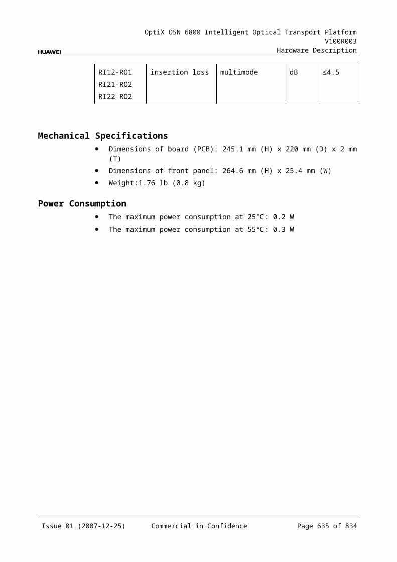
OptiX OSN 6800 Intelligent Optical Transport Platform V100R003
Hardware Description
Board Name
Insertion Loss (dB)
ITL RE-OUTRO-OUT
<4
IN-TEIN-TO
<2.5
M40 ≤6.5
M40V ≤8a
DCP Transmit-end insertion loss Single mode ≤4
Multimode ≤4.5
Receive-end insertion loss Single mode ≤1.5
Multimode ≤2
OLP Transmit-end insertion loss Single mode ≤4
Multimode ≤4.5
Receive-end insertion loss Single mode ≤1.5
Multimode ≤2
SCS Wavelength dropping insertion loss Single mode ≤4
Multimode ≤4.5
Wavelength adding insertion loss Single mode ≤4
Multimode ≤4.5
RMU9 EXPI-OUT ≤8.5
AMxb-TOA ≤12.5a
ROA-OUT ≤1.5
ROAM Mxc-OUT ≤9a
IN-DM ≤7
EXPI-OUT ≤14a
IN-EXPO ≤3
WSD9 IN-DMxd
IN-EXPO≤8a
WSM9 AMxb-OUTEXPI-OUT
≤8a
WSMD4 AMxb-OUTIN-DMxd
≤8a
Issue 01 (2007-12-25) Commercial in Confidence Page 635 of 664
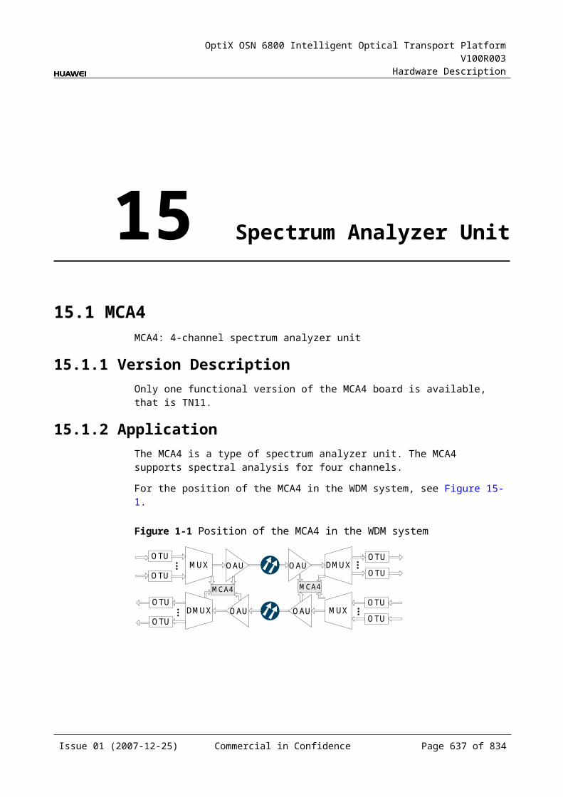
OptiX OSN 6800 Intelligent Optical Transport Platform V100R003
Hardware Description
a: The value tested when the VOA attenuation is set to 0 dB.
b: AMx denotes AM1–AM8.
c: Mx denotes M1–M40.
d: DMx denotes DM1–DM8.
D.4 MON Interface Optical Split RatioSome boards of WDM equipment provide a MON interface. A small number of supervisory signals are split from the main-path signals and are output through MON for in-service performance monitoring of the optical signals.
Table D-8 lists the ratio of the optical power of signals at MON to that of the main-path signals of each type of board.
Table D-1 Ratio of the optical power of signals at MON to that of the main-path signals of each type of board
Board Name
Ratio of MON Interface to Received Signal in Main Path
Ratio of MON Interface to Transmitting Signal in Main Path
CRPC – "MON"/"SYS" = 1/99 (20dB)
D40 "MON"/"IN" = 10/90 (10dB) –
D40V "MON"/"IN" = 10/90 (10dB) –
FIU – "MON"/"OUT" = 1/99 (20dB)
HBA – "MON"/"OUT" = 1/999 (30dB)
ITL – "MON"/"OUT" = 10/90 (10dB)
M40 – "MON"/"OUT" = 10/90 (10dB)
M40V – "MON"/"OUT" = 10/90 (10dB)
OAU1 – "MON"/"OUT" = 1/99 (20dB)
OBU1 – "MON"/"OUT" = 1/99 (20dB)
OBU2 – "MON"/"OUT" = 1/99 (20dB)
RMU9 "MONI"/"EXPI" = 3/97 (15dB) "MONO"/"TOA" = 3/97 (15dB)
WSD9 "MONI"/"IN" = 3/97 (15dB) "MONO"/"EXPO" = 3/97 (15dB)
WSM9 "MONI"/"EXPI" = 3/97 (15dB) "MONO"/"OUT" = 3/97 (15dB)
WSMD4 "MONI"/"IN" = 3/97 (15dB) "MONO"/"OUT" = 3/97 (15dB)
Issue 01 (2007-12-25) Commercial in Confidence Page 636 of 664
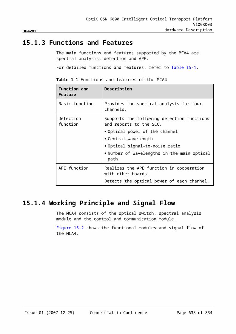
OptiX OSN 6800 Intelligent Optical Transport Platform V100R003
Hardware Description
D.5 Basic Functions of OTUs, Tributary Boards and Line Boards
The main functions and features supported by OTUs, tributary boards and line boards are wavelength conversion, cross-connection at the electrical layer, OTN interfaces and ESC.
For detailed functions and features, refer to Table D-9.
Table D-1 Basic functions of OTUs, tributary boards and line boards
Board name
Tunable wavelength function
ESC function
ALS function
OTN function
FEC encoding
WDM specification
Optical moduleFE
CAFEC
DWDM
CWDM
ECOM x x x x x x x √ eSFP
L4G √ √ √ √ √ x √ √ eSFP
LDGD √ √ √ √ √ x √ √ eSFP
LDGS √ √ √ √ √ x √ √ eSFP
LOG √ √ √ √ √ √ √ x eSFP
LOM √ √ √ √ √ √ √ x eSFP
LQMD √ √ √ √ √ x √ √ eSFP
LQMS √ √ √ √ √ x √ √ eSFP
LSX √ √ √ √ √ √ √ x XFP
LSXL √ √ √ √ √ √ √ x x
LSXLR √ √ √ √ √ √ √ x x
LSXR √ √ √ √ √ √ √ x XFP
LWX2 √ √ √ x x x √ √ eSFP
LWXD √ √ √ x x x √ √ eSFP
LWXS √ √ √ x x x √ √ eSFP
NS2 √ √ √ √ √ √ √ x x
TBE x x √ x x x x x eSFPXFP
TDG x x √ x x x x x eSFP
TDX x x √ x x x x x eSFP
TMX √ √ √ √ √ √ √ x eSFP
TQM x x √ x x x x x eSFP
Issue 01 (2007-12-25) Commercial in Confidence Page 637 of 664
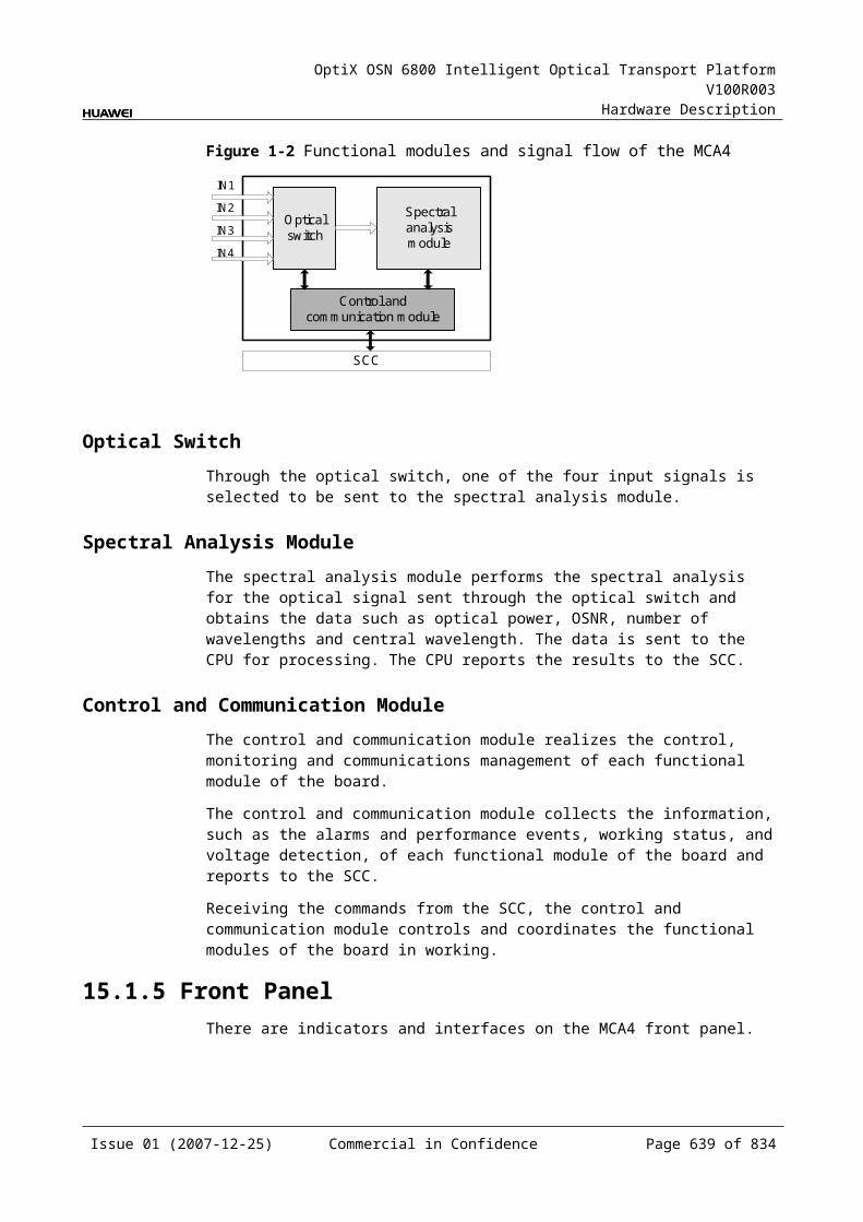
OptiX OSN 6800 Intelligent Optical Transport Platform V100R003
Hardware Description
Board name
Tunable wavelength function
ESC function
ALS function
OTN function
FEC encoding
WDM specification
Optical moduleFE
CAFEC
DWDM
CWDM
TQS x √ √ √ √ x x x eSFP
NOTE: "√" indicates that the OTU supports the function. "x" indicates that the OTU does not support the functionThe SCC board can automatically detect that the eSFP and XFP modules are installed and online. The following information about the modules can be obtained through a query on the T2000: VendorName, BarCode, and type of optical interface.
D.6 Loopback Function of OTUs, Tributary Boards and Line Boards
The OTUs, tributary boards and line boards support different loopback.
Table D-1 Loopback function of OTUs, tributary boards and line boards
Board Name
Client-Side Inloop
Client-Side Outloop
WDM-Side Inloop
WDM-Side Outloop
ECOM √ √ √ x
L4G √ √ √ √
LDGD √ √ √ √
LDGS √ √ √ √
LOG √ √ √ √
LOM √ √ √ √
LQMD √ √ √ √
LQMS √ √ √ √
LSX √ √ √ √
LSXL x x √ √
LSXLR x x x x
LSXR x x x x
LWX2 √ √ √ √
LWXD √ √ √ √
LWXS √ √ √ √
TMX √ √ √ √
NS2a x x √ √
Issue 01 (2007-12-25) Commercial in Confidence Page 638 of 664
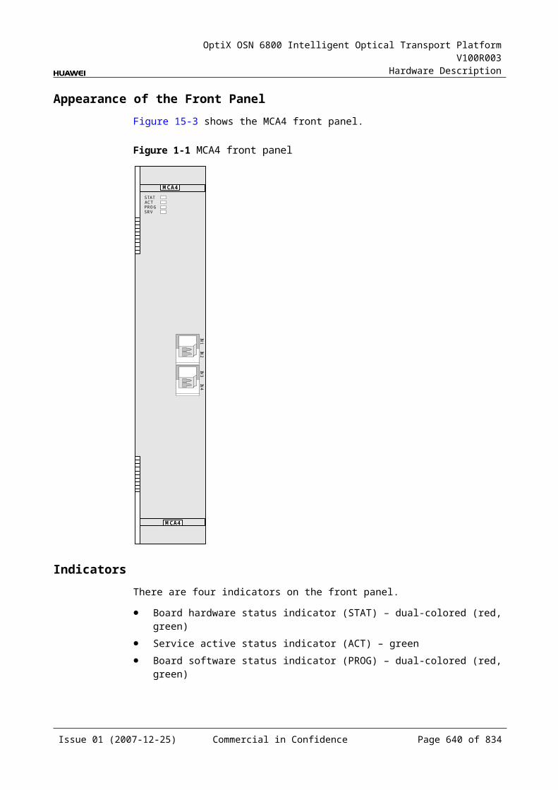
OptiX OSN 6800 Intelligent Optical Transport Platform V100R003
Hardware Description
TDG √ √ x x
TDX √ √ x x
TQM √ √ x x
TQS √ √ x x
NOTE: "√" indicates that the OTU supports the function. "x" indicates that the OTU does not support the function.
a: NS2 also supports path loopback.
Table D-2 Loop function of the Ethernet boards
Board Name Interface Loop Mode
L4G Client side MAC inloop
PHY outloop
WDM side Inloop
Outloop
TBE 10GE optical interface MAC inloop
MAC outloop
PHY inloop
PHY outloop
GE optical interface MAC inloop
PHY inloop
GE electric interface MAC inloop
PHY inloop
PHY outloop
FE optical interface MAC inloop
PHY inloop
FE electric interface MAC inloop
PHY inloop
PHY outloop
Issue 01 (2007-12-25) Commercial in Confidence Page 639 of 664
OptiX OSN 6800 Intelligent Optical Transport Platform V100R003
Hardware Description
D.7 Protection mode of OTUs, Tributary Boards and Line Boards
The OTUs, tributary boards and line boards support protection function.
For detailed protection mode, refer to Table D-12.
Table D-1 Protection mode of OTUs, tributary boards and line boards
Board name
Protection mode
SW SNCP
VLAN SNCP
ODUk SNCP
Client-side 1+1 protection
Intra-OTU 1+1 protection
OWSP protection
ODUk SPRing protection
BPS protection
ECOM x x x x x x x x
L4G √ √ x √ √ √ x x
LDGD √ x x √ √ √ x x
LDGS √ x x √ x √ x x
LOG √ √ √ √ √ √ x x
LOM x x x √ √ √ x x
LQMD √ x x √ √ √ x x
LQMS √ x x √ x √ x x
LSX x x x √ √ √ x x
LSXL x x x √ √ √ x x
LSXLR x x x x x x x x
LSXR x x x x x x x x
LWX2 x x x √ x √ x x
LWXD x x x √ √ √ x x
LWXS x x x √ x √ x x
NS2 x x √ x x √ √ x
TBE √ √ x √ √ x x √
TDG √ x √ √ x x √ x
TDX x x √ √ x x √ x
TMX x x x √ √ √ √ x
TQM √ x √ √ x x √ x
TQS x x √ √ x x √ x
Issue 01 (2007-12-25) Commercial in Confidence Page 640 of 664
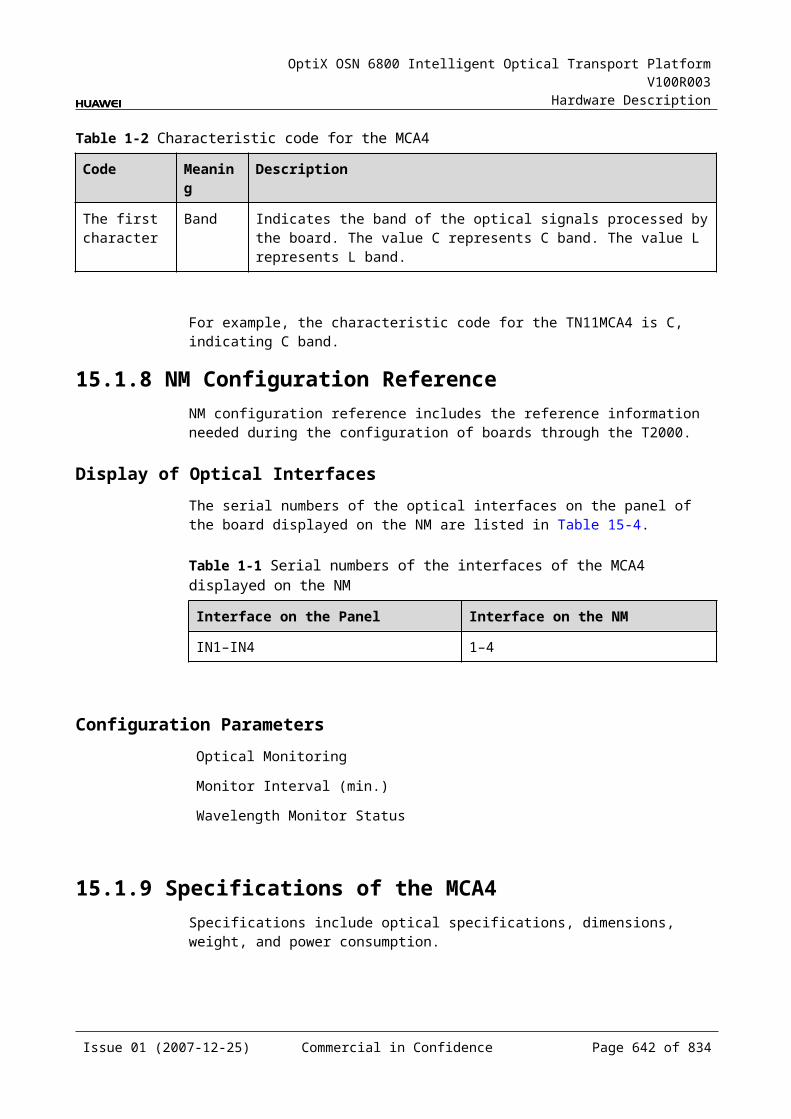
OptiX OSN 6800 Intelligent Optical Transport Platform V100R003
Hardware Description
Board name
Protection mode
SW SNCP
VLAN SNCP
ODUk SNCP
Client-side 1+1 protection
Intra-OTU 1+1 protection
OWSP protection
ODUk SPRing protection
BPS protection
NOTE: "√" indicates that the OTU supports the function. "x" indicates that the OTU does not support the function.
Issue 01 (2007-12-25) Commercial in Confidence Page 641 of 664
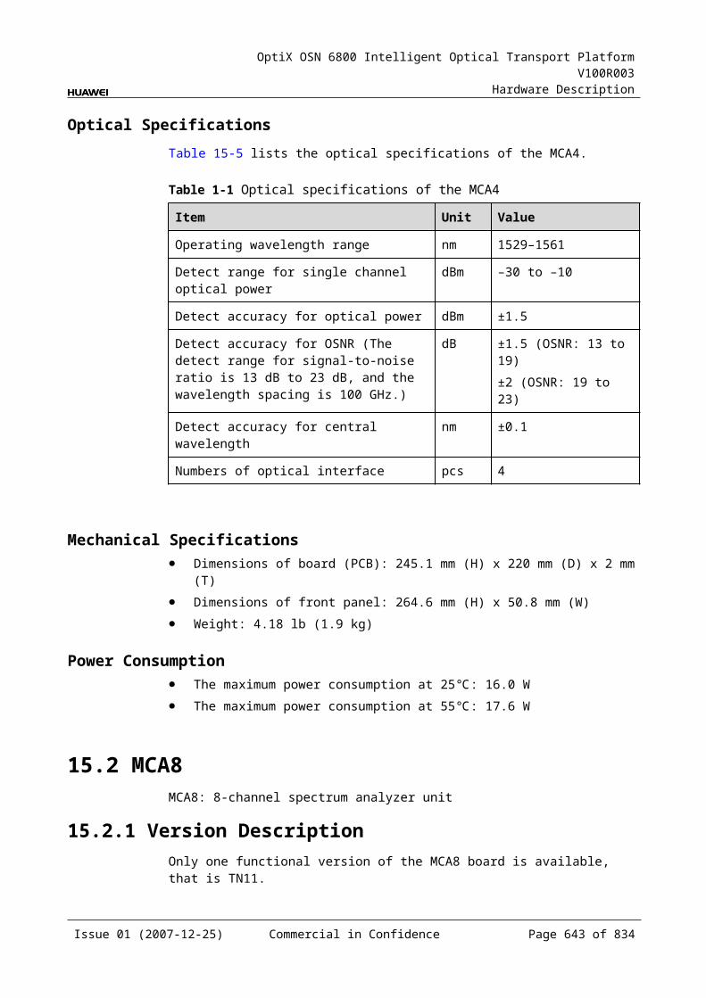
OptiX OSN 6800 Intelligent Optical Transport Platform V100R003
Hardware Description
D.8 Electrical cross-connection of OTUs, Tributary Boards and Line Boards
The OTUs, tributary boards and line boards support electrical cross-connection.
For detailed electrical cross-connection functions, refer to Table D-13.
Table D-1 Electrical cross-connection of OTUs, tributary boards and line boards
Board name
Electrical cross-connection
Integrated cross-connection
Distributed cross-connection
ECOM 1 x GE 1 x GE
L4G 4 x GE 4 x GE
LOG 8 x GE 8 x GE
LOM x x
LDGD 2 x GE 2 x GE
LDGS 2 x GE 2 x GE
LQMD x 4 x Any
LQMS x 4 x Any
LSX x x
LSXL x x
LSXLR x x
LSXR x x
LWX2 x x
LWXD x x
LWXS x x
NS2 4 x ODU1 4 x ODU1
TBE 8 x GE 8 x GE
TDG 2 x GE/1 x ODU1 2 x GE/1 x ODU1
TDX 8 x ODU1 8 x ODU1
TMX x x
TQM 1 x ODU1 4 x Any/1 x ODU1
TQS 4 x ODU1 4 x ODU1
Issue 01 (2007-12-25) Commercial in Confidence Page 642 of 664
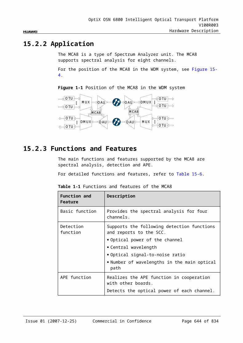
OptiX OSN 6800 Intelligent Optical Transport Platform V100R003
Hardware Description
Board name
Electrical cross-connection
Integrated cross-connection
Distributed cross-connection
NOTE: "x" indicates that the OTU does not support the function.
Issue 01 (2007-12-25) Commercial in Confidence Page 643 of 664
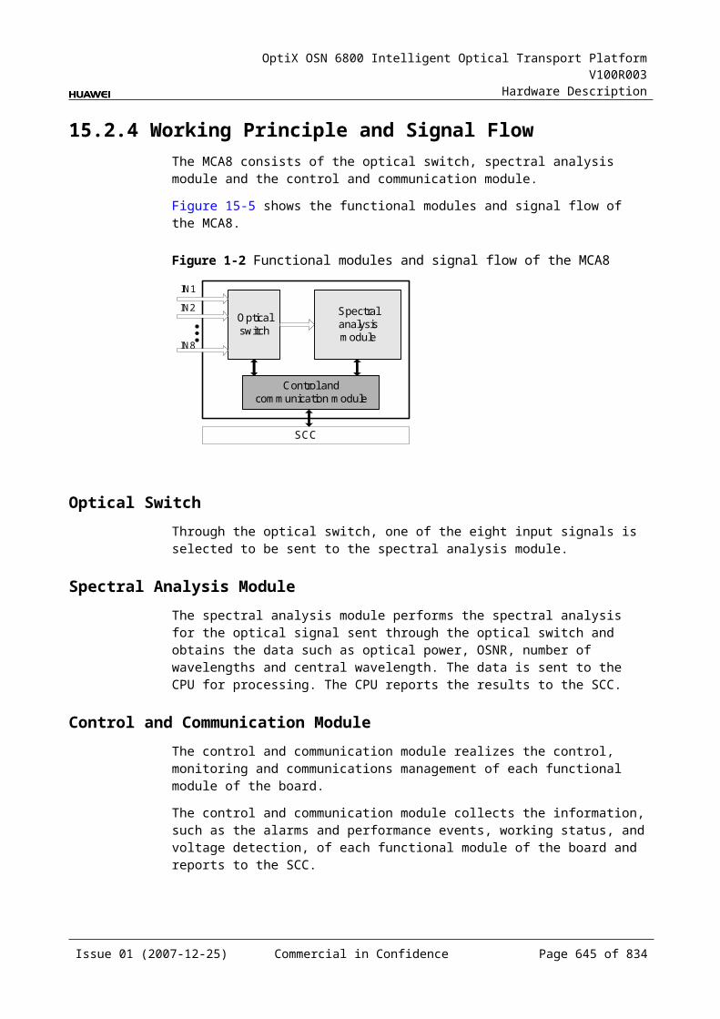
OptiX OSN 6800 Intelligent Optical Transport Platform V100R003
Hardware Description
E Power Consumption, Weight and Valid Slots of Boards
This chapter describes the power consumption, weight and valid slots of the boards used in the OptiX OSN 6800 system.
The power consumption, weight and valid slots of the OptiX OSN 6800 boards are shown in Table E-1. The values listed in the following table indicate the power consumption of the boards when they normally work at 25 and 55 .
Table E-1 Power consumption, weight and valid slots of the OptiX OSN 6800 boards
Board Optical Module Type
Maximum Power Consumption at 25 (W)
Maximum Power Consumption at 55 (W)
Weight (kg)
Number of Occupied Slots
Valid Slots
TN11ACS
- 0.2 0.3 0.8 1 IU1–IU17
TN11AUX
- 14.0 15.4 0.5 1 IU21
TN11CMR2
- 0.2 0.3 0.8 1 IU1–IU17
TN11CMR4
- 0.2 0.3 0.9 1 IU1–IU17
TN11CRPC
- 110.0 121.0 4.0 - –
TN11D40
- 20.0 22.0 2.2 3 IU1–IU15
TN11D40V
- 38.5 42.3 2.3 3 IU1–IU15
TN11DCP
- 6.8 7.5 1.0 1 IU1–IU17
Issue 01 (2007-12-25) Commercial in Confidence Page 645 of 664

OptiX OSN 6800 Intelligent Optical Transport Platform V100R003
Hardware Description
Board Optical Module Type
Maximum Power Consumption at 25 (W)
Maximum Power Consumption at 55 (W)
Weight (kg)
Number of Occupied Slots
Valid Slots
TN11DCU
- 0.5 0.5 1.5 1 IU1–IU17
TN11DMR1
- 0.2 0.3 0.7 1 IU1–IU17
TN11ECOM
- 19.6 21.6 1.01 1 IU1–IU8, IU11–IU16
TN11FIU/TN12FIU
- 4.2 4.6 1.0 1 IU1–IU17
TN11HBA
- 47.0 75.0 3 3 IU2–IU16
TN11ITL
- 0.2 0.3 1.2 1 IU1–IU17
TN11L4G
NRZ-fixed(D)(5G) (3400 ps/nm6400 ps/nm)
50.0 55.0 1.4 1 IU1–IU8, IU11–IU16
NRZ-fixed(C)(5G) (3400 ps/nm)
45.0 50.0
NRZ-tunable(5G) (3400 ps/nm)
53.0 58.0
TN11LDGD
Fixed(2.5G) (12800 ps/nm-PIN12800 ps/nm-APD6500 ps/nm-PIN3200 ps/nm-2mW-APD)
34.0 37.4 1.4 1 IU1–IU8, IU11–IU16
Tunable(2.5G) (12800 ps/nm)
36.0 39.6
TN11LDGS
Fixed(2.5G) (12800 ps/nm-PIN12800 ps/nm-APD6500 ps/nm-PIN3200 ps/nm-2mW-APD)
32.0 35.2 1.2 1 IU1–IU8, IU11–IU16
Issue 01 (2007-12-25) Commercial in Confidence Page 646 of 664
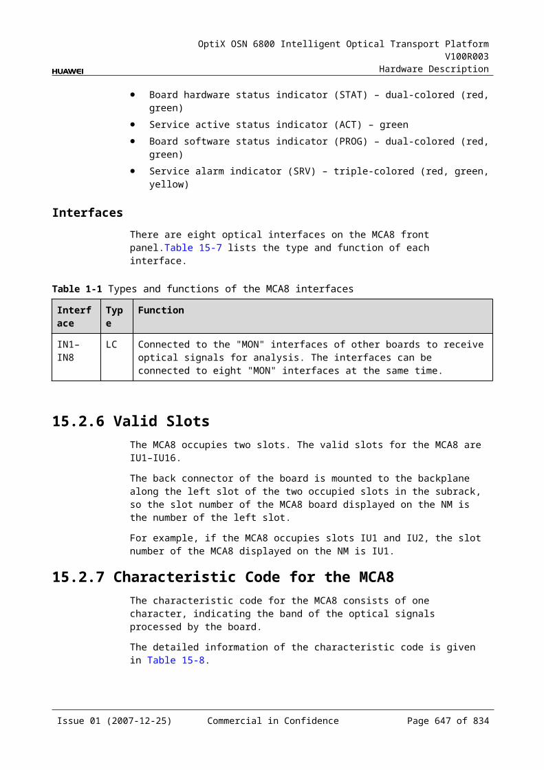
OptiX OSN 6800 Intelligent Optical Transport Platform V100R003
Hardware Description
Board Optical Module Type
Maximum Power Consumption at 25 (W)
Maximum Power Consumption at 55 (W)
Weight (kg)
Number of Occupied Slots
Valid Slots
Tunable(2.5G)(12800 ps/nm)
34.0 37.4
TN11LOG
NRZ-fixed(10G) (800 ps/nm-40 channels fixed1600 ps/nm-40 channels fixed
49.5 54.5 1.6 1 IU1–IU8, IU11–IU16
NRZ-tunable(10G) (1200 ps/nm-PIN-80 channels tunable1200 ps/nm-APD-80 channels tunable)
50.0 55.0
DRZ-tunable(10G) (800 ps/nm-80 channels tunable)
51.2 56.1
ODB-tunable(10G) (4800 ps/nm-80 channels tunable)
55.0 60.5
TN11LOM
NRZ-fixed(10G) (800 ps/nm-40 channels fixed1600 ps/nm-40 channels fixed
92.7 101.7 2.32 2 IU1–IU8, IU11–IU16
NRZ-tunable(10G) (1200 ps/nm-PIN-80 channels tunable1200 ps/nm-APD-80 channels tunable)
92.9 101.9
DRZ-tunable (10G) (800 ps/nm-80 channels tunable)
93.4 102.7
ODB-tunable(10G) (4800 ps/nm-80 channels tunable)
98.2 108.0
TN11LQMD
Fixed(2.5G) (12800 ps/nm-PIN12800 ps/nm-APD6500 ps/nm-PIN3200 ps/nm-2mW-APD)
54.9 60.4 1.4 1 IU1–IU8, IU11–IU16
Issue 01 (2007-12-25) Commercial in Confidence Page 647 of 664

OptiX OSN 6800 Intelligent Optical Transport Platform V100R003
Hardware Description
Board Optical Module Type
Maximum Power Consumption at 25 (W)
Maximum Power Consumption at 55 (W)
Weight (kg)
Number of Occupied Slots
Valid Slots
Tunable(2.5G) (12800 ps/nm)
59.1 65.1
TN11LQMS
Fixed(2.5G) (12800 ps/nm-PIN12800 ps/nm-APD6500 ps/nm-PIN3200 ps/nm-2mW-APD)
53.2 58.5 1.3 1 IU1–IU8, IU11–IU16
Tunable(2.5G)(12800 ps/nm)
57.8 63.6
TN11LSX
NRZ-fixed(10G) (800 ps/nm-40 channels fixed1600 ps/nm-40 channels fixed)
47.7 52.3 1.3 1 IU1–IU17
NRZ-tunable(10G) (1200 ps/nm-PIN-80 channels tunable1200 ps/nm-APD-80 channels tunable)
47.9 52.5
DRZ-tunable(10G) (800 ps/nm-80 channels tunable)
49.7 52.7
ODB-tunable(10G) (4800 ps/nm-80 channels tunable)
52.7 55.7
TN12LSX
NRZ-fixed(10G) (800 ps/nm-40 channels fixed1600 ps/nm-40 channels fixed
32.0 38.4 1.4 1 IU1–IU17
NRZ-tunable (10G) (1200 ps/nm-PIN-80 channels tunable1200 ps/nm-APD-80 channels tunable)
32.2 38.6
DRZ-tunable(10G) (800 ps/nm-80 channels tunable)
34.0 40.8
Issue 01 (2007-12-25) Commercial in Confidence Page 648 of 664
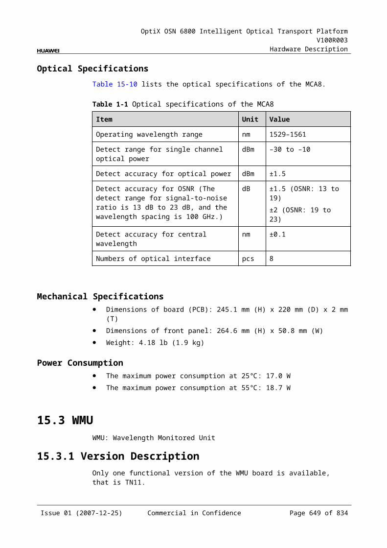
OptiX OSN 6800 Intelligent Optical Transport Platform V100R003
Hardware Description
Board Optical Module Type
Maximum Power Consumption at 25 (W)
Maximum Power Consumption at 55 (W)
Weight (kg)
Number of Occupied Slots
Valid Slots
ODB-tunable(10G) (4800 ps/nm-80 channels tunable)
36.0 43.2
TN11LSXL
DRZ-tunable(40G) (Transponder)
103.0 110.0 5.0 4 IU1–IU14
ODB-tunable(40G) (Transponder)
98.0 105.0
TN11LSXLR
DRZ-tunable(40G) (Transponder)
87.0 90.0 3.05 4 IU1–IU14
ODB-tunable(40G) (Transponder)
82.0 85.0
TN11LSXR
NRZ-fixed(10G) (800 ps/nm-40 channels fixed1600 ps/nm-40 channels fixed
34.8 38.3 1.2 1 IU1–IU17
NRZ-tunable(10G) (1200 ps/nm-PIN-80 channels tunable1200 ps/nm-APD-80 channels tunable)
35.0 38.5
DRZ-tunable(10G) (800 ps/nm-80 channels tunable)
36.8 40.3
ODB-tunable(10G) (4800 ps/nm-80 channels tunable)
39.8 43.3
TN11LWX2
- 38.5 42.4 1.3 1 IU1–IU17
TN11LWXD
- 35.8 39.4 1.2 1 IU1–IU17
TN11LWXS
- 33.9 37.3 1.1 1 IU1–IU17
TN11M40
- 20.0 22.0 2.2 3 IU1–IU15
TN11M40V
- 38.5 42.3 2.3 3 IU1–IU15
Issue 01 (2007-12-25) Commercial in Confidence Page 649 of 664
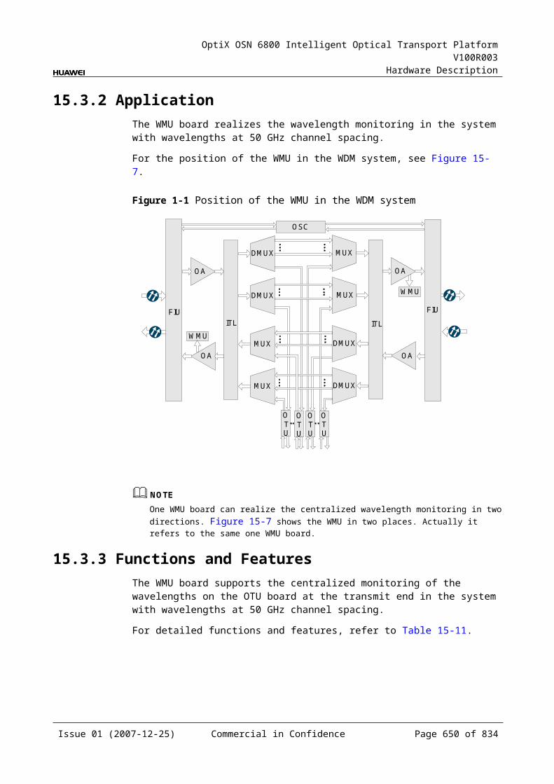
OptiX OSN 6800 Intelligent Optical Transport Platform V100R003
Hardware Description
Board Optical Module Type
Maximum Power Consumption at 25 (W)
Maximum Power Consumption at 55 (W)
Weight (kg)
Number of Occupied Slots
Valid Slots
TN11MB2
- 0.2 0.3 0.9 1 IU1–IU17
TN11MCA4
- 16.0 17.6 1.9 2 IU1–IU16
TN11MCA8
- 17.0 18.7 1.9 2 IU1–IU16
TN11MR2
- 0.2 0.3 0.9 1 IU1–IU17
TN11MR4
- 0.2 0.3 0.9 1 IU1–IU17
TN11MR8
- 0.2 0.3 1.0 2 IU1–IU16
TN11NS2
NRZ-fixed(10G) (800 ps/nm-40 channels fixed1600 ps/nm-40 channels fixed)
38.0 41.8 1.2 1 IU1–IU8, IU11–IU16
NRZ-tunable(10G) (1200 ps/nm-PIN-80 channels tunable1200 ps/nm-APD-80 channels tunable)
39.0 42.9
DRZ-tunable (10G) (800 ps/nm-80 channels tunable)
41.0 45.1
ODB-tunable(10G) (4800 ps/nm-80 channels tunable)
44.0 48.4
TN11OAU1
- 33.0 36.3 1.8 2 IU2–IU17
TN11OBU101/ TN11OBU104
- 16.0 17.6 1.3 1 IU1–IU17
TN11OBU103
- 18.0 19.8 1.3 1 IU1–IU17
TN11OBU2
- 35.0 38.5 1.9 2 IU2–IU17
Issue 01 (2007-12-25) Commercial in Confidence Page 650 of 664
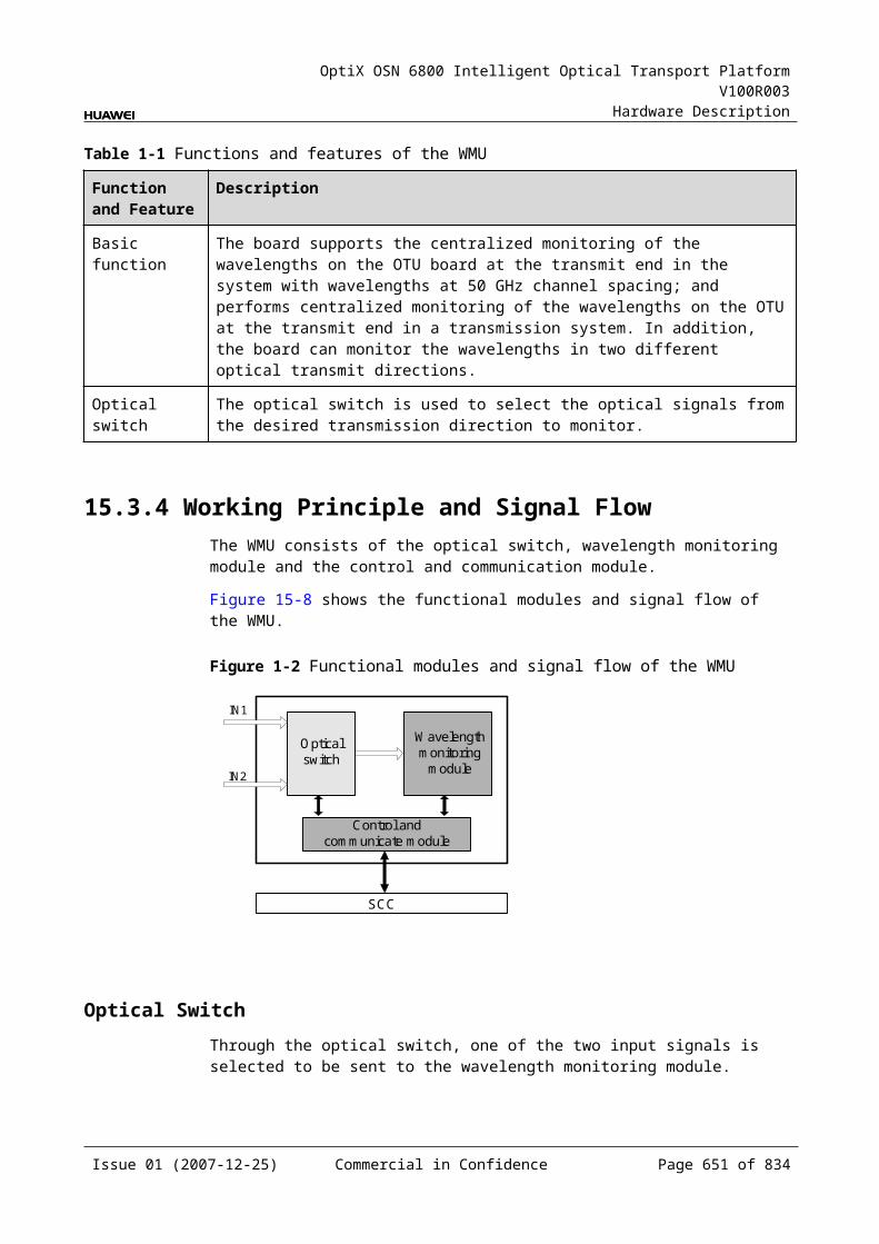
OptiX OSN 6800 Intelligent Optical Transport Platform V100R003
Hardware Description
Board Optical Module Type
Maximum Power Consumption at 25 (W)
Maximum Power Consumption at 55 (W)
Weight (kg)
Number of Occupied Slots
Valid Slots
TN11OLP
- 6.0 6.6 0.9 1 IU1–IU17
TN11PIU
- 35 35 0.5 1 IU19, IU20
TN11RMU9
- 11.0 12.1 1.1 1 IU1–IU17
TN11ROAM
- 66.0 72.6 3.2 3 IU1–IU15
TN11SBM2
- 0.2 0.3 0.82 1 IU1–IU17
TN11SC1
- 13.5 14.9 1.0 1 IU1–IU17
TN11SC2
- 13.5 14.9 1.0 1 IU1–IU17
TN11SCC
- 30.0 33.0 1.2 1 IU17, IU18
TN11SCS
- 0.2 0.3 0.8 1 IU1–IU17
TN11TBE
- 40.7 44.8 1.4 1 IU1–IU8, IU11–IU16
TN11TDG
- 30.0 33.0 1.1 1 IU1–IU8, IU11–IU16
TN11TDX
- 78.0 80.0 1.25 1 IU1–IU8, IU11–IU16
TN11TMX
NRZ-fixed(10G) (800 ps/nm-40 channels fixed1600 ps/nm-40 channels fixed)
40.3 44.3 1.4 1 IU1–IU17
NRZ-tunable(10G) (1200 ps/nm-PIN-80 channels tunable1200 ps/nm-APD-80 channels tunable)
42.1 46.4
Issue 01 (2007-12-25) Commercial in Confidence Page 651 of 664
OptiX OSN 6800 Intelligent Optical Transport Platform V100R003
Hardware Description
Board Optical Module Type
Maximum Power Consumption at 25 (W)
Maximum Power Consumption at 55 (W)
Weight (kg)
Number of Occupied Slots
Valid Slots
DRZ-tunable(10G) (800 ps/nm-80 channels tunable)
42.4 46.6
ODB-tunable(10G) (4800 ps/nm-80 channels tunable)
46.5 51.2
TN11TQM
- 49.1 54.1 1.2 1 IU1–IU8, IU11–IU16
TN11TQS
- 43.0 47.3 1.2 1 IU1–IU8, IU11–IU16
TN11TSXL
- 65 72 2.5 2 IU2–IU8, IU12–IU16
TN11VA1/ TN12VA1
- 6.5 7.2 1.0 1 IU1–IU17
TN11VA4/ TN12VA4
- 8.5 9.4 1.0 1 IU1–IU17
TN11WMU
- 12.0 15.0 1.02 1 IU1–IU17
TN11WSD9
- 17.0 18.7 2.2 2 IU1–IU16
TN12WSD9
- 30.0 35.0 2.5 2 IU1–IU16
TN13WSD9
- 30.0 35.0 2.5 3 IU1–IU15
TN11WSM9
- 17.0 18.7 2.2 2 IU1–IU16
TN12WSM9
- 30.0 35.0 2.5 2 IU1–IU16
TN13WSM9
- 30.0 35.0 2.5 3 IU1–IU15
Issue 01 (2007-12-25) Commercial in Confidence Page 652 of 664

OptiX OSN 6800 Intelligent Optical Transport Platform V100R003
Hardware Description
Board Optical Module Type
Maximum Power Consumption at 25 (W)
Maximum Power Consumption at 55 (W)
Weight (kg)
Number of Occupied Slots
Valid Slots
TN11WSMD4
- 17.0 18.7 3.2 2 IU1–IU15
TN11XCS
- 20.0 22.0 1.0 1 IU9, IU10
Issue 01 (2007-12-25) Commercial in Confidence Page 653 of 664
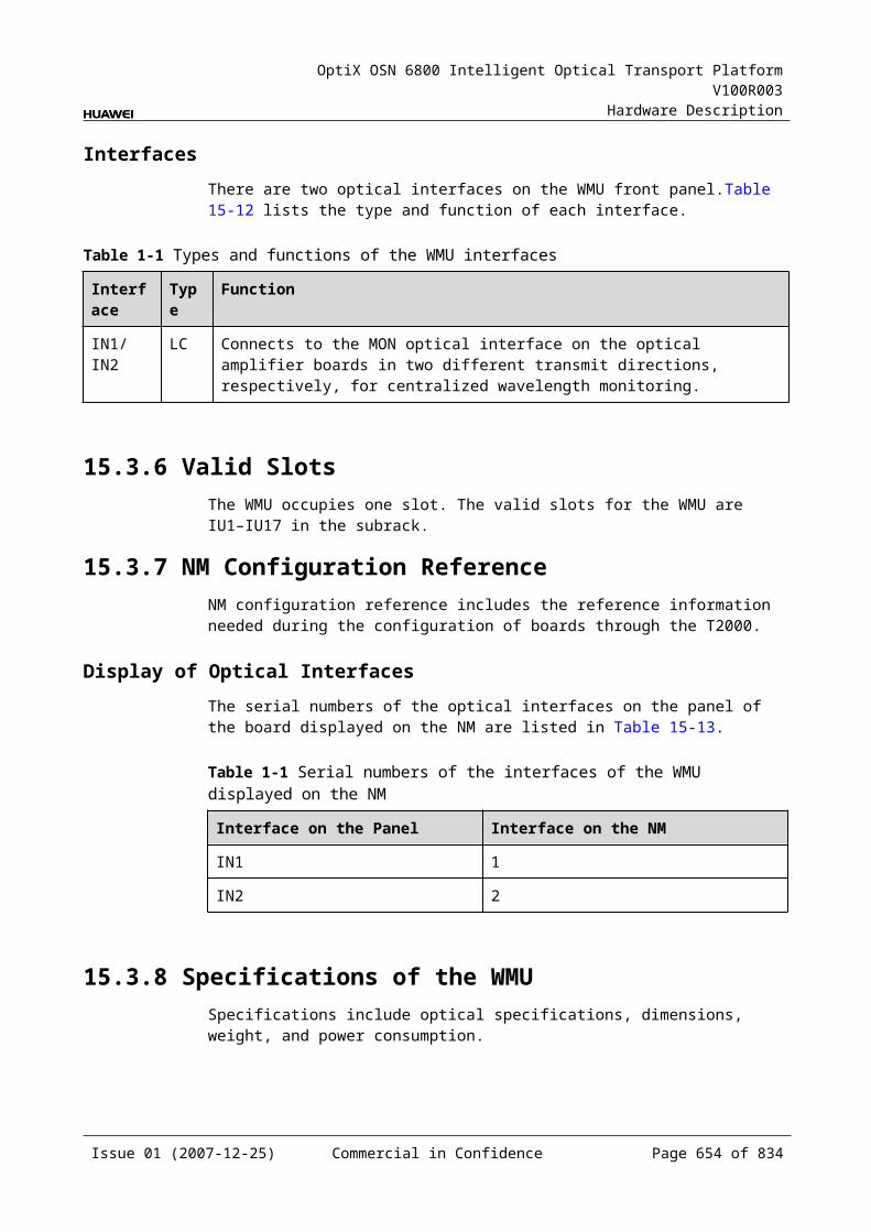
OptiX OSN 6800 Intelligent Optical Transport Platform V100R003
Hardware Description
F Glossary
This document defines the following terms:
Numerics 3R Regenerating, Reshaping and Retiming.
A
Alarm cascading The shunt-wound output of the alarm signals of several subracks or cabinets.
Alarm A visible or an audible indication to notify the person concerned that a failure or an emergency has occurred. See also Event.
ALC Automatic Level Control. The technique supports the adjustment of optical power aimed to restrain the output power to be inferior on the downstream and keep the optical power to be within a certain working range.
ATM Asynchronous Transfer Mode. A transfer mode in which the information is organized into cells. It is asynchronous in the sense that the recurrence of cells containing information from an individual user is not necessarily periodic. It is a protocol within the OSI layer 1. An ATM cell consists of a 5 octet header followed by 48 octets of data.
Attenuation Reduction of signal magnitude or signal loss, usually expressed in decibels.
Attenuator A passive component that attenuates an electrical or optical signal.
B
Back up A method to copy the important data into a backing storage in case that the original is damaged or corrupted.
Backplane A PCB circuit board in the subrack, which is connected with all the boards in position.
Bandwidth Information-carrying capacity of a communication channel. Analog bandwidth is the range of signal frequencies that can be transmitted by a communication channel or network.
Issue 01 (2007-12-25) Commercial in Confidence Page 655 of 664
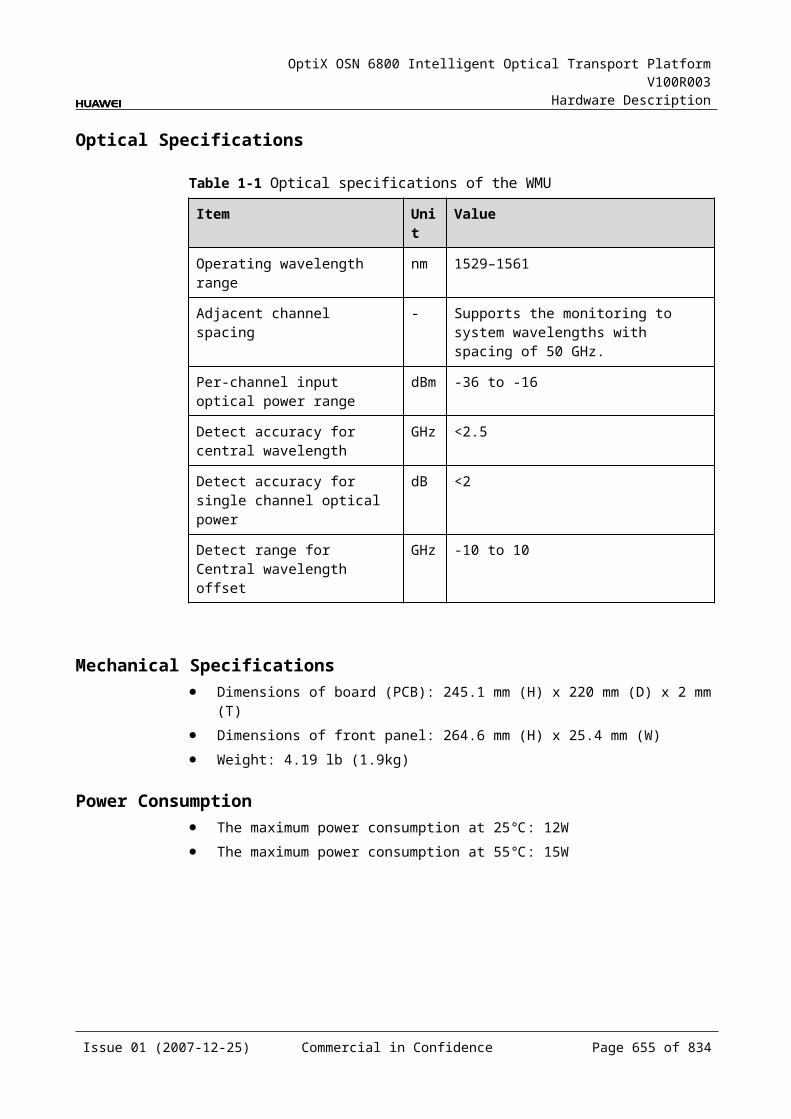
OptiX OSN 6800 Intelligent Optical Transport Platform V100R003
Hardware Description
Numerics Bit Error Rate The number of coding violations detected in a unit of time, usually one
second. Bit error rate (BER) is calculated with this formula: BER = error bits received/total bits sent
Bit error An error occurs to some bits in the digital code stream after being received, judged, and regenerated, thus damaging the quality of the transmitted information.
Broadcast The act of sending a frame addressed to all stations on the network
C
Chain network One type of network that all network nodes are connected one after one to be in series.
CWDM Coarse Wavelength Division Multiplexing. The technology for transmitting signals at multiple wavelengths through the same fiber with wide spacing between optical channels. Typical spacing is several nanometers or more.
D
DCF Dispersion Compensation Fiber. A kind of fiber which uses negative dispersion to compensate for the positive dispersion of transmitting fiber to maintain the original shape of the signal pulse.
DCM Dispersion Compensation Module. A module, which contains dispersion compensation fibers to compensate for the positive dispersion of transmitting fiber.
DCN Data Communication Network. A communication network within a TMN or between TMNs which supports the data communication function (DCF).
Demultiplexing A process applied to a multiplex signal for recovering signals combined within it and for restoring the distinct individual channels of the signals.
Dense Wavelength Division Multiplexing
The higher capacity version of WDM, which is a means of increasing the capacity of fiber-optic data transmission systems through the multiplexing of multiple wavelengths of light. Commercially available DWDM systems support the multiplexing of from 8 to 40 wavelengths of light.
E
ECC Embedded Control Channel. An ECC provides a logical operations channel between SDH NEs, utilizing a data communications channel (DCC) as its physical layer.
EDFA Erbium-Doped Fiber Amplifier. The optical amplifier that its fiber doped with the rare earth element erbium, which can amplify at 1530 to 1610 nm when the optical amplifier is pumped by an external light source.
ESCON Enterprise System Connection. A path protocol which connects the host with various control units in a storage system. It is a serial bit stream transmission protocol. The transmission rate is 200 Mbit/s.
Issue 01 (2007-12-25) Commercial in Confidence Page 656 of 664
OptiX OSN 6800 Intelligent Optical Transport Platform V100R003
Hardware Description
Numerics Ethernet A data link level protocol comprising the OSI model's bottom two layers. It is a
broadcast networking technology that can use several different physical media, including twisted pair cable and coaxial cable. Ethernet usually uses CSMA/CD. TCP/IP is commonly used with Ethernet networks.
EVPL Ethernet Virtual Private Line. An EVPL service is a service that is both a line service and a virtual private service.
Eye pattern A graphic presentation formed by the superimposition of the waveforms of all possible pulse sequences.
F
FC Fiber Channel. A standard of data storage network for transmitting signals at 100 Mbit/s to 4.25Gbit/s over fiber or (at slow speeds) copper.
FICON Fiber Connect. A new generation connection protocol which connects the host with various control units. It carries single byte command protocol through the physical path of fiber channel, and provides higher rate and better performance than ESCON.
Frame A cyclic set of consecutive time slots in which the relative position of each time slot can be identified.
G
Gain The ratio between the optical power from the input optical interface of the optical amplifier and the optical power from the output optical interface of the jumper fiber, which expressed in dB.
Grooming Consolidating or segregating traffic for efficiency.
H
History alarms Alarms that have been cleared and acknowledged.
I
IP over DCC The IP Over DCC follows TCP/IP telecommunications standards and controls the remote NEs through the Internet. The IP Over DCC means that the IP over DCC uses overhead DCC byte (the default is D1-D3) for communication.
IPA Intelligent Power Adjustment. The technology that the system reduces the optical power of all the amplifiers in an adjacent regeneration section in the upstream to a safety level if the system detects the loss of optical signals on the link. The loss of optical signals may due to the fiber is broken, the performance of equipments trend to be inferior or the connector is not plugged well. Thus, the maintenance engineers are not hurt by the laser being sent out from the slice of broken fiber.
Issue 01 (2007-12-25) Commercial in Confidence Page 657 of 664
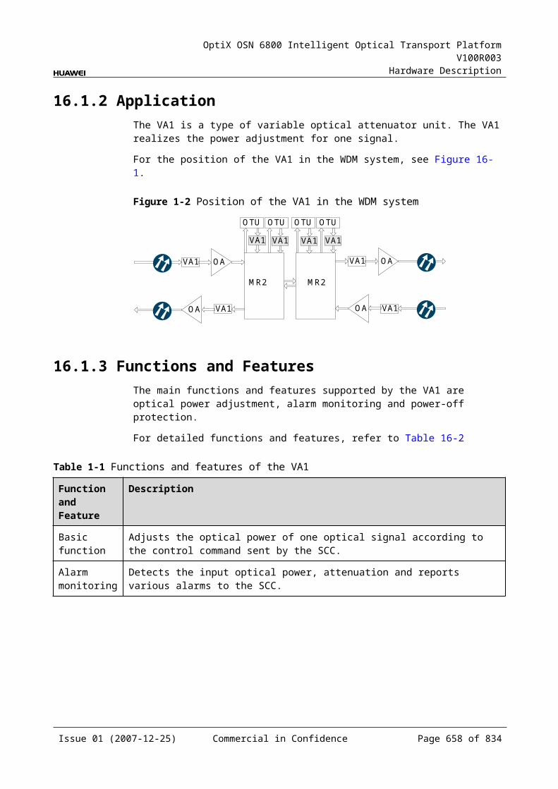
OptiX OSN 6800 Intelligent Optical Transport Platform V100R003
Hardware Description
Numerics M
MAN Metropolitan Area Network. An IEEE-approved network that supports high speeds over a metropolitan area.
Mapping A procedure by which tributaries are adapted into virtual containers at the boundary of an SDH network.
Multiplexer An equipment which combines a number of tributary channels onto a fewer number of aggregate bearer channels, the relationship between the tributary and aggregate channels being fixed.
Multiplexing A procedure by which multiple lower order path layer signals are adapted into a higher order path or the multiple higher order path layer signals are adapted into a multiplex section.
O
ONE Optical Network Element. A stand-alone physical entity in an optical transmission network that supports at least network element functions.
OSC Optical Supervisory Channel. A technology realizes communication among nodes in optical transmission network and transmits the monitoring data in a certain channel (the wavelength of the working channel for it is 1510 nm and that of the corresponding protection one is 1625 nm).
OSNR Optical Signal-to-Noise Ratio. Ratio of the optical power of the transmitted optical signal to the noise on the received signal.
P
Path protection The working principle of path protection: When the system works in path protection mode, the PDH path uses the dual-fed and signal selection mode. Through the tributary unit and cross-connect unit, the tributary signal is sent simultaneously to the east and west lines. Meanwhile, the cross-connect matrix sends the signal dually sent from the opposite end to the tributary board through the active and standby buses, and the hardware of the tributary board automatically and selectively receive the signal from the two groups of buses automatically according to the AIS number of the lower order path.
Paired slots A pair of slots whose overhead can be processed by the bus on the backplane. For the two boards in the paired slots, the inter-board cross-connection can be directly configured, and the cross-connect grooming of services can be realized without the cross-connect board.
Performance threshold
Performance events usually have upper and lower thresholds. When the performance event count value exceeds the upper threshold, a performance threshold-crossing event is generated; when the performance event count value is below the upper threshold for a period of time, the performance threshold-crossing event is ended. In this way, performance jitter caused by some sudden events can be shielded.
Polarization dependence loss
The maximum variation of loss result from a variation of the state of polarization of the input signal at nominal operating conditions.
Issue 01 (2007-12-25) Commercial in Confidence Page 658 of 664
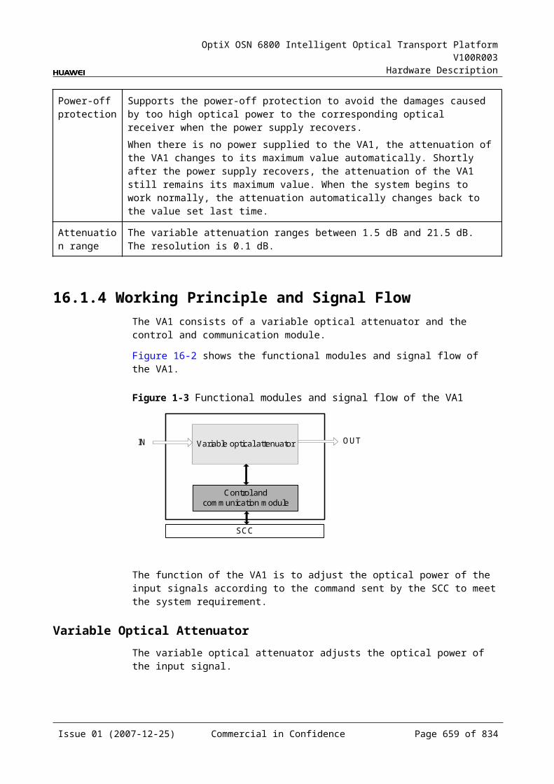
OptiX OSN 6800 Intelligent Optical Transport Platform V100R003
Hardware Description
Numerics
R
Receiver overload Receiver overload is the maximum acceptable value of the received average power at point R to achieve a 1 x 10⁻¹⁰ BER.
Receiver sensitivity
Receiver sensitivity is defined as the minimum acceptable value of average received power at point R to achieve a 1 x 10-12 BER.
Ring network One type of network that all network nodes are connected one after one to be a cycle.
S
SAN Storage Area Network. A dedicated high-speed data storage network which interconnects multiple independent storage systems with multiple servers through fiber path switch or other switch equipment.
SDH Synchronous Digital Hierarchy. A hierarchical set of digital transport structures, standardized for the transport of suitably adapted payloads over physical transmission networks.
Simple Network Management Protocol
An IETF protocol for monitoring and managing systems and devices in a network. The data being monitored and managed is defined by a Management Information Base (MIB). The functions supported by the protocol are the request and retrieval of data, the setting or writing of data, and traps that signal the occurrence of events.
Small Form-Factor Pluggable
A specification for a new generation of optical modular transceivers. The devices are designed for use with small form factor (SFF) connectors, and offer high speed and physical compactness, and are hot-swappable. SFP transceivers are expected to perform at data speeds of up to five gigabits per second (5 Gbit/s), and possibly higher. Because SFP modules can be easily interchanged, electro-optical or fiber optic networks can be upgraded and maintained more conveniently than has been the case with traditional soldered-in modules. Rather than replacing an entire circuit board containing several soldered-in modules, a single module can be removed and replaced for repair or upgrading. This can result in a substantial cost savings, both in maintenance and in upgrading efforts.
T
T2000 The T2000 is a subnet management system (SNMS). In the telecommunication management network architecture, the T2000 is located between the NE level and network level, which can supports all NE level functions and part of the network level management functions. See also NM.
TCM Tandem Connection Monitor. In the SDH transport hierarchy, the TCM is located between the AU/TU management layer and HP/LP layer. It uses the N1/N2 byte of POH overhead to monitor the quality of the transport channels on a transmission section (TCM section).
Issue 01 (2007-12-25) Commercial in Confidence Page 659 of 664

OptiX OSN 6800 Intelligent Optical Transport Platform V100R003
Hardware Description
Numerics TCP/IP Transmission Control Protocol/Internet Protocol. Common name for the suite
of protocols developed to support the construction of worldwide internetworks.
TMN Telecommunications Management Network. The entity which provides the means used to transport and process information related to management functions for the telecommunications network.
V
VLAN Virtual local area network. A subset of the active topology of a Bridged Local Area Network. Associated with each VLAN is a VLAN Identifier (VID).
VOA Variable Optical Attenuator. An attenuator in which the attenuation can be varied.
W
Wavelength Division Multiplexing
A means of increasing the capacity of fiber-optic data transmission systems through the multiplexing of multiple wavelengths of light. WDM systems support the multiplexing of as many as four wavelengths.
WDM Wavelength-Division Multiplexing. WDM technology utilizes the characteristics of broad bandwidth and low attenuation of single mode optical fiber, employs multiple wavelengths as carriers, and allows multiple channels to transmit simultaneously in a single fiber.
Working path A specific path that is part of a protection group and is labeled working.
Issue 01 (2007-12-25) Commercial in Confidence Page 660 of 664

OptiX OSN 6800 Intelligent Optical Transport Platform V100R003
Hardware Description
G Acronyms and Abbreviations
A
AFEC Advanced Forward Error Correction
AIS Alarm Indication Signal
ALC Automatic Level Control
ALS Automatic Laser Shutdown
APE Automatic Power Equilibrium
APS Automatic Protection Switch
ASON Automatic Switched Optical Network
B
BER Bit Error Ratio
C
CMI Coded Mark Inversion
CRZ Chirped Return to Zero
CWDM Coarse Wavelength Division Multiplex
D
DCC Data Communication Channel
DCF Dispersion Compensation Fiber
DCM Dispersion Compensation Module
DCN Data Communication Network
DSCR Dispersion Slope Compensation Rate
Issue 01 (2007-12-25) Commercial in Confidence Page 661 of 664
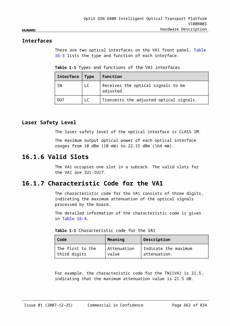
OptiX OSN 6800 Intelligent Optical Transport Platform V100R003
Hardware Description
DWDM Dense Wave Division Multiplexer
E
ECC Embedded Control Channel
EDFA Erbium-Doped Fiber Amplifier
EMC Electromagnetic Compatibility
EPL Ethernet Private Line
ESCON Enterprise Systems Connection
eSFP Enhanced Small Form-Factor Pluggable
ETSI European Telecommunication Standards Institute
EVPL Ethernet Virtual Private Line
F
FEC Forward Error Correction
FWM Four-Wave Mixing
G
GE Gigabit Ethernet
I
ID Identity
IEEE Institute of Electrical and Electronic Engineers
IP Internet Protocol
IPA Intelligent Power Adjustment
ITU-T International Telecommunication Union-Telecommunication Sector
L
LAG Link Aggregation Group
LAN Local Area Network
LCN Local Communication Network
LCT Local Craft Terminal
LOF Loss Of Frame
LOS Loss Of Signal
Issue 01 (2007-12-25) Commercial in Confidence Page 662 of 664
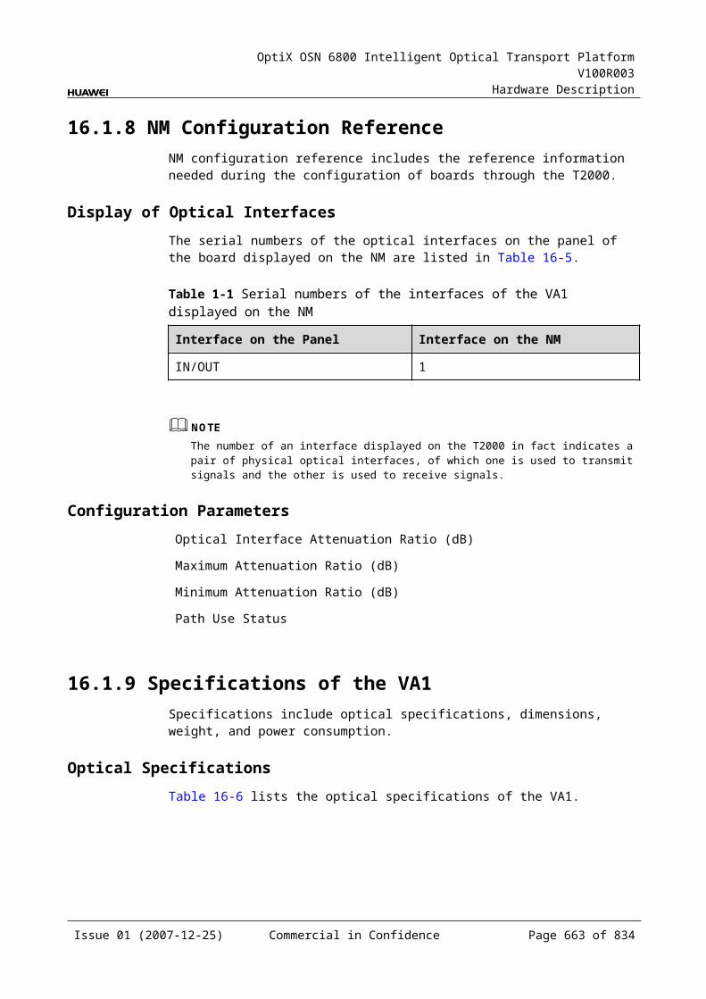
OptiX OSN 6800 Intelligent Optical Transport Platform V100R003
Hardware Description
N
NE Network Element
NRZ Non Return to Zero
O
OA Optical Amplifier
OADM Optical Add/Drop Multiplexer
OD Optical Demultiplexing
ODU Optical Channel Data Unit
OLA Optical Line Amplifier
OM Optical Multiplexing
OMS Optical Multiplex Section
OSC Optical Supervisory Channel
OSN Optical Switch Node
OSNR Optical Signal-to-noise Ratio
OTM Optical Terminal Multiplexer
OTN Optical Transmission Network
OTS Optical Transmission Section
OTU Optical Transponder Unit
Q
QA Q Adaptation
QoS Quality of Service
QinQ 802.1Q in 802.1Q
R
ROADM Reconfiguration Optical Add/drop Multiplexer
S
SDH Synchronous Digital Hierarchy
SNCP Subnetwork Connection Protection
SNMP Simple Network Management Protocol
Issue 01 (2007-12-25) Commercial in Confidence Page 663 of 664
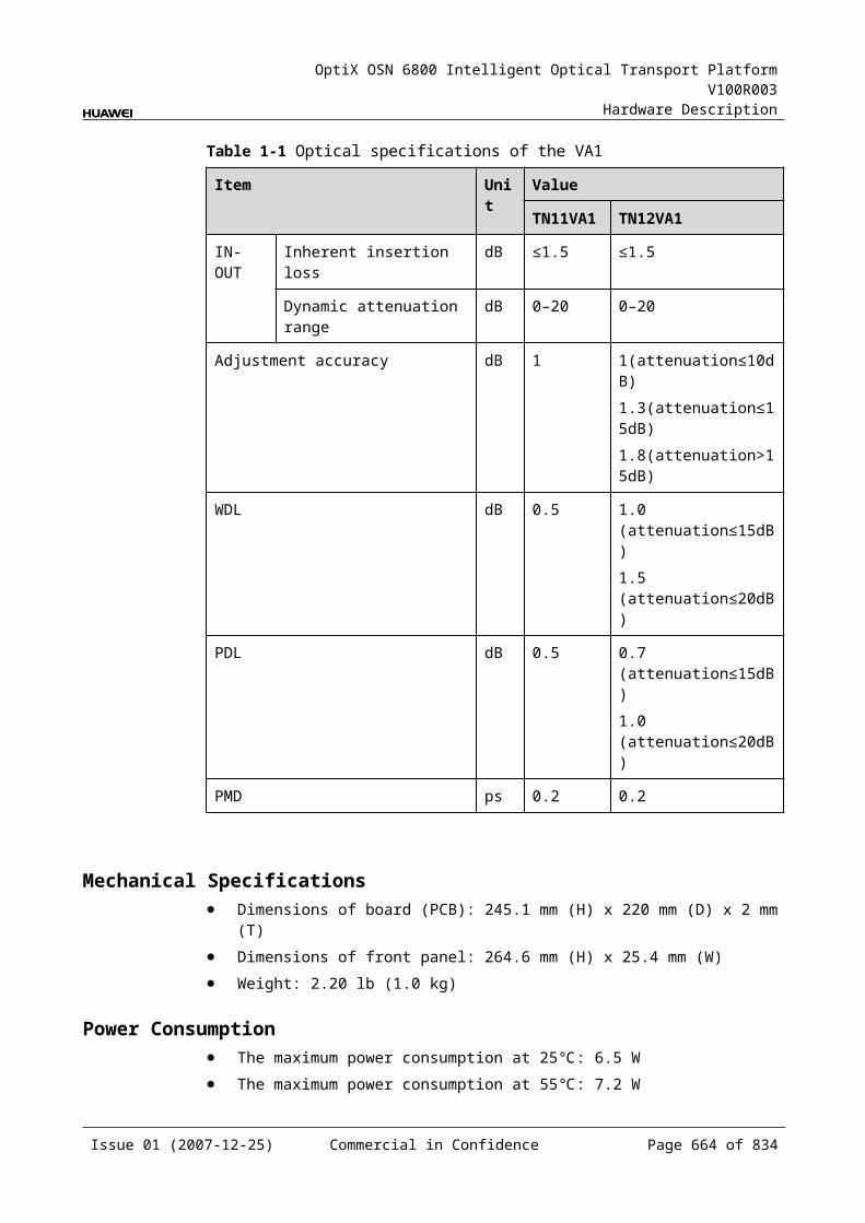
OptiX OSN 6800 Intelligent Optical Transport Platform V100R003
Hardware Description
SONET Synchronous Optical Network
TMN Telecommunications Management Network
V
VOA Variable Optical Attenuator
W
WDM Wavelength Division Multiplex
Copyright©2009 Huawei Technologies Co., Ltd. All Rights Reserved.
The information contained in this document is for reference purpose only, and is subject to change or withdrawal according to specific customer requirements and
conditions.
Issue 01 (2007-12-25) Commercial in Confidence Page 664 of 664