Embed Size (px)
Citation preview
Owner’s Manual
01903667 ‘00-11-D3-31N
Thank you, and congratulations on your choice of the BOSSVF-1 24-BIT MULTIPLE EFFECTS PROCESSOR.
Before using this unit, carefully read the sections entitled:
• USING THE UNIT SAFELY (page 2–3)
• IMPORTANT NOTES (page 11)
These sections provide important information concerningthe proper operation of the unit.
Additionally, in order to feel assured that you have gained agood grasp of every feature provided by your new unit,Owner’s manual should be read in its entirety. The manualshould be saved and kept on hand as a convenient reference.
Copyright © 1999 BOSS CORPORATION
All rights reserved. No part of this publication may be reproduced in any formwithout the written permission of BOSS CORPORATION.
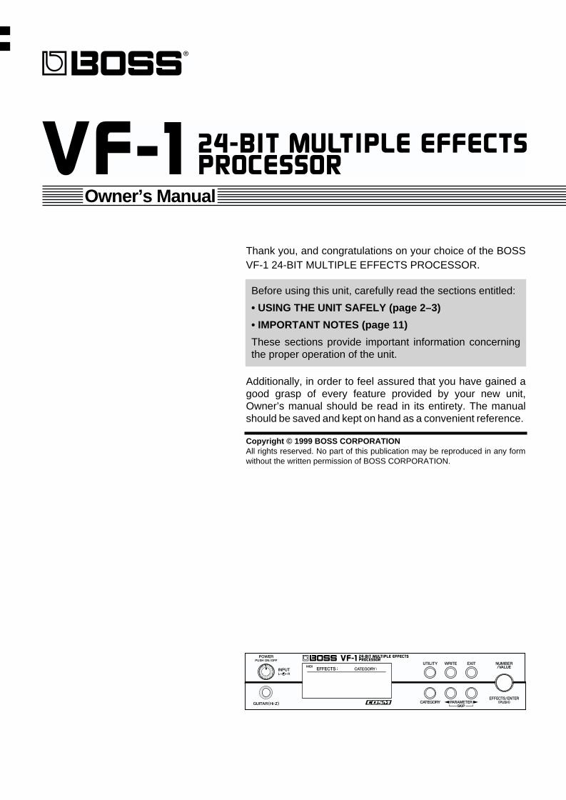
Used for instructions intended to alert the user to the risk of injury or material damage should the unit be used improperly.
* Material damage refers to damage or other adverse effects caused with respect to the home and all its furnishings, as well to domestic animals or pets.
Used for instructions intended to alert the user to the risk of death or severe injury should the unit be used improperly.
The symbol alerts the user to things that must be carried out. The specific thing that must be done is indicated by the design contained within the circle. In the case of the symbol at left, it means that the power-cord plug must be unplugged from the outlet.
The symbol alerts the user to important instructions or warnings.The specific meaning of the symbol is determined by the design contained within the triangle. In the case of the symbol at left, it is used for general cautions, warnings, or alerts to danger.
The symbol alerts the user to items that must never be carried out (are forbidden). The specific thing that must not be done is indicated by the design contained within the circle. In the case of the symbol at left, it means that the unit must never be disassembled.
For the USA
FEDERAL COMMUNICATIONS COMMISSIONRADIO FREQUENCY INTERFERENCE STATEMENT
This equipment has been tested and found to comply with the limits for a Class B digital device, pursuant to Part 15 of the FCC Rules. These limits are designed to provide reasonable protection against harmful interference in a residential installation. This equipment generates, uses, and can radiate radio frequency energy and, if not installed and used in accordance with the instructions, may cause harmful interference to radio communications. However, there is no guarantee that interference will not occur in a particular installation. If this equipment does cause harmful interference to radio or television reception, which can be determined by turning the equipment off and on, the user is encouraged to try to correct the interference by one or more of the following measures:
– Reorient or relocate the receiving antenna.– Increase the separation between the equipment and receiver.– Connect the equipment into an outlet on a circuit different from that to which the receiver is connected.– Consult the dealer or an experienced radio/TV technician for help.
Unauthorized changes or modification to this system can void the users authority to operate this equipment.This equipment requires shielded interface cables in order to meet FCC class B Limit.
This product complies with the requirements of European Directive 89/336/EEC.
For EU Countries
For Canada
This Class B digital apparatus meets all requirements of the Canadian Interference-Causing Equipment Regulations.
Cet appareil numérique de la classe B respecte toutes les exigences du Règlement sur le matériel brouilleur du Canada.
NOTICE
AVIS
2
001
• Before using this unit, make sure to read the instructions below, and the Owner’s Manual.
..........................................................................................................
002c
• Do not open (or modify in any way) the unit or its AC adaptor.
..........................................................................................................
003
• Do not attempt to repair the unit, or replace parts within it (except when this manual provides specific instructions directing you to do so). Refer all servicing to your retailer, the nearest Roland Service Center, or an authorized Roland distributor, as listed on the “Information” page.
..........................................................................................................
004
• Never use or store the unit in places that are:
• Subject to temperature extremes (e.g., direct sunlight in an enclosed vehicle, near a heating duct, on top of heat-generating equipment); or are
• Damp (e.g., baths, washrooms, on wet floors); or are
• Humid; or are
• Exposed to rain; or are
• Dusty; or are
• Subject to high levels of vibration...........................................................................................................
005
• This unit should be used only with a rack or stand that is recommended by Roland.
..........................................................................................................
006
• When using the unit with a rack or stand recom-mended by Roland, the rack or stand must be carefully placed so it is level and sure to remain stable. If not using a rack or stand, you still need to make sure that any location you choose for placing the unit provides a level surface that will properly support the unit, and keep it from wobbling.
..........................................................................................................
008c
• Be sure to use only the AC adaptor supplied with the unit. Also, make sure the line voltage at the installation matches the input voltage specified on the AC adaptor’s body. Other AC adaptors may use a different polarity, or be designed for a different voltage, so their use could result in damage, malfunction, or electric shock.
..........................................................................................................
009
• Avoid damaging the power cord. Do not bend it excessively, step on it, place heavy objects on it, etc. A damaged cord can easily become a shock or fire hazard. Never use a power cord after it has been damaged.
..........................................................................................................
010
• This unit, either alone or in combination with an amplifier and headphones or speakers, may be capable of producing sound levels that could cause permanent hearing loss. Do not operate for a long period of time at a high volume level, or at a level that is uncomfortable. If you experience any hearing loss or ringing in the ears, you should immediately stop using the unit, and consult an audiologist.
..........................................................................................................
011
• Do not allow any objects (e.g., flammable material, coins, pins); or liquids of any kind (water, soft drinks, etc.) to penetrate the unit.
..............................................................................................................
3
012b• Immediately turn the power off, remove the AC
adaptor from the outlet, and request servicing by your retailer, the nearest Roland Service Center, or an authorized Roland distributor, as listed on the “Information” page when:
• The AC adaptor, the power-supply cord, or the plug has been damaged; or
• Objects have fallen into, or liquid has been spilled onto the unit; or
• The unit has been exposed to rain (or otherwise has become wet); or
• The unit does not appear to operate normally or exhibits a marked change in performance.
..........................................................................................................013• In households with small children, an adult
should provide supervision until the child is capable of following all the rules essential for the safe operation of the unit.
..........................................................................................................014• Protect the unit from strong impact. (Do not drop it!)..........................................................................................................015• Do not force the unit’s power-supply cord to share
an outlet with an unreasonable number of other devices. Be especially careful when using extension cords—the total power used by all devices you have connected to the extension cord’s outlet must never exceed the power rating (watts/amperes) for the extension cord. Excessive loads can cause the insulation on the cord to heat up and eventually melt through.
..........................................................................................................016• Before using the unit in a foreign country, consult
with your retailer, the nearest Roland Service Center, or an authorized Roland distributor, as listed on the “Information” page.
..........................................................................................................
101b• The unit and the AC adaptor should be located so
their location or position does not interfere with their proper ventilation.
..........................................................................................................102c• Always grasp only the plug on the AC adaptor
cord when plugging into, or unplugging from, an outlet or this unit.
..........................................................................................................103b• Whenever the unit is to remain unused for an
extended period of time, disconnect the AC adaptor.
..........................................................................................................104• Try to prevent cords and cables from becoming
entangled. Also, all cords and cables should be placed so they are out of the reach of children.
..........................................................................................................106• Never climb on top of, nor place heavy objects on
the unit.
..........................................................................................................107c• Never handle the AC adaptor or its plugs with wet
hands when plugging into, or unplugging from, an outlet or this unit.
..........................................................................................................108b• Before moving the unit, disconnect the AC adaptor
and all cords coming from external devices.
..........................................................................................................109b• Before cleaning the unit, turn off the power and
unplug the AC adaptor from the outlet (p. 17).
..........................................................................................................110b• Whenever you suspect the possibility of lightning
in your area, disconnect the AC adaptor from the outlet.
..........................................................................................................
Contents
Main Features..........................................................................................9
How to use this manual........................................................................10Conventions used in this manual......................................................................................................... 10
IMPORTANT NOTES .............................................................................11
Front and rear panels ...........................................................................12Front panel ................................................................................................................................................ 12
Rear panel ................................................................................................................................................. 13
Section 1. Producing Sound ................................................................14Making connections................................................................................................................................ 14
Connecting a guitar....................................................................................................................... 14Connecting a keyboard ................................................................................................................ 15Connecting a mic........................................................................................................................... 15Connecting to the send/return of a mixer................................................................................. 16Connecting an expression pedal or foot switch........................................................................ 16
Turning on the power, and standby .................................................................................................... 17Turning on the power................................................................................................................... 17Adjusting the Input Level ............................................................................................................ 17
Selecting the effect sound...................................................................................................................... 18About the Screen Indications....................................................................................................... 18Selecting a patch............................................................................................................................ 18Quickly finding the desired patch (Category Search) ............................................................. 19Selecting Patches with a Foot Switch ......................................................................................... 20
Switching EFFECTS on/off.................................................................................................................... 22
Tuning your instrument......................................................................................................................... 22Displaying the tuner ..................................................................................................................... 22About the tuner display ............................................................................................................... 23Tuning Procedure ......................................................................................................................... 23Modifying the tuner settings (Standard pitch/Volume)......................................................... 24
Adjusting the display contrast.............................................................................................................. 24
Section 2. Creating Sounds .................................................................25Before You Begin Creating Sounds ..................................................................................................... 25
User banks and preset banks....................................................................................................... 25Algorithms ..................................................................................................................................... 25Settings that are stored in a patch............................................................................................... 25The display screen......................................................................................................................... 25
Rapidly editing a patch (Quick Setting) ............................................................................................. 26
Editing a patch ......................................................................................................................................... 27About display selection................................................................................................................ 27Procedure ....................................................................................................................................... 27Copying a patch ............................................................................................................................ 28Turning an effect on/off .............................................................................................................. 28Editing the settings of each effect ............................................................................................... 29Changing the order of the effects................................................................................................ 30Checking the input/output levels of each effect ...................................................................... 31Copying effect settings (Effect Copy)......................................................................................... 32
4
Setting the output level ................................................................................................................ 32Controlling parameters in real time (Control Assign)............................................................. 33Assigning the category................................................................................................................. 37Editing the patch name ................................................................................................................ 37Canceling your edits ..................................................................................................................... 38Saving the changes you make (the Write operation) ............................................................... 38
Ways to use control assign..................................................................................................................... 39Using an expression pedal ........................................................................................................... 39Using two foot switches ............................................................................................................... 40Using an expression pedal (example) ........................................................................................ 41
Section 3. Overall Settings (Utility) .....................................................42Utility functions....................................................................................................................................... 42
How to make settings ............................................................................................................................. 42
TUNER....................................................................................................................................................... 42
SYSTEM SETTING................................................................................................................................. 43
GLOBAL SOUND SETTINGS ............................................................................................................. 45
FACTORY RESET ................................................................................................................................... 46
MIDI........................................................................................................................................................... 46
Section 4. Effect guide .........................................................................47About the algorithm list......................................................................................................................... 47
About POSITION .......................................................................................................................... 47About “The function of each parameter” ........................................................................................... 47
About MOD.............................................................................................................................................. 47MOD parameters........................................................................................................................... 47
About SFX ................................................................................................................................................. 48SFX parameters.............................................................................................................................. 48
About FV (foot volume) ......................................................................................................................... 48
About DELAY, MultiTAP DELAY and STEREO PS DLY .............................................................. 48
Algorithm list.........................................................................................49PB1 GUITAR MULTI 1 ......................................................................................................................... 49
PB2 GUITAR MULTI 2 ......................................................................................................................... 52
PB3 BASS MULTI .................................................................................................................................. 54
PB4 ACOUSTIC MULTI ....................................................................................................................... 56
PB5 KEYBOARD MULTI...................................................................................................................... 57
PB6 ROTARY MULTI............................................................................................................................ 59
PB7 VOCAL MULTI .............................................................................................................................. 60
PB8 VOCODER....................................................................................................................................... 62
PB9 VoiceTRANSFORM (Voice Transformer)................................................................................. 63
PB10 ISOLATOR .................................................................................................................................... 64
PB11 LOFI PROCESSOR ...................................................................................................................... 65
PB12 REVERB 1 ...................................................................................................................................... 66
PB13 REVERB 2 ...................................................................................................................................... 67
PB14 GATE REVERB............................................................................................................................. 68
PB15 2CH RSS (2 channel RSS) ........................................................................................................... 69
PB16 DELAY RSS ................................................................................................................................... 70
5
PB17 CHORUS RSS ............................................................................................................................... 71
PB18 REVERB RSS................................................................................................................................. 72
PB19 RSS PANNER................................................................................................................................ 73
PB20 DELAY............................................................................................................................................ 74
PB21 MultiTAP DELAY (20 TAP) ....................................................................................................... 75
PB22 TAPE ECHO201 ............................................................................................................................ 76
PB23 MIC SIMULATOR....................................................................................................................... 77
PB24 SPACE CHORUS.......................................................................................................................... 78
PB25 StFLANGER DLY (Stereo Flanger Delay) ............................................................................... 79
PB26 StPHASER DLY (Stereo Phaser Delay).................................................................................... 80
PB27 StCHORUS DLY (Stereo Chorus Delay) ................................................................................ 81
PB28 STEREO PS DLY (Stereo Pitch Shifter Delay) ....................................................................... 82
PB29 STEREO MULTI........................................................................................................................... 83
PB30 10GRAPHIC EQ (10-Band Graphic Equalizer)....................................................................... 84
PB31 HUM CANCELER........................................................................................................................ 85
PB32 VOCAL CANCELER.................................................................................................................... 86
PB33 REVERB+REVERB....................................................................................................................... 87
PB34 CHORUS+REVERB..................................................................................................................... 88
PB35 DELAY+REVERB......................................................................................................................... 89
PB36 DELAY+CHORUS ....................................................................................................................... 90
The function of each parameter ..........................................................912x2 CHORUS............................................................................................................................................ 91
4BAND EQ (equalizer) ........................................................................................................................... 91
ACOUSTIC............................................................................................................................................... 92
ACOUSTIC GtSIM (acoustic guitar simulator)................................................................................. 92
AFB (anti-feedbacker)............................................................................................................................. 92
BASS GTR SIM (bass guitar simulator) ............................................................................................. 92
BCF (bass cut filter)................................................................................................................................. 92
CHOURUS................................................................................................................................................ 93
COMPRESSOR/LIMITER ..................................................................................................................... 93
DE-ESSER ................................................................................................................................................. 94
DEFRETTER............................................................................................................................................. 95
DELAY....................................................................................................................................................... 95
DISTANCE ............................................................................................................................................... 96
DISTORTION.......................................................................................................................................... 96
ENHANCER ............................................................................................................................................. 97
FEEDBACKER ......................................................................................................................................... 97
FLANGER ................................................................................................................................................. 98
GRAPHIC EQ (graphic equalizer) ....................................................................................................... 98
GUITAR SYNTH (guitar synthesizer) ................................................................................................ 99
HARMONIST ........................................................................................................................................ 101
HUM CANCELER (hum canceller).................................................................................................... 102
HUMANIZER......................................................................................................................................... 103
3BAND ISOLATOR.............................................................................................................................. 103
LOFI BOX................................................................................................................................................ 104
MASTER ................................................................................................................................................. 105
6
MIC CONV (Mic Converter)............................................................................................................... 106
MULTI TAP DELAY............................................................................................................................. 107
NS.SUPPRESSOR (Noise Suppressor) ............................................................................................. 107
OCTAVE ................................................................................................................................................. 108
OVER DRIVE......................................................................................................................................... 108
PHASER .................................................................................................................................................. 108
PICKUP SIM (Pickup Simulator)....................................................................................................... 109
PITCH SHIFTER.................................................................................................................................... 109
PREAMP/SP.SIM (Preamp/Speaker Simulator).............................................................................. 110
REVERB................................................................................................................................................... 111
GATE ....................................................................................................................................................... 112
RING MODULATOR........................................................................................................................... 112
ROTARY ................................................................................................................................................. 113
RSS PANNER......................................................................................................................................... 114
RSS (2ch) ................................................................................................................................................. 114
SHORT DELAY ..................................................................................................................................... 114
SLICER .................................................................................................................................................... 114
SLOW GEAR.......................................................................................................................................... 115
SPACE CHORUS................................................................................................................................... 115
STEREO PS DLY (Stereo Pitch Shifter Delay) ................................................................................ 115
SUB 4BAND EQ (Sub 4 Band Equalizer) ......................................................................................... 116
T-WAH (Touch WAH).......................................................................................................................... 116
TAPE ECHO201 ..................................................................................................................................... 117
TREMOLO/PAN.................................................................................................................................... 117
VIBRATO................................................................................................................................................ 118
VOCAL CANCELER............................................................................................................................. 118
VOCODER.............................................................................................................................................. 118
VoiceTRANSFORM (Voice Transformer)........................................................................................ 119
WAH......................................................................................................................................................... 120
Before using RSS................................................................................................................................... 121
Section 5. Using MIDI to Operate the VF-1 .......................................122What you can do using MIDI.............................................................................................................. 122
Making settings ..................................................................................................................................... 122Setting the MIDI channel ........................................................................................................... 123Setting the Omni mode .............................................................................................................. 123Setting the Device ID .................................................................................................................. 123
Program Change Map Settings ........................................................................................................... 124Making settings ........................................................................................................................... 124
Transmitting VF-1 data (Bulk Dump) ............................................................................................... 125Connections.................................................................................................................................. 125Transmission Procedure............................................................................................................. 125
Restoring data from a Sequencer to the VF-1 (Bulk Load)............................................................ 126Connections.................................................................................................................................. 126Reception procedure................................................................................................................... 126
7
Section 6. Appendices........................................................................127About the VF-1’s digital output.......................................................................................................... 127
Digital output signal ................................................................................................................... 127Connecting the VF-1 to a digital audio device........................................................................ 127Digital OUT specifications......................................................................................................... 127
VF-1 operation using the FC-200 ........................................................................................................ 127VF-1 and FC-200 connections .................................................................................................... 127Selecting Patches from the FC-200............................................................................................ 128Control Assign operations using the FC-200 .......................................................................... 129
VF-1 operation using the FC-50 .......................................................................................................... 130Connecting the VF-1 and FC-50 ................................................................................................ 130Controlling the VF-1 from the FC-50........................................................................................ 130
About MIDI............................................................................................................................................ 131How MIDI messages are transmitted and received............................................................... 131Main types of MIDI message used by the VF-1...................................................................... 132About the MIDI Implementation Chart................................................................................... 132
Restoring the factory settings (Factory Reset).................................................................................. 133
Troubleshooting .................................................................................................................................... 134
Error Messages ....................................................................................................................................... 135
MIDI Implementation Chart............................................................................................................... 136
Specifications ......................................................................................................................................... 137
Index.....................................................................................................138
Preset Patch List.................................................................................140
8
Main Features
Versatile algorithms and high-quality sound that rivals dedicated professional equipmentThe VF-1 provides 46 effects, and 36 algorithms (effects
combinations).
A variety of simulations including preamp / speaker
simulators produced by COSM as well as a rich array of
effects such as reverb and chorus are provided.
It features 24 bit AD/DA conversion, and uses high-speed,
custom DPS to ensure quality that rivals expensive
professional equipment. It is a perfect match for any
instrument, and is ideal for use with any instrument, even for
serious recording efforts.
Algorithms and effect settings can be saved as patches.
In addition to 200 preset patches, the VF-1 allows you to
create 200 user patches.
Rapid searching by categoryEach patch is classified by a category such as guitar or vocal,
etc. You can use the Category Search function to rapidly find
the desired patch. (p.19)
Graphic LCDThe front panel of the VF-1 features a graphic LCD for easy
and highly visual editing.
Quick settingA preset setting is provided for each edit function. You can
easily create the desired effect sound simply by selecting the
preset setting for the function (effect) you wish to use. (p.26)
Guitar input jackThe front panel provides a high impedance input jack for
direct connection of an electric guitar. (p.12)
Built-in tuner functionThe VF-1 contains a chromatic tuner function. (p.22)
Realtime parameter controlParameters can be controlled from a foot switch or
expression pedal, or via MIDI messages. (p.33)
2-IN, 2-OUTThe VF-1 supports stereo input and output. You can apply
effects without impairing the stereo input image, or apply
two independent effects in parallel. (p.13)
Mountable in a 19-inch rackA separately sold rack mount adapter (RAD-50) allows the
VF-1 to be mounted in a standard 19-inch rack.
Digital out connectorA coaxial type digital output is provided, allowing
connection to another digital device with no sacrifice in
audio quality. (p.127)
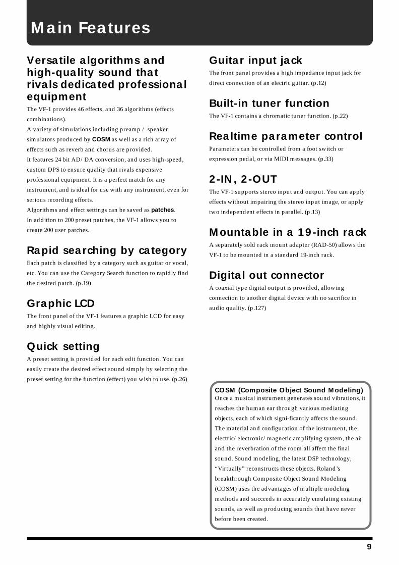
COSM (Composite Object Sound Modeling)Once a musical instrument generates sound vibrations, it
reaches the human ear through various mediating
objects, each of which signi-ficantly affects the sound.
The material and configuration of the instrument, the
electric/electronic/magnetic amplifying system, the air
and the reverbration of the room all affect the final
sound. Sound modeling, the latest DSP technology,
“Virtually” reconstructs these objects. Roland’s
breakthrough Composite Object Sound Modeling
(COSM) uses the advantages of multiple modeling
methods and succeeds in accurately emulating existing
sounds, as well as producing sounds that have never
before been created.
9
How to use this manual
This manual is broadly organized into six sections, covering the operations and functions that you will use for normal performance, as well as how to make various settings. Please read the sections consecutively.An alphabetical index is provided at the end of the manual. Please refer to the index if you come across any unfamiliar term.
Section 1.Producing Sound
This section explains basic operation of the VF-1, including connections with external devices and how to change patches.
Section 2.Creating Sounds
This section explains how to modify the effect settings, and how to use various functions.
Section 3.Overall Settings (Utility)
This section explains settings that affect the overall operation of the VF-1, such as how to use the tuner, and how to make system settings.
Section 4.Effect Guide
This section explains the effects and algorithms of the VF-1, and what they do.
Section 5. Using MIDI to Operate the VF-1
This section explains the settings used when controlling the VF-1 from an external MIDI device, and operations using MIDI to exchange data.
Section 6. Appendices
This section explains operations when using the FC-200 MIDI foot controller (sold separately).It also provides information that will help you get the most out of the VF-1, how to restore the factory settings, and troubleshooting.
Conventions used in this manual
For clarity in explaining operations, the following conventions are used in this manual.
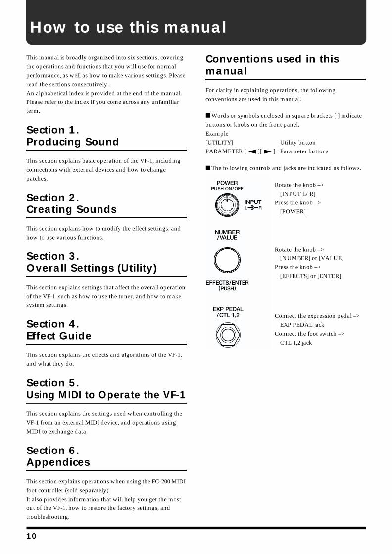
Words or symbols enclosed in square brackets [ ] indicate buttons or knobs on the front panel.Example[UTILITY] Utility buttonPARAMETER [ ][ ] Parameter buttons
The following controls and jacks are indicated as follows.fig.0-04Rotate the knob –>
[INPUT L/R]Press the knob –>
[POWER]
fig.0-05
Rotate the knob –>[NUMBER] or [VALUE]
Press the knob –>[EFFECTS] or [ENTER]
fig.0-06Connect the expression pedal –>
EXP PEDAL jackConnect the foot switch –>
CTL 1,2 jack
10
IMPORTANT NOTES
291a
In addition to the items listed under “USING THE UNIT SAFELY” on page 2–3, please read and observe the following:
Power Supply301• Do not use this unit on the same power circuit with any
device that will generate line noise (such as an electric motor or variable lighting system).
302• The AC adaptor will begin to generate heat after long
hours of consecutive use. This is normal, and is not a cause for concern.
307• Before connecting this unit to other devices, turn off the
power to all units. This will help prevent malfunctions and/or damage to speakers or other devices.
Placement351• Using the unit near power amplifiers (or other equipment
containing large power transformers) may induce hum. To alleviate the problem, change the orientation of this unit; or move it farther away from the source of inter-ference.
352• This device may interfere with radio and television
reception. Do not use this device in the vicinity of such receivers.
355• To avoid possible breakdown, do not use the unit in a wet
area, such as an area exposed to rain or other moisture.
Maintenance401a• For everyday cleaning wipe the unit with a soft, dry cloth
or one that has been slightly dampened with water. To remove stubborn dirt, use a cloth impregnated with a mild, non-abrasive detergent. Afterwards, be sure to wipe the unit thoroughly with a soft, dry cloth.
402• Never use benzine, thinners, alcohol or solvents of any
kind, to avoid the possibility of discoloration and/or deformation.
Additional Precautions551• Please be aware that the contents of memory can be
irretrievably lost as a result of a malfunction, or the improper operation of the unit. To protect yourself against the risk of loosing important data, we recommend that you periodically save a backup copy of important data you have stored in the unit’s memory in another MIDI device (e.g., a sequencer).
552• Unfortunately, it may be impossible to restore the contents
of data that was stored in another MIDI device (e.g., a sequencer) once it has been lost. Roland Corporation assumes no liability concerning such loss of data.
553• Use a reasonable amount of care when using the unit’s
buttons, sliders, or other controls; and when using its jacks and connectors. Rough handling can lead to malfunctions.
554• Never strike or apply strong pressure to the display.
556• When connecting / disconnecting all cables, grasp the
connector itself—never pull on the cable. This way you will avoid causing shorts, or damage to the cable’s internal elements.
558a• To avoid disturbing your neighbors, try to keep the unit’s
volume at reasonable levels. You may prefer to use headphones, so you do not need to be concerned about those around you (especially when it is late at night).
559• When you need to transport the unit, package it in the box
(including padding) that it came in, if possible. Otherwise, you will need to use equivalent packaging materials.
561• Use only the specified expression pedal (BOSS FV-
300L+PCS-33 (Roland) or EV-5 (Roland); sold separately). By connecting any other expression pedals, you risk causing malfunction and/or damage to the unit.
562• Use a cable from Roland to make the connection. If using
some other make of connection cable, please note the following precautions.
• Some connection cables contain resistors. Do not use cables that incorporate resistors for connecting to this unit. The use of such cables can cause the sound level to be extremely low, or impossible to hear. For infor-mation on cable specifications, contact the manufac-turer of the cable.
11
Front and rear panels
Front panel
fig.0-001
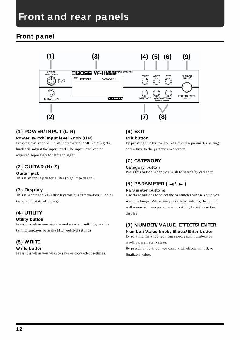
(1) POWER/INPUT (L/R)Power switch/Input level knob (L/R)Pressing this knob will turn the power on/off. Rotating the
knob will adjust the input level. The input level can be
adjusted separately for left and right.
(2) GUITAR (Hi-Z)Guitar jackThis is an input jack for guitar (high impedance).
(3) DisplayThis is where the VF-1 displays various information, such as
the current state of settings.
(4) UTILITYUtility buttonPress this when you wish to make system settings, use the
tuning function, or make MIDI-related settings.
(5) WRITEWrite buttonPress this when you wish to save or copy effect settings.
(6) EXITExit buttonBy pressing this button you can cancel a parameter setting
and return to the performance screen.
(7) CATEGORYCategory buttonPress this button when you wish to search by category.
(8) PARAMETER ( / )Parameter buttonsUse these buttons to select the parameter whose value you
wish to change. When you press these buttons, the cursor
will move between parameter or setting locations in the
display.
(9) NUMBER/VALUE, EFFECTS/ENTERNumber/Value knob, Effects/Enter buttonBy rotating the knob, you can select patch numbers or
modify parameter values.
By pressing the knob, you can switch effects on/off, or
finalize a value.
(1)
(2)
(3) (4) (5) (6)
(7) (8)
(9)
12
Front and rear panels
Rear panel
fig.0-002
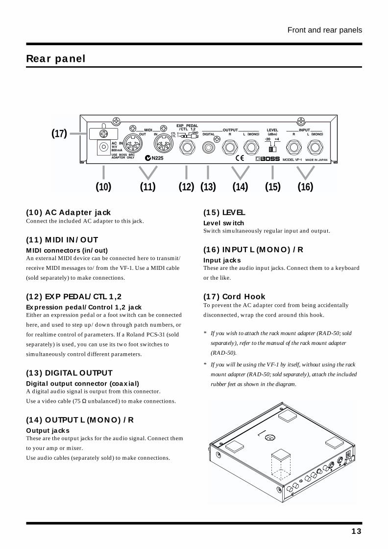
(10) AC Adapter jackConnect the included AC adapter to this jack.
(11) MIDI IN/OUTMIDI connectors (in/out)An external MIDI device can be connected here to transmit/
receive MIDI messages to/from the VF-1. Use a MIDI cable
(sold separately) to make connections.
(12) EXP PEDAL/CTL 1,2 Expression pedal/Control 1,2 jackEither an expression pedal or a foot switch can be connected
here, and used to step up/down through patch numbers, or
for realtime control of parameters. If a Roland PCS-31 (sold
separately) is used, you can use its two foot switches to
simultaneously control different parameters.
(13) DIGITAL OUTPUTDigital output connector (coaxial)A digital audio signal is output from this connector.
Use a video cable (75 Ω unbalanced) to make connections.
(14) OUTPUT L (MONO) /ROutput jacksThese are the output jacks for the audio signal. Connect them
to your amp or mixer.
Use audio cables (separately sold) to make connections.
(15) LEVELLevel switchSwitch simultaneously regular input and output.
(16) INPUT L (MONO) /RInput jacksThese are the audio input jacks. Connect them to a keyboard
or the like.
(17) Cord HookTo prevent the AC adapter cord from being accidentally
disconnected, wrap the cord around this hook.
* If you wish to attach the rack mount adapter (RAD-50; sold
separately), refer to the manual of the rack mount adapter
(RAD-50).
* If you will be using the VF-1 by itself, without using the rack
mount adapter (RAD-50; sold separately), attach the included
rubber feet as shown in the diagram.
fig.0-03
(10) (11) (12) (13) (14) (15) (16)
(17)
13
Section 1. Producing Sound
Making connections
Make connections as follows, depending on how you will be using the VF-1.
To prevent malfunction and/or damage to speakers or other devices, always turn down the volume, and turn off the power on all devices before making any connections.
* To output in monaural, connect a cable to only the OUTPUT L
(MONO) jack.
* There are three input jacks: the GUITAR jack, and the INPUT L
(MONO) / R jacks. If you make connections both to the
GUITAR jack and to the INPUT L (MONO) jack, the input
from the GUITAR jack will be given priority.
* To prevent the inadvertent disruption of power to your unit
(should the plug be pulled out accidentally), and to avoid
applying undue stress to the AC adaptor jack, anchor the power
cord using the cord hook, as shown in the illustration.
fig.1-02
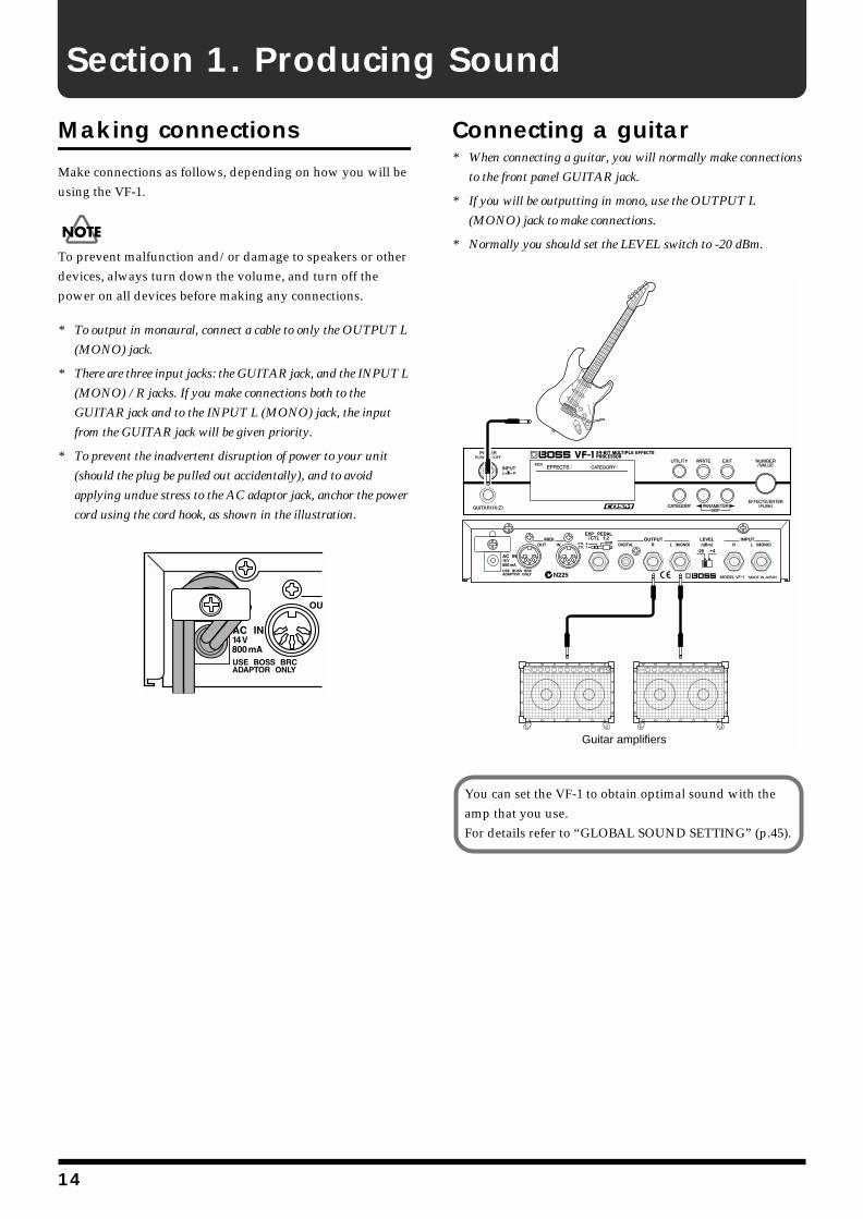
Connecting a guitar* When connecting a guitar, you will normally make connections
to the front panel GUITAR jack.
* If you will be outputting in mono, use the OUTPUT L
(MONO) jack to make connections.
* Normally you should set the LEVEL switch to -20 dBm.
fig.1-03
Guitar amplifiers
You can set the VF-1 to obtain optimal sound with the amp that you use.For details refer to “GLOBAL SOUND SETTING” (p.45).
14
Section 1. Producing Sound
Section 1
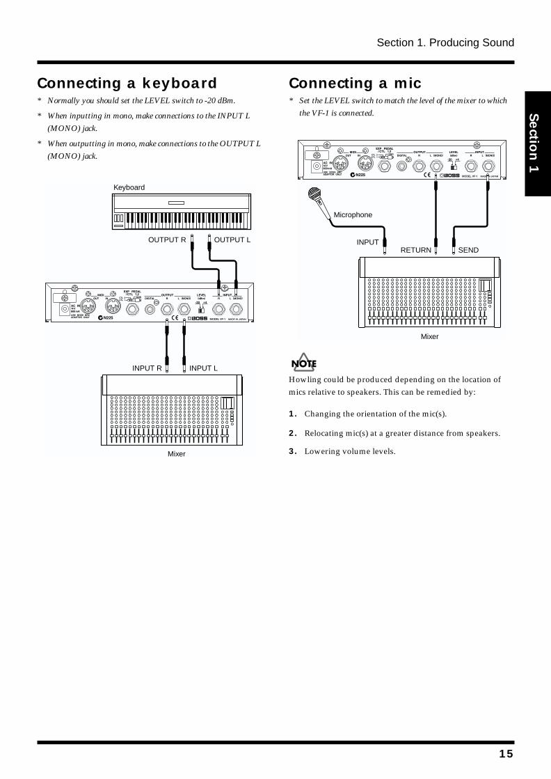
Connecting a keyboard* Normally you should set the LEVEL switch to -20 dBm.
* When inputting in mono, make connections to the INPUT L
(MONO) jack.
* When outputting in mono, make connections to the OUTPUT L
(MONO) jack.
fig.1-04
Connecting a mic* Set the LEVEL switch to match the level of the mixer to which
the VF-1 is connected.
fig.1-42
Howling could be produced depending on the location of mics relative to speakers. This can be remedied by:
1. Changing the orientation of the mic(s).
2. Relocating mic(s) at a greater distance from speakers.
3. Lowering volume levels.Mixer
INPUT R INPUT L
Keyboard
OUTPUT R OUTPUT L
Mixer
Microphone
RETURNINPUT
SEND
15
Section 1. Producing Sound
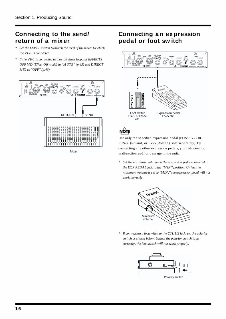
Connecting to the send/return of a mixer* Set the LEVEL switch to match the level of the mixer to which
the VF-1 is connected.
* If the VF-1 is connected to a send/return loop, set EFFECTS
OFF MD (Effect Off mode) to “MUTE” (p.43) and DIRECT
MIX to “OFF” (p.46).
fig.1-05
Connecting an expression pedal or foot switchfig.1-06a
Use only the specified expression pedal (BOSS FV-300L + PCS-33 (Roland) or EV-5 (Roland); sold separately). By connecting any other expression pedals, you risk causing malfunction and/or damage to the unit.
* Set the minimum volume on the expression pedal connected to
the EXP PEDAL jack to the “MIN” position. Unless the
minimum volume is set to “MIN,” the expression pedal will not
work correctly.
fig.1-06b
* If connecting a footswitch to the CTL 1/2 jack, set the polarity
switch as shown below. Unless the polarity switch is set
correctly, the foot switch will not work properly.
fig.1-06c
Mixer
RETURN SENDFoot switch
FS-5U / FS-5Letc.
Expression pedalEV-5 etc.
Roland
Minimumvolume
Polarity switch
16
Section 1. Producing Sound
Section 1
Turning on the power, and standbyIn order to take full advantage of the VF-1’s potential, be sure to adjust the input/output levels after turning on the power.
Turning on the powerOnce the connections have been completed (p. 14–16), turn on power to your various devices in the order specified. By turning on devices in the wrong order, you risk causing malfunction and/or damage to speakers and other devices.
1. Before turning on the power, check the following points.
• Have connections with external devices been made correctly?
• Has the volume been turned completely down on the VF-1 and on the connected amp, etc.?
2. Turn on the power on the sound generating device (keyboard or other device).
3. Press the VF-1’s [POWER] switch to turn on the power.The following display will appear, and after several seconds, the VF-1 will be ready for normal playing. This display is referred to as the “Play mode.”fig.1-07
This unit is equipped with a protection circuit. A brief interval (a few seconds) after power up is required before the unit will operate normally.
* When the power is turned on, the last-selected Patch number
will be selected.
* Depending on the location where the VF-1 is placed, the display
may be difficult to read. In this case, adjust the display contrast
(P.24).
4. Turn on the power of your other equipment in the order of effect processors –> mixer –> amp.
Turn up the amp volume only after all devices have been powered on.
Turning off the power1. Before turning off the power, check the following points.
• Has the volume of the connected amp, etc. been turned completed down?
2. Turn off the power in the order of amp –> mixer –> other effect processors.
3. Press the [POWER] switch of the VF-1 to turn off the power.
4. Turn off the power on your sound generating devices (keyboard or other device).
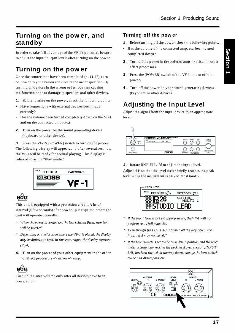
Adjusting the Input LevelAdjust the signal from the input device to an appropriate level.fig.1-08
1. Rotate [INPUT L/R] to adjust the input level.
Adjust this so that the level meter briefly reaches the peak level when the instrument is played most loudly.fig.1-09
* If the input level is not set appropriately, the VF-1 will not
perform to its full potential.
* Even though [INPUT L/R] is turned all the way down, the
input level may not be “0.”
* If the level switch is set to the “-20 dBm” position and the level
meter occasionally reaches the peak level even though [INPUT
L/R] has been turned all the way down, change the level switch
to the “+4 dBm” position.
fig.1-10
1
Peak Level
17
Section 1. Producing Sound
Selecting the effect sound
The VF-1 contains 400 effect settings covering a wide range of sounds. Each of these is called a Patch. The 400 patches are organized into four banks, each with 100 patches numbered 1–100.To select the desired patch, you can operate the front panel or an external MIDI device to switch banks and patch numbers.
A “bank” contains 100 patches. There are four banks: Preset
banks A and B, and User banks A and B.
Patches can be selected only when the screen display is in Play mode (showing the patch number).If the display is not in Play mode, press [EXIT] several times to select Play mode.
About the Screen Indicationsfig.1-13
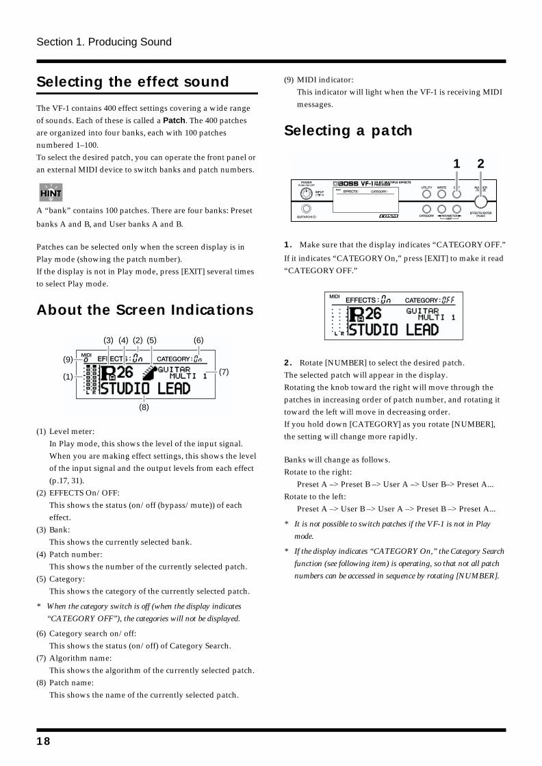
(1) Level meter:In Play mode, this shows the level of the input signal. When you are making effect settings, this shows the level of the input signal and the output levels from each effect (p.17, 31).
(2) EFFECTS On/OFF:This shows the status (on/off (bypass/mute)) of each effect.
(3) Bank:This shows the currently selected bank.
(4) Patch number:This shows the number of the currently selected patch.
(5) Category:This shows the category of the currently selected patch.
* When the category switch is off (when the display indicates
“CATEGORY OFF”), the categories will not be displayed.
(6) Category search on/off:This shows the status (on/off) of Category Search.
(7) Algorithm name:This shows the algorithm of the currently selected patch.
(8) Patch name:This shows the name of the currently selected patch.
(9) MIDI indicator:This indicator will light when the VF-1 is receiving MIDI messages.
Selecting a patchfig.1-14
1. Make sure that the display indicates “CATEGORY OFF.”
If it indicates “CATEGORY On,” press [EXIT] to make it read “CATEGORY OFF.”fig.1-15
2. Rotate [NUMBER] to select the desired patch.The selected patch will appear in the display.Rotating the knob toward the right will move through the patches in increasing order of patch number, and rotating it toward the left will move in decreasing order.If you hold down [CATEGORY] as you rotate [NUMBER], the setting will change more rapidly.
Banks will change as follows.Rotate to the right:
Preset A –> Preset B –> User A –> User B–> Preset A...Rotate to the left:
Preset A –> User B –> User A –> Preset B –> Preset A...
* It is not possible to switch patches if the VF-1 is not in Play
mode.
* If the display indicates “CATEGORY On,” the Category Search
function (see following item) is operating, so that not all patch
numbers can be accessed in sequence by rotating [NUMBER].
(1)
(2)(3) (5) (6)
(7)
(8)
(9)
(4)
1 2
18
Section 1. Producing Sound
Section 1
Quickly finding the desired patch (Category Search)The VF-1 classifies all patches by category (such as performance style or instrument).The VF-1 provides a Category Search function that lets you select a category so that only the patches in that category are displayed. By using this function, you can view only the patches of the currently selected category, and rapidly find the patch you want.The following categories are provided.fig.1-16
* “OTHERS1,” “OTHERS2,” and “OTHERS3” are user
categories. You can use them to categorize your own favorite
patches. For details refer to “Assigning the category” (p.37).
* With the factory settings, none of the patches are assigned to
“OTHERS1,” “OTHERS2,” or “OTHERS3” categories.
fig.1-17
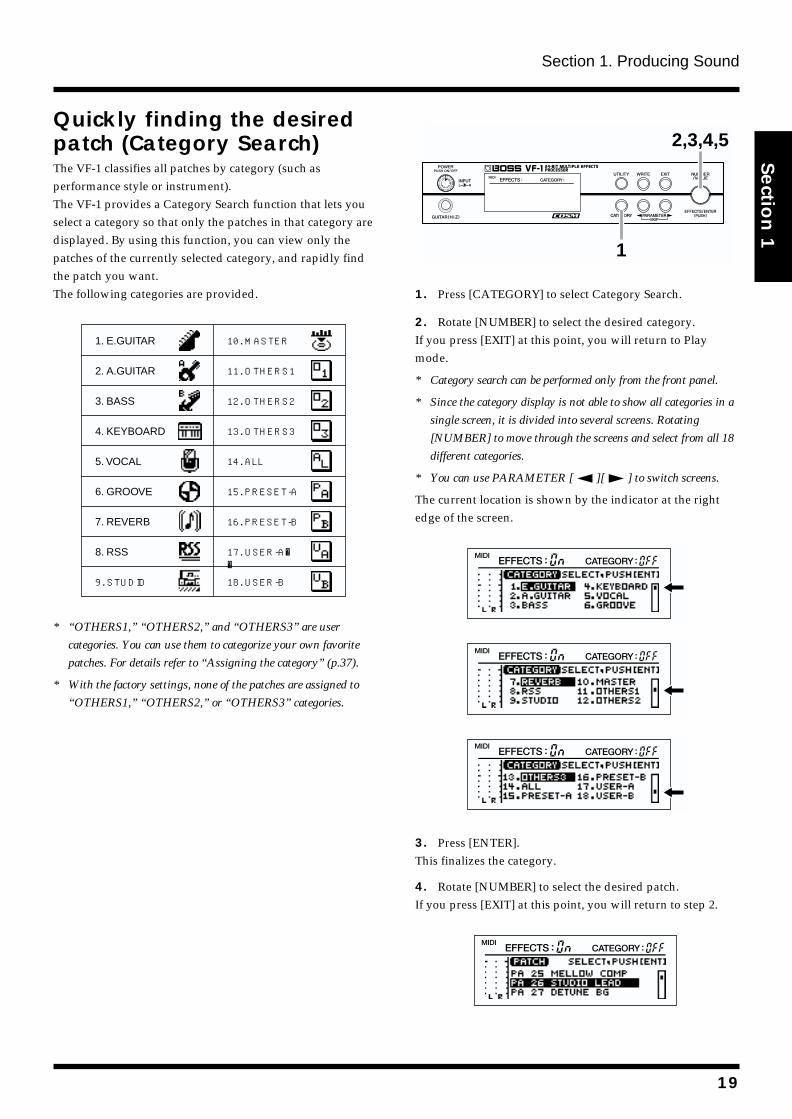
1. Press [CATEGORY] to select Category Search.
2. Rotate [NUMBER] to select the desired category.If you press [EXIT] at this point, you will return to Play mode.
* Category search can be performed only from the front panel.
* Since the category display is not able to show all categories in a
single screen, it is divided into several screens. Rotating
[NUMBER] to move through the screens and select from all 18
different categories.
* You can use PARAMETER [ ][ ] to switch screens.
The current location is shown by the indicator at the right edge of the screen.fig.1-18a
fig.1-18b
fig.1-18c
3. Press [ENTER].This finalizes the category.
4. Rotate [NUMBER] to select the desired patch.If you press [EXIT] at this point, you will return to step 2.fig.1-19
1. E.GUITAR
2. A.GUITAR
3. BASS
4. KEYBOARD
5. VOCAL
6. GROOVE
7. REVERB
8. RSS
9. STUDIO
10. MASTER
11. OTHERS1
12. OTHERS2
13. OTHERS3
14. ALL
15. PRESET-A
16. PRESET-B
17. USER-A
18. USER-B
1
2,3,4,5
19
Section 1. Producing Sound
5. Press [ENTER].The selected patch will be recalled, and you will return to Play mode.At this time, the display will show the symbol of the selected category, and will indicate “CATEGORY On.”Now you can rotate [NUMBER] to select other patches of the same category.fig.1-20
* If you select “ALL” as the category, no category symbol will
appear, and the display will indicate “CATEGORY OFF.” In
this case, rotating [NUMBER] will select from all patches.
* After you have finished with Category Search, and
wish to select from all patches, press [EXIT] to make
the display read “CATEGORY OFF.”
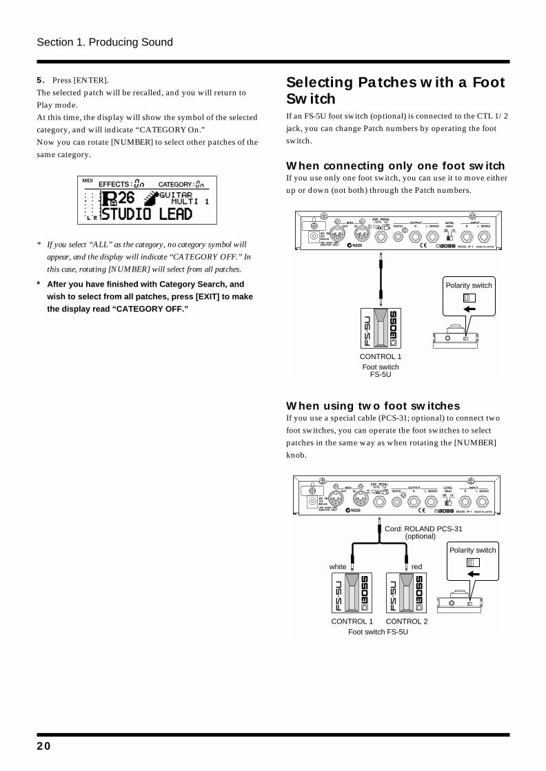
Selecting Patches with a Foot SwitchIf an FS-5U foot switch (optional) is connected to the CTL 1/2 jack, you can change Patch numbers by operating the foot switch.
When connecting only one foot switchIf you use only one foot switch, you can use it to move either up or down (not both) through the Patch numbers.fig.1-21
When using two foot switchesIf you use a special cable (PCS-31; optional) to connect two foot switches, you can operate the foot switches to select patches in the same way as when rotating the [NUMBER] knob.fig.1-22
CONTROL 1Foot switch
FS-5U
Polarity switch
CONTROL 1Foot switch FS-5U
Cord: ROLAND PCS-31 (optional)
redwhite
CONTROL 2
Polarity switch
20
Section 1. Producing Sound
Section 1
fig.1-23
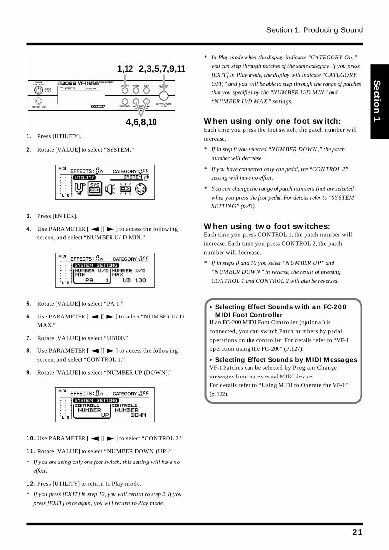
1. Press [UTILITY].
2. Rotate [VALUE] to select “SYSTEM.”fig.1-24
3. Press [ENTER].
4. Use PARAMETER [ ][ ] to access the following screen, and select “NUMBER U/D MIN.”
fig.1-25
5. Rotate [VALUE] to select “PA 1.”
6. Use PARAMETER [ ][ ] to select “NUMBER U/D MAX.”
7. Rotate [VALUE] to select “UB100.”
8. Use PARAMETER [ ][ ] to access the following screen, and select “CONTROL 1.”
9. Rotate [VALUE] to select “NUMBER UP (DOWN).”fig.1-26
10. Use PARAMETER [ ][ ] to select “CONTROL 2.”
11. Rotate [VALUE] to select “NUMBER DOWN (UP).”
* If you are using only one foot switch, this setting will have no
effect.
12. Press [UTILITY] to return to Play mode.
* If you press [EXIT] in step 12, you will return to step 2. If you
press [EXIT] once again, you will return to Play mode.
* In Play mode when the display indicates “CATEGORY On,”
you can step through patches of the same category. If you press
[EXIT] in Play mode, the display will indicate “CATEGORY
OFF,” and you will be able to step through the range of patches
that you specified by the “NUMBER U/D MIN” and
“NUMBER U/D MAX” settings.
When using only one foot switch:Each time you press the foot switch, the patch number will increase.
* If in step 8 you selected “NUMBER DOWN,” the patch
number will decrease.
* If you have connected only one pedal, the “CONTROL 2”
setting will have no effect.
* You can change the range of patch numbers that are selected
when you press the foot pedal. For details refer to “SYSTEM
SETTING” (p.43).
When using two foot switches:Each time you press CONTROL 1, the patch number will increase. Each time you press CONTROL 2, the patch number will decrease.
* If in steps 8 and 10 you select “NUMBER UP” and
“NUMBER DOWN” in reverse, the result of pressing
CONTROL 1 and CONTROL 2 will also be reversed.
1,12
4,6,8,10
2,3,5,7,9,11
•Selecting Effect Sounds with an FC-200 MIDI Foot Controller
If an FC-200 MIDI Foot Controller (optional) is connected, you can switch Patch numbers by pedal operations on the controller. For details refer to “VF-1 operation using the FC-200” (P.127).
•Selecting Effect Sounds by MIDI MessagesVF-1 Patches can be selected by Program Change messages from an external MIDI device. For details refer to “Using MIDI to Operate the VF-1” (p.122).
21
Section 1. Producing Sound
Switching EFFECTS on/off
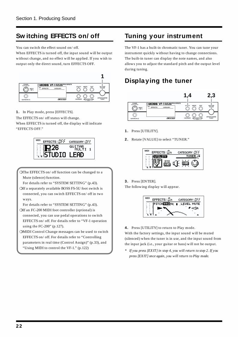
You can switch the effect sound on/off. When EFFECTS is turned off, the input sound will be output without change, and no effect will be applied. If you wish to output only the direct sound, turn EFFECTS OFF.fig.1-27
1. In Play mode, press [EFFECTS].
The EFFECTS on/off status will change.When EFFECTS is turned off, the display will indicate “EFFECTS OFF.”fig.1-28
Tuning your instrument
The VF-1 has a built-in chromatic tuner. You can tune your instrument quickly without having to change connections.The built-in tuner can display the note names, and also allows you to adjust the standard pitch and the output level during tuning.
Displaying the tunerfig.1-29
1. Press [UTILITY].
2. Rotate [VALUE] to select “TUNER.”fig.1-30
3. Press [ENTER].The following display will appear.fig.1-31
4. Press [UTILITY] to return to Play mode.With the factory settings, the input sound will be muted (silenced) when the tuner is in use, and the input sound from the input jack (i.e., your guitar or bass) will not be output.
* If you press [EXIT] in step 4, you will return to step 2. If you
press [EXIT] once again, you will return to Play mode.
1
The EFFECTS on/off function can be changed to a Mute (silence) function.For details refer to “SYSTEM SETTING” (p.43).
If a separately available BOSS FS-5U foot switch is connected, you can switch EFFECTS on/off in two ways.For details refer to “SYSTEM SETTING” (p.43).
If an FC-200 MIDI foot controller (optional) is connected, you can use pedal operations to switch EFFECTS on/off. For details refer to “VF-1 operation using the FC-200” (p.127).
MIDI Control Change messages can be used to switch EFFECTS on/off. For details refer to “Controlling parameters in real time (Control Assign)” (p.33), and “Using MIDI to control the VF-1.” (p.122)
1,4 2,3
22
Section 1. Producing Sound
Section 1
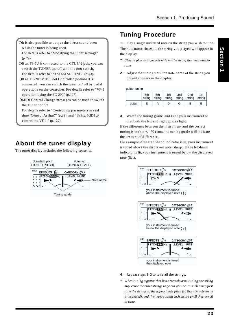
About the tuner displayThe tuner display includes the following contents.fig.1-32
Tuning Procedure1. Play a single unfretted note on the string you wish to tune.
The note name closest to the string you played will appear in the display.
* Cleanly play a single note only on the string that you wish to
tune.
2. Adjust the tuning until the note name of the string you played appears in the display.
fig.1-33
3. Watch the tuning guide, and tune your instrument so that both the left and right guides light.
If the difference between the instrument and the correct tuning is within +/-50 cents, the tuning guide will indicate the amount of difference.For example if the right-hand indicator is lit, your instrument is tuned above the displayed note (sharp). If the left-hand indicator is lit, your instrument is tuned below the displayed note (flat).fig.1-34
fig.1-35
fig.1-36
4. Repeat steps 1–3 to tune all the strings.
* When tuning a guitar that has a tremolo arm, tuning one string
may cause the other strings to go out of tune. In such cases, first
tune the strings to the approximate pitch (so that the note name
is displayed), and then keep tuning each string until they are all
in tune.
It is also possible to output the direct sound even while the tuner is being used.For details refer to “Modifying the tuner settings” (p.24).
If an FS-5U is connected to the CTL 1/2 jack, you can switch the TUNER on/off with the foot switch.For details refer to “SYSTEM SETTING” (p.43).
If an FC-200 MIDI Foot Controller (optional) is connected, you can switch the tuner on/off by pedal operations on the controller. For details refer to “VF-1 operation using the FC-200” (p.127).
MIDI Control Change messages can be used to switch the Tuner on/off.For details refer to “Controlling parameters in real time (Control Assign)” (p.33), and “Using MIDI to control the VF-1.” (p.122)
Tuning guide
Standard pitch(TUNER PITCH)
Volume(TUNER LEVEL)
Note name
6thstring
5thstring
4thstring
3rdstring
2ndstring
1ststring
Eguitar A D G B E
guitar tuning
your instrument is tuned above the displayed note ( )
your instrument is tuned below the displayed note ( )
your instrument is tuned the displayed note
23
Section 1. Producing Sound
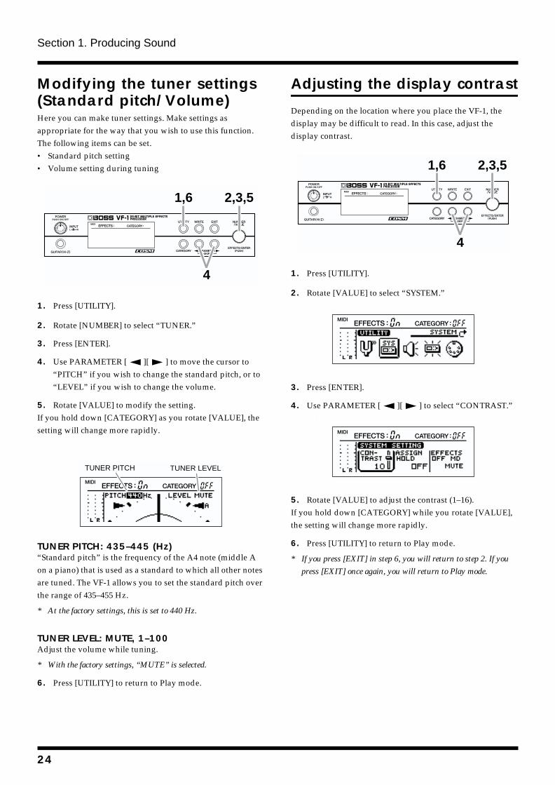
Modifying the tuner settings (Standard pitch/Volume)Here you can make tuner settings. Make settings as appropriate for the way that you wish to use this function. The following items can be set.• Standard pitch setting• Volume setting during tuningfig.1-37
1. Press [UTILITY].
2. Rotate [NUMBER] to select “TUNER.”
3. Press [ENTER].
4. Use PARAMETER [ ][ ] to move the cursor to “PITCH” if you wish to change the standard pitch, or to “LEVEL” if you wish to change the volume.
5. Rotate [VALUE] to modify the setting.If you hold down [CATEGORY] as you rotate [VALUE], the setting will change more rapidly.
fig.1-38
TUNER PITCH: 435–445 (Hz)“Standard pitch” is the frequency of the A4 note (middle A on a piano) that is used as a standard to which all other notes are tuned. The VF-1 allows you to set the standard pitch over the range of 435–455 Hz.
* At the factory settings, this is set to 440 Hz.
TUNER LEVEL: MUTE, 1–100 Adjust the volume while tuning.
* With the factory settings, “MUTE” is selected.
6. Press [UTILITY] to return to Play mode.
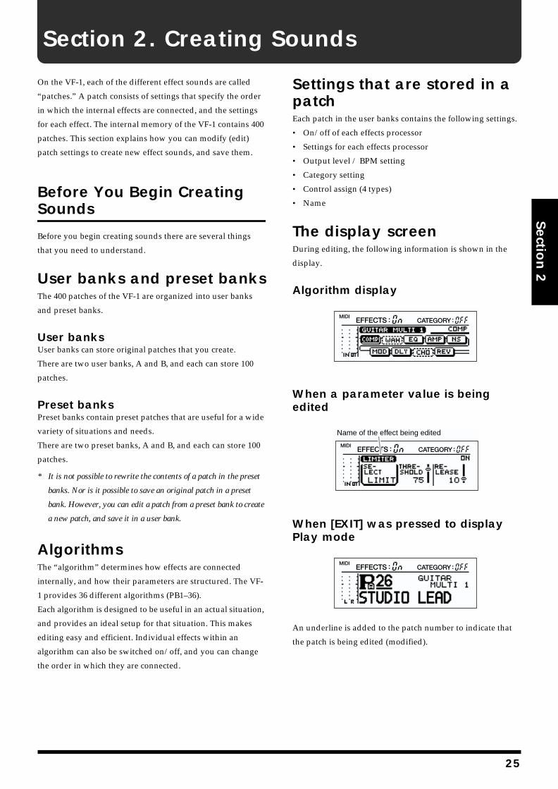
Adjusting the display contrast
Depending on the location where you place the VF-1, the display may be difficult to read. In this case, adjust the display contrast.fig.1-39
1. Press [UTILITY].
2. Rotate [VALUE] to select “SYSTEM.”fig.1-40
3. Press [ENTER].
4. Use PARAMETER [ ][ ] to select “CONTRAST.”fig.1-41
5. Rotate [VALUE] to adjust the contrast (1–16).If you hold down [CATEGORY] while you rotate [VALUE], the setting will change more rapidly.
6. Press [UTILITY] to return to Play mode.
* If you press [EXIT] in step 6, you will return to step 2. If you
press [EXIT] once again, you will return to Play mode.
1,6
4
2,3,5
TUNER PITCH TUNER LEVEL
1,6
4
2,3,5
24
Section 2. Creating Sounds
Section 2
On the VF-1, each of the different effect sounds are called
“patches.” A patch consists of settings that specify the order
in which the internal effects are connected, and the settings
for each effect. The internal memory of the VF-1 contains 400
patches. This section explains how you can modify (edit)
patch settings to create new effect sounds, and save them.
Before You Begin Creating Sounds
Before you begin creating sounds there are several things
that you need to understand.
User banks and preset banksThe 400 patches of the VF-1 are organized into user banks
and preset banks.
User banksUser banks can store original patches that you create.
There are two user banks, A and B, and each can store 100
patches.
Preset banksPreset banks contain preset patches that are useful for a wide
variety of situations and needs.
There are two preset banks, A and B, and each can store 100
patches.
* It is not possible to rewrite the contents of a patch in the preset
banks. Nor is it possible to save an original patch in a preset
bank. However, you can edit a patch from a preset bank to create
a new patch, and save it in a user bank.
AlgorithmsThe “algorithm” determines how effects are connected
internally, and how their parameters are structured. The VF-
1 provides 36 different algorithms (PB1–36).
Each algorithm is designed to be useful in an actual situation,
and provides an ideal setup for that situation. This makes
editing easy and efficient. Individual effects within an
algorithm can also be switched on/off, and you can change
the order in which they are connected.
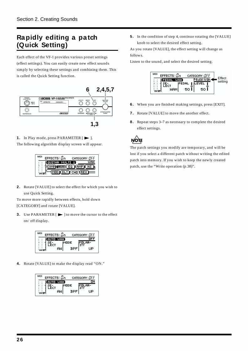
Settings that are stored in a patchEach patch in the user banks contains the following settings.
• On/off of each effects processor
• Settings for each effects processor
• Output level / BPM setting
• Category setting
• Control assign (4 types)
• Name
The display screenDuring editing, the following information is shown in the
display.
Algorithm displayfig.2-01
When a parameter value is being editedfig.2-02
When [EXIT] was pressed to display Play modefig.2-03
An underline is added to the patch number to indicate that
the patch is being edited (modified).
Name of the effect being edited
25
Section 2. Creating Sounds
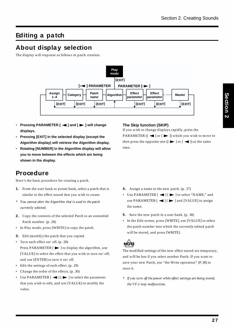
Rapidly editing a patch (Quick Setting)
Each effect of the VF-1 provides various preset settings
(effect settings). You can easily create new effect sounds
simply by selecting these settings and combining them. This
is called the Quick Setting function.
fig.2-04
1. In Play mode, press PARAMETER [ ].
The following algorithm display screen will appear.
fig.2-05
2. Rotate [VALUE] to select the effect for which you wish to
use Quick Setting.
To move more rapidly between effects, hold down
[CATEGORY] and rotate [VALUE].
3. Use PARAMETER [ ] to move the cursor to the effect
on/off display.
fig.2-06
4. Rotate [VALUE] to make the display read “ON.”
fig.2-07
5. In the condition of step 4, continue rotating the [VALUE]
knob to select the desired effect setting.
As you rotate [VALUE], the effect setting will change as
follows.
Listen to the sound, and select the desired setting.
fig.2-08
6. When you are finished making settings, press [EXIT].
7. Rotate [VALUE] to move the another effect.
8. Repeat steps 3–7 as necessary to complete the desired
effect settings.
The patch settings you modify are temporary, and will be
lost if you select a different patch without writing the edited
patch into memory. If you wish to keep the newly created
patch, use the “Write operation (p.38)”.
2,4,5,7
1,3
6
Effectsetting
26
Section 2. Creating Sounds
Section 2
Editing a patch
About display selectionThe display will response as follows in patch creation:
fig.2-200
• Pressing PARAMETER [ ] and [ ] will change
displays.
• Pressing [EXIT] in the selected display (except the
Algorithm display) will retrieve the Algorithm display.
• Rotating [NUMBER] in the Algorithm display will allow
you to move between the effects which are being
shown in the display.
The Skip function (SKIP)If you wish to change displays rapidly, press the
PARAMETER ([ ] or [ ]) which you wish to move to
then press the opposite one ([ ] or [ ]) at the same
time.
ProcedureHere’s the basic procedure for creating a patch.
1. From the user bank or preset bank, select a patch that is
similar to the effect sound that you wish to create.
* You cannot alter the Algorithm that is used in the patch
currently selected.
2. Copy the contents of the selected Patch to an unneeded
Patch number. (p. 28)
• In Play mode, press [WRITE] to copy the patch.
3. Edit (modify) the patch that you copied.
• Turn each effect on/off. (p. 28)
Press PARAMETER [ ] to display the algorithm, use
[VALUE] to select the effect that you wish to turn on/off,
and use [ENTER] to turn it on/off.
• Edit the settings of each effect. (p. 29)
• Change the order of the effects. (p. 30)
• Use PARAMETER [ ] [ ] to select the parameter
that you wish to edit, and use [VALUE] to modify the
value.
4. Assign a name to the new patch. (p. 37)
• Use PARAMETER [ ] [ ] to select “NAME,” and
use PARAMETER [ ] [ ] and [VALUE] to assign
the name.
5. Save the new patch in a user bank. (p. 38)
• In the Edit screen, press [WRITE], use [VALUE] to select
the patch number into which the currently-edited patch
will be stored, and press [WRITE].
The modified settings of the new effect sound are temporary,
and will be lost if you select another Patch. If you want to
save your new Patch, use “the Write operation” (P.38) to
store it.
* If you turn off the power while effect settings are being stored,
the VF-1 may malfunction.
[EXIT]
MasterAlgorithmAssign1–4
Category Patchname
Effectparameter
Effectparameter
[EXIT] [EXIT] [EXIT] [EXIT] [EXIT]
Playmode
[ ] PARAMETER PARAMETER [ ]
[EXIT]
27
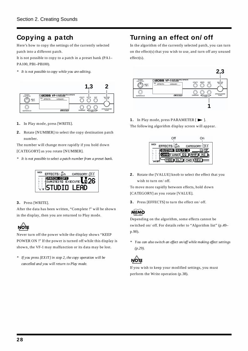
Section 2. Creating Sounds
Copying a patchHere’s how to copy the settings of the currently selected
patch into a different patch.
It is not possible to copy to a patch in a preset bank (PA1–
PA100, PB1–PB100).
* It is not possible to copy while you are editing.
fig.2-09
1. In Play mode, press [WRITE].
2. Rotate [NUMBER] to select the copy destination patch
number.
The number will change more rapidly if you hold down
[CATEGORY] as you rotate [NUMBER].
* It is not possible to select a patch number from a preset bank.
fig.2-10
3. Press [WRITE].
After the data has been written, “Complete !” will be shown
in the display, then you are returned to Play mode.
Never turn off the power while the display shows “KEEP
POWER ON !” If the power is turned off while this display is
shown, the VF-1 may malfunction or its data may be lost.
* If you press [EXIT] in step 2, the copy operation will be
cancelled and you will return to Play mode.
Turning an effect on/offIn the algorithm of the currently selected patch, you can turn
on the effect(s) that you wish to use, and turn off any unused
effect(s).
fig.2-11
1. In Play mode, press PARAMETER [ ].
The following algorithm display screen will appear.
fig.2-12a
2. Rotate the [VALUE] knob to select the effect that you
wish to turn on/off.
To move more rapidly between effects, hold down
[CATEGORY] as you rotate [VALUE].
3. Press [EFFECTS] to turn the effect on/off.
Depending on the algorithm, some effects cannot be
switched on/off. For details refer to “Algorithm list” (p.49–
p.90).
* You can also switch an effect on/off while making effect settings
(p.29).
If you wish to keep your modified settings, you must
perform the Write operation (p.38).
1,3 2
1
2,3
Off On
28
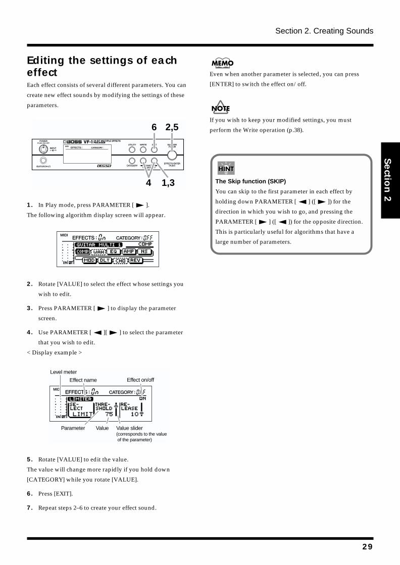
Section 2. Creating Sounds
Section 2
Editing the settings of each effectEach effect consists of several different parameters. You can
create new effect sounds by modifying the settings of these
parameters.
fig.2-13
1. In Play mode, press PARAMETER [ ].
The following algorithm display screen will appear.
fig.2-12
2. Rotate [VALUE] to select the effect whose settings you
wish to edit.
3. Press PARAMETER [ ] to display the parameter
screen.
4. Use PARAMETER [ ][ ] to select the parameter
that you wish to edit.
< Display example >
fig.2-14a
5. Rotate [VALUE] to edit the value.
The value will change more rapidly if you hold down
[CATEGORY] while you rotate [VALUE].
6. Press [EXIT].
7. Repeat steps 2–6 to create your effect sound.
Even when another parameter is selected, you can press
[ENTER] to switch the effect on/off.
If you wish to keep your modified settings, you must
perform the Write operation (p.38).
4
2,5
1,3
6
Effect name
Parameter Value Value slider(corresponds to the value of the parameter)
Effect on/off
Level meter
The Skip function (SKIP)
You can skip to the first parameter in each effect by
holding down PARAMETER [ ] ([ ]) for the
direction in which you wish to go, and pressing the
PARAMETER [ ] ([ ]) for the opposite direction.
This is particularly useful for algorithms that have a
large number of parameters.
29
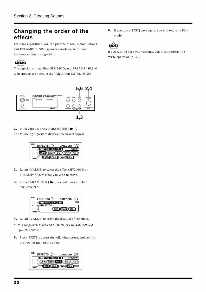
Section 2. Creating Sounds
Changing the order of the effectsFor some algorithms, you can place SFX, MOD (modulation),
and PREAMP/SP.SIM (speaker simulator) in different
locations within the algorithm.
The algorithms that allow SFX, MOD, and PREAMP/SP.SIM
to be moved are noted in the “Algorithm list” (p. 49–90).
fig.2-15
1. In Play mode, press PARAMETER [ ].
The following algorithm display screen will appear.
fig.2-16
2. Rotate [VALUE] to select the effect (SFX, MOD or
PREAMP/SP.SIM) that you wish to move.
3. Press PARAMETER [ ] several times to select
“POSITION.”
fig.2-17
4. Rotate [VALUE] to move the location of the effect.
* It is not possible to place SFX, MOD, or PREAMP/SP.SIM
after “MASTER.”
5. Press [EXIT] to access the following screen, and confirm
the new location of the effect.
fig.2-60
6. If you press [EXIT] once again, you will return to Play
mode.
If you wish to keep your settings, you must perform the
Write operation (p. 38).
5,6
1,3
2,4
30
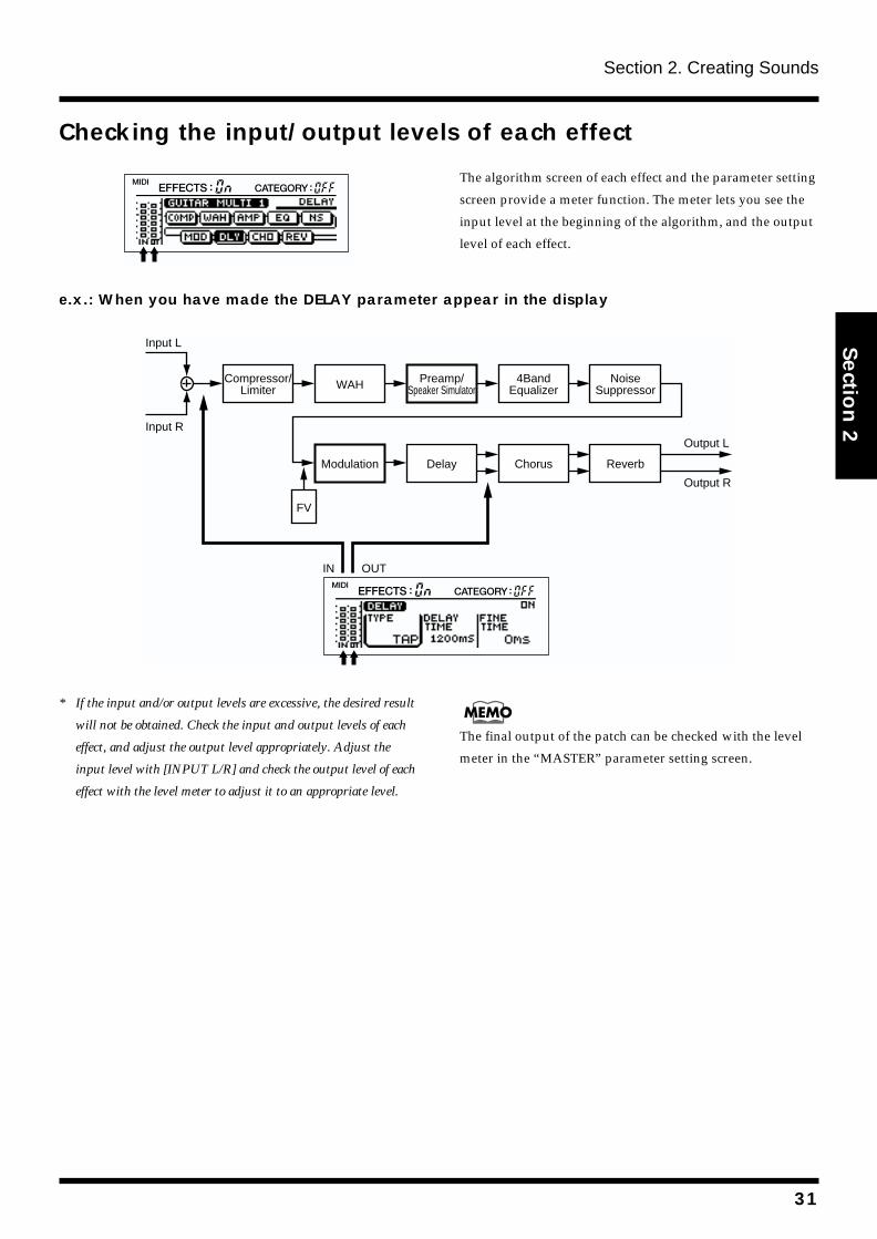
Section 2. Creating Sounds
Section 2
Checking the input/output levels of each effectfig.2-21
The algorithm screen of each effect and the parameter setting
screen provide a meter function. The meter lets you see the
input level at the beginning of the algorithm, and the output
level of each effect.
e.x.: When you have made the DELAY parameter appear in the displayfig.2-49
* If the input and/or output levels are excessive, the desired result
will not be obtained. Check the input and output levels of each
effect, and adjust the output level appropriately. Adjust the
input level with [INPUT L/R] and check the output level of each
effect with the level meter to adjust it to an appropriate level.
The final output of the patch can be checked with the level
meter in the “MASTER” parameter setting screen.
Input L
Input R
Compressor/Limiter
Preamp/Speaker Simulator
Modulation
WAH
Delay
FV
Chorus Reverb
4BandEqualizer
NoiseSuppressor
Output L
Output R
OUTIN
31
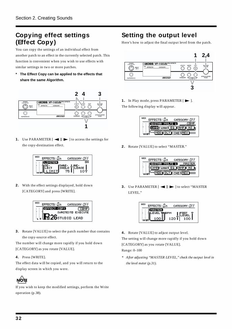
Section 2. Creating Sounds
Copying effect settings (Effect Copy)You can copy the settings of an individual effect from
another patch to an effect in the currently selected patch. This
function is convenient when you wish to use effects with
similar settings in two or more patches.
* The Effect Copy can be applied to the effects that
share the same Algorithm.
fig.2-22
1. Use PARAMETER [ ][ ] to access the settings for
the copy-destination effect.
fig.2-61
2. With the effect settings displayed, hold down
[CATEGORY] and press [WRITE].
fig.2-23
3. Rotate [VALUE] to select the patch number that contains
the copy-source effect.
The number will change more rapidly if you hold down
[CATEGORY] as you rotate [VALUE].
4. Press [WRITE].
The effect data will be copied, and you will return to the
display screen in which you were.
If you wish to keep the modified settings, perform the Write
operation (p.38).
Setting the output levelHere’s how to adjust the final output level from the patch.
fig.2-24
1. In Play mode, press PARAMETER [ ].
The following display will appear.
fig.2-12
2. Rotate [VALUE] to select “MASTER.”
fig.2-201
3. Use PARAMETER [ ][ ] to select “MASTER
LEVEL.”
fig.2-25
4. Rotate [VALUE] to adjust output level.
The setting will change more rapidly if you hold down
[CATEGORY] as you rotate [VALUE].
Range: 0–100
* After adjusting “MASTER LEVEL,” check the output level in
the level meter (p.31).
1
32 43
2,41
32
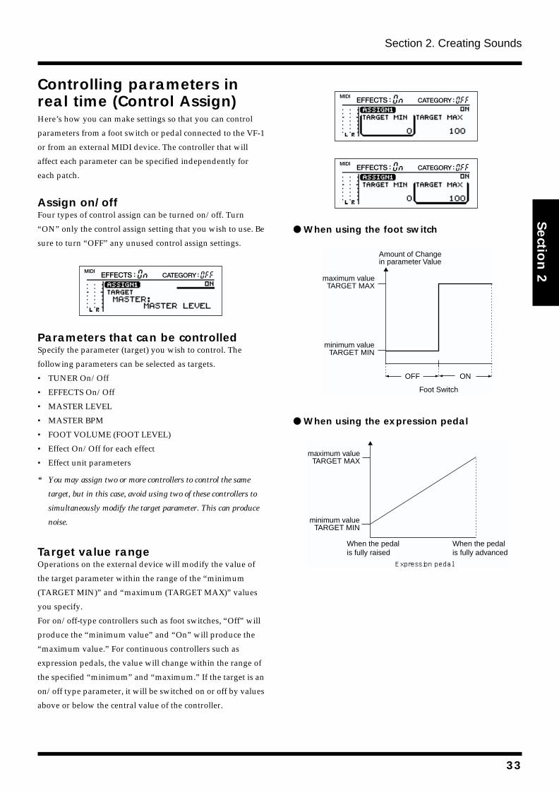
Section 2. Creating Sounds
Section 2
Controlling parameters in real time (Control Assign)Here’s how you can make settings so that you can control
parameters from a foot switch or pedal connected to the VF-1
or from an external MIDI device. The controller that will
affect each parameter can be specified independently for
each patch.
Assign on/offFour types of control assign can be turned on/off. Turn
“ON” only the control assign setting that you wish to use. Be
sure to turn “OFF” any unused control assign settings.
fig.2-51
Parameters that can be controlledSpecify the parameter (target) you wish to control. The
following parameters can be selected as targets.
• TUNER On/Off
• EFFECTS On/Off
• MASTER LEVEL
• MASTER BPM
• FOOT VOLUME (FOOT LEVEL)
• Effect On/Off for each effect
• Effect unit parameters
* You may assign two or more controllers to control the same
target, but in this case, avoid using two of these controllers to
simultaneously modify the target parameter. This can produce
noise.
Target value rangeOperations on the external device will modify the value of
the target parameter within the range of the “minimum
(TARGET MIN)” and “maximum (TARGET MAX)” values
you specify.
For on/off-type controllers such as foot switches, “Off” will
produce the “minimum value” and “On” will produce the
“maximum value.” For continuous controllers such as
expression pedals, the value will change within the range of
the specified “minimum” and “maximum.” If the target is an
on/off type parameter, it will be switched on or off by values
above or below the central value of the controller.
fig.2-28
fig.2-29
When using the foot switchfig.2-30a
When using the expression pedalfig.2-30b
Amount of Change in parameter Value
ON
Foot Switch
OFF
maximum valueTARGET MAX
minimum valueTARGET MIN
maximum valueTARGET MAX
minimum valueTARGET MIN
When the pedal is fully advanced
When the pedal is fully raised
Expression pedal
33
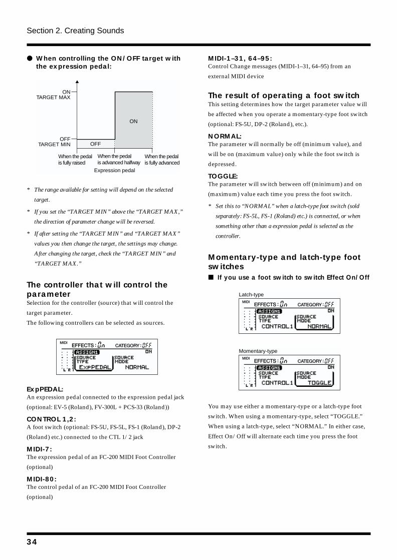
Section 2. Creating Sounds
When controlling the ON/OFF target with the expression pedal:
fig.2-30c
* The range available for setting will depend on the selected
target.
* If you set the “TARGET MIN” above the “TARGET MAX,”
the direction of parameter change will be reversed.
* If after setting the “TARGET MIN” and “TARGET MAX”
values you then change the target, the settings may change.
After changing the target, check the “TARGET MIN” and
“TARGET MAX.”
The controller that will control the parameterSelection for the controller (source) that will control the
target parameter.
The following controllers can be selected as sources.
fig.2-31
ExpPEDAL:An expression pedal connected to the expression pedal jack
(optional: EV-5 (Roland), FV-300L + PCS-33 (Roland))
CONTROL 1,2:A foot switch (optional: FS-5U, FS-5L, FS-1 (Roland), DP-2
(Roland) etc.) connected to the CTL 1/2 jack
MIDI-7:The expression pedal of an FC-200 MIDI Foot Controller
(optional)
MIDI-80:The control pedal of an FC-200 MIDI Foot Controller
(optional)
MIDI-1–31, 64–95:Control Change messages (MIDI-1–31, 64–95) from an
external MIDI device
The result of operating a foot switchThis setting determines how the target parameter value will
be affected when you operate a momentary-type foot switch
(optional: FS-5U, DP-2 (Roland), etc.).
NORMAL:The parameter will normally be off (minimum value), and
will be on (maximum value) only while the foot switch is
depressed.
TOGGLE:The parameter will switch between off (minimum) and on
(maximum) value each time you press the foot switch.
* Set this to “NORMAL” when a latch-type foot switch (sold
separately: FS-5L, FS-1 (Roland) etc.) is connected, or when
something other than a expression pedal is selected as the
controller.
Momentary-type and latch-type foot switches If you use a foot switch to switch Effect On/Offfig.2-70
fig.2-71
You may use either a momentary-type or a latch-type foot
switch. When using a momentary-type, select “TOGGLE.”
When using a latch-type, select “NORMAL.” In either case,
Effect On/Off will alternate each time you press the foot
switch.
OFF
ONTARGET MAX
OFFTARGET MIN
When the pedal is fully advanced
When the pedal is fully raised
When the pedal is advanced halfway
Expression pedal
ON
Latch-type
Momentary-type
34
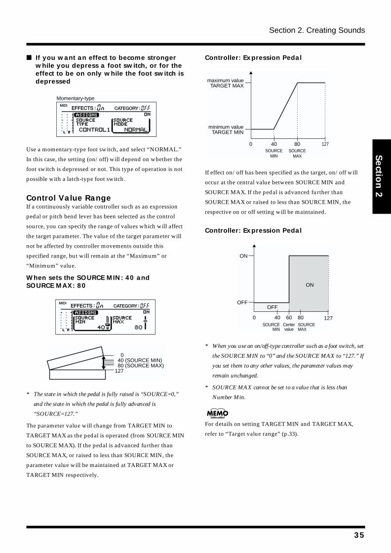
Section 2. Creating Sounds
Section 2
If you want an effect to become stronger while you depress a foot switch, or for the effect to be on only while the foot switch is depressed
fig.2-71a
Use a momentary-type foot switch, and select “NORMAL.”
In this case, the setting (on/off) will depend on whether the
foot switch is depressed or not. This type of operation is not
possible with a latch-type foot switch.
Control Value RangeIf a continuously variable controller such as an expression
pedal or pitch bend lever has been selected as the control
source, you can specify the range of values which will affect
the target parameter. The value of the target parameter will
not be affected by controller movements outside this
specified range, but will remain at the “Maximum” or
“Minimum” value.
When sets the SOURCE MIN: 40 and SOURCE MAX: 80fig.2-33
fig.2-35a
* The state in which the pedal is fully raised is “SOURCE=0,”
and the state in which the pedal is fully advanced is
“SOURCE=127.”
The parameter value will change from TARGET MIN to
TARGET MAX as the pedal is operated (from SOURCE MIN
to SOURCE MAX). If the pedal is advanced further than
SOURCE MAX, or raised to less than SOURCE MIN, the
parameter value will be maintained at TARGET MAX or
TARGET MIN respectively.
Controller: Expression Pedalfig.2-35b
If effect on/off has been specified as the target, on/off will
occur at the central value between SOURCE MIN and
SOURCE MAX. If the pedal is advanced further than
SOURCE MAX or raised to less than SOURCE MIN, the
respective on or off setting will be maintained.
Controller: Expression Pedalfig.2-35c
* When you use an on/off-type controller such as a foot switch, set
the SOURCE MIN to “0” and the SOURCE MAX to “127.” If
you set them to any other values, the parameter values may
remain unchanged.
* SOURCE MAX cannot be set to a value that is less than
Number Min.
For details on setting TARGET MIN and TARGET MAX,
refer to “Target value range” (p.33).
Momentary-type
0 40 (SOURCE MIN) 80 (SOURCE MAX)127
0 40 80 127
maximum valueTARGET MAX
minimum valueTARGET MIN
SOURCEMIN
SOURCEMAX
OFF
ON
OFF
Centervalue
ON
0 40 8060 127SOURCEMAX
SOURCEMIN
35
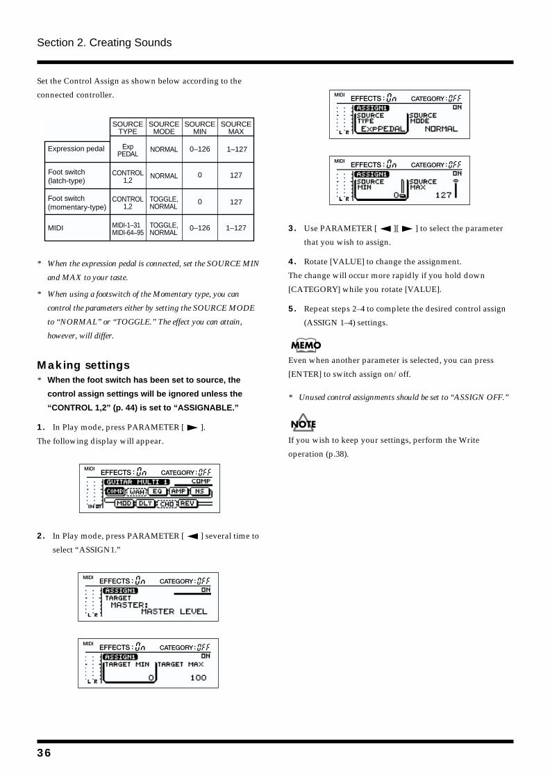
Section 2. Creating Sounds
Set the Control Assign as shown below according to the
connected controller.
fig.2-35d
* When the expression pedal is connected, set the SOURCE MIN
and MAX to your taste.
* When using a footswitch of the Momentary type, you can
control the parameters either by setting the SOURCE MODE
to “NORMAL” or “TOGGLE.” The effect you can attain,
however, will differ.
Making settings* When the foot switch has been set to source, the
control assign settings will be ignored unless the
“CONTROL 1,2” (p. 44) is set to “ASSIGNABLE.”
1. In Play mode, press PARAMETER [ ].
The following display will appear.
fig.2-12
2. In Play mode, press PARAMETER [ ] several time to
select “ASSIGN1.”
fig.2-36a
fig.2-36b
fig.2-36c
fig.2-36d
3. Use PARAMETER [ ][ ] to select the parameter
that you wish to assign.
4. Rotate [VALUE] to change the assignment.
The change will occur more rapidly if you hold down
[CATEGORY] while you rotate [VALUE].
5. Repeat steps 2–4 to complete the desired control assign
(ASSIGN 1–4) settings.
Even when another parameter is selected, you can press
[ENTER] to switch assign on/off.
* Unused control assignments should be set to “ASSIGN OFF.”
If you wish to keep your settings, perform the Write
operation (p.38).
Expression pedal
SOURCETYPE
SOURCEMODE
SOURCEMIN
SOURCEMAX
Foot switch(latch-type)
Foot switch(momentary-type)
ExpPEDAL
CONTROL1,2
CONTROL1,2
NORMAL
NORMAL
TOGGLE, NORMAL
1–1270–126
0 127
0 127
MIDI MIDI-1–31MIDI-64–95
TOGGLE, NORMAL
0–126 1–127
36
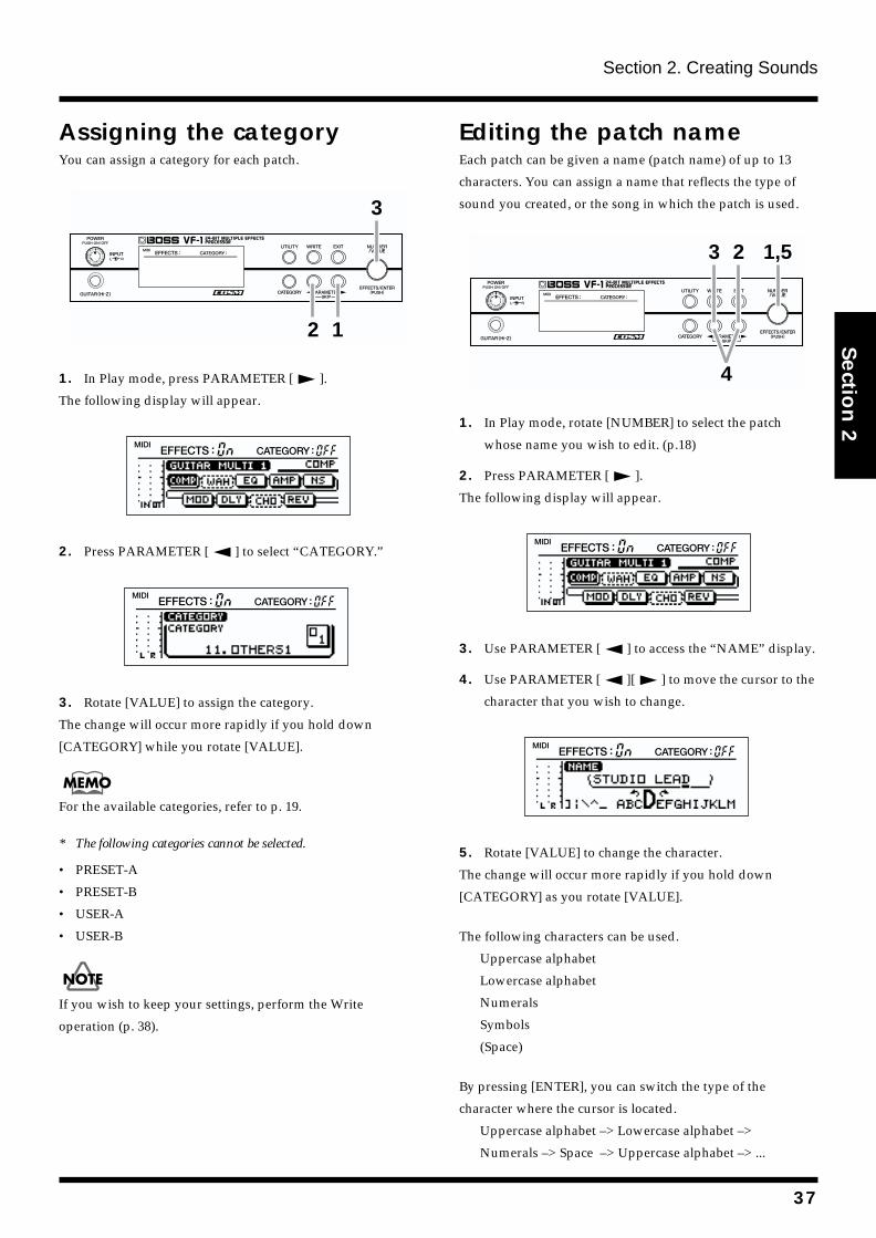
Section 2. Creating Sounds
Section 2
Assigning the categoryYou can assign a category for each patch.
fig.2-26
1. In Play mode, press PARAMETER [ ].
The following display will appear.
fig.2-12
2. Press PARAMETER [ ] to select “CATEGORY.”
fig.2-27
3. Rotate [VALUE] to assign the category.
The change will occur more rapidly if you hold down
[CATEGORY] while you rotate [VALUE].
For the available categories, refer to p. 19.
* The following categories cannot be selected.
• PRESET-A
• PRESET-B
• USER-A
• USER-B
If you wish to keep your settings, perform the Write
operation (p. 38).
Editing the patch nameEach patch can be given a name (patch name) of up to 13
characters. You can assign a name that reflects the type of
sound you created, or the song in which the patch is used.
fig.2-37
1. In Play mode, rotate [NUMBER] to select the patch
whose name you wish to edit. (p.18)
2. Press PARAMETER [ ].
The following display will appear.
fig.2-12
3. Use PARAMETER [ ] to access the “NAME” display.
4. Use PARAMETER [ ][ ] to move the cursor to the
character that you wish to change.
fig.2-38
5. Rotate [VALUE] to change the character.
The change will occur more rapidly if you hold down
[CATEGORY] as you rotate [VALUE].
The following characters can be used.
Uppercase alphabet
Lowercase alphabet
Numerals
Symbols
(Space)
By pressing [ENTER], you can switch the type of the
character where the cursor is located.
Uppercase alphabet –> Lowercase alphabet –>
Numerals –> Space –> Uppercase alphabet –> ...
1
3
2
4
1,523
37
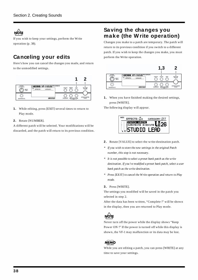
Section 2. Creating Sounds
If you wish to keep your settings, perform the Write
operation (p. 38).
Canceling your editsHere’s how you can cancel the changes you made, and return
to the unmodified settings.
fig.2-39
1. While editing, press [EXIT] several times to return to
Play mode.
2. Rotate [NUMBER].
A different patch will be selected. Your modifications will be
discarded, and the patch will return to its previous condition.
Saving the changes you make (the Write operation)Changes you make to a patch are temporary. The patch will
return to its previous condition if you switch to a different
patch. If you wish to keep the changes you make, you must
perform the Write operation.
fig.2-40
1. When you have finished making the desired settings,
press [WRITE].
The following display will appear.
fig.2-41
2. Rotate [VALUE] to select the write-destination patch.
* If you wish to store the new settings in the original Patch
number, this step is not necessary.
* It is not possible to select a preset bank patch as the write
destination. If you’ve modified a preset bank patch, select a user
bank patch as the write destination.
* Press [EXIT] to cancel the Write operation and return to Play
mode.
3. Press [WRITE].
The settings you modified will be saved in the patch you
selected in step 2.
After the data has been written, “Complete !” will be shown
in the display, then you are returned to Play mode.
Never turn off the power while the display shows “Keep
Power ON !” If the power is turned off while this display is
shown, the VF-1 may malfunction or its data may be lost.
While you are editing a patch, you can press [WRITE] at any
time to save your settings.
1 2
1,3 2
38
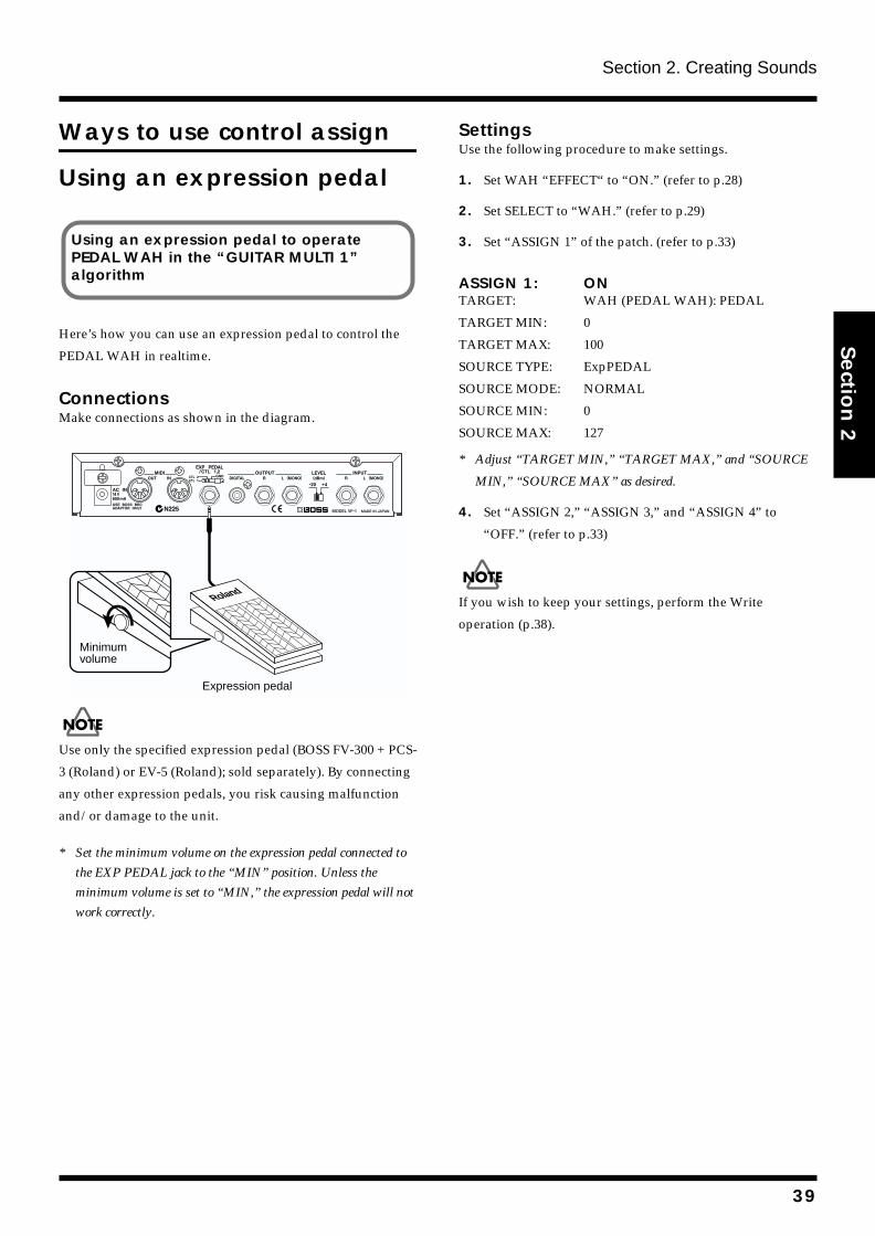
Section 2. Creating Sounds
Section 2
Ways to use control assign
Using an expression pedal
Here’s how you can use an expression pedal to control the
PEDAL WAH in realtime.
ConnectionsMake connections as shown in the diagram.
fig.2-44
Use only the specified expression pedal (BOSS FV-300 + PCS-
3 (Roland) or EV-5 (Roland); sold separately). By connecting
any other expression pedals, you risk causing malfunction
and/or damage to the unit.
* Set the minimum volume on the expression pedal connected to
the EXP PEDAL jack to the “MIN” position. Unless the
minimum volume is set to “MIN,” the expression pedal will not
work correctly.
SettingsUse the following procedure to make settings.
1. Set WAH “EFFECT“ to “ON.” (refer to p.28)
2. Set SELECT to “WAH.” (refer to p.29)
3. Set “ASSIGN 1” of the patch. (refer to p.33)
ASSIGN 1: ONTARGET: WAH (PEDAL WAH): PEDAL
TARGET MIN: 0
TARGET MAX: 100
SOURCE TYPE: ExpPEDAL
SOURCE MODE: NORMAL
SOURCE MIN: 0
SOURCE MAX: 127
* Adjust “TARGET MIN,” “TARGET MAX,” and “SOURCE
MIN,” “SOURCE MAX” as desired.
4. Set “ASSIGN 2,” “ASSIGN 3,” and “ASSIGN 4” to
“OFF.” (refer to p.33)
If you wish to keep your settings, perform the Write
operation (p.38).
Using an expression pedal to operate PEDAL WAH in the “GUITAR MULTI 1” algorithm
Roland
Minimumvolume
Expression pedal
39
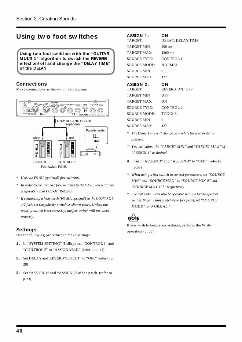
Section 2. Creating Sounds
Using two foot switches
ConnectionsMake connections as shown in the diagram.
fig.2-45
* Use two FS-5U (optional) foot switches.
* In order to connect two foot switches to the VF-1, you will need
a separately sold PCS-31 (Roland).
* If connecting a footswitch (FS-5U; optional) to the CONTROL
1/2 jack, set the polarity switch as shown above. Unless the
polarity switch is set correctly, the foot switch will not work
properly.
SettingsUse the following procedure to make settings.
1. In “SYSTEM SETTING” (Utility), set “CONTROL 1” and
“CONTROL 2” to “ASSIGNABLE.” (refer to p. 44)
2. Set DELAY and REVERB “EFFECT” to “ON.” (refer to p.
28)
3. Set “ASSIGN 1” and “ASSIGN 2” of the patch. (refer to
p.33)
ASSIGN 1: ONTARGET: DELAY: DELAY TIME
TARGET MIN: 300 ms
TARGET MAX: 1300 ms
SOURCE TYPE: CONTROL 1
SOURCE MODE: NORMAL
SOURCE MIN: 0
SOURCE MAX: 127
ASSIGN 2: ONTARGET: REVERB: ON/OFF
TARGET MIN: OFF
TARGET MAX: ON
SOURCE TYPE: CONTROL 2
SOURCE MODE: TOGGLE
SOURCE MIN: 0
SOURCE MAX: 127
* The Delay Time will change only while the foot switch is
pressed.
* You can adjust the “TARGET MIN” and “TARGET MAX” of
“ASSIGN 1” as desired.
4. Turn “ASSIGN 3” and “ASSIGN 4” to “OFF.” (refer to
p.33)
* When using a foot switch to control parameters, set “SOURCE
MIN” and “SOURCE MAX” to “SOURCE MIN 0” and
“SOURCE MAX 127” respectively.
* Control pedal 2 can also be operated using a latch-type foot
switch. When using a latch-type foot pedal, set “SOURCE
MODE” to “NORMAL.”
If you wish to keep your settings, perform the Write
operation (p. 38).
Using two foot switches with the “GUITAR MULTI 1” algorithm to switch the REVERB effect on/off and change the “DELAY TIME” of the DELAY
CONTROL 1Foot switch FS-5U
Cord: ROLAND PCS-31 (optional)
redwhite
CONTROL 2
Polarity switch
40
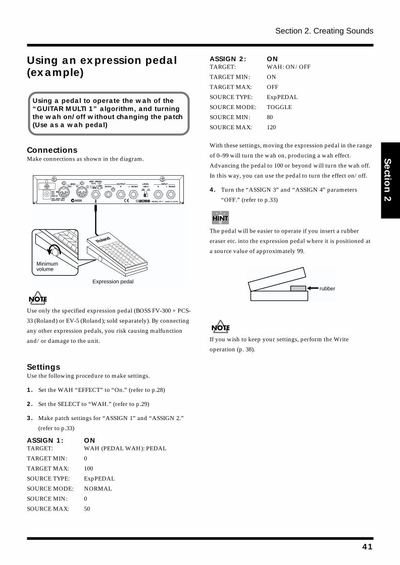
Section 2. Creating Sounds
Section 2
Using an expression pedal (example)
ConnectionsMake connections as shown in the diagram.
fig.2-44
Use only the specified expression pedal (BOSS FV-300 + PCS-
33 (Roland) or EV-5 (Roland); sold separately). By connecting
any other expression pedals, you risk causing malfunction
and/or damage to the unit.
SettingsUse the following procedure to make settings.
1. Set the WAH “EFFECT” to “On.” (refer to p.28)
2. Set the SELECT to “WAH.” (refer to p.29)
3. Make patch settings for “ASSIGN 1” and “ASSIGN 2.”
(refer to p.33)
ASSIGN 1: ONTARGET: WAH (PEDAL WAH): PEDAL
TARGET MIN: 0
TARGET MAX: 100
SOURCE TYPE: ExpPEDAL
SOURCE MODE: NORMAL
SOURCE MIN: 0
SOURCE MAX: 50
ASSIGN 2: ONTARGET: WAH: ON/OFF
TARGET MIN: ON
TARGET MAX: OFF
SOURCE TYPE: ExpPEDAL
SOURCE MODE: TOGGLE
SOURCE MIN: 80
SOURCE MAX: 120
With these settings, moving the expression pedal in the range
of 0–99 will turn the wah on, producing a wah effect.
Advancing the pedal to 100 or beyond will turn the wah off.
In this way, you can use the pedal to turn the effect on/off.
4. Turn the “ASSIGN 3” and “ASSIGN 4” parameters
“OFF.” (refer to p.33)
The pedal will be easier to operate if you insert a rubber
eraser etc. into the expression pedal where it is positioned at
a source value of approximately 99.
fig.2-48
If you wish to keep your settings, perform the Write
operation (p. 38).
Using a pedal to operate the wah of the “GUITAR MULTI 1” algorithm, and turning the wah on/off without changing the patch (Use as a wah pedal)
Roland
Minimumvolume
Expression pedalrubber
41
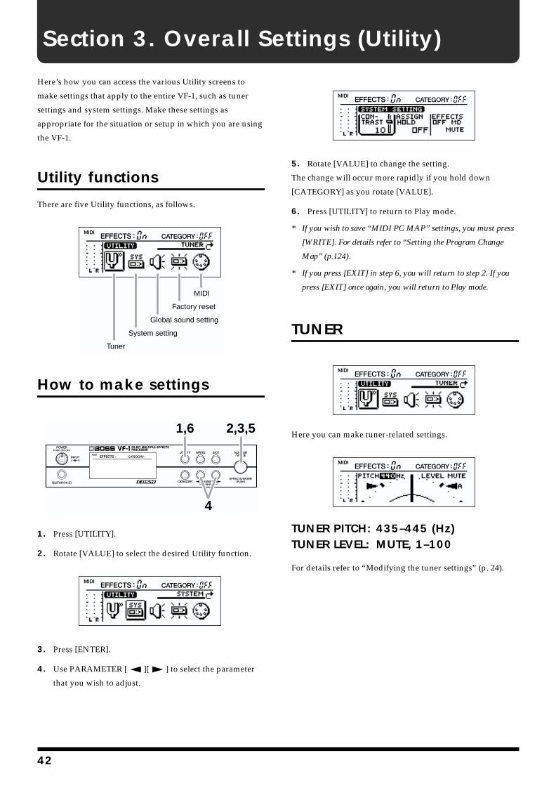
Section 3. Overall Settings (Utility)
Here’s how you can access the various Utility screens to
make settings that apply to the entire VF-1, such as tuner
settings and system settings. Make these settings as
appropriate for the situation or setup in which you are using
the VF-1.
Utility functions
There are five Utility functions, as follows.
fig.3-01
How to make settings
fig.3-02
1. Press [UTILITY].
2. Rotate [VALUE] to select the desired Utility function.
fig.3-03
3. Press [ENTER].
4. Use PARAMETER [ ][ ] to select the parameter
that you wish to adjust.
fig.3-04
5. Rotate [VALUE] to change the setting.
The change will occur more rapidly if you hold down
[CATEGORY] as you rotate [VALUE].
6. Press [UTILITY] to return to Play mode.
* If you wish to save “MIDI PC MAP” settings, you must press
[WRITE]. For details refer to “Setting the Program Change
Map” (p.124).
* If you press [EXIT] in step 6, you will return to step 2. If you
press [EXIT] once again, you will return to Play mode.
TUNER
fig.3-05
Here you can make tuner-related settings.
fig.3-06
TUNER PITCH: 435–445 (Hz)TUNER LEVEL: MUTE, 1–100
For details refer to “Modifying the tuner settings” (p. 24).
MIDI
Factory reset
Global sound setting
System setting
Tuner
1,6
4
2,3,5
42
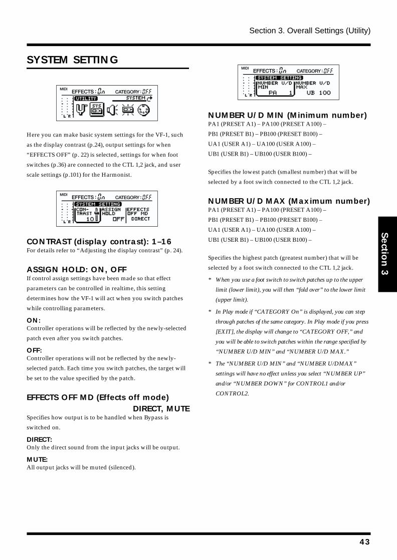
Section 3. Overall Settings (Utility)
Section 3
SYSTEM SETTING
fig.3-07
Here you can make basic system settings for the VF-1, such
as the display contrast (p.24), output settings for when
“EFFECTS OFF” (p. 22) is selected, settings for when foot
switches (p.36) are connected to the CTL 1,2 jack, and user
scale settings (p.101) for the Harmonist.
fig.3-08
CONTRAST (display contrast): 1–16For details refer to “Adjusting the display contrast” (p. 24).
ASSIGN HOLD: ON, OFFIf control assign settings have been made so that effect
parameters can be controlled in realtime, this setting
determines how the VF-1 will act when you switch patches
while controlling parameters.
ON:Controller operations will be reflected by the newly-selected
patch even after you switch patches.
OFF:Controller operations will not be reflected by the newly-
selected patch. Each time you switch patches, the target will
be set to the value specified by the patch.
EFFECTS OFF MD (Effects off mode)DIRECT, MUTE
Specifies how output is to be handled when Bypass is
switched on.
DIRECT:Only the direct sound from the input jacks will be output.
MUTE:All output jacks will be muted (silenced).
fig.3-09
NUMBER U/D MIN (Minimum number)PA1 (PRESET A1) – PA100 (PRESET A100) –
PB1 (PRESET B1) – PB100 (PRESET B100) –
UA1 (USER A1) – UA100 (USER A100) –
UB1 (USER B1) – UB100 (USER B100) –
Specifies the lowest patch (smallest number) that will be
selected by a foot switch connected to the CTL 1,2 jack.
NUMBER U/D MAX (Maximum number)PA1 (PRESET A1) – PA100 (PRESET A100) –
PB1 (PRESET B1) – PB100 (PRESET B100) –
UA1 (USER A1) – UA100 (USER A100) –
UB1 (USER B1) – UB100 (USER B100) –
Specifies the highest patch (greatest number) that will be
selected by a foot switch connected to the CTL 1,2 jack.
* When you use a foot switch to switch patches up to the upper
limit (lower limit), you will then “fold over” to the lower limit
(upper limit).
* In Play mode if “CATEGORY On” is displayed, you can step
through patches of the same category. In Play mode if you press
[EXIT], the display will change to “CATEGORY OFF,” and
you will be able to switch patches within the range specified by
“NUMBER U/D MIN” and “NUMBER U/D MAX.”
* The “NUMBER U/D MIN” and “NUMBER U/DMAX”
settings will have no effect unless you select “NUMBER UP”
and/or “NUMBER DOWN” for CONTROL1 and/or
CONTROL2.
43
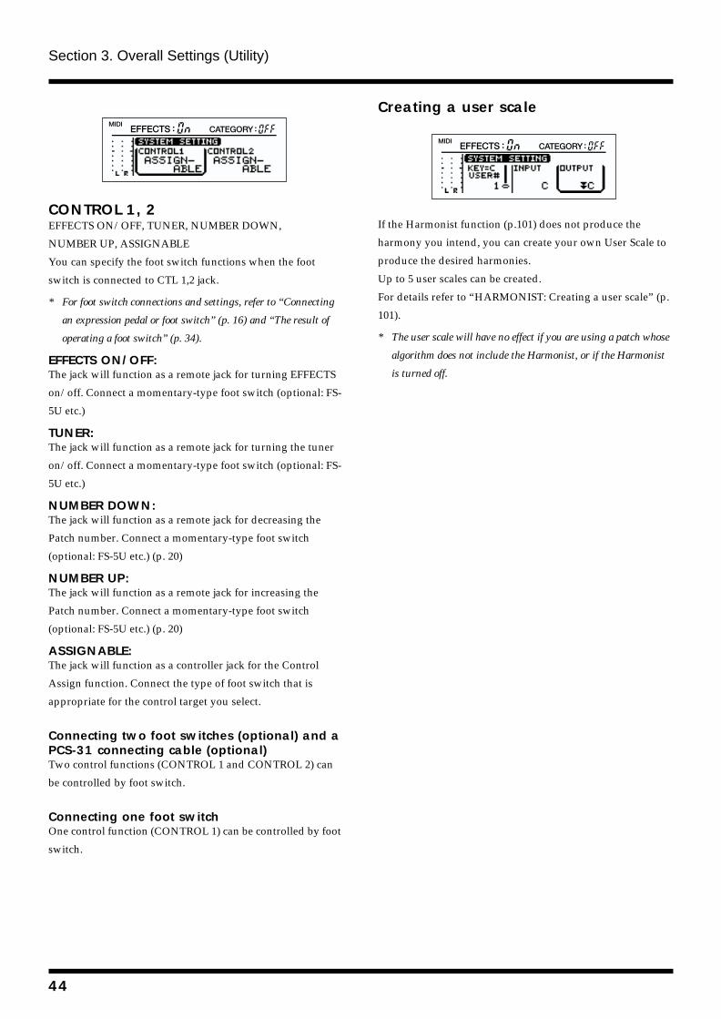
Section 3. Overall Settings (Utility)
fig.3-10
CONTROL 1, 2EFFECTS ON/OFF, TUNER, NUMBER DOWN,
NUMBER UP, ASSIGNABLE
You can specify the foot switch functions when the foot
switch is connected to CTL 1,2 jack.
* For foot switch connections and settings, refer to “Connecting
an expression pedal or foot switch” (p. 16) and “The result of
operating a foot switch” (p. 34).
EFFECTS ON/OFF:The jack will function as a remote jack for turning EFFECTS
on/off. Connect a momentary-type foot switch (optional: FS-
5U etc.)
TUNER:The jack will function as a remote jack for turning the tuner
on/off. Connect a momentary-type foot switch (optional: FS-
5U etc.)
NUMBER DOWN:The jack will function as a remote jack for decreasing the
Patch number. Connect a momentary-type foot switch
(optional: FS-5U etc.) (p. 20)
NUMBER UP:The jack will function as a remote jack for increasing the
Patch number. Connect a momentary-type foot switch
(optional: FS-5U etc.) (p. 20)
ASSIGNABLE:The jack will function as a controller jack for the Control
Assign function. Connect the type of foot switch that is
appropriate for the control target you select.
Connecting two foot switches (optional) and a PCS-31 connecting cable (optional)Two control functions (CONTROL 1 and CONTROL 2) can
be controlled by foot switch.
Connecting one foot switchOne control function (CONTROL 1) can be controlled by foot
switch.
Creating a user scalefig.3-11
If the Harmonist function (p.101) does not produce the
harmony you intend, you can create your own User Scale to
produce the desired harmonies.
Up to 5 user scales can be created.
For details refer to “HARMONIST: Creating a user scale” (p.
101).
* The user scale will have no effect if you are using a patch whose
algorithm does not include the Harmonist, or if the Harmonist
is turned off.
44
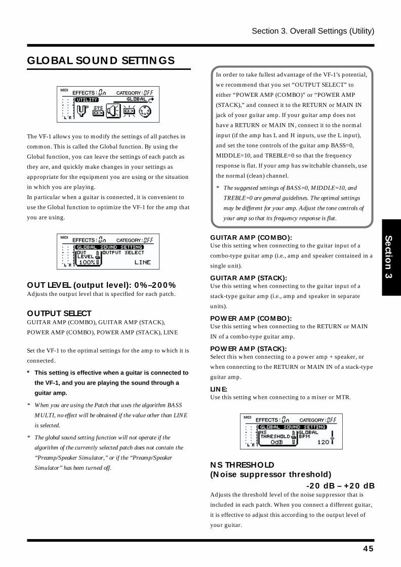
Section 3. Overall Settings (Utility)
Section 3
GLOBAL SOUND SETTINGS
fig.3-12
The VF-1 allows you to modify the settings of all patches in
common. This is called the Global function. By using the
Global function, you can leave the settings of each patch as
they are, and quickly make changes in your settings as
appropriate for the equipment you are using or the situation
in which you are playing.
In particular when a guitar is connected, it is convenient to
use the Global function to optimize the VF-1 for the amp that
you are using.
fig.3-13
OUT LEVEL (output level): 0%–200%Adjusts the output level that is specified for each patch.
OUTPUT SELECTGUITAR AMP (COMBO), GUITAR AMP (STACK),
POWER AMP (COMBO), POWER AMP (STACK), LINE
Set the VF-1 to the optimal settings for the amp to which it is
connected.
* This setting is effective when a guitar is connected to
the VF-1, and you are playing the sound through a
guitar amp.
* When you are using the Patch that uses the algorithm BASS
MULTI, no effect will be obtained if the value other than LINE
is selected.
* The global sound setting function will not operate if the
algorithm of the currently selected patch does not contain the
“Preamp/Speaker Simulator,” or if the “Preamp/Speaker
Simulator” has been turned off.
GUITAR AMP (COMBO):Use this setting when connecting to the guitar input of a
combo-type guitar amp (i.e., amp and speaker contained in a
single unit).
GUITAR AMP (STACK):Use this setting when connecting to the guitar input of a
stack-type guitar amp (i.e., amp and speaker in separate
units).
POWER AMP (COMBO):Use this setting when connecting to the RETURN or MAIN
IN of a combo-type guitar amp.
POWER AMP (STACK):Select this when connecting to a power amp + speaker, or
when connecting to the RETURN or MAIN IN of a stack-type
guitar amp.
LINE:Use this setting when connecting to a mixer or MTR.
fig.3-14
NS THRESHOLD(Noise suppressor threshold)
-20 dB – +20 dBAdjusts the threshold level of the noise suppressor that is
included in each patch. When you connect a different guitar,
it is effective to adjust this according to the output level of
your guitar.
In order to take fullest advantage of the VF-1’s potential,
we recommend that you set “OUTPUT SELECT” to
either “POWER AMP (COMBO)” or “POWER AMP
(STACK),” and connect it to the RETURN or MAIN IN
jack of your guitar amp. If your guitar amp does not
have a RETURN or MAIN IN, connect it to the normal
input (if the amp has L and H inputs, use the L input),
and set the tone controls of the guitar amp BASS=0,
MIDDLE=10, and TREBLE=0 so that the frequency
response is flat. If your amp has switchable channels, use
the normal (clean) channel.
* The suggested settings of BASS=0, MIDDLE=10, and
TREBLE=0 are general guidelines. The optimal settings
may be different for your amp. Adjust the tone controls of
your amp so that its frequency response is flat.
45
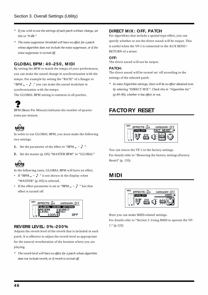
Section 3. Overall Settings (Utility)
* If you wish to use the settings of each patch without change, set
this to “0 dB.”
* The noise suppressor threshold will have no effect for a patch
whose algorithm does not include the noise suppressor, or if the
noise suppressor is turned off.
GLOBAL BPM: 40–250, MIDIBy setting the BPM to match the tempo of your performance,
you can make the sound change in synchronization with the
tempo. For example by setting the “RATE” of a flanger to
“BPM ,” you can make the sound modulate in
synchronization with the tempo.
The GLOBAL BPM setting is common to all patches.
BPM (Beats Per Minute) indicates the number of quarter
notes per minute.
In order to use GLOBAL BPM, you must make the following
two settings.
1. Set the parameter of the effect to “BPM ”
2. Set the master (p.105) “MASTER BPM” to “GLOBAL”
In the following cases, GLOBAL BPM will have no effect.
• If “BPM ” is not shown in the display when
“MASTER” (p.105) is selected.
• If the effect parameter is set to “BPM ” but that
effect is turned off
fig.3-17
REVERB LEVEL: 0%–200%Adjusts the reverb level of the reverb that is included in each
patch. It is effective to adjust the reverb level as appropriate
for the natural reverberation of the location where you are
playing.
* The reverb level will have no effect for a patch whose algorithm
does not include reverb, or if reverb is turned off.
DIRECT MIX: OFF, PATCHFor algorithms that include a spatial-type effect, you can
specify whether or not the direct sound will be output. This
is useful when the VF-1 is connected to the AUX SEND /
RETURN of a mixer.
OFF:The direct sound will not be output.
PATCH:The direct sound will be turned on/off according to the
settings of the selected patch.
* In some Algorithm settings, there will be no effect obtained even
by selecting “DIRECT MIX”. Check this in “Algorithm list”
(p.49–90), whether it has effect or not.
FACTORY RESET
fig.6-08
You can return the VF-1 to the factory settings.
For details refer to “Restoring the factory settings (Factory
Reset)” (p. 133).
MIDI
fig.5-03
Here you can make MIDI-related settings.
For details refer to “Section 5. Using MIDI to operate the VF-
1.” (p.122)
46
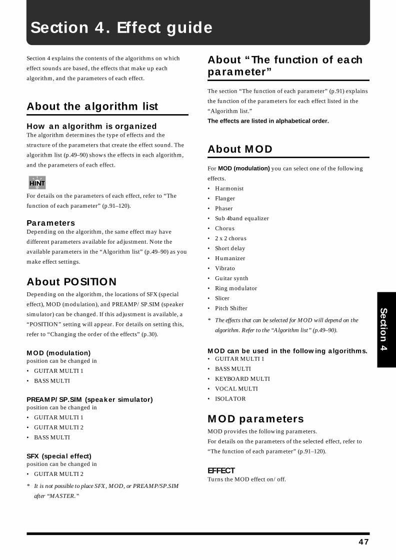
Section 4. Effect guide
Section 4
Section 4 explains the contents of the algorithms on which
effect sounds are based, the effects that make up each
algorithm, and the parameters of each effect.
About the algorithm list
How an algorithm is organizedThe algorithm determines the type of effects and the
structure of the parameters that create the effect sound. The
algorithm list (p.49–90) shows the effects in each algorithm,
and the parameters of each effect.
For details on the parameters of each effect, refer to “The
function of each parameter” (p.91–120).
ParametersDepending on the algorithm, the same effect may have
different parameters available for adjustment. Note the
available parameters in the “Algorithm list” (p.49–90) as you
make effect settings.
About POSITIONDepending on the algorithm, the locations of SFX (special
effect), MOD (modulation), and PREAMP/SP.SIM (speaker
simulator) can be changed. If this adjustment is available, a
“POSITION” setting will appear. For details on setting this,
refer to “Changing the order of the effects” (p.30).
MOD (modulation)position can be changed in
• GUITAR MULTI 1
• BASS MULTI
PREAMP/SP.SIM (speaker simulator)position can be changed in
• GUITAR MULTI 1
• GUITAR MULTI 2
• BASS MULTI
SFX (special effect)position can be changed in
• GUITAR MULTI 2
* It is not possible to place SFX, MOD, or PREAMP/SP.SIM
after “MASTER.”
About “The function of each parameter”
The section “The function of each parameter” (p.91) explains
the function of the parameters for each effect listed in the
“Algorithm list.”
The effects are listed in alphabetical order.
About MOD
For MOD (modulation) you can select one of the following
effects.
• Harmonist
• Flanger
• Phaser
• Sub 4band equalizer
• Chorus
• 2 x 2 chorus
• Short delay
• Humanizer
• Vibrato
• Guitar synth
• Ring modulator
• Slicer
• Pitch Shifter
* The effects that can be selected for MOD will depend on the
algorithm. Refer to the “Algorithm list” (p.49–90).
MOD can be used in the following algorithms.• GUITAR MULTI 1
• BASS MULTI
• KEYBOARD MULTI
• VOCAL MULTI
• ISOLATOR
MOD parametersMOD provides the following parameters.
For details on the parameters of the selected effect, refer to
“The function of each parameter” (p.91–120).
EFFECTTurns the MOD effect on/off.
47
Section 4. Effect guide
SELECT (select effect)Selects one of the following effects to use.
If you modify the effect by “SELECT,” parameter used before
modifying is initialized.
HR (Harmonist) (p.101)FL (Flanger) (p.98)PH (Phaser) (p.108)SEQ (Sub 4band equalizer) (p.116)CE (Chorus) (p.93)2CE (2x2 chorus) (p.91)SDD (Short delay) (p.114)HU (Humanizer) (p.103)VB (Vibrato) (p.118)SYN (Guitar synth) (p.99)RM (Ring modulator) (p.112)SL (Slicer) (p.114)PS (Pitch Shifter) (p.109)
About SFX
For SFX (special effects), you can choose one of the
following effects.
• Acoustic guitar simulator
• Bass guitar simulator
• Slow gear
• Feedbacker
• Pickup simulator
• Tremolo/pan
* SFX can be used in the “GUITAR MULTI 2” algorithm.
SFX parametersSFX has the following parameters.
For details on the parameters of the selected effect, refer to
“The function of each parameter” (p.91–120).
EFFECT Turn the SFX effect on/off.
SELECT (select effect)From the following effects, select the one that you wish to
use.
For details on the parameters of the selected effect, refer to
“The function of each parameter” (p.91–120).
* If you edit an effect with “SELECT,” the effect is parameter that
you have set before editing will be initialized.
AC (Acoustic guitar simulator) (p.92)BS (Bass guitar simulator) (p.92)SG (Slow gear) (p.115)FB (Feedbacker) (p.97)PIC (Pickup simulator) (p.109)TR (Tremolo/pan) (p.117)
About FV (foot volume)
[FV] shown in the Algorithm represents the position where
the volume is controlled with the expression pedal or
footswitch when the Target of the Control Assign is set to
FOOT VOLUME LEVEL (p.33, 105).
About DELAY, MultiTAP DELAY and STEREO PS DLY
When you have set BPM in DELAY TIME, DELAY
TIME [L] and [R], and FB DELAY TIME [L] and [R], the
following parameters will not be shown in the display.
DELAY (p.95)DELAY TIME = BPM • FINE TIME
STEREO DELAY (p.95)DELAY TIME [L] = BPM • FINE TIME [L]
DELAY TIME [R] = BPM • FINE TIME [R]
MULTI TAP DELAY (p.107)TAP [1]–[20] DELAY TIME = BPM • TAP [1]–[20] FINE TIME
STEREO PS DLY (stereo pitch shifter delay) (p.115)FB DELAY TIME [L] = BPM • FB FINE TIME [L]
FB DELAY TIME [R] = BPM • FB FINE TIME [R]
48
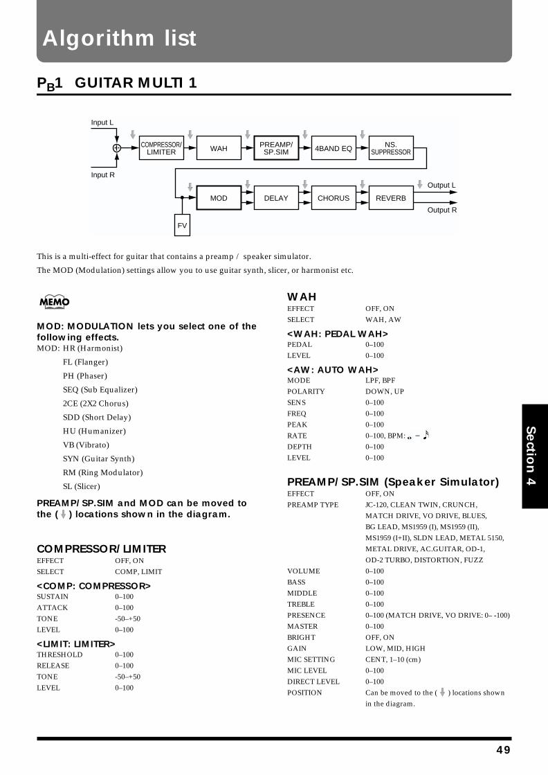
Algorithm list
Section 4
PB1 GUITAR MULTI 1
fig.4-231
This is a multi-effect for guitar that contains a preamp / speaker simulator.
The MOD (Modulation) settings allow you to use guitar synth, slicer, or harmonist etc.
MOD: MODULATION lets you select one of the following effects.MOD: HR (Harmonist)
FL (Flanger)
PH (Phaser)
SEQ (Sub Equalizer)
2CE (2X2 Chorus)
SDD (Short Delay)
HU (Humanizer)
VB (Vibrato)
SYN (Guitar Synth)
RM (Ring Modulator)
SL (Slicer)
PREAMP/SP.SIM and MOD can be moved to the ( ) locations shown in the diagram.
COMPRESSOR/LIMITEREFFECT OFF, ONSELECT COMP, LIMIT
<COMP: COMPRESSOR>SUSTAIN 0–100ATTACK 0–100TONE -50–+50LEVEL 0–100
<LIMIT: LIMITER>THRESHOLD 0–100RELEASE 0–100TONE -50–+50LEVEL 0–100
WAHEFFECT OFF, ONSELECT WAH, AW
<WAH: PEDAL WAH>PEDAL 0–100LEVEL 0–100
<AW: AUTO WAH>MODE LPF, BPFPOLARITY DOWN, UPSENS 0–100FREQ 0–100PEAK 0–100RATE 0–100, BPM: DEPTH 0–100LEVEL 0–100
PREAMP/SP.SIM (Speaker Simulator)EFFECT OFF, ONPREAMP TYPE JC-120, CLEAN TWIN, CRUNCH,
MATCH DRIVE, VO DRIVE, BLUES, BG LEAD, MS1959 (I), MS1959 (II), MS1959 (I+II), SLDN LEAD, METAL 5150, METAL DRIVE, AC.GUITAR, OD-1, OD-2 TURBO, DISTORTION, FUZZ
VOLUME 0–100BASS 0–100MIDDLE 0–100TREBLE 0–100PRESENCE 0–100 (MATCH DRIVE, VO DRIVE: 0– -100)MASTER 0–100BRIGHT OFF, ONGAIN LOW, MID, HIGHMIC SETTING CENT, 1–10 (cm)MIC LEVEL 0–100DIRECT LEVEL 0–100POSITION Can be moved to the ( ) locations shown
in the diagram.
Input L
Input R
COMPRESSOR/LIMITER
PREAMP/SP.SIM
MOD
WAH
DELAY
FV
CHORUS REVERB
4BAND EQ NS.SUPPRESSOR
Output L
Output R
49
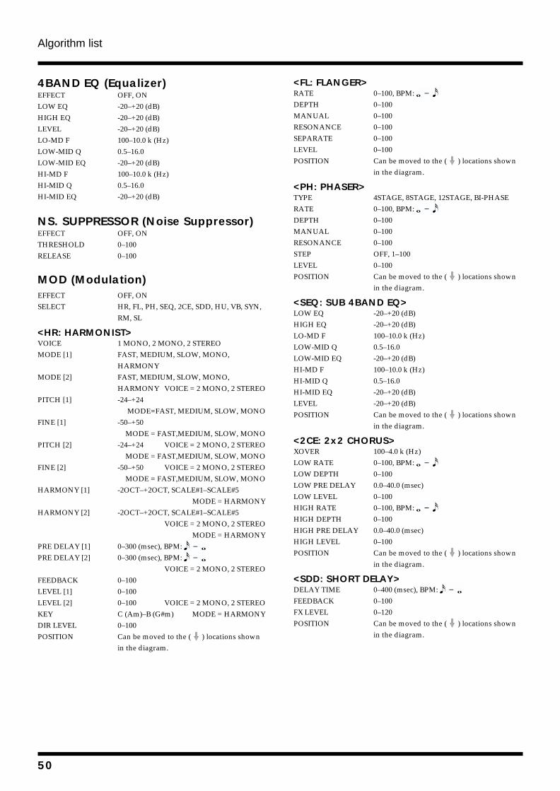
Algorithm list
4BAND EQ (Equalizer)EFFECT OFF, ONLOW EQ -20–+20 (dB)HIGH EQ -20–+20 (dB)LEVEL -20–+20 (dB)LO-MD F 100–10.0 k (Hz)LOW-MID Q 0.5–16.0LOW-MID EQ -20–+20 (dB)HI-MD F 100–10.0 k (Hz)HI-MID Q 0.5–16.0HI-MID EQ -20–+20 (dB)
NS. SUPPRESSOR (Noise Suppressor)EFFECT OFF, ONTHRESHOLD 0–100RELEASE 0–100
MOD (Modulation)EFFECT OFF, ONSELECT HR, FL, PH, SEQ, 2CE, SDD, HU, VB, SYN,
RM, SL
<HR: HARMONIST>VOICE 1 MONO, 2 MONO, 2 STEREOMODE [1] FAST, MEDIUM, SLOW, MONO,
HARMONYMODE [2] FAST, MEDIUM, SLOW, MONO,
HARMONY VOICE = 2 MONO, 2 STEREOPITCH [1] -24–+24
MODE=FAST, MEDIUM, SLOW, MONOFINE [1] -50–+50
MODE = FAST,MEDIUM, SLOW, MONOPITCH [2] -24–+24 VOICE = 2 MONO, 2 STEREO
MODE = FAST,MEDIUM, SLOW, MONOFINE [2] -50–+50 VOICE = 2 MONO, 2 STEREO
MODE = FAST,MEDIUM, SLOW, MONOHARMONY [1] -2OCT–+2OCT, SCALE#1–SCALE#5
MODE = HARMONYHARMONY [2] -2OCT–+2OCT, SCALE#1–SCALE#5
VOICE = 2 MONO, 2 STEREOMODE = HARMONY
PRE DELAY [1] 0–300 (msec), BPM: PRE DELAY [2] 0–300 (msec), BPM:
VOICE = 2 MONO, 2 STEREOFEEDBACK 0–100LEVEL [1] 0–100LEVEL [2] 0–100 VOICE = 2 MONO, 2 STEREOKEY C (Am)–B (G#m) MODE = HARMONYDIR LEVEL 0–100POSITION Can be moved to the ( ) locations shown
in the diagram.
<FL: FLANGER>RATE 0–100, BPM: DEPTH 0–100MANUAL 0–100RESONANCE 0–100SEPARATE 0–100LEVEL 0–100POSITION Can be moved to the ( ) locations shown
in the diagram.
<PH: PHASER>TYPE 4STAGE, 8STAGE, 12STAGE, BI-PHASERATE 0–100, BPM: DEPTH 0–100MANUAL 0–100RESONANCE 0–100STEP OFF, 1–100LEVEL 0–100POSITION Can be moved to the ( ) locations shown
in the diagram.
<SEQ: SUB 4BAND EQ>LOW EQ -20–+20 (dB)HIGH EQ -20–+20 (dB)LO-MD F 100–10.0 k (Hz)LOW-MID Q 0.5–16.0LOW-MID EQ -20–+20 (dB)HI-MD F 100–10.0 k (Hz)HI-MID Q 0.5–16.0HI-MID EQ -20–+20 (dB)LEVEL -20–+20 (dB)POSITION Can be moved to the ( ) locations shown
in the diagram.
<2CE: 2x2 CHORUS>XOVER 100–4.0 k (Hz)LOW RATE 0–100, BPM: LOW DEPTH 0–100LOW PRE DELAY 0.0–40.0 (msec)LOW LEVEL 0–100HIGH RATE 0–100, BPM: HIGH DEPTH 0–100HIGH PRE DELAY 0.0–40.0 (msec)HIGH LEVEL 0–100POSITION Can be moved to the ( ) locations shown
in the diagram.
<SDD: SHORT DELAY>DELAY TIME 0–400 (msec), BPM: FEEDBACK 0–100FX LEVEL 0–120POSITION Can be moved to the ( ) locations shown
in the diagram.
50
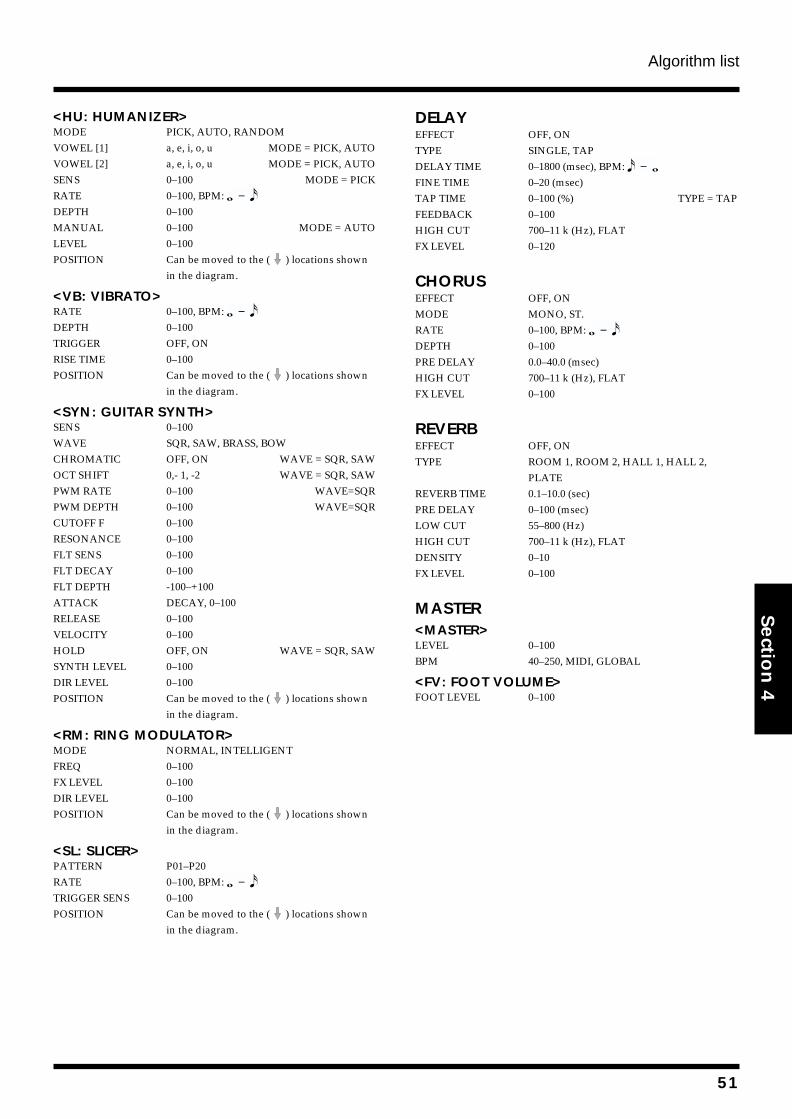
Algorithm list
Section 4
<HU: HUMANIZER>MODE PICK, AUTO, RANDOMVOWEL [1] a, e, i, o, u MODE = PICK, AUTOVOWEL [2] a, e, i, o, u MODE = PICK, AUTOSENS 0–100 MODE = PICKRATE 0–100, BPM: DEPTH 0–100MANUAL 0–100 MODE = AUTOLEVEL 0–100POSITION Can be moved to the ( ) locations shown
in the diagram.
<VB: VIBRATO>RATE 0–100, BPM: DEPTH 0–100TRIGGER OFF, ONRISE TIME 0–100POSITION Can be moved to the ( ) locations shown
in the diagram.
<SYN: GUITAR SYNTH>SENS 0–100WAVE SQR, SAW, BRASS, BOWCHROMATIC OFF, ON WAVE = SQR, SAWOCT SHIFT 0,- 1, -2 WAVE = SQR, SAWPWM RATE 0–100 WAVE=SQRPWM DEPTH 0–100 WAVE=SQRCUTOFF F 0–100RESONANCE 0–100FLT SENS 0–100FLT DECAY 0–100FLT DEPTH -100–+100ATTACK DECAY, 0–100RELEASE 0–100VELOCITY 0–100HOLD OFF, ON WAVE = SQR, SAWSYNTH LEVEL 0–100DIR LEVEL 0–100POSITION Can be moved to the ( ) locations shown
in the diagram.
<RM: RING MODULATOR>MODE NORMAL, INTELLIGENTFREQ 0–100FX LEVEL 0–100DIR LEVEL 0–100POSITION Can be moved to the ( ) locations shown
in the diagram.
<SL: SLICER>PATTERN P01–P20RATE 0–100, BPM: TRIGGER SENS 0–100POSITION Can be moved to the ( ) locations shown
in the diagram.
DELAYEFFECT OFF, ONTYPE SINGLE, TAPDELAY TIME 0–1800 (msec), BPM: FINE TIME 0–20 (msec)TAP TIME 0–100 (%) TYPE = TAPFEEDBACK 0–100HIGH CUT 700–11 k (Hz), FLATFX LEVEL 0–120
CHORUSEFFECT OFF, ONMODE MONO, ST.RATE 0–100, BPM: DEPTH 0–100PRE DELAY 0.0–40.0 (msec)HIGH CUT 700–11 k (Hz), FLATFX LEVEL 0–100
REVERBEFFECT OFF, ONTYPE ROOM 1, ROOM 2, HALL 1, HALL 2,
PLATEREVERB TIME 0.1–10.0 (sec)PRE DELAY 0–100 (msec)LOW CUT 55–800 (Hz)HIGH CUT 700–11 k (Hz), FLATDENSITY 0–10FX LEVEL 0–100
MASTER<MASTER>LEVEL 0–100BPM 40–250, MIDI, GLOBAL
<FV: FOOT VOLUME>FOOT LEVEL 0–100
51
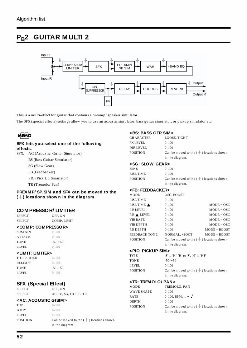
Algorithm list
PB2 GUITAR MULTI 2
fig.4-232
This is a multi-effect for guitar that contains a preamp/speaker simulator.
The SFX (special effects) settings allow you to use an acoustic simulator, bass guitar simulator, or pickup simulator etc.
SFX lets you select one of the following effects.SFX: AC (Acoustic Guitar Simulator)
BS (Bass Guitar Simulator)
SG (Slow Gear)
FB (Feedbacker)
PIC (Pick Up Simulator)
TR (Tremolo/Pan)
PREAMP/SP.SIM and SFX can be moved to the ( ) locations shown in the diagram.
COMPRESSOR/LIMITEREFFECT OFF, ONSELECT COMP, LIMIT
<COMP: COMPRESSOR>SUSTAIN 0–100ATTACK 0–100TONE -50–+50LEVEL 0–100
<LIMIT: LIMITER>THRESHOLD 0–100RELEASE 0–100TONE -50–+50LEVEL 0–100
SFX (Special Effect)EFFECT OFF, ONSELECT AC, BS, SG, FB, PIC, TR
<AC: ACOUSTIC GtSIM>TOP 0–100BODY 0–100LEVEL 0–100POSITION Can be moved to the ( ) locations shown
in the diagram.
<BS: BASS GTR SIM>CHARACTER LOOSE, TIGHTFX LEVEL 0–100DIR LEVEL 0–100POSITION Can be moved to the ( ) locations shown
in the diagram.
<SG: SLOW GEAR>SENS 0–100RISE TIME 0–100POSITION Can be moved to the ( ) locations shown
in the diagram.
<FB: FEEDBACKER>MODE OSC, BOOSTRISE TIME 0–100RISE TIME 0–100 MODE = OSCF.B LEVEL 0–100 MODE = OSCF.B LEVEL 0–100 MODE = OSCVIB RATE 0–100 MODE = OSCVIB DEPTH 0–100 MODE = OSCF.B DEPTH 0–100 MODE = BOOSTFEEDBACK TONE NORMAL, +1OCT MODE = BOOSTPOSITION Can be moved to the ( ) locations shown
in the diagram.
<PIC: PICKUP SIM>TYPE 'S' to 'H', 'H' to 'S', 'H' to 'HF'TONE -50–+50LEVEL 0–100POSITION Can be moved to the ( ) locations shown
in the diagram.
<TR: TREMOLO/PAN>MODE TREMOLO, PANWAVE SHAPE 0–100RATE 0–100, BPM: DEPTH 0–100POSITION Can be moved to the ( ) locations shown
in the diagram.
Input L
Input R
COMPRESSOR/LIMITER
NS.SUPPRESSOR
SFX WAH
DELAY
FV
CHORUS REVERB
PREAMP/SP.SIM 4BAND EQ
Output L
Output R
52
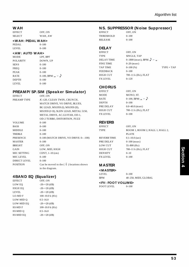
Algorithm list
Section 4
WAHEFFECT OFF, ONSELECT WAH, AW
<WAH: PEDAL WAH>PEDAL 0–100LEVEL 0–100
<AW: AUTO WAH>MODE LPF, BPFPOLARITY DOWN, UPSENS 0–100FREQ 0–100PEAK 0–100RATE 0–100, BPM: DEPTH 0–100LEVEL 0–100
PREAMP/SP.SIM (Speaker Simulator)EFFECT OFF, ONPREAMP TYPE JC-120, CLEAN TWIN, CRUNCH,
MATCH DRIVE, VO DRIVE, BLUES, BG LEAD, MS1959 (I), MS1959 (II), MS1959 (I+II), SLDN LEAD, METAL 5150, METAL DRIVE, AC.GUITAR, OD-1, OD-2 TURBO, DISTORTION, FUZZ
VOLUME 0–100BASS 0–100MIDDLE 0–100TREBLE 0–100PRESENCE 0–100 (MATCH DRIVE, VO DRIVE: 0– -100)MASTER 0–100BRIGHT OFF, ONGAIN LOW, MID, HIGHMIC SETTING CENT, 1–10 (cm)MIC LEVEL 0–100DIRECT LEVEL 0–100POSITION Can be moved to the ( ) locations shown
in the diagram.
4BAND EQ (Equalizer)EFFECT OFF, ONLOW EQ -20–+20 (dB)HIGH EQ -20–+20 (dB)LEVEL -20–+20 (dB)LO-MD F 100–10.0 k (Hz)LOW-MID Q 0.5–16.0LOW-MID EQ -20–+20 (dB)HI-MD F 100–10.0 k (Hz)HI-MID Q 0.5–16.0HI-MID EQ -20–+20 (dB)
NS. SUPPRESSOR (Noise Suppressor)EFFECT OFF, ONTHRESHOLD 0–100RELEASE 0–100
DELAYEFFECT OFF, ONTYPE SINGLE, TAPDELAY TIME 0–1800 (msec), BPM: FINE TIME 0–20 (msec)TAP TIME 0–100 (%) TYPE = TAPFEEDBACK 0–100HIGH CUT 700–11 k (Hz), FLATFX LEVEL 0–120
CHORUSEFFECT OFF, ONMODE MONO, ST.RATE 0–100, BPM: DEPTH 0–100PRE DELAY 0.0–40.0 (msec)HIGH CUT 700–11 k (Hz), FLATFX LEVEL 0–100
REVERBEFFECT OFF, ONTYPE ROOM 1, ROOM 2, HALL 1, HALL 2,
PLATEREVERB TIME 0.1–10.0 (sec)PRE DELAY 0–100 (msec)LOW CUT 55–800 (Hz)HIGH CUT 700–11 k (Hz), FLATDENSITY 0–10FX LEVEL 0–100
MASTER<MASTER>LEVEL 0–100BPM 40–250, MIDI, GLOBAL
<FV: FOOT VOLUME>FOOT LEVEL 0–100
53
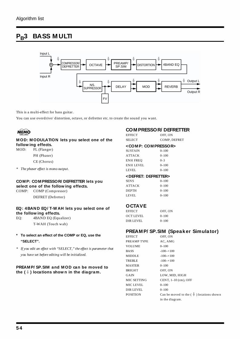
Algorithm list
PB3 BASS MULTI
fig.4-233
This is a multi-effect for bass guitar.
You can use overdrive/distortion, octave, or defretter etc. to create the sound you want.
MOD: MODULATION lets you select one of the following effects.MOD: FL (Flanger)
PH (Phaser)
CE (Chorus)
* The phaser effect is mono output.
COMP: COMPRESSOR/DEFRETTER lets you select one of the following effects.COMP: COMP (Compressor)
DEFRET (Defretter)
EQ: 4BAND EQ/T-WAH lets you select one of the following effects.EQ: 4BAND EQ (Equalizer)
T-WAH (Touch wah)
* To select an effect of the COMP or EQ, use the
“SELECT”.
* If you edit an effect with “SELECT,” the effect is parameter that
you have set before editing will be initialized.
PREAMP/SP.SIM and MOD can be moved to the ( ) locations shown in the diagram.
COMPRESSOR/DEFRETTEREFFECT OFF, ONSELECT COMP, DEFRET
<COMP: COMPRESSOR>SUSTAIN 0–100ATTACK 0–100ENH FREQ 0–3ENH LEVEL 0–100LEVEL 0–100
<DEFRET: DEFRETTER>SENS 0–100ATTACK 0–100DEPTH 0–100LEVEL 0–100
OCTAVEEFFECT OFF, ONOCT LEVEL 0–100DIR LEVEL 0–100
PREAMP/SP.SIM (Speaker Simulator)EFFECT OFF, ONPREAMP TYPE AC, AMGVOLUME 0–100BASS -100–+100MIDDLE -100–+100TREBLE -100–+100MASTER 0–100BRIGHT OFF, ONGAIN LOW, MID, HIGHMIC SETTING CENT, 1–10 (cm), OFFMIC LEVEL 0–100DIR LEVEL 0–100POSITION Can be moved to the ( ) locations shown
in the diagram.
Input L
Input R
COMPRESSOR/DEFRETTER
NS.SUPPRESSOR
OCTAVE DISTORTION
DELAY MOD REVERB
Output L
Output R
PREAMP/SP.SIM
4BAND EQ
FV
54
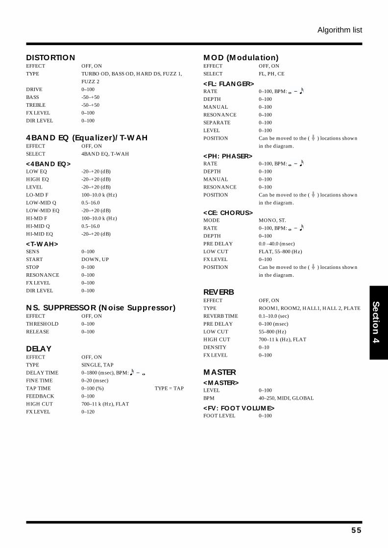
Algorithm list
Section 4
DISTORTIONEFFECT OFF, ONTYPE TURBO OD, BASS OD, HARD DS, FUZZ 1,
FUZZ 2DRIVE 0–100BASS -50–+50TREBLE -50–+50FX LEVEL 0–100DIR LEVEL 0–100
4BAND EQ (Equalizer)/T-WAHEFFECT OFF, ONSELECT 4BAND EQ, T-WAH
<4BAND EQ>LOW EQ -20–+20 (dB)HIGH EQ -20–+20 (dB)LEVEL -20–+20 (dB)LO-MD F 100–10.0 k (Hz)LOW-MID Q 0.5–16.0LOW-MID EQ -20–+20 (dB)HI-MD F 100–10.0 k (Hz)HI-MID Q 0.5–16.0HI-MID EQ -20–+20 (dB)
<T-WAH>SENS 0–100START DOWN, UPSTOP 0–100RESONANCE 0–100FX LEVEL 0–100DIR LEVEL 0–100
NS. SUPPRESSOR (Noise Suppressor)EFFECT OFF, ONTHRESHOLD 0–100RELEASE 0–100
DELAYEFFECT OFF, ONTYPE SINGLE, TAPDELAY TIME 0–1800 (msec), BPM: FINE TIME 0–20 (msec)TAP TIME 0–100 (%) TYPE = TAPFEEDBACK 0–100HIGH CUT 700–11 k (Hz), FLATFX LEVEL 0–120
MOD (Modulation)EFFECT OFF, ONSELECT FL, PH, CE
<FL: FLANGER>RATE 0–100, BPM: DEPTH 0–100MANUAL 0–100RESONANCE 0–100SEPARATE 0–100LEVEL 0–100POSITION Can be moved to the ( ) locations shown
in the diagram.
<PH: PHASER>RATE 0–100, BPM: DEPTH 0–100MANUAL 0–100RESONANCE 0–100POSITION Can be moved to the ( ) locations shown
in the diagram.
<CE: CHORUS>MODE MONO, ST.RATE 0–100, BPM: DEPTH 0–100PRE DELAY 0.0 –40.0 (msec)LOW CUT FLAT, 55–800 (Hz)FX LEVEL 0–100POSITION Can be moved to the ( ) locations shown
in the diagram.
REVERBEFFECT OFF, ONTYPE ROOM1, ROOM2, HALL1, HALL 2, PLATEREVERB TIME 0.1–10.0 (sec)PRE DELAY 0–100 (msec)LOW CUT 55–800 (Hz)HIGH CUT 700–11 k (Hz), FLATDENSITY 0–10FX LEVEL 0–100
MASTER<MASTER>LEVEL 0–100BPM 40–250, MIDI, GLOBAL
<FV: FOOT VOLUME>FOOT LEVEL 0–100
55
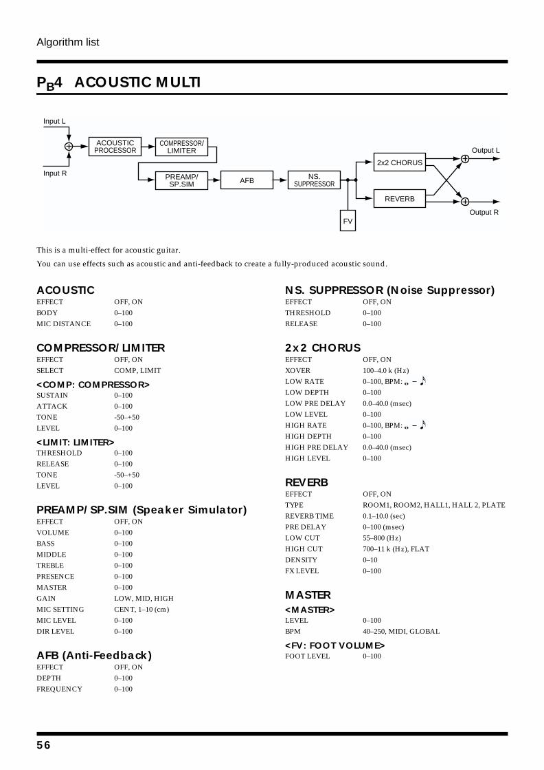
Algorithm list
PB4 ACOUSTIC MULTI
fig.4-234
This is a multi-effect for acoustic guitar.
You can use effects such as acoustic and anti-feedback to create a fully-produced acoustic sound.
ACOUSTICEFFECT OFF, ONBODY 0–100MIC DISTANCE 0–100
COMPRESSOR/LIMITEREFFECT OFF, ONSELECT COMP, LIMIT
<COMP: COMPRESSOR>SUSTAIN 0–100ATTACK 0–100TONE -50–+50LEVEL 0–100
<LIMIT: LIMITER>THRESHOLD 0–100RELEASE 0–100TONE -50–+50LEVEL 0–100
PREAMP/SP.SIM (Speaker Simulator)EFFECT OFF, ONVOLUME 0–100BASS 0–100MIDDLE 0–100TREBLE 0–100PRESENCE 0–100MASTER 0–100GAIN LOW, MID, HIGHMIC SETTING CENT, 1–10 (cm)MIC LEVEL 0–100DIR LEVEL 0–100
AFB (Anti-Feedback)EFFECT OFF, ONDEPTH 0–100FREQUENCY 0–100
NS. SUPPRESSOR (Noise Suppressor)EFFECT OFF, ONTHRESHOLD 0–100RELEASE 0–100
2x2 CHORUSEFFECT OFF, ONXOVER 100–4.0 k (Hz)LOW RATE 0–100, BPM: LOW DEPTH 0–100LOW PRE DELAY 0.0–40.0 (msec)LOW LEVEL 0–100HIGH RATE 0–100, BPM: HIGH DEPTH 0–100HIGH PRE DELAY 0.0–40.0 (msec)HIGH LEVEL 0–100
REVERBEFFECT OFF, ONTYPE ROOM1, ROOM2, HALL1, HALL 2, PLATEREVERB TIME 0.1–10.0 (sec)PRE DELAY 0–100 (msec)LOW CUT 55–800 (Hz)HIGH CUT 700–11 k (Hz), FLATDENSITY 0–10FX LEVEL 0–100
MASTER<MASTER>LEVEL 0–100BPM 40–250, MIDI, GLOBAL
<FV: FOOT VOLUME>FOOT LEVEL 0–100
Output L
Output R
2x2 CHORUS
REVERB
NS.SUPPRESSOR
ACOUSTICPROCESSOR
AFBPREAMP/SP.SIM
Input L
Input R
FV
COMPRESSOR/LIMITER
56
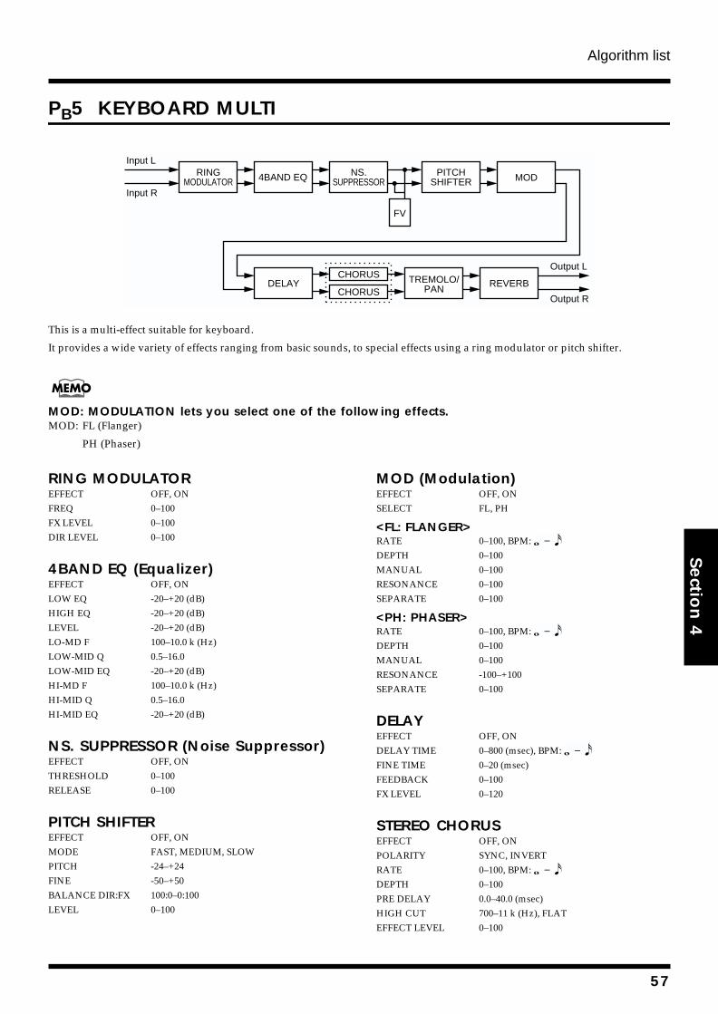
Algorithm list
Section 4
PB5 KEYBOARD MULTI
fig.4-211
This is a multi-effect suitable for keyboard.
It provides a wide variety of effects ranging from basic sounds, to special effects using a ring modulator or pitch shifter.
MOD: MODULATION lets you select one of the following effects.MOD: FL (Flanger)
PH (Phaser)
RING MODULATOREFFECT OFF, ONFREQ 0–100FX LEVEL 0–100DIR LEVEL 0–100
4BAND EQ (Equalizer)EFFECT OFF, ONLOW EQ -20–+20 (dB)HIGH EQ -20–+20 (dB)LEVEL -20–+20 (dB)LO-MD F 100–10.0 k (Hz)LOW-MID Q 0.5–16.0LOW-MID EQ -20–+20 (dB)HI-MD F 100–10.0 k (Hz)HI-MID Q 0.5–16.0HI-MID EQ -20–+20 (dB)
NS. SUPPRESSOR (Noise Suppressor)EFFECT OFF, ONTHRESHOLD 0–100RELEASE 0–100
PITCH SHIFTEREFFECT OFF, ONMODE FAST, MEDIUM, SLOWPITCH -24–+24FINE -50–+50BALANCE DIR:FX 100:0–0:100LEVEL 0–100
MOD (Modulation)EFFECT OFF, ONSELECT FL, PH
<FL: FLANGER>RATE 0–100, BPM: DEPTH 0–100MANUAL 0–100RESONANCE 0–100SEPARATE 0–100
<PH: PHASER>RATE 0–100, BPM: DEPTH 0–100MANUAL 0–100RESONANCE -100–+100SEPARATE 0–100
DELAYEFFECT OFF, ONDELAY TIME 0–800 (msec), BPM: FINE TIME 0–20 (msec)FEEDBACK 0–100FX LEVEL 0–120
STEREO CHORUSEFFECT OFF, ONPOLARITY SYNC, INVERTRATE 0–100, BPM: DEPTH 0–100PRE DELAY 0.0–40.0 (msec)HIGH CUT 700–11 k (Hz), FLATEFFECT LEVEL 0–100
RINGMODULATOR 4BAND EQ PITCH
SHIFTERNS.
SUPPRESSOR
CHORUS TREMOLO/PAN
REVERB
Output L
Output R
Input L
Input R
MOD
FV
CHORUSDELAY
57
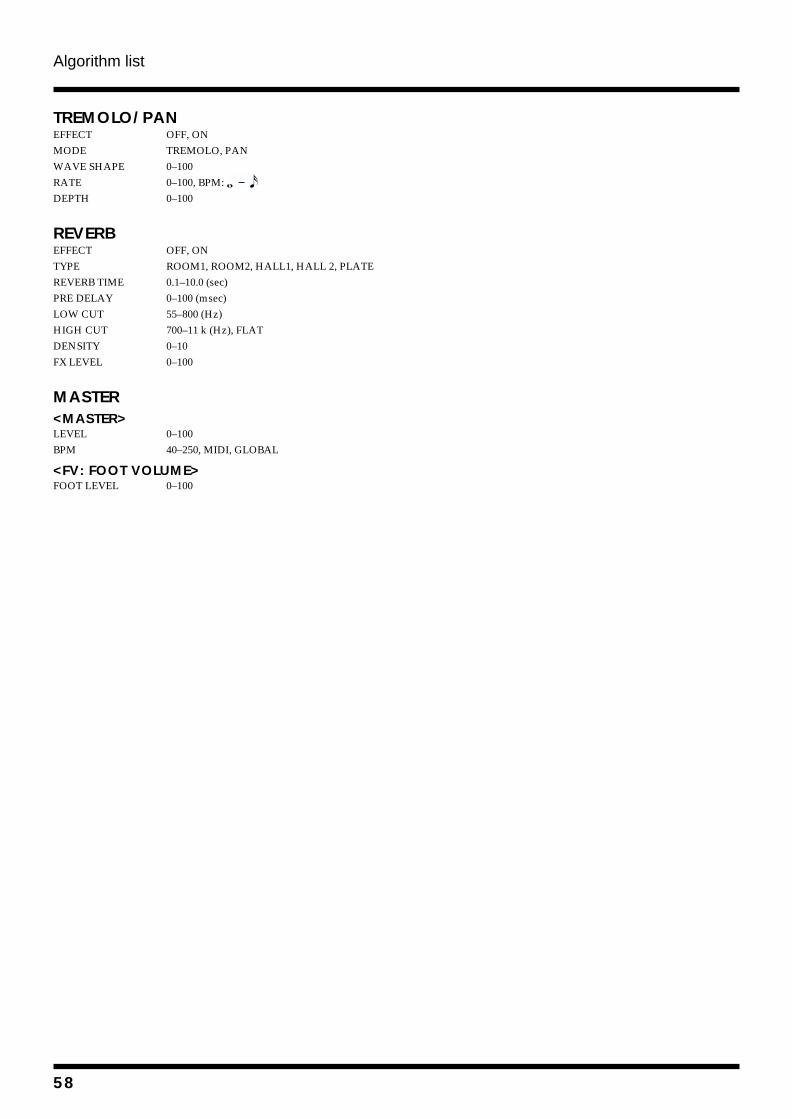
Algorithm list
TREMOLO/PANEFFECT OFF, ONMODE TREMOLO, PANWAVE SHAPE 0–100RATE 0–100, BPM: DEPTH 0–100
REVERBEFFECT OFF, ONTYPE ROOM1, ROOM2, HALL1, HALL 2, PLATEREVERB TIME 0.1–10.0 (sec)PRE DELAY 0–100 (msec)LOW CUT 55–800 (Hz)HIGH CUT 700–11 k (Hz), FLATDENSITY 0–10FX LEVEL 0–100
MASTER<MASTER>LEVEL 0–100BPM 40–250, MIDI, GLOBAL
<FV: FOOT VOLUME>FOOT LEVEL 0–100
58
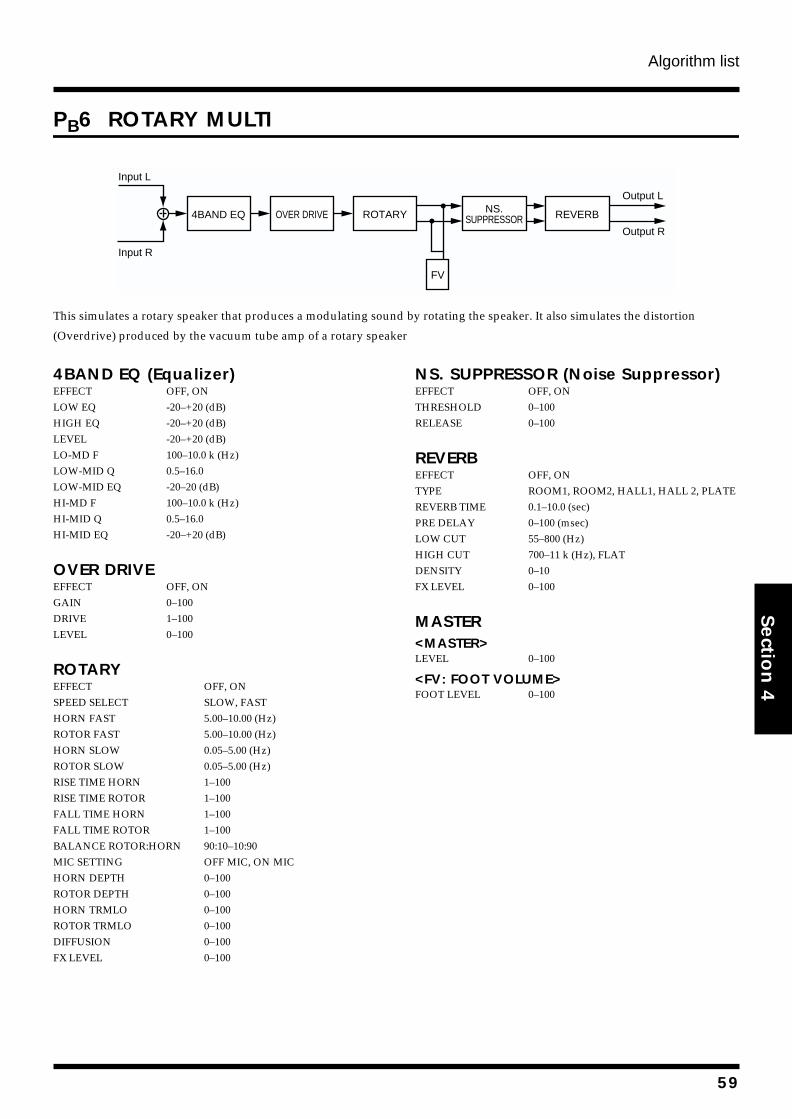
Algorithm list
Section 4
PB6 ROTARY MULTI
fig.4-212
This simulates a rotary speaker that produces a modulating sound by rotating the speaker. It also simulates the distortion
(Overdrive) produced by the vacuum tube amp of a rotary speaker
4BAND EQ (Equalizer)EFFECT OFF, ONLOW EQ -20–+20 (dB)HIGH EQ -20–+20 (dB)LEVEL -20–+20 (dB)LO-MD F 100–10.0 k (Hz)LOW-MID Q 0.5–16.0LOW-MID EQ -20–20 (dB)HI-MD F 100–10.0 k (Hz)HI-MID Q 0.5–16.0HI-MID EQ -20–+20 (dB)
OVER DRIVEEFFECT OFF, ONGAIN 0–100DRIVE 1–100LEVEL 0–100
ROTARYEFFECT OFF, ONSPEED SELECT SLOW, FASTHORN FAST 5.00–10.00 (Hz)ROTOR FAST 5.00–10.00 (Hz)HORN SLOW 0.05–5.00 (Hz)ROTOR SLOW 0.05–5.00 (Hz)RISE TIME HORN 1–100RISE TIME ROTOR 1–100FALL TIME HORN 1–100FALL TIME ROTOR 1–100BALANCE ROTOR:HORN 90:10–10:90MIC SETTING OFF MIC, ON MICHORN DEPTH 0–100ROTOR DEPTH 0–100HORN TRMLO 0–100ROTOR TRMLO 0–100DIFFUSION 0–100FX LEVEL 0–100
NS. SUPPRESSOR (Noise Suppressor)EFFECT OFF, ONTHRESHOLD 0–100RELEASE 0–100
REVERBEFFECT OFF, ONTYPE ROOM1, ROOM2, HALL1, HALL 2, PLATEREVERB TIME 0.1–10.0 (sec)PRE DELAY 0–100 (msec)LOW CUT 55–800 (Hz)HIGH CUT 700–11 k (Hz), FLATDENSITY 0–10FX LEVEL 0–100
MASTER<MASTER>LEVEL 0–100
<FV: FOOT VOLUME>FOOT LEVEL 0–100
Output L
Output R
Input L
Input R
4BAND EQ OVER DRIVE NS.SUPPRESSORROTARY REVERB
FV
59
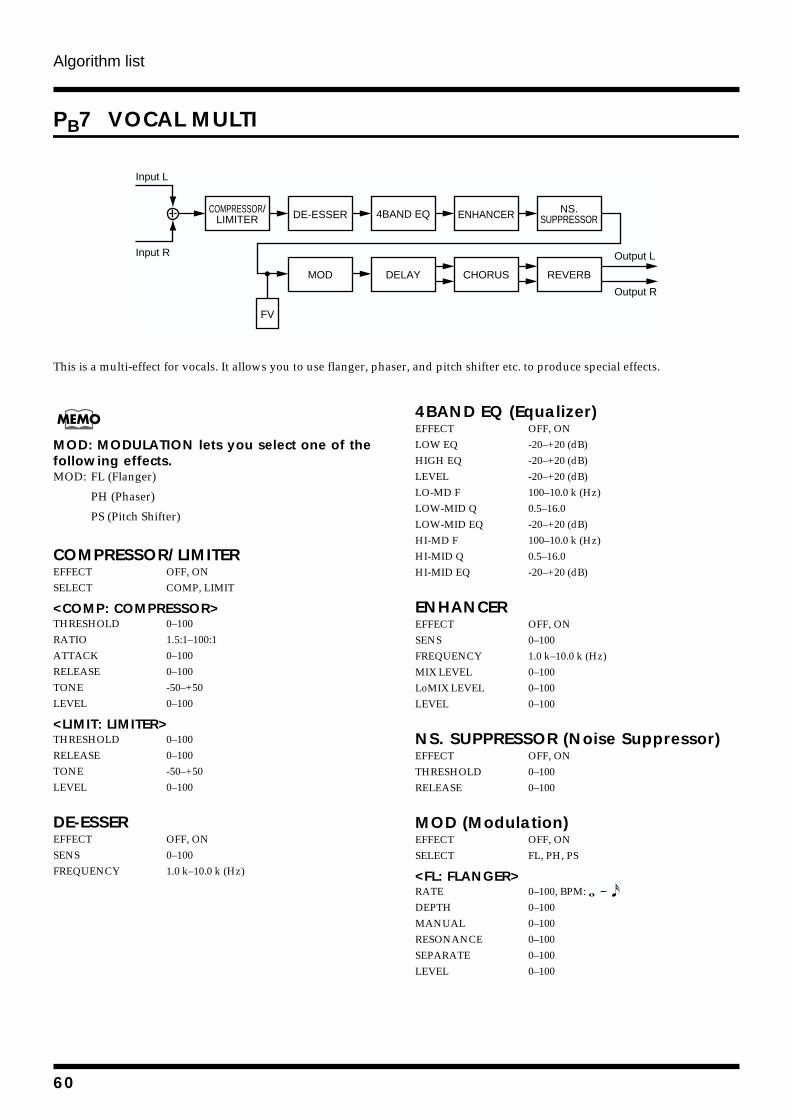
Algorithm list
PB7 VOCAL MULTI
fig.4-210
This is a multi-effect for vocals. It allows you to use flanger, phaser, and pitch shifter etc. to produce special effects.
MOD: MODULATION lets you select one of the following effects.MOD: FL (Flanger)
PH (Phaser)
PS (Pitch Shifter)
COMPRESSOR/LIMITEREFFECT OFF, ONSELECT COMP, LIMIT
<COMP: COMPRESSOR>THRESHOLD 0–100RATIO 1.5:1–100:1ATTACK 0–100RELEASE 0–100TONE -50–+50LEVEL 0–100
<LIMIT: LIMITER>THRESHOLD 0–100RELEASE 0–100TONE -50–+50LEVEL 0–100
DE-ESSEREFFECT OFF, ONSENS 0–100FREQUENCY 1.0 k–10.0 k (Hz)
4BAND EQ (Equalizer)EFFECT OFF, ONLOW EQ -20–+20 (dB)HIGH EQ -20–+20 (dB)LEVEL -20–+20 (dB)LO-MD F 100–10.0 k (Hz)LOW-MID Q 0.5–16.0LOW-MID EQ -20–+20 (dB)HI-MD F 100–10.0 k (Hz)HI-MID Q 0.5–16.0HI-MID EQ -20–+20 (dB)
ENHANCEREFFECT OFF, ONSENS 0–100FREQUENCY 1.0 k–10.0 k (Hz)MIX LEVEL 0–100LoMIX LEVEL 0–100LEVEL 0–100
NS. SUPPRESSOR (Noise Suppressor)EFFECT OFF, ONTHRESHOLD 0–100RELEASE 0–100
MOD (Modulation)EFFECT OFF, ONSELECT FL, PH, PS
<FL: FLANGER>RATE 0–100, BPM: DEPTH 0–100MANUAL 0–100RESONANCE 0–100SEPARATE 0–100LEVEL 0–100
Input L
Input R
COMPRESSOR/LIMITER DE-ESSER ENHANCER4BAND EQ
MOD DELAY CHORUS REVERB
Output L
Output R
NS.SUPPRESSOR
FV
60
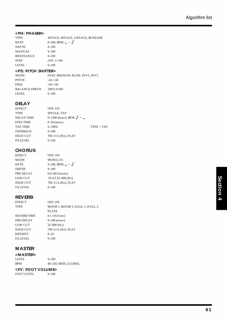
Algorithm list
Section 4
<PH: PHASER>TYPE 4STAGE, 8STAGE, 12STAGE, BI-PHASERATE 0–100, BPM: DEPTH 0–100MANUAL 0–100RESONANCE 0–100STEP OFF, 1–100LEVEL 0–100
<PS: PITCH SHIFTER>MODE FAST, MEDIUM, SLOW, INV1, INV2PITCH -24–+24FINE -50–+50BALANCE DIR:FX 100:0–0:100LEVEL 0–100
DELAYEFFECT OFF, ONTYPE SINGLE, TAPDELAY TIME 0–1200 (msec), BPM: FINE TIME 0–20 (msec)TAP TIME 0–100% TYPE = TAPFEEDBACK 0–100HIGH CUT 700–11 k (Hz), FLATFX LEVEL 0–120
CHORUSEFFECT OFF, ONMODE MONO, ST.RATE 0–100, BPM: DEPTH 0–100PRE DELAY 0.0–40.0 (msec)LOW CUT FLAT,55–800 (Hz)HIGH CUT 700–11 k (Hz), FLATFX LEVEL 0–100
REVERBEFFECT OFF, ONTYPE ROOM 1, ROOM 2, HALL 1, HALL 2,
PLATEREVERB TIME 0.1–10.0 (sec)PRE DELAY 0–100 (msec)LOW CUT 55–800 (Hz)HIGH CUT 700–11 k (Hz), FLATDENSITY 0–10FX LEVEL 0–100
MASTER<MASTER>LEVEL 0–100BPM 40–250, MIDI, GLOBAL
<FV: FOOT VOLUME>FOOT LEVEL 0–100
61
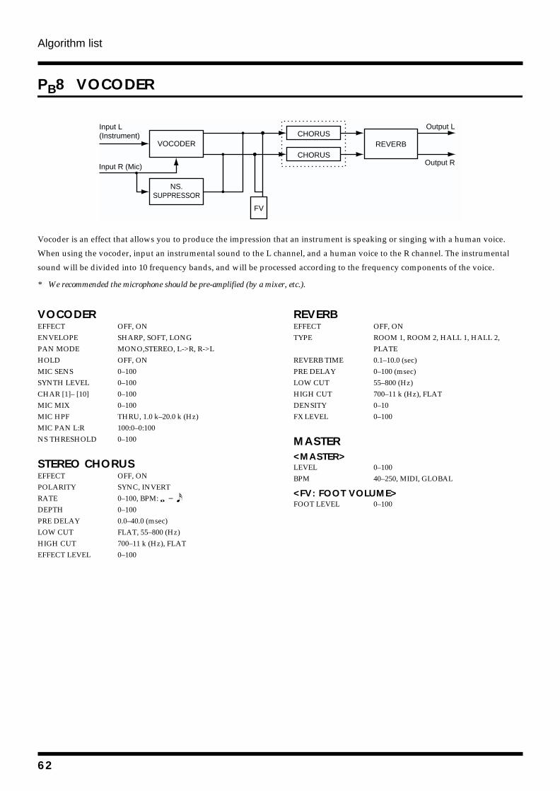
Algorithm list
PB8 VOCODER
fig.4-227
Vocoder is an effect that allows you to produce the impression that an instrument is speaking or singing with a human voice.
When using the vocoder, input an instrumental sound to the L channel, and a human voice to the R channel. The instrumental
sound will be divided into 10 frequency bands, and will be processed according to the frequency components of the voice.
* We recommended the microphone should be pre-amplified (by a mixer, etc.).
VOCODEREFFECT OFF, ONENVELOPE SHARP, SOFT, LONGPAN MODE MONO,STEREO, L->R, R->LHOLD OFF, ONMIC SENS 0–100SYNTH LEVEL 0–100CHAR [1]– [10] 0–100MIC MIX 0–100MIC HPF THRU, 1.0 k–20.0 k (Hz)MIC PAN L:R 100:0–0:100NS THRESHOLD 0–100
STEREO CHORUSEFFECT OFF, ONPOLARITY SYNC, INVERTRATE 0–100, BPM: DEPTH 0–100PRE DELAY 0.0–40.0 (msec)LOW CUT FLAT, 55–800 (Hz)HIGH CUT 700–11 k (Hz), FLATEFFECT LEVEL 0–100
REVERBEFFECT OFF, ONTYPE ROOM 1, ROOM 2, HALL 1, HALL 2,
PLATEREVERB TIME 0.1–10.0 (sec)PRE DELAY 0–100 (msec)LOW CUT 55–800 (Hz)HIGH CUT 700–11 k (Hz), FLATDENSITY 0–10FX LEVEL 0–100
MASTER<MASTER>LEVEL 0–100BPM 40–250, MIDI, GLOBAL
<FV: FOOT VOLUME>FOOT LEVEL 0–100
Input L(Instrument)
Input R (Mic)
Output L
Output R
FV
VOCODER
NS.SUPPRESSOR
CHORUS
CHORUSREVERB
62
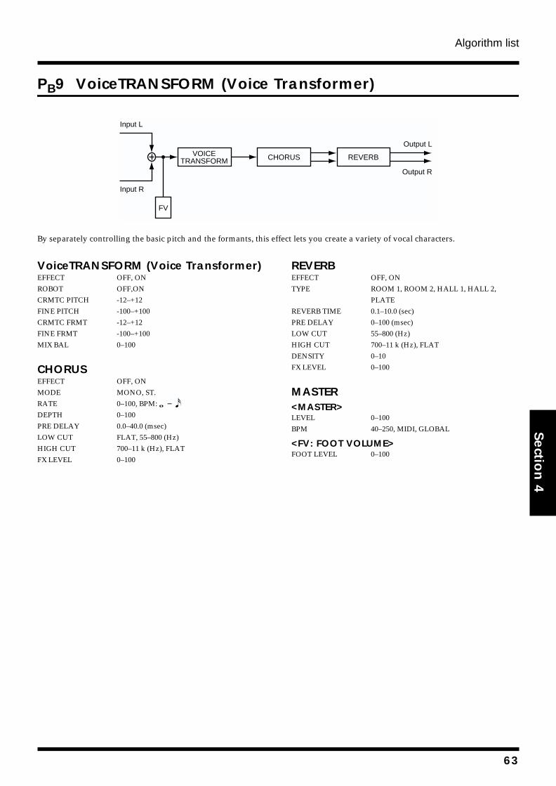
Algorithm list
Section 4
PB9 VoiceTRANSFORM (Voice Transformer)
fig.4-226
By separately controlling the basic pitch and the formants, this effect lets you create a variety of vocal characters.
VoiceTRANSFORM (Voice Transformer)EFFECT OFF, ONROBOT OFF,ONCRMTC PITCH -12–+12FINE PITCH -100–+100CRMTC FRMT -12–+12FINE FRMT -100–+100MIX BAL 0–100
CHORUSEFFECT OFF, ONMODE MONO, ST.RATE 0–100, BPM: DEPTH 0–100PRE DELAY 0.0–40.0 (msec)LOW CUT FLAT, 55–800 (Hz)HIGH CUT 700–11 k (Hz), FLATFX LEVEL 0–100
REVERBEFFECT OFF, ONTYPE ROOM 1, ROOM 2, HALL 1, HALL 2,
PLATEREVERB TIME 0.1–10.0 (sec)PRE DELAY 0–100 (msec)LOW CUT 55–800 (Hz)HIGH CUT 700–11 k (Hz), FLATDENSITY 0–10FX LEVEL 0–100
MASTER<MASTER>LEVEL 0–100BPM 40–250, MIDI, GLOBAL
<FV: FOOT VOLUME>FOOT LEVEL 0–100
Input L
Input R
Output R
Output L
FV
VOICETRANSFORM CHORUS REVERB
63
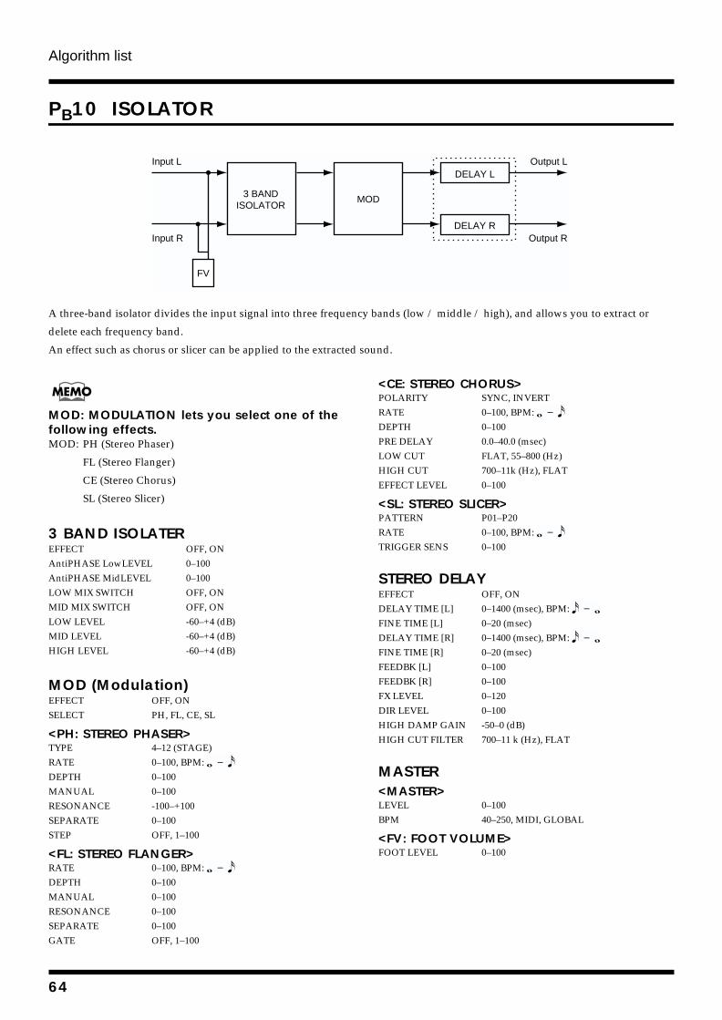
Algorithm list
PB10 ISOLATOR
fig.4-229
A three-band isolator divides the input signal into three frequency bands (low / middle / high), and allows you to extract or
delete each frequency band.
An effect such as chorus or slicer can be applied to the extracted sound.
MOD: MODULATION lets you select one of the following effects.MOD: PH (Stereo Phaser)
FL (Stereo Flanger)
CE (Stereo Chorus)
SL (Stereo Slicer)
3 BAND ISOLATEREFFECT OFF, ONAntiPHASE LowLEVEL 0–100AntiPHASE MidLEVEL 0–100LOW MIX SWITCH OFF, ONMID MIX SWITCH OFF, ONLOW LEVEL -60–+4 (dB)MID LEVEL -60–+4 (dB)HIGH LEVEL -60–+4 (dB)
MOD (Modulation)EFFECT OFF, ONSELECT PH, FL, CE, SL
<PH: STEREO PHASER>TYPE 4–12 (STAGE)RATE 0–100, BPM: DEPTH 0–100MANUAL 0–100RESONANCE -100–+100SEPARATE 0–100STEP OFF, 1–100
<FL: STEREO FLANGER>RATE 0–100, BPM: DEPTH 0–100MANUAL 0–100RESONANCE 0–100SEPARATE 0–100GATE OFF, 1–100
<CE: STEREO CHORUS>POLARITY SYNC, INVERTRATE 0–100, BPM: DEPTH 0–100PRE DELAY 0.0–40.0 (msec)LOW CUT FLAT, 55–800 (Hz)HIGH CUT 700–11k (Hz), FLATEFFECT LEVEL 0–100
<SL: STEREO SLICER>PATTERN P01–P20RATE 0–100, BPM: TRIGGER SENS 0–100
STEREO DELAYEFFECT OFF, ONDELAY TIME [L] 0–1400 (msec), BPM: FINE TIME [L] 0–20 (msec)DELAY TIME [R] 0–1400 (msec), BPM: FINE TIME [R] 0–20 (msec)FEEDBK [L] 0–100FEEDBK [R] 0–100FX LEVEL 0–120DIR LEVEL 0–100HIGH DAMP GAIN -50–0 (dB)HIGH CUT FILTER 700–11 k (Hz), FLAT
MASTER<MASTER>LEVEL 0–100BPM 40–250, MIDI, GLOBAL
<FV: FOOT VOLUME>FOOT LEVEL 0–100
Input L
Input R
Output L
Output R
DELAY L
DELAY R
FV
3 BANDISOLATOR
MOD
64
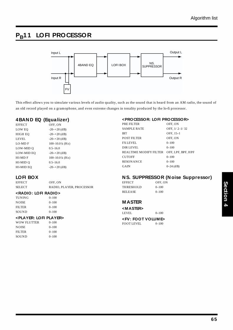
Algorithm list
Section 4
PB11 LOFI PROCESSOR
fig.4-216a
This effect allows you to simulate various levels of audio quality, such as the sound that is heard from an AM radio, the sound of
an old record played on a gramophone, and even extreme changes in tonality produced by the lo-fi processor.
4BAND EQ (Equalizer)EFFECT OFF, ONLOW EQ -20–+20 (dB)HIGH EQ -20–+20 (dB)LEVEL -20–+20 (dB)LO-MD F 100–10.0 k (Hz)LOW-MID Q 0.5–16.0LOW-MID EQ -20–+20 (dB)HI-MD F 100–10.0 k (Hz)HI-MID Q 0.5–16.0HI-MID EQ -20–+20 (dB)
LOFI BOXEFFECT OFF, ONSELECT RADIO, PLAYER, PROCESSOR
<RADIO: LOFI RADIO>TUNING 0–100NOISE 0–100FILTER 0–100SOUND 0–100
<PLAYER: LOFI PLAYER>WOW FLUTTER 0–100NOISE 0–100FILTER 0–100SOUND 0–100
<PROCESSOR: LOFI PROCESSOR>PRE FILTER OFF, ONSAMPLE RATE OFF, 1/2–1/32BIT OFF, 15–1POST FILTER OFF, ONFX LEVEL 0–100DIR LEVEL 0–100REALTIME MODIFY FILTER OFF, LPF, BPF, HPFCUTOFF 0–100RESONANCE 0–100GAIN 0–24 (dB)
NS. SUPPRESSOR (Noise Suppressor)EFFECT OFF, ONTHRESHOLD 0–100RELEASE 0–100
MASTER<MASTER>LEVEL 0–100
<FV: FOOT VOLUME>FOOT LEVEL 0–100
Input L
Input R
Output L
Output R
LOFI BOX
FV
4BAND EQ NS.SUPPRESSOR
65
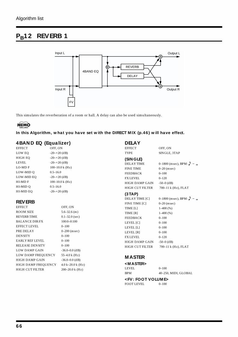
Algorithm list
PB12 REVERB 1
fig.4-236
This simulates the reverberation of a room or hall. A delay can also be used simultaneously.
In this Algorithm, what you have set with the DIRECT MIX (p.46) will have effect.
4BAND EQ (Equalizer)EFFECT OFF, ONLOW EQ -20–+20 (dB)HIGH EQ -20–+20 (dB)LEVEL -20–+20 (dB)LO-MD F 100–10.0 k (Hz)LOW-MID Q 0.5–16.0LOW-MID EQ -20–+20 (dB)HI-MD F 100–10.0 k (Hz)HI-MID Q 0.5–16.0HI-MID EQ -20–+20 (dB)
REVERBEFFECT OFF, ONROOM SIZE 5.6–32.6 (m)REVERB TIME 0.1–32.0 (sec)BALANCE DIR:FX 100:0–0:100EFFECT LEVEL 0–100PRE DELAY 0–200 (msec)DENSITY 0–100EARLY REF LEVEL 0–100RELEASE DENSITY 0–100LOW DAMP GAIN -36.0–0.0 (dB)LOW DAMP FREQUENCY 55–4.0 k (Hz)HIGH DAMP GAIN -36.0–0.0 (dB)HIGH DAMP FREQUENCY 4.0 k–20.0 k (Hz)HIGH CUT FILTER 200–20.0 k (Hz)
DELAYEFFECT OFF, ONTYPE SINGLE, 3TAP
(SINGLE)DELAY TIME 0–1800 (msec), BPM: FINE TIME 0–20 (msec)FEEDBACK 0–100FX LEVEL 0–120HIGH DAMP GAIN -50–0 (dB)HIGH CUT FILTER 700–11 k (Hz), FLAT
(3TAP)DELAY TIME [C] 0–1800 (msec), BPM: FINE TIME [C] 0–20 (msec)TIME [L] 1–400 (%)TIME [R] 1–400 (%)FEEDBACK 0–100LEVEL [C] 0–100LEVEL [L] 0–100LEVEL [R] 0–100FX LEVEL 0–120HIGH DAMP GAIN -50–0 (dB)HIGH CUT FILTER 700–11 k (Hz), FLAT
MASTER<MASTER>LEVEL 0–100BPM 40–250, MIDI, GLOBAL
<FV: FOOT VOLUME>FOOT LEVEL 0–100
Input L
Input R
4BAND EQ
Output L
Output R
REVERB
DELAY
FV
66
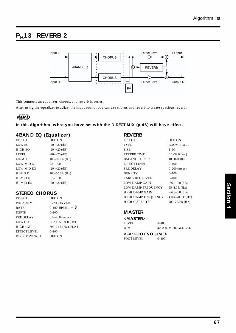
Algorithm list
Section 4
PB13 REVERB 2
fig.4-202
This connects an equalizer, chorus, and reverb in series.
After using the equalizer to adjust the input sound, you can use chorus and reverb to create spacious reverb.
In this Algorithm, what you have set with the DIRECT MIX (p.46) will have effect.
4BAND EQ (Equalizer)EFFECT OFF, ONLOW EQ -20–+20 (dB)HIGH EQ -20–+20 (dB)LEVEL -20–+20 (dB)LO-MD F 100–10.0 k (Hz)LOW-MID Q 0.5–16.0LOW-MID EQ -20–+20 (dB)HI-MD F 100–10.0 k (Hz)HI-MID Q 0.5–16.0HI-MID EQ -20–+20 (dB)
STEREO CHORUSEFFECT OFF, ONPOLARITY SYNC, INVERTRATE 0–100, BPM: DEPTH 0–100PRE DELAY 0.0–40.0 (msec)LOW CUT FLAT, 55–800 (Hz)HIGH CUT 700–11 k (Hz), FLATEFFECT LEVEL 0–100DIRECT SWITCH OFF, ON
REVERBEFFECT OFF, ONTYPE ROOM, HALLSIZE 1–10REVERB TIME 0.1–32.0 (sec)BALANCE DIR:FX 100:0–0:100EFFECT LEVEL 0–100PRE DELAY 0–200 (msec)DENSITY 0–100EARLY REF LEVEL 0–100LOW DAMP GAIN -36.0–0.0 (dB)LOW DAMP FREQUENCY 55–4.0 k (Hz)HIGH DAMP GAIN -36.0–0.0 (dB)HIGH DAMP FREQUENCY 4.0 k–20.0 k (Hz)HIGH CUT FILTER 200–20.0 k (Hz)
MASTER<MASTER>LEVEL 0–100BPM 40–250, MIDI, GLOBAL
<FV: FOOT VOLUME>FOOT LEVEL 0–100
Input L
Input R
Output L
Output RDirect Level
Direct Level
REVERB4BAND EQ
CHORUS
CHORUS
FV
67
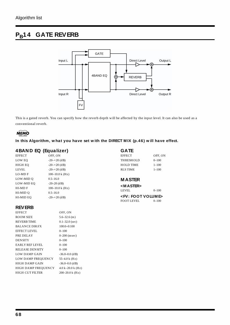
Algorithm list
PB14 GATE REVERB
fig.4-201
This is a gated reverb. You can specify how the reverb depth will be affected by the input level. It can also be used as a
conventional reverb.
In this Algorithm, what you have set with the DIRECT MIX (p.46) will have effect.
4BAND EQ (Equalizer)EFFECT OFF, ONLOW EQ -20–+20 (dB)HIGH EQ -20–+20 (dB)LEVEL -20–+20 (dB)LO-MD F 100–10.0 k (Hz)LOW-MID Q 0.5–16.0LOW-MID EQ -20–20 (dB)HI-MD F 100–10.0 k (Hz)HI-MID Q 0.5–16.0HI-MID EQ -20–+20 (dB)
REVERBEFFECT OFF, ONROOM SIZE 5.6–32.6 (m)REVERB TIME 0.1–32.0 (sec)BALANCE DIR:FX 100:0–0:100EFFECT LEVEL 0–100PRE DELAY 0–200 (msec)DENSITY 0–100EARLY REF LEVEL 0–100RELEASE DENSITY 0–100LOW DAMP GAIN -36.0–0.0 (dB)LOW DAMP FREQUENCY 55–4.0 k (Hz)HIGH DAMP GAIN -36.0–0.0 (dB)HIGH DAMP FREQUENCY 4.0 k–20.0 k (Hz)HIGH CUT FILTER 200–20.0 k (Hz)
GATEEFFECT OFF, ONTHRESHOLD 0–100HOLD TIME 1–100RLS TIME 1–100
MASTER<MASTER>LEVEL 0–100
<FV: FOOT VOLUME>FOOT LEVEL 0–100
4BAND EQ
Output L
Output R
Direct Level
Direct Level
REVERB
GATE
Input L
Input R
FV
68
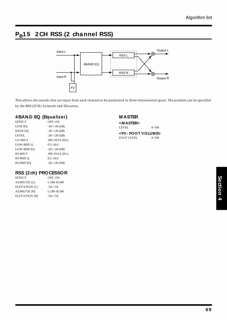
Algorithm list
Section 4
PB15 2CH RSS (2 channel RSS)
fig.4-206
This allows the sounds that are input from each channel to be positioned in three-dimensional space. The position can be specified
by the RSS (2CH) Azimuth and Elevation.
4BAND EQ (Equalizer)EFFECT OFF, ONLOW EQ -20–+20 (dB)HIGH EQ -20–+20 (dB)LEVEL -20–+20 (dB)LO-MD F 100–10.0 k (Hz)LOW-MID Q 0.5–16.0LOW-MID EQ -20–+20 (dB)HI-MD F 100–10.0 k (Hz)HI-MID Q 0.5–16.0HI-MID EQ -20–+20 (dB)
RSS (2ch) PROCESSOREFFECT OFF, ONAZIMUTH [L] L:180–R:180ELEVATION [L] -54–+54AZIMUTH [R] L:180–R:180ELEVATION [R] -54–+54
MASTER<MASTER>LEVEL 0–100
<FV: FOOT VOLUME>FOOT LEVEL 0–100
Input L
Input R
Output L
Output R
RSS L
RSS R
4BAND EQ
FV
69
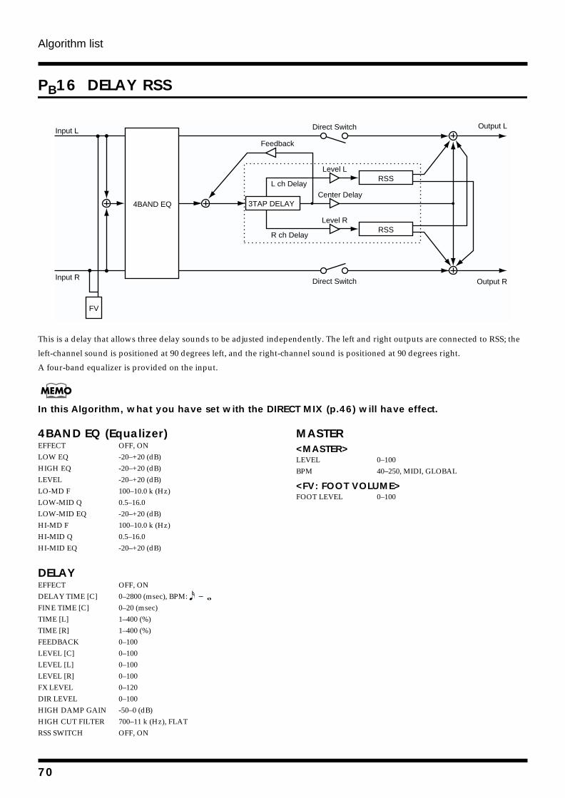
Algorithm list
PB16 DELAY RSS
fig.4-208
This is a delay that allows three delay sounds to be adjusted independently. The left and right outputs are connected to RSS; the
left-channel sound is positioned at 90 degrees left, and the right-channel sound is positioned at 90 degrees right.
A four-band equalizer is provided on the input.
In this Algorithm, what you have set with the DIRECT MIX (p.46) will have effect.
4BAND EQ (Equalizer)EFFECT OFF, ONLOW EQ -20–+20 (dB)HIGH EQ -20–+20 (dB)LEVEL -20–+20 (dB)LO-MD F 100–10.0 k (Hz)LOW-MID Q 0.5–16.0LOW-MID EQ -20–+20 (dB)HI-MD F 100–10.0 k (Hz)HI-MID Q 0.5–16.0HI-MID EQ -20–+20 (dB)
DELAYEFFECT OFF, ONDELAY TIME [C] 0–2800 (msec), BPM: FINE TIME [C] 0–20 (msec)TIME [L] 1–400 (%)TIME [R] 1–400 (%)FEEDBACK 0–100LEVEL [C] 0–100LEVEL [L] 0–100LEVEL [R] 0–100FX LEVEL 0–120DIR LEVEL 0–100HIGH DAMP GAIN -50–0 (dB)HIGH CUT FILTER 700–11 k (Hz), FLATRSS SWITCH OFF, ON
MASTER<MASTER>LEVEL 0–100BPM 40–250, MIDI, GLOBAL
<FV: FOOT VOLUME>FOOT LEVEL 0–100
Output L
Output R
3TAP DELAY
Feedback
R ch Delay
L ch Delay
Input L
Input R
RSS
RSS
4BAND EQ
Level L
Center Delay
Level R
FV
Direct Switch
Direct Switch
70
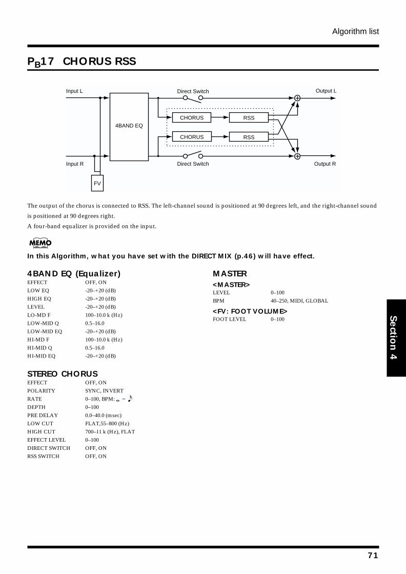
Algorithm list
Section 4
PB17 CHORUS RSS
fig.4-209
The output of the chorus is connected to RSS. The left-channel sound is positioned at 90 degrees left, and the right-channel sound
is positioned at 90 degrees right.
A four-band equalizer is provided on the input.
In this Algorithm, what you have set with the DIRECT MIX (p.46) will have effect.
4BAND EQ (Equalizer)EFFECT OFF, ONLOW EQ -20–+20 (dB)HIGH EQ -20–+20 (dB)LEVEL -20–+20 (dB)LO-MD F 100–10.0 k (Hz)LOW-MID Q 0.5–16.0LOW-MID EQ -20–+20 (dB)HI-MD F 100–10.0 k (Hz)HI-MID Q 0.5–16.0HI-MID EQ -20–+20 (dB)
STEREO CHORUSEFFECT OFF, ONPOLARITY SYNC, INVERTRATE 0–100, BPM: DEPTH 0–100PRE DELAY 0.0–40.0 (msec)LOW CUT FLAT,55–800 (Hz)HIGH CUT 700–11 k (Hz), FLATEFFECT LEVEL 0–100DIRECT SWITCH OFF, ONRSS SWITCH OFF, ON
MASTER<MASTER>LEVEL 0–100BPM 40–250, MIDI, GLOBAL
<FV: FOOT VOLUME>FOOT LEVEL 0–100
Input L
Input R
CHORUS
Output L
Output R
Direct Switch
Direct Switch
RSS4BAND EQ
RSS
FV
CHORUS
71
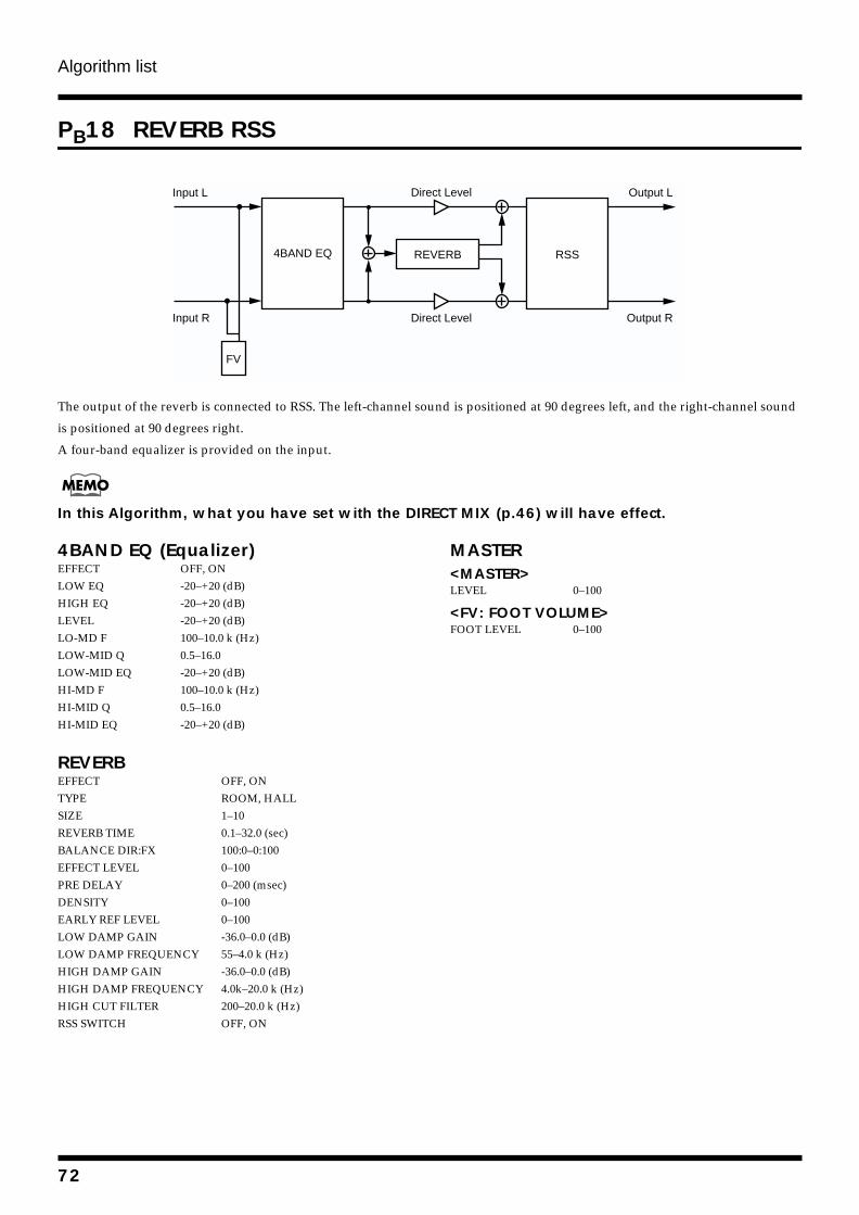
Algorithm list
PB18 REVERB RSS
fig.4-235
The output of the reverb is connected to RSS. The left-channel sound is positioned at 90 degrees left, and the right-channel sound
is positioned at 90 degrees right.
A four-band equalizer is provided on the input.
In this Algorithm, what you have set with the DIRECT MIX (p.46) will have effect.
4BAND EQ (Equalizer)EFFECT OFF, ONLOW EQ -20–+20 (dB)HIGH EQ -20–+20 (dB)LEVEL -20–+20 (dB)LO-MD F 100–10.0 k (Hz)LOW-MID Q 0.5–16.0LOW-MID EQ -20–+20 (dB)HI-MD F 100–10.0 k (Hz)HI-MID Q 0.5–16.0HI-MID EQ -20–+20 (dB)
REVERBEFFECT OFF, ONTYPE ROOM, HALLSIZE 1–10REVERB TIME 0.1–32.0 (sec)BALANCE DIR:FX 100:0–0:100EFFECT LEVEL 0–100PRE DELAY 0–200 (msec)DENSITY 0–100EARLY REF LEVEL 0–100LOW DAMP GAIN -36.0–0.0 (dB)LOW DAMP FREQUENCY 55–4.0 k (Hz)HIGH DAMP GAIN -36.0–0.0 (dB)HIGH DAMP FREQUENCY 4.0k–20.0 k (Hz)HIGH CUT FILTER 200–20.0 k (Hz)RSS SWITCH OFF, ON
MASTER<MASTER>LEVEL 0–100
<FV: FOOT VOLUME>FOOT LEVEL 0–100
Output L
Output R
Direct Level
Direct Level
RSS4BAND EQ
Input L
Input R
REVERB
FV
72
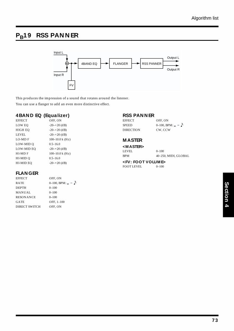
Algorithm list
Section 4
PB19 RSS PANNER
fig.4-207
This produces the impression of a sound that rotates around the listener.
You can use a flanger to add an even more distinctive effect.
4BAND EQ (Equalizer)EFFECT OFF, ONLOW EQ -20–+20 (dB)HIGH EQ -20–+20 (dB)LEVEL -20–+20 (dB)LO-MD F 100–10.0 k (Hz)LOW-MID Q 0.5–16.0LOW-MID EQ -20–+20 (dB)HI-MD F 100–10.0 k (Hz)HI-MID Q 0.5–16.0HI-MID EQ -20–+20 (dB)
FLANGEREFFECT OFF, ONRATE 0–100, BPM: DEPTH 0–100MANUAL 0–100RESONANCE 0–100GATE OFF, 1–100DIRECT SWITCH OFF, ON
RSS PANNEREFFECT OFF, ONSPEED 0–100, BPM: DIRECTION CW, CCW
MASTER<MASTER>LEVEL 0–100BPM 40–250, MIDI, GLOBAL
<FV: FOOT VOLUME>FOOT LEVEL 0–100
Output L
Output R
4BAND EQ FLANGER RSS PANNER
Input L
Input R
FV
73
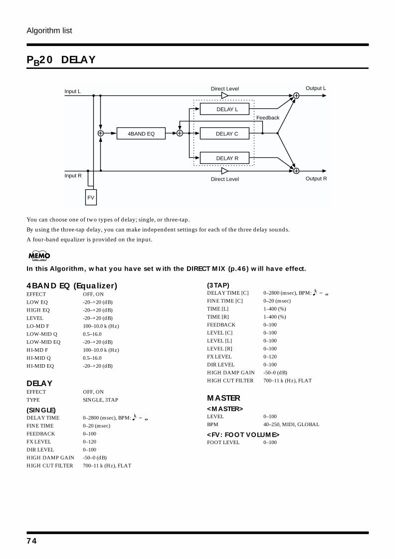
Algorithm list
PB20 DELAY
fig.4-203
You can choose one of two types of delay; single, or three-tap.
By using the three-tap delay, you can make independent settings for each of the three delay sounds.
A four-band equalizer is provided on the input.
In this Algorithm, what you have set with the DIRECT MIX (p.46) will have effect.
4BAND EQ (Equalizer)EFFECT OFF, ONLOW EQ -20–+20 (dB)HIGH EQ -20–+20 (dB)LEVEL -20–+20 (dB)LO-MD F 100–10.0 k (Hz)LOW-MID Q 0.5–16.0LOW-MID EQ -20–+20 (dB)HI-MD F 100–10.0 k (Hz)HI-MID Q 0.5–16.0HI-MID EQ -20–+20 (dB)
DELAYEFFECT OFF, ONTYPE SINGLE, 3TAP
(SINGLE)DELAY TIME 0–2800 (msec), BPM: FINE TIME 0–20 (msec)FEEDBACK 0–100FX LEVEL 0–120DIR LEVEL 0–100HIGH DAMP GAIN -50–0 (dB)HIGH CUT FILTER 700–11 k (Hz), FLAT
(3TAP)DELAY TIME [C] 0–2800 (msec), BPM: FINE TIME [C] 0–20 (msec)TIME [L] 1–400 (%)TIME [R] 1–400 (%)FEEDBACK 0–100LEVEL [C] 0–100LEVEL [L] 0–100LEVEL [R] 0–100FX LEVEL 0–120DIR LEVEL 0–100HIGH DAMP GAIN -50–0 (dB)HIGH CUT FILTER 700–11 k (Hz), FLAT
MASTER<MASTER>LEVEL 0–100BPM 40–250, MIDI, GLOBAL
<FV: FOOT VOLUME>FOOT LEVEL 0–100
DELAY C
DELAY R
DELAY L
4BAND EQ
Output L
Output R
Feedback
Direct Level
Direct Level
Input L
Input R
FV
74
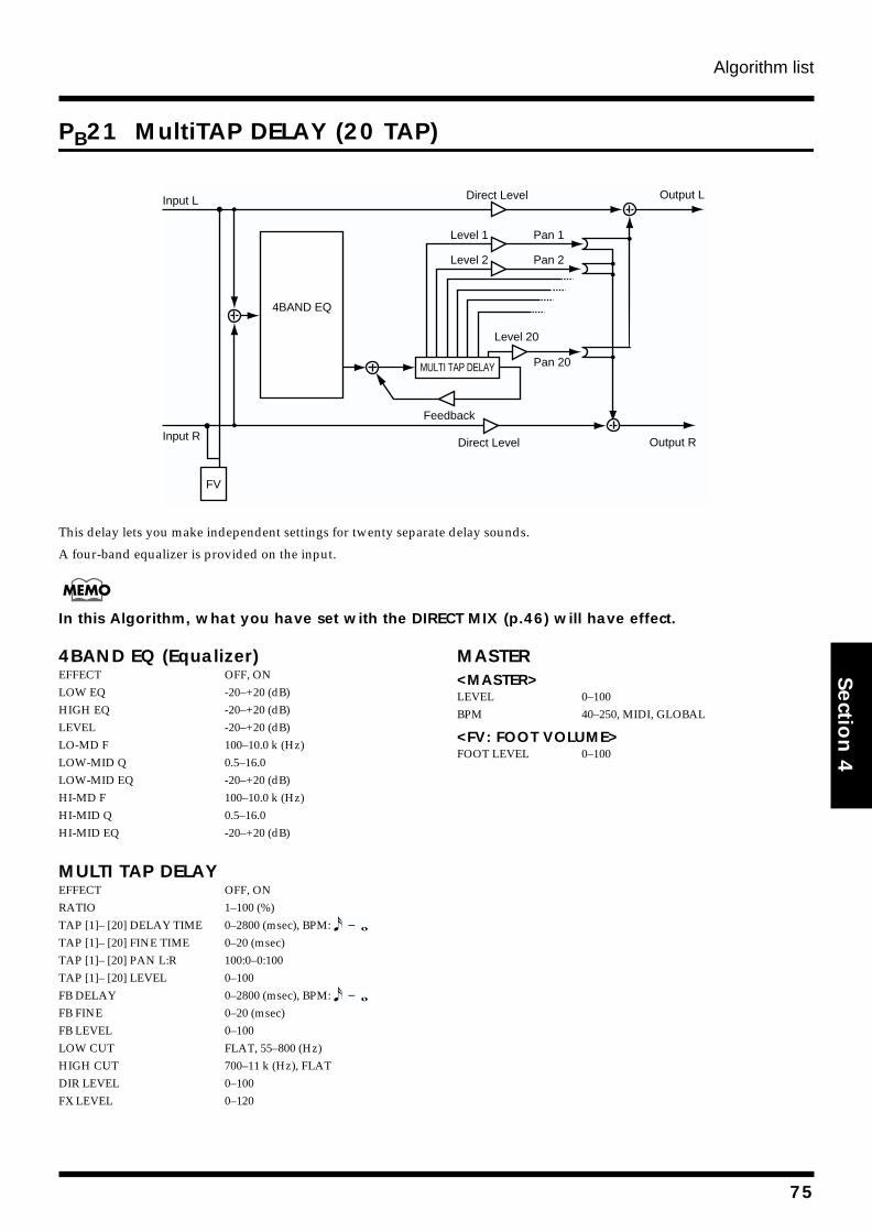
Algorithm list
Section 4
PB21 MultiTAP DELAY (20 TAP)
fig.4-223
This delay lets you make independent settings for twenty separate delay sounds.
A four-band equalizer is provided on the input.
In this Algorithm, what you have set with the DIRECT MIX (p.46) will have effect.
4BAND EQ (Equalizer)EFFECT OFF, ONLOW EQ -20–+20 (dB)HIGH EQ -20–+20 (dB)LEVEL -20–+20 (dB)LO-MD F 100–10.0 k (Hz)LOW-MID Q 0.5–16.0LOW-MID EQ -20–+20 (dB)HI-MD F 100–10.0 k (Hz)HI-MID Q 0.5–16.0HI-MID EQ -20–+20 (dB)
MULTI TAP DELAYEFFECT OFF, ONRATIO 1–100 (%)TAP [1]– [20] DELAY TIME 0–2800 (msec), BPM: TAP [1]– [20] FINE TIME 0–20 (msec)TAP [1]– [20] PAN L:R 100:0–0:100TAP [1]– [20] LEVEL 0–100FB DELAY 0–2800 (msec), BPM: FB FINE 0–20 (msec)FB LEVEL 0–100LOW CUT FLAT, 55–800 (Hz)HIGH CUT 700–11 k (Hz), FLATDIR LEVEL 0–100FX LEVEL 0–120
MASTER<MASTER>LEVEL 0–100BPM 40–250, MIDI, GLOBAL
<FV: FOOT VOLUME>FOOT LEVEL 0–100
Input R Output R
MULTI TAP DELAY
4BAND EQ
Pan 1
Pan 2
Pan 20
Feedback
Direct Level
Level 1
Level 2
Level 20
Direct Level
Input L Output L
FV
75
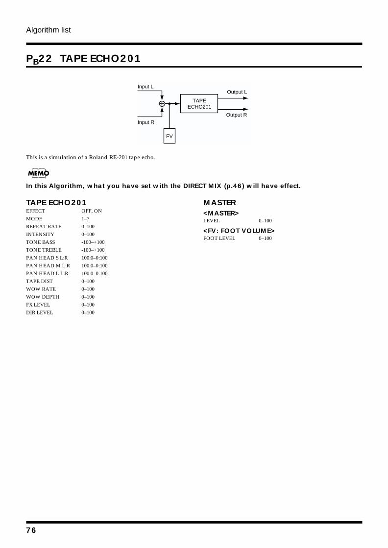
Algorithm list
PB22 TAPE ECHO201
fig.4-230
This is a simulation of a Roland RE-201 tape echo.
In this Algorithm, what you have set with the DIRECT MIX (p.46) will have effect.
TAPE ECHO201EFFECT OFF, ONMODE 1–7REPEAT RATE 0–100INTENSITY 0–100TONE BASS -100–+100TONE TREBLE -100–+100PAN HEAD S L:R 100:0–0:100PAN HEAD M L:R 100:0–0:100PAN HEAD L L:R 100:0–0:100TAPE DIST 0–100WOW RATE 0–100WOW DEPTH 0–100FX LEVEL 0–100DIR LEVEL 0–100
MASTER<MASTER>LEVEL 0–100
<FV: FOOT VOLUME>FOOT LEVEL 0–100
Input L
Input R
Output L
Output R
FV
TAPEECHO201
76
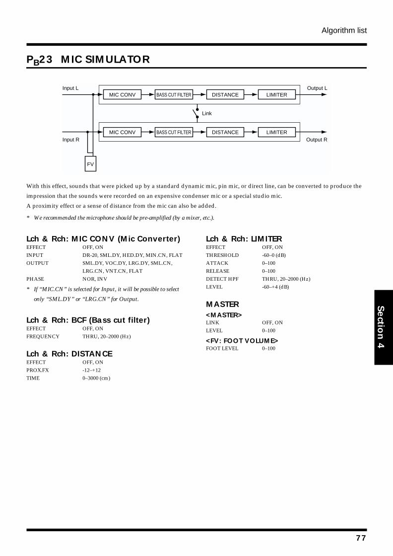
Algorithm list
Section 4
PB23 MIC SIMULATOR
fig.4-228
With this effect, sounds that were picked up by a standard dynamic mic, pin mic, or direct line, can be converted to produce the
impression that the sounds were recorded on an expensive condenser mic or a special studio mic.
A proximity effect or a sense of distance from the mic can also be added.
* We recommended the microphone should be pre-amplified (by a mixer, etc.).
Lch & Rch: MIC CONV (Mic Converter)EFFECT OFF, ONINPUT DR-20, SML.DY, HED.DY, MIN.CN, FLATOUTPUT SML.DY, VOC.DY, LRG.DY, SML.CN,
LRG.CN, VNT.CN, FLATPHASE NOR, INV
* If “MIC.CN” is selected for Input, it will be possible to select
only “SML.DY” or “LRG.CN” for Output.
Lch & Rch: BCF (Bass cut filter)EFFECT OFF, ONFREQUENCY THRU, 20–2000 (Hz)
Lch & Rch: DISTANCEEFFECT OFF, ONPROX.FX -12–+12TIME 0–3000 (cm)
Lch & Rch: LIMITEREFFECT OFF, ONTHRESHOLD -60–0 (dB)ATTACK 0–100RELEASE 0–100DETECT HPF THRU, 20–2000 (Hz)LEVEL -60–+4 (dB)
MASTER<MASTER>LINK OFF, ONLEVEL 0–100
<FV: FOOT VOLUME>FOOT LEVEL 0–100
MIC CONV DISTANCE LIMITER
MIC CONV DISTANCE LIMITER
Link
Input L
Input R
Output L
Output R
FV
BASS CUT FILTER
BASS CUT FILTER
77
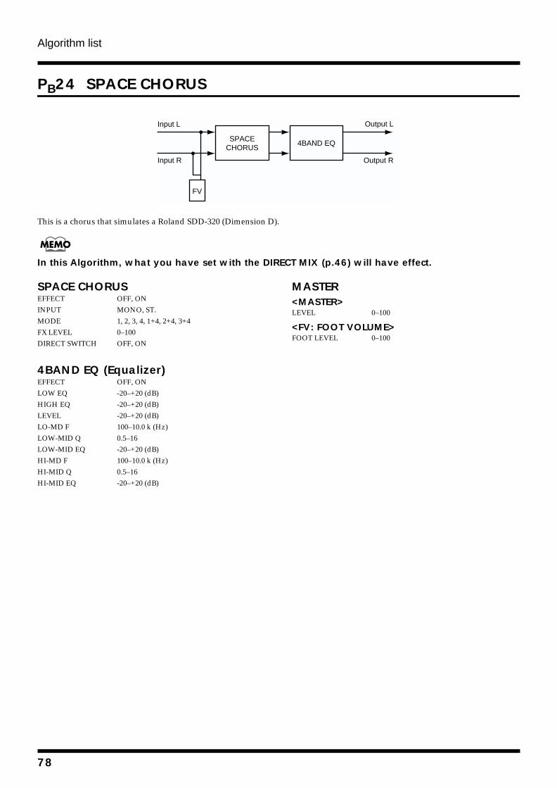
Algorithm list
PB24 SPACE CHORUS
fig.4-217
This is a chorus that simulates a Roland SDD-320 (Dimension D).
In this Algorithm, what you have set with the DIRECT MIX (p.46) will have effect.
SPACE CHORUSEFFECT OFF, ONINPUT MONO, ST.MODE 1, 2, 3, 4, 1+4, 2+4, 3+4FX LEVEL 0–100DIRECT SWITCH OFF, ON
4BAND EQ (Equalizer)EFFECT OFF, ONLOW EQ -20–+20 (dB)HIGH EQ -20–+20 (dB)LEVEL -20–+20 (dB)LO-MD F 100–10.0 k (Hz)LOW-MID Q 0.5–16LOW-MID EQ -20–+20 (dB)HI-MD F 100–10.0 k (Hz)HI-MID Q 0.5–16HI-MID EQ -20–+20 (dB)
MASTER<MASTER>LEVEL 0–100
<FV: FOOT VOLUME>FOOT LEVEL 0–100
Input L
Input R
Output L
Output R
FV
SPACECHORUS
4BAND EQ
78
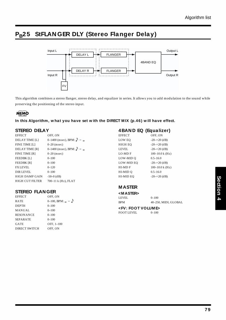
Algorithm list
Section 4
PB25 StFLANGER DLY (Stereo Flanger Delay)
fig.4-214
This algorithm combines a stereo flanger, stereo delay, and equalizer in series. It allows you to add modulation to the sound while
preserving the positioning of the stereo input.
In this Algorithm, what you have set with the DIRECT MIX (p.46) will have effect.
STEREO DELAYEFFECT OFF, ONDELAY TIME [L] 0–1400 (msec), BPM: FINE TIME [L] 0–20 (msec)DELAY TIME [R] 0–1400 (msec), BPM: FINE TIME [R] 0–20 (msec)FEEDBK [L] 0–100FEEDBK [R] 0–100FX LEVEL 0–120DIR LEVEL 0–100HIGH DAMP GAIN -50–0 (dB)HIGH CUT FILTER 700–11 k (Hz), FLAT
STEREO FLANGEREFFECT OFF, ONRATE 0–100, BPM: DEPTH 0–100MANUAL 0–100RESONANCE 0–100SEPARATE 0–100GATE OFF, 1–100DIRECT SWITCH OFF, ON
4BAND EQ (Equalizer)EFFECT OFF, ONLOW EQ -20–+20 (dB)HIGH EQ -20–+20 (dB)LEVEL -20–+20 (dB)LO-MD F 100–10.0 k (Hz)LOW-MID Q 0.5–16.0LOW-MID EQ -20–+20 (dB)HI-MD F 100–10.0 k (Hz)HI-MID Q 0.5–16.0HI-MID EQ -20–+20 (dB)
MASTER<MASTER>LEVEL 0–100BPM 40–250, MIDI, GLOBAL
<FV: FOOT VOLUME>FOOT LEVEL 0–100
Input L
Input R
Output L
Output R
4BAND EQ
DELAY L
DELAY R
FV
FLANGER
FLANGER
79
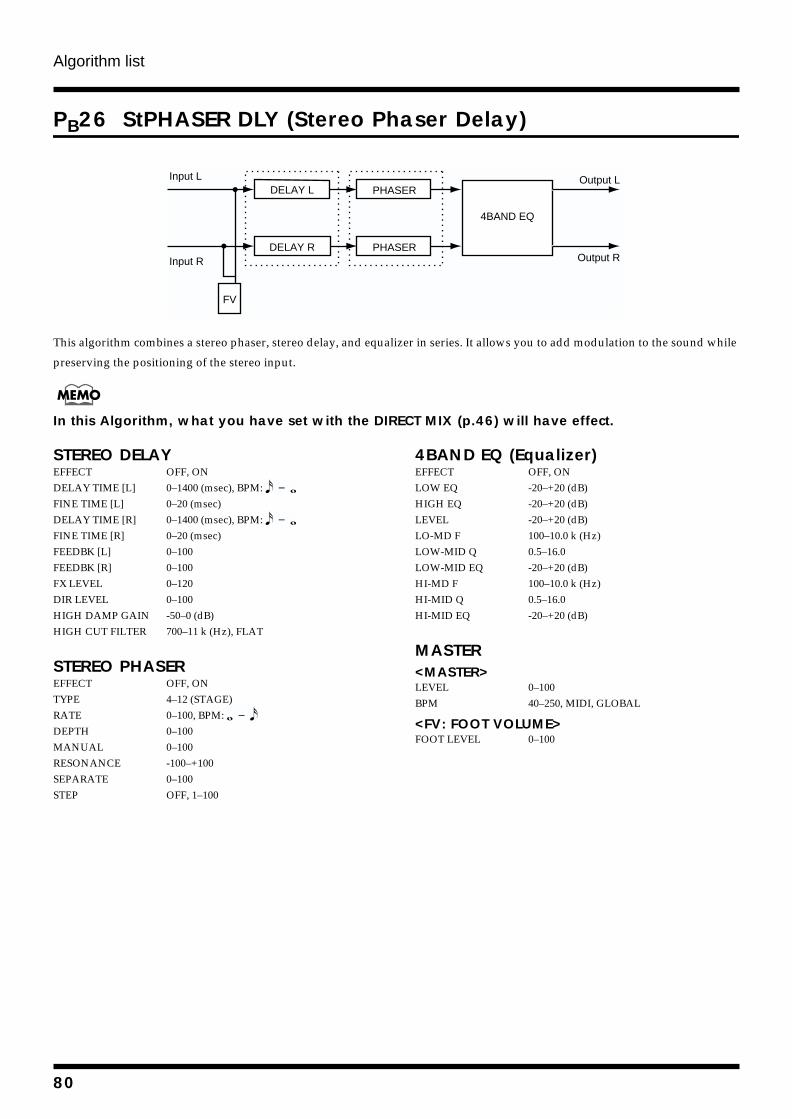
Algorithm list
PB26 StPHASER DLY (Stereo Phaser Delay)
fig.4-213
This algorithm combines a stereo phaser, stereo delay, and equalizer in series. It allows you to add modulation to the sound while
preserving the positioning of the stereo input.
In this Algorithm, what you have set with the DIRECT MIX (p.46) will have effect.
STEREO DELAYEFFECT OFF, ONDELAY TIME [L] 0–1400 (msec), BPM: FINE TIME [L] 0–20 (msec)DELAY TIME [R] 0–1400 (msec), BPM: FINE TIME [R] 0–20 (msec)FEEDBK [L] 0–100FEEDBK [R] 0–100FX LEVEL 0–120DIR LEVEL 0–100HIGH DAMP GAIN -50–0 (dB)HIGH CUT FILTER 700–11 k (Hz), FLAT
STEREO PHASEREFFECT OFF, ONTYPE 4–12 (STAGE)RATE 0–100, BPM: DEPTH 0–100MANUAL 0–100RESONANCE -100–+100SEPARATE 0–100STEP OFF, 1–100
4BAND EQ (Equalizer)EFFECT OFF, ONLOW EQ -20–+20 (dB)HIGH EQ -20–+20 (dB)LEVEL -20–+20 (dB)LO-MD F 100–10.0 k (Hz)LOW-MID Q 0.5–16.0LOW-MID EQ -20–+20 (dB)HI-MD F 100–10.0 k (Hz)HI-MID Q 0.5–16.0HI-MID EQ -20–+20 (dB)
MASTER<MASTER>LEVEL 0–100BPM 40–250, MIDI, GLOBAL
<FV: FOOT VOLUME>FOOT LEVEL 0–100
Output L
Output R
4BAND EQ
DELAY L
DELAY R
Input L
Input R
FV
PHASER
PHASER
80
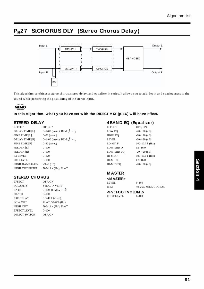
Algorithm list
Section 4
PB27 StCHORUS DLY (Stereo Chorus Delay)
fig.4-204
This algorithm combines a stereo chorus, stereo delay, and equalizer in series. It allows you to add depth and spaciousness to the
sound while preserving the positioning of the stereo input.
In this Algorithm, what you have set with the DIRECT MIX (p.46) will have effect.
STEREO DELAYEFFECT OFF, ONDELAY TIME [L] 0–1400 (msec), BPM: FINE TIME [L] 0–20 (msec)DELAY TIME [R] 0–1400 (msec), BPM: FINE TIME [R] 0–20 (msec)FEEDBK [L] 0–100FEEDBK [R] 0–100FX LEVEL 0–120DIR LEVEL 0–100HIGH DAMP GAIN -50–0 (dB)HIGH CUT FILTER 700–11 k (Hz), FLAT
STEREO CHORUSEFFECT OFF, ONPOLARITY SYNC, INVERTRATE 0–100, BPM: DEPTH 0–100PRE DELAY 0.0–40.0 (msec)LOW CUT FLAT, 55–800 (Hz)HIGH CUT 700–11 k (Hz), FLATEFFECT LEVEL 0–100DIRECT SWITCH OFF, ON
4BAND EQ (Equalizer)EFFECT OFF, ONLOW EQ -20–+20 (dB)HIGH EQ -20–+20 (dB)LEVEL -20–+20 (dB)LO-MD F 100–10.0 k (Hz)LOW-MID Q 0.5–16.0LOW-MID EQ -20–+20 (dB)HI-MD F 100–10.0 k (Hz)HI-MID Q 0.5–16.0HI-MID EQ -20–+20 (dB)
MASTER<MASTER>LEVEL 0–100BPM 40–250, MIDI, GLOBAL
<FV: FOOT VOLUME>FOOT LEVEL 0–100
CHORUSOutput L
Output R
4BAND EQ
CHORUS
DELAY L
DELAY RInput R
Input L
FV
81
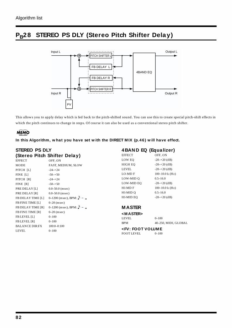
Algorithm list
PB28 STEREO PS DLY (Stereo Pitch Shifter Delay)
fig.4-205
This allows you to apply delay which is fed back to the pitch-shifted sound. You can use this to create special pitch-shift effects in
which the pitch continues to change in steps. Of course it can also be used as a conventional stereo pitch shifter.
In this Algorithm, what you have set with the DIRECT MIX (p.46) will have effect.
STEREO PS DLY(Stereo Pitch Shifter Delay)EFFECT OFF, ONMODE FAST, MEDIUM, SLOWPITCH [L] -24–+24FINE [L] -50–+50PITCH [R] -24–+24FINE [R] -50–+50PRE DELAY [L] 0.0–50.0 (msec)PRE DELAY [R] 0.0–50.0 (msec)FB DELAY TIME [L] 0–1200 (msec), BPM: FB FINE TIME [L] 0–20 (msec)FB DELAY TIME [R] 0–1200 (msec), BPM: FB FINE TIME [R] 0–20 (msec)FB LEVEL [L] 0–100FB LEVEL [R] 0–100BALANCE DIR:FX 100:0–0:100LEVEL 0–100
4BAND EQ (Equalizer)EFFECT OFF, ONLOW EQ -20–+20 (dB)HIGH EQ -20–+20 (dB)LEVEL -20–+20 (dB)LO-MD F 100–10.0 k (Hz)LOW-MID Q 0.5–16.0LOW-MID EQ -20–+20 (dB)HI-MD F 100–10.0 k (Hz)HI-MID Q 0.5–16.0HI-MID EQ -20–+20 (dB)
MASTER<MASTER>LEVEL 0–100BPM 40–250, MIDI, GLOBAL
<FV: FOOT VOLUMEFOOT LEVEL 0–100
Output L
Output R
4BAND EQ
PITCH SHIFTER L
FB DELAY L
Input L
Input RPITCH SHIFTER R
FB DELAY R
FV
82
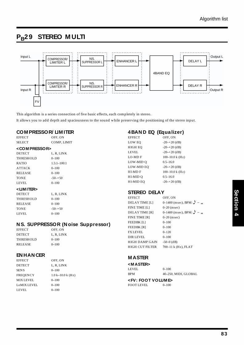
Algorithm list
Section 4
PB29 STEREO MULTI
fig.4-215
This algorithm is a series connection of five basic effects, each completely in stereo.
It allows you to add depth and spaciousness to the sound while preserving the positioning of the stereo input.
COMPRESSOR/LIMITEREFFECT OFF, ONSELECT COMP, LIMIT
<COMPRESSOR>DETECT L, R, LINKTHRESHOLD 0–100RATIO 1.5:1–100:1ATTACK 0–100RELEASE 0–100TONE -50–+50LEVEL 0–100
<LIMITER>DETECT L, R, LINKTHRESHOLD 0–100RELEASE 0–100TONE -50–+50LEVEL 0–100
NS. SUPPRESSOR (Noise Suppressor)EFFECT OFF, ONDETECT L, R, LINKTHRESHOLD 0–100RELEASE 0–100
ENHANCEREFFECT OFF, ONDETECT L, R, LINKSENS 0–100FREQENCY 1.0 k–10.0 k (Hz)MIX LEVEL 0–100LoMIX LEVEL 0–100LEVEL 0–100
4BAND EQ (Equalizer)EFFECT OFF, ONLOW EQ -20–+20 (dB)HIGH EQ -20–+20 (dB)LEVEL -20–+20 (dB)LO-MD F 100–10.0 k (Hz)LOW-MID Q 0.5–16.0LOW-MID EQ -20–+20 (dB)HI-MD F 100–10.0 k (Hz)HI-MID Q 0.5–16.0HI-MID EQ -20–+20 (dB)
STEREO DELAYEFFECT OFF, ONDELAY TIME [L] 0–1400 (msec), BPM: FINE TIME [L] 0–20 (msec)DELAY TIME [R] 0–1400 (msec), BPM: FINE TIME [R] 0–20 (msec)FEEDBK [L] 0–100FEEDBK [R] 0–100FX LEVEL 0–120DIR LEVEL 0–100HIGH DAMP GAIN -50–0 (dB)HIGH CUT FILTER 700–11 k (Hz), FLAT
MASTER<MASTER>LEVEL 0–100BPM 40–250, MIDI, GLOBAL
<FV: FOOT VOLUME>FOOT LEVEL 0–100
Input L
Input R
Output L
Output R
COMPRESSOR/LIMITER L
COMPRESSOR/LIMITER R
NS.SUPPRESSOR L
NS.SUPPRESSOR R
ENHANCER L
ENHANCER R
4BAND EQ
DELAY L
DELAY R
FV
83
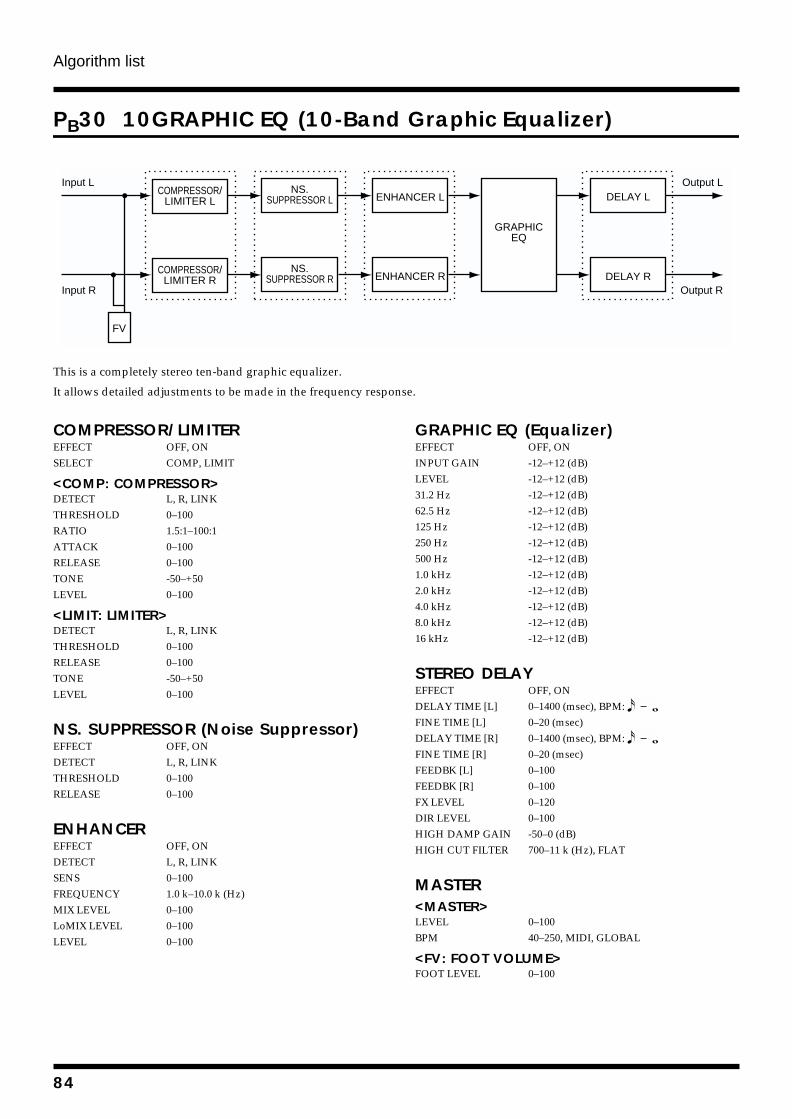
Algorithm list
PB30 10GRAPHIC EQ (10-Band Graphic Equalizer)
fig.4-222
This is a completely stereo ten-band graphic equalizer.
It allows detailed adjustments to be made in the frequency response.
COMPRESSOR/LIMITEREFFECT OFF, ONSELECT COMP, LIMIT
<COMP: COMPRESSOR>DETECT L, R, LINKTHRESHOLD 0–100RATIO 1.5:1–100:1ATTACK 0–100RELEASE 0–100TONE -50–+50LEVEL 0–100
<LIMIT: LIMITER>DETECT L, R, LINKTHRESHOLD 0–100RELEASE 0–100TONE -50–+50LEVEL 0–100
NS. SUPPRESSOR (Noise Suppressor)EFFECT OFF, ONDETECT L, R, LINKTHRESHOLD 0–100RELEASE 0–100
ENHANCEREFFECT OFF, ONDETECT L, R, LINKSENS 0–100FREQUENCY 1.0 k–10.0 k (Hz)MIX LEVEL 0–100LoMIX LEVEL 0–100LEVEL 0–100
GRAPHIC EQ (Equalizer)EFFECT OFF, ONINPUT GAIN -12–+12 (dB)LEVEL -12–+12 (dB)31.2 Hz -12–+12 (dB)62.5 Hz -12–+12 (dB)125 Hz -12–+12 (dB)250 Hz -12–+12 (dB)500 Hz -12–+12 (dB)1.0 kHz -12–+12 (dB)2.0 kHz -12–+12 (dB)4.0 kHz -12–+12 (dB)8.0 kHz -12–+12 (dB)16 kHz -12–+12 (dB)
STEREO DELAYEFFECT OFF, ONDELAY TIME [L] 0–1400 (msec), BPM: FINE TIME [L] 0–20 (msec)DELAY TIME [R] 0–1400 (msec), BPM: FINE TIME [R] 0–20 (msec)FEEDBK [L] 0–100FEEDBK [R] 0–100FX LEVEL 0–120DIR LEVEL 0–100HIGH DAMP GAIN -50–0 (dB)HIGH CUT FILTER 700–11 k (Hz), FLAT
MASTER<MASTER>LEVEL 0–100BPM 40–250, MIDI, GLOBAL
<FV: FOOT VOLUME>FOOT LEVEL 0–100
Input L
Input R
Output L
Output R
COMPRESSOR/LIMITER L
NS.SUPPRESSOR L ENHANCER L
GRAPHICEQ
COMPRESSOR/LIMITER R
NS.SUPPRESSOR R ENHANCER R
DELAY L
DELAY R
FV
84
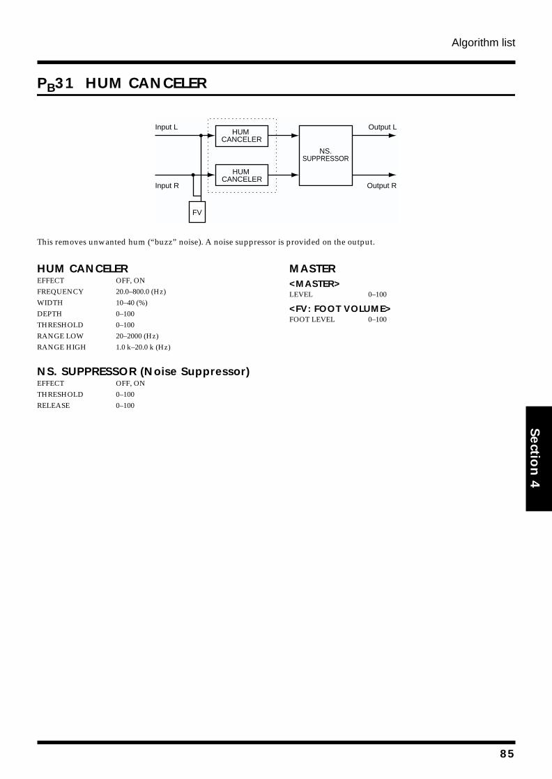
Algorithm list
Section 4
PB31 HUM CANCELER
fig.4-224
This removes unwanted hum (“buzz” noise). A noise suppressor is provided on the output.
HUM CANCELEREFFECT OFF, ONFREQUENCY 20.0–800.0 (Hz)WIDTH 10–40 (%)DEPTH 0–100THRESHOLD 0–100RANGE LOW 20–2000 (Hz)RANGE HIGH 1.0 k–20.0 k (Hz)
NS. SUPPRESSOR (Noise Suppressor)EFFECT OFF, ONTHRESHOLD 0–100RELEASE 0–100
MASTER<MASTER>LEVEL 0–100
<FV: FOOT VOLUME>FOOT LEVEL 0–100
Input L
Input R
Output L
Output R
FV
HUM CANCELER
HUM CANCELER
NS.SUPPRESSOR
85
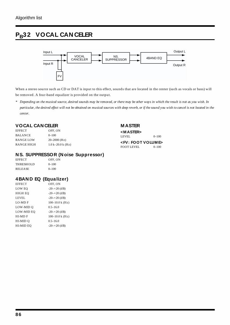
Algorithm list
PB32 VOCAL CANCELER
fig.4-225
When a stereo source such as CD or DAT is input to this effect, sounds that are located in the center (such as vocals or bass) will
be removed. A four-band equalizer is provided on the output.
* Depending on the musical source, desired sounds may be removed, or there may be other ways in which the result is not as you wish. In
particular, the desired effect will not be obtained on musical sources with deep reverb, or if the sound you wish to cancel is not located in the
center.
VOCAL CANCELEREFFECT OFF, ONBALANCE 0–100RANGE LOW 20–2000 (Hz)RANGE HIGH 1.0 k–20.0 k (Hz)
NS. SUPPRESSOR (Noise Suppressor)EFFECT OFF, ONTHRESHOLD 0–100RELEASE 0–100
4BAND EQ (Equalizer)EFFECT OFF, ONLOW EQ -20–+20 (dB)HIGH EQ -20–+20 (dB)LEVEL -20–+20 (dB)LO-MD F 100–10.0 k (Hz)LOW-MID Q 0.5–16.0LOW-MID EQ -20–+20 (dB)HI-MD F 100–10.0 k (Hz)HI-MID Q 0.5–16.0HI-MID EQ -20–+20 (dB)
MASTER<MASTER>LEVEL 0–100
<FV: FOOT VOLUME>FOOT LEVEL 0–100
Input L
Input R
Output L
Output R
FV
VOCALCANCELER
NS.SUPPRESSOR 4BAND EQ
86
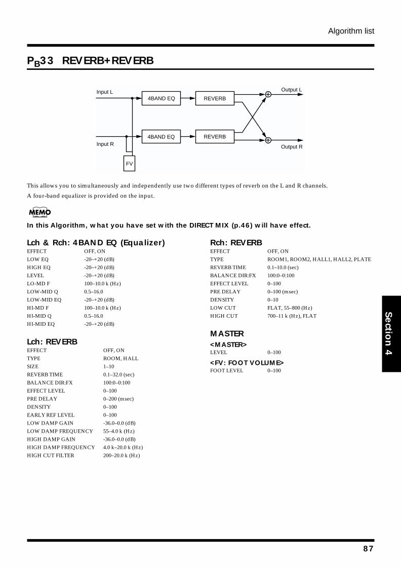
Algorithm list
Section 4
PB33 REVERB+REVERB
fig.4-218
This allows you to simultaneously and independently use two different types of reverb on the L and R channels.
A four-band equalizer is provided on the input.
In this Algorithm, what you have set with the DIRECT MIX (p.46) will have effect.
Lch & Rch: 4BAND EQ (Equalizer)EFFECT OFF, ONLOW EQ -20–+20 (dB)HIGH EQ -20–+20 (dB)LEVEL -20–+20 (dB)LO-MD F 100–10.0 k (Hz)LOW-MID Q 0.5–16.0LOW-MID EQ -20–+20 (dB)HI-MD F 100–10.0 k (Hz)HI-MID Q 0.5–16.0HI-MID EQ -20–+20 (dB)
Lch: REVERBEFFECT OFF, ONTYPE ROOM, HALLSIZE 1–10REVERB TIME 0.1–32.0 (sec)BALANCE DIR:FX 100:0–0:100EFFECT LEVEL 0–100PRE DELAY 0–200 (msec)DENSITY 0–100EARLY REF LEVEL 0–100LOW DAMP GAIN -36.0–0.0 (dB)LOW DAMP FREQUENCY 55–4.0 k (Hz)HIGH DAMP GAIN -36.0–0.0 (dB)HIGH DAMP FREQUENCY 4.0 k–20.0 k (Hz)HIGH CUT FILTER 200–20.0 k (Hz)
Rch: REVERBEFFECT OFF, ONTYPE ROOM1, ROOM2, HALL1, HALL2, PLATEREVERB TIME 0.1–10.0 (sec)BALANCE DIR:FX 100:0–0:100EFFECT LEVEL 0–100PRE DELAY 0–100 (msec)DENSITY 0–10LOW CUT FLAT, 55–800 (Hz)HIGH CUT 700–11 k (Hz), FLAT
MASTER<MASTER>LEVEL 0–100
<FV: FOOT VOLUME>FOOT LEVEL 0–100
Input L
Input R
Output L
Output R
REVERB4BAND EQ
REVERB
FV
4BAND EQ
87
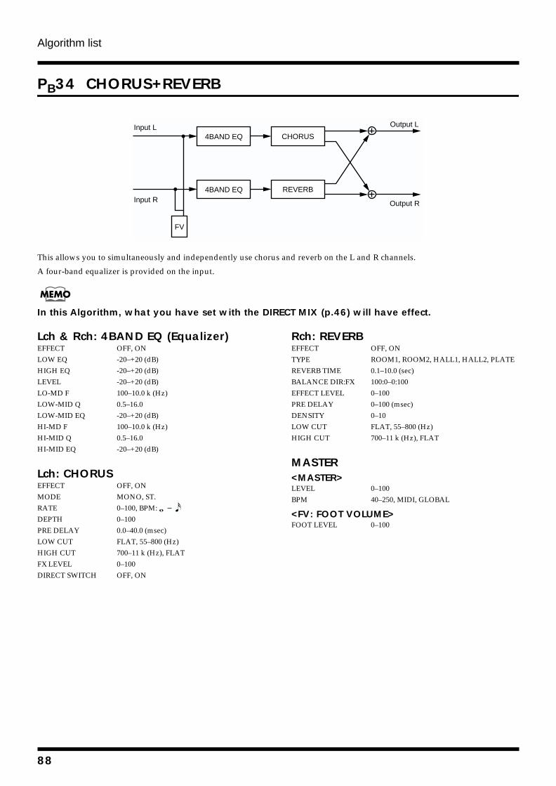
Algorithm list
PB34 CHORUS+REVERB
fig.4-220
This allows you to simultaneously and independently use chorus and reverb on the L and R channels.
A four-band equalizer is provided on the input.
In this Algorithm, what you have set with the DIRECT MIX (p.46) will have effect.
Lch & Rch: 4BAND EQ (Equalizer)EFFECT OFF, ONLOW EQ -20–+20 (dB)HIGH EQ -20–+20 (dB)LEVEL -20–+20 (dB)LO-MD F 100–10.0 k (Hz)LOW-MID Q 0.5–16.0LOW-MID EQ -20–+20 (dB)HI-MD F 100–10.0 k (Hz)HI-MID Q 0.5–16.0HI-MID EQ -20–+20 (dB)
Lch: CHORUSEFFECT OFF, ONMODE MONO, ST.RATE 0–100, BPM: DEPTH 0–100PRE DELAY 0.0–40.0 (msec)LOW CUT FLAT, 55–800 (Hz)HIGH CUT 700–11 k (Hz), FLATFX LEVEL 0–100DIRECT SWITCH OFF, ON
Rch: REVERBEFFECT OFF, ONTYPE ROOM1, ROOM2, HALL1, HALL2, PLATEREVERB TIME 0.1–10.0 (sec)BALANCE DIR:FX 100:0–0:100EFFECT LEVEL 0–100PRE DELAY 0–100 (msec)DENSITY 0–10LOW CUT FLAT, 55–800 (Hz)HIGH CUT 700–11 k (Hz), FLAT
MASTER<MASTER>LEVEL 0–100BPM 40–250, MIDI, GLOBAL
<FV: FOOT VOLUME>FOOT LEVEL 0–100
Input L
Input R
Output L
Output R
CHORUS4BAND EQ
REVERB4BAND EQ
FV
88
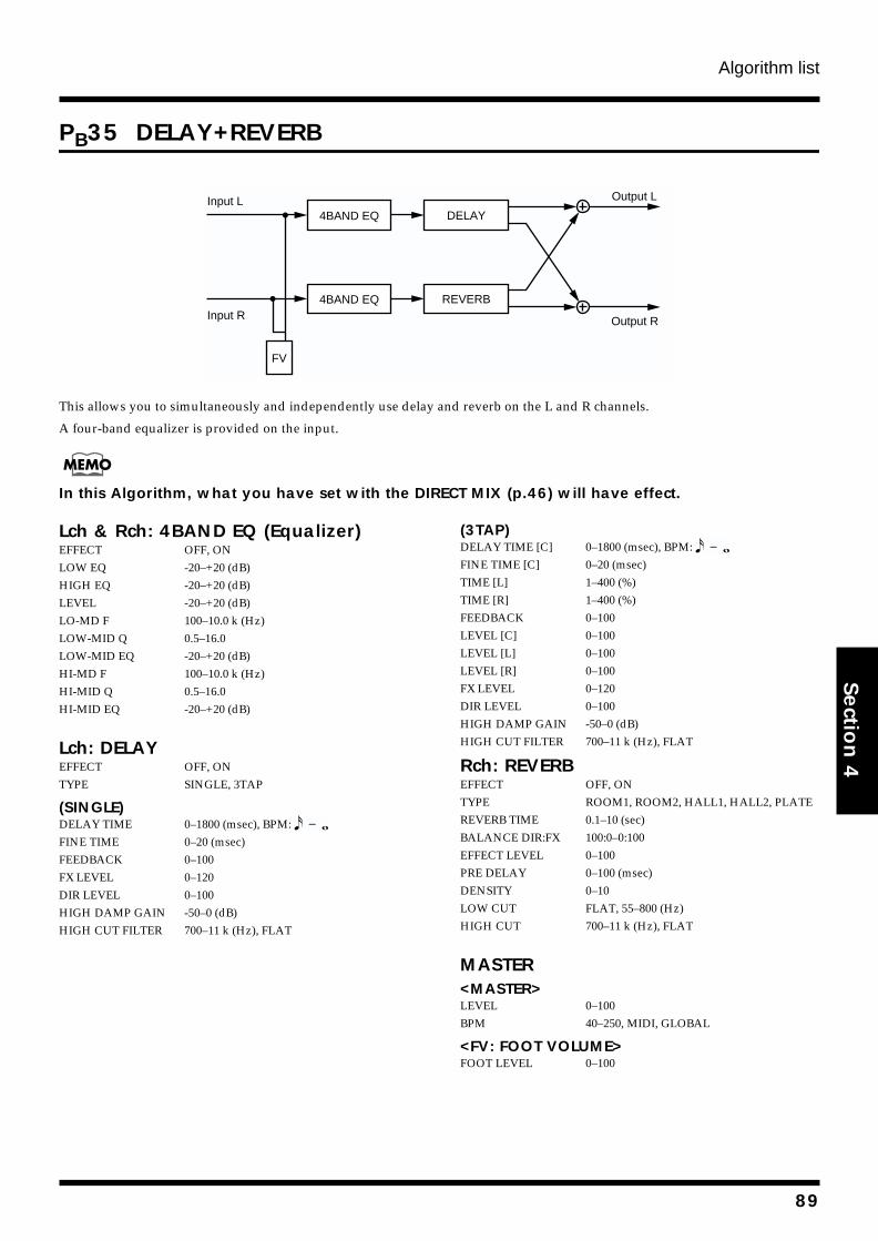
Algorithm list
Section 4
PB35 DELAY+REVERB
fig.4-219
This allows you to simultaneously and independently use delay and reverb on the L and R channels.
A four-band equalizer is provided on the input.
In this Algorithm, what you have set with the DIRECT MIX (p.46) will have effect.
Lch & Rch: 4BAND EQ (Equalizer)EFFECT OFF, ONLOW EQ -20–+20 (dB)HIGH EQ -20–+20 (dB)LEVEL -20–+20 (dB)LO-MD F 100–10.0 k (Hz)LOW-MID Q 0.5–16.0LOW-MID EQ -20–+20 (dB)HI-MD F 100–10.0 k (Hz)HI-MID Q 0.5–16.0HI-MID EQ -20–+20 (dB)
Lch: DELAYEFFECT OFF, ONTYPE SINGLE, 3TAP
(SINGLE)DELAY TIME 0–1800 (msec), BPM: FINE TIME 0–20 (msec)FEEDBACK 0–100FX LEVEL 0–120DIR LEVEL 0–100HIGH DAMP GAIN -50–0 (dB)HIGH CUT FILTER 700–11 k (Hz), FLAT
(3TAP)DELAY TIME [C] 0–1800 (msec), BPM: FINE TIME [C] 0–20 (msec)TIME [L] 1–400 (%)TIME [R] 1–400 (%)FEEDBACK 0–100LEVEL [C] 0–100LEVEL [L] 0–100LEVEL [R] 0–100FX LEVEL 0–120DIR LEVEL 0–100HIGH DAMP GAIN -50–0 (dB)HIGH CUT FILTER 700–11 k (Hz), FLAT
Rch: REVERBEFFECT OFF, ONTYPE ROOM1, ROOM2, HALL1, HALL2, PLATEREVERB TIME 0.1–10 (sec)BALANCE DIR:FX 100:0–0:100EFFECT LEVEL 0–100PRE DELAY 0–100 (msec)DENSITY 0–10LOW CUT FLAT, 55–800 (Hz)HIGH CUT 700–11 k (Hz), FLAT
MASTER<MASTER>LEVEL 0–100BPM 40–250, MIDI, GLOBAL
<FV: FOOT VOLUME>FOOT LEVEL 0–100
Input L
Input R
Output L
Output R
DELAY4BAND EQ
REVERB4BAND EQ
FV
89
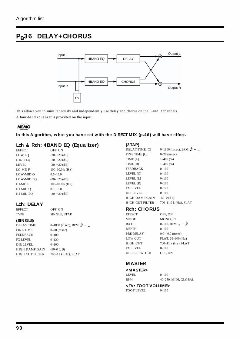
Algorithm list
PB36 DELAY+CHORUS
fig.4-221
This allows you to simultaneously and independently use delay and chorus on the L and R channels.
A four-band equalizer is provided on the input.
In this Algorithm, what you have set with the DIRECT MIX (p.46) will have effect.
Lch & Rch: 4BAND EQ (Equalizer)EFFECT OFF, ONLOW EQ -20–+20 (dB)HIGH EQ -20–+20 (dB)LEVEL -20–+20 (dB)LO-MD F 100–10.0 k (Hz)LOW-MID Q 0.5–16.0LOW-MID EQ -20–+20 (dB)HI-MD F 100–10.0 k (Hz)HI-MID Q 0.5–16.0HI-MID EQ -20–+20 (dB)
Lch: DELAYEFFECT OFF, ONTYPE SINGLE, 3TAP
(SINGLE)DELAY TIME 0–1800 (msec), BPM: FINE TIME 0–20 (msec)FEEDBACK 0–100FX LEVEL 0–120DIR LEVEL 0–100HIGH DAMP GAIN -50–0 (dB)HIGH CUT FILTER 700–11 k (Hz), FLAT
(3TAP)DELAY TIME [C] 0–1800 (msec), BPM: FINE TIME [C] 0–20 (msec)TIME [L] 1–400 (%)TIME [R] 1–400 (%)FEEDBACK 0–100LEVEL [C] 0–100LEVEL [L] 0–100LEVEL [R] 0–100FX LEVEL 0–120DIR LEVEL 0–100HIGH DAMP GAIN -50–0 (dB)HIGH CUT FILTER 700–11.0 k (Hz), FLAT
Rch: CHORUSEFFECT OFF, ONMODE MONO, ST.RATE 0–100, BPM: DEPTH 0–100PRE DELAY 0.0–40.0 (msec)LOW CUT FLAT, 55–800 (Hz)HIGH CUT 700–11 k (Hz), FLATFX LEVEL 0–100DIRECT SWITCH OFF, ON
MASTER<MASTER>LEVEL 0–100BPM 40–250, MIDI, GLOBAL
<FV: FOOT VOLUME>FOOT LEVEL 0–100
Input L
Input R
Output L
Output R
DELAY4BAND EQ
CHORUS4BAND EQ
FV
90
The function of each parameter
Section 4
2x2 CHORUS
This adds a pitch-shifted sound to the original sound,
producing an effect of greater depth and spaciousness. Two
separate stereo chorus units are used for the low-frequency
and high-frequency ranges in order to create a more natural
chorus sound.
EFFECTThis parameter turns the 2x2 Chorus effect on/off.
XOVER (crossover frequency)This parameter sets the frequency at which the frequency
components of the effect sound are divided into bass and
treble bands.
LOW RATEAdjust the speed of the chorus effect for the low frequency
range.
* If this is set to BPM, the MASTER BPM (p.105) value that is set
for each patch will determine the speed of the effect, so that the
effect will match the tempo of the song. However if the BPM value
is large, the effect will synchronize to 1/2 or 1/4 of the BPM.
LOW DEPTHAdjust the depth of the chorus effect for the low frequency
range. If you wish to use this as a doubling effect, use a
setting of “0.”
LOW PRE DELAYAdjust the time from when the low frequency range direct
sound is output until the effect sound is output. Extending
the pre-delay will produce the sensation of multiple sounds
(doubling effect).
LOW LEVELAdjust the volume of the low frequency range effect sound.
HIGH RATEAdjust the speed of the chorus effect for the high frequency
range.
* If this is set to BPM, the MASTER BPM (p.105) value that is set
for each patch will determine the speed of the effect, so that the
effect will match the tempo of the song. However if the BPM value
is large, the effect will synchronize to 1/2 or 1/4 of the BPM.
HIGH DEPTHAdjust the depth of the chorus effect for the high frequency
range. If you wish to use this as a doubling effect, use a
setting of “0.”
HIGH PRE DELAYAdjust the time from when the high frequency range direct
sound is output until the effect sound is output. Extending
the pre-delay will produce the sensation of multiple sounds
(doubling effect).
HIGH LEVELAdjust the volume of the high frequency range effect sound.
4BAND EQ (equalizer)
This simulates a 4-band equalizer.
EFFECTThis parameter turns the equalizer effect on/off.
LOW EQ (low equalizer)Adjusts the low frequency range tone.
HIGH EQ (high equalizer)Adjusts the high frequency range tone.
LEVELThis parameter adjusts the volume after the equalizer stage.
LO-MD F (low-middle frequency)This parameter sets the central frequency for the “LOW-MID
EQ.”
LOW-MID Q (low-middle Q)This parameter sets the range of change in gain for the
frequency set by the “LO-MD F.” A larger value results in a
narrower range of change.
LOW-MID EQ (low-middle equalizer)Adjusts the low-middle frequency range tone.
HI-MD F (high-middle frequency)This parameter sets the central frequency for the “HI-MID
EQ.”
HI-MID Q (high-middle Q)This parameter sets the range of change in gain for the
frequency set by the “HI-MD F.” A larger value results in a
narrower range of change.
HI-MID EQ (high-middle equalizer)Adjusts the high-middle frequency range tone.
91
The function of each parameter
ACOUSTIC
With this feature, you can change the sound from a pickup
on an electric-acoustic guitar into a richer sound, similar to
that obtained by a microphone placed near a guitar.
EFFECTThis parameter turns the acoustic effect on/off.
BODYThis adjusts the resonance of the sound caused by the body.
That is, it adjusts the softness and fatness of the sound which
is the typical characteristics of acoustic guitars.
MIC DISTANCEThis simulates the distance between the microphone
capturing the sound of an acoustic guitar and the guitar
itself.
ACOUSTIC GtSIM (acoustic guitar simulator)
This simulates the sound of an acoustic guitar. It allows you
to use an electric guitar to produce sounds similar to those of
an acoustic guitar.
This effect can be used in the “GUITAR MULTI 2” algorithm
when the SFX “SELECT” parameter is set to “AC.”
* For details on SFX settings, refer to “About SFX” (p.48).
TOPThis adjusts the interference to the strings made by the top
plate. That is, it adjusts the attack sense or harmonic
contents.
BODYThis adjusts the resonance of the sound caused by the body.
That is, it adjusts the softness and fatness of the sound which
is the typical characteristics of acoustic guitars.
LEVELThis adjusts the volume of the acoustic guitar simulator.
AFB (anti-feedbacker)This prevents the acoustic feedback that can be produced by
the body resonances of a guitar.
EFFECTThis parameter turns the anti-feedback effect on/off.
DEPTHAdjust the suppression strength of the fixed frequency point
for feedback cancellation.
FREQUENCYAdjust the fixed frequency point at which feedback will be
cancelled.
BASS GTR SIM (bass guitar simulator)Simulates the sound of a bass guitar. Obtain the sound of a
bass guitar while playing an electric guitar.
This effect can be used in the “GUITAR MULTI 2” algorithm
when the SFX “SELECT” parameter is set to “BS.”
* For details on SFX settings, refer to “About SFX” (p.48).
CHARACTERBass tone characteristic is set. When “LOOSE” is selected, as
if the string gauge was getting thicker.
FX LEVEL (effect level) Adjusts the volume of the bass guitar simulator sound.
DIR LEVEL (direct level)This adjusts the volume of the direct sound when the effect is
tured on.
BCF (bass cut filter)This is a filter that cuts unwanted low range noise, such as
pops. It simulates the bass cut switch that is found on some
mics.
EFFECTThis parameter turns the bass cut filter effect on/off.
FREQUENCYThis parameter sets the cutoff frequency for the bass cut
filter.
92
The function of each parameter
Section 4
CHOURUS
A sound with a subtly shifted pitch is added to the direct
sound, making the final output sound thicker and broader.
EFFECTThis parameter turns the chorus effect on/off.
POLARITYThis parameter is for the Stereo Chorus. It lets you choose the
difference in LFO phase for the left and right channels.
SYNC (synchro):The left and right phase will be the same.
INVERT:The left and right phase will be opposite.
MODESelection for the chorus mode.
MONO:This chorus effect outputs the same sound from both L and
R.
ST. (stereo):This is a stereo chorus effect that adds different chorus
sounds to L and R.
RATEAdjusts the rate of the Chorus effect.
* If this is set to BPM, the MASTER BPM (p.105) setting for
each patch will determine the rate, so that the effect sound will
match the song tempo. However, if the BPM value is high, the
effect will synchronize to 1/2 or 1/4 of the BPM.
DEPTHAdjusts the depth of the Chorus effect. To use it for doubling,
set the value to “0.”
PRE DELAYAdjusts the time needed for the effect sound to be output
after the direct sound has been output. By setting a longer
Pre Delay time, you can obtain an effect that sounds like
more than one sound is being played at the same time
(doubling effect).
LOW CUT (low cut filter)The low cut filter cuts the frequencies below the specified
frequency. This setting adjusts the frequency at which the
low cut filter will begin to take effect. When “Flat” is
selected, the low cut filter will have no effect.
HIGH CUT (high cut filter)This setting adjusts the frequency at which the high cut filter
will begin to take effect. When “Flat” is selected, the high cut
filter will have no effect.
FX (EFFECT) LEVELAdjusts the volume of the effect sound.
DIRECT SWITCHSwitch the direct sound ON/OFF (OUTPUT/NO OUTPUT).
COMPRESSOR/LIMITER
The compressor is an effect that attenuates loud input levels
and boosts soft input levels, thus evening out the volume to
create sustain without distortion.
The limiter attenuates loud input levels to prevent distortion.
EFFECTThis parameter turns the Compressor/Limiter effect on/off.
DETECT (detector in)This parameter is for both “STEREO MULTI” and “10
GRAPHIC EQ.” Select the input source which will control
the compressor/limiter.
L:The input source of channel L will control the compressor/
limiter.
R:The input source of channel R will control the compressor/
limiter.
LINK:The input source whose level is higher will control the
compressor/limiter.
* If you edit an effect with “SELECT,” the effect is parameter that
you have set before editing will be initialized.
SELECTSelect either Compressor or Limiter.
COMP (compressor):The effect will function as a compressor.
LIMIT (limiter):The effect will function as a limiter.
<When “COMP (compressor)” is selected>EFFECTThis parameter turns the Compressor effect on/off.
93
The function of each parameter
THRESHOLDThis adjusts the level at which the effect will be made
apparent.
RATIOThis parameter is for both “STEREO MULTI,” “10 GRAPHIC
EQ” and “VOCAL MULTI.” Selects the extent to which the
signal will be compressed (compression ratio) while the
Limiter is working.
SUSTAINAdjusts the range (time) over which low-level signals are
boosted. Larger values will result in longer sustain.
ATTACKAdjusts the strength of the attack. Larger values will result in
a sharper attack, creating a more clearly defined sound.
RELEASEThis adjusts the time from when the signal level drops below
the threshold until when limiting is removed.
ENH FREQ (enhance frequency)This is the parameters for “BASS MULTI.” This sets the
frequency band where you wish to apply the Enhancer effect.
Increasing the value will target a higher frequency band.
ENH LEVEL (enhance level)This is the parameters for “BASS MULTI.” This adjusts the
intensity of the Enhance effect. Increasing the value will
emphasize the Enhance effect.
TONEAdjusts the tone.
LEVELAdjusts the volume.
<When “LIMIT (limiter)” is selected>EFFECTThis parameter turns the Limiter effect on/off.
THRESHOLDAdjusts this as appropriate for the inputs signal. When the
input signal level exceeds this threshold level, limiting will
be applied.
ATTACK (attack time)This is the parameter for “MIC SIMULATOR.” Adjust the
time from when the input level exceeds the threshold level to
when the effect begins to apply.
RELEASEThis adjusts the time from when the signal level drops below
the threshold until when limiting is removed.
DETECT HPF (detect frequency)This is the parameter for “MIC SIMULATOR.” Adjust the
cutoff frequency of the level detection section. With a setting
of Thru, this will operate as a conventional limiter.
TONEAdjusts the tone.
LEVELAdjusts the volume.
DE-ESSER
Useful for reducing ‘sibilant’ or ‘S’ sounds produced by a
vocalist.
EFFECTThis parameter turns the de-esser effect on/off.
SENS (sensitivity)Adjusts the sensitivity relative to the input volume, which
controls how the effect is applied.
FREQUENCYSet the frequency at which the de-esser effect will be applied.
The effect will be made apparent in the frequencies above the
frequency set here.
94
The function of each parameter
Section 4
DEFRETTER
This simulates a fretless bass. The defretter can be selected in
the “BASS MULTI” algorithm as an alternate for the
compressor.
SENS (sensitivity)This controls the input sensitivity of the Defretter. It should
be adjusted for the bass guitar you have until you get the
harmonic changes to sound natural.
ATTACKThis controls the attack of the Defretter. Increasing the value
will cause the harmonics to change more slowly, thus
producing a relatively attack-less sound, similar to a fretless
bass.
DEPTHThis controls the rate of the harmonics. Increasing the value
will increase the harmonic content and therefore will create a
more unusual sound.
LEVELAdjusts the volume of the defretter sound.
DELAY
This parameter creates a distinctive effect (such as a thicker
sound) by applying a delayed sound to the direct sound.
EFFECTThis parameter turns the delay effect on/off.
TYPEThis Parameter selects the type of delay.
SINGLE:This is a simple delay.
TAP:This allows you to obtain the tap delay effect that divides the
delay time, then deliver them to left and right channel.
3TAP:Tap Delay that allows you to adjust the delay time for each
channel (L and R channel) by setting the Tap time L and the
Tap time R.
DELAY TIMEThis parameter adjusts the delay time (i.e., the interval for
which sound is delayed).
* If “3TAP” is selected as the Type, this parameter will be
displayed as “DELAY TIME [C].”
* If this is set to BPM, the MASTER BPM (p.105) value that is
set for each patch will determine the delay time, so that the effect
will match the tempo of the song. However if the BPM value is
low, the effect will synchronize to twice or four times the BPM.
DELAY TIME [L]DELAY TIME [R]These are the stereo input delay parameters, allowing you to
adjust the delay time independently for left and right
channels.
* If this is set to BPM, the MASTER BPM (p.105) value that is
set for each patch will determine the delay time, so that the effect
will match the tempo of the song. However if the BPM value is
low, the effect will synchronize to twice or four times the BPM.
FINE TIME (delay time fine)Make fine adjustments to the delay time.
* If “3TAP” is selected as the Type, this parameter will be
displayed as “FINE TIME [C].”
FINE TIME [L] (delay time fine L)FINE TIME [R] (delay time fine R)These are the stereo input delay parameters, allowing you to
fine adjust the delay time independently for left and right
channels.
TAP TIMEAdjust the delay time of the right channel. The delay time of
the left channel is considered at 100%, and the delay time of
the right channel is adjusted relative to this.
TIME [L] (tap time L)TIME [R] (tap time R)These parameters are for “3TAP.” They adjust the TAP TIME
L and TAP TIME R relative to “DELAY TIME C” as 100%.
FEEDBACKThis parameter is for a monaural-input delay, and adjusts the
amount of feedback.
Changing the amount of feedback causes the number of time
the delayed sound is repeated to change as well.
95
The function of each parameter
FEEDBK [L] (feedback L)FEEDBK [R] (feedback R)These parameters are for a stereo-input delay, and adjust the
amount of feedback for left and right channels
independently. Adjusting the amount of feedback will
change the number of times that the delay sound is repeated.
LEVEL [C]LEVEL [L] LEVEL [R] These parameters are for “3TAP.” Adjusts the volume of the
output from each tap.
HIGH DAMP GAINThis parameter adjusts the amount of damping for High
Damp. No high-frequency damping occurs when set to “0.”
HIGH CUT FILTER (HIGH CUT)The High Cut Filter cuts the frequency contents that are
higher than the set frequency. This parameter adjusts the
frequency where the high cut filter starts working. When it is
set to “FLAT,” the high cut filter does not work at all.
FX LEVEL (effect level)This adjusts the volume of the delay sound.
DIR LEVEL (direct level)Adjusts the volume of the direct sound.
DISTANCE
Microphones have a characteristic which causes the low
frequency range to be boosted when the sound source is
nearby. This setting simulates this phenomenon.
EFFECTThis parameter turns the distance effect on/off.
PROX.FX (proximity effects)Adjust the low frequency response that is affected by the mic
distance from the sound source. Adjustment in the “+”
direction will move the mic closer to the sound source, and in
the “–” direction will move it away from the sound source.
TIMEThis simulates the time difference due to distance from the
sound source.
DISTORTION
This effect distorts the sound. By changing the TYPE, you can
create many different sounds.
EFFECTThis parameter turns the distortion effect on/off.
TYPEThis allows you to select the distortion type you like.
TURBO OD (turbo overdrive):Allows you to obtain a rich effect just like distortion, without
losing the subtle nuance of the overdrive.
BASS OD (bass overdrive):Rich and firm overdrive sound can be created.
HARD DS (hard distortion):This produces a rich and powerful heavy metal sound.
FUZZ 1:This produces a full-bodied, traditional fuzz sound that has
the lower and middle range emphasized.
FUZZ 2:This produces an exciting fuzz sound that has its overtones
emphasized.
DRIVEAdjusts the depth of distortion. A higher value will
emphasize the distortion.
BASSThis controls the bass sounds. You can set an appropriate
frequency band for each TYPE.
TREBLEThis controls the treble sounds. You can set an appropriate
frequency band for each TYPE.
FX LEVEL (effect level)This adjusts the volume of the distorted sound.
DIR LEVEL (direct level)This adjusts the volume of the direct sound when the effect is
turned on.
96
The function of each parameter
Section 4
ENHANCER
By adding sounds which are out-of-phase with the direct
sound, this effect enhances the definition of the sound, and
pushes it to the forefront.
EFFECTThis parameter turns the enhancer effect on/off.
DETECT (detector in)This is the parameters for both “STEREO MULTI” and “10
GRAPHIC EQ.” Select the input source which will control
the enhancer.
L:The input source of channel L will control the enhancer.
R:The input source of channel R will control the enhancer.
LINK:The input source whose level is higher will control the
enhancer.
SENS (sensitivity)Adjusts the manner in which the enhancer will be applied
relative to the input signals.
FREQUENCYAdjusts the frequency at which the enhancer effect will begin
to be applied. The effect will be made apparent in the
frequencies above the frequency set here.
MIX LEVELAdjusts the amount of phase-shifted sound of the range set
by “Frequency” that is to be mixed with the input.
LoMIX LEVEL (low mix level)Adjusts the amount of phase-shifted sound of the lower
range that is to be mixed with the input.
LEVELAdjusts the volume of the enhanced sound.
FEEDBACKER
This allows you to use feedback playing techniques.
This effect can be used in the “GUITAR MULTI 2” algorithm
when the SFX “SELECT” parameter is set to “FB.”
* For details on SFX settings, refer to “About SFX” (p.48).
When using the feedbacker, play a single note accurately and
then switch the effect on to produce a feedback effect. When
you turn the effect off, the feedback will disappear. Use the
foot switch to switch the effect on/off, so that the effect will
be on only while the pedal is being pressed. To make a note
feedback, you must cleanly play a single note. Then, when
the sound has stabilized, turn on the effect.
MODESelect either oscillator “OSC” or boost “BOOST.”
OSC (oscillator): An artificial feedback sound will be created internally.
BOOST: Only the frequency at which you want feedback will be
boosted, making it easier to use feedback playing techniques.
* Since boost mode only assists you with feedback playing, the
result will not be satisfactory if the volume of your guitar amp is
low.
RISE TIMEThis determines the time needed for the volume of the
feedback sound to reach its maximum from the moment the
effect is turned on.
<When “OSC (oscillator)” is selected>RISE TIME This determines the time needed for the volume of the one
octave higher feedback sound to reach its maximum from the
moment the effect is turned on.
F.B LEVEL (feedback level)Adjusts the volume of the feedback sound.
F.B LEVEL (feedback level)This adjusts the volume of the one octave higher feedback
sound.
VIB RATE (vibrato rate)This adjusts the rate of the vibrato when the feedbacker is on.
97
The function of each parameter
VIB DEPTH (vibrato depth)This adjusts the depth of the vibrato when the feedbacker is
on.
<When “BOOST” is selected>F.B DEPTH (feedback depth)Adjust the amount of boost for the feedback frequency.
FEEDBACK TONE Adjust the frequency range at which you wish to create
feedback.
FLANGER
The flanger effect gives a twisting, jet-airplane-like character
to the sound.
EFFECTThis parameter turns the flanger effect on/off.
RATEDetermines the rate of the flanging effect.
* If this is set to BPM, the MASTER BPM (p.105) setting for
each patch will determine the rate, so that the effect sound will
match the song tempo. However, if the BPM value is high, the
effect will synchronize to 1/2 or 1/4 of the BPM.
DEPTHDetermines the depth of the flanging effect.
MANUALAdjusts the center frequency at which to apply the effect.
RESONANCEDetermines the amount of resonance (feedback). Increasing
the value will emphasize the effect, creating a more unusual
sound.
SEPARATE (separation)Adjusts the diffusion. The diffusion increases as the value
increases.
LEVELThis adjusts the volume of the flanger.
GATEThis can be effectively used to cyclically cut the output from
the flanger. Increasing the value will shorten the interval. If
this is “Off,” gate will have no effect.
DIRECT SWITCHSwitch the direct sound on/off (output/no output).
GRAPHIC EQ (graphic equalizer)
This simulates a 10-band graphic equalizer.
EFFECTThis parameter turns the graphic EQ effect on/off.
INPUT GAINAdjust the overall volume level of the sound before it passes
through the equalizer.
LEVELAdjust the volume level of the sound which as passed
through the equalizer.
31.2–16KHz (Gain)Adjust the gain (amount of boost/cut) of the equalizer for
each frequency.
FEEDBACKER ON/OFFTo switch the feedbacker on/off using the Footswitch
(FS-5U, DP-2 (Roland), etc.), set “Control Assign” (p. 33)
as follows.
< ASSIGN1: ON >
TARGET: SFX: ON/OFF
TARGET MIN: OFF
TARGET MAX: ON
SOURCE TYPE: CONTROL1
SOURCE MODE: NORMAL
SOURCE MIN: 0
SOURCE MAX: 127
98
The function of each parameter
Section 4
GUITAR SYNTH (guitar synthesizer)
This detects the pitch of an electric guitar and outputs a
synthesizer sound.
This effect can be used in the “GUITAR MULTI 1” algorithm
when the MOD “SELECT” parameter is set to “SYN.”
* For details on MOD (Modulation) settings, refer to “About
MOD ” (p.47).
* When you use a guitar synthesizer, observe the following points.
• It does not work properly when a chord is played. Be sure
to mute all the other strings and play in a single note.
• When you are to play the next string while a certain sound
is still playing, perfectly mute the previous sound then
play the next one with a clear attack. If the unit cannot
detect the attack, it may not sound correctly.
SENS (sensitivity)This adjusts the input sensitivity. The response of the internal
sound source is better with a higher sensitivity value, but the
malfunctions will be increased on the other hand. So, try to
set it as high as possible without causing malfunction.
WAVEThis selects a wave type that is the source of the guitar
synthesizer.
SQR (square) ( ):The unit detects the pitch and attack information from the
input guitar sound, then send the square waveform from the
internal sound source.
SAW ( ):The unit detects the pitch and attack information from the
input guitar sound, then send the saw waveform from the
internal sound source.
BRASS:The unit directly processes the input guitar sound and
creates a guitar synthesizer sound. It gives a quick sound rise
and send the sound with a sharp edge.
BOW:The unit directly processes the input guitar sound and
creates a guitar synthesizer sound. It outputs a soft sound
without attack.
CHROMATICThis switches on or off the chromatic function. When it is on,
the pitch change of the synthesizer sound is in semitone
steps. This does not respond to pitch changes less than a
semitone, such as what might be obtained with bending or
vibrato. Thus, this is effectively used for realistically playing
musical instruments whose pitch will change in steps greater
than a semitone, such as a keyboard.
* Use this parameter when “Square” or “Saw” is selected for
wave.
OCT SHIFT (octave shift)This allows you to shift the pitch of the internal sound
module in an octave step from the guitar sound.
* This parameter should be set when “SQR” or “SAW” is selected
for the wave.
PWM RATE (pulse width modulation rate)This gives breadth or fatness to the sound by applying
modulation to the waveform (only to Square) in the internal
sound module. A higher value will quicken the rate of the
modulation.
* This parameter should be set only when “SQR” is selected for
the wave.
PWM DEPTH (pulse width modulation depth)This adjusts the depth of the PWM. When it is set to “0,” no
PWM effect is obtained.
* This parameter should be set only when “SQR” is selected for
the wave.
CUTOFF F (cutoff frequency)This adjusts the frequency where the harmonics contents of
the sound is cut off.
RESONANSEThis adjusts how much of the harmonics contents around the
cutoff frequency should be emphasized.
FLT SENS (filter sensitivity)This adjusts the sensitivity of the filter. When it is set to a
lower value, the filter is affected only with a stronger
picking. When it is set higher, the filter changes even with a
weaker picking. When it is set to “0,” the depth of the filter
will be the same no matter how the picking strength may be.
FLT DECAY (filter decay)This sets the time needed until the filter change will be stable.
99
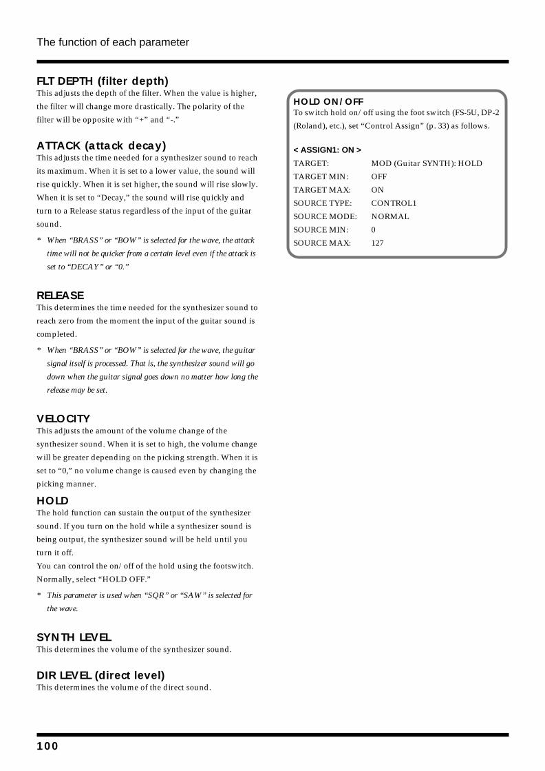
The function of each parameter
FLT DEPTH (filter depth)This adjusts the depth of the filter. When the value is higher,
the filter will change more drastically. The polarity of the
filter will be opposite with “+” and “-.”
ATTACK (attack decay)This adjusts the time needed for a synthesizer sound to reach
its maximum. When it is set to a lower value, the sound will
rise quickly. When it is set higher, the sound will rise slowly.
When it is set to “Decay,” the sound will rise quickly and
turn to a Release status regardless of the input of the guitar
sound.
* When “BRASS” or “BOW” is selected for the wave, the attack
time will not be quicker from a certain level even if the attack is
set to “DECAY” or “0.”
RELEASEThis determines the time needed for the synthesizer sound to
reach zero from the moment the input of the guitar sound is
completed.
* When “BRASS” or “BOW” is selected for the wave, the guitar
signal itself is processed. That is, the synthesizer sound will go
down when the guitar signal goes down no matter how long the
release may be set.
VELOCITYThis adjusts the amount of the volume change of the
synthesizer sound. When it is set to high, the volume change
will be greater depending on the picking strength. When it is
set to “0,” no volume change is caused even by changing the
picking manner.
HOLDThe hold function can sustain the output of the synthesizer
sound. If you turn on the hold while a synthesizer sound is
being output, the synthesizer sound will be held until you
turn it off.
You can control the on/off of the hold using the footswitch.
Normally, select “HOLD OFF.”
* This parameter is used when “SQR” or “SAW” is selected for
the wave.
SYNTH LEVELThis determines the volume of the synthesizer sound.
DIR LEVEL (direct level)This determines the volume of the direct sound.
HOLD ON/OFFTo switch hold on/off using the foot switch (FS-5U, DP-2
(Roland), etc.), set “Control Assign” (p. 33) as follows.
< ASSIGN1: ON >
TARGET: MOD (Guitar SYNTH): HOLD
TARGET MIN: OFF
TARGET MAX: ON
SOURCE TYPE: CONTROL1
SOURCE MODE: NORMAL
SOURCE MIN: 0
SOURCE MAX: 127
100
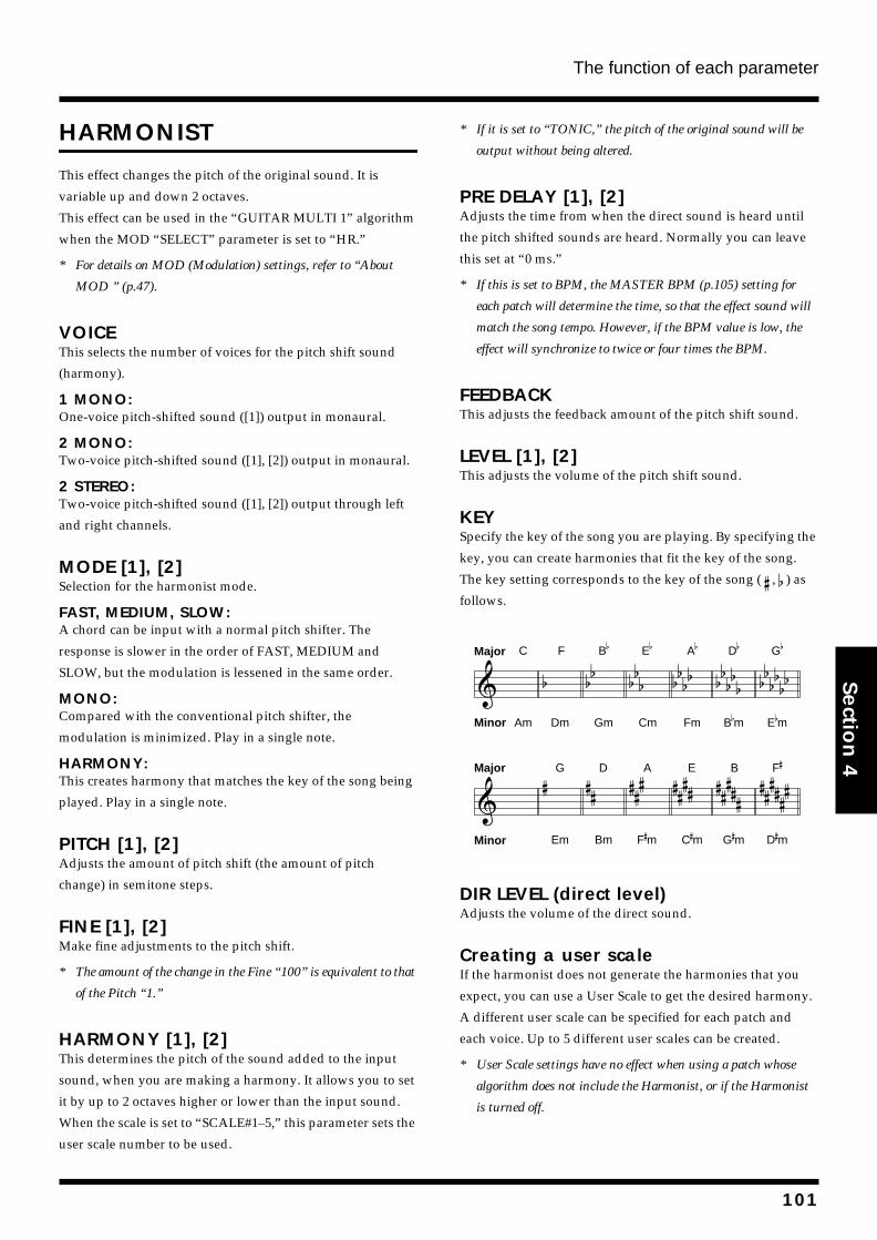
The function of each parameter
Section 4
HARMONIST
This effect changes the pitch of the original sound. It is
variable up and down 2 octaves.
This effect can be used in the “GUITAR MULTI 1” algorithm
when the MOD “SELECT” parameter is set to “HR.”
* For details on MOD (Modulation) settings, refer to “About
MOD ” (p.47).
VOICEThis selects the number of voices for the pitch shift sound
(harmony).
1 MONO:One-voice pitch-shifted sound ([1]) output in monaural.
2 MONO:Two-voice pitch-shifted sound ([1], [2]) output in monaural.
2 STEREO:Two-voice pitch-shifted sound ([1], [2]) output through left
and right channels.
MODE [1], [2]Selection for the harmonist mode.
FAST, MEDIUM, SLOW:A chord can be input with a normal pitch shifter. The
response is slower in the order of FAST, MEDIUM and
SLOW, but the modulation is lessened in the same order.
MONO:Compared with the conventional pitch shifter, the
modulation is minimized. Play in a single note.
HARMONY:This creates harmony that matches the key of the song being
played. Play in a single note.
PITCH [1], [2]Adjusts the amount of pitch shift (the amount of pitch
change) in semitone steps.
FINE [1], [2]Make fine adjustments to the pitch shift.
* The amount of the change in the Fine “100” is equivalent to that
of the Pitch “1.”
HARMONY [1], [2]This determines the pitch of the sound added to the input
sound, when you are making a harmony. It allows you to set
it by up to 2 octaves higher or lower than the input sound.
When the scale is set to “SCALE#1–5,” this parameter sets the
user scale number to be used.
* If it is set to “TONIC,” the pitch of the original sound will be
output without being altered.
PRE DELAY [1], [2]Adjusts the time from when the direct sound is heard until
the pitch shifted sounds are heard. Normally you can leave
this set at “0 ms.”
* If this is set to BPM, the MASTER BPM (p.105) setting for
each patch will determine the time, so that the effect sound will
match the song tempo. However, if the BPM value is low, the
effect will synchronize to twice or four times the BPM.
FEEDBACKThis adjusts the feedback amount of the pitch shift sound.
LEVEL [1], [2]This adjusts the volume of the pitch shift sound.
KEYSpecify the key of the song you are playing. By specifying the
key, you can create harmonies that fit the key of the song.
The key setting corresponds to the key of the song ( , ) as
follows.
fig.4-304
DIR LEVEL (direct level)Adjusts the volume of the direct sound.
Creating a user scaleIf the harmonist does not generate the harmonies that you
expect, you can use a User Scale to get the desired harmony.
A different user scale can be specified for each patch and
each voice. Up to 5 different user scales can be created.
* User Scale settings have no effect when using a patch whose
algorithm does not include the Harmonist, or if the Harmonist
is turned off.
Major C F B
E
A
D
Am Dm Gm Cm Fm BmMinor
Major G D A E B
Em Bm Fm C
m G
mMinor
F
Dm
G
Em
101
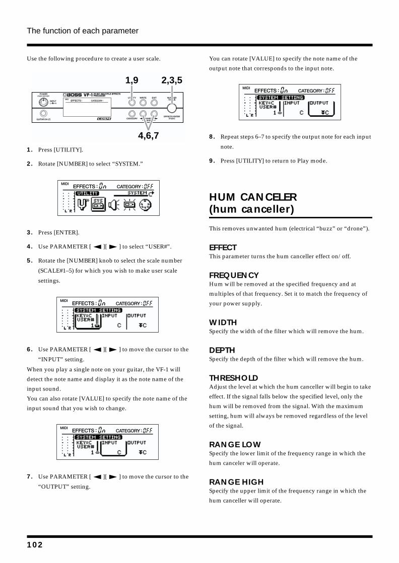
The function of each parameter
Use the following procedure to create a user scale.
fig.4-305
1. Press [UTILITY].
2. Rotate [NUMBER] to select “SYSTEM.”
fig.4-07
3. Press [ENTER].
4. Use PARAMETER [ ][ ] to select “USER#”.
5. Rotate the [NUMBER] knob to select the scale number
(SCALE#1–5) for which you wish to make user scale
settings.
fig.4-307
6. Use PARAMETER [ ][ ] to move the cursor to the
“INPUT” setting.
When you play a single note on your guitar, the VF-1 will
detect the note name and display it as the note name of the
input sound.
You can also rotate [VALUE] to specify the note name of the
input sound that you wish to change.
fig.4-308
7. Use PARAMETER [ ][ ] to move the cursor to the
“OUTPUT” setting.
You can rotate [VALUE] to specify the note name of the
output note that corresponds to the input note.
fig.4-309
8. Repeat steps 6–7 to specify the output note for each input
note.
9. Press [UTILITY] to return to Play mode.
HUM CANCELER (hum canceller)
This removes unwanted hum (electrical “buzz” or “drone”).
EFFECTThis parameter turns the hum canceller effect on/off.
FREQUENCYHum will be removed at the specified frequency and at
multiples of that frequency. Set it to match the frequency of
your power supply.
WIDTHSpecify the width of the filter which will remove the hum.
DEPTHSpecify the depth of the filter which will remove the hum.
THRESHOLDAdjust the level at which the hum canceller will begin to take
effect. If the signal falls below the specified level, only the
hum will be removed from the signal. With the maximum
setting, hum will always be removed regardless of the level
of the signal.
RANGE LOWSpecify the lower limit of the frequency range in which the
hum canceler will operate.
RANGE HIGHSpecify the upper limit of the frequency range in which the
hum canceller will operate.
1,9
4,6,7
2,3,5
102
The function of each parameter
Section 4
HUMANIZER
This can create vowel sounds of the human beings using the
guitar sound.
This effect can be used in the “GUITAR MULTI 1” algorithm
when the MOD “SELECT” parameter is set to “HU.”
* For details on MOD (Modulation) settings, refer to “About
MOD ” (p.47).
MODE This sets the mode that switches the vowels.
PICK (picking):It changes from vowel 1 to vowel 2 along with the picking.
The time spent for the change is adjusted with the rate.
AUTO:By adjusting the rate and depth, two vowels (Vowel 1 and
Vowel 2) can be switched.
RANDOM:Five vowels (a, e, i, o, u) are called out at random by
adjusting the “RATE” and “DEPTH.”
VOWEL [1]This selects the first vowel.
VOWEL [2]This selects the second vowel.
SENS (sensitivity)This adjusts the sensitivity of the humanizer. When it is set to
a lower value, no effect of the humanizer is obtained with
weaker picking, while stronger picking produces the effect.
When it is set to a higher value, the effect of the humanizer
can be obtained whether the picking is weak or strong.
RATEThis adjusts the cycle for changing the two vowels.
* If this is set to BPM, the MASTER BPM (p.105) value set for
each patch will determine the cycle, so that the effect sound will
match the tempo of the song. However if the BPM value is high,
the effect will synchronize to 1/2 or 1/4 of the BPM value.
DEPTHThis adjusts the depth of the effect.
MANUALThis determines the point where the two vowels are
switched.When it is set to “50,” vowel 1 and vowel 2 are
switched in the same length of time. When it is set to lower
than “50,” the time for vowel 1 is shorter. When it is set to
higher than “50,” the time for vowel 1 is longer.
LEVELThis sets the volume of the humanizer.
3BAND ISOLATOR
The input sound is separated into three frequency ranges —
high, mid, and low — each of which can be boost or cut. With
ordinary equalizers, even when the gain control for any of the
frequency ranges turned all the way down, some sound from
that range remains, whereas the VF-1’s Isolator cuts it
completely. You may find turning the Isolator on and off or
adjusting the level in real time to be a very effective technique.
EFFECTThis parameter turns the 3-band isolator iso effect on/off.
AnitiPHASE LowLEVEL (anti-phase low level)AnitiPHASE MidLEVEL (anti-phase middle level)These set the level of the Anti-Phase function. Adjusting
these levels for certain frequencies allows you to lend
emphasis to specific parts.
LOW MIX SWITCH (anti-phase low mix switch)MID MIX SWITCH (anti-phase middle mix switch)These turn the low- and mid-range Anti-Phase function on
and off. When turned on, the phases of opposite stereo
channels are reversed and then added.
LOW LEVELMID LEVEL (middle level)HIGH LEVELThese boost and cut each of the Low, Mid, and High
frequency ranges. Setting any of these to “-60 dB,” the
sounds in that range become inaudible. When set to “0 dB,”
the sound remains at the input level.
103
The function of each parameter
LOFI BOX
This allows you to create a “lo-fi” sound.
EFFECTThis parameter turns the lo-fi box effect on/off.
SELECTSelect the mode of the lo-fi box.
* If you edit an effect with “SELECT,” the effect parameter that
you have set before editing will be initialized.
RADIO:The sound will appear to be heard from an AM radio. By
adjusting “Tuning,” you can simulate the sounds that occur
when you adjust the tuning frequency of the radio.
PLAYER:The sound will appear to be heard from a gramophone. The
noise caused by scratches and dust on the record is
simulated.
PROCESSOR:This allows you to create a “lo-fi” sound by lowering the
sample rate and/or decreasing the number of bits. Realtime
modify filters connected in series allow you to reshape the
sound freely.
<When “RADIO” or “PLAYER” is selected>TUNINGThis is a parameter for “Radio.” It simulates the sounds that
occur when you adjust the tuning frequency of an AM radio.
WOW FLUTTERThis is a parameter for “PLAYER.” It simulates the wow and
flutter which occur when the speed of the turntable is not
constant.
NOISEThis simulates noise.
FILTERAdjusts the filter.
SOUNDAdjusts the tone.
<When “PROCESSOR” is selected>PRE FILTERThis filter decreases digital distortion. By turning this off,
you can create an extremely lo-fi sound that includes digital
distortion.
SAMPLE RATEModify the sample rate. If this is turned off, when it is set to
“off” the sample rate does not work at all.
BITModify the number of data bits. If this is turned off, the
number of data bits will be unchanged.
If an extremely low number of bits is selected, loud noise
may appear even when there is no sound, depending on the
input source. In such cases, raise the threshold of the noise
suppressor.
POST FILTERThis filter decreases the digital distortion produced by lo-fi.
By turning this off, you can create an extremely lo-fi sound.
FX LEVEL (effect level)Adjust the volume of the lo-fi sound.
DIR LEVEL (direct level)Adjust the volume of the direct sound.
REALTIME MODIFY FILTERSelect the filter type.
OFF:The realtime modify filter will not be used.
LPF:The low pass filter will operate.
BPF:The band pass filter will operate.
HPF:The high pass filter will operate.
CUTOFFAdjust the cutoff frequency.
RESONANCEAdjust the resonance.
GAINAdjust the volume level of the sound that has passed
through the realtime modify filter.
104
The function of each parameter
Section 4
MASTER
“Master” is located on the last of all each algorithm, allowing
you to set the patch’s output level, and foot volume level.
LINKThis parameter is for “MIC SIMULATOR.”
This is a link switch for channels L and R.
If this is turned off, the channels will function independently
as two monaural channels. If this is turned on, both channels
will be controlled simultaneously by the settings of channel
L.
* If “LINK=ON” has been selected, the parameter you have set on
the R channel will have no effect, turning it to exactly the same
setting as the L channel.
LEVEL (master level)This adjusts the output volume of the VF-1.
When making Master settings, the level meter (p.18, 31) will
show the initial input of the patch (the signal before it passes
through any effect) and the final output (the signal after it
has passed through all effects of the algorithm).
BPM (master BPM)By specifying a BPM to match the tempo of your song, you
can create an effect that changes the sound in
synchronization with the tempo. For example if you use BPM
for a flanger, the sound will modulate in synchronization
with the tempo.
Here you can make the BPM setting for each effect.
* If there is no parameter that can set the BPM in the effects of the
Algorithm, “BPM” will not be shown in the display.
BPM (Beats Per Minute) indicates the number of quarter
notes per minute.
The notes for the BPM can be selected from the followings:
fig.4-230
BPM can be set in one of the following three ways.
* In order to make the effect use the BPM setting, you must set
the appropriate parameter (e.g., Chorus Rate or Dly Time) to
“BPM .”
40–250:Set the BPM in the range of 40-250.
MIDI:The Timing Clock messages received at MIDI IN will
determine the BPM value.
GLOBAL:The value (speed) specified for the GLOBAL SOUND
SETTING parameter “GLOBAL BPM” will control the effect.
* For details on the “GLOBAL” BPM setting, refer to “GLOBAL
SYSYTEM SETTING: GLOBAL BPM (p.45).”
* In the following cases, the BPM setting will have no effect.
• When “BPM ” is selected as the effect parameter,
but that effect is turned off
• When the effect parameter is set to other than “BPM
.”
FOOT LEVEL (foot volume level)This adjusts the volume at the position where “FV (foot
volume)” in the Algorithm is connected.
* The foot volume is placed in the optimal location for each
algorithm. For details refer to “Algorithm list” (p.49–90).
BPM BPM
BPM BPM BPM BPM
BPM
BPM BPM
BPM BPM BPM
BPM
BPMBPM
BPM
To control the volume of foot level with the Expression
pedal, set “Control Assign” (p. 103) as follows.
< ASSIGN1: ON >
TARGET: MASTER:FOOT VOLUME LEVEL
TARGET MIN: 0
TARGET MAX: 100
SOURCE TYPE: ExpPEDAL
SOURCE MODE: NORMAL
SOURCE MIN: 0
SOURCE MAX: 127
105
The function of each parameter
MIC CONV (Mic Converter)
This converts the characteristics of an inexpensive general
purpose mic into the characteristics of an expensive studio
mic (Microphone –> Microphone conversion). For an
already-recorded sound, it can create the same tonal change
as if the type or distance of the mic had been changed.
This adds a feeling of “air” to an instrumental sound that
was recorded by direct line input, causing it to sound as
though it had been recorded with a microphone (Line –>
Microphone conversion).
EFFECTThis parameter turns the mic converter effect on/off.
INPUTSelect the type of mic that was actually used to record.
DR-20:Roland DR-20
SML.DY:Small Dynamic Microphone
HED.DY:Head-worn Dynamic Microphone
MIN.CN:Miniature Condenser Microphone
FLAT:Line Input
OUTPUTSpecify the mic that will be simulated.
SML.DY:General purpose dynamic mic for instruments or vocals.
Ideal for guitar amp or snare drum.
VOC.DY:A popular dynamic mic for vocals. Characterized by a tight
mid-range. Use for vocals.
LRG.DY:Dynamic mic with extended low end. Use for bass drum or
tom, etc.
SML.CN:Small condenser mic for instruments. Characterized by a
sparkling high range. Use for metallic percussion or acoustic
guitar.
LRG.CN:Condenser mic with flat response. Use for vocals, narration,
or acoustic instruments etc.
VNT.CN:Vintage condenser mic. Use for vocals or acoustic
instruments etc.
FLAT:Mic with flat frequency response. For cancelling the
characteristics of the mic used for recording.
* When you select a condenser-type mic simulator, the low range
response is strengthened. This may cause noise transmitted
from the mic stand to be emphasized. In this case, either use a
bass cut filter (p. 92) to cut the unwanted low range, or equip
the mic stand that you use at the time of recording with an
isolation mount (a mic holder that uses rubber etc. to absorb
vibration).
* If INPUT is set to “MIC.CN,” the OUTPUT can be set only to
“SML.DY” or “LRG.CN.”
PHASESpecify the phase of the mic.
NOR:Same phase as the input
INV:Opposite phase as the input
106
The function of each parameter
Section 4
MULTI TAP DELAY
This is an effect in the “Multi tap delay (20 tap)” algorithm.
This parameter creates a distinctive effect (such as a thicker
sound) by applying a delayed sound to the direct sound.
Multi tap delay lets you make independent settings for each
of 20 tap delays.
EFFECTThis parameter turns the multi tap delay effect on/off.
RATIO (time ratio)This setting maintains the time ratio set in the DELAY TIME
[1]–[20] settings and extends / shortens this ratio to the
overall time.
TAP [1]–[20] DELAY TIMEAdjust the delay time for each delay (TAP [1]–[20]).
* If this is set to BPM, the MASTER BPM (p.105) value that is
set for each patch will determine the delay time, so that the effect
will match the tempo of the song. However if the BPM value is
low, the effect will synchronize to twice or four times the BPM.
TAP [1]–[20] FINE TIMEMake fine adjustments to the delay time for each delay (TAP [1]–[20]).
TAP [1]–[20] PAN L:RAdjust the stereo location (pan) of each delay sound (TAP
[1]–[20]).
L0-100:Adjust the output level of the L channnel.
R0-100:Adjust the output level of the R channnel.
* When L100 is set, only the L channel will be used, while only
the R channel will be used when R100 is set.
TAP [1]–[20] LEVELAdjust the volume of each delay sound (TAP [1]–[20]).
FB DELAY (feedback delay time)Adjust the delay time for the feedback sound.
* If this is set to BPM, the MASTER BPM (p.105) value that is
set for each patch will determine the delay time, so that the effect
will match the tempo of the song. However if the BPM value is
low, the effect will synchronize to twice or four times the BPM.
FB FINE (feedback delay time)Make fine adjustments to the delay time for the feedback sound.
FB LEVEL (feedback level)Adjust the amount of feedback. Higher settings will result
more delay repeats.
LOW CUT (low cut filter)The Low Cut Filter cuts the frequency contents that are lower
than the set frequency. This parameter adjusts the frequency
where the low cut filter starts working. When it is set to
“FLAT,” the high cut filter does not work at all.
HIGH CUT (high cut filter)This parameter adjusts the frequency where the high cut
filter starts working. When it is set to “FLAT,” the high cut
filter does not work at all.
DIR LEVEL (direct level)Adjusts the volume of the direct sound.
FX LEVEL (effect level)This adjusts the volume of the delay sound.
NS.SUPPRESSOR (Noise Suppressor)
This effect reduces the noise and hum. Since it suppresses the
noise in synchronization with the envelope of the sound (the
way in which the sound decays over time), it has very little
effect on the guitar sound, and does not harm the natural
character of the sound.
EFFECTThis parameter turns the noise suppressor effect on/off.
DETECT (detector in)This is the parameters for both “STEREO MULTI” and “10
GRAPHIC EQ.” It selects the input source which will control
the nose suppressor.
L:It will be controlled by the input source of channel L.
R:It will be controlled by the input source of channel R.
LINK:It will be controlled by the input source whose level is
greater.
107
The function of each parameter
THRESHOLDAdjust this parameter as appropriate for the volume of the
noise. If the noise level is high, a higher setting is
appropriate. If the noise level is low, a lower setting is
appropriate. Adjust this value until the decay of the sound is
as natural as possible.
* High settings for the Threshold parameter may result in there
being no sound when you play with your instruments volume
turned down.
RELEASEAdjusts the time from when the noise suppressor begins to
function until volume reaches “0.”
OCTAVE
This adds a note one octave lower,creating a richer sound.
EFFECTThis parameter turns the octave effect on/off.
OCT LEVEL (octave level)This adjust the volume of the sound one octave below.
DIR LEVEL (direct level)This adjust the volume of the direct sound.
OVER DRIVE
It’s possible to simulate the distortion produced by a rotary
speaker’s vacuum-tube amp (Overdrive).
EFFECTThis parameter turns the overdrive effect on/off.
GAINThis parameter adjusts the input level for Overdrive. Larger
values result in greater distortion.
DRIVEThis parameter adjusts the amount of distortion.
LEVELThis parameter adjusts the output level for Overdrive.
PHASER
By adding varied-phase portions to the direct sound, the
phaser effect gives a whooshing, swirling character to the
sound.
EFFECTThis parameter turns the phaser effect on/off.
TYPESelects the number of stages that the phaser effect will use.
4STAGE:This is a four-phase effect. A light phaser effect is obtained.
6STAGE:This is a six-phase effect. A popular phaser effect is obtained.
8STAGE:This is an eight-phase effect. It is the most popular phaser
effect.
10STAGE:This is a ten-phase effect. A deep phaser effect is obtained.
12STAGE:This is a twelve-phase effect. The deepest phaser effect is
obtained.
BI-PHASE:This is the phaser with two phase shift circuits connected in
series.
RATEThis sets the rate of the Phaser effect.
* If this is set to BPM, the MASTER BPM (p.105) setting for
each patch will determine the rate, and the effect sound will
synchronize to the tempo of the song. However if the BPM value
is large, the effect will synchronize to 1/2 or 1/4 of the BPM.
DEPTHDetermines the depth of the Phaser effect.
MANUALAdjusts the center frequency of the phaser effect.
RESONANCEDetermines the amount of resonance (feedback). Increasing
the value will emphasize the effect, creating a more unusual
sound. Setting it to a minus value will create resonance
having a reversed phase.
SEPARATE (separation)Adjusts the diffusion. The diffusion increases as the value
increases.
108
The function of each parameter
Section 4
STEPThis can be used to cause the sound to change in a stepped
manner. Increasing the value will make the change finer. If
this is “OFF,” step will have no effect.
LEVELThis adjusts the volume of the phaser.
PICKUP SIM (Pickup Simulator)
This produces the sound of different types of pickup. You
can produce thick humbucking-style sounds even with a
single-coil guitar.
This effect can be used in the “GUITAR MULTI 2” algorithm
when the SFX “SELECT” parameter is set to “PIC.”
* For details on SFX settings, refer to “About SFX” (p.48).
TYPESelect the type of pickup.
‘S’ to ‘H’ (single to hum):This converts the sound of a single coil pickup to the sound
of a humbucking pickup.
‘H’ to ‘S’ (hum to single):This converts the sound of a humbucking pickup to the
sound of a single coil pickup.
‘H’ to ‘HF’ (hum to half-tone):This converts the sound of a humbucking pickup to the half-
tone sound of a single-coil pickup.
TONEAdjusts the tone.
LEVELAdjusts the volume.
PITCH SHIFTER
This effect changes the pitch of the original sound (up or
down) within a range of two octaves.
EFFECTThis parameter turns the pitch shifter effect on/off.
MODEThis parameter selects the mode of the Pitch Shifter.
FAST, MEDIUM, SLOW:A chord can be input with a normal pitch shifter. The
response is slower in the order of Fast, Medium and Slow,
but the modulation is lessened in the same order.
INV1:Provides reverse sound. Response is fast; reverse time is
short.
INV2:Provides reverse sound. Response is slow; reverse time is
long.
PITCHAdjusts the amount of pitch shift (the amount of pitch
change) in semitone steps.
FINEMake fine adjustments to the pitch shift.
* The amount of the change in the Fine “100” is equivalent to that
of the Pitch “1.”
BALANCE DIR:FX (direct: effect)This adjusts the volume balance of the direct and effect
sounds.
DIR:FX=100:0 Only the direct sound will be output.
DIR:FX=0:100 Only the effect sound will be output.
LEVELThis parameter adjusts the volume level.
109
The function of each parameter
PREAMP/SP.SIM (Preamp/Speaker Simulator)
Adjust the distortion and tone of the guitar sound.
* When all BASS, MIDDLE and TREBLE are set to “0,” no
sound may be produced depending on the Type settings.
* When using the preamp / speaker simulator, specifying it as a
“global sound setting” will produce the most effective preamp /
speaker simulator effect. For details refer to “Global sound
settings” (p.45).
* For the “GUITAR MULTI 1,” “GUITAR MULTI 2,” and
“BASS MULTI” algorithms, you can change the location where
PRE/SP.SIM will be placed. In this case, PRE/SP.SIM will
indicate “POSITION.” For details on the setting, refer to
“Changing the order of the effects” (p.30).
EFFECTTurns the PREAMP/SP.SIM effect on/off.
PREAMP TYPEThis sets the type of the guitar preamp. The distortion and
tone characteristics of each amp are as shown below:
JC-120:The sound of the Roland “JC-120” (Jazz Chorus 120), a
favorite of pro musicians around the world.
CLEAN TWIN:The sound of a conventional built-in tube amp.
CRUNCH:Allows you to obtain a crunch effect that creates a natural
distortion.
MATCH DRIVE:A simulation of the latest tube amp widely used in styles of
blues, rock and fusion.
VO DRIVE:Allows you to obtain the Liverpool sound of the 60’s.
BLUES:A lead sound with a rich middle ideal for Blues.
BG LEAD:The sound of a tube amp typical of the late ‘70s to ‘80s,
characterized by a distinctive mid-range.
MS1959 (I, II, I+II):The sound of a large tube amp stack that was indispensable
to the British hard rock of the 70’s, and is used to this day by
many hard rock guitarists.
I:A trebly sound created by using input I of the guitar amp.
II:A mild sound created by using input II of the guitar amp.
I+II:The sound of connecting inputs I and II of the guitar amp in
parallel, creating a sound with a stronger low end than I.
SLDN LEAD:A tube amp sound with versatile distortion, usable in a wide
range of styles.
METAL 5150:The sound of a large tube amp, suitable for heavy metal.
METAL DRIVE:A high gain and powerful metal sound.
AC.GUITAR (acoustic guitar):This is a preamp for electric-acoustic guitars.
* Choosing “AC.GUITAR” activates the built-in flat-amp
simulator, delivering a natural sound with no guitar-amp
idiosyncrasies. Note that when “GLOBAL SOUND
SETTING” for OUTPUT SELECT is set to “LINE,” the flat-
amp simulator is switched off.
OD-1:The sound of the renowned OD-1 from the BOSS compact
series.
OD-2 TURBO:The sound of the OD-2 from the BOSS compact series, with
Turbo switched on.
DISTORTION:This produces a standard distortion.
FUZZ:This produces a basic fuzz sound.
AC:This can be selected in the “BASS MULTI” algorithm.
It produces the vintage sound of an early transistor amp.
AMG:This can be selected in the “BASS MULTI” algorithm.
It produces the sound of a large double-stack vacuum tube
amp with ultra-lows and a crisp edge.
VOLUMEAdjusts the volume and distortion of the amp.
BASSAdjusts the tone for the low frequency range.
MIDDLEAdjusts the tone for the middle frequency range.
* If you have selected “MATCH DRIVE” as the type, the middle
control will have no effect.
110
The function of each parameter
Section 4
TREBLE Adjusts the tone for the high frequency range.
PRESENCEAdjusts the tone for the ultra high frequency range.
* If you have selected “MATCH DRIVE” or “VO DRIVE” as the
type, raising presence will cut the high range (the value will
change from “0” to “-100”).
MASTERAdjusts the volume of the entire preamp.
BRIGHTTurns the bright setting on/off.
OFF:Bright is not used.
ON:Bright is switched on to create a lighter and crisper tone.
* Depending on the “PREAMP TYPE” setting, this may not be
displayed.
GAINAdjusts the distortion of the amp. Distortion will
successively increase for settings of “LOW,” “MID” and
“HIGH.”
* The sound of each Type is created on the basis that the Gain is
set to “MID.” So, normally set it to “MID.”
MIC SETTINGThis simulates the microphone position. “CENT (center)”
simulates the condition that the microphone is set in the
middle of the speaker cone. “1–10 cm” means that the
microphone is moved away from the center of the speaker
cone.
MIC LEVELAdjusts the volume of the microphone.
DIR (DIRECT) LEVELAdjusts the volume of the direct sound.
* If you’ve chosen “AC.GUITAR” for “PREAMP TYPE”, use
with MIC LEVEL=100 and DIRECT LEVEL=0.
* MIC SETTING, MIC LEVEL or DIR (DIRECT) LEVEL will
not be shown in the display if being set as follows:
• When the OUTPUT SELECT of the Global Sound Setting
(p.45) is set to other than ”LINE”.
• When the TYPE of the Preamp Speaker Simulator is set to
“OD1”, “OD-2 TURBO”, “DISTORTION” or “FUZZ”.
REVERB
Reverberation (or reverb) is the effect caused by sound
waves decaying in an acoustic space, or a digital simulation
thereof. This decay occurs because sound waves bounce off
many walls, ceilings, objects, etc. in a very complex way.
These reflections, coupled with absorption by various
objects, dissipate the acoustic energy over a certain period of
time (called the decay time). The ear perceives this
phenomenon as a continuous wash of sound.
EFFECTThis parameter turns the reverb effect on/off.
TYPEThis selects the Reverb Type. Various different simulations of
space are offered.
* The available types will depend on the algorithm which is used.
ROOM:Simulates the reverberation in a small room.
HALL:Simulates the reverberation in a concert hall.
ROOM1:Simulates the reverberation in a small room. Provides the
bright reverberations.
ROOM2:Simulates the reverberation in a small room. Provides warm
reverberations.
HALL1:Simulates the reverberating in a concert hall. Provides clear
and spacious reverberations.
HALL2:Simulates the reverberation in a concert hall. Provides warm
reverberations.
PLATE:Simulates plate reverberation (a reverb unit that uses the
vibration of a metallic plate). Provides a metallic sound with
a distinct upper range.
(ROOM) SIZEThis parameter adjusts the size of the room which is
simulated.
REVERB TIMEThis parameter adjusts the duration (time) of the reverb.
111
The function of each parameter
BALANCE DIR:FX (direct: effect)This adjusts the volume balance of the direct and effect
sounds.
DIR:FX 100:0 Only the direct sound will be output.
DIR:FX 0:100 Only the effect sound will be output.
FX (EFFECT) LEVELThis parameter adjusts the effect level.
PRE DELAYThis parameter adjusts the time interval between the direct
sound and the beginning of the reverb sound.
DENSITYAdjust the density of the sound (Early Reflections) that
arrives at the listener after bouncing off the walls once or a
few times.
EARLY REF LEVEL (early reflection level)This parameter adjusts the volume level of the initial
reflected sound.
RELEASE DENSITYThis parameter adjusts the density of the sound that reaches
the listener after many repeated reflections.
LOW DAMP GAINThis parameter adjusts the amount of damping for Low
Damp. No low-frequency damping occurs when set to “0.”
LOW DAMP FREQUENCYThis parameter adjusts the standard frequency at which the
low-frequencies are damped. The reverb sound in the band
below this frequency is damped.
HIGH DAMP GAINThis parameter adjusts the amount of damping for High
Damp. No high-frequency damping occurs when set to “0.”
HIGH DAMP FREQUENCY This parameter adjusts the standard frequency at which the
high-frequencies are damped. The reverb sound in the band
above the standard frequency is damped.
LOW CUT (low cut filter)This parameter adjusts the frequency at which a high-pass
filter starts to be applied. The effect is applied to the reverb
sound.
HIGH CUT (FILTER)This parameter adjusts the frequency at which a low-pass
filter starts to be applied. The effect is applied to the reverb
sound.
GATE
Adjust the input level to control the reverb.
This setting can be used in the “GATE REVERB” algorithm.
EFFECTThis parameter turns the GATE effect on/off.
THRESHOLD (gate threshold)This parameter adjusts the standard level for controlling
opening and closing of the gate.
HOLD TIME (gate hold time)This parameter adjusts the time interval between the gate
opening and closing completely.
RLS TIME (gate release time)This parameter adjusts the time from when the hold time
ends to when the sound is completely muted.
RING MODULATOR
This creates a bell-like sound by ring-modulating the input
sound with the signal from the internal oscillator. The sound
will be unmusical and lack distinctive pitches.
MODEThis selects the mode for the ring modulator.
NORMAL:By ring-modulating the signal with the guitar sound and the
signal of the internal oscillator, it can create a bell like sound.
You can obtain a non-musical sound with the sense of pitch.
INTELLIGENT:By ring-modulating the input signal, a bell like sound is
created. The intelligent ring modulator changes the
oscillation frequency according to the pitch of the input
sound and therefore produces a sound with the sense of
pitch, which is quite different from “Normal.” This effect
does not give a satisfactory result if the pitch of the guitar
sound is not correctly detected. So, you must use a single
note.
112
The function of each parameter
Section 4
FREQ (frequency)This adjusts the frequency of the internal oscillator.
FX LEVEL (effect level)This adjusts the volume of the effect sound.
DIR LEVEL (direct level)This adjusts the volume of the direct sound.
ROTARY
This parameter simulates an old-fashioned rotary speaker,
which added undulations to the sound by rotating the
speaker as it played.
A real rotary speaker has a switch to select slow or fast
rotation. Its horn (treble-range speaker) and rotor (bass-range
speaker) can also be rotated independently. The ROTARY
Effector has parameters that can be used to re-create these
subtle effects.
EFFECTThis parameter turns the rotary effect on/off.
SPEED SELECTThis parameter changes the simulated speaker’s rotating
speed (SLOW or FAST).
HORN FASTThis parameter adjusts the speed of rotation for the horn
when set to “FAST.”
ROTOR FASTThis parameter adjusts the speed of rotation for the rotor
when set to “FAST.”
HORN SLOWThis parameter adjusts the speed of rotation for the horn
when set to “SLOW.”
ROTORY SLOWThis parameter adjusts the speed of rotation for the rotor
when set to “SLOW.”
RISE TIME HORNThis parameter adjusts the time it takes for the rotation speed
of the horn to change when switched from “SLOW” to
“FAST.”
RISE TIME ROTORThis parameter adjusts the time it takes for the rotation speed
of the rotor to change when switched from “SLOW” to
“FAST.”
FALL TIME HORNThis parameter adjusts the time it takes for the rotation speed
of the horn to change when switched from “FAST” to
“SLOW.”
FALL TIME ROTORThis parameter adjusts the time it takes for the rotation speed
of the rotor to change when switched from “FAST” to
“SLOW.”
BALANCE ROTOR:HORNThis parameter adjusts the volume balance between the horn
and rotor.
MIC SETTING This parameter switches the position of the microphone used
to record the sound of the rotary speaker.
OFF MIC:This simulates the sound recorded by a microphone
positioned at a distance from the rotary speaker. There are
few undulations in the sound. This setting is good for
instruments such as a jazz organ.
ON MIC:This simulates the sound recorded by a microphone
positioned close to the rotary speaker. The sound has many
undulations. This setting is good for instruments such as a
rock organ.
HORN DEPTHThis parameter adjusts the amount of depth in the Doppler
effect for the horn.
ROTOR DEPTHThis parameter adjusts the amount of depth in the Doppler
effect for the rotor.
HORN TRMLO (horn tremolo)This parameter adjusts the amount of change in volume for
the horn.
ROTOR TRMLO (rotor tremolo)This parameter adjusts the amount of change in volume for
the rotor.
DIFFUSIONThis parameter adjusts the “fatness” of the sound.
FX LEVEL (effect level)This adjusts the volume of the effect sound.
113
The function of each parameter
RSS PANNER
RSS PANNER can make the sound seem to revolve around
the listener.
EFFECTThis parameter turns the RSS PANNER effect on/off.
SPEEDThis parameter adjusts the speed with which the position of
the sound moves.
* If this is set to BPM, the MASTER BPM (p.105) setting for
each patch will determine the rate, so that the effect sound will
match the song tempo. However, if the BPM value is high, the
effect will synchronize to 1/2 or 1/4 of the BPM.
DIRECTIONThis parameter selects the sound’s direction of rotation.
CW (clockwise):Rotates the sound clockwise, looking down from above.
CCW (counterclockwise):Rotates the sound counterclockwise, looking down from above.
RSS (2ch)
RSS (Roland Sound Space) is an effector that creates a three-
dimensional sonic field. RSS can let you orient the sonic
image at a position above, below, before, behind, or to one
side or the other of the listener.
* To get the most out of the effects that RSS can provide, be sure
to read “Before using RSS” (page 121).
EFFECTThis parameter turns the RSS (2ch) effect on/off.
AZIMUTH [L]AZIMUTH [R]This parameter moves the sound horizontally along the
perimeter of an imaginary sphere. The setting can be made
within a range of about 180 degrees to the left or right, with
the standard setting (“0”) indicating a position directly in
front of the listener.
ELEVATION [L]ELEVATION [R]This parameter moves the sound vertically along the
perimeter of an imaginary sphere. The setting is made as the
number of degrees from the front of the listener (0).
SHORT DELAY
This is the delay with the maximum delay time of 400 ms.
This effect is efficient for making the sound fatter.
This effect can be used in the “GUITAR MULTI 1” algorithm
when the MOD “SELECT” parameter is set to “SDD.”
* For details on MOD (Modulation) settings, refer to “About
MOD ” (p.47).
DELAY TIMEAdjusts the delay time.
* If this is set to BPM, the MASTER BPM (p.105) value that is
set for each patch will determine the delay time, so that the effect
will match the tempo of the song. However if the BPM value is
low, the effect will synchronize to twice or four times the BPM.
FEEDBACKFeedback refers to returning the delayed signal back into the
input of the delay. This parameter adjusts the volume that is
returned to the input. Higher settings will result in more
delay repeats.
FX LEVEL (effect level)Adjusts the volume of delay sound.
SLICER
This consecutively interrupts the sound to create the
impression that a rhythm backing phrase is being played.
This effect can be used in the “GUITAR MULTI 1” and
“ISOLETER” algorithm when the MOD “SELECT”
parameter is set to “SL.”
* For details on MOD (Modulation) settings, refer to “About
MOD ” (p.47).
PATTERNSelect the slice pattern that will be used to cut the sound.
RATEAdjust the rate at which the sound will be cut.
* When this is set to BPM, the MASTER BPM setting (p.105)
made for each patch will determine the rate, producing an effect
sound that is synchronized with the tempo of the song.
However, if the BPM value is large, the effect will synchronize
to 1/2 or 1/4 of the BPM.
114
The function of each parameter
Section 4
TRIGGER SENS (trigger sensitivity)Adjust the sensitivity of triggering. With low settings of this
parameter, softly picked notes will not retrigger the phrase
(i.e., the phrase will continue playing), but strongly picked
notes will retrigger the phrase so that it will playback from
the beginning. With high settings of this parameter, the
phrase will be retriggered even by softly picked notes.
SLOW GEAR
This produces a volume-swell effect (“violin-like” sound).
This effect can be used in the “GUITAR MULTI 2” algorithm
when the SFX “SELECT” parameter is set to “SG.”
* For details on SFX settings, refer to “About SFX” (p.48).
SENS (sensitivity)This adjusts the sensitivity of the slow gear. When it is set to
a lower value, the effect of the slow gear can be obtained only
with a stronger picking, while no effect is obtained with a
weaker picking. When the value is set higher, the effect is
obtained even with a weak picking.
RISE TIMEThis adjusts the time needed for the volume to reach its
maximum from the moment you begin picking.
SPACE CHORUS
This chorus effect simulates the sound from Roland’s well-
known SDD-320 Dimension D.
EFFECTThis parameter turns the space chorus effect on/off.
INPUTThis parameter toggles between stereo and monaural input
signals.
MONO:This produces a space chorus for mono input with the left
and right channels mixed.
ST. (stereo):This produces a space chorus for stereo input with Space
Chorus applied separately to the left and right channels.
MODEThis parameter lets you choose how the chorus changes.
FX LEVEL (effect level)This adjusts the volume of the effect sound.
DIRECT SWITCHSwitch the direct sound on/off (output/no output).
STEREO PS DLY (Stereo Pitch Shifter Delay)
This applies a delay effect to the sound of the pitch shifter
effect.
EFFECTThis parameter turns the pitch shifter effect on/off.
MODEThis parameter selects the mode of the Pitch Shifter.
FAST, MEDIUM, SLOW:A chord can be input with a normal pitch shifter. The
response is slower in the order of Fast, Medium and Slow,
but the modulation is lessened in the same order.
PITCH [L]PITCH [R]Adjusts the amount of pitch shift (the amount of pitch
change) in semitone steps separately for each right and left
channel.
FINE [L]FINE [R]Make fine Adjustments to the pitch shift separately for each
right and left channel.
* The amount of the change in the FINE “100” is equivalent that
of the Pitch “1.”
PRE DELAY [L]PRE DELAY [R]Adjusts the time from when the direct sound is heard until
the pitch shifted sounds are heard separately for each right
and left channel. Normally you can leave this set at “0 ms.”
FB DELAY TIME [L] (feedback delay time L)FB DELAY TIME [R] (feedback delay time R)They adjust the delay time of the pitch-shifted feedback
sound independently for the right and left channels.
115
The function of each parameter
* If this is set to BPM, the MASTER BPM (p.105) value that is
set for each patch will determine the delay time, so that the effect
will match the tempo of the song. However if the BPM value is
low, the effect will synchronize to twice or four times the BPM.
FB FINE TIME [L] (feedback delay time fine L)FB FINE TIME [R] (feedback delay time fine R)They allow fine adjustment of the delay time of the pitch-
shifted feedback sound, independently for the left and right
channels.
FB LEVEL [L] (feedback level L)FB LEVEL [R] (feedback level R)These parameters adjust the feedback amount of the pitch-
shifted sound independently for the right and left channels.
Changing the feedback amount will change the number of
times that the pitch-shifted sound is repeated.
BALANCE DIR: FX (direct: effect)This adjusts the volume balance of the direct and effect
sounds.
DIR:FX 100:0 Only the direct sound will be output.
DIR:FX 0:100 Only the effect sound will be output.
LEVELThis parameter adjusts the volume level.
SUB 4BAND EQ (Sub 4 Band Equalizer)
This adjusts the tone as a sub equalizer. A parametric type is
adopted for the high-middle and low-middle range.
This effect can be used in the “GUITAR MULTI 1” algorithm
when the MOD “SELECT” parameter is set to “SEQ.”
* For details on MOD (Modulation) settings, refer to “About
MOD ” (p.47).
LOW EQ (low equalizer)Adjusts the low frequency range tone.
HIGH EQ (high equalizer)Adjusts the high frequency range tone.
LO-MD F (low-middle frequency)Specify the center of the frequency range that will be
adjusted by the “LOW-MID EQ.”
LOW-MID Q (low-middle Q)Adjusts the width of the area affected by the EQ centered at
the “LO-MD F.” Higher values will narrow the area.
LOW-MID EQ (low-middle equalizer)Adjusts the low-middle frequency range tone.
HI-MD F (high-middle frequency)Specify the center of the frequency range that will be
adjusted by the “HI-MID EQ.”
HI-MID Q (high-middle Q)Adjusts the width of the area affected by the EQ centered at
the “HI-MD F.” Higher values will narrow the area.
HI-MID EQ (high-middle equalizer)Adjusts the high-middle frequency range tone.
LEVELAdjusts the volume after the equalizer.
T-WAH (Touch WAH)
Touch wah creates an automatic wah by changing the filter
in response to the volume of input.
This effect can be used in the “BASS MULTI” algorithm when the EQ/TW “SELECT” parameter is set to “TW.”
SENS (Sensitivity)Adjust the sensitivity with which the filter will be affected.
Higher settings will produce a greater response, and if this is
set to a value of “0,” a fixed wah will result.
STARTThis determines the direction to which the filter’s cutoff
frequency should move.
UP:A wah in which the input will cause the filter to move
toward a higher frequency.
DOWN:A wah in which the input will cause the filter to move
toward a lower frequency.
STOPThis adjust the frequency where the filter’s cutoff frequency
will ultimately stop as the input level decreases.
116
The function of each parameter
Section 4
RESONANCEThis adjusts the feedback amount of the filter. As it is set to a
higher value, the created sound will be more unusual.
FX LEVEL (effect level)Adjusts the volume of the effect sound.
DIR LEVEL (direct level)This adjusts the volume of the direct sound when the effect is
tured on.
TAPE ECHO201
This echo effect simulates the sound from Roland’s well-
known RE-201.
EFFECTThis parameter turns tape echo201 effect on/off.
MODE (mode selector)This is used to select the different delay times (short, middle,
and long) combination of three playback heads. When set to
“4,” you can select short delays.
REPEAT RATEThis adjusts the “tape’s” running speed. The higher the
value, the shorter the interval of the repeated sound.
INTENSITYThis sets the number of times the sound is repeated.
TONE BASSThis adjusts the volume of the low end of the Tape Echo
sound.
TONE TREBLEThis adjusts the volume of the Tape Echo sound’s high end.
PAN HEAD S L:RPAN HEAD M L:RPAN HEAD L L:RThese adjust the pan settings for each of the short, middle,
and long delay playback heads individually. This function is
not featured on Roland’s RE-201.
TAPE DIST (tape distortion)This adds the distortion characteristic of a tape. It simulates
even the very subtle behavior that can be detected only by an
analyzer.
WOW RATE (wow flutter rate)This adjusts the wavering of the pitch that occurs with
deterioration or unevenness in the tape. The higher the value,
the more intense the wavering effect.
WOW DEPTH (wow flutter depth)Adjust the depth of pitch modulation that is produced by
wear on the tape and by irregular rotation of the tape
mechanism. Increasing this value will produce deeper
modulation.
FX LEVEL (effect level)This adjusts the volume level of the Tape Echo effect.
DIR LEVEL (direct level)This adjusts the volume level of the direct sound.
TREMOLO/PAN
Tremolo is an effect that creates a cyclic change in volume.
Pan cyclically moves the stereo position between left and
right (when stereo output is used).
EFFECTThis parameter turns the tremolo/pan effect on/off.
MODESelection for tremolo or pan.
TREMOLO:The volume will change cyclically.
PAN:The sound will be moved cyclically between left and right.
WAVE SHAPEThis adjusts changes in volume level.
RATEAdjust the rate at which the effect will operate.
* When this is set to BPM, the MASTER BPM setting (p.105)
made for each patch will determine the rate, producing an effect
sound that is synchronized with the tempo of the song.
However, if the BPM value is large, the effect will synchronize
to 1/2 or 1/4 of the BPM.
DEPTHAdjusts the depth of the effect.
117
The function of each parameter
VIBRATO
This effect creates vibrato by slightly modulating the pitch.
This effect can be used in the “GUITAR MULTI 1” algorithm
when the MOD “SELECT” parameter is set to “VB.”
* For details on MOD (Modulation) settings, refer to “About
MOD ” (p.47).
RATEThis adjusts the rate of the vibrato.
* If this is set to BPM, the MASTER BPM (p.105) setting for
each patch will determine the rate, so that the effect sound will
match the song tempo. However, if the BPM value is high, the
effect will synchronize to 1/2 or 1/4 of the BPM.
DEPTHThis adjusts the depth of the vibrato.
TRIGGERThis parameter works as a switch that turns on the vibrato
effect.
When it is set to ON, the vibrato effect will be obtained
according to the RISE TIME setting.
* This effect assumes that the trigger will be turned on with a foot
switch for attaining the vibrato effect.
RISE TIMEThis sets the time passing from the moment the trigger is
turned on until the set vibrato is obtained.
VOCAL CANCELER
When a stereo source is being input from CD or DAT etc.,
this cancels the sound which is located in the stereo center,
such as the vocal or bass.
EFFECTThis parameter turns the vocal canceller effect on/off.
BALANCEIf the sound that you wish to cancel is not located in the
center, find the point at which it is most effectively cancelled.
When the value is set to “50,” the sound that is located at the
center will be muted.
RANGE LOWSpecify the lower limit of the frequency range from which
you wish to cancel a sound. Use this setting when you wish
to decrease the volume of the vocal without affecting a low-
frequency instrument (such as bass) located in the center.
RANGE HIGHSpecify the upper limit of the frequency range from which
you wish to cancel a sound. Use this setting when you wish
to decrease the volume of the vocal without affecting a high-
frequency instrument located in the center.
VOCODER
This is a 10 band vocoder. A clear sound that was not
possible with conventional vocoders can be obtained. Input
an instrumental sound into the left channel, and a voice into
the right channel.
EFFECTThis parameter turns the vocoder effect on/off.
ENVELOPESelect how the sound will be produced.
SHARP:The human voice will be emphasized.
SOFT:The instrumental sound will be emphasized.
LONG:A vintage sound with long decay will be produced.
PAN MODESelect MONO, STEREO, L->R or R->L.
TRIGGER ON/OFFTo switch the trigger on/off of the vibrato using the foot
switch (FS-5U, DP-2 (Roland), etc.), set “Control Assign”
(p. 33) as follows.
< ASSIGN1: ON >
TARGET: MOD (VIBRATO): TRIGGER
TARGET MIN: OFF
TARGET MAX: ON
SOURCE TYPE: CONTROL1
SOURCE MODE: NORMAL
SOURCE MIN: 0
SOURCE MAX: 127
118
The function of each parameter
Section 4
MONO:The components of each frequency band will be located in
the center.
STEREO:The odd-numbered frequency bands will be located at the
left, and the even-numbered components at the right.
L->R:The low frequency bands will be located increasingly toward
the left, and the high frequency bands will be located
increasingly toward the right.
R->L:The low frequency bands will be located increasingly toward
the right, and the high frequency bands will be located
increasingly toward the left.
HOLDThis turns the Hold function on/off. If you turn Hold on
while a voice is being input into the mic, the instrument will
sound with the vocal formats that are fixed at that time.
MIC SENS (mic sensitivity)Adjust the input sensitivity of the mic.
SYNTH LEVEL (synthesizer in level)Adjust the input level of the instrument.
CHAR [1]–[10] (voice character channel)Adjust the volume of each frequency band. This setting
adjusts the tone of the vocoder. As the value is increased, the
frequency will rise.
MIC MIXAdjust the amount of the mic audio (R channel input) which
has passed through the mic HPF that will be added to the
output of the vocoder.
MIC HPFWhen mic mix is used, this adjusts the frequency at which
the high pass filter (HPF) will begin to affect the mic audio.
Higher values for this setting will allow you to mix only the
consonants. With a setting of Thru, the HPF will not be
applied.
MIC PAN L:RAdjust the panning of the mic audio.
NS THRESHOLD (noise suppressor threshold)Adjust the level at which the noise suppressor applied to the
Mic input (R channel input) will begin to function.
VoiceTRANSFORM (Voice Transformer)
This independently controls the basic pitch and the formants,
allowing a variety of voice characters to be created.
EFFECTThis parameter turns the voice transformer effect on/off.
ROBOTTurn the robot function on/off. When this is on, the audio
will be output at a fixed pitch regardless of the pitch that is
input, producing a voice character without inflection.
CRMTC PITCH (chromatic pitch)Adjust the pitch of the voice character in semitone steps. This
can be adjusted over a range of 1 octave down to 1 octaves up.
FINE PITCHMake fine adjustments to the pitch of the voice character.
CRMTC FRMT (chromatic formant)Adjust the formant of the voice character in semitone steps.
This can be adjusted over a range of 1 octave down to 1
octaves up.
FINE FRMT (fine formant)Make fine adjustments to the formant of the voice character.
MIX BAL (mix balance)Adjust the balance between the voice character volume and
the normal voice volume. When the value is set to “0,” only
the normal voice will be output, while only the voice
character sound is output when it is set to “100.”
HOLD ON/OFFTo switch hold on/off using the foot switch (FS-5U,DP-2
(Roland),etc.), set “Control Assign” (p. 33) as follows.
< ASSIGN1: ON >
TARGET: VOCODER: HOLD
TARGET MIN: OFF
TARGET MAX: ON
SOURCE TYPE: CONTROL1
SOURCE MODE: NORMAL
SOURCE MIN: 0
SOURCE MAX: 127
119
The function of each parameter
WAH
The wah effect creates a unique tone by changing the
frequency response characteristics of a filter. Pedal wah lets
you use an Expression pedal or the like to obtain real-time
control of the wah effect. Auto wah creates an automatic wah
by cyclically changing the filter, or by changing the filter in
response to the volume of the input.
EFFECTTurns the pedal wah/auto wah effect on/off.
SELECT (effect select)Selects either pedal wah “WAH” or auto wah “AW”.
* If you edit an effect with “SELECT,” the effect parameter that
you have set before editing will be initialized.
WAH (pedal wah):The effect will function as a pedal wah.
AW (auto wah):The effect will function as an auto wah.
< When “WAH (pedal wah)” is selected >The effect of the wah pedal can be obtained by operating the
Expression pedal.
* For a detailed explanation, see “Ways to use control assign”
(page 39).
PEDALThis adjusts the position of the wah pedal.
LEVELAdjusts the volume.
< When “AW (auto wah)” is selected >MODESelection for the wah mode.
LPF (low pass filter):This creates a wah effect over a wide frequency range.
BPF (band pass filter):This creates a wah effect in a narrow frequency range.
POLARITYSelection for the direction in which the filter will change in
response to the input.
UP:The frequency of the filter will rise.
DOWN:The frequency of the filter will fall.
SENS (sensitivity)This adjusts the sensitivity at which the filter will change in
the direction determined by the polarity setting. Higher
values will result in a stronger response. With a setting of
“0,” the strength of picking will have no effect.
FREQ (frequency)This adjusts the center frequency of the Wah effect.
PEAKAdjusts the way in which the wah effect applies to the area
around the center frequency. Lower values will produce a
wah effect over a wide area around the center frequency.
Higher values will produce a wah effect in a narrow area
around the center frequency.
* With a value of “50” a standard wah sound will be produced.
RATEAdjusts the rate of the auto wah.
* If this is set to BPM, the MASTER BPM (p.105) value set for
each patch will determine the rate, so that the effect sound will
match the tempo of the song. However if the BPM value is high,
the effect will synchronize to 1/2 or 1/4 of the BPM value.
DEPTHAdjusts the depth of the auto wah effect.
LEVELAdjusts the volume.
120
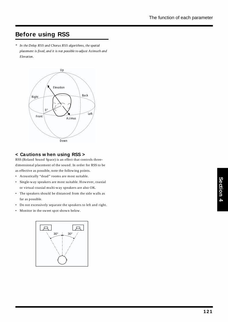
The function of each parameter
Section 4
Before using RSS
* In the Delay RSS and Chorus RSS algorithms, the spatial
placement is fixed, and it is not possible to adjust Azimuth and
Elevation.
fig.4-310
< Cautions when using RSS >RSS (Roland Sound Space) is an effect that controls three-
dimensional placement of the sound. In order for RSS to be
as effective as possible, note the following points.
• Acoustically “dead” rooms are most suitable.
• Single-way speakers are most suitable. However, coaxial
or virtual coaxial multi-way speakers are also OK.
• The speakers should be distanced from the side walls as
far as possible.
• Do not excessively separate the speakers to left and right.
• Monitor in the sweet spot shown below.
fig.4-311
Front
Right
Left
Back
Up
Down
0°
Elevation
Azimus
30° 30°
121
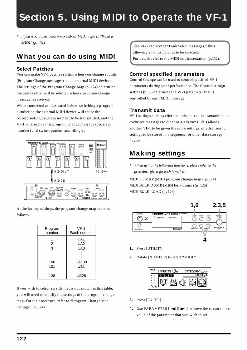
Section 5. Using MIDI to Operate the VF-1
* If you would like to learn more about MIDI, refer to “What is
MIDI” (p. 131).
What you can do using MIDI
Select PatchesYou can make VF-1 patches switch when you change sounds
(Program Change messages) on an external MIDI device.
The settings of the Program Change Map (p. 124) determine
the patches that will be selected when a program change
message is received.
When connected as illustrated below, switching a program
number on the external MIDI device will cause the
corresponding program number to be transmitted, and the
VF-1 will receive this program change message (program
number) and switch patches accordingly.
fig.5-01
At the factory settings, the program change map is set as
follows.
fig.5-01a
If you wish to select a patch that is not shown in this table,
you will need to modify the settings of the program change
map. For the procedure, refer to “Program Change Map
Settings” (p. 124).
Control specified parametersControl Change can be used to control specified VF-1
parameters during your performance. The Control Assign
settings (p.33) determine the VF-1 parameter that is
controlled by each MIDI message.
Transmit dataVF-1 settings such as effect sounds etc. can be transmitted as
exclusive messages to other MIDI devices. This allows
another VF-1 to be given the same settings, or effect sound
settings to be stored in a sequencer or other data storage
device.
Making settings
* When using the following functions, please refer to the
procedure given for each function.
MIDI PC MAP (MIDI program change map) (p. 124)
MIDI BULK DUMP (MIDI bulk dump) (p. 125)
MIDI BULK LOAD (p. 126)
fig.5-02
1. Press [UTILITY].
2. Rotate [NUMBER] to select “MIDI.”
fig.5-03
3. Press [ENTER].
4. Use PARAMETER [ ][ ] to move the cursor to the
value of the parameter that you wish to set.
FC-200MIDI OUT
MIDI IN
Programnumber
VF-1Patch number
123
100101
128
UA1UA2UA3
UA100UB1
UB28
The VF-1 can accept “Bank Select messages,” thus
allowing all of its patches to be selected.
For details refer to the MIDI implementation (p.132).
1,6
4
2,3,5
122
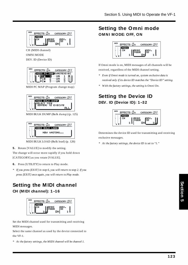
Section 5. Using MIDI to Operate the VF-1
Section 5
fig.5-04
CH (MIDI channel)
OMNI MODE
DEV. ID (Device ID)
fig.5-12
MIDI PC MAP (Program change map)
fig.5-06
MIDI BULK DUMP (Bulk dump) (p. 125)
fig.5-07
MIDI BULK LOAD (Bulk load) (p. 126)
5. Rotate [VALUE] to modify the setting.
The change will occur more rapidly if you hold down
[CATEGORY] as you rotate [VALUE].
6. Press [UTILITY] to return to Play mode.
* If you press [EXIT] in step 6, you will return to step 2. If you
press [EXIT] once again, you will return to Play mode.
Setting the MIDI channelCH (MIDI channel): 1–16fig.5-08
Set the MIDI channel used for transmitting and receiving
MIDI messages.
Select the same channel as used by the device connected to
the VF-1.
* At the factory settings, the MIDI channel will be channel 1.
Setting the Omni modeOMNI MODE: OFF, ONfig.5-09
If Omni mode is on, MIDI messages of all channels will be
received, regardless of the MIDI channel setting.
* Even if Omni mode is turned on, system exclusive data is
received only if its device ID matches the “Device ID” setting.
* With the factory settings, the setting is Omni On.
Setting the Device IDDEV. ID (Device ID): 1–32fig.5-10
Determines the device ID used for transmitting and receiving
exclusive messages.
* At the factory settings, the device ID is set to “1.”
123
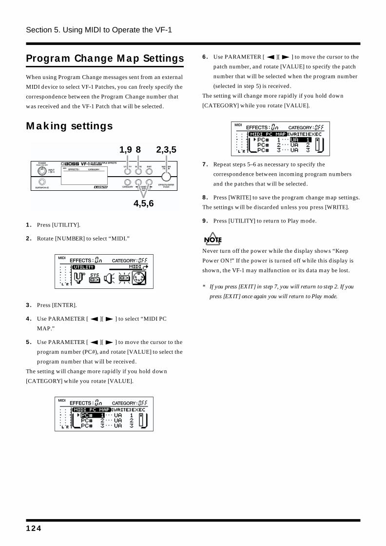
Section 5. Using MIDI to Operate the VF-1
Program Change Map Settings
When using Program Change messages sent from an external
MIDI device to select VF-1 Patches, you can freely specify the
correspondence between the Program Change number that
was received and the VF-1 Patch that will be selected.
Making settingsfig.5-11
1. Press [UTILITY].
2. Rotate [NUMBER] to select “MIDI.”
fig.5-03
3. Press [ENTER].
4. Use PARAMETER [ ][ ] to select “MIDI PC
MAP.”
5. Use PARAMETER [ ][ ] to move the cursor to the
program number (PC#), and rotate [VALUE] to select the
program number that will be received.
The setting will change more rapidly if you hold down
[CATEGORY] while you rotate [VALUE].
fig.5-12
6. Use PARAMETER [ ][ ] to move the cursor to the
patch number, and rotate [VALUE] to specify the patch
number that will be selected when the program number
(selected in step 5) is received.
The setting will change more rapidly if you hold down
[CATEGORY] while you rotate [VALUE].
fig.5-25
7. Repeat steps 5–6 as necessary to specify the
correspondence between incoming program numbers
and the patches that will be selected.
8. Press [WRITE] to save the program change map settings.
The settings will be discarded unless you press [WRITE].
9. Press [UTILITY] to return to Play mode.
Never turn off the power while the display shows “Keep
Power ON!” If the power is turned off while this display is
shown, the VF-1 may malfunction or its data may be lost.
* If you press [EXIT] in step 7, you will return to step 2. If you
press [EXIT] once again you will return to Play mode.
1,9 8
4,5,6
2,3,5
124
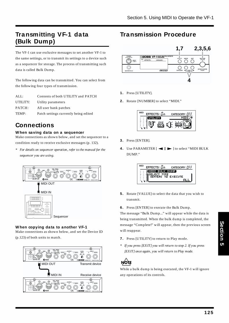
Section 5. Using MIDI to Operate the VF-1
Section 5
Transmitting VF-1 data (Bulk Dump)
The VF-1 can use exclusive messages to set another VF-1 to
the same settings, or to transmit its settings to a device such
as a sequencer for storage. The process of transmitting such
data is called Bulk Dump.
The following data can be transmitted. You can select from
the following four types of transmission.
ALL: Contents of both UTILITY and PATCH
UTILITY: Utility parameters
PATCH: All user bank patches
TEMP: Patch settings currently being edited
ConnectionsWhen saving data on a sequencerMake connections as shown below, and set the sequencer to a
condition ready to receive exclusive messages (p. 132).
* For details on sequencer operation, refer to the manual for the
sequencer you are using.
fig.5-13
When copying data to another VF-1Make connections as shown below, and set the Device ID
(p.123) of both units to match.
fug.5-14
Transmission Procedurefig.5-15
1. Press [UTILITY].
2. Rotate [NUMBER] to select “MIDI.”
fig.5-03
3. Press [ENTER].
4. Use PARAMETER [ ][ ] to select “MIDI BULK
DUMP.”
fig.5-06
5. Rotate [VALUE] to select the data that you wish to
transmit.
6. Press [ENTER] to execute the Bulk Dump.
The message “Bulk Dump...” will appear while the data is
being transmitted. When the bulk dump is completed, the
message “Complete!” will appear, then the previous screen
will reappear.
7. Press [UTILITY] to return to Play mode.
* If you press [EXIT] you will return to step 2. If you press
[EXIT] once again, you will return to Play mode.
While a bulk dump is being executed, the VF-1 will ignore
any operations of its controls.
Sequencer
MIDI OUT
MIDI IN
MIDI OUT
MIDI IN
Transmit device
Receive device
1,7
4
2,3,5,6
125
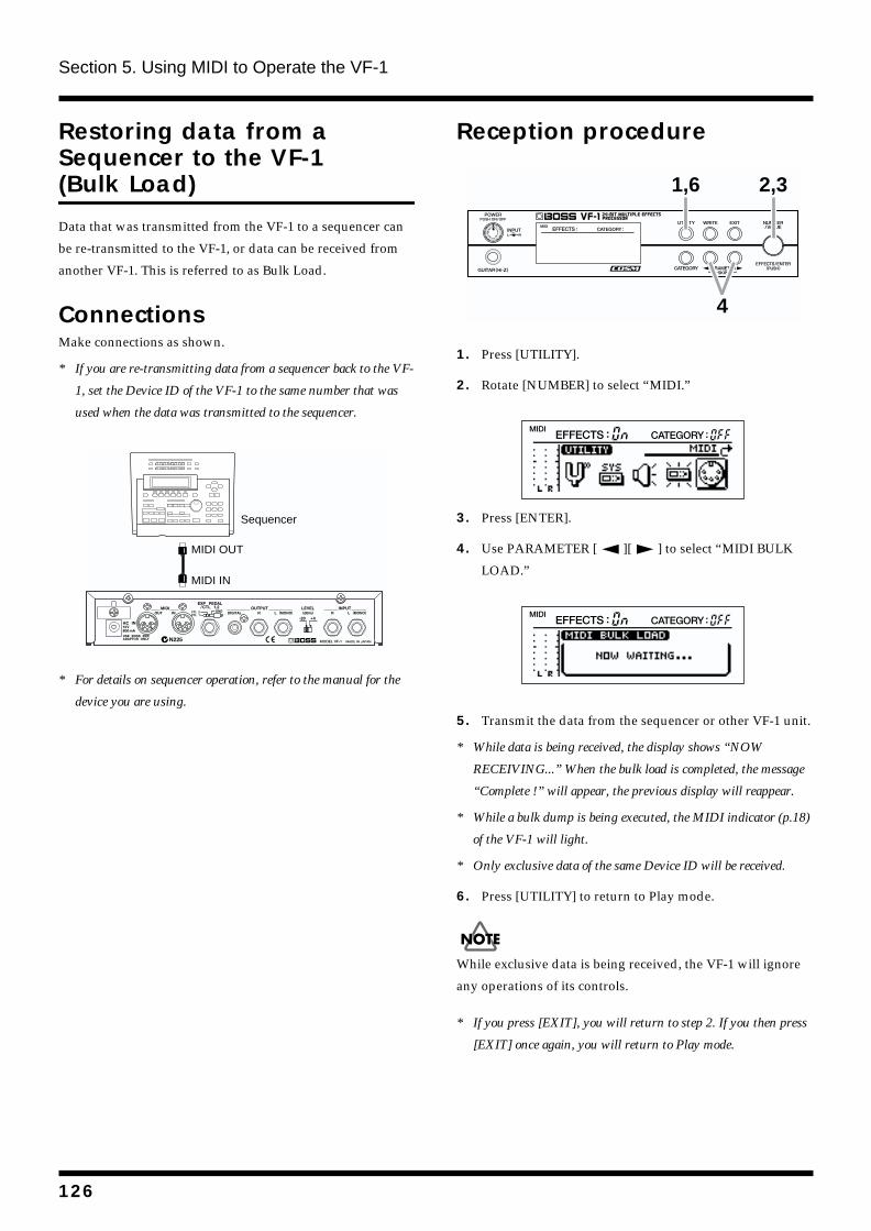
Section 5. Using MIDI to Operate the VF-1
Restoring data from a Sequencer to the VF-1 (Bulk Load)
Data that was transmitted from the VF-1 to a sequencer can
be re-transmitted to the VF-1, or data can be received from
another VF-1. This is referred to as Bulk Load.
ConnectionsMake connections as shown.
* If you are re-transmitting data from a sequencer back to the VF-
1, set the Device ID of the VF-1 to the same number that was
used when the data was transmitted to the sequencer.
fig.5-17
* For details on sequencer operation, refer to the manual for the
device you are using.
Reception procedurefig.5-18
1. Press [UTILITY].
2. Rotate [NUMBER] to select “MIDI.”
fig.5-03
3. Press [ENTER].
4. Use PARAMETER [ ][ ] to select “MIDI BULK
LOAD.”
fig.5-07
5. Transmit the data from the sequencer or other VF-1 unit.
* While data is being received, the display shows “NOW
RECEIVING...” When the bulk load is completed, the message
“Complete !” will appear, the previous display will reappear.
* While a bulk dump is being executed, the MIDI indicator (p.18)
of the VF-1 will light.
* Only exclusive data of the same Device ID will be received.
6. Press [UTILITY] to return to Play mode.
While exclusive data is being received, the VF-1 will ignore
any operations of its controls.
* If you press [EXIT], you will return to step 2. If you then press
[EXIT] once again, you will return to Play mode.
Sequencer
MIDI OUT
MIDI IN
1,6
4
2,3
126
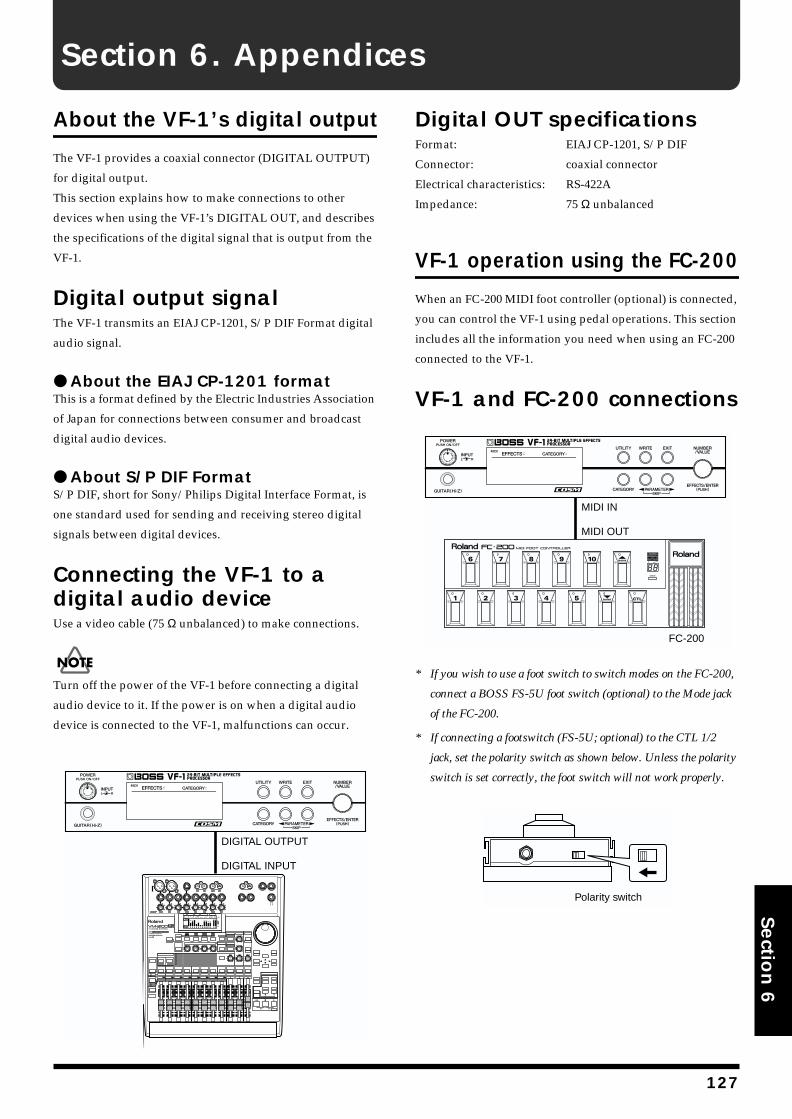
Section 6. Appendices
Section 6
About the VF-1’s digital output
The VF-1 provides a coaxial connector (DIGITAL OUTPUT)
for digital output.
This section explains how to make connections to other
devices when using the VF-1’s DIGITAL OUT, and describes
the specifications of the digital signal that is output from the
VF-1.
Digital output signalThe VF-1 transmits an EIAJ CP-1201, S/P DIF Format digital
audio signal.
About the EIAJ CP-1201 formatThis is a format defined by the Electric Industries Association
of Japan for connections between consumer and broadcast
digital audio devices.
About S/P DIF FormatS/P DIF, short for Sony/Philips Digital Interface Format, is
one standard used for sending and receiving stereo digital
signals between digital devices.
Connecting the VF-1 to a digital audio deviceUse a video cable (75 Ω unbalanced) to make connections.
Turn off the power of the VF-1 before connecting a digital
audio device to it. If the power is on when a digital audio
device is connected to the VF-1, malfunctions can occur.
fig.6-00
Digital OUT specificationsFormat: EIAJ CP-1201, S/P DIF
Connector: coaxial connector
Electrical characteristics: RS-422A
Impedance: 75 Ω unbalanced
VF-1 operation using the FC-200
When an FC-200 MIDI foot controller (optional) is connected,
you can control the VF-1 using pedal operations. This section
includes all the information you need when using an FC-200
connected to the VF-1.
VF-1 and FC-200 connectionsfig.6-01
* If you wish to use a foot switch to switch modes on the FC-200,
connect a BOSS FS-5U foot switch (optional) to the Mode jack
of the FC-200.
* If connecting a footswitch (FS-5U; optional) to the CTL 1/2
jack, set the polarity switch as shown below. Unless the polarity
switch is set correctly, the foot switch will not work properly.
fig.6-02
DIGITAL OUTPUT
DIGITAL INPUT
FC-200
MIDI IN
MIDI OUT
Polarity switch
127
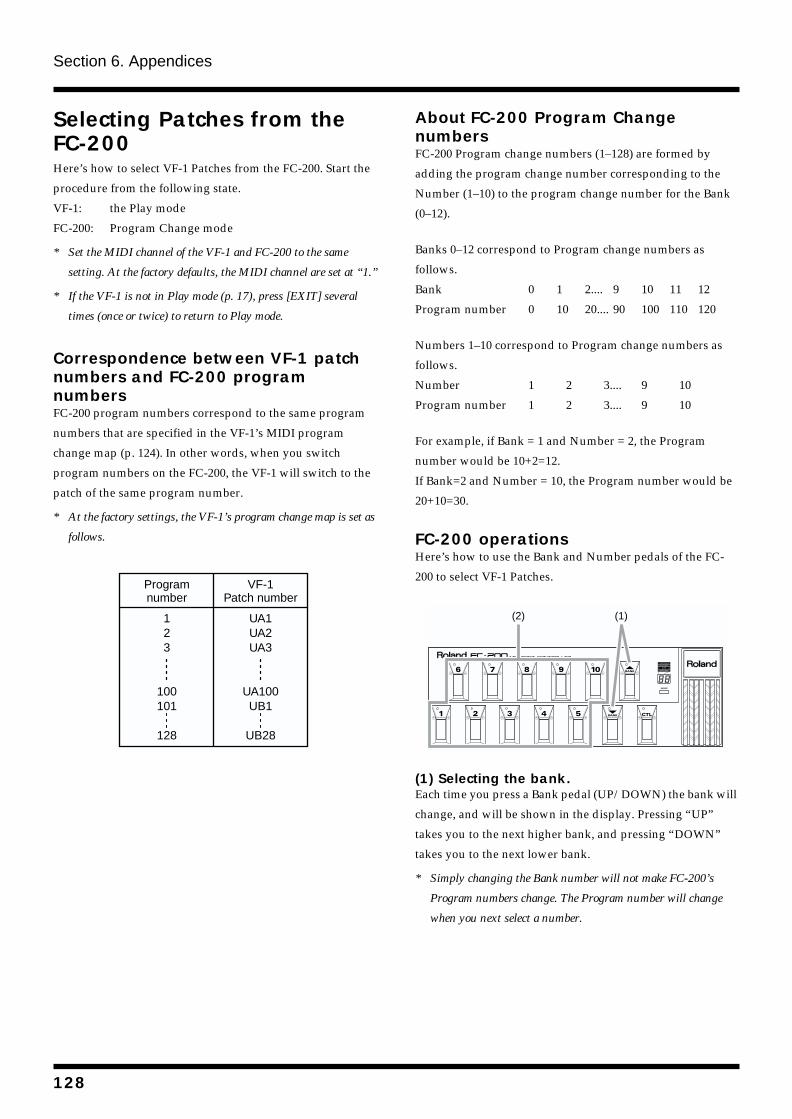
Section 6. Appendices
Selecting Patches from the FC-200Here’s how to select VF-1 Patches from the FC-200. Start the
procedure from the following state.
VF-1: the Play mode
FC-200: Program Change mode
* Set the MIDI channel of the VF-1 and FC-200 to the same
setting. At the factory defaults, the MIDI channel are set at “1.”
* If the VF-1 is not in Play mode (p. 17), press [EXIT] several
times (once or twice) to return to Play mode.
Correspondence between VF-1 patch numbers and FC-200 program numbersFC-200 program numbers correspond to the same program
numbers that are specified in the VF-1’s MIDI program
change map (p. 124). In other words, when you switch
program numbers on the FC-200, the VF-1 will switch to the
patch of the same program number.
* At the factory settings, the VF-1’s program change map is set as
follows.
fig.5-01a
About FC-200 Program Change numbersFC-200 Program change numbers (1–128) are formed by
adding the program change number corresponding to the
Number (1–10) to the program change number for the Bank
(0–12).
Banks 0–12 correspond to Program change numbers as
follows.
Bank 0 1 2.... 9 10 11 12
Program number 0 10 20.... 90 100 110 120
Numbers 1–10 correspond to Program change numbers as
follows.
Number 1 2 3.... 9 10
Program number 1 2 3.... 9 10
For example, if Bank = 1 and Number = 2, the Program
number would be 10+2=12.
If Bank=2 and Number = 10, the Program number would be
20+10=30.
FC-200 operationsHere’s how to use the Bank and Number pedals of the FC-
200 to select VF-1 Patches.
fig.6-03
(1) Selecting the bank.Each time you press a Bank pedal (UP/DOWN) the bank will
change, and will be shown in the display. Pressing “UP”
takes you to the next higher bank, and pressing “DOWN”
takes you to the next lower bank.
* Simply changing the Bank number will not make FC-200’s
Program numbers change. The Program number will change
when you next select a number.
Programnumber
VF-1Patch number
123
100101
128
UA1UA2UA3
UA100UB1
UB28
(1)(2)
128
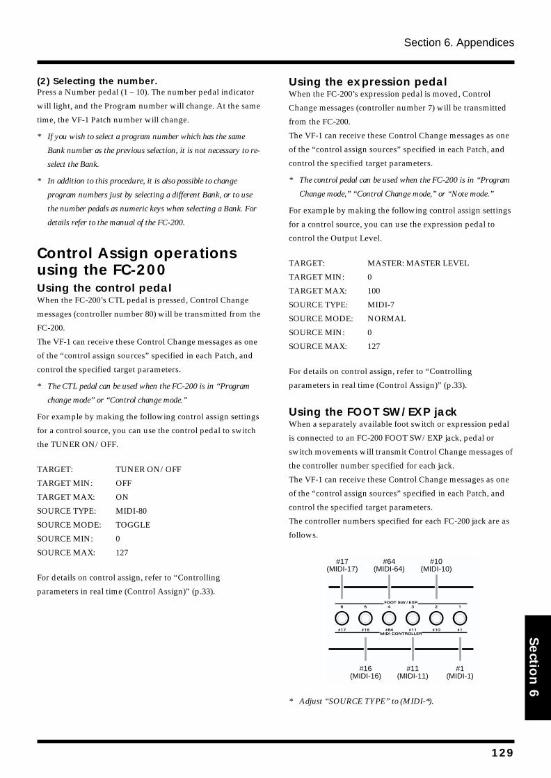
Section 6. Appendices
Section 6
(2) Selecting the number.Press a Number pedal (1 – 10). The number pedal indicator
will light, and the Program number will change. At the same
time, the VF-1 Patch number will change.
* If you wish to select a program number which has the same
Bank number as the previous selection, it is not necessary to re-
select the Bank.
* In addition to this procedure, it is also possible to change
program numbers just by selecting a different Bank, or to use
the number pedals as numeric keys when selecting a Bank. For
details refer to the manual of the FC-200.
Control Assign operations using the FC-200Using the control pedalWhen the FC-200’s CTL pedal is pressed, Control Change
messages (controller number 80) will be transmitted from the
FC-200.
The VF-1 can receive these Control Change messages as one
of the “control assign sources” specified in each Patch, and
control the specified target parameters.
* The CTL pedal can be used when the FC-200 is in “Program
change mode” or “Control change mode.”
For example by making the following control assign settings
for a control source, you can use the control pedal to switch
the TUNER ON/OFF.
TARGET: TUNER ON/OFF
TARGET MIN: OFF
TARGET MAX: ON
SOURCE TYPE: MIDI-80
SOURCE MODE: TOGGLE
SOURCE MIN: 0
SOURCE MAX: 127
For details on control assign, refer to “Controlling
parameters in real time (Control Assign)” (p.33).
Using the expression pedalWhen the FC-200’s expression pedal is moved, Control
Change messages (controller number 7) will be transmitted
from the FC-200.
The VF-1 can receive these Control Change messages as one
of the “control assign sources” specified in each Patch, and
control the specified target parameters.
* The control pedal can be used when the FC-200 is in “Program
Change mode,” “Control Change mode,” or “Note mode.”
For example by making the following control assign settings
for a control source, you can use the expression pedal to
control the Output Level.
TARGET: MASTER: MASTER LEVEL
TARGET MIN: 0
TARGET MAX: 100
SOURCE TYPE: MIDI-7
SOURCE MODE: NORMAL
SOURCE MIN: 0
SOURCE MAX: 127
For details on control assign, refer to “Controlling
parameters in real time (Control Assign)” (p.33).
Using the FOOT SW/EXP jackWhen a separately available foot switch or expression pedal
is connected to an FC-200 FOOT SW/EXP jack, pedal or
switch movements will transmit Control Change messages of
the controller number specified for each jack.
The VF-1 can receive these Control Change messages as one
of the “control assign sources” specified in each Patch, and
control the specified target parameters.
The controller numbers specified for each FC-200 jack are as
follows.
fig.6-04
* Adjust “SOURCE TYPE” to (MIDI-*).
#17(MIDI-17)
#64(MIDI-64)
#10(MIDI-10)
#16(MIDI-16)
#11(MIDI-11)
#1(MIDI-1)
129
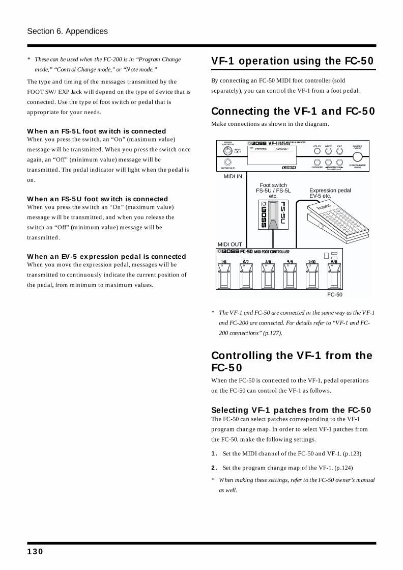
Section 6. Appendices
* These can be used when the FC-200 is in “Program Change
mode,” “Control Change mode,” or “Note mode.”
The type and timing of the messages transmitted by the
FOOT SW/EXP Jack will depend on the type of device that is
connected. Use the type of foot switch or pedal that is
appropriate for your needs.
When an FS-5L foot switch is connectedWhen you press the switch, an “On” (maximum value)
message will be transmitted. When you press the switch once
again, an “Off” (minimum value) message will be
transmitted. The pedal indicator will light when the pedal is
on.
When an FS-5U foot switch is connectedWhen you press the switch an “On” (maximum value)
message will be transmitted, and when you release the
switch an “Off” (minimum value) message will be
transmitted.
When an EV-5 expression pedal is connectedWhen you move the expression pedal, messages will be
transmitted to continuously indicate the current position of
the pedal, from minimum to maximum values.
VF-1 operation using the FC-50
By connecting an FC-50 MIDI foot controller (sold
separately), you can control the VF-1 from a foot pedal.
Connecting the VF-1 and FC-50Make connections as shown in the diagram.
fig.6-10
* The VF-1 and FC-50 are connected in the same way as the VF-1
and FC-200 are connected. For details refer to “VF-1 and FC-
200 connections” (p.127).
Controlling the VF-1 from the FC-50When the FC-50 is connected to the VF-1, pedal operations
on the FC-50 can control the VF-1 as follows.
Selecting VF-1 patches from the FC-50The FC-50 can select patches corresponding to the VF-1
program change map. In order to select VF-1 patches from
the FC-50, make the following settings.
1. Set the MIDI channel of the FC-50 and VF-1. (p.123)
2. Set the program change map of the VF-1. (p.124)
* When making these settings, refer to the FC-50 owner’s manual
as well.
FC-50
Roland
Foot switchFS-5U / FS-5L
etc.Expression pedalEV-5 etc.
MIDI IN
MIDI OUT
130
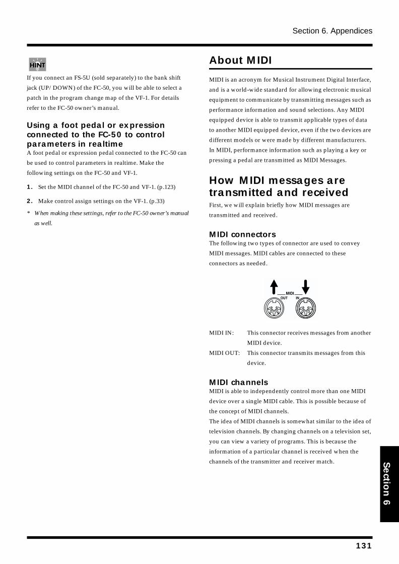
Section 6. Appendices
Section 6
If you connect an FS-5U (sold separately) to the bank shift
jack (UP/DOWN) of the FC-50, you will be able to select a
patch in the program change map of the VF-1. For details
refer to the FC-50 owner’s manual.
Using a foot pedal or expression connected to the FC-50 to control parameters in realtimeA foot pedal or expression pedal connected to the FC-50 can
be used to control parameters in realtime. Make the
following settings on the FC-50 and VF-1.
1. Set the MIDI channel of the FC-50 and VF-1. (p.123)
2. Make control assign settings on the VF-1. (p.33)
* When making these settings, refer to the FC-50 owner’s manual
as well.
About MIDI
MIDI is an acronym for Musical Instrument Digital Interface,
and is a world-wide standard for allowing electronic musical
equipment to communicate by transmitting messages such as
performance information and sound selections. Any MIDI
equipped device is able to transmit applicable types of data
to another MIDI equipped device, even if the two devices are
different models or were made by different manufacturers.
In MIDI, performance information such as playing a key or
pressing a pedal are transmitted as MIDI Messages.
How MIDI messages are transmitted and receivedFirst, we will explain briefly how MIDI messages are
transmitted and received.
MIDI connectorsThe following two types of connector are used to convey
MIDI messages. MIDI cables are connected to these
connectors as needed.
fig.6-05
MIDI IN: This connector receives messages from another
MIDI device.
MIDI OUT: This connector transmits messages from this
device.
MIDI channelsMIDI is able to independently control more than one MIDI
device over a single MIDI cable. This is possible because of
the concept of MIDI channels.
The idea of MIDI channels is somewhat similar to the idea of
television channels. By changing channels on a television set,
you can view a variety of programs. This is because the
information of a particular channel is received when the
channels of the transmitter and receiver match.
131
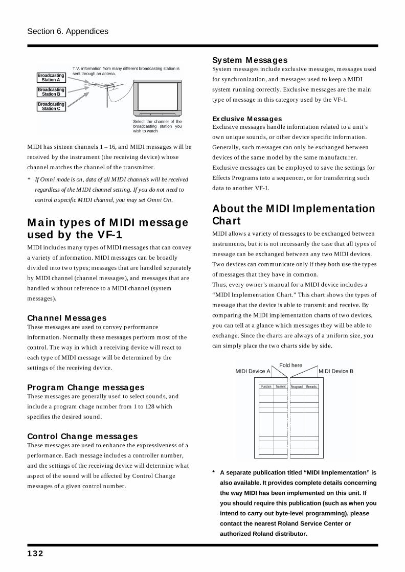
Section 6. Appendices
fig.6-06
MIDI has sixteen channels 1 – 16, and MIDI messages will be
received by the instrument (the receiving device) whose
channel matches the channel of the transmitter.
* If Omni mode is on, data of all MIDI channels will be received
regardless of the MIDI channel setting. If you do not need to
control a specific MIDI channel, you may set Omni On.
Main types of MIDI message used by the VF-1MIDI includes many types of MIDI messages that can convey
a variety of information. MIDI messages can be broadly
divided into two types; messages that are handled separately
by MIDI channel (channel messages), and messages that are
handled without reference to a MIDI channel (system
messages).
Channel MessagesThese messages are used to convey performance
information. Normally these messages perform most of the
control. The way in which a receiving device will react to
each type of MIDI message will be determined by the
settings of the receiving device.
Program Change messagesThese messages are generally used to select sounds, and
include a program chage number from 1 to 128 which
specifies the desired sound.
Control Change messagesThese messages are used to enhance the expressiveness of a
performance. Each message includes a controller number,
and the settings of the receiving device will determine what
aspect of the sound will be affected by Control Change
messages of a given control number.
System MessagesSystem messages include exclusive messages, messages used
for synchronization, and messages used to keep a MIDI
system running correctly. Exclusive messages are the main
type of message in this category used by the VF-1.
Exclusive MessagesExclusive messages handle information related to a unit’s
own unique sounds, or other device specific information.
Generally, such messages can only be exchanged between
devices of the same model by the same manufacturer.
Exclusive messages can be employed to save the settings for
Effects Programs into a sequencer, or for transferring such
data to another VF-1.
About the MIDI Implementation ChartMIDI allows a variety of messages to be exchanged between
instruments, but it is not necessarily the case that all types of
message can be exchanged between any two MIDI devices.
Two devices can communicate only if they both use the types
of messages that they have in common.
Thus, every owner’s manual for a MIDI device includes a
“MIDI Implementation Chart.” This chart shows the types of
message that the device is able to transmit and receive. By
comparing the MIDI implementation charts of two devices,
you can tell at a glance which messages they will be able to
exchange. Since the charts are always of a uniform size, you
can simply place the two charts side by side.
fig.6-07
* A separate publication titled “MIDI Implementation” is
also available. It provides complete details concerning
the way MIDI has been implemented on this unit. If
you should require this publication (such as when you
intend to carry out byte-level programming), please
contact the nearest Roland Service Center or
authorized Roland distributor.
BroadcastingStation A
T.V. information from many different broadcasting station is sent through an antena.
Select the channel of the broadcasting station you wish to watch
BroadcastingStation B
BroadcastingStation C
TransmitFunction
Fold hereMIDI Device A MIDI Device B
Recognized Remarks
132
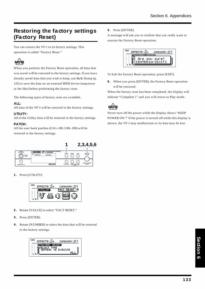
Section 6. Appendices
Section 6
Restoring the factory settings (Factory Reset)
You can restore the VF-1 to its factory settings. This
operation is called “Factory Reset.”
When you perform the Factory Reset operation, all data that
was saved will be returned to the factory settings. If you have
already saved data that you wish to keep, use Bulk Dump (p.
125) to save the data on an external MIDI device (sequencer
or the like) before performing the factory reset.
The following types of factory reset are available.
ALL:All data of the VF-1 will be restored to the factory settings.
UTILITY:All of the Utility data will be restored to the factory settings.
PATCH:All the user bank patches (UA1–100, UB1–100) will be
restored to the factory settings.
fig.6-101
1. Press [UTILITY].
fig.6-08
2. Rotate [VALUE] to select “FACT RESET.”
3. Press [ENTER].
4. Rotate [NUMBER] to select the data that will be restored
to the factory settings.
fig.6-09
5. Press [ENTER].
A message will ask you to confirm that you really want to
execute the Factory Reset operation.
fig.6-20
To halt the Factory Reset operation, press [EXIT].
6. When you press [ENTER], the Factory Reset operation
will be executed.
When the factory reset has been completed, the display will
indicate “Complete !,” and you will return to Play mode.
Never turn off the power while the display shows “KEEP
POWER ON !” If the power is turned off while this display is
shown, the VF-1 may malfunction or its data may be lost.
1 2,3,4,5,6
133
Section 6. Appendices
Troubleshooting
In there is no sound or other operational problema occur, first check through the following solutions. If this does not resolve the problem, then contact your dealer or a nearby Roland service station.
No Sound/Volume Too Low Are the connection cables broken?
Try using a different set of connection cables.
Could you be using a connection cable that contains a
resistor?
Use a connection cable that does not contain a resistor.
Is the VF-1 correctly connected to the other devices?
Check connections with the other devices. (p.14)
Is the connected amp/mixer turned off, or the volume
lowered?
Check the settings of your amp/mixer system.
Is the INPUT Level knob lowered?
Adjust [INPUT L/R] to an appropriate position. (p.17)
Is EFFECTS OFF?
If the EFFECTS operation has been set to “MUTE,” setting
EFFECTS will mean that the direct sound is not output
either. (p.22, 43)
Is each effect set correctly?
Use the level meter to check the output level of each
effect.If there is an effect for which the meter does not
move, check the settings for that effect. (p.31)
Is the LEVEL or FOOT LEVEL set to “0”?
Adjust the MASTER and FOOT LEVEL to appropriate
volumes. (p.105)
Are “MASTER LEVEL” and “FOOT VOLUME LEVEL”
specified as a control assign Target?
Move the controller to which it is assigned. (p.33)
Sound Is Distorted Are the input levels set appropriately?
Adjust [INPUT L/R] to an appropriate position. (p.17)
Is each effect set correctly?
Use the Level Meter (p.31) to check the output level of
each effect.
If the output level moves beyond the peak, adjust the
settings of the effect.
Are the levels of connected devices excessively high?
Adjust the output levels of connected devices to an
appropriate setting.
The direct and effect sounds are not output as you have set. Is the DIRECT MIX is set to “OFF”?
If the DIRECT MIX is set to “OFF,” no direct sound is
output, but only the effect sound is sent.
Set the DIRECT MIX (p. 46) of the Global Sound Settings
to “PATCH”
Patch Number Does Not Change Is something other than the Play mode screen (p.17)
shown in the display?
On the VF-1, patches cannot be selected outside of the
Play mode screen. Press [EXIT] once or twice to return to
Play mode.
Pedal Connected to CTL 1/2 Jack Doesn’t Change Patches Is something other than the Play mode screen (p.17)
shown in the display?
On the VF-1, patches cannot be selected outside of the
Play mode screen. Press [EXIT] once or twice to return to
Play mode.
Is the VF-1 set to “CATEGORY On”?
In Play mode when the display indicates “CATEGORY
On,” patches of the same category will be selected
sequentially. Pressing [EXIT] in Play mode will make the
display change to “CATEGORY OFF,” and you will be
able to select patches as you specified in the “NUMBER
U/D MIN” and “NUMBER U/D MAX” settings.
Has the Patch number select range been set
appropriately?
Check the “NUMBER U/D MIN” and “NUMBER U/D
MAX” range. (p.43)
Has the function of the CTL 1/2 jack been set
correctly?
Set the function of the CTL 1/2 jack to either “NUMBER
UP” or “NUMBER DOWN.” (p.44)
134
Section 6. Appendices
Section 6
Parameters Specified with Control Assign Can’t Be Controlled If you are using a foot switch connected to the CTL 1,2
jack to control the effect, make sure that the function
of the jack to which the foot switch is connected is set
to “ASSIGNABLE.” (p.44)
Has the source setting been made correctly for the
Control Assign?
Make sure that “SOURCE TYPE” and “SOURCE MODE”
are set appropriately for the “source” (foot switch,
expression pedal) that is connected to the CTL 1,2 jack.
(p.34)
When using MIDI to control parameters
Make sure that the MIDI channels of both devices match.
(p.123)
Make sure that the controller numbers you are using
match. (p.34)
MIDI Messages Are Not Received Are the MIDI cables broken?
Try another set of MIDI cables.
Is the VF-1 correctly connected to the other MIDI
device?
Check connections with the other MIDI device.
Do the MIDI channel settings of both devices match?
Make sure that the MIDI channels of both devices match.
(p.124)
Did you set the device IDs to match?
If you wish to transfer data between two VF-1 units, the
transmitting VF-1 and receiving VF-1 must be set to the
same device ID. (p.123)
Error Messages
MIDI FORMAT ERR!Reason: The format of the Exclusive message that is being
received is incorrect.
Action: Check the data that is being transmitted and try
the operation again. Also, make sure the MIDI
cable isn’t unplugged, broken, or shorted.
CHECK SUM ERROR!Reason: The Check Sum of the Exclusive message that is
being received is incorrect.
Action: Check the data that is being transmitted and try
the operation again. Also, make sure the MIDI
cable isn’t unplugged, broken, or shorted.
MIDI RXBUF ERR!Reason: A large amount of MIDI data was received in a
short time and could not be processed.
Action: Check that the transmitting device is not
transmitting excessive amounts of MIDI data.
MIDI RX ERROR!Reason1: A large amount of MIDI data was received in a
short time and could not be processed.
Action 1: Check that the transmitting device is not
transmitting excessive amounts of MIDI data.
Reason 2: It is possible that the MIDI cable connected to
MIDI IN has been pulled out, or damaged?
Action 2: Check the MIDI cable connections.
135
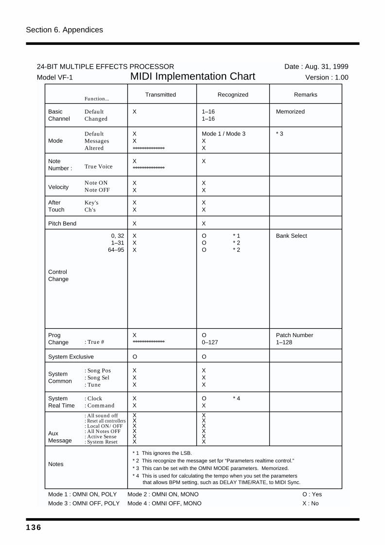
Section 6. Appendices
MIDI Implementation Chart
Function...
BasicChannel
Mode
NoteNumber :
Velocity
AfterTouch
Pitch Bend
ControlChange
ProgChange
System Exclusive
SystemCommon
SystemReal Time
AuxMessage
Notes
Transmitted Recognized Remarks
DefaultChanged
DefaultMessagesAltered
True Voice
Note ONNote OFF
Key'sCh's
0, 321–31
64–95
: True #
: Song Pos: Song Sel: Tune
: Clock: Command
: All sound off: Reset all controllers: Local ON/OFF: All Notes OFF: Active Sense: System Reset
X
XX
XX
X
XX
X
XXX
OOO
X**************
O
XXX
XX
XXXXXX
1–161–16
Mode 1 / Mode 3XX
XX
X
XX
X
O0–127
O
XXX
OX
XXXXXX
Bank Select
* 1 This ignores the LSB.* 2 This recognize the message set for “Parameters realtime control.”* 3 This can be set with the OMNI MODE parameters. Memorized.* 4 This is used for calculating the tempo when you set the parameters that allows BPM setting, such as DELAY TIME/RATE, to MIDI Sync.
Model VF-1
Date : Aug. 31, 1999
Version : 1.00MIDI Implementation Chart
**************
**************
Mode 1 : OMNI ON, POLY
Mode 3 : OMNI OFF, POLY
Mode 2 : OMNI ON, MONO
Mode 4 : OMNI OFF, MONO
O : Yes
X : No
Patch Number1–128
Memorized
* 1* 2* 2
* 4
24-BIT MULTIPLE EFFECTS PROCESSOR
* 3
136
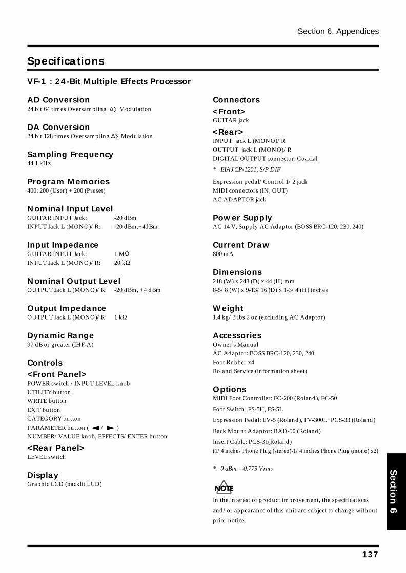
Section 6. Appendices
Section 6
Specifications
VF-1 : 24-Bit Multiple Effects Processor
AD Conversion24 bit 64 times Oversampling ∆∑ Modulation
DA Conversion24 bit 128 times Oversampling ∆∑ Modulation
Sampling Frequency44.1 kHz
Program Memories400: 200 (User) + 200 (Preset)
Nominal Input LevelGUITAR INPUT Jack: -20 dBmINPUT Jack L (MONO)/R: -20 dBm,+4dBm
Input ImpedanceGUITAR INPUT Jack: 1 MΩINPUT Jack L (MONO)/R: 20 kΩ
Nominal Output LevelOUTPUT Jack L (MONO)/R: -20 dBm, +4 dBm
Output ImpedanceOUTPUT Jack L (MONO)/R: 1 kΩ
Dynamic Range97 dB or greater (IHF-A)
Controls<Front Panel>POWER switch /INPUT LEVEL knobUTILITY buttonWRITE buttonEXIT buttonCATEGORY buttonPARAMETER button ( / ) NUMBER/VALUE knob, EFFECTS/ENTER button
<Rear Panel>LEVEL switch
DisplayGraphic LCD (backlit LCD)
Connectors<Front>GUITAR jack
<Rear>INPUT jack L (MONO)/ROUTPUT jack L (MONO)/RDIGITAL OUTPUT connector: Coaxial
* EIAJ CP-1201, S/P DIF
Expression pedal/Control 1/2 jackMIDI connectors (IN, OUT)AC ADAPTOR jack
Power SupplyAC 14 V; Supply AC Adaptor (BOSS BRC-120, 230, 240)
Current Draw800 mA
Dimensions218 (W) x 248 (D) x 44 (H) mm8-5/8 (W) x 9-13/16 (D) x 1-3/4 (H) inches
Weight1.4 kg/3 lbs 2 oz (excluding AC Adaptor)
AccessoriesOwner’s ManualAC Adaptor: BOSS BRC-120, 230, 240Foot Rubber x4Roland Service (information sheet)
OptionsMIDI Foot Controller: FC-200 (Roland), FC-50
Foot Switch: FS-5U, FS-5L
Expression Pedal: EV-5 (Roland), FV-300L+PCS-33 (Roland)
Rack Mount Adaptor: RAD-50 (Roland)
Insert Cable: PCS-31(Roland)(1/4 inches Phone Plug (stereo)-1/4 inches Phone Plug (mono) x2)
* 0 dBm = 0.775 Vrms
In the interest of product improvement, the specifications
and/or appearance of this unit are subject to change without
prior notice.
137
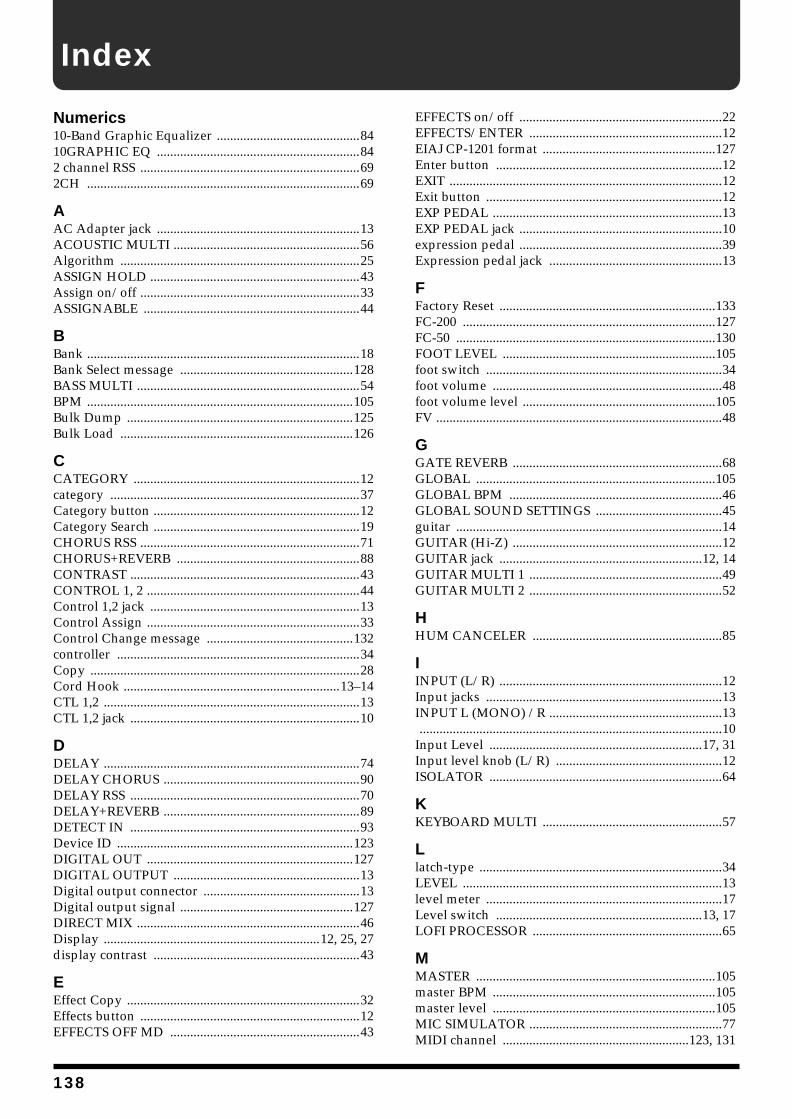
Index
Numerics10-Band Graphic Equalizer ...........................................8410GRAPHIC EQ .............................................................842 channel RSS ..................................................................692CH ..................................................................................69
AAC Adapter jack .............................................................13ACOUSTIC MULTI ........................................................56Algorithm ........................................................................25ASSIGN HOLD ...............................................................43Assign on/off ..................................................................33ASSIGNABLE .................................................................44
BBank ..................................................................................18Bank Select message ....................................................128BASS MULTI ...................................................................54BPM ................................................................................105Bulk Dump ....................................................................125Bulk Load ......................................................................126
CCATEGORY ....................................................................12category ...........................................................................37Category button ..............................................................12Category Search ..............................................................19CHORUS RSS ..................................................................71CHORUS+REVERB .......................................................88CONTRAST .....................................................................43CONTROL 1, 2 ................................................................44Control 1,2 jack ...............................................................13Control Assign ................................................................33Control Change message ............................................132controller .........................................................................34Copy .................................................................................28Cord Hook .................................................................13–14CTL 1,2 .............................................................................13CTL 1,2 jack .....................................................................10
DDELAY .............................................................................74DELAY CHORUS ...........................................................90DELAY RSS .....................................................................70DELAY+REVERB ...........................................................89DETECT IN .....................................................................93Device ID .......................................................................123DIGITAL OUT ..............................................................127DIGITAL OUTPUT ........................................................13Digital output connector ...............................................13Digital output signal ....................................................127DIRECT MIX ...................................................................46Display .................................................................12, 25, 27display contrast ..............................................................43
EEffect Copy ......................................................................32Effects button ..................................................................12EFFECTS OFF MD .........................................................43
EFFECTS on/off .............................................................22EFFECTS/ENTER ..........................................................12EIAJ CP-1201 format ....................................................127Enter button ....................................................................12EXIT ..................................................................................12Exit button .......................................................................12EXP PEDAL .....................................................................13EXP PEDAL jack .............................................................10expression pedal .............................................................39Expression pedal jack ....................................................13
FFactory Reset .................................................................133FC-200 ............................................................................127FC-50 ..............................................................................130FOOT LEVEL ................................................................105foot switch .......................................................................34foot volume .....................................................................48foot volume level ..........................................................105FV ......................................................................................48
GGATE REVERB ...............................................................68GLOBAL ........................................................................105GLOBAL BPM ................................................................46GLOBAL SOUND SETTINGS ......................................45guitar ................................................................................14GUITAR (Hi-Z) ...............................................................12GUITAR jack .............................................................12, 14GUITAR MULTI 1 ..........................................................49GUITAR MULTI 2 ..........................................................52
HHUM CANCELER .........................................................85
IINPUT (L/R) ...................................................................12Input jacks .......................................................................13INPUT L (MONO) /R ....................................................13 ...........................................................................................10Input Level ................................................................17, 31Input level knob (L/R) ..................................................12ISOLATOR ......................................................................64
KKEYBOARD MULTI ......................................................57
Llatch-type .........................................................................34LEVEL ..............................................................................13level meter .......................................................................17Level switch ..............................................................13, 17LOFI PROCESSOR .........................................................65
MMASTER ........................................................................105master BPM ...................................................................105master level ...................................................................105MIC SIMULATOR ..........................................................77MIDI channel ........................................................123, 131
138
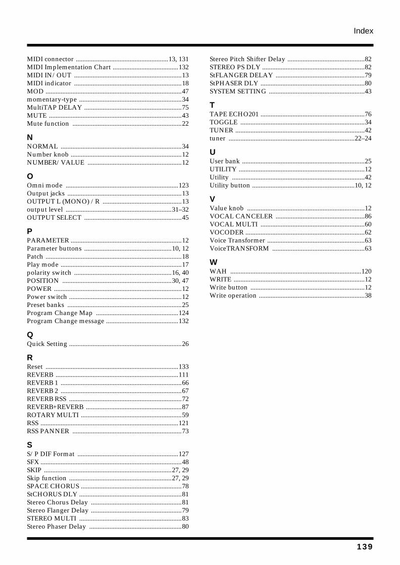
Index
MIDI connector .......................................................13, 131MIDI Implementation Chart .......................................132MIDI IN/OUT ................................................................13MIDI indicator ................................................................18MOD .................................................................................47momentary-type .............................................................34MultiTAP DELAY ..........................................................75MUTE ...............................................................................43Mute function .................................................................22
NNORMAL ........................................................................34Number knob ..................................................................12NUMBER/VALUE ........................................................12
OOmni mode ...................................................................123Output jacks ....................................................................13OUTPUT L (MONO) /R ...............................................13output level ...............................................................31–32OUTPUT SELECT ..........................................................45
PPARAMETER ..................................................................12Parameter buttons ....................................................10, 12Patch .................................................................................18Play mode ........................................................................17polarity switch ..........................................................16, 40POSITION .................................................................30, 47POWER ............................................................................12Power switch ...................................................................12Preset banks ....................................................................25Program Change Map .................................................124Program Change message ...........................................132
QQuick Setting ...................................................................26
RReset ...............................................................................133REVERB .........................................................................111REVERB 1 ........................................................................66REVERB 2 ........................................................................67REVERB RSS ...................................................................72REVERB+REVERB .........................................................87ROTARY MULTI ............................................................59RSS ..................................................................................121RSS PANNER .................................................................73
SS/P DIF Format ............................................................127SFX ....................................................................................48SKIP ............................................................................27, 29Skip function .............................................................27, 29SPACE CHORUS ............................................................78StCHORUS DLY .............................................................81Stereo Chorus Delay ......................................................81Stereo Flanger Delay ......................................................79STEREO MULTI .............................................................83Stereo Phaser Delay .......................................................80
Stereo Pitch Shifter Delay ..............................................82STEREO PS DLY .............................................................82StFLANGER DELAY .....................................................79StPHASER DLY ..............................................................80SYSTEM SETTING .........................................................43
TTAPE ECHO201 ..............................................................76TOGGLE ..........................................................................34TUNER .............................................................................42tuner ...........................................................................22–24
UUser bank .........................................................................25UTILITY ...........................................................................12Utility ...............................................................................42Utility button .............................................................10, 12
VValue knob ......................................................................12VOCAL CANCELER .....................................................86VOCAL MULTI ..............................................................60VOCODER .......................................................................62Voice Transformer ..........................................................63VoiceTRANSFORM .......................................................63
WWAH ..............................................................................120WRITE ..............................................................................12Write button ....................................................................12Write operation ...............................................................38
139
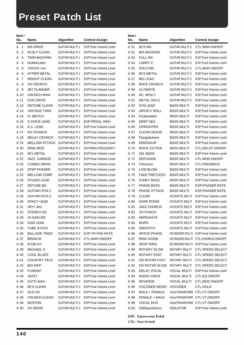
Preset Patch List
Bank /No. Name Algorithm Control Assign
A 1 MS DRIVE GUITAR MULTI 1 EXP:Foot Volume Level
A 2 W DLY CLEAN GUITAR MULTI 1 EXP:Foot Volume Level
A 3 TWIN BACKING GUITAR MULTI 1 EXP:Foot Volume Level
A 4 HUM4Cuttin’ GUITAR MULTI 1 EXP:Foot Volume Level
A 5 TOUCH <oi> GUITAR MULTI 1 EXP:Foot Volume Level
A 6 HYPER METAL GUITAR MULTI 1 EXP:Foot Volume Level
A 7 BRIGHT CLEAN GUITAR MULTI 1 EXP:Foot Volume Level
A 8 VO CRUNCH GUITAR MULTI 1 EXP:Foot Volume Level
A 9 JET FLANGER GUITAR MULTI 1 EXP:Foot Volume Level
A 10 CRUNCH WAH GUITAR MULTI 1 EXP:Foot Volume Level
A 11 5150 DRIVE GUITAR MULTI 1 EXP:Foot Volume Level
A 12 DETUNE CLEAN GUITAR MULTI 1 EXP:Foot Volume Level
A 13 VINTAGE TWIN GUITAR MULTI 1 EXP:Foot Volume Level
A 14 FL MATCH GUITAR MULTI 1 EXP:Foot Volume Level
A 15 3-VOICE LEAD GUITAR MULTI 1 EXP:PEDAL WAH
A 16 E.C. LEAD GUITAR MULTI 1 EXP:Foot Volume Level
A 17 PH CRUNCH GUITAR MULTI 1 EXP:Foot Volume Level
A 18 DELAY CRUNCH GUITAR MULTI 1 EXP:Foot Volume Level
A 19 MELLOW ATTACK GUITAR MULTI 1 EXP:Foot Volume Level
A 20 RING MOD GUITAR MULTI 1 EXP:RING FREQUENCY
A 21 90’s METAL GUITAR MULTI 1 EXP:Foot Volume Level
A 22 JAZZ GARAGE GUITAR MULTI 1 EXP:Foot Volume Level
A 23 COMBO DRIVE GUITAR MULTI 1 EXP:Foot Volume Level
A 24 STEP PHASER GUITAR MULTI 1 EXP:Foot Volume Level
A 25 MELLOW COMP GUITAR MULTI 1 EXP:Foot Volume Level
A 26 STUDIO LEAD GUITAR MULTI 1 EXP:Foot Volume Level
A 27 DETUNE BG GUITAR MULTI 1 EXP:Foot Volume Level
A 28 GUITAR+SYN 1 GUITAR MULTI 1 EXP:Foot Volume Level
A 29 GUITAR+SYN 2 GUITAR MULTI 1 EXP:Foot Volume Level
A 30 SPACY LEAD GUITAR MULTI 1 EXP:Foot Volume Level
A 31 HEY! Jimi GUITAR MULTI 1 EXP:Foot Volume Level
A 32 STEREO OD GUITAR MULTI 1 EXP:Foot Volume Level
A 33 HI GAIN MS GUITAR MULTI 1 EXP:Foot Volume Level
A 34 5150 LEAD GUITAR MULTI 1 EXP:Foot Volume Level
A 35 TUBE STACK GUITAR MULTI 1 EXP:Foot Volume Level
A 36 BALLADE TREM GUITAR MULTI 2 EXP:TR PAN RATE
A 37 BRIAN M GUITAR MULTI 2 CTL:WAH ON/OFF
A 38 M DELAY GUITAR MULTI 2 EXP:Foot Volume Level
A 39 MICHAEL S GUITAR MULTI 2 EXP:Foot Volume Level
A 40 COOL BLUES GUITAR MULTI 2 EXP:Foot Volume Level
A 41 COUNTRY TELE GUITAR MULTI 2 EXP:Foot Volume Level
A 42 BIG RIFF GUITAR MULTI 2 EXP:Foot Volume Level
A 43 FUSION? GUITAR MULTI 2 EXP:Foot Volume Level
A 44 JAZZY GUITAR MULTI 2 EXP:Foot Volume Level
A 45 AUTO WAH GUITAR MULTI 2 EXP:Foot Volume Level
A 46 80’S CLEAN GUITAR MULTI 2 EXP:Foot Volume Level
A 47 OLD VH GUITAR MULTI 2 EXP:Foot Volume Level
A 48 CRUNCH CLEAN GUITAR MULTI 2 EXP:Foot Volume Level
A 49 BOSTON GUITAR MULTI 2 EXP:Foot Volume Level
A 50 VO DRIVE GUITAR MULTI 2 EXP:Foot Volume Level
Bank /No. Name Algorithm Control Assign
A 51 60’S MS GUITAR MULTI 2 CTL:WAH ON/OFF
A 52 BIG BACKING GUITAR MULTI 2 EXP:Foot Volume Level
A 53 FULL MS GUITAR MULTI 2 EXP:Foot Volume Level
A 54 LARRY C GUITAR MULTI 2 EXP:Foot Volume Level
A 55 SOLO MS GUITAR MULTI 2 CTL:WAH ON/OFF
A 56 80’S METAL GUITAR MULTI 2 EXP:Foot Volume Level
A 57 BIG LEAD GUITAR MULTI 2 EXP:Foot Volume Level
A 58 BACK CRUNCH GUITAR MULTI 2 EXP:Foot Volume Level
A 59 ULTIMATE GUITAR MULTI 2 EXP:Foot Volume Level
A 60 AC. W/DLY GUITAR MULTI 2 EXP:Foot Volume Level
A 61 METAL SOLO GUITAR MULTI 2 EXP:Foot Volume Level
A 62 SYN LEAD BASS MULTI EXP:Foot Volume Level
A 63 DRIVE’n’ ROLL BASS MULTI EXP:Foot Volume Level
A 64 Funkenstein BASS MULTI EXP:Foot Volume Level
A 65 DEEP SEA BASS MULTI EXP:Foot Volume Level
A 66 UPRIGHTER BASS MULTI EXP:Foot Volume Level
A 67 CLEAN HEADS BASS MULTI EXP:Foot Volume Level
A 68 FlangJackson BASS MULTI EXP:Foot Volume Level
A 69 DINOSAUR BASS MULTI EXP:Foot Volume Level
A 70 ROCK CS PICK BASS MULTI CTL:DELAY ON/OFF
A 71 Std. BASS BASS MULTI EXP:Foot Volume Level
A 72 DEFUSION BASS MULTI CTL:MOD ON/OFF
A 73 FXtorious BASS MULTI CTL:FEEDBACK
A 74 LOW BLOW BASS MULTI EXP:Foot Volume Level
A 75 FAKE FRETLESS BASS MULTI EXP:Foot Volume Level
A 76 FUNKY BASS BASS MULTI EXP:Foot Volume Level
A 77 PHASE BASS BASS MULTI EXP:PHASER RATE
A 78 PHASE ATTACK BASS MULTI EXP:PHASER RATE
A 79 CLEAR ACOUSTIC MULTI EXP:Foot Volume Level
A 80 DARK ROOM ACOUSTIC MULTI EXP:Foot Volume Level
A 81 JAZZ CHORUS ACOUSTIC MULTI EXP:Foot Volume Level
A 82 OV PUNCH ACOUSTIC MULTI EXP:Foot Volume Level
A 83 ARPEGIATE ACOUSTIC MULTI EXP:Foot Volume Level
A 84 BURN ACOUSTIC MULTI EXP:Foot Volume Level
A 85 SMOOTHY ACOUSTIC MULTI EXP:Foot Volume Level
A 86 SPACE PHASE KEYBOARD MULTI EXP:Foot Volume Level
A 87 RING NOISE KEYBOARD MULTI CTL:CHORUS ON/OFF
A 88 DEEP RING KEYBOARD MULTI EXP:Foot Volume Level
A 89 ROTARY SLOW ROTARY MULTI CTL:SPEED SELECT
A 90 ROTARY FAST ROTARY MULTI CTL:SPEED SELECT
A 91 OD ROTAR FAST ROTARY MULTI CTL:SPEED SELECT
A 92 OD ROTAR SLOW ROTARY MULTI CTL:SPEED SELECT
A 93 DELAY VOCAL VOCAL MULTI EXP:Foot Volume Level
A 94 RADIO VOICE VOCAL MULTI CTL:EQ ON/OFF
A 95 REVERSE VOCAL MULTI CTL:MOD ON/OFF
A 96 VOCODER MONO VOCODER CTL:HOLD
A 97 MALE > FEMALE VoiceTRANSFORM CTL:VT ON/OFF
A 98 FEMALE > MALE VoiceTRANSFORM CTL:VT ON/OFF
A 99 VOCAL DUO VoiceTRANSFORM CTL:VT ON/OFF
A100 OldSpaceDisco ISOLATOR EXP:Foot Volume Level
EXP: Expresssion Pedal
CTL: Foot Switch
140
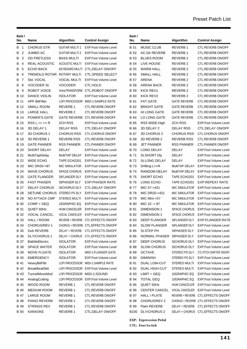
Preset Patch List
Bank /No. Name Algorithm Control Assign
B 1 CHORUS GTR GUITAR MULTI 1 EXP:Foot Volume Level
B 2 JUMBO AC GUITAR MULTI 2 EXP:Foot Volume Level
B 3 OD FRETLESS BASS MULTI EXP:Foot Volume Level
B 4 REAL ACOUSTIC ACOUSTIC MULTI EXP:Foot Volume Level
B 5 ECHO BACK KEYBOARD MULTI CTL:DELAY ON/OFF
B 6 TREMOLO ROTAR ROTARY MULTI CTL:SPEED SELECT
B 7 Std. VOCAL VOCAL MULTI EXP:Foot Volume Level
B 8 VOCODER St. VOCODER CTL:HOLD
B 9 ROBOT VOICE VoiceTRANSFORM CTL:ROBOT ON/OFF
B 10 DANCE VIOLIN ISOLATOR EXP:Foot Volume Level
B 11 HPF BitFilter LOFI PROCESSOR MIDI-1:SAMPLE RATE
B 12 SMALL ROOM REVERB 1 CTL:REVERB ON/OFF
B 13 LARGE HALL REVERB 2 CTL:REVERB ON/OFF
B 14 POWER’S GATE GATE REVERB CTL:REVERB ON/OFF
B 15 RSS L << >> R 2CH RSS EXP:Foot Volume Level
B 16 3D DELAY 1 DELAY RSS CTL:DELAY ON/OFF
B 17 3D CHORUS 1 CHORUS RSS CTL:CHORUS ON/OFF
B 18 3D REVERB 1 REVERB RSS CTL:REVERB ON/OFF
B 19 GATE PANNER RSS PANNER CTL:PANNER ON/OFF
B 20 SHORT DELAY DELAY EXP:Foot Volume Level
B 21 MultiTapDelay MultiTAP DELAY EXP:Foot Volume Level
B 22 WIDE ECHO TAPE ECHO201 EXP:Foot Volume Level
B 23 MIC DR20->87 MIC SIMULATOR EXP:Foot Volume Level
B 24 WAVE CHORUS SPACE CHORUS EXP:Foot Volume Level
B 25 GATE FLANGER StFLANGER DLY EXP:Foot Volume Level
B 26 FAST PHASER StPHASER DLY EXP:PHASER RATE
B 27 DELAY CHORUS StCHORUS DLY CTL:DELAY ON/OFF
B 28 DETUNE CHORUS STEREO PS DLY EXP:Foot Volume Level
B 29 NO ATTACK CMP STEREO MULTI EXP:Foot Volume Level
B 30 COMP + GEQ 10GRAPHIC EQ EXP:Foot Volume Level
B 31 QUIET 60Hz HUM CANCELER EXP:Foot Volume Level
B 32 VOCAL CANCEL VOCAL CANCELER EXP:Foot Volume Level
B 33 HALL / ROOM REVERB + REVERB CTL:EFFECTS ON/OFF
B 34 CHORUS/REV 1 CHORUS + REVERB CTL:EFFECTS ON/OFF
B 35 Dub REVERB DELAY + REVERB CTL:EFFECTS ON/OFF
B 36 DLY/CHORUS 1 DELAY + CHORUS CTL:EFFECTS ON/OFF
B 37 BabbleElectro ISOLATOR EXP:Foot Volume Level
B 38 SPACE WATER ISOLATOR EXP:Foot Volume Level
B 39 MOVE FLGATE ISOLATOR MIDI-1:FLANGER GATE
B 40 EMERGENCY ISOLATOR EXP:Foot Volume Level
B 41 HeavyBitFiltr LOFI PROCESSOR MIDI-1:SAMPLE RATE
B 42 BreakBeatSkit LOFI PROCESSOR EXP:Foot Volume Level
B 43 TunnelMoveMod LOFI PROCESSOR MIDI-1:SOUND
B 44 AnalogCutting LOFI PROCESSOR EXP:Foot Volume Level
B 45 WOOD ROOM REVERB 1 CTL:REVERB ON/OFF
B 46 MEDIUM ROOM REVERB 1 CTL:REVERB ON/OFF
B 47 LARGE ROOM REVERB 1 CTL:REVERB ON/OFF
B 48 PIANO REVERB REVERB 1 CTL:REVERB ON/OFF
B 49 STRINGS REV REVERB 1 CTL:REVERB ON/OFF
B 50 KARAOKE REVERB 1 CTL:DELAY ON/OFF
Bank /No. Name Algorithm Control Assign
B 51 MUSIC CLUB REVERB 1 CTL:REVERB ON/OFF
B 52 AC.Gtr REVERB REVERB 1 CTL:REVERB ON/OFF
B 53 BLUES ROOM REVERB 2 CTL:REVERB ON/OFF
B 54 LIVE HOUSE REVERB 2 CTL:REVERB ON/OFF
B 55 WARM HALL REVERB 2 CTL:REVERB ON/OFF
B 56 SMALL HALL REVERB 2 CTL:REVERB ON/OFF
B 57 ARENA REVERB 2 CTL:REVERB ON/OFF
B 58 ARENA BACK REVERB 2 CTL:REVERB ON/OFF
B 59 KICK REV1 REVERB 2 CTL:REVERB ON/OFF
B 60 KICK REV2 REVERB 2 CTL:REVERB ON/OFF
B 61 FAT GATE GATE REVERB CTL:REVERB ON/OFF
B 62 BRIGHT GATE GATE REVERB CTL:REVERB ON/OFF
B 63 HI LONG GATE GATE REVERB CTL:REVERB ON/OFF
B 64 LO LONG GATE GATE REVERB CTL:REVERB ON/OFF
B 65 RSS WIDE-High 2CH RSS EXP:Foot Volume Level
B 66 3D DELAY 2 DELAY RSS CTL:DELAY ON/OFF
B 67 3D CHORUS 2 CHORUS RSS CTL:CHORUS ON/OFF
B 68 3D REVERB 2 REVERB RSS CTL:REVERB ON/OFF
B 69 JET PANNER RSS PANNER CTL:PANNER ON/OFF
B 70 LONG DELAY DELAY EXP:Foot Volume Level
B 71 St.SHORT Dly DELAY EXP:Foot Volume Level
B 72 St.LONG DELAY DELAY EXP:Foot Volume Level
B 73 Drifting L>>R MultiTAP DELAY EXP:Foot Volume Level
B 74 RANDOM DELAY MultiTAP DELAY EXP:Foot Volume Level
B 75 SHORT ECHO TAPE ECHO201 EXP:Foot Volume Level
B 76 LONG ECHO TAPE ECHO201 EXP:REPEAT RATE
B 77 MIC 57->421 MIC SIMULATOR EXP:Foot Volume Level
B 78 MIC DR20->421 MIC SIMULATOR EXP:Foot Volume Level
B 79 MIC Mini->57 MIC SIMULATOR EXP:Foot Volume Level
B 80 MIC 10 -> 87 MIC SIMULATOR EXP:Foot Volume Level
B 81 DIMENSION 1 SPACE CHORUS EXP:Foot Volume Level
B 82 DIMENSION 2 SPACE CHORUS EXP:Foot Volume Level
B 83 DEEP FLANGER StFLANGER DLY EXP:FLANGER RATE
B 84 SLOW FLANGER StFLANGER DLY EXP:Foot Volume Level
B 85 St.STEP PH StPHASER DLY EXP:Foot Volume Level
B 86 NORMAL PHASER StPHASER DLY EXP:Foot Volume Level
B 87 DEEP CHORUS StCHORUS DLY EXP:Foot Volume Level
B 88 SLOW CHORUS StCHORUS DLY EXP:Foot Volume Level
B 89 OCTAVE STEREO PS DLY CTL:PITCH SHIFTER ON/OFF
B 90 DIMINISH STEREO PS DLY EXP:Foot Volume Level
B 91 DUAL LOW-CUT STEREO MULTI EXP:Foot Volume Level
B 92 DUAL HIGH-CUT STEREO MULTI EXP:Foot Volume Level
B 93 LIMIT + GEQ 10GRAPHIC EQ EXP:Foot Volume Level
B 94 TOTAL GEQ 10GRAPHIC EQ EXP:Foot Volume Level
B 95 QUIET 50Hz HUM CANCELER EXP:Foot Volume Level
B 96 CENTER CANCEL VOCAL CANCELER EXP:Foot Volume Level
B 97 HALL / PLATE REVERB + REVERB CTL:EFFECTS ON/OFF
B 98 CHORUS/REV 2 CHORUS + REVERB CTL:EFFECTS ON/OFF
B 99 Flam REVERB DELAY + REVERB CTL:EFFECTS ON/OFF
B100 DLY/CHORUS 2 DELAY + CHORUS CTL:EFFECTS ON/OFF
EXP: Expresssion Pedal
CTL: Foot Switch
141
Preset Patch List
MEMO
142
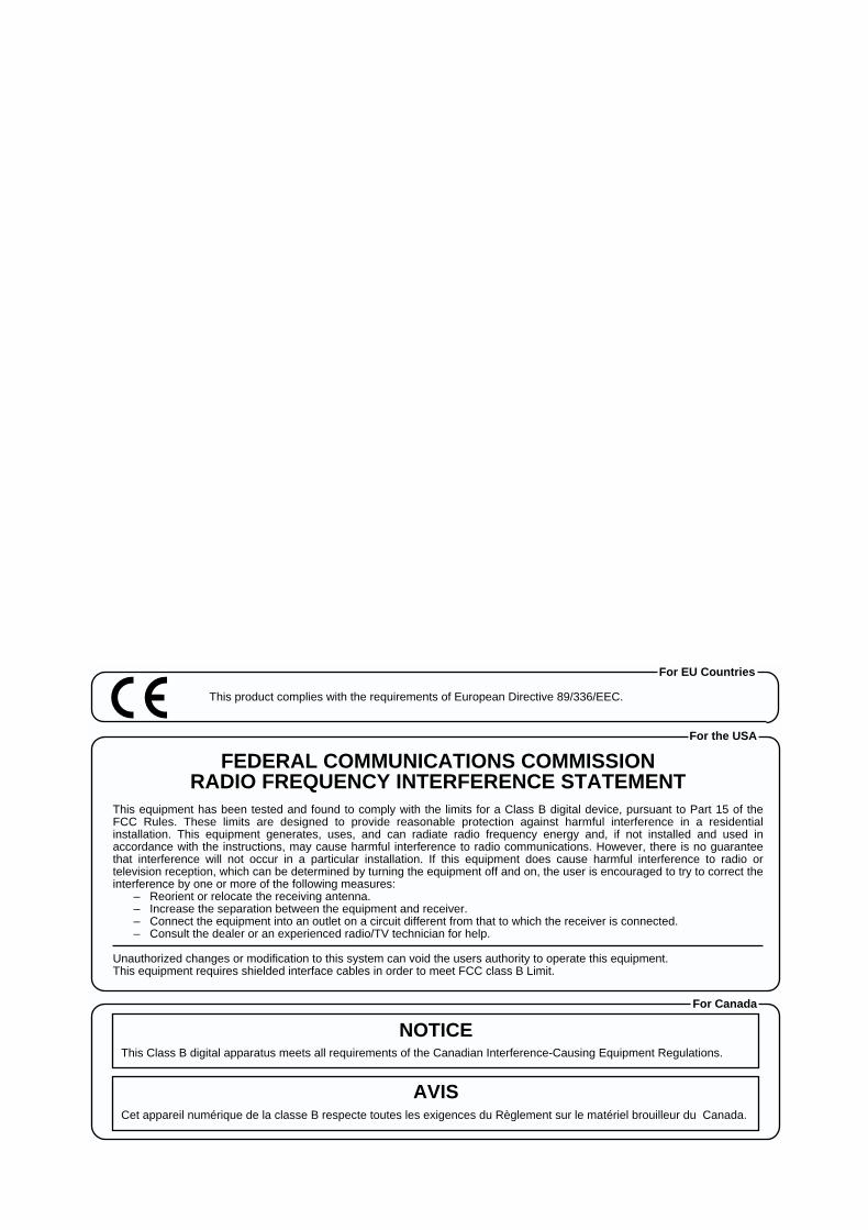
Used for instructions intended to alert the user to the risk of injury or material damage should the unit be used improperly.
* Material damage refers to damage or other adverse effects caused with respect to the home and all its furnishings, as well to domestic animals or pets.
Used for instructions intended to alert the user to the risk of death or severe injury should the unit be used improperly.
The symbol alerts the user to things that must be carried out. The specific thing that must be done is indicated by the design contained within the circle. In the case of the symbol at left, it means that the power-cord plug must be unplugged from the outlet.
The symbol alerts the user to important instructions or warnings.The specific meaning of the symbol is determined by the design contained within the triangle. In the case of the symbol at left, it is used for general cautions, warnings, or alerts to danger.
The symbol alerts the user to items that must never be carried out (are forbidden). The specific thing that must not be done is indicated by the design contained within the circle. In the case of the symbol at left, it means that the unit must never be disassembled.
For the USA
FEDERAL COMMUNICATIONS COMMISSIONRADIO FREQUENCY INTERFERENCE STATEMENT
This equipment has been tested and found to comply with the limits for a Class B digital device, pursuant to Part 15 of the FCC Rules. These limits are designed to provide reasonable protection against harmful interference in a residential installation. This equipment generates, uses, and can radiate radio frequency energy and, if not installed and used in accordance with the instructions, may cause harmful interference to radio communications. However, there is no guarantee that interference will not occur in a particular installation. If this equipment does cause harmful interference to radio or television reception, which can be determined by turning the equipment off and on, the user is encouraged to try to correct the interference by one or more of the following measures:
– Reorient or relocate the receiving antenna.– Increase the separation between the equipment and receiver.– Connect the equipment into an outlet on a circuit different from that to which the receiver is connected.– Consult the dealer or an experienced radio/TV technician for help.
Unauthorized changes or modification to this system can void the users authority to operate this equipment.This equipment requires shielded interface cables in order to meet FCC class B Limit.
This product complies with the requirements of European Directive 89/336/EEC.
For EU Countries
For Canada
This Class B digital apparatus meets all requirements of the Canadian Interference-Causing Equipment Regulations.
Cet appareil numérique de la classe B respecte toutes les exigences du Règlement sur le matériel brouilleur du Canada.
NOTICE
AVIS
2
001
• Before using this unit, make sure to read the instructions below, and the Owner’s Manual.
..........................................................................................................
002c
• Do not open (or modify in any way) the unit or its AC adaptor.
..........................................................................................................
003
• Do not attempt to repair the unit, or replace parts within it (except when this manual provides specific instructions directing you to do so). Refer all servicing to your retailer, the nearest Roland Service Center, or an authorized Roland distributor, as listed on the “Information” page.
..........................................................................................................
004
• Never use or store the unit in places that are:
• Subject to temperature extremes (e.g., direct sunlight in an enclosed vehicle, near a heating duct, on top of heat-generating equipment); or are
• Damp (e.g., baths, washrooms, on wet floors); or are
• Humid; or are
• Exposed to rain; or are
• Dusty; or are
• Subject to high levels of vibration...........................................................................................................
005
• This unit should be used only with a rack or stand that is recommended by Roland.
..........................................................................................................
006
• When using the unit with a rack or stand recom-mended by Roland, the rack or stand must be carefully placed so it is level and sure to remain stable. If not using a rack or stand, you still need to make sure that any location you choose for placing the unit provides a level surface that will properly support the unit, and keep it from wobbling.
..........................................................................................................
008c
• Be sure to use only the AC adaptor supplied with the unit. Also, make sure the line voltage at the installation matches the input voltage specified on the AC adaptor’s body. Other AC adaptors may use a different polarity, or be designed for a different voltage, so their use could result in damage, malfunction, or electric shock.
..........................................................................................................
009
• Avoid damaging the power cord. Do not bend it excessively, step on it, place heavy objects on it, etc. A damaged cord can easily become a shock or fire hazard. Never use a power cord after it has been damaged.
..........................................................................................................
010
• This unit, either alone or in combination with an amplifier and headphones or speakers, may be capable of producing sound levels that could cause permanent hearing loss. Do not operate for a long period of time at a high volume level, or at a level that is uncomfortable. If you experience any hearing loss or ringing in the ears, you should immediately stop using the unit, and consult an audiologist.
..........................................................................................................
011
• Do not allow any objects (e.g., flammable material, coins, pins); or liquids of any kind (water, soft drinks, etc.) to penetrate the unit.
..............................................................................................................

Owner’s Manual
01903667 ‘00-11-D3-31N
Thank you, and congratulations on your choice of the BOSSVF-1 24-BIT MULTIPLE EFFECTS PROCESSOR.
Before using this unit, carefully read the sections entitled:
• USING THE UNIT SAFELY (page 2–3)
• IMPORTANT NOTES (page 11)
These sections provide important information concerningthe proper operation of the unit.
Additionally, in order to feel assured that you have gained agood grasp of every feature provided by your new unit,Owner’s manual should be read in its entirety. The manualshould be saved and kept on hand as a convenient reference.
Copyright © 1999 BOSS CORPORATION
All rights reserved. No part of this publication may be reproduced in any formwithout the written permission of BOSS CORPORATION.


![xo ýí' !rÈ¢@ È°+] ¸ù Ò* æ ¥ èTµf 0H Sµðe & >N&Hî` Ú û ¹U£0 ... Brand Elements to … · Title: xo ýí' !rÈ¢@ È°+] ¸ù Ò* æ ¥ èTµf 0H Sµðe & >N&Hî`](https://img.pdfslide.tips/doc/110x75/5eaab71782955642725543b7/xo-r-tf-0h-se-nh-.jpg)


![[a.a. Samarski] Introducción a Los Métodos Numé(BookZZ.org)](https://img.pdfslide.tips/doc/110x75/563db8f1550346aa9a986fde/aa-samarski-introduccion-a-los-metodos-numebookzzorg.jpg)