Embed Size (px)
Citation preview
1
PALETTO PENDULO TELESCOPICOPIEU PENDANT TÉLESCOPIQUETELESCOPIC HANGING SUPPORTTELESKOPISCHE STÜTZPENDELVARILLA PÉNDULA TELESCÓPICA
Cod. ACG8285MONTAGGIO SU ASTA Ø 80 RIB
ASSEMBLAGE SUR LISSE Ø 80 RIB
FITTING ON RIB BOOM ARM Ø 80
INSTALLIERUNG AUF STANGE Ø 80 RIB
MONTAJE EN BRAZO RIB Ø 80
MONTAGGIO SU ASTA RIB CON LED
ASSEMBLAGE SUR LISSE RIB AVEC LED
FITTING ON RIB BOOM ARM WITH LEDS
INSTALLIERUNG AUF STANGE RIB MIT LEDS
MONTAJE EN BRAZO RIB CON LEDS
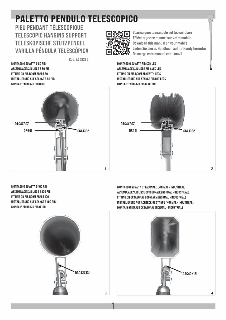
MONTAGGIO SU ASTA Ø 100 RIB
ASSEMBLAGE SUR LISSE Ø 100 RIB
FITTING ON RIB BOOM ARM Ø 100
INSTALLIERUNG AUF STANGE Ø 100 RIB
MONTAJE EN BRAZO RIB Ø 100
1 2
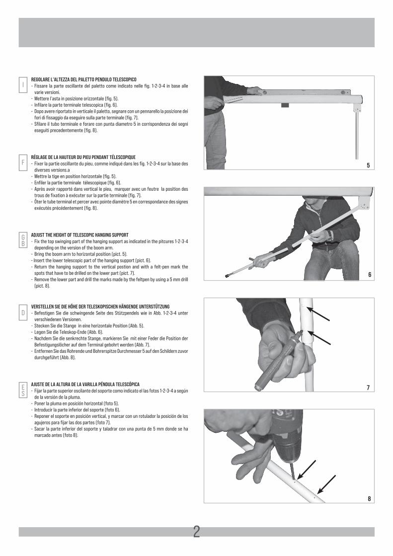
MONTAGGIO SU ASTA OTTAGONALE (NORMAL - INDUSTRIAL)
ASSEMBLAGE SUR LISSE OCTOGONALE (NORMAL - INDUSTRIAL)
FITTING ON OCTAGONAL BOOM ARM (NORMAL - INDUSTRIAL)
INSTALLIERUNG AUF ACHTECKIGE STANGE (NORMAL - INDUSTRIAL)
MONTAJE EN BRAZO OCTAGONAL (NORMAL - INDUSTRIAL)
3 4
DTC4X20Z
DRG4I DRG4I
DTC4X20Z
DAC42X13I DAC42X13I
CCA1332 CCA1332
Scarica questo manuale sul tuo cellulareTéléchargez ce manuel sur votre mobileDownload this manual on your mobileLaden Sie dieses Handbuch auf Ihr Handy herunterDescarga este manual en tu móvil
2
REGOLARE L’ALTEZZA DEL PALETTO PENDULO TELESCOPICO- Fissare la parte oscillante del paletto come indicato nelle fig. 1-2-3-4 in base alle
varie versioni. - Mettere l’asta in posizione orizzontale (fig. 5).- Infilare la parte terminale telescopica (fig. 6).- Dopo avere riportato in verticale il paletto, segnare con un pennarello la posizione dei
fori di fissaggio da eseguire sulla parte terminale (fig. 7).- Sfilare il tubo terminale e forare con punta diametro 5 in corrispondenza dei segni
eseguiti precedentemente (fig. 8).
I
RÉGLAGE DE LA HAUTEUR DU PIEU PENDANT TÉLESCOPIQUE- Fixer la partie oscillante du pieu, comme indiqué dans les fig. 1-2-3-4 sur la base des
diverses versions.a- Mettre la tige en position horizontale (fig. 5).- Enfiler la partie terminale télescopique (fig. 6).- Après avoir rapporté dans vertical le pieu, marquer avec un feutre la position des
trous de fixation à exécuter sur la partie terminale (fig. 7).- Ôter le tube terminal et percer avec pointe diamètre 5 en correspondance des signes
exécutés précédentement (fig. 8).
ADJUST THE HEIGHT OF TELESCOPIC HANGING SUPPORT- Fix the top swinging part of the hanging support as indicated in the pitcures 1-2-3-4
depending on the version of the boom arm.- Bring the boom arm to horizontal position (pict. 5).- Insert the lower telescopic part of the hanging support (pict. 6).- Return the hanging support to the vertical postion and with a felt-pen mark the
spots that have to be drilled on the lower part (pict. 7).- Remove the lower part and drill the marks made by the feltpen by using a 5 mm drill
(pict. 8).
VERSTELLEN SIE DIE HÖHE DER TELESKOPISCHEN HÄNGENDE UNTERSTÜTZUNG- Befestigen Sie die schwingende Seite des Stützpendels wie in Abb. 1-2-3-4 unter
verschiedenen Versionen.- Stecken Sie die Stange in eine horizontale Position (Abb. 5).- Legen Sie die Teleskop-Ende (Abb. 6).- Nachdem Sie die senkrechte Stange, markieren Sie mit einer Feder die Position der
Befestigungslöcher auf dem Terminal gebohrt werden (Abb. 7).- Entfernen Sie das Rohrende und Bohrerspitze Durchmesser 5 auf den Schildern zuvor
durchgeführt (Abb. 8).
D
AJUSTE DE LA ALTURA DE LA VARILLA PÉNDULA TELESCÓPICA- Fijar la parte superior oscilante del soporte como indicato el las fotos 1-2-3-4 a según
de la versión de la pluma. - Poner la pluma en posición horizontal (foto 5).- Introducir la parte inferior del soporte (foto 6).- Reponer el soporte en posición vertical, y marcar con un rotulador la posición de los
agujeros para fijar las dos partes (foto 7).- Sacar la parte inferior del soporte y taladrar con una punta de 5 mm donde se ha
marcado antes (foto 8).
F
GB
ES
6
5
8
7
3
I
D- Legen Sie die Stützpendel-Ende, befestigen Sie diese mit dem röhrenförmigen
CME6132 mit den mitgelieferten Schrauben DAC55x16I (Abb. 9).- Überprüfen Sie den korrekten Betrieb des teleskopischen Stützpendels, indem Sie
einen vollständigen Zyklus der Barriere (Abb. 10).
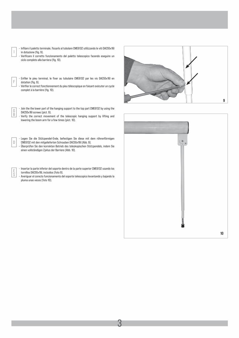
- Infilare il paletto terminale, fissarlo al tubolare CME6132 utilizzando le viti DAC55x16I in dotazione (fig. 9).
- Verificare il corretto funzionamento del paletto telescopico facendo eseguire un ciclo completo alla barriera (fig. 10).
F- Enfiler le pieu terminal, le fixer au tubulaire CME6132 par les vis DAC55x16I en
dotation (fig. 9).- Vérifier le correct fonctionnement du pieu télescopique en faisant exécuter un cycle
complet à la barrière (fig. 10).
GB
- Join the the lower part of the hanging support to the top part CME6132 by using the DAC55x16I screws (pict. 9).
- Verify the correct movement of the telescopic hanging support by lifting and lowering the boom arm for a few times (pict. 10).
ES
- Insertar la parte inferior del soporte dentro de la parte superior CME6132 usando los tornillos DAC55x16L incluidos (foto 9).
- Averiguar el corecto funcionamento del soporte telescopico levantando y bajando la pluma unas veces (foto 10).
9
10
Cod.
CVA
2017
- 04
2021
- Re
v. 0
6
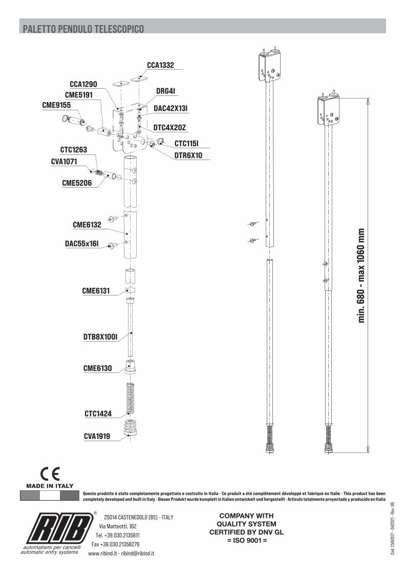
PALETTO PENDULO TELESCOPICO
CCA1290
CCA1332
DRG4I
DAC42X13I
DTC4X20Z
CTC115I
CME9155CME5191
CTC1263CVA1071
CME5206
CME6132
DAC55x16I
CME6131
DTB8X100I
CME6130
CTC1424
CVA1919
DTR6X10
min
. 680
- m
ax 10
60 m
m
Questo prodotto è stato completamente progettato e costruito in Italia · Ce produit a été complètement développé et fabriqué en Italie · This product has been completely developed and built in Italy · Dieses Produkt wurde komplett in Italien entwickelt und hergestellt · Artìculo totalmente proyectado y producido en Italia
25014 CASTENEDOLO (BS) - ITALY
Via Matteotti, 162
Tel. +39.030.2135811
Fax +39.030.21358279
www.ribind.it - [email protected] per cancelli
automatic entry systems
®