Embed Size (px)
Citation preview

BA382C/07/en/POD
Valid as of:
Software version 13.04.01
Operating Instructions
Liquiline M CM42Two-wire transmitter for conductivity (digital sensors)
Part 2: Operation

Operating concept
a0005773
Fig. 1: Press soft key: select menu directlya0005777-en
Fig. 2: Turn navigator: move cursor in the menu
a0005779-en
Fig. 3: Press navigator: select a functiona0005781-en
Fig. 4: Turn navigator: change value
a0005783-en
Fig. 5: Press navigator: accept new value
Operating concept
1. You select a menu directly by pressing the
soft key in question.
2. You move the cursor in the menu by
turning the navigator.
3. Press the navigator and select the desired
function.
4. Change the value by turning the
navigator.
5. Press the navigator to accept the new
value.

Endress+Hauser
Liquiline M CM42
Table of contents
1 Display . . . . . . . . . . . . . . . . . . . 4
1.1 Overview . . . . . . . . . . . . . . . . . . . . . . . . . . 4
1.2 Status messages . . . . . . . . . . . . . . . . . . . . . 4
2 Notes on software description . 5
2.1 Types of setting . . . . . . . . . . . . . . . . . . . . . 5
2.2 Editing tables . . . . . . . . . . . . . . . . . . . . . . . 5
2.3 User administration . . . . . . . . . . . . . . . . . . 5
3 Measure (MEAS) . . . . . . . . . . . 6
4 Specifying the parameters
(PARAM) . . . . . . . . . . . . . . . . . 6
4.1 Menu structure, top hierarchy level . . . . . . 6
4.2 Sensor . . . . . . . . . . . . . . . . . . . . . . . . . . . . 7
4.3 Operating mode . . . . . . . . . . . . . . . . . . . . . 8
4.4 Current output . . . . . . . . . . . . . . . . . . . . . 10
4.5 Temperature compensation table . . . . . . . 11
4.6 Concentration table . . . . . . . . . . . . . . . . . 12
4.7 General settings . . . . . . . . . . . . . . . . . . . . 14
4.8 Display . . . . . . . . . . . . . . . . . . . . . . . . . . 17
4.9 Quick Setup . . . . . . . . . . . . . . . . . . . . . . . 18
5 Device diagnosis (DIAG) . . . . 21
5.1 Menu structure, top hierarchy level . . . . . 22
5.2 Errors/messages . . . . . . . . . . . . . . . . . . . 22
5.3 Output state . . . . . . . . . . . . . . . . . . . . . . . 22
5.4 Logbooks . . . . . . . . . . . . . . . . . . . . . . . . . 22
5.5 Sensor information . . . . . . . . . . . . . . . . . . 24
5.6 Device information . . . . . . . . . . . . . . . . . 25
5.7 Service . . . . . . . . . . . . . . . . . . . . . . . . . . . 26
6 Calibration (CAL) . . . . . . . . . . 26
6.1 Types of calibration . . . . . . . . . . . . . . . . . 26
6.2 Current values . . . . . . . . . . . . . . . . . . . . . 27
6.3 Cell constant . . . . . . . . . . . . . . . . . . . . . . 27
6.4 Temperature adjustment . . . . . . . . . . . . . 28
7 Communication . . . . . . . . . . . 29
7.1 HART Communicator . . . . . . . . . . . . . . . 29
7.2 Fieldcare . . . . . . . . . . . . . . . . . . . . . . . . . 30
7.3 Device identification . . . . . . . . . . . . . . . . 30
7.4 Interfaces . . . . . . . . . . . . . . . . . . . . . . . . . 31
7.5 HART: Universal commands . . . . . . . . . . . 32
7.6 HART: Common practice commands . . . . . 34
7.7 Device-specific commands . . . . . . . . . . . . 36
7.8 Status messages . . . . . . . . . . . . . . . . . . . . 36
8 Troubleshooting . . . . . . . . . . . 38
8.1 Troubleshooting instructions . . . . . . . . . . . 38
8.2 Diagnosis messages . . . . . . . . . . . . . . . . . . 38
8.3 Process errors without messages . . . . . . . . 42
8.4 Software history . . . . . . . . . . . . . . . . . . . . 45
Index. . . . . . . . . . . . . . . . . . . . 46
Display Liquiline M CM42
4 Endress+Hauser
1 Display
1.1 Overview
1.2 Status messages
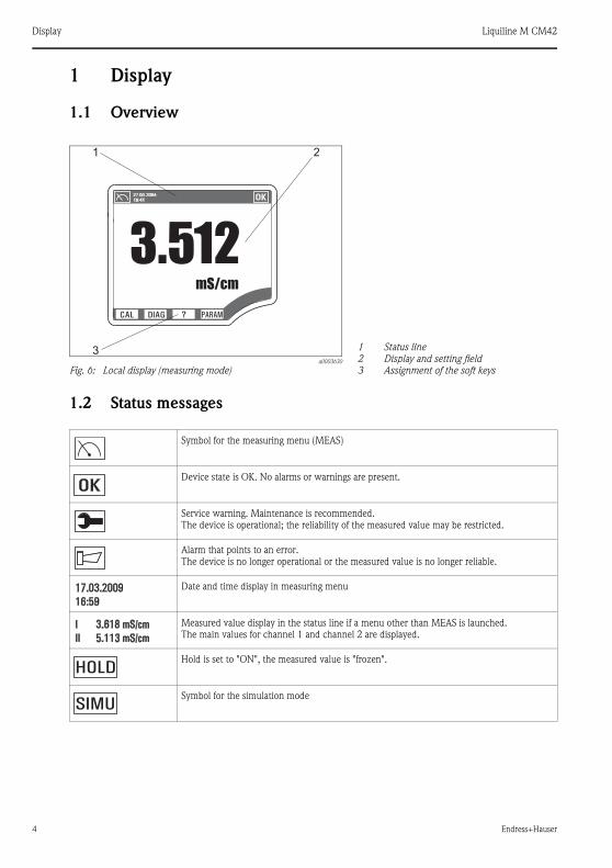
a0003630
Fig. 6: Local display (measuring mode)
1
2
3
Status line
Display and setting field
Assignment of the soft keys
Symbol for the measuring menu (MEAS)
Device state is OK. No alarms or warnings are present.
Service warning. Maintenance is recommended.
The device is operational; the reliability of the measured value may be restricted.
Alarm that points to an error.
The device is no longer operational or the measured value is no longer reliable.
Date and time display in measuring menu
Measured value display in the status line if a menu other than MEAS is launched.
The main values for channel 1 and channel 2 are displayed.
Hold is set to "ON", the measured value is "frozen".
Symbol for the simulation mode

Liquiline M CM42 Notes on software description
Endress+Hauser 5
2 Notes on software description
2.1 Types of setting
• Display fields
– You can only read the values, not change them.
• Selection fields
– You receive a list with options.
– You select one of these options.
• Input fields
– There are value ranges with upper and lower range limits that depend on the measured
value configured and its units.
– There are also menu functions where you can enter arbitrary text. The number of
characters is then limited.
– Set a value with the navigator:
Turn to increase/reduce a value/letter/special character
Press to confirm or to enter the next character for arbitrary text.
2.2 Editing tables
You can set some software functions using a table:
• The number of columns depends on the menu function that is set via the table.
• You can add lines ("Insert") or delete lines ("Del").
• The maximum number of lines also depends on the menu function in question.
• You can press "Esc" at any time to exit the table and stop entering information.
• If the values entered result in a valid table, you receive the message "Table is valid" and the
options:
– Save table
– Continue edit table
– Discard table
• If the values entered are invalid, an error message is output with the options:
– Continue edit table
– Discard table
2.3 User administration
As a "Specialist" you can assign user authorization for each individual software function.
Below, you will find the factory settings for the "Maintenance" user under "Configuration
options" ("AC" column). The possible authorizations are as follows:
• R (=Read), only read access
• R/W (=Read+Write), Read and write access
! Note!
The "Specialist" always has read and write access (R/W) and is, therefore, not listed.

Measure (MEAS) Liquiline M CM42
6 Endress+Hauser
3 Measure (MEAS)
! Note!
In the measuring menu, you can switch between three different types of display. To do so, simply
press the enter button of the navigator.
4 Specifying the parameters (PARAM)
4.1 Menu structure, top hierarchy level
Function name of local operation (Display)
Meas
Main value
Conductivity or Resistivity or Concentration
Main value and secondary value
Conductivity or Resistivity or Concentration
Temperature
All measured values
TAG name
Main value
Raw value1)
1) The raw value is the uncompensated conductivity
Temperature
Current output 1
Current output 2
PARAM
Sensor conductivity
Operating mode
Current output
Temp. comp. tab.
Conc. table
General settings
Display
Quick Setup

Liquiline M CM42 Specifying the parameters (PARAM)
Endress+Hauser 7
4.2 Sensor
4.2.1 Menu structure
4.2.2 Configuration options
Function name of display (local operation)
PARAM
Sensor conductivity
Cell constant
Damping
Temp. adjustment
Mode
Offset
(Mode="1-point / 2-point(offset/slope)")
Slope
(Mode="2-point(offset/slope)")
Enter table
(Mode="2-point (table)")
Sensor diagnosis
Diagnosis list
Function Options AC Info
Cell constant 0.0025 to 99.99 cm–1
Factory setting
Depends on the sensor
R/W The cell constant of the connected sensor is
detected. You can change it here.
Damping 0 to 20 s
Factory setting
0 s
R/W The damping causes a floating average curve of
the measured values over the time specified.
Temp. adjustment
Mode Options
• 1-point
• 2-point (offset/slope)
• 2-point (table)
Factory setting
1-point
R/W 1-point: You enter the temperature offset.
2-point (offset/slope): You enter the offset at
0 °C and a slope. The adjustment takes place
by means of the line defined in this way.
2-point (table): You enter the set point and
display value in a table.
Offset –5.0 to +5.0 °C
(–23 to 41 °F)
Factory setting
0.0 °C
R/W Only if "Mode"="1-point" or 2-point (off-
set/slope)"
Slope 0.9000 to 1.1000
Factory setting
1.0000
R/W Only if "Mode"="2-point (offset/slope)"

Specifying the parameters (PARAM) Liquiline M CM42
8 Endress+Hauser
4.3 Operating mode
4.3.1 Menu structure
4.3.2 Configuration options
Enter table Enter table values for:
• Set point
• Display
R/W Only if "Mode"="2-point (table)"
Sensor diagnosis
Diagnosis list Priority adjustable R You can change the priority of the errors by
moving them up or down in the list.
Function name of display (local operation)
PARAM
Operating mode
Measured value
Medium
(Measured value="Concentration")
Temp. compensation
(Measured value="Conductivity", "Resistivity")
Coeff. alpha
(Temp. compensation="Linear")
Alpha ref. temp.
(Temp. compensation="Linear")
Temp. source
Medium temperature
(Temp. source="Manual input")
Function Options AC Info
Measured value Options
• Conductivity
• Resistivity
• Concentration
Factory setting
Conductivity
R/W
Function Options AC Info

Liquiline M CM42 Specifying the parameters (PARAM)
Endress+Hauser 9
Medium Options
• NaOH
• HNO3
• H2SO4
• H3PO4
• HCl
• UserTab C1
• UserTab C2
• UserTab C3
• UserTab C4
Factory setting
NaOH
R/W Only for Measured value=Concentration.
The transmitter can convert from conductivity to
concentration.
Concentrations saved:
NaOH: 0 to 15%, 0 to 100 °C
HNO3: 0 to 25%, 0 to 90 °C
H2SO4: 0 to 30%, 0 to 100 °C
H3PO4: 0 to 15%, 0 to 90 °C
HCl: 0 to 20%, 0 to 80 °C
Temp. compensation Options
• None
• Linear
• NaCl (IEC 746-3)
• Water ISO7888
• UPW NaCl
• UPW HCl
• UserTab T1
• UserTab T2
• UserTab T3
• UserTab T4
Factory setting
Linear
R/W Function only available if you selected measured
value = "Conductivity" or "Resistivity".
If you select "Linear" you then have to specify
the temperature coefficient alpha (0.00 to 20.00
% per °C).
The "Ultrapure water HCl" type of compensation
is also suitable for ammonia (NH3).
Coeff. alpha 0.00 to 20.00 % / K
Factory setting
2.10 % / K
R/W Function only available if you have selected
Temp. compensation = "Linear"
Alpha ref. temp. –5 to +100 °C
Factory setting
25.0 °C
R/W
Temp. source Options
• Temp. sensor
• Manual input
Factory setting
Temp. sensor
R/W
Medium temperature –35.0 to 250.0 °C
Factory setting
25.0 °C
R/W Function only available if you have selected
Temp. source="Temp. input"
Function Options AC Info

Specifying the parameters (PARAM) Liquiline M CM42
10 Endress+Hauser
4.4 Current output
4.4.1 Menu structure
4.4.2 Configuration options
Function name of display (local operation)
PARAM
Current output
Current output 1
Output source
Low value (4mA)
Upper value (20mA)
Current output 2
Output source
Low value (4mA)
Upper value (20mA)
Enter table
Function Options AC Info
Current output 1
Output source Options
• Main value
• Cond.uncomp.
Factory setting
Main value
R/W
Low value (4mA) Depends on the measured
value
Factory setting
0.000 μS/cm
R/W Specify the measured value that should
correspond to the 4 mA or 20 mA value.
Upper value (20mA) Depends on the measured
value
Factory setting
20 mS/cm
R/W
Current output 2
Output source Options
• Main value
• Temperature
• Cond.uncomp.
Factory setting
Temperature
R/W

Liquiline M CM42 Specifying the parameters (PARAM)
Endress+Hauser 11
4.5 Temperature compensation table
4.5.1 Menu structure
4.5.2 Configuration options
Low value (4mA) –50 to
(20 mA value) - 5 °C
Factory setting
-20 °C
R/W The smallest possible spread between 4 mA
and 20 mA value is 1 °C.
Upper value (20mA) (4 mA value) + 5 °C to
250 °C
Factory setting
+100 °C
R/W
Function name of display (local operation)
PARAM
Temp. comp. tab.
Table selection
Table name
Enter table
Function Options AC Info
Table selection Options
• UserTab C1 ("Name")
• UserTab C2 ("Name")
• UserTab C3 ("Name")
• UserTab C4 ("Name")
R/W Select one of the four possible tables and then
assign a name for this table. This name then
appears in the table selection menu instead of the
name that was used previously.
Table name Enter any text R/W Max. 10 characters
Enter table Column-based entry
• Temperature
• Alpha value
or
• Temperature
• Conductivity
• Temperature-compensate
d conductivity
R/W • Maximum number of rows: 25
Function Options AC Info
Specifying the parameters (PARAM) Liquiline M CM42
12 Endress+Hauser
4.6 Concentration table
4.6.1 Menu structure
Function name of display (local operation)
PARAM
Conc. table
Table selection
Table name
Temp. comp. mode
Conc. unit
Enter table

Liquiline M CM42 Specifying the parameters (PARAM)
Endress+Hauser 13
4.6.2 Configuration options
Example of a concentration table:
Function Options AC Info
Table selection Options
• UserTab C1 ("Name")
• UserTab C2 ("Name")
• UserTab C3 ("Name")
• UserTab C4 ("Name")
R/W Select one of the four possible tables and then
assign a name for this table. This name then
appears in the table selection menu instead of the
name that was used previously.
Table name Enter any text R/W Max. 10 characters
Temp. comp. mode Options
• With temp. comp.
• Without temp. comp.
Factory setting
With temp. comp.
R/W Only select "Without temp. comp." in very
restricted temperature ranges.
Conc. unit Options
• None
• %
• ppm
• mg/l
Factory setting
%
R/W
Enter table Column-based entry
• Conductivity (uncomp.)
• Concentration
• Temperature1)
1) Only if you have selected Temp. comp. mode="With temp. comp"
R/W • Maximum number of rows:
– 25 (with Temp. compensation)
– 15 (without Temp. compensation)
• With Temp. compensation you have to enter
at least two curves of constant concentration.
The curves must not intersect.
• The curves must always be monotone.
With Temp. compensation, also monotone in
the same direction (all monotone rising or all
monotone falling). --> e.g.
Conductivity
(uncompensated)
Concentration Temperature
1.000 mS/cm 0.000 mg/l 0.00 °C
2.000 mS/cm 0.000 mg/l 100.00 °C
100.0 mS/cm 3.000 mg/l 0.00 °C
300.0 mS/cm 3.000 mg/l 100.00 °C

Specifying the parameters (PARAM) Liquiline M CM42
14 Endress+Hauser
4.7 General settings
4.7.1 Menu structure
4.7.2 Configuration options
Function name of display (local operation)
PARAM
General settings
TAG number
Date format
Set date
Time format
Set time
Alarms
Alarm message
Alarm active
Alarm value (Alarm active="Set value")
Maintenance message
Maintenance active
Maint. value (Maintenance active="Set
value")
Hold settings
Calib active
Calib value (calib. active ="Set value")
Param active
Param value (param. active ="Set value")
Diag active
Diag. value (diag. active="Set value")
Hold delay
Device diagnosis
Diagnosis list
User admin.
Log in
(not if "Specialist" is already logged on)
Password protection
Enter code
(only if you are logged on as a "Specialist")
Specialist
Maintenance
Bus address
Function Options AC Info
TAG number Can be edited at random R/W Max. 20 characters

Liquiline M CM42 Specifying the parameters (PARAM)
Endress+Hauser 15
Date format Options
• DD.MM.YYYY
• MM.DD.YYYY
Factory setting
DD.MM.YYYY
R/W Editing mode:
DD (day): 1 to 31
MM (month): 1 to 12
YYYY (year): 2005 to 2100
Set date Depends on the format
DD.MM.YYYY
R/W
Time format Options
• hhmmss (24 h)
• hhmmss (am / pm)
Factory setting
hhmmss (24 h)
R/W 24-hour display or 12-hour display
Editing mode:
hh (hour): 0 to 23 / 0 am to 12 pm
mm (minutes): 0 to 59
ss (seconds): 0 to 59
Set time Depends on the format
hh:mm:ss
R/W
Alarms
Alarm message
Alarm active Options
• Off
• Freeze (I1)
• Set value (I1)
Factory setting
Set value (I1)
R
Alarm value 20.5 to 22 mA
Factory setting
22 mA
R Only if Alarm active="Set value (I1)"
Maintenance message
Maintenance
active
Options
• Off
• Freeze (I2)
• Set value (I2)
Factory setting
Off
R
Maint. value 20.5 to 22 mA
Factory setting
22 mA
R Only if Maintenance active="Set value (I2)"
Hold settings
Calib active Options
• No hold
• Freeze
• Fixed
Factory setting
No hold
R • Freeze:
Device keeps the last measured value.
• Set value:
You define a set display value.
Function Options AC Info

Specifying the parameters (PARAM) Liquiline M CM42
16 Endress+Hauser
Calib value 20.5 to 22 mA
Factory setting
21.5 mA
R Only if Calib active="Set value"
Param active Options
• No hold
• Freeze
• Fixed
Factory setting
No hold
R • Freeze:
Device keeps the last measured value.
• Set value:
You define a set display value.
Param value 20.5 to 22 mA
Factory setting
21.5 mA
R Only if Param active="Set value"
Diag active Options
• No hold
• Freeze
• Fixed
Factory setting
No hold
R • Freeze:
Device keeps the last measured value.
• Set value:
You define a set display value.
Diag. value 20.5 to 22 mA
Factory setting
21.5 mA
R Only if Diag active="Set value"
Hold delay 0 to 60 s
Factory setting
5 s
R
Device diagnosis
Diagnosis list For all messages, you can assign a customer-specific status (alarm/warning/info), see Section
"Troubleshooting"/"Diagnosis messages".
User admin.
Log in Options
• Specialist
• Maintenance
Factory setting
Maintenance
R Once the user is selected, you are prompted to
enter a code of your choice.
Factory setting is empty.
!Note!
More information is provided on the user roles
under "Commissioning" in the first part of the
Operating Instructions.
Password protection Options
• None
• Enter code
Factory setting
None
R/W " Caution!
The "Enter code" option is only visible if you are
logged on as a "Specialist"!
Enter code Here, you can enter a code for the user roles "Specialist" and "Maintenance" (you have to be
logged on as a "Specialist"!).
Function Options AC Info
Liquiline M CM42 Specifying the parameters (PARAM)
Endress+Hauser 17
4.8 Display
4.8.1 Menu structure
4.8.2 Configuration options
Specialist Options
• Password
Factory setting
Empty (nothing entered)
• Store
Once you have specified a password of your
choice, go to Store (= Enter).
The message "Stored new password" and "OK" is
displayed.
Maintenance
Bus address Entry
• 0 to 15
Factory setting
0
R
Function name of display (local operation)
PARAM
Display
Language
Main meas. unit
Main value format
Temperature unit
Temperature format
Function Options AC Info
Language Options
• English
• Language ordered
Factory setting
Language ordered
R/W !Note!
"Language ordered" refers to the language that
you selected for your device using the order code
("device language").
If you select the other language in question, all
the other settings remain intact.
Main meas. unit Options
• Auto
• μS/cm, mS/cm, S/cm,
μS/m, mS/m, S/m
• kΩcm, MΩcm, kΩm
Factory setting
Auto
R/W The menu is not available if you selected
Sensor/measured value = "Concentration".
In this case, you make the setting for the unit in
the "Concentration table" menu.
Function Options AC Info

Specifying the parameters (PARAM) Liquiline M CM42
18 Endress+Hauser
4.9 Quick Setup
4.9.1 Menu structure
Main value format Options
• Auto
• xxx
• xxx.x
• xx.xx
• xx.xxx
Factory setting
Auto
R/W You select how many commas should appear
after the decimal point in the measured value
display.
Temperature unit Options
• °C
• °F
Factory setting
°C
R/W
Temperature format Options
• xxx
• xxx.x
Factory setting
xxx.x
R/W You select how many commas should appear
after the decimal point in the temperature
display.
Function name of display (local operation)
PARAM
Quick Setup
Language
TAG number
Date format
Set date
Time format
Set time
Cell constant
Temperature unit
Measured value
Medium (Measured value="Concentration")
Temp. compensation
Coeff. alpha
(measured value="Conductivity/resistance",
temp. compensation="Linear")
Temp. source
Function Options AC Info

Liquiline M CM42 Specifying the parameters (PARAM)
Endress+Hauser 19
4.9.2 Configuration options
Medium temperature
(Temp. source="Manual input")
Current output 1
Output source
Low value (4mA)
Upper value (20mA)
Current output 2
Output source
Low value (4mA)
Upper value (20mA)
Function Options AC Info
Language Options
• English
• Language ordered
Factory setting
Language ordered
R/W !Note!
"Language ordered" refers to the language that
you selected for your device using the order code
("device language").
If you select the other language in question, all
the other settings remain intact.
TAG number Can be edited at random R/W Enter the tag name.
Date format Options
• DD.MM.YYYY
• MM.DD.YYYY
Factory setting
DD.MM.YYYY
R/W Editing mode:
DD (day): 1 to 31
MM (month): 1 to 12
YYYY (year): 2005 to 2100
Set date Depends on the format
DD.MM.YYYY
R/W
Time format Options
• hhmmss (24 h)
• hhmmss (am / pm)
Factory setting
hhmmss (24 h)
R/W 24-hour display or 12-hour display
Editing mode:
hh (hour): 0 to 23 / 0 am to 12 pm
mm (minutes): 0 to 59
ss (seconds): 0 to 59
Set time Depends on the format
hh:mm:ss
R/W
Temperature unit Options
• °C
• °F
Factory setting
°C
R/W
Function name of display (local operation)

Specifying the parameters (PARAM) Liquiline M CM42
20 Endress+Hauser
Measured value Options
• Conductivity
• Resistivity
• Concentration
Factory setting
Conductivity
R/W
Medium Options
• NaOH
• HNO3
• H2SO4
• H3PO4
• HCl
• UserTab C1
• UserTab C2
• UserTab C3
• UserTab C4
Factory setting
NaOH
R/W Only for Measured value=Concentration.
The transmitter can convert from conductivity to
concentration.
Concentrations saved:
NaOH: 0 to 15%, 0 to 100 °C
HNO3: 0 to 25%, 0 to 90 °C
H2SO4: 0 to 30%, 0 to 100 °C
H3PO4: 0 to 15%, 0 to 90 °C
HCl: 0 to 20%, 0 to 80 °C
Temp. compensation Options
• None
• Linear
• NaCl (IEC 746-3)
• Water ISO7888
• UPW NaCl
• UPW HCl
• UserTab T1
• UserTab T2
• UserTab T3
• UserTab T4
R/W Function only available if you selected measured
value = "Conductivity" or "Resistivity".
If you select "Linear" you then have to specify
the temperature coefficient alpha (0.00 to 20.00
% per °C).
The "Ultrapure water HCl" type of compensation
is also suitable for ammonia (NH3).
Coeff. alpha 0.00 to 20.00 % / K
Factory setting
2.10 % / K
R/W Function only available if you have selected
Temp. compensation = "Linear"
Medium temperature –50 to + 250 °C
(–58 to + 482 °F)
Factory setting
25 °C (77 °F)
R/W Function only available if you have selected
Temp. source="Temp. input"
Current output 1 Main value
Output source Options
• Main value
• Cond.uncomp.
Factory setting
Main value
R
Function Options AC Info

Liquiline M CM42 Device diagnosis (DIAG)
Endress+Hauser 21
5 Device diagnosis (DIAG)
! Note!
In the DIAG menu you will find information about the device state, in particular detailed error
and maintenance messages.
In addition to this, there are various service functions available1).
Furthermore, you can configure your optional recorder in the "Datalogger" submenu.
Low value (4mA) Depends on the measured
value
Factory setting
0.000 μS/cm
R/W Specify the measured value that should
correspond to the 4 mA or 20 mA value.
Upper value (20mA) Depends on the measured
value
Factory setting
20 mS/cm
R/W
Current output 2 Temperature
Output source Options
• Main value
• Temperature
• Cond.uncomp.
Factory setting
Temperature
R
Low value (4mA) –50 to
(20 mA value) - 5 °C
Factory setting
-20 °C
R/W The smallest possible spread between 4 mA
and 20 mA value is 0.1 °C.
Upper value (20mA) (4 mA value) + 5 °C to
250 °C
Factory setting
+100 °C
R/W
Function Options AC Info
1) Depending on the device version

Device diagnosis (DIAG) Liquiline M CM42
22 Endress+Hauser
5.1 Menu structure, top hierarchy level
5.2 Errors/messages
5.3 Output state
5.4 Logbooks
5.4.1 Menu structure
DIAG
Errors/messages
Output state
Logbooks
Sensor information
Device information
Service
Function name of display (local operation)
DIAG
Errors/messages
Function name of display (local operation)
DIAG
Output state
Current settings for:
Current output 1
Current output 2
Output range
Function name of display (local operation)
DIAG
Logbooks
Recording
Calibration logbook
Event logbook
User logbook
Version logbook
Hardware logbook

Liquiline M CM42 Device diagnosis (DIAG)
Endress+Hauser 23
5.4.2 Configuration options
Data logbook
Recording
Sample time
Measured value
Show data
Delete entries
Function Options AC Info
Recording Options
• On
• Off
Factory setting
Off
R/W Activate or deactivate logbook recording.
Exception: data logbook. You can
activate/deactivate this in its own submenu.
Calibration logbook R Log of calibrations and adjustments
Event logbook R Log of the warnings and error messages
User logbook R Log of logins and logouts
Version logbook R Log of the firmware versions
Hardware logbook R Log of the installed hardware modules
Data logbook R Cyclic recording of measured values
Recording Options
• On
• Off
Factory setting
Off
R/W
Sample time 0 h 0 min 2 s to
99 h 59 min 59 s
Factory setting
0 h 0 min 2 s
R/W Here you can specify the intervals in which
measured values are recorded.
Measured value Options
• Raw value
• Temperature
• Main value
Factory setting
Raw value
R/W Define the measured value that should be
recorded.
Show data R Log of the measured values
Delete entries R This function deletes all the logbook entries.
Function name of display (local operation)

Device diagnosis (DIAG) Liquiline M CM42
24 Endress+Hauser
5.5 Sensor information
Function name of display (local operation)
DIAG
Sensor information
Memosens data
Identification
Hardware identifier
Serial number
Order code
Hardware version
Software version
Cell constant calib.
<Type of calibration> (last used)
Date of calibration
Cell constant
Temperature ref
Conductivity ref
Time of calibration
Number of cal.
Delta cell const
SN transmitter
(= with which the last calibration was)
Temp. Calibration
Type of calibration
Temperature offset
Temp. cal. date
Temp. cal. time
Slope
Temperature ref 1
Temperature ref 2
Operating hours
Operating time
Number of sterilizations
Commissioning date
Usage >80°C
Usage >120°C
Usage >140°C
Usage > 80 °C, <100n
Max. operating values
Max. temperature
Min. temperature
Max. conductivity
Min. conductivity
CIP cycles

Liquiline M CM42 Device diagnosis (DIAG)
Endress+Hauser 25
5.6 Device information
Specification
Min. conductivity
Max. conductivity
Min. temperature
Max. temperature
Function name of display (local operation)
DIAG
Device information
TAG number
Order code
Serial number
Software version
Bus address
CPU
Hardware identifier
Serial number
Part number
Hardware version
Bootloader version
Sensor module
Hardware identifier
Serial number
Part number
Hardware version
Firmware version
Current output
Hardware identifier
Serial number
Part number
Hardware version
Firmware version
Function name of display (local operation)

Calibration (CAL) Liquiline M CM42
26 Endress+Hauser
5.7 Service
! Note!
The "Reset" option causes the device to be restarted while maintaining the settings made.
If "Factory default" is selected, the device is reset and all the settings are reset to the factory
settings.
6 Calibration (CAL)
6.1 Types of calibration
• Cell constant
– The cell constant can be determined with or without automatic temperature compensation.
– With "Automatic", compensation takes place using the alpha temperature coefficient. You
must enter the value for alpha in the menu.
– If "Manual" is set, the uncompensated conductivity is used.
– The accessories kit of the Endress+Hauser calibration solutions and the Technical
Information contain the temperature coefficients or the uncompensated conductivities
depending on the temperature.
You can also find these tables on the CD-ROM.
• Temperature adjustment2)
– You calibrate and adjust the integrated temperature sensor of the connected sensor.
Function name of display (local operation)
DIAG
Service
Simulation
Current output 1
Simulation
Simulation value
Current output 2
Simulation
Simulation value
Reset
Confirmation: Abort action
Confirmation: Reset
Factory default
Confirmation: Abort action
Confirmation: Factory default
2) Only conductivity

Liquiline M CM42 Calibration (CAL)
Endress+Hauser 27
– You can choose from three adjustment modes: 1-point (offset), 2-point (offset/slope) and
2-point (table)
6.2 Current values
! Note!
In this submenu, you can only read the current calibration data but not edit them.
6.3 Cell constant
6.3.1 Menu structure
6.3.2 Configuration options
Function name of display (local operation)
CAL
Current values
Cell constant
Offset
Slope
Function name of display (local operation)
CAL
Cell constant
Current value
Temp. compensation
Coeff. alpha
("Temp. compensation"="With")
Alpha ref. temp.
("Temp. compensation"="With")
Temp. source
("Temp. compensation"="With")
Manual temperature
("Temperature source"="Manual input")
Conductivity ref.val.
Start calibration
Function Options Info
Current value Current value
(last calibration value)
"Read only" value
Temp. compensation Options
• With
• Without
Factory setting
With

Calibration (CAL) Liquiline M CM42
28 Endress+Hauser
6.4 Temperature adjustment
1. Select the mode for temperature adjustment:
– 1-point
– 2-point (offset/slope)
– 2-point (table)
2. Depending on the mode selected, you see the current values for the offset and slope.
Coeff. alpha 0.00 to 10.00 % / K
Factory setting
2.10 % / K
Only if temp. compensation ="With"
The temperature tables are available on the
CD-ROM for calibration solutions from
Endress+Hauser.
Specify the alpha value and reference temperature
for your calibration solution.
Alpha ref. temp. –50 to +250 °C
Factory setting
25 °C
Temp. source Options
• Temperature sensor
• Manual input
Factory setting
Temperature sensor
Manual temperature
(Temperature of the calibration
solution)
–50 to +250 °C
Factory setting
25 °C
Only if temp. compensation = "With" and temp.
source = "Manual input".
Specify the current temperature of your calibration
solution.
Conductivity ref.val. 0.000 μS/cm to
2000 S/cm
Factory setting
1.000 μS/cm
Specify the conductivity of your calibration solution
here.
Start calibration Calibrate
Store value
Yes/No
Factory setting
Yes
Follow the instructions in the menu.
The cell constant determined is then displayed and
you are prompted to accept this value.
Function name of display (local operation)
CAL
Temp. adjustment
Mode
Offset
Slope (only 2-point)
Edit table (only 2-point (table))
Start calibration
Function Options Info

Liquiline M CM42 Communication
Endress+Hauser 29
3. Depending on the mode selected, proceed as follows:
a. 1-point (offset)
– Immerse the sensor into the medium and start the calibration.
– Once the transmitter has a constant signal from the temperature sensor, you are
asked to enter the reference temperature.
– Enter the current medium temperature.
– The transmitter calculates the new temperature offset and displays it.
b. 2-point (offset/slope)
– Immerse the sensor into the medium with reference temperature 1 and start the
calibration.
– Once the transmitter has a constant signal from the temperature sensor, you are
asked to enter the reference temperature 1.
– Enter the current medium temperature.
– Immerse the sensor into the medium with reference temperature 2 and start the
calibration again.
– Once you have specified the second reference temperature, the transmitter
determines the new values for the offset and slope and displays them.
c. 2-point (table)
– Enter value pairs for the measured temperature and reference temperature.
– Once you have entered all the data, press "ESC". You then decide whether the table
should be stored, rejected or processed further.
– If you select "Store", the validity of the table is checked and calibration is then
performed using this table.
7 Communication
Parameter entry and measured value interrogation take place by means of HART® protocol.
When doing so, digital communication is performed via the 4 to 20 mA current output.
You have the following options for parameter entry:
• Operation via the universal handheld terminal Communicator DXR375
• Operation via PC using Endress+Hauser operating software, e.g. "Fieldcare", and a HART®
modem
! Note!
Detailed information about HART communication can be found in the document
CM42CCI-LIT-18.pdf (English) on the CD-ROM.
7.1 HART Communicator
If a Liquiline DD (Device Description) is installed on your Communicator, you can make all
settings via the Communicator.
Only restricted configuration or operation is possible with a (pre-installed) universal DD.

Communication Liquiline M CM42
30 Endress+Hauser
a0005134
Fig. 7: Operation of the handheld terminal
! Note!
For information about how to operate the handheld terminal, please refer to the Operating
Instructions enclosed with the handheld terminal.
7.2 Fieldcare
"Fieldcare" is a universally applicable service and communication software based on FDT/DTM
technology.
The DTMs available for the device can also be used with software from other manufacturers that
supports FDT/DTM technology.
! Note!
Further information can be found in the Installation Instructions from "Fieldcare" supplied with
the software, or on our homepage.
7.3 Device identification
Manufacturer name: Endress+Hauser
Model name: Liquiline M CM42
Manufacturer ID code: 17 (11h)
Device type code: 144 (90h)
HART protocol revision: 5.2
Device revision: 13 (0Dh)
Number of device variables: 3
Physical layers supported: FSK

Liquiline M CM42 Communication
Endress+Hauser 31
7.4 Interfaces
Analog output 1: Main value
The main value corresponds to the HART primary variable.
HART communication is only available at this output .
Analog output 2
No HART communication is available via this output.
! Note!
The diagram displays the Multidrop rotary switch in the "Off" position=no Multidrop.
Physical device category: Transmitter, non-DC-isolated bus device
Multidrop mode
If you want to operate Liquiline in the Multidrop mode, you have to turn the Multidrop rotary
switch at the CPU module (→ å 8, 45 ° counterclockwise).
In Multidrop mode, the current output is fixed at 4.2 mA right from when the device is started.
This allows you achieve the best Multidrop compatibility.
In contrast, Liquiline starts normal operation with 22.5 mA to guarantee SIL conformity.
a0005292
Fig. 8: CPU module (extract)
1 Multidrop screw
1

Communication Liquiline M CM42
32 Endress+Hauser
7.5 HART: Universal commands
No.1
)HART command/
Access type
Command data1) Response data1)
0 Unique device identifier
Access type
• Read
None Information on device and manufacturer (12 byte):
• Byte 0: fixed value 254
• Byte 1: manufacturer ID 17 (= Endress+Hauser)
• Byte 3: number of preambles
• Byte 4: rev. no. universal commands
• Byte 5: rev. no. device-specific commands
• Byte 6: software revision
• Byte 7: hardware revision
• Byte 8: additional device information
• Byte 9-11: device identification
1 Main value
Access type
• Read
None • Byte 0: HART unit ID of main value
• Byte 1-4: main value
2 Main value in mA and % of
measuring range
Access type
• Read
None • Byte 0-3: actual current [mA] at current output 1
• Byte 4-7: % of configured measuring range
3 Main value in mA and 4
dynamic process variables
Access type
• Read
None 24-byte response:
• Byte 0-3: value of current output 1 (main value in mA)
• Byte 4: HART unit ID of main value
• Byte 5-8: main value
• Byte 9: HART unit ID of secondary process variable
• Byte 10-13: secondary process variable
• Byte 14: HART unit ID of third process variable
• Byte 15-18: third process variable
• Byte 19: HART unit ID of fourth process variable
• Byte 20-23: fourth process variable
Factory setting
• Secondary process variable = temperature
6 HART short-form address
Access type
• Write
• Byte 0: desired address
Fact. setting
• 0
• Byte 0: active address
!Note!
If an address >0 (Multidrop mode), current output 1 is
permanently set to 4 mA. Any simulation running is
terminated.
The device boots again with 22 mA. It can be booted with 4
mA by adjusting the Multidrop switch.
11 Unique device identifier
using the tag name
Access type
• Read
Byte 0-5: tag name
!Note!
Setting with command 18
The response consists of a 12-byte ID if the tag name
specified matches that of the device.
!Note!
Settings as for command 0, see above.
12 User message
Access type
• Read
None • Byte 0-23: current user message
!Note!
Write message --> command 17

Liquiline M CM42 Communication
Endress+Hauser 33
13 Tag name, description and
date
Access type
• Read
None • Byte 0-5: tag name
• Byte 6-17: tag description
• Byte 18-20: date
!Note!
Write values --> command 18
14 Sensor info main value
Access type
• Read
None • Byte 0-2: sensor serial number
• Byte 3: unit ID, sensor limits and measuring range of
main value
• Byte 4-7: upper sensor limit
• Byte 8-11: lower sensor limit
• Byte 12-15: minimum distance from limits
15 Output info, main value
Access type
• Read
None • Byte 0: alarm selection ID
• Byte 1: ID for transmission function
• Byte 2: unit ID, main value measuring range
• Byte 3-6: end of measuring range (20 mA value)
• Byte 7-10: start of measuring range (4 mA value)
• Byte 11-14: damping in s
• Byte 15: ID for write protection
• Byte 16: ID of OEM dealer (17 = Endress+Hauser)
16 Production number
Access type
• Read
None • Byte 0-2: production number
!Note!
Write production number --> command 19
17 User message
Access type
• Write
Byte 0-23: desired message
(max. 32 characters)
• Byte 0-23: current message
18 Tag name, description and
date
Access type
• Write
• Tag (8 characters)
• Tag description (16
characters)
• Date
• Byte 0-5: tag name
• Byte 6-17: tag description
• Byte 18-20: date
19 Production number
Access type
• Write
Enter a number ranging
from 0 to 1677715
• Byte 0-2: production number
1) Numbers in decimal notation
No.1
)HART command/
Access type
Command data1) Response data1)
Communication Liquiline M CM42
34 Endress+Hauser
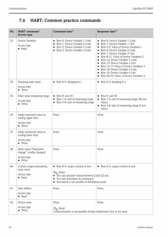
7.6 HART: Common practice commands
No. HART command/
Access type
Command data1) Response data1)
33 Device Variables
Access type
• Read
• Byte 0: Device Variable 1 Code
• Byte 1: Device Variable 2 Code
• Byte 2: Device Variable 3 Code
• Byte 3: Device Variable 4 Code
• Byte 0: Device Variable 1 Code
• Byte 1: Device Variable 1 Unit
• Byte 2-5: Value of Device Variables 1
• Byte 6: Device Variable 2 Code
• Byte 7: Device Variable 2 Unit
• Byte 8-11: Value of Device Variables 2
• Byte 12: Device Variable 3 Code
• Byte 13: Device Variable 3 Unit
• Byte 14-17: Value of Device Variables 3
• Byte 18: Device Variable 4 Code
• Byte 19: Device Variable 4 Unit
• Byte 20-23: Value of Device Variables 4
34 Damping main value
Access type
• Write
• Byte 0-3: damping in s • Byte 0-3: damping in s
35 Main value measuring range
Access type
• Write
• Byte 0: unit ID
• Byte 1-4: end of measuring range
• Byte 5-8: start of measuring range
• Byte 0: unit ID
• Byte 1-4: end of measuring range (20 mA
value)
• Byte 5-8: start of measuring range (4 mA
value)
36 Adopt measured value as
scaling upper limit
Access type
• Write
None None
37 Adopt measured value as
scaling lower limit
Access type
• Write
None None
38 Reset status "Parameter
change" (config changed)
Access type
• Write
None None
40 Current output simulation,
main value
Access type
• Read
• Byte 0-3: output current in mA • Byte 0-3: output current in mA
!Note!
• You can simulate values between 2 and 22 mA.
• You exit simulation by entering 0.
• Simulation is not possible in Multidrop mode.
41 Start selftest
Access type
• Read
None None
42 Device reset
Access type
• Write
None None
!Note!
Communication is not possible during initialization due to the reset.

Liquiline M CM42 Communication
Endress+Hauser 35
44 Main value unit
Access type
• Write
• Byte 0: unit ID • Byte 0: unit ID
None None
!Note!
Only units that suit the main value are accepted.
45 Calibrate the current output
lower limit (only possible in
4 mA simulation)
Access type
• Write
• Byte 0-3: externally measured
current value
• Byte 0-3: measured current value
46 Calibrate the current output
upper limit (only possible in
20 mA simulation)
Access type
• Write
• Byte 0-3: externally measured
current value
• Byte 0-3: measured current value
48 Extended device status
Access type
• Read
None See Section "Troubleshooting"/"Diagnosis
messages"
50 Assignment of the dynamic
process variables
Access type
• Read
None • Byte 0: Device Variables Code for dynamic
process variable 1
• Byte 1: Device Variables Code for dynamic
process variable 2
• Byte 2: Device Variables Code for dynamic
process variable 3
• Byte 3: Device Variables Code for dynamic
process variable 4
51 Assignment of the dynamic
process variables
Access type
• Write
• Byte 0: Device Variables Code for
dynamic process variable 1
• Byte 1: Device Variables Code for
dynamic process variable 2
• Byte 2: Device Variables Code for
dynamic process variable 3
• Byte 3: Device Variables Code for
dynamic process variable 4
• Byte 0: Device Variables Code for dynamic
process variable 1
• Byte 1: Device Variables Code for dynamic
process variable 2
• Byte 2: Device Variables Code for dynamic
process variable 3
• Byte 3: Device Variables Code for dynamic
process variable 4
53 Unit of a Device Variable
Access type
• Write
• Byte 0: Device Variables Code
• Byte 1: Unit code
• Byte 0: Device Variables Code
• Byte 1: Unit code
54 Information on a Device
Variable
Access type
• Read
• Byte 0: Device Variables Code • Byte 0: Device Variables Code
• Byte 1-3: Transmitter serial number
• Byte 4: Unit code
• Byte 5-8: Transmitter upper limit
• Byte 9-12: Transmitter lower limit
• Byte 13-16: Damping
• Byte 17-20: Minimum distance from limits
• Byte 21: Classification
• Byte 22: Family
No. HART command/
Access type
Command data1) Response data1)

Communication Liquiline M CM42
36 Endress+Hauser
! Note!
Code tables and further information can be found in the document .
7.7 Device-specific commands
A detailed description of the device-specific commands can be found in the document on the
CD-ROM.
" Caution!
The device-specific commands are used by DDs (Device Description) or DTMs (Device Type
Manager). Only use these commands "manually" in exceptional cases.
7.8 Status messages
59 Number of preambles in
telegram responses
Access type
• Write
• Byte 0: number of preambles (2 to
22)
• Byte 0: number of preambles
1) Numbers in decimal notation
No. HART command/
Access type
Command data1) Response data1)
Byte Bit Errors/Warnings (group) Errors/Warnings (local display)
0 0 Temperature sensor failure F003
0 1 Sensor communication failure C004, C010, F011
0 2 Sensor failure F012
0 3 Wrong sensor type F013
0 4 SCS alarm F100-F103
0 5 Sensor alarm F104, F105, M142, F149, F151
0 6 SCS warning M106, M107, M111, M112
0 7 Sensor warning M113, M131-M139, M141, M148, M150,
M152, M153
1 0 Calibration active C130
1 1 Internal sensor failure F170, M171
1 2 Module communication failure C200, F201
1 3 Module failure F202, F218
1 4 Module mismatch F203
1 5 Internal module failure F212, F218

Liquiline M CM42 Communication
Endress+Hauser 37
! Note!
Further information on errors and warnings can be found in the "Troubleshooting" section.
1 6 Simulation active C215
1 7 Hold active C216
2 0 Power bad M219
2 1 Multidrop active C221, C220
2 2 Limit alarm F404, F405
2 3 Limit warning -
2 4 PARAM menu active C406
2 5 DIAG menu active C407
2 6 Software version incompatible F500
2 7 Internal software failure F502, M503
3 0 Software configuration failure F510
3 1 Software framework failure F513, M514
3 2 Initialization in progress -
3 3 Initialization failure F520
3 4 General operation failure -
3 5 General operation warning M408
3 6 Internal process value failure F800, M801
3 7 Measured value limit alarm F810-F813
4 0 Measured value limit warning M840-M843
4 1 Process value alarm -
4 2 Process value warning -
4 3-7 Not used1) -
5,
14-24
0-7 Not used1 -
1) Bits that are not used are set to "0".
Byte Bit Errors/Warnings (group) Errors/Warnings (local display)

Troubleshooting Liquiline M CM42
38 Endress+Hauser
8 Troubleshooting
8.1 Troubleshooting instructions
The transmitter constantly monitors its functions itself.
The red alarm LED lights up if the device detects an error. You can read information on the error
in the "DIAG/Error messages" menu → å 9.
Please refer to the "Diagnosis messages" Section for the possible error numbers and remedial
action.
8.2 Diagnosis messages
In the "DIAG/error messages" menu, you can find additional information on the errors currently
pending (red alarm LED lights up3)).
The error messages are characterized by:
• Error class (internal variable, not visible)
• Error status (letter in front of the error number)
– F = Failure, general error message
– M = Maintenance required, an action is required (measured value is possibly still valid)
– C = Device is in service (Check), waiting loop (no error)
– U = Device status is uncertain, unidentifiable error
• Type of message
– Alarm
– Maintenance
– Service
a0002146-en
Fig. 9: Error messages (example)
3) Red LED only lights up if the error current is ≥ 20 mA

Liquiline M CM42 Troubleshooting
Endress+Hauser 39
! Note!
You have the option of increasing or decreasing the priority of a pending error. You do this by
reorganizing the diagnosis list in the "PARAM/General settings/Devicediagnosis" menu (see
Section "PARAM/General settings").
By giving an error currently displayed a lower priority, you can disable an error-related hold and
set the device back to the measuring mode.
Example:
Error "M503 Internal C (error number 0815)" is pending. The maintenance icon appears on the
device .
Go to the diagnosis list and move the error M503 down in the service error section (Cxxx).
Go to the measuring mode. The maintenance icon disappears and is displayed instead.
Only do this if you are absolutely certain that a critical error is not present and your measuring
results still remain plausible. Always inform your Service Team.
The following tables are split by the type of error message.
8.2.1 Alarm messages
No. Display text Tests and/or remedial action
F003 Temperature failure – Check wiring
F011 Sensor no comm.
– Check the measuring chain with a new sensor
– Check the settings for the sensor type used.F012 Sensor failure
F013 Wrong sensor type
F108 Cellconst upper limit
F109 Cellconst lower limit
F119 Temp offset upper limit
F120 Temp offset lower limit
F170 Intern S. (xxxxxxxx)Contact the Service Team! Quote the error number and the text displayed.
The (xxxxxxxx) stands for the text actually displayed.
F201 Transmitter no comm.
Test with a new transmitter module (CPU).F202 Transmitter failure
F203 Wrong transmitter type
F212 Intern E. (xxxxxxxx)Contact the Service Team! Quote the error number and the text displayed.
The (xxxxxxxx) here stands for the text actually displayed.
F218 Curr.out module defect Contact the Service Team!
F404 Lower limit current output – Measured value outside the specified current range
– Check plausibility
– Adjust current output assignment if necessaryF405 Upper limit current output
F500 Software not valid Contact the Service Team!

Troubleshooting Liquiline M CM42
40 Endress+Hauser
8.2.2 Maintenance messages
F502 Intern C. (xxxxxxxx)Contact the Service Team! Quote the error number and the text displayed.
The (xxxxxxxx) here stands for the text actually displayed.
F510 Invalid parameters Check your settings and adjust them.
F513 InternCFW (xxxxxxxx)Contact the Service Team! Quote the error number and the text displayed.
The (xxxxxxxx) here stands for the text actually displayed.
F520 No SA communicationRepeat the initialization. If the error occurs again, please contact the
Service Team.
F531 (Logbook): full1) Delete the logbook entries.
F800 Intern P. (xxxxxxxx)Contact the Service Team! Quote the error number and the text displayed.
The (xxxxxxxx) here stands for the text actually displayed.
F810 PV upper limit– Sensor in air
– Air cushion in assembly
– Check the measuring chain
!Note!
PV = primary value (main value)
F811 PV lower limit
F812 Temp upper limit
F813 Temp lower limit
F814 USP645 upper limit exceeded
F815 USP645 lower limit exceeded
1) Variable text: the logbook in question is named.
No. Display text Tests and/or remedial action
M110 Cellconst upper limit
M114 Cellconst lower limit
M121 Temp offset upper limit
M122 Temp offset lower limit
M131 PV not stable– Sensor too old
– Cable or connector defectiveM132 Temp. not stable
M171 Intern S. (xxxxxxxx)Contact the Service Team! Quote the error number and the text displayed.
M213 Intern E. (xxxxxxxx)
M219 Power supply bad Connect the device to a clean power supply.
M408 Calibration aborted Renew calibration solution, repeat calibration
M501 Device open Close the housing and tighten the screws.
No. Display text Tests and/or remedial action

Liquiline M CM42 Troubleshooting
Endress+Hauser 41
M503 Intern C. (xxxxxxxx)
Contact the Service Team! Quote the error number and the text displayed.M514 Intern CFW. (xxxxxxxx)
M801 Intern P. (xxxxxxxx)
M530 (Logbook): 20% remaining 1)
M840 PV upper limit
– Sensor in air
– Air cushion in assembly
– Check the measuring chain
M841 PV lower limit
M842 Temp upper limit
M843 Temp lower limit
M844 USP645 upper limit exceeded
M845 USP645 lower limit exceeded
M950 Conc temp lower limit
M951 Conc temp upper limit
M952 Conc kappa lower limit
M953 Conc kappa upper limit
M954 Conc lower limit
M955 Conc upper limit
M956 Cond temp lower limit
M957 Cond temp upper limit
M958 Cond kappa lower limit
M959 Cond kappa upper limit
M960 Cond kappa comp lower limit
M961 Cond kappa comp upper limit
1) Variable text: the logbook in question is named.
No. Display text Tests and/or remedial action

Troubleshooting Liquiline M CM42
42 Endress+Hauser
8.2.3 Service messages
8.3 Process errors without messages
No. Display text Tests and/or remedial action
C004 Scanning sensor
C010 Sensor initialization Wait for the initialization to finish.
C130 Calibration active Wait for the calibration to finish.
C200 Transmitter initialization Wait for the initialization to finish.
C215 Simulation active Active corresponding to your settings
C216 Hold active Active corresponding to your settings
C220 Multidrop mode active
C221 Multidrop switch on
C406 Param. active End parameter entry
C407 Diag active End query of device and sensor information
C519 Init. Software
Problem Possible cause Tests and/or remedial action
Display deviates from
comparison measurement
Incorrect calibration Repeat the calibration.
If necessary, check and repeat the calibration
with a reference device.
Sensor contaminated Clean the sensor.
Temperature measurement Check the temperature measured values of
both devices.
Temperature compensation Check the settings for temperature
compensation and adjustment for both devices.
Display deviates from
comparison measurement
Polarization error Use suitable sensor:
• Larger cell constant
• Graphite instead of stainless steel (note
stability)

Liquiline M CM42 Troubleshooting
Endress+Hauser 43
Implausible measured
values:
– Measured value
constantly 000
– Measured value too low
– Measured value too high
– Measured value frozen
– Current output value
does not meet
expectations
Short/moisture in sensor Check sensor.
Short in cable or box Check cable and box.
Interruption in sensor Check sensor.
Interruption in cable or box Check cable and box.
Cell constant incorrectly set Check cell constant.
Incorrect output assignment Check assignment of measured value to current
signal.
Output function incorrect Check preselection (0-20/4-20 mA) and curve
shape (linear/table).
Air cushion in assembly Check assembly and orientation.
Ground connection at or in device Measure in isolated device.
CPU module failure Check with new module.
Device has impermissible operating
status (no reaction to keys being
pressed)
Switch device off and then on again.
Temperature value incorrect
Temperature sensor wired incorrectly Check connections using wiring diagram;
three-wire connection always necessary.
Measuring cable defective Check cables for interruptions, short-circuit,
shunt.
Incorrect sensor type set Configure correct temperature sensor type.
Measured value in process
incorrect
No/incorrect temperature
compensation
ATC: Select type of compensation. If linear, set
suitable coefficient.
MTC: Set process temperature.
Temperature measurement incorrect Check temperature measured value.
Bubbles in medium Suppress bubble formation by:
– Using gas bubble trap
– Creating counterpressure (orifice plate)
– Measuring in bypass
Flow too high (can result in bubble
formation)
Reduce flow or select low-turbulence mounting
location.
Voltage potential in medium (only for
conductive)
Ground medium near sensor.
Sensor contaminated or coated in
buildup
Clean sensor (see Section "Cleaning the
conductivity sensors").
Measured value fluctuations
Interference on signal output line Check how line is laid, lay line separately if
necessary.
Interference potential in medium Remove source of interference or ground
medium as close as possible to sensor.
Measured value fluctuations Interference on measuring cable Connect cable shielding as per wiring diagram.
Problem Possible cause Tests and/or remedial action

Troubleshooting Liquiline M CM42
44 Endress+Hauser
8.3.1 Device-specific errors
No current output signalLine disconnected or short-circuited Disconnect line and measure directly at device.
Output defective See Section "Device-specific errors".
Fixed current output signal Current simulation active Switch off simulation.
Incorrect current output
signal
Total load in current loop too high Disconnect output and measure directly at
device.
EMC (interference coupling) Disconnect both output lines and measure
directly at device.
No HART--communication
Incorrect CPU module Check nameplate
• No or incorrect DD
• HART interface missing
• Device not registered in HART
server
• Load too low (> 230 Ω)
• HART receiver (e.g. FXA191) not
connected via load but via power
supply
• Line problems
(too long, cross-section too small,
not shielded, shield not grounded,
cores not twisted)
• Several devices configured on same
address
Further information is available on the
CD-ROM.
Problem Possible cause Tests and/or remedial action
Display dark No supply voltage Check if available.
CPU defective Replace CPU, make sure correct version is
used.
Display shows information
but
– no change in display
and/or
– device cannot be
operated
Module incorrectly wired Check modules and wiring.
Operating system has impermissible
status
Switch device off and then on again.
Implausible measured values Sensor module defective First perform tests and take measures as per
"Process-specific errors" Section
Test the measuring inputs:
– Connect a resistor instead of conductivity
sensor
– Tables on conductivity and temperature
simulation are provided on the CD-ROM.
Problem Possible cause Tests and/or remedial action

Liquiline M CM42 Troubleshooting
Endress+Hauser 45
8.4 Software history
Current output, current
value incorrect
Calibration not correct Test with integrated current simulation,
connect mA meter directly to current output.Load too high
Shunt/short to ground in current loop
No current output signal CPU defective Test with integrated current simulation,
connect mA meter directly to current output.
Date Version Changes in the software Documentation: Edition
05/2007 13.04.01 Extension
• Memosens for conductivity measured conductively
BA381/07/xx/07.05.01
BA382/07/xx/07.05.01
04/2006 13.04.00 Extension
• Advanced functionality:
– Logbooks
Improvement
• Fault elimination:
– Simulation, current output 2
– Temperature compensation
– Temperature adjustment with table and 2 point
• Corrections in various editors
• Corrections in text catalog
• Concentration measurement possible with negative
slope (via concentration table)
BA381/07/xx/06.10.01
BA382/07/xx/06.10.01
04/2006 13.03.00 Extension
• Advanced functionality:
– Temperature compensation and conversion of
conductivity to concentration via tables
– Current outputs can be assigned as required
• Standard functionality:
– Sensor diagnosis, device diagnosis
– Temperature compensation as per ISO7888
• Software update via DAT modules
• Date and time format selectable
• Language extension
BA381/07/xx/06.07.01
BA382/07/xx/06.07.01
01/2006 13.02.00 Improvement
• Selectable data sources for the current outputs
• Temperature adjustment
• Invalid resistance values are no longer displayed. An
error message appears instead.
BA381/07/xx/05.11.01
BA382/07/xx/05.11.01
09/2005 13.01.00 Extension
• Compensation integrated in four-electrode sensors
• Extended error codes
• Improvement of the update behavior
BA381/07/xx/05.11.01
BA382/07/xx/05.11.01
06/2005 13.00.00 Original software (analog sensors) BA381/07/xx/05.05.24
BA382/07/xx/05.05.24
Problem Possible cause Tests and/or remedial action

Liquiline M CM42
46
Index
CCAL . . . . . . . . . . . . . . . . . . . . . . . . . . . . . . . . . . 26
Calibration . . . . . . . . . . . . . . . . . . . . . . . . . . . . . 26
Cell constant . . . . . . . . . . . . . . . . . . . . . . . . . . . 27
Common practice commands . . . . . . . . . . . . . . . 34
Communication
HART. . . . . . . . . . . . . . . . . . . . . . . . . 32, 34, 36
Concentration table . . . . . . . . . . . . . . . . . . . . . . 12
Current output . . . . . . . . . . . . . . . . . . . . . . . . . . 10
DDevice identification . . . . . . . . . . . . . . . . . . . . . . 30
Device information . . . . . . . . . . . . . . . . . . . . . . . 22
Device-specific commands . . . . . . . . . . . . . . . . . 36
DIAG . . . . . . . . . . . . . . . . . . . . . . . . . . . . . . . . . 21
Diagnosis messages . . . . . . . . . . . . . . . . . . . . . . . 38
Display . . . . . . . . . . . . . . . . . . . . . . . . . . . . . . 4, 17
Display menu . . . . . . . . . . . . . . . . . . . . . . . . . . . 17
EEditing tables . . . . . . . . . . . . . . . . . . . . . . . . . . . . 5
Error messages . . . . . . . . . . . . . . . . . . . . . . . . . . 22
Alarm . . . . . . . . . . . . . . . . . . . . . . . . . . . . . . . 39
Maintenance . . . . . . . . . . . . . . . . . . . . . . . . . 40
Service . . . . . . . . . . . . . . . . . . . . . . . . . . . . . . 42
Errors . . . . . . . . . . . . . . . . . . . . . . . . . . . . . . . . . 38
FFaults . . . . . . . . . . . . . . . . . . . . . . . . . . . . . . . . . 38
Fieldcare. . . . . . . . . . . . . . . . . . . . . . . . . . . . . . . 30
Function group
CAL . . . . . . . . . . . . . . . . . . . . . . . . . . . . . . . . 26
DIAG . . . . . . . . . . . . . . . . . . . . . . . . . . . . . . . 21
MEAS. . . . . . . . . . . . . . . . . . . . . . . . . . . . . . . . 6
PARAM . . . . . . . . . . . . . . . . . . . . . . . . . . . . . . 6
GGeneral settings . . . . . . . . . . . . . . . . . . . . . . . . . 14
HHART
Common practice commands . . . . . . . . . . . . . 34
Device identification . . . . . . . . . . . . . . . . . . . . 30
Device-specific commands . . . . . . . . . . . . . . . 36
Interfaces . . . . . . . . . . . . . . . . . . . . . . . . . . . . 31
Multidrop mode . . . . . . . . . . . . . . . . . . . . . . 31
Status messages . . . . . . . . . . . . . . . . . . . . . . . 36
Universal commands . . . . . . . . . . . . . . . . . . . 32
HART Communicator . . . . . . . . . . . . . . . . . . . . 29
IInterfaces . . . . . . . . . . . . . . . . . . . . . . . . . . . . . 31
LLocal display . . . . . . . . . . . . . . . . . . . . . . . . . . . . 4
Logbooks. . . . . . . . . . . . . . . . . . . . . . . . . . . . . . 22
MMEAS . . . . . . . . . . . . . . . . . . . . . . . . . . . . . . . . . 6
Menu
Concentration table . . . . . . . . . . . . . . . . . . . . 12
Current output . . . . . . . . . . . . . . . . . . . . . . . 10
Device information . . . . . . . . . . . . . . . . . . . . 22
Display . . . . . . . . . . . . . . . . . . . . . . . . . . . . . 17
Error messages . . . . . . . . . . . . . . . . . . . . . . . 22
General settings. . . . . . . . . . . . . . . . . . . . . . . 14
Logbooks. . . . . . . . . . . . . . . . . . . . . . . . . . . . 22
Operating mode . . . . . . . . . . . . . . . . . . . . . . . 8
Quick Setup . . . . . . . . . . . . . . . . . . . . . . . . . 18
Sensor . . . . . . . . . . . . . . . . . . . . . . . . . . . . 7, 25
Sensor information . . . . . . . . . . . . . . . . . . . . 24
Service . . . . . . . . . . . . . . . . . . . . . . . . . . . . . 26
Temp. compensation table . . . . . . . . . . . . . . . 11
Multidrop mode . . . . . . . . . . . . . . . . . . . . . . . . 31
OOperating concept . . . . . . . . . . . . . . . . . . . . . . . . 2
Operating mode. . . . . . . . . . . . . . . . . . . . . . . . . . 8
PPARAM. . . . . . . . . . . . . . . . . . . . . . . . . . . . . . . . 6
Process errors . . . . . . . . . . . . . . . . . . . . . . . . . . 42
QQuick Setup . . . . . . . . . . . . . . . . . . . . . . . . . . . 18
SSensor . . . . . . . . . . . . . . . . . . . . . . . . . . . . . . 7, 25
Sensor information . . . . . . . . . . . . . . . . . . . . . . 24
Service . . . . . . . . . . . . . . . . . . . . . . . . . . . . . . . 26

Liquiline M CM42
Endress+Hauser
Software description
CAL . . . . . . . . . . . . . . . . . . . . . . . . . . . . . . . . 26
Cell constant . . . . . . . . . . . . . . . . . . . . . . . . . 27
Concentration table . . . . . . . . . . . . . . . . . . . . 12
Current output . . . . . . . . . . . . . . . . . . . . . . . . 10
Current values . . . . . . . . . . . . . . . . . . . . . . . . 27
Device information. . . . . . . . . . . . . . . . . . . . . 22
DIAG . . . . . . . . . . . . . . . . . . . . . . . . . . . . . . . 21
Display. . . . . . . . . . . . . . . . . . . . . . . . . . . . . . 17
Error messages . . . . . . . . . . . . . . . . . . . . . . . . 22
General settings . . . . . . . . . . . . . . . . . . . . . . . 14
Logbooks . . . . . . . . . . . . . . . . . . . . . . . . . . . . 22
MEAS . . . . . . . . . . . . . . . . . . . . . . . . . . . . . . . 6
Operating mode . . . . . . . . . . . . . . . . . . . . . . . . 8
PARAM . . . . . . . . . . . . . . . . . . . . . . . . . . . . . . 6
Quick Setup . . . . . . . . . . . . . . . . . . . . . . . . . . 18
Sensor . . . . . . . . . . . . . . . . . . . . . . . . . . . . 7, 25
Sensor information . . . . . . . . . . . . . . . . . . . . . 24
Service . . . . . . . . . . . . . . . . . . . . . . . . . . . . . . 26
Temp. compensation table . . . . . . . . . . . . . . . 11
Software history . . . . . . . . . . . . . . . . . . . . . . . . . 45
Status messages . . . . . . . . . . . . . . . . . . . . . . . 4, 36
TTemp. compensation table . . . . . . . . . . . . . . . . . 11
Temperature adjustment. . . . . . . . . . . . . . . . . . . 28
Types of calibration. . . . . . . . . . . . . . . . . . . . . . . 26
Types of setting . . . . . . . . . . . . . . . . . . . . . . . . . . 5
UUniversal commands . . . . . . . . . . . . . . . . . . . . . 32
User administration . . . . . . . . . . . . . . . . . . . . . . . 5

www.endress.com/worldwide
BA382C/07/en/POD
Printed in Germany / FM+SGML 6.0 /
POD