Embed Size (px)
Citation preview

PARTE SECONDA
PART TWO
85

86
VENTILATORI CENTRIFUGHI
Tutti i nostri ventilatori centrifughi sono costruitiper le più svariate applicazioni industriali nel cam-po della ventilazione, aspirazione, trasporto pneu-matico, tiraggio meccanico dei fumi e condiziona-mento. Ad eccezione di quelli ad alta pressione,essi vengono progettati e dimensionati per un bas-so regime di rotazione, così da offrire la massimasilenziosità di funzionamento e la più lunga duratadi tutti gli organi in movimento. Le prestazioni massime raggiungono valori di oltre200.000 m3/h di portata d’aria con pressioni dispo-nibili sino a 10.000 Pa (1000 mm H2O). Questi ventilatori vengono normalmente realizzatiin lamiera d’acciaio al carbonio oppure in inox AISI316/304; possono essere impiegati però a richiestaaltri materiali metallici speciali anticorrosivi o resi-stenti alle alte temperature.
PARAMETRI NECESSARI PER UNA CORRETTASCELTA DEL VENTILATORE Il costruttore di ventilatori ha necessità di conosce-re alcuni dati essenziali per essere in grado di for-nire macchine adeguate alle funzioni per le qualisono state previste. Essi sono:
DATI INDISPENSABILI
a. Portata d’aria effettiva (m3) che viene trattatanell’unità di tempo (h) dal ventilatore.
b. Temperatura (°C) del flusso gassoso aspirato c. Pressione totale necessaria (Pa oppure mm
H2O) per vincere tutte le perdite di carico delcircuito interessato.
d. Tipologia e densità del flusso gassoso con det-tagli sui contaminanti tossici, abrasivi, esplosivie corrosivi.
e. Configurazione del ventilatore con dettagli sulsenso di rotazione, posizione dello scarico, paleradiali o rovesce, dimensioni del condotto diaspirazione e mandata, ecc.
f. Particolari sul tipo di azionamento (direttooppure a cinghie) posizione orizzontale o ver-ticale dell’albero, tipo di motore, ecc.
DATI COMPLEMENTARI
a. Breve descrizione dell’applicazione o del lavo-ro a cui è destinato il ventilatore.
b. Condizioni ambientali nelle quali si trova il ven-tilatore, p.e. umidità e contaminanti atmosferici.
c. Servizio continuo o intermittente, numero diavviamenti al giorno, turni di lavoro, ecc.
d. Dettagli sulle norme o specifiche alle quali ilventilatore dovrà rispondere, tensione, prote-zioni, il luogo ove verrà installato.
e. Particolarità costruttive come ancoraggi per iso-lamento, supporti antivibranti, ecc.
f. Disposizioni di montaggio o fondazioni previste.
CENTRIFUGAL FANS
All our centrifugal fans are built to cover very wide-ly different industrial applications in the field ofventilation, exhaust, pneumatic conveying, supply-ing mechanical draught for fumes and air condi-tioning. Apart from the high-pressure types, the fansare designed and dimensioned for a low speed ofrotation in order to offer maximum silence in run-ning and a longer working life of all moving parts. Maximum performance levels reach over 200,000m3/h in air flow capacity with pressures availableup to 10,000 Pa (1000 mm H2O). These fans are normally of carbon steel or stainlesssteel (AISI 316/304) construction; however on requestthey can be made of other special metal materials,resistant to corrosion or high temperatures.
PARAMETERS REQUIRED FOR CORRECTCHOICE OF FAN The fan manufacturer requires to know certainessential data in order to be able to supplymachines suitable for the functions expected fromthem, namely:
ESSENTIAL DATA
a. Effective air flow (m3) to be handled in unittime (h) by the fan.
b. Temperature (°C) of the gaseous flow exhausted c. Total pressure required (Pa or mm H2O) to
overcome all the pressure drops of the circuitconcerned.
d. Type and density of the gaseous flow with detailsregarding toxic, abrasive, explosive and corro-sive contaminants.
e. Fan configuration with details regarding direc-tion of rotation, position of discharge, radial orbackward-curve blades, size of exhaust anddelivery ducts, etc.
f. Details concerning type of drive (direct or beltdrive), horizontal or vertical shaft position, typeof motor, etc.
COMPLEMENTARY DATA
a. Brief description of the application or work forwhich the fan is to be used.
b. Environmental conditions where the fan isinstalled; e.g. humidity and atmospheric con-taminants
c. Continuous or intermittent duty, number ofstart-ups per day, work shifts, etc.
d. Details concerning standards or specification tobe met by the fan, voltage, guards, place whereit is to be installed.
e. Design details such as anchorage for isolation,vibrating-damping supports, etc.
f. Any assembly or foundations instructions pre-scribed.

87
ESECUZIONI COSTRUTTIVE DESIGN VERSIONS
Sistemazioni Arrangements
Posizioni motori per trasmissioni a cinghia Position of motors for belt drive

88
TIPI DI VENTILATORI e relativi orientamenti
La nostra produzione comprende una vasta gammadi ventilatori centrifughi per ogni specifica esigenza. La costruzione accurata ed artigianale unita all’im-piego di lamiere di acciaio di forte spessore rendo-no queste nostre macchine affidabili e duratureanche in impieghi gravosi quali ad esempio, l’aspi-razione di pezzi e scarti o di grosse quantità di pol-veri. La gamma di ventilatori comprende: - ventilatori elicoidali in alluminio e acciaio con
ventole da 200 a 1500 mm di diametro a 3, 4, o6 pale;
FAN TYPES and relative arrangements
Our production includes an extensive range of cen-trifugal fans for each specific requirement. Thanks to the accurate and skillfully crafted fabri-cation together with the use of heavy gauge sheetsteel, our machines are found to be reliable andlong-lasting even under heavy duty conditions,such as, extraction of pieces and scrap or largequantities of dusts. The range of fans include: - aluminium and steel propeller fans, with impel-
lers from 200 to 1500 mm in diameter with 3, 4,or 6 blades;
LG Rotazione antioraria RD = Rotazione oraria

89
- ventilatori centrifughi con ventole a pale sciroc-co per ventilazione, condizionamento e aspira-zione fumi;
- ventole a pale rovesce per aspirazione fumi; - ventole a pale radiali aperte per aspirazione e
trasporto di polvere e trucioli.
Per quanto riguarda sempre i ventilatori centrifu-ghi, le serie di nostra produzione sono: serie CA-CB-CC-CE a pale scirocco con portateda 1000 a 100.000 m3/h e prevalenza da 1000 a3000 Pa serie AP alta pressione con ventole a pale radialiaperte, con portate da 100 a 8.000 m3/h e preva-lenze da 5000 a 20.000 Pa serie MP/tt e MP/at a media pressione con vento-le a pale rovesce o a pale radiali aperte adatteall’aspirazione e trasporto di trucioli, con portateda 1.000 a 100.000 m3/h e prevalenza da 800 a7000 Pa serie GP/at ad alta portata con ventole a pale rove-sce con portate da 3.000 a 200.000 m3/h e preva-lenza da 800 a 5000 Pa Di seguito riportiamo i possibili orientamenti conrispettive sigle di riconoscimento dei ventilatori.
Triangoli di velocità e curve caratteristiche
I ventilatori centrifughi si distinguono in ventilatori a: - bassa prevalenza (≤ 2000 Pa)- media prevalenza (2000 ÷ 8000 Pa)- alta prevalenza (8000 ÷ 15000 Pa)
Il loro funzionamento è simile a quello delle pom-pe centrifughe; la depressione creata al centro del-la rotazione di una girante genera un flusso d’ariache entra nel ventilatore in direzione assiale e cheesce in direzione radiale. Un diffusore di tipo achiocciola serve da collettore del flusso di aria cheesce dalla girante ed inoltre aumenta le pressionestatica del ventilatore.
Triangoli di velocità di un ventilatore cen-trifugo a pale in avanti
- centrifugal fans with sirocco bladed impellers forventilation, air conditioning and fume extraction;
- fan impellers with backward curved blades forfume extraction;
- fan impellers with open radial blades for extrac-tion and conveying of dusts or chips.
Still regarding our centrifugal fans, our productionseries include: series CA-CB-CC-CE with sirocco blades, flow ratesfrom 1000 to 100,000 m3/h and head from 1000 to3000 Paseries AP high pressure with open radial blades,flow rates from 100 to 8000 m3/h and head from5000 to 20,000 Pa series MP/tt and MP/at medium pressure with back-ward curved or open radial blades suitable for extrac-tion and conveying of chips, flow rates from 1000 to100,000 m3/h and head from 800 to 7000 Pa series GP/at high pressure with backward curvedblades, flow rates from 3000 to 200,000 m3/h andhead from 800 to 5000 Pa Some of the possible arrangements or designationsare given below with respective fan identifier sym-bols LG = Anti-clockwise rotation RD = Clockwise rotation
Velocity triangles and characteristic curves
The centrifugal fans can be classed into: - low head (≤ 2000 Pa)- medium head (2000 to 8000 Pa)- high head (8000 to 15000 Pa)
Their operation is similar to the one of centrifugalpumps; the depression created at the centre of rota-tion of an impeller generates an air flow which entersthe fan in axial direction and leaves the fan in radi-al direction. A diffuser of type with scroll housingserves as collector of the air flow leaving the impeller;it also increases the static pressure of the fan.
Velocity triangles of a centrifugal fan withforward curved blades

Le pale della girante sono di 3 tipi: - a pale radiali diritte - a pale curve in avanti (scirocco) - a pale curve all’indietro (rovesce)
Per i ventilatori a pale radiali sono possibili tutti gliorientamenti sia orari che antiorari mentre per i ven-tilatori a pale curve in avanti o all’indietro sono pos-sibili o solo gli orientamenti orari o solo quelli antio-rari; l’inversione del senso di rotazione della girantecauserebbe seri inconvenienti di funzionamento.
Triangoli di velocità di un ventilatore cen-trifugo a pale all’indietro
Le giranti a pale in avanti sono quelle maggiormen-te impiegate in quanto la funzione fondamentaledel ventilatore è quella di generare alte portated’aria. I caratteristici triangoli di velocità sonocostruiti con le stesse considerazioni usate per lepompe centrifughe ad eccezione della direzionedella velocità di ingresso. Essa in questo caso risen-te della forza di trascinamento data dalla rotazionedella girante per cui, invece di essere radiale, risul-ta inclinata in avanti rispetto al senso di rotazione.Il confronto fra i triangoli di velocità costruiti per lepale in avanti e per le pale all’indietro dimostracome, al contrario delle pompe centrifughe, sonoda preferire i ventilatori con pale in avanti (sciroc-co) in quanto a parità di condizioni all’ingresso,hanno una maggiore velocità di uscita.
Curve caratteristiche di un ventilatore cen-trifugo con pale in avanti
The impeller blades are of 3 types, namely: - with straight radial blades - with forward curved blades (sirocco) - with backward curved blades
For radial bladed fans all arrangements are possi-ble, whether clockwise or anti-clockwise, while forfans with forward or backward curved blades,either only clockwise arrangements are possible orjust counterclockwise arrangements; inversion ofthe direction of impeller rotation would cause seri-ous problems in operation.
Velocity triangles of a centrifugal fan withbackward curved blades
Impellers with forward curved blades are the onesmainly used as the basic function of the fan is thatof producing high air flow rates. The characteristicvelocity triangles are built based on the same con-siderations used for centrifugal pumps, except asregarding direction on the inlet velocity. In thiscase the latter is affected by the driving force givenby the impeller rotation, hence, instead of beingradial, it is inclined forward with respect to thedirection of rotation. Comparison between thevelocity triangles built for forward curved bladesand those for backward curved blades show, unlikein centrifugal pumps, fans with forward curved(sirocco) blades are to be preferred for equal inletconditions, as they have a greater exit velocity.
Characteristic curves of a centrifugal fanwith forward curved blades
90
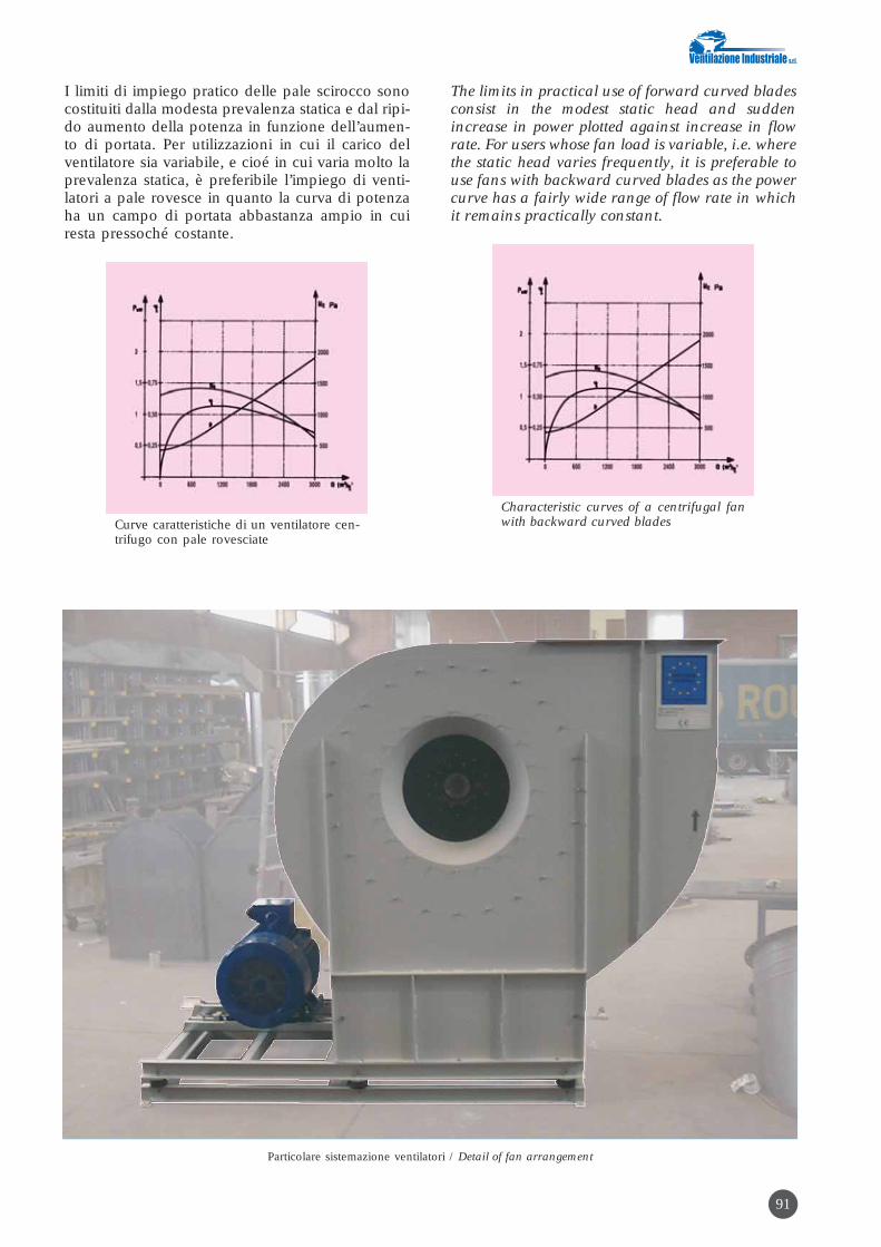
I limiti di impiego pratico delle pale scirocco sonocostituiti dalla modesta prevalenza statica e dal ripi-do aumento della potenza in funzione dell’aumen-to di portata. Per utilizzazioni in cui il carico delventilatore sia variabile, e cioé in cui varia molto laprevalenza statica, è preferibile l’impiego di venti-latori a pale rovesce in quanto la curva di potenzaha un campo di portata abbastanza ampio in cuiresta pressoché costante.
Curve caratteristiche di un ventilatore cen-trifugo con pale rovesciate
The limits in practical use of forward curved bladesconsist in the modest static head and suddenincrease in power plotted against increase in flowrate. For users whose fan load is variable, i.e. wherethe static head varies frequently, it is preferable touse fans with backward curved blades as the powercurve has a fairly wide range of flow rate in whichit remains practically constant.
Characteristic curves of a centrifugal fanwith backward curved blades
91
Particolare sistemazione ventilatori / Detail of fan arrangement

92
PRINCIPI DI FUNZIONAMENTO PER VENTILATORI
Le leggi che regolano il funzionamento dei ventila-tori sono le stesse dell’idrodinamica in quanto sipuò ritenere il fluido, gas o aria, praticamenteincomprimibile dato che la sua variazione di mas-sa volumica è trascurabile. Infatti, nell’equazionecaratteristica dei gas
P·V=R·T
dove: P = pressione V = Volume R = costante aria (287,1)T = temperatura
1sostituendo a V il rapporto ––– si ottiene
�
P–––– = R·T
�
Dove � = massa volumica
Pda cui � = ––––
R·T
che ci insegna che la ∂ risulta essere funzione del-la pressione e della temperatura.
Supponiamo ora che un ventilatore aspiri a pres-sione e temperatura ambiente:
Pressione barometrica Pb = 1 bar T = 273 + 20°C = 293°K
e che l’effetto di compressione da esso generato sia0,15 bar con temperatura dell’aria in uscita del ven-tilatore di 50°C, si ottiene:
massa volumetrica � 105
ingresso ventilatore = ––––––––––––––––– kg/m3287,1 x 293
massa volumetrica � 105 + 15.000uscita ventilatore = ––––––––––––––––––– kg/m3
287,1 x 323
Possiamo quindi concludere che, nel campo dellepressioni di impiego dei ventilatori, la massa volu-mica si può ritenere costante come per i liquidi.
Tenendo presente questa considerazione, la preva-lenza manometrica di un ventilatore sarà data da:
Pu Cu2
Hm = –––– + –––– (Pa)�g 2g
dove: Hm = prevalenza manometrica Pu = pressione uscita ventilatore g = gravità (9,81 m/sec2) Cu = velocità uscita ventilatore
PRINCIPLES OF FAN OPERATION
The laws governing fan operation are the sameones in hydrodynamics because the fluid, gas or airmay be considered as practically incompressibleowing to the fact that its variation in volumetricmass is negligible. In fact, in the characteristicequation of gases
P·V=R·T
where: P = pressure V = Volume R = air constant (287.1) T = temperature
1by substituting V with the ratio ––– we obtain
�
P–––– = R·T
�
where � = volumetric mass
Pwhence � = ––––
R·T
which tells us that is ∂ function of the pressure andtemperature.
Suppose now a fan works under suction at ambienttemperature and pressure:
Barometric pressure Pb = 1 bar T = 273 + 20°C = 293°K
and the compression effect generated by it is 0.15bar with air temperature at the fan outlet of 50°C,we obtain:
volumetric mass � 105
fan inlet = ––––––––––––––––– kg/m3287.1 x 293
volumetric mass � 105 + 15.000fan outlet = ––––––––––––––––– kg/m3
287.1 x 323
Hence we can conclude that, in the range of pres-sures used by the fan, volumetric mass may be con-sidered to be constant as in the case of liquids.
Bearing in mind this consideration, the gauge headof a fan will be given by:
Pu Cu2
Hm = –––– + –––– (Pa)�g 2g
where Hm = gauge head Pu = fan outlet pressure g = gravity (9.81 m/sec2)Cu = fan outlet velocity

93
To obtain the total head of a fan, merely multiplythe Hm obtained by g:
hence: HT = Hm x � g (Pa)
Pressure Pu serves to overcome the pressure dropsthrough the ducting (and any filters) downstreamof the fan and will be called static head HS
HS = Pu (Pa)
The dynamic head of the fan represents the pres-sure required to impart velocity Cu to the air atdownstream side of the fan
Cu2
HD = � –––– (Pa)2
Normally the total head of a fan HT will be the sumgiven by the HS and HD, and is expressed in con-cise form as follows:
HT = HS + HD (Pa)
As both static head and dynamic head are pres-sures, for measuring them merely involves insert-ing pressure measurers in the duct. The static headis normally measured by inserting a differentialwater-filled pressure gauge in a given section of theduct; instead, to measure the dynamic head, insert,in this ducting, a PITOT tube connected to a differ-ential pressure gauge. By knowing dynamic head HD it is possible todeduce the velocity in a section:
2HDC = √ ––––––– (m/s)
2
and in this way it is easy to deduce the air flow rateas well
Q = A x C (m3/s)
where A = duct section (m2) and C = air velocity
The output power of the fan is given by the productof the following factors already seen earlier on, Dand HT
i.e. W= Q x HT (W)
Q x HTor W = ––––––– (kW)
1000
The power consumed is obtained by introducing thetotal fan efficiency �
Q x HTWa= ––––––––– (kW)
1000 x �
Per ottenere la prevalenza totale di un ventilatore,sarà sufficiente moltiplicare l’ottenuta Hm con g:
per cui: HT = Hm x � g (Pa)
La pressione Pu serve per vincere le perdite di cari-co della tubazione (e eventuali filtri) a valle del ven-tilatore e si chiamerà prevalenza statica HS
HS = Pu (Pa)
La prevalenza dinamica del ventilatore rappresentala pressione necessaria per imprimere all’aria lavelocità Cu a valle dello stesso
Cu2
HD = � –––– (Pa)2
In generale la prevalenza totale di un ventilatoreHT sarà la somma data dalle HS e la HD e si espri-me sinteticamente:
HT = HS + HD (Pa)
Essendo, sia la prevalenza statica che quella dina-mica, pressioni, per misurarle sarà sufficiente inse-rire nella tubazione dei misuratori di pressione. Lamisura della prevalenza statica generalmente siesegue inserendo in una data sezione del condot-to un manometro differenziale ad acqua; la misuradella prevalenza dinamica si esegue invece inse-rendo nella stessa tubazione un tubo di PITOT col-legato ad un manometro differenziale. La conoscenza della prevalenza dinamica HD offrela possibilità di ricavare il valore della velocità inuna sezione:
2HDC = √ ––––––– (m/s)
2
risalendo in questo modo con facilità anche allaportata d’aria
Q = A x C (m3/s)
dove A= sezione della condotta (m2) e C= velocità dell’aria
La potenza utile del ventilatore è data dal prodottodei seguenti fattori già visti: D e HT
Vale a dire W= Q x HT (W)
Q x HToppure W = ––––––– (kW)
1000
La potenza assorbita si otterrà introducendo il ren-dimento totale del ventilatore �
Q x HTWa= –––––––– (kW)
1000 x �

94
B
MICRO COMPRESSORI CENTRIFUGHI MI-CO
Grazie alla nostra pluriennale esperienza nellacostruzione di ventilatori ad alta e altissima pressio-ne, abbiamo realizzato i compressori centrifughimultistadi della serie MI-CO per il trattamento diaria e gas puliti, ad una temperatura massima di + 120°C. La particolare esecuzione in lega leggeraantiscintillica, consente l'adozione del MI-CO permolteplici applicazioni fra cui aria e gas esplosivi.Le giranti, a profilo alare, uniscono all'alto rendi-mento, un ridotto valore di velocità periferica, conconseguente riduzione del livello sonoro. La realiz-zazione a più stadi componibili, consente, in fasedi dimensionamento, di utilizzare uno stessomodello per diverse prestazioni consentendone lascelta tecnicamente ed economicamente piùappropriata. Trova applicazione nelle pulizie e tra-sporti pneumatici, agitazione e rimozione liquidi,alimentazione di bruciatori a gas e nafta, soffiaggi,spruzzature, essicazione, collaudi motori a scop-pio, ecc. Consente portate da 54 a 6000 mc/h.
CENTRIFUGAL MICROCOMPRESSORS MI-CO
Thanks to our many years experience in the manu-facture of high pressure and very high pressurefans, we have been able to develop the multi-stagecentrifugal compressors of series MI-CO for han-dling clean air and gases at a max. temperature of+ 120°C. The special spark-proof light-weight ver-sion allows the MI-CO compressor to be used for sev-eral applications, including air and explosive gas-es. The wing-shaped impellers combine high effi-ciency and reduced peripheral speed, with conse-quent reduction in noise level. The design with twoor more modular stages in the dimensioning phase,allows using the same model for different perform-ance levels thus offering the most appropriate tech-nical and cost-effective choice. The centrifugalcompressor finds application in pneumatic clean-ing and conveying, in stirring and removal of liq-uids, feeding of gas-fired and fuel-oil fired burners,blasting, spraying, drying, I.C. engine testing, etc. Itallows flow capacities from 54 to 6000 cu.m/h.
A - MI-CO: pacco rotoricoB - MI-CO: esecuzione albero nudoC - Compressore centrifugo MI-CO
A - MI-CO: rotorB - MI-CO: bare shaft versionC - Centrifugal compressor MI-CO
CA

95
Applicazioni speciali / Special applications
Turbocompressore bistadio portata aria 12.000 Nm3/h pres-sione 250mbar
Two-stage Turbocompressor, air flow rate 12,000 Nm3/h pres-sure 250mbar
Ventilatore stracciatore per refili polietilene portata aria5.000 Nm3/h
Chopper fan for polyethylene trimmings, air flow rate 5000Nm3/h

96
CICLONI SERIE AR
1. TIPO DI TECNOLOGIAAbbattimento a secco.
2. INQUINANTI ABBATTIBILIPolveri in genere.
3. LIMITI DI EMISSIONE RAGGIUNGIBILIL’efficienza di abbattimento è fortemente legata allagranulometria e al peso specifico delle polveri datrattare, in genere è compresa tra 85 e 95%.
4. DESCRIZIONE DELLE APPARECCHIATUREE/O DEL PROCESSOVanno bene solo per polveri con peso specificooltre i 300 kg/m3 e con particelle abbastanza gros-solane (oltre i 10 micron per polveri con peso spe-cifico oltre i 1000-1500 kg/m3 e oltre i 50 micronper polveri con peso specifico oltre i 500 kg/m3),presenti nell’aria in concentrazioni abbastanza ele-vate (qualche grammo per m3.). I cicloni possonoavere efficienze di filtrazione comprese fra l’85% eil 95% e comunque nel caso occorrano gradi di fil-trazione molto elevati servono solo come pre-filtri afiltri finali più efficienti.Dove ci sono concentrazioni molto elevate di pol-veri è sempre utile installare un ciclone per la pre-filtrazione, così da diminuire sensibilmente il cari-co di polveri inviato al filtro finale, aumentare ilgrado di separazione delle polveri ed evitare peri-colosi intasamenti nel filtro più efficiente che pos-sono causare fastidi a tutto l’impianto.Questo è il caso tipico dei trasporti pneumaticidove le concentrazioni di polveri nell’aria sono ele-vatissime e dove a volte è sufficiente il solo cicloneper ottenere un’efficienza di filtrazione accettabile.
Per contro i cicloni offrono alcuni vantaggi apprez-zabili:l) bassa resistenza o perdita di carico (60-70 mm
H2O); 2) nessun costo di manutenzione;3) costo di esercizio bassissimo;4) basso costo di installazione.
A volte può capitare che il materiale trasportato einviato al ciclone eserciti un’azione abrasiva al con-tatto con le pareti. In questo caso il ciclone (comedel resto le curve dell’impianto) sono i punti mag-giormente interessati dall’azione abrasiva. Infatti lepolveri che entrano nel ciclone decantano con unmovimento rotatorio lungo le pareti interne delciclone e qui esercitano la loro azione abrasiva.In questo caso possiamo adottare alcuni accorgi-menti:Occorre costruire il corpo del ciclone con lamieradi forte spessore con la fascia flangiata e imbullo-
CYCLONES SERIES AR
1. TYPE OF TECHNOLOGYDry collection.
2. CONTAMINANTS WHICH CAN BE REMOVEDDusts in general.
3. EMISSION LIMITS POSSIBLECollection efficiency very much depends on the par-ticle size and specific gravity of the dusts to be han-dled. Normally it lies between 85 and 95%.
4. DESCRIPTION OF THE EQUIPMENTAND/OR PROCESSThese cyclone separators are suitable only for dustswith specific gravity greater than 300 kg/m3 withfairly coarse particles (more than 10 micron fordusts with specific gravity greater than 1000-1500kg/m3 and more than 50 micron for dusts specificgravity exceeding 500 kg/m3), present in the air infairly high concentrations (a few grams per m3.).Collection efficiencies of the cyclones can rangebetween 85% and 95%. When very high collectionefficiencies are required, the cyclones serve merely asprecleaners to more efficient final filters.Where there are very high concentrations of dusts itis always useful to install a cyclone for precleaningin order to obtain appreciable reduction in the dustload sent to the final filter, as well as to increase thedust collection efficiency and to avoid hazardousplugging in the more efficient filter which couldcause trouble to the entire plant.Such case is typical of pneumatic conveyors wherethere are extremely high dust concentrations in theair and where sometimes just the cyclone is suffi-cient to obtain an acceptable collection efficiency.
On the other hands cyclones offer certain apprecia-ble advantages, namely:l) low resistance or pressure drop (60-70 mm
H2O); 2) no maintenance costs;3) very low running costs;4) low installation cost.
Sometimes the material conveyed and sent to thecyclone exerts an abrasive action on coming intocontact with the walls. In this case the cyclone(like the elbows in the plant ductwork) representsthe points most affected by the abrasive action. Infact, the dusts entering the cyclone settle with aspiralling movement along the inner walls of thecyclone and here they exert their abrasive action.In this case certain precautions can be adopted:The cylindrical housing of the cyclone should bemade of heavy gauge metal sheet with the top bodyflanged and bolted to allow replacement without
nata in modo da consentire la sostituzione senzadover sostituire tutto il ciclone, costruito semprecon lamiere di forte spessore (4-6 mm).Lo stesso sistema può essere usato per le curve eper i ventilatori.
5. APPLICAZIONI INDUSTRIALI TIPICHETutti i processi industriali ove vi è una forte produ-zione di polvere. Industria lavorazione del legno,mangimifici, cave, trasporti pneumatici, ecc.
6. VANTAGGI E SVANTAGGIVantaggi: bassa resistenza o perdita di carico, nes-sun costo di manutenzione, basso costo di eserci-zio, basso costo di installazione.Svantaggi: viene utilizzato solo come apparecchiodi prefiltrazione a causa dei bassi rendimenti diabbattimento.
7. CALCOLI E TABELLEEfficienza di separazione
L’efficienza totale di separazione di un ciclone èdefinita dalla relazione:
Øt = 1 - cu/ce
dove cu e ce esprimono le concentrazioni di mas-sa di particelle solide nel gas in uscita ed in entra-ta. Segue che la portata di massa di solido trascina-to all’esterno con l’effluente è:
Mu = V ce (1 - Øt)
Se ∆ Ri è la frazione di massa della classe granulo-metrica di polvere di diametro medio dpm, a bassicarichi di polvere (ce < 10 g/m3), l’efficienza tota-le è data dalla:
NØt = ∑i ∆Re,i ØFi
1
dove N è il numero di classe e ØF l’efficienza frazio-naria intesa come rapporto fra il numero o la massadi particelle di diametro dpm separate ed il numeroo la massa di particelle della stessa dimensioneintrodotte con l’alimentazione. Quindi noto ØF, sipossono calcolare Øt, Mu e la granulometria dellapolvere contenuta nell’effluente:
∆Ru,i = ∆Re,i (1 - ØFi) / (1 - Øt)
Il problema è quindi ricondotto a derivare unmodello di previsione di ØF in funzione della geo-metria del ciclone, delle condizioni di esercizio edelle caratteristiche fisiche della miscela trattata. Leteorie fino ad oggi sviluppate possono essereinquadrate in due classi a seconda che si basino sultempo di permanenza delle particelle nell’apparec-chio o sulla superficie limite di separazione. Nelprimo caso una particella viene «considerata» sepa-rata se, nell’attraversamento del ciclone, ha temposufficiente per raggiungere la parete; da lì, infatti,
having to replace the entire cyclone, likewise builtof heavy gauge metal sheet (4-6 mm).The same system can be used for the elbows andfans.
5. TYPICAL INDUSTRIAL APPLICATIONSAll industrial processes where there is a heavy pro-duction of dust: industries such as woodworking,animal fodder, quarries, pneumatic conveying,etc.
6. ADVANTAGES AND DISADVANTAGESAdvantages: low resistance or pressure drop, nomaintenance costs, low running cost, lost installa-tion cost.Disadvantages: can be used only as a pre-cleanerowing to the low collection efficiencies.
7. CALCULATIONS AND TABLESSeparation efficiency
The total separation efficiency of a cyclone isdefined by the relation:
Øt = 1 - cu/ce
where cu and ce express the mass concentrations ofsolid particles in the gas at the inlet and outlet.Therefore it follows that the mass flow rate of the sol-id entrained with the effluent is:
Mu = V ce (1 - Øt)
Suppose ∆ Ri is the mass fraction of the particle sizeclass of the dust with average diameter dpm, withlow dust loads (ce < 10 g/m3), the total efficiency isgiven by:
NØt = ∑i ∆Re,i ØFi
1
where N is the class number and ØF the fractionalefficiency intended as ratio between the number orthe mass of particles separated with diameter dpmand the number or mass of particles with the samesize introduced with the supply of air. Hence givenØF, it is possible to calculate Øt, Mu and the parti-cle size of the dust contained in the effluent:
∆Ru,i = ∆ Re,i (1 - ØFi) / (1 - Øt)
Hence the problem lies in deriving a model to pre-dict ØF in relation to the cyclone geometry, operat-ing conditions and physical properties of the mix-ture handled. The theories worked out up till nowcan be placed in two classes according to whetherthey are based on the residence time of the particlesin the cyclone or on the limiting separation surface.In the first case, a particle is «considered» separatedif, when flowing through the cyclone, it has suffi-cient time to reach the wall; from there, in fact, itcan be assumed that the particle has no alternativebut to flow into the collecting vessel. In the second
97

per ipotesi, non può che confluire nel vaso diraccolta. Nel secondo caso si ammette che le parti-celle, appena entrate nel ciclone, si assestino inorbite circolari di equilibrio: quelle che ruotanonelle orbite esterne al volume racchiuso nellacosiddetta superficie di separazione, sostanzial-mente la superficie immaginaria ottenuta estenden-do fino alla punta il tubo di scarico, sono abbattu-te, le altre vengono aspirate dalla corrente che fuo-riesce dalla sommità. Queste teorie fornisconoun’espressione che permette di calcolare il diame-tro minimo separabile, ma tale grandezza avrebbeutilità pratica solo se il ciclone si comportassecome un classificatore perfetto. In realtà, come èben noto, questo non accade, e per valutare l’an-damento dell’efficienza frazionaria di separazionein funzione del diametro delle particelle si deve farriferimento a curve sperimentali ottenute per casispecifici e a fattori di aggiustamento empirici daadottarsi per poter estendere l’applicazione di talicurve a situazioni diverse. Purtroppo, questo mododi procedere, oltre a non fornire una spiegazioneesauriente dei meccanismi di separazione cheavvengono nel ciclone, comporta errori tanto piùgravi quanto più ci si scosta dalle condizioni diesercizio che hanno fornito le curve sperimentali.
8. INFORMAZIONI SUI COSTISe non ci sono accorgimenti costruttivi particolari iprezzi indicativi sono tra 0,7 e 1,25 € /m3 di ariatrattata.
case it is assumed that as soon as the particles enterthe cyclone, they are arranged in spiralling equilib-rium orbits: those spiralling in the orbits external tothe volume enclosed in the so-called separation sur-face, essentially the imaginary surface obtained byextension up to the tip of the discharge pipe, areremoved; the others are sucked up by the streamleaving from the top. These theories provide anexpression that allows calculating the minimumseparable diameter, but such dimension wouldhave practical use only if the cyclone behaved likea classical classifier. In actual fact, as is wellknown, this does not happen and to assess theprogress in fractional separation efficiency in rela-tion to the particle diameter, it is necessary to makereference to experimental curves obtained for spe-cific cases and also to empirical adjustment factorswhich should be adopted to extend application ofsuch curve to different situations. Unfortunately notonly does this method of approach fail to give a fullexplanation of the separation mechanisms takingplace in the cyclone, but it also leads to errorswhich becomes more serious the further one devi-ates from the operating conditions providing theexperimental curves.
8. INFORMATION REGARDING COSTSIf there are no special design arrangements,approximate prices lie between 0.7 and 1.25 € /m3of air handled.
98
Particolare ciclone / Detail of cyclone

99
N.B. Bear in mind that when reading the tables, the values are given with the European decimal notation; for English readers the comma should be taken as the decimal point.
DATI / DATA DIMENSIONI / DIMENSIONS
Tipo Q m3/h mm c.a. HS Ø min. part. V ingr. A B C D E F G H I L MType Q m3/h mm w.g. HS Ø min. part. V inlet.
1 1000 68 0.11 18 80 200 350 250 400 800 100 30 80 1310 130
1.5 1500 65 0.13 18 100 230 480 300 460 1100 130 30 80 1670 150
2 2000 62 0.16 18 130 250 600 320 500 1400 150 50 100 2050 180
2.5 2500 62 0.19 18 130 300 650 350 600 1500 150 50 130 2280 180
3 3000 58 0.21 18 150 320 700 380 640 1650 180 50 130 2520 200
4 4000 57 0.22 18 150 430 750 420 860 1800 200 80 150 2890 230
4.5 4500 57 0.23 18 150 450 800 480 900 1900 230 80 150 3060 250
5.5 5600 56 0.25 18 150 550 950 550 1100 2150 250 80 150 3530 280
8 8000 52 0.27 19 180 700 1100 580 1400 2200 280 80 180 3900 300
9.5 9500 51 0.28 18 200 750 1200 720 1500 2400 300 80 180 4250 380
11 11000 50 0.32 19 200 800 1250 750 1600 2600 380 80 200 4550 380
13 13000 50 0.40 20 220 820 1300 780 1640 2700 350 100 200 4640 400
16 16000 49 0.45 21 240 850 1450 850 1700 2800 380 100 220 4870 450
20 20000 48 0.48 25 250 880 1650 950 1760 2900 380 100 220 4980 500

MULTICICLONI
1. TIPO DI TECNOLOGIAAbbattimento a secco.
2. INQUINANTI ABBATTIBILIPolveri in genere.
3. LIMITI DI EMISSIONE RAGGIUNGIBILIEfficienza di abbattimento fino al 95%.
4. DESCRIZIONE DELLE APPARECCHIATUREE/O DEL PROCESSOSi tratta di depolveratori a ciclone costituiti - comedice il loro nome - da più unità in parallelo. Sonostati realizzati per poter trattare portate considere-voli senza che gli elementi assumano dimensioniproibitive.Sono costituiti da un certo numero, che può esse-re anche elevatissimo, di elementi di captazione dipiccolo diametro, posti in parallelo secondo le piùsvariate soluzioni tecniche e costruttive. L’impiegodi elementi di piccolo diametro porta all’ottenimen-to di elevate efficienze di captazione, giacché l’ef-ficienza aumenta con il diminuire del diametro del-l’elemento, a parità di tutte le altre condizioni.Le limitazioni in questo caso sono: concentrazionidi polvere nell’aria troppo elevate che possonocreare problemi di intasamento, costo di installa-zione più elevato rispetto ai cicloni data la laborio-sità di costruzione di queste apparecchiature.Quest’ultimo motivo ne sconsiglia l’uso come pre-filtri ma solo come filtri unici.In questo caso il campo di applicazione si restrin-ge notevolmente ed è limitato quasi esclusivamen-te a problemi di filtrazione di polveri non abrasivepresenti in concentrazione non elevata, con pesospecifico oltre 300 kg/m3 e con particelle non trop-po fini (oltre i 10 micron).I vantaggi offerti sono:1) bassa perdita di carico (80 mm H2O. circa); 2) nessun costo di manutenzione;3) costo di esercizio bassissimo;4) costo dell’apparecchio medio.
5. APPLICAZIONI INDUSTRIALI TIPICHETutti i processi industriali ove vi è una forte produ-zione di polvere. Industria lavorazione del legno,mangimifici, cave, ecc.
6. VANTAGGI E SVANTAGGIVantaggi: bassa perdita di carico, basso costo dimanutenzione, basso costo di esercizio e bassocosto di acquisto.Svantaggi: se si richiedono elevate efficienze diabbattimento, tale sistema deve essere affiancatoda altri, quali filtri a manica.
MULTICYCLONES
1. TYPE OF TECHNOLOGYDry collection.
2. CONTAMINANTS WHICH CAN BE REMOVEDDusts in general.
3. EMISSION LIMITS POSSIBLECollection efficiency up to 95%.
4. DESCRIPTION OF THE EQUIPMENTAND/OR PROCESSAs the name suggests, these are dust collectors madeup of various cyclones in parallel. They have beendesigned for handling heavy flows without thecyclone units assuming prohibitive dimensions.The multicyclones consist of a certain number,sometimes very high, of small diameter collectionunits, arranged in parallel according to widely dif-fering technical and design solutions. The use ofsmall diameter units allows obtaining high settlingefficiencies, because the efficiency increases as thediameter of the unit decreases, when all other con-ditions remain the same. .The limitations in this case are: too high dust con-centrations in the air which could create problemsof plugging, higher installations costs as comparedwith normal cyclones owing to the difficulty inmanufacturing this type of equipment. The latterreason discourages its use as pre-cleaner but onlyas single dust collectors.In this case, the field of application is considerablyrestricted and is limited almost exclusively to prob-lems of collecting non-abrasive particles present innot too high concentration, with specific gravityover 300 kg/m3 and with not too fine particles (over10 micron).Advantages offered are:1) low pressure drop (approx. 80 mm H2O); 2) no maintenance cost;3) very low running cost;4) average cost of the equipment.
5. TYPICAL INDUSTRIAL APPLICATIONSAll industrial processes where there is a heavy pro-duction of dust: industries such as woodworking,animal fodder, quarries, etc.
6. ADVANTAGES AND DISADVANTAGESAdvantages: low pressure drop, low maintenancecost, low running cost and low purchasing cost.Disadvantages: if high collection efficiencies arerequired, such system must be backed up by others,such as bag filters.
100

7. CALCOLI E TABELLEI calcoli che governano il dimensionamento deimulticicloni sono gli stessi che sono applicati aicicloni.
8. INFORMAZIONI SUI COSTISe non ci sono accorgimenti costruttivi particolari iprezzi indicativi sono di 2,1 € /m3 di aria trattata.
7. CALCULATIONS AND TABLESThe calculations governing multicyclones dimen-sioning are the same as those applicable tocyclones.
8. INFORMATION REGARDING COSTSIf there are no special design arrangements,approximate prices are 2.1 € /m3 of air handled.
101
LEGENDA
1. ENTRATA ARIAPOLVEROSA
2. USCITA ARIA FILTRATA
3. CORPO4. CICLONCINO5. TRAMOGGIA6. SECCHIELLO
RACCOLTA POLVERI
LEGEND
1. DUST-LADEN AIR INLET
2. CLEAN AIROUTLET
3. HOUSING4. CYCLONE UNIT5. HOPPER6. DUST
COLLECTING BIN
A - MULTICICLONE "per decantazione fumi da caldaie a legno"
A - MULTICYCLONE "for separating fumes from wood boilers"
B - MULTICICLONE "per polveri in genere"
B - MULTICYCLONE "for dusts in general"

102
DIMENSIONI MULTICICLONICO - BDIMENSIONS MULTICYCLONE - B
PORTATA m3/h N. ELEMENTI A B C
FLOW RATE m3/h N° OF ELEMENTS A B C
900 3 (1x3) 250 500 2800
1800 6 (2x3) 350 500 2800
2400 8 (2x4) 350 650 2800
3600 12 (3x4) 500 650 3200
4800 16 (4x4) 650 650 3200
6000 20 (4x5) 650 850 3200
7200 24 (4x6) 650 950 3200
7200 24 (3x8) 500 1250 3200
8400 28 (4x7) 650 1100 3200
9600 32 (4x8) 650 1250 3200
10800 36 (4x9) 650 1400 3200
10800 36 (3x12) 500 1500 3200
12000 40 (4x10) 650 1550 3200
12000 40 (5x8) 850 1250 3500
13200 44(4x11) 650 1700 3500
14400 48 (4x12) 650 2000 3500 (*)
15600 52(4x13) 650 2100 3500(*)
16800 56(4x14) 650 2200 3500(*)
18000 60 (6x10) 950 1550 3500
18000 60(5x12) 850 2000 3500(*)
DIMENSIONI MULTICICLONICO - ADIMENSIONS MULTICYCLONE - A
CALDAIA Kcal./h PORTATA FUMI m3/h N. ELEMENTI A B C
BOILER Kcal./h FUME FLOW RATE m3/h N° OF ELEMENTS A B C
100000 800 6 (2x3) 350 500 2800
200000 1600 12 (3x4) 500 650 2800
300000 2400 16 (4x4) 650 650 2800
400000 3200 21 (3x7) 500 1100 3200
500000 4000 27 (3x9) 500 1400 3200
600000 4800 32 (4x8) 650 1250 3200
700000 5600 40(4x10) 650 1550 3200
800000 6400 42 (6x7) 950 1100 3200
900000 7200 48 (6x8) 950 1250 3200
1000000 8000 54(6x9) 950 1400 3200
1100000 8800 60 (6x10) 950 1550 3200
1200000 9600 64 (8x8) 1250 1250 3200
1300000 10400 70(7x10) 1100 1550 3200
1400000 11200 77 (7x11) 1100 1700 3500
1500000 12000 80 (8x10) 1250 1550 3500
1800000 14500 100 (10x10) 1550 1550 3500
2000000 16000 110 (10x11) 1550 1700 3500
TABELLA COMPARATIVA / COMPARATIVE TABLE
(*) N. 2 scarichi / N. 2 discharge points.
N.B. Bear in mind that when reading the tables, the values are given with the European decimal notation; for English readers the comma should be taken as the decimal point.

FILTRO A MANICHE AUTOPULENTI CONGETTO DI ARIA COMPRESSA IN CONTRO-CORRENTE
1. TIPO DI TECNOLOGIAFiltrazione a secco.
2. INQUINANTI ABBATTIBILITutti i tipi di polvere.
3. LIMITI DI EMISSIONE RAGGIUNGIBILIIl campo di impiego è decisamente ampio, da pol-veri grossolane fino a polveri submicromiche(0,20–0,25 micron)con rese di abbattimento che,con superfici filtranti adeguate superano il 97%.
4. DESCRIZIONE DELLE APPARECCHIATUREE/O DEL PROCESSOÈ un depolveratore automatico, a tessuto, adattoper funzionamento continuo (24 ore su 24), conpulizia del tessuto filtrante in controcorrente.Può trattare aria contenente polveri molto fini, con-servando un rendimento di captazione assai eleva-to, anche per particelle aventi dimensioni inferioria l micron.Con l’impiego di particolari tessuti, può essereimpiegato per temperature massime di eserciziosuperiori anche a 200°C. (fibre di vetro).La costruzione prevede infatti pannelli componibi-li. Questo facilita il trasporto e il montaggio, e ren-de possibile e semplice l’eventuale ampliamentodel depolveratore anche dopo l’installazione.Il depolveratore è dotato di ampi portelli di ispezio-ne, aperti sul cielo del depolveratore stesso o sullatramoggia sottostante alle celle, che consentono dieseguire con estrema facilità le operazioni di manu-tenzione o, comunque, il controllo delle parti interne.Elementi filtranti sono costituiti da cestelli opportu-namente dimensionati e da una manica costituitada un particolare tessuto filtrante le cui caratteristi-che vengono determinate in funzione di ogni spe-cifica applicazione. L’aggancio dell’elemento fil-trante ai «Venturi», solidali con il diaframma supe-riore, è pratico e di facile e veloce esecuzione: par-ticolare questo che consente di contenere notevol-mente i costi di manutenzione.Il ciclo di lavaggio è variabile in funzione delle rea-li necessità dell’impianto al quale il depolveratore ècollegato. Il dispositivo di controllo è concepito inmodo da poter ottenere sia la variazione del tempodi lavaggio sia la variazione della frequenza dell’aria.Questa elasticità di funzionamento facilita i feno-meni fisici secondari derivanti dal lavaggio in con-trocorrente che provocano il distacco dello stratodi polvere depositato sul tessuto, in modo da puli-re lo stesso in profondità, restituendo al tessuto fil-trante il massimo grado di permeabilità.
SELF-CLEANING, REVERSE -JET BAG FILTER
1. TYPE OF TECHNOLOGYDry collections.
2. CONTAMINANTS WHICH CAN BE REMOVEDAll types of dust.
3. EMISSION LIMITS POSSIBLEThe range of application is decidedly wide, fromcoarse dusts to submicronic dusts (0.20–0.25micron) with collection efficiencies which, withadequate filter surfaces, can exceed 97%.
4. DESCRIPTION OF THE EQUIPMENTAND/OR PROCESSThis is an automatic fabric dust collector,designed for continuous duty (24 hours a day),with reverse flow cleaning of the filter fabric.It can handles air containing very fine dustsmaintaining a fairly high capture efficiency, evenin the case of particles with diameter less than lmicron.When special fabrics are adopted, the dust collec-tor can be used for maximum operating tempera-tures also up to 200°C. (glass fibres).The construction is based on modular panels. Thismakes for easier transport and assembly while thedust collector can easily be extended also afterinstallation.The dust collector is provided with ample inspec-tion doors, opening at the top of the dust collectoror on the hopper under the cells. Thus mainte-nance is greatly simplified or at least it is easy toinspect the internal parts.The filter elements consist of suitably sized wirecages and a bag of special filter fabric whose char-acteristics are determined in accordance witheach specific application. Connection of the filterelements to the «Venturis», integral with the toptube sheet is quick, easy and practical; such factorallows cutting down on maintenance costs. The cleaning cycle is variable depending on theactual needs of the plant to which the dust collec-tor is connected. The control device is designed soas to allow variation of both cleaning time andfrequency of the air jet.This flexibility in operation facilitates the second-ary physical phenomena deriving from reverseflow cleaning which causes the dislodgement ofthe layer of dust built up on the fabric so that thelatter is thoroughly cleaned thus restoring themaximum degree of permeability to the filter fab-ric.In other words, it is possible to «calibrate» each fil-
103

In altre parole, è possibile «tarare» ogni filtro per lespecifiche necessità e particolarità di ogni installa-zione, utilizzando in pieno le caratteristiche dellamacchina e ottenendo quindi, in ciascun particola-re caso, il rendimento migliore.È infine possibile effettuare la pulizia dei tessuti fil-tranti a temperature diverse da quella ambiente, aseconda delle necessità dell’impianto, in relazioneai fenomeni di condensazione che vi si possonoverificare.I nostri filtri vengono collegati in genere con instal-lazione fissa o mobile ad una o più fonti di polve-ri all’origine, prima che esse si diffondino nell’am-biente ed inquinino il luogo di lavoro.
4.1 FunzionamentoL’aria polverosa entra nella camera filtrante e pas-sa attraverso le maniche filtranti dall’esterno versol’interno.La pulizia avviene facendo fluire il getto di ariacompressa 6-7 atm. attraverso delle elettrovalvoledall’interno verso l’esterno delle maniche.Ogni elettrovalvola è comandata con intervallisequenziali da 10-50 sec. da un pannello elettroni-co.Le perdite di carico delle maniche generalmentenon superano i 120 mm. c.a.; il consumo di ariacompressa è di circa 0,15 m3/ora per mq. di tessu-to (2,5 lt/min).
5. APPLICAZIONI INDUSTRIALI TIPICHETutti i processi industriali ove sia presente polvere,aziende nei settori:- Ceramiche- Alimentari - Colorifici- Fonderie - Chimiche - Gomma - Saccarifere - Estrazione - Cementifici
6. VANTAGGI E SVANTAGGIVantaggi: costi di acquisto ed esercizio ridotti, sem-plicità d’uso, bassa necessità di manutenzione.Svantaggi: alti ingombri.
ter for the specific needs and characteristics ofeach installation, thus making full use of themachine’s characteristics and obtaining the bestpossible efficiency in each particular case.Lastly it is possible to clean the filter fabrics at tem-peratures other than ambient temperature accord-ing to plant requirements, in relation to potentialcondensation phenomena. Our bag filters are normally connected via a fixedor mobile installation to one or more sources gen-erating the dust before the latter can be diffused inthe environment and pollute the workplace.Collection efficiencies achieved almost alwaysexceed 99% and the dust collectors find optimumapplication in the following industries:
4.1 OperationThe dust-laden air enters the filter chamber andflows through the filter bags from the outsidetowards the inside.Cleaning is performed by causing a jet of com-pressed air 6-7 atm. to flow, via solenoid valves,from the inside towards the outside of the filterbags.Each solenoid valve is commanded with sequen-tial intervals from 10-50 sec. via an electroniccontrol panel.The pressure drops across the filter bags do notnormally exceed 120 mm. water gauge; com-pressed air consumption is approx. 0.15 m3/hourper sq.m. of fabric (2.5 lt/min).
5. TYPICAL INDUSTRIAL APPLICATIONSAll industrial processes where dust is present, com-panies in the following sectors:- Ceramics- Foodstuffs - Paints- Foundries - Chemical processing - Rubber - Sugar refineries - Mining
6. ADVANTAGES AND DISADVANTAGESAdvantages: lower purchasing and running costs,user-friendly, low maintenance requirements.Disadvantages: large overall size.
104

7. CALCOLI E TABELLEEsempio di calcolo di un impianto di aspira-zione (con filtro a maniche)
7.1.1 Simboli
HT = Resistenza totale del circuito o dell’impiantoin mm. di H2O
HD = Pressione/Resistenza dinamica dell’impiantoHS = Pressione/Resistenza statica dell’impiantoHT = HD + HS + resistenza dovuta a filtri, silenzia-
tori etc.
dove: V = Velocità di ingresso dell’aria o velocitàmassima dell’aria nell’impianto.
Y = Peso specifico dell’ aria alla temperatu-ra di 0°C (273 ° K) (~ 1,22 kg/m3).
g = Accelerazione di gravità 9,81 m/sec2.
Resistenze statiche dei filtri di nostra produzione
TIPO DI FILTRO PERDITA DI CARICO mm H2O
CICLONI 50-70MUL TICICLONI 70-80SEPARATORI DI GOCCE 40BATTERIE RADIANTI 10-20SILENZIATORI 30FILTRI A SETTO METALLICO 5-10FILTRI STATICI 100-150SCRUBBER A PIATTI O CORPI 150-200SCRUBBER VENTURI 300-350FILTRI A TASCHE 40-50FILTRI ELETTROSTATICI 20FILTRI A CARBONE ATTIVO 100-250FILTRI A CARTUCCE 100-150FILTRI A MANICHE 100-150
HS = Resistenza lungo la linea dell’impianto piùsfavorita. In base ai diametri di tale linea ealle velocità dell’aria relative a questi diame-tri si ricava la perdita di carico in mm. H2O,per ogni metro di tubazione di quel dia-metro. Moltiplicando tale valore per la lun-ghezza in metri di tubo di quel diametro siottiene la resistenza che l’aria incontra nell’attraversare quel pezzo di linea. Tenere con-to che:- le curve a 90° offrono una resistenza al pas-saggio dell’aria pari alla resistenza offerta daun tubo rettilineo dello stesso diametro macon una lunghezza pari a 12 volte il diame-tro stesso;- i tubi flessibili in genere offrono una resi-stenza al passaggio dell’ aria pari alla resi-stenza offerta da un tubo rettilineo dello stes-so diametro ma con lunghezza pari a duevolte la lunghezza del tubo flessibile.
V2
HD = Yx –––2xg
7. CALCULATIONS AND TABLESExample of calculation of an exhaust plant(with bag filter)
7.1.1 Symbols
HT = Total resistance of the circuit or plant in mm.of H2O
HD = Pressure/Dynamic resistance of the plantHS = Pressure/Static resistance of the plantHT = HD + HS + resistance due to filters, silencers,
etc.
where: V = Air inlet velocity or max. velocity ofthe air in the plant.
Y = Specific gravity of air at the tempera-ture of 0°C (273 °K) (~ 1.22 kg/m3).
g = Acceleration of gravity 9.81 m/sec2.
Static resistance of filters manufactured by us
FILTER TYPE PRESSURE DROP mm H2O
CYCLONES 50-70MULTICYCLONES 70-80MIST ELIMINATORS 40RADIANT COIL TYPE 10-20SILENCERS 30FILTERS W. METAL MESH 5-10STATIC FILTERS 100-150PACKED/ IMPINGEMENT PLATE SCRUBBERS 150-200VENTURI SCRUBBERS 300-350ENVELOPE FILTERS 40-50ELECTROSTATIC PRECIPITATORS 20ACTIVATED CARBON FILTERS 100-250CARTRIDGE FILTERS 100-150BAG FILTERS 100-150
HS = Resistance along the most unfavourable lineof the plant. Depending on the diameters ofsuch line and relative air velocities the pres-sure drop in mm. H2O is determined for eachmetre of duct of that particular diameter.Multiplying such value by the length inmetres of duct of that diameter, gives the resi-stance encountered by the air when followingthrough that part of the line. Bear in mind:- 90° elbows offer resistance to the air flowequal to the resistance offered by a straightduct of the same diameter but with a lengthequal to 12 times the actual diameter;- flexible hoses or duct normally offer a resi-stance to air flow equal to the resistance offe-red by a straight duct of the same diameterbut with length equal to twice the length ofthe flexible hose of duct.
V2
HD = Yx –––2xg
105

7.1.2 Esempio di calcoloDovendo calcolare un impianto di aspirazione eabbattimento si dovranno conoscere i seguenti dati:- tipo di polvere- posizioni delle fonti delle polveri- granulometria della polvere- posizione dell’abbattitore- temperatura dell’aria polverosa- altitudine dell’impianto
Abbiamo stabilito:Posizione 1: tavolo di lavoroPosizione 2: levigatrice a colonnaPolveri da aspirare ed abbattere: polveri di ferroGranulometria: sopra i 10 micronTemperatura: ambiente
7.1.3 Determiniamo la portata dell’impianto
A) Per il tavolo di lavoro n. 4 fessure con leseguenti dimensioni:50 mm. per 2000 mm. di lunghezza, (superficiedi 0,4 m2).Velocità alla fessura: 2 mt/sec. equivalente aduna portata di: 0,8 m3/sec.
B) Per la levigatrice a colonna avente 2 cappe dicaptazione con sezione di m2. 0,05 cadaunaavremo: Velocità alla fessura: 4 mt/sec. equivalente auna portata di: 0,2 m2/sec.Si moltiplica per 2. Portata totale: 0,4 m3/sec.per i due dischi della levigatrice.
C) Avremo una portata totale dell’impianto:A + B (0,8 + 0,4): 1,2 m3/sec. che, moltiplican-do per 3.600, dà una portata di 4.320 che siarrotonda a 4.400 m3/h.
7.1.4 Determiniamo i diametri dell’impianto
A) Per il tavolo abbiamo una portata di 0,8m3/sec. Stabiliamo una velocità di 25 mt/sec.Dividendo la portata per la velocità (0,8÷25)abbiamo una sezione pari a 0,032 m2 - equiva-lente ad un diametro di mt 0,2 che portiamoper comodità a mm. 200.
B) Per la levigatrice abbiamo una portata di 0,4m3/sec. Stabiliamo una velocità di 25 mt/sec.Dividendo la portata per la velocità (0,4÷25)abbiamo una sezione pari a 0,016 m2- equiva-lente ad un diametro di mt. 0,14 che portiamoper comodità a mm. 140.
C) Dalla somma dei diametri delle due macchine,cioé Ø 200 mm. e levigatrice Ø 140 mm., avre-mo secondo tabella a pag. 31 per il primo ilmodulo 8, per il secondo il modulo 4.Sommiamo i due moduli e ne otterremo uno di12, pari a un diametro di 245 mm. che si arro-tonda a 250 mm.
7.1.2 Example of calculation The following data should be known for calculatingan exhaust and dust collecting plant:- type of dust- positions of the dust sources- particle size of the dust- dust collector position- temperature of the dust-laden air- altitude of the plant
We have established:Position 1: work tablePosition 2: floor disc sander Dusts to exhaust and remove: iron dustsParticle size: above 10 micronTemperature: ambient
7.1.3 Determine the plant flow capacity
A) For the work table with 4 slots of the followingsize:50 mm. for 2000 mm. of length, (surface of 0.4m2).Velocity at the slot: 2 m/sec. equivalent to a flowrate of: 0.8 m3/sec.
B) For the floor disc sander having 2 capturinghoods, each with section of 0.05 m2 we have: Velocity at the slot: 4 m/sec. equivalent to a flowrate of: 0.2 m2/sec.Multiply by 2. Total flow: 0.4 m3/sec. for the twosanding discs.
C) We have a total flow for the plant as follows:A + B (0.8 + 0.4): 1.2 m3/sec. which, when mul-tiplied by 3600, gives a flow of 4320 roundedup to 4400 m3/h.
7.1.4 Determine the diameters of the plant
A) For the work table we have a flow of 0.8 m3/sec.Consider a velocity of 25 m/sec. Then dividingthe flow by the velocity (0.8 to 25) we obtain asection equal to 0.032 m2 – equivalent to adiameter of 0.2 m which, for convenience, weshall convert to 200 mm.
B) For the sander we have a flow 0.4 m3/sec.Consider a velocity of 25 m/sec. Then dividingthe flow by the velocity (0.4 to 25) we obtain asection equal to 0.016 m2- equivalent to adiameter of. 0.14 m which, for convenience, weshall convert to 140 mm.
C) From the sum of the diameters of the twomachines, i.e. dia. 200 mm. and dia. 140 mm.(sanding machine), we shall have, according tothe table on page 31, a module of 8 for the firstand a module of 4 for the second. On summingthe two modules we obtain one of 12, equal to adiameter of 245 mm. which is rounded up to250 mm.
106

D) Stabiliamo l’ingresso al filtro che deve avereuna velocità non superiore a 10 mt/sec., avre-mo dalla divisione della portata di 1,2 m3/sec.e dalla velocità di 10 mt/sec. una sezione di0,12 m2 pari ad un rettangolo di 600 mm x 200mm. di altezza.
E) Stabiliamo infine il diametro della tubazione dicollegamento filtro/ventilatore e camino diespulsione aria in atmosfera. Per non crearefonti di rumore la velocità al camino dev’esse-re inferiore a 13 mt/sec. Dalla divisione dellaportata di 1,2 m3/sec. e la velocità di 13mt/sec., avremo un diametro di 0,345 mt chearrotondiamo a 350 mm.
7.1.5 Calcoliamo le perdite di carico di tutto ilcircuito
Avremo delle tubazioni di vari diametri, diritte, cur-ve, diramazioni, cappe e in questo caso un filtrodel tipo autopulente a maniche. A questo puntosistemiamo una distinta considerando il tratto piùlungo ed accidentale del percorso.
Tubo Ø 200 mm. mt 2+3 = 5(V =25) x 4,5 mm H2O 22,5
Tubo Ø 250 mm. mt 3+2,5 = 5,5(V =25) x 3 mm H2O 16,5
Tubo Ø 350 mm. mt 5+2+8 = 15(V =13) x 0,5 mm H2O 7,5
Curve n. 5 x 0,5 x HD 97,5Diramazioni n.1 x 0,7 x D 27,5
1,22x252HD Dinamica –––––––––– = 38,9
19,62
che arrotondiamo a 39
Imbocco alla presa = 1/2 HD 19,25Filtro autopulente (max perdite) 120
––––Totale 350 mm H2O
Per quanto riguarda le perdite di carico delle tuba-zioni diritte si veda la tabella a pagina 32 e dall’in-crocio del diametro delle tubazioni e dalla veloci-tà, si otterrà sulla discesa le perdite di carico perogni metro di tubo. Per le perdite delle curve e del-le diramazioni si veda la tabella a pagina 30.Dalle tabelle e curve di prestazioni stabiliamo lapotenza di un ventilatore attraversato da aria pulitacon un rendimento sull’80% con la formula:
Q x HT 1,2 x 350 420CV ASS = ––––––– = ––––––––– = ––––– = 7
75 x n 75 x 0,80 60
D) Suppose we establish that the filter inlet must nothave a velocity exceeding 10 m/sec., then fromthe division of the flow of 1.2 m3/sec. and of thevelocity of 10 m/sec. we obtain a section of 0.12m2 equal to a rectangle of 600 mm x 200 mm.in height.
E) Lastly we fix the diameter of the duct connect-ing filter/fan to the stack discharging the air inthe atmosphere. In order not to create noisesources, the velocity in the stack should be lessthan 13 m/sec. By the division of the flow of 1.2m3/sec. and velocity of 13 m/sec., we obtain adiameter of 0.345 m rounded up to 350 mm.
7.1.5 Calculate the pressure drops across theentire circuit
We have ducts of various diameters, straight sec-tions, elbows, branches, hoods and in this case aself-cleaning bag filter. We now make up a list con-sidering the longest and most uneven section of thepath.
Duct dia. Ø 200 mm. mt 2+3 = 5(V =25) x 4,5 mm H2O 22,5
Duct dia. Ø 250 mm. mt 3+2,5 = 5,5(V =25) x 3 mm H2O 16,5
Duct dia. Ø 350 mm. mt 5+2+8 = 15(V =13) x 0,5 mm H2O 7,5
5 elbows 0.5 x HDD 97,51 branch x 0.7 x D 27,5
1,22x252Dynamic HD –––––––––– = 38,9
19,62
rounded up to 39
Air intake inlet = 1/2 HD 19,25Self-cleaning filter (max pressure drops) 120
––––Total 350 mm H2O
As regards the pressure drops for the straight duct,see table on page 32. By the intersection of the ductdiameter and the velocity, we obtain the pressuredrops on the down part for each metre of ducts. Forpressure drops across the elbows and branches, seetable on page 30.From the tables and performance curves, we candetermine the power rating of a fan through whichclean air flows, with an efficiency of 80% throughthe following formula:
Q x HT 1,2 x 350 420CV ASS = ––––––– = ––––––––– = ––––– = 7
75 x n 75 x 0,80 60
107

Dove:
CV ASS =Potenza assorbita in CV (a regime)Q =Portata in m3/sec.HT =Prevalenza totalen =Rendimento (vedi curve ventilatore
oppure pag. 104)CV ASS = 7 CV + 20% per trasmissione; avremo 8,4CV quindi installeremo 10 CV equivalenti a 7,5 KW.Infine stabiliamo il filtro.Dalla tabella a pag. 44 avremo una velocità di fil-trazione di 0,03 mt/sec.Dalla divisione della portata 1,2 m3/sec. e dellavelocità di filtrazione avremo m2 40 di tessuto fil-trante del tipo e spessori da stabilire di volta in vol-ta.Considerando maniche con Ø 123 alte 2500, equi-valenti a circa 1 m2 cadauna, avremo n. 40 mani-che totali.
Calcolo della perdita di carico per singola manica (secondo Rietsche)
Portata d’aria (m3)H = K x ––––––––––––––––
Superficie (m2)
dove K = coefficiente variabile da 0,015 (maglia larga) a 0,03 (maglia stretta)
8. INFORMAZIONI SUI COSTIIl costo specifico di acquisto per applicazioni chenon richiedono accorgimenti costuttivi particolari ècompreso tra 160 e 200 € /m2 di superficie filtran-te. Il costo di esercizio del filtro a maniche, esclu-dendo i costi di captazione gas derivanti dal venti-latore, è limitato al consumo dell’aria compressautilizzata per la pulizia delle maniche.
Where:
HP cons. =Power consumption in HP (in normaloperation)
Q =Flow rate in m3/sec.HT =Total head n =Efficiency (see fan curves or else page
104)HP cons. = 7 HP + 20% by transmission; we shallhave 8.4 HP therefore 10 HP will be installed equiv-alent to 7.5 KW.Lastly we shall decide the filter size:From the table on page 44 we have a filtrationvelocity of 0.03 m/sec.Based on the division of the flow rate 1.2 m3/sec.and filtration velocity, we shall have 40 m2 of fil-ter fabric of type and thickness to be determined ineach individual case.Assuming the filter bags to be with dia. 123 andheight 2500 mm high, each equivalent to approx. 1m2, there will be a total of 40 filter bags.
Calculation of the pressure drop for individual filter bag (according to Rietsche)
Air flow (m3)H = K x ––––––––––––––––
Surface (m2)
where K = coefficient variable from 0.015 (coarse mesh) to 0.03 (fine mesh)
8. INFORMATION REGARDING COSTThe specific purchasing cost for applications notrequiring special design arrangements lies between160 and 200 € /m2 of the filter surface. Runningcosts for bag filters, excluding costs for capturinggases coming from the fan, are limited to compres-sed air consumption for bag cleaning.
108

109
Self-cleaning bag filter for filtration of polyester resin dusts.Air flow rate 15,000 Nm3/h
Filtro a maniche autopulente per la filtrazione di polveri diresina poliestere. Portata d’aria 15.000 Nm3/h

110
FILTRI A MANICHE AUTOPULENTI
SELF CLEANING BAG FILTERS
Filtri a maniche di dimensioni maggiori possono essere pro-gettati e realizzati su richiesta
Larger bag filters can be designed and built on request.
DIMENSIONI / DIMENSIONS
Filtro tipo Superficie mq. N. maniche Lunghezza maniche A B C Scarico tipoFilter type Surface sq.m N. bags Bag length A B C Type of unloading
30/5 30 30 2500 1050 900 4700 1 secchiello / 1 bin
30/5/R 24 30 2000 1050 900 4200 1 secchiello / 1 bin
42/6 42 42 2500 1200 1050 4700 1 secchiello / 1 bin
42/6/R 33 42 2000 1200 1050 4200 1 secchiello / 1 bin
48/6 48 48 2500 1400 1050 4700 1 secchiello / 1 bin
48/6/R 38 48 2000 1400 1050 4200 1 secchiello / 1 bin
60/6 60 60 2500 1050 1700 5700 1 secchiello / 1 bin
60/6/R 48 60 2000 1050 1700 5200 1 secchiello / 1 bin
70/7 70 70 2500 1250 1700 5700 1 secchiello / 1 bin
70/7/R 55 70 2000 1250 1700 5200 1 secchiello / 1 bin
80/8 80 80 2500 1400 1700 5700 1 secchiello / 1 bin
80/8/R 64 80 2000 1400 1700 5200 1 secchiello / 1 bin
90/9 90 90 2500 1550 1700 5700 1 secchiello / 1 bin
90/9/R 71 90 2000 1550 1700 5200 1 secchiello / 1 bin
100/10 100 100 2500 1700 1700 5700 1 secchiello / 1 bin
100/10/R 80 100 2000 1700 1700 5200 1 secchiello / 1 bin
120/12 120 120 2500 2000 1700 5700 2 secchielli / 2 bins
120/12/R 96 120 2000 2000 1700 5200 2 secchielli / 2 bins
140/14 140 140 2500 2350 1700 5700 2 secchielli / 2 bins
140/14/R 110 140 2000 2350 1700 5200 2 secchielli / 2 bins
160/16 160 160 2500 2650 1700 5700 coclea /screw conveyor
160/61/R 128 160 2000 2650 1700 5200 coclea /screw conveyor
180/18 180 180 2500 3000 1700 5700 coclea /screw conveyor
180/18/R 142 180 2000 3000 1700 5200 coclea /screw conveyor
200/20 200 200 2500 3300 1700 5700 coclea /screw conveyor
200/20/R 158 200 2000 3300 1700 5200 coclea /screw conveyor
250/25 250 250 2500 4100 1700 5700 coclea /screw conveyor
250/25/R 191 250 2000 4100 1700 5200 coclea /screw conveyor
300/30 300 300 2500 4900 1700 5700 coclea /screw conveyor
300/30/R 236 300 2000 4900 1700 5200 coclea /screw conveyor
350/35 350 350 2500 5700 1700 5700 coclea /screw conveyor
350/35/R 275 350 2000 5700 1700 5200 coclea /screw conveyor
400/40 400 400 2500 6500 1700 5700 coclea /screw conveyor
400/40/R 314 400 2000 6500 1700 5200 coclea /screw conveyor
TABELLA COMPARATIVA / COMPARATIVE TABLE
N.B. Bear in mind that when reading the tables, the values are given with the European decimal notation; for English readers the comma should be taken as the decimal point.

111
LEGEND
1. SOLENOID VALVE2. AIR MANIFOLD 3. SET OF FILTER BAGS4. COMPRESSED AIR INLET5. VENTURI NOZZLE6. FILTER HOUSING7. FILTER BAG8. SOLENOID VALVE CONTROL PANEL 9. DIFFERENTIAL PRESSURE GAUGE10. DUST UNLOADING
LEGENDA
1. ELETTROVALVOLE2. TUBO POLMONE3. GRUPPO FILTRANTE4. ARRIVO ARIA COMPRESSA5. TUBO VENTURI6. CORPO FILTRO7. MANICA8. QUADRO COMANDO ELETTROVALVOLE9. MANOMETRO DIFFERENZIALE10. SCARICO POLVERI

112
INQUINANTE TIPO DI FELTRO VELOCITA' DI FILTRAZ. (mt/sec) min./max.
OSSIDO DI ALLUMINIO feltro poliestere 0,019 - 0,026
BAUXITE feltro poliestere 0,019 - 0,026
CARBONE CALCINATO feltro poliestere antistatico 0,019 - 0,026
CARBONE feltro poliestere 0,019 - 0,026
CEMENTO CRUDO feltro poliestere 0,019 - 0,026
CEMENTO FINITO feltro poliestere 0,019 - 0,026
CEMENTO MACINATO feltro poliestere 0,019 - 0,026
FRANTUMAZIONE FERRO CROMO feltro poliestere 0,023 - 0,030
ARGILLA VERDE feltro poliestere 0,023 - 0,030
ARGILLA SILICEA VETRIFICATA feltro poliestere 0,030 - 0,038
PORCELLANA feltro poliestere 0,023 - 0,030
FARINA feltro poliestere o lana 0,030 - 0,038
GRANAGLIE CEREALI feltro poliestere o lana 0,038 - 0,045
GRAFITE feltro poliestere 0,011 - 0,019
GESSO IDRATO feltro poliestere 0,023 - 0,030
FUMI DI OSSIDO DI PIOMBO feltro poliestere nomex 0,015 - 0,023
CALCE feltro poliestere 0,023 - 0,030
MACINAZIONE CALCARE feltro poliestere 0,030 - 0,030
FUMI METALLURGICI feltro poliestere dralon o nomex 0,015 - 0,023
MICA feltro poliestere 0,030 - 0,034
PIGMENTI PER VERNICIPOLVERI FENOLICHE PER STAMPAGGIO feltro poliestere 0,011 - 0,019
MATERIE PLASTICHE ANIME IN SABBIA feltro poliestere antistatico 0,023 - 0,030
POLIVINILCLORURO (PVC) feltro poliestere, lana 0,023 - 0,026
MACINAZIONE REFRATTARI feltro poliestere 0,023 - 0,030
SABBIA feltro poliestere 0,023 - 0,030
CARBURO DI SILICIO feltro in lana 0,023 - 0,030
POLVERI DI DETERSIVI E SAPONI feltro poliestere, polipropilene 0,023 - 0,026
SOIA feltro poliestere, lana 0,023 - 0,030
AMIDO feltro polipropilene 0,023 - 0,030
ZUCCHERO tessuto poliestere, feltro polipropilene 0,023 - 0,030
TALCO feltro poliestere 0,023 - 0,030
POLVERI DI TANTANIO feltro poliestere 0,015 - 0,023
TABACCO feltro poliestere antistatico 0,023 - 0,030
FARINA DI LEGNO feltro poliestere antistatico 0,023 - 0,030
SEGATURA DI LEGNO feltro poliestere, cotone 0,023 - 0,030
ZINCO METALLICO feltro poliestere, nomex 0,023 - 0,030
OSSIDO DI ZINCO feltro poliestere 0,015 - 0,023
OSSIDO DI TITANIO feltro poliestere 0,011 - 0,015
POLVERE DI MARMO feltro agugliato in poliestere 0,011 - 0,015
TIPI DI TESSUTO PER MANICHE E VELOCITA' MEDIE DI FILTRAZIONE PER POLVERI E FUMI

113
CONTAMINANT TYPE OF FELT FILTRAT. VELOCITY (mt/sec) min./max.
ALUMINIUM OXIDE polyester felt 0,019 - 0,026
BAUXITE polyester felt 0,019 - 0,026
CALCINATED COAL antistatic polyester felt 0,019 - 0,026
COAL polyester felt 0,019 - 0,026
RAW CEMENT polyester felt 0,019 - 0,026
FINISHED CEMENT polyester felt 0,019 - 0,026
GROUND CEMENT polyester felt 0,019 - 0,026
IRON - CHROMIUM CHRUSHING polyester felt 0,023 - 0,030
GREEN CLAY polyester felt 0,023 - 0,030
VITRIFIED SILCA CLAY polyester felt 0,030 - 0,038
PORCELAIN polyester felt 0,023 - 0,030
FLOUR polyester felt or wool 0,030 - 0,038
GRAIN CEREALS polyester felt or wool 0,038 - 0,045
GRAPHITE polyester felt 0,011 - 0,019
HYDRATED GYPSUM polyester felt 0,023 - 0,030
LEAD OXIDE FUMES polyester felt, nomex 0,015 - 0,023
LIME polyester felt 0,023 - 0,030
LIMESTONE GRINDING polyester felt 0,030 - 0,030
METALLURGICAL FUMES polyester felt, dralon or nomex 0,015 - 0,023
MICA polyester felt 0,030 - 0,034
PAINT PIGMENTSPHENOLIC POWDERS FOR MOULDING polyester felt 0,011 - 0,019
PLASTICS SAND CORES antistatic polyester felt 0,023 - 0,030
POLYVINYL CHLORIDE(PVC) polyester felt, wool 0,023 - 0,026
REFRACTORY MATERIAL GRINDING polyester felt 0,023 - 0,030
SAND polyester felt 0,023 - 0,030
SILICON CARBIDE wool felt 0,023 - 0,030
DETERGENT POWDERS AND SOAPS polyester, polypropylene felt 0,023 - 0,026
SOYA polyester felt, wool 0,023 - 0,030
STARCH polypropylene felt 0,023 - 0,030
SUGAR polyester fabric, polypropylene 0,023 - 0,030
TALC polyester felt 0,023 - 0,030
TANTANIUM DUSTS polyester felt 0,015 - 0,023
TOBACCO antistatic polyester felt 0,023 - 0,030
WOOD FLOUR antistatic polyester felt 0,023 - 0,030
SAWDUST polyester felt, cotton 0,023 - 0,030
ZINC METAL polyester felt, nomex 0,023 - 0,030
ZINC OXIDE polyester felt 0,015 - 0,023
TITANIUM OXIDE polyester felt 0,011 - 0,015
MARBLE DUST polyester needlefelt 0,011 - 0,015
N.B. Bear in mind that when reading the tables, the values are given with the European decimal notation; for English readers the comma should be taken as the decimal point.
TYPES OF FABRIC FOR FILTER BAGS AND AVERAGE FILTRATION VELOCITIES FOR DUST AND FUMES

FILTRI A CARTUCCE AUTOPULENTI CON GETTO DI ARIA COMPRESSA IN CONTRO - CORRENTE
1. TIPO DI TECNOLOGIAFiltrazione a secco.
2. INQUINANTI ABBATTIBILITutti i tipi di polvere.
3. LIMITI DI EMISSIONE RAGGIUNGIBILITale tecnologia è in grado di trattare polveri di gra-nulometria media a grandezze submicromiche conrese di abbattimento superiori al 97%.
4. DESCRIZIONE DELLE APPARECCHIATUREE/O DEL PROCESSOI filtri a cartucce sono in grado di sostituire le tra-dizionali maniche filtranti in tessuto o feltro agu-gliato, negli impianti di depolverazione, a certecondizioni lavorative o per mancanza di spazio.La struttura stellare delle cartucce filtranti permetteun'ampia area filtrante.I vantaggi: superficie filtrante circa 10 volte mag-giore rispetto alla maniche filtranti con la medesi-ma proporzione: niente cestelli, meno fori, menoelettrovalvole, meno carpenteria (manodopera emateriale). Esempio: per una superficie filtrante di100 m2 sono necessarie 100 maniche Ø 123 x 2500mm. mentre sono sufficienti 10 cartucce. Le cartuc-ce filtranti sono progettate e realizzate per esserepulite automaticamente col sistema ad aria com-pressa in controcorrente. La pressione dell'aria dilavaggio, da 5 a 7 bar, è in relazione alle caratteri-stiche chimico-fisiche delle polveri da trattare. Itempi di lavaggio sono contenuti tra i 3/10 e 6/10di secondo con un intervallo tra due cicli di lavag-gio da 1 a 25 minuti.La perdita di carico da considerare è di circa 100mm. H2O per polveri grossolane e di 100÷150 mm.H2O per polveri fini. Le cartucce sono fatte dimisture di cellulosa (carta), a veli di poliestere epolipropilene, o nomex ecc. secondo la natura delmateriale. Efficienza filtrante del 99%.Per grandi quantità di polveri è consigliato un pre-selettore.
5. APPLICAZIONI INDUSTRIALI TIPICHETutti i processi industriali ove sia presente polveree la temperatura del gas da trattare non sia supe-riore a 140°C.
6. VANTAGGI E SVANTAGGIVantaggi: costi di acquisto ed esercizio ridotti, sem-plicità di uso, bassa necessità di manutenzione,bassi ingombri.Svantaggi: limiti di utilizzo ad alte temperature, dif-
SELF-CLEANING, REVERSE-JET CARTRIDGE FILTERS
1. TYPE OF TECHNOLOGYDry collection.
2. CONTAMINANTS WHICH CAN BE REMOVEDAll types of dust.
3. EMISSION LIMITS POSSIBLESuch technology is able to handle dusts of particlesize from medium to submicronic size, with collec-tion efficiency exceeding 97%.
4. DESCRIPTION OF THE EQUIPMENTAND/OR PROCESSCartridge filters may be used to replace the conven-tional woven fabric or needled felt filter bags indust collection equipment under certain workingconditions or where there is restricted space.The star-shaped structure of the filter cartridgesoffers an ample filter surface.Advantages: filter surface approx. 10 times greaterthan that of the filter bags with the same proportion:no wire cages, less holes, less solenoid valves, less fab-ricated metalwork (labour and material). Example:for a filter surface of 100 m2, 100 filter bags dia. 123x 2500 mm. are required, while just 10 filter car-tridges are sufficient. The filter cartridges aredesigned and built for automatic cleaning throughthe reverse-jet system. Pressure of the cleaning air,from 5 to 7 bar, depends on the chemical-physicalproperties of the dusts to be handled. Cleaning timeslie within 3/10 and 6/10 of a second with an intervalfrom 1 to 25 minutes between the two cleaning cycles.The pressure drop is approx. 100 mm. H2O forcoarse dusts and 100 to 150 mm. H2O for finedusts. The cartridges are made of a mixture of cel-lulose (paper), with layers of polyester andpolypropylene, or nomex etc. depending on thenature of the material. Collection efficiency is 99%.For heavy dust loads, the use of a precleaner is rec-ommended.
5. TYPICAL INDUSTRIAL APPLICATIONSAll industrial processes where dust is present andwhere temperature of the gases to be handled doesnot exceed 140°C.
6. ADVANTAGES AND DISADVANTAGESAdvantages: lower purchasing and running costs,user-friendly, low maintenance requirements, com-pact size.Disadvantages: limitation on use at high tempera-tures, difficult to clean the filter cartridges in thepresence of dusts tending to “clog”.
114

ficoltà di pulizia delle cartucce in presenza di pol-veri con tendenza “all’impaccamento”.
7. CALCOLI E TABELLEIl calcolo della superficie filtrante dell’abbattitore siottiene applicando le seguente formula:
Sf: (Q/3600)/VfDoveSf: superficie filtrante in m2Q: portata aria in m3/hVf: velocità di filtrazione in m/sec
La velocità di filtrazione dipende dal tipo di settodella cartuccia filtrante. Successivamente, in basealle dimensioni delle cartucce e alle speficiche esi-genze di ingombro verrà scelto il tipo e la geome-tria del filtro.
8. INFORMAZIONI SUI COSTIIl costo specifico di acquisto per applicazioni chenon richiedono accorgimenti costruttivi particolariè compreso tra 135 e 170 € /m2 di superficie fil-trante. Il costo di esercizio del filtro, escludendo icosti di captazione gas derivanti dal ventilatore, èlimitato al consumo dell’aria compressa utilizzataper la pulizia delle cartucce.
7. CALCULATIONS AND TABLESCalculation of the filter surface of the dust collectorcan be made by applying the following formula:
Sf: (Q/3600)/VfWhereSf: filter surface in m2Q: air flow rate in m3/hVf: filtration velocity in m/sec
The filtration velocity depends on the type of filtercartridge medium. Then, on the basis of the filtercartridge size and specific size requirements thetype and geometry of the filter will be chosen.
8. INFORMATION REGARDING COSTThe specific purchasing cost for applications notrequiring special design arrangements lies between135 and 170 € /m2 of the filter surface. Runningcosts for the filter, excluding costs for capturing gas-es coming from the fan, are limited to compressedair consumption for cleaning the filter cartridges.
115
SETTORI INDUSTRIALID’IMPIEGO:Verniciatura a polveriAlimentariChimicheMangimificiSabbiatrici
INDUSTRIAL FIELDS OF APPLICATION:Powder coatingFoodstuffsChemical processingFodder productionShot blasting

116
DIMENSIONI / DIMENSIONS
Filtro tipo Superficie m2 N. cartucce A B C N. barilottiFilter type Surface m2 N° of cartridges A B C N° of traps
T2 20 2 700 1000 2700 1
T3 30 3 1000 1000 2700 1
T4 40 4 1250 1000 2800 1
T5 50 5 1000 1500 3000 1
T6 60 6 1250 1500 3000 1
T7 70 7 1250 2000 3000 2
T8 80 8 1300 2000 3000 2
T9 90 9 1800 1500 3000 2
T 10 100 10 1300 2500 3000 2
T 11 110 11 1350 3000 3000 2
T 12 (2 x 6) 120 12 1400 3000 3000 2
T 12 (4 x 3) 120 12 1900 2000 2700 4
1 13 130 13 1350 3500 3000 3
T 14 140 14 1900 2500 3000 4
T 15 150 15 2000 2500 2800 4
T 16 (2 x 8) 160 16 1500 4000 3000 6
T 16 (4 x 4) 160 16 2500 2000 3000 4
T 17 170 17 1450 4500 3000 4
T 18 (2 x 9) 180 18 1500 4500 3000 4
T 18 (3 x 6) 180 18 2000 4500 3000 6
T 19 190 19 1450 5000 3000 5
T 20 (2 x 10) 200 20 1500 5000 3000 5
T 20 (4 x 5) 200 20 2500 2500 2800 4
TABELLA COMPARATIVA / COMPARATIVE TABLE
N.B. Bear in mind that when reading the tables, the values are given with the European decimal notation; for English readers the comma should be taken as the decimal point.

SCRUBBER A CONI VENTURI
1. TIPO DI TECNOLOGIAAbbattimento ad umido.
2. INQUINANTI ABBATTIBILIPolveri e, salvo verifica delle concentrazioni,sostanze idrosolubili.
3. LIMITI DI EMISSIONE RAGGIUNGIBILIPer quanto concerne l’abbattimento delle polveri siottengono senza difficoltà rese di abbattimentosuperiori al 96%. Inerentemente all’abbattimentodelle sostanze idrosolubili le rese sono general-mente modeste.
4. DESCRIZIONE DELLE APPARECCHIATUREE/O DEL PROCESSOLo scrubber a cascata o a coni Venturi si basa sul prin-cipio della atomizzazione del liquido di lavaggio dal-lo stesso flusso gassoso contenente l’inquinante daeliminare, che è costretto ad attraversare uno o piùorifizi di sezione anulare, aumentando di n-volte lasua velocità di passaggio in quel punto, trascinandol’acqua nebulizzata in virtù del noto effetto Venturi.E’ durante questa fase che avviene l’interazione tra gase liquido che provoca la “cattura” delle particelle soli-de. Questo tipo di impianto è un filtro sviluppato inorizzontale e occupa quindi uno spazio molto più ridot-to rispetto alla classica torre di lavaggio.Con rispetto verso tutti i limiti intrinseci di tale siste-ma, esso rappresenta tuttavia la soluzione ottimale eun buon compromesso qualità/prezzo in tutti queicasi in cui lo spazio a disposizione è limitato e quan-do il flusso gassoso contiene una grande quantità diparticelle solide, meglio se di alto peso specifico.Il filtro consiste in una serie di elementi standardidentici tra loro, in grado di trattare una portatad’aria di 2500 m3/h cadauno.Trattasi quindi di una struttura modulare che puòessere composta da un numero variabile di ele-menti da uno sino a venti coni (e oltre).Il livello dell’acqua utilizzata rimane costante grazieall’impiego di un reintegratore automatico di livello.Per far sì che i valori di emissione residua rientrinonei limiti stabiliti dalla legge, anche per questo tipodi impianto è fondamentale che a monte siano statirispettati taluni parametri progettuali come:- portata d’aria- velocità del flusso nel punto di interazione aria/
acqua (che supera generalmente i 60 mt x s-1)- la corretta forma del cono Venturi - il livello dell’acqua- l’altezza della campana rispetto al deflettore, che
su quasi tutti i modelli dovrà essere regolabile inverticale per raggiungere il massimo delleprestazioni in termini di abbattimento.
VENTURI SCRUBBERS
1. TYPE OF TECHNOLOGYWet collection.
2. CONTAMINANTS WHICH CAN BE REMOVEDDusts and water soluble substances after checkingthe concentrations.
3. EMISSION LIMITS POSSIBLEAs regards removal of dusts, collection efficienciesover 96% can be achieved without difficulty. Efficiencies concerning removal of water solublesubstances are generally modest.
4. DESCRIPTION OF THE EQUIPMENTAND/OR PROCESSVenturi scrubbers are based on the principle of atom-ization of the scrubbing liquid from the samegaseous flow containing the contaminant to beremoved, which is forced to flow through one ormore annular orifices, thus increasing its face veloc-ity at that point by n times, and entraining the atom-ized water in virtue of the well known Venturi effect.During this phase there is the interaction betweengas and liquid which causes the “capture” of thesolid particles. This type of wet collector is horizon-tal in arrangement, therefore it takes up very moreless space compared to the classic scrubbing tower.With due consideration for all the intrinsic limits ofsuch system, it represents, however, the optimumsolution and a good compromise betweenquality/price in all those cases where there is limit-ed space available and when the gaseous flow con-tains a large quantity of solid particles, better if ofhigh specific gravity.The scrubber consists of a series of standard ele-ments, identical to each other, and each able tohandle an air flow rate of 2500 m3/h.Hence it is a modular structure which can consistsof a variable number of elements, from one up totwenty venturis (or more).The level of water used remains constant thanks tothe use of an automatic level control. In order toensure that residual emission values fall within theregulatory limits, also for this type of plant it is vital-ly important to observe certain design parameterson upstream side, such as:- air flow rate- velocity of the flow at the air/water interaction
point (which normally exceeds 60 mt x s-1)- correct shape of the Venturi - water level- height of the bell housing with respect to the baf-
fle, which, in all models, should be verticallyadjustable in order to achieve maximum perfor-mance in contaminant removal.
117

Impianti di questo tipo hanno il vantaggio di ave-re un costo decisamente contenuto rispetto alle tor-ri di lavaggio ma, date le alte perdite di carico,necessitano di energia superiore.In genere sono disponibili impianti che vanno daun minimo di 2500 m3/h (un cono Venturi) ad unmassimo di 50000 m3/h (venti coni Venturi).Portate d’aria superiori sono però realizzabili surichiesta.A seconda dell’inquinante da abbattere (se polve-rulenza o acida) la costruzione può essere sia inlamiera di acciaio al carbonio con doppia vernicia-tura in epossidico, oppure in acciaio inox anch’es-so con protezione epossidica. Qualora il flusso gas-soso da trattare contenga particolato solido anchedi minima granulometria, è sempre consigliabilel’impiego di un decantatore per fanghi. E’ ovvioche anche questo tipo di impianto necessita di unsuccessivo trattamento dell’acqua satura raccoltanella vasca sottostante.Come già detto, rispetto alla versione verticale, leperdite di carico in gioco sono più alte (per l’effet-to Venturi) e per la stessa portata d’ariageneralmente si applica un aumento di potenza delmotore del 30% - 50%.Del resto, data la semplicità dell’impianto, i costirelativi all’investimento e alla gestione sono piutto-sto ridotti come pure i costi di manutenzione.
5. APPLICAZIONI INDUSTRIALI TIPICHEGli scrubber a coni Venturi trovano impiego in tut-ti quei casi dove si necessita di un sistema di abbat-timento polveri ed esiste la possibilità / rischio, di
Plants of this type have the advantage of a decided-ly more favourable price compared to scrubbingtowers but, owing to the high pressure drops, theyrequire more energy.Generally speaking plants are available rangingfrom a minimum of 2500 m3/h (one Venturi) anda maximum of 50000 m3/h (20 Venturis).However provision can be made for higher flow rateon request.Depending on the contaminant to be removed (if indust-form or acidic) the construction can be of car-bon steel sheet with double coat of epoxy paint orelse of stainless steel likewise with protective poly-ester coating. When the gas flow to be handled con-tains solid particulate, also of minimum particlesize, the adoption of a sludge decanter is alwaysrecommended. Obviously also the type of plantrequires subsequent treatment of the saturatedwater collected in the tank below.As stated previously, with respect to the vertical ver-sion, higher pressure drops are involved (owing tothe Venturi effect) and normally for the same airflow rate, an increase in motor power rating of30% - 50% is applied.Actually, thanks to the straightforward design of thescrubber, investment and running costs are ratherreduced; likewise for the maintenance costs.
5. TYPICAL INDUSTRIAL APPLICATIONSVenturi scrubbers find application in all those caseswhere a dust collection system is needed and wherethere is the possibility / risk, of having in the dirtygas stream to be handled, incandescent particles
118
Tipo / Type Portata d’aria N m3/h N. Coni Venturi DIMENSIONI / DIMENSIONS Tipo / Type Portata d’aria N m3/h N. Coni Venturi DIMENSIONI / DIMENSIONSAir flow rate N m3/h N° of Venturis A B C Air flow rate N m3/h N° of Venturis A B C
2.5 2500 1 900 900 2200 27.5 27500 11 4150 1550 2500
5 5000 2 1550 900 2200 30 30000 12 4150 1550 2800
7.5 7500 3 2200 900 2200 32.5 32500 13 4800 1550 2800
10 10000 4 1550 1550 2500 35 35000 14 4800 1550 2800
12.5 12500 5 2200 1550 2500 37.5 37500 15 5450 1550 2800
15 15000 6 2200 1550 2500 40 40000 16 5450 1550 2800
17.5 17500 7 2850 1550 2500 42.5 42500 17 6100 1550 2800
20 20000 8 2850 1550 2500 45 45000 18 6100 1550 2800
22.5 22500 9 3500 1550 2500 47.5 47500 19 6750 1550 2800
25 25000 10 3500 1550 2500 50 50000 20 6750 1550 2800
N.B. Bear in mind that when reading the tables, the values are given with the European decimal notation; for English readers the comma should be taken as the decimal point.

avere nella corrente gassosa da trattare, delle parti-celle incandescenti che comporterebbero unrischio di incendio per i sistemi tradizionali.
6. VANTAGGI E SVANTAGGIVantaggi: dimensioni compatte, bassa necessità dimanutenzione, costi ridotii, possibilità di impiegosu affluenti gassosi con pericolo di incendio.Svantaggi: presenza di acqua e/o fanghi da smalti-re.
that could lead to a fire risk in the case of conven-tional systems.
6. ADVANTAGES AND DISADVANTAGESAdvantages: compact size, low maintenance requi-rements, reduced costs, possibility of application forgaseous streams with fire hazard.Disadvantages: presence of water and/or sludge tobe removed.
119
LEGENDA
1. SCARICO PER LAVAGGIO VASCA2. COMPENSATORE DI LIVELLO COLLEGATO
ALLA RETE H2O3. TROPPO PIENO4. CONTA LITRI5. ENTRATA ARIA INQUINATA6. TUBAZIONE DI COLLEGAMENTO
ALLA POMPA7. SISTEMA DI SMALTIMENTO FANGHI8. SACCHI DI RACCOLTA FANGHI9. CONI VENTURI10. RETE DI UGELLI NEBULIZZATORI11. USCITA ARIA FILTRATA12. VASCA DI RACCOLTA ACQUA13. POMPA DI RICIRCOLO ACQUA
LEGEND
1. SCRUBBING TANK DRAIN2. LEVEL CONTROL CON-NECTED
TO THE H2O MAIN 3. OVERFLOW4. LITRE COUNTER 5. DIRTY AIR INLET6. PIPE CONNECTING TO THE PUMP7. SLUDGE DISPOSAL SYSTEM 8. SLUDGE COLLECTING SACKS9. VENTURIS10. NETWORK OF SPRAY NOZZLES11. CLEAN AIR OUTLET12. WATER COLLECTING TANK13. WATER RECIRCULATING PUMP
a TUBO CENTRALE (CONO VENTURI)
b ZONA DI CONTATTO DELL’INQUINANTE CON L’ACQUA
c CAMPANA
d ZONA DI LAVAGGIO
e DEFLETTORE
a CENTRAL PIPE (VENTURI)
b ZONE OF CONTACT OF THE CONTAMINANT WITH WATER
c BELL HOUSING
d SCRUBBING ZONE
e BAFFLE

7. CALCOLI E TABELLEIl dimensionamento di un cono Venturi prevedel’applicazione di tradizionali calcoli di fluidodina-mica. Nel caso specifico degli impianti scrubber aconi Venturi di nostra produzione è utilizzabile unsingolo coni Venturi per trattare 2500 m3/h. In basealla portata d’aria si decide il numero di coniVenturi da installare sullo scrubber. Per il calcolobisogna considerare l’effettiva portata d’aria da trat-tare, ossia la portata d’aria alla temperatura di fun-zionamento.
8. INFORMAZIONI SUI COSTIIl costo specifico di acquisto varia notevolmente aseconda della struttura dell’impianto e degli acces-sori installati, tendenzialmente l’investimento è paria 2,6 – 4 € /(m3/h) di aria trattata. Il costo digestione dell’impianto è da calcolare per ogni sin-golo caso, in quanto spesso è necessario smaltirel’acqua e i costi di smaltimento sono da verificarecaso per caso.
7. CALCULATIONS AND TABLESDimensioning of a Venturi involves application oftraditional fluid dynamic calculations. In the spe-cific case of Venturi scrubber systems of our pro-duction, one single Venturi is used for handling2500 m3/h. The number of Venturis to be installedon the scrubber is decided on the basis of the airflow rate. For the calculation, the actual air flowrate should be considered, i.e. the air flow rate atthe operating temperature.
8. INFORMATION REGARDING COSTThe specific purchasing cost varies considerablydepending on the structure of the system and theaccessories installed. The investment borders on 2.6– 4 € /(m3/h) of air handled. Running cost of theVenturi scrubber should be calculated in each indi-vidual case as it is often necessary to dispose of thewater and disposal costs should be checked on acase-by-case basis.
120
Scrubber. Air flow rate 15,000 Nm3/hScrubber a coni Venturi. Portata d’aria 15.000 Nm3/h

SCRUBBER
1. TIPO DI TECNOLOGIAAbbattimento ad umido / assorbimento.
2. INQUINANTI ABBATTIBILISostanze idrosolubili.
3. LIMITI DI EMISSIONE RAGGIUNGIBILIE’ possibile raggiungere rese di abbattimento supe-riori al 97%.
4. DESCRIZIONE DELLE APPARECCHIATUREE/O DEL PROCESSOIl depuratore a umido o scrubber rappresenta il piùantico e semplice sistema di depurazione di unflusso aeriforme inquinato.Il principio di funzionamento consiste nel convo-gliare l’aria inquinata dentro una camera all’internodella quale viene realizzato attraverso opportune esvariate tecnologie, un intimo contatto tra l’ariastessa e una certa quantità di acqua, in modo taleda ottenere un trasferimento degli inquinanti dal-l’aria all’acqua, fino a consentire lo scarico direttoin atmosfera con concentrazione di inquinantientro i limiti consentiti dell’aria trattata.A valle del processo di depurazione con scrubbersi ritrovano solitamente dei sottoprodotti come peresempio fanghi che devono essere smaltiti nelrispetto della salute pubblica e dell’ambiente.I fanghi possono prima essere sottoposti a disidra-tazione e quindi compattati per renderli adatti altrasporto per essere, se di natura non tossica, inter-rati nelle discariche autorizzate, oppure in casocontrario, smaltiti o inceneriti in impianti apposita-mente attrezzati a tale scopo. La vivacità dell’inte-razione aria-acqua e la percentuale di sostanzeinquinanti trasmesse dall’aria all’acqua, sono forte-mente condizionate sia dalla tecnologia applicatache dalla tipologia di progetto e di costruzione delfiltro scelto. A parte ogni considerazione per lenecessarie formule matematiche relative allo studioe alla progettazione dell’impianto, di non minoreimportanza appaiono in questo caso i dati empiri-ci di cui ogni fabbricante potrà servirsi di riflessoalle proprie esperienze fatte.Quando una particella di inquinante viene “cattura-ta” da una data massa di acqua o goccia di liquido,ne diventa parte integrante, ne condivide la sorte ene segue intimamente il percorso obbligato dalfabbricante all’acqua in ricircolo sino a venire rac-colta in una apposita vasca di decantazione e quin-di scaricata per il trattamento finale.Alla base di tutto ciò è fondamentale che siano rea-lizzati i presupposti a quanto detto, vale a dire:- una zona di contatto aria-liquido in cui si favori-
sca il più possibile l’incontro e l’unione tra la
SCRUBBER
1. TYPE OF TECHNOLOGYWet collection / absorption.
2. CONTAMINANTS WHICH CAN BE REMOVEDWater solubile substances.
3. EMISSION LIMITS POSSIBLECollection efficiencies exceeding 97% can be achie-ved.
4. DESCRIPTION OF THE EQUIPMENTAND/OR PROCESSWet collectors or scrubbers represent the oldest andsimplest system of cleaning a contaminated air-borne flow.The principle of operation consists in conveying thecontaminated air into a chamber. Inside thischamber, thanks to suitable and widely differingtechnologies, an intimate contact takes placebetween the air and a certain quantity of water sothat contaminants are transferred from the air intothe water to the extent as to allow direct dischargeof the air into the atmosphere with contaminantconcentration within the allowable limits for thecleaned air.Downstream to the scrubber-based air cleaningprocesses, by-products are normally to be foundsuch as sludge that require disposal in accordancewith public health and environmental concerns.The sludge should first be submitted to dewatering,then compacted to make it suitable for transporta-tion followed (if not toxic in nature) by burying inauthorized waste disposal sites; if not, they are dis-posed of or incinerated in plants suitably equippedfor such purposes. The quickness of air-water inter-action and percentage of contaminating sub-stances transferred from the air into the water arestrongly conditioned both by the technology appliedand the type of design and construction of the wetcollector chosen. Besides all considerations for thenecessary mathematical formulae concerning thestudy and design of the plant, no less important inthis case are the empirical data which can be uti-lized by each manufacturer on the basis of his ownexperience.When a contaminated particle is “captured” by agiven mass of water or liquid droplet, such particlebecomes integral part of it, sharing its destinationand very closely following its path established by themanufacturer, into recirculating water until it iscollected in a special settling tank, then is dis-charged for final treatment.Underlying all this it is vitally important to imple-ment the requirements as stated above, i.e.:- an air-liquid contact zone where the encounter-
121

particella da catturare e il liquido previsto alloscopo;
- una zona di decantazione in cui le particelle diliquido vengono separate dal flusso principale diaria;
- una zona di trattenimento e di recupero dellaparticella solida (qualora ce ne fossero) conappositi sistemi meccanici.
Questi ultimi hanno inoltre il compito di mantene-re il più possibile pulita l’acqua di ricircolo da com-ponenti sedimentosi e fangosi.Ciò premesso, è utile ricordare che esistono svaria-ti tipi di scrubber che si distinguono per:- tipologia di abbattimento - modello- dimensioni- rendimentoe la scelta dell’uno o dell’altro tipo è strettamentesubordinata a taluni fattori di importanza prioritariache devono essere valutati di volta in volta, di cui:- natura chimica e fisica dell’inquinamento da cat-
turare,- la fonte delle emissioni,- il potere corrosivo dell’effluente gassoso,- il rendimento richiesto.
4.1 Tipologie di impianto
La Ventilazione Industriale realizza una serie moltovasta di scrubber appartenenti a due tipologie bendistinte, ognuna prodotta in una grande varietà dimisure e prestazioni. Esse si identificano in:- Scrubber a torre (o torri di lavaggio) a loro voltasuddivisi in tre categorie:• a corpi di riempimento;• a piatti filtranti;• a letti flottanti.
4.2 Scrubber a torre
La torre di lavaggio rappresenta senza dubbio loscrubber classico per eccellenza, di alta efficienzadi abbattimento, conosciuto ormai ovunque per leindiscusse prestazioni intrinseche e l’affidabilità intermini di mantenimento nel tempo dei valori limi-te imposti.Trattasi di un manufatto sviluppato in verticale checontiene una certa quantità di corpi di riempimen-to che varia per la portata d’aria e sempre nel piùristretto rispetto di un tempo di contatto e di unavelocità di passaggio dell’aria da calcolarsi di voltain volta a seconda delle specifiche esigenze del-l’utente.Di riflesso è importante che sia erogata e mantenu-ta anche una certa quantità di acqua o liquido dilavaggio al fine di mantenere alta e costante l’effi-cienza dello scrubber. Per poter ridurre entro certilimiti la quantità di tale liquido .può essere utile (acerte condizioni) raffreddare il flusso gassoso pri-ma del suo ingresso nella colonna.Il volume e la particolare forma dei corpi di riem-pimento devono essere determinati in modo tale
ing and union between the particle to be cap-tured and the liquid provided for such purpose isfavoured as much as possible;
- a settling zone in which the liquid particles areseparated from the main air stream;
- a zone for capturing and recovering the solidparticle (if existing) through special mechanicalsystems.
The latter also serve for keeping the recirculatingwater as clean as possible from sedimenting andmuddy components.After this introduction it is useful to bear in mindthat widely differing types of scrubbers exist, whichcan be classed by:- type of contaminant removal - model- size- efficiencywhile the choice of one type or the other strictlydepends on certain factors of priority importancewhich should be assessed in each individual case,including:- chemical and physical nature of the contami-
nant to be captured,- source of the emissions,- corrosive capability of the gaseous effluent,- required efficiency.
4.1 Types of plant
Ventilazione Industriale manufactures a veryextensive range of scrubbers belonging to two clear-ly distinct types, each one available in a great vari-ety of sizes and performance levels. They can beclassed into:- Tower scrubbers (or scrubbing towers) in turnsubdivided into three categories:• packed tower scrubbers; • impingement-plate scrubbers ;• mobile-bed scrubbers.
4.2 Tower scrubbers
The scrubbing tower certainly represents the classicscrubber par excellence, with its high collection effi-ciency, while it is known everywhere for its unbeat-able intrinsic performance levels and reliability inholding the set limit values over the long-term.The scrubber is vertical in design. It contains a cer-tain quantity of packings which vary according tothe air flow, strictly in accordance with a contacttime and air face velocity to be calculated in eachindividual case to meet the user’s requirements.Therefore it is important to ensure a constant sup-ply of a certain amount of scrubbing water or liq-uid in order to keep the scrubber efficiency at aconsistently high level. In order to reduce the quan-tity of such liquid to within certain limits, it couldbe advantageous (under certain conditions) to coolthe gaseous flow before it enters the column.The volume and special shapes of the packingsshould be determined in such a way that they
122

che essi impongano agli inquinanti da abbatterebruschi cambiamenti di direzione, in modo daintercettare meglio le particelle e nello stesso tem-po offrire la massima superficie di contatto lascian-do contemporaneamente il massimo spazio possi-bile all’attraversamento dell’aria, riducendo così alminimo le perdite di carico.I materiali solitamente usati sono il metallo, la cera-mica e materiali termoplastici in genere.Nel caso in cui siano stati scelti dal costruttore ipiatti filtranti anziché i corpi, la torre si presentasempre come un contenitore sviluppato in vertica-le in cui l’aria è costretta a risalire l’interno dellacamera gorgogliando attraverso diversi piatti forati(generalmente due o tre posti in serie a diversealtezze) sulla cui superficie è mantenuto un certostrato di liquido.Gli scrubber a letti flottanti contengono corpi sferi-ci molto leggeri e simili ai corpi di riempimento;anziché essere statici sono posti in continuomovimento per effetto dell’aria che lambisce leloro pareti esterne.
4.3 Condizioni di buon funzionamento
In teoria l’efficienza dovrebbe essere superiorenegli scrubber con corpi di riempimento, ma lapratica informa che i sistemi si equivalgono in qua-si tutte le condizioni di lavoro e di impiego, a van-taggio dei corpi statici meno soggetti a forze abra-sive e di usura.I tipi di impianti a umido descritti sono tutti carat-terizzati da valori di efficienza paragonabili tra loroe variabili in funzione delle portate fluenti (il rap-porto aria-liquido di lavaggio), delle caratteristichedegli inquinanti e dal potere di interazione tra leparticelle inquinanti e le gocce d’acqua.Sostanzialmente è possibile affermare che, tantopiù piccole sono le particelle inquinanti (ciò valesoprattutto per le polveri), tanto più difficile èsepararle dal flusso gassoso e tanto maggiore èl’energia che deve essere fornita all’acqua di lavag-gio perché l’efficienza complessiva si mantengaentro i valori desiderati.A prescindere da questo dato di fatto, il buon fun-zionamento e l’alta efficienza di filtrazione di unoscrubber impone al costruttore un corretto studio edimensionamento di tutto il filtro nel suo insiemeoltre alla conoscenza delle proprietà e delle carat-teristiche dell’aria alla sezione di ingresso e a quel-la in uscita dello scrubber.I dati relativi alla sezione di ingresso dipendonoovviamente dalla tipologia dei locali e dalle caratte-ristiche delle attività che producono gli inquinanti daabbattere, mentre quelli relativi alla sezione di usci-ta sono strettamente legati ai valori limite tabellari darispettare al camino, a fronte dei quali può esserenecessaria la realizzazione di un sistema filtrantesupplementare da collegare a valle dello scrubber.E’ altresì consigliabile, e questo il progettista lo sa,prevedere in fase di studio un adeguato margine di
impose sudden changes in direction of the contam-inants to be removed for better interception of theparticles; at the same time they should also offermaximum surface of contact allowing the maxi-mum space possible for the flow of air, hence mini-mizing pressure drops.The materials normally used for packings are met-al, ceramic and thermoplastics in general.If the manufacturer chooses plates instead of pack-ings, the tower is increasingly like a vertical con-tainer where the air is forced to rise inside thechamber bubbling through various perforatedplates (normally two or three placed in series at dif-ferent heights) on whose surface a certain liquidlayer is maintained.Mobile-bed scrubbers contain very light spheres,similar to packings; instead of being static, they areplaced in continuous movement thanks to the effectof the air impinging on the outer walls of the scrub-bers.
4.3 Conditions for correct operation
In theory the efficiency should be higher in packedscrubbers, but practical experience shows that thesystems are equivalent under almost all work andoperating conditions, to the advantage of the staticpackings which are less subject to abrasive forceand wear.The types of wet collectors described are all charac-terized by efficiency levels comparable betweeneach other and variable depending on the flowrates (air-scrubbing liquid ratio), the characteris-tics of the contaminants and the power of interac-tion between the contaminating particles and waterdroplets.Basically it can be stated that the smaller are thecontaminating particles (this applies above all todusts), the more difficult it is to separate them fromthe gas stream and the greater is the energy to besupplied to the scrubbing water in order to keep theoverall efficiency within the required values.Regardless of this factor, correct operation and highcollection efficiency of a scrubber obliges the man-ufacturer to carry out a correct study and dimen-sioning of the entire wet collector in addition toknowing the properties and characteristics of theair at the inlet and outlet sections of the scrubber.Obviously data regarding the inlet section dependon the type of workplaces and characteristics of theactivities producing the contaminants to beremoved, while data regarding the outlet sectiondepend strictly on the table limit values to beobserved at the stack; and in this connection itcould prove necessary to build an additional filtersystem to be connected downstream of the scrubber.It is also necessary (and the design engineer knowsthis) to leave an adequate safety margin during thedesign stage so that the plant can cater for abnor-mal operating conditions and keep in line withfuture legislative updates and restriction of the spe-
123

sicurezza in modo tale che l’impianto possa sop-perire a condizioni di funzionamento anomale erisulti in linea sia con futuri aggiornamenti legislativie di ristrettezze dei valori limite imposti che di quan-tità inquinanti che entreranno nell’impianto.I parametri costruttivi e dati di progetto checomunque dovranno essere resi noti alla dittacostruttrice sono:- portata dell’aria da trattare- temperatura del flusso- inquinante e sua composizione chimica - scheda tossicologica e rischi- aggressività chimica dell’inquinante - granulometria, densità, esplosività e igroscopicità.Solo in presenza di questi dati sarà possibile al pro-gettista, anche sulla base delle esperienze fatte, distabilire con soddisfacente precisione la tipologiadi intervento, il dimensionamento dell’impianto, lasua efficienza di filtrazione, il volume di acquanecessario per saturare e catturare l’inquinante e lafrequenza manutentiva per mantenere alto il rendi-mento dell’impianto.Alcuni di questi punti potranno essere sviluppaticon l’ausilio di formule, diagrammi e nozioni dicarattere tecnico, mentre altri potranno essere fis-sati solo grazie alle esperienze del costruttore.
4.4 Conclusioni
I sistemi di abbattimento a umido o scrubber rap-presentano in genere un’ottima alternativa a moltialtri sistemi di differente tecnologia (a secco, peradsorbimento, ecc.) riguardo a quasi tutte le pro-blematiche di impatto ambientale delle medie egrandi industrie, ed essi vengono sempre più presiin considerazione nelle possibili configurazioni disistemi per la depurazione di sostanze dannose siasotto forma di particelle (polveri, nebbie e fumi)che di vapori acidi.Recenti applicazioni hanno dato risultati assai con-fortanti anche in quei processi in cui lo scrubber erasottoposto a temperature elevate (�200°C), comeper esempio in uscita da impianti di incenerimen-to (previo preraffreddamento dei fumi con oppor-tuni scambiatori e quench) o di caldaie installate daindustrie del legno.Sono state fatte poi diverse esperienze su fumi dacementifici e fonderie, e quasi tutte si possonoconsiderare più che apprezzabili e in linea con leaspettative tant’è che il sistema descritto rappresen-ta un’affermata realtà.Al riguardo però è necessario fare le seguenti con-siderazioni:- quando l’aria da trattare ha un grande contenu-
to di particelle solide (polverino di medio pesospecifico e dal diametro dinamico compreso trai 20 e i 200 µm con concentrazione all’ingressosuperiore ai 10/20 g/m3 di aria) è bene installa-re a monte dello scrubber un’unità filtrante ditipo meccanico o ciclonico (o multiciclonico), alfine di evitare un inutile intasamento dei condot-
cific limit values regarding the quantity of contam-inants entering the plant.However the manufacturing parameters anddesign data that should be made known to themanufacturer are as follows:- flow rate of the air to be handled- temperature of the air flow- contaminant and its chemical composition - risk and toxicological data sheet- chemical aggressiveness of the contaminant - particle size, density, explosiveness and hygro-
scopic properties.Only with such data at hand will it be possible forthe design engineer (also on the basis of experiencegained) to determine with satisfactory accuracy thetype of intervention, plant dimensioning, its collec-tion efficiency, the volume of water required for sat-urating and capturing the contaminant, as well asthe maintenance frequency to ensure keeping theplant efficiency at high levels.Certain of these points can be worked out with theaid of formulae, graphs and technical notions,while others can only be established thanks to themanufacturer’s experience.
4.4 Conclusions
The wet collection systems or scrubbers normallyrepresent an optimum alternative to many othersystems of different technology (dry collection, or byadsorption, etc.) as regards almost all the problemsof environmental impact of the medium and large-scale industries. They are being more and moretaken into consideration in the possible configura-tions of systems for removal of harmful substanceswhether under the form of particles (dusts, mistsand fumes) or acid vapours.Recent applications have given quite comfortingresults also in those processes where the scrubberwas submitted to high temperatures (200°C), suchas, for example, at the outlet of incineration plants(after precooling of the fumes with appropriate heatexchangers or by quenching) or boilers installed bywood industries.Then various experiments have been carried out onfumes of cement works and foundries. Almost all ofthem can be considered as more than appreciableand in keeping with expectations, so much so thatthe system described has become a well-consolidat-ed fact.However in this connection the following consider-ations should be made:- when the air to be handled has a large content of
solid particles (dust of medium specific gravityand dynamic diameter falling within 20 and200 µm with inlet concentration exceeding10/20 g/m3 of air) it is advisable to install a pre-cleaner of mechanical or cyclone type (or multi-cyclone) upstream of the scrubber in order toavoid unnecessary plugging of the ducts, pac-kings, recirculating water and sludge decanter.
124

ti, dei corpi di riempimento, dell’acqua di ricir-colo e del decantatore dei fanghi.In caso di temperature dell’aria molto elevate, èconsigliabile l’installazione di una batteria di raf-freddamento o scambiatore, per aumentare laconcentrazione degli inquinanti e garantire lun-ga vita ai condotti e al sistema stesso. La tempe-ratura non deve comunque mai essere abbattutasotto il punto medio di rugiada delle sostanzeinquinanti (�30°C) e può essere ottenuto:• utilizzando recuperatori di calore• iniettando acqua fredda nelle condotte
mediante quench.Quest’ultimo metodo va però usato con estremacautela e solo in assenza di sostanze inquinanti chepossono produrre a contatto con l’acqua, formazio-ne di acidi corrosivi per le condotte e l’ingressoscrubber.L’uso della diluizione del flusso mediante miscela-zione di aria falsa è anch’esso poco convenienteperché obbliga un aumento delle dimensioni del-l’impianto con conseguenti costi di investimento edi gestione più alti.- Poiché la perdita di carico dei sistemi di depura-zione con scrubber può essere fortemente variabi-le durante il funzionamento, è necessario scegliereventilatori con caratteristiche tali da sopperireeventuali sbalzi in su o in giù di tali perdite, mante-nendo il più costante possibile la portata d’aria.Il relativo ventilatore di aspirazione sarà posto nel-la maggioranza dei casi a valle del filtro in modotale che la girante risulti investita da aria già resapulita dagli inquinanti e sia eliminato quindi il peri-colo della abrasione e della corrosione che l’inqui-nante può esercitare su di essa.Ciò offre la possibilità di utilizzare ventilatori pre-giati come per esempio quelli a pale rovesce, i piùadatti a evitare accumoli di polveri e di sostanzecorrosive nella girante.Si realizza altresì il mantenimento in depressionerispetto all’atmosfera di quella parte di impianto incui circola il gas ancora inquinato, eliminando cosìil pericolo di contagio esterno.L’impiego del ventilatore a valle permette anche lenecessarie periodiche ispezioni sullo stesso anchecon l’impianto in moto senza pericolo di fuoriusci-ta di sostanze tossiche.
5. APPLICAZIONI INDUSTRIALI TIPICHEIndustria chimica, impianti galvanici, trattamentosuperficiale, lavaggio industriale, industria farma-ceutica.
6. VANTAGGI E SVANTAGGIVantaggi: facilità di gestione, basso costo di instal-lazione.Svantaggi: generalmente produce dei liquami chedevono essere trattati.
If the air temperature is very high, it is advisableto install a cooling coil or heat exchanger, toincrease the concentration of the contaminantsand to ensure a long working life to the ductsand system itself. However the temperature mustnever be cooled to under the average dew point ofthe contaminating substances (30°C). Coolingcan be obtained:• by using heat recovery units• by injecting cold water in the ducts through
quenching.However the latter method must be used with theutmost caution and only in absence of contaminat-ing substances which, upon contact with water,could lead to formation of acids corrosive for theducts and scrubber inlet.The use of diluting the flow through mixture of falseair is likewise not very cost-effective as it wouldrequire an increase in size of the plant with conse-quent higher investment and running costs.- As the pressure drops in wet collection systemswith scrubbers can be highly variable during oper-ation, it is necessary to select fans with characteris-tics such as to cater for any changes in such pres-sure drops (either up or down), thus keeping the airflow rate as constant as possible.The relative exhaust fan should be installed in mostcases after the dust collector so that the impeller willbe impinged by air already cleaned from contami-nants, therefore there is no risk of the contaminantfrom exerting an abrasive or corrosive action onthe impeller.This offers the possibility of using high quality fanssuch as those with reversed blades: the ones mostsuitable for avoiding build-up of dusts and corro-sive substances in the impeller.Also that part of the plant where the contaminatinggas is still circulating is placed under negative pres-sure, thus eliminating the risk of external pollution.The use of the downstream fan also requires period-ic inspection of the fan also with the plant runningwithout risk of toxic substances from escaping.
5. TYPICAL INDUSTRIAL APPLICATIONSChemical industry, galvanic plants, surface treat-ment, industrial cleaning, pharmaceutical industry.
6. ADVANTAGES AND DISADVANTAGESAdvantages: easy to run, low installation cost.Disadvantages: normally it produces sewage whichrequires treatment.
125

7. CALCOLI E TABELLE
7.1 Il ruolo dei dati empirici nella pro-gettazione di uno scrubber.
Poniamo il caso in cui l’aria da trattare contengacome inquinanti prevalentemente particelle solide(polveri o fumi) dal diametro dinamico compresotra l’uno e i 50 µm. Per taluni separatori l’efficien-za di separazione in genere si è stabilizzata intornoa valori compresi tra il 90 e il 95%, per altre mac-chine invece l’efficienza per le particelle più finipuò rapidamente precipitare fino a quasi zero.Ciò non vale per gli scrubber a torre e a coni Venturise ben calcolati, per cui l’efficienza rimane su livellimolto alti anche per particelle intorno al micron.Per questa tipologia l’efficienza del sistema è tantospinta quanto più alta risulta essere:- la pressione dell’acqua nebulizzata - il tempo di contatto e quanto più bassa è la velo-
cità di passaggio dell’aria (scrubber a torre).A prescindere dalla portata dell’acqua e dalla suapressione, che sono comunque valori non fissi edentro certi limiti variabili, determinanti per un buonfunzionamento dell’impianto (perchè non più modi-ficabile a impianto realizzato) sarà il corretto dimen-sionamento del tempo di contatto e della velocità diattraversamento dell’aria, componenti fondamentalinella progettazione di un impianto di questo tipo. Lateoria invoglierebbe ad affermare che più alto è iltempo di contatto e più bassa la velocità del fluido,più efficace risulterebbe essere il sistema. Ciò è verosolo in parte, perchè per entrambi i parametri esisto-no comunque dei limiti oltre i quali l’efficienza ten-de nuovamente a decadere.Qui entrano in gioco i cosiddetti dati empirici dicui ogni buon costruttore si serve a seconda delleesperienze fatte e i risultati raggiunti.
7.2 Alcuni esempi di calcolo
Per comprendere meglio l’importanza di parametricome tempo di contatto e velocità dell’aria e comeessi vanno applicati in un contesto progettuale di unatorre di lavaggio, è opportuno proporre alcuni esem-pi di calcolo pratico per meglio capire l’iter da segui-re in un dimensionamento generale di un impianto.
Tempo di contatto
Questo parametro, in pratica, indica il tempo di per-manenza dell’aria ricca di particelle inquinanti nelvolume dei corpi di riempimento, ovvero il tempo chel’aria impiega per attraversare tutto il suo spessore.Si fissi ora questo valore in 2s, perchè dati empiri-ci indicano proprio in questo spazio di tempo ilcompromesso medio che permette all’acqua di“catturare” la particella e di separarla dall’aria.Pur fissando a priori un valore ottimale al tempo dicontatto, esso rimane però pur sempre un rapportodiretto tra il volume dei corpi di riempimento espres-so in m3 (variabile), il tempo in s (costante) e la por-
7. CALCULATIONS AND TABLEs
7.1 The role of empirical data in designing ascrubber.
Suppose we take the case in which the air to becleaned consists mainly of solid particles (dusts orfumes) as contaminant, with dynamic diameterlying between 1 and 50 µm. For certain scrubbersthe collection efficiency is stabilized at valuesbetween 90 and 95%, while for other machines,instead, the efficiency for finer particles can droprapidly down to almost zero.This is not applicable to tower scrubbers or Venturiscrubbers if well designed, for which the efficiencyremains at very high levels also for particles of sizearound one micron.For this type, the efficiency of the system is higher,the greater is:- the pressure of the atomized water - the contact time and the lower is the air face
velocity (tower scrubbers).Regardless of the flow rate and pressure of thewater, which, however are not fixed, rather theyare variable within certain limits, correct dimen-sioning of the contact time and air face velocity(because these can no longer be modified afterconstruction of the plant) will be important for cor-rect operation of the scrubber; in fact these arevital components n the designing of a plant of thistype. The theory appears to implicate that the high-er is the contact time, the lower is the fluid veloci-ty, and the more efficient would be the system. Thisis only partly true, because there are limits for bothparameters beyond which the efficiency tends todrop again.Here the so-called empirical data, used by everygood manufacturer depending on the experiencegained and results achieved, come into play.
7.2 Certain calculation examples
For better understanding of the importance ofparameters such as contact time and air velocity,and how they should be applied in the design of thescrubbing time, it is appropriate to propose certainexamples of practical calculation for better under-standing of the procedure to follow in generaldimensioning of a plant.
Contact time
On a practical basis, this parameter indicatesthe residence time of air laden with contaminat-ing particles in the volume of packings, i.e. thetime used by the air to through its entire thick-ness.Now suppose this parameter is set to 2s, as empiricaldata indicate, within this time space, the averagecompromise which allows the water to “capture” theparticle and to separate it from the air.Although an optimum value is set for the contact
126

tata d’aria espressa in m3/h (variabile). Vale a dire:
volume corpi x 3600Tempo di contatto = ––––––––––––––––––
Portata aria
oppure il rapporto diretto fra spessore corpi e velo-cità di attraversamento
spessori corpiTempo di contatto = –––––––––––––––––––––––
velocità di attraversamento
Attraverso queste formule è semplice quindi risali-re al volume necessario di corpi di riempimento,avendo in precedenza fissato in due secondi il tem-po di contatto e conoscendo la portata d’aria datrattare (per esempio: 10000 m3/h)
portata aria x t. di contattoVolume corpi = –––––––––––––––––––– = 5,55 m3
3600
Di riflesso si può anche risalire alla massima porta-ta d’aria ammissibile conoscendo il tempo di con-tatto e il volume dei corpi di riempimento:
volume corpi x 3600 Portata aria = –––––––––––––––––– = 10000 m3/h
tempo di contatto
A questo punto si è già in possesso di alcuni datifondamentali (tempo di contatto e volume corpi)per procedere nel corretto dimensionamento delfiltro.Con l’ausilio della velocità di passaggio dell’ariaverrà determinato il giusto spessore del volume deicorpi (in armonia con le perdite di carico che sicreeranno e che non dovranno essere superiori amax 150 mm H2O).
Velocità di attraversamento
essa indica la velocità espressa in m.s-1 con cui laparticella da catturare ancora avvolta dall’aria chela trasporta attraversa tutto lo spessore dei corpi diriempimento all’interno dei quali verrà poi cattura-ta. In questo caso fisseremo un buon valore mediodi 1,5 m.s-1, sufficiente per quasi tutte le applica-zioni. Stando pure la velocità di attraversamento instrettissimo rapporto con la portata d’aria da tratta-re, lo spessore, il tempo e il volume dei corpi, valea dire:
portata aria x spessore corpivelocità = ––––––––––––––––––––––––attraversamento volume corpi x 3600
Essa è anche il rapporto diretto fra spessore corpie tempo di contatto:
spessore corpiVelocità di attraversam. = ––––––––––––––––
tempo di contatto
attraverso queste formule è semplice quindi risali-re allo spessore del letto dei corpi di riempimento:
volume corpi x velocità attr. x 3600Spessori = –––––––––––––––––––––––––––––––corpi portata aria
time, it always remains, however, a direct ratiobetween the volume of packings expressed in m3
(variable), the time in s (constant) and the air flowexpressed in m3/h (variable), namely:
packing volume x 3600Contact time = –––––––––––––––––––––
Air flow
i.e. the direct ratio between packing thickness andface velocity
packing thicknessContact time = ––––––––––––––––––
face velocity
Hence thanks to these formulae it is easy to derivethe required volume of packings, having previouslyset the contact time to two seconds and by knowingthe air flow to be handled (e.g.: 10000 m3/h)
air flow x contact timePacking volume= –––––––––––––––––– = 5,55 m3
3600
Therefore it is also possible to deduce the max. per-missible air flow rate by knowing the contact timeand the volume of packings:
packing volume x 3600 Air flow = ––––––––––––––––––––– =10000 m3/h
contact time
We now possess certain fundamental data (contacttime and packing volume) in order to proceed tocorrect dimensioning of the scrubber.The correct thickness of the packing volume can bedetermined with the aid of the air face velocity (inagreement with the pressure drops created, whichshould not exceed a max of 150 mm H20).
Face velocity
This indicates the velocity expressed in m.s-1 withwhich the particle to be captured still shrouded bythe air which entrains it through the entire thick-ness of packings where the particle is then captured.In this case a good average value of 1.5 m.s-1
should be fixed, sufficient for almost all applica-tions. Also the face velocity is strictly related to theflow of air to be cleaned, thickness, time and pack-ing volume, i.e.:
air flow x packing thicknessFace velocity = –––––––––––––––––––––––––––
packing volume x 3600
It is also the direct ratio between packing thicknessand contact time:
packing thicknessFace velocity = –––––––––––––––––
contact time
Hence, by these formulae it is easy to obtain thethickness of the packing bed:
packing volume x face velocity x 3600Packing = –––––––––––––––––––––––––––––––––thickness air flow
127

Lo spessore dei corpi è anche il prodotto che siottiene tra il tempo di contatto e la velocità di attra-versamento:
Spessore = tempo di contatto x velocità corpi di attraversamento
Conoscendo ora il volume dei corpi e lo spessorenecessario del suo letto, non resta che calcolare ildiametro della torre di lavaggio dato dalla formula:
diametro volume corpi= 2x √––––––––––––––––
scrubber spes. corpi x 3,14
L’altezza totale data allo scrubber dovrà tenere con-to dell’altezza della vasca di raccolta sottostante,del possibile separatore di gocce posto in testa, alleragionevoli altezze delle gambe di sostegno, ecc.
The packing thickness is also the product obtainedfrom the contact time and face velocity:
Packing = contact time x face velocitythickness
Now by knowing the volume of packings andrequired thickness of their bed, it only remains tocalculate the diameter of the scrubbing toward giv-en by the following formula:
diameter packing volume= 2x √–––––––––––––––––––––––
scrubber packing thickness x 3,14
The total height given by the scrubber should takeinto account the height of the underlying collectingtank, a top-mounted mist eliminator, reasonableheight of the support legs, etc.
128
LEGENDA
A. separazione di gocceB. rampe porta ugelliC. corpi di riempimentoD. entrata aria da depurareE. pompa centrifugaF. decantatore fanghiG. vasca di decantazioneH. ventilatore centrifugoI. camino di scaricoL. attacco per prelievi
Schema di flusso dello scrubber con corpi di riempimento.
LEGEND
A. mist separator B. spray nozzle banksC. packingsD. dirty air inletE. centrifugal pumpF. sludge decanterG. settling tankH. centrifugal fanI. discharge stackL. sampling port
Flow diagram of the packed scrubber.

129
Impianto “Scrubber” di abbattimento H2S con colonna di assorbi-mento e batteria di filtri a carbone attivo. Portata d’aria: 1.000 Nm3/h.
Scrubber per abbattimento ad umido da 10000 Nm3/h / Scrubber for wet absorption 10000 Nm3/h
Scrubber for removal of H2S with absorption column andbank of activated carbon filters. Air flow rate: 1,000 Nm3/h.

130
PACKED SCRUBBER SCRUBBER CON CORPI
DI RIEMPIMENTO

131
Tipo CARATTERISTICHE TECNICHE POMPA DIMENSIONIType TECHNICAL CHARACTERISTICS PUMP DIMENSIONS
Portata Velocità di Tempo di Vol. corpi Portata HP m/h passaggio contatto di riemp. lt/l’ instal
m/sec sec m3
A B C ØD ØE ØF G H ØI LFlow Face Contact Packing Flow Installed rate velocity time volume m3 rate HPm3/h mt/sec sec lt/1’
1.5 1500 1.25 2.4 1 70 1 2500 700 1000 650 300 200 3000 7000 250 7500
2.5 2500 1.38 2.17 1.5 100 1 3000 800 1000 800 400 250 3000 7500 300 9000
4 4000 1.56 1.92 2 160 1.5 3500 900 1100 950 500 300 3000 8500 350 9000
5.5 5500 1.47 2.04 3 230 3 4000 1000 1100 115 600 350 3000 9000 450 12000
7 7000 1.46 2.05 4 300 3 4000 1100 1200 1300 650 400 3000 9500 500 12000
8.5 8500 1.43 2.09 5 360 3 4500 1100 1200 1450 750 450 3000 10000 550 12000
10 10000 1,38 2.17 6 420 4 5000 1100 1200 1600 800 500 3000 10500 550 12000
12.5 12500 1.44 2.08 7 520 5.5 5000 1200 1200 1750 900 550 3000 10500 600 12000
15 15000 1.47 2.04 8.5 630 7.5 5500 1200 1300 900 950 600 3000 11000 700 12000
17.5 17500 1.47 2.04 10 750 7.5 5500 1200 1300 2050 1000 650 3000 11500 750 12000
20 20000 1.46 2.05 11.5 880 7.5 6000 1200 1300 2200 1050 700 3000 12000 800 13500
22.5 22500 1.5 2 12.5 950 10 6000 1200 1300 2300 1100 750 3000 12500 850 13500
25 25000 1.47 2.04 14 1100 12.5 6000 1200 1300 2450 1200 800 3000 13500 900 15000
30 30000 1.47 2.04 17 1250 12.5 6000 1200 1300 2700 1300 900 3000 13500 1000 15000
40 40000 1.47 2.04 22.7 1600 15 8000 1300 1400 3100 1400 950 3000 14000 1100 15000
50 50000 1.47 2.04 28.35 2000 15 10000 1400 1400 3470 1500 1000 3000 14500 1200 16000
TABELLA COMPARATIVA / COMPARATIVE TABLE
LEGENDA
1. SEPARATORE DI GOCCE2. RAMPE PORTA UGELLI3. CORPI DI RIEMPIMENTO4. OBLO’5. ENTRATA ARIA DA DEPURARE6. POMPA CENTRIFUGA7. VASCA DI DECANTAZIONE8. MOTORE ELETTRICO9. VENTILATORE CENTRIFUGO10. CAMINO DI SCARICO11. SCALA ALLA MARINARA12. BALLATOIO DI SOSTA13. ATTACCO PER PRELIEVI
LEGEND
1. 1. MIST SEPARATOR2. SPRAY NOZZLE BANKS 3. PACKINGS4. INSPECTION WINDOW5. DIRTY AIR INLET6. CENTRIFUGAL PUMP7. SETTLING TANK 8. ELECTRIC MOTOR9. CENTRIFUGAL FAN10. DISCHARGE STACK11. LADDER12. INSPECTION WALKWAY13. SAMPLING PORT
N.B. Bear in mind that when reading the tables, the values are given with the European decimal notation; for English readers the comma should be taken as the decimal point.

132
RECUPERO SOLVENTI MEDIANTE ASSORBIMENTO INGEGNERIA SULZER CHEMTECH AG (CH)
UTILIZZATORI:c Industrie petrolchimichec Ind. chimiche e farmaceutichec Ind. del metalloc Ind. alimentaric Ind. dell’imballaggioc Ind. della cellulosac ecc.
RECOVERY OF SOLVENTS BY ABSORPTIONSULZER CHEMTECH AG (CH)
USERS:c Petrochemical industriesc Chemical and pharmaceutical ind.cMetal Ind. c Food ind. c Packaging ind. c Cellulose ind. c etc.
Aria pulita /Clean air
Liquido di lavaggio /Scrubbing liquid
Separatore /Separator
Corpi di riempimento /Packings
Supporto corpi /Packing support
Flusso gassoso carico /Flow of gaseous load
Liquido carico / Liquid load
SEZIONE DI UN ASSORBITORE/DEASSORBITORE TIPICO
SECTION OF A TYPICALABSORBER/DESORBER

133
ALCUNE SOSTANZE SEPARATE IN PIU’ DI 1.000 COLONNE NEL MONDO
Acetato di etile DimetilamminaAcetone FormaldeideAcrilonitrile FenoloAmmoniaca FosgeneAlcool metilico Idrocarburi cloruratiAlcol etilico MEKAcido formico Ossido di cloroAlcool isopropilico Ossido di etileneBenzene PropanoBenzolo Solventi in genereButanolo StireneCloro TolueneCloruro di metilene Xilene ecc.
ALCUNI TIPI DI CORPI DI RIEMPIMENTO PER IMPIANTI DI RECUPERO SOLVENTE
SOME OF THE SUBSTANCES SEPARATED IN MORE THAN 1000 COLUMNS THROUGHOUT THE WORLD
Ethyl acetate DimethylamineAcetone FormaldehydeAcrylonitrile PhenolAmmonia PhosgeneMethyl alcohol Chlorinated hydrocarbonsEthyl alcohol MEKFormic acid Chlorine oxideIso-propyl alcohol Ethylene oxide Benzene PropaneBenzol Solvents in generalButanol StyreneChlorine TolueneMethylene chloride Xylene etc.
CERTAIN TYPES OF PACKINGS FOR SOLVENT RECOVERY PLANTS
TECNOLOGIA:SULZER CHEMTECH AG (CH)
CORPI DI RIEMPIMENTO:MELLAPAK, MELLACARBON; MELLADUR
COSTRUZIONE IMPIANTI:VENTILAZIONE INDUSTRIALE SRL LISSONE (MI)
Recupero solventi mediante assorbimento: (ingegneria Sulzer Chemtech AG-CH)Esso viene proposto per basse / medie portate (da1000 fino a 50000 m3/h) e concentrazioni moltospinte nell'ordine dei 10÷100 g/m3 e per svariatitipi di solvente (MEK, clorurati, ecc.).Questo impianto rappresenta un'ottima soluzionenei casi in cui il recupero per mezzo di carboni atti-vi non è attuabile.Il costo di gestione è ancora più basso rispettoall'impianto a carboni in quanto lo strippaggio vie-ne effettuato a pressioni generalmente più basse(0,5 bar). Il minor consumo di vapore per lo strip-paggio dell'inquinante è dato dal fatto che a deter-minarne la quantità è la portata d'aria da trattare, enon la concentrazione delle SOV; per questa ragio-ne sono avvantaggiati i casi in cui le concentrazio-ni sono altissime.Un ulteriore punto a favore è senz'altro quello del-l'ingombro ridotto dato che questo impianto si svi-luppa prevalentemente in verticale.Si possono recuperare senza difficoltà anche sol-venti altobollenti.
c Moltissimi i solventi recuperabili. c Più di 1000 impianti in funzione
TECHNOLOGY:SULZER CHEMTECH AG (CH)
PACKINGS:MELLAPAK, MELLACARBON; MELLADUR
PLANT MANUFACTURER:VENTILAZIONE INDUSTRIALE SRL LISSONE (MI)
Recovery of solvents by absorption: (Sulzer Chemtech AG-CH)This technique is recommended for low / mediumflow rates (from 1000 up to 50,000 m3/h) and veryhigh concentrations in the order of 10 to100 g/m3as well as for widely differing types of solvent (MEK,chlorides, etc.).This plant represents an optimum solution whenrecovery with the use of activated carbons is notfeasible.The running cost is still lower compared to the plantwith activated carbons as the stripping is normallycarried out at lower pressures (0.5 bar). The lowersteam consumption for stripping the contaminant isdue to the fact that it is the dirty air flow rate whichdetermines quantity of steam, and not the concen-tration of VOCs; for this reason the cases where con-centrations are very high are the one to benefit.Another point in favour is certainly the more com-pact size because this plant extends mainly in thevertical direction.High-boiling solvents can be recovered without dif-ficulty.
cMany solvents can be recovered. cOver 1000 plants in operation

134
SCHEMA DI PROCESSO DELLA SEPARAZIONE ED IL
RECUPERO DI SOLVENTI DA UN FLUSSO GASSOSO
PROCESS DIAGRAM FOR THE SEPARATION
AND RECOVERY OF SOLVENTS FROM A GASEOUS FLOW
8. INFORMAZIONI SUI COSTILe variabili che governano il dimensionamento e lecaratteristiche costruttive di un scrubber sono mol-te. E’ quindi impossibile avere un’idea generale deicosti di acquisto.
DECANTATORE PER FANGHI TIPO RC PERSCRUBBER
1. TIPO DI TECNOLOGIAFiltrazione tramite tessuto.
2. SOSTANZE TRATTABILIFanghi provenienti da scrubber, fanghi in generale.
3. DESCRIZIONE DELLE APPARECCHIATUREE/O DEL PROCESSOIl sistema più pratico ed economico per la filtrazionedelle torbide provenienti dallo scrubber mediantesacchi filtro a perdere in grado di filtrare, disidrataree “imballare” i fanghi stessi.
8. INFORMATION REGARDING COSTThere are several variables governing the dimen-sioning and design features of a scrubber. Hence itis not possible to have a general idea of the purchas-ing costs.
SLUDGE DECANTER TYPE RC FOR SCRUBBERS
1. TYPE OF TECHNOLOGYFabric filtration.
2. SUBSTANCES WHICH CAN BE HANDLEDSludge coming from scrubbers, sludge in general.
3. DESCRIPTION OF THE EQUIPMENTAND/OR PROCESSThis is the most practical and economic system forfiltering slurries from the scrubber by means of dis-posable filter sacks, designed to filter, dewater and“pack” the sludge.
Emissione aria pulita /Emission of clean air
Refrigeratore /Chiller
Assorbitore /Absorber
Ventilatore /Fan
Refrigeratore /Chiller
Emissione aria pulita /Emission of clean air
Radiatore/Cooler
Deassorbitore /Desorber
Separatore di fase/Phase separator
Preriscaldatore /Preheater
Evaporatore /Evaporator
Recupero tricloroetilene /Recovery of trichloroethylene
Essiccazione etanolo /Drying of ethanol
Recupero etanolo /Recovery of ethanol
Pompa sotto vuoto/Vacuum pump
Distillazione etanolo/Distillation of ethanol
Condensatore / Condenser Condensatore / CondenserCondensatore / Condenser
Scambiatore/Preheater
Liquido di strippaggio /Stripping liquid

135
entrata acqua con melmesludge-laden water inlet
Il sistema comprende:• Le tubazioni e la pompa necessaria al trasferimen-
to dei fanghi dalla vasca dello scrubber al filtro.• N. 1 modulo filtrante, al quale vanno alimentate le
torbide, dotato di n. 2,3,4 sacchi o più.I sacchi sono realizzati in tessuto robusto, inerte aiprodotti chimici, acidi, batteri e insetti. Il tessutoporoso e resistente permette la costruzione di un sac-co filtro che lascia libero il passaggio dell’acqua trat-tenendo le particelle solide anche le più fini e fungeda robusto contenitore per il materiale trattenuto.Terminata la fase di filtrazione il sacco può essererimosso dal modulo filtrante, chiuso e stoccatoall’aperto. Durante lo stoccaggio il fango insaccatosubisce una disidratazione naturale, senza stillicidiodell’acqua, che può essere spinta sino al grado per-centuale di secco desiderato, aumentando il tempodi permanenza all’aperto.I sacchi contenenti il fango secco fungono da robus-to contenitore che consente un semplice ed agevolecaricamento e trasporto del fango dall’impianto didepurazione.Dato l’esiguo costo del sacco a perdere, l’estremasemplicità dell’impianto e quindi il basso costo digestione, insieme all’alto grado di riduzione del vol-ume e del peso dei fanghi, il sistema riduce del 70%i costi complessivi attualmente sostenuti dai produt-tori di fanghi per la disidratazione dei fanghi stessicon sistemi tradizionali quali filtri a pressa, sotto vuo-to o le centrifughe.I decantatori fanghi possono essere realizzatiper scrubber con portate d’aria da 2.500 a50.000 m3/h ed oltre.
The system includes:• Piping and pump required for transferring the
sludge from the scrubber tank to the filter.• 1 filter module, fed with the slurries, provided
with 2,3,4 or more sacks.The sacks are made of tough fabric, inert to chemi-cal products, acids, bacteria and insects. The strongporous fabric allows making up a filter sack whichallows the water to pass but retains the solid parti-cles also the finest ones, while it acts as a ruggedcontainers for the captured material.After the filtering phase, the sack can be removedfrom the filter module, then closed and stored out-doors. During storage the bagged sludge undergoesnatural dewatering without trickling of water,which can be forced until reaching the requireddegree of dryness by increasing the residence timeoutdoors.The sacks containing the dry sludge act as ruggedcontainers thus allowing easy loading and trans-portation of the sludge from the air cleaning plant.Thanks to the low cost of the disposable sack, thegreat simplicity of the decanter and therefore lowrunning cost, together with the great reduction involume and weight of the sludge, the system reducesby 70% the overall costs currently borne by sludgeproducers for dewatering of the sludge using con-ventional systems such as filter presses, vacuum fil-ters or centrifuges.The sludge decanters can be designed forscrubbers with air flow rates ranging from2,500 to 50,000 m3/h or more.

IMPIANTI DI ABBATTIMENTO A COALE-SCENZA
1. TIPO DI TECNOLOGIAPrincipio fisico della coalescenza.
2. INQUINANTI ABBATTIBILINebbie e vapori di olio lubrificante, olio di raffred-damento, inchiostri, asfalti, DOP. Emissioni prove-nienti da lavorazioni di materie plastiche, lavora-zioni tessili, ecc..
3. LIMITI DI EMISSIONE RAGGIUNGIBILIAndrebbe analizzato caso per caso, è possibile rag-giungere rendimenti di abbattimento superiori al90%.
4. DESCRIZIONE DELLE APPARECCHIATUREE/O DEL PROCESSODi seguito verrà descritto un impianto utilizzato perl’abbattimento del DOP.
Scopo di questo impianto è quello di abbattere non-ché di recuperare il DOP presente in un dato volu-me di gas di processo e scaturito (nel nostro casospecifico) da alcune linee di spalmatura e di accop-piatura nastri di trasporto in fase di produzione.
L’industria in genere dà spesso luogo a gas di pro-cesso contenenti sostanze inquinanti di difficilecaptazione e smaltimento. Questi fumi peraltro nonpossono essere scaricati liberamente in atmosferaper cui esiste sempre l’esigenza di procedere a unadepurazione degli stessi che riporti la quantità diinquinanti al di sotto dei valori limite imposti dallalegge o accettabile per un reimpiego diretto nelciclo produttivo.Ciò comporta nella fattispecie notevoli investimen-ti e costi di gestione che non sempre sono attuabi-li dalle industrie medio/piccole.Nel caso del DOP, il monodisperso per eccellenza(*) e le cui caratteristiche fisiche hanno dato vita aduno degli standard ufficiali in vigore che si occupa-no della determinazione del grado di efficienza diquasi tutti i filtri assoluti oggi in produzione, il pro-blema della separazione delle sue particelle dal-l’aria è alquanto complessa, molto variabile tra l’al-tro a seconda della sua concentrazione e la tempe-ratura dei fumi.Sono note numerose tecnologie di abbattimento ele più svariate apparecchiature che consentonoqueste operazioni su principi fisico/meccanici:assorbimento, decantazione, centrifugazione, ultra-filtrazione ecc., sono solo alcune delle metodologiepiù ricorrenti. Però di solito la tecnologia migliorein assoluto non è data mai da una soltanto di esse,bensì dall’insieme o dal connubio di 2 di esse.
COALESCENCE TYPE SEPARATORS
1. TYPE OF TECHNOLOGYPhysical principle of coalescence.
2. CONTAMINANTS WHICH CAN BE REMOVEDMists and vapours of lubricating oil, cooling oil,inks, asphalt, DOP. Emissions from plastic and tex-tile processes, etc.
3. EMISSION LIMITS POSSIBLEEmission limits should be examined case-by-case; itis possible to reach collection efficiencies over 90%.
4. DESCRIPTION OF THE EQUIPMENTAND/OR PROCESSThe following is the description of an DOP abate-ment system.
Purpose of this plant is to remove and to recover theDOP present in a given volume of process gases andreleased (in our specific case) by certain conveyorbelt coating and bonding lines during production.
Industry in general often gives rise to process gasescontaining contaminating substances that are dif-ficult to capture and disposed of. Moreover thesefumes may not be discharged freely in the atmos-phere. Hence it is also necessary to proceed to cleanthem in order to reduce the quantity of contami-nants to below regulatory limit values or acceptablevalues for direct reuse in the production cycle.In this case the above requirement involves consid-erable investments and running costs which are notalways feasible in industries in the small/mediumscale.In the case of DOP, the monodisperse medium parexcellence (*), whose physical properties have givenrise to one of the current official standards con-cerned with the determination of the degree of effi-ciency of almost all the currently produced HEPA fil-ters, the problem of separating its particles from theair is very complex and highly variable dependingon its concentration and temperature of the fumes.There are many well known abatement technolo-gies and widely different equipment which allowthese operations based on physical/mechanicalprinciples: absorption, decantation, centrifugation,ultrafiltration etc. – these are only just some of themore widely used methods. However the very besttechnology is not usually offered by just one ofthem, rather it is based on a set or union of 2 ofthem. Furthermore, optimum efficiency of any sys-tem is very much based on the need to fully under-stand the operating conditions to ensure maximumperformance and to maintain these conditions.
136

Inoltre, alla base di un ottimale rendimento di unqualunque sistema, sta il “centrare” e mantenere lecondizioni operative che garantiscono la massimaresa. E’ molto importante poi avere una bassa resi-stenza del mezzo filtrante e nello stesso tempo unaelevatissima capacità di separazione.E’ proprio il caso di questo impianto in particolare,la cui efficienza complessiva è data da 2 stadi di fil-trazione distinti, per cui il significato di esistenza diognuno è strettamente dipendente e correlato allapresenza ed il rendimento in continuo dell’altro.Un primo abbattimento su base ciclonica ed iner-ziale ad alette avviene ancora prima del necessarioraffreddamento dei fumi per mezzo di 4 batterie lacui temperatura dell’acqua è tenuta sotto costantecontrollo da una torre evaporativa. La definitivaseparazione del DOP dal gas di processo si ottieneattraverso l’impiego di una serie di candele a coa-lescenza che costituiscono il cuore dell’impianto edil mezzo più affidabile per ottenere una efficienzadi filtrazione pari o superiore al 99% del DOP pre-sente nell’aria.Le candele a coalescenza, se correttamente impie-gate e con i parametri progettuali rigidamenterispettati, mantengono inalterate nel tempo le pro-prietà meccaniche, non subiscono degradi o depe-rimenti anche in seguito a shock termici (entro cer-ti limiti) e non richiedono particolare manutenzio-ne o sostituzioni precoci. Avendo il DOP particelledal diametro dinamico identico tra loro con diffu-sione omogenea, il pericolo dell’intasamentoimprovviso del mezzo filtrante in pratica è scongiu-rato, con conseguente vantaggio delle perdite dicarico che rimangono costanti entro uno spettrosufficientemente lineare.Il flusso depurato viene spinto al camino e in atmo-sfera per mezzo di un silenzioso ventilatore postorigorosamente a valle del sistema.Il DOP viene recuperato praticamente per intero eraccolto in un opportuno serbatoio da cui ritornanel ciclo produttivo.(*) La particolare caratteristica dei monodispersi, dicui il DOP è forse il più rappresentato, è quella dicontare una data quantità di microparticelle sospe-se tutte di diametro identico tra loro (Ø dinamicodella particella DOP = 0,5 µ)
Apparecchiature impiegate:
- 4 cicloni di preabbattimento- 2 separatori di gocce inerziali- 4 batterie di raffreddamento- 2 torri evaporative- 2 completi sistemi di candele filtranti a coale-
scenza- 2 serbatoi di raccolta DOP- 2 ventilatori- 1 camino di espulsione
Moreover it is highly important to have a low resist-ance of the filter medium but at the same time tohave a very high collection efficiency.This is very much case of this plant in particular,whose overall efficiency is given by 2 distinct filtra-tion stages. Hence the reason for the existence ofeach strictly depends on and is correlated to thepresence and continuous efficiency of the other.A preliminary removal on an inertial cyclonic basewith fins takes place before the necessary cooling ofthe fumes by means of 4 cooling coils whose watertemperature is kept under constant control by anevaporating tower. The definitive separation of DOPfrom the process gas is achieved by using a series ofcoalescence filter plugs which form the heart of theplant and represent the most reliable means ofachieving a collection efficiency equal to or above99% of DOP present in the air.Provided the coalescence filter plugs are correctlyused, with full observance of the design parameters,they retain their mechanical properties over the longterm, they are not subject to deterioration or dam-age even after heat shocks (within certain limits)while they do not require special maintenance orpremature replacement. As the DOP particles havethe same dynamic diameter with respect to each oth-er and uniform diffusion, the risk of sudden plug-ging of the filter medium is practically avoided, withconsequent advantage of the pressure drops remain-ing constant within a sufficient linear spectrum.The clean air stream is sent towards the stack anddischarged into the atmosphere via a silent-runningfan installed solely downstream of the system.Practically all the DOP is recovered and is collectedin a suitable tank from which it is returned to theproduction cycle.(*) The special characteristic of monodisperse media,of which perhaps DOP is the most representative, isthat of including a given quantity of suspendedmicroparticles, with each of the same diameter(dynamic diameter of DOP particle = 0.5 µ)
Equipment used:
- 4 precleaning cyclones - 2 inertial mist eliminators- 4 cooling coils- 2 evaporating towers- 2 complete systems of coalescence filter plugs- 2 DOP collecting tanks- 2 fans- 1 discharge stack
137

Condizioni operative:
- Potenzialità complessiva impianto: 60000 Nm3/h
- Temperatura fumi: 110°C- Contenuto di DOP: 350 ÷ 500 mg/m3
- Rendimento: oltre il 99%
5. APPLICAZIONI INDUSTRIALI TIPICHELavorazioni tessili, pittura carta vinilica, impianti didecoppaggio, ecc.
6. VANTAGGI E SVANTAGGIVantaggi: possibilità di recupero dell’inquinanteabbattuto, bassa necessità di manutenzione.Svantaggi: poca applicabilità in caso di alte tempe-rature.
7. CALCOLI E TABELLEOgni applicazione và analizzata singolarmente,non è possibile fornire un modello di calcolo gene-rale.
8. INFORMAZIONI SUI COSTIA causa della rilevante diversità che si ha da appli-cazione ad applicazione, non è possibile avereinformazioni generali sui costi.
Operating conditions:
- Overall plant capacity: 60000 Nm3/h- Fume temperature: 110°C- DOP content: 350 to 500 mg/m3
- Efficiency: above 99%
5. TYPICAL INDUSTRIAL APPLICATIONSTextile working, vinyl paper painting, picklingplants, etc.
6. ADVANTAGES AND DISADVANTAGESAdvantages: possible to recover the solvent collected,low maintenance requirements.Disadvantages: low application possibilities in thecase of high temperatures.
7. CALCULATIONS AND TABLESEach application should be examined separately. Itis not possible to provide a general calculationmodel.
8. INFORMATION REGARDING COSTOwing to the appreciable diversity from applicationto application, it is not possible to have generalinformation about costs.
138
Impianto di abbattimentoDOP. Portata d’aria:60.000 Nm3/h
DOP abatement plant. Air flow: 60,000 Nm3/h

FILTRI A CARBONE ATTIVO A PERDERE
1. TIPO DI TECNOLOGIAAdsorbimento fisico e/o chimico/fisico su carboneattivo.
2. INQUINANTI ABBATTIBILISostanze organiche volatili (SOV) solubili e non, lacapacità adsorbente tendenzialmente cresce al cre-scere del peso molecolare della sostanza da abbat-tere.
3. LIMITI DI EMISSIONE RAGGIUNGIBILISe opportunamente dimensionati si ottengono resedi abbattimento del 99%. Tendenzialmente la resadi abbattimento decresce all’aumentare del gradodi saturazione del carbone attivo.
4. DESCRIZIONE DELLE APPARECCHIATUREE/O DEL PROCESSOCon questo processo si ottiene una “condensazio-ne” del solvente dall’aria su una “certa” superficiesolida (Forze di Van der Waals).La superficie solida più comunemente impiegata ècostituita da una massa carboniosa ad altissimaporosità, denominata “carboni attivi” la cui attivitàè direttamente proporzionale alla superficie dellasua porosità, (si pensi che un grammo di CarboneAttivo può arrivare a 1250 m2 di superficie, edoltre). Il solvente contenuto nell’aria da trattare vie-ne quindi “condensato” per capillarità, e trattenuto,nel Carbone Attivo stesso. La capacità di adsorbi-mento è quindi proporzionale alla sua superficie, efortemente influenzata da molti altri fattori, tra iquali: la concentrazione delle SOV da depurare,l’umidità, la temperatura, la velocità di passaggio,tempo di contatto ed alla granulometria del carbo-ne stesso.Ad ogni tipo di solvente corrisponde una sua pro-pria “isoterma” applicata ad ogni specifica qualitàdi Carbone Attivo, dalla cui curva di saturazione sipuò determinare lo specifico dimensionamento. Adogni temperatura corrisponde una sua propria cur-va di rendimento. L’adsorbimento è sempre unafase esotermica, di conseguenza l’incremento dellaconcentrazione dei solventi comporta un aumentodi temperatura ed una conseguente diminuzionedel valore di adsorbimento. In generale è necessa-rio non superare i 40°C di temperatura durante illavoro e tenersi sempre sotto il 25% del L.E.L (Datidi concentrazione molti simili a quelli prescritti peri combustori).
Nei filtri a carbone attivi di nostra produzione, illetto a carbone attivo è di forma torcidale, l’aria datrattare attraversa il letto dall’interno verso l’ester-no. Questo accorgimento fa in modo che durante
DISPOSABLE ACTIVATED CARBON FILTERS
1. TYPE OF TECHNOLOGYPhysical and/or chemical/physical adsorption onactivated carbon.
2. CONTAMINANTS WHICH CAN BE REMOVEDVolatile organic compounds (VOC), both soluble orinsoluble, the adsorption capacity tends to increasethe higher is the molecular weight of the substanceto capture.
3. EMISSION LIMITS POSSIBLEIf dimensioned appropriately, collection efficienciesof 99% can be achieved. Collection efficiency tendsto decrease as the degree of saturation of the acti-vated carbon increases.
4. DESCRIPTION OF THE EQUIPMENTAND/OR PROCESSThis process involves a “condensation” of the sol-vent from the air on a “certain” solid surface (Vander Waals forces).The most frequently used solid surface is that of ahigh porous carbon mass known as “activated car-bons” whose activity is directly proportional to thesurface of its porosity, (just think that one gram ofactivated carbon can have a surface of up to 1250m2 or even more). The solvent contained in the airto be cleaned is then “condensed” by capillarity,and held in the activated carbon. Hence theadsorption capacity is proportional to the activatedcarbon surface and is strongly influenced by manyother factors such as: concentration of the VOCs tobe removed, humidity, temperature, face velocity,contact time and particle size of the activated car-bon.Each type of solvent is associated with its own par-ticular “isotherm” applicable to each specific qual-ity of activated carbon whose saturation curve canbe used for determining the specific dimensioning.Furthermore there is an efficiency curve for eachtemperature. The adsorption is always an exother-mic phase, hence the increase in concentration ofthe solvents brings about an increase in tempera-ture and a consequent decrease in the degree ofadsorption. Normally the temperature should notbe allowed to exceed 40°C during operation whichshould always be kept under 25% of the L.E.L(Concentration data very similar to those pre-scribed for incinerators).
In the activated carbon filters manufactured by us,the activated carbon bed is toroidal in shape andthe dirty air flows through the bed from insidetowards the outside. Such an arrangement makessure that during the flow through the activated car-
139

l’attraversamento del carbone attivo, man manoche l’aria si impoverisce di inquinante, diminuiscaanche la velocità di attraversamento nel carbone,aumentando così la resa di abbattimento. Taleaccorgimento ha lo scopo di ottimizzare al massi-mo l’utilizzo del letto di carbone attivo.
5. APPLICAZIONI INDUSTRIALI TIPICHETutti i processi industriali ove si presenti la neces-sità di abbattere SOV o odori a concentrazioni mol-to basse. Linee di verniciatura, industria chimica,industria alimentare, ecc.
6. VANTAGGI E SVANTAGGIVantaggi: semplicità di funzionamento, massima efficienza diadsorbimento, basso costo di gestione, nessunpericolo di incendio, l’intervento di personale peril controllo è nullo, gas nocivi all’uscita a normevigenti, semplicità di manutenzione.Svantaggi: Se le concentrazioni di inquinante sono superiori a100 mg/m3 è necessario valutare attentamente icosti di gestione. Temperature di impiego ridotte(non superiori a 40°C). Non applicabili con gasaventi umidità relativa superiore al 70%. Non toller-ano la presenza di polveri nei gas da trattare.
7. CALCOLI E TABELLE
7.1 Dati:
Q = 11.000 Nm3/h alla temperatura massima diemissione di 37,8 °C = (3,055 Nm3/s)equivalente a 12.500 m3/h effettivi (c.ca) = (3,48Em3/s)
SOV = Solvente evaporato (o preso in conside-razione) n. Esano
Massima evaporazione presunta = 2,75 kg/h x16 h/gg = 44 kg/gg• Corrispondente ad una concentrazione di 250
mg/ Nm3
• Differenza da abbattere ≥100 mg/ Nm3
• Corrispondente a 1,1 kg/h e 17,6 kg/gg di SOVda abbattere
7.2 Applicazione
• L’applicazione più specifica è l’adozione delFiltro a Carboni Attivi nos. Mod. 12,5, con uncontenuto di Carboni attivi Specifici di 5,2 m3,equivalenti a 2.188 kg di ECOCARB 354, (conun peso specifico di ~ 420 kg/m3).
• Sezione media di passaggio dell’aria = 10,5 mt2
• Altezza media del letto = 500 mm.
bon, as the air becomes less laden with contami-nant, likewise the face velocity in the activated car-bon is decreased, thus increasing collection effi-ciency. Purpose of such arrangement is to obtainmaximum optimization of the activated carbonbed.
Typical industrial applicationsAll industrial processes where it is necessary toremove VOC or odours at very low concentrations.Painting lines, chemical industry, food industry,etc.
6. ADVANTAGES AND DISADVANTAGESAdvantages: Seasy operation, maximum adsorption efficiency,low running cost, no fire risk, no monitoring bypersonnel noxious gaseous emissions, in accor-dance with current regulations, easy maintenance.Disadvantages: if contaminant concentrations exceed a 100mg/m3, running costs should be carefully evaluat-ed. Reduced operating temperatures (not above40°C). Not applicable for gases with relative humid-ity exceeding 70%. Such filters do not tolerate thepresence of dusts in the gases to be handled.
7. CALCULATIONS AND TABLES
7.1 Data:
Q = 11,000 Nm3/h at max. emission tempera-ture of 37.8 °C = (3.055 Nm3/s)equivalent to 12,500 m3/h effective (approx.) =(3.48 Em3/s)
VOC = Solvent evaporated (or taken into con-sideration) Hexane N°
Assumed max. evaporation = 2.75 kg/h x 16h/day = 44 kg/day• Corresponding to a concentration of 250 mg/
Nm3
• Difference to be eliminated ≥100 mg/ Nm3
• Corresponding to 1.1 kg/h and 17.6 kg/day ofVOC to be removed
7.2 Application
• The most specific application is the adoption ofActivated Carbon Filter, our model Mod. 12,5,with specific Activated Carbon content of 5,2 m3,equivalent to 2188 kg of ECOCARB 354, (withspecific gravity of ~ 420 kg/m3).
• Average air flow area = 10.5 mt2
• Average bed height = 500 mm.
140

7.3 Determinazione della durata
• Efficienza media richiesta al Carbone Attivo pre-so in considerazione 60%.
• Velocità media di attraversamento (di calcolo) =33 cm/sec
• tempo minimo di contatto adottato (di calcolo)= 1,15 sec
• Trattandosi di un adsorbimento “a secco” (chenon prevede rigenerazioni locali con vapore); lacapacità di adsorbimento del Carbone Attivo pre-so in considerazione, (alle condizioni di lavoroespresse) si può dedurre dall’Isoterma specifica,riferita alla saturazione (Vedi allegato) corretta daun fattore K, (dovuta all’efficienza richiesta del60%) equivalente ad una capacità di adsorbimen-to totale del 14% in peso circa. Si noti che sepotessimo abbassare la temperatura dell’aria dai37,8°C dell’esempio, ad un minimo di 0°C, talecapacità salirebbe ad oltre il 23% in peso.
Durata della carica di Carbone Attivo in opera, pri-ma di doverla avvicendare in forno di riattivazioneper poterla riutilizzare:A = Nel caso di SOV (come n. Esano) in aria a 37,8°C:
2.188 kg di C.A.–––––––––––––– x 14 = 306 kg di SOV trattenute
100
B=Nel caso di SOV (come n. Esano) in aria a 0°C
2.188 kg di C.A. –––––––––––––– x 23 = 505 kg. di SOV trattenute
100
306 kg di SOV Nel caso A) = –––––––––––––– =
17 kg/gg
18 gg lavorativi di 16 h/gg
505 kg di SOV Nel caso B) = –––––––––––––– =
17 kg/gg
29 gg lavorativi di 16 h/gg
7.4 Perdita di carico del filtro
La perdita di carico totale del filtro preso in esame èricavabile dai singoli diagrammi elaborati in funzionedi ogni specifica granulometria del Carbone Attivoadottato. Ad esempio per un Ø 4 mm, avremo:
• Per una velocità di attraversamento di 33 cm/s,equivale una perdita di carico di 260 mm diH2O per metro di letto.
• Con un’altezza di letto di 0,5 mt sarà uguale a130 mm di H2O.
• Ai quali vanno aggiunti c. ca 10 mm dovuti aimaterassini di contenimento.
7.3 Determination of the duration
• Average efficiency required from the ActivatedCarbon examined 60%.
• Average face velocity (calculated) = 33 cm/sec• minimum contact time adopted (calculated) =
1.15 sec• We are dealing with “dry” adsorption (which
does not have local steam regeneration); theadsorption capacity of the activated carbon con-sidered, (under the work conditions described)can be deduced from the special isotherm,referred to the saturation (See Annex) correctedby a factor K, (due to the required efficiency of60%) equivalent to a total adsorption capacity ofapprox. 14% by weight. Note that if we couldlower the air temperature from the 37.8°C in theexample, to a minimum of 0°C, such capacitywould rise to over 23% by weight.
Duration of the Activated Carbon charge duringthe work cycle, before having to send it to the reac-tivation furnace to allow its reutilization:A= In the case of VOC (as Hexane N°) in air at 37.8°C:
2188 kg of A.C.–––––––––––––– x 14 = 306 kg of VOC captured
100
B= In the case of VOC (as Hexane N°) in air at 0°C
2188 kg of A.C.–––––––––––––– x 23 = 505 kg. of VOC captured
100
306 kg of VOCIn case A) = –––––––––––––– =
17 kg/day
18 working days, 16 h per day
505 kg of VOCIn case B) = –––––––––––––– =
17 kg/day
29 working days, 16 h per day
7.4 Pressure drop across the filter
Total pressure drop across the filter in question canbe deduced from the single graphs worked out inrelation to each specific particle size of theActivated Carbon adopted. For example, with a dia.4 mm, we shall have:
• For a face velocity of 33 cm/s, it is equivalent toa pressure drop of 260 mm, H2O gauge, permetre of bed.
• With a bed height of 0.5 m it will be equal to 130mm H2O gauge.
• To which we must add about 10 mm due to thefilter mats.
141

7.5 Determinazione dei due fattori (di calcolo):
• Velocità di attraversamento dell’aria (in cm/s) =
Q (portata) in m3/sec –––––––––––––––––––– x 100sezione media in m2
• Tempo minimo di contatto (in secondi) =
m3 di Carbone Attivo––––––––––––––––––––
(portata) m3/sec
7.6 Equivalenze
Nell’esempio abbiamo preso in considerazione unSolvente (come l’esano) con una capacità medioalta di adsorbimento. Se prendessimo come solven-te l’Acetone, a queste condizioni di lavoro, la capa-cità di adsorbimento (o caricamento del carbone)scenderebbe a meno di un quarto! (vedi Isotermaallegata). Pertanto dalla tabella si può scegliere ilTipo di Filtro corrispondente alla portata che si vuo-le trattare, con una durata del carbone attivo conte-nuto, in funzione della concentrazione e soprattut-to del tipo di solvente da adsorbire. Se si volesserodurate superiori, bisognerà adottare modelli semprepiù grandi, a beneficio del rendimento.
7.5 Determination of the two factors (by cal-culation):
• Face velocity of the air (in cm/s) =
Q (flow rate) in m3/sec –––––––––––––––––––– x 100
average area in m2
• Min. contact time (in seconds) =
m3 of Activated Carbon–––––––––––––––––––––
Q (flow rate) m3/sec
7.6 Equivalents
In the above example we have considered a Solvent(such as hexane) with medium-high adsorptioncapacity. Suppose we take Acetone as solvent, underthese working conditions, the adsorption capacity (orcarbon loading) would drop to less than a quarter!(see enclosed Isotherm). Hence it is possible to select,from this table, the Type of Filter corresponding to theflow to be handled, with a favourable activated car-bon duration, in relation to the concentration andabove all to the type of solvent to be adsorbed. Iflonger durations are required, larger models shouldbe adopted, to the advantage of the efficiency.
142
Filtro a carboni attivi a perdere.Portata d’aria: 15.000 Nm3/h
Filter with disposable activated carbons.Air flow: 15,000 Nm3/h
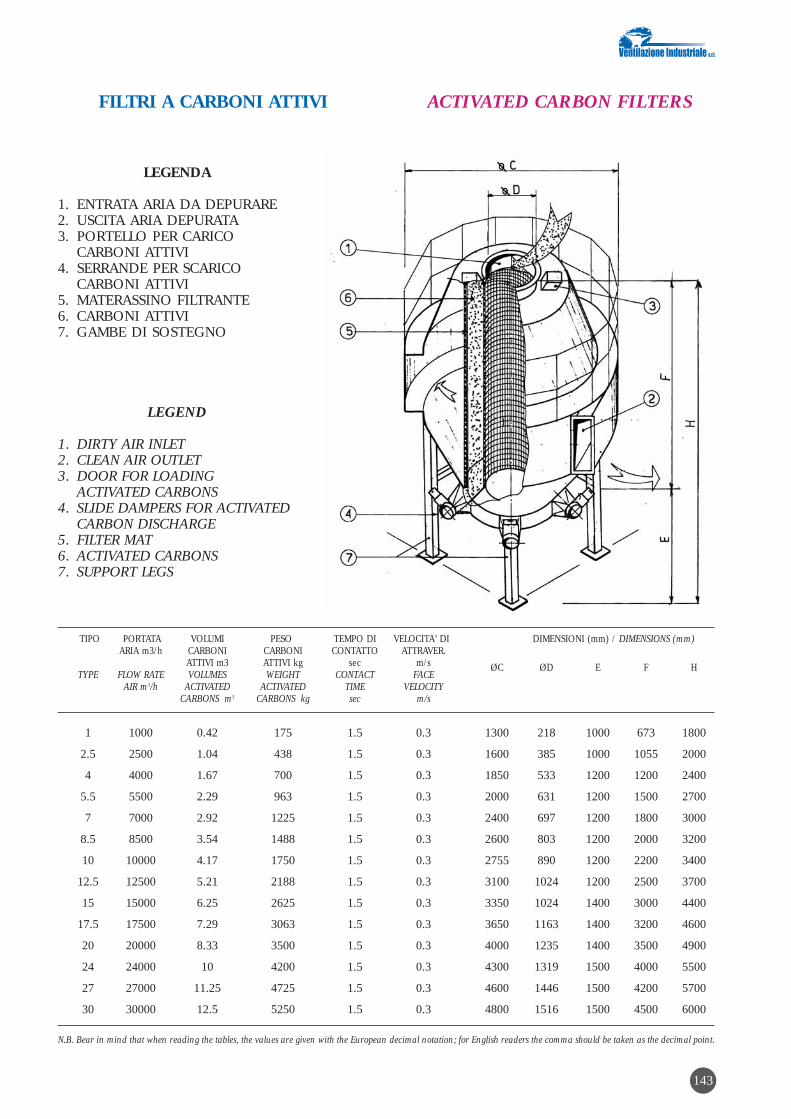
143
LEGENDA
1. ENTRATA ARIA DA DEPURARE2. USCITA ARIA DEPURATA3. PORTELLO PER CARICO
CARBONI ATTIVI4. SERRANDE PER SCARICO
CARBONI ATTIVI5. MATERASSINO FILTRANTE6. CARBONI ATTIVI7. GAMBE DI SOSTEGNO
LEGEND
1. DIRTY AIR INLET 2. CLEAN AIR OUTLET3. DOOR FOR LOADING
ACTIVATED CARBONS4. SLIDE DAMPERS FOR ACTIVATED
CARBON DISCHARGE5. FILTER MAT6. ACTIVATED CARBONS7. SUPPORT LEGS
TIPO PORTATA VOLUMI PESO TEMPO DI VELOCITA’ DI DIMENSIONI (mm) / DIMENSIONS (mm)ARIA m3/h CARBONI CARBONI CONTATTO ATTRAVER.
ATTIVI m3 ATTIVI kg sec m/s ØC ØD E F HTYPE FLOW RATE VOLUMES WEIGHT CONTACT FACE
AIR m3/h ACTIVATED ACTIVATED TIME VELOCITYCARBONS m3 CARBONS kg sec m/s
1 1000 0.42 175 1.5 0.3 1300 218 1000 673 1800
2.5 2500 1.04 438 1.5 0.3 1600 385 1000 1055 2000
4 4000 1.67 700 1.5 0.3 1850 533 1200 1200 2400
5.5 5500 2.29 963 1.5 0.3 2000 631 1200 1500 2700
7 7000 2.92 1225 1.5 0.3 2400 697 1200 1800 3000
8.5 8500 3.54 1488 1.5 0.3 2600 803 1200 2000 3200
10 10000 4.17 1750 1.5 0.3 2755 890 1200 2200 3400
12.5 12500 5.21 2188 1.5 0.3 3100 1024 1200 2500 3700
15 15000 6.25 2625 1.5 0.3 3350 1024 1400 3000 4400
17.5 17500 7.29 3063 1.5 0.3 3650 1163 1400 3200 4600
20 20000 8.33 3500 1.5 0.3 4000 1235 1400 3500 4900
24 24000 10 4200 1.5 0.3 4300 1319 1500 4000 5500
27 27000 11.25 4725 1.5 0.3 4600 1446 1500 4200 5700
30 30000 12.5 5250 1.5 0.3 4800 1516 1500 4500 6000
N.B. Bear in mind that when reading the tables, the values are given with the European decimal notation; for English readers the comma should be taken as the decimal point.
FILTRI A CARBONI ATTIVI ACTIVATED CARBON FILTERS

CARBONE ATTIVATO GRANULARE ECOCARB 354 (4mm)
ORIGINE
Carbone di legno di pino attivato fisicamente convapore d’acqua
APPLICAZIONI
Recupero di solventi – Purificazione di aria e gas
SPECIFICHE TECNICHE
• superficie specifica (BET) m2/g: ≥ 1000• umidità di insaccaggio %: 10 max• massa volumetrica apparente kg/m3:< 550• granulometria: passaggio a 3,15 mm %: 10 max• indice di benzolo (metodo Ceca 10% c.s.): > 33• tenore in ceneri (metodo Cefic) %: <14
CARATTERISTICHE MEDIE (valori indicativi riferiti alla produzione media degliultimi 2 anni)
• massa volumetrica assestata kg/m3: 500-550• massa volumetrica tal quale kg/m3: 460-550• indice di benzolo (metodo Ceca 10% c.S.): 33-35• contenuto in ceneri (CEFIC) %: 12-14• perdita di carico in aria ambiente
a 24m/minuto, 1 m di strato, in mm col. acqua:letto assestato: 500letto non assestato: 150
IMBALLAGGIO
Sacchi di carta in strati multipli da 25 kg netti
GRANULAR ACTIVATED CARBON ECOCARB 354 (4mm)
ORIGIN
Pine wood charcoal activated physically with steam
APPLICATIONS
Recovery of solvents – Purification of air and gases
SPECIFICATION
• surface area (BET) m2/g: ≥ 1000• packed moisture %: 10 max• apparent volumetric mass kg/m3:< 550• particle size: passing at 3.15 mm %: 10 max• benzene index (Ceca method 10% c.s):> 33• ash content (Cefic method) %: <14
AVERAGE CHARACTERISTICS (approximate values referred to average productionin the last 2 years)
• volumetric mass, settled kg/m3: 500/550• volumetric mass, as such kg/m3: 460/550• benzene index (Ceca method 10% c.S): 33-35• ash content (CEFIC) %: 12-14• pressure drop in surrounding air at
24m/minute, 1 m of layer, in mm Water gauge:settled bed: 500non settled bed: 150
PACKING
Multi-ply paper sacks, 25 kg net
144
Aceton
e Capa
cità, g/
g / Ac
etone
Capacit
y, g/g
ISOTERMA / ISOTHERM ISOTERMA / ISOTHERM
n-Hexa
ne Cap
acità, g
/g / n
-Hexan
e Capa
city, g/
g

145
CAPACITA’ DI ADSORBIMENTO DEI CARBONI ATTIVI NEI CONFRONTIDI ALCUNI GAS E VAPORI
Si può avere una indicazione di massima del potereadsorbente di un carbone attivo nei confronti divapori o gas industriali consultando le liste sottoindi-cate nelle quali le sostanze sono state classificate in4 categorie a seconda della loro adsorbibilità. Questaclassificazione ha solo valore indicativo in quanto lacapacità d’adsorbimento dei carboni varia con laconcentrazione del prodotto nell’aria, il grado diumidità, la temperatura e la velocità di passaggio.
A Sostanze nei confronti delle quali i carboni attivi dimo-strano un’elevata capacità di adsorbimento
Acetato di amile DietilcetoneAcetato di butile DimetilsofatoAcetato di cellosolve DiossanoAcetato di etile DipropilcetoneAcetato di isopropile Etere amilicoAcetato di metilcellosolve Etere butilicoAcetato di propile Etere isopropilicoAcido acetico Etere propilicoAcido acrilico EtilbenzoloAcido butirrico EtilmercaptanoAcido lattico EptanoAcido propionico EptileneAcido solforico FenoloAcrilato di etile IndoloAcrilato di metile IodioAcrilonitrile IodoformioAlcool amilico MentoloAlcool butilico MercaptaniAlcool etilico MetilbutilchetoneAlcool isopropilico MetilcellosolveAlcool propilico MetilcloroformioAnidride acetica MetilsobutilchetoneAnilina MetilcicloesanoBenzina MetilcicloesanoloBenzolo MetilcicloesanoneBromo MetilmercaptanoButilcellosolve Monocloridrina di glicoleCamfora MonoclorobenzoloCellosolve NaftalinaCherosene NicotinaClorobenzolo NitrobenzoloClorobutadiene NitroetanoCloroformio NitrometanoCloronitropropano NitropropanoCloropicrina NitrotoluoloCloruro di butile NonanoCloruro di metilene OctanoCloruro di propile Ozono*Composti soforati Ossido di mesitileCreosoto PentanoneCresolo PercloroetileneCrotonaldeide PropilmercaptanoCicloesano Silicato di etileCicloesanolo TrementinaCicloesanone TetracloretanoDecano TetracloretileneDibromoetano Tetracloruro di carbonioDiclorobenzolo ToluoloDicloretano Tricloretilene
ACTIVATED CARBON ADSORPTIONCAPACITY FOR CERTAIN GASES AND VAPOURS
A broad idea of the adsorption capacity of an acti-vated carbon for industrial gases or vapours can beobtained by consulting the lists given below wherethe substances are classed into 4 categories depen-ding on their capacity to be adsorbed. This classifi-cation is only approximate as the adsorption capa-city of activated carbons varies with the concentra-tion of the product in air, degree of moisture, tem-perature and face velocity.
A Substances for which the activated carbons show ahigh adsorption capacity
Amyl acetate DiethylcetoneButyl acetate DimethylsulphateCellosolve acetate DioxaneEthyl acetate DipropylcetoneIsopropyl acetate Amyl ether Methylcellosolve acetate Butyl ether Propyl acetate Isopropyl ether Acetic acid Propyl ether Acrylic acid Ethylbenze Butyric acid Ethyl mercaptanLactic acid HeptanePropionic acid HeptyleneSulphuric acid PhenolEthyl acrylate IndoleMethyl acrylate IodineAcrylonitrile IodoformAmyl alcohol MentholButyl alcohol MercaptansEthyl alcohol MethylbutylketoneIsopropyl alcohol MethylcellosolvePropyl alcohol MethylchloroformAcetic anhydride MethylsobutylketoneAniline MethylcyclohexaneBenzene MethylcyclohexanolBenzol MethylcyclohexanoneBromium Methyl mercaptan Butylcellosolve Glycol monochloridrinCamphor MonochlorobenzeneCellosolve NaphthalineKerosene NicotineChlorobenzene NitrobenzeneChlorobutadiene NitroethaneChloroform NitromethaneChloronitropropane NitropropaneChloropicrin NitrotolueneButyl chloride NonaneMethylene chloride OctanePropyl chloride Ozone*Sulphur compounds Mesityl oxideCreosote PentanoneCresol PerchloroethyleneCrotonaldehyde Propyl mercaptanCyclohexane Ethyl silicateCyclohexanol TurpentineCyclohexanone TetrachlorethaneDecane TetrachlorethyleneDibromoethane Carbon tetrachlorideDichlorobenzene TolueneDichloroethane Triclorethylene

Dicloretilene Xilolo DicloretiletereDicloronitroetanoDicloropropano
BSostanze nei confronti delle quali i carboni attivi dimo-strano una buona capacità di adsorbimento
Acetone DietilamminaAcetato di metile EsanoAcido cianidrico Etere etilicoAcido formico Etere metilicoAcido iodidrico EtilamminaAcido nitrico FluorotriclorometanoAcroleina Formiato di etileAlcool metilico Formiato di metileAldeide propionica FosgeneAnidride solforica FreonBromuro di etile Gas tossiciBromuro di metile Idrogeno solforatoButadiene IsopreneCloro MonofluorotriclorometanoCloruro di etile Ossido di etileneCloruro di metile PentanoCloruro di vinile PenteneDiclorodifluorometano Solventi diversiDicloromonofluorometano Solfuro di carbonio Diclorotetrafluoroetano
CSostanze poco adsorbite dai carboni attivi in condizio-ni normali
AcetaldeideAcido bromidricoAcido cloridricoAcido fluoridricoAmmineAmmoniacaBiossido d’azotoButanoButeneFormaldeideGas solforosiPropanoPropene
DSostanze praticamente non adsorbite dai carboni attiviin condizioni normali
AcetileneAcido carbonicoEtanoEtileneIdrogenoMetanoMonossido di carbonioPerossido di azoto
Dichloroethylene XyleneDichloroethyletherDichloronitroethaneDichloropropane
BSubstances for which the activated carbons show agood adsorption capacity
Acetone DiethylamineMethyl acetate HexaneHydrocyanic acid Ethyl etherFormic acid Methyl etherHydriodic acid EthylamineNitric acid FluorotrichloromethaneAcrolein Ethyl formate Ethyl alcohol Methyl formatePropionaldehyde PhosgeneSulphur dioxide FreonEthyl bromide Toxic gasesMethyl bromide Hydrogen sulphideButadiene IsopreneChlorine MonofluorotrichloromethaneEthyl chloride Ethylene oxide Methyl chloride PentaneVinyl chloride PenteneDichlorodifluoromethane Various solventsDichloromonofluoromethane Carbon disulphideDichlorotetrafluoroethane
CSubstances scarsely adsorbed by activated carbonsunder normal conditions
AcetaldehydeHydrobromic acidHydrochloric acidHydrofluoric acidAminesAmmoniaNitrogen dioxideButaneButeneFormaldehydeSulphurous gases PropanePropene
DSubstances practically not adsorbed by activated car-bons under normal conditions
AcetyleneCarbonic acidEthaneEthyleneHydrogenMethaneCarbon monoxide Nitrogen peroxide
146
* Per l’ozono il carbone attivo reagisce da catalizzatore * For ozone, the activated carbon reacts as catalyst
8. INFORMAZIONI SUI COSTIIl costo specifico di acquisto per applicazioni chenon richiedono accorgimenti costruttivi particolari ècompreso tra 1 e 1,4 € /(m3/h) di aria trattata. Ilcosto di esercizio deve essere calcolata caso percaso.
8. INFORMATION REGARDING COSTSpecific purchasing cost for applications not requir-ing special design arrangements is between 1 and1.4 € /(m3/h) of air handled. The running costshould be calculated in each individual case.

IMPIANTO DI ADSORBIMENTO SU CARBONE ATTIVO CON RECUPEROSOLVENTE
1. TIPO DI TECNOLOGIAAdsorbimento fisico su carbone attivo.
2. INQUINANTI ABBATTIBILISostanze organiche volatili (SOV), l’impianto inoggetto si presta in particolar modo al trattamentodi aria contenente un solo solvente.
3. LIMITI DI EMISSIONE RAGGIUNGIBILISe opportunamente dimensionati si ottengono resedi abbattimento del 99%.
4. DESCRIZIONE DELLE APPARECCHIATUREE/O DEL PROCESSO“Per avere un futuro non si deve distruggere. Usa isolventi e recuperali dando fine sia allo spreco chealla ricerca dei prodotti e sistemi alternativi a sca-pito della qualità e con alti costi”.Con questo slogan nato già nei primi anni ‘80quando la Ventilazione Industriale srl si è orientatasugli impianti di recupero solventi con strippaggioa vapore, l’azienda ha voluto attirare su di sé l’at-tenzione di molti settori industriali tra cui stampa-tori su carta, metallo e film plastico, distillerie, car-tiere, fonderie, plastificatori ecc. mandando a que-sti il messaggio che ora è possibile usufruire di unimpianto pilota per definire con precisione qualidebbono essere il processo e le condizioni ottima-li di funzionamento per ottimizzare al meglio l’in-vestimento proposto. L’utilizzo di tale impianto siallinea inoltre alle esigenze ecologiche della socie-tà in cui viviamo, poiché oltre a garantire un sicu-rissimo risparmio monetario, esso consente di ren-dere completamente disinquinata l’aria satura disolvente e di cattivi odori emessi in atmosfera.
4.1 Principio di funzionamento
Sono 4 le fasi salienti di un processo di recuperosolventi:A. separazione dall’aria del solvente mediante
adsorbimento su carbone attivoB. desorbimento tramite vaporeC. separazione del solvente dall’acqua attraverso
la disidratazione del solvente idrato D. distillazione del solvente
Il processo di recupero completo è così sinte-tizzabile:
La vena di aria inquinata dai vapori di solvente vie-ne preliminariamente filtrata e quindi, tramite aspi-razione forzata, inviata alla batteria di adsorbitori acarbone attivo. Questo trattiene il solvente presen-
ACTIVATED CARBON ADSORPTIONPLANTS (TYPE WITH SOLVENT RECOVERY)
1. TYPE OF TECHNOLOGYPhysical adsorption on activated carbon.
2. CONTAMINANTS WHICH CAN BE REMOVEDVolatile organic compounds (VOC), the above plantis particularly suitable for cleaning air containingjust one solvent.
3. EMISSION LIMITS POSSIBLEWhen suitably dimensioned, collection efficienciesof 99% are obtained.
4. DESCRIPTION OF THE EQUIPMENTAND/OR PROCESS“To ensure a future, we must not destroy. Use sol-vents and recover them thus avoid waste andsearch for products and alternative systems at theexpense of quality and with high costs”.With this slogan dating well back to the early 1980’swhen Ventilazione Industriale srl was turningtowards solvent recovery plants with steam strip-ping, the company wished to attract the attention ofmany industrial sectors including printers onpaper, metal and plastic film, distilleries, papermills, foundries, plastic coating firms etc. byinforming them that it is now possible to make useof a pilot plant to define with a high degree of accu-racy what should be the process and optimum run-ning conditions to best optimize the proposedinvestment. Moreover the use of such plant is in linewith the ecological requirements of the society inwhich we live, because besides guaranteeing a verycertain saving in money, it allows full cleaning ofthe air saturated with solvent and removal ofobnoxious odours emitted in the atmosphere.
4.1 Principle of operation
There are 4 main phases in a solvent recoveryprocess, namely:A. separation of the solvent from the air by adsorp-
tion on activated carbonB. desorption through steamC. separation of the solvent from the water by
dehydrating the hydrated solvent D. distillation of the solvent
The full recovery process can be summed upas follows:
The air stream contaminated with solvent vapoursis first filtered and then sent, through forcedexhaust, to the bank of activated carbon adsorbers.This captures the solvent present in the air so that
147

te nell’aria in modo che questa possa venire scari-cata in atmosfera direttamente attraverso un cami-no.La filtrazione meccanica a monte ha lo scopo ditrattenere eventuali microparticelle solide contenu-te nel flusso gassoso le quali comprometterebberoin parte la capacità di adsorbimento del carbone.La fase di adsorbimento viene alternata con la fasedi rigenerazione a intervalli prestabiliti o quando ilcarbone ha raggiunto lo stato di saturazione tale alquale corrisponde una diminuzione ponderata del-la efficienza di depurazione della vena in ingresso.La durata delle fasi di adsorbimento e di rigenera-zione è in genere di 1 ora.La rigenerazione, o desorbimento, avviene permezzo di un flusso di vapore d’acqua diretto cheha il potere di strippare il solvente dal carbone inmodo da ottenere all’uscita degli adsorbitori unamiscela di solvente e vapore. Con tale tecnologiaviene sfruttata la capacità termica del fluido e il suocalore latente di evaporazione; ciò è parti-colarmente significativo quando il solventecontenuto nella vena da depurare forma un “azeo-tropo” caratterizzato da una temperatura di ebolli-zione inferiore a quella dell’acqua. La miscelavapore/solvente viene quindi raffreddata e con-densata con l’ausilio di uno scambiatore di calorea fascio tubiero e acqua di raffreddamento e invia-ta ad un decantatore ove si ottengono:• una fase organica costituita da solvente idrato • una fase acquosa (acque madri) costituita da
acqua satura di solvente.
Dal decantatore viene estratta la fase organica cheviene disidratata mediante un letto di cloruro dicalcio contenuto in un serbatoio cilindrico, dettacolonna di essiccazione.Il solvente disidratato viene inviato successivamen-te in una colonna di distillazione ove viene raffina-to da impurità residue e abilitato per essere riutiliz-zato nel ciclo produttivo. Le acque madri estrattedal decantatore vengono invece inviate in un ribol-litore la cui funzione è quella di estrarre, per mez-zo di evaporazione a bassa temperatura, il solven-te in esse contenute e mandate quindi al conden-satore per il riciclo. La fase acquosa pesante, impo-verita di solvente, verrà inviata in una fase evapo-rativa che terrà bassa la temperatura dell’acqua uti-lizzata in circuito chiuso nelle sezioni dell’impiantodi adsorbimento. Le varie manovre dell’impiantovengono impostate a distanza per mezzo di unaquadro di comando centralizzato utilizzando ariacompressa a 7 ate come fluido di servocomando.Opzione: volendo spingere ulteriormente la disi-dratazione del solvente recuperato, è possibile cor-redare l’impianto di un serbatoio volano per ali-mentare una colonna azeotropica di essiccazionespinta.
the air can be discharged directly into the atmos-phere via a stack.Purpose of the upstream mechanical filtration is tocapture any solid microparticles contained in thegaseous stream which would partly impair theadsorption capacity of the activated carbon. Theadsorption phase is alternated with the regenera-tion phases at fixed intervals or when the activatedcarbon has reached the state of saturation to whichcorresponds a timed-weighted decrease in filtrationefficiency of the air stream at the inlet. Duration ofthe adsorption and regeneration phases is normal-ly 1 hour.Regeneration, or desorption, is by a direct flow ofsteam which has the power to strip the solvent fromthe activated carbon so as to obtain a mixture ofsolvent and vapour at the adsorber outlet. Withsuch technology, maximum use is made of the ther-mal capacity of the fluid and its latent heat of evap-oration; this is particularly significant when the sol-vent contained in the dirty air stream forms an“azeotrope” characterized by a boiling point lowerthan that of water. The vapour/solvent mixture issubsequently cooled and condensed with the aid ofa tube bundle heat exchanger and the coolingwater then it is sent to a decanter where the follow-ing is obtained: • a organic phase consisting of hydrated solvent • a aqueous phase (mother liquors) consisting of
water saturated with solvent.
The organic phase is extracted from the decanter.This organic phase is then dehydrated by means ofa calcium chloride bed contained in a cylindricaltank, called drying column.The dehydrated solvent is then sent to a distillationcolumn where it is refined from residual impuritiesand is prepared for reuse in the production cycle.The mother liquors extracted from the decanter aresent to a reboiler unit whose function is that ofextracting the solvent contained in them throughlow temperature evaporation, then they are sent tothe condenser for recycling. The heavy aqueousphase, after solvent removal, is sent to an evaporat-ing stage which holds a low temperature of thewater used in closed circuit in the sections of theadsorption plant. The various manoeuvres of theplant are remotely set via a centralized controlpanel using compressed air at 7 atm. as servocom-mand fluid.Option: to achieve a higher performance in dehy-drating the recovered solvent, the plant can be pro-vided with a storage tank feeding a high-perform-ance drying azeotropic column.
148

149
Vapore / Steam
S.L.A. Ingresso aria da depurare / Solvent Laden Air inlet
Solvente di recupero / Recovered solventAcqua da depurare / Water to be treated
Figura 1. Schema di un impianto di recupero per adsorbi-mento su carboni attivi e rigenerazione a vapore. In rosso èevidenziato il percorso dell’aria inquinata attraverso gliadsorbitori (1), contenenti i letti di carbone attivo; in verdequello dell’aria pulita ai camini; il precorso del vapore dirigenerazione è evidenziato in azzurro chiaro, quello delsolvente recuperato in giallo e in blu l’uscita dell’acqua ver-so l’impianto di depurazione.Legenda: 1) adsorbitori; 2) ventilatori; 3) filtro; 4) refrige-rante; 5) scarico aria depurata; 6) e 12) condensatori divapori; 7) separatore; 8) stoccaggio intermedio solvente; 10)e 15) pompe; 11) colonna di disidratazione solvente; 13)refrigerante del solvente; 14) refrigerante ad aria; 16) refri-gerante dell’acqua.
Figure 1. Diagram of an activated carbon adsorption plantwith steam regeneration. Highlighted in red is the path ofthe dirty air through adsorbers (1), containing the activatedcarbon beds; while the path of the clean air to the stacks ishighlighted in green; the path of the regenerating steam isshown in light blue, that of the recovered solvent in yellowwhile the path in dark blue shows the outflow of water tothe water treatment plant.Legend: 1) adsorbers; 2) fans; 3) filter; 4) cooler; 5) cleanair discharge; 6) and 12) vapour condensers; 7) separator; 8)intermediate solvent storage; 10) and 15) pumps; 11) solventdehydrating column; 13) solvent cooler; 14) air cooler; 16)water cooler.
Lato distilleria di impianto recupero solvente a 6 adsorbitori Distillation side, solvent recovery plant with 6 adsorbers

150
METAN
O /
NATUR
AL GA
S
CALDA
IA VAP
ORE /
STEAM
GENER
ATOR
ACQUA
DI RE
TE /
PROCES
S WATE
R
ADDO
LCITOR
E /WA
TER SO
FTENER
IN ATM
OSFERA
/ IN
ATMOSP
HERE
VAPOR
E 2 BA
R/ ST
EAM 2
BAR
ARIA D
I PROCE
SSO /
PROCES
S AIR
ADSOR
BITOR
E / AD
SORBER
CONDEN
SATOR
E / CO
NDENS
ER DECAN
TATOR
E / DE
CANTER
S.O.V.
ESSICC
ATO /
DRIED
VOC
ESSICA
TORE /
DR
YER
Ca Cl L
IQUEFA
TTO /
LIQ
UEFIED
Ca Cl
RIBOLL
ITORE
/ REB
OILER
VAPOR
E / ST
EAM
ACQUA / WATER
ACQUA / WATER
S.O.V. + ACQUA / VOC + WATER
S.O.V. / VOC
ACQUA
DI RE
TE /
PROCES
S WATE
R
TORRE
EVAPO
RATIVA
/EVA
PORAT
ING TO
WER
SCH
EM
A D
I P
RO
CE
SSO
IM
PIA
NT
O D
I R
EC
UP
ER
O S
OLV
EN
TE
P
RO
CE
SS D
IAG
RA
M O
F S
OLV
EN
T R
EC
OV
ER
Y P
LA
NT

4.2 Impianto a vapore per recupero solventetipo “monoblocco multicelle”
DescrizioneQuesto tipo di impianto “monoadsorbitore” siapplica egregiamente per carichi di solvente da 4 a60 kg/ora.L’uso dell’impianto risulta estremamente semplifi-cato in quanto, durante la normale giornata lavora-tiva non richiede alcun intervento, assolvendo inmodo autonomo la sua funzione di depuratore.Soltanto al termine della giornata lavorativa, e perpochi minuti, si provvederà alla rigenerazione convapore dei carboni attivi, predisponendo l’impian-to per la giornata successiva.Dalla rigenerazione con vapore si ottengono duefasi liquide distinte:
una leggera
- Costituita essenzialmente dai solventi leggerideadsorbiti che possono essere eventualmentere-impiegati
una pesante
- Costituita dalle borlande liquide che potrannoessere successivamente strippate.
4.2 Activated carbon solvent recovery plant,steam regeneration, “multi-cell single body”type
DescriptionThis type of “single-adsorber” plant is particularlysuitable for solvent loads from 4 to 60 kg/hour.Use of the plant is very much simplified because,during the normal workday, no operation is neces-sary as its air cleaning function is self-contained.Just at the end of the working day and only for afew minutes, it is necessary to regenerate the acti-vated carbon with steam, thus preparing the plantfor the next day.Two distinct liquid phases are obtained after steamregeneration, namely:
a light phase
- Essentially consisting of light desorbed solventswhich can be reused if necessary
a heavy phase
- Consisting of liquid pulp which can be subse-quently stripped.
151

5. APPLICAZIONI INDUSTRIALI TIPICHEGli impianti di recupero solvente trovano impiegonei processi industriali dove vi sono delle impor-tanti emissioni di solvente con un interessantevalore economico. Stamperie, industrie chimiche,accoppiamento film plastico, produzione nastriadesivi, ecc.
6. VANTAGGI E SVANTAGGIVantaggi: recupero dell’inquinante abbattuto, bassocosto di gestione, abbassamento costi di produzio-ne.Svantaggi: utilizzo dell’impianto nella maggior par-te dei casi con un solo tipo di solvente, la gestionedell’impianto non risulta semplice come con altretecnologie.
7. CALCOLI E TABELLEDi seguito verrà illustrato uno schema di calcolosemplificato per il dimensionamento di un adsorbi-tore a carbone attivo con rigenerazione del carbo-ne tramite vapore.
Legenda:Q: portata d’aria (m3/h)M: flusso di massa solvente (kg/h)V: velocità di attraversamento su carbone attivo
(m/sec)C: carico percentuale in peso di solvente in car-
bone attivo (% in peso)S: sezione letto carbone attivo (m2)h: altezza letto carbone attivo (m)Ps: peso specifico carbone attivo (kg/m3)Vc: volume carbone attivo (m3)Pc: peso carbone attivo (kg)Mc: solvente adsorbito del letto di carbone attivo (kg)T: tempo di saturazione carbone attivo (h)Qv: quantità vapore necessario per la rigenerazio-
ne del carbone attivo (kg)
Calcolo della sezione del letto di carbone attivo:
(Q/3600)S = –––––––––
V
(per V si adotta un valore compreso tra 0,5 e 0,33m/sec)
Calcolo del letto del carbone attivo:
Vc = Sxh
(se non vi sono considerazioni particolari riguardola concentrazione di solvente nell’aria h ha unvalore di 0,7-0,8 m)
Calcolo del peso del letto di carbone attivo:
Pc = VcxPs
(Ps dipende dal tipo di carbone, tendenzialmente ècompreso tra 400 e 500 kg/m3)
5. TYPICAL INDUSTRIAL APPLICATIONSThe solvent recovery plants find application inindustrial processes where there are appreciablesolvent emissions with a certain degree of econom-ic value. Printing works, chemical industries, plas-tic film bonding, adhesive tape production, etc.
6. ADVANTAGES AND DISADVANTAGESAdvantages: recovery of the contaminant captured,low running cost, lower production costs.Disadvantages: the plant is used mainly in thosecases with just one type of solvent. Plant running isnot so easy as is the case with other technologies.
7. CALCULATIONS AND TABLESThe following is a simplified calculation scheme fordimensioning an activated carbon adsorptionplant with steam regeneration of the activated car-bon.
Legend:Q: air flow (m3/h)M: flow of solvent mass (kg/h)V: face velocity on activated carbon (m/sec)C: percentage loading by weight of solvent in acti-
vated carbon (% by weight)S: section of activated carbon bed (m2)h: height of activated carbon bed (m)Ps: specific gravity of activated carbon (kg/m3)Vc: volume of activated carbon (m3)Pc: weight of activated carbon (kg)Mc: solvent adsorbed by activated carbon bed (kg)T: activated carbon saturation time (h)Qv: quantity of steam required for regeneration of
the activated carbon (kg)
Calculation of the activated carbon bed
(Q/3600)S = –––––––––
V
(for V a value lying between 0.5 and 0.33 m/sec isadopted)
Calculation of the activated carbon bed:
Vc = Sxh
(if there are no special consideration regarding theconcentration of solvent in air, h has a value of 0.7-0.8 m)
Calculation of the activated carbon bed weight:
Pc = VcxPs
(Ps depends on the type of activated carbon; it tendsto lie between 400 and 500 kg/m3)
152

Calcolo della quantità di solvente adsorbito dal let-to di carbone attivo:
CMc = Pc x (–––––)100
(un valore approssimato di c può essere considera-to come un terzo del valore di caricamento percen-tuale massimo del solvente specifico in carboneattivo)
Calcolo della quantità di vapore necessaria allarigenerazione del carbone attivo:
Qv = Mcx4,5
(approssimativamente si può ritenere che per strip-pare un kg di solvente accorrono 4-5 kg di vapo-re)
Calcolo del tempo di saturazione del letto di carbo-ne attivo:
McT = –––––
M
Sulla base del letto di saturazione del letto di car-bone attivo e alla quantità di vapore necessaria allarigenerazione si decide se adottare un adsorbitoresingolo o diversi adsorbitori utilizzati a rotazione,tenendone sempre uno in rigenerazione.
8. INFORMAZIONI SUI COSTIUn impianto a carbone attivo con rigenerazione avapore in base al tipo di solvente, alla quantità del-l’aria da trattare, alla concentrazione del solvente ealla quantità richiesta del solvente recuperato puòessere progettato e costruito in svariate configura-zioni con una svariata gamma di accessori. E’ quin-di difficile fare delle considerazioni attendibili suicosti dell’impianto.
Calculation of the quantity of solvent adsorbed bythe activated carbon bed:
CMc = Pc x (–––––)100
(an approximate value of c can be taken as onethird of the value of max. percentage loading of thespecific solvent in activated carbon)
Calculation of the quantity of steam required forregeneration of activated carbon:
Qv = Mcx4,5
(approximately it can be considered that 4 – 5 kg ofsteam are required for stripping one kg of solvent)
Calculation of the saturation time of the activatedcarbon bed:
McT = –––––
M
The decision of whether to adopt a single activatedcarbon adsorber or various adsorbers used in rota-tion, with one always kept in regeneration, willdepend on the saturation of the activated carbonbed and the quantity of steam required for regener-ation.
8. INFORMATION REGARDING COSTAn activated carbon plant with steam regenerationdepending on the type of solvent, quantity of air tobe handled, solvent concentration and the requiredquantity of recovered solvent can be designed andbuilt in various configurations with a widely differ-ing range of accessories. Hence it is difficult tomake reliable considerations regarding plant costs.
153

IMPIANTI CATALITICI PER LA BONIFICADI SOLVENTI IN EFFLUENTI GASSOSI
1. TIPO DI TECNOLOGIAOssidazione con supporto di catalizzatore.
2. INQUINANTI ABBATTIBILITutti gli idrocarburi non alogenati.
3. LIMITI DI EMISSIONE RAGGIUNGIBILIE’ possibile raggiungere rese di conversione supe-riori al 99%.
4. DESCRIZIONE DELLE APPARECCHIATUREE/O DEL PROCESSO
4.1 - Il processo di combustione catalitica
4.1.1 - Lo scopo dell’impianto è di depurare e dideodorizzare correnti gassose provenienti da pro-cessi industriali.Qualsiasi processo di combustione è il prodottodell’ossidazione delle molecole organiche formateda atomi di carbonio e di idrogeno; la cui reazioneesotermica dà come prodotti anidride carbonica(CO2) e vapore acqueo (H2O).Nella combustione a fiamma libera si verificanonumerosi fenomeni: in particolare, se sono presentiatomi di cloro (Cl) e di Zolfo (S), questi ultimi dopola scissione termica della molecola danno come pro-dotti della reazione rispettivamente HCl e SOx i qua-li dovrebbero essere abbattuti nel caso fossero pre-senti in quantità superiori ai valori ammessi.La combustione ad alta temperatura, in eccessod’aria, genera quantità di NOx in rapporto direttocon la temperatura. In presenza di sostanze cloru-rate e catene polimeriche nei fumi della combustio-ne ad alta temperatura si possono generare sostan-ze aromatiche policlorurate.
4.1.2 - Nel processo di combustione, in presenzadi un catalizzatore, alla temperatura di circa 260-450° C questi fenomeni sono annullati.
Ad una temperatura tra i 260 ed i 450°C, le mole-cole della stragrande maggioranza delle SOV inaria, al contatto con la parte attiva del catalizzatoreappropriato, vengono scisse. L’aeriforme da depu-rare viene portato alla temperatura di innesco del-la combustione dapprima mediante preriscaldo inuno scambiatore e poi, se necessario, mediante ilcalore prodotto dalla combustione del combustibi-le di supporto che normalmente è metano.L’ossidazione degli inquinanti può essere realizza-ta con un rendimento che può raggiungere il 100%se il tempo di contatto tra effluente da depurare ecatalizzatore è adeguato.
CATALYTIC PLANTS FOR CLEAN-UP OFSOLVENTS IN GASEOUS STREAMS
1. TYPE OF TECHNOLOGYOxidation with catalyst support.
2. CONTAMINANTS WHICH CAN BE REMOVEDAll non-halogenated hydrocarbons.
3. EMISSION LIMITS POSSIBLEConversion efficiencies exceeding al 99% can beobtained.
4. DESCRIPTION OF THE EQUIPMENTAND/OR PROCESS
4.1 - The catalytic combustion process
4.1.1 - Purpose of the plant is to clean and deodor-ize gaseous streams coming from industrialprocesses.Any combustion process is the product of the oxida-tion of organic molecules formed by atoms of car-bon and hydrogen whose exothermic reaction givescarbon dioxide (CO2) and water vapour (H2O) asproducts.In direct-flame combustion many phenomenaoccur: above all, if atoms of chlorine (Cl) and sul-phur (S) are present; these give as reaction prod-ucts, after thermal decomposition of the molecule,HCl and SOx respectively which require removal ifpresent in quantities exceeding the permissible lev-els.High temperature combustion, in excess air, gene-rates quantities of NOx in direct proportion to thetemperature. If chlorinated substances and poly-meric chains are present in the combustion fumesat high temperature, aromatic polychlorinated sub-stances could be produced.
4.12 - Such phenomena are eliminated in com-bustion processes carried out in the presence of acatalyst at the temperature of approx. 260-450° C.
At a temperature between 260 and 450°C, the mol-ecules of most of the VOCs in the air are decom-posed upon coming into contact with the activatedpart of the appropriate catalyst. The gaseous streamto be cleaned is first brought to the combustion igni-tion temperature by preheating in a heat exchang-er and then, if necessary, through the heat pro-duced by the combustion of the auxiliary fuelwhich is normally natural gas.Oxidation of the pollutants can be achieved withan efficiency up to 100% if there is an adequatecontact time between the effluent to be cleaned andthe catalyst.
154

L’adeguato tempo di contatto è assicurato dal cor-retto dimensionamento del letto catalitico.
Il contenuto termico della corrente gassosa depura-ta è recuperato in parte tramite uno scambiatore peril preriscaldo della corrente gassosa da depurare.
La temperatura di preriscaldo e quindi l’efficienzadello scambiatore vengono stabiliti in funzione del-le quantità degli inquinanti e in base al risparmioenergetico che si vuole ottenere.In genere l’efficienza dello scambiatore (che nor-malmente è del tipo a tubi lisci) è del 70% circa.Questo primo recupero può essere seguito da altreforme di recupero termico, attuate a valle dal pro-cesso, atte al preriscaldo di aria, acqua oppure diolio diatermico.
4.1.3 - Un nuovo approccio, culturale e tecnologi-co, alla soluzione dei problemi di bonifica di cor-renti gassose inquinate è imposto dalla molteplici-tà dei processi, dalle condizioni di processo e dal-la varietà dei parametri di sicurezza che occorretenere presente di volta in volta nonché dall’insie-me dei fattori di economicità che occorre bilancia-re nei diversi processi.
5. APPLICAZIONI INDUSTRIALI TIPICHEI combustori catalitici trovano impiego in tutte leindustrie ove vi siano dei processi con emissione diaria con idrocarburi, impianti di stampa, accoppia-mento film plastico, impianti chimici, ecc.
6. VANTAGGI E SVANTAGGIVantaggi: semplicità di utilizzo, flessibilità rispetto avariazioni di concentrazioni inquinanti, possibilitàdi effettuare dei recuperi energetici supplementari,bassa richiesta di manutenzione.Svantaggi: possibilità di avvelenamento catalizzato-re, sostituzione periodica del catalizzatore.
7. CALCOLI E TABELLENoi vogliamo qui brevemente richiamare le procedu-re logiche ed elencare le questioni principali implici-te nella svolta della combustione catalitica, per valu-tarne gli aspetti di debolezza e di forza alla luce del-le nuove e nuovissime proposte tecnologiche.Queste sono pure le linee guida da noi seguite, inlaboratorio, in officina e presso i Clienti, per affron-tare in modo affidabile ed efficace i complessi pro-blemi per la realizzazione di processi e tecnologie“pulite”.
7.1 - Sequenza delle attività necessarie per lavalutazione preliminare della tecnologia daadottare
7.2.1 - Comprensione del ciclo produttivo e in par-ticolare:- Transitori;- Condizioni delle emissioni e loro rigorosa
Adequate contact time is ensured by correct dimen-sioning of the catalytic bed.
The heat content in the clean gaseous stream ispartly recovered via a heat exchanger for preheat-ing subsequent gaseous streams to be cleaned.
The preheating temperature and therefore efficien-cy of the heat exchanger should be determinedaccording to the quantities of contaminants andthe amount of energy to be saved.Normally heat exchanger efficiency (usually of thesmooth tube type) is approx. 70%.The initial heat recovery can be followed by otherforms of heat recovery, downstream of the process,and suitable for preheating the air, water or heattransfer oil.
4.1.3 - A new cultural and technological approachto solving problems of treating polluted gaseousstreams should be adopted owing to the very manyprocesses as well as the process conditions and vari-ety of safety parameters which must be taken intoaccount each time, not to mention the cost-effec-tiveness factors to be balanced in the variousprocesses.
5. TYPICAL INDUSTRIAL APPLICATIONSCatalytic combustion units find application in allthose industries where there are processes withhydrocarbon-laden air, printing machines, bond-ing of plastic film, chemical plants, etc.
6. ADVANTAGES AND DISADVANTAGESAdvantages: user-friendly, flexibility in relation tovariations in contaminant concentrations, provi-sion for additional energy recovery, low mainte-nance requirements.Disadvantages: risk of catalyst poisoning, periodicsubstitution of catalyst.
7. CALCULATIONS AND TABLESHere we wish to give a brief survey of the logic pro-cedures and list the main issues involved in catalyt-ic combustion in order to assess its weak and strongpoints in the light of the new and very latest techno-logical developments.These are also the guidelines followed by us in thelaboratory, in the workshop and at the Customers’premises to enable us to tackle, both reliably andeffectively, the complex problems involved in theengineering of “clean” technologies and processes.
7.1 - Sequence of actions necessary for prelim-inary assessment of the technology to beadopted
7.2.1 - Understanding of the production cycle,above all:- Transients;- Conditions of the emission and their strict
155

dipendenza dal ciclo stesso (es.: portate,temperature, fumi, diluizione o concentrazioneinquinanti, recupero termico utilizzabile, etc.).
7.1.3 - Analisi chimiche delle emissioni:- Prelievi percentuali e loro esame completo in
laboratorio;- Monitoraggio “on line” per un tempo adeguato
almeno delle principali molecole;- Loro esame in relazione al ciclo produttivo e alla
sua eventuale modifica.
7.1.4 - Fattibilità:- Produzione di miscele sintetiche similari;- Sperimentazione in laboratorio, con micro reat-
tori, della tecnica più probabile.
7.1.5 - Test in campo con impianto pilota ed esa-me critico dei risultati.
7.1.6 - Dati di progetto per una valutazioneCosti/Benefici.
7.2 - Elementi di valutazione per la scelta dell’im-pianto di combustione catalitica
7.2.1 - Scelta della natura chimica del catalizzatore- Metalli preziosi;- Ossidi misti.
7.2.2 - Parametri critici alla base della scelta dellanatura chimica:- Avvelenamento;- Shock termici;- Natura dei prodotti di conversione;- Costi.
7.2.3 - Caratteristiche chimico / fisiche del catalizzato-re:- Natura del supporto;- Granulometria e perdite di carico;- Conducibilità e scambio nel letto;- Velocità spaziali.
7.2.4 - Innesco e recupero termico:- Preriscaldamento elettrico;- Preriscaldamento a gas;- Temperatura di ingresso fumi nel reattore.
7.2.5 - Cicli di preconcentrazione- Sistemi di controllo analitici da processo.
7.2.6 - Sicurezze:- Chimiche;- Elettriche.
7.3 - Fattore di carico e velocità spaziale
Un aspetto significativo del dimensionamento del let-to catalitico è il fattore di carico dato dalla velocitàspaziale. Per velocità spaziale si intende la quantità
dependence on the production cycle (e.g.: flowrates, temperatures, fumes, dilution or concen-tration of contaminants, useable heat recovery,etc.).
7.1.3 - Chemical analysis of the emissions:- Percentage sampling and their complete analysis
in the laboratory;- “On line” monitoring for an adequate time at
least of the main molecules;- Their examination in relation to the production
cycle and their modification if necessary.
7.1.4 - Feasibility:- Production of similar synthetic mixtures;- Laboratory experiments with microreactors to
determine the most suitable technique.
7.1.5 - Field testing with pilot plant and criticalexamination of the results.
7.1.6 - Design data for Costs/Benefits evaluation.
7.2 - Assessment factors in choosing a catalyt-ic incinerator
7.2.1 - Choice of the chemical nature of the catalyst- Precious metals;- Mixed oxides.
7.2.2- Critical parameters lying behind the choiceof the chemical nature:- Poisoning;- Thermal shocks;- Nature of the conversion products;- Costs.
7.2.3 - Chemical / physical properties of the catalyst:- Nature of the support;- Particle size and pressure drops;- Conductivity and exchange in the bed;- Space velocities.
7.2.4 - Firing and heat recovery:- Electric preheating;- Gas-fired preheating;- Fume inlet temperature in the reactor.
7.2.5 - Preconcentration cycles- In-process analytical testing systems.
7.2.6 - Safety:- Chemical;- Electrical.
7.3 - Load factor and space velocity
An important aspect in dimensioning the catalyticbed is the load factor given by the space velocity. Byspace velocity we mean the quantity of gas whichflows per unit of time in relation to the catalyst vol-
156

di gas che passa per unità di tempo in rapporto alvolume di catalizzatore, ed è inversamente propor-zionale al tempo di sosta del gas nei catalizzatori:
in cui:
Vs = velocità spaziale (h-l) Qg = quantità di gas che attraversa il letto cataliti-
co Vk = volume di catalizzatore
Le velocità spaziali utilizzabili, normalmente sonoin pratica tra le 5000 e le 20000 h-l e dipendono:- dal grado di purezza delle emissioni richiesto;- dalla temperatura;- dalla perdita di pressione consentita.Ad una temperatura costante, il rendimento dellaconversione catalitica diminuisce, insieme allapurezza del gas, quando aumenta la velocità spa-ziale. D’altra parte si può ottenere una miglioreconversione ad una velocità spaziale costanteaumentando la temperatura.
7.4 - Temperatura di utilizzo
Temperature di reazione diverse ai catalizzatoridevono essere utilizzate, secondo i componenti darimuovere. Nella tabella 1 ad esempio, sono rap-presentate le temperature di conversione di alcunemolecole.Si osservi come le reazioni esotermiche che avven-gono nel catalizzatore portano ad un incremento ditemperatura che in gran parte dipende dal grado diimpurità.I catalizzatori a metalli preziosi resistono in generea temperature fino a 600°C.I catalizzatori a base di ossidi possono resistere, inalcuni casi, fino oltre 1250°C.
Composti Temperatura Temperatura a cuidi soglia si ha il 90%
catalitica °C di conversione °C
Idrogeno 20 20Ossido di carbonio 150 150-200Benzene 180 250-300Toluene 170 250-300Xilene 200 250-300∂-pirene 190 250-300Etanolo 180 250-300n-eptano 180 250-300Metilisobutilchetone 175 300-350Metilchetone 175 300-350Dimetilformammide 200 350-400Etilacetato 270 400-450Metano 300 400-450
Tab. 1 - Temperature caratteristiche per una data fami-glia di catalizzatori di ossidazione (Pt)
QgVs –––
Vk
ume and it is inversely proportional to the residencetime of the gas in the catalysts.
where:
Vs = space velocity (h-l)Qg = quantity of gas flowing through the catalytic
bed Vk = volume of catalyst
The space velocities normally used lie between 5000and 20000 h-l. They depend on:- required degree of purity of the emissions;- temperature;- permissible pressure drop.Under constant temperature, the efficiency of cat-alytic conversion decreases (together with the puri-ty of the gas) as the space velocity increases. On theother hand, improved conversion at constant spacevelocity can be obtained by increasing the temper-ature.
7.4 - Reaction temperature
Different reaction temperatures should be used forthe catalyts according to the components to beremoved. For example, table l gives the conversiontemperatures of certain molecules.Note that the exothermic reactions taking place inthe catalyst cause an increase in temperaturewhich mainly depends on the degree of impurity.Precious metal catalysts normally withstand tempe-ratures up to 600°C.In certain cases oxide-based catalysts can with
Compounds Catalytic threshold Temperature attemperature °C which 90% of
conversion is obtained °C
Hydrogen 20 20Carbon oxide 150 150-200Benzene 180 250-300Toluene 170 250-300Xylene 200 250-300∂-pyrene 190 250-300Ethanol 180 250-300n-heptane 180 250-300Methylisobutylketone 175 300-350Methylketone 175 300-350Dimethylformamide 200 350-400Ethylacetate 270 400-450Methane 300 400-450
Table 1 – Characteristic temperatures for a given familyof oxidation catalysts (Pt)
QgVs –––
Vk
157

Le temperature previste per una conversione cata-litica ottimale vengono indicate sullo schema gene-rale del sistema catalitico.
Fig. 2 - Andamento della temperatura minima di preri-scaldo per ottenere un abbattimento del 90%, in funzio-ne della portata oraria dei gas da trattare.
7.5 - Perdite di pressione e velocità lineare
Un altro importante fattore, nel dimensionare unimpianto catalitico, è la perdita di pressione. Laperdita di pressione in un catalizzatore dipendeprincipalmente dalla velocità lineare del gas e dal-la perdita di carico del materiale catalitico.Si può valutare preventivamente una perdita dicarico, ad esempio, se si usa il metodo di calcoloErgun. Questa equazione comprende sia il motolaminare che quello turbolento di perdita di carico.
Alla Fig. 3 è rappresentata la perdita di pressionecalcolata in catalizzatori di forma diversa in rappor-to alla velocità lineare.Ai fini di una conversione catalitica ottimale, sonoessenziali una certa turbolenza nel gas ed una per-dita di pressione minima nel letto catalitico.E’ possibile ottenere risultati ottimali a velocitàlineari di 0,1-0,5 m/s, ma in pratica si possono uti-lizzare velocità lineari diverse, in funzione dellealtre condizioni operative (pressione, temperatura,viscosità dei gas, ecc.).
Fig. 3 - Andamento della perdita di carico, in funzionedella portata oraria per m2 di superficie e per uno spes-sore catalitico di 100 mm (catalizzatore: A e B = mono-liti ceramici da 1/4” e da 1/8”: C = rotoli di fogli metal-lici corrugati; D = sferette da 1/8”; Fluido = aria a con-dizioni ambiente).
Flusso d’aria m3/m2_ h
∆P, mm H2O / dm letto
Flusso
di gas
, scfm
pollice
2
Velocit
à spaz
io h-l
Temperatura di ingresso nel combustore, °C
spessore = 100 mm
bruciatore termico
The required temperatures for optimum catalyticconversion are indicated on the general layout ofthe catalytic system
.
Fig. 2 – Minimum preheating temperature curves forobtaining a 90% abatement, in relation to the hourlyflow rate of the gases to be cleaned.
7.5 - Pressure drops and linear velocity
Another important factor when dimensioning acatalytic incinerator, is the pressure drop. The pres-sure drop in a catalyst depends mainly on the lin-ear velocity of the gas and the pressure drop of thecatalytic material.It is possible to assess the pressure drop beforehand;for example, by using the Ergun calculationmethod. This equation includes both the laminarand turbulent motions of the pressure drop.
Fig. 3 shows the calculated pressure drop in cata-lysts of different shape in relation to the linearvelocity.A certain turbulence in the gas and minimum pres-sure drop across the catalyst bed are essential foroptimum catalytic conversion.Excellent results can be obtained at linear velocitiesof 0.1-0.5 m/s, but in practice different linear veloc-ities can be used, depending on the other operatingconditions (pressure, temperature, viscosity of thegases, etc.).
Fig. 3 – Pressure drop curves plotted against the hourlyflow rate per m2 of surface and for a catalyst thicknessof 100 mm (catalyst: A and B = monolithic ceramics, size1/4” and 1/8”: C = rolls of corrugated metal sheets; D =1/8” spheres; Fluid = air at ambient conditions).
Air flow m3/m2_ h
∆P, mm H2O / dm bed
Gas flo
w, scfm
inch2
Space
velocit
y h-l
Inlet temperature in the combustion unit, °C
Thickness = 100mm
Burner
158
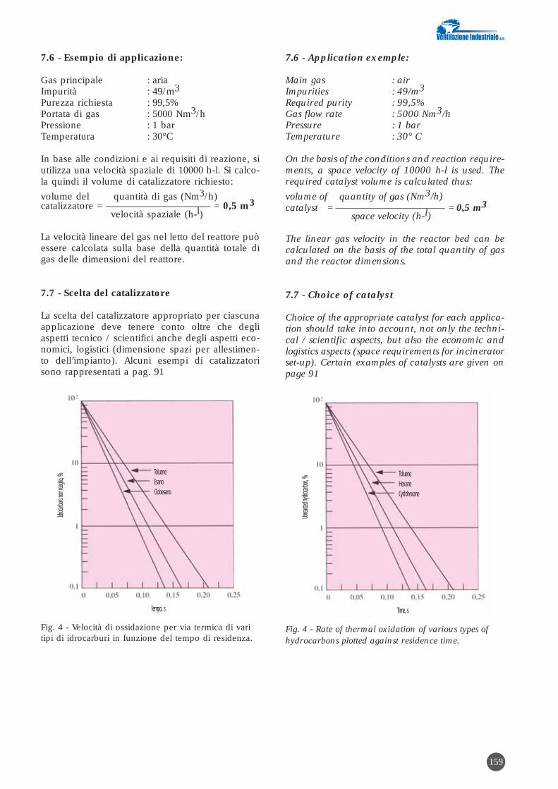
7.6 - Esempio di applicazione:
Gas principale : ariaImpurità : 49/m3
Purezza richiesta : 99,5%Portata di gas : 5000 Nm3/h Pressione : 1 barTemperatura : 30°C
In base alle condizioni e ai requisiti di reazione, siutilizza una velocità spaziale di 10000 h-l. Si calco-la quindi il volume di catalizzatore richiesto:
volume del quantità di gas (Nm3/h)catalizzatore = ––––––––––––––––––––– = 0,5 m3
velocità spaziale (h-l)
La velocità lineare del gas nel letto del reattore puòessere calcolata sulla base della quantità totale digas delle dimensioni del reattore.
7.7 - Scelta del catalizzatore
La scelta del catalizzatore appropriato per ciascunaapplicazione deve tenere conto oltre che degliaspetti tecnico / scientifici anche degli aspetti eco-nomici, logistici (dimensione spazi per allestimen-to dell’impianto). Alcuni esempi di catalizzatorisono rappresentati a pag. 91
Fig. 4 - Velocità di ossidazione per via termica di varitipi di idrocarburi in funzione del tempo di residenza.
Idroca
rburo
non re
agito,
%
Tempo, s
TolueneEsanoCicloesano
7.6 - Application exemple:
Main gas : airImpurities : 49/m3
Required purity : 99,5%Gas flow rate : 5000 Nm3/h Pressure : 1 barTemperature : 30° C
On the basis of the conditions and reaction require-ments, a space velocity of 10000 h-l is used. Therequired catalyst volume is calculated thus:
volume of quantity of gas (Nm3/h)catalyst = –––––––––––––––––––––– = 0,5 m3
space velocity (h-l)
The linear gas velocity in the reactor bed can becalculated on the basis of the total quantity of gasand the reactor dimensions.
7.7 - Choice of catalyst
Choice of the appropriate catalyst for each applica-tion should take into account, not only the techni-cal / scientific aspects, but also the economic andlogistics aspects (space requirements for incineratorset-up). Certain examples of catalysts are given onpage 91
Fig. 4 - Rate of thermal oxidation of various types ofhydrocarbons plotted against residence time.
Unrea
cted h
ydroca
rbon, %
Time, s
TolueneHexaneCyclohexane
159

160
Impianto di combustione catalitica da 8000 Nm3/h installatopresso una ditta che sensibilizza lastre fotografiche in allu-minio.
Catalytic combustion plant, 8000 Nm3/h, installed at a com-
pany sensitizing aluminium photographic sheets.
N.1 Catalizzatore con supporto a nido d’ape al Platino (Pt)N.2 Catalizzatore ad anelli con basse perdite di caricoN.3 Catalizzatore ad ossidi metallici per alte temperatureN.4 Catalizzatore su sfere con Palladio (Pd)N.5 Catalizzatore ad ossidi metallici ad alta superficie spe-
cificaN.6 Catalizzatore in pellets con Platino per purificazione ad
uso analiticoN.7 Catalizzatore per il trattamento di ossidi di azotoN.8 Catalizzatore ad ossidi metallici ad alta efficienza e alta
temperatura
N.1 Catalyst with honeycomb platinum (Pt) carrierN.2 Catalyst in rings with low pressure dropsN.3 Metal oxide catalyst for high temperaturesN.4 Catalyst in spheres based on palladium (Pd)N.5 Metal oxide catalyst with high specific surfaceN.6 Catalyst in pellets based on platinum for analytical
grade purificationN.7 Catalyst for treatment of nitrogen oxidesN.8 Metal oxide catalyst, high efficiency type, for high tem-
peratures
TIPI DI CATALIZZATORI TYPES OF CATALYSTS

161
Impianto di combustione catalitica da 10.500 Nm3/h installa-to presso una ditta che plastifica carta e cartone.
Catalytic combustion plant, 10,500 Nm3/h, installed in apaper and cardboard plasticizing company.
Dati analitici:
Inquinanti Concentrazione Emissione (mg/ Nm3) oraria (g/h)
ingresso uscita ingresso uscitaAcetone 0,8 0,4 8,5 4,2Acetato di etile 1275 9,2 13387 96,5Toluene 920 6,3 9660 66,5Alcool etilico 1,2 0,8 - 8,4
SOT 2197 16,7 23056 175,7
Analytical data:
Contaminants Concentration Hourly(mg/ Nm3) emission (g/h)
inlet outlet inlet outletAcetone 0.8 0.4 8.5 4.2Ethyl acetate 1275 9.2 13387 96.5Toluene 920 6.3 9660 66.5Ethyl alcohol 1.2 0.8 - 8.4
TOTAL 2197 16.7 23056 175.7

162
Profili di Temperatura / Temperature profiles
406590
115140165190215240265290315340365390415440465
tempo / time
Tem
pera
ture
°C
/ T
empe
ratu
res °
C
ingresso / inlet
preriscaldo / preheating
reg. bruciatore / burner reg.
catalizzatore / catalyst
camino / stack
13.0
0
11.4
1
11.2
9
11.2
4
11.2
0
11.1
7
11.1
5
11.1
2
11.0
3
10.5
5
10.4
5
10.3
6
10.1
0
1000 350 1,5 7,7 1,20 3 1 50.000
2500 350 4 8,2 1,50 3 1 130.000
5000 350 7,5 11,71 1,72 4,5 1 250.000
7500 350 9 12,6 2,10 4,5 1 400.000
10000 350 15 12,92 2,43 5,5 1 500.000
15000 350 18,5 13,47 2,97 6 1 750.000
20000 350 30 14,08 3,43 6 1 1.000.000
25000 350 37 14 3,84 6 1 1.250.000
30000 350 37 14 4,62 6 1 1.500.000
35000 350 45 14 5,50 6 1 1.850.000
40000 350 55 14 6,00 6 1 2.000.000
portata prevalenza potenza instal- lunghezza larghezza altezza numero potenzialitàaria (m3/h) (mmCA) lata (Kw) (m) (m) (m) bruciatori bruciatore
air flow head total installed length (m) width (m) height (m) number of burner (m3/h) (mmWG) power (Kw) burners capacity
VENTILATORE PRINCIPALE DIMENSIONI IMPIANTOMAIN FAN PLANT DIMENSIONS
TABELLA DELLE CARATTERISTICHE TECNICHE DEGLI IMPIANTI CATALITICI TABLE OF TECHNICAL CHARACTERISTICS OF CATALYTIC PLANTS
Impianti con portate d’aria superiori o diverse possono essere realizzati su richiesta
* I consumi relativi al normale funzionamento a regime dipendono dalla concentrazione dei solventi trattati e dal loro potere calorifico. L’autosostentamento si raggiunge con circa 4 gr/m3 di SOV con p.c.i. di 10.000 kcal/h.
N.B. Bear in mind that when reading the tables, the values are given with the European decimal notation; for English readers the comma should be taken as the decimal point.

163
SCH
EM
A D
I P
RO
CE
SSO
IM
PIA
NT
O C
ATA
LIT
ICO
P
RO
CE
SS D
IAG
RA
M, C
AT
ALY
TIC
PLA
NT
ARIA D
I PROCE
SSO /
PRO
CESS A
IR
BYPAS
S / B
YPASS
ARIA A
MBIEN
TE /
AMBIE
NT AIR
METAN
O /
NATUR
AL GA
S
ARIA C
OMBU
RENTE
/ COM
BUSTI
ON-SU
PPORTI
NG AI
R

8. INFORMAZIONI SUI COSTI
I numerosi risultati, espressi in letteratura, del con-fronto economico tra combustione termica e catali-tica, mostrano che l’incenerimento per via cataliti-ca è più conveniente in tutti i possibili tipi digestione: da quello di massimo consumo di com-bustibile a quello di autosostentamento termico.I margini di convenienza sono in realtà migliori diquelli indicati in letteratura, sia perché la durata delcatalizzatore è largamente superiore alle 8.000 oredi vita sia perché si è omesso di considerare a cari-co del sistema termico gli oneri derivanti dal mag-gior costo della camera di combustione (tipo dimateriale e dimensioni) e dalla maggior spesa dienergia consumata a causa delle perdite di caricodella sezione di recupero in più che esso richiede.Ciò vale, evidentemente, per qualsiasi impianto ditermodistruzione ad alta temperatura. Sono pureesclusi dal bilancio comparativo i costi della produ-zione di NOx e CO che invece nella combustionecatalitica sono assenti.Per quanto concerne la durata del catalizzatore sideve osservare che il suo avvelenamento, intesocome fenomeno irreversibile, non esiste pratica-mente, in quanto i buoni catalizzatori resistonoottimamente a tutti gli elementi chimici presenti neisolventi; mentre l’eventuale perdita di attività dovu-ta a contaminazione da polvere, nero fumo, ossidimetallici, aerosols, ha carattere temporaneo e puòessere ripristinata mediante un opportuno tratta-mento di pulizia.
A seconda delle dimensioni dell’impianto e daeventuali esecuzioni speciali si può considerare unprezzo specifico di acquisto compreso tra 13 e 23€ /(m3/h) di aria trattata.
8. INFORMATION REGARDING COST
The great number of results, reported in the litera-ture, of economic comparison between thermal andcatalytic combustion, show that catalytic incinera-tion is the more advantageous in all possible typesof control: from control over maximum fuel con-sumption to control in thermal self-supportingterms. In actual fact, the margins of cost-effectiveness arebetter than those reported in the literature bothbecause the life cycle of the catalyst is far greaterthan 8000 hours and because no consideration hasbeen given to the onus due to the greater cost of thecombustion chamber (type of material and size)and also the greater expense in energy consumedowing to the pressure drops required by the recov-ery section exceeding its requirements.Obviously this applies to any type of high tempera-ture incinerator systems. Furthermore the compar-ative balance does not include the costs of NOx andCO production, which, instead, are not present incatalytic combustion.As regards the life cycle of the catalyst, it should bestressed that there is practically no poisoning(intended as an irreversible phenomenon) as goodcatalysts exhibit excellent resistance to all chemicalelements contained in the solvents; while any loss inactivity due to contamination by dust, carbonblack, metal oxides and aerosols is temporary, andcan be restored through appropriate cleaning treat-ment.
Depending on the plant size and any special ver-sions, a specific price could be considered as lyingbetween 13 and 23 € /(m3/h) of air handled.
164

IMPIANTI DI COMBUSTIONE RIGENERA-TIVI
1. TIPO DI TECNOLOGIAOssidazione termica.
2. INQUINANTI ABBATTIBILITutti gli idrocarburi.
3. LIMITI DI EMISSIONE RAGGIUNGIBILIE’ possibile raggiungere rese di abbattimento supe-riori al 99%.
4. DESCRIZIONE DELLE APPARECCHIATUREE/O DEL PROCESSOI.T.R. è il nome scelto dalla Ventilazione Industrialeper il suo nuovo impianto di combustione con recu-pero termico intrinseco di tipo rigenerativo, cioè unsistema di combustione nel quale il recupero del-l’energia termica avviene al proprio interno con lamassima efficienza possibile. Rispetto ad altri sistemidi abbattimento, il combustore di tipo rigenerativo èidoneo alla combustione di qualsiasi tipo di sostanzaorganica volatile in forma gassosa anche a basse con-centrazioni (solventi clorurati e non, compostiinfiammabili, idrocarburi, odori) ed ha inoltre il van-taggio di minimizzare i costi di gestione ed i consu-mi di fonti primarie di energia.La eliminazione degli inquinanti nella vena gassosaavviene esponendo questi per un periodo di tempoconforme alle normative vigenti ad una temperaturatale per cui sia sempre garantita la completa ossida-zione. Anche per questo tipo di impianto (esatta-mente come per quello catalitico) i prodotti di com-bustione derivanti dalla reazione esotermica sonoprevalentemente anidride carbonica e vapor acqueo.Il processo di combustione termico-rigenerativo èestremamente versatile per il trattamento delle emis-sioni gassose e non risente praticamente di eventua-li variazioni di composizione chimica della emissio-ne, circostanza che si verifica frequentemente suprocessi industriali legati alla produzione di prodot-ti diversificati e che possono variare rapidamente neltempo in funzione delle realtà di mercato.I consumi energetici (elevati negli impianti di com-bustione tradizionali) sono per l’impianto di com-bustione rigenerativo estremamente contenuti, gra-zie al sistema di recupero termico che utilizza mas-se di materiale ceramico aventi funzione di “vola-no termico” in grado di ricevere dal gas, accumu-lare e restituire al gas stesso, calore con facilità.In sommi capi, le caratteristiche salienti di questiimpianti sono:
Stabilità termo-meccanica:
La scelta della fibra ceramica, per i rivestimentiinterni delle camere calde, garantisce un’ottima
REGENERATIVE COMBUSTION PLANTS
1. TYPE OF TECHNOLOGYThermal oxidation.
2. CONTAMINANTS WHICH CAN BE REMOVEDAll hydrocarbons.
3. EMISSION LIMITS POSSIBLECollection efficiencies exceeding 99% can be rea-ched.
4. DESCRIPTION OF THE EQUIPMENTAND/OR PROCESSI.T.R. is the name chosen by Ventilazione Industrialefor its new regenerative type of incinerator plant withintrinsic heat recovery, i.e. a combustion system inwhich the heat energy is recovered inside the plantwith the maximum possible efficiency. Comparedwith other abatement systems, the regenerative com-bustion unit (incinerator) is ideal for the incinera-tion of any type of volatile organic compound ingaseous form also in low concentrations (chlorinat-ed and non-chlorinated solvents, inflammable com-pounds, hydrocarbons, odours); furthermore it hasthe advantage of minimizing running costs andconsumption of primary energy sources.The contaminants in the gaseous stream are elimi-nated by exposing them for a period of time inaccordance with current regulations and at a tem-perature such that complete oxidation is alwaysguaranteed. Likewise for this type of plant (exactlyas for the catalytic incinerator) the combustionproducts formed by the exothermic reaction aremainly carbon dioxide and water vapour.The thermal-regenerative combustion process is high-ly versatile as regards treatment of the gaseous emis-sions. Moreover it is practically unaffected by anyvariations in chemical composition of the emission,such circumstance frequently occurring in industrialprocesses involved with the manufacture of diversi-fied products and which can vary rapidly over a peri-od of time, depending on market requirements.Energy consumption (high in conventional inciner-ator plants) is very limited for the regenerative com-bustion plant thanks to the heat recovery systemwhich uses packing of ceramic material having thefunction of a “heat wheel” able to receive heat eas-ily from such gas and store the heat, then give itback readily to the gas.In short, the chief characteristics of these incinera-tors are:
Thermal-mechanical stability:
Appropriate choice of ceramic fibre, for internallining of the combustion chambers, guarantees an
165

risposta del sistema agli stress termici e quindi, neltempo, il mantenimento della perfetta funzionalità;il materiale di riempimento, è in grado di soppor-tare un numero di cicli illimitato.
Flessibilità - Versatilità:
Il riscaldo iniziale del sistema, affidato ad un bru-ciatore tradizionale, ed il tipo di rivestimento refrat-tario consentono il raggiungimento della tempera-tura di esercizio in tempi brevi e quindi consento-no di disattivare il sistema con la frequenza neces-saria o voluta, quindi di evitare la fase di stand-by;il range di buon esercizio è ampio, grazie alla ridot-ta perdita di carico dei letti ceramici, alla flessibili-tà del generatore di calore a fiamma ed alla dispo-nibilità del volume geometrico della camera dicombustione che assicura tempi di contatto, tra ilgas di processo ed il fluido ossidante, di valoreconservativo.
Efficienza di abbattimento:
La presenza di una camera di combustione vera epropria garantisce la completa ossidazione dellesostanze inquinanti;
ed inoltre: Affidabilità e semplicità di conduzio-ne ed interventi minimi di manutenzione ordi-naria e straordinaria.
4.1 Descrizione della soluzione tecnica
Descrizione del principio di funzionamentodell’impianto
I gas aspirati dalle macchine operatrici e/o dal-l’ambiente nella loro immediata vicinanza vengo-no immessi nell’unità di trattamento. Questa ècostituita essenzialmente da tre camere rigenerati-ve di preriscaldo/recupero, disposte verticalmente,e da due camere di combustione, disposte oriz-zontalmente, al di sopra delle tre camere rigenera-tive. Le tre camere fanno parte di un unico corpo,costruito in lamiera di acciaio al carbonio, rivesti-ta internamente con fibra ceramica in spessorepari a 200 mm, in multistrato ed in moduli, così dagarantire una temperatura del mantello esternoinferiore a 70°C.Nelle camere di preriscaldo/recupero sono realizza-ti i riempimenti di materiale inerte ceramico checostituiscono tre masse distinte di grande capacitàtermica. Tale materiale viene sostenuto da una robu-sta griglia costruita in lamiere di acciaio e carbonio.Nelle camere di combustione viene generato,mediante un bruciatore a funzionamento automati-co di tipo modulante, proporzionale, il calorenecessario all’avviamento dell’impianto e cioè alpreriscaldo delle camere e dei letti ceramici. Ilcombustore può essere by-passato mediante l’azio-namento, semiautomatico od automatico, di unavalvola servocomandata.
optimum response of the system to heat stressesand therefore long-term perfect performance; thepacking, consisting of small ceramic saddles isdesigned to withstand an unlimited number ofcycles.
Flexibility - Versatility:
The preliminary heating of the system by means ofa conventional burner, and the type of refractorylining allow the operating temperature to bereached quickly. So it is possible to disactivate thesystem with the necessary or required frequency,thereby avoiding the stand-by phase; there is amplerange for correct operation thanks to the reducedpressure drop of the ceramic beds as well as the flex-ibility of the flame type heat generator and avail-ability of the geometric volume of the combustionchamber which ensures sufficient times of contact,of conservative value, between the process gas andoxidizing fluid.
Abatement or reduction efficiency:
The presence of a real combustion chamberensures the full oxidation of contaminating sub-stances;
while it also ensures: Reliability and easy opera-tion, with minimum routine and unscheduledmaintenance.
4.1 Description of the technical solution
Description of the principle of operation ofthe incinerator
The gases extracted from production machinesand/or their immediate surrounding environmentare introduced in the treatment unit. This unitbasically consists of three preheating/recoveryregenerative chambers arranged vertically, andtwo horizontal combustion chambers, installedabove the three regenerative chambers. The threechambers form part of a single body, of carbon steelsheet construction, internally lined with ceramicfibre 200 mm thick, in multi-layers and in mod-ules, thus ensuring a temperature of the outer jack-et less than 70°C.The preheating/recovery chambers are packedinside with inert ceramic material which formthree distinct masses of high thermal capacity. Suchmaterial is held by rugged grid of carbon steel plateconstruction.The heat required for plant start-up (i.e. pre-heating of the chambers and ceramic beds) isgenerated in the combustion chambers bymeans of an automatic burner of the propor-tional modulating type. The combustion unit(incinerator) can be by-passed by actuating aservo-controlled valve in semi-automatic orautomatic mode.
166

L’esercizio del sistema I.T.R. si articola nelleseguenti fasi:
A) PrelavaggioB) Preriscaldo iniziale con partenza
da freddoC) Attraversamento letto di preriscaldo 1 e letto di
recupero 2D) Attraversamento letto di preriscaldo 2 e letto di
recupero 3E) Attraversamento letto di preriscaldo 3 e letto di
recupero 1F) Funzionamento ciclo a partire dalla fase C
La fase di prelavaggio ha la funzione di garantire losvuotamento completo dell’unità da eventuali residuidi gas combustibile, prima della partenza, e si realiz-za facendo passare aria pulita nell’impianto freddo. Nella fase di preriscaldo iniziale viene avviato ilventilatore VC1 a doppia polarità alla portata mini-ma (~1/3 della portata nominale) e vengono attiva-ti il bruciatore di supporto. In tale istante ha già ini-zio il funzionamento ciclico dell’impianto, nono-stante non si fosse ancora fatto entrare il gas diprocesso perché l’impianto non ha ancora raggiun-to la temperatura d’innesco. Raggiunto ciò, puòavere inizio l’afflusso dell’effluente nel sistema. L’aeriforme da depurare attraversa il primo letto dimateriale ceramico e si scalda fino a raggiungereuna temperatura prossima all’autocombustione del-le molecole di SOV in esso contenute. La loro ossi-dazione termica genera calore nella parte superio-re del letto e nella camera di combustione, oveessa si completa con la trasformazione degli inqui-nanti in CO2 e H2O. In uscita dalla camera di com-bustione il fluido vettore, miscelato con i prodottidi combustione, incontra ed attraversa un secondoletto, relativamente più freddo del primo, cedendoagli elementi ceramici gran parte della propriaentalpia. La miscela gassosa così raffreddata vieneespulsa al camino. Raggiunta la temperatura di set nella parte superio-re del secondo letto, il sistema viene portato allecondizioni di funzionamento ciclico, vale a dire: ilflusso di gas viene invertito in modo che esso entridapprima nel secondo letto già caldo e successiva-mente nel terzo, più freddo poi nel terzo più caldoe nel primo più freddo. Ciò avviene ad intervalliregolari di tempo (60÷90 secondi) in modo che tut-ti i letti si scambino la funzione di preriscaldatoree di recuperatore. In questo modo l’unità utilizzaalternativamente il calore accumulato in uno dei treletti ceramici per riscaldare il gas in ingresso edaccumula in un altro letto, il calore del gas in usci-ta. Una serie di valvole automatiche provvede adinviare il flusso del gas alle varie sezioni dell’unità,durante le fasi del ciclo di funzionamento. Tali val-vole, del tipo a piattello con azionamento pneuma-tico, garantiscono una tenuta di gas pressoché per-fetta. Il flusso d’aria investe sempre due letti di materia-
Operation of the I.T.R. system is subdivided into thefollowing phases:
A) PrecleaningB) Preliminary preheating
with cold startC) Flowing through preheated bed 1and recovery
bed 2D) Flowing through preheated bed 2and recovery
bed 3E) Flowing through preheated bed 3and recovery
bed 1F) Cyclic operation starting from phase c
Function of the precleaning phase is to ensure thecomplete elimination of any traces of combustiblegas from the unit, before start-up, and is performedby causing clean air to flow through the cold plant.During the preheating phase, two-speed fan VC1 isstarted at minimum flow rate (~1/3 of nominalcapacity) and the auxiliary burner is activated. Insuch instant the cyclic operation of the incineratorhas already started, even though the process gas hasnot yet been allowed to enter because the plant hasstill not reached the firing temperature. When suchtemperature is reached, the effluent can then startto flow into the system. The dirty gas stream flows through the first bed ofceramic material and is heated until reaching atemperature close to self-combustion of the VOCmolecules contained in the stream. Their thermaloxidation generates heat in the top part of the bedand in the combustion chamber, where suchprocess is completed with the transformation of thecontaminants into in CO2 and H2O. After leavingthe combustion chamber, the carrier fluid mixedwith the combustion products, meets and flowsthrough the second bed, relatively cooler than thefirst bed, thus giving up most of its enthalpy to theceramic saddles. The so-cooled gaseous mixture isthen discharged via the stack. After reaching the set temperature in the top part ofthe second bed, the system is switched to the cyclicoperating conditions, i.e.: the gas flow is inverted sothat first it enters the already heated second bed,then it passes into the third, cooler bed then enterthe hoter third and the cooler first. This occurs atregular time intervals (60 to 90 seconds) so that allbeds exchange function of preheating and recov-ery. In this way the unit makes alternative use of theheat built up in one of the three ceramic beds toheat the incoming gas while it builds up, in anoth-er bed, the heat of the outflowing gas. A series ofautomatic valves sends the gas stream to the varioussections of the unit during the various phases of theoperating cycle. Such valves, of the plate type andwith pneumatic operator, ensure practically perfectgas-tightness. The air stream always impinges two beds of ceram-ic material, while the third bed is on stand-by.During the regeneration cycle, the tower on stand-
167
}solo dopo sosta prolungata }
only afterprolonged idle period

le ceramico, mentre il terzo é posto in stand-by.Durante il ciclo di rigenerazione la torre in stand-by viene posta in depressione per aspirare l’ariainquinata che durante il ciclo precedente non haattraversato la camera di combustione. Questoaccorgimento permette di ottenere una continuitànei risultati di efficienza di abbattimento delle SOVanche durante il cambio valvole. Qualora nella zona centrale dei letti sia rilevato unvalore di temperatura minore rispetto a quello dinormale esercizio, ad esempio per bassa concen-trazione di SOV, al gas in alimentazione vieneaggiunto, mediante insufflaggio a monte dell’aspi-ratore centrifugo, gas combustibile di supporto,fino a che il valore di temperatura nei letti non rag-giunge il set point massimo. Ottenuta la tempera-tura necessaria, il flusso di combustibile ausiliarioviene intercettato automaticamente da 2 elettroval-vole disposte in serie. La linea di mandata del ventilatore é di lunghezzatale da garantire una buona miscelazione di GNcon il gas di processo prima dell’ingresso nell’uni-tà di combustione. Su tale linea é installato un flus-sostato con funzione di allarme di bassa portata edun misuratore del limite inferiore di esplosività confunzione di allarme per alta concentrazione del gascombustibile. Le anomalie causano il blocco delgas combustibile ausiliario nell’impianto. In alter-nativa il calore necessario al mantenimento delladesiderata temperatura all’interno dei letti, semprenel caso in cui l’apporto termico delle SOV risultiinsufficiente, viene generato mediante il bruciatoredi preriscaldo posto nella camera di combustione.La scelta fra le due alternative viene operata con unselettore posto sul pannello frontale del quadro dicomando e controllo. Sul camino, a valle dell’unità di combustione, èposta una termoresistenza TE avente la funzione dicontrollare in continuo la temperatura dei gas inuscita dell’unità. La soglia di allarme segnala il per-durare di anomalie di funzionamento dell’impiantoe ne determina il blocco. All’arresto dell’impianto si ferma il ventilatore VC1e rimane aperta soltanto la via di deflusso del gas,dal letto di recupero al camino. Il combustore puòessere by-passato mediante apertura/chiusura dellevalvole di processo e l’apertura della valvola di by-pass. Un indicatore di pressione differenziale con-sente il controllo delle perdite di carico dei letticeramici.
by is placed under negative pressure to draw in thedirty air which had not flowed through the combus-tion chamber during the previous cycle. This pre-caution allows achieving continuity in the results ofVOC removal efficiency, also when changing thevalves.When a temperature measured in the central zoneof the beds is found to be lower than the normaloperating conditions, e.g. owing to low VOC con-centration, auxiliary combustible gas is added tothe feed gas by blowing it before the centrifugalexhaust fan, until the temperature in the bedsreaches the maximum set-point. After reaching thetemperature, the flow of auxiliary combustible gasis automatically shut-off by 2 solenoid valvesinstalled in series.The fan delivery line is of sufficient length to ensuregood mixing of natural gas with the process gas pri-or to entering the combustion unit. A flow meterwith function of low flow alarm is installed in suchline as well as a measurer of the lower explosionlimit with alarm function for high concentration ofthe combustible gas.Abnormal conditions cause stopping of the flow ofauxiliary combustible gas in the incinerator.Alternatively the heat required for maintaining therequired temperature inside the beds, always if theheat supplied by the VOC is insufficient, is generat-ed by means of the preheating burner installed inthe combustion chamber. The two alternatives arechosen by an appropriate selector switch on thefront panel of the control console. A thermal resistor TE is installed downstream of thecombustion unit on the stack. Purpose of this ther-mal resistor is to monitor continuously the temper-ature of the gases flowing out from the combustionunit. The alarm threshold signals the persistence ofabnormal operating conditions in the incineratorand causes it to be stopped.When the incinerator is stopped, fan VC1 is stoppedwhile only the gas line from the recovery bed to thestack remains open. The incinerator (combustionunit) can be by-passed by opening/closing theprocess valves and opening the by-pass valve. A dif-ferential pressure indicator allows monitoring thepressure drops across the ceramic beds.
168
Impianto di combustione tipo rigenerativo da 10.000 Nm3/hinstallato in industria chimica
Regenerative incinerator, 10,000 Nm3/h installed in a chem-ical industry

SCH
EM
A I
MP
IAN
TO
RIG
EN
ER
AT
IVO
A T
RE
TO
RR
I P
RO
CE
SS D
IAG
RA
M, R
EG
EN
ER
AT
IVE
PLA
NT
WIT
H T
HR
EE
TO
WE
RS
169
1 CAN
ERA DI
COMB
USTION
E /
1 COM
BUSTI
ON CH
AMBER
2 CAN
ERA DI
COMB
USTION
E /
2 COM
BUSTI
ON CH
AMBER
SCARIC
O IN A
TMOSF
ERA /
DIS
CHARG
E IN AT
MOSPH
ERE
VALVO
LA DI
SCAMB
IO /
SWITC
HING C
ONTRO
L VALV
E
VENTIL
ATORE
/ FAN
ARIA D
I PROCE
SSO /
PRO
CESS A
IRLIN
EA DI
BY-PAS
S /
BY-PAS
S LINE
LINEA
DI RIC
IRCOLO
ARIA
/
AIR RE
CIRCUL
ATION
LINE
BRUCIA
TORE /
BU
RNER
BRUCIA
TORE /
BU
RNER
CAMINO
/
STACK
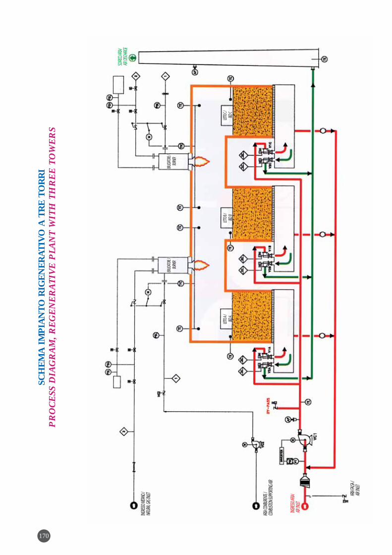
INGRES
SO ME
TANO/
NAT
URAL
GAS IN
LET
ARIA C
OMBU
RENTE
/ COM
BUSTI
ON-SU
PPORTI
NG AI
R
BRUCIA
TORE/
BU
RNER
LETTO
A /
BED A
LETTO
B /
BED B
LETTO
C /
BED C
BRUCIA
TORE/
BU
RNER
ARIA F
ALSA/
AIR
INLET
INGRES
SO ARI
A/
AIR IN
LET
SCARIC
O ARIA
/ AIR
DISCH
ARGE
SCH
EM
A I
MP
IAN
TO
RIG
EN
ER
AT
IVO
A T
RE
TO
RR
I P
RO
CE
SS D
IAG
RA
M, R
EG
EN
ER
AT
IVE
PLA
NT
WIT
H T
HR
EE
TO
WE
RS
170

171
Ventilazione Industriale s.r.l. ha fornito alla societàFornaci di Manzano s.p.a. un combustore termicorigenerativo ad inversione di flusso, per la depura-zione dei fumi di emissione provenienti dai forni dicottura dei laterizi. L’impianto permette la termodi-struzione delle SOV presenti, mantenendo la tem-peratura in camera di combustione uguale o supe-riore ai 750°C, e tempi di contatto superiori a unsecondo. Le sostanze organiche volatili nell’emis-sione sono riconducibili agli additivi aggiunti alleargille (polistirolo, fanghi di cartiere, ecc.), neces-sari per la produzione di laterizi alleggeriti in pasta,con una elevata capacità di isolamento acustico,ottimo isolamento termico e con una notevole iner-zia termica. L’elevata temperatura dei fumi di emis-sione dei forni di cottura può essere sfruttata perl’ottenimento di aria calda T = 70°C ~ utilizzata poinegli essiccatoi di produzione laterizi, senza deter-minare un sostanziale aumento di consumo dicombustibile per il mantenimento della temperatu-ra in camera di combustione.
I risultati processistici ottenuti riguardanti le emis-sioni in termini di:Portata nominale 40.000 Nm3/hTemperatura a camino 140°C
sono ampiamente al di sotto rispetto alle normativedi riferimento: COT < 1 mg/Nm3
Benzene < 1 mg/Nm3
NOx < 40 mg/Nm3
Le emissioni della produzione di laterizi con l’ausiliodi additivi, deve sottostare al recente D.M. del 5 feb-braio 1998.
Ventilazione Industriale s.r.l. has supplied Fornacidi Manzano s.p.a. with a regenerative type of incin-erator with reverse flow, for cleaning emission flowscoming from brick kilns. The combustion plantallows incineration of the VOC present, by holdingthe combustion chamber temperature equal to orhigher than 750°C, and contact times greater thanone second. The Volatile Organic Compounds inthe emission may be due to the additives added tothe clay (polystyrene, paper mill sludge, etc.),required for production of light-weight brick inpaste form, with high sound insulation capacity,optimum thermal insulation and considerable ther-mal inertia. The high temperature of the emissionfumes of the brick kilns can be exploited to obtainhot air T = 70°C ~ subsequently used in dryers inbrick production, without causing a substantialincrease in fuel consumption in order to hold thetemperature in the combustion chamber.
Process results regarding emissions in terms of: Nominal flow rate 40,000 Nm3/h Stack temperature 140°C are amply below those specified by the normativestandards:
Tot. organic C < 1 mg/Nm3 Benzene < 1 mg/Nm3 NOx < 40 mg/Nm3
The emissions of brick production with the aid ofadditives, must abide by a recent Italian MinisterialDecree 5th February 1998.
Impianto di combustione di tipo rigenerativo da 25.000 Nm3/h Regenerative incinerator plant, 25,000 Nm3/h

172
Impianto di combustione di tipo rigenerativo da 9.000 Nm3/h Regenerative incinerator 9,000 Nm3/h
Impianto di combustione di tipo rigenerativo da 30.000 Nm3/h Regenerative incinerator 30,000 Nm3/h
Impianto di combustione di tipo rigenerativo da 10.000 Nm3/h Regenerative incinerator 10,000 Nm3/h

5. APPLICAZIONI INDUSTRIALI TIPICHEI combustori rigenerativi trovano impiego in tuttele industrie ove vi siano dei processi con emissio-ne di aria con idrocarburi, impianti di stampa,accoppiamento film plastico, impianti chimici,ecc.
6. VANTAGGI E SVANTAGGIVantaggi: L’impianto di combustione rigenerativo rappresen-ta l’evoluzione più recente nel settore ecologico ditrattamento di effluenti gassosi tramite processo dicombustione, ideato per soddisfare la richiesta delmercato che è sempre più orientata verso impiantiaffidabili, di semplice conduzione e manutenzione,e con costi di gestione il più possibile contenuti(anche in confronto con altri tipi di impianto).
L’impianto di combustione rigenerativo si configurainoltre come una unità estremamente flessibile edindipendente, che si inserisce a valle del processo pro-duttivo senza comportare problematiche in quanto:
- è praticamente insensibile alla composizione delgas da trattare;
- non è soggetto a fenomeni di avvelenamentodovuti a sostanze particolari (composti clorurati,aerosols, metalli pesanti) o alla presenza di trac-ce di polveri per cui si interfaccia perfettamenteanche con i processi produttivi eterogenei evariabili nel corso del tempo;
- non genera ulteriori scarichi che richiedano trat-tamento o smaltimento;
- è affidabile nel tempo; - non richiede la presenza di una richiesta termi-
ca contemporanea dall’insediamento produttivodal momento che il recupero termico avvienecompletamente all’interno ed è completamenteassorbito da questo;
- Le potenze termiche dei bruciatori installati sonocontenuti per cui non si verificano in linea gene-rale particolari incrementi di portate di metanoche richiedano una ristrutturazione della rete didistribuzione di stabilimento;
- non è soggetto a fenomeni di corrosione inquanto le temperature operative impedisconofenomeni di condensazione sulle pareti.
Svantaggi: tale impianto non è molto indicato peralte concentrazioni di inquinante.
7. CALCOLI E TABELLEDi seguito verrà illustrato uno schema di calcolosemplificato per stimare il consumo di metano diun combustore rigenerativo, con e senza apportodi inquinante.Legenda:Q: portata aria da trattare (m3/h)M: flusso di massa inquinante (kg/h)Cc: PCI dell’inquinante da abbattere (kcal/kg)Hi: apporto di calore generato dalla combustio-
ne dell’inquinante (kcal/h)
5. TYPICAL INDUSTRIAL APPLICATIONSRegeneration incinerators (combustion units) findapplication in all those industries where there areprocesses with hydrocarbon-laden air, printingmachines, bonding of plastic film, chemical plants,etc.
6. ADVANTAGES AND DISADVANTAGESAdvantages: The regenerative combustion system represents themost recent development in the ecological sector oftreatment of gaseous effluents through a combus-tion process designed to meet market requirementsincreasingly more oriented towards reliable plantswhich are easy to run and maintain, with the low-est possible running costs (also in comparison withother types of systems).
Moreover the regenerative incinerator represents ahighly flexible and independent unit which can beinstalled downstream of the production processwithout causing problems because:
- it is practically insensitive to the composition ofthe gas to be handled;
- it is not subject to poisoning due to particularsubstances (chlorinated compounds, aerosols,heavy metals) or traces of dusts, hence it can beinterfaced perfectly with heterogeneous and vari-able processes which vary over time;
- it does not generate further waste requiring treat-ment or disposal;
- it is reliable over the long-term; - it does not require the presence of simultaneous
heat demand from the production facility thanksto the fact that the heat recovery takes place fullyinside the system and is fully absorbed by the lat-ter;
- the heating capacities of the installed burners aremoderate, therefore generally speaking there areno particular increases in flow rate of the natu-ral gas which would require restructuring thefactory distribution network;
- it is not subject to corrosion as the operatingtemperatures inhibit condensation on thewalls.
Disadvantages: such plant is not very suitable forhigh contaminant concentrations.
7. CALCULATIONS AND TABLESThe following is a description of a simplified calcu-lation scheme for estimating natural gas consum-ption with or without heat input by the contami-nant. Legend:Q: solvent-laden air flow (m3/h)M: flow of contaminating mass (kg/h)Cc: LCP of the contaminant to be captured
(kcal/kg)Hi: heat input generated by combustion of the
contaminant (kcal/h)
173

Cmz: consumo di metano senza apporto di inqui-nante (m3/h)
Cmi: consumo di metano con apporto di inqui-nante (m3/h)
Calcolo del consumo di metano senza apporto diinquinante:
Qx50x1,29x0,25Cmz = –––––––––––––––
8400
(50 è il ∆ t considerato tra ingresso e uscita di uncombustibile in °C, 1,29 è il peso specifico dell’ariain kg/m3, 0,25 è il calore specifico dell’aria inkcal/kg x °C, 8400 è il calore di combustione delmetano in kcal/m3)
Calcolo del calore apportato dalla combustionedegli inquinanti:
Hi=MxCc
Calcolo del consumo di metano con apporto diinquinante:
(Qx50x1,29x0,25) – HiCmi = ––––––––––––––––––––
8400
8. INFORMAZIONI SUI COSTIA seconda delle dimensioni dell’impianto e daeventuali esecuzioni speciali si può considerare unprezzo specifico di acquisto compreso tra 10 e 18€ /(m3/h) di aria trattata.
Cmz: natural gas consumption without heat inputfrom contaminant (m3/h)
Cmi: natural gas consumption with heat inputfrom contaminant (m3/h)
Calculation of natural gas consumption withoutheat input from contaminant:
Qx50x1,29x0,25Cmz = –––––––––––––––
8400
(50 is the ^ t considered between inlet and outlet ofa fuel °C, 1.29 is the specific gravity of air in kg/m3,0.25 is the specific heat of air in kcal/kg x °C, 8400is the heat of combustion of natural gas in kcal/m3)
Calculation of the heat input provided by combu-stion of the contaminants:
Hi=MxCc
Calculation of natural gas consumption with heatinput from contaminant:
(Qx50x1,29x0,25) – HiCmi = ––––––––––––––––––––
8400
8. INFORMATION REGARDING COSTDepending on the plant size and any special ver-sions, a specific price could be considered as lyingbetween 10 and 18 € /(m3/h) of air handled.
174
1000 300 1.1 1.8 6.50 1.93 2.98 1 30.000
2500 300 3 4.5 8.34 2.58 3.24 1 75.000
5000 300 5.5 9 9.85 3.32 3.50 1 150.000
7500 300 9 13.5 11.51 3.88 3.65 1 225.000
10000 325 15 18 11.51 4.04 3.88 1 300.000
15000 325 18.5 27 13.43 4.76 4.11 1 450.000
20000 325 22 36 14.62 5.38 4.31 1 600.000
25000 325 30 45 16.17 5.92 4.49 1 750.000
30000 350 37 54 16.50 6.20 4.71 1 900.000
35000 350 45 63 17.83 6.63 4.86 1 1.050.000
40000 350 55 72 18.59 7.03 5.00 1 1.200.000
VENTILATORE PRINCIPALE DIMENSIONI IMPIANTOMAIN FAN PLANT DIMENSIONS
I valori espressi sono puramente indicativi e possono variare in fun-zione della temperatura e natura del gas e delle disponibilità delcliente Impianti di portate superiori possono essere realizzati su richiesta
I consumi relativi al normale funzionamento a regime dipen-dono dalla concentrazione dei solventi trattati e dal loro pote-re calorifico. L’autosostentamento si raggiunge con circa 2gr/m3 di SOV con p.c.i. di 10.000 kcal/h.
* questi valori sono riferiti a celle ceramiche di grandezza tipica 1”
The values expressed are approximate only and may vary dependingon the temperature and nature of the gas as well as Customer’s avai-lability Plants with higher flow rates can be manufactured on request.
Consumption levels referred to normal operating conditionsdepend on the concentration of the solvents handled andtheir calorific power. Self-supporting can be reached withapprox. 2 gr/m3 of VOC with i.c.p. of 10,000 kcal/h.
* these valuer are refered at ceramic saddles 1” size
portata prevalenza potenza volume lunghezza larghezza altezza numero di potenzialità aria (mmCA) installata massa termica (m) (m) (m) bruciatori bruciatore
(m3/h) (Kw) rigenerativa (m3) *air flow head installed thermal regenerative length width height number of burner (m3/h) (mmWG) power mass volume (m) (m) (m) burners capacity
(Kw) (m3) *
N.B. Bear in mind that when reading the tables, the values are given with the European decimal notation; for English readers the comma should be taken as the decimal point.

IMPIANTI DI COMBUSTIONE TERMICARECUPERATIVI
1. TIPO DI TECNOLOGIAOssidazione termica
2. INQUINANTI ABBATTIBILITutti gli idrocarburi
3. LIMITI DI EMISSIONE RAGGIUNGIBILIE' possibile raggiungere rese di abbattimento supe-riori al 99%
4. DESCRIZIONE DELLA SOLUZIONE TECNICAIl processo di combustione non è altro che l’ossi-dazione degli atomi di carbonio (C-) e di idrogeno(H-) contenuti nelle molecole degli idrocarburi esolventi da bruciare, la cui reazione esotermica dàcome prodotti: anidride carbonica (CO2) e vaporeacqueo (H2O).Con riferimento allo schema di processo allegato,l'impianto è essenzialmente costituito da:- ventilatore centrifugo VC1- scambiatori a fascio tubiero He1- scambiatori a fascio tubiero He2- postcombustore PC1- bruciatore BR1- camino.I fumi aspirati attraversano dapprima il filtro a pan-nelli e tasche sostituibili, dove vengono trattenutele particelle solide trascinate di resina e tessuto.I fumi aspirati vengono eventualmente diluiti conaria ambiente aspirata dall'esterno in modo che laconcentrazione massima di solvente, misurata daun rivelvatore di L.E.L. %, sia costantemente nonsuperiore a un terzo del L.E.L. (Limite Inferiore diInfiammabilità) della miscela aspirata.
I fumi diluiti con aria, sono aspirati dal ventilatorecentrifugo VC1, che li spinge dapprima nel latomantello dello scambiatore He1 attraverso la valvo-la V2 e successivamente nel lato mantello delloscambiatore He2 e quindi nel postcombustore PC1.Attraversando il lato mantello dei due citati scam-biatori He1 e He2, i fumi si preriscaldano fino atemperature di 450 - 650°C a spese del calore cedu-to dai gas di combustione uscenti dal postcombu-store PC1 e che attraversano in successione il latotubi prima dello scambiatore He2 e poi dello scam-biatore He1.All'interno del postcombustore i fumi contenenti leS.O.V. da distruggere sono ulteriormente riscaldatifino alla temperatura minima di 770°C per mezzodell'energia liberata dalla combustione del metanonel bruciatore BR1 e dall'ossidazione termica dellestesse S.O.V. contenute nei fumi, fino alla forma-zione di anidride carbonica e acqua.
RECUPERATIVE THERMAL COMBUS-TION PLANTS
1. TYPE OF TECHNOLOGYThermal oxidation
2. CONTAMINANTS WHICH CAN BE REMOVEDAll hydrocarbons
3. POSSIBLE EMISSION LIMITSCollection efficiencies exceeding 99% can beachieved
4. DESCRIPTION OF THE TECHNICAL SOLUTION The combustion process merely involves oxidationof the carbon (C-) and hydrogen (H-) atoms con-tained in the molecules of hydrocarbons and sol-vents to be burnt, whose exothermic reaction givesrise to the following products: carbon dioxide(CO2) and steam (H2O).With reference to the attached process diagram, theplant basically consists of:- centrifugal fan VC1- tube-bundle heat exchanger He1- tube-bundle heat exchanger He2- postcombustor PC1- burner BR1- stack.The extracted fumes flow first through the panel filterand replaceable envelope filter media, where theentrained resin and fabric particles are captured.After extraction the fumes can be diluted, if neces-sary, with ambient air taken from outside so that themax. solvent concentration, measured by a LEL %detector is not constantly above one third of the L.E.L.(Lower Explosion Limit) of the extracted mixture.
The fumes diluted with air are extracted with cen-trifugal fan VC1, which forces them first in the shellside of heat exchanger He1 via valve V2 and thenin the shell side of heat exchanger He2. Next theyenter postcombustor PC1.While flowing through the shell side of the twoabove-mentioned heat exchangers He1 and He2,the fumes are preheated up to temperatures of 450- 650°C at the expense of the heat given up by thegases of combustion flowing out from postcombus-tor PC1; subsequently the gases of combustion flowthrough the tube side, first of heat exhanger He2,then of heat exchanger He1.Inside the postcombustor, the fumes containing theVOC to be destroyed are heated further up to a min.temperature of 770°C thanks to the energy freed bythe combustion of natural gas in burner BR1andby the thermal oxidation of the VOC contained inthe fumes, until the formation of carbon dioxideand water.
175

I gas di combustione prodotti, attraversando i duescambiatori He2 e He1 dal lato tubi, si raffreddanoe successivamente sono emessi in atmosfera allatemperatura minima di circa 350°C.L'impianto è gestito in maniera completamenteautomatica, sia nelle fasi di accensione / spegni-mento che durante il funzionamento a regime, tra-mite un controllore a logica programmabile (PLC),collegato alla strumentazione analogica e digitale, ea un sistema di supervisione su PC che permette dimonitorare e registrare in continuo su supportomagnetico le principali variabili di processo e glistati di funzionamento e di allarme.L'impianto è dotato di:- un sistema di diluizione dei fumi aspirati con
aria esterna tramite la valvola regolatrice auto-matica ACV1;
- un sistema di by-pass automatico del combusto-re in caso di anomalia tramite le valvole servo-comandate V2 e V3;
- un sistema di controllo del calore scambiato /recuperato nello scambiatore He1, al fine di con-trollare l'esubero di energia nei casi di maggioreconcentrazione di S.O.V. per mezzo della valvoladi by-pass V1 asservita al controllo della tempera-tura in uscita dalla camera di combustione TT2.
5. APPLICAZIONI INDUSTRIALI TIPICHEI combustori termici recuperativi trovano impiegoin tutte le industrie ove vi siano dei processi conemissioni di aria con idrocarburi con particolareriferimento alle emissioni con alte concentrazionidi inquinante.
6. VANTAGGI E SVANTAGGIVantaggi: semplicità di utilizzo, flessibilità rispetto avariazione di concentrazione di inquinante, possi-bilità di effettuare dei recuperi energetici supple-mentari, bassa richiesta di manutenzione.Svantaggi: elevati consumi nel caso di utilizzo del-l'impianto con basse concentrazioni di inquinante.
7. CALCOLI E TABELLEDi seguito viene riportato un esempio di calcoloper dimensionare il volume della camera di com-bustione, per semplicità si considera una camera dicombustione di forma cilindrica.
Elenco sigle:Q: portata dei fumi da trattare (Nm3/h)T: temperatura di combustione (°C), normalmen-
te, per idrocarburi non alogenati è di 750 °CV: velocità di attraversamento in camera di com-
bustione (da 5 a 7 Em/sec)Qe: portata effettiva dei fumi (Em3/h)S: sezione camera di combustione (m2)Vo: volume camera di combustione (m3)D: diametro camera di combustione (m)t: tempo di residenza in capera di combustione
(sec), normalmente è di 0,6 secL: lunghezza camera di combustione (m)
The gases of combustion produced when flowingthrough the two heat exchangers He2 and He1 onthe tube side, are cooled and are then emitted intothe atmosphere at the min. temperature of approx.350°C.The plant is controlled in fully automatic mode, inboth switching on/off stages as well as during nor-mal operation, thanks to a Programmable LogicController (PLC), connected to analog and digitalinstruments, and a supervisory system on a PCallowing continuous monitoring and recording onmagnetic support of the main process variables andoperating/alarm statuses.The plant is equipped with:- a system for diluting the extracted fumes with air
from outside via an automatic control valveACV1;
- a system for automatic by-pass of the combustorin case of faulty operation, via servocontrolledvalves V2 and V3;
- a system for controlling the heat exchanged /recovered in heat exchanger He1, in order tocontrol the surplus energy when there is greaterVOC concentration, thanks to by-pass valve V1used in the outlet temperature control from com-bustion chamber TT2.
5. TYPICAL INDUSTRIAL APPICATIONSRecuperative incinerators find application in allthose industries where there are processes with airemissions containing hydrocarbons, with specialemphasis on emissions with high contaminant con-centrations.
6. ADVANTAGES AND DISADVANTAGESAdvantages: easy operation, flexibility against vari-ation in contaminant concentration, possibility ofadditional energy recovery, low maintenancerequirement.Disdvantages: high levels of consumption when usingthe plant with low contaminant concentrations.
7. CALCULATIONS AND TABLESThe following is an example of calculation fordimensioning the combustion chamber volume. Forthe sake of simplicity, a cylindrically shaped com-bustion chamber has been considered.
List of symbols:Q: flow rate of fumes to be handed (Nm3/h)T: combustion temperature (°C), normally 750
°C for non halogenated hydrocarbonsV: face velocity in the combustion chamber (from
5 to 7 Em/sec)Qe: effective flow rate of fumes (Em3/h)S: section, combustion chamber (m2)Vo: volume, combustion chamber (m3)D: diameter, combustion chamber (m)t: residence time in combustion chamber (sec),
normally 0.6 secL: length, combustion chamber (m)
176

Partendo dalla portata dei fumi da abbattere (Q) siprosegue come segue:
calcolo della portata d'aria effettiva
Qe=((273+T)/273)xQ
calcolo del volume della camera di combustione
Vo=(Qe/3600)xt
calcolo della sezione della camera di combustione
S=Qe/3600/V
calcolo del diametro della camera di combustione
D=2x√(S/3,14)
calcolo lunghezza camera di combustione
L=Vo/S
8. INFORMAZIONI SUI COSTIPer calcolare il prezzo di un combustore termicosarebbe necessario sviluppare un progetto sullabase delle reali condizioni di impiego.Indicativamente si puo' dire che il prezzo di acqui-sto di un combustore puo' variare dai 12 a i 21 eper m3 di gas trattato.
Starting from the flow rate of fumes to be captured(Q) proceed as follows:
calculation of effective air flow rate
Qe=((273+T)/273)xQ
calculation of combustion chamber volume
Vo=(Qe/3600)xt
calculation of combustion chamber section
S=Qe/3600/V
calculation of combustion chamber diameter
D=2x√(S/3,14)
calculation of combustion chamber length
L=Vo/S
8. INFORMATION REGARDING COSTSTo calculate the price of a thermal combustor it isnecessary to work out a design on the basis of actu-al operating conditions.As a guide we could say that the purchasing pricefor a combustor can vary from 12 to 21 e per m3 ofgas handled.
177

178
SCH
EM
A I
NC
EN
ER
ITO
RE
RE
CU
PE
RA
TIV
O
PR
OC
ESS
D
IAG
RA
M, R
EG
EN
ER
AT
IVE
%L.
E.L.
BR1
PC1
HE1
HE2
CO
NTR
OLL
OFI
AM
MA
Z.C
.Z
.C.
Z.C
.
A.S.
TT 3
TT 7
TT 4
TT 1
TT 2
TT 6
PSL 5
VC
1M
TT 5
AT 1
PT 1
AP 1
BSL 1
BE 1M
SS S
PI 3
PSL 4
PSH 4
ARIA D
I DILU
IZIONE/
DIL
UITION
AIR
ARIA D
A DEPU
RARE /
AIR
TO DE
PURE
METAN
O /
NATUR
AL GA
S
CAMERA
DI CO
MBUST
IONE /
COM
BUSTI
ON CH
AMBER
ARIA D
EPURAT
A /
DEPUR
ED AIR
CONTRO
LLO FIAM
MA /
CONTRO
L FLAME

L’ABBATTIMENTO DELLE SOSTANZEORGANICHE VOLATILI MEDIANTE FILTRAZIONE, CONCENTRAZIONE ECOMBUSTIONE CON RECUPERO TERMICO DI TIPO RIGENERATIVO
1. TIPO DI TECNOLOGIAAdsorbimento su carbone attivo o zeoliti, seguito dadesorbimento con aria calda o ossidazione termica deldesorbato con recupero termico di tipo rigenerativo.
2. INQUINANTI ABBATTIBILISostanze organiche volatili di qualsiasi genere conpunto di ebollizione inferiore a 160 °C e campo diconcentrazione in ingresso tra 0 e 1000 mg/Nm3.
3. LIMITI DI EMISSIONE RAGGIUNGIBILIEfficienza di abbattimento complessiva compresa tra90 e 99%. Limiti di emissione inferiori a 20 mg/Nm3di C.O.T. (carbonio organico totale)
4. DESCRIZIONE DELLA SOLUZIONE TECNICAUn nuovo sistema di concentrazione e combu-stione con recupero termico rigenerativo Ventilazione Industriale ha messo a punto unimpianto completamente automatico costituito da unsistema di concentrazione delle emissioni medianteadsorbimento delle sostanze organiche volatili(S.O.V) su carbone attivo e successiva rigenerazionemediante riscaldamento e desorbimento con aria cal-da e combustione delle sostanze organiche desorbi-te in un combustore termico con recupero termico ditipo rigenerativo. Con riferimento allo schema allega-to, in questo sistema, l’aria inquinata dalle sostanzeorganiche viene dapprima filtrata in filtri per la rimo-zione delle particelle di solido eventualmente sospe-se, e successivamente attraversa con moto dal bassoverso l’alto delle unità filtranti in parallelo divise inpiù settori, attraversate in parallelo, riempiti con ilmateriale adsorbente. Attraversando tali settori lesostanze organiche vengono trattenute dal materialeadsorbente e l’aria viene emessa in atmosfera depu-rata ben al di sotto dei limiti di emissione impostidalle normative. Durante la fase di adsorbimento, talisettori sono rigenerati uno per volta con aria atmo-sferica riscaldata in un generatore diretto di aria cal-da funzionante con un bruciatore a metano (brucia-tore 2). L’aria così riscaldata attraversa il settore del-le unità di filtrazione interessato alla rigenerazione incontrocorrente rispetto al flusso di adsorbimento conmoto dall’alto verso il basso. L’aria calda attraversan-do lo strato di materiale adsorbente lo riscalda e faevaporare (desorbe) le sostanze organiche trattenuteall’interno dei pori. L’aria e le sostanze organiche cosìdesorbite con un flusso gassoso complessivo di circa10÷50 volte inferiore a quello in fase di adsorbimen-to vengono ossidate termicamente in un combustoretermico con recupero termico di tipo rigenerativo
REMOVAL OF VOLATILE ORGAN COMPOUNDS (VOC) THROUGH FILTRATION, CONCENTRATION ANDCOMBUSTION WITH REGENERATIVE HEAT RECOVERY
1. TYPE OF TECHNOLOGYAdsorption on activated carbon or zeolites, followedby desorption with hot air or thermal oxidation of thedesorbed substance with regenerative heat recovery.
2. CONTAMINANTS WHICH CAN BE REMOVEDVolatile organic compounds of any type with boilingpoint below 160 °C and inlet concentration rangebetween 0 and 1000 mg/Nm3.
3. EMISSION LIMITS POSSIBLEOverall collection efficiency lying between 90 e 99%.Emission limits lower than 20 mg/Nm3 of TOC (totalorganic carbon).
4. DESCRIPTION OF THE TECHNICAL SOLUTIONA new concentration and combustion systemwith regenerative heat recoveryVentilazione Industriale has developed a fully auto-matic plant based on a concentration system foremissions through adsorption of the VOC on acti-vated carbon and subsequent regeneration throughheating, and desorption with hot air and combus-tion of the organic substances in a incinerator withregenerative heat recovery. With reference to theenclosed diagram: in this system the VOC-laden airis first filtered in collectors for the removal of anysuspended solid particles, then it flows with motionfrom bottom towards top through filter unitsarranged in parallel, divided into various sectorsand packed with adsorbent material. On flowingthrough these sectors, the organic substances arecaptured by the adsorbent material and the air,cleaned well below the regulatory emission limits, isdischarged into the atmosphere. During the adsorp-tion phase, such sectors are regenerated one-at-time with the heated atmospheric air in a direct hotair generator with natural gas burner (burner 2).The so-heated air flows through the sector of filter-ing units concerned with regeneration on areversed flow basis (opposite to the adsorption flow,from top towards bottom). The hot air, on flowingthrough the bed of adsorbent material, heats it andcauses the organic substances captured inside thepores to evaporate (desorb). After desorbing the airand organic substanced with a gaseous flow about10 ÷50 times lower overall than that in the adsorp-tion phase, they are thermally oxidized in a ther-mal type incinerator with heat recovery type i.e.: inwhich the contaminating organic compounds areconverted, by effect of the temperature and oxida-tion reaction with the oxygen in the air, into car-
179

I.T.R., nel quale le sostanze organiche inquinanti pereffetto della temperatura e della reazione di ossida-zione con l’ossigeno dell’aria vengono convertite inanidride carbonica ed acqua con una efficienzasuperiore al 99%. Il processo consegue il risultatoimportantissimo di ridurre di circa 10÷50 volte (infunzione della concentrazione iniziale) il volume digas da bruciare termicamente, aumentando parimen-ti la concentrazione delle sostanze organiche in essocontenute; in questo modo l’ossidazione termica del-le S.O.V non richiede alcun tipo di combustibile ausi-liario, poiché il calore che si genera per l’ossidazio-ne senza fiamma delle sostanze organiche contenutenel gas desorbito è sufficiente a mantenere la tempe-ratura minima di combustione. Il bruciatore a meta-no (bruciatore 1) viene utilizzato solamente per l’av-viamento dell’impianto per il tempo strettamentenecessario a portare le masse ceramiche alla tempe-ratura di lavoro (da 15 a 30 minuti). Il riconcentrato-re su carbone attivo è una unità di trattamentocostruita in unità modulari di dimensioni molto com-patte, completamente premontate e pronte all’uso,complete di quadro di comando e controllo, con PLCe computer di supervisione per il monitoraggiocostante e continuo dei dati di funzionamento.
5. APPLICAZIONI INDUSTRIALI TIPICHETutti i processi industriali ove si presenti la necessitàdi abbattere SOV a basse concentrazione, come peresempio le verniciature e base solvente e le applica-zioni di resine (fabbricazione di manufatti in vetrore-sina) o di deodorizzare.
6. VANTAGGILo sviluppo di questo sistema innovativo di trattamentoha portato ai seguenti risultati: Efficienza globale di abbattimento maggiore del 95%. Riduzione della portata da trattare termicamente di unfattore fino a 50 volte rispetto alla portata di aria dadepurare. Notevole riduzione delle dimensioni complessive dell’im-pianto di trattamento e conseguente possibilità di fornitu-ra di impianti completamente preassemblati e testati pri-ma dell’installazione presso il cliente finale. Riduzione delcosto di trattamento al minimo possibile, praticamentesoltanto il costo dell’energia elettrica per i ventilatori e delmetano per il riscaldamento iniziale, e per il riscaldamen-to dell’area di strippaggio.Riduzione del costo di investimento complessivo dal 30al 60% rispetto alle tecnologie convenzionali conosciute.
7. SVANTAGGIIl sistema non è idoneo per le alte concentrazioni diS.O.V. (maggiori di 1000 mg/Nm3).
8. INFORMAZIONI SUI COSTIIl costo specifico di acquisto per applicazioni chenon richiedono accorgimenti costruttivi particolari ècompreso tra 5 e 10 e/(m3/h) di aria trattata. Il costodi esercizio deve essere calcolato di volta in volta,comunque molto basso.
bon dioxide and water, with efficiency over 99%.The process achieves the highly important result ofreducing by 30 to 40 times (depending on the ini-tial concentration) the volume of gas to be inciner-ated, likewise increasing the concentration of VOCcontained in the gas; in this way thermal oxidationof the VOCs does not require any type of auxiliaryfuel, because the heat that is generated by flamelessoxidation of the organic substances contained inthe desorbed gas is sufficient to hold the minimumcombustion temperature. The natural gas burner(burner 1) is only used to start-up the plant for thetime strictly necessary to bring the ceramic massesto the work temperature (from 15 to 30 minutes).The reconcentrator on activated carbon is a treat-ment unit of very compact size, fully preassembledand ready for use, complete with control panel, PLCand supervisory computer for constant and contin-uous monitoring of the operating data.
5. TYPICAL INDUSTRIAL APPLICATIONSAll industrial processes where there is need to removeVOC at low concentration, such as, for example, sol-vent-base painting and applications of resins (manu-facture of reinforced plastics) or deodorizing.
6. ADVANTAGESDevelopment of this innovative treatment systemhas led to the following results: Overall abatement efficiency greater than 95%. Reduction in the flow rate to be thermally treated bya factor up to 50 times of the dirty air flow rate. Considerable reduction in the overall dimensions ofthe treatment plant and consequent possibility ofsupplying fully preassembled and tested plantsbefore installation at the end customer’s premises.Treatment cost reduced to the minimum possible,practically just the cost of the electricity for power-ing the fan and the natural gas for initial preheat-ing and for heating the stripping area. Reduction in the overall investment cost from 30 to60% compared to already known conventionaltechnologies.
7. SVANTAGGIIl sistema non è idoneo per le alte concentrazioni diS.O.V. (maggiori di 1000 mg/Nm3).
8. INFORMATION REGARDING COSTSThe specific purchasing cost for applications notrequiring special design arrangements lies between 5and 10 ?/m3 of air handled. The running cost shouldbe calculated on a case-by-case basis; however it isvery low.
180

181
VC1
FL
TIC
PSLS
S
SPS
LPS
H
M
M1
PCV
PI
AP
VC2
M2
V1A
ACA-
AV2A
V1B
ACA-
BV2B
V1C
ACA-
CV2C
V1D
ACA-
DV2D
SS
M3
VC3
PSL
BGBEBS
L
TE
PSL
PSH
PI
PI
PI
TE
APTE TE
AP AP
AP
V2A
V1ATE
TETE
V2B
V1BTE
DPI
DPSH
ACA-
BAC
A-C
ACA-
A
INGRES
SO ME
TANO /
NAT
URAL
GAS IN
LET
ARIA C
OMPRE
SSA /
COM
PRESSE
D AIR
GENERA
TORE D
I ARIA
CALDA
/
HOT A
IR GEN
ERATOR
FILTRO
/ FILT
ER
INGRES
SO,GA
S /
GAS IN
LET GA
S
A VALV
OLE - A
SOLEN
OIDE /
WIT
H SOLE
NOID
VALVES
ARIA A
MBIEN
TE /
AMBIE
NT AIR
METAN
O /
NATUR
AL GA
S
BRUCIA
TORE 2
/ BU
RNER
BRUCIA
TORE 1
/ BU
RNER
ARIA A
MBIEN
TE /
AMBIE
NT AIR
CONTRO
LLO TE
NUTA
/ SEA
L INSPE
CTION
LETTO
A /
BED A
LET
TO B /
BED
B
SCARIC
O ARIA
/
AIR DI
SCHARG
E
SCH
EM
A D
I P
RO
CE
SSO
RIC
ON
CE
NT
RA
TO
RE
P
RO
CE
SS D
IAG
RA
M, R
EC
ON
CE
NT
RA
TO
R

182
IMPIANTI DI TRASPORTO PNEUMATICO
1. TIPO DI TECNOLOGIATrasporto pneumatico.
2. DESCRIZIONE DELLE APPARECCHIATUREE/O DEL PROCESSOGli impianti di trasporto pneumatico di nostra pro-duzione prevedono l’installazione delle seguentiapparecchiature:- gruppo di dosaggio del materiale da trasportare- soffiante per pompaggio aria- tubazione di trasporto- silos di destinazione materiale con filtro depol-
veratore sullo scarico
Gli impianti di trasporto pneumatico è preferibileche siano in mandata. La scelta dipende dal mate-riale da trasportare, dal percorso dell’impianto edall’ubicazione e numero dei punti di carico escarico.I parametri principali da osservare per la correttaprogettazione degli impianti di trasporto pneumati-co sono:
1) quantità di materiale da trasportare in kg./h.;2) peso specifico apparente del materiale da
trasportare;3) peso specifico assoluto del materiale da
trasportare;4) natura del materiale;5) composizione del materiale ed eventuale pez-
zatura massima;6) ubicazione dell’impianto e percorso delle
tubazioni;7) numero e ubicazioni dei punti di carico e scari-
co.
Per il trasporto pneumatico dei materiali, a secon-da della portata d’aria e della pressione totale richi-este, si possono installare: compressori volumetriciad aspi rotanti, ventilatori multistadio, ventilatorimonostadio ad alta pressione, pompe ad anello liq-uido.La separazione del materiale, dall’aria di trasporto,avviene per mezzo di cicloni di decantazioneseguiti da filtri statici a maniche autopulenti quan-do vi siano polveri leggere o si vogliano ottenereelevate efficienze di filtrazione.
Di recente questo tipo di impianto ha trovato appli-cazione come impianto centralizzato di puliziapneumatica di reparti o macchine di lavorazione.In questo modo si evita l’utilizzo di gruppi portatililimitando gli ingombri nel capannone con la possi-bilità di avere più punti di utilizzo contemporanea-mente.
PNEUMATIC CONVEYING SYSTEMS
1. TYPE OF TECHNOLOGYPneumatic conveying.
2. DESCRIPTION OF THE EQUIPMENTAND/OR PROCESSThe pneumatic conveying systems manufacturedby us involve installation of the following equip-ment:- unit for metering the material to be conveyed- blower for air pumping- conveyor ducting- material storage silos with dust collector on
discharge side
It is preferable for the pneumatic conveyor systemsto be on the delivery line. The choice depends on thematerial handed, route of the system as well as thelocation and number of loading/unloading points.Chief parameters to be observed for correct design-ing of pneumatic conveying systems are:
1) quantity of material to be conveyed in kg./h.;2) apparent specific gravity of the material to be
conveyed;3) absolute specific gravity of the material to be
conveyed;4) nature of the material;5) composition of the material and any max. par-
ticle size;6) location of the system and path of ductwork;7) number and location of the loading/unloading
points.
For pneumatic conveying of the materials, it is pos-sible to install (depending on the required air flowand total pressure): rotary-type positive displace-ment compressors, multi-stage fans, high-pressuresingle stage fans, liquid ring pumps.Separation of the material from the conveyor air isthrough settling cyclones followed by static self-cleaning bag filters where there are light dusts orwhen it is wished to achieve high collection efficien-cies.
Recently this type of system has found applicationas centralized pneumatic cleaning plant indepartments or on processing machines. Thisavoids use of portable units with consequent spacesaving in the factory buildings while it is possible tohave two or more user points at the same time.

183
3. APPLICAZIONI INDUSTRIALI TIPICHEI settori di attività nei quali abitualmente operia-mo con questi impianti sono:
Settore legno: trasporto pneumatico di polvere,trucioli, scarti e cortecce di legno per impianti diproduzione e per alimentazione di caldaie a com-bustibili solidi.
Settore distillerie: trasporto pneumatico di mate-riali per produzione di alcool da frutta, trasportopneumatico scarti di lavorazione e ceneri per ali-mentazione caldaie a combustibili solidi.
Settore Materie Plastiche: trasporto pneumatico digranuli di materie plastiche, di polveri e compo-nenti primari per produzione materie plastiche,impianti per l’alimentazione automatica di mac-chine ed impianti per la produzione e lavorazio-ne di materie plastiche.
Settore Agricolo-Zootecnico: trasporto pneumati-co di cereali, granaglie, mangimi, fertilizzanti ecc.
Ed inoltre: trasporto pneumatico di zucchero,sale, farina, chicchi di caffé, avena, segale, ecc.per l’industria alimentare; trasporto pneumaticodi polveri e granuli nel settore ceramiche; tra-sporto pneumatico di polveri di carbone, laterizi,cemento, sabbia, minerali ecc.Gruppi carrellati per il trasporto pneumaticocompleti di gruppo filtrante e compressore.
4. VANTAGGI E SVANTAGGI- dimensioni di ingombro irrilevanti rispetto ad
altri sistemi;- velocità elevatissima nel trasporto a parità di
portata di materiale;- bassissimi costi di manutenzione;- rapidità di installazione;- versatilità di impianto con la possibilità di
modifiche di percorso e reinstallazioni senzaapportare rilevanti modifiche;
- possibilità di servire più punti di utilizzo con lasola installazione di deviatori automatici e sen-za peraltro dover prevedere serbatoi di com-pensazione.
Svantaggi: nei sistemi in pressione usura della tuba-zione di trasporto.
3. TYPICAL INDUSTRIAL APPLICATIONSThe fields of activity where these systems are nor-mally used are the following:
Wood industry: pneumatic conveying of dusts,chips, waste and wood bark for production plantsand for feeding solid fuel-fired boilers.
Distillery industry: pneumatic conveying of mate-rials for production of alcohol from fruit, pneu-matic conveying of machining waste and ashesalso for feeding solid fuel-fired boilers.
Plastics industry: pneumatic conveying of gran-ules of plastic materials, powders and primarycomponents for plastics production, systems forautomatic feeding of machines and plants for theproduction and processing of plastics.
Agricultural-Animal husbandry sector: pneumat-ic conveying of cereals, grain, fodder, fertilizers,etc.
And also: pneumatic conveying of sugar, salt,floor, coffee beans, oats, rye, etc. for the foodindustry; pneumatic conveying of powders andgranules in the ceramics industry; pneumaticconveying of coal dusts, bricks, cement, sand,minerals, etc.Portable wheeled units for the pneumatic convey-or complete with filter and compressor.
4. ADVANTAGES AND DISADVANTAGES- overall dimensions negligible compared to
other systems;- much higher conveying speed to the same load
of material;- very low maintenance costs;- quick installation;- versatility in the plant with possibility of modi-
fying the path and re-installation withouthaving to made major changes;
- possible to have two or more user points just byinstalling automatic deviators and alsowithout having to provide compensation airreceivers.
Disadvantages: in pressure systems: wear of theconveying duct.

184
SCH
EM
A D
I P
RO
CE
SSO
P
RO
CE
SS D
IAG
RA
M
INGRES
SO ARI
A COM
PRESSA
/COM
PRESSE
D AIR
INLET
INGRES
SO MA
TERIAL
E GRAN
ULARE
/GR
ANULA
R MATE
RIAL IN
LET
INGRES
SO ARI
A DI TR
ASPOR
TO/CON
VEYING
AIR I
NLET
SCARIC
O ARIA
/AIR
DISCH
ARGE
SILOS
DI STI
VAGGIO
/STO
RAGE S
ILOS
ROMP
I PONTE
/BRI
DGE B
REAKER
FILTRO
A MA
NICHE
/BAG
FILTER
SCARIC
O MATE
RIALE
/ MATE
RIAL D
ISCHA
RGE

185
VELOCITA’ DELL’ARIA NECESSARIA PERIL TRASPORTO PNEUMATICO DI ALCUNIMATERIALI
CONCENTRAZIONE: ~ 1 KG DI MATERIALE X 2m3 DI ARIA
MATERIALE VELOCITA' ARIA (in mt./sec)
CENERI, SCORIE, TERRE 25÷40
ORZO 30÷40
CEMENTO 30÷45
CARBONE IN POLVERE 25÷35
CHICCHI DI CAFFE' MONDATI 25÷30
CHICCHI DI CAFFE' NON MONDATI 25÷30
SUGHERO 22÷30
CHICCHI DI CEREALI 25÷35
COTONE 20÷25
SEMI DI COTONE 25÷30
FARINA 22÷30
CANAPA 22÷30
IUTA 22÷30
CALCE 25÷35
AMIANTO 25
ARGILLA IN POLVERE 25
GESSO 27
TRUCIOLI METALLICI 25÷35
AVENA 25÷30
TRUCIOLI E SCAGLIE DI LEGNO 25÷35
STRACCI IN PEZZETTI 25÷35
SEGALE 25÷35
SALE 30÷35
SABBIA 30÷40
SEGATURA 20÷30
ZUCCHERO 25÷30
CORTECCE SECCHE (in scaglie) 25÷35
CORTECCE UMIDE 30÷37,5
GRANO 25÷35
FARINA DI LEGNO 20÷30
LANA 25÷30
PAGLIA TRINCIATA 25
SANSE DI OLIVE 30
TALCO 25
AIR VELOCITY REQUIRED FOR PNEUMATIC CONVEYING OF CERTAIN MATERIALS
CONCENTRATION: ~ 1 KG OF MATERIAL X 2m3 OF AIR
MATERIAL AIR VELOCITY (in mt./sec)
ASH, SLAG, EARTH 25÷40
BARLEY 30÷40
CEMENT 30÷45
COAL DUST 25÷35
COFFEE BEANS SHELLED 25÷30
COFFEE BEANS UNSHELLED 25÷30
CORK 22÷30
CEREAL GRAINS 25÷35
COTTON 20÷25
COTTON SEEDS 25÷30
FLOUR 22÷30
HEMP 22÷30
JUTE 22÷30
LIME 25÷35
ASBESTOS 25
CLAY POWDER 25
GYPSUM 27
METAL CHIPS 25÷35
OAT 25÷30
WOOD CHIPS AND FLAKES 25÷35
PIECES OF RAG 25÷35
RYE 25÷35
SALT 30÷35
SAND 30÷40
SAWDUST 20÷30
SUGAR 25÷30
DRY BARK (in flakes) 25÷35
MOIST BARK 30÷37,5
GRAIN 25÷35
WOOD FLOUR 20÷30
WOOL 25÷30
CUT STRAW 25
OLIVE RESIDUES 30
TALC 25

186
5. CALCOLI E TABELLE
Dati
Materiale: saleQuantità da trasportare: 1000 kg/h = 0,27 kg/sec Percorso tubazione orizzontale: 150 mtPercorso tubazione verticale: 20 mtN. curve: 3 a 90° con raggio = 4 x Ø tubaz. (0,6 mt)Angolo di ingresso materiale in tubazione: 35° (tan 35° = 0,7)
Velocità di trasporto
Dalla tabella a pag. 185 ricaviamo una velocitàmedia di 32 mt/sec
Calcolo della resistenza dovuta al materiale
1) Calcolo della resistenza di accelerazione:
AL = MV2/2g
dove M = quantità di materiale in kg/secV = velocità di trasporto in mt/secG = accelerazione di gravità in mt/sec2
0,27 x 322
e pertanto –––––––––– = 14 mm H2O2x9,81
Calcolo della resistenza nel tratto verticale
LE = M x dv
dove M = quantità di materiale in kg/secdv = lunghezza del tratto verticale in mt
e pertanto 0,27 x 20 = 5,4 mm H2O
Calcolo della resistenza nel tratto orizzontale
HL = M x dh x f
dove M = quantità di materiale in kg/secdh = lunghezza del tratto orizzontalef = tangente dell’angolo di ingresso del
materiale in tubazione
e pertanto 0,27 x 150 = 28,5 mm H2O
5. CALCULATIONS AND TABLES
Data
Material: saltQuantity to be handled: 1000 kg/h = 0.27 kg/sec Length of horizontal ducting: 150 mtLength of vertical ducting: 20 mtN. of elbows: three 90° elbows with radius = 4 x duct dia. (0.6 m)Entry angle of material in duct: 35° (tan 35° = 0.7)
Conveying velocity
From the table on page 185 we can deduce an aver-age velocity of 32 m/sec
Calculation of total resistance due to thematerial
1) Calculation of acceleration resistance:
AL = MV2/2g
where M = quantity of material in kg/secV = conveying velocity in m/secG = acceleration of gravity in m/sec2
0,27 x 322
and hence –––––––––– = 14 mm H2O2x9,81
Calculation of resistance in the vertical sec-tion
LE = M x dv
where M = quantity of material in kg/secdv = length of vertical section in m
hence 0.27 x 20 = 5.4 mm H2O
Calculation of resistance in the horizontalsection
HL = M x dh x f
where M = quantity of material in kg/secdh = length of horizontal section f = tangent of the material entry angle in
the duct
hence 0.27 x 150 = 28.5 mm H2O

187
Calcolo della resistenza dovuta alle curve
M x V2 x d x fEL = N. curve x –––––––––––––
g x R
dove M = quantità di materiale in kg/secV = velocità di trasporto in mt/secd = sviluppo della curva = 1/4 della circon-
ferenza totale data dal raggiof = tangente dell’angolo di ingresso del
materiale in tubazione g = accelerazione di gravità in mt/sec2
R = raggio della curva in mt
0,27x322x0,94x0,7e pertanto 3 x ––––––––––––––––– = 92,7 mm H2O
9,81 x 0,6
Calcolo della resistenza totale dovuta al mate-riale
TML = AL + LE + HL+ EL e pertanto14 + 5,4 + 28,5 + 92,7 = 140,6 mm H2O
Calcolo del volume d’aria necessario per il tra-sporto
Per una concentrazione di 0,5 kg ogni m3 aria Materiale 1000 kgPortata aria = kg materiale x 2 m3 = 2000 m3/hVelocità nelle tubazioni = 32 mt/sec
Calcolo del diametro della tubazione
Portata m3/h = 2000Portata m3/sec = m3/h :
3600 = 2000 : 3600 = 0,56 m3/secSezione tubazione = portata: velocità0,56 : 32 = 0,0175 m2 sezione tubazione = Ø 0,15mt che trasformiamo in mm = 150
Calculation of resistance due to the elbows
M x V2 x d x fEL = N. of elbows x –––––––––––––
g x R
where M = quantity of material in kg/secV = conveying velocity in m/secd = length of the elbow = 1/4 of the total cir-
cumference given by the radius f = tangent of the material entry angle in
the duct g = acceleration of gravity in m/sec2
R = radius of the elbow in m
0.27x322x0.94x0.7hence 3 x –––––––––––––––––– = 92.7 mm H2O
9.81 x 0.6
Calculation of total resistamce due to thematerial
TML = AL + LE + HL+ EL hence 14 + 5.4 + 28.5 + 92.7 = 140.6 mm H2O
Calculation of volume of air required for con-veying
For a concentration of 0.5 kg every m3 of air Material 1000 kgAir flow = kg material x 2 m3 = 2000 m3/hVelocity in the ducts = 32 m/sec
Calculation of the duct diameter
Flow rate m3/h = 2000Flow rate m3/sec = m3/h :
3600 = 2000 : 3600 = 0.56 m3/secDuct section = flow rate: velocity0.56 : 32 = 0.0175 m2 duct section = dia Ø 0.15 mdia. which we transform into mm = 150

188
Calcolo delle resistenze dovute al movimentodell’aria
Tubazione lineare:(Vedi tab. perdite di carico: V = 32 mt/sec)
Ø 150 mt = 170 x 9 mm 1530
1,22 x V2 dinamica = ––––––––– mm 64
19,62
curve = 3 x 0,2 x dinamica = 3 x 0,2 x 64 mm 38,5
ingresso = 1/2 dinamica mm 32
filtro o ciclone mm 100–––––––––––mm 1764,5
Resistenze dovute al movimento dell’aria = 1764mm H2O
Calcolo totale delle resistenze
Resistenze dovute al materiale + resistenze dovuteall’aria:
140,6 + 1764,5 = 1905,1 mm H2O (resistenza totale)
Pertanto l’aspiratore dovrà avere queste caratteristi-che:portata 2000 m3/h prevalenza 1950 mm H2O
Presumendo un rendimento del 60% possiamo cal-colare la potenza necessaria
portata x prevalenza 3.900.000CV ass. = ––––––––––––– = ––––––– = 24,0 CV ass.
3600 x rendimento x 75 162.000
Aggiungiamo il 10% per la trasmissione
e avremo:
24,0 + 2,40 = 26,4 CV assorbiti
Equivalenti ad un motore da 30 CV
6. INFORMAZIONI SUI COSTII trasporti pneumatici si dimensionano in base allaportata di materiale da trasportare, in base allaestensione del percorso e in base alle caratteristi-che del percorso. Non è possibile impostare unaregola per ricavare il prezzo.
Calculation of resistance due to air movement
Linear duct:(See Pressure drop table: V = 32 m/sec)
Ø 150 mt = 170 x 9 mm 1530
1.22 x V2 dinamica = ––––––––– mm 64
19.62
elbows = 3 x 0.2 x dynamic = 3 x 0.2 x 64 mm 38.5
inlet = 1/2 dynamic mm 32
filter or cyclone mm 100–––––––––––mm 1764.5
Resistances due to air movement = 1764 mm H2O
Total calculation of the resistances
Resistances due to the material + resistances due tothe air:
140.6 + 1764.5 = 1905.1 mm H2O (total resistance)
Hence the exhauster unit should have the followingcharacteristics:flow rate 2000 m3/h head 1950 mm H2O
Assuming an efficiency of 60% we can calculate thepower required
flow rate x head 3,900,000HP cons. = –––––––––––––= ––––––– = 24.0 CV ass.
3600 x efficiency x 75 162,000
Adding 10% for the transmission
we shall have:
24.0 + 2.40 = 26.4 HP consumed
Equivalent to a 30 HP motor
6. INFORMATION REGARDING COSTThe pneumatic conveyors are dimensioned on thebasis of the flow rate of the material to be handledas well as the length and characteristics of the rou-te. It is not possible to establish a rule for obtainingthe price.

TERMODISTRUZIONE DI RIFIUTI SOLIDI
La termodistruzione costituisce un’efficace soluzio-ne impiantistica per incenerire i rifiuti solidi; in più,i fumi di post-combustione, grazie allo sfruttamen-to del contenuto entalpico posseduto, rappresenta-no un’importante risorsa energetica. Dal processodi incenerimento vengono prodotti fumi contenen-ti particolato, incombusti organici, ossidi di variogenere (di zolfo e di azoto), composti organici aro-matici policondensati, composti organici clorurati eacidi organici. Pertanto si rende necessario l’utilizzoa valle della camera di incenerimento di soluzioniimpiantistiche in grado di trattare e abbattere lesostanze inquinanti contenute nei fumi di primoincenerimento. In tale contesto, di particolare inte-resse risulta la proposta tecnologica di VentilazioneIndustriale, descritta — di seguito — nelle sue lineeessenziali.
Il processo
Come indicato sullo schema riportato nella Fig. 1, irifiuti — pericolosi e non — vengono termodistruttinel forno inceneritore; i fumi raggiungono la com-pleta ossidazione nel post-combustore, alla tempera-tura media di 850 °C. I fumi in uscita dal post-com-bustore attraversano in serie il lato tubi di due scam-biatori a fascio tubiero; un sistema di quench di tipoVenturi scrubber, di nuovo il lato mantello delsecondo scambiatore a fascio tubiero, ed infine unfiltro a maniche prima dell’emissione in atmosferaattraverso un camino di altezza opportuna. Nel pri-mo scambiatore i fumi cedono parte del loro conte-nuto termico all’aria comburente, per ridurre l’ap-porto di combustibile ausiliario alla camera di post-combustione; nel secondo scambiatore cedono unaulteriore quota del loro contenuto termico ai fumistessi uscenti dal sistema di quench in modo daimpedire la condensazione di vapori corrosivi all’in-terno del successivo filtro a maniche. Nello scrubberdi tipo Venturi i fumi vengono raffreddati fino allatemperatura di saturazione adiabatica (45 ÷ 60°C) esuccessivamente lavati con soluzione di soda inmodo da abbattere le polveri grossolane ed i fumiacidi; successivamente all’uscita dallo scrubber ifumi vengono post riscaldati fino alla temperatura dicirca 160 °C nel lato mantello del secondo scambia-tore ed entrano nel filtro a maniche, dove vengonoabbattute le particelle di polvere più fini.
Le apparecchiature in gioco
Forno di incenerimento
Il materiale da incenerire viene introdotto in unforno innovativo — di tipo statico — tramite unapposito sistema di caricamento automatico, con
SOLID WASTE INCINERATORS
Thermal incineration offers an efficient plant engi-neering solution for incinerating solid waste; more-over, the post-combustion fumes, thanks to exploita-tion of the enthalpy content possessed, represent animportant energy resource. The incinerationprocess produces fumes containing particulate,unburnt substances, oxides of various kind (sul-phur and nitrogen oxides), polycondensed aromat-ic organic compounds, chlorinated organic com-pounds and organic acids. Hence downstream ofthe incineration chamber it is necessary to adoptplant engineering solution designed to capture andremove the contaminating substances contained inthe fumes of the first incineration phase. In thisconnection, particularly interesting is the techno-logical proposal of Ventilazione Industriale,described below in its essential lines.
The process
As shown in the diagram given in Fig. 1, the waste— whether hazardous or not — is incinerated inthe incinerator furnace; the fumes are fully oxi-dized in the post-combustion unit, at the averagetemperature of 850 °C. The outlet fumes from thepost-combustion unit flows, in series, along the tubeside of two tube bundle heat exchangers; a quenchsystem of the Venturi scrubber type, again along thetube side of the second tube bundle heat exchanger,and lastly through a bag filter prior to emission inthe atmosphere through a stack of suitable height.In the first heat exchanger, the fumes give up part oftheir heat content to the combustion-supporting airthereby reducing the quantity of auxiliary fuel inthe post-combustion chamber; in the second heatexchanger the fumes give up another part of theirheat content to the fumes leaving the quench systemso as to prevent condensation of corrosive vapoursinside the subseqent bag filter. In the Venturi scrub-ber, the fumes are cooled to the adiabatic satura-tion temperature (45 to 60°C) and subsequentlyscrubbed with sodium hydroxide solution in orderto remove the coarse dusts and acidic fumes; thenthe exit fumes from the scrubber are post-heated ata temperature of about 160 °C in the shell side ofthe second heat exchanger and enter the bag filterwhere the finer dust particles are removed.
Equipment involved
Incineration furnace
The material to be incinerated is charged in aninnovative furnace — of static type — via a specialautomatic loading system, with drives operated byhydraulic cylinders (Fig. 2). The waste material
189

190
azionamenti guidati da pistoni idraulici (Fig. 2). Irifiuti immessi nella camera di combustione (Fig. 2)raggiungono la temperatura di autocombustionegrazie a uno specifico bruciatore di supporto adaria comburente, di tipo modulante proporzionale.Il forno potrà essere corredato di un’opportuna gri-glia in ghisa di qualità elevata, al di sopra dellaquale sarà alloggiato il bruciatore di supporto ener-getico. Sul lato frontale del forno è installato il por-tellone di ispezione della camera di combustione,mentre nella parte inferiore è previsto uno sportel-lo ad apertura automatica per lo scarico delle cene-ri. Sul lato frontale opposto è sistemato il portelload apertura automatica per il caricamento del for-no. Il bruciatore posto lateralmente lambisce con lapropria fiamma i rifiuti sistemati all’interno dellacamera di incenerimento. Lo spessore del refratta-rio, tale da resistere fino a 1.400 °C, assicura l’inte-grità della struttura costituente il forno.
Camera di post-combustione
Tale camera ha lo scopo di ossidare gli incombustiorganici ed il monossido di carbonio, contenuti neifumi provenienti dal forno e viene alimentata coningresso radiale in modo da garantire la turbolenzafluidodinamica necessaria per completare l’ossida-zione dei composti organici suddetti. In casi parti-colari è prevista la possibilità di utilizzare ossigenopuro come comburente al posto dell’aria, per otti-mizzare il processo di post-combustione. La tempe-ratura media di esercizio è pari a 850 °C, mantenu-ta mediante l’apporto di energia di un bruciatoreausiliario funzionante a metano e il processo vienecontrollato sia dal punto di vista termico/energeti-co che massico. Il tempo di permanenza minimo èdi 2 s e la temperatura media di esercizio può esse-re superiore a quella precedentemente indicata, aseconda della composizione chimica del rifiuto e diconseguenza dei relativi fumi di combustione.
Unità di recupero energetico
Utilizzando i fumi di post-combustione è possibilepre-riscaldare l’aria comburente per il bruciatoredella camera stessa, surriscaldare i fumi provenien-ti dal Venturi scrubber e, in casi specifici, ottenereulteriori recuperi energetici. A tal fine si è pensatodi ricorrere a unità di recupero, costituite da scam-biatori a fascio tubiero, interamente realizzati inacciaio inox per alte temperature e la cui superfi-cie esterna è isolata termicamente. La progettazio-ne di tali apparecchiature, specifica per ogni appli-cazione, contempla il dimensionamento deiseguenti parametri: diametro, lunghezza, spessoree disposizione dei tubi di scambio energetico.
Venturi scrubber
I fumi provenienti dalle unità di recupero energeti-co subiscono un quench controllato sia termica-mente che chimicamente (di fondamentale impor-
loaded in the combustion chamber (Fig. 2) reachesthe self-combustion temperature thanks to a specif-ic support burner with combustion-supporting air,of proportional modulating type. The furnace canbe provided with a suitable grid made of qualitycast iron, above which the energy support burnerwill be seated. The inspection door of the combus-tion chamber is installed at the front of the furnace,while at the bottom there is a door with automaticopening for unloading the ashes. On the oppositefront there is the furnace charging door with auto-matic opening. The burner, placed sideways, lickswith its flame the waste material arranged insidethe incineration chamber. Thickness of the refracto-ry lining is such as to withstand temperatures up to1400 °C, thus ensuring the intactness of the fur-nace structure.
Post-combustion chamber
Purpose of the post-combustion chamber is to oxi-dize the unburnt organics and carbon monoxidecontained in the fumes exiting from the furnace. Itis fed via a radial inlet in order to ensure the flui-dynamic turbulence required to complete oxidationof the above-mentioned organic compounds. Inparticular cases there is provision for using pureoxygen as combustion-supporting medium insteadof air so as to optimize the post-combustion process.The average operating temperature is equal to 850°C, and is held by the energy supplied from an aux-iliary, natural gas-fired burner. The process is con-trolled in both thermal/energy terms as well asregards mass. Minimum residence time is 2 s. Theaverage operating time can exceed the one givenpreviously, depending on the chemical compositionof the waste material, and therefore that of the rel-ative fumes of combustion.
Energy recovery unit
By using the post-combustion fumes it is possible topreheat the combustion-supporting air for the burn-er of the combustion chamber, overheat the fumescoming from the Venturi scrubber and, in specialcases, to obtain further energy recovery. For suchpurpose, use is made of a recovery unit consisting ofa tube bundle heat exchanger, of all-stainless steelconstruction for high temperatures, with thermallyinsulating outer surface. Designing of such equip-ment (specific for each application), involvesdimensioning of the following parameters: diame-ter, length, wall thickness and arrangement of theenergy exchange tubes.
Venturi scrubber
The fumes coming from the energy recovery unitare quenched both thermally and chemically (ofvital importance in order to allow absorption in theaqueous phase of all the water-soluble acidic inor-ganic substances derived from the thermal destruc-

tanza per poter assorbire nella fase acquosa tutte lesostanze inorganiche acide idrosolubili derivantidal processo di termodistruzio-ne/postcombustio-ne) in uno scrubber multi-Venturi. Come è noto,questo tipo di scrubber, permette inoltre di tratte-nere in fase acquosa anche eventuali polveri didimensioni “medio-grandi”, presenti nei fumi chelo attraversano. I suddetti impianti sono di tipomodulare e ognuno di essi ha la possibilità di pro-cessare 2.500 Em3 /h. Tale accorgimento assicurauna maggiore turbolenza specifica ed un migliorcontatto tra le fasi, fornendo risultati superioririspetto al singolo cono Venturi.
Filtro a maniche autopulente
Questa unità è adibita alla filtrazione del restanteparticolato presente nei fumi provenienti dal Venturiscrubber. L’apparecchiatura consiste in un depolve-ratore adatto per il funzionamento continuo, conpulizia in automatico del tessuto filtrante. Gli ele-menti filtranti sono costituiti da cestelli portanti ade-guate maniche, le cui caratteristiche sono in questocaso dettate principalmente dalla temperatura diesercizio (> 160 °C). Il ciclo di pulizia delle manicheè variabile in funzione delle reali necessità dell’im-pianto e permette sia la variazione del tempo chedella frequenza di lavaggio. Inoltre, è possibile pro-gettare ogni filtro per le specifiche esigenze, utiliz-zando appieno le peculiarità dell’apparecchiatura.
Considerazioni conclusive
Il processo avviene totalmente in depressione e,tramite specifici trasmettitori di pressione relativa,si controllano in continuo i valori di depressionepresenti nel forno e nella camera di post-combu-stione. L’applicazione proposta rappresenta, inmodo indiretto, un controllo massico del processo,di fondamentale importanza per il corretto svolgi-mento dello stesso. Tutte le apparecchiature sono corredate di loop dicontrollo per il completo funzionamento automati-co del processo di termodistruzione rifiuti e tratta-mento fumi di incenerimento. L’intera logica digestione impianto fa riferimento a un unico quadroelettrico centrale, dotato di PLC. Dal fronte quadroè possibile gestire l’impianto e controllare i valoridi processo fondamentali (v. Tabella). Sono stati omessi i controlli delle rampe GN perbruciatori e delle rampe O2 per l’arricchimento incamera di combustione con apposita lancia, non-ché i controlli delle emissioni. L’impianto deveessere dotato dei controlli continui alle emissionispecificati nel D.M.A. 19 novembre 1997, n° 503per i rifiuti urbani e quelli speciali non pericolosi enel D.M.A. 25 febbraio 2000, n°124 per i rifiuti spe-ciali pericolosi. Complessivamente l’impianto simostra decisamente flessibile e di agevole taratura,caratteristica necessaria per poter applicare la ter-modistruzione alle diverse tipologie dei rifiuti soli-di da incenerire.
tion/post-combustion process) in a multi-Venturiscrubber. As is well known, this type of scrubber,besides capturing in aqueous phase, can also cap-ture any dusts of the “medium-large” size, con-tained in the fumes flowing through it. The aboveplants are modular in type and each one isdesigned to process 2500 Em3 /h. Such measureensures greater specific turbulence and improvedcontact between the phases, thus supplying betterresults compared to the single Venturi scrubber.
Self-cleaning filter bag
This unit serves for filtration of the remaining par-ticulate present in the fumes coming from theVenturi scrubber. The equipment consists of a dustcollector, designed for continuous duty, with auto-matic cleaning of the filter fabric. The filter ele-ments consist of cages carrying suitable bags whosecharacteristics are dictated in this case mainly bythe operating temperature (> 160 °C). The bagcleaning cycle is variable depending on actualneeds of the plant; it allows variation both in timeand in cleaning frequency. It is also possible todesign each filter for the specific requirements bymaking full use of the duct collector’s special char-acteristics.
Concluding remarks
The process takes place fully under negative pres-sure while, thanks to specific transmitters of relativepressure, the negative pressures levels in the fur-nace and post-combustion chamber are continu-ously monitored. The application proposed repre-sents, indirectly, a mass control of the process, ofvital importance for correct running of the actualprocess. All units are provided with control loop for fullyautomatic operation of the waste incinerationprocess and clean-up of the incineration fumes.The entire plant control logic is based on a singlecentral control panel, provided with PLC. From thefront of the control panel it is possible to control theplant and monitor the basic process values (seeTable). The system does not include controls for the NGramps for burners and O2 ramps for enrichment inthe combustion chamber with special nozzle, nordoes it include controls of the emissions. The plantshould be provided with continuous monitoring ofthe emissions as specified in Italian EnvironmentalMinisterial Decree 19th November 1997, n° 503 forurban waste and special non-hazardous wastes,and in accordance with Environmental MinisterialDecree 25th February 2000, n°124 for hazardousspecial waste. Overall the plant proves to be decid-edly flexible and easy to set, such characteristicbeing necessary so that the thermal incinerationtechnique can be applied to the various types of sol-id waste to be incinerated.
191

192
S
S
S
S
S
S
S
S
S
S
S
S
S
S
S
GNF
OGN
2
PSL
PI
M
M
PSH
PIPI
PT TE PI
BG BHE
TE
PTPI
TE
MPSL
FE
MPI
MTE
TEM
M
AP
MM
TEPS
L
M
LSH LSL TE
NaOH
(30%
) /
NaOH
(30%
)
ACQUA
DI RE
TE /
PROCES
S WATE
R
SCRUB
BER VE
NTURI
/ VEN
TURI SC
RUBBE
R
SCARIC
O ARIA
/ AIR
DISCH
ARGE
CAMINO
/ STA
CK
VENTIL
ATORE
DI PRO
CESSO
/ PRO
CESS F
AN
POMP
E DI PR
OCESSO
/ PRO
CESS P
UMPS
VENTIL
ATORE
ARIA C
OMBU
RENTE
/FAN
, COM-B
USTION
SUPPO
RTING
AIR
SCAMB
IATOR
I ARIA
-ARIA
/AIR
-AIR H
EAT EX
CHANG
ERSPO
STCOM
BUSTO
RE /
POST-
COMBU
STOR VEN
TILATO
RE / F
AN
INGRES
SO MA
TERIAL
E SOLI
DO /
SOLID
MATER
IAL IN
LET
FORNO
INCEN
ERITOR
E /INC
INERAT
OR FU
RNACE
ARIA A
MBIEN
TE /
AMBIE
NT AIR
FILTRO
A MA
NICHE
/BAG
FILTER
ALLA S
EZION
E DEPU
RAZION
E ACQ
UE /
TO WA
TER TR
EATME
NT SEC
TION
SPURG
O / VE
NT
POMP
A DOSA
TRICE
/ PU
MP
SCH
EM
A I
MP
IAN
TO
DI
TE
RM
OD
IST
RU
ZIO
NE
RIF
IUT
I SO
LID
I P
RO
CE
SS D
IAG
RA
M, S
OLID
WA
STE
IN
CIN
ER
AT
OR

V
V
A
B
C
H
G
Sigla Caratteristiche FP12 FP24 FP40 FP55 FP75 FP90Sigla Characteristics
V Volume interno utile m3 1.24 2.39 4.02 5.49 7.47 9.08
A Lunghezza interna mm 1100 1800 2000 2250 2500 2750
B Larghezza esterna max mm 1550 1650 2000 2250 2400 2550
C Lunghezza esterna max mm 1280 2050 2350 2650 2900 3150
G Lunghezza totale max mm 1880 2650 2950 3250 3500 3750
H Altezza esterna max mm 1750 1850 2100 2350 2500 2750
P Peso indicativo Kg 3700 5800 8600 11700 13800 16650
Tmax Temp. max sopportabile °C 1400 1400 1400 1400 1400 1400
Pb Potenzialità bruciatore Kcal/h 30000 40000 50000 60000 60000 70000
Q Portata ventilatore estraz. Nm3/h 1500 1500 2500 3500 3500 4000
Pt Potenzialità termica Kcal/h 400000 750000 1100000 1500000 1850000 2250000
MODELLI FORNI / FURNACE MODELS
N.B. Bear in mind that when reading the tables, the values are given with the European decimal notation; for English readers the comma should be taken as the decimal point.
CAMINO DI SCARICO /DISCHARGE STACK
TESTA BRUCIATORE / BURNER HEAD
PISTONE PER FUNZ. SPORTELLO / DOOR OPERATING CYLINDER
CAMERA DI CARICO / CHARGING CHAMBER
PISTONE PER SCARICO CENERI / CYLINDER FOR ASH UNLOADING
CENTRALINA IDRAULICA / HYDRAULIC POWER PACK
CAMERA DI COMBUSTIONE / COMBUSTION CHAMBER
SPORTELLO DI SCARICO CENERI / ASH UNLOADING DOOR
PORTA DI ISPEZIONE / INSPECTION DOOR
Max. internal volume e m3
Internal length mm
External width max mm
External length max mm
Total length max mm
External height max mm
Approx. weight Kg
Max. withstandable temp. °C
Burner capacity Kcal/h
Fan flow rate, extraction Nm3/h
Heat capacity Kcal/h
193

194
Forno, vista caricatore
Forno, vista complessiva
Furnace, charger view
Furnace, overall view