Embed Size (px)
Citation preview

Universidade do Minho
Escola de Engenharia
Paulo Cristiano Pinheiro Faria
Web-base user interface prototyping
and simulation
Janeiro de 2014

Universidade do Minho
Dissertação de Mestrado
Escola de Engenharia
Departamento de Informática
Paulo Cristiano Pinheiro Faria
Web-base user interface prototyping
and simulation
Mestrado em Engenharia Informática
Trabalho realizado sob orientação de
Professor José Francisco Creissac Campos
Janeiro de 2014

Web-based user interface prototyping and simulation
iii
A special thanks to the family who gave me the conditions to study and support my
decisions; to my friends who helped me and contributed to my motivation; to Paolo Masci and
Patrick Oladimeji, researchers at QMUL, for the availability and willingness to answer questions
about PVSio-web; and to my advisor José Francisco Creissac Campos for the opportunity and
continuous help, for making corrections and valuable suggestions.

Web-based user interface prototyping and simulation
iv
Web-based user interface prototyping and simulation
v
ABSTRACT
Animation of user interface prototypes simulating their behavior
and analyzing the correctness of their specifications, resorting to
formal methods.
PVSio-web is a platform for the simulation and prototyping of user interfaces that has
been developed by researchers at Queen Mary University of London. This platform aims to
reduce barriers to the use of PVS by users unfamiliar with formal methods.
The main features of PVSio-web focus on creating, opening and saving projects, loading
images and creating widget areas over them, and not least, editing PVS files. Editing files is
limited to only one file per project and the platform also does not have image editing features.
PVSio-web can then be improved by implementing features to support editing multiple files and
images (such as cropping and resizing). The interaction areas can also be improved to thereby
enhance the quality of the prototype, by adjusting the precision of the dimensions and positioning
of the area relatively to the image.
In this dissertation the improvements achieved on the editing of files, images and
interaction areas in PVSio-web, in order to increase the quality and optimize its use in a real
environment, are described.
Key words (Theme): User interfaces; PVSio-web; image; file; widget area
Key words (Technologies): JavaScript; D3.js; Node.js; EasyImage.js; CropperUI.js

Web-based user interface prototyping and simulation
vi
Web-based user interface prototyping and simulation
vii
RESUMO
Animação de protótipos de interface de utilizador, simulando o seu
comportamento e analisar a justeza das suas especificações,
recorrendo a métodos formais.
PVSio-web é uma plataforma para prototipagem e simulação de interfaces de utilizador
que tem vindo a ser desenvolvida por investigadores da Queen Mary Universidade de Londres.
Esta plataforma tem por objectivo diminuir as barreiras à utilização do PVS por parte de
utilizadores não familiarizados com métodos formais.
Para dar suporte à criação de protótipos, o PVSio-web possui funcionalidades para criar,
abrir e gravar projectos, carregar de imagens e definir áreas de interação sobre esta e, não
menos importante, edição de ficheiros PVS. A edição de ficheiros está limitada a apenas um
único ficheiro por projecto e a plataforma não possui também funcionalidades de edição de
imagem. O PVSio-web pode então ser melhorado com a implementação de funcionalidades para
o suporte de edição de múltiplos ficheiros e de imagem (por exemplo corte e
redimensionamento). As áreas de interação podem também ser melhoradas para assim
aumentar a qualidade do protótipo, ajustando a precisão das dimensões e posicionamento da
área em relação à imagem.
Nesta dissertação são descritos os melhoramentos realizados a nível de edição de
ficheiros, imagens e áreas de interação no PVSio-web de modo a aumentar a qualidade e
otimizar o seu uso em ambiente real.
Palavras Chave (Tema): Interfaces de utilizador; PVSio-web; imagem; ficheiro; área de widget
Palavras Chave (Tecnologias): JavaScript; D3.js; Node.js; EasyImage.js; CropperUI.js

Web-based user interface prototyping and simulation
viii
Web-based user interface prototyping and simulation
ix
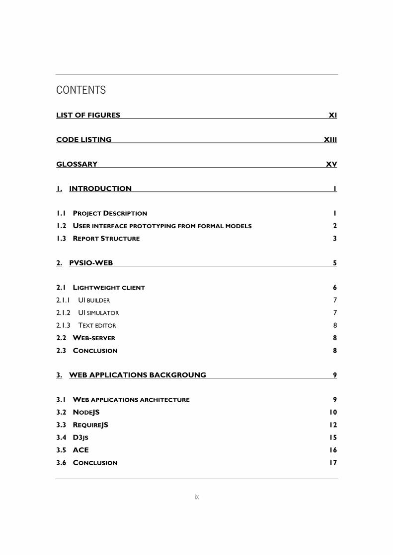
CONTENTS
LIST OF FIGURES XI
CODE LISTING XIII
GLOSSARY XV
1. INTRODUCTION 1
1.1 PROJECT DESCRIPTION 1
1.2 USER INTERFACE PROTOTYPING FROM FORMAL MODELS 2
1.3 REPORT STRUCTURE 3
2. PVSIO-WEB 5
2.1 LIGHTWEIGHT CLIENT 6
2.1.1 UI BUILDER 7
2.1.2 UI SIMULATOR 7
2.1.3 TEXT EDITOR 8
2.2 WEB-SERVER 8
2.3 CONCLUSION 8
3. WEB APPLICATIONS BACKGROUNG 9
3.1 WEB APPLICATIONS ARCHITECTURE 9
3.2 NODEJS 10
3.3 REQUIREJS 12
3.4 D3JS 15
3.5 ACE 16
3.6 CONCLUSION 17
Web-based user interface prototyping and simulation
x
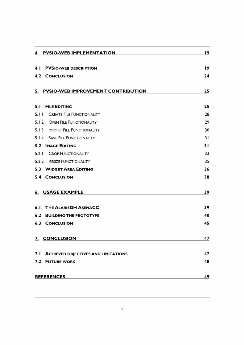
4. PVSIO-WEB IMPLEMENTATION 19
4.1 PVSIO-WEB DESCRIPTION 19
4.2 CONCLUSION 24
5. PVSIO-WEB IMPROVEMENT CONTRIBUTION 25
5.1 FILE EDITING 25
5.1.1 CREATE FILE FUNCTIONALITY 28
5.1.2 OPEN FILE FUNCTIONALITY 29
5.1.3 IMPORT FILE FUNCTIONALITY 30
5.1.4 SAVE FILE FUNCTIONALITY 31
5.2 IMAGE EDITING 31
5.2.1 CROP FUNCTIONALITY 33
5.2.2 RESIZE FUNCTIONALITY 35
5.3 WIDGET AREA EDITING 36
5.4 CONCLUSION 38
6. USAGE EXAMPLE 39
6.1 THE ALARISGH ASENACC 39
6.2 BUILDING THE PROTOTYPE 40
6.3 CONCLUSION 45
7. CONCLUSION 47
7.1 ACHIEVED OBJECTIVES AND LIMITATIONS 47
7.2 FUTURE WORK 48
REFERENCES 49
Web-based user interface prototyping and simulation
xi
LIST OF FIGURES
FIGURE 1 - PVSIO-WEB ARCHITECTURE [21] 5
FIGURE 2 - PVSIO-WEB GRAPHICAL FRONT-END 6
FIGURE 3 - CLIENT-SERVER ARCHITECTURE 9
FIGURE 4 - REQUIREJS, STRUCTURE EXEMPLE [14] 13
FIGURE 5 - PVSIO-WEB PLATFORM, DETAILED ARCHITECTURE 19
FIGURE 6 - FORMS EXAMPLE, DEPENDENCIES BETWEEN MODULES 21
FIGURE 7 - FORMS EXAMPLE, DEPENDENCIES BETWEEN EVENT MODULES 22
FIGURE 8 - PVSIO-WEB TOOLBAR AND FILE EDITOR 25
FIGURE 9 - NEW FILE FORM 28
FIGURE 10 - NEW FILE MENU ELEMENT AND DEFAULT SOURCE 28
FIGURE 11 - OPEN FILE FORM 29
FIGURE 12 - IMPORT FILE FORM 31
FIGURE 13 - IMAGE EDITING, CROP 34
FIGURE 14 - IMAGE EDITING, RESIZE 35
FIGURE 15 - WIDGET AREAS EDITING FORM 37
FIGURE 16 - ALARISGH ASENACC 39
FIGURE 17 - USAGE EXAMPLE, NEW PROJECT 40
FIGURE 18 - USAGE EXAMPLE, RESIZING 41
FIGURE 19 - USAGE EXAMPLE, CROPPING 42
FIGURE 20 - USAGE EXAMPLE, IMPORT FILE 43
FIGURE 21 – USAGE EXAMPLE, WIGET AREA EDITING 44
FIGURE 22 - USAGE EXAMPLE, UI SIMULATOR 45

Web-based user interface prototyping and simulation
xii
Web-based user interface prototyping and simulation
xiii
CODE LISTING
CODE LISTING 1 - SIMPLE SERVER IN NODE.JS .......................................................................................................... 12
CODE LISTING 2 - REQUIREJS, FILE PURCHASE.JS, DEFINE FUNCTION EXAMPLE 14 ............................. 14
CODE LISTING 3 - ACE EDITOR INITIALIZATION ................................................................................................... 17
CODE LISTING 4 - INDEX.JS, CODE SNIPPET SHOWING REQUIRED MODULES AND LIBRARIES .... 21
CODE LISTING 5 - CURRENTPROJECT STRUCTURE EXAMPLE ......................................................................... 23
CODE LISTING 6 - CURRENTFILE STRUCTURE EXAMPLE .................................................................................... 23
CODE LISTING 7 - PART OF THE LISTPROJECT() FUNCTION ON THE BACKEND ................................. 26
CODE LISTING 8 - FILESOPENED STRUCTURE EXAMPLE ..................................................................................... 27
CODE LISTING 9 - PART OF THE "OPENFILE()" FUNCTION ON THE FRONTEND ................................. 30
CODE LISTING 10 - EASYIMAGE CROP FUNCTION ................................................................................................ 33
CODE LISTING 11 - EASYIMAGE RESIZE FUNCTION .............................................................................................. 33
CODE LISTING 12 - CROPPERUI, NEW CROPPER.IMG EXAMPLE ..................................................................... 34
CODE LISTING 13 - ONENDCROP CALLBACK FUNCTION ............................................................................... 34
CODE LISTING 14 - CODE SNIPPET, CREATE AND/OR UPDATE WIDGET AREA .................................... 38

Web-based user interface prototyping and simulation
xiv
Web-based user interface prototyping and simulation
15
GLOSSARY
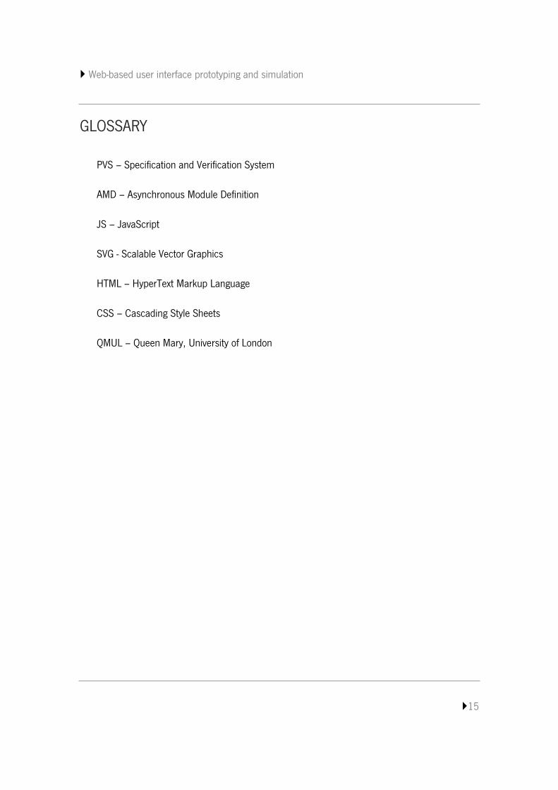
PVS – Specification and Verification System
AMD – Asynchronous Module Definition
JS – JavaScript
SVG - Scalable Vector Graphics
HTML – HyperText Markup Language
CSS – Cascading Style Sheets
QMUL – Queen Mary, University of London

Web-based user interface prototyping and simulation
1
1. INTRODUCTION
The growing number of software users increases the challenges of industry: more
experienced and demanding users, more diverse interfaces, software used in critical situations
requiring higher reliability. Formal methods can perform an important role supporting systematic
and exhaustive reasoning about the design of a system, leading to the creation of more reliable
software [22, 23]. However, being more reliable does not necessarily means being better in
terms of usage experience. As such, the need to validate the model from a user perspective has
been identified. Thus, prototyping may have the ability to complement formal verification.
Researchers at Queen Mary University of London (QMUL) have been using a web-based
approach – PVSio-web [21] – where the process of generating a prototype starts with an image of
the user interface which is then animated in a browser by linking parts of the image to calls to a
model of how the interface should behave. PVSio-web is under development and this project will
reflect on further contributions to it.
1.1 Project Description
PVSio-web is a tool for the rapid prototyping of devices’ user interfaces, which extends the
simulation component of the PVS (Specification and Verification System) proof system [21]. PVS
is a verification system that provides a specification language integrated with a suite of tools that
supports editing and proving properties of formal models written in its specification language.
PVSio-web supports image and file editing. On the one side, file editiing enables showing and
editing a PVS specification and type-checking the specification in the PVS system. On the other,
at this point image editing enables uploading an image and drawing widget areas over it. Widget
areas are drawn to identify interaction areas, such as buttons or displays, to be linked to the
specification variables that they will represent. After created and, even, saved, widget areas can
be edited to adjust or correct their configurations.
Web-based user interface prototyping and simulation
2
In summary, PVSio-web supports the editing of one file source, image upload and widget
area editing. PVS specifications, however, can be constituted by more than one file, which
creates the opportunity to improve PVSio-web to support multi-files editing. Currently, image
editing may not be a correct term for what is supported as it is a single upload feature. Editing
the image by resizing or cropping in order to better define the limits of the image or highlight a
specific area may increase the prototyping quality. Image editing features can be explored to
better adjust the image to the prototyping needs. Speaking of increase prototyping quality, widget
areas are not always drawn with the right dimensions or in the correct coordinates to match the
intended areas of the image. These make resizing widget area another, and not least important,
feature to consider for contribution.
1.2 User interface prototyping from formal models
A number of other tools also support some form of user interface prototyping from of
formal model of the user interfaces.
The IVY workbench, which has been developed at the Department of Informatics of the
University of Minho, is a model based tool for the analysis of interactive systems designs, using
formal methods [1,2]. The tool act as a front end to the NuSMV model checker [6], creating an
abstraction layer where models of interactive systems can be developed and analyzed. The model
checker tries to prove properties of the interface and generates counterexamples when failures
happen. These counterexamples illustrate behaviors in which the property is not verified. The
model checking process can be time and computational resources intensive. While it is good to
prove that the model exhibits desired properties, it is not ideal as a validation tool during model
development. In this context, the need for an animator tool that allow user to ‘play’ with the
model has been identified.
The latest version of IVY workbench already allows prototyping of interfaces. For one side,
a prototyping component for models that supports building a mockup of a user interface in order
to playback counterexamples in a more real user interface [3]. For another side, a tool that
Web-based user interface prototyping and simulation
3
enables the animation of the models but does not support a representation of the user interface
[4].
The power of simulation through an interface prototype is an advantage of PVSio-web
against IVY. PVSio-web is able to present a prototype of the user interface and to animate it in
runtime according to the model. It can better represent the behavior to the user and provides
extra support for the analysis.
Without belittling other model-based prototyping tools or systems, it is also worth
mentioning PetShop [24]. PetShop supports and promotes an interactive design process. At run
time, users can interact with the specification and the actual state of the application which is an
advantage of model-based prototyping regarding to immediately evaluate the impact of a
modification.
1.3 Report Structure
The report contains five chapters which are:
1. Chapter 1 – Introduction: This chapter presents the scope, project description with
a brief state-of-art and intervention areas and related work.
2. Chapter 2 – PVSio-web: Introduces PVSio-web giving a state-of-art overview.
3. Chapter 3 – Web applications background: Introduces the main concepts of
web applications and describes some JavaScript libraries relevant to PVSio-web.
4. Chapter 4 – PVSio-web implementation: This chapter describes the PVSio-web
implementation, identifying the main components, modules and objects.
5. Chapter 5 – PVSio-web improvement contribution: This chapter presents the
analysis and implementation of the features added to PVSio-web.
6. Chapter 6 – Usage example: This Chapter presents the PVSio-web usage, giving
emphasis to the new features.
Web-based user interface prototyping and simulation
4
7. Chapter 7 – Conclusion: Description of the objectives achieved, final remarks and
presentation of possible future work.
Web-based user interface prototyping and simulation
5
2. PVSIO-WEB
PVSio-web is a tool for the rapid prototyping of device’s user interfaces in PVS. PVSio-web
extends the simulation component of the PVS proof system, providing a web based prototyping
approach. The tool has the aim to reduce the barriers that prevent non-experts in formal methods
from using PVS, promoting and facilitating the use of verification tools when developing device
user interfaces.
The process of generating a prototype starts with an image of the user interface which is then
animated in a browser. Such animation is obtained by linking parts of the image to functions of a
model of how the interface should behave. This concept of linking parts of an image – image
mapping – in HTML, is used to define areas that can be linked in order to animate the image,
supporting user interactions.
This image mapping approach consists of a list of coordinates on a specific image intended
to identify areas to be linked to different destinations, giving an extended flexibility to the
prototyping and simulation environment. It allows the inclusion of idealized images of the user
interfaces and the selection of the part that need to be linked to calls to a model in order to
support the interactive actions.
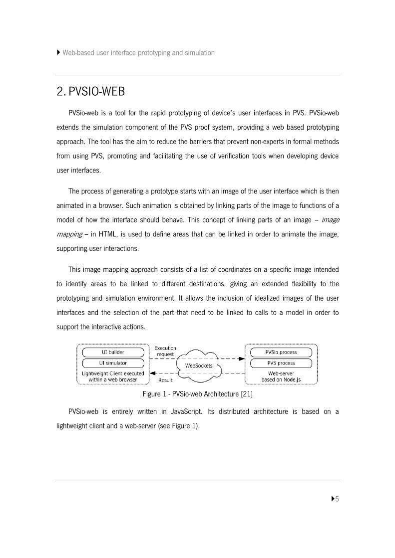
Figure 1 - PVSio-web Architecture [21]
PVSio-web is entirely written in JavaScript. Its distributed architecture is based on a
lightweight client and a web-server (see Figure 1).
Web-based user interface prototyping and simulation
6
2.1 Lightweight client
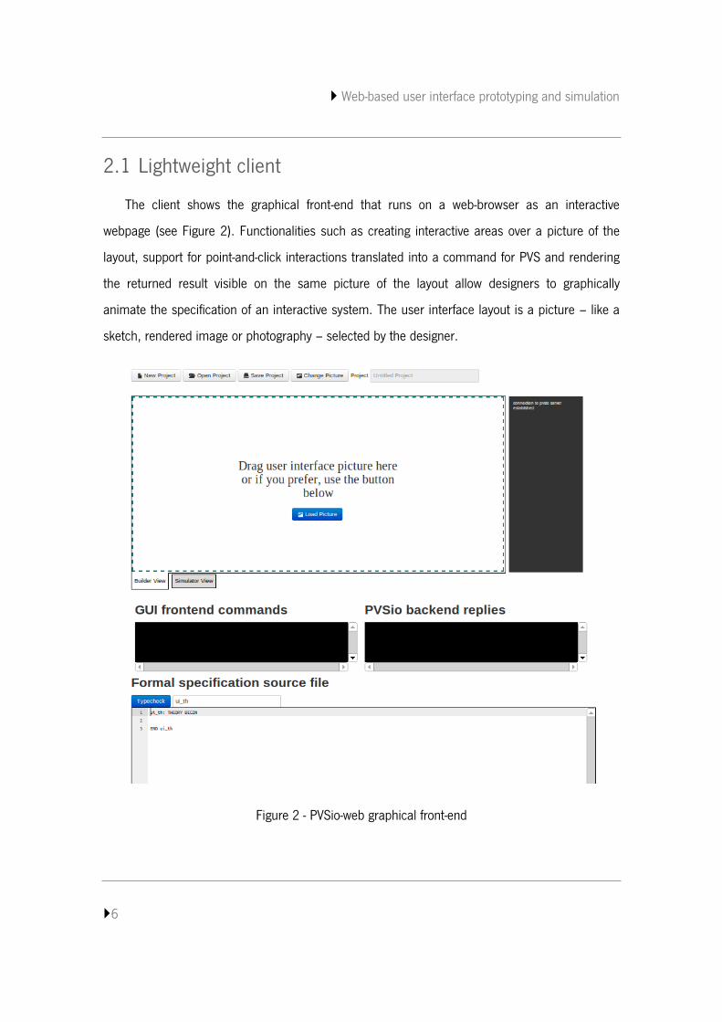
The client shows the graphical front-end that runs on a web-browser as an interactive
webpage (see Figure 2). Functionalities such as creating interactive areas over a picture of the
layout, support for point-and-click interactions translated into a command for PVS and rendering
the returned result visible on the same picture of the layout allow designers to graphically
animate the specification of an interactive system. The user interface layout is a picture – like a
sketch, rendered image or photography – selected by the designer.
Figure 2 - PVSio-web graphical front-end
Web-based user interface prototyping and simulation
7
2.1.1 UI builder
The UI builder allows designers to create interactive areas over the layout of the user
interface under development, and bind them to a PVS specification. The interactive areas can
take one of two types:
1. Button areas – input elements whose behavior is specified by functions in the PVS
specification;
2. Display areas – output elements whose value is specified in the state of the user interface
defined in the PVS specification.
The UI builder also supports editing the definitions of areas already created. With a single
click, areas can be selected and a border is highlighted to identify the selected area. With a
double click over some area, an editing form is shown, with configurations that can be modified
of a selected area.
2.1.2 UI simulator
The UI simulator section is where the user interface is animated. Such animation allows
essentially user point-and-click interaction through the interactive areas previously defined in the
UI builder.
User interactions with button areas will send a request to the web-server specifying the
name and arguments of the functions in the PVS specification, to be evaluated by PVS. Results of
the execution are returned from the web-server and parsed though regular expressions by the UI
simulator.
The value of the state variable associated with display areas are extracted and rendered on
the corresponding display areas defined on the user interface layout.
Web-based user interface prototyping and simulation
8
2.1.3 Text editor
The Text editor presents the PVS specification. It is the ACE code editor that allows the
edition of the shown specification. A button “Type check” sends a command to the web-server for
type-checking the specification, with the changes present on the editor.
2.2 Web-server
The web-server hosts processes that runs PVS and PVSio. The PVS process is used to type-
check the PVS specification. The PVSio process is used to animate the PVS specification. The
input, output and error streams of these processes are accessed over a generic interface
exposed by the server.
The client-server communication is based on websockets. After initializing a websocket
connection, the client can send requests to the server to start or close a process, or commands
to be executed in the running processes. The server will respond with results from the processes
through the same connection.
The web-server runs on the Node.js platform. This technology uses an event-driven, non-
blocking I/O model which makes scalable applications.
2.3 Conclusion
This chapter has introduced PVSio-web, the system under improvement. An overview was
given summarizing its architecture and existing features.
Web-based user interface prototyping and simulation
9
3. WEB APPLICATIONS BACKGROUNG
This chapter discusses concepts considered relevant for a better understanding of PVSio-
web as a web application in JavaScript (JS). JavaScript is a programming language generally
used by programmers to easily design webpages and add interactive features.
The first section gives an overview of a web applications’ architecture and the following
ones describe JavaScript libraries that support PVSio-Web functionalities.
3.1 Web applications architecture
“A configurable skeleton of any kind of software beast on which you hang
implementation specific muscle to make it live.” 1
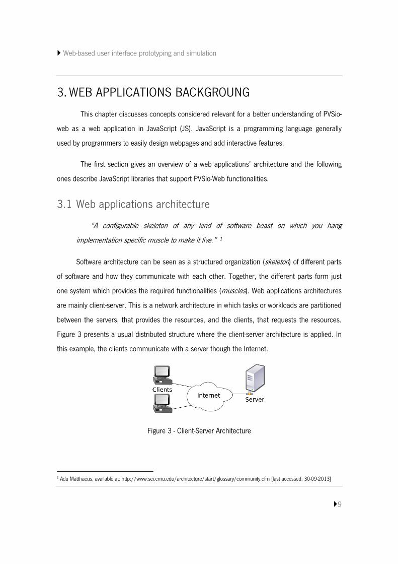
Software architecture can be seen as a structured organization (skeleton) of different parts
of software and how they communicate with each other. Together, the different parts form just
one system which provides the required functionalities (muscles). Web applications architectures
are mainly client-server. This is a network architecture in which tasks or workloads are partitioned
between the servers, that provides the resources, and the clients, that requests the resources.
Figure 3 presents a usual distributed structure where the client-server architecture is applied. In
this example, the clients communicate with a server though the Internet.
Figure 3 - Client-Server Architecture
1 Adu Matthaeus, available at: http://www.sei.cmu.edu/architecture/start/glossary/community.cfm [last accessed: 30-09-2013]
Web-based user interface prototyping and simulation
10
In client-server applications the client and server sides are often called frontend and
backend respectively. In general, the frontend is what the user can see like a user interface
design. Furthermore, the frontend has the responsibility to collect and process the user inputs
and then make necessary requests to the backend. The backend gives support to the frontend
handling the requests and returning the responses that will be used on frontend. The backend is
usually responsible of business logic and database access.
Moreover, frontend and backend may have a complex structure to provide the expected
functionalities with quality. Developing Web applications implies the development of the client
component and the server component, each having its own architecture and implementation
technologies. Since they are often complex structures, it is necessary to manage dependencies
between all components. JavaScript has developer’s communities that contributes with
platforms, frameworks and libraries for both the server and client sides. Particularly relevant to
this project’s context, node.js is a platform for server development, and d3.js supports
operational functionalities on the client. Providing the capability to manage dependencies
between different parts of a system, require.js can be used in both server and client components.
3.2 NodeJS
“Node.js is a platform built on Chrome's JavaScript runtime for easily building
fast, scalable network applications. Node.js uses an event-driven, non-blocking I/O
model that makes it lightweight and efficient, perfect for data-intensive real-time
applications that run across distributed devices.” 2
The more well-known applications of JavaScript are related to the frontend, where it is nice to
have libraries like jQuery [26], or Prototype [25] at our disposal. JavaScript on the server side is a
relatively new concept. Node.js supports this approach which means that it is possible to write an
entire application with JavaScript [12]. Node.js makes use of Google’s V8 Virtual Machine to
2 http://nodejs.org/ [accessed at 16-01-2014]
Web-based user interface prototyping and simulation
11
execute JavaScript in the server. Google’s V8 Virtual Machine3 is an open source JavaScript
engine written in C++ and is used in the Google Chrome browser. As other libraries, Node.js
provides a pack of modules that gives support to common operations.
Node.js underlying execution mode is different from common runtime environments. Node.js
introduces the concept of event-driven asynchronous callback. Understanding this concept, event-
driven regards detecting and handling events such as user interactions like clicking a submit
button or system messages. Each event is assigned a Callback. Callback respects to functions
that are evaluated when certain events happen. This permits to subscribe a callback function to
an event that will be called when the event happens. Asynchronous means that the system will
permit various requests without blocking the entire application (non-blocking), multiple events can
be processed simultaneously.
Node.js is used in PVSio-web. To help understand the basis of Node.js, this provides a step-
by-step explanation on how to create a simple “Hello World” application [13].
In order to create a simple http server the http package, which is installed by default, must
be loaded. This is achieved by using the next code line:
o var http = require(‘http’);
Once the load is done all methods of the module can be used. The server can now be
created and started by recurring to the following code:
o var http = http.createServer();
server.listen(1337, ‘127.0.0.1’);
3 https://code.google.com/p/v8/ [accessed at 16-01-2014]
Web-based user interface prototyping and simulation
12
1 var http = require("http"); 2 http.createServer(function(req, res) { 3 response.writeHead(200, {"Content-Type": "text/plain"}); 4 response.end("Hello World"); 5 }).listen(1337,'127.0.0.1');
Where the parameters of the ‘listen’ method represent a specific port number and URL,
respectively. This code should create and start a server doing nothing. The createServer method
can take a function as it arguments that is passed in details on the request and response:
http.createServer(function(req,res){});. Thus, the “Hello World” can easily be written in the
browser by adding the head and the end response - res. The end will contain the words and the
head will include the content type and status. Code listing 1 presents a simple “Hello World”.
Code listing 1 - Simple server in Node.js
In order to handle the requests, the backend needs to be able to look at the HTTP request
and extract the requested address as well as GET or POST parameters from it. The information of
the request will be available through the request object which is passed as the first parameter to
the request function – request(request,response). In order to interpret such information, Node.js
provides additional modules like url which has the utilities for uniform resource locator (URL)
resolution and parsing.
3.3 RequireJS
“RequireJS is a JavaScript file and module loader. It is optimized for in-browser use,
but it can be used in other JavaScript environments, like Rhino and Node. Using a modular
script loader like RequireJS will improve the speed and quality of your code.”4
Organizing pieces of code into useful modules and accessing the capabilities of modules
has been a concern of developers. Separating code into components eases the effort with
maintenance and increases reusability. Despite the advantages, organizing code into modules
also raises problems. An important aspect is managing dependencies. 4 http://requirejs.org/ [accessed at: 18-01-2014]
Web-based user interface prototyping and simulation
13
Usually, JavaScript files are loaded using the <script> tags and each file can be
dependent on another files. However, the order in which the files are loaded has to obey a rule
for correct execution. To load a module that depends on other modules, the other modules need
to be loaded first (coming first on the tags list) [14]. Apart from that hand-writing <script> tags is
not very scalable, this can be difficult to manage on large projects particularly when scripts start
to have many dependencies.
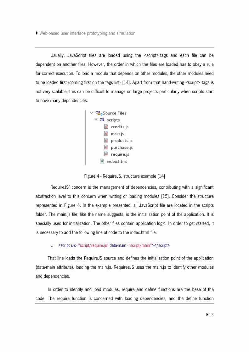
Figure 4 - RequireJS, structure exemple [14]
RequireJS’ concern is the management of dependencies, contributing with a significant
abstraction level to this concern when writing or loading modules [15]. Consider the structure
represented in Figure 4. In the example presented, all JavaScript file are located in the scripts
folder. The main.js file, like the name suggests, is the initialization point of the application. It is
specially used for initialization. The other files contain application logic. In order to get started, it
is necessary to add the following line of code to the index.html file.
o <script src="script/require.js" data-main="script/main"></script>
That line loads the RequireJS source and defines the initialization point of the application
(data-main attribute), loading the main.js. RequiresJS uses the main.js to identify other modules
and dependencies.
In order to identify and load modules, require and define functions are the base of the
code. The require function is concerned with loading dependencies, and the define function
Web-based user interface prototyping and simulation
14
allows modules to be defined. The first parameter of these two functions is used to specify
dependencies. Each module can be dependent on one or more modules.
o require( ["dependency01", "dependency02", "dependency03", ...] ,
function( module01, module02, ... ){ //callback function code
});
The require function has two arguments. The first is the list of dependencies necessary
to be loaded and the second is the callback function. This callback function will be called when
all dependencies listed in the first argument are loaded, receiving as parameters the modules
that were loaded.
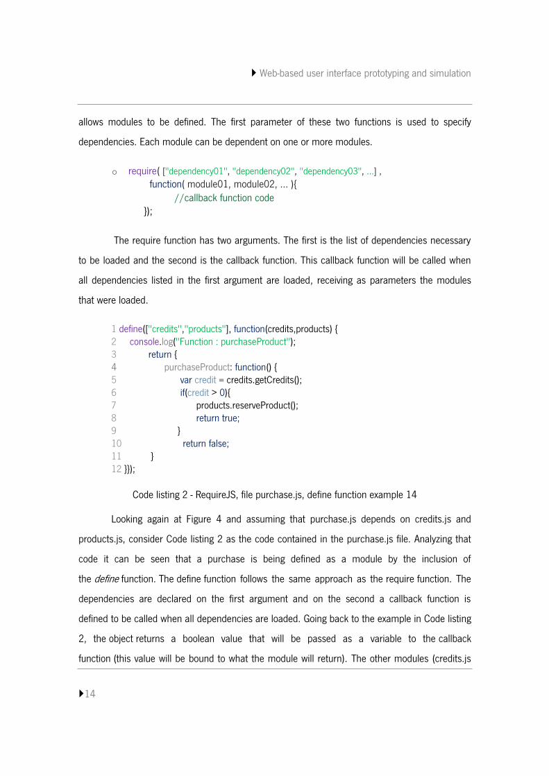
1 define(["credits","products"], function(credits,products) { 2 console.log("Function : purchaseProduct"); 3 return { 4 purchaseProduct: function() { 5 var credit = credits.getCredits(); 6 if(credit > 0){ 7 products.reserveProduct(); 8 return true; 9 } 10 return false; 11 } 12 }});
Code listing 2 - RequireJS, file purchase.js, define function example 14
Looking again at Figure 4 and assuming that purchase.js depends on credits.js and
products.js, consider Code listing 2 as the code contained in the purchase.js file. Analyzing that
code it can be seen that a purchase is being defined as a module by the inclusion of
the define function. The define function follows the same approach as the require function. The
dependencies are declared on the first argument and on the second a callback function is
defined to be called when all dependencies are loaded. Going back to the example in Code listing
2, the object returns a boolean value that will be passed as a variable to the callback
function (this value will be bound to what the module will return). The other modules (credits.js
Web-based user interface prototyping and simulation
15
and products.js) present a similar implementation, but will not have any dependencies. The
credits.js may return an object while products.js may not return anything.
Finishing this background on RequireJS, it is important to refer that top level files (files
that do not define a module) can have a configuration object. A configuration object supports
creating reference names to file paths or urls. For example:
o require.config({ paths: { “dep01”: “scipt/dependency01”, } } ) ;
With this code, the module dependency01 from the script folder can be referenced
through its defined reference name – dep01 – in the configuration object.
3.4 D3js
“With D3, designers selectively bind input data to arbitrary document elements,
applying dynamic transforms to both generate and modify content.” [16]
D3 is a JavaScript library for manipulating documents based on data. This exposes the full
capabilities of web standards such as CSS, HTML and SVG, combining powerful visualization
components and a data-driven approach to DOM manipulation. It supports the generation of an
HTML table from an array of numbers or, even, using the same data to create an interactive SVG
bar chart with smooth transitions and interaction.
The main operation area of D3 is the construction and manipulation of SVG graphs and
charts. SVG – Scalable Vector Graphics – is a language that describes images or two-dimensional
graphics with vectors [17]. The DOM allows for straightforward and efficient vector graphics
animation via scripting which enables dynamic and interactive SVG drawings.
D3 is fast and supports large datasets and dynamic behaviors for interaction and
animation. Further, it supports code reuse through a diverse collection of components and
plugins. Although D3 is specialized in SVG, PVSio-web uses it for data manipulation via DOM,
similarly to JQuery.

Web-based user interface prototyping and simulation
16
Getting and modifying HTML elements can become a hard chore with traditional methods.
D3 employs a declarative approach, operating on arbitrary sets of nodes called selections. For
example, if what is intended is to change the text color of paragraph elements, with D3 this can
be done with just one single line of code - avoiding the use of manual loops -, as follows:
o d3.selectAll(“p”).style(“color”,”white”);
The "selectAll" method will, as its name suggest, select all html elements with the tag
passed as parameter. In the example presented, the method will select all paragraph (p)
elements and will apply a style change - all paragraphs will take the color white.
To manipulate individual nodes the "select" method can be used. This method receive as
parameter the tag name (if only one node is represented by that name) or the element
identification (id).
Furthermore, D3.js supports asynchronous requests through the XHR module which also
provides a set of features for data parsing. The main advantage of this is to support interactivity
data at the same time that something is being loaded.
3.5 ACE
Ace is a standalone code editor written in JavaScript. It matches features, usability and
performance of existing native editors. Furthermore, Ace can be easily embedded in any webpage
or JavaScript application.
Among its various features, search and replace with regular expressions, syntax
highlighting for over 40 languages, automatic indent and outdent, text drag and drop using the
mouse, live syntax checking (currently JavaScript/CoffeeScript/CSS/XQuery), fully customizable
key bindings including vim and Emacs modes and more can be highlighted.
Web-based user interface prototyping and simulation
17
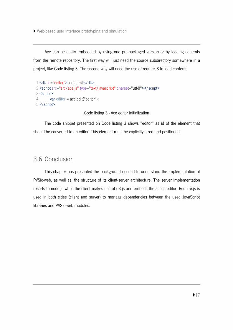
Ace can be easily embedded by using one pre-packaged version or by loading contents
from the remote repository. The first way will just need the source subdirectory somewhere in a
project, like Code listing 3. The second way will need the use of requireJS to load contents.
Code listing 3 - Ace editor initialization
The code snippet presented on Code listing 3 shows "editor" as id of the element that
should be converted to an editor. This element must be explicitly sized and positioned.
3.6 Conclusion
This chapter has presented the background needed to understand the implementation of
PVSio-web, as well as, the structure of its client-server architecture. The server implementation
resorts to node.js while the client makes use of d3.js and embeds the ace.js editor. Require.js is
used in both sides (client and server) to manage dependencies between the used JavaScript
libraries and PVSio-web modules.
1 <div id="editor">some text</div> 2 <script src="src/ace.js" type="text/javascript" charset="utf-8"></script> 3 <script> 4 var editor = ace.edit("editor"); 5 </script>

Web-based user interface prototyping and simulation
18
Web-based user interface prototyping and simulation
19
4. PVSIO-WEB IMPLEMENTATION
The objective of this project is contribute to PVSio-web with some improvements. In this
chapter a description of the PVSio-web implementation state is presented, identifying its relevant
architectural elements.
4.1 PVSio-web description
PVSio-web has already a consistent structure. Thus, a detailed study of the architecture
was necessary in order to understand the implementation state of PVSio-web. This allowed
identify components, packages, modules and objects and libraries in use.
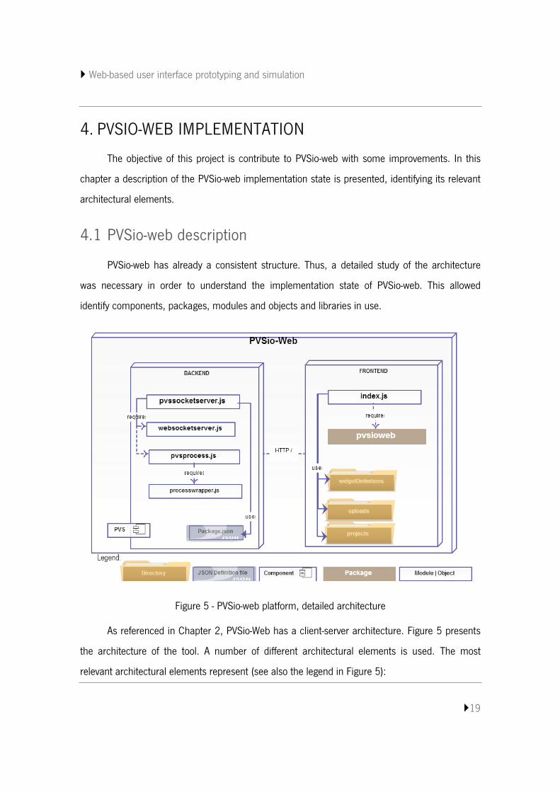
Figure 5 - PVSio-web platform, detailed architecture
As referenced in Chapter 2, PVSio-Web has a client-server architecture. Figure 5 presents
the architecture of the tool. A number of different architectural elements is used. The most
relevant architectural elements represent (see also the legend in Figure 5):
Web-based user interface prototyping and simulation
20
Packages, modules and objects are the components of PVSio-web
implementation;
Components represent external systems or services;
Definition files contain useful definitions to be used by the system;
Directories represent folders where the system saves files that can be definitions
files, temporary files or project files.
The main module of the system is pvssocketserver.js. This module is responsible for
creating a node server and a web socket server. The web socket server is specially used for
connections to the PVS process. The node.js server answers to PVSio-web and http frontend
requests. Complementarily to node.js, PVSio-web uses express.js. Express.js is a node.js
framework that provides a roubust set of features to build application, providing a large set of
HTTP utility methods.
As the web socket server is used to connect with the PVS process, it is responsible for
supporting three interaction commands supported by PVS process. These commands are the
following ones:
sendCommand – for send a PVSio command to the process;
startProcess – for start the PVS process;
getSourceCode – for get the PVS source code being executed.
PVSio is a package of the external PVS component. PVSio extends the ground evaluator
with a predefined library of imperative programming language features [18]. pvsprocess.js is a
module for communicating with a PVS process using PVSio. It resorts to processwrapper.js for
spawning, shutting down and sending messages to a PVS process.
The front end is responsible for managing data and dealing with user interactions. index.js
is the main object, responsible to managing functionalities and delegating responsibilities. It
Web-based user interface prototyping and simulation
21
requires a set of modules and libraries provided in the pvsioweb package. Code listing 4 shows a
code snippet with the modules and libraries required by index.js.
1 require(['websockets/pvs/pvsiowebsocket', 'pvsioweb/displayManager', 2 'pvsioweb/createOverlay', 3 'ace/ace', 'pvsioweb/widgetMaps', 'util/shuffle', 4 'pvsioweb/widgetEditor', 'pvsioweb/widgetEvents', 5 'pvsioweb/buttonWidget', 'pvsioweb/displayWidget', 6 'pvsioweb/displayMappings', "pvsioweb/forms/newProject", 7 "pvsioweb/forms/events", "pvsioweb/forms/openProject", 8 "pvsioweb/forms/saveProjectAs", 'd3/d3'],
Code listing 4 - index.js, code snippet showing required modules and libraries
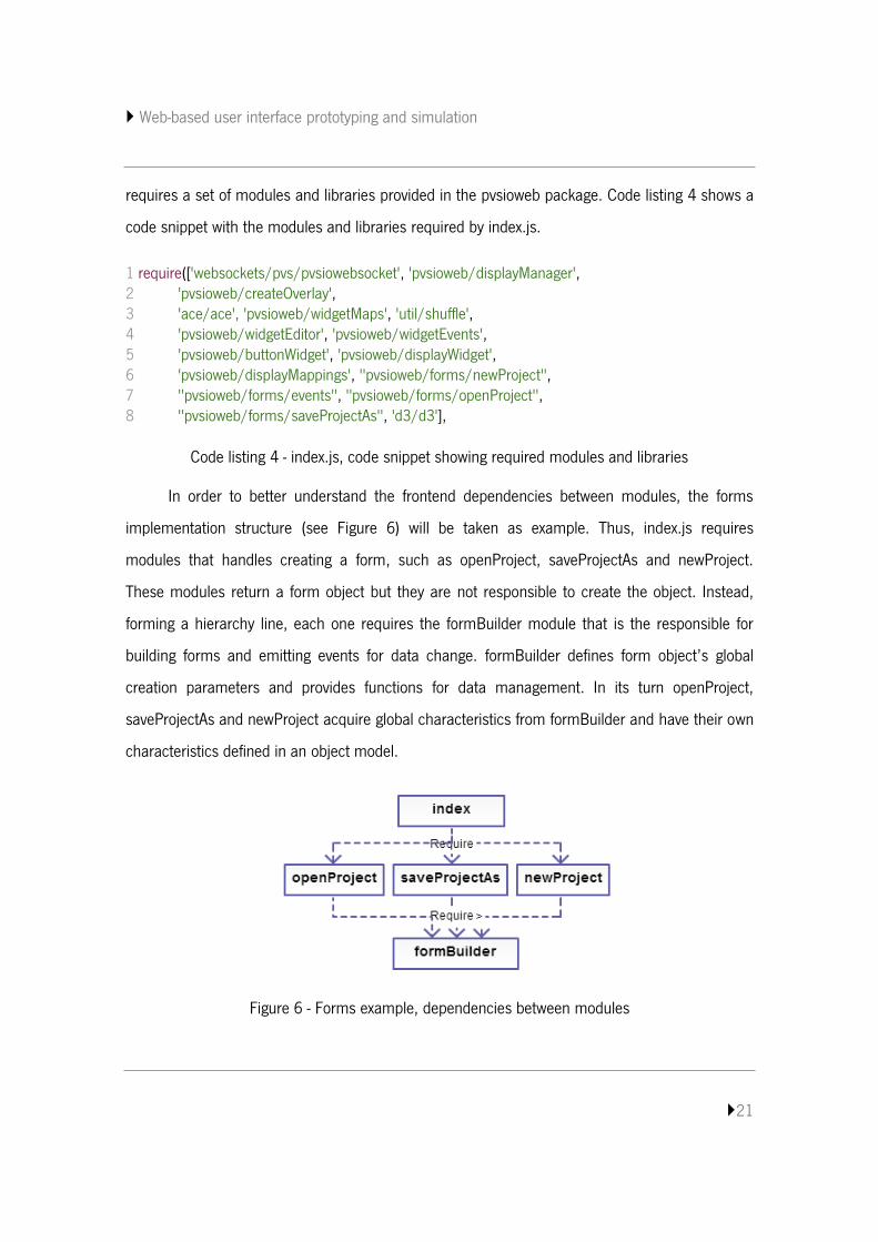
In order to better understand the frontend dependencies between modules, the forms
implementation structure (see Figure 6) will be taken as example. Thus, index.js requires
modules that handles creating a form, such as openProject, saveProjectAs and newProject.
These modules return a form object but they are not responsible to create the object. Instead,
forming a hierarchy line, each one requires the formBuilder module that is the responsible for
building forms and emitting events for data change. formBuilder defines form object’s global
creation parameters and provides functions for data management. In its turn openProject,
saveProjectAs and newProject acquire global characteristics from formBuilder and have their own
characteristics defined in an object model.
Figure 6 - Forms example, dependencies between modules
Web-based user interface prototyping and simulation
22
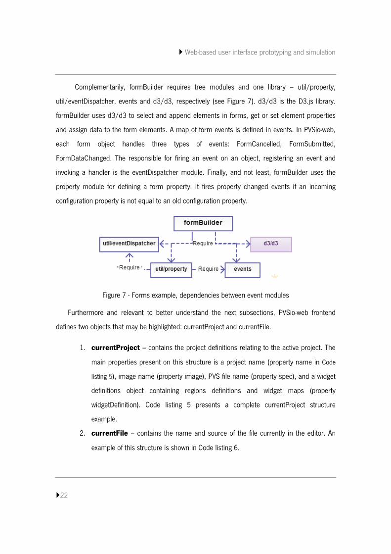
Complementarily, formBuilder requires tree modules and one library – util/property,
util/eventDispatcher, events and d3/d3, respectively (see Figure 7). d3/d3 is the D3.js library.
formBuilder uses d3/d3 to select and append elements in forms, get or set element properties
and assign data to the form elements. A map of form events is defined in events. In PVSio-web,
each form object handles three types of events: FormCancelled, FormSubmitted,
FormDataChanged. The responsible for firing an event on an object, registering an event and
invoking a handler is the eventDispatcher module. Finally, and not least, formBuilder uses the
property module for defining a form property. It fires property changed events if an incoming
configuration property is not equal to an old configuration property.
Figure 7 - Forms example, dependencies between event modules
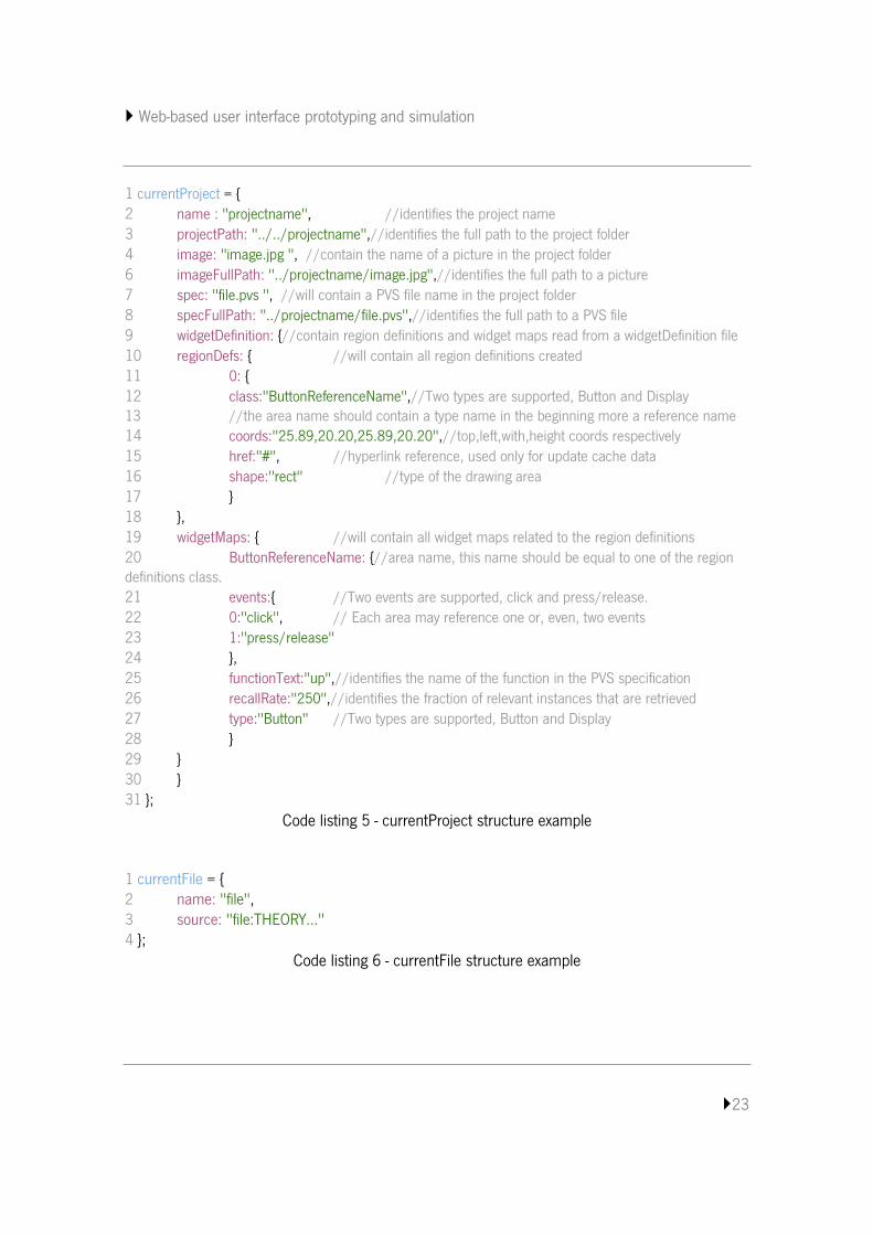
Furthermore and relevant to better understand the next subsections, PVSio-web frontend
defines two objects that may be highlighted: currentProject and currentFile.
1. currentProject – contains the project definitions relating to the active project. The
main properties present on this structure is a project name (property name in Code
listing 5), image name (property image), PVS file name (property spec), and a widget
definitions object containing regions definitions and widget maps (property
widgetDefinition). Code listing 5 presents a complete currentProject structure
example.
2. currentFile – contains the name and source of the file currently in the editor. An
example of this structure is shown in Code listing 6.
Web-based user interface prototyping and simulation
23
1 currentProject = { 2 name : "projectname", //identifies the project name 3 projectPath: "../../projectname",//identifies the full path to the project folder 4 image: "image.jpg ", //contain the name of a picture in the project folder 6 imageFullPath: "../projectname/image.jpg",//identifies the full path to a picture 7 spec: "file.pvs ", //will contain a PVS file name in the project folder 8 specFullPath: "../projectname/file.pvs",//identifies the full path to a PVS file 9 widgetDefinition: {//contain region definitions and widget maps read from a widgetDefinition file 10 regionDefs: { //will contain all region definitions created 11 0: { 12 class:"ButtonReferenceName",//Two types are supported, Button and Display 13 //the area name should contain a type name in the beginning more a reference name 14 coords:"25.89,20.20,25.89,20.20",//top,left,with,height coords respectively 15 href:"#", //hyperlink reference, used only for update cache data 16 shape:"rect" //type of the drawing area 17 } 18 }, 19 widgetMaps: { //will contain all widget maps related to the region definitions 20 ButtonReferenceName: {//area name, this name should be equal to one of the region definitions class. 21 events:{ //Two events are supported, click and press/release. 22 0:"click", // Each area may reference one or, even, two events 23 1:"press/release" 24 }, 25 functionText:"up",//identifies the name of the function in the PVS specification 26 recallRate:"250",//identifies the fraction of relevant instances that are retrieved 27 type:"Button" //Two types are supported, Button and Display 28 } 29 } 30 } 31 };
Code listing 5 - currentProject structure example
1 currentFile = { 2 name: "file", 3 source: "file:THEORY..." 4 };
Code listing 6 - currentFile structure example
Web-based user interface prototyping and simulation
24
4.2 Conclusion
This chapter described the PVSio-web implementation, identifying its components,
packages, modules, objects and libraries in use. PVSio-web only supports one PVS file editing
and does not have image editing features (only supports upload and creating areas over an
image). In the next chapter the new functionalities implemented in PVSio-web will be described.
Web-based user interface prototyping and simulation
25
5. PVSIO-WEB IMPROVEMENT CONTRIBUTION
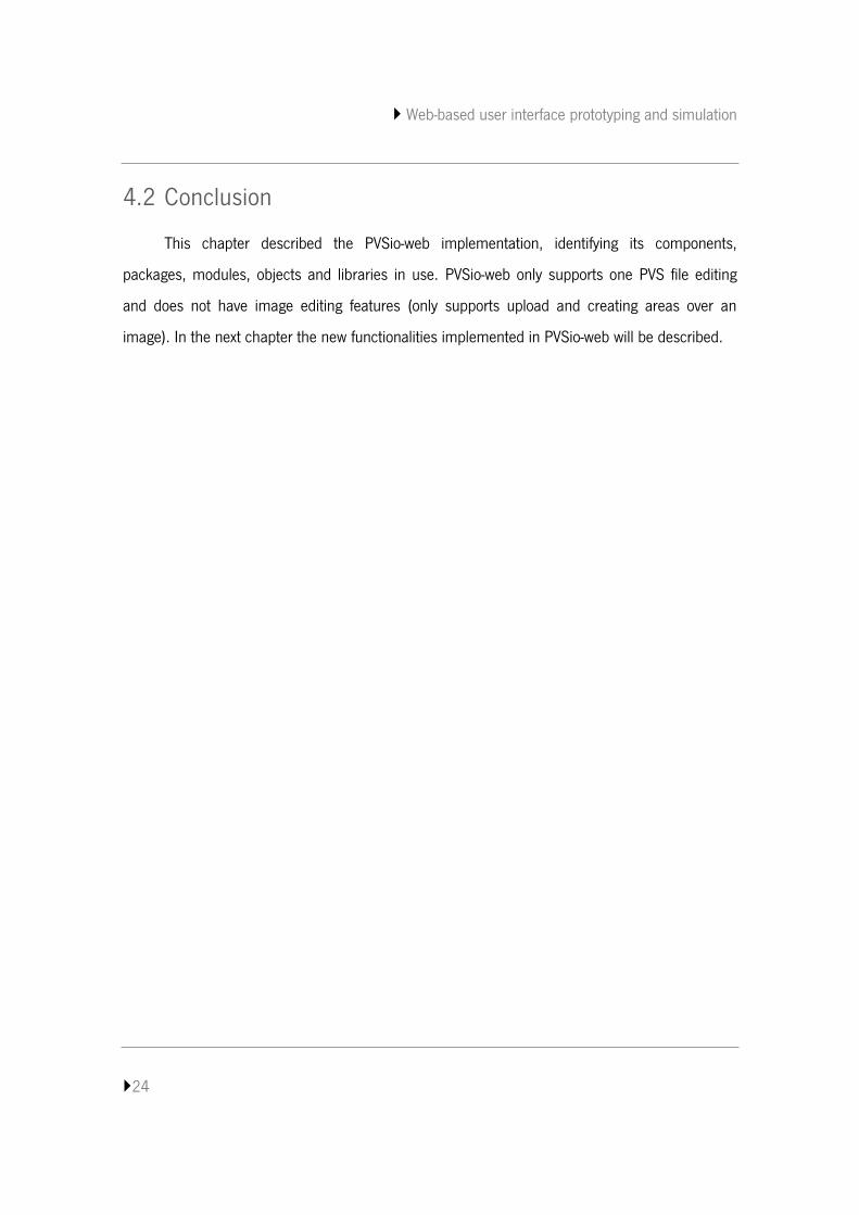
New features were identified to improve PVSio-web. These improvements regard to file and
image editing. This chapter will describe the implementation of the new create, open, import and
save file functionalities, and the cropping and resizing image functionalities.
Figure 8 - PVSio-web toolbar and file editor
5.1 File Editing
PVSio-web currently supports editing and type-checking of specifications. However, it only
supports the presence of a single PVS file per project. This is limiting because the PVS allows
structuring specifications into several files. Thus arises the need to add the ability to work with
multiple files at PVSio-web. The intention is to add a toolbar (Figure 8) providing create, import,
open and save files functionalities.
Once identified the possible improvement to make, it was necessary to understand how they
were meant to be implemented. The knowledge of how PVSio-web deals with more than one PVS
file in the same project folder was critical to advance the implementation. When trying to use
more than one PVS file in the same project folder it was found that the system loaded the last
PVS file found, and the process is initialized with that file. This can cause errors or, even, crash
the server if the file sent to the process does not correspond to the main PVS file. These errors
can happen when the source file does not have the expected syntax or, when receiving calls, the
command contains a function name that is not defined on the loaded PVS specification.
Web-based user interface prototyping and simulation
26
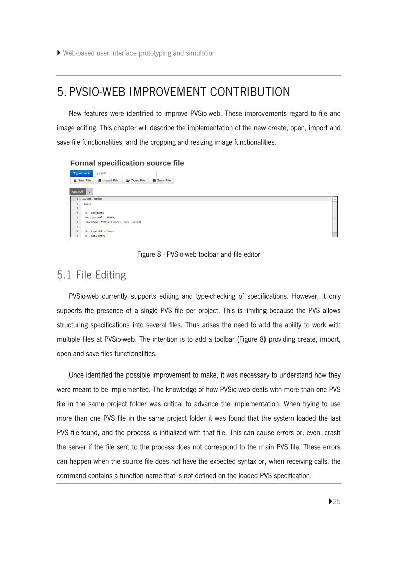
In order to guarantee that only the main PVS file is sent to the PVS process, a configuration
file was added where the name of the file can be kept. Code listing 7 presents a code snippet of
the “listProjects()” function in the backend file “pvssocketserver.js”. The mentioned function was
changed so that it would read the configuration file (Code listing 7, line 7) and extract the name
of the main PVS file (Code listing 7, lines 8 to 22). That name will be assigned to the “specMain”
response object attribute (Code listing 7, line 13). The source of the PVS main file will be
assigned to the “specMainSource” attribute (Code listing 7, line 17). If, for some reason, the
configuration file is not part of the project or becomes corrupted, the “specMain” attribute of the
response will be returned empty (Code listing 7, line 20).
1 else if(confExts.indexOf(ext) > -1) { 2 //existing the configuration file, it will read the content for 3 // extract the name of the PVS main file and then read the source 4 // the name and the source will be assigned to the response object 5 p.conf = f; 6 p.confFullPath = projectDir + d + "/" + f; 7 var fileText = fs.readFileSync(projectDir + d + "/" + f, "utf8"); 8 if (fileText !== ""){ 9 var lines = fileText.split("|"); 10 if (lines.length==2){ 11 p.imageMain = lines[0].split(":")[1]; 12 p.imageFullPathMain = projectDir + d + "/" + p.image; 13 p.specMain = lines[1].split(":")[1]; 14 p.specFullPathMain = projectDir + d + "/" + p.spec; 15 var source = fs.readFileSync(projectDir+d+"/"+p.specMain,"utf8"); 16 if (source !== null){ 17 p.specMainSource = source; 18 } 19 }else{ 20 p.specMain = ""; 21 } 22 } 23 }else{
Code listing 7 - Part of the listProject() function on the backend
As expected, the frontend also requires some changes in order to make sense of this
improvement. It was necessary to update the “openProject()” function in the “index.js” file. In
Web-based user interface prototyping and simulation
27
general, this function requests the project collection to the server, show each project name as a
select option in a form and tries to open a chosen project after user selection.
As previously mentioned, the “specMain” attribute of the server object response will be
empty if the configuration file is corrupted or does not exist. If it comes empty, a feature was
added to ask the user which is the main PVS file. After the user chooses a file, the system will
update or create the configuration file for the project, initialize the PVS process and really open
the project. With correct configurations, it directly initializes the PVS process and opens the
project in the frontend.
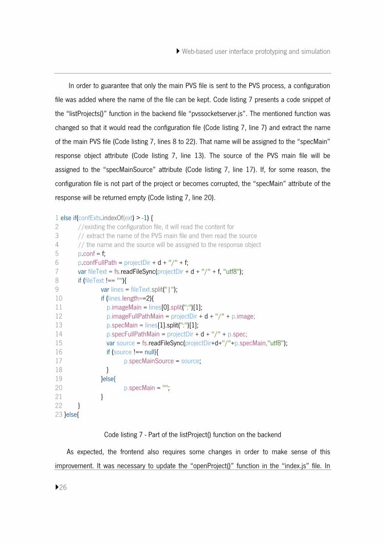
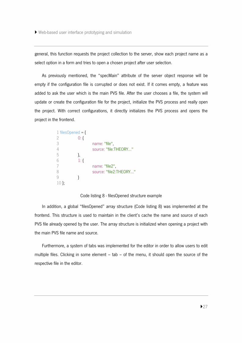
1 filesOpened = { 2 0: { 3 name: "file", 4 source: "file:THEORY..." 5 }, 6 1: { 7 name: "file2", 8 source: "file2:THEORY..." 9 } 10 };
Code listing 8 - filesOpened structure example
In addition, a global “filesOpened” array structure (Code listing 8) was implemented at the
frontend. This structure is used to maintain in the client’s cache the name and source of each
PVS file already opened by the user. The array structure is initialized when opening a project with
the main PVS file name and source.
Furthermore, a system of tabs was implemented for the editor in order to allow users to edit
multiple files. Clicking in some element – tab – of the menu, it should open the source of the
respective file in the editor.
Web-based user interface prototyping and simulation
28
As said before, the intention is to add a toolbar for support user create, import, open and
save files. These functionalities will be active and allowed only when a project is opened. A
detailed description of the available functionalities on the toolbar will be presented next.
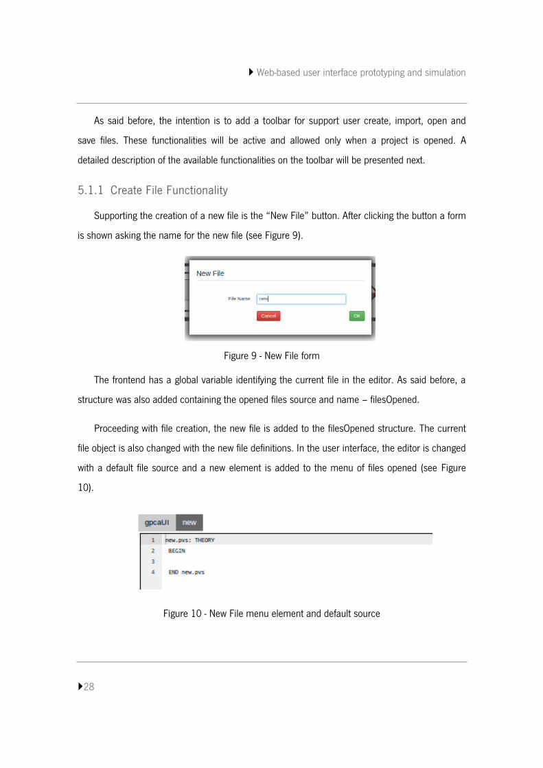
5.1.1 Create File Functionality
Supporting the creation of a new file is the “New File” button. After clicking the button a form
is shown asking the name for the new file (see Figure 9).
Figure 9 - New File form
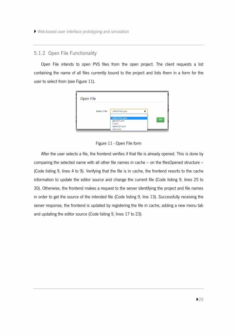
The frontend has a global variable identifying the current file in the editor. As said before, a
structure was also added containing the opened files source and name – filesOpened.
Proceeding with file creation, the new file is added to the filesOpened structure. The current
file object is also changed with the new file definitions. In the user interface, the editor is changed
with a default file source and a new element is added to the menu of files opened (see Figure
10).
Figure 10 - New File menu element and default source
Web-based user interface prototyping and simulation
29
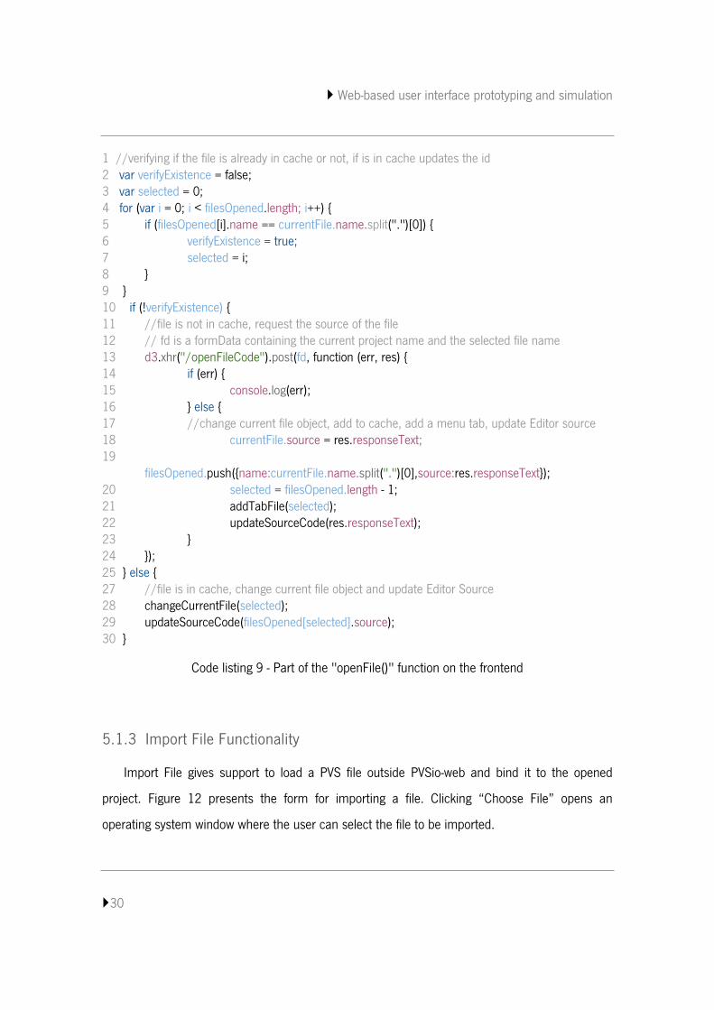
5.1.2 Open File Functionality
Open File intends to open PVS files from the open project. The client requests a list
containing the name of all files currently bound to the project and lists them in a form for the
user to select from (see Figure 11).
Figure 11 - Open File form
After the user selects a file, the frontend verifies if that file is already opened. This is done by
comparing the selected name with all other file names in cache – on the filesOpened structure –
(Code listing 9, lines 4 to 9). Verifying that the file is in cache, the frontend resorts to the cache
information to update the editor source and change the current file (Code listing 9, lines 25 to
30). Otherwise, the frontend makes a request to the server identifying the project and file names
in order to get the source of the intended file (Code listing 9, line 13). Successfully receiving the
server response, the frontend is updated by registering the file in cache, adding a new menu tab
and updating the editor source (Code listing 9, lines 17 to 23).
Web-based user interface prototyping and simulation
30
1 //verifying if the file is already in cache or not, if is in cache updates the id 2 var verifyExistence = false; 3 var selected = 0; 4 for (var i = 0; i < filesOpened.length; i++) { 5 if (filesOpened[i].name == currentFile.name.split(".")[0]) { 6 verifyExistence = true; 7 selected = i; 8 } 9 } 10 if (!verifyExistence) { 11 //file is not in cache, request the source of the file 12 // fd is a formData containing the current project name and the selected file name 13 d3.xhr("/openFileCode").post(fd, function (err, res) { 14 if (err) { 15 console.log(err); 16 } else { 17 //change current file object, add to cache, add a menu tab, update Editor source 18 currentFile.source = res.responseText; 19 filesOpened.push({name:currentFile.name.split(".")[0],source:res.responseText}); 20 selected = filesOpened.length - 1; 21 addTabFile(selected); 22 updateSourceCode(res.responseText); 23 } 24 }); 25 } else { 27 //file is in cache, change current file object and update Editor Source 28 changeCurrentFile(selected); 29 updateSourceCode(filesOpened[selected].source); 30 }
Code listing 9 - Part of the "openFile()" function on the frontend
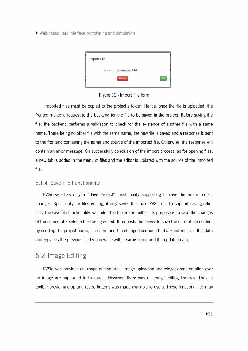
5.1.3 Import File Functionality
Import File gives support to load a PVS file outside PVSio-web and bind it to the opened
project. Figure 12 presents the form for importing a file. Clicking “Choose File” opens an
operating system window where the user can select the file to be imported.
Web-based user interface prototyping and simulation
31
Figure 12 - Import File form
Imported files must be copied to the project’s folder. Hence, once the file is uploaded, the
fronted makes a request to the backend for the file to be saved in the project. Before saving the
file, the backend performs a validation to check for the existence of another file with a same
name. There being no other file with the same name, the new file is saved and a response is sent
to the frontend containing the name and source of the imported file. Otherwise, the response will
contain an error message. On successfully conclusion of the import process, as for opening files,
a new tab is added in the menu of files and the editor is updated with the source of the imported
file.
5.1.4 Save File Functionality
PVSio-web has only a “Save Project” functionality supporting to save the entire project
changes. Specifically for files editing, it only saves the main PVS files. To support saving other
files, the save file functionality was added to the editor toolbar. Its purpose is to save the changes
of the source of a selected file being edited. It requests the server to save the current file content
by sending the project name, file name and the changed source. The backend receives this data
and replaces the previous file by a new file with a same name and the updated data.
5.2 Image Editing
PVSio-web provides an image editing area. Image uploading and widget areas creation over
an image are supported in this area. However, there was no image editing features. Thus, a
toolbar providing crop and resize buttons was made available to users. These functionalities may
Web-based user interface prototyping and simulation
32
be relevant to have when the image is too big or too small or, even, when it contains unnecessary
parts.
In order to support image editing features, the EasyImage module was used. EasyImage is a
module for image processing and manipulation in Node.js. EasyImage is built on top of
ImageMagick5 providing a user-friendly sintax. ImageMagick is a popular serverside technology for
image manipulation. EasyImage supports image resizing, cropping and format converting (for
example, converting a png image to jpg) [19]. This module has been added to the PVSio-web to
meet the server side needs for the new features of image editing.
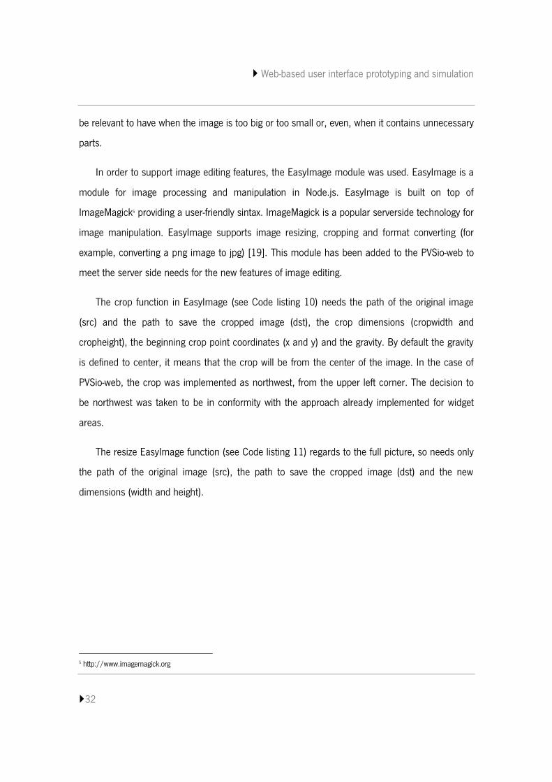
The crop function in EasyImage (see Code listing 10) needs the path of the original image
(src) and the path to save the cropped image (dst), the crop dimensions (cropwidth and
cropheight), the beginning crop point coordinates (x and y) and the gravity. By default the gravity
is defined to center, it means that the crop will be from the center of the image. In the case of
PVSio-web, the crop was implemented as northwest, from the upper left corner. The decision to
be northwest was taken to be in conformity with the approach already implemented for widget
areas.
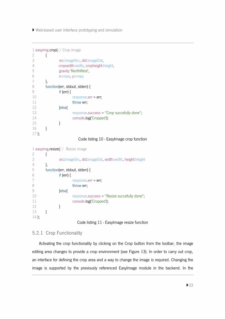
The resize EasyImage function (see Code listing 11) regards to the full picture, so needs only
the path of the original image (src), the path to save the cropped image (dst) and the new
dimensions (width and height).
5 http://www.imagemagick.org
Web-based user interface prototyping and simulation
33
1 easyimg.crop(// Crop image 2 { 3 src:imageSrc, dst:imageDst, 4 cropwidth:width, cropheight:height, 5 gravity:'NorthWest', 6 x:cropx, y:cropy 7 }, 8 function(err, stdout, stderr) { 9 if (err) { 10 response.err = err; 11 throw err; 12 }else{ 13 response.success = "Crop succefully done"; 14 console.log('Cropped'); 15 } 16 } 17 );
Code listing 10 - EasyImage crop function
1 easyimg.resize(// Resize image 2 { 3 src:imageSrc, dst:imageDst, width:width, height:height 4 }, 5 function(err, stdout, stderr) { 6 if (err) { 7 response.err = err; 8 throw err; 9 }else{ 10 response.success = "Resize succefully done"; 11 console.log('Cropped'); 12 } 13 } 14 );
Code listing 11 - EasyImage resize function
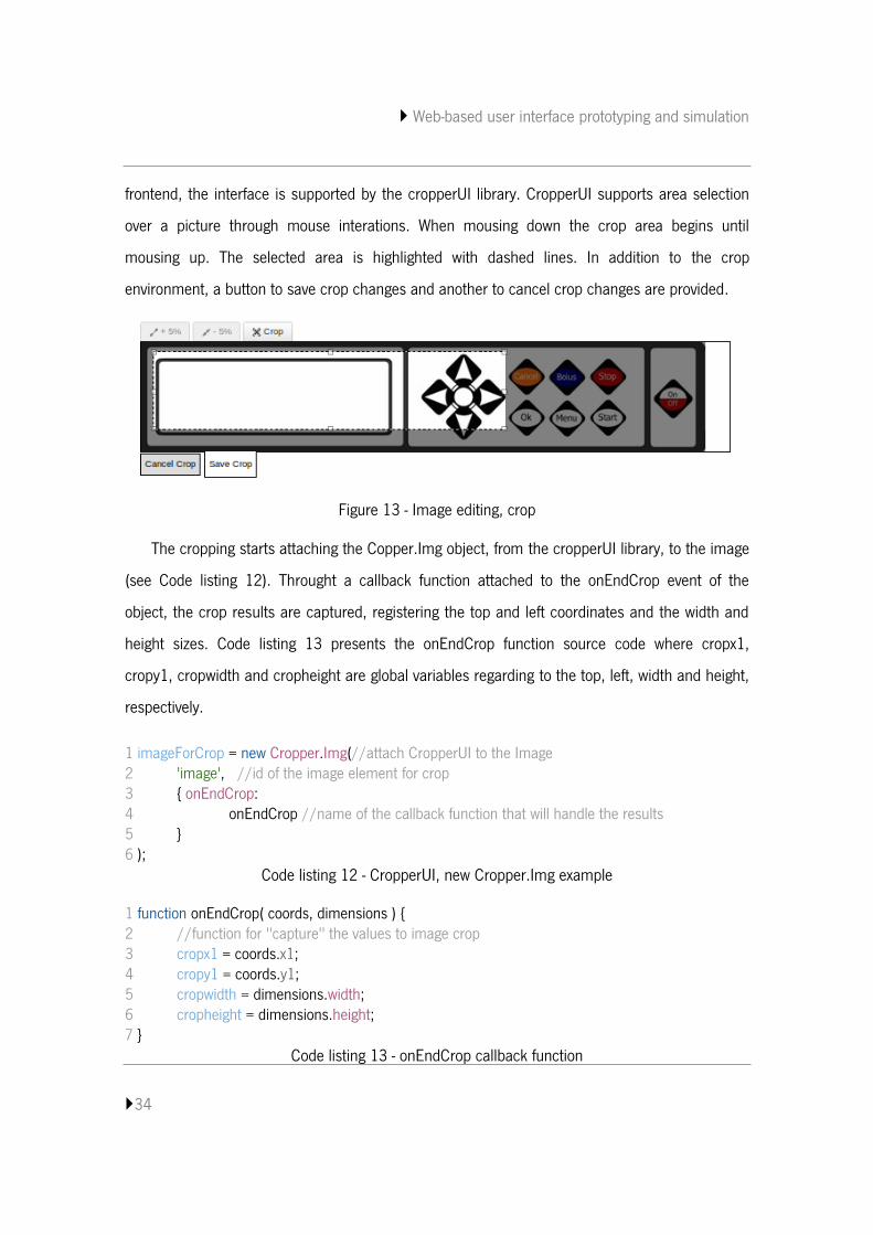
5.2.1 Crop Functionality
Activating the crop functionality by clicking on the Crop button from the toolbar, the image
editing area changes to provide a crop environment (see Figure 13). In order to carry out crop,
an interface for defining the crop area and a way to change the image is required. Changing the
image is supported by the previously referenced EasyImage module in the backend. In the
Web-based user interface prototyping and simulation
34
frontend, the interface is supported by the cropperUI library. CropperUI supports area selection
over a picture through mouse interations. When mousing down the crop area begins until
mousing up. The selected area is highlighted with dashed lines. In addition to the crop
environment, a button to save crop changes and another to cancel crop changes are provided.
Figure 13 - Image editing, crop
The cropping starts attaching the Copper.Img object, from the cropperUI library, to the image
(see Code listing 12). Throught a callback function attached to the onEndCrop event of the
object, the crop results are captured, registering the top and left coordinates and the width and
height sizes. Code listing 13 presents the onEndCrop function source code where cropx1,
cropy1, cropwidth and cropheight are global variables regarding to the top, left, width and height,
respectively.
1 imageForCrop = new Cropper.Img(//attach CropperUI to the Image 2 'image', //id of the image element for crop 3 { onEndCrop: 4 onEndCrop //name of the callback function that will handle the results 5 } 6 );
Code listing 12 - CropperUI, new Cropper.Img example
1 function onEndCrop( coords, dimensions ) { 2 //function for "capture" the values to image crop 3 cropx1 = coords.x1; 4 cropy1 = coords.y1; 5 cropwidth = dimensions.width; 6 cropheight = dimensions.height; 7 }
Code listing 13 - onEndCrop callback function
Web-based user interface prototyping and simulation
35
Saving the crop changes, a request with the values captured by the onEndCrop callback
function for croping the image will be sent to the backend. A success response returned means
image cropped successfully.
After cropping the image, some widgets areas may be out of the area that was selected, or
only partially inside. In any case the coordinates have to be adjusted to the new measurements of
the image. In order to calculate the new coordinates of the widget areas, the coordinates
captured by onEndCrop are subtracted to the old widget areas coordinates. The old coordinates
are replaced by the new ones and widget areas with coordinates outside the boundaries of the
changed image are deleted. This will cause the widget areas move to the left and top in order to
match with the changed image.
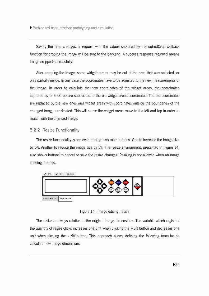
5.2.2 Resize Functionality
The resize functionality is achieved through two main buttons. One to increase the image size
by 5%. Another to reduce the image size by 5%. The resize environment, presented in Figure 14,
also shows buttons to cancel or save the resize changes. Resizing is not allowed when an image
is being cropped.
Figure 14 - Image editing, resize
The resize is always relative to the original image dimensions. The variable which registers
the quantity of resize clicks increases one unit when clicking the + 5% button and decreases one
unit when clicking the - 5% button. This approach allows defining the following formulas to
calculate new image dimensions:
Web-based user interface prototyping and simulation
36
𝑖𝑚𝑔𝑅𝑒𝑠𝑖𝑧𝑒𝑊𝑖𝑑𝑡ℎ = 𝑤𝑖𝑑𝑡ℎ𝑂𝑟𝑖𝑔𝑖𝑛𝑎𝑙 + 𝑤𝑖𝑑𝑡ℎ𝑂𝑟𝑖𝑔𝑖𝑛𝑎𝑙 ∗ 𝑟𝑒𝑠𝑖𝑧𝑒𝐼𝑡𝑒𝑟𝑎𝑡𝑖𝑜𝑛 ∗ 5100⁄ ;
𝑖𝑚𝑔𝑅𝑒𝑠𝑖𝑧𝑒𝐻𝑒𝑖𝑔ℎ𝑡 = ℎ𝑒𝑖𝑔ℎ𝑡𝑂𝑟𝑖𝑔𝑖𝑛𝑎𝑙 + ℎ𝑒𝑖𝑔ℎ𝑡𝑂𝑟𝑖𝑔𝑖𝑛𝑎𝑙 ∗ 𝑟𝑒𝑠𝑖𝑧𝑒𝐼𝑡𝑒𝑟𝑎𝑡𝑖𝑜𝑛 ∗ 5100⁄ ;
Where, imgResizeWidth and imgResizeHeight will be the new width and height dimensions
values, while widthOriginal and heightOriginal are the original width and height image dimensions
values and resizeIteration is the quantity of resize clicks.
After resizing, the widget areas are redefined by using the following formula:
𝑛𝑒𝑤𝐶𝑜𝑜𝑟𝑑 = 𝑜𝑙𝑑𝐶𝑜𝑜𝑟𝑑 + 𝑜𝑙𝑑𝐶𝑜𝑜𝑟𝑑 ∗ 𝑟𝑒𝑠𝑖𝑧𝑒𝐼𝑡𝑒𝑟𝑎𝑡𝑖𝑜𝑛 ∗ 5100⁄ .
newCoord and oldCoord represent the top, left, right or button coordinates that will take the
new value and that contains the old value, respectively.
5.3 Widget Area Editing
PVSio-web supports creating widget areas and moving them by mouse action. When creating
a new area, with mouse actions, the widget area dimensions may not be best suited. The
configuration properties of a widget area can be edited through a widget editor form. Thus, it is
intended to add four new elements – Top position, Left position, Width, Height – to that form in
order to enable the user to adjust the position and dimensions of a widget area.
A selected widget area is marked as selected by assigning it the class “selected”. Selected
a widget area, its coordinates and dimensions values can be accessed and assigned to the form
elements. The top and left properties are the coordinates that identify the point where the area
begins and the height and width are the area dimensions. Assigning these values to the
respective elements of the widget editor form, the user will be able to change them. Saving the
changes to the widget area, the redraw of the widget area will happen in order for it take the new
appearance.
Web-based user interface prototyping and simulation
37
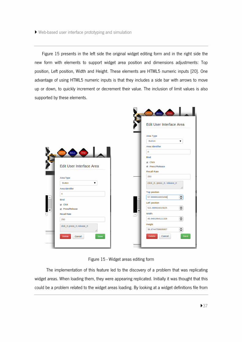
Figure 15 presents in the left side the original widget editing form and in the right side the
new form with elements to support widget area position and dimensions adjustments: Top
position, Left position, Width and Height. These elements are HTML5 numeric inputs [20]. One
advantage of using HTML5 numeric inputs is that they includes a side bar with arrows to move
up or down, to quickly increment or decrement their value. The inclusion of limit values is also
supported by these elements.
Figure 15 - Widget areas editing form
The implementation of this feature led to the discovery of a problem that was replicating
widget areas. When loading them, they were appearing replicated. Initially it was thought that this
could be a problem related to the widget areas loading. By looking at a widget definitions file from
Web-based user interface prototyping and simulation
38
a project it was found that the bug was from save actions. The code for saving widget edits was
always creating a new area instead of updating the existing ones. Thus, a condition to restrict
areas creation was added in order to create a new area only if an area does not already exists.
The absence of an area is validated when the identification property – id – is empty, meaning
that the area is new and still needs to be created. Otherwise, widget areas will only be updated
with new definitions. Code listing 14 presents the code snippet responsible for verifying the
existence of an area, and create or update an area as appropriate.
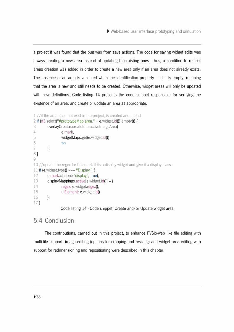
1 //if the area does not exist in the project, is created and added 2 if (d3.select("#prototypeMap area." + e.widget.id()).empty()) { 3 overlayCreator.createInteractiveImageArea( 4 e.mark, 5 widgetMaps.get(e.widget.id()), 6 ws 7 ); 8 } 9 10 //update the regex for this mark if its a display widget and give it a display class 11 if (e.widget.type() === "Display") { 12 e.mark.classed("display", true); 13 displayMappings.active[e.widget.id()] = { 14 regex: e.widget.regex(), 15 uiElement: e.widget.id() 16 }; 17 }
Code listing 14 - Code snippet, Create and/or Update widget area
5.4 Conclusion
The contributions, carried out in this project, to enhance PVSio-web like file editing with
multi-file support, image editing (options for cropping and resizing) and widget area editing with
support for redimensioning and repositioning were described in this chapter.
Web-based user interface prototyping and simulation
39
6. USAGE EXAMPLE
In the previous chapter were described the changes made to the PVSio-web. In this
chapter will present an illustrative example of the new features. For this example will be used a
model of the AlarisGH AsenaCC syring pump.
6.1 The AlarisGH AsenaCC
The AlarisGH AsenaCC is a variable pressure syringe pump suitable for critical care
applications. Researchers from Queen Mary, University of London (QMUL) wrote a PVS
specification that focuses on number entry. In this particular pump number entry is made
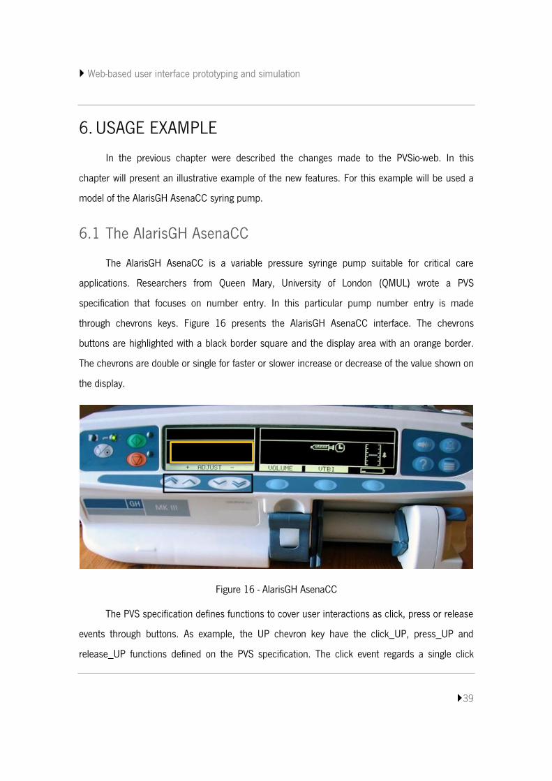
through chevrons keys. Figure 16 presents the AlarisGH AsenaCC interface. The chevrons
buttons are highlighted with a black border square and the display area with an orange border.
The chevrons are double or single for faster or slower increase or decrease of the value shown on
the display.
Figure 16 - AlarisGH AsenaCC
The PVS specification defines functions to cover user interactions as click, press or release
events through buttons. As example, the UP chevron key have the click_UP, press_UP and
release_UP functions defined on the PVS specification. The click event regards a single click
Web-based user interface prototyping and simulation
40
interaction. The press event regards a continuous pressing interactions. The release event
regards a finalization of the press event. The display area reflects the state of the variable display
which change when some event happens.
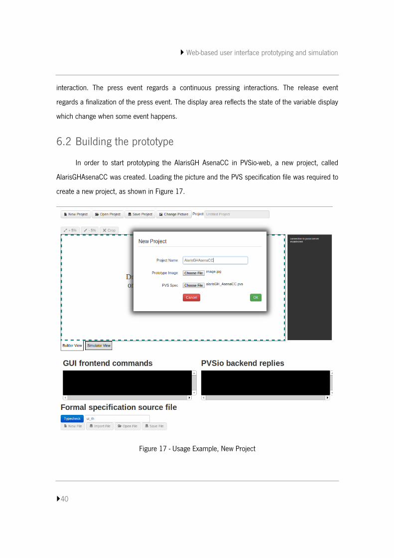
6.2 Building the prototype
In order to start prototyping the AlarisGH AsenaCC in PVSio-web, a new project, called
AlarisGHAsenaCC was created. Loading the picture and the PVS specification file was required to
create a new project, as shown in Figure 17.
Figure 17 - Usage Example, New Project
Web-based user interface prototyping and simulation
41
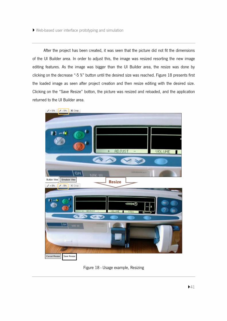
After the project has been created, it was seen that the picture did not fit the dimensions
of the UI Builder area. In order to adjust this, the image was resized resorting the new image
editing features. As the image was bigger than the UI Builder area, the resize was done by
clicking on the decrease “-5 %” button until the desired size was reached. Figure 18 presents first
the loaded image as seen after project creation and then resize editing with the desired size.
Clicking on the “Save Resize” botton, the picture was resized and reloaded, and the application
returned to the UI Builder area.
Figure 18 - Usage example, Resizing
Resize
Web-based user interface prototyping and simulation
42
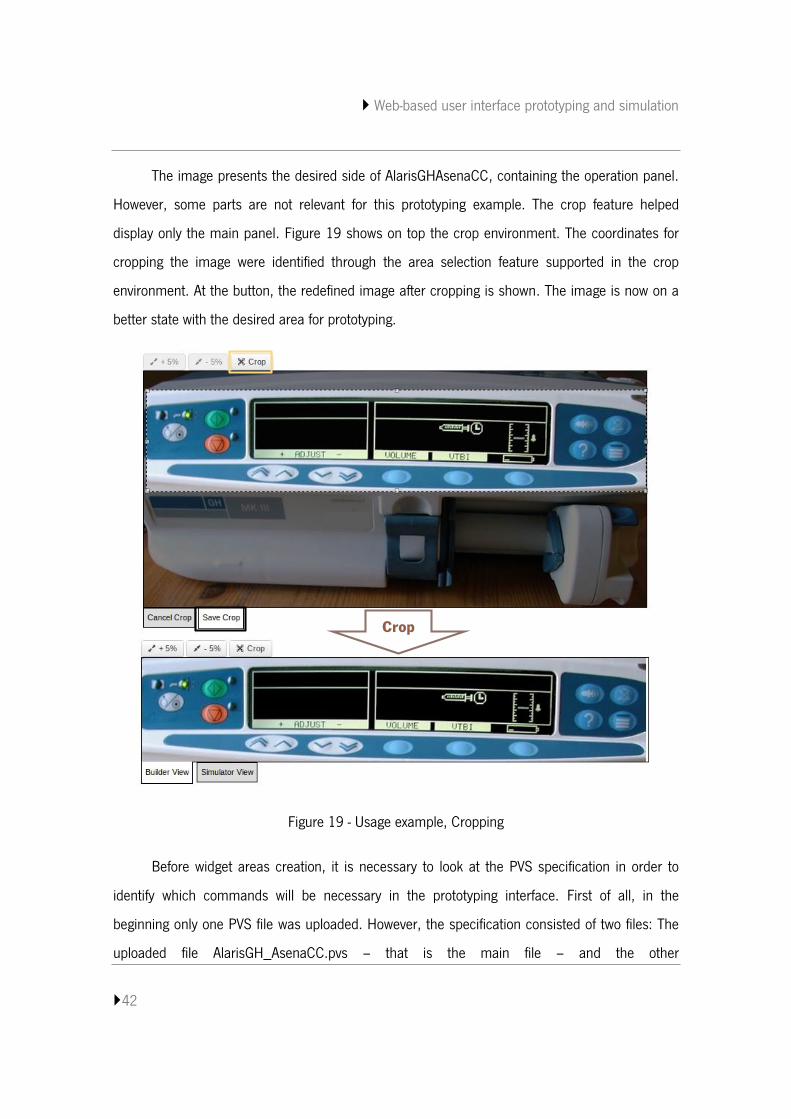
The image presents the desired side of AlarisGHAsenaCC, containing the operation panel.
However, some parts are not relevant for this prototyping example. The crop feature helped
display only the main panel. Figure 19 shows on top the crop environment. The coordinates for
cropping the image were identified through the area selection feature supported in the crop
environment. At the button, the redefined image after cropping is shown. The image is now on a
better state with the desired area for prototyping.
Figure 19 - Usage example, Cropping
Before widget areas creation, it is necessary to look at the PVS specification in order to
identify which commands will be necessary in the prototyping interface. First of all, in the
beginning only one PVS file was uploaded. However, the specification consisted of two files: The
uploaded file AlarisGH_AsenaCC.pvs – that is the main file – and the other
Crop
Web-based user interface prototyping and simulation
43
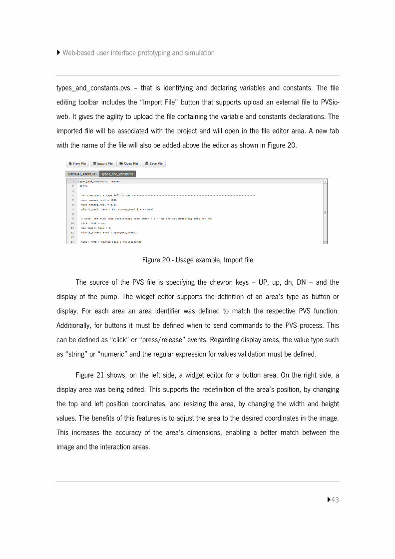
types_and_constants.pvs – that is identifying and declaring variables and constants. The file
editing toolbar includes the “Import File” button that supports upload an external file to PVSio-
web. It gives the agility to upload the file containing the variable and constants declarations. The
imported file will be associated with the project and will open in the file editor area. A new tab
with the name of the file will also be added above the editor as shown in Figure 20.
Figure 20 - Usage example, Import file
The source of the PVS file is specifying the chevron keys – UP, up, dn, DN – and the
display of the pump. The widget editor supports the definition of an area’s type as button or
display. For each area an area identifier was defined to match the respective PVS function.
Additionally, for buttons it must be defined when to send commands to the PVS process. This
can be defined as “click” or “press/release” events. Regarding display areas, the value type such
as “string” or “numeric” and the regular expression for values validation must be defined.
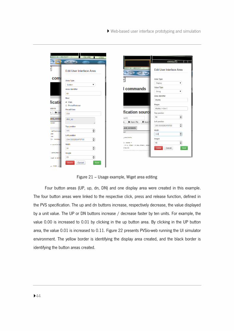
Figure 21 shows, on the left side, a widget editor for a button area. On the right side, a
display area was being edited. This supports the redefinition of the area’s position, by changing
the top and left position coordinates, and resizing the area, by changing the width and height
values. The benefits of this features is to adjust the area to the desired coordinates in the image.
This increases the accuracy of the area’s dimensions, enabling a better match between the
image and the interaction areas.
Web-based user interface prototyping and simulation
44
Figure 21 – Usage example, Wiget area editing
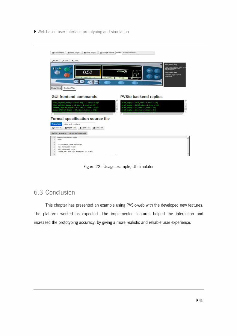
Four button areas (UP, up, dn, DN) and one display area were created in this example.
The four button areas were linked to the respective click, press and release function, defined in
the PVS specification. The up and dn buttons increase, respectively decrease, the value displayed
by a unit value. The UP or DN buttons increase / decrease faster by ten units. For example, the
value 0.00 is increased to 0.01 by clicking in the up button area. By clicking in the UP button
area, the value 0.01 is increased to 0.11. Figure 22 presents PVSio-web running the UI simulator
environment. The yellow border is identifying the display area created, and the black border is
identifying the button areas created.
Web-based user interface prototyping and simulation
45
Figure 22 - Usage example, UI simulator
6.3 Conclusion
This chapter has presented an example using PVSio-web with the developed new features.
The platform worked as expected. The implemented features helped the interaction and
increased the prototyping accuracy, by giving a more realistic and reliable user experience.

Web-based user interface prototyping and simulation
46
Web-based user interface prototyping and simulation
47
7. CONCLUSION
This dissertation described a PVSio-web improvement. PVSio-web extends the simulation
component of the PVS proof system with functionalities for the rapid prototyping of device’s user
interfaces [21]. This comes as a high level environment to validate the behavior of these
interfaces resorting to the specifications, and facilitates user interactions. More functionalities can
be added to support more useful interactions and increasing the prototyping accuracy.
7.1 Achieved objectives and limitations
The original functionalities of PVSio-web supported creating, opening and saving a project,
creating widget areas over an image and linking them to the specification, editing a specification
file and, last but not least, running the prototyping simulator component. There are, however, a
large set of features that could be implemented to improve PVSio-web.
A first aspect was related to the file editor supporting multiple files. A new toolbar was
designed to support creating a new file, importing an external file, opening some internal file and
saving file changes. These features are all associated with the current project under prototyping.
Furthermore, a menu of tabs was implemented in order to identify files opened and allow
switching between them.
A second aspect regarded to adjusting the image to better prototyping. An image editing
toolbar was designed to support two points: cropping and resizing. Cropping resorts to area
selection with mouse events supporting a redefinition of the image crop area limits. Resizing
resorts to two buttons supporting resizing an image in less or more five percent of its dimension
per click event. However, this characteristic of resizing may not to be too user friendly, being
based on button events. It is intended to be improved in the future by implementing an approach
based on mouse actions. Moreover, in the future this two points might also allow direct editing of
values in order to cover possible mouse fails with more precision.
Web-based user interface prototyping and simulation
48
A last but not least aspect contributes to increase the accuracy of the widget areas’
dimensions. Widget areas are created resorting to mouse actions. With this approach, the
accuracy in the definition of the areas is low. In order to improve this, it was added a new feature
for the widget area editor allowing direct values editing.
7.2 Future work
Although it already has a large set of functionality, PVSio-web can still grow. Analyzing new
features that might be interesting for PVSio-web and the limitations identified above, it might be
relevant to consider:
Support for widget areas with distinct forms, such as circles, ovals and triangles
among others, in order to increase flexibility in the definition of the prototype;
Making the functionalities of image editing more similar, supporting resizing by
mouse actions;
Support for uploading multiple specification files when creating a new project, not
being obligated and restricted to one and only one file;
Possibility to create empty projects, not being mandatory to import an image and a
specification file when creating a project.
Web-based user interface prototyping and simulation
49
REFERENCES
1. J. C. Campos and M. D. Harrison. Systematic analysis of control panel interfaces using
formal tools. In XVth International Workshop on the Design, Verification and Specification
of Interactive Systems (DSV-IS 2008), number 5136 of Lecture Notes in Computer
Science, pages 72-85. Springer-Verlag. 2008.
2. J. C. Campos and M. D. Harrison. Interaction engineering using the IVY tool. In ACM
Symposium on Engineering Interactive Computing Systems (EICS 2009), pages 35-44.
ACM. 2009.
3. N. Guerreiro and S. Mendes and V. Pinheiro and J. C. Campos, AniMAL - a user interface
prototyper and animator for MAL interactor models, Interacção 2008 - Actas da 3a.
Conferência Nacional em Interacção Pessoa-Máquina, pages 93-102, 2008.
4. N. M. E. Sousa, WildAniMAL - MAL Interactors Model Animator, Dissertation under
supervision of J. C. Campos, master degree in Informatics Engineering at University of
Minho, November 2012.
5. Christel Baier and Joost-Pieter Katoen, Principles of model checking, The MIT Press,
2008.
6. A. Cimatti, E. Clarke, E. Giunchiglia, F. Giunchiglia, M. Pistore, M. Roveri, R. Sebastiani
and A. Tacchella, NuSMV Version 2: An OpenSource Tool for Symbolic Model Checking,
Proc. International Conference on Computer-Aided Verification (CAV 2002), 2002,
Copenhagen - Denmark, Volume 2404.
7. Sanjeev Arora, The Computational Universe, How To Design A Finite State Machine
[online], Available at [last accessed: 10 January 2013]:
http://www.cs.princeton.edu/courses/archive/spr06/cos116/FSM_Tutorial.pdf.
8. J. C. Campos, J. Saraiva, C. Silva and J. C. Silva (2012). GUI Surfer: A Reverse
Engineering Framework for User Interface Software, Reverse Engineering - Recent
Advances and Applications, Alexandru C. Telea (Ed.), InTech, DOI: 10.5772/32931,
2012.
Web-based user interface prototyping and simulation
50
9. Jason Cai, Ranjit Kapila and Gaurav Pal, HMVC The layared pattern for developing strong
client tiers, Java World, [online], Available at [last accessed: 06 February 2013]:
http://www.javaworld.com/jw-07-2000/jw-0721-hmvc.html
10. Tomi Tuomainen, Use high-level MVC and POJOs with Swing, Java World, [online],
Available at [last accessed: 06 February 2013]:
http://www.javaworld.com/javaworld/jw-06-2005/jw-0620-tikeswing.html
11. Manuel Kiessling, The Node Beginner Book, [online], Available at [last accessed: 18
March 2013]: http://www.nodebeginner.org/
12. Michael Abernethy, O que é exactamente Node.js?, IBM, [online], Available at [last
accessed: 18 March 2013]: http://www.ibm.com/developerworks/br/library/os-nodejs/
13. Jack Franklin, Beginning Node.js, JavaScript Playground, [online], Available at [last
accessed: 18 March 2013]: http://javascriptplayground.com/blog/2012/04/beginning-
node-js-express-tutorial
14. Rakhitha Nimesh, Understanding RequireJS for Effective JavaScript Module Loading,
sitepoint, [online], Available at [last accessed: 08 April 2013]:
http://www.sitepoint.com/understanding-requirejs-for-effective-javascript-module-
loading/
15. Jack Franklin, Introduction to RequireJS, JavaScript Playground, [online], Available at
[last accessed: 08 April 2013]:
http://javascriptplayground.com/blog/2012/07/requirejs-amd-tutorial-introduction
16. Mike Bostock, V. Ogievetsky and J. Heer, Visualization and Computer Graphics, IEEE
Transactions, 2011, Volume 17, Issue 12, Page(s): 2301 - 2309
17. Bhavin Shah, Scalable Vector Graphics, in Conference on Multimedia Systems, 2003.
18. César A. Muñoz, PVSio Reference Manual, National Institute of Aerospace, Available at
[last accessed: 23 July 2013]: http://shemesh.larc.nasa.gov/people/cam/PVSio/PVSio-
2.d.pdf
19. Hage Yaapa, Node.js Image Processing and Manipulation, Available at [last accessed: 25
October 2013]:
Web-based user interface prototyping and simulation
51
http://www.hacksparrow.com/node-js-image-processing-and-manipulation.html
20. Richard Clark, HTML5 forms input types, Available at [last accessed: 31 October 2013]:
http://html5doctor.com/html5-forms-input-types
21. Patrick Oladimeji, Paolo Masci, Paul Curzon and Harold Thimbledy, PVSio-web: a tool for
rapid prototyping device user interfaces in PVS, In 5th International Workshop on Formal
Methods for Interactive Systems (FMIS 2013). Electronic Communications of the
EASST10. 2013.
22. M. D. Harrison, J. C. Campos, and K. Loer. Formal analysis of interactive systems:
opportunities and weaknesses. In P. Cairns and A. Cox, editors, Research Methods in
Human Computer Interaction, chapter 5. Cambridge University Press, 2008.
23. J. Campos, G. Doherty, and M. Harrison. Analysing interactive devices based on
information resource constraints. International Journal of Human-Computer Studies,
72(3):284–297, March 2014.
24. Rémi Bastide, David Navarre and Philippe Palanque. A Tool-Supported Design
Framework for Safety Critical Interactive Systems. Interacting with Computers,
15(3):309-328, June 2003.
25. Sam Stephenson and the Prototype Team. Prototype 1.6: The Complete API Reference.
Available at [last accessed: 27 January 2014]:
http://globalmoxie.com/bm~doc/prototype-160-api.pdf.
26. Jonathan Chaffer and Karl Swedberg. Learning jQuery: better interaction design and web
development with simple JavaScript techniques. Packt Publishing, 2007.