Embed Size (px)
Citation preview

P.Chellapandi, P.Puthiyavinayagam, T.Jeyakumar
S.Chetal and Baldev Raj
Indira Gandhi Centre for Atomic Research
Kalpakkam - 603102
IAEA-Technical Meeting on
‘Design, Manufacturing and Irradiation Behavior of Fast Reactor
Fuels’ 30 May-3 June 2011, IPPE, Russia

Scope of Presentation
Nuclear Power & FBR Programme in India
Economic advantages of high burnups
Int. experience on achieving high burnup
Roadmap of enhancing the burnup
Experience with carbide & oxide fuels
Highlights of R&D
Future Plans
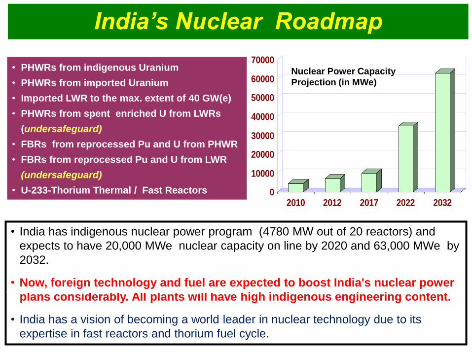
India’s Nuclear Roadmap
• India has indigenous nuclear power program (4780 MW out of 20 reactors) and
expects to have 20,000 MWe nuclear capacity on line by 2020 and 63,000 MWe by
2032.
• Now, foreign technology and fuel are expected to boost India's nuclear power
plans considerably. All plants will have high indigenous engineering content.
• India has a vision of becoming a world leader in nuclear technology due to its
expertise in fast reactors and thorium fuel cycle.
0
10000
20000
30000
40000
50000
60000
70000
2010 2012 2017 2022 2032
Nuclear Power Capacity
Projection (in MWe)
• PHWRs from indigenous Uranium
• PHWRs from imported Uranium
• Imported LWR to the max. extent of 40 GW(e)
• PHWRs from spent enriched U from LWRs
(undersafeguard)
• FBRs from reprocessed Pu and U from PHWR
• FBRs from reprocessed Pu and U from LWR
(undersafeguard)
• U-233-Thorium Thermal / Fast Reactors

FBR Programme in India
• Indigenous Design & Construction
• Comprehensiveness in development of Design, R&D and Construction
• High Emphasis on Scientific Breakthroughs
• Synthesis of Operating Experiences
• Synthesis of Emerging Concepts (Ex.GENIV)
• Focus on National & International Collaborations
• Emphasis on high quality human resources
• Creation of environment for enabling innovations
• Marching towards world leadership by 2025
PFBR
•1250 MWt
•500 MWe
•Pool Type
•UO2-PuO2
•Indigenous
•From 2013..
----Thermal
Insulation
12
95110Anchor safety
vessel
11
----Core04
5561Inner vessel05
----Transfer Arm06
----Large Rotatable
Plug
07
----SRP/Control Plug08
----IHX09
----Primary Pump10
3644.8Core support
structure
02
3476Grid Plate03
01
No.
116134Main vessel
CFBRPFBR
Weight in tComponent
10 09
07 08
06
04 05
03
02 01
11
12
13
72
5
Ø11950
CFBR
•500 MWe
•Pool Type
•UO2-PuO2
•3 twin units
•Indigenous
•From 2023…
Future FBR
• 1000 MWe
• Pool Type
• Metallic fuel
• Serial constr.
• Indegenous
• Beyond 2025
FBTR • 40 MWt
• 13.5 MWe
• Loop type
• PuC – UC
• Design: CEA
• Since 1985

Economic Befefits of High Burnup
High Burnup is desired to
• Reduce Fuel Cycle Cost
- to lower unit energy cost
• Minimise Waste Generation
- less minor actinides and
fission products
• Reduce Man Rem Exposure
Fuel Cycle Cost Variation
Cost Projection (%) EFR EPR
Capital 71 55
O & M 19 17
Fuel Cycle 10 20
FR Burn-up (MWd/Kg)
Re
lati
ve
fu
el c
yc
le c
os
t
Target - 200 GWd/t gradually
enhanced to 250 GWd/ti
For PFBR with 100 GWd/t (peak)
Unit Energy Cost Rs. 3.22
Fuel Cycle Cost Rs. 0.73

Country or
group of
countries
Standard MOX fuel Experimental fuel
No. of pins
irradiated
Burn-up
reached
MWd/t
Maximum
burn-up
MWd/t
Main reactors Type of fuel
pellets
Western
Europe 265 000 135 000 200 000
Phenix, PFR,
KNK-II
Solid &
annular
Unites States 64 000 130 000 200 000 FFTF Leading pins
Japan 50 000 100 000 120 000 Joyo Solid
CIS 13 000 135 000 240 000 BOR-60 Vibro-pac
1 800 100 000 - BN-350 Solid &annular
1 500 100 000 - BN-600 Solid &
annular
Country Reactor Burnup (% h.A)
Russia BR-10
BOR-60
5
10
Germany KNK-II -
USA EBR-II 20.7
India FBTR 17
Carbide
Oxide
200 GWd/t is realisable. Burnup on whole core basis is important
Worldwide Experience on Burnup

Issues Related to High Burnup
In-Pile Behaviour of Fuel
Element & Subassembly
- FCMI
- FCCI
Degradation in
Mechanical Properties
Fuel Cycle Aspects
Multi Disciplinary Expertise
• Reactor physics
• Fuel Properties
• Material Development
• Core engineering
PIE
Modelling
• Reprocessing and
Waste Management
Limitation to achieve high burnup comes from the current generation
core structural materials owing to its excessive deformation and
degradation due to irradiation rather than from the fuel. Thus, the
capability to achieve high burn up is limited by the capability to
accommodate higher neutron doses.
Integrated and Synergistic Approach is Essential
Governing Parameters

Experience with Carbide Fuel

FBTR and Its Fuel Cycle • FBTR is in operation since 1985: completed
more than 25 years of operation
• It uses a unique U,Pu mixed carbide fuel
with high Pu content (Mk-I:70%, Mk-II: 55 %)
• Over 1000 fuel pins have reached an
international record in burn-up (165 GWd/t)
without any failure in the core
• PFBR test fuel SA attained allowable burnup
of 112 GWd/t.
The performance of FBTR has been excellent in recent years, with
plant availability during each campaign exceeding 80 %.
FBTR would operate further around 10 EFPY for irradiation tests on
metallic fuel, sol-gel fuel and advanced clad materials
• Since no direct data was available, physical, chemical and irradiation
behaviour of fuel were obtained through extensive out-of-pile tests
and with the gradual increase of burnup in the reactor.
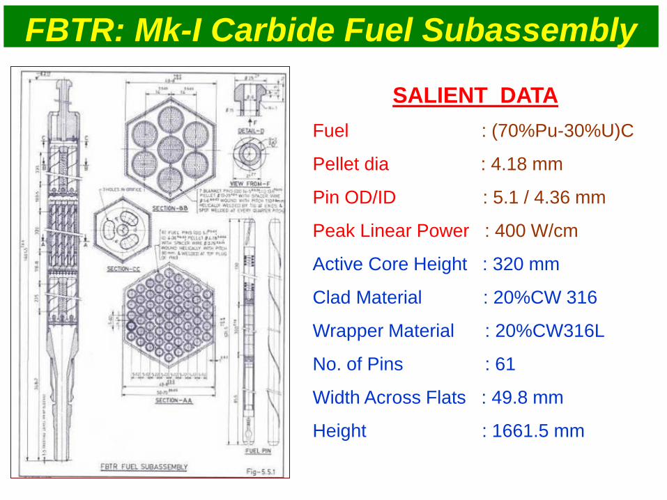
FBTR: Mk-I Carbide Fuel Subassembly
SALIENT DATA
Fuel : (70%Pu-30%U)C
Pellet dia : 4.18 mm
Pin OD/ID : 5.1 / 4.36 mm
Peak Linear Power : 400 W/cm
Active Core Height : 320 mm
Clad Material : 20%CW 316
Wrapper Material : 20%CW316L
No. of Pins : 61
Width Across Flats : 49.8 mm
Height : 1661.5 mm

Mark-I SA Performance
Parameters Active core
bottom
Active core
Middle Active Core top
Coolant Temp (Av.)
º C 340 405 515
Coolant Pressure
MPa 0.34 0.25 0.17
Neutron Flux
n/cm2/sec 1.25X 10¹⁵ 1.71X 10¹⁵ 0.98X 10¹⁵
Burnup
(GWd/t) DPA
Peak Fluence
(n/cm2)
100 46.8 0.783E+23
150 70.2 1.17E+23
154 72.5 1.21E+23
160 74.9 1.25E+23
165 77.2 1.28E+23
Temp & DPA variation over SA length
0
100
200
300
400
500
600
0 50 100 150 200 250 300 350Axial length of SA (mm)
Tem
pera
ture
( C
) .
0
10
20
30
40
50
60
70
80
Flu
en
ce (
DP
A)
.

Radial cracking at low burn-ups in free swelling regime Progressive reduction in fuel clad gap with burn-up Cracking pattern changes from radial to circumferential cracking with closure of fuel clad gap Complete closure of fuel-clad gap along the entire fuel column at 155 GWd/t burnup Porosity free dense zone at the outer rim of the fuel Swelling of fuel accommodated by porosities & clad swelling
Micrographs of fuel pin cross section at the centre of fuel column
25GWd/t 50GWd/t 100GWd/t 155GWd/t
End of fuel column
155GWd/t
Micrographs of Fuel Pin Cross Section

5
Max. FG release ~ 16 %
FG Pressure ~ 20 bars
(155 GWd/t)
Fuel column elongation (X-ray)
0
2
4
6
8
10
12
0 50 100 150 200
Burn-up(GWd/t)
Ave
rag
e in
crea
se i
n s
tack
len
gth
(mm
)
Burn-up in GWd/t
Av.
inc
rea
se in
sta
ck
le
ng
th
X –radiography & Neutron radiography
Plenum
Fuel column
Fuel column Plenum
Higher axial swelling in the restrained swelling phase & low fission gas release
and plenum pressure
X-radiographs N-radiographs

(485 C)
(430 C)
11.5%
3.5%
Performance of Fuel Clad and Wrapper
Burnup Max Fluence Peakdpa
155 GWd/t 1.2 x 10²³ n/cm2 83
D
iam
etr
al s
train
(∆
d /
d %
)
•
155 GWd/t Burnup Fuel assembly and Fuel Pins
20 % CW SS316
Dimensional Changes in Wrapper & Clad
∆V
/ V
%
Void Swelling of FBTR Clad & Wrapper
Progressive
increase in
dimensions of
clad &
wrapper with
dpa

Structural Material Properties: PIE Data
Cladding
Wrapper
∆V
/ V
%
81 dpa
40 dpa
30 dpa
Virgin
TEM studies
100 n
m
100 n
m
100 n
m
500 n
m
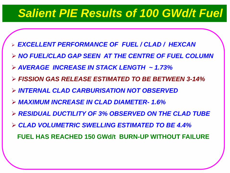
EXCELLENT PERFORMANCE OF FUEL / CLAD / HEXCAN
NO FUEL/CLAD GAP SEEN AT THE CENTRE OF FUEL COLUMN
AVERAGE INCREASE IN STACK LENGTH ~ 1.73%
FISSION GAS RELEASE ESTIMATED TO BE BETWEEN 3-14%
INTERNAL CLAD CARBURISATION NOT OBSERVED
MAXIMUM INCREASE IN CLAD DIAMETER- 1.6%
RESIDUAL DUCTILITY OF 3% OBSERVED ON THE CLAD TUBE
CLAD VOLUMETRIC SWELLING ESTIMATED TO BE 4.4%
FUEL HAS REACHED 150 GWd/t BURN-UP WITHOUT FAILURE
Salient PIE Results of 100 GWd/t Fuel

Burnup
(GWd/t)
Total Clad Strain Clad Diametrical Increase
Predicted PIE Predicted PIE
50 0.2% 0.3% 0.01 mm 0.018 mm
100 1.9% 1.6% 0.09 mm 0.08 mm
150 5.7 % - 0.27 mm -
154 6.2% 5% 0.274 mm 0.27
160 6.7% - 0.32 mm -
165 7.2% - 0.34 mm -
Swelling and Creep Strains in Clad
Burnup Limited to 165 GMd/t based on residual ductility consideration (<10 %)

SA Active Core
Length (mm)
Theoretical Normalised At Max. B.U Limit
154GWd/t 154 GWd/t 164.2 GWd/t
0 0.008 0.004 0.004
32 0.009 0.004 0.005
64 0.010 0.005 0.006
96 0.029 0.017 0.019
128 0.104 0.072 0.080
160 0.245 0.199 0.224
192 0.455 0.405 0.462
224 0.647 0.596 0.690
256 0.701 0.650 0.765
288 0.575 0.525 0.633
320 0.343 0.297 0.362
Dilation Width Across Flat
Burnup Limited to 165 GMd/t based Handling consideration (< 1 mm)

Campaign started in Dec ‘10 with 48 fuel SA 27 MK-I, 13 MK-II & 8 MOX
In Feb 2011, at 18 MWt with TG feeding the grid, scram took place on
DND signal provided for detection of fuel clad failure
Cladding Failure in 17th Campaign
• From DND signals and the ratio of Kr85
/ Kr87 in cover gas samples, failed fuel
identified to be one with a burn-up of
>100 GWd/t.
• From the DND signals during the flux
tilting experiment with operation of
control rod at 2 MWt power, the failed
fuel was identified in the first instance
itself, with only a single fuel handling
• The failed fuel has been presently
discharged for further investigation and
PIE.

Experience with Oxide Fuel
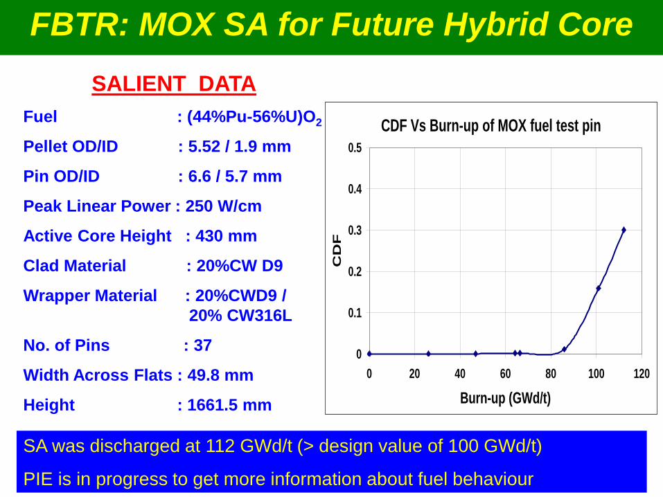
FBTR: MOX SA for Future Hybrid Core
SALIENT DATA
Fuel : (44%Pu-56%U)O2
Pellet OD/ID : 5.52 / 1.9 mm
Pin OD/ID : 6.6 / 5.7 mm
Peak Linear Power : 250 W/cm
Active Core Height : 430 mm
Clad Material : 20%CW D9
Wrapper Material : 20%CWD9 /
20% CW316L
No. of Pins : 37
Width Across Flats : 49.8 mm
Height : 1661.5 mm
CDF Vs Burn-up of MOX fuel test pin
0
0.1
0.2
0.3
0.4
0.5
0 20 40 60 80 100 120
Burn-up (GWd/t)
CD
F
SA was discharged at 112 GWd/t (> design value of 100 GWd/t)
PIE is in progress to get more information about fuel behaviour

Road Map for Achieving
High Burnup
(Materials and Design)

Fuel : (Pu-U)O2
Pellet OD/ID : 5.55/1.8 mm
Pin OD/ID : 6.6/5.7 mm
Peak Linear Power : 450 W/cm
Active core height : 1000 mm
Breeding Ratio : 1.05
Clad & Wrapper : 20 % CW D9
No.of Pins : 217
Width Across Flats : 131.3
Peak target Burnup : 100 GWd/t
Peak neutron dose : 85 dpa
PFBR Core & Fuel Subassembly
Fuel SA - 181
Blanket SA - 120
Total SA - 1758
Salient Details

Advanced Clad and Wrapper Materials
Parameter Current Stage-1 Stage-2 Stage-3 Stage-4
Target Burnup
GWd/t
100 <150 150 200 200
Fuel Oxide Oxide Oxide Oxide Metallic
Clad material D9 IFAC-1 SS
(Indian fast
reactor
advanced
core material)
IFAC-1
SS
9-18 Cr
ODS
steels
T91
F-M steel
Wrapper
Material
D9 IFAC-1 SS T9 F-M
steel T9 F-M
steel
T9
F-M steel
Linear Power,
W/cm 450 450 450 500 >500
• 316 SS, limited to 50,000 MWd/t
• D9 - 15Cr-15Ni-Ti limited to 100,000 MWd/t
• IFAC1 - 14Cr-15Ni-Ti-Si-P limited to 150,000 MWd/t
• 9-18 Cr-1Mo ODS steels upto 200,000 MWd/t

• Rationalisation of hot spot factors
• Increase in residence time with excessive reactivity
• Increasing the fuel handling cycle length
• Increased fissile enrichment zones,
• Optimum core restraint design for reduced bowing & dilation of
wrapper
• Optimization of inter-wrapper gap
• Increasing the fission gas plenum
• Increasing the pellet density and decreasing smeared density,
• Optimum O/M ratio,
• Optimum fuel pin diameter,
• Optimum subassembly size,
• Differential axial enrichment
• Rationalization of over power margin
Design Approach for Future FBRs

Linear Power to Melt
Design Safety Limit
Allowable Linear Power
Over Power Margin
Margin for Uncertainties
Through hot spot factors
Rationalisation of hot spot factors for fixing the Design
Safety Limit & Allowable Linear Power
700 W/cm
518 W/cm
450 W/cm
Rationalization has resulted in lowering of the fuel centre line hot spot
temperature by about 12-15% and the clad midwall hot spot temperature by
about 3-5%, in general. Safety margin is improved

Linear Power = 370 W/cm
0
300
600
900
1200
1500
1800
2100
2400
Tinlet Tna Tco Tci Ts Tcen
Te
mp
era
ture
(K
)
Old Hotspot temperature Rationalized Hotspot temperature
Tmelt = 2123 K
Benefits of Rationalisation of HSF

Thermal Hydraulics Analysis of 217 Fuel Pin Bundle
Validation through CFD Simulations
Fuel pin Spacer wire Hexcan
• Temperature
distribution has been
estimated considering
axial as well as pin-to-
pin variations in heat
generation rate.
•CFD calculations have
been performed for
typical fuel and blanket
SA in all the flow zones
and hotspot factors
have been estimated.
Structured mesh for 217 fuel
pins with helical wires
Sodium temperature variation
at various cross sections along
fuel SA height (every 200 mm in
active zone)

Parameter Present Future
Cycle length
(full power days)
180 270
Fuel enrichment (%) 21/28 23/31
Fraction of core
discharge per cycle
1/3 1/4
Peak fuel burnup
(MWd/t)
100,000 200,000
Improved Oxide Core For High Burnup

R&D Highlights

Swelling studies in IFAC-1 ---- Effect of P and Si
Peak swelling 3.9% and 2.5% for 0.026%P and 0.04%P respectively.
P effective in suppressing swelling at temperature above 850 K due to needle like
phosphide precipitates. P in solution is effective for swelling at lower temperatures
30 appm He pre-implanted + 5 MeV Ni++ ion irradiation; Damage rate: 7x10⁻³ dpa/s
Optimised composition: 0.26Ti, 0.75Si, 0.04P (IFAC-1)
Weldability studies and irradiation in FBTR in progress. IFAC1 - 14Cr-15Ni-Ti-Si-P targeted to 150,000 MWd/t
100 dpa
700 750 800 850 900 9500.0
2.5
5.0
Sw
ellin
g (
%)
Temperature (K)
Si 0.9 Si 0.75

Optimisation of F-M Steel for Wrapper Application
Optimised composition (T9)
Si 0.4 – 0.6, P <0.005, S< 0.005
Normalising at 970 – 1000 C
Tempering at 740 -760 C IFAC 1 clad + P9 wrapper
9% Cr steels shows
minimum shift in DBTT

Clad tubes with improved creep strength
ODS alloy composition (Ferritic vs F-M)
Processing route (upsetting/forging/extrusion)
Particle size & distribution and vol. fraction of dispersoid
Microstructural stability – thermal and irradiation
Anisotropy and mechanical properties (strength/ductility,
toughness)
Weldability
Fuel side compatibility
Sodium compatibility
Reprocessing compatibility
Key Issues in the Development of ODS Steel

1 2
3
300
nm
Substrate
Rp =
5hf
39 40 41 42 43 44 45 46
0
500
1000
1500
2000
2500
3000
3500
4000
4500
5000
5500
6000
RT
A100
A200
A300
A400
A500
A600
A700
A720
A760
2 ( Degrees)
Co
un
ts
Studies on ODS Alloys : Fe-0.3%Y2O3
0 10000 20000 30000 40000 50000
0.0
90.0µ
180.0µ
270.0µ
360.0µ
450.0µ0 10000 20000 30000 40000 50000
0.0
0.2
0.4
0.6
0.8
1.0
No
rmalised
Dam
ag
e p
rofi
le / A
Depth (A)
Nu
mb
er
of
Imp
lan
ted
He/A
Depth (A)
30000 Al
38000 Al
5 MeV
Fe Damage
~ 1.8 µm
thick damage
layer
No dissolution at 25 dpa;
Dissolution seen at 100 dpa
High Temp. XRD across bcc to fcc transition in Fe
TEM Studies on stability of nano- precipitates under irradiation and interactions with dilocations
Dual beam irradiation : 5 MeV Fe + and Helium at 600°C
Dual indentor nanomechanical studies to estimate yield strength & strain hardening exponent in irradiated sample

Alloy powder, Plate-like,
varying sizes <300 m
{100} {110} {111}
NO TEXTURE EBSD/ pole figures
2.5-4.5 4.5-6.5 6.5-8.5 8.5-10.5 10.5-12.5 12.5-15
0
100
200
300
400
fre
qu
en
cy
of
the d
isp
ers
oid
s
Size (nm)2.5 4.5 6.5 8.5 10.5 12.5 15
Development of 9Cr-2W-0.1C-0.2Ti-0.35Y2O3 ODS Clad Tube
Characterisation

200 400 600 800 1000 1200-200
0
200
400
600
800
1000
1200
YS (NFC)
UTS (NFC)
YS (IGCAR)
UTS (IGCAR)
YS (Japanese data)
UTS (Japanese data)
Str
en
gth
, M
Pa
Temperature, K
Element C Cr W Ti Y2O3 Mn N O (Total)
Spec. 0.11 - 0.13 8.8 - 9.2 1.9 - 2.1 0.19 - 0.22 0.32 - 0.35 0.04 max < 0.01
4.2 m
Clad tube 0.12 8.85 2.01 0.21 0.36 0.01 0.01 0.12
100 1000 10000
30
40
50
60708090
200
300
Grade 91
India ODS clad tube
9Cr-ODS Japan
Alloy D9
Ap
pli
ed
str
ess,
MP
a
Rupture life, hour
700 oCTest in progress
Clad-tubes with 6.6 mm O.D., 0.45 mm thick and 4.2 m length have been successfully produced
Development of 9Cr-2W-0.1C-0.2Ti-0.35Y2O3 ODS Clad Tube
Mechanical properties

PFBR Core
Radial Shields:
9 Rows (SS & B4C)
609 SS + 417 B4C
Advantage of using ferroboron
• Reduction of 1 row of SA
• Reduction in no. of SA - 145
• Reduction in MV diameter by ~350
mm
• High temperature metallurgical
interaction tests with 304L SS have
shown good compatibility
• Low cost
• Estimated cost redn - ~ 40 Crores
CFBR Core
Radial Shields:
8 Rows (Ferroboron)
• Ferroboron is used as a master
alloy in steel industry as an additive
for boron.
• Commercial ferroboron has 15-18
wt% boron
• Available in form of lumps, granules
and powder
• Bulk density: ~4 g/cm3
Bulk Shield Reduction through Advanced Shielding Material
881 FERRO BORON SA

Thermal and epithermal neutron flux attenuation in Ferro
Boron slabs
1.00E-04
1.00E-03
1.00E-02
1.00E-01
1.00E+00
0 20 40 60 80 100 120
Thickness(cm) x Density (g/cm3)
Neu
tron
atten
uatio
n
Mn Equivalent flux
Na Equivalent flux
Gold Equivalent flux
Fast neutron flux attenuation in ferro boron slabs.
0.01
0.1
1
0 20 40 60 80 100
Thickness (cm) x Density (g/cm3)
Neu
tron
atten
uatio
n
Rh Equivalent flux
In Equivalent flux
Potential of ferroboron as shield material tested in neutron attenuation experiments in KAMINI
Ferro boron as the shielding material
Metallographic characterization
of ferro-boron powder has shown
boron as iron borides
Hot-sodium experiment has
shown that ferro boron does not
react with liquid Na upto 650 o C.
Metallurgical and chemical
compatibility studies in progress
High temperature clad-ferro boron
(304lss/feb) interaction tests at
high temperatures with varying
time durations; estimation of clad
penetration depth at 700oC in
progress
EXPERIMENTS WITH VARYING B CONTENT IN PROGRESS

Numerical Simulations
Analyses leading to cost benefits
0
20
40
60
80
100
120
120 80 40 10
Axial Distance from top - mm
Gap
- m
icro
ns
Cold gap - Pre irradiation Cold gap - post irradiation
Time to reach full power
Irradiation expt in FBTR
Numerical Analysis & expt both
confirm that LHR can be taken to 450
W/ cm in few days
-25
-20
-15
-10
-5
0
5
10
15
20
25
Clad_ID % He Pellet_ID Pellet_OD Pellet
Density
O/M ratio
Parameters affecting LPM
Ch
an
ge
in L
PM
(%
)
% LPM change for -2.5% variation in all parameters
% LPM change for +2.5% variation in all parameters
Key parameters to reach high
linear power
Clad ID & Pellet OD
Influence of fab.parameters on LPM

Allowable Manufacturing Deviations Pellet Defects Acceptability
Analysis defines pellet depth for
defect area. Improves in pellet
recovery without compromising
safety
Rupture Life of Fuel pin end plug w elding,36 tubes simultanious testing
0
100
200
300
400
500
600
700
800
900
1000
1100
1200
1300
1400
1500
1600
0 1 2 3 4
No of w eld repaires
Ruptu
re L
ife(H
ours)
No of weld repairs
Ru
ptu
re
life
-h
No of weld repairs
Reductio
n f
acto
rWeld strength reduction factor
The rupture lives measured for the
various test cases, based on the test
data and analysis, a design approach
is proposed for the inclusion in RCC-
MR:2007 edition.
Acceptability of refused end plug weld

Status on Metallic Fuel Studies

Metallic Fuel Pin Design Concepts
LINER
Sodium Bonded
U-Pu-Zr(6/10%)
No liner
75 % smeared
density
Top Plenum
Mechanical bonded
U-15Pu (4 grooves)
Zr- 4 Liner
75 % smeared
density
Bottom plenum
Mechanical bonded
U-15Pu ( 2 grooves)
Zr- 4 Liner
85 % smeared
density
Bottom plenum
Sodium Bonded
U-15Pu (No Zr in
fuel)
Zr- 4 Liner
75 % smeared
density
Top Plenum
Mechanical Bonded
Fuel Pin Cross
Section
CLAD
FUE
L
Advantages:
High BR, Low T, High linear rating, Inherent safety
Doubling time : 30 y for oxide , 12 y for metal and
8 ys for improved metal (without Zr)

Linear Power
- 450 W/ cm
Clad
- T91
Irradiation
Capsule irradiation – 3 pins
SA irradiation – 37 pins
Prototype scale -217 pins
Target Burnup
-150 GWd/ t
Pin Irradiation in
FBTR
Subassembly
Irradiation in FBTR
Full Core Metallic
Fuel in FBTR
Metallic Fuel
320 MWe Design
Metallic Fuel
1000 MWe Design
Metallic Fuel Development
Road Map
Expt Pin - Schematic Salient Highlights

Metallic Fuel Sodium Bonding Facilities
Argon Glove Box
for Sodium Handling
Sodium wire extruder
Sodium wire extrusion
into PVC tube
Pin welding fixture
Sodium Bonding
Furnace with Vibrator
Dummy Fuel Pin
Developmental Facilities
established in BARC and
IGCAR to demonstrate the
technology
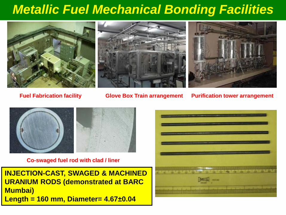
Purification tower arrangement Glove Box Train arrangement Fuel Fabrication facility
Co-swaged fuel rod with clad / liner
INJECTION-CAST, SWAGED & MACHINED
URANIUM RODS (demonstrated at BARC
Mumbai)
Length = 160 mm, Diameter= 4.67±0.04
Metallic Fuel Mechanical Bonding Facilities

Facilities for R&D on Fuel Pin Behavior
Induction heating
• FBTR for further about 10 EFPY
• Radio Metallurgy Laboratory
• Material Development Laboratory
• PFBR from 2013…
• JHR at Cadarache under CEA-DAE agreement and IGCAR is
developing an innovative sodium loops for the irradiation tests of
multiple specimens at high temperature in JHR.
• 320 MWt Metallic Fast Reactor (MFR: to test the SA on 1:1 scale
basis) from 2017…
A dedicated test facility for studying the
oxide as well metallic fuel pin behaviour
under rapid heating that would simulate
various accident conditions leading to fuel
melting

Epilogue: Success Mantra
• Well conceived roadmap for the development of fuels &
structural materials and test facilities for enhancing burnup
gradually to 200 GWd/t, subsequently 250 GMd/t
• Experience from 400 r-y of FBRs worldwide including FBTR
• Expertise developed on the essential domains such as
material development including fuel, design, structural
mechanics, core thermal hydraulics, numerical simulations of
fuel behavior, PIE, manufacturing, testing and Evaluations
• Availability of FBTR, PFBR and 320 MWt MFR over long period
• Excellent coordination among various units in the Department
of Atomic Energy, involved in design, manufacturing and R&D
• National and International Collaborations

INDIAN NUCLEAR PROGRAMME Towards sustainable energy