Embed Size (px)
Citation preview
���������������������� �����������������������������������
����� �!����!"#$��%$���!$$����&�'�� �!����!"#$��$����!$�
������()��*�+���
HIWIN PCI-4P Motion Library
User’s Manual
PPH WObit �������� �Witold Ober
61-474 ������ , ul. Gruszkowa 4
tel.061/8350-620, -621 fax. 061/8350704
e-mail: [email protected]. http://www.wobit.com.pl
Ver. 1.0
2003
���������������������� �����������������������������������
����� �!����!"#$��%$���!$$����&�'�� �!����!"#$��$����!$�
WObit 2003 2
������()��*�+���
Contents
1. INTRODUCTION TO MCCL MOTION LIBRARY 3
2. MCCL FEATURES 5
2.1 SOFTWARE SPECIFICATION .. . . . . . . . . . . . . . . . . . . . . . . . . . . . . . . . . . . . . . . . . . . . . . . . . . . . . . . . . . . . . . . . . . . 5
2.2 HARDWARE SPECIFICATION .. . . . . . . . . . . . . . . . . . . . . . . . . . . . . . . . . . . . . . . . . . . . . . . . . . . . . . . . . . . . . . . . . . 6
2.3 DEFINITION OF CONTROL AXES .. . . . . . . . . . . . . . . . . . . . . . . . . . . . . . . . . . . . . . . . . . . . . . . . . . . . . . . . . . . . . 6
2.4 MECHANISM PARAMETER SETTING .. . . . . . . . . . . . . . . . . . . . . . . . . . . . . . . . . . . . . . . . . . . . . . . . . . . . . . . . 7
2.5 INITIALIZE AND CLOSE MCCL ... . . . . . . . . . . . . . . . . . . . . . . . . . . . . . . . . . . . . . . . . . . . . . . . . . . . . . . . . . . .16
2.5.1 Initialize MCCL 16
2.5.2 Close MCCL 21
2.6 MOTION CONTROL .. . . . . . . . . . . . . . . . . . . . . . . . . . . . . . . . . . . . . . . . . . . . . . . . . . . . . . . . . . . . . . . . . . . . . . . . . . . . .21
2.6.1 Coordinate System 21
2.6.2 Basic Trajectory Planning 22
2.6.3 Advanced Trajectory Planning 25
2.6.4 Interpolation Time and Acceleration/Deceleration Step Setting 30
2.6.5 System Status 32
2.7 HOMING .. . . . . . . . . . . . . . . . . . . . . . . . . . . . . . . . . . . . . . . . . . . . . . . . . . . . . . . . . . . . . . . . . . . . . . . . . . . . . . . . . . . . . . . . . . .33
2.8 LOCAL INPUT/OUTPUT (I/O) CONTROL.. . . . . . . . . . . . . . . . . . . . . . . . . . . . . . . . . . . . . . . . . . . . . . . . . .36
2.8.1 Input 36
2.8.2 Output 37
2.9 ENCODER CONTROL .. . . . . . . . . . . . . . . . . . . . . . . . . . . . . . . . . . . . . . . . . . . . . . . . . . . . . . . . . . . . . . . . . . . . . . . . . . .37
3. COMPILER ENVIRONMENT 38
3.1 USING VISUAL C++.. . . . . . . . . . . . . . . . . . . . . . . . . . . . . . . . . . . . . . . . . . . . . . . . . . . . . . . . . . . . . . . . . . . . . . . . . . . .38
3.2 USING VISUAL BASIC .. . . . . . . . . . . . . . . . . . . . . . . . . . . . . . . . . . . . . . . . . . . . . . . . . . . . . . . . . . . . . . . . . . . . . . . . .39
���������������������� �����������������������������������
����� �!����!"#$��%$���!$$����&�'�� �!����!"#$��$����!$�
WObit 2003 3
������()��*�+���
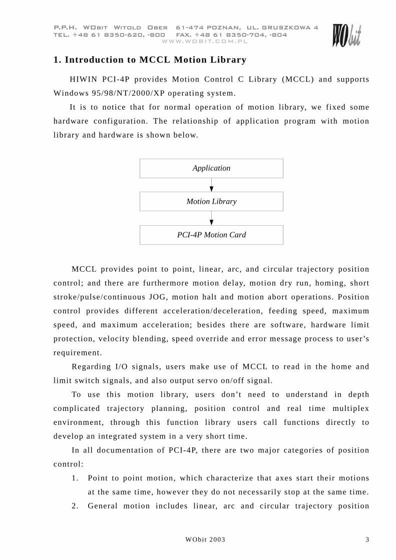
1. Introduction to MCCL Motion Library
HIWIN PCI-4P provides Motion Control C Library (MCCL) and supports
Windows 95/98/NT/2000/XP operating system.
It is to notice that for normal operation of motion library, we fixed some
hardware configuration. The relationship of application program with motion
library and hardware is shown below.
Application
PCI-4P Motion Card
Motion Library
MCCL provides point to point, l inear, arc, and circular trajectory position
control; and there are furthermore motion delay, motion dry run, homing, short
stroke/pulse/continuous JOG, motion halt and motion abort operations. Position
control provides different acceleration/deceleration, feeding speed, maximum
speed, and maximum acceleration; besides there are software, hardware limit
protection, velocity blending, speed override and error message process to user’s
requirement.
Regarding I/O signals, users make use of MCCL to read in the home and
limit switch signals, and also output servo on/off signal.
To use this motion library, users don’t need to understand in depth
complicated trajectory planning, position control and real time multiplex
environment, through this function library users call functions directly to
develop an integrated system in a very short time.
In all documentation of PCI-4P, there are two major categories of position
control:
1. Point to point motion, which characterize that axes start their motions
at the same time, however they do not necessarily stop at the same time.
2. General motion includes linear, arc and circular trajectory position
���������������������� �����������������������������������
����� �!����!"#$��%$���!$$����&�'�� �!����!"#$��$����!$�
WObit 2003 4
������()��*�+���
control. In this case, motions of axes are related and start and stop at
the same time.
RELATED MANUALS:
HARDWARE RELATED
HIWIN PCI-4P hardware user’s manual
MOTION LIBRARY
HIWIN PCI-4P motion library reference manual
HIWIN PCI-4P motion library example manual
HIWIN PCI-4P motion library user ’s manual
���������������������� �����������������������������������
����� �!����!"#$��%$���!$$����&�'�� �!����!"#$��$����!$�
WObit 2003 5
������()��*�+���
2. MCCL Features
2 .1 Software Speci f icat ion
� Operation System Environment
� WINDOWS 95
� WINDOWS 98
� WINDOWS NT
� WINDOWS 2000/XP
��Development Environment� Visual C++ (VC++)
� Visual Basic
� Library Name
MCCL.h, MCCL_Fun.h (for VC++)
MCCLPCI_45.bas (for VB)
MCCLPCI_45.lib (for VC++)
MCCLPCI_45.dll
ACTADrv.dll
���������������������� �����������������������������������
����� �!����!"#$��%$���!$$����&�'�� �!����!"#$��$����!$�
WObit 2003 6
������()��*�+���
2.2 Hardware Speci f icat ion
User Application
M otion Library
PCI-4P
PCI-4P
PCI-4P
PCI-4P
M otor Driver
M otor Driver
M otor Driver
M otor Driver
M otor
M otor
M otor
M otor
M otor Driver M otor
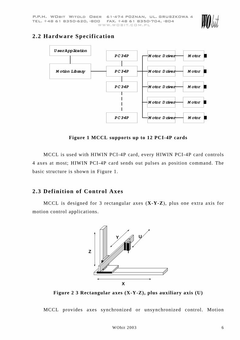
Figure 1 MCCL supports up to 12 PCI-4P cards
MCCL is used with HIWIN PCI-4P card, every HIWIN PCI-4P card controls
4 axes at most; HIWIN PCI-4P card sends out pulses as position command. The
basic structure is shown in Figure 1.
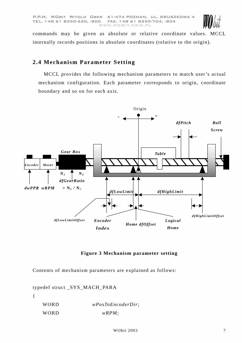
2.3 Def ini t ion of Control Axes
MCCL is designed for 3 rectangular axes (X-Y-Z), plus one extra axis for
motion control applications.
X
Z
Y U
Figure 2 3 Rectangular axes (X-Y-Z), plus auxiliary axis (U)
MCCL provides axes synchronized or unsynchronized control. Motion
���������������������� �����������������������������������
����� �!����!"#$��%$���!$$����&�'�� �!����!"#$��$����!$�
WObit 2003 7
������()��*�+���
commands may be given as absolute or relative coordinate values. MCCL
internally records positions in absolute coordinates (relative to the origin).
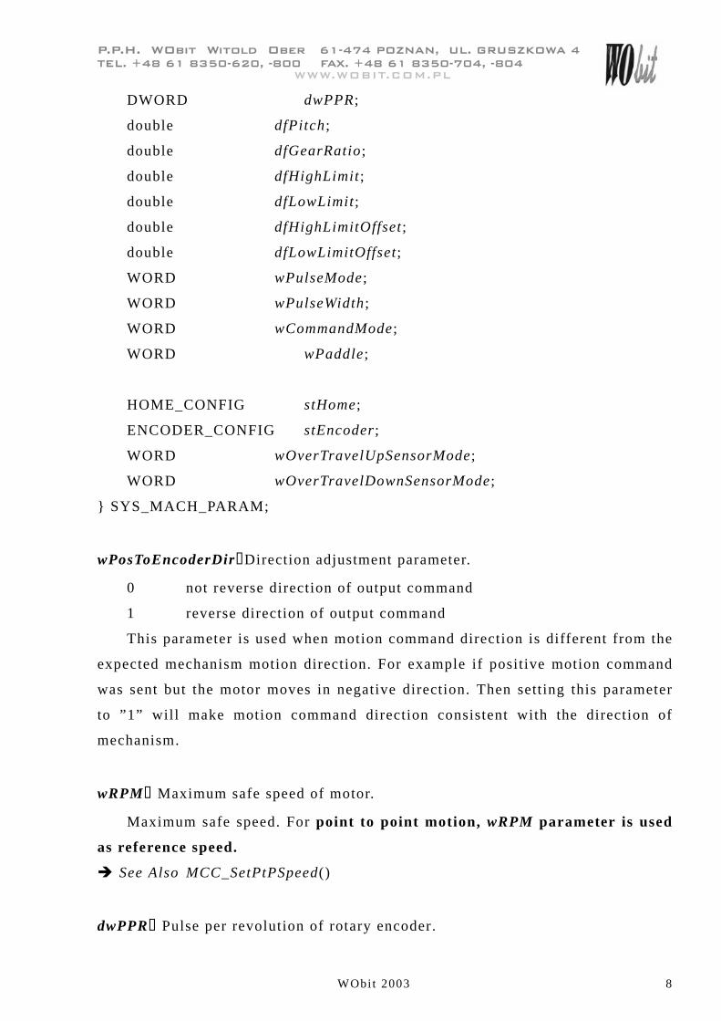
2.4 Mechanism Parameter Sett ing
MCCL provides the following mechanism parameters to match user ’s actual
mechanism configuration. Each parameter corresponds to origin, coordinate
boundary and so on for each axis.
Figure 3 Mechanism parameter setting
Contents of mechanism parameters are explained as follows:
typedef struct _SYS_MACH_PARA
{
WORD wPosToEncoderDir ;
WORD wRPM ;
Table
Ball
Screw
E n c od e r M o t or
Gear Box
N1 N2
dfGearRatio
= N1 / N 2dwPPR wRPM
dfPitch
d f L o wL i m i t O ff s e td f Hi g h L i m i tO ff s e t
dfHighLimitdfLowLimit
Encoder
Index
Logical
HomeHome dfOffset
+-
Origin
���������������������� �����������������������������������
����� �!����!"#$��%$���!$$����&�'�� �!����!"#$��$����!$�
WObit 2003 8
������()��*�+���
DWORD dwPPR ;
double dfPitch ;
double dfGearRatio ;
double dfHighLimit ;
double dfLowLimit ;
double dfHighLimitOffset;
double dfLowLimitOffset;
WORD wPulseMode;
WORD wPulseWidth ;
WORD wCommandMode ;
WORD wPaddle ;
HOME_CONFIG stHome;
ENCODER_CONFIG stEncoder ;
WORD wOverTravelUpSensorMode;
WORD wOverTravelDownSensorMode;
} SYS_MACH_PARAM;
wPosToEncoderDir�Direction adjustment parameter.
0 not reverse direction of output command
1 reverse direction of output command
This parameter is used when motion command direction is different from the
expected mechanism motion direction. For example if positive motion command
was sent but the motor moves in negative direction. Then setting this parameter
to ”1” will make motion command direction consistent with the direction of
mechanism.
wRPM� Maximum safe speed of motor.
Maximum safe speed. For point to point motion, wRPM parameter is used
as reference speed.
� See Also MCC_SetPtPSpeed()
dwPPR� Pulse per revolution of rotary encoder.
���������������������� �����������������������������������
����� �!����!"#$��%$���!$$����&�'�� �!����!"#$��$����!$�
WObit 2003 9
������()��*�+���
For rotary servomotor, it is set to pulse number of encoder per revolution,
after considering 1x, 2x, and 4x encoder mode. The 1x, 2x, and 4x encoder mode
is set by MCC_SetENCInputRate().
For open loop stepping motor, there is no encoder; it is set to the number of
pulses, with which motor would turn one revolution.
For linear motor, this parameter could be set to any value. However, notice
that moving distance is calculated with the following formula:
(Pulse × dfPitch)/(dwPPR × dfGearRatio)
For MCCL function call, the unit is always mm or inch except
MCC_JogPulse().
dfPitch� Ball screw pitch value. (lead)
This parameter is the table displacement for one revolution of the ball
screw; its unit is mm. For linear motors, this value should be set 1.
dfGearRatio� Gear ratio
This is the number of revolutions of rotary motor when ball screw makes
one revolution.
dfHighLimit� Set value for positive software limit
This value is the maximum allowable displacement in the positive direction
relative to the logical home; its unit is mm.
� See Also MMC_SetOverTravelCheck()
dfLowLimit�Set value for negative software limit
This value is the maximum allowable displacement in the negative direction
relative to the logical home; its unit is mm. This value must be negative.
dfHighLimitOffset�Offset value for dfHighLimit
This value must be positive and can’t be greater than dfHighLimit . After
setting in the designated axis, its effective working interval in the positive
direction = dfHighLimit�dfHighLimitOffset
���������������������� �����������������������������������
����� �!����!"#$��%$���!$$����&�'�� �!����!"#$��$����!$�
WObit 2003 10
������()��*�+���
dfLowLimitOffset�Offset value for dfLowLimit
This value must be positive and can’t be greater than absolute value of
dfLowLimit. After setting in the designated axis, its effective working interval in
the negative direction = dfLowLimitOffset + dfLowLimit
wPulseMode�Pulse output mode.
0 Pulse/Direction
1 CW/CCW
2 A/B phase
wPulseWidth�Output pulse width.
Set the width of output pulse to satisfy driver ’s specification. The real
output pulse width is the set value multiplied by system cycle width (25 ns).
Please follow the driver ’s specification to set the output pulse width.
wCommandMode�Motion command output mode.
0 pulse command
wOverTravelUpSensorMode� Type of positive limit switch.
0 Normal Open (NO)
1 Normal Close (NC)
2 No limit switch is installed
wOverTravelDownSensorMode� Type of negative limit switch.
0 Normal Open (NO)
1 Normal Close (NC)
3 No limit switch is installed
wPaddle
Reserved data, users don’t need to set.
���������������������� �����������������������������������
����� �!����!"#$��%$���!$$����&�'�� �!����!"#$��$����!$�
WObit 2003 11
������()��*�+���
Users should call MCC_EnableLimitSwitchCheck() to enable checking limit
switch ; but when wOverTravelUpSensorMode and
wOverTravelDownSensorMode are set to 2, then calling
MCC_EnableLimitSwitchCheck() will have no meaning.
There are two modes to call MCC_EnableLimitSwitchCheck().
Mode0: direction sensitive limit switches. For example move in the positive
direction and touch the positive limit switch or move in the negative direction
and touch the negative limit switch, it will stop outputting pulses (but that
command is still in calculation).
Mode1: Not direction sensitive limit switches. As long as the limit switch is
engaged, it will stop outputting pulses.
In general, MCC_EnableLimitSwitchCheck() and
MCC_GetLimitSwitchStatus() are used together. If limit switch was engaged,
users should call MCC_AbortMotion() to abort the motion command in
execution.
Homing Parameters (HOME_CONFIG) :
This defines necessary homing parameters. Format and explanation are as
follows. Regarding homing related detailed explanation, please refer to later
sections.
typedef struct _HOME_CONFIG
{
WORD wType ;
WORD wPhase0Dir ;
WORD wPhase1Dir ;
WORD wSensorMode;
double dfOffset;
} HOME_CONFIG ;
wType: Homing mode.
0 NORMAL_MODE Use the encoder index closest to the
home sensor as the mechanism origin.
(Mechanism origin is also called

���������������������� �����������������������������������
����� �!����!"#$��%$���!$$����&�'�� �!����!"#$��$����!$�
WObit 2003 12
������()��*�+���
electrical origin. Mechanism origin
and logical origin will be explained
later.)
1 HOME_ONLY_MODE Home sensor as mechanism origin.
2 INDEX_ONLY_MODE Use the first encoder index as
mechanism origin.
wPhase0Dir: Motion direction for homing phase 0
0 positive direction
1 negative direction
wPhase1Dir: Motion direction for homing phase 1
0 positive direction
1 negative direction
wSensorMode: Type of home sensor
0 Normal Open (NO)
1 Normal Close (NC)
COM
HOM
NO
+24V
24V_GND
PCI-4P Motion CardHome Sensor
COM
HOM
NC
+24V
24V_GND
PCI-4P Motion Card Home Sensor
Figure 4 Type of home sensor
dfOffset: Position offset of logical origin.
During homing process and after mechanism origin was found, PCI-4P
would move a distance of dfOffset and stops. The point of stop is called logical
home. Notice that dfOffset could be positive or negative value. If it is set to 0,
���������������������� �����������������������������������
����� �!����!"#$��%$���!$$����&�'�� �!����!"#$��$����!$�
WObit 2003 13
������()��*�+���
mechanism origin is equal to logical home.
Set Encoder Format (ENCODER_CONFIG)�
typedef struct _ENCODER_CONFIG
{
WORD wType;
WORD wAInverse;
WORD wBInverse;
WORD wCInverse;
WORD wABSwap ;
WORD wPaddle[3];
} ENCODER_CONFIG
wType�Encoder type
0 A/B Phase
1 CW/CCW
2 Pulse/Direction
wAInverse�Whether to inverse phase A of encoder
1 Inverse
0 Not Inverse
wBInverse�Whether to inverse phase B of encoder
1 Inverse
0 Not Inverse
wCInverse�Whether to inverse phase Z of encoder
1 Inverse
0 Not Inverse
wABSwap�Whether to swap phase A and B of encoder
���������������������� �����������������������������������
����� �!����!"#$��%$���!$$����&�'�� �!����!"#$��$����!$�
WObit 2003 14
������()��*�+���
0 Swap
1 Not Swap
wPaddle�Reserve data, users don’t need to set.
After collecting all the mechanism parameters, use MCC_SetMachParam() to
set them; an example is shown as follows:
SYS_MACH_PARAM stAxisParam;
stAxisParam.wPosToEncoderDir = 0;
stAxisParam.dwPPR = 500;
stAxisParam.wRPM = 3000;
stAxisParam.dfPitch = 1.0;
stAxisParam.dfGearRatio = 1.0;
stAxisParam.dfHighLimit = 50000.0;
stAxisParam.dfLowLimit = -50000.0;
stAxisParam.dfHighLimitOffset = 5.0;
stAxisParam.dfLowLimitOffset = 5.0;
stAxisParam.wPulseMode = 0;
stAxisParam.wPulseWidth = 100;
stAxisParam.wCommandMode = 0;
stAxisParam.wOverTravelUpSensorMode = 2;// Not Check
stAxisParam.wOverTravelDownSensorMode = 2;
stAxisParam.stHome.wType = NORMAL_MODE;
stAxisParam.stHome.wSensorMode = 0;
stAxisParam.stHome.wPhase0Dir = 1;
stAxisParam.stHome.wPhase1Dir = 0;
stAxisParam.stHome.dfOffset = 0;
stAxisParam.stEncoder.wType = ENC_TYPE_AB;
stAxisParam.stEncoder.wAInverse = NO;
���������������������� �����������������������������������
����� �!����!"#$��%$���!$$����&�'�� �!����!"#$��$����!$�
WObit 2003 15
������()��*�+���
stAxisParam.stEncoder.wBInverse = NO;
stAxisParam.stEncoder.wCInverse = NO;
stAxisParam.stEncoder.wABSwap = NO;
MCC_SetMachParam(&stAxisParam, 0, 0);//set parameters for axis 0 of 0th-card
The mechanism parameters have to be set individually for every axis. Once
MCC_InitSystem() is called to initialize MCCL and you use
MCC_SetMachParam() to change mechanism parameters again, it is necessary to
call MCC_UpdateMachParam() to update them.
� See Also MCC_GetMachParam()
���������������������� �����������������������������������
����� �!����!"#$��%$���!$$����&�'�� �!����!"#$��$����!$�
WObit 2003 16
������()��*�+���
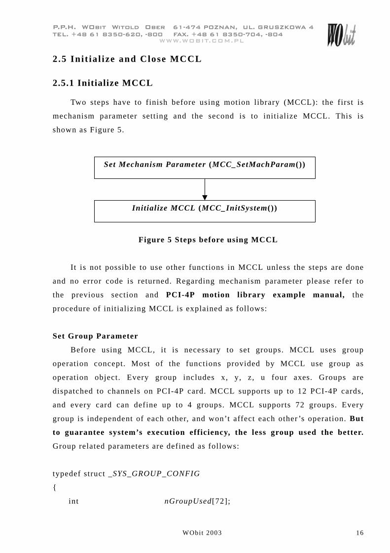
2.5 Ini t ia l ize and Close MCCL
2.5.1 Initialize MCCL
Two steps have to finish before using motion library (MCCL): the first is
mechanism parameter setting and the second is to initialize MCCL. This is
shown as Figure 5.
Figure 5 Steps before using MCCL
It is not possible to use other functions in MCCL unless the steps are done
and no error code is returned. Regarding mechanism parameter please refer to
the previous section and PCI-4P motion library example manual, the
procedure of initializing MCCL is explained as follows:
Set Group Parameter
Before using MCCL, it is necessary to set groups. MCCL uses group
operation concept. Most of the functions provided by MCCL use group as
operation object. Every group includes x, y, z, u four axes. Groups are
dispatched to channels on PCI-4P card. MCCL supports up to 12 PCI-4P cards,
and every card can define up to 4 groups. MCCL supports 72 groups. Every
group is independent of each other, and won’t affect each other ’s operation. But
to guarantee system’s execution efficiency, the less group used the better.
Group related parameters are defined as follows:
typedef struct _SYS_GROUP_CONFIG
{
int nGroupUsed[72];
Set Mechanism Parameter (MCC_SetMachParam())
Initialize MCCL (MCC_InitSystem())
���������������������� �����������������������������������
����� �!����!"#$��%$���!$$����&�'�� �!����!"#$��$����!$�
WObit 2003 17
������()��*�+���
SYS_GROUP_INFO stGroupInfo[72];
} SYS_GROUP_CONFIG;
nGroupUsed[]
0 Use this group
-1 Not use this group
stGroupInfo[]
Use this to dispatch which channels on which card to a group, please refer
to the explanation as below:
typedef struct _SYS_GROUP_INFO
{
int nCardIndex ;
int nChannel[6];
} SYS_GROUP_INFO ;
nCardIndex
Set card number (0 ~ 11) used by group.
nChannel[]
This dispatches channel on the PCI-4P with nCardIndex to x, y, z, u axes of
a group.
nChannel[0] nChannel[1] nChannel[2] nChannel[3] nChannel[4] nChannel[5]
X Y Z U not used not used
Set each according variable in the array to the channel number to dispatch.
Setting a value of –1 means that axis is not dispatched and thus no use of that
axis. Please set nChannel[4] and nChannel[5] to –1.
���������������������� �����������������������������������
����� �!����!"#$��%$���!$$����&�'�� �!����!"#$��$����!$�
WObit 2003 18
������()��*�+���
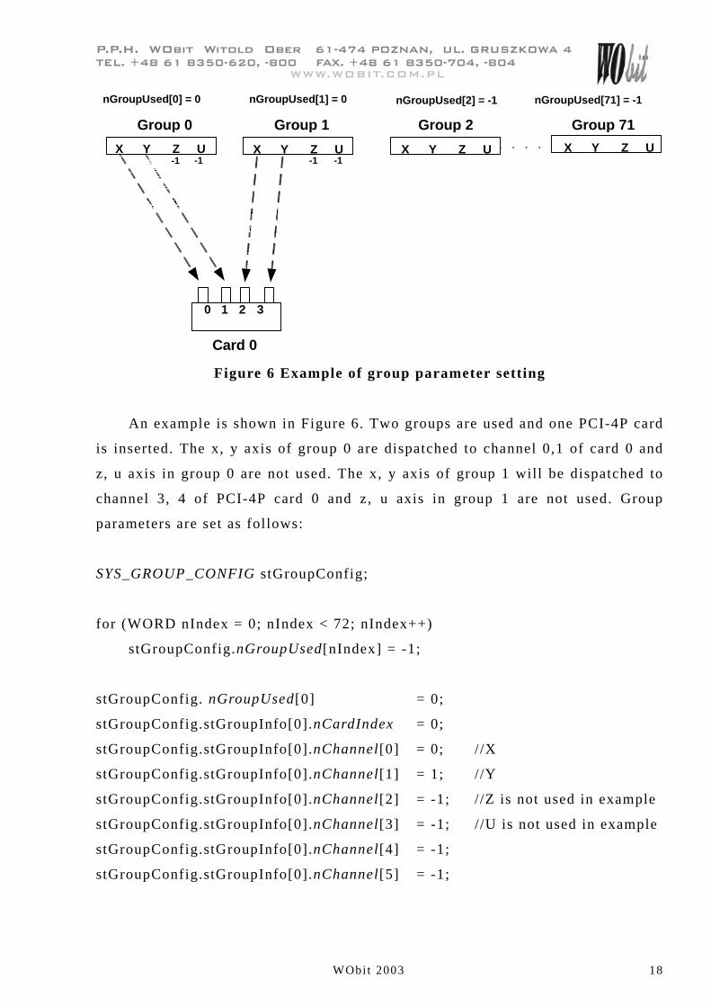
Group 0 Group 1 Group 71
0 1 2 3
Card 0
-1 -1 -1X Y Z U
nGroupUsed[0] = 0
Group 2
nGroupUsed[2] = -1 nGroupUsed[71] = -1
X Y Z U
nGroupUsed[1] = 0
X Y Z U X Y Z U-1
Figure 6 Example of group parameter setting
An example is shown in Figure 6. Two groups are used and one PCI-4P card
is inserted. The x, y axis of group 0 are dispatched to channel 0,1 of card 0 and
z, u axis in group 0 are not used. The x, y axis of group 1 will be dispatched to
channel 3, 4 of PCI-4P card 0 and z, u axis in group 1 are not used. Group
parameters are set as follows:
SYS_GROUP_CONFIG stGroupConfig;
for (WORD nIndex = 0; nIndex < 72; nIndex++)
stGroupConfig.nGroupUsed[nIndex] = -1;
stGroupConfig. nGroupUsed[0] = 0;
stGroupConfig.stGroupInfo[0].nCardIndex = 0;
stGroupConfig.stGroupInfo[0].nChannel[0] = 0; //X
stGroupConfig.stGroupInfo[0].nChannel[1] = 1; //Y
stGroupConfig.stGroupInfo[0].nChannel[2] = -1; //Z is not used in example
stGroupConfig.stGroupInfo[0].nChannel[3] = -1; //U is not used in example
stGroupConfig.stGroupInfo[0].nChannel[4] = -1;
stGroupConfig.stGroupInfo[0].nChannel[5] = -1;
���������������������� �����������������������������������
����� �!����!"#$��%$���!$$����&�'�� �!����!"#$��$����!$�
WObit 2003 19
������()��*�+���
stGroupConfig.nGroupUsed[1] = 0;
stGroupConfig.stGroupInfo[1].nCardIndex = 0;
stGroupConfig.stGroupInfo[1].nChannel[0] = 2; //X
stGroupConfig.stGroupInfo[1].nChannel[1] = 3; //Y
stGroupConfig.stGroupInfo[1].nChannel[2] = -1; //Z is not used in example
stGroupConfig.stGroupInfo[1].nChannel[3] = -1; //U is not used in example
stGroupConfig.stGroupInfo[1].nChannel[4] = -1;
stGroupConfig.stGroupInfo[1].nChannel[5] = -1;
// At last call this function to finish setting group parameter.
MCC_SetGroupConfig(&stGroupConfig);
Let’s take the example of MCC_Line(20, 20, 0, 0, 0, 0, 1), in which the last
argument 1 means group number. Thus channel 2, 3 of PCI-4P card 0 will output
phases for axis x, y in group 1. Furthermore�
MCC_Line(10, 10, 0, 0, 0, 0, 0); //---- command 0
MCC_Line(15, 34, 0, 0, 0, 0, 0); //---- command 1
MCC_Line(20, 20, 0, 0, 0, 0, 1); //---- command 2
MCC_Line(73, 54, 0, 0, 0, 0, 1); //---- command 3
These 4 lines will go into queue for motion executions. The queue for group
0 and group 1 are separate. This means command 0 and command 2 are first
command in their queue and will start at the same time. Command 0 and 1 are in
queue of group 0. Command 2 and 3 are in queue of group 1.
Without setting group parameters, preset value use group 0 only and x, y, z,
u axis of group 0 corresponds to channel 0 ~ 3 of card 0.
Set Hardware Parameter of Motion Control Card
Hardware parameter of motion control card is used to set the type of PCI-4P
card. The hardware parameters have to be set before calling MCC_InitSystem().
They are defined as follows:
���������������������� �����������������������������������
����� �!����!"#$��%$���!$$����&�'�� �!����!"#$��$����!$�
WObit 2003 20
������()��*�+���
typedef struct _SYS_CARD_CONFIG
{
WORD wCardType;
WORD wCardAddress ; //not used
WORD wIRQ_No ; //not used
WORD wPaddle ; / /reserved
} SYS_CARD_CONFIG;
wCardType:
For PCI-4P motion control card it is always 2.
wCardAdress: Not used.
This parameter can be any value.
wIRQ_No: Not used.
This parameter can be any value.
wPaddle: Reserve data, users don’t need to set.
Initialize MCCL
Use MCC_InitSystem() to initialize MCCL� i t is declared as follows:
int MCC_InitSystem ( int nInterpolateTime ,
SYS_CARD_CONFIG *psCardConfig ,
WORD wCardNo);
nInterpolateTime is interpolation time(please refer to explanation in later
section), the unit is ms, range is between 1 ms ~ 100 ms, in general set to 5ms.
PsCardConfig is the hardware parameter of PCI-4P motion control card
explained earlier. wCardNo is the number of totally installed PCI-4P motion
control card. The following is an example of using two PCI-4P motion control
cards:
SYS_CARD_CONFIG stCardConfig[] = {{2, 0x200, 5, 0},{2, 0x240, 7 0}}
���������������������� �����������������������������������
����� �!����!"#$��%$���!$$����&�'�� �!����!"#$��$����!$�
WObit 2003 21
������()��*�+���
MCC_InitSystem(5, stCardConfig, 2);
2.5.2 Close MCCL
Call MCC_CloseSystem() to close MCCL.
2.6 Motion Control
2.6.1 Coordinate System
This category includes the following functions:
I. To choose between absolute command relative coordinate system.
� See Also MCC_SetAbsolute(), MCC_SetIncrease() , MCC_GetCoordType()
II. To set the unit: inch or mm
� See Also MCC_SetUnit() , MCC_GetUnit()
III. To get current coordinates
� See Also MCC_GetCurPos() , MCC_GetPulsePos()
No matter which coordinate system is selected, MCCL internally use
absolute coordinate (relative to logical home).
IV. To enable/disable software limit check
When software limit check is enabled, MCCL will check if the coordinate
exceeds limit at each interpolation time. If limit is exceeded, the card will stop.
Users can refer to error code by calling MCC_GetErrorCode().
� See Also MCC_GetOverTravelCheck() , MCC_ClearError()
V. To enable/disable limit switch check
� See Also MCC_EnableLimitSwitchCheck() ,
MCC_ DisableLimitSwitchCheck() ,
MCC_GetLimitSwitchStatus()
���������������������� �����������������������������������
����� �!����!"#$��%$���!$$����&�'�� �!����!"#$��$����!$�
WObit 2003 22
������()��*�+���
2.6.2 Basic Trajectory Planning
MCCL provides point to point motion and general motion including linear,
arc and circular motion. Users should set feeding speed,
acceleration/deceleration type (S-curve or T-curve) and
acceleration/deceleration time according to the mechanism inertia and special
demand. (See also 2.6.3 for setting)
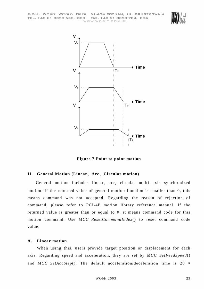
I. Point to point motion
Point to point motion applies to multi axis. Each axis starts simultaneously
with its own acceleration/deceleration time and speed, but doesn’t have to arrive
at the same time (see Figure 7). This is different from general motion. In case of
multi axis point to point motion MCCL waits till all the axes have stopped then
it proceeds to next motion command.
Call MCC_PtP() to do point to point motion. It takes target position or
displacement of each axis as arguments. Each axis will move in the given feed
speed. If the returned value of MCC_PtP() is smaller than 0, this means
command was not accepted. Regarding the reason of rejection of command,
please refer to PCI-4P motion library reference manual. If the returned value is
greater than or equal to 0, it means command code for this motion command.
Use MCC_ResetCommandIndex() to reset command code value.
Use MCC_SetPtPSpeed() to set the feeding speed of point to point motion
for axes in a group, one argument needed is speed ratio. i.e.
feeding speed for axes= maximum safe speed of each axis � (speed ratio /
100)
(Unit: %)
In which the maximum safe speed (mm/sec) = wRPM � dfPitch /
dfGearRatio . For example for a speed ratio of 30, the feeding speed for axes is
wRPM � dfPitch / dfGearRatio � 30 / 100.
The default feeding speed ratio is 10 %. And the default
acceleration/deceleration time is 20 � Interpolation Time.
���������������������� �����������������������������������
����� �!����!"#$��%$���!$$����&�'�� �!����!"#$��$����!$�
WObit 2003 23
������()��*�+���
V
TimeV
TimeV
Time
Vx
Vy
Vz
Tx
Ty
Tz
Figure 7 Point to point motion
II. General Motion (Linear��Arc��Circular motion)
General motion includes linear �� arc �� circular multi axis synchronized
motion. If the returned value of general motion function is smaller than 0, this
means command was not accepted. Regarding the reason of rejection of
command, please refer to PCI-4P motion library reference manual. If the
returned value is greater than or equal to 0, it means command code for this
motion command. Use MCC_ResetCommandIndex() to reset command code
value.
A. Linear motion
When using this, users provide target position or displacement for each
axis. Regarding speed and acceleration, they are set by MCC_SetFeedSpeed()
and MCC_SetAccStep(). The default acceleration/deceleration time is 20 �
���������������������� �����������������������������������
����� �!����!"#$��%$���!$$����&�'�� �!����!"#$��$����!$�
WObit 2003 24
������()��*�+���
interpolation time.
� See Also MCC_SetFeedSpeed(), MCC_Line()
B. Arc motion
When using this, users provide a reference point (center) and a target point.
Regarding speed and acceleration, they are set by MCC_SetFeedSpeed() and
MCC_SetAccStep(). The default acceleration/deceleration time is 20 �
interpolation time. MCCL also provides 3-D arc motion .
� See Also MCC_SetFeedSpeed(), MCC_ArcXYZ(), MCC_ArcXY(),
MCC_ArcYZ(), MCC_ArcZX()
C. Circular motion
When using this, users provide a center point and motion direction
(clockwise or counterclockwise). Regarding speed and acceleration, they are set
by MCC_SetFeedSpeed() and MCC_SetAccStep(). The default
acceleration/deceleration time is 20 � interpolation time.
� See Also MCC_CircleXY(), MCC_CircleYZ(), MCC_CircleZX()
D. Set feeding speed for General motion
The feeding speed for general motion is set by MCC_SetFeedSpeed(). The
value should not exceed the value for MCC_SetSysMaxSpeed(). The speed is in
target direction of motion.
� See Also MCC_GetFeedSpeed() , MCC_GetCurFeedSpeed() , MCC_GetSpeed()
III. Jog
There are 3 types of jog.
A. Pulse Jog
Jog with a distance designated in pulses (maximum pulse number= 2048);
this command can only be used when there is no motion. For example:
MCC_JogPulse(10, 0, 0)
Displacement (pulse), axis number, group index
���������������������� �����������������������������������
����� �!����!"#$��%$���!$$����&�'�� �!����!"#$��$����!$�
WObit 2003 25
������()��*�+���
B. Short stroke Jog
Jog with a distance designated in mm or inch. Its speed is set as speed ratio
(similar to point to point motion); use MCC_AbortMotion() to stop. For example:
MCC_JogSpace(1, 20, 0, 0)
Displacement (mm), feed speed ratio, axis number,group index
C. Continuous Jog
Jog continuously. Its speed is set as speed ratio (similar to point to point
motion). When it moves to the border, which is set by mechanism parameter, it
will stop. When software limit or limit switch are reached and their checks are
enabled, it will also stop; use MCC_AbortMotion() to stop. For example:
MCC_JogConti(0, 20, 0, 0);
Direction, feed speed ratio, axis number, group index
(0: positive, 1: negative)
IV. Hold, continue, and abort motion
Use MCC_HoldMotion() to halt current command in execution (it slows
with constant deceleration and then stop motion). Then use MCC_ContiMotion()
to resume and finish executing the undone motion. Use MCC_AbortMotion() to
abort a motion in execution or to discard a hold motion.
� See Also MCC_GetMotionStatus()
2.6.3 Advanced Trajectory Planning
For more flexible, more efficient position control, MCCL provides advanced
trajectory planning. There are two types of velocity profile, namely T-curve and
S-curve. There is also velocity blending between different motion command, and
reach the designated position quicker. There is also speed override to adjust
feeding speed.
���������������������� �����������������������������������
����� �!����!"#$��%$���!$$����&�'�� �!����!"#$��$����!$�
WObit 2003 26
������()��*�+���
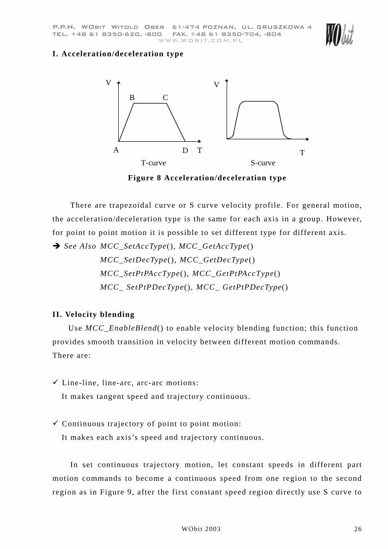
I. Acceleration/deceleration type
T
VV
A D T
CB
T-curve S-curve
Figure 8 Acceleration/deceleration type
There are trapezoidal curve or S curve velocity profile. For general motion,
the acceleration/deceleration type is the same for each axis in a group. However,
for point to point motion it is possible to set different type for different axis.
� See Also MCC_SetAccType(), MCC_GetAccType()
MCC_SetDecType(), MCC_GetDecType()
MCC_SetPtPAccType(), MCC_GetPtPAccType()
MCC_ SetPtPDecType(), MCC_ GetPtPDecType()
II. Velocity blending
Use MCC_EnableBlend() to enable velocity blending function; this function
provides smooth transition in velocity between different motion commands.
There are:
� Line-line, line-arc, arc-arc motions:
It makes tangent speed and trajectory continuous.
� Continuous trajectory of point to point motion:
It makes each axis’s speed and trajectory continuous.
In set continuous trajectory motion, let constant speeds in different part
motion commands to become a continuous speed from one region to the second
region as in Figure 9, after the first constant speed region directly use S curve to
���������������������� �����������������������������������
����� �!����!"#$��%$���!$$����&�'�� �!����!"#$��$����!$�
WObit 2003 27
������()��*�+���
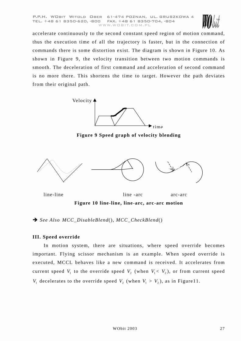
accelerate continuously to the second constant speed region of motion command,
thus the execution time of all the trajectory is faster, but in the connection of
commands there is some distortion exist. The diagram is shown in Figure 10. As
shown in Figure 9, the velocity transition between two motion commands is
smooth. The deceleration of first command and acceleration of second command
is no more there. This shortens the time to target. However the path deviates
from their original path.
Figure 9 Speed graph of velocity blending
l ine-line l ine -arc arc-arc
Figure 10 line-line, line-arc, arc-arc motion
� See Also MCC_DisableBlend(), MCC_CheckBlend()
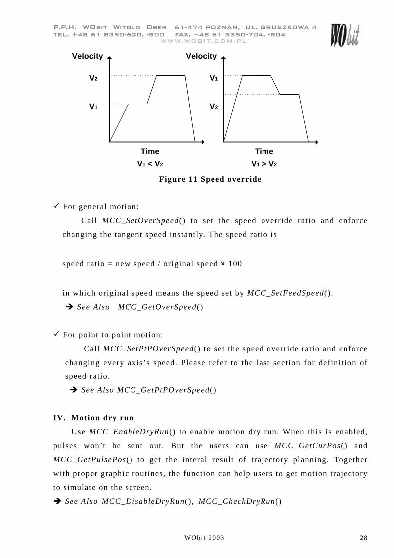
III. Speed override
In motion system, there are situations, where speed override becomes
important. Flying scissor mechanism is an example. When speed override is
executed, MCCL behaves like a new command is received. It accelerates from
current speed 1V to the override speed 2V (when 1V < 2V ), or from current speed
1V decelerates to the override speed 2V (when 1V > 2V ), as in Figure11.
Velocity
time
���������������������� �����������������������������������
����� �!����!"#$��%$���!$$����&�'�� �!����!"#$��$����!$�
WObit 2003 28
������()��*�+���
Velocity
Time
V1 < V2
Velocity
Time
V1 > V2
V2
V1
V1
V2
Figure 11 Speed override
� For general motion:
Call MCC_SetOverSpeed() to set the speed override ratio and enforce
changing the tangent speed instantly. The speed ratio is
speed ratio = new speed / original speed � 100
in which original speed means the speed set by MCC_SetFeedSpeed().
� See Also MCC_GetOverSpeed()
� For point to point motion:
Call MCC_SetPtPOverSpeed() to set the speed override ratio and enforce
changing every axis’s speed. Please refer to the last section for definition of
speed ratio.
� See Also MCC_GetPtPOverSpeed()
IV. Motion dry run
Use MCC_EnableDryRun() to enable motion dry run. When this is enabled,
pulses won’t be sent out. But the users can use MCC_GetCurPos() and
MCC_GetPulsePos() to get the interal result of trajectory planning. Together
with proper graphic routines, the function can help users to get motion trajectory
to simulate on the screen.
� See Also MCC_DisableDryRun(), MCC_CheckDryRun()
���������������������� �����������������������������������
����� �!����!"#$��%$���!$$����&�'�� �!����!"#$��$����!$�
WObit 2003 29
������()��*�+���
V. Motion delay
Use MCC_DelayMotion() to get delay between motion commands. The unit
of delay time is the interpolation time (interpolation time is explained in coming
section); an example is shown as follows:
MCC_Line(10, 10, 10, 0, 0, 0);---------A
MCC_DelayMotion(200);
MCC_Line(15, 15, 15, 0, 0, 0);---------B
After finishing the motion command A, it will delay 200 � interpolation
time, then the motion command B will be executed.
� See Also MCC_CheckDelay()
VI. Error code
There are errors like over travel, exceeding the maximum set speed,
acceleration, arc command error and error during arc command execution etc.
Users can use MCC_GetErrorCode() to get the error codes. (Please refer to
“HIWIN PCI-4P motion library reference manual” about error codes.) When
errors occur, MCCL stops execution of all motion commands. Therefore, users
have to call MCC_GetErrorCode() to identify the error reason, and use
MCC_ClearError() to clear errors after which system will return to its normal
state.
���������������������� �����������������������������������
����� �!����!"#$��%$���!$$����&�'�� �!����!"#$��$����!$�
WObit 2003 30
������()��*�+���
2.6.4 Interpolation Time and Acceleration/Deceleration Step
Setting
I. Interpolation time
Speed
Max. Pulse Speed
Max. Pulse Acc.
Interpolation Time
Acc. StepDec. Step
Time
Figure 12 Interpolation time and related parameters
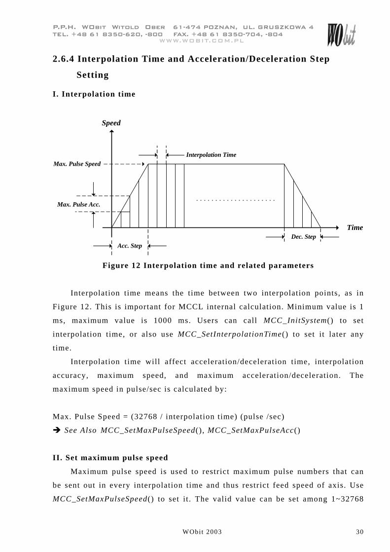
Interpolation time means the time between two interpolation points, as in
Figure 12. This is important for MCCL internal calculation. Minimum value is 1
ms, maximum value is 1000 ms. Users can call MCC_InitSystem() to set
interpolation time, or also use MCC_SetInterpolationTime() to set it later any
time.
Interpolation time will affect acceleration/deceleration time, interpolation
accuracy, maximum speed, and maximum acceleration/deceleration. The
maximum speed in pulse/sec is calculated by:
Max. Pulse Speed = (32768 / interpolation time) (pulse /sec)
� See Also MCC_SetMaxPulseSpeed(), MCC_SetMaxPulseAcc()
II. Set maximum pulse speed
Maximum pulse speed is used to restrict maximum pulse numbers that can
be sent out in every interpolation time and thus restrict feed speed of axis. Use
MCC_SetMaxPulseSpeed() to set it . The valid value can be set among 1~32768
���������������������� �����������������������������������
����� �!����!"#$��%$���!$$����&�'�� �!����!"#$��$����!$�
WObit 2003 31
������()��*�+���
and its default value is 30000 pulses.
� See Also MCC_GetMaxPulseSpeed()
III. Set maximum pulse acceleration/deceleration
Maximum pulse acceleration/deceleration is used to restrict the difference
of sent pulses between two neighbored interpolation times, thus the tracking
error will be reduced. If acceleration/deceleration time is set too small,
acceleration/deceleration will become too big for mass of the mechanism. Users
can use MCC_GetErrorCode() to diagnose if the acceleration/deceleration is too
large in motion. Users can set maximum pulse acceleration/deceleration by
MCC_SetMaxPulseAcc(); the value range is 1~32768 and its default value is
30000 pulses.
� See Also MCC_GetMaxPulseAcc()
IV. Acceleration/Deceleration step
The acceleration/deceleration time is calculated as follows:
Acceleration time = acceleration step � interpolation time
Deceleration time = deceleration step � interpolation time
Use MCC_SetAccStep() and MCC_SetDecStep() for general motion. Use
MCC_SetPtPAccStep() and MCC_SetPtPDecStep() for point to point motion.
Normally for higher feeding speed, users should set bigger acceleration time.
Therefore, MCC_SetAccStep() and MCC_SetDecStep() are usually used with
MCC_SetFeedSpeed(), so are MCC_SetPtPAccStep(), MCC_SetPtPDecStep() and
MCC_SetPtPSpeed().

���������������������� �����������������������������������
����� �!����!"#$��%$���!$$����&�'�� �!����!"#$��$����!$�
WObit 2003 32
������()��*�+���
feeding speed
tAcc. time
V
Figure 13 Acceleration
To calculate the acceleration, use the formula:
a = feeding speed / Acc. Time
in which feeding speed is in sm / and Acc. Time is in second, thus the
acceleration is in 2/ sm . Use F = m � a to calculate the thrust force.
2.6.5 System Status
Use MCC_GetCurPos() to get current command position in mm or inch unit.
Users can also use MCC_GetPulsePos() to get current command position in
pulse unit. If the system includes an encoder, use MCC_GetENCValue() to get
feedback position (unit: pulse).
Users can use MCC_GetPtPSpeed() to get the feeding speed ratio of point to
point motion.
For general motion use MCC_GetCurFeedSpeed() to get current feeding
speed; use MCC_GetSpeed() to get speed component of each axis in a group; use
MCC_GetFeedSpeed() to get feeding speed.
Use the return value of MCC_GetMotionStatus() to get current motion
status. If the return value is 0 system is normal; if the return value is 1 motion is
stopped; and if the return value is 2 motion is hold by MCC_HoldMotion(), .
Use MCC_ GetCurCommand() to get information of the motion command in
execution. The prototype of MCC_GetCurCommand() function is as follows:
MCC_GetCurCommand(COMMAND_INFO *pstCurCommand,
WORD wGroupIndex)
���������������������� �����������������������������������
����� �!����!"#$��%$���!$$����&�'�� �!����!"#$��$����!$�
WObit 2003 33
������()��*�+���
COMMAND_INFO saves information of the motion command in execution. It is
defined as follows:
Typedef struct _COMMAND_INFO
{
int nType;
int nCommandIndex ;
double dfFeedSpeed ;
double dfPos[6];
} COMMAND_INFO;
nType: Motion command type
0 point to point motion
1 linear motion
2 clockwise arc or circular motion
3 counterclockwise arc or circular motion
nCommandIndex: motion command index
dfFeedSpeed: feeding speed for general motion; speed ratio for point to point
motion
dfPos[]: target position; dfPos[4] and dfPos[5] are not used
Use MCC_GetCommandCount() to get the number of motion commands
which have not been executed. The motion command in execution is not counted.
If the return value of MCC_GetMotionStatus() were 1, the number of motion
commands in stock would be 0.
2.7 Homing
Users can set the order, speed, direction and mode of homing for each axis.
The order of homing for each axis is defined by parameters nXOrder ~ nUOrder
���������������������� �����������������������������������
����� �!����!"#$��%$���!$$����&�'�� �!����!"#$��$����!$�
WObit 2003 34
������()��*�+���
in MCC_GoHome(). Homing process of PCI-4P motion card is divided into phase
0 ~ phase 3 and explained as follows:
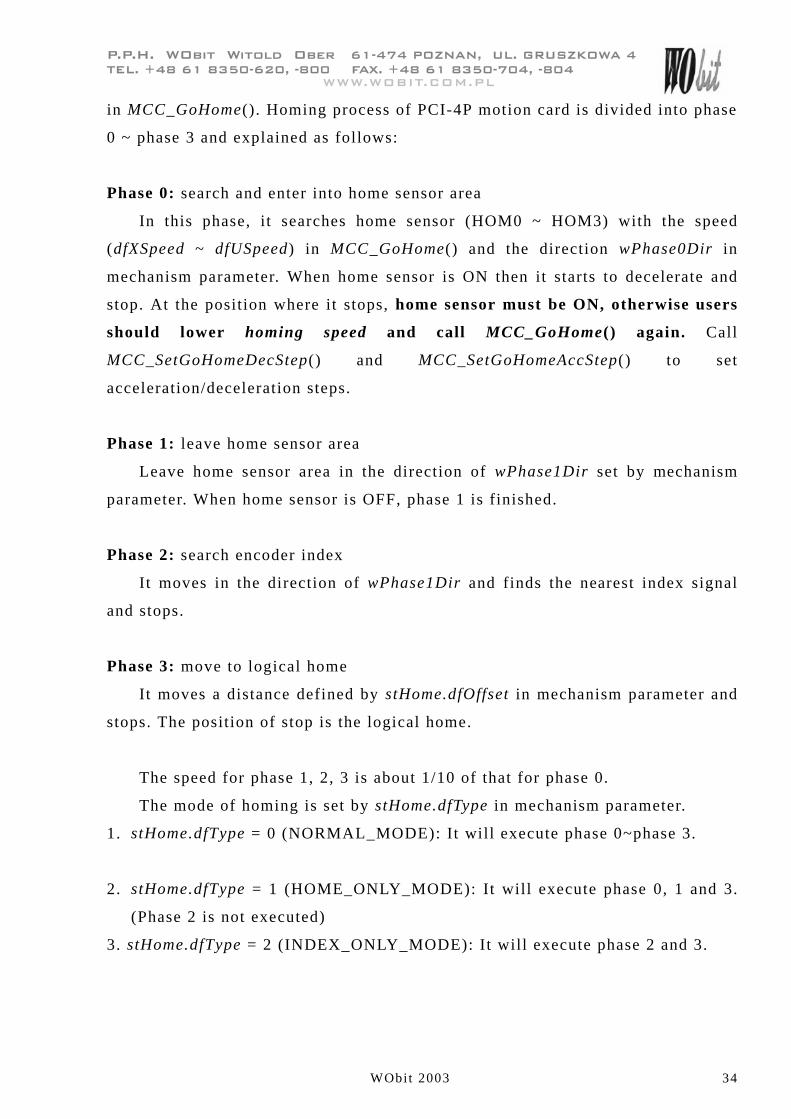
Phase 0: search and enter into home sensor area
In this phase, it searches home sensor (HOM0 ~ HOM3) with the speed
(dfXSpeed ~ dfUSpeed) in MCC_GoHome() and the direction wPhase0Dir in
mechanism parameter. When home sensor is ON then it starts to decelerate and
stop. At the position where it stops, home sensor must be ON, otherwise users
should lower homing speed and call MCC_GoHome() again. Call
MCC_SetGoHomeDecStep() and MCC_SetGoHomeAccStep() to set
acceleration/deceleration steps.
Phase 1: leave home sensor area
Leave home sensor area in the direction of wPhase1Dir set by mechanism
parameter. When home sensor is OFF, phase 1 is finished.
Phase 2: search encoder index
It moves in the direction of wPhase1Dir and finds the nearest index signal
and stops.
Phase 3: move to logical home
It moves a distance defined by stHome.dfOffset in mechanism parameter and
stops. The position of stop is the logical home.
The speed for phase 1, 2, 3 is about 1/10 of that for phase 0.
The mode of homing is set by stHome.dfType in mechanism parameter.
1. stHome.dfType = 0 (NORMAL_MODE): It will execute phase 0~phase 3.
2. stHome.dfType = 1 (HOME_ONLY_MODE): It will execute phase 0, 1 and 3.
(Phase 2 is not executed)
3. stHome.dfType = 2 (INDEX_ONLY_MODE): It will execute phase 2 and 3.
���������������������� �����������������������������������
����� �!����!"#$��%$���!$$����&�'�� �!����!"#$��$����!$�
WObit 2003 35
������()��*�+���
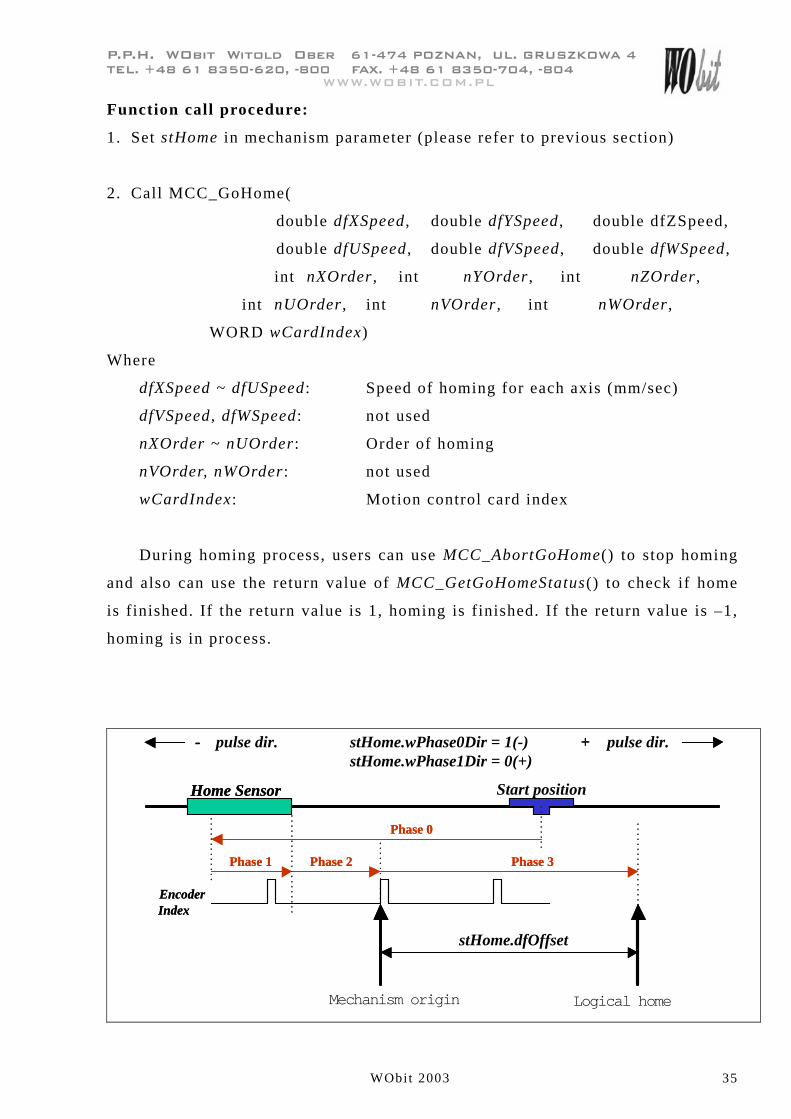
Function call procedure:
1. Set stHome in mechanism parameter (please refer to previous section)
2. Call MCC_GoHome(
double dfXSpeed , double dfYSpeed , double dfZSpeed,
double dfUSpeed , double dfVSpeed , double dfWSpeed ,
int nXOrder , int nYOrder , int nZOrder ,
int nUOrder , int nVOrder , int nWOrder ,
WORD wCardIndex)
Where
dfXSpeed ~ dfUSpeed : Speed of homing for each axis (mm/sec)
dfVSpeed, dfWSpeed : not used
nXOrder ~ nUOrder : Order of homing
nVOrder, nWOrder: not used
wCardIndex : Motion control card index
During homing process, users can use MCC_AbortGoHome() to stop homing
and also can use the return value of MCC_GetGoHomeStatus() to check if home
is finished. If the return value is 1, homing is finished. If the return value is –1,
homing is in process.
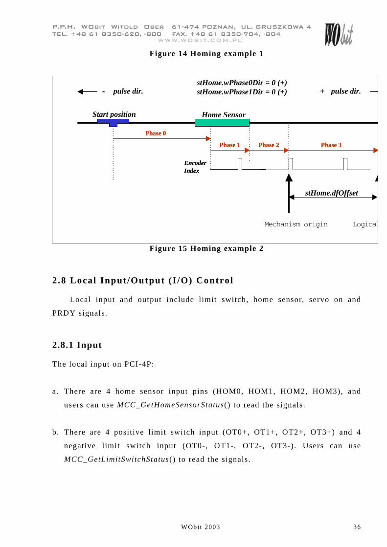
Phase 0
Phase 1
stHome.wPhase0Dir = 1(-)
Mechanism origin
Phase 2 Phase 3
Logical home
Phase 0
Phase 1 Phase 2 Phase 3
stHome.dfOffset
stHome.wPhase1Dir = 0(+)+ pulse dir.+
EncoderIndexEncoderIndex
Home SensorHome Sensor
- pulse dir.-
Start position
���������������������� �����������������������������������
����� �!����!"#$��%$���!$$����&�'�� �!����!"#$��$����!$�
WObit 2003 36
������()��*�+���
Figure 14 Homing example 1
Phase 0
Phase 1 Phase 2 Phase 3
Phase 0
Phase 1 Phase 2 Phase 3
stHome.dfOffset
stHome.wPhase0Dir = 0 (+)- pulse dir.- + pulse dir.+stHome.wPhase1Dir = 0 (+)
EncoderIndexEncoderIndex
Home SensorStart position
Mechanism origin Logical
Figure 15 Homing example 2
2 .8 Local Input /Output (I /O) Control
Local input and output include limit switch, home sensor, servo on and
PRDY signals.
2.8.1 Input
The local input on PCI-4P:
a. There are 4 home sensor input pins (HOM0, HOM1, HOM2, HOM3), and
users can use MCC_GetHomeSensorStatus() to read the signals.
b. There are 4 positive limit switch input (OT0+, OT1+, OT2+, OT3+) and 4
negative limit switch input (OT0-, OT1-, OT2-, OT3-). Users can use
MCC_GetLimitSwitchStatus() to read the signals.
���������������������� �����������������������������������
����� �!����!"#$��%$���!$$����&�'�� �!����!"#$��$����!$�
WObit 2003 37
������()��*�+���
2.8.2 Output
The local output on PCI-4P:
a. There are 4 servo on/off control pins (SVN0, SVN1, SVN2, SVN3), and users
can use MCC_SetServoOn() and MCC_SetServoOff() to output servo on/off
signals.
b. There is 1 position ready signal (PRDY) for one PCI-4P card, and users can
use MCC_EnablePosReady() and MCC_DisablePosReady() to set or clear the
signal.
2.9 Encoder Control
Users have to set correctly the according parameters for encoder in
mechanism parameters.
If stEncoder.wType in mechanism parameters is set to 0 i.e. the input mode
of encoder is set to A/B phase, users can use MCC_SetENCInputRate() to set the
encoder mode. This value can be set to 1, 2 and 4 i.e. �1, �2 and �4. The default
encoder mode is �4.
Use MCC_GetENCValue() to get the encoder count value.
NOTICE
Please confirm that motion command and Encoder feedback value has the
same direction. If not, set Encoder mechanism parameter AB_swap = YES , so
that motion command and Encoder feedback have the same direction definition.
���������������������� �����������������������������������
����� �!����!"#$��%$���!$$����&�'�� �!����!"#$��$����!$�
WObit 2003 38
������()��*�+���
3. Compiler Environment
3.1 Using Visual C++
Including Files
MCCL.h
MCCL_Fun.h
Import Library (users have to add this file into project)
MCCLPCI_45.lib
Dynamic Library (dynamic link file for run-time)
MCCLPCI_45.dll
ACTADrv.dll
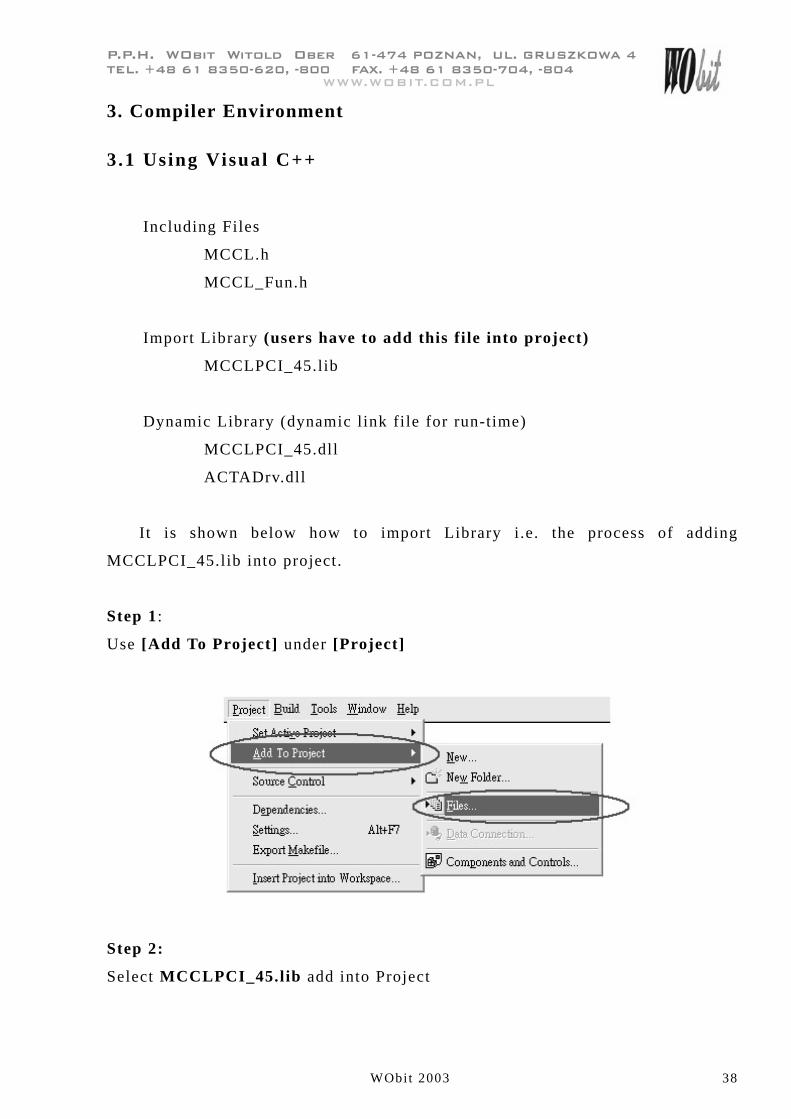
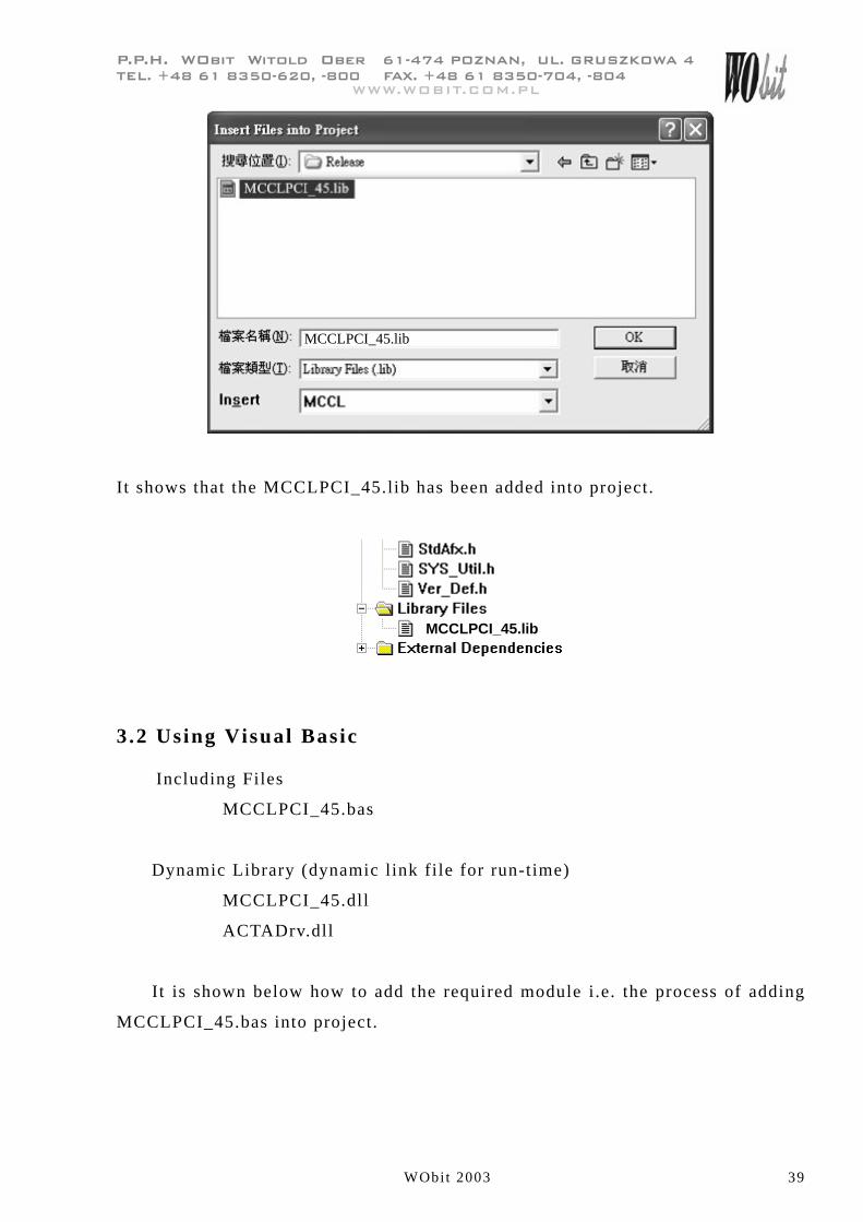
It is shown below how to import Library i.e. the process of adding
MCCLPCI_45.lib into project.
Step 1:
Use [Add To Project] under [Project]
Step 2:
Select MCCLPCI_45.lib add into Project
���������������������� �����������������������������������
����� �!����!"#$��%$���!$$����&�'�� �!����!"#$��$����!$�
WObit 2003 39
������()��*�+���
MCCLPCI_45.lib
It shows that the MCCLPCI_45.lib has been added into project.
MCCLPCI_45.lib
3.2 Using Visual Basic
Including Files
MCCLPCI_45.bas
Dynamic Library (dynamic link file for run-time)
MCCLPCI_45.dll
ACTADrv.dll
It is shown below how to add the required module i .e. the process of adding
MCCLPCI_45.bas into project.
���������������������� �����������������������������������
����� �!����!"#$��%$���!$$����&�'�� �!����!"#$��$����!$�
WObit 2003 40
������()��*�+���
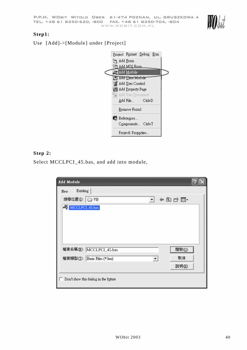
Step1:
Use [Add]->[Module] under [Project]
Step 2:
Select MCCLPCI_45.bas, and add into module,
MCCLPCI_45.bas
MCCLPCI_45.bas

���������������������� �����������������������������������
����� �!����!"#$��%$���!$$����&�'�� �!����!"#$��$����!$�
WObit 2003 41
������()��*�+���
It shows that MCCLPCI_45.bas has been added into project.
MCCLPCI_45 (MCCLPCI_45.bas)