Embed Size (px)
Citation preview

• Editorial-Chief
Kiyoshi Takakuwa • Editorial Advisors
Chisato Kobayashi Kanae Ishida Makoto Egashira Koji Yasui Hiroaki Kawachi Masayuki Masuda Takahiro Nishikawa Tetsuyuki Yanase Tetsuji Ishikawa Taizo Kittaka Keiji Hatanaka Itsuo Seki Kazufumi Tanegashima Kazumasa Mitsunaga
• Vol. 129 Feature Articles Editor
Junichi Mito • Editorial Inquiries
Makoto Egashira Corporate Total Productivity Management & Environmental Programs Fax +81-3-3218-2465
• Product Inquiries Masahiro Fujisawa Automation & Motion Control Systems Section Overseas Marketing Department Fax +81-3-3218-6820
Mitsubishi Electric Advance is published on line quarterly (in March, June, September, and December) by Mitsubishi Electric Corporation. Copyright © 2010 by Mitsubishi Electric Corporation; all rights reserved. Printed in Japan.
CONTENTS
Technical Reports
Overview ..........................................................................................1 by Kazuaki Iwata Servo Gain Self-Adjustment Function in MELSERVO .................2 by Takayuki Wakana Easy-to-Operate and Compact Inverter, the FREQROL-D700 Series ...............................................................................................5 by Manabu Yoshimura and Masanori Kato Standalone Type Motion Controller ..............................................8 by Hiroshi Mihara Multi Hybrid Drive, the MDS-DM Series ......................................11 by Kazuyuki Nakamura, Yoji Tsutsumishita and Yoshitomo Hayashi New Mitsubishi CNC M700V Series .............................................13 by Hirokatsu Miyatake New Frame-Type Spindle Motor, the SJ-D Series ......................15 by Toru Ogawa
MITSUBISHI ELECTRIC ADVANCE
Mar. 2010 / Vol. 129
Mitsubishi FA Drive Systems & Products

*Emeritus Professor, Osaka University Mitsubishi Electric ADVANCE March 2010 1
TECHNICAL REPORTS
Overview
Author: Kazuaki Iwata*
Thoughts on Monozukuri in the 21st Century
In the worsening global environment and the worldwide recession that emerged in 2008, Japanese monozukuri (manufacturing) companies are struggling under unprofitable conditions and uncertain prospects. Looking at the future of value-added monozukuri, I would like to focus on at least three viewpoints: (1) consideration of strategic risk, (2) paradigm shift to sustainable development, and (3) development of a new science of science and technology.
The first point considers various risks resulting from the increasingly complex monozukuri environment, globalization, and growing uncertainty; specific risks include the changing behavior of customers and competitors, the maturing and shrinking market, and the fluctuating exchange rate and price of natural resources. The second point requires explicit consideration of the global environment, natural resources and the like, which used to be an assumed external environmental condition. This new situation calls for the sustainable development of a total system incorporating external systems. Third, while conventional monozukuri relies solely on physical rule-based science and technology, we began to see the limits of this problem-solving approach. It is now important to have new viewpoints – a new science of science – integrated with the biological and social rules.
With a view to “Monozukuri as a civilization and culture” that encompasses those viewpoints, we look forward to the new monozukuri created by fostering the wisdom of humans, and utilizing both explicit and implicit knowledge.
*Nagoya Works 2
TECHNICAL REPORTS
Servo Gain Self-Adjustment Function in MELSERVO
Author: Takayuki Wakana*
1. Introduction
For the purposes of improving performance, elimi-nating the need for special skills, and reducing work time, we have developed “Advanced Gain Search”, a new servo automatic adjustment function.
2. Features of Advanced Gain Search
(AGS) AGS provides the following:
(1) Easy adjustment: Optimum adjustment is available without requiring special knowledge about the servo. → Eliminates the need for special skills and improves performance
(2) Quick adjustment: Adjustment can be made in a short time by reducing the repetition of actual ma-chine checks. → Reduces the work time
(3) Stable adjustment: Enables adjustment with appro-priate margins considering variable elements of the machine. → Improves quality
(4) Secure adjustment: Enables adjustment that sup-presses oscillation and prevents machine stress during adjustment → Improves work safety and prevents machine degradation
(5) Visual adjustment: Easy-to-understand adjustment is available by using the display format that pro-vides intuitive understanding of the adjustment re-sults → Improves operability
3. Operation Flow 3.1 Adjustment parameter settings
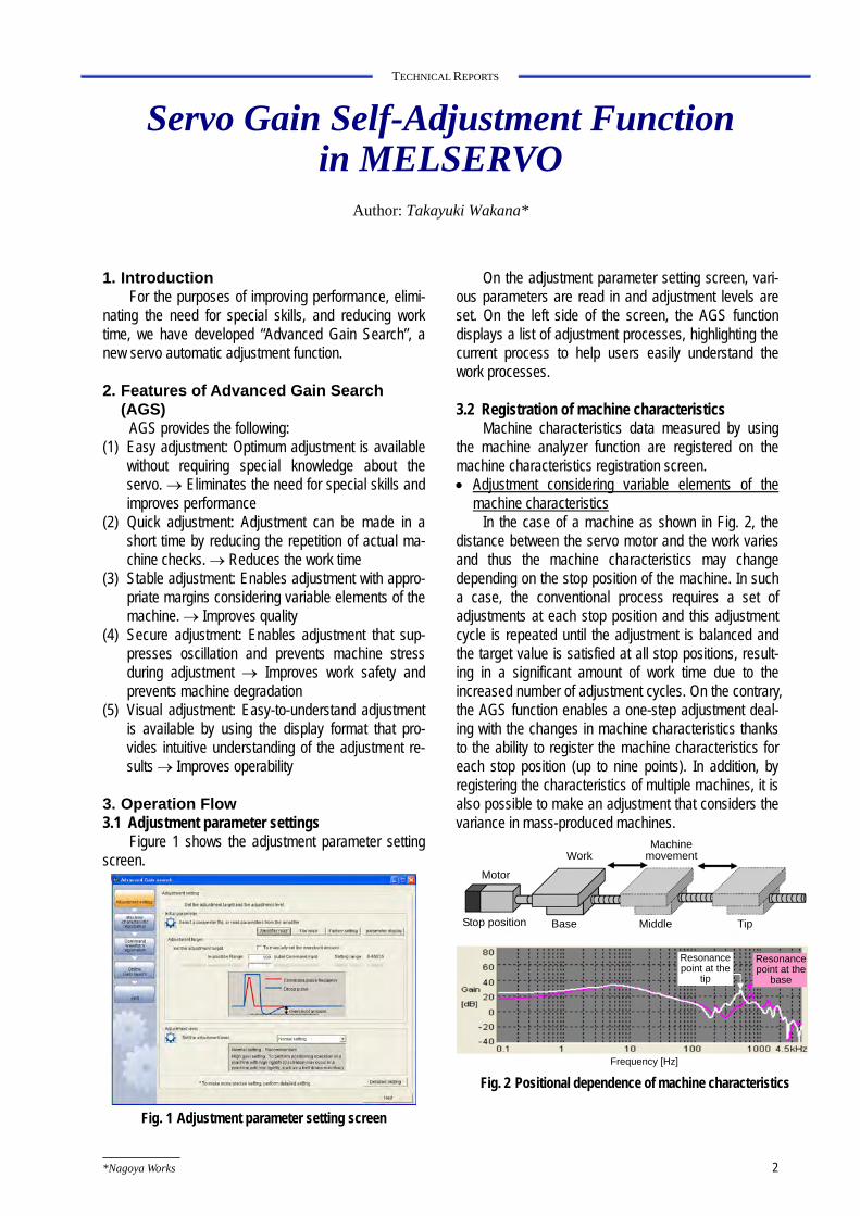
Figure 1 shows the adjustment parameter setting screen.
Fig. 1 Adjustment parameter setting screen
On the adjustment parameter setting screen, vari-ous parameters are read in and adjustment levels are set. On the left side of the screen, the AGS function displays a list of adjustment processes, highlighting the current process to help users easily understand the work processes.
3.2 Registration of machine characteristics
Machine characteristics data measured by using the machine analyzer function are registered on the machine characteristics registration screen. • Adjustment considering variable elements of the
machine characteristics In the case of a machine as shown in Fig. 2, the
distance between the servo motor and the work varies and thus the machine characteristics may change depending on the stop position of the machine. In such a case, the conventional process requires a set of adjustments at each stop position and this adjustment cycle is repeated until the adjustment is balanced and the target value is satisfied at all stop positions, result-ing in a significant amount of work time due to the increased number of adjustment cycles. On the contrary, the AGS function enables a one-step adjustment deal-ing with the changes in machine characteristics thanks to the ability to register the machine characteristics for each stop position (up to nine points). In addition, by registering the characteristics of multiple machines, it is also possible to make an adjustment that considers the variance in mass-produced machines.
Motor
Frequency [Hz]
WorkMachine
movement
Stop position Base Middle Tip
Resonance point at the
tip
Resonance point at the
base
Fig. 2 Positional dependence of machine characteristics
Mitsubishi Electric ADVANCE March 2010 3
TECHNICAL REPORTS
3.3 Registration of command waveform On the command waveform registration screen, a
series of control data entered from the controller is measured and then registered by using the waveform measuring function. • Adjustment considering multiple commands
Similar to the machine characteristics, command patterns also affect the adjustment process. Therefore, multiple sets of operation speed and traveling distance can be registered for up to nine points.
3.4 Online gain search
This process actually carries out an adjustment. Automated adjustment eliminates the need for special skills and making judgments. Consideration is also given to improved performance, reduced adjustment time, suppression of oscillation, and intuitive operation. • Adjustment that maximizes performance
A machine resonance suppression filter is effective for improving machine responsivity when there is a resonance frequency. Since the end-user’s machine usually consists of many parts and thus has a reso-nance frequency, adjustment of the filter is an essential part of the servo adjustment to improve performance. The AGS function provides an automatic search on a personal computer for optimum filter settings that give the best responsivity corresponding to the registered machine characteristics. • Reduced adjustment time
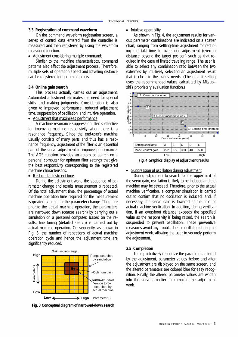
During the adjustment work, the sequence of pa-rameter change and results measurement is repeated. Of the total adjustment time, the percentage of actual machine operation time required for the measurement is greater than that for the parameter change. Therefore, prior to the actual machine operation, the parameters are narrowed down (coarse search) by carrying out a simulation on a personal computer. Based on the re-sults, fine tuning (detailed search) is carried out by actual machine operation. Consequently, as shown in Fig. 3, the number of repetitions of actual machine operation cycle and hence the adjustment time are significantly reduced.
Gain setting range
Parameter B
High
Low
Par
amet
er A
Range searched by simulation
Optimum gain
Narrowed-down range to be searched by
actual machine
Low High Fig. 3 Conceptual diagram of narrowed-down search
• Intuitive operability As shown in Fig. 4, the adjustment results for vari-
ous parameter combinations are indicated on a scatter chart, ranging from settling-time adjustment for reduc-ing the takt time to overshoot adjustment (overrun distance beyond the target position) such as that re-quired in the case of limited traveling range. The user is able to select any combination ratio between the two extremes by intuitively selecting an adjustment result that is close to the user’s needs. (The default setting uses the recommended values calculated by Mitsubi-shi’s proprietary evaluation function.)
A: Overshoot oriented
B
C: Recommended values
D
E: Settling-time oriented
Setting candidate A B C D E
Model control gain 222 272 333 408 500
Low High
Fig. 4 Graphics display of adjustment results
• Suppression of oscillation during adjustment During adjustment to search for the upper limit of
the servo gain, oscillation is likely to be induced and the machine may be stressed. Therefore, prior to the actual machine verification, a computer simulation is carried out to confirm that no oscillation is induced; and, if necessary, the servo gain is lowered at the time of actual machine verification. In addition, during verifica-tion, if an overshoot distance exceeds the specified value as the responsivity is being raised, the search is suspended to prevent oscillation. These preventive measures avoid any trouble due to oscillation during the adjustment work, allowing the user to securely perform the adjustment.
3.5 Completion
To help intuitively recognize the parameters altered by the adjustment, parameter values before and after the adjustment are displayed on the same screen, and the altered parameters are colored blue for easy recog-nition. Finally, the altered parameter values are written into the servo amplifier to complete the adjustment work.
4
TECHNICAL REPORTS
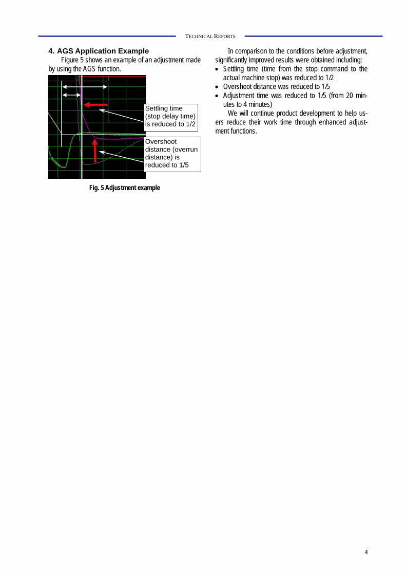
4. AGS Application Example Figure 5 shows an example of an adjustment made
by using the AGS function.
Settling time (stop delay time) is reduced to 1/2
Overshoot distance (overrun distance) is reduced to 1/5
Fig. 5 Adjustment example
In comparison to the conditions before adjustment, significantly improved results were obtained including: • Settling time (time from the stop command to the
actual machine stop) was reduced to 1/2 • Overshoot distance was reduced to 1/5 • Adjustment time was reduced to 1/5 (from 20 min-
utes to 4 minutes) We will continue product development to help us-
ers reduce their work time through enhanced adjust-ment functions.
*Nagoya Works Mitsubishi Electric ADVANCE March 2010 5
TECHNICAL REPORTS
Easy-to-Operate and Compact Inverter, the FREQROL-D700 Series
Authors: Manabu Yoshimura* and Masanori Kato*
1. Introduction
Until now, the use of compact inverters has been limited to low-end applications. However, demand is increasing for cost reduction and downsizing of equip-ment, and the low-end product market also requires enhanced functionality, performance and reliability. In response, we are expected to provide not only low price and simple operability, that is, advantages of compact models, but also high performance, functionality and reliability.
In addition to the simple operability that has always been required in the low-end market, the newly devel-oped compact inverter FREQROL-D700 provides the highest level of reliability, and improved drive perform-ance equivalent to or better than the level of the previ-ous model, FREQROL-E500, which has long been a leading product in the field of high-performance and high-functionality compact inverters.
2. Improved Reliability
2.1 Improved reliability in the control wiring
As the systems equipped with inverters obtain higher performance and functionality, they require an increased number of controller terminals, simpler wiring, and improved wiring reliability for compact inverters.
To ensure sufficient space for the required number of terminals on a compact product, the conventional approach was to use a screw-type terminal block with small-sized screws. However, this type provides only a low tightening torque, and thus the applicable wire gauges are limited to 0.75 mm2. In addition, when the equipment is operated or transported, vibration may loosen the screws and lead to poor electrical contact, necessitating frequent maintenance work such as screw re-tightening.
The FREQROL-D700 employs a spring clamp ter-minal. The spring structure prevents loosening of screws due to vibration, and eliminates the need for re-tightening maintenance. It also provides a simple wiring feature where special rod terminals are used and end-treated electrical wires are simply inserted to com-plete the wiring. In addition, the shape of the wire inser-tion opening and the structure of the internal spring are optimized to accept greater wire gauges up to 1.5 mm2, resulting in improved reliability.
This spring clamp terminal solves the problems re-lated to the control wiring of conventional models, and the FREQROL-D700 has achieved both the highest level of wiring reliability and simplicity of wiring.
2.2 Safety stop function
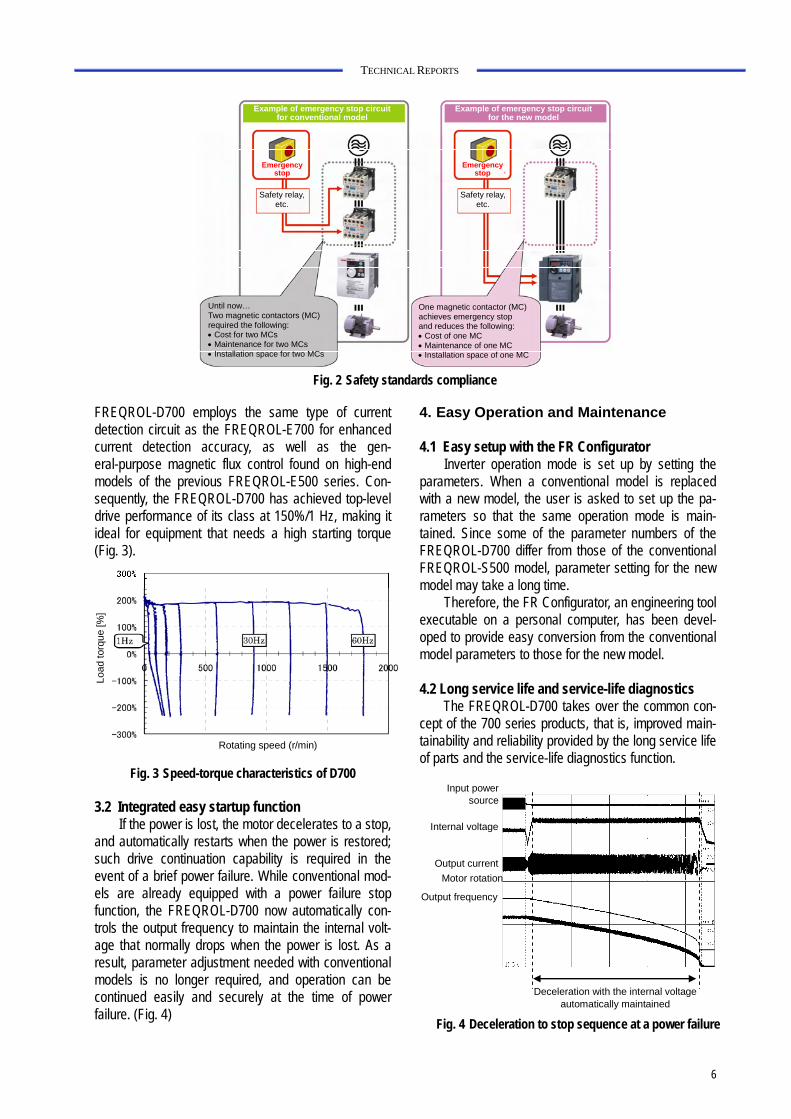
For the first time with Mitsubishi general-purpose inverters, the FREQROL-D700 is equipped with a shut-off circuit conforming to the following safety standards, facilitating compliance with the European Machinery Directive. • EN954-1 Category 3 • IEC60204-1 Stop Category 0
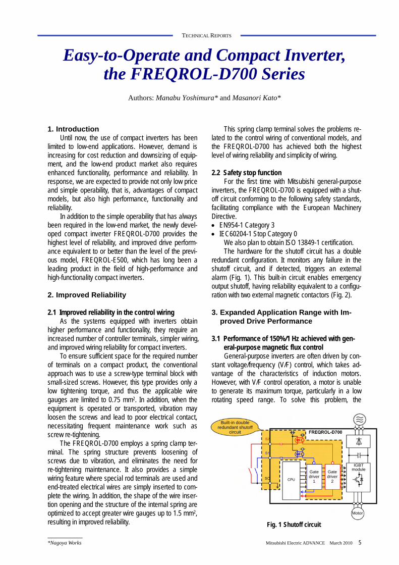
We also plan to obtain ISO 13849-1 certification. The hardware for the shutoff circuit has a double
redundant configuration. It monitors any failure in the shutoff circuit, and if detected, triggers an external alarm (Fig. 1). This built-in circuit enables emergency output shutoff, having reliability equivalent to a configu-ration with two external magnetic contactors (Fig. 2).
3. Expanded Application Range with Im-
proved Drive Performance
3.1 Performance of 150%/1 Hz achieved with gen-eral-purpose magnetic flux control General-purpose inverters are often driven by con-
stant voltage/frequency (V/F) control, which takes ad-vantage of the characteristics of induction motors. However, with V/F control operation, a motor is unable to generate its maximum torque, particularly in a low rotating speed range. To solve this problem, the
Built-in double
redundant shutoffcircuit
Gate driver
1
Gate driver
2
IGBT module
Motor
Fig. 1 Shutoff circuit
6
TECHNICAL REPORTS
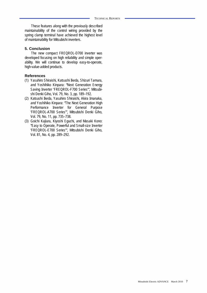
FREQROL-D700 employs the same type of current detection circuit as the FREQROL-E700 for enhanced current detection accuracy, as well as the gen-eral-purpose magnetic flux control found on high-end models of the previous FREQROL-E500 series. Con-sequently, the FREQROL-D700 has achieved top-level drive performance of its class at 150%/1 Hz, making it ideal for equipment that needs a high starting torque (Fig. 3).
Rotating speed (r/min)
Load
torq
ue [%
]
Fig. 3 Speed-torque characteristics of D700
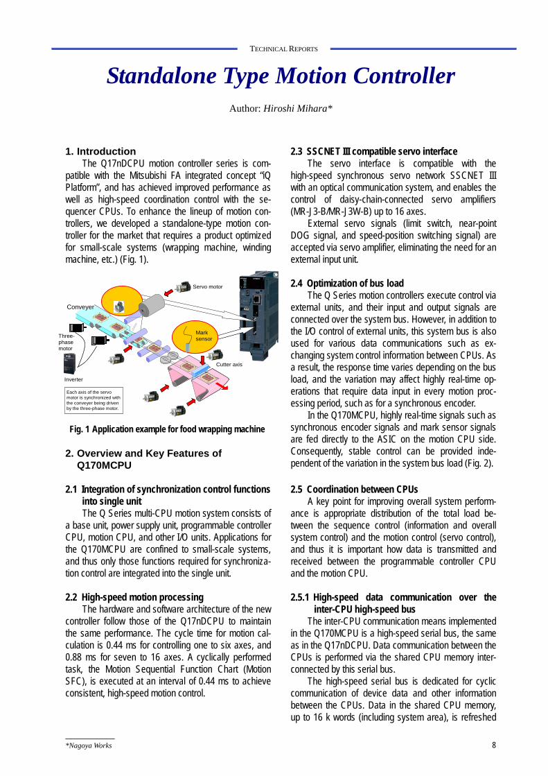
3.2 Integrated easy startup function If the power is lost, the motor decelerates to a stop,
and automatically restarts when the power is restored; such drive continuation capability is required in the event of a brief power failure. While conventional mod-els are already equipped with a power failure stop function, the FREQROL-D700 now automatically con-trols the output frequency to maintain the internal volt-age that normally drops when the power is lost. As a result, parameter adjustment needed with conventional models is no longer required, and operation can be continued easily and securely at the time of power failure. (Fig. 4)
4. Easy Operation and Maintenance
4.1 Easy setup with the FR Configurator Inverter operation mode is set up by setting the
parameters. When a conventional model is replaced with a new model, the user is asked to set up the pa-rameters so that the same operation mode is main-tained. Since some of the parameter numbers of the FREQROL-D700 differ from those of the conventional FREQROL-S500 model, parameter setting for the new model may take a long time.
Therefore, the FR Configurator, an engineering tool executable on a personal computer, has been devel-oped to provide easy conversion from the conventional model parameters to those for the new model.
4.2 Long service life and service-life diagnostics
The FREQROL-D700 takes over the common con-cept of the 700 series products, that is, improved main-tainability and reliability provided by the long service life of parts and the service-life diagnostics function.
Safety relay, etc.
Example of emergency stop circuit for conventional model
Emergency stop
Until now… Two magnetic contactors (MC) required the following: • Cost for two MCs • Maintenance for two MCs • Installation space for two MCs
Example of emergency stop circuit for the new model
Safety relay, etc.
Emergency stop
One magnetic contactor (MC) achieves emergency stop and reduces the following: • Cost of one MC • Maintenance of one MC • Installation space of one MC
Fig. 2 Safety standards compliance
Internal voltage
Output currentMotor rotation
Output frequency
Deceleration with the internal voltage automatically maintained
Input power source
Fig. 4 Deceleration to stop sequence at a power failure
Mitsubishi Electric ADVANCE March 2010 7
TECHNICAL REPORTS
These features along with the previously described maintainability of the control wiring provided by the spring clamp terminal have achieved the highest level of maintainability for Mitsubishi inverters.
5. Conclusion
The new compact FREQROL-D700 inverter was developed focusing on high reliability and simple oper-ability. We will continue to develop easy-to-operate, high-value-added products.
References (1) Yasuhiro Shiraishi, Katsushi Ikeda, Shizuri Tamura,
and Yoshihiko Kinpara: “Next Generation Energy Saving Inverter ‘FREQROL-F700 Series’”, Mitsubi-shi Denki Giho, Vol. 79, No. 3, pp. 189–192.
(2) Katsushi Ikeda, Yasuhiro Shiraishi, Akira Imanaka, and Yoshihiko Kinpara: “The Next Generation High Performance Inverter for General Purpose ‘FREQROL-A700 Series’”, Mitsubishi Denki Giho, Vol. 79, No. 11, pp. 735–738.
(3) Goichi Kajiura, Kiyoshi Eguchi, and Masaki Kono: “Easy to Operate, Powerful and Small-size Inverter ‘FREQROL-E700 Series’”, Mitsubishi Denki Giho, Vol. 81, No. 4, pp. 289–292.
*Nagoya Works 8
TECHNICAL REPORTS
Standalone Type Motion Controller Author: Hiroshi Mihara*
1. Introduction
The Q17nDCPU motion controller series is com-patible with the Mitsubishi FA integrated concept “iQ Platform”, and has achieved improved performance as well as high-speed coordination control with the se-quencer CPUs. To enhance the lineup of motion con-trollers, we developed a standalone-type motion con-troller for the market that requires a product optimized for small-scale systems (wrapping machine, winding machine, etc.) (Fig. 1).
2. Overview and Key Features of
Q170MCPU
2.1 Integration of synchronization control functions into single unit The Q Series multi-CPU motion system consists of
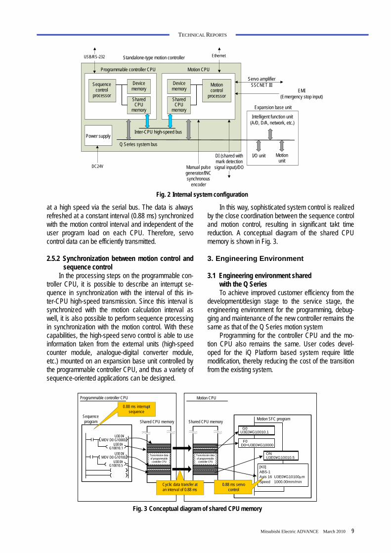
a base unit, power supply unit, programmable controller CPU, motion CPU, and other I/O units. Applications for the Q170MCPU are confined to small-scale systems, and thus only those functions required for synchroniza-tion control are integrated into the single unit.
2.2 High-speed motion processing
The hardware and software architecture of the new controller follow those of the Q17nDCPU to maintain the same performance. The cycle time for motion cal-culation is 0.44 ms for controlling one to six axes, and 0.88 ms for seven to 16 axes. A cyclically performed task, the Motion Sequential Function Chart (Motion SFC), is executed at an interval of 0.44 ms to achieve consistent, high-speed motion control.
2.3 SSCNET III compatible servo interface The servo interface is compatible with the
high-speed synchronous servo network SSCNET III with an optical communication system, and enables the control of daisy-chain-connected servo amplifiers (MR-J3-B/MR-J3W-B) up to 16 axes.
External servo signals (limit switch, near-point DOG signal, and speed-position switching signal) are accepted via servo amplifier, eliminating the need for an external input unit.
2.4 Optimization of bus load
The Q Series motion controllers execute control via external units, and their input and output signals are connected over the system bus. However, in addition to the I/O control of external units, this system bus is also used for various data communications such as ex-changing system control information between CPUs. As a result, the response time varies depending on the bus load, and the variation may affect highly real-time op-erations that require data input in every motion proc-essing period, such as for a synchronous encoder.
In the Q170MCPU, highly real-time signals such as synchronous encoder signals and mark sensor signals are fed directly to the ASIC on the motion CPU side. Consequently, stable control can be provided inde-pendent of the variation in the system bus load (Fig. 2).
2.5 Coordination between CPUs
A key point for improving overall system perform-ance is appropriate distribution of the total load be-tween the sequence control (information and overall system control) and the motion control (servo control), and thus it is important how data is transmitted and received between the programmable controller CPU and the motion CPU.
2.5.1 High-speed data communication over the
inter-CPU high-speed bus The inter-CPU communication means implemented
in the Q170MCPU is a high-speed serial bus, the same as in the Q17nDCPU. Data communication between the CPUs is performed via the shared CPU memory inter-connected by this serial bus.
The high-speed serial bus is dedicated for cyclic communication of device data and other information between the CPUs. Data in the shared CPU memory, up to 16 k words (including system area), is refreshed
Synchronization
encoder
Cutter axis
Servo motor
Conveyer
Three-phase motor
Inverter
Each axis of the servo motor is synchronized with the conveyer being driven by the three-phase motor.
Mark sensor
Fig. 1 Application example for food wrapping machine
Mitsubishi Electric ADVANCE March 2010 9
TECHNICAL REPORTS
at a high speed via the serial bus. The data is always refreshed at a constant interval (0.88 ms) synchronized with the motion control interval and independent of the user program load on each CPU. Therefore, servo control data can be efficiently transmitted.
2.5.2 Synchronization between motion control and
sequence control In the processing steps on the programmable con-
troller CPU, it is possible to describe an interrupt se-quence in synchronization with the interval of this in-ter-CPU high-speed transmission. Since this interval is synchronized with the motion calculation interval as well, it is also possible to perform sequence processing in synchronization with the motion control. With these capabilities, the high-speed servo control is able to use information taken from the external units (high-speed counter module, analogue-digital converter module, etc.) mounted on an expansion base unit controlled by the programmable controller CPU, and thus a variety of sequence-oriented applications can be designed.
In this way, sophisticated system control is realized by the close coordination between the sequence control and motion control, resulting in significant takt time reduction. A conceptual diagram of the shared CPU memory is shown in Fig. 3.
3. Engineering Environment
3.1 Engineering environment shared
with the Q Series To achieve improved customer efficiency from the
development/design stage to the service stage, the engineering environment for the programming, debug-ging and maintenance of the new controller remains the same as that of the Q Series motion system
Programming for the controller CPU and the mo-tion CPU also remains the same. User codes devel-oped for the iQ Platform based system require little modification, thereby reducing the cost of the transition from the existing system.
Standalone-type motion controller USB/RS-232 Ethernet
Programmable controller CPU Motion CPU
Sequence control
processor
Device memory
Device memory
Shared CPU
memory
Shared CPU
memory
Inter-CPU high-speed bus Power supply
DC24V
Q Series system bus
Manual pulse generator/INC synchronous
encoder
DI (shared with mark detection
signal input)/DO
Motion control
processor
Servo amplifier SSCNET III
EMI (Emergency stop input)
Expansion base unit
Intelligent function unit (A/D, D/A, network, etc.)
I/O unit Motion unit
Fig. 2 Internal system configuration
U3E0¥ MOV D0 G10000
U3E0¥ G10010.1
U3E0¥ MOV D0 G10100
U3E0¥ G10010.5
G0U3E0¥G10010.1
F0D0=U3E0¥G10000
ONU3E0¥G10010.5
[K0] ABS-1 Axis 16 U3E0¥G10100μm Speed 1000.00mm/min
Motion CPU Programmable controller CPU
0.88 ms interrupt sequence
Sequence program Shared CPU memory Shared CPU memory
Transmission data of programmable
controller CPU
Transmission data of programmable
controller CPU
Cyclic data transfer at an interval of 0.88 ms
0.88 ms servo control
Motion SFC program
Fig. 3 Conceptual diagram of shared CPU memory
10
TECHNICAL REPORTS
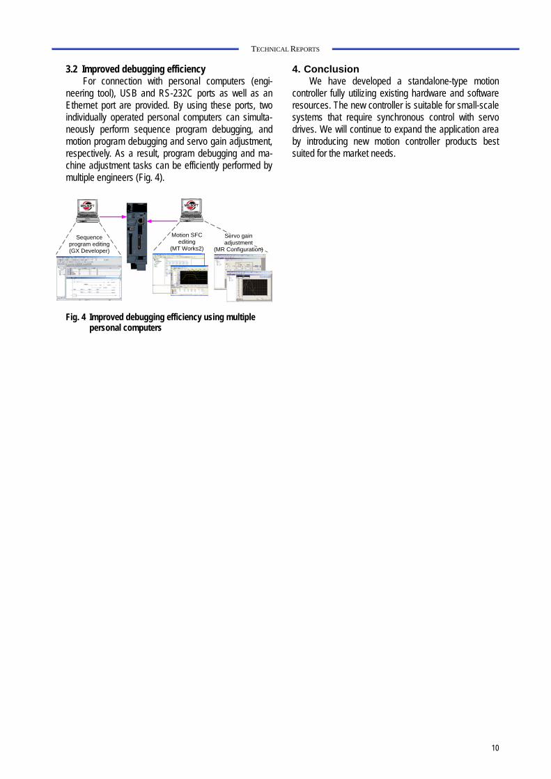
3.2 Improved debugging efficiency For connection with personal computers (engi-
neering tool), USB and RS-232C ports as well as an Ethernet port are provided. By using these ports, two individually operated personal computers can simulta-neously perform sequence program debugging, and motion program debugging and servo gain adjustment, respectively. As a result, program debugging and ma-chine adjustment tasks can be efficiently performed by multiple engineers (Fig. 4).
Sequence program editing (GX Developer)
Motion SFC editing
(MT Works2)
Servo gain adjustment
(MR Configuration)
Fig. 4 Improved debugging efficiency using multiple
personal computers
4. Conclusion We have developed a standalone-type motion
controller fully utilizing existing hardware and software resources. The new controller is suitable for small-scale systems that require synchronous control with servo drives. We will continue to expand the application area by introducing new motion controller products best suited for the market needs.
*Nagoya Works Mitsubishi Electric ADVANCE March 2010 11
TECHNICAL REPORTS
Multi Hybrid Drive, the MDS-DM Series Authors: Kazuyuki Nakamura*, Yoji Tsutsumishita* and Yoshitomo Hayashi*
1. Introduction
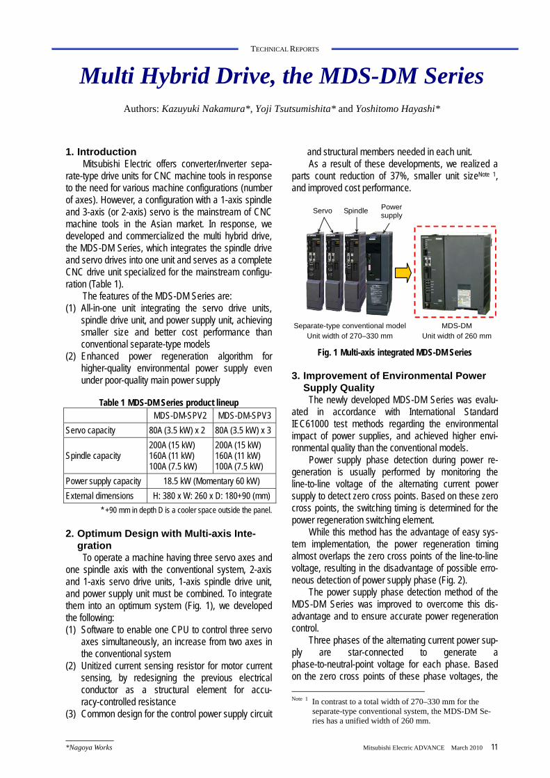
Mitsubishi Electric offers converter/inverter sepa-rate-type drive units for CNC machine tools in response to the need for various machine configurations (number of axes). However, a configuration with a 1-axis spindle and 3-axis (or 2-axis) servo is the mainstream of CNC machine tools in the Asian market. In response, we developed and commercialized the multi hybrid drive, the MDS-DM Series, which integrates the spindle drive and servo drives into one unit and serves as a complete CNC drive unit specialized for the mainstream configu-ration (Table 1).
The features of the MDS-DM Series are: (1) All-in-one unit integrating the servo drive units,
spindle drive unit, and power supply unit, achieving smaller size and better cost performance than conventional separate-type models
(2) Enhanced power regeneration algorithm for higher-quality environmental power supply even under poor-quality main power supply
Table 1 MDS-DM Series product lineup MDS-DM-SPV2 MDS-DM-SPV3 Servo capacity 80A (3.5 kW) x 2 80A (3.5 kW) x 3
Spindle capacity 200A (15 kW) 160A (11 kW) 100A (7.5 kW)
200A (15 kW) 160A (11 kW) 100A (7.5 kW)
Power supply capacity 18.5 kW (Momentary 60 kW) External dimensions H: 380 x W: 260 x D: 180+90 (mm)
* +90 mm in depth D is a cooler space outside the panel.
2. Optimum Design with Multi-axis Inte-gration
To operate a machine having three servo axes and one spindle axis with the conventional system, 2-axis and 1-axis servo drive units, 1-axis spindle drive unit, and power supply unit must be combined. To integrate them into an optimum system (Fig. 1), we developed the following: (1) Software to enable one CPU to control three servo
axes simultaneously, an increase from two axes in the conventional system
(2) Unitized current sensing resistor for motor current sensing, by redesigning the previous electrical conductor as a structural element for accu-racy-controlled resistance
(3) Common design for the control power supply circuit
and structural members needed in each unit. As a result of these developments, we realized a
parts count reduction of 37%, smaller unit sizeNote 1, and improved cost performance.
Separate-type conventional model Unit width of 270–330 mm
Servo Power supply Spindle
MDS-DM Unit width of 260 mm
Fig. 1 Multi-axis integrated MDS-DM Series
3. Improvement of Environmental Power Supply Quality
The newly developed MDS-DM Series was evalu-ated in accordance with International Standard IEC61000 test methods regarding the environmental impact of power supplies, and achieved higher envi-ronmental quality than the conventional models.
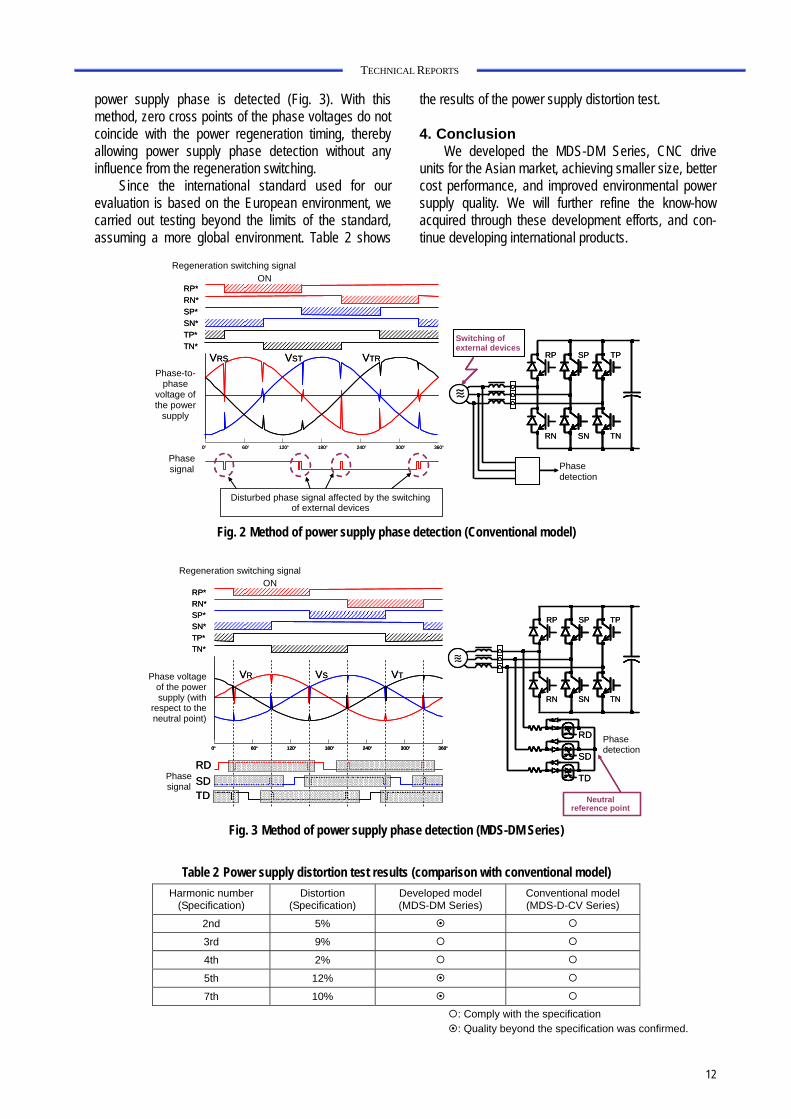
Power supply phase detection during power re-generation is usually performed by monitoring the line-to-line voltage of the alternating current power supply to detect zero cross points. Based on these zero cross points, the switching timing is determined for the power regeneration switching element.
While this method has the advantage of easy sys-tem implementation, the power regeneration timing almost overlaps the zero cross points of the line-to-line voltage, resulting in the disadvantage of possible erro-neous detection of power supply phase (Fig. 2).
The power supply phase detection method of the MDS-DM Series was improved to overcome this dis-advantage and to ensure accurate power regeneration control.
Three phases of the alternating current power sup-ply are star-connected to generate a phase-to-neutral-point voltage for each phase. Based on the zero cross points of these phase voltages, the Note 1 In contrast to a total width of 270–330 mm for the
separate-type conventional system, the MDS-DM Se-ries has a unified width of 260 mm.
12
TECHNICAL REPORTS
power supply phase is detected (Fig. 3). With this method, zero cross points of the phase voltages do not coincide with the power regeneration timing, thereby allowing power supply phase detection without any influence from the regeneration switching.
Since the international standard used for our evaluation is based on the European environment, we carried out testing beyond the limits of the standard, assuming a more global environment. Table 2 shows
the results of the power supply distortion test.
4. Conclusion We developed the MDS-DM Series, CNC drive
units for the Asian market, achieving smaller size, better cost performance, and improved environmental power supply quality. We will further refine the know-how acquired through these development efforts, and con-tinue developing international products.
0° 60° 120° 180° 240° 300° 360°
RP SP TP
RN SN TN
RP*RN*SP*SN*TP*TN*
VRS VST VTR
0° 60° 120° 180° 240° 300° 360°
RP SP TP
RN SN TN
RP*RN*SP*SN*TP*TN*
VRS VST VTR
Regeneration switching signal ON
Phase-to- phase
voltage of the power
supply
Phase signal
Disturbed phase signal affected by the switching of external devices
Phase detection
Switching of external devices
Fig. 2 Method of power supply phase detection (Conventional model)
0° 60° 120° 180° 240° 300° 360°
RP*RN*SP*SN*TP*TN*
RD
SD
TD
RP SP TP
RN SN TN
VR VS VT
RDSDTD
0° 60° 120° 180° 240° 300° 360°0° 60° 120° 180° 240° 300° 360°
RP*RN*SP*SN*TP*TN*
RD
SD
TD
RP SP TP
RN SN TN
VR VS VT
RDSDTD
Regeneration switching signal ON
Phase voltage of the power supply (with
respect to the neutral point)
Phase signal
Phase detection
Neutral reference point
Fig. 3 Method of power supply phase detection (MDS-DM Series)
Table 2 Power supply distortion test results (comparison with conventional model) Harmonic number
(Specification) Distortion
(Specification) Developed model (MDS-DM Series)
Conventional model (MDS-D-CV Series)
2nd 5%
3rd 9%
4th 2%
5th 12%
7th 10%
: Comply with the specification : Quality beyond the specification was confirmed.
*Nagoya Works Mitsubishi Electric ADVANCE March 2010 13
TECHNICAL REPORTS
New Mitsubishi CNC M700V Series Author: Hirokatsu Miyatake*
1. Introduction
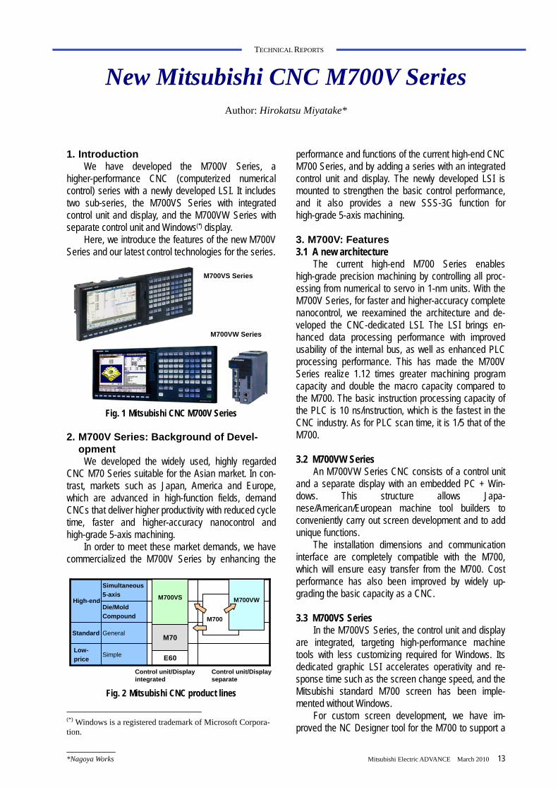
We have developed the M700V Series, a higher-performance CNC (computerized numerical control) series with a newly developed LSI. It includes two sub-series, the M700VS Series with integrated control unit and display, and the M700VW Series with separate control unit and Windows(*) display.
Here, we introduce the features of the new M700V Series and our latest control technologies for the series.
M700VS Series
M700VW Series
Fig. 1 Mitsubishi CNC M700V Series
2. M700V Series: Background of Devel-
opment We developed the widely used, highly regarded
CNC M70 Series suitable for the Asian market. In con-trast, markets such as Japan, America and Europe, which are advanced in high-function fields, demand CNCs that deliver higher productivity with reduced cycle time, faster and higher-accuracy nanocontrol and high-grade 5-axis machining.
In order to meet these market demands, we have commercialized the M700V Series by enhancing the
(*) Windows is a registered trademark of Microsoft Corpora-tion.
performance and functions of the current high-end CNC M700 Series, and by adding a series with an integrated control unit and display. The newly developed LSI is mounted to strengthen the basic control performance, and it also provides a new SSS-3G function for high-grade 5-axis machining.
3. M700V: Features 3.1 A new architecture
The current high-end M700 Series enables high-grade precision machining by controlling all proc-essing from numerical to servo in 1-nm units. With the M700V Series, for faster and higher-accuracy complete nanocontrol, we reexamined the architecture and de-veloped the CNC-dedicated LSI. The LSI brings en-hanced data processing performance with improved usability of the internal bus, as well as enhanced PLC processing performance. This has made the M700V Series realize 1.12 times greater machining program capacity and double the macro capacity compared to the M700. The basic instruction processing capacity of the PLC is 10 ns/instruction, which is the fastest in the CNC industry. As for PLC scan time, it is 1/5 that of the M700.
3.2 M700VW Series
An M700VW Series CNC consists of a control unit and a separate display with an embedded PC + Win-dows. This structure allows Japa-nese/American/European machine tool builders to conveniently carry out screen development and to add unique functions.
The installation dimensions and communication interface are completely compatible with the M700, which will ensure easy transfer from the M700. Cost performance has also been improved by widely up-grading the basic capacity as a CNC.
3.3 M700VS Series
In the M700VS Series, the control unit and display are integrated, targeting high-performance machine tools with less customizing required for Windows. Its dedicated graphic LSI accelerates operativity and re-sponse time such as the screen change speed, and the Mitsubishi standard M700 screen has been imple-mented without Windows.
For custom screen development, we have im-proved the NC Designer tool for the M700 to support a
E60
Control unit/Displayintegrated
GeneralStandard
SimpleLow-price
Die/MoldCompound
Simultaneous5-axis
High-end
M70
M700VS
M700
M700VW
Control unit/Displayseparate
Fig. 2 Mitsubishi CNC product lines
14
TECHNICAL REPORTS
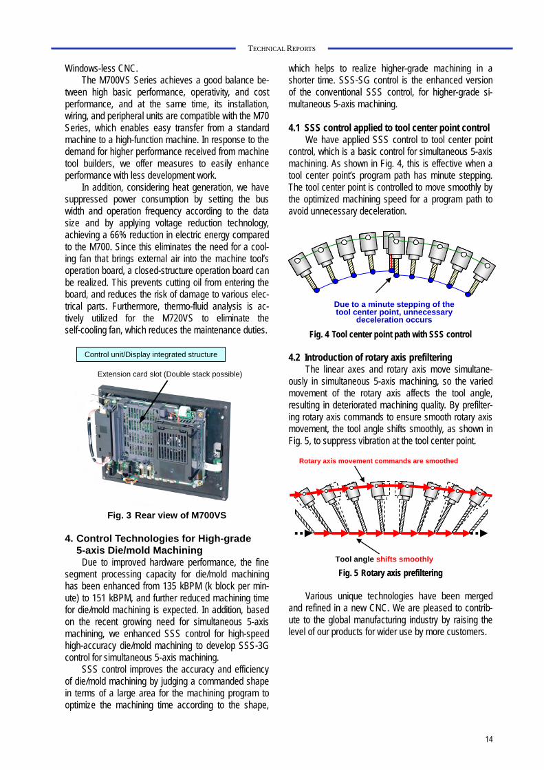
Windows-less CNC. The M700VS Series achieves a good balance be-
tween high basic performance, operativity, and cost performance, and at the same time, its installation, wiring, and peripheral units are compatible with the M70 Series, which enables easy transfer from a standard machine to a high-function machine. In response to the demand for higher performance received from machine tool builders, we offer measures to easily enhance performance with less development work.
In addition, considering heat generation, we have suppressed power consumption by setting the bus width and operation frequency according to the data size and by applying voltage reduction technology, achieving a 66% reduction in electric energy compared to the M700. Since this eliminates the need for a cool-ing fan that brings external air into the machine tool’s operation board, a closed-structure operation board can be realized. This prevents cutting oil from entering the board, and reduces the risk of damage to various elec-trical parts. Furthermore, thermo-fluid analysis is ac-tively utilized for the M720VS to eliminate the self-cooling fan, which reduces the maintenance duties.
Control unit/Display integrated structure
Extension card slot (Double stack possible)
Fig. 3 Rear view of M700VS
4. Control Technologies for High-grade
5-axis Die/mold Machining Due to improved hardware performance, the fine
segment processing capacity for die/mold machining has been enhanced from 135 kBPM (k block per min-ute) to 151 kBPM, and further reduced machining time for die/mold machining is expected. In addition, based on the recent growing need for simultaneous 5-axis machining, we enhanced SSS control for high-speed high-accuracy die/mold machining to develop SSS-3G control for simultaneous 5-axis machining.
SSS control improves the accuracy and efficiency of die/mold machining by judging a commanded shape in terms of a large area for the machining program to optimize the machining time according to the shape,
which helps to realize higher-grade machining in a shorter time. SSS-SG control is the enhanced version of the conventional SSS control, for higher-grade si-multaneous 5-axis machining.
4.1 SSS control applied to tool center point control
We have applied SSS control to tool center point control, which is a basic control for simultaneous 5-axis machining. As shown in Fig. 4, this is effective when a tool center point’s program path has minute stepping. The tool center point is controlled to move smoothly by the optimized machining speed for a program path to avoid unnecessary deceleration.
Due to a minute stepping of the tool center point, unnecessary
deceleration occurs
Fig. 4 Tool center point path with SSS control
4.2 Introduction of rotary axis prefiltering The linear axes and rotary axis move simultane-
ously in simultaneous 5-axis machining, so the varied movement of the rotary axis affects the tool angle, resulting in deteriorated machining quality. By prefilter-ing rotary axis commands to ensure smooth rotary axis movement, the tool angle shifts smoothly, as shown in Fig. 5, to suppress vibration at the tool center point.
Tool angle shifts smoothly
Rotary axis movement commands are smoothed
Fig. 5 Rotary axis prefiltering Various unique technologies have been merged
and refined in a new CNC. We are pleased to contrib-ute to the global manufacturing industry by raising the level of our products for wider use by more customers.
*Nagoya Works Mitsubishi Electric ADVANCE March 2010 15
TECHNICAL REPORTS
New Frame-Type Spindle Motor, the SJ-D Series
Author: Toru Ogawa*
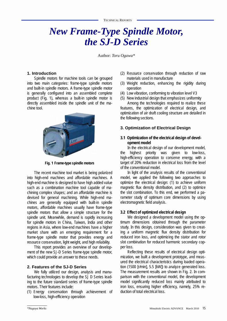
1. Introduction
Spindle motors for machine tools can be grouped into two main categories: frame-type spindle motors and built-in spindle motors. A frame-type spindle motor is generally configured into an assembled complete product (Fig. 1), whereas a built-in spindle motor is directly assembled inside the spindle unit of the ma-chine tool.
Fig. 1 Frame-type spindle motors The recent machine tool market is being polarized
into high-end machines and affordable machines. A high-end machine is designed to have high added value such as a combination machine tool capable of ma-chining complex shapes; and an affordable machine is devised for general machining. While high-end ma-chines are generally equipped with built-in spindle motors, affordable machines usually have frame-type spindle motors that allow a simple structure for the spindle unit. Meanwhile, demand is rapidly increasing for spindle motors in China, Taiwan, India and other regions in Asia, where low-end machines have a higher market share with an emerging requirement for a frame-type spindle motor that provides energy and resource conservation, light weight, and high reliability.
This report provides an overview of our develop-ment of the new SJ-D Series frame-type spindle motor, which could provide an answer to these needs.
2. Features of the SJ-D Series
We fully utilized our design, analysis and manu-facturing technologies to develop the SJ D Series lead-ing to the future standard series of frame-type spindle motors. Their features include: (1) Energy conservation through achievement of
low-loss, high-efficiency operation
(2) Resource conservation through reduction of raw materials used in manufacture
(3) Weight reduction, enhancing the rigidity during operation
(4) Low vibration, conforming to vibration level V3 (5) New industrial design that emphasizes uniformity
Among the technologies required to realize these features, the optimization of electrical design, and optimization of air draft cooling structure are detailed in the following sections.
3. Optimization of Electrical Design
3.1 Optimization of the electrical design of devel-
opment model In the electrical design of our development model,
the highest priority was given to low-loss, high-efficiency operation to conserve energy, with a target of 20% reduction in electrical loss from the level of the conventional model.
In light of the analysis results of the conventional model, we applied the following two approaches to optimize the electrical design: (1) to achieve uniform magnetic flux density distribution, and (2) to optimize the slot combination. To this end, we performed a pa-rameter study of optimum core dimensions by using electromagnetic field analysis.
3.2 Effect of optimized electrical design
We designed a development model using the op-timum dimensions obtained through the parameter study. In this design, consideration was given to creat-ing a uniform magnetic flux density distribution for reduced iron loss, and optimizing the stator and rotor slot combination for reduced harmonic secondary cop-per loss.
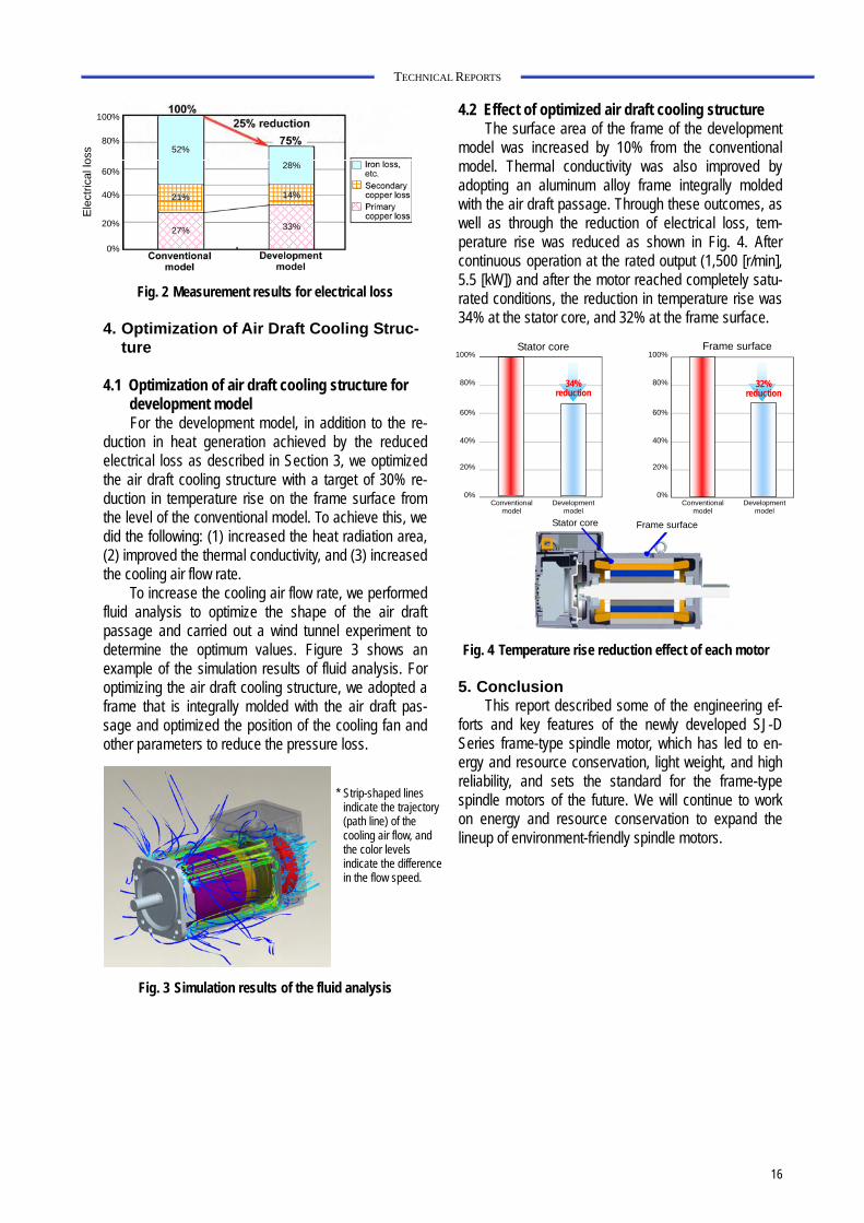
Reflecting these results of electrical design opti-mization, we built a development prototype, and meas-ured the electrical characteristics during loaded opera-tion (1500 [r/min], 5.5 [kW]) to analyze generated loss. The measurement results are shown in Fig. 2. In com-parison with the conventional model, the development model significantly reduced loss mainly attributed to iron loss, ensuring higher efficiency, namely, 25% re-duction of total electrical loss.
16
TECHNICAL REPORTS
Fig. 2 Measurement results for electrical loss
4. Optimization of Air Draft Cooling Struc-ture
4.1 Optimization of air draft cooling structure for
development model For the development model, in addition to the re-
duction in heat generation achieved by the reduced electrical loss as described in Section 3, we optimized the air draft cooling structure with a target of 30% re-duction in temperature rise on the frame surface from the level of the conventional model. To achieve this, we did the following: (1) increased the heat radiation area, (2) improved the thermal conductivity, and (3) increased the cooling air flow rate.
To increase the cooling air flow rate, we performed fluid analysis to optimize the shape of the air draft passage and carried out a wind tunnel experiment to determine the optimum values. Figure 3 shows an example of the simulation results of fluid analysis. For optimizing the air draft cooling structure, we adopted a frame that is integrally molded with the air draft pas-sage and optimized the position of the cooling fan and other parameters to reduce the pressure loss.
* Strip-shaped lines
indicate the trajectory (path line) of the cooling air flow, and the color levels indicate the difference in the flow speed.
Fig. 3 Simulation results of the fluid analysis
4.2 Effect of optimized air draft cooling structure
The surface area of the frame of the development model was increased by 10% from the conventional model. Thermal conductivity was also improved by adopting an aluminum alloy frame integrally molded with the air draft passage. Through these outcomes, as well as through the reduction of electrical loss, tem-perature rise was reduced as shown in Fig. 4. After continuous operation at the rated output (1,500 [r/min], 5.5 [kW]) and after the motor reached completely satu-rated conditions, the reduction in temperature rise was 34% at the stator core, and 32% at the frame surface.
34% reduction
32% reduction
100%
80%
60%
40%
20%
0%
100%
80%
60%
40%
20%
0% Conventional
model Development
model Conventional
model Development
model
Stator core Frame surface
Stator core Frame surface
Fig. 4 Temperature rise reduction effect of each motor
5. Conclusion This report described some of the engineering ef-
forts and key features of the newly developed SJ-D Series frame-type spindle motor, which has led to en-ergy and resource conservation, light weight, and high reliability, and sets the standard for the frame-type spindle motors of the future. We will continue to work on energy and resource conservation to expand the lineup of environment-friendly spindle motors.
Ele
ctric
al lo
ss
100%
80%
60%
40%
20%
0%
52%
21%
27%
28%
14%
33%


![PDF [5149 KB]](https://img.pdfslide.tips/doc/110x75/5874b9e31a28abc52a8b8543/pdf-5149-kb.jpg)