Embed Size (px)
Citation preview
802.11 Wireless Networks (PHY)
Kate Ching-Ju Lin (林靖茹) Academia Sinica
2016.03.18 CSIE, NTU
Reference 1. OFDM Tutorial
online: http://home.iitj.ac.in/~ramana/ofdm-tutorial.pdf
2. OFDM Wireless LWNs: A Theoretical and Practical Guide By John Terry, Juha Heiskala
3. Next Generation Wireless LANs: 802.11n and 802.11ac By Eldad Perahia
We will cover … § Medium Access Control
– Infrastructure mode vs. Ad Hoc mode – DCF vs. PCF – CSMA/CA with exponential backoff – Hidden terminal
§ Physical Layer Basics – Packet Detection – OFDM – Synchronization
Packet Detection
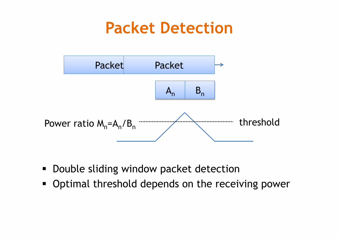
§ Double sliding window packet detection § Optimal threshold depends on the receiving power
Packet
An Bn
threshold Power ratio Mn=An/Bn
Packet Packet
Packet Detection
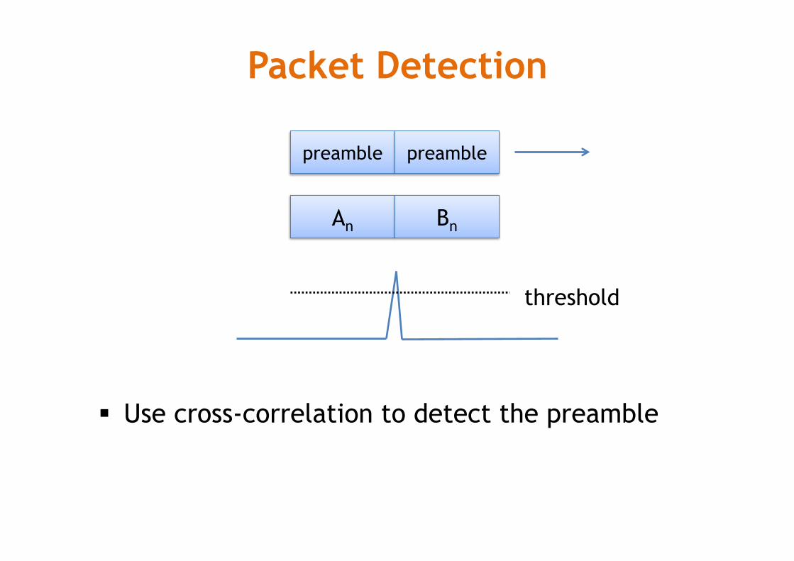
§ Use cross-correlation to detect the preamble
An Bn
preamble preamble
threshold
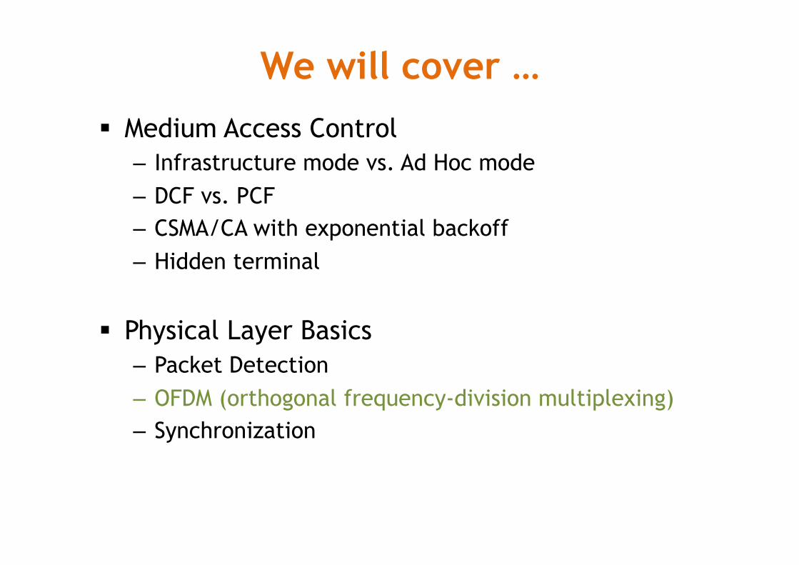
We will cover … § Medium Access Control
– Infrastructure mode vs. Ad Hoc mode – DCF vs. PCF – CSMA/CA with exponential backoff – Hidden terminal
§ Physical Layer Basics – Packet Detection – OFDM (orthogonal frequency-division multiplexing) – Synchronization
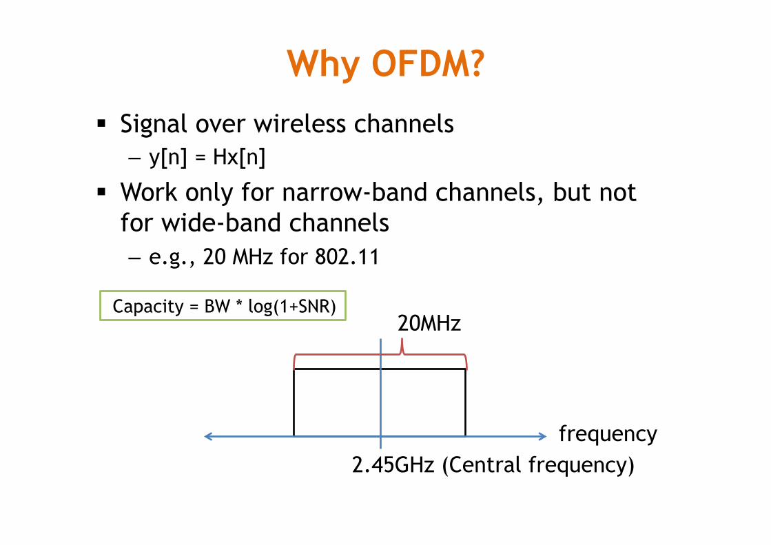
Why OFDM? § Signal over wireless channels
– y[n] = Hx[n]
§ Work only for narrow-band channels, but not for wide-band channels – e.g., 20 MHz for 802.11
frequency 2.45GHz (Central frequency)
20MHz Capacity = BW * log(1+SNR)
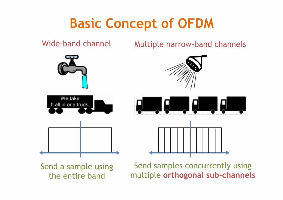
Basic Concept of OFDM
Send a sample using the entire band
Send samples concurrently using multiple orthogonal sub-channels
Wide-band channel Multiple narrow-band channels
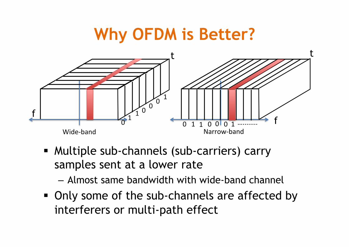
Why OFDM is Better?
§ Multiple sub-channels (sub-carriers) carry samples sent at a lower rate – Almost same bandwidth with wide-band channel
§ Only some of the sub-channels are affected by interferers or multi-path effect
f f
t t
Wide-band Narrow-band0 1
1 00 0
1
0 1 1 0 0 0 1…........
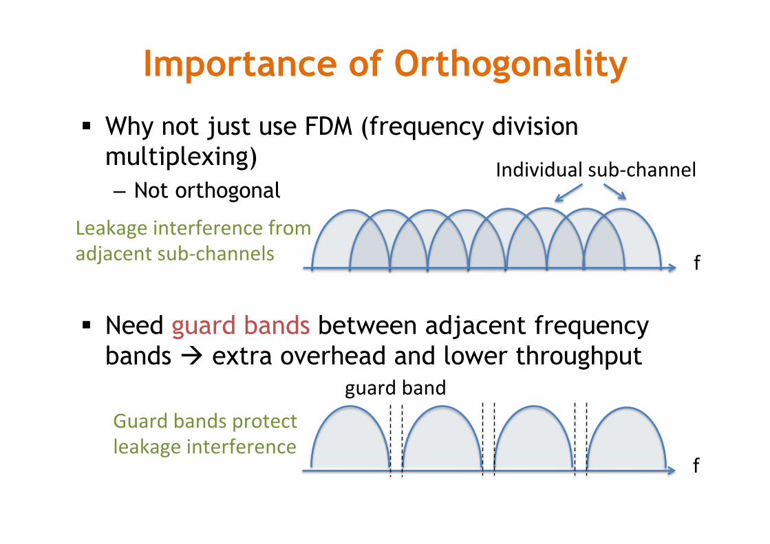
Importance of Orthogonality
§ Why not just use FDM (frequency division multiplexing) – Not orthogonal
§ Need guard bands between adjacent frequency bands à extra overhead and lower throughput
f
Individualsub-channel
Leakageinterferencefromadjacentsub-channels
f
guardbandGuardbandsprotectleakageinterference
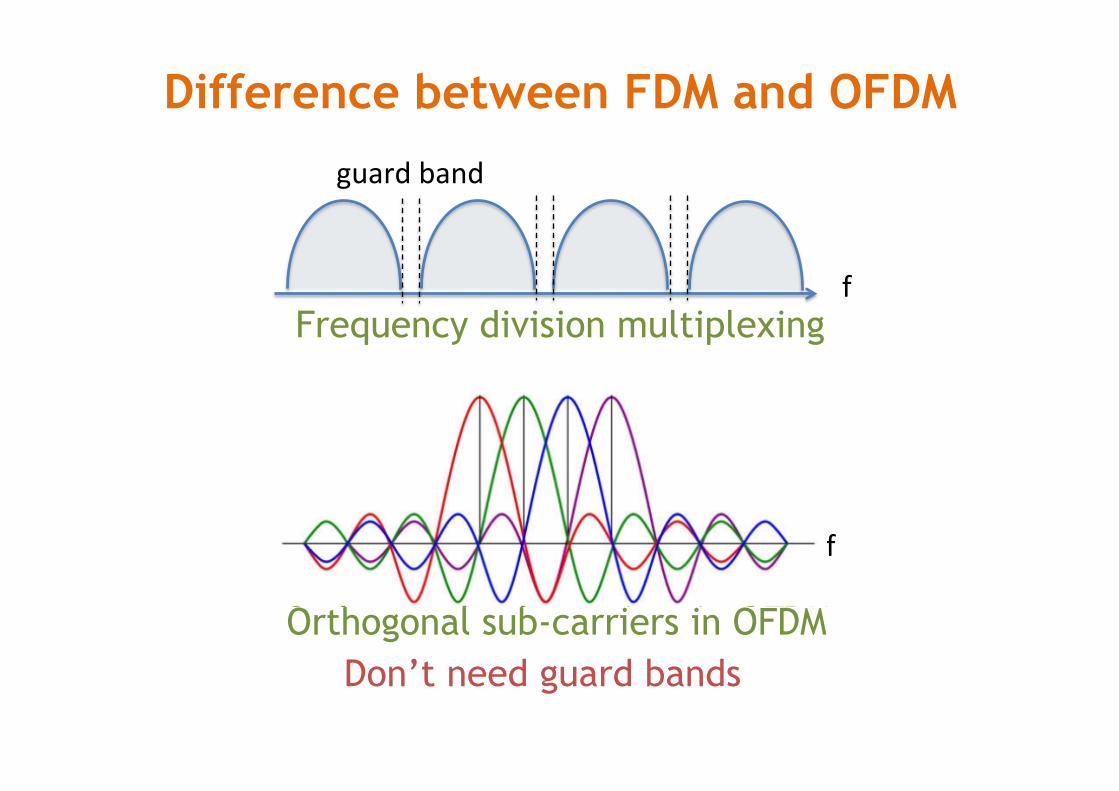
Difference between FDM and OFDM
f
guardband
Frequency division multiplexing
Orthogonal sub-carriers in OFDM Don’t need guard bands
f
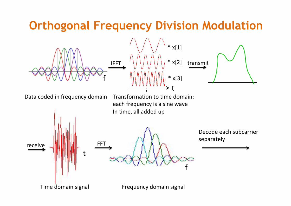
Orthogonal Frequency Division Modulation
Datacodedinfrequencydomain
fIFFT
*x[1]
*x[2]
*x[3]
… t
TransformaMontoMmedomain:eachfrequencyisasinewaveInMme,alladdedup
receive
Timedomainsignal Frequencydomainsignal
FFT
Decodeeachsubcarrierseparately
transmit
f
f
t
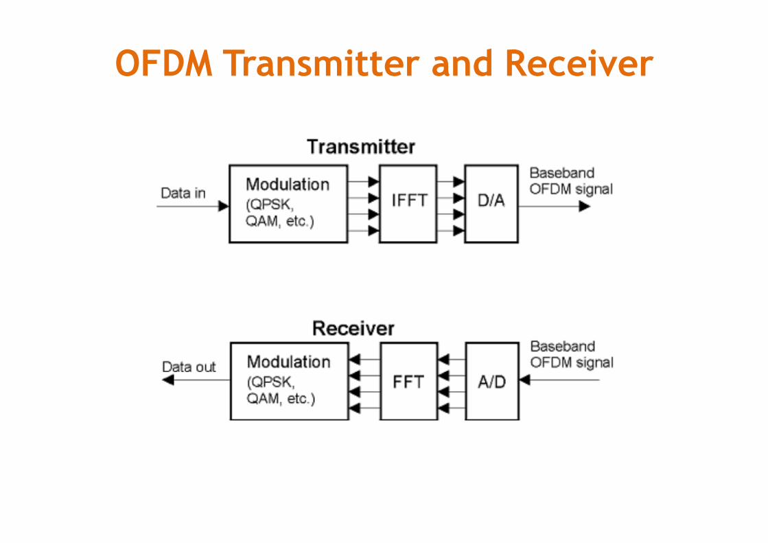
OFDM Transmitter and Receiver
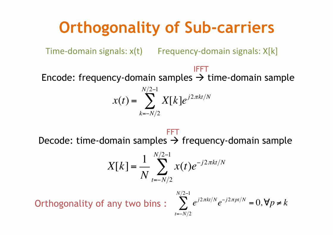
Orthogonality of Sub-carriers
x(t) = X[k]e j2πkt Nk=−N 2
N 2−1
∑
Encode: frequency-domain samples à time-domain sample IFFT
Decode: time-domain samples à frequency-domain sample FFT
X[k]= 1N
x(t)e− j2πkt Nt=−N 2
N 2−1
∑
Orthogonality of any two bins : e j2πkt Ne− j2π pt Nt=−N 2
N 2−1
∑ = 0,∀p ≠ k
Time-domainsignals:x(t)Frequency-domainsignals:X[k]
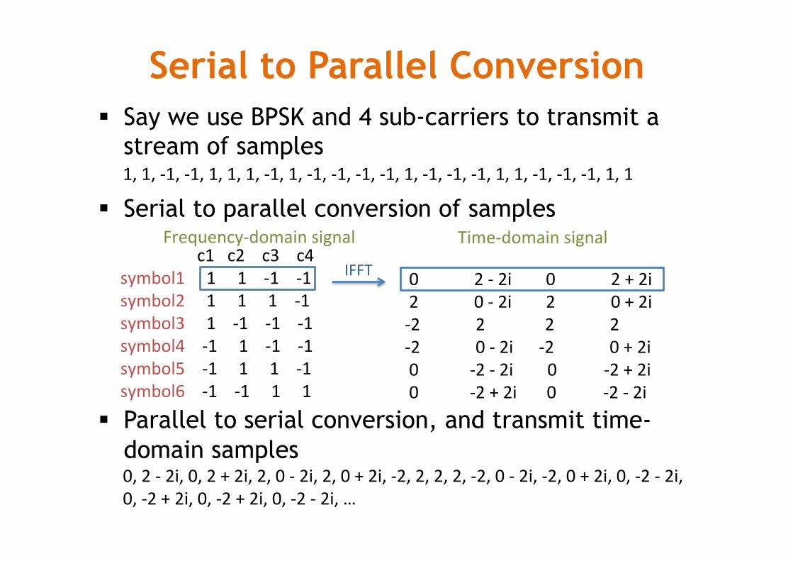
Serial to Parallel Conversion § Say we use BPSK and 4 sub-carriers to transmit a
stream of samples
§ Serial to parallel conversion of samples
§ Parallel to serial conversion, and transmit time-domain samples
c1c2c3c4symbol111-1-1symbol2111-1symbol31-1-1-1symbol4-11-1-1symbol5-111-1symbol6-1-111
Frequency-domainsignal Time-domainsignal
02-2i02+2i20-2i20+2i-2222-20-2i-20+2i0-2-2i0-2+2i0-2+2i0-2-2i
IFFT
0,2-2i,0,2+2i,2,0-2i,2,0+2i,-2,2,2,2,-2,0-2i,-2,0+2i,0,-2-2i,0,-2+2i,0,-2+2i,0,-2-2i,…
1,1,-1,-1,1,1,1,-1,1,-1,-1,-1,-1,1,-1,-1,-1,1,1,-1,-1,-1,1,1
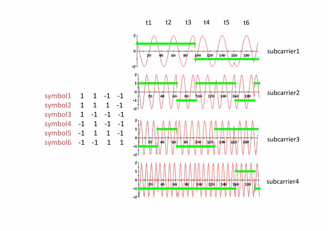
t2
symbol111-1-1symbol2111-1symbol31-1-1-1symbol4-11-1-1symbol5-111-1symbol6-1-111
subcarrier1
subcarrier2
subcarrier3
subcarrier4
t1 t3 t4 t5 t6
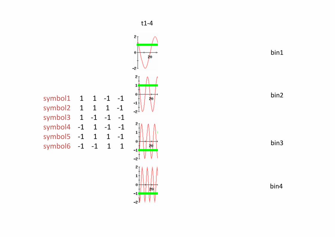
t1-4 t5-8 t9-12 t13-16t17-20 t21-24
symbol111-1-1symbol2111-1symbol31-1-1-1symbol4-11-1-1symbol5-111-1symbol6-1-111
bin1
bin2
bin3
bin4
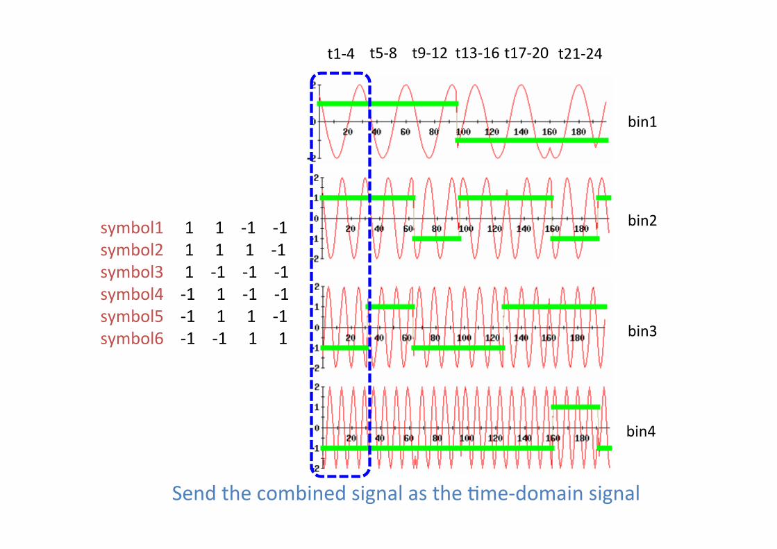
symbol111-1-1symbol2111-1symbol31-1-1-1symbol4-11-1-1symbol5-111-1symbol6-1-111
bin1
bin2
bin3
bin4
SendthecombinedsignalastheMme-domainsignal
t1-4 t5-8 t9-12 t13-16t17-20 t21-24
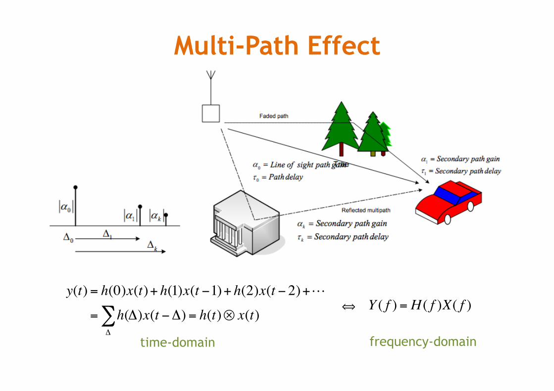
Multi-Path Effect
y(t) = h(0)x(t)+ h(1)x(t −1)+ h(2)x(t − 2)+
= h(Δ
∑ Δ)x(t −Δ) = h(t)⊗ x(t)
time-domain
⟺ Y ( f ) = H ( f )X( f )
frequency-domain
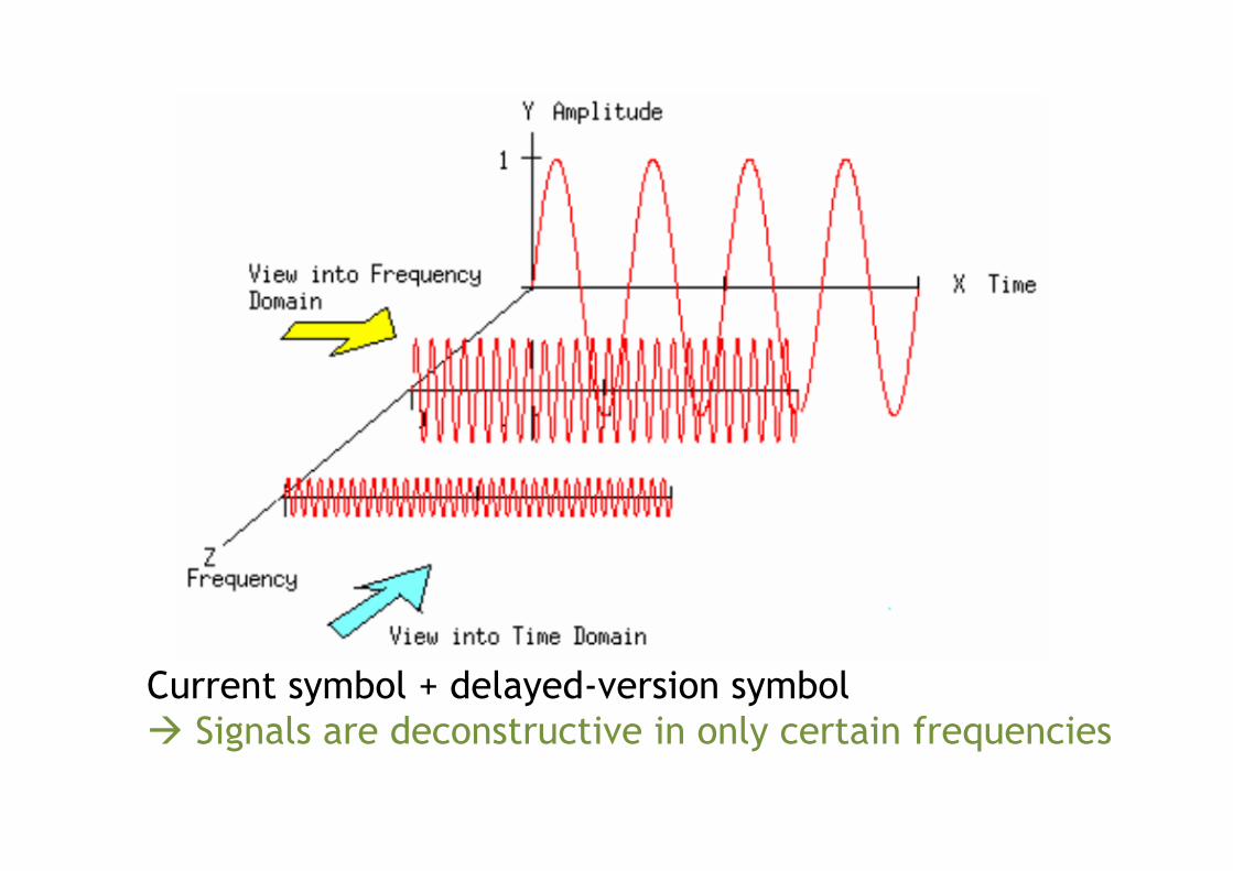
Current symbol + delayed-version symbol à Signals are deconstructive in only certain frequencies
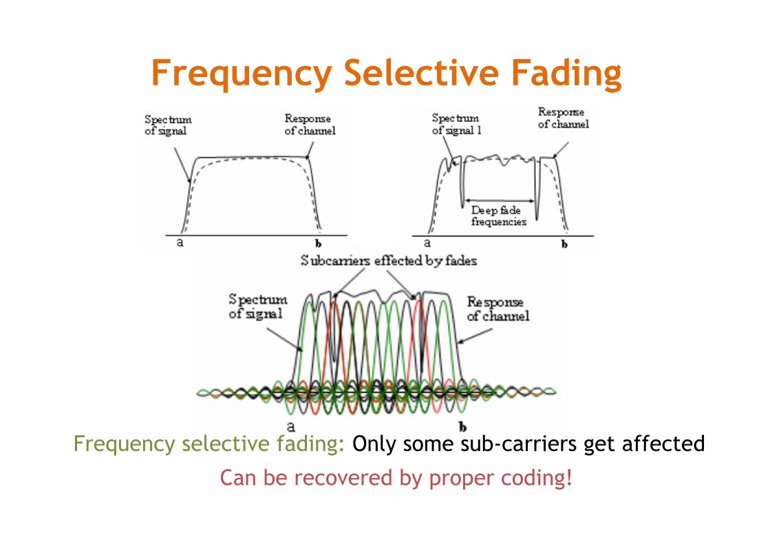
Frequency Selective Fading
Frequency selective fading: Only some sub-carriers get affected
Can be recovered by proper coding!
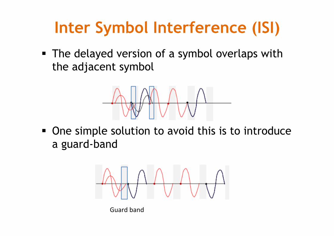
§ The delayed version of a symbol overlaps with the adjacent symbol
§ One simple solution to avoid this is to introduce a guard-band
Inter Symbol Interference (ISI)
Guardband
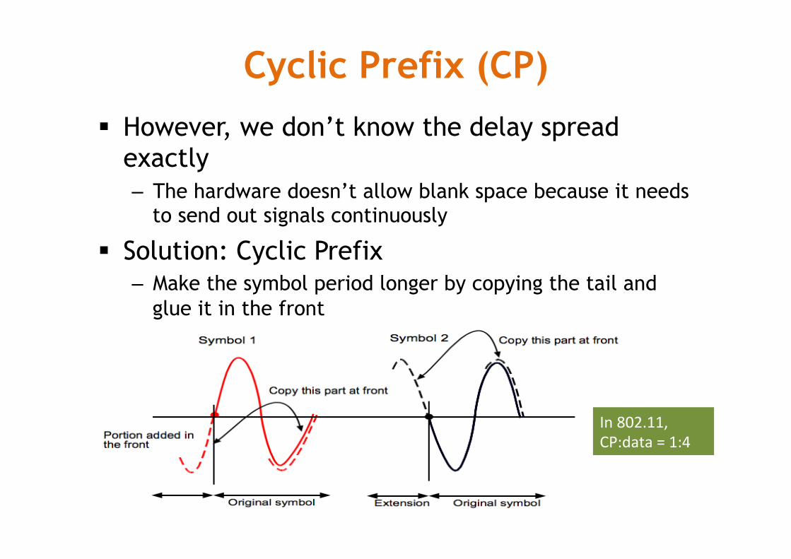
§ However, we don’t know the delay spread exactly – The hardware doesn’t allow blank space because it needs
to send out signals continuously
§ Solution: Cyclic Prefix – Make the symbol period longer by copying the tail and
glue it in the front
Cyclic Prefix (CP)
In802.11,CP:data=1:4
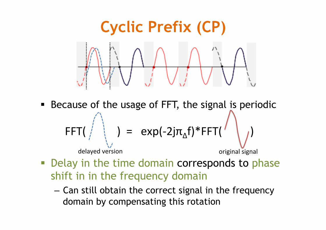
§ Because of the usage of FFT, the signal is periodic
§ Delay in the time domain corresponds to phase shift in in the frequency domain – Can still obtain the correct signal in the frequency
domain by compensating this rotation
Cyclic Prefix (CP)
FFT()=exp(-2jπΔf)*FFT()delayedversion originalsignal
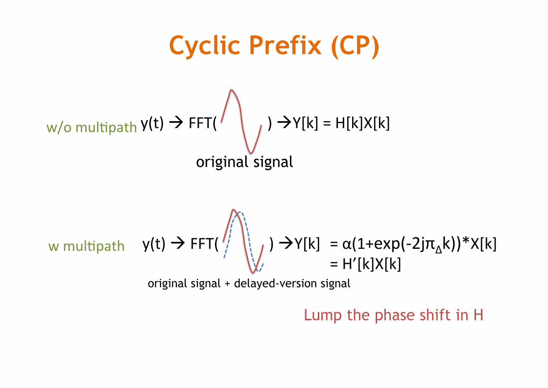
Cyclic Prefix (CP)
original signal
y(t)àFFT()àY[k]=H[k]X[k]w/omulMpath
wmulMpath
original signal + delayed-version signal
y(t)àFFT()àY[k] =α(1+exp(-2jπΔk))*X[k] =H’[k]X[k]
Lump the phase shift in H
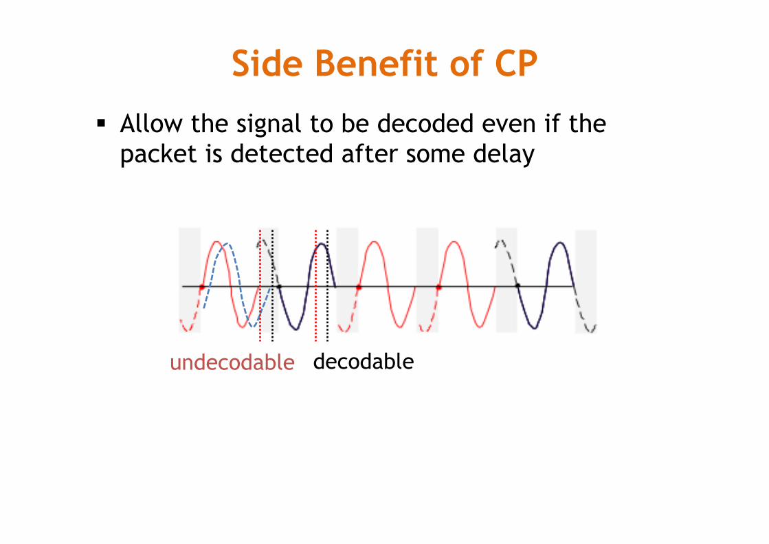
Side Benefit of CP § Allow the signal to be decoded even if the
packet is detected after some delay
decodable undecodable
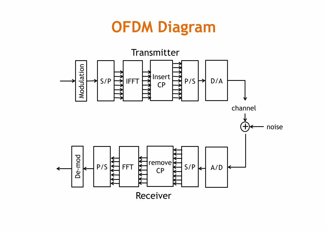
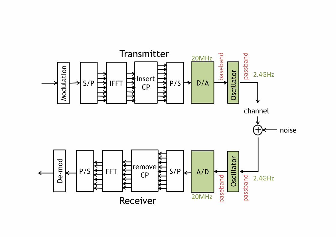
OFDM Diagram
Mod
ulat
ion
S/P IFFT P/S Insert
CP D/A
channel
noise +
A/D
De-
mod
P/S FFT S/P remove
CP
Transmitter
Receiver
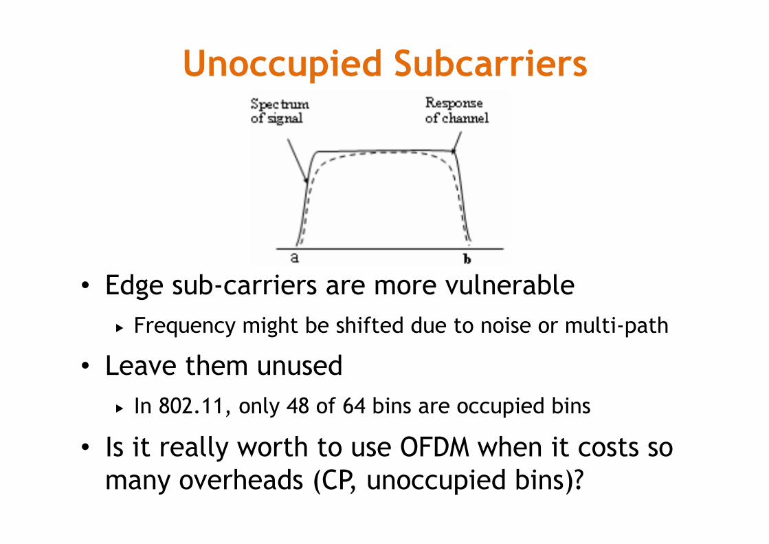
Unoccupied Subcarriers
• Edge sub-carriers are more vulnerable � Frequency might be shifted due to noise or multi-path
• Leave them unused � In 802.11, only 48 of 64 bins are occupied bins
• Is it really worth to use OFDM when it costs so many overheads (CP, unoccupied bins)?
Mod
ulat
ion
S/P IFFT P/S Insert
CP D/A
channel
noise +
A/D
De-
mod
P/S FFT S/P remove
CP
Transmitter
Receiver
Osc
illat
or
Osc
illat
or
20MHz
20MHz
baseband
baseband
passband
passband
2.4GHz
2.4GHz
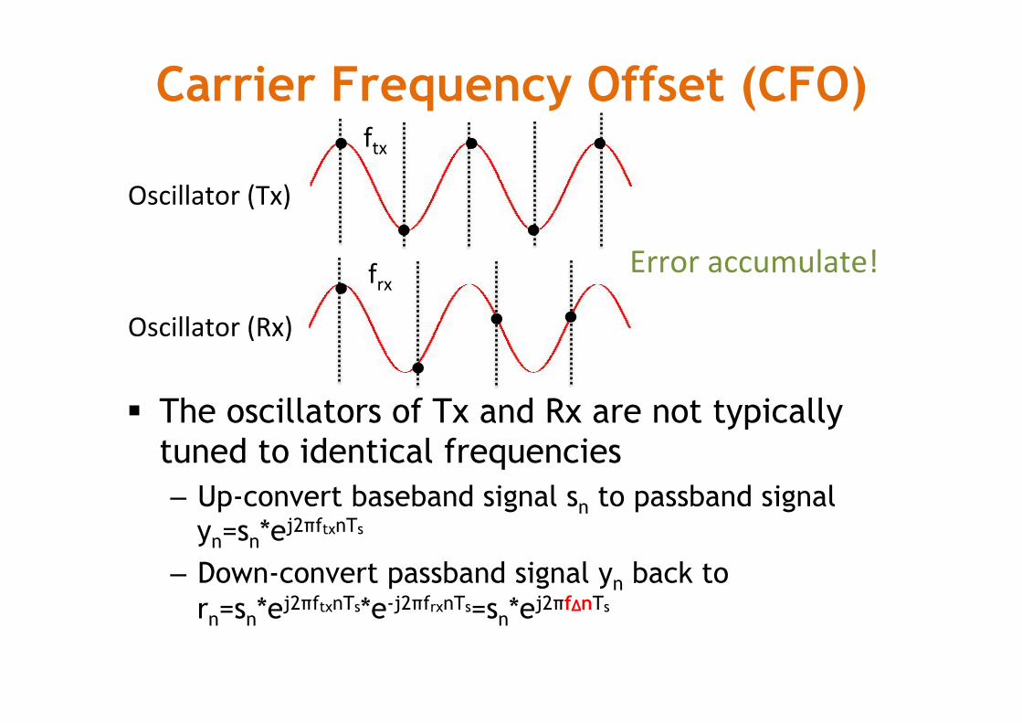
Carrier Frequency Offset (CFO)
§ The oscillators of Tx and Rx are not typically tuned to identical frequencies – Up-convert baseband signal sn to passband signal
yn=sn*ej2πftxnTs
– Down-convert passband signal yn back to rn=sn*ej2πftxnTs*e-j2πfrxnTs=sn*ej2πfΔnTs
Oscillator(Tx)
Oscillator(Rx)
ftx
frx Erroraccumulate!
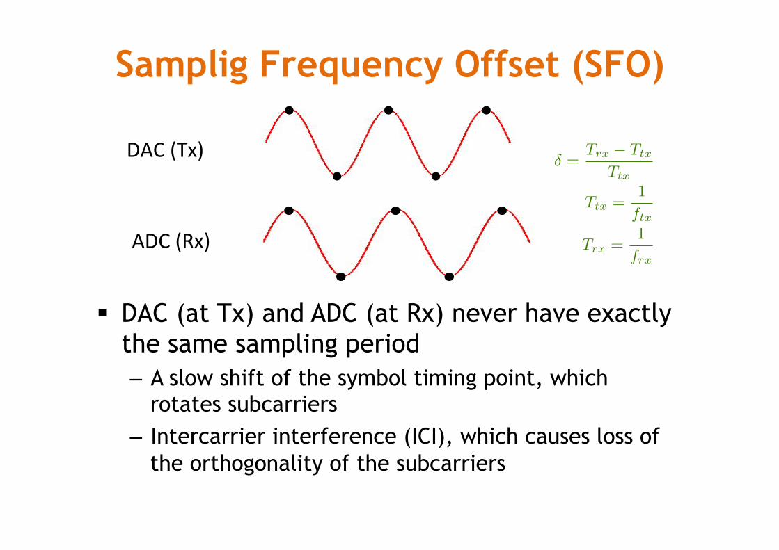
Samplig Frequency Offset (SFO)
§ DAC (at Tx) and ADC (at Rx) never have exactly the same sampling period – A slow shift of the symbol timing point, which
rotates subcarriers – Intercarrier interference (ICI), which causes loss of
the orthogonality of the subcarriers
DAC(Tx)
ADC(Rx)
� =Trx
� Ttx
Ttx
Ttx
=1
ftx
Trx
=1
frx
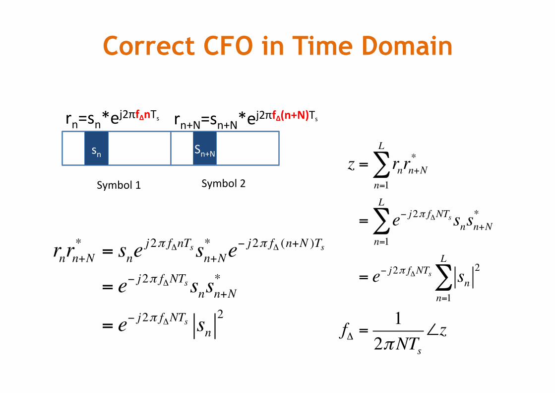
Correct CFO in Time Domain
Symbol1 Symbol2
sn Sn+N
rn=sn*ej2πfΔnTs rn+N=sn+N*ej2πfΔ(n+N)Ts
rnrn+N* = sne
j2π fΔnTs sn+N* e− j2π fΔ (n+N )Ts
= e− j2π fΔNTs snsn+N*
= e− j2π fΔNTs sn2
z = rnrn+N*
n=1
L
∑
= e− j2π fΔNTs snsn+N*
n=1
L
∑
= e− j2π fΔNTs sn2
n=1
L
∑
fΔ =1
2πNTs∠z
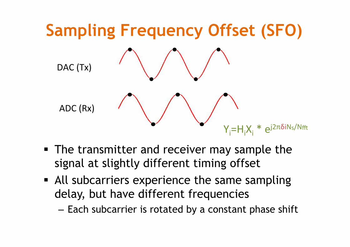
Sampling Frequency Offset (SFO)
§ The transmitter and receiver may sample the signal at slightly different timing offset
§ All subcarriers experience the same sampling delay, but have different frequencies – Each subcarrier is rotated by a constant phase shift
DAC(Tx)
ADC(Rx)
Yi=HiXi*ej2πδiNs/Nm
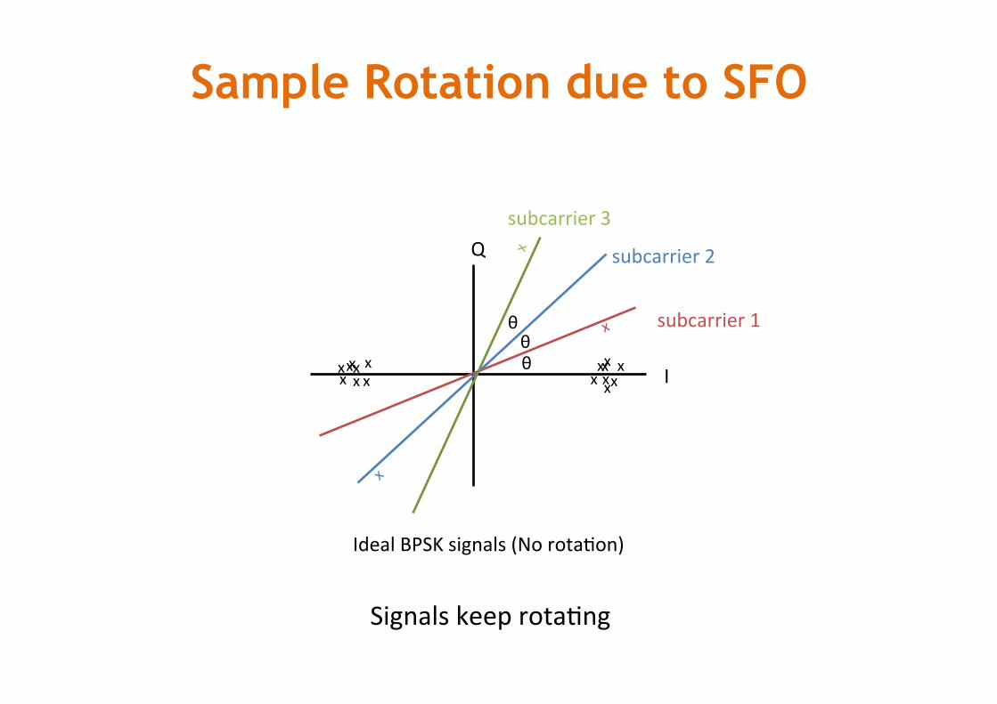
Sample Rotation due to SFO
I
Q
xxxx
xxx
xx xx xxxx
x
IdealBPSKsignals(NorotaMon)
θ
x
subcarrier1
subcarrier2
subcarrier3
SignalskeeprotaMng
θθ
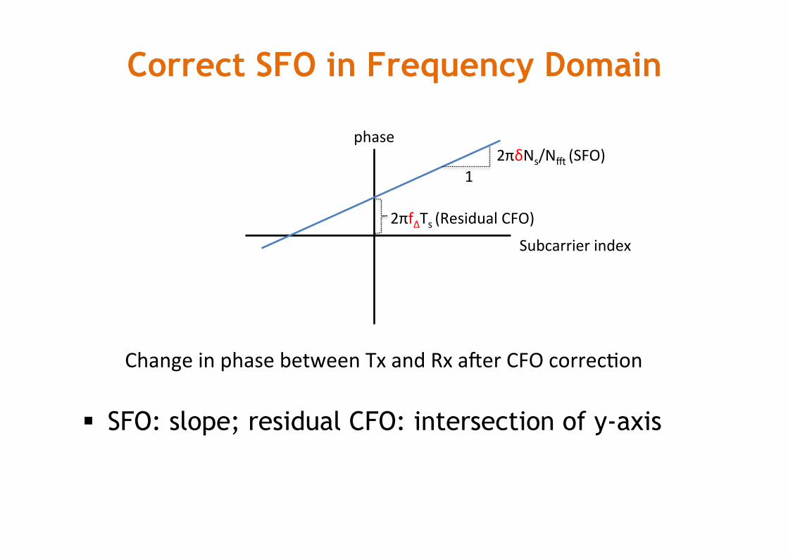
Correct SFO in Frequency Domain
§ SFO: slope; residual CFO: intersection of y-axis
2πfΔTs(ResidualCFO)
12πδNs/Nm(SFO)
ChangeinphasebetweenTxandRxarerCFOcorrecMon
Subcarrierindex
phase
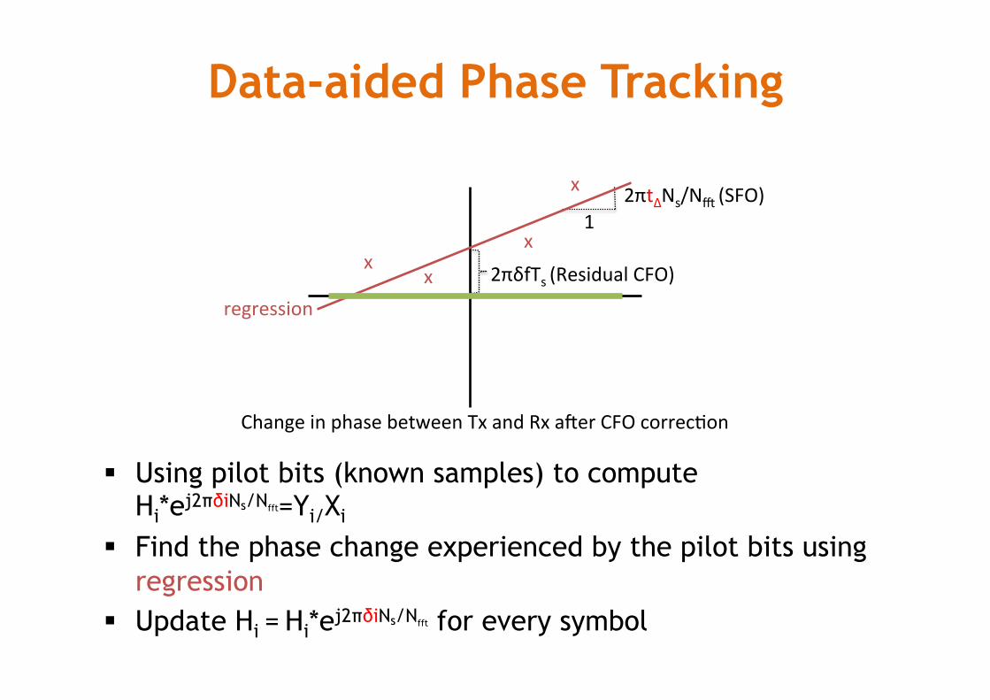
Data-aided Phase Tracking
§ Using pilot bits (known samples) to compute Hi*ej2πδiNs/Nfft=Yi/Xi
§ Find the phase change experienced by the pilot bits using regression
§ Update Hi = Hi*ej2πδiNs/Nfft for every symbol
2πδfTs(ResidualCFO)
12πtΔNs/Nm(SFO)
ChangeinphasebetweenTxandRxarerCFOcorrecMon
xx
x
x
regression
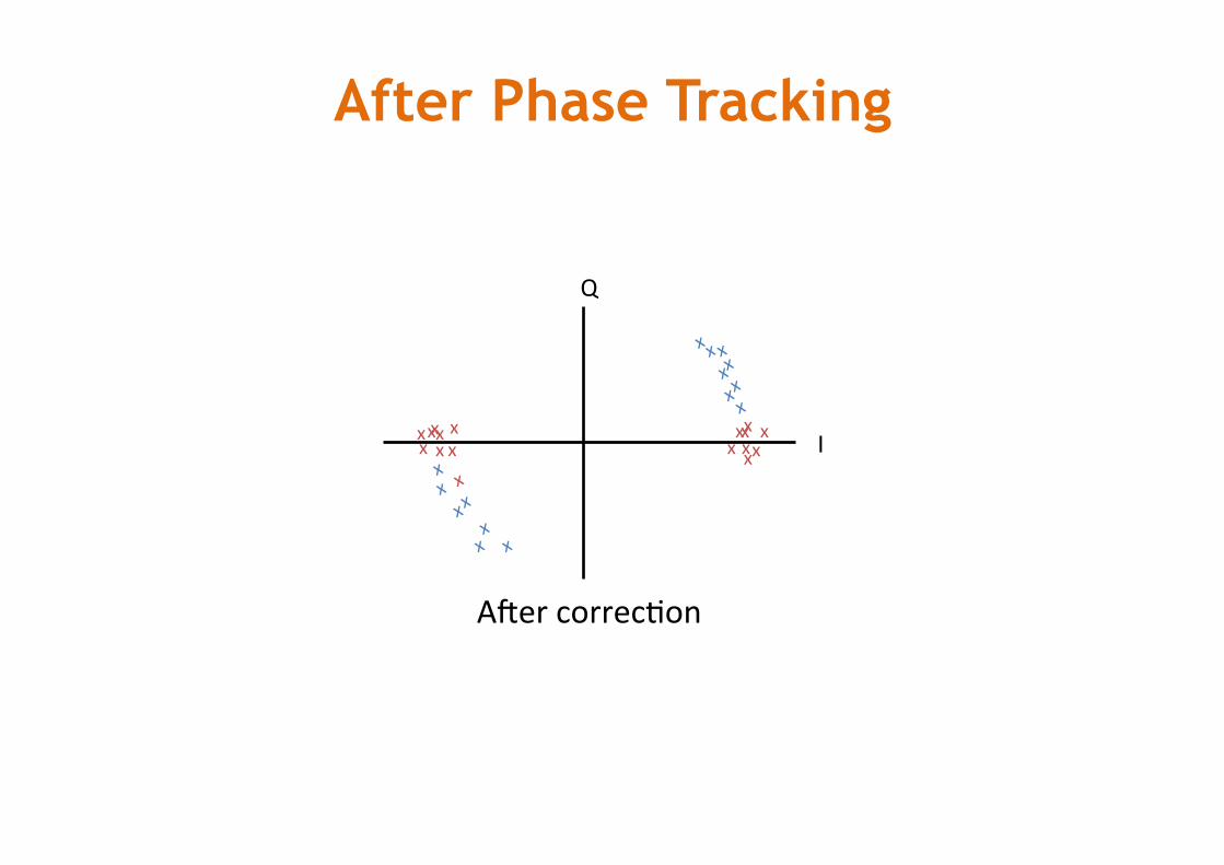
After Phase Tracking
I
Q
xxxx
xxx
xx xx xxxx
x
ArercorrecMon
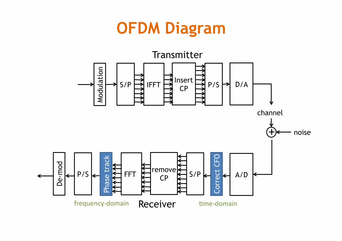
OFDM Diagram
Mod
ulat
ion
S/P IFFT P/S Insert
CP D/A
channel
noise +
A/D
De-
mod
P/S FFT S/P remove
CP
Transmitter
Receiver Co
rrec
t CF
O
Phas
e tr
ack
Mme-domainfrequency-domain
Quiz § Please explain what is the “multipath effect” § Please explain what is ”frequency selective
fading” and what is its root cause