Embed Size (px)
Citation preview
EN
9000-600-11/30
2010
/08
Installation and Operating Instructions
Periomat Plus


EN
2010/08� 3
Content
Important Information1. Warnings and Symbols��������������������������� 42. General ��������������������������������������������������� 5
2�1� Note�on�Conformity� �������������������������� 52�2� General�Notes� ���������������������������������� 52�3� Disposal�� ������������������������������������������ 52�4� Notes�on�medical�products����������������� 52�5� Notes�on�EMC�and�medical�products��62�6� Correct�Usage� ���������������������������������� 62�7� Incorrect�usage� �������������������������������� 62�8� Connecting�peripheral�appliances������� 6
3. Safety � ���������������������������������������������������� 63�1� General�Safety�Notes������������������������� 63�2� Electrical�safety�instructions��������������� 6
4. Delivery Contents� ���������������������������������� 94�1� Special�accessories��������������������������� 94�2� Disposable�materials� ������������������������ 9
5. Technical Data��������������������������������������� 105�1� Model�Overview������������������������������� 105�2� Model�identification�plate� ���������������� 105�3� Ambient�conditions��������������������������� 11
6. Switch panel functions ������������������������� 11
Mounting7. Set-up ��������������������������������������������������� 12
7�1� Room�for�Set-up� ���������������������������� 127�2� Set-up��������������������������������������������� 12
8. Start-up������������������������������������������������� 128�1� Prepare�the�appliance����������������������� 12
9. Circuit diagram� ������������������������������������ 169�1� Descriptions������������������������������������� 179�2� Connection�colours� ������������������������ 17
Use10. Chemical preparation��������������������������� 1811. Instructions for use������������������������������� 19
11�1� Film�insertion�without�adapter��������� 1911�2� Film�insertion�with�adapter��������������� 2111�3� Miscellaneous��������������������������������� 24
12. Maintenance ����������������������������������������� 2512�1� Weekly�2�x�water��
change�and�check�level�of�chemi-cals������������������������������������������������ 25
12�2� Every�3�weeks�change�chemicals� �� 2712�3� Every�6�months�clean�the�film�
transport����������������������������������������� 28

EN
4� 2010/08
Important Information
1. Warnings and SymbolsWarnings
The�warning�notes�in�this�document�are�desi-gned�to�point�out�possible�hazards�which�could�cause�either�injury�to�staff�or�damage�to�the�appliance�
They�are�marked�using�the�following�warning�symbols:
General�warning�symbols
Warning�-�dangerous�electrical�voltage
Danger�to�health
The�safety�instructions�are�laid�out�in�the�following�way:
SIGNAL WORDDescription of type and cause of hazardDescription�of�possible�outcomes�if�safety�notes�are�ignored•�Observe�these�measures�to�prevent�
any�possible�danger�occuring�
The�safety�instructions�are�graded�in�four�levels�of�danger:�
DANGER Extremely�hazardous�and�could�lead�to�serious�injury�or�death
WARNING Possibly�hazardous�but�could�lead�to�serious�injury�or�death
CAREFUL Could�lead�to�minor�injury
ATTENTION Could�lead�to�serious�damage
Further symbols used
These�symbols�are�used�in�this�documentation�and�/or�on�the�appliance:�
Notes,�e�g��special�instructions�concer-ning�efficient�usage�of�the�appliance��
Unplug�at�the�mains�and�remove�all�power�
Observe�the�instruction�documentation�supplied
Date�of�manufacture
Dispose�of�this�appliance�correctly�according�to�EU�directive�(2002/96/EG-WEE)�
Handling instructions
Handling�instructions�are�marked�with�a�dot:
•�Execute�this�handling�step��

EN
2010/08� 5
2. General2.1 Note on ConformityThis�product�has�been�tested�for�conformity�according�to�the�appropriate�directives�as�laid�down�by�the�European�Union�and�has�been�found�to�conform�to�all�the�required�specifica-tions�
2.2 General Notes•�These�Installation�and�Operating�Instructions�
form�an�integral�part�of�the�unit��They�must�be�kept�close�to�the�unit�at�all�times��Precise�observance�of�these�instructions�is�a�pre-condition�for�use�of�the�unit�for�the�intended�purpose�and�for�its�correct�operation��New�personnel�must�be�made�aware�of�the�contents,�and�they�should�be�passed�on�to�future�operating�staff��
•�Safety�for�the�operator�as�well�as�trouble-free�operation�of�the�unit�are�only�ensured�if�use�is�made�of�original�equipment�parts��Additionally,�only�parts�specifically�refer-red�to�in�these�Installation�and�Operating�Instructions�or�accessories�and�disposable�materials�specifically�recommended�by�Dürr�Dental�may�be�used��If�other�accessories�or�disposable�materials�are�used�with�this�ap-pliance,�Dürr�Dental�cannot�guarantee�safe�operation�or�proper�functioning��No�liability�on�the�part�of�the�manufacturer�will�be�accepted�in�the�case�that�damage�arises�through�the�use�of�non-approved�accessories�
•�Dürr�Dental�are�only�responsible�for�the�equip-ment�with�regard�to�safety,�reliability�and�pro-per�functioning�where�assembly,�resettings,�changes�or�modifications,�extensions�and�repairs�have�been�carried�out�by�Dürr�Dental�or�an�agency�authorized�by�Dürr�Dental�and�if�the�equipment�is�used�in�conformity�with�the�Installation�and�Operating�Instructions�
•�These�Installation�and�Operating�Instructions�conform�to�the�relevant�version�of�the�equip-ment�and�the�underlying�safety�standards�valid�at�the�time�of�going�to�press��All�circuits,�processes,�names,�software�and�appliances�quoted�are�protected�under�industrial�proper-ty�rights�
•�The�translation�of�these�Installation�and�Operating�Instructions�has�been�carried�out�in�good�faith��No�liability�can�be�accepted�for�mistakes�in�the�translation��The�enclo-sed�German�version�of�these�Installation�and�Operating�Instructions�is�the�reference�
version��If�there�is�any�doubt�about�the�trans-lation�please�consult�your�dealer�
•�Any�reprinting�of�the�technical�documentation,�in�whole�or�in�part,�is�subject�to�prior�approval�of�Dürr�Dental�being�given�in�writing�
•�Retain�the�packaging�for�possible�return�of�the�product�to�the�manufacturers��Only�the�origi-nal�packaging�provides�adequate�protection�during�transport�of�the�unit��Should�return�of�the�product�to�the�manuf-acturers�be�necessary�during�the�guarantee�period,�Dürr�Dental�accepts�no�responsibility�for�damage�occurring�during�transport�where�the�original�packaging�was�not�used!�Ensure�that�the�packaging�is�kept�out�of�the�reach�of�children�
2.3 Disposal 2.3.1 Appliance
•�EU�directive�2002/96/EG�-�WEEE�(Waste�Electric�and�Electronic�Equipment)�of�27th�January�2003�and�its�current�implementation�state�that�under�national�law�Dental�Products�are�covered�by�the�said�directive�and�therefo-re,�within�the�European�Union,�must�be�dispo-sed�of�as�special�waste�
•� If�you�have�any�questions�at�all�concerning�the�proper�disposal�of�this�product,�please�contact�either�Dürr�Dental�directly�or�your�usu-al�specialist�dental�trader�
2.3.1 X-ray chemicals
Observe�any�local�or�national�rules�and�regulati-ons�concerning�disposal�of�x-ray�chemicals�
2.4 Notes on medical products•�This�product�is�a�technical�medical�appli-
ance�and,�as�such,�may�only�be�operated�by�such�persons�who,�as�a�result�of�training�or�experience,�can�be�confidently�expected�to�operate�it�correctly�and�safely�for�patients�and�staff�alike�
•�Do�not�lie�multi-socket�units�on�the�floor��When�using�portable�multiple�socket-outlets�then�the�requirements�as�laid�out�under�EN�60601-1-1�must�be�observed�
•�Other�systems�should�not�be�plugged�into�the�same�multi-socket�unit�

EN
6� 2010/08
2.5 Notes on EMC and medical products
Medical�products�should�be�treated�with�respect�when�it�comes�to�electro-magnetic�compatibility�and�special�safety�measures�must�be�taken�Special�instructions�concerning�electro-ma-gnetic�compatibility�for�medical�products�can�be�found�in�our�special�leaflet,�order�number�9000-606-67/30,�or�the�information�can�be�found�on�the�internet�(www�duerr�de)�in�the�Technical�Documentation�download�pages�
2.6 Correct UsageThe�Periomat�Plus�is�designed�for�the�develop-ment�of�intraoral�X-ray�films�of�sizes�2�x�3 cm�to�5�7�x�7�6 cm�
2.7 Incorrect usageAny�use�of�this�appliance/these�appliances�above�and�beyond�that�laid�down�in�the�Instal-lation�and�Operating�Instructions�is�deemed�to�be�incorrect�usage��The�manufacturer�cannot�be�held�liable�for�any�damage�resulting�from�incorrect�usage��The�operator�will�be�held�liable�and�bears�all�risks�
2.8 Connecting peripheral appliances
Appliances�may�only�be�connected�together�or�connected�to�any�other�assemblies�where�complete�and�utter�safety�of�the�patients,�opera-tors�and�staff�and�of�the�environment�will�not�be�affected�in�any�way��Where�any�doubts�remain�concerning�the�safety�when�connecting�to�other�units�then�the�opera-tor�is�obliged�to�ascertain�that�such�connection�can�in�no�way�affect�the�safety�of�operator,�patient�or�other�staff�by�referring�to�the�manuf-acturer�or�a�fully�qualified�and�competent�expert�
3. Safety 3.1 General Safety NotesThis�appliance�has�been�so�designed�and�deve-loped�by�Dürr�Dental�that�under�correct�usage�that�there�can�be�no�danger�to�operator�or�patient���In�spite�of�this,�we�feel�it�is�our�duty�to�mention�the�following�safety�measures�in�order�to�prevent�any�possible�danger�•�When�using�this�appliance�all�local�and�rele-
vant�regulations�must�be�observed!�Converting�or�modifying�the�appliance�in�any�way�is�strictly�prohibited��In�such�cases,�any�and�all�guarantees�immediately�become�in-valid��The�operation�of�modified�appliances�can�be�punishable�by�law��In�the�interests�of�trouble-free�operation�the�operator�is�respon-sible�for�observing�these�regulations�
•� Installation�must�be�carried�out�by�a�technical�expert�
•�Before�every�use�the�operator�must�check�the�functional�safety��and�the�condition�of�the�appliance�
•�The�operator�must�be�knowledgeable�in�the�operation�of�the�appliance�
•�The�product�is�not�designed�to�be�used�in�medical�treatment�areas�where�there�exists�the�danger�of�explosion��Areas�where�explo-sions�could�occur�are�those�where�flammable�anesthetic�material,�skin�cleansers,�oxygen�and�skin�disinfectants�are�present��This�ap-pliance�is�not�to�be�used�in�areas�where�the�atmosphere�could�cause�fire��
3.2 Electrical safety instructions•�The�appliance�may�only�be�connected�to�an�
earthed�safety�socket�
•�Before�connecting�to�the�electricity�supply�the�appliance�must�be�inspected�and�checked�that�the�supply�voltage�and�the�supply�fre-quency�correspond�to�that�of�the�local�electri-cal�supply�
•�Before�initial�use�and�start-up�the�appliance�and�all�supply�lines�must�be�checked�for�any�signs�of�damage��Damaged�supply�lines�and�connections�must�be�replaced�immediately�
•�Never�come�into�contact�with�patients�and�open�plug-in�connections�on�the�appliance�at�the�same�time�
•�When�using�the�appliance�observe�all�the�rele-vant�electrical�safety�procedures�

EN
2010/08� 7

EN
8� 2010/08
2
9
6
87
15
12
13
10
14
19
18
3
4
1
11a
5
16 17
1 2
3
11b
11c 11d
11
EN
2010/08� 9
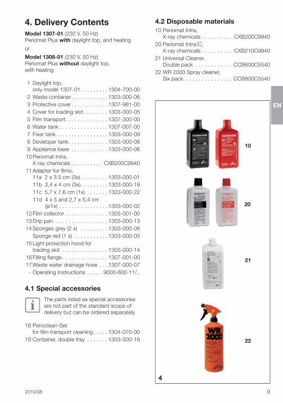
4. Delivery ContentsModel 1307-01�(230 V,�50 Hz)Periomat�Plus�with�daylight�top,�and�heating
or
Model 1308-01�(230 V,�50 Hz)Periomat�Plus�without�daylight�top,�with�heating
� 1� Daylight�top,��only�model�1307-01������������������ 1304-700-00
� 2� Waste�container������������������������ 1303-000-06� 3� Protective�cover������������������������ 1307-981-00� 4� Cover�for�loading�slot���������������� 1303-000-05� 5� Film�transport���������������������������� 1307-300-00� 6� Water�tank�������������������������������� 1307-007-00� 7� Fixer�tank���������������������������������� 1303-000-09� 8� Developer�tank�������������������������� 1303-000-08� 9� Appliance�base ������������������������ 1303-000-06�10�Periomat�Intra,�
X-ray�chemicals��������������������� CXB200C9940�11�Adapter�for�films,�
11a��2�x�3�5�cm�(3x)������������������ 1303-000-01� � 11b��2,4�x�4�cm�(3x)������������������ 1303-000-18� � 11c��5,7�x�7,6�cm�(1x) �������������� 1303-000-22� � 11d��4�x�5�and�2,7�x�5,4�cm��
� (je1x)�������������������������������� 1303-000-02�12�Film�collector���������������������������� 1303-001-00�13�Drip�pan������������������������������������ 1303-000-13�14�Sponges�grey�(2�x)� ������������������ 1303-000-06� � Sponge�red�(1�x)����������������������� 1303-000-05�15�Light�protection�hood�for�
loading�slot ������������������������������ 1303-000-14�16�Filling�flange������������������������������ 1307-001-00�17�Waste�water�drainage�hose ������ 1307-000-07��-�Operating�Instructions �����������9000-600-11/��
4.1 Special accessories
The�parts�listed�as�special�accessories�are�not�part�of�the�standard�scope�of�delivery�but�can�be�ordered�separately�
18�Perioclean-Set�for�film�transport�cleaning���������� 1304-070-00
19�Container,�double�tray �������������� 1303-000-16
4.2 Disposable materials10�Periomat�Intra,�
X-ray�chemicals��������������������� CXB200C994020�Periomat�Intra/C,��
X-ray�chemicals��������������������� CXB210C994021�Universal�Cleaner,�
Double�pack �������������������������CCB600C554022�WR�2000�Spray�cleaner,�
Six�pack���������������������������������CCB800C5540
20
4
21
22
10

EN
10� 2010/08
5. Technical Data5.1 Model OverviewModel 1307-01�(230 V,�50 Hz)Periomat�Plus�with�daylight�top,�and�heating
Model 1308-01�(230 V,�50 Hz)Periomat�Plus�without�daylight�top,�with�heating
Model 1307-01 / 1308-01
Voltage V 230
Frequency Hz 50
Rated current A 2,2
Rated power W 500
Duty cycle %ED 100
Film processing time min 5
Developing temperature °C 25
Warm-up time min�/�°C
~7
Heating V 24
Appliance fuse A T�2�5
Volume�D�eveloper-��tank l 1�Fixer�tank l 1�Water�tank l 1,25
Weight kg 11,2�/�10,2
Dimensions (HxBxT)
cm 40�x�63�x�25�(1307-01)
22�x�63�x�25�(1308-01)
5.2 Model identification plateThe�model�identification�plate�can�be�found�on�the�rear�side�of�the�appliance�under�the�protec-tive�cover�
REF Order�no���/�Model�no��
SN Serial�no�
5
6

EN
2010/08� 11
5.3 Ambient conditionsAmbient conditions for storage and transportTemperature�(°C)��������������������������� -10�up�to�+60Rel��humidity�(%)������������������������������������ max��95Ambient conditions on operationTemperature�(°C)�������������������������� +10�up�to�+40Rel��humidity�(%)������������������������������������ max��70
6. Switch panel functionsThe�yellow�and�green�switches�are�fitted�with�an�integrated�control�lamp�
Yellow main power supply (23)
Pos��O:�� Periomat�Plus�OFFPos��l:� Periomat�Plus�ON
Green transport schwitch (24)
Pos��O:� Transport�motor�OFFPos��l:� Transport�motor�ON,�
Developer�process�starts�up
7
23
24

EN
12� 2010/08
Mounting
7. Set-up 7.1 Room for Set-up
Max. Ambient temperature 25 °C. Never use the Periomat in a position with direct sunlight! The film material may become expo-sed despite the use of the daylight top.
•�Set�up�the�Periomat�in�a�dry,�well�ventilated�room�
•�The�mains�supply�socket�should�be�so�laid�out�that�the�main�appliance�plug�is�clearly�visible,�and�is�easily�accessible�
7.2 Set-up•�Take�the�Periomat�out�of�its�carton�
•�Set�the�appliance�up�on�a�stable�and�hori-zontal�surface�in�the�vicinity�of�a�mains�supply�socket�
8. Start-up8.1 Prepare the appliance•�Remove�the�protective�cover�
•�Remove�the�box�containing�the�adapter�
•�Remove�the�water�bottle�and�the�flexible�pou-ring�container�
•�Remove�the�transportation�safety�padding�material�(foam�rubber�and�cardboard�in�dryer�compartments)!
•�Remove�the�sponges�from�the�tanks�
•�Swivel�the�temperature�controller�(25)�upwards�
•�Remove�the�film�transport�(5),�developer�tank�(8),�fixer�tank�(7)�and�water�tank�(6),�and�remo-ve�any�traces�of�packing�material�
•�Attach�the�water�drainage�hose�(17)
8
5
25
8
7
6
17
9
10

EN
2010/08� 13
•�Replace�the�parts�in�position�
•�Place�an�empty�collector�vessel�with�a�capaci-ty�of�at�least�5�liters�at�the�ready�
•�Place�this�collector�on�the�floor�
•�Feed�the�water�drainage�hose�into�this�container�
•�Shorten�the�water�drainage�hose�so�that�it�hangs�into�the�container�about�3 cm�
•�Mix�up�the�chemicals,�see�section�10�
•�Place�the�protective�cover�(3)�in�position�
•�Place�the�cover�(4)�onto�the�loading�slot�(slot�8�must�face�to�the�front)�
•�Hang�the�film�collector�(12)�in�position�
11
4
5
13
12
4
3
12

EN
14� 2010/08
•�Check�that�the�local�supply�voltage�of�the�mains�supply�socket�is�identical�to�the�voltage�information�on�the�model�identification�plate�of�the�appliance�
CAREFUL Danger of a short circuit due to con-densated water coming into contact with the electronic circuit board! •�Only�connect�and�operate�the�appli-
ance�after�allowing�it�to�warm�up�to�room�temperature�after�transport��
•�Plug�in�at�the�mains�
•�Switch�on�the�appliance�at�the�yellow�switch�(23)�
The�developer�and�fixer�tanks�are�loca-ted�on�a�temperature�regulated�heating�plate���If�the�temperature�level�when�filling�is�lower�than�25 °C�then,�after�switching�on�at�the�yellow�main�power�switch,�the�chemicals�will�automatically�be�heated�up�and�kept�to�a�constant�temperature�
Example:��Warm�up�time�per�°C�is�ca��7�min�The�optimum�developer�temperature�is�25 °C�Assuming�an�initial�temperature�of�18 °C,�the�warm�up�time�will�be�approximately�ca��45�min�,�until�the�ideal�developer�temperature�has�been�reached�
The�green�transport�switch�(24)�lights�as�soon�as�the�set�developer�temperature�of�25 °C�has�been�reached�
24
23
14
15
3

EN
2010/08� 15

EN
16� 2010/08
9. Circuit diagram

EN
2010/08� 17
9.1 Descriptions� 1� Green�transport�switch� 2� Yellow�main�power�supply� 3� Transformer�unit� 4� Electronics� 5� Temperature�sensing�device� 6� Bath�heating� 7� Plug� 8� Ventilation�fan�for�film�drying� 9� Transport�motor�10� Heating�for�film�drying�11� Thermal�fuse�12� Fuse�power�supply�13� Fuse�controller�14� Distributor�1�15� Distributor�2�16� Distributor�power�supply
9.2 Connection coloursgn/ge� =� green/yellowrt/sw� =� red/blackws/or� =� white/orangesw� =� blackrt� =� redbr� =� brownbl� =� blueor� =� orangegn� =� green
EN
18� 2010/08
Use
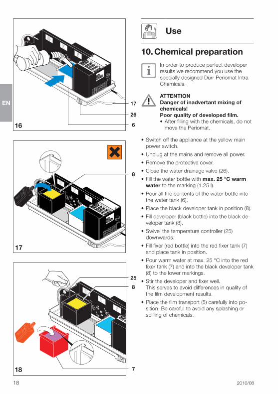
10. Chemical preparationIn�order�to�produce�perfect�developer�results�we�recommend�you�use�the�specially�designed�Dürr�Periomat�Intra�Chemicals�
ATTENTION Danger of inadvertant mixing of chemicals!Poor quality of developed film.•�After�filling�with�the�chemicals,�do�not�
move�the�Periomat�
•� �Switch�off�the�appliance�at�the�yellow�main�power�switch�
•�Unplug�at�the�mains�and�remove�all�power�
•�Remove�the�protective�cover�
•�Close�the�water�drainage�valve�(26)�
•�Fill�the�water�bottle�with�max. 25 °C warm water�to�the�marking�(1�25�l)�
•�Pour�all�the�contents�of�the�water�bottle�into�the�water�tank�(6)�
•�Place�the�black�developer�tank�in�position�(8)�
•�Fill�developer�(black�bottle)�into�the�black�de-veloper�tank�(8)��
•�Swivel�the�temperature�controller�(25)�downwards�
•�Fill�fixer�(red�bottle)�into�the�red�fixer�tank�(7)�and�place�tank�in�position�
•�Pour�warm�water�at�max��25 °C�into�the�red�fixer�tank�(7)�and�into�the�black�developer�tank�(8)�to�the�lower�markings�
•�Stir�the�developer�and�fixer�well���This�serves�to�avoid�differences�in�quality�of�the�film�development�results�
•�Place�the�film�transport�(5)�carefully�into�po-sition��Be�careful�to�avoid�any�splashing�or�spilling�of�chemicals��
6
8
25
8
7
17
26
16
17
18

EN
2010/08� 19
11. Instructions for useFilms�of�format�3�x�4�cm�are�placed�into�the�loading�slot�without�adapter,�see�11�1�Films�of�larger�formats�are�first�placed�in�the�ap-propriate�adapter�before�insertion�in�the�loading�slot,�see�11�2�
11.1 Film insertion without adapter•�Switch�on�the�appliance�at�the�green�transport�
switch�(24)�
•� Insert�3�x�4�cm�films�in�the�numbered�cover�(4)�of�the�8-slot�loading�slot� Only insert one film into each slot.
•�Place�the�light�protective�cover�(15)�in�position�
•�Slide�the�start�lever�(27)�to�the�right�
A�new�film�can�only�be�inserted�once�the�start�lever�(27)�is�back�in�its�starting�position�(after�ca��50 seconds)�
24
4
15
27
19
20
21
EN
20� 2010/08
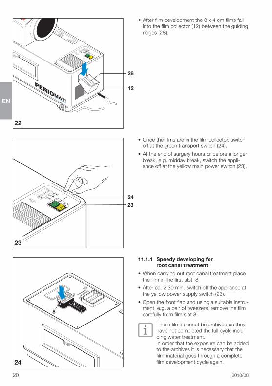
•�After�film�development�the�3�x�4�cm�films�fall�into�the�film�collector�(12)�between�the�guiding�ridges�(28)�
•�Once�the�films�are�in�the�film�collector,�switch�off�at�the�green�transport�switch�(24)�
•�At�the�end�of�surgery�hours�or�before�a�longer�break,�e�g��midday�break,�switch�the�appli-ance�off�at�the�yellow�main�power�switch�(23)�
24
12
28
22
23
24
23
8
11.1.1 Speedy developing for root canal treatment
•�When�carrying�out�root�canal�treatment�place�the�film�in�the�first�slot,�8�
•�After�ca��2:30�min��switch�off�the�appliance�at�the�yellow�power�supply�switch�(23)�
•�Open�the�front�flap�and�using�a�suitable�instru-ment,�e�g��a�pair�of�tweezers,�remove�the�film�carefully�from�film�slot�8�
These�films�cannot�be�archived�as�they�have�not�completed�the�full�cycle�inclu-ding�water�treatment���In�order�that�the�exposure�can�be�added�to�the�archives�it�is�necessary�that�the�film�material�goes�through�a�complete�film�development�cycle�again�

EN
2010/08� 21
11.2 Film insertion with adapterWhen�working�with�the�adapter�the�guiding�ridges�in�the�film�collector�must�first�be�remo-ved�
When�frequent�switching�between�films�with�and�without�adapter�is�encountered,�we�recommend�that�a�second�film�collector�(12)�is�ordered��(Order�no��1303-001-00)
•�Extract�the�guiding�ridge�(28)�from�the�film�collector�(12)�
•�Remove�the�cover�(4)�to�the�loading�slot��
•� Insert�film(s)�in�appropriate�adapter:
11.2.1 Occlusal-Film (5.7 x 7.6 cm)
•�Very�carefully�bend�the�occlusal-film�along�the�centre�and�place�in�the�appropriate�adapter�(11c)�
•�Check�that�the�film�is�secure�in�its�mounting�(11e)�
28
12
4
11c
11e
25
26
27

EN
22� 2010/08
•�Place�the�adapter�(11),�arrow�downwards,�into�the�loading�slot�
ATTENTION Danger of inadvertant mixing of chemicals! If the adapter is falsely inserted (not with arrow pointing down) then film developer and fixer will be carried over.Poor quality of developed film.•�Check�carefully�that�the�arrow�on�the�
adapter�points�downwards�
11.2.2 Film at 2 x 3.5 cm and 2.4 x 4 cm
•�Place�adapter�(11a)�or�(11b)�in�mounting�(29)�
•�Press�each�film�individually�(max��6�films)�into�the�slot�of�the�adapter�until�thez�make�contact�with�the�mounting��The�films�must�stay�parallel�to�each�other�and�must�not�be�allowed�to�make�contact�with�each�other�
•�Place�the�adapter�vertically�into�the�loading�slot�
29
11a11b
11
28
29
30

EN
2010/08� 23
11.2.3 Film at 4 x 5 cm and 2.7 x 5,4 cm
•�Place�the�films�(max��2�films)�into�the�adapter�(11d)�
•�Place�the�adapter�vertically�into�the�loading�slot���The�film�edges�must�no�be�allowed�to�touch�the�shaft�sides�
•�Place�the�light�protective�cover�(15)�in�position�
•�Slide�the�start�lever�(27)�to�the�right�
11d
15
27
31
32
33
1.
2.

EN
24� 2010/08
After�the�films�have�been�developed�they�fall�with�the�adapter�into�the�film�collector�(12)�
•�After�film�development�switch�off�the�film�transport�at�the�green�transport�switch�(24)�
•�At�the�end�of�surgery�hours�or�before�a�longer�break,�e�g��midday�break,�switch�the�appli-ance�off�at�the�yellow�main�power�switch�(23)�
11.3 MiscellaneousA�waste�container�(3)�has�been�integrated�which�can�be�lifted�out�and�has�been�designed�for�the�film�packing�material��3
24
23
12
34
35
36

EN
2010/08� 25
12. Maintenance12.1 Weekly 2 x water
change and check level of chemicals.
•�Switch�off�the�appliance�at�the�yellow�switch�(23)�
Unplug�at�the�mains�and�remove�all�power�
•�Check�whether�an�empty�5-liter-collector�ves-sel�has�been�connected�
•�Open�the�water�drainage�tap�(26)�so�that�water�can�drain�off�into�the�collector�vessel�
23
26
37
38
39
5 L
0
1
0
1
•�Close�the�water�drainage�tap�(26),�position�"0"
•�Dispose�of�the�waste�water�according�to�local�regulations�

EN
26� 2010/08
•�Fill�the�water�bottle�with�max. 25 °C warm water�to�the�marking�(l)�
•�Open�the�front�flap�
•�Pour�the�complete�contents�of�the�water�bottle�into�the�water�tank�
•�Check�the�level�of�the�chemicals�in�the�devel-oper�and�fixer�tanks�
•�Top�up�any�liquid�loss�by�adding�water�at�max. 25 °C to�the�markings�(see�inside�of�flap)�
Film�qualityThe�developer�and�fixer�temperatures�are�set�at�25 °C���If�water�warmer�than�25�°C�is�added,�this�will�lead�to�films�being�darker�
•�Close�flap�
•�Plug�in�at�the�mains�
•�Switch�on�the�appliance�at�the�yellow�switch�(23)�
23
40
41

EN
2010/08� 27
12.2 Every 3 weeks change chemicals
After�ca��3�weeks�or�after�developing�approximately�350�films�of�3 x 4 cm�format�the�developer�and�fixer�are�used�up�and�need�to�be�replaced�
•�Before�cleaning�place�the�sponge�and�brushes�(from�Perioclean-Set)�ready�
•�Switch�off�the�appliance�at�the�yellow�switch�(23)�
Unplug�at�the�mains�and�remove�all�power�
•�Remove�the�film�collector�(12)�
•�Remove�the�protective�cover�(3)�
23
12
3
42
43
44

EN
28� 2010/08
•�Lift�the�film�transport�(5)�slightly�and�allow�the�chemicals�to�drain�off�
•�Place�the�film�transport�in�a�suitable�area,�e�g��washbasin�or�sink,�spray�with�Spray�Cleaner�WR 2000�and�allow�to�work�for�ca��10�min�
•�Swivel�the�temperature�controller�(25)�upwards�
•�Empty�both�chemicals�and�water�
•�Observe�any�local�or�national�rules�and�regula-tions�concerning�disposal�of�x-ray�chemicals�
•�Clean�all�3�tanks�(6,�7,�8)�using�the�correct�colour�coded�sponge�thoroughly�with�warm water�and�wipe�clean�
•�Dry�the�area�surrounding�the�loading�slot�with�a�non-fluffy�cloth�
•�Remove�any�possible�remaining�deposits�or�dirt�from�the�film�transport�using�a�brush�(e��g��from�the�Perioclean-Set)�
•�Rinse�the�film�transport�(5)�thoroughly�under�warm�running�water�
•�Place�the�film�transport�onto�a�draining�board�(fig��46)�
•�Make�up�chemicals,�see�10� Chemical�preparation�
12.3 Every 6 months clean the film transport
Only when using "Periomat Intra" X-ray chemicalsWhen�cleaning�the�film�transport,�we�recom-mend�you�use�the�Dürr�Dental�Perioclean-Set,�order�number:�1304-070-00��Detailed�instructions�for�use�are�supplied�with�each�set�
5
25
45
46
47
6
87

EN
2010/08� 29

EN
30� 2010/08

EN
2010/08� 31

DÜRR DENTAL AGHöpfigheimer Strasse 17 74321 Bietigheim-BissingenGermanyFon: +49 7142 [email protected]